
1 full D1 DVR. user Manual Intelligent Video surveillance GUI Display with USB Mouse Control Please read instructions thoroughly before operation and retain it for future reference. For the actual display & operation, please refer to your DVR in hand. IMPORTANT SAFEGUARD. CAUTION. RISK OF ELECTRIC SHOCK. CAUTION: To reduce the risk of electric shock, do not expose this apparatus to rain or moisture. Only operate this apparatus from the type of power source indicated on the label. The company shall not be liable for any damages arising out of any improper use, even if we have been advised of the possibility of such damages. The lightning flash with arrowhead symbol, within an equilateral triangle, is intended to alert the user to the presence of uninsulated dangerous voltage within the product’s enclosure that may be of sufficient magnitude to constitute a risk of electric shock to persons. This exclamation point within an equilateral triangle is intended to alert the user to the presence of important operating and maintenance (servicing) instructions in the literature accompanying the appliance.
2 All lead-free products offered by the company comply with the requirements of the European law on the Restriction of Hazardous Substances (RoHS) directive, which means our manufacture processes and products are strictly lead-free and without the hazardous substances cited in the directive. The crossed-out wheeled bin mark symbolizes that within the European Union the product must be collected separately at the product end-of-life. This applies to your product and any peripherals marked with this symbol. Do not dispose of these products as unsorted municipal waste. Contact your local dealer for procedures for recycling this equipment. This apparatus is manufactured to comply with the radio interference requirements. Federal Communications Commission Interference Statement This equipment has been tested and found to comply with the limits for a Class A digital device, pursuant to Part 15 of the FCC Rules. These limits are designed to provide reasonable protection against harmful interference when the equipment is operated in a commercial environment.
3 This equipment generates, uses, and can radiate radio frequency energy and, if not installed and used in accordance with the instruction Manual , may cause harmful interference to radio communications. Operation of this equipment in a residential area is likely to cause harmful interference in which case the user will be required to correct the interference at his own expense. Trademark Acknowledgements and (EagleEyes) — The trademark application is filed and under process in the and other countries. iPhone is the registered trademark of Apple Inc. BlackBerry and related trademarks, names and logos are the property of Research In Motion Limited and are registered and/or used in the and countries around the world. Used under license from Research In Motion Limited. Android is a trademark of Google Inc. Use of this trademark is subject to Google Permissions. Microsoft , Windows , Internet Explorer , Mozilla Firefox , Google Chrome , Safari , QuickTime , Windows Mobile & Symbian.
4 Mentioned in this document are the registered trademarks of their respective holders. Disclaimer The information in this Manual was current when released. We reserve the right to revise or remove any content in this Manual at any time. We do not warrant or assume any legal liability or responsibility for the accuracy, completeness, or usefulness of this Manual . For the actual display & operation, please refer to your DVR in hand. The content of this Manual is subject to change without notice. Grounding This is a Safety Class 1 Product (provided with a protective earthing ground incorporated in the power cord). The mains plug shall only be inserted in a socket outlet provided with a protective earth contact. Any interruption of the protective conductor inside or outside of the instrument is likely to make the instrument dangerous. Intentional interruption is prohibited. Water & Moisture Do not expose this product to dripping or splashing and that no objects filled with liquids, such as vases, shall be placed on the product.
5 MPEG4 Licensing THIS PRODUCT IS LICENSED UNDER THE MPEG-4 VISUAL PATENT PORTFOLIO LICENSE FOR THE PERSONAL AND. NON-COMMERCIAL USE OF A CONSUMER FOR (i) ENCODING VIDEO IN COMPLIANCE WITH THE MPEG-4 VISUAL STANDARD. ( MPEG-4 VIDEO ) AND/OR (ii) DECODING MPEG-4 VIDEO THAT WAS ENCODED BY A CONSUMER ENGAGED IN A PERSONAL AND. NON-COMMERCIAL ACTIVITY AND/OR WAS OBTAINED FROM A VIDEO PROVIDER LICENSED BY MPEG LA TO PROVIDE MPEG-4. VIDEO. NO LICENSE IS GRANTED OR SHALL BE IMPLIED FOR ANY OTHER USE. ADDITIONAL INFORMATION INCLUDING THAT. RELATING TO PROMOTIONAL INTERNAL AND COMMERCIAL USES AND LICENSING MAY BE OBTAINED FROM MPEG LA, LLC. SEE. GPL Licensing This product contains codes which are developed by Third-Party-Companies and which are subject to the GNU General Public License ( GPL ) or the GNU Lesser Public License ( LGPL ). The GPL Code used in this product is released without warranty and is subject to the copyright of the corresponding author.
6 Further source codes which are subject to the GPL-licenses are available upon request. We are pleased to provide our modifications to the Linux Kernel, as well as a few new commands, and some tools to get you into the code. The codes are provided on the FTP site, and please download them from the following site or you can refer to your distributor: TABLE OF CONTENTS. 1. HARDWARE 1. Package Content ..1. Front Panel ..1. Rear Panel ..2. 2. CONNECTION AND SETUP .. 4. SATA Hard Disk Camera Connection ..7. Normal / DCCS Camera ..7. PTZ Camera ..7. External Device DVR Power On ..9. Date and Time Clear Hard Password Setting ..10. Examining DCCS Signal Transmission ..11. 3. user 12. DVR Access ..12. Live Page ..12. DVR Status ..12. Channel Status..13. Record-related Icons ..13. Quick Menu Bar ..13. Main Menu ..14. 4. FREQUENTLY-USED FUNCTIONS .. 15. Key Lock / Unlock ..15. user Level Creation ..15. PTZ Playback ..17. Playback Event Search ..18. Audio Playback.
7 18. Video Backup ..18. Video Playback on PC (.dv5) ..19. Convert the file format to AVI ..19. Digital Zoom ..20. 5. MAIN MENU .. 21. QUICK START ..21. GENERAL ..21. TIME SETUP ..22. DAYLIGHT ..23. SYSTEM ..23. ACCOUNT ..23. SYSTEM INFO ..25. BACKUP DATA ..26. BACKUP LOG ..28. REGULAR REPORT ..29. EVENT INFORMATION ..29. QUICK SEARCH ..29. EVENT HDD INFO ..31. EVENT LOG ..31. ADVANCED CAMERA ..31. DETECTION ..32. ALERT ..33. NETWORK ..34. RECORD ..38. DCCS ..39. NOTIFY ..44. SCHEDULE SETTING ..47. RECORD ..47. DETECTION ..48. ALARM ..48. 6. REMOTE 49. Supplied Licensed Installation & Network Connection ..49. Control Panel Overview ..50. General Operation ..52. E-Map ..54. Web Browser ..60. Event Playback & IVS APPENDIX 1 64. APPENDIX 2 PIN 76. APPENDIX 3 PUSH VIDEO CONFIGURATION .. 77. PIN Connection ..77. Configuration ..78. APPENDIX 4 MOBILE surveillance VIA EAGLEEYES .. 80. Where to APPENDIX 5 SET PUSH 81. Prerequisite ..81. Enable Push Video.
8 81. From iOS Mobile Device (iPhone / iPad )..81. From Android Mobile APPENDIX 6 COMPATIBLE USB FLASH DRIVE LIST .. 83. APPENDIX 7 COMPATIBLE SATA HDD 84. APPENDIX 8 MAIN MENU 85. APPENDIX 9 DVR BATTERY REPLACEMENT .. 87. APPENDIX 10 DVD WRITER INSTALLATION .. 88. HARDWARE OVERVIEW. 1. HARDWARE OVERVIEW. Note: The functions on the front panel and rear panel may vary, depending on the model you have. Package Content Standard Package DVR HDD screws Adapter & power cord Manual for IR remote controller IR remote controller Optional Accessories IR Receiver extension cable CD Manual USB Mouse HDD brackets Front Panel 1) LED Indicators DVR is powered on. The hard disk is reading or recording. An alarm is triggered. Timer recording is on. Under playback status. 2) CH1 ~ 16 / 1 ~ 8 / 1 ~ 4. Press the channel number buttons to select the channel to display. 3). Press to show the 4 channel display mode. 4) SEQ. Press to display each channel in full screen one by one starting from CH1.
9 When the last channel is displayed, it will repeat from CH1 again. To exit this mode, press SEQ again. 5) SLOW. In the playback mode, press to show slow playback. 6) ZOOM. Press to enlarge the picture of selected channel in the FRAME or FIELD recording mode. 7) PLAY. Press to playback the latest recorded data.  LIST (Event List Search). Press to quickly search the recorded files by event types, or select full to show all the event logs. To quickly search the time you want, select QUICK SEARCH . For details, please refer to QUICK. SEARCH in the user Manual . 9) MENU. Press MENU to enter the main menu. 10) ENTER. Press ENTER to confirm the setting. 1. HARDWARE OVERVIEW. 11) ( ) / ( ) / ( ) / ( ). Press / / / to move up / down / left / right. In the playback mode: Press to pause playback. Press to stop playback. Press to fast forward. Press to fast rewind. 12) AUDIO (SLOW + ZOOM). Press SLOW + ZOOM to select live or playback audio from audio channel 1~4.
10 Live audio from audio channel 1~4 Playback audio from audio channel 1~4. (indicated in white). (indicated in yellow). Audio channel unselected 13) ( + SEQ). Press + SEQ at the same time to enter / exit the PTZ control mode. 14) USB port There are two USB ports on the front panel, one for connecting your USB mouse for mouse control, and the other one for connecting your USB flash drive for video backup. Note: It’s not allowed to have two USB mice or two USB flash drives connected on the front panel. Note: For the compatible USB flash drive list, please refer to APPENDIX 6 COMPATIBLE USB FLASH. DRIVE LIST at page 83. 15) (For selected models only). Press to eject the disk tray of the DVD writer. Rear Panel 1) 75 / HI-IMPEDANCE (For selected models only). When using VIDEO LOOP, switch to HI-IMPEDANCE. If not, switch to 75 . 2) VIDEO IN: Connect to the video connector of a camera. VIDEO LOOP (For selected models only): Video output connector.
-
FREQUENTLY-USED FUNCTIONS 15 How to go to a preset point: Step1: Step2: Select the numbering within which saves the camera view you want to see, and wait till you see (command sending) appearing and disappearing on the DVR status bar. 4.4 Playback Note: This function is NOT available for “GUEST”. please refer to “4.2 User Level Creation” at page 13. Click “ ” on the quick menu bar to display the playback control panel, and click to
-
NST FULL D1 DVR MAIN MENU 35 5) HDD DISPLAY MODE Select “REMAINING SIZE” to show the remaining HDD capacity for recording in GB, “REMAINING TIME” to show the remaining recording time, or “DAYS KEPT” to show how many recording data are saved in day. 6) DISPLAY OUTPUT Select the display resolution you want. There are three options as follows: AUTO (default) 1920 x 1080 1024 x 768 Note: To have the best image quality on your monitor, make sure (1) the selected DVR output resolution is supported by your monitor,
-
USER INTERFACE 10 3. USER INTERFACE 3.1 DVR Access Connect your USB mouse to one of the USB ports on the DVR front panel, and check if there’s a mouse icon ( ) on the screen, indicating the USB mouse is detected properly. Move your mouse to enter the DVR password with the password keypad. The default user name and password are both “admin”. The status will be changed from (key lock) to (unlock). Note: You may configure four different user levels to have different access privi
-
CONNECTION AND SETUP 7 2.4 DVR Power On This device should be operated only with the type of power source indicated on the manufacturer’s label. Connect the indicated AC power cord to the power adapter, and plug into an electrical outlet. Then turn the power switch on the rear panel to “—“. The power LED will be on. Note: Before the DVR is powered on, make sure (1) the cameras are connected and power-supplied for the detection of the camera video system to be correct, and (2) a HDMI monitor is connected to the DVR for correct video output detect
-
NST FULL D1 DVR REMOTE OPERATION 56 For Single E-Map Group Right-click on the group name to show the shortcut menu list, and select “Edit E-MAP” or “Remove E-MAP” as needed. For Building E-Map Group Right-click on the group name to show the shortcut menu list, and select “Edit Building E-MAP” or “Remove E-MAP” as needed.
-
NST FULL D1 DVR APPENDIX 1 SPECIFICATIONS 63 Model 1 Model 2 Model 3 Model 4 Model 5 General Video Adjustable Hue / Saturation / Contrast / Brightness Date Display Format YY/MM/DD, DD/MM/YY & MM/DD/YY General Daylight Saving YES Power Source (±10%) DC 19V Power Consumption (±10%) < 64 W Operating Temperature 10℃ ~ 40℃ (50℉~104℉) Dimensions (mm)** 432(W) × 90(H) × 326(D) Network Ethernet 10/100 Base-T. Supports remote control and live view via Ethernet Network Protocol TCP/IP, PPPOE, DHCP and DDNS �
-
NST FULL D1 DVR APPENDIX 3 PUSH VIDEO CONFIGURATION 66
-
REMOTE OPERATION 50 6.1.3. General Operation Record To record remotely at the same time for any event or alarm at the DVR side, click “ ” or “ ” → “ ” to go to the “Record Setting” page. In the “Record Setting” page, you can set the following items: Record type Hard disk overwriting Pre- / post-alarm record time Record time setting Record path If “Manual” is checked, click “ ” or “ ” on the main control panel to start the manual recording immediately, and the
-
NST FULL D1 DVR MAIN MENU 22 5.2.2 TOOLS SYSTEM ACCOUNT LANGUAGE ENGLISH TOOLS UPGRADE SUBMIT SYSTEM INFO NETWORK UPGRADE SUBMIT BACKUP DATA BACKUP CONFIG SUBMIT BACKUP LOG RESTORE CONFIG SUBMIT EXIT 1) LANGUAGE Select the language of the OSD. 2) UPGRADE Save the upgrade files obtained from your installer or distributor in a compatible USB flash drive, and insert it into the USB port at the front panel. Then, click “SUBMIT” to start upgrading. Note: Before using the USB flash drive, please use your PC to format the US
-
APPENDIX 5 SET PUSH VIDEO 71 A5.2.2 From Android Mobile Device In the address book, switch “Guard” from “OFF” to “ON”.
-
NST FULL D1 DVR APPENDIX 4 MOBILE SURVEILLANCE VIA EAGLEEYES 69 Follow the onscreen instructions to start downloading. When the download is completed, EagleEyes will be installed automatically to the location where all applications are saved in your phone by default, or where you specify. Note: For more details about configuring this program, scroll down the download page to see related instructions.
-
MAIN MENU 37 5.4.8 DCCS Note: This function is for selected models only. Note: DCCS is supported only for CH1. Make sure you’ve connected a DCCS-enabled camera to the video channel of CH1, and you see “ ” in the channel status bar. ADVANCED CONFIG C A M E R A CH1 CH2 CH3 CH4 CH5 CH6 CH7 CH8 CH9 CH10 CH11 DETECTION DIAGNOSTIC START ALERT MENU SETUP NETWORK DISPLAY RECORD DEVICES DEVICE AVK523 DCCS CONNECTION OK IVS NOTIFY
-
APPENDIX 7 COMPATIBLE SATA HDD LIST 73 APPENDIX 7 COMPATIBLE SATA HDD LIST Please upgrade the firmware of the device to the latest version to ensure the accuracy of the following table. Note: It’s not recommended to use a green hard disk with this device to make sure it works properly. MANUFACTURER MODEL CAPACITY Seagate ST250DN000 250GB ST3320613AS 320GB ST33500320AS 500GB ST3500410SV 500GB ST3750330AS 750GB ST31000525SV 1TB ST31000340AS 1TB ST2000VX000 2TB ST2000DM001 2TB WD WD2500AAKX 250GB WD3200AAKS 320GB
-
NST FULL D1 DVR CONNECTION AND SETUP 5 2.2 Camera Connection Install the camera on the wall or ceiling based on your installation environment and camera type. For installation details, please refer to the user manual of your camera. 2.2.1 Normal / DCCS Camera 1) Connecting to DVR video input Connect the camera video output to the DVR video input port with a coaxial cable or RCA line with a BNC connector. Note: For connecting a DCCS-type camera, make sure your DVR model supports DCCS, the camera is connected to the 1 st video channel (CH1), and the distance between the camera and DVR needs
-
NST FULL D1 DVR APPENDIX 3 PUSH VIDEO CONFIGURATION 67 A3.2 Configuration Before configuring Push Video, make sure: 1. The DVR system is set up as described in “2. CONNECTION AND SETUP” at page 4. 2. The DVR is connected to Internet. 3. You’ve installed the app, EagleEyes, on your iPhone, iPad or Android mobile devices. For details, please refer to “APPENDIX 4 MOBILE SURVEILLANCE VIA EAGLEEYES” at page 68. Step1: Right click to show the main menu. Go to (ADVANCED CONFIG.) «NOTIFY” to enable “GUARD” to “ON”, and c
-
CONNECTION AND SETUP 9 2.8 Examining DCCS Signal Transmission Note: Needed only when the camera connected to CH1 supports DCCS. Check the channel status bar of CH1, and see if the status icon of DCCS connection is “ ”. If yes, the connection is ok. If you see “ ”, make sure: — The distance between this DVR and the DCCS camera should not exceed 200 meters with a 3C2V coaxial cable (112 braids). Note: However, different materials used in 3C2V coaxial cables with different connection distance may cause some effects
-
MAIN MENU 28 4) EVENT TYPE Select the event type you want to search, or select “ALL” to choose all events. Note: Some events are available only for selected models. 5) SEARCH Click “START” to start search and play the video data immediately. 5.3.3 HDD INFO You can check the remaining capacity of the connected HDD in this device. EVENT INFORMATION QUICK SEARCH NUMBER MODEL TEMP. SIZE FREE FORMAT TIME SERIAL NUMBER F. W. EVENT SEARCH HDD-0 ST31000526SV 46 890.562GB 864.832GB
-
NST FULL D1 DVR APPENDIX 4 MOBILE SURVEILLANCE VIA EAGLEEYES 68 APPENDIX 4 MOBILE SURVEILLANCE VIA EAGLEEYES EagleEyes is a mobile phone program used with our surveillance system for remote surveillance. It has several advantages: It’s free (Except EagleEyes Plus for iPhone, EagleEyes Plus+ for Android, and EagleEyesHD Plus for iPad). It’s compatible with several popular mobile platforms, such as iPhone, iPad, BlackBerry and Android. It’s easy to download, install and configure. For more details about configuring and operating
-
NST FULL D1 DVR APPENDIX 8 MAIN MENU STRUCTURE 74 APPENDIX 8 MAIN MENU STRUCTURE QUICK START GENERAL CHANNEL TITLE EVENT STATUS DATE DISPLAY BUTTON CONTROL DISPLAY MOUSE SENSITIVITY RECORD CONFIG TIME SETUP DATE TIME NTP SERVER FORMAT SYNC PERIOD GMT DAYLIGHT SYSTEM ACCOUNT TOOLS LANGUAGE UPGRADE NETWORK UPGRADE BACKUP CONFIG RESTORE CONFIG SYSTEM INFO BAUD RATE HOST ID R.E.T.R. AUTO KEY LOCK(S) CLEAR HDD RESET DEFAULT REMOTE CONTROL ID SERIAL TYPE VIDEO FORMAT
-
MAIN MENU 38 5.4.9 IVS Note: This function is for selected models only. Note: Before using the IVS function, make sure the event record function is enabled on your DVR. IVS, Intelligent Video Surveillance, is the advanced application for motion detection, but more precise and smarter. It can be applied to different situations with one of the following three modes: FLOW COUNTING, VIRTUAL FENCE, and ONE WAY. When anyone crosses the detection line (virtual fence), the recording will be on. Note: Four camera channels are support
-
MAIN MENU 29 5.4 ADVANCED CONFIG 5.4.1 CAMERA ADVANCED CONFIG CAMERA CH1 CH2 CH3 CH4 CH5 CH6 CH7 CH8 CH9 CH10 CH11 DETECTION BRIGHTNESS 128 ALERT CONTRAST 128 NETWORK SATURATION 128 DISPLAY HUE 128 RECORD COV. OFF DEVICES REC ON DCCS CHANNEL TITLE CH1 IVS NOTIFY EXIT 1) BRIGHTNESS / CONTRAST / SATURATION / HUE Click the current value to manually adjust the brightness/contrast/saturation/hue of each channel here. . 2) COV. Select
-
NST FULL D1 DVR REMOTE OPERATION 59 Icon Description means mute. To disable the mute status, click this icon again and select the audio channel you want. Channel Control Channel Selection (1~16) Click one of the number to switch to the channel you want to see in full screen. / Click to go to the previous / next channel, or change setting. Click to take a snapshot of the current view, and save it to the specified path in your PC set in “ ” “General”. : Click to display four channels at a time. / : Click to display each channel one by one, starting from CH1. Whe
-
NST FULL D1 DVR USER INTERFACE 12 3.4 Main Menu Right-click anywhere on the screen to show the main menu as follows, and right-click again to exit. Main Menu QUICK START Click to set the status display, image settings, and date & time. SYSTEM Click to set the system configurations. EVENT INFORMATION Click to enter the event search menu. ADVANCED CONFIG Click to set CAMERA, DETECTION, ALERT, NETWORK, DISPLAY, RECORD, DEVICES, DCCS*, IVS* & NOTIFY*. SCHEDULE SETTING Click to set record timer, detection timer & alarm timer. * For selected models only
-
MAIN MENU 34 DDNS You need to additionally set DDNS when your network type is PPPOE or DHCP. We have our own DDNS server for quick DDNS service configuration. You don’t need to additionally apply a DDNS service. To use our own DDNS server, select “eagleeyes” in “SYSTEM NAME”. The default host name is the MAC address of the DVR. Then, note down the whole address under “CURRENT HOST ADDRESS”, such as MAC000E53ECA7B4.ddns.eagleeyes.tw. This is
-
NST FULL D1 DVR APPENDIX 2 PIN CONFIGURATION 64 APPENDIX 2 PIN CONFIGURATION Siren: When the DVR is triggered by alarm or motion, the COM connects with NO and the siren with strobe starts wailing and flashing. * The D-Sub connector shown above is optional. Magnetic Contact: When the magnetic contact is opened, the alarm will be triggered and the recording is on. PIN FUNCTION DESCRIPTION 1 GND GROUND 2~9 ALARM INPUT Connect ALARM INPUT (PIN 2 — 9) and GND (PIN 1) connector with wires. Once an alarm is triggered, the DVR will start recording and the buzzer will be on. PIN Alarm Corresponding video channel PI
-
NST FULL D1 DVR CONNECTION AND SETUP 6 STEP 3: Twist the RS485-A and RS485-B wires of the RJ11 cable and the speed dome camera together. Twist the RS485-A (red) and RS485-B (green) wires of the RJ11 cable to the RS485-A (brown) and RS485-B (orange) wires of the speed dome camera. To protect the naked wires, use the insulation tape to cover on the twisted wires. STEP 4: Connect the other end of the RJ11 cable to DVR. Solder the RS485-A (red) and RS485-B (green) wires of the RJ11 cable to the corresponding pins on the solder side of the 9 or 25 PIN D-Sub connec
-
NST FULL D1 DVR CONNECTION AND SETUP 8 2.6 Clear Hard Disk It’s recommended to clear all data in the hard disk for the first time to user this DVR to ensure the recorded data are not mixed with other data previously saved in the same hard disk. Right-click to show the main menu, and select (SYSTEM) “SYSTEM INFO” “CLEAR HDD”. The DVR will reboot when hard disk data are cleared. SYSTEM ACCOUNT BAUD RATE 2400 TOOLS HOST ID 000 SYSTEM INFO R.E.T.R 5 BACKUP DATA AUTO KEY LOCK(S) NEVER BACKUP LOG CLEAR HDD HDD-0 RESET DEFAULT SUBMIT
-
NST FULL D1 DVR MAIN MENU 25 7) BACKUP Click “SUBMIT” to start backup.
 REQUIRE SIZE To know the size of the expected backup video before backup, click “SUBMIT” to start calculating. Video Playback on PC (.dv5) For video backup with the format “.dv5”, you can only use our own player to play. Note: It’s NOT allowed to remove the hard disk installed in the DVR and connect it directly to your PC to check recorded video clips. It might impair the files saved in the hark disk, causing the loss of those files even when the disk is replaced ba
 -
MAIN MENU 36 7) RECORD CONFIG Click “SETUP” to enter the setting page individually for manual record, event record and timer record. For details, please refer to “5.1.1 GENERAL” at page 19. 5.4.7 DEVICES ADVANCED CONFIG C A M E R A CH1 CH2 CH3 CH4 CH5 CH6 CH7 CH8 CH9 CH10 CH11 DETECTION DEVICE PTZ ALERT ID 00 NETWORK PROTOCOL NORMAL DISPLAY RATE 2400 RECORD DEVICES DCCS IVS NOTIFY EXIT 1) DEVICE For the PTZ camera, select
-
NST FULL D1 DVR MAIN MENU 44 MESSAGE MAIL Note: For E-mail notifications, make sure you have configured an E-mail account in “NETWORK” “E-MAIL” to send the notifications. Enable this function in “ACTION”, select the event type(s) you want to send notifications in “EVENT”, and add the E-mail address(es) to which you want to send notifications in “RECEIVER”. You’ll get an E-mail telling you the occurrence of your selected event(s). ADVANCED CONFIG CANERA PUSH VIDEO PUSH MESSAGE MESSAGE MAIL
-
NST FULL D1 DVR CONNECTION AND SETUP 4 2. CONNECTION AND SETUP Before the DVR is powered on, make sure you have installed a hard disk, connected at least one camera and a HDMI monitor. For details, please refer to the following sections. Note: The DVR is designed to automatically detect the video system of the connected cameras (NTSC or PAL). To make sure the system detection is correct, please check if the cameras are connected to the DVR and power-supplied before the DVR is powered on. 2.1 SATA Hard Disk Installation A SATA hard di
-
NST FULL D1 DVR HARDWARE OVERVIEW 3 7) VGA Connect to the VGA port of the monitor which supports HDMI video output. Note: Dual video outputs via both VGA and HDMI ports are supported. Note: It’s not supported to connect to the VGA port of the monitor which doesn’t support HDMI video output.
IR Connect the IR receiver extension line for remote control. 9) eSATA This port is used to connect a storage device supporting eSATA interface; for instance, an external hard disk or a disk array. Note: Please purchase a disk arra -
NST FULL D1 DVR APPENDIX 9 DVR BATTERY REPLACEMENT 76 APPENDIX 9 DVR BATTERY REPLACEMENT DVR time reset after power failure, for example, caused by a power outage, will cause the disorder of the recorded data, and users may have problems in searching the event clip they want. To keep the DVR time from resetting, a non-chargeable lithium battery, CR2032, is installed in the DVR. However, the DVR time might still get reset when the DVR battery is low or even running out of power. If so, please replace the DVR battery, CR2032, right away as instructed below. How to replace CR2032 Note: The lithium battery, CR2032, is a non-chargeab
-
NST FULL D1 DVR MAIN MENU 40 V V I I R R T T U U A A L L F F E E N N C C E E a a n n d d O O N N E E W W A A Y Y Step1: Go to “VIRTUAL FENCE AREA” to draw a detection line with your mouse, and decide the detection direction by selecting “REVERSE”. Step2: Finish the IVS setting and return to the live view. When anyone walks across the detection line, the system will determine his movement is in or out, and: VIRTUAL FENCE An event happens for anyone walking across the detection line, and “ ” will
-
NST FULL D1 DVR APPENDIX 1 SPECIFICATIONS 62 APPENDIX 1 SPECIFICATIONS Model 1 Model 2 Model 3 Model 4 Model 5 Video Video System NTSC / PAL (auto detection) Video Compression Format H.264 Video Input 16 channels (Composite video signal 1 Vp-p 75Ω BNC) Video Loop Output 16 channels (Composite video signal 1 Vp-p 75Ω BNC) NO Video Output BNC YES (Call monitor for sequence display) NO VGA YES (Full HD display) HDMI YES (Full HD display) Dual Video Output YES Record & Backup Maximum Record
-
REMOTE OPERATION 47 6. REMOTE OPERATION You can also control the DVR remotely via the supplied licensed software “Video Viewer”, web browser, and your smart phones. Note: For more details about mobile surveillance via your smart phones, please visit our official website www.eagleeyescctv.com, or download the instructions of EagleEyes installation and configuration from www.surveillance-download.com/user/eagleeyes_quick.pdf. 6.1 Supplied Licensed Software The sections below describe frequently-used functions of the Video Viewer. For details about this soft
-
APPENDIX 10 DVD WRITER INSTALLATION 77 APPENDIX 10 DVD WRITER INSTALLATION Model 1 allows users to install a DVD writer by themselves. The supported DVD writer models are as follows. Please use only the suggested DVD writer models to ensure the compatibility. Type Brand Model SATA Liteon iHAS120 SONY AD-7240S Note: Before installing the DVD writer, make sure your DVR is powered off and your DVR supports this feature. Step1: Remove the DVR cover, and find the DVD writer brac
-
NST FULL D1 DVR REMOTE OPERATION 58 6.2 Web Browser You can view the images or operate your DVR with a web browser, for example, Microsoft Internet Explorer. Note: The supported PC operation systems are Windows 7, Vista & XP. Note: To use Mozilla Firefox or Google Chrome for remote access, please go to Apple’s official website (http://www.apple.com) to download and install QuickTime first. Note: The illustration below is just for your reference and may be different from what you actually see. Some functions and buttons a
-
MAIN MENU 31 6) ALARM BUZZER Select to enable or disable the sound when any internal alarm is triggered (ON / OFF). 7) HDD BUZZER Select to enable or disable the sound (ON / OFF) when the HDD remaining capacity reaches to the value set in “HDD NEARLY FULL (GB)”.
ALARM DURATION (SEC) Select the duration time for alarm buzzer in second (5 / 10 / 20 / 40). 9) HDD NEARLY FULL (GB) If HDD BUZZER is enabled, select the duration time for buzzer notifications when the hard disk available capacity is 5/10/15/20 GB left. 10) HDD OVERHEAT ALERT (° -
NST FULL D1 DVR MAIN MENU 23 5.2.3 SYSTEM INFO SYSTEM ACCOUNT BAUD RATE 2400 TOOLS HOST ID 000 SYSTEM INFO R.E.T.R 5 BACKUP DATA AUTO KEY LOCK(S) NEVER BACKUP LOG CLEAR HDD HDD-0 RESET DEFAULT SUBMIT REMOTE CONTROL ID 000 SERIAL TYPE RS485 VIDEO FORMAT NTSC VERSION 1010-1005-1006-1007 EXIT 1) BAUD RATE Set the baud rate of the DVR (2400 / 4800 / 9600 / 19200 / 38400 / 57600 / 115200). 2) HOST ID Set the ID of the DVR (000 ~ 254). 3) R.E.T.R Select the timeout in m
-
NST FULL D1 DVR REMOTE OPERATION 60 6.2.1 Event Playback & Download Note: Certain icons are for selected models only. / Close all / Close Click to close the current playback video clip (in the red frame), or to close all playback video clips. / Previous / Next Hour Click to jump to the next / previous time interval in an hour, for example, 11:00 ~ 12:00 or 14:00 ~ 15:00, and start playing the earliest event video clip recorded during this whole hour. Fast Forward Increase the speed for fast forward.
-
REMOTE OPERATION 52 Function Description Simultaneous Playback To view the backup images simultaneously when the download process is in progress, select the checkbox “Simultaneous Playback”. You will see the backup images while the images are being downloaded to the PC or notebook. To simply backup images without previewing, deselect the checkbox “Simultaneous Playback”. You will only see a message box indicating the total time needed, the current
-
NST FULL D1 DVR MAIN MENU 46 5.5.2 DETECTION Select “ON” to enable detection timer, and select the day and time for this function. SCHEDULE SETTING RECORD DETECTION TIMER ON DETECTION 0 2 4 6 8 10 12 14 16 18 20 22 24 ALARM SUN MON TUE
-
NST FULL D1 DVR MAIN MENU 27 5.3 EVENT INFORMATION 5.3.1 QUICK SEARCH EVENT INFORMATION QUICK SEARCH HARD DISK ALL HDD EVENT SEARCH CHANNEL 2 SELECTED HDD INFO EVENT LOG 2009 NOV SUN MON TUE WED THU FRI SAT 1 2 3 4 5 6 7 8 9 10 11 12 13 14 15 16 17 18 19 20 21 22 23 24 25 26 27 28 29 30 00 06 12 18 24 EXIT 15 : 20 SUBMIT Step
-
NST FULL D1 DVR REMOTE OPERATION 57 To edit or remove a certain level of the building E-Map group, right click on the level name, and select “Edit E-MAP” or “Remove E-MAP” as needed.
-
NST FULL D1 DVR MAIN MENU 21 5.1.3 DAYLIGHT QUICK START GENERAL DAYLIGHT SAVING ON TIME SETUP DAYLIGHT START TIME 1ST MON AUG 06:00 END TIME LAST MON OCT 10:00 ADJUST 01:00 EXIT Depending on the time zone you’re in: 1) DAYLIGHT SAVING Select to enable (ON) or disable (OFF) this function. 2) START TIME / END TIME Set the start time and end time. 3) ADJUST Set the time in HOUR : MIN. 5.2 SYSTEM 5.2.1 ACCOUNT This function is used to create a new user account, or modify or delete an existing account for different access privilege. Note: For details
-
NST FULL D1 DVR REMOTE OPERATION 53 Note: Before using this function, make sure Video Viewer is connected to all the devices (up to 16) you want to monitor. E-Map is ONLY available when the control panel is switch to the full function version. How to Add an E-Map Group STEP1: In the simplified version, click “ ” to switch the control panel to the full function version, and click “ ” to enter the E-Map page as follows. Note: To know where the buttons are, please refer to “Simplified Version (Default) at page 48, and “Full Function Version” at page 49. STEP2: Right-click to show the shortcut menu on the top-left panel, and selec
-
HARDWARE OVERVIEW 1 1. HARDWARE OVERVIEW Note: The functions on the front panel and rear panel may vary, depending on the model you have. 1.1 Package Content Standard Package DVR HDD screws Adapter & power cord USB Mouse IR remote controller Manual for IR remote controller Optional Accessories IR Receiver extension cable CD manual 1.2 Front Panel 1) LED Indicators DVR is powered on. The hard disk is reading or recording. An alarm is triggered. Timer recording is on. Under pl
-
NST FULL D1 DVR APPENDIX 3 PUSH VIDEO CONFIGURATION 65 APPENDIX 3 PUSH VIDEO CONFIGURATION Note: Available only when your DVR supports Push Video. A3.1 PIN Connection This DVR supports sending instant event notifications to your mobile devices, such as iPhone, iPad and Android mobile devices, for an alarm event (Push Video). However, only certain alarm-in pins support this function. There are two methods to connect alarm sensors for Push Video to take efforts: via PUSH VIDEO alarm-in terminal and via external I/O port. PUSH VIDEO alarm-in terminal A PUSH VIDEO alarm-in terminal is p
-
MAIN MENU 26 5.2.5 BACKUP LOG This function is used to backup the event log. Insert a compatible USB flash drive to the USB port at the front panel. Note: Before using the USB flash drive, please use your PC to format the USB flash drive to FAT32 format first. For the list of compatible USB flash drives, please refer to “APPENDIX 6 COMPATIBLE USB FLASH DRIVE LIST” at page 72. SYSTEM ACCOUNT START DATE 2009/NOV/19 TOOLS START TIME 08:30:21
-
NST FULL D1 DVR USER INTERFACE 11 3.1.2 Channel Status. Note: Certain icons are for selected models only. Original size Fit to screen DCCS connection OK DCCS connection failed Live audio on Audio off Audio playback on Audio playback off Recording Human detection event Motion event Alarm event Record mode: Frame Record mode: Field Record mode: CIF Virtual fence event One way pass event Scene Change event 3.1.3 Record-related Icons 1) Manual Recording By defaults, manual recording is on ( ) when the DVR is powered on and a hard disk is installed.
-
5.3.1 QUICK SEARCH ………………………………………………………………………………………………………………………..27 5.3.2 EVENT SEARCH………………………………………………………………………………………………………………………..27 5.3.3 HDD INFO …………………………………………………………………………………………………………………………………28 5.3.4 EVENT LOG …………
-
FREQUENTLY-USED FUNCTIONS 17 Note: It’s recommended to save the file to the default format for security reasons. Only specific video player supports the default format and not everyone can see the video footage. When «AVI» is selected, the copied video will be converted to “avi”, and you can open it with any media player which supports the “avi” format on PC. Step4: In “TRAGET DEVICE”, select “USB DEVICE” or “DVD DEVICE” based on the device you want to use for video backup.
-
NST FULL D1 DVR MPEG4 Licensing THIS PRODUCT IS LICENSED UNDER THE MPEG-4 VISUAL PATENT PORTFOLIO LICENSE FOR THE PERSONAL AND NON-COMMERCIAL USE OF A CONSUMER FOR (i) ENCODING VIDEO IN COMPLIANCE WITH THE MPEG-4 VISUAL STANDARD (“MPEG-4 VIDEO”) AND/OR (ii) DECODING MPEG-4 VIDEO THAT WAS ENCODED BY A CONSUMER ENGAGED IN A PERSONAL AND NON-COMMERCIAL ACTIVITY AND/OR WAS OBTAINED FROM A VIDEO PROVIDER LICENSED BY MPEG LA TO PROVIDE MPEG-4 VIDEO. NO LICENSE IS GRANTED OR SHALL BE IMPLIED FOR ANY OTHER USE. ADDITIONAL INFORMATION INCLUDING THAT RELATING TO PROMOTIONAL INTERNAL AND COMMERCIAL USES AND LICENSING MAY BE OBTAINED FROM MPEG LA, LLC.
-
NST FULL D1 DVR FREQUENTLY-USED FUNCTIONS 13 4. FREQUENTLY-USED FUNCTIONS 4.1 Key Lock / Unlock To lock or unlock NVR local operation, click (unlock) or (lock) on the DVR status bar to change the status to (lock) or (unlock). To unlock NVR local operation, you’ll be prompted to enter the user name and password to access. Note: The default user name and password are both “admin”, which is the highest user level. Note: Different user level has different access privilege for certain DVR functions. Please refer to “4.2 User Level Creation” at page 13. 4.2 User Level Creation Note: This function is available only for “SUPERVISO
-
REMOTE OPERATION 49 Full Function Version Main Button Overview Button Simplified Full Function Function Description Address Book Click to show the predefined IP address(es). You can add, remove or search the IP address to log in the DVR remotely. Remote Config Click to go into the detailed DVR setting. Record Setting Click to go to the detailed record setting. Miscellaneous Control Custom Setting Click to choose the language of this program. The language change will take effec
-
NST FULL D1 DVR APPENDIX 6 COMPATIBLE USB FLASH DRIVE LIST 72 APPENDIX 6 COMPATIBLE USB FLASH DRIVE LIST Please upgrade the firmware of the DVR to the latest version to ensure the accuracy of the following table. If the USB flash drive is not supported by the DVR, you will see on the screen. Note: Please use your PC to format the USB flash drive as “FAT32”. Note: You can backup up to 2GB video data for one-time USB backup. To backup more data, please set the time & channel(s) you want, and start USB backup again. MANUFACTURER MODEL CAPACITY Transcend JFV35 4GB JFV30 8GB Kingston DataTraveler 1GB PQI U172P
-
NST FULL D1 DVR REMOTE OPERATION 61 6.2.2 IVS Statistics Note: This function is for selected models only.
-
NST FULL D1 DVR MAIN MENU 43 Note: For details about DVR operations from your mobile device, please visit http://www.eagleeyescctv.com. 2) ALARM TYPE Select the external alarm type to “ALARM NO.” or “ALARM N.C.” For CH01, there’s one more option of “INTERNAL ALARM”. This option should be selected only when the camera connected to CH1 is a human detection camera. 3) CH1 ~ 4 Enter the text you want to see when your iPhone, iPad or Android mobile device receives Push Video. The default text is the channel number. PUSH MESSAGE Note: This function is
-
NST FULL D1 DVR FREQUENTLY-USED FUNCTIONS 16 4.4.2 Event Search Click to quickly search the recorded files by event types, or select FULL to show all the event logs. To quickly search the time you want, select “QUICK SEARCH”. 4.4.3 Audio Playback In the playback mode, click or on the channel status bar to play or mute audio recording. Note: To make a video backup with audio, or play a recording with audio, make sure the camera which supports the audio function is connected to the video-in channel and audio-in c
-
700_708h_m769_769-b_769h_Manual_V1.4 FULL D1 DVR User Manual Intelligent Video Surveillance GUI Display with USB Mouse Control Please read instructions thoroughly before operation and retain it for future reference. For the actual display & operation, please refer to your DVR in hand.
-
TABLE OF CONTENTS 1. HARDWARE OVERVIEW…………………………………………………………………………………………………. 1 1.1 Package Content …………………………………………………………………………………………………………………………………1 1.2 Front Panel ………………………………………………………………………………………………………………………………
-
MAIN MENU 30 2) SS (Spatial Sensitivity) “SS” is to set the sensitivity for detecting the size of one object (the number of the grids) on the screen. The smaller the value is, the higher sensitivity for motion detection. The highest sensitivity setting is 00, and the lowest sensitivity setting is 15. The default setting is 03. Note: The default setting of SS is 03, which means once an object is detected more than 3 grids, the system will get triggered. So the value of SS must be less than the number of grids that you set up for the motion
-
NST FULL D1 DVR MAIN MENU 19 5. MAIN MENU 5.1 QUICK START 5.1.1 GENERAL QUICK START GENERAL CHANNEL TITLE ON TIME SETUP EVENT STATUS ON DAYLIGHT DATE DISPLAY ON BUTTON CONTROL DISPLAY ON MOUSE SENSITIVITY — ׀ ׀ ׀ ׀ ׀ ׀ ׀ ׀ ׀ + RECORD CONFIG SETUP EXIT 1) CHANNEL TITLE Select to display the channel title or not (ON / OFF). 2) EVENT STATUS Select to display the event icons or not (ON / OFF). Note: For details about each event icon, please refer to “3.2 Live Page” at page 10. 3) DA
-
NST FULL D1 DVR REMOTE OPERATION 55 Icon Description The connected device is camera. When it’s selected, it will become red. The connected device is DVR. When it’s selected, it will become red. For any motion or alarm event, it will appear on the screen to catch your attention. To know what’s happening quickly, double-click the device icon on the E-Map to show the live view. How to Edit / Remove an Existing E-Map Group For Google E-Map Group Right-click on the group name to show the shortcut menu list, and select “Edit E-MAP” or “Remove E-MAP” as needed. You can also add
-
MAIN MENU 41 IVS STATISTICS Press “LIST” on the DVR front panel, or click “ ” “ ” to enter the event search menu. Then, select “STATISTIC” LIST QUICK SEARCH CHANNEL 3 SELECTED RECORD ALL MOTION CH1 ALARM CH2 TIME CH3 HUMAN DETECTION CH4 IVS CH5 FULL STATISTIC EVENT TYPE 3 SELECTED ALL INFLOW OUTFLOW VIRTUAL FENCE
-
REMOTE OPERATION 54 STEP3: When the E-Map group is created, you will see the tree on the top-left panel, showing all the devices you’ve added to this group.
-
NST FULL D1 DVR MAIN MENU 24 5.2.4 BACKUP DATA Note: It’s NOT allowed to remove the hard disk installed in the DVR and connect it directly to your PC to check recorded video clips. It might impair the files saved in the hard disk, causing the loss of those files even when the disk is replaced back to the DVR. Insert a compatible USB flash drive to the USB port at the front panel, or press to eject the DVD writer and place a DVD-R or CD-R to it. Note: Copying video footage to CD / DVD is available only for selected models. Note: Before using the USB flash drive, please use
-
APPENDIX 8 MAIN MENU STRUCTURE 75 DISPLAY FULL SCREEN DURATION QUAD SCREEN DURATION CALL SCREEN DURATION* DISPLAY COVERT HDD DISPLAY MODE DISPLAY OUTPUT RECORD MANUAL RECORD EVENT RECORD TIMER RECORD PRE-ALARM RECORD OVERWRITE KEEP DATA LIMIT (DAYS) RECORD CONFIG DEVICES DCCS* IVS* CAMERA IVS MODE DISPLAY LINE SENSITIVITY RESET COUNT VIRTUAL FENCE AREA SCENE CHANGE SCENE
-
MAIN MENU 39 7) SCENE CHANGE Select “ON” to trigger a motion event when the camera is sensed to be moved and the camera scene is changed. At the same time, the icon “ ” will be also shown on the screen in addition to the motion icon “ ”.
SCENE CHANGE LEVEL Set the detection sensitivity for “SCENE CHANGE” to “HIGH”, “MIDDLE” or “LOW”. IVS APPLICATION F F L L O O W W C C O O U U N N T T I I N N G G Step1: Go to “VIRTUAL FENCE ARE -
NST FULL D1 DVR APPENDIX 5 SET PUSH VIDEO 70 APPENDIX 5 SET PUSH VIDEO Note: Available only when your DVR supports Push Video. This DVR series supports instant event notifications to your iPhone / iPad / Android mobile device with our self-developed program, “EagleEyes”, installed. When a man is detected by a human detection camera or the external alarm device, the DVR will immediately receive alarm signals and send to your iPhone / iPad / Android mobile device. Note: iPhone, iPad and Android are the trademarks or registered trademarks of their respective holders. A5.1 Prerequ
-
NST FULL D1 DVR MAIN MENU 20 QUICK START MANUAL EVENT TIMER CHANNEL IMAGE SIZE I.P.S. QUALITY CH1 960H 40 SUPER BEST CH2 CIF 30 SUPER BEST CH3 CIF 30 HIGH CH4 FIELD 15 SUPER BEST CH5 FRAME 15 SUPER BEST CH6 CIF 30 SUPER BEST CH7 CIF 30 HIGH CH8 FIELD 7.5 SUPER BEST NEXT AVAILABLE IPS: CIF 705 / FIELD 352.5 / FRAME 176.25 APPLY EXIT Note: The image size of 960H is available for selected models only. 5.1.2 TIME SETUP QUICK START GENERAL DATE 2009 / NOV / 1
-
IMPORTANT SAFEGUARD CAUTION RISK OF ELECTRIC SHOCK CAUTION: To reduce the risk of electric shock, do not expose this apparatus to rain or moisture. Only operate this apparatus from the type of power source indicated on the label. The company shall not be liable for any damages arising out of any improper use, even if we have been advised of the possibility of such damages. The lightning flash with arrowhead symbol, within an equilateral triangle, is intended to al
-
NST FULL D1 DVR MAIN MENU 45 How to check video recording Step1: Open the html file attached. Note: Please accept to install ActiveX control on your computer. Step2: Enter the user name and password to log into this NVR, and select the channel you want. Step3: Click “Open” to download the motion recording to your computer and start playing. 5.5 SCHEDULE SETTING 5.5.1 RECORD Select “ON” to enable record timer, and select the day and time for this function. SCHEDULE SETTING RECORD RECORD TIMER ON DETECTION 0 2 4 6 8 10 12 14 16 18 20 22 24 ALARM SUN
-
REMOTE OPERATION 51 To immediately play a recording, select a log from the list, and click “Play”, or double-click the selected log. Network Backup Click “ ” → “ ”, or click “ ” to go into the “Backup” page as follows, and you can select a specific time range or event to make a video backup remotely. The file(s) you backup will be from the currently selected IP address. Function Description HDD Number / Channel Specify the hard disk (HDD Number) and channel number
-
NST FULL D1 DVR HARDWARE OVERVIEW 2 11) (▲) / (▼) / (◄) / (►) Press ▲ / ▼ / ◄ / ► to move up / down / left / right. In the playback mode: Press “” to pause playback. Press “” to stop playback. Press ““ to fast forward. Press ““ to fast rewind. 12) AUDIO (SLOW + ZOOM) Press “SLOW” + “ZOOM” to select live or playback audio from audio channel 1~4. Live audio from audio channel 1~4 (indicated in white). Playback audio from audio channel 1~4 (indicated in yellow). Audio channel unselected 13) P.T.Z. ( + SEQ) Press “
-
NST FULL D1 DVR REMOTE OPERATION 48 R R e e m m o o t t e e C C o o n n n n e e c c t t i i o o n n ( ( v v i i a a I I n n t t e e r r n n e e t t ) ) When the network configuration of your DVR is completed, you can access your DVR remotely via Internet. a) Double-click “ ” on your PC desktop to enter the control panel. By defaults, the “Address Book” panel will be displayed on the right side of the control panel. b) Click ” ” ” ” to key in the IP address, user name, password, and port number of the DVR you intend to connect.
-
MAIN MENU 42 Chart View IVS STATISTIC LIST CHART 30 24 18
-
NST FULL D1 DVR FREQUENTLY-USED FUNCTIONS 18 To exit this mode, right-click anywhere on the screen. Note: You need to exit the zoom mode first to use other DVR functions.
-
NST FULL D1 DVR MAIN MENU 32 P P P P P P O O E E Note: When PPPOE configuration is completed, please move to “DDNS” to configure the DDNS service. ADVANCED CONFIG CAMERA WAN FTP E-MAIL DDNS DETECTION NETWORK TYPE PPPOE ALERT IP 192.168.001.010 NETWORK GATEWAY 192.168.001.254 DISPLAY NETMASK 255.255.255.000 RECORD PRIMARY DNS 168.095.001.001 DEVICES SECONDARY DNS 139.175.055.244 DCCS PORT 0080 IVS USER NAME OFFICE NOTIFY PASSWORD ●●●●●● EXIT MAC: 00:0E:53:EC:A7:B4 1) NETWORK TYPE Sel
-
NST FULL D1 DVR FREQUENTLY-USED FUNCTIONS 14 Function User Level SUPERVISOR POWER NORMAL GUEST Main menu Quick Start System Event Information Advanced Config. Schedule Setting Playback control Fast Forward Fast Rewind / Play / Pause Stop Slow Playback / Previous / Next Hour Quick Search 4.3 PTZ Control Note: This function is ava
-
NST FULL D1 DVR MAIN MENU 44 MESSAGE MAIL Note: For E-mail notifications, make sure you have configured an E-mail account in “NETWORK” “E-MAIL” to send the notifications. Enable this function in “ACTION”, select the event type(s) you want to send notifications in “EVENT”, and add the E-mail address(es) to which you want to send notifications in “RECEIVER”. You’ll get an E-mail telling you the occurrence of your selected event(s). ADVANCED CONFIG CANERA PUSH VIDEO PUSH MESSAGE MESS
-
NST FULL D1 DVR MAIN MENU 28 4) EVENT TYPE Select the event type you want to search, or select “ALL” to choose all events. Note: Some events are available only for selected models. 5) SEARCH Click “START” to start search and play the video data immediately. 5.3.3 HDD INFO You can check the remaining capacity of the connected HDD in this device. EVENT INFORMATION QUICK SEARCH NUMBER MODEL TEMP. SIZE FREE FORMAT TIME SERIAL NUMBER F. W. EVENT SEARCH HDD-0 ST31000526SV 46 890.562GB 864.832GB 2011/DEC/13 18:18:53 9V0DN5WS ST31000526SV
-
APPENDIX 3 PUSH VIDEO CONFIGURATION 67 A3.2 Configuration Before configuring Push Video, make sure: 1. The DVR system is set up as described in “2. CONNECTION AND SETUP” at page 4. 2. The DVR is connected to Internet. 3. You’ve installed the app, EagleEyes, on your iPhone, iPad or Android mobile devices. For details, please refer to “APPENDIX 4 MOBILE SURVEILLANCE VIA EAGLEEYES” at page 68. Step1: Right click to show the main menu. Go to (ADVANCED CONFIG.) «NOTIFY” to enable “GUARD” to “ON”, and configure your alarm
-
MAIN MENU 43 Note: For details about DVR operations from your mobile device, please visit http://www.eagleeyescctv.com. 2) ALARM TYPE Select the external alarm type to “ALARM NO.” or “ALARM N.C.” For CH01, there’s one more option of “INTERNAL ALARM”. This option should be selected only when the camera connected to CH1 is a human detection camera. 3) CH1 ~ 4 Enter the text you want to see when your iPhone, iPad or Android mobile device receives Push Vide
-
NST FULL D1 DVR APPENDIX 5 SET PUSH VIDEO 71 A5.2.2 From Android Mobile Device In the address book, switch “Guard” from “OFF” to “ON”.
-
REMOTE OPERATION 57 To edit or remove a certain level of the building E-Map group, right click on the level name, and select “Edit E-MAP” or “Remove E-MAP” as needed.
-
APPENDIX 1 SPECIFICATIONS 63 Model 1 Model 2 Model 3 Model 4 Model 5 General Video Adjustable Hue / Saturation / Contrast / Brightness Date Display Format YY/MM/DD, DD/MM/YY & MM/DD/YY General Daylight Saving YES Power Source (±10%) DC 19V Power Consumption (±10%) < 64 W Operating Temperature 10℃ ~ 40℃ (50℉~104℉) Dimensions (mm)** 432(W) × 90(H) × 326(D) Network Ethernet 10/100 Base-T. Supports remote control and live view via Ethernet Network Protocol TCP/IP, PPPOE, DHCP and DDNS Remote Surveillan
-
NST FULL D1 DVR USER INTERFACE 11 3.1.2 Channel Status. Note: Certain icons are for selected models only. Original size Fit to screen DCCS connection OK DCCS connection failed Live audio on Audio off Audio playback on Audio playback off Recording Human detection event Motion event Alarm event Record mode: Frame Record mode: Field Record mode: CIF Virtual fence event One way pass event Scene Change event 3.1.3 Record-related Icons 1) Manual Recording By defaults, manual recording is on ( ) when the DVR is powered
-
NST FULL D1 DVR CONNECTION AND SETUP 7 2.4 DVR Power On This device should be operated only with the type of power source indicated on the manufacturer’s label. Connect the indicated AC power cord to the power adapter, and plug into an electrical outlet. Then turn the power switch on the rear panel to “—“. The power LED will be on. Note: Before the DVR is powered on, make sure (1) the cameras are connected and power-supplied for the detection of the camera video system to be correct, and (2) a HDMI monitor is connected to the DVR for correct video output detection. Note: To ensure
-
NST FULL D1 DVR MAIN MENU 22 5.2.2 TOOLS SYSTEM ACCOUNT LANGUAGE ENGLISH TOOLS UPGRADE SUBMIT SYSTEM INFO NETWORK UPGRADE SUBMIT BACKUP DATA BACKUP CONFIG SUBMIT BACKUP LOG RESTORE CONFIG SUBMIT EXIT 1) LANGUAGE Select the language of the OSD. 2) UPGRADE Save the upgrade files obtained from your installer or distributor in a compatible USB flash drive, and insert it into the USB port at the front panel. Then, click “SUBMIT” to start upgrading. Note: Before using the USB flash drive
-
REMOTE OPERATION 53 Note: Before using this function, make sure Video Viewer is connected to all the devices (up to 16) you want to monitor. E-Map is ONLY available when the control panel is switch to the full function version. How to Add an E-Map Group STEP1: In the simplified version, click “ ” to switch the control panel to the full function version, and click “ ” to enter the E-Map page as follows. Note: To know where the buttons are, please refer to “Simplified Version (Default) at page 48, and “Full Function Version”
-
NST FULL D1 DVR FREQUENTLY-USED FUNCTIONS 15 How to go to a preset point: Step1: Step2: Select the numbering within which saves the camera view you want to see, and wait till you see (command sending) appearing and disappearing on the DVR status bar. 4.4 Playback Note: This function is NOT available for “GUEST”. please refer to “4.2 User Level Creation” at page 13. Click “ ” on the quick menu bar to display the playback control panel, and click to play the latest recorded video clip, or click to enter the search list. Note: There must be at least 8192 images of recorded data for playback to work properly. If not, the device wi
-
NST FULL D1 DVR APPENDIX 10 DVD WRITER INSTALLATION 77 APPENDIX 10 DVD WRITER INSTALLATION Model 1 allows users to install a DVD writer by themselves. The supported DVD writer models are as follows. Please use only the suggested DVD writer models to ensure the compatibility. Type Brand Model SATA Liteon iHAS120 SONY AD-7240S Note: Before installing the DVD writer, make sure your DVR is powered off and your DVR supports this feature. Step1: Remove the DVR cover, and find the DVD writer bracket to remove it. Step2: P
-
MAIN MENU 45 How to check video recording Step1: Open the html file attached. Note: Please accept to install ActiveX control on your computer. Step2: Enter the user name and password to log into this NVR, and select the channel you want. Step3: Click “Open” to download the motion recording to your computer and start playing. 5.5 SCHEDULE SETTING 5.5.1 RECORD Select “ON” to enable record timer, and select the day and time for this function. SCHEDULE SETTING RECO
-
NST FULL D1 DVR HARDWARE OVERVIEW 3 7) VGA Connect to the VGA port of the monitor which supports HDMI video output. Note: Dual video outputs via both VGA and HDMI ports are supported. Note: It’s not supported to connect to the VGA port of the monitor which doesn’t support HDMI video output.
IR Connect the IR receiver extension line for remote control. 9) eSATA This port is used to connect a storage device supporting eSATA interface; for instance, an external hard disk or a disk array. Note: Please purchase a disk array supporting -
NST FULL D1 DVR MAIN MENU 33 FTP When this function is enabled and an event occurs, a html file including a link will be sent to the specified FTP site. Click the link to access to this DVR and check the event recording. ADVANCED CONFIG CAMERA WAN FTP E-MAIL DDNS DETECTION FTP ALERT ON ALERT USER NAME MANAGER NETWORK PASSWORD ●●●●●● DISPLAY SERVER 192.168.2.32 RECORD PORT 0021 DEVICES DIRECTORY UPLOAD DCCS IVS NOTIFY EXIT E-MAIL When this function is enabled and an event occurs, a html file including a link will be sent to the specified E
-
NST FULL D1 DVR REMOTE OPERATION 58 6.2 Web Browser You can view the images or operate your DVR with a web browser, for example, Microsoft Internet Explorer. Note: The supported PC operation systems are Windows 7, Vista & XP. Note: To use Mozilla Firefox or Google Chrome for remote access, please go to Apple’s official website (http://www.apple.com) to download and install QuickTime first. Note: The illustration below is just for your reference and may be different from what you actually see. Some functions and buttons are for selected models or
-
5.3.1 QUICK SEARCH ………………………………………………………………………………………………………………………..27 5.3.2 EVENT SEARCH………………………………………………………………………………………………………………………..27 5.3.3 HDD INFO ……………………………………………………………………………………………………………………………
-
NST FULL D1 DVR MAIN MENU 38 5.4.9 IVS Note: This function is for selected models only. Note: Before using the IVS function, make sure the event record function is enabled on your DVR. IVS, Intelligent Video Surveillance, is the advanced application for motion detection, but more precise and smarter. It can be applied to different situations with one of the following three modes: FLOW COUNTING, VIRTUAL FENCE, and ONE WAY. When anyone crosses the detection line (virtual fence), the recording will be on. Note: Four camera channels are sup
-
NST FULL D1 DVR REMOTE OPERATION 56 For Single E-Map Group Right-click on the group name to show the shortcut menu list, and select “Edit E-MAP” or “Remove E-MAP” as needed. For Building E-Map Group Right-click on the group name to show the shortcut menu list, and select “Edit Building E-MAP” or “Remove E-MAP” as needed.
-
NST FULL D1 DVR REMOTE OPERATION 48 R R e e m m o o t t e e C C o o n n n n e e c c t t i i o o n n ( ( v v i i a a I I n n t t e e r r n n e e t t ) ) When the network configuration of your DVR is completed, you can access your DVR remotely via Internet. a) Double-click “ ” on your PC desktop to enter the control panel. By defaults, the “Address Book” panel will be displayed on the right side of the control panel. b) Click ” ” ” ” to key in the IP address, user name, password, and port number of the DVR you intend to conne
-
APPENDIX 2 PIN CONFIGURATION 64 APPENDIX 2 PIN CONFIGURATION Siren: When the DVR is triggered by alarm or motion, the COM connects with NO and the siren with strobe starts wailing and flashing. * The D-Sub connector shown above is optional. Magnetic Contact: When the magnetic contact is opened, the alarm will be triggered and the recording is on. PIN FUNCTION DESCRIPTION 1 GND GROUND 2~9 ALARM INPUT Connect ALARM INPUT (PIN 2 — 9) and GND (PIN 1) connector with wires. Once an alarm is triggered, the DVR will start recording and the buzzer will
-
FREQUENTLY-USED FUNCTIONS 17 Note: It’s recommended to save the file to the default format for security reasons. Only specific video player supports the default format and not everyone can see the video footage. When «AVI» is selected, the copied video will be converted to “avi”, and you can open it with any media player which supports the “avi” format on PC. Step4: In “TRAGET DEVICE”, select “USB DEVICE” or “DVD DEVICE” based on the device
-
NST FULL D1 DVR REMOTE OPERATION 52 Function Description Simultaneous Playback To view the backup images simultaneously when the download process is in progress, select the checkbox “Simultaneous Playback”. You will see the backup images while the images are being downloaded to the PC or notebook. To simply backup images without previewing, deselect the checkbox “Simultaneous Playback”. You will only see a message box indicating the total time needed, the current status and the saving location. Download / Cancel Click �
-
NST FULL D1 DVR REMOTE OPERATION 55 Icon Description The connected device is camera. When it’s selected, it will become red. The connected device is DVR. When it’s selected, it will become red. For any motion or alarm event, it will appear on the screen to catch your attention. To know what’s happening quickly, double-click the device icon on the E-Map to show the live view. How to Edit / Remove an Existing E-Map Group For Google E-Map Group Right-click on the group name to show the shortcut menu list, and select “Ed
-
APPENDIX 4 MOBILE SURVEILLANCE VIA EAGLEEYES 69 Follow the onscreen instructions to start downloading. When the download is completed, EagleEyes will be installed automatically to the location where all applications are saved in your phone by default, or where you specify. Note: For more details about configuring this program, scroll down the download page to see related instructions.
-
MAIN MENU 21 5.1.3 DAYLIGHT QUICK START GENERAL DAYLIGHT SAVING ON TIME SETUP DAYLIGHT START TIME 1ST MON AUG 06:00 END TIME LAST MON OCT 10:00 ADJUST 01:00 EXIT Depending on the time zone you’re in: 1) DAYLIGHT SAVING Select to enable (ON) or disable (OFF) this function. 2) START TIME / END TIME Set the start time and end time. 3) ADJUST Set the time in HOUR : MIN. 5.2 SYSTEM 5.2.1 ACCOUNT This function is used to crea
-
NST FULL D1 DVR HARDWARE OVERVIEW 1 1. HARDWARE OVERVIEW Note: The functions on the front panel and rear panel may vary, depending on the model you have. 1.1 Package Content Standard Package DVR HDD screws Adapter & power cord USB Mouse IR remote controller Manual for IR remote controller Optional Accessories IR Receiver extension cable CD manual 1.2 Front Panel 1) LED Indicators DVR is powered on. The hard disk is reading or recording. An alarm is triggered. Timer recording is on. Under playback status. 2) CH1 ~ 16 Press the channel number buttons to select the channel to displ
-
USER INTERFACE 12 3.4 Main Menu Right-click anywhere on the screen to show the main menu as follows, and right-click again to exit. Main Menu QUICK START Click to set the status display, image settings, and date & time. SYSTEM Click to set the system configurations. EVENT INFORMATION Click to enter the event search menu. ADVANCED CONFIG Click to set CAMERA, DETECTION, ALERT, NETWORK, DISPLAY, RECORD, DEVICES, DCCS*, IVS* & NOTIFY*. SCHEDULE SETTING Click to set record timer, detection
-
FREQUENTLY-USED FUNCTIONS 14 Function User Level SUPERVISOR POWER NORMAL GUEST Main menu Quick Start System Event Information Advanced Config. Schedule Setting Playback control Fast Forward Fast Rewind / Play / Pause Stop Slow Playback / Previous / Next Hour Quick Search 4.3 PTZ Control Note: This function is available only for “SUPERVISOR” and “POWER USER”
-
NST FULL D1 DVR CONNECTION AND SETUP 9 2.8 Examining DCCS Signal Transmission Note: Needed only when the camera connected to CH1 supports DCCS. Check the channel status bar of CH1, and see if the status icon of DCCS connection is “ ”. If yes, the connection is ok. If you see “ ”, make sure: — The distance between this DVR and the DCCS camera should not exceed 200 meters with a 3C2V coaxial cable (112 braids). Note: However, different materials used in 3C2V coaxial cables with different connection distance may cause some effects for the availability and fluency of signal transmission. — It’s not allowed to use a
-
NST FULL D1 DVR REMOTE OPERATION 50 6.1.3. General Operation Record To record remotely at the same time for any event or alarm at the DVR side, click “ ” or “ ” → “ ” to go to the “Record Setting” page. In the “Record Setting” page, you can set the following items: Record type Hard disk overwriting Pre- / post-alarm record time Record time setting Record path If “Manual” is checked, click “ ” or “ ” on the main control panel to start the manual recording immediately, and the recordings will be saved in the specified location. If “Motion” and / or “Alarm” a
-
NST FULL D1 DVR APPENDIX 8 MAIN MENU STRUCTURE 74 APPENDIX 8 MAIN MENU STRUCTURE QUICK START GENERAL CHANNEL TITLE EVENT STATUS DATE DISPLAY BUTTON CONTROL DISPLAY MOUSE SENSITIVITY RECORD CONFIG TIME SETUP DATE TIME NTP SERVER FORMAT SYNC PERIOD GMT DAYLIGHT SYSTEM ACCOUNT TOOLS LANGUAGE UPGRADE NETWORK UPGRADE BACKUP CONFIG RESTORE CONFIG SYSTEM INFO BAUD RATE HOST ID R.E.T.R. AUTO KEY LOCK(S) CLEAR HDD RESET DEFAULT REMOTE CONTROL ID SERIAL TYPE VIDEO FORMAT VERSION BACKUP DATA
-
TABLE OF CONTENTS 1. HARDWARE OVERVIEW…………………………………………………………………………………………………. 1 1.1 Package Content …………………………………………………………………………………………………………………………………1 1.2 Front Panel ……………………………………………………………………………………………………………………………………..
-
NST FULL D1 DVR MAIN MENU 26 5.2.5 BACKUP LOG This function is used to backup the event log. Insert a compatible USB flash drive to the USB port at the front panel. Note: Before using the USB flash drive, please use your PC to format the USB flash drive to FAT32 format first. For the list of compatible USB flash drives, please refer to “APPENDIX 6 COMPATIBLE USB FLASH DRIVE LIST” at page 72. SYSTEM ACCOUNT START DATE 2009/NOV/19 TOOLS START TIME 08:30:21 SYSTEM INFO END DATE 2009/NOV/19 BACKUP DATA (USB) END TIME 17:59:29 BACKUP LOG (USB) CHANNEL ALL DATA TYPE 3 SELECTED
-
APPENDIX 3 PUSH VIDEO CONFIGURATION 66
-
APPENDIX 4 MOBILE SURVEILLANCE VIA EAGLEEYES 68 APPENDIX 4 MOBILE SURVEILLANCE VIA EAGLEEYES EagleEyes is a mobile phone program used with our surveillance system for remote surveillance. It has several advantages: It’s free (Except EagleEyes Plus for iPhone, EagleEyes Plus+ for Android, and EagleEyesHD Plus for iPad). It’s compatible with several popular mobile platforms, such as iPhone, iPad, BlackBerry and Android. It’s easy to download, install and configure. For more details about configuring and operating this program
-
NST FULL D1 DVR MAIN MENU 19 5. MAIN MENU 5.1 QUICK START 5.1.1 GENERAL QUICK START GENERAL CHANNEL TITLE ON TIME SETUP EVENT STATUS ON DAYLIGHT DATE DISPLAY ON BUTTON CONTROL DISPLAY ON MOUSE SENSITIVITY — ׀ ׀ ׀ ׀ ׀ ׀ ׀ ׀ ׀ + RECORD CONFIG SETUP EXIT 1) CHANNEL TITLE Select to display the channel title or not (ON / OFF). 2) EVENT STATUS Select to display the event icons or not (ON / OFF). Note: For details about each event icon, please refer to “3.2 Live Page” at page 10. 3) DATE DISPLAY Select to display the date or not (ON / OFF). 4) BUTTON CONTROL D
-
IMPORTANT SAFEGUARD CAUTION RISK OF ELECTRIC SHOCK CAUTION: To reduce the risk of electric shock, do not expose this apparatus to rain or moisture. Only operate this apparatus from the type of power source indicated on the label. The company shall not be liable for any damages arising out of any improper use, even if we have been advised of the possibility of such damages. The lightning flash with arrowhead symbol, within an equilateral triangle, is intended to alert the user to the presence of uninsulated “dangerous voltage” within the product’s
-
NST FULL D1 DVR APPENDIX 5 SET PUSH VIDEO 70 APPENDIX 5 SET PUSH VIDEO Note: Available only when your DVR supports Push Video. This DVR series supports instant event notifications to your iPhone / iPad / Android mobile device with our self-developed program, “EagleEyes”, installed. When a man is detected by a human detection camera or the external alarm device, the DVR will immediately receive alarm signals and send to your iPhone / iPad / Android mobile device. Note: iPhone, iPad and Android are the trademarks or r
-
NST FULL D1 DVR MAIN MENU 20 QUICK START MANUAL EVENT TIMER CHANNEL IMAGE SIZE I.P.S. QUALITY CH1 960H 40 SUPER BEST CH2 CIF 30 SUPER BEST CH3 CIF 30 HIGH CH4 FIELD 15 SUPER BEST CH5 FRAME 15 SUPER BEST CH6 CIF 30 SUPER BEST CH7 CIF 30 HIGH CH8 FIELD 7.5 SUPER BEST NEXT AVAILABLE IPS: CIF 705 / FIELD 352.5 / FRAME 176.25 APPLY EXIT Note: The image size of 960H is available for selected models only. 5.1.2 TIME SETUP QUICK START GENERAL DATE 2009 / NOV / 17 TIME SETUP TIME 15 : 35
-
NST FULL D1 DVR MAIN MENU 25 7) BACKUP Click “SUBMIT” to start backup.
REQUIRE SIZE To know the size of the expected backup video before backup, click “SUBMIT” to start calculating. Video Playback on PC (.dv5) For video backup with the format “.dv5”, you can only use our own player to play. Note: It’s NOT allowed to remove the hard disk installed in the DVR and connect it directly to your PC to check recorded video clips. It might impair the files saved in the hark disk, causing the loss of those files even when the disk is replaced back to the DVR. To p -
NST FULL D1 DVR MAIN MENU 40 V V I I R R T T U U A A L L F F E E N N C C E E a a n n d d O O N N E E W W A A Y Y Step1: Go to “VIRTUAL FENCE AREA” to draw a detection line with your mouse, and decide the detection direction by selecting “REVERSE”. Step2: Finish the IVS setting and return to the live view. When anyone walks across the detection line, the system will determine his movement is in or out, and: VIRTUAL FENCE An event happens for anyone walking across the detection line, and “ ” will be shown on the screen. ONE WAY An event happens for anyone walking
-
NST FULL D1 DVR MAIN MENU 31 6) ALARM BUZZER Select to enable or disable the sound when any internal alarm is triggered (ON / OFF). 7) HDD BUZZER Select to enable or disable the sound (ON / OFF) when the HDD remaining capacity reaches to the value set in “HDD NEARLY FULL (GB)”.
ALARM DURATION (SEC) Select the duration time for alarm buzzer in second (5 / 10 / 20 / 40). 9) HDD NEARLY FULL (GB) If HDD BUZZER is enabled, select the duration time for buzzer notifications when the hard disk available capacity is 5/10/15/20 GB left. 10) HDD OVERHE -
REMOTE OPERATION 49 Full Function Version Main Button Overview Button Simplified Full Function Function Description Address Book Click to show the predefined IP address(es). You can add, remove or search the IP address to log in the DVR remotely. Remote Config Click to go into the detailed DVR setting. Record Setting Click to go to the detailed record setting. Miscellaneous Control Custom Setting Click to choose the language of this program. The language change will take effect when this program is closed and executed again. Log Cli
-
NST FULL D1 DVR REMOTE OPERATION 54 STEP3: When the E-Map group is created, you will see the tree on the top-left panel, showing all the devices you’ve added to this group.
-
MAIN MENU 29 5.4 ADVANCED CONFIG 5.4.1 CAMERA ADVANCED CONFIG CAMERA CH1 CH2 CH3 CH4 CH5 CH6 CH7 CH8 CH9 CH10 CH11 DETECTION BRIGHTNESS 128 ALERT CONTRAST 128 NETWORK SATURATION 128 DISPLAY HUE 128 RECORD COV. OFF DEVICES REC ON DCCS CHANNEL TITLE CH1 IVS NOTIFY EXIT 1) BRIGHTNESS / CONTRAST / SATURATION / HUE Click the current value to manually adjust the brightness/contrast/saturation/hue of each channel here. . 2) COV. Select if you want to mask the sele
-
NST FULL D1 DVR APPENDIX 3 PUSH VIDEO CONFIGURATION 65 APPENDIX 3 PUSH VIDEO CONFIGURATION Note: Available only when your DVR supports Push Video. A3.1 PIN Connection This DVR supports sending instant event notifications to your mobile devices, such as iPhone, iPad and Android mobile devices, for an alarm event (Push Video). However, only certain alarm-in pins support this function. There are two methods to connect alarm sensors for Push Video to take efforts: via PUSH VIDEO alarm-in terminal and via external I/O por
-
NST FULL D1 DVR FREQUENTLY-USED FUNCTIONS 13 4. FREQUENTLY-USED FUNCTIONS 4.1 Key Lock / Unlock To lock or unlock NVR local operation, click (unlock) or (lock) on the DVR status bar to change the status to (lock) or (unlock). To unlock NVR local operation, you’ll be prompted to enter the user name and password to access. Note: The default user name and password are both “admin”, which is the highest user level. Note: Different user level has different access privilege for certain DVR functions. Please refer to “4.2 User Level Creation” at page 13. 4.2 User Level Creation Note: This function is available only for “SU
-
NST FULL D1 DVR CONNECTION AND SETUP 8 2.6 Clear Hard Disk It’s recommended to clear all data in the hard disk for the first time to user this DVR to ensure the recorded data are not mixed with other data previously saved in the same hard disk. Right-click to show the main menu, and select (SYSTEM) “SYSTEM INFO” “CLEAR HDD”. The DVR will reboot when hard disk data are cleared. SYSTEM ACCOUNT BAUD RATE 2400 TOOLS HOST ID 000 SYSTEM INFO R.E.T.R 5 BACKUP DATA AUTO KEY LOCK(S) NEVER BACKUP LOG
-
MAIN MENU 30 2) SS (Spatial Sensitivity) “SS” is to set the sensitivity for detecting the size of one object (the number of the grids) on the screen. The smaller the value is, the higher sensitivity for motion detection. The highest sensitivity setting is 00, and the lowest sensitivity setting is 15. The default setting is 03. Note: The default setting of SS is 03, which means once an object is detected more than 3 grids, the system will get triggered. So the value of SS must be less
-
APPENDIX 6 COMPATIBLE USB FLASH DRIVE LIST 72 APPENDIX 6 COMPATIBLE USB FLASH DRIVE LIST Please upgrade the firmware of the DVR to the latest version to ensure the accuracy of the following table. If the USB flash drive is not supported by the DVR, you will see on the screen. Note: Please use your PC to format the USB flash drive as “FAT32”. Note: You can backup up to 2GB video data for one-time USB backup. To backup more data, please set the time & channel(s) you want, and start USB backup again. MANUFACTURER MODEL CAPACITY Transcend JFV35 4GB JFV
-
NST FULL D1 DVR MAIN MENU 46 5.5.2 DETECTION Select “ON” to enable detection timer, and select the day and time for this function. SCHEDULE SETTING RECORD DETECTION TIMER ON DETECTION 0 2 4 6 8 10 12 14 16 18 20 22 24 ALARM SUN MON TUE
-
MPEG4 Licensing THIS PRODUCT IS LICENSED UNDER THE MPEG-4 VISUAL PATENT PORTFOLIO LICENSE FOR THE PERSONAL AND NON-COMMERCIAL USE OF A CONSUMER FOR (i) ENCODING VIDEO IN COMPLIANCE WITH THE MPEG-4 VISUAL STANDARD (“MPEG-4 VIDEO”) AND/OR (ii) DECODING MPEG-4 VIDEO THAT WAS ENCODED BY A CONSUMER ENGAGED IN A PERSONAL AND NON-COMMERCIAL ACTIVITY AND/OR WAS OBTAINED FROM A VIDEO PROVIDER LICENSED BY MPEG LA TO PROVIDE MPEG-4 VIDEO. NO LICENSE IS GRAN
-
NST FULL D1 DVR 700_708h_m769_769-b_769h_Manual_V1.4 FULL D1 DVR User Manual Intelligent Video Surveillance GUI Display with USB Mouse Control Please read instructions thoroughly before operation and retain it for future reference. For the actual display & operation, please refer to your DVR in hand.
-
NST FULL D1 DVR MAIN MENU 27 5.3 EVENT INFORMATION 5.3.1 QUICK SEARCH EVENT INFORMATION QUICK SEARCH HARD DISK ALL HDD EVENT SEARCH CHANNEL 2 SELECTED HDD INFO EVENT LOG 2009 NOV SUN MON TUE WED THU FRI SAT 1 2 3 4 5 6 7 8 9 10 11 12 13 14 15 16 17 18 19 20 21 22 23 24 25 26 27 28 29 30 00 06 12 18 24 EXIT 15
-
NST FULL D1 DVR MAIN MENU 35 5) HDD DISPLAY MODE Select “REMAINING SIZE” to show the remaining HDD capacity for recording in GB, “REMAINING TIME” to show the remaining recording time, or “DAYS KEPT” to show how many recording data are saved in day. 6) DISPLAY OUTPUT Select the display resolution you want. There are three options as follows: AUTO (default) 1920 x 1080 1024 x 768 Note: To have the best image quality on your monitor, make sure (1) the selected DVR output resolution is supported by your monito
-
NST FULL D1 DVR MAIN MENU 37 5.4.8 DCCS Note: This function is for selected models only. Note: DCCS is supported only for CH1. Make sure you’ve connected a DCCS-enabled camera to the video channel of CH1, and you see “ ” in the channel status bar. ADVANCED CONFIG C A M E R A CH1 CH2 CH3 CH4 CH5 CH6 CH7 CH8 CH9 CH10 CH11 DETECTION DIAGNOSTIC START ALERT MENU SETUP NETWORK DISPLAY RECORD DEVICES DEVICE AVK523 DCCS CONNECTION OK IVS NOTIFY
-
REMOTE OPERATION 60 6.2.1 Event Playback & Download Note: Certain icons are for selected models only. / Close all / Close Click to close the current playback video clip (in the red frame), or to close all playback video clips. / Previous / Next Hour Click to jump to the next / previous time interval in an hour, for example, 11:00 ~ 12:00 or 14:00 ~ 15:00, and start playing the earliest event video clip recorded during this whole hour. Fast Forward Increase the speed for fast
-
NST FULL D1 DVR USER INTERFACE 10 3. USER INTERFACE 3.1 DVR Access Connect your USB mouse to one of the USB ports on the DVR front panel, and check if there’s a mouse icon ( ) on the screen, indicating the USB mouse is detected properly. Move your mouse to enter the DVR password with the password keypad. The default user name and password are both “admin”. The status will be changed from (key lock) to (unlock). Note: You may configure four different user levels to have different access privileges in “SYSTEM” “ACCOUNT”. For details, please refer to “4.2 User Level Creation” at page 13. Password Input 3.2 Live Pag
-
FREQUENTLY-USED FUNCTIONS 16 4.4.2 Event Search Click to quickly search the recorded files by event types, or select FULL to show all the event logs. To quickly search the time you want, select “QUICK SEARCH”. 4.4.3 Audio Playback In the playback mode, click or on the channel status bar to play or mute audio recording. Note: To make a video backup with audio, or play a recording with audio, make sure the camera which supports the audio fun
-
NST FULL D1 DVR REMOTE OPERATION 51 To immediately play a recording, select a log from the list, and click “Play”, or double-click the selected log. Network Backup Click “ ” → “ ”, or click “ ” to go into the “Backup” page as follows, and you can select a specific time range or event to make a video backup remotely. The file(s) you backup will be from the currently selected IP address. Function Description HDD Number / Channel Specify the hard disk (HDD Number) and channel number (Channel) within which have the video data you need. Download by Time Specify the
-
REMOTE OPERATION 59 Icon Description means mute. To disable the mute status, click this icon again and select the audio channel you want. Channel Control Channel Selection (1~16) Click one of the number to switch to the channel you want to see in full screen. / Click to go to the previous / next channel, or change setting. Click to take a snapshot of the current view, and save it to the specified path in your PC set in “ ” “General”. : Click to display four channels at a time. / : Click to display each channel one by one,
-
FREQUENTLY-USED FUNCTIONS 18 To exit this mode, right-click anywhere on the screen. Note: You need to exit the zoom mode first to use other DVR functions.
-
NST FULL D1 DVR APPENDIX 1 SPECIFICATIONS 62 APPENDIX 1 SPECIFICATIONS Model 1 Model 2 Model 3 Model 4 Model 5 Video Video System NTSC / PAL (auto detection) Video Compression Format H.264 Video Input 16 channels (Composite video signal 1 Vp-p 75Ω BNC) Video Loop Output 16 channels (Composite video signal 1 Vp-p 75Ω BNC) NO Video Output BNC YES (Call monitor for sequence display) NO VGA YES (Full HD display) HDMI YES (Full HD display) Dual Video Output YES Record & Backup Maximum Recording Rate 960H — 960 x 480 pixels with 360 IPS <NTSC> /
-
REMOTE OPERATION 61 6.2.2 IVS Statistics Note: This function is for selected models only.
-
NST FULL D1 DVR APPENDIX 9 DVR BATTERY REPLACEMENT 76 APPENDIX 9 DVR BATTERY REPLACEMENT DVR time reset after power failure, for example, caused by a power outage, will cause the disorder of the recorded data, and users may have problems in searching the event clip they want. To keep the DVR time from resetting, a non-chargeable lithium battery, CR2032, is installed in the DVR. However, the DVR time might still get reset when the DVR battery is low or even running out of power. If so, please replace the DVR battery, CR2032, right away as i
-
NST FULL D1 DVR MAIN MENU 39 7) SCENE CHANGE Select “ON” to trigger a motion event when the camera is sensed to be moved and the camera scene is changed. At the same time, the icon “ ” will be also shown on the screen in addition to the motion icon “ ”.
SCENE CHANGE LEVEL Set the detection sensitivity for “SCENE CHANGE” to “HIGH”, “MIDDLE” or “LOW”. IVS APPLICATION F F L L O O W W C C O O U U N N T T I I N N G G Step1: Go to “VIRTUAL FENCE AREA” to draw a detection line with your mouse, and decide the detection direction by selecting “RE -
MAIN MENU 36 7) RECORD CONFIG Click “SETUP” to enter the setting page individually for manual record, event record and timer record. For details, please refer to “5.1.1 GENERAL” at page 19. 5.4.7 DEVICES ADVANCED CONFIG C A M E R A CH1 CH2 CH3 CH4 CH5 CH6 CH7 CH8 CH9 CH10 CH11 DETECTION DEVICE PTZ ALERT ID 00 NETWORK PROTOCOL NORMAL DISPLAY RATE 2400 RECORD DEVICES DCCS IVS NOTIFY EXIT 1) DEVICE For th
-
NST FULL D1 DVR MAIN MENU 34 DDNS You need to additionally set DDNS when your network type is PPPOE or DHCP. We have our own DDNS server for quick DDNS service configuration. You don’t need to additionally apply a DDNS service. To use our own DDNS server, select “eagleeyes” in “SYSTEM NAME”. The default host name is the MAC address of the DVR. Then, note down the whole address under “CURRENT HOST ADDRESS”, such as MAC000E53ECA7B4.ddns.eagleeyes.tw. This is the default IP address used to access your DVR remotely. Note: Please at least use the default address to access your DVR remotely once. This is to ensure our D
-
NST FULL D1 DVR MAIN MENU 41 IVS STATISTICS Press “LIST” on the DVR front panel, or click “ ” “ ” to enter the event search menu. Then, select “STATISTIC” LIST QUICK SEARCH CHANNEL 3 SELECTED RECORD ALL MOTION CH1 ALARM CH2 TIME CH3 HUMAN DETECTION CH4 IVS CH5 FULL STATISTIC EVENT TYPE 3 SELECTED ALL INFLOW OUTFLOW VIRTUAL FENCE ONEWAY
-
MAIN MENU 42 Chart View IVS STATISTIC LIST CHART 30 24 18 12
-
NST FULL D1 DVR HARDWARE OVERVIEW 2 11) (▲) / (▼) / (◄) / (►) Press ▲ / ▼ / ◄ / ► to move up / down / left / right. In the playback mode: Press “” to pause playback. Press “” to stop playback. Press ““ to fast forward. Press ““ to fast rewind. 12) AUDIO (SLOW + ZOOM) Press “SLOW” + “ZOOM” to select live or playback audio from audio channel 1~4. Live audio from audio channel 1~4 (indicated in white). Playback audio from audio channel 1~4 (indicated in yellow). Audio channel unselected 13) P.T
-
NST FULL D1 DVR APPENDIX 7 COMPATIBLE SATA HDD LIST 73 APPENDIX 7 COMPATIBLE SATA HDD LIST Please upgrade the firmware of the device to the latest version to ensure the accuracy of the following table. Note: It’s not recommended to use a green hard disk with this device to make sure it works properly. MANUFACTURER MODEL CAPACITY Seagate ST250DN000 250GB ST3320613AS 320GB ST33500320AS 500GB ST3500410SV 500GB ST3750330AS 750GB ST31000525SV 1TB ST31000340AS 1TB ST2000VX000 2TB ST2000DM001 2TB WD WD2500AAKX 250GB WD3200AAKS 320GB WD5000AZRX 500GB WD5000AACS 500GB WD6400AAKS 64
-
NST FULL D1 DVR CONNECTION AND SETUP 5 2.2 Camera Connection Install the camera on the wall or ceiling based on your installation environment and camera type. For installation details, please refer to the user manual of your camera. 2.2.1 Normal / DCCS Camera 1) Connecting to DVR video input Connect the camera video output to the DVR video input port with a coaxial cable or RCA line with a BNC connector. Note: For connecting a DCCS-type camera, make sure your DVR model supports DCCS, the camera is connected to the 1 st video channel (CH1
-
NST FULL D1 DVR APPENDIX 8 MAIN MENU STRUCTURE 75 DISPLAY FULL SCREEN DURATION QUAD SCREEN DURATION CALL SCREEN DURATION* DISPLAY COVERT HDD DISPLAY MODE DISPLAY OUTPUT RECORD MANUAL RECORD EVENT RECORD TIMER RECORD PRE-ALARM RECORD OVERWRITE KEEP DATA LIMIT (DAYS) RECORD CONFIG DEVICES DCCS* IVS* CAMERA IVS MODE DISPLAY LINE SENSITIVITY RESET COUNT VIRTUAL FENCE AREA SCENE CHANGE SCENE CHANGE LEVEL NOTIFY PUSH VIDEO* PUSH MESSAGE* MESSAGE MAIL VIDEO MAIL SCHEDULE SETTING RECORD DETECTIO
-
NST FULL D1 DVR CONNECTION AND SETUP 6 STEP 3: Twist the RS485-A and RS485-B wires of the RJ11 cable and the speed dome camera together. Twist the RS485-A (red) and RS485-B (green) wires of the RJ11 cable to the RS485-A (brown) and RS485-B (orange) wires of the speed dome camera. To protect the naked wires, use the insulation tape to cover on the twisted wires. STEP 4: Connect the other end of the RJ11 cable to DVR. Solder the RS485-A (red) and RS485-B (green) wires of the RJ11 cable to the corresponding pins on the solder side of the 9 or 25 PIN D-Sub co
-
MAIN MENU 24 5.2.4 BACKUP DATA Note: It’s NOT allowed to remove the hard disk installed in the DVR and connect it directly to your PC to check recorded video clips. It might impair the files saved in the hard disk, causing the loss of those files even when the disk is replaced back to the DVR. Insert a compatible USB flash drive to the USB port at the front panel, or press to eject the DVD writer and place a DVD-R or CD-R to it. Note: Copying video footage to CD / DVD is available only for selected models. Note: Before using the USB flash drive, please use your PC to fo
-
MAIN MENU 32 P P P P P P O O E E Note: When PPPOE configuration is completed, please move to “DDNS” to configure the DDNS service. ADVANCED CONFIG CAMERA WAN FTP E-MAIL DDNS DETECTION NETWORK TYPE PPPOE ALERT IP 192.168.001.010 NETWORK GATEWAY 192.168.001.254 DISPLAY NETMASK 255.255.255.000 RECORD PRIMARY DNS 168.095.001.001 DEVICES SECONDARY DNS 139.175.055.244 DCCS PORT 0080 IVS USER NAME OFFICE NOTIFY PASSWORD ●●●●●● EXIT
(Ocr-Read Summary of Contents of some pages of the NST FULL D1 DVR Document (Main Content), UPD: 09 September 2023)
-
75, APPENDIX 5 SET PUSH VIDEO 70 APPENDIX 5 SET PUSH VIDEO Note: Available only when your DVR supports Push Video. This DVR series supports instant event notifications to your iPhone / iPad / Android mobile device with our self-developed program, “EagleEyes”, installed. When a man is detected by a human detection camera or the external alarm device, the DVR will immediately receive alarm signals and send to your iPhone / iPad / Android mobile …
-
4, NST FULL D1 DVR TABLE OF CONTENTS 1. HARDWARE OVERVIEW…………………………………………………………………………………………………. 1 1.1 Package Content …………………………………………………………………………………………………………………………………1 1.2 Front Panel ……………………………………………………………………………………………………………………………
-
19, FREQUENTLY-USED FUNCTIONS 14 Function User Level SUPERVISOR POWER NORMAL GUEST Main menu Quick Start System Event Information Advanced Config. Schedule Setting Playback control Fast Forward Fast Rewind / Play / Pause Stop Slow Playback / Previous / Next Hour Quick Search 4.3 PTZ Control Note: This fun…
-
42, MAIN MENU 37 5.4.8 DCCS Note: This function is for selected models only. Note: DCCS is supported only for CH1. Make sure you’ve connected a DCCS-enabled camera to the video channel of CH1, and you see “ ” in the channel status bar. ADVANCED CONFIG C A M E R A CH1 CH2 CH3 CH4 CH5 CH6 CH7 CH8 CH9 CH10 CH11 DETECTION DIAGNOSTIC START ALERT MENU SETUP NETWORK DISPLAY RECORD DEVICES DEVICE AVK523 DCCS CONNECTION OK IVS NOTIFY EXIT 1) DIAGNOSTIC Clic…
-
82, APPENDIX 10 DVD WRITER INSTALLATION 77 APPENDIX 10 DVD WRITER INSTALLATION Model 1 allows users to install a DVD writer by themselves. The supported DVD writer models are as follows. Please use only the suggested DVD writer models to ensure the compatibility. Type Brand Model SATA Liteon iHAS120 SONY AD-7240S Note: Before installing the DVD writer, make sure your DVR is powered off and your DVR supports this feature. Step1: Remove the DVR cove…
-
26, MAIN MENU 21 5.1.3 DAYLIGHT QUICK START GENERAL DAYLIGHT SAVING ON TIME SETUP DAYLIGHT START TIME 1ST MON AUG 06:00 END TIME LAST MON OCT 10:00 ADJUST 01:00 EXIT Depending on the time zone you’re in: 1) DAYLIGHT SAVING Select to enable (ON) or disable (OFF) this function. 2) START TIME / END TIME Set the start time and end time. 3) ADJUST Set the time in HOUR : MI…
-
70, APPENDIX 3 PUSH VIDEO CONFIGURATION 65 APPENDIX 3 PUSH VIDEO CONFIGURATION Note: Available only when your DVR supports Push Video. A3.1 PIN Connection This DVR supports sending instant event notifications to your mobile devices, such as iPhone, iPad and Android mobile devices, for an alarm event (Push Video). However, only certain alarm-in pins support this function. There are two methods to connect alarm sensors for Push Video to take efforts: via PUSH VIDEO alarm-in terminal and via external I/O port. PUSH VIDEO alarm-in terminal A PUS…
-
14, NST FULL D1 DVR CONNECTION AND SETUP 9 2.8 Examining DCCS Signal Transmission Note: Needed only when the camera connected to CH1 supports DCCS. Check the channel status bar of CH1, and see if the status icon of DCCS connection is “ ”. If yes, the connection is ok. If you see “ ”, make sure: — The distance between this DVR and the DCCS camera should not exceed 200 meters with a 3C2V coaxial cable (112 braids). Note: However, different materials used in 3C2V coaxial cables with differe…
-
44, NST FULL D1 DVR MAIN MENU 39 7) SCENE CHANGE Select “ON” to trigger a motion event when the camera is sensed to be moved and the camera scene is changed. At the same time, the icon “ ” will be also shown on the screen in addition to the motion icon “ ”.
SCENE CHANGE LEVEL Set the detection sensitivity for “SCENE CHANGE” to “HIGH”, “MIDDLE” or “LOW”. IVS APPLICATION F F L L O O W W C … -
67, APPENDIX 1 SPECIFICATIONS 62 APPENDIX 1 SPECIFICATIONS Model 1 Model 2 Model 3 Model 4 Model 5 Video Video System NTSC / PAL (auto detection) Video Compression Format H.264 Video Input 16 channels (Composite video signal 1 Vp-p 75Ω BNC) Video Loop Output 16 channels (Composite video signal 1 Vp-p 75Ω BNC) NO Video Output BNC YES (Call monitor for sequence display) NO VGA YES (Full HD display) HDMI YES (Full HD display) Dual Video Out…
-
21, FREQUENTLY-USED FUNCTIONS 16 4.4.2 Event Search Click to quickly search the recorded files by event types, or select FULL to show all the event logs. To quickly search the time you want, select “QUICK SEARCH”. 4.4.3 Audio Playback In the playback mode, click or on the channel status bar to play or mute audio recording. Note: To make a video backup with audio, or play a recording with audio, make sure the camera which supports the audio function is connected to the video-in channel…
-
12, CONNECTION AND SETUP 7 2.4 DVR Power On This device should be operated only with the type of power source indicated on the manufacturer’s label. Connect the indicated AC power cord to the power adapter, and plug into an electrical outlet. Then turn the power switch on the rear panel to “—“. The power LED will be on. Note: Before the DVR is powered on, make sure (1) the cameras are connected and power-supplied for the detection of the cam…
-
80, APPENDIX 8 MAIN MENU STRUCTURE 75 DISPLAY FULL SCREEN DURATION QUAD SCREEN DURATION CALL SCREEN DURATION* DISPLAY COVERT HDD DISPLAY MODE DISPLAY OUTPUT RECORD MANUAL RECORD EVENT RECORD TIMER RECORD PRE-ALARM RECORD OVERWRITE KEEP DATA LIMIT (DAYS) RECORD CONFIG DEVICES DCCS* IVS* CAMERA IVS MODE DISPLAY LINE SENSITIVITY RESET COUNT VIRTUAL FENCE AREA SCENE CHANGE SCENE CHANGE LEV…
-
61, REMOTE OPERATION 56 For Single E-Map Group Right-click on the group name to show the shortcut menu list, and select “Edit E-MAP” or “Remove E-MAP” as needed. For Building E-Map Group Right-click on the group name to show the shortcut menu list, and select “Edit Building E-MAP” or “Remove E-MAP” as needed.
… -
23, FREQUENTLY-USED FUNCTIONS 18 To exit this mode, right-click anywhere on the screen. Note: You need to exit the zoom mode first to use other DVR functions.
… -
36, NST FULL D1 DVR MAIN MENU 31 6) ALARM BUZZER Select to enable or disable the sound when any internal alarm is triggered (ON / OFF). 7) HDD BUZZER Select to enable or disable the sound (ON / OFF) when the HDD remaining capacity reaches to the value set in “HDD NEARLY FULL (GB)”.
ALARM DURATION (SEC) Select the duration time for alarm buzzer in second (5 / 10 / 20 / 40). 9) HDD NEARLY FULL (GB) If HDD BUZZER is enabled, select the duration time for buzzer notifications when the hard disk available capacity is 5/10/15/20 GB left. 10) HDD OVERHEAT… -
72, APPENDIX 3 PUSH VIDEO CONFIGURATION 67 A3.2 Configuration Before configuring Push Video, make sure: 1. The DVR system is set up as described in “2. CONNECTION AND SETUP” at page 4. 2. The DVR is connected to Internet. 3. You’ve installed the app, EagleEyes, on your iPhone, iPad or Android mobile devices. For details, please refer to “APPENDIX 4 MOBILE SURVEILLANCE VIA EAGLEEYES” at page 68. Step1: Right click to show the ma…
-
74, APPENDIX 4 MOBILE SURVEILLANCE VIA EAGLEEYES 69 Follow the onscreen instructions to start downloading. When the download is completed, EagleEyes will be installed automatically to the location where all applications are saved in your phone by default, or where you specify. Note: For more details about configuring this program, scroll down the download page to see related instructions.
… -
81, APPENDIX 9 DVR BATTERY REPLACEMENT 76 APPENDIX 9 DVR BATTERY REPLACEMENT DVR time reset after power failure, for example, caused by a power outage, will cause the disorder of the recorded data, and users may have problems in searching the event clip they want. To keep the DVR time from resetting, a non-chargeable lithium battery, CR2032, is installed in the DVR. However, the DVR time might still get reset when the DVR battery is l…
-
43, NST FULL D1 DVR MAIN MENU 38 5.4.9 IVS Note: This function is for selected models only. Note: Before using the IVS function, make sure the event record function is enabled on your DVR. IVS, Intelligent Video Surveillance, is the advanced application for motion detection, but more precise and smarter. It can be applied to different situations with one of the following three modes: FLOW COUNTING, VIRTUAL FENCE, and ONE WAY. When anyone cro…
-
24, NST FULL D1 DVR MAIN MENU 19 5. MAIN MENU 5.1 QUICK START 5.1.1 GENERAL QUICK START GENERAL CHANNEL TITLE ON TIME SETUP EVENT STATUS ON DAYLIGHT DATE DISPLAY ON BUTTON CONTROL DISPLAY ON MOUSE SENSITIVITY — ׀ ׀ ׀ ׀ ׀ ׀ ׀ ׀ ׀ + RECORD CONFIG SETUP EXIT 1) CHANNEL TITLE Select to display the channel title or not (ON / OFF). 2) EVENT STATUS Select to display the event icons or not (ON / O…
-
28, MAIN MENU 23 5.2.3 SYSTEM INFO SYSTEM ACCOUNT BAUD RATE 2400 TOOLS HOST ID 000 SYSTEM INFO R.E.T.R 5 BACKUP DATA AUTO KEY LOCK(S) NEVER BACKUP LOG CLEAR HDD HDD-0 RESET DEFAULT SUBMIT REMOTE CONTROL ID 000 SERIAL TYPE RS485 VIDEO FORMAT NTSC VERSION 1010-1005-1006-1007 EXIT 1) BAUD RATE Set the baud rate of the DVR (2400 / 4800 / 9600 / 19200 / 38400 / 57600 / 115200). 2) HOST ID Set the ID of the DVR (000 ~ 254). 3) R.E.T.R Select the timeout in minute after …
-
60, NST FULL D1 DVR REMOTE OPERATION 55 Icon Description The connected device is camera. When it’s selected, it will become red. The connected device is DVR. When it’s selected, it will become red. For any motion or alarm event, it will appear on the screen to catch your attention. To know what’s happening quickly, double-click the device icon on the E-Map to show the live view. How to Edit / Remove an Existing E-M…
Адрес:
4th Floor, Guangfu Building, Baoyuan Road, Xixiang Town, Baoan District, Shenzhen, Guangdong, China
Тип Бизнеса:
Производитель/Завод
Диапазон Бизнеса:
Безопасность и Защита
Введение Компании:
Paramount Technology Limited, (Branch:Shenzhen Paramount Technology co.Ltd) является ведущим производителем, специализирующимся на исследованиях, производстве, маркетинге камер видеонаблюдения, IP-камер, DVR, LCD видеостены, ЖК-монитора…с сильным дизайном, производственными возможностями и высоким качеством, мы получили CE, FCC, RoHS и т.д. мы постоянно разрабатываем новые продукты высокого качества и модных стилей, внедряем передовые технологии для снижения затрат и улучшения послепродажного обслуживания.Все вышеперечисленное делает продукцию исключительно конкурентоспособной в сфере безопасности.мы можем производить продукцию в соответствии с требованиями клиентов.если у вас есть собственный бренд, мы можем сделать OEM/ODM.
Благодаря профессиональным исследованиям, отличному управлению и безупречным услугам мы можем предложить вам передовые и высококачественные продукты безопасности. Мы уверены, что мы можем быть вашими верными друзьями и надежным партнером навсегда.
Once receive your question, the supplier will answer you as soon as possible.
Product Detail
FAQ
Product Tags
Overview
Quick Details
- Place of Origin:
-
Guangdong, China
- Brand Name:
-
sunivision
- Model Number:
-
AP-9604HV
- Video input(BNC)/output:
-
4/1
- Audio input/output:
-
4/1
- Playback synchronou sly MAX:
-
4CH
- HDD qty:
-
1
- Maximun of each HDD:
-
2T
- Maximun of total HDD:
-
2T
- CMS software:
-
yes
- Flash memory backup:
-
yes
- VGA:
-
1
- PTZ Control:
-
YES,built-in RS-485 port
Support 4ch full D1
manual dvr 4ch h 264 DVR
Features:
1.H.264 video compression
2.support 4CH playback simultaneously
3.support multiplex
4.support D1,HD1.CIF recording resolutions,4CH realtime D1 record
5.support PTZ control via built-in RS-485 port
6. Support 26 languages
Specifications:
|
Video Compression Format |
H.264 |
|
Video System |
NTSC / PAL |
|
GUI OSD |
YES |
|
Video Input(BNC) |
4CH BNC input(composite video signal 1Vp-p 75Ω BNC) |
|
Video Output(BNC) |
1CH BNC output |
|
Audio Input/Output |
4CH audio input,1CH audio output(RCA) |
|
Maximum Recording Rate(CIF/HD1/D1) |
CIF:352×240 pixels with 480 IPS /352×288 pixels with 400 IPS HD1:704×240 pixels with 224 IPS /704×288 pixels with 192 IPS D1:704×480 pixels with 112 IPS /704×576 pixels with 96 IPS |
|
Image Quality Setting |
Supper Best,Well,Good,Medium,Normal and Bad |
|
Hard Disk Storage |
Support 1 SATA HDD,each max upto 2TB |
|
Alarm Input/Output |
No |
|
Multiplex Operation |
Live display/record/playback/backup/network transmit |
|
Recording Mode |
Manual/Timer/Motion |
|
Playback Mode |
Multiple slow and rapid play speeds,manual and single-frame play modes,and support of drag the sliding bar to set. |
|
Backup Device |
USB flash disk/Network backup |
|
Pre-alarm Recording |
Recording for 10 seconds before alarming |
|
Network Protocol |
TCP/IP,PPPOE ,DDNS and NTP |
|
Ethernet remote view |
Support remote surveillance up to 10 users simultaneously |
|
CMS software |
YES |
|
Mobilephone View |
YES |
|
VGA Interface |
YES |
|
Log record function |
YES |
|
Image Tour |
YES |
|
IR Remote control |
YES |
|
Video Loss Detection |
YES |
|
Video Adjustable |
Hue /Saturation /Contrast /Brightness adjust |
|
PTZ Control |
YES,built-in RS-485 port |
|
USB Mouse |
YES |
|
Power Source |
DC 12V |
|
Key Lock(Password Protection) |
YES |
|
Power-down recovery function |
YES |
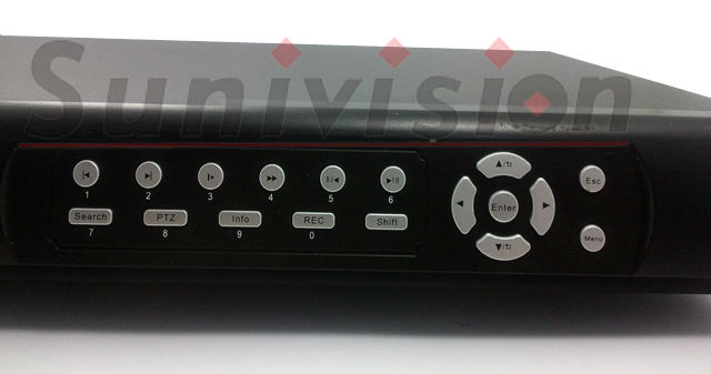
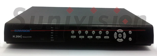


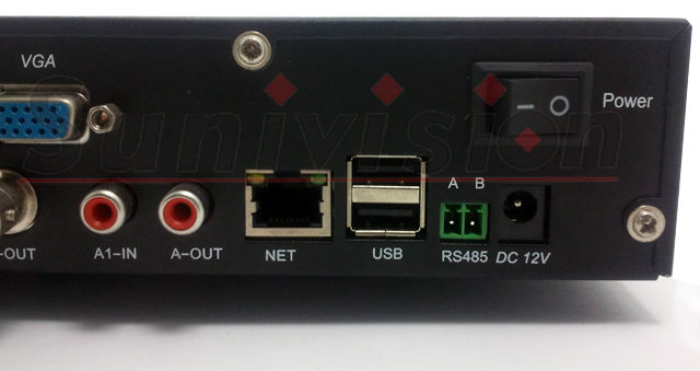
After-Sale Services:
All our products have 2 year warranty,
And we sure the product will be free from maintenance within warranty period.
Faster delivery:
Within 5 days for sample after payment cleared.
Within 5-10 days for medium & large order after payment cleared.
Remark:
1, can design and print packing box according to your requirements.
2, can put your logo & model No. & series No. on the cameras and packing Box
….
8CH AHD / TVI / CVI / CVBS 720P and 1080N XMEYE DVR
Flat Cat6 RJ45 Patch Cord Network Cable