
Page 1 — AVR 2650, AVR 265
AVR 3650, AVR 365 AVR 2650, AVR 265 Audio/video receiverOwner’s ManualENGLISH0295CSK — HK (x65Series) AVR3650_365_2650_265 CORE OM, WORK18 danny.indd
Page 2 — Table of Contents
AVR10Zone 2 Remote Control Functions (AVR 3650/AVR 365 only)Zone 2 Remote Control Functions (AVR 3650/AVR 365 only)Continued on next pageIR Transmitte
Page 3 — Place the Receiver
AVR11ENGLISHZone 2 Remote Control Functions (AVR 3650/AVR 365 only), continuedBy installing an IR receiver in the remote zone of a multizone system an
Page 4 — Front-Panel Controls
AVR12Introduction to Home TheaterThis introductory section will help you to familiarize yourself with some basic concepts unique to multichannel surro
Page 5
AVR13ENGLISHPlace Your Speakers Determine the locations for your system’s speakers according to their manufacturer’s directions and the layout of yo
Page 6 — Rear-Panel Connectors
AVR14Types of Home Theater System ConnectionsThere are different types of audio and video connections used to connect the AVR to your speakers, your T
Page 7
AVR15ENGLISHTypes of Home Theater System ConnectionsDigital Audio Connections – CoaxialCoaxial digital audio jacks are usually color-coded in orange.
Page 8
AVR16Types of Home Theater System ConnectionsRadio ConnectionsYour AVR uses separate terminals for the included FM and AM antennas. The FM antenna use
Page 9
AVR17ENGLISHMaking ConnectionsCAUTION: Before making any connections to the audio/video receiver, ensure that the AVR’s AC cord is unplugged fr
Page 10 — Continued on next page
AVR18AVR Input Connector Connected ComponentDefault Source ButtonAssigned Source ButtonAVR 3650/AVR 365 AVR 2650/AVR 265HDMI 1 Blu-ray Blu-ray/TVHDMI
Page 11 — Connect IR Equipment
AVR19ENGLISHMaking ConnectionsAVRConnect Your HDMI DevicesIf any of your source devices have HDMI connectors, using them will provide the best possibl
Page 13 — Place Your Speakers
AVR20Making ConnectionsConnect Your Audio RecordersConnect a digital audio recorder’s optical digital input to the AVR’s optical digital output. You c
Page 14 — Source Device Connections
AVR21ENGLISHMaking ConnectionsInstall a Multizone SystemIMPORTANT SAFETY NOTE: Installing a multizone system typically requires running cables
Page 15 — Video Connections
AVR22Making ConnectionsB. Connect an external amplifier to the AVR’s Zone 2 Out connectors. This method offers the benefit of retaining a 7.1-channel ho
Page 16 — RS-232 Connector
AVR23ENGLISHMaking Connections, Set Up the Remote ControlTo control more than one source device through the AVR’s IR Remote Out connector,
Page 17 — Making Connections
AVR24Set Up the Remote ControlOnce you have programmed the remote, you can switch the remote’s control mode to access the functions for a particular
Page 18
AVR25ENGLISHSet Up the AVRSet Up the AVRIn this section, you will configure the AVR to match your actual system’s makeup. Although it’s p
Page 19
AVR26Set Up the AVRUse the remote’s Up/Down/Left/Right and OK buttons to select “Speaker Setup.”6. Automatic Setup – EzSet/EQAutomated Speaker Setup a
Page 20
AVR27ENGLISHSet Up the AVRResolution from Source: This line is informational only. It indicates the resolution of the video output by the source devic
Page 21
AVR28Operating Your AVROperating Your AVRNow that you have installed your components and completed a basic configuration, you are ready to begin enjoyi
Page 22
AVR29ENGLISHOperating Your AVRVideo Troubleshooting TipsIf there is no picture:Check the source selection and video input assignment. •Check all conne
Page 23 — Set Up the Remote Control
AVR3ENGLISHIntroduction, Supplied Accessories, Important Safety Information and Place the ReceiverIntroductionThank you for choosing this Harman Kard
Page 24
AVR30Operating Your AVRListening to Media on a USB Device (AVR 3650/AVR 365)Your AVR is compatible with MP3 and WMA media. MP3 compatibility: Mono or
Page 25 — Set Up the AVR
AVR31ENGLISHOperating Your AVRIf a video monitor is connected to the AVR and the system is not in iPod manual mode, a The Bridge screen will appear an
Page 26
AVR32Operating Your AVRListening to Media via Your Home NetworkYour AVR can play MP3 and WMA audio media that is stored on a PC when both the PC and t
Page 27
AVR33ENGLISHAdvanced FunctionsAdvanced FunctionsMuch of the adjusting and configuration your AVR requires is handled automatically, with little interve
Page 28 — Operating Your AVR
AVR34Advanced FunctionsAudio Effects ButtonTo adjust other audio settings, such as the tone controls, press the Audio Effects button to display the Au
Page 29
AVR35ENGLISHAdvanced FunctionsPlasma and CRT monitors may suffer from “burn-in” when the same image, such as the horizontal or vertical bars, is left
Page 30
AVR36Advanced Functions, Manual Speaker SetupContrast AdjustmentAdjust the contrast on your TV until you see a bright white bar in the lower right cor
Page 31
AVR37ENGLISHManual Speaker SetupIf you have already run the EzSet/EQ process as explained in Configure the AVR for Your Speakers, on page 25, the AVR s
Page 32
AVR38Manual Speaker SetupSet the Speaker DistancesAs described above in Step Two, when you measured the distances from each of your speakers to the li
Page 33 — Advanced Functions
AVR39ENGLISHManual Speaker Setup, System SettingsListening in Zone 2With the multizone system in use, you may enjoy an exciting 5.1-channel home theat
Page 34
AVR4Front-Panel ControlsFront-Panel ControlsContinued on next pagePower IndicatorMessage DisplayVolume KnobVideo Modes ButtonSetup ButtonIR SensorPow
Page 35
AVR40System SettingsGeneral AVR SettingsNetwork Settings: Select this to set up your AVR for connection to your home network.Network SettingsID#:Netwo
Page 36 — Manual Speaker Setup
AVR41ENGLISHAdvanced Remote Control ProgrammingAdvanced Remote Control ProgrammingRemote Channel-Control Punch-ThroughThe punch-through feature allows
Page 37
AVR42Advanced Remote Control ProgrammingIf the message indicates that an update is available, press the front-panel OK button 4. to begin the update.D
Page 38
AVR43ENGLISHTroubleshootingSymptom Cause SolutionUnit does not function when Main Power switch is turned onNo AC power • Ensure that the power cord is
Page 39 — System Settings
AVR44SpecificationsAudio SectionStereo power: AVR 3650/AVR 365: 110W per channel, two channels driven @ 8 ohms, 20Hz – 20kHz, <0.09% THDAVR 2650/AV
Page 40
AVR45ENGLISHTable A2 – Source Setting DefaultsAppendix – Default settings, worksheets, remote product codesTable A1 – Recommended Source Component Con
Page 41 — Sleep Timer
AVR46AppendixAll Digital and Two-Chan nel Analog Audio Input ConnectorsYour Settings Position 1Your Settings Position 2Left/Right Speakers ONCenter Sp
Page 42 — Processor Reset
AVR47ENGLISHAppendixCable/SatBlu-ray DiscMedia ServerRadio TVUSB (AVR 3650/ AVR 365)Network Game AUX The BridgeDVR (AVR 2650/AVR 265)Device Type US
Page 43 — Troubleshooting
AVR48AppendixDefault Cable/SatBlu-ray DiscMedia ServerRadio TVUSB (AVR 3650/ AVR 365)Network Game AUXThe BridgeDVR (AVR 2650/ AVR 265)Video Mode Of
Page 44 — Specifications
AVR49ENGLISHAppendixSource Input Device Type (if changed) Product Brand and Code NumberCable/SatBlu-ray DiscDVR (AVR 2650/AVR 265)Media ServerTVGameAU
Page 45 — Appendix
AVR5ENGLISHFront-Panel Controls, continuedPower Indicator: This LED has three possible modes:LED is off: Indicates that the AVR is unplugged or the re
Page 46
AVR50AppendixSurround Mode Description Incoming Bitstream or SignalDolby Digital Provides up to five separate main audio channels and a dedicated low-f
Page 47
AVR51ENGLISHAppendixTable A12 – Surround Modes – continuedSurround Mode Description Incoming Bitstream or SignalDolby Pro Logic IIx MusicThis mode is
Page 48
AVR52AppendixTable A12 – Surround Modes – continuedSurround Mode Description Incoming Bitstream or SignalDTS Neo:6 Mode GroupDTS Neo:6 analog process
Page 49
AVR53ENGLISHAppendixRefer to the numbered buttons when using the Function List in Table A13.Remote Control Function List Reference0295CSK — HK (x65Ser
Page 50
AVR5454AppendixTable A13 – Remote Control Function ListNo. Button Name AVRRadioDVDMedia ServerTV The BridgeFM AM XM DMC100001 AVR Power On AVR Power O
Page 51
AVR55 55ENGLISHAppendixTable A13 – Remote Control Function List – continuedNo. Button Name Cable/SAT GameAUXCD HDTV PVD TIVO VCR01 AVR Power On AVR Po
Page 52
AVR56AppendixTV Manufacturer/Brand Setup Code NumberADMIRAL 192ANAM 045 106 109 112 122AOC 037 122 123 128AUDIOVOX 012BLAUPUNKT 084BROKSONIC 205 206CI
Page 53
AVR57ENGLISHAppendixTV Manufacturer/Brand Setup Code NumberAPEX 614 616DISH NETWORK 612LG 604MAGNAVOX 607 608 609 610 611MOTOROLA 605RCA 601 612SAMSUN
Page 54
AVR58AppendixCD Manufacturer/Brand Setup Code NumberADCOM 063 069 AIWA 072 111 118 156 170AKAI 050 177 184AUDIO TECHNICA 053AUDIOACCESS 125AUDIOFILE 2
Page 55
AVR59ENGLISHAppendixSAT Manufacturer/Brand Setup Code NumberBIRDVIEW 425CHANNEL MASTER 320 321 325 361CHAPARRAL 315 316 451CITOH 360DIRECTV 309 310 31
Page 56
AVR6Rear-Panel ConnectorsRear-Panel ConnectorsAnalog Record Out connector: Connect this analog audio output to the analog audio input of a
Page 57
AVR60AppendixManufacturer/Brand Setup Code NumberCOMCAST TIVO 808COX TIVO 808DIRECTV TIVO 806 HUMAX TIVO 803Nero LiquidTV TIVO 805PIONEER TIVO 801TIVO
Page 58
www.harmankardon.comHARMAN Consumer, Inc. 8500 Balboa Boulevard, Northridge, CA 91329 USA© 2011 HARMAN International Industries, Incorporated. All rig
Page 59
0295CSK — HK (x65Series) AVR3650_365_2650_265 CORE OM, WORK18 danny.indd 62 01/07/11 11:34:16
Page 60
AVR7ENGLISHRear-Panel Connectors, continuedRear-Panel Connectors, continuedComposite Video Monitor Out connector: If your TV or video displa
Page 61
AVR8System Remote Control FunctionsSystem Remote Control FunctionsContinued on next pageSource Selector Buttons (AVR 2650/AVR 265)AVR Power On/Off B
Page 62
AVR9ENGLISHSystem Remote Control Functions, continuedSystem Remote Control Functions, continuedIn addition to controlling the AVR, the AVR remote is c
Скачать
AVR 3650, AVR 365
AVR 2650, AVR 265
Audio/video receiver
Owner’s Manual
EN
GL
ISH
0295CSK — HK (x65Series) AVR3650_365_2650_265 CORE OM, WORK18 danny.indd 1
01/07/11 11:33:28
![]()
AVR 3650,AVR 365 AVR 2650,AVR 265
Audio/video receiver

AVR
|
Introduction |
3 |
|
Supplied Accessories |
3 |
|
Important Safety Information |
3 |
|
Place the Receiver |
3 |
|
Front-Panel Controls |
4 |
|
Rear-Panel Connectors |
6 |
|
System Remote Control Functions |
8 |
|
Zone 2 Remote Control Functions |
|
|
(AVR 3650/AVR 365 only) |
10 |
|
Introduction to Home Theater |
12 |
|
Typical Home Theater System |
12 |
|
Multichannel Audio |
12 |
|
Surround Modes |
12 |
|
Place Your Speakers |
13 |
|
Placing the Left, Center and Right Speakers |
13 |
|
Placing the Surround Speakers in a |
|
|
5.1-Channel System |
13 |
|
Placing the Surround Speakers in a |
|
|
7.1-Channel System |
13 |
|
Placing Front Height Speakers in a |
|
|
7.1-Channel System |
13 |
|
Placing the Subwoofer |
13 |
|
Types of Home Theater System Connections |
14 |
|
Speaker Connections |
14 |
|
Subwoofer Connections |
14 |
|
Source Device Connections |
14 |
|
Video Connections |
15 |
|
Radio Connections |
16 |
|
Network Connector |
16 |
|
USB Port |
16 |
|
RS-232 Connector |
16 |
|
Making Connections |
17 |
|
Connect Your Speakers |
17 |
|
Connect Your Subwoofer |
17 |
|
Connect Your TV or Video Display |
17 |
|
Connect Your Audio and Video Source Devices |
18 |
|
Connect The Bridge IIIP |
20 |
|
Connect to Your Home Network |
20 |
|
Connect the Radio Antennas |
20 |
|
Install a Multizone System |
21 |
|
Connect IR Equipment (AVR 3650/AVR 365 only) |
22 |
|
Connect the 12V Trigger Output |
23 |
|
Connect to AC Power |
23 |
Table of Contents
|
Set Up the Remote Control |
23 |
|
Install the Batteries in the Remote Control |
23 |
|
Program the Remote to Control |
|
|
Your Source Devices and TV |
23 |
|
Set Up the AVR |
25 |
|
Turn On the AVR |
25 |
|
Using the On-Screen Menu System |
25 |
|
Configure the AVR for Your Speakers |
25 |
|
Set Up Your Sources |
26 |
|
Set Up the Network |
27 |
|
Operating Your AVR |
28 |
|
Controlling the Volume |
28 |
|
Muting the Sound |
28 |
|
Dolby® Volume |
28 |
|
Listening Through Headphones |
28 |
|
Selecting a Source |
28 |
|
Listening to FM and AM Radio |
29 |
|
Listening to SIRIUS® Satellite Radio |
29 |
|
Listening to Media on a USB Device |
|
|
(AVR 3650/AVR 365) |
30 |
|
Listening to an iPod/iPhone Device |
30 |
|
Listening to Internet Radio |
31 |
|
Listening to Media via Your Home Network |
32 |
|
Selecting a Surround Mode |
32 |
|
Audio Effects |
32 |
|
Video Modes |
32 |
|
Advanced Functions |
33 |
|
Audio Processing and Surround Sound |
33 |
|
Video Processing |
34 |
|
Manual Speaker Setup |
36 |
|
Listening in Zone 2 |
39 |
|
System Settings |
39 |
|
Settings Lock |
40 |
|
Advanced Remote Control Programming |
41 |
|
Recording |
41 |
|
Sleep Timer |
41 |
|
Resetting the Remote |
42 |
|
Processor Reset |
42 |
|
TROUBLESHOOTING |
43 |
|
Specifications |
44 |
|
Appendix |
45 |
2

AVR
Introduction, Supplied Accessories,
Important Safety Information and Place the Receiver
Introduction
Thank you for choosing this Harman Kardon product!
For more than fifty years,the Harman Kardon mission has been to share a passion for music and entertainment, using leading-edge technology to achieve premium performance. Sidney Harman and Bernard Kardon invented the receiver, a single component designed to simplify home entertainment without compromising performance. Over the years, Harman Kardon products have become easier to use, while offering more features and sounding better than ever.
The AVR 3650, AVR 2650, AVR 365 and AVR 265 7.1-channel digital audio/video receivers continue this tradition with some of the most advanced audio and video processing capabilities yet, and a wealth of listening and viewing options.
To obtain the maximum enjoyment from your new receiver, please read this manual and refer back to it as you become more familiar with its features and their operation.
If you have any questions about this product, its installation or its operation, please contact your Harman Kardon retailer or custom installer, or visit the Web site at www.harmankardon.com.
Supplied Accessories
The following accessory items are supplied with your receiver. If any of these items are missing, please contact your Harman Kardon dealer or Harman Kardon customer service at www.harmankardon.com.
•• System remote control
•• Zone 2 remote control (AVR 3650/AVR 365 only)
•• EzSet/EQ™ microphone
•• AM loop antenna
•• FM wire antenna
•• Six AAA batteries (AVR 3650/AVR 365); four AAA batteries (AVR 2650/AVR 265)
•• AC power cord
IMPORTANT SAFETY INFORMATION
Verify Line Voltage Before Use
The AVR 3650 and AVR 2650 have been designed for use with 120-volt AC current. The AVR 365 and AVR 265 have been designed for use with 220 – 240-volt AC current. Connection to a line voltage other than that for which your receiver is intended can create a safety and fire hazard and may damage the unit. If you have any questions about the voltage requirements for your specific model, or about the line voltage in your area, contact your selling dealer before plugging the unit into a wall outlet.
Do Not Use Extension Cords
To avoid safety hazards, use only the power cord supplied with your unit. We do not recommend that extension cords be used with this product. As with all electrical devices, do not run power cords under rugs or carpets, or place heavy objects on them. Damaged power cords should be replaced immediately by an authorized service center with a cord meeting factory specifications.
Handle the AC Power Cord Gently
When disconnecting the power cord from an AC outlet, always pull the plug; never pull the cord. If you do not intend to use your receiver for any considerable length of time, disconnect the plug from the AC outlet.
Do Not Open the Cabinet
There are no user-serviceable components inside this product. Opening the cabinet may present a shock hazard, and any modification to the product will void your warranty. If water or any metal object such as a paper clip, wire or staple accidentally falls inside the unit, disconnect it from the AC power source immediately, and consult an authorized service center.
CATV or Antenna Grounding (AVR 3650/AVR 2650)
If an outside antenna or cable system is connected to this product, be certain that it is grounded so as to provide some protection against voltage surges and static charges. Section 810 of the United States National Electrical Code, ANSI/NFPA No. 70-1984, provides information with respect to proper grounding of the mast and supporting structure, grounding of the lead-in wire to an antenna discharge unit, size of grounding conductors, location of antenna discharge unit, connection to grounding electrodes and requirements of the grounding electrode.
NOTE TO CATV SYSTEM INSTALLER: This reminder is provided to call the CATV (cable TV) system installer’s attention to article 820-40 of the NEC, which provides guidelines for proper grounding and, in particular, specifies that the cable ground shall be connected to the grounding system of the building, as close to the point of cable entry as possible.
Place the Receiver
•• Place the receiver on a firm and level surface. Be certain that the surface and any mounting hardware can support the AVR’s weight.
•• Provide proper space above and below the receiver for ventilation. If you install the receiver in a cabinet or other enclosed area, provide cooling air within the cabinet. Under some circumstances, a fan may be required.
•• Do not obstruct the ventilation slots on the top of the receiver or place objects directly over them.
•• Do not place the receiver directly on a carpeted surface.
•• Do not place the receiver in moist or humid locations, in extremely hot or cold locations, in areas near heaters or heat registers, or in direct sunlight.
ENGLISH
3
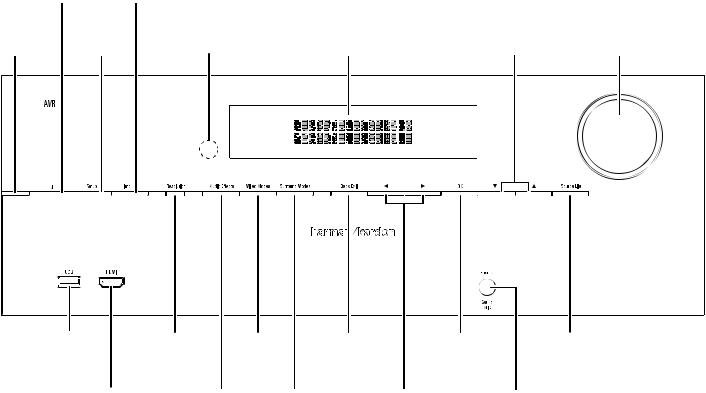
Front-Panel Controls
|
power |
Info |
||||
|
button |
button |
||||
|
power |
Setup |
Ir |
message |
up/down |
volume |
|
Indicator |
button |
Sensor |
display |
buttons |
knob |
|
uSb |
resolution |
video |
back/exit |
ok |
Source list |
|
|
port |
button |
modes |
button |
button |
button |
|
|
button |
||||||
|
hdmI® front |
Audio |
Surround |
left/right |
headphone Jack/ |
||
|
Input connector |
effects |
modes |
buttons |
ezSet/eq |
||
|
button |
button |
mic Input |
Continued on next page
4

AVR
Front-Panel Controls, continued
Front-Panel Controls, continued
Power Indicator: this led has three possible modes:
•led is off: Indicates that the Avr is unplugged or the rear-panel main power switch is off.
•led glows amber: Indicates that the Avr is in the Standby mode.
•led glows white: Indicates that the Avr is turned on.
IMPORTANT NOTE: If the protect message ever appears on the Avr’s frontpanel message display, turn off the Avr and unplug it from the Ac outlet. check all speaker wires for a possible short-circuit (the “+” and “–” conductors touching each other or both touching the same piece of metal). If a short-circuit is not found, bring the unit to an authorized harman kardon service center for inspection and repair before using it again.
Power button: press this button to turn the receiver on or to place it in the Standby mode.
Setup button: press this button to access the Avr’s main menu.
Info button: press this button to access the Avr’s Source submenu, which contains the settings for the source currently playing. use the up/down buttons to scroll through the different settings.
Message display: various messages appear in this two-line display in response to commands and changes in the incoming signal. In normal operation, the current source name appears on the upper line, while the surround mode is displayed on the lower line. when the on-screen display menu system (oSd) is in use, the current menu settings appear.
IR sensor: this sensor receives infrared (Ir) commands from the remote control. It is important to ensure that the sensor is not blocked. AVR 3650/AVR 365 only: If covering the Ir sensor is unavoidable (such as when the receiver is installed inside of a cabinet), connect an optional infrared receiver to the remote Ir In connector on the Avr’s rear panel.
Up/Down buttons: use these buttons to navigate the Avr’s menus. Volume knob: turn this knob to raise or lower the volume.
USB port: you can use this port to perform software upgrades that may be offered in the future. do not connect a storage device, peripheral product or a pc here, unless you are instructed to do so as part of an upgrade procedure.
HDMI (High-Definition Multimedia Interface®) Front Input connector: connect an hdmI-capable source component that will be used only temporarily, such as a camcorder or game console, here.
Resolution button: press this button to access the Avr’s video output resolution setting: 480i, 480p, 720p, 1080i, 1080p or 1080p/24hz. use the up/down and ok buttons to change the setting.
IMPORTANT NOTE: If you set the Avr’s video output resolution higher than the capabilities of the actual connection between the Avr and your tv or video display, you will not see a picture. If you are using the composite video connection from the Avr to your tv (see connect your tv or video display, on page 17), press the resolution button and use the up/down and ok buttons to change the resolution to 480i.
Audio Effects button: press this button to access the Audio effects submenu, which allows you to adjust the Avr’s tone controls and other audio controls. See Set up your Sources, on page 26, for more information.
Video Modes button: press this button for direct access to the video modes submenu, which contains settings you can use to improve the video picture. use the ok button to scroll through the different modes, and use the up/down and left/ right buttons to make adjustments within each mode. See Set up your Sources, on page 26, for more information.
Surround Modes button: press this button to select a listening mode. the Surround modes menu will appear on screen, and the menu line will appear in the front-panel display. use the up/down buttons to change the surround-mode category and the left/right buttons to change the surround mode for that category. See Set up your Sources, on page 26, for more information.
Back/Exit button: press this button to return to the previous menu or to exit the menu system.
Left/Right buttons: use these buttons to navigate the Avr’s menus. OK button: press this button to select the currently highlighted item.
Headphone jack/EzSet/EQ Mic input: connect a 1/4″ stereo headphone plug to this jack for private listening. this jack is also used to connect the supplied microphone for the ezSet/eq procedure described in configure the Avr for your Speakers, on page 25.
Source List button: press this button to select a source device to watch/listen to. use the up/down buttons to scroll through the source-device list, and press the ok button to select the source being displayed.
ENGLISH
5

AVR
Rear-Panel Connectors
|
composite |
composite |
SIrIuS® tuner |
|||||||||||
|
video Input |
video monitor |
connector |
|||||||||||
|
connectors |
out connector |
(Avr 3650/Avr 2650) |
|||||||||||
|
Analog |
digital Audio |
composite |
12v |
||||||||||
|
record out |
video record |
trigger |
|||||||||||
|
Input connectors |
|||||||||||||
|
connector |
out connector |
connector |
|||||||||||
|
hdmI |
composite |
Zone 2 Ir In |
the bridge IIIp |
||||||||||
|
monitor out |
hdmI Input |
video Input |
connector |
||||||||||
|
connector |
|||||||||||||
|
connector |
connectors |
connectors |
(Avr 3650/Avr 365) |
||||||||||
|
radio Antenna |
Subwoofer |
optical |
Speaker |
network |
Ac Input |
Ir remote |
|
connectors |
connector |
digital output |
connectors |
connector |
connector |
In/out connectors |
|
connector |
(Avr 3650/Avr 365) |
|
Zone 2 out |
Analog Audio |
main power |
rS-232 |
fan |
|
connector |
Input connectors |
Switch |
connector |
vents |
|
Rear-Panel Connectors (AVR 3650 shown) |
Analog Record Out connector: connect this analog audio output to the analog audio input of a recording device. A signal is available at this output whenever an analog audio source is playing.
HDMI Monitor Out connector: If your tv has an hdmI connector, use an hdmI cable (not included) to connect it to the Avr’s hdmI monitor out connector. the Avr will automatically transcode component and composite video input signals to the hdmI format (upscaling to as high as 1080p), so you do not need to make any other connections to your tv from the Avr or from any of your video source devices.
Notes on using the HDMI Monitor Out connector:
•when connecting a dvI-equipped display to the hdmI monitor out connector, use an hdmI-to-dvI adapter and make a separate audio connection.
•make sure the hdmI-equipped display is hdcp (high-bandwidth digital content protection)-compliant. If it isn’t, do not connect it via an hdmI connection; use an analog video connection instead and make a separate audio connection.
HDMI Input connectors: An hdmI connection transmits digital audio and video signals between devices. If your source devices have hdmI connectors, using them will provide the best possible video and audio performance quality. Since the hdmI cable carries both digital video and digital audio signals, you do not have to make any additional audio connections for devices you connect via the hdmI connection. See connect your Audio and video Source devices, on page 18, for more information.
Composite Video Input connectors: use composite video connectors for video source devices that don’t have hdmI or component video connectors. you will also need to make an audio connection from the source device to the Avr. See connect your Audio and video Source devices, on page 18, for more information.
Digital Audio Input connectors: If your non-hdmI source devices have digital outputs, connect them to the Avr’s digital audio connectors. note: make only one type of digital connection (hdmI, optical or coaxial) from each device. See connect your Audio and video Source devices, on page 18, for more information.
Continued on next page
6

AVR
Rear-Panel Connectors, continued
Rear-Panel Connectors, continued
Composite Video Monitor Out connector: If your tv or video display does not have an hdmI connector, use a composite video cable (not included) to connect the Avr’s composite video monitor out connector to your tv’s composite video input. NOTE: the hdmI connection to your tv is preferred. If you use the composite video connection to your tv, you will not be able to view the Avr’s on-screen menus.
Composite Video Record Out connector: connect an analog video recorder’s video input connector to the Avr’s composite video rec out connector. you can record any composite video input signal. NOTE: to record the audio and video from the source device, connect the Avr’s Analog record output connectors to the analog video recorder’s audio inputs.
Component Video Input connectors: If any of your video source devices have component video connectors (and do not have hdmI connectors), using the component video connectors will provide superior video performance. you will also need to make an audio connection from the device to the receiver. See connect your Audio and video Source devices, on page 18, for more information.
SIRIUS® Tuner connector: connect a SIrIuSconnect™ satellite radio tuner module here. (not included. Available at www.sirius.com.) See connect your Audio and video Source devices, on page 18, for more information.
12V Trigger connector: this connector provides 12v dc whenever the Avr is on. It can be used to turn on and off other devices such as a powered subwoofer.
Zone 2 IR Input connector (AVR 3650/AVR 365 only): connect a remote Ir receiver located in Zone 2 of a multizone system to this jack to control the Avr (and any source devices connected to the remote Ir output connector) from the remote zone.
The Bridge IIIP connector: connect an optional harman kardon the bridge IIIp docking station to this input. Insert the plug until it snaps into place in the connector. IMPORTANT: connect the bridge IIIp only with the Avr’s power turned off.
Radio Antenna connectors: connect the included Am and fm antennas to their respective terminals for radio reception.
Zone 2 Out connectors: connect these jacks to an external amplifier to power the speakers in the remote zone of a multizone system.
Subwoofer connector: connect this jack to a powered subwoofer with a line-level input. See connect your Subwoofer, on page 17, for more information.
Analog Audio Input connectors: use the Avr’s Analog Audio Input connectors for source devices that don’t have hdmI or digital audio connectors. See connect your Audio and video Source devices, on page 18, for more information.
Optical Digital Output connector: connect a digital audio recorder’s optical digital input to the Avr’s optical digital output connector. you can record both coaxial and optical digital audio signals.
Speaker connectors: use two-conductor speaker wire to connect each set of terminals to the correct speaker. See connect your Speakers, on page 17, for more information.
NOTE: the speaker connectors, also called Assigned Amp speaker connectorsare used for the surround back channels in a 7.1- channel home theater, or you can reassign them to a remote room for multizone operation or to front height channels for dolby pro logic® IIz operation. See place your Speakers, on page 13, for more information.
Network connector: use a cat. 5 or cat. 5e cable (not supplied) to connect the Avr’s network connector to your home network to enjoy Internet radio and content from dlnA®-compatible devices that are connected to the network. See connect to your home network, on page 20, for more information.
Main Power switch: this mechanical switch turns the Avr’s power supply on or off. It is usually left on, and it cannot be turned on or off using the remote control.
AC Input connector: After you have made all other connections, plug the supplied Ac power cord into this receptacle and into an unswitched wall outlet.
RS-232 connector: this connector is used to connect to external control hardware. consult a certified professional installer for more information.
IR Remote In/Out connectors (AVR 3650/AVR 365 only): when the Ir sensor on the front panel is blocked (such as when the Avr is installed inside a cabinet), connect an optional Ir receiver to the Ir remote In jack. the Ir remote out jack may be connected to the Ir input of a compatible product to enable remote control through the Avr.
Fan Vents: these vents are used by the Avr’s fan to cool the system. maintain a clearance of at least three inches (75mm) from the nearest surface to avoid overheating the unit. It is normal for the fan to remain off at most normal volume levels. An automatic temperature sensor turns the fan on only when it is needed.
IMPORTANT NOTE: never block the fan vents. doing so could allow the Avr to overheat to dangerous levels.
ENGLISH
7
AVR
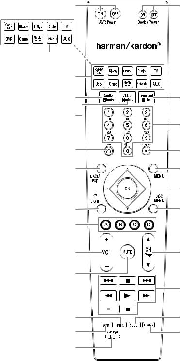
System Remote Control Functions
System Remote Control Functions
Avr power on/off buttons
Source Selector buttons (Avr 2650/Avr 265)
Source Selector buttons (Avr 3650/Avr 365)
Audio effects button
video modes button
last channel button
back/exit button
ok button 
backlight button
(Avr 3650/Avr 365 only)
A/b/c/d buttons
volume up/down buttons
mute button
Info button
Avr button
Zone Selector
Switch
 Ir transmitter lens
device power on/off buttons
Surround modes button
number buttons
Activity button
menu button
up/down/left/right buttons
disc menu button
channel up/down and page buttons
transport control buttons
Sleep button
learn button
(Avr 3650/Avr 365 only)
Continued on next page
8

AVR
System Remote Control Functions, continued
System Remote Control Functions, continued
In addition to controlling the Avr, the Avr remote is capable of controlling eight other devices, including an ipod/iphone device docked in a the bridge IIIp docking station connected to the Avr. during the installation process, you may program the codes for each of your source components into the remote. (See program the remote to control your Source devices and tv, on page 23, for programming information.) to operate a component, press its Source Selector button to change the remote’s control mode.
A button’s function depends on which component is being controlled. See table A13 in the Appendix for listings of the functions for each type of component. most of the buttons on the remote have dedicated functions, although the precise codes transmitted vary depending on the specific device being controlled. due to the wide variety of functions for various source devices, we have included only a few of the most-often used functions on the remote: alphanumeric keys, transport controls, television-channel control, menu access and power on and off. buttons dedicated to the Avr – Avr power on/off, Audio effects, video modes, Surround modes, volume, mute and Sleep Settings – are available at any time, even when the remote is controlling another device. to return the remote to the Avr control mode at any time, press the Setup button.
AVR Power On/Off buttons: press these buttons to turn the Avr on and off. the main power switch on the Avr’s rear panel must be on for this button to work.
IR Transmitter Lens: As buttons are pressed on the remote, infrared codes are emitted through this lens.
Device Power On/Off buttons: press a device’s Source Selector button, then press these buttons to turn the device on and off.
Source Selector buttons: press one of these buttons to select a source device, e.g., blu-ray, cable/Sat, radio, etc. this action will also turn on the Avr and switch the remote’s control mode to operate the selected source device. NOTE: the first press of the radio Source Selector button switches the Avr to the last-used tuner band (Am, fm or SIrIuS). each successive press changes the band.
Audio Effects button: press this button to access the Audio effects submenu, which allows adjustment of the Avr’s tone and other audio controls. See the Set up your Sources section, on page 26, for more information.
Video Modes button: press this button for direct access to the video modes submenu, which contains picture adjustments you can use after you have adjusted the picture settings on your tv or video display. See the Advanced functions section, on page 33, for more information.
Surround Modes button: press this button to access the Surround modes submenu. Select a surround-mode category: Auto Select, virtual Surround, Stereo, movie, music or game. when you select the category, it is highlighted and the surround mode changes.
to change the surround mode for the selected category, press the ok button when the menu line is highlighted and use the up/down buttons to select one of the available surround-mode options. press the ok button; or press the back/exit button to exit the Surround modes menu and display the next higher menu in the hierarchy. See the Advanced functions section, on page 33, for more information.
Number buttons: use these buttons to enter numbers for radio-station frequencies or to select station presets.
Last Channel button: when controlling a cable, satellite or hdtv set-top box or a tv, press this button to return to the previous television channel.
Activity button: with this button you can program the remote to store up to 11 different macros (Activities). (A macro is a series of commands that are transmitted by a single button press.) execute a macro by pressing this button, followed by the number button (or the Avr power on button) into which you programmed the macro. See programming macro (Activity) commands, on page 41, for more information.
Back/Exit button: press this button to return to the previous menu or to exit the menu system.
Menu button: this button is used within the tuner menus (including SIrIuS radio) and the bridge IIIp control menu, and is also used to display the main menu on some source devices. to display the Avr’s menu system, press the Setup button.
Up/Down/Left/Right buttons: these buttons are used to navigate the menu system and to operate the tuner.
OK button: this button is used to select items from the menu system.
Backlight button (AVR 3650/AVR 365 only): press this button to illuminate the buttons on the remote. press it again to turn the backlight off, or wait 5 seconds after the last button press for the light to turn off on its own.
Disc Menu button: to display the disc’s menu while a dvd or blu-ray disc is playing, press the blu-ray Source Selector button, then press this button.
A/B/C/D buttons: these buttons can be used as additional source buttons and can also operate certain functions when used with some source devices. See table A13 in the Appendix for details. these buttons are also used with a teletext®-capable television if your broadcast, cable or satellite provider offers teletext service.
Volume Up/Down buttons: press these buttons to raise or lower the volume.
Channel Up/Down and Page buttons: when the tuner has been selected, press these buttons to select a preset radio station. while operating a cable, satellite or hdtv set-top box or a television, press these buttons to change channels.
Mute button: press this button to mute the Avr’s speaker-output connectors and headphone jack. to restore the sound, press this button or adjust the volume.
Transport Control buttons: these buttons are used to control source devices and the bridge IIIp.
Info button: press to display the Avr’s Info menu, which contains the settings for the current source.
Setup button: press to display the Avr’s main menu or to switch the remote to the Avr control mode.
Sleep button: press this button to activate the sleep timer, which turns off the receiver after a programmed period of time. each press increases the time by 10 minutes, up to 90 minutes – ending with the “Sleep off” message.
Learn button (AVR 3650/AVR 365 only): the Avr 3650/Avr 365 remote is capable of “learning” individual Ir codes from the original remote that came with a source device. See program the remote to control your Source devices and tv, on page 23, for more information.
Zone Selector switch: use this switch to select whether the Avr commands will affect the main listening area (Zone 1) or the remote zone of a multizone system (Zone 2). for normal operation, leave the switch in the Zone 1 position.
ENGLISH
9
AVR
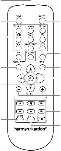
Zone 2 Remote Control Functions (AVR 3650/AVR 365 only)
Zone 2 Remote Control Functions (AVR 3650/AVR 365 only)
Ir transmitter lens
power off button
Source Selector
buttons
Avr button 
back/exit button
ok button 
Zone Selector
button
mute button

 Sleep button
menu button
up/down/left/right buttons
volume up/down buttons
transport control buttons
Zone Indicator light
Continued on next page
10
![]()
AVR
Zone 2 Remote Control Functions (AVR 3650/AVR 365 only), continued
Zone 2 Remote Control Functions (AVR 3650/AVR 365 only), continued
by installing an Ir receiver in the remote zone of a multizone system and connecting it to the Avr’s Zone 2 Ir Input connector, you can use the Zone 2 remote to control the sound in the remote zone from within the remote zone. you can use it to control the Avr’s power, volume and mute functions or to select a source input for the remote zone, and to control a harman kardon source device connected to one of the Avr’s remote Ir out connectors. See connect Ir equipment, on page 22, for more information.
you can also use the Zone 2 remote in the main listening room to control the Avr and harman kardon blu-ray disc™, dvd, cd or tape players. when the Zone 2 remote is in the Zone 1 control mode (the remote’s Zone Indicator light will turn green), its power, volume and mute controls will affect only the main listening area. to restore operation to the remote zone, press the remote’s Zone Selector button so that its Zone Indicator light turns red.
IR Transmitter lens: As buttons are pressed on the remote, infrared codes are emitted through this lens.
Power Off button: press this button to turn the Avr off.
Mute button: press to mute the Avr’s remote-zone speakers. to restore the sound, press this button, adjust the volume or turn off the multizone system. make sure to switch the remote to Zone 2 mode so that only the remote zone will be affected.
Source Selector buttons: with the remote in Zone 2 mode, press one of these buttons to select a source device for the remote zone. pressing the button will also turn on the multizone system and switch the remote to the selected source device’s control mode. you may select a different external source device than that for the main room, but not different tuner bands. If you select the same source as that for the main room, any commands sent to the source device will affect both zones. the first press of the radio Source Selector button switches the Avr to the last-used tuner band (Am, fm or SIrIuS). each successive press changes the band.
Sleep button: press this button to activate the sleep timer, which turns off the receiver after a programmed period of time. each press increases the time by 10 minutes, up to 90 minutes – ending with the “Sleep off” message.
AVR button: press this button to turn on the Avr and select the last-used source. this button is also used to switch the remote control to Avr control mode.
Back/Exit button: press this button to return to the previous menu or to exit the menu system.
Menu button: this button is used within the tuner menus (including SIrIuS radio) and the bridge IIIp control menu, and is also used to display the main menu on some source devices. to display the Avr’s menu system, press the Setup button.
Up/Down/Left/Right buttons: these buttons are used to navigate the menu system and to operate the tuner.
OK button: this button is used to select items from the menu system.
Volume Up/Down buttons: press to raise or lower the volume level in the remote zone.
Transport Control buttons: these buttons are used to control source devices and the bridge IIIp.
Zone Selector button and Zone Indicator light: each press of the Zone Selector button determines whether the Avr commands will affect the main listening area (Zone 1) or the remote zone (Zone 2). the Zone Indicator light will turn green when Zone 1 has been selected, and red when Zone 2 has been selected. the Zone Indicator light will also light up briefly when any button is pressed.
ENGLISH
11

AVR
Introduction to Home Theater
This introductory section will help you to familiarize yourself with some basic concepts unique to multichannel surround-sound receivers, which will make it easier for you to set up and operate your AVR.
Typical Home Theater System
A home theater typically includes an audio/video receiver, which controls the system and supplies amplification for the loudspeakers; a disc player; a source component for television broadcasts (cable box, satellite dish receiver, HDTV tuner or antenna connected to the TV); a TV or video display; and multiple loudspeakers.
Multichannel Audio
The main benefit of a home theater system is its ability to produce “surround sound.” Surround sound uses multiple speakers and amplifier channels to immerse you in the audio/video presentation for a dramatically increased sense of realism.
Your AVR may have up to seven main speakers connected directly to it, plus a subwoofer. Each main speaker is powered by its own amplifier channel inside the AVR. A system with more than two speakers is called a multichannel system. The different main speaker types in a home theater system are:
•• Front Left and Right: The front left and right speakers are used as in a two-channel system. In many surround-sound modes, these speakers are secondary, while the main action, especially dialogue, is reproduced by the center speaker.
•• Center: When you are watching movies and television programs, the center speaker reproduces most of the dialogue and other soundtrack information, anchoring it with the picture. When you are listening to a musical program, the center speaker helps to create a seamless front soundstage, creating a realistic “you-are-there” listening experience.
•• Surround Left and Right: The surround left and right speakers produce ambient sounds that help create a realistic and immersive surround-sound environment. They also help recreate directional sound effects such as aircraft flyovers.
•• Surround Back Left and Right: Surround back channel speakers are used with surround modes such as the Dolby Digital EX, Dolby Digital Plus, Dolby TrueHD, DTS-ES® (Discrete and Matrix), DTS-HD™ High Resolution Audio, DTS-HD Master Audio™ and Logic 7® 7.1 modes that are designed for 7.1-channel systems.
The surround back channel speakers are optional. If your system does not include surround back left and right speakers, you can set up your AVR with a 5.1-channel surround-sound system in the main listening area, and you can reassign the surround back channel amplifiers to power loudspeakers located in another room in a multizone system. (Alternately, you can reassign the surround back channel amplifiers to power front height speakers for use with Dolby Pro Logic IIz. See Manual Speaker Setup, on page 36, for more information.)
Many people expect the surround speakers to play as loudly as the front speakers. Although you will calibrate all of the speakers in your system to sound equally loud at the listening position, most artists use the surround speakers for ambient effects only, and they create their programs to steer relatively little sound to these speakers.
•• Subwoofer: A subwoofer is designed to play only the lowest frequencies (the deep bass). It augments smaller, limited-range main speakers that are usually used for the other channels. Many digital-format programs, such as movies recorded in Dolby Digital, contain a low-frequency effects (LFE) channel that is directed to the subwoofer. The LFE channel packs the punch of a rumbling train or airplane, or the power of an explosion, adding realism and excitement to your home theater. Some people use two subwoofers for additional power and for even distribution of the sound.
Introduction to Home Theater
Surround Modes
There are different theories as to the best way to present surround sound and to distribute each audio channel’s sounds to the surround-sound system’s speakers. A variety of algorithms have been developed in an effort to recreate the way we hear sounds in the real world, resulting in a rich variety of options. Several companies have developed different surround-sound technologies, all of which can be accurately reproduced by your AVR:
•• Dolby Laboratories: Dolby TrueHD, Dolby Digital Plus, Dolby Digital, Dolby Digital EX, Dolby Pro Logic® IIx and IIz.
•• DTS: DTS-HD High Resolution Audio, DTS-HD Master Audio, DTS, DTS-ES (Discrete and Matrix), DTS Neo:6®, DTS 96/24™.
•• HARMAN International: Logic 7®, HARMAN virtual speaker, HARMAN headphone.
•• Stereo Modes: Generic modes that expand upon conventional two-channel stereo, including 5CH and 7CH Stereo.
Appendix Table A12, on page 50, contains detailed explanations of the different surround-sound options available on your AVR. Digital surround-sound modes, such as the Dolby Digital and DTS modes, are available only on specially encoded programs, such as those available via HDTV, DVD and Blu-ray Disc media and digital cable or satellite television. Other surround modes may be used with digital and analog signals to create a different surround presentation or to use a different number of speakers. Surround-mode selection depends upon the number of speakers in your system, the program you are watching or listening to, and your personal tastes.
12
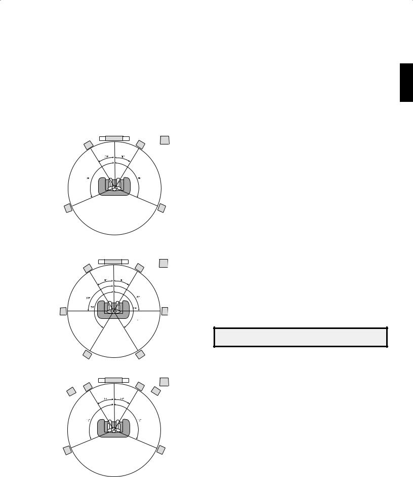
Place Your Speakers
Determine the locations for your system’s speakers according to their manufacturer’s directions and the layout of your listening room. Use the illustrations below as a guide for 7.1-channel and 5.1-channel systems.
To create the most realistic surround-sound environment possible, you should place your speakers in a circle with the listening position at its center. You should angle each speaker so it directly faces the listening position. Use the diagrams below as a guide.
Speaker Positioning for 5.1-Channel Systems
|
SBL |
SBR |
|
TV |
SUB |
|
C |
|
|
FL |
FR |
|
FHL* |
FHR* |
*FHL and FHR speakers should be at least 3 ft (0.9m) above the FL and FR speakers.
Speaker Positioning for 7.1-Channel Systems
(Top: with Surround Back Speakers; Bottom: with Front Height Speakers)
NOTE: In a 7.1-channel system, you must choose to use either surround back speakers or front height speakers – you cannot use both simultaneously.
Placing the Left, Center and Right Speakers
Place the center speaker either on top of, below or mounted on the wall above or below the TV or video display screen. Place the front left and right speakers along the circle, about 30 degrees from the center speaker and angled toward the listener.
Place the front left, front right and center speakers at the same height, preferably at about the same height as the listener’s ears. The center speaker should be no more than 2 feet (0.6m) above or below the left/right speakers. If you’re using only two speakers with your AVR, place them in the front left and right positions.
Placing the Surround Speakers in a 5.1-Channel System
You should place the left and right surround speakers approximately 110 degrees from the center speaker, slightly behind and angled toward the listener. Alternatively, place them behind the listener, with each surround speaker facing the opposite-side front speaker. You should place the surround speakers 2 feet – 6 feet (0.6m – 1.8m) higher than the listener’s ears.
Placing the Surround Speakers in a 7.1-Channel System
In a 7.1-channel system, place the side surround speakers 90 degrees from the center speaker, directly to either side of the listening position. Place the surround back left and right speakers 150 degrees from the center speaker, directly facing the opposite-side front speaker. You should place all the surround speakers 2 feet – 6 feet (0.6m – 1.8m) higher than the listener’s ears.
Placing Front Height Speakers in a 7.1-Channel System
Your AVR includes Dolby Pro Logic IIz decoding, which uses the AVR’s Assigned Amp channels as front height channels. The addition of front height channels – an additional pair of speakers positioned above the front left and right speakers – produces a surroundsound experience with added depth and dimension by creating lifelike sound that comes at you from varying heights.
We recommend placing front height speakers at least 3 feet (0.9m) higher than the front left and front right speakers, and directly above or farther apart than the front left and right speakers. The higher and further apart you place the front height speakers, the more you should angle them down and in toward the listening position.
NOTE: Your receiver will sound its best when the same model or brand of loudspeaker is used for all positions.
Placing the Subwoofer
Because a room’s shape and volume can have a dramatic effect on a subwoofer’s performance, it is best to experiment with placement so that you will find the location that produces the best results in your particular listening room. With that in mind, these rules will help you get started:
•• Placing the subwoofer next to a wall generally will increase the amount of bass in the room.
•• Placing the subwoofer in a corner generally will maximize the amount of bass in the room.
•• In many rooms, placing the subwoofer along the same plane as the left and right speakers can produce the best integration between the sound of the subwoofer and that of the left and right speakers.
•• In some rooms, the best performance could even result from placing the subwoofer behind the listening position.
A good way to determine the best location for the subwoofer is by temporarily placing it in the listening position and playing music with strong bass content. Move around to various locations in the room while the system is playing (putting your ears where the subwoofer would be placed), and listen until you find the location where the bass performance is best. Place the subwoofer in that location.
ENGLISH
13
AVR
Types of Home Theater System Connections
Types of Home Theater System Connections
There are different types of audio and video connections used to connect the AVR to your speakers, your TV or video display, and your source devices. The Consumer Electronics Association has established the CEA® color-coding standard.
|
Analog Audio Connection |
Color |
|
Front Left/Right |
White/Red |
|
Center |
Green |
|
Surround Left/Right |
Blue/Gray |
|
Surround Back/Front Height Left/Right |
Brown/Tan |
|
Subwoofer |
Purple |
|
Digital Audio Connection |
Color |
|
Coaxial (input or output) |
Orange |
|
Optical Input |
Black |
|
Optical Record Output |
Gray |
|
Analog Video Connection |
Color |
|
Component Video |
Red/Green/Blue |
|
Composite Video |
Yellow |
Speaker Connections
Speaker cables carry an amplified signal from the AVR’s speaker terminals to each loudspeaker. They contain two wire conductors, or leads, that are differentiated in some way, such as with colors or stripes.
The differentiation helps you maintain proper polarity, without which your system’s lowfrequency performance can suffer. Each speaker is connected to the AVR’s speakeroutput terminals using two wires, one positive (+) and one negative (–). Always connect the positive terminal on the speaker, which is usually colored red, to the positive terminal on the receiver, which is colored as indicated in the Connection Color Guide Table, above. The negative terminals on the speakers and the AVR are black.
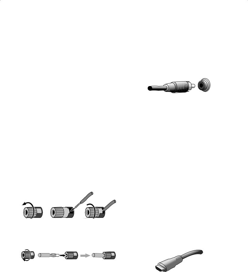
Your AVR uses binding-post speaker terminals that can accept bare-wire cables or banana plugs. Bare-wire cables are installed as shown below:
|
1. Unscrew Cap |
2. Insert Bare Wire |
3. Tighten Cap |
Banana plugs are inserted into the hole in the middle of the terminal cap, as shown below:
|
A. Tighten Cap |
B. Insert Banana Connector |
|
into Hole in Cap |
Always connect the colored (+) terminal on the AVR to the (+) terminal on the speaker (usually red), and the black (–) terminal on the AVR to the (–) terminal on the speaker (usually black).
IMPORTANT: Make sure the ( + ) and ( – ) bare wires do not touch each other or the other terminal. Touching wires can cause a short circuit that can damage your receiver or amplifier.
Subwoofer Connections
The subwoofer is a speaker dedicated to reproducing only the low (bass) frequencies, which require more power. To obtain the best results, most speaker manufacturers offer powered subwoofers that contain their own amplifiers. Use a single RCA audio cable to make a line-level (non-amplified) connection from the AVR’s Subwoofer connector to a corresponding input jack on the subwoofer.
Although the AVR’s purple subwoofer output looks similar to a full-range analog audio jack, it is filtered so that only the low frequencies pass through it. Don’t connect this output to any device other than a subwoofer.
Source Device Connections
Audio and video signals originate in source devices (components where a playback signal originates) such as your Blu-ray Disc or DVD player, CD player, DVR (digital video recorder) or other recorder, tape deck, game console, cable or satellite television tuner, an iPod or iPhone (docked in an optional The Bridge IIIP docking station) or an MP3 player. The AVR’s FM/AM tuner also counts as a source, even though no external connections are needed other than the FM and AM antennas and an optional SIRIUS tuner module. Separate connections are required for the audio and video portions of the source device’s signal, except for digital HDMI connections. The types of connections you use will depend upon the capabilities of the source device and of your TV or video display.
Digital Audio Connections – HDMI
There are two types of audio connections – digital and analog. Digital audio signals are required for listening to sources encoded with digital surround modes, such as Dolby Digital and DTS, or for uncompressed PCM digital audio. Your AVR has three types of digital audio connections: HDMI, coaxial and optical. Do not use more than one type of digital audio connection for each source device. However, it’s okay to make both analog and digital audio connections to the same source.
Your AVR is equipped with five rear-panel HDMI input connectors, and one HDMI monitor output connector. (The AVR 3650 and AVR 365 also have a front-panel HDMI input connector.) HDMI technology enables digital audio and video information to be carried using a single cable, delivering the highest quality picture and sound. If your TV or video display device has an HDMI input connector, make a single HDMI connection from each source device to the AVR. Usually, a separate digital audio connection is not required.
The AVR’s HDMI monitor output connection contains an Audio Return Channel (ARC) that carries a digital audio signal from your TV or video display back to the AVR. It allows you to listen to HDMI devices that are connected directly to your TV (such as an Internet connection) without making an additional connection from the device to the AVR. The ARC signal is active when the TV source is selected. See System Settings, on page 39, for more information.
The HDMI connector is shaped for easy plug-in (see illustration, below), and HDMI cable runs are limited to about 10 feet (3m). If your video display has a DVI input and is HDCP-compliant, use an HDMI-to-DVI adapter (not included), and make a separate audio connection.
14
AVR
Types of Home Theater System Connections
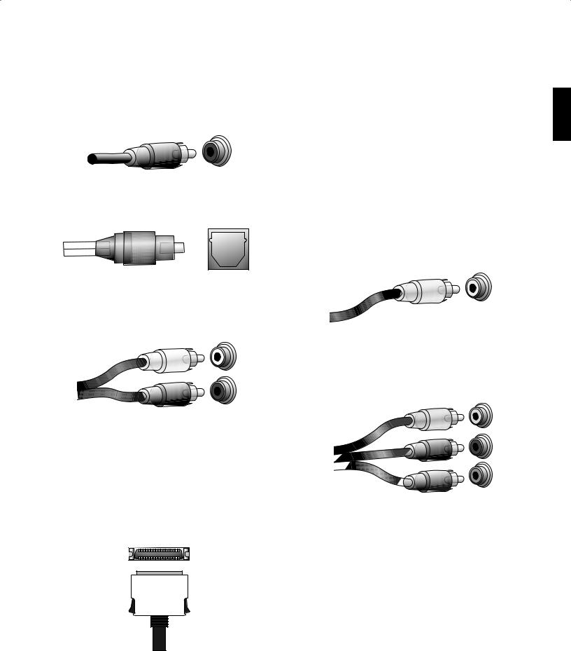
Digital Audio Connections – Coaxial
Coaxial digital audio jacks are usually color-coded in orange. Although they look like standard RCA-type analog jacks, you should not connect coaxial digital audio outputs to analog inputs or vice versa.
Digital Audio Connections – Optical
Optical digital audio connectors are normally covered by a shutter to protect them from dust. The shutter opens as the cable is inserted. Optical input connectors are colorcoded using a black shutter, while optical outputs use a gray shutter.
Analog Audio Connections
Two-channel analog connections require a stereo audio cable, with one connector for the left channel (white) and one for the right channel (red). These two connectors are attached to each other.
For source devices that have both digital and analog audio outputs, you may make both connections. If you are going to be setting up a multizone system, remember that Zone 2 is an audio-only zone (the AVR does not have a Zone 2 video output). Therefore, make analog connections for any audio source devices (such as a CD changer) that you will want available for listening in Zone 2 at all times.
The analog connections also feed the analog record outputs. You may record materials from Blu-ray Disc recordings, DVDs or other copy-protected sources using only analog connections. Remember to comply with all copyright laws if you choose to make a copy for your own personal use.
The Bridge IIIP Connection
Your AVR includes a proprietary, dedicated connector for an optional The Bridge IIIP docking station for the iPod or iPhone. The Bridge IIIP outputs analog audio to the AVR and is available as a source to Zone 2 in a multizone system.
Video Connections
Many source devices output both audio and video signals (e.g., Blu-ray Disc, DVD player, cable television box, HDTV tuner, satellite box, VCR, DVR). In addition to an audio connection as described above, make a video connection for each of these source devices. Make only one type of video connection for each device.
Digital Video Connections
If you have already connected a source device to one of the AVR’s HDMI input connectors, you have automatically made a video connection for that device, since the HDMI cable carries both digital audio and digital video signals.
Analog Video Connections – Composite Video
Your AVR uses two types of analog video connections: composite video and component video.
Composite video is the basic connection most commonly available. Both the chrominance (color) and luminance (intensity) components of the video signal are transmitted using a single cable. The jack is usually color-coded yellow and looks like an analog audio jack. Do not connect a composite video jack to an analog audio or coaxial digital audio jack, or vice versa.
Analog Video Connections – Component Video
Component video separates the video signal into three components – one luminance (“Y”) and two sub-sampled color signals (“Pb” and “Pr”) – that are transmitted using three separate cables that are color-coded green (Y), blue (Pb) and red (Pr). Component video cables that join three separate green, blue and red connectors into a single cable are sold separately.
If your TV or video display has an HDMI connection, we recommend it as the best quality connection. Your AVR converts composite and component analog video input signals to the HDMI format, upscaling them to high-definition 1080p resolution.
ENGLISH
15
AVR
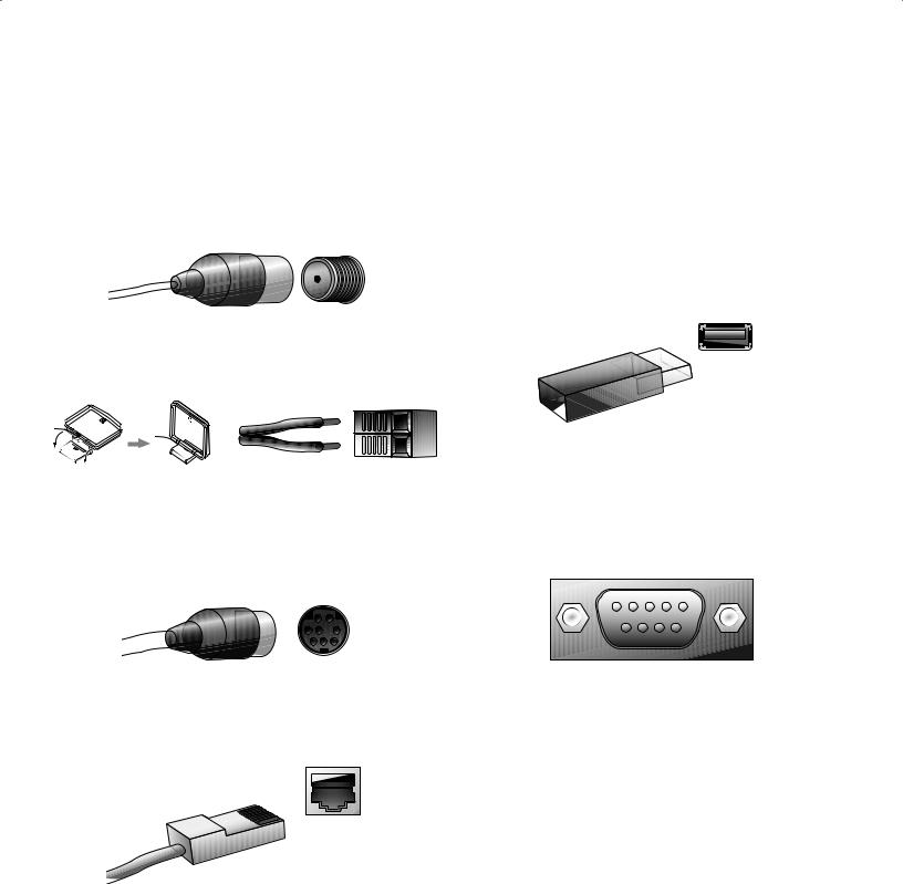
Radio Connections
Your AVR uses separate terminals for the included FM and AM antennas. The FM antenna uses a 75-ohm F-connector.
The AM antenna connector uses spring-clip terminals. After assembling the antenna as shown below, press the levers to open the connectors, insert the bare wires into the openings, and release the levers to secure the wires. The antenna wires are not polarized, so you can insert either wire into either connector.
SIRIUS Satellite Radio
To enjoy SIRIUS satellite radio, purchase a SIRIUSConnect tuner module and a subscription to the SIRIUS service. Visit www.sirius.com for information on SIRIUSConnect tuner modules. The SiriusConnect modules include an eight-pin DIN cable for connection to the eight-pin jack on the AVR, allowing you to control the tuner module via the AVR. Although you may also use a “plug-and-play” tuner module equipped with standard audio connections, you will not be able to use the AVR to control the SIRIUS tuner.
Network Connector
The AVR’s Network connector allows you to enjoy Internet radio or content from other DLNA-compatible devices that are connected to the same network. Use a Cat. 5 or Cat. 5E cable to connect the AVR’s RJ-45 connector to your home network.
Types of Home Theater System Connections
USB Port
The USB port on your AVR is used for firmware upgrades. If an upgrade for the AVR’s operating system is released in the future, you will be able to download it to the AVR using this port. Complete instructions will be provided at that time.
In addition to performing firmware upgrades, the AVR 3650/AVR 365 can play MP3 and WMA audio files from a USB device inserted into the USB port. Insert the device into the USB port with the device’s plug oriented so it fits all the way into the port. You may insert or remove the device at any time – there is no installation or ejection procedure.
IMPORTANT: Do not connect a PC or other USB host/controller to the AVR’s USB port, or you may damage both the AVR and the other device.
RS-232 Connector
Your AVR’s RS-232 serial port may be connected to an external control system to allow it to transmit control commands to the AVR. The port is bidirectional so that the AVR can transmit status updates to the control device. Connecting and using the RS-232 port requires considerable technical knowledge and is best left to a professional custom installer.
16
Making Connections
CAUTION: Before making any connections to the audio/video receiver, ensure that the AVR’s AC cord is unplugged from the receiver and the AC outlet. Making connections with the receiver plugged in and turned on could damage the speakers.
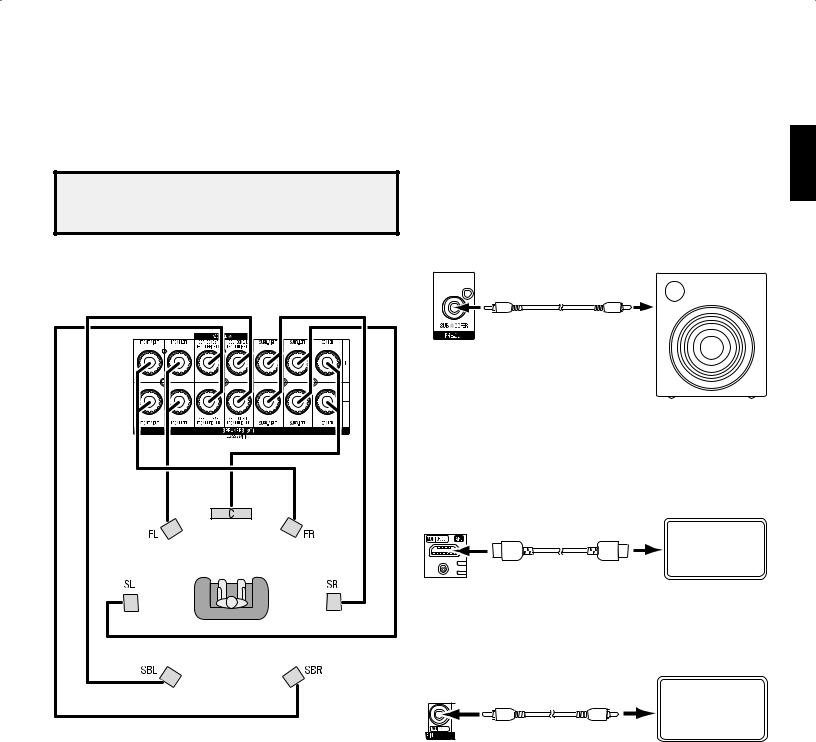
Connect Your Speakers
After you have placed your loudspeakers in the room as explained in Place Your Speakers, on page 13, connect each speaker to its color-coded terminal on the AVR as explained in Speaker Connections, on page 14. Connect the speakers as shown in the illustration.
Connect Your Subwoofer
Use a single RCA audio cable to connect the AVR’s Subwoofer connector to your subwoofer as explained in Subwoofer Connections, on page 14. Consult your subwoofer’s user manual for specific information about making connections to it.
|
AVRAVRSubwooferoofer |
PPooweredd |
|
|
Conn |
Subwooferr |
|
|
Connector |
Single |
|
|
Single |
||
|
RCA Audio Cable |
||
|
RCA Audio Cable |
||
|
(notsupplied) |
Connect Your TV or Video Display
If your TV has an HDMI connector: Use an HDMI cable (not included) to connect it to the AVR’s HDMI Monitor Out connector. You do not need to make any other connections to your TV from the receiver or from any of your video source components.
NOTE: If you installed front height speakers, connect them as shown for the SBL and SBR speakers.
Receiver
HDMI Monitor Out TV
Connector
HDMI Cable (not supplied)
If your TV does not have an HDMI connector: Use a composite video cable (not included) to connect the AVR’s Composite Monitor Out connector to your TV’s composite video connector.
Receiver
Composite TV
Monitor Out
Connector
Composite Video Cable (not supplied)
NOTE: The HDMI connection to your TV is preferred. If you use the composite video connection to your TV, you will not be able to view the AVR’s on-screen menus.
ENGLISH
17

Connect Your Audio and Video Source Devices
Your receiver has several different types of input connectors for your audio and video source devices: HDMI, component video, composite video, optical digital audio, coaxial digital audio and analog audio. The connectors are not labeled for specific types of source devices; they are labeled numerically, so you can connect your devices according to your individual system’s makeup.
Your AVR’s various source buttons have default assignments to different input connectors (listed in the “Default Source Button” column of the table below). For ease of setup, you should connect each source device to the connector where the corresponding default
source button is assigned (e.g., connect your Blu-ray Disc player to HDMI 1). However, you can connect your source devices as you wish and re-assign any of the source buttons to any of the input connectors listed in the table according to where you actually connect each of your source devices.
As you connect your various source components, fill out the “Connected Component” column in the table – it will make it easier for you to assign the various source buttons after you have completed making all of the connections. (You will make any changes to the source-button assignments and fill in the “Assigned Source Button” column later in the setup process.)
|
AVR Input Connector |
Connected Component |
Default Source Button |
Assigned |
|||
|
AVR 3650/AVR 365 |
AVR 2650/AVR 265 |
Source Button |
||||
|
HDMI 1 |
Blu-ray |
Blu-ray/TV |
||||
|
HDMI 2 |
Cable/Sat |
Cable/Sat |
||||
|
HDMI 3 |
Game |
Game |
||||
|
HDMI 4 |
Media Server |
Media Server |
||||
|
HDMI 5 |
TV |
DVR |
||||
|
(AVR 3650/AVR 365 only) HDMI Front |
Aux |
– – |
||||
|
Component Video 1 |
A (red) |
A (red) |
||||
|
Component Video 2 |
B (green) |
B (green) |
||||
|
Composite Video 1 |
C (yellow) |
C (yellow) |
||||
|
Composite Video 2 |
D (blue) |
D (blue) |
||||
|
Optical Digital Audio 1 |
A (red) |
A (red) |
||||
|
Optical Digital Audio 2 |
B (green) |
B (green) |
||||
|
Coaxial Digital Audio Input 1 |
C (yellow) |
C (yellow) |
||||
|
Coaxial Digital Audio Input 2 |
||||||
|
Analog Audio In 1 |
D (blue) |
D (blue) |
||||
|
Analog Audio In 2 |
Aux |
|||||
|
Analog Audio In 3 |
||||||
|
Monitor Output Connector |
Connected Component |
— — — — |
— — — — |
|||
|
HDMI Monitor Out |
— — — — |
— — — — |
||||
|
Composite Video Monitor Out |
— — — — |
— — — — |
||||
|
Record Output Connector |
Connected Component |
— — — — |
— — — — |
|||
|
Composite Video Rec Out |
— — — — |
— — — — |
||||
|
Optical Digital Audio Out |
— — — — |
— — — — |
||||
Input Connections and Assigned Source Buttons
18
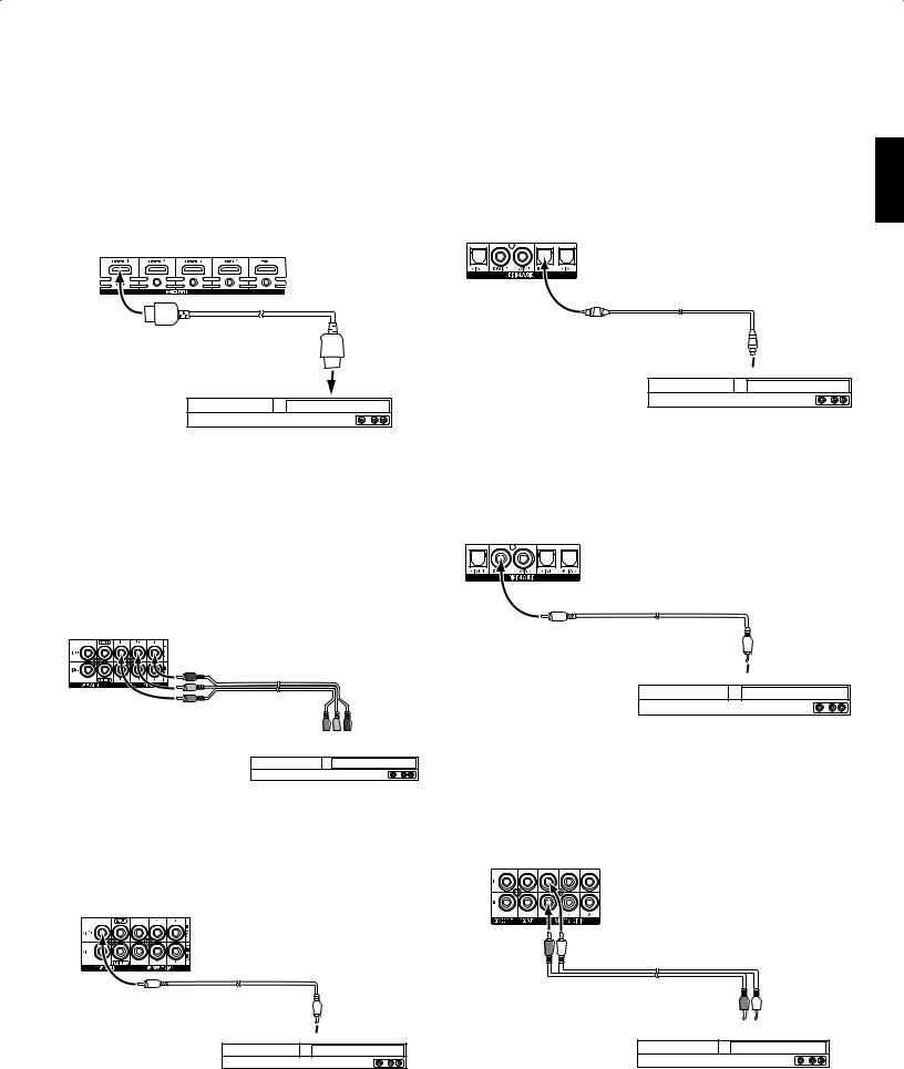
Connect Your HDMI Devices
If any of your source devices have HDMI connectors, using them will provide the best possible video and audio performance quality. Since the HDMI cable carries both digital video and digital audio signals, you do not have to make any additional audio connections for devices you connect via an HDMI cable.
Receiver
HDMI Connectors
HDMI Cable (not supplied)
To HDMI
Output
HDMI-Equipped
Source Device
NOTE: If you have HDMI devices (such as an Internet connection) already connected directly to your TV, you can feed their sound to the AVR via the HDMI Monitor Out connector’s Audio Return Channel, and they will not require additional connections to the AVR.
Connect Your Component Video Devices
If any of your video source devices have component video connectors (and do not have HDMI connectors), using the component video connectors will provide superior video performance. You will also need to make an audio connection from the device to the receiver.
Receiver
Video Connectors
Component Video
Cable (not supplied)


 To Component Video


 Outputs
Component Video-Equipped
Source Device
Connect Your Composite Video Devices
Use composite video connectors for video source devices that don’t have HDMI or component video connectors. You will also need to make an audio connection from the source device to the receiver.
Receiver
Video Connectors
Composite Video
Cable (not supplied)
To Composite Video
 Output
Composite Video-Equipped
Source Device
Connect Your Optical Digital Video Devices
If your non-HDMI source devices have optical digital outputs, connect them to the AVR’s optical digital audio connectors. NOTE: Make only one type of digital connection (HDMI, optical or coaxial) from each device.
Receiver
Digital Audio Connectors
Optical Digital Audio
Cable (not supplied)
To Optical Digital
 Audio Output
Optical Digital-Equipped
Source Device
Connect Your Coaxial Digital Audio Devices
If your non-HDMI source devices have coaxial digital outputs, connect them to the AVR’s coaxial digital audio connectors. NOTE: Make only one type of digital connection (HDMI, optical or coaxial) from each device.
Receiver
Digital Audio Connectors
Coaxial Digital Audio
Cable (not supplied)
To Coaxial Digital
 Audio Output
Coaxial Digital-Equipped
Source Device
Connect Your Analog Audio Devices
Use the AVR’s analog audio connectors for source devices that don’t have HDMI or digital audio connectors. NOTE: If you’re installing a multizone system, make analog audio connections for any source devices you want to be able to listen to in Zone 2. Only analog sources are available in Zone 2.
Receiver
Analog Audio Connectors
Stereo Audio Cable
(not supplied)


 To Stereo Analog

 Audio Output
Analog Source Device
ENGLISH
19
 Loading…
-
Страница 1
A VR 3650, A VR 365 A V R 2 6 5 0 , A V R 2 6 5 Aud io /vid eo rec eive r Owner’s Manual ENGLISH 0295CSK — HK (x65Series) AVR3650_365_2650_265 CORE OM, WORK18 danny.indd 1 01/07/11 11:33:28[…]
-
Страница 2
AV R 2 T able of Contents INTRODUCTION 3 SUPPLIED ACCESSORIES 3 IMPORT ANT SAFETY INFORMA TION 3 PLACE THE RECEIVER 3 FRONT -P ANEL CONTROLS 4 REAR-P ANEL CONNECTORS 6 SYSTEM REMOTE CONTROL FUNCTIONS 8 ZONE 2 REMOTE CONTROL FUNCTIONS (AVR 3650/A VR 365 ONL Y) 10 INTRODUCTION TO HOME THEA TER 12 TYPICAL HOME THEA TER SYSTEM 12 MUL TICHANNEL AUDIO 12[…]
-
Страница 3
AV R 3 ENGLISH Introduction, Supplied Accessories, Important Safety Information and Place the Receiver Introduction Thank you for choosing this Harman Kardon product! For more than fifty years, the Harman Kardon mission has been to share a passion for music and entertainment, using leading-edge technolog y to achieve premium performance. Sidney Ha[…]
-
Страница 4
AV R 4 Front-Panel Controls Front-P anel Controls Continued on next page Power Indicator Message Display Volume Knob Video Modes Button Setup Button IR Sensor Power Button Left/Right Buttons Headphone Jack/ EzSet/EQ Mic Input Back/Exit Button Resolution Button Audio Effects Button Surround Modes Button Up/Down Buttons USB Port OK Button HDMI ® Fro[…]
-
Страница 5
AV R 5 ENGLI SH Front-Panel Controls, continued Power Indicator: This LED has three possible modes: LED is off: Indicates tha t the AVR is unplugged or the rear-panel Main Power switch • is off. LED glows amber: Indicates that the AVR is in the Standby mode. • LED glows white: Indicates that the AVR is turned on. • IMPORT ANT NOTE: If the PRO[…]
-
Страница 6
AV R 6 Rear -Panel Connectors Rear -Panel Connectors Analog Record Out connector: Connect this analog audio output to the analog audio input of a recording device. A signal is available at this output whenever an analog audio source is playing. HDMI Monitor Out connector: If your TV has an HDMI connector , use an HDMI cable (not included) to connec[…]
-
Страница 7
AV R 7 ENGLI SH Rear -Panel Connectors, continued Rear -Panel Connectors, continued Composite V ideo Monitor Out connector: If your TV or video display does not have an HDMI connector , use a composite video cable (not included) to connect the AVR ’s Composite Video Monitor Out connector to your TV’ s composite video input. NOTE: The HDMI conne[…]
-
Страница 8
AV R 8 System Remote Control Functions System Remote Control Functions Continued on next page Source Selector Buttons (AVR 2650/A VR 265) AVR P o wer On/Off Buttons Audio Effects Button Back/Exit Button A/B/C/D Buttons Volume Up/Down Buttons Mute Button Info Button AVR Button Zone Selector Switch OK Button Last Channel Button Video Modes Button IR […]
-
Страница 9
AV R 9 ENGLI SH System Remote Control Functions, continued System Remote Control Functions, continued In addition to controlling the AVR, the AVR remote is capable of controlling eight other devices, including an iPod/iPhone device docked in a The Bridge IIIP docking station connected to the AVR . During the installation process, you may program th[…]
-
Страница 10
AV R 10 Zone 2 Remote Control Functions (A VR 3650/AVR 365 only) Zone 2 Remote Control Functions (AVR 3650/AVR 365 only) Continued on next page IR T ransmitter Lens Source Selector Buttons Mute Button Sleep Button Menu Button Up/Down/Left/Right Buttons Volume Up/Down Buttons T ransport Control Buttons AVR Button OK Button Zone Selector Button Back/[…]
-
Страница 11
AV R 11 ENGLI SH Zone 2 Remote Control Functions (A VR 3650/AVR 365 only), continued By installing an IR receiver in the remote zone of a multizone system and connecting it to the AVR’ s Zone 2 IR Input connector , you can use the Zone 2 remote to control the sound in the remote zone from within the remote zone. Y ou can use it to control the AVR[…]
-
Страница 12
AV R 12 Introduction to Home Theater This introductor y section will help you to familiarize yourself with some basic concepts unique to multichannel surround-sound receivers, which will make it easier for you to set up and operate your A VR. T ypical Home Theater System A home theater typically includes an audio/video receiver , which controls the[…]
-
Страница 13
AV R 13 ENGLISH Place Y our Speakers Determine the locations for your system’s speakers according to their manufacturer’ s directions and the layout of your listening room. Use the illustra tions below as a guide for 7.1-channel and 5.1-channel systems. T o create the most realistic surround-sound environment possible, you should place your spe[…]
-
Страница 14
AV R 14 T ypes of Home Theater System Connections There are different types of audio and video connections used to connect the AVR to your speakers, your TV or video display , and your source devices. The Consumer Electronics Association has established the CEA ® color-coding standard. Analog Audio Connection Color Front Left/Right White/Red Cente[…]
-
Страница 15
AV R 15 ENGLISH T ypes of Home Theater System Connections Digital Audio Connections – Coaxial Coaxial digital audio jacks are usually color -coded in orange. Although they look like standard RCA-type analog jacks, you should not connect coaxial digital audio outputs to analog inputs or vice versa. Digital Audio Connections – Optical Optical dig[…]
-
Страница 16
AV R 16 T ypes of Home Theater System Connections Radio Connections Y our AVR uses separate terminals for the included FM and AM antennas. The FM antenna uses a 75-ohm F-connector . The AM antenna connector uses spring-clip terminals. After assembling the antenna as shown below, press the levers to open the connectors, insert the bare wires into th[…]
-
Страница 17
AV R 17 ENGLISH Making Connections CAUTION: Before making an y connections to the audio/video receiver , ensure that the AVR’s AC cord is unplugged from the receiver and the AC outlet. Making connections with the receiver plugged in and turned on could damage the speakers. Connect Y our Speakers After you have placed your loudspeakers in the room[…]
-
Страница 18
AV R 18 A VR Input Connector Connected Component Default Source Button Assigned Source Button AVR 3650/A VR 365 AVR 2650/A VR 265 HDMI 1 Blu-ray Blu-ray/TV HDMI 2 Cable/Sat Cable/Sat HDMI 3 Game Game HDMI 4 Media Server Media Server HDMI 5 TV DVR (AVR 3650/A VR 365 only) HDMI Front Aux – – Component Video 1 A (red) A (red) Component Video 2 B ([…]
-
Страница 19
AV R 19 ENGLISH Making Connections AV R Connect Y our HDMI Devices If any of your source devices ha ve HDMI connectors, using them will provide the best possible video and audio performance quality . Since the HDMI cable carries both digital video and digital audio signals, you do not have to make any additional audio connections for devices you co[…]
-
Страница 20
AV R 20 Making Connections Connect Y our Audio Recorders Connect a digital audio recorder’ s optical digital input to the AVR’ s optical digital output. Y ou can record both coaxial and optical digital audio input signals. Optical Digital Audio Cable (not supplied) T o Optical Digital Record Input Digital Recording Device Receiver Digital Audio[…]
-
Страница 21
AV R 21 ENGLISH Making Connections Install a Multizone System IMPORT ANT SAFETY NOTE: Installing a multizone system typically requires running cables inside walls. Always comply with the appropriate safety codes when installing concealed wiring, particularly all applicable building codes. Failure to do so may present a safety hazard. If you have an[…]
-
Страница 22
AV R 22 Making Connections B. Connect an external amplifier to the AVR’s Zone 2 Out connectors. This method offers the benefit of retaining a 7.1-channel home theater in the main room simultaneously with multizone operation, although it does require an additional component (the Zone 2 amplifier). We recommend that you place the Zone 2 amplifi[…]
-
Страница 23
AV R 23 ENGLI SH Making Connections, Set Up the Remote Control T o control more than one source device through the A VR’ s IR Remote Out connector , connect all sources in “daisy chain” fashion, connecting each device’s IR output to the next device’ s IR input, starting with the AVR. If you install a multizone system, connect an IR contro[…]
-
Страница 24
AV R 24 Set Up the Remote Control Once you have programmed the remote, you can s witch the remote’ s control mode to access the functions for a particular device by pressing the remote’ s Source Selector button for that device. T o control the receiver , press the remote’ s Setup button. Follow these steps to program the Source Selector butto[…]
-
Страница 25
AV R 25 ENGLISH Set Up the A VR Set Up the AVR In this section, you will configure the AVR to match your actual system’ s makeup. Although it’ s possible to configure the AVR using only the remote and the messa ges on the AVR’ s front-panel display , it is easier if you use the full-screen menu system. T urn On the A VR Set the rear -panel […]
-
Страница 26
AV R 26 Set Up the A VR Use the remote’ s Up/Down/Left/Right and OK buttons to select “Speaker Setup.” 6. Automatic Setup – EzSet/EQ Automated Speaker Setup and EQ Manual Setup Manually Adjust Speaker Settings Speaker Setup Select “Automa tic Setup – EzSet/EQ” and then select “Continue.” 7. Select the number of speakers in your sy[…]
-
Страница 27
AV R 27 ENGLISH Set Up the A VR Resolution from Source: This line is informational only . It indicates the resolution of the video output by the source device. HDMI Bypass: This setting allo ws you to bypass the AVR’ s internal video processing for proper display of 3-D video content and of source devices (such as some game consoles) where the AV[…]
-
Страница 28
AV R 28 Operating Y our A VR Operating Y our AVR Now tha t you have installed your components and completed a basic configura tion, you are ready to begin enjoying your home theater system. Controlling the Volume Adjust the volume either by turning the front-panel Volume knob (clockwise to increase volume or counterclockwise to decrease volume) or[…]
-
Страница 29
AV R 29 ENGLISH Operating Y our A VR Video T roubleshooting T ips If there is no picture: Check the source selection and video input assignment. • Check all connections for a loose or incorrect connection. • Check the video input selection on the TV/display device. • Press the front-panel Resolution button and use the Up/Down buttons until th[…]
-
Страница 30
AV R 30 Operating Y our A VR Listening to Media on a USB Device (AVR 3650/AVR 365) Y our AVR is compatible with MP3 and WMA media. MP3 compatibility: Mono or stereo, contstant bit ra tes (CBR) from 8kbps to 320kbps, variable bit ra tes (VBR) from lowest to highest quality , with sample rates from 8kHz – 48kHz. WMA compatibility: V er . 9.2, stere[…]
-
Страница 31
AV R 31 ENGLISH Operating Y our A VR If a video monitor is connected to the AVR and the system is not in iPod manual mode, a The Bridge screen will appear and display the play mode icon, song title, artist and album. A graphic bar indicates the current play position within the track. If random or repeat play has been programmed, an icon will appear[…]
-
Страница 32
AV R 32 Operating Y our A VR Listening to Media via Y our Home Network Y our A VR can play MP3 and WMA audio media that is stored on a PC when both the PC and the AVR are connected to your home network router . MP3 compatibility: Mono or stereo, contstant bit ra tes (CBR) from 8kbps to 320kbps, variable bit ra tes (VBR) from lowest to highest quali[…]
-
Страница 33
AV R 33 ENGLISH Advanced Functions Advanced Functions Much of the adjusting and configuration your AVR requires is handled automatically , with little intervention required on your part. Y ou can also customize your AVR to suit your system and your tastes. In this section we will describe some of the more advanced adjustments available to you. Aud[…]
-
Страница 34
AV R 34 Advanced Functions Audio Effects Button T o adjust other audio settings, such as the tone controls, press the Audio Effects button to display the Audio Effects menu. Y ou can also access the menu by pressing the Info button and selecting Audio Effects. Audio Effects – Cable/Sat Dolby V olume: PLIIz Height Gain: Edit: Dolby PLII Music Edit[…]
-
Страница 35
AV R 35 ENGLISH Advanced Functions Plasma and CRT monitors may suffer from “burn-in” when the same image, such as the horizontal or vertical bars, is left on screen for a long period of time. Adjust the picture so that it fills the display’ s screen. Highlight this setting and press the OK Button. Each press of the Up/Down buttons changes th[…]
-
Страница 36
AV R 36 Advanced Functions, Manual Speaker Setup Contrast Adjustment Adjust the contrast on your TV until you see a bright white bar in the lo wer right corner 1. of the screen and a deep, dark, black bar to the left. If the brightness of the white bar no longer increases when the Contrast is turned 2. up or the borders of white letters bloom (over[…]
-
Страница 37
AV R 37 ENGLISH Manual Speaker Setup If you have alread y run the EzSet/EQ process as explained in Configure the AVR for Y our Speakers , on pa ge 25, the A VR sa ved the results. T o fine-tune the EzSet/EQ results, or to configure the A VR from scratch, select Manual Setup. A screen similar to the one shown below will appear . Sub Number of Spe[…]
-
Страница 38
AV R 38 Manual Speaker Setup Set the Speaker Distances As described above in Step T wo, when you measured the distances from each of your speakers to the listening position, your AVR provides an adjustment that compensates for the different distances so tha t the sound from each speaker will reach the listening position at the proper time. This pro[…]
-
Страница 39
AV R 39 ENGLISH Manual Speaker Setup, System Settings Listening in Zone 2 With the multizone system in use, you may enjoy an exciting 5.1-channel home thea ter presentation in the main listening area, while others listen to the same program or an entirely different source in another room. See Install a Multizone System , on page 21, for installatio[…]
-
Страница 40
AV R 40 System Settings General AVR Settings Network Settings: Select this to set up your AVR for connection to your home network. Network Settings ID#: Network Settings: IP A ddress: Subnet Mask: 00 00 00 00 A0 A0 Manual 000 . 000 . 000 . 000 000 . 000 . 000 . 000 000 . 000 . 000 . 000 000 . 000 . 000 . 000 000 . 000 . 000 . 000 Not Connected Gate[…]
-
Страница 41
AV R 41 ENGLISH Advanced Remote Control Programming Advanced Remote Control Programming Remote Channel-Control Punch-Through The punch-through fea ture allows you to operate one component while setting certain groups of controls to operate another component. For example, while using the AVR controls for surround modes and other audio functions, you[…]
-
Страница 42
AV R 42 Advanced Remote Control Programming If the message indicates tha t an update is available, press the front-panel OK button 4. to begin the update. During the update a progress bar and status messages will appear on the Messa ge 5. Display . Do not touch any controls on the AVR and do not interrupt the network connection during the update. W[…]
-
Страница 43
AV R 43 ENGLISH T roubleshooting Symptom Cause Solution Unit does not function when Main Power switch is turned on No AC po wer • Ensure that the power cord is plugged into a live AC • power outlet Check if the AC outlet is s witch-controlled • Front-panel Message display lights, but there’ s no sound or picture Intermittent input connectio[…]
-
Страница 44
AV R 44 Specifications Audio Section Stereo power: AVR 3650/A VR 365: 110W per channel, two channels driven @ 8 ohms, 20Hz – 20kHz, <0.09% THD AVR 2650/A VR 265: 95W per channel, two channels driven @ 8 ohms, 20Hz – 20kHz, <0.09% THD Multichannel power: AVR 3650/A VR 365: 110W per channel, two channels driven @ 8 ohms, 20Hz – 20kHz, <[…]
-
Страница 45
AV R 45 ENGLISH T able A2 – Source Setting Def aults Appendix – Default settings, worksheets, remote product codes T able A1 – Recommended Source Component Connections Cable/Sat Blu-ray Media Server Radio TV Game AUX The Bridge DVR (A VR 2650/ A VR 265 only) USB (A VR 3650/ A VR 365 only) Surround Modes (Auto Select) Logic 7 Movie Logic 7 Mov[…]
-
Страница 46
AV R 46 Appendix All Digital and T wo-Chan nel Analog Audio Input Connectors Y our Settings Position 1 Y our Settings Position 2 Left/Right Speakers ON Center Speaker ON Left/Right Surround Speakers ON Left/Right Surround Back Speakers OFF Subwoofer 1 ON Subwoofer 2 ON Left/Right Speakers Crossover Frequenc y 100Hz Center Speaker Crossover Frequenc[…]
-
Страница 47
AV R 47 ENGLISH Appendix Cable/Sat Blu-ray Disc Media Server Radio TV USB (A VR 3650/ A VR 365) Network Game AUX The Bridge DVR (A VR 2650/ A VR 265) Device Type USB Surround Modes Video Input N/A The Bridge III Audio Input USB The Bridge III Resolution to Display Adjust Lip Sync Change Name N/A N/A Audio Auto Polling N/A N/A Zone 2 Audio USB The B[…]
-
Страница 48
AV R 48 Appendix Default Cable/Sat Blu-ray Disc Media Server Radio TV USB (A VR 3650/ A VR 365) Network Game AUX The Bridge DVR (A VR 2650/ A VR 265) Video Mode Off Brightness* 50 Contrast* 50 Color* 50 Sharpness* 50 Picture Adjust Auto Adjust Overscan Off Noise Reduction** Off MPEG Noise Reduction** Off Cross Color Suppressor** Off Flesh T one Enh[…]
-
Страница 49
AV R 49 ENGLISH Appendix Source Input Device T ype (if changed) Product Brand and Code Number Cable/Sat Blu-ray Disc DVR (AVR 2650/A VR 265) Media Server TV Game AUX T able A9 – Remote Control Codes Feature Default Y our Settings Front P anel Dimmer On 100% HDMI Audio to TV Off HDMI Control Off Audio Return Channel Off Power Control Off TV Contro[…]
-
Страница 50
AV R 50 Appendix Surround Mode Description Incoming Bitstream or Signal Dolby Digital Provides up to five separate main audio channels and a dedica ted low-frequency effects (LFE) channel. Dolby Digital 1/0/.0 or .1, 2/0/.0 or .1, 3/0/.0 or .1, • 2/1/.0 or .1, 2/2/.0 or .1, 3/2/.0 or .1 Dolby Digital EX (played as 5.1) • Dolby Digital Plus dec[…]
-
Страница 51
AV R 51 ENGLISH Appendix T able A12 – Surround Modes – continued Surround Mode Description Incoming Bitstream or Signal Dolby Pro Logic IIx Music This mode is similar to Dolby Pro Logic II Movie, with an added surround back channel. Dolby Digital 2/0/.0 or .1, 2/2/.0 or .1, 3/2/.0 or .1, EX • Analog (two-channel) • T uner • PCM (32kHz, 44[…]
-
Страница 52
AV R 52 Appendix T able A12 – Surround Modes – continued Surround Mode Description Incoming Bitstream or Signal DTS Neo:6 Mode Group DTS Neo:6 analog processing is available with DTS and DTS 96/24 signals and two-channel analog or PCM signals to create a 3-, 5- or 6-channel presentation. See below DTS Neo:6 Cinema Depending on the number of spe[…]
-
Страница 53
AV R 53 ENGLISH Appendix Refer to the numbered buttons when using the Function List in T able A13. Remote Control Function List Reference 0295CSK — HK (x65Series) AVR3650_365_2650_265 CORE OM, WORK18 danny.indd 53 01/07/11 11:34:14[…]
-
Страница 54
AV R 54 54 Appendix T able A13 – Remote Control Function List No. Button Name AV R Radio DVD Media Server TV The Bridge FM AM XM DMC1000 01 AVR Power On AVR P o wer On AVR P ower On AVR Power On AVR Power On AVR P o wer On AVR P o wer On AVR P ower On AVR Power On 02 AVR Power Off AVR P ower Off AVR P ower Off AVR Power Off AVR Power Off AVR Powe[…]
-
Страница 55
AV R 55 55 ENGLISH Appendix T able A13 – Remote Control Function List – continued No. Button Name Cable/SA T Game AUX CD HDTV PVD TIVO VCR 01 AVR Power On AVR Power On AVR Power On AVR Power On AVR Power On AVR Power On AVR P ower On AVR Power On 02 AVR Power Off AVR Power Off AVR Power Off AVR Power Off AVR Power Off AVR P o wer Off AVR Power […]
-
Страница 56
AV R 56 Appendix TV Manufacturer/Brand Setup Code Number ADMIRAL 192 ANAM 045 106 109 112 122 AOC 037 122 123 128 AUDIOVOX 012 BLAUPUNKT 084 BROKSONIC 205 206 CITIZEN 045 123 128 132 CONTEC 045 CRAIG 045 157 158 159 CROWN 045 132 CURTIS MA THES 123 128 132 DAEWOO 045 087 102 105 106 108 111 114 116 119 127 128 132 DA YTRON 128 132 DYNA TECH 063 DYN[…]
-
Страница 57
AV R 57 ENGLISH Appendix TV Manufacturer/Brand Setup Code Number APEX 614 616 DISH NETWORK 612 LG 604 MAGNAVO X 607 608 609 610 611 MOTOROLA 605 RCA 601 612 SAMSUNG 603 T A TUNG 618 TIVO See T able A24 ZENITH 602 606 619 VCR Manufacturer/Brand Setup Code Number MGA 349 MITSUBISHI 349 431 MUL TITECH 340 NAD 439 NA TIONAL 440 NEC 318 348 NORDMENDE 34[…]
-
Страница 58
AV R 58 Appendix CD Manufacturer/Brand Setup Code Number ADCOM 063 069 AIWA 072 111 118 156 170 AKAI 050 177 184 AUDIO TECHNICA 053 AUDIOACCESS 125 AUDIOFILE 211 BSR 044 CALIFORNIA AUDIO 109 CAPETRONIC 070 CARRERA 087 CARVER 136 140 141 143 144 145 185 186 CASIO 117 166 CLARINETTE 166 DENON 187 188 213 EMERSON 052 093 108 FISHER 055 095 FUNAI 126 G[…]
-
Страница 59
AV R 59 ENGLISH Appendix SA T Manufacturer/Brand Setup Code Number BIRDVIEW 425 CHANNEL MASTER 320 321 325 361 CHAP ARRAL 315 316 451 CITOH 360 DIRECTV 309 310 314 DISH NETWORK 364 DRAKE 313 317 318 413 481 DX ANTENNA 331 352 379 483 ECHOST AR 364 395 397 452 453 463 477 478 484 485 ELECTRO HOME 392 FUJITSU 324 329 334 GENERAL INSTRUMENT 303 311 32[…]
-
Страница 60
AV R 60 Appendix Manufacturer/Brand Setup Code Number COMCAST TIVO 808 COX TIVO 808 DIRECTV TIVO 806 HUMAX TIVO 803 Nero LiquidTV TIVO 805 PIONEER TIVO 801 TIVO HD XL DVR 807 TIVO HD DVR 804 TIVO SERIES2™ DT DVR 802 TOSHIBA TIVO 803 Manufacturer/Brand Setup Code Number APPLE 008 009 BEYOND 003 ESCIENT (FIREBALL) 004 005 006 007 HARMAN KARDON 001 […]
-
Страница 61
www.harmankardon.com HARMAN Consumer, Inc. 8500 Balboa Boulevard, Northridge, CA 91329 USA © 2011 HARMAN International Industries, Incorporated. All rights reserved. Harman Kardon and Logic 7 are trademarks of HARMAN International Industries, Incorporated, registered in the United States and/or other countries. EzSet/EQ is a trademark of HARMAN In[…]
-
Страница 62
0295CSK — HK (x65Series) AVR3650_365_2650_265 CORE OM, WORK18 danny.indd 62 01/07/11 11:34:16[…]
Manuals Directory
ManualsDir.com — online owner manuals library
Harman-Kardon Receivers and Amplifiers
- Text mode
- Original mode
Advertising

AVR 3650, AVR 365
AVR 2650, AVR 265
Audio/video receiver
Owner’s Manual
EN
GL
ISH
0295CSK — HK (x65Series) AVR3650_365_2650_265 CORE OM, WORK18 danny.indd 1
01/07/11 11:33:28
Advertising
This manual is related to the following products:
AVR 2650
Popular Brands
- Apple
- Bissell
- Brother
- Canon
- Casio
- Cisco
- Craftsman
- Dell
- FRIGIDAIRE
- Garmin
- GE
- Honeywell
- HP
- John Deere
- Kenmore
- LG
- Maytag
- Motorola
- NETGEAR
- Nikon
- Panasonic
- Pioneer
- Samsung
- Sharp
- SINGER
- Sony
- Whirlpool
- Yamaha
Popular manuals
- Canon — AE-1
- Fitbit — Flex
- Nikon — D5000
- Nikon — D40
- Nikon — D3100
- Nikon — D90
- Nikon — D7000
- Nikon — D80
- Nikon — D3000
- HP — Officejet Pro 8600
- Canon — EOS 60D
- HP — 12C Financial calculator
This is the 168 pages manual for harman kardon avr 265 230.
Read or download the pdf for free.
If you want to contribute, please mail your pdfs to info@audioservicemanuals.com.
Page 1
Harman Kardon AVR 265/230V Service Manual
Harman Kardon Service Manual
AVR 265/230
7.1 CHANNEL A/V RECEIVER
harmanu kaldon
CONTE NTS
ESD WARNING 2 DISASSEMBLY 23
FRONT AND REAR PANELS 4 EXPLODED VIEW AND PARTS 24
REMOTE CONTROLS 8 ELECTRICAL PARTS LIST 25
SETTINGS LOCK 12 IC PINOUTS 63
UPDATING NETWORK SOFTWARE 13 PCB DRAWINGS 130
RESET REMOTE AND PROCESSOR 14 BLOCK DIAGRAMS 148
TROUBLESHOOTING GUIDE 15 WIRING DIAGRAM 150
BASIC SPECIFICATIONS 16 AMP BIAS ADJUSTMENT 151
APPENDIX, SETTINGS 17 SCHEMATIC DIAGRAMS 152-168
PACKAGE LISTS AND PARTS 22
Released EU2011 Harman Consumer Group, Inc. Rev 0, 10/2011
8500 Balboa Boulevard
Northridge, California 91329
Page 1 of 168
Page 2
Harman Kardon AVR 265/230V Service Manual
ELECTROSTATICALLY SENSITIVE (ES) DEVICES
Some semiconductor (solid state) devices can be damaged easily by static electricity. Such components commonly are called
Electrostatically Sensitive (ES) Devices. Examples of typical ES devices are integrated circuits and some field effect transistors and
semiconductor chip components
The following techniques should be used to help reduce the incidence of component damage caused by static electricity.
1. Immediately before handling any semiconductor component or semiconductoreequipped assembly, drain off any electrostatic charge on
your body by touching a known earth ground. Alternatively, obtain and wear a commercially available discharging wrist strap device,
which should be removed for potential shock reasons prior to applying power to the unit under test.
2. After removing an electrical assembly equipped with ES devices, place the assembly on a conductive surface such as aluminum foil, to
prevent electrostatic charge buildeup or exposure of the assembly.
3. Use only a groundedetip soldering iron to solder or unsolder ES devices.
4. Use only an antiestatic solder removal device. Some solder removal devices not classified as «antistatic» can generate electrical charges
sufficient to damage ES devices.
5. Do not use freonepropelled chemicals. These can generate electrical change sufficient to damage ES devices.
6. Do not remove a replacement ES device from its protective package until immediately before you are ready to install it. (Most replacement
ES devices are packaged with leads electrically shorted together by conductive foam, aluminum foil or comparable conductive material.)
7, Immediately before removing the protective material from the leads of a replacement ES device, touch the protective material to the
chassis or circuit assembly into which the device will be installed.
CAUTION : Be sure no power is applied to the chassis or circuit, and observe all other safety precautions.
8. Minimize bodily motions when handling unpackaged replacement ES devices. (Otherwise harmless motion such as the brushing together
or your clothes fabric or the lifting of your foot from a carpeted floor can generate static electricity sufficient to damage an ES devices
PRODUCT SAFETY NOTICE
Each precaution in this manual should be followed during servicing.
Components identified with the IEC symbol A in the parts list are special significance to safety. When replacing a component identified with
A, use only the replacement parts designated, or parts with the same ratings or resistance, wattage, or voltage that are designated in the
parts list in this manual. Leakageecurrent or resistance measurements must be made to determine that exposed parts are acceptably
insulated from the supply circuit before returning the product to the customer.
Page 2 of 168