

To reduce the impacts on global warming, the packaging materials of this product
are recyclable and reusable. GIGABYTE works with you to protect the environment.
For more product details, please visit GIGABYTE’s website.
B450 AORUS PROB450 AORUS PRO WIFI
B450 AORUS PRO WIFI
B450 AORUS PRO
User’s Manual
Rev. 1001
12ME-B45ASPW-1001R
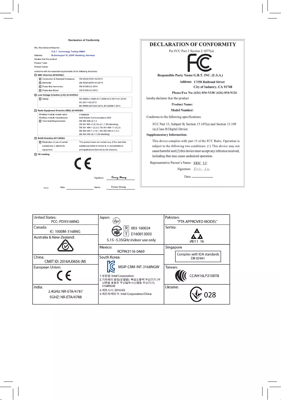
Wireless Module Country Approvals:
Jun. 11, 2018
Motherboard
B450 AORUS PRO WIFI
Motherboard
B450 AORUS PRO WIFI
Jun. 11, 2018
Copyright
© 2018 GIGA-BYTE TECHNOLOGY CO., LTD. All rights reserved.
The trademarks mentioned in this manual are legally registered to their respective owners.
Disclaimer
Information in this manual is protected by copyright laws and is the property of GIGABYTE.
Changes to the specications and features in this manual may be made by GIGABYTE without prior notice.
No part of this manual may be reproduced, copied, translated, transmitted, or published in any form or
by any means without GIGABYTE’s prior written permission.
In order to assist in the use of this product, carefully read the User’s Manual.
For product-related information, check on our website at: https://www.gigabyte.com
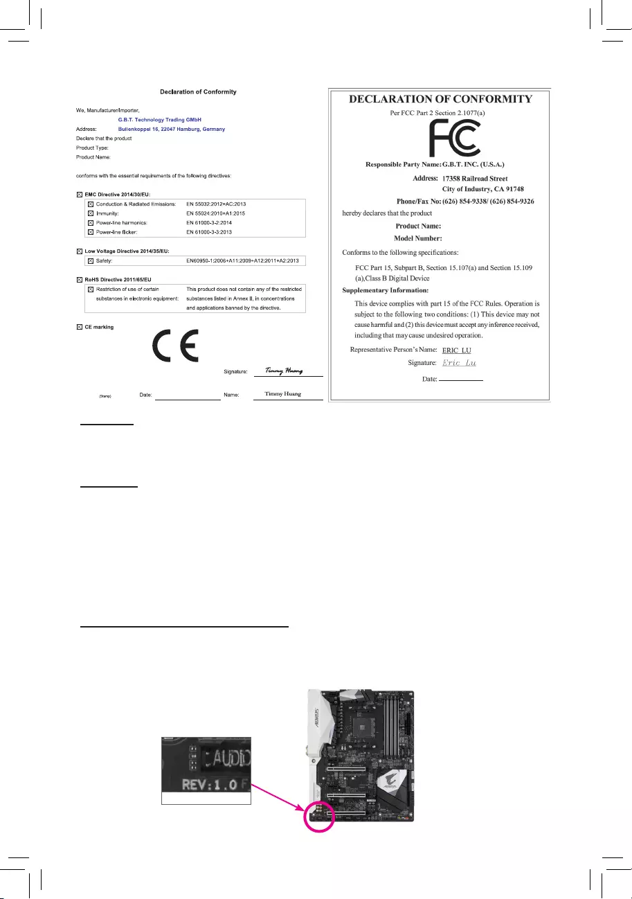
Identifying Your Motherboard Revision
The revision number on your motherboard looks like this: «REV: X.X.» For example, «REV: 1.0″ means
the revision of the motherboard is 1.0. Check your motherboard revision before updating motherboard
BIOS, drivers, or when looking for technical information.
Example:
Motherboard
B450 AORUS PRO
Jun. 11, 2018
Jun. 11, 2018
Motherboard
B450 AORUS PRO

— 4 —
Table of Contents
B450 AORUS PRO (WIFI) Motherboard Layout ……………………………………………………..5
Chapter 1 Hardware Installation ………………………………………………………………………….6
1-1 Installation Precautions ………………………………………………………………………… 6
1-2 ProductSpecications ………………………………………………………………………….. 7
1-3 Installing the CPU ……………………………………………………………………………… 10
1-4 Installing the Memory …………………………………………………………………………. 10
1-5 Installing an Expansion Card ………………………………………………………………. 11
1-6 Back Panel Connectors ………………………………………………………………………. 11
1-7 Internal Connectors ……………………………………………………………………………. 13
Chapter 2 BIOS Setup ……………………………………………………………………………………..23
2-1 Startup Screen ………………………………………………………………………………….. 23
2-2 The Main Menu …………………………………………………………………………………. 24
2-3 M.I.T. ……………………………………………………………………………………………….. 25
2-4 System …………………………………………………………………………………………….. 29
2-5 BIOS ………………………………………………………………………………………………… 30
2-6 Peripherals ……………………………………………………………………………………….. 33
2-7 Chipset …………………………………………………………………………………………….. 35
2-8 Power ………………………………………………………………………………………………. 37
2-9 Save & Exit ……………………………………………………………………………………….. 39
Chapter 3 Appendix …………………………………………………………………………………………40
3-1 ConguringaRAIDSet ………………………………………………………………………. 40
3-2 DriversInstallation ……………………………………………………………………………… 42
Regulatory Statements …………………………………………………………………………………. 43
Contact Us …………………………………………………………………………………………………. 48
— 5 —
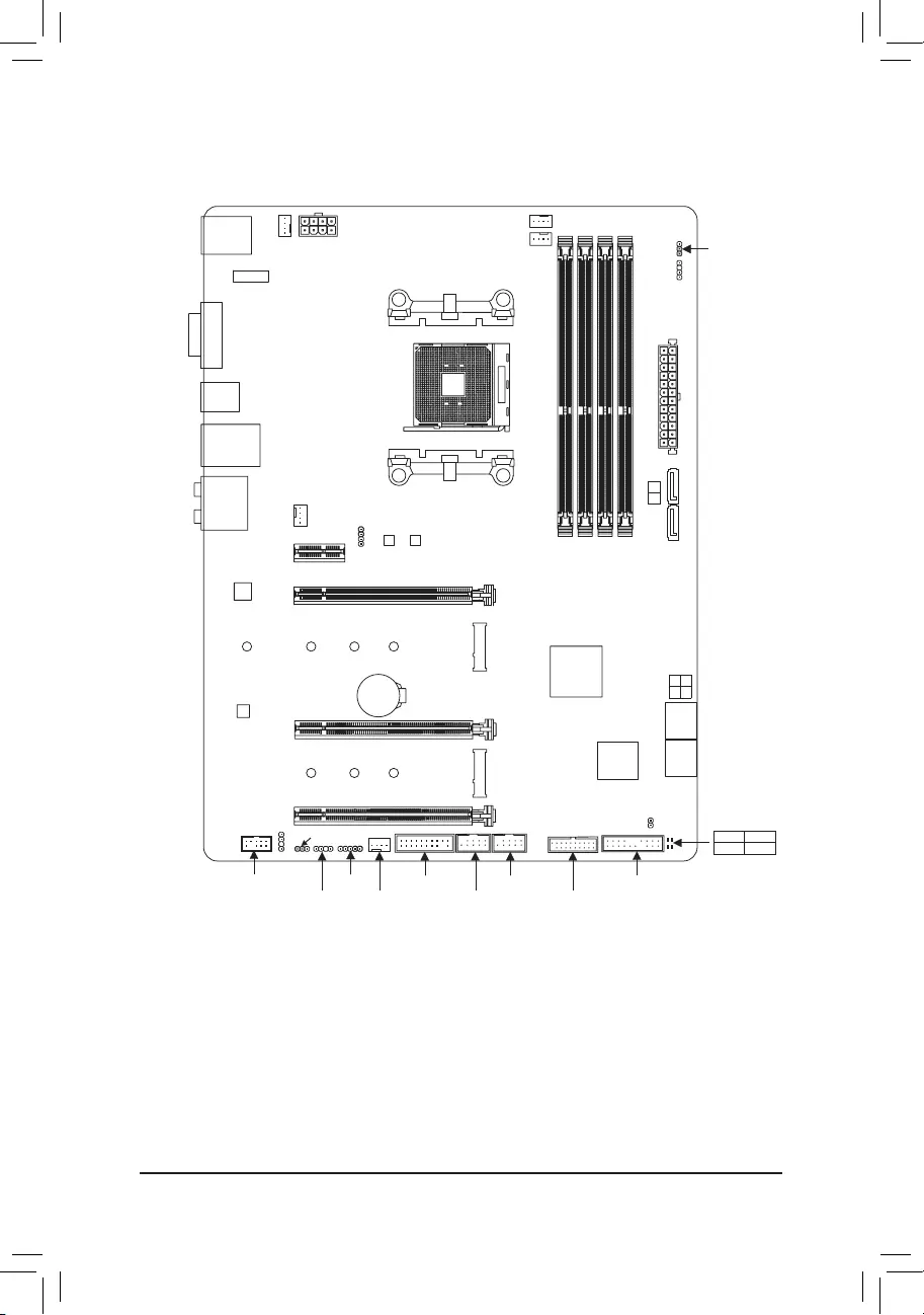
B450 AORUS PRO (WIFI) Motherboard Layout
* The box contents above are for reference only and the actual items shall depend on the product package you obtain.
The box contents are subject to change without notice.
Box Contents
5B450 AORUS PRO WIFI or B450 AORUS PRO motherboard
5Two SATA cables 5M.2 screw(s)/M.2 standoff(s)
5Motherboard driver disk 5One G Connector
5User’s Manual 5One Wi-Fi antenna (Note)
(Note) Only for the B450 AORUS PRO WIFI.
CPU DRAM
VGA BOOT
Socket AM4
AMDB450
R_USB30 CPU_FAN
ATX_12V
ATX
F_AUDIO
AUDIO
B_BIOS
PCIEX4
DDR4_2
DDR4_1
DDR4_4
DDR4_3
BAT
F_PANEL
PCIEX1_2
CLR_CMOS
CODEC
M_BIOS
PCIEX1_1
PCIEX16
SPDIF_O
B450 AORUS PRO (WIFI)
DVI
TYPEC
HDMI
USB30_LAN
SATA3
iTE®
Super I/O
F_USB1
LED_C
SYS_FAN2
TPM
M2A_SOCKET
Intel®
GbE LAN
0 2
1 3
F_USB30
42
6080
110
CPU_OPT
LED_CPU
M2_WIFI (Note)
SYS_FAN1
42
6080
M2B_SOCKET
F_USB2SYS_FAN3_PUMPD_LED1
DLED_V_SW1
WIFI Module (Note)
D_LED2
DLED_V_SW2
USB31
ASATA3 1 0

Chapter 1 Hardware Installation
1-1 Installation Precautions
The motherboard contains numerous delicate electronic circuits and components which can become
damagedasaresultofelectrostaticdischarge(ESD).Priortoinstallation,carefullyreadtheuser’s
manual and follow these procedures:
•Prior to installation, make sure the chassis is suitable for the motherboard.
•Prior to installation, do not remove or break motherboard S/N (Serial Number) sticker or
warranty sticker provided by your dealer. These stickers are required for warranty validation.
•Always remove the AC power by unplugging the power cord from the power outlet before
installing or removing the motherboard or other hardware components.
•When connecting hardware components to the internal connectors on the motherboard, make
sure they are connected tightly and securely.
•When handling the motherboard, avoid touching any metal leads or connectors.
•It is best to wear an electrostatic discharge (ESD) wrist strap when handling electronic
componentssuchasamotherboard,CPUormemory.IfyoudonothaveanESDwriststrap,
keepyourhandsdryandrsttouchametalobjecttoeliminatestaticelectricity.
•Prior to installing the motherboard, please have it on top of an antistatic pad or within an
electrostatic shielding container.
•Before connecting or unplugging the power supply cable from the motherboard, make sure
the power supply has been turned off.
•Before turning on the power, make sure the power supply voltage has been set according to
the local voltage standard.
•Before using the product, please verify that all cables and power connectors of your hardware
components are connected.
•To prevent damage to the motherboard, do not allow screws to come in contact with the
motherboard circuit or its components.
•Make sure there are no leftover screws or metal components placed on the motherboard or
within the computer casing.
•Donotplacethecomputersystemonanunevensurface.
•Donotplacethecomputersysteminahigh-temperatureorwetenvironment.
•Turning on the computer power during the installation process can lead to damage to system
components as well as physical harm to the user.
•If you are uncertain about any installation steps or have a problem related to the use of the
product,pleaseconsultacertiedcomputertechnician.
•If you use an adapter, extension power cable, or power strip, ensure to consult with its installation
and/or grounding instructions.
— 6 —
1-2 ProductSpecications
CPU AM4 Socket:
- AMDRyzen™ 2nd Generation processors
- AMDRyzen™ with Radeon™ Vega Graphics processors
- AMDRyzen™ 1st Generation processors
(Go to GIGABYTE’s website for the latest CPU support list.)
Chipset AMDB450
Memory 4xDDR4DIMMsocketssupportingupto64GBofsystemmemory
Dualchannelmemoryarchitecture
SupportforDDR42933/2667/2400/2133MHzmemorymodules
SupportforECCUn-bufferedDIMM1Rx8/2Rx8memorymodules(operate in
non-ECC mode)
Supportfornon-ECCUn-bufferedDIMM1Rx8/2Rx8/1Rx16memorymodules
SupportforExtremeMemoryProle(XMP)memorymodules
(Go to GIGABYTE’s website for the latest supported memory speeds and memory
modules.)
Onboard
Graphics (Note 1)
Integrated Graphics Processor:
- 1xDVI-Dport,supportingamaximumresolutionof1920×1200@60Hz
* TheDVI-DportdoesnotsupportD-Subconnectionbyadapter.
- 1xHDMIport,supportingamaximumresolutionof4096×2160@60Hz (Note 1)
* SupportforHDMI2.0versionandHDCP2.2. (Note 1)
— Maximum shared memory of 16 GB
Audio Realtek® ALC1220 codec
HighDenitionAudio
2/4/5.1/7.1-channel
SupportforS/PDIFOut
LAN Intel® GbE LAN chip (10/100/1000 Mbit)
Wireless
Communication
Module (Note 2)
Wi-Fi802.11a/b/g/n/ac,supporting2.4/5GHzDual-Band
BLUETOOTH 4.2
Support for 11ac wireless standard and up to 433 Mbps data rate
* Actual data rate may vary depending on environment and equipment.
Expansion Slots 1 x PCI Express x16 slot, running at x16 (PCIEX16) (Note 1)
* For optimum performance, if only one PCI Express graphics card is to be installed,
be sure to install it in the PCIEX16 slot.
(The PCIEX16 slot conforms to PCI Express 3.0 standard.)
1 x PCI Express x16 slot, running at x4 (PCIEX4)
* The PCIEX4 slot shares bandwidth with the PCIEX1_1 and PCIEX1_2 slots. The
PCIEX4 slot operates at up to x2 mode when the PCIEX1_1/PCIEX1_2 slot is
populated. The PCIEX4 slot operates at up to x4 mode when both of the PCIEX1_1
and PCIEX1_2 slots are empty.
1 x PCI Express x16 slot, running at x1 (PCIEX1_2)
1 x PCI Express x1 slot (PCIEX1_1)
(The PCIEX4 and PCIEX1 slots conform to PCI Express 2.0 standard.)
1 x M.2 Socket 1 connector for a wireless communication module (M2_WIFI) (Note 2)
* Only the B450 AORUS PRO WIFI includes the wireless communication module. (Note 2)
Multi-Graphics
Technology SupportforAMDQuad-GPUCrossFire™and2-WayAMDCrossFire™ technologies
(Note 1) Actual support may vary by CPU.
(Note 2) Only for the B450 AORUS PRO WIFI.
— 7 —
Storage Interface 1 x M.2 connector (Socket 3, M key, type 2242/2260/2280/22110 SATA and PCIe
3.0x4/x2SSDsupport)(M2A_SOCKET)
1x M.2 connector(Socket 3,M key,type 2242/2260/2280PCIe 3.0 x2SSD
support)(M2B_SOCKET)
6 x SATA 6Gb/s connectors
SupportforRAID0,RAID1,andRAID10
* Refer to «1-7 Internal Connectors,» for the installation notices for the M.2 and SATA
connectors.
USB Chipset:
— 1 x USB Type-C™ port on the back panel, with USB 3.1 Gen 2 support
— 1 x USB 3.1 Gen 2 Type-A port (red) on the back panel
— 2 x USB 3.1 Gen 1 ports available through the internal USB header
— 4 x USB 2.0/1.1 ports available through the internal USB headers
CPU:
— 4 x USB 3.1 Gen 1 ports on the back panel
Internal
Connectors
1 x 24-pin ATX main power connector
1 x 8-pin ATX 12V power connector
2 x M.2 Socket 3 connectors
6 x SATA 6Gb/s connectors
1 x CPU fan header
1 x water cooling CPU fan header
2 x system fan headers
1 x system fan/water cooling pump header
1xCPUcoolerLEDstrip/RGBLEDstripheader
2xdigitalLEDstripheaders
2xdigitalLEDstrippowerselectjumpers
1xRGB(RGBW)LEDstripheader
1 x front panel header
1 x front panel audio header
1xS/PDIFOutheader
1 x USB 3.1 Gen 1 header
2 x USB 2.0/1.1 headers
1 x Trusted Platform Module (TPM) header (2×10 pin, for the GC-TPM2.0 module
only)
1 x Clear CMOS jumper
Back Panel
Connectors
1xHDMIport
2 x SMA antenna connectors (1T1R) (Note)
1xDVI-Dport
4 x USB 3.1 Gen 1 ports
1 x USB Type-C™ port, with USB 3.1 Gen 2 support
1 x USB 3.1 Gen 2 Type-A port (red)
1 x RJ-45 port
1xopticalS/PDIFOutconnector
5 x audio jacks
I/O Controller iTE® I/O Controller Chip
Hardware
Monitor
Voltage detection
Temperature detection
Fan speed detection
Water cooling ow rate detection
(Note) Only for the B450 AORUS PRO WIFI.
— 8 —
Hardware
Monitor
Overheating warning
Fan fail warning
Fan speed control
* Whether the fan (pump) speed control function is supported will depend on the fan
(pump) you install.
BIOS 2x128Mbitash
Use of licensed AMI UEFI BIOS
SupportforDualBIOS™
PnP1.0a,DMI2.7,WfM2.0,SMBIOS2.7,ACPI5.0
Unique Features Support for APP Center
* Available applications in APP Center may vary by motherboard model. Supported
functionsofeachapplicationmayalsovarydependingonmotherboardspecications.
- 3DOSD
- @BIOS
— AutoGreen
— Cloud Station
— EasyTune
— Fast Boot
— Game Boost
— ON/OFF Charge
— RGB Fusion
— Smart Backup
— Smart Keyboard
— Smart TimeLock
- SmartHUD
— Smart Survey
— System Information Viewer
— USB Blocker
— V-Tuner
SupportforQ-Flash
Support for Xpress Install
Bundled
Software
Norton® Internet Security (OEM version)
cFosSpeed
Operating
System Support for Windows 10 64-bit
Form Factor ATX Form Factor; 30.5cm x 24.4cm
* GIGABYTEreservestherighttomakeanychangestotheproductspecicationsandproduct-relatedinformationwithout
prior notice.
Please visit GIGABYTE’s website for support lists of CPU, memory
modules,SSDs,andM.2devices.
Please visit the Support\Utility List page on GIGABYTE’s website to download the latest
version of apps.
B450 AORUS PROB450 AORUS PRO WIFI
— 9 —
1-4 Installing the Memory
DualChannelMemoryConguration
ThismotherboardprovidesfourmemorysocketsandsupportsDualChannelTechnology.Afterthememory
isinstalled,theBIOSwillautomaticallydetectthespecicationsandcapacityofthememory.EnablingDual
Channel memory mode will double the original memory bandwidth.
The four memory sockets are divided into two channels and each channel has two memory sockets as following:
ChannelA:DDR4_2,DDR4_4
ChannelB:DDR4_1,DDR4_3
Read the following guidelines before you begin to install the memory:
•Make sure that the motherboard supports the memory. It is recommended that memory of the
same capacity, brand, speed, and chips be used.
(Go to GIGABYTE’s website for the latest supported memory speeds and memory modules.)
•Always turn off the computer and unplug the power cord from the power outlet before installing the
memory to prevent hardware damage.
•Memory modules have a foolproof design. A memory module can be installed in only one direction.
If you are unable to insert the memory, switch the direction.
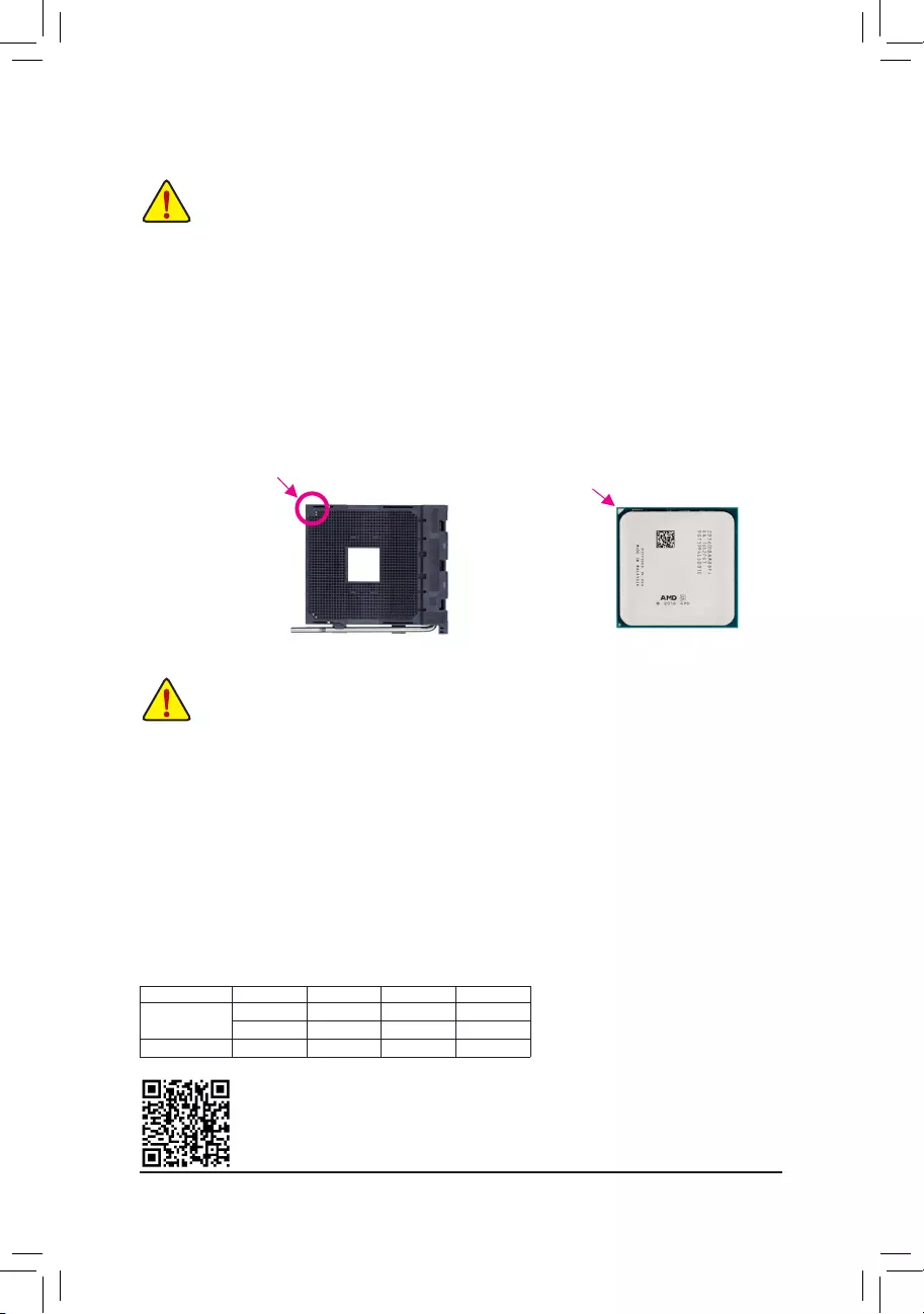
1-3 Installing the CPU
Installing the CPU
Locate the pin one (denoted by a small triangle) of the CPU socket and the CPU.
AM4 Socket
A Small Triangle Marking
DenotesPinOneofthe
Socket AM4 CPU
A Small Triangle Marking
DenotesCPUPinOne
Read the following guidelines before you begin to install the CPU:
•Make sure that the motherboard supports the CPU.
(Go to GIGABYTE’s website for the latest CPU support list.)
•Always turn off the computer and unplug the power cord from the power outlet before installing the
CPU to prevent hardware damage.
•Locate the pin one of the CPU. The CPU cannot be inserted if oriented incorrectly.
•Apply an even and thin layer of thermal grease on the surface of the CPU.
•DonotturnonthecomputeriftheCPUcoolerisnotinstalled,otherwiseoverheatinganddamage
of the CPU may occur.
•SettheCPUhostfrequencyinaccordancewiththeCPUspecications.Itisnotrecommended
thatthesystembusfrequencybesetbeyondhardwarespecicationssinceitdoesnotmeetthe
standard requirements for the peripherals. If you wish to set the frequency beyond the standard
specications,pleasedosoaccordingtoyourhardwarespecicationsincludingtheCPU,graphics
card, memory, hard drive, etc.
DualChannelMemoryCongurationsTable:
DDR4_4 DDR4_2 DDR4_3 DDR4_1
Two Modules — — DS/SS — — DS/SS
DS/SS — — DS/SS — —
Four Modules DS/SS DS/SS DS/SS DS/SS
(SS=Single-Sided,DS=Double-Sided,»--«=NoMemory)
Please visit GIGABYTE’s website for details on hardware installation.
— 10 —
1-5 Installing an Expansion Card
Read the following guidelines before you begin to install an expansion card:
•Make sure the motherboard supports the expansion card. Carefully read the manual that came
with your expansion card.
•Always turn off the computer and unplug the power cord from the power outlet before installing an
expansion card to prevent hardware damage.
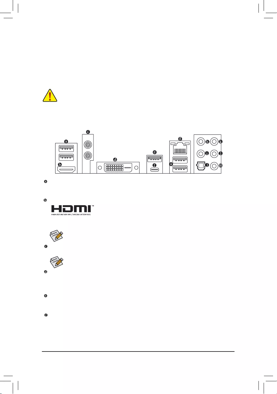
1-6 Back Panel Connectors
USB 3.1 Gen 1 Port
TheUSB3.1Gen1portsupportstheUSB3.1Gen1specicationandiscompatibletotheUSB2.0
specication.UsethisportforUSBdevices.
HDMI Port
TheHDMIportsupportsHDCP2.2(Note 2)andDolbyTrueHDandDTSHDMaster
Audioformats.Italsosupportsupto192KHz/24bit8-channelLPCMaudiooutput.
YoucanusethisporttoconnectyourHDMI-supportedmonitor.Themaximumsupportedresolutionis
4096×2160@60Hz(Note 2), but the actual resolutions supported are dependent on the monitor being used.
SMA Antenna Connectors (1T1R) (Note 1)
Use this connector to connect an antenna.
(Note 1) Only for the B450 AORUS PRO WIFI.
(Note 2) Actual support may vary by CPU.
(Note3) TheDVI-DportdoesnotsupportD-Subconnectionbyadapter.
AfterinstallingtheHDMIdevice,makesuretosetthedefaultsoundplaybackdevicetoHDMI.(The
item name may differ depending on your operating system.)
DuetoCPUlimitations,readthefollowingguidelinesbeforeinstallingthememoryinDualChannelmode.
1. DualChannelmodecannotbeenabledifonlyonememorymoduleisinstalled.
2. WhenenablingDualChannelmodewithtwoorfourmemorymodules,itisrecommendedthatmemory
of the same capacity, brand, speed, and chips be used. For optimum performance, when enabling
DualChannelmodewithtwomemorymodules,werecommendthatyouinstallthemintheDDR4_1
andDDR4_2sockets.
(Note 1)
Tighten the antenna cables to the antenna connectors and then move the antenna to a place
where the signal is good.
DVI-D Port (Note 3)
TheDVI-DportconformstotheDVI-Dspecicationandsupportsamaximumresolutionof1920×1200@60Hz
(theactualresolutionssupporteddependonthemonitorbeingused).ConnectamonitorthatsupportsDVI-D
connection to this port.
USB 3.1 Gen 2 Type-A Port (Red)
TheUSB3.1Gen2Type-AportsupportstheUSB3.1Gen2specicationandiscompatibletotheUSB
3.1Gen1andUSB2.0specication.UsethisportforUSBdevices.
USB Type-C™ Port
ThereversibleUSBportsupportstheUSB3.1Gen2specicationandiscompatibletotheUSB3.1Gen1
andUSB2.0specication.UsethisportforUSBdevices.
— 11 —
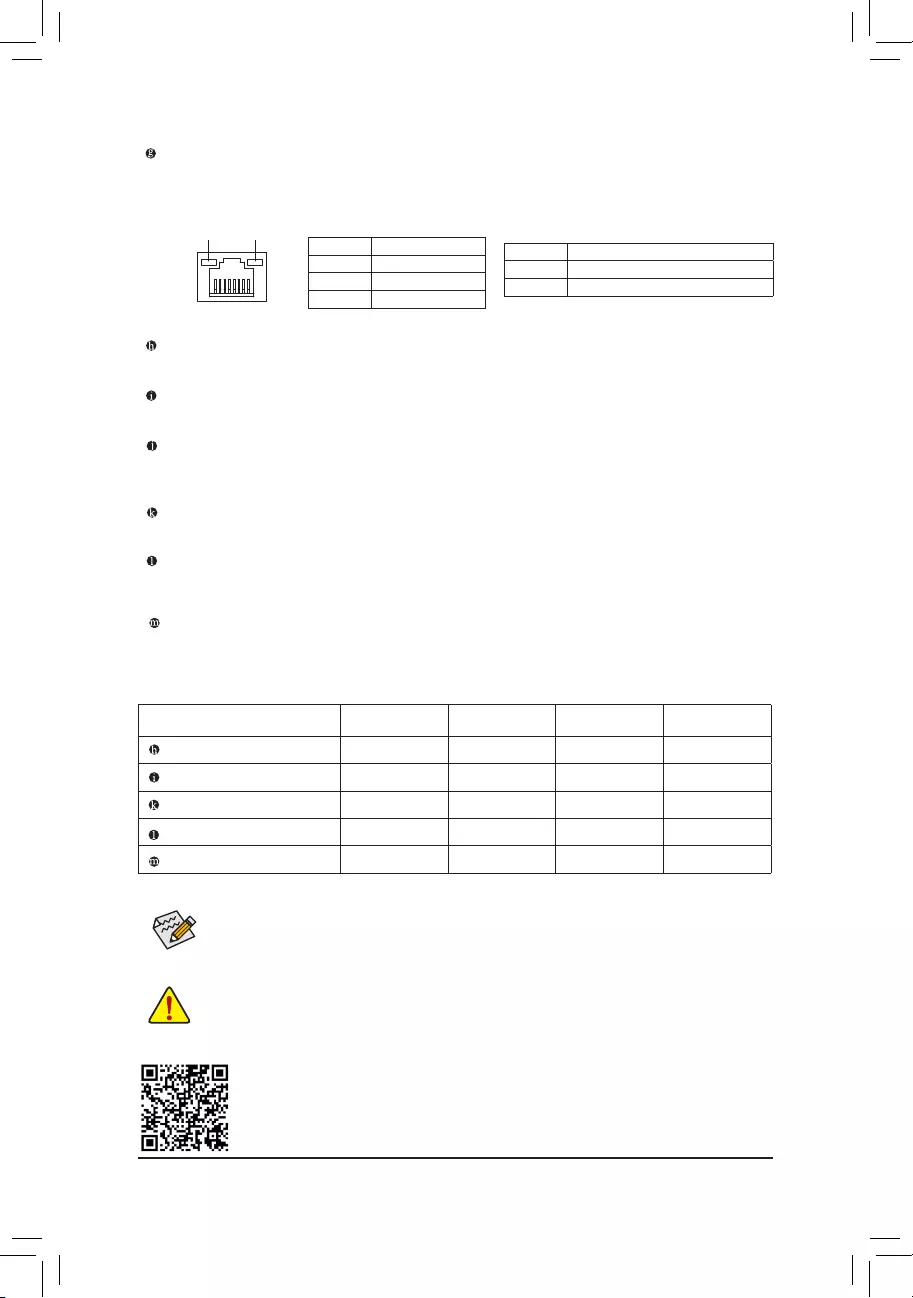
RJ-45 LAN Port
The Gigabit Ethernet LAN port provides Internet connection at up to 1 Gbps data rate. The following
describesthestatesoftheLANportLEDs.
Center/Subwoofer Speaker Out (Orange)
Use this audio jack to connect center/subwoofer speakers.
Rear Speaker Out (Black)
This jack can be used to connect rear speakers.
Optical S/PDIF Out Connector
This connector provides digital audio out to an external audio system that supports digital optical audio.
Before using this feature, ensure that your audio system provides an optical digital audio in connector.
Line In/Rear Speaker Out (Blue)
The line in jack. Use this audio jack for line in devices such as an optical drive, walkman, etc.
Line Out/Front Speaker Out (Green)
The line out jack. This jack supports audio amplifying function. For better sound quality, it is recommended
that you connect your headphone/speaker to this jack (actual effects may vary by the device being used).
Mic In/Side Speaker Out (Pink)
The Mic in jack.
ActivityLED
Connection/
SpeedLED
LAN Port
ActivityLED:
Connection/SpeedLED:
State Description
Orange 1 Gbps data rate
Green 100 Mbps data rate
Off 10 Mbps data rate
State Description
Blinking Datatransmissionorreceivingisoccurring
On No data transmission or receiving is occurring
•Whenremovingthecableconnectedtoabackpanelconnector,rstremovethecablefromyour
device and then remove it from the motherboard.
•Whenremovingthecable,pullitstraightoutfromtheconnector.Donotrockitsidetosideto
prevent an electrical short inside the cable connector.
AudioJackCongurations:
Jack Headphone/
2-channel 4-channel 5.1-channel 7.1-channel
Center/Subwoofer Speaker Out a a
Rear Speaker Out a a a
Line In/Side Speaker Out a
Line Out/Front Speaker Out a a a a
Mic In/Side Speaker Out a
•ToenableorconguretheaudioamplifyingfunctionfortheLineoutjack,pleaseaccesstheHD
Audio Manager application.
•Please visit GIGABYTE’s website
for more audio software information.
PleasevisitGIGABYTE’swebsitefordetailsonconguringtheaudiosoftware.
— 12 —
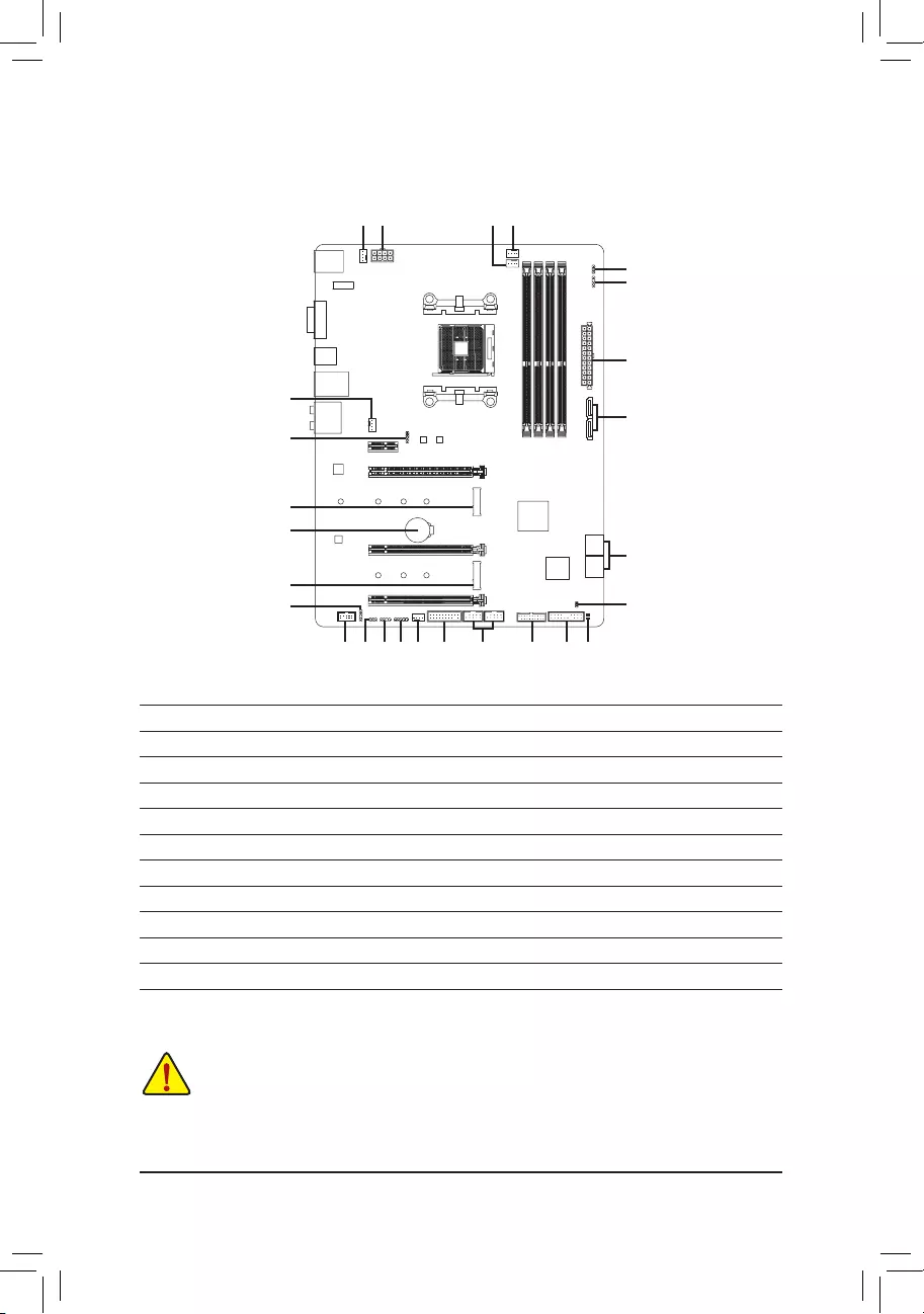
1-7 Internal Connectors
Read the following guidelines before connecting external devices:
•First make sure your devices are compliant with the connectors you wish to connect.
•Before installing the devices, be sure to turn off the devices and your computer. Unplug the power
cord from the power outlet to prevent damage to the devices.
•After installing the device and before turning on the computer, make sure the device cable has
been securely attached to the connector on the motherboard.
1
4
156
7
13
11
20
18
2
3
12
16 19
21
17
22
4
5
10
9
9 8
13
10
14
1) ATX_12V
2) ATX
3) CPU_FAN
4) SYS_FAN1/2
5) CPU_OPT
6) SYS_FAN3_PUMP
7) LED_CPU
 LED_C
LED_C
9) D_LED1/D_LED2
10) DLED_V_SW1/DLED_V_SW2
11) ASATA3 0/1
12) SATA3 0/1/2/3
13) M2A_SOCKET/M2B_SOCKET
14) SPDIF_O
15) F_PANEL
16) F_AUDIO
17) BAT
18) CLR_CMOS
19) F_USB30
20) F_USB1/F_USB2
21) TPM
22) CPU/DRAM/VGA/BOOT
— 13 —
131
2412
ATX
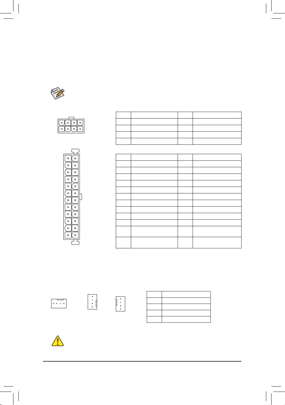
1/2) ATX_12V/ATX (2×4 12V Power Connector and 2×12 Main Power Connector)
With the use of the power connector, the power supply can supply enough stable power to all the components
onthemotherboard.Beforeconnectingthepowerconnector,rstmakesurethepowersupplyisturned
off and all devices are properly installed. The power connector possesses a foolproof design. Connect the
power supply cable to the power connector in the correct orientation.
The 12V power connector mainly supplies power to the CPU. If the 12V power connector is not connected,
the computer will not start.
To meet expansion requirements, it is recommended that a power supply that can withstand high
power consumption be used (500W or greater). If a power supply is used that does not provide the
required power, the result can lead to an unstable or unbootable system.
ATX:
Pin No. Denition Pin No. Denition
1 3.3V 13 3.3V
2 3.3V 14 -12V
3GND 15 GND
4 +5V 16 PS_ON (soft On/Off)
5GND 17 GND
6 +5V 18 GND
7GND 19 GND
8 Power Good 20 NC
9 5VSB (stand by +5V) 21 +5V
10 +12V 22 +5V
11 +12V (Only for 2×12-pin
ATX)
23 +5V (Only for 2×12-pin ATX)
12 3.3V (Only for 2×12-pin
ATX)
24 GND(Onlyfor2×12-pinATX)
ATX_12V:
Pin No. Denition Pin No. Denition
1GND(Onlyfor2×4-pin12V) 5 +12V (Only for 2×4-pin 12V)
2GND(Onlyfor2×4-pin12V) 6 +12V (Only for 2×4-pin 12V)
3GND 7 +12V
4GND 8 +12V
ATX_12V
4
1
8
5
3/4) CPU_FAN/SYS_FAN1/2 (Fan Headers)
All fan headers on this motherboard are 4-pin. Most fan headers possess a foolproof insertion design.
When connecting a fan cable, be sure to connect it in the correct orientation (the black connector wire is
the ground wire). The speed control function requires the use of a fan with fan speed control design. For
optimum heat dissipation, it is recommended that a system fan be installed inside the chassis.
•Be sure to connect fan cables to the fan headers to prevent your CPU and system from
overheating. Overheating may result in damage to the CPU or the system may hang.
•Thesefanheadersarenotcongurationjumperblocks.Donotplaceajumpercapontheheaders.
CPU_FAN
SYS_FAN2
1
1Pin No. Denition
1 GND
2 Voltage Speed Control
3 Sense
4 PWM Speed Control
SYS_FAN1
1
— 14 —
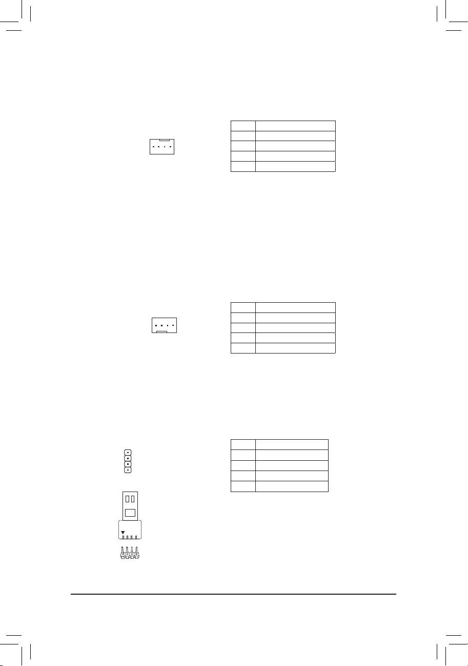
6) SYS_FAN3_PUMP (System Fan/Water Cooling Pump Header)
The fan/pump header is 4-pin and possess a foolproof insertion design. Most fan headers possess a
foolproof insertion design. When connecting a fan cable, be sure to connect it in the correct orientation
(the black connector wire is the ground wire). The speed control function requires the use of a fan with
fan speed control design. For optimum heat dissipation, it is recommended that a system fan be installed
inside the chassis. The header also provides speed control for a water cooling pump, refer to Chapter 2,
«BIOS Setup,» «M.I.T.,» for more information.
1
5) CPU_OPT (Water Cooling CPU Fan Header)
The fan header is 4-pin and possesses a foolproof insertion design. Most fan headers possess a foolproof
insertion design. When connecting a fan cable, be sure to connect it in the correct orientation (the black
connector wire is the ground wire). The speed control function requires the use of a fan with fan speed control
design.
1
Pin No. Denition
1 GND
2 Voltage Speed Control
3 Sense
4 PWM Speed Control
Pin No. Denition
1 GND
2 Voltage Speed Control
3 Sense
4 PWM Speed Control
Pin No. Denition
1 12V
2 G
3 R
4 B
1
7) LED_CPU (CPU Cooler LED Strip/RGB LED Strip Header)
TheheadercanbeusedtoconnectaCPUcoolerLEDstriporastandard5050RGBLEDstrip(12V/G/R/B),
with maximum power rating of 2A (12V) and maximum length of 2m.
ConnecttheCPUcoolerLEDstrip/RGBLEDstriptotheheader.The
powerpin(markedwithatriangleontheplug)oftheLEDstripmust
be connected to Pin 1 of this header. Incorrect connection may lead
tothedamageoftheLEDstrip.
LEDStrip
1
12V
— 15 —
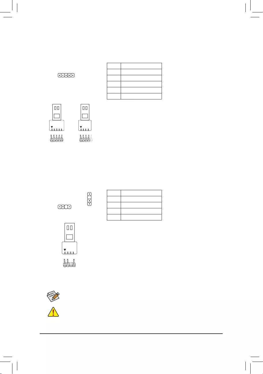
9) D_LED1/D_LED2 (Digital LED Strip Headers)
Theheaderscanbeusedtoconnectastandard5050digitalLEDstrip,withmaximumpowerratingof2A
(12Vor5V)andmaximumlengthof5mormaximumnumberof300LEDs.Thereare12Vand5Vdigital
LEDstrips.BesuretoverifythevoltagerequirementsofyourdigitalLEDstripandsettheDLED_V_SW1
andDLED_V_SW2jumpersaccordingly.
Pin No. Denition
1 V
2D
3 No Pin
4 G
Before installing the devices, be sure to turn off the devices and your computer. Unplug the power
cord from the power outlet to prevent damage to the devices.
Forhowtoturnon/offthelightsoftheLEDstrip,refertotheinstructionsoninChapter2,«BIOS
Setup,» «Peripherals.»
D_LED1 D_LED2
ConnectyourdigitalLEDstriptotheheader.Thereare12Vand5V
digitalLEDstrips.Besuretoverifythevoltagerequirementsofyour
digitalLED strips andset theDLED_V_SW1 and DLED_V_SW2
jumpers accordingly. The power pin (marked with a triangle on the
plug)oftheLEDstripmustbeconnectedtoPin1ofthedigitalLEDstrip
header.IncorrectconnectionmayleadtothedamageoftheLEDstrip.
1
F_USB30 F_U
B_
F_ F_
_
B
BS_
B
SB_
B
_S
S_
_
B
_U
_
B
S
123
123
123
123
1
1
1
1
BSS
S
_S
SSU
1 2 3
S3 BSSS
U
__ 3
F_USB3F
S _
S _
S _
SF
B_
B_
F
_0
S
S
_0F
_F
_
_
__B
U
S _S
_ SF_
USB0_B
B_ F_USB3
_
_3U
LED_C (RGB (RGBW) LED Strip Header)
Theheadercanbeusedtoconnectastandard5050RGB(RGBW)LEDstrip(12V/G/R/B/W),withmaximum
power rating of 2A (12V) and maximum length of 2m.
Pin No. Denition
1 12V
2 G
3 R
4 B
5 W
F_USB30 F_U
B_
F_ F_
_
B
BS_
B
SB_
B
_S
S_
_
B
_U
_
B
S
123
123
123
123
1
1
1
1
BSS
S
_S
SSU
1 2 3
S3 BSSS
U
__ 3
F_USB3F
S _
S _
S _
SF
B_
B_
F
_0
S
S
_0F
_F
_
_
__B
U
S _S
_
USB0_B
B_ F_USB3
_
1
ConnectyourRGB(RGBW)LEDstriptotheheader.Thepowerpin
(markedwithatriangleontheplug)oftheLEDstripmustbeconnected
to Pin 1 (12V) of this header. Incorrect connection may lead to the
damageoftheLEDstrip.
RGBW
LEDStrip
1
12V
RGB
LEDStrip
1
12V
F_USB30 F_U
B_
F_ F_
_
B
BS_
B
SB_
B
_S
S_
_
B
_U
_
B
S
123
123
123
123
1
1
1
1
BSS
S
_S
SSU
1 2 3
S3 BSSS
U
__ 3
F_USB3F
S _
S _
S _
SF
B_
B_
F
_0
S
S
_0F
_F
_
_
__B
U
S _S
_ SF_
USB0_B
B_ F_USB3
_
_3U
1
DigitalLED
Strip
1
— 16 —
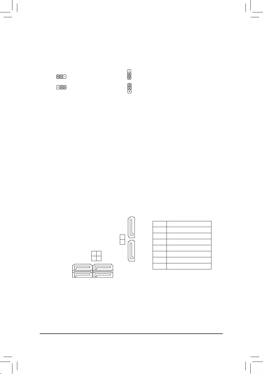
10) DLED_V_SW1/DLED_V_SW2 (Digital LED Strip Power Select Jumpers)
ThejumpersallowyoutoselectthesupplyvoltageoftheD_LED1andD_LED2headers.Besureto
verifythevoltagerequirementsofyourdigitalLEDstripandsetthecorrectvoltagewiththisjumperbefore
connection.IncorrectconnectionmayleadtothedamageoftheLEDstrip.
1
1
1-2:5V(Default) 1-2:5V(Default)
2-3: 12V 2-3: 12V
DLED_V_SW1
1
1
DLED_V_SW2
11/12) ASATA3 0/1, SATA3 0/1/2/3 (SATA 6Gb/s Connectors)
The SATA connectors conform to SATA 6Gb/s standard and are compatible with SATA 3Gb/s and
SATA 1.5Gb/s standard. Each SATA connector supports a single SATA device. The SATA connectors
supportRAID0,RAID1,andRAID10.RefertoChapter3,«ConguringaRAIDSet,»forinstructions
onconguringaRAIDarray.
Pin No. Denition
1GND
2 TXP
3 TXN
4GND
5 RXN
6 RXP
7GND
SATA3
0 2
1 3 7
1
7 1
7 1
ASATA3 0
1
— 17 —
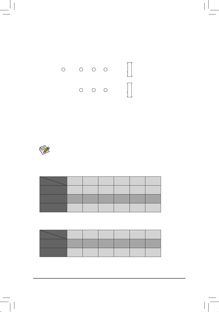
13) M2A_SOCKET/M2B_SOCKET (M.2 Socket 3 Connectors)
TheM.2connectorssupportM.2SATASSDsorM.2PCIeSSDs(Note)andsupportRAIDconguration.
PleasenotethatanM.2PCIeSSDcannotbeusedtocreateaRAIDseteitherwithanM.2SATASSDora
SATAharddrive.TocreateaRAIDarraywithanM.2PCIeSSD,youmustsetupthecongurationinUEFI
BIOSmode.RefertoChapter3,»ConguringaRAIDSet,»forinstructionsonconguringaRAIDarray.
SelecttheproperholefortheM.2SSDtobeinstalledandrefastenthescrewandstandoff.
Installation Notices for the M.2 and SATA Connectors:
DuetothelimitednumberoflanesprovidedbytheChipset,theavailabilityoftheSATAconnectorsmay
be affected by the type of device installed in the M.2 connectors. Refer to the following table for details.
F_USB30 F_U
B_
F_ F_
_
B
BS_
B
SB_
B
_S
S_
_
B
_U
_
B
S
123
123
123
123
1
1
1
1
BSS
S
_S
SSU
1 2 3
S3 BSSS
U
__ 3
F_USB3F
S _
S _
S _
SF
B_
B_
F
_0
S
S
_0F
_F
_
_
__B
U
S _S
_ SF_
USB0_B
B_ F_USB3
F_USB303
_
_3U
80110 60 42
F_USB30 F_U
B_
F_ F_
_
B
BS_
B
SB_
B
_S
S_
_
B
_U
_
B
S
123
123
123
123
1
1
1
1
BSS
S
_S
SSU
1 2 3
S3 BSSS
U
__ 3
F_USB3F
S _
S _
S _
SF
B_
B_
F
_0
S
S
_0F
_F
_
_
__B
U
S _S
_ SF_
USB0_B
B_ F_USB3
F_USB303
_
_3U
80 60 42
M2A_SOCKET
M2B_SOCKET
•M2B_SOCKET:
SATA3 0 SATA3 1 SATA3 2 SATA3 3 ASATA3 0 ASATA3 1
M.2PCIex2SSD*
a a r r a a
NoM.2SSDInstalled aaaaaa
a: Available, r: Not available
* TheM2B_SOCKETconnectorsupportsuptoPCIex2SSDs.
Connector
Type of
M.2SSD
•M2A_SOCKET:
SATA3 0 SATA3 1 SATA3 2 SATA3 3 ASATA3 0 ASATA3 1
M.2SATASSD aaaaar
M.2PCIeSSD
aaaar r
NoM.2SSDInstalled aaaaaa
a: Available, r: Not available
Connector
Type of
M.2SSD
(Note) TheM2B_SOCKETconnectorsupportsonlyPCIeSSDs.
FollowthestepsbelowtocorrectlyinstallanM.2SSDintheM.2connector.
Step 1:
Get a screw and a standoff from the included M.2 screw kit. Locate the M.2 connector where you will install
theM.2SSD,useascrewdrivertounfastenthescrewontheheatsinkandthenremovetheheatsink.
Step 2:
LocatethepropermountingholefortheM.2SSDtobeinstalledandthentightenthestandoffrst.Insert
theM.2SSDintotheM.2connectoratanangle.
Step 3:
PresstheM.2SSDdownandthensecureitwiththescrew.Replacetheheatsinkandsecureittothe
original hole.
— 18 —
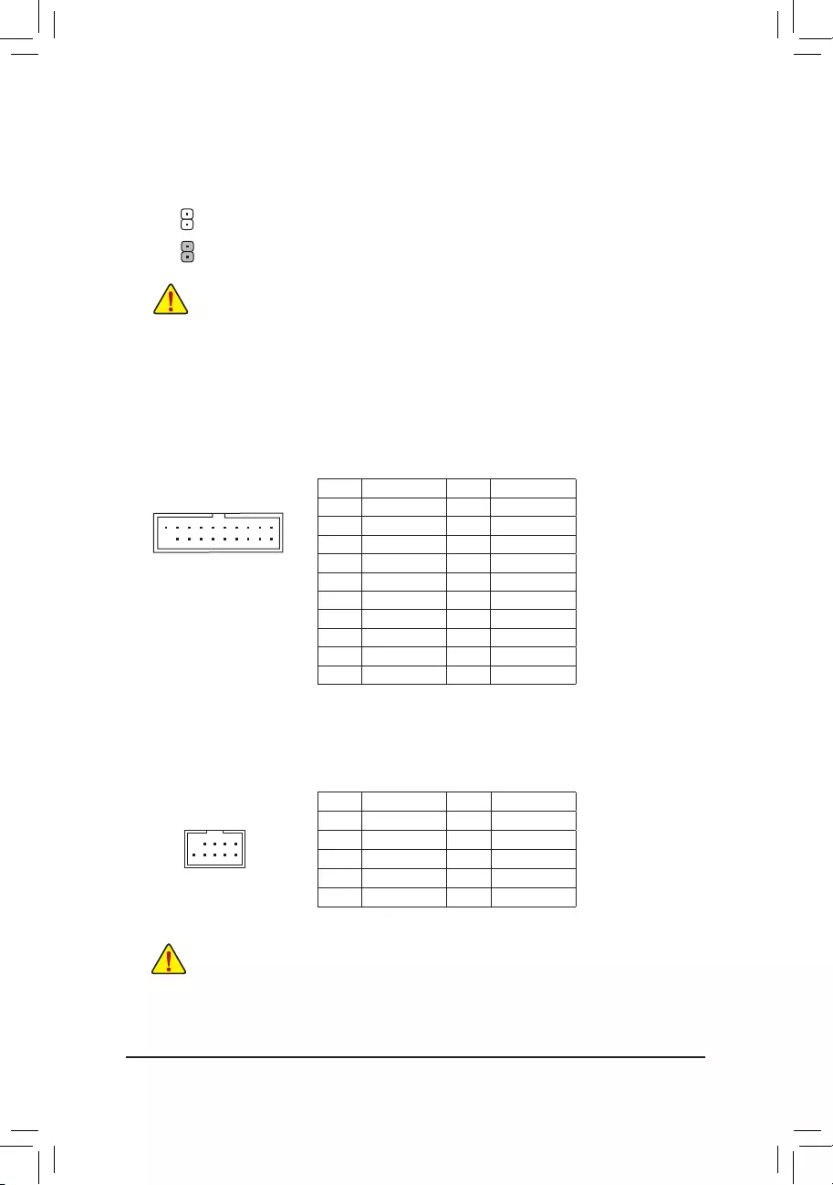
14) SPDIF_O (S/PDIF Out Header)
ThisheadersupportsdigitalS/PDIFOutandconnectsaS/PDIFdigitalaudiocable(providedbyexpansion
cards) for digital audio output from your motherboard to certain expansion cards like graphics cards and
soundcards.Forexample,somegraphicscardsmayrequireyoutouseaS/PDIFdigitalaudiocablefor
digitalaudiooutputfromyourmotherboardtoyourgraphicscardifyouwishtoconnectanHDMIdisplay
tothegraphicscardandhavedigitalaudiooutputfromtheHDMIdisplayatthesametime.Forinformation
aboutconnectingtheS/PDIFdigitalaudiocable,carefullyreadthemanualforyourexpansioncard.
1
F_USB30 F_U
B_
F_ F_
_
B
BS_
B
SB_
B
_S
S_
_
B
_U
_
B
S
123
123
123
123
1
1
1
1
BSS
S
_S
SSU
1 2 3
S3 BSSS
U
__ 3
F_USB3F
S _
S _
S _
SF
B_
B_
F
_0
S
S
_0F
_F
_
_
__B
U
S _S
_ SF_
USB0_B
B_ F_USB3
_
_3U
Pin No. Denition
15VDUAL
2 No Pin
3SPDIFO
4GND
The front panel design may differ by chassis. A front panel module mainly consists of power switch,
resetswitch,powerLED,harddriveactivityLED,speakerandetc.Whenconnectingyourchassis
front panel module to this header, make sure the wire assignments and the pin assignments are
matched correctly.
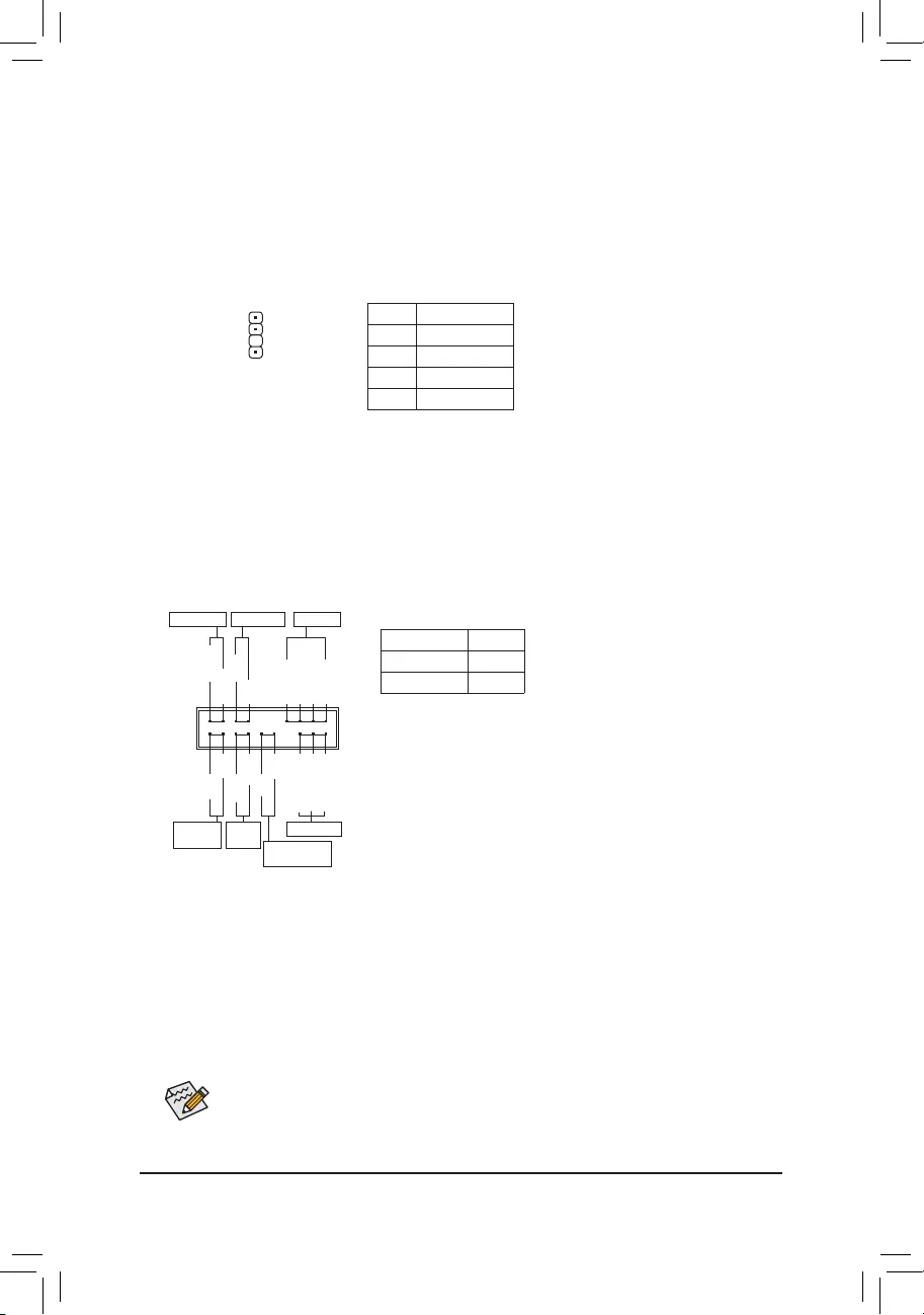
15) F_PANEL (Front Panel Header)
Connect the power switch, reset switch, speaker, chassis intrusion switch/sensor and system status indicator
on the chassis to this header according to the pin assignments below. Note the positive and negative pins
before connecting the cables.
System Status LED
S0 On
S3/S4/S5 Off
•PW (Power Switch, Red):
Connects to the power switch on the chassis front panel. You may
congurethewaytoturnoffyoursystemusingthepowerswitch(refer
to Chapter 2, «BIOS Setup,» «Power,» for more information).
•SPEAK (Speaker, Orange):
Connects to the speaker on the chassis front panel. The system reports
system startup status by issuing a beep code. One single short beep
will be heard if no problem is detected at system startup.
•PLED/PWR_LED (PowerLED,Yellow/Purple):
Connects to the power status indicator
onthechassisfrontpanel.TheLEDison
whenthesystemisoperating.TheLEDis
off when the system is in S3/S4 sleep state
or powered off (S5).
•HD (HardDriveActivityLED,Blue):
ConnectstotheharddriveactivityLEDonthechassisfrontpanel.TheLEDisonwhentheharddrive
is reading or writing data.
•RES (Reset Switch, Green):
Connects to the reset switch on the chassis front panel. Press the reset switch to restart the computer
ifthecomputerfreezesandfailstoperformanormalrestart.
•CI (Chassis Intrusion Header, Gray):
Connects to the chassis intrusion switch/sensor on the chassis that can detect if the chassis cover has
been removed. This function requires a chassis with a chassis intrusion switch/sensor.
•NC (Orange): No Connection.
PowerLED
1
2
19
20
CI-
CI+
PWR_LED-
PWR_LED+
PLED-
PW-
SPEAK+
SPEAK-
PLED+
PW+
PowerLED
HD-
RES+
HD+
RES-
HardDrive
ActivityLED
Reset
Switch Chassis Intrusion
Header
Power Switch Speaker
PWR_LED-
NC
NC
— 19 —
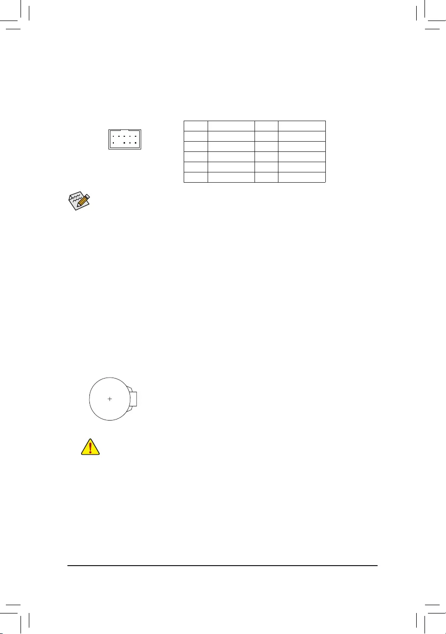
17) BAT (Battery)
Thebatteryprovidespowertokeepthevalues(suchasBIOScongurations,date,andtimeinformation)
in the CMOS when the computer is turned off. Replace the battery when the battery voltage drops to a low
level, or the CMOS values may not be accurate or may be lost.
You may clear the CMOS values by removing the battery:
1. Turn off your computer and unplug the power cord.
2. Gently remove the battery from the battery holder and wait for one minute. (Or use a
metal object like a screwdriver to touch the positive and negative terminals of the battery
holder, making them short for 5 seconds.)
3. Replace the battery.
4. Plug in the power cord and restart your computer.
•Always turn off your computer and unplug the power cord before replacing the battery.
•Replacethebatterywithanequivalentone.Damagetoyourdevicesmayoccurifthebatteryis
replaced with an incorrect model.
•Contact the place of purchase or local dealer if you are not able to replace the battery by yourself
or uncertain about the battery model.
•When installing the battery, note the orientation of the positive side (+) and the negative side (-)
of the battery (the positive side should face up).
•Used batteries must be handled in accordance with local environmental regulations.
16) F_AUDIO (Front Panel Audio Header)
ThefrontpanelaudioheadersupportsHighDenitionaudio(HD).Youmayconnectyourchassisfront
panel audio module to this header. Make sure the wire assignments of the module connector match the
pin assignments of the motherboard header. Incorrect connection between the module connector and the
motherboard header will make the device unable to work or even damage it.
Some chassis provide a front panel audio module that has separated connectors on each wire instead
of a single plug. For information about connecting the front panel audio module that has different wire
assignments, please contact the chassis manufacturer.
F_USB30 F_U
B_
F_ F_
_
B
BS_
B
SB_
B
_S
S_
_
B
_U
_
B
S
123
123
123
123
1
1
1
1
BSS
S
_S
SSU
1 2 3
S3 BSSS
U
__ 3
F_USB3F
S _
S _
S _
SF
B_
B_
F
_0
S
S
_0F
_F
_
_
__B
U
S _S
_
USB0_B
B_ F_USB3
_
9 1
10 2
Pin No. Denition Pin No. Denition
1 MIC2_L 6 Sense
2GND 7FAUDIO_JD
3 MIC2_R 8 No Pin
4 NC 9 LINE2_L
5 LINE2_R 10 Sense
— 20 —
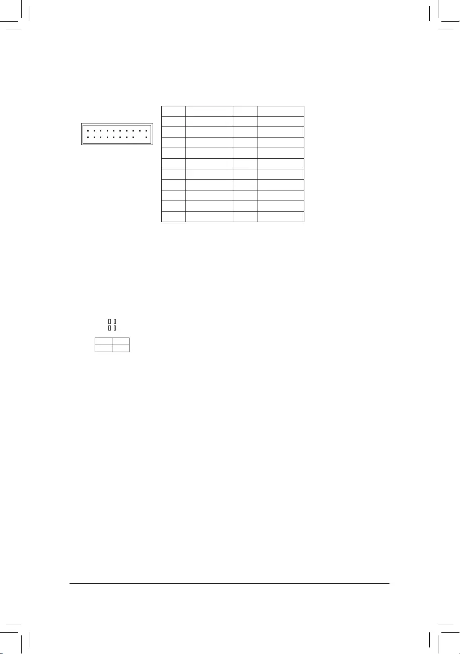
20) F_USB1/F_USB2 (USB 2.0/1.1 Headers)
TheheadersconformtoUSB2.0/1.1specication.EachUSBheadercanprovidetwoUSBportsviaan
optional USB bracket. For purchasing the optional USB bracket, please contact the local dealer.
Pin No. Denition Pin No. Denition
1 Power (5V) 6 USBDY+
2 Power (5V) 7 GND
3USBDX- 8GND
4USBDY— 9 No Pin
5USBDX+ 10 NC
•DonotplugtheIEEE1394bracket(2×5-pin)cableintotheUSB2.0/1.1header.
•Prior to installing the USB bracket, be sure to turn off your computer and unplug the power cord
from the power outlet to prevent damage to the USB bracket.
10
9
2
1
Pin No. Denition Pin No. Denition
1 VBUS 11 D2+
2 SSRX1- 12 D2-
3 SSRX1+ 13 GND
4GND 14 SSTX2+
5 SSTX1- 15 SSTX2-
6 SSTX1+ 16 GND
7GND 17 SSRX2+
8D1- 18 SSRX2-
9D1+ 19 VBUS
10 NC 20 No Pin
19) F_USB30 (USB 3.1 Gen 1 Header)
The header conforms to USB 3.1 Gen 1 and USB 2.0 specication and can provide two USB ports. For
purchasing the optional 3.5″ front panel that provides two USB 3.1 Gen 1 ports, please contact the local
dealer.
F_USB30 F_U
B_
F_ F_
_
B
BS_
B
SB_
B
_S
S_
_
B
_U
_
B
S
123
123
123
123
1
1
1
1
BSS
S
_S
SSU
1 2 3
S3 BSSS
U
__ 3
F_USB3F
S _
S _
S _
SF
B_
B_
F
_0
S
S
_0F
_F
_
_
__B
U
S _S
_
USB0_B
B_ F_USB3
10
11
1
20
18) CLR_CMOS (Clear CMOS Jumper)
UsethisjumpertocleartheBIOScongurationandresettheCMOSvaluestofactorydefaults.Toclear
the CMOS values, use a metal object like a screwdriver to touch the two pins for a few seconds.
•Always turn off your computer and unplug the power cord from the power outlet before clearing
the CMOS values.
•Aftersystemrestart,gotoBIOSSetuptoloadfactorydefaults(selectLoadOptimizedDefaults)or
manuallyconguretheBIOSsettings(refertoChapter2,«BIOSSetup,»forBIOScongurations).
Open: Normal
Short: Clear CMOS Values
— 21 —
22) CPU/DRAM/VGA/BOOT (Status LEDs)
Thestatus LEDs showwhether the CPU, memory,graphics card, andoperating system are working
properlyaftersystempower-on.IftheCPU/DRAM/VGALEDison,thatmeansthecorrespondingdevice
isnotworkingnormally;iftheBOOTLEDison,thatmeansyouhaven’tenteredtheoperatingsystemyet.
CPU: CPUstatusLED
DRAM: MemorystatusLED
VGA: GraphicscardstatusLED
BOOT: OperatingsystemstatusLED
F_USB30 F_U
B_
F_ F_
_
B
BS_
B
SB_
B
_S
S_
_
B
_U
_
B
S
123
123
123
123
1
1
1
1
BSS
S
_S
SSU
1 2 3
S3 BSSS
U
__ 3
F_USB3F
S _
S _
S _
SF
B_
B_
F
_0
S
S
_0F
_F
_
_
__B
U
S _S
_
USB0_B
B_ F_USB3
CPU DRAM
VGA BOOT
20
19
2
1
F_USB30 F_U
B_
F_ F_
_
B
BS_
B
SB_
B
_S
S_
_
B
_U
_
B
S
123
123
123
123
1
1
1
1
BSS
S
_S
SSU
1 2 3
S3 BSSS
U
__ 3
F_USB3F
S _
S _
S _
SF
B_
B_
F
_0
S
S
_0F
_F
_
_
__B
U
S _S
_
USB0_B
B_ F_USB3
21) TPM (Trusted Platform Module Header)
You may connect a TPM (Trusted Platform Module) to this header.
Pin No. Denition Pin No. Denition
1 LCLK 11 LAD0
2GND 12 GND
3 LFRAME 13 NC
4 No Pin 14 NC
5 LRESET 15 SB3V
6 NC 16 SERIRQ
7LAD3 17 GND
8LAD2 18 NC
9 VCC3 19 NC
10 LAD1 20 NC
— 22 —
Chapter 2 BIOS Setup
BIOS (Basic Input and Output System) records hardware parameters of the system in the CMOS on the
motherboard. Its major functions include conducting the Power-On Self-Test (POST) during system startup,
saving system parameters and loading operating system, etc. BIOS includes a BIOS Setup program that allows
theusertomodifybasicsystemcongurationsettingsortoactivatecertainsystemfeatures.
When the power is turned off, the battery on the motherboard supplies the necessary power to the CMOS to
keepthecongurationvaluesintheCMOS.
ToaccesstheBIOSSetupprogram,pressthe<Delete>keyduringthePOSTwhenthepoweristurnedon.
ToupgradetheBIOS,useeithertheGIGABYTEQ-Flashor@BIOSutility.
•Q-FlashallowstheusertoquicklyandeasilyupgradeorbackupBIOSwithoutenteringtheoperatingsystem.
•@BIOSisaWindows-basedutilitythatsearchesanddownloadsthelatestversionofBIOSfromtheInternet
and updates the BIOS.
•BecauseBIOSashingispotentiallyrisky,ifyoudonotencounterproblemsusingthecurrentversionofBIOS,
itisrecommendedthatyounotashtheBIOS.ToashtheBIOS,doitwithcaution.InadequateBIOSashing
may result in system malfunction.
•It is recommended that you not alter the default settings (unless you need to) to prevent system instability or other
unexpected results. Inadequately altering the settings may result in system’s failure to boot. If this occurs, try to
cleartheCMOSvaluesandresettheboardtodefaultvalues.(Refertothe»LoadOptimizedDefaults»sectionin
this chapter or introductions of the battery/clear CMOS jumper in Chapter 1 for how to clear the CMOS values.)
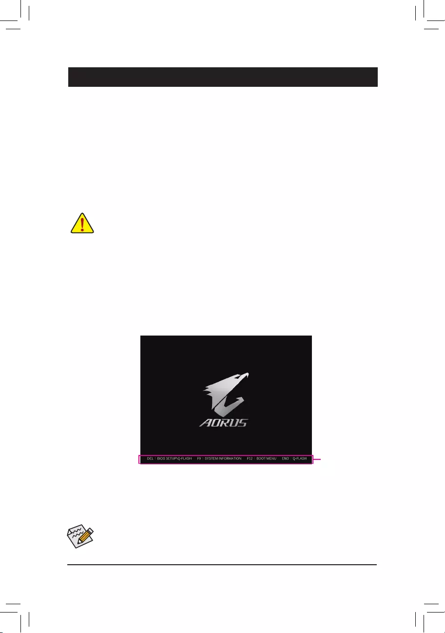
2-1 Startup Screen
The following startup Logo screen will appear when the computer boots.
(Sample BIOS Version: B450 AORUS PRO E9)
Function Keys
•When the system is not stable as usual, select the Load Optimized Defaults item to set your system to its defaults.
•The BIOS Setup menus described in this chapter are for reference only and may differ by BIOS version.
TherearetwodifferentBIOSmodesasfollowsandyoucanusethe<F2>keytoswitchbetweenthetwomodes.
The Classic Setup mode provides detailed BIOS settings. You can press the arrow keys on your keyboard to move
amongtheitemsandpress<Enter>toacceptorenterasub-menu.Oryoucanuseyourmousetoselecttheitemyou
want. Easy Mode allows users to quickly view their current system information or to make adjustments for optimum
performance.InEasyMode,youcanuseyourmousetomovethroughcongurationitems.
— 23 —
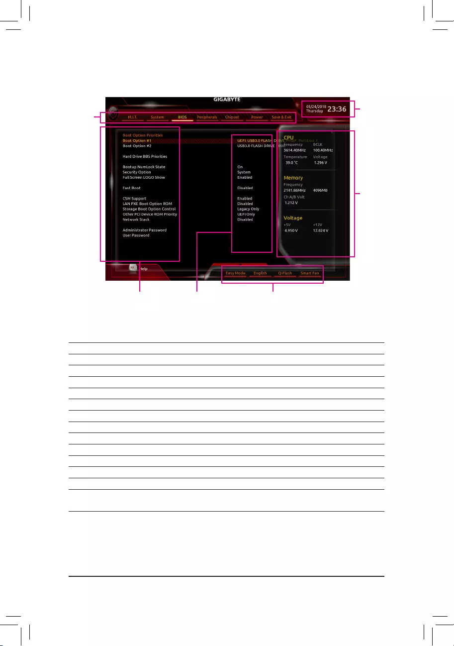
2-2 The Main Menu
Classic Setup Function Keys
<f><g>Move the selection bar to select a setup menu
<h><i> Movetheselectionbartoselectancongurationitemonamenu
<Enter> Execute command or enter a menu
<+>/<PageUp> Increase the numeric value or make changes
<—>/<PageDown> Decreasethenumericvalueormakechanges
<F1> Show descriptions of the function keys
<F2> Switch to Easy Mode
<F5> Restore the previous BIOS settings for the current submenus
<F7> LoadtheOptimizedBIOSdefaultsettingsforthecurrentsubmenus
<F8> AccesstheQ-Flashutility
<F9> Displaysysteminformation
<F10> Save all the changes and exit the BIOS Setup program
<F12> Capture the current screen as an image and save it to your USB drive
<Esc> Main Menu: Exit the BIOS Setup program
Submenus: Exit current submenu
CongurationItems Current Settings
Setup Menus
System Time
QuickAccessBarallowsyoutoenterEasyMode,select
BIOSdefaultlanguage,congurefansettings,orenter
Q-Flash.
Hardware
Information
— 24 —
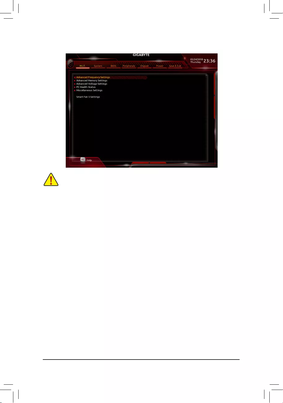
2-3 M.I.T.
Whether the system will work stably with the overclock/overvoltage settings you made is dependent on your overall
systemcongurations.Incorrectlydoingoverclock/overvoltagemayresultindamagetoCPU,chipset,ormemory
and reduce the useful life of these components. This page is for advanced users only and we recommend you not to
alter the default settings to prevent system instability or other unexpected results. Inadequately altering the settings
may result in system’s failure to boot. If this occurs, clear the CMOS values and reset the board to default values.)
`Advanced Frequency Settings
&Host Clock Value
DisplaysthecurrentoperatingHostClockfrequency.
&GFX Clock Frequency (Note)
Allows you to alter the frequency for the GPU. After you alter the GFX Clock Frequency settings, make
sure to adjust the GFX Core Voltagesettings.(Default:Auto)
Note: The adjustable range is dependent on the CPU being installed. Auto lets the BIOS automatically
congurethissetting.
&GFX Core Voltage (Note)
AllowsyoutoalterthevoltagefortheGPU.(Default:Auto)
Note: The adjustable range is dependent on the CPU being installed. Auto lets the BIOS automatically
congurethissetting.
&CPU Clock Ratio
Allows you to alter the clock ratio for the installed CPU. The adjustable range is dependent on the CPU
being installed.
&CPU Frequency
DisplaysthecurrentoperatingCPUfrequency.
`Advanced CPU Core Settings
&CPU Clock Ratio, CPU Frequency
The settings above are synchronous to those under the same items on the Advanced Frequency Settings
menu.
(Note) This item is present only when you install a CPU that supports this feature.
— 25 —

&Core Performance Boost
Allows you to determine whether to enable the Core Performance Boost (CPB) technology, a CPU
performance-boosttechnology.(Default:Auto)
&AMD Cool&Quiet function
Enabled LetstheAMDCool’n’QuietdriverdynamicallyadjusttheCPUclockandVIDto
reduceheatoutputfromyourcomputeranditspowerconsumption.(Default)
Disabled Disablesthisfunction.
&SVM Mode
VirtualizationenhancedbyVirtualizationTechnologywillallowaplatformtorunmultipleoperatingsystems
andapplicationsinindependentpartitions.Withvirtualization,onecomputersystemcanfunctionasmultiple
virtualsystems.(Default:Disabled)
&Global C-state Control
Allows you to determine whether to let the CPU enter C states. When enabled, the CPU core frequency
willbereducedduringsystemhaltstatetodecreasepowerconsumption.(Default:Auto)
&Power Supply Idle Control
Enables or disables Package C6 State.
TypicalCurrentIdle Disablesthisfunction.
Low Current Idle Enables this function.
Auto LetstheBIOSautomaticallycongurethissetting. (Default)
&Opcache Control
(Note 1)
Enables or disables Opcache. AutoletstheBIOSautomaticallycongurethissetting.(Default:Auto)
&Downcore Control
Allows you to select the number of CPU cores to enable (the number of CPU cores may vary by CPU).
AutoletstheBIOSautomaticallycongurethissetting.(Default:Auto)
&SMT Mode
Allows you to enable or disable the CPU Simultaneous Multi-Threading technology. This feature only works
for operating systems that support multi-processor mode. AutoletstheBIOSautomaticallycongurethis
setting.(Default:Auto)
&ExtremeMemoryProle(X.M.P.)(Note 2)
AllowstheBIOStoreadtheSPDdataonXMPmemorymodule(s)toenhancememoryperformancewhen
enabled.
Disabled Disablesthisfunction.(Default)
Prole1 UsesProle1settings.
Prole2(Note 2) UsesProle2settings.
&System Memory Multiplier
Allows you to set the system memory multiplier. AutosetsmemorymultiplieraccordingtomemorySPD
data.(Default:Auto)
&Memory Frequency (MHz)
Therstmemoryfrequencyvalueisthenormaloperatingfrequencyofthememorybeingused;thesecond
is the memory frequency that is automatically adjusted according to the System Memory Multiplier settings.
(Note 1) This item is present only when you install a CPU that supports this feature.
(Note 2) This item is present only when you install a CPU and a memory module that support this feature.
— 26 —

`Advanced Memory Settings
&
ExtremeMemoryProle(X.M.P.)
(Note)
, System Memory Multiplier , Memory
Frequency(Mhz)
The settings above are synchronous to those under the same items on the Advanced Frequency Settings
menu.
&Memory Timing Mode
Manualallowsthememorytimingsettingsbelowtobecongurable.Optionsare:Auto(default),Manual.
&ProleDDRVoltage
When using a non-XMP memory module or ExtremeMemoryProle(X.M.P.) is set to Disabled, the value
isdisplayedaccordingtoyourmemoryspecication.WhenExtremeMemoryProle(X.M.P.) is set to
Prole1 or Prole2,thevalueisdisplayedaccordingtotheSPDdataontheXMPmemory.
` Standard Timing Control, Advanced Timing Control, CAD Bus Setup Timing, CAD Bus
DriveStrength,DataBusConguration
Thesesectionsprovidememorytimingsettings.Therespectivetimingsettingscreensarecongurableonly
when Memory Timing Mode is set to Manual. Note: Your system may become unstable or fail to boot after
you make changes on the memory timings. If this occurs, please reset the board to default values by loading
optimizeddefaultsorclearingtheCMOSvalues.
`Advanced Voltage Settings
This sub-menu allows you to set CPU, chipset and memory voltages.
`PC Health Status
&Reset Case Open Status
Disabled Keepsorclearstherecordofpreviouschassisintrusionstatus.(Default)
Enabled Clears the record of previous chassis intrusion status and the Case Openeldwill
show «No» at next boot.
&Case Open
DisplaysthedetectionstatusofthechassisintrusiondetectiondeviceattachedtothemotherboardCI
header.Ifthesystemchassiscoverisremoved,thiseldwillshow«Yes»,otherwiseitwillshow»No».To
clear the chassis intrusion status record, set Reset Case Open Status to Enabled, save the settings to
the CMOS, and then restart your system.
& CPU Vcore/CPU VDDP/DRAM Channel A/B Voltage/+3.3V/+5V/+12V/VCORE SOC
Displaysthecurrentsystemvoltages.
`Miscellaneous Settings
&PCIeSlotConguration
Allows you to set the operation mode of the PCI Express slots to Gen 1, Gen 2, or Gen 3. Actual operation
modeissubjecttothehardwarespecicationofeachslot.AutoletstheBIOSautomaticallycongurethis
setting.(Default:Auto)
&3DMark01 Enhancement
Allowsyoutodeterminewhethertoenhancesomelegacybenchmarkperformance.(Default:Disabled)
(Note) This item is present only when you install a CPU and a memory module that support this feature.
— 27 —

`Smart Fan 5 Settings
&Monitor
Allowsyoutoselectatargettomonitorandtomakefurtheradjustment.(Default:CPUFAN)
&Fan Speed Control
Allows you to determine whether to enable the fan speed control function and adjust the fan speed.
Normal Allows the fan to run at different speeds according to the temperature. You can adjust
the fan speed with System Information Viewer based on your system requirements.
(Default)
Silent Allows the fan to run at slow speeds.
Manual Allows you to control the fan speed in the curve graph.
Full Speed Allows the fan to run at full speeds.
&Fan Control Use Temperature Input
Allows you to select the reference temperature for fan speed control.
&Temperature Interval
Allows you to select the temperature interval for fan speed change.
&FAN/Pump Control Mode
Auto Lets the BIOS automatically detect the type of fan/pump installed and sets the optimal
controlmode.(Default)
Voltage Voltage mode is recommended for a 3-pin fan/pump.
PWM PWM mode is recommended for a 4-pin fan/pump.
&FAN Stop
Enables or disables the fan/pump stop function. You can set the temperature limit using the temperature
curve.Thefanorpumpstopsoperationwhenthetemperatureislowerthanthelimit.(Default:Disabled)
&Temperature
Displaysthecurrenttemperatureoftheselectedtargetarea.
&Fan Speed
Displayscurrentfan/pumpspeeds.
&Flow Rate
Displaystheowrateofyourwatercoolingsystem.
&Temperature Warning Control
Sets the warning threshold for temperature. When temperature exceeds the threshold, BIOS will emit
warningsound.Optionsare:Disabled(default),60oC/140oF, 70oC/158oF, 80oC/176oF, 90oC/194oF.
&Fan/Pump Fail Warning
Allows the system to emit warning sound if the fan/pump is not connected or fails. Check the fan/pump
conditionorfan/pumpconnectionwhenthisoccurs.(Default:Disabled)
— 28 —
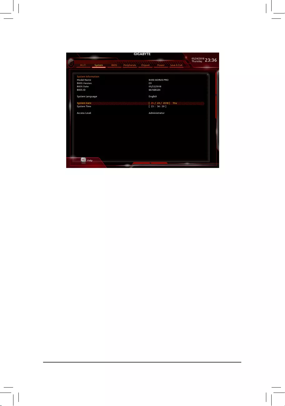
2-4 System
This section provides information on your motherboard model and BIOS version. You can also select the default
language used by the BIOS and manually set the system time.
&System Language
Selects the default language used by the BIOS.
&System Date
Setsthesystemdate.Thedateformatisweek(read-only),month,date,andyear.Use<Enter>toswitch
betweentheMonth,Date,andYeareldsandusethe<PageUp>or<PageDown>keytosetthedesired
value.
&System Time
Sets the system time. The time format is hour, minute, and second. For example, 1 p.m. is 13:00:00. Use
<Enter>toswitchbetweentheHour,Minute,andSecondeldsandusethe<PageUp>or<PageDown>
key to set the desired value.
&Access Level
Displaysthecurrentaccessleveldependingonthetypeofpasswordprotectionused.(Ifnopasswordis
set, the default will display as Administrator.) The Administrator level allows you to make changes to all
BIOS settings; the User level only allows you to make changes to certain BIOS settings but not all.
— 29 —
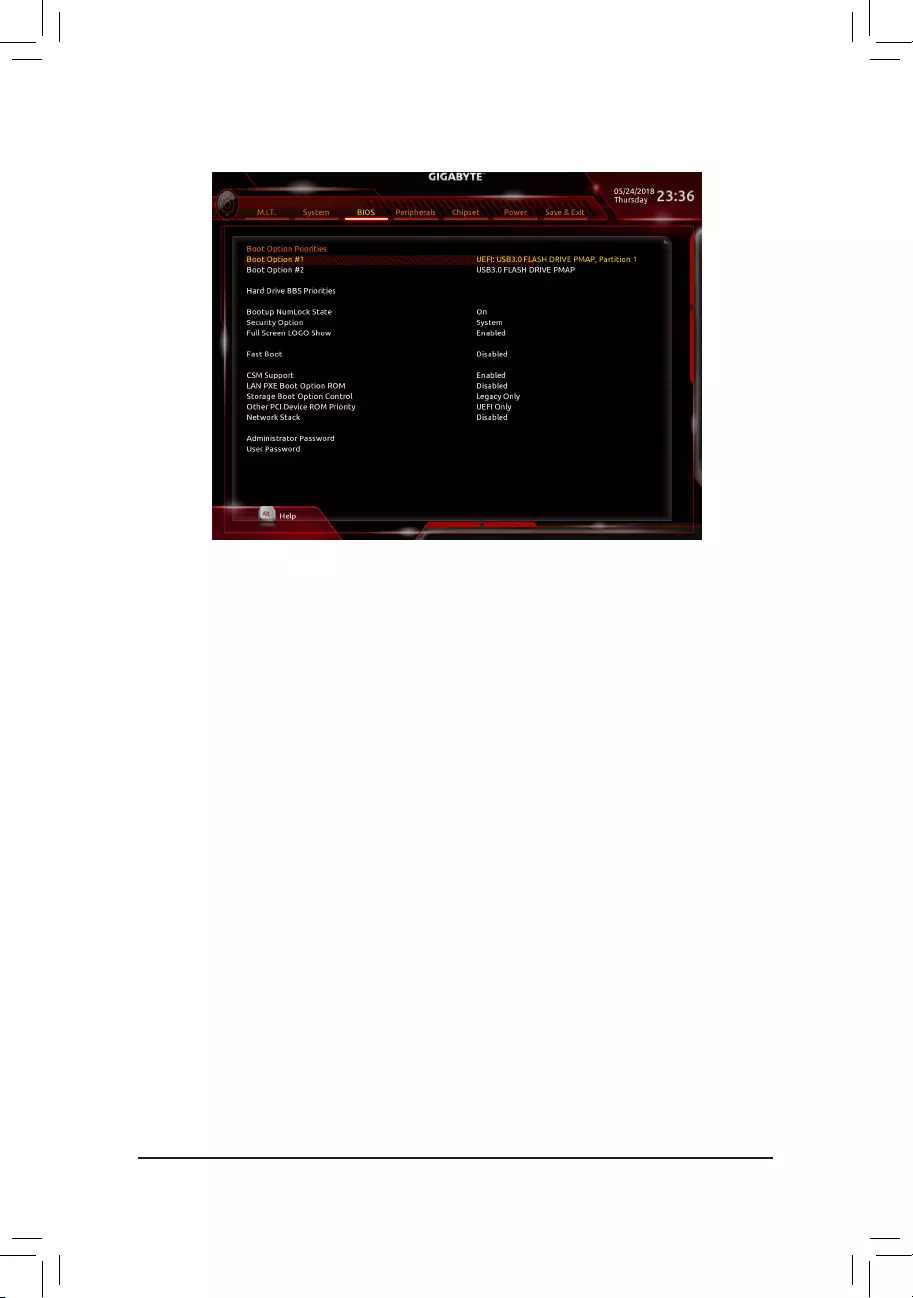
2-5 BIOS
&Boot Option Priorities
Speciestheoverallbootorderfromtheavailabledevices.RemovablestoragedevicesthatsupportGPT
formatwillbeprexedwith«UEFI:»stringonthebootdevicelist.Tobootfromanoperatingsystemthat
supportsGPTpartitioning,selectthedeviceprexedwith»UEFI:»string.
Or if you want to install an operating system that supports GPT partitioning such as Windows 10 64-bit,
selecttheopticaldrivethatcontainstheWindows1064-bitinstallationdiskandisprexedwith«UEFI:»
string.
&Hard Drive/CD/DVD ROM Drive/Floppy Drive/Network Device BBS Priorities
Speciesthebootorderforaspecicdevicetype,suchasharddrives,opticaldrives,oppydiskdrives,
anddevicesthatsupportBootfromLANfunction,etc.Press<Enter>onthisitemtoenterthesubmenuthat
presents the devices of the same type that are connected. This item is present only if at least one device
for this type is installed.
&Bootup NumLock State
EnablesordisablesNumlockfeatureonthenumerickeypadofthekeyboardafterthePOST.(Default:On)
&Security Option
Specieswhetherapasswordisrequiredeverytimethesystemboots,oronlywhenyouenterBIOSSetup.
Afterconguringthisitem,setthepassword(s)undertheAdministrator Password/User Password item.
Setup A password is only required for entering the BIOS Setup program.
System A password is required for booting the system and for entering the BIOS Setup
program.(Default)
&Full Screen LOGO Show
Allows you to determine whether to display the GIGABYTE Logo at system startup. Disabled skips the
GIGABYTELogowhenthesystemstartsup.(Default:Enabled)
&Fast Boot
Enables or disables Fast Boot to shorten the OS boot process. Ultra Fast provides the fastest bootup
speed.(Default:Disabled)
&SATA Support
AllSataDevices AllSATAdevicesarefunctionalintheoperatingsystemandduringthePOST.
LastBootHDDOnly Exceptforthepreviousbootdrive,allSATAdevicesaredisabledbeforetheOS
bootprocesscompletes.(Default)
ThisitemiscongurableonlywhenFast Boot is set to Enabled or Ultra Fast.
— 30 —

&VGA Support
Allows you to select which type of operating system to boot.
Auto Enables legacy option ROM only.
EFI Driver Enables EFI option ROM. (Default)
ThisitemiscongurableonlywhenFast Boot is set to Enabled or Ultra Fast.
&USB Support
Disabled All USB devices are disabled before the OS boot process completes.
Full Initial All USB devices are functional in the operating system and during the POST.
(Default)
Partial Initial Part of the USB devices are disabled before the OS boot process completes.
ThisitemiscongurableonlywhenFast Boot is set to Enabled. This function is disabled when Fast Boot
is set to Ultra Fast.
&PS2 Devices Support
Disabled All PS/2 devices are disabled before the OS boot process completes.
Enabled All PS/2 devices are functional in the operating system and during the POST.
(Default)
ThisitemiscongurableonlywhenFast Boot is set to Enabled. This function is disabled when Fast Boot
is set to Ultra Fast.
&NetWork Stack Driver Support
Disabled Disables booting from the network. (Default)
Enabled Enables booting from the network.
ThisitemiscongurableonlywhenFast Boot is set to Enabled or Ultra Fast.
&CSM Support
Enables or disables UEFI CSM (Compatibility Support Module) to support a legacy PC boot process.
Enabled Enables UEFI CSM. (Default)
Disabled Disables UEFI CSM and supports UEFI BIOS boot process only.
&LAN PXE Boot Option ROM
Allows you to select whether to enable the legacy option ROM for the LAN controller. (Default: Disabled)
ThisitemiscongurableonlywhenCSM Support is set to Enabled.
&Storage Boot Option Control
Allows you to select whether to enable the UEFI or legacy option ROM for the storage device controller.
Disabled Disables option ROM.
UEFI Only Enables UEFI option ROM only.
Legacy Only Enables legacy option ROM only. (Default)
ThisitemiscongurableonlywhenCSM Support is set to Enabled.
&Other PCI Device ROM Priority
Allows you to select whether to enable the UEFI or Legacy option ROM for the PCI device controller other
than the LAN, storage device, and graphics controllers.
Disabled Disables option ROM.
UEFI Only Enables UEFI option ROM only. (Default)
Legacy Only Enables legacy option ROM only.
ThisitemiscongurableonlywhenCSM Support is set to Enabled.
&Network Stack
Disables or enables booting from the network to install a GPT format OS, such as installing the OS from
the Windows Deployment Services server. (Default: Disabled)
&Ipv4 PXE Support
EnablesordisablesIPv4PXESupport.ThisitemiscongurableonlywhenNetwork Stack is enabled.
— 31 —

&Ipv4 HTTP Support
EnablesordisablesHTTPbootsupportforIPv4.ThisitemiscongurableonlywhenNetwork Stack is
enabled.
&Ipv6 PXE Support
EnablesordisablesIPv6PXESupport.ThisitemiscongurableonlywhenNetwork Stack is enabled.
&Ipv6 HTTP Support
EnablesordisablesHTTPbootsupportforIPv6.ThisitemiscongurableonlywhenNetwork Stack is
enabled.
&IPSECCerticate
Enablesordisables Internet Protocol Security.Thisitemiscongurableonlywhen Network Stack is
enabled.
&Administrator Password
Allowsyoutocongureanadministratorpassword.Press<Enter>onthisitem,typethepassword,and
thenpress<Enter>.Youwillberequestedtoconrmthepassword.Typethepasswordagainandpress
<Enter>.Youmustentertheadministratorpassword(oruserpassword)atsystemstartupandwhenentering
BIOSSetup.Differingfromtheuserpassword,theadministratorpasswordallowsyoutomakechangesto
all BIOS settings.
&User Password
Allowsyoutocongureauserpassword.Press<Enter>onthisitem,typethepassword,andthenpress
<Enter>.Youwillberequestedtoconrmthepassword.Typethepasswordagainandpress<Enter>.
You must enter the administrator password (or user password) at system startup and when entering BIOS
Setup. However, the user password only allows you to make changes to certain BIOS settings but not all.
Tocancelthepassword,press<Enter>onthepassworditemandwhenrequestedforthepassword,enter
thecorrectonerst.Whenpromptedforanewpassword,press<Enter>withoutenteringanypassword.
Press<Enter>againwhenpromptedtoconrm.
NOTE:BeforesettingtheUserPassword,besuretosettheAdministratorPasswordrst.
— 32 —
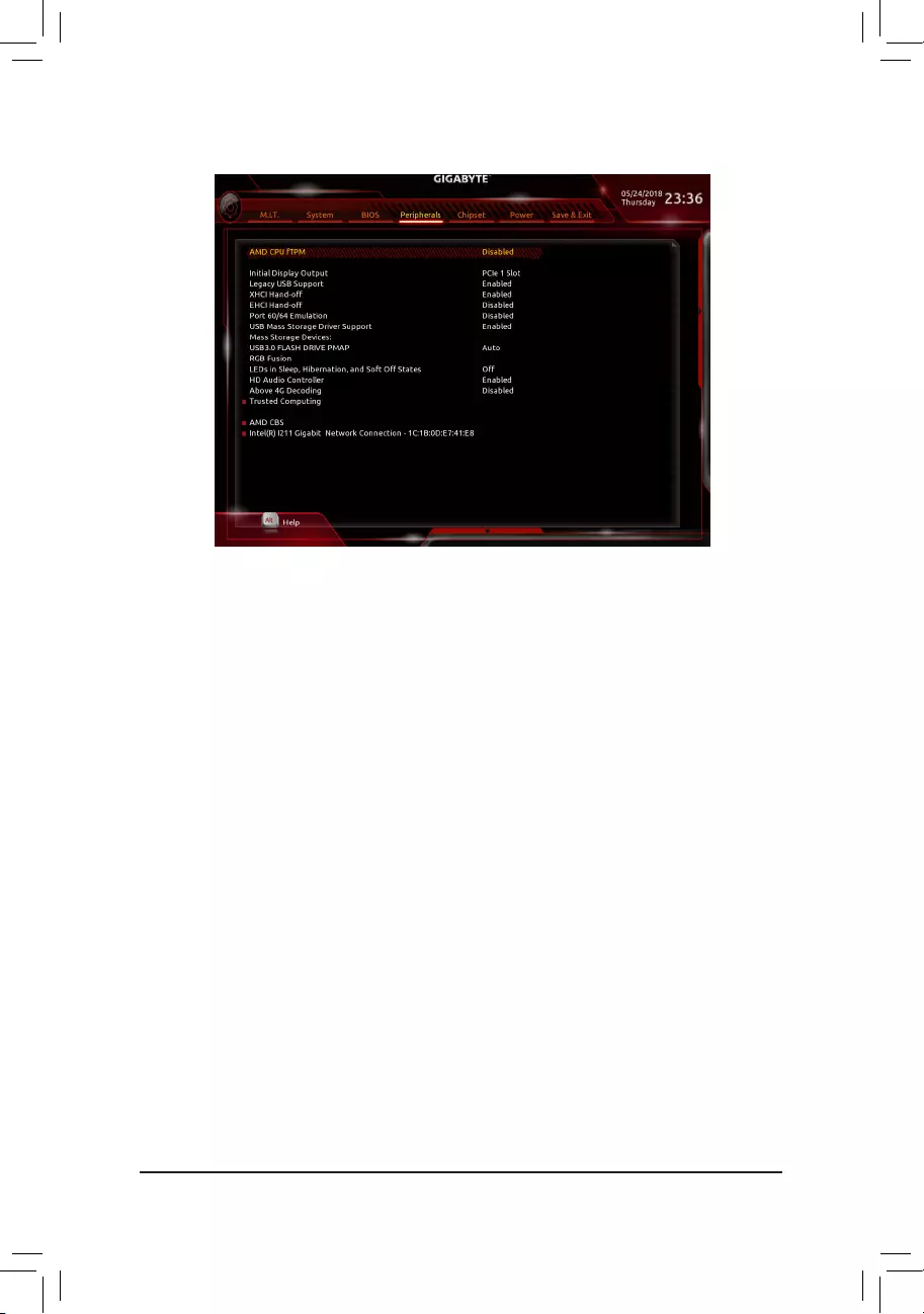
2-6 Peripherals
&AMD CPU fTPM
Enables or disables the TPM 2.0 function integrated in the AMD CPU. (Default: Disabled)
&Initial Display Output
SpeciestherstinitiationofthemonitordisplayfromtheinstalledPCIExpressgraphicscardortheonboard
graphics.
IGDVideo(Note) Setstheonboardgraphicsastherstdisplay.
PCIe1Slot SetsthegraphicscardonthePCIEX16slotastherstdisplay.(Default)
PCIe2Slot SetsthegraphicscardonthePCIEX4slotastherstdisplay.
PCIe3Slot SetsthegraphicscardonthePCIEX1_2slotastherstdisplay.
&Legacy USB Support
AllowsUSBkeyboard/mousetobeusedinMS-DOS.(Default:Enabled)
&XHCI Hand-off
Determineswhether toenable XHCI Hand-offfeature for anoperating systemwithout XHCI Hand-off
support. (Default: Enabled)
&EHCI Hand-off
Determineswhether toenable EHCI Hand-offfeature for anoperating systemwithout EHCI Hand-off
support. (Default: Disabled)
&Port 60/64 Emulation
EnablesordisablesemulationofI/Oports64hand60h.Thisshouldbeenabledforfulllegacysupport
forUSBkeyboards/miceinMS-DOSorinoperatingsystemthatdoesnotnativelysupportUSBdevices.
(Default: Disabled)
&USB Mass Storage Driver Support
EnablesordisablessupportforUSBstoragedevices.(Default:Enabled)
&Mass Storage Devices
DisplaysalistofconnectedUSBmassstoragedevices.ThisitemappearsonlywhenaUSBstoragedevice
is installed.
(Note) ThisitemispresentonlywhenyouinstallaCPUthatsupportsthisfeature.
-33-

&RGB Fusion
AllowsyoutosettheLEDlightingmodeforthemotherboard.
Off Disablesthisfunction.
PulseMode AllLEDssimultaneouslyfadeinandfadeout.
ColorCycle AllLEDssimultaneouslycyclethroughafullspectrumofcolors.
StaticMode AllLEDsemitasinglecolor.(Default)
FlashMode AllLEDssimultaneouslyashonandoff.
DoubleFlash AllLEDsashinaninterlacedpattern.
&LEDs in Sleep, Hibernation, and Soft Off States
AllowsyoutosetthelightingmodeofthemotherboardLEDsinsystemS3/S4/S5state.
Thisfeatureissupportedonlywitha5VdigitalLEDstrip.
Off DisablestheselectedlightingmodewhenthesystementersS3/S4/S5state.(Default)
On Enables the selected lighting mode when the system enters S3/S4/S5 state.
&HD Audio Controller
Enablesordisablestheonboardaudiofunction.(Default:Enabled)
If you wish to install a 3rd party add-in audio card instead of using the onboard audio, set this item to
Disabled.
&Above 4G Decoding
Enables or disables 64-bit capable devices to be decoded in above 4 GB address space (only if your system
supports 64-bit PCI decoding). Set to Enabled if more than one advanced graphics card are installed and
their drivers are not able to be launched when entering the operating system (because of the limited 4 GB
memoryaddressspace).(Default:Disabled)
`Trusted Computing
Enables or disables Trusted Platform Module (TPM).
`AMD CBS
Thissub-menuprovidesAMDCBS-relatedcongurationoptions.
`Intel(R) Gigabit Network Connection
Thissub-menuprovidesinformationonLANcongurationandrelatedcongurationoptions.
— 34 —
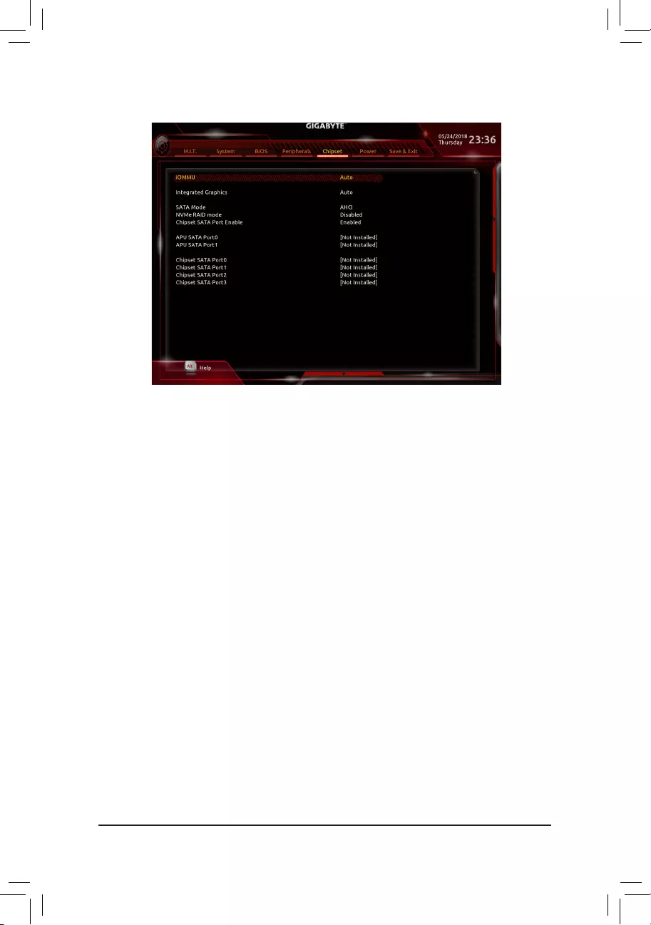
&IOMMU
EnablesordisablesAMDIOMMUsupport.(Default:Auto)
&Integrated Graphics (Note)
Enables or disables the onboard graphics function.
Auto The BIOS will automatically enable or disable the onboard graphics depending on the
graphicscardbeinginstalled.(Default)
Forces Enables the onboard graphics.
Disabled Disablestheonboardgraphics.
&UMA Mode (Note)
Specify the UMA mode.
Auto LetstheBIOSautomaticallycongurethissetting. (Default)
UMASpecied SetstheUMAFrameBufferSize.
UMA Auto Sets the display resolution.
ThisitemiscongurableonlywhenIntegrated Graphics is set to Forces.
&UMA Frame Buffer Size (Note)
Framebuffersizeisthetotalamountofsystemmemoryallocatedsolelyfortheonboardgraphicscontroller.
MS-DOS,forexample,willuseonlythismemoryfordisplay.Optionsare:Auto(default),64M~16G.
ThisitemiscongurableonlywhenUMA Mode is set to UMASpecied.
&Display Resolution (Note)
Allows you to set the display resolution. Options are: Auto (default), 1920×1080 and below, 2560×1600,
3840×2160.
ThisitemiscongurableonlywhenUMA Mode is set to UMA Auto.
2-7 Chipset
(Note) This item is present only when you install a CPU that supports this feature.
— 35 —

&SATA Mode
EnablesordisablesRAIDfortheintegratedSATAcontrollersorcongurestheSATAcontrollerstoAHCI
mode.
RAID EnablesRAIDfortheSATAcontroller.
AHCI CongurestheSATAcontrollerstoAHCImode.AdvancedHostControllerInterface
(AHCI)isaninterfacespecicationthatallowsthestoragedrivertoenableadvanced
SerialATAfeaturessuchasNativeCommandQueuingandhotplug.(Default)
&NVMe RAID mode (M2A_SOCKET and M2B_SOCKET Connectors)
AllowsyoutodeterminewhethertouseyourM.2NVMePCIeSSDstocongureRAID.(Default:Disabled)
&Chipset SATA Port Enable
EnablesordisablestheintegratedSATAcontroller(s).(Default:Enabled)
&APU SATA Port 0/1 (ASATA3 0, 1 Connectors)
DisplaystheinformationoftheconnectedSATAdevice(s).
&Chipset SATA Port 0/1/2/3 (SATA3 0, 1, 2, 3 Connectors)
DisplaystheinformationoftheconnectedSATAdevice(s).
— 36 —
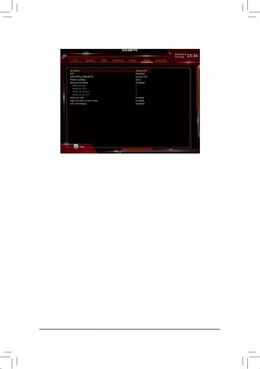
&AC BACK
DeterminesthestateofthesystemafterthereturnofpowerfromanACpowerloss.
Memory The system returns to its last known awake state upon the return of the AC power.
Always On The system is turned on upon the return of the AC power.
AlwaysOff ThesystemstaysoffuponthereturnoftheACpower.(Default)
&ErP
DetermineswhethertoletthesystemconsumeleastpowerinS5(shutdown)state.Note:Whenthisitem
is set to Enabled, the following functions will become unavailable: Resume by Alarm, PME event wake
up, power on by mouse, power on by keyboard, and wake on LAN.
&Soft-Off by PWR-BTTN
ConguresthewaytoturnoffthecomputerinMS-DOSmodeusingthepowerbutton.
Instant-Off Pressthepowerbuttonandthenthesystemwillbeturnedoffinstantly.(Default)
Delay4Sec. Pressandholdthepowerbuttonfor4secondstoturnoffthesystem.Ifthepower
button is pressed for less than 4 seconds, the system will enter suspend mode.
&Power Loading
Enables or disables dummy load. When the power supply is at low load, a self-protection will activate causing
it to shutdown or fail. If this occurs, please set to Enabled. AutoletstheBIOSautomaticallycongurethis
setting.(Default:Auto)
&Resume by Alarm
Determineswhethertopoweronthesystematadesiredtime.(Default:Disabled)
If enabled, set the date and time as following:
Wakeupday:Turnonthesystemataspecictimeoneachdayoronaspecicdayinamonth.
Wake up hour/minute/second: Set the time at which the system will be powered on automatically.
Note: When using this function, avoid inadequate shutdown from the operating system or removal of the
AC power, or the settings may not be effective.
&Wake on LAN
EnablesordisablesthewakeonLANfunction.(Default:Enabled)
2-8 Power
— 37 —

&High Precision Event Timer
EnablesordisablesHighPrecisionEventTimer(HPET)intheoperatingsystem.(Default:Enabled)
&CEC 2019 Ready
Allows you to select whether to allow the system to adjust power consumption when it is in shutdown, idle,
orstandbystateinordertocomplywiththeCEC(CaliforniaEnergyCommission)2019Standards.(Default:
Disabled)
— 38 —
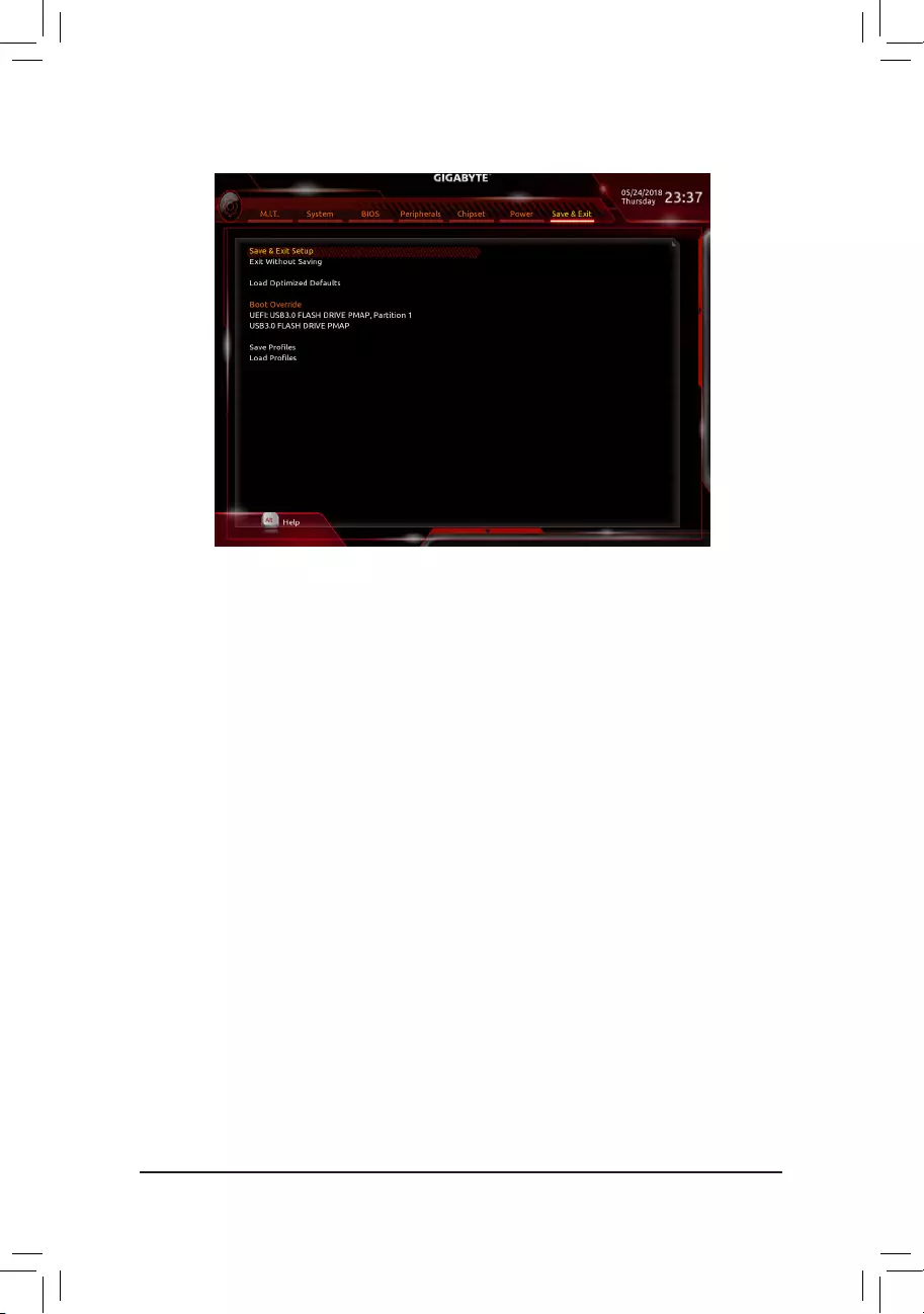
2-9 Save & Exit
&Save & Exit Setup
Press<Enter>onthisitemandselectYes. This saves the changes to the CMOS and exits the BIOS Setup
program. Select Noorpress<Esc>toreturntotheBIOSSetupMainMenu.
&Exit Without Saving
Press<Enter>onthisitemandselectYes. This exits the BIOS Setup without saving the changes made
in BIOS Setup to the CMOS. Select Noorpress<Esc>toreturntotheBIOSSetupMainMenu.
&Load Optimized Defaults
Press<Enter>onthisitemandselectYes to load the optimal BIOS default settings. The BIOS defaults
settingshelpthesystemtooperateinoptimumstate.AlwaysloadtheOptimizeddefaultsafterupdating
the BIOS or after clearing the CMOS values.
&Boot Override
Allowsyoutoselectadevicetobootimmediately.Press<Enter>onthedeviceyouselectandselectYes
toconrm.Yoursystemwillrestartautomaticallyandbootfromthatdevice.
&SaveProles
ThisfunctionallowsyoutosavethecurrentBIOSsettingstoaprole.Youcancreateupto8prolesand
saveasSetupProle1~SetupProle8.Press<Enter>tocomplete.OryoucanselectSelect File in
HDD/FDD/USBtosavetheproletoyourstoragedevice.
&LoadProles
If your system becomes unstable and you have loaded the BIOS default settings, you can use this function
toloadtheBIOSsettings fromaprolecreatedbefore,withoutthehasslesofreconguringtheBIOS
settings.Firstselecttheproleyouwishtoloadandthenpress<Enter>tocomplete.YoucanselectSelect
File in HDD/FDD/USBtoinputtheprolepreviouslycreatedfromyourstoragedeviceorloadtheprole
automatically created by the BIOS, such as reverting the BIOS settings to the last settings that worked
properly (last known good record).
— 39 —
Chapter 3 Appendix
3-1 ConguringaRAIDSet
Before you begin, please prepare the following items:
•AtleasttwoSATAharddrivesorSSDs(Note 1) (to ensure optimal performance, it is recommended that you
use two hard drives with identical model and capacity). (Note 2)
•Windows setup disk.
•Motherboard driver disk.
•A USB thumb drive.
ConguringtheOnboardSATAController
A. Installing SATA hard drive(s) in your computer
Installtheharddrives/SSDsintheSATA/M.2connectorsonthemotherboard.Thenconnectthepowerconnectors
from your power supply to the hard drives.
B.ConguringSATAcontrollermodeinBIOSSetup
MakesuretoconguretheSATAcontrollermodecorrectlyinsystemBIOSSetup.
Steps:
1. Turnonyourcomputerandpress<Delete>toenterBIOSSetupduringthePOST(Power-OnSelf-Test).
Under Chipset, ensure Chipset SATA Port Enable is enabled. Set SATA Mode to RAID. Then save the
settingsandrestartyourcomputer.(IfyouwanttouseNVMePCIeSSDstocongureRAID,makesureto
set NVMe RAID mode to Enabled.)
2. IfyouwanttocongureUEFIRAID,followthestepsin«C-1.»ToenterthelegacyRAIDROM,savethe
settings and exit BIOS Setup. Refer to «C-2» for more information.
The BIOS Setup menus described in this section may differ from the exact settings for your motherboard.
The actual BIOS Setup menu options you will see shall depend on the motherboard you have and
the BIOS version.
C-1.UEFIRAIDConguration
Steps:
1. In BIOS Setup, go to BIOS and set CSM Support to Disabled. Save the changes and exit BIOS Setup.
2. After the system reboot, enter BIOS Setup again. Then enter the Peripherals\RAIDXpert2Conguration
Utility sub-menu.
3. On the RAIDXpert2CongurationUtilityscreen,press<Enter>on Array Management to enter the Create
Array screen. Then, select a RAID level.RAIDlevelssupportedincludeRAID0(Stripe),RAID1(Mirror),
andRAID10(theselectionsavailabledependonthenumberoftheharddrivesbeinginstalled).Next,press
<Enter>onSelect Physical Disks to enter the Select Physical Disks screen.
4. On the Select Physical Disksscreen,selecttheharddrivestobeincludedintheRAIDarrayandsetthem
to Enabled. Next, use the down arrow key to move to Apply Changesandpress<Enter>.Thenreturnto
thepreviousscreenandsettheArraySize,ArraySizeUnit,ReadCachePolicyandWriteCachePolicy.
RAID Levels
RAID 0 RAID 1 RAID 10
Minimum Number of
HardDrives ≥2 2 4
Array Capacity Number of hard drives *
Sizeofthesmallestdrive
Sizeofthesmallestdrive (Number of hard drives/2) *
Sizeofthesmallestdrive
Fault Tolerance No Yes Yes
(Note1) AnM.2PCIeSSDcannotbeusedtosetupaRAIDseteitherwithanM.2SATASSDoraSATAharddrive.
(Note 2) Refer to «1-7 Internal Connectors,» for the installation notices for the M.2 and SATA connectors.
— 40 —
5. After setting the capacity, move to Create Arrayandpress<Enter>tobegin.
6. After completing, you’ll be brought back to the Array Management screen. Under Manage Array Properties
youcanseethenewRAIDvolumeandinformationonRAIDlevel,arrayname,arraycapacity,etc.
C-2.ConguringLegacyRAIDROM
EnterthelegacyRAIDBIOSsetuputilitytocongureaRAIDarray.Skipthisstepandproceedwiththeinstallation
ofWindowsoperatingsystemforanon-RAIDconguration.
Steps:
1. After the POST memory test begins and before the operating system boot begins, look for a message which
says«Press<Ctrl-F>toenterRAIDOptionROMUtility».Press<Ctrl>+<R>toentertheRAIDBIOSsetuputility.
2. Tocreateanewarray,press<Enter>ontheCreateArrayoption.
3. TheselectionbarwillmovetotheDiskssectionontherightofthescreen.Selecttheharddrivestobeincluded
intheRAIDarray.Usetheupordownarrowkeytoselectaharddriveandpress<Insert>.Theselectedhard
drivewillbeshowningreen.Tousealloftheharddrives,simplypress<A>toselectall.Thenpress<Enter>
and the selection bar will move to the User Input section on the left bottom of the screen.
4. First,selectaRAIDmodeandpress<Enter>.Theselectionsavailabledependonthenumberoftheharddrives
beinginstalled.Thenfollowtheon-screeninstructionstospecifythearraysize.YoucanselectAllavailable
spacetousethemaximumsizeallowedorusetheupordownarrowkeytoadjustthesizeandpress<Enter>.
5. Selectacachingmode.OptionsincludeRead/Write,ReadOnly,andNone.Thenpress<Enter>toproceed.
6. Finally,amessagewhichsays«ConrmCreationofArray»willappear.Press<C>toconrmor<Esc>to
return to the previous screen.
7. Whencompleted,youwillseethenewarrayonthemainscreen.ToexittheRAIDBIOSutility,press<Esc>
andthenpress<C>toconrm.
Installing the RAID/AHCI Driver and Operating System
With the correct BIOS settings, you are ready to install the operating system.
Installing the Operating System
AssomeoperatingsystemsalreadyincludeRAID/AHCIdriver,youdonotneedtoinstallseparateRAID/AHCI
driver during the Windows installation process. After the operating system is installed, we recommend that you
install all required drivers from the motherboard driver disk using «Xpress Install» to ensure system performance
andcompatibility.IftheoperatingsystemtobeinstalledrequiresthatyouprovideadditionalRAID/AHCIdriver
during the OS installation process, please refer to the steps below:
1. Copy the Hw10 folder under the \Boot folder in the driver disk to your USB thumb drive.
2. Boot from the Windows setup disk and perform standard OS installation steps. When the screen requesting
you to load the driver appears, select Browse.
3. Insert the USB thumb drive and then browse to the location of the driver. The location of the drivers is as
follows:
\Hw10\RAID\x64
4. Select AMD-RAID Bottom DevicerstandclickNexttoloadthedriver.ThenselectAMD-RAID Controller
and click Next to load the driver. Finally, continue the OS installation.
PleasevisitGIGABYTE’swebsitefordetailsonconguringaRAIDarray.
— 41 —
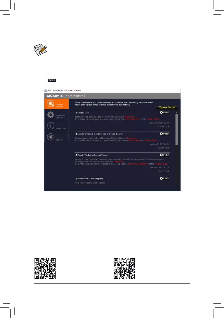
• Beforeinstallingthedrivers,rstinstalltheoperatingsystem.
• After installing the operating system, insert the motherboard driver disk into your optical drive. Click
on the message «Tap to choose what happens with this disc» on the top-right corner of the screen
and select «Run Run.exe.» (Or go to My Computer, double-click the optical drive and execute the
Run.exe program.)
3-2 Drivers Installation
«Xpress Install» will automatically scan your system and then list all of the drivers that are recommended to
install. You can click the Xpress Install button and «Xpress Install» will install all of the selected drivers. Or click
the arrow icon to individually install the drivers you need.
Please visit GIGABYTE’s website for
more software information.
Please visit GIGABYTE’s website for
more troubleshooting information.
— 42 —
Regulatory Statements
Regulatory Notices
This document must not be copied without our written permission, and the contents there of must not be imparted
toathirdpartynorbeusedforanyunauthorizedpurpose.
Contravention will be prosecuted. We believe that the information contained herein was accurate in all respects
at the time of printing. GIGABYTE cannot, however, assume any responsibility for errors or omissions in this text.
Also note that the information in this document is subject to change without notice and should not be construed
as a commitment by GIGABYTE.
Our Commitment to Preserving the Environment
Inaddition to high-efciency performance, allGIGABYTE motherboardsfulll European Unionregulations
forRoHS(RestrictionofCertainHazardousSubstancesinElectricalandElectronicEquipment)andWEEE
(Waste Electrical and Electronic Equipment) environmental directives, as well as most major worldwide safety
requirements.Topreventreleasesofharmfulsubstancesintotheenvironmentandtomaximizetheuseofour
natural resources, GIGABYTE provides the following information on how you can responsibly recycle or reuse
most of the materials in your «end of life» product.
Restriction of Hazardous Substances (RoHS) Directive Statement
GIGABYTEproductshavenotintendedtoaddandsafefromhazardoussubstances(Cd,Pb,Hg,Cr+6,PBDE
and PBB). The parts and components have been carefully selected to meet RoHS requirement. Moreover, we at
GIGABYTE are continuing our efforts to develop products that do not use internationally banned toxic chemicals.
Waste Electrical & Electronic Equipment (WEEE) Directive Statement
GIGABYTEwillfulllthenationallawsasinterpretedfromthe2002/96/ECWEEE(WasteElectricalandElectronic
Equipment)directive.TheWEEEDirectivespeciesthetreatment,collection,recyclinganddisposalofelectric
andelectronicdevicesandtheircomponents.UndertheDirective,usedequipmentmustbemarked,collected
separately, and disposed of properly.
WEEE Symbol Statement
The symbol shown below is on the product or on its packaging, which indicates that this product
must not be disposed of with other waste. Instead, the device should be taken to the waste collection
centers for activation of the treatment, collection, recycling and disposal procedure. The separate
collection and recycling of your waste equipment at the time of disposal will help to conserve natural
resources and ensure that it is recycled in a manner that protects human health and the environment.
For more information about where you can drop off your waste equipment for recycling, please contact your
localgovernmentofce,yourhouseholdwastedisposalserviceorwhereyoupurchasedtheproductfordetails
of environmentally safe recycling.
When your electrical or electronic equipment is no longer useful to you, «take it back» to your local or regional
waste collection administration for recycling.
If you need further assistance in recycling, reusing in your «end of life» product, you may contact us at the
Customer Care number listed in your product’s user’s manual and we will be glad to help you with your effort.
Finally, we suggest that you practice other environmentally friendly actions by understanding and using the
energy-saving features of this product (where applicable), recycling the inner and outer packaging (including
shipping containers) this product was delivered in, and by disposing of or recycling used batteries properly.
With your help, we can reduce the amount of natural resources needed to produce electrical and electronic
equipment,minimizetheuseoflandllsforthedisposalof«endoflife»products,andgenerallyimproveour
qualityoflifebyensuringthatpotentiallyhazardoussubstancesarenotreleasedintotheenvironmentandare
disposed of properly.
— 43 —

FCC Notice (U.S.A. Only)
Operation is subject to the following two conditions: (1) this device may not cause harmful interference, and (2)
this device must accept any interference received, including interference that may cause undesired operation.
WARNING: This equipment has been tested and found to comply with the limits for a Class B digital device,
pursuant to Part 15 of the FCC Rules. These limits are designed to provide reasonable protection against harmful
interference in a residential installation.
This equipment generates and radiates radio frequency energy and, if not installed and used in accordance
with the instructions, may cause harmful interference to radio communications.
However, there is no guarantee that interference will not occur in a particular installation. If this equipment does
cause harmful interference to radio or television reception, which can be determined by turning the equipment
off and on, the user is encouraged to try to correct the interference by one or more of the following measures:
•Reorient or relocate the receiving antenna.
•Increase the separation between the equipment and receiver.
•Connect the equipment into an outlet on a circuit different from that to which the receiver is connected.
•Consult a dealer or experienced TV/radio technician for help.
TheusermayndthefollowingbookletpreparedbytheFederalCommunicationsCommissionhelpful:
The Interference Handbook.
ThisbookletisavailablefromtheU.S.GovernmentPrintingOfce,Washington,D.C.20402.StockNo.004-
000-00345-4
Notice for 5GHz
Operationsinthe5.15-5.25GHzbandarerestrictedtoindoorusageonly.(For5GHzonly)
RF exposure statement
The product comply with the FCC portable RF exposure limit set forth for an uncontrolled environment and are
safe for intended operation as described in this manual. The further RF exposure reduction can be achieved if
the product can be kept as far as possible from the user body or set the device to lower output power if such
function is available.
CAUTION:
Themanufacturerisnotresponsibleforanyinterferencecausedbyunauthorized
modicationsand/oruseofunauthorizedantennas.
Suchchangesand/ormodicationsnotexpresslyapprovedbythepartyresponsiblefor
compliance of this device could void the user’s authority to operate the equipment.
— 44 —

Canada-Industry Canada (IC):
This device complies with Canadian RSS-210.
This device complies with Industry Canada license-exempt RSS standard(s). Operation is subject to the
following two conditions:
(1) this device may not cause interference, and
(2) this device must accept any interference, including interference that may cause undesired operation of
the device.
Ce dispositif est conforme à la norme CNR-210 d’Industrie Canada applicable aux appareils radio exempts de
licence. Son fonctionnement est sujet aux deux conditions suivantes:
(1) le dispositif ne doit pas produire de brouillage préjudiciable, et
(2) ce dispositif doit accepter tout brouillage reçu, y compris un brouillage susceptible de provoquer un
fonctionnement indésirable.
Notice for 5GHz:
Caution :
(i)thedeviceforoperationintheband5150-5250MHzisonlyforindoorusetoreducethepotentialforharmful
interference to co-channel mobile satellite systems;
(ii)themaximumantennagainpermittedfordevicesinthebands5250-5350MHzand5470-5725MHzshall
comply with the e.i.r.p. limit; and
(iii)themaximumantennagainpermittedfordevicesintheband5725-5825MHzshallcomplywiththee.i.r.p.
limitsspeciedforpoint-to-pointandnonpoint-to-pointoperationasappropriate.
(iv) Users should also be advised that high-power radars are allocated as primary users (i.e. priority users)
ofthebands5250-5350MHzand5650-5850MHzandthattheseradarscouldcauseinterferenceand/or
damage to LE-LAN devices.
Avertissement:
Le guide d’utilisation des dispositifs pour réseaux locaux doit inclure des instructions précises sur les restrictions
susmentionnées, notamment :
(i)lesdispositifsfonctionnantdanslabande5150-5250MHzsontréservésuniquementpouruneutilisationà
l’intérieuranderéduirelesrisquesdebrouillagepréjudiciableauxsystèmesdesatellitesmobilesutilisant
les mêmes canaux;
(ii)legainmaximald’antennepermispourlesdispositifsutilisantlesbandes5250-5350MHzet5470-5725
MHzdoitseconformeràlalimitedep.i.r.e.;
(iii)legainmaximald’antennepermis(pourlesdispositifsutilisantlabande5725-5825MHz)doitseconformer
àlalimitedep.i.r.e.spéciéepourl’exploitationpointàpointetnonpointàpoint,selonlecas.
(iv)Deplus,lesutilisateursdevraientaussiêtreavisésquelesutilisateursderadarsdehautepuissancesont
désignésutilisateursprincipaux(c.-à-d.,qu’ilsontlapriorité)pourlesbandes5250-5350MHzet5650-5
850MHzetquecesradarspourraientcauserdubrouillageet/oudesdommagesauxdispositifsLAN-EL.
Radiation Exposure Statement:
The product comply with the Canada portable RF exposure limit set forth for an uncontrolled environment and
are safe for intended operation as described in this manual. The further RF exposure reduction can be achieved
if the product can be kept as far as possible from the user body or set the device to lower output power if such
function is available.
— 45 —

European Community Radio Equipment Directive (RED) Compliance Statement:
ThisequipmentcomplieswithalltherequirementsandotherrelevantprovisionsofRadioEquipmentDirective
2014/53/EU.
ThisequipmentissuitableforhomeandofceuseinalltheEuropeanCommunityMemberStatesandEFTA
Member States.
Thelowband5.15-5.35GHzisforindooruseonly.
Restrictions d’utilisation en France:
Pour la France métropolitaine
2.400-2.4835GHz(Canaux1à13)autoriséenusageintérieur
2.400-2.454GHz(canaux1à7)autoriséenusageextérieur
Pour la Guyane et la Réunion
2.400-2.4835GHz(Canaux1à13)autoriséenusageintérieur
2.420-2.4835GHz(canaux5à13)autoriséenusageextérieur
Notice for Italy:
The use of these equipments is regulated by:
1. D.L.gs1.8.2003,n.259,article104(activitysubjecttogeneralauthorization)foroutdooruseandarticle
105 (free use) for indoor use, in both cases for private use.
2. D.M.28.5.03,forsupplytopublicofRLANaccesstonetworksandtelecomservices.L’usodegliapparati
èregolamentatoda:
1. D.L.gs1.8.2003,n.259,articoli104(attivitàsoggetteadautorizzazionegenerale)seutilizzatialdifuori
delpropriofondoe105(liberouso)seutilizzatientroilpropriofondo,inentrambiicasiperusoprivate.
2. D.M.28.5.03,perlafornituraalpubblicodell’accessoR-LANalleretieaiserviziditelecomunicazioni.
Taiwan NCC Wireless Statements / 無線設備警告聲明:
低功率電波輻射性電機管理辦法
第十二條: 經型式認證合格之低功率射頻電機,非經許可,公司、商號或使用者均不得擅自變更頻
率、加大功率或變更原設計之特性及功能。
第十四條: 低功率射頻電機之使用不得影響飛航安全及干擾合法通信;經發現有干擾現象時,應立
即停用,並改善至無干擾時方得繼續使用。前項合法通信,指依電信法規定作業之無線
電通信。低功率射頻電機須忍受合法通信或工業、科學及醫療用電波輻射性電機設備之
干擾。
在5.25-5.35秭赫頻帶內操作之無線資訊傳輸設備,限於室內使用。
Korea KCC NCC Wireless Statement:
5,25GHz-5,35GHz대역을 사용하는 무선 장치는 실내에서만 사용하도록 제한됩니다。
Japan Wireless Statement:
5.15GHz帯~5.35GHz帯: 屋内のみの使用。
— 46 —

— 47 —
Contact Us
GIGA-BYTE TECHNOLOGY CO., LTD.
Address:No.6,BaoqiangRd.,XindianDist.,NewTaipeiCity231,Taiwan
TEL: +886-2-8912-4000, FAX: +886-2-8912-4005
Tech. and Non-Tech. Support (Sales/Marketing) : https://esupport.gigabyte.com
WEB address (English): https://www.gigabyte.com
WEB address (Chinese): https://www.gigabyte.com/tw
•GIGABYTE eSupport
To submit a technical or non-technical (Sales/Marketing) question, please link to:
https://esupport.gigabyte.com
— 48 —
Мы уже рассмотрели несколько новых моделей плат компании Asus на чипсете AMD B450. А сегодня в фокусе нашего внимание новинка компании Gigabyte: плата B450 Aorus Pro. Напомним, что под брендом Aorus компания производит игровые решения.
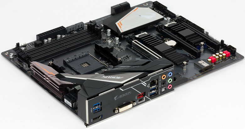
Комплектация и упаковка
Плата B450 Aorus Pro поставляется в компактной по размерам картонной коробке, типичной для плат игровой серии Aorus.
Комплект поставки включает руководство пользователя, два SATA-кабеля (все разъемы с защелками, один кабель имеет угловой разъем с одной стороны), DVD-диск с драйверами, а также стикер Aorus на корпус ПК.
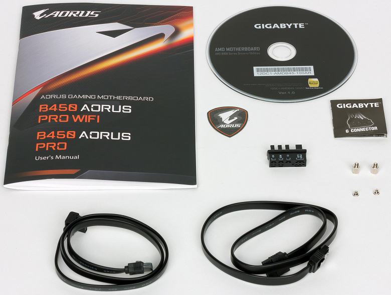
Конфигурация и особенности платы
Сводная таблица характеристик платы B450 Aorus Pro приведена ниже, а далее по тексту мы рассмотрим все ее особенности и функциональные возможности.
| Поддерживаемые процессоры | AMD Ryzen 2/Ryzen/Ryzen with Vega Graphics |
|---|---|
| Процессорный разъем | AM4 |
| Чипсет | AMD B450 |
| Память | 4 × DDR4 (до 64 ГБ) |
| Аудиоподсистема | Realtek ALC1220 |
| Сетевой контроллер | 1 × Intel i211-АТ |
| Слоты расширения | 1 × PCI Express 3.0 x16/x8 1 × PCI Express 2.0 x4 (в форм-факторе PCI Express x16) 1 × PCI Express 2.0 x1 (в форм-факторе PCI Express x16) 1 × PCI Express 2.0 x1 2 × M.2 |
| SATA-разъемы | 6 × SATA 6 Гбит/с |
| USB-порты | 6 × USB 3.0 (Type A) 2 × USB 3.1 (Type С, Type A) 4 × USB 2.0 |
| Разъемы на задней панели | 1 × USB 3.1 Type A 1 × USB 3.1 Type C 4 × USB 3.0 Type A 1 × RJ-45 1 × HDMI 2.0 1 × DVI-D 5 аудиоразъемов типа миниджек 1 × S/PDIF |
| Внутренние разъемы | 24-контактный разъем питания ATX 8-контактный разъем питания ATX 12 В 6 × SATA 6 Гбит/с 2 × M.2 5 разъемов для подключения 4-контактных вентиляторов 1 разъем для подключения портов USB 3.0 2 разъема для подключения портов USB 2.0 2 разъема для подключения обычной RGB-ленты 12 В 2 разъема для подключения адресуемой RGB-ленты |
| Форм-фактор | ATX (305×244 мм) |
| Средняя цена |
узнать цены |
| Розничные предложения |
узнать цену |
Форм-фактор
Плата B450 Aorus Pro выполнена в форм-факторе ATX (305×244 мм), для ее монтажа в корпус предусмотрены стандартные девять отверстий.
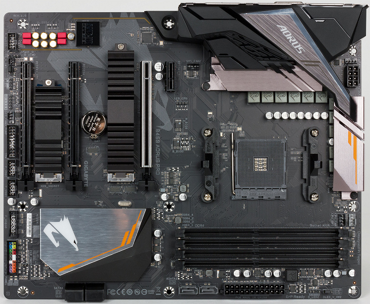
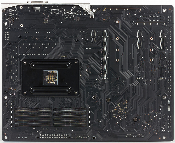
Чипсет и процессорный разъем
Плата основана на чипсете AMD B450 и поддерживает процессоры семейства AMD Ryzen с разъемом AM4 (Ryzen 2/Ryzen/Ryzen with Radeon Vega Graphics).
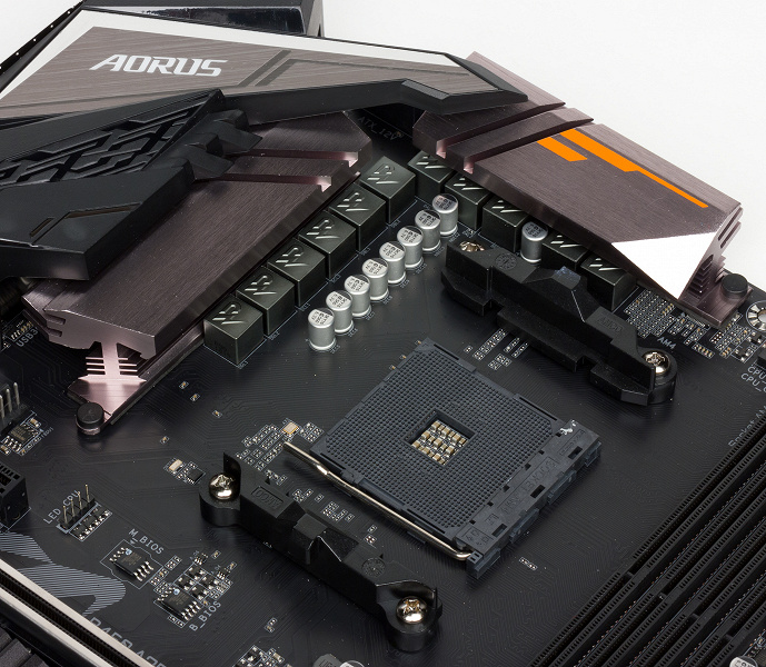
Память
Для установки модулей памяти на плате B450 Aorus Pro предусмотрено четыре DIMM-слота. Поддерживается небуферизованная память DDR4 (non-EСС), а максимальный ее объем составляет 64 ГБ (при использовании модулей емкостью по 16 ГБ).
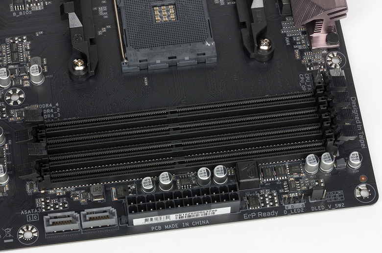
Согласно спецификации, максимальная тактовая частота памяти составляет 2999 МГц, однако в настройках UEFI BIOS можно задать частоту памяти до 4200 МГц.
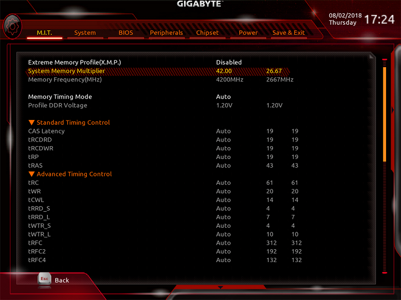
Слоты расширения
Для установки видеокарт, плат расширения и накопителей на плате имеется три слота с форм-фактором PCI Express x16, один слот PCI Express 2.0 x1, а также два разъема M.2.
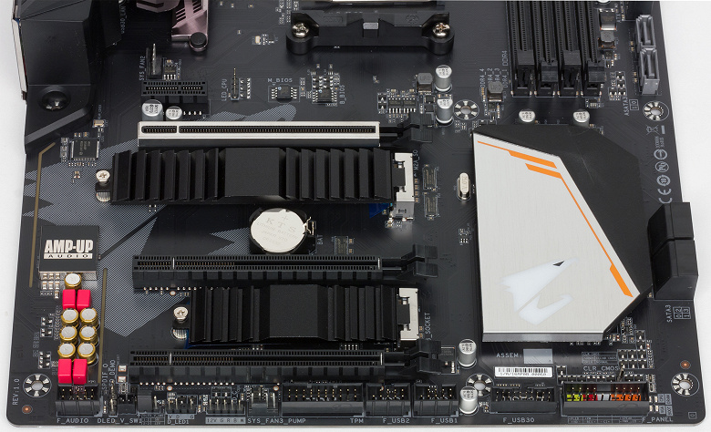
Первый (если считать от процессорного разъема) слот (PCIEX16) с форм-фактором PCI Express x16 реализован на базе 16 или 8 (в зависимости от процессора) процессорных линий PCIe 3.0. То есть это слот PCI Express 3.0 x16/x8. Второй слот (PCIEX4) с форм-фактором PCI Express x16 реализован на базе четырех чипсетных линий PCIe, причем версии 2.0. То есть это слот PCI Express 2.0 x4. Третий слот (PCIEX1_2) с форм-фактором PCI Express x16 реализован на базе одной чипсетной линии PCIe 2.0. То есть это слот PCI Express 2.0 x1 в форм-факторе PCI Express x16.
Слот PCI Express 2.0 x1 (PCIEX1_1) также реализован на базе чипсетной линии PCIe 2.0.
С разъемами M.2, предназначенными для установки накопителей, ситуация следующая. Один разъем (M2A) поддерживает накопители типоразмера 2242/2260/2280/22110 с интерфейсами PCIe 3.0 x4/x2 и SATA. Второй разъем M2B поддерживает накопители типоразмера 2242/2260/2280, только с интерфейсом PCIe 3.0 x2.
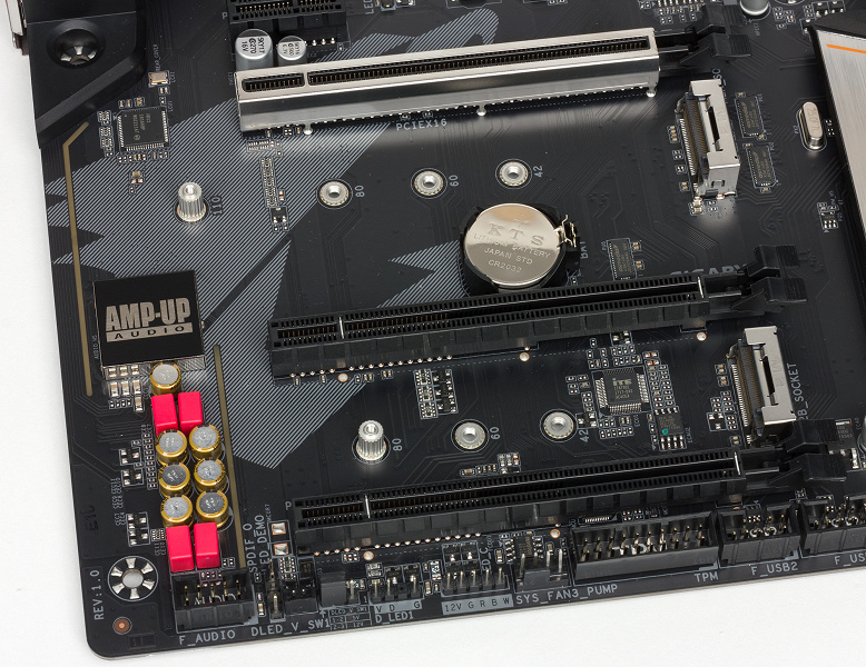
Видеоразъемы
На плате B450 Aorus Pro имеются видеовыходы HDMI 2.0 (4096×2160 @60 Гц) и DVI-D (1920×1080 @60 Гц), которые могут использоваться при установке процессоров AMD с графическим ядром.
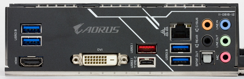
SATA-порты
Для подключения накопителей или оптических приводов на плате предусмотрено шесть портов SATA 6 Гбит/с, четыре из которых реализованы на базе интегрированного в чипсет AMD B450 контроллера. Еще два SATA-порта (ASATA3 0/1) реализованы через процессор.
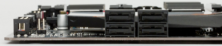
Разъемы USB
Для подключения всевозможных периферийных устройств на плате предусмотрено два порта USB 3.1, шесть портов USB 3.0 и четыре порта USB 2.0
Четыре порта USB 3.0, выведенные на заднюю панель платы, реализованы через процессор. Все эти порты имеют разъем Type-A.
Остальные порты USB реализованы через чипсет B450. Два порта USB 3.1 (Type-A и Type-С) выведены на заднюю панель платы, а для подключения еще двух портов USB 3.0 и четырех портов USB 2.0 имеются соответствующие разъемы.
Сетевой интерфейс
Для подключения к сети на плате имеется гигабитный сетевой контроллер Intel i211-AT, задействующий для подключения чипсетный порт PCIe 2.0.
Как это работает
Напомним, что есть два типа процессоров AMD Ryzen: с графикой и без. У процессоров с графикой имеется только 8 линий PCIe 3.0, которые предназначены для слота PCI Express 3.0 x8, а у процессоров без графики имеется 16 линий PCIe 3.0, которые могут группироваться в один порт x16 или в два порта x8 и предназначены для слотов PCI Express 3.0 x16/x8. Помимо этого в процессорах AMD Ryzen есть еще четыре высокоскоростных порта ввода/вывода. Два из них — PCIe 3.0, а еще два могут конфигурироваться либо как PCIe 3.0, либо как SATA 6 Гбит/с. Есть в процессоре и контроллер USB 3.0 на четыре порта.
Сам чипсет AMD B450 обеспечивает шесть портов PCIe 2.0, четыре порта SATA 6 Гбит/с, а также два порта USB 3.1, два порта USB 3.0 и шесть портов USB 2.0. Кроме того, чипсет поддерживает возможность создания одного разъема SATA Express (для него есть две линии PCIe 3.0).
А теперь посмотрим, как возможности чипсета AMD B450 и процессоров AMD Ryzen реализованы в варианте платы B450 Aorus Pro.
Итак, через процессор на плате реализованы слот PCI Express 3.0 x16/x8, один разъем M.2 (M2A), два порта SATA (ASATA3 0/1) и четыре порта USB 3.0. Через чипсет AMD B450 реализованы слот PCI Express 2.0 x4 (в форм-факторе PCI Express x16), слот PCI Express 2.0 x1 (в форм-факторе PCI Express x16), слот PCI Express 2.0 x1, разъем M2B, два порта USB 3.0, два порта USB 3.1, четыре порта USB 2.0, сетевой контроллер Intel i211-AT, четыре порта SATA 6 Гбит/с. Понятно, что при таком количестве слотов, разъемов и портов что-то с чем-то должно разделяться.
Начнем с процессоров AMD Ryzen без графики. У них имеется 20 (16+4) линий PCIe 3.0, из которых 16 линий используются для слота PCI Express 3.0 x16 (PCIEX16). Еще четыре высокоскоростных порта PCIe 3.0 процессора используются для реализации разъема M2A, который поддерживает накопители с интерфейсом PCIe 3.0 x4/x2 и SATA, а также двух портов SATA 6 Гбит/с (ASATA3 0/1). Режимы работы разъема M2A и портов ASATA3 0/1 следующие. Если в разъем M2A устанавливается SATA-накопитель, то порт ASATA3 1 будет недоступен. Если в разъем M2A устанавливается PCIe-накопитель, то недоступны будут оба порта ASATA3 0/1. Если же разъем M2A не используется, то оба порта ASATA3 0/1 доступны.
В случае, когда на плату устанавливается процессор AMD Ryzen с графикой, меняется только режим работы слота PCIEX16: он работает в режиме PCI Express 3.0 x8.
Теперь разберемся с чипсетом. Тут уже неважно, какой именно установлен процессор (с графикой или без). Как известно, у чипсета AMD B450 только шесть портов PCIe 2.0. На базе этих портов реализованы слот PCI Express 2.0 x4, два слота PCI Express 2.0 x1 (один из них — в форм-факторе PCI Express x16) и сетевой контроллер Intel i211-AT. И фокус тут в том, что слот PCI Express 2.0 x4 (PCIEX4) разделяется с двумя слотами PCI Express 2.0 x1 (PCIEX1_1 и PCIEX1_2). То есть если слоты PCIEX1_1 и PCIEX1_2 доступны, то слот PCIEX4 работает в режиме x2, а если слот PCIEX4 используется в режиме x4, то слоты PCIEX1_1 и PCIEX1_2 недоступны. При таком разделении количества линий PCIe 2.0 чипсета AMD B450 будет хватать для реализации слотов и сетевого контроллера.
Осталось разобраться лишь с разъемом M2B, который поддерживает накопители с интерфейсом PCIe 3.0 x2. Напомним, что чипсет AMD B450 поддерживает возможность создания разъема SATA Express. Сам разъем уже умер, на новых материнских платах его не реализуют, однако для того чтобы этот разъем все-таки можно было реализовать, в чипсете предусмотрены две линии PCIe 3.0 и два порта SATA 6 Гбит/с из числа четырех поддерживаемых чипсетом. Вот эти две линии PCIe 3.0 как раз и можно использовать для реализации разъема M2B, который работает только в режиме PCIe 3.0 x2. Однако этот разъем будет разделяться в двумя портами SATA (SATA3 2/3).
Блок-схема платы B450 Aorus Pro приведена далее.
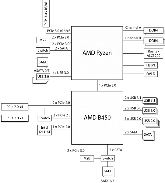
Дополнительные особенности
Количество дополнительных особенностей у платы B450 Aorus Pro минимально, что типично для решений на базе чипсета AMD B450. Напомним, что платы на данном чипсете не относятся к топовым решениям, а потому здесь нет ни кнопок, ни индикатора POST-кодов.
Можно отметить лишь наличие двух четырехконтактных (12V, G, R, B) разъемов для подключения стандартных RGB-лент типа 5050 с максимальной длиной до 2 м, а также двух трехконтактных (V,D,G) разъемов для подключения адресуемых светодиодных лент длиной до 5 м и с максимальным количеством светодиодов до 300. Эти разъемы поддерживают подключение лент с питанием 5 В и 12 В, а для выбора нужного напряжения каждый разъем дополнен двухпозиционными переключателями с использованием перемычек.
Есть на этой плате и настраиваемая светодиодная RGB-подсветка. Подсвечиваются чипсет (светится логотип Aorus) и надпись Aorus на кожухе задней панели разъемов.
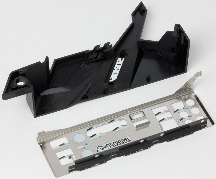
Кроме того, подсвечивается надпись Aorus на заглушке панели разъемов, а также граница зоны аудиотракта с обратной стороны платы.
Настройку подсветки можно производить через UEFI BIOS или с использованием фирменной утилиты Gigabyte. Можно выбирать цвет подсветки, а также различные цветовые эффекты.
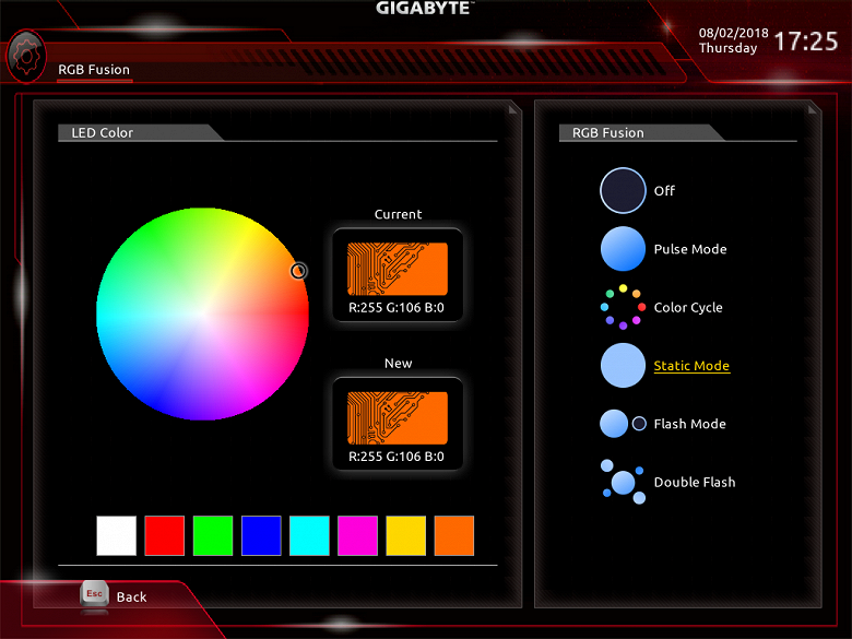
Система питания
Как и большинство плат, модель B450 Aorus Pro имеет 24-контактный и 8-контактный разъемы для подключения блока питания.
Регулятор напряжения питания процессора в данном случае 11-канальный (8+3) и основан на PWM-контроллере Intersil ISL95712. Данный контроллер обеспечивает 4 фазы для ядер процессора и 3 фазы для подсистемы ввода/вывода процессора.
В каждом канале питания используются полевые транзисторы (MOSFET) 4C06N и 4C10N компании On Semiconductor.
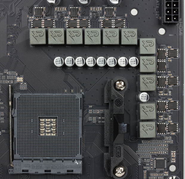
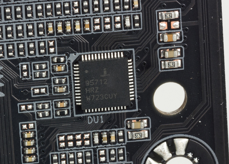
Система охлаждения
Система охлаждения платы состоит из пяти радиаторов. Два радиатора расположены по смежным сторонам процессорного разъема и предназначены для отвода тепла от элементов регулятора напряжения питания процессора. Еще один радиатор охлаждает чипсет. Есть и два отдельных радиатора для накопителей, устанавливаемых в разъемы M.2.
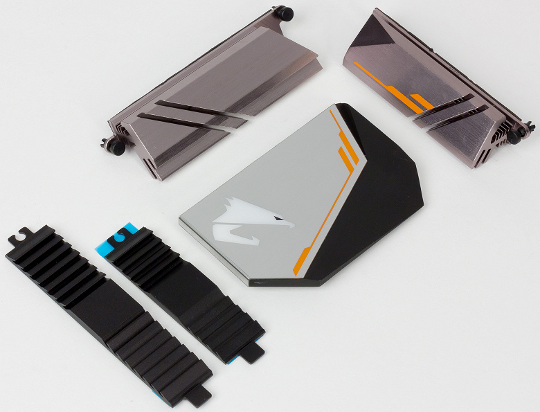
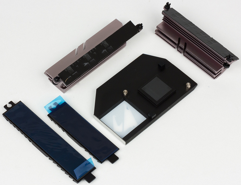
Помимо этого, для создания эффективной системы теплоотвода на плате предусмотрено пять четырехконтактных разъемов для подключения вентиляторов. Один из этих разъемов ориентирован на подключения СВО.
Аудиоподсистема
Аудиоподсистема платы основана на HDA-аудиокодеке Realtek ALC1220. Все элементы аудиотракта выделены в отдельную зону на PCB, а сам кодек закрыт металлическим кожухом.
Для тестирования выходного звукового тракта, предназначенного для подключения наушников или внешней акустики, мы использовали внешнюю звуковую карту Creative E-MU 0204 USB в сочетании с утилитой RightMark Audio Analyzer 6.3.0. Тестирование проводилось для режима стерео, 24-бит/44,1 кГц. По результатам тестирования аудиотракт на плате получил оценку «Очень хорошо».
Результаты тестирования в RightMark Audio Analyzer 6.3.0
Итого
B450 Aorus Pro — типичный вариант платы на чипсете AMD B450. Здесь нет никаких излишних наворотов, но функциональные возможности чипсета используются в полной мере. Для тех, кому надо немного больше, Gigabyte выпускает модификацию этой модели с предустановленным контроллером Wi-Fi.
Такую плату оптимально использовать для универсальных и не очень дорогих домашних ПК, на которых можно и поработать, и поиграть (если установить дискретную видеокарту). Еще раз отметим, что это не топовый вариант платы, но, тем не менее, если использовать производительный процессор (например, серии AMD Ryzen 7), то в сочетании с производительной дискретной видеокартой и SSD-накопителем можно получить очень мощный компьютер, который справится с любыми ресурсоемкими пользовательскими приложениями.
На момент публикации обзора розничная стоимость платы B450 Aorus Pro составляла примерно 9000 рублей. Для плат на основе чипсета AMD B450 это средняя стоимость.
В заключение предлагаем посмотреть наш видеообзор материнской платы Gigabyte B450 Aorus Pro:
Наш видеообзор материнской платы Gigabyte B450 Aorus Pro можно также посмотреть на iXBT.Video
To reduce the impacts on global warming, the packaging materials of this product
are recyclable and reusable. GIGABYTE works with you to protect the environment.
For more product details, please visit GIGABYTE’s website.
B450 AORUS PROB450 AORUS PRO WIFI
B450 AORUS PRO WIFI
B450 AORUS PRO
User’s Manual
Rev. 1001
12ME-B45ASPW-1001R
Wireless Module Country Approvals:
Jun. 11, 2018
Motherboard
B450 AORUS PRO WIFI
Motherboard
B450 AORUS PRO WIFI
Jun. 11, 2018
Copyright
© 2018 GIGA-BYTE TECHNOLOGY CO., LTD. All rights reserved.
The trademarks mentioned in this manual are legally registered to their respective owners.
Disclaimer
Information in this manual is protected by copyright laws and is the property of GIGABYTE.
Changes to the specications and features in this manual may be made by GIGABYTE without prior notice.
No part of this manual may be reproduced, copied, translated, transmitted, or published in any form or
by any means without GIGABYTE’s prior written permission.
In order to assist in the use of this product, carefully read the User’s Manual.
For product-related information, check on our website at: https://www.gigabyte.com
Identifying Your Motherboard Revision
The revision number on your motherboard looks like this: «REV: X.X.» For example, «REV: 1.0″ means
the revision of the motherboard is 1.0. Check your motherboard revision before updating motherboard
BIOS, drivers, or when looking for technical information.
Example:
Motherboard
B450 AORUS PRO
Jun. 11, 2018
Jun. 11, 2018
Motherboard
B450 AORUS PRO
— 4 —
Table of Contents
B450 AORUS PRO (WIFI) Motherboard Layout ……………………………………………………..5
Chapter 1 Hardware Installation ………………………………………………………………………….6
1-1 Installation Precautions ………………………………………………………………………… 6
1-2 ProductSpecications ………………………………………………………………………….. 7
1-3 Installing the CPU ……………………………………………………………………………… 10
1-4 Installing the Memory …………………………………………………………………………. 10
1-5 Installing an Expansion Card ………………………………………………………………. 11
1-6 Back Panel Connectors ………………………………………………………………………. 11
1-7 Internal Connectors ……………………………………………………………………………. 13
Chapter 2 BIOS Setup ……………………………………………………………………………………..23
2-1 Startup Screen ………………………………………………………………………………….. 23
2-2 The Main Menu …………………………………………………………………………………. 24
2-3 M.I.T. ……………………………………………………………………………………………….. 25
2-4 System …………………………………………………………………………………………….. 29
2-5 BIOS ………………………………………………………………………………………………… 30
2-6 Peripherals ……………………………………………………………………………………….. 33
2-7 Chipset …………………………………………………………………………………………….. 35
2-8 Power ………………………………………………………………………………………………. 37
2-9 Save & Exit ……………………………………………………………………………………….. 39
Chapter 3 Appendix …………………………………………………………………………………………40
3-1 ConguringaRAIDSet ………………………………………………………………………. 40
3-2 DriversInstallation ……………………………………………………………………………… 42
Regulatory Statements …………………………………………………………………………………. 43
Contact Us …………………………………………………………………………………………………. 48
— 5 —
B450 AORUS PRO (WIFI) Motherboard Layout
* The box contents above are for reference only and the actual items shall depend on the product package you obtain.
The box contents are subject to change without notice.
Box Contents
5B450 AORUS PRO WIFI or B450 AORUS PRO motherboard
5Two SATA cables 5M.2 screw(s)/M.2 standoff(s)
5Motherboard driver disk 5One G Connector
5User’s Manual 5One Wi-Fi antenna (Note)
(Note) Only for the B450 AORUS PRO WIFI.
CPU DRAM
VGA BOOT
Socket AM4
AMDB450
R_USB30 CPU_FAN
ATX_12V
ATX
F_AUDIO
AUDIO
B_BIOS
PCIEX4
DDR4_2
DDR4_1
DDR4_4
DDR4_3
BAT
F_PANEL
PCIEX1_2
CLR_CMOS
CODEC
M_BIOS
PCIEX1_1
PCIEX16
SPDIF_O
B450 AORUS PRO (WIFI)
DVI
TYPEC
HDMI
USB30_LAN
SATA3
iTE®
Super I/O
F_USB1
LED_C
SYS_FAN2
TPM
M2A_SOCKET
Intel®
GbE LAN
0 2
1 3
F_USB30
42
6080
110
CPU_OPT
LED_CPU
M2_WIFI (Note)
SYS_FAN1
42
6080
M2B_SOCKET
F_USB2SYS_FAN3_PUMPD_LED1
DLED_V_SW1
WIFI Module (Note)
D_LED2
DLED_V_SW2
USB31
ASATA3 1 0
Chapter 1 Hardware Installation
1-1 Installation Precautions
The motherboard contains numerous delicate electronic circuits and components which can become
damagedasaresultofelectrostaticdischarge(ESD).Priortoinstallation,carefullyreadtheuser’s
manual and follow these procedures:
•Prior to installation, make sure the chassis is suitable for the motherboard.
•Prior to installation, do not remove or break motherboard S/N (Serial Number) sticker or
warranty sticker provided by your dealer. These stickers are required for warranty validation.
•Always remove the AC power by unplugging the power cord from the power outlet before
installing or removing the motherboard or other hardware components.
•When connecting hardware components to the internal connectors on the motherboard, make
sure they are connected tightly and securely.
•When handling the motherboard, avoid touching any metal leads or connectors.
•It is best to wear an electrostatic discharge (ESD) wrist strap when handling electronic
componentssuchasamotherboard,CPUormemory.IfyoudonothaveanESDwriststrap,
keepyourhandsdryandrsttouchametalobjecttoeliminatestaticelectricity.
•Prior to installing the motherboard, please have it on top of an antistatic pad or within an
electrostatic shielding container.
•Before connecting or unplugging the power supply cable from the motherboard, make sure
the power supply has been turned off.
•Before turning on the power, make sure the power supply voltage has been set according to
the local voltage standard.
•Before using the product, please verify that all cables and power connectors of your hardware
components are connected.
•To prevent damage to the motherboard, do not allow screws to come in contact with the
motherboard circuit or its components.
•Make sure there are no leftover screws or metal components placed on the motherboard or
within the computer casing.
•Donotplacethecomputersystemonanunevensurface.
•Donotplacethecomputersysteminahigh-temperatureorwetenvironment.
•Turning on the computer power during the installation process can lead to damage to system
components as well as physical harm to the user.
•If you are uncertain about any installation steps or have a problem related to the use of the
product,pleaseconsultacertiedcomputertechnician.
•If you use an adapter, extension power cable, or power strip, ensure to consult with its installation
and/or grounding instructions.
— 6 —
1-2 ProductSpecications
CPU AM4 Socket:
- AMDRyzen™ 2nd Generation processors
- AMDRyzen™ with Radeon™ Vega Graphics processors
- AMDRyzen™ 1st Generation processors
(Go to GIGABYTE’s website for the latest CPU support list.)
Chipset AMDB450
Memory 4xDDR4DIMMsocketssupportingupto64GBofsystemmemory
Dualchannelmemoryarchitecture
SupportforDDR42933/2667/2400/2133MHzmemorymodules
SupportforECCUn-bufferedDIMM1Rx8/2Rx8memorymodules(operate in
non-ECC mode)
Supportfornon-ECCUn-bufferedDIMM1Rx8/2Rx8/1Rx16memorymodules
SupportforExtremeMemoryProle(XMP)memorymodules
(Go to GIGABYTE’s website for the latest supported memory speeds and memory
modules.)
Onboard
Graphics (Note 1)
Integrated Graphics Processor:
- 1xDVI-Dport,supportingamaximumresolutionof1920×1200@60Hz
* TheDVI-DportdoesnotsupportD-Subconnectionbyadapter.
- 1xHDMIport,supportingamaximumresolutionof4096×2160@60Hz (Note 1)
* SupportforHDMI2.0versionandHDCP2.2. (Note 1)
— Maximum shared memory of 16 GB
Audio Realtek® ALC1220 codec
HighDenitionAudio
2/4/5.1/7.1-channel
SupportforS/PDIFOut
LAN Intel® GbE LAN chip (10/100/1000 Mbit)
Wireless
Communication
Module (Note 2)
Wi-Fi802.11a/b/g/n/ac,supporting2.4/5GHzDual-Band
BLUETOOTH 4.2
Support for 11ac wireless standard and up to 433 Mbps data rate
* Actual data rate may vary depending on environment and equipment.
Expansion Slots 1 x PCI Express x16 slot, running at x16 (PCIEX16) (Note 1)
* For optimum performance, if only one PCI Express graphics card is to be installed,
be sure to install it in the PCIEX16 slot.
(The PCIEX16 slot conforms to PCI Express 3.0 standard.)
1 x PCI Express x16 slot, running at x4 (PCIEX4)
* The PCIEX4 slot shares bandwidth with the PCIEX1_1 and PCIEX1_2 slots. The
PCIEX4 slot operates at up to x2 mode when the PCIEX1_1/PCIEX1_2 slot is
populated. The PCIEX4 slot operates at up to x4 mode when both of the PCIEX1_1
and PCIEX1_2 slots are empty.
1 x PCI Express x16 slot, running at x1 (PCIEX1_2)
1 x PCI Express x1 slot (PCIEX1_1)
(The PCIEX4 and PCIEX1 slots conform to PCI Express 2.0 standard.)
1 x M.2 Socket 1 connector for a wireless communication module (M2_WIFI) (Note 2)
* Only the B450 AORUS PRO WIFI includes the wireless communication module. (Note 2)
Multi-Graphics
Technology SupportforAMDQuad-GPUCrossFire™and2-WayAMDCrossFire™ technologies
(Note 1) Actual support may vary by CPU.
(Note 2) Only for the B450 AORUS PRO WIFI.
— 7 —
Storage Interface 1 x M.2 connector (Socket 3, M key, type 2242/2260/2280/22110 SATA and PCIe
3.0x4/x2SSDsupport)(M2A_SOCKET)
1x M.2 connector(Socket 3,M key,type 2242/2260/2280PCIe 3.0 x2SSD
support)(M2B_SOCKET)
6 x SATA 6Gb/s connectors
SupportforRAID0,RAID1,andRAID10
* Refer to «1-7 Internal Connectors,» for the installation notices for the M.2 and SATA
connectors.
USB Chipset:
— 1 x USB Type-C™ port on the back panel, with USB 3.1 Gen 2 support
— 1 x USB 3.1 Gen 2 Type-A port (red) on the back panel
— 2 x USB 3.1 Gen 1 ports available through the internal USB header
— 4 x USB 2.0/1.1 ports available through the internal USB headers
CPU:
— 4 x USB 3.1 Gen 1 ports on the back panel
Internal
Connectors
1 x 24-pin ATX main power connector
1 x 8-pin ATX 12V power connector
2 x M.2 Socket 3 connectors
6 x SATA 6Gb/s connectors
1 x CPU fan header
1 x water cooling CPU fan header
2 x system fan headers
1 x system fan/water cooling pump header
1xCPUcoolerLEDstrip/RGBLEDstripheader
2xdigitalLEDstripheaders
2xdigitalLEDstrippowerselectjumpers
1xRGB(RGBW)LEDstripheader
1 x front panel header
1 x front panel audio header
1xS/PDIFOutheader
1 x USB 3.1 Gen 1 header
2 x USB 2.0/1.1 headers
1 x Trusted Platform Module (TPM) header (2×10 pin, for the GC-TPM2.0 module
only)
1 x Clear CMOS jumper
Back Panel
Connectors
1xHDMIport
2 x SMA antenna connectors (1T1R) (Note)
1xDVI-Dport
4 x USB 3.1 Gen 1 ports
1 x USB Type-C™ port, with USB 3.1 Gen 2 support
1 x USB 3.1 Gen 2 Type-A port (red)
1 x RJ-45 port
1xopticalS/PDIFOutconnector
5 x audio jacks
I/O Controller iTE® I/O Controller Chip
Hardware
Monitor
Voltage detection
Temperature detection
Fan speed detection
Water cooling ow rate detection
(Note) Only for the B450 AORUS PRO WIFI.
— 8 —
Hardware
Monitor
Overheating warning
Fan fail warning
Fan speed control
* Whether the fan (pump) speed control function is supported will depend on the fan
(pump) you install.
BIOS 2x128Mbitash
Use of licensed AMI UEFI BIOS
SupportforDualBIOS™
PnP1.0a,DMI2.7,WfM2.0,SMBIOS2.7,ACPI5.0
Unique Features Support for APP Center
* Available applications in APP Center may vary by motherboard model. Supported
functionsofeachapplicationmayalsovarydependingonmotherboardspecications.
- 3DOSD
- @BIOS
— AutoGreen
— Cloud Station
— EasyTune
— Fast Boot
— Game Boost
— ON/OFF Charge
— RGB Fusion
— Smart Backup
— Smart Keyboard
— Smart TimeLock
- SmartHUD
— Smart Survey
— System Information Viewer
— USB Blocker
— V-Tuner
SupportforQ-Flash
Support for Xpress Install
Bundled
Software
Norton® Internet Security (OEM version)
cFosSpeed
Operating
System Support for Windows 10 64-bit
Form Factor ATX Form Factor; 30.5cm x 24.4cm
* GIGABYTEreservestherighttomakeanychangestotheproductspecicationsandproduct-relatedinformationwithout
prior notice.
Please visit GIGABYTE’s website for support lists of CPU, memory
modules,SSDs,andM.2devices.
Please visit the SupportUtility List page on GIGABYTE’s website to download the latest
version of apps.
B450 AORUS PROB450 AORUS PRO WIFI
— 9 —
1-4 Installing the Memory
DualChannelMemoryConguration
ThismotherboardprovidesfourmemorysocketsandsupportsDualChannelTechnology.Afterthememory
isinstalled,theBIOSwillautomaticallydetectthespecicationsandcapacityofthememory.EnablingDual
Channel memory mode will double the original memory bandwidth.
The four memory sockets are divided into two channels and each channel has two memory sockets as following:
ChannelA:DDR4_2,DDR4_4
ChannelB:DDR4_1,DDR4_3
Read the following guidelines before you begin to install the memory:
•Make sure that the motherboard supports the memory. It is recommended that memory of the
same capacity, brand, speed, and chips be used.
(Go to GIGABYTE’s website for the latest supported memory speeds and memory modules.)
•Always turn off the computer and unplug the power cord from the power outlet before installing the
memory to prevent hardware damage.
•Memory modules have a foolproof design. A memory module can be installed in only one direction.
If you are unable to insert the memory, switch the direction.
1-3 Installing the CPU
Installing the CPU
Locate the pin one (denoted by a small triangle) of the CPU socket and the CPU.
AM4 Socket
A Small Triangle Marking
DenotesPinOneofthe
Socket AM4 CPU
A Small Triangle Marking
DenotesCPUPinOne
Read the following guidelines before you begin to install the CPU:
•Make sure that the motherboard supports the CPU.
(Go to GIGABYTE’s website for the latest CPU support list.)
•Always turn off the computer and unplug the power cord from the power outlet before installing the
CPU to prevent hardware damage.
•Locate the pin one of the CPU. The CPU cannot be inserted if oriented incorrectly.
•Apply an even and thin layer of thermal grease on the surface of the CPU.
•DonotturnonthecomputeriftheCPUcoolerisnotinstalled,otherwiseoverheatinganddamage
of the CPU may occur.
•SettheCPUhostfrequencyinaccordancewiththeCPUspecications.Itisnotrecommended
thatthesystembusfrequencybesetbeyondhardwarespecicationssinceitdoesnotmeetthe
standard requirements for the peripherals. If you wish to set the frequency beyond the standard
specications,pleasedosoaccordingtoyourhardwarespecicationsincludingtheCPU,graphics
card, memory, hard drive, etc.
DualChannelMemoryCongurationsTable:
DDR4_4 DDR4_2 DDR4_3 DDR4_1
Two Modules — — DS/SS — — DS/SS
DS/SS — — DS/SS — —
Four Modules DS/SS DS/SS DS/SS DS/SS
(SS=Single-Sided,DS=Double-Sided,»--«=NoMemory)
Please visit GIGABYTE’s website for details on hardware installation.
— 10 —
1-5 Installing an Expansion Card
Read the following guidelines before you begin to install an expansion card:
•Make sure the motherboard supports the expansion card. Carefully read the manual that came
with your expansion card.
•Always turn off the computer and unplug the power cord from the power outlet before installing an
expansion card to prevent hardware damage.
1-6 Back Panel Connectors
USB 3.1 Gen 1 Port
TheUSB3.1Gen1portsupportstheUSB3.1Gen1specicationandiscompatibletotheUSB2.0
specication.UsethisportforUSBdevices.
HDMI Port
TheHDMIportsupportsHDCP2.2(Note 2)andDolbyTrueHDandDTSHDMaster
Audioformats.Italsosupportsupto192KHz/24bit8-channelLPCMaudiooutput.
YoucanusethisporttoconnectyourHDMI-supportedmonitor.Themaximumsupportedresolutionis
4096×2160@60Hz(Note 2), but the actual resolutions supported are dependent on the monitor being used.
SMA Antenna Connectors (1T1R) (Note 1)
Use this connector to connect an antenna.
(Note 1) Only for the B450 AORUS PRO WIFI.
(Note 2) Actual support may vary by CPU.
(Note3) TheDVI-DportdoesnotsupportD-Subconnectionbyadapter.
AfterinstallingtheHDMIdevice,makesuretosetthedefaultsoundplaybackdevicetoHDMI.(The
item name may differ depending on your operating system.)
DuetoCPUlimitations,readthefollowingguidelinesbeforeinstallingthememoryinDualChannelmode.
1. DualChannelmodecannotbeenabledifonlyonememorymoduleisinstalled.
2. WhenenablingDualChannelmodewithtwoorfourmemorymodules,itisrecommendedthatmemory
of the same capacity, brand, speed, and chips be used. For optimum performance, when enabling
DualChannelmodewithtwomemorymodules,werecommendthatyouinstallthemintheDDR4_1
andDDR4_2sockets.
(Note 1)
Tighten the antenna cables to the antenna connectors and then move the antenna to a place
where the signal is good.
DVI-D Port (Note 3)
TheDVI-DportconformstotheDVI-Dspecicationandsupportsamaximumresolutionof1920×1200@60Hz
(theactualresolutionssupporteddependonthemonitorbeingused).ConnectamonitorthatsupportsDVI-D
connection to this port.
USB 3.1 Gen 2 Type-A Port (Red)
TheUSB3.1Gen2Type-AportsupportstheUSB3.1Gen2specicationandiscompatibletotheUSB
3.1Gen1andUSB2.0specication.UsethisportforUSBdevices.
USB Type-C™ Port
ThereversibleUSBportsupportstheUSB3.1Gen2specicationandiscompatibletotheUSB3.1Gen1
andUSB2.0specication.UsethisportforUSBdevices.
— 11 —
RJ-45 LAN Port
The Gigabit Ethernet LAN port provides Internet connection at up to 1 Gbps data rate. The following
describesthestatesoftheLANportLEDs.
Center/Subwoofer Speaker Out (Orange)
Use this audio jack to connect center/subwoofer speakers.
Rear Speaker Out (Black)
This jack can be used to connect rear speakers.
Optical S/PDIF Out Connector
This connector provides digital audio out to an external audio system that supports digital optical audio.
Before using this feature, ensure that your audio system provides an optical digital audio in connector.
Line In/Rear Speaker Out (Blue)
The line in jack. Use this audio jack for line in devices such as an optical drive, walkman, etc.
Line Out/Front Speaker Out (Green)
The line out jack. This jack supports audio amplifying function. For better sound quality, it is recommended
that you connect your headphone/speaker to this jack (actual effects may vary by the device being used).
Mic In/Side Speaker Out (Pink)
The Mic in jack.
ActivityLED
Connection/
SpeedLED
LAN Port
ActivityLED:
Connection/SpeedLED:
State Description
Orange 1 Gbps data rate
Green 100 Mbps data rate
Off 10 Mbps data rate
State Description
Blinking Datatransmissionorreceivingisoccurring
On No data transmission or receiving is occurring
•Whenremovingthecableconnectedtoabackpanelconnector,rstremovethecablefromyour
device and then remove it from the motherboard.
•Whenremovingthecable,pullitstraightoutfromtheconnector.Donotrockitsidetosideto
prevent an electrical short inside the cable connector.
AudioJackCongurations:
Jack Headphone/
2-channel 4-channel 5.1-channel 7.1-channel
Center/Subwoofer Speaker Out a a
Rear Speaker Out a a a
Line In/Side Speaker Out a
Line Out/Front Speaker Out a a a a
Mic In/Side Speaker Out a
•ToenableorconguretheaudioamplifyingfunctionfortheLineoutjack,pleaseaccesstheHD
Audio Manager application.
•Please visit GIGABYTE’s website
for more audio software information.
PleasevisitGIGABYTE’swebsitefordetailsonconguringtheaudiosoftware.
— 12 —
1-7 Internal Connectors
Read the following guidelines before connecting external devices:
•First make sure your devices are compliant with the connectors you wish to connect.
•Before installing the devices, be sure to turn off the devices and your computer. Unplug the power
cord from the power outlet to prevent damage to the devices.
•After installing the device and before turning on the computer, make sure the device cable has
been securely attached to the connector on the motherboard.
1
4
156
7
13
11
20
18
2
3
12
16 19
21
17
22
4
5
10
9
9 8
13
10
14
1) ATX_12V
2) ATX
3) CPU_FAN
4) SYS_FAN1/2
5) CPU_OPT
6) SYS_FAN3_PUMP
7) LED_CPU
LED_C
9) D_LED1/D_LED2
10) DLED_V_SW1/DLED_V_SW2
11) ASATA3 0/1
12) SATA3 0/1/2/3
13) M2A_SOCKET/M2B_SOCKET
14) SPDIF_O
15) F_PANEL
16) F_AUDIO
17) BAT
18) CLR_CMOS
19) F_USB30
20) F_USB1/F_USB2
21) TPM
22) CPU/DRAM/VGA/BOOT
— 13 —
131
2412
ATX
1/2) ATX_12V/ATX (2×4 12V Power Connector and 2×12 Main Power Connector)
With the use of the power connector, the power supply can supply enough stable power to all the components
onthemotherboard.Beforeconnectingthepowerconnector,rstmakesurethepowersupplyisturned
off and all devices are properly installed. The power connector possesses a foolproof design. Connect the
power supply cable to the power connector in the correct orientation.
The 12V power connector mainly supplies power to the CPU. If the 12V power connector is not connected,
the computer will not start.
To meet expansion requirements, it is recommended that a power supply that can withstand high
power consumption be used (500W or greater). If a power supply is used that does not provide the
required power, the result can lead to an unstable or unbootable system.
ATX:
Pin No. Denition Pin No. Denition
1 3.3V 13 3.3V
2 3.3V 14 -12V
3GND 15 GND
4 +5V 16 PS_ON (soft On/Off)
5GND 17 GND
6 +5V 18 GND
7GND 19 GND
8 Power Good 20 NC
9 5VSB (stand by +5V) 21 +5V
10 +12V 22 +5V
11 +12V (Only for 2×12-pin
ATX)
23 +5V (Only for 2×12-pin ATX)
12 3.3V (Only for 2×12-pin
ATX)
24 GND(Onlyfor2×12-pinATX)
ATX_12V:
Pin No. Denition Pin No. Denition
1GND(Onlyfor2×4-pin12V) 5 +12V (Only for 2×4-pin 12V)
2GND(Onlyfor2×4-pin12V) 6 +12V (Only for 2×4-pin 12V)
3GND 7 +12V
4GND 8 +12V
ATX_12V
4
1
8
5
3/4) CPU_FAN/SYS_FAN1/2 (Fan Headers)
All fan headers on this motherboard are 4-pin. Most fan headers possess a foolproof insertion design.
When connecting a fan cable, be sure to connect it in the correct orientation (the black connector wire is
the ground wire). The speed control function requires the use of a fan with fan speed control design. For
optimum heat dissipation, it is recommended that a system fan be installed inside the chassis.
•Be sure to connect fan cables to the fan headers to prevent your CPU and system from
overheating. Overheating may result in damage to the CPU or the system may hang.
•Thesefanheadersarenotcongurationjumperblocks.Donotplaceajumpercapontheheaders.
CPU_FAN
SYS_FAN2
1
1Pin No. Denition
1 GND
2 Voltage Speed Control
3 Sense
4 PWM Speed Control
SYS_FAN1
1
— 14 —
6) SYS_FAN3_PUMP (System Fan/Water Cooling Pump Header)
The fan/pump header is 4-pin and possess a foolproof insertion design. Most fan headers possess a
foolproof insertion design. When connecting a fan cable, be sure to connect it in the correct orientation
(the black connector wire is the ground wire). The speed control function requires the use of a fan with
fan speed control design. For optimum heat dissipation, it is recommended that a system fan be installed
inside the chassis. The header also provides speed control for a water cooling pump, refer to Chapter 2,
«BIOS Setup,» «M.I.T.,» for more information.
1
5) CPU_OPT (Water Cooling CPU Fan Header)
The fan header is 4-pin and possesses a foolproof insertion design. Most fan headers possess a foolproof
insertion design. When connecting a fan cable, be sure to connect it in the correct orientation (the black
connector wire is the ground wire). The speed control function requires the use of a fan with fan speed control
design.
1
Pin No. Denition
1 GND
2 Voltage Speed Control
3 Sense
4 PWM Speed Control
Pin No. Denition
1 GND
2 Voltage Speed Control
3 Sense
4 PWM Speed Control
Pin No. Denition
1 12V
2 G
3 R
4 B
1
7) LED_CPU (CPU Cooler LED Strip/RGB LED Strip Header)
TheheadercanbeusedtoconnectaCPUcoolerLEDstriporastandard5050RGBLEDstrip(12V/G/R/B),
with maximum power rating of 2A (12V) and maximum length of 2m.
ConnecttheCPUcoolerLEDstrip/RGBLEDstriptotheheader.The
powerpin(markedwithatriangleontheplug)oftheLEDstripmust
be connected to Pin 1 of this header. Incorrect connection may lead
tothedamageoftheLEDstrip.
LEDStrip
1
12V
— 15 —
9) D_LED1/D_LED2 (Digital LED Strip Headers)
Theheaderscanbeusedtoconnectastandard5050digitalLEDstrip,withmaximumpowerratingof2A
(12Vor5V)andmaximumlengthof5mormaximumnumberof300LEDs.Thereare12Vand5Vdigital
LEDstrips.BesuretoverifythevoltagerequirementsofyourdigitalLEDstripandsettheDLED_V_SW1
andDLED_V_SW2jumpersaccordingly.
Pin No. Denition
1 V
2D
3 No Pin
4 G
Before installing the devices, be sure to turn off the devices and your computer. Unplug the power
cord from the power outlet to prevent damage to the devices.
Forhowtoturnon/offthelightsoftheLEDstrip,refertotheinstructionsoninChapter2,«BIOS
Setup,» «Peripherals.»
D_LED1 D_LED2
ConnectyourdigitalLEDstriptotheheader.Thereare12Vand5V
digitalLEDstrips.Besuretoverifythevoltagerequirementsofyour
digitalLED strips andset theDLED_V_SW1 and DLED_V_SW2
jumpers accordingly. The power pin (marked with a triangle on the
plug)oftheLEDstripmustbeconnectedtoPin1ofthedigitalLEDstrip
header.IncorrectconnectionmayleadtothedamageoftheLEDstrip.
1
F_USB30 F_U
B_
F_ F_
_
B
BS_
B
SB_
B
_S
S_
_
B
_U
_
B
S
123
123
123
123
1
1
1
1
BSS
S
_S
SSU
1 2 3
S3 BSSS
U
__ 3
F_USB3F
S _
S _
S _
SF
B_
B_
F
_0
S
S
_0F
_F
_
_
__B
U
S _S
_ SF_
USB0_B
B_ F_USB3
_
_3U
LED_C (RGB (RGBW) LED Strip Header)
Theheadercanbeusedtoconnectastandard5050RGB(RGBW)LEDstrip(12V/G/R/B/W),withmaximum
power rating of 2A (12V) and maximum length of 2m.
Pin No. Denition
1 12V
2 G
3 R
4 B
5 W
F_USB30 F_U
B_
F_ F_
_
B
BS_
B
SB_
B
_S
S_
_
B
_U
_
B
S
123
123
123
123
1
1
1
1
BSS
S
_S
SSU
1 2 3
S3 BSSS
U
__ 3
F_USB3F
S _
S _
S _
SF
B_
B_
F
_0
S
S
_0F
_F
_
_
__B
U
S _S
_
USB0_B
B_ F_USB3
_
1
ConnectyourRGB(RGBW)LEDstriptotheheader.Thepowerpin
(markedwithatriangleontheplug)oftheLEDstripmustbeconnected
to Pin 1 (12V) of this header. Incorrect connection may lead to the
damageoftheLEDstrip.
RGBW
LEDStrip
1
12V
RGB
LEDStrip
1
12V
F_USB30 F_U
B_
F_ F_
_
B
BS_
B
SB_
B
_S
S_
_
B
_U
_
B
S
123
123
123
123
1
1
1
1
BSS
S
_S
SSU
1 2 3
S3 BSSS
U
__ 3
F_USB3F
S _
S _
S _
SF
B_
B_
F
_0
S
S
_0F
_F
_
_
__B
U
S _S
_ SF_
USB0_B
B_ F_USB3
_
_3U
1
DigitalLED
Strip
1
— 16 —
10) DLED_V_SW1/DLED_V_SW2 (Digital LED Strip Power Select Jumpers)
ThejumpersallowyoutoselectthesupplyvoltageoftheD_LED1andD_LED2headers.Besureto
verifythevoltagerequirementsofyourdigitalLEDstripandsetthecorrectvoltagewiththisjumperbefore
connection.IncorrectconnectionmayleadtothedamageoftheLEDstrip.
1
1
1-2:5V(Default) 1-2:5V(Default)
2-3: 12V 2-3: 12V
DLED_V_SW1
1
1
DLED_V_SW2
11/12) ASATA3 0/1, SATA3 0/1/2/3 (SATA 6Gb/s Connectors)
The SATA connectors conform to SATA 6Gb/s standard and are compatible with SATA 3Gb/s and
SATA 1.5Gb/s standard. Each SATA connector supports a single SATA device. The SATA connectors
supportRAID0,RAID1,andRAID10.RefertoChapter3,«ConguringaRAIDSet,»forinstructions
onconguringaRAIDarray.
Pin No. Denition
1GND
2 TXP
3 TXN
4GND
5 RXN
6 RXP
7GND
SATA3
0 2
1 3 7
1
7 1
7 1
ASATA3 0
1
— 17 —
13) M2A_SOCKET/M2B_SOCKET (M.2 Socket 3 Connectors)
TheM.2connectorssupportM.2SATASSDsorM.2PCIeSSDs(Note)andsupportRAIDconguration.
PleasenotethatanM.2PCIeSSDcannotbeusedtocreateaRAIDseteitherwithanM.2SATASSDora
SATAharddrive.TocreateaRAIDarraywithanM.2PCIeSSD,youmustsetupthecongurationinUEFI
BIOSmode.RefertoChapter3,»ConguringaRAIDSet,»forinstructionsonconguringaRAIDarray.
SelecttheproperholefortheM.2SSDtobeinstalledandrefastenthescrewandstandoff.
Installation Notices for the M.2 and SATA Connectors:
DuetothelimitednumberoflanesprovidedbytheChipset,theavailabilityoftheSATAconnectorsmay
be affected by the type of device installed in the M.2 connectors. Refer to the following table for details.
F_USB30 F_U
B_
F_ F_
_
B
BS_
B
SB_
B
_S
S_
_
B
_U
_
B
S
123
123
123
123
1
1
1
1
BSS
S
_S
SSU
1 2 3
S3 BSSS
U
__ 3
F_USB3F
S _
S _
S _
SF
B_
B_
F
_0
S
S
_0F
_F
_
_
__B
U
S _S
_ SF_
USB0_B
B_ F_USB3
F_USB303
_
_3U
80110 60 42
F_USB30 F_U
B_
F_ F_
_
B
BS_
B
SB_
B
_S
S_
_
B
_U
_
B
S
123
123
123
123
1
1
1
1
BSS
S
_S
SSU
1 2 3
S3 BSSS
U
__ 3
F_USB3F
S _
S _
S _
SF
B_
B_
F
_0
S
S
_0F
_F
_
_
__B
U
S _S
_ SF_
USB0_B
B_ F_USB3
F_USB303
_
_3U
80 60 42
M2A_SOCKET
M2B_SOCKET
•M2B_SOCKET:
SATA3 0 SATA3 1 SATA3 2 SATA3 3 ASATA3 0 ASATA3 1
M.2PCIex2SSD*
a a r r a a
NoM.2SSDInstalled aaaaaa
a: Available, r: Not available
* TheM2B_SOCKETconnectorsupportsuptoPCIex2SSDs.
Connector
Type of
M.2SSD
•M2A_SOCKET:
SATA3 0 SATA3 1 SATA3 2 SATA3 3 ASATA3 0 ASATA3 1
M.2SATASSD aaaaar
M.2PCIeSSD
aaaar r
NoM.2SSDInstalled aaaaaa
a: Available, r: Not available
Connector
Type of
M.2SSD
(Note) TheM2B_SOCKETconnectorsupportsonlyPCIeSSDs.
FollowthestepsbelowtocorrectlyinstallanM.2SSDintheM.2connector.
Step 1:
Get a screw and a standoff from the included M.2 screw kit. Locate the M.2 connector where you will install
theM.2SSD,useascrewdrivertounfastenthescrewontheheatsinkandthenremovetheheatsink.
Step 2:
LocatethepropermountingholefortheM.2SSDtobeinstalledandthentightenthestandoffrst.Insert
theM.2SSDintotheM.2connectoratanangle.
Step 3:
PresstheM.2SSDdownandthensecureitwiththescrew.Replacetheheatsinkandsecureittothe
original hole.
— 18 —
14) SPDIF_O (S/PDIF Out Header)
ThisheadersupportsdigitalS/PDIFOutandconnectsaS/PDIFdigitalaudiocable(providedbyexpansion
cards) for digital audio output from your motherboard to certain expansion cards like graphics cards and
soundcards.Forexample,somegraphicscardsmayrequireyoutouseaS/PDIFdigitalaudiocablefor
digitalaudiooutputfromyourmotherboardtoyourgraphicscardifyouwishtoconnectanHDMIdisplay
tothegraphicscardandhavedigitalaudiooutputfromtheHDMIdisplayatthesametime.Forinformation
aboutconnectingtheS/PDIFdigitalaudiocable,carefullyreadthemanualforyourexpansioncard.
1
F_USB30 F_U
B_
F_ F_
_
B
BS_
B
SB_
B
_S
S_
_
B
_U
_
B
S
123
123
123
123
1
1
1
1
BSS
S
_S
SSU
1 2 3
S3 BSSS
U
__ 3
F_USB3F
S _
S _
S _
SF
B_
B_
F
_0
S
S
_0F
_F
_
_
__B
U
S _S
_ SF_
USB0_B
B_ F_USB3
_
_3U
Pin No. Denition
15VDUAL
2 No Pin
3SPDIFO
4GND
The front panel design may differ by chassis. A front panel module mainly consists of power switch,
resetswitch,powerLED,harddriveactivityLED,speakerandetc.Whenconnectingyourchassis
front panel module to this header, make sure the wire assignments and the pin assignments are
matched correctly.
15) F_PANEL (Front Panel Header)
Connect the power switch, reset switch, speaker, chassis intrusion switch/sensor and system status indicator
on the chassis to this header according to the pin assignments below. Note the positive and negative pins
before connecting the cables.
System Status LED
S0 On
S3/S4/S5 Off
•PW (Power Switch, Red):
Connects to the power switch on the chassis front panel. You may
congurethewaytoturnoffyoursystemusingthepowerswitch(refer
to Chapter 2, «BIOS Setup,» «Power,» for more information).
•SPEAK (Speaker, Orange):
Connects to the speaker on the chassis front panel. The system reports
system startup status by issuing a beep code. One single short beep
will be heard if no problem is detected at system startup.
•PLED/PWR_LED (PowerLED,Yellow/Purple):
Connects to the power status indicator
onthechassisfrontpanel.TheLEDison
whenthesystemisoperating.TheLEDis
off when the system is in S3/S4 sleep state
or powered off (S5).
•HD (HardDriveActivityLED,Blue):
ConnectstotheharddriveactivityLEDonthechassisfrontpanel.TheLEDisonwhentheharddrive
is reading or writing data.
•RES (Reset Switch, Green):
Connects to the reset switch on the chassis front panel. Press the reset switch to restart the computer
ifthecomputerfreezesandfailstoperformanormalrestart.
•CI (Chassis Intrusion Header, Gray):
Connects to the chassis intrusion switch/sensor on the chassis that can detect if the chassis cover has
been removed. This function requires a chassis with a chassis intrusion switch/sensor.
•NC (Orange): No Connection.
PowerLED
1
2
19
20
CI-
CI+
PWR_LED-
PWR_LED+
PLED-
PW-
SPEAK+
SPEAK-
PLED+
PW+
PowerLED
HD-
RES+
HD+
RES-
HardDrive
ActivityLED
Reset
Switch Chassis Intrusion
Header
Power Switch Speaker
PWR_LED-
NC
NC
— 19 —
17) BAT (Battery)
Thebatteryprovidespowertokeepthevalues(suchasBIOScongurations,date,andtimeinformation)
in the CMOS when the computer is turned off. Replace the battery when the battery voltage drops to a low
level, or the CMOS values may not be accurate or may be lost.
You may clear the CMOS values by removing the battery:
1. Turn off your computer and unplug the power cord.
2. Gently remove the battery from the battery holder and wait for one minute. (Or use a
metal object like a screwdriver to touch the positive and negative terminals of the battery
holder, making them short for 5 seconds.)
3. Replace the battery.
4. Plug in the power cord and restart your computer.
•Always turn off your computer and unplug the power cord before replacing the battery.
•Replacethebatterywithanequivalentone.Damagetoyourdevicesmayoccurifthebatteryis
replaced with an incorrect model.
•Contact the place of purchase or local dealer if you are not able to replace the battery by yourself
or uncertain about the battery model.
•When installing the battery, note the orientation of the positive side (+) and the negative side (-)
of the battery (the positive side should face up).
•Used batteries must be handled in accordance with local environmental regulations.
16) F_AUDIO (Front Panel Audio Header)
ThefrontpanelaudioheadersupportsHighDenitionaudio(HD).Youmayconnectyourchassisfront
panel audio module to this header. Make sure the wire assignments of the module connector match the
pin assignments of the motherboard header. Incorrect connection between the module connector and the
motherboard header will make the device unable to work or even damage it.
Some chassis provide a front panel audio module that has separated connectors on each wire instead
of a single plug. For information about connecting the front panel audio module that has different wire
assignments, please contact the chassis manufacturer.
F_USB30 F_U
B_
F_ F_
_
B
BS_
B
SB_
B
_S
S_
_
B
_U
_
B
S
123
123
123
123
1
1
1
1
BSS
S
_S
SSU
1 2 3
S3 BSSS
U
__ 3
F_USB3F
S _
S _
S _
SF
B_
B_
F
_0
S
S
_0F
_F
_
_
__B
U
S _S
_
USB0_B
B_ F_USB3
_
9 1
10 2
Pin No. Denition Pin No. Denition
1 MIC2_L 6 Sense
2GND 7FAUDIO_JD
3 MIC2_R 8 No Pin
4 NC 9 LINE2_L
5 LINE2_R 10 Sense
— 20 —
20) F_USB1/F_USB2 (USB 2.0/1.1 Headers)
TheheadersconformtoUSB2.0/1.1specication.EachUSBheadercanprovidetwoUSBportsviaan
optional USB bracket. For purchasing the optional USB bracket, please contact the local dealer.
Pin No. Denition Pin No. Denition
1 Power (5V) 6 USBDY+
2 Power (5V) 7 GND
3USBDX- 8GND
4USBDY— 9 No Pin
5USBDX+ 10 NC
•DonotplugtheIEEE1394bracket(2×5-pin)cableintotheUSB2.0/1.1header.
•Prior to installing the USB bracket, be sure to turn off your computer and unplug the power cord
from the power outlet to prevent damage to the USB bracket.
10
9
2
1
Pin No. Denition Pin No. Denition
1 VBUS 11 D2+
2 SSRX1- 12 D2-
3 SSRX1+ 13 GND
4GND 14 SSTX2+
5 SSTX1- 15 SSTX2-
6 SSTX1+ 16 GND
7GND 17 SSRX2+
8D1- 18 SSRX2-
9D1+ 19 VBUS
10 NC 20 No Pin
19) F_USB30 (USB 3.1 Gen 1 Header)
The header conforms to USB 3.1 Gen 1 and USB 2.0 specication and can provide two USB ports. For
purchasing the optional 3.5″ front panel that provides two USB 3.1 Gen 1 ports, please contact the local
dealer.
F_USB30 F_U
B_
F_ F_
_
B
BS_
B
SB_
B
_S
S_
_
B
_U
_
B
S
123
123
123
123
1
1
1
1
BSS
S
_S
SSU
1 2 3
S3 BSSS
U
__ 3
F_USB3F
S _
S _
S _
SF
B_
B_
F
_0
S
S
_0F
_F
_
_
__B
U
S _S
_
USB0_B
B_ F_USB3
10
11
1
20
18) CLR_CMOS (Clear CMOS Jumper)
UsethisjumpertocleartheBIOScongurationandresettheCMOSvaluestofactorydefaults.Toclear
the CMOS values, use a metal object like a screwdriver to touch the two pins for a few seconds.
•Always turn off your computer and unplug the power cord from the power outlet before clearing
the CMOS values.
•Aftersystemrestart,gotoBIOSSetuptoloadfactorydefaults(selectLoadOptimizedDefaults)or
manuallyconguretheBIOSsettings(refertoChapter2,«BIOSSetup,»forBIOScongurations).
Open: Normal
Short: Clear CMOS Values
— 21 —
22) CPU/DRAM/VGA/BOOT (Status LEDs)
Thestatus LEDs showwhether the CPU, memory,graphics card, andoperating system are working
properlyaftersystempower-on.IftheCPU/DRAM/VGALEDison,thatmeansthecorrespondingdevice
isnotworkingnormally;iftheBOOTLEDison,thatmeansyouhaven’tenteredtheoperatingsystemyet.
CPU: CPUstatusLED
DRAM: MemorystatusLED
VGA: GraphicscardstatusLED
BOOT: OperatingsystemstatusLED
F_USB30 F_U
B_
F_ F_
_
B
BS_
B
SB_
B
_S
S_
_
B
_U
_
B
S
123
123
123
123
1
1
1
1
BSS
S
_S
SSU
1 2 3
S3 BSSS
U
__ 3
F_USB3F
S _
S _
S _
SF
B_
B_
F
_0
S
S
_0F
_F
_
_
__B
U
S _S
_
USB0_B
B_ F_USB3
CPU DRAM
VGA BOOT
20
19
2
1
F_USB30 F_U
B_
F_ F_
_
B
BS_
B
SB_
B
_S
S_
_
B
_U
_
B
S
123
123
123
123
1
1
1
1
BSS
S
_S
SSU
1 2 3
S3 BSSS
U
__ 3
F_USB3F
S _
S _
S _
SF
B_
B_
F
_0
S
S
_0F
_F
_
_
__B
U
S _S
_
USB0_B
B_ F_USB3
21) TPM (Trusted Platform Module Header)
You may connect a TPM (Trusted Platform Module) to this header.
Pin No. Denition Pin No. Denition
1 LCLK 11 LAD0
2GND 12 GND
3 LFRAME 13 NC
4 No Pin 14 NC
5 LRESET 15 SB3V
6 NC 16 SERIRQ
7LAD3 17 GND
8LAD2 18 NC
9 VCC3 19 NC
10 LAD1 20 NC
— 22 —
Chapter 2 BIOS Setup
BIOS (Basic Input and Output System) records hardware parameters of the system in the CMOS on the
motherboard. Its major functions include conducting the Power-On Self-Test (POST) during system startup,
saving system parameters and loading operating system, etc. BIOS includes a BIOS Setup program that allows
theusertomodifybasicsystemcongurationsettingsortoactivatecertainsystemfeatures.
When the power is turned off, the battery on the motherboard supplies the necessary power to the CMOS to
keepthecongurationvaluesintheCMOS.
ToaccesstheBIOSSetupprogram,pressthe<Delete>keyduringthePOSTwhenthepoweristurnedon.
ToupgradetheBIOS,useeithertheGIGABYTEQ-Flashor@BIOSutility.
•Q-FlashallowstheusertoquicklyandeasilyupgradeorbackupBIOSwithoutenteringtheoperatingsystem.
•@BIOSisaWindows-basedutilitythatsearchesanddownloadsthelatestversionofBIOSfromtheInternet
and updates the BIOS.
•BecauseBIOSashingispotentiallyrisky,ifyoudonotencounterproblemsusingthecurrentversionofBIOS,
itisrecommendedthatyounotashtheBIOS.ToashtheBIOS,doitwithcaution.InadequateBIOSashing
may result in system malfunction.
•It is recommended that you not alter the default settings (unless you need to) to prevent system instability or other
unexpected results. Inadequately altering the settings may result in system’s failure to boot. If this occurs, try to
cleartheCMOSvaluesandresettheboardtodefaultvalues.(Refertothe»LoadOptimizedDefaults»sectionin
this chapter or introductions of the battery/clear CMOS jumper in Chapter 1 for how to clear the CMOS values.)
2-1 Startup Screen
The following startup Logo screen will appear when the computer boots.
(Sample BIOS Version: B450 AORUS PRO E9)
Function Keys
•When the system is not stable as usual, select the Load Optimized Defaults item to set your system to its defaults.
•The BIOS Setup menus described in this chapter are for reference only and may differ by BIOS version.
TherearetwodifferentBIOSmodesasfollowsandyoucanusethe<F2>keytoswitchbetweenthetwomodes.
The Classic Setup mode provides detailed BIOS settings. You can press the arrow keys on your keyboard to move
amongtheitemsandpress<Enter>toacceptorenterasub-menu.Oryoucanuseyourmousetoselecttheitemyou
want. Easy Mode allows users to quickly view their current system information or to make adjustments for optimum
performance.InEasyMode,youcanuseyourmousetomovethroughcongurationitems.
— 23 —
2-2 The Main Menu
Classic Setup Function Keys
<f><g>Move the selection bar to select a setup menu
<h><i> Movetheselectionbartoselectancongurationitemonamenu
<Enter> Execute command or enter a menu
<+>/<PageUp> Increase the numeric value or make changes
<—>/<PageDown> Decreasethenumericvalueormakechanges
<F1> Show descriptions of the function keys
<F2> Switch to Easy Mode
<F5> Restore the previous BIOS settings for the current submenus
<F7> LoadtheOptimizedBIOSdefaultsettingsforthecurrentsubmenus
<F8> AccesstheQ-Flashutility
<F9> Displaysysteminformation
<F10> Save all the changes and exit the BIOS Setup program
<F12> Capture the current screen as an image and save it to your USB drive
<Esc> Main Menu: Exit the BIOS Setup program
Submenus: Exit current submenu
CongurationItems Current Settings
Setup Menus
System Time
QuickAccessBarallowsyoutoenterEasyMode,select
BIOSdefaultlanguage,congurefansettings,orenter
Q-Flash.
Hardware
Information
— 24 —
2-3 M.I.T.
Whether the system will work stably with the overclock/overvoltage settings you made is dependent on your overall
systemcongurations.Incorrectlydoingoverclock/overvoltagemayresultindamagetoCPU,chipset,ormemory
and reduce the useful life of these components. This page is for advanced users only and we recommend you not to
alter the default settings to prevent system instability or other unexpected results. Inadequately altering the settings
may result in system’s failure to boot. If this occurs, clear the CMOS values and reset the board to default values.)
`Advanced Frequency Settings
&Host Clock Value
DisplaysthecurrentoperatingHostClockfrequency.
&GFX Clock Frequency (Note)
Allows you to alter the frequency for the GPU. After you alter the GFX Clock Frequency settings, make
sure to adjust the GFX Core Voltagesettings.(Default:Auto)
Note: The adjustable range is dependent on the CPU being installed. Auto lets the BIOS automatically
congurethissetting.
&GFX Core Voltage (Note)
AllowsyoutoalterthevoltagefortheGPU.(Default:Auto)
Note: The adjustable range is dependent on the CPU being installed. Auto lets the BIOS automatically
congurethissetting.
&CPU Clock Ratio
Allows you to alter the clock ratio for the installed CPU. The adjustable range is dependent on the CPU
being installed.
&CPU Frequency
DisplaysthecurrentoperatingCPUfrequency.
`Advanced CPU Core Settings
&CPU Clock Ratio, CPU Frequency
The settings above are synchronous to those under the same items on the Advanced Frequency Settings
menu.
(Note) This item is present only when you install a CPU that supports this feature.
— 25 —
&Core Performance Boost
Allows you to determine whether to enable the Core Performance Boost (CPB) technology, a CPU
performance-boosttechnology.(Default:Auto)
&AMD Cool&Quiet function
Enabled LetstheAMDCool’n’QuietdriverdynamicallyadjusttheCPUclockandVIDto
reduceheatoutputfromyourcomputeranditspowerconsumption.(Default)
Disabled Disablesthisfunction.
&SVM Mode
VirtualizationenhancedbyVirtualizationTechnologywillallowaplatformtorunmultipleoperatingsystems
andapplicationsinindependentpartitions.Withvirtualization,onecomputersystemcanfunctionasmultiple
virtualsystems.(Default:Disabled)
&Global C-state Control
Allows you to determine whether to let the CPU enter C states. When enabled, the CPU core frequency
willbereducedduringsystemhaltstatetodecreasepowerconsumption.(Default:Auto)
&Power Supply Idle Control
Enables or disables Package C6 State.
TypicalCurrentIdle Disablesthisfunction.
Low Current Idle Enables this function.
Auto LetstheBIOSautomaticallycongurethissetting. (Default)
&Opcache Control
(Note 1)
Enables or disables Opcache. AutoletstheBIOSautomaticallycongurethissetting.(Default:Auto)
&Downcore Control
Allows you to select the number of CPU cores to enable (the number of CPU cores may vary by CPU).
AutoletstheBIOSautomaticallycongurethissetting.(Default:Auto)
&SMT Mode
Allows you to enable or disable the CPU Simultaneous Multi-Threading technology. This feature only works
for operating systems that support multi-processor mode. AutoletstheBIOSautomaticallycongurethis
setting.(Default:Auto)
&ExtremeMemoryProle(X.M.P.)(Note 2)
AllowstheBIOStoreadtheSPDdataonXMPmemorymodule(s)toenhancememoryperformancewhen
enabled.
Disabled Disablesthisfunction.(Default)
Prole1 UsesProle1settings.
Prole2(Note 2) UsesProle2settings.
&System Memory Multiplier
Allows you to set the system memory multiplier. AutosetsmemorymultiplieraccordingtomemorySPD
data.(Default:Auto)
&Memory Frequency (MHz)
Therstmemoryfrequencyvalueisthenormaloperatingfrequencyofthememorybeingused;thesecond
is the memory frequency that is automatically adjusted according to the System Memory Multiplier settings.
(Note 1) This item is present only when you install a CPU that supports this feature.
(Note 2) This item is present only when you install a CPU and a memory module that support this feature.
— 26 —
`Advanced Memory Settings
&
ExtremeMemoryProle(X.M.P.)
(Note)
, System Memory Multiplier , Memory
Frequency(Mhz)
The settings above are synchronous to those under the same items on the Advanced Frequency Settings
menu.
&Memory Timing Mode
Manualallowsthememorytimingsettingsbelowtobecongurable.Optionsare:Auto(default),Manual.
&ProleDDRVoltage
When using a non-XMP memory module or ExtremeMemoryProle(X.M.P.) is set to Disabled, the value
isdisplayedaccordingtoyourmemoryspecication.WhenExtremeMemoryProle(X.M.P.) is set to
Prole1 or Prole2,thevalueisdisplayedaccordingtotheSPDdataontheXMPmemory.
` Standard Timing Control, Advanced Timing Control, CAD Bus Setup Timing, CAD Bus
DriveStrength,DataBusConguration
Thesesectionsprovidememorytimingsettings.Therespectivetimingsettingscreensarecongurableonly
when Memory Timing Mode is set to Manual. Note: Your system may become unstable or fail to boot after
you make changes on the memory timings. If this occurs, please reset the board to default values by loading
optimizeddefaultsorclearingtheCMOSvalues.
`Advanced Voltage Settings
This sub-menu allows you to set CPU, chipset and memory voltages.
`PC Health Status
&Reset Case Open Status
Disabled Keepsorclearstherecordofpreviouschassisintrusionstatus.(Default)
Enabled Clears the record of previous chassis intrusion status and the Case Openeldwill
show «No» at next boot.
&Case Open
DisplaysthedetectionstatusofthechassisintrusiondetectiondeviceattachedtothemotherboardCI
header.Ifthesystemchassiscoverisremoved,thiseldwillshow«Yes»,otherwiseitwillshow»No».To
clear the chassis intrusion status record, set Reset Case Open Status to Enabled, save the settings to
the CMOS, and then restart your system.
& CPU Vcore/CPU VDDP/DRAM Channel A/B Voltage/+3.3V/+5V/+12V/VCORE SOC
Displaysthecurrentsystemvoltages.
`Miscellaneous Settings
&PCIeSlotConguration
Allows you to set the operation mode of the PCI Express slots to Gen 1, Gen 2, or Gen 3. Actual operation
modeissubjecttothehardwarespecicationofeachslot.AutoletstheBIOSautomaticallycongurethis
setting.(Default:Auto)
&3DMark01 Enhancement
Allowsyoutodeterminewhethertoenhancesomelegacybenchmarkperformance.(Default:Disabled)
(Note) This item is present only when you install a CPU and a memory module that support this feature.
— 27 —
`Smart Fan 5 Settings
&Monitor
Allowsyoutoselectatargettomonitorandtomakefurtheradjustment.(Default:CPUFAN)
&Fan Speed Control
Allows you to determine whether to enable the fan speed control function and adjust the fan speed.
Normal Allows the fan to run at different speeds according to the temperature. You can adjust
the fan speed with System Information Viewer based on your system requirements.
(Default)
Silent Allows the fan to run at slow speeds.
Manual Allows you to control the fan speed in the curve graph.
Full Speed Allows the fan to run at full speeds.
&Fan Control Use Temperature Input
Allows you to select the reference temperature for fan speed control.
&Temperature Interval
Allows you to select the temperature interval for fan speed change.
&FAN/Pump Control Mode
Auto Lets the BIOS automatically detect the type of fan/pump installed and sets the optimal
controlmode.(Default)
Voltage Voltage mode is recommended for a 3-pin fan/pump.
PWM PWM mode is recommended for a 4-pin fan/pump.
&FAN Stop
Enables or disables the fan/pump stop function. You can set the temperature limit using the temperature
curve.Thefanorpumpstopsoperationwhenthetemperatureislowerthanthelimit.(Default:Disabled)
&Temperature
Displaysthecurrenttemperatureoftheselectedtargetarea.
&Fan Speed
Displayscurrentfan/pumpspeeds.
&Flow Rate
Displaystheowrateofyourwatercoolingsystem.
&Temperature Warning Control
Sets the warning threshold for temperature. When temperature exceeds the threshold, BIOS will emit
warningsound.Optionsare:Disabled(default),60oC/140oF, 70oC/158oF, 80oC/176oF, 90oC/194oF.
&Fan/Pump Fail Warning
Allows the system to emit warning sound if the fan/pump is not connected or fails. Check the fan/pump
conditionorfan/pumpconnectionwhenthisoccurs.(Default:Disabled)
— 28 —
2-4 System
This section provides information on your motherboard model and BIOS version. You can also select the default
language used by the BIOS and manually set the system time.
&System Language
Selects the default language used by the BIOS.
&System Date
Setsthesystemdate.Thedateformatisweek(read-only),month,date,andyear.Use<Enter>toswitch
betweentheMonth,Date,andYeareldsandusethe<PageUp>or<PageDown>keytosetthedesired
value.
&System Time
Sets the system time. The time format is hour, minute, and second. For example, 1 p.m. is 13:00:00. Use
<Enter>toswitchbetweentheHour,Minute,andSecondeldsandusethe<PageUp>or<PageDown>
key to set the desired value.
&Access Level
Displaysthecurrentaccessleveldependingonthetypeofpasswordprotectionused.(Ifnopasswordis
set, the default will display as Administrator.) The Administrator level allows you to make changes to all
BIOS settings; the User level only allows you to make changes to certain BIOS settings but not all.
— 29 —
2-5 BIOS
&Boot Option Priorities
Speciestheoverallbootorderfromtheavailabledevices.RemovablestoragedevicesthatsupportGPT
formatwillbeprexedwith«UEFI:»stringonthebootdevicelist.Tobootfromanoperatingsystemthat
supportsGPTpartitioning,selectthedeviceprexedwith»UEFI:»string.
Or if you want to install an operating system that supports GPT partitioning such as Windows 10 64-bit,
selecttheopticaldrivethatcontainstheWindows1064-bitinstallationdiskandisprexedwith«UEFI:»
string.
&Hard Drive/CD/DVD ROM Drive/Floppy Drive/Network Device BBS Priorities
Speciesthebootorderforaspecicdevicetype,suchasharddrives,opticaldrives,oppydiskdrives,
anddevicesthatsupportBootfromLANfunction,etc.Press<Enter>onthisitemtoenterthesubmenuthat
presents the devices of the same type that are connected. This item is present only if at least one device
for this type is installed.
&Bootup NumLock State
EnablesordisablesNumlockfeatureonthenumerickeypadofthekeyboardafterthePOST.(Default:On)
&Security Option
Specieswhetherapasswordisrequiredeverytimethesystemboots,oronlywhenyouenterBIOSSetup.
Afterconguringthisitem,setthepassword(s)undertheAdministrator Password/User Password item.
Setup A password is only required for entering the BIOS Setup program.
System A password is required for booting the system and for entering the BIOS Setup
program.(Default)
&Full Screen LOGO Show
Allows you to determine whether to display the GIGABYTE Logo at system startup. Disabled skips the
GIGABYTELogowhenthesystemstartsup.(Default:Enabled)
&Fast Boot
Enables or disables Fast Boot to shorten the OS boot process. Ultra Fast provides the fastest bootup
speed.(Default:Disabled)
&SATA Support
AllSataDevices AllSATAdevicesarefunctionalintheoperatingsystemandduringthePOST.
LastBootHDDOnly Exceptforthepreviousbootdrive,allSATAdevicesaredisabledbeforetheOS
bootprocesscompletes.(Default)
ThisitemiscongurableonlywhenFast Boot is set to Enabled or Ultra Fast.
— 30 —
&VGA Support
Allows you to select which type of operating system to boot.
Auto Enables legacy option ROM only.
EFI Driver Enables EFI option ROM. (Default)
ThisitemiscongurableonlywhenFast Boot is set to Enabled or Ultra Fast.
&USB Support
Disabled All USB devices are disabled before the OS boot process completes.
Full Initial All USB devices are functional in the operating system and during the POST.
(Default)
Partial Initial Part of the USB devices are disabled before the OS boot process completes.
ThisitemiscongurableonlywhenFast Boot is set to Enabled. This function is disabled when Fast Boot
is set to Ultra Fast.
&PS2 Devices Support
Disabled All PS/2 devices are disabled before the OS boot process completes.
Enabled All PS/2 devices are functional in the operating system and during the POST.
(Default)
ThisitemiscongurableonlywhenFast Boot is set to Enabled. This function is disabled when Fast Boot
is set to Ultra Fast.
&NetWork Stack Driver Support
Disabled Disables booting from the network. (Default)
Enabled Enables booting from the network.
ThisitemiscongurableonlywhenFast Boot is set to Enabled or Ultra Fast.
&CSM Support
Enables or disables UEFI CSM (Compatibility Support Module) to support a legacy PC boot process.
Enabled Enables UEFI CSM. (Default)
Disabled Disables UEFI CSM and supports UEFI BIOS boot process only.
&LAN PXE Boot Option ROM
Allows you to select whether to enable the legacy option ROM for the LAN controller. (Default: Disabled)
ThisitemiscongurableonlywhenCSM Support is set to Enabled.
&Storage Boot Option Control
Allows you to select whether to enable the UEFI or legacy option ROM for the storage device controller.
Disabled Disables option ROM.
UEFI Only Enables UEFI option ROM only.
Legacy Only Enables legacy option ROM only. (Default)
ThisitemiscongurableonlywhenCSM Support is set to Enabled.
&Other PCI Device ROM Priority
Allows you to select whether to enable the UEFI or Legacy option ROM for the PCI device controller other
than the LAN, storage device, and graphics controllers.
Disabled Disables option ROM.
UEFI Only Enables UEFI option ROM only. (Default)
Legacy Only Enables legacy option ROM only.
ThisitemiscongurableonlywhenCSM Support is set to Enabled.
&Network Stack
Disables or enables booting from the network to install a GPT format OS, such as installing the OS from
the Windows Deployment Services server. (Default: Disabled)
&Ipv4 PXE Support
EnablesordisablesIPv4PXESupport.ThisitemiscongurableonlywhenNetwork Stack is enabled.
— 31 —
&Ipv4 HTTP Support
EnablesordisablesHTTPbootsupportforIPv4.ThisitemiscongurableonlywhenNetwork Stack is
enabled.
&Ipv6 PXE Support
EnablesordisablesIPv6PXESupport.ThisitemiscongurableonlywhenNetwork Stack is enabled.
&Ipv6 HTTP Support
EnablesordisablesHTTPbootsupportforIPv6.ThisitemiscongurableonlywhenNetwork Stack is
enabled.
&IPSECCerticate
Enablesordisables Internet Protocol Security.Thisitemiscongurableonlywhen Network Stack is
enabled.
&Administrator Password
Allowsyoutocongureanadministratorpassword.Press<Enter>onthisitem,typethepassword,and
thenpress<Enter>.Youwillberequestedtoconrmthepassword.Typethepasswordagainandpress
<Enter>.Youmustentertheadministratorpassword(oruserpassword)atsystemstartupandwhenentering
BIOSSetup.Differingfromtheuserpassword,theadministratorpasswordallowsyoutomakechangesto
all BIOS settings.
&User Password
Allowsyoutocongureauserpassword.Press<Enter>onthisitem,typethepassword,andthenpress
<Enter>.Youwillberequestedtoconrmthepassword.Typethepasswordagainandpress<Enter>.
You must enter the administrator password (or user password) at system startup and when entering BIOS
Setup. However, the user password only allows you to make changes to certain BIOS settings but not all.
Tocancelthepassword,press<Enter>onthepassworditemandwhenrequestedforthepassword,enter
thecorrectonerst.Whenpromptedforanewpassword,press<Enter>withoutenteringanypassword.
Press<Enter>againwhenpromptedtoconrm.
NOTE:BeforesettingtheUserPassword,besuretosettheAdministratorPasswordrst.
— 32 —
2-6 Peripherals
&AMD CPU fTPM
Enables or disables the TPM 2.0 function integrated in the AMD CPU. (Default: Disabled)
&Initial Display Output
SpeciestherstinitiationofthemonitordisplayfromtheinstalledPCIExpressgraphicscardortheonboard
graphics.
IGDVideo(Note) Setstheonboardgraphicsastherstdisplay.
PCIe1Slot SetsthegraphicscardonthePCIEX16slotastherstdisplay.(Default)
PCIe2Slot SetsthegraphicscardonthePCIEX4slotastherstdisplay.
PCIe3Slot SetsthegraphicscardonthePCIEX1_2slotastherstdisplay.
&Legacy USB Support
AllowsUSBkeyboard/mousetobeusedinMS-DOS.(Default:Enabled)
&XHCI Hand-off
Determineswhether toenable XHCI Hand-offfeature for anoperating systemwithout XHCI Hand-off
support. (Default: Enabled)
&EHCI Hand-off
Determineswhether toenable EHCI Hand-offfeature for anoperating systemwithout EHCI Hand-off
support. (Default: Disabled)
&Port 60/64 Emulation
EnablesordisablesemulationofI/Oports64hand60h.Thisshouldbeenabledforfulllegacysupport
forUSBkeyboards/miceinMS-DOSorinoperatingsystemthatdoesnotnativelysupportUSBdevices.
(Default: Disabled)
&USB Mass Storage Driver Support
EnablesordisablessupportforUSBstoragedevices.(Default:Enabled)
&Mass Storage Devices
DisplaysalistofconnectedUSBmassstoragedevices.ThisitemappearsonlywhenaUSBstoragedevice
is installed.
(Note) ThisitemispresentonlywhenyouinstallaCPUthatsupportsthisfeature.
-33-
&RGB Fusion
AllowsyoutosettheLEDlightingmodeforthemotherboard.
Off Disablesthisfunction.
PulseMode AllLEDssimultaneouslyfadeinandfadeout.
ColorCycle AllLEDssimultaneouslycyclethroughafullspectrumofcolors.
StaticMode AllLEDsemitasinglecolor.(Default)
FlashMode AllLEDssimultaneouslyashonandoff.
DoubleFlash AllLEDsashinaninterlacedpattern.
&LEDs in Sleep, Hibernation, and Soft Off States
AllowsyoutosetthelightingmodeofthemotherboardLEDsinsystemS3/S4/S5state.
Thisfeatureissupportedonlywitha5VdigitalLEDstrip.
Off DisablestheselectedlightingmodewhenthesystementersS3/S4/S5state.(Default)
On Enables the selected lighting mode when the system enters S3/S4/S5 state.
&HD Audio Controller
Enablesordisablestheonboardaudiofunction.(Default:Enabled)
If you wish to install a 3rd party add-in audio card instead of using the onboard audio, set this item to
Disabled.
&Above 4G Decoding
Enables or disables 64-bit capable devices to be decoded in above 4 GB address space (only if your system
supports 64-bit PCI decoding). Set to Enabled if more than one advanced graphics card are installed and
their drivers are not able to be launched when entering the operating system (because of the limited 4 GB
memoryaddressspace).(Default:Disabled)
`Trusted Computing
Enables or disables Trusted Platform Module (TPM).
`AMD CBS
Thissub-menuprovidesAMDCBS-relatedcongurationoptions.
`Intel(R) Gigabit Network Connection
Thissub-menuprovidesinformationonLANcongurationandrelatedcongurationoptions.
— 34 —
&IOMMU
EnablesordisablesAMDIOMMUsupport.(Default:Auto)
&Integrated Graphics (Note)
Enables or disables the onboard graphics function.
Auto The BIOS will automatically enable or disable the onboard graphics depending on the
graphicscardbeinginstalled.(Default)
Forces Enables the onboard graphics.
Disabled Disablestheonboardgraphics.
&UMA Mode (Note)
Specify the UMA mode.
Auto LetstheBIOSautomaticallycongurethissetting. (Default)
UMASpecied SetstheUMAFrameBufferSize.
UMA Auto Sets the display resolution.
ThisitemiscongurableonlywhenIntegrated Graphics is set to Forces.
&UMA Frame Buffer Size (Note)
Framebuffersizeisthetotalamountofsystemmemoryallocatedsolelyfortheonboardgraphicscontroller.
MS-DOS,forexample,willuseonlythismemoryfordisplay.Optionsare:Auto(default),64M~16G.
ThisitemiscongurableonlywhenUMA Mode is set to UMASpecied.
&Display Resolution (Note)
Allows you to set the display resolution. Options are: Auto (default), 1920×1080 and below, 2560×1600,
3840×2160.
ThisitemiscongurableonlywhenUMA Mode is set to UMA Auto.
2-7 Chipset
(Note) This item is present only when you install a CPU that supports this feature.
— 35 —
&SATA Mode
EnablesordisablesRAIDfortheintegratedSATAcontrollersorcongurestheSATAcontrollerstoAHCI
mode.
RAID EnablesRAIDfortheSATAcontroller.
AHCI CongurestheSATAcontrollerstoAHCImode.AdvancedHostControllerInterface
(AHCI)isaninterfacespecicationthatallowsthestoragedrivertoenableadvanced
SerialATAfeaturessuchasNativeCommandQueuingandhotplug.(Default)
&NVMe RAID mode (M2A_SOCKET and M2B_SOCKET Connectors)
AllowsyoutodeterminewhethertouseyourM.2NVMePCIeSSDstocongureRAID.(Default:Disabled)
&Chipset SATA Port Enable
EnablesordisablestheintegratedSATAcontroller(s).(Default:Enabled)
&APU SATA Port 0/1 (ASATA3 0, 1 Connectors)
DisplaystheinformationoftheconnectedSATAdevice(s).
&Chipset SATA Port 0/1/2/3 (SATA3 0, 1, 2, 3 Connectors)
DisplaystheinformationoftheconnectedSATAdevice(s).
— 36 —
&AC BACK
DeterminesthestateofthesystemafterthereturnofpowerfromanACpowerloss.
Memory The system returns to its last known awake state upon the return of the AC power.
Always On The system is turned on upon the return of the AC power.
AlwaysOff ThesystemstaysoffuponthereturnoftheACpower.(Default)
&ErP
DetermineswhethertoletthesystemconsumeleastpowerinS5(shutdown)state.Note:Whenthisitem
is set to Enabled, the following functions will become unavailable: Resume by Alarm, PME event wake
up, power on by mouse, power on by keyboard, and wake on LAN.
&Soft-Off by PWR-BTTN
ConguresthewaytoturnoffthecomputerinMS-DOSmodeusingthepowerbutton.
Instant-Off Pressthepowerbuttonandthenthesystemwillbeturnedoffinstantly.(Default)
Delay4Sec. Pressandholdthepowerbuttonfor4secondstoturnoffthesystem.Ifthepower
button is pressed for less than 4 seconds, the system will enter suspend mode.
&Power Loading
Enables or disables dummy load. When the power supply is at low load, a self-protection will activate causing
it to shutdown or fail. If this occurs, please set to Enabled. AutoletstheBIOSautomaticallycongurethis
setting.(Default:Auto)
&Resume by Alarm
Determineswhethertopoweronthesystematadesiredtime.(Default:Disabled)
If enabled, set the date and time as following:
Wakeupday:Turnonthesystemataspecictimeoneachdayoronaspecicdayinamonth.
Wake up hour/minute/second: Set the time at which the system will be powered on automatically.
Note: When using this function, avoid inadequate shutdown from the operating system or removal of the
AC power, or the settings may not be effective.
&Wake on LAN
EnablesordisablesthewakeonLANfunction.(Default:Enabled)
2-8 Power
— 37 —
&High Precision Event Timer
EnablesordisablesHighPrecisionEventTimer(HPET)intheoperatingsystem.(Default:Enabled)
&CEC 2019 Ready
Allows you to select whether to allow the system to adjust power consumption when it is in shutdown, idle,
orstandbystateinordertocomplywiththeCEC(CaliforniaEnergyCommission)2019Standards.(Default:
Disabled)
— 38 —
2-9 Save & Exit
&Save & Exit Setup
Press<Enter>onthisitemandselectYes. This saves the changes to the CMOS and exits the BIOS Setup
program. Select Noorpress<Esc>toreturntotheBIOSSetupMainMenu.
&Exit Without Saving
Press<Enter>onthisitemandselectYes. This exits the BIOS Setup without saving the changes made
in BIOS Setup to the CMOS. Select Noorpress<Esc>toreturntotheBIOSSetupMainMenu.
&Load Optimized Defaults
Press<Enter>onthisitemandselectYes to load the optimal BIOS default settings. The BIOS defaults
settingshelpthesystemtooperateinoptimumstate.AlwaysloadtheOptimizeddefaultsafterupdating
the BIOS or after clearing the CMOS values.
&Boot Override
Allowsyoutoselectadevicetobootimmediately.Press<Enter>onthedeviceyouselectandselectYes
toconrm.Yoursystemwillrestartautomaticallyandbootfromthatdevice.
&SaveProles
ThisfunctionallowsyoutosavethecurrentBIOSsettingstoaprole.Youcancreateupto8prolesand
saveasSetupProle1~SetupProle8.Press<Enter>tocomplete.OryoucanselectSelect File in
HDD/FDD/USBtosavetheproletoyourstoragedevice.
&LoadProles
If your system becomes unstable and you have loaded the BIOS default settings, you can use this function
toloadtheBIOSsettings fromaprolecreatedbefore,withoutthehasslesofreconguringtheBIOS
settings.Firstselecttheproleyouwishtoloadandthenpress<Enter>tocomplete.YoucanselectSelect
File in HDD/FDD/USBtoinputtheprolepreviouslycreatedfromyourstoragedeviceorloadtheprole
automatically created by the BIOS, such as reverting the BIOS settings to the last settings that worked
properly (last known good record).
— 39 —
Chapter 3 Appendix
3-1 ConguringaRAIDSet
Before you begin, please prepare the following items:
•AtleasttwoSATAharddrivesorSSDs(Note 1) (to ensure optimal performance, it is recommended that you
use two hard drives with identical model and capacity). (Note 2)
•Windows setup disk.
•Motherboard driver disk.
•A USB thumb drive.
ConguringtheOnboardSATAController
A. Installing SATA hard drive(s) in your computer
Installtheharddrives/SSDsintheSATA/M.2connectorsonthemotherboard.Thenconnectthepowerconnectors
from your power supply to the hard drives.
B.ConguringSATAcontrollermodeinBIOSSetup
MakesuretoconguretheSATAcontrollermodecorrectlyinsystemBIOSSetup.
Steps:
1. Turnonyourcomputerandpress<Delete>toenterBIOSSetupduringthePOST(Power-OnSelf-Test).
Under Chipset, ensure Chipset SATA Port Enable is enabled. Set SATA Mode to RAID. Then save the
settingsandrestartyourcomputer.(IfyouwanttouseNVMePCIeSSDstocongureRAID,makesureto
set NVMe RAID mode to Enabled.)
2. IfyouwanttocongureUEFIRAID,followthestepsin«C-1.»ToenterthelegacyRAIDROM,savethe
settings and exit BIOS Setup. Refer to «C-2» for more information.
The BIOS Setup menus described in this section may differ from the exact settings for your motherboard.
The actual BIOS Setup menu options you will see shall depend on the motherboard you have and
the BIOS version.
C-1.UEFIRAIDConguration
Steps:
1. In BIOS Setup, go to BIOS and set CSM Support to Disabled. Save the changes and exit BIOS Setup.
2. After the system reboot, enter BIOS Setup again. Then enter the PeripheralsRAIDXpert2Conguration
Utility sub-menu.
3. On the RAIDXpert2CongurationUtilityscreen,press<Enter>on Array Management to enter the Create
Array screen. Then, select a RAID level.RAIDlevelssupportedincludeRAID0(Stripe),RAID1(Mirror),
andRAID10(theselectionsavailabledependonthenumberoftheharddrivesbeinginstalled).Next,press
<Enter>onSelect Physical Disks to enter the Select Physical Disks screen.
4. On the Select Physical Disksscreen,selecttheharddrivestobeincludedintheRAIDarrayandsetthem
to Enabled. Next, use the down arrow key to move to Apply Changesandpress<Enter>.Thenreturnto
thepreviousscreenandsettheArraySize,ArraySizeUnit,ReadCachePolicyandWriteCachePolicy.
RAID Levels
RAID 0 RAID 1 RAID 10
Minimum Number of
HardDrives ≥2 2 4
Array Capacity Number of hard drives *
Sizeofthesmallestdrive
Sizeofthesmallestdrive (Number of hard drives/2) *
Sizeofthesmallestdrive
Fault Tolerance No Yes Yes
(Note1) AnM.2PCIeSSDcannotbeusedtosetupaRAIDseteitherwithanM.2SATASSDoraSATAharddrive.
(Note 2) Refer to «1-7 Internal Connectors,» for the installation notices for the M.2 and SATA connectors.
— 40 —
5. After setting the capacity, move to Create Arrayandpress<Enter>tobegin.
6. After completing, you’ll be brought back to the Array Management screen. Under Manage Array Properties
youcanseethenewRAIDvolumeandinformationonRAIDlevel,arrayname,arraycapacity,etc.
C-2.ConguringLegacyRAIDROM
EnterthelegacyRAIDBIOSsetuputilitytocongureaRAIDarray.Skipthisstepandproceedwiththeinstallation
ofWindowsoperatingsystemforanon-RAIDconguration.
Steps:
1. After the POST memory test begins and before the operating system boot begins, look for a message which
says«Press<Ctrl-F>toenterRAIDOptionROMUtility».Press<Ctrl>+<R>toentertheRAIDBIOSsetuputility.
2. Tocreateanewarray,press<Enter>ontheCreateArrayoption.
3. TheselectionbarwillmovetotheDiskssectionontherightofthescreen.Selecttheharddrivestobeincluded
intheRAIDarray.Usetheupordownarrowkeytoselectaharddriveandpress<Insert>.Theselectedhard
drivewillbeshowningreen.Tousealloftheharddrives,simplypress<A>toselectall.Thenpress<Enter>
and the selection bar will move to the User Input section on the left bottom of the screen.
4. First,selectaRAIDmodeandpress<Enter>.Theselectionsavailabledependonthenumberoftheharddrives
beinginstalled.Thenfollowtheon-screeninstructionstospecifythearraysize.YoucanselectAllavailable
spacetousethemaximumsizeallowedorusetheupordownarrowkeytoadjustthesizeandpress<Enter>.
5. Selectacachingmode.OptionsincludeRead/Write,ReadOnly,andNone.Thenpress<Enter>toproceed.
6. Finally,amessagewhichsays«ConrmCreationofArray»willappear.Press<C>toconrmor<Esc>to
return to the previous screen.
7. Whencompleted,youwillseethenewarrayonthemainscreen.ToexittheRAIDBIOSutility,press<Esc>
andthenpress<C>toconrm.
Installing the RAID/AHCI Driver and Operating System
With the correct BIOS settings, you are ready to install the operating system.
Installing the Operating System
AssomeoperatingsystemsalreadyincludeRAID/AHCIdriver,youdonotneedtoinstallseparateRAID/AHCI
driver during the Windows installation process. After the operating system is installed, we recommend that you
install all required drivers from the motherboard driver disk using «Xpress Install» to ensure system performance
andcompatibility.IftheoperatingsystemtobeinstalledrequiresthatyouprovideadditionalRAID/AHCIdriver
during the OS installation process, please refer to the steps below:
1. Copy the Hw10 folder under the Boot folder in the driver disk to your USB thumb drive.
2. Boot from the Windows setup disk and perform standard OS installation steps. When the screen requesting
you to load the driver appears, select Browse.
3. Insert the USB thumb drive and then browse to the location of the driver. The location of the drivers is as
follows:
Hw10RAIDx64
4. Select AMD-RAID Bottom DevicerstandclickNexttoloadthedriver.ThenselectAMD-RAID Controller
and click Next to load the driver. Finally, continue the OS installation.
PleasevisitGIGABYTE’swebsitefordetailsonconguringaRAIDarray.
— 41 —
• Beforeinstallingthedrivers,rstinstalltheoperatingsystem.
• After installing the operating system, insert the motherboard driver disk into your optical drive. Click
on the message «Tap to choose what happens with this disc» on the top-right corner of the screen
and select «Run Run.exe.» (Or go to My Computer, double-click the optical drive and execute the
Run.exe program.)
3-2 Drivers Installation
«Xpress Install» will automatically scan your system and then list all of the drivers that are recommended to
install. You can click the Xpress Install button and «Xpress Install» will install all of the selected drivers. Or click
the arrow icon to individually install the drivers you need.
Please visit GIGABYTE’s website for
more software information.
Please visit GIGABYTE’s website for
more troubleshooting information.
— 42 —
Regulatory Statements
Regulatory Notices
This document must not be copied without our written permission, and the contents there of must not be imparted
toathirdpartynorbeusedforanyunauthorizedpurpose.
Contravention will be prosecuted. We believe that the information contained herein was accurate in all respects
at the time of printing. GIGABYTE cannot, however, assume any responsibility for errors or omissions in this text.
Also note that the information in this document is subject to change without notice and should not be construed
as a commitment by GIGABYTE.
Our Commitment to Preserving the Environment
Inaddition to high-efciency performance, allGIGABYTE motherboardsfulll European Unionregulations
forRoHS(RestrictionofCertainHazardousSubstancesinElectricalandElectronicEquipment)andWEEE
(Waste Electrical and Electronic Equipment) environmental directives, as well as most major worldwide safety
requirements.Topreventreleasesofharmfulsubstancesintotheenvironmentandtomaximizetheuseofour
natural resources, GIGABYTE provides the following information on how you can responsibly recycle or reuse
most of the materials in your «end of life» product.
Restriction of Hazardous Substances (RoHS) Directive Statement
GIGABYTEproductshavenotintendedtoaddandsafefromhazardoussubstances(Cd,Pb,Hg,Cr+6,PBDE
and PBB). The parts and components have been carefully selected to meet RoHS requirement. Moreover, we at
GIGABYTE are continuing our efforts to develop products that do not use internationally banned toxic chemicals.
Waste Electrical & Electronic Equipment (WEEE) Directive Statement
GIGABYTEwillfulllthenationallawsasinterpretedfromthe2002/96/ECWEEE(WasteElectricalandElectronic
Equipment)directive.TheWEEEDirectivespeciesthetreatment,collection,recyclinganddisposalofelectric
andelectronicdevicesandtheircomponents.UndertheDirective,usedequipmentmustbemarked,collected
separately, and disposed of properly.
WEEE Symbol Statement
The symbol shown below is on the product or on its packaging, which indicates that this product
must not be disposed of with other waste. Instead, the device should be taken to the waste collection
centers for activation of the treatment, collection, recycling and disposal procedure. The separate
collection and recycling of your waste equipment at the time of disposal will help to conserve natural
resources and ensure that it is recycled in a manner that protects human health and the environment.
For more information about where you can drop off your waste equipment for recycling, please contact your
localgovernmentofce,yourhouseholdwastedisposalserviceorwhereyoupurchasedtheproductfordetails
of environmentally safe recycling.
When your electrical or electronic equipment is no longer useful to you, «take it back» to your local or regional
waste collection administration for recycling.
If you need further assistance in recycling, reusing in your «end of life» product, you may contact us at the
Customer Care number listed in your product’s user’s manual and we will be glad to help you with your effort.
Finally, we suggest that you practice other environmentally friendly actions by understanding and using the
energy-saving features of this product (where applicable), recycling the inner and outer packaging (including
shipping containers) this product was delivered in, and by disposing of or recycling used batteries properly.
With your help, we can reduce the amount of natural resources needed to produce electrical and electronic
equipment,minimizetheuseoflandllsforthedisposalof«endoflife»products,andgenerallyimproveour
qualityoflifebyensuringthatpotentiallyhazardoussubstancesarenotreleasedintotheenvironmentandare
disposed of properly.
— 43 —
FCC Notice (U.S.A. Only)
Operation is subject to the following two conditions: (1) this device may not cause harmful interference, and (2)
this device must accept any interference received, including interference that may cause undesired operation.
WARNING: This equipment has been tested and found to comply with the limits for a Class B digital device,
pursuant to Part 15 of the FCC Rules. These limits are designed to provide reasonable protection against harmful
interference in a residential installation.
This equipment generates and radiates radio frequency energy and, if not installed and used in accordance
with the instructions, may cause harmful interference to radio communications.
However, there is no guarantee that interference will not occur in a particular installation. If this equipment does
cause harmful interference to radio or television reception, which can be determined by turning the equipment
off and on, the user is encouraged to try to correct the interference by one or more of the following measures:
•Reorient or relocate the receiving antenna.
•Increase the separation between the equipment and receiver.
•Connect the equipment into an outlet on a circuit different from that to which the receiver is connected.
•Consult a dealer or experienced TV/radio technician for help.
TheusermayndthefollowingbookletpreparedbytheFederalCommunicationsCommissionhelpful:
The Interference Handbook.
ThisbookletisavailablefromtheU.S.GovernmentPrintingOfce,Washington,D.C.20402.StockNo.004-
000-00345-4
Notice for 5GHz
Operationsinthe5.15-5.25GHzbandarerestrictedtoindoorusageonly.(For5GHzonly)
RF exposure statement
The product comply with the FCC portable RF exposure limit set forth for an uncontrolled environment and are
safe for intended operation as described in this manual. The further RF exposure reduction can be achieved if
the product can be kept as far as possible from the user body or set the device to lower output power if such
function is available.
CAUTION:
Themanufacturerisnotresponsibleforanyinterferencecausedbyunauthorized
modicationsand/oruseofunauthorizedantennas.
Suchchangesand/ormodicationsnotexpresslyapprovedbythepartyresponsiblefor
compliance of this device could void the user’s authority to operate the equipment.
— 44 —
Canada-Industry Canada (IC):
This device complies with Canadian RSS-210.
This device complies with Industry Canada license-exempt RSS standard(s). Operation is subject to the
following two conditions:
(1) this device may not cause interference, and
(2) this device must accept any interference, including interference that may cause undesired operation of
the device.
Ce dispositif est conforme à la norme CNR-210 d’Industrie Canada applicable aux appareils radio exempts de
licence. Son fonctionnement est sujet aux deux conditions suivantes:
(1) le dispositif ne doit pas produire de brouillage préjudiciable, et
(2) ce dispositif doit accepter tout brouillage reçu, y compris un brouillage susceptible de provoquer un
fonctionnement indésirable.
Notice for 5GHz:
Caution :
(i)thedeviceforoperationintheband5150-5250MHzisonlyforindoorusetoreducethepotentialforharmful
interference to co-channel mobile satellite systems;
(ii)themaximumantennagainpermittedfordevicesinthebands5250-5350MHzand5470-5725MHzshall
comply with the e.i.r.p. limit; and
(iii)themaximumantennagainpermittedfordevicesintheband5725-5825MHzshallcomplywiththee.i.r.p.
limitsspeciedforpoint-to-pointandnonpoint-to-pointoperationasappropriate.
(iv) Users should also be advised that high-power radars are allocated as primary users (i.e. priority users)
ofthebands5250-5350MHzand5650-5850MHzandthattheseradarscouldcauseinterferenceand/or
damage to LE-LAN devices.
Avertissement:
Le guide d’utilisation des dispositifs pour réseaux locaux doit inclure des instructions précises sur les restrictions
susmentionnées, notamment :
(i)lesdispositifsfonctionnantdanslabande5150-5250MHzsontréservésuniquementpouruneutilisationà
l’intérieuranderéduirelesrisquesdebrouillagepréjudiciableauxsystèmesdesatellitesmobilesutilisant
les mêmes canaux;
(ii)legainmaximald’antennepermispourlesdispositifsutilisantlesbandes5250-5350MHzet5470-5725
MHzdoitseconformeràlalimitedep.i.r.e.;
(iii)legainmaximald’antennepermis(pourlesdispositifsutilisantlabande5725-5825MHz)doitseconformer
àlalimitedep.i.r.e.spéciéepourl’exploitationpointàpointetnonpointàpoint,selonlecas.
(iv)Deplus,lesutilisateursdevraientaussiêtreavisésquelesutilisateursderadarsdehautepuissancesont
désignésutilisateursprincipaux(c.-à-d.,qu’ilsontlapriorité)pourlesbandes5250-5350MHzet5650-5
850MHzetquecesradarspourraientcauserdubrouillageet/oudesdommagesauxdispositifsLAN-EL.
Radiation Exposure Statement:
The product comply with the Canada portable RF exposure limit set forth for an uncontrolled environment and
are safe for intended operation as described in this manual. The further RF exposure reduction can be achieved
if the product can be kept as far as possible from the user body or set the device to lower output power if such
function is available.
— 45 —
European Community Radio Equipment Directive (RED) Compliance Statement:
ThisequipmentcomplieswithalltherequirementsandotherrelevantprovisionsofRadioEquipmentDirective
2014/53/EU.
ThisequipmentissuitableforhomeandofceuseinalltheEuropeanCommunityMemberStatesandEFTA
Member States.
Thelowband5.15-5.35GHzisforindooruseonly.
Restrictions d’utilisation en France:
Pour la France métropolitaine
2.400-2.4835GHz(Canaux1à13)autoriséenusageintérieur
2.400-2.454GHz(canaux1à7)autoriséenusageextérieur
Pour la Guyane et la Réunion
2.400-2.4835GHz(Canaux1à13)autoriséenusageintérieur
2.420-2.4835GHz(canaux5à13)autoriséenusageextérieur
Notice for Italy:
The use of these equipments is regulated by:
1. D.L.gs1.8.2003,n.259,article104(activitysubjecttogeneralauthorization)foroutdooruseandarticle
105 (free use) for indoor use, in both cases for private use.
2. D.M.28.5.03,forsupplytopublicofRLANaccesstonetworksandtelecomservices.L’usodegliapparati
èregolamentatoda:
1. D.L.gs1.8.2003,n.259,articoli104(attivitàsoggetteadautorizzazionegenerale)seutilizzatialdifuori
delpropriofondoe105(liberouso)seutilizzatientroilpropriofondo,inentrambiicasiperusoprivate.
2. D.M.28.5.03,perlafornituraalpubblicodell’accessoR-LANalleretieaiserviziditelecomunicazioni.
Taiwan NCC Wireless Statements / 無線設備警告聲明:
低功率電波輻射性電機管理辦法
第十二條: 經型式認證合格之低功率射頻電機,非經許可,公司、商號或使用者均不得擅自變更頻
率、加大功率或變更原設計之特性及功能。
第十四條: 低功率射頻電機之使用不得影響飛航安全及干擾合法通信;經發現有干擾現象時,應立
即停用,並改善至無干擾時方得繼續使用。前項合法通信,指依電信法規定作業之無線
電通信。低功率射頻電機須忍受合法通信或工業、科學及醫療用電波輻射性電機設備之
干擾。
在5.25-5.35秭赫頻帶內操作之無線資訊傳輸設備,限於室內使用。
Korea KCC NCC Wireless Statement:
5,25GHz-5,35GHz대역을 사용하는 무선 장치는 실내에서만 사용하도록 제한됩니다。
Japan Wireless Statement:
5.15GHz帯~5.35GHz帯: 屋内のみの使用。
— 46 —
— 47 —
Contact Us
GIGA-BYTE TECHNOLOGY CO., LTD.
Address:No.6,BaoqiangRd.,XindianDist.,NewTaipeiCity231,Taiwan
TEL: +886-2-8912-4000, FAX: +886-2-8912-4005
Tech. and Non-Tech. Support (Sales/Marketing) : https://esupport.gigabyte.com
WEB address (English): https://www.gigabyte.com
WEB address (Chinese): https://www.gigabyte.com/tw
•GIGABYTE eSupport
To submit a technical or non-technical (Sales/Marketing) question, please link to:
https://esupport.gigabyte.com
— 48 —
Мы уже рассмотрели несколько новых моделей плат компании Asus на чипсете AMD B450. А сегодня в фокусе нашего внимание новинка компании Gigabyte: плата B450 Aorus Pro. Напомним, что под брендом Aorus компания производит игровые решения.
Комплектация и упаковка
Плата B450 Aorus Pro поставляется в компактной по размерам картонной коробке, типичной для плат игровой серии Aorus.
Комплект поставки включает руководство пользователя, два SATA-кабеля (все разъемы с защелками, один кабель имеет угловой разъем с одной стороны), DVD-диск с драйверами, а также стикер Aorus на корпус ПК.
Конфигурация и особенности платы
Сводная таблица характеристик платы B450 Aorus Pro приведена ниже, а далее по тексту мы рассмотрим все ее особенности и функциональные возможности.
| Поддерживаемые процессоры | AMD Ryzen 2/Ryzen/Ryzen with Vega Graphics |
|---|---|
| Процессорный разъем | AM4 |
| Чипсет | AMD B450 |
| Память | 4 × DDR4 (до 64 ГБ) |
| Аудиоподсистема | Realtek ALC1220 |
| Сетевой контроллер | 1 × Intel i211-АТ |
| Слоты расширения | 1 × PCI Express 3.0 x16/x8 1 × PCI Express 2.0 x4 (в форм-факторе PCI Express x16) 1 × PCI Express 2.0 x1 (в форм-факторе PCI Express x16) 1 × PCI Express 2.0 x1 2 × M.2 |
| SATA-разъемы | 6 × SATA 6 Гбит/с |
| USB-порты | 6 × USB 3.0 (Type A) 2 × USB 3.1 (Type С, Type A) 4 × USB 2.0 |
| Разъемы на задней панели | 1 × USB 3.1 Type A 1 × USB 3.1 Type C 4 × USB 3.0 Type A 1 × RJ-45 1 × HDMI 2.0 1 × DVI-D 5 аудиоразъемов типа миниджек 1 × S/PDIF |
| Внутренние разъемы | 24-контактный разъем питания ATX 8-контактный разъем питания ATX 12 В 6 × SATA 6 Гбит/с 2 × M.2 5 разъемов для подключения 4-контактных вентиляторов 1 разъем для подключения портов USB 3.0 2 разъема для подключения портов USB 2.0 2 разъема для подключения обычной RGB-ленты 12 В 2 разъема для подключения адресуемой RGB-ленты |
| Форм-фактор | ATX (305×244 мм) |
| Средняя цена |
узнать цены |
| Розничные предложения |
узнать цену |
Форм-фактор
Плата B450 Aorus Pro выполнена в форм-факторе ATX (305×244 мм), для ее монтажа в корпус предусмотрены стандартные девять отверстий.
Чипсет и процессорный разъем
Плата основана на чипсете AMD B450 и поддерживает процессоры семейства AMD Ryzen с разъемом AM4 (Ryzen 2/Ryzen/Ryzen with Radeon Vega Graphics).
Память
Для установки модулей памяти на плате B450 Aorus Pro предусмотрено четыре DIMM-слота. Поддерживается небуферизованная память DDR4 (non-EСС), а максимальный ее объем составляет 64 ГБ (при использовании модулей емкостью по 16 ГБ).
Согласно спецификации, максимальная тактовая частота памяти составляет 2999 МГц, однако в настройках UEFI BIOS можно задать частоту памяти до 4200 МГц.
Слоты расширения
Для установки видеокарт, плат расширения и накопителей на плате имеется три слота с форм-фактором PCI Express x16, один слот PCI Express 2.0 x1, а также два разъема M.2.
Первый (если считать от процессорного разъема) слот (PCIEX16) с форм-фактором PCI Express x16 реализован на базе 16 или 8 (в зависимости от процессора) процессорных линий PCIe 3.0. То есть это слот PCI Express 3.0 x16/x8. Второй слот (PCIEX4) с форм-фактором PCI Express x16 реализован на базе четырех чипсетных линий PCIe, причем версии 2.0. То есть это слот PCI Express 2.0 x4. Третий слот (PCIEX1_2) с форм-фактором PCI Express x16 реализован на базе одной чипсетной линии PCIe 2.0. То есть это слот PCI Express 2.0 x1 в форм-факторе PCI Express x16.
Слот PCI Express 2.0 x1 (PCIEX1_1) также реализован на базе чипсетной линии PCIe 2.0.
С разъемами M.2, предназначенными для установки накопителей, ситуация следующая. Один разъем (M2A) поддерживает накопители типоразмера 2242/2260/2280/22110 с интерфейсами PCIe 3.0 x4/x2 и SATA. Второй разъем M2B поддерживает накопители типоразмера 2242/2260/2280, только с интерфейсом PCIe 3.0 x2.
Видеоразъемы
На плате B450 Aorus Pro имеются видеовыходы HDMI 2.0 (4096×2160 @60 Гц) и DVI-D (1920×1080 @60 Гц), которые могут использоваться при установке процессоров AMD с графическим ядром.
SATA-порты
Для подключения накопителей или оптических приводов на плате предусмотрено шесть портов SATA 6 Гбит/с, четыре из которых реализованы на базе интегрированного в чипсет AMD B450 контроллера. Еще два SATA-порта (ASATA3 0/1) реализованы через процессор.
Разъемы USB
Для подключения всевозможных периферийных устройств на плате предусмотрено два порта USB 3.1, шесть портов USB 3.0 и четыре порта USB 2.0
Четыре порта USB 3.0, выведенные на заднюю панель платы, реализованы через процессор. Все эти порты имеют разъем Type-A.
Остальные порты USB реализованы через чипсет B450. Два порта USB 3.1 (Type-A и Type-С) выведены на заднюю панель платы, а для подключения еще двух портов USB 3.0 и четырех портов USB 2.0 имеются соответствующие разъемы.
Сетевой интерфейс
Для подключения к сети на плате имеется гигабитный сетевой контроллер Intel i211-AT, задействующий для подключения чипсетный порт PCIe 2.0.
Как это работает
Напомним, что есть два типа процессоров AMD Ryzen: с графикой и без. У процессоров с графикой имеется только 8 линий PCIe 3.0, которые предназначены для слота PCI Express 3.0 x8, а у процессоров без графики имеется 16 линий PCIe 3.0, которые могут группироваться в один порт x16 или в два порта x8 и предназначены для слотов PCI Express 3.0 x16/x8. Помимо этого в процессорах AMD Ryzen есть еще четыре высокоскоростных порта ввода/вывода. Два из них — PCIe 3.0, а еще два могут конфигурироваться либо как PCIe 3.0, либо как SATA 6 Гбит/с. Есть в процессоре и контроллер USB 3.0 на четыре порта.
Сам чипсет AMD B450 обеспечивает шесть портов PCIe 2.0, четыре порта SATA 6 Гбит/с, а также два порта USB 3.1, два порта USB 3.0 и шесть портов USB 2.0. Кроме того, чипсет поддерживает возможность создания одного разъема SATA Express (для него есть две линии PCIe 3.0).
А теперь посмотрим, как возможности чипсета AMD B450 и процессоров AMD Ryzen реализованы в варианте платы B450 Aorus Pro.
Итак, через процессор на плате реализованы слот PCI Express 3.0 x16/x8, один разъем M.2 (M2A), два порта SATA (ASATA3 0/1) и четыре порта USB 3.0. Через чипсет AMD B450 реализованы слот PCI Express 2.0 x4 (в форм-факторе PCI Express x16), слот PCI Express 2.0 x1 (в форм-факторе PCI Express x16), слот PCI Express 2.0 x1, разъем M2B, два порта USB 3.0, два порта USB 3.1, четыре порта USB 2.0, сетевой контроллер Intel i211-AT, четыре порта SATA 6 Гбит/с. Понятно, что при таком количестве слотов, разъемов и портов что-то с чем-то должно разделяться.
Начнем с процессоров AMD Ryzen без графики. У них имеется 20 (16+4) линий PCIe 3.0, из которых 16 линий используются для слота PCI Express 3.0 x16 (PCIEX16). Еще четыре высокоскоростных порта PCIe 3.0 процессора используются для реализации разъема M2A, который поддерживает накопители с интерфейсом PCIe 3.0 x4/x2 и SATA, а также двух портов SATA 6 Гбит/с (ASATA3 0/1). Режимы работы разъема M2A и портов ASATA3 0/1 следующие. Если в разъем M2A устанавливается SATA-накопитель, то порт ASATA3 1 будет недоступен. Если в разъем M2A устанавливается PCIe-накопитель, то недоступны будут оба порта ASATA3 0/1. Если же разъем M2A не используется, то оба порта ASATA3 0/1 доступны.
В случае, когда на плату устанавливается процессор AMD Ryzen с графикой, меняется только режим работы слота PCIEX16: он работает в режиме PCI Express 3.0 x8.
Теперь разберемся с чипсетом. Тут уже неважно, какой именно установлен процессор (с графикой или без). Как известно, у чипсета AMD B450 только шесть портов PCIe 2.0. На базе этих портов реализованы слот PCI Express 2.0 x4, два слота PCI Express 2.0 x1 (один из них — в форм-факторе PCI Express x16) и сетевой контроллер Intel i211-AT. И фокус тут в том, что слот PCI Express 2.0 x4 (PCIEX4) разделяется с двумя слотами PCI Express 2.0 x1 (PCIEX1_1 и PCIEX1_2). То есть если слоты PCIEX1_1 и PCIEX1_2 доступны, то слот PCIEX4 работает в режиме x2, а если слот PCIEX4 используется в режиме x4, то слоты PCIEX1_1 и PCIEX1_2 недоступны. При таком разделении количества линий PCIe 2.0 чипсета AMD B450 будет хватать для реализации слотов и сетевого контроллера.
Осталось разобраться лишь с разъемом M2B, который поддерживает накопители с интерфейсом PCIe 3.0 x2. Напомним, что чипсет AMD B450 поддерживает возможность создания разъема SATA Express. Сам разъем уже умер, на новых материнских платах его не реализуют, однако для того чтобы этот разъем все-таки можно было реализовать, в чипсете предусмотрены две линии PCIe 3.0 и два порта SATA 6 Гбит/с из числа четырех поддерживаемых чипсетом. Вот эти две линии PCIe 3.0 как раз и можно использовать для реализации разъема M2B, который работает только в режиме PCIe 3.0 x2. Однако этот разъем будет разделяться в двумя портами SATA (SATA3 2/3).
Блок-схема платы B450 Aorus Pro приведена далее.
Дополнительные особенности
Количество дополнительных особенностей у платы B450 Aorus Pro минимально, что типично для решений на базе чипсета AMD B450. Напомним, что платы на данном чипсете не относятся к топовым решениям, а потому здесь нет ни кнопок, ни индикатора POST-кодов.
Можно отметить лишь наличие двух четырехконтактных (12V, G, R, B) разъемов для подключения стандартных RGB-лент типа 5050 с максимальной длиной до 2 м, а также двух трехконтактных (V,D,G) разъемов для подключения адресуемых светодиодных лент длиной до 5 м и с максимальным количеством светодиодов до 300. Эти разъемы поддерживают подключение лент с питанием 5 В и 12 В, а для выбора нужного напряжения каждый разъем дополнен двухпозиционными переключателями с использованием перемычек.
Есть на этой плате и настраиваемая светодиодная RGB-подсветка. Подсвечиваются чипсет (светится логотип Aorus) и надпись Aorus на кожухе задней панели разъемов.
Кроме того, подсвечивается надпись Aorus на заглушке панели разъемов, а также граница зоны аудиотракта с обратной стороны платы.
Настройку подсветки можно производить через UEFI BIOS или с использованием фирменной утилиты Gigabyte. Можно выбирать цвет подсветки, а также различные цветовые эффекты.
Система питания
Как и большинство плат, модель B450 Aorus Pro имеет 24-контактный и 8-контактный разъемы для подключения блока питания.
Регулятор напряжения питания процессора в данном случае 11-канальный (8+3) и основан на PWM-контроллере Intersil ISL95712. Данный контроллер обеспечивает 4 фазы для ядер процессора и 3 фазы для подсистемы ввода/вывода процессора.
В каждом канале питания используются полевые транзисторы (MOSFET) 4C06N и 4C10N компании On Semiconductor.
Система охлаждения
Система охлаждения платы состоит из пяти радиаторов. Два радиатора расположены по смежным сторонам процессорного разъема и предназначены для отвода тепла от элементов регулятора напряжения питания процессора. Еще один радиатор охлаждает чипсет. Есть и два отдельных радиатора для накопителей, устанавливаемых в разъемы M.2.
Помимо этого, для создания эффективной системы теплоотвода на плате предусмотрено пять четырехконтактных разъемов для подключения вентиляторов. Один из этих разъемов ориентирован на подключения СВО.
Аудиоподсистема
Аудиоподсистема платы основана на HDA-аудиокодеке Realtek ALC1220. Все элементы аудиотракта выделены в отдельную зону на PCB, а сам кодек закрыт металлическим кожухом.
Для тестирования выходного звукового тракта, предназначенного для подключения наушников или внешней акустики, мы использовали внешнюю звуковую карту Creative E-MU 0204 USB в сочетании с утилитой RightMark Audio Analyzer 6.3.0. Тестирование проводилось для режима стерео, 24-бит/44,1 кГц. По результатам тестирования аудиотракт на плате получил оценку «Очень хорошо».
Результаты тестирования в RightMark Audio Analyzer 6.3.0
Итого
B450 Aorus Pro — типичный вариант платы на чипсете AMD B450. Здесь нет никаких излишних наворотов, но функциональные возможности чипсета используются в полной мере. Для тех, кому надо немного больше, Gigabyte выпускает модификацию этой модели с предустановленным контроллером Wi-Fi.
Такую плату оптимально использовать для универсальных и не очень дорогих домашних ПК, на которых можно и поработать, и поиграть (если установить дискретную видеокарту). Еще раз отметим, что это не топовый вариант платы, но, тем не менее, если использовать производительный процессор (например, серии AMD Ryzen 7), то в сочетании с производительной дискретной видеокартой и SSD-накопителем можно получить очень мощный компьютер, который справится с любыми ресурсоемкими пользовательскими приложениями.
На момент публикации обзора розничная стоимость платы B450 Aorus Pro составляла примерно 9000 рублей. Для плат на основе чипсета AMD B450 это средняя стоимость.
В заключение предлагаем посмотреть наш видеообзор материнской платы Gigabyte B450 Aorus Pro:
Наш видеообзор материнской платы Gigabyte B450 Aorus Pro можно также посмотреть на iXBT.Video
Содержание
- Gigabyte B450 Aorus Elite инструкция
- B450 AORUS ELITE
- User’s Manual
- Rev. 1002
- 12ME-B45ARSE-1002R
- Нужна помощь?
- Обзор GIGABYTE AORUS B450 Elite
- Где купить?
- Спецификации
- Дополнительная информация
- Разъемы и интерфейсы
- Обзор
- Главные особенности
- Поддержка AMD RYZEN™ 3000-серии
- Технология AMD StoreMI
- Hybrid Digital Power Design оптимизированный для процессоров второго поколения AMD Ryzen™
- Гибридный цифровой PWM + нижние МОП-транзисторы с RDS (on)
- Преимущества полевых транзисторов Lower RDS(on)
- Два NVMe M.2 PCIe SSD в RAID
- Термозащита AORUS M.2 Thermal Guard
- Термотроттлинг при повышении температуры
- Погружение в виртуальную реальность
- Коммуникации и сетевые возможности
- Эксклюзивная игровая сеть Realtek 8118
- Программа получает самый высокий приоритет
- Мониторинг сети в реальном времени
- Дизайн материнской платы и подсветка RGB
- RGB Fusion 2.0 с поддержкой цифровых светодиодов
- Многозональное световое шоу
- RGBW и UV светодиодные линейки и независимые прогграмируемые разъемы для их подключения
- RGBW Pin Header Support True White and RGB/UV LED Strips
- Программное обеспечение RGB Fusion 2.0
- Приложение GIGABYTE RGB Fusion
- RGB Fusion 2.0
- Охлаждение
- Функция SmartFan 5
- Интеллектуальное управление вентиляторами
- Гибридные Fan-разъемы
- Новое приложение SmartFan 5
- Аудиоподсистема
- Эксклюзивный дизайн встроенной аудиоподсистемы
- Концепция ULTRA DURABLE / защита разъемов ввода /вывода
- Усиленные контакты разъема питания
- Колодка с двойной фиксацией (запатентовано GIGABYTE)
- ЗАЩИТА ОТ ОКИСЛОВ СЕРЫ
- Светодиоды диагностики
- Идентификация и устранение неисправностей
- BIOS и приложения GIGABYTE
- Обновление BIOS
- Центр приложений APP Center
- Утилита 3D OSD
- XSplit Gamecaster + Broadcaster: руководство к действию
- Экономия электроэнергии одним щелчком кнопки мыши
- Экранное разрешение 4K (Ultra HD)
- HDMI™ – мультимедийный интерфейс нового поколения
- Отзывы покупателей
Gigabyte B450 Aorus Elite инструкция

инструкция Gigabyte B450 Aorus Elite

User’s Manual
Rev. 1002
12ME-B45ARSE-1002R
Посмотреть инструкция для Gigabyte B450 Aorus Elite бесплатно. Руководство относится к категории Материнские платы, 28 человек(а) дали ему среднюю оценку 8.9. Руководство доступно на следующих языках: английский. У вас есть вопрос о Gigabyte B450 Aorus Elite или вам нужна помощь? Задайте свой вопрос здесь
Нужна помощь?
У вас есть вопрос о Gigabyte а ответа нет в руководстве? Задайте свой вопрос здесь Дай исчерпывающее описание проблемы и четко задайте свой вопрос. Чем детальнее описание проблемы или вопроса, тем легче будет другим пользователям Gigabyte предоставить вам исчерпывающий ответ.
Провод FAN выходящий из кнопки на панели RGB как подключить в какой пин?

Поставил на данную материнку ssd накопитель формата М.2 wd black в первый слот. Накопитель ни где не отображается, система стоит на hdd 1500 gb на разъёме sata 0
Кувстовлять медиа инаушник

руководство на русском языке для материнской платы B450Aorus Elite
B450 aorus elite, при установке драйверов пишет что адаптер в глубоком сне,я подключал лан кабель, вытаскивал батарейку,память,менял виндовс 10, ничего не помогло, подскажите что сделать или надо по гарантии возвращать, и если да то через сколько будет материнка?
Прошил Биос до последней версии стоял процессор р 5 3600 ,так как продал видео карту купил ещё один процессор р 3 2200g,вставил увидел рабочий стол и всё каждый раз синий экран тоесть рабочий стол и потом синий экран,мать гигабайт в 450 елит аурс,может надо отметить Биос опять на f 1 по-моему ,щас стоит Биос под 5 тысячный процессор
B 450 aorus elit совместима с AMD PRO A6-8580 OEM. А то при включении мигнёт материка и все
Источник
Обзор GIGABYTE AORUS B450 Elite
GIGABYTE AORUS B450 Elite — типичный вариант платы на чипсете AMD B450. Здесь нет никаких излишних наворотов, но функциональные возможности чипсета используются в полной мере. Такую плату оптимально использовать для универсальных и не очень дорогих домашних ПК, на которых можно и поработать, и даже поиграть, установив дискретную видеокарту. Если использовать производительный процессор, скажем, AMD Ryzen 7, то в сочетании с производительной видеокартой и SSD-накопителем можно получить очень мощный компьютер, который справится с любыми ресурсоемкими пользовательскими приложениями. Если верить отзывам покупателей, на этой плате неплохо разгоняется и процессор и оперативная память. При возникновении проблем с совместимостью, следует обновить BIOS материнской платы.

Где купить?
Материнскую плату GIGABYTE AORUS B450 Elite можно купить на computeruniverse по цене 81,51 € (5757,92 ₽). Стоимость товара по Яндекс.Маркету составляет от 7 тысяч рублей. Выгодные цены предлагают такие магазины, как Регард, NewMart, Онлайнтрейд. Но мы рекомендуем покупать материнскую плату совместно с другими комплектующими в немецком интернет-магазине computeruniverse.net , используя купон на скидку FWANUVT (Как использовать купон computeruniverse?). Также, не лишним будет для оплаты завести Карту Кукурузу, чтобы сэкономить на конвертации 3-5% по сравнению с картами таких банков как Сбербанк, HomeCrdeit, Qiwi, Яндекс.

Спецификации
Дополнительная информация
- Поддержка многоядерных процессоров есть
- BIOS AMI
- Поддержка EFI есть
- Поддержка SLI/CrossFire CrossFire
- Тип памяти ECC/non-ECC
- Дисковые контроллеры IDE нет
Разъемы и интерфейсы
- Количество разъемов SATA 6Gb/s: 6, RAID: 0, 1, 10 на основе AMD B450 Количество слотов M.2: 2
- Тип интерфейса M.2 PCI-E/SATA 3.0
- Тип слотов M.2 Socket 3, M key, 2242/2260/2280/22110; Socket 3, M key, 2242/2260/2280
- Слоты расширения 2xPCI-E x16, 2xPCI-E x1
- Поддержка PCI Express 2.0 есть
- Поддержка PCI Express 3.0 есть
- Наличие интерфейсов 14 USB, 6 USB 3.1 (4 на задней панели), выход S/PDIF, 1xCOM, DVI, HDMI, Ethernet, PS/2 (клавиатура), PS/2 (мышь)
- Разъемы на задней панели 8 USB, DVI, HDMI, Ethernet, PS/2 (клавиатура), PS/2 (мышь)
- Основной разъем питания 24-pin
- Разъем питания процессора 8-pin
- Разъем подключения ленты RGB есть

Обзор
Компания Gigabyte стала использовать новую схему питания и лучшенную систему охлаждения во всех платах: количество дросселей было сильно увеличено и установлены годные радиаторы. В следствии этого VRM и дроссели питания (на которых нарисована молния) перестали перегреваться.
На питание процессора идет всего четыре фазы питания и максимальная нагрузка, которую выдерживают мосфеты всего 20 ампер – так что “топовые” процессоры поставить на эту плату не получится. На этой материнской плате прекрасно заведутся и будут работать любые шестиядерные процессоры, такие как 1600, 1600x, 2600, 2600x. Но восьмиядерники сюда лучше не ставить (2700x и более мощные “камни”).
Отличие от M и Pro версий заключается в следующем: отсутствие второго Bios’а, наличие дополнительного радиатора на фазе питания.

Главные особенности
- Поддержка AMD Ryzen™ 2nd Generation/ Ryzen™ with Radeon™ Vega Graphics/ Athlon™ with Radeon™ Vega Graphics/ Ryzen™ 1st Generation Processors
- 4 DIMM-разъема для ОЗУ DDR4, двухканальный режим работы модулей памяти без ECC и буферизации
- HDMI, DVI-D Ports for Multiple Display
- Интегрированный I/O Shield of Ultra Durable™ Design
- Dual Ultra-Fast NVMe PCIe Gen3 M.2 (x4, x2) with One Thermal Guard
- Высококачественные аудиоконденсаторы, экранирование шумов и LED-трассировка зоны размещения аудиоподсистемы
- RGB FUSION 2.0 with Multi-Zone LED Light Show Design, Supports Digital LED & RGB LED Strips
- Эксклюзивный LAN-контроллер GIGABYTE 8118 Gaming, контроль и управление пропускной способностью
- Smart Fan 5 Features 6 Temperature Sensors and 4 Hybrid Fan Headers with FAN STOP
- Набор фирменных приложений APP Center (утилиты EasyTune™ и Cloud Station™)
- Соответствие требованиям стандарта CEC 2019 Ready, активация функций энергосбережения кнопкой мыши

Поддержка AMD RYZEN™ 3000-серии
Материнские платы GIGABYTE AM4 готовы поддерживать новейшие процессоры AMD Ryzen ™ 3000 и обратно совместимы с процессорами AMD Ryzen ™ 2000 и 1000. С богатым списком функций на материнских платах GIGABYTE AM4, таких как Ultra Durable ™ Armor для слотов PCIe / памяти, интерфейсы USB Type-C ™ на отдельных платах, улучшенное качество звука, высокоскоростной Ethernet и новейшая стандартная конструкция WIFI, материнские платы GIGABYTE AM4 идеально подходят для пользователей, желающих создать лучшие системы на платформе AMD.

Совместима с процессорами AMD Ryzen™ 2000- и 1000-серии
Технология AMD StoreMI
Материнские платы GIGABYTE серии 400 максимизируют потенциал вашего ПК с технологией AMD StoreMI. StoreMI ускоряет традиционные устройства хранения данных, сокращая время загрузки и улучшая общее взаимодействие с пользователем. Эта простая в использовании утилита объединяет скорость SSD с высокой емкостью жестких дисков в одном жестком диске, повышает скорость чтения / записи устройства в соответствии со скоростью SSD, повышает производительность данных до невероятных значений и превращает повседневный ПК к производительности системы.
Преимущества AMD StoreMI:
• Быстрая, плавная и легкая работа на ПК
Минимальное время отклика и ускоренная загрузка ПК и приложений.
• Быстродействие SSD-накопителя и емкость типового жесткого диска по доступной цене
• Быстрый доступ к файлам на основе анализа поведения
- Гибридный цифровой PWM-контроллер
- 4 DIMM-разъема для модулей DDR4, Двухканальный режим
- Разъем AM4 для процессоров семейства AMD Ryzen™
- Цельнометаллические контакты разъема питания
- Разъем M.2 и радиатор Thermal Guard
- Видео: DVI-D, HDM
- Порты USB 3.1 Gen1 Type-A
- Антишумовой экран
- 8-канальный кодек HD Audio
- High-End аудиоконденсаторы
- RGB Fusion 2.0
- Addressable LED Header*2
- Разъем RGB LED*2

Hybrid Digital Power Design оптимизированный для процессоров второго поколения AMD Ryzen™
Гибридный цифровой PWM + нижние МОП-транзисторы с RDS (on)
Материнские платы AORUS серии 400 используют гибридные цифровые ШИМ + более низкие RDS (вкл.) Конструкции MOSFET для поддержки процессоров AMD Ryzen ™ 2-го поколения, предлагая невероятную точность при разработке мощности самых энергоемких и энергосберегающих компонентов материнской платы, а также предоставляя улучшенные производительность системы и максимальная аппаратная масштабируемость.
Преимущества полевых транзисторов Lower RDS(on)

Два NVMe M.2 PCIe SSD в RAID
Высочайшая производительность благодаря твердотельным накопителям NVMe PCIe Gen3 x4, x2
Благодаря наличию Dual M.2 на материнских платах AORUS серии 400, настройка RAID-массивов стала еще проще.

Термозащита AORUS M.2 Thermal Guard
Энергоэффективное решение GIGABYTE M.2 Thermal Guard
Чтобы повысить надежность и обеспечить безотказную работу компонентов на протяжении всего срока службы, инженеры GIGABYTE реализовали вариант принудительного охлаждения M.2-накопителей средствами фирменных радиаторов Thermal Guard. Комплексное решение Thermal Guard эффективно рассеивает тепло, помогая устранить причину троттлинга применительно к M.2- устройствам и не допуская падения производительности дисковой подсистемы.

Термотроттлинг при повышении температуры

Погружение в виртуальную реальность
VR требует от системы большей чем Full HD графика производительности, для гарантированной смены кадров с частотой не менее 90 кадр/c
Только игровые ПК способны раскрыть весь потенциал VR
ПК для виртуальной реальности: рекомендованная конфигурация
■ Видеокарта: NVIDIA GTX 1050 / AMD R9 290 or greater, Compatible HDMI 1.4 video output
■ Процессор: AMD Ryzen™ 7 series processor
■ Размеры платы: GIGABYTE AMD X470 / B450 motherboards
■ ОЗУ: 8GB RAM or greater
■ USB Ports: 3x USB 3.0 ports plus 1x USB 2.0 port or greater
■ OS: Windows 10 64-bit or newer
Коммуникации и сетевые возможности
Эксклюзивная игровая сеть Realtek 8118
Высокоскоростная гигабитная локальная сеть с автоматическим распределением полосы пропускания
Realtek 8118 LAN – это высокопроизводительный и дружественный сетевой чип для игровых плееров с автоматическим распределением полосы пропускания для обеспечения наивысшего сетевого приоритета игры или приложения. Он может предоставить пользователям самые всесторонние функции и самый быстрый и плавный опыт работы в Интернете.
Программа получает самый высокий приоритет

Мониторинг сети в реальном времени

Дизайн материнской платы и подсветка RGB
RGB Fusion 2.0 с поддержкой цифровых светодиодов

С материнскими платами AORUS RGB Fusion 2.0 еще лучше с цифровыми светодиодами.
RGB Fusion 2.0 предлагает пользователям возможность управления встроенными RGB и внешними светодиодами RGBW / Digital для своих ПК. RGB Fusion 2.0 на материнских платах AORUS, уже наполненных цветами и узорами, теперь дополнен поддержкой цифровых светодиодов. Благодаря внешним цифровым светодиодным полосам, где каждый светодиод имеет цифровую адресацию, пользователи могут получить еще больше рисунков, стилей и подсветок.
Материнские платы AORUS Gaming будут поддерживать цифровые светодиодные полосы 5 В или 12 В и до 300 светодиодных ламп. RGB Fusion 2.0 с цифровыми светодиодами поставляется с 9 новыми шаблонами и различными настройками скорости.


Многозональное световое шоу
Теперь, предлагая больше светодиодных настроек, чем когда-либо, пользователи могут по-настоящему адаптировать свой ПК для представления своего образа жизни. Благодаря полной поддержке RGB и переработанному приложению RGB Fusion 2.0 пользователь полностью контролирует светодиоды, которые окружают материнскую плату.


RGBW и UV светодиодные линейки и независимые прогграмируемые разъемы для их подключения
Не достаточно яркая подсветка? Вы можете установить стандартные 12 В внешние полосы RGB, RGBW или RGB / UV на контактный разъем RGBW и контролировать его цвет с помощью программного обеспечения RGB Fusion 2.0. Используя световую полосу RGBW с выделенным белым светодиодом, пользователи получат более яркие и более яркие оттенки цветов.

RGBW Pin Header Support True White and RGB/UV LED Strips
Цвет RGB/UV
RGB/UV могут осветить ваш компьютер флуоресцентным свечением. С помощью кабелей, реагирующих на ультрафиолетовое излучение, ваш ПК может излучать яркие или светящиеся лучи.
Настоящий белый цвет
RGBW light полоски могут давать чистый белый цвет вместо смешивания цветов R / G / B, из-за которого получаются неточный белый цвет.

Более богатый цвет
Благодаря выделенным белым светодиодам световые полосы могут давать более насыщенный и яркий цвет в цветовой гамме.

RGB калибровка
Разные световые полосы иногда имеют разные определения выводов RGB, программное обеспечение RGB Fusion 2.0 может перемещать расположение каждого вывода для лучшей совместимости.

Программное обеспечение RGB Fusion 2.0
Интуитивно понятный пользовательский интерфейс и расширенный функционал приложения RGB Fusion 2.0 позволяют быстро и максимально эффективно настроить подсветку любого совместимого с данной технологией устройства. Объединяйте в одну схему подсветки материнскую плату и графический 3D-ускоритель, периферийные устройства и другие компоненты, придайте Вашему игровому ПК уникальный неповторимый облик и поделитесь персональными профилями с друзьями. Новый режим подсветки позволяет применить доступные световые эффекты к выбранным игровым приложениям, помогая сделать развлечения на ПК еще более интерактивными и приобрести неоценимый игровой опыт.

Индивидуальные настройки к Вашим услугам

Приложение GIGABYTE RGB Fusion
Cделайте так, чтобы ваш компьютер засиял словно произведение искусства, друзьям на зависть! С помощью мобильного приложения GIGABYTE RGB Fusion пользователи могут наблюдать и управлять подсветкой собственного игрового ПК. Выполнить поставленную задачу стало намного проще, поскольку настроить цветовую гамму и выбрать скорость переходов, применительно к различным режимам, теперь можно без участия клавиатуры и монитора.

RGB Fusion 2.0
RGB Fusion 2.0 – это программное обеспечение, которое объединяет все это, позволяя синхронизировать ваши аксессуары в одном ритме. Настройте все свои светодиоды так, как вам нравится – пусть они совпадают, ослепляют и впечатляют. Узнайте больше о RGB Fusion 2.0

Охлаждение
Функция SmartFan 5
Благодаря Smart Fan 5 пользователи могут быть уверены в том, что их игровой ПК будет функционировать в наиболее благоприятном температурном режиме без ущерба для производительности. Благодаря термодатчикам, размещенным на материнской плате, средствами Smart Fan 5 можно контролировать работу каждого вентилятора. Кроме того, Smart Fan 5 – это еще и большее количество гибридных разъемов для подключения вентиляторов, которые поддерживают режимы работы PWM и Voltage, обеспечивая максимальное удобство обслуживания установленной жидкостной системы охлаждения.

■ 4 Fan Pin Headers
■ 6 термодатчиков
■ Гибридные разъемы двойного назначения
■ Supports High Current Fans up to 24W(2Ax12V) with Over-Current Protection
■ Интуитивно понятный интерфейс приложения
■ Разъемы для подключения вентиляторов
■ Internal Temperature Sensors
Разные модели плат имеют разное количество термодатчиков и разъемов для подключения вентиляторов Функционал приложения Smart Fan 5 варьируется в зависимости от модели платы.

Интеллектуальное управление вентиляторами
Выбирайте тишину! Когда температура опустится ниже заданного значения, функция Fan Stop выдаст команду остановить указанный вентилятор. Средствами встроенных датчиков отслеживается текущая температура и определяется момент остановки крыльчатки конкретного вентилятора, – функционал Fan Stop и персональные настройки доступны пользователю в полном объеме.

Гибридные Fan-разъемы
Все гибридные Fan-разъемы могут автоматически определять тип подключаемого устройства (вентилятор или помпа) и предусматривают возможность выбора режима PWM или Voltage.

Новое приложение SmartFan 5
Возможность выбора оптимального режима от самого тихого до полноскоростного, в соответствии с особенностями функционирования системы. Для каждого вентилятора или помпы может быть задан свой график работы с указанием пороговых значений для перехода на иную скорость вращения.

Датчики и вентиляторы оперативного взаимодействия
Для каждого вентилятора можно указать скорость вращения крыльчатки в соответствии с определенной температурой охлаждаемого компонента системы (за исключением вентилятора ЦП)
Функция кривой вентилятора
Индивидуальная настройка кривой вентилятора в зависимости от конкретной температуры, интуитивно понятный графический интерфейс утилиты.

Аудиоподсистема
Эксклюзивный дизайн встроенной аудиоподсистемы
Обеспечивает высокое качество звука и расширение звука для создания наиболее реалистичных звуковых эффектов для профессиональных геймеров.
Аудио шумозащита со Светодиодным освещением трассировки

Аудио компоненты класса High-End

Концепция ULTRA DURABLE / защита разъемов ввода /вывода
Интегрированная защитная защита разъемов ввода / вывода
Прочный дизайн и простота установки
Благодаря встроенному экрану ввода / вывода создание сверхпрочного ПК GIGABYTE становится еще проще и удобнее. Пользователи могут рассчитывать на превосходную долговечность благодаря прочной конструкции предварительно установленного экрана ввода / вывода.

Усиленные контакты разъема питания
Установите хорошее соединение и значительно уменьшите количество проводов
Материнские платы AORUS серии 400 имеют сплошные 24-контактные разъемы питания ATX 24 В и ATX 12 В для обеспечения стабильного питания при перегрузке ЦП.
Преимущества разъема Solid Pin Power
- Большая площадь контакта для электричества
- Большее количество металла для поддержания большей мощности и вырабатываемого тепла
- Ультра прочный и длительный срок службы

Колодка с двойной фиксацией (запатентовано GIGABYTE)

ЗАЩИТА ОТ ОКИСЛОВ СЕРЫ
Соединения серы в воздухе могут воздействовать на планарные компоненты (в частности, резисторы), создавая химические соединения, способные вызвать короткое замыкание. Если это произойдет, материнская плата не сможет функционировать. Устанавливая резисторы, устойчивые к воздействию окислов серы, компания GIGABYTE предлагает качественно новый уровень защиты Ultra Durable своих изделий.

Светодиоды диагностики
Идентификация и устранение неисправностей
Установленные на плате светодиоды встроенными средствами BIOS информируют о неисправностях на этапе загрузки, что дает возможность пользователю быстро определить какой из основных компонентов (ЦП / ОЗУ / Графика / Накопитель) неисправен, и незамедлительно принять соответствующие меры.

BIOS и приложения GIGABYTE
Обновление BIOS
Функционал BIOS имеет первостепенное значение для пользователя на этапе поиска и выбора оптимальных параметров. Предложенный GIGABYTE новый графический интерфейс обеспечивает удобный доступ к функционалу существенно переработанной BIOS и дает возможность пользователю приобрести уникальный опыт тонкой настройки новой системы.

Центр приложений APP Center
Центр приложений GIGABYTE App Center предоставляет мгновенный доступ к фирменным приложениям GIGABYTE, которые помогут получить максимальный эффект от эксплуатации материнской платы. Интуитивно понятный пользовательский интерфейс GIGABYTE App Center позволяет выполнять запуск всех приложений GIGABYTE, установленных в системе, проверять и уведомлять в режиме онлайн о доступных для загрузки обновлениях, загружать актуальные приложения, драйверы и BIOS.

Утилита 3D OSD
Утилита 3D OSD автоматически идентифицирует и выводит на дисплее информацию о системе одновременно с активным игровым приложением, что позволяет наблюдать и анализировать данные, не переключаясь между экранами утилиты (на рабочем столе) и приложения.

XSplit Gamecaster + Broadcaster: руководство к действию
Поделитесь с друзьями незабываемыми впечатлениями от прохождения того или иного эпизода игры с помощью XSplit Gamecaster + Broadcaster! Полностью оптимизированная процедура интеграции в социальные сети и интерактивное общение в режиме реального времени – оставайтесь в эпицентре событий, не теряя нитей игры. Всего один щелчок кнопкой мыши, и все ваши действия в игре переместят видеопоток в Twitch. Управляйте игрой как профи!
Экономия электроэнергии одним щелчком кнопки мыши
Требования CEC: Энергопотребление ПК должно находиться на определенном уровне, когда он находится в выключенном режиме, режиме ожидания или в состоянии покоя. Благодаря программно-аппаратному комплексу и точной настройке BIOS материнские платы GIGABYTE способны обеспечить более низкое энергопотребление в режиме ожидания и в полном объеме соответствуют стандартам, выработанным Калифорнийской энергетической комиссией (CEC 2019) для изделий с малой мощностью и высокой эффективностью.


Экранное разрешение 4K (Ultra HD)
Разрешение 4K является следующей технологической вехой в доставке контента высокой четкости, использующей приблизительно 4000 пикселей по горизонтальной оси, что более чем в четыре раза превышает стандартную плотность пикселей HD. Материнские платы GIGABYTE обеспечивают встроенную поддержку 4K с интегрированной графикой AMD Radeon® через HDMI.

HDMI™ – мультимедийный интерфейс нового поколения
HDMI™ (High Definiton Multimedia Interface) – это мультимедийный интерфейс высокой четкости, который обеспечивает одновременную передачу видеоконтента со скоростью до 5 Гбит/с (в рамках базовой спецификации HDMI 1.0) и 8-канального HD-аудиосигнала по одному кабелю. Среди преимуществ HDMI-интерфейса – возможность передачи видео- и аудио-компонентов без сжатия и передача цифрового контента в формате Full HD 1080p без потери качества (отсутствуют потери на операциях аналогово-цифрового преобразования сигнала, характерные для интерфейсов предыдущего поколения). Интерфейс HDMI совместим с функцией HDCP (High–bandwidth Digital Content Protection), которая обеспечивает защиту цифрового контента при воспроизведении дисков Blu-Ray, HD DVD и некоторых других форматов, распространяемых на защищенных носителях.

Отзывы покупателей
Покупатели остались довольны продуманной системой охлаждения платы – радиаторы качественные и в избытке (в том числе на M.2, в зоне VRM), гибко-настраиваемой RGB подсветкой, качеством звук встроенного аудиоконтроллера, дизайном и внешним видом материнской платы.
Покупатели отметили в качестве достоинств также наличие слота для ленты RGB, наличие четырех портов USB 3.0 и хороший и легкий разгон для памяти и процессора.
По словам пользователей, при разгоне Ryzen R5 1600 до 3,8 Ггц температура не превышала 60 градусов, чипсет оставался холодным и это почти при полной тишине кулеров.
Покупателям удавалось разогнать свои модули памяти с 2400 Mhz до 2933 Mhz или даже до 3400 Mhz на данной материнской плате:
Память Samsung [M378A1K43BB2-CRC] 8 ГБ разогналась до 3200 с таймингами 16-17-17-36 и напряжением 1,36
HX424C15FBK2/8 2400 завел до 2933 на 1.35В выше уже не инициализирует память
Память Samsung M378A1G43TB1 8Gb в двухканале спокойно взяла 3200 с таймингами 16 19 19 38 и напряжением 1.3v.
Некоторые покупатели пожаловались на проблемы в BIOS, связанные с настройкой памяти, которые, однако, можно решить, обновив прошивку. Другие недостатки, отмеченные пользователями связаны с форм-фактором платы, в отзывах утверждалось, что по ширине плата немного не стандартная, по этому при подключении 24 pin коннектора нужно быть аккуратным, так как текстолит начинает прогибаться.
Мой первый DIY PC $ 460 build.
15 марта 2019 г. Подтвержденная покупка
Я думаю, что сделал отличный выбор в пользу этой материнской платы Aorus Elite B450. Я добавил Ryzen 3 2200G. Эта плата имеет 6 датчиков температуры, что, на мой взгляд, является хорошей особенностью. 4 разъема RGB (2 адресуемых) плюс 2 зоны RGB, встроенные в МБ (одна из них – Falcon’s Head или “голова Сокола”). Вы можете программировать их все по-разному с помощью RGB Fusion. Я получил 3 зеленых вентилятора 4 пиновых за 10,00 $. Вентиляторы не меняют цвет, но 4 штифта позволяют регулировать скорость. Мне нравится местоположение разъемов памяти на плате. Я вставил 2 Patriot Vipers 3000mhz Red, они выглядят потрясающе светящимися от RGB-полосы, которую я установил. Я получаю 3000 МГц без разгона. Этот MB имеет два разъема для твердотельных накопителя NVME M.2, которые намного быстрее, чем твердотельных накопители форм-фактора 2.5. 1 – PCIE Gen 3×4, а 1 – PCIE Gen 3×2. Я купил X2, прежде чем понял, что X4 был в два раза быстрее X2 и в 5 раз быстрее, чем 2.5 SSD. Оба 256 ГБ, один был 41,00 $, другой 45,00 $. Это дает мне 500 ГБ места на дисках, причем полностью в твердотельном состоянии. Я использую StoreMI для объединения двух дисков. Я могу добавить свой старый жесткий диск емкостью 1 ТБ, но пока я хочу попробовать как будут чувствовать себя в паре твердотельные диски. Ryzen имеет довольно хорошую встроенную видеокарту, но мне нужно было подключить 3 монитора, поэтому я установил свою старую видеокарту 1050i. У моего старого компьютера Dell был DDR3, Intel I7 4-го поколения (так что не поддается оценке). DVD-плееры сейчас устарели. Я не знаю, в основном ли это NVME, но этот новый ПК намного быстрее и отзывчивее. Мой Windows 10 обновился пару раз и сделал это за 30 секунд. BIOS тоже великолепен, там можно увидеть температуру, скорость вращения каждого вентилятора, частоту, с которой работает память. Можно нажать F2 для переключения из простого режима в режим эксперта. Разогнать систему также легко. Я старый пердун, поэтому не то чтобы играю, но много занимаюсь графическим дизайном. Я рад, что сделал переход на AMD с Intel’а. Я рад, что ушел с материнской платой большего размера. Возможно, мне понадобятся дополнительные слоты PCI и DDR. Я уверен, что буду использовать все 4 светодиодных разъема, и думаю о том, чтобы повесить светодиодные часы на стену и поставить маленькое зеркало внутри системника. Таким образом, за 400 долларов + стоимость монитора(ов) вы можете построить хорошую игровую систему.
Положительный отзыв о материнской плате покупателя с сайта Amazon
Драйвера отстой
18 мая 2019 г.
По сравнению с моей материнской платой Asus ROG STRIX b350-F, эта модель кажется дешевкой. Она не идет с креплениями для материнской платы, есть только для m.2. Я потратил 9 часов, пытаясь обновить последние версии BIOS с помощью qflash, пошел читать статьи из Reddit, чтобы найти решение, и пришел к выводу, что нужно оставить все как есть и надеяться, что когда выйдет новое обновление BIOS, все заработает как надо. К счастью, у меня не было проблем с нестабильностью. Я обновлю свой обзор позже, если будут какие-либо изменения или если мне придется вернуть доску.
Негативный отзыв недовольного материнской платой покупателя
Производитель врет в описании. НЕ ПОКУПАЙТЕ
1 июня 2019 г.
Подтвержденная покупка
Я совершил ошибку, купив эту плату для нового компьютера на базе Ryzen. Два слота M. @, четыре SATA-порта, достойная цена, выглядели неплохо, верно? Нет.
На самом деле работает только один слот M.2; второе – подделка. Плата НЕ будет читать любые SSD во втором слоте, только в одном. Один рабочий слот M.2 нельзя установить для загрузки, что делает его более еще бесполезным, чем мэра в сенате из Кентукки. Также придется отключить все порты SATA, кроме одного, если вы его используете. Это означает, что у вас не может быть одновременно установлен SSD для программ и ОС (так как он в любом случае не загружается), жесткий диск для данных и DVD-привод или картридер.
Источник
Содержание
- Gigabyte B450 Aorus Elite инструкция
- B450 AORUS ELITE
- User’s Manual
- Rev. 1002
- 12ME-B45ARSE-1002R
- Инструкция
- Содержание
- Нужна помощь?
- Технические характеристики Gigabyte B450 Aorus Elite
- Часто задаваемые вопросы
- Gigabyte B450 Aorus elite Service Manual
- B450 AORUS ELITE Motherboard Layout
- Chapter 1 Hardware Installation
- 1-1 Installation Precautions
- 1-2 Product Specifications
- Installing the CPU
- 1-4 Installing the Memory
- 1-5 Installing an Expansion Card
- 1-6 Back Panel Connectors
Gigabyte B450 Aorus Elite инструкция
инструкция Gigabyte B450 Aorus Elite
B450 AORUS ELITE
User’s Manual
Rev. 1002
12ME-B45ARSE-1002R
Инструкция
Посмотреть инструкция для Gigabyte B450 Aorus Elite бесплатно. Руководство относится к категории Материнские платы, 26 человек(а) дали ему среднюю оценку 8.9. Руководство доступно на следующих языках: английский. У вас есть вопрос о Gigabyte B450 Aorus Elite или вам нужна помощь? Задайте свой вопрос здесь
Содержание
Нужна помощь?
У вас есть вопрос о Gigabyte B450 Aorus Elite а ответа нет в руководстве? Задайте свой вопрос здесь Дай исчерпывающее описание проблемы и четко задайте свой вопрос. Чем детальнее описание проблемы или вопроса, тем легче будет другим пользователям Gigabyte B450 Aorus Elite предоставить вам исчерпывающий ответ.
Провод FAN выходящий из кнопки на панели RGB как подключить в какой пин?
Поставил на данную материнку ssd накопитель формата М.2 wd black в первый слот. Накопитель ни где не отображается, система стоит на hdd 1500 gb на разъёме sata 0
Кувстовлять медиа инаушник
руководство на русском языке для материнской платы B450Aorus Elite
B450 aorus elite, при установке драйверов пишет что адаптер в глубоком сне,я подключал лан кабель, вытаскивал батарейку,память,менял виндовс 10, ничего не помогло, подскажите что сделать или надо по гарантии возвращать, и если да то через сколько будет материнка?
Прошил Биос до последней версии стоял процессор р 5 3600 ,так как продал видео карту купил ещё один процессор р 3 2200g,вставил увидел рабочий стол и всё каждый раз синий экран тоесть рабочий стол и потом синий экран,мать гигабайт в 450 елит аурс,может надо отметить Биос опять на f 1 по-моему ,щас стоит Биос под 5 тысячный процессор
B 450 aorus elit совместима с AMD PRO A6-8580 OEM. А то при включении мигнёт материка и все
Поддерживает ли плата B450 AORUS ELITE процессор AMD 6-9700 .При включении питания RGB мигнёт, и не запускается.
Поддерживает ли плата B450 AORUS ELITE процессор AMD 10-9700 R7.При включении питания RGB мигнёт, и не запускается.
Количество вопросов: 8


Технические характеристики Gigabyte B450 Aorus Elite
Ниже вы найдете технические характеристики изделия и руководства по эксплуатации Gigabyte B450 Aorus Elite.
| Бренд | Gigabyte |
| Модель | B450 Aorus Elite | B450 AORUS ELITE |
| Изделие | Материнская плата |
| EAN | 4719331803995 |
| Язык | английский |
| Тип файла | Руководство пользователя (PDF) |
Часто задаваемые вопросы
Не можете найти ответ на свой вопрос в руководстве? Вы можете найти ответ на свой вопрос ниже, в разделе часто задаваемых вопросов о Gigabyte B450 Aorus Elite.
Источник
Gigabyte B450 Aorus elite Service Manual
![]()
B450 AORUS ELITE
For more product details, please visit GIGABYTE’s website.
To reduce the impacts on global warming, the packaging materials of this product are recyclable and reusable. GIGABYTE works with you to protect the environment.
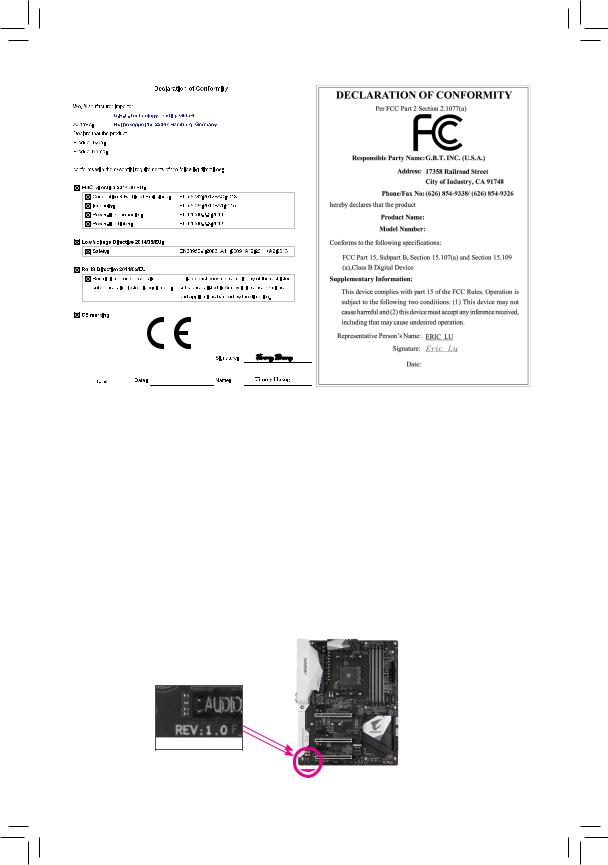
B450 AORUS ELITE
B450 AORUS ELITE
© 2018 GIGA-BYTE TECHNOLOGY CO., LTD. All rights reserved.
The trademarks mentioned in this manual are legally registered to their respective owners.
Information in this manual is protected by copyright laws and is the property of GIGABYTE.
No part of this manual may be reproduced, copied, translated, transmitted, or published in any form or by any means without GIGABYTE’s prior written permission.
In order to assist in the use of this product, carefully read the User’s Manual.
For product-related information, check on our website at: https://www.gigabyte.com
Identifying Your Motherboard Revision
The revision number on your motherboard looks like this: «REV: X.X.» For example, «REV: 1.0» means the revision of the motherboard is 1.0. Check your motherboard revision before updating motherboard BIOS, drivers, or when looking for technical information.

Table of Contents
B450 AORUS ELITE Motherboard Layout.
Chapter 1 Hardware Installation.
Installing the CPU.
Installing the Memory.
1-5 Installing an Expansion Card.
Back Panel Connectors.
Chapter 2 BIOS Setup.
Chapter 3 Appendix.
3-1 Configuring a RAID Set.
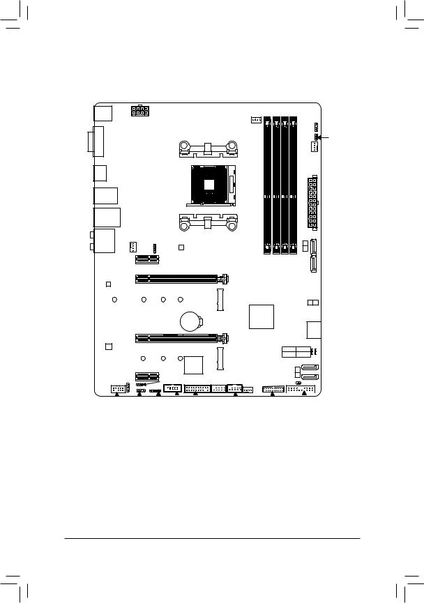
B450 AORUS ELITE Motherboard Layout
B450 AORUS ELITE
DDR4 2 DDR4 3 DDR4 1
F_AUDIO D_LED1 LED_C COMA TPM
B450 AORUS ELITE Motherboard
Two SATA cables
Motherboard driver disk
M.2 screw(s)/M.2 standoff(s)
* The box contents above are for reference only and the actual items shall depend on the product package you obtain. The box contents are subject to change without notice.

Chapter 1 Hardware Installation
1-1 Installation Precautions
The motherboard contains numerous delicate electronic circuits and components which can become damaged as a result of electrostatic discharge (ESD). Prior to installation, carefully read the user’s manual and follow these procedures:
• • Prior to installation, make sure the chassis is suitable for the motherboard.
• • Prior to installation, do not remove or break motherboard S/N (Serial Number) sticker or warranty sticker provided by your dealer. These stickers are required for warranty validation.
• • Always remove the AC power by unplugging the power cord from the power outlet before installing or removing the motherboard or other hardware components.
• • When connecting hardware components to the internal connectors on the motherboard, make sure they are connected tightly and securely.
• • When handling the motherboard, avoid touching any metal leads or connectors.
• • It is best to wear an electrostatic discharge (ESD) wrist strap when handling electronic components such as a motherboard, CPU or memory. If you do not have an ESD wrist strap, keep your hands dry and first touch a metal object to eliminate static electricity.
• • Prior to installing the motherboard, please have it on top of an antistatic pad or within an electrostatic shielding container.
• • Before connecting or unplugging the power supply cable from the motherboard, make sure the power supply has been turned off.
• • Before turning on the power, make sure the power supply voltage has been set according to the local voltage standard.
• • Before using the product, please verify that all cables and power connectors of your hardware components are connected.
• • To prevent damage to the motherboard, do not allow screws to come in contact with the motherboard circuit or its components.
• • Make sure there are no leftover screws or metal components placed on the motherboard or within the computer casing.
• • Do not place the computer system on an uneven surface.
• • Do not place the computer system in a high-temperature or wet environment.
• • Turning on the computer power during the installation process can lead to damage to system components as well as physical harm to the user.
• • If you are uncertain about any installation steps or have a problem related to the use of the product, please consult a certified computer technician.
• • If you use an adapter, extension power cable, or power strip, ensure to consult with its installation and/or grounding instructions.
1-2 Product Specifications
— AMD Ryzen ™ 2nd Generation processors
— AMD Ryzen ™ with Radeon ™ Vega Graphics processors
— AMD Ryzen ™ 1st Generation processors
(Go to GIGABYTE’s website for the latest CPU support list.)
4 x DDR4 DIMM sockets supporting up to 64 GB of system memory
Dual channel memory architecture
Support for DDR4 2933/2667/2400/2133 MHz memory modules
Support for ECC Un-buffered DIMM 1Rx8/2Rx8 memory modules (operate in
Support for non-ECC Un-buffered DIMM 1Rx8/2Rx8/1Rx16 memory modules
Support for Extreme Memory Profile (XMP) memory modules
(Go to GIGABYTE’s website for the latest supported memory speeds and memory
Integrated Graphics Processor:
— 1 x DVI-D port, supporting a maximum resolution of 1920×1200@60 Hz
* The DVI-D port does not support D-Sub connection by adapter.
— 1 x HDMI port, supporting a maximum resolution of 4096×2160@60 (Note) Hz
* Support for HDMI 2.0 version and HDCP 2.2. (Note)
— Maximum shared memory of 16 GB
Realtek ® ALC892 codec
High Definition Audio
Support for S/PDIF Out
Realtek ® GbE LAN chip (10/100/1000 Mbit)
1 x PCI Express x16 slot, running at x16 (PCIEX16) (Note)
* For optimum performance, if only one PCI Express graphics card is to be installed,
be sure to install it in the PCIEX16 slot.
(The PCIEX16 slot conforms to PCI Express 3.0 standard.)
1 x PCI Express x16 slot, running at x4 (PCIEX4)
* The PCIEX4 slot shares bandwidth with the PCIEX1_2 slot. The PCIEX4 slot operates
at up to x2 mode when the PCIEX1_2 slot is populated. The PCIEX4 slot operates
at up to x4 mode when the PCIEX1_2 is empty.
2 x PCI Express x1 slots
(The PCIEX4 and PCIEX1 slots conform to PCI Express 2.0 standard.)
SupportforAMDQuad-GPUCrossFire ™ and2-WayAMDCrossFire ™ technologies
(Note) Actual support may vary by CPU.
— 1 x M.2 connector (Socket 3, M key, type 2242/2260/2280/22110 SATA and
PCIe 3.0 x4/x2 SSD support) (M2A_SOCKET)
— 1 x M.2 connector (Socket 3, M key, type 2242/2260/2280 PCIe 3.0 x2 SSD
6 x SATA 6Gb/s connectors
Support for RAID 0, RAID 1, and RAID 10
* Refer to «1-7 Internal Connectors,» for the installation notices for the M.2 and SATA
— 2 x USB 3.1 Gen 1 ports available through the internal USB header
— 8 x USB 2.0/1.1 ports (4 ports on the back panel, 4 ports available through
the internal USB headers)
Integrated in the APU:
— 4 x USB 3.1 Gen 1 ports on the back panel
1 x 24-pin ATX main power connector
1 x 8-pin ATX 12V power connector
2 x M.2 Socket 3 connectors
6 x SATA 6Gb/s connectors
1 x CPU fan header
3 x system fan headers
1 x CPU cooler LED strip/RGB LED strip extension cable header
1 x RGB (RGBW) LED strip header
2 x digital LED strip headers
2 x digital LED strip power select jumpers
1 x front panel header
1 x front panel audio header
1 x S/PDIF Out header
1 x USB 3.1 Gen 1 header
2 x USB 2.0/1.1 headers
1 x Trusted Platform Module (TPM) header (2×10 pin, for the GC-TPM2.0 module
1 x serial port header
1 x Clear CMOS jumper
1 x PS/2 keyboard/mouse port
4 x USB 3.1 Gen 1 ports
4 x USB 2.0/1.1 ports
6 x audio jacks
iTE ® I/O Controller Chip
Fan speed detection
Fan fail warning
Fan speed control
* Whether the fan speed control function is supported will depend on the cooler you
1 x 128 Mbit flash
Use of licensed AMI UEFI BIOS
PnP 1.0a, DMI 2.7, WfM 2.0, SM BIOS 2.7, ACPI 5.0
Support for APP Center
* Available applications in APP Center may vary by motherboard model. Supported
System Information Viewer
Support for Q-Flash
Support for Xpress Install
Norton ® Internet Security (OEM version)
Realtek ® 8118 Gaming LAN Bandwidth Control Utility
Support for Windows 10 64-bit
ATX Form Factor; 30.5cm x 23.5cm
* GIGABYTE reserves the right to make any changes to the product specifications and product-related information without prior notice.
Please visit GIGABYTE’s website for support lists of CPU, memory modules, SSDs, and M.2 devices.
Please visit the SupportUtility List page on GIGABYTE’s website to download the latest version of apps.
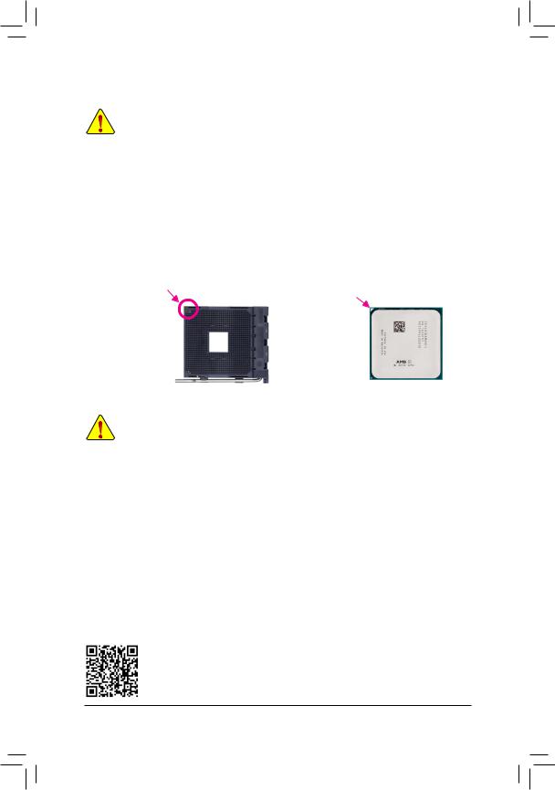
Installing the CPU
Read the following guidelines before you begin to install the CPU:
Make sure that the motherboard supports the CPU.
(Go to GIGABYTE’s website for the latest CPU support list.)
Always turn off the computer and unplug the power cord from the power outlet before installing the
CPU to prevent hardware damage.
Locate the pin one of the CPU. The CPU cannot be inserted if oriented incorrectly.
Apply an even and thin layer of thermal grease on the surface of the CPU.
Do not turn on the computer if the CPU cooler is not installed, otherwise overheating and damage
of the CPU may occur.
Set the CPU host frequency in accordance with the CPU specifications. It is not recommended
that the system bus frequency be set beyond hardware specifications since it does not meet the
standard requirements for the peripherals. If you wish to set the frequency beyond the standard
specifications, please do so according to your hardware specifications including the CPU, graphics
card, memory, hard drive, etc.
Installing the CPU
Locate the pin one (denoted by a small triangle) of the CPU socket and the CPU.
A Small Triangle
A Small Triangle
Marking Denotes Pin
Marking Denotes CPU
One of the Socket
1-4 Installing the Memory
Read the following guidelines before you begin to install the memory:
•• Make sure that the motherboard supports the memory. It is recommended that memory of the same capacity, brand, speed, and chips be used.
(Go to GIGABYTE’s website for the latest supported memory speeds and memory modules.)
•• Always turn off the computer and unplug the power cord from the power outlet before installing the memory to prevent hardware damage.
•• Memory modules have a foolproof design. A memory module can be installed in only one direction. If you are unable to insert the memory, switch the direction.
Dual Channel Memory Configuration
This motherboard provides four memory sockets and supports Dual Channel Technology. After the memory is installed, the BIOS will automatically detect the specifications and capacity of the memory. Enabling Dual
Channel memory mode will double the original memory bandwidth.
The four memory sockets are divided into two channels and each channel has two memory sockets as following:
Channel A: DDR4_2, DDR4_4Channel B: DDR4_1, DDR4_3
Dual Channel Memory Configurations Table
(SS=Single-Sided, DS=Double-Sided, «- -«=No Memory)
Please visit GIGABYTE’s website for details on hardware installation.
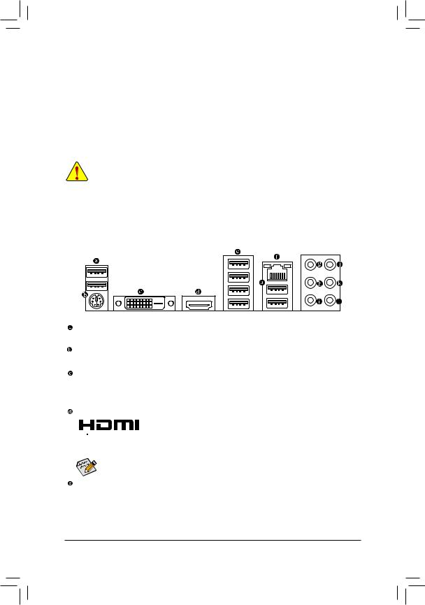
Due to CPU limitations, read the following guidelines before installing the memory in Dual Channel mode.
1. Dual Channel mode cannot be enabled if only one memory module is installed.
2. WhenenablingDualChannelmodewithtwoorfourmemorymodules,itisrecommendedthatmemory of the same capacity, brand, speed, and chips be used. For optimum performance, when enabling
Dual Channel mode with two memory modules, we recommend that you install them in the DDR4_1 and DDR4_2 sockets.
1-5 Installing an Expansion Card
Read the following guidelines before you begin to install an expansion card:
•• Make sure the motherboard supports the expansion card. Carefully read the manual that came with your expansion card.
•• Always turn off the computer and unplug the power cord from the power outlet before installing an expansion card to prevent hardware damage.
1-6 Back Panel Connectors
The USB port supports the USB 2.0/1.1 specification. Use this port for USB devices.
PS/2 Keyboard/Mouse Port
Use this port to connect a PS/2 mouse or keyboard.
DVI-D Port (Note 1)
The DVI-D port conforms to the DVI-D specification and supports a maximum resolution of 1920×1200@60 Hz (the actual resolutions supported depend on the monitor being used). Connect a monitor that supports DVI-D connection to this port.
 The HDMI port supports HDCP 2.2 (Note 2) and Dolby TrueHD and DTS HD Master


 Audioformats.Italsosupportsupto192KHz/24bit8-channelLPCMaudiooutput. You can use this port to connect your HDMI-supported monitor. The maximum supported resolution is 4096×2160@60 Hz (Note 2) , but the actual resolutions supported are dependent on the monitor being used.
After installing the HDMI device, make sure to set the default sound playback device to HDMI. (The
item name may differ depending on your operating system.)
USB 3.1 Gen 1 Port
The USB 3.1 Gen 1 port supports the USB 3.1 Gen 1 specification and is compatible to the USB 2.0 specification. Use this port for USB devices.
(Note 1) The DVI-D port does not support D-Sub connection by adapter.
(Note 2) Actual support may vary by CPU.
![]()
The Gigabit Ethernet LAN port provides Internet connection at up to 1 Gbps data rate. The following describes the states of the LAN port LEDs.
Источник
Содержание
- Gigabyte B450 Aorus Elite инструкция
- B450 AORUS ELITE
- User’s Manual
- Rev. 1002
- 12ME-B45ARSE-1002R
- Нужна помощь?
- Gigabyte B450 Aorus Elite инструкция
- 2-9 Save & Exit
- & Save & Exit Setup
- & Exit Without Saving
- & Load Optimized Defaults
- & Boot Override
- & SaveProles
- & LoadProles
- Нужна помощь?
- gigabyte b450 aorus elite сброс биос и CMOS. Обновление и прошивка Bios
- Когда необходимо обнулить настройки BIOS / EFI / сбросить CMOS
- gigabyte b450 aorus elite сброс биос
- Способы сброса
- Как обновить BIOS
- Добавить комментарий Отменить ответ
- Gigabyte B450 Aorus elite Service Manual
- B450 AORUS ELITE Motherboard Layout
- Chapter 1 Hardware Installation
- 1-1 Installation Precautions
- 1-2 Product Specifications
- Installing the CPU
- 1-4 Installing the Memory
- 1-5 Installing an Expansion Card
- 1-6 Back Panel Connectors
Gigabyte B450 Aorus Elite инструкция
инструкция Gigabyte B450 Aorus Elite
User’s Manual
Rev. 1002
12ME-B45ARSE-1002R
Посмотреть инструкция для Gigabyte B450 Aorus Elite бесплатно. Руководство относится к категории Материнские платы, 28 человек(а) дали ему среднюю оценку 8.9. Руководство доступно на следующих языках: английский. У вас есть вопрос о Gigabyte B450 Aorus Elite или вам нужна помощь? Задайте свой вопрос здесь
Нужна помощь?
У вас есть вопрос о Gigabyte а ответа нет в руководстве? Задайте свой вопрос здесь Дай исчерпывающее описание проблемы и четко задайте свой вопрос. Чем детальнее описание проблемы или вопроса, тем легче будет другим пользователям Gigabyte предоставить вам исчерпывающий ответ.
Провод FAN выходящий из кнопки на панели RGB как подключить в какой пин?
Поставил на данную материнку ssd накопитель формата М.2 wd black в первый слот. Накопитель ни где не отображается, система стоит на hdd 1500 gb на разъёме sata 0
Кувстовлять медиа инаушник
руководство на русском языке для материнской платы B450Aorus Elite
B450 aorus elite, при установке драйверов пишет что адаптер в глубоком сне,я подключал лан кабель, вытаскивал батарейку,память,менял виндовс 10, ничего не помогло, подскажите что сделать или надо по гарантии возвращать, и если да то через сколько будет материнка?
Прошил Биос до последней версии стоял процессор р 5 3600 ,так как продал видео карту купил ещё один процессор р 3 2200g,вставил увидел рабочий стол и всё каждый раз синий экран тоесть рабочий стол и потом синий экран,мать гигабайт в 450 елит аурс,может надо отметить Биос опять на f 1 по-моему ,щас стоит Биос под 5 тысячный процессор
B 450 aorus elit совместима с AMD PRO A6-8580 OEM. А то при включении мигнёт материка и все
Источник
Gigabyte B450 Aorus Elite инструкция
инструкция Gigabyte B450 Aorus Elite

2-9 Save & Exit
& Save & Exit Setup
& Exit Without Saving
& Load Optimized Defaults
& Boot Override
& SaveProles
Setup Prole 8. Press to complete. Or you can select Select File in
& LoadProles
Посмотреть инструкция для Gigabyte B450 Aorus Elite бесплатно. Руководство относится к категории Материнские платы, 28 человек(а) дали ему среднюю оценку 8.9. Руководство доступно на следующих языках: английский. У вас есть вопрос о Gigabyte B450 Aorus Elite или вам нужна помощь? Задайте свой вопрос здесь
Нужна помощь?
У вас есть вопрос о Gigabyte а ответа нет в руководстве? Задайте свой вопрос здесь Дай исчерпывающее описание проблемы и четко задайте свой вопрос. Чем детальнее описание проблемы или вопроса, тем легче будет другим пользователям Gigabyte предоставить вам исчерпывающий ответ.
Провод FAN выходящий из кнопки на панели RGB как подключить в какой пин?
Поставил на данную материнку ssd накопитель формата М.2 wd black в первый слот. Накопитель ни где не отображается, система стоит на hdd 1500 gb на разъёме sata 0
Кувстовлять медиа инаушник
руководство на русском языке для материнской платы B450Aorus Elite
B450 aorus elite, при установке драйверов пишет что адаптер в глубоком сне,я подключал лан кабель, вытаскивал батарейку,память,менял виндовс 10, ничего не помогло, подскажите что сделать или надо по гарантии возвращать, и если да то через сколько будет материнка?
Прошил Биос до последней версии стоял процессор р 5 3600 ,так как продал видео карту купил ещё один процессор р 3 2200g,вставил увидел рабочий стол и всё каждый раз синий экран тоесть рабочий стол и потом синий экран,мать гигабайт в 450 елит аурс,может надо отметить Биос опять на f 1 по-моему ,щас стоит Биос под 5 тысячный процессор
B 450 aorus elit совместима с AMD PRO A6-8580 OEM. А то при включении мигнёт материка и все
Источник
gigabyte b450 aorus elite сброс биос и CMOS. Обновление и прошивка Bios

Здесь я показываю на пальцах как сбросить настройки BIOS на gigabyte b450 aorus elite. с помощью простой инструкции и без вызова хитрожопых мастеров по объявлению на Avito.
Когда необходимо обнулить настройки BIOS / EFI / сбросить CMOS
- ПК перестал запускаться после смены оборудования, пересборки или смены настроек биоса.
- Вы потеряли пароль на вход в BIOS, если конечно он был установлен
- Нестабильная работа ПК
- Неудачный разгон
- Периодический BSOD
- Надпись на экране «please clear cmos if system no display after overclocking»
- Определёные звуки системного динамика, указывающие на то что надо изменить настройки
gigabyte b450 aorus elite сброс биос
Выключите блок питания или выдерните шнур из розетки. Теперь приступим.
Способы сброса
- Находим на материнке батарейку, она там одна и вытаскиваем её на 30 секунд. Потом возвращаем её на место. Готово, можно включать ПК! Выглядит так:

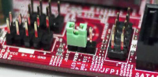
- Если контакта всего 2 и пластиковой перемычки нет, то замкните контакты, например, ножницами или отвёрткой на 30 секунд. Пример на фото ниже:

В общем сложного ничего нет, берите и делайте.
Как обновить BIOS
- Скачиваем самую последнюю версию BIOS для gigabyte b450 aorus elite
- Копируем файл на флешку, заходим в биос и в разделе обновлений выбираем нужный файл с флешки. В данный момент многие производители современных материнских плат позволяют обновляться из под Windows, но это рискованно, процесс может прервать ложно срабатывание антивируса и вы можете запороть bios, а потом пытаться его восстановить.
Прошивка до последней версии может улучшить работу вашего ПК и решить многие проблемы, убрать BSOD и проблемы с несовместимостью оборудования.
Добавить комментарий Отменить ответ
Для отправки комментария вам необходимо авторизоваться.
Источник
Gigabyte B450 Aorus elite Service Manual
![]()
B450 AORUS ELITE
For more product details, please visit GIGABYTE’s website.
To reduce the impacts on global warming, the packaging materials of this product are recyclable and reusable. GIGABYTE works with you to protect the environment.
B450 AORUS ELITE
B450 AORUS ELITE
© 2018 GIGA-BYTE TECHNOLOGY CO., LTD. All rights reserved.
The trademarks mentioned in this manual are legally registered to their respective owners.
Information in this manual is protected by copyright laws and is the property of GIGABYTE.
No part of this manual may be reproduced, copied, translated, transmitted, or published in any form or by any means without GIGABYTE’s prior written permission.
In order to assist in the use of this product, carefully read the User’s Manual.
For product-related information, check on our website at: https://www.gigabyte.com
Identifying Your Motherboard Revision
The revision number on your motherboard looks like this: «REV: X.X.» For example, «REV: 1.0» means the revision of the motherboard is 1.0. Check your motherboard revision before updating motherboard BIOS, drivers, or when looking for technical information.
Table of Contents
B450 AORUS ELITE Motherboard Layout.
Chapter 1 Hardware Installation.
Installing the CPU.
Installing the Memory.
1-5 Installing an Expansion Card.
Back Panel Connectors.
Chapter 2 BIOS Setup.
Chapter 3 Appendix.
3-1 Configuring a RAID Set.
B450 AORUS ELITE Motherboard Layout
B450 AORUS ELITE
DDR4 2 DDR4 3 DDR4 1
F_AUDIO D_LED1 LED_C COMA TPM
B450 AORUS ELITE Motherboard
Two SATA cables
Motherboard driver disk
M.2 screw(s)/M.2 standoff(s)
* The box contents above are for reference only and the actual items shall depend on the product package you obtain. The box contents are subject to change without notice.
Chapter 1 Hardware Installation
1-1 Installation Precautions
The motherboard contains numerous delicate electronic circuits and components which can become damaged as a result of electrostatic discharge (ESD). Prior to installation, carefully read the user’s manual and follow these procedures:
• • Prior to installation, make sure the chassis is suitable for the motherboard.
• • Prior to installation, do not remove or break motherboard S/N (Serial Number) sticker or warranty sticker provided by your dealer. These stickers are required for warranty validation.
• • Always remove the AC power by unplugging the power cord from the power outlet before installing or removing the motherboard or other hardware components.
• • When connecting hardware components to the internal connectors on the motherboard, make sure they are connected tightly and securely.
• • When handling the motherboard, avoid touching any metal leads or connectors.
• • It is best to wear an electrostatic discharge (ESD) wrist strap when handling electronic components such as a motherboard, CPU or memory. If you do not have an ESD wrist strap, keep your hands dry and first touch a metal object to eliminate static electricity.
• • Prior to installing the motherboard, please have it on top of an antistatic pad or within an electrostatic shielding container.
• • Before connecting or unplugging the power supply cable from the motherboard, make sure the power supply has been turned off.
• • Before turning on the power, make sure the power supply voltage has been set according to the local voltage standard.
• • Before using the product, please verify that all cables and power connectors of your hardware components are connected.
• • To prevent damage to the motherboard, do not allow screws to come in contact with the motherboard circuit or its components.
• • Make sure there are no leftover screws or metal components placed on the motherboard or within the computer casing.
• • Do not place the computer system on an uneven surface.
• • Do not place the computer system in a high-temperature or wet environment.
• • Turning on the computer power during the installation process can lead to damage to system components as well as physical harm to the user.
• • If you are uncertain about any installation steps or have a problem related to the use of the product, please consult a certified computer technician.
• • If you use an adapter, extension power cable, or power strip, ensure to consult with its installation and/or grounding instructions.
1-2 Product Specifications
— AMD Ryzen ™ 2nd Generation processors
— AMD Ryzen ™ with Radeon ™ Vega Graphics processors
— AMD Ryzen ™ 1st Generation processors
(Go to GIGABYTE’s website for the latest CPU support list.)
4 x DDR4 DIMM sockets supporting up to 64 GB of system memory
Dual channel memory architecture
Support for DDR4 2933/2667/2400/2133 MHz memory modules
Support for ECC Un-buffered DIMM 1Rx8/2Rx8 memory modules (operate in
Support for non-ECC Un-buffered DIMM 1Rx8/2Rx8/1Rx16 memory modules
Support for Extreme Memory Profile (XMP) memory modules
(Go to GIGABYTE’s website for the latest supported memory speeds and memory
Integrated Graphics Processor:
— 1 x DVI-D port, supporting a maximum resolution of 1920×1200@60 Hz
* The DVI-D port does not support D-Sub connection by adapter.
— 1 x HDMI port, supporting a maximum resolution of 4096×2160@60 (Note) Hz
* Support for HDMI 2.0 version and HDCP 2.2. (Note)
— Maximum shared memory of 16 GB
Realtek ® ALC892 codec
High Definition Audio
Support for S/PDIF Out
Realtek ® GbE LAN chip (10/100/1000 Mbit)
1 x PCI Express x16 slot, running at x16 (PCIEX16) (Note)
* For optimum performance, if only one PCI Express graphics card is to be installed,
be sure to install it in the PCIEX16 slot.
(The PCIEX16 slot conforms to PCI Express 3.0 standard.)
1 x PCI Express x16 slot, running at x4 (PCIEX4)
* The PCIEX4 slot shares bandwidth with the PCIEX1_2 slot. The PCIEX4 slot operates
at up to x2 mode when the PCIEX1_2 slot is populated. The PCIEX4 slot operates
at up to x4 mode when the PCIEX1_2 is empty.
2 x PCI Express x1 slots
(The PCIEX4 and PCIEX1 slots conform to PCI Express 2.0 standard.)
SupportforAMDQuad-GPUCrossFire ™ and2-WayAMDCrossFire ™ technologies
(Note) Actual support may vary by CPU.
— 1 x M.2 connector (Socket 3, M key, type 2242/2260/2280/22110 SATA and
PCIe 3.0 x4/x2 SSD support) (M2A_SOCKET)
— 1 x M.2 connector (Socket 3, M key, type 2242/2260/2280 PCIe 3.0 x2 SSD
6 x SATA 6Gb/s connectors
Support for RAID 0, RAID 1, and RAID 10
* Refer to «1-7 Internal Connectors,» for the installation notices for the M.2 and SATA
— 2 x USB 3.1 Gen 1 ports available through the internal USB header
— 8 x USB 2.0/1.1 ports (4 ports on the back panel, 4 ports available through
the internal USB headers)
Integrated in the APU:
— 4 x USB 3.1 Gen 1 ports on the back panel
1 x 24-pin ATX main power connector
1 x 8-pin ATX 12V power connector
2 x M.2 Socket 3 connectors
6 x SATA 6Gb/s connectors
1 x CPU fan header
3 x system fan headers
1 x CPU cooler LED strip/RGB LED strip extension cable header
1 x RGB (RGBW) LED strip header
2 x digital LED strip headers
2 x digital LED strip power select jumpers
1 x front panel header
1 x front panel audio header
1 x S/PDIF Out header
1 x USB 3.1 Gen 1 header
2 x USB 2.0/1.1 headers
1 x Trusted Platform Module (TPM) header (2×10 pin, for the GC-TPM2.0 module
1 x serial port header
1 x Clear CMOS jumper
1 x PS/2 keyboard/mouse port
4 x USB 3.1 Gen 1 ports
4 x USB 2.0/1.1 ports
6 x audio jacks
iTE ® I/O Controller Chip
Fan speed detection
Fan fail warning
Fan speed control
* Whether the fan speed control function is supported will depend on the cooler you
1 x 128 Mbit flash
Use of licensed AMI UEFI BIOS
PnP 1.0a, DMI 2.7, WfM 2.0, SM BIOS 2.7, ACPI 5.0
Support for APP Center
* Available applications in APP Center may vary by motherboard model. Supported
System Information Viewer
Support for Q-Flash
Support for Xpress Install
Norton ® Internet Security (OEM version)
Realtek ® 8118 Gaming LAN Bandwidth Control Utility
Support for Windows 10 64-bit
ATX Form Factor; 30.5cm x 23.5cm
* GIGABYTE reserves the right to make any changes to the product specifications and product-related information without prior notice.
Please visit GIGABYTE’s website for support lists of CPU, memory modules, SSDs, and M.2 devices.
Please visit the SupportUtility List page on GIGABYTE’s website to download the latest version of apps.
Installing the CPU
Read the following guidelines before you begin to install the CPU:
Make sure that the motherboard supports the CPU.
(Go to GIGABYTE’s website for the latest CPU support list.)
Always turn off the computer and unplug the power cord from the power outlet before installing the
CPU to prevent hardware damage.
Locate the pin one of the CPU. The CPU cannot be inserted if oriented incorrectly.
Apply an even and thin layer of thermal grease on the surface of the CPU.
Do not turn on the computer if the CPU cooler is not installed, otherwise overheating and damage
of the CPU may occur.
Set the CPU host frequency in accordance with the CPU specifications. It is not recommended
that the system bus frequency be set beyond hardware specifications since it does not meet the
standard requirements for the peripherals. If you wish to set the frequency beyond the standard
specifications, please do so according to your hardware specifications including the CPU, graphics
card, memory, hard drive, etc.
Installing the CPU
Locate the pin one (denoted by a small triangle) of the CPU socket and the CPU.
A Small Triangle
A Small Triangle
Marking Denotes Pin
Marking Denotes CPU
One of the Socket
1-4 Installing the Memory
Read the following guidelines before you begin to install the memory:
•• Make sure that the motherboard supports the memory. It is recommended that memory of the same capacity, brand, speed, and chips be used.
(Go to GIGABYTE’s website for the latest supported memory speeds and memory modules.)
•• Always turn off the computer and unplug the power cord from the power outlet before installing the memory to prevent hardware damage.
•• Memory modules have a foolproof design. A memory module can be installed in only one direction. If you are unable to insert the memory, switch the direction.
Dual Channel Memory Configuration
This motherboard provides four memory sockets and supports Dual Channel Technology. After the memory is installed, the BIOS will automatically detect the specifications and capacity of the memory. Enabling Dual
Channel memory mode will double the original memory bandwidth.
The four memory sockets are divided into two channels and each channel has two memory sockets as following:
Channel A: DDR4_2, DDR4_4Channel B: DDR4_1, DDR4_3
Dual Channel Memory Configurations Table
(SS=Single-Sided, DS=Double-Sided, «- -«=No Memory)
Please visit GIGABYTE’s website for details on hardware installation.
Due to CPU limitations, read the following guidelines before installing the memory in Dual Channel mode.
1. Dual Channel mode cannot be enabled if only one memory module is installed.
2. WhenenablingDualChannelmodewithtwoorfourmemorymodules,itisrecommendedthatmemory of the same capacity, brand, speed, and chips be used. For optimum performance, when enabling
Dual Channel mode with two memory modules, we recommend that you install them in the DDR4_1 and DDR4_2 sockets.
1-5 Installing an Expansion Card
Read the following guidelines before you begin to install an expansion card:
•• Make sure the motherboard supports the expansion card. Carefully read the manual that came with your expansion card.
•• Always turn off the computer and unplug the power cord from the power outlet before installing an expansion card to prevent hardware damage.
1-6 Back Panel Connectors
The USB port supports the USB 2.0/1.1 specification. Use this port for USB devices.
PS/2 Keyboard/Mouse Port
Use this port to connect a PS/2 mouse or keyboard.
DVI-D Port (Note 1)
The DVI-D port conforms to the DVI-D specification and supports a maximum resolution of 1920×1200@60 Hz (the actual resolutions supported depend on the monitor being used). Connect a monitor that supports DVI-D connection to this port.
The HDMI port supports HDCP 2.2 (Note 2) and Dolby TrueHD and DTS HD Master
Audioformats.Italsosupportsupto192KHz/24bit8-channelLPCMaudiooutput. You can use this port to connect your HDMI-supported monitor. The maximum supported resolution is 4096×2160@60 Hz (Note 2) , but the actual resolutions supported are dependent on the monitor being used.
After installing the HDMI device, make sure to set the default sound playback device to HDMI. (The
item name may differ depending on your operating system.)
USB 3.1 Gen 1 Port
The USB 3.1 Gen 1 port supports the USB 3.1 Gen 1 specification and is compatible to the USB 2.0 specification. Use this port for USB devices.
(Note 1) The DVI-D port does not support D-Sub connection by adapter.
(Note 2) Actual support may vary by CPU.
![]()
The Gigabit Ethernet LAN port provides Internet connection at up to 1 Gbps data rate. The following describes the states of the LAN port LEDs.
Источник