
Specifications:1508/1508042-cu_100.pdf file (26 Jul 2023) |
Accompanying Data:
Grundfos CU 100 Controller, Control Unit PDF Installation And Operating Instructions Manual (Updated: Wednesday 26th of July 2023 02:55:10 AM)
Rating: 4.9 (rated by 90 users)
Compatible devices: MIXIT, SA Series, UPZC-1, CU 241, IO 112, CIM 500, BMS hs, COMFORT PM Series.
Recommended Documentation:
Installation And Operating Instructions Manual (Text Version):
(Ocr-Read Summary of Contents of some pages of the Grundfos CU 100 Document (Main Content), UPD: 26 July 2023)
-
2, Declaration of Conformity We, Grundfos, declare under our sole responsibility that the product CU 100, to which this declaration relates, is in conformity with these Council directives on the approximation of the laws of the EC member states: – Machinery Directive (2006/42/EC). Standard used: EN 60204-1: 2006 – Low Voltage Directive(2006/95/EC). Standard used: EN 60439-1: 2004. – EMC Directive (2004/108/EC). Standard used: EN 61000-6-2: 2005 and EN 61000-6-3: 2007. Konformitätserklärung Wir, Gr…
-
3, Grundfos CU 100 3 CU 100 Installation and operating instructions 4 Montage- und Betriebsanleitung 9 Notice d’installation et d’entretien 15 Istruzioni di installazione e funzionamento 20 Instrucciones de instalación y funcionamiento 25 Instruções de instalação e funcionamento 30 Οδηγίες εγκατάστασης και λειτουργίας 35 Installatie- en bedieningsinstructies 40 Monterings- och driftsinstruktion 45 A…
-
4, 4 Original installation and operating instructions. CONTENTS Page 1. General description 4 2. Applications 4 3. Type key 4 4. Functions 4 5. Construction 5 6. Installation 7 7. Wiring diagrams 7 8. Maintenance 7 9. Fault finding chart 8 10. Technical data 8 11. Disposal 8 1. General description The control box CU 100 is designed for the control of small pumps. The CU 100 is incorporated in an IP54 plastic cabinet and has screwed metric cable entries. The control box is availa…
-
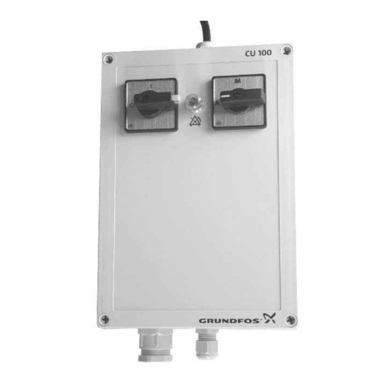
5, 5 5. Construction External construction: Fig. 2 Fig. 3 The position numbers in the table refer to figs. 2 and 3. TM02 6030 0703TM02 6028 0703 3 1 2 5 4 6 Single-phase Three-phase 3 1 2 5 4 6 Pos. Description 1 On/off switch – lockable 2 Man/auto switch 3 Single-phase: Resetting of thermal relay Three-phase: Phase sequence indicator 4 Connection of pump 5 Connection of float switch (model A only) 6 Mains connecting cable (3 metres): Single-pha…
-
6, Grundfos CU 100 6 Internal construction Fig. 4 Fig. 5 The position numbers in the table refer to figs. 4 and 5. The lead markings in [ ] refer to SEG, SE1, SEV, DP and EF pumps from Grundfos. * If the pump has more than one thermal switch, the switches must be connected in series so that the lowest switch stops the pump and the highest one is in reserve. ** The float switch is supplied with the control box and must be connected to the brown and black leads (NO contact). TM02 6031 4902TM02 6029 0509 4 3 6 5 …
-
7, 7 6. Installation • Check that the control box is suitable for the local conditions, i.e. pump (current, voltage, etc.). • Remove transport protectors, if any, from inside the cabinet. • Remove the cabinet front and mount the control box on a plane surface with four screws through the mounting holes in the back plate of the cabinet, see fig. 6. The cable entries for the pump and the float switch must pointing …
-
8, 8 9. Fault finding chart 10. Technical data Voltage variants, rated voltages • 1 x 230 V, 50 Hz. • 3 x 230 V, 50 Hz. • 3 x 400 V, 50 Hz. Voltage tolerances –15%/+10%. See the voltage tolerance stated in the installation and operating instructions for the pump. Back-up fuse Depending on variant, see nameplate. Ambient temperature • During operation: –30°C to +50°C. • In stock: –30°C to +60°C. Enclosure class IP54. EM…
-
16, Argentina Bombas GRUNDFOS de Argentina S.A. Ruta Panamericana km. 37.500 Lote 34A 1619 — Garin Pcia. de Buenos Aires Phone: +54-3327 414 444 Telefax: +54-3327 411 111 Australia GRUNDFOS Pumps Pty. Ltd. P.O. Box 2040 Regency Park South Australia 5942 Phone: +61-8-8461-4611 Telefax: +61-8-8340 0155 Austria GRUNDFOS Pumpen Vertrieb Ges.m.b.H. Grundfosstraße 2 A-5082 Grödig/Salzburg Tel.: +43-6246-883-0 Telefax: +43-6…
-
17, www.grundfos.com Being responsible is our foundation Thinking ahead makes it possible Innovation is the essence The name Grundfos, the Grundfos logo, and the payoff Be–Think–Innovate are registrated trademarks owned by Grundfos Management A/S or Grundfos A/S, Denmark. All rights reserved worldwide. 96498154 0610 30 Repl. 96498154 1209
…
-
Grundfos CU 100 User Manual
-
Grundfos CU 100 User Guide
-
Grundfos CU 100 PDF Manual
-
Grundfos CU 100 Owner’s Manuals
Recommended:
WODV230, BRAVIA KDL-60NX800, MultiSync XP29, XM29 Xtra
-
To properly use the product, read this manual thoroughly and retain for easy reference, inspection, and maintenance. Ensure the end user receives this manual.YASKAWA AC Drive-A1000High Performance Vector Control DriveQuick Start GuideType: CIMR-AUA MANUAL NO. TOEP C710616 41BModels: 200 V Class: 0.4 to 110 kW (3/4 to 175 HP ND)400 V Class: 0.4 to 630 kW (3/4 to 1000 H …
A1000 — 257
-
ACETYLENE REGULATORMODEL NO: SGA4.V2Thank you for purchasing a Sealey product. Manufactured to a high standard, this product will, if used according to these instructions, and properly maintained, give you years of trouble free performance.IMPORTANT: PLEASE READ THESE INSTRUCTIONS CAREFULLY. NOTE THE SAFE OPERATIONAL REQUIREMENTS, WARNINGS & CAUTIONS. USE TH …
SGA4.V2 2
-
Doc. no.: 9.17.084G Date: 16-03-2018ATTENTIONPlease read this Instruction Manual carefully before installing and operating the instrument.Not following the guidelines could result in personal injury and/or damage to the equipment.EL-FLOW® Prestige seriesThermal Mass Flow Meters/ControllersInstruction Manual …
EL-FLOW Prestige series 53
-
CONTROLLORE CENTRALE TIMER SETTIMANALEWEEKLY-TIMER CENTRAL CONTROLLERCONTROLADOR CENTRAL CON TEMPORIZADOR SEMANALCONTRÔLEUR CENTRAL AVEC PROGRAMMATEUR HEBDOMADAIRECONTROLADOR CENTRAL DE TEMPORIZADOR SEMANALMANUALE DI INSTALLAZIONE E USOITENINSTALLATION & OWNER’S MANUALMANUAL DE INSTALACIÓN Y DEL USUARIOESMANUEL D’INSTALLATION ET D’UTILISATIONFRMAN …
MD-CCM09(A) 164
-
Thank you for purchasing the Datapath VSN400 Wall Controller. The aim of this document is to quickly guide you through the process of initial setup. For detailed instructions consult the system User Guide which can be found on the Recovery Media.www.datapath.co.uk | [email protected] | +44 (0) 1332 294441Wall Controller Quick Start GuideVSN400 Series of Wall Controll …
VSN400 Series 12
-
1LT-3900LED RGB ControllerLT-3900 is a multi-function RGB controller that built-in 32 modes. Adopting advanced PWM (Pulse-Width Modulation) control technique, Changing effect is smooth without flicker. Adopting hi-power MOS driver, RGB 3 channels output and total current up to 18A, Unique touch technique, Controller has 8 touch buttons, Which are used for choos …
LT-3900 2
Popular Right Now:
Operating Impressions, Questions and Answers:
Table of Contents: Grundfos CU 100 Controller Owner’s Manual
-
Grundfos CU 100 64 Fig. E Fig. F TM 04 3942 1209
-
Grundfos CU 100 60 Fig. A TM 04 3943 1209
-
Grundfos CU 100 66
-
Grundfos CU 100 www.grundfos.com Being responsible is our foundation Thinking ahead makes it possible Innovation is the essence The name Grundfos, the Grundfos logo, and the payoff Be–Think–Innovate are registrated trademarks owned by Grundfos Management A/S or Grundfos A/S, Denmark. All rights reserved worldwide. 96498154 0610 30 Repl. 96498154 1209
-
65 TM 04 3941 1209
-
Grundfos CU 100 CU 100 GRUNDFOS INSTRUCTIONS Installation and operating instructions
-
Grundfos CU 100 4 Original installation and operating instructions. CONTENTS Page 1. General description 4 2. Applications 4 3. Type key 4 4. Functions 4 5. Construction 5 6. Installation 7 7. Wiring diagrams 7 8. Maintenance 7 9. Fault finding chart 8 10. Technical data 8 11. Disposal 8 1. General description The control box CU 100 is designed for the control of small pumps. The CU 100 is incorporated in an IP54 plastic cabinet and has screwed metric cable entries. The control box is available in several variants which can be used for • single-phase pumps or • three-phase pumps and • sta
-
Grundfos CU 100 Argentina Bombas GRUNDFOS de Argentina S.A. Ruta Panamericana km. 37.500 Lote 34A 1619 — Garin Pcia. de Buenos Aires Phone: +54-3327 414 444 Telefax: +54-3327 411 111 Australia GRUNDFOS Pumps Pty. Ltd. P.O. Box 2040 Regency Park South Australia 5942 Phone: +61-8-8461-4611 Telefax: +61-8-8340 0155 Austria GRUNDFOS Pumpen Vertrieb Ges.m.b.H. Grundfosstraße 2 A-5082 Grödig/Salzburg Tel.: +43-6246-883-0 Telefax: +43-6246-883-30 Belgium N.V. GRUNDFOS Bellux S.A. Boomsesteenweg 81-83 B-2630 Aartselaar Tél.: +32-3-870 7300 Télécopie: +32-3-870 7301 Belorussia Представительство ГРУНДФОС в Мин
-
Grundfos CU 100 5 5. Construction External construction: Fig. 2 Fig. 3 The position numbers in the table refer to figs. 2 and 3. TM02 6030 0703TM02 6028 0703 3 1 2 5 4 6 Single-phase Three-phase 3 1 2 5 4 6 Pos. Description 1 On/off switch – lockable 2 Man/auto switch 3 Single-phase: Resetting of thermal relay Three-phase: Phase sequence indicator 4 Connection of pump 5 Connection of float switch (model A only) 6 Mains connecting cable (3 metres): Single-phase: with Schuko plug Three-phase: with CE plug
-
7 6. Installation • Check that the control box is suitable for the local conditions, i.e. pump (current, voltage, etc.). • Remove transport protectors, if any, from inside the cabinet. • Remove the cabinet front and mount the control box on a plane surface with four screws through the mounting holes in the back plate of the cabinet, see fig. 6. The cable entries for the pump and the float switch must pointing downwards. Fig. 6 7. Wiring diagrams The figures in the table below refer to the wiring diagrams at the end of these instructions. 8. Maintenance During no
-
62 Fig. C TM 04 3939 1209
-
Declaration of Conformity We, Grundfos, declare under our sole responsibility that the product CU 100, to which this declaration relates, is in conformity with these Council directives on the approximation of the laws of the EC member states: – Machinery Directive (2006/42/EC). Standard used: EN 60204-1: 2006 – Low Voltage Directive(2006/95/EC). Standard used: EN 60439-1: 2004. – EMC Directive (2004/108/EC). Standard used: EN 61000-6-2: 2005 and EN 61000-6-3: 2007. Konformitätserklärung Wir, Grundfos, erklären in alleiniger Verantwortung, dass das Produkt CU 100, auf das s
-
Grundfos CU 100 61 Fig. B TM 04 3940 1209
-
Grundfos CU 100 63 Fig. D TM 04 3938 1209
-
6 Internal construction Fig. 4 Fig. 5 The position numbers in the table refer to figs. 4 and 5. The lead markings in [ ] refer to SEG, SE1, SEV, DP and EF pumps from Grundfos. * If the pump has more than one thermal switch, the switches must be connected in series so that the lowest switch stops the pump and the highest one is in reserve. ** The float switch is supplied with the control box and must be connected to the brown and black leads (NO contact).
-
3 CU 100 Installation and operating instructions 4 Montage- und Betriebsanleitung 9 Notice d’installation et d’entretien 15 Istruzioni di installazione e funzionamento 20 Instrucciones de instalación y funcionamiento 25 Instruções de instalação e funcionamento 30 Οδηγίες εγκατάστασης και λειτουργίας 35 Installatie- en bedieningsinstructies 40 Monterings- och driftsinstruktion 45 Asennus- ja käyttöohjeet 50 Monterings- og driftsinstruktion 55
Questions, Opinions and Exploitation Impressions:
You can ask a question, express your opinion or share our experience of Grundfos CU 100 device using right now.
Download or browse on-line these Instructions Manual for Grundfos CU 100 Controller, Control Unit.
Summary of Contents:
 |
[Page 1] Grundfos CU 100 CU 100 GRUNDFOS INSTRUCTIONS Installation and operating instructions ГК Водная техника [email protected] (495) 771 72 72 www.water-technics.ru Интернет-магазин [email protected] (499) 937 50 61 (8… |
 |
[Page 2] Grundfos CU 100 Declaration of Conformity We, Grundfos, declare under our sole responsibility that the product CU 100, to which this declaration relates, is in conformity with these Council directives on the approximation of the laws of the EC member states: – … |
 |
[Page 3] Grundfos CU 100 3 CU 100 Instrukcja montażu i eksploatacji 4 Руководство по монтажу и эксплуатации 10 Szerelési és üzemeltetési utasítás 18 Navodila za montažo in obratovanje 24 Montažne i pogonske upute 30 Uputstvo za insta… |
 |
[Page 4] Grundfos CU 100 4 SPIS TREŚCI Strona 1. Wskazówki bezpieczeństwa 4 1.1 Informacje ogólne 4 1.2 Oznakowanie wskazówek 4 1.3 Kwalifikacje i szkolenie personelu 4 1.4 Zagrożenia przy nieprzestrzeganiu wskazówek bezpieczeństwa 4 1.5 Bezpieczna praca 4 1.6 Wskaz… |
 |
[Page 5] Grundfos CU 100 5 1.6 Wskazówki bezpieczeństwa dla użytkownika/obsługującego • Ze znajdującego się w eksploatacji urządzenia nie usuwać istniejących osłon części ruchomych. •Wykluczyć możliwość porażenia prądem elektrycznym (szczegóły pat… |
 |
[Page 6] Grundfos CU 100 6 Schemat blokowy Rys. 1 6. Konstrukcja Konstrukcja zewnętrzna Rys. 2 Rys. 3 Numery dotyczą rysunków 2 oraz 3. TM01 1267 4097TM02 6030 0703 Sterownik Pompa Łącznik pływakowy 3 1 2 5 4 6 Wersja jednofazowa TM02 6030 0703 Nr Opis 1 Łącznik … |
 |
[Page 7] Grundfos CU 100 7 Konstrukcja wewnętrzna Rys. 4 Rys. 5 Numery dotyczą rysunków 4 oraz 5. Oznakowanie przewodów w [ ] dotyczy pomp Grundfos typu SEG, SE, SEV, DP oraz EF. *Jeżeli pompa wyposażona jest w więcej niż jeden łącznika termiczny, łącznika nale… |
 |
[Page 8] Grundfos CU 100 8 7. Instalacja •Należy upewnić się, że sterownik nadaje się do wykorzystania w lokalnych warunkach, tzn. z danym typem pompy (prąd, napięcie, itp.). •Z wnętrza obudowy należy usunąć wszelkie zabezpieczenia wykorzystywane podczas t… |
 |
[Page 9] Grundfos CU 100 9 10. Wykrywanie usterek 11. Dane techniczne Wersje napięcia, napięcie znamionowe • 1 x 230 V, 50 Hz. • 3 x 230 V, 50 Hz. • 3 x 400 V, 50 Hz. Tolerancje napięcia –15%/+10%. Patrz tolerancje napięcia przedstawione w instrukcji instalacji… |
 |
[Page 10] Grundfos CU 100 10 Àß56 СОДЕРЖАНИЕ Страницы 1. Указания по технике безопасности 10 1.1 Общие сведения 10 1.2 Значение символов и надписей 10 1.3 Квалификация и об�… |
 |
[Page 11] Grundfos CU 100 11 1.4 Опасные последствия несоблюдения указаний по технике безопасности Несоблюдение указаний по технике безопасности может повлечь з�… |
 |
[Page 12] Grundfos CU 100 12 4. Области применения Блок управления CU 100 предназначен для управления пуском и эксплуатацией, а также для обеспечения защиты насосов … |
 |
[Page 13] Grundfos CU 100 13 7. Конструкция Вид снаружи Рис. 2 Рис. 3 Номера позиций, приведенные в таблице, соответствуют позициям на рис. 2 и 3. TM02 6030 0703TM02 6028 0703 3 1 2 5 4 6 … |
 |
[Page 14] Grundfos CU 100 14 Внутренняя компоновка Рис. 4 Рис. 5 Номера позиций, приведенные в таблице, соответствуют позициям на рис. 4 и 5. Маркировка проводов, указ�… |
 |
[Page 15] Grundfos CU 100 15 8. Монтаж • Проверить, соответствует ли блок управления CU 100 местным условиям эксплуатации насоса (току и напряжению в сети и т.п.). • Де… |
 |
[Page 16] Grundfos CU 100 16 11. Обнаружение и устранение неисправностей Внимание Перед тем, как приступить к выполнению любых работ на насосах, использовавшихся д… |
 |
[Page 17] Grundfos CU 100 17 12. Технические данные Номинальные значения напряжения питания • 1 x 230 V, 50 Гц. • 3 x 230 V, 50 Гц. • 3 x 400 V, 50 Гц. Допустимые отклонения напряжен�… |
 |
[Page 18] Grundfos CU 100 18 TARTALOMJEGYZÉK Oldal 1. Biztonsági előírások 18 1.1 Általános rész 18 1.2 Figyelemfelhívó jelzések 18 1.3 A kezelőszemélyzet képzettsége és képzése 18 1.4 A biztonsági előírások figyelmen kívül hagyásának veszélyei 18… |
 |
[Page 19] Grundfos CU 100 19 1.8 Önhatalmú átépítés és alkatrészelőállítás A szivattyút megváltoztatni vagy átépíteni csak a gyártó előzetes engedélyével szabad. Az eredeti és a gyártó által engedélyezett alkatrészek használata megalapozza a b… |
 |
[Page 20] Grundfos CU 100 20 6. Felépítés Külső elrendezés: 2. ábra 3. ábra A táblázatban lévő pozíciószámok a 2. és 3. ábrára vonatkoznak. TM02 6030 0703TM02 6028 0703 3 1 2 5 4 6 Egyfázisú Háromfázisú 3 1 2 5 4 6 Poz. Leírás 1Főkapcsoló – … |
 |
[Page 21] Grundfos CU 100 21 Belső elrendezés: 4. ábra 5. ábra A táblázatban lévő pozíciószámok a 4. és 5. ábrára vonatkoznak. A szögletes zárójelben [ ] lévő vezető jelőlések az SEG, SE, SEV, DP és EF típusú Grundfos szivattyúkra vonatkoznak. *… |
 |
[Page 22] Grundfos CU 100 22 7. Telepítés •Ellenőrizzük hogy a vezérlőegység műszaki paraméterei megfelelnek-e az adott elkalmazáshoz. Pl.: szivattyú által igényelt feszültség, áramfelvétel, stb. • Távolítsuk el – ha van – a tokozat belsejében … |
 |
[Page 23] Grundfos CU 100 23 10. Hibakereső táblázat 11. Műszaki adatok Különböző feszültségű kivitelek • 1 x 230 V, 50 Hz. • 3 x 230 V, 50 Hz. • 3 x 400 V, 50 Hz. Tűrés a feszültségre –15 %/+10 %. Lásd a megengedett tűrést az adott szivattyú keze… |
 |
[Page 24] Grundfos CU 100 24 VSEBINA Stran 1. Varnostni napotki 24 1.1 Splošno 24 1.2 Oznake varnostnih navodil 24 1.3 Kvalificiranost in uvajanje osebja 24 1.4 Nevarnosti ob neupoštevanju varnostnih navodil 24 1.5 Varno delo 24 1.6 Varnostna navodila za uporabnika/ upravl… |
 |
[Page 25] Grundfos CU 100 25 1.8 Predelava in izdelava rezervnih delov Predelava ali spremembe na črpalkah se lahko opravijo le na osnovi dogovora s proizvajalcem. Zaradi varnosti se uporabljajo samo originalni nadomestni deli in od proizvajalca potrjena dodatna oprema. … |
 |
[Page 26] Grundfos CU 100 26 6. Konstrukcija Zunanja konstrukcija: Slika 2 Slika 3 Številke pozicij v tabeli se nanašajo na sliko. 2 in 3. TM02 6030 0703TM02 6028 0703 3 1 2 5 4 6 Enofazne različice Trifazne različice 3 1 2 5 4 6 Poz. Opis 1 Stikalo za vklop/izklop �… |
 |
[Page 27] Grundfos CU 100 27 Notranja konstrukcija: Slika 4 Slika 5 Številke pozicij v tabeli se nanašajo na sliko. 4 in 5. Oznake vodnikov v [ ] se nanašajo na Grundfosove črpalke SEG, SE, SEV, DP in EF. * Če ima črpalka več kot eno termično stikalo, je treba stika… |
 |
[Page 28] Grundfos CU 100 28 7. Instalacija •Prepričajte se, da je kontrolna omarica primerna za lokalne pogoje, t.j. črpalko (tok, napetost itd.). • Odstranite transportna varovala, če so nameščena, iz notranjosti omarice. • Odstranite sprednjo stran omarice in … |
 |
[Page 29] Grundfos CU 100 29 10. Tabela za iskanje napak 11. Tehnični podatki Napetostne različice, nominalne napetosti • 1 x 230 V, 50 Hz. • 3 x 230 V, 50 Hz. • 3 x 400 V, 50 Hz. Tolerance napetosti –15 %/+10 %. Glejte napetostne tolerance, ki so navedene v navod… |
 |
[Page 30] Grundfos CU 100 30 SADRŽAJ stranica 1. Sigurnosne upute 30 1.1 Općenito 30 1.2 Označavanje uputa 30 1.3 Kvalifikacija i školovanje osoblja 30 1.4 Opasnosti pri nepridržavanju sigurnosnih uputa 30 1.5 Rad uz sigurnosne mjere 30 1.6 Sigurnosne upute za korisnika… |
 |
[Page 31] Grundfos CU 100 31 1.8 Samovoljne pregradnje i neodgovarajući rezervni dijelovi Pregradnje ili izmjene uređaja dozvoljene su samo uz prethodni dogovor s proizvođačem. Originalni rezervni dijelovi i pribor koje je proizvođač odobrio služe sigurnosti; upora… |
 |
[Page 32] Grundfos CU 100 32 6. Raspored Vanjski raspored: Slika 2 Slika 3 Brojevi pozicija u sljedećoj tabeli odnose se na slike 2 i 3. TM02 6030 0703TM02 6028 0703 3 1 2 5 4 6 jednofazni trofazni 3 1 2 5 4 6 poz. opis 1 sklopka UKLJ./ISKLJ. – može se zaključati … |
 |
[Page 33] Grundfos CU 100 33 Nutarnji raspored: Slika 4 Slika 5 Brojevi pozicija u sljedećoj tabeli odnose se na slike 4 i 5. Oznake vodiča u [ ] odnose se na crpke SEG, SE, SEV, DP i EF tvrtke Grundfos. * Ukoliko crpka ima više od jedne termičke sklopke, moraju se skl… |
 |
[Page 34] Grundfos CU 100 34 7. Montaža • Provjeriti, odgovara li upravljački uređaj lokalnim uvjetima, tj. crpki (struja, napon itd.). •S kućišta skinuti eventualno postojeća transportna osiguranja. • Otpustiti poklopac pa upravljački uređaj kroz rupe na don… |
 |
[Page 35] Grundfos CU 100 35 10. Pregled smetnji 11. Tehnički podaci Varijante napona, nazivni naponi • 1 x 230 V, 50 Hz. • 3 x 230 V, 50 Hz. • 3 x 400 V, 50 Hz. Tolerancije napona –15 %/+10 %. vidi toleranciju napona u montažnoj i pogonskoj uputi odgovarajuće cr… |
 |
[Page 36] Grundfos CU 100 36 SADRŽAJ Strana 1. Upozorenja o merama sigurnosti 36 1.1 Opšte odredbe 36 1.2 Označavanje upozorenja 36 1.3 Kvalifikacije i obuka osoblja 36 1.4 Moguće opasnosti i posledice koje nastaju zbog nepridržavanja propisanim merama sigurnosti 36 1…. |
 |
[Page 37] Grundfos CU 100 37 1.7 Mere sigurnosti prilikom održavanja, kontrole i montažnih radova Korisnik mora da se stara da se svi radovi na održavanju, inspekciji i montaži izvode od strane obučenog stručnog osoblja, koje je proučilo i upoznato je sa propisima … |
 |
[Page 38] Grundfos CU 100 38 6. Raspored Spoljašnji raspored: Slika 2 Slika 3 Brojevi pozicija u sledećoj tabeli odnose se na slike 2 i 3. TM02 6030 0703TM02 6028 0703 3 1 2 5 4 6 jednofazni trofazni 3 1 2 5 4 6 poz. opis 1 sklopka UKLJ./ISKLJ. – može se zaključat… |
 |
[Page 39] Grundfos CU 100 39 Unutrašnji raspored: Slika 4 Slika 5 Brojevi pozicija u sledećoj tabeli odnose se na slike 4 i 5. Oznake vodiča u [ ] odnose se na pumpe SEG, SE, SEV, DP i EF firme Grundfos. * Ukoliko pumpa ima više od jedne termičke sklopke, moraju se sk… |
 |
[Page 40] Grundfos CU 100 40 7. Montaža • Proveriti, odgovara li upravljački uređaj lokalnim uslovima, tj. pumpi (struja, napon itd.). •S kućišta skinuti eventualno postojeća transportna osiguranja. • Otpustiti poklopac pa upravljački uređaj kroz rupe na donj… |
 |
[Page 41] Grundfos CU 100 41 10. Pregled smetnji 11. Tehnički podaci Varijante napona, nazivni naponi • 1 x 230 V, 50 Hz. • 3 x 230 V, 50 Hz. • 3 x 400 V, 50 Hz. Tolerancije napona –15 %/+10 %. vidi toleranciju napona u montažnom i radnom uputstvu odgovarajuće pu… |
 |
[Page 42] Grundfos CU 100 42 CUPRINS Pagina 1. Prezentare generală 42 2. Aplicaţii 42 3. Codificare 42 4. Funcţii 42 5. Construcţie 43 6. Instalare 45 7. Diagramele de conexiuni 45 8. Întreţinere 45 9. Tabel pentru detectarea defecţiunilor 46 10. Date tehnice 46 11. Sc… |
 |
[Page 43] Grundfos CU 100 43 5. Construcţie Construcţie externă: Fig. 2 Fig. 3 Numere le de poziţie din tabel se referă la figurile 2 şi3. TM02 6030 0703TM02 6028 0703 3 1 2 5 4 6 Monofazată Trifazată 3 1 2 5 4 6 Poz. Descriere 1 Întrerupător pornire/oprire �… |
 |
[Page 44] Grundfos CU 100 44 Construcţia internă: Fig. 4 Fig. 5 Numere de poziţie din tabel se referă la figurile 4 şi5. Marcajele conductorilor în [ ] se referă la pompele Grundfos SEG, SE, SEV, DP şi EF. *Dacă pompa are mai multe relee termice, acestea trebuie c… |
 |
[Page 45] Grundfos CU 100 45 6. Instalare • Trebuie să se verifice conformarea cutiei de control cu cerinţele locale, adică pompa (curent, tensiune etc.). • Îndepărtaţi protecţiile de transport, dacă este cazul, din interiorul carcasei. • Îndepărtaţi parte… |
 |
[Page 46] Grundfos CU 100 46 9. Tabel pentru detectarea defecţiunilor 10. Date tehnice Variante de tensiune, tensiuni nominale • 1 x 230 V, 50 Hz. • 3 x 230 V, 50 Hz. • 3 x 400 V, 50 Hz. Toleranţe de tensiune –15 %/+10 %. A se vedea toleranţa de tensiune din instr… |
 |
[Page 47] Grundfos CU 100 47 OBSAH Strana 1. Bezpečnostní pokyny 47 1.1 Všeobecně 47 1.2 Označení důležitosti pokynů 47 1.3 Kvalifikace a školení personálu 47 1.4 Rizika při nedodržování bezpečnostních pokynů 47 1.5 Dodržování zásad bezpečnosti práce… |
 |
[Page 48] Grundfos CU 100 48 1.8 Svévolné provádění úprav na zařízení a výroba náhradních dílů Provádění přestavby a změn konstrukce na čerpadle je přípustné pouze po předchozí konzultaci s výrobcem. Pro bezpečný provoz doporučujeme používat… |
 |
[Page 49] Grundfos CU 100 49 6. Konstrukce Vnější konstrukce: Obr. 2 Obr. 3 Čísla položek uvedená v tabulce jsou shodná s čísly na obrázcích 2 a 3. TM02 6030 0703TM02 6028 0703 3 1 2 5 4 6 Jednofázové provedení Trojfázové provedení 3 1 2 5 4 6 Pol. Pop… |
 |
[Page 50] Grundfos CU 100 50 Vnitřní konstrukce: Obr. 4 Obr. 5 Čísla položek uvedená v tabulce jsou shodná s čísly na obrázcích 4 a 5. Označení vodičů v závorce [ ] se vztahuje k čerpadlům SEG, SE, SEV, DP a EF z výrobního programu fy Grundfos. * Jestli… |
 |
[Page 51] Grundfos CU 100 51 7. Instalace • Zkontrolujte, zda je řídící jednotka vhodná pro místní podmínky, tj. pro dané čerpadlo (proud, napětí atd.). •Z vnitřku řídící jednotky odstraňte ochranné přepravní pomůcky, pokud jsou nějaké použity…. |
 |
[Page 52] Grundfos CU 100 52 10. Poruchy jejich odstraňování 11. Technické údaje Napět’ové varianty, jmenovitá napětí • 1 x 230 V, 50 Hz. • 3 x 230 V, 50 Hz. • 3 x 400 V, 50 Hz. Napět’ové tolerance –15 %/+10 %. Viz napět’ové tolerance uvedené v mo… |
 |
[Page 53] Grundfos CU 100 53 OBSAH Strana 1. Bezpečnostné pokyny 53 1.1 Všeobecne 53 1.2 Označenie dôležitosti pokynov 53 1.3 Kvalifikácia a školenie personálu 53 1.4 Riziká pri nedodržiavaní bezpečnostných pokynov 53 1.5 Dodržiavanie bezpečnosti práce 53 1…. |
 |
[Page 54] Grundfos CU 100 54 1.7 Bezpečnostné pokyny pre prevádzanie údržbárskych, kontrolných a montážnych prác Prevádzkovateľ sa musí postarat’, aby všetky práce spojené s údržbou, kontrolou a montážou boli prevádzané oprávnenými a kvalifikovan… |
 |
[Page 55] Grundfos CU 100 55 Bloková funkčná schéma: Obr. 1 6. Konštrukcia Vonkajšia konštrukcia: Obr. 2 Obr. 3 Čísla položiek uvedené v tabuľke sú zhodné s číslami na obrázkoch 2 a 3. TM01 1267 4097TM02 6030 0703 Riadiaca jednotka Čerpadlo Plavákový sp�… |
 |
[Page 56] Grundfos CU 100 56 Vnútorná konštrukcia: Obr. 4 Obr. 5 Čísla položiek uvedené v tabuľke sú zhodné s číslami na obrázkoch 4 a 5. Označenie vodičov v zátvorke [ ] sa vzt’ahuje k čerpadlám SEG, SE, SEV, DP a EF z výrobného programu fy Grundfos…. |
 |
[Page 57] Grundfos CU 100 57 7. Inštalácia • Skontrolujte, či je riadiaca jednotka vhodná pre miestne podmienky, tj. pre dané čerpadlo (prúd, napätie atď.). • Z vnútra riadiacej jednotky odstráňte ochranné prepravné pomôcky, pokiaľ sú nejaké použité… |
 |
[Page 58] Grundfos CU 100 58 10. Poruchy a ich odstraňovanie 11. Technické údaje Napät’ové verzie, menovité napätia • 1 x 230 V, 50 Hz. • 3 x 230 V, 50 Hz. • 3 x 400 V, 50 Hz. Napět’ové tolerancie –15 %/+10 %. Viď napät’ové tolerancie uvedené v mon… |
 |
[Page 59] Grundfos CU 100 59 İÇİNDEKİLER Sayfa 1. Genel tanımlar 59 2. Uygulamalar 59 3. Tip anahtarı 59 4. Fonksiyonalar 59 5. Yapısı 60 6. Montaj 62 7. Kablo diyagramları 62 8. Bakım62 9. Arıza tespit tablosu 63 10. Teknik bilgiler 63 11. Hurdaya çıkarma 63 1. … |
 |
[Page 60] Grundfos CU 100 60 5. Yapısı Dış yapısı: Şekil 2 Şekil 3 Tabloda bulunan konum rakamları şekil 2 ve 3’e aittir. TM02 6030 0703TM02 6028 0703 3 1 2 5 4 6 Tek fazlı Üç fazlı 3 1 2 5 4 6 Konum Tanımı 1 Açma/kapama şalteri – kilitlenebilir 2 … |
 |
[Page 61] Grundfos CU 100 61 İç yapısı: Şekil 4 Şekil 5 Tabloda bulunan konum rakamları şekil 4 ve 5’e aittir. [ ] içerisindeki kablo ucu işaretleri Grundfos’un SEG, SE, SEV, DP ve EF pomplarını göstermektedir. * Pompada birden fazla termik şalter varsa, … |
 |
[Page 62] Grundfos CU 100 62 6. Montaj Kontrol panosunun yerel koşullara uygun olup olmadığını kontrol edin, örneğin pompa (akım, voltaj vb.). • Varsa, kabin içerisinden taşıma koruyucularını sökün. • Kabinin ön kısmını sökün ve vidalar kabinin ark… |
 |
[Page 63] Grundfos CU 100 63 9. Arıza tespit tablosu 10. Teknik bilgiler Voltaj modelleri, nominal voltajlar • 1 x 230 V, 50 Hz. • 3 x 230 V, 50 Hz. • 3 x 400 V, 50 Hz. Voltaj toleransları –% 15/+% 10. Pompa montaj ve çalıştırma talimatlarında belirtilen volt… |
 |
[Page 64] Grundfos CU 100 64 YETKİLİ GRUNDFOS SERVİSLERİ SERVİS ÜNVANI ADRES TEL FAX GSM GRUNDFOS MERKEZ Gebze Organize Sanayi Bölgesi İhsan Dede Cadde No. 2. Yol 200. Sokak No. 204 KOCAELİ 0262 679 79 79 0262 679 79 05 0530 402 84 84 DAMLA POMPA 1203/4 Sokak No. 2/… |
 |
[Page 65] Grundfos CU 100 65 BUXAR Çobanzade 45/A BAKÜ (AZERBAYCAN) 994 12 4706 510 994 12 4992 462 994 50 2040 561 BARIŞ BOBİNAJ Ziya Çakalp. Cadde No. 13/A MAGOSA (K.K.T.C.) 0392 366 95 55 0533 866 76 82 THERM ARSENAL Tsereteli Ave. 101, 0119 TBİLİSİ (GEORGIA) 995 … |
 |
[Page 66] Grundfos CU 100 66 Original installation and operating instructions. CONTENTS Page 1. General description 66 2. Applications 66 3. Type key 66 4. Functions 66 5. Construction 67 6. Installation 69 7. Wiring diagrams 69 8. Maintenance 69 9. Fault finding chart 70 10…. |
 |
[Page 67] Grundfos CU 100 67 5. Construction External construction: Fig. 2 Fig. 3 The position numbers in the table refer to figs. 2 and 3. TM02 6030 0703TM02 6028 0703 3 1 2 5 4 6 Single-phase Three-phase 3 1 2 5 4 6 Pos. Description 1 On/off switch – lockable 2 Man/… |
 |
[Page 68] Grundfos CU 100 68 Internal construction: Fig. 4 Fig. 5 The position numbers in the table refer to figs. 4 and 5. The lead markings in [ ] refer to SEG, SE, SEV, DP and EF pumps from Grundfos. * If the pump has more than one thermal switch, the switches must be c… |
 |
[Page 69] Grundfos CU 100 69 6. Installation • Check that the control box is suitable for the local conditions, i.e. pump (current, voltage, etc.). • Remove transport protectors, if any, from inside the cabinet. • Remove the cabinet front and mount the control box on… |
 |
[Page 70] Grundfos CU 100 70 9. Fault finding chart 10. Technical data Voltage variants, rated voltages • 1 x 230 V, 50 Hz. • 3 x 230 V, 50 Hz. • 3 x 400 V, 50 Hz. Voltage tolerances –15 %/+10 %. See the voltage tolerance stated in the installation and operating ins… |
 |
[Page 71] Grundfos CU 100 71 INHALTSVERZEICHNIS Seite 1. Sicherheitshinweise 71 1.1 Allgemeines 71 1.2 Kennzeichnung von Hinweisen 71 1.3 Personalqualifikation und -schulung 71 1.4 Gefahren bei Nichtbeachtung der Sicherheitshinweise 71 1.5 Sicherheitsbewusstes Arbeiten 71 1…. |
 |
[Page 72] Grundfos CU 100 72 1.6 Sicherheitshinweise für den Betreiber/ Bediener • Ein vorhandener Berührungsschutz für sich bewegende Teile darf bei einer sich in Betrieb befindlichen Anlage nicht entfernt werden. • Gefährdungen durch elektrische Energie sind ausz… |
 |
[Page 73] Grundfos CU 100 73 Funktionsdiagramm: Abb. 1 6. Aufbau Äußerer Aufbau: Abb. 2 Abb. 3 Die Positionsnummern in der nachstehenden Tabelle verweisen auf Abb. 2 und 3. TM01 1267 4097TM02 6030 0703 Steuerung Pumpe Schwimmerschalter 3 1 2 5 4 6 Einphasig TM02 6028 0… |
 |
[Page 74] Grundfos CU 100 74 Innerer Aufbau: Abb. 4 Abb. 5 Die Positionsnummern in der nachstehenden Tabelle verweisen auf Abb. 4 und 5. Die Leitermarkierungen in [ ] verweisen auf die Pum- pen SEG, SE, SEV, DP und EF von Grundfos. * Falls die Pumpe mit mehr als einem Thermo… |
 |
[Page 75] Grundfos CU 100 75 7. Montage • Sicherstellen, daß die Steuerung für die örtlichen Bedingungen, d.h. Pumpe (Strom, Spannung usw.) geeignet ist. • Eventuelle Transportsicherungen vom Gehäuse entfernen. • Den Deckel lösen und die Steuerung durch die Lö… |
 |
[Page 76] Grundfos CU 100 76 10. Störungsübersicht 11. Technische Daten Spannungsvarianten, Bemessungsspannungen • 1 x 230 V, 50 Hz. • 3 x 230 V, 50 Hz. • 3 x 400 V, 50 Hz. Spannungstoleranzen –15 %/+10 %. Siehe die Spannungstoleranz in der Montage- und Betriebsan… |
 |
[Page 77] Grundfos CU 100 77 Fig. A TM 04 3943 1209 ГК Водная техника [email protected] (495) 771 72 72 www.water-technics.ru Интернет-магазин [email protected] (499) 937 50 61 (800) 505 78 67 www.wtpump.ru |
 |
[Page 78] Grundfos CU 100 78 Fig. B TM 04 3940 1209 ГК Водная техника [email protected] (495) 771 72 72 www.water-technics.ru Интернет-магазин [email protected] (499) 937 50 61 (800) 505 78 67 www.wtpump.ru |
 |
[Page 79] Grundfos CU 100 79 Fig. C TM 04 3939 1209 ГК Водная техника [email protected] (495) 771 72 72 www.water-technics.ru Интернет-магазин [email protected] (499) 937 50 61 (800) 505 78 67 www.wtpump.ru |
 |
[Page 80] Grundfos CU 100 80 Fig. D TM 04 3938 1209 ГК Водная техника [email protected] (495) 771 72 72 www.water-technics.ru Интернет-магазин [email protected] (499) 937 50 61 (800) 505 78 67 www.wtpump.ru |
 |
[Page 81] Grundfos CU 100 81 Fig. E TM 04 3942 1209 ГК Водная техника [email protected] (495) 771 72 72 www.water-technics.ru Интернет-магазин [email protected] (499) 937 50 61 (800) 505 78 67 www.wtpump.ru |
 |
[Page 82] Grundfos CU 100 82 Fig. F TM 04 3941 1209 ГК Водная техника [email protected] (495) 771 72 72 www.water-technics.ru Интернет-магазин [email protected] (499) 937 50 61 (800) 505 78 67 www.wtpump.ru |
 |
[Page 83] Grundfos CU 100 Argentina Bombas GRUNDFOS de Argentina S.A. Ruta Panamericana km. 37.500 Lote 34A 1619 — Garin Pcia. de Buenos Aires Phone: +54-3327 414 444 Telefax: +54-3327 411 111 Australia GRUNDFOS Pumps Pty. Ltd. P.O. Box 2040 Regency Park South Australia 59… |
 |
[Page 84] Grundfos CU 100 www.grundfos.com Being responsible is our foundation Thinking ahead makes it possible Innovation is the essence The name Grundfos, the Grundfos logo, and the payoff Be–Think–Innovate are registrated trademarks owned by Grundfos Management A/S or… |
| Document’s Content and Additional Information | Share Manual |
|---|---|
|
Grundfos CU 100 Installation and operating instructions manual
Pages Preview: Document Transcription:
See Details |
|
|
Grundfos CU 100 Instructions manual
See Details |


| Страна бренда | Дания |
| Страна-производитель | Дания |
| Диапазон рабочей температуры, °С | -30…+50 |
| Материал корпуса | Пластик |
| Гарантия, лет | 1 |
- Описание
Блок управления CU 100 предназначен для включения и выключения, а также защиты электродвигателя одного насоса SEG, DP, EF, SL1, SLV.
Имеет функции автоматической работы, а также включения и выключения в ручном режиме.
Исполнение «А»/в комплекте с одним поплавковым выключателем для автоматического включения и выключения.
В однофазном исполнении имеются встроенные пусковые конденсаторы.
Исполнение в пластмассовом корпусе, степень защиты IP 54.
Не подходит для насосов во взрывозащищенном исполнении!
Технические данные
Номинальные значения напряжения питания:
• 1 x 230 V, 50 Гц.
• 3 x 400 V, 50 Гц.
Допустимые отклонения напряжения: –15%/+10%.
Температура окружающей среды:
• При эксплуатации: –30°C до +50°C.
• При хранении: –30°C до +60°C.
Степень защиты: IP 54.
EMC (электромагнитная совместимость).
В соответствии с требованиями EN 61 000-6-2 и EN 61 000-6-3.
Масса: около 4 кг в зависимости от исполнения.
Розничные цены обновлены 28.11.2023. В зависимости от объема заказа предоставляются скидки.
* — заказной товар, срок поставки уточняйте у наших менеджеров
- Сопутствующие товары
- Аналогичные товары
Выберите артикул, чтобы оставить отзыв о нём

Вся информация на сайте о товарах и ценах носит справочный характер и не является публичной офертой. Производитель оставляет за собой право изменять характеристики товара, его внешний вид и комплектность без предварительного уведомления продавца
- Manuals
- Brands
- Grundfos Manuals
- Controller
- CU 100
- Installation and operating instructions manual
-
Contents
-
Table of Contents
-
Bookmarks
Quick Links
GRUNDFOS INSTRUCTIONS
CU 100
Installation and operating instructions
Related Manuals for Grundfos CU 100
Summary of Contents for Grundfos CU 100
-
Page 1
GRUNDFOS INSTRUCTIONS CU 100 Installation and operating instructions… -
Page 2
We, Grundfos, declare under our sole responsibility that the product Wir, Grundfos, erklären in alleiniger Verantwortung, dass das Produkt CU 100, to which this declaration relates, is in conformity with these CU 100, auf das sich diese Erklärung bezieht, mit den folgenden… -
Page 3
CU 100 Installation and operating instructions Montage- und Betriebsanleitung Notice d’installation et d’entretien Istruzioni di installazione e funzionamento Instrucciones de instalación y funcionamiento Instruções de instalação e funcionamento Οδηγίες εγκατάστασης και λειτουργίας Installatie- en bedieningsinstructies Monterings- och driftsinstruktion Asennus- ja käyttöohjeet… -
Page 4: Table Of Contents
• capacitors for single-phase variants. The control box CU 100 is designed for the control of small pumps. During manual operation, the pump is started and stopped by means of the man/auto switch or the The CU 100 is incorporated in an IP54 plastic thermal relay.
-
Page 5: Construction
5. Construction The position numbers in the table refer to figs. 2 and 3. External construction: Pos. Description Single-phase On/off switch – lockable Man/auto switch Single-phase: Resetting of thermal relay Three-phase: Phase sequence indicator Connection of pump Connection of float switch (model A only) Mains connecting cable (3 metres): Single-phase: with Schuko plug Three-phase: with CE plug…
-
Page 6
Three-phase Single-phase: Starting capacitor The lead markings in [ ] refer to SEG, SE1, SEV, DP and EF pumps from Grundfos. If the pump has more than one thermal switch, the switches must be connected in series so that the lowest switch stops the pump and the highest one is in reserve. -
Page 7: Installation
CU 100.230.1.9.30.A according to local regulations. CU 100.230.1.9.30/150 Before making any connections in the CU 100 or work on pumps, pits, etc., it CU 100.230.1.9.30/150.A must be ensured that the electricity CU 100.230.3.5.A supply has been switched off and that it cannot be accidentally switched on.
-
Page 8: Fault Finding Chart
Before making any connections in the CU 100 or work on pumps, pits, etc., it must be ensured that the electricity supply has been switched off and that it cannot be accidentally switched on.
-
Page 9
Fig. A… -
Page 10
Fig. B… -
Page 11
Fig. C… -
Page 12
Fig. D… -
Page 13
Fig. E Fig. F… -
Page 16
GRUNDFOS Pumps NZ Ltd. Turkey Telefax: +387 33 659 079 29-33 Wing Hong Street & 17 Beatrice Tinsley Crescent GRUNDFOS POMPA San. ve Tic. Ltd. Sti. e-mail: grundfos@bih.net.ba 68 King Lam Street, Cheung Sha Wan North Harbour Industrial Estate Gebze Organize Sanayi Bölgesi… -
Page 17
Thinking ahead makes it possible Innovation is the essence 96498154 0610 Repl. 96498154 1209 The name Grundfos, the Grundfos logo, and the payoff Be–Think–Innovate are registrated trademarks owned by Grundfos Management A/S or Grundfos A/S, Denmark. All rights reserved worldwide. www.grundfos.com…
-
Contents
-
Table of Contents
-
Bookmarks
-
ENGLISH, page 66
-
РУССКИЙ, страница 10
-
DEUTSCH, seite 71
-
POLSKI, strona 4
-
ČEŠTINA, strana 47
-
MAGYAR, oldal 18
-
SLOVENČINA, strana 53
-
TÜRKÇE, sayfa 59
-
ROMÂNĂ, pagina 42
-
SLOVENŠČINA, stran 24
-
HRVATSKI, stranica 30
Quick Links
GRUNDFOS INSTRUCTIONS
CU 100
Installation and operating instructions
ГК Водная техника info@water-technics.ru (495) 771 72 72 www.water-technics.ru
Интернет-магазин info@wtpump.ru (499) 937 50 61 (800) 505 78 67 www.wtpump.ru
Chapters
Summary of Contents for Grundfos CU 100
Specifications:2116/2116528-cu_100.pdf file (02 Mar 2023) |
Accompanying Data:
Grundfos CU 100 Controller, Control Unit PDF Instructions Manual (Updated: Thursday 2nd of March 2023 10:42:54 PM)
Rating: 4.3 (rated by 88 users)
Compatible devices: BM, MP 204, DDI Series, DID, Control HVAC, CU 3×4, LC 108, OHJEET CIM 500.
Recommended Documentation:
Text Version of Instructions Manual
(Ocr-Read Summary of Contents of some pages of the Grundfos CU 100 Document (Main Content), UPD: 02 March 2023)
-
1, Grundfos CU 100 CU 100 GRUNDFOS INSTRUCTIONS Installation and operating instructions ГК Водная техника [email protected] (495) 771 72 72 www.water-technics.ru Интернет-магазин [email protected] (499) 937 50 61 (800) 505 78 67 www.wtpump.ru
… -
68, Grundfos CU 100 68 Internal construction: Fig. 4 Fig. 5 The position numbers in the table refer to figs. 4 and 5. The lead markings in [ ] refer to SEG, SE, SEV, DP and EF pumps from Grundfos. * If the pump has more than one thermal switch, the switches must be connected in series so that the lowest switch stops the pump and …
-
18, 18 TARTALOMJEGYZÉK Oldal 1. Biztonsági előírások 18 1.1 Általános rész 18 1.2 Figyelemfelhívó jelzések 18 1.3 A kezelőszemélyzet képzettsége és képzése 18 1.4 A biztonsági előírások figyelmen kívül hagyásának veszélyei 18 1.5 Biztonságos munkavégzés 18 1.6 Az üzemeltetőre/kezelőre vo…
-
75, 75 7. Montage • Sicherstellen, daß die Steuerung für die örtlichen Bedingungen, d.h. Pumpe (Strom, Spannung usw.) geeignet ist. • Eventuelle Transportsicherungen vom Gehäuse entfernen. • Den Deckel lösen und die Steuerung durch die Löcher im Gehäuseunterteil mit vier Schrauben an einer …
-
57, 57 7. Inštalácia • Skontrolujte, či je riadiaca jednotka vhodná pre miestne podmienky, tj. pre dané čerpadlo (prúd, napätie atď.). • Z vnútra riadiacej jednotky odstráňte ochranné prepravné pomôcky, pokiaľ sú nejaké použité. •Odstráňte čelný panel skrinky a skrinku p…
-
37, 37 1.7 Mere sigurnosti prilikom održavanja, kontrole i montažnih radova Korisnik mora da se stara da se svi radovi na održavanju, inspekciji i montaži izvode od strane obučenog stručnog osoblja, koje je proučilo i upoznato je sa propisima datim u uputstvu za rukovanje i održavanje uređaja.…
-
Grundfos CU 100 User Manual
-
Grundfos CU 100 User Guide
-
Grundfos CU 100 PDF Manual
-
Grundfos CU 100 Owner’s Manuals
Recommended: X-Line Series, MKS2461, Courage SH265


-
Nibe VCC11
LEKVCC 11SEInstallatörshandbok växelventil, kylaGBInstaller manual shuttle valve, coolingDEInstallateurhandbuch wechselventil, kühlungPLInstrukcja instalatora, zawór przełączający na chłod-zenieIHB 1751-3231583 …
VCC11 16
-
Lutron Electronics PowPak RMJ-5R-DV-B
When installing a PowPakTM Relay Module, use the supplied conduit nut and wire the module as shown.If installing unit inside a junction box please see Application Note #423.For more information: www.lutron.com/powpakrelayInstall PowPakTM Relay Module1 All Wireless Transmitters must be installed within …
PowPak RMJ-5R-DV-B 2
-
INOXPA INNOVA F
INSTALLAT TION, STASERVICEANK BININOTele17Tel.: Fax: inoxwE AND MBOTTONNOV OXPA ers, 60 Ap7820 – Ba+34 972+34 [email protected] VAVA FS.A.U.ptdo. 174anyoles 2 57 52 02 57 55 0xpa.compa.com 10.248.32.0001 NANCE INALVEF 4 0 2 NSTRUCE Manua1CTIONSl Original10.248.30.01EN(A) 2018/11 l N 1 …
INNOVA F 24
-
Graco Series A
Corrosion Control Equipment and Supplies Distributed by:!Houston Office: 248 McCarty Dr. Houston, TX 77029-1195 (713) 672-8251 Fax (713) 672-6636 Dallas Branch: 4770 Gretna Dallas, TX 75207 (214) 631-0584 Fax (214) 631-5824 1-800-BLAST 97 Corpus Christi Branch: 4750 Westway Corpus Chrisi, TX 78408 (361) 882-8282 Fa …
Series A 17
Additional Information:
Operating Impressions, Questions and Answers:

| Страна бренда | Дания |
| Страна-производитель | Дания |
| Диапазон рабочей температуры, °С | -30…+50 |
| Материал корпуса | Пластик |
| Гарантия, лет | 1 |
- Описание
Блок управления CU 100 предназначен для включения и выключения, а также защиты электродвигателя одного насоса SEG, DP, EF, SL1, SLV.
Имеет функции автоматической работы, а также включения и выключения в ручном режиме.
Исполнение «А»/в комплекте с одним поплавковым выключателем для автоматического включения и выключения.
В однофазном исполнении имеются встроенные пусковые конденсаторы.
Исполнение в пластмассовом корпусе, степень защиты IP 54.
Не подходит для насосов во взрывозащищенном исполнении!
Технические данные
Номинальные значения напряжения питания:
• 1 x 230 V, 50 Гц.
• 3 x 400 V, 50 Гц.
Допустимые отклонения напряжения: –15%/+10%.
Температура окружающей среды:
• При эксплуатации: –30°C до +50°C.
• При хранении: –30°C до +60°C.
Степень защиты: IP 54.
EMC (электромагнитная совместимость).
В соответствии с требованиями EN 61 000-6-2 и EN 61 000-6-3.
Масса: около 4 кг в зависимости от исполнения.
Розничные цены обновлены 12.07.2023. Цены указаны с учетом НДС. В зависимости от объема заказа предоставляются скидки.
* — заказной товар, срок поставки уточняйте у наших менеджеров
- Сопутствующие товары
- Аналогичные товары
Выберите артикул, чтобы оставить отзыв о нём
Вся информация на сайте о товарах и ценах носит справочный характер и не является публичной офертой. Производитель оставляет за собой право изменять характеристики товара, его внешний вид и комплектность без предварительного уведомления продавца