
Характеристики
|
Производитель |
 |
|
Напряжение сети, Вт |
220 |
|
Макс. глубина строгания (рейсмус), мм |
3 |
|
Макс. ширина обработки, мм |
330 |
|
Потребляемая мощность, Вт |
1800 |
|
Вес, кг |
42.6 |
|
Количество ножей, шт |
1 |
|
Габариты, мм |
557х467х623 |
Рейсмусный станок DeWalt DW735-KS, 1800Вт и другие оригинальные товары в категории фуговально-рейсмусовые станки доступны на сайте интернет-магазина Бигам в Москве по специальной цене 98485 рублей. Перед покупкой данной модели бренда DeWalt рекомендуем посмотреть особенности, технические параметры, документацию и сертификаты на продукцию. Также предлагаем сравнить товар рейсмусный станок DeWalt DW735-KS, 1800Вт с ассортиментом модификаций и аналогов из категории фуговально-рейсмусовые станки DeWalt.
-
-
Инструкция Dewalt DW735-KS
Инструкция.pdf 2.93 МБ
На странице представлена инструкция по эксплуатации и другие материалы производителя о товаре рейсмусный станок DeWalt DW735-KS, 1800Вт, необходимые пользователю. Из руководства пользователя DeWalt можно узнать устройство изделия, срок службы и комплект поставки. Рейсмусный станок DeWalt DW735-KS, 1800Вт и все товары серии требуют соблюдения правил использования, обслуживания, ухода и хранения.
-
DeWALT DW735 — это мощный и надежный станок для обработки древесины. Прежде чем приступать к работе, необходимо ознакомиться с инструкцией по эксплуатации, чтобы гарантировать безопасность и эффективность работы.
Шаг 1: Подготовка к работе
Перед началом работы необходимо убедиться, что станок находится на ровной и прочной поверхности. Также необходимо проверить, что все детали и аксессуары находятся на своих местах и установлены правильно.
Шаг 2: Настройка станка
Перед началом работы необходимо настроить станок в соответствии с требуемыми параметрами. Для этого необходимо настроить высоту режущей головки и убедиться, что она правильно закреплена. Также необходимо настроить параметры подачи и глубины реза.
Шаг 3: Безопасность
При работе со станком необходимо соблюдать меры безопасности. Никогда не работайте без защитных очков или других средств индивидуальной защиты. Также необходимо убедиться, что все детали и аксессуары правильно закреплены и не могут отлететь во время работы.
Купил DeWalt DW735x Рейсмус и Стол за $800. Распаковка и Тестирование
Шаг 4: Работа со станком
Перед началом работы необходимо убедиться, что древесина правильно закреплена и не смещается во время работы. Также необходимо следить за процессом обработки и регулярно проверять качество реза.
Шаг 5: После работы
После завершения работы необходимо выключить станок и убрать все детали и аксессуары. Также необходимо очистить рабочую поверхность от остатков древесины и пыли. Никогда не оставляйте станок без присмотра.
Следуя этим простым инструкциям, вы сможете безопасно и эффективно работать со станком DeWALT DW735.
Дополнительные советы и рекомендации
Для достижения наилучших результатов при работе со станком DeWALT DW735 рекомендуется использовать только качественную древесину. Также необходимо регулярно чистить ножи и другие детали станка, чтобы поддерживать его в хорошем состоянии.
Если вы не уверены в своих навыках работы с такими инструментами, рекомендуется пройти специальное обучение или получить консультацию от опытных мастеров. Это поможет вам избежать возможных травм и повреждений станка.
Не пытайтесь использовать станок для обработки материалов, для которых он не предназначен. Это может привести к непредсказуемым последствиям и повреждению станка.
Никогда не оставляйте станок без присмотра во время работы. В случае возникновения каких-либо проблем или неисправностей, немедленно прекратите работу и обратитесь за помощью к специалистам.
Следуя этим рекомендациям, вы сможете использовать станок DeWALT DW735 с максимальной эффективностью и безопасностью. Удачи в работе!
Подготовка к работе
Перед началом работы с DeWALT DW735 необходимо убедиться, что станок находится на ровной поверхности и надежно закреплен. Также следует проверить состояние ножей и других деталей станка, чтобы избежать возможных поломок в процессе работы.
Перед первым использованием станка рекомендуется ознакомиться со всеми инструкциями по эксплуатации и техническому обслуживанию. Это поможет вам избежать ошибок и достичь наилучших результатов в работе.
Использование станка
Для начала работы с DeWALT DW735 необходимо включить станок и дождаться его нагрева до рабочей температуры. После этого можно приступать к обработке материала.
Во время работы необходимо следить за состоянием ножей и других деталей станка, чтобы избежать поломок или повреждений. Также рекомендуется периодически очищать станок от стружки и пыли, чтобы поддерживать его в хорошем состоянии.
При обработке материала необходимо следить за его положением и стабильностью. Не рекомендуется обрабатывать слишком тонкий материал или материалы, которые могут вызвать зажим ножей.
Техническое обслуживание
Для поддержания DeWALT DW735 в хорошем состоянии необходимо регулярно проводить его техническое обслуживание. Это включает в себя очистку станка от пыли и стружки, а также проверку состояния ножей и других деталей.
При необходимости замены или ремонта каких-либо деталей станка, рекомендуется обратиться к специалистам для получения квалифицированной помощи. Это поможет избежать повреждений станка и достичь наилучших результатов в работе.
Вывод
DeWALT DW735 — это высококачественный станок, который может использоваться для обработки различных материалов. Для достижения наилучших результатов рекомендуется следовать всем инструкциям по эксплуатации и техническому обслуживанию, а также использовать только качественную древесину.
При работе со станком необходимо соблюдать все меры предосторожности и следить за состоянием ножей и других деталей. Только при соблюдении всех этих условий вы сможете достичь наилучших результатов в работе и поддерживать станок в хорошем состоянии на долгие годы.
Читайте еще
Четверг Октябрь 19th, 2023
Современный дизайн квартиры: создание пространства, отражающего индивидуальность и комфорт
Пятница Май 12th, 2023
Лобзики электрические какие производители являются лидерами на рынке
Пятница Май 12th, 2023
Лист оцинковки 0.55мм характеристики и количество в 5 штук на складе
Пятница Май 12th, 2023
Лучшие производители инверторов-стабилизаторов напряжения на рынке
Пятница Май 12th, 2023
Преимущества жизни в доме из бруса с гаражом фотоотчёт
Пятница Май 12th, 2023
Материалы для изготовления садового бура какие инструменты и детали нужны
Пятница Май 12th, 2023
Экспертные советы по установке унитаза на деревянный пол
Пятница Май 12th, 2023
Эффективный способ утепления бани опилки или другие материалы
Пятница Май 12th, 2023
Электроды для сварки чугуна виды, особенности, применение
Пятница Май 12th, 2023
Эффективные средства для очистки пульверизатора после использования краски
-
Страница 1
DW735 13″ (325 mm) Heavy-Duty Portable Thickness Planer Raboteuse portative à service intensif 13 po (325 mm) Cepilladora portátil para trabajo pesado de 13″ (325 mm) INSTRUCTION MANUAL GUIDE D’UTILISA TION MANUAL DE INSTRUCCIONES INSTRUCTIVO DE OPERACIÓN, CENTROS DE SERVICIO Y PÓLIZA DE GARANTÍA. ADVERTENCIA: LÉASE ESTE INSTRU[…]
-
Страница 2
English 1 IF YOU HA VE ANY QUESTIONS OR COMMENTS ABOUT THIS OR ANY D E W AL T TOOL, CALL US TOLL FREE A T : 1-800-4-D E WA L T (1-800-433-9258) SA VE THESE INSTRUCTIONS Important Safety Instructions for All T ools WARNING: For your own safety , read the instruction manual before operating the planer . Failure to heed these warnings may result in pe[…]
-
Страница 3
English 2 Minimum Gauge for Cord Sets Ampere Rating V olts T otal Length of Cord in Feet (meters) 120V 25 (7.6) 50 (15.2) 100 (30.5) 150 (45.7) 240V 50 (15.2) 100 (30.5) 200 (61.0) 300 (91.4) More Than Not More Than AWG 0 6 18 16 16 14 61 0 1 8 1 6 1 4 1 2 10 12 16 16 14 12 12 16 14 12 Not Recommended • WEAR PROPER APP AREL. Do not wear loose clo[…]
-
Страница 4
English 3 • Be sure that the cutter knives are mounted as described in the instruction manual and check that all bolts are firmly tightened before connecting unit to power source. • T o avoid injur y , never rotate the cutter block directly with your hands. • Keep guards in place and in good working order . • Stay alert – never operate th[…]
-
Страница 5
English 4 Always mount your planer firmly to prevent movement. T o enhance the tool’ s portability , it can be mounted to a piece of 1/2″ (12.7mm) or thicker plywood which can then be clamped to your work support or moved to other job sites and reclamped. NOTE: If you elect to mount your planer onto a piece of plywood, make sure that the mou[…]
-
Страница 6
English 5 K H H C I 3. Slide the notches in the dust port over the pins on the chip ejection chute. 4. Rotate the port until the button engages the dust ejection chute and locks in place. WARNING: DO NOT OPERA TE YOUR PLANER WITHOUT THE DUST EJECTION PORT LOCKED INTO PLACE. DO NOT INSER T ANYTHING INTO THE DUST EJECTION CHUTE UNLESS THE PLANER IS U[…]
-
Страница 7
English 6 3. Crank the carriage down on the ma terial until the material removal bar engages the wood. Y ou will see the red arrow begin to move up the scale indicating the amount of material to be removed with the carriage at that height. 4. Adjust the carriage height until the desired depth of cut appears on the gauge. 5. Pull the material out fr[…]
-
Страница 8
English 7 DAMAGE TO THE HEIGHT ADJUST MENT SYSTEM ON YOUR PLANER WILL RESUL T . PLANING BASICS Proper Planing T echnique TO PLANE YOUR MA TERIAL 1. Lower the carriage to the desir ed height for your first pass. 2. T urn the unit on and feed the material into the feed rollers. 3. Examine the finished cut and adjust the carriage to the appropriate he[…]
-
Страница 9
English 8 TO PLANE TWISTED WOOD WARNING: TWISTED WOOD MA Y JAM YOUR THICKNESS PLANER. IF A JAM OCCURS, TURN THE POWER OFF , DISCONNECT THE POWER SUPPL Y AND RAISE THE CARRIAGE TO RELEASE THE MA TERIAL FROM THE CUTTER HEAD. If your material is only slightly twisted: Plane both sides alternating from one to the other until the desired thickness is re[…]
-
Страница 10
English 9 8. Use the T -wrench to remove the eight scr ews on the knife clamp and set them in the small screws bin (S) on the fr ont panel of the planer (Fig. 5). 9. Use the magnets on the top of the T -wrench to attract the knife clamp and lift it off of the cutter head. One of the knives should now be exposed. 10. Use the magnet (T) on the top of[…]
-
Страница 11
English 10 MAINTENANCE WARNING: T o reduce the risk of serious personal injur y , turn tool off and disconnect tool from power source before making any adjustments or removing/installing attachments or accessories. Brush Change U Y our planer is equipped with brush caps (U) that are external to the motor . If your brushes need to be replaced, begin[…]
-
Страница 12
English 11 NOTE: Circuit br eaker overload is often the result of dull knives. Change your knives on a regular basis to avoid tripping your breaker . Check your knives before r e-setting the circuit breaker and continuing to plane. See the T roubleshooting Guide on page 14 for additional information on circuit br eaker trips. Replacing the Drive Be[…]
-
Страница 13
English 12 WARNING: The planer could tilt or fall from the table if it is not properly secured opposite the end where the folding table is being installed. Serious injury may result. 3. Place the spring onto the small end of the stepped bolt. 4. Insert the end of the bolt with the spring around it into the larger hole on the side of the base. 5. Pu[…]
-
Страница 14
English 13 433-9258). This warranty does not apply to accessories or damage caused where r epairs have been made or attempted by others. This warranty gives you specific legal rights and you may have other rights which vary in certain states or provinces. In addition to the warranty , D E WAL T tools are covered by our: 1 YEAR FREE SERVICE D E W AL[…]
-
Страница 15
English 14 T roubleshooting Guide IF THE UNIT DOES NOT RUN, CHECK TO SEE: • if the unit is plugged in. • if the dust shr oud is properly in place. • if the top cover is pr operly in place. • if the cir cuit breaker needs to be reset. IF THE MA TERIAL DOES NOT FEED PROPERL Y , CHECK FOR: • excess clogging in the dust shr oud. • excess oi[…]
-
Страница 16
Français 15 POUR TOUTE QUESTION OU REMARQUE AU SUJET DE CET OUTIL OU DE TOUT AUTRE OUTIL D E W AL T , COMPOSER LE NUMÉRO SANS FRAIS : 1 800 4-D E W AL T (1 800 433-9258) CONSER VER CES CONSIGNES Consignes de sécurité générales pour tous les outils A VERTISSEMENT : pour sa propre sécurité, il est important de lire le guide d’utilisation av[…]
-
Страница 17
Français 16 • UTILISER L ’OUTIL APPROPRIÉ. Ne pas forcer un outil ou un accessoire à faire une tâche pour laquelle il n’est pas conçu. • UTILISER UNE RALLONGE APPROPRIÉE. V érifier si la rallonge est en bon état. S’il y a lieu d’utiliser une rallonge, s’assurer que celle-ci est de calibre suffisamment élevé pour acheminer le[…]
-
Страница 18
Français 17 • N’UTILISER QUE LES ACCESSOIRES RECOMMANDÉS. Consulter le guide d’utilisation pour les accessoires recommandés. L ’utilisation d’accessoires inadéquats risque d’entraîner des blessures. • NE JAMAIS SE METTRE DEBOUT SUR L ’OUTIL. On risque alors de graves blessures si l’outil s’incline ou si l’on entre acciden[…]
-
Страница 19
Français 18 A VERTISSEMENT : il est recommandé de se mettre à deux personnes pour soulever cet appareil afin d’éviter les risques de blessures graves. A VERTISSEMENT : pendant l’utilisation, porter systématiquement une protection auditive individuelle adéquate homologuée ANSI S12.6 (S3.19). Sous certaines conditions et suivant la long[…]
-
Страница 20
Français 19 Connexion électrique S’assurer que la sour ce d’alimentation correspond à l’indication sur la plaque signalétique. Les mentions V olts, 50/60 Hz ou “AC only” (c.a. seulement) signifient que la raboteuse doit être alimentée seulement par du courant alternatif et jamais par du courant continu. Une chute de tension de plus […]
-
Страница 21
Français 20 POUR INST ALLER LE SYSTÈME D’ÉV ACUA TION DES POUSSIÈRES K H H C I 1. Sélectionner l’orifice adéquat (I). 2. Appuyer sur le bouton de verrouillage (K) sur la chute d’évacuation des copeaux (H). 3. Faire glisser les encoches de l’orifice d’évacuation sur les goupilles de la chute d’évacuation des copeaux. 4. Fa[…]
-
Страница 22
Français 21 MANIVELLE DE RÉGLAGE DE LA PROFONDEUR Un tour de manivelle en sens horaire abaisse le porte-couteaux. Un tour de manivelle en sens antihoraire fait r emonter le porte-couteaux. Jauge de coupe du matériau La raboteuse est équipée d’une jauge de O coupe du matériau (O). Cette jauge sert à mesurer la quantité de bois qui sera enl[…]
-
Страница 23
Français 22 n’ont pas la capacité suffisante pour le volume de copeaux évacués durant le rabotage. Ceux-ci risquent d’obstruer le tuyau de l’aspirateur et de bloquer l’évacuation. V oir le Guide de dépannage, page 30, pour de plus amples renseignements. V errouillage automatique du chariot Il n’y a pas de verrou manuel du chariot su[…]
-
Страница 24
Français 23 LARGEUR/HAUTEUR/PROFONDEUR MINIMALE/MAXIMALE NOT A : toujours raboter dans le sens du grain. Soutenir la pièce de matériau correctement en tout temps. Il n’est pas recommandé de raboter des pièces d’une largeur inférieure à 3/4 po. Si on doit raboter une pièce étroite, rassembler plusieurs pièces et les raboter comme un to[…]
-
Страница 25
Français 24 POUR RABOTER DU BOIS DESSUS PLA T DESSOUS PLA T GAUCHI Les rouleaux d’alimentation et le porte-couteaux de la raboteuse élimineront le gauchissement du matériau durant le passage. Par contre, lorsque la pièce sortira de la raboteuse, elle sera libérée de la pr ession exercée par les rouleaux et le porte-outils et redeviendra ga[…]
-
Страница 26
Français 25 5. Pousser le carénage antipoussière vers la gauche pour le dégager du boîtier du ventilateur . 6. Sortir le carénage antipoussièr e de l’appareil (fig. 3) et le mettre de côté. 7. Le porte-couteaux est maintenant à découvert. Si les huit vis dans la bride du porte-couteaux ne sont pas visibles, utiliser un morceau de bois […]
-
Страница 27
Français 26 POUR REMPLACER LES BALAIS SUR LA RABOTEUSE 1. Utiliser le tour ne-à-gauche pour enlever le V couvercle supérieur et l’écran de pr otection des balais sur la raboteuse. 2. Utiliser un tournevis à tête plate pour dévisser le capuchon des balais situé à l’arrière de l’appar eil, à droite (V). 3. Fair e de même pour le cap[…]
-
Страница 28
Français 27 remplacement de la courr oie d’entraînement doit être effectué par un technicien d’entretien qualifié. V entilateur d’évacuation des copeaux On doit régulièr ement nettoyer et enlever les débris du ventilateur d’évacuation des copeaux de la raboteuse. NOT A : IL F AUT METTRE LA RABOTEUSE HORS TENSION ET LA DÉBRANCHER […]
-
Страница 29
Français 28 A VERTISSEMENT : la raboteuse risque d’être inclinée ou de tomber de la table si on n’immobilise pas correctement l’extrémité opposée de celle où l’on installe la table pliante. On risque ainsi de graves blessures. 3. Poser le r essort sur l’extrémité plus FIG. 7 petite du boulon à gradins. 4. Insér er l’extrémit[…]
-
Страница 30
Français 29 Garantie limitée de trois ans D E W AL T répar era, sans frais, tout produit défectueux causé par un défaut de matériel ou de fabrication pour une période de trois ans à compter de la date d’achat. La présente garantie ne couvr e pas les pièces dont la défectuosité a été causée par une usure normale ou l’usage abusif[…]
-
Страница 31
Français 30 Guide de dépannage SI L ’APP AREIL NE FONCTIONNE P AS, VÉRIFIER : • si l’appareil est branché; • si le carénage antipoussière est bien en place; • si le couvercle supérieur est bien en place; • s’il faut réenclencher le disjoncteur . SI LES PIÈCES DE MA TÉRIAU N’A VANCENT P AS CORRECTEMENT DANS LA RABOTEUSE, V?[…]
-
Страница 32
Español 31 SI TIENE ALGUNA PREGUNT A O DESEA HACER ALGÚN COMENT ARIO SOBRE EST A O CUALQUIER OTRA HERRAMIENT A D E W AL T , MARQUE EL NÚMERO SIN COSTO: 1-800-4-D E WAL T (1-800-433-9258) CONSER VE EST AS INSTRUCCIONES Instrucciones de seguridad importantes para todas las herramientas ADVERTENCIA: por su propia seguridad, lea el manual de instruc[…]
-
Страница 33
Español 32 • NO FUERCE LA HERRAMIENT A. La herramienta hace el trabajo mejor y más seguro dentro del rango para el que ha sido diseñada. • UTILICE LA HERRAMIENT A ADECUADA. No fuerce la herramienta o los aditamentos para hacer un trabajo para el cual no hayan sido diseñados. • USE LAS EXTENSIONES ADECUADAS. Cerciórese de que su extensió[…]
-
Страница 34
Español 33 • REDUZCA EL RIESGO DE PUEST AS EN MARCHA ACCIDENT ALES. Asegúrese de que el interruptor esté apagado antes de conectar el enchufe. • UTILICE LOS ACCESORIOS RECOMENDADOS. Consulte el manual de instrucciones para conocer los accesorios recomendados. El uso de accesorios inadecuados puede conllevar riesgo de lesiones a las personas.[…]
-
Страница 35
Español 34 interiores y pueden suponer un riesgo de lesiones graves, choque eléctrico o electrocución. UTILICE SIEMPRE LENTES DE SEGURIDAD. ADVERTENCIA: por su propia seguridad, se recomienda que dos personas carguen esta máquina, o se podrían ocasionar lesiones graves. ADVERTENCIA: siempre lleve la debida protección auditiva personal en conf[…]
-
Страница 36
Español 35 NOT A: si opta por instalar la cepilladora en una pieza de triplay , cuide que los tornillos con que la instale no sobresalgan por la parte inferior de la madera. El triplay debe asentarse plano sobre el soporte de trabajo. PRECAUCIÓN: la superficie de instalación no debe estar pandeada o desnivelada. MONT AJE E ADVERTENCIA: NO QUITE […]
-
Страница 37
Español 36 P ARA INST ALAR LA EXPULSIÓN DE POL VO K H H C I 1. Seleccione el puerto (I). 2. Presione el botón de cierre (K) en la tolva de expulsión de virutas (H). 3. Deslice las ranuras del puerto de polvo sobre las clavijas de la tolva de expulsión de virutas. 4. Gire el puerto hasta que el botón se cierre en la tolva de expulsión de viru[…]
-
Страница 38
Español 37 MANIVELA DE AJUSTE DE LA PROFUNDIDAD Al girar la manivela en sentido de las manecillas del reloj, la cabeza de corte baja. Al girar la manivela en sentido contrario a las manecillas del reloj, la cabeza de corte sube. Medidor de eliminación de material La cepilladora está dotada de un medidor de O eliminación de material (O). Se usa […]
-
Страница 39
Español 38 La manguera de la aspiradora puede obstruirse, deteniendo el flujo de virutas. Consulte la Guía de solución de problemas, página 47, para obtener más información. Bloqueo automático del carro La cepilladora no tiene bloqueo manual del carro. Los cuatr o postes con rosca tienen como parte de su diseño un dispositivo que minimiza a[…]
-
Страница 40
Español 39 ANCHURA, AL TURA Y ESPESOR MÍNIMOS Y MÁXIMOS NOT A: cepille siempre siguiendo la veta. En todo momento, sostenga correctamente la pieza en la que trabaja. No se recomienda cepillar material con una anchura de menos de 3/4 de pulgada. Si tiene que cepillar materiales muy estrechos, siempr e que sea posible agrupe varias piezas y cepíl[…]
-
Страница 41
Español 40 P ARA CEPILLAR MADERA ARQUEADA Los rodillos de alimentación y la P ARTE SUPERIOR PLANA P ARTE INFERIOR PLANA cabeza de corte de la cepilladora presionarán eliminando el ar co del material conforme se va alimentando. No obstante, cuando el material salga de la cepilladora, la presión de los r odillos y de la cabeza de corte dejará de[…]
-
Страница 42
Español 41 5. Empuje la cubierta de polvo a la izquierda para liberarla de la carcasa del ventilador . 6. Quite la cubierta de polvo de la unidad (Fig. 3) y déjela a un lado. 7. La cabeza de corte queda expuesta. Si no se pueden ver los ocho tornillos de la abrazadera de la cabeza de corte, use un trozo de madera de desper dicio para girar cuidad[…]
-
Страница 43
Español 42 Cambio de escobillas La cepilladora está dotado de casquillos U de escobilla (U) fuera del motor . Si hay que reemplazar las escobillas, empiece por comprar un juego nuevo en un centro de servicio D E W AL T o con un concesionario autorizado para dar servicio a los productos D E WAL T . Use solamente escobillas D E WAL T idénticas. P […]
-
Страница 44
Español 43 ADVERTENCIA: para evitar que la cepilladora se encienda inesperadamente si se activa el disyuntor y corta la electricidad, cerciórese de que el interruptor esté en posición OFF (apagado) antes de restablecer la electricidad. NOT A: la sobrecarga del disyuntor es con fr ecuencia resultado de tener cuchillas desafiladas. Cambie las cuc[…]
-
Страница 45
Español 44 La mesa plegable DW7351 debe incluir: 2 mesas plegables 4 tor nillos de 4 resortes cabeza 4 tornillos 4 tuercas escalonados INST ALACIÓN Y CONFIGURACIÓN DEL MA TERIAL DE LA BASE 1. Coloque la cepilladora en una mesa segura o un banco de trabajo. Coloque la cepilladora de modo que se pueda acceder desde abajo a las 3 o 4 pulgadas delan[…]
-
Страница 46
Español 45 P ARA QUIT AR LAS MESAS 1. Presione los tornillos con resorte de la base y deslice los dos extremos de la mesa hacia usted para que se liber en de los agujeros. Es r ecomendable usar la llave en T de la cepilladora para empujar los tornillos de modo que queden al nivel de la base, a fin de poder quitar las mesas fácilmente. 2. Deje los[…]
-
Страница 47
Español 46 Para hacer efectiva esta garantía deberá presentar su herramienta y esta póliza sellada por el establecimiento comercial donde se adquirió el producto, de no contar con ésta, bastará la factura de compra. EXCEPCIONES. Esta garantía no será válida en los siguientes casos: • Cuando el producto se hubiese utilizado en condicione[…]
-
Страница 48
Español 47 REEMPLAZO GRA TUITO DE LAS ETIQUET AS DE ADVERTENCIAS: si sus etiquetas de advertencia se vuelven ilegibles o faltan, llame al 1-800-4-D E W AL T para que se le reemplacen gratuitamente. Información T écnica DW735 T ensión de alimentación: 120 V AC Consumo de corriente: AC 15 A Frecuencia de alimentación: 60 Hz Potencia nominal: 16[…]
-
Страница 49
Español 48 Guía de solución de problemas SI LA UNIDAD NO FUNCIONA, REVISE P ARA VER: • si la unidad está conectada. • si la cubierta de polvo está en su lugar corr ecto. • si la cubierta superior está en su lugar corr ecto . • si es necesario r establecer el disyuntor . SI EL MA TERIAL NO SE ALIMENT A ADECUADAMENTE, REVISE P ARA VER S[…]
-
Страница 50
D E W AL T Industrial T ool Co., 701 East Joppa Road, Baltimore, MD 21286 (DEC11) Part # N130971 DW735 Copyright © 2003, 2004, 2005, 2009, 2011 D E WA L T The following are trademarks for one or mor e D E WAL T power tools: the yellow and black color scheme; the “D” shaped air intake grill; the array of pyramids on the handgrip; the kit box co[…]

-
Официальный дилер бренда DeWalt
-
Модель:
DW735-KS -
Производитель:
DeWALT -
Страна производства:
Тайвань
-
Гарантия:
1 год -
Наличие:
Под заказ

- 99 480 ₽
- Описание
- Характеристики
- Документация
- Отзывы (3)
- Вопросы ()
Информация о товаре носит справочный характер и может быть изменена производителем без уведомления.
Информация о товаре носит справочный характер и может быть изменена производителем без уведомления.
Разработан для придания заготовке правильной геометрической формы по заданным размерам.
- Мощность 1800 Вт
- Частота вращения вала 10000 об/мин
- Макс. глубина строгания 3 мм
- Макс. ширина / высота заготовки 330 мм / 152 мм
- Скорость подачи на 1-й/2-й 4.3/7 м/мин
- Вес 42,6 кг
Области применения:
- строгание древесины
| Технические характеристики | |
| Max толщина заготовки, мм: | 152 |
| Max ширина заготовки, мм: | 330 |
| Выходная мощность, Вт | 1000 |
| Количество ножей: | 1 |
| Максимальная глубина строгания, мм: | 3 |
| Потребляемая мощность, Вт | 1800 |
| Скорость движения детали, м/мин: | 4.3 |
| Уровень звуковой мощности, дБ (А) | 95 |
| Частота вращения строгального вала, об/мин: | 10000 |
| Число скоростей | 2 |
| Комплектация и размеры | |
| Вес товара нетто, кг | 42.6 |
| Габариты в собранном виде (ДxШxВ), см | 55.7×46.7×62.3 |
| Длина кабеля, м: | 4 |
| Тип станины: | сборная |
| Параметры упаковки | |
| Вес, кг | 45 |
| Габариты (ДxШxВ), см | 62 x 56 x 47 |
| Общие характеристики | |
| Источник питания | сеть 220V |
| Тип двигателя | щеточный |
| Тип инструмента | рейсмусовый станок |
| Особенности | |
| Особенности | Возможность подключения к пылесосу, Плавный пуск |
| Комплект поставки | |
| Круглый переходник пылеотвода | 1 шт. |
| Т-образный ключ (расположен на верхней крышке станка) | 1 шт. |
| Поворотная рукоятка настройки глубины | 1 шт. |
| Шестигранный винт для поворотной рукоятки | 1 шт. |
| Сменный комплект ножей | 1 шт. |
А почему в комплекте нет второй насадки для стружкорасбрасывания для работы на улице, раньше она была в комплекте? Можно ли ее купить дополнительно?
Ответ сотрудника:
Данная насадка была только в предсерийном комплекте, в стандартной комплектации она не идет. Заказать можно только в сервисных центрах. Их контакты указаны на сайте в разделе «Гарантия и сервис».
Задайте свой вопрос
-
Инструкция по эксплуатации: DeWalt DW735-KS (pdf, 2MB)
-
Скачать (pdf, 2MB)
| 15.01.2022 |
|
Плюсы Надежность, бренд, удобство в работе — все как я хотел Минусы Погрешность 5 соток. Вес Отзыв Покупал для домашней мастерской, где в основном рейсмусую твердую древесину. Искал станок, с которым не пришлось бы возиться и плясать шаманские танцы в полнолуние. И что еще важно — чтобы погрешность максимум 5 соток. Этот станок отвечает всем моим требованиям. |
|
Роман Сивцев
|
07.10.2021 |
|
Плюсы Один из топовых компактных рейсмусовых станков. Советую докупить столы, если нет или лень делать самим. Справляется с разными породами дерева, но для твердых пород я поставил спиральный строгальный вал. Минусы Цена Отзыв Надежный станок. |
|
Алексей
|
21.07.2021 |
|
Плюсы Транспортировочные рукоятки. Хорошо обрабатывает дерево. Не оставляет ступенек. В рабочей зоне не остается опилок. Хорошие запасные ножи в комплекте Минусы Дорогой. Неудобная настройка размеров Отзыв Наконец-то нашел хороший рейсмус. Предыдущий был китайцем и работал через раз. С этим уже построил дом и дальше буду использовать. |
Написать отзыв
Принимаем к оплате


![]()
If you have questions or comments, contact us. Pour toute question ou tout commentaire, nous contacter.
Si tiene dudas o comentarios, contáctenos.
1-800-4-DEWALT • www.dewalt.com
INSTRUCTION MANUAL
GUIDE D’UTILISATION MANUAL DE INSTRUCCIONES
INSTRUCTIVO DE OPERACIÓN, CENTROS DE SERVICIO Y PÓLIZA DE GARANTÍA. ADVERTENCIA: LÉASE ESTE INSTRUCTIVO ANTES DE USAR EL PRODUCTO.
DW735
13″ (325mm) Heavy Duty Portable Thickness Planer Raboteuse portative à service intensif 13 po (325 mm) Cepilladora portátil para trabajo pesado de 13″ (325 mm)

IF YOU HAVE ANY QUESTIONS OR COMMENTS ABOUT THIS OR ANY DEWALT TOOL, CALL US TOLL FREE AT:
1-800-4-DEWALT (1-800-433-9258)
SAVE THESE INSTRUCTIONS
Important Safety Instructions for All Tools
WARNING: For your own safety, read the instruction manual before operating the planer. Failure to heed these warnings may result in personal injury and serious damage to the planer. When servicing this tool, use only identical replacement parts. Have dam-
aged cords replaced by an authorized service center.
DOUBLE INSULATION
Double insulated tools are constructed throughout with two separate layers of electrical insulation or one double thickness of insulation between you and the tool’s electrical system. Tools built with this insulation system are not intended to be grounded. As a result, your tool is equipped with a two prong plug which permits you to use extension cords without concern for maintaining a ground connection.
NOTE: Double insulation does not take the place of normal safety precautions when operating this tool. The insulation system is for added protection against injury resulting from a possible electrical insulation failure within the tool.
POLARIZED PLUGS
To reduce the risk of electric shock, this equipment has a polarized plug (one blade is wider than the other). This plug will fit in a polarized outlet only one way. If the plug does not fit fully into the outlet, reverse the plug. If it still does not fit, contact a qualified electrician to install the proper outlet. Do not change the plug in any way.
1
 WARNING: When using electric tools, basic safety precautions should always be followed to reduce the risk of fire, electric shock, and personal injury, including the following:
General Safety Instructions
•KEEP GUARDS IN PLACE and in working order.
•REMOVE ADJUSTING KEYS AND WRENCHES. Form habit of checking to see that keys and adjusting wrenches are removed from tool before turning it on.
•KEEP WORK AREA CLEAN. Cluttered areas and benches invite injuries.
•DON’T USE IN DANGEROUS ENVIRONMENT. Don’t use power tools in damp or wet locations, or expose them to rain. Keep work area well lighted. Always operate tool in a well-ven- tilated area free of combustible materials, gasoline or solvent vapors. If sparks come in contact with flammable vapors, they may ignite, causing fire or explosion.
•KEEP CHILDREN AWAY. All visitors should be kept safe distance from work area.
•MAKE WORKSHOP KID PROOF with padlocks, master switches, or by removing starter keys.
•DON’T FORCE TOOL. It will do the job better and safer at the rate for which it was designed.
•USE RIGHT TOOL. Don’t force tool or attachment to do a job for which it was not designed.
•USE PROPER EXTENSION CORD. Make sure your extension cord is in good condition. When using and extension cord, be sure to use one heavy enough to carry the current your product will draw. An undersized cord will cause a drop in line voltage resulting in overheating and loss of power. The following table shows the correct size to use depending on cord length and nameplate ampere rating. If in doubt, use the next heavier gage.
English

English
The smaller the gage number, the heavier the cord. When operating a power tool outside, use an outdoor extension cord marked “W-A” or “W.” These cords are rated for outdoor use and reduce the risk of electric shock.
|
Minimum Gage for Cord Sets |
||||||
|
Volts |
Total Length of Cord in Feet |
|||||
|
120V |
0-25 |
26-50 |
51-100 |
101-150 |
||
|
Ampere Rating |
||||||
|
More |
Not more |
AWG |
||||
|
Than |
Than |
|||||
|
12 |
— 16 |
14 |
12 |
Not Recommended |
•WEAR PROPER APPAREL. Do not wear loose clothing, gloves, neckties, rings, bracelets, or other jewelry which may get caught in moving parts. Nonslip footwear is recommended. Wear protective hair covering to contain long hair. Air vents often cover moving parts and should also be avoided.
•ALWAYS USE SAFETY GLASSES. Also use face or dust mask it cutting operation is dusty. Everyday eyeglasses only have impact resistant lenses, they are not safety glasses.
•ACTUATING TOOL MAY RESULT IN FLYING DEBRIS, COLLATION MATERIAL, OR DUST WHICH COULD HARM OPERATOR’S EYES. The operator and all those persons in the general area should wear safety glasses with permanently attached side shields. Approved safety glasses are imprinted with the characters “Z87.1”. It is the employer’s responsibility to enforce the use of eye protection equipment by the tool operator and other people in the work area.
•SECURE WORK. Use of clamps or a vise to hold work when practical. It’s safer than using your hands and it frees both hands to operate tool.
•DON’T OVERREACH. Keep proper footing and balance at all times.
2
•MAINTAIN TOOLS WITH CARE. Keep tools sharp and clean for best and safest performance. Follow instructions for lubricating and changing accessories.
•DISCONNECT TOOLS before servicing; when changing accessories, such as blades, bits, cutters, and the like.
•REDUCE THE RISK OF UNINTENTIONAL STARTING. Make sure switch is in off position before plugging in.
•USE RECOMMENDED ACCESSORIES. Consult the instruction manual for recommended accessories. The use of improper accessories may cause risk of injury to persons.
•NEVER STAND ON TOOL. Serious injury could occur if the tool is tipped or if the cutting tool is unintentionally contacted.
•CHECK DAMAGED PARTS. Before further use of the tool, a guard or other part that is damaged should be carefully checked to determine that it will operate properly and perform its intended function–check for alignment of moving parts, binding of moving parts, breakage of parts, mounting, and any other conditions that may affect its operation. A guard or other part that is damaged should be properly repaired or replaced.
•DIRECTION OF FEED. Feed work into planer according to direction of feed arrows on top of the unit.
•NEVER LEAVE TOOL RUNNING UN ATTENDED. TURN POWER OFF. Don’t leave tool until it comes to a complete stop.
Additional Specific Safety Rules for Planers
•To reduce the risk of injury, user must read and understand instruction manual before operating planer.
•Always wear eye protection and dust mask if necessary.
•Keep hands away from the underside of the cutter head carriage.
•Never clear clogs, make cutter knife replacement, or any other repairs/adjustments with unit plugged in.

•Make certain that the switch is in the OFF position before connecting plug to a power source.
•Be sure that the cutter knives are mounted as described in the instruction manual and check that all bolts are firmly tightened before connecting unit to power source.
•To avoid injury, never rotate the cutter block directly with your hands.
•Keep guards in place and in good working order.
•Stay alert – never operate the unit when tired or under the influence of drugs, alcohol, or medication.
•Do not use in dangerous environments. Do not use near flammable substances, in damp or wet locations, or expose to rain.
•Never plane material which is shorter than 12 inches.
•Exhaust chute: remove shavings with brush or vacuum after power has been shut off and cutter head has stopped rotating.
•ALWAYS LOCATE PLANER WITH PROPER CLEARANCE ON THE OUTFEED SIDE of the unit to prevent pinching or binding of the workpiece against any obstacle.
•Clean out your tool often, especially after heavy use. Dust and grit containing metal particles often accumulate on interior surfaces and could create a risk of serious injury, electric shock or electrocution. ALWAYS WEAR SAFETY GLASSES.
 WARNING: For your own safety, it is recommended that two people carry this machine or serious injury could result.
 CAUTION: Wear appropriate personal hearing protection during use. Under some conditions and duration of use, noise from this product may contribute to hearing loss.
 WARNING: Some dust created by power sanding, sawing, grinding, drilling, and other construction activities contains chemicals known to cause cancer, birth defects or other reproductive harm. Some examples of these chemicals are:
• lead from lead-based paints.
3
•crystalline silica from bricks and cement and other masonry products.
•arsenic and chromium from chemically-treated lumber (CCA).
Your risk from these exposures varies, depending on how often you do this type of work. To reduce your exposure to these chemicals: work in a well ventilated area, and work with approved safety equipment, such as those dust masks that are specially designed to filter out microscopic particles.
•Avoid prolonged contact with dust from power sanding, sawing, grinding, drilling, and other construction activities. Wear protective clothing and wash exposed areas with soap and water. Allowing dust to get into your mouth, eyes, or lay on the skin may promote absorption of harmful chemicals.
CAUTION: A dust mask or respirator should be worn by all persons entering the work area. The filter should be replaced daily or whenever the wearer has difficulty breathing. See your local hardware store for the proper NIOSH/OSHA approved dust mask.
•The label on your tool may include the following symbols. The symbols and their definitions are as follows:
|
V ………. |
volts |
A ………. |
amperes |
||||
|
Hz …….. |
hertz |
W ………. |
watts |
||||
|
min …… |
minutes |
no …….. |
alternating current |
||||
|
….direct current |
no load speed |
||||||
|
Class II Construction |
earthing terminal |
||||||
|
…….. |
…….. |
||||||
|
…….. |
safety alert symbol |
…/min…. |
revolutions per minute |
||||
|
Specifications |
|||||||
|
Input |
…………………. |
120V AC |
, 15 Amp |
||||
|
No load speed …… |
10,000 RPM |
||||||
|
Feed speed ………… |
14 ft. per minute or 26 ft. per minute |
||||||
|
Planing height …….. |
Maximum 6″, Minimum 1/8″ |
English
English
|
Planing width |
……..Maximum 13″ |
|
Planing depth …….. |
Maximum 1/8″ (for boards 6″ wide or less) |
Electrical Connection
Be sure your power supply agrees with the nameplate marking. Volts, 50/60 Hz or “AC only” means your planer must be operated only with alternating current and never with direct current. Voltage decrease of more than 10% will cause loss of power and overheating. All DEWALT tools are factory tested, if this tool does not operate, check the power supply.
Unpacking Your Planer
Check the contents of your planer carton to make sure that you have received all parts. In addition to this instruction manual, the carton should contain:
|
• |
1 |
Planer |
• 1 |
Depth adjustment crank handle |
|
• 1 |
Round Dust Port |
• |
1 |
Long, Flat Dust Port |
|
• |
1 T-wrench (located in |
• |
1 |
Allen screw for |
the top cover of the unit) Crank Handle
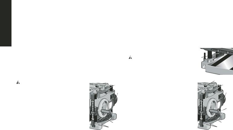
Transporting the Planer
|
WARNING: For your own safety, it |
is |
A |
|
|
recommended that two people carry this |
|||
|
machine or serious injury could result. |
C |
||
|
When moving your planer, carry it either |
|||
|
by the side carrying handles (A) or by the |
|||
|
handles at the base of the planer (B). When |
|||
|
transporting or storing the planer, use the |
|||
|
cord wrap located in the back of the tool (C) |
to keep the cord in place.
Bench Mounting
|
To facilitate bench mounting, two different |
B |
|
|
D |
||
|
sized holes (D) are provided on the four cor- |
||
4
ners of your planer. If mounting the planer with bolts, use the larger holes. If mounting the planer with nails or screws, use the smaller holes. It is not necessary to use both sets of holes.
Always mount your planer firmly to prevent movement. To enhance the tool’s portability, it can be mounted to a piece of 1/2″ (12.7mm) or thicker plywood which can then be clamped to your work support or moved to other job sites and reclamped.
NOTE: If you elect to mount your planer onto a piece of plywood, make sure that the mounting screws don’t protrude from the bottom of the wood. The plywood must sit flush on the work support.
 CAUTION: The mounting surface should not be warped or otherwise uneven.
|
ASSEMBLY |
E |
||
|
WARNING: |
DO NOT REMOVE |
||
|
GUARDS (E). Serious injury could result. |
|||
|
TO ATTACH THE DEPTH |
|||
|
ADJUSTMENT CRANK HANDLE |
|||
|
1. Remove the Allen screw located in the |
|||
|
crank handle shaft. |
G |
||
|
2. Insert the crank handle (F) over the |
A |
||
|
shaft. |
C |
||
|
3. Secure in place with the Allen screw |
|||
|
and T-wrench (G) provided. |
|||
|
DUST EJECTION PORTS |
|||
|
Your planer comes with two separate dust |
F |
||
|
ejection ports. The round port (I) as shown |
|||
|
below is for use with a 4″ dust collector |
|||
|
hose. The long, flat port (J) should be |
|||
|
attached when |
no dust collector will be |
B |
|
|
used. |
|||
|
D |

H
K
I


 C
C 


 H
H 
 J
J
TO SET UP DUST EJECTION
1.Select the port (I or J) that suits the type of dust collector you will be using.
2.Depress the lock button (K) on the chip ejection chute (H).
3.Slide the notches in the dust port over the pins on the chip ejection chute.
4.Rotate the port until the button engages the dust ejection chute and locks in place.
 WARNING: DO NOT OPERATE YOUR PLANER WITHOUT ONE OF THE DUST EJECTION PORTS LOCKED INTO PLACE. DO NOT INSERT ANYTHING INTO THE DUST EJECTION CHUTE UNLESS THE PLANER IS UNPLUGGED AND YOU ARE CLEARING A CLOG OR OBSTRUCTION IN THE UNIT. DO NOT GET YOUR FACE OR EYES NEAR THE DUST EJECTION PORT WHEN THE PLANER IS IN OPERATION. SERIOUS INJURY COULD RESULT.
 WARNING: Chips are ejected at significant velocity. Keep hands and face clear of dust ejection port.
TO REMOVE THE DUST EJECTION PORT
1.Use the T-wrench to depress the lock button on the dust chute.
2.Twist the port until the pins are disengaged from the notches on the port.
3.Pull the dust ejection port off of the dust chute.
5
OPERATION
On/Off Switch
To turn the planer on, lift the switch (L) up. The planer locks on automatically. To turn the tool off, press the switch down. A hole is provided under the switch (M) for insertion of a padlock to lock off the planer.
Depth Adjustment
DEPTH ADJUSTMENT SCALE
The depth adjustment scale (N), located on the right front of your planer, indicates the finished thickness of your workpiece. One rotation of the depth adjustment crank is equal to 1/16″, half rotation is equal to 1/32″, etc.
DEPTH ADJUSTMENT CRANK
Turning the crank clockwise lowers the cutter head. Turning the crank counterclockwise raises the cutter head.
Material Removal Gauge
Your planer is equipped with a material removal gauge (O). It is used to indicate the amount of wood that will be removed in one pass with the carriage set at its current height.
TO USE THE MATERIAL REMOVAL GAUGE
1.Slide approximately 3″ of your material under the middle of the carriage.
2.Be sure the wood is lying flat against the base of the planer. If the material is inserted at an angle, the reading may be inaccurate.
English

English
3.Crank the carriage down on the material until the material removal bar engages the wood. You will see the red arrow begin to move up the scale indicating the amount of material to be removed with the carriage at that height.
4.Adjust the carriage height until the desired depth of cut appears on the gauge.
5.Pull the material out from under the carriage.
6.Turn the unit on and feed your material into the cutter head. NOTE: Do not exceed the recommended depth of cut for various widths of material recommended on the material removal gauge.
 WARNING: DO NOT SWITCH THE UNIT ON WITH THE MATERIAL POSITIONED UNDER THE CARRIAGE. SERIOUS INJURY COULD RESULT.
Speed Selection
|
NOTE: ONLY SWITCH SPEEDS WHEN |
P |
|
THE PLANER IS RUNNING. |
|
|
Your planer has the ability to feed material |
|
|
at two different speeds. The two-speed |
|
|
feature (P) was designed to improve |
|
|
efficiency when planing and to provide the |
|
|
best possible surface finish to a variety of |
|
|
materials. |
To remove material thickness more quickly, set the unit at speed “2”. This setting delivers 96 cuts per inch to the material.
For finishing, set the unit to speed “1”. Speed “1” is ideal for ensuring the finest finish on the last pass before your final thickness is achieved.
NOTE: When planing particularly hard or figured species of wood, speed “1” is recommended. The slower feed rate will reduce knife wear and tear-out by delivering 179 cuts per inch to the material.
Fan-Assisted Chip Ejection System
Your planer is equipped with a fan-assisted chip ejection system to aid in exhausting chips from the unit. The fan-assisted chip ejection system will work in conjunction with independent dust collection systems.
NOTE: It is not recommended that a shop vac be connected to the DW735. The capacity of most vacs does not support the volume of chips ejected during planing. The vacuum hose may clog stopping the flow of chips.
See the Troubleshooting Guide, page 14, for additional information.
Automatic Carriage Lock
There is no manual carriage lock on your planer. A device that automatically minimizes the movement that causes snipe during planing is designed into the four threaded posts. 


Turret Stop
Your planer is equipped with a turret stop (Q) for Q repetitive planing at pre-set depths. Stops are set
at 1/8″, 1/4″, 1/2″, 3/4″, 1″, and 1-1/4″.
TO SET THE MINIMUM DEPTH TO WHICH
THE CARRIAGE CAN TRAVEL WITH THE
TURRET STOP
1.Be sure the carriage is set above 1-1/4″ before trying to set the turret stop.
2.Turn the dial on the front left of the planer until the desired thickness setting aligns with the red indicator then lower the carriage.
3.Plane the workpiece at desired increments until the correct final thickness is achieved.
NOTE: DO NOT USE FORCE TO CRANK THE CARRIAGE BELOW THE LEVEL THAT THE TURRET STOP INDICATES.
6
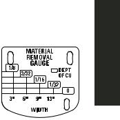
TABLE A
PERMANENT DAMAGE TO THE HEIGHT ADJUSTMENT SYSTEM ON YOUR PLANER WILL RESULT.
PLANING BASICS
Proper Planing Technique
TO PLANE YOUR MATERIAL
1.Lower the carriage to the desired height for your first pass.
2.Turn the unit on and feed the material into the feed rollers.
3.Examine the finished cut and adjust the carriage to the appropriate height for your next pass.
NOTE: Flip the board back and forth between each pass as recommended in Proper Planing Techniques.
See the Troubleshooting Guide, page 14, for additional information.
 WARNING: DO NOT TURN THE UNIT ON WITH THE MATERIAL ALREADY INSERTED UNDER THE CARRIAGE. WAIT UNTIL THE ROLLERS AND CUTTER HEAD ARE UP TO FULL SPEED BEFORE FEEDING YOUR MATERIAL INTO THE MACHINE.
For best results, plane both sides of the workpiece to reach a desired thickness. For example, if you need to remove 1/8″ from your workpiece, remove 1/16″ from each side. This not only allows the workpiece to dry with a even moisture content, it also produces finer cuts.
 WARNING: Plane only wood that is free from foreign objects, with no loose knots and as few tight knots as possible. Do not plane wood that is severely warped, twisted, knotted or bowed.
 WARNING: Do not place your body between the rear of the planer and a stationary object while material is feeding. Serious injury could result.
MINIMUM/MAXIMUM WIDTH/HEIGHT/DEPTH
NOTE: Always plane in the direction of the grain. Support the workpiece adequately at all times. Planing material less than 3/4″ wide is not recommended. If you must plane
narrow material, group several pieces
together and plane them as one wide workpiece whenever possible.
The maximum depth of cut your planer can take in one pass is 1/8″ (on material
less than 6″ wide). Never attempt to modify your planer to take a deeper cut. Follow the recommended depth/width of
cut guidelines shown in Table A for best results.
Snipe
Snipe is a depression made when an unsupported end of your material drops toward the floor, causing the opposite end to lift up into the cutter head.
TO AVOID SNIPE
Feed the workpiece into the planer so it is level and remains flat against the base at all times.
Keep the workpiece level throughout planing operation by receiving or “catching” it from the rear of the planer.
If you are planing material that is especially long, the use of additional material support is recommended.
Twisted, Cupped and Bowed Wood
If both sides of your material are very rough or if the material is cupped, bowed or twisted, your planer may not produce the desired result. Ideally, you should have at least one level face/surface on your material before you plane. Your thickness planer will work
7
English

English
best with material that has been run through a jointer to produce one flat surface. If you do not have at least one flat surface or a jointer, see the following recommendations.
TO PLANE TWISTED WOOD
 WARNING: TWISTED WOOD MAY JAM
YOUR THICKNESS PLANER. IF A JAM OCCURS, TURN THE POWER OFF, DISCONNECT THE POWER SUPPLY AND RAISE THE CARRIAGE TO RELEASE THE MATERIAL FROM THE CUTTER HEAD.
If your material is only slightly twisted:
Plane both sides alternating from one to the other until the desired thickness is reached.
TO PLANE CUPPED WOOD
To obtain the best possible results with cupped wood:
Rip the material down the middle and plane it as two separate pieces.
Ripping the material reduces the severity of the cup and allows the machine to deliver better results. Understand that you will have to remove more material on cupped wood to achieve the desired thickness than you would on a normal board.
If ripping the material is not an option:
Plane one side of the material until flat, then plane the opposite side until it is also flat .
NOTE: Do not flip the board back and forth between each pass as recommended by the general planing directions.
TO PLANE BOWED WOOD
The feed rollers and cutter head in your planer will push the bow out of the material as it feeds. However, when the material exits the
planer, the pressure of the rollers and cutter head will release allowing the wood to spring back into a bowed formation. To properly remove the bow, use a jointer.
BOWED WOOD WILL BE FLATTENED BY FEED ROLLERS AND CUTTER HEAD…
TOP FLAT
BOTTOM FLAT
…BUT BOW WILL RETURN AFTER WOOD IS PLANED
Changing the Planer Knives
 WARNING: DISCONNECT THE PLANER FROM THE POWER SOURCE BEFORE ATTEMPTING TO CHANGE OR ACCESS THE KNIVES.
TO CHANGE PLANER KNIVES
1.Use the T-wrench to remove the four screws in the top of the planer.
2.Lift the top off (Fig. 1) and place it aside.
3.Remove the three wing nuts that seal the dust shroud over the cutter head.
4.Rotate the dust shroud up so the round connection that locks onto the fan housing is in the open position (Fig. 2).
5.Push the dust shroud to the left so it disengages from the fan housing.
6.Take the dust shroud out of the unit (Fig. 3) and set it aside.
7.The cutter head is now exposed.
8
![]()
If the eight screws in the cutter head clamp are not visible, use a piece of scrap wood to carefully rotate the cutter head (Fig. 4) until the screws are accessible and the cutter head lock lever
(R) engages. This will prevent further rotation of the cutter head as you change the knives.
 WARNING: KEEP YOUR FINGERS AWAY FROM THE CUTTER HEAD AT ALL TIMES. USE THE TOOL PROVIDED TO HANDLE THE KNIVES.
8.Use the T-wrench to remove the eight screws on the knife clamp and set them in the small screws bin (S) on the front panel of the planer (Fig. 5).
9.Use the magnets on the top of the T-wrench to attract the knife clamp and lift it off of the cutter head. One of the knives should now be exposed.
10.Use the magnet (T) on the top of the T-wrench (Fig. 6) to attract the knife. Avoid touching it with your fingers.
If only one side of the knife is worn:
1.Turn the knife around so that the sharp, unused edge hangs over the end of the cutter head where it will cut the material. Be sure to set the oblong holes in the knife over the pins machined on the cutter head.
2.Reset the knife clamp over the knife. Be sure to align the beveled edge on the clamp with the sharp, cutting edge of the knife. If these are not aligned correctly, the clamp will not secure the knife properly.
3.Install the screws into the clamp and tighten sufficiently.
To access the other two knives:
1.Depress the cutter head lock lever (R) as shown in Figure 4.
2.Use the piece of scrap wood to carefully turn the cutter head until it locks into place revealing another knife clamp.
3.Follow the same knife change procedure indicated above.
English

English
4. Repeat the procedure for the last dull knife.
After installing new knives:
1.Insert the round end of the dust shroud into the fan housing and rotate it down to lock it into place.
2.Place the three wing nuts back into the shroud.
3.Screw the top cover of the planer back onto the unit.
NOTE: THE PLANER WILL NOT OPERATE IF THE TOP COVER IS NOT PLACED CORRECTLY.
MAINTENANCE
Brush Change
Your planer is equipped with brush caps
(U) that are external to the motor. If your brushes need to be replaced, begin by acquiring a new set from a DEWALT service center or a dealer authorized to service DEWALT products. Use only identical DEWALT brushes.
TO REPLACE THE BRUSHES ON YOUR PLANER
TURN OFF THE PLANER AND UNPLUG IT FROM THE POWER SOURCE.
1.Use the T-wrench to remove the top cover and brush cover screen on the planer.
2.Use a flathead screwdriver to unscrew
the brush cap located in the right, rear of the unit (V).
3.Do the same for the brush cap located on the side of the motor, inside the planer cover.
4.Place the new brushes into the brush holders.
5.After installing the brushes, replace the top cover and brush cover screen.
10
6.Before using the planer, run the unit for 10 minutes to seat new brushes.
NOTE: If existing brushes do not need replacing, be sure to maintain the same orientation when you reinstall them.
Calibrating the Depth Adjustment Scale
|
The depth adjustment scale (N) on |
|
|
your planer is set at the factory. |
|
|
However, with extended use, the |
|
|
depth adjustment scale could show |
|
|
an incorrect measurement. |
W |
|
To check the depth adjustment scale, |
N |
|
plane a piece of scrap wood, noting |
|
|
the measurement on the depth |
|
|
adjustment scale. |
Measure the finished thickness of the workpiece. If the thickness of the
workpiece does not match the reading on the depth adjustment scale, loosen the two screws (W) on the red indicator. Adjust the pointer up or down until its reading matches the finished thickness of the workpiece. Securely re-tighten the screws.
Base Maintenance
Keep the table clean and free from oil, grease, and pitch. Treat the table with paste wax to help maintain its smooth finish.
|
Circuit Breaker Reset |
|
|
Button |
X |
Your planer is equipped with an 18 amp circuit breaker. If your planer becomes overloaded and stops operating, turn off the planer, let the unit sit for 2 minutes and press the reset button (X) before you resume working.
 WARNING: To prevent the planer from starting unexpectedly if power is interrupted by a circuit breaker trip, make sure the switch is in the OFF position before restoring power.
NOTE: Circuit breaker overload is often the result of dull knives. Change your knives on a regular basis to avoid tripping your breaker. Check your knives before re-setting the circuit breaker and continuing to plane.
See the Troubleshooting Guide on page 14 for additional information on circuit breaker trips.
Replacing the Drive Belt
Drive belts are available at extra cost at DEWALT authorized service centers. Replacement of the drive belt should be performed by qualified service personnel.
Chip Ejection Fan
The chip ejection fan on your planer should be cleaned or cleared of debris periodically.
NOTE: TURN OFF AND UNPLUG THE PLANER
PRIOR TO ACCESSING THE CHIP EJECTION FAN.
TO ACCESS THE FAN
1.Remove the top cover of the planer with the T-wrench.
2.Remove the dust shroud (Fig. 2, 3) and place it aside.
3.Remove the screws around the fan housing.
4.Remove the fan housing and place it aside as shown. The fan will now be exposed for cleaning.
See the Troubleshooting Guide, page 14, for additional information.
 WARNING: Be sure to properly attach the fan housing and assemble the shroud and top cover correctly before using your planer again.
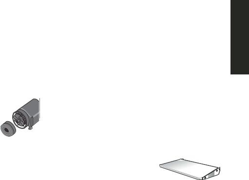
Accessories
Recommended accessories for use with your tool are available at extra cost from your distributor or local service center.
Four accessories are available for the DW735 Thickness Planer.
•DW7350 Mobile Stand
•DW7351 Folding Tables
•DW7352 13″ Knives
•DW7353 Chip Ejection Accessory
 CAUTION: The use of any other accessory not recommended for use with this tool could be hazardous.
If you need any assistance in locating these accessories, please contact DEWALT Industrial Tool Co., 701 East Joppa Road, Baltimore, MD 21286 or call 1-800-4-DEWALT (1-800-433-9258) or www.dewalt.com
DW7351 Accessory Folding Tables
 WARNING: For your own safety, read the tool instruction manual before attaching the tables. Failure to heed these warnings may result in personal injury and serious damage to the planer and the accessory. When servicing this tool, use only identical replacement parts. Have damaged cords replaced by an authorized service center.
Your DW7351 folding table box should include:
|
2 |
folding tables |
4 |
Allen cap screws |
|
4 |
springs |
4 |
nuts |
|
4 |
stepped Allen bolts |
SET-UP AND INSTALLATION OF
BASE HARDWARE
1.Place planer on a secure table or workbench. Position planer so the front 3-4″ of the base can be accessed from the underside.
11
English

FIG. 7
English
2.Secure the rear of the planer to the table/bench with nails or screws to prevent it from tilting or falling from the table.
WARNING: The planer could tilt or fall from the table if it is not properly secured opposite the end where the folding table is being installed. Serious injury may result.
3.Place the spring onto the small end of the stepped Allen bolt.
4.Insert the end of the bolt with the spring around it into the larger hole on the side of the base.
5.Push the stepped Allen bolt all the way through the hole in the first rib on the underside of the planer. The spring should engage the rib slightly and the threads should show on the right side of the rib.
6. On the underside of the planer, use a wrench to hold the nut in place while turning the stepped bolt into it. The T-wrench on your planer can be used to turn the stepped bolt until it is fully secured (Fig. 7).
7. Install the smaller Allen screw into the lower threaded hole on the side of the base. Use the T-wrench to tighten that fastener securely (Fig. 8).
8.Depress the top Allen pin until it is flush with the base and slide the top hole of the table over the pin and release the pin so they lock together (Fig. 8, 9).
9.To attach the table to the rear of the planer, install the bolts and spring following the above procedure.
Your tables should now fold up and down on the top Allen screw and rest on the bottom screw while in position for planing.
12
NOTE: To transport the planer with the tables, fold them up and carry the unit as recommended by the planer manual.
 WARNING: For your own safety, it is recommended that two people carry this machine or serious injury could result.
TO REMOVE THE TABLES
1.Depress the spring-loaded bolts on the base and slide each end of the table toward you so they disengage the holes in the tables. You may want to use the T-wrench from your planer to push the bolts flush with the base to easily remove the tables.
2.Leave the hardware (stepped bolts and small Allen cap screw) in the base until you need to re-attach the tables.
Repairs
To assure product SAFETY and RELIABILITY, repairs, maintenance and adjustment should be performed by authorized service centers or other qualified service personnel. Always use identical replacement parts.
Three Year Limited Warranty
DEWALT will repair, without charge, any defects due to faulty materials or workmanship for three years from the date of purchase. This warranty does not cover part failure due to normal wear or tool abuse. For further detail of warranty coverage and warranty repair information, visit www.dewalt.com or call 1-800-4-DEWALT (1-800-

433-9258). This warranty does not apply to accessories or damage caused where repairs have been made or attempted by others. This warranty gives you specific legal rights and you may have other rights which vary in certain states or provinces.
In addition to the warranty, DEWALT tools are covered by our:
1 YEAR FREE SERVICE
DEWALT will maintain the tool and replace worn parts caused by normal use, for free, any time during the first year after purchase.
90 DAY MONEY BACK GUARANTEE
If you are not completely satisfied with the performance of your DEWALT Power Tool, Laser, or Nailer for any reason, you can return it within 90 days from the date of purchase with a receipt for a full refund – no questions asked.
RECONDITIONED PRODUCT: Reconditioned product is covered under the 1 Year Free Service Warranty. The 90 Day Money Back Guarantee and the Three Year Limited Warranty do not apply to reconditioned product.
FREE WARNING LABEL REPLACEMENT:
If your warning labels become illegible or are missing, call 1-800-4-DEWALT for a free replacement.
13
English

English
Troubleshooting Guide
IF THE UNIT DOES NOT RUN, CHECK TO SEE:
•if the unit is plugged in.
•if the dust shroud is properly in place.
•if the top cover is properly in place.
•if the circuit breaker needs to be reset.
IF THE MATERIAL DOES NOT FEED PROPERLY, CHECK FOR:
•excess clogging in the dust shroud.
•excess oil/debris from feed rollers.
•excessively twisted, cupped or bowed material.
•a broken drive belt.
IF CHIPS DO NOT EJECT FROM THE REAR OF THE UNIT, CHECK TO SEE:
•if the dust shroud is properly in place.
•if the dust shroud and fan are clogged or obstructed.
IF THE CIRCUIT BREAKER TRIPS:
•check for dull knives. Dull knives could cause motor overloading.
•reduce depth of cut. An overly aggressive cut could cause motor overloading.
•drop feed rate to 14ft/min. A reduction in feed rate will reduce the load on the motor and prevent breaker trips.
IF THE BRANCH (HOUSE/SHOP) CIRCUIT BREAKER TRIPS REPEATEDLY:
•unplug or turn off other devices sharing the circuit with the planer OR use the planer on another branch circuit by itself.
•check for dull knives. Dull knives could cause motor overloading.
•reduce depth of cut. An overly aggressive cut could cause motor overloading.
•drop feed rate to 14ft/min. A reduction in feed rate will reduce the load on the motor and prevent breaker trips. NOTE: Even under normal loading conditions, other electrical loads on the same branch circuit may cause the circuit breaker to trip.
14
 Loading…