
Manufacturer: JEEP, Model Year: 2019,
Model line: COMPASS,
Model: JEEP COMPASS 2019
Pages: 420, PDF Size: 6.93 MB
Trending: подогрев сидений, панель, Капот, TPMS, мультимедиа, настройки системы
- Load previous 10 pages
Page 11 of 420
 ОКНА.......................... 57Органы управления электрическими
стеклоподъемниками.............. 57
Функция автоматического")
Page 12 of 420
 ДВИГАТЕЛЬ, РЕКОМЕНДАЦИИ ПО
ОБКАТКЕ...................... 175
СТОЯНОЧНЫЙ ТОРМОЗ............ 176
Электронный стояночный тормоз (E")
Page 13 of 420
 Фары высокой интенсивности (HID) — при
наличии...................... 233
Замена ламп наружного освещения.... 233
ПРЕДОХРАНИТ�")
Page 14 of 420
 Топливная система, предостережения . . 316
Предостережения об опасности
отравления угарным газом......... 316
НОМИН�")
Page 15 of 420
 Преобразование голосового ответа
в текстовое сообщение............ 379
Климат-контроль................ 380
Навигация (4C NAV) �")
Page 16 of 420
 ПРИБОРНАЯ ПАНЕЛЬ
Приборная панель
1 — Переключатель фар 6 — Рычаг стеклоочистителя ветрового стекла
2 — Мног")
Page 17 of 420
 ВНУТРЕННИЕ ЭЛЕМЕНТЫ
Элементы внутреннего оснащения
1 — Переключатели блокировки дверей 5 — Переключатель Sel")
Page 18 of 420
 КЛЮЧИ
Брелоки ключа
В автомобиле в зависимости от конфигу-
рации установлена система зажигания с
ключом или �")
Page 19 of 420
 ПРИМЕЧАНИЕ:
Если положение зажигания не изменя-
ется при нажатии кнопки, батарея бре-
лока ключа может иметь н")
Page 20 of 420
 Запирание дверей салона и багаж-
ника
Нажмите и отпустите кнопку блокировки
на брелоке ключа для блокировки �")
- Load next 10 pages
Trending: настройки системы, TPMS, подогрев сидений, панель, мультимедиа, Капот
View, print and download for free: JEEP COMPASS 2019 Руководство по эксплуатации и техобслуживанию (in Russian), 420 Pages, PDF Size: 6.93 MB. Search in JEEP COMPASS 2019 Руководство по эксплуатации и техобслуживанию (in Russian) online. CarManualsOnline.info is the largest online database of car user manuals. JEEP COMPASS 2019 Руководство по эксплуатации и техобслуживанию (in Russian) PDF Download. ОКНА…………………….. 57Органы управления электрическими
стеклоподъемниками………….. 57
Фун
All product names, logos, and brands are property of their respective owners.
Privacy Policy | About Us & Contact

2019 COMPASS USER GUIDE

Important
Get warranty and other information online – you can
review and print or download a copy of the Owner’s Manual, Navigation/Uconnect manuals and the limited warranties provided by FCA US LLC for your vehicle by visiting www.mopar.com (U.S.) or www.owners.mopar.ca (Canada). Click on the applicable link in the “Popular Topics” area of the www.mopar.com (U.S.) or www.owners.mopar.ca (Canada) homepage and follow the instructions to select the applicable year, make and model of your vehicle.
If you are the first registered retail owner of your vehicle, you may obtain a complimentary printed copy of the Warranty Booklet by calling 1-877-426-5337 (U.S.) or 1-800-387-1143 (Canada) or by contacting your dealer.
The driver’s primary responsibility is the safe operation of the vehicle. Driving while distracted can result in loss of vehicle control, resulting in a collision and personal injury. FCA US LLC strongly recommends that the driver use extreme caution when using any device or feature that may take their attention off the road.
Use of any electrical devices, such as cellular telephones, computers, portable radios, vehicle navigation or other devices, by the driver while the vehicle is moving is dangerous and could lead to a serious collision. Texting while driving is also dangerous and should never be done while the vehicle is moving.
If you find yourself unable to devote your full attention to vehicle operation, pull off the road to a safe location and stop your vehicle. Some states or provinces prohibit the use of cellular telephones or texting while driving. It is always the driver’s responsibility to comply with all local laws.
 WARNING: Operating, servicing and maintaining a passenger vehicle or off-road highway motor can expose you to chemicals including engine exhaust, carbon monoxide, phthalates, and lead, which are known to the State of California to cause cancer and birth defects or other reproductive harm. To minimize exposure, avoid breathing exhaust, do not idle the engine except as necessary, service your vehicle in a well-ventilated area and wear gloves or wash your hands frequently when servicing your vehicle. For more information go to: www.p65Warnings.ca.gov/passenger-vehicle.

Congratulations on selecting your new FCA US LLC vehicle. Be assured that it represents precision workmanship, distinctive styling, and high quality.
ALWAYS drive safely and pay attention to the road. ALWAYS drive safely with your hands on the steering wheel. You have full responsibility and assume all risks related to the use of the features and applications in this vehicle. Only use the features and applications when it is safe to do so. Failure to do so may result in an accident involving serious injury or death.
This guide illustrates and describes the operation of features and equipment that are either standard or optional on this vehicle. This guide may also include a description of features and equipment that are no longer available or were not ordered on this vehicle. Please disregard any features and equipment described in this guide that are not available on this vehicle. FCA US LLC reserves the right to make changes in design and specifications and/or make additions to or improvements to its products without imposing any
obligation upon itself to install them on products previously manufactured.
This User Guide has been prepared to help you quickly become acquainted with the important features of your vehicle. It contains most things you will need to operate and maintain the vehicle, including emergency information.
When it comes to service, remember that your authorized dealer knows your Jeep® vehicle best, has factory-trained technicians and genuine MOPAR® parts, and cares about your satisfaction.
HOW TO FIND YOUR OWNER’S MANUAL ONLINE
This publication has been prepared as a reference item to help you quickly become acquainted with the most important features and processes of your vehicle. It contains most things you will need to operate and maintain the vehicle, including emergency information and procedures.
This User Guide is not a replacement for the full Owner’s Manual, and does not fully cover every operation and procedure possible with your vehicle.
For more detailed descriptions of the topics discussed in this User Guide, as well as information covering features and processes not covered in this User Guide, the full vehicle Owner’s Manual can be accessed for free online in a printer-friendly PDF format.
To get the full Owner’s Manual or applicable supplement for your vehicle, follow the appropriate web address below:
www.mopar.com/en-us/care/owners-manual.html
(U.S. Residents)
www.owners.mopar.ca (Canadian Residents)
FCA US LLC is committed to protecting our environment and natural resources. By converting from paper to electronic delivery for the majority of the user information for your vehicle, together we greatly reduce the demand for tree-based products and lessen the stress on our environment. 

LLC US FCA FROM WELCOME
1

HOW TO USE THIS MANUAL
HOW TO USE THIS MANUAL
Essential Information
Each time direction instructions (left/right or forwards/backwards) about the vehicle are given, these must be intended as regarding an occupant in the driver’s seat. Special cases not complying with this rule will be properly specified in the text.
The figures in this User Guide are provided by way of example only: this might imply that some details of the image do not correspond to the actual arrangement of your vehicle.
In addition, the User Guide has been conceived considering vehicles with the steering wheel on the left side; it is therefore possible that in vehicles with the steering wheel on the right side, the position or construction of some controls is not exactly mirror-like with respect to the figure.
To identify the chapter with the information needed you can consult the index at the end of this User Guide.
Chapters can be rapidly identified with dedicated graphic tabs, at the side of each odd page. A few pages further there is a key for getting to know the chapter order and the relevant symbols in the tabs. There is always a textual indication of the current chapter at the side of each even page.
Symbols
Some vehicle components have colored labels whose symbols indicate precautions to be observed when using this component. Refer to “Warning Lights and Messages” in “Getting To Know Your Instrument Panel” for further information on the symbols used in your vehicle.
ROLLOVER WARNING
Utility vehicles have a significantly higher rollover rate than other types of vehicles. This vehicle has a higher ground clearance and a higher center of gravity than many passenger vehicles. It is capable of performing better in a wide variety of off-road applications. Driven in an unsafe manner, all vehicles can go out
of control. Because of the higher center of gravity, if this vehicle is out of control it may roll over while some other vehicles may not.
Do not attempt sharp turns, abrupt maneuvers, or other unsafe driving actions that can cause loss of vehicle control. Failure to operate this vehicle safely may result in a collision, rollover of the vehicle, and severe or fatal injury. Drive carefully.
Rollover Warning Label
Failure to use the driver and passenger seat belts provided is a major cause of severe or fatal injury. In fact, the U.S. government notes that the universal use of existing seat belts could cut the highway death toll by 10,000 or more each year and could reduce disabling injuries by two million annually.
2

In a rollover crash, an unbelted person is significantly more likely to die than a person wearing a seat belt. Always buckle up.
WARNINGS AND CAUTIONS
While reading this User Guide you will find a series of WARNINGS to be followed to prevent incorrect use of components which could cause accidents or injuries.
There are also CAUTIONS that must be followed to prevent against procedures that could result in damage to your vehicle.
MANUAL THIS USE TO HOW
3

4

GRAPHICAL TABLE OF CONTENTS
GETTING TO KNOW YOUR VEHICLE GETTING TO KNOW YOUR INSTRUMENT PANEL SAFETY STARTING AND OPERATING
IN CASE OF EMERGENCY
SERVICING AND MAINTENANCE
TECHNICAL SPECIFICATIONS
MULTIMEDIA
CUSTOMER ASSISTANCE
INDEX

TABLE OF CONTENTS
WELCOME FROM FCA US LLC
HOW TO FIND YOUR OWNER’S MANUAL ONLINE . . . . 1
HOW TO USE THIS MANUAL
HOW TO USE THIS MANUAL . . . . . . . . . . . . . . . 2
Essential Information . . . . . . . . . . . . . . . . 2
Symbols . . . . . . . . . . . . . . . . . . . . . . . . 2
|
ROLLOVER WARNING . . . . . . . . . . . . . |
. . . . . . 2 |
|
WARNINGS AND CAUTIONS . . . . . . . . . |
. . . . . . 3 |
|
GRAPHICAL TABLE OF CONTENTS |
|
|
INSTRUMENT PANEL . . . . . . . . . . . . . |
. . . . . 10 |
|
INTERIOR . . . . . . . . . . . . . . . . . . . . . |
. . . . 11 |
|
GETTING TO KNOW YOUR VEHICLE |
|
|
KEYS . . . . . . . . . . . . . . . . . . . . . . . |
. . . . 12 |
|
Key Fob . . . . . . . . . . . . . . . . . . . |
. . . . 12 |
|
IGNITION SWITCH . . . . . . . . . . . . . . . . |
. . . . 14 |
|
Keyless Enter-N-Go — Ignition . . . . . |
. . . . 14 |
|
REMOTE STARTING SYSTEM — IF EQUIPPED |
. . . . 15 |
|
How To Use Remote Start — If Equipped . . . 15 |
|
|
To Enter Remote Start Mode . . . . . . . |
. . . . 16 |
|
General Information . . . . . . . . . . . |
. . . . 16 |
|
VEHICLE SECURITY ALARM — IF EQUIPPED |
. . . . . 16 |
|
To Arm The System . . . . . . . . . . . . |
. . . . 17 |
|
To Disarm The System . . . . . . . . . . |
. . . . 17 |
|
Security System Manual Override . . . . |
. . . . 17 |
|
DOORS . . . . . . . . . . . . . . . . . . . . . . |
. . . . 17 |
|
Keyless Enter-N-Go — Passive Entry . . |
. . . . 17 |
|
Child-Protection Door Lock System — Rear |
|
|
Doors . . . . . . . . . . . . . . . . . . . . . |
. . . . 21 |
|
SEATS . . . . . . . . . . . . . . . . . . . . . . |
. . . . 22 |
|
Manual Adjustment (Rear Seats) . . . . |
. . . . 22 |
|
Front Heated Seats — If Equipped . . . |
. . . . 23 |
|
HEAD RESTRAINTS . . . . . . . . . . . . . . |
. . . . . 24 |
|
Front Head Restraint Adjustment . . . |
. . . . . 24 |
|
Rear Head Restraints . . . . . . . . . . |
. . . . . 25 |
|
STEERING WHEEL . . . . . . . . . . . . . . |
. . . . . 26 |
|
Tilt/Telescoping Steering Column . . . . |
. . . . 26 |
|
Heated Steering Wheel — If Equipped . |
. . . . 27 |
|
EXTERIOR LIGHTS . . . . . . . . . . . . . . . . |
. . . . 27 |
|
Multifunction Lever . . . . . . . . . . . . |
. . . . 27 |
|
Headlight Switch . . . . . . . . . . . . . . |
. . . . 27 |
|
Daytime Running Lights (DRL) — If |
|
|
Equipped . . . . . . . . . . . . . . . . . . |
. . . . 28 |
|
High/Low Beam Switch . . . . . . . . . . |
. . . . 28 |
|
Automatic High Beam Headlamp Control — |
|
|
If Equipped . . . . . . . . . . . . . . . . . |
. . . . 28 |
|
Flash-To-Pass . . . . . . . . . . . . . . . |
. . . . 29 |
|
Automatic Headlights — If Equipped |
. . . . . 29 |
|
Headlight Time Delay . . . . . . . . . . . |
. . . . 29 |
|
Lights-On Reminder . . . . . . . . . . . . |
. . . . 29 |
|
Fog Lights — If Equipped . . . . . . . . |
. . . . 29 |
|
Turn Signals . . . . . . . . . . . . . . . . |
. . . . 30 |
|
Battery Saver Feature . . . . . . . . . . . |
. . . . 30 |
|
WINDSHIELD WIPERS AND WASHERS . . . . . |
. . . . 30 |
|
Windshield Wiper Operation . . . . . . . |
. . . . 30 |
|
Rain Sensing Wipers — If Equipped . . |
. . . . 31 |
|
Rear Window Wiper/Washer . . . . . . . |
. . . . 32 |
|
CLIMATE CONTROLS . . . . . . . . . . . . . . |
. . . . 32 |
|
Climate Controls With A Touchscreen |
|
|
Overview . . . . . . . . . . . . . . . . . . . |
. . . . 32 |
|
Climate Control Functions . . . . . . . . |
. . . . 39 |
|
Automatic Temperature Control (ATC) |
. . . . . 39 |
|
Operating Tips . . . . . . . . . . . . . . . |
. . . . 40 |
|
WINDOWS . . . . . . . . . . . . . . . . . . . . |
. . . . 41 |
|
Power Window Controls . . . . . . . . . . |
. . . . 41 |
|
Auto-Down Feature . . . . . . . . . . . . |
. . . . 41 |
|
Auto-Up Feature With Anti-Pinch Protection |
. . 42 |
|
Window Lockout Switch . . . . . . . . . . . |
. . 42 |
|
Wind Buffeting . . . . . . . . . . . . . . . . |
. . 42 |
|
POWER SUNROOF WITH POWER SHADE — |
|
|
IF EQUIPPED . . . . . . . . . . . . . . . . . . . . . |
. . 43 |
|
Opening Sunroof . . . . . . . . . . . . . . . . |
. . 43 |
|
Opening Sunroof — Vent . . . . . . . . . . . |
. . 44 |
|
Closing Sunroof . . . . . . . . . . . . . . . . |
. . 44 |
|
Opening Power Shade . . . . . . . . . . . . . |
. . 44 |
|
Closing Power Shade . . . . . . . . . . . . . |
. . 45 |
|
Pinch Protect Feature . . . . . . . . . . . . . |
. . 45 |
|
Sunroof Maintenance . . . . . . . . . . . . . |
. . 45 |
|
Ignition Off Operation . . . . . . . . . . . . . |
. . 45 |
|
HOOD . . . . . . . . . . . . . . . . . . . . . . . . |
. . 46 |
|
Opening The Hood . . . . . . . . . . . . . . . |
. . 46 |
|
Closing The Hood . . . . . . . . . . . . . . . |
. . 46 |
|
LIFTGATE . . . . . . . . . . . . . . . . . . . . . . . |
. . 47 |
|
Opening . . . . . . . . . . . . . . . . . . . . . |
. . 47 |
|
Closing . . . . . . . . . . . . . . . . . . . . . . |
. . 47 |
|
Power Liftgate — If Equipped . . . . . . . . |
. . 47 |
|
INTERNAL EQUIPMENT . . . . . . . . . . . . . . . |
. . 49 |
|
Power Outlets . . . . . . . . . . . . . . . . . . |
. . 49 |
|
Power Inverter — If Equipped . . . . . . . . |
. . 50 |
|
ROOF LUGGAGE RACK — IF EQUIPPED . . . . . . |
. . 51 |
|
GETTING TO KNOW YOUR |
|
|
INSTRUMENT PANEL |
|
|
INSTRUMENT CLUSTER DISPLAY . . . . . . . . . |
. . 53 |
|
Instrument Cluster Display Location And |
|
|
Controls . . . . . . . . . . . . . . . . . . . . . |
. . 53 |
|
Oil Change Reset . . . . . . . . . . . . . . . |
. . 54 |
|
Instrument Cluster Display Menu Items . . . . 54 |
|
|
TRIP COMPUTER . . . . . . . . . . . . . . . . . . |
. . 54 |
6

|
WARNING LIGHTS AND MESSAGES . . . . . |
. . . . |
. 55 |
|
Red Warning Lights . . . . . . . . . . . |
. . . . . |
55 |
|
Yellow Warning Lights . . . . . . . . . . |
. . . . . |
58 |
|
Yellow Indicator Lights . . . . . . . . . |
. . . . . |
62 |
|
Green Indicator Lights . . . . . . . . . |
. . . . . |
62 |
|
White Indicator Lights . . . . . . . . . |
. . . . . |
63 |
|
Blue Indicator Lights . . . . . . . . . . |
. . . . . |
64 |
|
Gray Indicator Lights . . . . . . . . . . |
. . . . . |
64 |
|
ONBOARD DIAGNOSTIC SYSTEM — OBD II . |
. . . . . |
65 |
|
Onboard Diagnostic System (OBD II) |
||
|
Cybersecurity . . . . . . . . . . . . . . . |
. . . . . |
65 |
|
EMISSIONS INSPECTION AND MAINTENANCE |
||
|
PROGRAMS . . . . . . . . . . . . . . . . . . |
. . . . . |
66 |
|
SAFETY |
||
|
SAFETY FEATURES . . . . . . . . . . . . . . |
. . . . . |
67 |
|
Anti-Lock Brake System (ABS) . . . . |
. . . . . |
67 |
|
Electronic Brake Control System . . . |
. . . . . |
68 |
|
AUXILIARY DRIVING SYSTEMS . . . . . . . . |
. . . . . |
76 |
|
Blind Spot Monitoring (BSM) — If Equipped . . |
76 |
|
|
Forward Collision Warning (FCW) With |
||
|
Mitigation — If Equipped . . . . . . . |
. . . . . |
80 |
|
Tire Pressure Monitor System (TPMS) |
. . . . . 82 |
|
|
OCCUPANT RESTRAINT SYSTEMS . . . . . . |
. . . . . |
87 |
|
Occupant Restraint Systems Features |
. . . . . 87 |
|
|
Important Safety Precautions . . . . . |
. . . . . |
87 |
|
Seat Belt Systems . . . . . . . . . . . |
. . . . . |
88 |
|
Supplemental Restraint Systems (SRS) |
. . . . 97 |
|
|
Child Restraints . . . . . . . . . . . . . |
. . . . |
112 |
|
Transporting Pets . . . . . . . . . . . . |
. . . . |
123 |
|
SAFETY TIPS . . . . . . . . . . . . . . . . . |
. . . . |
123 |
|
Transporting Passengers . . . . . . . . |
. . . . |
123 |
|
Exhaust Gas . . . . . . . . . . . . . . . |
. . . . |
123 |
|
Safety Checks You Should Make Inside |
||
|
The Vehicle . . . . . . . . . . . . . . . . |
. . . . |
124 |
|
Periodic Safety Checks You Should Make |
|
|
Outside The Vehicle . . . . . . . . . . . . . |
. . 126 |
|
STARTING AND OPERATING |
|
|
STARTING THE ENGINE . . . . . . . . . . . . . . |
. . 127 |
|
Normal Starting . . . . . . . . . . . . . . . |
. . 127 |
|
Stopping The Engine . . . . . . . . . . . . . |
. 129 |
|
ENGINE BREAK-IN RECOMMENDATIONS . . . . . . |
. 129 |
|
PARK BRAKE . . . . . . . . . . . . . . . . . . . . . |
. 129 |
|
Electric Park Brake (EPB) . . . . . . . . . . |
. 129 |
|
MANUAL TRANSMISSION — IF EQUIPPED . . . . . |
. 132 |
|
Shifting . . . . . . . . . . . . . . . . . . . . . |
. 133 |
|
Downshifting . . . . . . . . . . . . . . . . . . |
. 133 |
|
Parking . . . . . . . . . . . . . . . . . . . . . . |
. 135 |
|
AUTOMATIC TRANSMISSION — IF EQUIPPED . . . . 135 |
|
|
Ignition Park Interlock . . . . . . . . . . . . . |
. 136 |
|
Brake/Transmission Shift Interlock System |
. . 136 |
|
Six-Speed Or Nine-Speed Automatic |
|
|
Transmission . . . . . . . . . . . . . . . . . . |
. 136 |
|
FOUR-WHEEL DRIVE OPERATION — IF EQUIPPED . |
. 142 |
|
Jeep Active Drive . . . . . . . . . . . . . . . . |
. 142 |
|
SELEC-TERRAIN — IF EQUIPPED . . . . . . . . . . |
. 144 |
|
Mode Selection Guide . . . . . . . . . . . . . |
. 144 |
|
STOP/START SYSTEM — IF EQUIPPED . . . . . . . |
. 145 |
|
Automatic Mode . . . . . . . . . . . . . . . . |
. 145 |
|
Possible Reasons The Engine Does Not |
|
|
Autostop . . . . . . . . . . . . . . . . . . . . . |
. 145 |
|
To Start The Engine While In Autostop |
|
|
Mode . . . . . . . . . . . . . . . . . . . . . . . |
. 146 |
|
To Manually Turn Off The Stop/Start System |
. . 147 |
|
To Manually Turn On The Stop/Start System |
. . 147 |
|
SPEED CONTROL — IF EQUIPPED . . . . . . . . . |
. 147 |
|
To Activate . . . . . . . . . . . . . . . . . . . |
. 148 |
|
To Set A Desired Speed . . . . . . . . . . . . |
. 148 |
|
To Resume Speed . . . . . . . . . . . . |
. . . . 148 |
|
To Deactivate . . . . . . . . . . . . . . . |
. . . . 148 |
|
ADAPTIVE CRUISE CONTROL (ACC) — IF |
|
|
EQUIPPED . . . . . . . . . . . . . . . . . . . |
. . . . 149 |
|
To Activate/Deactivate . . . . . . . . . . |
. . . . 149 |
|
To Set A Desired ACC Speed . . . . . . |
. . . . 149 |
|
To Resume . . . . . . . . . . . . . . . . . |
. . . 150 |
|
To Vary The Speed Setting . . . . . . . . |
. . . 150 |
|
Setting The Following Distance In ACC . |
. . . 151 |
|
General Information . . . . . . . . . . . . |
. . . 152 |
|
PARKSENSE REAR PARK ASSIST — IF EQUIPPED . . 152 |
|
|
ParkSense Sensors . . . . . . . . . . . . . |
. . . 152 |
|
ParkSense Warning Display . . . . . . . . |
. . . 153 |
|
Enabling And Disabling ParkSense . . . |
. . . 153 |
|
ParkSense System Usage Precautions |
. . . . 153 |
|
LANESENSE — IF EQUIPPED . . . . . . . . . . |
. . . 154 |
|
LaneSense Operation . . . . . . . . . . . |
. . . 154 |
|
Turning LaneSense On Or Off . . . . . . |
. . . 155 |
|
LaneSense Warning Message . . . . . . . |
. . . 155 |
|
Changing LaneSense Status . . . . . . . |
. . . 157 |
|
PARKVIEW REAR BACK UP CAMERA . . . . . . |
. . . 157 |
|
REFUELING THE VEHICLE . . . . . . . . . . . . |
. . . 158 |
|
TRAILER TOWING . . . . . . . . . . . . . . . . |
. . . 160 |
|
Trailer Towing Weights (Maximum Trailer |
|
|
Weight Ratings) . . . . . . . . . . . . . . . |
. . . 160 |
|
RECREATIONAL TOWING (BEHIND MOTORHOME, |
|
|
ETC.) . . . . . . . . . . . . . . . . . . . . . . . |
. . . 160 |
|
Towing This Vehicle Behind Another |
|
|
Vehicle . . . . . . . . . . . . . . . . . . . . |
. . . 160 |
|
Recreational Towing — Front-Wheel Drive |
|
|
(FWD) Models . . . . . . . . . . . . . . . . |
. . . 161 |
|
Recreational Towing — 4X4 Models . . . . . 161 |
|
|
IN CASE OF EMERGENCY |
|
|
HAZARD WARNING FLASHERS . . . . . . . . . |
. . . 162 |
7

TABLE OF CONTENTS
|
BULB REPLACEMENT . . . . . . . . . . . . . . . |
. . 162 |
|
Replacement Bulbs . . . . . . . . . . . . . . |
. 162 |
|
High Intensity Discharge (HID) Headlamps — |
|
|
If Equipped . . . . . . . . . . . . . . . . . . . |
. 163 |
|
Replacing Exterior Bulbs . . . . . . . . . . . |
. 163 |
|
FUSES . . . . . . . . . . . . . . . . . . . . . . . . |
. 167 |
|
General Information . . . . . . . . . . . . . . |
. 167 |
|
Fuse Location . . . . . . . . . . . . . . . . . . |
. 167 |
|
Engine Compartment Fuses/Distribution |
|
|
Unit . . . . . . . . . . . . . . . . . . . . . . . |
. 168 |
|
Interior Fuses . . . . . . . . . . . . . . . . . . |
. 171 |
|
Rear Cargo Fuse/Relay Distribution Unit . . |
. 172 |
|
JACKING AND TIRE CHANGING . . . . . . . . . . . |
. 173 |
|
Jack Location/Spare Tire Stowage . . . . . . |
. 174 |
|
Preparations For Jacking . . . . . . . . . . . |
. 175 |
|
Jacking Instructions . . . . . . . . . . . . . . |
. 176 |
|
Road Tire Installation . . . . . . . . . . . . . |
. 178 |
|
TIRE SERVICE KIT — IF EQUIPPED . . . . . . . . . |
. 179 |
|
JUMP STARTING . . . . . . . . . . . . . . . . . . . |
. 184 |
|
Preparations For Jump Start . . . . . . . . . |
. 185 |
|
Jump Starting Procedure . . . . . . . . . . . |
. 185 |
|
REFUELING IN EMERGENCY . . . . . . . . . . . . . |
. 187 |
|
IF YOUR ENGINE OVERHEATS . . . . . . . . . . . . |
. 187 |
|
GEAR SELECTOR OVERRIDE . . . . . . . . . . . . . |
. 188 |
|
FREEING A STUCK VEHICLE . . . . . . . . . . . . . |
. 188 |
|
TOWING A DISABLED VEHICLE . . . . . . . . . . . |
. 190 |
|
Without The Key Fob . . . . . . . . . . . . . |
. 191 |
|
Front-Wheel Drive (FWD) Models — |
|
|
With Key Fob . . . . . . . . . . . . . . . . . . |
. 191 |
|
4×4 Models . . . . . . . . . . . . . . . . . . . |
. 191 |
|
Emergency Tow Hooks . . . . . . . . . . . . . |
. 192 |
|
ENHANCED ACCIDENT RESPONSE SYSTEM (EARS) |
. . 192 |
|
EVENT DATA RECORDER (EDR) . . . . . . . . . . . |
. 192 |
SERVICING AND MAINTENANCE
|
SCHEDULED SERVICING . . . . . . . . . . . . . |
. . . 193 |
|
Maintenance Plan . . . . . . . . . . . . . |
. . . 194 |
|
ENGINE COMPARTMENT . . . . . . . . . . . . |
. . . 196 |
|
2.4L Engine . . . . . . . . . . . . . . . . . . |
. . 196 |
|
Checking Oil Level . . . . . . . . . . . . . . |
. . 197 |
|
Adding Washer Fluid . . . . . . . . . . . . |
. . 197 |
|
Maintenance-Free Battery . . . . . . . . . |
. . 197 |
|
DEALER SERVICE . . . . . . . . . . . . . . . . . |
. . 198 |
|
Air Conditioner Maintenance . . . . . . . . |
. . 198 |
|
Wiper Blades . . . . . . . . . . . . . . . . . |
. . 199 |
|
Cooling System . . . . . . . . . . . . . . . . |
. . 200 |
|
Brake System . . . . . . . . . . . . . . . . |
. . 200 |
|
Manual Transmission — If Equipped . . . . . 201 |
|
|
Automatic Transmission — If Equipped |
. . . 201 |
|
RAISING THE VEHICLE . . . . . . . . . . . . . . . |
. . 202 |
|
TIRES . . . . . . . . . . . . . . . . . . . . . . . . |
. . 202 |
|
Tire Safety Information . . . . . . . . . . . |
. . 202 |
|
Tires — General Information . . . . . . . |
. . 206 |
|
Tire Types . . . . . . . . . . . . . . . . . . . |
. . 211 |
|
Spare Tires — If Equipped . . . . . . . . |
. . 212 |
|
Tire Chains (Traction Devices) . . . . . . . |
. . 213 |
|
Tire Rotation Recommendations . . . . . . |
. . 214 |
|
DEPARTMENT OF TRANSPORTATION UNIFORM TIRE |
|
|
QUALITY GRADES . . . . . . . . . . . . . . . . . |
. . 215 |
|
Treadwear . . . . . . . . . . . . . . . . . . . |
. . 215 |
|
Traction Grades . . . . . . . . . . . . . . . . |
. . 216 |
|
Temperature Grades . . . . . . . . . . . . . |
. . 216 |
|
INTERIORS . . . . . . . . . . . . . . . . . . . . . |
. . 216 |
|
Seats And Fabric Parts . . . . . . . . . . . |
. . 216 |
|
Plastic And Coated Parts . . . . . . . . . . |
. . 217 |
|
Leather Parts . . . . . . . . . . . . . . . . . |
. . 218 |
|
Glass Surfaces . . . . . . . . . . . . . . . . |
. . 218 |
TECHNICAL SPECIFICATIONS
|
IDENTIFICATION DATA . . . . . . . . . . . . . |
. . . . 219 |
|
Vehicle Identification Number . . . . . |
. . . . 219 |
|
WHEEL AND TIRE TORQUE SPECIFICATIONS |
. . . . 220 |
|
Torque Specifications . . . . . . . . . . |
. . . . 220 |
|
FUEL REQUIREMENTS . . . . . . . . . . . . . |
. . . . 220 |
|
2.4L Engine . . . . . . . . . . . . . . . . . |
. . . 220 |
|
E-85 Usage In Non-Flex Fuel Vehicles |
. . . . 221 |
|
Materials Added To Fuel . . . . . . . . . |
. . . 221 |
|
FLUID CAPACITIES . . . . . . . . . . . . . . . . |
. . . 222 |
|
FLUIDS AND LUBRICANTS . . . . . . . . . . . . |
. . . 222 |
|
Engine . . . . . . . . . . . . . . . . . . . . |
. . . 222 |
|
Chassis . . . . . . . . . . . . . . . . . . . . |
. . . 223 |
|
MOPAR ACCESSORIES . . . . . . . . . . . . . . |
. . . 224 |
|
Authentic Accessories By Mopar . . . . |
. . . 224 |
|
MULTIMEDIA |
|
|
CYBERSECURITY . . . . . . . . . . . . . . . . |
. . . 226 |
|
UCONNECT 3 WITH 5–INCH DISPLAY — |
|
|
IF EQUIPPED . . . . . . . . . . . . . . . . . . . |
. . . 227 |
|
Uconnect 3 With 5–inch Display At A |
|
|
Glance . . . . . . . . . . . . . . . . . . . . |
. . . 227 |
|
Clock Setting . . . . . . . . . . . . . . . . |
. . . 228 |
|
Audio Setting . . . . . . . . . . . . . . . . |
. . . 228 |
|
Radio Operation . . . . . . . . . . . . . . |
. . . 229 |
|
USB/Audio Jack (AUX)/Bluetooth Operation . 229 |
|
|
Voice Text Reply (Not Compatible With |
|
|
iPhone) . . . . . . . . . . . . . . . . . . . |
. . . 230 |
|
UCONNECT 4 WITH 7-INCH DISPLAY . . . . . |
. . . 231 |
|
Uconnect 4 At A Glance . . . . . . . . . |
. . . 231 |
|
Drag & Drop Menu Bar . . . . . . . . . . |
. . . 233 |
|
Radio . . . . . . . . . . . . . . . . . . . . |
. . . 234 |
|
Media Hub — USB/Audio Jack (AUX) — |
|
|
If Equipped . . . . . . . . . . . . . . . . . |
. . . 235 |
8
![]()
|
Android Auto — If Equipped . . . . . . . |
. . . 237 |
|
Apple CarPlay Integration — If Equipped |
. . 238 |
|
UCONNECT SETTINGS . . . . . . . . . . . . . . |
. . . 239 |
|
TIPS CONTROLS AND GENERAL INFORMATION |
. . . 240 |
|
Steering Wheel Audio Controls . . . . . . |
. . . 240 |
|
Reception Conditions . . . . . . . . . . . . |
. . 240 |
|
Care And Maintenance . . . . . . . . . . . |
. . 241 |
|
Anti-Theft Protection . . . . . . . . . . . . |
. . 241 |
|
UCONNECT PHONE . . . . . . . . . . . . . . . . |
. . 242 |
|
Uconnect Phone |
|
|
(Bluetooth Hands Free Calling) . . . . . . |
. . 242 |
|
Pairing (Wirelessly Connecting) Your |
|
|
Mobile Phone To The Uconnect System |
. . . 245 |
|
Common Phone Commands (Examples) |
. . . 249 |
|
Mute (Or Unmute) Microphone During Call |
. . 249 |
|
Transfer Ongoing Call Between Handset |
|
|
And Vehicle . . . . . . . . . . . . . . . . . . |
. . 249 |
|
Phonebook . . . . . . . . . . . . . . . . . . |
. . 249 |
|
Voice Command Tips . . . . . . . . . . . . |
. . 250 |
|
Changing The Volume . . . . . . . . . . . . |
. . 250 |
|
Using Do Not Disturb . . . . . . . . . . . . |
. . 250 |
|
Incoming Text Messages . . . . . . . . . . |
. . 251 |
|
Helpful Tips And Common Questions To Improve |
|
|
Bluetooth Performance With Your Uconnect |
|
|
System . . . . . . . . . . . . . . . . . . . . |
. . 252 |
|
UCONNECT VOICE RECOGNITION QUICK TIPS . . . . 253 |
|
|
Introducing Uconnect . . . . . . . . . . . . |
. . 253 |
|
Get Started . . . . . . . . . . . . . . . . . . |
. . 253 |
|
Basic Voice Commands . . . . . . . . . . . |
. . 254 |
|
Radio . . . . . . . . . . . . . . . . . . . . . . |
. . 254 |
|
Media . . . . . . . . . . . . . . . . . . . . . |
. . 255 |
|
Phone . . . . . . . . . . . . . . . . . . . . . |
. . 256 |
|
Voice Text Reply . . . . . . . . . . . . . . . |
. . 256 |
|
Climate . . . . . . . . . . . . . . . . . . |
. . . . . 257 |
|
Siri Eyes Free — If Equipped . . . . |
. . . . . 258 |
|
Using Do Not Disturb . . . . . . . . . |
. . . . . 259 |
|
Android Auto — If Equipped . . . . . . |
. . . . 259 |
|
Apple CarPlay — If Equipped . . . . . |
. . . . 260 |
|
General Information . . . . . . . . . . . |
. . . . 261 |
|
Additional Information . . . . . . . . . |
. . . . 261 |
|
CUSTOMER ASSISTANCE |
|
|
IF YOU NEED ASSISTANCE . . . . . . . . . . |
. . . . 262 |
|
FCA US LLC Customer Center . . . . . |
. . . . 262 |
|
FCA Canada Inc. Customer Center . . |
. . . . 262 |
|
In Mexico Contact . . . . . . . . . . . . |
. . . . 262 |
|
Puerto Rico And U.S. Virgin Islands |
. . . . . 262 |
|
Customer Assistance For The Hearing Or |
|
|
Speech Impaired (TDD/TTY) . . . . . . |
. . . . 263 |
|
Service Contract . . . . . . . . . . . . . |
. . . . 263 |
|
WARRANTY INFORMATION . . . . . . . . . . |
. . . . 264 |
|
MOPAR PARTS . . . . . . . . . . . . . . . . . |
. . . . 264 |
|
REPORTING SAFETY DEFECTS . . . . . . . . . |
. . . . 264 |
|
In The 50 United States And Washington, |
|
|
D.C. . . . . . . . . . . . . . . . . . . . . . |
. . . . 264 |
|
In Canada . . . . . . . . . . . . . . . . . |
. . . . 264 |
|
PUBLICATION ORDER FORMS . . . . . . . . . |
. . . . 264 |
|
INDEX . . . . . . . . . . . . . . . . . . . |
. . . . 267 |
9
GRAPHICAL TABLE OF CONTENTS
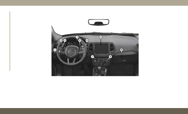
INSTRUMENT PANEL
|
Instrument Panel |
|||
|
1 |
— Headlight Switch |
6 |
— Windshield Wiper Lever |
|
2 |
— Multifunction Lever |
7 |
— Switch Panel |
|
3 |
— Instrument Cluster Display Controls |
8 |
— Uconnect System |
|
4 |
— Instrument Cluster |
9 |
— Climate Controls |
|
5 |
— Speed Controls |
10 — Glove Compartment |
|
10
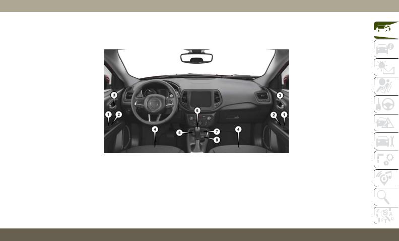
INTERIOR
|
Interior Features |
||||||||||
|
1 |
— Door Locks |
5 |
— Selec-Terrain Switch |
|||||||
|
2 |
— Window Switches |
6 |
— Gear Selector |
|||||||
|
3 |
— Door Handles |
7 |
— USB Port |
|||||||
|
4 |
— Seats |
8 |
— Front Power Outlet |
|||||||
11

GETTING TO KNOW YOUR VEHICLE
KEYS
Key Fob
Your vehicle uses a keyless ignition system. The ignition system consists of a key fob with Remote Keyless Entry (RKE) and a START/STOP push button ignition system. The Remote Keyless Entry system consists of a key fob and Keyless Enter-N-Go feature if equipped.
NOTE:
The key fob may not be found if it is located next to a mobile phone, laptop or other electronic device; these devices may block the key fob’s wireless signal.
The key fob allows you to lock or unlock the doors and liftgate from distances up to approximately 66 ft (20 m) using a handheld key fob. The key fob does not need to be pointed at the vehicle to activate the system.
|
Keyless Ignition Key Fob |
|||
|
1 |
— Unlock |
4 |
— Panic |
|
2 |
— Lock |
5 |
— Emergency |
|
3 |
— Remote Start |
Key |
|
The key fob also includes an emergency key, which stores in the rear of the key fob.
The emergency key allows for entry into the vehicle should the battery in the vehicle or the key fob go dead. The emergency key is also for locking the glove compartment. You can keep the emergency key with you when valet parking.
NOTE:
In case the ignition switch does not change with the push of a button, the key fob may have a low or fully depleted battery. A low key fob battery can be verified by referring to the instrument cluster, which will display directions to follow.
To remove the emergency key, slide the mechanical latch at the top of the key fob sideways with your thumb and then pull the key out with your other hand.
NOTE:
You can insert the double-sided emergency key into the lock cylinders with either side up.
12

To Unlock The Doors And Liftgate
Push and release the unlock button on the key fob once to unlock the driver’s door or twice within five seconds to unlock all doors and the liftgate.
All doors can be programmed to unlock on the first push of the unlock button. Refer to “Uconnect Settings” in “Multimedia” in your Owner’s Manual for further information.
To Lock The Doors And Liftgate
Push and release the lock button on the key fob to lock all doors and liftgate.
Programming Additional Key Fobs
Programming the key fob may be performed by an authorized dealer.
NOTE:
Once a key fob is programmed to a vehicle, it cannot be repurposed and reprogrammed to another vehicle.
Request For Additional Key Fobs
NOTE:
Only key fobs that are programmed to the vehicle electronics can be used to start and operate the vehicle. Once a key fob is programmed to a vehicle, it cannot be programmed to any other vehicle.
WARNING!
•Always remove the key fobs from the vehicle and lock all doors when leaving the vehicle unattended.
•For vehicles equipped with Keyless Enter- N-Go — Ignition, always remember to place the ignition in the OFF mode.
Duplication of key fobs may be performed at your authorized dealer. This procedure consists of programming a blank key fob to the vehicle electronics. A blank key fob is one that has never been programmed.
NOTE:
When having the Sentry Key Immobilizer System serviced, bring all vehicle keys with you to your authorized dealer.
General Information
The following regulatory statement applies to all radio frequency (RF) devices equipped in this vehicle:
This device complies with Part 15 of the FCC Rules and with Industry Canada licenseexempt RSS standard(s). Operation is subject to the following two conditions:
1.This device may not cause harmful interference, and
2.This device must accept any interference received, including interference that may cause undesired operation.
NOTE:
Changes or modifications not expressly approved by the party responsible for compliance could void the user’s authority to operate the equipment.
13

GETTING TO KNOW YOUR VEHICLE
IGNITION SWITCH
Keyless Enter-N-Go — Ignition
This feature allows the driver to operate the ignition with the push of a button as long as the key fob is in the passenger compartment.
The START/STOP push button ignition has three operating modes. The three modes are OFF, ON/RUN, and START.
NOTE:
If the ignition state/mode does not change with the push of a button, the key fob may have a low or dead battery. In this situation, a back up method can be used to operate the ignition switch. Put the nose side (side opposite of the emergency key) of the key fob against the ENGINE START/STOP button and push to operate the ignition.
START/STOP Ignition Button
The push button ignition can be placed in the following modes:
OFF
•The engine is stopped.
•Some electrical devices (e.g. Central locking, alarm, etc.) are still available.
ON/RUN
•Driving mode.
•All the electrical devices are available.
START
• Start the engine.
WARNING!
•When exiting the vehicle, always remove the key fob from the vehicle and lock your vehicle.
•Never leave children alone in a vehicle, or with access to an unlocked vehicle.
•Allowing children to be in a vehicle unattended is dangerous for a number of reasons. A child or others could be seriously or fatally injured. Children should be warned not to touch the parking brake, brake pedal or the gear selector.
•Do not leave the key fob in or near the vehicle, or in a location accessible to children, and do not leave the ignition of a vehicle equipped with Keyless Enter- N-Go in the ON/RUN mode. A child could operate power windows, other controls, or move the vehicle.
•Do not leave children or animals inside parked vehicles in hot weather. Interior heat build-up may cause serious injury or death.
•Never remove the mechanical key while the vehicle is moving, as the steering wheel will automatically lock as soon as
14
WARNING!
the key is turned. This also applies to vehicles that are being towed.
CAUTION!
An unlocked vehicle is an invitation for thieves. Always remove key fob from the vehicle and lock all doors when leaving the vehicle unattended.
NOTE:
For further information, refer to «Starting The Engine» in «Starting And Operating” in the Owner’s Manual.
REMOTE STARTING SYSTEM — IF EQUIPPED
Push the remote start button on the key fob twice within five seconds. Pushing the remote start button a third time shuts the engine off.
To drive the vehicle, push the START/STOP button to turn the ignition to the ON/RUN mode.
NOTE:
•With remote start, the engine will only run for 15 minutes (timeout) unless the ignition is placed in the ON/RUN mode.
•The vehicle must be started with the key after two consecutive timeouts.
How To Use Remote Start — If Equipped
•Push remote start button on the key fob twice within five seconds. Pushing the remote start button a third time shuts the engine off.
•To drive the vehicle, push unlock button, insert the key in the ignition and turn to the ON/RUN position.
•With remote start, the engine will only run for 15 minutes (timeout) unless the ignition key is placed in the ON/RUN position.
•The vehicle must be started with the key after two consecutive timeouts.
All of the following conditions must be met before the engine will remote start:
•Gear selector in PARK
•Doors closed
•Hood closed
•Liftgate closed
•Hazard switch off
•Brake switch inactive (brake pedal not pushed)
•Battery at an acceptable charge level
•Check engine light shall not be present
•PANIC button not pushed
•System not disabled from previous remote start event
•Vehicle alarm system indicator flashing
•Ignition in STOP/OFF position
•Fuel level meets minimum requirement
•Vehicle security alarm is not signaling an intrusion
15

GETTING TO KNOW YOUR VEHICLE
WARNING!
•Do not start or run an engine in a closed garage or confined area. Exhaust gas contains Carbon Monoxide (CO) which is odorless and colorless. Carbon Monoxide is poisonous and can cause serious injury or death when inhaled.
•Keep key fobs away from children. Operation of the Remote Start System, windows, door locks or other controls could cause serious injury or death.
To Enter Remote Start Mode
Push and release the remote start button on the key fob twice within five seconds. The vehicle doors will lock, the parking lights will flash, and the horn will chirp twice (if programmed). Then, the engine will start, and the vehicle will remain in the Remote Start mode for a 15-minute cycle.
NOTE:
•If an engine fault is present or fuel level is low, the vehicle will start and then shut down in 10 seconds.
•The park lamps will turn on and remain on during Remote Start mode.
•For security, power window and power sunroof operation (if equipped) are disabled when the vehicle is in the Remote Start mode.
•The engine can be started two consecutive times with the key fob. However, the ignition must be cycled by pushing the START/ STOP button twice (or the ignition switch must be cycled to the ON/RUN position) before you can repeat the start sequence for a third cycle.
General Information
The following regulatory statement applies to all radio frequency (RF) devices equipped in this vehicle:
This device complies with Part 15 of the FCC Rules and with Industry Canada licenseexempt RSS standard(s). Operation is subject to the following two conditions:
1.This device may not cause harmful interference, and
2.This device must accept any interference received, including interference that may cause undesired operation.
NOTE:
Changes or modifications not expressly approved by the party responsible for compliance could void the user’s authority to operate the equipment.
VEHICLE SECURITY ALARM — IF EQUIPPED
The vehicle security alarm monitors the vehicle doors, hood, liftgate, and the Keyless Enter-N-Go — Ignition for unauthorized operation. While the vehicle security alarm is armed, interior switches for door locks and liftgate release are disabled. If something triggers the alarm, the vehicle security alarm will provide the following audible and visible signals:
•The horn will pulse
•The turn signals will flash
•The vehicle security light in the instrument cluster will flash
16

To Arm The System
Follow these steps to arm the vehicle security alarm:
1.Make sure the vehicle’s ignition is placed in the “OFF” mode.
2.Perform one of the following methods to lock the vehicle:
•Push the lock button on the interior power door lock switch with the driver and/or passenger door open.
•Push the lock button on the key fob.
3.If any doors are open, close them.
To Disarm The System
The vehicle security alarm can be disarmed using any of the following methods:
•Push the unlock button on the key fob.
•Cycle the ignition out of the off mode to disarm the system.
NOTE:
•The driver’s door key cylinder and the liftgate button on the key fob cannot arm or disarm the vehicle security alarm.
•The vehicle security alarm remains armed during power liftgate entry. Pushing the liftgate button will not disarm the vehicle security alarm. If someone enters the vehicle through the liftgate and opens any door, the alarm will sound.
•When the vehicle security alarm is armed, the interior power door lock switches will not unlock the doors.
The vehicle security alarm is designed to protect your vehicle. However, you can create conditions where the system will give you a false alarm. If one of the previously described arming sequences has occurred, the vehicle security alarm will arm regardless of whether you are in the vehicle or not. If you remain in the vehicle and open a door, the alarm will sound. If this occurs, disarm the vehicle security alarm.
If the vehicle security alarm is armed and the battery becomes disconnected, the vehicle security alarm will remain armed when the battery is reconnected; the exterior lights will flash, and the horn will sound. If this occurs, disarm the vehicle security alarm.
Security System Manual Override
The vehicle security alarm will not arm if you lock the doors using the manual door lock plunger.
DOORS
Keyless Enter-N-Go — Passive Entry
The Passive Entry system is an enhancement to the vehicle’s Remote Keyless Entry system and a feature of Keyless Enter-N-Go — Passive Entry. This feature allows you to lock and unlock the vehicle’s door(s) and fuel door without having to push the key fob lock or unlock buttons.
17
GETTING TO KNOW YOUR VEHICLE
NOTE:
•Passive Entry may be programmed ON/ OFF; refer to “Uconnect Settings” in “Multimedia” in the Owner’s Manual for further information.
•If wearing gloves on your hands, or if it has been raining/snowing on the Passive Entry door handle, the unlock sensitivity can be affected, resulting in a slower response time.
•If the vehicle is unlocked by Passive Entry and no door is opened within 60 seconds, the vehicle will re-lock and if equipped will arm the security alarm.
•The key fob may not be able to be detected by the Passive Entry system if it is located next to a mobile phone, laptop or other electronic device; these devices may block the key fob’s wireless signal and prevent the Passive Entry system from locking and unlocking the vehicle.
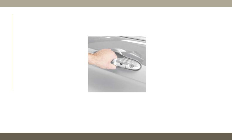
To Unlock From The Driver’s Side
With a valid Passive Entry key fob within 5 ft (1.5 m) of the driver’s door handle, grab the front driver door handle to unlock the driver’s door automatically.
Grab The Door Handle To Unlock
NOTE:
If “Unlock All Doors 1st Press” is programmed, all doors will unlock when you grab hold of the front driver’s door handle. To select between
“Unlock Driver Door 1st Push” and “Unlock All Doors 1st Press,” refer to “Uconnect Settings” in “Multimedia” in the Owner’s manual for further information.
To Unlock From The Passenger Side
With a valid Passive Entry key fob within 5 ft (1.5 m) of the passenger door handle, grab the front passenger door handle to unlock all four doors and the liftgate automatically.
NOTE:
All doors will unlock when the front passenger door handle is grabbed regardless of the driver’s door unlock preference setting (“Unlock Driver Door 1st Press” or “Unlock All Doors 1st Press”).
Preventing Inadvertent Locking Of Passive Entry Key Fob In Vehicle (FOBIK-Safe)
To minimize the possibility of unintentionally locking a Passive Entry key fob inside your vehicle, the Passive Entry system is equipped with an automatic door unlock feature which will function if the ignition switch is in the OFF position.
18
![]()
FOBIK-Safe only executes in vehicles with passive entry. There are three situations that trigger a FOBIK-Safe search in any passive entry vehicle:
•A lock request is made by a valid Passive Entry key fob while a door is open.
•A lock request is made by the Passive Entry door handle while a door is open.
•A lock request is made by the door panel switch while the door is open.
When any of these situations occur, after all open doors are shut, the FOBIK-Safe search will be executed. If it finds a Passive Entry key fob inside the car and it does not find any Passive Entry key fobs outside the car, then the car will unlock and alert the customer.
NOTE:
The vehicle will only unlock the doors when a valid Passive Entry key fob is detected inside the vehicle. The vehicle will not unlock the doors when any of the following conditions are true:
•The doors are manually locked using the door lock knobs.
•There is a valid Passive Entry key fob outside the vehicle and within 5 ft (1.5m) of either Passive Entry door handle.
•Three attempts are made to lock the doors using the door panel switch and then close the doors.
To Unlock/Enter The Liftgate
The liftgate passive entry unlock feature is built into liftgate handle release. With a valid Passive Entry key fob within 5 ft (1.5 m) of the liftgate, push the electronic liftgate release to open with one fluid motion.
To Lock The Liftgate
With a valid Passive Entry key fob within 5 ft (1.5 m) of the liftgate, push the passive entry lock button located to the right of liftgate handle release.
NOTE:
The liftgate passive entry lock button will lock all doors and the liftgate. The liftgate unlock feature is built into the electronic liftgate release.
To Lock The Vehicle’s Doors And Liftgate
With one of the vehicle’s Passive Entry key fob within 5 ft (1.5 m) of the driver or passenger front door handles, push the passive entry lock button located on the outside door handle, to lock the vehicle doors and liftgate.
19

GETTING TO KNOW YOUR VEHICLE
NOTE:
DO NOT grab the door handle, when pushing the door handle lock button. This could unlock the door(s).
Push The Door Handle Button To Lock
DO NOT Grab The Door Handle When
Locking
NOTE:
•After pushing the door handle button, you must wait two seconds before you can lock or unlock the doors, using either Passive Entry door handle. This is done to allow you to check if the vehicle is locked by pulling the door handle without the vehicle reacting and unlocking.
•If Passive Entry is disabled using the Uconnect System, the key protection described in «Preventing Inadvertent Locking of Passive Entry key fob in Vehicle» remains active/functional.
•The Passive Entry system will not operate if the key fob battery is dead.
The vehicle doors can also be locked by using the lock button located on the vehicle’s interior door panel.
General Information
The following regulatory statement applies to all radio frequency (RF) devices equipped in this vehicle:
This device complies with Part 15 of the FCC Rules and with Industry Canada licenseexempt RSS standard(s). Operation is subject to the following two conditions:
1.This device may not cause harmful interference, and
2.This device must accept any interference received, including interference that may cause undesired operation.
20
NOTE:
Changes or modifications not expressly approved by the party responsible for compliance could void the user’s authority to operate the equipment.
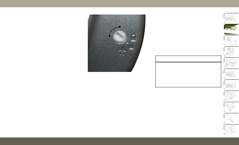
Child-Protection Door Lock System —
Rear Doors
To provide a safer environment for small children riding in the rear seats, the rear doors are equipped with a Child-Protection Door Lock system.
To use the system, open each rear door, use a flat blade screwdriver (or emergency key) and rotate the dial to the lock or unlock position. When the system on a door is engaged, that door can only be opened by using the outside door handle even if the inside door lock is in the unlocked position.
Child-Protection Door Lock Function
NOTE:
•When the child lock system is engaged, the door can be opened only by using the outside door handle even though the inside door lock is in the unlocked position.
•After disengaging the Child-Protection Door Lock system, always test the door from the inside to make certain it is in the desired position.
•After engaging the Child-Protection Door Lock system, always test the door from the inside to make certain it is in the desired position.
•For emergency exit with the system engaged, rotate the door lock button until the lock indicator is hidden (unlocked position), roll down the window, and open the door with the outside door handle.
WARNING!
Avoid trapping anyone in a vehicle in a collision. Remember that the rear doors can only be opened from the outside when the Child-Protection locks are engaged (locked).
21
GETTING TO KNOW YOUR VEHICLE
SEATS
Seats are a part of the Occupant Restraint System of the vehicle.
WARNING!
•It is dangerous to ride in a cargo area, inside or outside of a vehicle. In a collision, people riding in these areas are more likely to be seriously injured or killed.
•Do not allow people to ride in any area of your vehicle that is not equipped with seats and seat belts. In a collision, people riding in these areas are more likely to be seriously injured or killed.
•Be sure everyone in your vehicle is in a seat and using a seat belt properly.
Manual Adjustment (Rear Seats)
WARNING!
Do not pile luggage or cargo higher than the top of the seatback. This could impair visibility or become a dangerous projectile in a sudden stop or collision.
60/40 Split Folding Rear Seat With Fold-Flat
Feature
To provide additional storage area, each rear seat can be folded flat. This allows for extended cargo space and still maintains some rear seating room.
Rear Seat Release Lever
NOTE:
Prior to folding the rear seat, it may be necessary to position the front seat to its mid-track position. Also, be sure that the front seats are fully upright and positioned forward. This will allow the rear seat to fold down easily.
WARNING!
•It is extremely dangerous to ride in a cargo area, inside or outside of a vehicle. In a collision, people riding in these areas are more likely to be seriously injured or killed.
•Do not allow people to ride in any area of your vehicle that is not equipped with seats and seat belts.
•Be sure everyone in your vehicle is in a seat and using a seat belt properly.
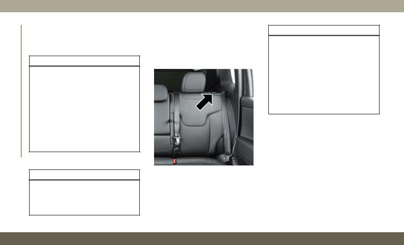
To Lower The Rear Seat
1.Pull the seatback release lever located on either side of the upper outer edge of the seat.
2.Fold that side of the rear seatback completely forward.
To Raise The Rear Seat
NOTE:
If interference from the cargo area prevents the seatback from fully locking, you will have difficulty returning the seat to its proper position.
22
Raise the seatback and lock it into place.
The release lever will show a red indicator while in the unlocked position. Once the seat is locked in, the red indicator will no longer be visible.
WARNING!
Be certain that the seatback is securely locked into position. If the seatback is not securely locked into position the seat will not provide the proper stability for child seats and/or passengers. An improperly latched seat could cause serious injury.
Front Heated Seats — If Equipped
The front heated seats control buttons are located within the Uconnect system. You can gain access to the control buttons through the climate screen or the controls screen.
•Press the heated seat button  once to turn the HI setting on.
•Press the heated seat button  a second time to turn the LO setting on.
•Press the heated seat button  a third time to turn the heating elements off.
If your vehicle is equipped with automatic temperature controls with an integrated center stack, or manual temperature controls, you’ll find the heated seat switches on the switch bank below the radio screen.
If the HI level setting is selected, the system will automatically switch to LO level after approximately 60 minutes of continuous operation. At that time, the display will change from HI to LO, indicating the change. The LO level setting will turn off automatically after approximately 45 minutes.
NOTE:
The engine must be running for the heated seats to operate.
Vehicles With Remote Start — If Equipped
On models that are equipped with remote start, the heated seats can be programmed to come on during a remote start.
This feature can be programmed through the Uconnect system. Refer to “Uconnect Settings” in “Multimedia” in the Owner’s Manual for further information.
WARNING!
•Persons who are unable to feel pain to the skin because of advanced age, chronic illness, diabetes, spinal cord injury, medication, alcohol use, exhaustion or other physical condition must exercise care when using the seat heater. It may cause burns even at low temperatures, especially if used for long periods of time.
•Do not place anything on the seat or seatback that insulates against heat, such as a blanket or cushion. This may cause the seat heater to overheat. Sitting in a seat that has been overheated could cause serious burns due to the increased surface temperature of the seat.
23

GETTING TO KNOW YOUR VEHICLE
HEAD RESTRAINTS
Head restraints are designed to reduce the risk of injury by restricting head movement in the event of a rear impact. Head restraints should be adjusted so that the top of the head restraint is located above the top of your ear.
WARNING!
•All occupants, including the driver, should not operate a vehicle or sit in a vehicle’s seat until the head restraints are placed in their proper positions in order to minimize the risk of neck injury in the event of a crash.
•Head restraints should never be adjusted while the vehicle is in motion. Driving a vehicle with the head restraints improperly adjusted or removed could cause serious injury or death in the event of a collision.
NOTE:
Do not reverse the head restraints (making the rear of the head restraint face forward) in an attempt to gain additional clearance to the back of your head.
Front Head Restraint Adjustment
Your vehicle is equipped with front four way driver and passenger head restraints.
To raise the head restraint, pull upward on the head restraint. To lower the head restraint, push the adjustment button, located at the base of the head restraint, and push downward on the head restraint.
Head Restraint Adjustment Button
To adjust the head restraint forward, pull the top of the head restraint toward the front of the vehicle as desired and release. To adjust the head restraint rearward, pull the top of the head restraint to the forward most position and release. The head restraint will return to the rear most position.
Head Restraint (Normal Position)
24

Head Restraint (Adjusted Position)
NOTE:
The head restraints should only be removed by qualified technicians, for service purposes only. If either of the head restraints require removal, see an authorized dealer.
WARNING!
•All occupants, including the driver, should not operate a vehicle or sit in a vehicle’s seat until the head restraints are placed in their proper positions in order to minimize the risk of neck injury in the event of a crash.
•Head restraints should never be adjusted while the vehicle is in motion. Driving a vehicle with the head restraints improperly adjusted or removed could cause serious injury or death in the event of a collision.
Rear Head Restraints
The rear head restraints have two positions: up or down. When the center seat is being occupied, the head restraint should be in the raised position. When there is no occupant in the center seat, the head restraint can be lowered for maximum visibility for the driver.
To raise the head restraint, pull upward on the head restraint. To lower the head restraint, push the adjustment button, located at the base of the head restraint, and push downward on the head restraint.
Outboard Head Restraint Adjustment
Button
25

GETTING TO KNOW YOUR VEHICLE
STEERING WHEEL
Tilt/Telescoping Steering Column
This feature allows you to tilt the steering column upward or downward. It also allows you to lengthen or shorten the steering column. The tilt/telescoping lever is located below the steering wheel at the end of the steering column.
Center Head Restraint Adjustment Button
NOTE:
The head restraints should only be removed by qualified technicians, for service purposes only. If either of the head restraints require removal, see an authorized dealer.
|
WARNING! |
||
|
ALL the head restraints MUST be rein- |
Tilt/Telescoping Lever |
|
|
stalled in the vehicle to properly protect |
||
|
the occupants. |
||
To unlock the steering column, push the control handle downward (toward the floor). To tilt the steering column, move the steering wheel upward or downward as desired. To lengthen or shorten the steering column, pull the steering wheel outward or push it inward as desired. To lock the steering column in position, push the control handle upward until fully engaged.
WARNING!
Do not adjust the steering column while driving. Adjusting the steering column while driving or driving with the steering column unlocked, could cause the driver to lose control of the vehicle. Failure to follow this warning may result in serious injury or death.
26

Heated Steering Wheel — If Equipped
The steering wheel contains a heating element that helps warm your hands in cold weather. The heated steering wheel has only one temperature setting. Once the heated steering wheel has been turned on, it will stay on until the operator turns it off. The heated steering wheel may not turn on when it is already warm.
The heated steering wheel control button is located on the center instrument panel below the touchscreen, as well as within the climate or controls screen of the touchscreen.
•Press the heated steering wheel button  once to turn the heating element on.
•Press the heated steering wheel button  a second time to turn the heating element off.
NOTE:
The engine must be running for the heated steering wheel to operate.
Vehicles Equipped With Remote Start
On models that are equipped with remote start, the heated steering wheel can be programmed to come on during a remote start.
This feature can be programmed through the Uconnect system. Refer to “Uconnect Settings” in “Multimedia” in the Owner’s Manual for further information.
WARNING!
•Persons who are unable to feel pain to the skin because of advanced age, chronic illness, diabetes, spinal cord injury, medication, alcohol use, exhaustion, or other physical conditions must exercise care when using the steering wheel heater. It may cause burns even at low temperatures, especially if used for long periods.
•Do not place anything on the steering wheel that insulates against heat, such as a blanket or steering wheel covers of any type and material. This may cause the steering wheel heater to overheat.
EXTERIOR LIGHTS
Multifunction Lever
The multifunction lever controls the operation of the turn signals, headlight beam selection and passing lights. The multifunction lever is located on the left side of the steering column.
Headlight Switch
The headlight switch is located on the left side of the instrument panel. This switch controls the operation of the headlights, parking lights, automatic headlights — if equipped, instrument panel lights, instrument panel light dimming, interior lights and fog lights — if equipped.
27

GETTING TO KNOW YOUR VEHICLE
Headlight Switch
1 — Rotate Headlight
2 — Push Fog
3 — Ambient Light Dimmer
4 — Instrument Panel Dimmer
Rotate the headlight switch clockwise to the first detent for parking light and instrument panel light operation. Rotate the headlight switch to the second detent for headlight, parking light and instrument panel light operation.
Daytime Running Lights (DRL) — If
Equipped
The Daytime Running Lights will turn on when the engine is started and remain on unless the headlamps are turned on or the ignition is turned OFF.
NOTE:
If allowed by law in the country in which the vehicle was purchased the Daytime Running Lights can be turned on and off using the Uconnect System. Refer to “Uconnect Settings” in “Multimedia” in the Owner’s Manual for further details.
High/Low Beam Switch
Push the multifunction lever toward the instrument panel to switch the headlights to high beams. Pulling the multifunction lever back toward the steering wheel will return the lights to low beams.
Automatic High Beam Headlamp Control —
If Equipped
The Automatic High Beam Headlamp Control system provides increased forward lighting at night by automating high beam control through the use of a digital camera mounted on the inside rearview mirror. This camera detects vehicle specific light and automatically switches from high beams to low beams until the approaching vehicle is out of view.
NOTE:
•The Automatic High Beam Headlamp Control can be turned on or off using the Uconnect System. Refer to “Uconnect Settings” in “Multimedia” in the Owner’s Manual for further information.
•Broken, muddy, or obstructed headlights and taillights of vehicles in the field of view will cause headlights to remain on longer (closer to the vehicle). Also, dirt, film, and other obstructions on the windshield or camera lens will cause the system to function improperly.
28
![]()
•To opt out of the Advanced Auto High-Beam Sensitivity Control (default) and enter Re-
duced High-Beam Sensitivity Control (not recommended), toggle highbeam lever 6 full on/off cycles within 10 seconds of ignition ON. System will return to default setting upon ignition off.
Flash-To-Pass
You can signal another vehicle with your headlights by lightly pulling the multifunction lever toward you. This will cause the high beam headlights to turn on, and remain on, until the lever is released.
Automatic Headlights — If Equipped
This system automatically turns the headlights on or off according to ambient light levels. To turn the system on, rotate the headlight switch clockwise to the last detent for automatic headlight operation. When the system is on, the headlight time delay feature is also on. This means the headlights will stay on for up to 90 seconds after you place the ignition into the OFF position. To turn the automatic system off, move the headlight switch out of the AUTO position.
NOTE:
The engine must be running before the headlights will come on in the automatic mode.
Headlight Time Delay
This feature provides the safety of headlight illumination for up to 90 seconds (programmable) when leaving your vehicle in an unlit area.
To activate the delay feature, place the ignition in the OFF position while the headlights are still on. Then, turn off the headlights within 45 seconds. The delay interval begins when the headlight switch is turned off.
If you turn the headlights or parking lights on, or place the ignition in ACC or RUN, the system will cancel the delay.
If you turn the headlights off before the ignition, they will turn off in the normal manner.
NOTE:
•The lights must be turned off within 45 seconds of placing the ignition in the OFF position to activate this feature. If the headlight switch is in the AUTO position
prior to turning the ignition OFF, there is no need to turn the headlight switch to off to activate Headlight Delay.
•The headlight delay time is programmable using the Uconnect System. Refer to “Uconnect Settings” in “Multimedia” in the Owner’s Manual for further details.
Lights-On Reminder
If the headlights or parking lights are on after the ignition is in the OFF position, a chime will sound to alert the driver when the driver’s door is opened.
Fog Lights — If Equipped
The front fog light switch is built into the headlight switch.
To activate the front fog lights, turn on the parking lights or the low beam headlights and push the headlight switch. To turn off the front fog lights, either push the headlight switch a second time or turn off the headlight switch.
An indicator light in the instrument cluster illuminates when the fog lights are turned on.
29

GETTING TO KNOW YOUR VEHICLE
NOTE:
The fog lights will operate with the low beam headlights or parking lights on. However, selecting the high beam headlights will turn off the fog lights.
Turn Signals
Move the multifunction lever up or down and the arrows on each side of the instrument cluster display flash to show proper operation of the front and rear turn signal lights.
NOTE:
•If either light remains on and does not flash, or there is a very fast flash rate, check for a defective outside light bulb. If an indicator fails to light when the lever is moved, it would suggest that the indicator bulb is defective.
•A “Turn Signal On” message will appear in the instrument cluster display and a continuous chime will sound if the vehicle is driven more than 1 mile (1.6 km) with either turn signal on.
•When the Daytime Running Lights are on and a turn signal is activated, the Daytime Running Lamp will turn off on the side of the vehicle in which the turn signal is flashing. The Daytime Running Lamp will turn back on when the turn signal is turned off.
Battery Saver Feature
To protect the battery, the interior lights will turn off automatically 15 minutes after the ignition switch is moved to the OFF/LOCK position. This will occur if the interior lights were switched on manually or are on because a door is open.
WINDSHIELD WIPERS AND WASHERS
The windshield wiper/washer controls are located on the windshield wiper/washer lever on the right side of the steering column. The front wipers are operated by rotating a switch, located on the end of the lever. For information on the rear wiper/washer, refer to “Rear Window Wiper/Washer” in this section.
Windshield Wiper/Washer Lever
1 — Rear Wiper Operation
2 — Front Wiper Operation
Windshield Wiper Operation
Rotate the end of the lever to one of the first two detent positions for intermittent settings. The first intermittent wiper interval is 10 seconds. The second intermittent wipe interval is based on vehicle speed. Rotate to the third detent for low wiper operation and the fourth detent for high wiper operation.
30

CAUTION!
•Always remove any buildup of snow that prevents the windshield wiper blades from returning to the “park” position. If the windshield wiper switch is turned off, and the blades cannot return to the “park” position, damage to the wiper motor may occur.
•Failure to follow these cautions can cause damage to the heating elements:
•Use care when washing the inside of the rear window. Do not use abrasive window cleaners on the interior surface of the window. Use a soft cloth and a mild washing solution, wiping parallel to the heating elements. Labels can be peeled off after soaking with warm water.
•Do not use scrapers, sharp instruments, or abrasive window cleaners on the interior surface of the window.
•Keep all objects a safe distance from the window.
Windshield Washer Operation
To use the washer, pull the lever toward you and hold while spray is desired. If the lever is pulled while in the intermittent setting, the wipers will turn on and operate for several wipe cycles after the lever is released, and then resume the intermittent interval previously selected.
WARNING!
Sudden loss of visibility through the windshield could lead to a collision. You might not see other vehicles or other obstacles. To avoid sudden icing of the windshield during freezing weather, warm the windshield with the defroster before and during windshield washer use.
Mist
Push the lever upward to the MIST position and release for a single wiping cycle.
NOTE:
The mist feature does not activate the washer pump; therefore, no washer fluid will be
sprayed on the windshield. The wash function must be used in order to spray the windshield with washer fluid.
Rain Sensing Wipers — If Equipped
This feature senses rain or snow fall on the windshield and automatically activates the wipers for the driver. The feature is especially useful for road splash or overspray from the windshield washers of the vehicle ahead. Rotate the end of the multifunction lever to one of two settings to activate this feature.
The sensitivity of the system can be adjusted with the multifunction lever. Wiper delay position one is the least sensitive, and wiper delay position two is the most sensitive. Place the wiper switch in the O (off) position when not using the system.
NOTE:
•The Rain Sensing feature will not operate when the wiper switch is in the low or high-speed position.
•The Rain Sensing feature may not function properly when ice, or dried salt water is present on the windshield.
31

GETTING TO KNOW YOUR VEHICLE
•Use of Rain-X or products containing wax or silicone may reduce Rain Sensing performance.
•The Rain Sensing feature can be turned on and off using the Uconnect System, refer to “Uconnect Settings” in “Multimedia” in your Owner’s Manual for further information.
The Rain Sensing system has protection features for the wiper blades and arms, and will not operate under the following conditions:
•Change In Ignition Position — If the vehicle is in Rain Sensing mode and the ignition is cycled from OFF to ON, the auto wiper will be suppressed until vehicle speed is greater than 3 mph (5 km/h), or the wiper switch is moved out of and back into the Intermittent wipe position.
•Transmission In NEUTRAL Position — The Rain Sensing system will not operate if the NEUTRAL gear is selected at speeds of 3 mph (5 km/h) or less unless the wiper switch is moved or the gear selector is moved out of NEUTRAL.
Remote Start Mode Inhibit — On vehicles equipped with Remote Starting system, Rain Sensing wipers are not operational when the vehicle is in the remote start mode. Once the operator is in the vehicle and has placed the ignition switch in the ON/RUN position, Rain Sensing wiper operation can resume, if it has been selected, and no other inhibit conditions (mentioned previously) exist.
Rear Window Wiper/Washer
The rear wiper/washer controls are located on the windshield wiper/washer lever on the right side of the steering column. The rear wiper/washer is operated by rotating a switch, located at the middle of the lever.
Rotate the center portion of the lever upward to the first detent for intermittent operation and to the second detent for continuous rear wiper operation.
To use the washer, push the lever forward and hold while spray is desired. If the lever is pushed while the wiper is in the off position, the wiper will operate for several wipe cycles, then turn off.
CLIMATE CONTROLS
The Climate Control System allows you to regulate the temperature, air flow, and direction of air circulating throughout the vehicle. The controls are located on the touchscreen (if equipped) and on the instrument panel below the radio.
Climate Controls With A Touchscreen
Overview
The controls for the heating and air conditioning system in this vehicle can consist of a series of outer rotary dials, inner push knobs, and/or a touchscreen. These comfort controls can be set to obtain desired interior conditions.
32

Uconnect 4 With 7-inch Display Automatic Climate Controls
33

GETTING TO KNOW YOUR VEHICLE
Uconnect 4/4C NAV With 8.4-inch Display Automatic Climate Controls
34

Automatic Climate Controls Faceplate Buttons
Climate Controls Description
|
Icon |
Description |
||||
|
MAX A/C Button |
|||||
|
Press and release the MAX A/C button on the touchscreen to change the current setting to the coldest output of air. |
|||||
|
Pressing the button again will cause the MAX A/C operation to exit. |
|||||
|
NOTE: |
|||||
|
The MAX A/C button is only available on the touchscreen. |
|||||
35

GETTING TO KNOW YOUR VEHICLE
|
Icon |
Description |
|
A/C Button |
|
|
Press and release to change the current setting, the indicator illuminates when A/C is ON. |
|
|
Recirculation Button |
|
|
Press and release this button to change the system between recirculation mode and outside air mode. Recirculation |
|
|
can be used when outside conditions such as smoke, odors, dust, or high humidity are present. Recirculation can be |
|
|
used in all modes. Recirculation may be unavailable (button on the touchscreen greyed out) if conditions exist that |
|
|
could create fogging on the inside of the windshield. The A/C can be deselected manually without disturbing the |
|
|
mode control selection. Continuous use of the Recirculation mode may make the inside air stuffy and window fog- |
|
|
ging may occur. Extended use of this mode is not recommended. |
|
|
AUTO Button |
|
|
Automatically controls the interior cabin temperature by adjusting airflow distribution and amount. Toggling this |
|
|
function will cause the system to switch between manual mode and automatic modes. Refer to “Automatic Opera- |
|
|
tion” within this section for more information. |
|
|
Front Defrost Button |
|
|
Press and release to change the current airflow setting to Defrost mode. The indicator illuminates when this feature |
|
|
is on. Air comes from the windshield and side window demist outlets. When the defrost button is selected, the |
|
|
blower level may increase. Use Defrost mode with maximum temperature settings for best windshield and side |
|
|
window defrosting and defogging. |
|
|
Performing this function will cause the ATC to switch into manual mode. If the front defrost mode is turned off the |
|
|
climate system will return the previous setting. |
|
|
Rear Defrost Button |
|
|
Push and release the Rear Defrost Control button to turn ON the rear window defroster and the heated outside |
|
|
mirrors (if equipped). An indicator will illuminate when the rear window defroster is on. The rear window defroster |
|
|
automatically turns off after ten minutes. |
|
36

|
Icon |
Description |
|||
|
Driver and Passenger Temperature Up and Down Buttons |
||||
|
Provides the driver and passenger with independent temperature control. Push the red button on the faceplate or |
||||
|
touchscreen or press and slide the temperature bar towards the red arrow button on the touchscreen for warmer |
||||
|
temperature settings. Push the blue button on the faceplate or touchscreen or press and slide the temperature bar |
||||
|
towards the blue arrow button on the touchscreen for cooler temperature settings. |
||||
SYNC Button
Press the SYNC button on the touchscreen to toggle the Sync feature on/off. The SYNC indicator is illuminated when this feature is enabled. SYNC is used to synchronize the passenger temperature setting with the driver temperature setting. Changing the passenger temperature setting while in SYNC will automatically exit this feature.
|
NOTE: |
|||||
|
The SYNC button is only available on the touchscreen. |
|||||
|
Faceplate Knobs |
Blower Control |
||||
|
Blower Control is used to regulate the amount of air forced through the climate system. There are seven blower |
|||||
|
MODE |
speeds available. Adjusting the blower will cause automatic mode to switch to manual operation. The speeds can be |
||||
|
selected using either the blower control knob on the faceplate or the buttons on the touchscreen. |
|||||
|
Touchscreen Buttons |
• Faceplate: The blower speed increases as you turn the blower control knob clockwise from the lowest blower setting. |
||||
|
The blower speed decreases as you turn the blower control knob counterclockwise. |
|||||
|
• Touchscreen: Use the small blower icon to reduce the blower setting and the large blower icon to increase the blower |
|||||
|
setting. Blower can also be selected by pressing the blower bar area between the icons. |
|||||
|
Modes Button |
Modes Button |
||||
|
Push the button in the center of the Blower Control Knob to change the airflow distribution mode. You can also |
|||||
|
change the mode by pressing the desired mode on the touchscreen. The airflow distribution mode can be adjusted |
|||||
|
MODE |
so air comes from the instrument panel outlets, floor outlets, defrost outlets and demist outlets. The Mode settings |
||||
|
are as follows: |
37

GETTING TO KNOW YOUR VEHICLE
|
Icon |
Description |
|
Panel Mode |
Panel Mode |
|
Air comes from the outlets in the instrument panel. Each of these outlets can be individually adjusted to direct the |
|
|
flow of air. The air vanes of the center outlets and outboard outlets can be moved up and down or side to side to |
|
|
regulate airflow direction. There is a shut off wheel located below the air vanes to shut off or adjust the amount of |
|
|
airflow from these outlets. |
|
Bi-Level Mode |
Bi-Level Mode |
|
Air comes from the instrument panel outlets and floor outlets. A slight amount of air is directed through the defrost |
|
|
and side window demister outlets. |
|
|
NOTE: |
|
|
Bi-Level mode is designed under comfort conditions to provide cooler air out of the panel outlets and warmer air |
|
|
from the floor outlets. |
|
|
Floor Mode |
Floor Mode |
|
Air comes from the floor outlets. A slight amount of air is directed through the defrost and side window demister |
|
|
outlets. |
|
|
Mix Mode |
Mix Mode |
|
Air is directed through the floor, defrost, and side window demister outlets. This setting works best in cold or snowy |
|
|
conditions that require extra heat to the windshield. This setting is good for maintaining comfort while reducing |
|
|
moisture on the windshield. |
|
|
Climate Control OFF Button |
|
|
Press and release this button to turn the Climate Controls off or turn the Blower Control knob to the off position. |
38
![]()
Climate Control Functions
A/C (Air Conditioning)
The Air Conditioning (A/C) button allows the operator to manually activate or deactivate the air conditioning system. When the air conditioning system is turned on, cool dehumidified air will flow through the outlets into the cabin. For improved fuel economy, press the A/C button to turn off the air conditioning and manually adjust the blower and airflow mode settings. Also, make sure to select only Panel, Bi-Level, or Floor modes.
NOTE:
•For Manual Climate Controls, if the system is in Mix, Floor or Defrost Mode, the A/C can be turned off, but the A/C system shall remain active to prevent fogging of the windows.
•If fog or mist appears on the windshield or side glass, select Defrost mode, and increase blower speed if needed.
•If your air conditioning performance seems lower than expected, check the front of the A/C condenser (located in front of the
radiator), for an accumulation of dirt or insects. Clean with a gentle water spray from the front of the radiator and through the condenser.
MAX A/C
MAX A/C sets the control for maximum cooling performance.
Press and release to toggle between MAX A/C and the prior settings. The button illuminates when MAX A/C is on.
In MAX A/C, the blower level and mode position can be adjusted to desired user settings. Pressing other settings will cause the MAX A/C operation to switch to the selected setting and MAX A/C to exit.
Recirculation
In cold weather, use of Recirculation mode may lead to excessive window fogging. The Recirculation feature may be unavailable (button on the touchscreen greyed out) if conditions exist that could create fogging on the inside of the windshield.
Automatic Temperature Control (ATC)
Automatic Operation
1.Push the AUTO button on the faceplate, or the AUTO button on the touchscreen (if equipped) on the Automatic Temperature Control (ATC) Panel.
2.Next, adjust the temperature you would like the system to maintain by adjusting the temperature control buttons. Once the desired temperature is displayed, the system achieves and automatically maintains that comfort level.
3.When the system is set up for your comfort level, it is not necessary to change the settings. You experience the greatest efficiency by simply allowing the system to function automatically.
NOTE:
•It is not necessary to move the temperature settings for cold or hot vehicles. The system automatically adjusts the temperature, mode, and blower speed to provide comfort as quickly as possible.
39

GETTING TO KNOW YOUR VEHICLE
•The temperature can be displayed in U.S. or Metric units by selecting the US/Metric customer-programmable feature.
To provide you with maximum comfort in the Automatic mode during cold start-ups, the blower fan remains on low until the engine warms up. The blower increases in speed and transition into Auto mode.
Manual Operation Override
This system offers a full complement of manual override features. The AUTO symbol in the front ATC display will be turned off when the system is being used in the manual mode.
Operating Tips
Summer Operation
The engine cooling system must be protected with a high-quality antifreeze coolant to provide proper corrosion protection and to protect against engine overheating. OAT coolant (conforming to MS.90032) is recommended.
Winter Operation
To ensure the best possible heater and defroster performance, make sure the engine cooling system is functioning properly and the proper amount, type, and concentration of coolant is used. Use of the Air Recirculation mode during Winter months is not recommended, because it may cause window fogging.
Vacation/Storage
Before you store your vehicle, or keep it out of service (i.e., vacation) for two weeks or more, run the air conditioning system at idle for about five minutes, in fresh air with the blower setting on high. This will ensure adequate system lubrication to minimize the possibility of compressor damage when the system is started again.
Window Fogging
Vehicle windows tend to fog on the inside in mild, rainy, and/or humid weather. To clear the windows, select Defrost or Mix mode and increase the front blower speed. Do not use the Recirculation mode without A/C for long periods, as fogging may occur.
CAUTION!
Failure to follow these cautions can cause damage to the heating elements:
•Use care when washing the inside of the rear window. Do not use abrasive window cleaners on the interior surface of the window. Use a soft cloth and a mild washing solution, wiping parallel to the heating elements. Labels can be peeled off after soaking with warm water.
•Do not use scrapers, sharp instruments, or abrasive window cleaners on the interior surface of the window.
•Keep all objects a safe distance from the window.
Outside Air Intake
Make sure the air intake, located directly in front of the windshield, is free of obstructions, such as leaves. Leaves collected in the air intake may reduce airflow, and if they enter the plenum, they could plug the water drains. In Winter months, make sure the air intake is clear of ice, slush, and snow.
40

Cabin Air Filter
The climate control system filters out dust and pollen from the air. Contact an authorized dealer to service your cabin air filter, and to have it replaced when needed.
WINDOWS
Power Window Controls
The window controls on the driver’s door control all the door windows.
Power Window Switches
There are single window controls on each passenger door trim panel, which operate the passenger door windows. The window controls will operate only when the ignition is in the ACC or ON/RUN position.
NOTE:
For vehicles equipped with the Uconnect, the power window switches will remain active for up to ten minutes after the ignition is cycled to the OFF position. Opening either front door will cancel this feature. The time is programmable. Refer to “Uconnect Settings” in “Multimedia” in the Owner’s Manual for further information.
WARNING!
Never leave children unattended in a vehicle. Do not leave the key fob in or near the vehicle or in a location accessible to children, and do not leave the ignition of a vehicle equipped with Keyless Enter-N-Go in the ACC or ON/RUN mode. Occupants,
WARNING!
particularly unattended children, can become entrapped by the windows while operating the power window switches. Such entrapment may result in serious injury or death.
Auto-Down Feature
The driver door power window switch and the passenger door power window switches have an Auto-Down feature. Push the window switch down, for a short period of time, and release and the window will go down automatically.
To open the window part way, push the window switch down briefly and release it when you want the window to stop.
To stop the window from going all the way down during the Auto-Down operation, pull up on the switch briefly.
41

GETTING TO KNOW YOUR VEHICLE
Auto-Up Feature With Anti-Pinch
Protection
NOTE:
•If the window runs into any obstacle during auto-closure, it will reverse direction and then go back down. Remove the obstacle and use the window switch again to close the window.
•Any impact due to rough road conditions may trigger the auto-reverse function unexpectedly during auto-closure. If this happens, pull the switch lightly and hold to close the window manually.
WARNING!
There is no anti-pinch protection when the window is almost closed. To avoid personal injury be sure to clear your arms, hands, fingers and all objects from the window path before closing.
Window Lockout Switch
The window lockout switch on the driver’s door trim panel allows you to disable the window controls on the rear passenger doors. To disable the window controls, push and release the window lockout button (the indicator light on the button with turn on). To enable the window controls, push and release the window lockout button again (the indicator light on the button will turn back off).
Window Lockout Switch
Wind Buffeting
Wind buffeting can be described as the perception of pressure on the ears or a helicopter-type sound in the ears. Your vehicle may exhibit wind buffeting with the windows down, or the sunroof (if equipped) in certain open or partially open positions. This is a normal occurrence and can be minimized. If the buffeting occurs with the rear windows open, open the front and rear windows together to minimize the buffeting. If the buffeting occurs with the sunroof open, adjust the sunroof opening to minimize the buffeting or open any window.
42

POWER SUNROOF WITH POWER SHADE — IF EQUIPPED
The power sunroof switches are located between the sun visors on the overhead console.
Power Sunroof Switches
1 — Power Shade Switch
2 — Front Panel Open/Close Switch
3 — Front Panel Vent Switch
WARNING!
•Never leave children unattended in a vehicle, or with access to an unlocked vehicle. Never leave the key fob in or near the vehicle, or in a location accessible to children. Do not leave the ignition of a vehicle equipped with Keyless Enter-N-Go in the ON/RUN mode. Occupants, particularly unattended children, can become entrapped by the power sunroof while operating the power sunroof switch. Such entrapment may result in serious injury or death.
•In a collision, there is a greater risk of being thrown from a vehicle with an open sunroof. You could also be seriously injured or killed. Always fasten your seat belt properly and make sure all passengers are also properly secured.
•Do not allow small children to operate the sunroof. Never allow your fingers, other body parts, or any object, to project through the sunroof opening. Injury may result.
Opening Sunroof
The sunroof has two programmed open positions, comfort stop position and full open position. The comfort stop position has been optimized to minimize wind buffeting when driving with side windows closed and sunroof open. If the sunshade is in the closed position when initiating a sunroof open or vent command the sunshade will automatically open to the half open position prior to the sunroof opening.
Express
Push the switch and release it within one-half second, the sunroof will open to the comfort stop position and automatically stop. Push the switch and release it again, the sunroof will open to the full open position and automatically stop. This is called “Express Open”. During Express Open operation, any movement of the sunroof switch will stop the sunroof.
43

GETTING TO KNOW YOUR VEHICLE
Manual Mode
Push and hold the switch, the sunroof will open to the comfort stop position and automatically stop. Push the switch and hold it again, the sunroof will open to the full open position and automatically stop. Any release of the switch will stop the sunroof movement. The sunroof will remain in a partially opened condition until the switch is pushed and held again.
Opening Sunroof — Vent
Push and release the «Vent» button within one-half second and the sunroof will move from the closed position to the vent position. This is called “Express Vent.” During Express Vent operation, any movement of the switch will stop the sunroof.
NOTE:
When the sunroof is in a full open or a partial open position, Express Vent operation is not available. You must push and hold the vent switch to cycle the sunroof from a slide open position to the vent position. Sunroof movement will stop if the switch is released prior to the sunroof reaching the vent position.
Closing Sunroof
Express
Pull the switch down and release it within one-half second and the sunroof will close automatically from any position. The sunroof will close fully and stop automatically. This is called “Express Close”. During Express Close operation, any other actuation of the switch will stop the sunroof.
Manual Mode
Pull and hold the switch down and the sunroof will close from any position. Any release of the switch will stop the movement and the sunroof will remain in a partially closed condition until the sunroof switch is pulled again.
Opening Power Shade
The sunshade has two programmed open positions: half open and full open positions. When opening the sunshade from the closed position, the sunshade will always stop at the half open position regardless of express or manual open operation. The switch must be actuated again to continue on to full open position.
Express
Push the sunshade switch and release it within one-half second, the sunshade will open to the half open position and stop automatically. Push and release the switch again from the half open position and the sunshade will open to the full open position and stop automatically. This is called “Express Open”. During Express Open operation, any movement of the sunshade switch will stop the shade.
Manual Mode
Push and hold the sunshade switch, the sunshade will open to the half open position and stop automatically. Push and hold the sunshade switch again and the sunshade will open to the full open position. Any release of the switch will stop the movement and the sunshade will remain in a partially opened condition until the switch is pushed again.
44

Closing Power Shade
If the sunroof is open/vented, the sunshade cannot be closed beyond the half open position. Pulling the sunshade close switch when sunshade is at half open position with sunroof open/vented will automatically close sunroof prior to the sunshade closing.
Express
Pull the sunshade switch down and release it within one-half second. If the sunroof is in closed position, the sunshade will full close automatically from any position. If the sunroof is open or vented, the sunshade will close to the half open position and stop; pull and release the sunshade switch again to automatically close both the sunroof and sunshade completely. This is called “Express Close”. During Express Close operation, any movement of the switch will stop the sunshade.
Manual
Pull and hold the sunshade switch down. If the sunroof is in closed position, the sunshade will fully close from any position. If the sunroof is open or vented, the sunshade will close to the half open position and stop; pulling and holding the sunshade switch again will close both the sunroof and sunshade completely. Any release of the switch will stop the movement and the sunshade will remain in a partially closed condition until the switch is pulled again.
Pinch Protect Feature
This feature will detect an obstruction in the opening of the sunroof during Express Close operation. If an obstruction in the path of the sunroof is detected, the sunroof will automatically retract. Remove the obstruction if this occurs. Next, pull the sunroof close switch and release to Express Close.
NOTE:
If three consecutive sunroof close attempts result in Pinch Protect reversals, Pinch Protect will disable and the sunroof must be closed in Manual Mode.
Sunroof Maintenance
Use only a non-abrasive cleaner and a soft cloth to clean the glass panel.
Ignition Off Operation
The power sunroof switch will remain active for up to approximately ten minutes after the ignition is turned OFF. Opening either front door will cancel this feature.
NOTE:
Ignition Off time is programmable through the Uconnect System. Refer to “Uconnect Settings/Customer Programmable Features” in “Multimedia” in your Owner’s Manual for further information.
45

GETTING TO KNOW YOUR VEHICLE
HOOD
Opening The Hood
Two latches must be released to open the hood.
1.Pull the hood release lever located underneath the driver’s side of the instrument panel.
Hood Release Location (Underneath
Instrument Panel)
2.Move to the outside of the vehicle. The safety latch release lever is located behind the front edge of the hood at the center. Reach in at the center of the hood with a palm facing the ground. Once contact is made with the safety latch release lever, push it toward the passenger side of the vehicle to fully release the hood.
Hood Safety Latch Release Lever Location
Closing The Hood
WARNING!
Be sure the hood is fully latched before driving your vehicle. If the hood is not fully latched, it could open when the vehicle is in motion and block your vision. Failure to follow this warning could result in serious injury or death.
CAUTION!
To prevent possible damage, do not slam the hood to close it. Lower hood to approximately 12 inches (30 cm) and drop the hood to close. Make sure hood is fully closed for both latches. Never drive vehicle unless hood is fully closed, with both latches engaged.
46

LIFTGATE
Opening
To Unlock/Enter The Liftgate
The liftgate may be released by the overhead console switch, the outside handle, or the key fob (if equipped).
The overhead console switch and key fob (if equipped) will release the liftgate when the liftgate is unlocked or locked. The outside handle requires the liftgate to be unlocked.
Liftgate Entry
NOTE:
Use the interior door lock/unlock button on the door panel or the key fob to lock and unlock the liftgate. The manual door locks on the doors and the exterior door lock cylinder will not lock and unlock the liftgate.
WARNING!
Driving with the liftgate open can allow poisonous exhaust gases into your vehicle. You and your passengers could be injured by these fumes. Keep the liftgate closed when you are operating the vehicle.
Closing
Grasp the liftgate pull handle and initiate lowering the liftgate. Release the handle when the liftgate reaches the self-closing position.
NOTE:
Before closing the liftgate, make sure to be in possession of the key because the liftgate may be locked.
Power Liftgate — If Equipped
 The power liftgate may be opened or closed by the key fob, outside handle, overhead console switch, and the liftgate switch on the upper left trim when the liftgate is open.
Using any of the above ways:
•When the liftgate is fully closed, the liftgate will open.
•When the liftgate is fully open, the liftgate will close.
•When the liftgate is moving, the liftgate will reverse.
The key fob and the overhead console switch will open the liftgate when the liftgate is locked. The outside handle requires the liftgate to be unlocked. Push the button on the key fob twice within five seconds to open or close the liftgate.
When the liftgate button on the key fob is pushed two times, the turn signals will flash twice to signal that the liftgate is opening or
47

GETTING TO KNOW YOUR VEHICLE
closing (if Flash Lamps with Lock is enabled in the Uconnect settings), and the liftgate chime will be audible. Refer to “Uconnect Settings” in “Multimedia” in your Owner’s Manual for further information.
NOTE:
•Before closing the liftgate, make sure to be in possession of the key because the liftgate may be locked.
•Use the interior door lock/unlock button on the door panel or the key fob to lock and unlock the liftgate. The manual door locks on the doors and the exterior door lock cylinder will not lock and unlock the liftgate.
Lock The Vehicle
WARNING!
During power operation, personal injury or cargo damage may occur. Ensure the liftgate travel path is clear. Make sure the liftgate is closed and latched before driving away.
NOTE:
•The liftgate will not power open or close if the gear selector is in gear or the vehicle speed is above 0 mph (0 km/h).
•If anything obstructs the power liftgate while it is closing or opening, the liftgate will automatically reverse to the closed or open position, provided it meets sufficient resistance.
•There are pinch sensors attached to the side of the liftgate opening. Light pressure anywhere along these strips will cause the liftgate to return to the open position.
•If the power liftgate encounters multiple obstructions within the same cycle, the system will automatically stop. If this occurs, the liftgate must be opened or closed manually.
•The power liftgate will not operate in temperatures below −22° F (−30° C) or temperatures above 150° F (65° C). Be sure to remove any buildup of snow or ice from the liftgate before pushing any of the power liftgate switches.
•If the liftgate is left open for an extended period of time, the liftgate may need to be closed manually to reset power liftgate functionality.
•Gas props support the liftgate in the open position. However, because the gas pressure drops with temperature, it may be necessary to assist the props when opening the liftgate in cold weather.
•Before driving off, check the instrument cluster for a liftgate or door open message or warning indicator. Failure to do this could result in unintentionally leaving the liftgate open while driving.
•If your liftgate is power closing and you put the vehicle in gear, the liftgate will continue to power close. However, vehicle movement may result in a detection of an obstruction.
•If the electronic liftgate release handle is pushed with the power liftgate is opening, the liftgate motor will disengage to allow manual operation.
•If the electronic liftgate release handle is pushed while the power liftgate is closing, the liftgate will reverse to the full open position.
48
 Loading…

(1 votes, average: 5.00 out of 5)
Loading…

Innovative, contemporary design that redefines classic Jeep features. Every detail of the exterior makes a difference – the streamlined body, the wide grille with seven slots, and the trapezoidal wheel arches. Thanks to this, the 2019 Jeep Compass is easily recognizable even in the city traffic.
High-quality materials were used for the interior upholstery, which makes the interior of the car ideal for both everyday driving and travel. The multifunctional steering wheel with integrated heating system and leather trim will allow you to fully concentrate on the road. Cruise control and side support for the seats will ensure passenger comfort.
The Jeep comes standard with a 2.4-liter inline four-cylinder engine. It produces 150 horsepower and 229 torque. Also, all modifications of the Compass run on gasoline and belong to the Euro 6 environmental class. Also, the car has all-wheel drive and automatic transmission with nine gears.
We also have owner’s manuals for other vehicle years:
- 2024 Jeep Compass
- 2023 Jeep Compass
- 2018 Jeep Compass Trailhawk
- 2018 Jeep Compass Limited
- 2019 Jeep Compass Trailhawk
- 2018 Jeep Compass Latitude
- 2022 Jeep Compass
- 2021 Jeep Compass
- 2020 Jeep Compass
- 2018 Jeep Compass
Need help?
Follow the link below to ask us a question about your 2019 Jeep Compass. Try to describe your problem with the car in as much detail as possible, in this case it will be easier for us to answer you. However, we try to answer all the questions of our visitors.
Ask your question on the page «Need Help«!
Find the 2019 Jeep Compass Owners Manual below. The 2019 Jeep Compass manual is for models – Sport, Latitude, Limited, and Trailhawk. It comes with a standard front-wheel drive along with optional four-wheel drive.
| Manufacturer | Jeep |
| Model | Compass |
| Year | 2019 |
Not the right manual? Also check
- 2018 Jeep Compass Manual
- 2020 Jeep Compass Manual
Jeep Compass is famous for its superb off-road capability. You will find its straightforward technology and upscale cabin as an impressive part of the Compass. Jeep has upgraded some features in the 2019 version like standard 7-inch screen, High Altitude appearance package, and adaptive cruise control. All the models of the 2019 Jeep Compass Owners Manual are offered with 2.4-liter four-cylinder engines. It has the power to produce 180 horsepower and 175 lb-ft torque with EPA estimates of 23/32 mpg when mated with front-wheel drive and six-speed manual.
Trailhawk is an exception that gets the four-wheel drive as a standard feature. When we talk about transmission, Jeep Compass has got a six-speed manual, but they do provide an option for a six and nine-speed automatic.
The interiors of the 2019 Jeep Compass Owners Manual are not the best when it comes to style but is passenger-friendly. Moreover, Compass has got logically arranged and labeled controls with an easily navigable infotainment system. The squared-off openings in the rear provide better headspace for in and out purposes. Wide doors give the advantage of wide entry.
2019 Jeep Compass Manual Features and Reviews
The driver’s seat does not offer a lot of adjustment, and tall drivers will face difficulty as the steering wheel does not provide much telescoping. The 2019 Jeep Compass manual is excellent when it comes to the roominess. You will find a lot of headroom, legroom, and elbow room. According to the reviewers, the front and side visibility of the model is pretty decent. Compass’s cabin has well-represented materials with a leather-covered steering wheel and soft-touch surfaces. A handsome Jeep Compass has taken its good looks from its family – Cherokee and Grand Cherokee. It has a seven-slot grille with softer lines separating the looks of the Compass from the mighty Wrangler.
The 2019 Jeep Compass Owners Manual provides four trim levels for different configurations. Its base model is the Sport which has got some features like wheels of 16-inch, Bluetooth, USB port, 7-inch touchscreen, and air conditioning. Next is the Latitude, which upgrades to larger wheels, stimulation of cloth and leather upholstery, keyless ignition, and some optional packages. Moreover, at the top are the Limited and Trailhawk that are equipped with enhanced features like larger wheels, remote start, satellite radio, matt-black hood accent, and Selec-Terrain system.
Some major setbacks of the 2019 Jeep Compass Owners Manual include a weak engine, limited storage capacity. The nine-speed transmission faces sluggish response.
What contains the 2019 Compass manual?
The Jeep Compass owner’s manual is a comprehensive guide provided by
Jeep to assist owners in understanding and operating their specific model of the
Jeep Compass.
It contains important information about the vehicle’s features, functions, and maintenance requirements.
A general overview of what you might find in
a Jeep Compass 2019 owner’s manual:
- Warranty Information, about the vehicle’s warranty coverage
- Maintenance for your Jeep Compass, such as oil changes, tire rotations,
brake inspections, and fluid checks - Best practice for driving your Jeep Compass
- Environmental Information about environmentally-friendly driving practices
- Fuel Information, with recommended fuel type and fuel tank capacity
- Basic operations, like starting and stopping the engine and driver settings
Where to download the 2019 Compass Jeep Owner’s
Manual?
The Jeep owner manual for the 2019
model year is to be found on this page.
Is the manual for the Jeep Compass free?
Yes, the owner’s manuals for the Jeep Compass are free,
but the repair manuals are usually not easy to get and may cost.
What is a Jeep Compass repair manual?
A Jeep Compass repair manual for the model 2019 is a
comprehensive guide that provides in-depth vehicle repairs and maintenance information,
unlike the owner’s manual, which focuses on general operation and maintenance.
The Jeep Compass (2019)
owner’s manual is available in English?
Yes, the owner’s manual for the model year 2019 is available in English.