
Elstat Ems25 Инструкция

Elstat EMS25 Ако Вашият хладилен шкаф е оборудван с електронен контрол. пользования холодильной витриной, внимательно изучите инструкции.
Elstat Ems25 Инструкция

COMO BAIXAR MANUAL DO EMS 25 EMS 55 EMS 75 SUBZERO. 395 — Trocando Controlador ems elstat 55, regulando a temperatura e.
Elstat Ems25 Инструкция

10. . 11. . 12. . 13. . 14. . 15. . 16. . 17. . 18. . 19. . 20. . 21. . 22. . 23. —>Elstat ems25 инструкция скачать. 24. . 25. > СКАЧАТЬ_ФАЙЛ.
ELSTAT EMS 25 ADVANCED USERS GUIDE User’S Guide, Instructions.
Инструкция elstat ems 25 dsibemw. STEAM GROUP. Инструкция elstat ems 25 dsibemw. 0. MEMBERS. 0. IN-GAME. 0. ONLINE. Founded. July 15, 2015.
Elstat Ems25 Инструкция

Elstat Electronics Ltd. Astra Business Centre, Roman Way, Preston, Lancashire PR2 5AP, UK. T: +44 161 227 7200. F: +44 161 227 7201 www.elstatgroup.com.
Entering The Set Point Ems 55 Advanced Controller — YouTube
elstat ems25. Пошли холодильники с этими самообучаемыми контроллерами. Через некоторое время они, обучившись, решают, а.
Контроллер Elstat Ems55 Инструкция

3 000 грн.: Контролер для холодильника: ELSTAT ems 55 advanced. Використовується в холодильних шафах типу Frigorex activator 700 Практично новий.
COMO BAIXAR MANUAL DO EMS 25 EMS 55 EMS 75 SUBZERO — YouTube

168 — Como regular a temperatura do controlador elstat ems 55, geladeira. 181,450 views181K views. • Mar 14, 2019. 1.3K 165. Share Save.
User Guide Ems25Plus
Новый elstat ems 25 расширенный ce12301111361027 (часть no.12301 — 3301 заказать с бесплатной доставкой из китая.
Купить Новый Elstat Ems 25 Расширенный Ce12301111361027 (Часть No.

summarised in ELSTAT firmware release notes. IMPORTANT. The EMS Advanced controller must only be adjusted by an authorised service agent. Figure 1.
Elstat Ems25 Fortgeschrittene Kommerzielle Kühlschrank Mit.
55 advanced for sale elstat ems 55 advanced settings elstat ems 55 error codes elstat ems 55 advanced full reset elstat ems 25 manual EMS.
Elstat Ems 55 Advanced — YouTube
ELSTAT EMS 25 R MANUAL DOWNLOAD ELSTAT EMS 25 R MANUAL READ ONLINE elstat ems 55 advanced manual ems 55 advanced.
Инструкция Elstat Ems55
Elstat Ems25 инструкция скачать — Руководства, Инструкции, Бланки It is unclear whether these controllers had any effect on machine energy use during the.
Elstat Ems25 Инструкция

Литература, инструкции и документация по холодильному. Мануал на ELSTAT EMS25 нужен (число прочтений — 15446.
Elstat Ems25 Инструкция

elstat ems 25 manual elstat coca colahow to set temperature on elstat ems 55 advanced elstat ems 100 parameters. 27 Jan 2018 Elstat Ems 55 Advanced User.
Elstat Ems 55 Troubleshooting Manual — Weekendbrown
Инструкция elstat ems 25 dsibemw. STEAM GROUP. Инструкция elstat ems 25 dsibemw. 0. MEMBERS. 0. IN-GAME. 0. ONLINE. Founded. July 15, 2015.
Controlador Ems 25 ( Conhecendo Os Parametros) — YouTube

The data dump is for Elstat use only for testing and development purposes. Page 25. ems100. Product Manual, Issue 4 www.nexo.com.
Elstat Ems 55 Instruction Manual

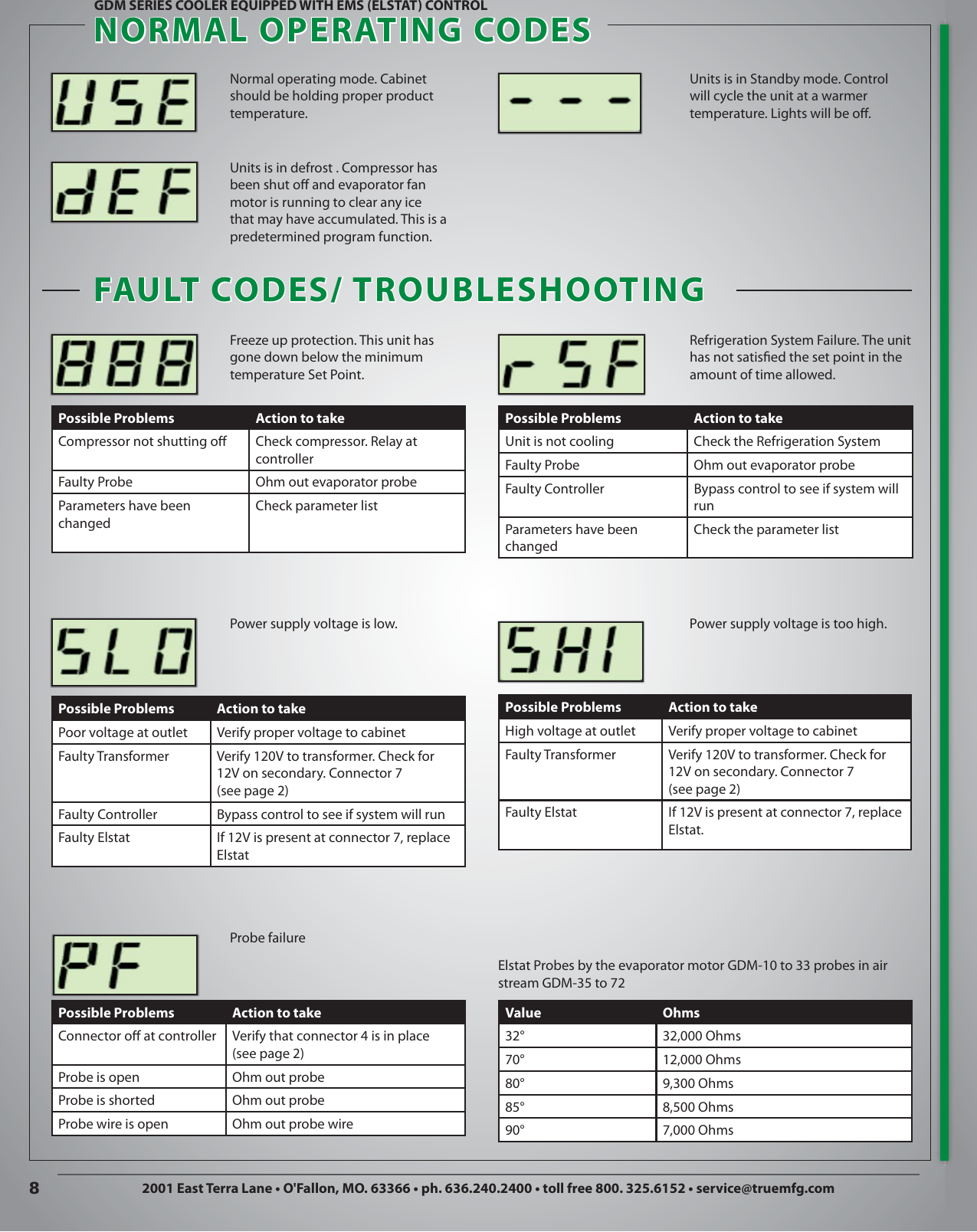
GDM SERIES COOLER EQUIPPED WITH EMS (ELSTAT) CONTROL. GDM-26. Once the cabinet is plugged in, the ELSTAT control will flash «888» and then.
Скачать Инструкция Контроллер Холодильных Установок Elstat Ems25.

May 31, · Download Elstat Ems 55 Manual English — book pdf free download link or read online here in PDF. Elstat Ems 55 R Advanced Manual Once the photo.
Контроллер Elstat Ems55 Инструкция
Thank you for purchasing a SKOPE refrigeration product. Page 3. SKOPE B600-2 /B600G-2. User Manual.
-
Page 1
ems25+ ems25 advanced PRODUCT MANUAL Firmware: U02 — n01 — ems25+ Firmware: U03 — n02 — ems25advanced… -
Page 2
Copyright © Elstat Ltd 2020 All Rights Reserved All information in this document is property of Elstat Ltd Commercial use and distribution of the contents of this publication is not allowed without express and prior written consent of Elstat Ltd www.elstat.io… -
Page 3: Table Of Contents
Water ingress — advisory information for FMEA analysis ems25+ and ems25advanced user interface environmental ratings ems25 series relay ratings ems25+ wiring diagram ems25 series thermal fuse (CQC only) ems25advanced wiring diagram How to mount ems25 series controllers Temperature input ranges How to mount the appliance sensor…
-
Page 4
How to troubleshoot refrigeration system failure (rSF) alarms How to troubleshoot temperature sensor alarms How to troubleshoot problems with freeze-up protection (888) How to troubleshoot not cooling problems elstat parameter loader What are the xml files? What are checksums? Parameter programming accessories… -
Page 5
How to install the drivers on Windows XP How to install the parameter loader How to start the parameter loader How to connect the docking cradle How to configure the COM port How to load the parameter settings 9.10 How to view the download counter 9.11 How to view the version of the parameter programming tool (dongle) -
Page 6
10.22 Fan set point (FSP) 10.23 Condenser high temperature (Ht) 10.24 Uninterrupted pull down (IPd) 10.25 Lights delay (Ld) 10.26 Learning period (LP) 10.27 Saving temperature disable (PEr) 10.28 Compressor rest time (rt) 10.29 Saving differential (Sd) 10.30 Motion sensor enable (Sn) 10.31 Set point (SPC of SPF) 10.32… -
Page 7: About This Reference Guide
Doubledoorcoolers • Openfrontcoolers • Vendingmachines • Sub-zerobeercoolers About this reference guide The purpose of this guide is toexplainindetail all informationregardingelstatcontrollers includingthe user interface, parameters, accessories andtroubleshooting. Complimentary informationis alsoavailable from elstatsuchas accessory lists, accessory datasheets andsingle shee- tuser guides. www.elstat.io…
-
Page 8: What Is The Ems25 Series
2. What is the ems25 series? The ems25 series consists of the ems25, ems25+, and ems25advanced. The ems25 series is designed as a compact alternative the ems55 series. The ems25 series with the suitable accessories also provide the following functionality:…
-
Page 9: Water Ingress-Advisory Informationforf Mea Analysis
Water ingress–advisory informationforF MEA analysis Elstat products have been designed to minimise any risks associated with water ingress and all controllers are IPX5 certified. The OEM or installer is responsible to ensure that local/country laws andregulatory requirements are met. ems25+ andems25advanced userinterface…
-
Page 10: Environmental Ratings
2.3 Environmental ratings The table below details the general characteristics of the ems25 series. Characteristic Value IP rating IPX5 Maximum operatiing temperature 55°C (131°F) Minimum operating temperature 0°C (32°F) Housing material Black polycarbonate 2.4 ems25 series relay ratings The table below details the relay ratings of ems25+ controllers…
-
Page 11: Ems25+ Wiring Diagram
2.5 ems25+ wiring diagram The wiring diagram for the ems25+: Drip loops must be made in all cables Note For security, once fitted, the rear cover can only be removed using a tool, such as a small, flat bladed screwdriver. www.elstat.io…
-
Page 12: Ems25 Series Thermal Fuse (Cqc Only)
(CQC only) The ems25 andems25+ housings are designed with an aperture for athermal fuse tobe located. The thermal fuse is apartof a main harness which is supplied by elstat. The location for the 4-way mains connector…
-
Page 13: Ems25Advanced Wiring Diagram
The wiring diagram for the ems25advanced: Drip loops must be made in all cables Note For security, once fitted, the rear cover can only be removed using a tool, such as a small, flat bladed screwdriver. www.elstat.io…
-
Page 14: How To Mount Ems25 Series Controllers
How to mount ems25 series controllers ems25 series controllers have an IP (Ingress Protection) rating of IP45. That is, the ems controller has protection against water jets. Anappropriate level of protection must be given for the effects of water ingress due to water jetting, condensation, product spillage, and so on.
-
Page 15
Cable routing looms must not be secured to hot pipes or vibrating components. Secure cable routing looms with clips whereever possible. For security, once fitted, the rear cover can only be removed using atool,such as a small, flat bladed screwdriver. www.elstat.io… -
Page 16: Temperature Input Ranges
3. Temperature input ranges The table below shows the temperature input ranges of the ems25 series controllers for eachsensor type Sensor Input range (°C) Input range (°F) -10°C to 23.3°C -14°F to 74°F Appliance sensor +/- 0.5°C +/- 1°F Condenser sensor 50°C to 125°C…
-
Page 17: How To Mount The Evaporator Sensor
This sensor measures the temperature of the refrigeration system. Excessive condenser temperature is usually due to poor preventive maintenance, i.e poorly cleaned condenser, or condenser fan failure. For example, fix using a metal pipe clip or direct fitting, as shown below. Elstat can supply pipe clips for 6-8mm and 8-10mm pipes.
-
Page 18: Door Switch
The screws must be tightened to a maximum torque of 0.5Nm (0.37lbfft). Note Door switches and activators supplied by elstat must not be installed using rivets. Using rivets invalidates the warranty. The alignment of the door switch and activator is critical for the correct operation of the door switch. The following table details alignment tolerances.
-
Page 19: How To Mount The Enhanced Door Switch
0.5Nm (0.37lbfft). Note Door switches and activators supplied by elstat must not be installed using rivets. Using rivets invalidates the warranty. The alignment of the door switch and activator is critical for the correct operation of the door switch. The following table details alignment tolerances.
-
Page 20: How To Mount Door Switches On Double-Door Coolers
Connect the red wire from the first cable and the white wire from the second cable together using a butt splice or similar. The image on the right shows two door switches connected in series. www.elstat.io…
-
Page 21: Ems Controller Functionality
1 (CA1) can add an offset to the temperature measured on the appliance sensor. ems controllers can be set to use Celsius (°C) or Fahrenheit (°F) — set by the Celsius or Fahrenheit (CF) parameter. www.elstat.io…
-
Page 22: Activity
At the end of the ready mode, ems controllers switch to the saving mode. However, the delay to saving (dS) parameter can delay the switch to the saving mode. The delay helps ensure that, for example, the ems controller remains in the ready mode during periods without activity immediately prior to outlets closing for marketing purposes. www.elstat.io…
-
Page 23: Saving Mode
30-minute period, but do not start cooling cycle. For more information about the parameters used in saving mode: • See “saving temperature disable (PEr)” • See “saving differential (Sd)” • See “saving restart period (Sr)” • See “saving set point (SSP)” www.elstat.io…
-
Page 24: Teach
To bring the cooler out of the saving mode during a teach period, press the up button and hold for 5 seconds. Note elstat recommends that outlet operators do not manually switch ems controllers to the saving mode. This functionality aims to stop outlet operators switching off coolers.
-
Page 25: Defrost On Glass Door Coolers (Gdc)
(dtt) temperature plus the differential (dIF) temperature. For ems controllers that manage the evaporator fan, the ems controller starts the evaporator fan cycle. For more information about the parameters used in freeze-up protect • See “differential (dIF)” • See “freeze-up protection (dtt)” www.elstat.io…
-
Page 26: Compressor Management
(R744) version. An ems55advanced CO2 controller will alternate between PF2 and the gas cooler temperature sensor temperature. • For evaporator failures indicated by PF3 alarms, ems controllers continue running the compressor. ems controllers alternate the display between PF3 and the appliance sensor temperature Note Ht alarms do not apply to CO2 coolers www.elstat.io…
-
Page 27: Lights Management
For more information about the parameters used in alarms • See ”buzzer enable (b0)” • See ” buzzer duration (b1)” Note For door open alarms, the buzzer sounds regardless of the buzzer enable (b0) setting. www.elstat.io…
-
Page 28: Self-Learning
This is the minimum time before ems controllers switch to the saving mode. Learning period (LP) Activity frequency (AF) Minimum time in ready mode only 1 day Pre-set 1 day (24 hours) 1 day Automatic 3 days (72 hours) 7 days Pre-set 7 days 7 days Automatic www.elstat.io…
-
Page 29: What Is The Self-Learning Matrix
Day 7: the ems controller remains in the saving mode. Note The self-learning matrix starts the moment the ems controller is first switched on and is not synchronized with calendar days. However, the diagram below starts at 00:00 on Day 1 for clarity www.elstat.io…
-
Page 30: How A 7-Day Learning Period Works
(AF) parameter. Therefore, at the end of day 1 (first 24-hours), the ems controller has set all the 30 minutes to ready (2) or saving (0) depending on the outlet activity pattern as shown in the following example matrix: www.elstat.io…
-
Page 31: How A 1-Day Learning Period Works
If the ems controller does not detect activity, the ems controller changes the state from monitor (1) to saving (0) Note The amount of activity required to change the state from monitor (1) to ready (2) depends on the setting of the activity frequency (AF) parameter. www.elstat.io…
-
Page 32
At the endof week 1, the ems controller has updated the self-learning matrix for the outlet activity pattern as shown below. Note that differences for activity patterns learnt on day 2 take two weeks to be implemented. Therefore, 1-day learning periods are recommended only for outlets with regular patterns every day of the week. www.elstat.io… -
Page 33: How The Self-Learning Matrix Updates After The Learningperiod
If activity occurs in a saving period (0), such as a motion detection or a door opening, the ems controller switches the cooler lights on and sets the period to monitor (1). However, the ems controller does not start the compressor to cool the product. www.elstat.io…
-
Page 34: How Ems Controllers Switch Between Ready And Saving Modes
(2), run in the ready mode for 30-minutes, and then switch to the saving mode (assuming no delay to saving (dS) parameter is in operation). For more informationaboutthe parameters used: See ”delay to saving( dS)” • • See ”saving restart period (Sr)” www.elstat.io…
-
Page 35: User Guide
At the power up, the ems controller displays the power-up sequence as follows: 8.8.8. toconfirm thatall segments of the display are functioningcorrectly Platform type and firmware version. (example) Checksum of the parameter set. (example) The display then shows the appropriate display code. For example, the temperature or the word USE. www.elstat.io…
-
Page 36: Display Codes
Problems may occur if the ambient temperature falls below 0°C(32°F) Protection or if the appliance sensor fails. See “how to trouble shootp roblems with freeze-up protection (888)” Refrigeration See “how to trouble shoot refrigeration system failure (rSF) alarms” System Failure Condenser High Not applicable toCO2 (R744) coolers. Temperature www.elstat.io…
-
Page 37
DISPLAY STATE DESCRIPTION Appliance Sensor Failure Condenser See “how to trouble shoot temperature sensor alarms” Sensor Failure Evaporator Sensor Failure www.elstat.io… -
Page 38: How To Access The Menu (Example)
Press and hold the set button Release the set button when PAS appears Press the set button four times (x4) Press the up button once (x1) Press the down button twice (x2) Press the defros / teach button teice (x2) www.elstat.io…
-
Page 39: How To Access The Menu
Displays the last three faults (alarms). Faults See “how to view the last three alarms (FLt)” Clears the self-learning matrix. Half Reset See “how to perform a half reset (Hr)” Full reset elstat use only. Data Dump elstat use only. www.elstat.io…
-
Page 40: How To View The Ems25+ Parameter Settings(Ps)
See “Set Point (SPS or SPF)” See “Buzzer Enable (b0)” See “Differential (dIF)” See “Buzzer Duration (b1)” See “Calibration 1 (CA1)” See “Alarm Delay (Ad)” See “Saving Set Point (SSP)” See “Alarm Frequency (AF)” See “Saving Differential (Sd)” See “Motion sensor enable (Sn)” www.elstat.io…
-
Page 41
See “Learning Period (LP)” Temperature (dtd)” See “Compressor Rest Time (rt)” See “Display (dIS)” See “Delay to Saving (dS)” See “Marketing Mode (Ar)” See “Refrigeration System See “Lights Delay (LD)” Failyre (Ct)” See “SSaving Restart Period (Sr)” See “Defrost Interval (de)” www.elstat.io… -
Page 42: How To View The Ems25Advanced Parameter Settings(Ps)
See “Set Point (SPS or SPF)” See “Defrost Duration (DD)” See “Differential (dIF)” See “Defrost Duration (DD)” See “Calibration 1 (CA1)” See “Display Stability (d2)” See “Saving Set Point (SSP)” See “Buzzer Enable (b0)” See “Saving Differential (Sd)” See “Buzzer Duration (b1)” www.elstat.io…
-
Page 43
Temperature (dtd)” Disable (PEr)” See “Compressor Rest Time (rt)” See “Learning Period (LP)” See “Delay to Saving (dS)” See “Display (dIS)” See “Lights Delay (LD)” See “Marketing Mode (Ar)” See “Refrigeration System See “SSaving Restart Period (Sr)” Failyre (Ct)” www.elstat.io… -
Page 44: How To Run The Test Routine (Tst)
BUTTON DISPLAY TEST CHECK Compressoris running and Compresspr Relay compressor LED is on Cooler lights are on Light Relay Evaporator Fan Relay Evaporator fan is running Note To switch off the relays that are on, press the defrost button. www.elstat.io…
-
Page 45
Move your hand from left to right and ensure the following: • The display count increments for each detected movement • The motion LED flashes for each detected movement. Press the defrost and set buttons simultaneously to end the test routine. www.elstat.io… -
Page 46: How To Perform A Half Reset (Hr)
Ensure that PS is displayed. Press the down button to scroll ro the Hr menu Re-enter the button sequence of the menu entry password Ensure that the ems controller resets. After a reset, the ems controller starts the power-up sequence. www.elstat.io…
-
Page 47: How To View The Last Three Alarms (Flt)
The last three faults, or alarms, to occur are displayed. For example: a condenser hight emperature a refrigeration system failure alarm has occurred alarm has occurred a door open alarm has occurred Note The alarms may have been cleared, or cancelled, by the retail outlet operators. www.elstat.io…
-
Page 48: Statistics
Note that the last full reset. average is a moving average. Total number of hours thatthe compressor has run since the Compressor No change. runtime ems controller was first powered up or since the last full reset. www.elstat.io…
-
Page 49
Value of the stand by temperature disable PEr parameter. Possible values Saving temperature are: OFF or ON. OFF= Standby No change. disable temperature disable is switched off. ON = Standby temperature disable is switched on. www.elstat.io… -
Page 50: Troubleshooting
• See”how to troubleshoot not cooling problems” If the ems controller is in the ready mode, check the lights switch inside the Cooler lights do not cooler. Note that ems controllers normally switch the cooler lights off in the switch on saving mode. www.elstat.io…
-
Page 51: How To Check That Ems Controllers Are Working Correctly
Condenser hightemperature (Ht) alert to problems with the refrigeration system such as a blocked condenser or faulty condenser fan. For information about the condenser hightemperature (Ht) parameter, see ”condenser high temperature (Ht)” Follow the chart below to troubleshoot condenser high temperature (Ht) alarms. www.elstat.io…
-
Page 52: How To Troubleshoot Door Alarms (Door Switch Fitted)
(Ad) parameter. If the door is closed, and a door open alarm is registered, this may indicate problems with the cooler door or the door switch. For information about the alarm delay (Ad) parameter see ”alarm delay (Ad)” Follow the chart below to troubleshoot door open alarms on coolers with a door switch. www.elstat.io…
-
Page 53: How To Troubleshoot Door Alarms (No Door Switch Fitted)
Door alarms with coolers without a door switch fitted usually indicate that the ems controller has an incorrect parameter set. For information about the alarm delay (Ad) parameter see ”alarm delay (Ad)” Follow the chart below to troubleshoot door open alarms on coolers without a door switch fitted. www.elstat.io…
-
Page 54: How To Troubleshoot Motion Sensor Alarms
The ems controller stays in the ready mode if the motion detection LED is flashing continuously. For information about the motion sensor enable (Sn) parameter, see ”motion sensor enable (Sn)” Follow the chart below to troubleshoot problems with the motion sensor. www.elstat.io…
-
Page 55: How To Troubleshoot Refrigeration System Failure (Rsf) Alarms
Refrigeration system failure (rSF) alarms trigger if the set point (SP) temperature is notr eached within the time defined by the compressor runtime (Ct)parameter. For information about the setpoint and compressor runtime parameters see ”refrigeration system failure (Ct)” and ”set point (SPC or SPF)”. Follow the chart below to troubleshoot refrigeration system failures. www.elstat.io…
-
Page 56: How To Troubleshoot Temperature Sensor Alarms
Sensor faults may also be identified by using the input test within the test routine, see ”how to run the test routine (tst)” . Follow the chart below to troubleshoot problems with the appliance sensor, condenser sensor, evaporator sensor or gas cooler sensor. www.elstat.io…
-
Page 57: How To Troubleshoot Problems With Freeze-Up Protection (888)
Problems with freeze-up protection may occur if the ambient temperature falls below 0°C(32°F) or if the appliance sensor fails. For information about the freeze-up protection (dtt) parameter, see ”freeze-up protection (dtt)”. How to troubleshoot not cooling problems Follow the chart below to troubleshoot problems of the cooler not cooling, i.e.the cooler or product is warm. www.elstat.io…
-
Page 58: Elstat Parameter Loader
2 MB of disk space What are the XML files? The XML files are supplied from elstat and include parameter information about each XML file The XML files contain the parameter settings to be downloaded to the ems controller, and the checksum values.
-
Page 59: What Are Checksums
Set up program programming tool • Drivers for Windows XP ZIP files containing the following: elstat files supplied on completion of the • Parameter information (PI), which is a PDF file that details the parameter settings parameter request form •…
-
Page 60: How To Install The Drivers On Windows Xp
For Windows XP, install the drivers as follows: Extract the ZIP file CDM20808.zip- from the files supplied by elstat which contain the Windows drivers for Windows XP — and save into a suitable location. For example, C:Program Fileselstatdrivers Insert the USB docking cradle into a spare USB port and ensure that the Windows New Hardware Found wizard…
-
Page 61
Click Browse and select the folder where the drivers were saved. For example, C:Program Fileselstatdrivers. Click Next and wait while the wizard searches and downloads the drivers Once completed, click Finish to close the wizard. www.elstat.io… -
Page 62: How To Install The Parameter Loader
Double-click the file Setup_ParameterLoader_Rx.x.exe to start in the setup wizard Click Next to start the installation wizard. Select the destination location. Click Next to use the default location or click Browse to define a different location and then click Next. www.elstat.io…
-
Page 63
Select the Start menu folder. Click Next to use the default folder or click Browse to define a different folder and then click Next Confirm that the setup information is correct. Click Install Click Finish to complete the installation of the parameter loader www.elstat.io… -
Page 64: How To Start The Parameter Loader
How to start the parameter loader Start the parameter loader as follows: Click Parameter Loaderin the Start menu. l Double-click the file ParameterLoader.exe located in, for example,the folder C:elstatParameterLoader Note On starting the parameter loader for the first time, the dialog box below appears prompting for the fractional separator.
-
Page 65: How To Configure The Com Port
Check the COM port allocated to the USB docking cradle (USB Serial Port). For example, in the diagram above, COM3 has been allocated Double-click the USB serial port and make a note of the port settings, as shown below. www.elstat.io…
-
Page 66
Set the parameters to the values of the USB serial port of the local computer. For example: PARAMETER VALUE COM port COM port allocated to the cradle, For example, 3. Baud rate 9600 Data bits Parity None Stop bits Flow control None Click OK www.elstat.io… -
Page 67: How To Load The Parameter Settings
To help service engineers, mark the appropriate checksum on the identification tag of the parameter programming tool (dongle). CRC-A Checksum of the XML file. For elstat reference purposes only. Checksum displayed on an ems55advanced with firmware version E52 F07. CRC-B Displayed when rebooting the ems controller following download of the parameter settings with the parameter programming tool (dongle).
-
Page 68: How To View The Download Counter
How to view the version of the parameter programming tool (dongle) View the version of a parameter programming tool (dongle) as follows: 1. Insert the parameter programming tool (dongle) into the USB docking cradle. 2. Click Tools, Get dongle version to display the dialog below. www.elstat.io…
-
Page 69: Display Codes For Parameter Downloads
The parameter programming tool (dongle) is connected. The parameter download is in progress The parameters were download but are out of range. The parameters were not downloaded The ems controller will reboot and display the checksum following successful parameter downloads. www.elstat.io…
-
Page 70: Parameter Reference
The parameter values vary between different cooler types, cooler characteristics, operating environments, brand requirements, and operational preferences. Parameter settings are defined by customers — OEMs, Bottlers and Brands — using an XML request form, and supplied in the relevant parameter information (PI) provided by elstat. 10.1 Parameters by function…
-
Page 71: Parameters By Owners
IPd must be higher than SSP + Sd • • IPd must be higher than dtd • dtd must be higher than SP + dIF SSP must be higher than SP + dIF • • dtt must be lower than SP www.elstat.io…
-
Page 72: Alarm Delay (Ad)
The activity frequency applies DESCRIPTION across all 30 minute periods within the self-learning matrix, not to individual 30 minute periods. CONSIDERATOINS See below RANGE See below GLOBAL DEFAULT 00 (low frequency) www.elstat.io…
-
Page 73: Marketing Mode (Ar)
The coolers lights will remain on during saving mode Does not affect saving temperature. CONSIDERATOINS Made available to ems55advanced GDC firmware from June 2012. Not used with OFC firmware. RANGE 00 (off) or 01 (on) GLOBAL DEFAULT 00 (off) www.elstat.io…
-
Page 74: Buzzer Enable (B0)
If the door remains open after the buzzer duration (b1), the ems controller switches off the compressor. The ems controller switches off the compressor after the duration defined by alarm delay CONSIDERATOINS (Ad) + buzzer duration (b1). RANGE 1 to 254 seconds GLOBAL DEFAULT 60 seconds www.elstat.io…
-
Page 75: Calibration 1 (Ca1)
Option to set the ems controller to Celsius (°C) or Fahrenheit (°F) • A global reset sets ems controllers using Fahrenheit (°F) to Celsius (°C) CONSIDERATOINS • Applies to alltemperature settings and values. RANGE 00 (°C) or 01 (°F) GLOBAL DEFAULT 00 (°C) www.elstat.io…
-
Page 76: Refrigeration System Failure (Ct)
Increasing the value for the display stability (d2) slows the rate of change of the displayed temperature. CONSIDERATOINS Use the global default value for normal operation RANGE 1 to 254 GLOBAL DEFAULT www.elstat.io…
-
Page 77: Defrost Duration (Dd)
A timebased defrost cycle helps improve evaporator efficiency. • In the event of powerloss,the defrost duration (dE) is not maintained. The defrost CONSIDERATOINS interval is reset. • If icing up occurs,review the values of the defrost parameters. RANGE 0 to 199 hours GLOBAL DEFAULT 06 hours www.elstat.io…
-
Page 78: Differential (Dif)
The table below details the display (diS) parameter DISPLAY Defines whether the ems controller displays the temperature 3.0, or the word USE during DESCRIPTION the ready mode. ems controllers always display alarms. CONSIDERATOINS None RANGE 00 (USE) or 01 (temperature) GLOBAL DEFAULT 01 (temperature) www.elstat.io…
-
Page 79: Delay To Saving (Ds)
CONSIDERATOINS • Must be set below IPd. • If icing up occurs,review the values of the defrost parameters. 1 to 30ºC (33 to 86ºF) RANGE ems75sz: -5 to 22ºC (23 to 71ºF) 9.0ºC (48ºF) GLOBAL DEFAULT ems75sz: 15.0ºC (59ºF) www.elstat.io…
-
Page 80: Fan Cycle Off (Fcf)
Defines the inactive period of the evaporator fan while the compressor is switched off Fan cycle is the fan cycle on (FCO) time + the fan cycle off (FC F) time. CONSIDERATOINS Not used on the ems25+ RANGE 1 to 30 minutes 1 minute GLOBAL DEFAULT ems75sz: 20 minutes www.elstat.io…
-
Page 81: Fan Cycle On (Fco)
On reaching set point (SP) temperature, the evaporator fan switches off during door openings. Not related to fan cycle on (FCO) or fan cycle off (FCF). CONSIDERATOINS Not used with OFC firmware or the ems25+ RANGE 01 to 30ºC (33 to 86ºF) GLOBAL DEFAULT 15ºC (59ºF) www.elstat.io…
-
Page 82: Condenser High Temperature (Ht)
During this time, defrost cycles do not occur. Must be set as follows: CONSIDERATOINS • Above the saving set point (SSP) plus saving differential (Sd) temperature. • Above the defrost termination (dtd) temperature. RANGE 0.0 to 30ºC (32 to 86ºF) GLOBAL DEFAULT 20ºC (68ºF) www.elstat.io…
-
Page 83: Lights Delay (Ld)
The table below details the learning period (LP) parameter DISPLAY DESCRIPTION Defines whether the ems controller uses a 1-day or a 7-day learning period. CONSIDERATOINS None RANGE 00 (1 day) or 01 (7 days) GLOBAL DEFAULT 00 (1 day) www.elstat.io…
-
Page 84: Saving Temperature Disable (Per)
If set too low, the compressor rest time may cycle on the set point (SP) and differential (dIF) CONSIDERATOINS temperatures or the saving set point (SSP) and saving differential (Sd) temperatures. RANGE 1 to 30 minutes GLOBAL DEFAULT 3 minutes www.elstat.io…
-
Page 85: Saving Differential (Sd)
The table below details the motion sensor enable (Sn) parameter DISPLAY DESCRIPTION Enables the input from the motion sensor. CONSIDERATOINS Must be disabled if a motion sensor is not fitted. RANGE 00 (disabled) or 01 (enabled) GLOBAL DEFAULT 01 (enabled) www.elstat.io…
-
Page 86: Set Point (Spc Of Spf)
Set and verified by OEMs through the test protocolto ensure that product temperatures CONSIDERATOINS are within specification when outlets open. • Must be set in multiples of 30 minutes. RANGE 0 to 240 minutes (in multiples of 30 minutes) GLOBAL DEFAULT 120 minutes www.elstat.io…
-
Page 87: Saving Set Point
Defines the compressor cut-out temperature during the saving mode. CONSIDERATOINS Must be set above the set point (SP) plus differential (dIF) temperature. 0.0 to 9.9°C (32 to 50°F) RANGE ems75sz: -9.9 to 9.9°C (14 to 50°F) all except ems75sz: 7.0°C (45°F) GLOBAL DEFAULT ems75sz: 3.0°C (37°F) www.elstat.io…
-
Page 88: Annex | Ul Information
(L) line in (7) All models Lighs relay (K2) 120VAC 250W Ballast lights (4) 11.1 ems25+ rear view (input reference) Door switch Condenser sensor Appliance sensor Lights out Neutral Compressor out Line in Micro RMD and parameter programming port www.elstat.io…
-
Page 89: Additional Information
The type of construction is: Integrated Control Maximum ambient operating temperature 55oC (131oF) Overvoltage category Pollution degree Software class Type 1 action Rated impulse 1500V elstat UL approvals UL 60730-1 CSA E 60730-1 UL 60730-2-9 CSA E 60730-2-9 UL reference: E325501 www.ul.com www.elstat.io…
-
Page 90: Technical Data Ems25
12.3 Temperature sensors SENSOR INPUT RANGE ( INPUT RANGE ( Appliance sensor C to 23.3ºC (+/- 0.5 14ºF to 74ºF (+/- 1ºC) Gas cooler sensor C to 23.3ºC (+/- 5 122ºF to 257ºF (+/- 10ºF) www.elstat.io…
-
Page 91: Environmentat Ratings
— UL mark. Component UL 60730-2-9 / CSA E60730-2-9 recognition mark GB14536.1-2008 China Quality Certification GB14536.10-2008 Please note that, on controller labelling, as of January 2013 CE (Conformité Européene / European Conformity) replaces: RoHS (Restriction of Hazardous Substances) www.elstat.io…
-
Page 92: Technical Data Ems25Advanced
4 (4) A, p.f. 0.6 Temperature sensors SENSOR INPUT RANGE ( INPUT RANGE ( Appliance sensor C to 23.3ºC (+/- 0.5 14ºF to 74ºF (+/- 1ºC) Gas cooler sensor C to 23.3ºC (+/- 5 122ºF to 257ºF (+/- 10ºF) www.elstat.io…
-
Page 93
55ºC (131ºF) Product approvals European Norms Electrical EN60730-1 Certification EN60730-2-9 IEC60730-1 International Electrotechnical IEC60730-2-9 Commission Glow wire: IEC60335-1 Please note that, on controller labelling, as of January 2013 CE (Conformité Européene / European Conformity) replaces: RoHS (Restriction of Hazardous Substances) www.elstat.io… -
Page 94: Ems Decorative Trims
14. ems decorative trims Decorative trim kits are supplied separately from ems25 series controllers in order to allow for custom installation. Two kit sizes are available — small and large — in three varieties as described in this section Note Ensure that a matching quantity of decorative trims are ordered with controllers.
-
Page 95
Insert the controllerinto the cooler aperture as shown in the example: Use the supplied side clips to secure the controllerinto position as shown: Note The side clips hold the controllerin position, make sure that the fit is not loose. www.elstat.io… -
Page 96: Large Decorative Trim Kits
A large decorative trim without a motion sensor-for use with a remote motion sensor kit These kits allow the ems25 series to be installed into an aperture for an ems55 series controller. Once fitted, the decorative trim kit can be screwed into place.
-
Page 97: Fitting The Large Decorative Trim — With Remote Motion Sensor
Fit the controller and make the electrical connections. 14.5 fitting the large decorative trim — without remote motion sensor Push the controllerinto the rear of the decorative trim untilthe controllerlocks securely into place: Fit the controller and make the electrical connections. www.elstat.io…
-
Page 98
agents.
-
Page 1
(Sub-Zero) Firmware: U09 n05 27 February 2014 www.elstatgroup.com… -
Page 2: Table Of Contents
Function buttons — ems sub zero Indicators Display codes What are the menus? How to access the menu EMS controllers How to view the ems75sz parameter settings (PS) How to run the test routine (tst) 4.8.1 The relay test 4.8.2 The heater relay test 4.8.3…
-
Page 3
Motion sensor — ems75sz 7.10 Motion sensor 7.11 How to mount a remote motion sensor 8 How to troubleshoot ems75sz Troubleshooting How to check that EMS controllers are working correctly How to troubleshoot condenser high temperature (Ht) alarms Door open alarm — display… -
Page 4
Learning period (LP) 9.35 Display (dIS) 9.36 Marketing mode (Ar) 9.37 Defrost heater (dHr) 10 What variations of the ems75sz (sub zero) can I order? 10.1 Examples of CDM colours 11 Technical data ems75sz 11.1 Dimensional drawings: 11.2 Controller relays: 11.3… -
Page 5: Ems Controller Reference Guide
Sub-zero beer coolers About this reference guide The purpose of this guide is to explain in detail all information regarding Elstat controllers including the user interface, parameters, accessories and troubleshooting. Complimentary information is also available from Elstat such as accessory lists, accessory data sheets and single sheet user guides.
-
Page 6: Water Ingress — Advisory Information For Fmea Analysis
Water ingress – advisory information for FMEA analysis Elstat products have been designed to minimise any risks associated with water ingress and all con- trollers are IPX5 certified. The OEM or installer is responsible to ensure that local/country laws and regulatory requirements are met.
-
Page 7: What Is An Ems75Sz (Sub-Zero)
An evaporator sensor is required for temperature-based defrost. The control display module is available with either an integrated or a remote motion sensor. Addi- tionally Elstat can supply and rectangular or curved CDM shape. All CDM variants are made from food grade plastics.
-
Page 8: Power Supply Module (Psm)
Auxiliary relay Switches a defrost heater to a solenoid valve for hot gas defrosts. Lights relay Switches the cooler lights. ems75sz user interface The user interface of the ems75sz is as follows: 7 of 86 27 February 2014…
-
Page 9: Push Buttons
On if the saving mode temperature is disabled. temperature The controller maintains ready mode temperature at all times. disable Motion On when motion is detected. ems75sz relay ratings The table below details the relay ratings of the ems75sz: 8 of 86 27 February 2014…
-
Page 10: Temperature Input Ranges
Evaporator sensor -30ºC to 15ºC +/- 0.5ºC -22ºF to 59ºF +/- 1ºF Note: The NTC thermistor from Elstat is rated at -35ºC to 125ºC (-31ºF to 257ºF). ems75sz wiring diagram Wiring diagram for the ems75sz: 9 of 86 27 February 2014…
-
Page 11: Power Supply Module
Power supply module The power supply module (PS M), as shown below, contains the power supply and relays for con- trolling the compressor, lights, evaporator fan, and an auxiliary relay that can be used for boosted defrosts. The power supply module is fitted with the following cables: High voltage cable terminated with 6-way connector for connecting to the compressor, lights, evaporator fan, and defrost heaters or valves.
-
Page 12: Power Supply Module — Electrical Connections
Power supply module – electrical connections The electrical connections of the high voltage connector are as follows: Description Connector Live Evaporator fan Defrost heater Neutral Lights Compressor How to mount the power supply module The power supply module must be fixed using screws with the following characteristics: Head: maximum diameter 7.8mm (0.31in) and minimum diameter 6.2mm (0.24in) Thread: maximum diameter 4.8mm (0.19in).
-
Page 13: Power Supply Module Dimensions
Attention: Cable routing looms must not be secured to hot pipes or vibrating components. Secure cable routing looms with clips where ever possible. 3.9.1 Power supply module dimensions The dimensions of the fixing holes are shown below. The following is an example of the Power Supply Module mounted, but not connected: 12 of 86 27 February 2014…
-
Page 14: Control Display Module
The internal variant is designed to be mounted within the cooler cabinet and does not have an integrated motion sensor. For example, mount into an internal header panel. The ems75sz controller display module is available in two styles as illustrated in the following dimen- sional diagrams:…
-
Page 15
(controller display modules) CDMs are made from food grade materials and safe for internal installation. The control display module has an IP rating of IPX5 — protection against water jets. Caution: 14 of 86 27 February 2014… -
Page 16: How To Mount The Control Display Module
The control display module must not be exposed to temperatures greater than 50°C (122°F) or lower than 0°C (32°F). 3.11 How to mount the control display module The control display module is designed for panel mounting and is secured using the fitted clips. The aperture dimensions are shown below.
-
Page 17: External Control Display Module — Electrical Connections
The image below shows the control display module fitted correctly into a header panel as seen from the front of the cooler. 3.12 External control display module – electrical connections The electrical connections of the external variant control display module as follows: Label Description Connectors…
-
Page 18: Internal Control Display Module — Electrical Connections
Condenser sensor 7 app Appliance sensor Note: The remote motion sensor has a micro connector. 3.14 Environmental ratings The table below details the general characteristics of the ems75sz: Characteristic Power supply module Control display module IP rating IPX5 IPX4 Maximum operating tem- 55ºC (131ºF)
-
Page 19: User Guide
User guide The user guide describes the power-up sequence and how to view parameters and statistics. The user guide also describes how to: Perform a half-reset — to clear the self learning matrix only Run the test routine — for all relays and inputs Power-up sequence At the power up, the EMS controller displays the power-up sequence as follows: 8.8.8.
-
Page 20: Indicators
Indicators The EMS controller LED indicators are as follows: Indicator Function Colour Compressor On when the compressor is running. Green On when the evaporator fan is running. Green On if the saving temperature is disabled. Saving temperature The EMS controller maintains the ready mode temperature at all disable times.
-
Page 21: What Are The Menus
Display State Description duration ( ) parameter, the EMS controller switches off the com- pressor. EMS controllers disable the compressor to prevent over cooling and run the evaporator fan, if applicable, according to the Alarm: evaporator fan cycle. Freeze-up Problems may occur if the ambient temperature falls below 0°C (32°F) or if the appliance sensor fails.
-
Page 22: How To Access The Menu Ems Controllers
Elstat use only. Note: The full reset is accessed with a password supplied by Elstat. It is not recommended for the end user to have access to this option. The data dump is for Elstat use only for testing and development purposes.
-
Page 23
Press and hold the Set button until PAS is displayed. 2. Enter the button sequence of the password. Ensure that PS is displayed. 4. Press and hold the Set button to view the parameter name and value alternately. 5. Keep the Set button pressed to scroll through the parameter settings. Parameter Please see: Notes:… -
Page 24: How To Run The Test Routine (Tst)
Parameter Please see: Notes: See «Defrost interval (dE)» on page 73 See «Defrost duration (dd)» on page 73 See «Defrost method (dF)» on page 73 See «Defrost termination method (dtF)» on page 74 See «Fan cycle on (FCO)» on page 74 See «Fan cycle off (FCF)»…
-
Page 25: The Relay Test
Step Action Display Press and hold the Set button The EMS display shows: Enter the appropriate password to access the menu. The EMS display shows: Press the Down button and scroll to the test (tSt) menu The EMS display shows: Press the Set button to test the seven segment display The EMS display shows: Press the Set button to start the relay test The EMS display shows:…
-
Page 26: The Heater Relay Test
Button Display Test Check Evaporator fan relay Evaporator fan is running Relay off Relays are off Note: To switch off the relays that are on, press the Defrost button. Step Action Display Press the Set and Defrost button together The EMS display shows: Press the Down button to begin the Heater relay test: 4.8.2 The heater relay test…
-
Page 27: The Analogue Input Test
Step Action Display The EMS display shows: Press the Up button to begin the analogue input test: 4.8.3 The analogue input test Button Display Test Check Appliance sensor Displayed temperature is correct temperature C L O Door switch Door is open ( ) or closed ( Displayed temperature is correct.
-
Page 28: How To View The Last Three Alarms (Flt)
Step Action Display Press the Defrost button Place your hand about 300mm from the motion sensor Move your hand from left to right. Check for the following: The display count increments for each detected movement. The motion LED flashes for each detected movement. Press the Menu button and the Defrost button together The test routine ends…
-
Page 29: Passwords
Step Action Display The EMS displays the last three faults The last three faults, or alarms, to occur are displayed for example: A condenser high temperature alarm has occurred An appliance sensor alarm has occurred A door open alarm has occurred Please note: The alarms may have been cleared, or cancelled, by the retail outlet operators.
-
Page 30: How To Perform A Half Reset (Hr)
Step Action Display Press the Down button twice (x 2) Press the Defrost button twice (x 2) The EMS display shows: You have successfully entered the EMS menu. 4.11 How to perform a half reset (Hr) Perform a half reset to clear the self-learning matrix if the EMS controller has been unable to detect activity correctly, for example, the view of the motion sensor was blocked, or if the cooler has been moved to a new location.
-
Page 31: Statistics
Step Action Display Press the Down button twice (x 2) Press the Defrost button twice (x 2) The EMS display shows: Press the Down button to scroll to the half re-set menu: Re-enter the menu entry password: Press the Set button four times (x 4) Press the Up button once (x 1) Press the Down button twice (x 2) Press the Defrost button twice (x 2)
-
Page 32
Statistics include door opening, average temperatures and activity counts. The EMS controller then scrolls through the statistics pausing for 20 seconds at each statistic before returning to normal operation. The 3-digit display can show values from 000 to 999. For values of 1000 and above, the display shows the value as a rounded decimal number. For example, 1.1 represents 1100, 1.2 represents 1200, and so on. -
Page 33: Ems Controllers Functionality
EMS controllers functionality EMS controllers have the capability to manage the following: Temperature: EMS controllers measure the air temperature of the refrigeration compartment to control the temperature of the products. EMS controllers ensure that products are at the optimal serving temperature. Condenser: EMS controllers manage the temperature on the condenser to prevent high temperature.
-
Page 34: Evaporator Fan Management
Note: Manual defrosts also end after the defrost duration (dd) or on reaching the defrost termination temperature (dtd). For more information about the parameters used in defrost: See «Defrost duration (dd)» on page 73 See «Defrost interval (dE)» on page 73 See «Defrost termination temperature (dtd)»…
-
Page 35: Lights Management
the fan set point (FS P) temperature. EMS controllers run the evaporator fan, even if the cooler door is opened, and continues to run the evaporator fan until reaching the set point (S P) temperature. For more information about the parameters used in evaporator fan management: See «Fan cycle off (FCF)»…
-
Page 36: Product Temperature
Passing peak current through the windings of the compressor motor Switching off the refrigeration system on the thermal overload protection Short-cycling the refrigeration system. However, if ready mode and saving mode differential temperatures are too small or if the compressor rest time (rt) is too short, the EMS controller cycles the compressor on the compressor rest time (rt) as the compressor rest time (rt ) overrides the differential temperatures.
-
Page 37
However, to compensate for differences between the air temperature and the product temperature, calibration 1 (C A1) can add an offset to the temperature measured on the appliance sensor. See «Calibration 1 (CA1)» on page 68 EMS controllers can be set to use Celsius (°C) or Fahrenheit (°F) — set by the Celsius or Fahrenheit (C F) parameter. -
Page 38: How Ems Controllers Work — Self-Learning
How EMS controllers work — self-learning EMS controllers monitor the cooler activity to record consumer patterns. EMS controllers use the learnt patterns to switch between the following modes: Ready mode the product is at the correct serving temperature and the cooler lights are on. Saving mode the product temperature is allowed to rise to save energy and the cooler lights are off.
-
Page 39: How Ems Controllers Work — Example
Controllers can then switch to the saving mode to allow the product temperature to rise during peri- ods that outlets are closed and switch to the ready mode to ensure that the product is at the correct serving temperature when outlets open, as shown below. After the learning period ends, controllers continuously update the self-learning matrix, therefore: If the cooler is moved, the controller updates the self-learning matrix from the previous location with the activity from the new location.
-
Page 40
During self-learning, EMS controllers learn the periods that outlets are open or closed by measuring the activity. EMS controllers have a self-learning matrix. The self-learning matrix is a 7-day (7 x 24 hour) matrix. Each 24 hour period consists of 48 30-minute periods. EMS controllers then set each 30-minute period with activity or without activity according to the out- let opening and closing pattern. -
Page 41: What Is The Self-Learning Matrix
See «Activity frequency (AF)» on page 76 See «Learning period (LP)» on page 77 What is the self-learning matrix? The self-learning matrix is a 7 day (7 x 24 hour), matrix with each 24 hour period divided into 48 30- minute periods.
-
Page 42: Activity Frequency
EMS controllers use activity to determine when retail outlets are open and closed. Periods with activ- ity mean the retail outlet is open, and periods without activity mean the retail outlet is closed. EMS controllers run coolers in the ready mode during periods with activity and the saving mode during periods without activity.
-
Page 43
EMS controllers then update the self-learning matrix depending on how much activity is detected in each 30 minute period as follows: If the EMS controller detects activity during a 30 minute period, the EMS controller changes the state from mon- itor (1) to ready (2) If the EMS controller does not detect activity, the EMS controllers changes the state from monitor (1) to saving (0). -
Page 44: How A 7-Day Learning Period Works
EMS controllers with a one day learning period start switching to the saving mode on the second day, (second 24 hours), if there are sufficient saving (0) periods. EMS controller then continue to update the self-learning matrix as follows: For periods set to ready (2), if no activity is detected change to monitor (1). Otherwise, keep the period set to ready (2).
-
Page 45
matrix. For periods set to monitor (1), EMS controllers run in the ready mode. EMS controllers then update the self-learning matrix depending on how much activity is detected in each 30 minute period as follows: If the EMS controller detects activity during a 30 minute period, the EMS controller changes the state from mon- itor (1) to ready (2) If the EMS controller does not detect activity, the EMS controllers changes the state from monitor (1) to saving (0). -
Page 46: Saving Mode
Saving mode EMS controllers run in the saving mode when retail outlets are closed. In the saving mode, the product temperature is allowed to rise to a predefined temperature. The sav- ing mode temperature range is defined by saving set point (S S P) and the saving differential (S d). The compressor runs until the saving set point (S S P) temperature is reached and then stops until the measured temperature reaches the saving set point (S S P) plus saving differential (S d) temperature.
-
Page 47: How Ems Controllers Switch Between The Ready And Saving Mode
If the cooler door is opened or the motion sensor detects activity during the saving mode, EMS con- trollers switch on the cooler lights for the remainder of the current 30-minute period, but do not start cooling cycle. For more information about the parameters used in saving mode: See «Saving temperature disable (PEr)»…
-
Page 48: Ready Mode
In the following example matrix, the EMS controller will start to cool by the saving restart period before the ready period (2), run in the ready mode for 30 minutes, and then switch to the saving mode (assuming no delay to saving dsparameter is in operation). For more information about the parameters used: See «Delay to saving (dS)»…
-
Page 49: How The Self-Learning Matrix Updates After The Learning Period
At the end of the ready mode, EMS controllers switch to the saving mode. However, the delay to saving (dS) parameter can delay the switch to the saving mode. The delay helps ensure that, for example, the EMS controller remains in the ready mode during periods without activity immediately prior to out- lets closing for marketing purposes.
-
Page 50: What Are The Accessories
Temperature sensors Temperature sensors are available from Elstat with various cable lengths. To help identify sensor cables during the installation, Elstat can supply sensor cables with blue identification sleeves. For example, if the appliance sensor cable is plain black and the condenser sensor cable can have a blue identification sleeve.
-
Page 51: How To Mount The Appliance Sensor
Sensor ems75sz Plus advanced Firmware type: GDC Firmware type: OFC Appliance sensor Condenser sensor Evaporator sensor How to mount the appliance sensor The appliance sensor measures air temperature of the refrigerated compartment by measuring the return air temperature.
-
Page 52: How To Mount The Condenser Sensor
(Ht) parameter. See «Condenser high temperature (Ht)» on page 70 For example, fix using a metal pipe clip or direct fitting, as shown below. Elstat can supply pipe clips for 6-8mm and 8-10mm pipes. Caution: Do not use cable ties.
-
Page 53: Door Switch
For coolers fitted with a defrost heater, the evaporator sensor should be placed as far away as pos- sible from the heating element, i.e. at the opposite end of the evaporator. If the evaporator sensor measures the localized heating from the heating element, defrost cycles will terminate before the whole evaporator has had the opportunity to defrost.
-
Page 54: How To Mount Door Switches On Double-Door Coolers
The screws must be tightened to a maximum torque of 0.5Nm (0.37lb ft). Caution: Door switch kits supplied by Elstat must not be installed using rivets. Using rivets invalidates the war- ranty. The alignment of the door switch and activator is critical for the correct operation of the door switch.
-
Page 55: Motion Sensor — Ems75Sz
As the motion sensor cannot monitor activity through glass or plastics, the remote motion sensor varient of the ems75sz CDM has been designed to be installed into header panels inside the cooler cabinet. The remote motion sensor may then be installed where it will be able to ‘view’ activity.
-
Page 56: Motion Sensor
The CDM is manufactured from food grade plastics. 7.10 Motion sensor Motion sensors are passive infra-red (PIR) devices that detect activity. The diagram below shows the detection pattern of motion sensors. The motion sensor must have an uninterrupted view directly in-front and to the sides. The preferred location of the motion sensor is in the upper section or in header panel of the cooler to ensure the best motion detection and to lower the risk of the motion sensor being blocked by objects such as packages.
-
Page 57
The screws must be tightened to a maximum torque of 0.5Nm (0.37lbfft). Caution: Using rivets invalidates the warranty. The dimensions and drilling details of the motion sensor are shown below. The dimensions of the mounting holes are shown below. 56 of 86 27 February 2014… -
Page 58: How To Troubleshoot Ems75Sz
How to troubleshoot ems75sz Various messages are displayed on EMS controllers to indicate alarm conditions, use the following section to troubleshoot EMS controllers with displays: Troubleshooting The following table shows the display for alarm conditions. EMS controllers can be programmed to sound a buzzer with alarm conditions.
-
Page 59: How To Troubleshoot Condenser High Temperature (Ht) Alarms
For information about the display (dI S ) parameter: See «Display (dIS)» on page 78 How to troubleshoot condenser high temperature (Ht) alarms Condenser high temperature (Ht) alert to problems with the refrigeration system such as a blocked condenser or faulty condenser fan. Note: This alarm is applicable with CO2 coolers and the ems55advanced CO2, see CO2 alarms for more information.
-
Page 60: How To Troubleshoot Door Alarms (Door Switch Fitted)
the time defined by the buzzer duration (b1) parameter, the EMS controller switches off the com- pressor and displays three horizontal bars, as shown below. Closing the door clears the alarm. However, if the alarm continues follow the appropriate flowchart for coolers fitted with door switches or coolers not fitted with door switches.
-
Page 61: How To Troubleshoot Problems With Freeze-Up Protection (888)
For information about the alarm delay (Ad) parameter: See «Alarm delay (Ad)» on page 76 Follow the chart to troubleshoot door open alarms on coolers without a door switch fitted. How to troubleshoot problems with freeze-up protection (888) Problems with freeze-up protection may occur if the ambient temperature falls below 0°C (32°F) or if the appliance sensor fails.
-
Page 62: How To Troubleshoot Motion Sensor Alarms
How to troubleshoot motion sensor alarms The motion detection LED flashes to indicate that movement has been detected. However, a motion sensor LED flashing continuously may indicate that the motion sensor is faulty or, if a motion sensor is not fitted, that the parameter settings are incorrect. Note: The EMS controller stays in the ready mode if the motion detection LED is flashing continuously.
-
Page 63: How To Troubleshoot Refrigeration System Failure (Rsf) Alarms
8.10 How to troubleshoot refrigeration system failure (rSF) alarms Refrigeration system failure (rS F) alarms trigger if the set point (S P) temperature is not reached within the time defined by the compressor runtime (C t) parameter. For information about the set point and compressor run time parameters: See «Refrigeration system failure (Ct)»…
-
Page 64: How To Troubleshoot Temperature Sensor Alarms
PF1, PF2 and PF3 on a controller displays always indicates a sensor failure. 8.12 How to troubleshoot temperature sensor alarms Elstat controllers manage sensor failures as follows: alarms: EMS controllers stop running the compressor and then waits 60 seconds before re-starting (switch off and then switch on).
-
Page 65
64 of 86 27 February 2014… -
Page 66: Parameter Reference
Parameter settings are defined by customers — OEMs, Bottlers and Brands — using an XML request form, and supplied in the relevant parameter information (PI) provided by Elstat. Parameter by owners The parameter owners are usually defined as performance, design, and operational parameters with different organizations being responsible for each set.
-
Page 67: Firmware Variants
9.2.1 Firmware variants Currently there are four variants of firmware used: Firmware — optimised for coolers with doors fitted (Glass Door Coolers). Use the aux input for a door switch. Firmware — optimised for Open Front Coolers. Use the aux input for the evaporator fan sensor. Firmware- optimised for sub zero coolers.
-
Page 68: Celsius Or Fahrenheit (Cf)
Considerations Must be above the freeze-up protection (dtt) temperature. Range -9.9 to 9.9°C (14 to 50°F) 3.0°C (37°F) Global default ems75sz: -3.0°C (27°F) Differential (dIF) The table below details the differential (dI F) parameter. 67 of 86 27 February 2014…
-
Page 69: Calibration 1 (Ca1)
The offset helps the positioning of the evaporator sensor. Applied to all temperatures measured on the evaporator sensor. Considerations Used with ems55advanced OFC firmware. Used with the ems75sz controller. Range -9.9 to 9.9ºC (-18 to 18ºF) Global default 0.0ºC (0ºF) Saving set point (SSP) The table below details the saving set point (S S P) parameter.
-
Page 70: Saving Differential (Sd)
Defines the compressor cut-out temperature during the saving mode. Considerations Must be set above the set point (S P) plus differential (dI F) temperature. 0.0 to 9.9°C (32 to 50°F) Range ems75sz: -9.9 to 9.9°C (14 to 50°F) all except ems75sz: 7.0°C (45°F) Global default ems75sz: 3.0°C (37°F) 9.10 Saving differential (Sd) The table below details the saving differential (S d) parameter.
-
Page 71: Condenser High Temperature (Ht)
The defrost activation temperature minimizes the risk of evaporator icing up. Defrost method (dF) must be set to 1 to start defrost cycles on the defrost activation temperature. Considerations Available only with the ems55 series using OFC (Open Front Cooler) firmware and the ems75sz. 70 of 86 27 February 2014…
-
Page 72: Defrost Termination Temperature (Dtd)
If icing up occurs, review the values of the defrost parameters. 1 to 30ºC (33 to 86ºF) Range ems75sz: -5 to 22ºC (23 to 71ºF) 9.0ºC (48ºF) — OFC firmware Global default 10.0°C (50°F) — Firmware excluding OFC and S Z 15.0ºC (59ºF) — S Z firmware…
-
Page 73: Delay To Saving (Ds)
9.17 Delay to saving (dS) The table below details the delay to saving (dS) parameter. Display Defines the delay in switching to the saving mode from ready mode. Description The delay starts at the end of the last active 30 minute period of the ready mode.
-
Page 74: Defrost Interval (De)
Display Defines the maximum continuous runtime of the compressor without reach- ing the set point (S P) temperature. Description If the set point (S P) temperature is not reached within this time, the EMS con- troller switches off the compressor and activates the refrigeration system (rS F) alarm.
-
Page 75: Defrost Termination Method (Dtf)
Display Description Provides the option for a time-based or temperature-based defrost cycle. None Available only with the ems55 series using OFC (Open Front Cooler) firmware Considerations and the ems75sz. Range 00 (time-based) or 01 (temperature-based) Global default 00 (time-based) 9.24 Defrost termination method (dtF) The table below details the defrost termination method (dtF) parameter.
-
Page 76: Display Stability (D2)
Display Defines the inactive period of the evaporator fan while the compressor is Description switched off. Considerations Fan cycle is the fan cycle on (FC O) time + the fan cycle off (FC F) time. Range 1 to 30 minutes 0 minutes Global default 20 minutes — S Z firmware…
-
Page 77: Buzzer Duration (B1)
9.29 Buzzer duration (b1) The table below details the buzzer duration (b1) parameter. Display Defines the duration of the buzzer for door open alarm conditions. Description If the door remains open after the buzzer duration (b1), the EMS controller switches off the compressor. The EMS controller switches off the compressor after the duration defined Considerations by alarm delay (Ad) + buzzer duration (b1 ).
-
Page 78: Motion Sensor Enable (Sn)
The table below describes the values for activity frequency (AF). Value Name Description Low frequency 1 door opening or 1 motion count Medium frequency 1 door opening or 3 motion counts High frequency 2 door openings or 6 motion counts The EMS controller runs continuously for 48 hours in the Automatic ready mode.
-
Page 79: Display (Dis)
The coolers lights will remain on during saving mode. Does not affect saving temperature. Only applies to the following controllers: ems55advanced and ems55Radvanced — GDC Considerations ems55advanced and ems55Radvanced — CO2 ems75sz (sub zero) ems55sz (sub zero) Range 00 (off) or 01 (on) Global default 00 (off) 9.37…
-
Page 80
Display Enables the use of an auxiliary relay to switch a defrost heater or solenoid Description valve. The defrost heater is a heating element located below the evaporator. Considerations None 00: Do not use a defrost heater. 01: Switch on the defrost heater during the defrost cycle and run the evap- orator fan. -
Page 81: What Variations Of The Ems75Sz (Sub Zero) Can I Order
What variations of the ems75sz (sub zero) can I order? Marketing type text here: Membrane Curved Rectangular Lead Availability colour colour time Black Approved for sale e.g.16 days Green Black Development product Pure Green Black Blue Black White Black Blue…
-
Page 82: Examples Of Cdm Colours
10.1 Examples of CDM colours 81 of 86 27 February 2014…
-
Page 83: Technical Data Ems75Sz
Technical data ems75sz 11.1 Dimensional drawings: 11.2 Controller relays: Relay IEC 60730 rating @ 100-120VAC and 220-240VAC 50/60Hz Compressor 10 (10) A, p.f. 0.6 Light 4 (4) A, p.f. 0.6 Evaporator fan 6 (6) A, p.f. 0.6 Auxiliary* 6 (6) A, p.f. 0.6 *relay used for defrost functionality 11.3…
-
Page 84: Environmental Ratings
Sensor Input range ( Input range ( +/- 0.5 +/- 1 C to 23.3 F to 257 Condenser sensor +/- 5 +/- 10 11.4 Environmental ratings: Characteristic Value IP (Ingress Protection): C DM IPX5 Controller display module Power supply module IPX5 PS M Maximum ambient…
-
Page 85: Glossary Of Terms
XMLs are used by Elstat to transfer parameter sets to EMS controllers. Markup The XMLs (parameter sets) determine how a controller will operate. Language Graphical Used to view XMLs (parameter sets) and supplied by Elstat as part of the User the Parameter Information documents. Interface I E C…
-
Page 86
Term Meaning The matrix is populated according to activity levels and the EMS manages the cooling system matrix accordingly. A remote motion detector (sensor) supplied with controllers which do not have an integrated microRMD motion detector. The microRMD can be fitted anywhere it can detect motion allowing the con- troller to be installed out of sight. -
Page 87
Elstat Electronics Astra Business Centre, Roman Way, Preston PR2 5AP, United Kingdom +44 (0) 161 22 77 200 www.elstatgroup.com…
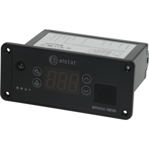
Elstat EMS25 является одним из самых популярных контроллеров, используемых для управления системами кондиционирования в различных предприятиях и офисах. Однако иногда в процессе эксплуатации могут возникать ошибки, которые требуют вмешательства специалиста для их устранения.
Одной из таких ошибок является PF2. Когда на электронном дисплее контроллера появляется сообщение PF2, это означает, что сенсор, отвечающий за измерение температуры, не работает должным образом. Это может быть вызвано различными причинами, такими как выход из строя датчика, неполадки в электрической цепи или ошибки программного обеспечения.
Для устранения ошибки PF2 важно последовательно провести несколько шагов. В первую очередь, необходимо проверить состояние датчика и его подключение. Если датчик исправен, следующим шагом будет проверка электрической цепи и идентификация возможных проблем. Возможно, что требуется заменить поврежденные провода или элементы электронной схемы.
Если после проведения вышеуказанных мероприятий ошибка PF2 продолжает появляться, рекомендуется обратиться к специалистам по ремонту и обслуживанию контроллеров Elstat EMS25. Они смогут провести более глубокую диагностику и выявить истинную причину ошибки, а также предложить эффективные способы ее устранения.
Содержание
- Контроллер Elstat EMS25: ошибка PF2
- В чем заключается ошибка PF2 и ее значение
- Причины возникновения ошибки PF2
- Влияние ошибки PF2 на работу контроллера
- Способы устранения ошибки PF2
- Проверка и замена датчика температуры для исправления ошибки PF2
- Где можно обратиться для ремонта контроллера Elstat EMS25 с ошибкой PF2
Контроллер Elstat EMS25: ошибка PF2
Контроллер Elstat EMS25 — достаточно распространенное устройство, используемое в промышленных холодильных системах для регулирования температуры и контроля работы компрессора. Однако, иногда в процессе работы контроллера может возникать ошибка PF2, которая требует немедленного вмешательства и устранения.
Причины возникновения ошибки PF2
- Некорректная установка или повреждение датчика температуры.
- Проблемы с электропитанием контроллера.
- Повреждение самого контроллера или его компонентов.
- Неправильные настройки параметров работы контроллера.
Способы устранения ошибки PF2
- Проверка датчика температуры. Проверьте, что датчик правильно установлен и не поврежден. Если необходимо, замените датчик.
- Проверка электропитания. Убедитесь, что контроллер правильно подключен к источнику электропитания и все соединения надежно зафиксированы. В случае необходимости, замените поврежденные компоненты.
- Проверка настроек контроллера. Проверьте, что параметры работы контроллера установлены корректно. При необходимости, внесите необходимые корректировки.
- Свяжитесь с производителем. Если проблема остается неразрешенной, обратитесь за помощью к производителю устройства или квалифицированному специалисту.
Важно помнить, что ошибка PF2 может быть связана с различными причинами, поэтому рекомендуется провести тщательную проверку и анализ устройства и его компонентов. В случае сомнений или непонимания, лучше обратиться за помощью к специалистам, чтобы предотвратить возможные серьезные поломки или поломку вообще.
В чем заключается ошибка PF2 и ее значение
Ошибка PF2 — одна из распространенных ошибок, которая может возникнуть на контроллере Elstat EMS25. Данная ошибка указывает на проблему с вентиляцией системы или неисправностью датчика температуры.
Значение ошибки PF2 заключается в том, что контроллер обнаружил, что температура внутри холодильной камеры находится выше заданной нормы. Это может быть вызвано различными причинами, такими как проблемы с вентиляцией, неправильная работы компрессора или неисправность датчика температуры.
Для устранения ошибки PF2 рекомендуется выполнить следующие шаги:
- Проверить работу вентиляционной системы. Убедиться, что вентиляционные отверстия не заблокированы и вентилятор работает исправно.
- Проверить работу компрессора. Убедиться, что компрессор включается и выключается в соответствии с заданными параметрами.
- Проверить работу датчика температуры. Убедиться, что датчик температуры работает исправно, его провода не повреждены и подключены к контроллеру правильно.
- Проверить наличие и состояние термостата. При неисправности термостата он может неправильно регулировать температуру внутри холодильной камеры.
Если выполнение вышеперечисленных шагов не помогло устранить ошибку PF2, рекомендуется обратиться к специалисту для проведения более детальной диагностики и ремонта системы.
Причины возникновения ошибки PF2
Ошибка PF2 на контроллере Elstat EMS25 может возникать по нескольким причинам:
- Неправильное подключение контроллера к основной системе, например, если кабели или контакты не соответствуют заданным спецификациям.
- Неисправности в электропитании, такие как перепады напряжения или плохое качество электрической сети, которые могут вызвать сбои в работе контроллера и привести к ошибке PF2.
- Проблемы с датчиками или устройствами в системе, подключенными к контроллеру. Например, неисправности в датчиках температуры или вентиляционных системах могут вызвать ошибку PF2.
- Необходимость обновления или переустановки программного обеспечения контроллера. Устаревшее или поврежденное программное обеспечение может вызывать сбои в работе системы и приводить к ошибке PF2.
- Механические повреждения контроллера, такие как удары или влага, могут привести к ошибке PF2 из-за повреждений электронных компонентов или короткого замыкания.
В случае появления ошибки PF2 на контроллере Elstat EMS25, рекомендуется сначала провести проверку подключения и состояния электропитания. Если проблема не устраняется, следует обратиться к специалисту или сервисному центру для диагностики и ремонта контроллера.
Влияние ошибки PF2 на работу контроллера
Ошибка PF2 является одной из возможных ошибок, которые могут возникнуть на контроллере Elstat EMS25. Эта ошибка сообщает о проблеме с датчиком температуры, который отвечает за контроль и регулировку работы системы.
Влияние ошибки PF2 на работу контроллера может быть серьезным, поскольку некорректно определенная или отсутствующая информация о температуре может привести к ошибочным расчетам и неправильному функционированию устройства.
Способы устранения ошибки PF2 зависят от конкретных причин ее возникновения. Однако, прежде чем пытаться устранить ошибку, необходимо перезагрузить контроллер, чтобы исключить ее временную природу.
Если перезагрузка не помогла, можно попробовать следующие методы:
- Проверить подключения: убедитесь, что все кабели и провода, связанные с датчиком температуры и контроллером, надежно прикреплены и не имеют повреждений.
- Проверить датчик температуры: возможно, датчик неисправен или его калибровка сбилась. Проверьте состояние датчика, а также его правильность установки и калибровку.
- Проверить настройки контроллера: убедитесь, что все настройки контроллера, связанные с датчиком температуры, корректны и соответствуют требуемым параметрам.
- Проверить окружающую среду: иногда ошибки PF2 могут вызываться внешними факторами, такими как конденсация или пыль. Проверьте, нет ли в окружающей среде каких-либо аномалий, которые могут повлиять на работу датчика.
Если все предыдущие методы не помогли устранить ошибку PF2, рекомендуется обратиться к производителю или сервисному центру для получения дополнительной помощи и консультации.
Способы устранения ошибки PF2
Ошибка PF2 на контроллере Elstat EMS25 может возникать по разным причинам, связанным с неисправностями оборудования или программными ошибками. Для устранения данной ошибки можно предпринять следующие действия:
- Проверить подключение – убедитесь, что все провода и кабели правильно подключены к контроллеру и не имеют повреждений. Проверьте также, что устройство питается от источника электропитания.
- Перезагрузить контроллер – попробуйте перезагрузить контроллер Elstat EMS25. Для этого отключите его от источника питания на некоторое время, затем снова подключите.
- Проверить программное обеспечение – проверьте, что контроллер Elstat EMS25 работает на последней версии программного обеспечения. Если вы используете устаревшую версию, попробуйте обновить ее до последней доступной.
- Сбросить настройки – если проблема не устраняется, попробуйте сбросить настройки контроллера Elstat EMS25 до заводских установок. Обратитесь к документации или инструкции по эксплуатации для получения подробных инструкций.
- Обратиться к производителю – если вы проделали все вышеперечисленные шаги и ошибка PF2 все еще не устранена, рекомендуется обратиться к производителю или сервисному центру для получения дальнейшей помощи и решения проблемы.
Устранение ошибки PF2 на контроллере Elstat EMS25 может потребовать некоторого времени и усилий. Важно следовать инструкциям, указанным в документации и обращаться за помощью в случае необходимости.
Проверка и замена датчика температуры для исправления ошибки PF2
Датчик температуры является одной из ключевых составляющих системы контроля Elstat EMS25. Если датчик выходит из строя или дает неверные показания, возникает ошибка PF2, которая указывает на неполадки в системе.
Для проверки и замены датчика температуры в случае ошибки PF2, следуйте следующим шагам:
- Выключите контроллер Elstat EMS25, отключив его от электропитания.
- Откройте защитный корпус контроллера, используя необходимые инструменты.
- Найдите датчик температуры, который обычно расположен рядом с компрессором или внутри холодильного блока.
- Проверьте соединение датчика с контроллером. Убедитесь, что провода целые и не имеют повреждений.
- Используя мультиметр, проверьте сопротивление датчика. Сопротивление должно быть в пределах нормы, указанной в инструкции по эксплуатации.
- Если сопротивление датчика не соответствует норме или он дает неправильные показания, замените датчик температуры соответствующим образом.
- Убедитесь, что новый датчик температуры правильно подключен к контроллеру и тщательно закрыт.
- Закройте защитный корпус контроллера и включите Elstat EMS25 обратно в сеть.
После выполнения этих шагов, ошибка PF2 должна быть исправлена, и контроллер Elstat EMS25 должен продолжать работать корректно.
Где можно обратиться для ремонта контроллера Elstat EMS25 с ошибкой PF2
Когда контроллер Elstat EMS25 выдает ошибку PF2, это указывает на проблемы с питанием или электрическими цепями в системе. Для устранения этой ошибки и восстановления нормальной работы контроллера необходим ремонт или замена поврежденных компонентов.
Если у вас возникла ошибка PF2 на контроллере Elstat EMS25, вы можете обратиться в сервисный центр, где эксперты проведут диагностику и ремонт устройства. В зависимости от сложности поломки и доступности запчастей, ремонт контроллера может занять разное время.
Выбор сервисного центра для ремонта контроллера Elstat EMS25 с ошибкой PF2 следует осуществлять осмотрительно. Рекомендуется обратиться к официальным сервисным партнерам производителя, чтобы быть уверенными в качестве и надежности ремонта.
Также можно обратиться к другим специализированным сервисным центрам, которые имеют опыт работы с контроллерами Elstat EMS25 и решают проблемы с ошибкой PF2. Важно выяснить у сервисного специалиста, имеются ли необходимые запасные части для ремонта и будет ли диагностика и ремонт произведены в срок.
Не рекомендуется пытаться самостоятельно решать проблему с ошибкой PF2 на контроллере Elstat EMS25, если вы не имеете необходимых навыков и оборудования. Неправильные действия могут привести к дополнительным повреждениям и усложнить процесс ремонта.
В целом, лучшим вариантом для ремонта контроллера Elstat EMS25 с ошибкой PF2 является обращение в сервисный центр, который специализируется на ремонте таких устройств. Это гарантирует качество и надежность восстановления работы контроллера.