
- Описание
- Custom tab
Описание
Надежный полуавтомат для работы в тяжелых условиях!
Отличительный функции
- Origo™ Mig C340 PRO – компактные сварочные источники со ступенчатой регулировкой тока.
- Предназначены для легких и средних условий работы.
- Сварщик может регулировать скорость подачи проволоки, время отжига проволоки и продолжительность сварки короткими швами.
- Origo™ Mig C340 PRO имеет 40 ступеней регулировки напряжения.
- Origo™ Mig C340 PRO 4WD V/A оснащен цифровым вольтамперметром в стандартной комплектации. Подающий механизм с 4-мя ведущими роликами.
- – Сварщик может регулировать скорость подачи проволоки и выбирать режим работы кнопки горелки (2-х или 4-х-тактный).
- – Функция «Плавный старт»
Комплектация
- Сварочная горелка PSF 305 3 м, PSF 305 4,5 м (для C340 PRO 4WD),
- 5 м сетевой кабель,
- 3,5 м обратный кабель с клеммой заземления (5 м для 4WD);
- подставка для газового баллона.
Руководства и инструкции
- Руководство по эксплуатации (инструкция) ESAB Origo Mig C340 PRO.pdf
- Детальная схема аппарата ESAB Origo Mig C340 PRO.pdf
Технические характеристики
| Характеристика | Значение |
|---|---|
|
Питание от 3ф сети переменного тока, В/Гц |
400-415 50/60 |
| Макс. ток при ПВ 30%, А | 340 |
| Макс. ток при ПВ 60%, А | 250 |
| Макс. ток при ПВ 100%, А | 195 |
| Напряжение холостого хода, В | 16-40 |
|
Скорость подачи проволоки, м/мин |
1.9-20 |
| Ø проволоки, сплошная (углерод.сталь) | 0,6-1,2 |
| Ø проволоки, корроз.-устойчивая | 0,6-1,2 |
| Ø проволоки, алюминиевая | 1,0-1,2 |
| Ø проволоки, порошковая | 1,0-1,2 |
| Масса, кг | 120 |
| Производитель | ESAB,Швеция |
Коды заказа
| Наименование | Артикул |
|---|---|
| Origo Mig С340 PRO 4WD+VA | 0349310830 |
| Противопылевой фильтр С280-С340 (стальн. сетка) | 0349302599 |
| Цифровой вольтметр/амперметр С280-С340 | 0349302598 |
| Трансформатор для предв. нагревателя | 0349302250 |
| Держатель кабеля | 0349303362 |
| Реле потока воды | 0349302251 |
| Соединение для МХН / Origo™ Mig C340 PRO | 0349308980 |
Custom tab content.
Цена: 178 644,62 руб.
Описание
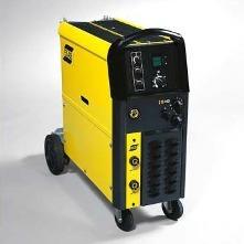
Origo™ Mig C340 PRO — сварочный полуавтомат ESAB со встроенным подающим механизмом и ступенчатой регулировкой напряжения (40 ступеней). Максимальный ток 340 А. Питание от сети 380 В. В аппарат помещается стандартная катушки диаметром до 300 мм (18 кг).
Origo™ Mig C340 PRO уже несколько лет трудится на самых разных производствах и заслужил отличную репутацию безотказного полуавтомата для тяжелых условий работы. Этому способствовали простота и надежность конструкции, прочный стальной корпус, мощный четырехроликовый подающий механизм и долговечные горелки ESAB PSF™ 305 в комплекте.
Особенности и возможности
- 40 ступеней регулировки напряжения
- Разъем для изменения индуктивности
- Индикация сварочного тока и напряжения
- 2/4-х тактный контроллер горелки
- Плавный старт
- Регулировка времени отжига проволоки
- Регулировка интервалов точечной сварки (сварка короткими швами)
- Изменение полярности
Комплект поставки
- В/А-метр (встроенный)
- Сварочная горелка PSF™ 305 (4,5 м, стандартный евроразъем)
- Обратный кабель с зажимом (4,5 м, стандартный разъем OKC50)
- Сетевой кабель (5 м, с трехфазной вилкой 32А)
- Газовый шланг с хомутом (5 м)
- Подставка для баллона (съемная)
- Поворотные колеса
По умолчанию аппарат укомплектован роликами и горелкой для работы проволокой диаметром 1,2 мм.
Гарантийный срок 24 месяца.
Технические характеристики
| Напряжение электросети, В | 380 |
| Диапазон настроек, А | 40-340 |
| Макс. ток при ПВ 30%, А | 340 |
| Макс. ток при ПВ 60%, А | 250 |
| Макс. ток при ПВ 100%, А | 195 |
| Напряжение холостого хода, В | 16-40 |
| Скорость подачи проволоки, м/мин | 1,9 — 12,0 |
| Диаметр проволоки, мм: | |
| Углеродистая и нержавеющая сталь | 0,6-1,2 |
| Порошковая проволока | 0,9-1,2 |
| Алюминий | 1,0-1,2 |
| Макс. диаметр катушки с проволокой, мм | 300 |
| Рабочая температура, °C | от -10 до +40 |
| Температура для транспортировки, °C | от -20 до +55 |
| Размеры ДxШxВ, мм | 840x425x830 |
| Масса, кг | 114 |
| Класс защиты | IP 23S |
Инструкции по эксплуатации (PDF)
- Инструкция на Origo™ Mig C340 PRO
Информация для заказа
| Сварочный полуавтомат Origo™ Mig C340 PRO | 0349310830 |
| Противопылевой фильтр (стальная сетка) | 0349302599 |
Origo™ Mig C340 PRO — сварочный полуавтомат ESAB со встроенным подающим механизмом и ступенчатой регулировкой напряжения (40 ступеней). Максимальный ток 340 А. Питание от сети 380 В. В аппарат помещается стандартная катушки диаметром до 300 мм (18 кг).
Origo™ Mig C340 PRO уже несколько лет трудится на самых разных производствах и заслужил отличную репутацию безотказного полуавтомата для тяжелых условий работы. Этому способствовали простота и надежность конструкции, прочный стальной корпус, мощный четырехроликовый подающий механизм и долговечные горелки ESAB PSF™ 305 в комплекте.
Особенности и преимущества:
- 40 ступеней регулировки напряжения.
- Разъем для изменения индуктивности.
- Индикация сварочного тока и напряжения.
- 2/4-х тактный контроллер горелки.
- Плавный старт.
- Регулировка времени отжига проволоки.
- Регулировка интервалов точечной сварки (сварка короткими швами).
- Изменение полярности.
Комплект поставки:
- В/А-метр (встроенный).
- Сварочная горелка PSF™ 305 (4,5 м, стандартный евроразъем).
- Обратный кабель с зажимом (4,5 м, стандартный разъем OKC50).
- Сетевой кабель (5 м, с трехфазной вилкой 32А).
- Газовый шланг с хомутом (5 м).
- Подставка для баллона (съемная).
- Поворотные колеса.
По умолчанию аппарат укомплектован роликами и горелкой для работы проволокой диаметром 1,2 мм.
Информация для заказа:
| Сварочный полуавтомат Origo™ Mig C340 PRO | 0349310830 |
| Противопылевой фильтр (стальная сетка) | 0349302599 |
Transcription
GBOrigo Mig C280 PROMig C340 PROInstruction manual0463 271 001 GB 20120905Valid for serial no. 627-xxx-xxxx, 119-xxx-xxxx
-2-
1 SAFETY . . . . . . . . . . . . . . . . . . . . . . . . . . . . . . . . . . . . . . . . . . . . . . . . . . . . . . . . . . .2 INTRODUCTION . . . . . . . . . . . . . . . . . . . . . . . . . . . . . . . . . . . . . . . . . . . . . . . . . . .2.146Equipment . . . . . . . . . . . . . . . . . . . . . . . . . . . . . . . . . . . . . . . . . . . . . . . . . . . . . . . . . . . . . . . .63 TECHNICAL DATA . . . . . . . . . . . . . . . . . . . . . . . . . . . . . . . . . . . . . . . . . . . . . . . . .4 INSTALLATION . . . . . . . . . . . . . . . . . . . . . . . . . . . . . . . . . . . . . . . . . . . . . . . . . . . .784.1 Location . . . . . . . . . . . . . . . . . . . . . . . . . . . . . . . . . . . . . . . . . . . . . . . . . . . . . . . . . . . . . . . . . .4.2 Assembly of components . . . . . . . . . . . . . . . . . . . . . . . . . . . . . . . . . . . . . . . . . . . . . . . . . . .WARNING . . . . . . . . . . . . . . . . . . . . . . . . . . . . . . . . . . . . . . . . . . . . . . . . . . . . . . . . . . . . . . . . . . . . .4.3 Electrical installation . . . . . . . . . . . . . . . . . . . . . . . . . . . . . . . . . . . . . . . . . . . . . . . . . . . . . . .4.4 Mains power supply . . . . . . . . . . . . . . . . . . . . . . . . . . . . . . . . . . . . . . . . . . . . . . . . . . . . . . . .89910105 OPERATION . . . . . . . . . . . . . . . . . . . . . . . . . . . . . . . . . . . . . . . . . . . . . . . . . . . . . . .115.15.25.35.45.55.6Connection and control devices . . . . . . . . . . . . . . . . . . . . . . . . . . . . . . . . . . . . . . . . . . . . .Overheating protection . . . . . . . . . . . . . . . . . . . . . . . . . . . . . . . . . . . . . . . . . . . . . . . . . . . . .Inductance connection . . . . . . . . . . . . . . . . . . . . . . . . . . . . . . . . . . . . . . . . . . . . . . . . . . . . .Polarity change . . . . . . . . . . . . . . . . . . . . . . . . . . . . . . . . . . . . . . . . . . . . . . . . . . . . . . . . . . .Wire feed pressure . . . . . . . . . . . . . . . . . . . . . . . . . . . . . . . . . . . . . . . . . . . . . . . . . . . . . . . .Replacing and inserting wire . . . . . . . . . . . . . . . . . . . . . . . . . . . . . . . . . . . . . . . . . . . . . . . .1212121313146 MAINTENANCE . . . . . . . . . . . . . . . . . . . . . . . . . . . . . . . . . . . . . . . . . . . . . . . . . . . .146.1Inspection and cleaning . . . . . . . . . . . . . . . . . . . . . . . . . . . . . . . . . . . . . . . . . . . . . . . . . . . .147 FAULT TRACING . . . . . . . . . . . . . . . . . . . . . . . . . . . . . . . . . . . . . . . . . . . . . . . . . .8 ORDERING OF SPARE PARTS . . . . . . . . . . . . . . . . . . . . . . . . . . . . . . . . . . . . . .DIAGRAM . . . . . . . . . . . . . . . . . . . . . . . . . . . . . . . . . . . . . . . . . . . . . . . . . . . . . . . . . . . .CONNECTION INSTRUCTION . . . . . . . . . . . . . . . . . . . . . . . . . . . . . . . . . . . . . . . . . .ORDER NUMBER . . . . . . . . . . . . . . . . . . . . . . . . . . . . . . . . . . . . . . . . . . . . . . . . . . . . .WEAR PARTS . . . . . . . . . . . . . . . . . . . . . . . . . . . . . . . . . . . . . . . . . . . . . . . . . . . . . . . .ACCESSORIES . . . . . . . . . . . . . . . . . . . . . . . . . . . . . . . . . . . . . . . . . . . . . . . . . . . . . . .15151624252629Rights reserved to alter specifications without notice.TOCe-3-
GB1SAFETYUsers of ESAB equipment have the ultimate responsibility for ensuring that anyone who works on ornear the equipment observes all the relevant safety precautions. Safety precautions must meet therequirements that apply to this type of equipment. The following recommendations should be ob served in addition to the standard regulations that apply to the workplace.All work must be carried out by trained personnel well-acquainted with the operation of the equip ment. Incorrect operation of the equipment may lead to hazardous situations which can result in in jury to the operator and damage to the equipment.1.Anyone who uses the equipment must be familiar with:S its operationS location of emergency stopsS its functionS relevant safety precautionsS welding and cutting2.The operator must ensure that:S no unauthorised person is stationed within the working area of the equipment when it isstarted up.S no-one is unprotected when the arc is struck3.The workplace must:S be suitable for the purposeS be free from drafts4.Personal safety equipmentS Always wear recommended personal safety equipment, such as safety glasses, flame-proofclothing, safety gloves.S Do not wear loose-fitting items, such as scarves, bracelets, rings, etc., which could becometrapped or cause burns.5.General precautionsS Make sure the return cable is connected securely.S Work on high voltage equipment may only be carried out by a qualified electrician.S Appropriate fire extinquishing equipment must be clearly marked and close at hand.S Lubrication and maintenance must not be carried out on the equipment during operation.WARNINGDo not use the power source for thawing frozen pipes.-4bc23de ESAB AB 2011
GBWARNINGArc welding and cutting can be injurious to yourself and others. Take precautions when welding andcutting. Ask for your employer’s safety practices which should be based on manufacturers’ hazarddata.ELECTRIC SHOCK — Can killSInstall and earth the unit in accordance with applicable standards.SDo not touch live electrical parts or electrodes with bare skin, wet gloves or wet clothing.SInsulate yourself from earth and the workpiece.SEnsure your working stance is safe.FUMES AND GASES — Can be dangerous to healthSKeep your head out of the fumes.SUse ventilation, extraction at the arc, or both, to take fumes and gases away from your breathing zoneand the general area.ARC RAYS — Can injure eyes and burn skin.SProtect your eyes and body. Use the correct welding screen and filter lens and wear protectiveclothing.SProtect bystanders with suitable screens or curtains.FIRE HAZARDSSparks (spatter) can cause fire. Make sure therefore that there are no inflammable materials nearby.NOISE — Excessive noise can damage hearingSProtect your ears. Use earmuffs or other hearing protection.SWarn bystanders of the risk.MALFUNCTION — Call for expert assistance in the event of malfunction.Read and understand the instruction manual before installing or operating.PROTECT YOURSELF AND OTHERS!CAUTIONClass A equipment is not intended for use in residential locations wherethe electrical power is provided by the public low-voltage supply system.There may be potential difficulties in ensuring electromagneticcompatibility of class A equipment in those locations, due to conductedas well as radiated disturbances.CAUTIONRead and understand the instruction manual beforeinstalling or operating.CAUTIONThis product is solely intended for arc welding.-5bc23de ESAB AB 2011
GBDispose of electronic equipment at the recycling facility!In observance of European Directive 2002/96/EC on Waste Electrical and ElectronicEquipment and its implementation in accordance with national law, electrical and/orelectronic equipment that has reached the end of its life must be disposed of at arecycling facility.As the person responsible for the equipment, it is your responsibility to obtaininformation on approved collection stations.For further information contact the nearest ESAB dealer.ESAB can provide you with all necessary welding protection and accessories.2INTRODUCTIONThe Mig C280 PRO and Mig C340 PRO are step controlled power sources in acompact design, intended for welding with solid steel, stainless steel or aluminiumwire as well as cored wire with or without shielding gas.The possibility of welding with homogeneous wire/shielding gas and welding withgasless cored wire is obtained by switching the and — connections on the switchingterminal above the wire feed unit.The power sources comes in different variants, see page 25ESAB’s accessories for the product can be found on page 29.2.1EquipmentThe power source Mig C280 PRO is supplied with:SWelding gun PSF 250 — 3m ( Mig C280 PRO 4WD — 4,5m)SReturn cable 3.5m with return clamp (Mig C280 PRO 4WD — 5m)SShelf for gas cylinderSInstruction manualThe power source Mig C340 PRO is supplied with:SWelding gun PSF 305 — 3m (Mig C340 PRO 4WD — 4,5m)SReturn cable 3.5m with return clamp (Mig C340 PRO 4WD — 5m)SShelf for gas cylinderSInstruction manual-6bc23de ESAB AB 2011
GB3TECHNICAL DATAMig C280 PROVoltage400-415 V, 3 50/60 Hz380V, 3 50/60 Hz230/400-415/500V, 3 50Hz230/440-460V, 3 60HzPermissible load at100% duty cycle150 A/22 V150 A/22 V60 % duty cycle190 A/24 V190 A/24 V30 % duty cycle280 A/28 V280 A/28 VSetting range (DC)30A/15V-280A/28V30A/15V-280A/28VOpen circuit voltage15-38 V15-38 VOpen circuit power190 W190 WEfficiency69%69%Power factor0.970.97Control voltage42 V, 50/60 Hz42 V, 50/60 HzWire feed speed1,9 — 19m/min1,9 — 19m/minBurnback time0 — 0,25s0 — 0,25sSpot welding0,2 — 2,5s0,2 — 2,5sWelding gun connectionEUROEURODimensions LxWxH840x425x830840x425x830Weight91 kg91 kgOperating temperature-10 to 40 C-10 to 40 CTransportation temperature-20 to 55 C-20 to 55 CEnclosure classIP 23IP 23Application classificationMig C340 PROVoltage400-415 V, 3 50/60 Hz380V, 3 50/60 Hz230/400-415/500V, 3 50Hz230/440-460V, 3 60HzPermissible load at100% duty cycle195 A/24 V195 A/24 V60 % duty cycle250 A/27 V250 A/27 V30 % duty cycle340 A/31 V340 A/31 VSetting range (DC)40A/16V-340A/31V40A/16V-340A/31VOpen circuit voltage16-40 V16-40 VOpen circuit power240 W240 WEfficiency77%77%Power factor0.950.95Control voltage42 V, 50/60 Hz42 V, 50/60 HzWire feed speed1,9 — 20m/min1,9 — 20m/minBurnback time0 — 0,5s0 — 0,5sCreep startOFF / ONOFF / ON-7bc23de ESAB AB 2011
GBMig C340 PRO2/4 stroke2/42/4Welding gun connectionEUROEURODimensions LxWxH840x425x830840x425x830Weight114 kg114 kgOperating temperature-10 to 40 C-10 to 40 CTransportation temperature-20 to 55 C-20 to 55 CEnclosure classIP 23IP 23Application classificationEnclosure classThe IP code indicates the enclosure class, i. e. the degree of protection against penetration by solidobjects or water. Equipment marked IP23 is designed for indoor and outdoor use.Duty cycleThe duty cycle refers to the time as a percentage of a ten-minute period that you can weld or cut ata certain load without overloading. The duty cycle is valid for 40 C.Application classThe symbolindicates that the power source is designed for use in areas with increasedelectrical hazard.4INSTALLATIONThe installation must be carried out by a professional.CAUTIONThis product is intended for industrial use. In a domestic environment this product maycause radio interference. It is the user’s responsibility to take adequate precautions.4.1LocationPosition the welding power source in such a way that its cooling air inlets and outletsare not obstructed.-8bc23de ESAB AB 2011
GB4.2Assembly of componentsWARNINGDuring transport, the rear wheels of the power source are in their forward position. Beforeuse, place the wheels in their rear position.-9bc23de ESAB AB 2011
GB4.3Electrical installation4.4Mains power supplyCheck that the unit is connected to the correct mains power supply voltage, and thatit is protected by the correct fuse size. A protective earth connection must be made,in accordance with regulations.Rating plate with supply connection data- 10 bc23de ESAB AB 2011
GBRecommended fuse sizes and minimum cable areasMig C280 PRO3 50 Hz3 50 Hz3 50/60 Hz3 50 Hz3 60 Hz3 60 HzVoltage V230380400-415500230440-460Current Aat 100% duty cycle13875117at 60% duty cycle18111081810at 30% duty cycle321918153217at 30% duty cycle4 x 2.54 x 1.54 x 1.54 x 1.54 x 2.54 x 1.5Fuse slow A201616162016Mig C340 PRO3 50 Hz3 50 Hz3 50/60 Hz3 50 Hz3 60 Hz3 60 HzVoltage V230380400-415500230440-460Current Aat 100% duty cycle161097168at 60% duty cycle241514112312at 30% duty cycle372021173619at 30% duty cycle4x44 x 2.54 x 2.54 x 2.54×44 x 2.5Fuse slow A201616162016NOTE: The mains cable areas and fuse sizes as shown above are in accordance with Swedishregulations. They may not be applicable in other countries: make sure that the cable area and fusesizes comply with the relevant national regulations.5OPERATIONGeneral safety regulations for handling the equipment can be found onpage 4. Read through before you start using the equipment!WARNINGRotating parts can cause injury, take great care.WARNINGTo prevent the reel from sliding off the hub: Lock thereel in place by turning the red knob as shown on thewarning label attached next to the hub.WARNINGSecure the equipment — particularly if theground is uneven or sloping.- 11 bc23de ESAB AB 2011
GB5.1Connection and control devices1Mains supply switch8Connection for return cable (-), lowinductance2Switch, coarse control9Knob for selecting — creep start — ON/OFF34567Switch, precise controlIndicating lamp, power supply ONOrange indicator lamp, overheatingEURO — connector (for welding gun)Connection for return cable (-), highinductance1011121314Knob for wire speed settingKnob for selecting 2/4-stroke control modeKnob for burn-back time settingDigital instrument — V / AKnob for spot welding — ON/OFF and timesetting5.2Overheating protectionA thermal overload cutout protects against overheating. The cutout resets automaticallywhen the unit has cooled.5.3Inductance connectionHigher inductance produces a more flowing weld and fewer spatters. Lower inductanceproduces a harsher sound and a stable, concentrated arc.- 12 bc23de ESAB AB 2011
GB5.4Polarity changeThe power source is delivered with the welding wire connected to the plus pole.Some wires, e.g self shielded cored wires, are recommended for welding withnegative polarity. Negative polarity means that the wire is connected to the minuspole and the return cable to the plus pole.Check the recommended polarity for the welding wire you want to use.5.5Wire feed pressureStart by making sure that the wire moves smoothly through the wire guide. Thenset the pressure of the wire feeder’s pressure rollers. It is important that thepressure is not too ÏÏFig 1Fig 2To check that the feed pressure is set correctly, you can feed out the wire againstan insulated object, e.g. a piece of wood.When you hold the gun approx. 5 mm from the piece of wood (fig. 1) the feedrollers should slip.If you hold the gun approx. 50 mm from the piece of wood, the wire should befed out and bend (fig. 2).- 13 bc23de ESAB AB 2011
GB5.6SSSSSSReplacing and inserting wireOpen the side panel.Disconnect the pressure sensor by folding it backwards, the pressure rollersslide up.Straighten out 10-20 cm of new wire. File off any burrs and sharp edges from theend of the wire before inserting it into the wire feed unit.Make sure that the wire goes properly into the feed roller track and into the outletnozzle and the wire guide.Secure the pressure sensor.Close the side panel.6MAINTENANCERegular maintenance is important for safe, reliable operation.CAUTIONAll guarantee undertakings from the supplier cease to apply if the customer attempts anywork to rectify any faults in the product during the guarantee period.6.1Inspection and cleaningPower sourceCheck regularly that the power source is free from dirt.The power source should be regularly blown clean using dry compressed air at reducedpressure. This should be done more frequently in dirty environments.Otherwise the air inlet/outlet may become blocked and cause overheating. To avoidthis you can use an airfilter.The airfilter is an accessory. Order number can be found on page 29.Welding gunSThe welding gun’s wear parts should be cleaned and replaced at regularintervals in order to achieve trouble-free wire feed. Blow the wire guide cleanregularly and clean the contact tip.The brake hubThe hub is adjusted when delivered, ifreadjustment is required, follow the instructionsbelow. Adjust the brake hub so that wire is slightlyslack when wire feed stops.SAdjusting the braking torque:STurn the red handle to the locked position.SInsert a screwdriver into the springs in the hub.Turn the springs clockwise to reduce the braking torqueTurn the springs counter-clockwise to increase the braking torque. NB: Turnboth springs the same amount.- 14 bc23de ESAB AB 2011
GB7FAULT TRACINGTry these recommended checks and inspections before sending for an authorisedservice technican.Type of faultActionsSSNo arcSWelding current is interruptedduring weldingSSCheck that the mains power supply switch is turned on.Check that the welding current supply and return cables arecorrectly connected.Check that correct current value is set.Check whether the thermal overload trip has operated(indicated by the orange lamp on the front).Check the main power supply fuses.Thermal overload tripsoperate frequentlySSCheck to see whether the air filters are clogged.Make sure that you are not exceeding the rated data for thepower source (i.e. that the unit is not being overloaded).Poor welding performanceSCheck that the welding current supply and return cables arecorrectly connected.Check that the correct current value is set.Check that the correct welding wires are being used.Check the main power supply fuses.Check the wire feed unit — if proper rolls are applied andproperly set the pressure of the wire feeder’s pressure rollersSSSS8ORDERING OF SPARE PARTSRepair and electrical work should be performed by an authorised ESAB servicetechnician. Use only ESAB original spare and wear parts.Mig C280 PRO, Mig C340 PRO is designed and tested in accordance with the interna tional and European standards 60974-1, 60974-5 and 60974-10 . It is the obligation ofthe service unit which has carried out the service or repair work to make sure that theproduct still conforms to the said standard.Spare parts may be ordered through your nearest ESAB dealer, see the last page ofthis publication.- 15 bc23de ESAB AB 2011
DiagramMig C280, 380-415V- 16 bc23e ESAB AB 2011
Mig C280, 380-415V- 17 bc23e ESAB AB 2011
Mig C280, 230-500V- 18 bc23e ESAB AB 2011
Mig C280, 230-500V- 19 bc23e ESAB AB 2011
Mig C340, 380-415V- 20 bc23e ESAB AB 2011
Mig C340, 380-415V- 21 bc23e ESAB AB 2011
Mig C340, 230-500V- 22 bc23e ESAB AB 2011
Mig C340, 230-500V- 23 bc23e ESAB AB 2011
Connection instruction230V / 380-415V / 440-460V / 500V- 24 bc23c ESAB AB 2011
Mig C280 PRO, Mig C340 PROOrder numberOrdering no.TypeNotes0349 312 510 Origo Mig C280 PRO380/400-415 V, 3 50 Hz, , with digital instrument0319 312 540 Origo Mig C280 PRO230/400-415/415/500V , 3 50 Hz; 230/440-460V , 3 60 Hz,with digital instrument0349 312 520 Origo Mig C280 PRO 4 WD 380/400-415 V, 3 50 Hz, with digital instrument0349 312 530 Origo Mig C280 PRO 4 WD 230/400-415/415/500V , 3 50 Hz; 230/440-460V , 3 60 Hz,with digital instrument0349 312 550 Origo Mig C340 PRO380/400-415 V, 3 50 Hz, with digital instrument0349 312 560 Origo Mig C340 PRO230/400-415/415/500V , 3 50 Hz; 230/440-460V , 3 60 Hz, withdigital instrument0349 310 830 Origo Mig C340 PRO 4 WD 380/400-415 V, 3 50 Hz, with digital instrument0349 312 570 Origo Mig C340 PRO 4 WD 230/400-415/415/500V , 3 50 Hz; 230/440-460V , 3 60 Hz, withdigital instrument0349 300 531 Origo Mig C280 PRO /Origo Mig C340 PROSpare parts listTechnical documentation is available on the Internet at www.esab.com- 25 bc23o ESAB AB 2011
Mig C280 PROWear parts(W. F. Mechanism 0455 890 888)ItemDenominationOrdering no.APressure roller0455 907 001BFeed roller0367 556 0010367 556 0020367 556 0060367 556 004CInlet nozzle0466 074 001DInsert tube0455 894 0010455 889 0010455 885 001EOutlet nozzle0455 886 001NotesØ 0.6-0.8mm Fe, Ss, cored wire.Ø 0.8-1.0mm Fe, Ss, cored wire.Ø 1.0-1.2mm cored wire.Ø 1.0-1.2mm Al wire.Plastic, must be used together with item 0455 885 001,for welding with Al wire.Steel, must be used togeth
ESAB’s accessories for the product can be found on page 29. 2.1 Equipment The power source Mig C280 PRO is supplied with: Welding gun PSF 250 — 3m ( Mig C280 PRO 4WD — 4,5m) Return cable 3.5m with return clamp (Mig C280 PRO 4WD — 5m) Shelf for gas cylinder Instructi
![]()
ESAB MIG C280 C340 SM

Type:  (PDF)
(PDF)
Size
969.2 KB
Page
39
Category
TOOL
SERVICE MANUAL
If you get stuck in repairing a defective appliance
download
this repair information for help. See below.
Good luck to the repair!
Please do not offer the downloaded file for sell only
use it for personal usage!
Looking for similar esab manual?
Document preview [1st page]

Click on the link for free download!
Document preview [2nd page]

Click on the link for free download!
Please tick the box below to get download link:
- Also known:
ESAB MIG C-280 C280 C340 280 340
- If you have any question about repairing write your question to the Message board. For this no need registration.
- If the site has helped you and you also want to help others, please Upload a manual, circuit diagram or eeprom that is not yet available on the site.
Have a nice Day! - See related repair forum topics below. May be help you to repair.
Warning!
If you are not familiar with electronics, do not attempt to repair!
You could suffer a fatal electrical shock! Instead, contact your nearest service center!
Note! To open downloaded files you need acrobat reader or similar pdf reader program. In addition,
some files are archived,
so you need WinZip or WinRar to open that files. Also some files are djvu so you need djvu viewer to open them.
These free programs can be found on this page: needed progs
If you use opera you have to disable opera turbo function to download file!
If you cannot download this file, try it with CHROME or FIREFOX browser.
Relevant TOOL forum topics:
Üdvözlet mindenkinek
Adott a címben említett inverteres hegesztő amiben a kimeneten lévő egyenirányító tönkrement és vitte magával a meghajtó Hybrid IC.A Hybridben a kimeneti 3 pár félvezető tönkre ment(zárlatos).
Kérdésem a következő lenne hol lehet ilyen IC-t beszerezni esetleg megjavítani vagy helyettesíteni,találkozott már valaki ilyennel?A válaszokat előre is köszönöm.
Hybrid típusa/adatai:
ESAB 150
0459185-001
DP35L600T101657
406247/06481m
Üdv:Mitu
Similar manuals:
If you want to join us and get
repairing help
please sign in or sign up by completing a simple electrical test
or write your question to the Message board without registration.
You can write in English language into the forum (not only in Hungarian)!
E-Waste Reduce