

Operating Instructions Safety System CES-AZ-AES-…
2
Contents
Correct Use
3
Possible combinations for CES components
4
Exclusion of Liability and Warranty
4
General Safety Instructions
5
Function
6
Block diagram CES-AZ-AES-…
7
Installation
8
Electrical Connection
10
Safety in case of faults
10
Fusing of the power supply and the safety contacts
10
Connection example CES-AZ-AES-01B
11
Connection example CES-AZ-AES-02B
12
Connection example CES-AZ-AES-04B
13
Commissioning
14
LED indicators
14
Teach-in operation
14
Functional Check
16
System Status Table
18
Technical Data
20
Evaluation unit CES-AZ-AES-01B
20
Evaluation unit CES-AZ-AES-02B
22
Evaluation unit CES-AZ-AES-04B
24
Read head CES-A-LNN-…
26
Read head CES-A-LSP-…
28
Read head CES-A-LNA-…
30
Read head CES-A-LNA-SC
32
Read head CES-A-LCA-…
34
Read head CES-A-LQA-SC
36
Read head CES-A-LMN-SC
38
Actuator CES-A-BBN
40
Actuator CES-A-BSP
41
Actuator CES-A-BDN-06
42
Actuator CES-A-BBA/CES-A-BCA
43
Actuator CES-A-BQA
44
Actuator CES-A-BDA
45
Actuator CES-A-BMB
46
Ordering Information and Accessories
47
Inspection and Service
49
Service
49
Declaration of Conformity
50

More than safety.
Operating instructions
Non-contact safety system
CES-AZ-AES-… (Unicode)

Operating Instructions Safety System CES-AZ-AES-…
2
Contents
Correct Use 3
Possible combinations for CES components 4
Exclusion of Liability and Warranty 4
General Safety Instructions 5
Function 6
Block diagram CES-AZ-AES-… 7
Installation 8
Electrical Connection 10
Safety in case of faults 10
Fusing of the power supply and the safety contacts 10
Connection example CES-AZ-AES-01B 11
Connection example CES-AZ-AES-02B 12
Connection example CES-AZ-AES-04B 13
Commissioning 14
LED indicators 14
Teach-in operation 14
Functional Check 16
System Status Table 18
Technical Data 20
Evaluation unit CES-AZ-AES-01B 20
Evaluation unit CES-AZ-AES-02B 22
Evaluation unit CES-AZ-AES-04B 24
Read head CES-A-LNN-… 26
Read head CES-A-LSP-… 28
Read head CES-A-LNA-… 30
Read head CES-A-LNA-SC 32
Read head CES-A-LCA-… 34
Read head CES-A-LQA-SC 36
Read head CES-A-LMN-SC 38
Actuator CES-A-BBN 40
Actuator CES-A-BSP 41
Actuator CES-A-BDN-06 42
Actuator CES-A-BBA/CES-A-BCA 43
Actuator CES-A-BQA 44
Actuator CES-A-BDA 45
Actuator CES-A-BMB 46
Ordering Information and Accessories 47
Inspection and Service 49
Service 49
Declaration of Conformity 50

Operating Instructions Safety System CES-AZ-AES-…
3
Correct Use
The Coded Electronic Safety switches series CES are safety devices for monitor-
ing movable safety guards.
In combination with a separating safety guard and the machine control, this safety
component prevents dangerous machine movements from occurring while the
safety guard is open. A stop command is triggered if the safety guard is opened
during the dangerous machine function.
Before safety switches are used, a risk assessment must be performed on the
machine in accordance with:
Ì EN ISO 13849-1, Safety of machinery. Safety related parts of control systems.
General principles for design
Ì EN ISO 14121-1, Safety of machinery. Risk assessment. Principles
Ì IEC 62061, Safety of machinery – Functional safety of safety-related electrical,
electronic and programmable electronic control systems.
Correct use includes compliance with the relevant requirements for installation
and operation, in particular
Ì EN ISO 13849-1, Safety of machinery. Safety related parts of control systems.
General principles for design
Ì EN 1088, Safety of machinery. Interlocking devices associated with guards.
Principles for design and selection
Ì EN 60204-1, Safety of machinery. Electrical equipment of machines. General
requirements
Ì EN 60947-5-3 Specification for low-voltage switchgear and controlgear. Con-
trol circuit devices and switching elements. Requirements for proximity devices
with defined behavior under fault conditions (PDF)
The following components can be connected to the evaluation unit CES-AZ—AES…:
Ì CES read heads
Ì CEM read heads
Ì CET read heads
Ì CKS key adapter
For further information, refer to the operating instructions of the corresponding
component and to the following table Possible combinations for CES components.
Important!
Ì The devices permit a safety-related stop function, initiated by a safety guard
according to Table 8 — DIN EN ISO 13849-1: 2008-12.
Ì The safety-related function of the PDF is the opening of the output
contacts (13/14, 23/24) when the actuator is absent.
Ì The user is responsible for safe integration of the device in a safe overall
system. For this purpose, the overall system must be validated, e.g. in ac-
cordance with EN ISO 13849-2.
Ì The permissible operating parameters must be observed for correct use
(see Technical Data).
Ì If a product data sheet is included with the product, the information on the
data sheet applies in case of discrepancies with the operating instructions.
Ì Only components may be used that are permissible in accordance with the
table below.
Operating Instructions Safety System CES-AZ-AES-…
4
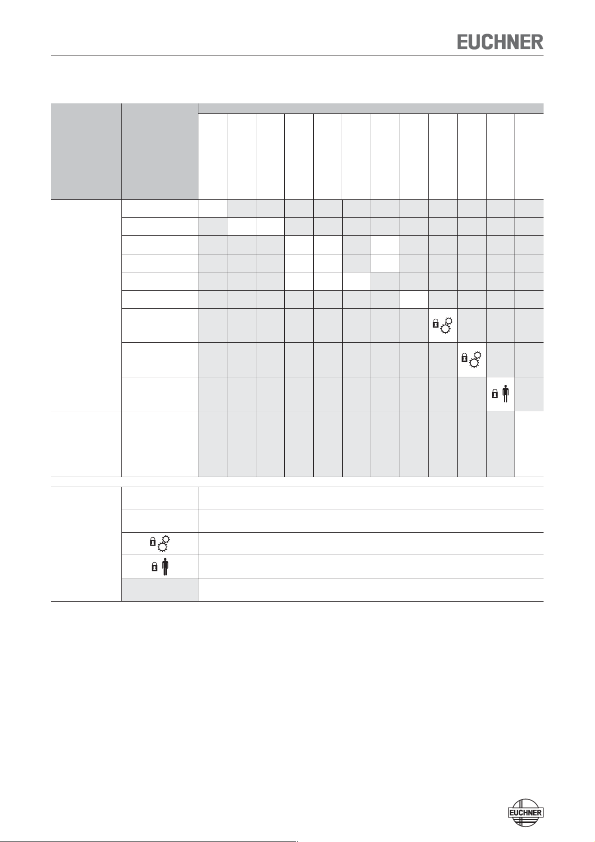
Possible combinations for CES components
Evaluation unit Read head
Actuator
CES-A-BSP-104970
104970
CES-A-BBN-106600
106600
CES-A-BDN-06-104730
104730
CES-A-BBA
071840
CES-A-BCA
088786
CES-A-BQA
098108
CES-A-BDA
084720
CES-A-BMB
077791
CEM-A-BE05
094805
CEM-A-BH10
095175
CET-A-BWK-50X
096327
CKS-A-BK1…
CKS key
CES-AZ-AES-01B
104770
CES-AZ-AES-02B
104775
CES-AZ-AES-04B
104780
CES-AZ-UES-01B
105139
CES-AZ-UES-02B
105140
CES-AZ-UES-04B
105141
CES-A-LSP-…
All items
20
CES-A-LNN-…
All items
15 19
CES-A-LCA-…
All items
15 15 16
CES-A-LNA-…
All items
15 15 16
CES-A-LQA-SC
095650
15 15 23
CES-A-LMN-SC
077790
5
CEM-A-LE05K-S2
094800
CEM-A-LE05R-S2
095792
CEM-A-LH10K-S3
095170
CEM-A-LH10R-S3
095793
CET1-AX-LRA-…
095735
CET1-AX-LDA-…
100399
CES-AZ-AES-01B
104770
CES-AZ-AES-02B
104775
CES-AZ-AES-04B
104780
CKS-A-L1B-…
113130
●
Key to symbols
●
Combination possible
15 Combination possible, typ. switch-on distance 15 mm
Combination possible, guard locking for process protection
Combination possible, guard locking for personal protection
Combination not permissible
Exclusion of Liability and Warranty
In case of failure to comply with the conditions for correct use stated above, or
if the safety instructions are not followed, or if any servicing is not performed as
required, liability will be excluded and the warranty void.
Operating Instructions Safety System CES-AZ-AES-…
5
General Safety Instructions
Safety switches fulfill personal protection functions. Incorrect installation or tamper-
ing can lead to severe injuries to personnel.
The number of teach-in and switching operations is saved in the internal memory
in the evaluation unit. If necessary, this memory can be read by the manufacturer.
Check the safe function of the safety guard particularly
Ì after any setup work
Ì after the replacement of a CES component
Ì after an extended period without use
Ì after every fault
Independent of these checks, the safe function of the safety guard should be
checked at suitable intervals as part of the maintenance schedule.
Warning!
Danger of fatal injury in the event of incorrect connection or incorrect use.
Ì Safety switches must not be bypassed (bridging of contacts), turned away,
removed or otherwise rendered ineffective.
On this topic pay attention in particular to the measures for reducing the pos-
sibility of bypassing from EN 1088:1995+A2:2008, section 5.7.
The device is only allowed to be installed and placed in operation by authorized
personnel
Ì who are familiar with the correct handling of safety components
Ì who are familiar with the applicable EMC regulations
Ì who are familiar with the applicable regulations on health and safety
Ì who have read and understood the operating instructions.
Important!
Prior to use, read the operating instructions and keep these in a safe place.
Ensure that the operating instructions are always available during mounting,
setup and servicing work. EUCHNER cannot provide any warranty in relation to
the readability of the CD for the storage period required. For this reason you
should archive a printed copy of the operating instructions. You can download
the operating instructions from www.EUCHNER.de.

Operating Instructions Safety System CES-AZ-AES-…
6
Function
The safety system CES-AZ-AES… complies with the following safety requirements:
Ì Category 4, PLe according to EN ISO 13849-1
Ì Proximity device with self-monitoring type PDF-M according to EN 60947-5-3.
Ì Redundant design of the circuit in the evaluation unit with self-monitoring. As a
result, the safety system is still effective even if a component fails.
Ì When the safety guard is opened and closed, it is checked whether the safety
system relays open and close correctly.
The CES non-contact safety system consists of three components:
Ì Coded actuator
Ì Read head
Ì Evaluation unit
The number of read heads that can be connected depends on the evaluation unit:
CES-AZ-AES-01B
¨ 1 read head
CES-AZ-AES-02B
¨ 2 read heads
CES-AZ-AES-04B ¨ 4 read heads
It is also possible to connect a start button (monitoring of the falling edge) and a
feedback loop for monitoring external relays and contactors.
The individual configuration is defined by a setup procedure.
Each delivered actuator possesses a unique electronic coding and so is a unique
element in the system used. The code in an actuator cannot be reprogrammed.
The read heads are fastened to the fixed part of the safety guard and are each
connected to the evaluation unit via a two-core screened cable.
The actuator fastened to the movable part of the safety guard is moved towards the
read head by closing the door. When the switch-on distance is reached, power is
supplied to the actuator by the read head by induction and data can be transferred.
The bit pattern read is compared with the code saved in the evaluation unit. If the
data match, the door monitoring output O1 or O1…O2 or O1…O4 (semiconductor
output) on the related read head is set HIGH. If all data for all read heads activated
match, the safety outputs (relay outputs) are then enabled. The OUT LED illuminates.
Optionally, a feedback loop can be connected to the evaluation unit. The evaluation
unit can then only be started with the feedback loop closed. A welded contactor
contact in the release path will thus be detected the next time the machine is started.
Due to the combination of dynamic polling of the actuators and the redundant,
diverse design of the safety electronics with two safety outputs, the evaluation
unit will enter the safe state with every detectable fault.
When a safety guard is opened, the safety outputs switch off the safety circuit and
the OUT LED goes out. The state of the safety outputs is monitored internally by
positively driven NC contacts (relay output).
Independent of the switching state of the safety circuit, the position of all safety
doors can be polled via the outputs O1 or O1…O2 or O1…O4.
If an internal fault occurs in the evaluation unit, the safety circuit is switched off,
the diagnostic output (DIA) is set HIGH and the DIA LED illuminates red.
Operating Instructions Safety System CES-AZ-AES-…
7
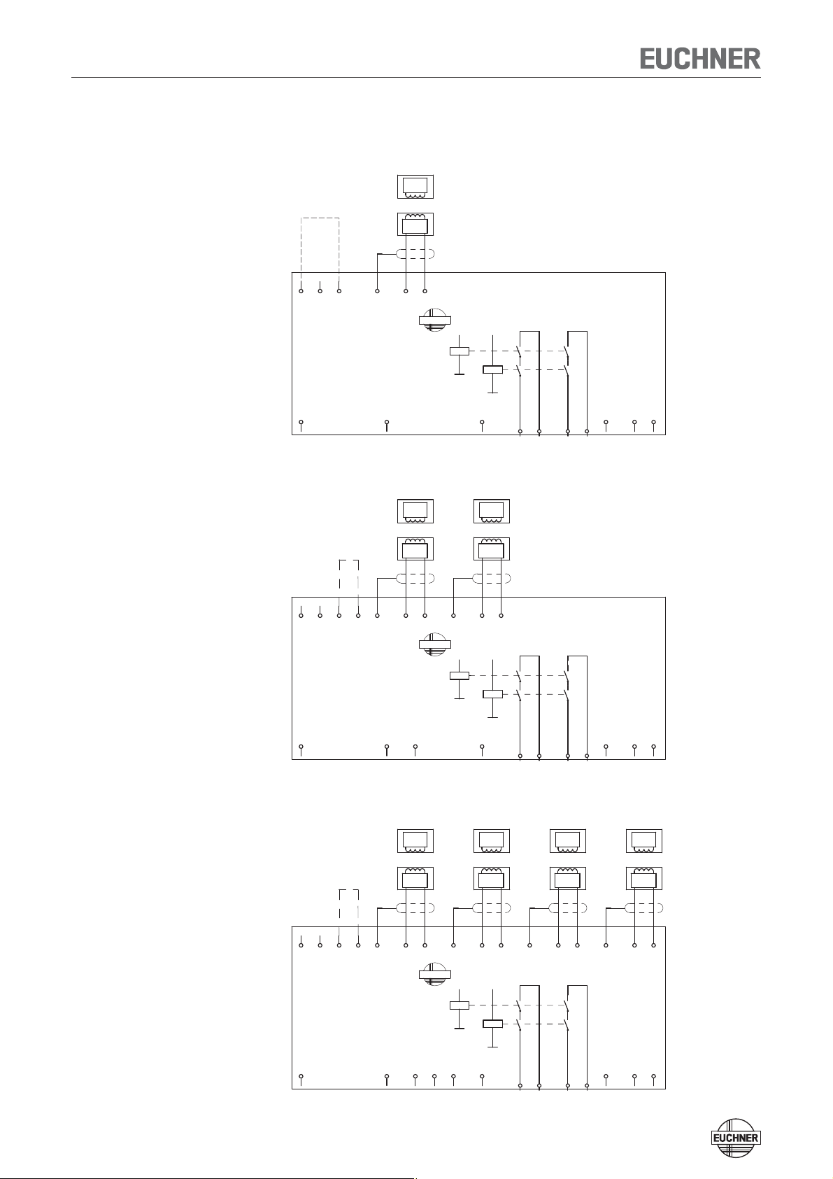
Block diagram CES-AZ-AES-…
CES-AZ-AES-01B
CES-AZ-AES-02B
CES-AZ-AES-04B
0V
TST
UB
CES-AZ-AES-04B
104780
J1 J2
SH1
O1
Read-
head
1
H11
Trans-
ponder
O2
H12
EUCHNER
O3
SH2
O4
Read-
head
2
H21
DIA
Trans-
ponder
H22
23
SH3
24
Read-
head
3
H31
Trans-
ponder
13
H32
14
SH4
Y1
Read-
head
4
H41
Y2
Trans-
ponder
H42
S
K2
+
K1
+
Activation of the
teach-in operation
with jumper
on J1, J2.
UB, 0V Power supply
J1, J2 Jumper for teach-in operation
H11/H12…H41/H42 Connection for read heads 1..0.4
SH1…SH4 Screen read heads 1…4
TST Test input (see „Self-test with test
input TST“ page 16)
O1…O4 Semiconductor monitoring
outputs
DIA Diagnostics output
13, 14 Connection for relay contact A,
safety relay enable
23, 24 Connection for relay contact B,
safety relay enable
Y1, Y2 Feedback loop
S Connection for start button
(monitoring of the falling edge)
0V
TST
UB
CES-AZ-AES-02B
104775
J1 J2 SH1
O1
Read-
head
1
H11
Trans-
ponder
O2
H12
EUCHNER
SH2
Read-
head
2
H21
DIA
Trans-
ponder
H22
23 24 13 14
Y1 Y2 S
K2
+
K1
+
Activation of the
teach-in operation
with jumper
on J1, J2.
UB, 0V Power supply
J1, J2 Jumper for teach-in operation
H11/H12, H21/H22 Connection for read heads 1 and
2
SH1, SH2 Screen read heads 1 and 2
TST Test input (see „Self-test with test
input TST“ page 16)
O1, O2 Semiconductor monitoring
outputs
DIA Diagnostics output
13, 14 Connection for relay contact A,
safety relay enable
23, 24 Connection for relay contact B,
safety relay enable
Y1, Y2 Feedback loop
S Connection for start button
(monitoring of the falling edge)
0V
TST
UB
CES-AZ-AES-01B
104770
J
SH1
O1
Read-
head
1
H11
Trans-
ponder
H12
EUCHNER
DIA
23 24
13 14
Y1 Y2 S
K2
+
K1
+
Activation of the
teach-in operation
with jumper
on J, 0V.
UB, 0V Power supply
J, 0V Jumper for teach-in operation
H11/H12 Connection for read head 1
SH1 Screen read head 1
TST Test input (see „Self-test with test
input TST“ page 16)
O1 Semiconductor monitoring output
DIA Diagnostics output
13, 14 Connection for relay contact A,
safety relay enable
23, 24 Connection for relay contact B,
safety relay enable
Y1, Y2 Feedback loop
S Connection for start button
(monitoring of the falling edge)
Operating Instructions Safety System CES-AZ-AES-…
8
Installation
Caution!
Safety switches must not be bypassed (bridging of contacts), turned away,
removed or otherwise rendered ineffective.
Ì On this topic pay attention in particular to the measures for reducing the pos-
sibility of bypassing according to EN 1088:1995.A2:2008, sec. 5.7.
Ì The evaluation unit must be mounted in a control cabinet with a minimum
degree of protection of IP 54. A snap-in element on the rear of the device is
used for fastening to standard rails.
Ì If several evaluation units are mounted side by side in a control cabinet with-
out air circulation (e.g. fan), a minimum distance of 10 mm must be main-
tained between the evaluation units.
The distance enables heat from the evaluation unit to dissipate.
Caution!
Risk of damage to equipment as a result of incorrect installation. Read heads
or actuators must not be used as a mechanical end stop.
Ì Fit an additional end stop for the movable part of the safety guard.
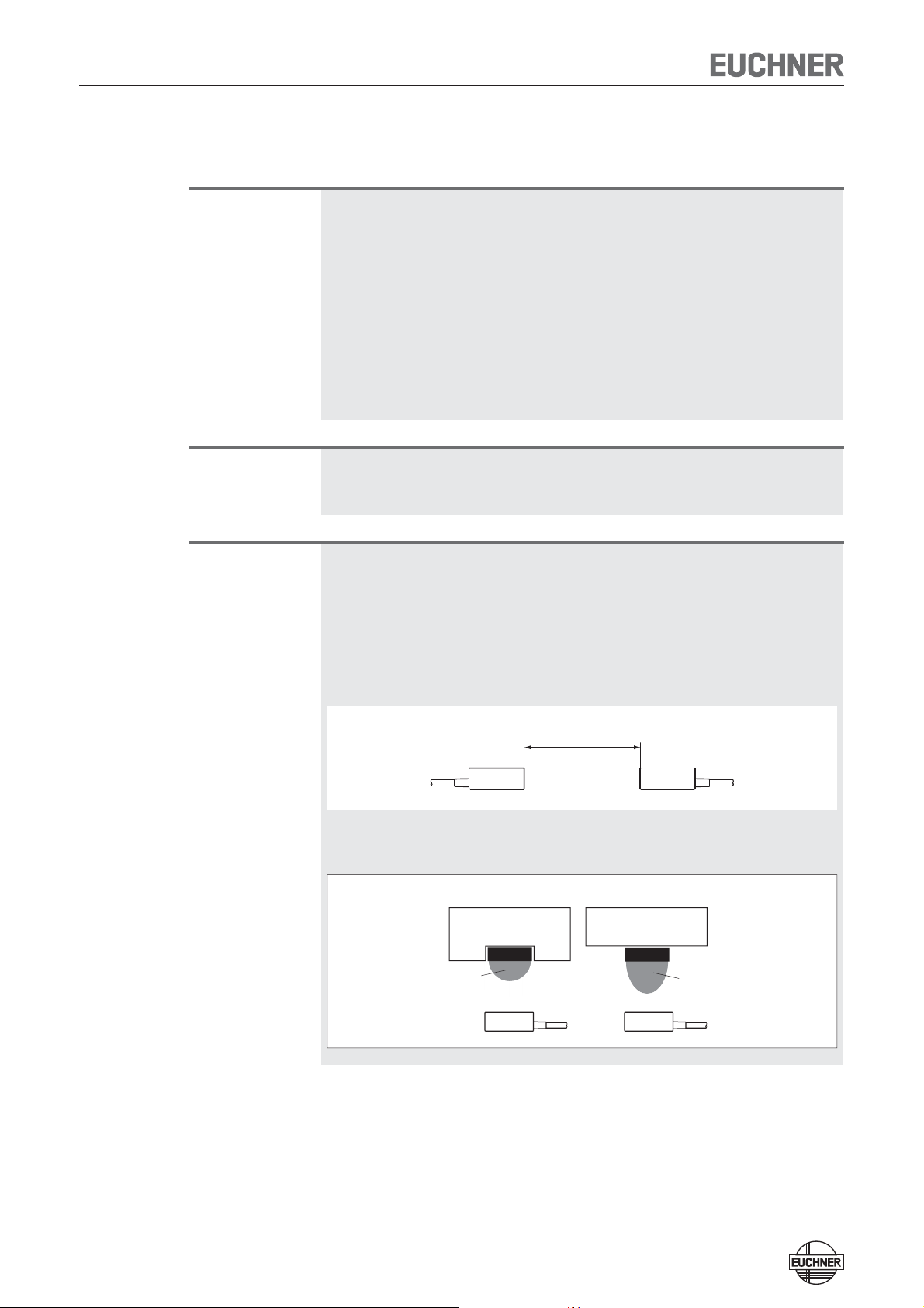
Important!
Ì From the assured switch-off distance S
ar
, the safety outputs are safely shut
down.
Ì When mounting several read heads, observe the stipulated minimum dis-
tance to avoid mutual interference.
— For CES-A-LNA/-LCA s
min
= 50 mm
— For CES-A-LMN s
min
= 20 mm
— For CES-A-LQA s
min
= 80 mm
s
min
Ì If the actuator is installed fl ush, the switching distance changes as a function
of the installation depth and the safety guard material.
Operating
distance
Actuator
Operating
distance
Actuator
Flush mounting Surface mounting

Operating Instructions Safety System CES-AZ-AES-…
9
Note the following points:
Ì Actuator and read head must be easily accessible for inspection and replace-
ment.
Ì The switching operation must only be triggered by the specific actuator desig-
nated for this purpose.
Ì Actuator and read head must be fitted so that
Ì the front faces are at the minimum switch-on distance 0.8 x S
ao
or closer
(see section Operating distances). To avoid entering the area of possible side
lobes, a minimum distance is to be maintained in case of a side approach
direction. See section Typical operating distance for the related actuator.
Ì when the safety guard is open up to the distance S
ar
(assured switch-off dis-
tance), a hazard is excluded.
Ì the actuator is positively mounted on the safety guard, e.g. by using the
safety screws included.
Ì they cannot be removed or tampered with using simple means.
Ì Pay attention to the maximum tightening torque for the read head or safety
switch and actuator mountings of 1 Nm. For read heads/actuators made of
PE-HD, the maximum tightening torque is only 0.5 Nm.
Operating Instructions Safety System CES-AZ-AES-…
10
Electrical Connection
Warning!
In the event of a fault, loss of the safety function due to incorrect connection.
Ì Monitoring outputs must not be used as safety outputs.
Ì Lay the connection cables with protection to prevent the risk of short cir-
cuits.
Caution!
Risk of damage to equipment or malfunctions as a result of incorrect connection.
Ì All the electrical connections must either be isolated from the mains supply
by a safety transformer according IEC 61558-2-6 with limited output voltage
in the event of a fault, or by other equivalent isolation measures.
Ì For use and operation as per the requirements, a power supply with the
feature «for use in class 2 circuits» must be used. The same requirement ap-
plies to the safety outputs.
Alternative solutions must comply with the following requirements:
a) Electrically isolated power supply unit with a max. open-circuit voltage of 30
V/DC and a limited current of max. 8 A.
b) Electrically isolated power supply unit in combination with fuse as per UL248.
This fuse should be designed for max. 3.3 A and should be integrated into
the 30 V/DC voltage section.
Ì All electrical outputs must have an adequate protective circuit for inductive
loads. The outputs must be protected with a free-wheeling diode for this pur-
pose.
Ì Use cable material made of copper with a temperature resistance of at least
75 °C.
Ì The tightening torque for the screws on the connection terminals must be
0.6 … 0.8 Nm.
Ì The connection cable for the read heads must only be extended using
EUCHNER plug connectors and adequate consideration must be given to
EMC. Intermediate terminals must not be used.
Ì The screen on the connection cable for the read head must be connected
to the appropriate terminal SH1 … 4 on the evaluation unit. The portion of
cable from which insulation is stripped should be kept as short as possible
(max. 3 cm).
Safety in case of faults
Ì The operating voltage U
B
is reverse polarity protected.
Ì The connections for the read heads are not short circuit-proof.
Ì A short circuit between 13/14 and 23/24 can be detected only by means of
external pulsing.
Ì A short circuit in the cable can be excluded by laying the cable with protection.
Fusing of the power supply and the safety
contacts
Ì Provide external contact fuses (6 A gG fuse or 6 A circuit breaker, characteris-
tic B or C) for relay outputs.
Ì The power supply must be protected with a max. 8 A fuse before terminal U
B
.
Operating Instructions Safety System CES-AZ-AES-…
11
Connection example CES-AZ-AES-01B
Important!
To achieve category 4 according to EN ISO 13849-1, it is necessary to monitor
the downstream contactors (here contacts of -K3 and -K4 in the feedback loop).
This example shows only an excerpt that is relevant for connection of the CES
system. The example illustrated here does not show complete system planning.
The user is responsible for safe integration in the overall system.
If only one enable path is to be used for control (e. g. of downstream contactors),
failures involving a short circuit between the contacts on the enable path and, for
example, the power supply must be excluded.
With reference to EN ISO 13849-2 Table D.5, this exclusion can be provided if
Ì the cables are inside an electrical installation space and
Ì the enclosure meets the related requirements (see EN 60204-1 or IEC 60204-1).
This example shows only an excerpt that is relevant for connection of the CES
system. The example illustrated here does not show complete system planning.
The user is responsible for safe integration in the overall system.
24 VDC
GND
-F1
0V
TST
-F2
UB
CES-AZ-AES-01B
104770
J SH1
O1
Read-
head
1
H11
Trans-
ponder
H12
EUCHNER
-V1
DIA
-K3
A1
A2
23 24
-V2
13 14
-K4
A1
A2
feedback loop
Y1
Y2
-K4
21
22
-K3
21
22
S
Start
L1
-K3
13
14
-K4
13
14
M
3
~
-M1
L2
23
24
23
24
L3
33
34
33
34
K2
+
K1
+
Operating Instructions Safety System CES-AZ-AES-…
12
Connection example CES-AZ-AES-02B
Important!
To achieve category 4 according to EN ISO 13849-1, it is necessary to monitor
the downstream contactors (here contacts of -K3 and -K4 in the feedback loop).
This example shows only an excerpt that is relevant for connection of the CES
system. The example illustrated here does not show complete system planning.
The user is responsible for safe integration in the overall system.
If only one enable path is to be used for control (e. g. of downstream contactors),
failures involving a short circuit between the contacts on the enable path and, for
example, the power supply must be excluded.
With reference to EN ISO 13849-2 Table D.5, this exclusion can be provided if
Ì the cables are inside an electrical installation space and
Ì the enclosure meets the related requirements (see EN 60204-1 or IEC 60204-1).
This example shows only an excerpt that is relevant for connection of the CES
system. The example illustrated here does not show complete system planning.
The user is responsible for safe integration in the overall system.
24 VDC
GND
-F1
0V
TST
-F2
UB
CES-AZ-AES-02B
104775
J1 J2 SH1
O1
Read-
head
1
H11
Trans-
ponder
O2
H12
EUCHNER
SH2
-V1
Read-
head
2
H21
DIA
Trans-
ponder
H22
-K3
A1
A2
23 24
-V2
13 14
-K4
A1
A2
feedback loop
Y1
Y2
-K4
21
22
-K3
21
22
S
Start
L1
-K3
13
14
-K4
13
14
M
3
~
-M1
L2
23
24
23
24
L3
33
34
33
34
K2
+
K1
+
Operating Instructions Safety System CES-AZ-AES-…
13
Connection example CES-AZ-AES-04B
Important!
To achieve category 4 according to EN ISO 13849-1, it is necessary to monitor
the downstream contactors (here contacts of -K3 and -K4 in the feedback loop).
This example shows only an excerpt that is relevant for connection of the CES
system. The example illustrated here does not show complete system planning.
The user is responsible for safe integration in the overall system.
If only one enable path is to be used for control (e. g. of downstream contactors),
failures involving a short circuit between the contacts on the enable path and, for
example, the power supply must be excluded.
With reference to EN ISO 13849-2 Table D.5, this exclusion can be provided if
Ì the cables are inside an electrical installation space and
Ì the enclosure meets the related requirements (see EN 60204-1 or IEC 60204-1).
This example shows only an excerpt that is relevant for connection of the CES
system. The example illustrated here does not show complete system planning.
The user is responsible for safe integration in the overall system.
24 VDC
GND
-F1
0V
TST
-F2
UB
CES-AZ-AES-04B
104780
J1 J2 SH1
O1
Read-
head
1
H11
Trans-
ponder
O2
H12
EUCHNER
O3
SH2
O4
-V1
Read-
head
2
H21
DIA
Trans-
ponder
H22
-K3
A1
A2
23
SH3
24
-V2
Read-
head
3
H31
Trans-
ponder
13
H32
14
-K4
A1
A2
feedback loop
SH4
Y1
Read-
head
4
H41
Y2
-K4
21
22
-K3
21
22
Trans-
ponder
H42
S
Start
L1
-K3
13
14
-K4
13
14
M
3
~
-M1
L2
23
24
23
24
L3
33
34
33
34
K2
+
K1
+
Operating Instructions Safety System CES-AZ-AES-…
14
Commissioning
LED indicators
STATE LED green State display (multifunction display using flashing modes)
OUT LED yellow Safety circuit closed
DIA LED red — Operating error or
— External fault (fault in the feedback loop) or
— Teach-in process not valid or
— Internal device fault or
— TST input activated (function test active)
Teach-in operation
Before the system forms a function unit, the parameters are set in the evaluation
unit in a teach-in operation (number of connected read heads, assignment of
the actuators to the read heads, with or without automatic start, with or without
feedback loop). In this process, the read heads are activated and the actuator
code is learned.
These configuration parameters are saved in the non-volatile memory in the evalu-
ation unit.
The safety outputs are open during the teach-in operation. The system is in a safe
state.
Important!
Ì During the teach-in operation the following conditions must be met:
Ì There must be no state change, e.g. opening a safety guard or closing a
further safety guard or a change in the signal on the terminals for the start
button and the feedback circuit.
Ì The power supply must not be switched off.
Ì If these conditions are not met, the evaluation unit switches to the safe fault
state (diagnostics LED illuminates) and signals this operating fault with the
STATE LED by 3 short flashes that are repeated every second. The teach-in
operation must be repeated.
Ì The number of teach-in operations is unlimited. The evaluation unit can be
re-configured as often as required.
Ì Actuators cannot be interchanged without a renewed teach-in operation.
Ì An actuator that has not been subjected to teach-in will not be detected by
the related read head.
Ì Even if only one new actuator needs to be taught, a complete new teach-in
operation must be carried out as described in the section Setup.
Ì Do not change DIP switches during operation.
To trigger a teach-in operation, the user must perform the following actions in the
stipulated order:
1. Prepare for teach-in operation
Ì Switch off power supply U
B
Ì Fit a jumper between terminals J1 and J2
(for CES-AZ-AES-01B between J and 0V)

Operating Instructions Safety System CES-AZ-AES-…
15
2. Set required configuration on DIP switches
Switch designation Switch position left (OFF) Switch position right (ON)
1 No read head connected to ter-
minals
H11, H12, SH1 connected
Read head connected to terminals
H11, H12, SH1 connected
2 No read head connected to ter-
minals
H21, H22, SH2 connected
Read head connected to terminals
H21, H22, SH2 connected
3 No read head connected to ter-
minals
H31, H32, SH3 connected
Read head connected to terminals
H31, H32, SH3 connected
4 No read head connected to ter-
minals
H41, H42, SH4 connected
Read head connected to terminals
H41, H42, SH4 connected
5 Automatic start
(No start button connected)
Manual start
(Start button connected)
6 No feedback loop connected Feedback loop connected
3. Set required configuration on machine
Ì Close all doors to be monitored (the actuators must be in the operating
distance of the related read head)
Ì For Manual start operating mode: Keep start button closed
Ì For With feedback loop operating mode: keep feedback loop closed
4. Start teach-in operation
Ì Switch on operating voltage
Ì Wait for self-test (STATE LED flashes for approx. 10 seconds at 15 Hz)
Ì Teach-in operation starts (STATE LED flashes at approx. 1 Hz)
Ì Wait for acknowledgement of the teach-in operation (STATE LED goes out
after approx. 10 seconds)
5. End teach-in operation
Ì Remove jumper between J1 and J2
(for CES-AZ-AES-01B between J and 0V)
Ì For Manual start operating mode: Start button must be connected
Ì For With feedback loop operating mode: Feedback loop must be
connected
Ì Press reset button or interrupt operating voltage for at least 10 seconds
Ì Wait for self-test (STATE LED flashes for approx. 10 seconds at 15 Hz)
6. Check all safety guards for effectiveness
Changing the configuration / new actuator
The evaluation unit can be re-configured as often as required. For this purpose you
must proceed as per the first teach-in operation according to the Setup procedure
section.
Faulty actuators can be replaced. Then a complete teach-in operation must be
performed as per the section Setup. The number of teach-in operations is unlimited.

Operating Instructions Safety System CES-AZ-AES-…
16
Functional Check
After installation and any fault, the safety function must be fully checked. Proceed
as follows:
Warning!
Danger of fatal injury as a result of faults in installation and functional check.
Ì Before carrying out the functional check, make sure that there are no per-
sons in the danger area.
Ì Observe the valid accident prevention regulations.
1. Switch on operating voltage.
Ì The safety switch carries out a self-test.
The green STATE LED flashes for approx. 10 seconds at 15 Hz).
The STATE LED then lights up continuously.
The OUT and ERROR LEDs do not light up.
2. Close all safety guards.
Ì The machine must not start automatically.
Ì The green STATE LED and the yellow OUT LED light up continuously.
3. Enable operation in the control system.
4. Open the safety guard.
Ì The machine must switch off and it must not be possible to start it as long as
the safety guard is open.
Ì The green STATE LED lights up continuously; the OUT and ERROR LEDs do not
light up.
Repeat steps 2-4 for each safety guard.
Self-test with test input TST
On electromechanical safety switches or magnetic switches, the function test can
be performed by cyclically opening the safety guard.
From category 2 according to EN ISO 13849-1 and in accordance with EN 60204-
1 : 1997 (sec. 9.4.2.4), a function test must be performed on the entire safety
system on start-up or after defined intervals.
Testing of the internal function of the device is not necessary because the device
monitors itself in real time. Welding of an output contact (relay output) is detected
by the device at the latest the next time the safety guard is opened. A short circuit
in the output cable is not detected by the device.
In addition, the entire safety circuit can be tested without opening the safety guard.
For this purpose, opening of the safety guard can be simulated by applying 24 V
DC to the test input TST.
The safety outputs are switched off, enabling testing of the complete safety circuit.
The diagnostic output DIA of the evaluation unit is also set HIGH as a monitoring
function.
When the test input TST is reset, the evaluation unit resets the diagnostic output
DIA to LOW, the red LED switches off and normal operation is continued.
In Manual start operating mode, the start button must be pressed again to start
the system.

Operating Instructions Safety System CES-AZ-AES-…
17
Important:
After the self-test, test input TST must be reconnected to 0 V or disconnected.
 Loading…

Euchner
CES-AZ-ALS-04B-113090
113090
Внешний блок оценки состояния для транспондерных предохранительных устройств

Euchner
CES-AZ-UES-01B
105139
Внешний блок оценки состояния для транспондерных предохранительных устройств
Euchner
CES-AZ-UES-02B
105140
Внешний блок оценки состояния для транспондерных предохранительных устройств
Euchner
CES-AZ-UES-04B
105141
Внешний блок оценки состояния для транспондерных предохранительных устройств
Euchner
CES-AZ-AES-01B
104770
Внешний блок оценки состояния для транспондерных предохранительных устройств

Euchner
CES-AZ-AES-02B
104775
Внешний блок оценки состояния для транспондерных предохранительных устройств

Euchner
CES-AZ-AES-04B
104780
Внешний блок оценки состояния для транспондерных предохранительных устройств
Руководство по эксплуатации Бесконтактный предохранительный выключатель CES-AR-C01-AH-SA (Unicode) Больше, чем безопасность.
Руководство по эксплуатации предохранительного выключателя CES-AR-C01-AH-SA Содержание Использование по назначению Возможности комбинирования компонентов CES 3 4 Исключение ответственности и гарантия 5 Общие указания по технике безопасности 5 Назначение 6 Изменение направления перемещения 8 Монтаж
Руководство по эксплуатации предохранительного выключателя CES-AR-C01-AH-SA Использование по назначению Кодированные электронные предохранительные выключатели серии CES являются обеспечивающими безопасность устройствами для контроля разделяющих подвижных защитных устройств. Вместе с разделяющим
Руководство по эксплуатации предохранительного выключателя CES-AR-C01-AH-SA Важно! При последовательном подключении более 11 устройств возможен расчет PFHd согласно одному из методов, указанных в стандарте EN ISO 13849-1:2008, раздел 4.5.1. В случае использования для проверки упрощенной
Руководство по эксплуатации предохранительного выключателя CES-AR-C01-AH-SA Исключение ответственности и гарантия В случае несоблюдения или неисполнения вышеуказанных условий для использования в соответствии с назначением или при проведении возможного технического обслуживания не в соответствии с
Руководство по эксплуатации предохранительного выключателя CES-AR-C01-AH-SA Назначение Устройство отвечает следующим требованиям к безопасности: категория 4, уровень эффективности «e» согласно EN ISO 13849-1; избыточная конструкция схемы в устройства с самоконтролем; благодаря этому
Руководство по эксплуатации предохранительного выключателя CES-AR-C01-AH-SA В случае оседания защитной двери с исполнительным ключом в ходе эксплуатации ключ может выйти из зоны срабатывания считывающей головки. Устройство распознает эту ситуацию и сигнализирует о том, что исполнительный ключ
Руководство по эксплуатации предохранительного выключателя CES-AR-C01-AH-SA Изменение направления перемещения Осторожно! Поломка устройства из-за зажатых проводов. Необходимо проследить за тем, чтобы при регулировке направления перемещения не были зажаты или оборваны провода. Активную поверхность
Руководство по эксплуатации предохранительного выключателя CES-AR-C01-AH-SA Монтаж Важно! Начиная с контролируемого расстояния выключения Sar предохранительные выходы надежно отключены. При монтаже нескольких предохранительных выключателей необходимо соблюдать предписанное минимальное
Руководство по эксплуатации предохранительного выключателя CES-AR-C01-AH-SA Электрическое подключение Имеются следующие возможности подключения: работа одного выключателя; рядное подключение посредством Y-образных разветвителей EUCHNER (только для штекерных разъемов M12); рядное подключение,
Руководство по эксплуатации предохранительного выключателя CES-AR-C01-AH-SA Осторожно! Силовые устройства, являющиеся источником сильных помех, должны находиться на достаточном расстоянии от входных и выходных контуров для обработки сигналов. Провода предохранительных контуров следует
Руководство по эксплуатации предохранительного выключателя CES-AR-C01-AH-SA Требования к соединительным проводам Осторожно! Поломка или неверная работа устройства из-за несоответствующих соединительных проводов. Необходимо использовать соединительные компоненты и провода компании EUCHNER При
Руководство по эксплуатации предохранительного выключателя CES-AR-C01-AH-SA Определение длины проводов с помощью таблицы с примерами Пример: требуется использовать 6 выключателя, подключенных по последовательной схеме. От предохранительного реле в распределительном шкафу до последнего выключателя
Руководство по эксплуатации предохранительного выключателя CES-AR-C01-AH-SA Схема контактов штекерного разъема предохранительного выключателя CES-AR RST UB 0V IA 8 2 7 6 8 6 1 IB OA OB OUT 5 7 4 1 3 4 5 2 3 Кодировочный выступ Вид предохранительного выключателя со стороны подключения Рис. 2. Схема
Руководство по эксплуатации предохранительного выключателя CES-AR-C01-AH-SA Подключение одного выключателя CES-AR-C При использовании одного выключателя CES-AR-C его требуется подключить так, как показано на рис. 3. Выход OUT может в данном случае использоваться в качестве сигнального для ПЛК.
Руководство по эксплуатации предохранительного выключателя CES-AR-C01-AH-SA Предупреждение! В случае неисправности: потеря предохранительной функции из-за неверного подключения. Для обеспечения безопасности требуется всегда выполнять анализ сигналов обоих предохранительных выходов (OA и OB).
Руководство по эксплуатации предохранительного выключателя CES-AR-C01-AH-SA Подключение нескольких CES-AR-C в одной цепи выключателей Важно! Цепь выключателей AR не должна содержать более 20 предохранительных выключателей. При оценке уровня эффективности всей системы для MTTFd может
Terminating plug 18 IB 6 IA Safety Inputs 1 8 Y-distributor 5 RST 2 UB 7 0V OA 4 OB CES Safety Outputs OUT 3 5 OUT 3 OA IB 6 IA Safety Inputs 1 8 RST 2 UB 7 0V Y-distributor OB CES Safety Outputs 4 IB 1 6 8 2 7 5 3 4 IA 4 4 OB 4 IB 0V 2 2 OA 3 3 0V 2 UB 1 IA RST 5 1 5 UB Read Head 1 Read Head RST
Руководство по эксплуатации предохранительного выключателя CES-AR-C01-AH-SA Указания по эксплуатации с защищенными ПЛК В случае подключения к защищенным ПЛК необходимо учитывать следующее: Для ПЛК и подключенного предохранительного выключателя требуется использовать совместный источник питания.
Terminating plug 20 IB 6 IA 8 Safety Inputs 1 RST 2 UB 7 0V Y-distributor 3 OA 4 OB Safety Output OUT CES 5 IB 6 IA 8 RST Safety Inputs 1 2 UB 7 0V Y-distributor 5 3 OA 4 OB CES Safety Output OUT 1 IA RST 6 8 2 Safety Inputs IB UB 7 0V Y-distributor 5 OA OB LED1 UCM J 0V(UCM) CET 3 4 X2:3 X2:4 X2:5
Руководство по эксплуатации предохранительного выключателя CES-AR-C01-AH-SA Ввод в эксплуатацию Светодиодные индикаторы Светодиод STATE DIA Цвет Состояние Значение горит Стандартный режим мигает — Процесс обучения или включение питания — Исполнительный ключ в предельной зоне (начиная с версии
Руководство по эксплуатации предохранительного выключателя CES-AR-C01-AH-SA Процедура обучения при последовательном подключении Рекомендуется программировать исполнительные ключи не в последовательной схеме, а по отдельности. Процедура обучения в последовательной схеме с принципиальной точки зрения
Руководство по эксплуатации предохранительного выключателя CES-AR-C01-AH-SA Проверка работоспособности После монтажа и после обнаружения каждой ошибки должен быть произведен полный контроль функции обеспечения безопасности. При этом используется следующий порядок действий: Предупреждение!
Руководство по эксплуатации предохранительного выключателя CES-AR-C01-AH-SA Таблица состояний системы X выкл. закр. вкл. закр. вкл. быстро мигает 2 Гц Стандартный режим, дверь закрыта, ключ в предельной зоне отрегулировать дверь (начиная с версии 1.1.2) закр. выкл. 1 раз инверт. Стандартный
Руководство по эксплуатации предохранительного выключателя CES-AR-C01-AH-SA Технические характеристики Указание! Если к изделию прилагается технический паспорт, то данные технического паспорта имеют приоритет в случае их отклонения от данных руководства по эксплуатации. Технические характеристики
Руководство по эксплуатации предохранительного выключателя CES-AR-C01-AH-SA Типичное время срабатывания системы Указанные значения времени являются максимальными для цепей выключателей AR с 20 устройствами. Отдельные устройства имеют боле короткое время срабатывания. Задержка готовности: после
Руководство по эксплуатации предохранительного выключателя CES-AR-C01-AH-SA Размерные чертежи и схемы контактов разъемов Схема контактов разъема Предохранительный выключатель CES-AR (8 конт., штырь) и Y-образный разветвитель (8 конт., гнездо) 34 20,5 40 40,5 Предохранительный выключатель CES-AR…
Руководство по эксплуатации предохранительного выключателя CES-AR-C01-AH-SA Технические характеристики исполнительного ключа CES-A-BBA Параметр Значение мин. Материал корпуса Единица станд. макс. Fortron, армированный стекловолокном термопласт, полная заливка Размеры 42 x 25 x 12 Масса 0,02
Руководство по эксплуатации предохранительного выключателя CES-AR-C01-AH-SA Расстояния переключения Зона срабатывания при смещении центров m = 0 (только в комбинации с ключом CES-A-BBA) Параметр Значение Единица мин. станд. макс. расстояние включения — 18 — Гарантированное расстояние включения sao
Руководство по эксплуатации предохранительного выключателя CES-AR-C01-AH-SA Технические характеристики исполнительного ключа CES-A-BPA Параметр Значение мин. Единица станд. Материал корпуса макс. PBT Размеры 40 x 40 x 10 Масса 0,025 Диапазон температур — 25 кг — Степень защиты по EN IEC 60529
Руководство по эксплуатации предохранительного выключателя CES-AR-C01-AH-SA Расстояния переключения Зона срабатывания при смещении центров m = 0 (только в комбинации с ключом CES-A-BPA при монтаже не заподлицо) Параметр Значение Единица мин. станд. макс. расстояние включения — 22 1) —
Руководство по эксплуатации предохранительного выключателя CES-AR-C01-AH-SA Технические характеристики исполнительного ключа CES-A-BRN Параметр Значение мин. Материал корпуса Единица станд. макс. PPS Размеры 80 x 40 x 15 Масса 0,06 Диапазон температур — 25 Степень защиты по EN IEC 60529 мм кг — +
Руководство по эксплуатации предохранительного выключателя CES-AR-C01-AH-SA Расстояния переключения Зона срабатывания при смещении центров m = 0 (только в комбинации с ключом CES-A-BRN) Параметр Значение Единица мин. станд. макс. расстояние включения — 27 — Гарантированное расстояние включения sao
Руководство по эксплуатации предохранительного выключателя CES-AR-C01-AH-SA Информация для заказа и дополнительные принадлежности Наименование Исполнение № для заказа unicode 098941 M12, 4 контакта, штырь 097645 Y-образный разветвитель M12, 1 на 8 контактов, 2 на 5 контактов 097627 Y-образный
Руководство по эксплуатации предохранительного выключателя CES-AR-C01-AH-SA Сервисная служба Адрес сервисной службы: EUCHNER GmbH + Co. KG Kohlhammerstraße 16 D-70771 Leinfelden-Echterdingen Телефон сервисной службы: +49 711 7597-500 Эл. почта: info@euchner.de Интернет: www.euchner.de 35
Руководство по эксплуатации предохранительного выключателя CES-AR-C01-AH-SA Заявление о соответствии 36
Руководство по эксплуатации предохранительного выключателя CES-AR-C01-AH-SA 37
Euchner GmbH + Co. KG Kohlhammerstraße 16 D-70771 Leinfelden-Echterdingen info@euchner.de www.euchner.de Издание: 098039-16-10/13 Название: Руководство по эксплуатации предохранительных выключателей CES-AR-C01-AH-SA (перевод оригинального руководства) Copyright: © EUCHNER GmbH + Co. KG, 10/2013
More products and manuals for Safety Euchner
| Models | Document Type |
|---|---|
|
CES-AZ-ALS-xxx (Unicode) |
User Manual
54 pages |
|
CES-AZ-ALS-xxx (Unicode) |
User Manual
52 pages |
|
CES-FD-AP-U-01-xxx (Unicode) |
User Manual
30 pages |
|
CES-FD-AP-U-01-xxx (Unicode) |
User Manual
30 pages |
|
CEM-A-LE05H-S2 |
User Manual
15 pages |
|
CEM-A-xxx |
User Manual
20 pages |
|
CET-AX |
User Manual
7 pages |
|
CET-AX |
User Manual
7 pages |
|
CET-AX |
User Manual
7 pages |
|
CET-AX |
User Manual
7 pages |
|
CKS-A-L1B-SC |
User Manual
4 pages |
|
CET-AX |
User Manual
7 pages |
|
CES-A-C5H-01 (Unicode) |
User Manual
30 pages |
|
CES-A-C5H-01 (Unicode) |
User Manual
30 pages |
|
CES-A-C5H-01 (Unicode) |
User Manual
30 pages |
|
CES-A-C5H-01 (Unicode) |
User Manual
30 pages |
|
CES-A-x5 |
User Manual
10 pages |
|
CES-A-C5H-01 (Unicode) |
User Manual
30 pages |
|
CES-A-S5H-01 (Unicode) |
User Manual
32 pages |
|
CES-A-S5H-01 (Unicode) |
User Manual
32 pages |


