
Документация и ПО
| Наименование | Наличие | Цена с НДС | |
|---|---|---|---|
|
EZM-3735.5.00.0.1/07.07/1.0.0.0 Цифровой таймер, 35×77 (управ. выход: реле (НО+НЗ, 16А, питание 230 VAC) |
В наличии | 5 468 | Купить |
Цифровой таймер EZM-3735 предназначен для отсчета заданного времени и управления различными механизмами в различных отраслях промышленности.
Может быть использован в любых механизмах, где требуется задержка включения или включение на заданное время. Например, в кондитерских печах для задания времени выпечки, в упаковочных машинах и т. д.
Благодаря простоте в настройке и эксплуатации, таймер может быть использован любым человеком без специальной подготовки.
![]()
<![if ! IE]>
<![endif]>EZM-3735 77×35 DIN Size Digital Timer Controller
<![if ! IE]>
<![endif]>ENGLISH
EZM-3735 77 x 35 DIN Size
Digital Timer Controller
—4 Digits Display
—Operation with One Set value
—Single Contact Output for Timing control ( ON /OFF )
—External Start and Pause Input
—Start and Stop Possibility by front Panel
—Pause possibility by front Panel
—Set value high limit boundaries
—Display can be adjusted to show Second, Minute and Hour
—Programmable Time Bases (Second, Minute, Hour)
—Adjustable internal buzzer according to Timer Stop status.
—Password protection for programming section
—Having CE mark according to European Norms
Instruction Manual. ENG EZM-3735 01 V04 07/17
1.Preface
EZM-3735 Programmable Timer can be used in package machines, production and quality control rollers, and can be adapted easily to all mechanical construction and automation system. Some application fields which they are used are below:
Application Fields
Package machines,
Quality Control rollers,
Filling Systems,
Tool Benchs,
Building Automation.
Production bands
1.1 Environmental Ratings
Operating Temperature : 0 to 50 °C
Max. Operating Humidity : 90% Rh (non-condensing)
cForbidden Conditions: Corrosive atmosphere
Explosive atmosphere
Home applications (The unit is only for industrial applications)
1.2 General Specifications
Standard
230VV ( ±%15) 50/60Hz
Optional Supply Voltage
115 VV(±%15) 50/60Hz,
24 VV(±%15) 50/60Hz,
10 — 30 V Z
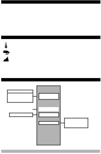
EZM-3735
Power Supply
Input
|
Start Input |
Digital Input |
Pause Input
Digital Input
Output Relay
Output
ON/OFF Operation
2

1.3 Installation
A visual inspection of this product for possible damage occurred during shipment is recommended before installation. It is your responsibility to ensure that qualified mechanical and electrical technicians install this product.
If there is danger of serious accident resulting from a failure or defect in this unit, power off the system and separate the electrical connection of the device from the system.
The unit is normally supplied without a power supply switch or a fuse. Use power switch and fuse as required.
Be sure to use the rated power supply voltage to protect the unit against damage and to prevent failure.
Keep the power off until all of the wiring is completed so that electric shock and trouble with the unit can be prevented.
Never attempt to disassemble, modify or repair this unit. Tampering with the unit may results in malfunction, electric shock or fire.
Do not use the unit in combustible or explosive gaseous atmospheres.
During putting equipment in hole on the metal panel while mechanical installation some metal burrs can cause injury on hands, you must be careful.
Montage of the product on a system must be done with it’s fixing clamps. Do not do the montage of the device with inappropriate fixing clamp. Be sure that device will not fall while doing the montage.
It is your responsibility if this equipment is used in a manner not specified in this instruction manual.
1.4 Warranty
EMKO Elektronik warrants that the equipment delivered is free from defects in material and workmanship. This warranty is provided for a period of two years. The warranty period starts from the delivery date. This warranty is in force if duty and responsibilities which are determined in warranty document and instruction manual performs by the customer completely.
1.5 Maintenance
Repairs should only be performed by trained and specialized personnel. Cut power to the device before accessing internal parts.
Do not clean the case with hydrocarbon-based solvents (Petrol, Trichlorethylene etc.). Use of these solvents can reduce the mechanical reliability of the device. Use a cloth dampened in ethyl alcohol or water to clean the external plastic case.
1.6 Manufacturer Company
Manufacturer Information:
Emko Elektronik Sanayi ve Ticaret A.Ş.
Demirtaş Organize Sanayi Bölgesi Karanfil Sk. No:6 16369 BURSA/TURKEY
|
Phone |
: +90 224 261 1900 |
|
Fax |
: +90 224 261 1912 |
|
Repair and maintenance service information: |
|
|
Emko Elektronik Sanayi ve Ticaret A.Ş. |
|
|
Demirtaş Organize Sanayi Bölgesi Karanfil Sk. No:6 16369 BURSA /TURKEY |
|
|
Phone |
: +90 224 261 1900 |
|
Fax |
: +90 224 261 1912 |
3
2. General Description
|
Front Panel |
Mounting Clamp |
|
IP65 protection |
Panel Surface |
|
NEMA 4X |
|
|
(maximum thickness 15 mm / 0.59 inch) |
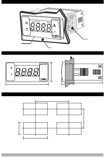
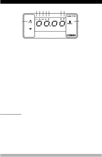
2.1 Front View and Dimensions of EZM-3735 Digital Timer
|
h m s |
S P |
|
START |
PAUSE |
|
STOP |
ü |
76 mm / 3 inch
Maximum 15 mm / 0.59 inch
<![if ! IE]>
<![endif]>34,5 mm / 1.36 inch
65 mm / 2.56 inch
6 mm / 0.24 inch
2.2 Panel Cut-Out
110 mm / 4.33 inch (min)
| <![if ! IE]>
<![endif]>/ 1.14 inch |
<![if ! IE]>
<![endif]>50 mm / 1.97 inch (min) |
| <![if ! IE]>
<![endif]>29 mm |
|
|
71 mm / 2.79 inch |
4
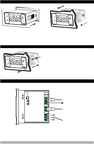
1-Before mounting the device in your panel, make sure that the cut-out is of the right size.
2-Insert the device through the cut-out. If the mounting clamps are on the unit, put out them before inserting the unit to the panel.
3- Insert the mounting clamps to the fixing sockets that located left and right sides of device and make the unit completely immobile within the panel
2.4 Removing from the Panel
1-Pull mounting clamps from left and right fixing sockets.
1
2-Pull the unit through the front side of the panel
2
cBefore starting to remove the unit from panel, power off the unit and the related system.
3
4. Electrical Wiring Diagram
| <![if ! IE]>
<![endif]>8 |
Digital Input |
||
| <![if ! IE]>
<![endif]>7 |
|||
| <![if ! IE]>
<![endif]>6 |
Pause |
||
|
Supply Voltage Input |
|||
| <![if ! IE]>
<![endif]>3735 |
<![if ! IE]>
<![endif]>4 5 |
N |
230VV ( ±%15) 50/60Hz |
|
aL |
115VV ( ±%15) 50/60Hz |
||
| <![if ! IE]>
<![endif]>- |
<![if ! IE]>
<![endif]>3 |
||
| <![if ! IE]>
<![endif]>EZM |
24VV ( ±%15) 50/60Hz |
||
| <![if ! IE]>
<![endif]>: |
<![if ! IE]>
<![endif]>2 |
10..30 VZ |
|
| <![if ! IE]>
<![endif]>P/N |
<![if ! IE]>
<![endif]>1 |
Must be determined in order. |
|
|
Relay Output |
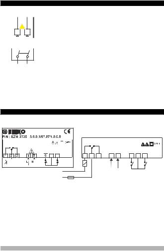
Note-1 : For 230VV , 115VV or 24VV power supply; input 4 is “L”, input 5 is “N”, for 10…30VZ power supply; input 4 is “-”, input 5 is “+”.
5
4.1 Supply Voltage Input Connection of the Device
Power Supply Connection
L a N
4 5
cMake sure that the power supply voltage is the same indicated on the instrument.
Switch on the power supply only after that all the electrical connections have been completed.
Supply voltage range must be determined in order. While installing the unit, supply voltage range must be controlled and appropriate supply voltage must be applied to the unit.
|
EXTERNAL |
<![if ! IE]>
<![endif]>-1 |
||||||
|
FUSE |
<![if ! IE]>
<![endif]>Note |
There is no power supply switch on the device. So a power |
|||||
|
(1A T) |
Supply |
csupply switch must be added to the supply voltage input. |
|||||
|
Switch |
Power switch must be two poled for seperating phase and |
cneutral, On/Off condition of power supply switch is very important in electrical connection.
|
Supply Voltage |
External fuse that on Vpower supply inputs must be on |
|
230VV( ±%15) 50/60Hz , |
phase connection. |
|
115VV(±%15) 50/60Hz, |
External fuse that on Zpower supply inputs must be on (+) |
|
24VV( ±%15) 50/60Hz , |
connection. |
|
10…30 VZ1.5 W |
Must be determined in order.
Note-1 : External fuse is recommended.
Note-2 : For 230VV , 115VV or 24VV power supply; input 4 is “L”, input 5 is “N”, for 10…30VZ power supply; input 4 is “-”, input 5 is “+”.
4.2 Device Label and Connection Diagram
230VVCONNECTION DIAGRAM
16A @
250VV1HP
NO C NC
LINE
LOAD
230 VV ± 15%
50/60Hz — 1.5VA
|
7 |
8 |
| <![if ! IE]>
<![endif]>PAUSE |
<![if ! IE]>
<![endif]>START |
|
N |
|
|
L |
|
16A |
|||||||
|
@250VV1HP |
|||||||
|
OUTPUT |
|||||||
|
NO |
C |
NC |
a |
6 |
7 |
8 |
|
|
1 |
2 |
3 |
4 |
5 |
|
LOAD |
<![if ! IE]>
<![endif]>PAUSE |
<![if ! IE]>
<![endif]>START |
L N
16A T Fuse
6
5.Front Panel Definition and Accessing to the Menus
2 


 4
4
BUTTON DEFINITIONS
1. Increment Button and Start Button :
** It is used to increase the value in the Set screen and Programming mode. ** It is used for Start the Timer in the Main Screen.
2. Decrement, Silencing Buzzer and Stop Button :
** It is used to decrease the value in the Set screen and Programming mode. ** It is used to silence the buzzer.
** It is used for Stop the Timer in the Main Screen.
3. Pause Button :
** While digital timer is running if Pause button is pressed or external pause input is activated, timer stops running.After that if the pause button is pressed again or external pause input is deactivated, timer starts running again.
4. Enter Button:
**In the main operation screen; if this button pressed, set value will be displayed. Value can be changed using increment and decrement buttons. When Set button pressed again, value is saved and returns back to main operating screen.
**To access the programming screen; in the main operation screen, press this button for 5 seconds.
**It is used to saving value in the Set screen and programming screen.
LED DEFINITIONS 5. Output led :
**This led indicates that Output is active.
6.Hour led :
**Indicates that device is in Hour mode.
7.Minute led :
**Indicates that device is in Minute mode.
8.Second led :
**Indicates that device is in Second mode.
9.Pause led :
**This led indicates that Pause is active.
10.Set led :
**Indicates that device is in Set value changing mode.
11.Program led :
**Blinks in programming mode .
7
6. Changing and Saving Timing Set Value
|
Main Operation Screen |
SET Value Screen |
Timer set value can be
When Enter button pressed ‘’S’’ led will
changed with increment and
be active and temperature set value will
decrement buttons.
be displayed.
Main Operation Screen
When Enter button pressed Timing set value can be saved.
‘’S’’ will be inactive and goes back to main operation screen.
|
Timer set value parameter (Default=01:00) |
|
|
Timer set value, can be programmed between minimum Timer set value 00:01 and |
maximum |
|
set limit. |
6.1 Programming Mode Parameter List
Filter Time of Digital Inputs ( Default = 100 )
It is used for protection against the electrical contact debounce or the signal that is less than the determined pulse time.
It can be adjusted from 


 to
to 


 msec .
Time Unit and Scale Selection Parameter ( Default = 1 )
Hour / Minute
It can be adjusted from  to
to .
.
Minute /Second
It can be adjusted from 


 to
to


 .
.
Second /10 Milisecond
It can be adjusted from 


 to
to 


 .
.
Start Type Selection Parameter ( Default =  )
)
Start / Stop buttons can be used to run or stop the timer.
Start / Stop buttons can be used to run or stop the timer.
External Start Input can be used to run or stop the timer.
External Start Input can only be used to run the timer. In order to stop the timer the Stop button must be used.
For detailed information refer to graphics.
|
Output Functions (Default = |
) |
if ON is selected timer runs by start and relay contact is closed. When time is over, relay contact opens.
if OFF is selected timer runs by start. When time is over, relay contact is closed.
8
Buzzer Function Selection Parameter ( Default = 0 )
if this parameter is selected 0, Buzzer is inactive. Adjustable 16 different buzzer sounds. It can be adjusted from 0 to16.
Buzzer is active during this time ( Default = )
)
Buzzer stays active during this time. It can be adjusted from 1 to 99 seconds When this parameter is 1, if decrement button is pressed, is observed. In this condition buzzer is active till buzzer Stop button is pressed.
Data Record ( Default = 1 )
Timer count value is saved to memory when power is disconnected and restored on power up.
Timer count value is not saved to memory when power is disconnected. When power up, Set value is shown on the screen.
Output Relay On Delay Time ( Default = 0 )
It determines how long output relay will be active. If it is 0000 second, then it operates indefinitely. It can be adjusted from  to
to  minute/second. This parameter is active only if
  =
=  .
.
Maximum Set Value Parameter ( Default = 01:00)
Maximum set value for set time value.
It can be adjusted from  to
to . ( If time value is monitored in miliseconds. )
It can be adjusted from  to
to .( If time value is monitored in Hours
  or Minutes.


 )
)
Timer Counting Direction ( Default = 1 )
Timer upcount. 0 to Set value.
Timer Downcount. Set value to 0.
Button Protection Parameter ( Default = 0 )
Button protection is not active.
Buttom protection is active for Timer set value.
Programming Section Access Password ( Default = 0 )
It is used for accessing to the programming section. It can be adjusted from 0 to 9999. If it is selected 0, password will not be asked.
9

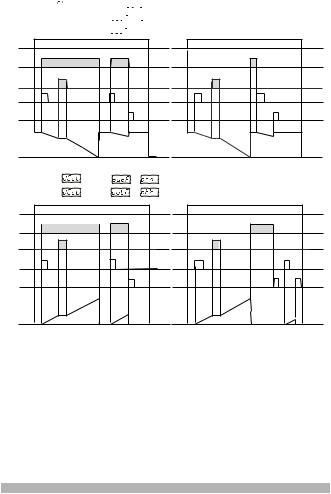
6.3 Operation Graphics of ESM-3735 Digital Timer
1.Control diagram using Start / Stop buttons.
1.1If Start type is selected as
  .
.
1.1.1If downcount  =1 and
  is
is  the control diagram is shown in Figure 1.1
1.1.2If downcount  =1 and
 is
is  the control diagram is shown in Figure 1.2
|
Power |
Power |
|
|
Output |
Output |
|
|
Pause |
Pause |
|
|
Start |
Start |
|
|
Button |
Button |
|
|
Stop |
Stop |
|
|
Button |
Button |
|
|
Set |
Set |
|
|
Screen |
Screen |
|
|
Figure 1.1 |
Figure 1.2 |
|
1.2If Start type  is selected as
 .
.
1.2.1If Upcount  =0 and
  is
is  the control diagram is shown in Figure 1.3
|
1.2.2 If Upcount |
=0 and |
is |
the control diagram is shown in Figure 1.4 |
|
Power |
Power |
||
|
Output |
Output |
||
|
Pause |
Pause |
||
|
Start |
Start |
||
|
Button |
Button |
||
|
Stop |
Stop |
||
|
Button |
Button |
||
|
Set |
Set |
||
|
Screen |
Screen |
||
|
Figure 1.3 |
Figure 1.4 |
10
![]()
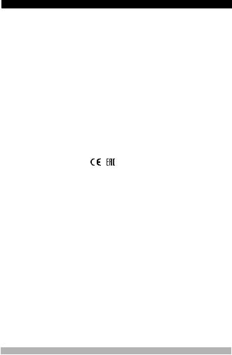
2.Control diagram using Start / Stop buttons.
2.1If Start type is selected as
 .
.
2.1.1If Downcount  =1 and
  is
is  the control diagram is shown in Figure 2.1
2.2.2If Downcount  =1 and
  is
is  the control diagram is shown in Figure 2.2
|
Power |
Power |
|
Output |
Output |
|
Pause |
Pause |
|
Start |
Start |
|
Button |
Button |
|
Stop |
Stop |
|
Button |
Button |
|
Set |
Set |
|
Screen |
Screen |
|
Figure 2.1 |
Figure 2.2 |
1.4 If Start type  is selected as
 .
.
|
1.4.1 If Upcount |
=0 and |
is |
the control diagram is shown in Figure 2.3 |
|
1.4.2 If Upcount |
=0 and |
is |
the control diagram is shown in Figure 2.4 |
|
Power |
Power |
||
|
Output |
Output |
||
|
Pause |
Pause |
||
|
Start |
Start |
||
|
Button |
Button |
||
|
Stop |
Stop |
||
|
Button |
Button |
||
|
Set |
Set |
||
|
Screen |
Screen |
||
|
Figure 2.3 |
Figure 2.4 |
11
3.Control diagram using External Digital Start Input.
3.1 If Start type  is selected as
  .
.
3.1.1If Downcount  =1 and
  is
is  the control diagram is shown in Figure 3.1
3.1.2If Downcount  =1 and
  is
is  the control diagram is shown in Figure 3.2
|
Power |
Power |
||
|
Output |
Output |
||
|
Pause |
Pause |
||
|
Start |
Start |
||
|
Input |
Input |
||
|
Set |
Set |
||
|
Screen |
Screen |
||
|
Figure 3.1 |
Figure 3.2 |
||
|
3.2.1 If Upcount |
=0 and |
is |
the control diagram is shown in Figure 3.3 |
|
3.2.2 If Upcount |
=0 and |
is |
the control diagram is shown in Figure 3.4 |
|
Power |
Power |
||
|
Output |
Output |
||
|
Pause |
Pause |
||
|
Start |
Start |
||
|
Input |
Input |
||
|
Set |
Set |
||
|
Screen |
Screen |
||
|
Figure 3.3 |
Figure 3.4 |
12
4.Control diagram using External Digital Start Input.
4.1 If Start type  is selected as
  .
.
4.1.1If Downcount  =1 and
  is
is  the control diagram is shown in Figure 4.1
4.1.2If Downcount  =1 and
 is
is  the control diagram is shown in Figure 4.2
|
Power |
Power |
||
|
Output |
Output |
||
|
Pause |
Pause |
||
|
Start |
Start |
||
|
Input |
Input |
||
|
Stop |
Stop |
||
|
Button |
Button |
||
|
Set |
Set |
||
|
Screen |
Screen |
||
|
Figure 4.1 |
Figure 4.2 |
||
|
4.2.1 If Upcount |
=0 and |
is |
the control diagram is shown in Figure 4.3 |
|
4.2.2 If Upcount |
=0 and |
is |
the control diagram is shown in Figure 4.4 |
|
Power |
Power |
||
|
Output |
Output |
||
|
Pause |
Pause |
||
|
Start |
Start |
||
|
Input |
Input |
||
|
Stop |
Stop |
||
|
Button |
Button |
||
|
Set |
Set |
||
|
Screen |
Screen |
||
|
Figure 4.3 |
Figure 4.4 |
13

6.5Entering To The Programming Mode, Changing and Saving Parameter
Main Operation Screen
|
When Enter button is pressed for 5 |
Note1: If programming |
|
seconds, “P” led starts to blink. If |
mode accessing |
|
programming mode entering |
password is 0, |
|
password is different from 0, |
Temperature Unit screen |
|
programming mode entering screen |
is observed instead of |
|
will be observed. |
programming screen |
Programming Mode
Entering Screen
Press Enter button for accessing to the password entering screen.
|
PAUSE |
PAUSE |
|
ü |
ü |
|
Password Entering Screen |
Password Entering Screen |
Enter programming mode accessing password with increment and decrement buttons.
Press OK button for entering the password.
Note2: If programming mode accessing password is 0, only three parameters are accessible, and the parameter values can be changed.
|
Filter Time of Start Input |
Filter Time of Start Input |
Press OK button for saving the parameter.
Press increment button for accessing to the next parameter, press decrement button for accessing to the previous parameter
|
i |
If no operation is performed in programming mode for 20 seconds, device turns to main |
|
operation screen automatically.. |
14
7. Specifications
|
Device Type |
: Digital Timer |
|
|
Housing&Mounting |
: 76mm x 34.5mm x 71mm plastic housing for panel |
|
|
Protection Class |
Mounting. Panel cut-out is 71x29mm. |
|
|
: Ip65 at front, Ip20 at rear. |
||
|
Weight |
: Approximately 0.20 Kg. |
|
|
Environmental Ratings |
: Standard, indoor at an altitude of less than 2000 meters |
|
|
Storage / Operating Temperature |
with none condensing humidity. |
|
|
: -40 oC to +80 oC / -30 oC to +80 oC |
||
|
Storage / Operating Humidity |
: 90 % max. (None condensing) |
|
|
Installation |
: Fixed installation |
|
|
Overvoltage Category |
: II. |
|
|
Pollution Degree |
: II, office or workplace, none conductive pollution |
|
|
Operating Conditions |
: Continuous |
|
|
Supply Voltage and Power |
: 230VV ( ±%15) 50/60Hz — 1.5VA |
|
|
: 115VV ( ±%15) 50/60Hz — 1.5VA |
||
|
Time Accuracy |
: 24VV ( ±%15) 50/60Hz — 1.5VA |
|
|
: within ±%1 error |
||
|
Digital Start and Pause Inputs |
: Mechanical contact |
|
|
Control Form |
: ON / OFF |
|
|
Relay Output |
: 16(8) A@250 V V for Resistive load (Output Relay) |
|
|
Display |
(Electrical life : 100.000 switching at full load) |
|
|
: 14 mm Red 4 digits LED Display |
||
|
LED |
: S (Green), P (Green), h (Red), m(Red),s (Red), |
|
|
Internal Buzzer |
Output (Red) |
|
|
: ³83dB |
||
|
Approvals |
: |
, |
15
8.Ordering Information
|
EZM-3735 |
A |
BC |
D |
E |
/ |
FG |
HI |
/ |
U |
V |
W |
Z |
|||||||||||||||||||||||||
|
(77×35 DIN Sizes) |
|||||||||||||||||||||||||||||||||||||
|
0 |
0 |
1 |
/ |
07 |
07 |
/ |
1 |
0 |
0 |
0 |
|||||||||||||||||||||||||||
A Supply Voltage
324VV ( ±%15) 50/60Hz — 1.5VA
4115VV ( ±%15) 50/60Hz — 1.5VA
5230VV ( ±%15) 50/60Hz — 1.5VA
810 — 30 V Z
E Output
1 Relay Output (16(8) A@250 V V,at resistive Load, 1 NO+NC )
FG Input
07 Digital Input
HI Input
07 Digital Input
All order information of EZM-3735 Digital Timer are given on the table at above. User may form appropriate device configuration from information and codes that at the table and convert it to the ordering codes. Firstly, supply voltage then other specifications must be determined. Please fill the order code blanks according to your needs.
Please contact us, if your needs are out of the standards.
Thank you very much for your preference to use Emko Elektronik products, please visit our
Your Technology Partner web page to download detailed user manual. www.emkoelektronik.com.tr
16
<![if ! IE]>
<![endif]>EZM-3735 77×35 DIN-Größe Digitaltimer-Steuerung
<![if ! IE]>
<![endif]>DEUTSCH
EZM-3735 77 x 35 DIN-Größe
Digitaltimer-Steuerung
—4-stellige Anzeige
—Betrieb mit einem Sollwert
—Einzelkontaktausgang für Zeitsteuerung (EIN/AUS)
—Externe Startund Pauseneingabe
—Startund Stoppmöglichkeit über Bedienfeld
—Pausenfunktion über Bedienfeld
—Obere Sollwertbegrenzung
—Anzeige kann eingestellt werden, damit Sekunden, Minuten und Stunden angezeigt werden
—Programmierbare Zeitbasen (Sekunde, Minute, Stunde)
—Einstellbarer interner Summer gemäß Timer-Stopp-Status.
—Passwortschutz für Programmierbereich
—CE-Kennzeichnung gemäß Europäischen Normen
Bedienungsanleitung. DE EZM-3735 01 V04 07/17
1. Einleitung
Der EZM-3735 Programmierbare Timer kann für Verpackungsmaschinen, Produktionsund Qualitätskontrollrollen verwendet werden und ist leicht an alle mechanischen Konstruktionsund Automatisierungssysteme anzupassen.
Anwendungsbereiche
Verpackungsmaschinen,
Qualitätskontrollrollen,
Abfüllanlagen,
Werkbänke,
Gebäudeautomation,
Produktionsbänder.
1.1 Umgebungsbedingte Leistungsfähigkeit
|
Betriebstemperatur |
: 0 bis 50 °C |
Max. Luftfeuchtigkeit bei Betrieb : 90% Rh (nicht kondensierend)
cVerbotene Bedingungen: Korrosive Atmosphäre
Explosionsfähige Atmosphäre
Heimbereich (Das Gerät ist nur für industrielle Anwendungen)
1.2 Allgemeine Spezifikationen
Standard
230VV ( ±%15) 50/60Hz
Optionale Versorgungsspannung
115 VV(±%15) 50/60Hz,
24 VV(±%15) 50/60Hz,
10 — 30 V Z
EZM-3735
Stromversorgungseingang
|
Starteingabe |
Digitaler Eingang |
|||
|
Pauseneingabe |
Digitaler Eingang |
|||
|
Ausgangsrelais |
||||
|
Ausgang |
EIN/AUS Betrieb |
|||
2

1.3 Installation
Eine Sichtprüfung dieses Produkts auf mögliche Transportschäden wird vor der Installation empfohlen. Es liegt in Ihrer Verantwortung dafür zu sorgen, dass qualifizierte Maschinenbauund Elektrotechniker dieses Produkt installieren.
Bei Gefahr eines schweren Unfalls durch Ausfall oder Defekt dieser Einheit, schalten Sie das System aus und trennen Sie die elektrische Verbindung des Geräts vom System.
Die Einheit wird normalerweise ohne Stromschalter oder Sicherung geliefert. Verwenden Sie Netzschalter und Sicherung nach Bedarf.
Stellen Sie sicher, dass Sie die Nennversorgungsspannung verwenden, um die Einheit vor Schäden zu schützen und einen Ausfall zu verhindern.
Lassen Sie den Strom abgeschaltet, bis die gesamte Verkabelung abgeschlossen ist, damit Stromschläge und Probleme mit dem Gerät verhindert werden können.
Versuchen Sie niemals die Einheit zu zerlegen, zu verändern oder zu reparieren.
Die Manipulierung des Geräts kann zu Fehlfunktion, Stromschlag oder Brand führen.
Verwenden Sie die Einheit nicht in brennbaren oder explosionsgefährdeten gashaltigen Atmosphären.
Beim Einsetzen des Geräts in die Öffnung der Metallplatte während der mechanischen Installation, können Metallgrate Verletzungen an den Händen verursachen. Seien Sie vorsichtig.
Die Montage des Produkts in einem System muss mit dessen Befestigungsklammern erfolgen. Führen Sie die Montage des Geräts nicht mit ungeeigneten Befestigungsklammern durch. Achten Sie darauf, dass das Gerät während der Montage nicht herunterfällt.
Es liegt in Ihrer Verantwortung, wenn das Gerät auf eine nicht in dieser Bedienungsanleitung vorgeschriebenen Art und Weise benutzt wird.
1.4 Garantie
EMKO Elektronik garantiert, dass das gelieferte Gerät keinerlei Materialoder Verarbeitungsmängel aufweist. Diese Garantie beschränkt sich auf einen Zeitraum von zwei Jahren. Die Garantiezeitbeginnt mit dem Lieferdatum. Diese Garantie ist gültig, wenn die im Garantieschein und in der Bedienungsanleitung festgelegten Pflichten und Verantwortlichkeiten vollständig durch den Kunden erfüllt werden.
1.5 Wartung
Reparaturen dürfen nur von geschultem Fachpersonal durchgeführt werden. Trennen Sie das Gerät von der Stromversorgung, bevor Sie Innenteile manipulieren. Reinigen Sie das Gehäuse nicht mit Kohlenwasserstoff-Lösemitteln (Benzin, Trichloräthylen usw.). Die Verwendung dieser Lösemittelkann die mechanische Zuverlässigkeit des Geräts beeinträchtigen. Verwenden Sie ein mit Ethylalkohol oder Wasser angefeuchtetes Tuch, um das externe Kunststoffgehäuse zu reinigen.
1.6 Herstellerfirma
Herstellerangaben:
Emko Elektronik Sanayi ve Ticaret A.Ş.
Demirtaş Organize Sanayi Bölgesi Karanfil Sk. No:6 16369 BURSA/TURKEY
|
Telefon |
: +90 224 261 1900 |
|
Fax |
: +90 224 261 1912 |
|
Reparatur und Wartungsservice: |
|
|
Emko Elektronik Sanayi ve Ticaret A.Ş. |
|
|
Demirtaş Organize Sanayi Bölgesi Karanfil Sk. No:6 16369 BURSA /TURKEY |
|
|
Telefon |
: +90 224 261 1900 |
|
Fax |
: +90 224 261 1912 |
3

2. Allgemeine Beschreibung
|
Bedienfeld |
Befestigungsklammer |
|
IP 65 Schutz |
Tafeloberfläche |
|
NEMA 4X |
|
|
(maximale Dicke 15 mm / 0,59 Zoll) |
2.1 Frontansicht und Abmessungen des EZM-3735 Digitaltimers
|
h m s |
S P |
|
START |
PAUSE |
|
STOP |
ü |
76 mm / 3 Zoll
Maximum 15 mm / 0,59 Zoll
<![if ! IE]>
<![endif]>34,5 mm / 1.36 inch
65 mm / 2,56 Zoll
6 mm / 0,24 Zoll
2.2 Tafelausschnitt
110 mm / 4,33 Zoll (min)
| <![if ! IE]>
<![endif]>/ 1,14 Zoll |
<![if ! IE]>
<![endif]>50 mm / 1,97 Zoll (min) |
| <![if ! IE]>
<![endif]>29 mm |
|
|
71 mm / 2,79 Zoll |
4
 Loading…
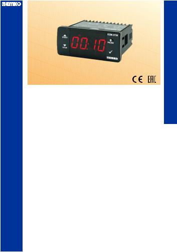
Назначение
Цифровой таймер EZM-xx35 разработан специально для отсчета заданного времени и управления исполнительными механизмами в различных промышленных отраслях. Он может быть применен в широком спектре механизмов, где необходима задержка перед включением, включение на определенное время или симметричное повторение.
Таймер EZM-xx35 обеспечивает точное отслеживание времени и надежное управление исполнительными механизмами. Он предлагает гибкие настройки, позволяющие задать нужные параметры работы в соответствии с требованиями конкретного процесса или системы.
Благодаря своей универсальности и надежности, цифровой таймер EZM-xx35 находит широкое применение в различных отраслях промышленности, где требуется точное управление временем и исполнительными механизмами.
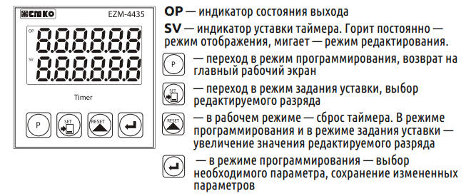
Лицевая панель
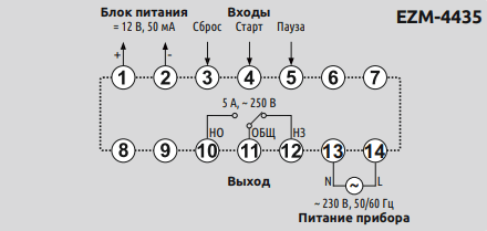
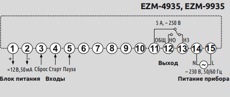
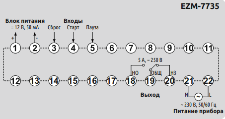
Cхемы подключения
EZM-4435
EZM-4935, EZM-9935
EZM-7735
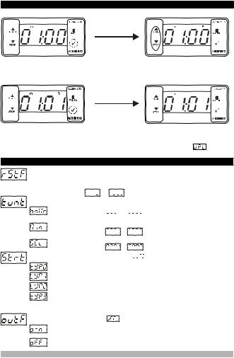
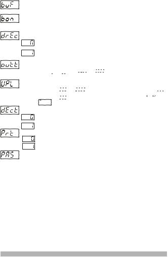
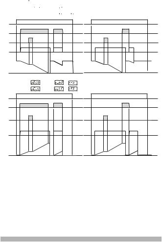
Настраиваемые параметры
| Параметр | Функция параметра | Заводское значение |
|---|---|---|
| t.un1t | Выбор формата отображения времени Диапазон значений: 0 — часы / минуты (0000,00…0099,59) 1 — минуты / секунды (0000,00…0099,59) 2 — секунды / милисекунды (0000,00…0099,99) 3 — часы / минуты (0000,00…0023,59) 4 — часы (0000,00…0999,99) 5 — минуты (0000,00…0999,99) 6 — секунды (0000,00…0999,99) |
0 |
| r.P.S.FLt | Время фильтрации дискретных входов, (мсек) Диапазон значений: (000002…000250) мсек |
50 |
| out.Fnc | Диапазон значений: 0 — ручной сброс 1 1 — ручной сброс 2 2 — ручной сброс 3 3 — автоматический сброс 1 4 — автоматический сброс 2 5 — автоматический сброс 3 6 — автоматический сброс 4 7 — автоматический сброс 5 |
0 |
| out.run | Начальное состояние выхода Диапазон значений: 0 — НО (нормально открытый) 1 — НЗ (нормально закрытый) |
0 |
| out.Pt1 | Время включенного состояния выхода, (сек) Диапазон значений: (00,00…99,99) секунд Если out.Pt1 = 00.00, то параметр не активен |
2 |
| d1rEct | Направление отсчета Диапазон значений: 0 — направление отсчета вверх: от «0» до уставки 1 — направление отсчета вниз: от уставки до «0» |
0 |
| dAt.rEc | Сохранение значения времени таймера в энергонезависимой памяти Диапазон значений: 0 — значение времени таймера сохраняется в энергонезависимой памяти при отключении питания, при появлении питания на экран выводится сохраненное время 1 — значение времени таймера не сохраняется в энергонезависимой памяти при отключении питания, при появлении питания на экран выводится уставка времени |
0 |
| nPn.PnP | Тип схемы подключения внешних датчиков управления таймером Диапазон значений: 0— NPN тип 1— PNP тип |
0 |
| ProtEc | Параметр защиты кнопок на лицевой панели Диапазон значений: 0 — защита отключена 1 — функция «RESET» неактивна, нет возможности сбросить таймер с лицевой панели прибора 2 — функция «SET» неактивна, нет возможности изменить уставку времени 3 – функции «RESET» и «SET» неактивны, нет возможности сбросить таймер и изменить уставку таймера с лицевой панели прибора |
0 |
| ProG.PS | Пароль для доступа к программируемым параметрам Диапазон значений: 000000…009999 |
0 |
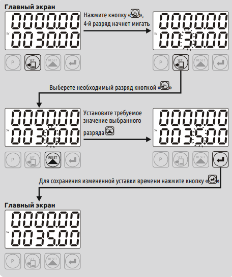
Изменение уставки таймера
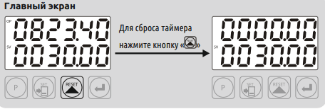
Сброс таймера
Список возможных неисправностей
| Экран | Описание ошибки |
|---|---|
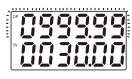 |
Мигает текущее время таймера, отсчет времени остановлен. Ошибка возникает в случае выхода текущего времени за верхний диапазон измерения времени. Сброс ошибки осуществляется кнопкой « reset ». |
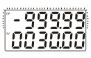 |
Мигает текущее время таймера, отсчет времени остановлен. Ошибка возникает в случае выхода текущего времени за нижний диапазон измерения времени. Сброс ошибки осуществляется кнопкой « reset » |
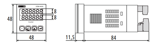
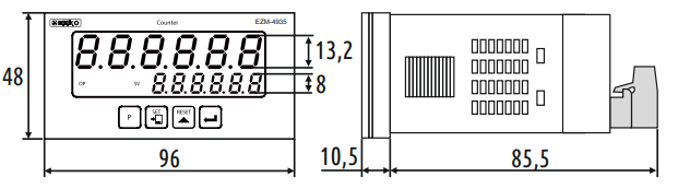
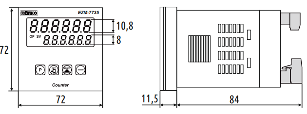
Габаритные размеры
EZM-4435
EZM-4935
EZM-7735
Скачать руководство.
| Document Information: | Share in Social: |
|---|---|
EMKO EZM-3735 Instruction manual (64 pages)
|


