
-
Драйверы
14
-
Инструкции по эксплуатации
15
Языки:

Gigabyte GA-965P-DS3 инструкция по эксплуатации
(72 страницы)
- Языки:Венгерский, Греческий, Испанский, Итальянский, Немецкий, Польский, Португальский, Русский, Турецкий, Французский, Чешский
-
Тип:
PDF -
Размер:
18.6 MB -
Описание:
Installation Guidebook


На NoDevice можно скачать инструкцию по эксплуатации для Gigabyte GA-965P-DS3. Руководство пользователя необходимо для ознакомления с правилами установки и эксплуатации Gigabyte GA-965P-DS3. Инструкции по использованию помогут правильно настроить Gigabyte GA-965P-DS3, исправить ошибки и выявить неполадки.

GA-965P-DS3/S3
Intel
®
Core
TM
2 Extreme quad-core / Core
TM
2 Quad /
Intel
®
Core
TM
2 Extreme dual-core / Core
TM
2 Duo /
Intel
®
Pentium
®
Processor Extreme Edition /
Intel
®
Pentium
®
D / Pentium
®
4 / Celeron
®
D LGA775 Processor Motherboard
User’s Manual
Rev. 3301
12ME-I65PDS3-3301R
* The WEEE marking on the product indicates this product must not be disposed of with user’s other household waste
and must be handed over to a designated collection point for the recycling of waste electrical and electronic equipment!!
* The WEEE marking applies only in European Union’s member states.
Motherboard
GA-965P-DS3
Oct. 20, 2006
Motherboard
GA-965P-DS3
Oct. 20, 2006

Motherboard
GA-965P-S3
Jan. 18, 2007
Motherboard
GA-965P-S3
Jan. 18, 2007

Copyright
© 2007 GIGA-BYTE TECHNOLOGY CO., LTD. All rights reserved.
The trademarks mentioned in the manual are legally registered to their respective companies.
Notice
The written content provided with this product is the property of Gigabyte.
No part of this manual may be reproduced, copied, translated, or transmitted in any form or by any
means without Gigabyte’s prior written permission. Specifications and features are subject to
change without prior notice.
Product Manual Classification
In order to assist in the use of this product, Gigabyte has categorized the user manual in the
following:
For quick installation, please refer to the «Hardware Installation Guide» included with the
product.
For detailed product information and specifications, please carefully read the
«Product User Manual».
For detailed information related to Gigabyte’s unique features, please go to «Technology
Guide» section on Gigabyte’s website to read or download the information you need.
For more product details, please click onto Gigabyte’s website at www.gigabyte.com.tw

— 5 —
Table of Contents
Item Checklist ………………………………………………………………………………………………….. 7
Optional Accessories ………………………………………………………………………………………… 7
GA-965P-DS3/S3 Motherboard Layout ………………………………………………………………. 8
Block Diagram …………………………………………………………………………………………………. 9
Chapter 1 Hardware Installation …………………………………………………………………………11
1-1 Considerations Prior to Installation …………………………………………………………. 11
1-2 Feature Summary ……………………………………………………………………………… 12
1-3 Installation of the CPU and CPU Cooler ………………………………………………. 14
1-3-1 Installation of the CPU …………………………………………………………………………….. 14
1-3-2 Installation of the CPU Cooler …………………………………………………………………. 15
1-4 Installation of Memory ………………………………………………………………………… 16
1-5 Installation of Expansion Cards ……………………………………………………………. 18
1-6 I/O Back Panel Introduction ………………………………………………………………… 19
1-7 Connectors Introduction ………………………………………………………………………. 20
Chapter 2 BIOS Setup …………………………………………………………………………………… 31
The Main Menu (Example BIOS Ver.: GA-965P-DS3, F10a) ……………………………. 32
2-1 Standard CMOS Features ………………………………………………………………….. 34
2-2 Advanced BIOS Features…………………………………………………………………… 36
2-3 Integrated Peripherals …………………………………………………………………………. 38
2-4 Power Management Setup ………………………………………………………………….. 41
2-5 PnP/PCI Configurations……………………………………………………………………… 43
2-6 PC Health Status ………………………………………………………………………………. 44
2-7 MB Intelligent Tweaker(M.I.T.) …………………………………………………………….. 46
2-8 Load Fail-Safe Defaults ……………………………………………………………………….. 49
2-9 Load Optimized Defaults ……………………………………………………………………… 49
2-10 Set Supervisor/User Password …………………………………………………………… 50
2-11 Save & Exit Setup…………………………………………………………………………….. 51
2-12 Exit Without Saving …………………………………………………………………………… 51

— 6 —
Chapter 3 Install Drivers ………………………………………………………………………………… 53
3-1 Install Chipset Drivers ………………………………………………………………………… 53
3-2 Software Applications …………………………………………………………………………. 54
3-3 Driver CD Information ………………………………………………………………………… 54
3-4 Hardware Information …………………………………………………………………………. 55
3-5 Contact Us ……………………………………………………………………………………….. 55
Chapter 4 Appendix ……………………………………………………………………………………… 57
4-1 Unique Software Utilities …………………………………………………………………….. 57
4-1-1 EasyTune 5 Introduction …………………………………………………………………………. 57
4-1-2 Xpress Recovery2 Introduction ………………………………………………………………. 58
4-1-3 Flash BIOS Method Introduction ……………………………………………………………… 60
4-1-4 Configuring SATA Hard Drive(s) (Controller: GIGABYTE SATA2) ……………. 64
4-1-5 2- / 4- / 6- / 8- Channel Audio Function Introduction ……………………………….. 77
4-2 Troubleshooting ………………………………………………………………………………….. 82

— 7 —
Item Checklist
IDE Cable x 1 and FDD Cable x 1
SATA 3Gb/s Cable x 4 (GA-965P-DS3 only)
SATA 3Gb/s Cable x 2 (GA-965P-S3 only)
I/O Shield
* The items listed above are for reference only, and are subject to change without notice.
Optional Accessories
2 Ports USB 2.0 Cable (Part Number: 12CR1-1UB030-51/R)
4 Ports USB 2.0 Cable (Part Number: 12CR1-1UB030-21/R)
S/PDIF-IN Cable (Part Number: 12CR1-1SPDIN-01R)
e-SATA Cable (Part Number: 12CF1-3SATPW-11R)

— 8 —
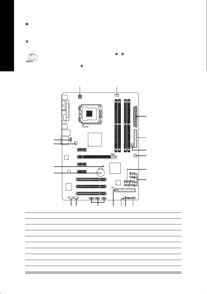
GA-965P-DS3/S3 Motherboard Layout
KB_MS
CPU_FAN
LGA775
ATX
GA-965P-DS3/S3
USB
LAN
CD_IN
F_AUDIO
AUDIO
BIOS
PCIE_16
PCIE_3
F_USB1
IDE1
PCIE_1
SPDIF_I
CI
DDRII1
DDRII2
DDRII3
DDRII4
F_USB2
BATTERY
GSATAII0
F_PANEL
IT8718
SYS_FAN
SATAII0
ATX_12V
Intel
®
P965
Intel
®
ICH8
PWR_LED
FDD
PCIE_2
SATAII1
SATAII2
SATAII3
GIGABYTE
SATA2
PCI1
PCI2
PCI3
USB
CLR_CMOS
COM
COAXIAL
OPTICAL
LPT
CODEC
Marvell
88E8056
F_USB3
GSATAII1
PWR_FAN
NB_FAN
— 9 —
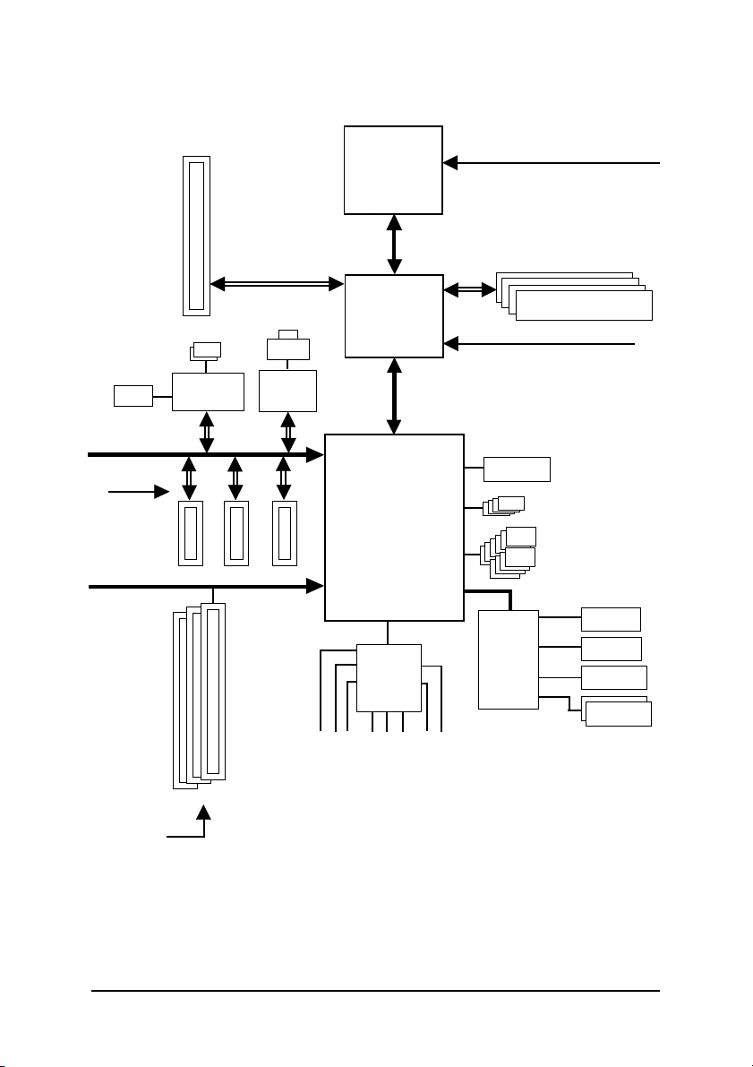
Block Diagram
(Note 1) Applies only when the GA-965P-DS3/S3 motherboard (rev. 3.3) is installed with a 1333 MHz
FSB processor. The system will automatically adjust BIOS to support 1333 MHz FSB by
overclocking when a 1333 MHz FSB processor is installed. In such a configuration, the actual
operating memory frequency will be 667 MHz or 833 MHz, depending on the memory being
installed.
(Note 2) To use a DDRII 800/667 memory module on the motherboard, you must install a 1333/1066/
800 MHz FSB processor.
CPU CLK+/-(333
(Note 1)
/266/200/133 MHz)
PCI Express x16
Host
Interface
MCH CLK (266/200/133 MHz)
DDRII 800/667/533 MHz
DIMM
(Note 2)
IT8718
BIOS
3 PCI
PCI Bus
3 PCI Express x1
PCI Express Bus
Dual Channel Memory
Floppy
PS/2 KB/Mouse
PCIe CLK
(100 MHz)
4 SATA 3Gb/s
LAN
RJ45
PCICLK (33 MHz)
PCIe CLK
(100 MHz)
Intel
®
P965
Intel
®
ICH8
LGA775
Processor
x1
x1
x1
ATA 33/66/100/133
IDE Channel
COM Port
LPT Port
Marvell
88E8056
2 SATA 3Gb/s
x1
x1
10 USB Ports
Center/Subwoofer
Speaker Out
Line-Out
MIC
Line-In
SPDIF In
SPDIF Out
Side Speaker Out
Surround Speaker Out
CODEC
GIGABYTE
SATA2

— 10 —

Hardware Installation— 11 —
English
1-1 Considerations Prior to Installation
Preparing Your Computer
The motherboard contains numerous delicate electronic circuits and components which can
become damaged as a result of electrostatic discharge (ESD). Thus, prior to installation, please
follow the instructions below:
1. Please turn off the computer and unplug its power cord.
2. When handling the motherboard, avoid touching any metal leads or connectors.
3. It is best to wear an electrostatic discharge (ESD) cuff when handling electronic components
(CPU, RAM).
4. Prior to installing the electronic components, please have these items on top of an antistatic pad or
within a electrostatic shielding container.
5. Please verify that the power supply is switched off before unplugging the power supply connector
from the motherboard.
Installation Notices
1. Prior to installation, please do not remove the stickers on the motherboard. These stickers are required
for warranty validation.
2. Prior to the installation of the motherboard or any hardware, please first carefully read the information
in the provided manual.
3. Before using the product, please verify that all cables and power connectors are connected.
4. To prevent damage to the motherboard, please do not allow screws to come in contact with the
motherboard circuit or its components.
5. Please make sure there are no leftover screws or metal components placed on the motherboard or
within the computer casing.
6. Please do not place the computer system on an uneven surface.
7. Turning on the computer power during the installation process can lead to damage to system
components as well as physical harm to the user.
8. If you are uncertain about any installation steps or have a problem related to the use of the product,
please consult a certified computer technician.
Instances of Non-Warranty
1. Damage due to natural disaster, accident or human cause.
2. Damage as a result of violating the conditions recommended in the user manual.
3. Damage due to improper installation.
4. Damage due to use of uncertified components.
5. Damage due to use exceeding the permitted parameters.
6. Product determined to be an unofficial Gigabyte product.
Chapter 1 Hardware Installation

GA-965P-DS3/S3 Motherboard — 12 —
English
1-2 Feature Summary
CPU LGA775 for Intel
®
Core
TM
2 Extreme quad-core / Core
TM
2 Extreme dual-core /
Core
TM
2 Quad / Core
TM
2 Duo / Pentium
®
processor Extreme Edition /
Pentium
®
D / Pentium
®
4 / Celeron
®
D
L2 cache varies with CPU
Front Side Bus Supports 1333
(Note 1)
/1066/800/533 MHz FSB
Chipset Northbridge: Intel
®
P965 Express Chipset
Southbridge: Intel
®
ICH8
LAN Onboard Marvell 88E8056 phy (10/100/1000 Mbit)
Audio Onboard Realtek ALC888 chip
Supports High Definition Audio
Supports 2 / 4 / 6 / 8 channel audio
Supports S/PDIF In/Out connection
Supports CD In connection
Storage ICH8 Southbrigde
— 1 FDD connector, allowing connection of 1 FDD device
— 4 SATA 3Gb/s connectors (SATAII0,1, 2, 3), allowing connection of 4
SATA 3Gb/s devices
Onboard GIGABYTE SATA2 chip
— 1 IDE connector (UDMA 33/ATA 66/ATA 100/ATA 133), allowing con-
nection of 2 IDE devices
— 2 SATA 3Gb/s connectors (GSATAII0,1), allowing connection of 2 SATA
3Gb/s devices
— Supports RAID 0, RAID 1, and JBOD for Serial ATA
O.S Support Microsoft Windows 2000/XP
Memory 4 DDRII DIMM memory slots (supports up to 8 GB memory)
Supports dual channel DDRII 800/667/533
unbuffered DIMMs
(Note 2)
Supports 1.8V DDRII DIMMs
Expanstion Slots 1 PCI Express x16 slot
3 PCI Express x1 slots
3 PCI slots
Internal Connectors 1 24-pin ATX power connector
1 4-pin ATX 12V power connector
1 floppy connector
1 IDE connector
6 SATA 3Gb/s connectors
1 CPU fan connector
1 system fan connector
1 power fan connector
1 northbridge fan connector
1 front panel connector
1 front audio connector
1 CD In connector
«*» Only the GA-965P-DS3 adopts All-Solid Capacitor design.

Hardware Installation— 13 —
English
Internal Connectors 3 USB 2.0/1.1 connectors for additional 6 ports by cables
1 S/PDIF In connector
1 power LED connector
1 Chassis Intrusion connector
Rear Panel I/O 1 PS/2 keyboard port
1 PS/2 mouse port
1 S/PDIF Out connection (coaxial+optical)
1 parallel port
1 serial port
4 USB 2.0/1.1 ports
1 RJ-45 port
6 audio jacks (Line In / Line Out / MIC In/Surround Speaker Out (Rear
Speaker Out)/Center/Subwoofer Speaker Out/Side Speaker Out)
I/O Control IT8718 chip
Hardware Monitor System voltage detection
CPU/System temperature detection
CPU/System/Power fan speed detection
CPU warning temperature
CPU/System/Power fan failure warning
CPU Smart Fan Control
BIOS 1 8 Mbit flash ROM
Use of licensed AWARD BIOS
PnP 1.0a, DMI 2.0, SM BIOS 2.3, ACPI 1.0b
Additional Features Supports @BIOS
Supports Download Center
Supports Q-Flash
Supports EasyTune
(Note 3)
Supports Xpress Install
Supports Xpress Recovery2
Supports Xpress BIOS Rescue
Bundle Software Norton Internet Security (OEM revision)
Form Factor ATX form factor; 30.5cm x 21.0cm
(Note 1) Applies only when the GA-965P-DS3/S3 motherboard (rev. 3.3) is installed with a 1333 MHz
FSB processor. The system will automatically adjust BIOS to support 1333 MHz FSB by
overclocking when a 1333 MHz FSB processor is installed. In such a configuration, the actual
operating memory frequency will be 667 MHz or 833 MHz, depending on the memory being
installed.
(Note 2) To use a DDRII 800/667 memory module on the motherboard, you must install a 1333/1066/
800 MHz FSB processor.
(Note 3) EasyTune functions may vary depending on different motherboards.

GA-965P-DS3/S3 Motherboard — 14 —
English
1-3 Installation of the CPU and CPU Cooler
Before installing the CPU, please comply with the following conditions:
1. Please make sure that the motherboard supports the CPU.
2. Please take note of the one indented corner of the CPU. If you install the CPU in the wrong
direction, the CPU will not insert properly. If this occurs, please change the insert direction
of the CPU.
3. Please add an even layer of heat paste between the CPU and CPU cooler.
4. Please make sure the CPU cooler is installed on the CPU prior to system use,
otherwise overheating and permanent damage of the CPU may occur.
5. Please set the CPU host frequency in accordance with the CPU specifications. It is not
recommended that the system bus frequency be set beyond hardware specifications
since it does not meet the required standards for the peripherals. If you wish to set
the frequency beyond the proper specifications, please do so according to your hard-
ware specifications including the CPU, graphics card, memory, hard drive, etc.
HT functionality requirement content :
Enabling the functionality of Hyper-Threading Technology for your computer system requires all
of the following platform components:
— CPU: An Intel
®
Pentium 4 CPU with HT Technology
— Chipset: An Intel
®
Chipset that supports HT Technology
— BIOS: A BIOS that supports HT Technology and has it enabled
— OS: An operation system that has optimizations for HT Technology
Fig. 1
Gently lift the metal
lever located on the
CPU socket to the
upright position.
Metal Lever
Fig. 2
Remove the plastic
covering on the CPU
socket.
Fig. 3
Notice the small gold
colored triangle located
on the edge of the CPU
socket. Align the
indented corner of the
Fig. 4
Once the CPU is
properly inserted,
please replace the
load plate and push the
metal lever back into
its original position.
CPU with the triangle and gently insert the CPU into
position. (Grasping the CPU firmly between your
thumb and forefinger, carefully place it into the socket
in a straight and downwards motion. Avoid twisting or
bending motions that might cause damage to the CPU
during installation.)
1-3-1 Installation of the CPU

Hardware Installation— 15 —
English
1-3-2 Installation of the CPU Cooler
The CPU cooler may adhere to the CPU as a result of hardening of the heat paste.To prevent
such an occurrence, it is suggested that either thermal tape rather than heat paste be used for
heat dissipation or using extreme care when removing the CPU cooler.
Fig. 6
Finally, please attach the power connector of the
CPU cooler to the CPU fan header located on the
motherboard.
Fig. 3
Place the CPU cooler atop the CPU and make
sure the push pins aim to the pin hole on the
motherboard.Pressing down the push pins
diagonally.
Fig. 4
Please make sure the Male and Female push pin
are joined closely. (for detailed installation
instructions, please refer to the CPU cooler instal-
lation section of the user manual)
Fig. 5
Please check the back of motherboard after
installing. If the push pin is inserted as the picture,
the installation is complete.
Fig.1
Please apply an even layer of heat paste on the
surface of the installed CPU.
Fig. 2
(Turning the push pin along the direction of arrow is to
remove the CPU cooler, on the contrary, is to install.)
Please note the direction of arrow sign on the male
push pin doesn’t face inwards before installation. (This
instruction is only for Intel boxed fan)
Male Push Pin
Female Push Pin
The top of Female Push Pin
GA-965P-DS3/S3 Motherboard — 16 —
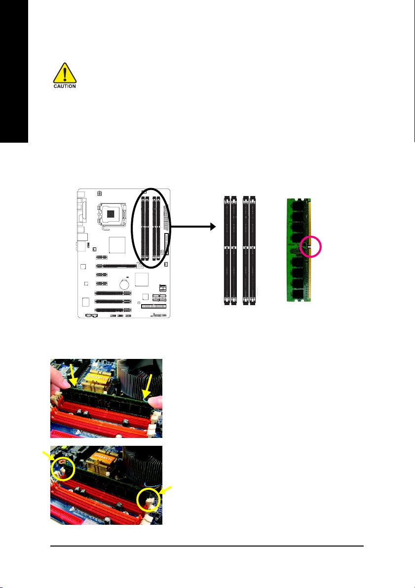
English
The motherboard supports DDRII memory modules, whereby BIOS will automatically detect memory
capacity and specifications. Memory modules are designed so that they can be inserted only in one direction.
The memory capacity used can differ with each slot.
Before installing the memory modules, please comply with the following conditions:
1. Please make sure that the memory used is supported by the motherboard. It is
recommended that memory of similar capacity, specifications and brand be used.
2. Before installing or removing memory modules, please make sure that the computer
power is switched off to prevent hardware damage.
3. Memory modules have a foolproof insertion design. A memory module can be installed
in only one direction. If you are unable to insert the module, please switch the direction.
1-4 Installation of Memory
Notch
DDRII
Fig.1
The DIMM socket has a notch, so the DIMM memory mod-
ule can only fit in one direction. Insert the DIMM memory
module vertically into the DIMM socket. Then push it down.
Fig.2
Close the plastic clip at both edges of the DIMM sockets to
lock the DIMM module.
Reverse the installation steps when you wish to remove
the DIMM module.
Hardware Installation— 17 —
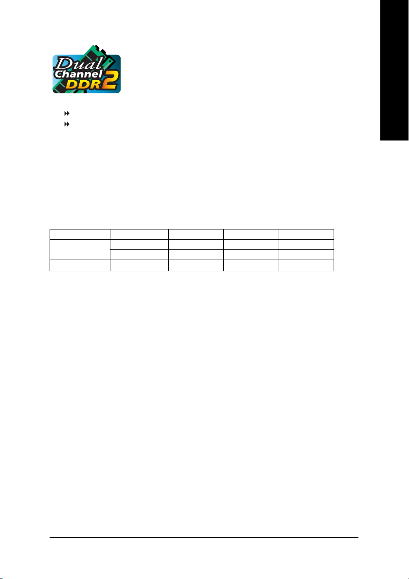
English
Dual Channel Memory Configuration
The GA-965P-DS3/S3 supports the Dual Channel Technology. After operat-
ing the Dual Channel Technology, the bandwidth of memory bus will double.
The GA-965P-DS3/S3 includes 4 DIMM sockets, and each Channel has two
DIMM sockets as following:
Channel 0 : DDRII1, DDRII2
Channel 1 : DDRII3, DDRII4
If you want to operate the Dual Channel Technology, please note the following explanations
due to the limitation of Intel chipset specifications.
1. Dual Channel mode will not be enabled if only one DDRII memory module is installed.
2. To enable Dual Channel mode with two or four memory modules (it is recommended to
use memory modules of identical brand, size, chips, and speed), you must install them
into DIMM sockets of the same color.
The following is a Dual Channel Memory configuration table: (DS: Double Side, SS: Single Side,
X:Empty)
2 memory modules
4 memory modules
DDR II 1 DDR II 2 DDR II 3 DDR II 4
DS/SS X DS/SS X
X DS/SS X DS/SS
DS/SS DS/SS DS/SS DS/SS
(Note) When memory modules of different size and chips are installed, a message which indicates
that memory is configured to Flex memory mode operation will appear during POST.
Intel
®
Flex Memory Technology offers easier upgrades by allowing different memory sizes to
be populated and remain in dual-channel mode.

GA-965P-DS3/S3 Motherboard — 18 —
English
1-5 Installation of Expansion Cards
You can install your expansion card by following the steps outlined below:
1. Read the related expansion card’s instruction document before install the expansion card into the
computer.
2. Remove your computer’s chassis cover, screws and slot bracket from the computer.
3. Press the expansion card firmly into expansion slot in motherboard.
4. Be sure the metal contacts on the card are indeed seated in the slot.
5. Replace the screw to secure the slot bracket of the expansion card.
6. Replace your computer’s chassis cover.
7. Power on the computer, if necessary, setup BIOS utility of expansion card from BIOS.
8. Install related driver from the operating system.
Installing a PCI Express x16 expansion card:
Please align the VGA card to the onboard
PCI Express x16 slot and press firmly
down on the slot. Make sure your VGA
card is locked by the latch at the end of
the PCI Express x16 slot. When you try
uninstall the VGA card, please gently
press the latch as the picture to the left
shows to release the card.

Hardware Installation— 19 —
English
1-6 I/O Back Panel Introduction
PS/2 Keyboard and PS/2 Mouse Connector
To install a PS/2 port keyboard and mouse, plug the mouse to the upper port (green) and the keyboard
to the lower port (purple).
LPT (Parallel Port)
The parallel port allows connection of a printer, scanner and other peripheral devices.
COAXIAL (S/PDIF Out)
The SPDIF coaxial output port is capable of providing digital audio to external speakers or
compressed AC3 data to an external Dolby Digital Decoder via a coaxial cable.
OPTICAL (S/PDIF Out)
The SPDIF optical output port is capable of providing digital audio to external speakers or com-
pressed AC3 data to an external Dolby Digital Decoder via an optical cable.
Serial Port
Connects to serial-based mouse or data processing devices.
USB Port
Before you connect your device(s) into USB connector(s), please make sure your device(s) such
as USB keyboard, mouse, scanner, zip, speaker…etc. have a standard USB interface.
Also make sure your OS supports USB controller. If your OS does not support USB controller,
please contact OS vendor for possible patch or driver upgrade. For more information please
contact your OS or device(s) vendors.
LAN Port
The provided Internet connection is Gigabit Ethernet, providing data transfer speeds of
10/100/1000Mbps.
Center/Subwoofer Speaker Out
The default Center/Subwoofer Speaker Out jack. Center/Subwoofer speakers can be connected to
Center/Subwoofer Speaker Out jack.
Surround Speaker Out (Rear Speaker Out)
The default Surround Speaker Out (Rear Speaker Out) jack. Rear surround speakers can be
connected to Surround Speaker Out (Rear Speaker Out) jack.
Side Speaker Out
The default Side Speaker Out jack. Surround side speakers can be connected to Side Speaker Out
jack.
Line In
The default Line In jack. Devices like CD-ROM, walkman etc. can be connected to Line In jack.
GA-965P-DS3/S3 Motherboard — 20 —
English
Line Out (Front Speaker Out)
The default Line Out (Front Speaker Out) jack. Stereo speakers, earphone or front surround
speakers can be connected to Line Out (Front Speaker Out) jack.
MIC In
The default MIC In jack. Microphone must be connected to MIC In jack.
1-7 Connectors Introduction
In addition to the default speakers settings, the ~ audio jacks can be reconfigured to
perform different functions via the audio software. Only microphones still MUST be connected
to the default Mic In jack ( ) . Please refer to the 2-/4-/6-/8- channel audio setup steps for
detailed software configuration information.
1) ATX_12V
2) ATX (Power Connector)
3) CPU_FAN
4) SYS_FAN
5) PWR_FAN
6) NB_FAN
7) FDD
 IDE1
IDE1
9) SATAII0/1/2/3
10) GSATAII0/1
11) F_PANEL
12) F_AUDIO
13) PWR_LED
14) CD_IN
15) SPDIF_I
16) F_USB1/F_USB2/F_USB3
17) C I
18) CLR_CMOS
19) BATTERY
2
3
10
1
16
7
4
815
18
14
12
17
9
13 11
19
5
6

Hardware Installation— 21 —
English
Pin No. Definition
13 3.3V
14 -12V
15 GND
16 PS_ON(soft On/Off)
17 GND
18 GND
19 GND
20 -5V
21 +5V
22 +5V
23 +5V (Only for 24-pin ATX)
24 GND(Only for 24-pin ATX)
Pin No. Definition
1 3.3V
2 3.3V
3 GND
4 +5V
5 GND
6 +5V
7 GND
8 Power Good
9 5V SB(stand by +5V)
10 +12V
11 +12V(Only for 24-pin ATX)
12 3.3V(Only for 24-pin ATX)
1/2) ATX_12V/ATX (Power Connector)
With the use of the power connector, the power supply can supply enough stable power to all
the components on the motherboard. Before connecting the power connector, please make sure
that all components and devices are properly installed. Align the power connector with its
proper location on the motherboard and connect tightly.
The ATX_12V power connector mainly supplies power to the CPU. If the ATX_12V power
connector is not connected, the system will not start.
Caution!
Please use a power supply that is able to handle the system voltage requirements. It is
recommended that a power supply that can withstand high power consumption be used (300W
or greater). If a power supply is used that does not provide the required power, the result can
lead to an unstable system or a system that is unable to start.
If you use a 24-pin ATX power supply, please remove the small cover on the power connector
on the motherboard before plugging in the power cord ; Otherwise, please do not remove it.
Pin No. Definition
1 GND
2 GND
3 +12V
4 +12V
1
3
2
4
1
13
24
12
GA-965P-DS3/S3 Motherboard — 22 —
English
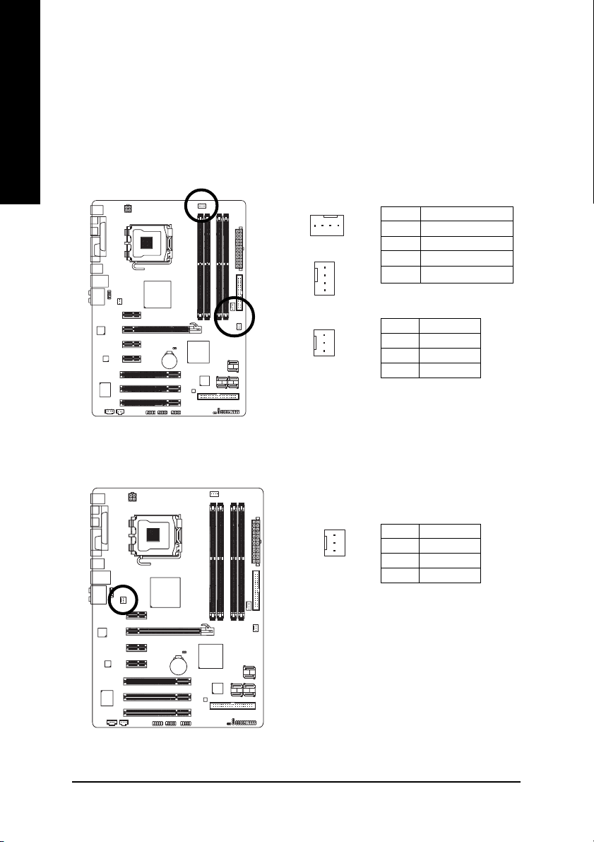
3/4/5) CPU_FAN / SYS_FAN / PWR_FAN (Cooler Fan Power Connector)
The cooler fan power connector supplies a +12V power voltage via a 3-pin/4-pin (only for
CPU_FAN/SYS_FAN) power connector and possesses a foolproof connection design. Most
coolers are designed with color-coded power connector wires. A red power connector wire
indicates a positive connection and requires a +12V power voltage. The black connector wire is
the ground wire (GND).
Please remember to connect the CPU/system fan cable to the CPU_FAN/SYS_FAN connector to
prevent the CPU/system from overheating and failure.
1
Pin No. Definition
1 GND
2 +12V/Speed Control
3 Sense
4 Speed Control
CPU_FAN/SYS_FAN:
PWR_FAN:
PWR_FAN
1
1
SYS_FAN
CPU_FAN
6) NB_FAN (Chip Fan Power Connector)
The chip fan will not work if you install it in the wrong direction and sometimes the chip fan will be
damaged.
1
Pin No. Definition
1 GND
2 +12V
3NC
Pin No. Definition
1 GND
2 +12V
3NC

Hardware Installation— 23 —
English
IDE1 (IDE Connector)
An IDE device connects to the computer via an IDE connector. One IDE connector can connect to
one IDE cable, and the single IDE cable can then connect to two IDE devices (hard drive or optical
drive). If you wish to connect two IDE devices, please set the jumper on one IDE device as Master
and the other as Slave (for information on settings, please refer to the instructions located on the IDE
device). Before attaching the IDE cable, please take note of the foolproof groove in the IDE connector.
1
2
39
40
7) FDD (Floppy Connector)
The FDD connector is used to connect the FDD cable while the other end of the cable connects to the
FDD drive. The types of FDD drives supported are: 360 KB, 720 KB, 1.2 MB, 1.44 MB and
2.88 MB. Before attaching the FDD cable, please take note of the foolproof groove in the FDD
connector.
1
2
33
34
GA-965P-DS3/S3 Motherboard — 24 —
English
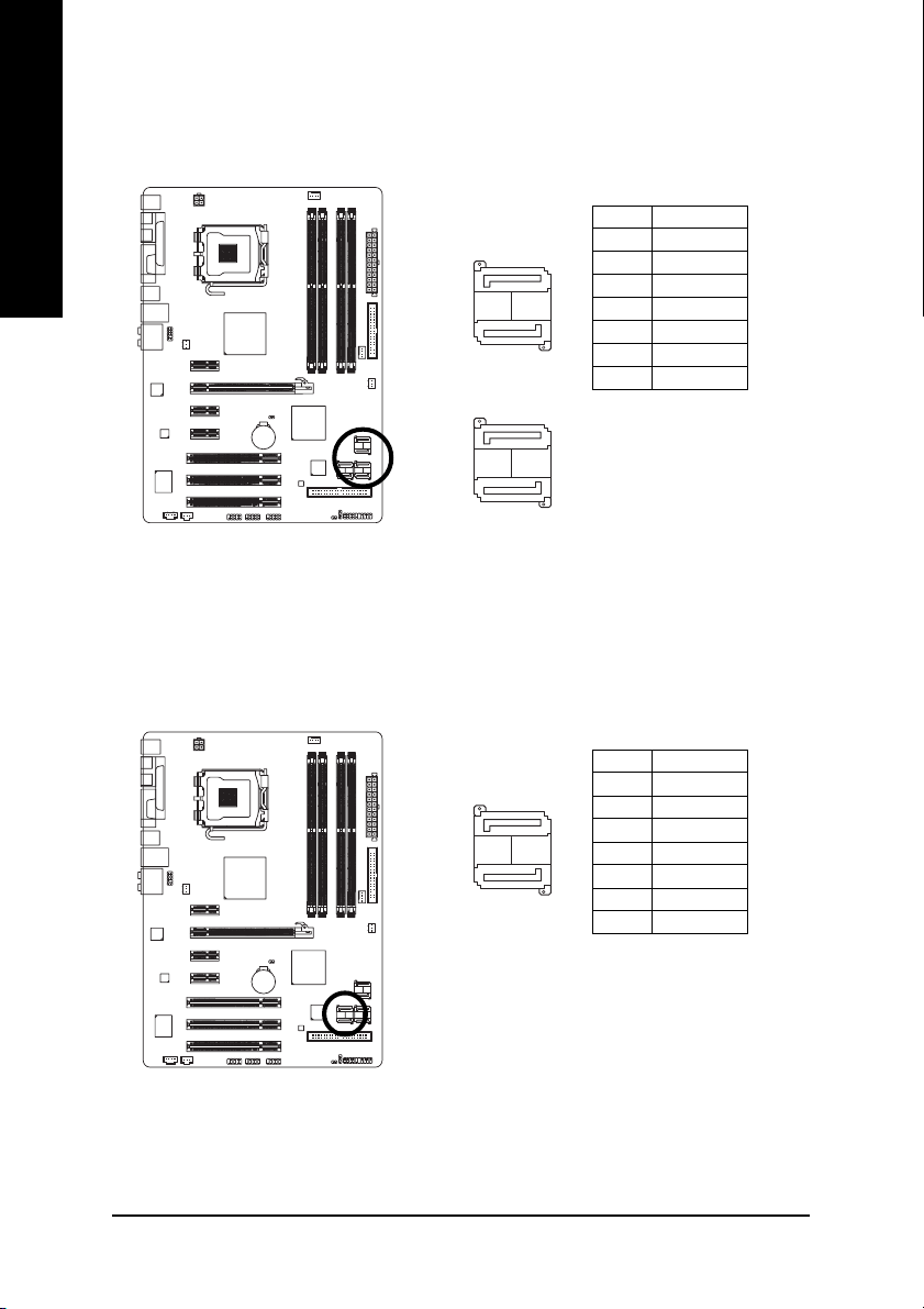
9) SATAII0/1/2/3 (SATA 3Gb/s Connector, Controlled by Intel ICH8)
SATA 3Gb/s can provide up to 300MB/s transfer rate. Please refer to the BIOS setting for the Serial
ATA and install the proper driver in order to work properly.
Pin No. Definition
1 GND
2 TXP
3 TXN
4 GND
5 RXN
6 RXP
7 GND
1
71
7
1
71
7
SATAII0
SATAII1
SATAII2
SATAII3
10) GSATAII0/1 (SATA 3Gb/s Connector, Controlled by GIGABYTE SATA2)
SATA 3Gb/s can provide up to 300MB/s transfer rate. Please refer to the BIOS setting for the Serial
ATA and install the proper driver in order to work properly.
Pin No. Definition
1 GND
2 TXP
3 TXN
4 GND
5 RXN
6 RXP
7 GND
1
71
7
GSATAII0
GSATAII1
Hardware Installation— 25 —
English
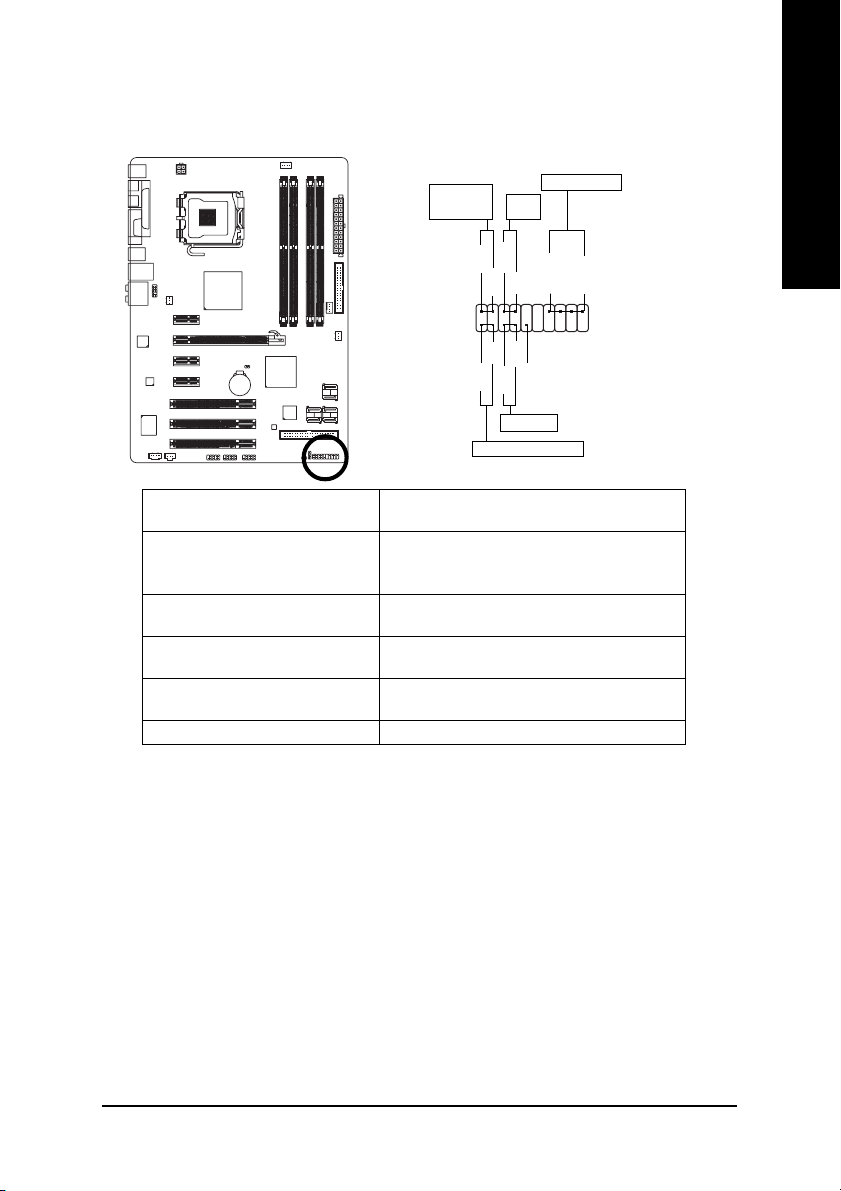
11) F_PANEL (Front Panel Jumper)
Please connect the power LED, PC speaker, reset switch and power switch etc. of your chassis
front panel to the F_PANEL connector according to the pin assignment below.
HD (IDE Hard Disk Active LED) Pin 1: LED anode(+)
(Blue) Pin 2: LED cathode(-)
SPEAK (Speaker Connector) Pin 1: Power
(Amber) Pin 2- Pin 3: NC
Pin 4: Data(-)
RES (Reset Switch) Open: Normal
(Green) Close: Reset Hardware System
PW (Power Switch) Open: Normal
(Red) Cl ose : Power On/Off
MSG (Message LED/Power/Sleep LED) Pin 1: LED anode(+)
(Yellow) Pin 2: LED cathode(-)
NC ( Purple) NC
1
2
19
20
HD-
HD+
RES+
RES-
NC
IDE Hard Disk Active LED
Reset Switch
SPEAK-
MSG-
MSG+
PW-
PW+
Message LED/
Power/
Sleep LED
Speaker Connector
SPEAK+
Power
Switch

GA-965P-DS3/S3 Motherboard — 26 —
English
12) F_AUDIO (Front Audio Connector)
This connector supports either HD (High Definition) or AC97 front panel audio module. If you wish
to use the front audio function, connect the front panel audio module to this connector. Check the pin
assignments carefully while you connect the front panel audio module. Incorrect connection
between the module and connector will make the audio device unable to work or even damage it.
For optional front panel audio module, please contact your chassis manufacturer.
By default, the audio driver is configured to support HD Audio. To connect an AC97 front panel
audio module to this connector, please refer to the instructions on Page 81 about the software
settings.
AC’97 Audio:HD Audio:
12
910
Pin No. Definition
1 MIC2_L
2 GND
3 MIC2_R
4 -ACZ_DET
5 LINE2_R
6 FSENSE1
7 FAUDIO_JD
8 No Pin
9 LINE2_L
10 FSENSE2
Pin No. Definition
1 MIC
2 GND
3 MIC Power
4NC
5 Line Out (R)
6NC
7NC
8 No Pin
9 Line Out (L)
10 NC
Hardware Installation— 27 —
English
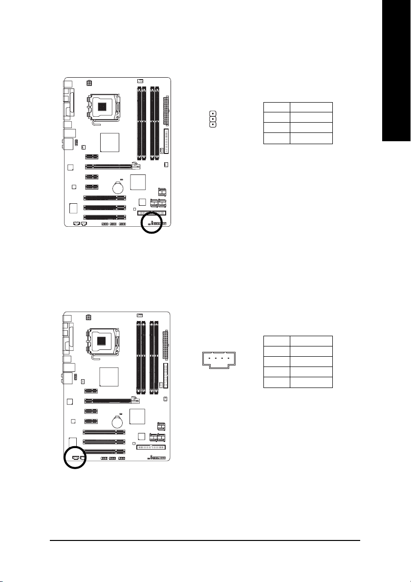
13) PWR_LED
The PWR_LED connector is connected with the system power indicator to indicate whether the
system is on/off. It will blink when the system enters suspend mode (S1).
Pin No. Definition
1 MPD+
2 MPD-
3 MPD-
1
14) CD_IN (CD IN)
Connect CD-ROM or DVD-ROM audio out to the connector.
Pin No. Definition
1 CD-L
2 GND
3 GND
4 CD-R
1
 Loading…
Page 1 — GA-965P-DS3
GA-965P-DS3Intel® CoreTM 2 Extreme / CoreTM 2 DuoIntel® Pentium® Processor Extreme EditionIntel® Pentium® D / Pentium® 4 LGA775 Processor MotherboardU
Page 2 — June 21, 2006
GA-965P-DS3 Motherboard — 10 -English1-2 Feature SummaryCPU Supports LGA775 Intel® CoreTM 2 Extreme / CoreTM 2 Duo / Pentium® Proces-sor Extreme Edi
Page 4 — Table of Contents
GA-965P-DS3 Motherboard — 12 -English1-3 Installation of the CPU and CPU CoolerBefore installing the CPU, please comply with the following conditions:
Page 5
Hardware Installation- 13 -English1-3-2 Installation of the CPU CoolerThe CPU cooler may adhere to the CPU as a result of hardening of the heat paste.
Page 6 — Optional Accessories
GA-965P-DS3 Motherboard — 14 -EnglishThe motherboard supports DDR II memory modules, whereby BIOS will automatically detect memorycapacity and specifi
Page 7
Hardware Installation- 15 -EnglishDual Channel Memory ConfigurationThe GA-965P-DS3 supports the Dual Channel Technology. After operatingthe Dual Chann
Page 8 — Block Diagram
GA-965P-DS3 Motherboard — 16 -English1-5 Installation of Expansion CardsYou can install your expansion card by following the steps outlined below:1. R
Page 9 — Instances of Non-Warranty
Hardware Installation- 17 -English1-6 I/O Back Panel IntroductionPS/2 Keyboard and PS/2 Mouse ConnectorTo install a PS/2 port keyboard and mouse, plug
Page 10 — 1-2 Feature Summary
GA-965P-DS3 Motherboard — 18 -EnglishLine Out (Front Speaker Out)The default Line Out (Front Speaker Out) jack. Stereo speakers, earphone or front sur
Page 11 — (Note 2)
Hardware Installation- 19 -EnglishPin No. Definition13 3.3V14 -12V15 GND16 PS_ON(soft On/Off)17 GND18 GND19 GND20 -5V21 +5V22 +5V23 +5V (Only for 24-p
Page 13 — The top of Female Push Pin
GA-965P-DS3 Motherboard — 20 -English5) FDD (Floppy Connector)The FDD connector is used to connect the FDD cable while the other end of the cable conn
Page 14 — 1-4 Installation of Memory
Hardware Installation- 21 -English6) IDE1 (IDE Connector)An IDE device connects to the computer via an IDE connector. One IDE connector can connect t
Page 15
GA-965P-DS3 Motherboard — 22 -English8) GSATAII0/1 (SATA 3Gb/s Connector, Controlled by GIGABYTE SATA2)SATA 3Gb/s can provide up to 300MB/s transfer r
Page 16
Hardware Installation- 23 -English10) F_PANEL (Front Panel Jumper)Please connect the power LED, PC speaker, reset switch and power switch etc. of your
Page 17
GA-965P-DS3 Motherboard — 24 -English11) F_AUDIO (Front Audio Connector)This connector supports either HD (High Definition) or AC97 front panel audio
Page 18 — 1-7 Connectors Introduction
Hardware Installation- 25 -English12) CD_IN (CD IN)Connect CD-ROM or DVD-ROM audio out to the connector.Pin No. Definition1 CD-L2 GND3 GND4 CD-R13) SP
Page 19
GA-965P-DS3 Motherboard — 26 -English14) F_ USB1/F_USB2/F_USB3 (Front USB Connector)Be careful with the polarity of the front USB connector. Check the
Page 20 — 5) FDD (Floppy Connector)
Hardware Installation- 27 -EnglishOpen: NormalShort: Clear CMOS16) CLR_CMOS (Clear CMOS)You may clear the CMOS data to its default values by this head
Page 22 — 9) PWR_LED
BIOS Setup- 29 -EnglishBIOS (Basic Input and Output System) includes a CMOS SETUP utility which allows user to configurerequired settings or to activa
Page 23 — Hardware Installation- 23
Copyright© 2006 GIGA-BYTE TECHNOLOGY CO., LTD. All rights reserved.The trademarks mentioned in the manual are legally registered to their respective c
Page 24
GA-965P-DS3 Motherboard — 30 -EnglishThe Main Menu (For example: BIOS Ver. : F1b)Once you enter Award BIOS CMOS Setup Utility, the Main Menu (as figur
Page 25 — 13) SPDIF_I (SPDIF In)
BIOS Setup- 31 -English Standard CMOS FeaturesThis setup page includes all the items in standard compatible BIOS. Advanced BIOS FeaturesThis
Page 26
GA-965P-DS3 Motherboard — 32 -English2-1 Standard CMOS FeaturesDateThe date format is <week>, <month>, <day>, <year>.Week The
Page 27 — 17) BATTERY
BIOS Setup- 33 -EnglishAccess Mode Use this to set the access mode for the hard drive. The two options are:Large/Auto(default:Auto)Capacity Capacity o
Page 28
GA-965P-DS3 Motherboard — 34 -English2-2 Advanced BIOS FeaturesHard Disk Boot PrioritySelect boot sequence for onboard(or add-on cards) SCSI, RAID, et
Page 29 — Chapter 2 BIOS Setup
BIOS Setup- 35 -EnglishCPU Hyper-Threading (Note)Enabled Enable CPU Hyper Threading Feature. Please note that this feature is onlyworking for operatin
Page 30 — <F12> Boot Menu
GA-965P-DS3 Motherboard — 36 -English2-3 Integrated PeripheralsSATA Port0-3 Native ModeEnabled Set SATA Port0~3 to operate at Native IDE mode.Disabled
Page 31
BIOS Setup- 37 -EnglishSMART LAN (LAN Cable Diagnostic Function)This motherboard incorporates cable diagnostic feature designed to detect the status o
Page 32 — 2-1 Standard CMOS Features
GA-965P-DS3 Motherboard — 38 -EnglishOnBoard LAN Boot ROMThis function decide whether to invoke the boot ROM of the onboard LAN chip.Enabled Enable th
Page 33
BIOS Setup- 39 -English2-4 Power Management SetupCMOS Setup Utility-Copyright (C) 1984-2006 Award SoftwarePower Management SetupACPI Suspend Type [S1(
Page 35
GA-965P-DS3 Motherboard — 40 -EnglishPower On By KeyboardDisabled Disabled this function. (Default value)Password Enter from 1 to 5 characters to set
Page 36 — 2-3 Integrated Peripherals
BIOS Setup- 41 -English2-6 PC Health StatusReset Case Open StatusDisabled Don’t reset case open status. (Default value)Enabled Clear case open st
Page 37
GA-965P-DS3 Motherboard — 42 -EnglishFAN Speed Control Method (Note)Auto BIOS sets the optimal CPU fan speed automatically. (Default Value)Intel(R) QS
Page 38
BIOS Setup- 43 -English2-7 MB Intelligent Tweaker(M.I.T.)Incorrect using these features may cause your system broken. For power end-user use only.CPU
Page 39 — 2-4 Power Management Setup
GA-965P-DS3 Motherboard — 44 -EnglishC.I.A.2C.I.A.2 (CPU Intelligent Acelerator 2) is designed to detect CPU loading during software programexecuting,
Page 40 — 2-5 PnP/PCI Configurations
BIOS Setup- 45 -EnglishDIMM OverVoltage ControlPlease note that by overclocking your system through the increase of the DIMM voltage, damageto the mem
Page 41 — 2-6 PC Health Status
GA-965P-DS3 Motherboard — 46 -English2-8 Load Fail-Safe DefaultsFail-Safe defaults contain the most appropriate values of the system parameters that a
Page 42 — FAN Speed Control Mode
BIOS Setup- 47 -English2-10 Set Supervisor/User PasswordWhen you select this function, the following message will appear at the center of the screen t
Page 44 — Memory Frequency (Mhz)
Install Drivers- 49 -EnglishChapter 3 Install DriversPictures below are shown in Windows XP.Insert the driver CD-title that came with your motherboard
Page 45
— 5 -Chapter 3 Install Drivers … 493-1 Install Chipset Dr
Page 46 — 2-9 Load Optimized Defaults
GA-965P-DS3 Motherboard — 50 -English3-2 Software ApplicationsThis page displays all the tools that Gigabyte developed and some free software, you can
Page 47
Install Drivers- 51 -English3-4 Hardware InformationThis page lists all device you have for this motherboard.3-5 Contact UsPlease see the last page fo
Page 49 — Chapter 3 Install Drivers
Appendix- 53 -EnglishChapter 4 Appendix4-1 Unique Software Utilities(Not all model support these Unique Software Utilities, please check your MB featu
Page 50 — 3-3 Driver CD Information
GA-965P-DS3 Motherboard — 54 -English4-1-2 Xpress Recovery2 IntroductionXpress Recovery2 is designed to provide quick backup and restora-tion of hard
Page 51 — 3-5 Contact Us
Appendix- 55 -English1. RESTORE:Restore the backed-up data to your hard disk.(This button will not appear if there is no backupfile.)2. BACKUP:Back up
Page 52
GA-965P-DS3 Motherboard — 56 -English4-1-3 Flash BIOS Method IntroductionMethod 1 : Q-FlashTM UtilityQ-FlashTM is a BIOS flash utility embedded in Fla
Page 53 — Chapter 4 Appendix
Appendix- 57 -EnglishEntering the Q-FlashTM utility:CMOS Setup Utility-Copyright (C) 1984-2004 Award Software Standard CMOS Features Advanced BIOS F
Page 55
Appendix- 59 -English3. Press Y button on your keyboard after you are sure to update BIOS. Then it will begin to update BIOS. The progress of updat
Page 56 — The BIOS file is Fa3
— 6 -Item ChecklistIDE Cable x 1 and FDD Cable x 1SATA 3Gb/s Cable x 4I/O Shield* The items listed above are for reference only, and are subject to ch
Page 57
GA-965P-DS3 Motherboard — 60 -English6. Press Del to enter BIOS menu after system reboots. When you are in BIOS menu, move toLoad Optimized Defaults i
Page 58 — 8KNXPU.Fba, is listed
Appendix- 61 -EnglishExploring the Q-FlashTM utility screenThe Q-FlashBIOS utility screen consists of the following key components.Task menu for Q-Fla
Page 59
GA-965P-DS3 Motherboard — 62 -English3. Press Y button on your keyboard after you are sure to update BIOS.Then it will begin to update BIOS. The progr
Page 60 — Updating BIOS with Q-Flash
Appendix- 63 -EnglishMethod 2 : @BIOSTM UtilityIf you do not have a DOS startup disk, we recommend that you use thenew @BIOS utility. @BIOS allows use
Page 61
GA-965P-DS3 Motherboard — 64 -EnglishIII. Save BIOSIn the very beginning, there is «Save Current BIOS» icon shown in dialog box. It means to
Page 62 — Do not turn off power or
Appendix- 65 -English(Note 1) Skip this step if you do not want to create RAID array on the SATA controller.To configure SATA hard drive(s), follow th
Page 63 — 1. Methods and steps:
GA-965P-DS3 Motherboard — 66 -EnglishFigure 1The BIOS Setup menus described in this section may not show the exact settings for yourmotherboard. The a
Page 64 — 2. Note:
GA-965P-DS3 Motherboard — 67 -EnglishStep 2:To boot from Windows installation CD-ROM disk, set First Boot Device under the Advanced BIOSFeatures menu
Page 65 — (Note 2)
Appendix- 68 -English(3) Configuring RAID array in RAID BIOSEnter the RAID BIOS setup utility to configure a RAID array. Skip this step if you do not
Page 66
GA-965P-DS3 Motherboard — 69 -EnglishFigure 6A. Create Array:In the main screen, press ENTER on the Create RAID Disk Drive item. Then the RAID creatio
Page 67
— 7 -GA-965P-DS3 Motherboard LayoutKB_MSCPU_FANLGA775ATXGA-965P-DS3USBLANCD_INF_AUDIOAUDIOBIOSPCIE_16PCIE_3F_USB1IDE1PCIE_1SPDIF_ICIDDRII1DDRII2DDRII3
Page 68
Appendix- 70 -English3. Assign Array Disks: After RAID mode is selected, RAID BIOS automatically assigns the two harddisks installed as the RAID disk
Page 69 — A. Create Array:
GA-965P-DS3 Motherboard — 71 -English6. Confirm Creation: After all of the items are configured, the selection bar automatically jumps to theConfirm C
Page 70
Appendix- 72 -EnglishGIGA-BYTE Technology Corp. PCIE-to-SATAII/IDE RAID Controller BIOS V1.06.53[ Main Menu ]Create RAID Disk DriveDelete RAID Disk Dr
Page 71
Appendix- 73 -EnglishGIGA-BYTE Technology Corp. PCIE-to-SATAII/IDE RAID Controller BIOS V1.06.53[ Main Menu ]Create RAID Disk DriveDelete RAID Disk Dr
Page 72
GA-965P-DS3 Motherboard — 74 -English(4) Making a SATA Driver Disk (Required for AHCI and RAID Mode)To install operating system onto a serial ATA ha
Page 73 — B. Delete Array:
Appendix- 75 -EnglishFigure 18Windows SetupPress F6 if you need to install a 3rd party SCSI or RAID driver.Figure 19Windows SetupS=Specify Additional
Page 74
GA-965P-DS3 Motherboard — 76 -EnglishStep 3:When Setup correctly recognizes the driver in the floppy disk, a controller menu similar to Figure 20below
Page 75
Appendix- 77 -EnglishAfter the SATA controller driver installation is completed, you can proceed with the Windows 2000/XPinstallation.Figure 22Windows
Page 76
GA-965P-DS3 Motherboard — 78 -English4-1-5 2- / 4- / 6- / 8- Channel Audio FunctionIntroductionSTEP 1 :After installation of the audio driver, you sho
Page 77
Appendix- 79 -EnglishSTEP 3:After a speaker or headphone is plugged into therear Line Out jack, a small window will pop up andask you what type of equ
Page 78 — Introduction
— 8 -Block Diagram(Note) To use a DDR II 800/667 memory module on the motherboard, you must install an 800/1066MHz FSB processor.Center/Subwoofer Spea
Page 79 — 4 Channel Audio Setup
GA-965P-DS3 Motherboard — 80 -English6 Channel Audio SetupSTEP 1 :After installation of the audio driver, you should findan Audio Manager icon in
Page 80 — 6 Channel Audio Setup
Appendix- 81 -EnglishSTEP 2:In the Audio Control Panel, click the Audio I/Otab. In the upper left list, click 8CH Speaker.STEP 3:After plugging in 8-c
Page 81 — 8 Channel Audio Setup
GA-965P-DS3 Motherboard — 82 -EnglishSound Effect Configuration:At the Sound Effect menu, users can adjust soundoption settings as desired.AC’97
Page 82
Appendix- 83 -English4-2 TroubleshootingBelow is a collection of general asked questions. To check general asked questions based on a specificmotherbo
Page 86
Appendix- 87 -EnglishContact Usyyyyy Taiwan (Headquarters)GIGA-BYTE TECHNOLOGY CO., LTD.Address: No.6, Bau Chiang Road, Hsin-Tien,Taipei 231, Taiwan T
Page 87 — Contact Us
GA-965P-DS3 Motherboard — 88 -Englishyyyyy GermanyG.B.T. TECHNOLOGY TRADING GMBHWEB address : http://www.gigabyte.deyyyyy U.K.G.B.T. TECH. CO., LTD.WE
Page 88
Hardware Installation- 9 -English1-1 Considerations Prior to InstallationPreparing Your ComputerThe motherboard contains numerous delicate electronic
3.0
Rated 3.0 out of 5
3.0 out of 5 stars (based on 1 review)
Your overall rating
GIGABYTE GA-965P-DS3P (01) PDF MANUAL
Click here to download GIGABYTE GA-965P-DS3P (01) PDF MANUAL
GIGABYTE GA-965P-DS3P (01) PDF MANUAL
FREE ENGLISH PDF
OPERATING INSTRUCTIONS
USER GUIDE – USER MANUAL
OWNER GUIDE – OWNER MANUAL
REFERENCE GUIDE – REFERENCE MANUAL
INSTRUCTION GUIDE – INSTRUCTION MANUAL
Your overall rating
- YouTube
GIGABYTE GA-965P-DS3P (01) PDF MANUAL
GIGABYTE GA-965P-DS3P (01) PDF MANUAL
GIGABYTE
GA-965P-DS3 (rev. 3.3) Инструкция по применению
Популярность:
954 просмотры
Подсчет страниц:
40 страницы
Тип файла:
Размер файла:
12.15 Mb
- Производитель
- Gigabyte
- Модель
- GA-965P-DS3
- Операционная система
-
- Неизвестная ОС
- Тип файла
-
- Инструкция
- Версия
-
3301
32-bit
Просмотреть содержимое архива
Вы нашли то, что искали?
Изображения

‹
›
×
Полезно
0 %
0
Commentary
Ваше имя