
-
Драйверы
13
-
Инструкции по эксплуатации
5
Языки:

Gigabyte GA-970A-UD3P инструкция по эксплуатации
(36 страниц)
- Языки:Английский
-
Тип:
PDF -
Размер:
12.36 MB
Просмотр

Gigabyte GA-970A-UD3P инструкция по эксплуатации
(88 страниц)
- Языки:Английский
-
Тип:
PDF -
Размер:
25.77 MB
Просмотр

Gigabyte GA-970A-UD3P инструкция по эксплуатации
(40 страниц)
- Языки:Китайский
-
Тип:
PDF -
Размер:
12.38 MB
Просмотр

Gigabyte GA-970A-UD3P инструкция по эксплуатации
(96 страниц)
- Языки:Китайский
-
Тип:
PDF -
Размер:
34.86 MB
Просмотр

Gigabyte GA-970A-UD3P инструкция по эксплуатации
(96 страниц)
- Языки:Китайский
-
Тип:
PDF -
Размер:
26.67 MB
Просмотр
На NoDevice можно скачать инструкцию по эксплуатации для Gigabyte GA-970A-UD3P. Руководство пользователя необходимо для ознакомления с правилами установки и эксплуатации Gigabyte GA-970A-UD3P. Инструкции по использованию помогут правильно настроить Gigabyte GA-970A-UD3P, исправить ошибки и выявить неполадки.
-
Page 1: Gigabyte GA-970A-UD3P
[…]
-
Page 2: Gigabyte GA-970A-UD3P
[…]
-
Page 3: Gigabyte GA-970A-UD3P
[…]
-
Page 4: Gigabyte GA-970A-UD3P
[…]
-
Page 5: Gigabyte GA-970A-UD3P
[…]
-
Page 6: Gigabyte GA-970A-UD3P
[…]
-
Page 7: Gigabyte GA-970A-UD3P
[…]
-
Page 8: Gigabyte GA-970A-UD3P
[…]
-
Page 9: Gigabyte GA-970A-UD3P
[…]
-
Page 10: Gigabyte GA-970A-UD3P
[…]
-
Page 11: Gigabyte GA-970A-UD3P
[…]
-
Page 12: Gigabyte GA-970A-UD3P
[…]
-
Page 13: Gigabyte GA-970A-UD3P
[…]
-
Page 14: Gigabyte GA-970A-UD3P
[…]
-
Page 15: Gigabyte GA-970A-UD3P
[…]
-
Page 16: Gigabyte GA-970A-UD3P
[…]
-
Page 17: Gigabyte GA-970A-UD3P
[…]
-
Page 18: Gigabyte GA-970A-UD3P
[…]
-
Page 19: Gigabyte GA-970A-UD3P
[…]
-
Page 20: Gigabyte GA-970A-UD3P
[…]
-
Page 21: Gigabyte GA-970A-UD3P
[…]
-
Page 22: Gigabyte GA-970A-UD3P
[…]
-
Page 23: Gigabyte GA-970A-UD3P
[…]
-
Page 24: Gigabyte GA-970A-UD3P
[…]
-
Page 25: Gigabyte GA-970A-UD3P
[…]
-
Page 26: Gigabyte GA-970A-UD3P
[…]
-
Page 27: Gigabyte GA-970A-UD3P
[…]
-
Page 28: Gigabyte GA-970A-UD3P
[…]
-
Page 29: Gigabyte GA-970A-UD3P
[…]
-
Page 30: Gigabyte GA-970A-UD3P
[…]
-
Page 31: Gigabyte GA-970A-UD3P
[…]
-
Page 32: Gigabyte GA-970A-UD3P
[…]
-
Page 33: Gigabyte GA-970A-UD3P
[…]
-
Page 34: Gigabyte GA-970A-UD3P
[…]
-
Page 35: Gigabyte GA-970A-UD3P
[…]
-
Page 36: Gigabyte GA-970A-UD3P
[…]
-
Page 37: Gigabyte GA-970A-UD3P
[…]
-
Page 38: Gigabyte GA-970A-UD3P
[…]
-
Page 39: Gigabyte GA-970A-UD3P
[…]
-
Page 40: Gigabyte GA-970A-UD3P
[…]
-
Page 41: Gigabyte GA-970A-UD3P
[…]
-
Page 42: Gigabyte GA-970A-UD3P
[…]
-
Page 43: Gigabyte GA-970A-UD3P
[…]
-
Page 44: Gigabyte GA-970A-UD3P
[…]
-
Page 45: Gigabyte GA-970A-UD3P
[…]
-
Page 46: Gigabyte GA-970A-UD3P
[…]
-
Page 47: Gigabyte GA-970A-UD3P
[…]
-
Page 48: Gigabyte GA-970A-UD3P
[…]
-
Page 49: Gigabyte GA-970A-UD3P
[…]
-
Page 50: Gigabyte GA-970A-UD3P
[…]
-
Page 51: Gigabyte GA-970A-UD3P
[…]
-
Page 52: Gigabyte GA-970A-UD3P
[…]
-
Page 53: Gigabyte GA-970A-UD3P
[…]
-
Page 54: Gigabyte GA-970A-UD3P
[…]
-
Page 55: Gigabyte GA-970A-UD3P
[…]
-
Page 56: Gigabyte GA-970A-UD3P
[…]
-
Page 57: Gigabyte GA-970A-UD3P
[…]
-
Page 58: Gigabyte GA-970A-UD3P
[…]
-
Page 59: Gigabyte GA-970A-UD3P
[…]
-
Page 60: Gigabyte GA-970A-UD3P
[…]
-
Page 61: Gigabyte GA-970A-UD3P
[…]
-
Page 62: Gigabyte GA-970A-UD3P
[…]
-
Page 63: Gigabyte GA-970A-UD3P
[…]
-
Page 64: Gigabyte GA-970A-UD3P
[…]
-
Page 65: Gigabyte GA-970A-UD3P
[…]
-
Page 66: Gigabyte GA-970A-UD3P
[…]
-
Page 67: Gigabyte GA-970A-UD3P
[…]
-
Page 68: Gigabyte GA-970A-UD3P
[…]
-
Page 69: Gigabyte GA-970A-UD3P
[…]
-
Page 70: Gigabyte GA-970A-UD3P
[…]
-
Page 71: Gigabyte GA-970A-UD3P
[…]
-
Page 72: Gigabyte GA-970A-UD3P
[…]
-
Page 73: Gigabyte GA-970A-UD3P
[…]
-
Page 74: Gigabyte GA-970A-UD3P
[…]
-
Page 75: Gigabyte GA-970A-UD3P
[…]
-
Page 76: Gigabyte GA-970A-UD3P
[…]
-
Page 77: Gigabyte GA-970A-UD3P
[…]
-
Page 78: Gigabyte GA-970A-UD3P
[…]
-
Page 79: Gigabyte GA-970A-UD3P
[…]
-
Page 80: Gigabyte GA-970A-UD3P
[…]
-
Page 81: Gigabyte GA-970A-UD3P
[…]
-
Page 82: Gigabyte GA-970A-UD3P
[…]
-
Page 83: Gigabyte GA-970A-UD3P
[…]
-
Page 84: Gigabyte GA-970A-UD3P
[…]
-
Page 85: Gigabyte GA-970A-UD3P
[…]
-
Page 86: Gigabyte GA-970A-UD3P
[…]
-
Page 87: Gigabyte GA-970A-UD3P
[…]
-
Page 88: Gigabyte GA-970A-UD3P
[…]
-
Page 89: Gigabyte GA-970A-UD3P
[…]
-
Page 90: Gigabyte GA-970A-UD3P
[…]
-
Page 91: Gigabyte GA-970A-UD3P
[…]
-
Page 92: Gigabyte GA-970A-UD3P
[…]
-
Page 93: Gigabyte GA-970A-UD3P
[…]
-
Page 94: Gigabyte GA-970A-UD3P
[…]
-
Page 95: Gigabyte GA-970A-UD3P
[…]
-
Page 96: Gigabyte GA-970A-UD3P
[…]
-
Page 97: Gigabyte GA-970A-UD3P
[…]
-
Page 98: Gigabyte GA-970A-UD3P
[…]
-
Page 99: Gigabyte GA-970A-UD3P
[…]
-
Page 100: Gigabyte GA-970A-UD3P
[…]
-
Page 101: Gigabyte GA-970A-UD3P
[…]
-
Page 102: Gigabyte GA-970A-UD3P
[…]
-
Page 103: Gigabyte GA-970A-UD3P
[…]
-
Page 104: Gigabyte GA-970A-UD3P
[…]
-
Page 105: Gigabyte GA-970A-UD3P
[…]
-
Page 106: Gigabyte GA-970A-UD3P
[…]
-
Page 107: Gigabyte GA-970A-UD3P
[…]
-
Page 108: Gigabyte GA-970A-UD3P
[…]
-
Page 109: Gigabyte GA-970A-UD3P
[…]
-
Page 110: Gigabyte GA-970A-UD3P
[…]
-
Page 111: Gigabyte GA-970A-UD3P
[…]
-
Page 112: Gigabyte GA-970A-UD3P
[…]
-
Page 113: Gigabyte GA-970A-UD3P
[…]
-
Page 114: Gigabyte GA-970A-UD3P
[…]
-
Page 115: Gigabyte GA-970A-UD3P
[…]
-
Page 116: Gigabyte GA-970A-UD3P
[…]
-
Page 117: Gigabyte GA-970A-UD3P
[…]
-
Page 118: Gigabyte GA-970A-UD3P
[…]
-
Page 119: Gigabyte GA-970A-UD3P
[…]
-
Page 120: Gigabyte GA-970A-UD3P
[…]
-
Page 121: Gigabyte GA-970A-UD3P
[…]
-
Page 122: Gigabyte GA-970A-UD3P
[…]
-
Page 123: Gigabyte GA-970A-UD3P
[…]
-
Page 124: Gigabyte GA-970A-UD3P
[…]
-
Page 125: Gigabyte GA-970A-UD3P
[…]
-
Page 126: Gigabyte GA-970A-UD3P
[…]
-
Page 127: Gigabyte GA-970A-UD3P
[…]
-
Page 128: Gigabyte GA-970A-UD3P
[…]
-
Page 129: Gigabyte GA-970A-UD3P
[…]
-
Page 130: Gigabyte GA-970A-UD3P
[…]
-
Page 131: Gigabyte GA-970A-UD3P
[…]
-
Page 132: Gigabyte GA-970A-UD3P
[…]
-
Page 133: Gigabyte GA-970A-UD3P
[…]
-
Page 134: Gigabyte GA-970A-UD3P
[…]
-
Page 135: Gigabyte GA-970A-UD3P
[…]
-
Page 136: Gigabyte GA-970A-UD3P
[…]
-
Page 137: Gigabyte GA-970A-UD3P
[…]
-
Page 138: Gigabyte GA-970A-UD3P
[…]
-
Page 139: Gigabyte GA-970A-UD3P
[…]
-
Page 140: Gigabyte GA-970A-UD3P
[…]
-
Page 141: Gigabyte GA-970A-UD3P
[…]
-
Page 142: Gigabyte GA-970A-UD3P
[…]
-
Page 143: Gigabyte GA-970A-UD3P
[…]
-
Page 144: Gigabyte GA-970A-UD3P
[…]
-
Page 145: Gigabyte GA-970A-UD3P
[…]
-
Page 146: Gigabyte GA-970A-UD3P
[…]
-
Page 147: Gigabyte GA-970A-UD3P
[…]
-
Page 148: Gigabyte GA-970A-UD3P
[…]
-
Page 149: Gigabyte GA-970A-UD3P
[…]
-
Page 150: Gigabyte GA-970A-UD3P
[…]
-
Page 151: Gigabyte GA-970A-UD3P
[…]
-
Page 152: Gigabyte GA-970A-UD3P
[…]
-
Page 153: Gigabyte GA-970A-UD3P
[…]
-
Page 154: Gigabyte GA-970A-UD3P
[…]
-
Page 155: Gigabyte GA-970A-UD3P
[…]
-
Page 156: Gigabyte GA-970A-UD3P
[…]
-
Page 157: Gigabyte GA-970A-UD3P
[…]
-
Page 158: Gigabyte GA-970A-UD3P
[…]
-
Page 159: Gigabyte GA-970A-UD3P
[…]
-
Page 160: Gigabyte GA-970A-UD3P
[…]
-
Page 161: Gigabyte GA-970A-UD3P
[…]
-
Page 162: Gigabyte GA-970A-UD3P
[…]
-
Page 163: Gigabyte GA-970A-UD3P
[…]
-
Page 164: Gigabyte GA-970A-UD3P
[…]
-
Page 165: Gigabyte GA-970A-UD3P
[…]
-
Page 166: Gigabyte GA-970A-UD3P
[…]
-
Page 167: Gigabyte GA-970A-UD3P
[…]
-
Page 168: Gigabyte GA-970A-UD3P
[…]
-
Page 169: Gigabyte GA-970A-UD3P
[…]
-
Page 170: Gigabyte GA-970A-UD3P
[…]
-
Page 171: Gigabyte GA-970A-UD3P
[…]
-
Page 172: Gigabyte GA-970A-UD3P
[…]
-
Page 173: Gigabyte GA-970A-UD3P
[…]
-
Page 174: Gigabyte GA-970A-UD3P
[…]
-
Page 175: Gigabyte GA-970A-UD3P
[…]
-
Page 176: Gigabyte GA-970A-UD3P
[…]
-
Page 177: Gigabyte GA-970A-UD3P
[…]
-
Page 178: Gigabyte GA-970A-UD3P
[…]
-
Page 179: Gigabyte GA-970A-UD3P
[…]
-
Page 180: Gigabyte GA-970A-UD3P
[…]
-
Page 181: Gigabyte GA-970A-UD3P
[…]
-
Page 182: Gigabyte GA-970A-UD3P
[…]
-
Page 183: Gigabyte GA-970A-UD3P
[…]
-
Page 184: Gigabyte GA-970A-UD3P
[…]
-
Page 185: Gigabyte GA-970A-UD3P
[…]
-
Page 186: Gigabyte GA-970A-UD3P
[…]
-
Page 187: Gigabyte GA-970A-UD3P
[…]
-
Page 188: Gigabyte GA-970A-UD3P
[…]
-
Page 189: Gigabyte GA-970A-UD3P
[…]
-
Page 190: Gigabyte GA-970A-UD3P
[…]
-
Page 191: Gigabyte GA-970A-UD3P
[…]
-
Page 192: Gigabyte GA-970A-UD3P
[…]
-
Page 193: Gigabyte GA-970A-UD3P
[…]
-
Page 194: Gigabyte GA-970A-UD3P
[…]
-
Page 195: Gigabyte GA-970A-UD3P
[…]
-
Page 196: Gigabyte GA-970A-UD3P
[…]
-
Page 197: Gigabyte GA-970A-UD3P
[…]
-
Page 198: Gigabyte GA-970A-UD3P
[…]
-
Page 199: Gigabyte GA-970A-UD3P
[…]
-
Page 200: Gigabyte GA-970A-UD3P
[…]
-
Page 201: Gigabyte GA-970A-UD3P
[…]
-
Page 202: Gigabyte GA-970A-UD3P
[…]
-
Page 203: Gigabyte GA-970A-UD3P
[…]
-
Page 204: Gigabyte GA-970A-UD3P
[…]
-
Page 205: Gigabyte GA-970A-UD3P
[…]
-
Page 206: Gigabyte GA-970A-UD3P
[…]
-
Page 207: Gigabyte GA-970A-UD3P
[…]
-
Page 208: Gigabyte GA-970A-UD3P
[…]
-
Page 209: Gigabyte GA-970A-UD3P
[…]
-
Page 210: Gigabyte GA-970A-UD3P
[…]
-
Page 211: Gigabyte GA-970A-UD3P
[…]
-
Page 212: Gigabyte GA-970A-UD3P
[…]
-
Page 213: Gigabyte GA-970A-UD3P
[…]
-
Page 214: Gigabyte GA-970A-UD3P
[…]
-
Page 215: Gigabyte GA-970A-UD3P
[…]
-
Page 216: Gigabyte GA-970A-UD3P
[…]
-
Page 217: Gigabyte GA-970A-UD3P
[…]
-
Page 218: Gigabyte GA-970A-UD3P
[…]
-
Page 219: Gigabyte GA-970A-UD3P
[…]
-
Page 220: Gigabyte GA-970A-UD3P
[…]
-
Page 221: Gigabyte GA-970A-UD3P
[…]
-
Page 222: Gigabyte GA-970A-UD3P
[…]
-
Page 223: Gigabyte GA-970A-UD3P
[…]
-
Page 224: Gigabyte GA-970A-UD3P
[…]
-
Page 225: Gigabyte GA-970A-UD3P
[…]
-
Page 226: Gigabyte GA-970A-UD3P
[…]
-
Page 227: Gigabyte GA-970A-UD3P
[…]
-
Page 228: Gigabyte GA-970A-UD3P
[…]
-
Page 229: Gigabyte GA-970A-UD3P
[…]
-
Page 230: Gigabyte GA-970A-UD3P
[…]
-
Page 231: Gigabyte GA-970A-UD3P
[…]
-
Page 232: Gigabyte GA-970A-UD3P
[…]
-
Page 233: Gigabyte GA-970A-UD3P
[…]
-
Page 234: Gigabyte GA-970A-UD3P
[…]
-
Page 235: Gigabyte GA-970A-UD3P
[…]
-
Page 236: Gigabyte GA-970A-UD3P
[…]
-
Page 237: Gigabyte GA-970A-UD3P
[…]
-
Page 238: Gigabyte GA-970A-UD3P
[…]
-
Page 239: Gigabyte GA-970A-UD3P
[…]
-
Page 240: Gigabyte GA-970A-UD3P
[…]
-
Page 241: Gigabyte GA-970A-UD3P
[…]
-
Page 242: Gigabyte GA-970A-UD3P
[…]
-
Page 243: Gigabyte GA-970A-UD3P
[…]
-
Page 244: Gigabyte GA-970A-UD3P
[…]
-
Page 245: Gigabyte GA-970A-UD3P
[…]
-
Page 246: Gigabyte GA-970A-UD3P
[…]
-
Page 247: Gigabyte GA-970A-UD3P
[…]
-
Page 248: Gigabyte GA-970A-UD3P
[…]
-
Page 249: Gigabyte GA-970A-UD3P
[…]
-
Page 250: Gigabyte GA-970A-UD3P
[…]
-
Page 251: Gigabyte GA-970A-UD3P
[…]
-
Page 252: Gigabyte GA-970A-UD3P
[…]
-
Page 253: Gigabyte GA-970A-UD3P
[…]
-
Page 254: Gigabyte GA-970A-UD3P
[…]
-
Page 255: Gigabyte GA-970A-UD3P
[…]
-
Page 256: Gigabyte GA-970A-UD3P
[…]
-
Page 257: Gigabyte GA-970A-UD3P
[…]
-
Page 258: Gigabyte GA-970A-UD3P
[…]
-
Page 259: Gigabyte GA-970A-UD3P
[…]
-
Page 260: Gigabyte GA-970A-UD3P
[…]
-
Page 261: Gigabyte GA-970A-UD3P
[…]
-
Page 262: Gigabyte GA-970A-UD3P
[…]
-
Page 263: Gigabyte GA-970A-UD3P
[…]
-
Page 264: Gigabyte GA-970A-UD3P
[…]
-
Page 265: Gigabyte GA-970A-UD3P
[…]
-
Page 266: Gigabyte GA-970A-UD3P
[…]
-
Page 267: Gigabyte GA-970A-UD3P
[…]
-
Page 268: Gigabyte GA-970A-UD3P
[…]
-
Page 269: Gigabyte GA-970A-UD3P
[…]
-
Page 270: Gigabyte GA-970A-UD3P
[…]
-
Page 271: Gigabyte GA-970A-UD3P
[…]
-
Page 272: Gigabyte GA-970A-UD3P
[…]
-
Page 273: Gigabyte GA-970A-UD3P
[…]
-
Page 274: Gigabyte GA-970A-UD3P
[…]
-
Page 275: Gigabyte GA-970A-UD3P
[…]
-
Page 276: Gigabyte GA-970A-UD3P
[…]
-
Page 277: Gigabyte GA-970A-UD3P
[…]
-
Page 278: Gigabyte GA-970A-UD3P
[…]
-
Page 279: Gigabyte GA-970A-UD3P
[…]
-
Page 280: Gigabyte GA-970A-UD3P
[…]
-
Page 281: Gigabyte GA-970A-UD3P
[…]
-
Page 282: Gigabyte GA-970A-UD3P
[…]
-
Page 283: Gigabyte GA-970A-UD3P
[…]
-
Page 284: Gigabyte GA-970A-UD3P
[…]
-
Page 285: Gigabyte GA-970A-UD3P
[…]
-
Page 286: Gigabyte GA-970A-UD3P
[…]
-
Page 287: Gigabyte GA-970A-UD3P
[…]
-
Page 288: Gigabyte GA-970A-UD3P
[…]
-
Page 289: Gigabyte GA-970A-UD3P
[…]
-
Page 290: Gigabyte GA-970A-UD3P
[…]
-
Page 291: Gigabyte GA-970A-UD3P
[…]
-
Page 292: Gigabyte GA-970A-UD3P
[…]
-
Page 293: Gigabyte GA-970A-UD3P
[…]
-
Page 294: Gigabyte GA-970A-UD3P
[…]
-
Page 295: Gigabyte GA-970A-UD3P
[…]
-
Page 296: Gigabyte GA-970A-UD3P
[…]
-
Page 297: Gigabyte GA-970A-UD3P
[…]
-
Page 298: Gigabyte GA-970A-UD3P
[…]
-
Page 299: Gigabyte GA-970A-UD3P
[…]
-
Page 300: Gigabyte GA-970A-UD3P
[…]
-
Page 301: Gigabyte GA-970A-UD3P
[…]
-
Page 302: Gigabyte GA-970A-UD3P
[…]
-
Page 303: Gigabyte GA-970A-UD3P
[…]
-
Page 304: Gigabyte GA-970A-UD3P
[…]
-
Page 305: Gigabyte GA-970A-UD3P
[…]
-
Page 306: Gigabyte GA-970A-UD3P
[…]
-
Page 307: Gigabyte GA-970A-UD3P
[…]
Хорошее руководство по эксплуатации
Законодательство обязывает продавца передать покупателю, вместе с товаром, руководство по эксплуатации Gigabyte GA-970A-UD3P. Отсутствие инструкции либо неправильная информация, переданная потребителю, составляют основание для рекламации в связи с несоответствием устройства с договором. В законодательстве допускается предоставлении руководства в другой, чем бумажная форме, что, в последнее время, часто используется, предоставляя графическую или электронную форму инструкции Gigabyte GA-970A-UD3P или обучающее видео для пользователей. Условием остается четкая и понятная форма.
Что такое руководство?
Слово происходит от латинского «instructio», тоесть привести в порядок. Следовательно в инструкции Gigabyte GA-970A-UD3P можно найти описание этапов поведения. Цель инструкции заключается в облегчении запуска, использования оборудования либо выполнения определенной деятельности. Инструкция является набором информации о предмете/услуге, подсказкой.
К сожалению немного пользователей находит время для чтения инструкций Gigabyte GA-970A-UD3P, и хорошая инструкция позволяет не только узнать ряд дополнительных функций приобретенного устройства, но и позволяет избежать возникновения большинства поломок.
Из чего должно состоять идеальное руководство по эксплуатации?
Прежде всего в инструкции Gigabyte GA-970A-UD3P должна находится:
— информация относительно технических данных устройства Gigabyte GA-970A-UD3P
— название производителя и год производства оборудования Gigabyte GA-970A-UD3P
— правила обслуживания, настройки и ухода за оборудованием Gigabyte GA-970A-UD3P
— знаки безопасности и сертификаты, подтверждающие соответствие стандартам
Почему мы не читаем инструкций?
Как правило из-за нехватки времени и уверенности в отдельных функциональностях приобретенных устройств. К сожалению само подсоединение и запуск Gigabyte GA-970A-UD3P это слишком мало. Инструкция заключает ряд отдельных указаний, касающихся функциональности, принципов безопасности, способов ухода (даже то, какие средства стоит использовать), возможных поломок Gigabyte GA-970A-UD3P и способов решения проблем, возникающих во время использования. И наконец то, в инструкции можно найти адресные данные сайта Gigabyte, в случае отсутствия эффективности предлагаемых решений. Сейчас очень большой популярностью пользуются инструкции в форме интересных анимаций или видео материалов, которое лучше, чем брошюра воспринимаются пользователем. Такой вид инструкции позволяет пользователю просмотреть весь фильм, не пропуская спецификацию и сложные технические описания Gigabyte GA-970A-UD3P, как это часто бывает в случае бумажной версии.
Почему стоит читать инструкции?
Прежде всего здесь мы найдем ответы касательно конструкции, возможностей устройства Gigabyte GA-970A-UD3P, использования отдельных аксессуаров и ряд информации, позволяющей вполне использовать все функции и упрощения.
После удачной покупки оборудования/устройства стоит посвятить несколько минут для ознакомления с каждой частью инструкции Gigabyte GA-970A-UD3P. Сейчас их старательно готовят или переводят, чтобы они были не только понятными для пользователя, но и чтобы выполняли свою основную информационно-поддерживающую функцию.
-
Gigabyte GA-970A-UD3P — page 1
…
-
Gigabyte GA-970A-UD3P — page 2
…
-
Gigabyte GA-970A-UD3P — page 3
…
-
Gigabyte GA-970A-UD3P — page 4
…
-
Gigabyte GA-970A-UD3P — page 5
…
-
Gigabyte GA-970A-UD3P — page 6
…
-
Gigabyte GA-970A-UD3P — page 7
…
-
Gigabyte GA-970A-UD3P — page 8
…
-
Gigabyte GA-970A-UD3P — page 9
…
-
Gigabyte GA-970A-UD3P — page 10
…
-
Gigabyte GA-970A-UD3P — page 11
…
-
Gigabyte GA-970A-UD3P — page 12
…
-
Gigabyte GA-970A-UD3P — page 13
…
-
Gigabyte GA-970A-UD3P — page 14
…
-
Gigabyte GA-970A-UD3P — page 15
…
-
Gigabyte GA-970A-UD3P — page 16
…
-
Gigabyte GA-970A-UD3P — page 17
…
-
Gigabyte GA-970A-UD3P — page 18
…
-
Gigabyte GA-970A-UD3P — page 19
…
-
Gigabyte GA-970A-UD3P — page 20
…
-
Gigabyte GA-970A-UD3P — page 21
…
-
Gigabyte GA-970A-UD3P — page 22
…
-
Gigabyte GA-970A-UD3P — page 23
…
-
Gigabyte GA-970A-UD3P — page 24
…
-
Gigabyte GA-970A-UD3P — page 25
…
-
Gigabyte GA-970A-UD3P — page 26
…
-
Gigabyte GA-970A-UD3P — page 27
…
-
Gigabyte GA-970A-UD3P — page 28
…
-
Gigabyte GA-970A-UD3P — page 29
…
-
Gigabyte GA-970A-UD3P — page 30
…
-
Gigabyte GA-970A-UD3P — page 31
…
-
Gigabyte GA-970A-UD3P — page 32
…
-
Gigabyte GA-970A-UD3P — page 33
…
-
Gigabyte GA-970A-UD3P — page 34
…
-
Gigabyte GA-970A-UD3P — page 35
…
-
Gigabyte GA-970A-UD3P — page 36
…
-
Gigabyte GA-970A-UD3P — page 37
…
-
Gigabyte GA-970A-UD3P — page 38
…
-
Gigabyte GA-970A-UD3P — page 39
…
-
Gigabyte GA-970A-UD3P — page 40
…
-
Gigabyte GA-970A-UD3P — page 41
…
-
Gigabyte GA-970A-UD3P — page 42
…
-
Gigabyte GA-970A-UD3P — page 43
…
-
Gigabyte GA-970A-UD3P — page 44
…
-
Gigabyte GA-970A-UD3P — page 45
…
-
Gigabyte GA-970A-UD3P — page 46
…
-
Gigabyte GA-970A-UD3P — page 47
…
-
Gigabyte GA-970A-UD3P — page 48
…
-
Gigabyte GA-970A-UD3P — page 49
…
-
Gigabyte GA-970A-UD3P — page 50
…
-
Gigabyte GA-970A-UD3P — page 51
…
-
Gigabyte GA-970A-UD3P — page 52
…
-
Gigabyte GA-970A-UD3P — page 53
…
-
Gigabyte GA-970A-UD3P — page 54
…
-
Gigabyte GA-970A-UD3P — page 55
…
-
Gigabyte GA-970A-UD3P — page 56
…
-
Gigabyte GA-970A-UD3P — page 57
…
-
Gigabyte GA-970A-UD3P — page 58
…
-
Gigabyte GA-970A-UD3P — page 59
…
-
Gigabyte GA-970A-UD3P — page 60
…
-
Gigabyte GA-970A-UD3P — page 61
…
-
Gigabyte GA-970A-UD3P — page 62
…
-
Gigabyte GA-970A-UD3P — page 63
…
-
Gigabyte GA-970A-UD3P — page 64
…
-
Gigabyte GA-970A-UD3P — page 65
…
-
Gigabyte GA-970A-UD3P — page 66
…
-
Gigabyte GA-970A-UD3P — page 67
…
-
Gigabyte GA-970A-UD3P — page 68
…
-
Gigabyte GA-970A-UD3P — page 69
…
-
Gigabyte GA-970A-UD3P — page 70
…
-
Gigabyte GA-970A-UD3P — page 71
…
-
Gigabyte GA-970A-UD3P — page 72
…
-
Gigabyte GA-970A-UD3P — page 73
…
-
Gigabyte GA-970A-UD3P — page 74
…
-
Gigabyte GA-970A-UD3P — page 75
…
-
Gigabyte GA-970A-UD3P — page 76
…
-
Gigabyte GA-970A-UD3P — page 77
…
-
Gigabyte GA-970A-UD3P — page 78
…
-
Gigabyte GA-970A-UD3P — page 79
…
-
Gigabyte GA-970A-UD3P — page 80
…
-
Gigabyte GA-970A-UD3P — page 81
…
-
Gigabyte GA-970A-UD3P — page 82
…
-
Gigabyte GA-970A-UD3P — page 83
…
-
Gigabyte GA-970A-UD3P — page 84
…
-
Gigabyte GA-970A-UD3P — page 85
…
-
Gigabyte GA-970A-UD3P — page 86
…
-
Gigabyte GA-970A-UD3P — page 87
…
-
Gigabyte GA-970A-UD3P — page 88
…
-
Gigabyte GA-970A-UD3P — page 89
…
-
Gigabyte GA-970A-UD3P — page 90
…
-
Gigabyte GA-970A-UD3P — page 91
…
-
Gigabyte GA-970A-UD3P — page 92
…
-
Gigabyte GA-970A-UD3P — page 93
…
-
Gigabyte GA-970A-UD3P — page 94
…
-
Gigabyte GA-970A-UD3P — page 95
…
-
Gigabyte GA-970A-UD3P — page 96
…
-
Gigabyte GA-970A-UD3P — page 97
…
-
Gigabyte GA-970A-UD3P — page 98
…
-
Gigabyte GA-970A-UD3P — page 99
…
-
Gigabyte GA-970A-UD3P — page 100
…
-
Gigabyte GA-970A-UD3P — page 101
…
-
Gigabyte GA-970A-UD3P — page 102
…
-
Gigabyte GA-970A-UD3P — page 103
…
-
Gigabyte GA-970A-UD3P — page 104
…
-
Gigabyte GA-970A-UD3P — page 105
…
-
Gigabyte GA-970A-UD3P — page 106
…
-
Gigabyte GA-970A-UD3P — page 107
…
-
Gigabyte GA-970A-UD3P — page 108
…
-
Gigabyte GA-970A-UD3P — page 109
…
-
Gigabyte GA-970A-UD3P — page 110
…
-
Gigabyte GA-970A-UD3P — page 111
…
-
Gigabyte GA-970A-UD3P — page 112
…
-
Gigabyte GA-970A-UD3P — page 113
…
-
Gigabyte GA-970A-UD3P — page 114
…
-
Gigabyte GA-970A-UD3P — page 115
…
-
Gigabyte GA-970A-UD3P — page 116
…
-
Gigabyte GA-970A-UD3P — page 117
…
-
Gigabyte GA-970A-UD3P — page 118
…
-
Gigabyte GA-970A-UD3P — page 119
…
-
Gigabyte GA-970A-UD3P — page 120
…
-
Gigabyte GA-970A-UD3P — page 121
…
-
Gigabyte GA-970A-UD3P — page 122
…
-
Gigabyte GA-970A-UD3P — page 123
…
-
Gigabyte GA-970A-UD3P — page 124
…
-
Gigabyte GA-970A-UD3P — page 125
…
-
Gigabyte GA-970A-UD3P — page 126
…
-
Gigabyte GA-970A-UD3P — page 127
…
-
Gigabyte GA-970A-UD3P — page 128
…
-
Gigabyte GA-970A-UD3P — page 129
…
-
Gigabyte GA-970A-UD3P — page 130
…
-
Gigabyte GA-970A-UD3P — page 131
…
-
Gigabyte GA-970A-UD3P — page 132
…
-
Gigabyte GA-970A-UD3P — page 133
…
-
Gigabyte GA-970A-UD3P — page 134
…
-
Gigabyte GA-970A-UD3P — page 135
…
-
Gigabyte GA-970A-UD3P — page 136
…
-
Gigabyte GA-970A-UD3P — page 137
…
-
Gigabyte GA-970A-UD3P — page 138
…
-
Gigabyte GA-970A-UD3P — page 139
…
-
Gigabyte GA-970A-UD3P — page 140
…
-
Gigabyte GA-970A-UD3P — page 141
…
-
Gigabyte GA-970A-UD3P — page 142
…
-
Gigabyte GA-970A-UD3P — page 143
…
-
Gigabyte GA-970A-UD3P — page 144
…
-
Gigabyte GA-970A-UD3P — page 145
…
-
Gigabyte GA-970A-UD3P — page 146
…
-
Gigabyte GA-970A-UD3P — page 147
…
-
Gigabyte GA-970A-UD3P — page 148
…
-
Gigabyte GA-970A-UD3P — page 149
…
-
Gigabyte GA-970A-UD3P — page 150
…
-
Gigabyte GA-970A-UD3P — page 151
…
-
Gigabyte GA-970A-UD3P — page 152
…
-
Gigabyte GA-970A-UD3P — page 153
…
-
Gigabyte GA-970A-UD3P — page 154
…
-
Gigabyte GA-970A-UD3P — page 155
…
-
Gigabyte GA-970A-UD3P — page 156
…
-
Gigabyte GA-970A-UD3P — page 157
…
-
Gigabyte GA-970A-UD3P — page 158
…
-
Gigabyte GA-970A-UD3P — page 159
…
-
Gigabyte GA-970A-UD3P — page 160
…
-
Gigabyte GA-970A-UD3P — page 161
…
-
Gigabyte GA-970A-UD3P — page 162
…
-
Gigabyte GA-970A-UD3P — page 163
…
-
Gigabyte GA-970A-UD3P — page 164
…
-
Gigabyte GA-970A-UD3P — page 165
…
-
Gigabyte GA-970A-UD3P — page 166
…
-
Gigabyte GA-970A-UD3P — page 167
…
-
Gigabyte GA-970A-UD3P — page 168
…
-
Gigabyte GA-970A-UD3P — page 169
…
-
Gigabyte GA-970A-UD3P — page 170
…
-
Gigabyte GA-970A-UD3P — page 171
…
-
Gigabyte GA-970A-UD3P — page 172
…
-
Gigabyte GA-970A-UD3P — page 173
…
-
Gigabyte GA-970A-UD3P — page 174
…
-
Gigabyte GA-970A-UD3P — page 175
…
-
Gigabyte GA-970A-UD3P — page 176
…
-
Gigabyte GA-970A-UD3P — page 177
…
-
Gigabyte GA-970A-UD3P — page 178
…
-
Gigabyte GA-970A-UD3P — page 179
…
-
Gigabyte GA-970A-UD3P — page 180
…
-
Gigabyte GA-970A-UD3P — page 181
…
-
Gigabyte GA-970A-UD3P — page 182
…
-
Gigabyte GA-970A-UD3P — page 183
…
-
Gigabyte GA-970A-UD3P — page 184
…
-
Gigabyte GA-970A-UD3P — page 185
…
-
Gigabyte GA-970A-UD3P — page 186
…
-
Gigabyte GA-970A-UD3P — page 187
…
-
Gigabyte GA-970A-UD3P — page 188
…
-
Gigabyte GA-970A-UD3P — page 189
…
-
Gigabyte GA-970A-UD3P — page 190
…
-
Gigabyte GA-970A-UD3P — page 191
…
-
Gigabyte GA-970A-UD3P — page 192
…
-
Gigabyte GA-970A-UD3P — page 193
…
-
Gigabyte GA-970A-UD3P — page 194
…
-
Gigabyte GA-970A-UD3P — page 195
…
-
Gigabyte GA-970A-UD3P — page 196
…
-
Gigabyte GA-970A-UD3P — page 197
…
-
Gigabyte GA-970A-UD3P — page 198
…
-
Gigabyte GA-970A-UD3P — page 199
…
-
Gigabyte GA-970A-UD3P — page 200
…
-
Gigabyte GA-970A-UD3P — page 201
…
-
Gigabyte GA-970A-UD3P — page 202
…
-
Gigabyte GA-970A-UD3P — page 203
…
-
Gigabyte GA-970A-UD3P — page 204
…
-
Gigabyte GA-970A-UD3P — page 205
…
-
Gigabyte GA-970A-UD3P — page 206
…
-
Gigabyte GA-970A-UD3P — page 207
…
-
Gigabyte GA-970A-UD3P — page 208
…
-
Gigabyte GA-970A-UD3P — page 209
…
-
Gigabyte GA-970A-UD3P — page 210
…
-
Gigabyte GA-970A-UD3P — page 211
…
-
Gigabyte GA-970A-UD3P — page 212
…
-
Gigabyte GA-970A-UD3P — page 213
…
-
Gigabyte GA-970A-UD3P — page 214
…
-
Gigabyte GA-970A-UD3P — page 215
…
-
Gigabyte GA-970A-UD3P — page 216
…
-
Gigabyte GA-970A-UD3P — page 217
…
-
Gigabyte GA-970A-UD3P — page 218
…
-
Gigabyte GA-970A-UD3P — page 219
…
-
Gigabyte GA-970A-UD3P — page 220
…
-
Gigabyte GA-970A-UD3P — page 221
…
-
Gigabyte GA-970A-UD3P — page 222
…
-
Gigabyte GA-970A-UD3P — page 223
…
-
Gigabyte GA-970A-UD3P — page 224
…
-
Gigabyte GA-970A-UD3P — page 225
…
-
Gigabyte GA-970A-UD3P — page 226
…
-
Gigabyte GA-970A-UD3P — page 227
…
-
Gigabyte GA-970A-UD3P — page 228
…
-
Gigabyte GA-970A-UD3P — page 229
…
-
Gigabyte GA-970A-UD3P — page 230
…
-
Gigabyte GA-970A-UD3P — page 231
…
-
Gigabyte GA-970A-UD3P — page 232
…
-
Gigabyte GA-970A-UD3P — page 233
…
-
Gigabyte GA-970A-UD3P — page 234
…
-
Gigabyte GA-970A-UD3P — page 235
…
-
Gigabyte GA-970A-UD3P — page 236
…
-
Gigabyte GA-970A-UD3P — page 237
…
-
Gigabyte GA-970A-UD3P — page 238
…
-
Gigabyte GA-970A-UD3P — page 239
…
-
Gigabyte GA-970A-UD3P — page 240
…
-
Gigabyte GA-970A-UD3P — page 241
…
-
Gigabyte GA-970A-UD3P — page 242
…
-
Gigabyte GA-970A-UD3P — page 243
…
-
Gigabyte GA-970A-UD3P — page 244
…
-
Gigabyte GA-970A-UD3P — page 245
…
-
Gigabyte GA-970A-UD3P — page 246
…
-
Gigabyte GA-970A-UD3P — page 247
…
-
Gigabyte GA-970A-UD3P — page 248
…
-
Gigabyte GA-970A-UD3P — page 249
…
-
Gigabyte GA-970A-UD3P — page 250
…
-
Gigabyte GA-970A-UD3P — page 251
…
-
Gigabyte GA-970A-UD3P — page 252
…
-
Gigabyte GA-970A-UD3P — page 253
…
-
Gigabyte GA-970A-UD3P — page 254
…
-
Gigabyte GA-970A-UD3P — page 255
…
-
Gigabyte GA-970A-UD3P — page 256
…
-
Gigabyte GA-970A-UD3P — page 257
…
-
Gigabyte GA-970A-UD3P — page 258
…
-
Gigabyte GA-970A-UD3P — page 259
…
-
Gigabyte GA-970A-UD3P — page 260
…
-
Gigabyte GA-970A-UD3P — page 261
…
-
Gigabyte GA-970A-UD3P — page 262
…
-
Gigabyte GA-970A-UD3P — page 263
…
-
Gigabyte GA-970A-UD3P — page 264
…
-
Gigabyte GA-970A-UD3P — page 265
…
-
Gigabyte GA-970A-UD3P — page 266
…
-
Gigabyte GA-970A-UD3P — page 267
…
-
Gigabyte GA-970A-UD3P — page 268
…
-
Gigabyte GA-970A-UD3P — page 269
…
-
Gigabyte GA-970A-UD3P — page 270
…
-
Gigabyte GA-970A-UD3P — page 271
…
-
Gigabyte GA-970A-UD3P — page 272
…
-
Gigabyte GA-970A-UD3P — page 273
…
-
Gigabyte GA-970A-UD3P — page 274
…
-
Gigabyte GA-970A-UD3P — page 275
…
-
Gigabyte GA-970A-UD3P — page 276
…
-
Gigabyte GA-970A-UD3P — page 277
…
-
Gigabyte GA-970A-UD3P — page 278
…
-
Gigabyte GA-970A-UD3P — page 279
…
-
Gigabyte GA-970A-UD3P — page 280
…
-
Gigabyte GA-970A-UD3P — page 281
…
-
Gigabyte GA-970A-UD3P — page 282
…
-
Gigabyte GA-970A-UD3P — page 283
…
-
Gigabyte GA-970A-UD3P — page 284
…
-
Gigabyte GA-970A-UD3P — page 285
…
-
Gigabyte GA-970A-UD3P — page 286
…
-
Gigabyte GA-970A-UD3P — page 287
…
-
Gigabyte GA-970A-UD3P — page 288
…
-
Gigabyte GA-970A-UD3P — page 289
…
-
Gigabyte GA-970A-UD3P — page 290
…
-
Gigabyte GA-970A-UD3P — page 291
…
-
Gigabyte GA-970A-UD3P — page 292
…
-
Gigabyte GA-970A-UD3P — page 293
…
-
Gigabyte GA-970A-UD3P — page 294
…
-
Gigabyte GA-970A-UD3P — page 295
…
-
Gigabyte GA-970A-UD3P — page 296
…
-
Gigabyte GA-970A-UD3P — page 297
…
-
Gigabyte GA-970A-UD3P — page 298
…
-
Gigabyte GA-970A-UD3P — page 299
…
-
Gigabyte GA-970A-UD3P — page 300
…
-
Gigabyte GA-970A-UD3P — page 301
…
-
Gigabyte GA-970A-UD3P — page 302
…
-
Gigabyte GA-970A-UD3P — page 303
…
-
Gigabyte GA-970A-UD3P — page 304
…
-
Gigabyte GA-970A-UD3P — page 305
…
-
Gigabyte GA-970A-UD3P — page 306
…
-
Gigabyte GA-970A-UD3P — page 307
…
![]()
GA-970A-UD3P
User’s Manual
Rev. 1001 12ME-970AU3P-1001R

Motherboard
GA-970A-UD3P
Motherboard
GA-970A-UD3P
Aug 23, 2013
Aug 23, 2013
Copyright
© 2013 GIGA-BYTE TECHNOLOGY CO., LTD. All rights reserved.
The trademarks mentioned in this manual are legally registered to their respective owners.
Disclaimer
Information in this manual is protected by copyright laws and is the property of GIGABYTE.
Changes to the specifications and features in this manual may be made by GIGABYTE without prior notice.
No part of this manual may be reproduced, copied, translated, transmitted, or published in any form or by any means without GIGABYTE’s prior written permission.
Documentation Classifications
In order to assist in the use of this product, GIGABYTE provides the following types of docu-
mentations:
For quick set-up of the product, read the Quick Installation Guide included with the product.For detailed product information, carefully read the User’s Manual.
For product-related information, check on our website at: http://www.gigabyte.com
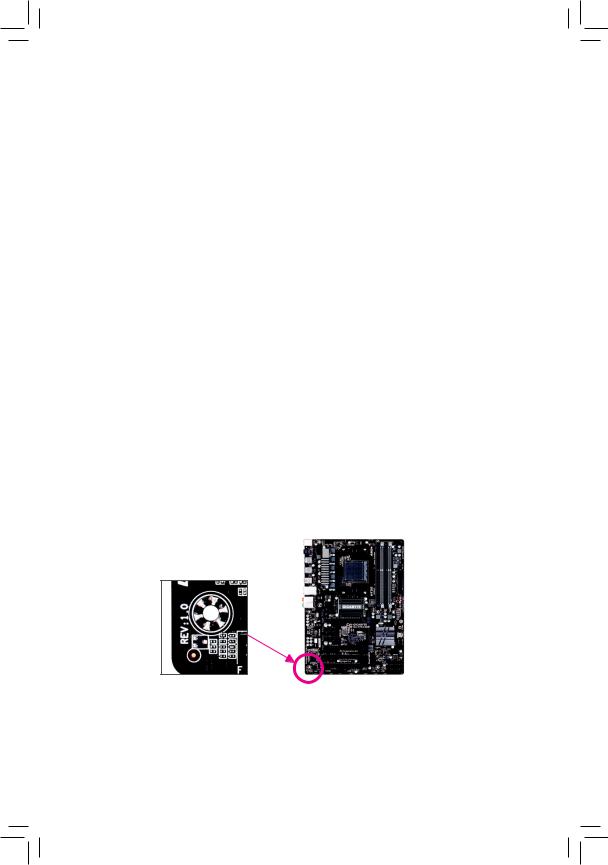
Identifying Your Motherboard Revision
The revision number on your motherboard looks like this: «REV: X.X.» For example, «REV: 1.0» means the revision of the motherboard is 1.0. Check your motherboard revision before updating motherboard BIOS, drivers, or when looking for technical information.
Example:

Table of Contents
|
Box Contents…………………………………………………………………………………………………….. |
6 |
||
|
Optional Items…………………………………………………………………………………………………… |
6 |
||
|
GA-970A-UD3P Motherboard Layout…………………………………………………………………… |
7 |
||
|
GA-970A-UD3P Motherboard Block Diagram……………………………………………………….. |
8 |
||
|
Chapter 1 Hardware Installation………………………………………………………………………….. |
9 |
||
|
1-1 |
Installation Precautions………………………………………………………………………… |
9 |
|
|
1-2 |
Product Specifications……………………………………………………………………….. |
10 |
|
|
1-3 |
Installing the CPU and CPU Cooler……………………………………………………… |
13 |
|
|
1-3-1 |
Installing the CPU……………………………………………………………………………………… |
13 |
|
|
1-3-2 Installing the CPU Cooler…………………………………………………………………………… |
15 |
||
|
1-4 |
Installing the Memory…………………………………………………………………………. |
16 |
|
|
1-4-1 Dual Channel Memory Configuration…………………………………………………………… |
16 |
||
|
1-4-2 |
Installing a Memory…………………………………………………………………………………… |
17 |
|
|
1-5 |
Installing an Expansion Card………………………………………………………………. |
18 |
|
|
1-6 |
Back Panel Connectors………………………………………………………………………. |
19 |
|
|
1-7 |
Internal Connectors……………………………………………………………………………. |
21 |
|
|
Chapter 2 BIOS Setup……………………………………………………………………………………… |
29 |
||
|
2-1 |
Startup Screen………………………………………………………………………………….. |
30 |
|
|
2-2 |
The Main Menu…………………………………………………………………………………. |
31 |
|
|
2-3 |
M.I.T…………………………………………………………………………………………………. |
33 |
|
|
2-4 |
System……………………………………………………………………………………………… |
41 |
|
|
2-5 |
BIOS Features…………………………………………………………………………………… |
42 |
|
|
2-6 |
Peripherals……………………………………………………………………………………….. |
45 |
|
|
2-7 |
Power Management…………………………………………………………………………… |
48 |
|
|
2-8 |
Save & Exit……………………………………………………………………………………….. |
50 |
|
|
Chapter 3 Configuring SATA Hard Drive(s)…………………………………………………………. |
51 |
||
|
3-1 |
Configuring SATA Controllers……………………………………………………………… |
51 |
|
|
3-2 |
Installing the SATA RAID/AHCI Driver and Operating System…………………. |
61 |
— 4 —

|
Chapter 4 Drivers Installation……………………………………………………………………………. |
65 |
|
|
4-1 |
Installing Chipset Drivers……………………………………………………………………. |
65 |
|
4-2 |
Application Software………………………………………………………………………….. |
66 |
|
4-3 |
Technical Manuals……………………………………………………………………………… |
66 |
|
4-4 |
Contact…………………………………………………………………………………………….. |
67 |
|
4-5 |
System……………………………………………………………………………………………… |
67 |
|
4-6 |
Download Center……………………………………………………………………………….. |
68 |
|
Chapter 5 Unique Features………………………………………………………………………………. |
69 |
|
|
5-1 |
BIOS Update Utilities………………………………………………………………………….. |
69 |
|
5-1-1 Updating the BIOS with the Q-Flash Utility…………………………………………………. |
69 |
|
|
5-1-2 Updating the BIOS with the @BIOS Utility…………………………………………………… |
72 |
|
|
5-2 |
EasyTune 6……………………………………………………………………………………….. |
73 |
|
5-3 |
Smart Recovery 2……………………………………………………………………………… |
74 |
|
Chapter 6 Appendix |
…………………………………………………………………………………………. |
77 |
|
|
6-1 Configuring Audio Input and Output……………………………………………………… |
77 |
||
|
6 |
-1-1 |
Configuring 2/4/5.1/7.1 — Channel Audio ………………………………………………………… |
77 |
|
6 |
-1-2 …………………………………………………………………………….. |
Configuring S/PDIF Out |
79 |
|
6 |
-1-3 ……………………………………………………………. |
Configuring Microphone Recording |
80 |
|
6 |
-1-4 …………………………………………………………………………. |
Using the Sound Recorder |
82 |
|
6-2 |
Troubleshooting…………………………………………………………………………………. |
83 |
|
|
6 |
-2-1 ……………………………………………………………………… |
Frequently Asked Questions |
83 |
|
6 |
-2-2 ……………………………………………………………………….. |
Troubleshooting Procedure |
84 |
|
Regulatory ………………………………………………………………………………….Statements |
86 |
||
|
Contact Us………………………………………………………………………………………………….. |
87 |
— 5 —
Box Contents
55 GA-970A-UD3P motherboard
55 Motherboard driver disk
55 User’s Manual
55 Quick Installation Guide
55 Four SATA cables
55 I/O Shield
The box contents above are for reference only and the actual items shall depend on the product package you obtain. The box contents are subject to change without notice.
Optional Items
2-port USB 2.0 bracket (Part No. 12CR1-1UB030-6*R)eSATA bracket (Part No. 12CF1-3SATPW-4*R)
3.5″ Front Panel with 2 USB 3.0/2.0 ports (Part No. 12CR1-FPX582-2*R)COM port cable (Part No. 12CF1-1CM001-3*R)
— 6 —
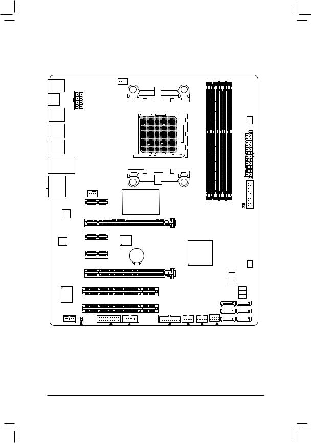
GA-970A-UD3P Motherboard Layout
KB_MS_USB
OPTICAL
R_USB2 ATX_12V
R_USB1
R_USB30
USB_LAN
AUDIO SYS_FAN1
PCIEX1_1(Note)
|
Realtek® |
PCIEX16 |
|
|
GbELAN |
||
|
PCIEX1_2 |
||
|
CODEC |
||
|
PCIEX1_3 |
||
|
PCIEX4 |
F_AUDIO
CPU_FAN
Socket AM3+
AMD 970
PWR_FAN
|
ATX |
|
|
F_PANEL |
|
|
DDR3 4 DDR3 2 DDR3 3 DDR3 1 |
CLR CMOS |
|
GA-970A-UD3P |
||
|
VIA® VL805 |
||
|
AMD SB950 |
||
|
BAT |
SYS_FAN2 |
|
|
B_BIOS |
||
|
M_BIOS |
||
|
0 |
3 |
|
|
SATA3 |
1 |
4 |
|
2 |
5 |
|
SPDIF |
_O |
||||||||||
|
TPM |
COMA |
F_USB30 F_USB3 F_ |
USB2 F_USB1 |
(Note) Due to a hardware limitation, the PCIEX1_1 slot can only accommodate a shorter PCI Express x1 expansion card. For a longer expansion card, use other expansion slots.
— 7 —
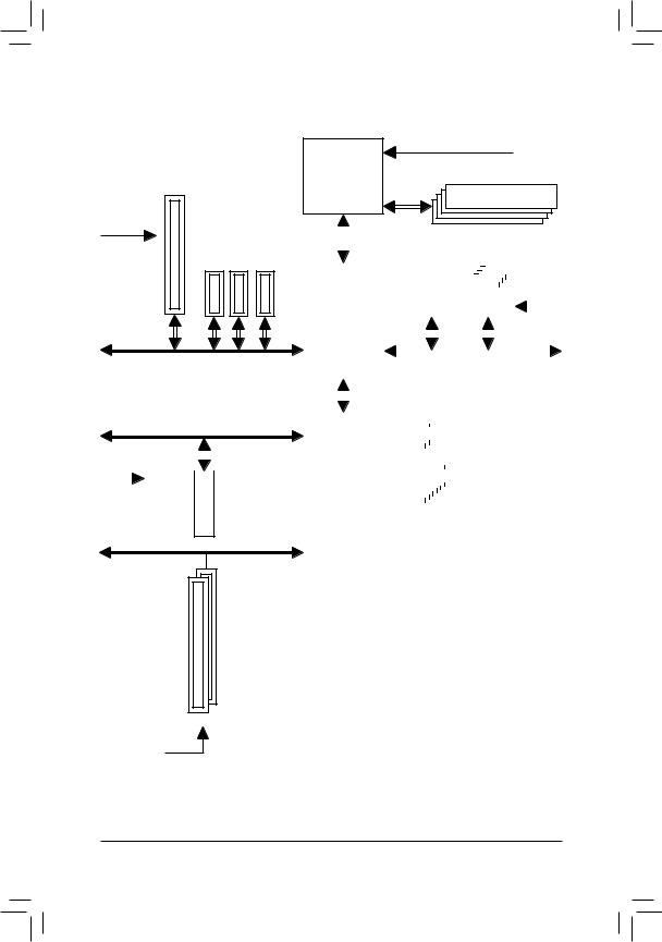
GA-970A-UD3P Motherboard Block Diagram
1 PCI Express x16
|
PCIe CLK |
|
|
(100 MHz) |
3 PCI Express x1 |
|
PCI Express Bus |
x16 |
x1 |
x1 |
x1 |
PCI Express Bus
|
x4 |
|||||||
|
PCIe CLK |
|||||||
|
(100 MHz) |
1 PCI Express x4 |
||||||
PCI Bus
CPU CLK+/- (200 MHz)
DDR3 2000 (O.C.)/1866/1600/
AM3+/AM3 CPU 1333/1066 MHz
Dual Channel Memory
|
Hyper Transport |
||||||||||||||||||||||||||||||||||||||||
|
Bus |
LAN |
4 USB 3.0/2.0 |
||||||||||||||||||||||||||||||||||||||
|
RJ45 |
||||||||||||||||||||||||||||||||||||||||
|
Realtek® |
VIA® |
|||||||||||||||||||||||||||||||||||||||
|
AMD 970 |
GbE LAN |
VL805 |
PCIe CLK |
|||||||||||||||||||||||||||||||||||||
|
x1 |
x1 |
(100 MHz) |
||||||||||||||||||||||||||||||||||||||
|
PCI Express Bus |
||||||||||||||||||||||||||||||||||||||||
|
6 SATA 6Gb/s |
||||||||||||||||||||||||||||||||||||||||
|
AMD SB950 |
14 USB 2.0/1.1 |
|||||||||||||||||||||||||||||||||||||||
|
Dual BIOS |
||||||||||||||||||||||||||||||||||||||||
|
LPC |
iTE® |
COM |
||||||||||||||||||||||||||||||||||||||
|
Bus |
Super I/O |
|||||||||||||||||||||||||||||||||||||||
|
CODEC |
PS/2 KB/Mouse |
|||||||||||||||||||||||||||||||||||||||
|
Out Out |
MIC |
Line |
Out |
|
Out |
Out |
||
|
In |
|||
|
Speaker Speaker Speaker |
Line |
S/PDIF |
|
|
Rear |
|||
|
Center/Subwoofer Side |

 For detailed product information/limitation(s), refer to «1-2 Product Specifications.»
— 8 —

Chapter 1 Hardware Installation
1-1 Installation Precautions
The motherboard contains numerous delicate electronic circuits and components which can become damaged as a result of electrostatic discharge (ESD). Prior to installation, carefully read the user’s manual and follow these procedures:
•• Prior to installation, make sure the chassis is suitable for the motherboard.
•• Prior to installation, do not remove or break motherboard S/N (Serial Number) sticker or warranty sticker provided by your dealer. These stickers are required for warranty validation.
•• Always remove the AC power by unplugging the power cord from the power outlet before installing or removing the motherboard or other hardware components.
•• When connecting hardware components to the internal connectors on the motherboard, make sure they are connected tightly and securely.
•• When handling the motherboard, avoid touching any metal leads or connectors.
•• It is best to wear an electrostatic discharge (ESD) wrist strap when handling electronic components such as a motherboard, CPU or memory. If you do not have an ESD wrist strap, keep your hands dry and first touch a metal object to eliminate static electricity.
•• Prior to installing the motherboard, please have it on top of an antistatic pad or within an electrostatic shielding container.
•• Before unplugging the power supply cable from the motherboard, make sure the power supply has been turned off.
•• Before turning on the power, make sure the power supply voltage has been set according to the local voltage standard.
•• Before using the product, please verify that all cables and power connectors of your hardware components are connected.
•• To prevent damage to the motherboard, do not allow screws to come in contact with the motherboard circuit or its components.
•• Make sure there are no leftover screws or metal components placed on the motherboard or within the computer casing.
•• Do not place the computer system on an uneven surface.
•• Do not place the computer system in a high-temperature environment.
•• Turning on the computer power during the installation process can lead to damage to system components as well as physical harm to the user.
•• If you are uncertain about any installation steps or have a problem related to the use of the product, please consult a certified computer technician.
|
— 9 — |
Hardware Installation |
1-2 Product Specifications
|
CPU |
AM3+ Socket: |
||
|
— AMD AM3+ FX processor |
|||
|
— AMD AM3 Phenom™ II processor/ AMD Athlon™ II processor |
|||
|
(Go to GIGABYTE’s website for the latest CPU support list.) |
|||
|
Hyper Transport |
4800 MT/s |
||
|
Bus |
|||
|
Chipset |
North Bridge: AMD 970 |
||
|
South Bridge: AMD SB950 |
|||
|
Memory |
4 x 1.5V DDR3 DIMM sockets supporting up to 32 GB of system memory |
|
* DuetoaWindows32-bitoperatingsystemlimitation,whenmorethan4GBofphysical |
|||
|
memory is installed, the actual memory size displayed will be less than the size of |
|||
|
the physical memory installed. |
|||
|
Dual channel memory architecture |
|||
|
Support for DDR3 2000(O.C.)/1866/1600/1333/1066 MHz memory modules |
|||
|
* To support a DDR3 1866 MHz (and above) memory, you must install anAM3+ CPU |
|||
|
first. |
|||
|
(GotoGIGABYTE’swebsiteforthelatestsupported memoryspeedsandmemory |
|||
|
modules.) |
|||
|
Audio |
VIA® VT2021 codec |
||
|
High Definition Audio |
|||
|
2/4/5.1/7.1-channel |
|||
|
Support for S/PDIF Out |
|||
|
LAN |
Realtek® GbE LAN chip (10/100/1000 Mbit) |
||
|
Expansion Slots |
1 x PCI Express x16 slot, running at x16 (PCIEX16) |
||
|
* For optimum performance, if only one PCI Express graphics card is to be installed, |
|||
|
be sure to install it in the PCIEX16 slot. |
|||
|
1 x PCI Express x16 slot, running at x4 (PCIEX4) |
|||
|
3 x PCI Express x1 slots |
|||
|
(All PCI Express slots conform to PCI Express 2.0 standard.) |
|||
|
2 x PCI slots |
|||
|
Storage Interface |
South Bridge: |
||
|
— |
6 x SATA 6Gb/s connectors |
||
|
— |
Support for RAID 0, RAID 1, RAID 5, RAID 10, and JBOD |
||
|
USB |
South Bridge: |
||
|
— |
14 USB 2.0/1.1 ports (8 ports on the back panel, 6 ports available through |
||
|
the internal USB headers) |
|||
|
VIA® VL805 chip: |
|||
|
— |
4 USB 3.0/2.0 ports (2 ports on the back panel, 2 ports available through |
||
|
the internal USB header) |
|
Hardware Installation |
— 10 — |
![]()
|
Internal |
1 x 24-pin ATX main power connector |
|
|
Connectors |
1 x 8-pin ATX 12V power connector |
|
|
6 x SATA 6Gb/s connectors |
||
|
1 x CPU fan header |
||
|
2 x system fan headers |
||
|
1 x power fan header |
||
|
1 x front panel header |
||
|
1 x front panel audio header |
||
|
1 x S/PDIF Out header |
||
|
1 x USB 3.0/2.0 header |
||
|
3 x USB 2.0/1.1 headers |
||
|
1 x serial port header |
||
|
1 x Clear CMOS jumper |
||
|
1 x Trusted Platform Module (TPM) header |
||
|
Back Panel |
1 x PS/2 keyboard/mouse port |
|
|
Connectors |
1 x optical S/PDIF Out connector |
|
|
8 x USB 2.0/1.1 ports |
||
|
2 x USB 3.0/2.0 ports |
||
|
1 x RJ-45 port |
||
|
6xaudiojacks(Center,SubwooferSpeakerOut,RearSpeakerOut,SideSpeaker |
||
|
Out, Line In, Line Out, Mic In) |
||
|
I/O Controller |
iTE® I/O Controller Chip |
|
|
Hardware |
System voltage detection |
|
|
Monitor |
CPU/System temperature detection |
|
|
CPU/System/Power fan speed detection |
||
|
CPU overheating warning |
||
|
CPU/System/Power fan fail warning |
||
|
CPU/System fan speed control |
*Whether the fan speed control function is supported will depend on the cooler you install.
|
BIOS |
2 x 32 Mbit flash |
|
|
Use of licensed AMI EFI BIOS |
||
|
Support for DualBIOS™ |
||
|
PnP 1.0a, DMI 2.0, SM BIOS 2.6, ACPI 2.0a |
|
— 11 — |
Hardware Installation |
|
Unique Features |
Support for @BIOS |
||
|
Support for Q-Flash |
|||
|
Support for Xpress Install |
|||
|
Support for EasyTune |
|||
|
* Available functions in EasyTune may differ by motherboard model. |
|||
|
Support for ON/OFF Charge |
|||
|
Support for Smart Recovery 2 |
|||
|
Bundled |
Norton® Internet Security (OEM version) |
||
|
Software |
|||
|
Operating |
Support for Windows 8/7/Vista/XP |
||
|
System |
|||
|
Form Factor |
ATX Form Factor; 30.5cm x 24.4cm |
*GIGABYTE reserves the right to make any changes to the product specifications and product-related information without prior notice.
*Please visit the Support & Downloads\Utility page on GIGABYTE’s website to check the supported operating system(s) for the software listed in the «Unique Features» and «Bundled Software» columns.
|
Hardware Installation |
— 12 — |

|
1-3 |
Installing the CPU and CPU Cooler |
|
|
Read the following guidelines before you begin to install the CPU: |
||
|
•• |
Make sure that the motherboard supports the CPU. |
|
|
(Go to GIGABYTE’s website for the latest CPU support list.) |
||
|
•• |
Always turn off the computer and unplug the power cord from the power outlet before installing the |
|
|
CPU to prevent hardware damage. |
||
|
•• |
Locate the pin one of the CPU. The CPU cannot be inserted if oriented incorrectly. |
|
|
•• |
Apply an even and thin layer of thermal grease on the surface of the CPU. |
|
|
•• |
Do not turn on the computer if the CPU cooler is not installed, otherwise overheating and damage |
|
|
of the CPU may occur. |
||
|
•• |
Set the CPU host frequency in accordance with the CPU specifications. It is not recommended |
|
|
that the system bus frequency be set beyond hardware specifications since it does not meet the |
||
|
standard requirements for the peripherals. If you wish to set the frequency beyond the standard |
||
|
specifications, please do so according to your hardware specifications including the CPU, graphics |
||
|
card, memory, hard drive, etc. |
1-3-1 Installing the CPU
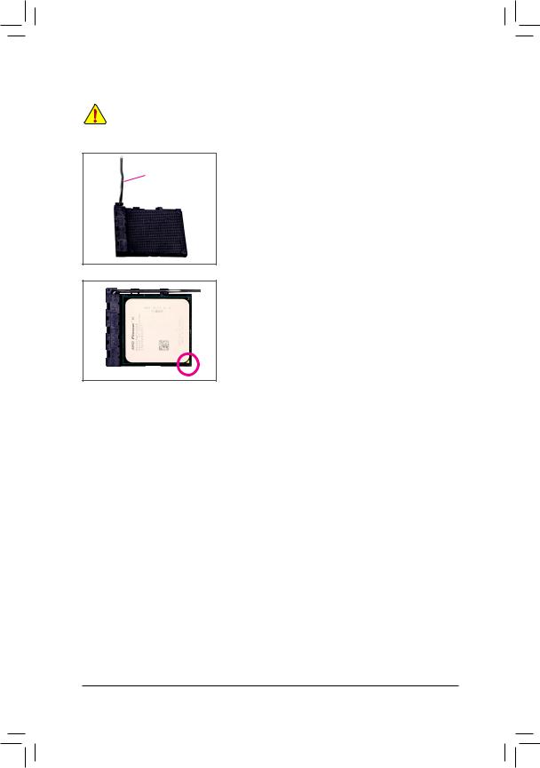
A. Locate the pin one (denoted by a small triangle) of the CPU socket and the CPU.
A Small Triangle
Marking Denotes Pin AM3+ Socket
One of the Socket
A Small Triangle
Marking Denotes AM3+/AM3 CPU
CPU Pin One
|
— 13 — |
Hardware Installation |
B. Follow the steps below to correctly install the CPU into the motherboard CPU socket.
•• Before installing the CPU, make sure to turn off the computer and unplug the power cord from the power outlet to prevent damage to the CPU.
•• Do not force the CPU into the CPU socket. The CPU cannot fit in if oriented incorrectly. Adjust the
CPU orientation if this occurs.
Step 1:
Completely lift up the CPU socket locking lever.
Step 2:
Align the CPU pin one (small triangle marking) with the triangle mark on the CPU socket and gently insert the CPU into the socket. Make sure that the CPU pins fit perfectly into their holes.
Once the CPU is positioned into its socket, place one finger down on the middle of the CPU, lowering the locking lever and latching it into the fully locked position.
|
Hardware Installation |
— 14 — |
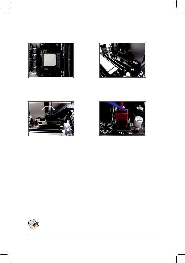
1-3-2 Installing the CPU Cooler
Follow the steps below to correctly install the CPU cooler on the motherboard. (The following procedure uses the GIGABYTE cooler as the example.)
Step 1:
Apply an even and thin layer of thermal grease on the surface of the installed CPU.
Step 3:
Turn the cam handle from the left side to the right side (as the picture above shows) to lock into place. (Refer to your CPU cooler installation manual for instructions on installing the cooler.)
Step 2:
Hook the CPU cooler clip to the mounting lug on one side of the retention frame. On the other side, push straight down on the CPU cooler clip to hook it to the mounting lug on the retention frame.
Step 4:
Finally, attach the power connector of the CPU cooler to the CPU fan header (CPU_FAN) on the motherboard.
Use extreme care when removing the CPU cooler because the thermal grease/tape between the CPU cooler and CPU may adhere to the CPU. Inadequately removing the CPU cooler may damage the CPU.
|
— 15 — |
Hardware Installation |
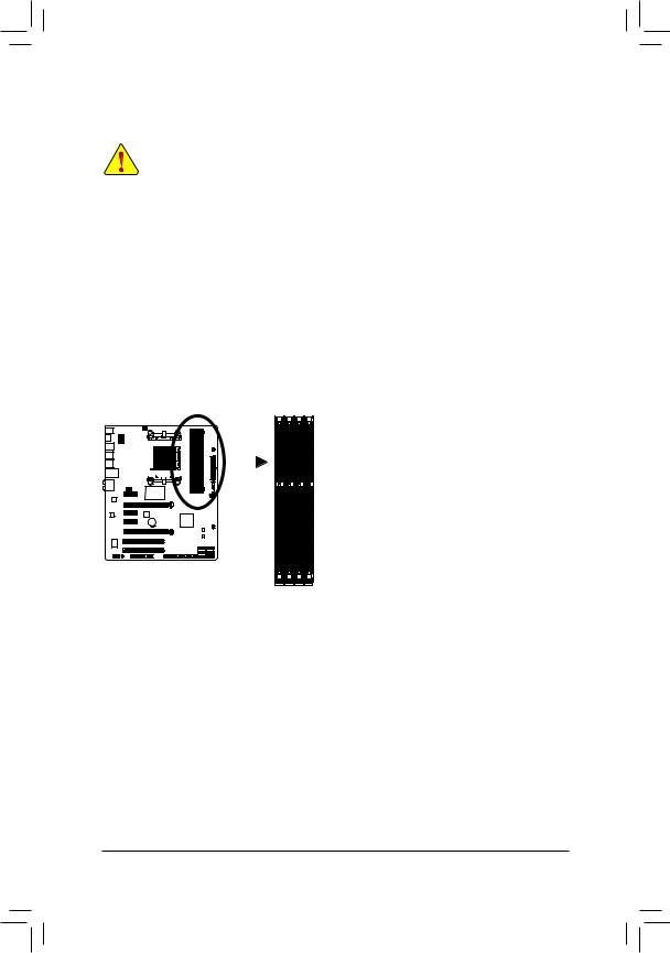
1-4 Installing the Memory
Read the following guidelines before you begin to install the memory:
•• Make sure that the motherboard supports the memory. It is recommended that memory of the same capacity, brand, speed, and chips be used.
(Go to GIGABYTE’s website for the latest supported memory speeds and memory modules.)
•• Always turn off the computer and unplug the power cord from the power outlet before installing the memory to prevent hardware damage.
•• Memory modules have a foolproof design. A memory module can be installed in only one direction. If you are unable to insert the memory, switch the direction.
1-4-1 Dual Channel Memory Configuration
This motherboard provides four DDR3 memory sockets and supports Dual Channel Technology. After the memory is installed, the BIOS will automatically detect the specifications and capacity of the memory. Enabling
Dual Channel memory mode will double the original memory bandwidth.
The four DDR3 memory sockets are divided into two channels and each channel has two memory sockets as following:
 Channel A: DDR3_2, DDR3_4
  Channel B: DDR3_1, DDR3_3
 Dual Channel Memory Configurations Table:
|
DDR3_4 |
DDR3_2 |
DDR3_3 |
DDR3_1 |
||||||||||||||
|
Two Modules |
— — |
DS/SS |
— — |
DS/SS |
|||||||||||||
|
DS/SS |
— — |
DS/SS |
— — |
||||||||||||||
|
Four Modules |
DS/SS |
DS/SS |
DS/SS |
DS/SS |
|||||||||||||
(SS=Single-Sided, DS=Double-Sided, «- -«=No Memory)
DDR3_1
DDR3_3
DDR3_2
DDR3_4
Due to CPU limitations, read the following guidelines before installing the memory in Dual Channel mode.
1.Dual Channel mode cannot be enabled if only one DDR3 memory module is installed.
2.WhenenablingDualChannelmode withtwoor fourmemorymodules,it isrecommendedthatmemory of the same capacity, brand, speed, and chips be used and installed in the same colored DDR3 sockets for optimum performance. For optimum performance, when enabling Dual Channel mode with two memory modules, we recommend that you install them in the DDR3_1 and DDR3_2 sockets.
|
Hardware Installation |
— 16 — |
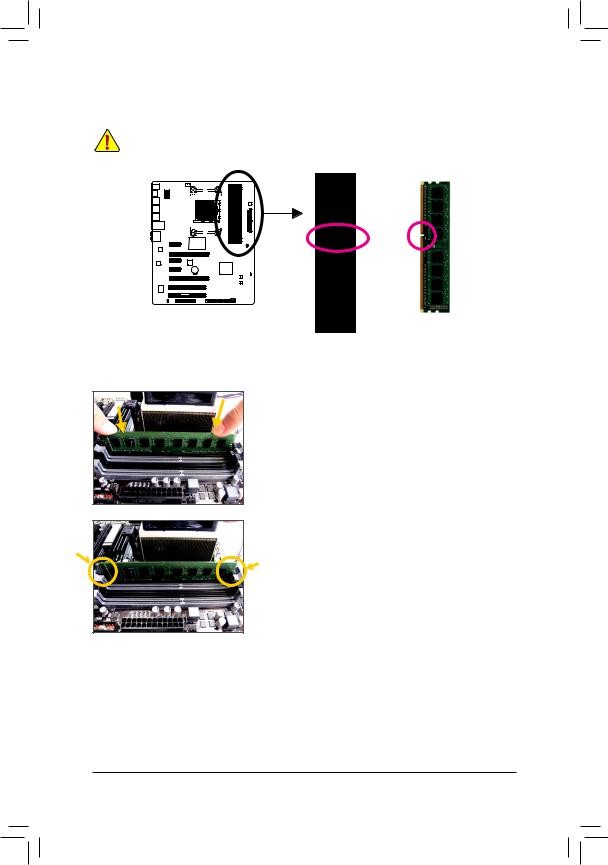
1-4-2 Installing a Memory
Before installing a memory module, make sure to turn off the computer and unplug the power cord from the power outlet to prevent damage to the memory module. DDR3 and DDR2 DIMMs are not compatible to each other or DDR DIMMs. Be sure to install DDR3 DIMMs on this motherboard.
Notch
DDR3 DIMM
ADDR3 memory module has a notch, so it can only fit in one direction. Follow the steps below to correctly install your memory modules in the memory sockets.
Step 1:
Note the orientation of the memory module. Spread the retaining clips at both ends of the memory socket. Place the memory module on the socket. As indicated in the picture on the left, place your fingers on the top edge of the memory, push down on the memory and insert it vertically into the memory socket.
Step 2:
The clips at both ends of the socket will snap into place when the memory module is securely inserted.
|
— 17 — |
Hardware Installation |
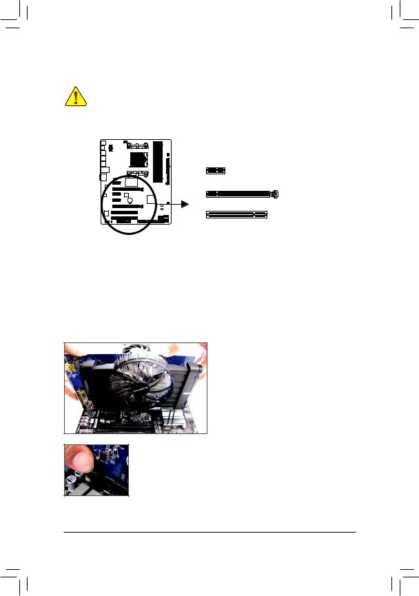
1-5 Installing an Expansion Card
Read the following guidelines before you begin to install an expansion card:
•• Make sure the motherboard supports the expansion card. Carefully read the manual that came with your expansion card.
•• Always turn off the computer and unplug the power cord from the power outlet before installing an expansion card to prevent hardware damage.
PCI Express x1 Slot
PCI Express x16 Slot
PCI Slot
Follow the steps below to correctly install your expansion card in the expansion slot.
1.Locate an expansion slot that supports your card. Remove the metal slot cover from the chassis back panel.
2.Align the card with the slot, and press down on the card until it is fully seated in the slot.
3.Make sure the metal contacts on the card are completely inserted into the slot.
4.Secure the card’s metal bracket to the chassis back panel with a screw.
5.After installing all expansion cards, replace the chassis cover(s).
6.Turn on your computer. If necessary, go to BIOS Setup to make any required BIOS changes for your expansion card(s).
7.Install the driver provided with the expansion card in your operating system.
Example: Installing and Removing a PCI Express Graphics Card:
•• Installing a Graphics Card:
Gently push down on the top edge of the card until it is fully inserted into the PCI Express slot. Make sure the card is securely seated in the slot and does not rock.
•• Removing the Card:
Gently push back on the lever on the slot and then lift the card straight out from the slot.
|
Hardware Installation |
— 18 — |
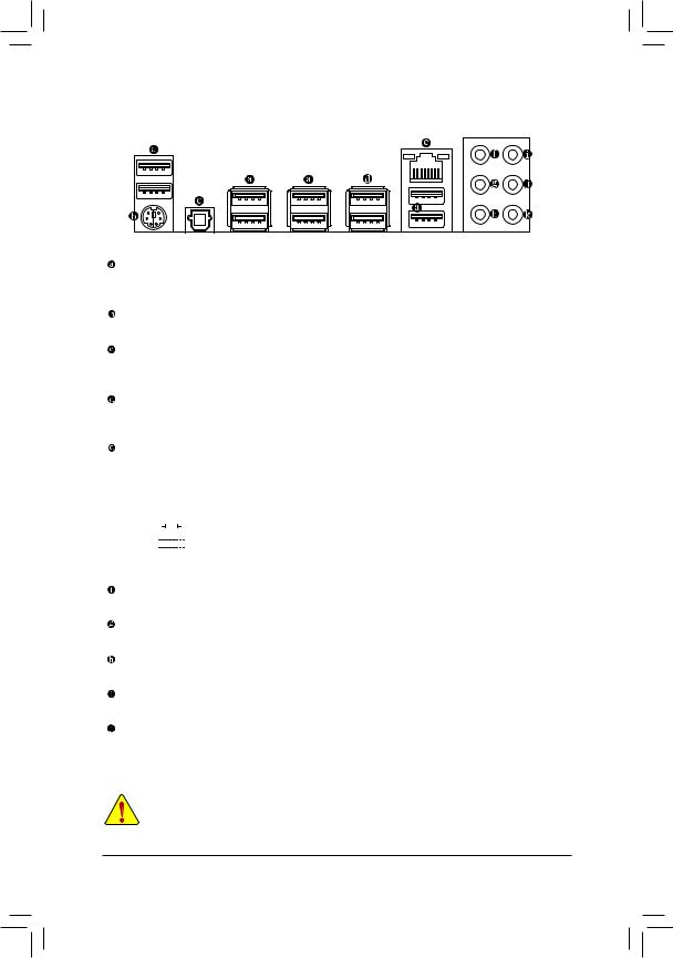
1-6 Back Panel Connectors
USB 2.0/1.1 Port
The USB port supports the USB 2.0/1.1 specification. Use this port for USB devices such as a USB keyboard/mouse, USB printer, USB flash drive and etc.
PS/2 Keyboard/Mouse Port
Use this port to connect a PS/2 mouse or keyboard.
Optical S/PDIF Out Connector
This connector provides digital audio out to an external audio system that supports digital optical audio. Before using this feature, ensure that your audio system provides an optical digital audio in connector.
USB 3.0/2.0 Port
The USB 3.0 port supports the USB 3.0 specification and is compatible to the USB 2.0/1.1 specification. Use this port for USB devices such as a USB keyboard/mouse, USB printer, USB flash drive and etc.
RJ-45 LAN Port
The Gigabit Ethernet LAN port provides Internet connection at up to 1 Gbps data rate. The following describes the states of the LAN port LEDs.
|
Connection/ |
Connection/Speed LED: |
Activity LED: |
|||||||||||||||||
|
Speed LED |
Activity LED |
||||||||||||||||||
|
State |
Description |
State |
Description |
||||||||||||||||
|
Orange |
1 Gbps data rate |
Blinking |
Data transmission or receiving is occurring |
||||||||||||||||
|
Green |
100 Mbps data rate |
Off |
No data transmission or receiving is occurring |
||||||||||||||||
|
Off |
10 Mbps data rate |
||||||||||||||||||
|
LAN Port |
|||||||||||||||||||
Center/Subwoofer Speaker Out Jack (Orange)
Use this audio jack to connect center/subwoofer speakers in a 5.1/7.1-channel audio configuration.
Rear Speaker Out Jack (Black)
This jack can be used to connect front speakers in a 4/5.1/7.1-channel audio configuration.
Side Speaker Out Jack (Gray)
Use this audio jack to connect side speakers in a 7.1-channel audio configuration.
Line In Jack (Blue)
The default line in jack. Use this audio jack for line in devices such as an optical drive, walkman, etc.
Line Out Jack (Green)
The default line out jack. Use this audio jack for a headphone or 2-channel speaker. This jack can be used to connect front speakers in a 4/5.1/7.1-channel audio configuration.
•• When removing the cable connected to a back panel connector, first remove the cable from your device and then remove it from the motherboard.
•• Whenremovingthecable,pullitstraightoutfromtheconnector.Donotrockitsidetosidetoprevent an electrical short inside the cable connector.
|
— 19 — |
Hardware Installation |
Mic In Jack (Pink)
The default Mic in jack. Microphones must be connected to this jack.

 Theaudiojackscanbereconfigured toperformdifferent functionsviatheaudiosoftware(supported
  functions for each jack may vary based on hardware specification). Only microphones still MUST be connected to the default Mic in jack. Refer to the instructions on setting up a 2/4/5.1/7.1-channel audio configuration in Chapter 6, «Configuring 2/4/5.1/7.1-Channel Audio.»
|
Hardware Installation |
— 20 — |
![]()
1-7 Internal Connectors
1 3
|
5 |
|||
|
2 |
|||
|
4 |
9 |
||
|
6 |
|||
|
8 |
4 |
||
|
12 |
|||
|
7 |
|||
|
10 |
|||
|
11 |
15 |
14 |
13 |
|
1) |
ATX_12V |
9) |
F_PANEL |
|
2) |
ATX |
10) |
F_AUDIO |
|
3) |
CPU_FAN |
11) |
SPDIF_O |
|
4) |
SYS_FAN1/SYS_FAN2 |
12) |
F_USB30 |
|
5) |
PWR_FAN |
13) |
F_USB1/F_USB2/F_USB3 |
|
6) |
CLR_CMOS |
14) |
COMA |
|
7) |
SATA3 0/1/2/3/4/5 |
15) |
TPM |
|
|
BAT |
Read the following guidelines before connecting external devices:
•• First make sure your devices are compliant with the connectors you wish to connect.
•• Before installing the devices, be sure to turn off the devices and your computer. Unplug the power cord from the power outlet to prevent damage to the devices.
•• After installing the device and before turning on the computer, make sure the device cable has been securely attached to the connector on the motherboard.
|
— 21 — |
Hardware Installation |
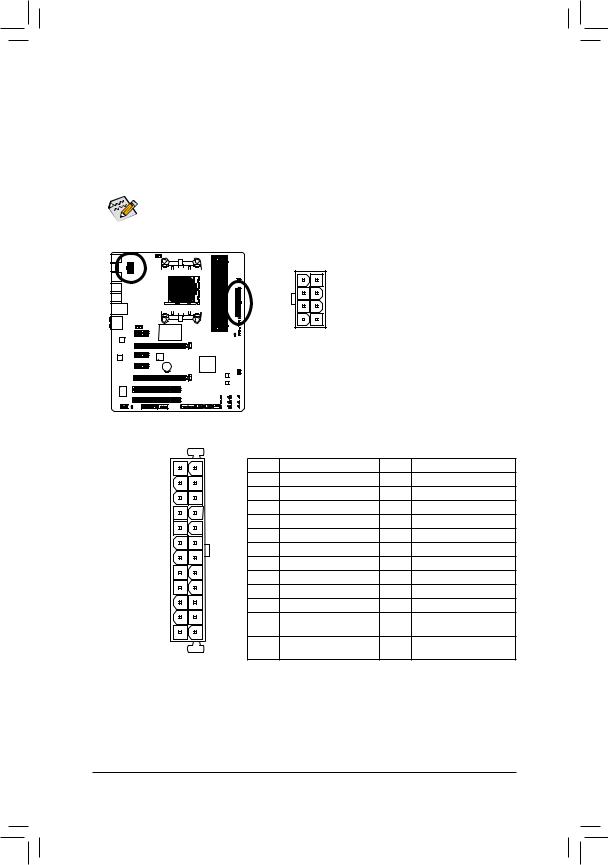
1/2) ATX_12V/ATX (2×4 12V Power Connector and 2×12 Main Power Connector)
Withtheuseofthepowerconnector,thepowersupplycansupplyenoughstablepowertoallthecomponents on the motherboard. Before connecting the power connector, first make sure the power supply is turned off and all devices are properly installed. The power connector possesses a foolproof design. Connect the power supply cable to the power connector in the correct orientation.
The 12V power connector mainly supplies power to the CPU. If the 12V power connector is not connected, the computer will not start.
To meet expansion requirements, it is recommended that a power supply that can withstand high power consumption be used (500W or greater). If a power supply is used that does not provide the required power, the result can lead to an unstable or unbootable system.
|
ATX_12V: |
|||||||||||||||||||
|
Pin No. |
Definition |
||||||||||||||||||
|
8 |
4 |
1 |
GND (Only for 2×4-pin 12V) |
||||||||||||||||
|
2 |
GND (Only for 2×4-pin 12V) |
||||||||||||||||||
|
3 |
GND |
||||||||||||||||||
|
5 |
1 |
4 |
GND |
||||||||||||||||
|
ATX_12V |
5 |
+12V (Only for 2×4-pin 12V) |
|||||||||||||||||
|
6 |
+12V (Only for 2×4-pin 12V) |
||||||||||||||||||
|
7 |
+12V |
||||||||||||||||||
|
8 |
+12V |
||||||||||||||||||
|
ATX: |
|||||
|
12 |
24 |
Pin No. |
Definition |
Pin No. |
Definition |
|
1 |
3.3V |
13 |
3.3V |
||
|
2 |
3.3V |
14 |
-12V |
||
|
3 |
GND |
15 |
GND |
||
|
4 |
+5V |
16 |
PS_ON (soft On/Off) |
||
|
5 |
GND |
17 |
GND |
||
|
6 |
+5V |
18 |
GND |
||
|
7 |
GND |
19 |
GND |
||
|
8 |
Power Good |
20 |
-5V |
||
|
9 |
5VSB (stand by +5V) |
21 |
+5V |
||
|
10 |
+12V |
22 |
+5V |
||
|
11 |
+12V (Only for 2×12-pin |
23 |
+5V (Only for 2×12-pin ATX) |
||
|
1 |
13 |
12 |
ATX) |
24 |
GND (Only for 2×12-pin |
|
3.3V (Only for 2×12-pin |
|||||
|
ATX |
ATX) |
ATX) |
|||
|
Hardware Installation |
— 22 — |
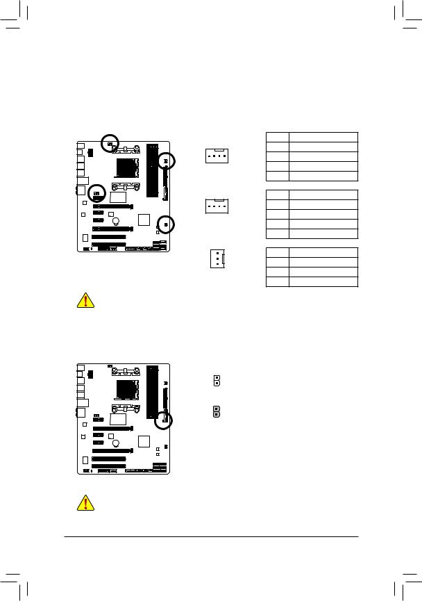
3/4/5) CPU_FAN/SYS_FAN1/SYS_FAN2/PWR_FAN (Fan Headers)
The motherboard has a 4-pin CPU fan header (CPU_FAN), a 4-pin (SYS_FAN1) and a 3-pin (SYS_FAN2) system fan headers, and a 3-pin power fan header (PWR_FAN). Most fan headers possess a foolproof insertion design. When connecting a fan cable, be sure to connect it in the correct orientation (the black connector wire is the ground wire). The speed control function requires the use of a fan with fan speed control design. For optimum heat dissipation, it is recommended that a system fan be installed inside the
|
chassis. |
CPU_FAN: |
||
|
Pin No. |
Definition |
||
|
1 |
GND |
||
|
1 |
2 |
+12V / Speed Control |
|
|
CPU_FAN |
3 |
Sense |
|
|
4 |
Speed Control |
||
|
SYS_FAN1: |
|||
|
Pin No. |
Definition |
||
|
1 |
1 |
GND |
|
|
SYS_FAN1 |
2 |
+12V / Speed Control |
|
|
3 |
Sense |
||
|
4 |
Reserve |
||
|
SYS_FAN2/PWR_FAN: |
|||
|
Pin No. |
Definition |
||
|
1 |
1 |
GND |
|
|
2 |
+12V |
||
|
SYS_FAN2/PWR_FAN |
|||
|
3 |
Sense |
||
•• Be sure to connect fan cables to the fan headers to prevent your CPU and system from overheating. Overheating may result in damage to the CPU or the system may hang.
•• Thesefanheadersarenotconfigurationjumperblocks.Donotplaceajumpercapontheheaders.
6)CLR_CMOS (Clear CMOS Jumper)
Use this jumper to clear the BIOS configuration and reset the CMOS values to factory defaults. To clear the CMOS values, use a metal object like a screwdriver to touch the two pins for a few seconds.
Open: Normal
Short: Clear CMOS Values
•• Always turn off your computer and unplug the power cord from the power outlet before clearing the CMOS values.
•• Aftersystemrestart,gotoBIOSSetuptoloadfactorydefaults(selectLoadOptimizedDefaults)or manuallyconfiguretheBIOSsettings(refertoChapter2,»BIOSSetup,»forBIOSconfigurations).
|
— 23 — |
Hardware Installation |
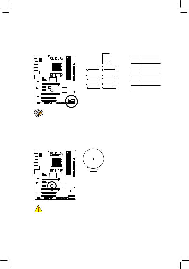
7)SATA3 0/1/2/3/4/5 (SATA 6Gb/s Connectors)
The SATA connectors conform to SATA 6Gb/s standard and are compatible with SATA 3Gb/s and SATA 1.5Gb/s standard. Each SATA connector supports a single SATA device. The AMD SB950 controller supports
RAID 0, RAID 1, RAID 5, RAID 10, and JBOD. Refer to Chapter 3, «Configuring SATA Hard Drive(s),» for instructions on configuring a RAID array.
|
0 |
3 |
Pin No. |
Definition |
|
|
1 |
4 |
|||
|
1 |
GND |
|||
|
SATA3 2 |
5 |
|||
|
1 |
7 |
2 |
TXP |
|
|
3 |
TXN |
|||
|
1 |
7 |
4 |
GND |
|
|
5 |
RXN |
|||
|
1 |
7 |
6 |
RXP |
|
|
7 |
GND |
|||
•• ARAID 0 or RAID 1 configuration requires at least two hard drives. If more than two hard drives are to be used, the total number of hard drives must be an even number.
•• ARAID 5 configuration requires at least three hard drives. (The total number of hard drives does not have to be an even number.)
•• A RAID 10 configuration requires four hard drives.
 BAT (Battery)
The battery provides power to keep the values (such as BIOS configurations, date, and time information) in the CMOS when the computer is turned off. Replace the battery when the battery voltage drops to a low level, or the CMOS values may not be accurate or may be lost.
You may clear the CMOS values by removing the battery: 1. Turn off your computer and unplug the power cord.
2. Gently remove the battery from the battery holder and wait for one minute.
(Oruseametalobjectlikeascrewdrivertotouchthepositiveandnegative terminals of the battery holder, making them short for 5 seconds.)
3. Replace the battery.
4. Plug in the power cord and restart your computer.
|
•• |
Always turn off your computer and unplug the power cord before replacing the battery. |
|
|
•• |
Replace the battery with an equivalent one. Danger of explosion if the battery is replaced with |
|
|
an incorrect model. |
||
|
•• Contact the place of purchase or local dealer if you are not able to replace the battery by yourself |
||
|
or uncertain about the battery model. |
||
|
•• |
When installing the battery, note the orientation of the positive side (+) and the negative side (-) |
|
|
of the battery (the positive side should face up). |
||
|
•• |
Used batteries must be handled in accordance with local environmental regulations. |
|
|
Hardware Installation |
— 24 — |
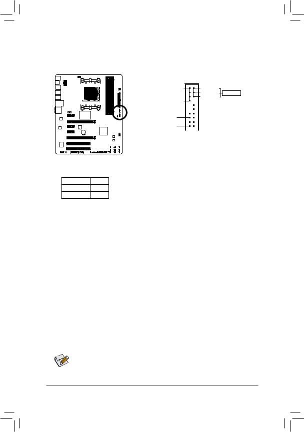
9)F_PANEL (Front Panel Header)
Connect the power switch, reset switch, speaker, chassis intrusion switch/sensor and system status indicator on the chassis to this header according to the pin assignments below. Note the positive and negative pins before connecting the cables.
|
SPEAK- |
|||||||||||||||||||||||||||
|
Speaker |
SPEAK+ |
||||||||||||||||||||||||||
|
PW- |
|||||||||||||||||||||||||||
|
Power Switch |
PW+ |
||||||||||||||||||||||||||
|
PLED- |
|||||||||||||||||||||||||||
|
Power LED |
PLED+ |
||||||||||||||||||||||||||
20 19
PWR_LED-
PWR_LED- Power LED PWR_LED+
|
CI+ |
Chassis Intrusion |
||||||||||||||||
|
CI- |
Header |
||||||||||||||||
|
RES+ |
Reset |
||||||||||||||||
|
RES- |
Switch |
||||||||||||||||
|
HD- |
|||||||||||||||||
|
Hard Drive |
|||||||||||||||||
|
HD+ |
|||||||||||||||||
|
Activity LED |
|||||||||||||||||
|
2 |
1 |
•• PLED/PWR_LED (Power LED, Yellow/Purple):
|
System Status |
LED |
|
S0 |
On |
|
S3/S4/S5 |
Off |
Connects to the power status indicator on the chassis front panel. The LED is on when the system is operating. The LED is off when the system is in S3/
S4 sleep state or powered off (S5).
•• PW (Power Switch, Red):
Connects to the power switch on the chassis front panel. You may configure the way to turn off your system using the power switch (refer to Chapter 2, «BIOS Setup,» «Power Management,» for more information).
•• SPEAK (Speaker, Orange):
Connects to the speaker on the chassis front panel. The system reports system startup status by issuing a beep code. One single short beep will be heard if no problem is detected at system startup.
•• HD (Hard Drive Activity LED, Blue):
Connects to the hard drive activity LED on the chassis front panel. The LED is on when the hard drive is reading or writing data.
•• RES (Reset Switch, Green):
Connects to the reset switch on the chassis front panel. Press the reset switch to restart the computer if the computer freezes and fails to perform a normal restart.
•• CI (Chassis Intrusion Header, Gray):
Connects to the chassis intrusion switch/sensor on the chassis that can detect if the chassis cover has been removed. This function requires a chassis with a chassis intrusion switch/sensor.

 The front panel design may differ by chassis. A front panel module mainly consists of power switch,
  reset switch, power LED, hard drive activity LED, speaker and etc. When connecting your chassis front panel module to this header, make sure the wire assignments and the pin assignments are matched correctly.
|
— 25 — |
Hardware Installation |
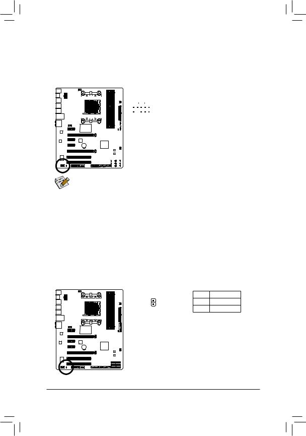
10)F_AUDIO (Front Panel Audio Header)
The front panel audio header supports Intel High Definition audio (HD) andAC’97 audio. You may connect your chassis front panel audio module to this header. Make sure the wire assignments of the module connector match the pin assignments of the motherboard header. Incorrect connection between the module connector and the motherboard header will make the device unable to work or even damage it.
|
For HD Front Panel Audio: |
For AC’97 Front Panel Audio: |
|||||||||||||||||||||||||
|
1 |
Pin No. |
Definition |
Pin No. |
Definition |
||||||||||||||||||||||
|
9 |
||||||||||||||||||||||||||
|
1 |
MIC2_L |
1 |
MIC |
|||||||||||||||||||||||
|
2 |
GND |
2 |
GND |
|||||||||||||||||||||||
|
3 |
MIC2_R |
3 |
MIC Power |
|||||||||||||||||||||||
|
10 |
2 |
|||||||||||||||||||||||||
|
4 |
-ACZ_DET |
4 |
NC |
|||||||||||||||||||||||
|
5 |
LINE2_R |
5 |
Line Out (R) |
|||||||||||||||||||||||
|
6 |
GND |
6 |
NC |
|||||||||||||||||||||||
|
7 |
FAUDIO_JD |
7 |
NC |
|||||||||||||||||||||||
|
8 |
No Pin |
8 |
No Pin |
|||||||||||||||||||||||
|
9 |
LINE2_L |
9 |
Line Out (L) |
|||||||||||||||||||||||
|
10 |
GND |
10 |
NC |
|||||||||||||||||||||||
•• The front panel audio header supports HD audio by default. If your chassis provides an AC’97 front panel audio module, refer to the instructions on how to activate AC’97 functionality via the audio software in Chapter 6, «Configuring 2/4/5.1/7.1-Channel Audio.»
•• Audio signals will be present on both of the front and back panel audio connections simultaneously.
If you want to mute the back panel audio (only supported when using an HD front panel audio module), refer to Chapter 6, «Configuring 2/4/5.1/7.1-Channel Audio.»
•• Some chassis provide a front panel audio module that has separated connectors on each wire instead of a single plug. For information about connecting the front panel audio module that has different wire assignments, please contact the chassis manufacturer.
11)SPDIF_O (S/PDIF Out Header)
This header supports digital S/PDIF Out and connects a S/PDIF digital audio cable (provided by expansion cards) for digital audio output from your motherboard to certain expansion cards like graphics cards and sound cards. For example, some graphics cards may require you to use a S/PDIF digital audio cable for digital audio output from your motherboard to your graphics card if you wish to connect an HDMI display to the graphics card and have digital audio output from the HDMI display at the same time. For information about connecting the S/PDIF digital audio cable, carefully read the manual for your expansion card.
|
Pin No. |
Definition |
|
|
1 |
SPDIFO |
|
|
1 |
2 |
GND |
|
Hardware Installation |
— 26 — |
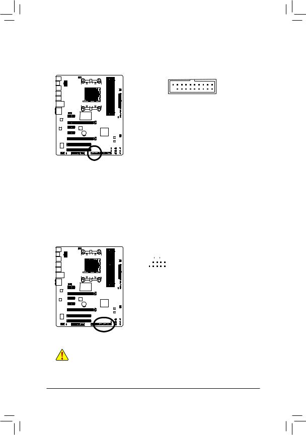
12) F_USB30 (USB 3.0/2.0 Header)
TheheaderconformstoUSB3.0/2.0specificationandcanprovidetwoUSBports.For purchasing the optional 3.5″ front panel that provides two USB 3.0/2.0 ports, please contact the local dealer.
|
1 |
10 |
|||||||||||||||||||
|
20 |
11 |
|||||||||||||||||||
|
Pin No. |
Definition |
Pin No. |
Definition |
|||||||||||||||||
|
1 |
VBUS |
11 |
D2+ |
|||||||||||||||||
|
2 |
SSRX1- |
12 |
D2- |
|||||||||||||||||
|
3 |
SSRX1+ |
13 |
GND |
|||||||||||||||||
|
4 |
GND |
14 |
SSTX2+ |
|||||||||||||||||
|
5 |
SSTX1- |
15 |
SSTX2- |
|||||||||||||||||
|
6 |
SSTX1+ |
16 |
GND |
|||||||||||||||||
|
7 |
GND |
17 |
SSRX2+ |
|||||||||||||||||
|
8 |
D1- |
18 |
SSRX2- |
|||||||||||||||||
|
9 |
D1+ |
19 |
VBUS |
|||||||||||||||||
|
10 |
NC |
20 |
No Pin |
13)F_USB1/F_USB2/F_USB3 (USB Headers)
The headers conform to USB 2.0/1.1 specification. Each USB header can provide two USB ports via an optional USB bracket. For purchasing the optional USB bracket, please contact the local dealer.
|
Pin No. |
Definition |
|||||||||||||||||||||
|
9 |
1 |
1 |
Power (5V) |
|||||||||||||||||||
|
2 |
Power (5V) |
|||||||||||||||||||||
|
10 |
2 |
|||||||||||||||||||||
|
3 |
USB DX- |
|||||||||||||||||||||
|
4 |
USB DY- |
|||||||||||||||||||||
|
5 |
USB DX+ |
|||||||||||||||||||||
|
6 |
USB DY+ |
|||||||||||||||||||||
|
7 |
GND |
|||||||||||||||||||||
|
8 |
GND |
|||||||||||||||||||||
|
9 |
No Pin |
|||||||||||||||||||||
|
10 |
NC |
|||||||||||||||||||||
•• Do not plug the IEEE 1394 bracket (2×5-pin) cable into the USB header.
•• Prior to installing the USB bracket, be sure to turn off your computer and unplug the power cord from the power outlet to prevent damage to the USB bracket.
|
— 27 — |
Hardware Installation |
 Loading…