
![]()
GA-990XA-UD3
User’s Manual
Rev. 1001 12ME-990XAU3-1001R

dr aobr eht o M
GA-990XA-UD3
Motherboard
GA-990XA-UD3
May 13, 2011
May 13, 2011

Copyright
© 2011 GIGA-BYTE TECHNOLOGY CO., LTD. All rights reserved.
The trademarks mentioned in this manual are legally registered to their respective owners.
Disclaimer
Information in this manual is protected by copyright laws and is the property of GIGABYTE.
Changes to the specifications and features in this manual may be made by GIGABYTE without prior notice. No part of this manual may be reproduced, copied, translated, transmitted, or published in any form or by any means without GIGABYTE’s prior written permission.
Documentation Classifications
In order to assist in the use of this product, GIGABYTE provides the following types of documentations:
For quick set-up of the product, read the Quick Installation Guide included with the product.
For detailed product information, carefully read the User’s Manual.
For product-related information, check on our website at:
http://www.gigabyte.com
Identifying Your Motherboard Revision
The revision number on your motherboard looks like this: «REV: X.X.» For example, «REV: 1.0» means the revision of the motherboard is 1.0. Check your motherboard revision before updating motherboard BIOS, drivers, or when looking for technical information.
Example:

Table of Contents
|
Box Contents…………………………………………………………………………………………………….. |
6 |
||
|
Optional Items…………………………………………………………………………………………………… |
6 |
||
|
GA-990XA-UD3 Motherboard Layout.………………………………………………………………….. |
7 |
||
|
GA-990XA-UD3 Motherboard Block Diagram………………………………………………………… |
8 |
||
|
Chapter 1 Hardware Installation………………………………………………………………………….. |
9 |
||
|
1-1 |
Installation Precautions…………………………………………………………………………. |
9 |
|
|
1-2 |
Product Specifications.……………………………………………………………………….. |
10 |
|
|
1-3 |
Installing the CPU and CPU Cooler………………………………………………………. |
13 |
|
|
1-3-1 |
Installing the CPU……………………………………………………………………………………… |
13 |
|
|
1-3-2 Installing the CPU Cooler……………………………………………………………………………. |
15 |
||
|
1-4 |
Installing the Memory………………………………………………………………………….. |
16 |
|
|
1-4-1 Dual Channel Memory Configuration……………………………………………………………. |
16 |
||
|
1-4-2 |
Installing a Memory …………………………………………………………………………………… |
17 |
|
|
1-5 |
Installing an Expansion Card……………………………………………………………….. |
18 |
|
|
1-6 |
Setup of AMD CrossFireX™ Configuration……………………………………………… |
19 |
|
|
1-7 |
Back Panel Connectors.……………………………………………………………………… |
20 |
|
|
1-8 |
Internal Connectors.…………………………………………………………………………… |
22 |
|
|
Chapter 2 BIOS Setup……………………………………………………………………………………… |
31 |
||
|
2-1 |
Startup Screen…………………………………………………………………………………… |
32 |
|
|
2-2 |
The Main Menu………………………………………………………………………………….. |
33 |
|
|
2-3 |
MB Intelligent Tweaker(M.I.T.).…………………………………………………………….. |
35 |
|
|
2-4 |
Standard CMOS Features.………………………………………………………………….. |
41 |
|
|
2-5 |
Advanced BIOS Features……………………………………………………………………. |
43 |
|
|
2-6 |
Integrated Peripherals.……………………………………………………………………….. |
45 |
|
|
2-7 |
Power Management Setup.…………………………………………………………………. |
49 |
|
|
2-8 |
PC Health Status.………………………………………………………………………………. |
51 |
|
|
2-9 |
Load Fail-Safe Defaults.……………………………………………………………………… |
53 |
|
|
2-10 |
Load Optimized Defaults.……………………………………………………………………. |
53 |
|
|
2-11 |
Set Supervisor/User Password…………………………………………………………….. |
54 |
|
|
2-12 |
Save & Exit Setup………………………………………………………………………………. |
55 |
|
|
2-13 |
Exit Without Saving…………………………………………………………………………….. |
55 |
— 4 —

|
Chapter 3 Drivers Installation.…………………………………………………………………………… |
57 |
|
|
3-1 |
Installing Chipset Drivers…………………………………………………………………….. |
57 |
|
3-2 |
Application Software…………………………………………………………………………… |
58 |
|
3-3 |
Technical Manuals.…………………………………………………………………………….. |
58 |
|
3-4 |
Contact.……………………………………………………………………………………………. |
59 |
|
3-5 |
System……………………………………………………………………………………………… |
59 |
|
3-6 |
Download Center……………………………………………………………………………….. |
60 |
|
3-7 |
New Utilities………………………………………………………………………………………. |
60 |
|
Chapter 4 Unique Features.……………………………………………………………………………… |
61 |
|
|
4-1 |
Xpress Recovery2.…………………………………………………………………………….. |
61 |
|
4-2 |
BIOS Update Utilities………………………………………………………………………….. |
64 |
|
4-2-1 Updating the BIOS with the Q-Flash Utility.…………………………………………………… |
64 |
|
|
4-2-2 Updating the BIOS with the @BIOS Utility…………………………………………………….. |
67 |
|
|
4-3 |
EasyTune 6……………………………………………………………………………………….. |
68 |
|
4-4 |
Easy Energy Saver…………………………………………………………………………….. |
69 |
|
4-5 |
Q-Share.…………………………………………………………………………………………… |
71 |
|
4-6 |
SMART Recovery………………………………………………………………………………. |
72 |
|
4-7 |
Auto Green.………………………………………………………………………………………. |
73 |
|
4-8 |
Cloud OC………………………………………………………………………………………….. |
74 |
|
Chapter 5 Appendix |
…………………………………………………………………………………………. |
75 |
|
|
5-1 |
Configuring .SATA Hard Drive(s) …………………………………………………………. |
75 |
|
|
5-1-1 ……………………………………………………………………… |
Configuring SATA Controllers |
75 |
|
|
5-1-2 …………………………..Installing the SATA RAID/AHCI Driver and Operating System |
81 |
||
|
5-2 |
Configuring ……………………………………………………….Audio Input and Output |
85 |
|
|
5-2-1 .………………………………………………………… |
Configuring 2/4/5.1/7.1 — Channel Audio |
85 |
|
|
5-2-2 ……………………………………………………………………………… |
Configuring S/PDIF Out |
87 |
|
|
5-2-3 .………………………………………………….Enabling the Dolby Home Theater Function |
88 |
||
|
5-2-4 ………………………………………………………………. |
Configuring Microphone Recording |
89 |
|
|
5-2-5 …………………………………………………………………………..Using the Sound Recorder |
91 |
||
|
5-3 |
Troubleshooting…………………………………………………………………………………. |
92 |
|
|
5-3-1 .……………………………………………………………………… |
Frequently Asked Questions |
92 |
|
|
5-3-2 …………………………………………………………………………. |
Troubleshooting Procedure |
93 |
— 5 —
Box Contents
GA-990XA-UD3 motherboard
Motherboard driver disk
User’s Manual
Quick Installation Guide
Four SATA cables
I/O Shield
One 2-Way SLI bridge connector (Note)
|
(Note) |
To enable NVIDIA SLI technology, you need SLI-supported graphics cards, BIOS, and driver. For more |
|
details, please go to GIGABYTE’s website. |
•The box contents above are for reference only and the actual items shall depend on the product package you obtain. The box contents are subject to change without notice.
•The motherboard image is for reference only.
Optional Items
2-port USB 2.0 bracket (Part No. 12CR1-1UB030-5*R)
2-port SATA power cable (Part No. 12CF1-2SERPW-0*R)
COM port cable (Part No. 12CF1-1CM001-3*R)
2-port IEEE 1394a bracket (Part No. 12CF1-1IE008-0*R)
3.5″ Front Panel with 2 USB 3.0/2.0 ports (Part No. 12CR1-FPX582-0*R)
— 6 —
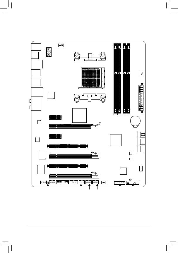
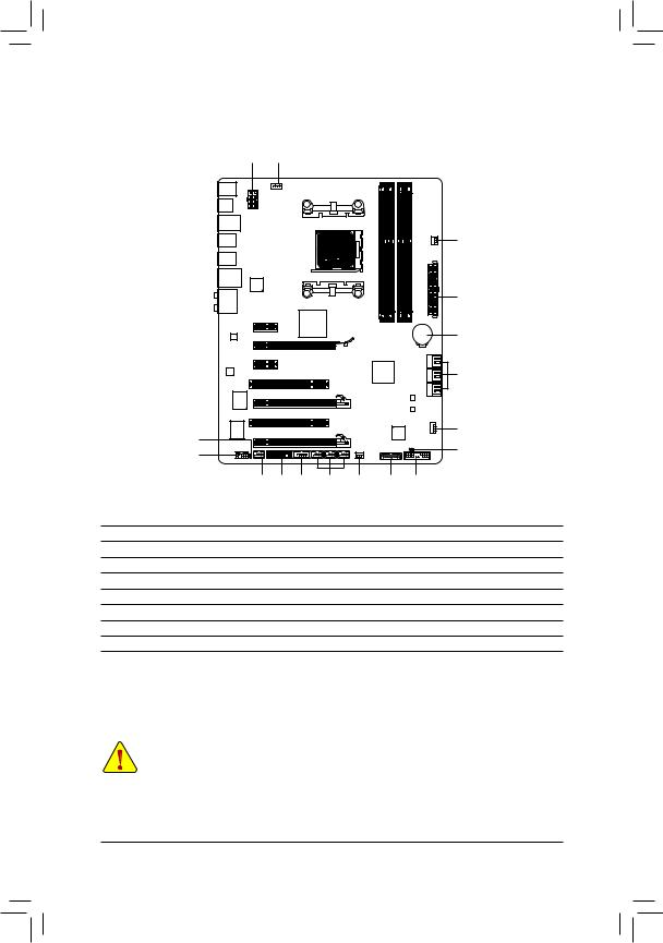
GA-990XA-UD3 Motherboard Layout
KB_MS_USB
ATX_12V
OPTICAL
USB_1394
R_USB
R_USB30
USB_LAN
Etron
EJ168
AUDIO
PCIEX1_1(Note)
PCIEX16
Realtek RTL8111E
PCIEX1_2
CODEC
PCI1
VIA PCIEX8
VT6308
PCI2
CPU_FAN
Socket AM3+
AMD 990X
GA-990XA-UD3
PWR_FAN
ATX
|
DDR3 4 DDR3 2 |
DDR3 3 DDR3 1 |
BAT |
SATA3_4
SATA3_5
AMD SB950 SATA3_2  SATA3_3
SATA3_0 
B_BIOS SATA3_1 
M_BIOS
|
iTE |
Etron |
|||
|
IT8720 |
PCIEX4 |
SYS_FAN1 |
||
|
EJ168 |
||||
|
F_AUDIO |
SYS_FAN2 |
CLR_CMOS |
||
|
F_1394 TPM |
COMA |
|||
|
SPDIF_O |
F_USB3 F_USB2 F_USB1 |
F_USB30 |
F_PANEL |
(Note) Due to a hardware limitation, the PCIEX1_1 slot can only accommodate a shorter PCI Express x1 expansion card. For a longer expansion card, use other expansion slots.
— 7 —
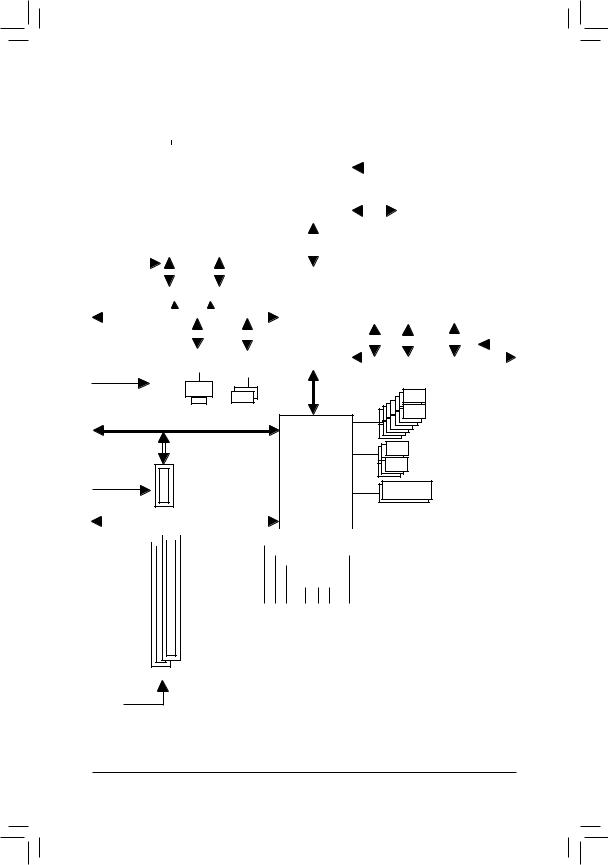
GA-990XA-UD3 Motherboard Block Diagram
|
2 PCI Express x8 |
1 PCI Express x16 |
||||||||||||||||||||||||||||||||||||||||||||||
|
CPU CLK+/- (200 MHz) |
|||||||||||||||||||||||||||||||||||||||||||||||
|
or |
AM3+/AM3 CPU |
DDR3 2000(O.C.)/1866/1600/1333/1066 MHz |
|||||||||||||||||||||||||||||||||||||||||||||
|
PCIe CLK |
Dual Channel Memory |
||||||||||||||||||||||||||||||||||||||||||||||
|
Hyper Transport Bus |
|||||||||||||||||||||||||||||||||||||||||||||||
|
(100 MHz) |
2 USB 3.0/2.0 |
||||||||||||||||||||||||||||||||||||||||||||||
|
x8 |
x16 |
2 PCI Express x1 |
|||||||||||||||||||||||||||||||||||||||||||||
|
Switch |
|||||||||||||||||||||||||||||||||||||||||||||||
|
PCI Express Bus |
AMD 990X |
Etron |
|||||||||||||||||||||||||||||||||||||||||||||
|
EJ168 |
PCIe CLK |
||||||||||||||||||||||||||||||||||||||||||||||
|
x1 |
x1 |
||||||||||||||||||||||||||||||||||||||||||||||
|
PCIe CLK |
x1 |
x1 |
x1 |
(100 MHz) |
|||||||||||||||||||||||||||||||||||||||||||
|
Realtek |
Etron |
||||||||||||||||||||||||||||||||||||||||||||||
|
(100 MHz) |
RTL8111E |
PCI Express Bus |
|||||||||||||||||||||||||||||||||||||||||||||
|
EJ168 |
|||||||||||||||||||||||||||||||||||||||||||||||
|
RJ45 |
||
|
LAN |
2 USB 3.0/2.0 |
14 USB 2.0/1.1Ports |
|
PCI Express Bus |
||
|
x4 |
6 SATA 6Gb/s |
|
|
PCIe CLK |
||
|
AMD SB950 |
||
|
(100 MHz) |
||
|
1 PCI Express x4 |
Dual BIOS |
|
LPC |
|||||||||||||||||||||||||||||
|
PCI Bus |
Bus |
iTE |
COM Port |
||||||||||||||||||||||||||
|
VIA VT6308 |
|||||||||||||||||||||||||||||
|
CODEC |
IT8720 |
||||||||||||||||||||||||||||
|
PS/2 KB/Mouse |
|||||||||||||||||||||||||||||
2 IEEE 1394a
|
Out Out |
MIC |
Line |
Out |
|
Out |
In |
||
|
Out |
S/PDIF |
||
|
Speaker Speaker Speaker |
Line |
||
|
Center/Subwoofer Side |
|||
|
Surround |
— 8 —

Chapter 1 Hardware Installation
1-1 Installation Precautions
The motherboard contains numerous delicate electronic circuits and components which can become damaged as a result of electrostatic discharge (ESD). Prior to installation, carefully read the user’s manual and follow these procedures:
•Prior to installation, do not remove or break motherboard S/N (Serial Number) sticker or warranty sticker provided by your dealer. These stickers are required for warranty validation.
•Always remove the AC power by unplugging the power cord from the power outlet before installing or removing the motherboard or other hardware components.
•When connecting hardware components to the internal connectors on the motherboard, make sure they are connected tightly and securely.
•When handling the motherboard, avoid touching any metal leads or connectors.
•It is best to wear an electrostatic discharge (ESD) wrist strap when handling electronic components such as a motherboard, CPU or memory. If you do not have an ESD wrist strap, keep your hands dry and first touch a metal object to eliminate static electricity.
•Prior to installing the motherboard, please have it on top of an antistatic pad or within an electrostatic shielding container.
•Before unplugging the power supply cable from the motherboard, make sure the power supply has been turned off.
•Before turning on the power, make sure the power supply voltage has been set according to the local voltage standard.
•Before using the product, please verify that all cables and power connectors of your hardware components are connected.
•To prevent damage to the motherboard, do not allow screws to come in contact with the motherboard circuit or its components.
•Make sure there are no leftover screws or metal components placed on the motherboard or within the computer casing.
•Do not place the computer system on an uneven surface.
•Do not place the computer system in a high-temperature environment.
•Turning on the computer power during the installation process can lead to damage to system components as well as physical harm to the user.
•If you are uncertain about any installation steps or have a problem related to the use of the product, please consult a certified computer technician.
|
— 9 — |
Hardware Installation |
|
1-2 |
Product Specifications |
||
|
CPU |
AM3+ Socket: |
||
|
— AMD AM3+ FX processors |
|||
|
— AMD AM3 Phenom™ II processors/ AMD Athlon™ II processors |
|||
|
(Go to GIGABYTE’s website for the latest CPU support list.) |
|||
|
Hyper Transport |
5200 MT/s |
||
|
Bus |
|||
|
Chipset |
North Bridge: AMD 990X |
||
|
South Bridge: AMD SB950 |
|||
|
Memory |
4 x 1.5V DDR3 DIMM sockets supporting up to 32 GB of system memory |
|
* Due to Windows 32-bit operating system limitation, when more than 4 GB of physical |
||||
|
memory is installed, the actual memory size displayed will be less than 4 GB. |
||||
|
Dual channel memory architecture |
||||
|
Support for DDR3 2000 (O.C.)/1866/1600/1333/1066 MHz memory modules |
||||
|
* To support a DDR3 1866 MHz (and above) memory, you must install an AM3+ CPU |
||||
|
first. |
||||
|
(Go to GIGABYTE’s website for the latest supported memory speeds and memory |
||||
|
modules.) |
||||
|
Audio |
Realtek ALC889 codec |
|||
|
High Definition Audio |
||||
|
2/4/5.1/7.1-channel |
||||
|
Support for Dolby® Home Theater |
||||
|
Support for S/PDIF Out |
||||
|
LAN |
1 x Realtek RTL8111E chip (10/100/1000 Mbit) |
|||
|
Expansion Slots |
1 x PCI Express x16 slot, running at x16 (PCIEX16) |
|||
|
* For optimum performance, if only one PCI Express graphics card is to be installed, |
||||
|
be sure to install it in the PCIEX16 slot. |
||||
|
1 x PCI Express x16 slot, running at x8 (PCIEX8) |
||||
|
* The PCIEX8 slot shares bandwidth with the PCIEX16 slot. When the PCIEX8 slot |
||||
|
is populated, the PCIEX16 slot will operate at up to x8 mode. |
||||
|
1 x PCI Express x16 slot, running at x4 (PCIEX4) |
||||
|
2 x PCI Express x1 slots |
||||
|
(All PCI Express slots conform to PCI Express 2.0 standard.) |
||||
|
2 x PCI slots |
||||
|
Multi-Graphics |
Support for AMD CrossFireX™ technology (PCIEX16 and PCIEX8) |
|||
|
Technology |
* The PCIEX16 slot operates at up to x8 mode when AMD CrossFireX™ is enabled. |
|||
|
Storage Interface |
South Bridge: |
|||
|
— |
6 x SATA 6Gb/s connectors supporting up to 6 SATA 6Gb/s devices |
|||
|
— |
Support for RAID 0, RAID 1, RAID 5, RAID 10, and JBOD |
|||
|
USB |
South Bridge: |
|||
|
— |
Up to 14 USB 2.0/1.1 ports (8 ports on the back panel, 6 ports available |
|||
|
through the internal USB headers) |
||||
|
2 x Etron EJ168 chips: |
||||
|
— |
Up to 4 USB 3.0/2.0 ports (2 ports on the back panel, 2 ports available |
|||
|
through the internal USB headers) |
||||
|
Hardware Installation |
— 10 — |
![]()
|
IEEE 1394 |
VIA VT6308 chip: |
||
|
— |
Up to 2 IEEE 1394a ports (1 port on the back panel, 1 port available through |
||
|
the internal IEEE 1394a header) |
|||
|
Internal |
1 x 24-pin ATX main power connector |
||
|
Connectors |
1 x 8-pin ATX 12V power connector |
||
|
6 x SATA 6Gb/s connectors |
|||
|
1 x CPU fan header |
|||
|
2 x system fan headers |
|||
|
1 x power fan header |
|||
|
1 x front panel header |
|||
|
1 x front panel audio header |
|||
|
1 x S/PDIF Out header |
|||
|
3 x USB 2.0/1.1 headers |
|||
|
1 x USB 3.0/2.0 header |
|||
|
1 x IEEE 1394a header |
|||
|
1 x serial port header |
|||
|
1 x clearing CMOS jumper |
|||
|
1 x Trusted Platform Module (TPM) header |
|||
|
Back Panel |
1 x PS/2 keyboard/mouse port |
||
|
Connectors |
1 x optical S/PDIF Out connector |
||
|
1 x IEEE 1394 port |
|||
|
8 x USB 2.0/1.1 ports |
|||
|
2 x USB 3.0/2.0 ports |
|||
|
1 x RJ-45 port |
|||
|
6 x audio jacks (Center/Subwoofer Speaker Out/Rear Speaker Out/Side Speaker |
|||
|
Out/Line In/Line Out/Microphone) |
|||
|
I/O Controller |
iTE IT8720 chip |
||
|
Hardware |
System voltage detection |
||
|
Monitor |
CPU/System temperature detection |
CPU/System/Power fan speed detectionCPU overheating warning
CPU/System/Power fan fail warningCPU/System fan speed control
*Whether the CPU/system fan speed control function is supported will depend on the CPU/system cooler you install.
|
BIOS |
2 x 32 Mbit flash |
|
|
Use of licensed AWARD BIOS |
||
|
Support for DualBIOS™ |
||
|
PnP 1.0a, DMI 2.0, SM BIOS 2.4, ACPI 1.0b |
|
— 11 — |
Hardware Installation |

|
Unique Features |
Support for @BIOS |
||
|
Support for Q-Flash |
|||
|
Support for Xpress BIOS Rescue |
|||
|
Support for Download Center |
|||
|
Support for Xpress Install |
|||
|
Support for Xpress Recovery2 |
|||
|
Support for EasyTune |
|||
|
* Available functions in EasyTune may differ by motherboard model. |
|||
|
Support for Easy Energy Saver |
|||
|
Support for Smart Recovery |
|||
|
Support for Auto Green |
|||
|
Support for ON/OFF Charge |
|||
|
Support for Cloud OC |
|||
|
Support for 3TB+ Unlock |
|||
|
Support for Q-Share |
|||
|
Bundled |
Norton Internet Security (OEM version) |
||
|
Software |
|||
|
Operating |
Support for Microsoft® Windows 7/Vista/XP |
||
|
System |
|||
|
Form Factor |
ATX Form Factor; 30.5cm x 24.4cm |
*GIGABYTE reserves the right to make any changes to the product specifications and product-related information without prior notice.
|
Hardware Installation |
— 12 — |
1-3 Installing the CPU and CPU Cooler
Read the following guidelines before you begin to install the CPU:
•Make sure that the motherboard supports the CPU.
(Go to GIGABYTE’s website for the latest CPU support list.)
•Always turn off the computer and unplug the power cord from the power outlet before installing the CPU to prevent hardware damage.
•Locate the pin one of the CPU. The CPU cannot be inserted if oriented incorrectly. (Or you may locate the notches on both sides of the CPU and alignment keys on the CPU socket.)
•Apply an even and thin layer of thermal grease on the surface of the CPU.
•Do not turn on the computer if the CPU cooler is not installed, otherwise overheating and damage of the CPU may occur.
•Set the CPU host frequency in accordance with the CPU specifications. It is not recommended that the system bus frequency be set beyond hardware specifications since it does not meet the standard requirements for the peripherals. If you wish to set the frequency beyond the standard specifications, please do so according to your hardware specifications including the CPU, graphics card, memory, hard drive, etc.
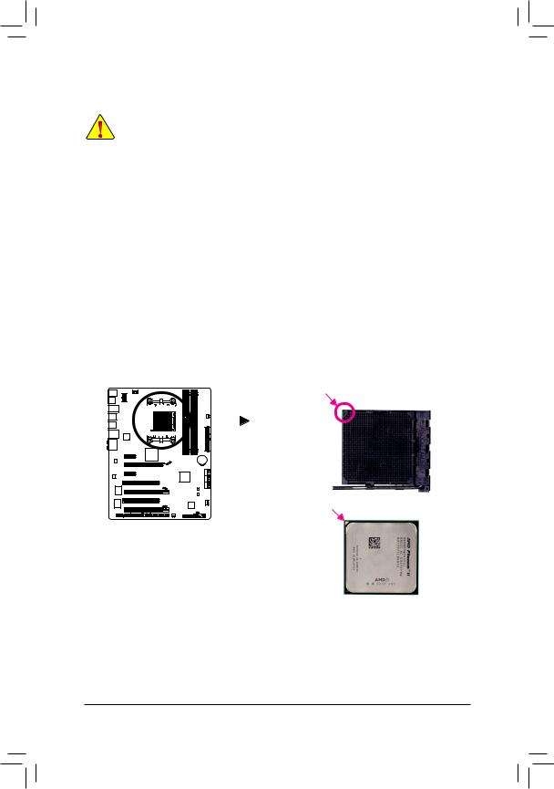
1-3-1 Installing the CPU
A. Locate the pin one (denoted by a small triangle) of the CPU socket and the CPU.
|
A Small Triangle Mark |
AM3+ Socket |
||||||||||
|
Denotes Pin One of the |
|||||||||||
|
Socket |
|||||||||||
|
A Small Triangle Marking |
AM3+/AM3 CPU |
|
Denotes CPU Pin One |
|
— 13 — |
Hardware Installation |
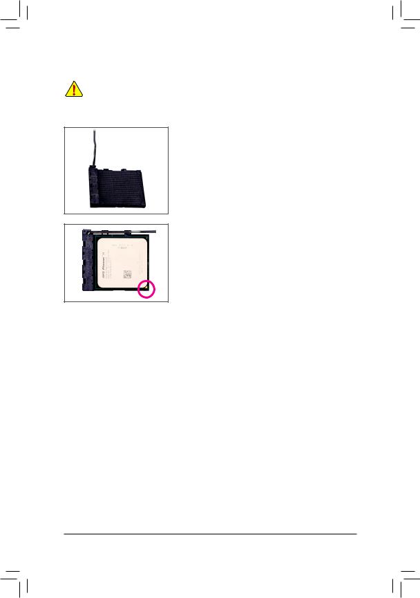
B.Follow the steps below to correctly install the CPU into the motherboard CPU socket.
•Before installing the CPU, make sure to turn off the computer and unplug the power cord from the power outlet to prevent damage to the CPU.
•Do not force the CPU into the CPU socket. The CPU cannot fit in if oriented incorrectly. Adjust the
CPU orientation if this occurs.
CPU Socket
 Locking Lever
Step 1:
Completely lift up the CPU socket locking lever.
Step 2:
Align the CPU pin one (small triangle marking) with the triangle mark on the CPU socket and gently insert the CPU into the socket. Make sure that the CPU pins fit perfectly into their holes. Once the CPU is positioned into its socket, place one finger down on the middle of the
CPU, lowering the locking lever and latching it into the fully locked position.
|
Hardware Installation |
— 14 — |
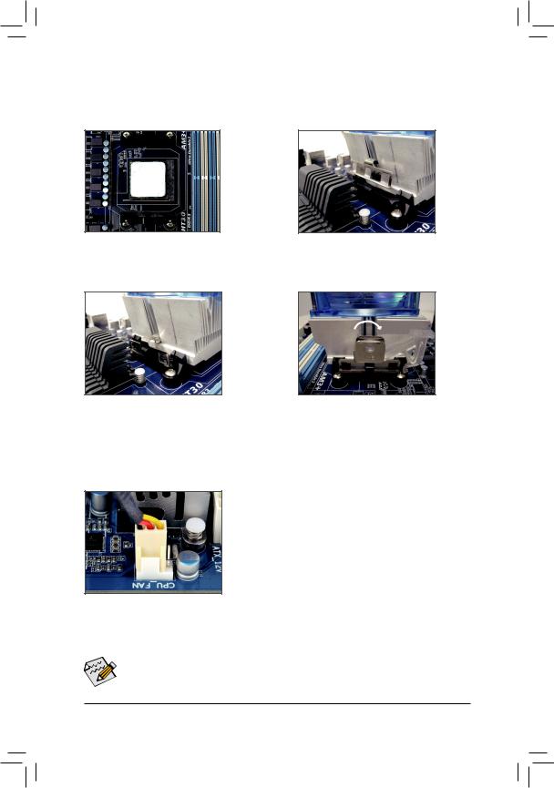
1-3-2 Installing the CPU Cooler
Follow the steps below to correctly install the CPU cooler on the CPU. (The following procedure uses the GIGABYTE cooler as the example.)
Step 1:
Apply an even and thin layer of thermal grease on the surface of the installed CPU.
Step 3:
Hook the CPU cooler clip to the mounting lug on one side of the retention frame. On the other side,push straight down on the the CPU cooler clip to hook it to the mounting lug on the retention frame.
Step 2:
Place the CPU cooler on the CPU.
Step 4:
Turn the cam handle from the left side to the right side (as the picture above shows) to lock into place. (Refer to your CPU cooler installation manual for instructions on installing the cooler.)
Step 5:
Finally, attach the power connector of the CPU cooler to the CPU fan header (CPU_FAN) on the motherboard.
Use extreme care when removing the CPU cooler because the thermal grease/tape between the CPU cooler and CPU may adhere to the CPU. Inadequately removing the CPU cooler may damage the CPU.
|
— 15 — |
Hardware Installation |
1-4 Installing the Memory
Read the following guidelines before you begin to install the memory:
•Make sure that the motherboard supports the memory. It is recommended that memory of the same capacity, brand, speed, and chips be used.
(Go to GIGABYTE’s website for the latest supported memory speeds and memory modules.)
•Always turn off the computer and unplug the power cord from the power outlet before installing the memory to prevent hardware damage.
•Memory modules have a foolproof design. A memory module can be installed in only one direction. If you are unable to insert the memory, switch the direction.
1-4-1 Dual Channel Memory Configuration
This motherboard provides four DDR3 memory sockets and supports Dual Channel Technology. After the memory is installed, the BIOS will automatically detect the specifications and capacity of the memory. Enabling Dual Channel memory mode will double the original memory bandwidth.
The four DDR3 memory sockets are divided into two channels and each channel has two memory sockets as following:
 Channel 0: DDR3_2, DDR3_4
  Channel 1: DDR3_1, DDR3_3
 Dual Channel Memory Configurations Table
|
DDR3_4 |
DDR3_2 |
DDR3_3 |
DDR3_1 |
|||||||||
|
Two Modules |
— — |
DS/SS |
— — |
DS/SS |
||||||||
|
DS/SS |
— — |
DS/SS |
— — |
|||||||||
|
Four Modules |
DS/SS |
DS/SS |
DS/SS |
DS/SS |
||||||||
(SS=Single-Sided, DS=Double-Sided, «- -«=No Memory)
DDR3_1
DDR3_3
DDR3_2
DDR3_4
Due to CPU limitations, read the following guidelines before installing the memory in Dual Channel mode.
1.Dual Channel mode cannot be enabled if only one DDR3 memory module is installed.
2.When enabling Dual Channel mode with two or four memory modules, it is recommended that memory of the same capacity, brand, speed, and chips be used and installed in the same colored DDR3 sockets for optimum performance. when enabling Dual Channel mode with two memory modules, we recommend that you install them in the DDR3_1 and DDR3_2 sockets.
|
Hardware Installation |
— 16 — |
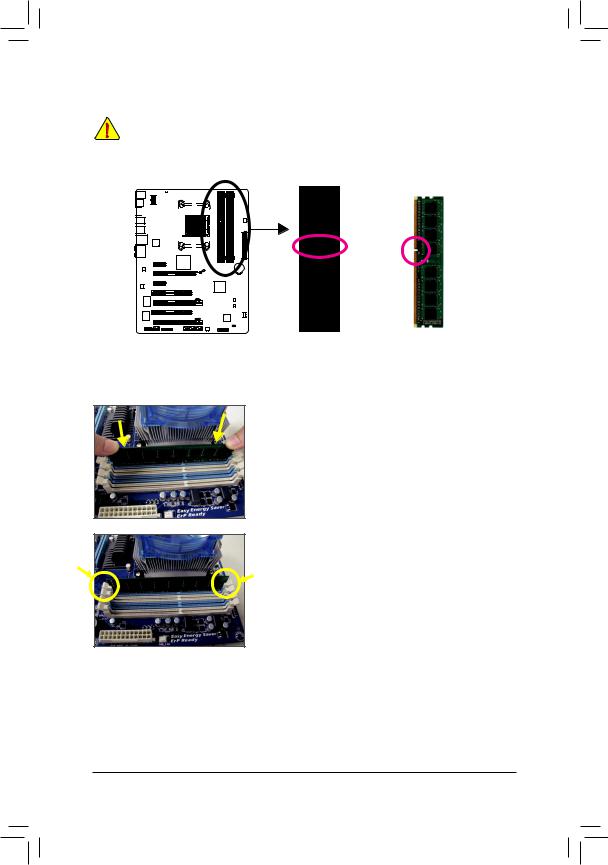
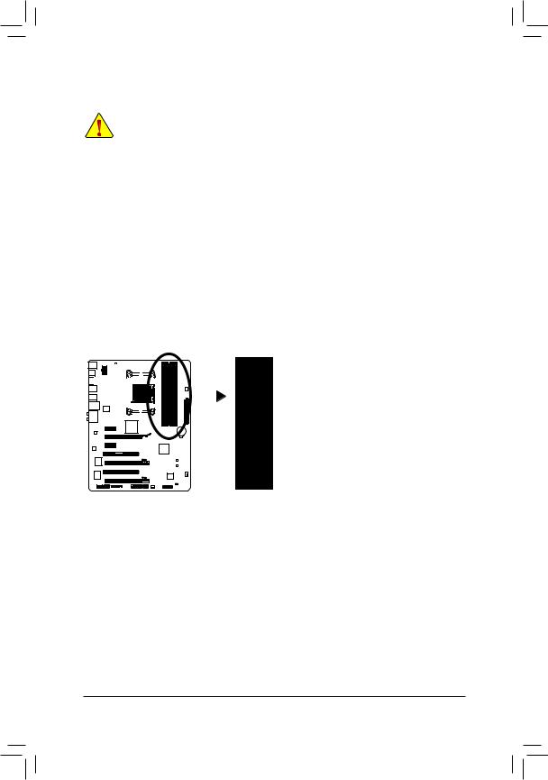
1-4-2 Installing a Memory
Before installing a memory module, make sure to turn off the computer and unplug the power cord from the power outlet to prevent damage to the memory module.
DDR3 and DDR2 DIMMs are not compatible to each other or DDR DIMMs. Be sure to install DDR3 DIMMs on this motherboard.
Notch
DDR3 DIMM
A DDR3 memory module has a notch, so it can only fit in one direction. Follow the steps below to correctly install your memory modules in the memory sockets.
Step 1:
Note the orientation of the memory module. Spread the retaining clips at both ends of the memory socket. Place the memory module on the socket. As indicated in the picture on the left, place your fingers on the top edge of the memory, push down on the memory and insert it vertically into the memory socket.
Step 2:
The clips at both ends of the socket will snap into place when the memory module is securely inserted.
|
— 17 — |
Hardware Installation |
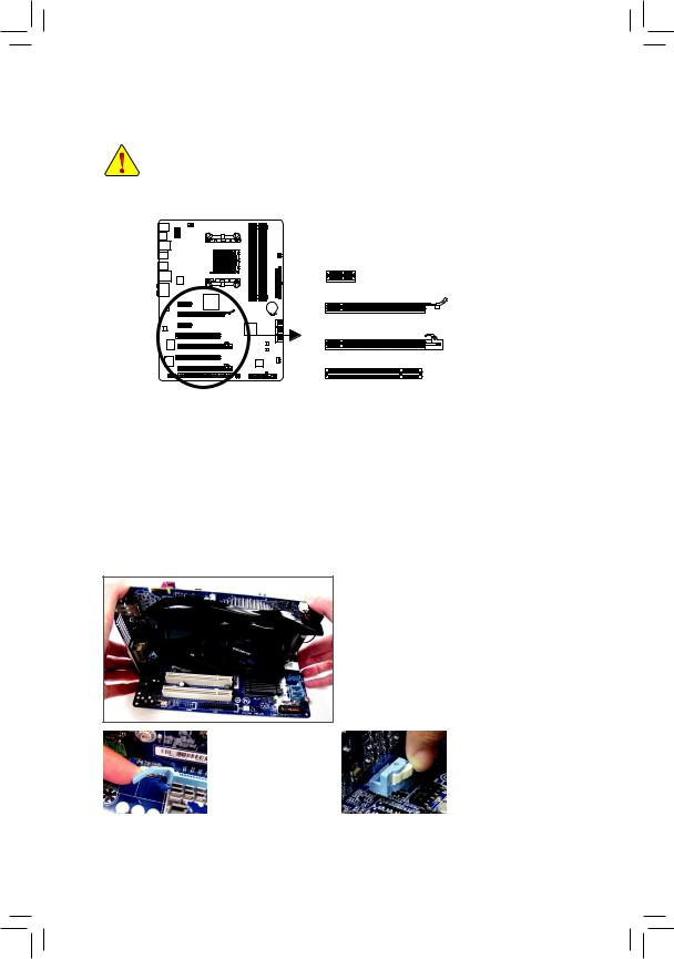
1-5 Installing an Expansion Card
Read the following guidelines before you begin to install an expansion card:
•Make sure the motherboard supports the expansion card. Carefully read the manual that came with your expansion card.
•Always turn off the computer and unplug the power cord from the power outlet before installing an expansion card to prevent hardware damage.
PCI Express x1 Slot
PCI Express x16 Slot (PCIEX16)
PCI Express x16 Slot (PCIEX8/PCIEX4)
PCI Slot
Follow the steps below to correctly install your expansion card in the expansion slot.
1.Locate an expansion slot that supports your card. Remove the metal slot cover from the chassis back panel.
2.Align the card with the slot, and press down on the card until it is fully seated in the slot.
3.Make sure the metal contacts on the card are completely inserted into the slot.
4.Secure the card’s metal bracket to the chassis back panel with a screw.
5.After installing all expansion cards, replace the chassis cover(s).
6.Turn on your computer. If necessary, go to BIOS Setup to make any required BIOS changes for your expansion card(s).
7.Install the driver provided with the expansion card in your operating system.
Example: Installing and Removing a PCI Express Graphics Card:
• Installing a Graphics Card:
Gently push down on the top edge of the card until it is fully inserted into the PCI Express slot. Make sure the card is securely seated in the slot and does not rock.
|
• Removing the Card from |
• Removing the Card from |
||
|
the PCIEX16 Slot: |
the PCIEX8/PCIEX4 Slot: |
||
|
Gently push back on the |
Press the latch at the end |
||
|
lever on the slot and then |
of the PCI Express slot to |
||
|
lift the card straight out |
release the card and then |
||
|
from the slot. |
pull the card straight up |
||
|
from the slot. |
|||
|
Hardware Installation |
— 18 — |
1-6 Setup of AMD CrossFireX™ Configuration
A.System Requirements
—Windows 7, Windows Vista or Windows XP operating system
—A CrossFireX-supported motherboard with two PCI Express x16 slots and correct driver
—Two CrossFireX-ready graphics cards of identical brand and chip and correct driver
—CrossFireX bridge connector(s) (Note)
—A power supply with sufficient power is recommended (Refer to the manual of your graphics cards for the power requirement)
B.Connecting the Graphics Cards
Step 1:
Observe the steps in «1-5 Installing an Expansion Card» and install two CrossFireX graphics cards on the PCIEX16 and PCIEX8 slots.
Step 2:
Insert the CrossFireX bridge connector(s) (Note) in the CrossFireX gold edge connectors on top of the two cards.
Step 3:
Plug the display cable into the graphics card on the PCIEX16 slot.
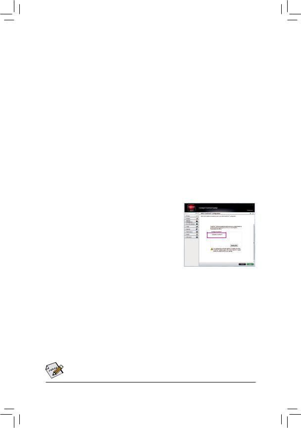
C. Configuring the Graphics Card Driver
To Enable CrossFireX Function:
After installing the graphics card driver in the operating system, go to the Catalyst Control Center. Browse to Performance\AMD CrossFireX Configurations and ensure the Enable CrossFireX™ check box is selected and click
Apply.
(Note) The bridge connector(s) may be needed or not depending on your graphics cards.

 Procedure and driver screen for enabling CrossFireX technology may differ by graphics cards and driver version. Refer to the manual that came with your graphics cards for more information about enabling CrossFireX technology.
|
— 19 — |
Hardware Installation |
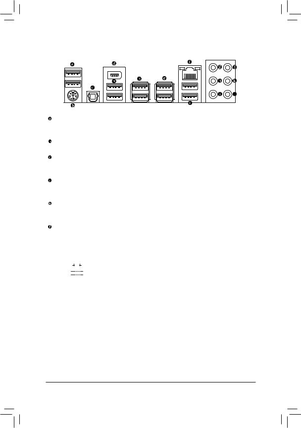
1-7 Back Panel Connectors
USB 2.0/1.1 Port
The USB port supports the USB 2.0/1.1 specification. Use this port for USB devices such as a USB keyboard/mouse, USB printer, USB flash drive and etc.
PS/2 Keyboard/Mouse Port
Use this port to connect a PS/2 mouse or keyboard.
Optical S/PDIF Out Connector
This connector provides digital audio out to an external audio system that supports digital optical audio. Before using this feature, ensure that your audio system provides an optical digital audio in connector.
IEEE 1394a Port
The IEEE 1394 port supports the IEEE 1394a specification, featuring high speed, high bandwidth and hotplug capabilities. Use this port for an IEEE 1394a device.
USB 3.0/2.0 Port
The USB 3.0 port supports the USB 3.0 specification and is compatible to the USB 2.0/1.1 specification. Use this port for USB devices such as a USB keyboard/mouse, USB printer, USB flash drive and etc.
RJ-45 LAN Port
The Gigabit Ethernet LAN port provides Internet connection at up to 1 Gbps data rate. The following escribes the states of the LAN port LEDs.
|
Connection/ |
Activity LED |
Connection/Speed LED: |
Activity LED: |
||||||||||||||||
|
Speed LED |
|||||||||||||||||||
|
State |
Description |
State |
Description |
||||||||||||||||
|
Orange |
1 Gbps data rate |
Blinking |
Data transmission or receiving is occurring |
||||||||||||||||
|
Green |
100 Mbps data rate |
Off |
No data transmission or receiving is occurring |
||||||||||||||||
|
Off |
10 Mbps data rate |
||||||||||||||||||
|
LAN Port |
|||||||||||||||||||
|
Hardware Installation |
— 20 — |
![]()
Center/Subwoofer Speaker Out Jack (Orange)
Use this audio jack to connect center/subwoofer speakers in a 5.1/7.1-channel audio configuration.
Rear Speaker Out Jack (Black)
Use this audio jack to connect rear speakers in a 7.1-channel audio configuration.
Side Speaker Out Jack (Gray)
Use this audio jack to connect side speakers in a 4/5.1/7.1-channel audio configuration.
Line In Jack (Blue)
The default line in jack. Use this audio jack for line in devices such as an optical drive, walkman, etc.
Line Out Jack (Green)
The default line out jack. Use this audio jack for a headphone or 2-channel speaker. This jack can be used to connect front speakers in a 4/5.1/7.1-channel audio configuration.
Mic In Jack (Pink)
The default Mic in jack. Microphones must be connected to this jack.

 In addition to the default speakers settings, the
 ~
~ audio jacks can be reconfigured to perform
different functions via the audio software. Only microphones still MUST be connected to the default Mic in jack ( ). Refer to the instructions on setting up a 2/4/5.1/7.1-channel audio configuration in Chapter 5, «Configuring 2/4/5.1/7.1-Channel Audio.»
•• When removing the cable connected to a back panel connector, first remove the cable from your device and then remove it from the motherboard.
•• When removing the cable, pull it straight out from the connector. Do not rock it side to side to prevent an electrical short inside the cable connector.
|
— 21 — |
Hardware Installation |
1-8 Internal Connectors
1 3
9
8
|
12 |
14 |
13 |
10 |
4 |
11 |
7 |
|
1) |
ATX_12V |
9) |
SPDIF_O |
|
2) |
ATX |
10) |
F_USB1/F_USB2/F_USB3 |
|
3) |
CPU_FAN |
11) |
F_USB30 |
|
4) |
SYS_FAN1/2 |
12) |
F_1394 |
|
5) |
PWR_FAN |
13) |
COMA |
|
6) |
SATA3_0/1/2/3/4/5 |
14) |
TPM |
|
7) |
F_PANEL |
15) |
BAT |
|
|
F_AUDIO |
16) |
CLR_CMOS |
Read the following guidelines before connecting external devices:
•First make sure your devices are compliant with the connectors you wish to connect.
•Before installing the devices, be sure to turn off the devices and your computer. Unplug the power cord from the power outlet to prevent damage to the devices.
•After installing the device and before turning on the computer, make sure the device cable has been securely attached to the connector on the motherboard.
|
Hardware Installation |
— 22 — |
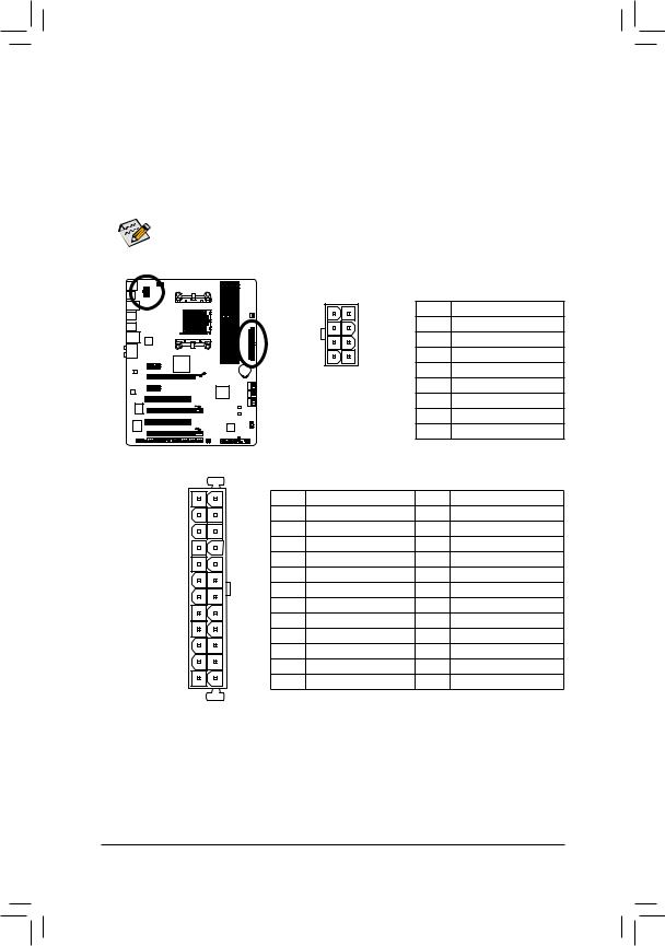
1/2) ATX_12V/ATX (2×4 12V Power Connector and 2×12 Main Power Connector)
With the use of the power connector, the power supply can supply enough stable power to all the components on the motherboard. Before connecting the power connector, first make sure the power supply is turned off and all devices are properly installed. The power connector possesses a foolproof design. Connect the power supply cable to the power connector in the correct orientation. The 12V power connector mainly supplies power to the CPU. If the 12V power connector is not connected, the computer will not start.
To meet expansion requirements, it is recommended that a power supply that can withstand high power consumption be used (500W or greater). If a power supply is used that does not
provide the required power, the result can lead to an unstable or unbootable system.
|
ATX_12V: |
||||||
|
8 |
4 |
Pin No. |
Definition |
|||
|
1 |
GND (Only for 2×4-pin 12V) |
|||||
|
2 |
GND (Only for 2×4-pin 12V) |
|||||
|
5 |
1 |
3 |
GND |
|||
|
ATX_12V |
4 |
GND |
||||
|
5 |
+12V (Only for 2×4-pin 12V) |
|||||
|
6 |
+12V (Only for 2×4-pin 12V) |
|||||
|
7 |
+12V |
|||||
|
8 |
+12V |
|||||
|
ATX: |
||||||
|
12 |
24 |
Pin No. |
Definition |
Pin No. |
Definition |
|
|
1 |
3.3V |
13 |
3.3V |
|||
|
2 |
3.3V |
14 |
-12V |
|||
|
3 |
GND |
15 |
GND |
|||
|
4 |
+5V |
16 |
PS_ON (soft On/Off) |
|||
|
5 |
GND |
17 |
GND |
|||
|
6 |
+5V |
18 |
GND |
|||
|
7 |
GND |
19 |
GND |
|||
|
8 |
Power Good |
20 |
-5V |
|||
|
9 |
5VSB (stand by +5V) |
21 |
+5V |
|||
|
10 |
+12V |
22 |
+5V |
|||
|
11 |
+12V (Only for 2×12-pin ATX) |
23 |
+5V (Only for 2×12-pin ATX) |
|||
|
1 |
13 |
12 |
3.3V (Only for 2×12-pin ATX) |
24 |
GND (Only for 2×12-pin ATX) |
ATX
|
— 23 — |
Hardware Installation |
CPU_FAN:
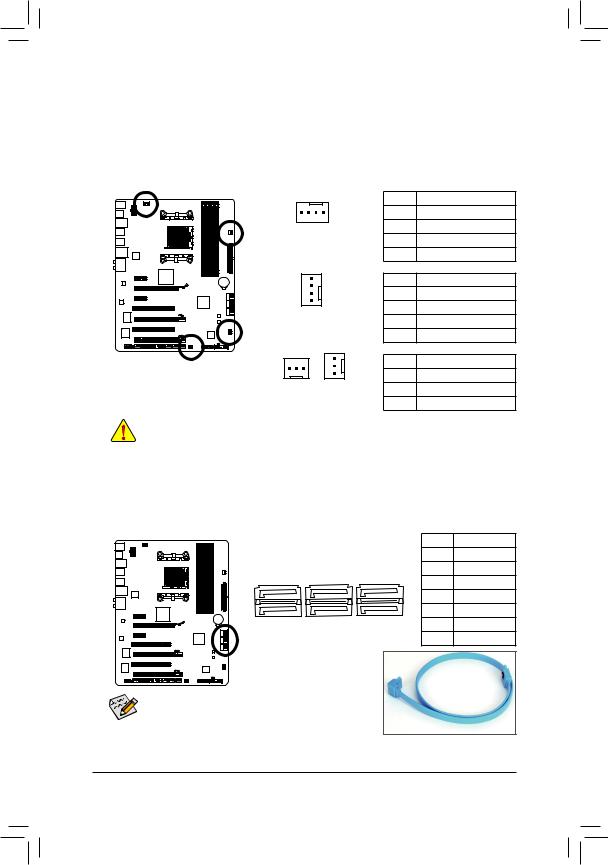
3/4/5) CPU_FAN/SYS_FAN1/SYS_FAN2/PWR_FAN (Fan Headers)
The motherboard has a 4-pin CPU fan header (CPU_FAN), a 4-pin (SYS_FAN1) and a 3-pin (SYS_FAN2) system fan headers, and a 3-pin power fan header (PWR_FAN). Most fan headers possess a foolproof insertion design. When connecting a fan cable, be sure to connect it in the correct orientation (the black connector wire is the ground wire). The motherboard supports CPU fan speed control, which requires the use of a CPU fan with fan speed control design. For optimum heat dissipation, it is recommended that a system fan be installed inside the chassis.
|
Pin No. |
Definition |
|||
|
1 |
1 |
GND |
||
|
CPU_FAN |
2 |
+12V /Speed Control |
||
|
3 |
Sense |
|||
|
4 |
Speed Control |
|||
|
SYS_FAN1: |
||||
|
Pin No. |
Definition |
|||
|
1 |
1 |
GND |
||
|
2 |
+12V /Speed Control |
|||
|
SYS_FAN1 |
||||
|
3 |
Sense |
|||
|
4 |
Reserve |
|||
|
SYS_FAN2/PWR_FAN: |
||||
|
1 |
Pin No. |
Definition |
||
|
1 |
1 |
GND |
||
|
SYS_FAN2 PWR_FAN |
2 |
+12V |
||
|
3 |
Sense |
•Be sure to connect fan cables to the fan headers to prevent your CPU and system from overheating. Overheating may result in damage to the CPU or the system may hang.
•These fan headers are not configuration jumper blocks. Do not place a jumper cap on the headers.
6)SATA3_0/1/2/3/4/5 (SATA 6Gb/s Connectors)
The SATA connectors conform to SATA 6Gb/s standard and are compatible with SATA 3Gb/s and SATA 1.5Gb/s standards. Each SATA connector supports a single SATA device. The AMD SB950 South Bridge supports RAID 0, RAID 1, RAID 5, RAID 10, and JBOD. Refer to Chapter 5, «Configuring SATA Hard Drive(s),» for instructions on configuring a RAID array.
|
Pin No. |
Definition |
||||
|
1 |
GND |
||||
|
SATA3_0 |
SATA3_2 |
SATA3_4 |
2 |
TXP |
|
|
3 |
TXN |
||||
|
7 |
1 |
||||
|
4 |
GND |
||||
|
1 |
|||||
|
7 |
5 |
RXN |
|||
|
SATA3_5 |
|||||
|
SATA3_1 |
SATA3_3 |
6 |
RXP |
||
|
7 |
GND |
|
• A RAID 0 or RAID 1 configuration requires at least two |
|
|
hard drives. If more than two hard drives are to be used, |
|
|
the total number of hard drives must be an even number. |
|
|
• A RAID 5 configuration requires at least three hard drives. |
|
|
(The total number of hard drives does not have to be an |
|
|
even number.) |
|
|
• A RAID 10 configuration requires four hard drives. |
|
|
Hardware Installation |
— 24 — |
Please connect the L-shaped end of the SATA cable to your SATA hard drive.
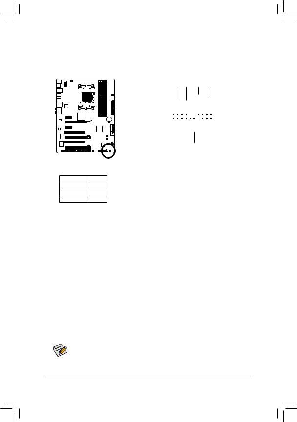
7)F_PANEL (Front Panel Header)
Connect the power switch, reset switch, speaker, chassis intrusion switch/sensor and system status indicator on the chassis to this header according to the pin assignments below. Note the positive and negative pins before connecting the cables.
|
Message/Power/ |
Power |
|||||||||||||||||||||||||||||||||||
|
Sleep LED |
Switch |
Speaker |
||||||||||||||||||||||||||||||||||
|
MSG+ MSG |
—PW |
SPEAK+ |
-SPEAK |
|||||||||||||||||||||||||||||||||
|
2 |
— PW+ |
20 |
||||||||||||||||||||||||||||||||||
|
1 |
19 |
|||||||||||||||||||||||||||||||||||
|
HD- |
RES+ |
CI+ |
PWR+ |
PWR- |
||||||||||||||||||||||||||||||||
|
HD+ |
RES- |
|||||||||||||||||||||||||||||||||||
|
CI |
||||||||||||||||||||||||||||||||||||
|
— |
||||||||||||||||||||||||||||||||||||
|
Hard Drive |
Reset |
Power LED |
||||||||||||||||||||||||||||||||||
|
Activity LED |
Switch |
|||||||||||||||||||||||||||||||||||
|
Chassis Intrusion |
||||||||||||||||||||||||||||||||||||
|
Header |
• MSG/PWR (Message/Power/Sleep LED, Yellow/Purple):
|
System Status |
LED |
|
S0 |
On |
|
S1 |
Blinking |
|
S3/S4/S5 |
Off |
Connects to the power status indicator on the chassis front panel. The LED is on when the system is operating. The LED keeps blinking when the system is in S1 sleep state. The LED is off when the system is in S3/S4 sleep state or powered off (S5).
•PW (Power Switch, Red):
Connects to the power switch on the chassis front panel. You may configure the way to turn off your system using the power switch (refer to Chapter 2, «BIOS Setup,» «Power Management Setup,» for more information).
•SPEAK (Speaker, Orange):
Connects to the speaker on the chassis front panel. The system reports system startup status by issuing a beep code. One single short beep will be heard if no problem is detected at system startup. If a problem is detected, the BIOS may issue beeps in different patterns to indicate the problem. Refer to Chapter 5, «Troubleshooting,» for information about beep codes.
•HD (Hard Drive Activity LED, Blue)
Connects to the hard drive activity LED on the chassis front panel. The LED is on when the hard drive is reading or writing data.
•RES (Reset Switch, Green):
Connects to the reset switch on the chassis front panel. Press the reset switch to restart the computer if the computer freezes and fails to perform a normal restart.
•CI (Chassis Intrusion Header, Gray):
Connects to the chassis intrusion switch/sensor on the chassis that can detect if the chassis cover has been removed. This function requires a chassis with a chassis intrusion switch/sensor.
The front panel design may differ by chassis. A front panel module mainly consists of power switch, reset switch, power LED, hard drive activity LED, speaker and etc. When connecting your chassis front panel module to this header, make sure the wire assignments and the pin assignments are matched correctly.
|
— 25 — |
Hardware Installation |
 F_AUDIO (Front Panel Audio Header)
The front panel audio header supports Intel High Definition audio (HD) and AC’97 audio. You may connect your chassis front panel audio module to this header. Make sure the wire assignments of the module connector match the pin assignments of the motherboard header. Incorrect connection between the module connector and the motherboard header will make the device unable to work or even damage it.
|
For HD Front Panel Audio: |
For AC’97 Front Panel Audio: |
||||||||||||||||||||||
|
Pin No. |
Definition |
Pin No. |
Definition |
||||||||||||||||||||
|
9 |
1 |
1 |
MIC2_L |
1 |
MIC |
||||||||||||||||||
|
2 |
GND |
2 |
GND |
||||||||||||||||||||
|
3 |
MIC2_R |
3 |
MIC Power |
||||||||||||||||||||
|
10 |
2 |
||||||||||||||||||||||
|
4 |
-ACZ_DET |
4 |
NC |
||||||||||||||||||||
|
5 |
LINE2_R |
5 |
Line Out (R) |
||||||||||||||||||||
|
6 |
GND |
6 |
NC |
||||||||||||||||||||
|
7 |
FAUDIO_JD |
7 |
NC |
||||||||||||||||||||
|
8 |
No Pin |
8 |
No Pin |
||||||||||||||||||||
|
9 |
LINE2_L |
9 |
Line Out (L) |
||||||||||||||||||||
|
10 |
GND |
10 |
NC |
• The front panel audio header supports HD audio by default. If your chassis provides an AC’97 front panel audio module, refer to the instructions on how to activate AC’97 functionality via the audio software in Chapter 5, «Configuring 2/4/5.1/7.1-Channel Audio.»
•Audio signals will be present on both of the front and back panel audio connections simultaneously. If you want to mute the back panel audio (only supported when using an HD front panel audio module), refer to Chapter 5, «Configuring 2/4/5.1/7.1-Channel Audio.»
•Some chassis provide a front panel audio module that has separated connectors on each wire instead of a single plug. For information about connecting the front panel audio module that has different wire assignments, please contact the chassis manufacturer.
9)SPDIF_O (S/PDIF Out Header)
This header supports digital S/PDIF Out and connects a S/PDIF digital audio cable (provided by expansion cards) for digital audio output from your motherboard to certain expansion cards like graphics cards and sound cards. For example, some graphics cards may require you to use a S/PDIF digital audio cable for digital audio output from your motherboard to your graphics card if you wish to connect an HDMI display to the graphics card and have digital audio output from the HDMI display at the same time. For information about connecting the S/PDIF digital audio cable, carefully read the manual for your expansion card.
|
Pin No. |
Definition |
|
|
1 |
SPDIFO |
|
|
1 |
2 |
GND |
|
Hardware Installation |
— 26 — |
10)F_USB1/F_USB2/F_USB3 (USB 2.0/1.1 Headers)
The headers conform to USB 2.0/1.1 specification. Each USB header can provide two USB ports via an optional USB bracket. For purchasing the optional USB bracket, please contact the local dealer.
|
Pin No. |
Definition |
|||||||||||||||||||
|
1 |
Power (5V) |
|||||||||||||||||||
|
9 |
1 |
2 |
Power (5V) |
|||||||||||||||||
|
3 |
USB DX- |
|||||||||||||||||||
|
10 |
2 |
|||||||||||||||||||
|
4 |
USB DY- |
|||||||||||||||||||
|
5 |
USB DX+ |
|||||||||||||||||||
|
6 |
USB DY+ |
|||||||||||||||||||
|
7 |
GND |
|||||||||||||||||||
|
8 |
GND |
|||||||||||||||||||
|
9 |
No Pin |
|||||||||||||||||||
|
10 |
NC |
|||||||||||||||||||
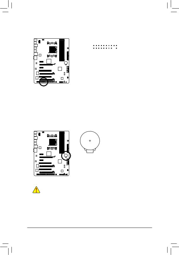
11)F_USB30 (USB 3.0/2.0 Header)
The header conforms to USB 3.0/2.0 specification and can provide two USB ports. For purchasing the optional 3.5″ front panel that provides two USB 3.0/2.0 ports, please contact the local dealer.
|
1 |
10 |
||||||||||||||||||
|
20 |
11 |
||||||||||||||||||
|
Pin No. |
Definition |
Pin No. |
Definition |
||||||||||||||||
|
1 |
VBUS |
11 |
D2+ |
||||||||||||||||
|
2 |
SSRX1- |
12 |
D2- |
||||||||||||||||
|
3 |
SSRX1+ |
13 |
GND |
||||||||||||||||
|
4 |
GND |
14 |
SSTX2+ |
||||||||||||||||
|
5 |
SSTX1- |
15 |
SSTX2- |
||||||||||||||||
|
6 |
SSTX1+ |
16 |
GND |
||||||||||||||||
|
7 |
GND |
17 |
SSRX2+ |
||||||||||||||||
|
8 |
D1- |
18 |
SSRX2- |
||||||||||||||||
|
9 |
D1+ |
19 |
VBUS |
||||||||||||||||
|
10 |
NC |
20 |
No Pin |
When the system is in S4/S5 mode, only the USB ports routed to the F_USB1 header can support the ON/OFF Charge function.
|
•• |
Do not plug the IEEE 1394 bracket (2×5-pin) cable into the USB 2.0/1.1 header. |
|
|
•• |
Prior to installing the USB bracket, be sure to turn off your computer and unplug the power |
|
|
cord from the power outlet to prevent damage to the USB bracket. |
||
|
— 27 — |
Hardware Installation |
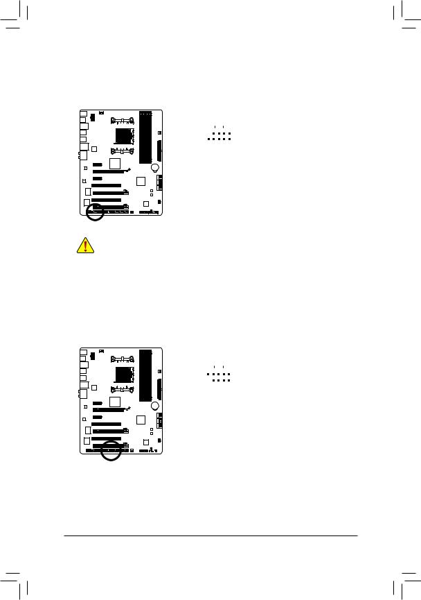
12)F_1394 (IEEE 1394a Header)
The header conforms to IEEE 1394a specification. The IEEE 1394a header can provide one IEEE 1394a port via an optional IEEE 1394a bracket. For purchasing the optional IEEE 1394a bracket, please contact the local dealer.
|
Pin No. |
Definition |
||||||||||||||
|
1 |
TPA+ |
||||||||||||||
|
9 |
1 |
||||||||||||||
|
2 |
TPA- |
||||||||||||||
|
10 |
2 |
||||||||||||||
|
3 |
GND- |
||||||||||||||
|
4 |
GND |
||||||||||||||
|
5 |
TPB+ |
||||||||||||||
|
6 |
TPB- |
||||||||||||||
|
7 |
Power (12V) |
||||||||||||||
|
8 |
Power (12V) |
||||||||||||||
|
9 |
No Pin |
||||||||||||||
|
10 |
GND |
• Do not plug the USB bracket cable into the IEEE 1394a header.
• Prior to installing the IEEE 1394a bracket, be sure to turn off your computer and unplug the power cord from the power outlet to prevent damage to the IEEE 1394a bracket.
•To connect an IEEE 1394a device, attach one end of the device cable to your computer and then attach the other end of the cable to the IEEE 1394a device. Ensure that the cable is securely connected.
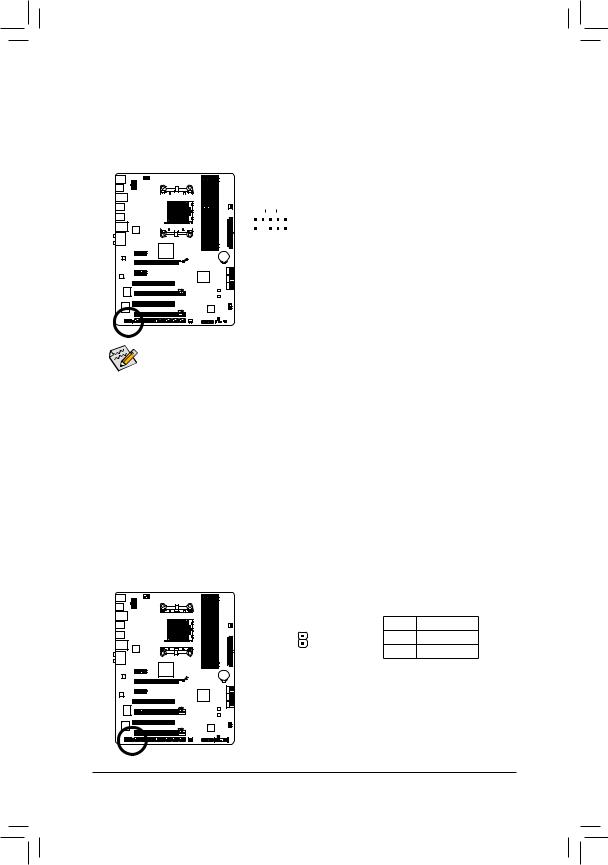
13)COMA (Serial Port Header)
The COM header can provide one serial port via an optional COM port cable. For purchasing the optional COM port cable, please contact the local dealer.
|
Pin No. |
Definition |
|||||||||||||||||||
|
1 |
NDCD- |
|||||||||||||||||||
|
9 |
1 |
|||||||||||||||||||
|
2 |
NSIN |
|||||||||||||||||||
|
10 |
2 |
|||||||||||||||||||
|
3 |
NSOUT |
|||||||||||||||||||
|
4 |
NDTR- |
|||||||||||||||||||
|
5 |
GND |
|||||||||||||||||||
|
6 |
NDSR- |
|||||||||||||||||||
|
7 |
NRTS- |
|||||||||||||||||||
|
8 |
NCTS- |
|||||||||||||||||||
|
9 |
NRI- |
|||||||||||||||||||
|
10 |
No Pin |
|||||||||||||||||||
|
Hardware Installation |
— 28 — |
14)TPM (Trusted Platform Module Header)
You may connect a TPM (Trusted Platform Module) to this header.
|
19 |
1 |
||||||||||||||||||||
|
20 |
2 |
||||||||||||||||||||
|
Pin No. |
Definition |
Pin No. |
Definition |
||||||||||||||||||
|
1 |
LCLK |
11 |
LAD0 |
||||||||||||||||||
|
2 |
GND |
12 |
GND |
||||||||||||||||||
|
3 |
LFRAME |
13 |
NC |
||||||||||||||||||
|
4 |
No Pin |
14 |
ID |
||||||||||||||||||
|
5 |
LRESET |
15 |
SB3V |
||||||||||||||||||
|
6 |
NC |
16 |
SERIRQ |
||||||||||||||||||
|
7 |
LAD3 |
17 |
GND |
||||||||||||||||||
|
8 |
LAD2 |
18 |
NC |
||||||||||||||||||
|
9 |
VCC3 |
19 |
NC |
||||||||||||||||||
|
10 |
LAD1 |
20 |
SUSCLK |
15)BAT (Battery)
The battery provides power to keep the values (such as BIOS configurations, date, and time information) in the CMOS when the computer is turned off. Replace the battery when the battery voltage drops to a low level, or the CMOS values may not be accurate or may be lost.
|
You may clear the CMOS values by removing the battery: |
||
|
111 |
Turn off your computer and unplug the power cord. |
|
|
222 |
Gently remove the battery from the battery holder and wait for one |
|
|
minute. (Or use a metal object like a screwdriver to touch the positive |
||
|
and negative terminals of the battery holder, making them short for 5 |
||
|
seconds.) |
||
|
333 |
Replace the battery. |
|
|
444 |
Plug in the power cord and restart your computer. |
|
|
•• |
Always turn off your computer and unplug the power cord before replacing the battery. |
|
|
•• |
Replace the battery with an equivalent one. Danger of explosion if the battery is replaced with |
|
|
•• |
an incorrect model. |
|
|
Contact the place of purchase or local dealer if you are not able to replace the battery by your- |
||
|
self or uncertain about the battery model. |
||
|
•• |
When installing the battery, note the orientation of the positive side (+) and the negative side (-) |
|
|
of the battery (the positive side should face up). |
||
|
•• |
Used batteries must be handled in accordance with local environmental regulations. |
|
— 29 — |
Hardware Installation |
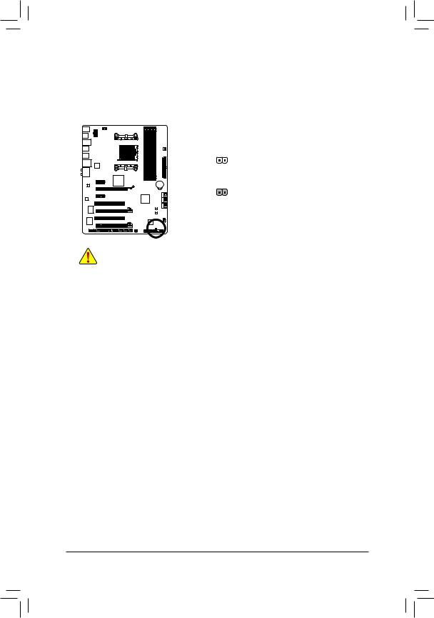
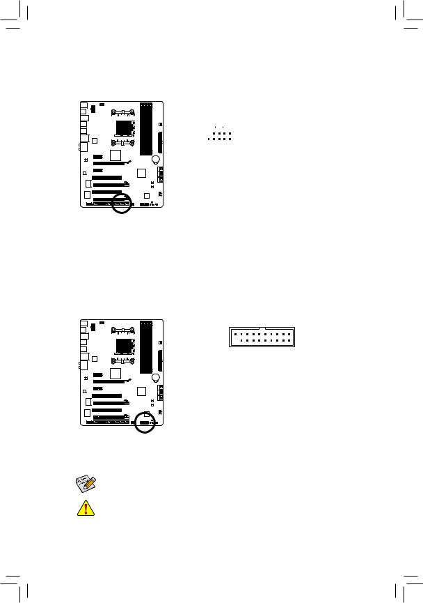
16)CLR_CMOS (Clearing CMOS Jumper)
Use this jumper to clear the CMOS values (e.g. date information and BIOS configurations) and reset the CMOS values to factory defaults. To clear the CMOS values, place a jumper cap on the two pins to temporarily short the two pins or use a metal object like a screwdriver to touch the two pins for a few seconds.
Open: Normal
Short: Clear CMOS Values
•• Always turn off your computer and unplug the power cord from the power outlet before clearing the CMOS values.
•• After clearing the CMOS values and before turning on your computer, be sure to remove the jumper cap from the jumper. Failure to do so may cause damage to the motherboard.
•• After system restart, go to BIOS Setup to load factory defaults (select Load Optimized Defaults) or manually configure the BIOS settings (refer to Chapter 2, «BIOS Setup,» for BIOS configurations).
|
Hardware Installation |
— 30 — |
 Loading…
Page 1 — GA-990XA-UD3
GA-990XA-UD3User’s ManualRev. 100112ME-990XAU3-1001R
Page 2 — May 13, 2011
Hardware Installation — 10 -1-2 Product SpecicationsCPU AM3+ Socket: — AMD AM3+ FX processors — AMD AM3 Phenom™ II processors/ AMD Athlon™ I
Page 3 — Documentation Classications
Appendix — 100 -• G.B.T. TECHNOLOGY TRADING GMBH — GermanyWEB address : http://www.gigabyte.de• G.B.T. TECH. CO., LTD. — U.K.WEB address : http://ww
Page 4 — Table of Contents
— 11 — Hardware InstallationIEEE 1394 VIA VT6308 chip: — Up to 2 IEEE 1394a ports (1 port on the back panel, 1 port available through the interna
Page 5
Hardware Installation — 12 -Unique Features Support for @BIOS Support for Q-Flash Support for Xpress BIOS Rescue Support for Download Center Suppo
Page 6 — Optional Items
— 13 — Hardware Installation1-3 Installing the CPU and CPU Cooler1-3-1 Installing the CPUA. Locate the pin one (denoted by a small triangle) of the
Page 7
Hardware Installation — 14 -B. Follow the steps below to correctly install the CPU into the motherboard CPU socket.• Before installing the CPU, make
Page 8
— 15 — Hardware Installation1-3-2 Installing the CPU CoolerFollow the steps below to correctly install the CPU cooler on the CPU. (The following
Page 9 — 1-1 Installation Precautions
Hardware Installation — 16 -1-4 Installing the MemoryRead the following guidelines before you begin to install the memory:• Make sure that the moth
Page 10 — 1-2 Product Specications
— 17 — Hardware Installation1-4-2 Installing a Memory NotchBefore installing a memory module, make sure to turn off the computer and unplug the power
Page 11
Hardware Installation — 18 -1-5 Installing an Expansion CardRead the following guidelines before you begin to install an expansion card:• Make sure
Page 12
— 19 — Hardware Installation1-6 Setup of AMD CrossFireX™ CongurationProcedure and driver screen for enabling CrossFireX technology may differ by gra
Page 14 — Locking Lever
Hardware Installation — 20 -1-7 Back Panel ConnectorsUSB 2.0/1.1 PortThe USB port supports the USB 2.0/1.1 specication. Use this port for USB device
Page 15
— 21 — Hardware InstallationIn addition to the default speakers settings, the ~ audio jacks can be recongured to perform different functions via t
Page 16 — 1-4 Installing the Memory
Hardware Installation — 22 -1-8 Internal ConnectorsRead the following guidelines before connecting external devices:• First make sure your devices a
Page 17 — 1-4-2 Installing a Memory
— 23 — Hardware InstallationDEBUG PORTG.QBOFM1312412ATX1/2) ATX_12V/ATX (2×4 12V Power Connector and 2×12 Main Power Connector) With the use of t
Page 18 — PCI Slot
Hardware Installation — 24 -3/4/5) CPU_FAN/SYS_FAN1/SYS_FAN2/PWR_FAN (Fan Headers) The motherboard has a 4-pin CPU fan header (CPU_FAN), a 4-pin (SYS
Page 19 — Conguration
— 25 — Hardware Installation7) F_PANEL (Front Panel Header) Connect the power switch, reset switch, speaker, chassis intrusion switch/sensor a
Page 20 — 1-7 Back Panel Connectors
Hardware Installation — 26 -8) F_AUDIO (Front Panel Audio Header) The front panel audio header supports Intel High Denition audio (HD) and AC’
Page 21
— 27 — Hardware Installation10) F_USB1/F_USB2/F_USB3 (USB 2.0/1.1 Headers) The headers conform to USB 2.0/1.1 specication. Each USB header can prov
Page 22 — 1-8 Internal Connectors
Hardware Installation — 28 -12) F_1394 (IEEE 1394a Header) The header conforms to IEEE 1394a specication. The IEEE 1394a header can provide one IEE
Page 23
— 29 — Hardware Installation14) TPM (Trusted Platform Module Header) You may connect a TPM (Trusted Platform Module) to this header.201921F_USB30F_A
Page 24
Copyright© 2011 GIGA-BYTE TECHNOLOGY CO., LTD. All rights reserved.The trademarks mentioned in this manual are legally registered to their respective
Page 25 — S3/S4/S5 Off
Hardware Installation — 30 -16) CLR_CMOS (Clearing CMOS Jumper) Use this jumper to clear the CMOS values (e.g. date information and BIO
Page 26
— 31 — BIOS SetupBIOS (Basic Input and Output System) records hardware parameters of the system in the CMOS on the motherboard. Its majo
Page 27
BIOS Setup — 32 -2-1 Startup ScreenThe following screens may appear when the computer boots.A. The LOGO Screen (Default)B. The POST Screen Motherboar
Page 29 — 15) BAT (Battery)
BIOS Setup — 34 - The Functions of the <F11> and <F12> keys (For the Main Menu Only) F11: Save CMOS to BIOS This function allows you
Page 30 — Short: Clear CMOS Values
— 35 — BIOS Setup2-3 MB Intelligent Tweaker(M.I.T.)• Whether the system will work stably with the overclock/overvoltage settings you made is depen-d
Page 31 — Chapter 2 BIOS Setup
BIOS Setup — 36 — CPU NorthBridge Freq. Allows you to alter the North Bridge controller frequency for the installed CPU. The adjustable range is dep
Page 32 — Function Keys
— 37 — BIOS Setup DRAM Conguration CPU Host Clock Control, CPU Frequency (MHz), Set Memory Clock, Memory Clock The settings under the four items a
Page 33 — 2-2 The Main Menu
BIOS Setup — 38 — 1T/2T Command Timing Options are: Auto (default), 1T, 2T. CAS# latency Options are: Auto (default), 5T~14T. RAS to CAS R/W Dela
Page 34
— 39 — BIOS Setup**DCTs Addr/Cmd Timing** Addr/Cmd Setup Time Options are: Auto (default), 1/2T, 2T. Addr/Cmd Fine Delay Options are: Auto (defaul
Page 36
BIOS Setup — 40 — DRAM Voltage Control Allows you to set memory voltage. Normal Supplies the memory voltage as required. (Default) 1.025V ~
Page 37 — DDR3 Timing Items
— 41 — BIOS Setup Date (mm:dd:yy) Sets the system date. The date format is week (read-only), month, date and year. Select the desired eld and use t
Page 38
BIOS Setup — 42 — Halt On Allows you to determine whether the system will stop for an error during the POST. All Errors Whenever the BIOS det
Page 39
— 43 — BIOS Setup2-5 Advanced BIOS Features AMD C1E Support (Note) Enables or disables the C1E CPU power-saving function in system halt state. When
Page 40
BIOS Setup — 44 — CPU core 1, 2/3/4/5 (Note) Enables or disables CPU Core 1/2/3/4/5. (Default: Enabled) Hard Disk Boot Priority Species the seq
Page 41 — 2-4 Standard CMOS Features
— 45 — BIOS Setup2-6 Integrated Peripherals OnChip SATA Controller (AMD SB950 South Bridge) Enables or disables the SATA controller integrated in t
Page 42 — Memory
BIOS Setup — 46 — Port0 as ESP/Port1 as ESP/Port2 as ESP/Port3 as ESP This option is congurable only when OnChip SATA Type is set to AHCI. Enabled
Page 43 — 2-5 Advanced BIOS Features
— 47 — BIOS Setup SMART LAN (LAN Cable Diagnostic Function)CMOS Setup Utility-Copyright (C) 1984-2011 Award SoftwareSMART LAN Start detecting at Por
Page 44
BIOS Setup — 48 — Onboard Audio Function Enables or disables the onboard audio function. (Default: Enabled) If you wish to install a 3rd party add-
Page 46
— 5 -Chapter 3 Drivers Installation …573-1 Installing Chipset
Page 47
BIOS Setup — 50 -(Note) Supported on Windows 7/Vista operating system only. HPET Support (Note) Enables or disables High Precision Event Timer (HP
Page 48
— 51 — BIOS Setup Hardware Thermal Control Enables or disables the CPU overheating protection function. When enabled, the CPU core voltage and ratio
Page 49 — 2-7 Power Management Setup
BIOS Setup — 52 — Current Voltage(V) Vcore/DDR3 1.5V/+3.3V/+12V Displays the current system voltages. Current System/CPU Temperature Displays cur
Page 50
— 53 — BIOS SetupPress <Enter> on this item and then press the <Y> key to load the safest BIOS default settings. In case system instabili
Page 51 — 2-8 PC Health Status
BIOS Setup — 54 -Press <Enter> on this item and type the password with up to 8 characters and then press <Enter>. You will be requested to
Page 52
— 55 — BIOS SetupPress <Enter> on this item and press the <Y> key. This saves the changes to the CMOS and exits the BIOS Setup program. Pr
Page 54
— 57 — Drivers Installation3-1 Installing Chipset DriversChapter 3 Drivers Installation• Before installing the drivers, rst install the operating
Page 55 — 2-13 Exit Without Saving
Drivers Installation — 58 -3-2 Application SoftwareThis page displays all the utilities and applications that GIGABYTE develops and some free softw
Page 56 — BIOS Setup — 56
— 59 — Drivers Installation3-4 ContactFor the detailed contact information of the GIGABYTE Taiwan headquarter or worldwide branch ofces, click the U
Page 57
— 6 -Box Contents GA-990XA-UD3 motherboard Motherboard driver disk User’s Manual Quick Installation Guide Four SATA cables I/O
Page 58 — 3-3 Technical Manuals
Drivers Installation — 60 -3-6 Download CenterTo update the BIOS, drivers, or applications, click the Download Center button to link to
Page 59 — 3-5 System
— 61 — Unique FeaturesChapter 4 Unique Features4-1 Xpress Recovery2Xpress Recovery2 is a utility that allows you to quickly compress and ba
Page 60 — 3-7 New Utilities
Unique Features — 62 -Step 3:When partitioning your hard drive, make sure to leave unallocated space (10 GB or more is recom-mended; actual siz
Page 61 — Chapter 4 Unique Features
— 63 — Unique FeaturesD. Using the Restore Function in Xpress Recovery2E. Removing the BackupF. Exiting Xpress Recovery2Select RESTORE to restore the
Page 62
Unique Features — 64 -Because BIOS ashing is potentially risky, please do it with caution. Inadequate BIOS ashing may result in system malfunction.4
Page 63
— 65 — Unique FeaturesQ-Flash Utility v2.23Flash Type/Size… MXIC 25L1605/1606 4M
Page 65 — B. Updating the BIOS
— 67 — Unique Features4-2-2 Updating the BIOS with the @BIOS UtilityA. Before You Begin1. In Windows, close all applications and TSR (Terminate and
Page 66
Unique Features — 68 -Available functions in EasyTune 6 may differ by motherboard model. Grayed-out area(s) indicates that the item is not congurable
Page 67 — C. After Updating the BIOS
— 69 — Unique Features4-4 Easy Energy SaverGIGABYTE Easy Energy Saver is a revolutionary technology that delivers unparalleled power savings with
Page 68 — 4-3 EasyTune 6
— 7 -GA-990XA-UD3 Motherboard LayoutKB_MS_USBCPU_FANATXGA-990XA-UD3AUDIOSYS_FAN1PCIEX1_1(Note)DDR3_4DDR3_2ATX_12VAMD 990XAMD SB950PCI1CODECBATPCI2F_US
Page 69 — 4-4 Easy Energy Saver
Unique Features — 70 -C. Stealth ModeIn Stealth Mode, the system continues to work with the user-dened power saving settings, even after the syste
Page 70 — B. Total Mode
— 71 — Unique Features4-5 Q-ShareQ-Share is an easy and convenient data sharing tool. After conguring your LAN connection settings and Q
Page 71 — 4-5 Q-Share
Unique Features — 72 -4-6 SMART RecoveryWith SMART Recovery, users can quickly create backups of changed data les (Note 1) or copy les from a spe-c
Page 72 — 4-6 SMART Recovery
— 73 — Unique Features4-7 Auto GreenAuto Green is an easy-to-use tool that provides users with simple options to enable system power savings via a B
Page 73 — 4-7 Auto Green
Unique Features — 74 -4-8 Cloud OCCloud OC (Note 1) is an easy-to-use overclocking utility designed for system overclock-ing via virtually any Intern
Page 74 — 4-8 Cloud OC
— 75 — AppendixChapter 5 Appendix5-1 Conguring SATA Hard Drive(s) To congure SATA hard drive(s), follow the steps below: A. Install SATA hard dri
Page 75 — Chapter 5 Appendix
Appendix — 76 -The BIOS Setup menus described in this section may differ from the exact settings for your moth-erboard. The actual BIOS Setup menu opt
Page 76
— 77 — AppendixC. Conguring RAID set in RAID BIOSEnter the RAID BIOS setup utility to congure a RAID array. Skip this step and proceed with the inst
Page 77
Appendix — 78 -In the LD Dene Menu, use the up or down arrow key to move to an item for further conguration (Figure 5). Figure 4Figure 5[ Keys Avail
Page 78
— 79 — AppendixIn the following procedure, we’ll create RAID 0 as an example.1. Under the RAID Mode section, press the <SPACE> key to sele
Page 79
— 8 -GA-990XA-UD3 Motherboard Block DiagramAM3+/AM3 CPUHyper Transport BusAMD 990X2 PCIPCI BusPCI CLK(33 MHz)PCIe CLK(100 MHz)PCI Express BusCPU CLK+/
Page 80
Appendix — 80 -Delete an ArrayThe Delete Array menu option allows for deletion of disk array assignments. Deleting an existing disk array could result
Page 82 — B. Installing Windows XP
Appendix — 82 -B. Installing Windows XPBefore installing Windows XP, connect a USB oppy disk drive to your computer rst because you need to in-stall
Page 83
— 83 — AppendixStep 2:Insert the oppy disk containing the SATA RAID/AHCI driver and press <Enter>. Then a controller menu simi-lar to that in F
Page 84
Appendix — 84 -Rebuilding an Array:Rebuilding is the process of restoring data to a hard drive from other drives in the array. Rebuilding applies only
Page 85 — A. Conguring Speakers
— 85 — Appendix5-2-1 Conguring 2/4/5.1/7.1-Channel AudioThe motherboard provides six audio jacks on the back panel which support 2/4/5.1/7.1-chan
Page 86 — B. Conguring Sound Effect
Appendix — 86 -Step 2:Connect an audio device to an audio jack. The The cur-rent connected device is dialog box appears. Select the device according
Page 88
Appendix — 88 -5-2-3 Enabling the Dolby Home Theater FunctionBefore Dolby Home Theater is enabled, you get only 2-channel playback output (
Page 89
— 89 — Appendix5-2-4 Conguring Microphone RecordingStep 1:After installing the audio driver, the HD Audio Manager icon will appear in the noticat
Page 90 — * Enabling Stereo Mix
— 9 — Hardware Installation1-1 Installation PrecautionsThe motherboard contains numerous delicate electronic circuits and components which can
Page 92 — 5-3 Troubleshooting
— 91 — AppendixStep 4:Now you can access the HD Audio Manager to cong-ure Stereo Mix and use Sound Recorder to record the sound.5-2-5 Using the Soun
Page 93 — — 93 — Appendix
Appendix — 92 -5-3 Troubleshooting5-3-1 Frequently Asked Questions To read more FAQs for your motherboard, please go to the Support & Downloads\
Page 94 — Appendix — 94
— 93 — Appendix5-3-2 Troubleshooting ProcedureIf you encounter any troubles during system startup, follow the troubleshooting procedure below to solv
Page 95 — — 95 — Appendix
Appendix — 94 -If the procedure above is unable to solve your problem, contact the place of purchase or local deal-er for help. Or go to the Support &
Page 100 — Appendix — 100
— 99 — AppendixContact Us• GIGA-BYTE TECHNOLOGY CO., LTD.Address: No.6, Bao Chiang Road, Hsin-Tien Dist.,New Taipei City 231,TaiwanTEL: +886-2-8912-4
-
Страница 1
GA-990XA-UD3 User’s Manual Rev . 1001 12ME-990XAU3-1001R[…]
-
Страница 2
May 13, 201 1 Motherboard GA-990XA-UD3 May 13, 201 1 Motherboard GA-990XA-UD3[…]
-
Страница 3
Copyright © 201 1 GIGA-BYTE TECHNOLOGY CO., L TD. All rights reserved. The trademarks mentioned in this manual are legally registered to their respective owners. Disclaimer Information in this manual is protected by copyright laws and is the property of GIGABYTE. Changes to the specications and features in this manual may be made by GIGABYTE wi[…]
-
Страница 4
— 4 — T able of Contents Box Contents ……………………………………………………………………………………………………. 6 Optional Items ………………………………………………………………………………………………….. 6 GA-990XA-UD3 Motherboard Layout ………………………….[…]
-
Страница 5
— 5 — Chapter 3 Drivers Installation ……………………………………………………………………………. 57 3-1 Installing Chipset Drivers ……………………………………………………………………. 57 3-2 Application Software ……………………………………………………………………….[…]
-
Страница 6
— 6 — Box Contents GA-990XA-UD3 motherboard Motherboard driver disk User’s Manual Quick Installation Guide Four SA T A cables I/O Shield One 2-W ay SLI bridge connector (Note) Optional Items 2-port USB 2.0 bracket (Part No. 12CR1-1UB030-5*R) 2-port SA T A power cable (Part No. 12CF1-2SERPW-0*R) COM port cable (Part No. 12CF1-1CM001-3*R) 2-port[…]
-
Страница 7
— 7 — GA-990XA-UD3 Motherboard Layout KB_MS_USB CPU_F AN A TX GA-990XA-UD3 AUDIO SYS_F AN1 PCIEX1_1 (Note) DDR3_4 DDR3_2 A TX_12V AMD 990X AMD SB950 PCI1 CODEC BA T PCI2 F_USB2 B_BIOS F_P ANEL M_BIOS F_USB1 PCIEX16 R_USB CLR_CMOS SPDIF_O Socket AM3+ Realtek RTL81 1 1E iTE IT8720 Etron EJ168 OPTICAL USB_1394 R_USB30 USB_LAN DDR3_3 DDR3_1 PWR_F AN SA[…]
-
Страница 8
— 8 — GA-990XA-UD3 Motherboard Block Diagram AM3+/AM3 CPU Hyper T ransport Bus AMD 990X 2 PCI PCI Bus PCI CLK (33 MHz) PCIe CLK (100 MHz) PCI Express Bus CPU CLK+/- (200 MHz) Dual BIOS COM Port LPC Bus 1 PCI Express x4 DDR3 2000(O.C.)/1866/1600/1333/1066 MHz 6 SA T A 6Gb/s LAN RJ45 x4 PS/2 KB/Mouse 14 USB 2.0/1.1Ports iTE IT8720 Realtek RTL81 1 1E […]
-
Страница 9
— 9 — Hardware Installation 1- 1 Installation Precautions Th e m ot her bo ar d c on ta in s n um er ou s d el ic at e e le ct ro ni c c ir cu it s a nd comp one nt s w hi ch can become damaged as a result of electrostatic discharge (ESD). Prior to installation, carefully read the user’s manual and follow these procedures: • Prio r to ins[…]
-
Страница 10
Hardware Installation — 10 — 1- 2 P roduct Sp ecicat ions CPU AM3+ Socket: — AMD AM3+ FX processors — AMD AM3 Phenom ™ II processors/ AMD Athlon ™ II processors (Go to GIGABYTE’s website for the latest CPU support list.) Hyper Transport Bus 520 0 MT/s Chipset North Bridge: AMD 990X South Bridge: AMD SB950 Memory 4 x 1.5V[…]
-
Страница 11
— 1 1 — Hardware Installation IEEE 1394 VI A V T6 30 8 ch ip: — Up to 2 IEEE 1394a ports (1 port on the back panel, 1 port available through the internal IEEE 1394a header) Internal Connectors 1 x 24-pin A TX main power connector 1 x 8-pin A TX 12V power connector 6 x SA T A 6Gb/s connectors 1 x CPU fan header 2 x system fan hea[…]
-
Страница 12
Hardware Installation — 12 — Uni que Feat ure s Support for @BIOS Support for Q-Flash Support for Xpress BIOS Rescue Support for Download Center Support for Xpress Install Support for Xpress Recovery2 Support for EasyTune * Available functions in EasyT une may differ by motherboard model. Supp or t for E asy Ener gy S av[…]
-
Страница 13
— 13 — Hardware Installation 1-3 Installing the CPU and C PU Cooler 1-3 -1 I nst all ing th e CPU A. Locate the pin one (denoted by a small triangle) of the CPU socket and the CPU. Read the following guidelines before you begin to install the CPU: • Make sure that the motherboard supports the CPU. (Go to GIGABYTE’s website for the latest […]
-
Страница 14
Hardware Installation — 14 — B. Follow the steps below to correctly install the CPU into the motherboard CPU socket. • Before installing the CPU, make sure to turn off the computer and unplug the power cord from the power outlet to prevent damage to the CPU. • Do not force the CPU into the CPU socket. The CPU cannot t in if oriented in[…]
-
Страница 15
— 15 — Hardware Installation 1-3 -2 I nst all ing th e CPU Cool er Follow the steps below to correctly install the CPU cooler on the CPU. (The following procedure uses the GIGABYTE cooler as the example.) Step 1: Apply an even and thin layer of thermal grease on the surface of the installed CPU. Step 2: Place the CPU cooler on the CPU. Step 3: Ho o[…]
-
Страница 16
Hardware Installation — 16 — 1- 4 Installing the Memor y Read the following guidelines before you begin to install the memory: • Make sure that the motherboard supports the memory . It is recommended that memory of the same capacity , brand, speed, and chips be used. (Go to GIGABYTE’s website for the latest supported memory speeds and memory[…]
-
Страница 17
— 17 — Hardware Installation 1- 4 -2 Inst all ing a M emo r y Notch Before installing a memory module, make sure to turn off the computer and unplug the power cord from the power outlet to prevent damage to the memory module. DDR3 and DDR2 DIMMs are not compatible to each other or DDR DIMMs. Be sure to install DDR3 DIMMs on this motherboard. DDR3 D[…]
-
Страница 18
Hardware Installation — 18 — 1-5 Installing an Expansion Card Read the following guidelines before you begin to install an expansion card: • Make sure the motherboard supports the expansion card. Carefully read the manual that came with your expansion card. • Always turn off the computer and unplug the power cord from the power outlet before in[…]
-
Страница 19
— 19 — Hardware Installation 1-6 Setup of AMD CrossF ireX ™ Conguration Procedure and driver screen for enabling CrossFireX technology may differ by graphics cards and driver version. Refer to the manual that came with your graphics cards for more information about enabling CrossFireX technology . (Note) The bridge connector(s) may be needed o[…]
-
Страница 20
Hardware Installation — 20 — 1- 7 Back P anel Connec tors USB 2.0/1.1 Port The USB port supports the USB 2.0/1.1 specication. Use this port for USB devices such as a USB key — board/mouse, USB printer , USB ash drive and etc. PS/2 Keyboard/Mouse Port Use this port to connect a PS/2 mouse or keyboard. Optical S/PDIF Out Connector This connecto[…]
-
Страница 21
— 21 — Hardware Installation In addition to the default speak ers settings, the ~ audio jacks can be recongured to perform differe nt fun ctio ns via the au dio so ftwa re. On ly mic roph ones s till M UST be co nnec ted to t he default Mic in jack ( ). Refer to the instructions on setting up a 2/4/5.1/7.1-channel audio con- guration in Chapt[…]
-
Страница 22
Hardware Installation — 22 — 1-8 Internal Connec tors Read the following guidelines before connecting external devices: • First make sure your devices are compliant with the connectors you wish to connect. • Befor e ins tall ing th e dev ices, be sur e to tu rn off th e devi ces a nd you r com pute r . Unplu g the power cord from the powe[…]
-
Страница 23
— 23 — Hardware Installation DEBUG PO RT G.QBOFM 13 1 24 12 A TX 1/2) A TX_12V/A TX (2×4 12V Power Connector and 2×12 Main Power Connector) W it h th e us e of the pow er con ne ct or, the p ow er s up pl y ca n su pp ly e no ug h st abl e p owe r to all the components on the moth erboard. B efore conne cting the p ower conne ctor, rst make sure[…]
-
Страница 24
Hardware Installation — 24 — 3/4/5) CPU_F AN/SYS_F AN1/SYS_F AN2/PWR_F AN (Fan Headers) The motherboard has a 4-pin CPU fan header (CPU_F AN), a 4-pin (SYS_F AN1) and a 3-pin (SYS_F AN2) system fan headers, and a 3-pin power fan header (PWR_F AN). Most fan headers possess a foolproof insertion design. When connecting a fan cable, be sure to connect[…]
-
Страница 25
— 25 — Hardware Installation 7) F_P ANEL (Front Panel Header) C onnec t the p ower s witch , rese t switc h, spe aker, chassi s intr usion s witc h/sen sor an d syst em sta tus indicator on the chassis to this header according to the pin assignments below. Note the positive and negative pins before connecting the cables. • PW (Power Switch, Red):[…]
-
Страница 26
Hardware Installation — 26 —
 F_AUDIO (Front Panel Audio Header) The front panel audio header supports Intel High Denition audio (HD) and AC’97 a udio. Y ou may connect your chassis front panel audio module to this header. Make sure the wire assignments of the module con — nector match the pin assignments of the motherboard header. Incorr[…]
 -
Страница 27
— 27 — Hardware Installation 10) F_USB1/F_USB2/F_USB3 (USB 2.0/1.1 Headers) The headers conform to USB 2.0/1.1 specication. Each USB header can provide two USB ports via an optional USB bracket. For purchasing the optional USB bracket, please contact the local dealer . DEBUG PO RT G.QBOFM 10 9 2 1 Pin No. Denition 1 Power (5V) 2 Power (5V) 3 […]
-
Страница 28
Hardware Installation — 28 — 12) F_1394 (IEEE 1394a Header) The header conforms to IEEE 1394a specication. The IEEE 1394a header can provide one IEEE 1394a port via an optional IEEE 1394a bracket. For purchasing the optional IEEE 1394a bracket, please con- tact the local dealer . • Do not plug the USB bracket cable into the IEEE 1394a header .[…]
-
Страница 29
— 29 — Hardware Installation 14) TPM (T rusted Platform Module Header) Y ou may connect a TPM (Trusted Platform Module) to this header . 20 19 2 1 F_USB30 F_AUDIO(H) DB_PORT F_ PA NEL(NH) F_ PA NEL (H61M-D2) TPM w/housing V oltage measurement module(X58A-OC) PCIe power connector (S ATA )(X58A-OC) DIP 1 2 3 DIP 1 2 3 DIP 1 2 3 DIP 12 3 1 1 1 1 BIOS […]
-
Страница 30
Hardware Installation — 30 — 16) CLR_CMOS (Clearing CMOS Jumper) Use this jumper to clear the CMOS values (e.g. date information and BIOS congurations) and reset the CMOS values to factory defaults. T o clear the CMOS values, place a jumper cap on the two pins to temporarily short the two pins or use a metal object like a screwdriver to touch th[…]
-
Страница 31
— 31 — BIOS Setup BIOS (Ba sic Inpu t and Out put Syst em) reco rds hard ware par ameters of the sy stem in t he CMOS o n the motherboard. Its major functions include conducting the Power-On Self-T est (POST) during system startup, saving sy stem param eters and l oading op erating sy stem, etc . BIOS incl udes a BIO S Setup pro gram that allows th[…]
-
Страница 32
BIOS Setup — 32 — 2-1 Startup Screen The following screens may appear when the computer boots. A. The LOGO Screen (Default) B. The POST Screen Motherboard Model BIOS V ersion Award Modular BIOS v6.00PG Copyright (C) 1984-201 1, Award Software, Inc. GA-990XA-UD3 F1a . . . . <DEL>: BIOS Setup <F9>: XpressRecovery2 <F12>: Boot Menu &[…]
-
Страница 33
— 33 — BIOS Setup 2-2 The Main Menu Once you enter the BIOS Setup program, the Main Menu (as shown below) appears on the screen. Use ar- row keys to move among the items and press <Enter> to accept or enter a sub-menu. (Sample BIOS V ersion: F1a) Main Menu Help The on-screen description of a highlighted setup option is displayed on the bottom[…]
-
Страница 34
BIOS Setup — 34 — The Functions of the <F1 1> and <F12> keys (For the Main Menu Only) F1 1: Save CMOS to BIOS This function allows you to save the current BIOS settings to a prole. Y ou can create up to 8 proles (Prole 1-8) and name each prole. First enter the prole name (to erase the default prole name, use[…]
-
Страница 35
— 35 — BIOS Setup 2-3 MB Intelligent T weaker(M.I.T .) • Whether the system will work stably with the overclock/overvoltage settings you made is depen — dent on your overall system congurations. Incorrectly doing overclock/overvoltage may result in damage to CPU, chipset, or memory and reduce the useful life of these components. This page is f[…]
-
Страница 36
BIOS Setup — 36 — CPU NorthBridge Freq. Allows you to alter the North Bridge controller frequency for the installed CPU. The adjustable range is dependent on the CPU being used. Core Performance Boost (Note) A ll ows y ou t o det er min e wh eth er to ena ble the C ore Per for man ce B oos t (C PB) tec hno log y , a CPU performance-boost technology[…]
-
Страница 37
— 37 — BIOS Setup DRAM Conguration CPU Host Clock Control, CPU Frequency (MHz), Set Memory Clock, Memory Clock The settings under the four items above are synchronous to those under the same items on the MB In- telligent T weaker(M.I.T .) main menu. DCT s Mode Allows you to set memory control mode . Ganged Sets memory control mode to single dual[…]
-
Страница 38
BIOS Setup — 38 — 1T/2T Command Timing Options are: Auto (default), 1T , 2T . CAS# latency Options are: Auto (default), 5T~14T . RAS to CAS R/W Delay Options are: Auto (default), 2T~19T . Row Precharge Time Options are: Auto (default), 2T~19T . Minimum RAS Active T ime Options are: Auto (default), 8T~40T . T wT r Command Delay Options are: Auto (de[…]
-
Страница 39
— 39 — BIOS Setup ** DCT s Addr/Cmd T iming ** Addr/Cmd Setup Time Options are: Auto (default), 1/2T , 2T . Addr/Cmd Fine Delay Options are: Auto (default), 0/64~31/64. CS/ODT Setup Time Options are: Auto (default), 1/2T , 2T . CS/ODT Fine Delay Options are: Auto (default), 0/64~31/64. CKE Setup Time Options are: Auto (default), 1/2T , 2T . CKE Fin[…]
-
Страница 40
BIOS Setup — 40 — DRAM V oltage Control Allows you to set memory voltage. Normal Supplies the memory voltage as required. (Default) 1.025V ~ 2.135V The adjustable range is from 1.025V to 2.135V . Note: Increasing memory voltage may result in damage to the memory or reduce the useful life of the memory . DDR VTT V oltage Control Allows you to set th[…]
-
Страница 41
— 41 — BIOS Setup Date (mm:dd:yy) Sets the system date. The date format is week (read-only), month, date and year . Select the desired eld and use the up arrow or down arrow key to set the date. Time (hh:mm:ss) Sets the system time. For example, 1 p.m. is 13:0:0. Select the desired eld and use the up arrow or down arrow key to set the time. I[…]
-
Страница 42
BIOS Setup — 42 — Halt On Allows you to determine whether the sy stem will stop for an error during the POST . All Errors Whenever the BIOS detects a non-fatal error the system boot will stop. No Errors The system boot will not stop for any error. All, But Keyboard The system boot will not stop for a keyboard error but stop for all other errors. (D[…]
-
Страница 43
— 43 — BIOS Setup 2-5 Advanced BIOS Features AMD C1E Support (Note) Enables or disables the C1E CPU power-saving function in system halt state. When enabled, the power consumption will be reduced during system halt state. Auto If a CP U t hat s uppo rts har dwa re C1 E is in stal led , the BIO S w ill aut omati call y e nabl e t he hardware C1E fun[…]
-
Страница 44
BIOS Setup — 44 — CPU core 1, 2/3/4/5 (Note) Enables or disables CPU Core 1/2/3/4/5. (Default: Enabled) Hard Disk Boot Priority Species the sequence of loading the operating system from the installed hard drives. Use the up or down arr ow k ey t o se lect a h ard driv e, t hen pres s th e pl us k ey < +> (or < Page Up>) or the minu s[…]
-
Страница 45
— 45 — BIOS Setup 2-6 Integrated Peripherals OnChip SA T A Controller (AMD SB950 South Bridge) Enables or disables the SAT A controller integrated in the AMD SB950 chip. (Default: Enabled) OnChip SA T A T ype (AMD SB950 South Bridge, SA T A3_0~SA T A3_3 connectors) Congures the operating mode of the in tegrated SA T A3_0~SA T A3_3 controller. Na[…]
-
Страница 46
BIOS Setup — 46 — Port0 as ESP/Port1 as ESP/Port2 as ESP/Port3 as ESP This option is congurable only when OnChip SA T A T ype is set to AHCI . Enabled will speed up the hot plug detection of the connected SAT A device. (Default: Disabled) Port4 as ESP/Port5 as ESP This option is congurable only when OnChip SA T A T ype is set to AHCI and OnCh[…]
-
Страница 47
— 47 — BIOS Setup SMART LAN (LAN Cable Diagnostic Function) CMOS Setup Utility-Copyright (C) 1984-2011 A ward Software SMAR T LAN Start detecting at Port….. Part1-2 Status = Open / Length = 0m Part3-6 Status = Open / Length = 0m Part4-5 Status = Open / Length = 0m Part7-8 Status = Open / Length = 0m higf : Move Enter: Select +/-/PU/PD: V alue F10[…]
-
Страница 48
BIOS Setup — 48 — Onboard Audio Function Enables or disables the onboard audio f unction. (Default: Enabled) If you wish to install a 3rd party add-in audio card instead of using the onboard audio, set this item to Disabled . Onboard 1394 Function Enables or disables the onboard IEEE 1394 function. (Default: Enabled) R_USB30 Controller (Etron EJ168[…]
-
Страница 49
— 49 — BIOS Setup ACPI Suspend T ype Species the ACPI sleep state when the system enters suspend. S1(POS) Enables the system to enter the ACPI S1 (Power on Suspend) sleep state. In S1 sleep state, the system appears suspended and stays in a low power mode. The system can be resumed at any time. S3(STR) Enables the system to enter the ACPI S3 (Su[…]
-
Страница 50
BIOS Setup — 50 — (Note) Supported on Windows 7/Vista operating system only . HPET Support (Note) Enables or disables High Precision Eve nt T imer (HPET) for Windows 7/Vista operating system. (Default: Enabled) Power On By Mouse Allows the system to be turned on by a PS/2 mouse wake-up event. Note: T o use this function, you need an A TX power supp[…]
-
Страница 51
— 51 — BIOS Setup Hardware Thermal Control Enables or disables the CPU overheating protection function. When enabled, the CPU core voltage and ratio will be reduced when the CPU is overheated. (Default: Enabled) Reset Case Open Status Keeps or clears the record of previous chassis intrusion status. Enabled clears the record of previous chassis intr[…]
-
Страница 52
BIOS Setup — 52 — Current V oltage(V) Vcore/DDR3 1.5V/+3.3V/+12V Displays the current system voltages. Current System/CPU T emperature Displays current system/CPU temperature. Current CPU/SYSTEM/POWER F AN Speed (RPM) Displays current CPU/system/power fan speed. CPU Warning T emperature S e ts t h e wa r ni n g th r es h ol d f or C P U te m pe r a[…]
-
Страница 53
— 53 — BIOS Setup Press <Enter> on this item and then press the <Y> key to load the safest BIOS default settings. In case system instability occurs, you may try to load Fail-Safe defaults, which are the safest and most stable BIOS settings for the motherboard. 2-9 Load Fail-Safe Defaults CMOS Setup Utility-Copyright (C) 1984-2011 A ward[…]
-
Страница 54
BIOS Setup — 54 — Press <Enter> on this item and type the password with up to 8 characters and then press <Enter>. Y ou will be requested to conrm the password. T ype the password again and press <Enter>. The BIOS Setup program allows you to specify two separate passwords: Supervisor Password When a system password is set and t[…]
-
Страница 55
— 55 — BIOS Setup Press <Enter> on this item and press the <Y> key . This saves the changes to the CMOS and exits the BIOS Setup program. Press <N> or <Esc> to return to the BIOS Setup Main Menu. 2-12 Save & Exit Setup Press <Enter> on this item and press the <Y> key. This exits the BIOS Setup without saving […]
-
Страница 56
BIOS Setup — 56 -[…]
-
Страница 57
— 57 — Drivers Installation 3-1 Installing Chipset Drivers Chapter 3 Drivers Installation • Before installing the drivers, rst install the operating system. • After installing the operating system, insert the motherboard driver disk into your optical drive. The driver Autorun screen is automatically displayed which looks like that show[…]
-
Страница 58
Drivers Installation — 58 — 3-2 Application Software This page displays all the utilities and applications that GIGABYTE develops and some free software. Y ou can click the Install button on the right of an item to install it. 3-3 T echnical Manuals This page provides GIGABYTE’s application guides, content descriptions for this driver disk, an[…]
-
Страница 59
— 59 — Drivers Installation 3-4 Contact For the detailed contact information of the GIGABYTE T aiwan headquarter or worldwide branch ofces, click the URL on this page to link to the GIGABYTE website. 3-5 System This page provides the basic system information.[…]
-
Страница 60
Drivers Installation — 60 — 3-6 Download Center T o update the BIOS , drivers, or applications, click the Download Ce nter button to link to t he GIGABYTE website. The latest version of the BIOS, drivers, or applications will be displayed. 3-7 New Utilities This page provides a quick link to GIGABYTE’s lately developed utilities for users to i[…]
-
Страница 61
— 61 — Unique Features Chapter 4 Unique Features 4-1 Xpress Recovery2 Xp r es s R e co v er y 2 i s a u ti l it y t h at a l l ow s y ou to q u i ck l y co m p re s s a nd back up your system data and perform restoration of it. Supporting NTFS, F A T32, and F A T16 le systems, Xpress Recovery2 can back up data on P A T A and SA T A hard drives a[…]
-
Страница 62
Unique Features — 62 — Step 3: Wh e n pa r ti t io n in g y o ur h a rd d r i ve , m ak e s ur e t o leave unallocated space (10 GB or more is recom- mended; actual size requirements vary , depending on the amount of data) and begin the installation of the operating system. Step 1: Select BACKUP to start backing up your hard drive data. Step 4: Aft[…]
-
Страница 63
— 63 — Unique Features D. Using the Restore Function in Xpress Recovery2 E. Removing the Backup F . Exiting Xpress Recovery2 Sel ec t RESTORE to re st or e th e ba ck up t o yo ur h ar d dr ive in case the system breaks down. The RESTORE option will not be present if no backup is created before. Select REBOOT to exit Xpress Recovery2. Step 2: After[…]
-
Страница 64
Unique Features — 64 — Because BIOS ashing is potentially risky , please do it with caution. Inadequate BIOS ashing may result in system malfunction. 4-2 BIOS Update Utilities GI GA B YT E m ot h er b oa r ds p r ov i de t w o un i qu e B IO S u pd a te t o ol s , Q- F la s h ™ an d @ BI O S ™ . GI G AB Y TE Q-Flash and @BIOS are easy-to-[…]
-
Страница 65
— 65 — Unique Features Q-Flash Utility v2.23 Flash T ype/Size…………………………… MXIC 25L1605/1606 4M Keep DMI Data Enable Load CMOS Default Enable Update BIOS from Drive Save BIOS to Drive Enter : Run hi :Move ESC:Reset F10:Power Off B. Updating the BIOS When updatin g the BIOS, ch oose the loc ation where t he BIOS le is saved. T[…]
-
Страница 66
Unique Features — 66 — Step 4: Press <Esc> and then <Enter> to exit Q-Flash and reboot the system. As the system boots, you should see the new BIOS version is present on the POST screen. Step 5: During the POST , press <Delete> to enter BIOS Setup. Select Load Optimized Defaults and press <Enter> to load BIOS defaults. Syste[…]
-
Страница 67
— 67 — Unique Features 4-2-2 Updating the BIOS with the @BIOS Utility A. Before Y ou Begin 1. In Windows, close all applications and TSR (T erminate and Stay Resident) programs. This helps prevent unexpected failures when performing a BIOS update. 2. Dur ing the B IOS upda te proc ess, ens ure the I nternet connect ion is st able an d do NOT inter […]
-
Страница 68
Unique Features — 68 — Available functions in EasyTune 6 may differ by motherboard model. Grayed-out area(s) indicates that the item is not congurable or the function is not supported. Incorrectly doing overclock/overvoltage may result in damage to the hardware components such as CPU, chipset, and memory and reduce the useful life of these compo[…]
-
Страница 69
— 69 — Unique Features 4-4 Easy Energy Saver GIGABYTE Easy Energy Saver is a revolutionary technology that delivers unparalleled power savings with a click of the button. Featuring an advanced proprietary software design, GIGABYTE Easy Energy Saver is able to provide exceptional power savings and enhanced power efciency without sacricing comp[…]
-
Страница 70
Unique Features — 70 — C. Stealth Mode In Stealth Mode, the system continues t o work with the user-dened power saving settings, even after the system is restarted. Re-enter the application only if you want to make any changes or completely close the application. (Note 1) Maximize system power saving with Dynamic CPU Frequency Function; system p[…]
-
Страница 71
— 71 — Unique Features 4-5 Q-Share Q-Share is an easy and convenient data sharing too l. After conguring your LAN connection settings and Q-Share, you are able to share your data with computers on the same network, making full use of Internet resources. Directions for using Q-Share After installing Q-Share from the motherboard driver disk, go to[…]
-
Страница 72
Unique Features — 72 — 4-6 SMART Recovery With SMART Recovery , users can quickly create backups of changed data les (Note 1) or copy les from a spe — cic backup on P A T A and SA T A hard drives (partitioned on NTFS le system) in Windows 7/V ista. Instructions for copying les/folders from a backup: T o b r ow se t hr ou g h yo ur b […]
-
Страница 73
— 73 — Unique Features 4-7 Auto Green Auto Green is an easy-to-use tool that provides users with simple options to enable system power savings via a Bluetooth cell phone. When the phone is out of the range of the computer’s Bluetooth receiver , the sys- tem will enter the specied power saving mode. Sele cting a sy stem e ner gy s aving mode[…]
-
Страница 74
Unique Features — 74 — 4-8 Cloud OC Cloud OC (Note 1) is an easy-to-use overclocking utility designed for system overclock- ing via virtually any Internet-conn ected device, such as a smart pho ne, iPhone, note — book PC, etc. By simply connecting to an Internet browser via LAN, wireless LAN, or Bluetooth (Note 2) and logging in to the Cloud OC ser[…]
-
Страница 75
— 75 — Appendix Chapter 5 Appendix 5-1 Conguring SA T A Hard Drive(s) T o congure SA T A hard drive(s), follow the steps below: A. Install SA T A hard drive(s) in your computer . B. Congure SA T A controller mode in BIOS Setup. C. Congure a RAID array in RAID BIOS. (Note 1) D. Install the SA T A RAID/AHCI driver (Note 2) and operating s[…]
-
Страница 76
Appendix — 76 — The BIOS Setup menus described in this section may differ from the exact settings for your moth- erboard. The actual BIOS Setup menu options you will see shall depend on the motherboard you have and the BIOS version. B. Conguring SA T A controller mode in BIOS Setup Make sure to congure the SA T A controller mode correctly in […]
-
Страница 77
— 77 — Appendix C. Conguring RAID set in RAID BIOS Enter the RAID BIOS setup utility to congure a RAID array . Skip this step and proceed with the installation of Windows operating system for a non-RAID conguration. Step 1: After the POST memory test begins and before the operating system boot begins, look for a message which says «Pr[…]
-
Страница 78
Appendix — 78 — In the LD Dene Menu , use the up or down arrow key to move to an item for further conguration (Figure 5). Figure 4 Figure 5 [ Keys Available ] Option ROM Utility (c) 2011 Advanced Micro Devices, Inc. [LDDeneMenu] [ h ] Up [ i ] Down [PaUp/PaDn] Switch Page [Space] Change Option [Ctrl+Y] Save [ESC] Exit [ Keys Av[…]
-
Страница 79
— 79 — Appendix In the following procedure, we’ll create RAID 0 as an example. 1. Under the RAID Mode section, press the <SP ACE> key to select RAID 0 . 2. Set the Stripe Block size. 64 KB is the default. 3. Under the Drives Assignments section, press the up or down arrow key to highlight a drive. 4. Press the <SP ACE> key or <Y[…]
-
Страница 80
Appendix — 80 — Delete an Array The Delete Array menu option allows for deletion of disk array assignments. Deleting an existing disk array could result in loss of data. Record all array information including the array type, the disk members, and stripe block size in case you wish to undo a deletion. 1. T o delete an array , press <3> in the […]
-
Страница 81
— 81 — Appendix A. Installing Windows 7/Vista (The following instructions use Windows 7 as the example operating system.) 5-1-2 Installing the SA T A RAID/AHCI Driver and Operating System With the correct BIOS settings, you are ready to install Windows 7/Vista/XP . Step 1: Boot from the Windows 7/Vista setup disk and perform standard OS installatio[…]
-
Страница 82
Appendix — 82 — B. Installing Windows XP Before installing Windows XP , connect a USB oppy disk drive to your computer rst because you need to in — stall the SA T A RAID/AHCI driver from a oppy disk that contains the driver during the OS installation. Without the driver , the hard drive(s) may not be recognized during the Windows setup pro[…]
-
Страница 83
— 83 — Appendix Step 2: Insert the oppy disk containing the SAT A RAID/AHCI driver and press <Enter>. Then a controller menu simi — lar to that in Figure 3 will appear. Select AMD AHCI Compatible RAID Controller-x86 platform and press <Enter>. Figure 3 Refer to the following for installing the driver during the Windows setup process.[…]
-
Страница 84
Appendix — 84 — Rebuilding an Array: Rebuilding is the process of restoring data to a hard drive from other drives in the array . Rebuilding applies only to fault-tolerant arrays such as RAID 1, RAID 5, or RAID 10. T o replace the old drive, make sure to use a new drive of equal or greater capacity . The procedures below assume a new drive is added[…]
-
Страница 85
— 85 — Appendix 5-2-1 Conguring 2/4/5.1/7.1-Channel Audio The motherboard provides six aud io jacks on the back pan el w hi ch s upp or t 2/ 4/ 5.1 /7 .1 -ch an ne l (Note) au dio . The picture to the right shows the default audio jack assignments. The integrated HD (High Definition) audio provides jack retasking capability that allows the user […]
-
Страница 86
Appendix — 86 — Step 2: Connect an audio device to an audio jack. The The cur- rent connected device is dialog box appears. Select the device according to the type of device you connect. Then click OK . Step 3: On the Speakers s creen, click t he Spe aker Co ngur a — tion tab. In the Speaker Conguration list, select Stereo , Quadraphonic , 5.[…]
-
Страница 87
— 87 — Appendix (Note) Enter the Digital Output(Optical) screen to congure further settings if you use the S/PDIF Out connector(s) on the back panel for digital audio output or enter the Digital Output screen if you use the internal S/PDIF Out connector (SPDIF_O) for digital audio output. 5-2-2 Conguring S/PDIF Out The S/PDIF Out jack can tra[…]
-
Страница 88
Appendix — 88 — 5-2-3 Enabling the Dolby Home Theater Function Before D olby Hom e Theater is enabled , you get only 2-c hannel p layback output ( from the front speakers) when playing 2-channel stereo sources. Y ou must play 4-, 5.1-, or 7.1- chan- nel content to get 4-, 5.1-, or 7.1- channel audio effects. With Dolby Home Theater enabled, 2-chann[…]
-
Страница 89
— 89 — Appendix 5-2-4 Conguring Microphone Recording Step 1: After installing the audio driver , the HD Audio Manager icon will appear in the notication area. Double-click the icon to access the HD Audio Manager . Step 2: Connect your microphone to the Mic in jack (pink) on th e ba c k pa ne l o r th e M ic i n j ac k ( pi nk ) o n th e f ro […]
-
Страница 90
Appendix — 90 — Step 5: After co mpletin g the set tings a bove, cl ick Start , p oint to All Programs , point to Accessories , and then click Sound Recorder to begin the sound recording. Step 1: Loca te t he i con in th e not ifi cati on a rea a nd ri ght — click on this icon. Select Recording Devices . Step 2: On the Recording tab, ri ght-click o[…]
-
Страница 91
— 91 — Appendix Step 4: Now you can access the HD Audio Manager to cong — ure Stereo Mix and use Sound Recorder to record the sound. 5-2-5 Using the Sound Recorder A. Recording Sound 1. Make sure you have connected the sound input device (e.g. microphone) to the computer. 2. T o record the audio, click the Start Recording button . 3. T o stop re[…]
-
Страница 92
Appendix — 92 — 5-3 T roubleshooting 5-3-1 Frequently Asked Questions T o read more F AQs for your motherboard, please go to the Support & DownloadsF AQ page on GIGABYTE’s website. Q: In the BIOS Setup program, why are some BIOS options missing? A: Some advanced options are hidden in the BIOS Setup program. Press <Delete> to enter B[…]
-
Страница 93
— 93 — Appendix 5-3-2 T roubleshooting Procedure If you encounter any troubles during system startup, follow the troubleshooting procedure below to solve the problem. ST ART A Turn off the power . Remove all peripherals, connecting cables, and power cord etc. Isolate the short circuit. Secure the CPU cooler on the CPU. Connect the CPU cooler power […]
-
Страница 94
Appendix — 94 — If the procedure above is unable to solve your problem, contact the place of purchase or local deal- er for help. Or go to the Support & DownloadsT echnical Support page to submit your question. Our customer service staff will reply you as soon as possible. The power supply , CPU or CPU socket might fail. The keyboard or keyboa[…]
-
Страница 95
— 95 — Appendix[…]
-
Страница 96
Appendix — 96 -[…]
-
Страница 97
— 97 — Appendix[…]
-
Страница 98
Appendix — 98 -[…]
-
Страница 99
— 99 — Appendix Contact Us • GIGA-BYTE TECHNOLOGY CO., L TD. Address: No.6, Bao Chiang Road, Hsin-Tien Dist., New T aipei City 231,T aiwan TEL: +886-2-8912-4000 F AX: +886-2-8912-4003 T ech. and Non-T ech. Support (Sales/Marketing) : http://ggts.gigabyte.com.tw WEB address (English): http://www .gigabyte.com WEB address (Chinese): http://www .gig[…]
-
Страница 100
Appendix — 100 — • G.B.T . TECHNOLOGY TRADING GMBH — Germany WEB address : http://www .gigabyte.de • G.B.T . TECH. CO., L TD. — U.K. WEB address : http://www .giga-byte.co.uk • Giga-Byte T echnology B.V . — The Netherlands WEB address : http://www .giga-byte.nl • GIGABYTE TECHNOLOGY FRANCE — France WEB address : http://www .gigabyte.fr • […]
-
Драйверы
25
-
Инструкции по эксплуатации
3
Языки:

Gigabyte GA-990XA-UD3 инструкция по эксплуатации
(92 страницы)
- Языки:Английский
-
Тип:
PDF -
Размер:
28.49 MB
Просмотр

Gigabyte GA-990XA-UD3 инструкция по эксплуатации
(100 страниц)
- Языки:Английский
-
Тип:
PDF -
Размер:
25.18 MB
Просмотр

Gigabyte GA-990XA-UD3 инструкция по эксплуатации
(100 страниц)
- Языки:Китайский
-
Тип:
PDF -
Размер:
25.81 MB
Просмотр
На NoDevice можно скачать инструкцию по эксплуатации для Gigabyte GA-990XA-UD3. Руководство пользователя необходимо для ознакомления с правилами установки и эксплуатации Gigabyte GA-990XA-UD3. Инструкции по использованию помогут правильно настроить Gigabyte GA-990XA-UD3, исправить ошибки и выявить неполадки.
-
Gigabyte GA-990XA-UD3 — page 1
GA-990XA-UD3 User’s Manual Rev . 1001 12ME-990XAU3-1001R …
-
Gigabyte GA-990XA-UD3 — page 2
May 13, 201 1 Motherboard GA-990XA-UD3 May 13, 201 1 Motherboard GA-990XA-UD3 …
-
Gigabyte GA-990XA-UD3 — page 3
Copyright © 201 1 GIGA-BYTE TECHNOLOGY CO., L TD. All rights reserved. The trademarks mentioned in this manual are legally registered to their respective owners. Disclaimer Information in this manual is protected by copyright laws and is the property of GIGABYTE. Changes to the specications and features in this manual may be made by GIGABYTE wi …
-
Gigabyte GA-990XA-UD3 — page 4
— 4 — T able of Contents Box Contents ……………………………………………………………………………………………………. 6 Optional Items ………………………………………………………………………………………………….. 6 GA-990XA-UD3 Motherboard Layout …………………………. …
-
Gigabyte GA-990XA-UD3 — page 5
— 5 — Chapter 3 Drivers Installation ……………………………………………………………………………. 57 3-1 Installing Chipset Drivers ……………………………………………………………………. 57 3-2 Application Software ………………………………………………………………………. …
-
Gigabyte GA-990XA-UD3 — page 6
— 6 — Box Contents GA-990XA-UD3 motherboard Motherboard driver disk User’s Manual Quick Installation Guide Four SA T A cables I/O Shield One 2-W ay SLI bridge connector (Note) Optional Items 2-port USB 2.0 bracket (Part No. 12CR1-1UB030-5*R) 2-port SA T A power cable (Part No. 12CF1-2SERPW-0*R) COM port cable (Part No. 12CF1-1CM001-3*R) 2-port …
-
Gigabyte GA-990XA-UD3 — page 7
— 7 — GA-990XA-UD3 Motherboard Layout KB_MS_USB CPU_F AN A TX GA-990XA-UD3 AUDIO SYS_F AN1 PCIEX1_1 (Note) DDR3_4 DDR3_2 A TX_12V AMD 990X AMD SB950 PCI1 CODEC BA T PCI2 F_USB2 B_BIOS F_P ANEL M_BIOS F_USB1 PCIEX16 R_USB CLR_CMOS SPDIF_O Socket AM3+ Realtek RTL81 1 1E iTE IT8720 Etron EJ168 OPTICAL USB_1394 R_USB30 USB_LAN DDR3_3 DDR3_1 PWR_F AN SA …
-
Gigabyte GA-990XA-UD3 — page 8
— 8 — GA-990XA-UD3 Motherboard Block Diagram AM3+/AM3 CPU Hyper T ransport Bus AMD 990X 2 PCI PCI Bus PCI CLK (33 MHz) PCIe CLK (100 MHz) PCI Express Bus CPU CLK+/- (200 MHz) Dual BIOS COM Port LPC Bus 1 PCI Express x4 DDR3 2000(O.C.)/1866/1600/1333/1066 MHz 6 SA T A 6Gb/s LAN RJ45 x4 PS/2 KB/Mouse 14 USB 2.0/1.1Ports iTE IT8720 Realtek RTL81 1 1E …
-
Gigabyte GA-990XA-UD3 — page 9
— 9 — Hardware Installation 1- 1 Installation Precautions Th e m ot her bo ar d c on ta in s n um er ou s d el ic at e e le ct ro ni c c ir cu it s a nd comp one nt s w hi ch can become damaged as a result of electrostatic discharge (ESD). Prior to installation, carefully read the user’s manual and follow these procedures: • Prio r to ins …
-
Gigabyte GA-990XA-UD3 — page 10
Hardware Installation — 10 — 1- 2 P roduct Sp ecicat ions CPU AM3+ Socket: — AMD AM3+ FX processors — AMD AM3 Phenom ™ II processors/ AMD Athlon ™ II processors (Go to GIGABYTE’s website for the latest CPU support list.) Hyper Transport Bus 520 0 MT/s Chipset North Bridge: AMD 990X South Bridge: AMD SB950 Memory 4 x 1.5V …
-
Gigabyte GA-990XA-UD3 — page 11
— 1 1 — Hardware Installation IEEE 1394 VI A V T6 30 8 ch ip: — Up to 2 IEEE 1394a ports (1 port on the back panel, 1 port available through the internal IEEE 1394a header) Internal Connectors 1 x 24-pin A TX main power connector 1 x 8-pin A TX 12V power connector 6 x SA T A 6Gb/s connectors 1 x CPU fan header 2 x system fan hea …
-
Gigabyte GA-990XA-UD3 — page 12
Hardware Installation — 12 — Uni que Feat ure s Support for @BIOS Support for Q-Flash Support for Xpress BIOS Rescue Support for Download Center Support for Xpress Install Support for Xpress Recovery2 Support for EasyTune * Available functions in EasyT une may differ by motherboard model. Supp or t for E asy Ener gy S av …
-
Gigabyte GA-990XA-UD3 — page 13
— 13 — Hardware Installation 1-3 Installing the CPU and C PU Cooler 1-3 -1 I nst all ing th e CPU A. Locate the pin one (denoted by a small triangle) of the CPU socket and the CPU. Read the following guidelines before you begin to install the CPU: • Make sure that the motherboard supports the CPU. (Go to GIGABYTE’s website for the latest …
-
Gigabyte GA-990XA-UD3 — page 14
Hardware Installation — 14 — B. Follow the steps below to correctly install the CPU into the motherboard CPU socket. • Before installing the CPU, make sure to turn off the computer and unplug the power cord from the power outlet to prevent damage to the CPU. • Do not force the CPU into the CPU socket. The CPU cannot t in if oriented in …
-
Gigabyte GA-990XA-UD3 — page 15
— 15 — Hardware Installation 1-3 -2 I nst all ing th e CPU Cool er Follow the steps below to correctly install the CPU cooler on the CPU. (The following procedure uses the GIGABYTE cooler as the example.) Step 1: Apply an even and thin layer of thermal grease on the surface of the installed CPU. Step 2: Place the CPU cooler on the CPU. Step 3: Ho o …
-
Gigabyte GA-990XA-UD3 — page 16
Hardware Installation — 16 — 1- 4 Installing the Memor y Read the following guidelines before you begin to install the memory: • Make sure that the motherboard supports the memory . It is recommended that memory of the same capacity , brand, speed, and chips be used. (Go to GIGABYTE’s website for the latest supported memory speeds and memory …
-
Gigabyte GA-990XA-UD3 — page 17
— 17 — Hardware Installation 1- 4 -2 Inst all ing a M emo r y Notch Before installing a memory module, make sure to turn off the computer and unplug the power cord from the power outlet to prevent damage to the memory module. DDR3 and DDR2 DIMMs are not compatible to each other or DDR DIMMs. Be sure to install DDR3 DIMMs on this motherboard. DDR3 D …
-
Gigabyte GA-990XA-UD3 — page 18
Hardware Installation — 18 — 1-5 Installing an Expansion Card Read the following guidelines before you begin to install an expansion card: • Make sure the motherboard supports the expansion card. Carefully read the manual that came with your expansion card. • Always turn off the computer and unplug the power cord from the power outlet before in …
-
Gigabyte GA-990XA-UD3 — page 19
— 19 — Hardware Installation 1-6 Setup of AMD CrossF ireX ™ Conguration Procedure and driver screen for enabling CrossFireX technology may differ by graphics cards and driver version. Refer to the manual that came with your graphics cards for more information about enabling CrossFireX technology . (Note) The bridge connector(s) may be needed o …
-
Gigabyte GA-990XA-UD3 — page 20
Hardware Installation — 20 — 1- 7 Back P anel Connec tors USB 2.0/1.1 Port The USB port supports the USB 2.0/1.1 specication. Use this port for USB devices such as a USB key — board/mouse, USB printer , USB ash drive and etc. PS/2 Keyboard/Mouse Port Use this port to connect a PS/2 mouse or keyboard. Optical S/PDIF Out Connector This connecto …
-
Gigabyte GA-990XA-UD3 — page 21
— 21 — Hardware Installation In addition to the default speak ers settings, the ~ audio jacks can be recongured to perform differe nt fun ctio ns via the au dio so ftwa re. On ly mic roph ones s till M UST be co nnec ted to t he default Mic in jack ( ). Refer to the instructions on setting up a 2/4/5.1/7.1-channel audio con- guration in Chapt …
-
Gigabyte GA-990XA-UD3 — page 22
Hardware Installation — 22 — 1-8 Internal Connec tors Read the following guidelines before connecting external devices: • First make sure your devices are compliant with the connectors you wish to connect. • Befor e ins tall ing th e dev ices, be sur e to tu rn off th e devi ces a nd you r com pute r . Unplu g the power cord from the powe …
-
Gigabyte GA-990XA-UD3 — page 23
— 23 — Hardware Installation DEBUG PO RT G.QBOFM 13 1 24 12 A TX 1/2) A TX_12V/A TX (2×4 12V Power Connector and 2×12 Main Power Connector) W it h th e us e of the pow er con ne ct or, the p ow er s up pl y ca n su pp ly e no ug h st abl e p owe r to all the components on the moth erboard. B efore conne cting the p ower conne ctor, rst make sure …
-
Gigabyte GA-990XA-UD3 — page 24
Hardware Installation — 24 — 3/4/5) CPU_F AN/SYS_F AN1/SYS_F AN2/PWR_F AN (Fan Headers) The motherboard has a 4-pin CPU fan header (CPU_F AN), a 4-pin (SYS_F AN1) and a 3-pin (SYS_F AN2) system fan headers, and a 3-pin power fan header (PWR_F AN). Most fan headers possess a foolproof insertion design. When connecting a fan cable, be sure to connect …
-
Gigabyte GA-990XA-UD3 — page 25
— 25 — Hardware Installation 7) F_P ANEL (Front Panel Header) C onnec t the p ower s witch , rese t switc h, spe aker, chassi s intr usion s witc h/sen sor an d syst em sta tus indicator on the chassis to this header according to the pin assignments below. Note the positive and negative pins before connecting the cables. • PW (Power Switch, Red): …
-
Gigabyte GA-990XA-UD3 — page 26
Hardware Installation — 26 —
F_AUDIO (Front Panel Audio Header) The front panel audio header supports Intel High Denition audio (HD) and AC’97 a udio. Y ou may connect your chassis front panel audio module to this header. Make sure the wire assignments of the module con — nector match the pin assignments of the motherboard header. Incorr … -
Gigabyte GA-990XA-UD3 — page 27
— 27 — Hardware Installation 10) F_USB1/F_USB2/F_USB3 (USB 2.0/1.1 Headers) The headers conform to USB 2.0/1.1 specication. Each USB header can provide two USB ports via an optional USB bracket. For purchasing the optional USB bracket, please contact the local dealer . DEBUG PO RT G.QBOFM 10 9 2 1 Pin No. Denition 1 Power (5V) 2 Power (5V) 3 …
-
Gigabyte GA-990XA-UD3 — page 28
Hardware Installation — 28 — 12) F_1394 (IEEE 1394a Header) The header conforms to IEEE 1394a specication. The IEEE 1394a header can provide one IEEE 1394a port via an optional IEEE 1394a bracket. For purchasing the optional IEEE 1394a bracket, please con- tact the local dealer . • Do not plug the USB bracket cable into the IEEE 1394a header . …
-
Gigabyte GA-990XA-UD3 — page 29
— 29 — Hardware Installation 14) TPM (T rusted Platform Module Header) Y ou may connect a TPM (Trusted Platform Module) to this header . 20 19 2 1 F_USB30 F_AUDIO(H) DB_PORT F_ PA NEL(NH) F_ PA NEL (H61M-D2) TPM w/housing V oltage measurement module(X58A-OC) PCIe power connector (S ATA )(X58A-OC) DIP 1 2 3 DIP 1 2 3 DIP 1 2 3 DIP 12 3 1 1 1 1 BIOS …
-
Gigabyte GA-990XA-UD3 — page 30
Hardware Installation — 30 — 16) CLR_CMOS (Clearing CMOS Jumper) Use this jumper to clear the CMOS values (e.g. date information and BIOS congurations) and reset the CMOS values to factory defaults. T o clear the CMOS values, place a jumper cap on the two pins to temporarily short the two pins or use a metal object like a screwdriver to touch th …
-
Gigabyte GA-990XA-UD3 — page 31
— 31 — BIOS Setup BIOS (Ba sic Inpu t and Out put Syst em) reco rds hard ware par ameters of the sy stem in t he CMOS o n the motherboard. Its major functions include conducting the Power-On Self-T est (POST) during system startup, saving sy stem param eters and l oading op erating sy stem, etc . BIOS incl udes a BIO S Setup pro gram that allows th …
-
Gigabyte GA-990XA-UD3 — page 32
BIOS Setup — 32 — 2-1 Startup Screen The following screens may appear when the computer boots. A. The LOGO Screen (Default) B. The POST Screen Motherboard Model BIOS V ersion Award Modular BIOS v6.00PG Copyright (C) 1984-201 1, Award Software, Inc. GA-990XA-UD3 F1a . . . . <DEL>: BIOS Setup <F9>: XpressRecovery2 <F12>: Boot Menu & …
-
Gigabyte GA-990XA-UD3 — page 33
— 33 — BIOS Setup 2-2 The Main Menu Once you enter the BIOS Setup program, the Main Menu (as shown below) appears on the screen. Use ar- row keys to move among the items and press <Enter> to accept or enter a sub-menu. (Sample BIOS V ersion: F1a) Main Menu Help The on-screen description of a highlighted setup option is displayed on the bottom …
-
Gigabyte GA-990XA-UD3 — page 34
BIOS Setup — 34 — The Functions of the <F1 1> and <F12> keys (For the Main Menu Only) F1 1: Save CMOS to BIOS This function allows you to save the current BIOS settings to a prole. Y ou can create up to 8 proles (Prole 1-8) and name each prole. First enter the prole name (to erase the default prole name, use …
-
Gigabyte GA-990XA-UD3 — page 35
— 35 — BIOS Setup 2-3 MB Intelligent T weaker(M.I.T .) • Whether the system will work stably with the overclock/overvoltage settings you made is depen — dent on your overall system congurations. Incorrectly doing overclock/overvoltage may result in damage to CPU, chipset, or memory and reduce the useful life of these components. This page is f …
-
Gigabyte GA-990XA-UD3 — page 36
BIOS Setup — 36 — CPU NorthBridge Freq. Allows you to alter the North Bridge controller frequency for the installed CPU. The adjustable range is dependent on the CPU being used. Core Performance Boost (Note) A ll ows y ou t o det er min e wh eth er to ena ble the C ore Per for man ce B oos t (C PB) tec hno log y , a CPU performance-boost technology …
-
Gigabyte GA-990XA-UD3 — page 37
— 37 — BIOS Setup DRAM Conguration CPU Host Clock Control, CPU Frequency (MHz), Set Memory Clock, Memory Clock The settings under the four items above are synchronous to those under the same items on the MB In- telligent T weaker(M.I.T .) main menu. DCT s Mode Allows you to set memory control mode . Ganged Sets memory control mode to single dual …
-
Gigabyte GA-990XA-UD3 — page 38
BIOS Setup — 38 — 1T/2T Command Timing Options are: Auto (default), 1T , 2T . CAS# latency Options are: Auto (default), 5T~14T . RAS to CAS R/W Delay Options are: Auto (default), 2T~19T . Row Precharge Time Options are: Auto (default), 2T~19T . Minimum RAS Active T ime Options are: Auto (default), 8T~40T . T wT r Command Delay Options are: Auto (de …
-
Gigabyte GA-990XA-UD3 — page 39
— 39 — BIOS Setup ** DCT s Addr/Cmd T iming ** Addr/Cmd Setup Time Options are: Auto (default), 1/2T , 2T . Addr/Cmd Fine Delay Options are: Auto (default), 0/64~31/64. CS/ODT Setup Time Options are: Auto (default), 1/2T , 2T . CS/ODT Fine Delay Options are: Auto (default), 0/64~31/64. CKE Setup Time Options are: Auto (default), 1/2T , 2T . CKE Fin …
-
Gigabyte GA-990XA-UD3 — page 40
BIOS Setup — 40 — DRAM V oltage Control Allows you to set memory voltage. Normal Supplies the memory voltage as required. (Default) 1.025V ~ 2.135V The adjustable range is from 1.025V to 2.135V . Note: Increasing memory voltage may result in damage to the memory or reduce the useful life of the memory . DDR VTT V oltage Control Allows you to set th …
-
Gigabyte GA-990XA-UD3 — page 41
— 41 — BIOS Setup Date (mm:dd:yy) Sets the system date. The date format is week (read-only), month, date and year . Select the desired eld and use the up arrow or down arrow key to set the date. Time (hh:mm:ss) Sets the system time. For example, 1 p.m. is 13:0:0. Select the desired eld and use the up arrow or down arrow key to set the time. I …
-
Gigabyte GA-990XA-UD3 — page 42
BIOS Setup — 42 — Halt On Allows you to determine whether the sy stem will stop for an error during the POST . All Errors Whenever the BIOS detects a non-fatal error the system boot will stop. No Errors The system boot will not stop for any error. All, But Keyboard The system boot will not stop for a keyboard error but stop for all other errors. (D …
-
Gigabyte GA-990XA-UD3 — page 43
— 43 — BIOS Setup 2-5 Advanced BIOS Features AMD C1E Support (Note) Enables or disables the C1E CPU power-saving function in system halt state. When enabled, the power consumption will be reduced during system halt state. Auto If a CP U t hat s uppo rts har dwa re C1 E is in stal led , the BIO S w ill aut omati call y e nabl e t he hardware C1E fun …
-
Gigabyte GA-990XA-UD3 — page 44
BIOS Setup — 44 — CPU core 1, 2/3/4/5 (Note) Enables or disables CPU Core 1/2/3/4/5. (Default: Enabled) Hard Disk Boot Priority Species the sequence of loading the operating system from the installed hard drives. Use the up or down arr ow k ey t o se lect a h ard driv e, t hen pres s th e pl us k ey < +> (or < Page Up>) or the minu s …
-
Gigabyte GA-990XA-UD3 — page 45
— 45 — BIOS Setup 2-6 Integrated Peripherals OnChip SA T A Controller (AMD SB950 South Bridge) Enables or disables the SAT A controller integrated in the AMD SB950 chip. (Default: Enabled) OnChip SA T A T ype (AMD SB950 South Bridge, SA T A3_0~SA T A3_3 connectors) Congures the operating mode of the in tegrated SA T A3_0~SA T A3_3 controller. Na …
-
Gigabyte GA-990XA-UD3 — page 46
BIOS Setup — 46 — Port0 as ESP/Port1 as ESP/Port2 as ESP/Port3 as ESP This option is congurable only when OnChip SA T A T ype is set to AHCI . Enabled will speed up the hot plug detection of the connected SAT A device. (Default: Disabled) Port4 as ESP/Port5 as ESP This option is congurable only when OnChip SA T A T ype is set to AHCI and OnCh …
-
Gigabyte GA-990XA-UD3 — page 47
— 47 — BIOS Setup SMART LAN (LAN Cable Diagnostic Function) CMOS Setup Utility-Copyright (C) 1984-2011 A ward Software SMAR T LAN Start detecting at Port….. Part1-2 Status = Open / Length = 0m Part3-6 Status = Open / Length = 0m Part4-5 Status = Open / Length = 0m Part7-8 Status = Open / Length = 0m higf : Move Enter: Select +/-/PU/PD: V alue F10 …
-
Gigabyte GA-990XA-UD3 — page 48
BIOS Setup — 48 — Onboard Audio Function Enables or disables the onboard audio f unction. (Default: Enabled) If you wish to install a 3rd party add-in audio card instead of using the onboard audio, set this item to Disabled . Onboard 1394 Function Enables or disables the onboard IEEE 1394 function. (Default: Enabled) R_USB30 Controller (Etron EJ168 …
-
Gigabyte GA-990XA-UD3 — page 49
— 49 — BIOS Setup ACPI Suspend T ype Species the ACPI sleep state when the system enters suspend. S1(POS) Enables the system to enter the ACPI S1 (Power on Suspend) sleep state. In S1 sleep state, the system appears suspended and stays in a low power mode. The system can be resumed at any time. S3(STR) Enables the system to enter the ACPI S3 (Su …
-
Gigabyte GA-990XA-UD3 — page 50
BIOS Setup — 50 — (Note) Supported on Windows 7/Vista operating system only . HPET Support (Note) Enables or disables High Precision Eve nt T imer (HPET) for Windows 7/Vista operating system. (Default: Enabled) Power On By Mouse Allows the system to be turned on by a PS/2 mouse wake-up event. Note: T o use this function, you need an A TX power supp …
-
Gigabyte GA-990XA-UD3 — page 51
— 51 — BIOS Setup Hardware Thermal Control Enables or disables the CPU overheating protection function. When enabled, the CPU core voltage and ratio will be reduced when the CPU is overheated. (Default: Enabled) Reset Case Open Status Keeps or clears the record of previous chassis intrusion status. Enabled clears the record of previous chassis intr …
-
Gigabyte GA-990XA-UD3 — page 52
BIOS Setup — 52 — Current V oltage(V) Vcore/DDR3 1.5V/+3.3V/+12V Displays the current system voltages. Current System/CPU T emperature Displays current system/CPU temperature. Current CPU/SYSTEM/POWER F AN Speed (RPM) Displays current CPU/system/power fan speed. CPU Warning T emperature S e ts t h e wa r ni n g th r es h ol d f or C P U te m pe r a …
-
Gigabyte GA-990XA-UD3 — page 53
— 53 — BIOS Setup Press <Enter> on this item and then press the <Y> key to load the safest BIOS default settings. In case system instability occurs, you may try to load Fail-Safe defaults, which are the safest and most stable BIOS settings for the motherboard. 2-9 Load Fail-Safe Defaults CMOS Setup Utility-Copyright (C) 1984-2011 A ward …
-
Gigabyte GA-990XA-UD3 — page 54
BIOS Setup — 54 — Press <Enter> on this item and type the password with up to 8 characters and then press <Enter>. Y ou will be requested to conrm the password. T ype the password again and press <Enter>. The BIOS Setup program allows you to specify two separate passwords: Supervisor Password When a system password is set and t …
-
Gigabyte GA-990XA-UD3 — page 55
— 55 — BIOS Setup Press <Enter> on this item and press the <Y> key . This saves the changes to the CMOS and exits the BIOS Setup program. Press <N> or <Esc> to return to the BIOS Setup Main Menu. 2-12 Save & Exit Setup Press <Enter> on this item and press the <Y> key. This exits the BIOS Setup without saving …
-
Gigabyte GA-990XA-UD3 — page 56
BIOS Setup — 56 — …
-
Gigabyte GA-990XA-UD3 — page 57
— 57 — Drivers Installation 3-1 Installing Chipset Drivers Chapter 3 Drivers Installation • Before installing the drivers, rst install the operating system. • After installing the operating system, insert the motherboard driver disk into your optical drive. The driver Autorun screen is automatically displayed which looks like that show …
-
Gigabyte GA-990XA-UD3 — page 58
Drivers Installation — 58 — 3-2 Application Software This page displays all the utilities and applications that GIGABYTE develops and some free software. Y ou can click the Install button on the right of an item to install it. 3-3 T echnical Manuals This page provides GIGABYTE’s application guides, content descriptions for this driver disk, an …
-
Gigabyte GA-990XA-UD3 — page 59
— 59 — Drivers Installation 3-4 Contact For the detailed contact information of the GIGABYTE T aiwan headquarter or worldwide branch ofces, click the URL on this page to link to the GIGABYTE website. 3-5 System This page provides the basic system information. …
-
Gigabyte GA-990XA-UD3 — page 60
Drivers Installation — 60 — 3-6 Download Center T o update the BIOS , drivers, or applications, click the Download Ce nter button to link to t he GIGABYTE website. The latest version of the BIOS, drivers, or applications will be displayed. 3-7 New Utilities This page provides a quick link to GIGABYTE’s lately developed utilities for users to i …
-
Gigabyte GA-990XA-UD3 — page 61
— 61 — Unique Features Chapter 4 Unique Features 4-1 Xpress Recovery2 Xp r es s R e co v er y 2 i s a u ti l it y t h at a l l ow s y ou to q u i ck l y co m p re s s a nd back up your system data and perform restoration of it. Supporting NTFS, F A T32, and F A T16 le systems, Xpress Recovery2 can back up data on P A T A and SA T A hard drives a …
-
Gigabyte GA-990XA-UD3 — page 62
Unique Features — 62 — Step 3: Wh e n pa r ti t io n in g y o ur h a rd d r i ve , m ak e s ur e t o leave unallocated space (10 GB or more is recom- mended; actual size requirements vary , depending on the amount of data) and begin the installation of the operating system. Step 1: Select BACKUP to start backing up your hard drive data. Step 4: Aft …
-
Gigabyte GA-990XA-UD3 — page 63
— 63 — Unique Features D. Using the Restore Function in Xpress Recovery2 E. Removing the Backup F . Exiting Xpress Recovery2 Sel ec t RESTORE to re st or e th e ba ck up t o yo ur h ar d dr ive in case the system breaks down. The RESTORE option will not be present if no backup is created before. Select REBOOT to exit Xpress Recovery2. Step 2: After …
-
Gigabyte GA-990XA-UD3 — page 64
Unique Features — 64 — Because BIOS ashing is potentially risky , please do it with caution. Inadequate BIOS ashing may result in system malfunction. 4-2 BIOS Update Utilities GI GA B YT E m ot h er b oa r ds p r ov i de t w o un i qu e B IO S u pd a te t o ol s , Q- F la s h ™ an d @ BI O S ™ . GI G AB Y TE Q-Flash and @BIOS are easy-to- …
-
Gigabyte GA-990XA-UD3 — page 65
— 65 — Unique Features Q-Flash Utility v2.23 Flash T ype/Size…………………………… MXIC 25L1605/1606 4M Keep DMI Data Enable Load CMOS Default Enable Update BIOS from Drive Save BIOS to Drive Enter : Run hi :Move ESC:Reset F10:Power Off B. Updating the BIOS When updatin g the BIOS, ch oose the loc ation where t he BIOS le is saved. T …
-
Gigabyte GA-990XA-UD3 — page 66
Unique Features — 66 — Step 4: Press <Esc> and then <Enter> to exit Q-Flash and reboot the system. As the system boots, you should see the new BIOS version is present on the POST screen. Step 5: During the POST , press <Delete> to enter BIOS Setup. Select Load Optimized Defaults and press <Enter> to load BIOS defaults. Syste …
-
Gigabyte GA-990XA-UD3 — page 67
— 67 — Unique Features 4-2-2 Updating the BIOS with the @BIOS Utility A. Before Y ou Begin 1. In Windows, close all applications and TSR (T erminate and Stay Resident) programs. This helps prevent unexpected failures when performing a BIOS update. 2. Dur ing the B IOS upda te proc ess, ens ure the I nternet connect ion is st able an d do NOT inter …
-
Gigabyte GA-990XA-UD3 — page 68
Unique Features — 68 — Available functions in EasyTune 6 may differ by motherboard model. Grayed-out area(s) indicates that the item is not congurable or the function is not supported. Incorrectly doing overclock/overvoltage may result in damage to the hardware components such as CPU, chipset, and memory and reduce the useful life of these compo …
-
Gigabyte GA-990XA-UD3 — page 69
— 69 — Unique Features 4-4 Easy Energy Saver GIGABYTE Easy Energy Saver is a revolutionary technology that delivers unparalleled power savings with a click of the button. Featuring an advanced proprietary software design, GIGABYTE Easy Energy Saver is able to provide exceptional power savings and enhanced power efciency without sacricing comp …
-
Gigabyte GA-990XA-UD3 — page 70
Unique Features — 70 — C. Stealth Mode In Stealth Mode, the system continues t o work with the user-dened power saving settings, even after the system is restarted. Re-enter the application only if you want to make any changes or completely close the application. (Note 1) Maximize system power saving with Dynamic CPU Frequency Function; system p …
-
Gigabyte GA-990XA-UD3 — page 71
— 71 — Unique Features 4-5 Q-Share Q-Share is an easy and convenient data sharing too l. After conguring your LAN connection settings and Q-Share, you are able to share your data with computers on the same network, making full use of Internet resources. Directions for using Q-Share After installing Q-Share from the motherboard driver disk, go to …
-
Gigabyte GA-990XA-UD3 — page 72
Unique Features — 72 — 4-6 SMART Recovery With SMART Recovery , users can quickly create backups of changed data les (Note 1) or copy les from a spe — cic backup on P A T A and SA T A hard drives (partitioned on NTFS le system) in Windows 7/V ista. Instructions for copying les/folders from a backup: T o b r ow se t hr ou g h yo ur b …
-
Gigabyte GA-990XA-UD3 — page 73
— 73 — Unique Features 4-7 Auto Green Auto Green is an easy-to-use tool that provides users with simple options to enable system power savings via a Bluetooth cell phone. When the phone is out of the range of the computer’s Bluetooth receiver , the sys- tem will enter the specied power saving mode. Sele cting a sy stem e ner gy s aving mode …
-
Gigabyte GA-990XA-UD3 — page 74
Unique Features — 74 — 4-8 Cloud OC Cloud OC (Note 1) is an easy-to-use overclocking utility designed for system overclock- ing via virtually any Internet-conn ected device, such as a smart pho ne, iPhone, note — book PC, etc. By simply connecting to an Internet browser via LAN, wireless LAN, or Bluetooth (Note 2) and logging in to the Cloud OC ser …
-
Gigabyte GA-990XA-UD3 — page 75
— 75 — Appendix Chapter 5 Appendix 5-1 Conguring SA T A Hard Drive(s) T o congure SA T A hard drive(s), follow the steps below: A. Install SA T A hard drive(s) in your computer . B. Congure SA T A controller mode in BIOS Setup. C. Congure a RAID array in RAID BIOS. (Note 1) D. Install the SA T A RAID/AHCI driver (Note 2) and operating s …
-
Gigabyte GA-990XA-UD3 — page 76
Appendix — 76 — The BIOS Setup menus described in this section may differ from the exact settings for your moth- erboard. The actual BIOS Setup menu options you will see shall depend on the motherboard you have and the BIOS version. B. Conguring SA T A controller mode in BIOS Setup Make sure to congure the SA T A controller mode correctly in …
-
Gigabyte GA-990XA-UD3 — page 77
— 77 — Appendix C. Conguring RAID set in RAID BIOS Enter the RAID BIOS setup utility to congure a RAID array . Skip this step and proceed with the installation of Windows operating system for a non-RAID conguration. Step 1: After the POST memory test begins and before the operating system boot begins, look for a message which says «Pr …
-
Gigabyte GA-990XA-UD3 — page 78
Appendix — 78 — In the LD Dene Menu , use the up or down arrow key to move to an item for further conguration (Figure 5). Figure 4 Figure 5 [ Keys Available ] Option ROM Utility (c) 2011 Advanced Micro Devices, Inc. [LDDeneMenu] [ h ] Up [ i ] Down [PaUp/PaDn] Switch Page [Space] Change Option [Ctrl+Y] Save [ESC] Exit [ Keys Av …
-
Gigabyte GA-990XA-UD3 — page 79
— 79 — Appendix In the following procedure, we’ll create RAID 0 as an example. 1. Under the RAID Mode section, press the <SP ACE> key to select RAID 0 . 2. Set the Stripe Block size. 64 KB is the default. 3. Under the Drives Assignments section, press the up or down arrow key to highlight a drive. 4. Press the <SP ACE> key or <Y …
-
Gigabyte GA-990XA-UD3 — page 80
Appendix — 80 — Delete an Array The Delete Array menu option allows for deletion of disk array assignments. Deleting an existing disk array could result in loss of data. Record all array information including the array type, the disk members, and stripe block size in case you wish to undo a deletion. 1. T o delete an array , press <3> in the …
-
Gigabyte GA-990XA-UD3 — page 81
— 81 — Appendix A. Installing Windows 7/Vista (The following instructions use Windows 7 as the example operating system.) 5-1-2 Installing the SA T A RAID/AHCI Driver and Operating System With the correct BIOS settings, you are ready to install Windows 7/Vista/XP . Step 1: Boot from the Windows 7/Vista setup disk and perform standard OS installatio …
-
Gigabyte GA-990XA-UD3 — page 82
Appendix — 82 — B. Installing Windows XP Before installing Windows XP , connect a USB oppy disk drive to your computer rst because you need to in — stall the SA T A RAID/AHCI driver from a oppy disk that contains the driver during the OS installation. Without the driver , the hard drive(s) may not be recognized during the Windows setup pro …
-
Gigabyte GA-990XA-UD3 — page 83
— 83 — Appendix Step 2: Insert the oppy disk containing the SAT A RAID/AHCI driver and press <Enter>. Then a controller menu simi — lar to that in Figure 3 will appear. Select AMD AHCI Compatible RAID Controller-x86 platform and press <Enter>. Figure 3 Refer to the following for installing the driver during the Windows setup process. …
-
Gigabyte GA-990XA-UD3 — page 84
Appendix — 84 — Rebuilding an Array: Rebuilding is the process of restoring data to a hard drive from other drives in the array . Rebuilding applies only to fault-tolerant arrays such as RAID 1, RAID 5, or RAID 10. T o replace the old drive, make sure to use a new drive of equal or greater capacity . The procedures below assume a new drive is added …
-
Gigabyte GA-990XA-UD3 — page 85
— 85 — Appendix 5-2-1 Conguring 2/4/5.1/7.1-Channel Audio The motherboard provides six aud io jacks on the back pan el w hi ch s upp or t 2/ 4/ 5.1 /7 .1 -ch an ne l (Note) au dio . The picture to the right shows the default audio jack assignments. The integrated HD (High Definition) audio provides jack retasking capability that allows the user …
-
Gigabyte GA-990XA-UD3 — page 86
Appendix — 86 — Step 2: Connect an audio device to an audio jack. The The cur- rent connected device is dialog box appears. Select the device according to the type of device you connect. Then click OK . Step 3: On the Speakers s creen, click t he Spe aker Co ngur a — tion tab. In the Speaker Conguration list, select Stereo , Quadraphonic , 5. …
-
Gigabyte GA-990XA-UD3 — page 87
— 87 — Appendix (Note) Enter the Digital Output(Optical) screen to congure further settings if you use the S/PDIF Out connector(s) on the back panel for digital audio output or enter the Digital Output screen if you use the internal S/PDIF Out connector (SPDIF_O) for digital audio output. 5-2-2 Conguring S/PDIF Out The S/PDIF Out jack can tra …
-
Gigabyte GA-990XA-UD3 — page 88
Appendix — 88 — 5-2-3 Enabling the Dolby Home Theater Function Before D olby Hom e Theater is enabled , you get only 2-c hannel p layback output ( from the front speakers) when playing 2-channel stereo sources. Y ou must play 4-, 5.1-, or 7.1- chan- nel content to get 4-, 5.1-, or 7.1- channel audio effects. With Dolby Home Theater enabled, 2-chann …
-
Gigabyte GA-990XA-UD3 — page 89
— 89 — Appendix 5-2-4 Conguring Microphone Recording Step 1: After installing the audio driver , the HD Audio Manager icon will appear in the notication area. Double-click the icon to access the HD Audio Manager . Step 2: Connect your microphone to the Mic in jack (pink) on th e ba c k pa ne l o r th e M ic i n j ac k ( pi nk ) o n th e f ro …
-
Gigabyte GA-990XA-UD3 — page 90
Appendix — 90 — Step 5: After co mpletin g the set tings a bove, cl ick Start , p oint to All Programs , point to Accessories , and then click Sound Recorder to begin the sound recording. Step 1: Loca te t he i con in th e not ifi cati on a rea a nd ri ght — click on this icon. Select Recording Devices . Step 2: On the Recording tab, ri ght-click o …
-
Gigabyte GA-990XA-UD3 — page 91
— 91 — Appendix Step 4: Now you can access the HD Audio Manager to cong — ure Stereo Mix and use Sound Recorder to record the sound. 5-2-5 Using the Sound Recorder A. Recording Sound 1. Make sure you have connected the sound input device (e.g. microphone) to the computer. 2. T o record the audio, click the Start Recording button . 3. T o stop re …
-
Gigabyte GA-990XA-UD3 — page 92
Appendix — 92 — 5-3 T roubleshooting 5-3-1 Frequently Asked Questions T o read more F AQs for your motherboard, please go to the Support & DownloadsF AQ page on GIGABYTE’s website. Q: In the BIOS Setup program, why are some BIOS options missing? A: Some advanced options are hidden in the BIOS Setup program. Press <Delete> to enter B …
-
Gigabyte GA-990XA-UD3 — page 93
— 93 — Appendix 5-3-2 T roubleshooting Procedure If you encounter any troubles during system startup, follow the troubleshooting procedure below to solve the problem. ST ART A Turn off the power . Remove all peripherals, connecting cables, and power cord etc. Isolate the short circuit. Secure the CPU cooler on the CPU. Connect the CPU cooler power …
-
Gigabyte GA-990XA-UD3 — page 94
Appendix — 94 — If the procedure above is unable to solve your problem, contact the place of purchase or local deal- er for help. Or go to the Support & DownloadsT echnical Support page to submit your question. Our customer service staff will reply you as soon as possible. The power supply , CPU or CPU socket might fail. The keyboard or keyboa …
-
Gigabyte GA-990XA-UD3 — page 95
— 95 — Appendix …
-
Gigabyte GA-990XA-UD3 — page 96
Appendix — 96 — …
-
Gigabyte GA-990XA-UD3 — page 97
— 97 — Appendix …
-
Gigabyte GA-990XA-UD3 — page 98
Appendix — 98 — …
-
Gigabyte GA-990XA-UD3 — page 99
— 99 — Appendix Contact Us • GIGA-BYTE TECHNOLOGY CO., L TD. Address: No.6, Bao Chiang Road, Hsin-Tien Dist., New T aipei City 231,T aiwan TEL: +886-2-8912-4000 F AX: +886-2-8912-4003 T ech. and Non-T ech. Support (Sales/Marketing) : http://ggts.gigabyte.com.tw WEB address (English): http://www .gigabyte.com WEB address (Chinese): http://www .gig …
-
Gigabyte GA-990XA-UD3 — page 100
Appendix — 100 — • G.B.T . TECHNOLOGY TRADING GMBH — Germany WEB address : http://www .gigabyte.de • G.B.T . TECH. CO., L TD. — U.K. WEB address : http://www .giga-byte.co.uk • Giga-Byte T echnology B.V . — The Netherlands WEB address : http://www .giga-byte.nl • GIGABYTE TECHNOLOGY FRANCE — France WEB address : http://www .gigabyte.fr • …