
-
Драйверы
41
-
Инструкции по эксплуатации
20
Языки:

Gigabyte GA-B75M-D3V инструкция по эксплуатации
(72 страницы)
- Языки:Венгерский, Греческий, Испанский, Итальянский, Немецкий, Польский, Португальский, Русский, Турецкий, Французский, Чешский
-
Тип:
PDF -
Размер:
18.6 MB -
Описание:
Installation Guidebook


На NoDevice можно скачать инструкцию по эксплуатации для Gigabyte GA-B75M-D3V. Руководство пользователя необходимо для ознакомления с правилами установки и эксплуатации Gigabyte GA-B75M-D3V. Инструкции по использованию помогут правильно настроить Gigabyte GA-B75M-D3V, исправить ошибки и выявить неполадки.
Если у вас отсутствует техническая возможность для скачивания Руководство по эксплуатации для GIGABYTE GA-B75M-D3V (rev. 1.0)
вы можете прочесть документ прямо на нашем сайте или
Скачать GIGABYTE GA-B75M-D3V (rev. 1.0) Руководство по эксплуатации
BB кодПрямая ссылка
 1
1- 2
- 3
- …
- 40
 1
1 2
2 3
3 40
40
- 1
- 2
- 3
- 4
- 5
- 6
- 7
- 8
- 9
- 10
- 11
- 12
- 13
- 14
- 15
- 16
- 17
- 18
- 19
- 20
- 21
- 22
- 23
- 24
- 25
- 26
- 27
- 28
- 29
- 30
- 31
- 32
- 33
- 34
- 35
- 36
- 37
- 38
- 39
- 40
- 41
Инструкции для прочих GIGABYTE GA-B75M-D3V (rev. 1.0)
-
GIGABYTE GA-B75M-D3V (rev. 1.0) Инструкция по применению
Популярность:
4214 просмотры
Подсчет страниц:
40 страницы
Тип файла:
PDF
Размер файла:
12.15 Mb
Скачать (PDF 12.15 Mb) Читать онлайн (40 страницы)

Инструкции для прочих GIGABYTE Материнские платы
-
GIGABYTE GA-X58A-OC (rev. 1.0) Инструкция по применению
Популярность:
876 просмотры
Подсчет страниц:
40 страницы
Тип файла:
PDF
Размер файла:
12.15 Mb
Скачать (PDF 12.15 Mb) Читать онлайн (40 страницы)
-
GIGABYTE GA-VT890P (rev. 1.0) Инструкция по применению
Популярность:
876 просмотры
Подсчет страниц:
40 страницы
Тип файла:
PDF
Размер файла:
12.15 Mb
Скачать (PDF 12.15 Mb) Читать онлайн (40 страницы)
-
GIGABYTE GA-G1975X (rev. 1.0) Руководство по эксплуатации
Популярность:
876 просмотры
Подсчет страниц:
5 страницы
Тип файла:
PDF
Размер файла:
115 Kb
Скачать (PDF 115 Kb) Читать онлайн (5 страницы)
-
GIGABYTE GA-P55-UD6 (rev. 1.0) Руководство по эксплуатации
Популярность:
878 просмотры
Подсчет страниц:
1 страницы
Тип файла:
PDF
Размер файла:
315 Kb
Скачать (PDF 315 Kb) Читать онлайн (1 страницы)
-
GIGABYTE GA-8N-SLI (rev. 1.0) Инструкция по применению
Популярность:
879 просмотры
Подсчет страниц:
6 страницы
Тип файла:
PDF
Размер файла:
866 Kb
Скачать (PDF 866 Kb) Читать онлайн (6 страницы)
-
GIGABYTE GA-EP45-DQ6 (rev. 1.0) Руководство по эксплуатации
Популярность:
879 просмотры
Подсчет страниц:
17 страницы
Тип файла:
PDF
Размер файла:
2.53 Mb
Скачать (PDF 2.53 Mb) Читать онлайн (17 страницы)
-
GIGABYTE GA-Q87M-MK (rev. 1.1) Инструкция по применению
Популярность:
880 просмотры
Подсчет страниц:
40 страницы
Тип файла:
PDF
Размер файла:
12.15 Mb
Скачать (PDF 12.15 Mb) Читать онлайн (40 страницы)
-
GIGABYTE GA-965G-DS3 (rev. 1.0) Руководство по эксплуатации
Популярность:
880 просмотры
Подсчет страниц:
88 страницы
Тип файла:
PDF
Размер файла:
8.13 Mb
Скачать (PDF 8.13 Mb) Читать онлайн (88 страницы)
-
GIGABYTE GA-D510UD (rev. 1.0) Инструкция по применению
Популярность:
880 просмотры
Подсчет страниц:
40 страницы
Тип файла:
PDF
Размер файла:
12.15 Mb
Скачать (PDF 12.15 Mb) Читать онлайн (40 страницы)
-
GIGABYTE GA-EX38-DQ6 (rev. 1.1) Руководство по эксплуатации
Популярность:
880 просмотры
Подсчет страниц:
13 страницы
Тип файла:
PDF
Размер файла:
1.26 Mb
Скачать (PDF 1.26 Mb) Читать онлайн (13 страницы)


Инструкции для прочих GIGABYTE
-
GIGABYTE Компьютерное аппаратное обеспечение GA-K8NE Инструкция по эксплуатации
Популярность:
0 просмотры
Подсчет страниц:
80 страницы
Тип файла:
PDF
Размер файла:
7.01 Mb
Скачать (PDF 7.01 Mb) Читать онлайн (80 страницы)
-
GIGABYTE Компоненты для ПК Superb 720 Руководство по эксплуатации
Популярность:
538 просмотры
Подсчет страниц:
1 страницы
Тип файла:
PDF
Размер файла:
4.45 Mb
Скачать (PDF 4.45 Mb) Читать онлайн (1 страницы)
-
GIGABYTE Компоненты для ПК Sumo 4112 Руководство по эксплуатации
Популярность:
538 просмотры
Подсчет страниц:
12 страницы
Тип файла:
PDF
Размер файла:
13.36 Mb
Скачать (PDF 13.36 Mb) Читать онлайн (12 страницы)
-
GIGABYTE Компоненты для ПК GO-R5232A (rev. 1.0) Руководство по эксплуатации
Популярность:
541 просмотры
Подсчет страниц:
2 страницы
Тип файла:
PDF
Размер файла:
1.13 Mb
Скачать (PDF 1.13 Mb) Читать онлайн (2 страницы)
-
GIGABYTE Компоненты для ПК GS-R12P8G (rev. 1.0) Руководство по эксплуатации
Популярность:
542 просмотры
Подсчет страниц:
31 страницы
Тип файла:
PDF
Размер файла:
1.33 Mb
Скачать (PDF 1.33 Mb) Читать онлайн (31 страницы)
-
GIGABYTE Компоненты для ПК GV-NX79X512DB-ED-RH Руководство по эксплуатации
Популярность:
542 просмотры
Подсчет страниц:
36 страницы
Тип файла:
PDF
Размер файла:
7.12 Mb
Скачать (PDF 7.12 Mb) Читать онлайн (36 страницы)
-
GIGABYTE Компоненты для ПК GO-D1600A (rev. 1.0) Руководство по эксплуатации
Популярность:
542 просмотры
Подсчет страниц:
2 страницы
Тип файла:
PDF
Размер файла:
744 Kb
Скачать (PDF 744 Kb) Читать онлайн (2 страницы)
-
GIGABYTE Компоненты для ПК GO-D1600D Руководство по эксплуатации
Популярность:
544 просмотры
Подсчет страниц:
2 страницы
Тип файла:
PDF
Размер файла:
1.1 Mb
Скачать (PDF 1.1 Mb) Читать онлайн (2 страницы)
-
GIGABYTE Компоненты для ПК GS-R12P4G (rev. 1.0) Руководство по эксплуатации
Популярность:
544 просмотры
Подсчет страниц:
31 страницы
Тип файла:
PDF
Размер файла:
1.33 Mb
Скачать (PDF 1.33 Mb) Читать онлайн (31 страницы)
-
GIGABYTE Компоненты для ПК GS-R1161-RH (rev. 1.1) Руководство по эксплуатации
Популярность:
545 просмотры
Подсчет страниц:
19 страницы
Тип файла:
PDF
Размер файла:
1.67 Mb
Скачать (PDF 1.67 Mb) Читать онлайн (19 страницы)


-
Gigabyte GA-B75M-D3V — page 1
GA-B75M-D3V User’s Manual Rev . 1001 12 M E — B 7 5 M D 3 V -1 0 01 R …
-
Gigabyte GA-B75M-D3V — page 2
Motherboard GA-B75M-D3V Feb. 8, 2012 Feb. 8, 2012 Motherboard GA-B75M-D3V …
-
Gigabyte GA-B75M-D3V — page 3
Copyright © 2012 GIGA-BYTE TECHNOLOGY CO., L TD. All rights reserved. The trademarks mentioned in this manual are legally registered to their respective owners. Disclaimer Information in this manual is protected by copyright laws and is the property of GIGABYTE. Changes to the spec ications and features in t his manual may be made by GI GABYTE …
-
Gigabyte GA-B75M-D3V — page 4
— 4 — T able of Contents GA — B75M- D3V Mot herb oard Layout ……………………………………………………………………. 5 GA — B75M- D3V Mot herb oard Blo ck Dia gram ………………………………………………………… 6 Chapter 1 H ardware Inst allation ………………………………………………….. …
-
Gigabyte GA-B75M-D3V — page 5
— 5 — GA- B7 5M — D3 V Mother board Lay out KB_MS_USB CPU_F AN SYS_F AN LGA1 155 A TX GA-B75M-D3V F_AUDIO AUDIO B_BIOS DDR3_1 DDR3_2 BA T A TX_12V Intel ® B75 SA T A2 SA T A2 R_USB30 CODEC CLR_CMOS F_USB30 M_BIOS VGA DVI LPT USB_LAN PCIEX16 PCIEX1_1 PCIEX1_2 PCI iTE Super I/O The box contents above are for reference only and the actual items shall …
-
Gigabyte GA-B75M-D3V — page 6
— 6 — iTE Super I/O GA- B7 5M — D3 V Mother board Block Diagram PS/2 KB/Mouse LGA1 155 CPU Intel ® B75 PCIe CLK (100 MHz) PCI Express Bus CPU CLK+/- (100 MHz) 1 PCI Express x16 Dual BIOS COM LPT 8 USB 2.0/1.1 4 USB 3.0 (Note 2) /2.0 DDR3 1600 (Note 1) /1333/1066 MHz PCI Express Bus PCIe CLK (100 MHz) 2 PCI Express x1 5 SA T A 3Gb/s D-Sub DVI-D 1 S …
-
Gigabyte GA-B75M-D3V — page 7
— 7 — Chapter 1 Hardware Installation 1-1 Installation Precautions The motherb oard contains numero us delic ate electronic circu its and compo nents which can become damaged as a result of electrostatic discharge (ESD). Prior to installation, carefully read the user’s manual and follow these procedures: Prior to installation, make sure the ch …
-
Gigabyte GA-B75M-D3V — page 8
— 8 — 1-2 ProductSpecications CPU Support for Intel ® Core ™ i7 processors/Intel ® Core ™ i5 processors/ Intel ® Core ™ i3 processors/Intel ® Pentium ® processors/Intel ® Celeron ® processors in the LGA1 155 package (Go to GIGABYTE’s website for the latest CPU support list.) L3 cache varies with CPU Chipset Intel …
-
Gigabyte GA-B75M-D3V — page 9
— 9 — Internal Connectors 1 x 24-pin A TX main power connector 1 x 4-pin A TX 12V power connector 1 x SA T A 6Gb/s connector 5 x SA T A 3Gb/s connectors 1 x CPU fan header 1 x system fan header 1 x front panel header 1 x front panel audio header 1 x USB 3.0/2.0 header 2 x USB 2.0/1.1 headers 1 x serial port h …
-
Gigabyte GA-B75M-D3V — page 10
— 10 — 1-3 Installing the CPU Installing the CPU A. Locate the alignment keys on the motherboard CPU socket and the notches on the CPU. Bundled Software Norton Internet Security (OEM version) Intel ® Rapid Start T echnology Intel ® Smart Connect T echnology Intel ® Small Business Advantage Operating System Support for Microsoft ? …
-
Gigabyte GA-B75M-D3V — page 11
— 1 1 — 1-4 Installing the Memory DualChannelMemoryConguration This motherboard provides two DDR3 memory sockets and supports Dual Channel T echnology . After the memory is installed, the BIOS will automatically detect the specications and capacity of the memory . Enabling Dual Channel memory mode will double the original memory band …
-
Gigabyte GA-B75M-D3V — page 12
— 12 — 1-6 Back Panel Connectors USB 2.0/1.1 Port The USB port supports the USB 2.0/1.1 specication. Use this port for USB devices such as a USB keyboard/mouse, USB printer , USB ash drive and etc. PS/2 Keyboard/Mouse Port Use this port to connect a PS/2 mouse or keyboard. Parallel Port Use the parallel port to connect devices such as a print …
-
Gigabyte GA-B75M-D3V — page 13
— 13 — 1-7 Internal Connectors Read the following guidelines before connecting external devices: First make sure your devices are compliant with the connectors you wish to connect. • Befor e installin g the devi ces, be sure to turn off the devic es and your compute r . Unplug the power • cord from the power outlet to prevent damage to the devi …
-
Gigabyte GA-B75M-D3V — page 14
— 14 — DEBUG PO RT G.QBOFM 13 1 24 12 A TX A TX_12V: 1/2) A TX_12V/A TX (2×2 12V Power Connector and 2×12 Main Power Connector) With the use of the power connec tor , the power supply can supply enough stabl e powe r to all the compone nts on the motherboard. Before connecting the power connector , rst make sure the power supply is turned off …
-
Gigabyte GA-B75M-D3V — page 15
— 15 — 3/4) CPU_F AN/SYS_FAN (Fan Header s) All fan headers on this motherboard are 4-pin. Most fan headers possess a foolproof insertion design. When connecting a fan cable, be sure to connect it in the correct orientation (the black connector wire is the ground wire). The speed control function requires the use of a fan with fan speed control des …
-
Gigabyte GA-B75M-D3V — page 16
— 16 — 7) SA T A2 1/2/3/4/5 (SA T A 3Gb/s Connectors, Controlled by Intel B75 Chipset) The SA TA connectors conform to SA T A 3Gb/s standard and are compatible with SA T A 1.5Gb/s standard. Each SA T A connector supports a single SA T A device. Pl ea s e co nn e ct t h e L-sh ap e d en d o f t h e S ATA c a b l e t o y o u r S ATA h a r d drive. Pi …
-
Gigabyte GA-B75M-D3V — page 17
— 17 —
F_P ANEL (Front Panel Header) Conn ect the powe r switch , reset switch , speake r , chass is intr usion switch/ sensor and system statu s indic ator on the chassis to this header according to the pin assignments below . Note the positive and negative pins before connecting the cables. 1 2 19 20 MSG- PW- SPEAK+ SPEAK- MSG+ PW+ Message/Pow … -
Gigabyte GA-B75M-D3V — page 18
— 18 — 9) F_AUDIO (Front Panel Audio Header) The front panel audio header supports Intel High Denition audio (HD) and AC’97 audio. Y ou may connect your chassis front panel audio module to this header . Make sure the wire assignments of the module con- nector match the pin assignments of the motherboard header. Incorrect connection between …
-
Gigabyte GA-B75M-D3V — page 19
— 19 — 12) F_USB1/F_USB2 (USB 2.0/1.1 Headers) The headers conform to USB 2.0/1.1 specication. Each USB header can provide two USB ports via an optional USB bracket. For purchasing the optional USB bracket, please contact the local dealer . Do not plug the IEEE 1394 bracket (2×5-pin) cable into the USB header . • Prior to installin g the USB b …
-
Gigabyte GA-B75M-D3V — page 20
— 20 — 13) CLR_CMOS (Clear CMOS Jumper) Use this jumper to clear the CMOS values (e.g. date information and BIOS congurations) and reset the CMOS values to factory defaults. T o clear the CMOS values, use a metal object like a screwdriver to touch the two pins for a few seconds. Alway s turn off your comput er and unplug the power cord from the …
-
Gigabyte GA-B75M-D3V — page 21
— 21 — Chapter 2 BIOS Setup Because BIOS ashing is potentially risky , if you do not encounter problems using the current • version of BIOS, it is recommended that you not ash the BIOS. T o ash the BIOS, do it with caution. Inadequate BIOS ashing may result in system malfunction. It is recommended that you not alter the default settin …
-
Gigabyte GA-B75M-D3V — page 22
— 22 — 2-2 The Main Menu On the main menu of the BIOS Setup program, press arrow keys to move among the items and press <Enter> to accept or enter a sub-menu. Or you can use your mouse to select the item you want. (Sample BIOS V ersion: D2) When the system is not stable as usual, select the • Load Optimized Defaults item to set your system …
-
Gigabyte GA-B75M-D3V — page 23
— 23 — 2-3 M.I.T . Whether the system will work stably with the overclock/overvoltage settings you made is dependent on your overall system congurations. Incorrectly doing overclock/overvoltage may result in damage to CPU, chipset, or memory and reduce the useful life of these components. This page is for advanced users only and we recommend you …
-
Gigabyte GA-B75M-D3V — page 24
— 24 — M.I.T . Current Status ` This screen provides information on CPU/memory frequencies/parameters. Advanced Frequency Settings ` Internal Graphics Clock & Allows you to set the onboard graphics clock. The adjustable range is from 400 MHz to 3200 MHz. (Default: Auto) CPU Clock Ratio & Allows you to alter the clock ratio for the installed …
-
Gigabyte GA-B75M-D3V — page 25
— 25 — (Note) This item is present only when you install a CPU that supports this feature. For more information about Intel CPUs’ unique features, please visit Intel’s website. CPU Clock Ratio, CPU Frequency & The settings under the two items above are synchronous to those under the same items on the Advanced Frequency Settings menu. …
-
Gigabyte GA-B75M-D3V — page 26
— 26 — ExtremeMemoryProle(X.M.P .) & (Note) Allows the BIOS to read the SPD data on XMP memory module(s) to enhance memory performance when enabled. Disabled Disables this function. (Default) Prole1 Uses Prole 1 settings. Prole2 (Note) Uses Prole 2 settings. System Memory Multiplier & Allows you to set …
-
Gigabyte GA-B75M-D3V — page 27
— 27 — ProleDDRV oltage & When using a non-XMP memory module or Extreme MemoryProle (X.M.P .) is set to Disabled , this item will display as 1.50V . When ExtremeMemoryProle(X.M.P .) is set to Prole1 or Prole2 , this item will display the value based on the SPD data on the XMP memory . ProleVTTV ol …
-
Gigabyte GA-B75M-D3V — page 28
— 28 — PC Health Status ` Reset Case Open Status & Disabled Keeps or clears the record of previous chassis intrusion status. (Default) Enabled Clears the record of previous chassis intrusion status and the Case Opened eld will show «No» at next boot. Case Opened & Displays the detection status of the chassis intrusion d …
-
Gigabyte GA-B75M-D3V — page 29
— 29 — Slope PWM & Allows you to control the CPU fan speed. This item is congurable only when CPU Fan Speed Control is set to Manual . Options are: 0.75 PWM value / o C ~ 2.50 PWM value / o C. System Fan Speed Control & Allows you to determine whether to enable the system fan speed control funct ion and adjust the fan speed. Normal All o …
-
Gigabyte GA-B75M-D3V — page 30
— 30 — System Time & Sets the system time. The time format is hour , minute, and second. For example, 1 p.m. is 13:0:0. Use <Enter> to switch between the Hour , Minute, and Second elds and use the <Page Up> or <Page Down> key to set the desired value. Access Level & Displays the current access level depending on the typ …
-
Gigabyte GA-B75M-D3V — page 31
— 31 — Hard Drive/CD/DVD ROM Drive/Floppy Drive/Network Device BBS Priorities & Species the boot order for a specic device type, such as hard drives, optical drives, oppy disk drives, and devices that support Boot from LAN function, etc. Press <Enter> on this item to enter the submenu that presents the devices of the same type th …
-
Gigabyte GA-B75M-D3V — page 32
— 32 — 2-6 Peripherals LAN PXE Boot Option ROM & Allows you to decide whether to activate the boot ROM integrated with the onboard LAN chip. (Default: Disabled) SA T A Controller(s) & Enables or disables the integrated SA T A controllers. (Default: Enabled) SA T A Mode Selection & Allowsyoutodecidewhethertocongu …
-
Gigabyte GA-B75M-D3V — page 33
— 33 — AHCI Congures the SA T A controllers to AHCI mode. Advanced Host Controller Interface (AHCI) is an interface specication that allows the storage driver to enable advanced Serial A T A features such as Native Command Queuing and hot plug. xHCI Pre-Boot Driver & Enabled The USB 3.0 ports are routed to the xHCI controller before b …
-
Gigabyte GA-B75M-D3V — page 34
— 34 — Init Display First & Specifesthe frstinitiation of themonitor display fromthe installed PCIgraphics card, PCIExpress graphics card,ortheonboardgraphics. Auto LetsBIOSautomaticallycongurethissetting.(Default) IGFX Setstheonboard …
-
Gigabyte GA-B75M-D3V — page 35
— 35 — AC BACK & Determines the state of the system after the return of power from an AC power loss. Memory The system returns to its last known awake state upon the return of the AC power . Always On The system is turned on upon the return of the AC power . Always Off The system stays off upon the return of the AC power . (Default) …
-
Gigabyte GA-B75M-D3V — page 36
— 36 — Resume by Alarm & Determines whether to power on the system at a desired time. (Default: Disabled) If enabled, set the date and time as following: Wake up day: Turn on the system at a specic time on each day or on a specic day in a month. Wake up hour/minute/second: Set the time at which the system will be powered on automatica …
-
Gigabyte GA-B75M-D3V — page 37
— 37 — 2-8 Save & Exit Save & Exit Setup & Press <Enter> on this item and select Yes . This saves the changes to the CMOS and exits the BIOS Setup program. Select No or press <Esc> to return to the BIOS Setup Main Menu. Exit Without Saving & Press <Enter> on this item and select Y es . This exits the BIOS Setup wit …
-
Gigabyte GA-B75M-D3V — page 38
— 38 — Chapter 3 Drivers Installation Before installing the drivers, rst install the operating system. • After installing the operating system, insert the motherboard driver disk into your optical drive. The • driver Autorun screen is automatically displayed which looks like that shown in the screen shot below . (If the d river Autorun scree …
-
Gigabyte GA-B75M-D3V — page 39
— 39 — Regulatory Statements Reg ula to r y No ti ce s This document must not be copied without our written permission, and the contents there of must not be imparted to a third party nor be used for any unauthorized purpose. Contravention will be prosecuted. W e believe that the information contained herein was accurate in all respects at the time …
-
Gigabyte GA-B75M-D3V — page 40
— 40 — Contact Us GIGA-BYTE TECHNOLOGY CO., L TD. Address: No.6, Bao Chiang Road, Hsin-Tien Dist., New T aipei City 231,T aiwan TEL: +886-2-8912-4000, F AX: +886-2-8912-4003 T ech. and Non-T ech. Support (Sales/Marketing) : http://ggts.gigabyte.com.tw WEB address (English): http://www .gigabyte.com WEB address (Chinese): http://www .gigabyte.tw Y o …
 F_P ANEL (Front Panel Header) Conn ect the powe r switch , reset switch , speake r , chass is intr usion switch/ sensor and system statu s indic ator on the chassis to this header according to the pin assignments below . Note the positive and negative pins before connecting the cables. 1 2 19 20 MSG- PW- SPEAK+ SPEAK- MSG+ PW+ Message/Pow …
-
Страница 1
GA-B75M-D3V User’s Manual Rev . 1001 12 M E — B 7 5 M D 3 V -1 0 01 R[…]
-
Страница 2
Motherboard GA-B75M-D3V Feb. 8, 2012 Feb. 8, 2012 Motherboard GA-B75M-D3V[…]
-
Страница 3
Copyright © 2012 GIGA-BYTE TECHNOLOGY CO., L TD. All rights reserved. The trademarks mentioned in this manual are legally registered to their respective owners. Disclaimer Information in this manual is protected by copyright laws and is the property of GIGABYTE. Changes to the spec ications and features in t his manual may be made by GI GABYTE […]
-
Страница 4
— 4 — T able of Contents GA — B75M- D3V Mot herb oard Layout ……………………………………………………………………. 5 GA — B75M- D3V Mot herb oard Blo ck Dia gram ………………………………………………………… 6 Chapter 1 H ardware Inst allation …………………………………………………..[…]
-
Страница 5
— 5 — GA- B7 5M — D3 V Mother board Lay out KB_MS_USB CPU_F AN SYS_F AN LGA1 155 A TX GA-B75M-D3V F_AUDIO AUDIO B_BIOS DDR3_1 DDR3_2 BA T A TX_12V Intel ® B75 SA T A2 SA T A2 R_USB30 CODEC CLR_CMOS F_USB30 M_BIOS VGA DVI LPT USB_LAN PCIEX16 PCIEX1_1 PCIEX1_2 PCI iTE Super I/O The box contents above are for reference only and the actual items shall[…]
-
Страница 6
— 6 — iTE Super I/O GA- B7 5M — D3 V Mother board Block Diagram PS/2 KB/Mouse LGA1 155 CPU Intel ® B75 PCIe CLK (100 MHz) PCI Express Bus CPU CLK+/- (100 MHz) 1 PCI Express x16 Dual BIOS COM LPT 8 USB 2.0/1.1 4 USB 3.0 (Note 2) /2.0 DDR3 1600 (Note 1) /1333/1066 MHz PCI Express Bus PCIe CLK (100 MHz) 2 PCI Express x1 5 SA T A 3Gb/s D-Sub DVI-D 1 S[…]
-
Страница 7
— 7 — Chapter 1 Hardware Installation 1-1 Installation Precautions The motherb oard contains numero us delic ate electronic circu its and compo nents which can become damaged as a result of electrostatic discharge (ESD). Prior to installation, carefully read the user’s manual and follow these procedures: Prior to installation, make sure the ch[…]
-
Страница 8
— 8 — 1-2 ProductSpecications CPU Support for Intel ® Core ™ i7 processors/Intel ® Core ™ i5 processors/ Intel ® Core ™ i3 processors/Intel ® Pentium ® processors/Intel ® Celeron ® processors in the LGA1 155 package (Go to GIGABYTE’s website for the latest CPU support list.) L3 cache varies with CPU Chipset Intel […]
-
Страница 9
— 9 — Internal Connectors 1 x 24-pin A TX main power connector 1 x 4-pin A TX 12V power connector 1 x SA T A 6Gb/s connector 5 x SA T A 3Gb/s connectors 1 x CPU fan header 1 x system fan header 1 x front panel header 1 x front panel audio header 1 x USB 3.0/2.0 header 2 x USB 2.0/1.1 headers 1 x serial port h[…]
-
Страница 10
— 10 — 1-3 Installing the CPU Installing the CPU A. Locate the alignment keys on the motherboard CPU socket and the notches on the CPU. Bundled Software Norton Internet Security (OEM version) Intel ® Rapid Start T echnology Intel ® Smart Connect T echnology Intel ® Small Business Advantage Operating System Support for Microsoft ?[…]
-
Страница 11
— 1 1 — 1-4 Installing the Memory DualChannelMemoryConguration This motherboard provides two DDR3 memory sockets and supports Dual Channel T echnology . After the memory is installed, the BIOS will automatically detect the specications and capacity of the memory . Enabling Dual Channel memory mode will double the original memory band[…]
-
Страница 12
— 12 — 1-6 Back Panel Connectors USB 2.0/1.1 Port The USB port supports the USB 2.0/1.1 specication. Use this port for USB devices such as a USB keyboard/mouse, USB printer , USB ash drive and etc. PS/2 Keyboard/Mouse Port Use this port to connect a PS/2 mouse or keyboard. Parallel Port Use the parallel port to connect devices such as a print[…]
-
Страница 13
— 13 — 1-7 Internal Connectors Read the following guidelines before connecting external devices: First make sure your devices are compliant with the connectors you wish to connect. • Befor e installin g the devi ces, be sure to turn off the devic es and your compute r . Unplug the power • cord from the power outlet to prevent damage to the devi[…]
-
Страница 14
— 14 — DEBUG PO RT G.QBOFM 13 1 24 12 A TX A TX_12V: 1/2) A TX_12V/A TX (2×2 12V Power Connector and 2×12 Main Power Connector) With the use of the power connec tor , the power supply can supply enough stabl e powe r to all the compone nts on the motherboard. Before connecting the power connector , rst make sure the power supply is turned off […]
-
Страница 15
— 15 — 3/4) CPU_F AN/SYS_FAN (Fan Header s) All fan headers on this motherboard are 4-pin. Most fan headers possess a foolproof insertion design. When connecting a fan cable, be sure to connect it in the correct orientation (the black connector wire is the ground wire). The speed control function requires the use of a fan with fan speed control des[…]
-
Страница 16
— 16 — 7) SA T A2 1/2/3/4/5 (SA T A 3Gb/s Connectors, Controlled by Intel B75 Chipset) The SA TA connectors conform to SA T A 3Gb/s standard and are compatible with SA T A 1.5Gb/s standard. Each SA T A connector supports a single SA T A device. Pl ea s e co nn e ct t h e L-sh ap e d en d o f t h e S ATA c a b l e t o y o u r S ATA h a r d drive. Pi[…]
-
Страница 17
— 17 —
F_P ANEL (Front Panel Header) Conn ect the powe r switch , reset switch , speake r , chass is intr usion switch/ sensor and system statu s indic ator on the chassis to this header according to the pin assignments below . Note the positive and negative pins before connecting the cables. 1 2 19 20 MSG- PW- SPEAK+ SPEAK- MSG+ PW+ Message/Pow[…] -
Страница 18
— 18 — 9) F_AUDIO (Front Panel Audio Header) The front panel audio header supports Intel High Denition audio (HD) and AC’97 audio. Y ou may connect your chassis front panel audio module to this header . Make sure the wire assignments of the module con- nector match the pin assignments of the motherboard header. Incorrect connection between […]
-
Страница 19
— 19 — 12) F_USB1/F_USB2 (USB 2.0/1.1 Headers) The headers conform to USB 2.0/1.1 specication. Each USB header can provide two USB ports via an optional USB bracket. For purchasing the optional USB bracket, please contact the local dealer . Do not plug the IEEE 1394 bracket (2×5-pin) cable into the USB header . • Prior to installin g the USB b[…]
-
Страница 20
— 20 — 13) CLR_CMOS (Clear CMOS Jumper) Use this jumper to clear the CMOS values (e.g. date information and BIOS congurations) and reset the CMOS values to factory defaults. T o clear the CMOS values, use a metal object like a screwdriver to touch the two pins for a few seconds. Alway s turn off your comput er and unplug the power cord from the […]
-
Страница 21
— 21 — Chapter 2 BIOS Setup Because BIOS ashing is potentially risky , if you do not encounter problems using the current • version of BIOS, it is recommended that you not ash the BIOS. T o ash the BIOS, do it with caution. Inadequate BIOS ashing may result in system malfunction. It is recommended that you not alter the default settin[…]
-
Страница 22
— 22 — 2-2 The Main Menu On the main menu of the BIOS Setup program, press arrow keys to move among the items and press <Enter> to accept or enter a sub-menu. Or you can use your mouse to select the item you want. (Sample BIOS V ersion: D2) When the system is not stable as usual, select the • Load Optimized Defaults item to set your system […]
-
Страница 23
— 23 — 2-3 M.I.T . Whether the system will work stably with the overclock/overvoltage settings you made is dependent on your overall system congurations. Incorrectly doing overclock/overvoltage may result in damage to CPU, chipset, or memory and reduce the useful life of these components. This page is for advanced users only and we recommend you[…]
-
Страница 24
— 24 — M.I.T . Current Status ` This screen provides information on CPU/memory frequencies/parameters. Advanced Frequency Settings ` Internal Graphics Clock & Allows you to set the onboard graphics clock. The adjustable range is from 400 MHz to 3200 MHz. (Default: Auto) CPU Clock Ratio & Allows you to alter the clock ratio for the installed[…]
-
Страница 25
— 25 — (Note) This item is present only when you install a CPU that supports this feature. For more information about Intel CPUs’ unique features, please visit Intel’s website. CPU Clock Ratio, CPU Frequency & The settings under the two items above are synchronous to those under the same items on the Advanced Frequency Settings menu. […]
-
Страница 26
— 26 — ExtremeMemoryProle(X.M.P .) & (Note) Allows the BIOS to read the SPD data on XMP memory module(s) to enhance memory performance when enabled. Disabled Disables this function. (Default) Prole1 Uses Prole 1 settings. Prole2 (Note) Uses Prole 2 settings. System Memory Multiplier & Allows you to set[…]
-
Страница 27
— 27 — ProleDDRV oltage & When using a non-XMP memory module or Extreme MemoryProle (X.M.P .) is set to Disabled , this item will display as 1.50V . When ExtremeMemoryProle(X.M.P .) is set to Prole1 or Prole2 , this item will display the value based on the SPD data on the XMP memory . ProleVTTV ol[…]
-
Страница 28
— 28 — PC Health Status ` Reset Case Open Status & Disabled Keeps or clears the record of previous chassis intrusion status. (Default) Enabled Clears the record of previous chassis intrusion status and the Case Opened eld will show «No» at next boot. Case Opened & Displays the detection status of the chassis intrusion d[…]
-
Страница 29
— 29 — Slope PWM & Allows you to control the CPU fan speed. This item is congurable only when CPU Fan Speed Control is set to Manual . Options are: 0.75 PWM value / o C ~ 2.50 PWM value / o C. System Fan Speed Control & Allows you to determine whether to enable the system fan speed control funct ion and adjust the fan speed. Normal All o[…]
-
Страница 30
— 30 — System Time & Sets the system time. The time format is hour , minute, and second. For example, 1 p.m. is 13:0:0. Use <Enter> to switch between the Hour , Minute, and Second elds and use the <Page Up> or <Page Down> key to set the desired value. Access Level & Displays the current access level depending on the typ[…]
-
Страница 31
— 31 — Hard Drive/CD/DVD ROM Drive/Floppy Drive/Network Device BBS Priorities & Species the boot order for a specic device type, such as hard drives, optical drives, oppy disk drives, and devices that support Boot from LAN function, etc. Press <Enter> on this item to enter the submenu that presents the devices of the same type th[…]
-
Страница 32
— 32 — 2-6 Peripherals LAN PXE Boot Option ROM & Allows you to decide whether to activate the boot ROM integrated with the onboard LAN chip. (Default: Disabled) SA T A Controller(s) & Enables or disables the integrated SA T A controllers. (Default: Enabled) SA T A Mode Selection & Allowsyoutodecidewhethertocongu[…]
-
Страница 33
— 33 — AHCI Congures the SA T A controllers to AHCI mode. Advanced Host Controller Interface (AHCI) is an interface specication that allows the storage driver to enable advanced Serial A T A features such as Native Command Queuing and hot plug. xHCI Pre-Boot Driver & Enabled The USB 3.0 ports are routed to the xHCI controller before b[…]
-
Страница 34
— 34 — Init Display First & Specifesthe frstinitiation of themonitor display fromthe installed PCIgraphics card, PCIExpress graphics card,ortheonboardgraphics. Auto LetsBIOSautomaticallycongurethissetting.(Default) IGFX Setstheonboard[…]
-
Страница 35
— 35 — AC BACK & Determines the state of the system after the return of power from an AC power loss. Memory The system returns to its last known awake state upon the return of the AC power . Always On The system is turned on upon the return of the AC power . Always Off The system stays off upon the return of the AC power . (Default) […]
-
Страница 36
— 36 — Resume by Alarm & Determines whether to power on the system at a desired time. (Default: Disabled) If enabled, set the date and time as following: Wake up day: Turn on the system at a specic time on each day or on a specic day in a month. Wake up hour/minute/second: Set the time at which the system will be powered on automatica[…]
-
Страница 37
— 37 — 2-8 Save & Exit Save & Exit Setup & Press <Enter> on this item and select Yes . This saves the changes to the CMOS and exits the BIOS Setup program. Select No or press <Esc> to return to the BIOS Setup Main Menu. Exit Without Saving & Press <Enter> on this item and select Y es . This exits the BIOS Setup wit[…]
-
Страница 38
— 38 — Chapter 3 Drivers Installation Before installing the drivers, rst install the operating system. • After installing the operating system, insert the motherboard driver disk into your optical drive. The • driver Autorun screen is automatically displayed which looks like that shown in the screen shot below . (If the d river Autorun scree[…]
-
Страница 39
— 39 — Regulatory Statements Reg ula to r y No ti ce s This document must not be copied without our written permission, and the contents there of must not be imparted to a third party nor be used for any unauthorized purpose. Contravention will be prosecuted. W e believe that the information contained herein was accurate in all respects at the time[…]
-
Страница 40
— 40 — Contact Us GIGA-BYTE TECHNOLOGY CO., L TD. Address: No.6, Bao Chiang Road, Hsin-Tien Dist., New T aipei City 231,T aiwan TEL: +886-2-8912-4000, F AX: +886-2-8912-4003 T ech. and Non-T ech. Support (Sales/Marketing) : http://ggts.gigabyte.com.tw WEB address (English): http://www .gigabyte.com WEB address (Chinese): http://www .gigabyte.tw Y o[…]
15-06-2012
Нередко при выборе материнской платы для построения или модернизации парка ПК на предприятии корпоративные пользователи отдают предпочтение наиболее доступным моделям от производителей так называемого «первого эшелона», которые имеют репутацию производителей качественных и надёжных решений. Такой подход выглядит вполне рациональным в случае если для выполнения поставленных задач от рабочих станций требуется лишь базовая функциональность и возможности удаленного администрирования, а бюджет является ограниченным. Сегодня в нашу тестовую лабораторию попала компактная (microATX) материнская плата GIGABYTE GA-B75M-D3V, основанная на наборе системной логики Intel B75 Express и совместимая с процессорами семейств Intel Sandy Bridge/Ivy Bridge для Socket LGA1155. Этот продукт имеет немало общего с платой GIGABYTE GA-B75M-D3H, о которой мы рассказывали в одном из наших предыдущих материалов, однако выделяется немного более низкой стоимостью, наличием всего двух слотов для оперативной памяти, а также и некоторыми другими функциональными «упрощениями», которые для бизнес-пользователей могут быть даже полезными. Так, например, интерфейсная панель системной платы GIGABYTE GA-B75M-D3V в сравнении с GIGABYTE GA-B75M-D3H лишилась не слишком нужного в повседневной работе мультимедийного порта HDMI, однако взамен получила разъем LPT, который у конкурентов встречается довольно редко, но давайте обо всем по порядку.
|
Производитель |
GIGABYTE |
|
Модель |
GIGABYTE GA-B75M-D3V |
|
Чипсет |
Intel B75 Express |
|
Процессорный разъем |
LGA 1155 |
|
Поддерживаемые процессоры |
Intel Core i7/Core i5/Core i3/Pentium/Celeron в исполнении LGA1155 |
|
Используемая память |
DDR3 1600/1333/1066/800 МГц |
|
Поддерживаемая память |
2х240 контактных DIMM двухканальной архитектуры до 16 ГБ |
|
Слоты расширения |
1 x PCI Express 3.0 x16 (х16) |
|
Дисковая подсистема |
Intel B75 Express поддерживает: |
|
Звуковая подсистема |
Realtek ALC887, 7.1-канальный High-Definition Audio кодек |
|
Поддержка LAN |
Гигабитный сетевой контроллер Realtek RTL8111F; |
|
Питание |
4-контактный разъем ATX12V питания |
|
Охлаждение |
Алюминиевый радиатор на чипсете |
|
Разъемы для вентиляторов |
1 x CPU (4-pin) |
|
Внешние порты I/O |
1 x PS/2 (клавиатура, мышь) |
|
Внутренние порты I/O |
2 x USB 3.0 (дополнительный 19-контактный интерфейс) |
|
BIOS |
2 x 64 Мб ПЗУ |
|
Фирменные технологии |
@BIOS |
|
Комплектация |
2 x SATA кабель |
|
Форм-фактор |
microATX, |
|
Сайт производителя |
http://www.gigabyte.ua/ |
В соответствии с ориентацией на корпоративный сегмент рынка и невысокую стоимость, рассматриваемая материнская плата не выделяется широкими возможностями расширения или поддержкой большого количества современных технологий. Тем не менее, GIGABYTE GA-B75M-D3V предлагает возможность воспользоваться в повседневной работе, как современными протоколами передачи данных (USB 3.0, SATA 6, PCIe 3.0), так и теряющими актуальность разъёмами LPT и COM, причем параллельный порт изначально выведен на интерфейсную панель, что может стать важной особенностью для многих пользователей, до сих пор использующих различную периферию с этим интерфейсом. Кроме этого, корпоративные заказчики по достоинству оценят применение качественной элементной базы и печатной платы в соответствии с концепцией Ultra Durable 4, что должно обеспечить долгую и стабильную работу системной платы даже в условиях повышенной влажности и температуры.

Весомым достоинством GIGABYTE GA-B75M-D3V для её целевой аудитории, безусловно, является поддержка программного пакета Intel Small Business Advantage (преимущества для малого бизнеса), который включает следующие функции:
-
Резервирование и восстановление данных в автоматическом режиме с помощью фирменных утилит, запуск которых возможно запланировать на внерабочее время;
-
Энергосберегающая опция (Energy Saver) позволяет настроить схему энергопотребления компьютера, чтобы снизить затраты на электроэнергию, а также запланировать время включения и выключения ПК;
-
PC Health Center — это решение, способное заметно упростить администрирование и обслуживание офисных компьютеров благодаря возможности планирования и запуска всех необходимых операций в заданное время без вмешательства пользователя или системного администратора;
-
Функция Software Monitor позволяет осуществлять мониторинг за работой антивирусных приложений, а в случае нарушения их работы система может автоматически направлять уведомления пользователю об ошибке;
-
Функция Intel Wireless Display при использовании фирменного Wi-Fi модуля обеспечивает поддержку подключения беспроводных дисплеев к системной плате GIGABYTE GA-B75M-D3V;
-
Опция под названием USB Blocker, как можно догадаться из названия, позволяет блокировать подключение нежелательных USB-устройств к ПК, что поможет избежать несанкционированного копирования информации.
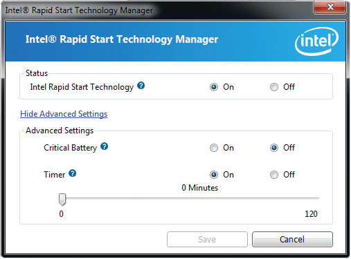

Также стоит отметить поддержку платой функций Intel Rapid Start, которая позволяет значительно снизить скорость выходу системы из спящего режима, а также технологии Intel Smart Connect, которая упрощает синхронизацию с облачными сервисами, ускоряет работу в Сети, плюс позволяет осуществлять проверку электронной почты даже если ПК находится в спящем режиме. Об остальных особенностях материнской платы GIGABYTE GA-B75M-D3V мы поговорим в соответствующих разделах нашего обзора, а пока давайте рассмотрим упаковку продукта и его комплектацию.
Упаковка и комплектация
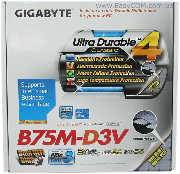
Оформление упаковки GIGABYTE GA-B75M-D3V выполнено в привычном стиле для продукции GIGABYTE. На лицевой стороне картонной коробки небольших размеров производитель перечислил некоторые ключевые спецификации решения и поддерживаемые им технологии. Наибольшее внимание уделено поддержке платой пакета Intel Small Business Advantage, а также фирменной концепции Ultra Durable 4, которая подразумевает применение качественной элементной базы (полевые транзисторы с низким последовательным сопротивлением, японские твердотельные конденсаторы) в процессе производства и дополнительную защиту платы от повышенной влажности, перепадов напряжения в процессе обновления версии прошивки, а также статического напряжения и высоких температур. Отдельно отмечена также поддержка протоколов SATA 6 Гб/с, USB 3.0 и PCIe 3.0, которые сегодня всё чаще оказываются востребованными в кругу бизнес пользователей.
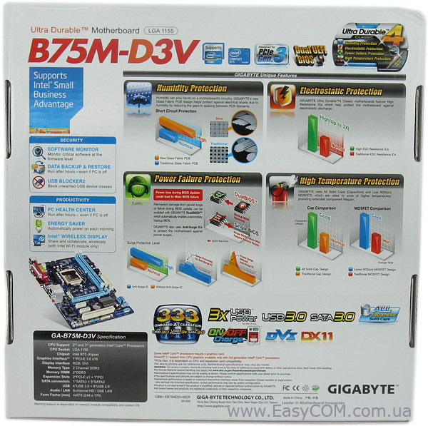
Обратная сторона коробки насыщена детальными описаниями отдельных функций и фирменных технологий GIGABYTE, поддержкой которых обладает продукт находящийся внутри. Наибольшее внимание снова уделено Ultra Durable 4 и Small Business Advantage.
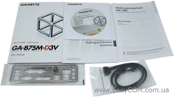
Помимо самой материнской платы GIGABYTE GA-B75M-D3V в коробке мы обнаружили:
- Руководства пользователя;
- Два SATA-кабеля;
- Заглушку интерфейсной панели;
- Диск с драйверами и утилитами.
Комплект поставки вполне типичен для бюджетного продукта, ведь добавление дополнительных аксессуаров вынудило бы производителя установить немного более высокую цену на него. Отметим, что ОЕМ-версия материнской платы GIGABYTE GA-B75M-D3V также комплектуется программным обеспечением Norton Internet Security.
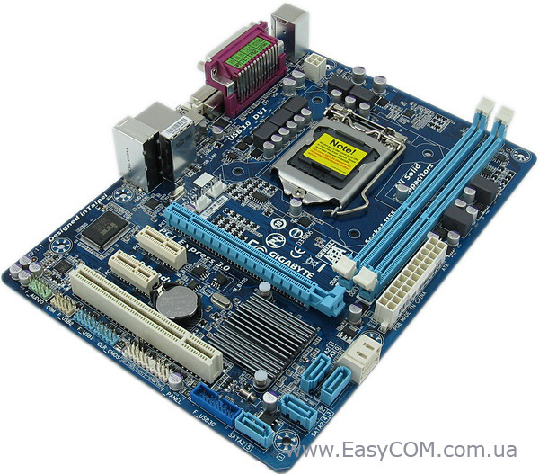
Дизайн
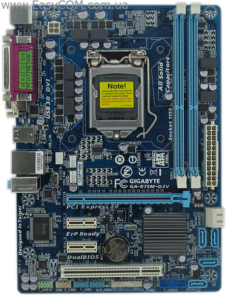
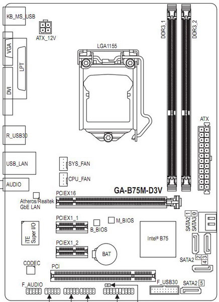
Материнская плата GIGABYTE GA-B75M-D3V имеет габариты 244 x 174 мм, что соответствует немного уменьшенному по ширине форм-фактору microATX. Для большинства потенциальных покупателей миниатюрный размер рассматриваемого решения может стать весомым аргументом при выборе, особенно принимая во внимание, что в офисных ПК, как правило, задействуется не более двух-трёх слотов расширения, а корпуса типа Desktop или Mini Tower дешевле и занимают меньше места в сравнении с более габаритными шасси типа Middle Tower. Традиционно для недорогих плат GIGABYTE последнего поколения, печатная плата оформлена в бело-голубых тонах. Несмотря на небольшие размеры, компоновка элементов на PCB осталась близкой к стандартной, все разъёмы находятся в наиболее подходящих для них местах, не блокируя друг друга и не мешая аккуратной укладке кабелей внутри системного блока. Отметим, что первый PEG слот находится на достаточном расстоянии от двух DIMM разъёмов, и даже массивная видеокарта не будет препятствовать замене модулей ОЗУ.
Системная плата GIGABYTE GA-B75M-D3V поддерживает установку всех актуальных CPU семейства Intel Sandy Bridge в исполнении LGA1155, а также изначально совместима с недавно анонсированными 22 нм процессорами с микроархитектурой Intel Ivy Bridge. Два DIMM-слота позволяют установить тандем модулей оперативной памяти стандарта DDR3 (1600/1333/1066/800 МГц) суммарным объёмом до 16 ГБ с поддержкой двухканальной архитектуры. На наш взгляд, уменьшение числа разъёмов для модулей ОЗУ можно отнести к недостаткам GIGABYTE GA-B75M-D3V лишь условно, ведь в подавляющем большинстве рабочих станций на предприятиях малого и среднего бизнеса четыре модуля оперативной памяти используются крайне редко.
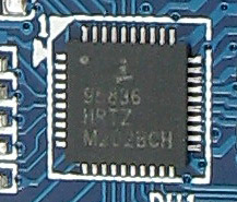
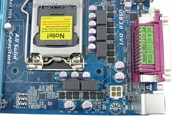
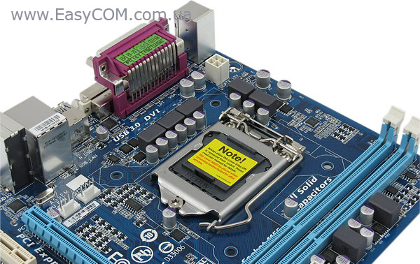
Модуль стабилизации питания CPU выполнен по 3+1+1-фазной схеме с применением ШИМ-контроллера Intersil ISL95836. При этом три фазы предназначены для питания непосредственно процессорных ядер, а по одной — для встроенного графического ядра и «системного агента». Преобразователь напряжения питания модулей ОЗУ включает две фазы, чего должно быть вполне достаточно, принимая во внимание позиционирование GIGABYTE GA-B75M-D3V.
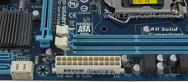
Для обеспечения питания элементов платы разработчиками предусмотрен 4-контактный разъем ATX12V и 24-контактный разъем ATX. Расположены они довольно стандартно и подключение шлейфов к ним не должно причинить неудобств в подавляющем большинстве случаев.

Отметим, что при производстве GIGABYTE GA-B75M-D3V действительно применялись твердотельные конденсаторы, качественные силовые транзисторы с низким сопротивлением, а также дроссели с ферритовыми сердечниками, что должно положительно сказаться на стабильности работы и сроке службы материнской платы.
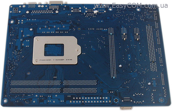
Обратная сторона печатной платы лишена каких-либо элементов. Отметим лишь, что изготовителем процессорного разъема является компания Foxconn.
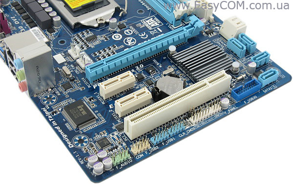
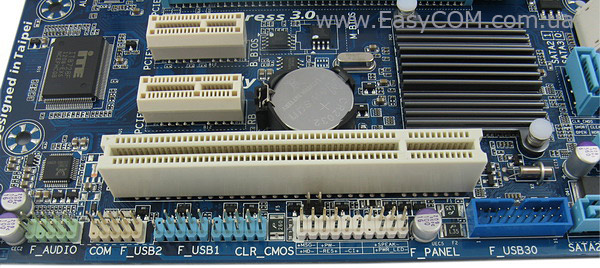
Набор слотов расширения представлен одним полноразмерным интерфейсом PCIe 3.0 x16, парой слотов PCIe x1, а также одним PCI, который постепенно теряет свою актуальность, но всё еще остается востребованным в корпоративном сегменте и поэтому изначально поддерживается бизнес-ориентированным чипсетом Intel B75 Express. Расположение скоростных шин, на наш взгляд, выбрано весьма удачное, ведь даже в случае установки видеокарты с двухслотовой системой охлаждения, доступными остаются по одному интерфейсу PCI и PCIe 2.0 х1, которые используются для подключения разнообразной периферии чаще всего.
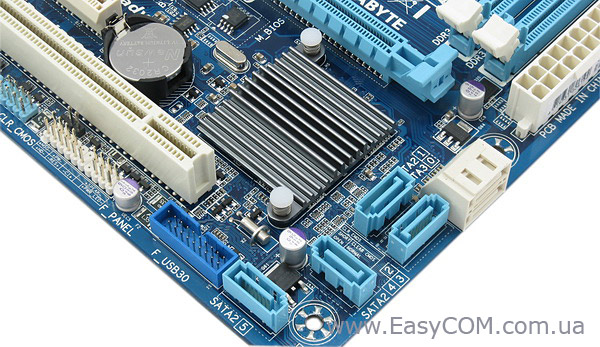
Справа от слотов расширения распаян чипсет Intel B75 Express, который поддерживает работу пяти интерфейсов SATA 3 Гбит/с и одного порта SATA 6 Гбит/с, расположенных неподалеку от него. Стоит учитывать, что из тандема SATA портов белого цвета, которые установлены горизонтально, только нижний — соответствует стандарту SATA 6 Гб/с. В правом нижнем углу печатной платы также распаян 19-контактный порт для подключения разъёмов USB 3.0, расположенных на фронтальной панели корпуса. Напомним, что возможности организовать RAID-массив на основе чипсета Intel B75 Express не предусмотрено.
У нижнего края текстолита мы обнаружили коннекторы фронтальной панели корпуса, пару внутренних портов USB 2.0, а также разъём COM, который при необходимости можно задействовать с помощью внешнего модуля (приобретается отдельно).
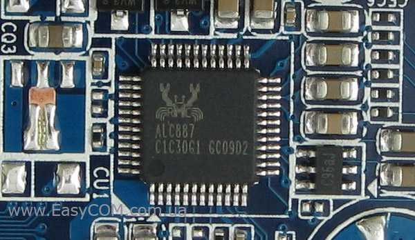
Звуковая подсистема материнской платы GIGABYTE GA-B75M-D3V основана на достаточно распространенном 8-канальном HDA-кодеке Realtek ALC887, заслужившем репутацию качественного решения среднего уровня.
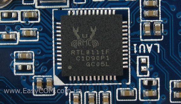
Для поддержки сетевых соединений служит гигабитный LAN-контроллер Realtek RTL8111F.
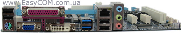
Набор портов на задней панели представлен следующим образом:
- один порт PS/2 (для подключения мыши/клавиатуры);
- интерфейсы VGA и DVI для подключения монитора;
- четыре разъема USB 2.0 и два USB 3.0;
- порт LPT;
- интерфейс Gigabit Ethernet;
- три разъёма Mini-Jack.
Стоит обратить внимание, что материнская плата GIGABYTE GA-B75M-D3V является одним из немногих современных продуктов, которые имеют порт LPT на задней панели ввода-вывода. В некоторых случаях эта особенность рассматриваемого продукта может быть весьма полезной. В целом же набор интерфейсов на панели достаточно скромный, что неудивительно для корпоративного решения стоимостью $75
Для подключения вентиляторов на материнской плате GIGABYTE GA-B75M-D3V предусмотрено всего два разъёма, чего многим пользователям может быть мало даже для системы начального уровня в корпусе формата Mini Tower. При этом радует лишь то, что оба коннектора 4-контактные и поддерживают регулировку частоты вращения с помощью ШИМ-метода.
UEFI BIOS
Материнская плата GIGABYTE GA-B75M-D3V оснащена современной прошивкой UEFI на основе микрокода AMI с приятным графическим интерфейсом, возможностью управления с помощью мышки и поддержкой накопителей объёмом больше 3 ТБ. Немаловажно, что плата оснащена двумя микросхемами BIOS (технология DualBIOS), что позволит сохранить работоспособность системы в случае повреждения основной микросхемы с прошивкой.
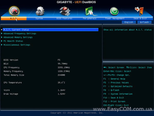
Основная часть настроек касающихся изменения частоты работы CPU в турборежиме, встроенного графического ядра, оперативной памяти, а также управления функциями «северного» моста находится в разделе MB Intelligent Tweaker (M.I.T.).
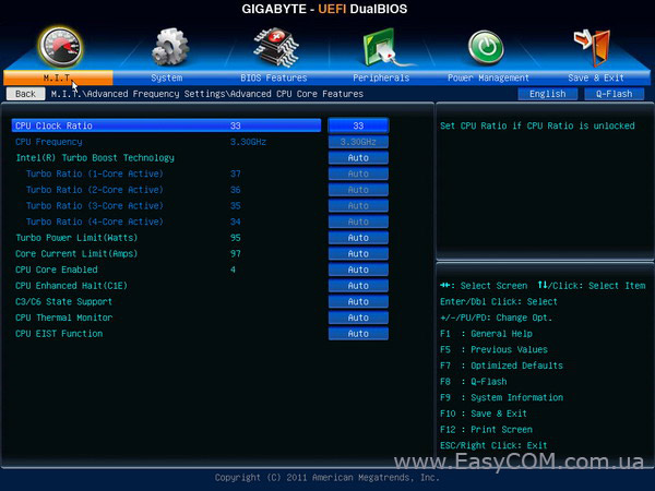
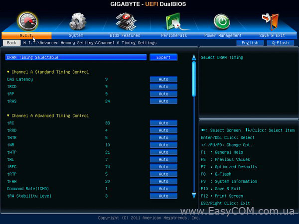
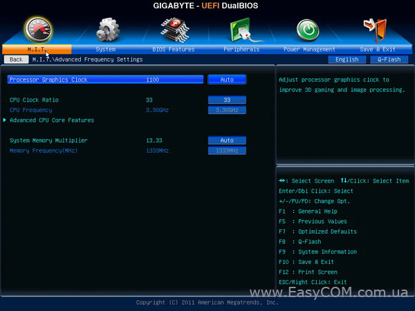
В соответствующих разделах меню продвинутые пользователи имеют возможность устанавливать частоту работы каждого активного вычислительного ядра в режиме Turbo Boost, лимит по току и по мощности, управлять процессорными технологиями, а также вручную задавать формулу задержек ОЗУ.
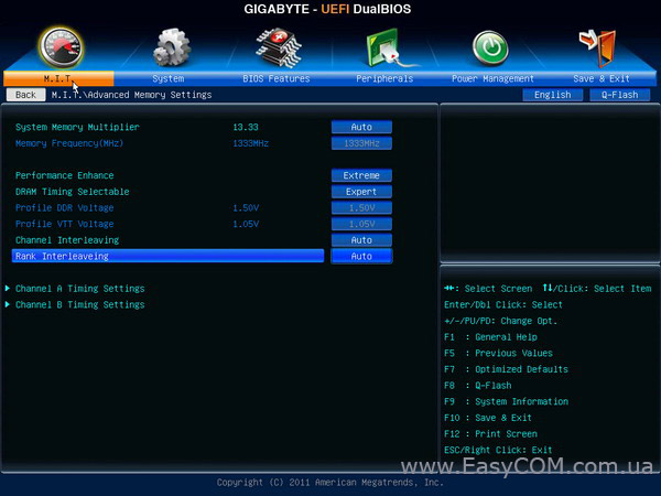
Настройки ручного управления напряжением питания основных узлов платы не предусмотрены, что неудивительно для материнской платы на основе набора системной логики Intel B75 Express, ориентированного на бизнес пользователей.
Для удобства читателей настройки, доступные для изменения, приведены в виде таблицы:
|
Параметр |
Название меню |
Диапазон |
Шаг |
|
Частота встроенного графического ядра, МГц |
Processor Graphics Clock |
400 – 1600 |
50 |
|
Процессорные технологии |
C1E, C3/C6 State, EIST, CPU Thermal Monitor, |
||
|
Процессорный множитель |
CPU Clock Ratio |
16 – 34 |
1 |
|
Ограничение по мощности, Вт |
Turbo Power Limit |
0 – 1200 |
1 |
|
Ограничение по току, А |
Core Current Limit |
0 – 300 |
1 |
|
Делитель для памяти |
System Memory Multipllier |
8, 10.66, 13.33, 16 |
|
|
Задержки ОЗУ |
CAS Latency, tRCD, tRP, tRAS, tRRD, tWTR, tWR, tWTP, tRFC, tRTP, tFAW, tCMD |
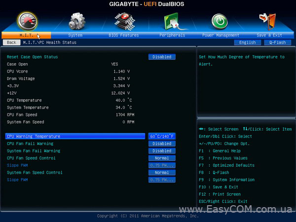
В разделе PC Health Status можно не только осуществлять мониторинг основных системных температур и напряжений на линиях 3,3В, 5В, 12В, но и управлять подключенными к плате вентиляторами. При необходимости пользователь может вручную задать «критическую» температуру процессора, при которой произойдет автоматическое отключение питания.
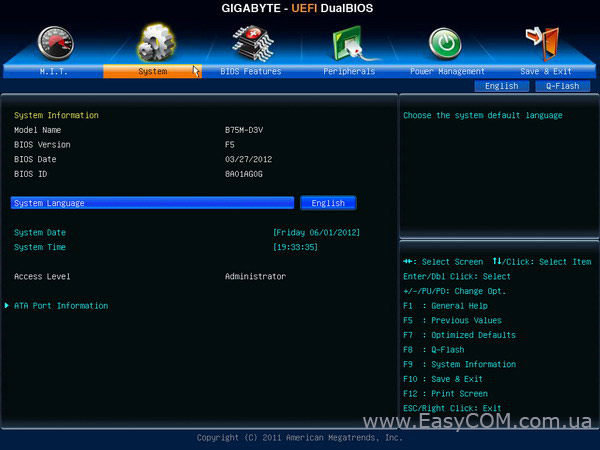
Во вкладке System представлена подробная информацию о версии прошивки. Также здесь можно установить системное время и дату, плюс выбрать язык интерфейса UEFI.
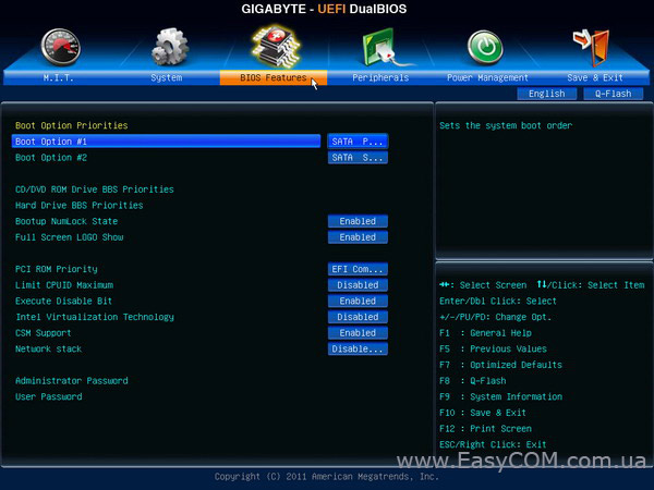
В следующем разделе «BIOS Features» можно задать порядок устройств, с которых будет загружаться операционная система, а также активировать технологию VT-d, установить пароль на включение компьютера и изменение настроек BIOS.
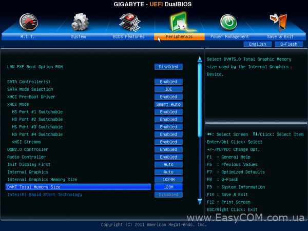
Во вкладке Peripherals собраны все настройки встроенных контроллеров, звукового кодека и сетевых адаптеров. Также здесь предлагается установить фиксированный или же динамически изменяемый в режиме DVMT объём системной памяти, отведенной под нужды встроенного в процессор графического ядра (до 1024 МБ).
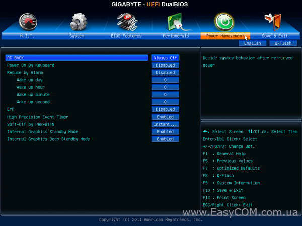
В последнем разделе под названием Power Management мы обнаружили настройки энергопитания и энергосберегающих функций.
Возможности BIOS системной платы GIGABYTE GA-B75M-D3V опытным пользователям могут показаться слишком ограниченными для того, чтобы осуществить тонкую настройку параметров, влияющих на производительность, тепловыделение и энергопотребление компонентов системного блока, однако на продвинутых энтузиастов рассматриваемый продукт и не ориентирован. В то же время, для целевой аудитории рассматриваемого решения имеющихся настроек будет вполне достаточно, а графический интерфейс и возможность управления с помощью мышки призваны значительно упростить процесс тюнинга системы.
Тестирование
Для проверки возможностей материнских плат использовалось следующее оборудование.
|
Процессор |
Intel Core i5-2500K (LGA1155, 3,3 ГГц, L3 6 МБ) Turbo Boost: enable C1E: enable |
|
Кулер |
Scythe Kama Angle Rev.B |
|
Оперативная память |
2xDDR3-2000 1024 МБ Kingston HyperX KHX16000D3T1K3/3GX |
|
Видеокарта |
MSI R4850-2D1G-OC (Radeon HD 4850, 1 ГБ GDDR3, PCIe 2.0) |
|
Жесткий диск |
Seagate Barracuda 7200.12 ST3500418AS, 500 ГБ, SATA-300, NCQ |
|
Оптический привод |
ASUS DRW-1814BLT SATA |
|
Блок питания |
Seasonic SS-650JT Active PFC (650 Вт, 120 мм вентилятор) |
|
Корпус |
CODEGEN M603 MidiTower (2х 120 мм вентилятора на вдув/выдув) |
Результаты тестов:
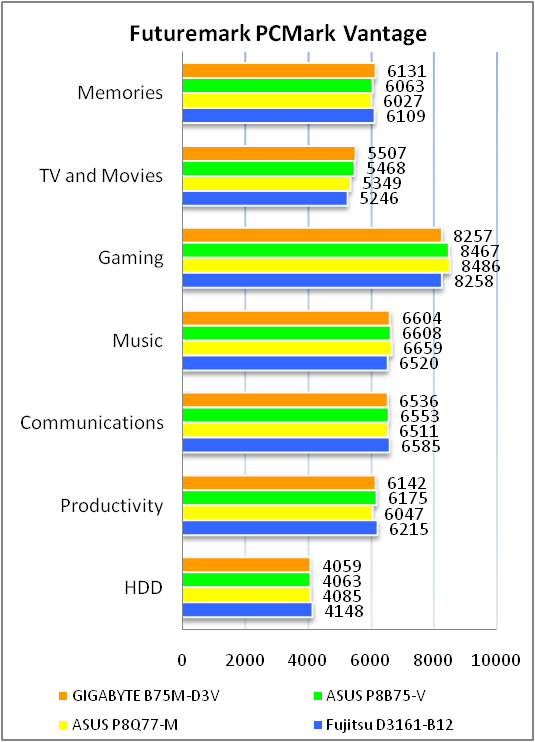
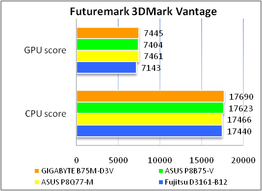
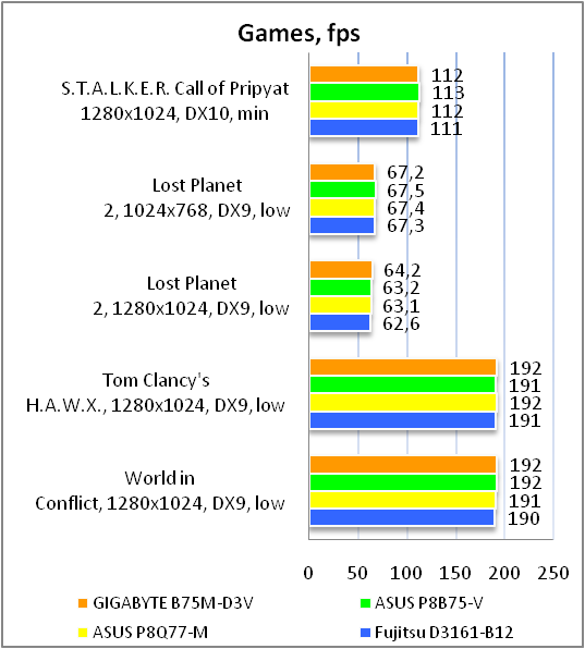
В очередной раз результаты продемонстрированные участниками тестирования на базе чипсетов Intel Q77/Q75 и B75 Express оказались практически идентичными, что неудивительно, учитывая, что все актуальные процессоры Intel имеют встроенный контроллер памяти DDR3. Успешное прохождение всех бенчмарков на одном уровне с «соперниками» свидетельствует о том, что актуальная версия прошивки материнской платы GIGABYTE GA-B75M-D3V полностью стабильна и не содержит ошибок, влияющих на производительность в игровых или офисных приложениях.
В процессе тестирования температура радиатора чипсета не превышала 46 градусов, что можно назвать хорошим результатом, который свидетельствует о том, что применяемый кулер вполне успешно справляется с охлаждением энергоэффективного чипа Intel B75 Express.
Тестирование звукового тракта на основе кодека Realtek ALC887
Общие результаты (RightMark Audio Analyzer)
Режим работы 16-bit, 44,1 kHz
|
Неравномерность АЧХ (в диапазоне 40 Гц — 15 кГц), дБ |
+0.12, -0.18 |
Очень хорошо |
|
Уровень шума, дБ (А) |
-86.1 |
Хорошо |
|
Динамические диапазон, дБ (А) |
86.1 |
Хорошо |
|
Гармонические искажения, % |
0.0030 |
Очень хорошо |
|
Гармонические искажения + шум, дБ(A) |
-77.1 |
Средне |
|
Интермодуляционные искажения + шум, % |
0.017 |
Очень хорошо |
|
Взаимопроникновение каналов, дБ |
-80.7 |
Очень хорошо |
|
Интермодуляции на 10 кГц, % |
0.017 |
Очень хорошо |
|
Общая оценка |
Хорошо |
Режим работы 24-bit, 192 kHz
|
Неравномерность АЧХ (в диапазоне 40 Гц — 15 кГц), дБ |
+0.10, -0.170 |
Очень хорошо |
|
Уровень шума, дБ (А) |
-86.4 |
Хорошо |
|
Динамические диапазон, дБ (А) |
86.5 |
Хорошо |
|
Гармонические искажения, % |
0.0028 |
Отлично |
|
Гармонические искажения + шум, дБ(A) |
-76.9 |
Средне |
|
Интермодуляционные искажения + шум, % |
0.017 |
Очень хорошо |
|
Взаимопроникновение каналов, дБ |
-81.3 |
Очень хорошо |
|
Интермодуляции на 10 кГц, % |
0.015 |
Очень хорошо |
|
Общая оценка |
Очень хорошо |
Встроенный 8-канальный звуковой кодек продемонстрировал довольно неплохие результаты, и подавляющему большинству пользователей его возможностей будет более чем достаточно для повседневной работы, прослушивания музыки, обеспечения звукового сопровождения к фильмам и презентаций.
Выводы
В ассортименте компании GIGABYTE на теперешний момент присутствует шесть недорогих продуктов на базе чипсета Intel B75 Express, которые предназначены для построения офисных ПК начального уровня на предприятиях малого и среднего бизнеса. Корпоративным пользователям эти решения интересны в первую очередь благодаря сбалансированному набору характеристик, демократичной стоимости, а также поддержке ряда функций «продвинутого» администрирования и защиты информации. Рассмотренная сегодня материнская плата GIGABYTE GA-B75M-D3V, выполненная в форм-факторе microATX, является наиболее доступным предложением тайваньского производителя в этом сегменте рынка. Тем не менее, по итогам тестирования мы убедились, что, несмотря на невысокую стоимость, это компактное решение вполне может стать хорошим выбором в качестве основы для рабочих станций на базе современных процессоров Intel Sandy Bridge и Ivy Bridge. Функциональные возможности GIGABYTE GA-B75M-D3V сегодня выглядят достаточно скромно, однако, по правде говоря, для рядового офисного ПК и не требуется большего. Два разъёма для модулей ОЗУ вместо привычных четырех, отсутствие поддержки технологии AMD CrossFireX, а также небогатый набор интерфейсов для вывода изображения, безусловно, стоит принимать во внимание при выборе, однако, вряд ли эти особенности платы смогут причинить неудобства рядовым бизнес пользователям. Большая часть мониторов и проекторов на предприятиях оснащены разъёмами DVI и VGA, модули ОЗУ приличного объёма сегодня имеют довольно демократичную стоимость, а построение связки CrossFireX для корпоративного ПК в режиме х16 + х4, на наш взгляд, практически лишено смысла. В то же время, целевая аудитория материнской платы GIGABYTE GA-B75M-D3V должна по достоинству оценить применение качественной элементной базы, а также простого и надежного преобразователя питания, удачный набор слотов и разъёмов расширения, включая параллельный порт на интерфейсной панели, удобную прошивку с приятным графическим интерфейсом.
Достоинства:
-
Расширенные возможности администрирования, поддержка пакета Intel Small Business Advantage, технологий Intel Rapid Start и Smart Connect;
-
Поддержка современных интерфейсов USB 3.0, SATA 6 Гбит/с, PCIe 3.0 и теряющих актуальность протоколов LPT, COM, PCI;
-
Примените качественной элементной базы (концепция Ultra Durable 4);
-
Поддержка DualBIOS и UEFI с графической оболочкой;
-
Удобный набор слотов расширения;
-
Невысокая стоимость;
-
Компактные габариты.
Недостатки:
-
Небольшое количество настроек BIOS для оптимизации энергопотребления и производительности;
-
Всего 2 разъёма для подключения вентиляторов.

Автор: Михаил Шульга
Выражаем благодарность компании MTI, официальному дистрибьютору продукции GIGABYTE, за предоставленную для тестирования материнскую плату.
Выражаем благодарность компаниям Intel, Kingston, MSI и Sea Sonic за предоставленное для тестового стенда оборудование.
-
Page 1
GA-B75M-D3V User’s Manual Rev. 1001 12ME-B75MD3V-1001R… -
Page 3: Identifying Motherboard Revision
The trademarks mentioned in this manual are legally registered to their respective owners. Disclaimer Information in this manual is protected by copyright laws and is the property of GIGABYTE. Changes to the specifications and features in this manual may be made by GIGABYTE without prior notice.
-
Page 4: Table Of Contents
Table of Contents GA-B75M-D3V Motherboard Layout …………….5 GA-B75M-D3V Motherboard Block Diagram …………..6 Chapter 1 Hardware Installation ………………7 Installation Precautions ………………. 7 Product Specifications ………………8 Installing the CPU ………………10 Installing the Memory ………………11 Installing an Expansion Card …………….11 Back Panel Connectors …………….. 12 Internal Connectors ………………
-
Page 5: Ga-B75M-D3V Motherboard Layout
GA-B75M-D3V Motherboard Layout KB_MS_USB ATX_12V LGA1155 R_USB30 USB_LAN SYS_FAN CPU_FAN AUDIO GA-B75M-D3V PCIEX16 Atheros GbE LAN PCIEX1_1 M_BIOS B_BIOS Intel ® PCIEX1_2 SATA2 CODEC F_USB30 SATA2 F_AUDIO F_USB2 F_USB1 F_PANEL CLR_CMOS Box Contents GA-B75M-D3V motherboard Motherboard driver disk Two SATA 6Gb/s cables…
-
Page 6: Ga-B75M-D3V Motherboard Block Diagram
GA-B75M-D3V Motherboard Block Diagram 1 PCI Express x16 CPU CLK+/- (100 MHz) LGA1155 DDR3 1600 /1333/1066 MHz (Note 1) PCIe CLK Dual Channel Memory (100 MHz) PCI Express Bus D-Sub Dual BIOS DVI-D 1 SATA 6Gb/s PCI Express Bus 5 SATA 3Gb/s Intel ®…
-
Page 7: Chapter 1 Hardware Installation
Chapter 1 Hardware Installation Installation Precautions The motherboard contains numerous delicate electronic circuits and components which can become damaged as a result of electrostatic discharge (ESD). Prior to installation, carefully read the user’s manual and follow these procedures: Prior to installation, make sure the chassis is suitable for the motherboard. •…
-
Page 8: 1-2 Product Specifications
Support for Extreme Memory Profile (XMP) memory modules Š * To support XMP memory, you must install an Intel 22nm (Ivy Bridge) CPU. (Go to GIGABYTE’s website for the latest supported memory speeds and memory modules.) Onboard Integrated Graphics Processor: Š…
-
Page 9
Internal 1 x 24-pin ATX main power connector Š Connectors 1 x 4-pin ATX 12V power connector Š 1 x SATA 6Gb/s connector Š 5 x SATA 3Gb/s connectors Š 1 x CPU fan header Š 1 x system fan header Š… -
Page 10: Installing The Cpu
Form Factor Micro ATX Form Factor; 24.4cm x 17.4cm Š * GIGABYTE reserves the right to make any changes to the product specifications and product-related information without prior notice. Installing the CPU Read the following guidelines before you begin to install the CPU: Make sure that the motherboard supports the CPU.
-
Page 11: Installing The Memory
• same capacity, brand, speed, and chips be used. (Go to GIGABYTE’s website for the latest supported memory speeds and memory modules.) Always turn off the computer and unplug the power cord from the power outlet before installing the •…
-
Page 12: Back Panel Connectors
Back Panel Connectors USB 2.0/1.1 Port The USB port supports the USB 2.0/1.1 specification. Use this port for USB devices such as a USB keyboard/mouse, USB printer, USB flash drive and etc. PS/2 Keyboard/Mouse Port Use this port to connect a PS/2 mouse or keyboard. Parallel Port Use the parallel port to connect devices such as a printer, scanner and etc.
-
Page 13: Internal Connectors
Mic In Jack (Pink) The default Mic in jack. Microphones must be connected to this jack. To configure 7.1-channel audio, you have to use an HD front panel audio module and enable the multi-channel audio feature through the audio driver. Internal Connectors 9 10 13 11…
-
Page 14
1/2) ATX_12V/ATX (2×2 12V Power Connector and 2×12 Main Power Connector) With the use of the power connector, the power supply can supply enough stable power to all the components on the motherboard. Before connecting the power connector, first make sure the power supply is turned off and all devices are properly installed. -
Page 15
3/4) CPU_FAN/SYS_FAN (Fan Headers) All fan headers on this motherboard are 4-pin. Most fan headers possess a foolproof insertion design. When connecting a fan cable, be sure to connect it in the correct orientation (the black connector wire is the ground wire). The speed control function requires the use of a fan with fan speed control design. For optimum heat dissipation, it is recommended that a system fan be installed inside the chassis. -
Page 16
6) SATA3 0 (SATA 6Gb/s Connectors, Controlled by Intel B75 Chipset) The SATA connector conforms to SATA 6Gb/s standard and are compatible with SATA 3Gb/s and SATA 1.5Gb/s standard. Each SATA connector supports a single SATA device. Pin No. Definition SATA3 DEBUG DEBUG… -
Page 17: Front Panel Heade
F_PANEL (Front Panel Header) Connect the power switch, reset switch, speaker, chassis intrusion switch/sensor and system status indicator on the chassis to this header according to the pin assignments below. Note the positive and negative pins before connecting the cables. Message/Power/ Power Sleep LED…
-
Page 18
9) F_AUDIO (Front Panel Audio Header) The front panel audio header supports Intel High Definition audio (HD) and AC’97 audio. You may connect your chassis front panel audio module to this header. Make sure the wire assignments of the module con- nector match the pin assignments of the motherboard header. -
Page 19
11) F_USB30 (USB 3.0/2.0 Header) The header conforms to USB 3.0/2.0 specification and can provide two USB ports. For purchasing the optional 3.5″ front panel that provides two USB 3.0/2.0 ports, please contact the local dealer. F_USB30 F_AUDIO(H) Pin No. Definition Pin No. -
Page 20
13) CLR_CMOS (Clear CMOS Jumper) Use this jumper to clear the CMOS values (e.g. date information and BIOS configurations) and reset the CMOS values to factory defaults. To clear the CMOS values, use a metal object like a screwdriver to touch the two pins for a few seconds. -
Page 21: Chapter 2 Bios Setup
To access the BIOS Setup program, press the <Delete> key during the POST when the power is turned on. To upgrade the BIOS, use either the GIGABYTE Q-Flash or @BIOS utility. Q-Flash allows the user to quickly and easily upgrade or back up BIOS without entering the operating •…
-
Page 22: The Main Menu
The Main Menu On the main menu of the BIOS Setup program, press arrow keys to move among the items and press <Enter> to accept or enter a sub-menu. Or you can use your mouse to select the item you want. (Sample BIOS Version: D2) Setup Menus Enter Q-Flash…
-
Page 23: M.i.t
M.I.T. Whether the system will work stably with the overclock/overvoltage settings you made is dependent on your overall system configurations. Incorrectly doing overclock/overvoltage may result in damage to CPU, chipset, or memory and reduce the useful life of these components. This page is for advanced users only and we recommend you not to alter the default settings to prevent system instability or other unexpected results.
-
Page 24
M.I.T. Current Status This screen provides information on CPU/memory frequencies/parameters. Advanced Frequency Settings Internal Graphics Clock & Allows you to set the onboard graphics clock. The adjustable range is from 400 MHz to 3200 MHz. (Default: Auto) CPU Clock Ratio &… -
Page 25
CPU Clock Ratio, CPU Frequency & The settings under the two items above are synchronous to those under the same items on the Advanced Frequency Settings menu. Real-Time CPU Ratio Control In OS (Note) & Enabled allows you to make real-time changes to the CPU clock ratio in your operating system. (Default: Disabled) Intel(R) Turbo Boost Technology (Note) -
Page 26
Extreme Memory Profile (X.M.P.) (Note) & Allows the BIOS to read the SPD data on XMP memory module(s) to enhance memory performance when enabled. Disabled Disables this function. (Default) Profile1 Uses Profile 1 settings. Profile2 Uses Profile 2 settings. (Note) System Memory Multiplier &… -
Page 27
Profile DDR Voltage & When using a non-XMP memory module or Extreme Memory Profile (X.M.P.) is set to Disabled, this item will display as 1.50V. When Extreme Memory Profile (X.M.P.) is set to Profile1 or Profile2, this item will display the value based on the SPD data on the XMP memory. Profile VTT Voltage &… -
Page 28
PC Health Status Reset Case Open Status & Disabled Keeps or clears the record of previous chassis intrusion status. (Default) Case Opened field will Enabled Clears the record of previous chassis intrusion status and the show «No» at next boot. Case Opened &… -
Page 29: System
Slope PWM & Allows you to control the CPU fan speed. This item is configurable only when CPU Fan Speed Control is set to Manual. Options are: 0.75 PWM value / C ~ 2.50 PWM value / System Fan Speed Control &…
-
Page 30: Bios Features
System Time & Sets the system time. The time format is hour, minute, and second. For example, 1 p.m. is 13:0:0. Use <Enter> to switch between the Hour, Minute, and Second fields and use the <Page Up> or <Page Down> key to set the desired value.
-
Page 31: Administrator Password
Enables or disables Numlock feature on the numeric keypad of the keyboard after the POST. (Default: Enabled) Full Screen LOGO Show & Allows you to determine whether to display the GIGABYTE Logo at system startup. Disabled skips the GIGABYTE Logo when the system starts up. (Default: Enabled) PCI ROM Priority &…
-
Page 32: Peripherals
Peripherals LAN PXE Boot Option ROM & Allows you to decide whether to activate the boot ROM integrated with the onboard LAN chip. (Default: Disabled) SATA Controller(s) & Enables or disables the integrated SATA controllers. (Default: Enabled) SATA Mode Selection &…
-
Page 33: Audio Controller
AHCI Configures the SATA controllers to AHCI mode. Advanced Host Controller Interface (AHCI) is an interface specification that allows the storage driver to enable advanced Serial ATA features such as Native Command Queuing and hot plug. xHCI Pre-Boot Driver & Enabled The USB 3.0 ports are routed to the xHCI controller before booting to OS.
-
Page 34
Init Display First & Specifes the frst initiation of the monitor display from the installed PCI graphics card, PCI Express graphics card, or the onboard graphics. Auto Lets BIOS automatically configure this setting. (Default) IGFX Sets the onboard graphics as the first display. PEG Sets the PCI Express graphics card on the PCIEX16 slot as the first display. PCI Sets the graphics card on the PCI slot as the first display. Internal Graphics & Enables or disables the onboard graphics function. (Default: Auto) Internal Graphics Memory Size & Allows you to set the onboard graphics memory size. Options are: 32M~1024M. (Default: 64M) DVMT Total Memory Size & Allows you to allocate the DVMT memory size of the onboard graphics. Options are: 128M, 256M, MAX. (Default: MAX) Intel(R) Rapid Start Technology &… -
Page 35: Power Management
Parallel Port & Enables or disables the onboard parallel port. (Default: Enabled) Intel(R) Smart Connect Technology ISCT Configuration & Enables or disables Intel Smart Connect Technology. (Default: Disabled) Power Management AC BACK & Determines the state of the system after the return of power from an AC power loss. Memory The system returns to its last known awake state upon the return of the AC power.
-
Page 36
Resume by Alarm & Determines whether to power on the system at a desired time. (Default: Disabled) If enabled, set the date and time as following: Wake up day: Turn on the system at a specific time on each day or on a specific day in a month. Wake up hour/minute/second: Set the time at which the system will be powered on automatically. -
Page 37: Save & Exit
Save & Exit Save & Exit Setup & Press <Enter> on this item and select Yes. This saves the changes to the CMOS and exits the BIOS Setup program. Select No or press <Esc> to return to the BIOS Setup Main Menu. Exit Without Saving &…
-
Page 38: Chapter 3 Drivers Installation
Chapter 3 Drivers Installation Before installing the drivers, first install the operating system. • After installing the operating system, insert the motherboard driver disk into your optical drive. The • driver Autorun screen is automatically displayed which looks like that shown in the screen shot below.
-
Page 39: Regulatory Statements
«end of life» product. Restriction of Hazardous Substances (RoHS) Directive Statement GIGABYTE products have not intended to add and safe from hazardous substances (Cd, Pb, Hg, Cr+6, PBDE and PBB). The parts and components have been carefully selected to meet RoHS requirement. Moreover, we at GIGABYTE are continuing our efforts to develop products that do not use internationally banned toxic chemicals.
-
Page 40
Tech. and Non-Tech. Support (Sales/Marketing) : http://ggts.gigabyte.com.tw WEB address (English): http://www.gigabyte.com WEB address (Chinese): http://www.gigabyte.tw You may go to the GIGABYTE website, select your language in the language list on the top right corner of the website. GIGABYTE Global Service System •…