

To reduce the impacts on global warming, the packaging materials of this product
are recyclable and reusable. GIGABYTE works with you to protect the environment.
For more product details, please visit
GIGABYTE’s website.
GA-H110M-S2H DDR3GA-H110M-S2H-GSMGA-H110M-S2H
GA-H110M-S2H
GA-H110M-S2H-GSM
GA-H110M-S2H DDR3
User’s Manual
Rev. 1002
Copyright
© 2016 GIGA-BYTE TECHNOLOGY CO., LTD. All rights reserved.
The trademarks mentioned in this manual are legally registered to their respective owners.
Disclaimer
Information in this manual is protected by copyright laws and is the property of GIGABYTE.
Changes to the specications and features in this manual may be made by GIGABYTE without prior notice.
No part of this manual may be reproduced, copied, translated, transmitted, or published in any form or
by any means without GIGABYTE’s prior written permission.
In order to assist in the use of this product, carefully read the User’s Manual.
For product-related information, check on our website at: http://www.gigabyte.com
Identifying Your Motherboard Revision
The revision number on your motherboard looks like this: «REV: X.X.» For example, «REV: 1.0″ means
the revision of the motherboard is 1.0. Check your motherboard revision before updating motherboard
BIOS, drivers, or when looking for technical information.
Example:
Sept. 11, 2015
Motherboard
Motherboard
GA-H110M-S2H
GA-H110M-S2H-GSM
GA-H110M-S2H DDR3
Sept. 11, 2015
GA-H110M-S2H
GA-H110M-S2H-GSM
GA-H110M-S2H DDR3

— 3 —
Table of Contents
GA-H110M-S2H/GA-H110M-S2H-GSM/GA-H110M-S2H DDR3 Motherboard Layout ….4
Chapter 1 Hardware Installation ………………………………………………………………………….5
1-1 Installation Precautions ………………………………………………………………………… 5
1-2 ProductSpecications ………………………………………………………………………….. 6
1-3 Installing the CPU ……………………………………………………………………………….. 9
1-4 Installing the Memory …………………………………………………………………………… 9
1-5 Installing an Expansion Card ………………………………………………………………. 10
1-6 Back Panel Connectors ………………………………………………………………………. 10
1-7 Internal Connectors ……………………………………………………………………………. 12
Chapter 2 BIOS Setup ……………………………………………………………………………………..18
2-1 Startup Screen ………………………………………………………………………………….. 18
2-2 M.I.T. ……………………………………………………………………………………………….. 19
2-3 System Information ……………………………………………………………………………. 24
2-4 BIOS Features ………………………………………………………………………………….. 25
2-5 Peripherals ……………………………………………………………………………………….. 28
2-6 Chipset …………………………………………………………………………………………….. 30
2-7 Power Management …………………………………………………………………………… 31
2-8 Save & Exit ……………………………………………………………………………………….. 33
Chapter 3 Appendix …………………………………………………………………………………………34
Drivers Installation ……………………………………………………………………………………….. 34
Regulatory Statements …………………………………………………………………………………. 35
Contact Us …………………………………………………………………………………………………. 37
— 4 —
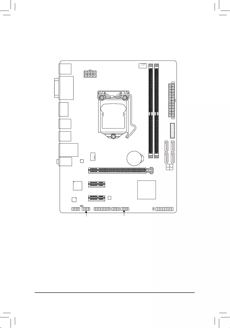
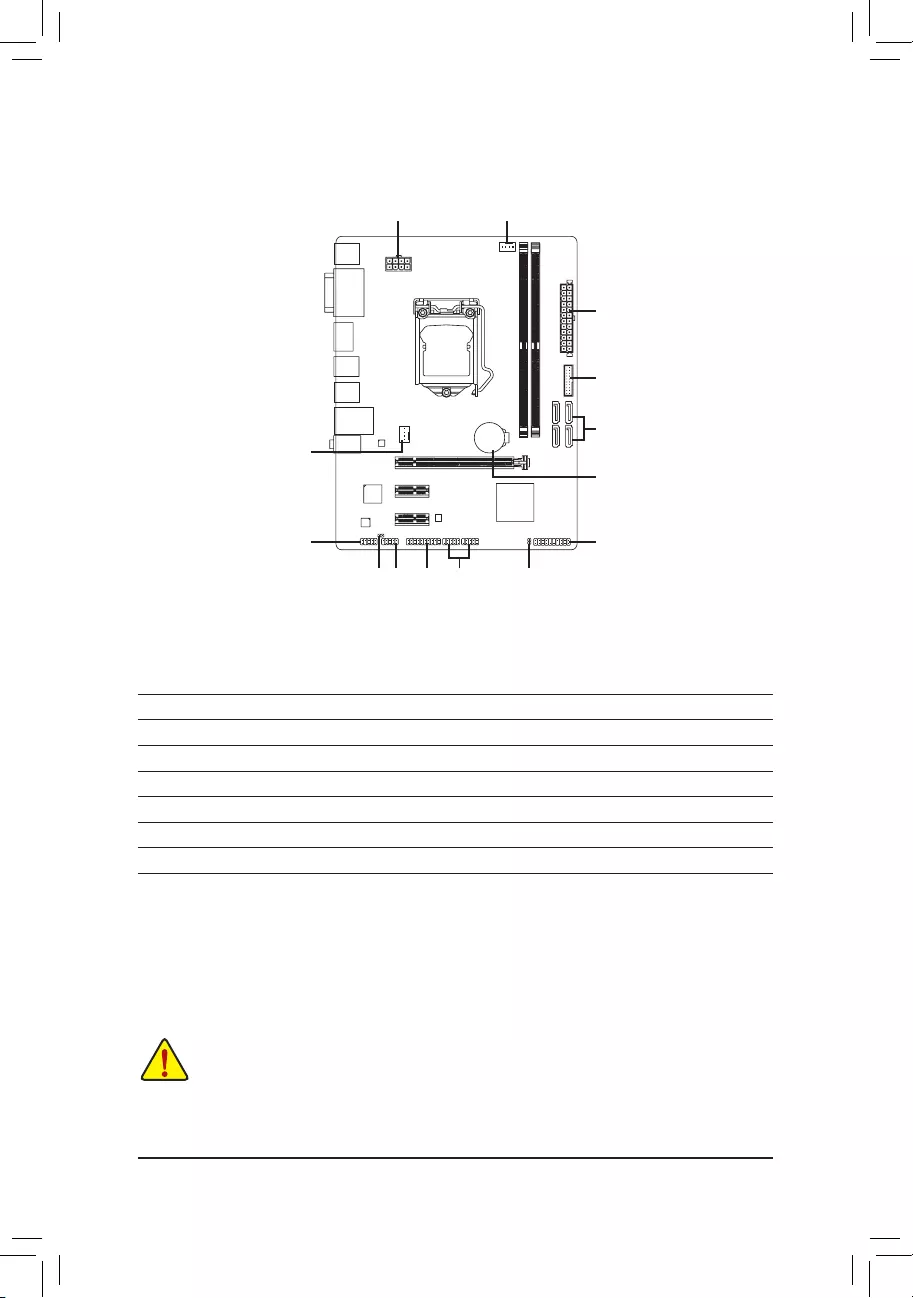
GA—H110M—S2H/GA—H110M—S2H—GSM/GA—H110M—S2H DDR3
Motherboard Layout
* The box contents above are for reference only and the actual items shall depend on the product package you obtain.
The box contents are subject to change without notice.
Box Contents
5GA-H110M-S2H, GA-H110M-S2H-GSM, or GA-H110M-S2H DDR3 motherboard
5Motherboard driver disk 5Two SATA cables
5User’s Manual 5I/O Shield
KB_MS
CPU_FAN
SYS_FAN
LGA1151
ATX
F_AUDIO
AUDIO BAT
ATX_12V_2X4
Intel® H110
R_USB30
CODEC
CLR_CMOS
M_BIOS
USB_LAN
PCIEX16
PCIEX1_1
PCIEX1_2
iTE®
Super I/O
Realtek®
GbE LAN
F_USB1
TPM F_USB2 F_PANEL
SPDIF_O
F_USB30
VGA
DDR4_2j/DDR3_2k
DDR4_1j/DDR3_1k
COMA
DVI
R_USB
HDMI
GA-H110M-S2H/GA-H110M-S2H-GSM
GA-H110M-S2H DDR3
SATA3 1 3
0 2
jOnly for GA-H110M-S2H/GA-H110M-S2H-GSM.
kOnly for GA-H110M-S2H DDR3.

Chapter 1 Hardware Installation
1-1 Installation Precautions
The motherboard contains numerous delicate electronic circuits and components which can become
damaged as a result of electrostatic discharge (ESD). Prior to installation, carefully read the user’s
manual and follow these procedures:
•Prior to installation, make sure the chassis is suitable for the motherboard.
•Prior to installation, do not remove or break motherboard S/N (Serial Number) sticker or
warranty sticker provided by your dealer. These stickers are required for warranty validation.
•Always remove the AC power by unplugging the power cord from the power outlet before
installing or removing the motherboard or other hardware components.
•When connecting hardware components to the internal connectors on the motherboard, make
sure they are connected tightly and securely.
•When handling the motherboard, avoid touching any metal leads or connectors.
•It is best to wear an electrostatic discharge (ESD) wrist strap when handling electronic
components such as a motherboard, CPU or memory. If you do not have an ESD wrist strap,
keepyourhandsdryandrsttouchametalobjecttoeliminatestaticelectricity.
•Prior to installing the motherboard, please have it on top of an antistatic pad or within an
electrostatic shielding container.
•Before connecting or unplugging the power supply cable from the motherboard, make sure
the power supply has been turned off.
•Before turning on the power, make sure the power supply voltage has been set according to
the local voltage standard.
•Before using the product, please verify that all cables and power connectors of your hardware
components are connected.
•To prevent damage to the motherboard, do not allow screws to come in contact with the
motherboard circuit or its components.
•Make sure there are no leftover screws or metal components placed on the motherboard or
within the computer casing.
•Do not place the computer system on an uneven surface.
•Do not place the computer system in a high-temperature or wet environment.
•Turning on the computer power during the installation process can lead to damage to system
components as well as physical harm to the user.
•If you are uncertain about any installation steps or have a problem related to the use of the
product,pleaseconsultacertiedcomputertechnician.
•If you use an adapter, extension power cable, or power strip, ensure to consult with its installation
and/or grounding instructions.
— 5 —
1-2 ProductSpecications
CPU Support for Intel® Core™ i7 processors/Intel® Core™ i5 processors/
Intel® Core™ i3 processors/Intel® Pentium® processors/
Intel® Celeron® processors in the LGA1151 package
(Go to GIGABYTE’s website for the latest CPU support list.)
L3 cache varies with CPU
Chipset Intel® H110 Express Chipset
Memoryj 2 x DDR4 DIMM sockets supporting up to 32 GB of system memory
* Due to a Windows 32-bit operating system limitation, when more than 4 GB of physical
memory is installed, the actual memory size displayed will be less than the size of
the physical memory installed.
Dual channel memory architecture
Support for DDR4 2133 MHz memory modules
Support for ECC UDIMM 1Rx8/2Rx8 memory modules (operate in non-ECC mode)
Support for non-ECC UDIMM 1Rx8/2Rx8/1Rx16 memory modules
(Go to GIGABYTE’s website for the latest supported memory speeds and
memory modules.)
Memoryk 2 x DDR3 DIMM sockets supporting up to 32 GB of system memory
* Due to a Windows 32-bit operating system limitation, when more than 4 GB of physical
memory is installed, the actual memory size displayed will be less than the size of
the physical memory installed.
Dual channel memory architecture
Support for DDR3/DDR3L 1600/1333 MHz memory modules
Support for ECC UDIMM 1Rx8/2Rx8 memory modules (operate in non-ECC mode)
Support for non-ECC UDIMM 1Rx8/2Rx8 memory modules
(Go to GIGABYTE’s website for the latest supported memory speeds and
memory modules.)
Onboard
Graphics
Integrated Graphics Processor-Intel® HD Graphics support:
— 1 x D-Sub port, supporting a maximum resolution of 1920×1200@60 Hz
— 1 x DVI-D port, supporting a maximum resolution of 1920×1200@60 Hz
* The DVI-D port does not support D-Sub connection by adapter.
— 1 x HDMI port, supporting a maximum resolution of 4096×2160@24 Hz
* Support for HDMI 1.4 version.
Support for up to 2 displays at the same time
Maximum shared memory of 512 MB
Audio Realtek® ALC887 codec
HighDenitionAudio
2/4/5.1/7.1-channel
* Tocongure7.1-channelaudio,youhavetouseanHDfrontpanelaudiomodule
and enable the multi-channel audio feature through the audio driver.
Support for S/PDIF Out
LAN Realtek® GbE LAN chip (10/100/1000 Mbit)
Expansion Slots 1 x PCI Express x16 slot, running at x16 (PCIEX16)
(The PCI Express x16 slot conforms to PCI Express 3.0 standard.)
2 x PCI Express x1 slots
(All of the PCI Express x1 slots conform to PCI Express 2.0 standard.)
jOnly for GA-H110M-S2H/GA-H110M-S2H-GSM.
kOnly for GA-H110M-S2H DDR3.
— 6 —
Storage Interface Chipset:
— 4 x SATA 6Gb/s connectors
USB Chipset:
— 4 x USB 3.0/2.0 ports (2 ports on the back panel, 2 ports available through
the internal USB header)
— 8 x USB 2.0/1.1 ports (4 ports on the back panel, 4 ports available through
the internal USB headers)
Internal
Connectors
1 x 24-pin ATX main power connector
1 x 8-pin ATX 12V power connector
4 x SATA 6Gb/s connectors
1 x CPU fan header
1 x system fan header
1 x front panel header
1 x front panel audio header
1 x S/PDIF Out header
1 x USB 3.0/2.0 header
2 x USB 2.0/1.1 headers
1 x Trusted Platform Module (TPM) header
1 x serial port header
1 x Clear CMOS jumper
Back Panel
Connectors
1 x PS/2 mouse port
1 x PS/2 Keyboard port
1 x D-Sub port
1 x DVI-D port
1 x HDMI port
2 x USB 3.0/2.0 ports
4 x USB 2.0/1.1 ports
1 x RJ-45 port
3 x audio jacks (Line In, Line Out, Mic In)
I/O Controller iTE® I/O Controller Chip
Hardware
Monitor
System voltage detection
CPU/System temperature detection
CPU/System fan speed detection
CPU/System overheating warning
CPU/System fan fail warning
CPU/System fan speed control
* Whether the fan speed control function is supported will depend on the cooler you install.
BIOS 1x64Mbitash
Use of licensed AMI UEFI BIOS
PnP 1.0a, DMI 2.7, WfM 2.0, SM BIOS 2.7, ACPI 5.0
— 7 —
Unique Features Support for APP Center
* Available applications in APP Center may vary by motherboard model. Supported
functionsofeachapplicationmayalsovarydependingonmotherboardspecications.
— 3D OSD
— @BIOS
— AutoGreen
— Cloud Station
— EasyTune
— Fast Boot
— Smart TimeLock
— Smart Keyboard
— Smart Backup
— System Information Viewer
— USB Blocker
Support for Q-Flash
Support for Smart Switch
Support for Xpress Install
Bundled
Software
Norton® Internet Security (OEM version)
cFosSpeed
Operating
System
Support for Windows 10/8.1 64-bit
Support for Windows 7 32-bit/64-bit
* Please download the «Windows USB Installation Tool» from GIGABYTE’s website and
install it before installing Windows 7.
Form Factor Micro ATX Form Factor; 22.6cm x 17.4cm
* GIGABYTEreservestherighttomakeanychangestotheproductspecicationsandproduct-relatedinformationwithout
prior notice.
Please visit the Support\Utility List page on GIGABYTE’s website to download the latest version
of apps.
Please visit GIGABYTE’s website for support lists of CPU, memory
modules, and SSDs.
GA-H110M-S2H GA-H110M-S2H-GSM GA-H110M-S2H DDR3
— 8 —
1-3 Installing the CPU
Read the following guidelines before you begin to install the CPU:
•Make sure that the motherboard supports the CPU.
(Go to GIGABYTE’s website for the latest CPU support list.)
•Always turn off the computer and unplug the power cord from the power outlet before installing the
CPU to prevent hardware damage.
•Locate the pin one of the CPU. The CPU cannot be inserted if oriented incorrectly. (Or you may locate
the notches on both sides of the CPU and alignment keys on the CPU socket.)
•Apply an even and thin layer of thermal grease on the surface of the CPU.
•Do not turn on the computer if the CPU cooler is not installed, otherwise overheating and damage
of the CPU may occur.
•Setthe CPU hostfrequency in accordancewith the CPUspecications. It isnot recommended
thatthesystembusfrequencybesetbeyondhardwarespecicationssinceitdoesnotmeetthe
standard requirements for the peripherals. If you wish to set the frequency beyond the standard
specications,pleasedosoaccordingtoyourhardwarespecicationsincludingtheCPU,graphics
card, memory, hard drive, etc.
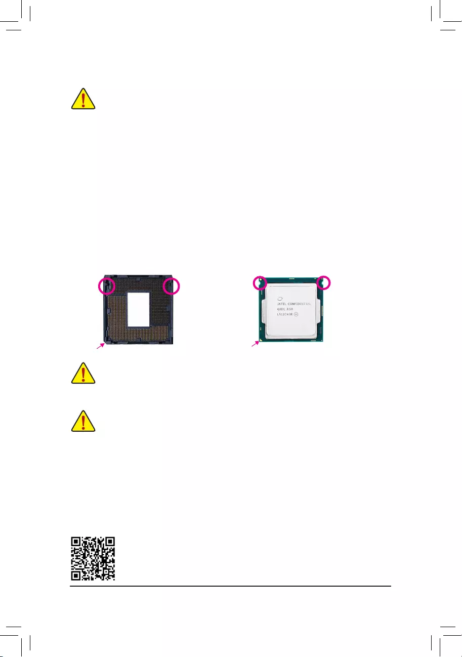
Installing the CPU
Locate the alignment keys on the motherboard CPU socket and the notches on the CPU.
Do not remove the CPU socket cover before inserting the CPU. It may pop off from the load
plate automatically during the process of re-engaging the lever after you insert the CPU.
Alignment
Key
Alignment
Key
LGA1151 CPU Socket
Pin One Corner of the CPU Socket
1-4 Installing the Memory
Read the following guidelines before you begin to install the memory:
•Make sure that the motherboard supports the memory. It is recommended that memory of the same
capacity, brand, speed, and chips be used.
(Go to GIGABYTE’s website for the latest supported memory speeds and memory modules.)
•Always turn off the computer and unplug the power cord from the power outlet before installing the
memory to prevent hardware damage.
•Memory modules have a foolproof design. A memory module can be installed in only one direction.
If you are unable to insert the memory, switch the direction.
DualChannelMemoryConguration
This motherboard provides two memory sockets and supports Dual Channel Technology. After the memory
isinstalled,theBIOSwillautomaticallydetectthespecicationsandcapacityofthememory.EnablingDual
Channel memory mode will double the original memory bandwidth.
LGA1151 CPU
Triangle Pin One Marking on the CPU
Notch
Notch
Please visit GIGABYTE’s website for details on hardware installation.
— 9 —
1-5 Installing an Expansion Card
Read the following guidelines before you begin to install an expansion card:
•Make sure the motherboard supports the expansion card. Carefully read the manual that came
with your expansion card.
•Always turn off the computer and unplug the power cord from the power outlet before installing an
expansion card to prevent hardware damage.
Due to CPU limitations, read the following guidelines before installing the memory in Dual Channel mode.
1. Dual Channel mode cannot be enabled if only one memory module is installed.
2. When enabling Dual Channel mode with two memory modules, it is recommended that memory of
the same capacity, brand, speed, and chips be used for optimum performance.
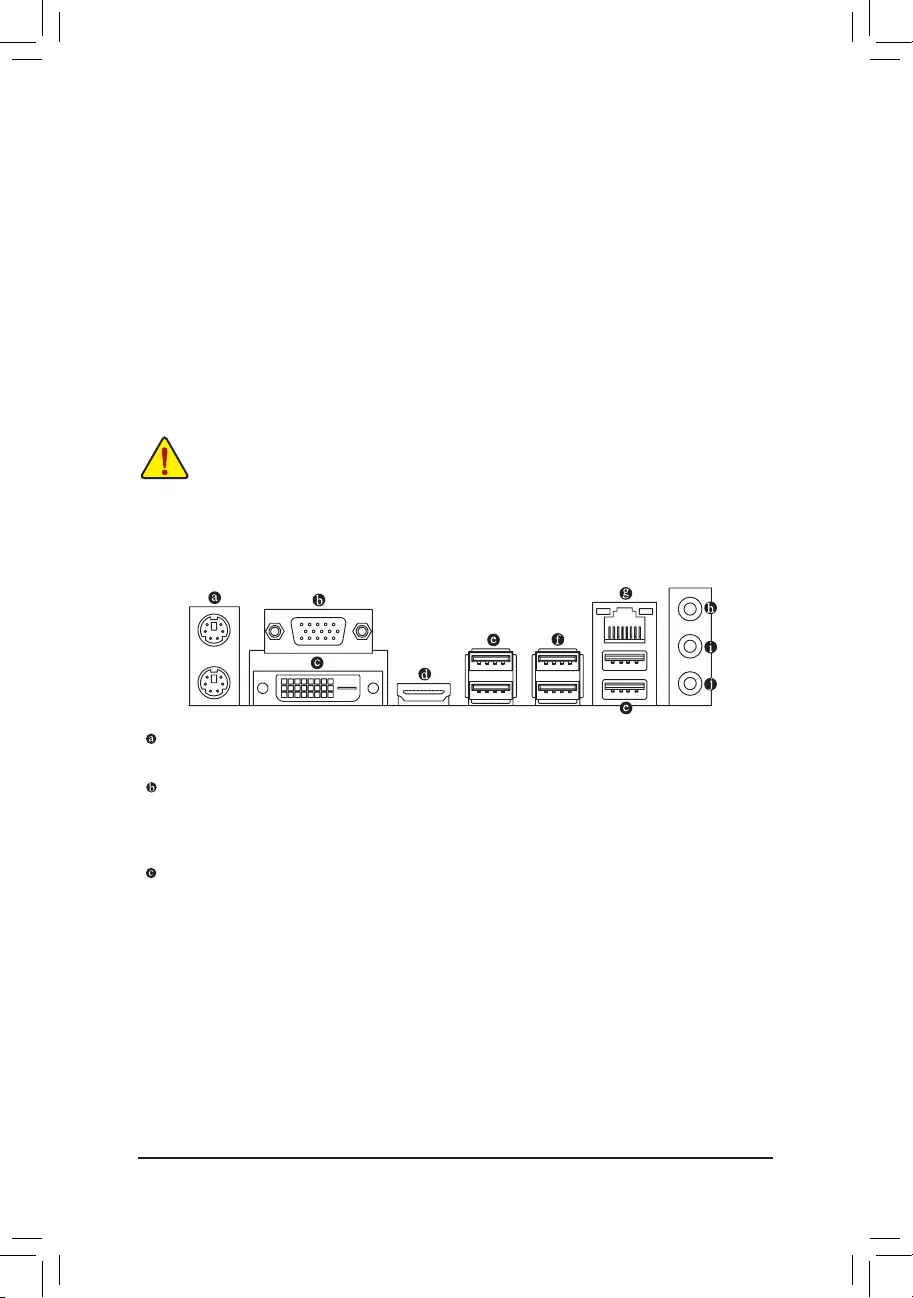
1-6 Back Panel Connectors
PS/2 Keyboard and PS/2 Mouse Port
Use the upper port (green) to connect a PS/2 mouse and the lower port (purple) to connect a PS/2 keyboard.
D-Sub Port
The D-Sub port supports a 15-pin D-Sub connector and supports a maximum resolution of 1920×1200@60 Hz
(the actual resolutions supported depend on the monitor being used). Connect a monitor that supports D-Sub
connection to this port.
DVI-D Port (Note)
TheDVI-DportconformstotheDVI-Dspecicationandsupportsamaximumresolutionof1920×1200@60Hz
(the actual resolutions supported depend on the monitor being used). Connect a monitor that supports DVI-D
connection to this port.
The two DDR4 memory sockets are divided into two channels and each channel has two memory sockets as
followingj:
Channel A: DDR4_1
Channel B: DDR4_2
The two DDR3 memory sockets are divided into two channels and each channel has two memory sockets as
followingk:
Channel A: DDR3_1
Channel B: DDR3_2
(Note) The DVI-D port does not support D-Sub connection by adapter.
jOnly for GA-H110M-S2H/GA-H110M-S2H-GSM.
kOnly for GA-H110M-S2H DDR3.
— 10 —
HDMI Port
The HDMI port is HDCP compliant and supports Dolby True HD and DTS HD
Master Audio formats. It also supports up to 192KHz/16bit 8-channel LPCM
audio output. You can use this port to connect your HDMI-supported monitor. The maximum supported
resolution is 4096×2160@24 Hz, but the actual resolutions supported are dependent on the monitor
being used.
•Whenremovingthecableconnectedtoabackpanelconnector,rstremovethecablefromyour
device and then remove it from the motherboard.
•When removing the cable, pull it straight out from the connector. Do not rock it side to side to prevent
an electrical short inside the cable connector.
Tocongure7.1-channelaudio,youhavetouseanHDfrontpanelaudiomoduleandenablethe
multi-channel audio feature through the audio driver. Please visit GIGABYTE’s website for more
software information.
•Tosetupadual-displayconguration,youmustinstallmotherboarddriversintheoperating
systemrst.
•After installing the HDMI device, make sure to set the default sound playback device to HDMI.
(The item name may differ depending on your operating system.)
USB 2.0/1.1 Port
TheUSBportsupportstheUSB2.0/1.1specication.UsethisportforUSBdevices.
USB 3.0/2.0 Port
TheUSB3.0portsupportstheUSB3.0specicationandiscompatibletotheUSB2.0/1.1specication.
Use this port for USB devices.
RJ-45 LAN Port
The Gigabit Ethernet LAN port provides Internet connection at up to 1 Gbps data rate. The following
describes the states of the LAN port LEDs.
Activity LED
Connection/
Speed LED
LAN Port
Activity LED:Connection/Speed LED:
State Description
Orange 1 Gbps data rate
Green 100 Mbps data rate
Off 10 Mbps data rate
State Description
Blinking Data transmission or receiving is occurring
Off No data transmission or receiving is occurring
Line In (Blue)
The line in jack. Use this audio jack for line in devices such as an optical drive, walkman, etc.
Line Out (Green)
The line out jack. Use this audio jack for a headphone or 2-channel speaker. This jack can be used to
connectfrontspeakersina4/5.1/7.1-channelaudioconguration.
Mic In (Pink)
The Mic in jack.
— 11 —
1-7 Internal Connectors
Read the following guidelines before connecting external devices:
•First make sure your devices are compliant with the connectors you wish to connect.
•Before installing the devices, be sure to turn off the devices and your computer. Unplug the power
cord from the power outlet to prevent damage to the devices.
•After installing the device and before turning on the computer, make sure the device cable has been
securely attached to the connector on the motherboard.
1) ATX_12V_2X4
2) ATX
3) CPU_FAN
4) SYS_FAN
5) SATA3 0/1/2/3
6) F_PANEL
7) F_AUDIO
 SPDIF_O
9) CLR_CMOS
10) F_USB30
11) F_USB1/F_USB2
12) COMA
13) TPM
14) BAT
2
9
10
5
128
1 3
4
6
7
1113
14
— 12 —
131
2412
ATX
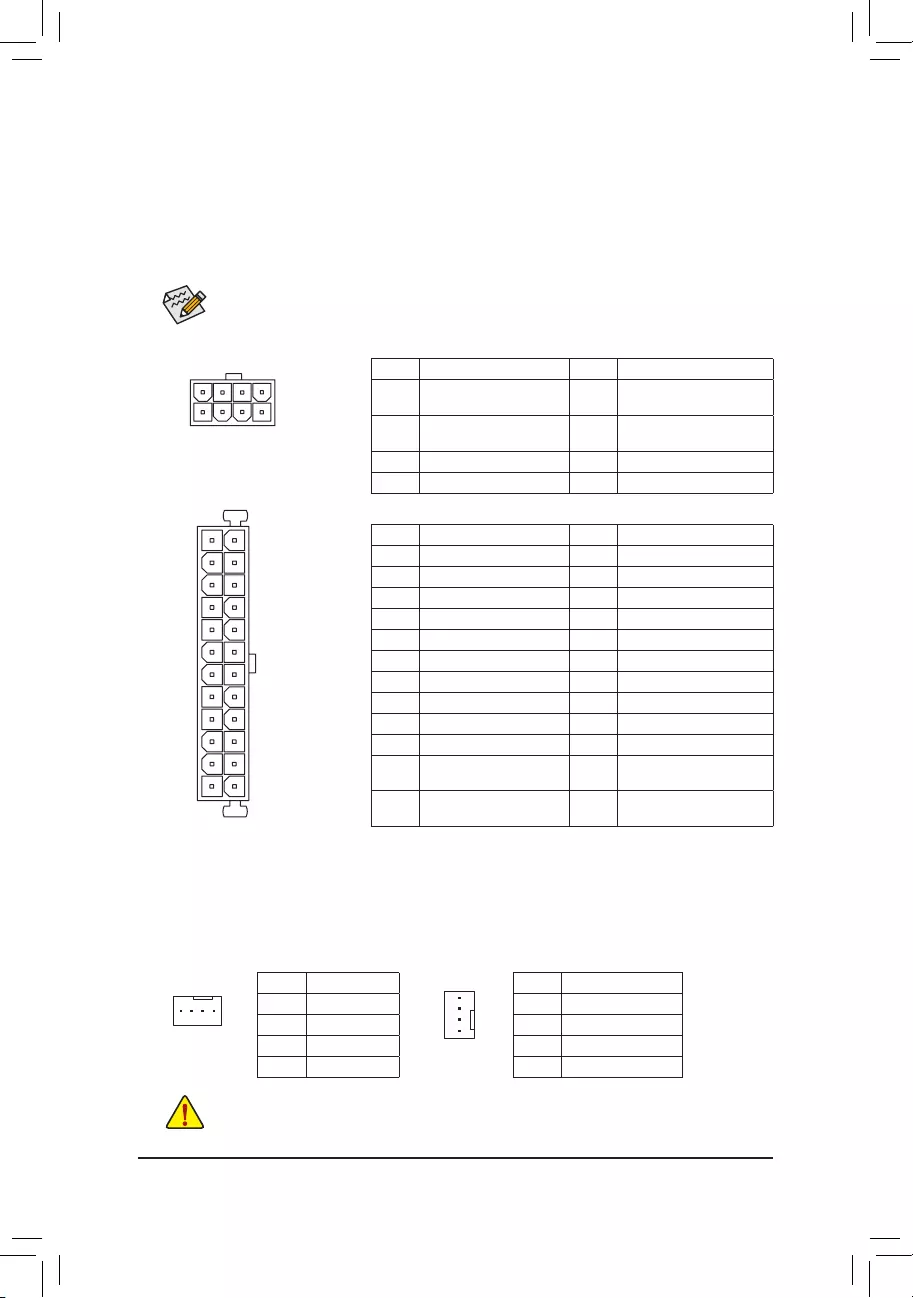
1/2) ATX_12V_2X4/ATX (2×4 12V Power Connector and 2×12 Main Power Connector)
With the use of the power connector, the power supply can supply enough stable power to all the components
onthemotherboard.Beforeconnectingthepowerconnector,rstmakesurethepowersupplyisturned
off and all devices are properly installed. The power connector possesses a foolproof design. Connect the
power supply cable to the power connector in the correct orientation.
The 12V power connector mainly supplies power to the CPU. If the 12V power connector is not connected,
the computer will not start.
To meet expansion requirements, it is recommended that a power supply that can withstand high
power consumption be used (500W or greater). If a power supply is used that does not provide the
required power, the result can lead to an unstable or unbootable system.
ATX:
Pin No. Denition Pin No. Denition
1 3.3V 13 3.3V
2 3.3V 14 -12V
3 GND 15 GND
4 +5V 16 PS_ON (soft On/Off)
5 GND 17 GND
6 +5V 18 GND
7 GND 19 GND
8 Power Good 20 NC
9 5VSB (stand by +5V) 21 +5V
10 +12V 22 +5V
11 +12V (Only for 2×12-pin
ATX)
23 +5V (Only for 2×12-pin ATX)
12 3.3V (Only for 2×12-pin
ATX)
24 GND (Only for 2×12-pin
ATX)
3/4) CPU_FAN/SYS_FAN (Fan Headers)
The fan headers on this motherboard are 4-pin. Most fan headers possess a foolproof insertion design.
When connecting a fan cable, be sure to connect it in the correct orientation (the black connector wire is
the ground wire). The speed control function requires the use of a fan with fan speed control design. For
optimum heat dissipation, it is recommended that a system fan be installed inside the chassis.
CPU_FAN: SYS_FAN:
Pin No. Denition
1 GND
2 +12V
3 Sense
4 Speed Control
Pin No. Denition
1 GND
2 Speed Control
3 Sense
4 VCC
•Be sure to connect fan cables to the fan headers to prevent your CPU and system from overheating.
Overheating may result in damage to the CPU or the system may hang.
•Thesefanheadersarenotcongurationjumperblocks.Donotplaceajumpercapontheheaders.
CPU_FAN
1
SYS_FAN
1
ATX_12V_2X4:
Pin No. Denition Pin No. Denition
1GND (Only for 2×4-pin
12V)
5 +12V (Only for 2×4-pin 12V)
2GND (Only for 2×4-pin
12V)
6 +12V (Only for 2×4-pin 12V)
3 GND 7 +12V
4 GND 8 +12V
ATX_12V_2X4
41
85
— 13 —
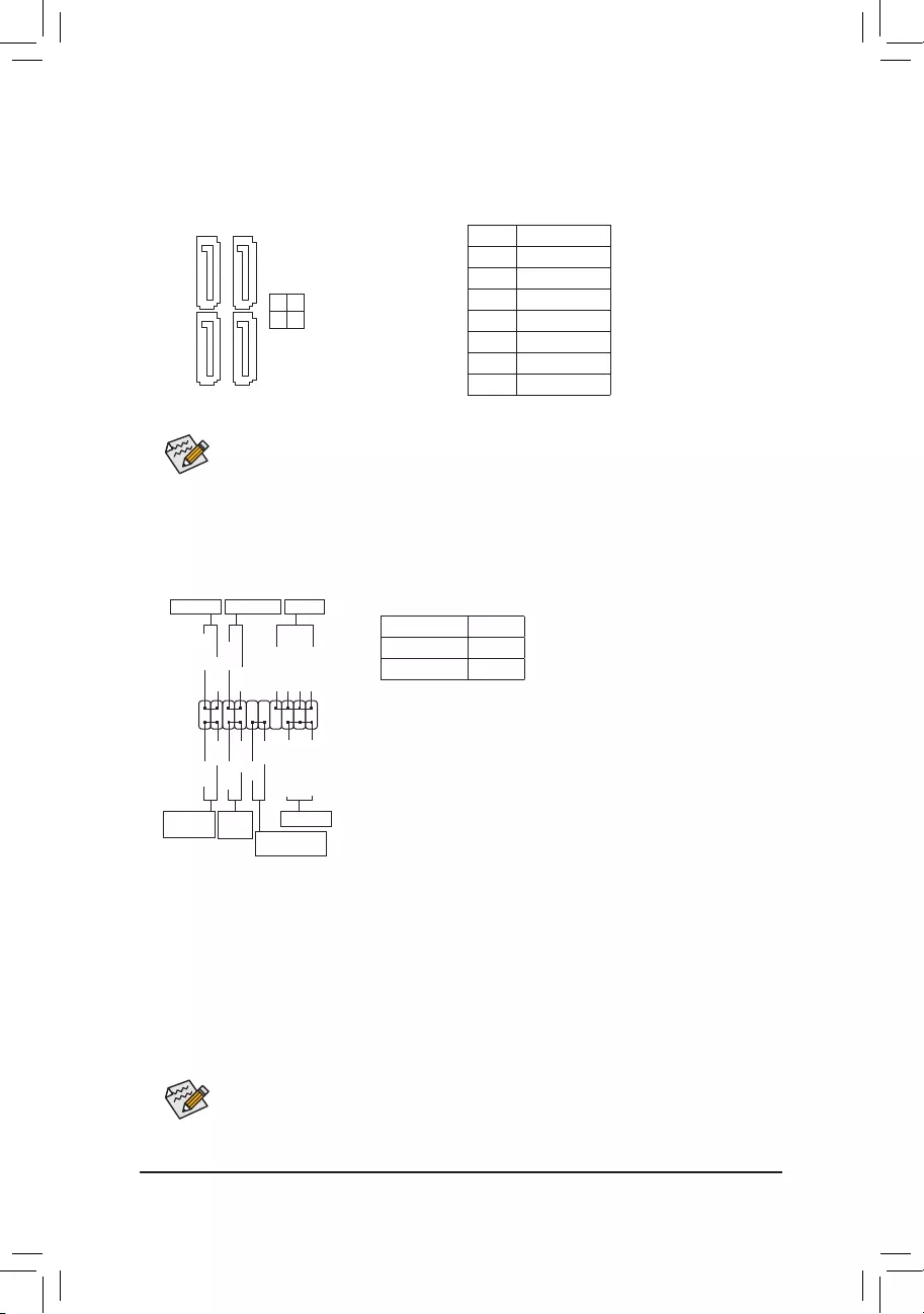
5) SATA3 0/1/2/3 (SATA 6Gb/s Connectors)
The SATA connectors conform to SATA 6Gb/s standard and are compatible with SATA 3Gb/s and SATA 1.5Gb/s
standard. Each SATA connector supports a single SATA device.
Pin No. Denition
1 GND
2 TXP
3 TXN
4 GND
5 RXN
6 RXP
7 GND
To enable hot-plugging for the SATA ports, refer to Chapter 2, «BIOS Setup,» «Peripherals\SATA
Conguration,»formoreinformation.
SATA3
3 2
1 0
1 1
7 7
The front panel design may differ by chassis. A front panel module mainly consists of power switch,
reset switch, power LED, hard drive activity LED, speaker and etc. When connecting your chassis
front panel module to this header, make sure the wire assignments and the pin assignments are
matched correctly.
6) F_PANEL (Front Panel Header)
Connect the power switch, reset switch, speaker, chassis intrusion switch/sensor and system status indicator
on the chassis to this header according to the pin assignments below. Note the positive and negative pins
before connecting the cables.
System Status LED
S0 On
S3/S4/S5 Off
•PW (Power Switch):
Connects to the power switch on the chassis front panel. You may
congurethewaytoturnoffyoursystemusingthepowerswitch(referto
Chapter 2, «BIOS Setup,» «Power Management,» for more information).
•SPEAK (Speaker):
Connects to the speaker on the chassis front panel. The system reports
system startup status by issuing a beep code. One single short beep
will be heard if no problem is detected at system startup.
•PLED/PWR_LED (Power LED):
Connects to the power status indicator
on the chassis front panel. The LED is on
when the system is operating. The LED is
off when the system is in S3/S4 sleep state
or powered off (S5).
•HD (Hard Drive Activity LED):
Connects to the hard drive activity LED on the chassis front panel. The LED is on when the hard drive is reading
or writing data.
•RES (Reset Switch):
Connects to the reset switch on the chassis front panel. Press the reset switch to restart the computer if the
computer freezes and fails to perform a normal restart.
•CI (Chassis Intrusion Header):
Connects to the chassis intrusion switch/sensor on the chassis that can detect if the chassis cover has been
removed. This function requires a chassis with a chassis intrusion switch/sensor.
•NC: No connection.
Power LED
1
2
19
20
CI-
CI+
PLED-
PW-
SPEAK+
SPEAK-
PLED+
PW+
Power LED
HD-
RES+
HD+
RES-
Hard Drive
Activity LED
Reset
Switch Chassis Intrusion
Header
Power Switch Speaker
F_USB30 F_U
B_
F_ F_
_
B
BS_
B
SB_
B
_S
S_
_
B
_U
_
B
S
123
123
123
123
1
1
1
1
BSS
S
_S
SSU
1 2 3
S3 BSSS U
__ 3
F_USB3F
S _
S _
S _
SF
B_
F
_0
S
S
_0F
_F
_
_
__B
PWR_LED-
PWR_LED+
PWR_LED-
NC
NC
— 14 —
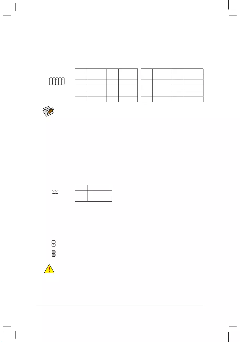
7) F_AUDIO (Front Panel Audio Header)
ThefrontpanelaudioheadersupportsIntelHighDenitionaudio(HD)andAC’97audio.Youmayconnect
your chassis front panel audio module to this header. Make sure the wire assignments of the module
connector match the pin assignments of the motherboard header. Incorrect connection between the module
connector and the motherboard header will make the device unable to work or even damage it.
•The front panel audio header supports HD audio by default.
•Audio signals will be present on both of the front and back panel audio connections simultaneously.
•Some chassis provide a front panel audio module that has separated connectors on each wire
instead of a single plug. For information about connecting the front panel audio module that has
different wire assignments, please contact the chassis manufacturer.
For HD Front Panel Audio: For AC’97 Front Panel Audio:
Pin No. Denition Pin No. Denition
1 MIC2_L 6 Sense
2 GND 7 FAUDIO_JD
3 MIC2_R 8 No Pin
4 -ACZ_DET 9 LINE2_L
5 LINE2_R 10 Sense
Pin No. Denition Pin No. Denition
1 MIC 6 NC
2 GND 7 NC
3 MIC Power 8 No Pin
4 NC 9 Line Out (L)
5Line Out (R) 10 NC
1
2
9
10
SPDIF_O (S/PDIF Out Header)
This header supports digital S/PDIF Out and connects a S/PDIF digital audio cable (provided by expansion
cards) for digital audio output from your motherboard to certain expansion cards like graphics cards and
sound cards. For example, some graphics cards may require you to use a S/PDIF digital audio cable for
digital audio output from your motherboard to your graphics card if you wish to connect an HDMI display
to the graphics card and have digital audio output from the HDMI display at the same time. For information
about connecting the S/PDIF digital audio cable, carefully read the manual for your expansion card.
Pin No. Denition
1 SPDIFO
2 GND
9) CLR_CMOS (Clear CMOS Jumper)
UsethisjumpertocleartheBIOScongurationandresettheCMOSvaluestofactorydefaults.Toclear
the CMOS values, use a metal object like a screwdriver to touch the two pins for a few seconds.
•Always turn off your computer and unplug the power cord from the power outlet before clearing
the CMOS values.
•After system restart, go to BIOS Setup to load factory defaults (select Load Optimized Defaults) or
manuallyconguretheBIOSsettings(refertoChapter2,«BIOSSetup,»forBIOScongurations).
Open: Normal
Short: Clear CMOS Values
1
— 15 —
11) F_USB1/F_USB2 (USB 2.0/1.1 Headers)
TheheadersconformtoUSB2.0/1.1specication.EachUSBheadercanprovidetwoUSBportsviaan
optional USB bracket. For purchasing the optional USB bracket, please contact the local dealer.
Pin No. Denition Pin No. Denition
1 Power (5V) 6 USB DY+
2 Power (5V) 7 GND
3 USB DX- 8 GND
4 USB DY— 9 No Pin
5 USB DX+ 10 NC
•Do not plug the IEEE 1394 bracket (2×5-pin) cable into the USB 2.0/1.1 header.
•Prior to installing the USB bracket, be sure to turn off your computer and unplug the power cord
from the power outlet to prevent damage to the USB bracket.
10
9
2
1
Pin No. Denition Pin No. Denition
1 VBUS 11 D2+
2 SSRX1- 12 D2-
3 SSRX1+ 13 GND
4 GND 14 SSTX2+
5 SSTX1- 15 SSTX2-
6SSTX1+ 16 GND
7 GND 17 SSRX2+
8 D1- 18 SSRX2-
9 D1+ 19 VBUS
10 NC 20 No Pin
10) F_USB30 (USB 3.0/2.0 Header)
Theheader conforms to USB 3.0/2.0specication and each header canprovide two USB ports. For
purchasing the optional 3.5″ front panel that provides two USB 3.0/2.0 ports, please contact the local dealer.
F_USB30 F_U
B_
F_ F_
_
B
BS_
B
SB_
B
_S
S_
_
B
_U
_
B
S
123
123
123
123
1
1
1
1
BSS
S
_S
SSU
1 2 3
S3 BSSS U
__ 3
F_USB3F
S _
S _
S _
SF
B_
F
_0
S
S
_0F
_F
_
_
__B
10
20 1
11
Pin No. Denition Pin No. Denition
1 NDCD- 6 NDSR-
2 NSIN 7 NRTS-
3 NSOUT 8 NCTS-
4 NDTR- 9 NRI-
5 GND 10 No Pin
12) COM (Serial Port Header)
The COM header can provide one serial port via an optional COM port cable. For purchasing the optional
COM port cable, please contact the local dealer.
10
9
2
1
— 16 —
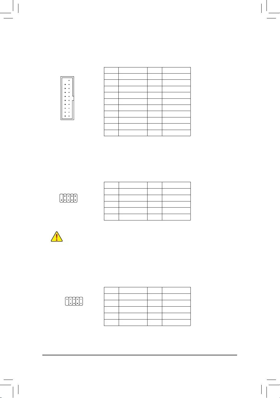
13) TPM (Trusted Platform Module Header)
You may connect a TPM (Trusted Platform Module) to this header.
Pin No. Denition Pin No. Denition
1 LCLK 11 LAD0
2 GND 12 GND
3 LFRAME 13 NC
4 No Pin 14 NC
5 LRESET 15 SB3V
6 NC 16 SERIRQ
7 LAD3 17 GND
8 LAD2 18 NC
9 VCC3 19 NC
10 LAD1 20 SUSCLK
20
19
2
1
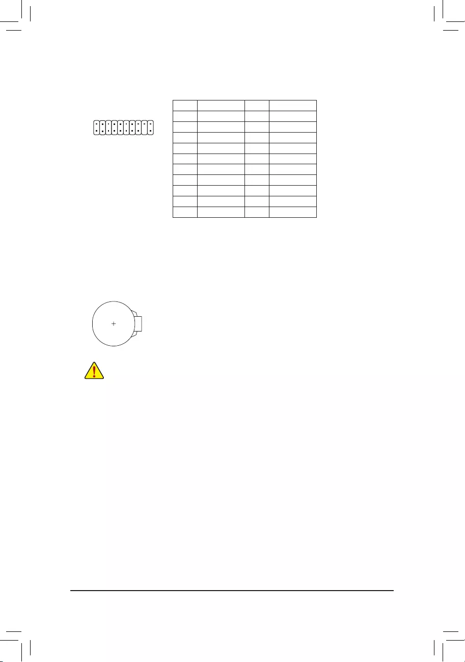
14) BAT (Battery)
Thebatteryprovidespowertokeepthevalues(suchasBIOScongurations,date,andtimeinformation)
in the CMOS when the computer is turned off. Replace the battery when the battery voltage drops to a low
level, or the CMOS values may not be accurate or may be lost.
You may clear the CMOS values by removing the battery:
1. Turn off your computer and unplug the power cord.
2. Gently remove the battery from the battery holder and wait for one minute. (Or use a metal
object like a screwdriver to touch the positive and negative terminals of the battery holder,
making them short for 5 seconds.)
3. Replace the battery.
4. Plug in the power cord and restart your computer.
•Always turn off your computer and unplug the power cord before replacing the battery.
•Replace the battery with an equivalent one. Danger of explosion if the battery is replaced with
an incorrect model.
•Contact the place of purchase or local dealer if you are not able to replace the battery by yourself
or uncertain about the battery model.
•When installing the battery, note the orientation of the positive side (+) and the negative side (-) of
the battery (the positive side should face up).
•Used batteries must be handled in accordance with local environmental regulations.
— 17 —
BIOS (Basic Input and Output System) records hardware parameters of the system in the CMOS on the
motherboard. Its major functions include conducting the Power-On Self-Test (POST) during system startup,
saving system parameters and loading operating system, etc. BIOS includes a BIOS Setup program that allows
theusertomodifybasicsystemcongurationsettingsortoactivatecertainsystemfeatures.
When the power is turned off, the battery on the motherboard supplies the necessary power to the CMOS to
keepthecongurationvaluesintheCMOS.
To access the BIOS Setup program, press the <Delete> key during the POST when the power is turned on.
To upgrade the BIOS, use either the GIGABYTE Q-Flash or @BIOS utility.
•Q-Flash allows the user to quickly and easily upgrade or back up BIOS without entering the operating system.
•@BIOS is a Windows-based utility that searches and downloads the latest version of BIOS from the Internet
and updates the BIOS.
Chapter 2 BIOS Setup
•BecauseBIOSashingispotentiallyrisky,ifyoudonotencounterproblemsusingthecurrentversionof
BIOS,itisrecommendedthatyounotashtheBIOS.ToashtheBIOS,doitwithcaution.Inadequate
BIOSashingmayresultinsystemmalfunction.
•It is recommended that you not alter the default settings (unless you need to) to prevent system
instability or other unexpected results. Inadequately altering the settings may result in system’s failure
to boot. If this occurs, try to clear the CMOS values and reset the board to default values. (Refer
to the «Load Optimized Defaults» section in this chapter or introductions of the battery/clear CMOS
jumper in Chapter 1 for how to clear the CMOS values.)
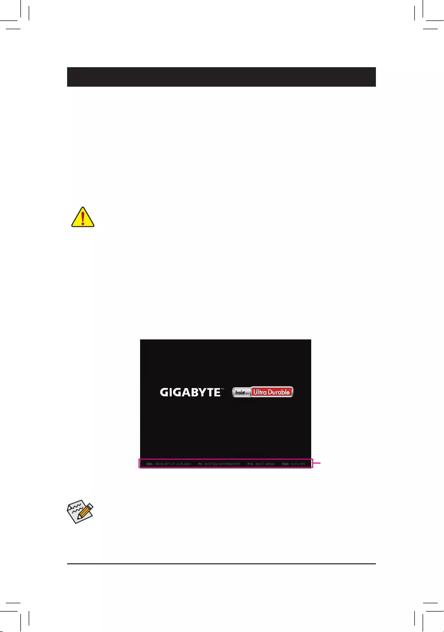
2-1 Startup Screen
The following startup Logo screen will appear when the computer boots.
(Sample BIOS Version: GA-H110M-S2H DDR3 F1a)
Function Keys
•When the system is not stable as usual, select the Load Optimized Defaults item to set your system to its defaults.
•The BIOS Setup menus described in this chapter are for reference only and may differ by BIOS version.
On the main menu of the BIOS Setup program, press arrow keys to move among the items and press <Enter>
to accept or enter a sub-menu. Or you can use your mouse to select the item you want.
— 18 —
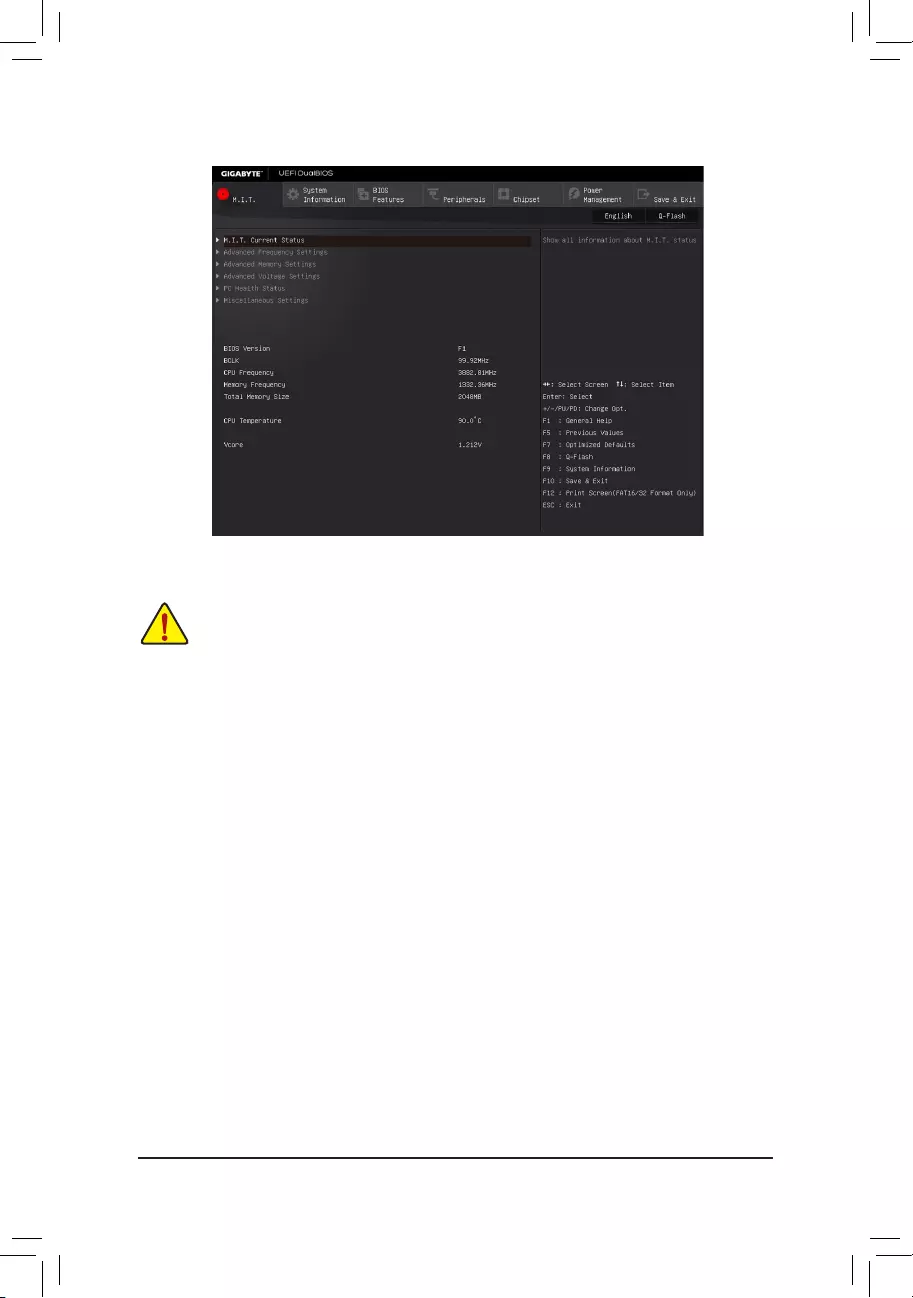
2-2 M.I.T.
This section provides information on the BIOS version, CPU base clock, CPU frequency, memory frequency,
total memory size, CPU temperature and CPU voltage, etc.
Whether the system will work stably with the overclock/overvoltage settings you made is dependent on your overall
systemcongurations.Incorrectlydoingoverclock/overvoltagemayresultindamagetoCPU,chipset,ormemory
and reduce the useful life of these components. This page is for advanced users only and we recommend you not to
alter the default settings to prevent system instability or other unexpected results. (Inadequately altering the settings
may result in system’s failure to boot. If this occurs, clear the CMOS values and reset the board to default values.)
`M.I.T. Current Status
This screen provides information on CPU/memory frequencies/parameters.
`Advanced Frequency Settings
&Graphics Slice Ratio
Allows you to set the Graphics Slice Ratio.
&Graphics UnSlice Ratio
Allows you to set the Graphics UnSlice Ratio.
&CPU Clock Ratio
Allows you to alter the clock ratio for the installed CPU. The adjustable range is dependent on the CPU
being installed.
&CPU Frequency
Displays the current operating CPU frequency.
`Advanced CPU Core Settings
&CPU Clock Ratio, CPU Frequency
The settings above are synchronous to those under the same items on the Advanced Frequency Settings
menu.
&Uncore Ratio
Allows you to set the CPU Uncore ratio. The adjustable range is dependent on the CPU being used.
— 19 —

(Note) This item is present only when you install a CPU that supports this feature. For more information about
Intel® CPUs’ unique features, please visit Intel’s website.
&Uncore Frequency
Displays the current CPU Uncore frequency.
&CPU Flex Ratio Override
Enables or disables the CPU Flex Ratio. The maximum CPU clock ratio will be based on the CPU Flex
Ratio Settings value if CPU Clock Ratio is set to Auto. (Default: Disabled)
&CPU Flex Ratio Settings
Allows you to set the CPU Flex Ratio. The adjustable range may vary by CPU. (Default: 20)
&Intel(R) Turbo Boost Technology (Note)
Allows you to determine whether to enable the Intel CPU Turbo Boost technology. Auto lets the BIOS
automaticallycongurethissetting.(Default:Auto)
&Turbo Ratio (Note)
Allows you to set the CPU Turbo ratios for different number of active cores. Auto sets the CPU Turbo ratios
accordingtotheCPUspecications.(Default:Auto)
&Power Limit TDP (Watts) / Power Limit Time
AllowsyoutosetthepowerlimitforCPUTurbomodeandhowlongittakestooperateatthespecied
powerlimit.Ifthespeciedvalueisexceeded,theCPUwillautomaticallyreducethecorefrequencyin
order to reduce the power. AutosetsthecurrentlimitaccordingtotheCPUspecications.(Default:Auto)
&Core Current Limit (Amps)
AllowsyoutosetacurrentlimitforCPUTurbomode.WhentheCPUcurrentexceedsthespeciedcurrent
limit, the CPU will automatically reduce the core frequency in order to reduce the current. Auto sets the
powerlimitaccordingtotheCPUspecications.(Default:Auto)
&No. of CPU Cores Enabled (Note)
Allows you to select the number of CPU cores to enable in an Intel® multi-core CPU (the number of CPU
cores may vary by CPU). AutoletstheBIOSautomaticallycongurethissetting.(Default:Auto)
&Hyper-Threading Technology (Note)
Allows you to determine whether to enable multi-threading technology when using an Intel® CPU that
supports this function. This feature only works for operating systems that support multi-processor mode.
AutoletstheBIOSautomaticallycongurethissetting.(Default:Auto)
&CPU Enhanced Halt (C1E) (Note)
Enables or disables Intel® CPU Enhanced Halt (C1E) function, a CPU power-saving function in system
halt state. When enabled, the CPU core frequency and voltage will be reduced during system halt state to
decrease power consumption. AutoletstheBIOSautomaticallycongurethissetting.(Default:Auto)
&C3 State Support (Note)
Allows you to determine whether to let the CPU enter C3 mode in system halt state. When enabled, the
CPU core frequency and voltage will be reduced during system halt state to decrease power consumption.
The C3 state is a more enhanced power-saving state than C1. AutoletstheBIOSautomaticallycongure
this setting. (Default: Auto)
&C6/C7 State Support (Note)
Allows you to determine whether to let the CPU enter C6/C7 mode in system halt state. When enabled, the
CPU core frequency and voltage will be reduced during system halt state to decrease power consumption.
The C6/C7 state is a more enhanced power-saving state than C3. AutoletstheBIOSautomaticallycongure
this setting. (Default: Auto)
&C8 State Support (Note)
Allows you to determine whether to let the CPU enter C8 mode in system halt state. When enabled, the CPU
core frequency and voltage will be reduced during system halt state to decrease power consumption. The
C8 state is a more enhanced power-saving state than C6/C7. AutoletstheBIOSautomaticallycongure
this setting. (Default: Auto)
— 20 —

&Package C State Limit (Note 1)
Allows you to specify the C-state limit for the processor. AutoletstheBIOSautomaticallycongurethis
setting. (Default: Auto)
&CPU Thermal Monitor (Note 1)
Enables or disables Intel® Thermal Monitor function, a CPU overheating protection function. When enabled,
the CPU core frequency and voltage will be reduced when the CPU is overheated. Auto lets the BIOS
automaticallycongurethissetting.(Default:Auto)
&CPU EIST Function (Note 1)
Enables or disables Enhanced Intel® Speed Step Technology (EIST). Depending on CPU loading, Intel
EIST technology can dynamically and effectively lower the CPU voltage and core frequency to decrease
average power consumption and heat production. AutoletstheBIOSautomaticallycongurethissetting.
(Default: Auto)
&Voltage Optimization
Allows you to determine whether to enable voltage optimization to reduce power consumption. (Default:
Enabled)
&RSR
Allows you to determine whether to automatically lower the CPU turbo ratio if the CPU voltage/temperature
is too high. (Default: Enabled)
&Hardware Prefetcher
Allows you to determine whether to enable hardware prefetcher to prefetch data and instructions from the
memory into the cache. (Default: Enabled)
&Adjacent Cache Line Prefetch
Allows you to determine whether to enable the adjacent cache line prefetch mechanism that lets the
processor retrieve the requested cache line as well as the subsequent cache line. (Default: Enabled)
&System Memory Multiplier
Allows you to set the system memory multiplier. Auto sets memory multiplier according to memory SPD
data. (Default: Auto)
&Memory Frequency (MHz)
Therstmemoryfrequencyvalueisthenormaloperatingfrequencyofthememorybeingused;thesecond
is the memory frequency that is automatically adjusted according to the System Memory Multiplier settings.
`Advanced Memory Settings
&System Memory Multiplier, Memory Frequency(MHz)
The settings above are synchronous to those under the same items on the Advanced Frequency Settings
menu.
&Memory Boot Mode (Note 2)
Provides memory detection and training methods.
Auto LetstheBIOSautomaticallycongurethissetting.(Default)
EnableFastBoot Skipmemorydetectionandtraininginsomespeciccriteriaforfastermemory
boot.
Disable Fast Boot Detect and train memory at every single boot.
(Note 1) This item is present only when you install a CPU that supports this feature. For more information about
Intel® CPUs’ unique features, please visit Intel’s website.
(Note 2) This item is present only when you install a CPU and a memory module that support this feature.
— 21 —

&Memory Enhancement Settings
Provides three different memory performance enhancement settings: Normal (basic performance), Enhanced
Stability, and Enhanced Performance. (Default: Normal)
&Memory Timing Mode
Manual and Advanced Manual allows the Memory Multiplier Tweaker, Channel Interleaving, Rank
Interleaving,andmemorytimingsettingsbelowtobecongurable.Optionsare:Auto(default),Manual,
Advanced Manual.
&ProleDDRVoltage
Displays the memory voltage.
&Memory Multiplier Tweaker
Provides different levels of memory auto-tuning. (Default: Auto)
&Channel Interleaving
Enables or disables memory channel interleaving. Enabled allows the system to simultaneously access
different channels of the memory to increase memory performance and stability. Auto lets the BIOS
automaticallycongurethissetting.(Default:Auto)
&Rank Interleaving
Enables or disables memory rank interleaving. Enabled allows the system to simultaneously access different
ranks of the memory to increase memory performance and stability. Auto lets the BIOS automatically
congurethissetting.(Default:Auto)
`IMC Timing Settings
This sub-menu provides options for tuning memory compatibility and stability.
`Channel A/B Memory Sub Timings
This sub-menu provides memory timing settings for each channel of memory. The respective timing setting
screensarecongurableonlywhenMemory Timing Mode is set to Manual or Advanced Manual. Note: Your
system may become unstable or fail to boot after you make changes on the memory timings. If this occurs,
please reset the board to default values by loading optimized defaults or clearing the CMOS values.
`Advanced Voltage Settings
`Advanced Power Settings
&CPU Vcore Loadline Calibration
AllowsyoutocongureLoad-LineCalibrationfortheCPUVcorevoltage.Selectingahigherlevelkeeps
the CPU Vcore voltage more consistent with what is set in BIOS under heavy load. Auto lets the BIOS
automaticallycongurethissettingandsetsthevoltagefollowingIntel®‘sspecications.(Default:Auto)
&VAXG Loadline Calibration
AllowsyoutocongureLoad-LineCalibrationfortheCPUVAXGvoltage.Selectingahigherlevelkeeps
the CPU VAXG voltage more consistent with what is set in BIOS under heavy load. Auto lets the BIOS
automaticallycongurethissettingandsetsthevoltagefollowingIntel®‘sspecications.(Default:Auto)
`CPU Core Voltage Control
This section provides CPU voltage control options.
`DRAM Voltage Control
This section provides memory voltage control options.
`Internal VR Control
This section provides VR voltage control options.
— 22 —

`PC Health Status
&Reset Case Open Status
Disabled Keeps or clears the record of previous chassis intrusion status. (Default)
Enabled Clears the record of previous chassis intrusion status and the Case Openeldwill
show «No» at next boot.
&Case Open
Displays the detection status of the chassis intrusion detection device attached to the motherboard CI
header.Ifthesystemchassiscoverisremoved,thiseldwillshow»Yes»,otherwiseitwillshow»No».To
clear the chassis intrusion status record, set Reset Case Open Status to Enabled, save the settings to
the CMOS, and then restart your system.
& CPU Vcore/CPU VCCSA/DRAM Channel A/B Voltage/+3.3V/+5V/+12V/CPU VAXG
Displays the current system voltages.
&CPU/System Temperature
Displays current CPU/system temperature.
&CPU/System Fan Speed
Displays current CPU/system fan speeds.
&CPU/System Temperature Warning
Sets the warning threshold for CPU/system temperature. When temperature exceeds the threshold, BIOS
will emit warning sound. Options are: Disabled (default), 60oC/140oF, 70oC/158oF, 80oC/176oF, 90oC/194oF.
& CPU/System Fan Fail Warning
Allows the system to emit warning sound if the fan is not connected or fails. Check the fan condition or fan
connection when this occurs. (Default: Disabled)
&CPU Fan Speed Control (CPU_FAN Connector)
Allows you to determine whether to enable the fan speed control function and adjust the fan speed.
Normal Allows the fan to run at different speeds according to the CPU temperature. You
can adjust the fan speed with System Information Viewer based on your system
requirements. (Default)
Silent Allows the fan to run at slow speeds.
Manual Allows you to control the fan speed under the Fan Speed Percentage item.
Full Speed Allows the fan to run at full speeds.
&Fan Speed Percentage
Allowsyoutocontrolthefanspeed.ThisitemiscongurableonlywhenCPU Fan Speed Control is set
to Manual. Options are: 0.75 PWM value /oC ~ 2.50 PWM value /oC.
&System Fan Speed Control (SYS_FAN Connector)
Allows you to determine whether to enable the fan speed control function and adjust the fan speed.
Normal Allows the fan to run at different speeds according to the system temperature. You
can adjust the fan speed with System Information Viewer based on your system
requirements. (Default)
Silent Allows the fan to run at slow speeds.
Manual Allows you to control the fan speed under the Fan Speed Percentage item.
Full Speed Allows the fan to run at full speeds.
&Fan Speed Percentage
Allowsyoutocontrolthefanspeed.ThisitemiscongurableonlywhenSystem Fan Speed Control is
set to Manual. Options are: 0.75 PWM value /oC ~ 2.50 PWM value /oC.
— 23 —
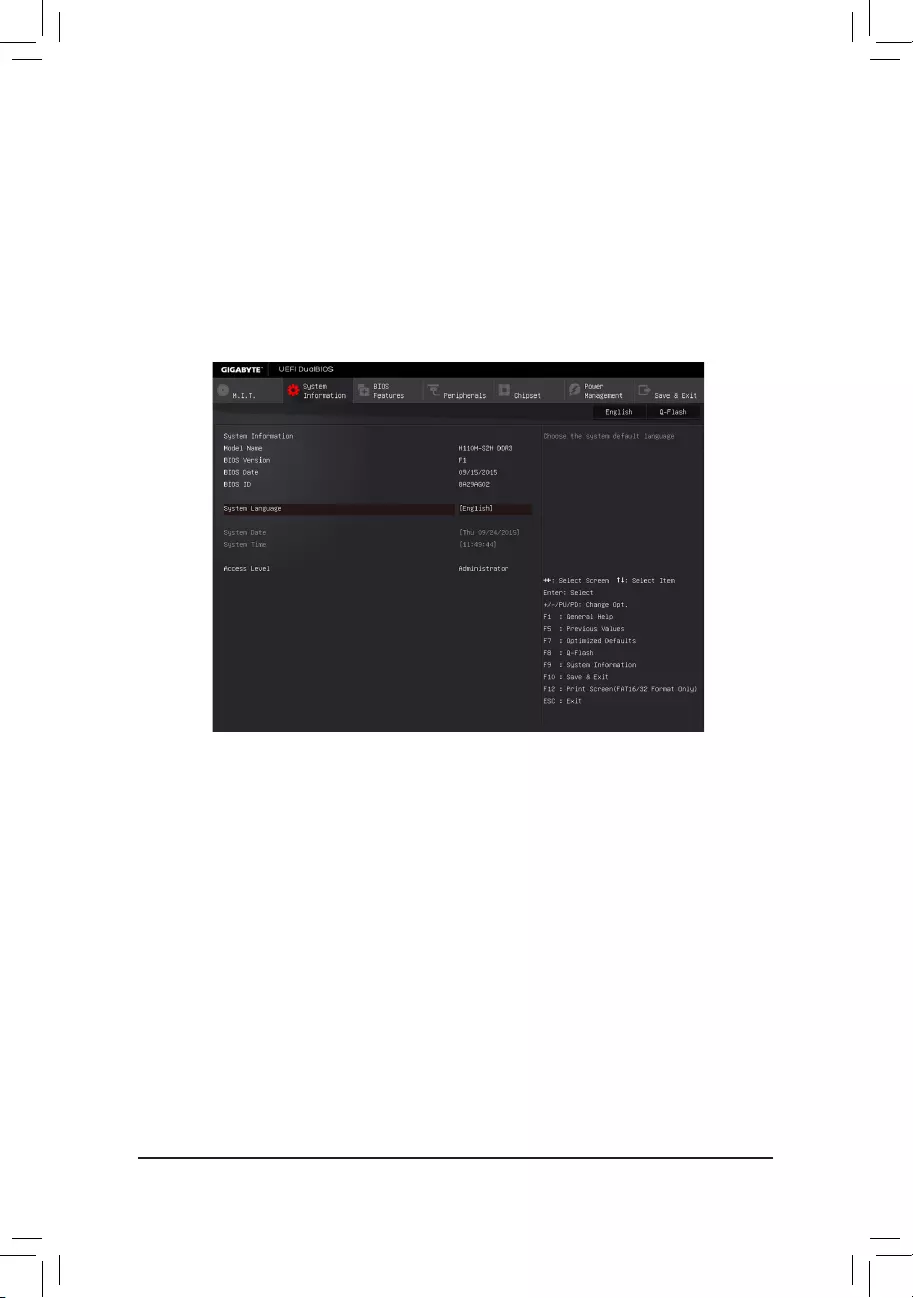
2-3 System Information
This section provides information on your motherboard model and BIOS version. You can also select the default
language used by the BIOS and manually set the system time.
&System Language
Selects the default language used by the BIOS.
&System Date
Sets the system date. The date format is week (read-only), month, date, and year. Use <Enter> to switch
betweentheMonth,Date,andYeareldsandusethe<PageUp>or<PageDown>keytosetthedesired
value.
&System Time
Sets the system time. The time format is hour, minute, and second. For example, 1 p.m. is 13:00:00. Use
<Enter>toswitchbetweentheHour,Minute,andSecondeldsandusethe<PageUp>or<PageDown>
key to set the desired value.
&Access Level
Displays the current access level depending on the type of password protection used. (If no password is
set, the default will display as Administrator.) The Administrator level allows you to make changes to all
BIOS settings; the User level only allows you to make changes to certain BIOS settings but not all.
`Miscellaneous Settings
&Max Link Speed
Allows you to set the operation mode of the PCI Express slots to Gen 1, Gen 2, or Gen 3. Actual operation
modeissubjecttothehardwarespecicationofeachslot.AutoletstheBIOSautomaticallycongurethis
setting. (Default: Auto)
&3DMark01 Enhancement
Allows you to determine whether to enhance some legacy benchmark performance. (Default: Disabled)
— 24 —
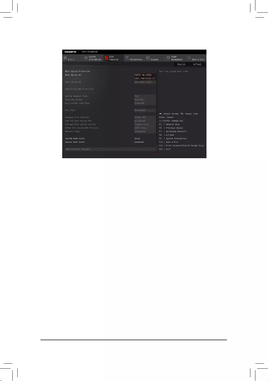
2-4 BIOS Features
&Boot Option Priorities
Speciestheoverallbootorderfromtheavailabledevices.
RemovablestoragedevicesthatsupportGPTformatwillbeprexedwith«UEFI:»stringonthebootdevice
list.TobootfromanoperatingsystemthatsupportsGPTpartitioning,selectthedeviceprexedwith«UEFI:»
string.
Or if you want to install an operating system that supports GPT partitioning such as Windows 7 64-bit, select
theopticaldrivethatcontainstheWindows764-bitinstallationdiskandisprexedwith»UEFI:»string.
& Hard Drive/CD/DVD ROM Drive/Floppy Drive/Network Device BBS Priorities
Speciesthebootorderforaspecicdevicetype,suchasharddrives,opticaldrives,oppydiskdrives,
and devices that support Boot from LAN function, etc. Press <Enter> on this item to enter the submenu that
presents the devices of the same type that are connected. This item is present only if at least one device
for this type is installed.
&Bootup NumLock State
Enables or disables Numlock feature on the numeric keypad of the keyboard after the POST. (Default: On)
&Security Option
Specieswhetherapasswordisrequiredeverytimethesystemboots,oronlywhenyouenterBIOSSetup.
Afterconguringthisitem,setthepassword(s)undertheAdministratorPassword/UserPassworditem.
Setup A password is only required for entering the BIOS Setup program.
System A password is required for booting the system and for entering the BIOS Setup program.
(Default)
&Full Screen LOGO Show
Allows you to determine whether to display the GIGABYTE Logo at system startup. Disabled skips the
GIGABYTE Logo when the system starts up. (Default: Enabled)
&Fast Boot
Enables or disables Fast Boot to shorten the OS boot process. Ultra Fast provides the fastest bootup
speed. (Default: Disabled)
— 25 —

&SATA Support
All Sata Devices All SATA devices are functional in the operating system and during the POST.
(Default)
Last Boot HDD Only Except for the previous boot drive, all SATA devices are disabled before the OS
boot process completes.
ThisitemiscongurableonlywhenFast Boot is set to Enabled or Ultra Fast.
&VGA Support
Allows you to select which type of operating system to boot.
Auto Enables legacy option ROM only.
EFI Driver Enables EFI option ROM. (Default)
ThisitemiscongurableonlywhenFast Boot is set to Enabled or Ultra Fast.
&USB Support
Disabled All USB devices are disabled before the OS boot process completes.
Full Initial All USB devices are functional in the operating system and during the POST.
Partial Initial Part of the USB devices are disabled before the OS boot process completes.
(Default)
ThisitemiscongurableonlywhenFast Boot is set to Enabled. This function is disabled when Fast Boot
is set to Ultra Fast.
&PS2 Devices Support
Disabled All PS/2 devices are disabled before the OS boot process completes.
Enabled All PS/2 devices are functional in the operating system and during the POST.
(Default)
ThisitemiscongurableonlywhenFast Boot is set to Enabled. This function is disabled when Fast Boot
is set to Ultra Fast.
&NetWork Stack Driver Support
Disabled Disables booting from the network. (Default)
Enabled Enables booting from the network.
ThisitemiscongurableonlywhenFast Boot is set to Enabled or Ultra Fast.
&Next Boot After AC Power Loss
Normal Boot Enables normal bootup upon the return of the AC power. (Default)
Fast Boot Keeps the Fast Boot settings upon the return of the AC power.
ThisitemiscongurableonlywhenFast Boot is set to Enabled or Ultra Fast.
&Windows 8/10 Features
Allows you to select the operating system to be installed. (Default: Other OS)
&CSM Support
Enables or disables UEFI CSM (Compatibility Support Module) to support a legacy PC boot process.
Enabled Enables UEFI CSM. (Default)
Disabled Disables UEFI CSM and supports UEFI BIOS boot process only.
ThisitemiscongurableonlywhenWindows8/10FeaturesissettoWindows 8/10 or Windows 8/10
WHQL.
&LAN PXE Boot Option ROM
Allows you to select whether to enable the legacy option ROM for the LAN controller. (Default: Disabled)
ThisitemiscongurableonlywhenCSM Support is set to Enabled.
&Storage Boot Option Control
Allows you to select whether to enable the UEFI or legacy option ROM for the storage device controller.
Disabled Disables option ROM.
UEFI Only Enables UEFI option ROM only.
Legacy Only Enables legacy option ROM only. (Default)
ThisitemiscongurableonlywhenCSM Support is set to Enabled.
— 26 —

&Other PCI Device ROM Priority
Allows you to select whether to enable the UEFI or Legacy option ROM for the PCI device controller other
than the LAN, storage device, and graphics controllers.
Disabled Disables option ROM.
UEFI Only Enables UEFI option ROM only. (Default)
Legacy Only Enables legacy option ROM only.
ThisitemiscongurableonlywhenCSM Support is set to Enabled.
&Network Stack
Disables or enables booting from the network to install a GPT format OS, such as installing the OS from
the Windows Deployment Services server. (Default: Disabled)
&Ipv4 PXE Support
EnablesordisablesIPv4PXESupport.ThisitemiscongurableonlywhenNetwork Stack is enabled.
&Ipv6 PXE Support
EnablesordisablesIPv6PXESupport.ThisitemiscongurableonlywhenNetwork Stack is enabled.
&Administrator Password
Allowsyoutocongureanadministratorpassword.Press<Enter>onthisitem,typethepassword,and
thenpress<Enter>.Youwillberequestedtoconrmthepassword.Typethepasswordagainandpress
<Enter>. You must enter the administrator password (or user password) at system startup and when entering
BIOS Setup. Differing from the user password, the administrator password allows you to make changes to
all BIOS settings.
&User Password
Allowsyoutocongureauserpassword.Press<Enter>onthisitem,typethepassword,andthenpress
<Enter>.Youwillberequestedtoconrmthepassword.Typethepasswordagainandpress<Enter>.
You must enter the administrator password (or user password) at system startup and when entering BIOS
Setup. However, the user password only allows you to make changes to certain BIOS settings but not all.
To cancel the password, press <Enter> on the password item and when requested for the password, enter
thecorrectonerst.Whenpromptedforanewpassword,press<Enter>withoutenteringanypassword.
Press<Enter>againwhenpromptedtoconrm.
NOTE:BeforesettingtheUserPassword,besuretosettheAdministratorPasswordrst.
— 27 —
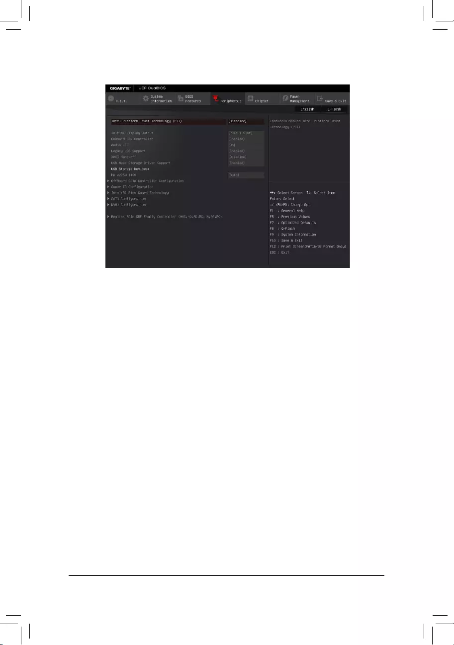
2-5 Peripherals
&Intel Platform Trust Technology (PTT)
Enables or disables Intel® PTT Technology. (Default: Disabled)
&Initial Display Output
SpeciestherstinitiationofthemonitordisplayfromtheinstalledPCIExpressgraphicscardortheonboard
graphics.
IGFX Setstheonboardgraphicsastherstdisplay.
PCIe1Slot SetsthegraphicscardonthePCIEX16slotastherstdisplay.(Default)
&OnBoard LAN Controller
Enables or disables the onboard LAN function. (Default: Enabled)
If you wish to install a 3rd party add-in network card instead of using the onboard LAN, set this item to
Disabled.
&Audio LED
Enables or disables the onboard audio LED. (Default: On)
&Legacy USB Support
Allows USB keyboard/mouse to be used in MS-DOS. (Default: Enabled)
&XHCI Hand-off
Determines whether to enable XHCI Hand-off feature for an operating system without XHCI Hand-off
support. (Default: Disabled)
&USB Mass Storage Driver Support
Enables or disables support for USB storage devices. (Default: Enabled)
&USB Storage Devices
Displays a list of connected USB mass storage devices. This item appears only when a USB storage device
is installed.
`OffBoardSATAControllerConguration
Displays information on your PCIe SSD if installed.
— 28 —

`Trusted Computing 2.0
This sub-menu appears only when Intel Platform Trust Technology is set to Enabled.
&Security Device Support
Enables or disables Trusted Platform Module (TPM). (Default: Enable)
&Pending operation
To clear TPM related settings, set this item to TPM Clear. (Default: None)
&TPM 20 InterfaceType
Allows you to select the communication interface for the TPM 2.0 device. Set to
External TPM2.0
if you
installanInneonTPM2.0module(optional).(Default:PTT)
&Device Select
Allows you to select whether to support TPM 1.2 or TPM 2.0 device. Auto lets the BIOS automatically
congurethissetting.(Default:Auto)
`SuperIOConguration
&Serial Port 1
Enables or disables the onboard serial port. (Default: Enabled)
`Intel(R) Bios Guard Technology
Enables or disables the Intel® BIOS Guard feature, which protects the BIOS from malicious attacks.
`SATAConguration
&SATA Controller(s)
Enables or disables the integrated SATA controllers. (Default: Enabled)
&SATA Mode Selection
AHCI CongurestheSATAcontrollerstoAHCImode.AdvancedHostControllerInterface
(AHCI)isaninterfacespecicationthatallowsthestoragedrivertoenableadvanced
Serial ATA features such as Native Command Queuing and hot plug. (Default)
&Aggressive LPM Support
Enables or disables the power saving feature, ALPM (Aggressive Link Power Management), for the Chipset
SATA controllers. (Default: Enabled)
&Port 0/1/2/3
Enables or disables each SATA port. (Default: Enabled)
&Hot plug
Enables or disable the hot plug capability for each SATA port. (Default: Disabled)
&External SATA
Enables or disables support for external SATA devices. (Default: Disabled)
`NVMeConguration
Displays information on your NVME PCIe SSD if installed.
`Realtek PCIe GBE Family Controller
Thissub-menuprovidesinformationonLANconguration.
— 29 —
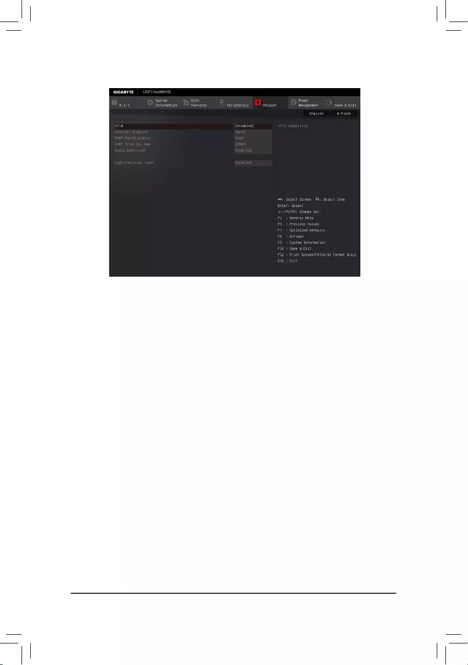
&VT-d (Note)
Enables or disables Intel® Virtualization Technology for Directed I/O. (Default: Disabled)
&Internal Graphics
Enables or disables the onboard graphics function. (Default: Auto)
&DVMT Pre-Allocated
Allows you to set the onboard graphics memory size. Options are: 32M~512M. (Default: 64M)
&DVMT Total Gfx Mem
Allows you to allocate the DVMT memory size of the onboard graphics. Options are: 128M, 256M, MAX.
(Default: 256M)
&Audio Controller
Enables or disables the onboard audio function. (Default: Enabled)
If you wish to install a 3rd party add-in audio card instead of using the onboard audio, set this item to
Disabled.
&High Precision Timer
Enables or disables High Precision Event Timer (HPET) in the operating system. (Default: Enabled)
2-6 Chipset
(Note) This item is present only when you install a CPU that supports this feature. For more information about
Intel® CPUs’ unique features, please visit Intel’s website.
— 30 —
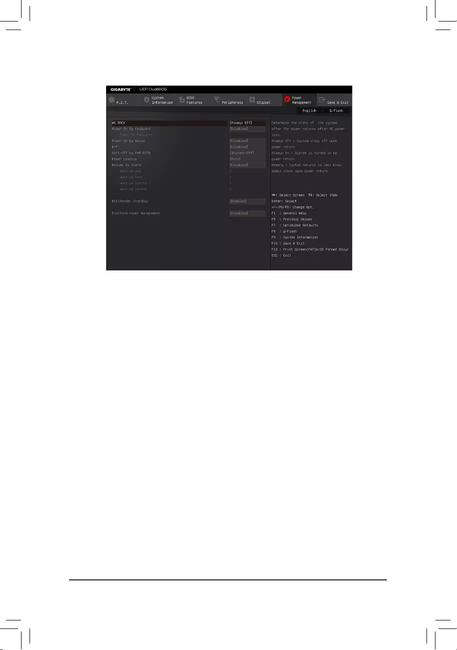
2-7 Power Management
&AC BACK
Determines the state of the system after the return of power from an AC power loss.
Always Off The system stays off upon the return of the AC power. (Default)
Always On The system is turned on upon the return of the AC power.
Memory The system returns to its last known awake state upon the return of the AC power.
&Power On By Keyboard
Allows the system to be turned on by a PS/2 keyboard wake-up event.
Note: To use this function, you need an ATX power supply providing at least 1A on the +5VSB lead.
Disabled Disables this function. (Default)
Password Set a password with 1~5 characters to turn on the system.
Keyboard 98 Press POWER button on the Windows 98 keyboard to turn on the system.
Any Key Press any key to turn on the system.
&Power On Password
Set the password when Power On By Keyboard is set to Password.
Press <Enter> on this item and set a password with up to 5 characters and then press <Enter> to accept.
To turn on the system, enter the password and press <Enter>.
Note: To cancel the password, press <Enter> on this item. When prompted for the password, press <Enter>
again without entering the password to clear the password settings.
&Power On By Mouse
Allows the system to be turned on by a PS/2 mouse wake-up event.
Note: To use this function, you need an ATX power supply providing at least 1A on the +5VSB lead.
Disabled Disables this function. (Default)
Move Move the mouse to turn on the system.
Double Click Double click on left button on the mouse to turn on the system.
&ErP
Determines whether to let the system consume least power in S5 (shutdown) state. (Default: Disabled)
Note: When this item is set to Enabled, the following functions will become unavailable: Resume by Alarm,
PME event wake up, power on by mouse, power on by keyboard, and wake on LAN.
— 31 —

&Soft-Off by PWR-BTTN
ConguresthewaytoturnoffthecomputerinMS-DOSmodeusingthepowerbutton.
Instant-Off Press the power button and then the system will be turned off instantly. (Default)
Delay 4 Sec. Press and hold the power button for 4 seconds to turn off the system. If the power
button is pressed for less than 4 seconds, the system will enter suspend mode.
&Power Loading
Enables or disables dummy load. When the power supply is at low load, a self-protection will activate causing
it to shutdown or fail. If this occurs, please set to Enabled. AutoletstheBIOSautomaticallycongurethis
setting. (Default: Auto)
&Resume by Alarm
Determines whether to power on the system at a desired time. (Default: Disabled)
If enabled, set the date and time as following:
Wakeupday:Turnonthesystemataspecictimeoneachdayoronaspecicdayinamonth.
Wake up hour/minute/second: Set the time at which the system will be powered on automatically.
Note: When using this function, avoid inadequate shutdown from the operating system or removal of the
AC power, or the settings may not be effective.
&RC6(Render Standby)
Allows you to determine whether to let the onboard graphics enter standby mode to decrease power
consumption. (Default: Enabled)
&Platform Power Management
Enables or disables the Active State Power Management function (ASPM). (Default: Disabled)
&PEG ASPM
Allowsyouto congure theASPMmode forthedeviceconnected totheCPUPEG bus.This itemis
congurableonlywhenPlatform Power Management is set to Enabled. (Default: Enabled)
&PCH ASPM
AllowsyoutoconguretheASPMmodeforthedeviceconnectedtoChipset’sPCIExpressbus.Thisitem
iscongurableonlywhenPlatform Power Management is set to Enabled. (Default: Enabled)
&DMI Link ASPM Control
AllowsyoutoconguretheASPMmodeforbothCPUsideandChipsetsideoftheDMIlink.Thisitemis
congurableonlywhenPlatform Power Management is set to Enabled. (Default: Enabled)
— 32 —
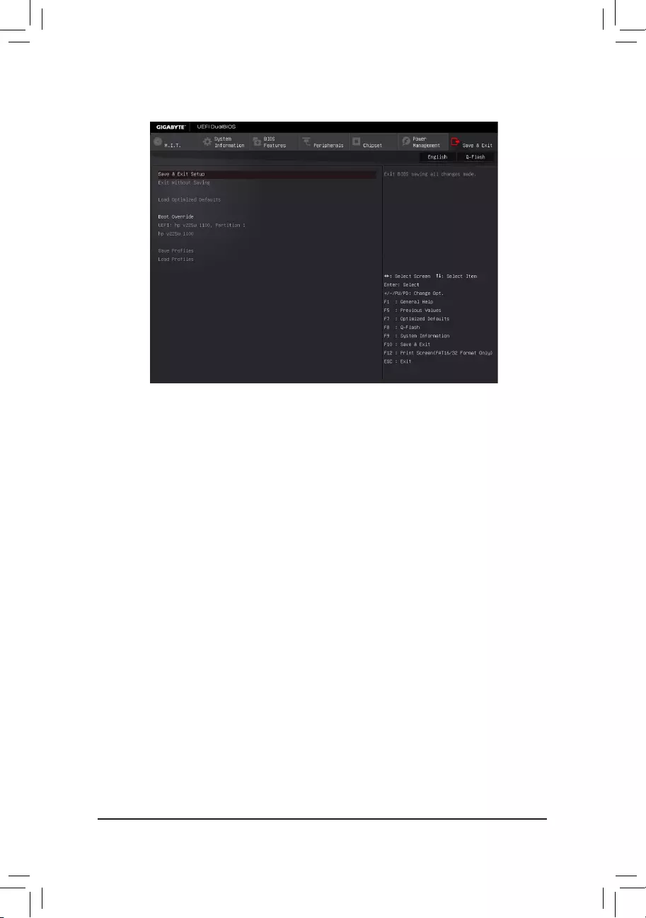
2-8 Save & Exit
&Save & Exit Setup
Press <Enter> on this item and select Yes. This saves the changes to the CMOS and exits the BIOS Setup
program. Select No or press <Esc> to return to the BIOS Setup Main Menu.
&Exit Without Saving
Press <Enter> on this item and select Yes. This exits the BIOS Setup without saving the changes made
in BIOS Setup to the CMOS. Select No or press <Esc> to return to the BIOS Setup Main Menu.
&Load Optimized Defaults
Press <Enter> on this item and select Yes to load the optimal BIOS default settings. The BIOS defaults
settings help the system to operate in optimum state. Always load the Optimized defaults after updating
the BIOS or after clearing the CMOS values.
&Boot Override
Allows you to select a device to boot immediately. Press <Enter> on the device you select and select Yes
toconrm.Yoursystemwillrestartautomaticallyandbootfromthatdevice.
&SaveProles
ThisfunctionallowsyoutosavethecurrentBIOSsettingstoaprole.Youcancreateupto8prolesand
saveasSetupProle1~SetupProle8.Press<Enter>tocomplete.OryoucanselectSelect File in
HDD/FDD/USBtosavetheproletoyourstoragedevice.
&LoadProles
If your system becomes unstable and you have loaded the BIOS default settings, you can use this function
toloadtheBIOSsettingsfromaprolecreatedbefore,withoutthe hassles ofreconguringtheBIOS
settings.Firstselecttheproleyouwishtoloadandthenpress<Enter>tocomplete.YoucanselectSelect
File in HDD/FDD/USBtoinputtheprolepreviouslycreatedfromyourstoragedeviceorloadtheprole
automatically created by the BIOS, such as reverting the BIOS settings to the last settings that worked
properly (last known good record).
— 33 —
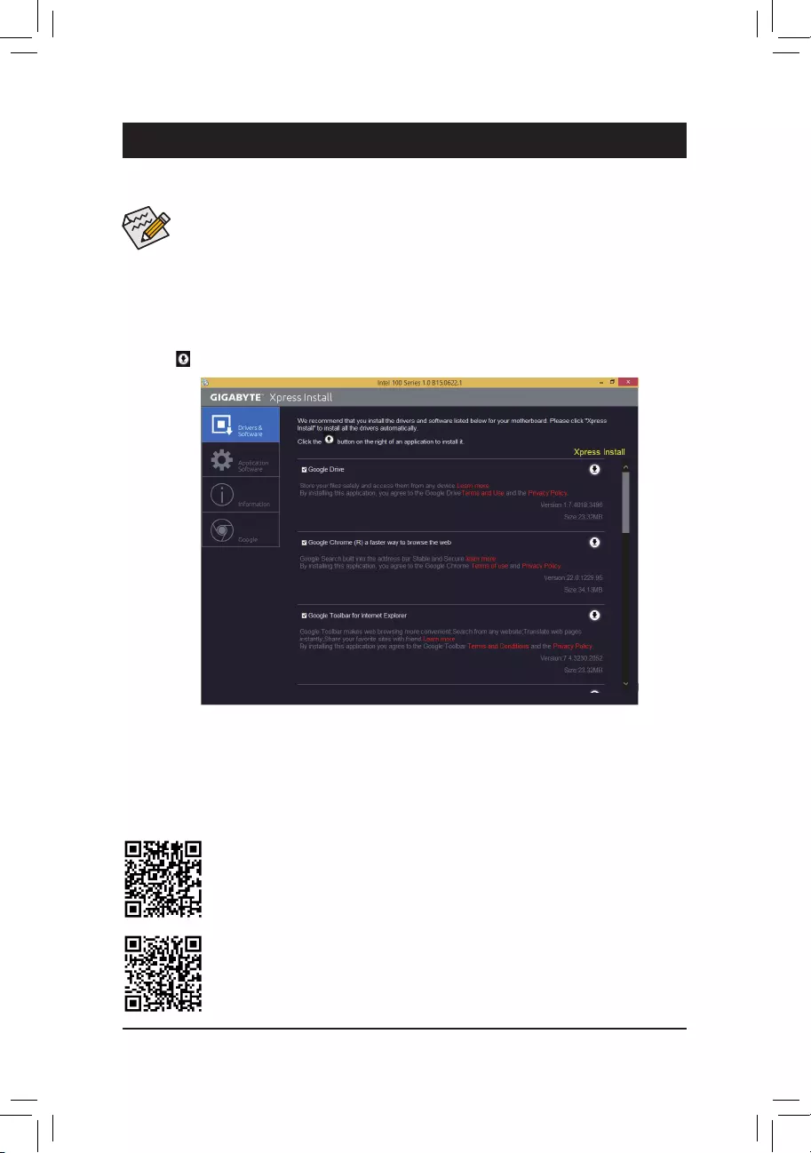
•Beforeinstallingthedrivers,rstinstalltheoperatingsystem.(ThefollowinginstructionsuseWindows
8.1 as the example operating system.)
•After installing the operating system, insert the motherboard driver disk into your optical drive. Click
on the message «Tap to choose what happens with this disc» on the top-right corner of the screen
and select «Run Run.exe.» (Or go to My Computer, double-click the optical drive and execute the
Run.exe program.)
Drivers Installation
«Xpress Install» will automatically scan your system and then list all of the drivers that are recommended to
install. You can click the Xpress Install button and «Xpress Install» will install all of the selected drivers. Or click
the arrow icon to individually install the drivers you need.
Chapter 3 Appendix
Please visit GIGABYTE’s website for more software information.
PleasevisitGIGABYTE’swebsitefordetailsonconguringtheaudiosoftware.
— 34 —

Regulatory Statements
Regulatory Notices
This document must not be copied without our written permission, and the contents there of must not be imparted
to a third party nor be used for any unauthorized purpose.
Contravention will be prosecuted. We believe that the information contained herein was accurate in all respects
at the time of printing. GIGABYTE cannot, however, assume any responsibility for errors or omissions in this text.
Also note that the information in this document is subject to change without notice and should not be construed
as a commitment by GIGABYTE.
Our Commitment to Preserving the Environment
Inaddition to high-efciency performance, all GIGABYTE motherboardsfulll EuropeanUnion regulations
for RoHS (Restriction of Certain Hazardous Substances in Electrical and Electronic Equipment) and WEEE
(Waste Electrical and Electronic Equipment) environmental directives, as well as most major worldwide safety
requirements. To prevent releases of harmful substances into the environment and to maximize the use of our
natural resources, GIGABYTE provides the following information on how you can responsibly recycle or reuse
most of the materials in your «end of life» product.
Restriction of Hazardous Substances (RoHS) Directive Statement
GIGABYTE products have not intended to add and safe from hazardous substances (Cd, Pb, Hg, Cr+6, PBDE
and PBB). The parts and components have been carefully selected to meet RoHS requirement. Moreover, we at
GIGABYTE are continuing our efforts to develop products that do not use internationally banned toxic chemicals.
Waste Electrical & Electronic Equipment (WEEE) Directive Statement
GIGABYTEwillfulllthenationallawsasinterpretedfromthe2002/96/ECWEEE(WasteElectricalandElectronic
Equipment)directive.TheWEEEDirectivespeciesthetreatment,collection,recyclinganddisposalofelectric
and electronic devices and their components. Under the Directive, used equipment must be marked, collected
separately, and disposed of properly.
WEEE Symbol Statement
The symbol shown below is on the product or on its packaging, which indicates that this product
must not be disposed of with other waste. Instead, the device should be taken to the waste collection
centers for activation of the treatment, collection, recycling and disposal procedure. The separate
collection and recycling of your waste equipment at the time of disposal will help to conserve natural
resources and ensure that it is recycled in a manner that protects human health and the environment.
For more information about where you can drop off your waste equipment for recycling, please contact your
localgovernmentofce,yourhouseholdwastedisposalserviceorwhereyoupurchasedtheproductfordetails
of environmentally safe recycling.
When your electrical or electronic equipment is no longer useful to you, «take it back» to your local or regional
waste collection administration for recycling.
If you need further assistance in recycling, reusing in your «end of life» product, you may contact us at the
Customer Care number listed in your product’s user’s manual and we will be glad to help you with your effort.
Finally, we suggest that you practice other environmentally friendly actions by understanding and using the
energy-saving features of this product (where applicable), recycling the inner and outer packaging (including
shipping containers) this product was delivered in, and by disposing of or recycling used batteries properly.
With your help, we can reduce the amount of natural resources needed to produce electrical and electronic
equipment,minimizetheuseoflandllsforthedisposalof«endoflife»products,andgenerallyimproveour
quality of life by ensuring that potentially hazardous substances are not released into the environment and are
disposed of properly.
— 35 —

FCC Notice (U.S.A. Only)
This equipment has been tested and found to comply with the limits for a Class B digital device, pursuant to Part
15 of the FCC Rules. These limits are designed to provide reasonable protection against harmful interference
in a residential installation. This equipment generates, uses, and can radiate radio frequency energy and, if not
installed and used in accordance with the instructions, may cause harmful interference to radio communications.
However, there is no guarantee that interference will not occur in a particular installation. If this equipment does
cause harmful interference to radio or television reception, which can be determined by turning the equipment
off and on, the user is encouraged to try to correct the interference by one or more of the following measures:
Reorient or relocate the receiving antenna.
Increase the separation between the equipment and receiver.
Connect the equipment into an outlet on a circuit different from that to which the receiver is connected.
Consult a dealer or experienced TV/radio technician for help.
Canada, Industry Canada (IC) Notices / Canada, avis d’Industry Canada (IC)
This Class B digital apparatus complies with Canadian ICES-003 and RSS-210.
Operation is subject to the following two conditions: (1) this device may not cause interference, and (2) this
device must accept any interference, including interference that may cause undesired operation of the device.
Cet appareil numérique de classe B est conforme aux normes canadiennes ICES-003 et RSS-210.
Son fonctionnement est soumis aux deux conditions suivantes : (1) cet appareil ne doit pas causer d’interférence
et (2) cet appareil doit accepter toute interférence, notamment les interférences qui peuvent affecter son
fonctionnement.
— 36 —
Contact Us
GIGA-BYTE TECHNOLOGY CO., LTD.
Address: No.6, Baoqiang Rd., Xindian Dist., New Taipei City 231, Taiwan
TEL: +886-2-8912-4000, FAX: +886-2-8912-4005
Tech. and Non—Tech. Support (Sales/Marketing) : http://esupport.gigabyte.com
WEB address (English): http://www.gigabyte.com
WEB address (Chinese): http://www.gigabyte.tw
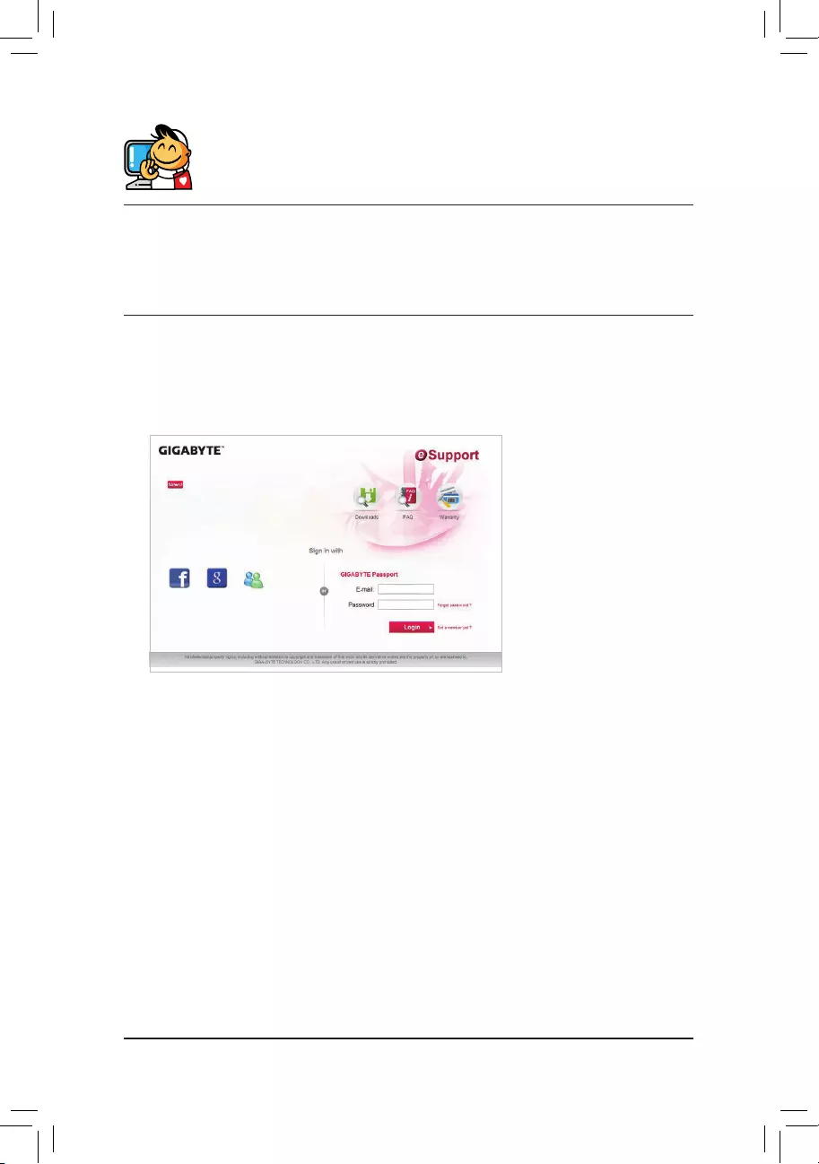
•GIGABYTE eSupport
To submit a technical or non-technical (Sales/Marketing) question, please link to:
http://esupport.gigabyte.com
— 37 —
Инструкцию для GIGABYTE GA-H110M-S2H на русском языке, в формате pdf можно скачать с нашего сайта. Наш каталог предоставляем Вам инструкцию производителя фирмы GIGABYTE, которая была взята из открытых источников. Ознакомившись с руководством по эксплуатации от GIGABYTE, Вы на все 100% и правильно сможете воспользоваться всеми функциями устройства.
Для сохранения инструкции «Материнская плата GIGABYTE GA-H110M-S2H» на русском языке на вашем компьютере либо телефоне, нажмите кнопку «Скачать инструкцию». Если активна кнопка «Инструкция онлайн», то Вы можете просмотреть документ (manual), в своём браузере онлайн.
Если у Вас нет возможности скачать инструкцию по эксплуатации либо просмотреть её, Вы можете поделиться ссылкой на эту страницу в социальных сетях и при удобном моменте скачать инструкцию. Либо добавьте эту страницу в закладки Вашего браузера, нажав кнопку «Добавить страницу в закладки браузера».
-
Драйверы
22
-
Инструкции по эксплуатации
1

Gigabyte GA-H110M-S2H инструкция по эксплуатации
(37 страниц)
- Языки:Английский
-
Тип:
PDF -
Размер:
9.94 MB
Просмотр
На NoDevice можно скачать инструкцию по эксплуатации для Gigabyte GA-H110M-S2H. Руководство пользователя необходимо для ознакомления с правилами установки и эксплуатации Gigabyte GA-H110M-S2H. Инструкции по использованию помогут правильно настроить Gigabyte GA-H110M-S2H, исправить ошибки и выявить неполадки.
• Windows XP(32bit) | GeForce Driver Release 335.28 WHQL (Size: 183.0MB) date 17.03.2014
• Windows XP(64bit) | GeForce Driver Release 335.28 WHQL (Size: 223.0MB) date 17.03.2014
• Windows Vista/7/8/8.1(32bit) | GeForce Driver Release 335.23 WHQL (Size: 219.0MB) date 10.03.2014
• Windows Vista/7/8/8.1(64bit) | GeForce Driver Release 335.23 WHQL (Size: 276.0MB) date 10.03.2014
• Windows XP(32bit) | GeForce R326 Game Ready Driver Release 327.23 WHQL (Size: 160.0MB) date 19.09.2013
• Windows Vista/7/8(32bit) | GeForce R326 Game Ready Driver Release 327.23 WHQL (Size: 182.0MB) date 19.09.2013
• Windows Vista/7/8(64bit) | GeForce R326 Game Ready Driver Release 327.23 WHQL (Size: 230.0MB) date 19.09.2013
nVidia GeForce: GTX TITAN, GTX 780, GTX 770, GTX 760, GTX 690, GTX 680, GTX 670, GTX 660 Ti, GTX 660, GTX 650 Ti BOOST, GTX 650 Ti, GTX 650, GT 645, GT 640, GT 630, GT 620, GT 610, 605, GTX 590, GTX 580, GTX 570, GTX 560 Ti, GTX 560 SE, GTX 560, GTX 555, GTX 550 Ti, GT 545, GT 530, GT 520, 510, GTX 480, GTX 470, GTX 465, GTX 460 v2, GTX 460 SE v2, GTX 460 SE, GTX 460, GTS 450, GT 440, GT 430, GT 420, 405, GT 340, GT 330, GT 320, 315, 310, GTX 295, GTX 285, GTX 280, GTX 275, GTX 260, GTS 250, GTS 240, GT 240, GT 230, GT 220, G210, 210, 205, GT 140, GT 130, GT 120, G 100, 9800 GX2, 9800 GTX/GTX+, 9800 GT, 9600 GT, 9600 GSO, 9600 GS, 9500 GT, 9500 GS, 9400 GT, 9400, 9300 GS, 9300 GE, 9300, 9200, 9100, 8800 Ultra, 8800 GTX, 8800 GTS 512, 8800 GTS, 8800 GT, 8800 GS, 8600 GTS, 8600 GT, 8600 GS, 8500 GT, 8400 SE, 8400 GS, 8400, 8300 GS, 8300, 8200 / nForce 730a, 8200, 8100 / nForce 720a. ION series: ION LE, ION
• Windows XP(32bit) | GeForce/ION Driver Release 310.70 WHQL (Size: 141.0MB) date 17.12.2012
• Windows XP(64bit) | GeForce/ION Driver Release 310.70 WHQL (Size: 176.0MB) date 17.12.2012
• Windows Vista(32bit) | GeForce/ION Driver Release 310.70 WHQL (Size: 163.0MB) date 17.12.2012
• Windows Vista(64bit) | GeForce/ION Driver Release 310.70 WHQL (Size: 210.0MB) date 17.12.2012
• Windows 7(32bit) | GeForce/ION Driver Release 310.70 WHQL (Size: 163.0MB) date 17.12.2012
• Windows 7(64bit) | GeForce/ION Driver Release 310.70 WHQL (Size: 210.0MB) date 17.12.2012
• Windows 8(32bit) | GeForce/ION Driver Release 310.70 WHQL (Size: 163.0MB) date 17.12.2012
• Windows 8(64bit) | GeForce/ION Driver Release 310.70 WHQL (Size: 210.0MB) date 17.12.2012
nVidia GeForce: 205, 210, 310, 315, 405, 510, 605, 8100 (nForce 720a), 8200, 8200 (nForce 730a), 8300, 8300 GS, 8400, 8400 GS, 8400 SE, 8500 GT, 8600 GS, 8600 GT, 8600 GTS, 8800 GS, 8800 GT, 8800 GTS, 8800 GTS 512, 8800 GTX, 8800 Ultra, 9100, 9200, 9300, 9300 GE, 9300 GS, 9400, 9400 GT, 9500 GS, 9500 GT, 9600 GS, 9600 GSO, 9600 GT, 9800 GT, 9800 GTX/GTX+, 9800 GX2, G 100, G 210, GT 120, GT 130, GT 140, GT 220, GT 230, GT 240, GT 320, GT 330, GT 340, GT 420, GT 430, GT 440, GT 520, GT 530, GT 545, GT 610, GT 620, GT 630, GT 640, GT 645, GTS 240, GTS 250, GTS 450, GTX 260, GTX 275, GTX 280, GTX 285, GTX 295, GTX 460, GTX 460 SE, GTX 460 SE v2, GTX 460 v2, GTX 465, GTX 470, GTX 480, GTX 550 Ti, GTX 555, GTX 560, GTX 560 SE, GTX 560 Ti, GTX 570, GTX 580, GTX 590, GTX 650, GTX 650 Ti, GTX 660, GTX 660 Ti, GTX 670, GTX 680, GTX 690, ION: ION, ION LE
• Windows XP(32bit) | GeForce/ION Driver Release 314.07 WHQL (Size: 142.0MB) date 18.02.2013
• Windows XP(64bit) | GeForce/ION Driver Release 314.07 WHQL (Size: 177.0MB) date 18.02.2013
• Windows Vista(32bit) | GeForce/ION Driver Release 314.07 WHQL (Size: 163.0MB) date 18.02.2013
• Windows Vista(64bit) | GeForce/ION Driver Release 314.07 WHQL (Size: 211.0MB) date 18.02.2013
• Windows 7(32bit) | GeForce/ION Driver Release 314.07 WHQL (Size: 163.0MB) date 18.02.2013
• Windows 7(64bit) | GeForce/ION Driver Release 314.07 WHQL (Size: 211.0MB) date 18.02.2013
• Windows 8(32bit) | GeForce/ION Driver Release 314.07 WHQL (Size: 163.0MB) date 18.02.2013
• Windows 8(64bit) | GeForce/ION Driver Release 314.07 WHQL (Size: 211.0MB) date 18.02.2013
nVidia GeForce: 205, 210, 310, 315, 405, 510, 605, 8100 (nForce 720a), 8200, 8200 (nForce 730a), 8300, 8300 GS, 8400, 8400 GS, 8400 SE, 8500 GT, 8600 GS, 8600 GT, 8600 GTS, 8800 GS, 8800 GT, 8800 GTS, 8800 GTS 512, 8800 GTX, 8800 Ultra, 9100, 9200, 9300, 9300 GE, 9300 GS, 9400, 9400 GT, 9500 GS, 9500 GT, 9600 GS, 9600 GSO, 9600 GT, 9800 GT, 9800 GTX/GTX+, 9800 GX2, G 100, G 210, GT 120, GT 130, GT 140, GT 220, GT 230, GT 240, GT 320, GT 330, GT 340, GT 420, GT 430, GT 440, GT 520, GT 530, GT 545, GT 610, GT 620, GT 630, GT 640, GT 645, GTS 240, GTS 250, GTS 450, GTX 260, GTX 275, GTX 280, GTX 285, GTX 295, GTX 460, GTX 460 SE, GTX 460 SE v2, GTX 460 v2, GTX 465, GTX 470, GTX 480, GTX 550 Ti, GTX 555, GTX 560, GTX 560 SE, GTX 560 Ti, GTX 570, GTX 580, GTX 590, GTX 650, GTX 650 Ti, GTX 660, GTX 660 Ti, GTX 670, GTX 680, GTX 690, ION: ION, ION LE
• Linux (32bit) | Linux nVidia Display Driver Release 331.49 (Size: 37.0MB) date 18.02.2014
• Linux (32bit) ARM | Linux ARM Display Driver Release 331.49 (Size: 22.0MB) date 18.02.2014
• Linux (64bit) | Linux nVidia Display Driver Release 331.49 (Size: 60.0MB) date 18.02.2014
GeForce 800M Series (Notebooks), GeForce 700 Series, GeForce 700M Series (Notebooks), GeForce 600 Series, GeForce 600M Series (Notebooks), GeForce 500 Series, GeForce 500M Series (Notebooks), GeForce 400 Series, GeForce 400M Series (Notebooks), GeForce 300 Series, GeForce 300M Series (Notebooks), GeForce 200 Series, GeForce 200M Series (Notebooks), GeForce 100 Series, GeForce 100M Series (Notebooks), GeForce 9 Series, GeForce 9M Series (Notebooks), GeForce 8 Series, GeForce 8M Series (Notebooks), Quadro Series, Quadro Series (Notebooks), Quadro FX Series, Quadro FX Series (Notebooks), Quadro Blade/Embedded Series, Quadro NVS Series, Quadro NVS Series (Notebooks), Quadro Plex Series, Quadro Sync Series, GRID Series, NVS Series, NVS Series (Notebooks), nForce 7, 9 Series, K-Series, C-Class, M-Class, ION (Desktops), ION (Notebooks), ION LE (Desktops), ION LE (Notebooks)
• Linux (32bit) | GeForce/ION Driver Release 310.32 Certified (Size: 37.0MB) date 21.01.2013
• Linux (64bit) | GeForce/ION Driver Release 310.32 Certified (Size: 65.1MB) date 21.01.2013
GeForce 600 series: GTX 690, GTX 680, GTX 670, GTX 660 Ti, GTX 660, GTX 650 Ti, GTX 650, GT 645, GT 640, GT 630, GT 620, GT 610, 605, GeForce 600M series: GTX 680M, GTX 675MX, GTX 675M, GTX 670MX, GTX 670M, GTX 660M, GT 650M, GT 645M, GT 640M LE, GT 640M, GT 635M, GT 630M, GT 620M, G610M, GeForce 500 series: GTX 590, GTX 580, GTX 570, GTX 560 Ti, GTX 560 SE, GTX 560, GTX 555, GTX 550 Ti, GT 545, GT 530, GT 520, 510, GeForce 500M series: GTX 580M, GTX 570M, GTX 560M, GT 555M, GT 550M, GT 540M, GT 525M, GT 520MX, GT 520M, GeForce 400 series: GTX 480, GTX 470, GTX 465, GTX 460 v2, GTX 460 SE v2, GTX 460 SE, GTX 460, GTS 450, GT 440, GT 430, GT 420, GT 415, 405, GeForce 400M series: GTX 485M, GTX 480M, GTX 470M, GTX 460M, GT 445M, GT 435M, GT 425M, GT 420M, GT 415M, 410M, GeForce 300 series: GT 340, GT 330, GT 320, 315, 310, GeForce 300M series: GTS 360M, GTS 350M, GT 335M, GT 330M, GT 325M, GT 320M, 320M, 315M, 310M, 305M, GeForce 200 series: GTX 295, GTX 285, GTX 280, GTX 275, GTX 260, GTS 250, GTS 240, GT 240, GT 230, GT 220, G210, 210, 205, GeForce 200M series: GTX 285M, GTX 280M, GTX 260M, GTS 260M, GTS 250M, GT 240M, GT 230M, GT 220M, G210M, GeForce 100 series: GT 140, GT 130, GT 120, G 100, GeForce 100M series: GTS 160M, GTS 150M, GT 130M, GT 120M, G 110M, G 105M, G 103M, G 102M, GeForce 9 series: 9800 GX2, 9800 GTX+, 9800 GTX/GTX+, 9800 GT, 9650 S, 9600 GT, 9600 GSO 512, 9600 GSO, 9600 GS, 9500 GT, 9500 GS, 9400 GT, 9400, 9300 SE, 9300 GS, 9300 GE, 9300 / nForce 730i, 9300, 9200, 9100, GeForce 9M series: 9800M GTX, 9800M GTS, 9800M GT, 9800M GS, 9700M GTS, 9700M GT, 9650M GT, 9650M GS, 9600M GT, 9600M GS, 9500M GS, 9500M G, 9400M G, 9400M, 9300M GS, 9300M G, 9200M GS, 9100M G, GeForce 8 series: 8800 Ultra, 8800 GTX, 8800 GTS 512, 8800 GTS, 8800 GT, 8800 GS, 8600 GTS, 8600 GT, 8600 GS, 8500 GT, 8400 SE, 8400 GS, 8400, 8300 GS, 8300, 8200, 8100 / nForce 720a, GeForce 8M series: 8800M GTX, 8800M GTS, 8700M GT, 8600M GT, 8600M GS, 8400M GT, 8400M GS, 8400M G, 8200M G, 8200M, NVS Series: NVS 510, NVS 310, NVS 300, Quadro series: K5000, 7000, 6000, 600, 5000, 410, 4000, 400, 2000D, 2000, Quadro FX series: FX 5800, FX 580, FX 570, FX 5600, FX 5500, FX 4800, FX 4700 X2, FX 4600, FX 380 LP, FX 3800, FX 380, FX 370 Low Profile, FX 3700, FX 370, FX 3400/4400, FX 1800, FX 1700, CX, Quadro Notebook series: K5000M, K4000M, K3000M, K2000M, K1000M, 5010M, 5000M, 4000M, 3000M, 2000M, 1000M, Quadro FX Notebook series: FX 880M, FX 770M, FX 570M, FX 380M, FX 3800M, FX 370M, FX 3700M, FX 360M, FX 3600M, FX 2800M, FX 2700M, FX 1800M, FX 1700M, FX 1600M, Quadro NVS series: NVS 450, NVS 420, NVS 295, NVS 290, Quadro NVS Notebook series: NVS 5400M, NVS 5200M, NVS 4200M, NVS 320M, NVS 160M, NVS 150M, NVS 140M, NVS 135M, NVS 130M, Quadro Plex series: Model IV, Model II, D Series, 7000, Quadro Sync series: Sync, G-Sync II, Quadro SDI series: Quadro SDI, ION series: ION LE, ION, C-Class Processors: Tesla C870, Tesla C2075, Tesla C2070, Tesla C2050, Tesla C1060, T10 Processor, M-Class Processors: Tesla M2090, Tesla M2075, Tesla M2070-Q, Tesla M2070, Tesla M2050, Tesla M1060, X-Class Processors: Tesla X2090, K-Series Processors: Tesla K20Xm, Tesla K20m, Tesla K20c, Tesla K10, NVS Notebook Series: NVS 5100M, NVS 3100M, NVS 2100M
• DirectX Software Development Kit v.9.29.1962.0 (Size: 571.7MB) date 02.06.2010
Download full DirectX SDK which contains DirectX and all DirectX the software necessary for creation of DirectX-compatible applications.
• Microsoft .NET Framework 4 Client Profile (Web Installer) (Size: 0.84MB) date 19.03.2010
Microsoft. net Framework 4 loads a web packet of installation and sets the. net Frameworks of a component necessary for start by the target machine, architecture and OS. Connection to the Internet during installation is required. The client profile is used for execution of the majority of the client applications intended for operation with a. net Framework 4.
• DirectX v.9.29.1974 packet for up-dating of the basis version DirectX 9.0c (Size: 95.6MB) date 18.04.2011
Microsoft DirectX is a row of technologies thanks to which computers on the basis of Windows become the ideal environment for start and display of the applications rich with elements of a multimedia, such as a color graphics, video, three-dimensional animation and a binaural sound. DirectX includes the updates increasing safety and productivity, and also the new functions relating to different technologies to which application can address by means of DirectX API.