
Page 1 — GA-H55M-US2H
GA-H55M-UD2H/GA-H55M-US2HLGA1156 socket motherboard for Intel® Core™ i7 processor family/Intel® Core™ i5 processor family/ Intel® Core™ i3 processor f
Page 2 — Nov. 14, 2009
— 10 -Hardware Installation1-2 Product Specications CPU Support for an Intel® Core™ i7 series processor/Intel® Core™ i5 series processor/
Page 4 — Table of Contents
— 12 -Hardware Installation(Note 1) Due to Windows 32-bit operating system limitation, when more than 4 GB of physical memory is installed, the
Page 5
— 13 — Hardware Installation1-3 Installing the CPU and CPU Cooler1-3-1 Installing the CPUA. Locate the alignment keys on the motherboard CPU socket
Page 6 — Optional Items
— 14 -Hardware InstallationStep 1: Gently press the CPU socket lever handle down and away from the socket with your nger. Then completely lift the
Page 7
— 15 — Hardware Installation1-3-2 Installing the CPU CoolerFollow the steps below to correctly install the CPU cooler on the motherboard. (The follow
Page 8 — Block Diagram
— 16 -Hardware Installation1-4-1 Dual Channel Memory CongurationThis motherboard provides four DDR3 memory sockets and supports Dual Channe
Page 9 — 1-1 Installation Precautions
— 17 — Hardware Installation1-4-2 Installing a Memory NotchDDR3 DIMMA DDR3 memory module has a notch, so it can only t in one direction. Follow the
Page 10 — 1-2 Product Specications
— 18 -Hardware Installation1-5 Installing an Expansion CardRead the following guidelines before you begin to install an expansion card:• Make sure t
Page 11 — (Note 2)(Note 4)
— 19 — Hardware Installation1-6 Back Panel Connectors USB Port The USB port supports the USB 2.0/1.1 specication. Use this port for USB devices su
Page 12
Nov. 14, 2009MotherboardGA-H55M-UD2H/GA-H55M-US2HMotherboardGA-H55M-UD2H/GA-H55M-US2HNov. 14, 2009
Page 13 — 1-3-1 Installing the CPU
— 20 -Hardware Installation DiplayPortj(Note 1)(Note 3) DisplayPort is one of the new generation interface technologies that delivers high quality
Page 14
— 21 — Hardware InstallationIn addition to the default speakers settings, the ~ audio jacks can be recongured to per-form different functions via the
Page 15
— 22 -Hardware Installation1-7 Internal ConnectorsRead the following guidelines before connecting external devices:• First make sure your devices ar
Page 17 — 1-4-2 Installing a Memory
— 24 -Hardware Installation3/4) CPU_FAN/SYS_FAN (Fan Headers) The motherboard has a 4-pin CPU fan header (CPU_FAN) and a 4-pin system fan header (SYS
Page 18 — PCI Slot
— 25 — Hardware Installation6) IDE (IDE Connector) The IDE connector supports up to two IDE devices such as hard drives and optical drives. Before a
Page 19 — 1-6 Back Panel Connectors
— 26 -Hardware Installation8) BAT (Battery) The battery provides power to keep the values (such as BIOS congurations, date, and time information) i
Page 20 — DiplayPort
— 27 — Hardware Installation9) F_PANEL (Front Panel Header) Connect the power switch, reset switch, speaker, chassis intrusion switch/sensor
Page 21
— 28 -Hardware Installation10) F_AUDIO (Front Panel Audio Header) The front panel audio header supports Intel High Denition audio (HD) and AC&apos
Page 22 — 1-7 Internal Connectors
— 29 — Hardware Installation12) SPDIF_I (S/PDIF In Header) This header supports digital S/PDIF In and can connect to an audio device that supports d
Page 23
Copyright© 2009 GIGA-BYTE TECHNOLOGY CO., LTD. All rights reserved.The trademarks mentioned in this manual are legally registered to their respective
Page 24
— 30 -Hardware Installation14) F_USB1/F_USB2/F_USB3 (USB Headers) The headers conform to USB 2.0/1.1 specication. Each USB header can provide two U
Page 25 — 6) IDE (IDE Connector)
— 31 — Hardware Installation16) COMA (Serial Port Header) The COMA header can provide one serial port via an optional COM port cable. For purchasing
Page 26 —  BAT (Battery)
— 32 -Hardware Installation18) PHASE LED The number of lighted LEDs indicates the CPU loading. The higher the CPU loading, the more
Page 27 — S3/S4/S5 Off
— 33 — BIOS SetupBIOS (Basic Input and Output System) records hardware parameters of the system in the CMOS on the motherboard. Its majo
Page 28
BIOS Setup — 34 -2-1 Startup ScreenThe following screens may appear when the computer boots.Function Keys: <DEL>: BIOS SETUP Press the <Del
Page 29
— 35 — BIOS Setup2-2 The Main MenuOnce you enter the BIOS Setup program, the Main Menu (as shown below) appears on the screen. Use ar-row keys to mov
Page 30
BIOS Setup — 36 - The Functions of the <F11> and <F12> keys (For the Main Menu Only) F11: Save CMOS to BIOS This function allows you
Page 32 — 18) PHASE LED
BIOS Setup — 38 — CPU Clock Ratio Allows you to alter the clock ratio for the installed CPU. The adjustable range is dependent on the CPU being
Page 33 — Chapter 2 BIOS Setup
— 39 — BIOS Setup(Note) This item is present only if you install a CPU that supports this feature. For more information about Intel CPUs’ u
Page 35 — 2-2 The Main Menu
BIOS Setup — 40 -(Note) This item appears only if you install a memory module that supports this feature. Extreme Memory Prole (X.M.P.) (Note) All
Page 36
— 41 — BIOS SetupCMOS Setup Utility-Copyright (C) 1984-2009 Award SoftwareAdvanced Memory Settingshigf: Move Enter: Select +/-/PU/PD: Value F10: Sa
Page 37 — M.I.T. Current Status
BIOS Setup — 42 -CMOS Setup Utility-Copyright (C) 1984-2009 Award SoftwareChannel A Timing Settingshigf: Move Enter: Select +/-/PU/PD: Value F10: S
Page 38
— 43 — BIOS Setup tRFC Options are: Auto (default), 1~255. tRTP Options are: Auto (default), 1~15. tFAW Options are: Auto (default), 1~63. Comm
Page 39
BIOS Setup — 44 - Advanced Voltage Settings >>> CPU Load-Line Calibration Enables or disables Load-Line Calibration. Enabling t
Page 40
— 45 — BIOS Setup Miscellaneous Settings CMOS Setup Utility-Copyright (C) 1984-2009 Award SoftwareMiscellaneous Settings Isochronous Support
Page 41 — (Note 1)
BIOS Setup — 46 — Date (mm:dd:yy) Sets the system date. The date format is week (read-only), month, date and year. Select the desired eld and use t
Page 42
— 47 — BIOS Setup The following elds display your hard drive specications. If you wish to enter the parameters manually, refer to the information o
Page 43
BIOS Setup — 48 -(Note) This item is present only if you install a CPU that supports this feature. For more information about Intel CPUs’ unique
Page 44
— 49 — BIOS Setup Limit CPUID Max. to 3 (Note) Allows you to determine whether to limit CPUID maximum value. Set this item to Disabled for Windows X
Page 46 — 2-4 Standard CMOS Features
BIOS Setup — 50 -2-6 Integrated Peripherals SATA AHCI Mode (Intel H55 Chipset) Allows you to decide whether to congure the SATA controller integra
Page 47 — Memory
— 51 — BIOS Setup Azalia Codec Enables or disables the onboard audio function. (Default: Auto) If you wish to install a 3rd party add-in audio card
Page 48 — 2-5 Advanced BIOS Features
BIOS Setup — 52 — Onboard LAN Boot ROM Allows you to decide whether to activate the boot ROM integrated with the onboard LAN chip. (Default: Disab
Page 49
— 53 — BIOS Setup ACPI Suspend Type Species the ACPI sleep state when the system enters suspend. S1(POS) Enables the system to enter the ACPI
Page 50 — 2-6 Integrated Peripherals
BIOS Setup — 54 -(Note) Supported on Windows Vista operating system only. Date (of Month) Alarm: Turn on the system at a specic time on each day o
Page 51 — SMART LAN
— 55 — BIOS Setup Reset Case Open Status Keeps or clears the record of previous chassis intrusion status. Enabled clears the record of previous chas
Page 52 — Onboard Serial Port 1
BIOS Setup — 56 — CPU Smart FAN Mode Species how to control CPU fan speed. This item is congurable only if CPU Smart FAN Control is set to Enabled
Page 54
BIOS Setup — 58 -Press <Enter> on this item and type the password with up to 8 characters and then press <Enter>. You will be requested to
Page 55 — 2-8 PC Health Status
— 59 — BIOS SetupPress <Enter> on this item and press the <Y> key. This saves the changes to the CMOS and exits the BIOS Setup program. Pr
Page 56 — CPU Smart FAN Mode
— 6 -Box Contents GA-H55M-UD2H or GA-H55M-US2H motherboard Motherboard driver disk User’s Manual Quick Installation Guide One IDE
Page 58
— 61 — Drivers Installation3-1 Installing Chipset DriversChapter 3 Drivers Installation• Before installing the drivers, rst install the operating
Page 59 — 2-13 Exit Without Saving
Drivers Installation — 62 -3-2 Application SoftwareThis page displays all the utilities and applications that GIGABYTE develops and some free softw
Page 60 — BIOS Setup — 60
— 63 — Drivers Installation3-4 ContactFor the detailed contact information of the GIGABYTE Taiwan headquarter or worldwide branch ofces, click the U
Page 61
Drivers Installation — 64 -3-6 Download CenterTo update the BIOS, drivers, or applications, click the Download Center button to link to
Page 62 — 3-3 Technical Manuals
— 65 — Unique Features4-1 Xpress Recovery2Chapter 4 Unique FeaturesXpress Recovery2 is a utility that allows you to quickly compress and b
Page 63 — 3-5 System
Unique Features — 66 -Step 3:When partitioning your hard drive, make sure to leave unallocated space (10 GB or more is recom-mended; actual siz
Page 64 — 3-7 New Utilities
— 67 — Unique FeaturesD. Using the Restore Function in Xpress Recovery2E. Removing the BackupF. Exiting Xpress Recovery2Select RESTORE to restore th
Page 65 — Chapter 4 Unique Features
Unique Features — 68 -4-2 BIOS Update UtilitiesGIGABYTE motherboards provide two unique BIOS update tools, Q-Flash™ and @BIOS™. GIGABYTE Q-F
Page 66
— 69 — Unique FeaturesB. Updating the BIOSWhen updating the BIOS, choose the location where the BIOS le is saved. The following procedur
Page 67
— 7 -GA-H55M-UD2H/GA-H55M-US2H Motherboard LayoutCPU_FANLGA1156ATXCD_INF_AUDIOAUDIOM_BIOSPCIEX4IDESPDIF_IDDR3_2DDR3_1DDR3_4DDR3_3BATF_PANELIT8720ATX_1
Page 69 — B. Updating the BIOS
— 71 — Unique Features4-2-2 Updating the BIOS with the @BIOS UtilityA. Before You Begin1. In Windows, close all applications and TSR (Terminate and
Page 70
Unique Features — 72 -4-3 EasyTune 6GIGABYTE’s EasyTune 6 is a simple and easy-to-use interface that allows users to ne-tune their system s
Page 72 — 4-3 EasyTune 6
Unique Features — 74 -B. Total ModeIn Total Mode, users are able to see how much total power savings they have accumulated in a set period of time sin
Page 73 — 4-4 Dynamic Energy Saver
— 75 — Unique Features4-5 Q-ShareQ-Share is an easy and convenient data sharing tool. After conguring your LAN connection settings and Q
Page 74 — C. Stealth Mode
Unique Features — 76 -4-6 Smart 6™GIGABYTE Smart 6™ (Note 1) is designed with user-friendliness in mind, and offers a combination of 6 innovative sof
Page 75 — 4-5 Q-Share
— 77 — Unique FeaturesSMART RecoveryWith SMART Recovery, users can quickly create backups of changed data les (Note 2) or copy les from a s
Page 76 — 4-6 Smart 6
Unique Features — 78 -(Note 1) When launching Smart 6™ for the rst time, the system will request you to set up a password. This password is required
Page 77 — SMART DualBIOS
— 79 — Unique Features4-7 Auto GreenAuto Green is an easy-to-use tool that provides users with simple options to enable system power savings via a B
Page 78 — SMART TimeLock
— 8 -Block DiagramCenter/Subwoofer Speaker OutLine OutMICLine InS/PDIF InS/PDIF OutSide Speaker OutSurround Speaker OutCODECPS/2 KB/MouseLGA1156CPUInt
Page 80 — Unique Features — 80
— 81 — Appendix5-1-1 Conguring 2/4/5.1/7.1-Channel AudioThe motherboard provides six audio jacks on the back panel which support 2/4/5.1/7.1-chan
Page 81 — Chapter 5 Appendix
Appendix — 82 -Step 2:Connect an audio device to an audio jack. The The cur-rent connected device is dialog box appears. Select the device according
Page 82 — B. Conguring Sound Effect
— 83 — Appendix5-1-2 Conguring S/PDIF In/OutA. S/PDIF InThe S/PDIF In cable (optional) allows you to input digital audio signals to the computer for
Page 83 — A. S/PDIF In
Appendix — 84 -B. S/PDIF OutThe S/PDIF Out jack can transmit audio signals to an external decoder for decoding to get the best audio quality.1. Con
Page 84 — B. S/PDIF Out
— 85 — Appendix5-1-3 Conguring Microphone RecordingStep 1:After installing the audio driver, the HD Audio Manager icon will appear in the noticati
Page 85
Appendix — 86 -Step 4:To raise the recording and playback volume for the microphone, click the Microphone Boost icon on the right of the R
Page 86 — * Enabling Stereo Mix
— 87 — AppendixStep 3:When the Stereo Mix item appears, right-click on this item and select Enable. Then set it as the default de-vice.Step 4:Now
Page 88 — 5-2 Troubleshooting
— 89 — Appendix5-2-2 Troubleshooting ProcedureIf you encounter any troubles during system startup, follow the troubleshooting procedure below to solv
Page 89 — — 89 — Appendix
— 9 — Hardware Installation1-1 Installation PrecautionsThe motherboard contains numerous delicate electronic circuits and components which can
Page 90 — Appendix — 90
Appendix — 90 -If the procedure above is unable to solve your problem, contact the place of purchase or local dealer for help. Or go to t
Page 91 — 5-3 Regulatory Statements
— 91 — Appendix5-3 Regulatory StatementsRegulatory NoticesThis document must not be copied without our written permission, and the contents
Page 92
Appendix — 92 -Finally, we suggest that you practice other environmentally friendly actions by understanding and using the energy-saving features of t
Page 95 — Contact Us
— 95 — AppendixContact Us• GIGA-BYTE TECHNOLOGY CO., LTD.Address: No.6, Bau Chiang Road, Hsin-Tien, Taipei 231, Taiwan TEL: +886-2-8912-4000 FAX: +88
Page 96 — Appendix — 96
Appendix — 96 -• G.B.T. TECHNOLOGY TRADING GMBH — GermanyWEB address : http://www.gigabyte.de• G.B.T. TECH. CO., LTD. — U.K.WEB address : http://www
GA-H55M-UD2H/ GA-H55M-US2H
LGA1156 socket motherboard for Intel® Core™ i7 processor family/ Intel® Core™ i5 processor family/ Intel® Core™ i3 processor family
User’s Manual
Rev. 1002
12ME-H55MUD2-1002R

Motherboard
GA-H55M-UD2H/GA-H55M-US2H
Motherboard
GA-H55M-UD2H/
GA-H55M-US2H
Nov. 14, 2009
Nov. 14, 2009
Copyright
© 2009 GIGA-BYTE TECHNOLOGY CO., LTD. All rights reserved.
The trademarks mentioned in this manual are legally registered to their respective owners.
Disclaimer
Information in this manual is protected by copyright laws and is the property of GIGABYTE.
Changes to the specifications and features in this manual may be made by GIGABYTE without prior notice. No part of this manual may be reproduced, copied, translated, transmitted, or published in any form or by any means without GIGABYTE’s prior written permission.
Documentation Classifications
In order to assist in the use of this product, GIGABYTE provides the following types of documentations:
For quick set-up of the product, read the Quick Installation Guide included with the product.
For detailed product information, carefully read the User’s Manual.
For instructions on how to use GIGABYTE’s unique features, read or download the information on/from the Support&Downloads\Motherboard\Technology Guide page on our website.
For product-related information, check on our website at:
http://www.gigabyte.com.tw
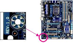
Identifying Your Motherboard Revision
The revision number on your motherboard looks like this: «REV: X.X.» For example, «REV: 1.0» means the revision of the motherboard is 1.0. Check your motherboard revision before updating motherboard BIOS, drivers, or when looking for technical information.
Example:

Table of Contents
|
Box Contents…………………………………………………………………………………………………….. |
6 |
||
|
Optional Items…………………………………………………………………………………………………… |
6 |
||
|
GA-H55M-UD2H/GA-H55M-US2H Motherboard Layout. |
…………………………………………7 |
||
|
Block Diagram…………………………………………………………………………………………………… |
8 |
||
|
Chapter 1 Hardware Installation………………………………………………………………………….. |
9 |
||
|
1-1 |
Installation Precautions…………………………………………………………………………. |
9 |
|
|
1-2 |
Product Specifications.……………………………………………………………………….. |
10 |
|
|
1-3 |
Installing the CPU and CPU Cooler………………………………………………………. |
13 |
|
|
1-3-1 |
Installing the CPU……………………………………………………………………………………… |
13 |
|
|
1-3-2 Installing the CPU Cooler……………………………………………………………………………. |
15 |
||
|
1-4 |
Installing the Memory………………………………………………………………………….. |
16 |
|
|
1-4-1 Dual Channel Memory Configuration……………………………………………………………. |
16 |
||
|
1-4-2 |
Installing a Memory …………………………………………………………………………………… |
17 |
|
|
1-5 |
Installing an Expansion Card……………………………………………………………….. |
18 |
|
|
1-6 |
Back Panel Connectors.……………………………………………………………………… |
19 |
|
|
1-7 |
Internal Connectors.…………………………………………………………………………… |
22 |
|
|
Chapter 2 BIOS Setup……………………………………………………………………………………… |
33 |
||
|
2-1 |
Startup Screen…………………………………………………………………………………… |
34 |
|
|
2-2 |
The Main Menu………………………………………………………………………………….. |
35 |
|
|
2-3 |
MB Intelligent Tweaker(M.I.T.).…………………………………………………………….. |
37 |
|
|
2-4 |
Standard CMOS Features.………………………………………………………………….. |
46 |
|
|
2-5 |
Advanced BIOS Features……………………………………………………………………. |
48 |
|
|
2-6 |
Integrated Peripherals.……………………………………………………………………….. |
50 |
|
|
2-7 |
Power Management Setup.…………………………………………………………………. |
53 |
|
|
2-8 |
PC Health Status.………………………………………………………………………………. |
55 |
|
|
2-9 |
Load Fail-Safe Defaults.……………………………………………………………………… |
57 |
|
|
2-10 |
Load Optimized Defaults.……………………………………………………………………. |
57 |
|
|
2-11 |
Set Supervisor/User Password…………………………………………………………….. |
58 |
|
|
2-12 |
Save & Exit Setup………………………………………………………………………………. |
59 |
|
|
2-13 |
Exit Without Saving…………………………………………………………………………….. |
59 |
— 4 —

|
Chapter 3 Drivers Installation.…………………………………………………………………………… |
61 |
|
|
3-1 |
Installing Chipset Drivers…………………………………………………………………….. |
61 |
|
3-2 |
Application Software…………………………………………………………………………… |
62 |
|
3-3 |
Technical Manuals.…………………………………………………………………………….. |
62 |
|
3-4 |
Contact.……………………………………………………………………………………………. |
63 |
|
3-5 |
System……………………………………………………………………………………………… |
63 |
|
3-6 |
Download Center……………………………………………………………………………….. |
64 |
|
3-7 |
New Utilities………………………………………………………………………………………. |
64 |
|
Chapter 4 Unique Features.……………………………………………………………………………… |
65 |
|
|
4-1 |
Xpress Recovery2.…………………………………………………………………………….. |
65 |
|
4-2 |
BIOS Update Utilities………………………………………………………………………….. |
68 |
|
4-2-1 Updating the BIOS with the Q-Flash Utility.…………………………………………………… |
68 |
|
|
4-2-2 Updating the BIOS with the @BIOS Utility…………………………………………………….. |
71 |
|
|
4-3 |
EasyTune 6……………………………………………………………………………………….. |
72 |
|
4-4 |
Dynamic Energy Saver™ 2.………………………………………………………………….. |
73 |
|
4-5 |
Q-Share.…………………………………………………………………………………………… |
75 |
|
4-6 |
Smart 6™…………………………………………………………………………………………… |
76 |
|
4-7 |
Auto Green.………………………………………………………………………………………. |
79 |
|
Chapter 5 Appendix |
…………………………………………………………………………………………. |
81 |
|
|
5-1 |
Configuring Audio Input and Output………………………………………………………. |
81 |
|
|
5-1-1 . |
Configuring 2/4/5.1/7.1 — Channel Audio ………………………………………………………… |
81 |
|
|
5-1-2 ………………………………………………………………………….. |
Configuring S/PDIF In/Out |
83 |
|
|
5-1-3 ………………………………………………………………. |
Configuring Microphone Recording |
85 |
|
|
5-1-4 …………………………………………………………………………..Using the Sound Recorder |
87 |
||
|
5-2 |
Troubleshooting…………………………………………………………………………………. |
88 |
|
|
5-2-1 .……………………………………………………………………… |
Frequently Asked Questions |
88 |
|
|
5-2-2 …………………………………………………………………………. |
Troubleshooting Procedure |
89 |
|
|
5-3 |
Regulatory .……………………………………………………………………….Statements |
91 |
— 5 —
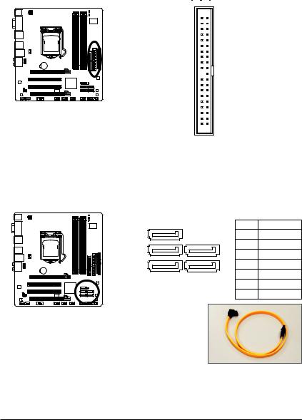
Box Contents
GA-H55M-UD2H or GA-H55M-US2H motherboard
Motherboard driver disk
User’s Manual
Quick Installation Guide
One IDE cable
Two SATA 3Gb/s cables
I/O Shield
•The box contents above are for reference only and the actual items shall depend on the product package you obtain. The box contents are subject to change without notice.
•The motherboard image is for reference only.
Optional Items
Floppy disk drive cable (Part No. 12CF1-1FD001-7*R)
2-port USB 2.0 bracket (Part No. 12CR1-1UB030-5*R)
2-port IEEE 1394a bracket (Part No. 12CF1-1IE008-0*R)j
2-port SATA power cable (Part No. 12CF1-2SERPW-0*R)
S/PDIF In cable (Part No. 12CR1-1SPDIN-0*R)
COM port cable (Part No. 12CF1-1CM001-3*R)
jOnly for GA-H55M-UD2H
— 6 —
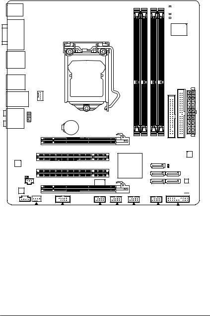
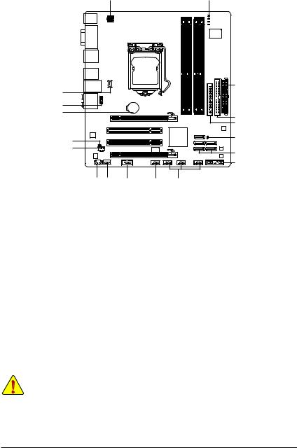
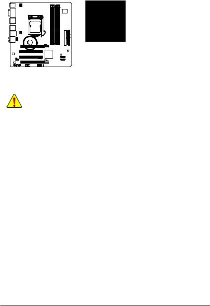
GA-H55M-UD2H/GA-H55M-US2H Motherboard Layout
PHASE LED KB_USB 


ATX_12V
DPj_HDMI_SPDIF
|
ESATA_1394j_USB |
IDE ATX |
|
FDD |
|
|
USB_LAN |
|
|
CPU_FAN |
|
AUDIO |
GA-H55M-UD2H/ |
||
|
F_AUDIO |
BAT |
GA-H55M-US2H |
|
|
PCIEX16 |
|||
|
DDR3 2 DDR3 1 |
|||
|
PCI1 |
|||
|
RTL8111D |
|||
|
PCI2 |
Intel® H55 |
||
|
SPDIF_O |
|||
|
SPDIF_I |
PCIEX4 |
TSB43AB23j |
|
|
CODEC |
|||
|
CD_IN |
|
DDR3 4 DDR3 3 |
JMicron |
|
JMB368 |
|
|
SATA2_0 |
CLR_CMOS |
|
M_BIOS |
SATA2_2 SATA2_1 B_BIOS SATA2_4 SATA2_3 

|
SYS_FAN |
F_1394j |
F_ |
USB2 |
F_ |
PANEL |
|||||
|
COMA |
F_ |
USB3 |
F_USB1 |
jOnly for GA-H55M-UD2H
«*» The GA-H55M-UD2H adopts All-Solid Capacitor design. — 7 —
PS/2 KB/Mouse
j Only for GA-H55M-UD2H
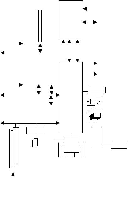
Block Diagram
1 PCI Express x16
PCIe CLK
(100 MHz)
|
x16 |
||||||||||||||||||||||
|
PCI Express Bus |
||||||||||||||||||||||
|
1 PCI Express x4 |
||||||||||||||||||||||
|
LAN |
||||||||||||||||||||||
|
PCIe CLK |
RJ45 |
|||||||||||||||||||||
|
(100 MHz) |
RTL8111D |
|||||||||||||||||||||
|
PCI Express Bus |
x4 |
x1 |
||||||||||||||||||||
|
x1 |
||||||||||||||||||||||
|
ATA-133/100/66/33 IDE Channel |
JMicron |
|||||||||||||||||||||
|
JMB368 |
||||||||||||||||||||||
PCI Bus
TSB43AB23j
2 IEEE 1394aj
|
CPU CLK+/- (133 MHz) |
|||||||||
|
DDR3 1666 (O.C.)/1333/1066/800 MHz |
|||||||||
|
LGA1156 |
Dual Channel Memory |
||||||||
|
CPU |
|||||||||
|
Interface DMI |
Interface FDI |
||||||
|
D-Sub |
|||||||
|
DVI-D, HDMI, or |
|||||||
|
Intel® H55 |
DisplayPortj(Note) |
||||||

 Dual BIOS


 6 SATA 3Gb/s


 12 USB Ports
|
LPC |
|||||||||
|
Bus |
IT8720 |
Floppy |
|||||||
|
COM Port |
|||||||||
CODEC
|
Out |
In |
S/PDIF In S/PDIF Out |
|||||||||
|
Out |
|||||||||||
|
Out |
Line |
||||||||||
|
2 PCI |
Speaker Speaker SpeakerOut |
MIC Line |
|||||||||
|
Surround |
|||||||||||
|
PCI CLK |
|||||||||||
|
(33 MHz) |
|||||||||||
|
Center/Subwoofer Side |
|||||||||||
(Note) You can use only one of the onboard digital graphics ports (e.g. DisplayPortj, HDMI, and DVI-D) for output when in the BIOS Setup program or when during the POST screens.
— 8 —

Chapter 1 Hardware Installation
1-1 Installation Precautions
The motherboard contains numerous delicate electronic circuits and components which can become damaged as a result of electrostatic discharge (ESD). Prior to installation, carefully read the user’s manual and follow these procedures:
•Prior to installation, do not remove or break motherboard S/N (Serial Number) sticker or warranty sticker provided by your dealer. These stickers are required for warranty validation.
•Always remove the AC power by unplugging the power cord from the power outlet before installing or removing the motherboard or other hardware components.
•When connecting hardware components to the internal connectors on the motherboard, make sure they are connected tightly and securely.
•When handling the motherboard, avoid touching any metal leads or connectors.
•It is best to wear an electrostatic discharge (ESD) wrist strap when handling electronic components such as a motherboard, CPU or memory. If you do not have an ESD wrist strap, keep your hands dry and first touch a metal object to eliminate static electricity.
•Prior to installing the motherboard, please have it on top of an antistatic pad or within an electrostatic shielding container.
•Before unplugging the power supply cable from the motherboard, make sure the power supply has been turned off.
•Before turning on the power, make sure the power supply voltage has been set according to the local voltage standard.
•Before using the product, please verify that all cables and power connectors of your hardware components are connected.
•To prevent damage to the motherboard, do not allow screws to come in contact with the motherboard circuit or its components.
•Make sure there are no leftover screws or metal components placed on the motherboard or within the computer casing.
•Do not place the computer system on an uneven surface.
•Do not place the computer system in a high-temperature environment.
•Turning on the computer power during the installation process can lead to damage to system components as well as physical harm to the user.
•If you are uncertain about any installation steps or have a problem related to the use of the product, please consult a certified computer technician.
|
— 9 — |
Hardware Installation |
|
1-2 |
Product Specifications |
|
|
CPU |
Support for an Intel® Core™ i7 series processor/Intel® Core™ i5 series processor/ |
|
|
Intel® Core™ i3 series processor in the LGA1156 package |
||
|
(Go to GIGABYTE’s website for the latest CPU support list.) |
L3 cache varies with CPU
|
Chipset |
|
Intel® H55 Express Chipset |
||
|
Memory |
|
4 x 1.5V DDR3 DIMM sockets supporting up to 16 GB of system memory (Note 1) |
||
|
|
Dual channel memory architecture |
|||
|
|
Support for DDR3 1666 (O.C.)/1333/1066/800 MHz memory modules |
|||
|
|
Support for non-ECC memory modules |
|||
|
|
Support for Extreme Memory Profile (XMP) memory modules |
|||
|
(Go to GIGABYTE’s website for the latest memory support list.) |
||||
|
Onboard Graphics |
Integrated in the Chipset: |
|||
|
— 1 x D-Sub port (Note 2) |
||||
|
— 1 x DVI-D port (Note 2)(Note 3)(Note 4) |
||||
|
— 1 x HDMI port (Note 2)(Note 4) |
||||
|
— 1 x DisplayPort j(Note 2)(Note 4) |
||||
|
Audio |
|
Realtek ALC889 codecj |
||
|
|
Realtek ALC888B codeck |
|||
|
|
High Definition Audio |
|||
|
|
2/4/5.1/7.1-channel |
|||
|
|
Support for S/PDIF In/Out |
|||
|
|
Support for CD In |
|||
|
LAN |
|
1 x RTL8111D chip (10/100/1000 Mbit) |
||
|
Expansion Slots |
|
1 x PCI Express x16 slot, running at x16 (PCIEX16) (Note 5) |
||
|
(The PCIEX16 slot conforms to PCI Express 2.0 standard.) |
||||
|
|
1 x PCI Express x16 slot, running at x4 (PCIEX4) |
|||
|
|
2 x PCI slots |
|||
|
Multi-Graphics |
|
Support for ATI CrossFireX™ technology (Note 6) |
||
|
Technology |
||||
|
Storage Interface |
|
Chipset: |
||
|
— |
5 x SATA 3Gb/s connectors supporting up to 5 SATA 3Gb/s devices |
|||
|
— |
1 x eSATA 3Gb/s connector on the back panel supporting up to 1 |
|||
|
SATA 3Gb/s device |
||||
|
|
JMicron JMB368 chip: |
|||
|
— |
1 x IDE connector supporting ATA-133/100/66/33 and up to 2 IDE devices |
|||
|
|
iTE IT8720 chip: |
|||
|
— |
1 x floppy disk drive connector supporting up to 1 floppy disk drive |
j Only for GA-H55M-UD2H
kOnly for GA-H55M-US2H
«*» The GA-H55M-UD2H adopts All-Solid Capacitor design.
|
Hardware Installation |
— 10 — |
![]()
|
USB |
|
Integrated in the Chipset |
|
Up to 12 USB 2.0/1.1 ports (6 on the back panel, 6 via the USB brackets con- |
||
|
nected to the internal USB headers) |
||
|
IEEE 1394j |
|
T.I. TSB43AB23 chip |
|
Up to 2 IEEE 1394a ports (1 on the back panel, 1 via the IEEE 1394a bracket |
||
|
connected to the internal IEEE 1394a header) |
||
|
Internal |
w |
1 x 24-pin ATX main power connector |
|
Connectors |
w |
1 x 4-pin ATX 12V power connector |
|
w 1 x floppy disk drive connector |
||
|
w 1 x IDE connector |
||
|
w 5 x SATA 3Gb/s connectors |
||
|
w 1 x CPU fan header |
||
|
w 1 x system fan header |
||
|
w 1 x front panel header |
||
|
w 1 x front panel audio header |
||
|
w 1 x CD In connector |
||
|
w 1 x S/PDIF In header |
||
|
w 1 x S/PDIF Out header |
||
|
w 3 x USB 2.0/1.1 headers |
||
|
w 1 x IEEE 1394a headerj |
||
|
w 1 x serial port header |
||
|
w 1 x clearing CMOS jumper |
||
|
Back Panel |
w |
1 x PS/2 keyboard/mouse port |
|
Connectors |
w |
1 x D-Sub port (Note 2) |
|
w |
1 x DVI-D port (Note 2)(Note 3)(Note 4) |
|
|
w 1 x optical S/PDIF Out connector |
||
|
w |
1 x HDMI port (Note 2)(Note 4) |
|
|
w |
1 x DisplayPortj(Note 2)(Note 4) |
|
|
w 1 x IEEE 1394a portj |
||
|
w 6 x USB 2.0/1.1 ports |
||
|
w 1 x eSATA 3Gb/s connector |
||
|
w 1 x RJ-45 port |
||
|
w 6 x audio jacks (Center/Subwoofer Speaker Out/Rear Speaker Out/ |
||
|
Side Speaker Out/Line In/Line Out/Microphone) |
||
|
I/O Controller |
w |
iTE IT8720 chip |
jOnly for GA-H55M-UD2H
|
— 11 — |
Hardware Installation |
Hardware Monitor w System voltage detection
w CPU/System temperature detection
wCPU/System fan speed detection
wCPU overheating warning
wCPU/System fan fail warning
wCPU/System fan speed control (Note 7)
|
BIOS |
w |
2 x 64 Mbit flash |
|
w |
Use of licensed AWARD BIOS |
wSupport for DualBIOS™
wPnP 1.0a, DMI 2.0, SM BIOS 2.4, ACPI 1.0b
Unique Features w Support for @BIOS w Support for Q-Flash
w Support for Xpress BIOS Rescue w Support for Download Center
w Support for Xpress Install
w Support for Xpress Recovery2 w Support for EasyTune (Note
w Support for Dynamic Energy Saver™ 2 w Support for Smart 6™
w Support Auto Green w Support for Q-Share
 Bundled Software w Norton Internet Security (OEM version)
 Operating System w Support for Microsoft® Windows 7/Vista/XP
|
Form Factor |
w MicroATX Form Factor; 24.4cm x 23cm |
(Note 1) Due to Windows 32-bit operating system limitation, when more than 4 GB of physical memory is installed, the actual memory size displayed will be less than 4 GB.
(Note 2) To use the onboard D-Sub, DVI-D, HDMI, and DisplayPortj ports, you must install an Intel CPU with integrated graphics.
(Note 3) The DVI-D port does not support D-Sub connection by adapter.
(Note 4) You can use only one of the onboard digital graphics ports (e.g. DisplayPortj, HDMI, and DVI-D) for output when in the BIOS Setup program or when during the POST screens.
(Note 5) For optimum performance, if only one PCI Express graphics card is to be installed, be sure to install it in the PCIEX16 slot.
(Note 6) The PCIEX16 slot operates at up to x4 mode when ATI CrossFireX™ is enabled.
(Note 7) Whether the CPU/system fan speed control function is supported will depend on the CPU/system cooler you install.
(Note Available functions in EasyTune may differ by motherboard model.
jOnly for GA-H55M-UD2H
|
Hardware Installation |
— 12 — |
1-3 Installing the CPU and CPU Cooler
Read the following guidelines before you begin to install the CPU:
• Make sure that the motherboard supports the CPU.
(Go to GIGABYTE’s website for the latest CPU support list.)
•Always turn off the computer and unplug the power cord from the power outlet before installing the CPU to prevent hardware damage.
•Locate the pin one of the CPU. The CPU cannot be inserted if oriented incorrectly. (Or you may locate the notches on both sides of the CPU and alignment keys on the CPU socket.)
•Apply an even and thin layer of thermal grease on the surface of the CPU.
•Do not turn on the computer if the CPU cooler is not installed, otherwise overheating and damage of the CPU may occur.
•Set the CPU host frequency in accordance with the CPU specifications. It is not recommended that the system bus frequency be set beyond hardware specifications since it does not meet the standard requirements for the peripherals. If you wish to set the frequency beyond the standard specifications, please do so according to your hardware specifications including the CPU, graphics card, memory, hard drive, etc.
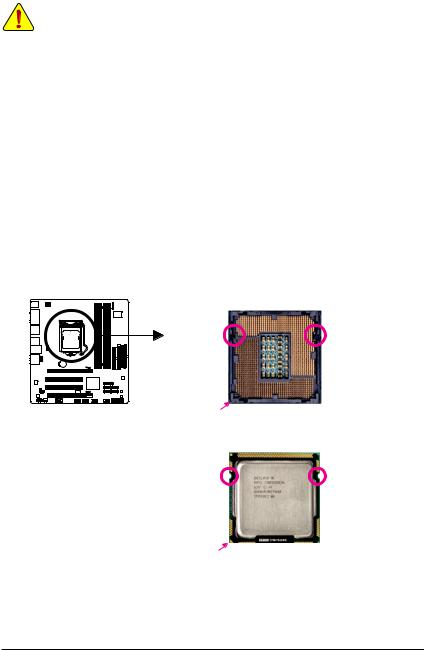
1-3-1 Installing the CPU
A. Locate the alignment keys on the motherboard CPU socket and the notches on the CPU.
LGA1156 CPU Socket
|
Alignment Key |
Alignment Key |
Pin One Corner of the CPU Socket
LGA1156 CPU
Triangle Pin One Marking on the CPU
|
— 13 — |
Hardware Installation |
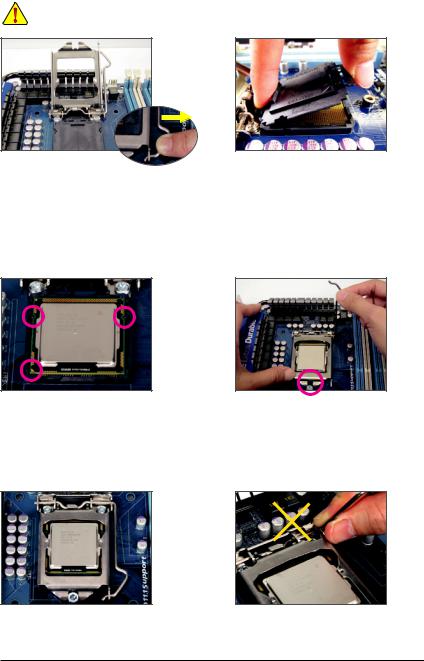
B. Follow the steps below to correctly install the CPU into the motherboard CPU socket.
Before installing the CPU, make sure to turn off the computer and unplug the power cord from the power outlet to prevent damage to the CPU.
Step 1:
Gently press the CPU socket lever handle down and away from the socket with your finger. Then completely lift the CPU socket lever and the metal load plate will be lifted as well.
Step 3:
Hold the CPU with your thumb and index fingers.
Align the CPU pin one marking (triangle) with the pin one corner of the CPU socket (or you may align the CPU notches with the socket alignment keys) and gently insert the CPU into position.
Step 5:
Push the CPU socket lever back into its locked position.
|
Hardware Installation |
— 14 — |
Step 2:
Remove the CPU socket cover as shown. Hold your index finger down on the rear grip of the socket cover and use your thumb to lift up the front edge (next to the «REMOVE» mark) and then remove the cover. (DO NOT touch socket contacts. To protect the CPU socket, always replace the protective socket cover when the CPU is not installed.)
Step 4:
Once the CPU is properly inserted, use one hand to hold the socket lever and use the other to lightly replace the load plate. When replacing the load plate, make sure the front end of the load plate is under the shoulder screw.
NOTE:
Hold the CPU socket lever by the handle, not the lever base portion.
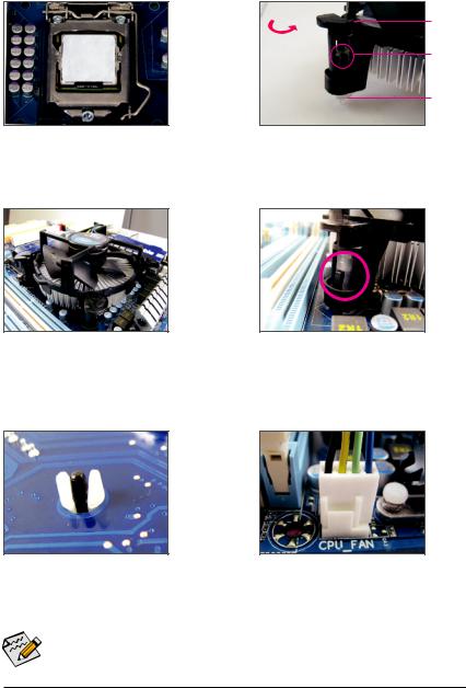
1-3-2 Installing the CPU Cooler
Follow the steps below to correctly install the CPU cooler on the motherboard. (The following procedure uses
Intel® boxed cooler as the example cooler.)
Direction of the Arrow Sign on the Male Push Pin
Male Push
Pin
The Top
of Female
Push Pin
Female
Push Pin
Step 1:
Apply an even and thin layer of thermal grease on the surface of the installed CPU.
Step 3:
Place the cooler atop the CPU, aligning the four push pins through the pin holes on the motherboard. Push down on the push pins diagonally.
Step 5:
After the installation, check the back of the motherboard. If the push pin is inserted as the picture above shows, the installation is complete.
Step 2:
Before installing the cooler, note the direction of the arrow sign  on the male push pin. (Turning the push pin along the direction of arrow is to remove the cooler, on the contrary, is to install.)
Step 4:
You should hear a «click» when pushing down each push pin. Check that the Male and Female push pins are joined closely. (Refer to your CPU cooler installation manual for instructions on installing the cooler.)
Step 6:
Finally, attach the power connector of the CPU cooler to the CPU fan header (CPU_FAN) on the motherboard.
Use extreme care when removing the CPU cooler because the thermal grease/tape between the CPU cooler and CPU may adhere to the CPU. Inadequately removing the CPU cooler may damage the CPU.
|
— 15 — |
Hardware Installation |
1-4 Installing the Memory
Read the following guidelines before you begin to install the memory:
•Make sure that the motherboard supports the memory. It is recommended that memory of the same capacity, brand, speed, and chips be used.
(Go to GIGABYTE’s website for the latest memory support list.)
•Always turn off the computer and unplug the power cord from the power outlet before installing the memory to prevent hardware damage.
•Memory modules have a foolproof design. A memory module can be installed in only one direction. If you are unable to insert the memory, switch the direction.
1-4-1 Dual Channel Memory Configuration
This motherboard provides four DDR3 memory sockets and supports Dual Channel Technology. After the memory is installed, the BIOS will automatically detect the specifications and capacity of the memory. Enabling Dual Channel memory mode will double the original memory bandwidth.
The four DDR3 memory sockets are divided into two channels and each channel has two memory sockets as following:
 Channel 0: DDR3_1, DDR3_2
  Channel 1: DDR3_3, DDR3_4
 Dual Channel Memory Configurations Table
|
DDR3_2 |
DDR3_1 DDR3_4 |
DDR3_3 |
||
|
Two Modules |
— — |
DS/SS |
— — |
DS/SS |
|
Four Modules |
DS/SS |
DS/SS |
DS/SS |
DS/SS |
(SS=Single-Sided, DS=Double-Sided, «- -«=No Memory)
DDR3_3
DDR3_4
DDR3_1
DDR3_2
Due to CPU limitations, read the following guidelines before installing the memory in Dual Channel mode.
1.Dual Channel mode cannot be enabled if only one DDR3 memory module is installed.
2.When enabling Dual Channel mode with two or four memory modules, it is recommended that memory of the same capacity, brand, speed, and chips be used for optimum performance. When
enabling Dual Channel mode with two memory modules, be sure to install them in the DDR3_1 and DDR3_ sockets.
If only one DDR3 memory module is installed, be sure to install it in the DDR3_1 or DDR3_3 socket.
|
Hardware Installation |
— 16 — |
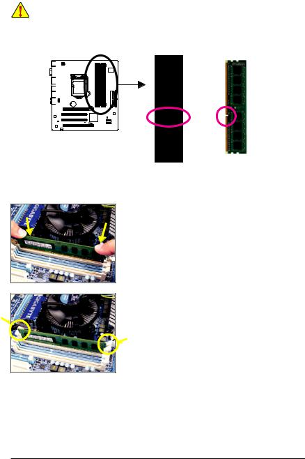
1-4-2 Installing a Memory
Before installing a memory module, make sure to turn off the computer and unplug the power cord from the power outlet to prevent damage to the memory module.
DDR3 and DDR2 DIMMs are not compatible to each other or DDR DIMMs. Be sure to install DDR3 DIMMs on this motherboard.
Notch
DDR3 DIMM
A DDR3 memory module has a notch, so it can only fit in one direction. Follow the steps below to correctly install your memory modules in the memory sockets.
Step 1:
Note the orientation of the memory module. Spread the retaining clips at both ends of the memory socket. Place the memory module on the socket. As indicated in the picture on the left, place your fingers on the top edge of the memory, push down on the memory and insert it vertically into the memory socket.
Step 2:
The clips at both ends of the socket will snap into place when the memory module is securely inserted.
|
— 17 — |
Hardware Installation |
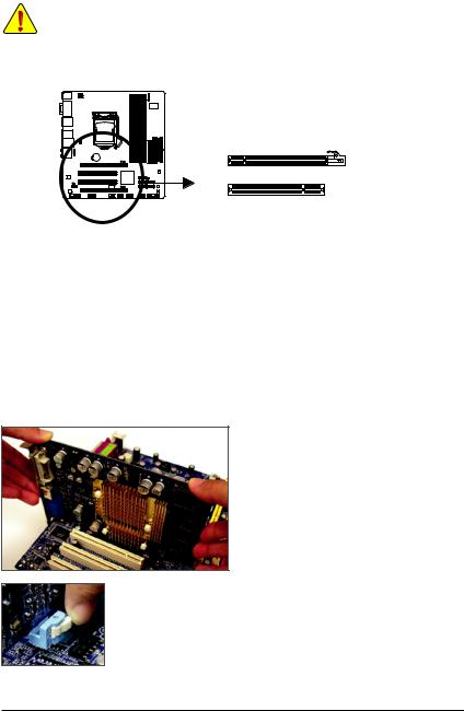
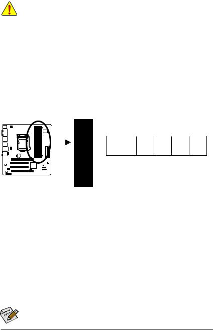
1-5 Installing an Expansion Card
Read the following guidelines before you begin to install an expansion card:
•Make sure the motherboard supports the expansion card. Carefully read the manual that came with your expansion card.
•Always turn off the computer and unplug the power cord from the power outlet before installing an expansion card to prevent hardware damage.
PCI Express x16 Slot (PCIEX16/PCIEX4)
PCI Slot
Follow the steps below to correctly install your expansion card in the expansion slot.
1.Locate an expansion slot that supports your card. Remove the metal slot cover from the chassis back panel.
2.Align the card with the slot, and press down on the card until it is fully seated in the slot.
3.Make sure the metal contacts on the card are completely inserted into the slot.
4.Secure the card’s metal bracket to the chassis back panel with a screw.
5.After installing all expansion cards, replace the chassis cover(s).
6.Turn on your computer. If necessary, go to BIOS Setup to make any required BIOS changes for your expansion card(s).
7.Install the driver provided with the expansion card in your operating system.
Example: Installing and Removing a PCI Express Graphics Card:
• Installing a Graphics Card:
Gently push down on the top edge of the card until it is fully inserted into the PCI Express slot. Make sure the card is securely seated in the slot and does not rock.
•Removing the Card:
Press the white latch at the end of the PCI Express slot to release the card and then pull the card straight up from the slot.
|
Hardware Installation |
— 18 — |
1-6 Back Panel Connectors
(Note 1)
|
(Note 1)(Note 3) |
||
|
(Note 1)(Note 2)(Note 3) |
j (Note 1)(Note 3) |
j |
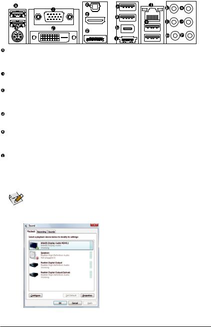
USB Port
The USB port supports the USB 2.0/1.1 specification. Use this port for USB devices such as a USB keyboard/mouse, USB printer, USB flash drive and etc.
PS/2 Keyboard/Mouse Port
Use this port a PS/2 keyboard or mouse.
D-Sub Port (Note 1)
The D-Sub port supports a 15-pin D-Sub connector. Connect a monitor that supports D-Sub connection to this port.
DVI-D Port (Note 1)(Note 2) (Note 3)
The DVI-D port supports DVI-D specifictation. Connect a monitor that supports DVI-D connection to this port.
Optical S/PDIF Out Connector
This connector provides digital audio out to an external audio system that supports digital optical audio. Before using this feature, ensure that your audio system provides an optical digital audio in connector.
HDMI Port (Note 1)(Note 3)
The HDMI (High-Definition Multimedia Interface) provides an all-digital audio/video interface to transmit the uncompressed audio/video signals and is HDCP compliant. Connect the HDMI audio/video device to this port. The HDMI Technology can support a maximum resolution of 1920x1080p but the actual resolutions supported depend on the monitor being used.

 • After installing the HDMI device, make sure the default device for sound playback is the HDMI
  device. (The item name may differ from operating system. Refer to the figure below for details.)
•Please note the HDMI audio output only supportsAC3, DTS and 2-channel-LPCM formats. (AC3 and
DTS require the use of an external decoder for decoding.)
In Windows Vista, select Start>Control Panel>Sound> Playback, set Intel(R) Display Audio HDMI 2 to the default playback device.
j Only for GA-H55M-UD2H
|
— 19 — |
Hardware Installation |

DiplayPortj(Note 1)(Note 3)
DisplayPort is one of the new generation interface technologies that delivers high quality digital imaging and audio, supporting bi-directional audio transmition. DisplayPort can support both DPCP and HDCP content protection mechanisms. Connect the audio/video device that supports DisplayPort to this port. The DisplayPort Technology can support a maximum resolution of 2560x1600p but the actual resolutions supported depend on the monitor being used.

 After installing the DisplayPort device, make sure the default device for sound playback is the Dis-
  playPort device. (The item name may differ from operating system. For example, in Windows Vista, go to Start>Control Panel>Sound>Playback and set the DisplayPort device as the default playback device. Refer to the HDMI settings information on the previous page for the configuration dialog box.)
Dual Display Configurations for the Onboard Graphics:
The table below shows the supported dual display configurations for the onboard graphics ports when in the BIOS Setup program or when during the POST stage. There is no such limitation in operating system environment.
|
Display |
Combination |
Supported or Not |
|
Matrix |
DVI-D + D-Sub |
Yes |
|
DVI-D + HDMI |
No |
|
|
DVI-D + DPj |
No |
|
|
HDMI + D-Sub |
Yes |
|
|
HDMI + DPj |
No |
|
|
DP + D-Subj |
No |
|
(Note 1) To use the onboard D-Sub, DVI-D, HDMI, and DisplayPortj ports, you must install an Intel CPU with integrated graphics.
(Note 2) The DVI-D port does not support D-Sub connection by adapter.
(Note 3) You can use only one of the onboard digital graphics ports (e.g. DisplayPortj, HDMI, and DVI-D) for output when in the BIOS Setup program or when during the POST screens.
|
j Only for GA-H55M-UD2H |
|
|
Hardware Installation |
— 20 — |
![]()
IEEE 1394a Portj
The IEEE 1394 port supports the IEEE 1394a specification, featuring high speed, high bandwidth and hotplug capabilities. Use this port for an IEEE 1394a device.
eSATA 3Gb/s Port
The eSATA 3Gb/s port conforms to SATA 3Gb/s standard and is compatible with SATA 1.5Gb/s standard. Use the port to connect an external SATA device.
RJ-45 LAN Port
The Gigabit Ethernet LAN port provides Internet connection at up to 1 Gbps data rate. The following describes the states of the LAN port LEDs.
|
Connection/ |
Activity LED |
Connection/Speed LED: |
Activity LED: |
||||||||||||||||
|
Speed LED |
|||||||||||||||||||
|
State |
Description |
||||||||||||||||||
|
State |
Description |
||||||||||||||||||
|
Orange |
1 Gbps data rate |
Blinking |
Data transmission or receiving is occurring |
||||||||||||||||
|
Green |
100 Mbps data rate |
Off |
No data transmission or receiving is occurring |
||||||||||||||||
|
LAN Port |
Off |
10 Mbps data rate |
|||||||||||||||||
Center/Subwoofer Speaker Out Jack (Orange)
Use this audio jack to connect center/subwoofer speakers in a 5.1/7.1-channel audio configuration.
Rear Speaker Out Jack (Black)
Use this audio jack to connect rear speakers in a 4/5.1/7.1-channel audio configuration.
Side Speaker Out Jack (Gray)
Use this audio jack to connect side speakers in a 7.1-channel audio configuration.
Line In Jack (Blue)
The default line in jack. Use this audio jack for line in devices such as an optical drive, walkman, etc.
Line Out Jack (Green)
The default line out jack. Use this audio jack for a headphone or 2-channel speaker. This jack can be used to connect front speakers in a 4/5.1/7.1-channel audio configuration.
Mic In Jack (Pink)
The default Mic in jack. Microphones must be connected to this jack.

 In addition to the default speakers settings, the
 ~
~ audio jacks can be reconfigured to per-
form different functions via the audio software. Only microphones still MUST be connected to the default Mic in jack ( ). Refer to the instructions on setting up a 2/4/5.1/7.1-channel audio
configuration in Chapter 5, «Configuring 2/4/5.1/7.1-Channel Audio.»
•When removing the cable connected to a back panel connector, first remove the cable from your device and then remove it from the motherboard.
•When removing the cable, pull it straight out from the connector. Do not rock it side to side to prevent an electrical short inside the cable connector.
j Only for GA-H55M-UD2H
|
— 21 — |
Hardware Installation |
1-7 Internal Connectors
|
3 |
2 |
|
10 |
|
|
8 |
6 |
|
5 |
|
13 |
17 |
||
|
12 |
7 |
||
|
9 |
|||
|
11 4 |
16 |
15j |
14 |
|
1) |
ATX_12V |
10) |
F_AUDIO |
|
2) |
ATX |
11) |
CD_IN |
|
3) |
CPU_FAN |
12) |
SPDIF_I |
|
4) |
SYS_FAN |
13) |
SPDIF_O |
|
5) |
FDD |
14) |
F_USB1/F_USB2/F_USB3 |
|
6) |
IDE |
15) |
F_1394j |
|
7) |
SATA2_0/1/2/3/4 |
16) |
COMA |
|
|
BAT |
17) |
CLR_CMOS |
|
9) |
F_PANEL |
18) |
PHASE_LED |
Read the following guidelines before connecting external devices:
• First make sure your devices are compliant with the connectors you wish to connect.
•Before installing the devices, be sure to turn off the devices and your computer. Unplug the power cord from the power outlet to prevent damage to the devices.
•After installing the device and before turning on the computer, make sure the device cable has been securely attached to the connector on the motherboard.
|
j Only for GA-H55M-UD2H |
|
|
Hardware Installation |
— 22 — |
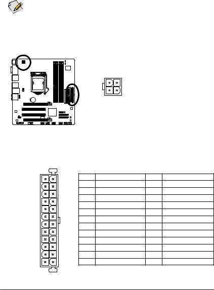
1/2) ATX_12V/ATX (2×2 12V Power Connector and 2×12 Main Power Connector)
With the use of the power connector, the power supply can supply enough stable power to all the components on the motherboard. Before connecting the power connector, first make sure the power supply is turned off and all devices are properly installed. The power connector possesses a foolproof design. Connect the power supply cable to the power connector in the correct orientation. The 12V power connector mainly supplies power to the CPU. If the 12V power connector is not connected, the computer will not start.

 • To meet expansion requirements, it is recommended that a power supply that can withstand
  high power consumption be used (500W or greater). If a power supply is used that does not provide the required power, the result can lead to an unstable or unbootable system.
•The main power connector is compatible with power supplies with 2×10 power connectors. When using a 2×12 power supply, remove the protective cover from the main power connector on the motherboard. Do not insert the power supply cable into pins under the protective cover when using a 2×10 power supply.
|
ATX_12V: |
||||
|
4 |
2 |
Pin No. |
Definition |
|
|
1 |
GND |
|||
|
2 |
GND |
|||
|
3 |
1 |
3 |
+12V |
|
|
4 |
+12V |
|||
|
ATX_12V |
||||
|
ATX: |
|||||
|
12 |
24 |
Pin No. |
Definition |
Pin No. |
Definition |
|
1 |
3.3V |
13 |
3.3V |
||
|
2 |
3.3V |
14 |
-12V |
||
|
3 |
GND |
15 |
GND |
||
|
4 |
+5V |
16 |
PS_ON (soft On/Off) |
||
|
5 |
GND |
17 |
GND |
||
|
6 |
+5V |
18 |
GND |
||
|
7 |
GND |
19 |
GND |
||
|
8 |
Power Good |
20 |
-5V |
||
|
9 |
5VSB (stand by +5V) |
21 |
+5V |
||
|
10 |
+12V |
22 |
+5V |
||
|
11 |
+12V (Only for 2×12-pin ATX) |
23 |
+5V (Only for 2×12-pin ATX) |
||
|
1 |
13 |
12 |
3.3V (Only for 2×12-pin ATX) |
24 |
GND (Only for 2×12-pin ATX) |
ATX
|
— 23 — |
Hardware Installation |
3/4) CPU_FAN/SYS_FAN (Fan Headers)
The motherboard has a 4-pin CPU fan header (CPU_FAN) and a 4-pin system fan header (SYS_FAN). Most fan headers possess a foolproof insertion design. When connecting a fan cable, be sure to connect it in the correct orientation (the black connector wire is the ground wire). The motherboard supports CPU fan speed control, which requires the use of a CPU fan with fan speed control design. For optimum heat dissipation, it is recommended that a system fan be installed inside the chassis.
|
CPU_FAN: |
||||||||
|
Pin No. |
Definition |
|||||||
|
1 |
1 |
GND |
||||||
|
2 |
+12V / Speed Control |
|||||||
|
3 |
Sense |
|||||||
|
CPU_FAN |
||||||||
|
4 |
Speed Control |
|||||||
|
SYS_FAN: |
||||||||
|
1 |
Pin No. |
Definition |
||||||
|
1 |
GND |
|||||||
|
SYS_FAN |
2 |
+12V / Speed Control |
||||||
|
3 |
Sense |
|||||||
|
4 |
Reserve |
•Be sure to connect fan cables to the fan headers to prevent your CPU and system from overheating. Overheating may result in damage to the CPU or the system may hang.
•These fan headers are not configuration jumper blocks. Do not place a jumper cap on the headers.
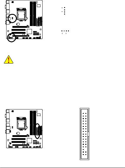
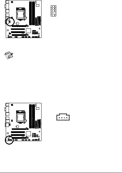
5)FDD (Floppy Disk Drive Connector)
This connector is used to connect a floppy disk drive. The types of floppy disk drives supported are: 360 KB, 720 KB, 1.2 MB, 1.44 MB, and 2.88 MB. Before connecting a floppy disk drive, be sure to locate pin 1 of the connector and the floppy disk drive cable. The pin 1 of the cable is typically designated by a stripe of different color. For purchasing the optional floppy disk drive cable, please contact the local dealer.
|
Hardware Installation |
— 24 — |
6)IDE (IDE Connector)
The IDE connector supports up to two IDE devices such as hard drives and optical drives. Before attaching the IDE cable, locate the foolproof groove on the connector. If you wish to connect two IDE devices, remember to set the jumpers and the cabling according to the role of the IDE devices (for example, master or slave). (For information about configuring master/slave settings for the IDE devices, read the instructions from the device manufacturers.)
39 1
7)SATA2_0/1/2/3/4 (SATA 3Gb/s Connectors, Controlled by H55 Chipset)
The SATA connectors conform to SATA 3Gb/s standard and are compatible with SATA 1.5Gb/s standard. Each SATA connector supports a single SATA device.
|
SATA2_0 1 |
7 |
Pin No. |
Definition |
|
|
1 |
GND |
|||
|
SATA2_1 |
2 |
TXP |
||
|
SATA2_2 1 |
7 |
|||
|
3 |
TXN |
|||
|
SATA2_4 1 |
7 |
4 |
GND |
|
|
5 |
RXN |
|||
|
SATA2_3 |
||||
|
6 |
RXP |
|||
|
7 |
GND |
Please connect the L-shaped end of the SATA 3Gb/s cable to your SATA hard drive.
|
— 25 — |
Hardware Installation |
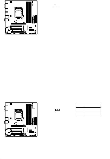
BAT (Battery)
The battery provides power to keep the values (such as BIOS configurations, date, and time information) in the CMOS when the computer is turned off. Replace the battery when the battery voltage drops to a low level, or the CMOS values may not be accurate or may be lost.
You may clear the CMOS values by removing the battery:
1.Turn off your computer and unplug the power cord.
2.Gently remove the battery from the battery holder and wait for one minute. (Or use a metal object like a screwdriver to touch the positive and negative terminals of the battery holder, making them short for 5 seconds.)
3.Replace the battery.
4.Plug in the power cord and restart your computer.
•Always turn off your computer and unplug the power cord before replacing the battery.
•Replace the battery with an equivalent one. Danger of explosion if the battery is replaced with an incorrect model.
•Contact the place of purchase or local dealer if you are not able to replace the battery by yourself or uncertain about the battery model.
•When installing the battery, note the orientation of the positive side (+) and the negative side (-) of the battery (the positive side should face up).
•Used batteries must be handled in accordance with local environmental regulations.
|
Hardware Installation |
— 26 — |
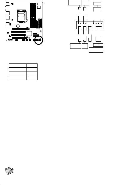
9)F_PANEL (Front Panel Header)
Connect the power switch, reset switch, speaker, chassis intrusion switch/sensor and system status indicator on the chassis to this header according to the pin assignments below. Note the positive and negative pins before connecting the cables.
|
Message/Power/ |
Power |
Speaker |
|||||
|
Sleep LED |
Switch |
||||||
|
MSG+ MSG |
—PW |
SPEAK+ |
SPEAK- |
||||
|
— PW+ |
|||||||
|
2 |
20 |
||||||
|
1 |
19 |
||||||
|
HD- |
RES+ |
CI+ |
PWR+ |
PWR- |
|||
|
HD+ RES- |
CI |
||||||
|
— |
|||||||
|
Hard Drive |
Reset |
Power LED |
|||||
|
Activity LED |
Switch |
Chassis Intrusion |
|||||
|
Header |
|||||||
|
• MSG/PWR (Message/Power/Sleep LED, Yellow/Purple): |
|||||||
|
System Status |
LED |
Connects to the power status indicator on the chassis front panel. The LED |
|||||
|
S0 |
On |
is on when the system is operating. The LED keeps blinking when the sys- |
|||||
|
S1 |
Blinking |
tem is in S1 sleep state. The LED is off when the system is in S3/S4 sleep |
|||||
|
S3/S4/S5 |
Off |
state or powered off (S5). |
•PW (Power Switch, Red):
Connects to the power switch on the chassis front panel. You may configure the way to turn off your system using the power switch (refer to Chapter 2, «BIOS Setup,» «Power Management Setup,» for more information).
•SPEAK (Speaker, Orange):
Connects to the speaker on the chassis front panel. The system reports system startup status by issuing a beep code. One single short beep will be heard if no problem is detected at system startup. If a problem is detected, the BIOS may issue beeps in different patterns to indicate the problem. Refer to Chapter 5, «Troubleshooting,» for information about beep codes.
•HD (Hard Drive Activity LED, Blue)
Connects to the hard drive activity LED on the chassis front panel. The LED is on when the hard drive is reading or writing data.
•RES (Reset Switch, Green):
Connects to the reset switch on the chassis front panel. Press the reset switch to restart the computer if the computer freezes and fails to perform a normal restart.
•CI (Chassis Intrusion Header, Gray):
Connects to the chassis intrusion switch/sensor on the chassis that can detect if the chassis cover has been removed. This function requires a chassis with a chassis intrusion switch/sensor.
The front panel design may differ by chassis. A front panel module mainly consists of power  switch, reset switch, power LED, hard drive activity LED, speaker and etc. When connecting your chassis front panel module to this header, make sure the wire assignments and the pin assign-
ments are matched correctly.
|
— 27 — |
Hardware Installation |
10)F_AUDIO (Front Panel Audio Header)
The front panel audio header supports Intel High Definition audio (HD) and AC’97 audio. You may connect your chassis front panel audio module to this header. Make sure the wire assignments of the module connector match the pin assignments of the motherboard header. Incorrect connection between the module connector and the motherboard header will make the device unable to work or even damage it.
|
For HD Front Panel Audio: |
For AC’97 Front Panel Audio: |
|||||
|
1 |
2 |
Pin No. |
Definition |
Pin No. |
Definition |
|
|
1 |
MIC2_L |
1 |
MIC |
|||
|
2 |
GND |
2 |
GND |
|||
|
9 |
10 |
3 |
MIC2_R |
3 |
MIC Power |
|
|
4 |
-ACZ_DET |
4 |
NC |
|||
|
5 |
LINE2_R |
5 |
Line Out (R) |
|||
|
6 |
GND |
6 |
NC |
|||
|
7 |
FAUDIO_JD |
7 |
NC |
|||
|
8 |
No Pin |
8 |
No Pin |
|||
|
9 |
LINE2_L |
9 |
Line Out (L) |
|||
|
10 |
GND |
10 |
NC |
• The front panel audio header supports HD audio by default. If your chassis provides an AC’97  front panel audio module, refer to the instructions on how to activate AC’97 functionality via
the audio software in Chapter 5, «Configuring 2/4/5.1/7.1-Channel Audio.»
•Audio signals will be present on both of the front and back panel audio connections simultaneously. If you want to mute the back panel audio (only supported when using an HD front panel audio module), refer to Chapter 5, «Configuring 2/4/5.1/7.1-Channel Audio.»
•Some chassis provide a front panel audio module that has separated connectors on each wire instead of a single plug. For information about connecting the front panel audio module that has different wire assignments, please contact the chassis manufacturer.
11)CD_IN (CD In Connector)
You may connect the audio cable that came with your optical drive to the header.
|
Pin No. |
Definition |
|
|
1 |
CD-L |
|
|
1 |
2 |
GND |
|
3 |
GND |
|
|
4 |
CD-R |
|
Hardware Installation |
— 28 — |
12)SPDIF_I (S/PDIF In Header)
This header supports digital S/PDIF In and can connect to an audio device that supports digital audio out via an optional S/PDIF In cable. For purchasing the optional S/PDIF In cable, please contact the local dealer.
|
Pin No. |
Definition |
|||||||
|
1 |
1 |
Power |
||||||
|
2 |
SPDIFI |
|||||||
|
3 |
GND |
13)SPDIF_O (S/PDIF Out Header)
This header supports digital S/PDIF Out and connects a S/PDIF digital audio cable (provided by expansion cards) for digital audio output from your motherboard to certain expansion cards like graphics cards and sound cards. For example, some graphics cards may require you to use a S/PDIF digital audio cable for digital audio output from your motherboard to your graphics card if you wish to connect an HDMI display to the graphics card and have digital audio output from the HDMI display at the same time. For information about connecting the S/PDIF digital audio cable, carefully read the manual for your expansion card.
|
Pin No. |
Definition |
|
|
1 |
1 |
SPDIFO |
|
2 |
GND |
|
— 29 — |
Hardware Installation |
 Loading…
-
Драйверы
19
-
Инструкции по эксплуатации
32
Языки:

Gigabyte GA-H55M-UD2H инструкция по эксплуатации
(72 страницы)
- Языки:Венгерский, Греческий, Испанский, Итальянский, Немецкий, Польский, Португальский, Русский, Турецкий, Французский, Чешский
-
Тип:
PDF -
Размер:
18.6 MB -
Описание:
Installation Guidebook


На NoDevice можно скачать инструкцию по эксплуатации для Gigabyte GA-H55M-UD2H. Руководство пользователя необходимо для ознакомления с правилами установки и эксплуатации Gigabyte GA-H55M-UD2H. Инструкции по использованию помогут правильно настроить Gigabyte GA-H55M-UD2H, исправить ошибки и выявить неполадки.
GA-H55M-UD2H/ GA-H55M-US2H LGA1156 socket motherboard for Intel® Core™ i7 processor family/ Intel® Core™ i5 processor family/ Intel® Core™ i3 processor family User’s Manual Rev. 1002 12ME-H55MUD2-1002R
Motherboard GA-H55M-UD2H/GA-H55M-US2H Nov. 14, 2009 Motherboard GA-H55M-UD2H/ GA-H55M-US2H Nov. 14, 2009
Copyright © 2009 GIGA-BYTE TECHNOLOGY CO., LTD. All rights reserved. The trademarks mentioned in this manual are legally registered to their respective owners. Disclaimer Information in this manual is protected by copyright laws and is the property of GIGABYTE. Changes to the specifications and
Table of Contents Box Contents……………………………………………………………………………………………………..6 Optional Items……………………………………………………………………………………………………6
Chapter 3 Drivers Installation……………………………………………………………………………..61 3-1 3-2 3-3 3-4 3-5 3-6 3-7 Installing Chipset Drivers…………………………………………………………………….. 61 Application
Box Contents GA-H55M-UD2H or GA-H55M-US2H motherboard Motherboard driver disk User’s Manual Quick Installation Guide One IDE cable Two SATA 3Gb/s cables I/O Shield • The box contents above are for reference only and the actual items shall depend on the product package you obtain. The box contents
GA-H55M-UD2H/GA-H55M-US2H Motherboard Layout PHASE LED KB_USB ATX_12V IT8720 VGA_DVI LGA1156 DPj_HDMI_SPDIF ESATA_1394j_USB IDE ATX FDD USB_LAN CPU_FAN DDR3_2 PCIEX16 GA-H55M-UD2H/ GA-H55M-US2H PCI1 RTL8111D Intel® H55 PCI2 DDR3_3 BAT DDR3_4 F_AUDIO DDR3_1 AUDIO SATA2_0 SPDIF_O SPDIF_I CODEC
Block Diagram 1 PCI Express x16 CPU CLK+/- (133 MHz) DDR3 1666 (O.C.)/1333/1066/800 MHz LGA1156 CPU Dual Channel Memory PCIe CLK (100 MHz) PCI Express Bus 1 PCI Express x4 FDI Interface DMI Interface x16 D-Sub LAN DVI-D, HDMI, or DisplayPortj (Note) RJ45 PCIe CLK (100 MHz) RTL8111D PCI Express Bus
Chapter 1 1-1 Hardware Installation Installation Precautions The motherboard contains numerous delicate electronic circuits and components which can become damaged as a result of electrostatic discharge (ESD). Prior to installation, carefully read the user’s manual and follow these procedures: •
1-2 Product Specifications CPU Support for an Intel® Core™ i7 series processor/Intel® Core™ i5 series processor/ Intel® Core™ i3 series processor in the LGA1156 package (Go to GIGABYTE’s website for the latest CPU support list.) L3 cache varies with CPU Chipset Intel® H55 Express Chipset
USB IEEE 1394j Internal w Connectors w w w w w w w w w w w w w w w Back Panel w Connectors w w w w w w w w w w I/O Controller j w Integrated in the Chipset Up to 12 USB 2.0/1.1 ports (6 on the back panel, 6 via the USB brackets connected to the internal USB headers) T.I. TSB43AB23 chip Up
Hardware Monitor BIOS Unique Features w w w w w w w w w w w w w w w w w w w w w System voltage detection CPU/System temperature detection CPU/System fan speed detection CPU overheating warning CPU/System fan fail warning CPU/System fan speed control (Note 7) 2 x 64 Mbit flash Use of licensed AWARD
1-3 Installing the CPU and CPU Cooler Read the following guidelines before you begin to install the CPU: • Make sure that the motherboard supports the CPU. (Go to GIGABYTE’s website for the latest CPU support list.) • Always turn off the computer and unplug the power cord from the power outlet
B. Follow the steps below to correctly install the CPU into the motherboard CPU socket. Before installing the CPU, make sure to turn off the computer and unplug the power cord from the power outlet to prevent damage to the CPU. Step 1: Gently press the CPU socket lever handle down and away from the
1-3-2 Installing the CPU Cooler Follow the steps below to correctly install the CPU cooler on the motherboard. (The following procedure uses Intel® boxed cooler as the example cooler.) Male Push Pin Direction of the Arrow Sign on the Male Push Pin The Top of Female Push Pin Female Push Pin Step 1:
1-4 Installing the Memory Read the following guidelines before you begin to install the memory: • Make sure that the motherboard supports the memory. It is recommended that memory of the same capacity, brand, speed, and chips be used. (Go to GIGABYTE’s website for the latest memory support list.) •
1-4-2 Installing a Memory Before installing a memory module, make sure to turn off the computer and unplug the power cord from the power outlet to prevent damage to the memory module. DDR3 and DDR2 DIMMs are not compatible to each other or DDR DIMMs. Be sure to install DDR3 DIMMs on this
1-5 Installing an Expansion Card Read the following guidelines before you begin to install an expansion card: • Make sure the motherboard supports the expansion card. Carefully read the manual that came with your expansion card. • Always turn off the computer and unplug the power cord from the
1-6 Back Panel Connectors (Note 1) (Note 1)(Note 3) (Note 1)(Note 2)(Note 3) j (Note 1)(Note 3) j USB Port The USB port supports the USB 2.0/1.1 specification. Use this port for USB devices such as a USB keyboard/mouse, USB printer, USB flash drive and etc. PS/2 Keyboard/Mouse Port Use this port a
DiplayPortj(Note 1)(Note 3) DisplayPort is one of the new generation interface technologies that delivers high quality digital imaging and audio, supporting bi-directional audio transmition. DisplayPort can support both DPCP and HDCP content protection mechanisms. Connect the audio/video device
IEEE 1394a Portj The IEEE 1394 port supports the IEEE 1394a specification, featuring high speed, high bandwidth and hotplug capabilities. Use this port for an IEEE 1394a device. eSATA 3Gb/s Port The eSATA 3Gb/s port conforms to SATA 3Gb/s standard and is compatible with SATA 1.5Gb/s standard. Use
1-7 Internal Connectors 1 18 2 3 10 8 6 5 17 13 12 7 9 11 1) 2) 3) 4) 5) 6) 7) 9) ATX_12V ATX CPU_FAN SYS_FAN FDD IDE SATA2_0/1/2/3/4 BAT F_PANEL 4 16 15j 10) 11) 12) 13) 14) 15) 16) 17) 18) 14 F_AUDIO CD_IN SPDIF_I SPDIF_O F_USB1/F_USB2/F_USB3 F_1394j COMA CLR_CMOS PHASE_LED Read the following
1/2) ATX_12V/ATX (2×2 12V Power Connector and 2×12 Main Power Connector) With the use of the power connector, the power supply can supply enough stable power to all the components on the motherboard. Before connecting the power connector, first make sure the power supply is turned off and all
3/4) CPU_FAN/SYS_FAN (Fan Headers) The motherboard has a 4-pin CPU fan header (CPU_FAN) and a 4-pin system fan header (SYS_FAN). Most fan headers possess a foolproof insertion design. When connecting a fan cable, be sure to connect it in the correct orientation (the black connector wire is the
6) IDE (IDE Connector) The IDE connector supports up to two IDE devices such as hard drives and optical drives. Before attaching the IDE cable, locate the foolproof groove on the connector. If you wish to connect two IDE devices, remember to set the jumpers and the cabling according to the role of
BAT (Battery) The battery provides power to keep the values (such as BIOS configurations, date, and time information) in the CMOS when the computer is turned off. Replace the battery when the battery voltage drops to a low level, or the CMOS values may not be accurate or may be lost. You may
9) F_PANEL (Front Panel Header) Connect the power switch, reset switch, speaker, chassis intrusion switch/sensor and system status indicator on the chassis to this header according to the pin assignments below. Note the positive and negative pins before connecting the cables. Power Switch SPEAK-
10) F_AUDIO (Front Panel Audio Header) The front panel audio header supports Intel High Definition audio (HD) and AC’97 audio. You may connect your chassis front panel audio module to this header. Make sure the wire assignments of the module connector match the pin assignments of the motherboard
12) SPDIF_I (S/PDIF In Header) This header supports digital S/PDIF In and can connect to an audio device that supports digital audio out via an optional S/PDIF In cable. For purchasing the optional S/PDIF In cable, please contact the local dealer. Pin No. 1 2 3 1 Definition Power SPDIFI GND 13)
14) F_USB1/F_USB2/F_USB3 (USB Headers) The headers conform to USB 2.0/1.1 specification. Each USB header can provide two USB ports via an optional USB bracket. For purchasing the optional USB bracket, please contact the local dealer. 9 10 1 2 Pin No. 1 2 3 4 5 6 7 8 9 10 Definition Power (5V) Power
16) COMA (Serial Port Header) The COMA header can provide one serial port via an optional COM port cable. For purchasing the optional COM port cable, please contact the local dealer. 9 10 1 2 Pin No. 1 2 3 4 5 6 7 8 9 10 Definition NDCDNSIN NSOUT NDTRGND NDSRNRTSNCTSNRINo Pin 17) CLR_CMOS (Clearing
18) PHASE LED The number of lighted LEDs indicates the CPU loading. The higher the CPU loading, the more the number of lighted LEDs. To enable the Phase LED display function, please first enable Dynamic Energy Saver™ 2. Refer to Chapter 4, «Dynamic Energy Saver™ 2,» for more details. Hardware
Chapter 2 BIOS Setup BIOS (Basic Input and Output System) records hardware parameters of the system in the CMOS on the motherboard. Its major functions include conducting the Power-On Self-Test (POST) during system startup, saving system parameters and loading operating system, etc. BIOS includes a
2-1 Startup Screen The following screens may appear when the computer boots. Award Modular BIOS v6.00PG, An Energy Star Ally Copyright (C) 1984-2009, Award Software, Inc. Motherboard Model BIOS Version H55M-UD2H E18 . . . . <DEL>: BIOS Setup <F9>: XpressRecovery2 <F12>: Boot Menu <End>: Qflash
2-2 The Main Menu Once you enter the BIOS Setup program, the Main Menu (as shown below) appears on the screen. Use arrow keys to move among the items and press <Enter> to accept or enter a sub-menu. (Sample BIOS Version: H55M-UD2H, E18) CMOS Setup Utility-Copyright (C) 1984-2009 Award Software MB
The Functions of the <F11> and <F12> keys (For the Main Menu Only) F11: Save CMOS to BIOS This function allows you to save the current BIOS settings to a profile. You can create up to 8 profiles (Profile 1-8) and name each profile. First enter the profile name (to erase the default profile
2-3 MB Intelligent Tweaker(M.I.T.) CMOS Setup Utility-Copyright (C) 1984-2009 Award Software MB Intelligent Tweaker(M.I.T.) M.I.T Current Status Advanced Frequency Settings Advanced Memory Settings Advanced Voltage Settings Miscellaneous Settings } } } } } BIOS Version BCLK CPU Frequency Memory
CPU Clock Ratio Allows you to alter the clock ratio for the installed CPU. The adjustable range is dependent on the CPU being installed. CPU Frequency Displays the current operating CPU frequency. Advanced CPU Core Features CMOS Setup Utility-Copyright (C) 1984-2009 Award Software Advanced CPU
C3/C6/C7 State Support (Note) Allows you to determine whether to let the CPU enter C3/C6/C7 mode in system halt state. When enabled, the CPU core frequency and voltage will be reduced during system halt state to decrease power consumption. The C3/C6/C7 state is a more enhanced power-saving state
Extreme Memory Profile (X.M.P.) (Note) Allows the BIOS when enabled. Disabled Profile1 Profile2 (Note) to read the SPD data on XMP memory module(s) to enhance memory performance Disables this function. (Default) Uses Profile 1 settings. Uses Profile 2 settings. System Memory Multiplier (SPD) Allows
Advanced Memory Settings CMOS Setup Utility-Copyright (C) 1984-2009 Award Software Advanced Memory Settings x x } } } } Extreme Memory Profile (X.M.P.) (Note 1) System Memory Multiplier (SPD) Memory Frequency (Mhz) 1333 Performance Enhance DRAM Timing Selectable (SPD) Profile DDR Voltage Profile
Channel Interleaving (Note) Options are: Auto (default), 1~6. Rank Interleaving (Note) Options are: Auto (default), 1~4. >>>>> Channel A/B Timing Settings CMOS Setup Utility-Copyright (C) 1984-2009 Award Software Channel A Timing Settings x x x x x x x x x x x x x x x x >>>>> Channel A Standard
tRFC Options are: Auto (default), 1~255. tRTP Options are: Auto (default), 1~15. tFAW Options are: Auto (default), 1~63. Command Rate(CMD) Options are: Auto (default), 1~3. >>>>> Channel A/B Misc Timing Control B2B CAS Delay (Note) Options are: Auto (default), 1~31. Round Trip Latency (Note)
Advanced Voltage Settings CMOS Setup Utility-Copyright (C) 1984-2009 Award Software Advanced Voltage Settings ****** Mother Board Voltage Control ****** Voltage Types Normal Current —————————————————————————->>> CPU Load-Line Calibration
Miscellaneous Settings CMOS Setup Utility-Copyright (C) 1984-2009 Award Software Miscellaneous Settings Isochronous Support Virtualization Technology (Note) Enter: Select : Move F5: Previous Values Item Help Menu Level [Enabled] [Enabled] +/-/PU/PD: Value F10: Save F6: Fail-Safe Defaults
2-4 Standard CMOS Features CMOS Setup Utility-Copyright (C) 1984-2009 Award Software Standard CMOS Features } } } } } } } } Date (mm:dd:yy) Time (hh:mm:ss) Fri, May 22 2009 22:31:24 IDE Channel 0 Master IDE Channel 0 Slave IDE Channel 1 Master IDE Channel 1 Slave IDE Channel 2 Master IDE Channel 3
The following fields display your hard drive specifications. If you wish to enter the parameters manually, refer to the information on the hard drive. Capacity Approximate capacity of the currently installed hard drive. Cylinder Number of cylinders. Head Number of heads. Precomp Write
2-5 Advanced BIOS Features CMOS Setup Utility-Copyright (C) 1984-2009 Award Software Advanced BIOS Features } Hard Disk Boot Priority Quick Boot First Boot Device Second Boot Device Third Boot Device Password Check HDD S.M.A.R.T. Capability Limit CPUID Max. to 3 (Note) No-Execute Memory Protect
Limit CPUID Max. to 3 (Note) Allows you to determine whether to limit CPUID maximum value. Set this item to Disabled for Windows XP operating system; set this item to Enabled for legacy operating system such as Windows NT4.0. (Default: Disabled) No-Execute Memory Protect (Note) Enables or disables
2-6 Integrated Peripherals CMOS Setup Utility-Copyright (C) 1984-2009 Award Software Integrated Peripherals SATA AHCI Mode SATA Port0-3 Native Mode USB Controllers USB Legacy Function USB Storage Function Azalia Codec Onboard H/W 1394j Onboard H/W LAN Green LAN } SMART LAN Onboard LAN Boot ROM
Azalia Codec Enables or disables the onboard audio function. (Default: Auto) If you wish to install a 3rd party add-in audio card instead of using the onboard audio, set this item to Disabled. Onboard H/W 1394 j Enables or disables the onboard IEEE 1394 function. (Default: Enabled) Onboard H/W LAN
When a Cable Problem Occurs… If a cable problem occurs on a specified pair of wires, the Status field will show Short and then length shown will be the approximate distance to the fault or short. Example: Part1-2 Status = Short / Length = 2m Explanation: A fault or short might occur at about 2m
2-7 Power Management Setup CMOS Setup Utility-Copyright (C) 1984-2009 Award Software Power Management Setup ACPI Suspend Type Soft-Off by PWR-BTTN PME Event Wake Up Power On by Ring Resume by Alarm x Date (of Month) Alarm x Time (hh:mm:ss) Alarm HPET Support (Note) HPET Mode (Note) Power On By
Date (of Month) Alarm: Turn on the system at a specific time on each day or on a specific day in a month. Time (hh: mm: ss) Alarm: Set the time at which the system will be powered on automatically. Note: When using this function, avoid inadequate shutdown from the operating system or removal of the
2-8 PC Health Status CMOS Setup Utility-Copyright (C) 1984-2009 Award Software PC Health Status Reset Case Open Status Case Opened Vcore DDR15V +5V +12V Current System Temperature Current CPU Temperature Current CPU FAN Speed Current SYSTEM FAN Speed CPU Warning Temperature CPU FAN Fail Warning
CPU Smart FAN Mode Specifies how to control CPU fan speed. This item is configurable only if CPU Smart FAN Control is set to Enabled. Auto Lets the BIOS automatically detect the type of CPU fan installed and sets the optimal CPU fan control mode. (Default) Voltage Sets Voltage mode for a 3-pin CPU
2-9 Load Fail-Safe Defaults CMOS Setup Utility-Copyright (C) 1984-2009 Award Software MB Intelligent Tweaker(M.I.T.) Standard CMOS Features Advanced BIOS Features Integrated Peripherals Power Management Setup PC Health Status ESC: Quit F8: Q-Flash Load Fail-Safe Defaults Load Optimized
2-11 Set Supervisor/User Password CMOS Setup Utility-Copyright (C) 1984-2009 Award Software MB Intelligent Tweaker(M.I.T.) Standard CMOS Features Advanced BIOS Features Integrated Peripherals Power Management SetupEnter Password: PC Health Status ESC: Quit F8: Q-Flash Load Fail-Safe
2-12 Save & Exit Setup CMOS Setup Utility-Copyright (C) 1984-2009 Award Software MB Intelligent Tweaker(M.I.T.) Load Fail-Safe Defaults Standard CMOS Features Load Optimized Defaults Save to CMOS and EXIT (Y/N)? Y Advanced BIOS Features Set Supervisor Password Integrated Peripherals Set
BIOS Setup — 60 —
Chapter 3 Drivers Installation • Before installing the drivers, first install the operating system. • After installing the operating system, insert the motherboard driver disk into your optical drive. The driver Autorun screen is automatically displayed which looks like that shown in the screen
3-2 Application Software This page displays all the utilities and applications that GIGABYTE develops and some free software. You can click the Install button on the right of an item to install it. 3-3 Technical Manuals This page provides GIGABYTE’s application guides, content descriptions for this
3-4 Contact For the detailed contact information of the GIGABYTE Taiwan headquarter or worldwide branch offices, click the URL on this page to link to the GIGABYTE website. 3-5 System This page provides the basic system information. — 63 — Drivers Installation
3-6 Download Center To update the BIOS, drivers, or applications, click the Download Center button to link to the GIGABYTE website. The latest version of the BIOS, drivers, or applications will be displayed. 3-7 New Utilities This page provides a quick link to GIGABYTE’s lately developed utilities
Chapter 4 4-1 Unique Features Xpress Recovery2 Xpress Recovery2 is a utility that allows you to quickly compress and back up your system data and perform restoration of it. Supporting NTFS, FAT32, and FAT16 file systems, Xpress Recovery2 can back up data on PATA and SATA hard drives and restore it.
Step 3: When partitioning your hard drive, make sure to leave unallocated space (10 GB or more is recommended; actual size requirements vary, depending on the amount of data) and begin the installation of the operating system. Step 4: After the operating system is installed, right-click the
D. Using the Restore Function in Xpress Recovery2 Select RESTORE to restore the backup to your hard drive in case the system breaks down. The RESTORE option will not be present if no backup is created before. E. Removing the Backup Step 1: If you wish to remove the backup file, select REMOVE. Step
4-2 BIOS Update Utilities GIGABYTE motherboards provide two unique BIOS update tools, Q-Flash™ and @BIOS™. GIGABYTE Q-Flash and @BIOS are easy-to-use and allow you to update the BIOS without the need to enter MS-DOS mode. Additionally, this motherboard features the DualBIOS™ design, which enhances
B. Updating the BIOS When updating the BIOS, choose the location where the BIOS file is saved. The following procedure assumes that you save the BIOS file to a floppy disk. Step 1: 1. Insert the floppy disk containing the BIOS file into the floppy disk drive. In the main menu of Q-Flash, use the up
Step 4: Press <Esc> and then <Enter> to exit Q-Flash and reboot the system. As the system boots, you should see the new BIOS version is present on the POST screen. Step 5: During the POST, press <Delete> to enter BIOS Setup. Select Load Optimized Defaults and press <Enter> to load BIOS defaults.
4-2-2 Updating the BIOS with the @BIOS Utility A. Before You Begin 1. 2. 3. 4. In Windows, close all applications and TSR (Terminate and Stay Resident) programs. This helps prevent unexpected failures when performing a BIOS update. During the BIOS update process, ensure the Internet connection is
4-3 EasyTune 6 GIGABYTE’s EasyTune 6 is a simple and easy-to-use interface that allows users to fine-tune their system settings or do overclock/overvoltage in Windows environment. The user-friendly EasyTune 6 interface also includes tabbed pages for CPU and memory information, letting users read
4-4 Dynamic Energy Saver™ 2 GIGABYTE Dynamic Energy Saver™ 2 (Note 1) is a revolutionary technology that delivers unparalleled power savings with a click of the button. Featuring an advanced proprietary hardware and software design, GIGABYTE Dynamic Energy Saver™ 2 is able to provide exceptional
B. Total Mode In Total Mode, users are able to see how much total power savings they have accumulated in a set period of time since activating Dynamic Energy Saver™ 2 for the first time (Note 3). 11 12 13 3 2 4 6 5 7 1 8 14 9 15 10 Total Mode — Button Information Table 1 2 3 4 5 6 7 8 9 10 11 12 13
4-5 Q-Share Q-Share is an easy and convenient data sharing tool. After configuring your LAN connection settings and Q-Share, you are able to share your data with computers on the same network, making full use of Internet resources. Directions for using Q-Share After installing Q-Share from the
4-6 Smart 6™ GIGABYTE Smart 6™ (Note 1) is designed with user-friendliness in mind, and offers a combination of 6 innovative software utilities that provide easier and smarter PC system management. Smart 6™ allows you to speed up system performance, reduce boot-up time, manage a secure platform and
SMART Recovery With SMART Recovery, users can quickly create backups of changed data files (Note 2) or copy files from a specific backup on PATA and SATA hard drives (partitioned on NTFS file system) in Windows Vista. Instructions: In the main menu, click the Config button to open the Smart
SMART Recorder SMART Recorder monitors and records the activities in a system such as the time when the computer was turned on/off or even when large data files were moved within the hard drive or copied to an external storage device (Note 5). Instructions: Select the Enable check box at the bottom
4-7 Auto Green Auto Green is an easy-to-use tool that provides users with simple options to enable system power savings via a Bluetooth cell phone. When the phone is out of the range of the computer’s Bluetooth receiver, the system will enter the specified power saving mode. The Configuration
Unique Features — 80 —
Chapter 5 5-1 Appendix Configuring Audio Input and Output 5-1-1 Configuring 2/4/5.1/7.1-Channel Audio The motherboard provides six audio jacks on the back panel which support 2/4/5.1/7.1-channel (Note) audio. The picture to the right shows the default audio jack Center/Subwoofer Line In Speaker Out
Step 2: Connect an audio device to an audio jack. The The current connected device is dialog box appears. Select the device according to the type of device you connect. Then click OK. Step 3: On the Speakers screen, click the Speaker Configuration tab. In the Speaker Configuration list, select
5-1-2 Configuring S/PDIF In/Out A. S/PDIF In The S/PDIF In cable (optional) allows you to input digital audio signals to the computer for audio processing. S/PDIF In Cable Optical S/PDIF In Coaxial S/PDIF In 1. Installing the S/PDIF In Cable: Step 1: First, attach the connector at the end of the
B. S/PDIF Out The S/PDIF Out jack can transmit audio signals to an external decoder for decoding to get the best audio quality. 1. Connecting a S/PDIF Out Cable: S/PDIF Optical Cable Connect a S/PDIF optical cable to an external decoder for transmitting the S/PDIF digital audio signals. 2.
5-1-3 Configuring Microphone Recording Step 1: After installing the audio driver, the HD Audio Manager will appear in the notification area. Double-click icon the icon to access the HD Audio Manager. Step 2: Connect your microphone to the Mic in jack (pink) on the back panel or the Mic in jack
Step 4: To raise the recording and playback volume for the microphone, click the Microphone Boost icon on the right of the Recording Volume slider and set the Microphone Boost level. Step 5: After completing the settings above, click Start, point to All Programs, point to Accessories, and then
Step 3: When the Stereo Mix item appears, right-click on this item and select Enable. Then set it as the default device. Step 4: Now you can access the HD Audio Manager to configure Stereo Mix and use Sound Recorder to record the sound. 5-1-4 Using the Sound Recorder A. Recording Sound 1. Make sure
5-2 Troubleshooting 5-2-1 Frequently Asked Questions To read more FAQs for your motherboard, please go to the Support&Downloads\Motherboard\FAQ page on GIGABYTE’s website. Q: In the BIOS Setup program, why are some BIOS options missing? A: Some advanced options are hidden in the BIOS Setup program.
5-2-2 Troubleshooting Procedure If you encounter any troubles during system startup, follow the troubleshooting procedure below to solve the problem. START Turn off the power. Remove all peripherals, connecting cables, and power cord etc. Make sure the motherboard does not short-circuit with the
A When the computer is turned on, is the CPU cooler running? Yes No The power supply, CPU or CPU socket might fail. The problem is verified and solved. Check if there is display on your monitor. Yes No The graphics card, expansion slot, or monitor might fail. The problem is verified and solved.
5-3 Regulatory Statements Regulatory Notices This document must not be copied without our written permission, and the contents there of must not be imparted to a third party nor be used for any unauthorized purpose. Contravention will be prosecuted. We believe that the information contained herein
Finally, we suggest that you practice other environmentally friendly actions by understanding and using the energy-saving features of this product (where applicable), recycling the inner and outer packaging (including shipping containers) this product was delivered in, and by disposing of or
— 93 — Appendix
Appendix — 94 —
Contact Us • GIGA-BYTE TECHNOLOGY CO., LTD. Address: No.6, Bau Chiang Road, Hsin-Tien, Taipei 231, Taiwan TEL: +886-2-8912-4000 FAX: +886-2-8912-4003 Tech. and Non-Tech. Support (Sales/Marketing) : http://ggts.gigabyte.com.tw WEB address (English): http://www.gigabyte.com.tw WEB address (Chinese):
• G.B.T. TECHNOLOGY TRADING GMBH — Germany WEB address : http://www.gigabyte.de • G.B.T. TECH. CO., LTD. — U.K. WEB address : http://www.giga-byte.co.uk • Giga-Byte Technology B.V. — The Netherlands WEB address : http://www.giga-byte.nl • GIGABYTE TECHNOLOGY FRANCE — France WEB address :
GA-H55M-UD2H/ GA-H55M-US2H LGA1156 socket motherboard for Intel® Core™ i7 processor family/ Intel® Core™ i5 processor family/ Intel® Core™ i3 processor family User’s Manual Rev. 1301 12ME-H55MUD2-1301R
Motherboard GA-H55M-UD2H/GA-H55M-US2H May 10, 2010 Motherboard GA-H55M-UD2H/ GA-H55M-US2H May 10, 2010
Copyright © 2010 GIGA-BYTE TECHNOLOGY CO., LTD. All rights reserved. The trademarks mentioned in this manual are legally registered to their respective owners. Disclaimer Information in this manual is protected by copyright laws and is the property of GIGABYTE. Changes to the specifications and
Table of Contents Box Contents……………………………………………………………………………………………………..6 Optional Items……………………………………………………………………………………………………6
Chapter 3 Drivers Installation……………………………………………………………………………..61 3-1 3-2 3-3 3-4 3-5 3-6 3-7 Installing Chipset Drivers…………………………………………………………………….. 61 Application
Box Contents GA-H55M-UD2H or GA-H55M-US2H motherboard Motherboard driver disk User’s Manual Quick Installation Guide One IDE cable Two SATA cables I/O Shield • The box contents above are for reference only and the actual items shall depend on the product package you obtain. The box contents are
GA-H55M-UD2H/GA-H55M-US2H Motherboard Layout PHASE LED KB_USB ATX_12V iTE IT8720 VGA_DVI LGA1156 DPj_HDMI_SPDIF ESATA_1394j_USB IDE ATX FDD CPU_FAN BAT DDR3_2 PCIEX16 GA-H55M-UD2H/ GA-H55M-US2H PCI1 Realtek RTL8111E Intel® H55 PCI2 DDR3_3 F_AUDIO DDR3_4 AUDIO DDR3_1 USB_LAN SATA2_0 SPDIF_O SPDIF_I
GA-H55M-UD2H/GA-H55M-US2H Motherboard Block Diagram 1 PCI Express x16 CPU CLK+/- (133 MHz) DDR3 1666 (O.C.)/1333/1066/800 MHz LGA1156 CPU Dual Channel Memory PCIe CLK (100 MHz) PCI Express Bus 1 PCI Express x4 FDI Interface DMI Interface x16 D-Sub LAN DVI-D (Note) RJ45 PCIe CLK (100 MHz) Realtek
Chapter 1 1-1 Hardware Installation Installation Precautions The motherboard contains numerous delicate electronic circuits and components which can become damaged as a result of electrostatic discharge (ESD). Prior to installation, carefully read the user’s manual and follow these procedures: •
1-2 Product Specifications CPU Support for an Intel® Core™ i7 series processor/Intel® Core™ i5 series processor/ Intel® Core™ i3 series processor in the LGA1156 package (Go to GIGABYTE’s website for the latest CPU support list.) L3 cache varies with CPU Chipset Intel® H55 Express Chipset
USB Integrated in the Chipset — Up to 12 USB 2.0/1.1 ports (6 on the back panel, 6 via the USB brackets connected to the internal USB headers) IEEE 1394j T.I. TSB43AB23 chip — Up to 2 IEEE 1394a ports (1 on the back panel, 1 via the IEEE 1394a bracket connected to the internal IEEE 1394a
Hardware Monitor BIOS Unique Features w w w w w w w w w w w w w w w w w w w w w w System voltage detection CPU/System temperature detection CPU/System fan speed detection CPU overheating warning CPU/System fan fail warning CPU/System fan speed control (Note 7) 2 x 64 Mbit flash Use of licensed
1-3 Installing the CPU and CPU Cooler Read the following guidelines before you begin to install the CPU: • Make sure that the motherboard supports the CPU. (Go to GIGABYTE’s website for the latest CPU support list.) • Always turn off the computer and unplug the power cord from the power outlet
B. Follow the steps below to correctly install the CPU into the motherboard CPU socket. Before installing the CPU, make sure to turn off the computer and unplug the power cord from the power outlet to prevent damage to the CPU. Step 1: Gently press the CPU socket lever handle down and away from the
1-3-2 Installing the CPU Cooler Follow the steps below to correctly install the CPU cooler on the motherboard. (The following procedure uses Intel® boxed cooler as the example cooler.) Male Push Pin Direction of the Arrow Sign on the Male Push Pin The Top of Female Push Pin Female Push Pin Step 1:
1-4 Installing the Memory Read the following guidelines before you begin to install the memory: • Make sure that the motherboard supports the memory. It is recommended that memory of the same capacity, brand, speed, and chips be used. (Go to GIGABYTE’s website for the latest supported memory speeds
1-4-2 Installing a Memory Before installing a memory module, make sure to turn off the computer and unplug the power cord from the power outlet to prevent damage to the memory module. DDR3 and DDR2 DIMMs are not compatible to each other or DDR DIMMs. Be sure to install DDR3 DIMMs on this
1-5 Installing an Expansion Card Read the following guidelines before you begin to install an expansion card: • Make sure the motherboard supports the expansion card. Carefully read the manual that came with your expansion card. • Always turn off the computer and unplug the power cord from the
1-6 Back Panel Connectors j j USB Port The USB port supports the USB 2.0/1.1 specification. Use this port for USB devices such as a USB keyboard/mouse, USB printer, USB flash drive and etc. PS/2 Keyboard/Mouse Port Use this port to connect a PS/2 keyboard or mouse. D-Sub Port (Note 1) The D-Sub
DisplayPortj(Note 1)(Note 3) DisplayPort is one of the new generation interface technologies that delivers high quality digital imaging and audio, supporting bi-directional audio transmition. DisplayPort can support both DPCP and HDCP content protection mechanisms. Connect the audio/video device
IEEE 1394a Portj The IEEE 1394 port supports the IEEE 1394a specification, featuring high speed, high bandwidth and hotplug capabilities. Use this port for an IEEE 1394a device. eSATA 3Gb/s Port The eSATA 3Gb/s port conforms to SATA 3Gb/s standard and is compatible with SATA 1.5Gb/s standard. Use
1-7 Internal Connectors 1 18 2 3 10 8 6 5 17 13 12 7 9 11 1) 2) 3) 4) 5) 6) 7) 9) ATX_12V ATX CPU_FAN SYS_FAN FDD IDE SATA2_0/1/2/3/4 BAT F_PANEL 4 16 15j 10) 11) 12) 13) 14) 15) 16) 17) 18) 14 F_AUDIO CD_IN SPDIF_I SPDIF_O F_USB1/F_USB2/F_USB3 F_1394j COMA CLR_CMOS PHASE LED Read the following
1/2) ATX_12V/ATX (2×2 12V Power Connector and 2×12 Main Power Connector) With the use of the power connector, the power supply can supply enough stable power to all the components on the motherboard. Before connecting the power connector, first make sure the power supply is turned off and all
3/4) CPU_FAN/SYS_FAN (Fan Headers) The motherboard has a 4-pin CPU fan header (CPU_FAN) and a 4-pin system fan header (SYS_FAN). Most fan headers possess a foolproof insertion design. When connecting a fan cable, be sure to connect it in the correct orientation (the black connector wire is the
6) IDE (IDE Connector) The IDE connector supports up to two IDE devices such as hard drives and optical drives. Before attaching the IDE cable, locate the foolproof groove on the connector. If you wish to connect two IDE devices, remember to set the jumpers and the cabling according to the role of
BAT (Battery) The battery provides power to keep the values (such as BIOS configurations, date, and time information) in the CMOS when the computer is turned off. Replace the battery when the battery voltage drops to a low level, or the CMOS values may not be accurate or may be lost. You may
9) F_PANEL (Front Panel Header) Connect the power switch, reset switch, speaker, chassis intrusion switch/sensor and system status indicator on the chassis to this header according to the pin assignments below. Note the positive and negative pins before connecting the cables. Power Switch SPEAK-
10) F_AUDIO (Front Panel Audio Header) The front panel audio header supports Intel High Definition audio (HD) and AC’97 audio. You may connect your chassis front panel audio module to this header. Make sure the wire assignments of the module connector match the pin assignments of the motherboard
12) SPDIF_I (S/PDIF In Header) This header supports digital S/PDIF In and can connect to an audio device that supports digital audio out via an optional S/PDIF In cable. For purchasing the optional S/PDIF In cable, please contact the local dealer. Pin No. 1 2 3 1 Definition Power SPDIFI GND 13)
14) F_USB1/F_USB2/F_USB3 (USB Headers) The headers conform to USB 2.0/1.1 specification. Each USB header can provide two USB ports via an optional USB bracket. For purchasing the optional USB bracket, please contact the local dealer. 9 10 1 2 Pin No. 1 2 3 4 G.QBOFM 5 6 7 8 9 10 Definition Power
16) COMA (Serial Port Header) The COMA header can provide one serial port via an optional COM port cable. For purchasing the optional COM port cable, please contact the local dealer. 9 10 1 2 Pin No. 1 2 3 4 5 6 7 8 9 10 Definition NDCDNSIN NSOUT NDTRGND NDSRNRTSNCTSNRINo Pin 17) CLR_CMOS (Clearing
18) PHASE LED The number of lighted LEDs indicates the CPU loading. The higher the CPU loading, the more the number of lighted LEDs. To enable the Phase LED display function, please first enable Dynamic Energy Saver™ 2. Refer to Chapter 4, «Dynamic Energy Saver™ 2,» for more details. Hardware
Chapter 2 BIOS Setup BIOS (Basic Input and Output System) records hardware parameters of the system in the CMOS on the motherboard. Its major functions include conducting the Power-On Self-Test (POST) during system startup, saving system parameters and loading operating system, etc. BIOS includes a
2-1 Startup Screen The following screens may appear when the computer boots. A. The LOGO Screen (Default) Function Keys B. The POST Screen Motherboard Model BIOS Version Award Modular BIOS v6.00PG, An Energy Star Ally Copyright (C) 1984-2010, Award Software, Inc. H55M-UD2H F9g . . . . <DEL>: BIOS
2-2 The Main Menu Once you enter the BIOS Setup program, the Main Menu (as shown below) appears on the screen. Use arrow keys to move among the items and press <Enter> to accept or enter a sub-menu. (Sample BIOS Version: H55M-UD2H, F9g) CMOS Setup Utility-Copyright (C) 1984-2010 Award Software MB
The Functions of the <F11> and <F12> keys (For the Main Menu Only) F11: Save CMOS to BIOS This function allows you to save the current BIOS settings to a profile. You can create up to 8 profiles (Profile 1-8) and name each profile. First enter the profile name (to erase the default profile
2-3 MB Intelligent Tweaker(M.I.T.) CMOS Setup Utility-Copyright (C) 1984-2010 Award Software MB Intelligent Tweaker(M.I.T.) M.I.T Current Status Advanced Frequency Settings Advanced Memory Settings Advanced Voltage Settings Miscellaneous Settings } } } } } BIOS Version BCLK CPU Frequency Memory
CPU Clock Ratio Allows you to alter the clock ratio for the installed CPU. The adjustable range is dependent on the CPU being installed. CPU Frequency Displays the current operating CPU frequency. Advanced CPU Core Features CMOS Setup Utility-Copyright (C) 1984-2010 Award Software Advanced CPU
C3/C6/C7 State Support (Note) Allows you to determine whether to let the CPU enter C3/C6/C7 mode in system halt state. When enabled, the CPU core frequency and voltage will be reduced during system halt state to decrease power consumption. The C3/C6/C7 state is a more enhanced power-saving state
Extreme Memory Profile (X.M.P.) (Note) Allows the BIOS when enabled. Disabled Profile1 Profile2 (Note) to read the SPD data on XMP memory module(s) to enhance memory performance Disables this function. (Default) Uses Profile 1 settings. Uses Profile 2 settings. System Memory Multiplier (SPD) Allows
Advanced Memory Settings CMOS Setup Utility-Copyright (C) 1984-2010 Award Software Advanced Memory Settings Extreme Memory Profile (X.M.P.) (Note) System Memory Multiplier (SPD) Memory Frequency (Mhz) 1333 Performance Enhance DRAM Timing Selectable (SPD) Profile DDR Voltage Profile QPI Voltage
>>>>> Channel A/B Timing Settings CMOS Setup Utility-Copyright (C) 1984-2010 Award Software Channel A Timing Settings x x x x x x x x x x x x x x x >>>>> Channel A Standard Timing Control CAS Latency Time 9 tRCD 9 tRP 9 tRAS 24 >>>>> Channel A Advanced Timing Control tRC 33 tRRD 4 tWTR 5 tWR 10
tRTP Options are: Auto (default), 1~15. tFAW Options are: Auto (default), 1~63. Command Rate(CMD) Options are: Auto (default), 1~3. >>>>> Channel A/B Misc Timing Control Static tRD Options are: Auto (default), 1~31. Advanced Voltage Settings CMOS Setup Utility-Copyright (C) 1984-2010 Award
>>> MCH/ICH PCH Core The default is Auto. CPU PLL The default is Auto. >>> DRAM DRAM Voltage The default is Auto. DRAM Termination The default is Auto. Ch-A Data VRef. The default is Auto. Ch-B Data VRef. The default is Auto. Ch-A Address VRef. The default is Auto. Ch-B Address VRef. The default is
Virtualization Technology (Note) Enables or disables Intel Virtualization Technology. Virtualization enhanced by Intel Virtualization Technology will allow a platform to run multiple operating systems and applications in independent partitions. With virtualization, one computer system can function
2-4 Standard CMOS Features CMOS Setup Utility-Copyright (C) 1984-2010 Award Software Standard CMOS Features } } } } } } } } Date (mm:dd:yy) Time (hh:mm:ss) Fri, May 22 2010 22:31:24 IDE Channel 0 Master IDE Channel 0 Slave IDE Channel 1 Master IDE Channel 1 Slave IDE Channel 2 Master IDE Channel 3
Landing Zone Sector Drive A Landing zone. Number of sectors. Allows you to select the type of floppy disk drive installed in your system. If you do not install a floppy disk drive, set this item to None. Options are: None, 360K/5.25″, 1.2M/5.25″, 720K/3.5″, 1.44M/3.5″, 2.88M/3.5″. Halt On Allows
2-5 Advanced BIOS Features CMOS Setup Utility-Copyright (C) 1984-2010 Award Software Advanced BIOS Features } Hard Disk Boot Priority Quick Boot First Boot Device Second Boot Device Third Boot Device Password Check HDD S.M.A.R.T. Capability Limit CPUID Max. to 3 (Note) No-Execute Memory Protect
Limit CPUID Max. to 3 (Note) Allows you to determine whether to limit CPUID maximum value. Set this item to Disabled for Windows XP operating system; set this item to Enabled for legacy operating system such as Windows NT4.0. (Default: Disabled) No-Execute Memory Protect (Note) Enables or disables
2-6 Integrated Peripherals CMOS Setup Utility-Copyright (C) 1984-2010 Award Software Integrated Peripherals SATA AHCI Mode SATA Port0-3 Native Mode USB Controllers USB Legacy Function USB Storage Function Azalia Codec Onboard H/W 1394j Onboard H/W LAN Green LAN } SMART LAN Onboard LAN Boot ROM
Azalia Codec Enables or disables the onboard audio function. (Default: Auto) If you wish to install a 3rd party add-in audio card instead of using the onboard audio, set this item to Disabled. Onboard H/W 1394 j Enables or disables the onboard IEEE 1394 function. (Default: Enabled) Onboard H/W LAN
When a Cable Problem Occurs… If a cable problem occurs on a specified pair of wires, the Status field will show Short and then length shown will be the approximate distance to the fault or short. Example: Part1-2 Status = Short / Length = 2m Explanation: A fault or short might occur at about 2m
2-7 Power Management Setup CMOS Setup Utility-Copyright (C) 1984-2010 Award Software Power Management Setup ACPI Suspend Type Soft-Off by PWR-BTTN PME Event Wake Up Power On by Ring Resume by Alarm x Date (of Month) Alarm x Time (hh:mm:ss) Alarm HPET Support (Note) HPET Mode (Note) Power On By
Date (of Month) Alarm: Turn on the system at a specific time on each day or on a specific day in a month. Time (hh: mm: ss) Alarm: Set the time at which the system will be powered on automatically. Note: When using this function, avoid inadequate shutdown from the operating system or removal of the
2-8 PC Health Status CMOS Setup Utility-Copyright (C) 1984-2010 Award Software PC Health Status Reset Case Open Status Case Opened Vcore DDR15V +5V +12V Current System Temperature Current CPU Temperature Current CPU FAN Speed Current SYSTEM FAN Speed CPU Warning Temperature CPU FAN Fail Warning
CPU Smart FAN Mode Specifies how to control CPU fan speed. This item is configurable only if CPU Smart FAN Control is set to Enabled. Auto Lets the BIOS automatically detect the type of CPU fan installed and sets the optimal CPU fan control mode. (Default) Voltage Sets Voltage mode for a 3-pin CPU
2-9 Load Fail-Safe Defaults CMOS Setup Utility-Copyright (C) 1984-2010 Award Software MB Intelligent Tweaker(M.I.T.) Standard CMOS Features Advanced BIOS Features Integrated Peripherals Power Management Setup PC Health Status ESC: Quit F8: Q-Flash Load Fail-Safe Defaults Load Optimized
2-11 Set Supervisor/User Password CMOS Setup Utility-Copyright (C) 1984-2010 Award Software MB Intelligent Tweaker(M.I.T.) Standard CMOS Features Advanced BIOS Features Integrated Peripherals Power Management SetupEnter Password: PC Health Status ESC: Quit F8: Q-Flash Load Fail-Safe
2-12 Save & Exit Setup CMOS Setup Utility-Copyright (C) 1984-2010 Award Software MB Intelligent Tweaker(M.I.T.) Load Fail-Safe Defaults Standard CMOS Features Load Optimized Defaults Save to CMOS and EXIT (Y/N)? Y Advanced BIOS Features Set Supervisor Password Integrated Peripherals Set
BIOS Setup — 60 —
Chapter 3 Drivers Installation • Before installing the drivers, first install the operating system. • After installing the operating system, insert the motherboard driver disk into your optical drive. The driver Autorun screen is automatically displayed which looks like that shown in the screen
3-2 Application Software This page displays all the utilities and applications that GIGABYTE develops and some free software. You can click the Install button on the right of an item to install it. 3-3 Technical Manuals This page provides GIGABYTE’s application guides, content descriptions for this
3-4 Contact For the detailed contact information of the GIGABYTE Taiwan headquarter or worldwide branch offices, click the URL on this page to link to the GIGABYTE website. 3-5 System This page provides the basic system information. — 63 — Drivers Installation
3-6 Download Center To update the BIOS, drivers, or applications, click the Download Center button to link to the GIGABYTE website. The latest version of the BIOS, drivers, or applications will be displayed. 3-7 New Utilities This page provides a quick link to GIGABYTE’s lately developed utilities
Chapter 4 4-1 Unique Features Xpress Recovery2 Xpress Recovery2 is a utility that allows you to quickly compress and back up your system data and perform restoration of it. Supporting NTFS, FAT32, and FAT16 file systems, Xpress Recovery2 can back up data on PATA and SATA hard drives and restore it.
Step 3: When partitioning your hard drive, make sure to leave unallocated space (10 GB or more is recommended; actual size requirements vary, depending on the amount of data) and begin the installation of the operating system. Step 4: After the operating system is installed, right-click the
D. Using the Restore Function in Xpress Recovery2 Select RESTORE to restore the backup to your hard drive in case the system breaks down. The RESTORE option will not be present if no backup is created before. E. Removing the Backup Step 1: If you wish to remove the backup file, select REMOVE. Step
4-2 BIOS Update Utilities GIGABYTE motherboards provide two unique BIOS update tools, Q-Flash™ and @BIOS™. GIGABYTE Q-Flash and @BIOS are easy-to-use and allow you to update the BIOS without the need to enter MS-DOS mode. Additionally, this motherboard features the DualBIOS™ design, which enhances
B. Updating the BIOS When updating the BIOS, choose the location where the BIOS file is saved. The following procedure assumes that you save the BIOS file to a USB flash drive. Step 1: 1. Insert the USB flash drive containing the BIOS file into the computer. In the main menu of Q-Flash, use the up
Step 4: Press <Esc> and then <Enter> to exit Q-Flash and reboot the system. As the system boots, you should see the new BIOS version is present on the POST screen. Step 5: During the POST, press <Delete> to enter BIOS Setup. Select Load Optimized Defaults and press <Enter> to load BIOS defaults.
4-2-2 Updating the BIOS with the @BIOS Utility A. Before You Begin 1. 2. 3. 4. In Windows, close all applications and TSR (Terminate and Stay Resident) programs. This helps prevent unexpected failures when performing a BIOS update. During the BIOS update process, ensure the Internet connection is
4-3 EasyTune 6 GIGABYTE’s EasyTune 6 is a simple and easy-to-use interface that allows users to fine-tune their system settings or do overclock/overvoltage in Windows environment. The user-friendly EasyTune 6 interface also includes tabbed pages for CPU and memory information, letting users read
4-4 Dynamic Energy Saver™ 2 GIGABYTE Dynamic Energy Saver™ 2 (Note 1) is a revolutionary technology that delivers unparalleled power savings with a click of the button. Featuring an advanced proprietary hardware and software design, GIGABYTE Dynamic Energy Saver™ 2 is able to provide exceptional
B. Total Mode In Total Mode, users are able to see how much total power savings they have accumulated in a set period of time since activating Dynamic Energy Saver™ 2 for the first time (Note 3). 11 12 13 3 2 4 6 5 7 1 8 14 9 15 10 Total Mode — Button Information Table 1 2 3 4 5 6 7 8 9 10 11 12 13
4-5 Q-Share Q-Share is an easy and convenient data sharing tool. After configuring your LAN connection settings and Q-Share, you are able to share your data with computers on the same network, making full use of Internet resources. Directions for using Q-Share After installing Q-Share from the
4-6 Smart 6™ GIGABYTE Smart 6™ (Note 1) is designed with user-friendliness in mind, and offers a combination of 6 innovative software utilities that provide easier and smarter PC system management. Smart 6™ allows you to speed up system performance, reduce boot-up time, manage a secure platform and
SMART Recovery With SMART Recovery, users can quickly create backups of changed data files (Note 2) or copy files from a specific backup on PATA and SATA hard drives (partitioned on NTFS file system) in Windows Vista. Instructions: In the main menu, click the Config button to open the Smart
SMART Recorder SMART Recorder monitors and records the activities in a system such as the time when the computer was turned on/off or even when large data files were moved within the hard drive or copied to an external storage device (Note 5). Instructions: Select the Enable check box at the bottom
4-7 Auto Green Auto Green is an easy-to-use tool that provides users with simple options to enable system power savings via a Bluetooth cell phone. When the phone is out of the range of the computer’s Bluetooth receiver, the system will enter the specified power saving mode. The Configuration
Unique Features — 80 —
Chapter 5 5-1 Appendix Configuring Audio Input and Output 5-1-1 Configuring 2/4/5.1/7.1-Channel Audio The motherboard provides six audio jacks on the back panel which support 2/4/5.1/7.1-channel (Note) audio. The picture to the right shows the default audio jack Center/Subwoofer Line In Speaker Out
Step 2: Connect an audio device to an audio jack. The The current connected device is dialog box appears. Select the device according to the type of device you connect. Then click OK. Step 3: On the Speakers screen, click the Speaker Configuration tab. In the Speaker Configuration list, select
5-1-2 Configuring S/PDIF In/Out A. S/PDIF In The S/PDIF In cable (optional) allows you to input digital audio signals to the computer for audio processing. S/PDIF In Cable Optical S/PDIF In Coaxial S/PDIF In 1. Installing the S/PDIF In Cable: Step 1: First, attach the connector at the end of the
B. S/PDIF Out The S/PDIF Out jack can transmit audio signals to an external decoder for decoding to get the best audio quality. 1. Connecting a S/PDIF Out Cable: S/PDIF Optical Cable Connect a S/PDIF optical cable to an external decoder for transmitting the S/PDIF digital audio signals. 2.
5-1-3 Configuring Microphone Recording Step 1: After installing the audio driver, the HD Audio Manager icon will appear in the notification area. Double-click the icon to access the HD Audio Manager. Step 2: Connect your microphone to the Mic in jack (pink) on the back panel or the Mic in jack
Step 4: To raise the recording and playback volume for the microphone, click the Microphone Boost icon on the right of the Recording Volume slider and set the Microphone Boost level. Step 5: After completing the settings above, click Start, point to All Programs, point to Accessories, and then
Step 3: When the Stereo Mix item appears, right-click on this item and select Enable. Then set it as the default device. Step 4: Now you can access the HD Audio Manager to configure Stereo Mix and use Sound Recorder to record the sound. 5-1-4 Using the Sound Recorder A. Recording Sound 1. Make sure
5-2 Troubleshooting 5-2-1 Frequently Asked Questions To read more FAQs for your motherboard, please go to the Support&Downloads\Motherboard\FAQ page on GIGABYTE’s website. Q: In the BIOS Setup program, why are some BIOS options missing? A: Some advanced options are hidden in the BIOS Setup program.
5-2-2 Troubleshooting Procedure If you encounter any troubles during system startup, follow the troubleshooting procedure below to solve the problem. START Turn off the power. Remove all peripherals, connecting cables, and power cord etc. Make sure the motherboard does not short-circuit with the
A When the computer is turned on, is the CPU cooler running? Yes No The power supply, CPU or CPU socket might fail. The problem is verified and solved. Check if there is display on your monitor. Yes No The graphics card, expansion slot, or monitor might fail. The problem is verified and solved.
5-3 Regulatory Statements Regulatory Notices This document must not be copied without our written permission, and the contents there of must not be imparted to a third party nor be used for any unauthorized purpose. Contravention will be prosecuted. We believe that the information contained herein
Finally, we suggest that you practice other environmentally friendly actions by understanding and using the energy-saving features of this product (where applicable), recycling the inner and outer packaging (including shipping containers) this product was delivered in, and by disposing of or
— 93 — Appendix
Appendix — 94 —
Contact Us • GIGA-BYTE TECHNOLOGY CO., LTD. Address: No.6, Bau Chiang Road, Hsin-Tien, Taipei 231, Taiwan TEL: +886-2-8912-4000 FAX: +886-2-8912-4003 Tech. and Non-Tech. Support (Sales/Marketing) : http://ggts.gigabyte.com.tw WEB address (English): http://www.gigabyte.com.tw WEB address (Chinese):
• G.B.T. TECHNOLOGY TRADING GMBH — Germany WEB address : http://www.gigabyte.de • G.B.T. TECH. CO., LTD. — U.K. WEB address : http://www.giga-byte.co.uk • Giga-Byte Technology B.V. — The Netherlands WEB address : http://www.giga-byte.nl • GIGABYTE TECHNOLOGY FRANCE — France WEB address :
-
Страница 1
GA-H55M-UD2H/ GA-H55M-US2H LGA1 156 socket motherboard for Intel ® Core ™ i7 processor family/ Intel ® Core ™ i5 processor family/ Intel ® Core ™ i3 processor family User’s Manual Rev . 100 2 12ME-H55MUD2-100 2 R[…]
-
Страница 2
Nov . 14, 2009 Motherboard GA-H55M-UD2H/GA-H55M-US2H Motherboard GA-H55M-UD2H/ GA-H55M-US2H Nov . 14, 2009[…]
-
Страница 3
Copyright © 2009 GIGA-BYTE TECHNOLOGY CO., L TD. All rights reserved. The trademarks mentioned in this manual are legally registered to their respective owners. Disclaimer Information in this manual is protected by copyright laws and is the property of GIGABYTE. Changes to the specications and features in this manual may be made by GIGABYTE wit[…]
-
Страница 4
— 4 — T able of Contents Box Contents ……………………………………………………………………………………………………. 6 Optional Items ………………………………………………………………………………………………….. 6 GA-H55M-UD2H/GA-H55M-US2H Motherboard Layout ………………[…]
-
Страница 5
— 5 — Chapter 3 Drivers Installation ……………………………………………………………………………. 61 3-1 Installing Chipset Drivers ……………………………………………………………………. 61 3-2 Application Software ……………………………………………………………………….[…]
-
Страница 6
— 6 — Box Contents GA-H55M-UD2H or GA-H55M-US2H motherboard Motherboard driver disk User’s Manual Quick Installation Guide One IDE cable T wo SA T A 3Gb/s cables I/O Shield Optional Items Floppy disk drive cable (Part No. 12CF1-1FD001-7*R) 2-port USB 2.0 bracket (Part No. 12CR1-1UB030-5*R) 2-port IEEE 1394a bracket (Part No. 12CF1-1IE008-0*R) […]
-
Страница 7
— 7 — GA-H55M-UD2H/GA-H55M-US2H Motherboard Layout CPU_F AN LGA1 156 A TX CD_IN F_AUDIO AUDIO M_BIOS PCIEX4 IDE SPDIF_I DDR3_2 DDR3_1 DDR3_4 DDR3_3 BA T F_P ANEL IT8720 A TX_12V Intel ® H55 SA T A2_1 SA T A2_3 SA T A2_0 SA T A2_2 SA T A2_4 PCI1 CODEC B_BIOS F_USB2 VGA_DVI USB_LAN PCIEX16 SPDIF_O F_USB1 TSB43AB23 j RTL81 1 1D PHASE LED DP j _HDMI_S[…]
-
Страница 8
— 8 — Block Diagram Center/Subwoofer Speaker Out Line Out MIC Line In S/PDIF In S/PDIF Out Side Speaker Out Surround Speaker Out CODEC PS/2 KB/Mouse LGA1 156 CPU Intel ® H55 2 PCI PCI Bus PCI CLK (33 MHz) PCIe CLK (100 MHz) PCI Express Bus IT8720 Floppy CPU CLK+/- (133 MHz) 6 SA TA 3Gb/s 1 PCI Express x16 Dual BIOS COM Port 12 USB Ports LPC Bus TS[…]
-
Страница 9
— 9 — Hardware Installation 1- 1 Installation Pr ecautions Th e m ot her bo ar d c on ta in s n um er ou s d el ic at e e le ct ro ni c c ir cu it s a nd comp one nt s w hi ch can become damaged as a result of electrostatic discharge (ESD). Prior to installation, carefully read the user’s manual and follow these procedures: • Prio r to in[…]
-
Страница 10
— 10 — Hardware Installation 1- 2 Product Specications CPU Support for an Intel ® Core ™ i7 series processor/Intel ® Core ™ i5 series processor/ Intel ® Core ™ i3 series processor in the LGA1 156 package (Go to GIGABYTE’s website for the latest CPU support list.) L3 cache varies with CPU Chipset Intel ® H[…]
-
Страница 11
— 1 1 — Hardware Installation USB Integrated in the Chipset Up to 12 USB 2.0/1.1 ports (6 on the back panel, 6 via the USB brackets con- nected to the internal USB headers) IEEE 1394 j T .I. TSB43AB23 chip Up to 2 IEEE 1394a ports (1 on the back panel, 1 via the IEEE 1394a bracket connected to the internal IEEE 1394a header) Interna[…]
-
Страница 12
— 12 — Hardware Installation (Note 1) Due to Windows 32-bit operating system limitation, when more than 4 GB of physical memory is installed, the actual memory size displayed will be less than 4 GB. (Note 2) T o use the onboard D-Sub, DVI-D, HDMI, and DisplayPort j ports, you must install an Intel CPU with integrated graphics. (Note 3) The DVI-D po[…]
-
Страница 13
— 13 — Hardware Installation 1-3 Installing the CPU and C PU Cooler 1-3 -1 I nst all ing t he CPU A. Locate the alignment keys on the motherboard CPU socket and the notches on the CPU. Notch Notch Alignment Key Alignment Key LGA1 156 CPU LGA1 156 CPU Socket Pin One Corner of the CPU Socket Triangle Pin One Marking on the CPU Read the following guid[…]
-
Страница 14
— 14 — Hardware Installation Step 1: Gently press the CPU socket lever handle down and away from the socket with your nger . Then completely lift the CPU socket lever and the metal load plate will be lifted as well. Step 3: Hold the CPU with your thumb and index ngers. Align the CPU pin one marking (triangle) with the pin one corner o f the C[…]
-
Страница 15
— 15 — Hardware Installation 1-3 -2 I nst all ing t he CPU Cool er Follow the steps below to correctly install the CPU cooler on the motherboard. (The following procedure uses Intel ® boxed cooler as the example cooler .) Step 1: Apply an even and thin layer of thermal grease on the surface of the installed CPU. Male Push Pin Female Push Pin The T[…]
-
Страница 16
— 16 — Hardware Installation 1- 4 — 1 Dual Cha nne l Me mor y Con gur ati on This motherboard provides four D DR3 memory sock ets and supports Dual Channel T echnology. After the memory is installed, the BIOS will automatically detect the specications and capacity of the memory . En — abling Dual Channel memory mode will double the original m[…]
-
Страница 17
— 17 — Hardware Installation 1- 4 -2 Inst all ing a M emo r y Notch DDR3 DIMM A DDR3 memory module has a notch, so it can only t in one direction. Follow the steps below to correctly install your memory modules in the memory sockets. Step 1: Note the orienta tion of t he memo ry modul e. Sprea d the ret aining clips at both ends of the memory so[…]
-
Страница 18
— 18 — Hardware Installation 1-5 Installing an Expansion Card Read the following guidelines before you begin to install an expansion card: • Make sure the motherboard supports the expansion card. Carefully read the manual that came with your expansion card. • Always turn off the computer and unplug the power cord from the power outlet before in[…]
-
Страница 19
— 19 — Hardware Installation 1-6 Back Panel Connectors USB Port The USB port supports the USB 2.0/1.1 specication. Use this port for USB devices such as a USB key — board/mouse, USB printer , USB ash drive and etc. PS/2 Keyboard/Mouse Port Use this port a PS/2 keyboard or mouse. D-Sub Port (Note 1) The D-Sub port supports a 15-pin D-Sub conne[…]
-
Страница 20
— 20 — Hardware Installation DiplayPort j (Note 1)(Note 3) DisplayPort is one of the new generation interface technologies that delivers high quality digital imaging and audio, supporting bi-directional audio transmition. DisplayPort can support both DPCP and HDCP content protection mechanisms. Conn ec t the audi o/ vi de o dev ic e tha t sup po rt[…]
-
Страница 21
— 21 — Hardware Installation In addition to the default speakers settings, the ~ audio jacks can be recongured to per — form different functions via the audio software. Only microphones still MUST be connected to the default Mic in jack ( ). Refer to the instructions on setting up a 2/4/5.1/7.1-channel audio conguration in Chapter 5, «Co[…]
-
Страница 22
— 22 — Hardware Installation 1- 7 Inter nal Connectors Read the following guidelines before connecting external devices: • First make sure your devices are compliant with the connectors you wish to connect. • Bef ore in stal ling t he de vice s, be s ure to t urn o ff the de vice s and y our co mput er. Un plug t he power cord from the po[…]
-
Страница 23
— 23 — Hardware Installation 13 1 24 12 A TX A TX: Pin No. Denition 13 3.3V 14 -12V 15 GND 16 PS_ON (soft On/Off) 17 GND 18 GND 19 GND 20 -5V 21 +5V 22 +5V 23 +5V (Only fo r 2×12-pi n A TX) 24 GND (On ly for 2x 12- pin A TX) Pin No. Denition 1 3.3V 2 3.3V 3 GND 4 +5V 5 GND 6 +5V 7 GND 8 Power Good 9 5VSB (stand by +5V) 10 +12V 1 1 +1 2 V ( O […]
-
Страница 24
— 24 — Hardware Installation 3/4) CPU_F AN/SYS_F AN (Fan Headers) The motherboard has a 4-pin CPU fan header (CPU_F AN) and a 4-pin system fan header (SYS_F AN). Most fan headers possess a foolproof insertion design. When connecting a fan cable, be sure to connect it in the correct orientation (the black connector wire is the ground wire). The moth[…]
-
Страница 25
— 25 — Hardware Installation 6) IDE (IDE Connector) The IDE connector supports up to two IDE devices such as hard drives and optical drives. Before attach- ing the IDE cable, locate the foolproof groove on the connector . If you wish to connect two IDE devices, remember to set the jumpers and t he cabling accor ding to the role of the IDE devic es […]
-
Страница 26
— 26 — Hardware Installation
 BA T (Battery) The battery provides power to keep the values (such as BIOS congurations, date, and time information) in the CMOS when the computer is turned off. Replace the battery when the battery voltage drops to a low level, or the CMOS values may not be accurate or may be lost. Y ou may clear the CMOS values […]
 -
Страница 27
— 27 — Hardware Installation 9) F_P ANEL (Front Panel Header) Conne ct the p ower s witch , rese t swit ch, sp eaker, chassi s intr usio n switc h/se nsor an d syst em sta tus indicator on the chassis to this header according to the pin assignments below. Note the positive and negative pins before connecting the cables. • PW (Power Switch, Red): […]
-
Страница 28
— 28 — Hardware Installation 10) F_AUDIO (Front Panel Audio Header) The front panel audio header supports Intel High Denition audio (HD) an d AC’97 audio. Y ou may connect your chassis front panel audio module to this header. Make sure the wire assignments of the module con — nector match the pin assignments of the motherboard header. Incor[…]
-
Страница 29
— 29 — Hardware Installation 12) SPDIF_I (S/PDIF In Header) This header supports digital S/PDIF In and can connect to an audio device that supports digital audio out via an optional S/PDIF In cable. For purchasing the optional S/PDIF In cable, please contact the local dealer . 1 Pin No. Denition 1 Power 2 SPDIFI 3 GND Pin No. Denition 1 SPDIF[…]
-
Страница 30
— 30 — Hardware Installation 14) F_USB1/F_USB2/F_USB3 (USB Headers) The headers conform to USB 2.0/1.1 specication. Each USB header can provide two USB ports via an optional USB bracket. For purchasing the optional USB bracket, please contact the local dealer . 15) F_1394 (IEEE 1394a Header) j The header conforms to IEEE 1394a specication. Th[…]
-
Страница 31
— 31 — Hardware Installation 16) COMA (Serial Port Header) The COMA header can provide one serial port via an optional COM port cable. For purchasing the op- tional COM port cable, please contact the local dealer . 10 9 2 1 Pin No. Denition 1 NDCD- 2 NSIN 3 NSOUT 4 NDTR- 5 GND 6 NDSR- 7 NRTS- 8 NCTS- 9 NRI- 10 No Pin 17) CLR_CMOS (Clearing CMOS […]
-
Страница 32
— 32 — Hardware Installation 18) PHASE LED The n umb er of l igh ted L EDs i ndi cate s the CPU l oad ing. Th e hi gher the C PU lo adi ng, t he mo re th e number of lighted LEDs. T o enable the Phase LED display function, please rst enable Dynamic Energy Saver ™ 2. Refer to Chapter 4, «Dynamic Energy Saver ™ 2,» for more details.[…]
-
Страница 33
— 33 — BIOS Setup BIOS (Ba sic Inpu t and Out put Syst em) reco rds hard ware par ameters of the sy stem in t he CMOS o n the motherboard. Its major functions include conducting the Power-On Self-T est (POST) during system startup, saving sy stem param eters and l oading op erating sy stem, etc . BIOS incl udes a BIO S Setup pro gram that allows th[…]
-
Страница 34
BIOS Setup — 34 — 2-1 Startup Screen The following screens may appear when the computer boots. Function Keys: <DEL>: BIOS SETUP Press the <Delete> key to enter BIOS Setup or to access the Q-Flash utility in BIOS Setup. <F9>: XPRESS RECOVERY2 If you have ever entered Xpress Recovery2 to back up hard drive data using the driver disk[…]
-
Страница 35
— 35 — BIOS Setup 2-2 The Main Menu Once you enter the BIOS Setup program, the Main Menu (as shown below) appears on the screen. Use ar- row keys to move among the items and press <Enter> to accept or enter a sub-menu. (Sample BIOS V ersion: H55M-UD2H, E18) Main Menu Help The on-screen description of a highlighted setup option is displayed on[…]
-
Страница 36
BIOS Setup — 36 — The Functions of the <F1 1> and <F12> keys (For the Main Menu Only) F1 1: Save CMOS to BIOS This function allows you to save the current BIOS settings to a prole. Y ou can create up to 8 proles (Prole 1-8) and name each prole. First enter the prole name (to erase the default prole name, use[…]
-
Страница 37
— 37 — BIOS Setup 2-3 MB Intelligent T weaker(M.I.T .) Whether the system will work stably with the overclock/overvoltage settings you made is dependent on your overall system congurations. Incorrectly doing overclock/overvoltage may result in dam — age to CPU, chipset, or memory and reduce the useful life of these components. This page is for a[…]
-
Страница 38
BIOS Setup — 38 — CPU Clock Ratio Allows you to alter the clock ratio for the installed CPU. The adjustable range is dependent on the CPU being installed. CPU Frequency Displays the current operating CPU frequency . (Note) This item is present only if you install a CPU that supports this feature. For more information about Intel CPUs’ unique f[…]
-
Страница 39
— 39 — BIOS Setup (Note) This item is present only if you install a CPU that supports this feature. For more information about Intel CPUs’ unique features, please visit Intel’s website. C3/C6/C7 State Support (Note) Allows you to determine whether to let the CPU enter C3/C6/C7 mode in system halt state. When en- abled, the CPU core freque[…]
-
Страница 40
BIOS Setup — 40 — (Note) This item appears only if you install a memory module that supports this feature. Extreme Memory Prole (X.M.P .) (Note) Allows the BIOS to read the SPD data on XMP memory module(s) to enhance memory performance when enabled. Disabled Disables this function. (Default) Prole1 Uses Prole 1 settings. Prole2 (Note) U[…]
-
Страница 41
— 41 — BIOS Setup CMOS Setup Utility-Copyright (C) 1984-2009 A ward Software Advanced Memory Settings higf : Move Enter: Select +/-/PU/PD: V alue F10: Save ESC: Exit F1: General Help F5: Previous V alues F6: Fail-Safe Defaults F7: Optimized Defaults Item Help Menu Level ExtremeMemoryProle(X.M.P .) (Note 1) [Disabled] Syste[…]
-
Страница 42
BIOS Setup — 42 — CMOS Setup Utility-Copyright (C) 1984-2009 A ward Software Channel A T iming Settings higf : Move Enter: Select +/-/PU/PD: V alue F10: Save ESC: Exit F1: General Help F5: Previous V alues F6: Fail-Safe Defaults F7: Optimized Defaults Item Help Menu Level >>>>> Channel A Standard T iming Control x CAS La[…]
-
Страница 43
— 43 — BIOS Setup tRFC Options are: Auto (default), 1~255. tRTP Options are: Auto (default), 1~15. t FAW Options are: Auto (default), 1~63. Command Rate(CMD) Options are: Auto (default), 1~3. >>>>> Channel A/B Misc T iming Control B2B CAS Delay (Note) Options are: Auto (default), 1~31. Round T rip Latency (Note) Options are: Auto (de[…]
-
Страница 44
BIOS Setup — 44 — Advanced V oltage Settings >>> CPU Load-Line Calibration Ena bl es o r di sa bl es L oa d- Li ne C al ibr at io n. E na bl in g th is f ea tur e ad ju st s Vd ro op , ke ep in g th e CP U voltage more constant under light and heavy CPU load. Disabled sets the CPU voltage following Intel specications. (Default: Disa[…]
-
Страница 45
— 45 — BIOS Setup Miscellaneous Settings CMOS Setup Utility-Copyright (C) 1984-2009 A ward Software Miscellaneous Settings Isochronous Support [Enabled] V irtualization T echnology (Note) [Enabled] higf : Move Enter: Select +/-/PU/PD: V alue F10: Save ESC: Exit F1: General Help F5: Previous V alues F6: Fail-Safe Defaults F7: Optimized Defaults […]
-
Страница 46
BIOS Setup — 46 — Date (mm:dd:yy) Sets the system date. The date format is week (read-only), month, date and year . Select the desired eld and use the up arrow or down arrow key to set the date. Time (hh:mm:ss) Sets the system time. For example, 1 p.m. is 13:0:0. Select the desired eld and use the up arrow or down arrow key to set the time. I[…]
-
Страница 47
— 47 — BIOS Setup The following elds display your hard drive specications. If you wish to enter the parameters manually , refer to the information on the hard drive. Capacity Approximate capacity of the currently installed hard drive. Cylinder Number of cylinders. Head Number of heads. Precomp Write precompensation cylinder. Landing Zone Land[…]
-
Страница 48
BIOS Setup — 48 — (Note) This item is present only if you install a CPU that supports this feature. For more information about Intel CPUs’ unique features, please visit Intel’s website. 2-5 Advanced BIOS Features Hard Disk Boot Priority Species the sequence of loading the operating system from the installed hard drives. Use the up or d[…]
-
Страница 49
— 49 — BIOS Setup Limit CPUID Max. to 3 (Note) Allows you to determine whether to limit CPUID maximum value. Set this item to Disabled for Windows XP operating system; set this item to Enabled for legacy operating system such as Windows NT4.0. (Default: Disabled) No-Execute Memory Protect (Note) Enables o r disable s Intel Ex ecute Dis able Bit f u[…]
-
Страница 50
BIOS Setup — 50 — 2-6 Integrated Peripherals SA T A AHCI Mode (Intel H55 Chipset) Allows you to decide whether to congure the SA T A controller integrated in the Intel H55 Chipset to AHCI mode. IDE Congures the SA T A controller to IDE mode. (Default) AHCI Congures the SA T A controller to AHCI mode. Advanced Host Controller Interface (AHC[…]
-
Страница 51
— 51 — BIOS Setup Azalia Codec Enables or disables the onboard audio function. (Default: Auto) If you wish to install a 3rd party add-in audio card instead of using the onboard audio, set this item to Disabled . Onboard H/W 1394 j Enables or disables the onboard IEEE 1394 function. (Default: Enabled) Onboard H/W LAN Enables or disables the onboard […]
-
Страница 52
BIOS Setup — 52 — Onboard LAN Boot ROM Allows you to decide whether to activate the boot ROM integrated with the onboard LAN chip. (Default: Disabled) Onboard IDE Controller (JMicron JMB368 Chip) Enables or disables the IDE controller integrated in the JMicron JMB368 chip. (Default: Enabled) Onboard Serial Port 1 Enables or disables the rst seri[…]
-
Страница 53
— 53 — BIOS Setup ACPI Suspend T ype Species the ACPI sleep state when the system enters suspend. S1(POS) Enables the system to enter the ACPI S1 (Power on Suspend) sleep state. In S1 sleep state, the system appears suspended and stays in a low power mode. The system can be resumed at any time. S3(STR) Enables the system to enter the ACPI S3 (Su[…]
-
Страница 54
BIOS Setup — 54 — (Note) Supported on Windows Vista operating system only . Date (of Month) Alarm: Turn on the system at a specic time on each day or on a specic day in a month. Time (hh: mm: ss) Alarm: Set the time at which the system will be powered on automatica lly . Note: When using this function, avoid inadequate shutdown from the opera[…]
-
Страница 55
— 55 — BIOS Setup Reset Case Open Status Keeps or clears the record of previous chassis intrusion status. Enabled clears the record of previous chassis intrusion status and the Case Opened eld will show «No» at next boot. (Default: Disabled) Case Opened Displays the detection status of the chassis intrusion detection device attached to[…]
-
Страница 56
BIOS Setup — 56 — CPU Smart F AN Mode Species how to control CPU fan speed. This item is congurable only if CPU Smart F AN Control is set to Enabled . Auto Lets the BIOS automatically detect the type of CPU fan installed and sets the optimal CPU fan control mode. (Default) V oltage Sets Voltage mode for a 3-pin CPU fan. PWM Sets PWM mode for […]
-
Страница 57
— 57 — BIOS Setup Press <Enter> on this item and then press the <Y> key to load the safest BIOS default settings. In case system instability occurs, you may try to load Fail-Safe defaults, which are the safest and most stable BIOS settings for the motherboard. 2-9 Load Fail-Safe Defaults Press <Enter> on this item and then press t[…]
-
Страница 58
BIOS Setup — 58 — Press <Enter> on this item and type the password with up to 8 characters and then press <Enter>. Y ou will be requested to conrm the password. T ype the password again and press <Enter>. The BIOS Setup program allows you to specify two separate passwords: Supervisor Password When a system password is set and t[…]
-
Страница 59
— 59 — BIOS Setup Press <Enter> on this item and press the <Y> key . This saves the changes to the CMOS and exits the BIOS Setup program. Press <N> or <Esc> to return to the BIOS Setup Main Menu. 2-12 Save & Exit Setup Press <Enter> on this item and press the <Y> key. This exits the BIOS Setup without saving […]
-
Страница 60
BIOS Setup — 60 -[…]
-
Страница 61
— 61 — Drivers Installation 3-1 Installing Chipset Drivers Chapter 3 Drivers Installation • Before installing the drivers, rst install the operating system. • After installing the operating system, insert the motherboard driver disk into your optical drive. The driver Autorun screen is automatically displayed which looks like that show[…]
-
Страница 62
Drivers Installation — 62 — 3-2 Application Software This page displays all the utilities and applications that GIGABYTE develops and some free software. Y ou can click the Install button on the right of an item to install it. 3-3 T echnical Manuals This page provides GIGABYTE’s application guides, content descriptions for this driver disk, an[…]
-
Страница 63
— 63 — Drivers Installation 3-4 Contact For the detailed contact information of the GIGABYTE T aiwan headquarter or worldwide branch ofces, click the URL on this page to link to the GIGABYTE website. 3-5 System This page provides the basic system information.[…]
-
Страница 64
Drivers Installation — 64 — 3-6 Download Center T o update the BIOS, driver s, or applications, click the Download Center button to link to the G IGABYTE website. The latest version of the BIOS, drivers, or applications will be displayed. 3-7 New Utilities This page provides a quick link to GIGABYTE’s lately developed utilities for users to in[…]
-
Страница 65
— 65 — Unique Features 4-1 Xpress Recovery2 Chapter 4 Unique Features Xp r es s R e co v er y 2 i s a u ti l it y t h at a l l ow s y ou to q u i ck l y c om p re s s a nd back up your system data and perform restoration of it. Supporting NTFS, F A T32, and FA T16 le systems, Xpress Recovery2 can back up data on P AT A and SA T A hard drives and[…]
-
Страница 66
Unique Features — 66 — Step 3: Wh e n pa r ti t io n in g y o ur h a rd d r i ve , m ak e s ur e t o leave unallocated space (10 GB or more is recom- mended; actual size requirements vary , depending on the amount of data) and begin the installation of the operating system. Step 1: Select BACKUP to start backing up your hard drive data. Step 4: Aft[…]
-
Страница 67
— 67 — Unique Features D. Using the Restore Function in Xpress Recovery2 E. Removing the Backup F . Exiting Xpress Recovery2 Sel ec t RESTORE to re st or e th e ba ck up t o yo ur h ar d dr iv e in case the system breaks down. The RESTORE option will not be present if no backup is created before. Select REBOOT to exit Xpress Recovery2. Step 2: Afte[…]
-
Страница 68
Unique Features — 68 — 4-2 BIOS Update Utilities GI GA B YT E m ot h er b oa r ds p r ov i de t w o un i qu e B IO S u pd a te t o ol s , Q- F la s h ™ an d @ BI O S ™ . GI G AB Y TE Q-Flash and @BIOS are easy-to-use and allow you to update the BIOS without the need to enter MS-DOS mod e. Ad dit ion all y , this mot her boa rd fe atu res the D […]
-
Страница 69
— 69 — Unique Features B. Updating the BIOS When updatin g the BIOS, ch oose the loc ation where t he BIOS le is saved. The follo wing procedur e as — sumes that you save the BIOS le to a oppy disk. Step 1: 1. Insert the oppy disk containing the BIOS le into the oppy disk drive. I n the main menu of Q-Flash, use the up or down arr[…]
-
Страница 70
Unique Features — 70 — Step 4: Press <Esc> and then <Enter> to exit Q-Flash and reboot the system. As the system boots, you should see the new BIOS version is present on the POST screen. Step 5: During the POST , press <Delete> to enter BIOS Setup. Select Load Optimized Defaults and press <Enter> to load BIOS defaults. Syste[…]
-
Страница 71
— 71 — Unique Features 4-2-2 Updating the BIOS with the @BIOS Utility A. Before Y ou Begin 1. In Windows, close all applications and TSR (T erminate and Stay Resident) programs. This helps prevent unexpected failures when performing a BIOS update. 2. Du ring the BIOS upd ate proc ess, en sure the Interne t conne ction is stable a nd do NOT int erru[…]
-
Страница 72
Unique Features — 72 — 4-3 EasyT une 6 GIGABYTE’s EasyTune 6 is a simple and easy-to-use interface that allows users to ne-tune their system settings or do overclock/overvoltage in Windows environment. The user-friendly EasyTune 6 interface also includes tabbed pages for CPU and memory information, letting users read their system-related in[…]
-
Страница 73
— 73 — Unique Features 4-4 Dynamic Energy Saver ™ 2 GIGABYTE Dynamic Energy Sav er ™ 2 (Note 1) is a revolutionary tech nology that delivers unpara lleled power savings with a click of the button. Featuring an advanced proprietary hardware and software design, GIGA- BYTE Dynamic Energy Saver ™ 2 is able to provide exceptional power savings an[…]
-
Страница 74
Unique Features — 74 — B. T otal Mode In T otal Mode, users are able to see how much total power savings they have accumulated in a set period of time since activating Dynamic Energy Saver ™ 2 for th e rst time (Note 3) . (Note 1) Before using the Dynamic Energy Saver ™ 2 function, make sure the CPU Enhanced Halt (C1E) and CPU EIST Function […]
-
Страница 75
— 75 — Unique Features 4-5 Q-Share Q-Share is an easy and convenient data sharing too l. After conguring your LAN connection settings and Q-Share, you are able to share your data with computers on the same network, making full use of Internet resources. Directions for using Q-Share After installing Q-Share from the motherboard driver disk, go to[…]
-
Страница 76
Unique Features — 76 — 4-6 Smart 6 ™ GIGABYTE Smart 6 ™ (Note 1) is designed with user-friendliness i n mind, and offers a comb ination of 6 innovative software utilities that provide easier and smarter PC system management. Smart 6 ™ allows you to speed up system performance, reduce boot-up time, manage a secure platform and recover speci[…]
-
Страница 77
— 77 — Unique Features SMART Recovery With SMART Recovery , users can quickly create backups of changed data les (Note 2) or copy les from a specic backup on P A T A and SA T A hard drives (partitioned on NTFS le system) in Windows Vista. SMART DualBIOS SMART DualBIOS is a new feature that can record personal passwords and important dat[…]
-
Страница 78
Unique Features — 78 — (Note 1) When launching Smart 6 ™ for the rst time, the system will request you to set up a password. This password is required when you activate SMART DualBIOS or when you want to make changes to the SMAR T Recorder or SMART TimeLock settings. (Note 2) The changed data refers to the data that has been modied, deleted[…]
-
Страница 79
— 79 — Unique Features 4-7 Auto Green Auto Green is an easy-to-use tool that provides users with simple options to enable system power savings via a Bluetooth cell phone. When the phone is out of the range of the computer’s Bluetooth receiver , the sys- tem will enter the specied power saving mode. Sele cti ng a sys tem ene rgy savi ng m od[…]
-
Страница 80
Unique Features — 80 -[…]
-
Страница 81
— 81 — Appendix 5-1-1 Conguring 2/4/5.1/7.1-Channel Audio The motherboard provides six audio jacks on the back pan el w hi ch s upp or t 2/ 4/ 5.1 /7 .1 -ch an ne l (Note) au dio . The picture to the right shows the default audio jack assignments. The integrated HD (High Definition) audio provides jack retasking capability that allows the user t[…]
-
Страница 82
Appendix — 82 — Step 2: Connect an audio device to an audio jack. The The cur- rent connected device is dialog box appears. Select the device according to the type of device you connect. Then click OK . Step 3: On the Speakers s creen, click t he Spe aker Co ngur a — tion tab. In the Speaker Conguration list, select Stereo , Quadraphonic , 5.[…]
-
Страница 83
— 83 — Appendix 5-1-2 Conguring S/PDIF In/Out A. S/PDIF In The S/PDIF In cable (optional) allows you to input digital audio signals to the computer for audio processing. 1. Installing the S/PDIF In Cable: 2. Conguring S/PDIF In: On the Digital Input screen, click the Default Format tab to select the default format. Click OK to complete. (Note[…]
-
Страница 84
Appendix — 84 — B. S/PDIF Out The S/PDIF Out jack can transmit audio signals to an external decoder for decoding to get the best audio quality . 1. Connecting a S/PDIF Out Cable: 2. Conguring S/PDIF Out: On the Digital Output screen, click the Default Format tab and then select the sample rate and bit depth. Click OK to complete. Connect a S/PDI[…]
-
Страница 85
— 85 — Appendix 5-1-3 Conguring Microphone Recording Step 1: After installing the audio driver , the HD Audio Manager icon will appear in the notication area. Double-click the icon to access the HD Audio Manager . Step 2: Connect your microphone to the Mic in jack (pink) on th e ba c k pa ne l o r th e M ic i n j ac k ( pi nk ) o n th e f ro […]
-
Страница 86
Appendix — 86 — Step 4: T o r a i s e t h e r e co r d i n g a n d p la y b a c k v o lu m e f o r t h e microphone, click the Microphone Boost icon on the right of the Recor ding V olume slider and set the Microphone Boost level. Step 5: After co mpletin g the set tings a bove, cl ick Start , po int to All Programs , point to Accessories , and the[…]
-
Страница 87
— 87 — Appendix Step 3: When the Stereo Mix item appears, right-click on this item and select Enable . Then set it as the default de- vice. Step 4: Now you can access the HD Audio Manager to cong — ure Stereo Mix and use Sound Recorder to record the sound. 5-1-4 Using the Sound Recorder A. Recording Sound 1. Make sure you have connected the soun[…]
-
Страница 88
Appendix — 88 — 5-2 T roubleshooting 5-2-1 Frequently Asked Questions T o read more F AQs for your motherboard, please go to the Support&DownloadsMotherboardF AQ page on GIGABYTE’s website. Q: In the BIOS Setup program, why are some BIOS options missing? A: Some advanced options are hidden in the BIOS Setup program. Press <Delete> […]
-
Страница 89
— 89 — Appendix 5-2-2 T roubleshooting Procedure If you encounter any troubles during system startup, follow the troubleshooting procedure below to solve the problem. ST ART A Turn off the power . Remove all peripherals, connecting cables, and power cord etc. Isolate the short circuit. Secure the CPU cooler on the CPU. Connect the CPU cooler power […]
-
Страница 90
Appendix — 90 — If the proc edur e abov e is un able t o sol ve you r prob lem, cont act th e pla ce of pu rcha se or l ocal dealer for help. Or go to the Support&DownloadsT echnical Service Zone page to submit your question. Our customer service staff will reply you as soon as possible. The power supply , CPU or CPU socket might fail. The key[…]
-
Страница 91
— 91 — Appendix 5-3 Regulatory Statements Regulatory Notices This document must not be copied without our writ ten permission, and the co ntents there of must not be imparted to a third party nor be used for any unauthorized purpose. Contravention will be prosecuted. We believe that the information contained herein was accurate in all respects at t[…]
-
Страница 92
Appendix — 92 — Finally , we suggest that you practice other environmentally friendly actions by understanding and using the energy-saving features of this product (where applicable), recycling the inner and outer packaging (including shipping containers) this product was delivered in, and by disposing of or recycling used batteries properly . With[…]
-
Страница 93
— 93 — Appendix[…]
-
Страница 94
Appendix — 94 -[…]
-
Страница 95
— 95 — Appendix Contact Us • GIGA-BYTE TECHNOLOGY CO., L TD. Address: No.6, Bau Chiang Road, Hsin-Tien, T aipei 231, T aiwan TEL: +886-2-8912-4000 F AX: +886-2-8912-4003 T ech. and Non-T ech. Support (Sales/Marketing) : http://ggts.gigabyte.com.tw WEB address (English): http://www .gigabyte.com.tw WEB address (Chinese): http://www .gigabyte.tw ?[…]
-
Страница 96
Appendix — 96 — • G.B.T . TECHNOLOGY TRADING GMBH — Germany WEB address : http://www .gigabyte.de • G.B.T . TECH. CO., L TD. — U.K. WEB address : http://www .giga-byte.co.uk • Giga-Byte T echnology B.V . — The Netherlands WEB address : http://www .giga-byte.nl • GIGABYTE TECHNOLOGY FRANCE — France WEB address : http://www .gigabyte.fr • S[…]