
GA-P55M-UD2
LGA1156 socket motherboard for Intel® Core™ i7 processor family/ Intel® Core™ i5 processor family
User’s Manual
Rev. 1001
12ME-P55MUD2-1001R

dr aobr eht o M
GA-P55M-UD2
Motherboard
GA-P55M-UD2
Jul. 24, 2009
Jul. 24, 2009
Copyright
© 2009 GIGA-BYTE TECHNOLOGY CO., LTD. All rights reserved.
The trademarks mentioned in this manual are legally registered to their respective owners.
Disclaimer
Information in this manual is protected by copyright laws and is the property of GIGABYTE.
Changes to the specifications and features in this manual may be made by GIGABYTE without prior notice. No part of this manual may be reproduced, copied, translated, transmitted, or published in any form or by any means without GIGABYTE’s prior written permission.
Documentation Classifications
In order to assist in the use of this product, GIGABYTE provides the following types of documentations:
For quick set-up of the product, read the Quick Installation Guide included with the product.
For detailed product information, carefully read the User’s Manual.
For instructions on how to use GIGABYTE’s unique features, read or download the information on/from the Support&Downloads\Motherboard\Technology Guide page on our website.
For product-related information, check on our website at:
http://www.gigabyte.com.tw
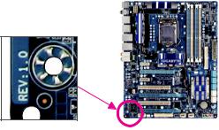
Identifying Your Motherboard Revision
The revision number on your motherboard looks like this: «REV: X.X.» For example, «REV: 1.0» means the revision of the motherboard is 1.0. Check your motherboard revision before updating motherboard BIOS, drivers, or when looking for technical information.
Example:

Table of Contents
|
Box Contents…………………………………………………………………………………………………….. |
6 |
||
|
Optional Items…………………………………………………………………………………………………… |
6 |
||
|
GA-P55M-UD2 Motherboard Layout…………………………………………………………………….. |
7 |
||
|
Block Diagram…………………………………………………………………………………………………… |
8 |
||
|
Chapter 1 Hardware Installation………………………………………………………………………….. |
9 |
||
|
1-1 |
Installation Precautions…………………………………………………………………………. |
9 |
|
|
1-2 |
Product Specifications.……………………………………………………………………….. |
10 |
|
|
1-3 |
Installing the CPU and CPU Cooler………………………………………………………. |
13 |
|
|
1-3-1 |
Installing the CPU……………………………………………………………………………………… |
13 |
|
|
1-3-2 Installing the CPU Cooler……………………………………………………………………………. |
15 |
||
|
1-4 |
Installing the Memory………………………………………………………………………….. |
16 |
|
|
1-4-1 Dual Channel Memory Configuration……………………………………………………………. |
16 |
||
|
1-4-2 |
Installing a Memory …………………………………………………………………………………… |
17 |
|
|
1-5 |
Installing an Expansion Card……………………………………………………………….. |
18 |
|
|
1-6 |
Back Panel Connectors.……………………………………………………………………… |
19 |
|
|
1-7 |
Internal Connectors.…………………………………………………………………………… |
21 |
|
|
Chapter 2 BIOS Setup……………………………………………………………………………………… |
33 |
||
|
2-1 |
Startup Screen…………………………………………………………………………………… |
34 |
|
|
2-2 |
The Main Menu………………………………………………………………………………….. |
35 |
|
|
2-3 |
MB Intelligent Tweaker(M.I.T.).…………………………………………………………….. |
37 |
|
|
2-4 |
Standard CMOS Features.………………………………………………………………….. |
47 |
|
|
2-5 |
Advanced BIOS Features……………………………………………………………………. |
49 |
|
|
2-6 |
Integrated Peripherals.……………………………………………………………………….. |
51 |
|
|
2-7 |
Power Management Setup.…………………………………………………………………. |
54 |
|
|
2-8 |
PC Health Status.………………………………………………………………………………. |
56 |
|
|
2-9 |
Load Fail-Safe Defaults.……………………………………………………………………… |
58 |
|
|
2-10 |
Load Optimized Defaults.……………………………………………………………………. |
58 |
|
|
2-11 |
Set Supervisor/User Password…………………………………………………………….. |
59 |
|
|
2-12 |
Save & Exit Setup………………………………………………………………………………. |
60 |
|
|
2-13 |
Exit Without Saving…………………………………………………………………………….. |
60 |
— 4 —

|
Chapter 3 Drivers Installation.…………………………………………………………………………… |
61 |
|
|
3-1 |
Installing Chipset Drivers…………………………………………………………………….. |
61 |
|
3-2 |
Application Software…………………………………………………………………………… |
62 |
|
3-3 |
Technical Manuals.…………………………………………………………………………….. |
62 |
|
3-4 |
Contact.……………………………………………………………………………………………. |
63 |
|
3-5 |
System……………………………………………………………………………………………… |
63 |
|
3-6 |
Download Center……………………………………………………………………………….. |
64 |
|
3-7 |
New Utilities………………………………………………………………………………………. |
64 |
|
Chapter 4 Unique Features.……………………………………………………………………………… |
65 |
||
|
4-1 |
Xpress Recovery2.…………………………………………………………………………….. |
65 |
|
|
4-2 |
BIOS Update Utilities………………………………………………………………………….. |
68 |
|
|
4-2-1 |
Updating the BIOS with the Q-Flash Utility.…………………………………………………… |
68 |
|
|
4-2-2 |
Updating the BIOS with the @BIOS Utility…………………………………………………….. |
71 |
|
|
4-3 |
EasyTune 6……………………………………………………………………………………….. |
72 |
|
|
4-4 |
Dynamic Energy Saver™ 2.………………………………………………………………….. |
73 |
|
|
4-5 |
Q-Share.…………………………………………………………………………………………… |
75 |
|
|
4-6 |
Smart 6™ ………………………………………………………………………………………….. |
76 |
|
Chapter 5 Appendix |
…………………………………………………………………………………………. |
79 |
|
|
5-1 |
Configuring .SATA Hard Drive(s) ………………………………………………………….. |
79 |
|
|
5-1-1 Configuring Intel P55 SATA Controllers ………………………………………………………… |
79 |
||
|
5-1-2 .Configuring GIGABYTE SATA2 SATA Controller …………………………………………… |
87 |
||
|
5-1-3 .…………………………………………………..Making a SATA RAID/AHCI Driver Diskette |
93 |
||
|
5-1-4 …………………………..Installing the SATA RAID/AHCI Driver and Operating System |
94 |
||
|
5-2 |
Configuring ……………………………………………………..Audio Input and Output |
105 |
|
|
5-2-1 .………………………………………………………. |
Configuring 2/4/5.1/7.1 — Channel Audio |
105 |
|
|
5-2-2 ………………………………………………………………………… |
Configuring S/PDIF In/Out |
107 |
|
|
5-2-3 …………………………………………………………….. |
Configuring Microphone Recording |
109 |
|
|
5-2-4 …………………………………………………………………………Using the Sound Recorder |
111 |
||
|
5-3 |
Troubleshooting……………………………………………………………………………….. |
112 |
|
|
5-3-1 .……………………………………………………………………. |
Frequently Asked Questions |
112 |
|
|
5-3-2 ……………………………………………………………………….. |
Troubleshooting Procedure |
113 |
|
|
5-4 |
Regulatory .……………………………………………………………………..Statements |
115 |
— 5 —
Box Contents
GA-P55M-UD2 motherboard
Motherboard driver disk
User’s Manual
Quick Installation Guide
One IDE cable
Two SATA 3Gb/s cables
I/O Shield
•The box contents above are for reference only and the actual items shall depend on the product package you obtain. The box contents are subject to change without notice.
•The motherboard image is for reference only.
Optional Items
Floppy disk drive cable (Part No. 12CF1-1FD001-7*R)
2-port USB 2.0 bracket (Part No. 12CR1-1UB030-5*R)
2-port IEEE 1394a bracket (Part No. 12CF1-1IE008-0*R)
2-port SATA power cable (Part No. 12CF1-2SERPW-0*R)
S/PDIF In cable (Part No. 12CR1-1SPDIN-0*R)
COM port cable (Part No. 12CF1-1CM001-3*R)
— 6 —
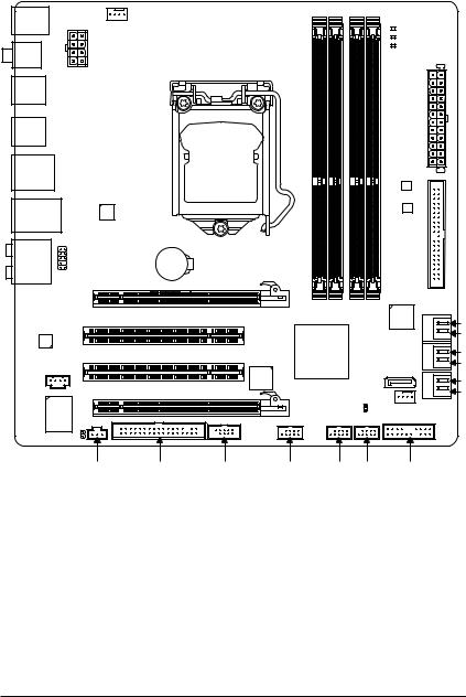
GA-P55M-UD2 Motherboard Layout
|
KB_USB |
CPU_FAN |
|
R_SPDIF |
ATX_12V_2X4 |
|
R_USB_2 |
|
R_USB_1 |
||
|
USB_1394_ESATA |
||
|
-UD2 |
||
|
USB_LAN |
P55M-GA |
RTL8111D |
|
AUDIO |
||
|
F_AUDIO |
PCIEX16 |
|
|
CODEC |
PCI1 |
|
|
PCI2 |
||
|
CD_IN |
||
|
PCIEX4 |
||
|
IT8720 |
||
|
SPDIF_O |

 PHASE LED
ATX
B_BIOS
M_BIOS
|
IDE |
||
|
_4 _3 |
GIGABYTE |
|
|
DDR3 DDR3 |
||
|
SATA2 |
GSATA2_1 |
|
|
GSATA2_0 |
||
|
SATA2_1 |
||
|
SATA2_4 |
SATA2_0 |
|
|
SATA2_3 |
||
|
CLR_CMOS |
SATA2_2 |
|
|
SYS_FAN |
|
SPDIF_I |
FDD |
COMA |
F1_1394 |
F_USB2 F_USB1 F_PANEL |
— 7 —
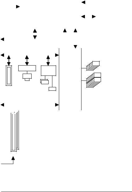
Block Diagram
|
1 PCI Express x16 |
||||||||||||||||||||||||||
|
CPU CLK+/- (133 MHz) |
||||||||||||||||||||||||||
|
LGA1156 |
DDR3 2200/1333/1066/800 MHz |
|||||||||||||||||||||||||
|
PCIe CLK |
||||||||||||||||||||||||||
|
(100 MHz) |
CPU |
|||||||||||||||||||||||||
|
Dual Channel Memory |
||||||||||||||||||||||||||
|
x16 |
DMI |
|||||||||||||||||||||||||
|
Interface |
||||||||||||||||||||||||||
|
PCI Express Bus |
||||||||||||||||||||||||||
|
PCI Express Bus |
||||||||||||||||||||||||||
|
Dual BIOS |
||||||||||||||||||||||||||
|
x4 |
x1 |
x1 |
6 SATA 3Gb/s |
|
RTL8111D |
GIGABYTE |
||
|
RJ45 |
SATA2 |
||
|
Intel® P55 |
14 USB Ports |
||
|
LAN |
|||
|
1 PCI Express x4 |
2 SATA 3Gb/s |
||
|
ATA-133/100/66/33 |
||||||||||||||||||||||||||||||||||||
|
IDE Channel |
LPC |
Floppy |
||||||||||||||||||||||||||||||||||
|
PCI Bus |
IT8720 |
|||||||||||||||||||||||||||||||||||
|
COM |
||||||||||||||||||||||||||||||||||||
|
Bus |
||||||||||||||||||||||||||||||||||||
|
TSB43AB23 |
||||||||||||||||||||||||||||||||||||
|
CODEC |
PS/2 KB/Mouse |
|||||||||||||||||||||||||||||||||||
|
2 IEEE 1394a |
||||||||||||||||||||||||||||||||||||
|
Out |
In |
S/PDIF In S/PDIF Out |
|
Out |
||
|
Out |
Line |
|
|
Speaker Speaker SpeakerOut |
MIC Line |
|
|
Center/Subwoofer Side |
||
|
Surround |
— 8 —

Chapter 1 Hardware Installation
1-1 Installation Precautions
The motherboard contains numerous delicate electronic circuits and components which can become damaged as a result of electrostatic discharge (ESD). Prior to installation, carefully read the user’s manual and follow these procedures:
•Prior to installation, do not remove or break motherboard S/N (Serial Number) sticker or warranty sticker provided by your dealer. These stickers are required for warranty validation.
•Always remove the AC power by unplugging the power cord from the power outlet before installing or removing the motherboard or other hardware components.
•When connecting hardware components to the internal connectors on the motherboard, make sure they are connected tightly and securely.
•When handling the motherboard, avoid touching any metal leads or connectors.
•It is best to wear an electrostatic discharge (ESD) wrist strap when handling electronic components such as a motherboard, CPU or memory. If you do not have an ESD wrist strap, keep your hands dry and first touch a metal object to eliminate static electricity.
•Prior to installing the motherboard, please have it on top of an antistatic pad or within an electrostatic shielding container.
•Before unplugging the power supply cable from the motherboard, make sure the power supply has been turned off.
•Before turning on the power, make sure the power supply voltage has been set according to the local voltage standard.
•Before using the product, please verify that all cables and power connectors of your hardware components are connected.
•To prevent damage to the motherboard, do not allow screws to come in contact with the motherboard circuit or its components.
•Make sure there are no leftover screws or metal components placed on the motherboard or within the computer casing.
•Do not place the computer system on an uneven surface.
•Do not place the computer system in a high-temperature environment.
•Turning on the computer power during the installation process can lead to damage to system components as well as physical harm to the user.
•If you are uncertain about any installation steps or have a problem related to the use of the product, please consult a certified computer technician.
|
— 9 — |
Hardware Installation |
|
1-2 |
Product Specifications |
|
|
CPU |
w Support for an Intel® Core™ i7 series processor/Intel® Core™ i5 series processor |
|
|
in the LGA1156 package |
||
|
(Go to GIGABYTE’s website for the latest CPU support list.) |
wL3 cache varies with CPU
|
Chipset |
w |
Intel® P55 Express Chipset |
|
Memory |
|
4 x 1.5V DDR3 DIMM sockets supporting up to 16 GB of system memory (Note 1) |
|
w Dual channel memory architecture |
||
|
Support for DDR3 2200/1333/1066/800 MHz memory modules |
||
|
Support for non-ECC memory modules |
||
|
Support for Extreme Memory Profile (XMP) memory modules |
||
|
(Go to GIGABYTE’s website for the latest memory support list.) |
||
|
Audio |
|
Realtek ALC888B codec |
|
|
High Definition Audio |
|
|
|
2/4/5.1/7.1-channel |
|
|
Support for S/PDIF In/Out |
||
|
Support for CD In |
||
|
LAN |
|
1 x RTL8111D chip (10/100/1000 Mbit) |
|
Expansion Slots |
|
1 x PCI Express x16 slot, running at x16 (PCIEX16) (Note 2) |
|
(The PCIEX16 slot conforms to PCI Express 2.0 standard.) |
1 x PCI Express x16 slot, running at x4 (PCIEX4) w 2 x PCI slots
|
Multi-Graphics |
|
Support for ATI CrossFireX™ technology (Note 3) |
|
|
Technology |
|||
|
Storage Interface |
|
Intel® P55 Express Chipset: |
|
|
— |
5 x SATA 3Gb/s connectors (SATA2_0, SATA2_1, SATA2_2, SATA2_3, |
||
|
SATA2_4) supporting up to 5 SATA 3Gb/s devices |
|||
|
— |
1 x eSATA 3Gb/s connector on the back panel supporting up to 1 SATA |
||
|
3Gb/s device |
—Support for SATA RAID 0, RAID 1, RAID 5, and RAID 10 w GIGABYTE SATA2 chip:
—1 x IDE connector supporting ATA-133/100/66/33 and up to 2 IDE devices
—2 x SATA 3Gb/s connectors (GSATA2_0, GSATA2_1) supporting up to 2 SATA 3Gb/s devices
—Support for SATA RAID 0, RAID 1, and JBOD
wiTE IT8720 chip:
— 1 x floppy disk drive connector supporting up to 1 floppy disk drive
|
Hardware Installation |
— 10 — |
![]()
|
USB |
|
Integrated in the Chipset |
|
w |
Up to 14 USB 2.0/1.1 ports (10 on the back panel, 4 via the USB brackets |
|
|
connected to the internal USB headers) |
||
|
IEEE 1394 |
|
T.I. TSB43AB23 chip |
|
w |
Up to 2 IEEE 1394a ports (1 on the back panel, 1 via the IEEE 1394a bracket |
|
|
connected to the internal IEEE 1394a header) |
||
|
Internal |
w |
1 x 24-pin ATX main power connector |
|
Connectors |
w |
1 x 8-pin ATX 12V power connector |
|
w |
1 x floppy disk drive connector |
|
|
w |
1 x IDE connector |
|
|
w |
7 x SATA 3Gb/s connectors |
|
|
w |
1 x CPU fan header |
|
|
w |
1 x system fan header |
|
|
w |
1 x front panel header |
|
|
w |
1 x front panel audio header |
|
|
w |
1 x CD In connector |
|
|
w |
1 x S/PDIF In header |
|
|
w |
1 x S/PDIF Out header |
|
|
w |
2 x USB 2.0/1.1 headers |
|
|
w |
1 x IEEE 1394a header |
|
|
w |
1 x serial port header |
|
|
w |
1 x clearing CMOS jumper |
|
|
Back Panel |
w |
1 x PS/2 keyboard or PS/2 mouse port |
|
Connectors |
w |
1 x coaxial S/PDIF Out connector |
|
w |
1 x optical S/PDIF Out connector |
|
|
w |
10 x USB 2.0/1.1 ports |
|
|
w |
1 x eSATA 3Gb/s port |
|
|
w |
1 x IEEE 1394a port |
|
|
w |
1 x RJ-45 port |
|
|
w |
6 x audio jacks (Center/Subwoofer Speaker Out/Rear Speaker Out/ |
|
|
Side Speaker Out/Line In/Line Out/Microphone) |
||
|
I/O Controller |
w |
iTE IT8720 chip |
|
Hardware Monitor w |
System voltage detection |
|
|
w |
CPU/System temperature detection |
|
|
w |
CPU/System fan speed detection |
|
|
w |
CPU overheating warning |
|
|
w |
CPU/System fan fail warning |
|
|
w |
CPU/System fan speed control (Note 4) |
|
— 11 — |
Hardware Installation |

|
BIOS |
w |
2 x 16 Mbit flash |
|
w |
Use of licensed AWARD BIOS |
wSupport for DualBIOS™
wPnP 1.0a, DMI 2.0, SM BIOS 2.4, ACPI 1.0b
Unique Features w Support for @BIOS w Support for Q-Flash
w Support for Xpress BIOS Rescue w Support for Download Center
w Support for Xpress Install
w Support for Xpress Recovery2 w Support for EasyTune (Note 5)
w Support for Dynamic Energy Saver™ 2 w Support for Smart 6™
w Support for Q-Share
 Bundled Software w Norton Internet Security (OEM version)
 Operating System w Support for Microsoft® Windows® 7/Vista/XP
|
Form Factor |
w Micro ATX Form Factor; 24.4cm x 24.4cm |
(Note 1) Due to Windows Vista/XP 32-bit operating system limitation, when more than 4 GB of physical memory is installed, the actual memory size displayed will be less than 4 GB.
(Note 2) For optimum performance, if only one PCI Express graphics card is to be installed, be sure to install it in the PCIEX16 slot.
(Note 3) The PCIEX16 slot operates at up to x4 mode when ATI CrossFireX™ is enabled.
(Note 4) Whether the CPU/system fan speed control function is supported will depend on the CPU/system cooler you install.
(Note 5) Available functions in EasyTune may differ by motherboard model.
|
Hardware Installation |
— 12 — |
1-3 Installing the CPU and CPU Cooler
Read the following guidelines before you begin to install the CPU:
•Make sure that the motherboard supports the CPU.
(Go to GIGABYTE’s website for the latest CPU support list.)
•Always turn off the computer and unplug the power cord from the power outlet before installing the CPU to prevent hardware damage.
•Locate the pin one of the CPU. The CPU cannot be inserted if oriented incorrectly. (Or you may locate the notches on both sides of the CPU and alignment keys on the CPU socket.)
•Apply an even and thin layer of thermal grease on the surface of the CPU.
•Do not turn on the computer if the CPU cooler is not installed, otherwise overheating and damage of the CPU may occur.
•Set the CPU host frequency in accordance with the CPU specifications. It is not recommended that the system bus frequency be set beyond hardware specifications since it does not meet the standard requirements for the peripherals. If you wish to set the frequency beyond the standard specifications, please do so according to your hardware specifications including the CPU, graphics card, memory, hard drive, etc.
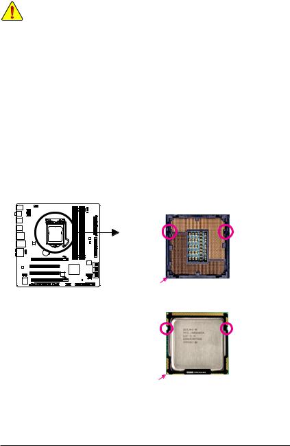
1-3-1 Installing the CPU
A. Locate the alignment keys on the motherboard CPU socket and the notches on the CPU.
LGA1156 CPU Socket
|
Alignment Key |
Alignment Key |
Pin One Corner of the CPU Socket
LGA1156 CPU
Triangle Pin One Marking on the CPU
|
— 13 — |
Hardware Installation |
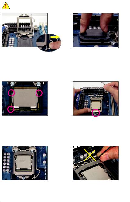
B. Follow the steps below to correctly install the CPU into the motherboard CPU socket.
Before installing the CPU, make sure to turn off the computer and unplug the power cord from the power outlet to prevent damage to the CPU.
Step 1:
Gently press the CPU socket lever handle down and away from the socket with your finger. Then completely lift the CPU socket lever and the metal load plate will be lifted as well.
Step 3:
Hold the CPU with your thumb and index fingers.
Align the CPU pin one marking (triangle) with the pin one corner of the CPU socket (or you may align the CPU notches with the socket alignment keys) and gently insert the CPU into position.
Step 2:
Use your thumb and index finger to grasp the protective socket cover as indicated and lift it up vertically. (DO NOT touch socket contacts. To protect the CPU socket, always replace the protective socket cover when the CPU is not installed.)
Step 4:
Once the CPU is properly inserted, use one hand to hold the socket lever and use the other to lightly replace the load plate. When replacing the load plate, make sure the front end of the load plate is under the shoulder screw.
Step 5:
Push the CPU socket lever back into its locked position.
NOTE:
Hold the CPU socket lever by the handle, not the lever base portion.
|
Hardware Installation |
— 14 — |
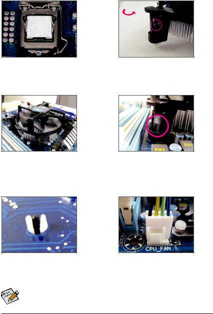
1-3-2 Installing the CPU Cooler
Follow the steps below to correctly install the CPU cooler on the motherboard. (The following procedure uses
Intel® boxed cooler as the example cooler.)
Step 1:
Apply an even and thin layer of thermal grease on the surface of the installed CPU.
Step 3:
Place the cooler atop the CPU, aligning the four push pins through the pin holes on the motherboard. Push down on the push pins diagonally.
|
Male Push |
|||||
|
Direction of the |
Pin |
||||
|
Arrow Sign on |
The Top |
||||
|
the Male Push |
|||||
|
of Female |
|||||
|
Pin |
|||||
|
Push Pin |
|||||
|
Female |
|||||
|
Push Pin |
Step 2:
Before installing the cooler, note the direction of the arrow sign on the male push pin. (Turning the push pin along the direction of arrow is to remove the cooler, on the contrary, is to install.)
Step 4:
You should hear a «click» when pushing down each push pin. Check that the Male and Female push pins are joined closely. (Refer to your CPU cooler installation manual for instructions on installing the cooler.)
Step 5:
After the installation, check the back of the motherboard. If the push pin is inserted as the picture above shows, the installation is complete.
Step 6:
Finally, attach the power connector of the CPU cooler to the CPU fan header (CPU_FAN) on the motherboard.
Use extreme care when removing the CPU cooler because the thermal grease/tape between the CPU cooler and CPU may adhere to the CPU. Inadequately removing the CPU cooler may damage the CPU.
|
— 15 — |
Hardware Installation |
1-4 Installing the Memory
Read the following guidelines before you begin to install the memory:
•Make sure that the motherboard supports the memory. It is recommended that memory of the same capacity, brand, speed, and chips be used.
(Go to GIGABYTE’s website for the latest memory support list.)
•Always turn off the computer and unplug the power cord from the power outlet before installing the memory to prevent hardware damage.
•Memory modules have a foolproof design. A memory module can be installed in only one direction. If you are unable to insert the memory, switch the direction.
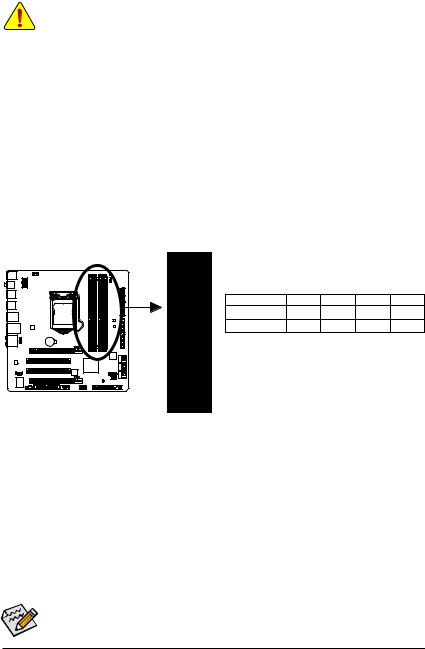
1-4-1 Dual Channel Memory Configuration
This motherboard provides four DDR3 memory sockets and supports Dual Channel Technology. After the memory is installed, the BIOS will automatically detect the specifications and capacity of the memory. Enabling Dual Channel memory mode will double the original memory bandwidth.
The four DDR3 memory sockets are divided into two channels and each channel has two memory sockets as following:
 Channel 0: DDR3_2, DDR2_1
  Channel 1: DDR3_4, DDR3_3
 Dual Channel Memory Configurations Table
|
DDR3_2 |
DDR3_1 DDR3_4 |
DDR3_3 |
||
|
Two Modules |
— — |
DS/SS |
— — |
DS/SS |
|
Four Modules |
DS/SS |
DS/SS |
DS/SS |
DS/SS |
(SS=Single-Sided, DS=Double-Sided, «- -«=No Memory)
DDR3_3
DDR3_4
DDR3_1
DDR3_2
Due to CPU limitations, read the following guidelines before installing the memory in Dual Channel mode.
1.Dual Channel mode cannot be enabled if only one DDR3 memory module is installed.
2.When enabling Dual Channel mode with two or four memory modules, it is recommended that memory of the same capacity, brand, speed, and chips be used for optimum performance. When enabling Dual Channel mode with two memory modules, be sure to install them in the DDR3_1 and DDR3_3 sockets.
If only one DDR3 memory module is installed, it is recommended to install it in the DDR3_1 or DDR3_3 sockets.
|
Hardware Installation |
— 16 — |
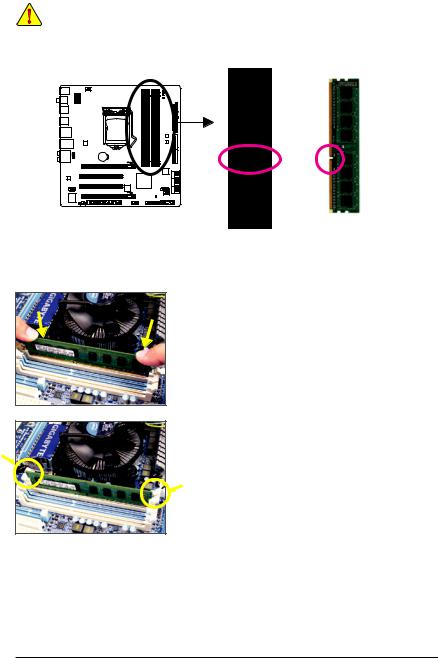
1-4-2 Installing a Memory
Before installing a memory module, make sure to turn off the computer and unplug the power cord from the power outlet to prevent damage to the memory module.
DDR3 and DDR2 DIMMs are not compatible to each other or DDR DIMMs. Be sure to install DDR3 DIMMs on this motherboard.
Notch
DDR3 DIMM
A DDR3 memory module has a notch, so it can only fit in one direction. Follow the steps below to correctly install your memory modules in the memory sockets.
Step 1:
Note the orientation of the memory module. Spread the retaining clips at both ends of the memory socket. Place the memory module on the socket. As indicated in the picture on the left, place your fingers on the top edge of the memory, push down on the memory and insert it vertically into the memory socket.
Step 2:
The clips at both ends of the socket will snap into place when the memory module is securely inserted.
|
— 17 — |
Hardware Installation |
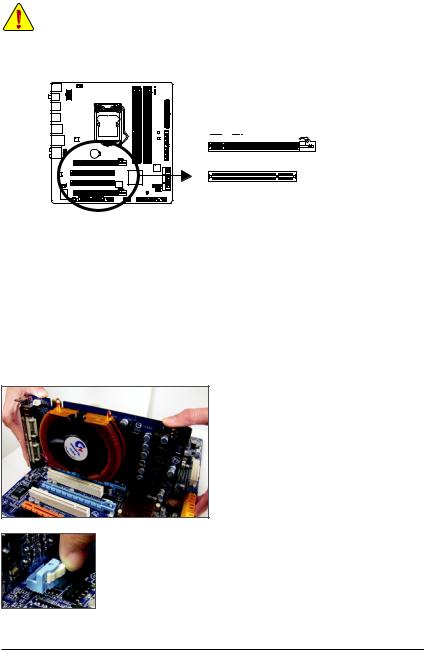
1-5 Installing an Expansion Card
Read the following guidelines before you begin to install an expansion card:
•Make sure the motherboard supports the expansion card. Carefully read the manual that came with your expansion card.
•Always turn off the computer and unplug the power cord from the power outlet before installing an expansion card to prevent hardware damage.
PCI Express x16 Slot
PCI Slot
Follow the steps below to correctly install your expansion card in the expansion slot.
1.Locate an expansion slot that supports your card. Remove the metal slot cover from the chassis back panel.
2.Align the card with the slot, and press down on the card until it is fully seated in the slot.
3.Make sure the metal contacts on the card are completely inserted into the slot.
4.Secure the card’s metal bracket to the chassis back panel with a screw.
5.After installing all expansion cards, replace the chassis cover(s).
6.Turn on your computer. If necessary, go to BIOS Setup to make any required BIOS changes for your expansion card(s).
7.Install the driver provided with the expansion card in your operating system.
Example: Installing and Removing a PCI Express Graphics Card:
• Installing a Graphics Card:
Gently push down on the top edge of the card until it is fully inserted into the PCI Express slot. Make sure the card is securely seated in the slot and does not rock.
•Removing the Card:
Press the white latch at the end of the PCI Express slot to release the card and then pull the card straight up from the slot.
|
Hardware Installation |
— 18 — |
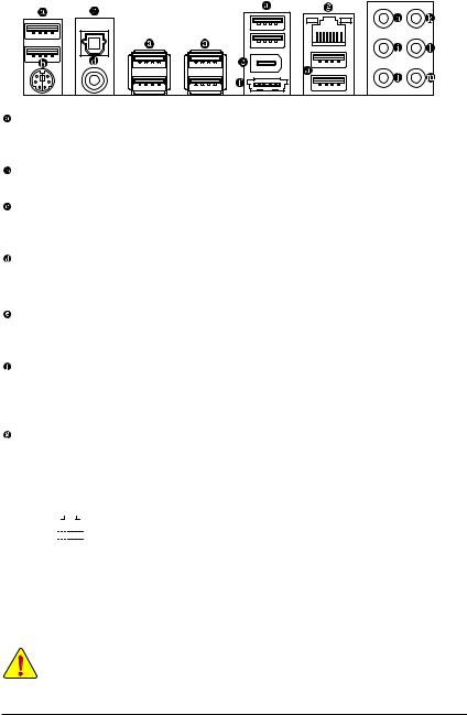
1-6 Back Panel Connectors
USB Port
The USB port supports the USB 2.0/1.1 specification. Use this port for USB devices such as a USB keyboard/mouse, USB printer, USB flash drive and etc.
PS/2 Keyboard and PS/2 Mouse Port
Use this port to connect a PS/2 keyboard or mouse.
Optical S/PDIF Out Connector
This connector provides digital audio out to an external audio system that supports digital optical audio. Before using this feature, ensure that your audio system provides an optical digital audio in connector.
Coaxial S/PDIF Out Connector
This connector provides digital audio out to an external audio system that supports digital coaxial audio. Before using this feature, ensure that your audio system provides a coaxial digital audio in connector.
IEEE 1394a Port
The IEEE 1394 port supports the IEEE 1394a specification, featuring high speed, high bandwidth and hotplug capabilities. Use this port for an IEEE 1394a device.
eSATA 3Gb/s Port
The eSATA 3Gb/s port conforms to SATA 3Gb/s standard and is compatible with SATA 1.5Gb/s standard.
Use the port to connect an external SATA device or a SATA port multiplier. Refer to Chapter 5, «Configuring SATA Hard Drive(s),» for instructions on configuring a RAID array.
RJ-45 LAN Port
The Gigabit Ethernet LAN port provides Internet connection at up to 1 Gbps data rate. The following describes the states of the LAN port LEDs.
|
Connection/ |
Activity LED |
Connection/Speed LED: |
Activity LED: |
||||||||||||||||
|
Speed LED |
|||||||||||||||||||
|
State |
Description |
State |
Description |
||||||||||||||||
|
Orange |
1 Gbps data rate |
Blinking |
Data transmission or receiving is occurring |
||||||||||||||||
|
Green |
100 Mbps data rate |
Off |
No data transmission or receiving is occurring |
||||||||||||||||
|
LAN Port |
Off |
10 Mbps data rate |
|||||||||||||||||
•When removing the cable connected to a back panel connector, first remove the cable from your device and then remove it from the motherboard.
•When removing the cable, pull it straight out from the connector. Do not rock it side to side to prevent an electrical short inside the cable connector.
|
— 19 — |
Hardware Installation |

Center/Subwoofer Speaker Out Jack (Orange)
Use this audio jack to connect center/subwoofer speakers in a 5.1/7.1-channel audio configuration.
Rear Speaker Out Jack (Black)
Use this audio jack to connect rear speakers in a 4/5.1/7.1-channel audio configuration.
Side Speaker Out Jack (Gray)
Use this audio jack to connect side speakers in a 7.1-channel audio configuration.
Line In Jack (Blue)
The default line in jack. Use this audio jack for line in devices such as an optical drive, walkman, etc.
Line Out Jack (Green)
The default line out jack. Use this audio jack for a headphone or 2-channel speaker. This jack can be used to connect front speakers in a 4/5.1/7.1-channel audio configuration.
Mic In Jack (Pink)
The default Mic in jack. Microphones must be connected to this jack.

 In addition to the default speakers settings, the
 ~
~ audio jacks can be reconfigured to perform
  different functions via the audio software. Only microphones still MUST be connected to the default Mic in jack (
 ). Refer to the instructions on setting up a 2/4/5.1/7.1-channel audio configuration in Chapter 5, «Configuring 2/4/5.1/7.1-Channel Audio.»
|
Hardware Installation |
— 20 — |
![]()
1-7 Internal Connectors
|
1 |
3 |
19 |
|||
|
2 |
|||||||
|
6 |
|||||||
|
11 |
|||||||
|
9 |
8 |
||||||
|
12 |
7 |
||||||
|
4 |
|||||||
|
14 |
13 |
5 |
17 |
16 |
18 |
15 |
10 |
|
1) |
ATX_12V_2X4 |
11) |
F_AUDIO |
|
2) |
ATX |
12) |
CD_IN |
|
3) |
CPU_FAN |
13) |
SPDIF_I |
|
4) |
SYS_FAN |
14) |
SPDIF_O |
|
5) |
FDD |
15) |
F_USB1/F_USB2 |
|
6) |
IDE |
16) |
F1_1394 |
|
7) |
SATA2_0/1/2/3/4 |
17) |
COMA |
|
|
GSATA2_0/1 |
18) |
CLR_CMOS |
|
9) |
BAT |
19) |
PHASE_LED |
|
10) |
F_PANEL |
Read the following guidelines before connecting external devices:
•First make sure your devices are compliant with the connectors you wish to connect.
•Before installing the devices, be sure to turn off the devices and your computer. Unplug the power cord from the power outlet to prevent damage to the devices.
•After installing the device and before turning on the computer, make sure the device cable has been securely attached to the connector on the motherboard.
|
— 21 — |
Hardware Installation |
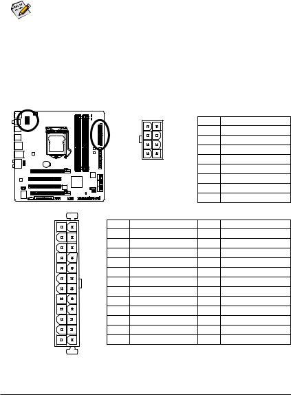
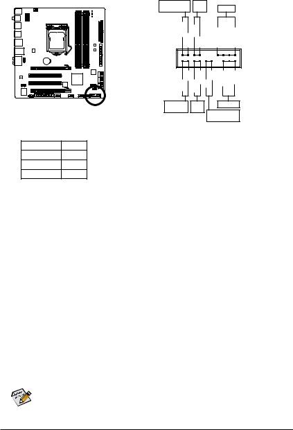
1/2) ATX_12V_2X4/ATX (2×4 12V Power Connector and 2×12 Main Power Connector)
With the use of the power connector, the power supply can supply enough stable power to all the components on the motherboard. Before connecting the power connector, first make sure the power supply is turned off and all devices are properly installed. The power connector possesses a foolproof design. Connect the power supply cable to the power connector in the correct orientation. The 12V power connector mainly supplies power to the CPU. If the 12V power connector is not connected, the computer will not start.
• Use of a power supply providing a 2×4 12V power connector is recommended by the CPU manufacturer when using an Intel Extreme Edition CPU (130W).
•To meet expansion requirements, it is recommended that a power supply that can withstand high power consumption be used (500W or greater). If a power supply is used that does not provide the required power, the result can lead to an unstable or unbootable system.
•The power connectors are compatible with power supplies with 2×2 12V and 2×10 power connectors. When using a power supply providing a 2×4 12V and a 2×12 power connector, remove the protective covers from the 12V power connector and the main power connector on the motherboard. Do not insert the power supply cables into pins under the protective covers when using a power supply providing a 2×2 12V and a 2×10 power connector.
|
ATX_12V_2X4: |
||||||
|
8 |
4 |
Pin No. |
Definition |
|||
|
1 |
GND (Only for 2×4-pin 12V) |
|||||
|
2 |
GND (Only for 2×4-pin 12V) |
|||||
|
5 |
1 |
3 |
GND |
|||
|
4 |
GND |
|||||
|
ATX_12V_2X4 |
||||||
|
5 |
+12V (Only for 2×4-pin 12V) |
|||||
|
6 |
+12V (Only for 2×4-pin 12V) |
|||||
|
7 |
+12V |
|||||
|
8 |
+12V |
|||||
|
ATX: |
||||||
|
12 |
24 |
Pin No. |
Definition |
Pin No. |
Definition |
|
|
1 |
3.3V |
13 |
3.3V |
|||
|
2 |
3.3V |
14 |
-12V |
|||
|
3 |
GND |
15 |
GND |
|||
|
4 |
+5V |
16 |
PS_ON (soft On/Off) |
|||
|
5 |
GND |
17 |
GND |
|||
|
6 |
+5V |
18 |
GND |
|||
|
7 |
GND |
19 |
GND |
|||
|
8 |
Power Good |
20 |
-5V |
|||
|
9 |
5VSB (stand by +5V) |
21 |
+5V |
|||
|
10 |
+12V |
22 |
+5V |
|||
|
11 |
+12V (Only for 2×12-pin ATX) |
23 |
+5V (Only for 2×12-pin ATX) |
|||
|
1 |
13 |
12 |
3.3V (Only for 2×12-pin ATX) |
24 |
GND (Only for 2×12-pin ATX) |
ATX
|
Hardware Installation |
— 22 — |
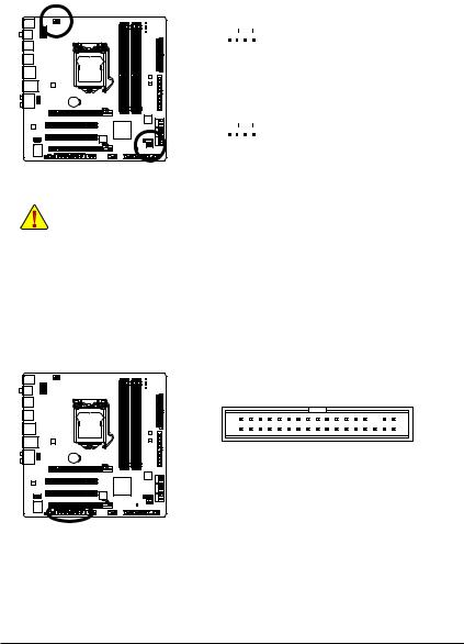
3/4) CPU_FAN/SYS_FAN (Fan Headers)
The motherboard has a 4-pin CPU fan header (CPU_FAN) and a 4-pin (SYS_FAN). Most fan headers possess a foolproof insertion design. When connecting a fan cable, be sure to connect it in the correct orientation (the black connector wire is the ground wire). The motherboard supports CPU fan speed control, which requires the use of a CPU fan with fan speed control design. For optimum heat dissipation, it is recommended that a system fan be installed inside the chassis.
|
CPU_FAN: |
||||||
|
Pin No. |
Definition |
|||||
|
1 |
1 |
GND |
||||
|
2 |
+12V / Speed Control |
|||||
|
CPU_FAN |
||||||
|
3 |
Sense |
|||||
|
4 |
Speed Control |
|||||
|
SYS_FAN: |
||||||
|
Pin No. |
Definition |
|||||
|
1 |
1 |
GND |
||||
|
2 |
+12V / Speed Control |
|||||
|
SYS_FAN |
||||||
|
3 |
Sense |
|||||
|
4 |
Reserve |
•Be sure to connect fan cables to the fan headers to prevent your CPU and system from overheating. Overheating may result in damage to the CPU or the system may hang.
•These fan headers are not configuration jumper blocks. Do not place a jumper cap on the headers.
5)FDD (Floppy Disk Drive Connector)
This connector is used to connect a floppy disk drive. The types of floppy disk drives supported are: 360 KB, 720 KB, 1.2 MB, 1.44 MB, and 2.88 MB. Before connecting a floppy disk drive, be sure to locate pin 1 of the connector and the floppy disk drive cable. The pin 1 of the cable is typically designated by a stripe of different color. For purchasing the optional floppy disk drive cable, please contact the local dealer.
|
— 23 — |
Hardware Installation |
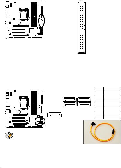
6)IDE (IDE Connector)
The IDE connector supports up to two IDE devices such as hard drives and optical drives. Before attaching the IDE cable, locate the foolproof groove on the connector. If you wish to connect two IDE devices, remember to set the jumpers and the cabling according to the role of the IDE devices (for example, master or slave). (For information about configuring master/slave settings for the IDE devices, read the instructions from the device manufacturers.)
40 39
2 1
7)SATA2_0/1/2/3/4 (SATA 3Gb/s Connectors, Controlled by P55 Chipset, Blue)
The SATA connectors conform to SATA 3Gb/s standard and are compatible with SATA 1.5Gb/s standard. Each SATA connector supports a single SATA device. The P55 Chipset supports RAID 0, RAID 1,
RAID 5 and RAID 10. Refer to Chapter 5, «Configuring SATAHard Drive(s),» for instructions on configuring a RAID array.
|
Pin No. |
Definition |
|||
|
SATA2_3 |
SATA2_1 |
1 |
GND |
|
|
2 |
TXP |
|||
|
7 |
1 |
|||
|
3 |
TXN |
|||
|
7 |
1 |
|||
|
4 |
GND |
|||
|
SATA2_2 |
SATA2_0 |
5 |
RXN |
|
|
SATA2_4 |
6 |
RXP |
||
|
7 |
1 |
|||
|
7 |
GND |
|||
• A RAID 0 or RAID 1 configuration requires at least two hard drives. If more than two hard drives are to be used, the total number of hard drives must be an even number.
•A RAID 5 configuration requires at least three hard drives.
(The total number of hard drives does not have to be an even number.)
•A RAID 10 configuration requires at least four hard drives and the total number of hard drives must be an even number.
|
Hardware Installation |
— 24 — |
Please connect the L-shaped end of the SATA 3Gb/s cable to your SATA hard drive.
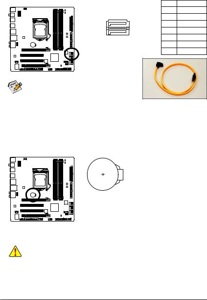
 GSATA2_0/1 (SATA 3Gb/s Connectors, Controlled by GIGABYTE SATA2, White)
The SATA connectors conform to SATA 3Gb/s standard and are compatible with SATA 1.5Gb/s standard. Each SATA connector supports a single SATA device. The GIGABYTE SATA2 controller supports RAID 0 and RAID 1. Refer to Chapter 5, «Configuring SATA Hard Drive(s),» for instructions on configuring a RAID
|
array. |
Pin No. |
Definition |
|
|
1 |
GND |
||
|
GSATA2_1 |
2 |
TXP |
|
|
7 |
1 |
3 |
TXN |
|
7 |
1 |
4 |
GND |
|
GSATA2_0 |
5 |
RXN |
|
|
6 |
RXP |
||
|
7 |
GND |
A RAID 0 or RAID 1 configuration requires at least two hard drives. If more than two hard drives are to be used, the total
number of hard drives must be an even number.
Please connect the L-shaped end of the SATA 3Gb/s cable to your SATA hard drive.
9)BAT (Battery)
The battery provides power to keep the values (such as BIOS configurations, date, and time information) in the CMOS when the computer is turned off. Replace the battery when the battery voltage drops to a low level, or the CMOS values may not be accurate or may be lost.
You may clear the CMOS values by removing the battery: 1. Turn off your computer and unplug the power cord.
2. Gently remove the battery from the battery holder and wait for one minute. (Or use a metal object like a screwdriver to touch the positive and negative terminals of the battery holder, making them short for 5 seconds.)
3.Replace the battery.
4.Plug in the power cord and restart your computer.
•Always turn off your computer and unplug the power cord before replacing the battery.
•Replace the battery with an equivalent one. Danger of explosion if the battery is replaced with an incorrect model.
•Contact the place of purchase or local dealer if you are not able to replace the battery by yourself or uncertain about the battery model.
•When installing the battery, note the orientation of the positive side (+) and the negative side (-) of the battery (the positive side should face up).
•Used batteries must be handled in accordance with local environmental regulations.
|
— 25 — |
Hardware Installation |
10)F_PANEL (Front Panel Header)
Connect the power switch, reset switch, speaker, chassis intrusion switch/sensor and system status indicator on the chassis to this header according to the pin assignments below. Note the positive and negative pins before connecting the cables.
|
Message/Power/ |
Power |
Speaker |
|||||
|
Sleep LED |
Switch |
||||||
|
MSG+ MSG |
—PW |
SPEAK+ |
SPEAK- |
||||
|
— PW+ |
|||||||
|
2 |
20 |
||||||
|
1 |
19 |
||||||
|
HD- |
RES+ |
CI+ |
PWR+ |
PWR- |
|||
|
HD+ RES- |
CI |
||||||
|
— |
|||||||
|
Hard Drive |
Reset |
Power LED |
|||||
|
Activity LED |
Switch |
Chassis Intrusion |
|||||
|
Header |
|||||||
|
• MSG/PWR (Message/Power/Sleep LED, Yellow/Purple): |
|||||||
|
System Status |
LED |
Connects to the power status indicator on the chassis front panel. The LED |
|||||
|
S0 |
On |
is on when the system is operating. The LED keeps blinking when the sys- |
|||||
|
S1 |
Blinking |
tem is in S1 sleep state. The LED is off when the system is in S3/S4 sleep |
|||||
|
S3/S4/S5 |
Off |
state or powered off (S5). |
•PW (Power Switch, Red):
Connects to the power switch on the chassis front panel. You may configure the way to turn off your system using the power switch (refer to Chapter 2, «BIOS Setup,» «Power Management Setup,» for more information).
•SPEAK (Speaker, Orange):
Connects to the speaker on the chassis front panel. The system reports system startup status by issuing a beep code. One single short beep will be heard if no problem is detected at system startup. If a problem is detected, the BIOS may issue beeps in different patterns to indicate the problem. Refer to Chapter 5, «Troubleshooting,» for information about beep codes.
•HD (Hard Drive Activity LED, Blue)
Connects to the hard drive activity LED on the chassis front panel. The LED is on when the hard drive is reading or writing data.
•RES (Reset Switch, Green):
Connects to the reset switch on the chassis front panel. Press the reset switch to restart the computer if the computer freezes and fails to perform a normal restart.
•CI (Chassis Intrusion Header, Gray):
Connects to the chassis intrusion switch/sensor on the chassis that can detect if the chassis cover has been removed. This function requires a chassis with a chassis intrusion switch/sensor.
The front panel design may differ by chassis. A front panel module mainly consists of power switch, reset switch, power LED, hard drive activity LED, speaker and etc. When connecting your chassis front panel module to this header, make sure the wire assignments and the pin assignments are matched correctly.
|
Hardware Installation |
— 26 — |
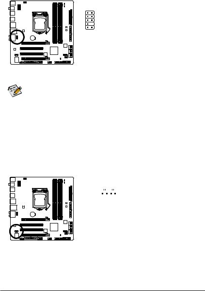
11)F_AUDIO (Front Panel Audio Header)
The front panel audio header supports Intel High Definition audio (HD) and AC’97 audio. You may connect your chassis front panel audio module to this header. Make sure the wire assignments of the module connector match the pin assignments of the motherboard header. Incorrect connection between the module connector and the motherboard header will make the device unable to work or even damage it.
|
For HD Front Panel Audio: |
For AC’97 Front Panel Audio: |
|||||
|
1 |
2 |
Pin No. |
Definition |
Pin No. |
Definition |
|
|
1 |
MIC2_L |
1 |
MIC |
|||
|
2 |
GND |
2 |
GND |
|||
|
9 |
10 |
3 |
MIC2_R |
3 |
MIC Power |
|
|
4 |
-ACZ_DET |
4 |
NC |
|||
|
5 |
LINE2_R |
5 |
Line Out (R) |
|||
|
6 |
GND |
6 |
NC |
|||
|
7 |
FAUDIO_JD |
7 |
NC |
|||
|
8 |
No Pin |
8 |
No Pin |
|||
|
9 |
LINE2_L |
9 |
Line Out (L) |
|||
|
10 |
GND |
10 |
NC |
•The front panel audio header supports HD audio by default. If your chassis provides an AC’97 front panel audio module, refer to the instructions on how to activate AC’97 functionality via the audio software in Chapter 5, «Configuring 2/4/5.1/7.1-Channel Audio.»
•Audio signals will be present on both of the front and back panel audio connections simultaneously. If you want to mute the back panel audio (only supported when using an HD front panel audio module), refer to Chapter 5, «Configuring 2/4/5.1/7.1-Channel Audio.»
•Some chassis provide a front panel audio module that has separated connectors on each wire instead of a single plug. For information about connecting the front panel audio module that has different wire assignments, please contact the chassis manufacturer.
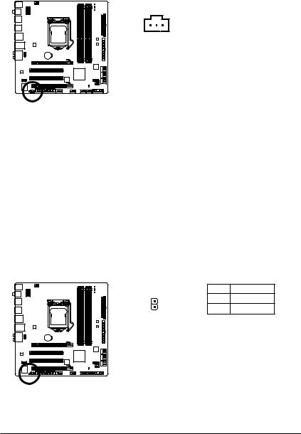
12)CD_IN (CD In Connector, Black)
You may connect the audio cable that came with your optical drive to the header.
|
Pin No. |
Definition |
|||||||
|
1 |
1 |
CD-L |
||||||
|
2 |
GND |
|||||||
|
3 |
GND |
|||||||
|
4 |
CD-R |
|
— 27 — |
Hardware Installation |
13)SPDIF_I (S/PDIF In Header, White)
This header supports digital S/PDIF In and can connect to an audio device that supports digital audio out via an optional S/PDIF In cable. For purchasing the optional S/PDIF In cable, please contact the local dealer.
|
Pin No. |
Definition |
|
|
1 |
Power |
|
|
1 |
2 |
SPDIFI |
|
3 |
GND |
14)SPDIF_O (S/PDIF Out Header)
This header supports digital S/PDIF Out and connects a S/PDIF digital audio cable (provided by expansion cards) for digital audio output from your motherboard to certain expansion cards like graphics cards and sound cards. For example, some graphics cards may require you to use a S/PDIF digital audio cable for digital audio output from your motherboard to your graphics card if you wish to connect an HDMI display to the graphics card and have digital audio output from the HDMI display at the same time. For information about connecting the S/PDIF digital audio cable, carefully read the manual for your expansion card.
|
1 |
Pin No. |
Definition |
|
|
1 |
SPDIFO |
||
|
2 |
GND |
|
Hardware Installation |
— 28 — |
15)F_USB1/F_USB2 (USB Headers, Blue)
The headers conform to USB 2.0/1.1 specification. Each USB header can provide two USB ports via an optional USB bracket. For purchasing the optional USB bracket, please contact the local dealer.
|
Pin No. |
Definition |
|||||
|
1 |
Power (5V) |
|||||
|
9 |
1 |
2 |
Power (5V) |
|||
|
3 |
USB DX- |
|||||
|
10 |
2 |
|||||
|
4 |
USB DY- |
|||||
|
5 |
USB DX+ |
|||||
|
6 |
USB DY+ |
|||||
|
7 |
GND |
|||||
|
8 |
GND |
|||||
|
9 |
No Pin |
|||||
|
10 |
NC |
• Do not plug the IEEE 1394 bracket (2×5-pin) cable into the USB header.
• Prior to installing the USB bracket, be sure to turn off your computer and unplug the power cord from the power outlet to prevent damage to the USB bracket.
16)F1_1394 (IEEE 1394a Header, Gray)
The header conforms to IEEE 1394a specification. The IEEE 1394a header can provide one IEEE 1394a port via an optional IEEE 1394a bracket. For purchasing the optional IEEE 1394a bracket, please contact the local dealer.
|
Pin No. |
Definition |
||||||
|
9 |
1 |
1 |
TPA+ |
||||
|
2 |
TPA- |
||||||
|
10 |
2 |
||||||
|
3 |
GND |
||||||
|
4 |
GND |
||||||
|
5 |
TPB+ |
||||||
|
6 |
TPB- |
||||||
|
7 |
Power (12V) |
||||||
|
8 |
Power (12V) |
||||||
|
9 |
No Pin |
||||||
|
10 |
GND |
• Do not plug the USB bracket cable into the IEEE 1394a header.
• Prior to installing the IEEE 1394a bracket, be sure to turn off your computer and unplug the power cord from the power outlet to prevent damage to the IEEE 1394a bracket.
•To connect an IEEE 1394a device, attach one end of the device cable to your computer and then attach the other end of the cable to the IEEE 1394a device. Ensure that the cable is securely connected.
|
— 29 — |
Hardware Installation |
17)COMA (Serial Port Header, White)
The COMA header can provide one serial port via an optional COM port cable. For purchasing the optional COM port cable, please contact the local dealer.
|
Pin No. |
Definition |
|||||
|
1 |
NDCD- |
|||||
|
9 |
1 |
2 |
NSIN |
|||
|
3 |
NSOUT |
|||||
|
10 |
2 |
|||||
|
4 |
NDTR- |
|||||
|
5 |
GND |
|||||
|
6 |
NDSR- |
|||||
|
7 |
NRTS- |
|||||
|
8 |
NCTS- |
|||||
|
9 |
NRI- |
|||||
|
10 |
No Pin |
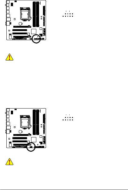
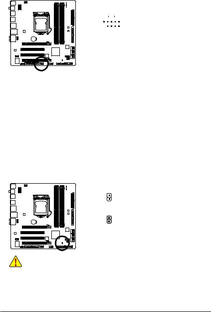
18)CLR_CMOS (Clearing CMOS Jumper)
Use this jumper to clear the CMOS values (e.g. date information and BIOS configurations) and reset the CMOS values to factory defaults. To clear the CMOS values, place a jumper cap on the two pins to temporarily short the two pins or use a metal object like a screwdriver to touch the two pins for a few seconds.
Open: Normal
Short: Clear CMOS Values
•Always turn off your computer and unplug the power cord from the power outlet before clearing the CMOS values.
•After clearing the CMOS values and before turning on your computer, be sure to remove the jumper cap from the jumper. Failure to do so may cause damage to the motherboard.
•After system restart, go to BIOS Setup to load factory defaults (select Load Optimized Defaults) or manually configure the BIOS settings (refer to Chapter 2, «BIOS Setup,» for BIOS configurations).
|
Hardware Installation |
— 30 — |
![]()
19)PHASE LED
The number of lighted LEDs indicates the CPU loading. The higher the CPU loading, the more the number of lighted LEDs. To enable the Phase LED display function, please first enable Dynamic Energy
Saver™ 2. Refer to Chapter 4, «Dynamic Energy Saver™ 2,» for more details.
|
— 31 — |
Hardware Installation |

|
Hardware Installation |
— 32 — |

Chapter 2 BIOS Setup
BIOS (Basic Input and Output System) records hardware parameters of the system in the CMOS on the motherboard. Its major functions include conducting the Power-On Self-Test (POST) during system startup, saving system parameters and loading operating system, etc. BIOS includes a BIOS Setup program that allows the user to modify basic system configuration settings or to activate certain system features. When the power is turned off, the battery on the motherboard supplies the necessary power to the CMOS to keep the configuration values in the CMOS.
To access the BIOS Setup program, press the <Delete> key during the POST when the power is turned on. To see more advanced BIOS Setup menu options, you can press <Ctrl> + <F1> in the main menu of the BIOS Setup program.
To upgrade the BIOS, use either the GIGABYTE Q-Flash or @BIOS utility.
•Q-Flash allows the user to quickly and easily upgrade or back up BIOS without entering the operating system.
•@BIOS is a Windows-based utility that searches and downloads the latest version of BIOS from the Internet and updates the BIOS.
For instructions on using the Q-Flash and @BIOS utilities, refer to Chapter 4, «BIOS Update Utilities.»
•Because BIOS flashing is potentially risky, if you do not encounter problems using the current version of BIOS, it is recommended that you not flash the BIOS. To flash the BIOS, do it with caution. Inadequate BIOS flashing may result in system malfunction.
•BIOS will emit a beep code during the POST. Refer to Chapter 5, «Troubleshooting,» for the beep codes description.
•It is recommended that you not alter the default settings (unless you need to) to prevent system instability or other unexpected results. Inadequately altering the settings may result in system’s failure to boot. If this occurs, try to clear the CMOS values and reset the board to default values. (Refer to the «Load Optimized Defaults» section in this chapter or introductions of the battery/ clearing CMOS jumper in Chapter 1 for how to clear the CMOS values.)

2-1 Startup Screen
The following screens may appear when the computer boots.
A. The LOGO Screen (Default)
Function Keys
B. The POST Screen
 Award Modular BIOS v6.00PG, An Energy Star Ally Copyright (C) 1984-2009, Award Software, Inc.
|
P55M-UD2 D8 |
||
|
Motherboard Model |
. |
|
|
BIOS Version |
. |
|
|
. |
||
|
. |
||
|
<DEL>: BIOS Setup <F9>: XpressRecovery2 <F12>: Boot Menu <End>: Qflash |
Function Keys |
|
|
07/16/2009-P55-7A89RG0EC-00 |
SATA Mode Message:
«SATA is found running at IDE MODE!»
When the motherboard is set to its default values, the monitor will display a message during the POST, telling you the SATA controller is running at IDE mode. The message that follows asks if you want to change it to AHCI mode and enable hot plug functionality for the SATA connectors.
Press <Y> to enable AHCI mode or <N> to continue IDE mode operation and stop showing this message again. Note: This message will appear again at next boot if you do not respond YES or NO in time.
Function Keys:
<TAB>: POST SCREEN
Press the <Tab> key to show the BIOS POST screen. To show the BIOS POST screen at system startup, refer to the instructions on the Full Screen LOGO Show item on page 50.
<DEL>: BIOS SETUP\Q-FLASH
Press the <Delete> key to enter BIOS Setup or to access the Q-Flash utility in BIOS Setup.
<F9>: XPRESS RECOVERY2
If you have ever entered Xpress Recovery2 to back up hard drive data using the driver disk, the <F9> key can be used for subsequent access to Xpress Recovery2 during the POST. For more information, refer to Chapter 4, «Xpress Recovery2.»
<F12>: BOOT MENU
Boot Menu allows you to set the first boot device without entering BIOS Setup. In Boot Menu, use the up arrow key <h> or the down arrow key <i> to select the first boot device, then press <Enter> to accept. To exit Boot Menu, press <Esc>. The system will directly boot from the device configured in Boot Menu.
Note: The setting in Boot Menu is effective for one time only. After system restart, the device boot order will still be based on BIOS Setup settings. You can access Boot Menu again to change the first boot device setting as needed.
<END>: Q-FLASH
Press the <End> key to access the Q-Flash utility directly without having to enter BIOS Setup first.

2-2 The Main Menu
Once you enter the BIOS Setup program, the Main Menu (as shown below) appears on the screen. Use arrow keys to move among the items and press <Enter> to accept or enter a sub-menu.
(Sample BIOS Version: D8)
CMOS Setup Utility-Copyright (C) 1984-2009 Award Software
|
|
MB Intelligent Tweaker(M.I.T.) |
Load Fail-Safe Defaults |
|
|
Standard CMOS Features |
Load Optimized Defaults |
|
|
Advanced BIOS Features |
Set Supervisor Password |
|
|
Integrated Peripherals |
Set User Password |
|
|
Power Management Setup |
Save & Exit Setup |
|
|
PC Health Status |
Exit Without Saving |
|
ESC: Quit |
: Select Item |
F11: Save CMOS to BIOS |
|
F8: Q-Flash |
F10: Save & Exit Setup |
F12: Load CMOS from BIOS |
|
Change CPU’s Clock & Voltage |
BIOS Setup Program Function Keys
<h><i><f><g> Move the selection bar to select an item
|
<Enter> |
Execute command or enter the submenu |
|
<Esc> |
Main Menu: Exit the BIOS Setup program |
|
Submenus: Exit current submenu |
|
|
<Page Up> |
Increase the numeric value or make changes |
|
<Page Down> |
Decrease the numeric value or make changes |
|
<F1> |
Show descriptions of the function keys |
|
<F2> |
Move cursor to the Item Help block on the right (submenus only) |
|
<F5> |
Restore the previous BIOS settings for the current submenus |
|
<F6> |
Load the Fail-Safe BIOS default settings for the current submenus |
|
<F7> |
Load the Optimized BIOS default settings for the current submenus |
|
<F8> |
Access the Q-Flash utility |
|
<F9> |
Display system information |
|
<F10> |
Save all the changes and exit the BIOS Setup program |
|
<F11> |
Save CMOS to BIOS |
|
<F12> |
Load CMOS from BIOS |
Main Menu Help
The on-screen description of a highlighted setup option is displayed on the bottom line of the Main Menu.
Submenu Help
While in a submenu, press <F1> to display a help screen (General Help) of function keys available for the menu. Press <Esc> to exit the help screen. Help for each item is in the Item Help block on the right side of the submenu.
• If you do not find the settings you want in the Main Menu or a submenu, press <Ctrl>+<F1> to access more advanced options.
•When the system is not stable as usual, select the Load Optimized Defaults item to set your system to its defaults.
•The BIOS Setup menus described in this chapter are for reference only and may differ by BIOS version.

The Functions of the <F11> and <F12> keys (For the Main Menu Only)
F11: Save CMOS to BIOS
This function allows you to save the current BIOS settings to a profile. You can create up to 8 profiles (Profile 1-8) and name each profile. First enter the profile name (to erase the default profile name, use the SPACE key) and then press <Enter> to complete.
F12: Load CMOS from BIOS
If your system becomes unstable and you have loaded the BIOS default settings, you can use this function to load the BIOS settings from a profile created before, without the hassles of reconfiguring the BIOS settings. First select the profile you wish to load, then press <Enter> to complete.
MB Intelligent Tweaker(M.I.T.)
Use this menu to configure the clock, frequency and voltages of your CPU, memory, etc.
Standard CMOS Features
Use this menu to configure the system time and date, hard drive types, floppy disk drive types, and the type of errors that stop the system boot, etc.
Advanced BIOS Features
Use this menu to configure the device boot order, advanced features available on the CPU, and the primary display adapter.
Integrated Peripherals
Use this menu to configure all peripheral devices, such as IDE, SATA, USB, integrated audio, and integrated LAN, etc.
Power Management Setup
Use this menu to configure all the power-saving functions.
PC Health Status
Use this menu to see information about autodetected system/CPU temperature, system voltage and fan speed, etc.
Load Fail-Safe Defaults
Fail-Safe defaults are factory settings for the most stable, minimal-performance system operations.
Load Optimized Defaults
Optimized defaults are factory settings for optimal-performance system operations.
Set Supervisor Password
Change, set, or disable password. It allows you to restrict access to the system and BIOS Setup. A supervisor password allows you to make changes in BIOS Setup.
Set User Password
Change, set, or disable password. It allows you to restrict access to the system and BIOS Setup. A user password only allows you to view the BIOS settings but not to make changes.
Save & Exit Setup
Save all the changes made in the BIOS Setup program to the CMOS and exit BIOS Setup. (Pressing <F10> can also carry out this task.)
Exit Without Saving
Abandon all changes and the previous settings remain in effect. Pressing <Y> to the confirmation message will exit BIOS Setup. (Pressing <Esc> can also carry out this task.)
 Loading…
GA-MA770-UD3 AM2 AMD770 DDRII 1200+

Gigabyte GA-MA770-UD3 AM2 AMD770 DDRII 1200+,
100 pages
GA-880GM-D2H
Gigabyte GA-880GM-D2H motherboard,
100 pages
GA-H61M-D2-B3
Gigabyte GA-H61M-D2-B3 motherboard,
40 pages
GA-X58A-OC
Gigabyte GA-X58A-OC motherboard,
120 pages
GA-M68M-S2P
Gigabyte GA-M68M-S2P,
40 pages
GA-P55A-UD7
Gigabyte GA-P55A-UD7 motherboard,
144 pages
GA-H57M-USB3
Gigabyte GA-H55M-USB3 motherboard,
128 pages
GA-P67X-UD3-B3
Gigabyte GA-P67X-UD3-B3 motherboard,
116 pages
GA-G41MT-ES2L
Gigabyte GA-G41MT-ES2L motherboard,
88 pages
GA-8VM533
Gigabyte GA-8VM533 motherboard,
96 pages
GA-A75-D3H
Gigabyte GA-A75-D3H,
96 pages
P41-ES3G
Gigabyte P41-ES3G,
104 pages
GA-MA74GM-S2H rev. 3.0
Gigabyte GA-MA74GM-S2H rev. 3.0,
96 pages
GA-G41M-ES2L
Gigabyte GA-G41M-ES2L,
96 pages
GA-790XTA-UD4
Gigabyte GA-790XTA-UD4 motherboard,
120 pages
GA-870A-UD3
Gigabyte GA-870A-UD3,
116 pages
GA-EP43-UD3L
Gigabyte GA-EP43-UD3L motherboard,
96 pages
GA-P43-ES3G (rev. 1.0)
Gigabyte GA-P43-ES3G (rev. 1.0),
88 pages
GA-890GPA-UD3H
Gigabyte GA-890GPA-UD3H,
120 pages
GA-P55-UD3L
Gigabyte GA-P55-UD3L motherboard,
128 pages
-
Драйверы
17
-
Инструкции по эксплуатации
18
Языки:

Gigabyte GA-P55M-UD2 инструкция по эксплуатации
(72 страницы)
- Языки:Венгерский, Греческий, Испанский, Итальянский, Немецкий, Польский, Португальский, Русский, Турецкий, Французский, Чешский
-
Тип:
PDF -
Размер:
18.6 MB -
Описание:
Installation Guidebook


На NoDevice можно скачать инструкцию по эксплуатации для Gigabyte GA-P55M-UD2. Руководство пользователя необходимо для ознакомления с правилами установки и эксплуатации Gigabyte GA-P55M-UD2. Инструкции по использованию помогут правильно настроить Gigabyte GA-P55M-UD2, исправить ошибки и выявить неполадки.
-
Страница 1
GA-P55M-UD2 LGA1 156 socket motherboard for Intel ® Core ™ i7 processor family/ Intel ® Core ™ i5 processor family User’s Manual Rev . 1001 12ME-P55MUD2-1001R[…]
-
Страница 2
Motherboard GA-P55M-UD2 Jul. 24, 2009 Jul. 24, 2009 Motherboard GA-P55M-UD2[…]
-
Страница 3
Copyright © 2009 GIGA-BYTE TECHNOLOGY CO., L TD. All rights reserved. The trademarks mentioned in this manual are legally registered to their respective owners. Disclaimer Information in this manual is protected by copyright laws and is the property of GIGABYTE. Changes to the specications and features in this manual may be made by GIGABYTE wit[…]
-
Страница 4
— 4 — T able of Contents Box Contents ……………………………………………………………………………………………………. 6 Optional Items ………………………………………………………………………………………………….. 6 GA-P55M-UD2 Motherboard Layout …………………………..[…]
-
Страница 5
— 5 — Chapter 3 Drivers Installation ……………………………………………………………………………. 61 3-1 Installing Chipset Drivers ……………………………………………………………………. 61 3-2 Application Software ……………………………………………………………………….[…]
-
Страница 6
— 6 — Box Contents GA-P55M-UD2 motherboard Motherboard driver disk User’s Manual Quick Installation Guide One IDE cable T wo SA T A 3Gb/s cables I/O Shield Optional Items Floppy disk drive cable (Part No. 12CF1-1FD001-7*R) 2-port USB 2.0 bracket (Part No. 12CR1-1UB030-5*R) 2-port IEEE 1394a bracket (Part No. 12CF1-1IE008-0*R) 2-port SA T A pow[…]
-
Страница 7
— 7 — GA-P55M-UD2 Motherboard Layout KB_USB R_SPDIF CPU_F AN PHASE LED LGA1 156 A TX GA-P55M-UD2 CD_IN F_AUDIO AUDIO B_BIOS M_BIOS PCIEX16 IDE SPDIF_O DDR3_2 DDR3_1 DDR3_4 DDR3_3 BA T TSB43AB23 IT8720 A TX_12V_2X4 Intel ® P55 GI G AB Y TE SA T A2 PCIEX4 R_USB_2 R_USB_1 USB_LAN USB_1394_ESA T A CLR_CMOS CODEC F_USB1 F_USB2 F1_1394 SPDIF_I COMA FDD […]
-
Страница 8
— 8 — Block Diagram PS/2 KB/Mouse Floppy COM 14 USB Ports LGA1 156 CPU DMI Interface Intel ® P55 PCI Bus PCI Express Bus PCI Express Bus IT8720 CPU CLK+/- (133 MHz) PCIe CLK (100 MHz) 6 SA TA 3Gb/s Dual BIOS Center/Subwoofer Speaker Out Line Out MIC Line In S/PDIF In S/PDIF Out Side Speaker Out Surround Speaker Out CODEC 1 PCI Express x4 2 PCI PCI[…]
-
Страница 9
— 9 — Hardware Installation 1- 1 Installation Pr ecautions Th e m ot her bo ar d c on ta in s n um er ou s d el ic at e e le ct ro ni c c ir cu it s a nd comp one nt s w hi ch can become damaged as a result of electrostatic discharge (ESD). Prior to installation, carefully read the user’s manual and follow these procedures: • Prio r to in[…]
-
Страница 10
Hardware Installation — 10 — 1- 2 Product Specications CPU w Support for an Intel ® Core ™ i7 series processor/Intel ® Core ™ i5 series processor in the LGA1 156 package (Go to GIGABYTE’s website for the latest CPU support list.) w L3 cache varies with CPU Chipset w Intel ® P55 Express Chipset Memory w 4 x 1.5V DDR3 DIMM s[…]
-
Страница 11
— 1 1 — Hardware Installation USB w Integrated in the Chipset w Up to 14 USB 2.0/1.1 ports (10 on the back panel, 4 via the USB brackets connected to the internal USB headers) IEEE 1394 w T .I. TSB43AB23 chip w Up to 2 IEEE 1394a ports (1 on the back panel, 1 via the IEEE 1394a bracket connected to the internal IEEE 1394a header) Internal w 1 x 24-[…]
-
Страница 12
Hardware Installation — 12 — (Note 1) Due to Win dows Vis ta/X P 32-bi t oper atin g sys tem li mita tion , when more t han 4 G B of ph ysica l memory is installed, the actual memory size displayed will be less than 4 GB. (Note 2) For optimum performance, if only one PCI Express graphics card is to be installed, be sure to install it in the PCIEX16[…]
-
Страница 13
— 13 — Hardware Installation 1-3 Installing the CPU and C PU C ooler Read the following guidelines before you begin to install the CPU: • Make sure that the motherboard supports the CPU. (Go to GIGABYTE’s website for the latest CPU support list.) • Always turn off the computer and unplug the power cord from the power outlet before in[…]
-
Страница 14
Hardware Installation — 14 — Step 1: Gently press the CPU socket lever handle down and away from the socket with your nger . Then completely lift the CPU socket lever and the metal load plate will be lifted as well. Step 3: Hold the CPU with your thumb and index ngers. Align the CPU pin one marking (triangle) with the pin one corner o f the C[…]
-
Страница 15
— 15 — Hardware Installation Use extreme care when removing the CPU cooler because the thermal grease/tape between the CPU cooler and CPU may adhere to the CPU. Inadequately removing the CPU cooler may damage the CPU. 1-3 -2 I nst all ing t he CPU Cool er Follow the steps below to correctly install the CPU cooler on the motherboard. (The following […]
-
Страница 16
Hardware Installation — 16 — 1- 4 Installin g the Me mor y Dual Channel Memory Congurations T able (SS=Single-Sided, DS=Double-Sided, «- -«=No Memory) Due to CPU limitations, read the following guidelines before installing the memory in Dual Channel mode. 1. Dual Channel mode cannot be enabled if only one DDR3 memory module is installe[…]
-
Страница 17
— 17 — Hardware Installation 1- 4 -2 Inst all ing a M emo r y Before installing a memory module, make sure to turn off the computer and unplug the power cord from the power outlet to prevent damage to the memory module. DDR3 and DDR2 DIMMs are not compatible to each other or DDR DIMMs. Be sure to install DDR3 DIMMs on this motherboard. Notch DDR3 D[…]
-
Страница 18
Hardware Installation — 18 — 1-5 Installing an Expansion Card Read the following guidelines before you begin to install an expansion card: • Make sure the motherboard supports the expansion card. Carefully read the manual that came with your expansion card. • Always turn off the computer and unplug the power cord from the power outlet before in[…]
-
Страница 19
— 19 — Hardware Installation 1-6 Back Panel Connectors • When removing the cable connected to a back panel connector, rst remove the cable from your device and then remove it from the motherboard. • When removing the cable, pull it straight out from the connector . Do not rock it side to side to prevent an electrical short inside the c[…]
-
Страница 20
Hardware Installation — 20 — Center/Subwoofer Speaker Out Jack (Orange) Use this audio jack to connect center/subwoofer speakers in a 5.1/7.1-channel audio conguration. Rear Speaker Out Jack (Black) Use this audio jack to connect rear speakers in a 4/5.1/7.1-channel audio conguration. Side Speaker Out Jack (Gray) Use this audio jack to connec[…]
-
Страница 21
— 21 — Hardware Installation 1- 7 Inter nal Connectors Read the following guidelines before connecting external devices: • First make sure your devices are compliant with the connectors you wish to connect. • Befor e ins tall ing th e dev ices, be sur e to tu rn off th e devi ces a nd you r com puter. Unplu g the power cord from the power[…]
-
Страница 22
Hardware Installation — 22 — Pin No. Denition 1 GND ( Only fo r 2x 4-pi n 12 V) 2 GND ( Only fo r 2x 4-pi n 12 V) 3 GND 4 GND 5 +12V (Onl y f or 2 x4-p in 1 2V) 6 +12V (Onl y f or 2 x4-p in 1 2V) 7 +12V 8 +12V A TX_12V_2X4: 13 1 24 12 A TX A TX: Pin No. Denition 13 3.3V 14 -12V 15 GND 16 PS_ON (soft On/Off) 17 GND 18 GND 19 GND 20 -5V 21 +5V […]
-
Страница 23
— 23 — Hardware Installation 3/4) CPU_F AN/SYS_F AN (Fan Headers) The motherboa rd has a 4-pin CPU fan header (CPU_F AN ) and a 4-pin (SYS_F AN). Most fan headers possess a foolproof insertion design. When connecting a fan cable, be sure to connect it in the correct orientation (the black connector wire is the ground wire). The motherboard supports[…]
-
Страница 24
Hardware Installation — 24 — 6) IDE (IDE Connector) The IDE connector supports up to two IDE devices such as hard drives and optical drives. Before attach- ing the IDE cable, locate the foolproof groove on the connector . If you wish to connect two IDE devices, remember to set the jumpers and th e cabling accordi ng to the role o f the IDE devices […]
-
Страница 25
— 25 — Hardware Installation
 GSA T A2_0 /1 ( SA T A 3Gb /s C on nec to rs , Con tr ol le d b y GI GA BYT E SA T A 2, Wh it e) The SA T A connectors conform to SAT A 3Gb/s standard and are compatible with SA T A 1.5Gb/s standard. Each SA T A connector supports a single SA T A device. The GIGABYTE SA T A2 controller supports RAID 0 and RAID 1. Ref[…]
 -
Страница 26
Hardware Installation — 26 — 10) F_P ANEL (Front Panel Header) Conne ct the p ower s witch , rese t swit ch, sp eaker, chassi s intr usio n switc h/se nsor an d syst em sta tus indicator on the chassis to this header according to the pin assignments below. Note the positive and negative pins before connecting the cables. Power LED 1 2 19 20 CI- CI+[…]
-
Страница 27
— 27 — Hardware Installation 1 1) F_AUDIO (Front Panel Audio Header) The front panel audio header supports Intel High Denition audio (HD) an d AC’97 audio. Y ou may connect your chassis front panel audio module to this header. Make sure the wire assignments of the module con — nector match the pin assignments of the motherboard header. Inco[…]
-
Страница 28
Hardware Installation — 28 — Pin No. Denition 1 Power 2 SPDIFI 3 GND 13) SPDIF_I (S/PDIF In Header , White) This header supports digital S/PDIF In and can connect to an audio device that supports digital audio out via an optional S/PDIF In cable. For purchasing the optional S/PDIF In cable, please contact the local dealer . Pin No. Denition 1[…]
-
Страница 29
— 29 — Hardware Installation 15) F_USB1/F_USB2 (USB Headers, Blue) The headers conform to USB 2.0/1.1 specication. Each USB header can provide two USB ports via an optional USB bracket. For purchasing the optional USB bracket, please contact the local dealer . Pin No. Denition 1 Power (5V) 2 Power (5V) 3 USB DX- 4 USB DY — 5 USB DX+ 6 USB DY+[…]
-
Страница 30
Hardware Installation — 30 — 17) COMA (Serial Port Header , White) The COMA header can provide one serial port via an optional COM port cable. For purchasing the op- tional COM port cable, please contact the local dealer . Pin No. Denition 1 NDCD- 2 NSIN 3 NSOUT 4 NDTR- 5 GND 6 NDSR- 7 NRTS- 8 NCTS- 9 NRI- 10 No Pin 10 9 2 1 18) CLR_CMOS (Cleari[…]
-
Страница 31
— 31 — Hardware Installation 19) PHASE LED The n umb er of l igh ted L EDs i ndi cate s the CPU l oadi ng. Th e hig her t he CP U loa din g, th e mor e th e number of lighted LEDs. T o enable the Phase LED display function, please rst enable Dynamic Energy Saver ™ 2. Refer to Chapter 4, «Dynamic Energy Saver ™ 2,» for more details.[…]
-
Страница 32
Hardware Installation — 32 -[…]
-
Страница 33
— 33 — BIOS Setup BIOS (Ba sic Inpu t and Out put Syst em) reco rds hard ware par ameters of the sy stem in t he CMOS o n the motherboard. Its major functions include conducting the Power-On Self-T est (POST) during system startup, saving sy stem param eters and l oading op erating sy stem, etc . BIOS incl udes a BIO S Setup pro gram that allows th[…]
-
Страница 34
BIOS Setup — 34 — 2-1 Startup Screen The following screens may appear when the computer boots. A. The LOGO Screen (Default) B. The POST Screen Function Keys: <T AB>: POST SCREEN Press the <T ab> key to show the BIOS POST screen. T o show the BIOS POST screen at system startup, refer to the instructions on the Full Screen LOGO Show item […]
-
Страница 35
— 35 — BIOS Setup 2-2 The Main Menu Once you enter the BIOS Setup program, the Main Menu (as shown below) appears on the screen. Use ar- row keys to move among the items and press <Enter> to accept or enter a sub-menu. (Sample BIOS V ersion: D8) Main Menu Help The on-screen description of a highlighted setup option is displayed on the bottom […]
-
Страница 36
BIOS Setup — 36 — The Functions of the <F1 1> and <F12> keys (For the Main Menu Only) F1 1: Save CMOS to BIOS This function allows you to save the current BIOS settings to a prole. Y ou can create up to 8 proles (Prole 1-8) and name each prole. First enter the prole name (to erase the default prole name, use[…]
-
Страница 37
— 37 — BIOS Setup 2-3 MB Intelligent T weaker(M.I.T .) Whether the system will work stably with the overclock/overvoltage settings you made is dependent on your overall system congurations. Incorrectly doing overclock/overvoltage may result in dam — age to CPU, chipset, or memory and reduce the useful life of these components. This page is for a[…]
-
Страница 38
BIOS Setup — 38 — CPU Clock Ratio (Note) Allows you to alter the clock ratio for the installed CPU. The item is present only if a CPU with unlocked clock ratio is installed. CPU Frequency Displays the current operating CPU frequency . (Note) This item is present only if you install a CPU that supports this feature. For more information about Intel […]
-
Страница 39
— 39 — BIOS Setup (Note) This item is present only if you install a CPU that supports this feature. For more information about Intel CPUs’ unique features, please visit Intel’s website. C3/C6/C7 State Support (Note) Allows you to determine whether to let the CPU enter C3/C6/C7 mode in system halt state. When en- abled, the CPU core freque[…]
-
Страница 40
BIOS Setup — 40 — (Note) This item appears only if you install a memory module that supports this feature. >>>>> Standard Clock Control Base Clock(BCLK) Control Enables or disables the control of CPU base clock. Enabled will allow the BCLK Frequency(Mhz) item below to be congurable. Note: If your system fails to boot after overclo[…]
-
Страница 41
— 41 — BIOS Setup >>>>> Advanced Clock Control CPU Clock Drive Allows you to adjust the amplitude of the CPU and Chipset clock. Options are: 700mV , 800mV (default), 900mV , 1000mV . PCI Express Clock Drive Allows you to adjust the amplitude of the PCI Express and Chipset clock. Options are: 700mV , 800mV , 900mV (default), 1000mV . […]
-
Страница 42
BIOS Setup — 42 — Performance Enhance Allows the system to operate at three different performance levels. Standard Lets the system ope rate at its basic performance level. Turbo Lets the system operate at its good performance level. (Default) Extreme Lets the system operate at its best performance level. DRAM Timing Selectable (SPD) Quick and Exper[…]
-
Страница 43
— 43 — BIOS Setup tRP Options are: Auto (default), 1~15. tRAS Options are: Auto (default), 1~31. >>>>> Channel A/B Advanced Timing Control tRC Options are: Auto (default), 1~63. tRRD Options are: Auto (default), 1~7. tWTR Options are: Auto (default), 1~31. tWR Options are: Auto (default), 1~15. tWTP Options are: Auto (default), 1~31.[…]
-
Страница 44
BIOS Setup — 44 — CMOS Setup Utility-Copyright (C) 1984-2009 A ward Software Channel A T urnaround Settings higf : Move Enter: Select +/-/PU/PD: V alue F10: Save ESC: Exit F1: General Help F5: Previous V alues F6: Fail-Safe Defaults F7: Optimized Defaults Item Help Menu Level >>>>> Channel A Reads Followed by Reads x Dif[…]
-
Страница 45
— 45 — BIOS Setup Advanced V oltage Settings >>> CPU Load-Line Calibration Ena bl es o r di sa bl es L oa d- Li ne C al ibr at io n. E na bl in g th is f ea tur e ad ju st s Vd ro op , ke ep in g th e CP U voltage more constant under light and heavy CPU load. Disabled sets the CPU voltage following Intel specications. (Default: Disa[…]
-
Страница 46
BIOS Setup — 46 — Ch-A Address VRef. The default is Auto . Ch-B Address VRef. The default is Auto . Isochronous Support Determines whether to enable specic streams within the CPU and Chipset. (Default: Enabled) This section provides information on the BIOS version, CPU base clock, CPU frequency , memory frequency , total memory size , CPU temper[…]
-
Страница 47
— 47 — BIOS Setup Date (mm:dd:yy) Sets the system date. The date format is week (read-only), month, date and year . Select the desired eld and use the up arrow or down arrow key to set the date. Time (hh:mm:ss) Sets the system time. For example, 1 p.m. is 13:0:0. Select the desired eld and use the up arrow or down arrow key to set the time. I[…]
-
Страница 48
BIOS Setup — 48 — • Auto Lets the BIOS aut omatically detec t IDE/SA T A devices during the POST . (Default) • None If no IDE/SA T A devices are used, set this item to None so the system will skip the detection of the device during the POST for faster system startup. • Manual Allows you to manually enter the specications of the ha[…]
-
Страница 49
— 49 — BIOS Setup (Note) This item is present only if you install a CPU that supports this feature. For more information about Intel CPUs’ unique features, please visit Intel’s website. 2-5 Advanced BIOS Features Hard Disk Boot Priority Species the sequence of loading the operating system from the installed hard drives. Use the up or d[…]
-
Страница 50
BIOS Setup — 50 — Limit CPUID Max. to 3 (Note) Allows you to determine whether to limit CPUID maximum value. Set this item to Disabled for Windows XP operating system; set this item to Enabled for legacy operating system such as Windows NT4.0. (Default: Disabled) No-Execute Memory Protect (Note) Enables o r disable s Intel Ex ecute Dis able Bit f u[…]
-
Страница 51
— 51 — BIOS Setup 2-6 Integrated Peripherals SA T A RAID/AH CI Mode (Intel P55 Chipset) Enables or disables RAID for the SA T A controllers integrated in the Intel P55 chipset or congures the SA TA controllers to AHCI mode. Disabled Disables RAID for the SA T A controllers and congures the SA T A controllers to IDE mode. (Default) RAID Enable[…]
-
Страница 52
BIOS Setup — 52 — Azalia Codec Enables or disables the onboard audio function. (Default: Auto) If you wish to install a 3rd party add-in audio card instead of using the onboard audio, set this item to Disabled . Onboard H/W 1394 Enables or disables the onboard IEEE 1394 function. (Default: Enabled) Onboard H/W LAN Enables or disables the onboard LA[…]
-
Страница 53
— 53 — BIOS Setup Onboard LAN Boot ROM Allows you to decide whether to activate the boot ROM integrated with the onboard LAN chip. (Default: Disabled) Onboard SA T A/IDE Device (GIGABYTE SA T A2, IDE and GSA T A2_0/1 Connectors) Enables or disables the IDE and SA T A controllers integrated in the GIGABYTE SA T A2 chip. (Default: Enabled) Onboard SA[…]
-
Страница 54
BIOS Setup — 54 — ACPI Suspend T ype Species the ACPI sleep state when the system enters suspend. S1(POS) Enables the system to enter the ACPI S1 (Power on Suspend) sleep state. In S1 sleep state, the system appears suspended and stays in a low power mode. The system can be resumed at any time. S3(STR) Enables the system to enter the ACPI S3 (Su[…]
-
Страница 55
— 55 — BIOS Setup (Note) Supported on Windows Vista operating system only . Resume by Alarm Determines whether to power on the system at a desired time. (Default: Disabled) If enabled, set the date and time as following: Date (of Month) Alarm: Turn on the system at a specic time on each day or on a specic day in a month. Time (hh: mm: ss) Ala[…]
-
Страница 56
BIOS Setup — 56 — Reset Case Open Status Keeps or clears the record of previous chassis intrusion status. Enabled clears the record of previous chassis intrusion status and the Case Opened eld will show «No» at next boot. (Default: Disabled) Case Opened Displays the detection status of the chassis intrusion detection device attached to[…]
-
Страница 57
— 57 — BIOS Setup CPU Smart F AN Control Species how to control CPU fan speed. This item is congurable only if CPU Smart F AN Control is set to Enabled . Auto Lets the BIOS automatically detect the type of CPU fan installed and sets the optimal CPU fan control mode. (Default) Voltage Sets Voltage mode for a 3-pin CPU fan. PWM Sets PWM mode fo[…]
-
Страница 58
BIOS Setup — 58 — Press <Enter> on this item and then press the <Y> key to load the safest BIOS default settings. In case system instability occurs, you may try to load Fail-Safe defaults, which are the safest and most stable BIOS settings for the motherboard. 2-9 Load Fail-Safe Defaults Press <Enter> on this item and then press t[…]
-
Страница 59
— 59 — BIOS Setup Press <Enter> on this item and type the password with up to 8 characters and then press <Enter>. Y ou will be requested to conrm the password. T ype the password again and press <Enter>. The BIOS Setup program allows you to specify two separate passwords: Supervisor Password When a system password is set and t[…]
-
Страница 60
BIOS Setup — 60 — Press <Enter> on this item and press the <Y> key . This saves the changes to the CMOS and exits the BIOS Setup program. Press <N> or <Esc> to return to the BIOS Setup Main Menu. 2-12 Save & Exit Setup Press <Enter> on this item and press the <Y> key. This exits the BIOS Setup without saving […]
-
Страница 61
— 61 — Drivers Installation 3-1 Installing Chipset Drivers Chapter 3 Drivers Installation • Before installing the drivers, rst install the operating system. • After installing the operating system, insert the motherboard driver disk into your optical drive. The driver Autorun screen is automatically displayed which looks like that show[…]
-
Страница 62
Drivers Installation — 62 — 3-2 Application Software This page displays all the utilities and applications that GIGABYTE develops and some free software. Y ou can click the Install button on the right of an item to install it. 3-3 T echnical Manuals This page provides GIGABYTE’s application guides, content descriptions for this driver disk, an[…]
-
Страница 63
— 63 — Drivers Installation 3-4 Contact For the detailed contact information of the GIGABYTE T aiwan headquarter or worldwide branch ofces, click the URL on this page to link to the GIGABYTE website. 3-5 System This page provides the basic system information.[…]
-
Страница 64
Drivers Installation — 64 — 3-6 Download Center T o update the BIOS, driver s, or applications, click the Download Center but ton to link to the GIGAB YTE website. The latest version of the BIOS, drivers, or applications will be displayed. 3-7 New Utilities This page provides a quick link to GIGABYTE’s lately developed utilities for users to i[…]
-
Страница 65
— 65 — Unique Features 4-1 Xpress Recovery2 Chapter 4 Unique Features Xp r es s R e co v er y 2 i s a u ti l it y t h at a l l ow s y ou to q u ic k l y co m p re s s an d back up your system data and perform restoration of it. Supporting NTFS, F A T32, and FA T16 le systems, Xpress Recovery2 can back up data on P AT A and SA T A hard drives and[…]
-
Страница 66
Unique Features — 66 — Step 3: Wh e n pa r ti t io n in g y o ur h a rd d r i ve , m ak e s ur e t o leave unallocated space (10 GB or more is recom- mended; actual size requirements vary , depending on the amount of data) and begin the installation of the operating system. Step 1: Select BACKUP to start backing up your hard drive data. Step 4: Aft[…]
-
Страница 67
— 67 — Unique Features D. Using the Restore Function in Xpress Recovery2 E. Removing the Backup F . Exiting Xpress Recovery2 Sel ec t RESTORE to re st or e th e ba ck up t o yo ur h ar d dr ive in case the system breaks down. The RESTORE option will not be present if no backup is created before. Select REBOOT to exit Xpress Recovery2. Step 2: After[…]
-
Страница 68
Unique Features — 68 — 4-2 BIOS Update Utilities GI GA B YT E m ot h er b oa r ds p r ov i de t w o un i qu e B IO S u pd a te t o ol s , Q- F la s h ™ an d @ BI O S ™ . GI G AB Y TE Q-Flash and @BIOS are easy-to-use and allow you to update the BIOS without the need to enter MS-DOS mod e. Ad dit ion all y , this m oth erb oar d fe atu res t he […]
-
Страница 69
— 69 — Unique Features B. Updating the BIOS When updatin g the BIOS, ch oose the loc ation where t he BIOS le is saved. The followi ng procedure as — sumes that you save the BIOS le to a oppy disk. Step 1: 1. Insert the oppy disk containing the BIOS le into the oppy disk driv e. In the main menu of Q-Flash, use the up or down arro[…]
-
Страница 70
Unique Features — 70 — Step 4: Press <Esc> and then <Enter> to exit Q-Flash and reboot the system. As the system boots, you should see the new BIOS version is present on the POST screen. Step 5: During the POST , press <Delete> to enter BIOS Setup. Select Load Optimized Defaults and press <Enter> to load BIOS defaults. Syste[…]
-
Страница 71
— 71 — Unique Features 4-2-2 Updating the BIOS with the @BIOS Utility A. Before Y ou Begin 1. In Windows, close all applications and TSR (T erminate and Stay Resident) programs. This helps prevent unexpected failures when performing a BIOS update. 2. Du ring the BIOS upd ate proc ess, ens ure the I nternet connect ion is st able an d do NOT inte rr[…]
-
Страница 72
Unique Features — 72 — 4-3 EasyT une 6 GIGABYTE’s EasyTune 6 is a simple and easy-to-use interface that allows users to ne-tune their system settings or do overclock/overvoltage in Windows environment. The user-friendly EasyTune 6 interface also includes tabbed pages for CPU and memory information, letting users read their system-related in[…]
-
Страница 73
— 73 — Unique Features 4-4 Dynamic Energy Saver ™ 2 GIGABYTE Dynamic Energy Sav er ™ 2 (Note 1) is a revolutionary tech nology that delivers unpara lleled power savings with a click of the button. Featuring an advanced proprietary hardware and software design, GIGA- BYTE Dynamic Energy Saver ™ 2 is able to provide exceptional power savings an[…]
-
Страница 74
Unique Features — 74 — B. T otal Mode In T otal Mode, users are able to see how much total power savings they have accumulated in a set period of time since activating Dynamic Energy Saver ™ 2 for th e rst time (Note 3) . (Note 1) Before using the Dynamic Energy Saver ™ 2 function, make sure the CPU Enhanced Halt (C1E) and CPU EIST Function […]
-
Страница 75
— 75 — Unique Features 4-5 Q-Share Q-Share is an easy and convenient data sharing too l. After conguring your LAN connection settings and Q-Share, you are able to share your data with computers on the same network, making full use of Internet resources. Directions for using Q-Share After installing Q-Share from the motherboard driver disk, go to[…]
-
Страница 76
Unique Features — 76 — 4-6 Smart 6 ™ GIGABYTE Smart 6 ™ (Note 1) is designed with user-friendliness i n mind, and offers a combination of 6 innovative software utilities that provide easier and smarter PC system management. Smart 6 ™ allows you to speed up system performance, reduce boot-up time, manage a secure platform and recover specie[…]
-
Страница 77
— 77 — Unique Features SMART Recovery With SMART Recovery , users can quickly create backups of changed data les (Note 2) or copy les from a specic backup on P A T A and SA T A hard drives (partitioned on NTFS le system) in Windows Vista. SMART DualBIOS SMART DualBIOS is a new feature that can record personal passwords and important dat[…]
-
Страница 78
Unique Features — 78 — (Note 1) When launching Smart 6 ™ for the rst time, the system will request you to set up a password. This password is required when you activate SMART DualBIOS or when you want to make changes to the SMART Recorder or SMART TimeLock settings. (Note 2) The changed data refers to the data that has been modied, deleted,[…]
-
Страница 79
— 79 — Appendix Chapter 5 Appendix 5-1 Conguring SA T A Hard Drive(s) T o congure SA T A hard drive(s), follow the steps below: A. Install SA T A hard drive(s) in your computer . B. Congure SA T A controller mode in BIOS Setup. C. Congure a RAID array in RAID BIOS. (Note 1) D. Make a oppy disk containing the SA T A RAID/AHCI driver f[…]
-
Страница 80
Appendix — 80 — B. Conguring SA T A controller mode in BIOS Setup Make sure to congure the SA TA controller mode correctly in system BIOS Setup. Step 1: Turn on your com puter an d press < Delete> to enter BIOS Setu p durin g the POS T (Power-On Self-T e st). T o create RAID, set SA T A RAID/AHCI Mode under the Integrated Peripherals me[…]
-
Страница 81
— 81 — Appendix C. Conguring a RAID array in RAID BIOS Enter the RAID BIOS setup utility to congure a RAID array . Skip this step and proceed with the installation of Windows operating system for a non-RAID conguration. Step 1: After the POST memory test begins and before the operating system boot begins, look for a message which says &quo[…]
-
Страница 82
Appendix — 82 — Step 3: After entering the CREA TE VOLUME MENU screen, enter a volume name with 1~16 letters (letters cannot be special characters) under the Name item and press <Enter>. Then, select a RAID level (Figure 4). RAID levels supported include RAID 0, RAID 1, Recovery , RAID 10, and RAID 5 (the selections available depend on the nu[…]
-
Страница 83
— 83 — Appendix Step 5: Enter the array capacity and press <Enter>. Finally press <Enter> on the Create V olume item to begin creat- ing the RAID array . When prompted to conrm whether to create this volume, press <Y> to conrm or <N> to cancel (Figure 6). When completed, you can see detailed information about the RAID […]
-
Страница 84
Appendix — 84 — Recovery V olume Options Intel Rapid Recover T echnology provides data protection by allowing users to easily restore data and system operation using a designated recovery drive. With the Rapid Recovery T echnology , which employs RAID 1 functionality , users can copy the data from the master drive to the recovery drive; if needed, […]
-
Страница 85
— 85 — Appendix Figure 10 Step 3: Press <Enter> under the Select Disks item. In the SELECT DISKS box, press <T ab> on the hard drive you want to use for the master drive and press <Space> on the hard drive you want to use for the recovery drive. (Make sure the recovery drive has equal or larger capacity than the master drive.) The[…]
-
Страница 86
Appendix — 86 — Delete RAID V olume T o delete a RAID array, select Delete RAID V olume in MAIN MENU and pres s <Enter>. In the DELETE VOLUME MENU section, use the up or down arrow key to select the array to be deleted and press <Delete>. When prompted to conrm your selection (Figure 12), press <Y> to conrm or <N> to a[…]
-
Страница 87
— 87 — Appendix 5-1-2 Conguring GIGABYTE SA T A2 SA T A Controller A. Installing SA T A hard drive(s) in your computer Attach one end of the SA TA signal cable to the rear of the SA T A hard drive and the other end to available SA TA port on the motherboard. On this motherboard, the GSA T A2_0 and GSA T A2_1 ports are supported by the GIGABYTE S[…]
-
Страница 88
Appendix — 88 — C. Conguring a RAID array in RAID BIOS Enter the RAID BIOS setup utility to congure a RAID array . Skip this step and proceed to the installation of Windows operating system for a non-RAID conguration. After the POST memory test begins and before the operating system boot begins, look for a message which says «Press &l[…]
-
Страница 89
— 89 — Appendix Create a RAID Array: In the main screen, press <Enter> on the Create RAID Disk Drive item. Then the Create New RAID screen appears (Figure 4). The Create New RAID block displays all the items that need to be set for creating an array (Figure 5). Steps: 1. Enter Array Name: Under the Name item, enter an array name with 1~16 let[…]
-
Страница 90
Appendix — 90 — 3. Assign Array Disks: After a RAID mode is selected, RAID BIOS automaticall y assigns the two hard drives installed as the RAID drives. 4. Set Block Size (RAID 0 only): Under the Block item, use the up or down arrow key to select the stripe block size (Figure 6), ranging from 4 KB to 128 KB. Press <Enter>. 5. Set Array Size: […]
-
Страница 91
— 91 — Appendix When nished, the new RAID array will be displayed in the RAID Disk Drive List block (Figure 8). Figure 8 Model Name RAID Level Capacity Status Members(HDDx) RDD0: GRAID 0-Stripe 240 GB Normal 01 [ fg T AB]-Switch Window [ hi ]-Select ITEM [ENTER]-Action [ESC]-Exit [ RAID Disk Drive List ] [ Main Menu ] [ Hard Disk Drive List ] Gi[…]
-
Страница 92
Appendix — 92 — Model Name RAID Level Capacity Status Members(HDDx) RDD0: GRAID 0-Stripe 240 GB Normal 01 [ fg T AB]-Switch Window [ hi ]-Select ITEM [ENTER]-Action [ESC]-Exit [ RAID Disk Drive List ] [ Main Menu ] [ Hard Disk Drive List ] Gigabyte T echnology Corp. RAID Setup Utility v1.07.06 Create RAID Disk Drive Delete RAID Disk Drive Revert HD[…]
-
Страница 93
— 93 — Appendix 5-1-3 Making a SA T A RAID/AHCI Driver Diskette (Required for AHCI and RAID Mode) T o successfully install operating system onto SA T A hard drive(s) that is/are congured to RAID/AHCI mode, you need to install the SA T A controller driver during the OS installation. Without the driver , the hard drive may not be recognized during[…]
-
Страница 94
Appendix — 94 — 5-1-4 Installing the SA T A RAID/AHCI Driver and Operating System With the SA T A RAID/AHCI driver diskette and correct BIOS settings, you are ready to install Windows Vista/ XP onto your hard drive(s). The followings are examples of Windows XP and Vista installation. A. Installing Windows XP Step 1: Restart your system to boot from[…]
-
Страница 95
— 95 — Appendix For the GIGABYTE SA TA2: Insert the oppy disk containing the SA T A RAID/AHCI driver and press <S>. Then a controller menu similar to Figure 3 below will appear. Select (Windows XP/2003) RAID/AHCI Driver for GIGABYTE GBB36X Con- troller and press <Enter>. Step 3: On the next screen, press <Enter> to continue the[…]
-
Страница 96
Appendix — 96 — B. Installing Windows Vista (The procedure below assumes that only one RAID array exists in your system.) For the Intel P55: Step 1: Restart your system to boot from the Windows Vista setup disk and perform standard OS installation steps. When a screen similar to that below appears, select Load Driver (Figure 4). Step 2: Inse rt th […]
-
Страница 97
— 97 — Appendix Step 3: When a screen as shown in Figure 6 appears, select Intel(R) ICH8R/ICH9R/ICH10R/DO/PCH SA T A RAID Controller and click Next . Step 4: After the driver is loaded, select the RAID/AHCI drive(s) where you want to install the operating system and then click Next to continue the OS installation (Figure 7). Figure 6 Figure 7[…]
-
Страница 98
Appendix — 98 — For the GIGABYTE SA TA2: Step 1: Restart your system to boot from the Windows Vista setup disk and perform standard OS installation steps. When a screen similar to that below appears (RAID/AHCI hard drive(s) will not be detected at this stage), select Load Driver (Figure 8). Step 2: Insert the motherboard driver disk (Method A) or t[…]
-
Страница 99
— 99 — Appendix Step 3: When a screen as shown in Figure 10 appears, select GIGABYTE GBB36X Controller and click Next . Step 4: After the driver is loaded, select the RAID/AHCI drive(s) where you want to install the operating system and then click Next to continue the OS installation (Figure 1 1). Figure 10 Figure 1 1[…]
-
Страница 100
Appendix — 100 — Intel(R) Matrix Storage Manager option ROM v8.9.0.1023 PCH-D wRAID5 Copyright(C) 2003-09 Intel Corporation. All Rights Reserved. 3. Reset Disks to Non-RAID 4. Exit RAID V olumes : Nonedened. Physical Disks : Port Drive Model Serial # Size T ype/Status(V ol ID) 0 ST3120026AS 3JT354CP 1 1 1.7GB Member Disk (0) 1 WDC WD800JD-22L[…]
-
Страница 101
— 101 — Appendix • Performing the Rebuild in the Operating System While in the operating system, make sure the chipset driver has been installed from the motherboard driver disk. Then launch the Intel Matrix Storage Console from All Programs in the Start menu. Step 1: On th e View men u of t he In te l Ma tri x St ora ge C o n s o l e , s e l e c[…]
-
Страница 102
Appendix — 102 — • Restoring the Master Drive to a Previous State (for Recovery V olume only) When two hard drives are set to Recovery Volume in Update on Request mode, you can restore the master drive data to the last backup state when needed. For example, in case the master drive detects a virus, you can restore the recovery drive data to the m[…]
-
Страница 103
— 103 — Appendix For the GIGABYTE SA TA2: Turn off your computer and replace the failed hard drive with a new one. Use either the RAID setup utility or the GIGABYTE RAID CONFIGURER utility in the operating system to perform the rebuild. • Rebuilding with the RAID setup utility Step 1: When the message «Press <Ctrl-G> to enter RAID Setu[…]
-
Страница 104
Appendix — 104 — • Rebuilding in the operating system Make sure the GIGABYTE SA T A2 SA T A controller driver has been installed from the motherboard driver disk. Launch the GIGABYTE RAID CONFIGURER from All Programs in the Start menu. Step 1: In the GIGABYTE RAID CONFIGURER screen, right-click on the array to be rebuilt in the RAID LIST block. S[…]
-
Страница 105
— 105 — Appendix 5-2-1 Conguring 2/4/5.1/7.1-Channel Audio Th e mo t h e r b o a r d p r o v i d e s s i x a u d i o j a c k s o n t h e ba c k p a ne l w h i c h su p p o rt 2/ 4 / 5. 1 / 7 .1 — c h an n e l (Note) audio. The picture to the right shows the default audio jack assignments. The integrated HD (High Definition) audio provides jack r[…]
-
Страница 106
Appendix — 106 — Step 2: Connect an audio device to an audio jack. The The cur- rent connected device is dialog box appears. Select the device according to the type of device you connect. Then click OK . Step 3: On the Speakers s creen, click t he Spe aker Co ngura — tion tab. In the Speaker Conguration list, select Stereo , Quadraphonic , 5.[…]
-
Страница 107
— 107 — Appendix 5-2-2 Conguring S/PDIF In/Out A. S/PDIF In The S/PDIF In cable (optional) allows you to input digital audio signals to the computer for audio processing. 1. Installing the S/PDIF In Cable: 2. Conguring S/PDIF In: On the Digital Input screen, click the Default Format tab to select the default format. Click OK to complete. (Not[…]
-
Страница 108
Appendix — 108 — B. S/PDIF Out The S/PDIF Out jacks can transmit audio signals to an external decoder for decoding to get the best audio quality . 1. Connecting a S/PDIF Out Cable: 2. Conguring S/PDIF Out: On the Digital Output screen, click the Default Format tab and then select the sample rate and bit depth. Click OK to complete. S/PDIF Coaxia[…]
-
Страница 109
— 109 — Appendix 5-2-3 Conguring Microphone Recording Step 1: After installing the audio driver , the HD Audio Manager icon will appear in the notication area. Double-click the icon to access the HD Audio Manager . Step 2: Connect your microphone to the Mic in jack (pink) on th e ba c k pa ne l o r th e M ic i n j ac k ( pi nk ) o n th e f ro[…]
-
Страница 110
Appendix — 110 — Step 4: T o r a i s e t h e r e co r d i n g a n d p la y b a c k v o lu m e f o r t h e microphone, click the Microphone Boost icon on the right of the Recor ding V olume slider and set the Microphone Boost level. Step 5: After co mpletin g the set tings a bove, cl ick Start , p oint to All Programs , point to Accessories , and th[…]
-
Страница 111
— 1 11 — Appendix Step 3: When the Stereo Mix item appears, right-click on this item and select Enable . Then set it as the default de- vice. Step 4: Now you can access the HD Audio Manager to cong — ure Stereo Mix and use Sound Recorder to record the sound. 5-2-4 Using the Sound Recorder A. Recording Sound 1. Make sure you have connected the so[…]
-
Страница 112
Appendix — 112 — 5-3 T roubleshooting 5-3-1 Frequently Asked Questions T o read more F AQs for your motherboard, please go to the Support&DownloadsMotherboardFAQ page on GIGABYTE’s website. Q: In the BIOS Setup program, why are some BIOS options missing? A: Some advanced options are hidden in the BIOS Setup program. Press <Delete> […]
-
Страница 113
— 1 13 — Appendix 5-3-2 T roubleshooting Procedure If you encounter any troubles during system startup, follow the troubleshooting procedure below to solve the problem. ST AR T A Turn off the power . Remove all peripherals, connecting cables, and power cord etc. Isolate the short circuit. Secure the CPU cooler on the CPU. Connect the CPU cooler pow[…]
-
Страница 114
Appendix — 114 — If the proce dure above is una ble to solv e your p robl em, c onta ct the place of pur chas e or lo cal dealer for help. Or go to the Support&DownloadsT echnical Service Zone page to submit your question. Our customer service staff will reply you as soon as possible. The power supply , CPU or CPU socket might fail. The keyboa[…]
-
Страница 115
— 1 15 — Appendix 5-4 Regulatory Statements Regulatory Notices This document must not be copied without our written permission, and the conten ts there of must not be imparted to a third party nor be used for any unauthorized purpose. Contravention will be prosecuted. We believe that the information contained herein was accurate in all respects at […]
-
Страница 116
Appendix — 116 — Finally , we suggest that you practice other environmentally friendly actions by understanding and using the energy-saving features of this product (where applicable), recycling the inner and outer packaging (including shipping containers) this product was delivered in, and by disposing of or recycling used batteries properly . Wit[…]
-
Страница 117
— 1 17 — Appendix[…]
-
Страница 118
Appendix — 118 -[…]
-
Страница 119
— 1 19 — Appendix Contact Us • GIGA-BYTE TECHNOLOGY CO., L TD. Address: No.6, Bau Chiang Road, Hsin-Tien, T aipei 231, T aiwan TEL: +886-2-8912-4000 F AX: +886-2-8912-4003 T ech. and Non-T ech. Support (Sales/Marketing) : http://ggts.gigabyte.com.tw WEB address (English): http://www .gigabyte.com.tw WEB address (Chinese): http://www .gigabyte.tw […]
-
Страница 120
Appendix — 120 — • G.B.T . TECHNOLOGY TRADING GMBH — Germany WEB address : http://www .gigabyte.de • G.B.T . TECH. CO., L TD. — U.K. WEB address : http://www .giga-byte.co.uk • Giga-Byte T echnology B.V . — The Netherlands WEB address : http://www .giga-byte.nl • GIGABYTE TECHNOLOGY FRANCE — France WEB address : http://www .gigabyte.fr • […]
 |
[Page 1] Gigabyte GA-P55M-UD2 GA-P55M-UD2 GA-P55M-US2 User’s Manual Rev. 1101 |
 |
[Page 2] Gigabyte GA-P55M-UD2 Motherboard GA-P55M-UD2/ GA-P55M-US2 Nov. 30, 2009 Nov. 30, 2009 Motherboard GA-P55M-UD2/GA-P55M-US2 |
 |
[Page 3] Gigabyte GA-P55M-UD2 Copyright © 2009 GIGA-BYTE TECHNOLOGY CO., LTD. All rights reserved. The trademarks mentioned in this manual are legally registered to their respective owners. Disclaimer Information in this manual is protected by copyright laws and is the property … |
 |
[Page 4] Gigabyte GA-P55M-UD2 — 4 — Table of Contents Box Contents …………………………………………………………………………………………………….6 Optional Items ………………………………………………………………………… |
 |
[Page 5] Gigabyte GA-P55M-UD2 — 5 — Chapter 3 Drivers Installation …………………………………………………………………………….61 3-1 Installing Chipset Drivers ……………………………………………………………………. 61 3-2 A… |
 |
[Page 6] Gigabyte GA-P55M-UD2 — 6 — Box Contents GA-P55M-UD2 or GA-P55M-US2 motherboard Motherboard driver disk User’s Manual Quick Installation Guide One IDE cable Two SATA 3Gb/s cables I/O Shield Optional Items Floppy disk drive cable (Part … |
 |
[Page 7] Gigabyte GA-P55M-UD2 — 7 — GA-P55M-UD2/US2 Motherboard Layout KB_USB j R_SPDIF CPU_FAN PHASE LED LGA1156 ATX GA-P55M-UD2/US2 CD_IN F_AUDIO AUDIO B_BIOS M_BIOS PCIEX16 IDE SPDIF_O DDR3_2 DDR3_1 DDR3_4 DDR3_3 BAT TSB43AB23 IT8720 ATX_12V_2X4 Intel ® P55 j Intel ® H55 … |
 |
[Page 8] Gigabyte GA-P55M-UD2 — 8 — Block Diagram PS/2 KB/Mouse Floppy COM 12 USB Ports k 14 USB Ports j LGA1156 CPU DMI Interface Intel ® P55 j Intel ® H55 k PCI Bus PCI Express Bus PCI Express Bus IT8720 CPU CLK+/- (133 MHz) PCIe CLK (100 MHz) 6 SATA 3Gb/s Dual BIOS C… |
 |
[Page 9] Gigabyte GA-P55M-UD2 — 9 — Hardware Installation 1-1 Installation Precautions The motherboard contains numerous delicate electronic circuits and components which can become damaged as a result of electrostatic discharge (ESD). Prior to installation, carefully r… |
 |
[Page 10] Gigabyte GA-P55M-UD2 Hardware Installation — 10 — 1-2 Product Specications CPU w Support for an Intel ® Core ™ i7 series processor/Intel ® Core ™ i5 series processor in the LGA1156 package (Go to GIGABYTE’s website for… |
 |
[Page 11] Gigabyte GA-P55M-UD2 — 11 — Hardware Installation USB w Chipset — Up to 14 USB 2.0/1.1 ports (10 on the back panel, 4 via the USB brackets connected to the internal USB headers) j — Up to 12 USB 2.0/1.1 ports (8 on th… |
 |
[Page 12] Gigabyte GA-P55M-UD2 Hardware Installation — 12 — (Note 1) Due to Windows 32-bit operating system limitation, when more than 4 GB of physical memory is installed, the actual memory size displayed will be less than 4 GB. (Note 2) For optimum performance, if only one P… |
 |
[Page 13] Gigabyte GA-P55M-UD2 — 13 — Hardware Installation 1-3 Installing the CPU and CPU Cooler Read the following guidelines before you begin to install the CPU: • Make sure that the motherboard supports the CPU. (Go to GIGABYTE’s website for the latest CPU support… |
 |
[Page 14] Gigabyte GA-P55M-UD2 Hardware Installation — 14 — Step 1: Gently press the CPU socket lever handle down and away from the socket with your nger. Then completely lift the CPU socket lever and the metal load plate will be lifted as well. Step 3: Hold the CPU with … |
 |
[Page 15] Gigabyte GA-P55M-UD2 — 15 — Hardware Installation Use extreme care when removing the CPU cooler because the thermal grease/tape between the CPU cooler and CPU may adhere to the CPU. Inadequately removing the CPU cooler may damage the CPU. 1-3-2 Installing the CPU Cool… |
 |
[Page 16] Gigabyte GA-P55M-UD2 Hardware Installation — 16 — 1-4 Installing the Memory Dual Channel Memory Congurations Table (SS=Single-Sided, DS=Double-Sided, «- -«=No Memory) Due to CPU limitations, read the following guidelines before installing the memory in Dual… |
 |
[Page 17] Gigabyte GA-P55M-UD2 — 17 — Hardware Installation 1-4-2 Installing a Memory Before installing a memory module, make sure to turn off the computer and unplug the power cord from the power outlet to prevent damage to the memory module. DDR3 and DDR2 DIMMs are not comp… |
 |
[Page 18] Gigabyte GA-P55M-UD2 Hardware Installation — 18 — 1-5 Installing an Expansion Card Read the following guidelines before you begin to install an expansion card: • Make sure the motherboard supports the expansion card. Carefully read the manual that came with your e… |
 |
[Page 19] Gigabyte GA-P55M-UD2 — 19 — Hardware Installation 1-6 Back Panel Connectors • When removing the cable connected to a back panel connector, rst remove the cable from your device and then remove it from the motherboard. • When removing the cable, pull it st… |
 |
[Page 20] Gigabyte GA-P55M-UD2 Hardware Installation — 20 — Center/Subwoofer Speaker Out Jack (Orange) Use this audio jack to connect center/subwoofer speakers in a 5.1/7.1-channel audio conguration. Rear Speaker Out Jack (Black) Use this audio jack to connect rear spea… |
 |
[Page 21] Gigabyte GA-P55M-UD2 — 21 — Hardware Installation 1-7 Internal Connectors Read the following guidelines before connecting external devices: • First make sure your devices are compliant with the connectors you wish to connect. • Before installing the devices, … |
 |
[Page 22] Gigabyte GA-P55M-UD2 Hardware Installation — 22 — Pin No. Denition 1 GND (Only for 2×4-pin 12V) 2 GND (Only for 2×4-pin 12V) 3 GND 4 GND 5 +12V (Only for 2×4-pin 12V) 6 +12V (Only for 2×4-pin 12V) 7 +12V 8 +12V ATX_12V_2X4: DEBUG PORT G.QBOF… |
 |
[Page 23] Gigabyte GA-P55M-UD2 — 23 — Hardware Installation 3/4) CPU_FAN/SYS_FAN (Fan Headers) The motherboard has a 4-pin CPU fan header (CPU_FAN) and a 4-pin (SYS_FAN). Most fan headers possess a foolproof insertion design. When connecting a fan cable, be sure to connect it i… |
 |
[Page 24] Gigabyte GA-P55M-UD2 Hardware Installation — 24 — 6) IDE (IDE Connector) The IDE connector supports up to two IDE devices such as hard drives and optical drives. Before attach- ing the IDE cable, locate the foolproof groove on the connector. If you wish to connect two… |
 |
[Page 25] Gigabyte GA-P55M-UD2 — 25 — Hardware Installation |
 |
[Page 26] Gigabyte GA-P55M-UD2 Hardware Installation — 26 — 10) F_PANEL (Front Panel Header) Connect the power switch, reset switch, speaker, chassis intrusion switch/sensor and system status indicator on the chassis to this header according to the pin assignments be… |
 |
[Page 27] Gigabyte GA-P55M-UD2 — 27 — Hardware Installation 11) F_AUDIO (Front Panel Audio Header) The front panel audio header supports Intel High Denition audio (HD) and AC’97 audio. You may connect your chassis front panel audio module to this header. Make sure the … |
 |
[Page 28] Gigabyte GA-P55M-UD2 Hardware Installation — 28 — Pin No. Denition 1 Power 2 SPDIFI 3 GND 13) SPDIF_I (S/PDIF In Header) This header supports digital S/PDIF In and can connect to an audio device that supports digital audio out via an optional S/PDIF In c… |
 |
[Page 29] Gigabyte GA-P55M-UD2 — 29 — Hardware Installation 15) F_USB1/F_USB2 (USB Headers) The headers conform to USB 2.0/1.1 specication. Each USB header can provide two USB ports via an optional USB bracket. For purchasing the optional USB bracket, please contact the loc… |
 |
[Page 30] Gigabyte GA-P55M-UD2 Hardware Installation — 30 — 17) COMA (Serial Port Header) The COMA header can provide one serial port via an optional COM port cable. For purchasing the op- tional COM port cable, please contact the local dealer. Pin No. Denition 1 NDCD- … |
 |
[Page 31] Gigabyte GA-P55M-UD2 — 31 — Hardware Installation 19) PHASE LED The number of lighted LEDs indicates the CPU loading. The higher the CPU loading, the more the number of lighted LEDs. To enable the Phase LED display function, please rst enable Dynamic E… |
 |
[Page 32] Gigabyte GA-P55M-UD2 Hardware Installation — 32 — |
 |
[Page 33] Gigabyte GA-P55M-UD2 — 33 — BIOS Setup BIOS (Basic Input and Output System) records hardware parameters of the system in the CMOS on the motherboard. Its major functions include conducting the Power-On Self-Test (POST) during system startup, saving syste… |
 |
[Page 34] Gigabyte GA-P55M-UD2 BIOS Setup — 34 — 2-1 Startup Screen The following screens may appear when the computer boots. A. The LOGO Screen (Default) B. The POST Screen Function Keys: <TAB>: POST SCREEN Press the <Tab> key to show the BIOS POST screen. To sho… |
 |
[Page 35] Gigabyte GA-P55M-UD2 — 35 — BIOS Setup 2-2 The Main Menu Once you enter the BIOS Setup program, the Main Menu (as shown below) appears on the screen. Use ar- row keys to move among the items and press <Enter> to accept or enter a sub-menu. (Sample BIOS Version: GA… |
 |
[Page 36] Gigabyte GA-P55M-UD2 BIOS Setup — 36 — The Functions of the <F11> and <F12> keys (For the Main Menu Only) F11: Save CMOS to BIOS This function allows you to save the current BIOS settings to a prole. You can create up to 8 proles (Pro�… |
 |
[Page 37] Gigabyte GA-P55M-UD2 — 37 — BIOS Setup 2-3 MB Intelligent Tweaker(M.I.T.) Whether the system will work stably with the overclock/overvoltage settings you made is dependent on your overall system congurations. Incorrectly doing overclock/overvoltage may result in dam… |
 |
[Page 38] Gigabyte GA-P55M-UD2 BIOS Setup — 38 — CPU Clock Ratio (Note) Allows you to alter the clock ratio for the installed CPU. The item is present only if a CPU with unlocked clock ratio is installed. CPU Frequency Displays the current operating CPU frequency. (Not… |
 |
[Page 39] Gigabyte GA-P55M-UD2 — 39 — BIOS Setup (Note) This item is present only if you install a CPU that supports this feature. For more information about Intel CPUs’ unique features, please visit Intel’s website. C3/C6/C7 State Support (Note) Allows you t… |
 |
[Page 40] Gigabyte GA-P55M-UD2 BIOS Setup — 40 — (Note) This item appears only if you install a memory module that supports this feature. Extreme Memory Prole (X.M.P.) (Note) Allows the BIOS to read the SPD data on XMP memory module(s) to enhance memory performance w… |
 |
[Page 41] Gigabyte GA-P55M-UD2 — 41 — BIOS Setup CMOS Setup Utility-Copyright (C) 1984-2009 Award Software Advanced Memory Settings higf : Move Enter: Select +/-/PU/PD: Value F10: Save ESC: Exit F1: General Help F5: Previous Values F6: Fail-Safe Defaults F7: Optimized D… |
 |
[Page 42] Gigabyte GA-P55M-UD2 BIOS Setup — 42 — Prole DDR Voltage When using a non-XMP memory module or Extreme Memory Prole (X.M.P.) is set to Disabled, this item will display as 1.5V. When Extreme Memory Prole (X.M.P.) is set to Prole1 or Prole2, this … |
 |
[Page 43] Gigabyte GA-P55M-UD2 — 43 — BIOS Setup tWTR Options are: Auto (default), 1~31. tWR Options are: Auto (default), 1~15. tWTP Options are: Auto (default), 1~31. tWL Options are: Auto (default), 1~10 tRFC Options are: Auto (default), 1~255. tRTP Optio… |
 |
[Page 44] Gigabyte GA-P55M-UD2 BIOS Setup — 44 — CMOS Setup Utility-Copyright (C) 1984-2009 Award Software Channel A Turnaround Settings higf : Move Enter: Select +/-/PU/PD: Value F10: Save ESC: Exit F1: General Help F5: Previous Values F6: Fail-Safe Defaults F7: Optimi… |
 |
[Page 45] Gigabyte GA-P55M-UD2 — 45 — BIOS Setup Advanced Voltage Settings >>> CPU Load-Line Calibration Enables or disables Load-Line Calibration. Enabling this feature adjusts Vdroop, keeping the CPU voltage more constant under light and heavy CPU … |
 |
[Page 46] Gigabyte GA-P55M-UD2 BIOS Setup — 46 — Ch-B Address VRef. The default is Auto. Isochronous Support Determines whether to enable specic streams within the CPU and Chipset. (Default: Enabled) Virtualization Technology (Note) Enables or disables Intel Virtu… |
 |
[Page 47] Gigabyte GA-P55M-UD2 — 47 — BIOS Setup Date (mm:dd:yy) Sets the system date. The date format is week (read-only), month, date and year. Select the desired eld and use the up arrow or down arrow key to set the date. Time (hh:mm:ss) Sets the system time. For e… |
 |
[Page 48] Gigabyte GA-P55M-UD2 BIOS Setup — 48 — •Auto Lets the BIOS automatically detect IDE/SATA devices during the POST. (Default) •None If no IDE/SATA devices are used, set this item to None so the system will skip the detection of the de… |
 |
[Page 49] Gigabyte GA-P55M-UD2 — 49 — BIOS Setup (Note) This item is present only if you install a CPU that supports this feature. For more information about Intel CPUs’ unique features, please visit Intel’s website. 2-5 Advanced BIOS Features Hard Disk Boot Priorit… |
 |
[Page 50] Gigabyte GA-P55M-UD2 BIOS Setup — 50 — Limit CPUID Max. to 3 (Note) Allows you to determine whether to limit CPUID maximum value. Set this item to Disabled for Windows XP operating system; set this item to Enabled for legacy operating system such as Win… |
 |
[Page 51] Gigabyte GA-P55M-UD2 — 51 — BIOS Setup 2-6 Integrated Peripherals eXtreme Hard Drive (Intel P55 Chipset) j Enables or disables the X.H.D function for the SATA controllers integrated in the Intel P55 Chipset. When set to Enabled, the PCH SATA Control Mode item belo… |
 |
[Page 52] Gigabyte GA-P55M-UD2 BIOS Setup — 52 — SATA Port0-3 Native Mode (Intel P55/H55 Chipset) Species the operating mode of the integrated SATA controllers. Disabled Allows the SATA controllers to operate in Legacy IDE mode. In Legacy mode the SATA contr… |
 |
[Page 53] Gigabyte GA-P55M-UD2 — 53 — BIOS Setup Onboard LAN Boot ROM Allows you to decide whether to activate the boot ROM integrated with the onboard LAN chip. (Default: Disabled) Onboard SATA/IDE Device (GIGABYTE SATA2, IDE and GSATA2_0/1 Connectors) Enables or disab… |
 |
[Page 54] Gigabyte GA-P55M-UD2 BIOS Setup — 54 — ACPI Suspend Type Species the ACPI sleep state when the system enters suspend. S1(POS) Enables the system to enter the ACPI S1 (Power on Suspend) sleep state. In S1 sleep state, the system appears suspended a… |
 |
[Page 55] Gigabyte GA-P55M-UD2 — 55 — BIOS Setup (Note) Supported on Windows 7/Vista operating system only. Resume by Alarm Determines whether to power on the system at a desired time. (Default: Disabled) If enabled, set the date and time as following: Date (of Month) A… |
 |
[Page 56] Gigabyte GA-P55M-UD2 BIOS Setup — 56 — Reset Case Open Status Keeps or clears the record of previous chassis intrusion status. Enabled clears the record of previous chassis intrusion status and the Case Opened eld will show «No» at next boot. (Default: … |
 |
[Page 57] Gigabyte GA-P55M-UD2 — 57 — BIOS Setup CPU Smart FAN Mode Species how to control CPU fan speed. This item is congurable only if CPU Smart FAN Control is set to Enabled. Auto Lets the BIOS automatically detect the type of CPU fan installed and sets the op… |
 |
[Page 58] Gigabyte GA-P55M-UD2 BIOS Setup — 58 — Press <Enter> on this item and then press the <Y> key to load the safest BIOS default settings. In case system instability occurs, you may try to load Fail-Safe defaults, which are the safest and most stable BIOS sett… |
 |
[Page 59] Gigabyte GA-P55M-UD2 — 59 — BIOS Setup Press <Enter> on this item and type the password with up to 8 characters and then press <Enter>. You will be requested to conrm the password. Type the password again and press <Enter>. The BIOS Setup program a… |
 |
[Page 60] Gigabyte GA-P55M-UD2 BIOS Setup — 60 — Press <Enter> on this item and press the <Y> key. This saves the changes to the CMOS and exits the BIOS Setup program. Press <N> or <Esc> to return to the BIOS Setup Main Menu. 2-12 Save & Exit Setup Pr… |
 |
[Page 61] Gigabyte GA-P55M-UD2 — 61 — Drivers Installation 3-1 Installing Chipset Drivers Chapter 3 Drivers Installation • Before installing the drivers, rst install the operating system. • After installing the operating system, insert the motherboard driver disk in… |
 |
[Page 62] Gigabyte GA-P55M-UD2 Drivers Installation — 62 — 3-2 Application Software This page displays all the utilities and applications that GIGABYTE develops and some free software. You can click the Install button on the right of an item to install it. 3-3 Technical Manuals… |
 |
[Page 63] Gigabyte GA-P55M-UD2 — 63 — Drivers Installation 3-4 Contact For the detailed contact information of the GIGABYTE Taiwan headquarter or worldwide branch ofces, click the URL on this page to link to the GIGABYTE website. 3-5 System This page provides the basic syste… |
 |
[Page 64] Gigabyte GA-P55M-UD2 Drivers Installation — 64 — 3-6 Download Center To update the BIOS, drivers, or applications, click the Download Center button to link to the GIGABYTE website. The latest version of the BIOS, drivers, or applications will be displayed. … |
 |
[Page 65] Gigabyte GA-P55M-UD2 — 65 — Unique Features 4-1 Xpress Recovery2 Chapter 4 Unique Features Xpress Recovery2 is a utility that allows you to quickly compress and back up your system data and perform restoration of it. Supporting NTFS, FAT32, and FAT16 l… |
 |
[Page 66] Gigabyte GA-P55M-UD2 Unique Features — 66 — Step 3: When partitioning your hard drive, make sure to leave unallocated space (10 GB or more is recom- mended; actual size requirements vary, depending on the amount of data) and begin the installation of the operatin… |
 |
[Page 67] Gigabyte GA-P55M-UD2 — 67 — Unique Features D. Using the Restore Function in Xpress Recovery2 E. Removing the Backup F. Exiting Xpress Recovery2 Select RESTORE to restore the backup to your hard drive in case the system breaks down. The RESTORE option will not be… |
 |
[Page 68] Gigabyte GA-P55M-UD2 Unique Features — 68 — 4-2 BIOS Update Utilities GIGABYTE motherboards provide two unique BIOS update tools, Q-Flash ™ and @BIOS ™ . GIGABYTE Q-Flash and @BIOS are easy-to-use and allow you to update the BIOS without the need to enter MS… |
 |
[Page 69] Gigabyte GA-P55M-UD2 — 69 — Unique Features B. Updating the BIOS When updating the BIOS, choose the location where the BIOS le is saved. The following procedure as- sumes that you save the BIOS le to a oppy disk. Step 1: 1. Insert the oppy disk… |
 |
[Page 70] Gigabyte GA-P55M-UD2 Unique Features — 70 — Step 4: Press <Esc> and then <Enter> to exit Q-Flash and reboot the system. As the system boots, you should see the new BIOS version is present on the POST screen. Step 5: During the POST, press <Delete> to e… |
 |
[Page 71] Gigabyte GA-P55M-UD2 — 71 — Unique Features 4-2-2 Updating the BIOS with the @BIOS Utility A. Before You Begin 1. In Windows, close all applications and TSR (Terminate and Stay Resident) programs. This helps prevent unexpected failures when performing a BIOS update. … |
 |
[Page 72] Gigabyte GA-P55M-UD2 Unique Features — 72 — 4-3 EasyTune 6 GIGABYTE’s EasyTune 6 is a simple and easy-to-use interface that allows users to ne-tune their system settings or do overclock/overvoltage in Windows environment. The user-friendly EasyTune 6 interfac… |
 |
[Page 73] Gigabyte GA-P55M-UD2 — 73 — Unique Features 4-4 Dynamic Energy Saver ™ 2 GIGABYTE Dynamic Energy Saver ™ 2 (Note 1) is a revolutionary technology that delivers unparalleled power savings with a click of the button. Featuring an advanced proprietary har… |
 |
[Page 74] Gigabyte GA-P55M-UD2 Unique Features — 74 — B. Total Mode In Total Mode, users are able to see how much total power savings they have accumulated in a set period of time since activating Dynamic Energy Saver ™ 2 for the rst time (Note 3) . (Note 1) Before using… |
 |
[Page 75] Gigabyte GA-P55M-UD2 — 75 — Unique Features 4-5 Q-Share Q-Share is an easy and convenient data sharing tool. After conguring your LAN connection settings and Q-Share, you are able to share your data with computers on the same network, making full use of Inte… |
 |
[Page 76] Gigabyte GA-P55M-UD2 Unique Features — 76 — 4-6 Smart 6 ™ GIGABYTE Smart 6 ™ (Note 1) is designed with user-friendliness in mind, and offers a combination of 6 innovative software utilities that provide easier and smarter PC system management. Smart 6 ™ allow… |
 |
[Page 77] Gigabyte GA-P55M-UD2 — 77 — Unique Features SMART Recovery With SMART Recovery, users can quickly create backups of changed data les (Note 2) or copy les from a specic backup on PATA and SATA hard drives (partitioned on NTFS le system) in Windows… |
 |
[Page 78] Gigabyte GA-P55M-UD2 Unique Features — 78 — (Note 1) When launching Smart 6 ™ for the rst time, the system will request you to set up a password. This password is required when you activate SMART DualBIOS or when you want to make changes to the SMART Recorder or … |
 |
[Page 79] Gigabyte GA-P55M-UD2 Unique Features — 79 — 4-7 Auto Green Auto Green is an easy-to-use tool that provides users with simple options to enable system power savings via a Bluetooth cell phone. When the phone is out of the range of the computer’s Bluetooth receive… |
 |
[Page 80] Gigabyte GA-P55M-UD2 Unique Features — 80 — With GIGABYTE eXtreme Hard Drive (X.H.D) (Note 1) , users can quickly congure a RAID- ready system for RAID 0 when a new SATA drive is added. For a RAID 0 array that al- ready exists, users also can use X.H.D to easily add a… |
 |
[Page 81] Gigabyte GA-P55M-UD2 — 81 — Appendix Chapter 5 Appendix 5-1 Conguring SATA Hard Drive(s) To congure SATA hard drive(s), follow the steps below: A. Install SATA hard drive(s) in your computer. B. Congure SATA controller mode in BIOS Setup. C. Congure … |
 |
[Page 82] Gigabyte GA-P55M-UD2 Appendix — 82 — B. Conguring SATA controller mode in BIOS Setup Make sure to congure the SATA controller mode correctly in system BIOS Setup. Step 1: Turn on your computer and press <Delete> to enter BIOS Setup during the POST (Power-On S… |
 |
[Page 83] Gigabyte GA-P55M-UD2 — 83 — Appendix C. Conguring a RAID array in RAID BIOS Enter the RAID BIOS setup utility to congure a RAID array. Skip this step and proceed with the installation of Windows operating system for a non-RAID conguration. Step 1: After the P… |
 |
[Page 84] Gigabyte GA-P55M-UD2 Appendix — 84 — Step 3: After entering the CREATE VOLUME MENU screen, enter a volume name with 1~16 letters (letters cannot be special characters) under the Name item and press <Enter>. Then, select a RAID level (Figure 4). RAID levels suppo… |
 |
[Page 85] Gigabyte GA-P55M-UD2 — 85 — Appendix Step 5: Enter the array capacity and press <Enter>. Finally press <Enter> on the Create Volume item to begin creat- ing the RAID array. When prompted to conrm whether to create this volume, press <Y> to conrm o… |
 |
[Page 86] Gigabyte GA-P55M-UD2 Appendix — 86 — Recovery Volume Options Intel Rapid Recover Technology provides data protection by allowing users to easily restore data and system operation using a designated recovery drive. With the Rapid Recovery Technology, which employs RAID 1… |
 |
[Page 87] Gigabyte GA-P55M-UD2 — 87 — Appendix Figure 10 Step 3: Press <Enter> under the Select Disks item. In the SELECT DISKS box, press <Tab> on the hard drive you want to use for the master drive and press <Space> on the hard drive you want to use for the re… |
 |
[Page 88] Gigabyte GA-P55M-UD2 Appendix — 88 — Delete RAID Volume To delete a RAID array, select Delete RAID Volume in MAIN MENU and press <Enter>. In the DELETE VOLUME MENU section, use the up or down arrow key to select the array to be deleted and press <D… |
 |
[Page 89] Gigabyte GA-P55M-UD2 — 89 — Appendix 5-1-2 Conguring GIGABYTE SATA2 SATA Controller A. Installing SATA hard drive(s) in your computer Attach one end of the SATA signal cable to the rear of the SATA hard drive and the other end to available SATA port on the motherboa… |
 |
[Page 90] Gigabyte GA-P55M-UD2 Appendix — 90 — C. Conguring a RAID array in RAID BIOS Enter the RAID BIOS setup utility to congure a RAID array. Skip this step and proceed to the installation of Windows operating system for a non-RAID conguration. After the POST memory… |
 |
[Page 91] Gigabyte GA-P55M-UD2 — 91 — Appendix Create a RAID Array: In the main screen, press <Enter> on the Create RAID Disk Drive item. Then the Create New RAID screen appears (Figure 4). The Create New RAID block displays all the items that need to be set for creating an… |
 |
[Page 92] Gigabyte GA-P55M-UD2 Appendix — 92 — 3. Assign Array Disks: After a RAID mode is selected, RAID BIOS automatically assigns the two hard drives installed as the RAID drives. 4. Set Block Size (RAID 0 only): Under the Block item, use the up or down arrow key to select t… |
 |
[Page 93] Gigabyte GA-P55M-UD2 — 93 — Appendix When nished, the new RAID array will be displayed in the RAID Disk Drive List block (Figure 8). Figure 8 Model Name RAID Level Capacity Status Members(HDDx) RDD0: GRAID 0-Stripe 240 GB Normal 01 [ fg TAB]-Switch Wind… |
 |
[Page 94] Gigabyte GA-P55M-UD2 Appendix — 94 — Model Name RAID Level Capacity Status Members(HDDx) RDD0: GRAID 0-Stripe 240 GB Normal 01 [ fg TAB]-Switch Window [ hi ]-Select ITEM [ENTER]-Action [ESC]-Exit [ RAID Disk Drive List ] [ Main Menu ] [ Hard Disk Dri… |
 |
[Page 95] Gigabyte GA-P55M-UD2 — 95 — Appendix 5-1-3 Making a SATA RAID/AHCI Driver Diskette (Required for AHCI and RAID Mode) To successfully install operating system onto SATA hard drive(s) that is/are congured to RAID/AHCI mode, you need to install the SATA controller … |
 |
[Page 96] Gigabyte GA-P55M-UD2 Appendix — 96 — 5-1-4 Installing the SATA RAID/AHCI Driver and Operating System With the SATA RAID/AHCI driver diskette and correct BIOS settings, you are ready to install Windows Vista/ XP onto your hard drive(s). The followings are examples of Win… |
 |
[Page 97] Gigabyte GA-P55M-UD2 — 97 — Appendix For the GIGABYTE SATA2: Insert the oppy disk containing the SATA RAID/AHCI driver and press <S>. Then a controller menu similar to Figure 3 below will appear. Select (Windows XP/2003) RAID/AHCI Driver for GIGABYTE GBB36X Con… |
 |
[Page 98] Gigabyte GA-P55M-UD2 Appendix — 98 — B. Installing Windows Vista (The procedure below assumes that only one RAID array exists in your system.) For the Intel P55: Step 1: Restart your system to boot from the Windows Vista setup disk and perform standard OS installation st… |
 |
[Page 99] Gigabyte GA-P55M-UD2 — 99 — Appendix Step 3: When a screen as shown in Figure 6 appears, select Intel(R) ICH8R/ICH9R/ICH10R/DO/PCH SATA RAID Controller and click Next. Step 4: After the driver is loaded, select the RAID/AHCI drive(s) where you want to install the opera… |
 |
[Page 100] Gigabyte GA-P55M-UD2 Appendix — 100 — For the GIGABYTE SATA2: Step 1: Restart your system to boot from the Windows Vista setup disk and perform standard OS installation steps. When a screen similar to that below appears (RAID/AHCI hard drive(s) will not be detected at … |
-
Page 1: Gigabyte GA-P55M-UD2
GA-P55M-UD2 LGA1 156 socket motherboard for Intel ® Core ™ i7 processor family/ Intel ® Core ™ i5 processor family User’s Manual Rev . 1001 12ME-P55MUD2-1001R[…]
-
Page 2: Gigabyte GA-P55M-UD2
Motherboard GA-P55M-UD2 Jul. 24, 2009 Jul. 24, 2009 Motherboard GA-P55M-UD2[…]
-
Page 3: Gigabyte GA-P55M-UD2
Copyright © 2009 GIGA-BYTE TECHNOLOGY CO., L TD. All rights reserved. The trademarks mentioned in this manual are legally registered to their respective owners. Disclaimer Information in this manual is protected by copyright laws and is the property of GIGABYTE. Changes to the specications and features in this manual may be made by GIGABYTE wit[…]
-
Page 4: Gigabyte GA-P55M-UD2
— 4 — T able of Contents Box Contents ……………………………………………………………………………………………………. 6 Optional Items ………………………………………………………………………………………………….. 6 GA-P55M-UD2 Motherboard Layout …………………………..[…]
-
Page 5: Gigabyte GA-P55M-UD2
— 5 — Chapter 3 Drivers Installation ……………………………………………………………………………. 61 3-1 Installing Chipset Drivers ……………………………………………………………………. 61 3-2 Application Software ……………………………………………………………………….[…]
-
Page 6: Gigabyte GA-P55M-UD2
— 6 — Box Contents GA-P55M-UD2 motherboard Motherboard driver disk User’s Manual Quick Installation Guide One IDE cable T wo SA T A 3Gb/s cables I/O Shield Optional Items Floppy disk drive cable (Part No. 12CF1-1FD001-7*R) 2-port USB 2.0 bracket (Part No. 12CR1-1UB030-5*R) 2-port IEEE 1394a bracket (Part No. 12CF1-1IE008-0*R) 2-port SA T A pow[…]
-
Page 7: Gigabyte GA-P55M-UD2
— 7 — GA-P55M-UD2 Motherboard Layout KB_USB R_SPDIF CPU_F AN PHASE LED LGA1 156 A TX GA-P55M-UD2 CD_IN F_AUDIO AUDIO B_BIOS M_BIOS PCIEX16 IDE SPDIF_O DDR3_2 DDR3_1 DDR3_4 DDR3_3 BA T TSB43AB23 IT8720 A TX_12V_2X4 Intel ® P55 GI G AB Y TE SA T A2 PCIEX4 R_USB_2 R_USB_1 USB_LAN USB_1394_ESA T A CLR_CMOS CODEC F_USB1 F_USB2 F1_1394 SPDIF_I COMA FDD […]
-
Page 8: Gigabyte GA-P55M-UD2
— 8 — Block Diagram PS/2 KB/Mouse Floppy COM 14 USB Ports LGA1 156 CPU DMI Interface Intel ® P55 PCI Bus PCI Express Bus PCI Express Bus IT8720 CPU CLK+/- (133 MHz) PCIe CLK (100 MHz) 6 SA TA 3Gb/s Dual BIOS Center/Subwoofer Speaker Out Line Out MIC Line In S/PDIF In S/PDIF Out Side Speaker Out Surround Speaker Out CODEC 1 PCI Express x4 2 PCI PCI[…]
-
Page 9: Gigabyte GA-P55M-UD2
— 9 — Hardware Installation 1- 1 Installation Pr ecautions Th e m ot her bo ar d c on ta in s n um er ou s d el ic at e e le ct ro ni c c ir cu it s a nd comp one nt s w hi ch can become damaged as a result of electrostatic discharge (ESD). Prior to installation, carefully read the user’s manual and follow these procedures: • Prio r to in[…]
-
Page 10: Gigabyte GA-P55M-UD2
Hardware Installation — 10 — 1- 2 Product Specications CPU w Support for an Intel ® Core ™ i7 series processor/Intel ® Core ™ i5 series processor in the LGA1 156 package (Go to GIGABYTE’s website for the latest CPU support list.) w L3 cache varies with CPU Chipset w Intel ® P55 Express Chipset Memory w 4 x 1.5V DDR3 DIMM s[…]
-
Page 11: Gigabyte GA-P55M-UD2
— 1 1 — Hardware Installation USB w Integrated in the Chipset w Up to 14 USB 2.0/1.1 ports (10 on the back panel, 4 via the USB brackets connected to the internal USB headers) IEEE 1394 w T .I. TSB43AB23 chip w Up to 2 IEEE 1394a ports (1 on the back panel, 1 via the IEEE 1394a bracket connected to the internal IEEE 1394a header) Internal w 1 x 24-[…]
-
Page 12: Gigabyte GA-P55M-UD2
Hardware Installation — 12 — (Note 1) Due to Win dows Vis ta/X P 32-bi t oper atin g sys tem li mita tion , when more t han 4 G B of ph ysica l memory is installed, the actual memory size displayed will be less than 4 GB. (Note 2) For optimum performance, if only one PCI Express graphics card is to be installed, be sure to install it in the PCIEX16[…]
-
Page 13: Gigabyte GA-P55M-UD2
— 13 — Hardware Installation 1-3 Installing the CPU and C PU C ooler Read the following guidelines before you begin to install the CPU: • Make sure that the motherboard supports the CPU. (Go to GIGABYTE’s website for the latest CPU support list.) • Always turn off the computer and unplug the power cord from the power outlet before in[…]
-
Page 14: Gigabyte GA-P55M-UD2
Hardware Installation — 14 — Step 1: Gently press the CPU socket lever handle down and away from the socket with your nger . Then completely lift the CPU socket lever and the metal load plate will be lifted as well. Step 3: Hold the CPU with your thumb and index ngers. Align the CPU pin one marking (triangle) with the pin one corner o f the C[…]
-
Page 15: Gigabyte GA-P55M-UD2
— 15 — Hardware Installation Use extreme care when removing the CPU cooler because the thermal grease/tape between the CPU cooler and CPU may adhere to the CPU. Inadequately removing the CPU cooler may damage the CPU. 1-3 -2 I nst all ing t he CPU Cool er Follow the steps below to correctly install the CPU cooler on the motherboard. (The following […]
-
Page 16: Gigabyte GA-P55M-UD2
Hardware Installation — 16 — 1- 4 Installin g the Me mor y Dual Channel Memory Congurations T able (SS=Single-Sided, DS=Double-Sided, «- -«=No Memory) Due to CPU limitations, read the following guidelines before installing the memory in Dual Channel mode. 1. Dual Channel mode cannot be enabled if only one DDR3 memory module is installe[…]
-
Page 17: Gigabyte GA-P55M-UD2
— 17 — Hardware Installation 1- 4 -2 Inst all ing a M emo r y Before installing a memory module, make sure to turn off the computer and unplug the power cord from the power outlet to prevent damage to the memory module. DDR3 and DDR2 DIMMs are not compatible to each other or DDR DIMMs. Be sure to install DDR3 DIMMs on this motherboard. Notch DDR3 D[…]
-
Page 18: Gigabyte GA-P55M-UD2
Hardware Installation — 18 — 1-5 Installing an Expansion Card Read the following guidelines before you begin to install an expansion card: • Make sure the motherboard supports the expansion card. Carefully read the manual that came with your expansion card. • Always turn off the computer and unplug the power cord from the power outlet before in[…]
-
Page 19: Gigabyte GA-P55M-UD2
— 19 — Hardware Installation 1-6 Back Panel Connectors • When removing the cable connected to a back panel connector, rst remove the cable from your device and then remove it from the motherboard. • When removing the cable, pull it straight out from the connector . Do not rock it side to side to prevent an electrical short inside the c[…]
-
Page 20: Gigabyte GA-P55M-UD2
Hardware Installation — 20 — Center/Subwoofer Speaker Out Jack (Orange) Use this audio jack to connect center/subwoofer speakers in a 5.1/7.1-channel audio conguration. Rear Speaker Out Jack (Black) Use this audio jack to connect rear speakers in a 4/5.1/7.1-channel audio conguration. Side Speaker Out Jack (Gray) Use this audio jack to connec[…]
-
Page 21: Gigabyte GA-P55M-UD2
— 21 — Hardware Installation 1- 7 Inter nal Connectors Read the following guidelines before connecting external devices: • First make sure your devices are compliant with the connectors you wish to connect. • Befor e ins tall ing th e dev ices, be sur e to tu rn off th e devi ces a nd you r com puter. Unplu g the power cord from the power[…]
-
Page 22: Gigabyte GA-P55M-UD2
Hardware Installation — 22 — Pin No. Denition 1 GND ( Only fo r 2x 4-pi n 12 V) 2 GND ( Only fo r 2x 4-pi n 12 V) 3 GND 4 GND 5 +12V (Onl y f or 2 x4-p in 1 2V) 6 +12V (Onl y f or 2 x4-p in 1 2V) 7 +12V 8 +12V A TX_12V_2X4: 13 1 24 12 A TX A TX: Pin No. Denition 13 3.3V 14 -12V 15 GND 16 PS_ON (soft On/Off) 17 GND 18 GND 19 GND 20 -5V 21 +5V […]
-
Page 23: Gigabyte GA-P55M-UD2
— 23 — Hardware Installation 3/4) CPU_F AN/SYS_F AN (Fan Headers) The motherboa rd has a 4-pin CPU fan header (CPU_F AN ) and a 4-pin (SYS_F AN). Most fan headers possess a foolproof insertion design. When connecting a fan cable, be sure to connect it in the correct orientation (the black connector wire is the ground wire). The motherboard supports[…]
-
Page 24: Gigabyte GA-P55M-UD2
Hardware Installation — 24 — 6) IDE (IDE Connector) The IDE connector supports up to two IDE devices such as hard drives and optical drives. Before attach- ing the IDE cable, locate the foolproof groove on the connector . If you wish to connect two IDE devices, remember to set the jumpers and th e cabling accordi ng to the role o f the IDE devices […]
-
Page 25: Gigabyte GA-P55M-UD2
— 25 — Hardware Installation
GSA T A2_0 /1 ( SA T A 3Gb /s C on nec to rs , Con tr ol le d b y GI GA BYT E SA T A 2, Wh it e) The SA T A connectors conform to SAT A 3Gb/s standard and are compatible with SA T A 1.5Gb/s standard. Each SA T A connector supports a single SA T A device. The GIGABYTE SA T A2 controller supports RAID 0 and RAID 1. Ref[…] -
Page 26: Gigabyte GA-P55M-UD2
Hardware Installation — 26 — 10) F_P ANEL (Front Panel Header) Conne ct the p ower s witch , rese t swit ch, sp eaker, chassi s intr usio n switc h/se nsor an d syst em sta tus indicator on the chassis to this header according to the pin assignments below. Note the positive and negative pins before connecting the cables. Power LED 1 2 19 20 CI- CI+[…]
-
Page 27: Gigabyte GA-P55M-UD2
— 27 — Hardware Installation 1 1) F_AUDIO (Front Panel Audio Header) The front panel audio header supports Intel High Denition audio (HD) an d AC’97 audio. Y ou may connect your chassis front panel audio module to this header. Make sure the wire assignments of the module con — nector match the pin assignments of the motherboard header. Inco[…]
-
Page 28: Gigabyte GA-P55M-UD2
Hardware Installation — 28 — Pin No. Denition 1 Power 2 SPDIFI 3 GND 13) SPDIF_I (S/PDIF In Header , White) This header supports digital S/PDIF In and can connect to an audio device that supports digital audio out via an optional S/PDIF In cable. For purchasing the optional S/PDIF In cable, please contact the local dealer . Pin No. Denition 1[…]
-
Page 29: Gigabyte GA-P55M-UD2
— 29 — Hardware Installation 15) F_USB1/F_USB2 (USB Headers, Blue) The headers conform to USB 2.0/1.1 specication. Each USB header can provide two USB ports via an optional USB bracket. For purchasing the optional USB bracket, please contact the local dealer . Pin No. Denition 1 Power (5V) 2 Power (5V) 3 USB DX- 4 USB DY — 5 USB DX+ 6 USB DY+[…]
-
Page 30: Gigabyte GA-P55M-UD2
Hardware Installation — 30 — 17) COMA (Serial Port Header , White) The COMA header can provide one serial port via an optional COM port cable. For purchasing the op- tional COM port cable, please contact the local dealer . Pin No. Denition 1 NDCD- 2 NSIN 3 NSOUT 4 NDTR- 5 GND 6 NDSR- 7 NRTS- 8 NCTS- 9 NRI- 10 No Pin 10 9 2 1 18) CLR_CMOS (Cleari[…]
-
Page 31: Gigabyte GA-P55M-UD2
— 31 — Hardware Installation 19) PHASE LED The n umb er of l igh ted L EDs i ndi cate s the CPU l oadi ng. Th e hig her t he CP U loa din g, th e mor e th e number of lighted LEDs. T o enable the Phase LED display function, please rst enable Dynamic Energy Saver ™ 2. Refer to Chapter 4, «Dynamic Energy Saver ™ 2,» for more details.[…]
-
Page 32: Gigabyte GA-P55M-UD2
Hardware Installation — 32 -[…]
-
Page 33: Gigabyte GA-P55M-UD2
— 33 — BIOS Setup BIOS (Ba sic Inpu t and Out put Syst em) reco rds hard ware par ameters of the sy stem in t he CMOS o n the motherboard. Its major functions include conducting the Power-On Self-T est (POST) during system startup, saving sy stem param eters and l oading op erating sy stem, etc . BIOS incl udes a BIO S Setup pro gram that allows th[…]
-
Page 34: Gigabyte GA-P55M-UD2
BIOS Setup — 34 — 2-1 Startup Screen The following screens may appear when the computer boots. A. The LOGO Screen (Default) B. The POST Screen Function Keys: <T AB>: POST SCREEN Press the <T ab> key to show the BIOS POST screen. T o show the BIOS POST screen at system startup, refer to the instructions on the Full Screen LOGO Show item […]
-
Page 35: Gigabyte GA-P55M-UD2
— 35 — BIOS Setup 2-2 The Main Menu Once you enter the BIOS Setup program, the Main Menu (as shown below) appears on the screen. Use ar- row keys to move among the items and press <Enter> to accept or enter a sub-menu. (Sample BIOS V ersion: D8) Main Menu Help The on-screen description of a highlighted setup option is displayed on the bottom […]
-
Page 36: Gigabyte GA-P55M-UD2
BIOS Setup — 36 — The Functions of the <F1 1> and <F12> keys (For the Main Menu Only) F1 1: Save CMOS to BIOS This function allows you to save the current BIOS settings to a prole. Y ou can create up to 8 proles (Prole 1-8) and name each prole. First enter the prole name (to erase the default prole name, use[…]
-
Page 37: Gigabyte GA-P55M-UD2
— 37 — BIOS Setup 2-3 MB Intelligent T weaker(M.I.T .) Whether the system will work stably with the overclock/overvoltage settings you made is dependent on your overall system congurations. Incorrectly doing overclock/overvoltage may result in dam — age to CPU, chipset, or memory and reduce the useful life of these components. This page is for a[…]
-
Page 38: Gigabyte GA-P55M-UD2
BIOS Setup — 38 — CPU Clock Ratio (Note) Allows you to alter the clock ratio for the installed CPU. The item is present only if a CPU with unlocked clock ratio is installed. CPU Frequency Displays the current operating CPU frequency . (Note) This item is present only if you install a CPU that supports this feature. For more information about Intel […]
-
Page 39: Gigabyte GA-P55M-UD2
— 39 — BIOS Setup (Note) This item is present only if you install a CPU that supports this feature. For more information about Intel CPUs’ unique features, please visit Intel’s website. C3/C6/C7 State Support (Note) Allows you to determine whether to let the CPU enter C3/C6/C7 mode in system halt state. When en- abled, the CPU core freque[…]
-
Page 40: Gigabyte GA-P55M-UD2
BIOS Setup — 40 — (Note) This item appears only if you install a memory module that supports this feature. >>>>> Standard Clock Control Base Clock(BCLK) Control Enables or disables the control of CPU base clock. Enabled will allow the BCLK Frequency(Mhz) item below to be congurable. Note: If your system fails to boot after overclo[…]
-
Page 41: Gigabyte GA-P55M-UD2
— 41 — BIOS Setup >>>>> Advanced Clock Control CPU Clock Drive Allows you to adjust the amplitude of the CPU and Chipset clock. Options are: 700mV , 800mV (default), 900mV , 1000mV . PCI Express Clock Drive Allows you to adjust the amplitude of the PCI Express and Chipset clock. Options are: 700mV , 800mV , 900mV (default), 1000mV . […]
-
Page 42: Gigabyte GA-P55M-UD2
BIOS Setup — 42 — Performance Enhance Allows the system to operate at three different performance levels. Standard Lets the system ope rate at its basic performance level. Turbo Lets the system operate at its good performance level. (Default) Extreme Lets the system operate at its best performance level. DRAM Timing Selectable (SPD) Quick and Exper[…]
-
Page 43: Gigabyte GA-P55M-UD2
— 43 — BIOS Setup tRP Options are: Auto (default), 1~15. tRAS Options are: Auto (default), 1~31. >>>>> Channel A/B Advanced Timing Control tRC Options are: Auto (default), 1~63. tRRD Options are: Auto (default), 1~7. tWTR Options are: Auto (default), 1~31. tWR Options are: Auto (default), 1~15. tWTP Options are: Auto (default), 1~31.[…]
-
Page 44: Gigabyte GA-P55M-UD2
BIOS Setup — 44 — CMOS Setup Utility-Copyright (C) 1984-2009 A ward Software Channel A T urnaround Settings higf : Move Enter: Select +/-/PU/PD: V alue F10: Save ESC: Exit F1: General Help F5: Previous V alues F6: Fail-Safe Defaults F7: Optimized Defaults Item Help Menu Level >>>>> Channel A Reads Followed by Reads x Dif[…]
-
Page 45: Gigabyte GA-P55M-UD2
— 45 — BIOS Setup Advanced V oltage Settings >>> CPU Load-Line Calibration Ena bl es o r di sa bl es L oa d- Li ne C al ibr at io n. E na bl in g th is f ea tur e ad ju st s Vd ro op , ke ep in g th e CP U voltage more constant under light and heavy CPU load. Disabled sets the CPU voltage following Intel specications. (Default: Disa[…]
-
Page 46: Gigabyte GA-P55M-UD2
BIOS Setup — 46 — Ch-A Address VRef. The default is Auto . Ch-B Address VRef. The default is Auto . Isochronous Support Determines whether to enable specic streams within the CPU and Chipset. (Default: Enabled) This section provides information on the BIOS version, CPU base clock, CPU frequency , memory frequency , total memory size , CPU temper[…]
-
Page 47: Gigabyte GA-P55M-UD2
— 47 — BIOS Setup Date (mm:dd:yy) Sets the system date. The date format is week (read-only), month, date and year . Select the desired eld and use the up arrow or down arrow key to set the date. Time (hh:mm:ss) Sets the system time. For example, 1 p.m. is 13:0:0. Select the desired eld and use the up arrow or down arrow key to set the time. I[…]
-
Page 48: Gigabyte GA-P55M-UD2
BIOS Setup — 48 — • Auto Lets the BIOS aut omatically detec t IDE/SA T A devices during the POST . (Default) • None If no IDE/SA T A devices are used, set this item to None so the system will skip the detection of the device during the POST for faster system startup. • Manual Allows you to manually enter the specications of the ha[…]
-
Page 49: Gigabyte GA-P55M-UD2
— 49 — BIOS Setup (Note) This item is present only if you install a CPU that supports this feature. For more information about Intel CPUs’ unique features, please visit Intel’s website. 2-5 Advanced BIOS Features Hard Disk Boot Priority Species the sequence of loading the operating system from the installed hard drives. Use the up or d[…]
-
Page 50: Gigabyte GA-P55M-UD2
BIOS Setup — 50 — Limit CPUID Max. to 3 (Note) Allows you to determine whether to limit CPUID maximum value. Set this item to Disabled for Windows XP operating system; set this item to Enabled for legacy operating system such as Windows NT4.0. (Default: Disabled) No-Execute Memory Protect (Note) Enables o r disable s Intel Ex ecute Dis able Bit f u[…]
-
Page 51: Gigabyte GA-P55M-UD2
— 51 — BIOS Setup 2-6 Integrated Peripherals SA T A RAID/AH CI Mode (Intel P55 Chipset) Enables or disables RAID for the SA T A controllers integrated in the Intel P55 chipset or congures the SA TA controllers to AHCI mode. Disabled Disables RAID for the SA T A controllers and congures the SA T A controllers to IDE mode. (Default) RAID Enable[…]
-
Page 52: Gigabyte GA-P55M-UD2
BIOS Setup — 52 — Azalia Codec Enables or disables the onboard audio function. (Default: Auto) If you wish to install a 3rd party add-in audio card instead of using the onboard audio, set this item to Disabled . Onboard H/W 1394 Enables or disables the onboard IEEE 1394 function. (Default: Enabled) Onboard H/W LAN Enables or disables the onboard LA[…]
-
Page 53: Gigabyte GA-P55M-UD2
— 53 — BIOS Setup Onboard LAN Boot ROM Allows you to decide whether to activate the boot ROM integrated with the onboard LAN chip. (Default: Disabled) Onboard SA T A/IDE Device (GIGABYTE SA T A2, IDE and GSA T A2_0/1 Connectors) Enables or disables the IDE and SA T A controllers integrated in the GIGABYTE SA T A2 chip. (Default: Enabled) Onboard SA[…]
-
Page 54: Gigabyte GA-P55M-UD2
BIOS Setup — 54 — ACPI Suspend T ype Species the ACPI sleep state when the system enters suspend. S1(POS) Enables the system to enter the ACPI S1 (Power on Suspend) sleep state. In S1 sleep state, the system appears suspended and stays in a low power mode. The system can be resumed at any time. S3(STR) Enables the system to enter the ACPI S3 (Su[…]
-
Page 55: Gigabyte GA-P55M-UD2
— 55 — BIOS Setup (Note) Supported on Windows Vista operating system only . Resume by Alarm Determines whether to power on the system at a desired time. (Default: Disabled) If enabled, set the date and time as following: Date (of Month) Alarm: Turn on the system at a specic time on each day or on a specic day in a month. Time (hh: mm: ss) Ala[…]
-
Page 56: Gigabyte GA-P55M-UD2
BIOS Setup — 56 — Reset Case Open Status Keeps or clears the record of previous chassis intrusion status. Enabled clears the record of previous chassis intrusion status and the Case Opened eld will show «No» at next boot. (Default: Disabled) Case Opened Displays the detection status of the chassis intrusion detection device attached to[…]
-
Page 57: Gigabyte GA-P55M-UD2
— 57 — BIOS Setup CPU Smart F AN Control Species how to control CPU fan speed. This item is congurable only if CPU Smart F AN Control is set to Enabled . Auto Lets the BIOS automatically detect the type of CPU fan installed and sets the optimal CPU fan control mode. (Default) Voltage Sets Voltage mode for a 3-pin CPU fan. PWM Sets PWM mode fo[…]
-
Page 58: Gigabyte GA-P55M-UD2
BIOS Setup — 58 — Press <Enter> on this item and then press the <Y> key to load the safest BIOS default settings. In case system instability occurs, you may try to load Fail-Safe defaults, which are the safest and most stable BIOS settings for the motherboard. 2-9 Load Fail-Safe Defaults Press <Enter> on this item and then press t[…]
-
Page 59: Gigabyte GA-P55M-UD2
— 59 — BIOS Setup Press <Enter> on this item and type the password with up to 8 characters and then press <Enter>. Y ou will be requested to conrm the password. T ype the password again and press <Enter>. The BIOS Setup program allows you to specify two separate passwords: Supervisor Password When a system password is set and t[…]
-
Page 60: Gigabyte GA-P55M-UD2
BIOS Setup — 60 — Press <Enter> on this item and press the <Y> key . This saves the changes to the CMOS and exits the BIOS Setup program. Press <N> or <Esc> to return to the BIOS Setup Main Menu. 2-12 Save & Exit Setup Press <Enter> on this item and press the <Y> key. This exits the BIOS Setup without saving […]
-
Page 61: Gigabyte GA-P55M-UD2
— 61 — Drivers Installation 3-1 Installing Chipset Drivers Chapter 3 Drivers Installation • Before installing the drivers, rst install the operating system. • After installing the operating system, insert the motherboard driver disk into your optical drive. The driver Autorun screen is automatically displayed which looks like that show[…]
-
Page 62: Gigabyte GA-P55M-UD2
Drivers Installation — 62 — 3-2 Application Software This page displays all the utilities and applications that GIGABYTE develops and some free software. Y ou can click the Install button on the right of an item to install it. 3-3 T echnical Manuals This page provides GIGABYTE’s application guides, content descriptions for this driver disk, an[…]
-
Page 63: Gigabyte GA-P55M-UD2
— 63 — Drivers Installation 3-4 Contact For the detailed contact information of the GIGABYTE T aiwan headquarter or worldwide branch ofces, click the URL on this page to link to the GIGABYTE website. 3-5 System This page provides the basic system information.[…]
-
Page 64: Gigabyte GA-P55M-UD2
Drivers Installation — 64 — 3-6 Download Center T o update the BIOS, driver s, or applications, click the Download Center but ton to link to the GIGAB YTE website. The latest version of the BIOS, drivers, or applications will be displayed. 3-7 New Utilities This page provides a quick link to GIGABYTE’s lately developed utilities for users to i[…]
-
Page 65: Gigabyte GA-P55M-UD2
— 65 — Unique Features 4-1 Xpress Recovery2 Chapter 4 Unique Features Xp r es s R e co v er y 2 i s a u ti l it y t h at a l l ow s y ou to q u ic k l y co m p re s s an d back up your system data and perform restoration of it. Supporting NTFS, F A T32, and FA T16 le systems, Xpress Recovery2 can back up data on P AT A and SA T A hard drives and[…]
-
Page 66: Gigabyte GA-P55M-UD2
Unique Features — 66 — Step 3: Wh e n pa r ti t io n in g y o ur h a rd d r i ve , m ak e s ur e t o leave unallocated space (10 GB or more is recom- mended; actual size requirements vary , depending on the amount of data) and begin the installation of the operating system. Step 1: Select BACKUP to start backing up your hard drive data. Step 4: Aft[…]
-
Page 67: Gigabyte GA-P55M-UD2
— 67 — Unique Features D. Using the Restore Function in Xpress Recovery2 E. Removing the Backup F . Exiting Xpress Recovery2 Sel ec t RESTORE to re st or e th e ba ck up t o yo ur h ar d dr ive in case the system breaks down. The RESTORE option will not be present if no backup is created before. Select REBOOT to exit Xpress Recovery2. Step 2: After[…]
-
Page 68: Gigabyte GA-P55M-UD2
Unique Features — 68 — 4-2 BIOS Update Utilities GI GA B YT E m ot h er b oa r ds p r ov i de t w o un i qu e B IO S u pd a te t o ol s , Q- F la s h ™ an d @ BI O S ™ . GI G AB Y TE Q-Flash and @BIOS are easy-to-use and allow you to update the BIOS without the need to enter MS-DOS mod e. Ad dit ion all y , this m oth erb oar d fe atu res t he […]
-
Page 69: Gigabyte GA-P55M-UD2
— 69 — Unique Features B. Updating the BIOS When updatin g the BIOS, ch oose the loc ation where t he BIOS le is saved. The followi ng procedure as — sumes that you save the BIOS le to a oppy disk. Step 1: 1. Insert the oppy disk containing the BIOS le into the oppy disk driv e. In the main menu of Q-Flash, use the up or down arro[…]
-
Page 70: Gigabyte GA-P55M-UD2
Unique Features — 70 — Step 4: Press <Esc> and then <Enter> to exit Q-Flash and reboot the system. As the system boots, you should see the new BIOS version is present on the POST screen. Step 5: During the POST , press <Delete> to enter BIOS Setup. Select Load Optimized Defaults and press <Enter> to load BIOS defaults. Syste[…]
-
Page 71: Gigabyte GA-P55M-UD2
— 71 — Unique Features 4-2-2 Updating the BIOS with the @BIOS Utility A. Before Y ou Begin 1. In Windows, close all applications and TSR (T erminate and Stay Resident) programs. This helps prevent unexpected failures when performing a BIOS update. 2. Du ring the BIOS upd ate proc ess, ens ure the I nternet connect ion is st able an d do NOT inte rr[…]
-
Page 72: Gigabyte GA-P55M-UD2
Unique Features — 72 — 4-3 EasyT une 6 GIGABYTE’s EasyTune 6 is a simple and easy-to-use interface that allows users to ne-tune their system settings or do overclock/overvoltage in Windows environment. The user-friendly EasyTune 6 interface also includes tabbed pages for CPU and memory information, letting users read their system-related in[…]
-
Page 73: Gigabyte GA-P55M-UD2
— 73 — Unique Features 4-4 Dynamic Energy Saver ™ 2 GIGABYTE Dynamic Energy Sav er ™ 2 (Note 1) is a revolutionary tech nology that delivers unpara lleled power savings with a click of the button. Featuring an advanced proprietary hardware and software design, GIGA- BYTE Dynamic Energy Saver ™ 2 is able to provide exceptional power savings an[…]
-
Page 74: Gigabyte GA-P55M-UD2
Unique Features — 74 — B. T otal Mode In T otal Mode, users are able to see how much total power savings they have accumulated in a set period of time since activating Dynamic Energy Saver ™ 2 for th e rst time (Note 3) . (Note 1) Before using the Dynamic Energy Saver ™ 2 function, make sure the CPU Enhanced Halt (C1E) and CPU EIST Function […]
-
Page 75: Gigabyte GA-P55M-UD2
— 75 — Unique Features 4-5 Q-Share Q-Share is an easy and convenient data sharing too l. After conguring your LAN connection settings and Q-Share, you are able to share your data with computers on the same network, making full use of Internet resources. Directions for using Q-Share After installing Q-Share from the motherboard driver disk, go to[…]
-
Page 76: Gigabyte GA-P55M-UD2
Unique Features — 76 — 4-6 Smart 6 ™ GIGABYTE Smart 6 ™ (Note 1) is designed with user-friendliness i n mind, and offers a combination of 6 innovative software utilities that provide easier and smarter PC system management. Smart 6 ™ allows you to speed up system performance, reduce boot-up time, manage a secure platform and recover specie[…]
-
Page 77: Gigabyte GA-P55M-UD2
— 77 — Unique Features SMART Recovery With SMART Recovery , users can quickly create backups of changed data les (Note 2) or copy les from a specic backup on P A T A and SA T A hard drives (partitioned on NTFS le system) in Windows Vista. SMART DualBIOS SMART DualBIOS is a new feature that can record personal passwords and important dat[…]
-
Page 78: Gigabyte GA-P55M-UD2
Unique Features — 78 — (Note 1) When launching Smart 6 ™ for the rst time, the system will request you to set up a password. This password is required when you activate SMART DualBIOS or when you want to make changes to the SMART Recorder or SMART TimeLock settings. (Note 2) The changed data refers to the data that has been modied, deleted,[…]
-
Page 79: Gigabyte GA-P55M-UD2
— 79 — Appendix Chapter 5 Appendix 5-1 Conguring SA T A Hard Drive(s) T o congure SA T A hard drive(s), follow the steps below: A. Install SA T A hard drive(s) in your computer . B. Congure SA T A controller mode in BIOS Setup. C. Congure a RAID array in RAID BIOS. (Note 1) D. Make a oppy disk containing the SA T A RAID/AHCI driver f[…]
-
Page 80: Gigabyte GA-P55M-UD2
Appendix — 80 — B. Conguring SA T A controller mode in BIOS Setup Make sure to congure the SA TA controller mode correctly in system BIOS Setup. Step 1: Turn on your com puter an d press < Delete> to enter BIOS Setu p durin g the POS T (Power-On Self-T e st). T o create RAID, set SA T A RAID/AHCI Mode under the Integrated Peripherals me[…]
-
Page 81: Gigabyte GA-P55M-UD2
— 81 — Appendix C. Conguring a RAID array in RAID BIOS Enter the RAID BIOS setup utility to congure a RAID array . Skip this step and proceed with the installation of Windows operating system for a non-RAID conguration. Step 1: After the POST memory test begins and before the operating system boot begins, look for a message which says &quo[…]
-
Page 82: Gigabyte GA-P55M-UD2
Appendix — 82 — Step 3: After entering the CREA TE VOLUME MENU screen, enter a volume name with 1~16 letters (letters cannot be special characters) under the Name item and press <Enter>. Then, select a RAID level (Figure 4). RAID levels supported include RAID 0, RAID 1, Recovery , RAID 10, and RAID 5 (the selections available depend on the nu[…]
-
Page 83: Gigabyte GA-P55M-UD2
— 83 — Appendix Step 5: Enter the array capacity and press <Enter>. Finally press <Enter> on the Create V olume item to begin creat- ing the RAID array . When prompted to conrm whether to create this volume, press <Y> to conrm or <N> to cancel (Figure 6). When completed, you can see detailed information about the RAID […]
-
Page 84: Gigabyte GA-P55M-UD2
Appendix — 84 — Recovery V olume Options Intel Rapid Recover T echnology provides data protection by allowing users to easily restore data and system operation using a designated recovery drive. With the Rapid Recovery T echnology , which employs RAID 1 functionality , users can copy the data from the master drive to the recovery drive; if needed, […]
-
Page 85: Gigabyte GA-P55M-UD2
— 85 — Appendix Figure 10 Step 3: Press <Enter> under the Select Disks item. In the SELECT DISKS box, press <T ab> on the hard drive you want to use for the master drive and press <Space> on the hard drive you want to use for the recovery drive. (Make sure the recovery drive has equal or larger capacity than the master drive.) The[…]
-
Page 86: Gigabyte GA-P55M-UD2
Appendix — 86 — Delete RAID V olume T o delete a RAID array, select Delete RAID V olume in MAIN MENU and pres s <Enter>. In the DELETE VOLUME MENU section, use the up or down arrow key to select the array to be deleted and press <Delete>. When prompted to conrm your selection (Figure 12), press <Y> to conrm or <N> to a[…]
-
Page 87: Gigabyte GA-P55M-UD2
— 87 — Appendix 5-1-2 Conguring GIGABYTE SA T A2 SA T A Controller A. Installing SA T A hard drive(s) in your computer Attach one end of the SA TA signal cable to the rear of the SA T A hard drive and the other end to available SA TA port on the motherboard. On this motherboard, the GSA T A2_0 and GSA T A2_1 ports are supported by the GIGABYTE S[…]
-
Page 88: Gigabyte GA-P55M-UD2
Appendix — 88 — C. Conguring a RAID array in RAID BIOS Enter the RAID BIOS setup utility to congure a RAID array . Skip this step and proceed to the installation of Windows operating system for a non-RAID conguration. After the POST memory test begins and before the operating system boot begins, look for a message which says «Press &l[…]
-
Page 89: Gigabyte GA-P55M-UD2
— 89 — Appendix Create a RAID Array: In the main screen, press <Enter> on the Create RAID Disk Drive item. Then the Create New RAID screen appears (Figure 4). The Create New RAID block displays all the items that need to be set for creating an array (Figure 5). Steps: 1. Enter Array Name: Under the Name item, enter an array name with 1~16 let[…]
-
Page 90: Gigabyte GA-P55M-UD2
Appendix — 90 — 3. Assign Array Disks: After a RAID mode is selected, RAID BIOS automaticall y assigns the two hard drives installed as the RAID drives. 4. Set Block Size (RAID 0 only): Under the Block item, use the up or down arrow key to select the stripe block size (Figure 6), ranging from 4 KB to 128 KB. Press <Enter>. 5. Set Array Size: […]
-
Page 91: Gigabyte GA-P55M-UD2
— 91 — Appendix When nished, the new RAID array will be displayed in the RAID Disk Drive List block (Figure 8). Figure 8 Model Name RAID Level Capacity Status Members(HDDx) RDD0: GRAID 0-Stripe 240 GB Normal 01 [ fg T AB]-Switch Window [ hi ]-Select ITEM [ENTER]-Action [ESC]-Exit [ RAID Disk Drive List ] [ Main Menu ] [ Hard Disk Drive List ] Gi[…]
-
Page 92: Gigabyte GA-P55M-UD2
Appendix — 92 — Model Name RAID Level Capacity Status Members(HDDx) RDD0: GRAID 0-Stripe 240 GB Normal 01 [ fg T AB]-Switch Window [ hi ]-Select ITEM [ENTER]-Action [ESC]-Exit [ RAID Disk Drive List ] [ Main Menu ] [ Hard Disk Drive List ] Gigabyte T echnology Corp. RAID Setup Utility v1.07.06 Create RAID Disk Drive Delete RAID Disk Drive Revert HD[…]
-
Page 93: Gigabyte GA-P55M-UD2
— 93 — Appendix 5-1-3 Making a SA T A RAID/AHCI Driver Diskette (Required for AHCI and RAID Mode) T o successfully install operating system onto SA T A hard drive(s) that is/are congured to RAID/AHCI mode, you need to install the SA T A controller driver during the OS installation. Without the driver , the hard drive may not be recognized during[…]
-
Page 94: Gigabyte GA-P55M-UD2
Appendix — 94 — 5-1-4 Installing the SA T A RAID/AHCI Driver and Operating System With the SA T A RAID/AHCI driver diskette and correct BIOS settings, you are ready to install Windows Vista/ XP onto your hard drive(s). The followings are examples of Windows XP and Vista installation. A. Installing Windows XP Step 1: Restart your system to boot from[…]
-
Page 95: Gigabyte GA-P55M-UD2
— 95 — Appendix For the GIGABYTE SA TA2: Insert the oppy disk containing the SA T A RAID/AHCI driver and press <S>. Then a controller menu similar to Figure 3 below will appear. Select (Windows XP/2003) RAID/AHCI Driver for GIGABYTE GBB36X Con- troller and press <Enter>. Step 3: On the next screen, press <Enter> to continue the[…]
-
Page 96: Gigabyte GA-P55M-UD2
Appendix — 96 — B. Installing Windows Vista (The procedure below assumes that only one RAID array exists in your system.) For the Intel P55: Step 1: Restart your system to boot from the Windows Vista setup disk and perform standard OS installation steps. When a screen similar to that below appears, select Load Driver (Figure 4). Step 2: Inse rt th […]
-
Page 97: Gigabyte GA-P55M-UD2
— 97 — Appendix Step 3: When a screen as shown in Figure 6 appears, select Intel(R) ICH8R/ICH9R/ICH10R/DO/PCH SA T A RAID Controller and click Next . Step 4: After the driver is loaded, select the RAID/AHCI drive(s) where you want to install the operating system and then click Next to continue the OS installation (Figure 7). Figure 6 Figure 7[…]
-
Page 98: Gigabyte GA-P55M-UD2
Appendix — 98 — For the GIGABYTE SA TA2: Step 1: Restart your system to boot from the Windows Vista setup disk and perform standard OS installation steps. When a screen similar to that below appears (RAID/AHCI hard drive(s) will not be detected at this stage), select Load Driver (Figure 8). Step 2: Insert the motherboard driver disk (Method A) or t[…]
-
Page 99: Gigabyte GA-P55M-UD2
— 99 — Appendix Step 3: When a screen as shown in Figure 10 appears, select GIGABYTE GBB36X Controller and click Next . Step 4: After the driver is loaded, select the RAID/AHCI drive(s) where you want to install the operating system and then click Next to continue the OS installation (Figure 1 1). Figure 10 Figure 1 1[…]
-
Page 100: Gigabyte GA-P55M-UD2
Appendix — 100 — Intel(R) Matrix Storage Manager option ROM v8.9.0.1023 PCH-D wRAID5 Copyright(C) 2003-09 Intel Corporation. All Rights Reserved. 3. Reset Disks to Non-RAID 4. Exit RAID V olumes : Nonedened. Physical Disks : Port Drive Model Serial # Size T ype/Status(V ol ID) 0 ST3120026AS 3JT354CP 1 1 1.7GB Member Disk (0) 1 WDC WD800JD-22L[…]
-
Page 101: Gigabyte GA-P55M-UD2
— 101 — Appendix • Performing the Rebuild in the Operating System While in the operating system, make sure the chipset driver has been installed from the motherboard driver disk. Then launch the Intel Matrix Storage Console from All Programs in the Start menu. Step 1: On th e View men u of t he In te l Ma tri x St ora ge C o n s o l e , s e l e c[…]
-
Page 102: Gigabyte GA-P55M-UD2
Appendix — 102 — • Restoring the Master Drive to a Previous State (for Recovery V olume only) When two hard drives are set to Recovery Volume in Update on Request mode, you can restore the master drive data to the last backup state when needed. For example, in case the master drive detects a virus, you can restore the recovery drive data to the m[…]
-
Page 103: Gigabyte GA-P55M-UD2
— 103 — Appendix For the GIGABYTE SA TA2: Turn off your computer and replace the failed hard drive with a new one. Use either the RAID setup utility or the GIGABYTE RAID CONFIGURER utility in the operating system to perform the rebuild. • Rebuilding with the RAID setup utility Step 1: When the message «Press <Ctrl-G> to enter RAID Setu[…]
-
Page 104: Gigabyte GA-P55M-UD2
Appendix — 104 — • Rebuilding in the operating system Make sure the GIGABYTE SA T A2 SA T A controller driver has been installed from the motherboard driver disk. Launch the GIGABYTE RAID CONFIGURER from All Programs in the Start menu. Step 1: In the GIGABYTE RAID CONFIGURER screen, right-click on the array to be rebuilt in the RAID LIST block. S[…]
-
Page 105: Gigabyte GA-P55M-UD2
— 105 — Appendix 5-2-1 Conguring 2/4/5.1/7.1-Channel Audio Th e mo t h e r b o a r d p r o v i d e s s i x a u d i o j a c k s o n t h e ba c k p a ne l w h i c h su p p o rt 2/ 4 / 5. 1 / 7 .1 — c h an n e l (Note) audio. The picture to the right shows the default audio jack assignments. The integrated HD (High Definition) audio provides jack r[…]
-
Page 106: Gigabyte GA-P55M-UD2
Appendix — 106 — Step 2: Connect an audio device to an audio jack. The The cur- rent connected device is dialog box appears. Select the device according to the type of device you connect. Then click OK . Step 3: On the Speakers s creen, click t he Spe aker Co ngura — tion tab. In the Speaker Conguration list, select Stereo , Quadraphonic , 5.[…]
-
Page 107: Gigabyte GA-P55M-UD2
— 107 — Appendix 5-2-2 Conguring S/PDIF In/Out A. S/PDIF In The S/PDIF In cable (optional) allows you to input digital audio signals to the computer for audio processing. 1. Installing the S/PDIF In Cable: 2. Conguring S/PDIF In: On the Digital Input screen, click the Default Format tab to select the default format. Click OK to complete. (Not[…]
-
Page 108: Gigabyte GA-P55M-UD2
Appendix — 108 — B. S/PDIF Out The S/PDIF Out jacks can transmit audio signals to an external decoder for decoding to get the best audio quality . 1. Connecting a S/PDIF Out Cable: 2. Conguring S/PDIF Out: On the Digital Output screen, click the Default Format tab and then select the sample rate and bit depth. Click OK to complete. S/PDIF Coaxia[…]
-
Page 109: Gigabyte GA-P55M-UD2
— 109 — Appendix 5-2-3 Conguring Microphone Recording Step 1: After installing the audio driver , the HD Audio Manager icon will appear in the notication area. Double-click the icon to access the HD Audio Manager . Step 2: Connect your microphone to the Mic in jack (pink) on th e ba c k pa ne l o r th e M ic i n j ac k ( pi nk ) o n th e f ro[…]
-
Page 110: Gigabyte GA-P55M-UD2
Appendix — 110 — Step 4: T o r a i s e t h e r e co r d i n g a n d p la y b a c k v o lu m e f o r t h e microphone, click the Microphone Boost icon on the right of the Recor ding V olume slider and set the Microphone Boost level. Step 5: After co mpletin g the set tings a bove, cl ick Start , p oint to All Programs , point to Accessories , and th[…]
-
Page 111: Gigabyte GA-P55M-UD2
— 1 11 — Appendix Step 3: When the Stereo Mix item appears, right-click on this item and select Enable . Then set it as the default de- vice. Step 4: Now you can access the HD Audio Manager to cong — ure Stereo Mix and use Sound Recorder to record the sound. 5-2-4 Using the Sound Recorder A. Recording Sound 1. Make sure you have connected the so[…]
-
Page 112: Gigabyte GA-P55M-UD2
Appendix — 112 — 5-3 T roubleshooting 5-3-1 Frequently Asked Questions T o read more F AQs for your motherboard, please go to the Support&DownloadsMotherboardFAQ page on GIGABYTE’s website. Q: In the BIOS Setup program, why are some BIOS options missing? A: Some advanced options are hidden in the BIOS Setup program. Press <Delete> […]
-
Page 113: Gigabyte GA-P55M-UD2
— 1 13 — Appendix 5-3-2 T roubleshooting Procedure If you encounter any troubles during system startup, follow the troubleshooting procedure below to solve the problem. ST AR T A Turn off the power . Remove all peripherals, connecting cables, and power cord etc. Isolate the short circuit. Secure the CPU cooler on the CPU. Connect the CPU cooler pow[…]
-
Page 114: Gigabyte GA-P55M-UD2
Appendix — 114 — If the proce dure above is una ble to solv e your p robl em, c onta ct the place of pur chas e or lo cal dealer for help. Or go to the Support&DownloadsT echnical Service Zone page to submit your question. Our customer service staff will reply you as soon as possible. The power supply , CPU or CPU socket might fail. The keyboa[…]
-
Page 115: Gigabyte GA-P55M-UD2
— 1 15 — Appendix 5-4 Regulatory Statements Regulatory Notices This document must not be copied without our written permission, and the conten ts there of must not be imparted to a third party nor be used for any unauthorized purpose. Contravention will be prosecuted. We believe that the information contained herein was accurate in all respects at […]
-
Page 116: Gigabyte GA-P55M-UD2
Appendix — 116 — Finally , we suggest that you practice other environmentally friendly actions by understanding and using the energy-saving features of this product (where applicable), recycling the inner and outer packaging (including shipping containers) this product was delivered in, and by disposing of or recycling used batteries properly . Wit[…]
-
Page 117: Gigabyte GA-P55M-UD2
— 1 17 — Appendix[…]
-
Page 118: Gigabyte GA-P55M-UD2
Appendix — 118 -[…]
-
Page 119: Gigabyte GA-P55M-UD2
— 1 19 — Appendix Contact Us • GIGA-BYTE TECHNOLOGY CO., L TD. Address: No.6, Bau Chiang Road, Hsin-Tien, T aipei 231, T aiwan TEL: +886-2-8912-4000 F AX: +886-2-8912-4003 T ech. and Non-T ech. Support (Sales/Marketing) : http://ggts.gigabyte.com.tw WEB address (English): http://www .gigabyte.com.tw WEB address (Chinese): http://www .gigabyte.tw […]
-
Page 120: Gigabyte GA-P55M-UD2
Appendix — 120 — • G.B.T . TECHNOLOGY TRADING GMBH — Germany WEB address : http://www .gigabyte.de • G.B.T . TECH. CO., L TD. — U.K. WEB address : http://www .giga-byte.co.uk • Giga-Byte T echnology B.V . — The Netherlands WEB address : http://www .giga-byte.nl • GIGABYTE TECHNOLOGY FRANCE — France WEB address : http://www .gigabyte.fr • […]