

GA-Z170X-Gaming 7
User’s Manual
Rev. 1002
12ME-Z17XGE7-1002R
For more product details, please visit GIGABYTE’s website.
To reduce the impacts on global warming, the packaging materials of this product
are recyclable and reusable. GIGABYTE works with you to protect the environment.

Motherboard
GA-Z170X-Gaming 7
Jul. 24, 2015
Jul. 24, 2015
Motherboard
GA-Z170X-Gaming 7
Copyright
© 2016 GIGA-BYTE TECHNOLOGY CO., LTD. All rights reserved.
The trademarks mentioned in this manual are legally registered to their respective owners.
Disclaimer
Information in this manual is protected by copyright laws and is the property of GIGABYTE.
Changes to the specications and features in this manual may be made by GIGABYTE
without prior notice.
No part of this manual may be reproduced, copied, translated, transmitted, or published in any
form or by any means without GIGABYTE’s prior written permission.
Documentation Classications
In order to assist in the use of this product, GIGABYTE provides the following types of
documentations:
For quick set-up of the product, read the Quick Installation Guide included with the product.
For detailed product information, carefully read the User’s Manual.
For product-related information, check on our website at: http://www.gigabyte.com
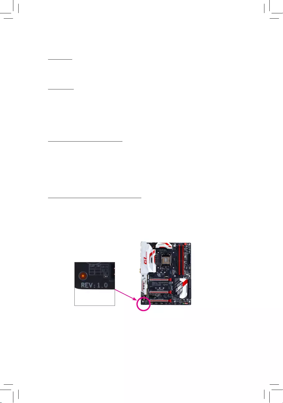
Identifying Your Motherboard Revision
The revision number on your motherboard looks like this: «REV: X.X.» For example, «REV: 1.0″
means the revision of the motherboard is 1.0. Check your motherboard revision before updating
motherboard BIOS, drivers, or when looking for technical information.
Example:

— 4 —
Table of Contents
Box Contents …………………………………………………………………………………………………….6
Optional Items …………………………………………………………………………………………………..6
GA-Z170X-Gaming 7 Motherboard Layout …………………………………………………………….7
Chapter 1 Hardware Installation ………………………………………………………………………….9
1-1 Installation Precautions ………………………………………………………………………… 9
1-2 ProductSpecications ………………………………………………………………………… 10
1-3 Installing the CPU and CPU Cooler ……………………………………………………… 14
1-3-1 Installing the CPU ………………………………………………………………………………………14
1-3-2 Installing the CPU Cooler ……………………………………………………………………………16
1-4 Installing the Memory …………………………………………………………………………. 17
1-4-1 DualChannelMemoryConguration ……………………………………………………………17
1-4-2 Installing a Memory ……………………………………………………………………………………18
1-5 Installing an Expansion Card ………………………………………………………………. 19
1-6 Setting up AMD CrossFire™/NVIDIA® SLI™Conguration ………………………… 20
1-7 Back Panel Connectors ………………………………………………………………………. 21
1-8 Onboard Buttons and Switches ……………………………………………………………. 23
1-9 ChangingtheOperationalAmplier ……………………………………………………… 25
1-10 Internal Connectors ……………………………………………………………………………. 26
Chapter 2 BIOS Setup ……………………………………………………………………………………..39
2-1 Startup Screen ………………………………………………………………………………….. 40
2-2 The Main Menu …………………………………………………………………………………. 41
2-3 M.I.T. ……………………………………………………………………………………………….. 43
2-4 System Information ……………………………………………………………………………. 56
2-5 BIOS Features ………………………………………………………………………………….. 57
2-6 Peripherals ……………………………………………………………………………………….. 60
2-7 Chipset …………………………………………………………………………………………….. 63
2-8 Power Management …………………………………………………………………………… 64
2-9 Save & Exit ……………………………………………………………………………………….. 66
Chapter3 ConguringaRAIDSet …………………………………………………………………….. 67
3-1 ConguringSATAControllers ………………………………………………………………. 67
3-2 InstallingtheSATARAID/AHCIDriverandOperatingSystem ………………….. 79
Chapter 4 Drivers Installation …………………………………………………………………………….83
4-1 Drivers & Software …………………………………………………………………………….. 83

— 5 —
4-2 Application Software ………………………………………………………………………….. 84
4-3 Information ……………………………………………………………………………………….. 84
Chapter 5 Unique Features ……………………………………………………………………………….85
5-1 BIOS Update Utilities …………………………………………………………………………. 85
5-1-1 Updating the BIOS with the Q-Flash Utility …………………………………………………….85
5-1-2 Updating the BIOS with the @BIOS Utility …………………………………………………….88
5-2 APP Center ………………………………………………………………………………………. 89
5-2-1 EasyTune………………………………………………………………………………………………….90
5-2-2 System Information Viewer ………………………………………………………………………….91
5-2-3 Fast Boot ………………………………………………………………………………………………….92
5-2-4 Smart TimeLock…………………………………………………………………………………………93
5-2-5 USB Blocker ……………………………………………………………………………………………..94
5-2-6 Smart Keyboard …………………………………………………………………………………………95
5-2-7 Smart Backup ……………………………………………………………………………………………96
5-2-8 Ambient LED …………………………………………………………………………………………….98
5-2-9 3D OSD ……………………………………………………………………………………………………99
5-2-10 Cloud Station …………………………………………………………………………………………..100
5-2-11 AutoGreen ………………………………………………………………………………………………105
5-2-12 EasyRAID ………………………………………………………………………………………………106
5-3 Smart Switch …………………………………………………………………………………… 109
Chapter 6 Appendix ………………………………………………………………………………………. 111
6-1 Killer Network Manager ……………………………………………………………………… 111
6-2 ConguringAudioInputandOutput ……………………………………………………. 112
6-2-1 Conguring2/5.1-ChannelAudio ………………………………………………………………..112
6-2-2 Creative Software Suite ……………………………………………………………………………. 112
6-2-3 ConguringS/PDIFOut ……………………………………………………………………………. 116
6-2-4 ConguringAudioRecording …………………………………………………………………….. 117
6-2-5 UsingtheSoundRecorder ………………………………………………………………………..119
6-3 Troubleshooting……………………………………………………………………………….. 120
6-3-1 Frequently Asked Questions …………………………………………………………………….. 120
6-3-2 Troubleshooting Procedure ……………………………………………………………………….121
6-4 Debug LED Codes …………………………………………………………………………… 123
RegulatoryStatements ……………………………………………………………………………….. 127
Contact Us ……………………………………………………………………………………………….. 131

— 6 —
Optional Items
2-portUSB2.0bracket(PartNo.12CR1-1UB030-6*R)
eSATAbracket(PartNo.12CF1-3SATPW-4*R)
3.5″FrontPanelwith2USB3.0/2.0ports(PartNo.12CR1-FPX582-2*R)
HDMI-to-DVIadapter(PartNo.12CT2-HDMI01-1*R)
COMportcable(PartNo.12CF1-1CM001-3*R)
The box contents above are for reference only and the actual items shall depend on the product package you obtain.
The box contents are subject to change without notice.
Box Contents
5GA-Z170X-Gaming 7 motherboard
5Motherboard driver disk
5User’s Manual
5Quick Installation Guide
5Four SATA cables
5I/O Shield
5One 2-Way SLI bridge connector
5One G Connector
5One pack of back I/O dust covers
— 7 —
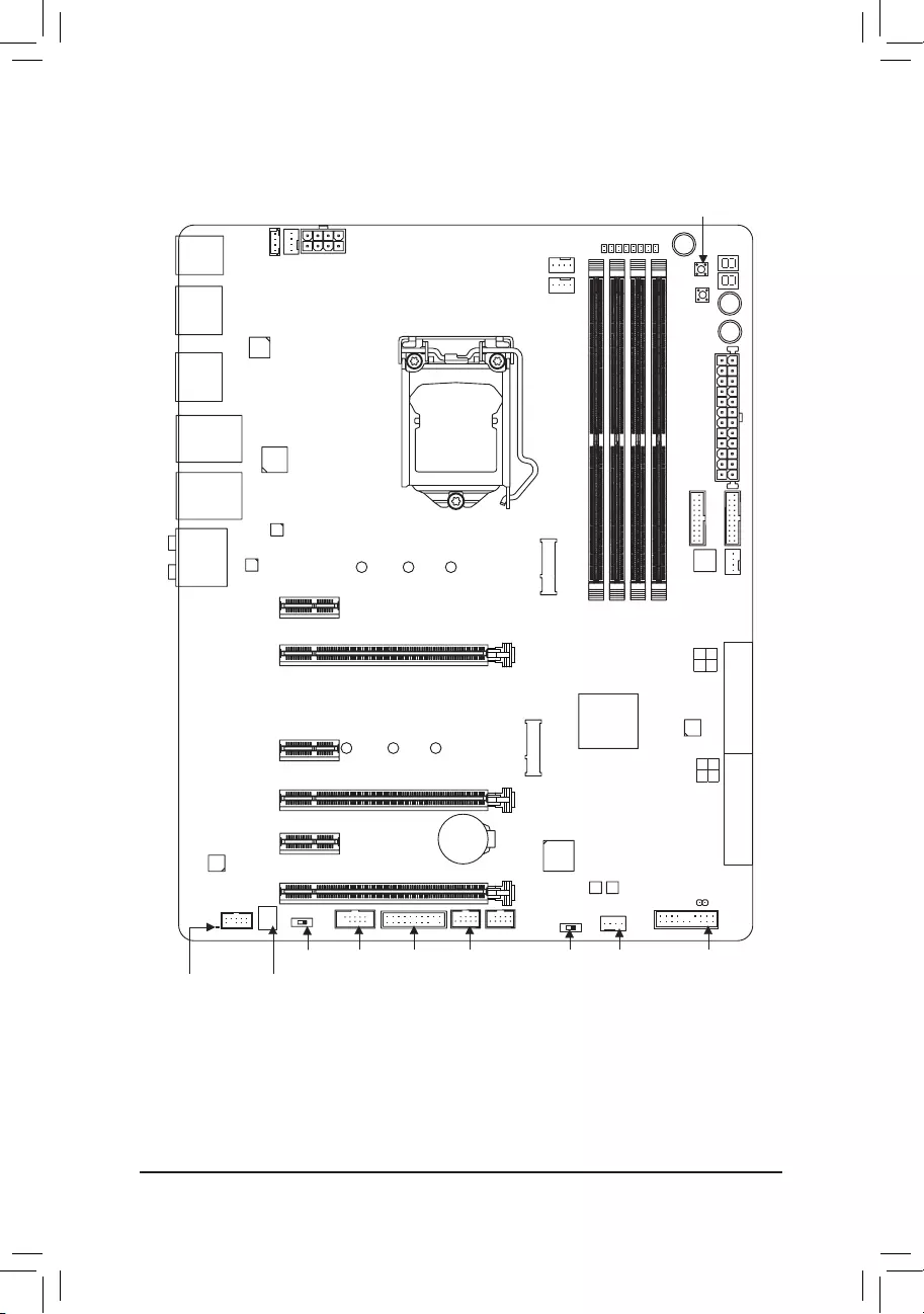
GA-Z170X-Gaming 7 Motherboard Layout
(Note) Fordebugcodeinformation,pleaserefertoChapter6.
KB_MS_USB30
CPU_FAN
ATX_12V_2X4
ATX
F_AUDIO
AUDIO
B_BIOS
PCIEX8
DDR4_2
DDR4_1
DDR4_4
DDR4_3
BAT
F_PANELCOMA
Intel® Z170
CLR_CMOS
M_BIOS
PCIEX1_1
PCIEX16
F_USB1
LGA1151
GA-Z170X-Gaming 7
USB30_LAN1
SATAEXPRESS
F_USB30_2
PCIEX1_2
SYS_FAN3
SATA3
iTE®
Super I/O
SYS_FAN2F_USB2
SYS_FAN1
TPM
M2D_32G
Intel®
GbE LAN
SATA3 7 6
3 2
CPU_OPT
TYPEC
OC
5 4
1 0
SATAEXPRESS
F_USB30_1
MegaChips
MCDP2800
R_USB30
LAN2
DP_HDMI
M2H_32G
RivetNetworks
Killer™ E2400 LAN
PCIEX1_3
PCIEX4
Debug LED(註)
ECO
PW_SW
CMOS_SW
RST_SW
ASMedia®
ASM1061
TI Burr Brown
®
OPA2134
CAP_SW SB
Creative®
Sound Core 3D
LED_IO
Intel®
Thunderbolt™ 3
Controller
Renesas®
USB 3.0 Hub
80D 60D 42D
80H 60H 42H
System Temperature
Sensor

— 8 —

— 9 —
1-1 Installation Precautions
The motherboard contains numerous delicate electronic circuits and components which can become
damagedasaresultofelectrostaticdischarge(ESD).Priortoinstallation,carefullyreadtheuser’s
manual and follow these procedures:
•Prior to installation, make sure the chassis is suitable for the motherboard.
•Priortoinstallation,donotremoveorbreakmotherboard S/N (Serial Number) sticker or
warranty sticker provided by your dealer. These stickers are required for warranty validation.
•Always remove the AC power by unplugging the power cord from the power outlet before
installing or removing the motherboard or other hardware components.
•When connecting hardware components to the internal connectors on the motherboard, make
sure they are connected tightly and securely.
•When handling the motherboard, avoid touching any metal leads or connectors.
•It is best to wear an electrostatic discharge (ESD) wrist strap when handling electronic
components such as a motherboard, CPU or memory. If you do not have an ESD wrist strap,
keepyourhandsdryandrsttouchametalobjecttoeliminatestaticelectricity.
•Prior to installing the motherboard, please have it on top of an antistatic pad or within an
electrostatic shielding container.
•Before connecting or unplugging the power supply cable from the motherboard, make sure
the power supply has been turned off.
•Before turning on the power, make sure the power supply voltage has been set according to
the local voltage standard.
•Before using the product, please verify that all cables and power connectors of your hardware
components are connected.
•To prevent damage to the motherboard, do not allow screws to come in contact with the
motherboard circuit or its components.
•Make sure there are no leftover screws or metal components placed on the motherboard or
within the computer casing.
•Do not place the computer system on an uneven surface.
•Do not place the computer system in a high-temperature or wet environment.
•Turning on the computer power during the installation process can lead to damage to system
components as well as physical harm to the user.
•If you are uncertain about any installation steps or have a problem related to the use of the
product,pleaseconsultacertiedcomputertechnician.
•If you use an adapter, extension power cable, or power strip, ensure to consult with its installation
and/or grounding instructions.
Chapter 1 Hardware Installation
— 10 —
1-2 ProductSpecications
CPU Support for Intel® Core™ i7 processors/Intel® Core™ i5 processors/
Intel® Core™ i3 processors/Intel® Pentium® processors/
Intel® Celeron® processors in the LGA1151 package
(GotoGIGABYTE’swebsiteforthelatestCPUsupportlist.)
L3 cache varies with CPU
Chipset Intel® Z170 Express Chipset
Memory 4xDDR4DIMMsocketssupportingupto64GBofsystemmemory
* DuetoaWindows32-bitoperatingsystemlimitation,whenmorethan4GBofphysical
memory is installed, the actual memory size displayed will be less than the size of
the physical memory installed.
Dual channel memory architecture
SupportforDDR42133MHzmemorymodules
SupportforECCUDIMM1Rx8/2Rx8memorymodules(operateinnon-ECCmode)
Supportfornon-ECCUDIMM1Rx8/2Rx8/1Rx16memorymodules
SupportforExtremeMemoryProle(XMP)memorymodules
(Go to GIGABYTE’s website for the latest supported memory speeds and memory
modules.)
Onboard
Graphics
Integrated Graphics Processor-Intel® HD Graphics support:
— 1 x DisplayPort, supporting a maximum resolution of
4096×2304@60 Hz
* SupportforDisplayPort1.2version.
Integrated Graphics Processor+MegaChips MCDP2800 chip:
— 1 x HDMI port, supporting a maximum resolution of 4096×2160@60 Hz
* SupportforHDMI2.0version.(RequiresthelatestIntel® graphics driver from the
GIGABYTEwebsite.)
Maximum shared memory of 512 MB
Audio Creative® Sound Core 3D chip
SupportforSoundBlasterRecon3Di
TI Burr Brown®OPA2134operationalamplier
HighDenitionAudio
2/5.1-channel
Support for S/PDIF Out
LAN 1 x Intel®GbELANchip(10/100/1000Mbit)(LAN1)
1xRivetNetworksKiller™E2400LANchip(10/100/1000Mbit)(LAN2)
* Teamingisnotsupported.
Expansion Slots 1xPCIExpressx16slot,runningatx16(PCIEX16)
* Foroptimumperformance,ifonlyonePCIExpressgraphicscardistobeinstalled,
be sure to install it in the PCIEX16 slot.
1xPCIExpressx16slot,runningatx8(PCIEX8)
* ThePCIEX8slotsharesbandwidthwiththePCIEX16slot.WhenthePCIEX8slot
is populated, the PCIEX16 slot will operate at up to x8 mode.
1xPCIExpressx16slot,runningatx4(PCIEX4)
* ThePCIEX4slotsharesbandwidthwiththeM2H_32Gconnector.ThePCIEX4slot
will become unavailable when an SSD is installed in the M2H_32G connector.
3 x PCI Express x1 slots
(AllofthePCIExpressslotsconformtoPCIExpress3.0standard.)
— 11 —
Multi-Graphics
Technology
Support for NVIDIA® Quad-GPU SLI™ and 2-Way NVIDIA® SLI™ technologies
Support for AMD Quad-GPU CrossFireX™ and 3-Way/2-Way AMD CrossFire™
technologies
Storage Interface Chipset:
— 2 x M.2 connectors (Socket 3, M key, type 2242/2260/2280 SATA and PCIe
x4/x2/x1SSDsupport)
— 3 x SATA Express connectors
- 6xSATA6Gb/sconnectors(SATA30~5)
- SupportforRAID0,RAID1,RAID5,andRAID10
* Referto«1-10InternalConnectors,»forthesupportedcongurationswiththeM.2,
SATA Express, and SATA connectors.
ASMedia® ASM1061 chip:
- 2xSATA6Gb/sconnectors(SATA36~7),supportingAHCImodeonly
USB Chipset:
— 5 x USB 3.0/2.0 ports on the back panel
- 4xUSB2.0/1.1ports(availablethroughtheinternalUSBheaders)
Chipset+Renesas® USB 3.0 Hub:
- 4xUSB3.0/2.0ports(availablethroughtheinternalUSBheaders)
Chipset+Intel® Thunderbolt™ 3 Controller:
— 1 x USB Type-C™ port on the back panel, with USB 3.1 support
- 1xUSB3.1Type-Aport(red)onthebackpanel
Internal
Connectors
1 x 24-pin ATX main power connector
1 x 8-pin ATX 12V power connector
2 x M.2 Socket 3 connectors
3 x SATA Express connectors
8 x SATA 6Gb/s connectors
1 x I/O shield audio LED power connector
1 x CPU fan header
1xwatercoolingfanheader(CPU_OPT)
3 x system fan headers
1 x front panel header
1 x front panel audio header
2 x USB 3.0/2.0 headers
2 x USB 2.0/1.1 headers
1xTrustedPlatformModule(TPM)header
1 x serial port header
1 x Clear CMOS jumper
1 x power button
1 x reset button
1 x Clear CMOS button
1 x ECO button
1 x OC button
1 x audio gain control switch
Voltage Measurement Points
1 x BIOS switch
— 12 —
Back Panel
Connectors
1 x PS/2 keyboard/mouse port
1 x DisplayPort
1 x HDMI port
1 x USB Type-C™ port, with USB 3.1 support
1xUSB3.1Type-Aport(red)
5 x USB 3.0/2.0 ports
2xRJ-45ports
1 x optical S/PDIF Out connector
5xaudiojacks(Center/SubwooferSpeakerOut,RearSpeakerOut,LineIn/Mic
In,LineOut,Headphone)
I/O Controller iTE® I/O Controller Chip
Hardware
Monitor
System voltage detection
CPU/System/Chipset temperature detection
CPU/CPU OPT/System fan speed detection
CPU/System/Chipset overheating warning
CPU/CPU OPT/System fan fail warning
CPU/CPU OPT/System fan speed control
* Whetherthefanspeedcontrolfunctionissupportedwilldependonthecooleryou
install.
BIOS 2x128Mbitash
Use of licensed AMI UEFI BIOS
Support for DualBIOS™
PnP 1.0a, DMI 2.7, WfM 2.0, SM BIOS 2.7, ACPI 5.0
Unique Features Support for APP Center
* AvailableapplicationsinAPPCentermayvarybymotherboardmodel.Supported
functionsofeachapplicationmayalsovarydependingonmotherboardspecications.
— 3D OSD
— @BIOS
— Ambient LED
— AutoGreen
— Cloud Station
— EasyTune
- EasyRAID
— Fast Boot
— Smart TimeLock
— Smart Keyboard
— Smart Backup
— System Information Viewer
— USB Blocker
Support for Q-Flash
Support for Smart Switch
Support for Xpress Install
— 13 —
Bundled
Software
Norton®InternetSecurity(OEMversion)
Intel®SmartResponseTechnology
Operating
System
Support for Windows 10/8.1 64-bit
Support for Windows 7 32-bit/64-bit
* Pleasedownloadthe«WindowsUSBInstallationTool»fromGIGABYTE’swebsite
and install it before installing Windows 7.
Form Factor ATX Form Factor; 30.5cm x 24.4cm
* GIGABYTEreservestherighttomakeanychangestotheproductspecicationsandproduct-relatedinformationwithout
prior notice.
Please visit GIGABYTE’s website for support lists of CPU, memory modules, SSDs, and M.2
devices.
Please visit the Support\Utility List page on GIGABYTE’s website to download the latest
version of apps.
— 14 —
1-3 Installing the CPU and CPU Cooler
ReadthefollowingguidelinesbeforeyoubegintoinstalltheCPU:
•Make sure that the motherboard supports the CPU.
(GotoGIGABYTE’swebsiteforthelatestCPUsupportlist.)
•Always turn off the computer and unplug the power cord from the power outlet before installing the
CPU to prevent hardware damage.
•Locate the pin one of the CPU. The CPU cannot be inserted if oriented incorrectly. (Or you may
locatethenotchesonbothsidesoftheCPUandalignmentkeysontheCPUsocket.)
•Apply an even and thin layer of thermal grease on the surface of the CPU.
•Do not turn on the computer if the CPU cooler is not installed, otherwise overheating and damage
of the CPU may occur.
•SettheCPUhostfrequencyinaccordancewiththeCPUspecications.Itisnotrecommended
thatthesystembusfrequencybesetbeyondhardwarespecicationssinceitdoesnotmeetthe
standard requirements for the peripherals. If you wish to set the frequency beyond the standard
specications,pleasedosoaccordingtoyourhardwarespecicationsincludingtheCPU,graphics
card, memory, hard drive, etc.
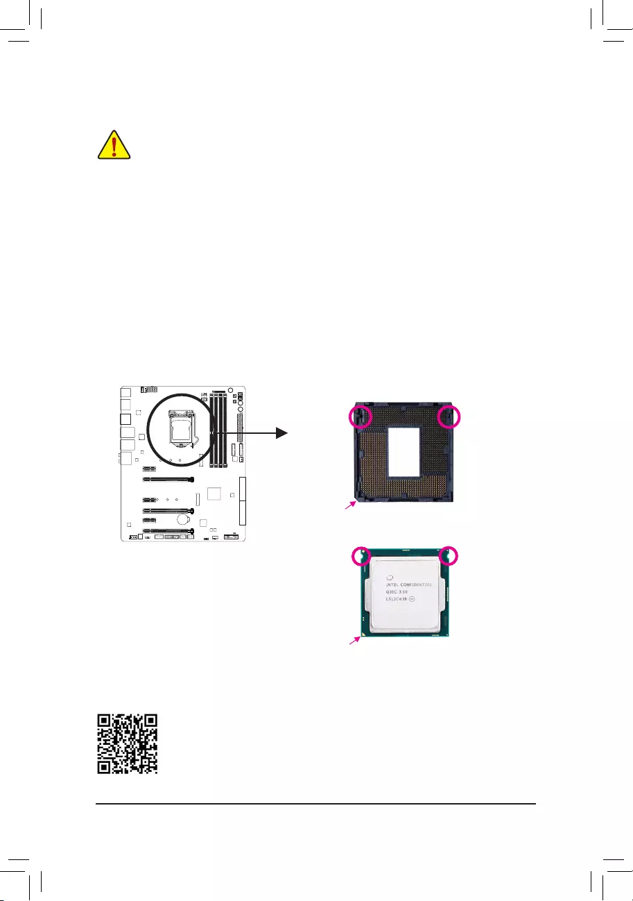
1-3-1 Installing the CPU
A. Locate the alignment keys on the motherboard CPU socket and the notches on the CPU.
Alignment KeyAlignment Key
LGA1151 CPU
LGA1151 CPU Socket
Pin One Corner of the CPU Socket
Triangle Pin One Marking on the CPU
Notch
Notch
Please visit GIGABYTE’s website for details on hardware installation.
— 15 —
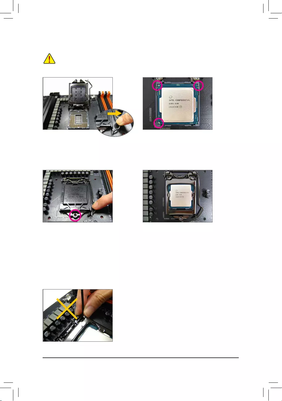
B. Follow the steps below to correctly install the CPU into the motherboard CPU socket.
Step 1:
Gently press the CPU socket lever handle down
andawayfromthesocketwithyournger.Then
completely lift the CPU socket lever and the metal
load plate/plastic cover will be lifted as well.
Step 2:
HoldtheCPUwithyourthumbandindexngers.
AligntheCPUpinonemarking(triangle)withthe
pin one corner of the CPU socket (or you may align
theCPUnotcheswiththesocketalignmentkeys)
and gently insert the CPU into position.
Step 4:
Finally, secure the lever under its retention tab to
complete the installation of the CPU.
NOTE:
Hold the CPU socket lever by the handle, not the lever base portion.
•Before installing the CPU, make sure to turn off the computer and unplug the power cord from
the power outlet to prevent damage to the CPU.
•To protect the socket contacts, do not remove the protective plastic cover unless the CPU is
inserted into the CPU socket. Save the cover properly and replace it if the CPU is removed.
Step 3:
Once the CPU is properly inserted, carefully
replace the load plate. When replacing the load
plate, make sure the front end of the load plate
is under the shoulder screw. Then press the CPU
socket lever. The protective plastic cover may
pop off from the load plate during the process of
engagingthelever.Removethecover.(Savethe
cover properly and always replace it when the
CPUisnotinstalled.)
— 16 —
Use extreme care when removing the CPU cooler because the thermal grease/tape between the CPU
cooler and CPU may adhere to the CPU. Inadequately removing the CPU cooler may damage the CPU.
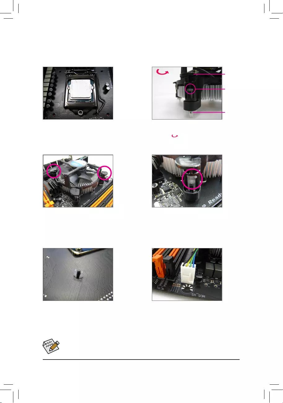
1-3-2 Installing the CPU Cooler
RefertothestepsbelowtocorrectlyinstalltheCPUcooleronthemotherboard.(Actualinstallationprocessmay
differdependingtheCPUcoolertobeused.Refertotheuser’smanualforyourCPUcooler.)
Step 5:
After the installation, check the back of the
motherboard. If the push pin is inserted as the
picture above shows, the installation is complete.
Step 6:
Finally, attach the power connector of the CPU
coolertotheCPUfanheader(CPU_FAN)onthe
motherboard.
Step 1:
Apply an even and thin layer of thermal grease on
the surface of the installed CPU.
Step 2:
Before installing the cooler, note the direction of the
arrow sign on the male push pin. (Turning the
push pin along the direction of arrow is to remove
thecooler,onthecontrary,istoinstall.)
Step 3:
Place the cooler atop the CPU, aligning the
four push pins through the pin holes on the
motherboard. Push down on the push pins
diagonally.
Step 4:
You should hear a «click» when pushing down each
push pin. Check that the Male and Female push
pins are joined closely.
(RefertoyourCPUcoolerinstallationmanualfor
instructionsoninstallingthecooler.)
Male
Push Pin
Female
Push Pin
The Top
of Female
Push Pin
Direction of
the Arrow Sign
on the Male
Push Pin
— 17 —
1-4 Installing the Memory
Readthefollowingguidelinesbeforeyoubegintoinstallthememory:
•Make sure that the motherboard supports the memory. It is recommended that memory of the same
capacity, brand, speed, and chips be used.
(GotoGIGABYTE’swebsiteforthelatestsupportedmemoryspeedsandmemorymodules.)
•Always turn off the computer and unplug the power cord from the power outlet before installing the
memory to prevent hardware damage.
•Memory modules have a foolproof design. A memory module can be installed in only one direction.
If you are unable to insert the memory, switch the direction.
DDR4_2
DDR4_3
DDR4_4
DDR4_1
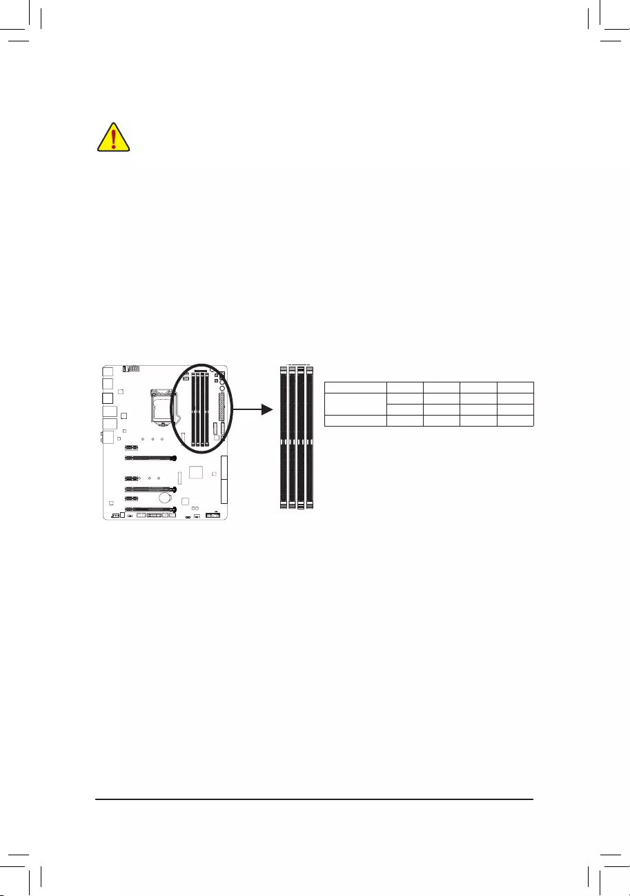
1-4-1 DualChannelMemoryConguration
This motherboard provides four memory sockets and supports Dual Channel Technology. After the memory
isinstalled,theBIOSwillautomaticallydetectthespecicationsandcapacityofthememory.EnablingDual
Channel memory mode will double the original memory bandwidth.
The four memory sockets are divided into two channels and each channel has two memory sockets as following:
ChannelA:DDR4_2,DDR4_4
ChannelB:DDR4_1,DDR4_3
DualChannelMemoryCongurationsTable
DDR4_4 DDR4_2 DDR4_3 DDR4_1
2 Modules — — DS/SS — — DS/SS
DS/SS — — DS/SS — —
4 Modules DS/SS DS/SS DS/SS DS/SS
(SS=Single-Sided,DS=Double-Sided,»--«=NoMemory)
Due to CPU limitations, read the following guidelines before installing the memory in Dual Channel mode.
1. Dual Channel mode cannot be enabled if only one memory module is installed.
2. When enabling Dual Channel mode with two or four memory modules, it is recommended that memory
of the same capacity, brand, speed, and chips be used and installed in the same colored sockets.
— 18 —
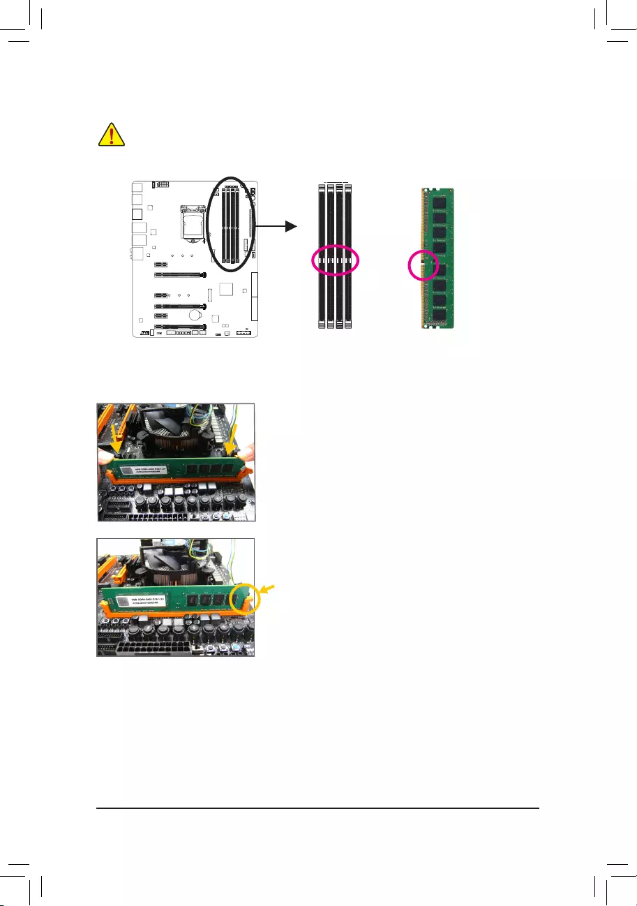
1-4-2 Installing a Memory
Before installing a memory module, make sure to turn off the computer and unplug the
power cord from the power outlet to prevent damage to the memory module. DDR4 and DDR3
DIMMs are not compatible to each other or DDR2 DIMMs. Be sure to install DDR4 DIMMs on
this motherboard.
ADDR4memorymodulehasanotch,soitcanonlytinonedirection.Followthestepsbelowtocorrectlyinstall
your memory modules in the memory sockets.
Step 1:
Note the orientation of the memory module. Spread the retaining clip
at the right end of the memory socket. Place the memory module on
thesocket.Asindicatedinthepictureontheleft,placeyourngers
on the top edge of the memory, push down on the memory and insert
it vertically into the memory socket.
Step 2:
The clip at the right end of the socket will snap into place when the
memory module is securely inserted.
Notch
DDR4DIMM
— 19 —
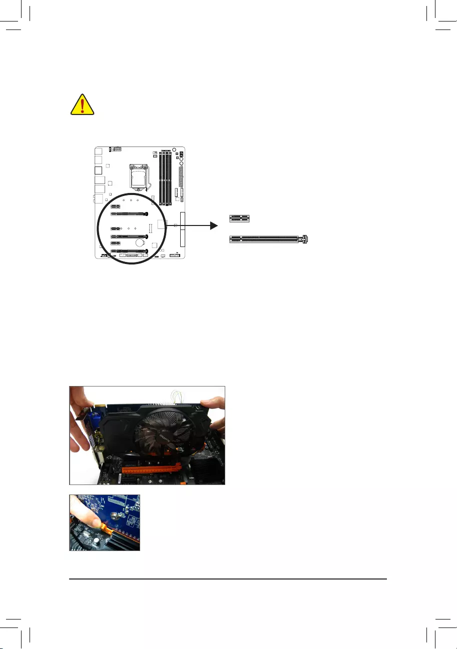
1-5 Installing an Expansion Card
Readthefollowingguidelinesbeforeyoubegintoinstallanexpansioncard:
•Make sure the motherboard supports the expansion card. Carefully read the manual that came
with your expansion card.
•Always turn off the computer and unplug the power cord from the power outlet before installing an
expansion card to prevent hardware damage.
Follow the steps below to correctly install your expansion card in the expansion slot.
1. Locateanexpansionslotthatsupportsyourcard.Removethemetalslotcoverfromthechassisbackpanel.
2. Align the card with the slot, and press down on the card until it is fully seated in the slot.
3. Make sure the metal contacts on the card are completely inserted into the slot.
4. Secure the card’s metal bracket to the chassis back panel with a screw.
5. Afterinstallingallexpansioncards,replacethechassiscover(s).
6. Turn on your computer. If necessary, go to BIOS Setup to make any required BIOS changes for your
expansioncard(s).
7. Install the driver provided with the expansion card in your operating system.
Example:InstallingandRemovingaPCIExpressGraphicsCard:
PCI Express x1 Slot
PCI Express x16 Slot
•Installing a Graphics Card:
Gently push down on the top edge of the card until
it is fully inserted into the PCI Express slot. Make
sure the card is securely seated in the slot and
does not rock.
•RemovingtheCard:
Gently push back on the lever on the slot and then lift the card straight out from
the slot.
— 20 —
B. Connecting the Graphics Cards
Step 1:
Observe the steps in «1-5 Installing an Expansion Card» and install CrossFire/SLI graphics cards on the PCI
Express x16 slots.
Step 2:
Insert the CrossFire(Note)/SLI bridge connectors in the CrossFire/SLI gold edge connectors on top of the cards.
Step 3:
Plug the display cable into the graphics card on the PCIEX16 slot.
Procedure and driver screen for enabling CrossFire/SLI technology may differ by graphics cards and driver version.
RefertothemanualthatcamewithyourgraphicscardsformoreinformationaboutenablingCrossFire/SLItechnology.
1-6 Setting up AMD CrossFire™/NVIDIA® SLI™Conguration
(Note) Thebridgeconnector(s)maybeneededornotdependingonyourgraphicscards.
A. System Requirements
—Windows 10/8.1/7 operating system
—A CrossFire/SLI-supported motherboard with two or more PCI Express x16 slots and correct driver
—CrossFire/SLI-ready graphics cards of identical brand and chip and correct driver
(CurrentGPUsthatsupport3-WayCrossFiretechnologyincludetheATIRadeon™ HD 3800, HD 4800, HD
5800series,andAMDRadeon™ HD 6800, HD 6900, HD 7800, and HD 7900 series. For the latest GPU
supportinformation,pleaserefertotheAMDwebsite.)
—CrossFire(Note)/SLI bridge connectors
—Apowersupplywithsufcientpowerisrecommended(Refertothemanualofyourgraphicscardsforthe
powerrequirement)
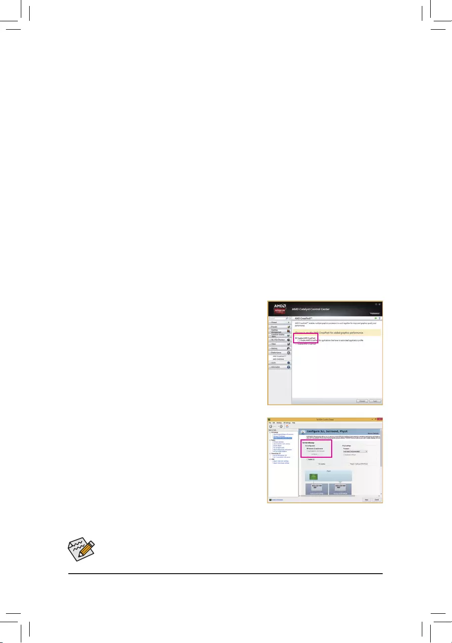
C-2. To Enable SLI Function
After installing the graphics card driver in the operating system, go to
the NVIDIA Control Panel. Browse to the CongureSLI,Surround,
Physx screen and ensure Maximize 3D performance is enabled.
C.ConguringtheGraphicsCardDriver
C-1. To Enable CrossFire Function
After installing the graphics card driver in the operating system, go
to the AMD Catalyst Control Center. Browse to Performance\
AMD CrossFireX™ and ensure the Enable AMD CrossFireX
check box is selected. If your system has more than two CrossFire
cards, select the GPU combination you want to use and click Apply.
(Available combination options are dependent on the number of
graphicscards.)
— 21 —
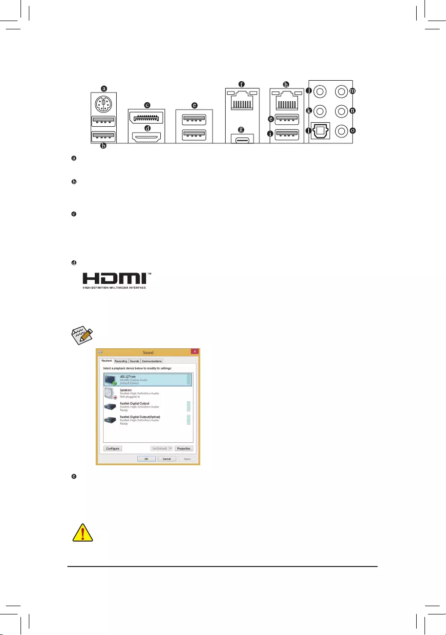
1-7 Back Panel Connectors
PS/2 Keyboard/Mouse Port
Use this port to connect a PS/2 mouse or keyboard.
USB 3.0/2.0 Port
TheUSB3.0portsupportstheUSB3.0specicationandiscompatibletotheUSB2.0/1.1specication.
You can connect a USB DAC to this port or use this port for USB devices.
DisplayPort
DisplayPort delivers high quality digital imaging and audio, supporting bi-directional audio transmission.
DisplayPort can support both DPCP and HDCP content protection mechanisms. You can use this port to
connect your DisplayPort-supported monitor. The maximum supported resolution is 4096×2304@60 Hz,
but the actual resolutions supported are dependent on the monitor being used.
HDMI Port
The HDMI port is HDCP compliant and supports Dolby True HD and DTS HD
Master Audio formats. It also supports up to 192 KHz/16bit 8-channel LPCM
audio output. You can use this port to connect your HDMI-supported monitor. The maximum supported
resolution is 4096×2160@60 Hz, but the actual resolutions supported are dependent on the monitor being
used.
USB 3.0/2.0 Port
TheUSB3.0portsupportstheUSB3.0specicationandiscompatibletotheUSB2.0/1.1specication.
Use this port for USB devices.
In Windows 8.1, select Apps>Control Panel>Hardware
andSound>Sound>Playback,setIntel(R)DisplayAudio
to the default playback device.
After installing the HDMI/DisplayPort device, make sure to set the default sound playback device to
HDMI/DisplayPort.(Theitemnamemaydifferdependingonyouroperatingsystem.)
•Whenremovingthecableconnectedtoabackpanelconnector,rstremovethecablefromyour
device and then remove it from the motherboard.
•When removing the cable, pull it straight out from the connector. Do not rock it side to side to
prevent an electrical short inside the cable connector.
— 22 —
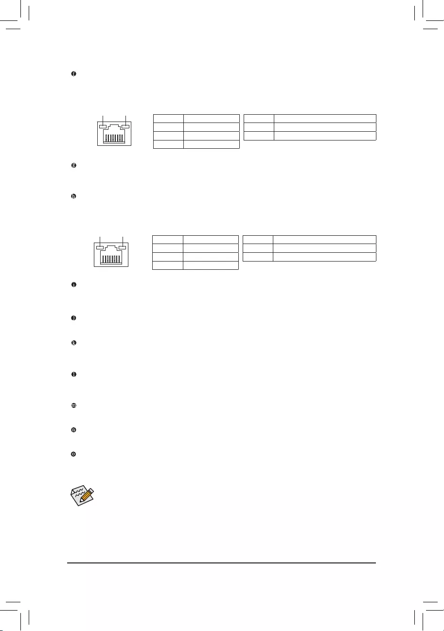
USB 3.1 Type-A Port (Red)
TheUSB3.1Type-AportsupportstheUSB3.1specicationandiscompatibletotheUSB3.0/2.0/1.1
specication.UsethisportforUSBdevices.
Line In/Mic In
The line in/Mic in jack. Use this audio jack for line in devices such as optical drive, walkman, microphone, etc.
Line Out
The line out jack. Use this audio jack for a 2-channel speaker. This jack can be used to connect front
speakersina5.1-channelaudioconguration.
Optical S/PDIF Out Connector
This connector provides digital audio out to an external audio system that supports digital optical audio.
Before using this feature, ensure that your audio system provides an optical digital audio in connector.
Center/Subwoofer Speaker Out
Usethisaudiojacktoconnectcenter/subwooferspeakersina5.1-channelaudioconguration.
Rear Speaker Out
Usethisaudiojacktoconnectrearspeakersina5.1-channelaudioconguration.
Headphone
This audio output jack supports audio amplifying function. For better sound quality, it is recommended that
you connect your headphone to this jack.
Refertotheinstructionsonsettingupa2/5.1-channelaudiocongurationinChapter6,»Conguring
2/5.1-Channel Audio.»
Activity LED
Connection/
Speed LED
LAN Port
Activity LED:Connection/Speed LED:
State Description
Orange 1 Gbps data rate
Green 100 Mbps data rate
Off 10 Mbps data rate
State Description
Blinking Data transmission or receiving is occurring
On No data transmission or receiving is occurring
USB Type-C™ Port
Thereversible USBport supportsthe USB3.1 specicationand iscompatible tothe USB 3.0/2.0
specication.UsethisportforUSBdevices.
RJ-45 LAN Port (LAN1)
The Gigabit Ethernet LAN port provides Internet connection at up to 1 Gbps data rate. The following
describes the states of the LAN port LEDs.
RJ-45 LAN Port (LAN2)
The Gigabit Ethernet LAN port provides Internet connection at up to 1 Gbps data rate. The following
describes the states of the LAN port LEDs.
Activity LED
Connection/
Speed LED
LAN Port
State Description
Orange 1 Gbps data rate
Green 100 Mbps data rate
Off 10 Mbps data rate
State Description
Blinking Data transmission or receiving is occurring
Off No data transmission or receiving is occurring
— 23 —
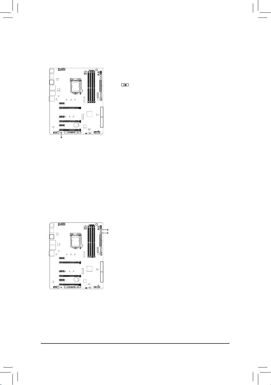
1-8 Onboard Buttons and Switches
Quick Buttons
This motherboard has 3 quick buttons: power button, reset button and clear CMOS button. The power button
and reset button allow users to quickly turn on/off or reset the computer in an open-case environment when
they want to change hardware components or conduct hardware testing.
Use this button to clear the BIOS
congurationandresettheCMOSvaluestofactorydefaultswhenneeded.
PW_SW: Power Button
RST_SW: ResetButton
CMOS_SW: Clear CMOS Button
•Always turn off your computer and unplug the power cord from the power outlet before clearing
the CMOS values.
•NOTE: Do not use the clear CMOS button when the system is on, or the system may shutdown
and data loss or damage may occur.
•Aftersystemrestart,gotoBIOSSetuptoloadfactorydefaults(selectLoadOptimizedDefaults)or
manuallyconguretheBIOSsettings(refertoChapter2,«BIOSSetup,»forBIOScongurations).
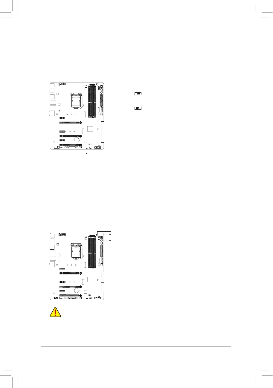
BIOS Switch
The SB switch allows enabling or disabling of the Dual BIOS function.
2: Single BIOS
1: Dual BIOS
SB
CMOS_SW
PW_SW
RST_SW
F_USB30 F_U
B_
F_ F_
_
B
BS_
B
SB_
B
_S
S_
_
B
_U
_
B
S
123
123
123
123
1
1
1
1
BSS
S
_S
SSU
1 2 3
S3 BSSS U
__ 3
F_USB3F
S _
S _
S _
SF
B_
B_
F
_0
S
S
_0F
_F
_
_
__B
U
12
F_USB30 F_U
B_
F_ F_
_
B
BS_
B
SB_
B
_S
S_
_
B
_U
_
B
S
123
123
123
123
1
1
1
1
BSS
S
_S
SSU
1 2 3
S3 BSSS U
__ 3
F_USB3F
S _
S _
S _
SF
B_
B_
F
_0
S
S
_0F
_F
_
_
__B
U
12
— 24 —
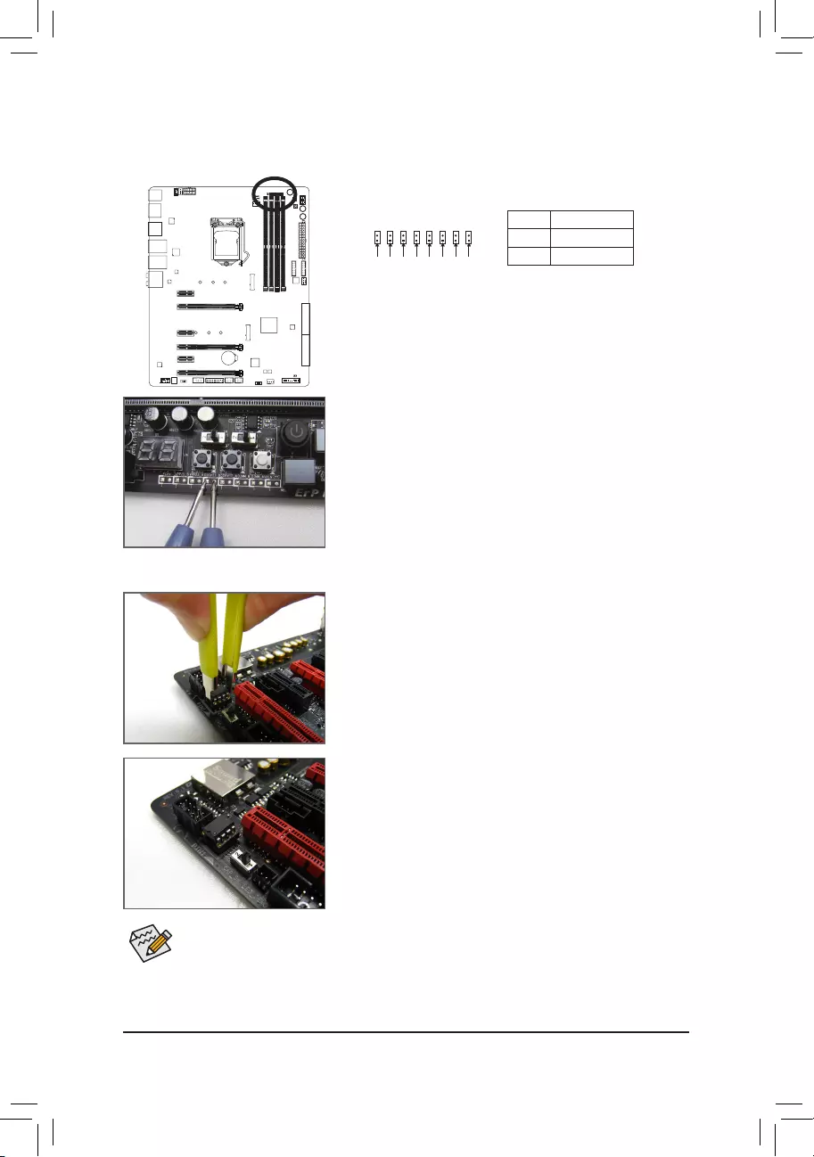
Audio Gain Control Switches
The switch allows for audio gain control for the headphone/speaker out jack on the back panel. Please set it
accordingtoyourheadphonespecication(actualeffectsmayvarybythedevicebeingused).
2: 6x
1:2.5x(Default)
12
F_USB30 F_U
B_
F_ F_
_
B
BS_
B
SB_
B
_S
S_
_
B
_U
_
B
S
123
123
123
123
1
1
1
1
BSS
S
_S
SSU
1 2 3
S3 BSSS U
__ 3
F_USB3F
S _
S _
S _
SF
B_
B_
F
_0
S
S
_0F
_F
_
_
__B
U
CAP_SW
ECO Button and OC Button
GIGABYTE’s unique ECO button provides power-saving features by automatically reducing the overall power
consumption according to current system load. The OC button helps enthusiasts and overclockers not only get
the most performance from their hardware, but also the absolute most enjoyable OC experience.
OC
ECO ECO Button:
Press this button to enable this feature.
OC Button:
Press this button to load the most optimized GIGABYTE overclock—
ingcongurationforyourhardware.
— 25 —
1-9 ChangingtheOperationalAmplier
Step 1:
Use an IC extractor to carefully grip the IC’s sides and extract it from
the socket.
Step 2:
Align the notch on your OP chip with the notch on the socket and
gently press the chip into the socket until seated.
For purchasing the IC extractor and OP Chip, please contact the local dealer.
Pin No. Denition
1 Power
2 GND
Voltage Measurement Points
Use a multimeter to measure the following motherboard voltages. You can employ following way to measure
component voltages.
Steps:
Connecttheredleadofthemultimetertothepin1(Power)ofavoltage
measurementpointandtheblackleadtothepin2(ground).
F_USB30 F_U
B_
F_ F_
_
B
BS_
B
SB_
B
_S
S_
_
B
_U
_
B
S
123
123
123
123
1
1
1
1
BSS
S
_S
SSU
1 2 3
S3 BSSS U
__ 3
F_USB3F
S _
S _
S _
SF
B_
B_
F
_0
S
S
_0F
_F
_
_
__B
U
Pin 1 VCCIO
F_USB30 F_U
B_
F_ F_
_
B
BS_
B
SB_
B
_S
S_
_
B
_U
_
B
S
123
123
123
123
1
1
1
1
BSS
S
_S
SSU
1 2 3
S3 BSSS U
__ 3
F_USB3F
S _
S _
S _
SF
B_
B_
F
_0
S
S
_0F
_F
_
_
__B
U
Pin 1 VAXG
F_USB30 F_U
B_
F_ F_
_
B
BS_
B
SB_
B
_S
S_
_
B
_U
_
B
S
123
123
123
123
1
1
1
1
BSS
S
_S
SSU
1 2 3
S3 BSSS U
__ 3
F_USB3F
S _
S _
S _
SF
B_
B_
F
_0
S
S
_0F
_F
_
_
__B
U
Pin 1 VDIMM
F_USB30 F_U
B_
F_ F_
_
B
BS_
B
SB_
B
_S
S_
_
B
_U
_
B
S
123
123
123
123
1
1
1
1
BSS
S
_S
SSU
1 2 3
S3 BSSS U
__ 3
F_USB3F
S _
S _
S _
SF
B_
B_
F
_0
S
S
_0F
_F
_
_
__B
U
Pin 1 DDRVTT
F_USB30 F_U
B_
F_ F_
_
B
BS_
B
SB_
B
_S
S_
_
B
_U
_
B
S
123
123
123
123
1
1
1
1
BSS
S
_S
SSU
1 2 3
S3 BSSS U
__ 3
F_USB3F
S _
S _
S _
SF
B_
B_
F
_0
S
S
_0F
_F
_
_
__B
U
Pin 1 PCHIO
VCORE
F_USB30 F_U
B_
F_ F_
_
B
BS_
B
SB_
B
_S
S_
_
B
_U
_
B
S
123
123
123
123
1
1
1
1
BSS
S
_S
SSU
1 2 3
S3 BSSS U
__ 3
F_USB3F
S _
S _
S _
SF
B_
B_
F
_0
S
S
_0F
_F
_
_
__B
U
Pin 1
F_USB30 F_U
B_
F_ F_
_
B
BS_
B
SB_
B
_S
S_
_
B
_U
_
B
S
123
123
123
123
1
1
1
1
BSS
S
_S
SSU
1 2 3
S3 BSSS U
__ 3
F_USB3F
S _
S _
S _
SF
B_
B_
F
_0
S
S
_0F
_F
_
_
__B
U
Pin 1 VSA
VPP_25V
F_USB30 F_U
B_
F_ F_
_
B
BS_
B
SB_
B
_S
S_
_
B
_U
_
B
S
123
123
123
123
1
1
1
1
BSS
S
_S
SSU
1 2 3
S3 BSSS U
__ 3
F_USB3F
S _
S _
S _
SF
B_
B_
F
_0
S
S
_0F
_F
_
_
__B
U
Pin 1
— 26 —
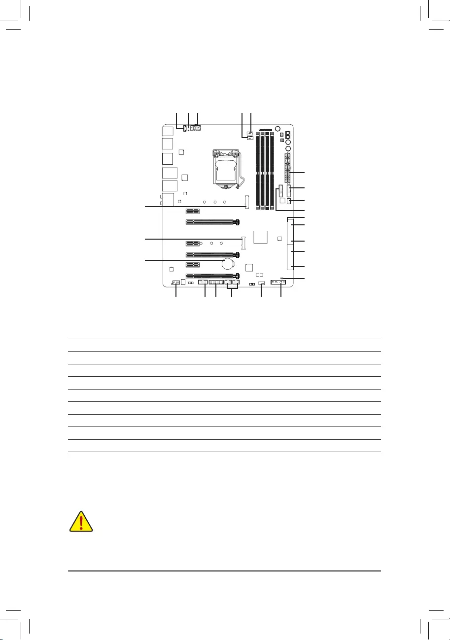
1-10 Internal Connectors
Readthefollowingguidelinesbeforeconnectingexternaldevices:
•First make sure your devices are compliant with the connectors you wish to connect.
•Before installing the devices, be sure to turn off the devices and your computer. Unplug the power
cord from the power outlet to prevent damage to the devices.
•After installing the device and before turning on the computer, make sure the device cable has
been securely attached to the connector on the motherboard.
2
4151612
1
4
1) ATX_12V_2X4
2) ATX
3) CPU_FAN
4) SYS_FAN1/2/3
5) CPU_OPT
6) LED_IO
7) SATA EXPRESS
 SATA3 0/1/2/3/4/5
9) SATA3 6/7
10) M2D_32G/M2H_32G
11) F_PANEL
12) F_ AUDIO
13) F_USB30_1/F_USB30_2
14) F_USB1/F_USB2
15) TPM
16) COMA
17) BAT
18) CLR_CMOS
11
3
13
18
17
14
5
7
8
4
13
7
8
10
10
9
6
— 27 —
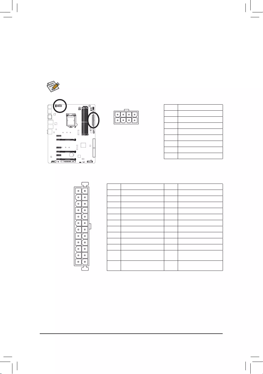
1/2) ATX_12V_2X4/ATX (2×4 12V Power Connector and 2×12 Main Power Connector)
With the use of the power connector, the power supply can supply enough stable power to all the components
onthemotherboard.Beforeconnectingthepowerconnector,rstmakesurethepowersupplyisturned
off and all devices are properly installed. The power connector possesses a foolproof design. Connect the
power supply cable to the power connector in the correct orientation.
The 12V power connector mainly supplies power to the CPU. If the 12V power connector is not connected,
the computer will not start.
To meet expansion requirements, it is recommended that a power supply that can withstand high
powerconsumptionbeused(500Worgreater).Ifapowersupplyisusedthatdoesnotprovidethe
required power, the result can lead to an unstable or unbootable system.
131
2412
ATX
ATX_12V_2X4
8
4
ATX_12V_2X4:
Pin No. Denition
1GND(Onlyfor2×4-pin12V)
2GND(Onlyfor2×4-pin12V)
3 GND
4 GND
5+12V(Onlyfor2×4-pin12V)
6+12V(Onlyfor2×4-pin12V)
7 +12V
8 +12V
ATX:
Pin No. Denition Pin No. Denition
1 3.3V 13 3.3V
2 3.3V 14 -12V
3 GND 15 GND
4 +5V 16 PS_ON(softOn/Off)
5 GND 17 GND
6 +5V 18 GND
7 GND 19 GND
8 Power Good 20 NC
95VSB(standby+5V) 21 +5V
10 +12V 22 +5V
11 +12V (Only for 2×12-pin
ATX)
23 +5V(Onlyfor2×12-pinATX)
12 3.3V (Only for 2×12-pin
ATX)
24 GND(Onlyfor2×12-pinATX)
5
1
— 28 —
•Be sure to connect fan cables to the fan headers to prevent your CPU and system from
overheating. Overheating may result in damage to the CPU or the system may hang.
•Thesefanheadersarenotcongurationjumperblocks.Donotplaceajumpercapontheheaders.
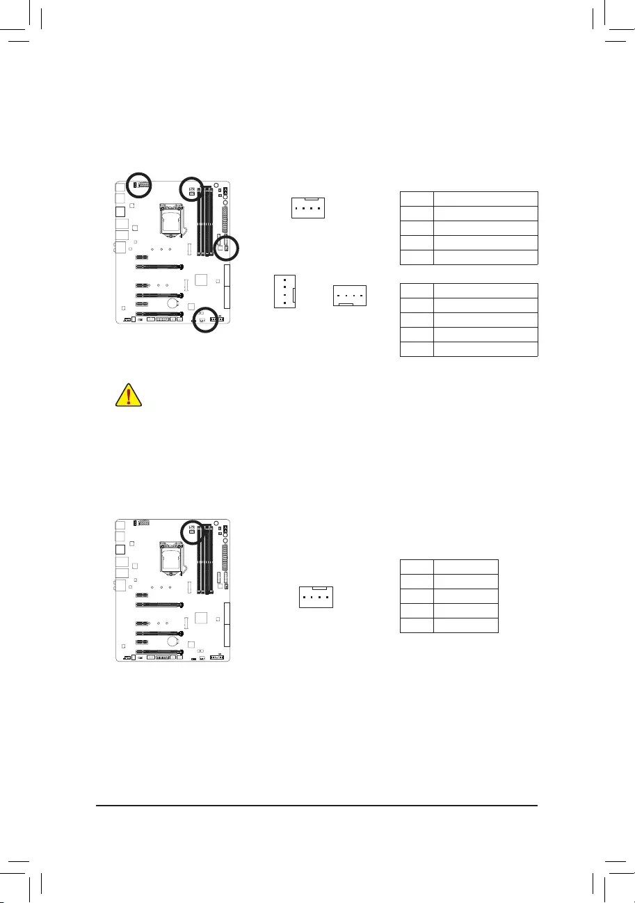
3/4) CPU_FAN/SYS_FAN1/2/3 (Fan Headers)
All fan headers on this motherboard are 4-pin. Most fan headers possess a foolproof insertion design.
When connecting a fan cable, be sure to connect it in the correct orientation (the black connector wire is
thegroundwire).Thespeedcontrolfunctionrequirestheuseofafanwithfanspeedcontroldesign.For
optimum heat dissipation, it is recommended that a system fan be installed inside the chassis.
CPU_FAN:
Pin No. Denition
1 GND
2 +12V
3 Sense
4 Speed Control
1
SYS_FAN1/2/3:
Pin No. Denition
1 GND
2 Speed Control
3 Sense
4 VCC
SYS_FAN2
1
CPU_FAN
1
SYS_FAN1/3
5) CPU_OPT (Water Cooling CPU Fan Header)
The fan header is 4-pin and possesses a foolproof insertion design. When connecting a fan cable, be sure to
connectitinthecorrectorientation(theblackconnectorwireisthegroundwire).Thespeedcontrolfunction
requires the use of a fan with fan speed control design.
Pin No. Denition
1 GND
2 Speed Control
3 Sense
4 VCC
1
— 29 —
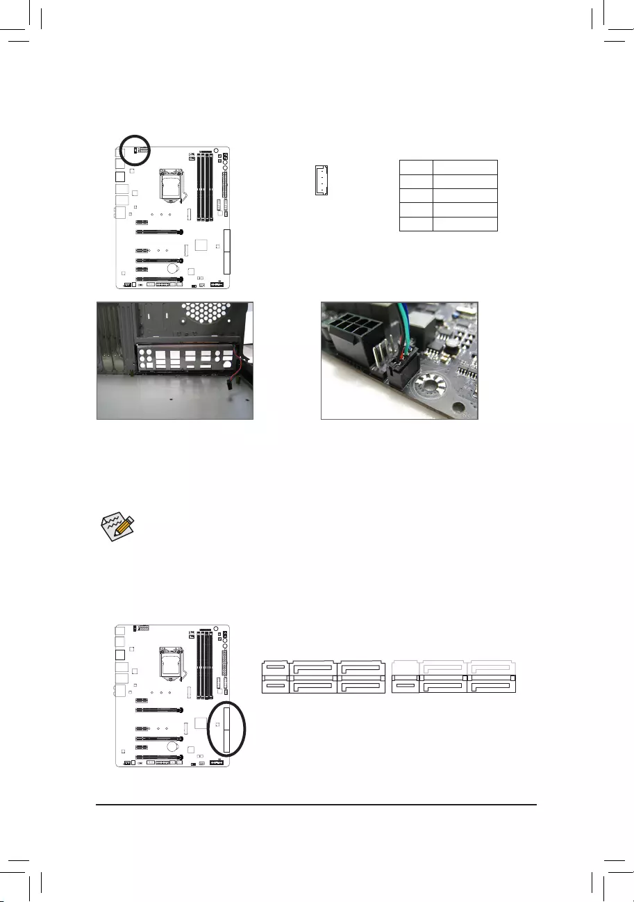
6) LED_IO (I/O Shield Audio LED Power Connector)
The power connector provides power to the LEDs on the I/O shield on the motherboard back panel.
F_USB30 F_U
B_
F_ F_
_
B
BS_
B
SB_
B
_S
S_
_
B
_U
_
B
S
123
123
123
123
1
1
1
1
BSS
S
_S
SSU
1 2 3
S3 BSSS U
__ 3
F_USB3F
S _
S _
S _
SF
B_
B_
F
_0
S
S
_0F
_F
_
_
__B
U
1Pin No. Denition
1 +5V
2Red
3 Green
4 Blue
Step 1:
Install the included I/O shield into the chassis.
(For actual installation, please refer to the user
guideforyourchassis.)
Step 2:
Place the motherboard into the chassis, aligning
the back panel connectors with the installed
I/O shield. Connect the power cable from the
I/O shield to the LED_IO connector on the
motherboard.
For how to turn on/off the I/O shield LED indicators, refer to the instructions on in Chapter 2, «BIOS
Setup,» «Peripherals,» or Chapter 5, «Unique Features,» «APP Center\Ambient LED.»
7) SATA EXPRESS (SATA Express Connectors)
Each SATA Express connector supports a single SATA Express device.
F_USB30 F_U
B_
F_ F_
_
B
BS_
B
SB_
B
_S
S_
_
B
_U
_
B
S
123
123
123
123
1
1
1
1
BSS
S
_S
SSU
1 2 3
S3 BSSS U
__ 3
F_USB3F
S _
S _
S _
SF
B_
B_
F
_0
S
S
_0F
_F
_
_
__B
U
F_USB30 F_U
B_
F_ F_
_
B
BS_
B
SB_
B
_S
S_
_
B
_U
_
B
S
123
123
123
123
1
1
1
1
BSS
S
_S
SSU
1 2 3
S3 BSSS U
__ 3
F_USB3F
S _
S _
S _
SF
B_
B_
F
_0
S
S
_0F
_F
_
_
__B
U
— 30 —
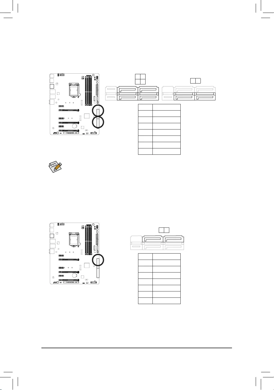
SATA3 0/1/2/3/4/5 (SATA 6Gb/s Connectors, Controlled by Intel® Z170 Chipset)
The SATA connectors conform to SATA 6Gb/s standard and are compatible with SATA 3Gb/s and SATA
1.5Gb/s standard. Each SATA connector supports a single SATA device. The Intel®ChipsetsupportsRAID0,
RAID1,RAID5,andRAID10.RefertoChapter3,«ConguringaRAIDSet,»forinstructionsonconguring
aRAIDarray.
1
1
Pin No. Denition
1 GND
2 TXP
3 TXN
4 GND
5RXN
6RXP
7 GND
SATA3 5 4
1 0
F_USB30 F_U
B_
F_ F_
_
B
BS_
B
SB_
B
_S
S_
_
B
_U
_
B
S
123
123
123
123
1
1
1
1
BSS
S
_S
SSU
1 2 3
S3 BSSS U
__ 3
F_USB3F
S _
S _
S _
SF
B_
B_
F
_0
S
S
_0F
_F
_
_
__B
U
7
7
To enable hot-plugging for the SATA ports, refer to Chapter 2, «BIOS Setup,» «Peripherals\SATA
Conguration,»formoreinformation.
F_USB30 F_U
B_
F_ F_
_
B
BS_
B
SB_
B
_S
S_
_
B
_U
_
B
S
123
123
123
123
1
1
1
1
BSS
S
_S
SSU
1 2 3
S3 BSSS U
__ 3
F_USB3F
S _
S _
S _
SF
B_
B_
F
_0
S
S
_0F
_F
_
_
__B
U
SATA3 3 2
9) SATA3 6/7 (SATA 6Gb/s Connectors, Controlled by ASMedia® ASM1061 Chip)
The SATA connectors conform to SATA 6Gb/s standard and are compatible with SATA 3Gb/s and SATA
1.5Gb/s standard. Each SATA connector supports a single SATA device.
1
1
Pin No. Denition
1 GND
2 TXP
3 TXN
4 GND
5RXN
6RXP
7 GND
7
7
F_USB30 F_U
B_
F_ F_
_
B
BS_
B
SB_
B
_S
S_
_
B
_U
_
B
S
123
123
123
123
1
1
1
1
BSS
S
_S
SSU
1 2 3
S3 BSSS U
__ 3
F_USB3F
S _
S _
S _
SF
B_
B_
F
_0
S
S
_0F
_F
_
_
__B
U
SATA3 7 6
— 31 —
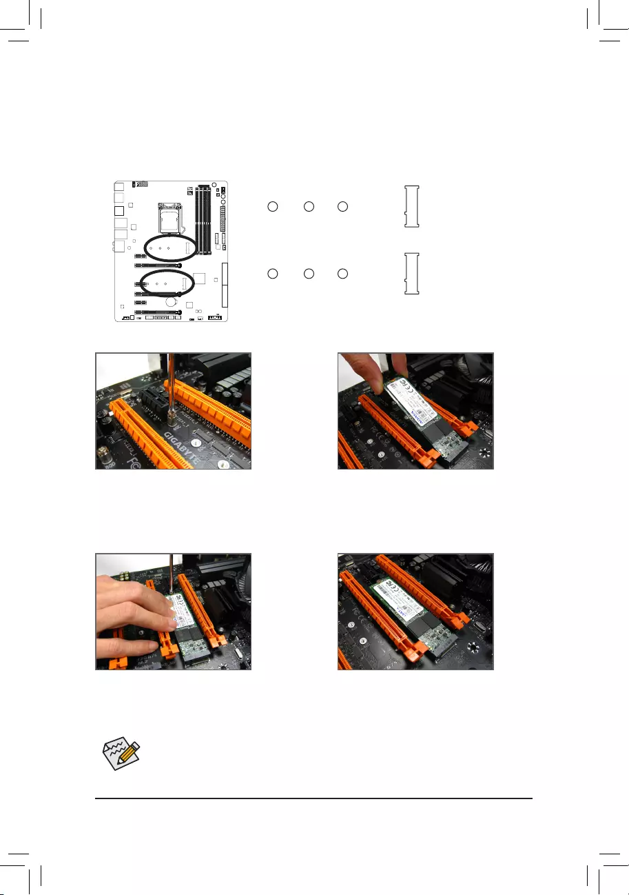
10) M2D_32G/M2H_32G (M.2 Socket 3 Connectors)
TheM.2connectorssuppor tM.2SATASSDsandM.2PCIeSSDsandsupportRAIDcongurationthrough
the Intel®Chipset.PleasenotethatanM.2PCIeSSDcannotbeusedtocreateaRAIDseteitherwith
anM.2SATASSDoraSATAharddrive.TocreateaRAIDarraywithanM.2PCIeSSD,youmustset
upthecongurationinUEFIBIOSmode.RefertoChapter3,»ConguringaRAIDSet,»forinstructions
onconguringaRAIDarray.
Follow the steps below to correctly install an M.2 SSD in the M.2 connector.
Step 1:
Use a screw driver to unfasten the screw and nut
from the motherboard. Locate the proper mounting
hole for the M.2 SSD to be installed and then
screwthenutrst.
Step 2:
Slide the M.2 SSD into the connector at an angle.
Step 3:
Press the M.2 SSD down and then secure it with
the screw.
Step 4:
The installation is completed, as shown in the
picture above.
On the motherboard there are three length adjustment holes for the M.2 SSD. Select the proper
hole for the M.2 SSD to be installed and refasten the screw and nut.
F_USB30 F_U
B_
F_ F_
_
B
BS_
B
SB_
B
_S
S_
_
B
_U
_
B
S
123
123
123
123
1
1
1
1
BSS
S
_S
SSU
1 2 3
S3 BSSS U
__ 3
F_USB3F
S _
S _
S _
SF
B_
B_
F
_0
S
S
_0F
_F
_
_
__B
U
80D 60D 42D
F_USB30 F_U
B_
F_ F_
_
B
BS_
B
SB_
B
_S
S_
_
B
_U
_
B
S
123
123
123
123
1
1
1
1
BSS
S
_S
SSU
1 2 3
S3 BSSS U
__ 3
F_USB3F
S _
S _
S _
SF
B_
B_
F
_0
S
S
_0F
_F
_
_
__B
U
80H 60H 42H
M2H_32G
M2D_32G
— 32 —
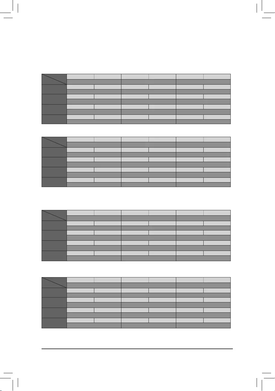
WheninstallingdifferenttypesofM.2SSDs(includingSATASSDs,PCIex4SSDs,andPCIex2SSDs),be
suretorefertothesupportedcongurationsinthetablesbelowaccordingtotheoperatingmodeofyour
SATAcontroller(AHCImodeorRAIDmode).
M2H_32G M.2 connector
SATA3_0 SATA3_1 SATA3_2 SATA3_3 SATA3_4 SATA3_5
SATA Express SATA Express SATA Express
M.2 SATA SSD raaaaa
a a a
M.2 PCIe x4
SSD
aaaaar
a a r
M.2 PCIe x2
SSD
aaaaar
a a r
No M.2 SSDs
Installed
aaaaaa
a a a
a: Supported, r: Not supported.
Connector
Type of SSD
(Note) ThePCIex4SSDrunsatx2speed.
•RAID mode:
M2D_32G M.2 connector
SATA3_0 SATA3_1 SATA3_2 SATA3_3 SATA3_4 SATA3_5
SATA Express SATA Express SATA Express
M.2 SATA SSD aaara a
ara
M.2 PCIe x4
SSD
r r r r ar
a(Note)r r
M.2 PCIe x2
SSD
a a r r ar
ar r
No M.2 SSDs
Installed
aaaaaa
a a a
a: Supported, r: Not supported.
Connector
Type of SSD
•AHCI mode:
M2D_32G M.2 connector
SATA3_0 SATA3_1 SATA3_2 SATA3_3 SATA3_4 SATA3_5
SATA Express SATA Express SATA Express
M.2 SATA SSD a a a ra a
ara
M.2 PCIe x4
SSD
r r r r a a
a(Note) ra
M.2 PCIe x2
SSD
a a r r a a
ara
No M.2 SSDs
Installed
a a a a a a
a a a
a: Supported, r: Not supported.
Connector
Type of SSD
M2H_32G M.2 connector
SATA3_0 SATA3_1 SATA3_2 SATA3_3 SATA3_4 SATA3_5
SATA Express SATA Express SATA Express
M.2 SATA SSD ra a a a a
a a a
M.2 PCIe x4
SSD
a a a a a a
a a a
M.2 PCIe x2
SSD
a a a a a a
a a a
No M.2 SSDs
Installed
a a a a a a
a a a
a: Supported, r: Not supported.
Connector
Type of SSD
— 33 —
The front panel design may differ by chassis. A front panel module mainly consists of power switch,
reset switch, power LED, hard drive activity LED, speaker and etc. When connecting your chassis
front panel module to this header, make sure the wire assignments and the pin assignments are
matched correctly.
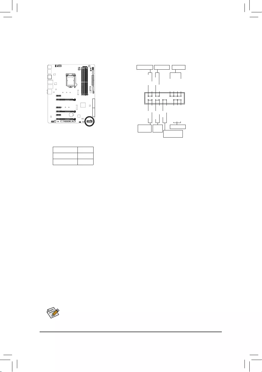
11) F_PANEL (Front Panel Header)
Connect the power switch, reset switch, speaker, chassis intrusion switch/sensor and system status indicator
on the chassis to this header according to the pin assignments below. Note the positive and negative pins
before connecting the cables.
•PW(PowerSwitch,Red):
Connectstothepowerswitchonthechassisfrontpanel.Youmaycongurethewaytoturnoffyour
system using the power switch (refer to Chapter 2, «BIOS Setup,» «Power Management,» for more
information).
•SPEAK (Speaker,Orange):
Connects to the speaker on the chassis front panel. The system reports system startup status by issuing
a beep code. One single short beep will be heard if no problem is detected at system startup.
•HD (HardDriveActivityLED,Blue):
Connects to the hard drive activity LED on the chassis front panel. The LED is on when the hard drive
is reading or writing data.
•RES (ResetSwitch,Green):
Connects to the reset switch on the chassis front panel. Press the reset switch to restart the computer
if the computer freezes and fails to perform a normal restart.
•CI (ChassisIntrusionHeader,Gray):
Connects to the chassis intrusion switch/sensor on the chassis that can detect if the chassis cover has
been removed. This function requires a chassis with a chassis intrusion switch/sensor.
•NC (Orange):NoConnection.
•PLED/PWR_LED (PowerLED,Yellow/Purple):
Connects to the power status indicator on the chassis front panel. The LED
is on when the system is operating. The LED is off when the system is in S3/
S4sleepstateorpoweredoff(S5).
System Status LED
S0 On
S3/S4/S5 Off
Power LED
1
2
19
20
CI-
CI+
PWR_LED-
PWR_LED+
PLED-
PW-
SPEAK+
SPEAK-
PLED+
PW+
Power LED
HD-
RES+
HD+
RES-
Hard Drive
Activity LED
Reset
Switch Chassis Intrusion
Header
Power Switch Speaker
PWR_LED-
NC
NC
— 34 —
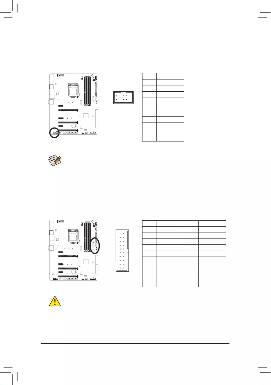
12) F_AUDIO (Front Panel Audio Header)
The front panel audio header supports Intel®HighDenitionaudio(HD).Youmayconnectyourchassis
front panel audio module to this header. Make sure the wire assignments of the module connector match
the pin assignments of the motherboard header. Incorrect connection between the module connector and
the motherboard header will make the device unable to work or even damage it.
F_USB30 F_U
B_
F_ F_
_
B
BS_
B
SB_
B
_S
S_
_
B
_U
_
B
S
123
123
123
123
1
1
1
1
BSS
S
_S
SSU
1 2 3
S3 BSSS U
__ 3
F_USB3F
S _
S _
S _
SF
B_
B_
F
_0
S
S
_0F
_F
_
_
__B
U
9 1
10 2
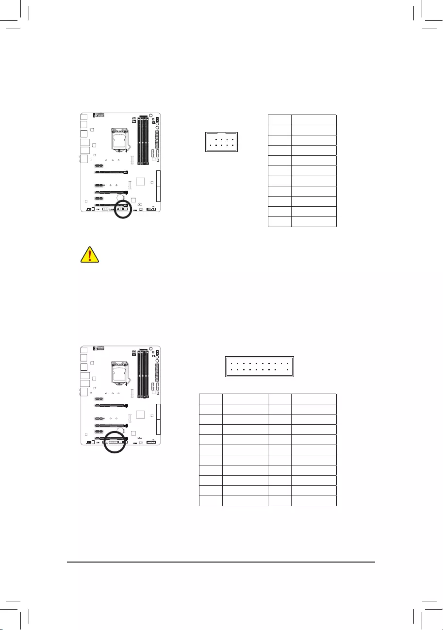
13) F_USB30_1/F_USB30_2 (USB 3.0/2.0 Headers)
Theheaders conform to USB 3.0/2.0 specication andeach header can provide two USB ports.For
purchasing the optional 3.5″ front panel that provides two USB 3.0/2.0 ports, please contact the local dealer.
20 1
1011
Pin No. Denition Pin No. Denition
1 VBUS 11 D2+
2SSRX1- 12 D2-
3SSRX1+ 13 GND
4 GND 14 SSTX2+
5 SSTX1- 15 SSTX2-
6 SSTX1+ 16 GND
7 GND 17 SSRX2+
8 D1- 18 SSRX2-
9 D1+ 19 VBUS
10 NC 20 No Pin
F_USB30 F_U
B_
F_ F_
_
B
BS_
B
SB_
B
_S
S_
_
B
_U
_
B
S
123
123
123
123
1
1
1
1
BSS
S
_S
SSU
1 2 3
S3 BSSS U
__ 3
F_USB3F
S _
S _
S _
SF
B_
B_
F
_0
S
S
_0F
_F
_
_
__B
U
Prior to installing the USB front panel, be sure to turn off your computer and unplug the power cord
from the power outlet to prevent damage to the USB front panel.
Some chassis provide a front panel audio module that has separated connectors on each wire
instead of a single plug. For information about connecting the front panel audio module that has
different wire assignments, please contact the chassis manufacturer.
Pin No. Denition
1 MIC2_L
2 GND
3MIC2_R
4 FP_DET
5LINE2_R
6 NC
7 GND
8 No Pin
9 LINE2_L
10 Sense
— 35 —
14) F_USB1/F_USB2 (USB 2.0/1.1 Headers)
TheheadersconformtoUSB2.0/1.1specication.EachUSBheadercanprovidetwoUSBportsviaan
optional USB bracket. For purchasing the optional USB bracket, please contact the local dealer.
Pin No. Denition
1Power(5V)
2Power(5V)
3 USB DX-
4 USB DY—
5 USB DX+
6 USB DY+
7 GND
8 GND
9 No Pin
10 NC
10
9
2
1
•DonotplugtheIEEE1394bracket(2×5-pin)cableintotheUSB2.0/1.1header.
•Prior to installing the USB bracket, be sure to turn off your computer and unplug the power cord
from the power outlet to prevent damage to the USB bracket.
20
19
2
1
F_USB30 F_U
B_
F_ F_
_
B
BS_
B
SB_
B
_S
S_
_
B
_U
_
B
S
123
123
123
123
1
1
1
1
BSS
S
_S
SSU
1 2 3
S3 BSSS U
__ 3
F_USB3F
S _
S _
S _
SF
B_
B_
F
_0
S
S
_0F
_F
_
_
__B
U
15) TPM (Trusted Platform Module Header)
YoumayconnectaTPM(TrustedPlatformModule)tothisheader.
Pin No. Denition Pin No. Denition
1 LCLK 11 LAD0
2 GND 12 GND
3LFRAME 13 NC
4 No Pin 14 NC
5LRESET 15 SB3V
6 NC 16 SERIRQ
7 LAD3 17 GND
8 LAD2 18 NC
9 VCC3 19 NC
10 LAD1 20 SUSCLK
— 36 —
10
9
2
1
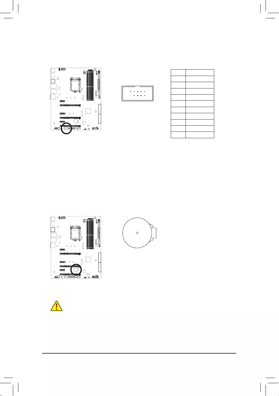
16) COMA (Serial Port Header)
The COM header can provide one serial port via an optional COM port cable. For purchasing the optional
COM port cable, please contact the local dealer.
Pin No. Denition
1 NDCD-
2 NSIN
3 NSOUT
4NDTR-
5 GND
6NDSR-
7NRTS-
8 NCTS-
9NRI-
10 No Pin
17) BAT (Battery)
Thebatteryprovidespowertokeepthevalues(suchasBIOScongurations,date,andtimeinformation)
intheCMOSwhenthecomputeristurnedoff.Replacethebatterywhenthebatteryvoltagedropstoalow
level, or the CMOS values may not be accurate or may be lost.
You may clear the CMOS values by removing the battery:
1. Turn off your computer and unplug the power cord.
2. Gently remove the battery from the battery holder and wait for one minute.
(Or use a metal object like a screwdriver to touch the positive and negative
terminalsofthebatteryholder,makingthemshortfor5seconds.)
3. Replacethebattery.
4. Plug in the power cord and restart your computer.
•Always turn off your computer and unplug the power cord before replacing the battery.
•Replacethebatterywithanequivalentone.Dangerofexplosionifthebatteryisreplacedwith
an incorrect model.
•Contact the place of purchase or local dealer if you are not able to replace the battery by yourself
or uncertain about the battery model.
•Wheninstallingthebattery,notetheorientationofthepositiveside(+)andthenegativeside(-)
ofthebattery(thepositivesideshouldfaceup).
•Used batteries must be handled in accordance with local environmental regulations.
— 37 —
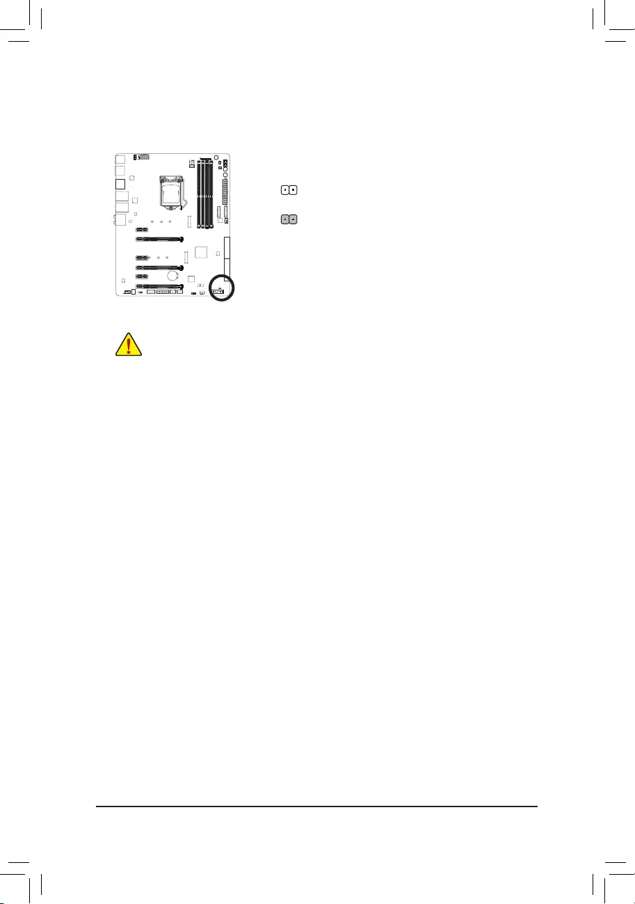
18) CLR_CMOS (Clear CMOS Jumper)
UsethisjumpertocleartheBIOScongurationandresettheCMOSvaluestofactorydefaults.Toclear
the CMOS values, use a metal object like a screwdriver to touch the two pins for a few seconds.
•Always turn off your computer and unplug the power cord from the power outlet before clearing
the CMOS values.
•Aftersystemrestart,gotoBIOSSetuptoloadfactorydefaults(selectLoadOptimizedDefaults)or
manuallyconguretheBIOSsettings(refertoChapter2,«BIOSSetup,»forBIOScongurations).
Open: Normal
Short: Clear CMOS Values

— 38 —

— 39 —
BIOS(Basic Input and Output System) records hardware parameters ofthe system in the CMOS on the
motherboard.ItsmajorfunctionsincludeconductingthePower-OnSelf-Test(POST)duringsystemstartup,
saving system parameters and loading operating system, etc. BIOS includes a BIOS Setup program that allows
theusertomodifybasicsystemcongurationsettingsortoactivatecertainsystemfeatures.
When the power is turned off, the battery on the motherboard supplies the necessary power to the CMOS to
keepthecongurationvaluesintheCMOS.
To access the BIOS Setup program, press the <Delete> key during the POST when the power is turned on.
To upgrade the BIOS, use either the GIGABYTE Q-Flash or @BIOS utility.
•Q-Flash allows the user to quickly and easily upgrade or back up BIOS without entering the operating system.
•@BIOS is a Windows-based utility that searches and downloads the latest version of BIOS from the Internet
and updates the BIOS.
For instructions on using the Q-Flash and @BIOS utilities, refer to Chapter 5, «BIOS Update Utilities.»
Chapter 2 BIOS Setup
•BecauseBIOS ashingispotentiallyrisky,ifyoudo notencounterproblemsusingthe current
versionofBIOS,itisrecommendedthatyounot ashtheBIOS.ToashtheBIOS, doitwith
caution.InadequateBIOSashingmayresultinsystemmalfunction.
•Itisrecommendedthatyounotalterthedefaultsettings(unlessyouneedto)topreventsystem
instability or other unexpected results. Inadequately altering the settings may result in system’s
failure to boot. If this occurs, try to clear the CMOS values and reset the board to default values.
(Refertothe«LoadOptimizedDefaults»sectioninthischapterorintroductionsofthebatteryorthe
clearCMOSjumper/buttoninChapter1forhowtocleartheCMOSvalues.)
— 40 —
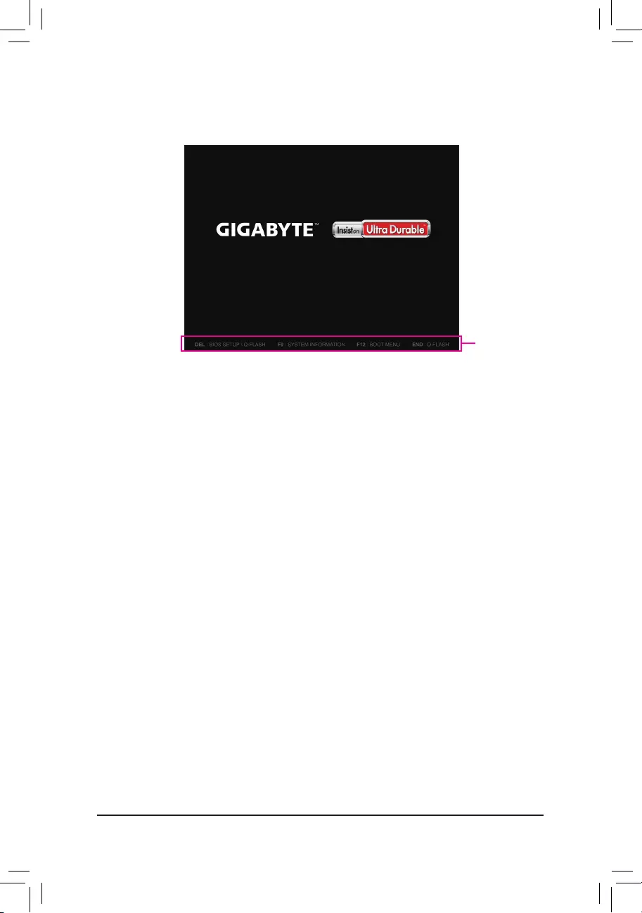
2-1 Startup Screen
The following startup Logo screen will appear when the computer boots.
Function Keys:
<DEL>: BIOS SETUP\Q—FLASH
Press the <Delete> key to enter BIOS Setup or to access the Q-Flash utility in BIOS Setup.
<F9>: SYSTEM INFORMATION
Press the <F9> key to display your system information.
<F12>: BOOT MENU
BootMenuallowsyoutosettherstbootdevicewithoutenteringBIOSSetup.InBootMenu,usetheup
arrow key <h> or the down arrow key <i>toselecttherstbootdevice,thenpress<Enter>toaccept.
The system will boot from the device immediately.
Note: The setting in Boot Menu is effective for one time only. After system restart, the device boot order
will still be based on BIOS Setup settings.
<END>: Q—FLASH
Pressthe<End>keytoaccesstheQ-FlashutilitydirectlywithouthavingtoenterBIOSSetuprst.
Function Keys
— 41 —
•When the system is not stable as usual, select the Load Optimized Defaults item to set your
system to its defaults.
•The BIOS Setup menus described in this chapter are for reference only and may differ by BIOS
version.
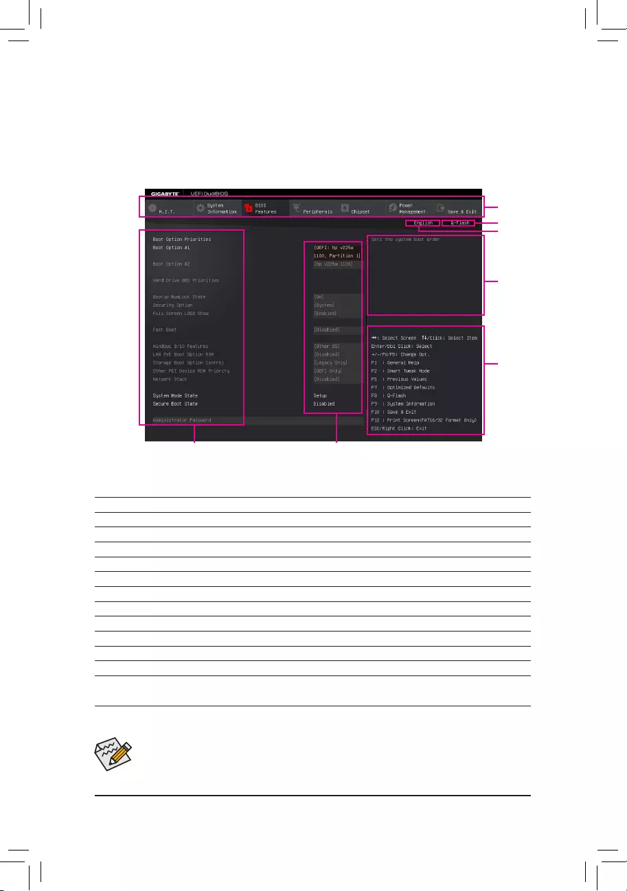
2-2 The Main Menu
The Main Menu
On the main menu of the BIOS Setup program, press arrow keys to move among the items and press <Enter>
to accept or enter a sub-menu. Or you can use your mouse to select the item you want.
(Sample BIOS Version: F1a)
BIOS Setup Program Function Keys
<f><g> Move the selection bar to select a setup menu
<h><i>Movetheselectionbartoselectancongurationitemonamenu
<Enter> Execute command or enter a menu
<+>/<Page Up> Increase the numeric value or make changes
<->/<Page Down> Decrease the numeric value or make changes
<F1> Show descriptions of the function keys
<F5> RestorethepreviousBIOSsettingsforthecurrentsubmenus
<F7> Load the Optimized BIOS default settings for the current submenus
<F8> Access the Q-Flash utility
<F9> Display system information
<F10> Save all the changes and exit the BIOS Setup program
<F12> Capture the current screen as an image and save it to your USB drive
<Esc> Main Menu: Exit the BIOS Setup program
Submenus: Exit current submenu
Setup Menus
Function Keys
Help
Enter Q-Flash
Select Default
Language
CongurationItems Current Settings

— 42 —
BIOS Setup Menus
M.I.T.
Usethismenutoconguretheclock,frequency,andvoltagesofyourCPUandmemory,etc.Orcheckthe
system/CPU temperatures, voltages, and fan speeds.
System Information
UsethismenutocongurethedefaultlanguageusedbytheBIOSandsystemtimeanddate.
BIOS Features
UsethismenutocongurethedevicebootorderandadvancedfeaturesavailableontheCPU.
Peripherals
Usethismenutocongureallperipheraldevices,suchasUSB,displaysettings,etc.
Chipset
UsethismenutocongureChipset-relatedoptions,suchasSATA,onboardLAN,etc.
Power Management
Usethismenutocongureallthepower-savingfunctions.
Save & Exit
Save all the changes made in the BIOS Setup program to the CMOS and exit BIOS Setup. You can save
thecurrentBIOSsettingstoaproleorloadoptimizeddefaultsforoptimal-performancesystemoperations.
— 43 —
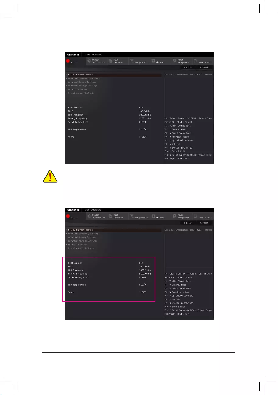
2-3 M.I.T.
Whether the system will work stably with the overclock/overvoltage settings you made is dependent
onyouroverallsystemcongurations.Incorrectlydoingoverclock/overvoltagemayresultindamage
to CPU, chipset, or memory and reduce the useful life of these components. This page is for advanced
users only and we recommend you not to alter the default settings to prevent system instability or
other unexpected results. (Inadequately altering the settings may result in system’s failure to boot. If
thisoccurs,cleartheCMOSvaluesandresettheboardtodefaultvalues.)
This section provides information on the BIOS version, CPU base clock, CPU frequency, memory frequency,
total memory size, CPU temperature and CPU voltage, etc.
— 44 —
`M.I.T. Current Status
This screen provides information on CPU/memory frequencies/parameters.
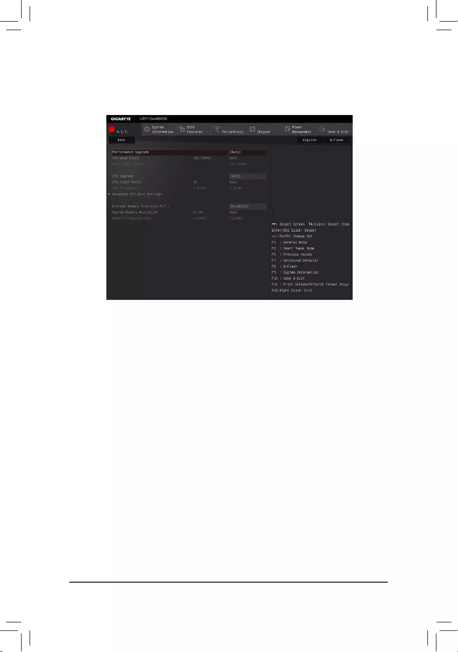
`Advanced Frequency Settings
&Performance Upgrade (Note)
Providesyouwithvedifferentoverclockingcongurations.Optionsare:20%Upgrade,40%Upgrade,
60%Upgrade,80%Upgrade,100%Upgrade.(Default:Auto)
&CPU Base Clock
AllowsyoutomanuallysettheCPUbaseclockin0.01MHzincrements.(Default:Auto)
Important: It is highly recommended that the CPU frequency be set in accordance with the CPU
specications.
&Host Clock Value
This value changes with the
CPU Base Clock
setting.
&CPU Upgrade (Note)
AllowsyoutosettheCPUfrequency.OptionsmayvarydependingontheCPUbeingused.(Default:Auto)
&CPU Clock Ratio
Allows you to alter the clock ratio for the installed CPU. The adjustable range is dependent on the CPU
being installed.
&CPU Frequency
Displays the current operating CPU frequency.
(Note) ThisitemispresentonlywhenyouinstallaCPUthatsupportsthisfeature.Formoreinformationabout
Intel® CPUs’ unique features, please visit Intel’s website.
— 45 —
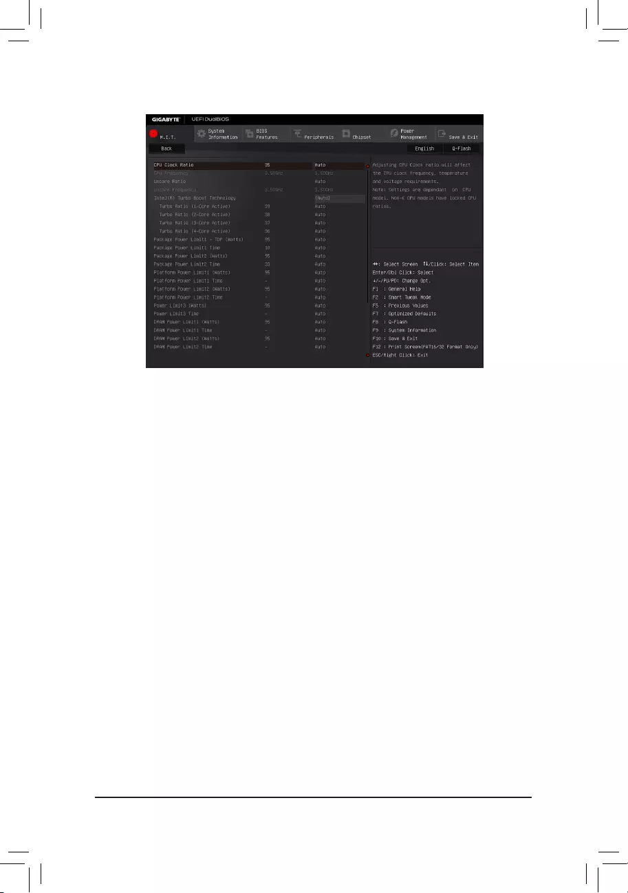
&CPU Clock Ratio, CPU Frequency
The settings above are synchronous to those under the same items on the Advanced Frequency Settings
menu.
&Uncore Ratio
Allows you to set the CPU Uncore ratio. The adjustable range is dependent on the CPU being used.
&Uncore Frequency
Displays the current CPU Uncore frequency.
&Intel(R) Turbo Boost Technology (Note)
Allows you to determine whether to enable the Intel CPU Turbo Boost technology. Auto lets the BIOS
automaticallycongurethissetting.(Default:Auto)
&Turbo Ratio (Note)
Allows you to set the CPU Turbo ratios for different number of active cores. Auto sets the CPU Turbo ratios
accordingtotheCPUspecications.(Default:Auto)
&Power Limit TDP (Watts) / Power Limit Time
AllowsyoutosetthepowerlimitforCPUTurbomodeandhowlongittakestooperateatthespecied
powerlimit.Ifthespeciedvalueisexceeded,theCPUwillautomaticallyreducethecorefrequencyin
order to reduce the power. AutosetsthecurrentlimitaccordingtotheCPUspecications.(Default:Auto)
&Core Current Limit (Amps)
AllowsyoutosetacurrentlimitforCPUTurbomode.WhentheCPUcurrentexceedsthespeciedcurrent
limit, the CPU will automatically reduce the core frequency in order to reduce the current. Auto sets the
powerlimitaccordingtotheCPUspecications.(Default:Auto)
&No. of CPU Cores Enabled (Note)
Allows you to select the number of CPU cores to enable in an Intel® multi-core CPU (the number of CPU
coresmayvarybyCPU).AutoletstheBIOSautomaticallycongurethissetting.(Default:Auto)
`Advanced CPU Core Settings
(Note) ThisitemispresentonlywhenyouinstallaCPUthatsupportsthisfeature.Formoreinformationabout
Intel® CPUs’ unique features, please visit Intel’s website.

— 46 —
&Hyper-Threading Technology (Note 1)
Allows you to determine whether to enable multi-threading technology when using an Intel® CPU that
supports this function. This feature only works for operating systems that support multi-processor mode.
AutoletstheBIOSautomaticallycongurethissetting.(Default:Auto)
&CPU Enhanced Halt (C1E) (Note 1)
Enables or disables Intel
®
CPUEnhancedHalt(C1E)function,aCPUpower-savingfunctioninsystemhalt
state. When enabled, the CPU core frequency and voltage will be reduced during system halt state to decrease
power consumption. AutoletstheBIOSautomaticallycongurethissetting.(Default:Auto)
&C3 State Support (Note 1)
Allows you to determine whether to let the CPU enter C3 mode in system halt state. When enabled, the
CPU core frequency and voltage will be reduced during system halt state to decrease power consumption.
The C3 state is a more enhanced power-saving state than C1. AutoletstheBIOSautomaticallycongure
thissetting.(Default:Auto)
&C6/C7 State Support (Note 1)
Allows you to determine whether to let the CPU enter C6/C7 mode in system halt state. When enabled, the
CPU core frequency and voltage will be reduced during system halt state to decrease power consumption.
The C6/C7 state is a more enhanced power-saving state than C3. AutoletstheBIOSautomaticallycongure
thissetting.(Default:Auto)
&C8 State Support (Note 1)
Allows you to determine whether to let the CPU enter C8 mode in system halt state. When enabled, the CPU
core frequency and voltage will be reduced during system halt state to decrease power consumption. The
C8 state is a more enhanced power-saving state than C6/C7. AutoletstheBIOSautomaticallycongure
thissetting.(Default:Auto)
&Package C State Limit (Note 1)
Allows you to specify the C-state limit for the processor. AutoletstheBIOSautomaticallycongurethis
setting.(Default:Auto)
&CPU Thermal Monitor (Note 1)
Enables or disables Intel® Thermal Monitor function, a CPU overheating protection function. When enabled,
the CPU core frequency and voltage will be reduced when the CPU is overheated. Auto lets the BIOS
automaticallycongurethissetting.(Default:Auto)
&CPU EIST Function (Note 1)
Enables or disables Enhanced Intel®SpeedStepTechnology(EIST).DependingonCPUloading,Intel
EIST technology can dynamically and effectively lower the CPU voltage and core frequency to decrease
average power consumption and heat production. AutoletstheBIOSautomaticallycongurethissetting.
(Default:Auto)
&ExtremeMemoryProle(X.M.P.)(Note 2)
AllowstheBIOStoreadtheSPDdataonXMPmemorymodule(s)toenhancememoryperformancewhen
enabled.
Disabled Disablesthisfunction.(Default)
Prole1 UsesProle1settings.
Prole2(Note2) UsesProle2settings.
(Note1) ThisitemispresentonlywhenyouinstallaCPUthatsupportsthisfeature.Formoreinformationabout
Intel® CPUs’ unique features, please visit Intel’s website.
(Note2) ThisitemispresentonlywhenyouinstallaCPUandamemorymodulethatsupportthisfeature.

— 47 —
&System Memory Multiplier
Allows you to set the system memory multiplier. Auto sets memory multiplier according to memory SPD
data.(Default:Auto)
&Memory Frequency (MHz)
Therstmemoryfrequencyvalueisthenormaloperatingfrequencyofthememorybeingused;thesecond
is the memory frequency that is automatically adjusted according to the System Memory Multiplier settings.
— 48 —
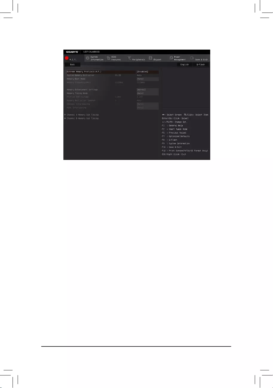
`Advanced Memory Settings
&ExtremeMemoryProle(X.M.P.)(Note), System Memory Multiplier, Memory Frequency(MHz)
The settings above are synchronous to those under the same items on the Advanced Frequency Settings
menu.
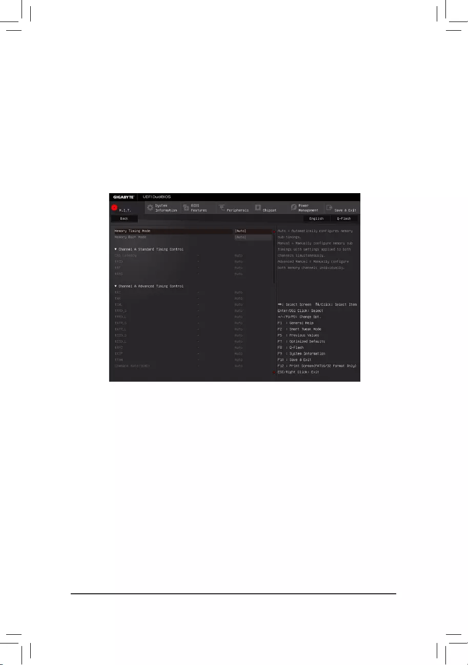
&Memory Boot Mode
(Note)
Provides memory detection and training methods.
Auto LetstheBIOSautomaticallycongurethissetting.(Default)
EnableFastBoot Skipmemorydetectionandtraininginsomespeciccriteriaforfastermemory
boot.
Disable Fast Boot Detect and train memory at every single boot.
&Memory Enhancement Settings
Providesthreedifferentmemoryperformanceenhancementsettings:Normal(basicperformance),Enhanced
Stability,andEnhancedPerformance.(Default:Normal)
&Memory Timing Mode
Manual and Advanced Manual allows the Memory Multiplier Tweaker, Channel Interleaving, Rank
Interleaving,andmemorytimingsettingsbelowtobecongurable.Optionsare:Auto(default),Manual,
Advanced Manual.
&ProleDDRVoltage
When using a non-XMP memory module or ExtremeMemoryProle(X.M.P.) is set to Disabled, the value
isdisplayedaccordingtoyourmemoryspecication.WhenExtremeMemoryProle(X.M.P.) is set to
Prole1 or Prole2, the value is displayed according to the SPD data on the XMP memory.
&Memory Multiplier Tweaker
Providesdifferentlevelsofmemoryauto-tuning.(Default:Auto)
(Note) ThisitemispresentonlywhenyouinstallaCPUandamemorymodulethatsupportthisfeature.
— 49 —
&Channel Interleaving
Enables or disables memory channel interleaving. Enabled allows the system to simultaneously access
different channels of the memory to increase memory performance and stability. Auto lets the BIOS
automaticallycongurethissetting.(Default:Auto)
&Rank Interleaving
Enables or disables memory rank interleaving. Enabled allows the system to simultaneously access different
ranks of the memory to increase memory performance and stability. Auto lets the BIOS automatically
congurethissetting.(Default:Auto)
This sub-menu provides memory timing settings for each channel of memory. This sub-menu provides memory
timingsettingsforeachchannelofmemory.Therespectivetimingsettingscreensarecongurableonlywhen
Memory Timing Mode is set to Manual or Advanced Manual. Note: Your system may become unstable or fail
to boot after you make changes on the memory timings. If this occurs, please reset the board to default values
by loading optimized defaults or clearing the CMOS values.
`Channel A/B Memory Sub Timings
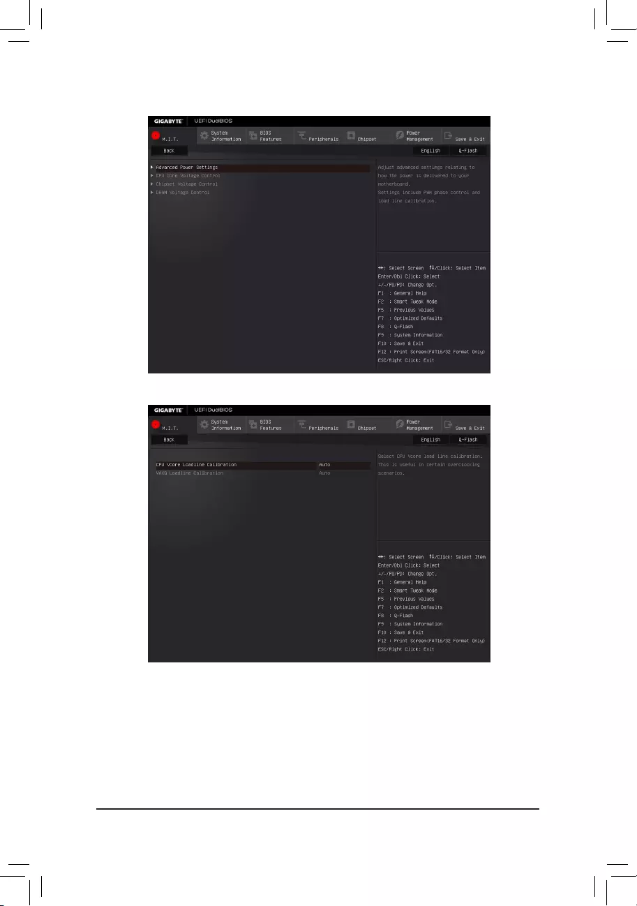
— 50 —
`Advanced Voltage Settings
`Advanced Power Settings
&CPU Vcore Loadline Calibration
AllowsyoutocongureLoad-LineCalibrationfortheCPUVcorevoltage.Selectingahigherlevelkeeps
the CPU Vcore voltage more consistent with what is set in BIOS under heavy load. Auto lets the BIOS
automaticallycongurethissettingandsetsthevoltagefollowingIntel’sspecications.(Default:Auto)
&VAXG Loadline Calibration
AllowsyoutocongureLoad-LineCalibrationfortheCPUVAXGvoltage.Selectingahigherlevelkeeps
the CPU VAXG voltage more consistent with what is set in BIOS under heavy load. Auto lets the BIOS
automaticallycongurethissettingandsetsthevoltagefollowingIntel’sspecications.(Default:Auto)

— 51 —
`CPU Core Voltage Control
This section provides CPU voltage control options.
`Chipset Voltage Control
This section provides Chipset voltage control options.
`DRAM Voltage Control
This section provides memory voltage control options.
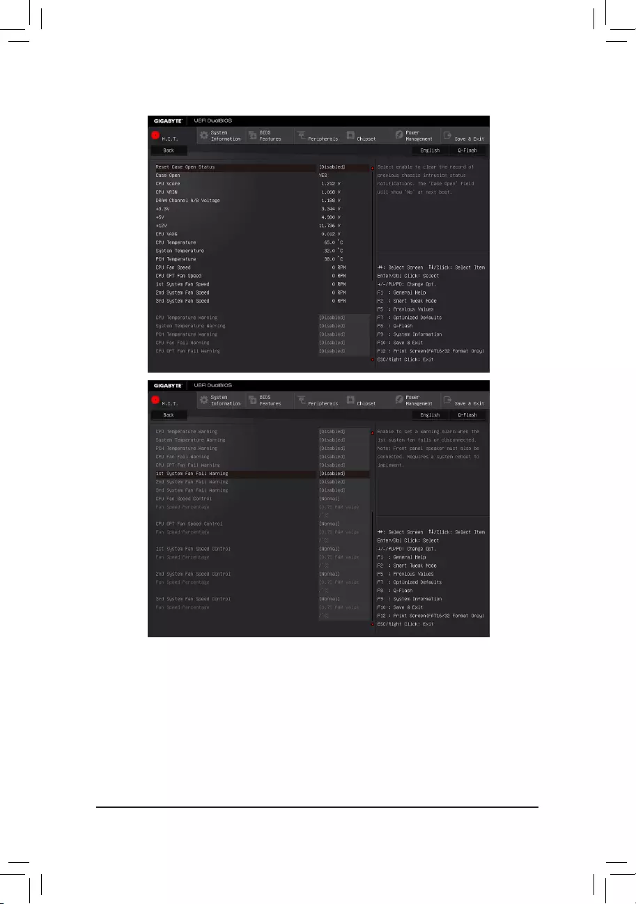
— 52 —
`PC Health Status
&Reset Case Open Status
Disabled Keepsorclearstherecordofpreviouschassisintrusionstatus.(Default)
Enabled Clears the record of previous chassis intrusion status and the Case Openeldwillshow
«No» at next boot.
&Case Open
Displays the detection status of the chassis intrusion detection device attached to the motherboard CI
header.Ifthesystemchassiscoverisremoved,thiseldwillshow«Yes»,otherwiseitwillshow»No».To
clear the chassis intrusion status record, set Reset Case Open Status to Enabled, save the settings to
the CMOS, and then restart your system.

— 53 —
&CPU Vcore/CPU VRIN/DRAM Channel A/B Voltage/+3.3V/+5V/+12V/CPU VAXG
Displays the current system voltages.
&CPU/PCH Temperature
Displays current CPU/Chipset temperature.
&System Temperature
Displays current system temperatures detected by the system temperature sensors on the motherboard.
&CPU/CPU OPT/System Fan Speed
Displays current CPU/CPU_OPT/system fan speeds.
&CPU/System/PCH Temperature Warning
Sets the warning threshold for CPU/system/Chipset temperature. When temperature exceeds the threshold,
BIOS will emit warning sound. Options are: Disabled (default), 60oC/140oF, 70oC/158oF, 80oC/176oF,
90oC/194oF.
&CPU/CPU OPT/System Fan Fail Warning
Allows the system to emit warning sound if the fan is not connected or fails. Check the fan condition or fan
connectionwhenthisoccurs.(Default:Disabled)
&CPU Fan Speed Control (CPU_FAN Connector)
Allows you to determine whether to enable the fan speed control function and adjust the fan speed.
Normal Allows the fan to run at different speeds according to the CPU temperature. You
can adjust the fan speed with System Information Viewer based on your system
requirements.(Default)
Silent Allows the fan to run at slow speeds.
Manual Allows you to control the fan speed under the Fan Speed Percentage item.
Full Speed Allows the fan to run at full speeds.
&Fan Speed Percentage
Allowsyoutocontrolthefanspeed.ThisitemiscongurableonlywhenCPU Fan Speed Control is set
to Manual. Options are: 0.75 PWM value /oC ~ 2.50 PWM value /oC.
&CPU OPT Fan Speed Control (CPU_OPT Connector)
Allows you to determine whether to enable the fan speed control function and adjust the fan speed.
Normal Allows the fan to run at different speeds according to the CPU temperature. You
can adjust the fan speed with System Information Viewer based on your system
requirements.(Default)
Silent Allows the fan to run at slow speeds.
Manual Allows you to control the fan speed under the Fan Speed Percentage item.
Full Speed Allows the fan to run at full speeds.
&Fan Speed Percentage
Allowsyoutocontrolthefanspeed.ThisitemiscongurableonlywhenCPU OPT Fan Speed Control is
set to Manual. Options are: 0.75 PWM value /oC ~ 2.50 PWM value /oC.

— 54 —
&1st System Fan Speed Control (SYS_FAN1 Connector)
Allows you to determine whether to enable the fan speed control function and adjust the fan speed.
Normal Allows the fan to run at different speeds according to the system temperature. You
can adjust the fan speed with System Information Viewer based on your system
requirements.(Default)
Silent Allows the fan to run at slow speeds.
Manual Allows you to control the fan speed under the Fan Speed Percentage item.
Full Speed Allows the fan to run at full speeds.
&Fan Speed Percentage
Allowsyoutocontrolthefanspeed.Thisitemiscongurableonlywhen1st System Fan Speed Control
is set to Manual. Options are: 0.75 PWM value /oC ~ 2.50 PWM value /oC.
&2nd System Fan Speed Control (SYS_FAN2 Connector)
Allows you to determine whether to enable the fan speed control function and adjust the fan speed.
Normal Allows the fan to run at different speeds according to the system temperature. You
can adjust the fan speed with System Information Viewer based on your system
requirements.(Default)
Silent Allows the fan to run at slow speeds.
Manual Allows you to control the fan speed under the Fan Speed Percentage item.
Full Speed Allows the fan to run at full speeds.
&Fan Speed Percentage
Allowsyoutocontrolthefanspeed.Thisitemiscongurableonlywhen2nd System Fan Speed Control
is set to Manual. Options are: 0.75 PWM value /oC ~ 2.50 PWM value /oC.
&3rd System Fan Speed Control (SYS_FAN3 Connector)
Allows you to determine whether to enable the fan speed control function and adjust the fan speed.
Normal Allows the fan to run at different speeds according to the system temperature. You
can adjust the fan speed with System Information Viewer based on your system
requirements.(Default)
Silent Allows the fan to run at slow speeds.
Manual Allows you to control the fan speed under the Fan Speed Percentage item.
Full Speed Allows the fan to run at full speeds.
&Fan Speed Percentage
Allowsyoutocontrolthefanspeed.Thisitemiscongurableonlywhen3rd System Fan Speed Control
is set to Manual. Options are: 0.75 PWM value /oC ~ 2.50 PWM value /oC.
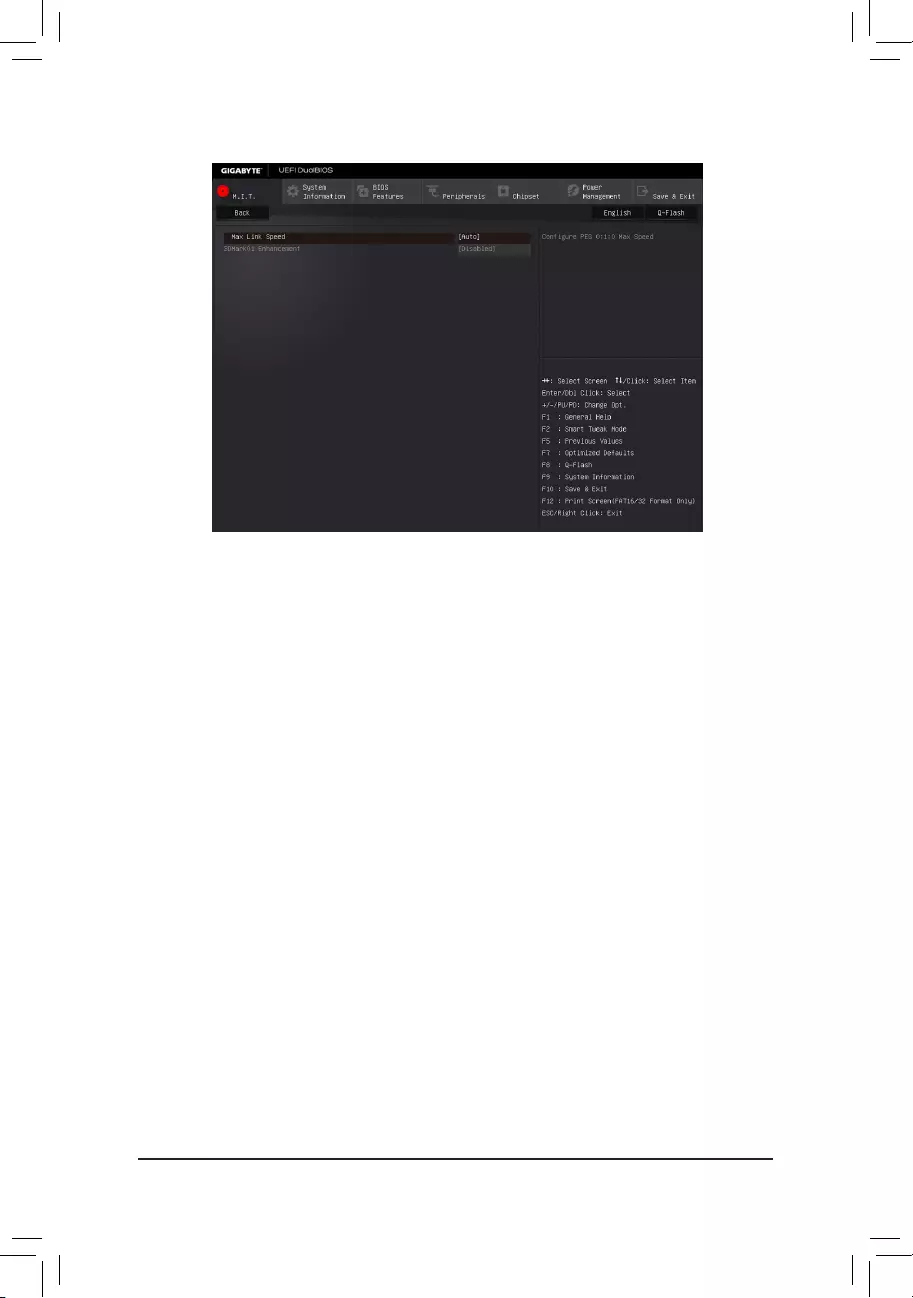
— 55 —
`Miscellaneous Settings
&Max Link Speed
Allows you to set the operation mode of the PCI Express slots to Gen 1, Gen 2, or Gen 3. Actual operation
modeissubjecttothehardwarespecicationofeachslot.AutoletstheBIOSautomaticallycongurethis
setting.(Default:Auto)
&3DMark01 Enhancement
Allowsyoutodeterminewhethertoenhancesomelegacybenchmarkperformance.(Default:Disabled)
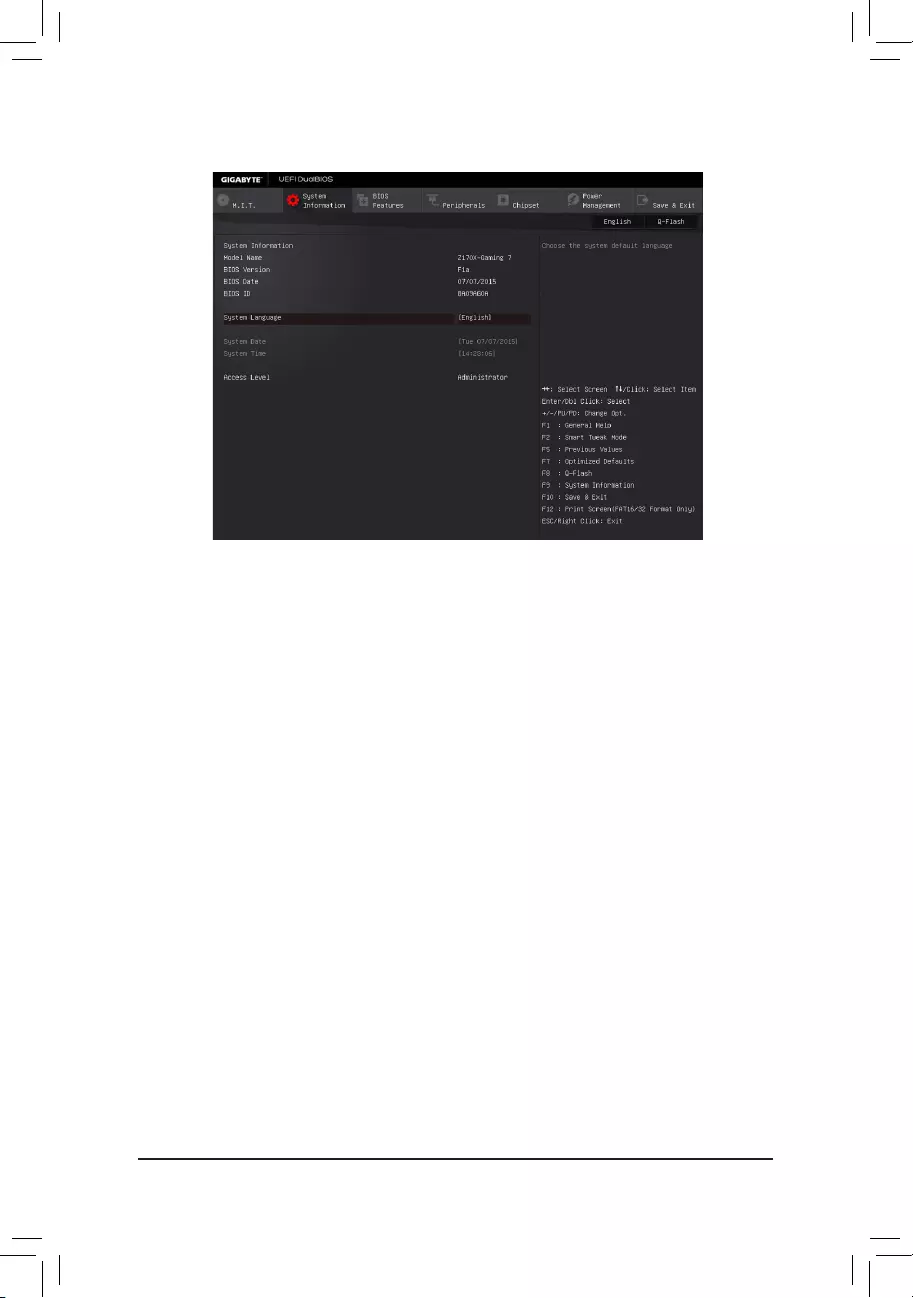
— 56 —
2-4 System Information
This section provides information on your motherboard model and BIOS version. You can also select the default
language used by the BIOS and manually set the system time.
&System Language
Selects the default language used by the BIOS.
&System Date
Setsthesystemdate.Thedateformatisweek(read-only),month,date,andyear.Use<Enter>toswitch
betweentheMonth,Date,andYeareldsandusethe<PageUp>or<PageDown>keytosetthedesired
value.
&System Time
Sets the system time. The time format is hour, minute, and second. For example, 1 p.m. is 13:0:0. Use <Enter>
toswitchbetweentheHour,Minute,andSecondeldsandusethe<PageUp>or<PageDown>keytoset
the desired value.
&Access Level
Displays the current access level depending on the type of password protection used. (If no password is
set, the default will display as Administrator.)TheAdministratorlevelallowsyoutomakechangestoall
BIOS settings; the User level only allows you to make changes to certain BIOS settings but not all.
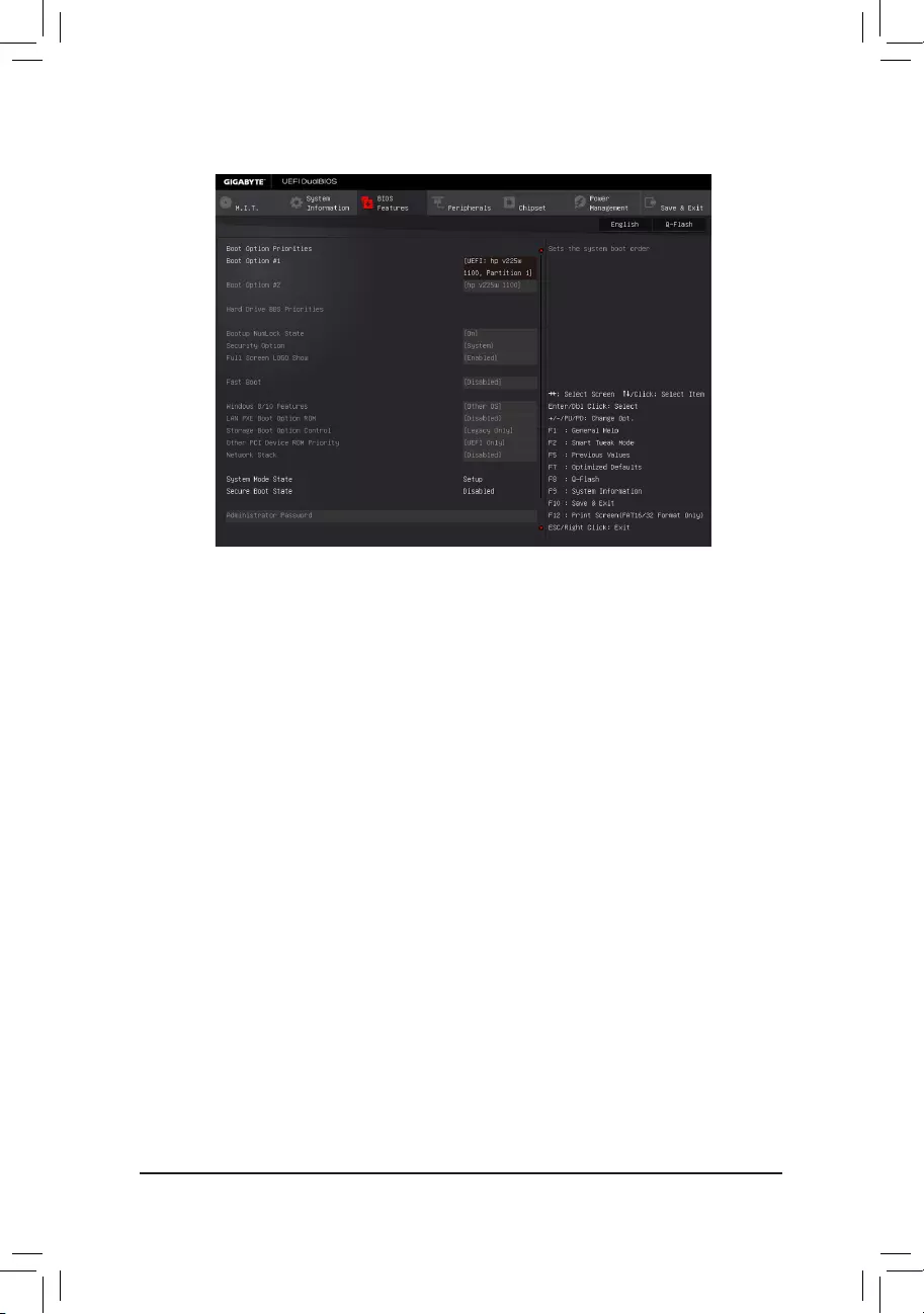
— 57 —
2-5 BIOS Features
&Boot Option Priorities
Speciestheoverallbootorderfromtheavailabledevices.RemovablestoragedevicesthatsupportGPT
formatwillbeprexedwith«UEFI:»stringonthebootdevicelist.Tobootfromanoperatingsystemthat
supportsGPTpartitioning,selectthedeviceprexedwith»UEFI:»string.
Or if you want to install an operating system that supports GPT partitioning such as Windows 7 64-bit, select
theopticaldrivethatcontainstheWindows764-bitinstallationdiskandisprexedwith»UEFI:»string.
& Hard Drive/CD/DVD ROM Drive/Floppy Drive/Network Device BBS Priorities
Speciesthebootorderforaspecicdevicetype,suchasharddrives,opticaldrives,oppydiskdrives,
and devices that support Boot from LAN function, etc. Press <Enter> on this item to enter the submenu that
presents the devices of the same type that are connected. This item is present only if at least one device
for this type is installed.
&Bootup NumLock State
EnablesordisablesNumlockfeatureonthenumerickeypadofthekeyboardafterthePOST.(Default:On)
&Security Option
Specieswhetherapasswordisrequiredeverytimethesystemboots,oronlywhenyouenterBIOSSetup.
Afterconguringthisitem,setthepassword(s)undertheAdministrator Password/User Password item.
Setup A password is only required for entering the BIOS Setup program.
System A password is required for booting the system and for entering the BIOS Setup program.
(Default)
&Full Screen LOGO Show
Allows you to determine whether to display the GIGABYTE Logo at system startup. Disabled skips the
GIGABYTELogowhenthesystemstartsup.(Default:Enabled)
&Fast Boot
Enables or disables Fast Boot to shorten the OS boot process. Ultra Fast provides the fastest bootup
speed.(Default:Disabled)

— 58 —
&SATA Support
All Sata Devices All SATA devices are functional in the operating system and during the POST.
(Default)
Last Boot HDD Only Except for the previous boot drive, all SATA devices are disabled before the OS
boot process completes.
ThisitemiscongurableonlywhenFast Boot is set to Enabled or Ultra Fast.
&VGA Support
Allows you to select which type of operating system to boot.
Auto EnableslegacyoptionROMonly.
EFIDriver EnablesEFIoptionROM.(Default)
ThisitemiscongurableonlywhenFast Boot is set to Enabled or Ultra Fast.
&USB Support
Disabled All USB devices are disabled before the OS boot process completes.
Full Initial All USB devices are functional in the operating system and during the POST.
Partial Initial Part of the USB devices are disabled before the OS boot process completes.
(Default)
ThisitemiscongurableonlywhenFast Boot is set to Enabled. This function is disabled when Fast Boot
is set to Ultra Fast.
&PS2 Devices Support
Disabled All PS/2 devices are disabled before the OS boot process completes.
Enabled All PS/2 devices are functional in the operating system and during the POST.
(Default)
ThisitemiscongurableonlywhenFast Boot is set to Enabled. This function is disabled when Fast Boot
is set to Ultra Fast.
&NetWork Stack Driver Support
Disabled Disablesbootingfromthenetwork.(Default)
Enabled Enables booting from the network.
ThisitemiscongurableonlywhenFast Boot is set to Enabled or Ultra Fast.
&Next Boot After AC Power Loss
NormalBoot EnablesnormalbootupuponthereturnoftheACpower.(Default)
Fast Boot Keeps the Fast Boot settings upon the return of the AC power.
ThisitemiscongurableonlywhenFast Boot is set to Enabled or Ultra Fast.
&Windows 8/10 Features
Allowsyoutoselecttheoperatingsystemtobeinstalled.(Default:OtherOS)
&CSM Support
EnablesordisablesUEFICSM(CompatibilitySupportModule)tosupportalegacyPCbootprocess.
Enabled EnablesUEFICSM.(Default)
Disabled Disables UEFI CSM and supports UEFI BIOS boot process only.
ThisitemiscongurableonlywhenWindows 8/10 Features is set to Windows 8/10 or Windows 8/10
WHQL.
&LAN PXE Boot Option ROM
AllowsyoutoselectwhethertoenablethelegacyoptionROMfortheLANcontroller.(Default:Disabled)
ThisitemiscongurableonlywhenCSM Support is set to Enabled.

— 59 —
&Storage Boot Option Control
AllowsyoutoselectwhethertoenabletheUEFIorlegacyoptionROMforthestoragedevicecontroller.
Disabled DisablesoptionROM.
LegacyOnly EnableslegacyoptionROMonly.(Default)
UEFIOnly EnablesUEFIoptionROMonly.
ThisitemiscongurableonlywhenCSM Support is set to Enabled.
&Other PCI Device ROM Priority
AllowsyoutoselectwhethertoenabletheUEFIorLegacyoptionROMforthePCIdevicecontrollerother
than the LAN, storage device, and graphics controllers.
Disabled DisablesoptionROM.
LegacyOnly EnableslegacyoptionROMonly.
UEFIOnly EnablesUEFIoptionROMonly.(Default)
ThisitemiscongurableonlywhenCSM Support is set to Enabled.
&Network Stack
Disables or enables booting from the network to install a GPT format OS, such as installing the OS from
theWindowsDeploymentServicesserver.(Default:Disabled)
&Ipv4 PXE Support
EnablesordisablesIPv4PXESupport.ThisitemiscongurableonlywhenNetwork Stack is enabled.
&Ipv6 PXE Support
EnablesordisablesIPv6PXESupport.ThisitemiscongurableonlywhenNetwork Stack is enabled.
&Administrator Password
Allowsyoutocongureanadministratorpassword.Press<Enter>onthisitem,typethepassword,and
thenpress<Enter>.Youwillberequestedtoconrmthepassword.Typethepasswordagainandpress
<Enter>.Youmustentertheadministratorpassword(oruserpassword)atsystemstartupandwhenentering
BIOS Setup. Differing from the user password, the administrator password allows you to make changes to
all BIOS settings.
&User Password
Allowsyoutocongureauserpassword.Press<Enter>onthisitem,typethepassword,andthenpress
<Enter>.Youwillberequestedtoconrmthepassword.Typethepasswordagainandpress<Enter>.
Youmustentertheadministratorpassword(oruserpassword)atsystemstartupandwhenenteringBIOS
Setup. However, the user password only allows you to make changes to certain BIOS settings but not all.
To cancel the password, press <Enter> on the password item and when requested for the password, enter
thecorrectonerst.Whenpromptedforanewpassword,press<Enter>withoutenteringanypassword.
Press<Enter>againwhenpromptedtoconrm.
NOTE:BeforesettingtheUserPassword,besuretosettheAdministratorPasswordrst.
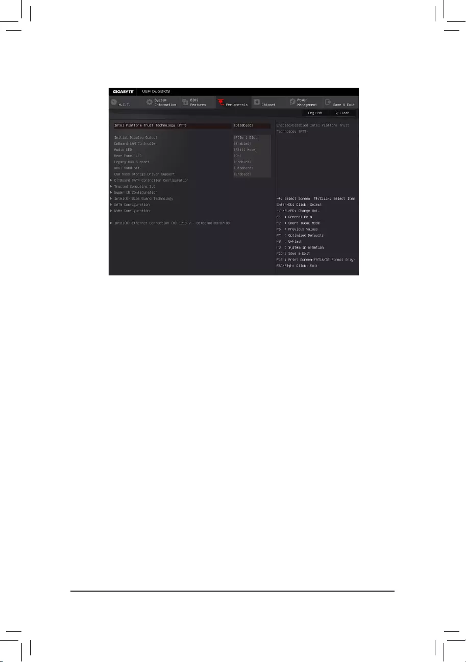
— 60 —
2-6 Peripherals
&Intel Platform Trust Technology (PTT)
Enables or disables Intel®PTTTechnology.(Default:Disabled)
&Initial Display Output
SpeciestherstinitiationofthemonitordisplayfromtheinstalledPCIExpressgraphicscardortheonboard
graphics.
IGFX Setstheonboardgraphicsastherstdisplay.
PCIe1Slot SetsthegraphicscardonthePCIEX16slotastherstdisplay.(Default)
PCIe2Slot SetsthegraphicscardonthePCIEX8slotastherstdisplay.
PCIe3Slot SetsthegraphicscardonthePCIEX4slotastherstdisplay.
&OnBoard LAN Controller (Rivet Networks Killer™ E2400 LAN Chip, LAN2)
Enables or disables the RivetNetworksKiller™ E2400LANfunction.(Default:Enabled)
If you wish to install a 3rd party add-in network card instead of using the onboard LAN, set this item to
Disabled.
&Audio LED
Enables or disables the onboard audio LED function.
Off Disables this function.
StillMode TheLEDsstayconstantlyon.(Default)
Beat Mode The brightness of the LED changes according to the music rhythm.
Pulse Mode The brightness of the LED changes slowly and smoothly like breath.
&Rear Panel LED
Enables or disables the audio LED on the rear panel I/O shield.
On TheLEDwilllightandfollowthebehavioroftheonboardaudioLEDs.(Default)
Off Disables this function.
&LED Hue
AllowsyoutochangethecoloroftheaudioLEDs.(Default:Red)

— 61 —
&Legacy USB Support
AllowsUSBkeyboard/mousetobeusedinMS-DOS.(Default:Enabled)
&XHCI Hand-off
Determines whether to enable XHCI Hand-off feature for an operating system without XHCI Hand-off
support.(Default:Disabled)
&USB Mass Storage Driver Support
EnablesordisablessupportforUSBstoragedevices.(Default:Enabled)
&USB Storage Devices
Displays a list of connected USB mass storage devices. This item appears only when a USB storage device
is installed.
`OffBoardSATAControllerConguration
Displays information on your M.2 PCIe SSD if installed.
`Trusted Computing 2.0
This sub-menu appears only when Intel Platform Trust Technology is set to Enabled.
&Security Device Support
EnablesordisablesTrustedPlatformModule(TPM).(Default:Enable)
&TPM 20 InterfaceType
Allows you to select the communication interface for the TPM 2.0 device. Set to
External TPM2.0
if you
installanInneonTPM2.0module(optional).(Default:PTT)
&Device Select
Allows you to select whether to support TPM 1.2 or TPM 2.0 device. Auto lets the BIOS automatically
congurethissetting.(Default:Auto)
`SuperIOConguration
&Serial Port 1
Enablesordisablestheonboardserialport.(Default:Enabled)
`Intel(R) Bios Guard Technology
Enables or disables the Intel® BIOS Guard feature, which protects the BIOS from malicious attacks.
`SATAConguration
&SATA Controller(s)
EnablesordisablestheintegratedSATAcontrollers.(Default:Enabled)
&SATA Mode Selection
EnablesordisablesRAIDfortheSATAcontrollersintegratedintheChipsetorcongurestheSATAcontrollers
to AHCI mode.
RAID EnablesRAIDfortheSATAcontroller.
AHCI CongurestheSATAcontrollerstoAHCImode.AdvancedHostControllerInterface(AHCI)
isaninterfacespecicationthatallowsthestoragedrivertoenableadvancedSerialATA
featuressuchasNativeCommandQueuingandhotplug.(Default)
&Aggressive LPM Support
Enablesordisablesthepowersavingfeature,ALPM(AggressiveLinkPowerManagement),fortheChipset
SATAcontrollers.(Default:Enabled)

— 62 —
&Port 0/1/2/3/4/5
EnablesordisableseachSATAport.(Default:Enabled)
&Hot plug
EnablesordisablethehotplugcapabilityforeachSATAport.(Default:Disabled)
&External SATA
EnablesordisablessupportforexternalSATAdevices.(Default:Disabled)
`NVMeConguration
Displays information on your M.2 NVME PCIe SSD if installed.
`Intel(R) Ethernet Network Connection
Thissub-menuprovidesinformationonLANcongurationandrelatedcongurationoptions.
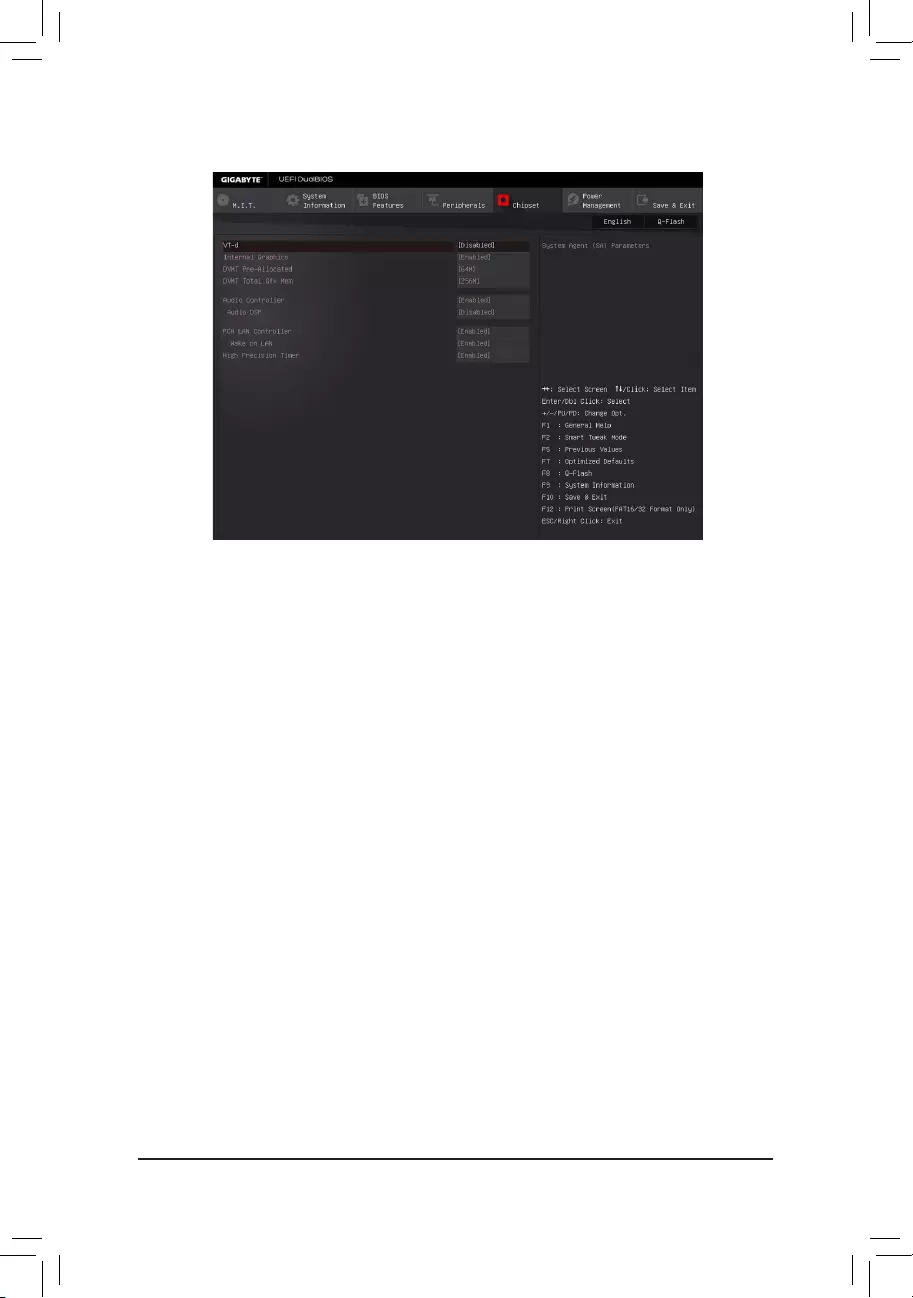
— 63 —
&VT-d (Note)
Enables or disables Intel®VirtualizationTechnologyforDirectedI/O.(Default:Disabled)
&Internal Graphics
Enablesordisablestheonboardgraphicsfunction.(Default:Enabled)
&DVMT Pre-Allocated
Allowsyoutosettheonboardgraphicsmemorysize.Optionsare:32M~512M.(Default:64M)
&DVMT Total Gfx Mem
Allows you to allocate the DVMT memory size of the onboard graphics. Options are: 128M, 256M, MAX.
(Default:256M)
&Audio Controller
Enablesordisablestheonboardaudiofunction.(Default:Enabled)
If you wish to install a 3rd party add-in audio card instead of using the onboard audio, set this item to
Disabled.
&Audio DSP
EnablesordisablestheDSPfunctionalityofthePCHaudiounit.(Default:Disabled)
&PCH LAN Controller (Intel® GbE LAN Chip, LAN1)
Enables or disables the Intel®GbELANfunction.(Default:Enabled)
If you wish to install a 3rd party add-in network card instead of using the onboard LAN, set this item to
Disabled.
&Wake on LAN
EnablesordisablesthewakeonLANfunction.(Default:Enabled)
&High Precision Timer
EnablesordisablesHighPrecisionEventTimer(HPET)intheoperatingsystem.(Default:Enabled)
2-7 Chipset
(Note) ThisitemispresentonlywhenyouinstallaCPUthatsupportsthisfeature.Formoreinformationabout
Intel® CPUs’ unique features, please visit Intel’s website.
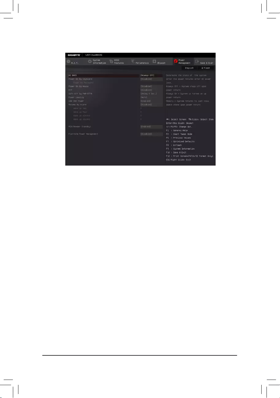
— 64 —
&AC BACK
Determines the state of the system after the return of power from an AC power loss.
AlwaysOff ThesystemstaysoffuponthereturnoftheACpower.(Default)
Always On The system is turned on upon the return of the AC power.
Memory The system returns to its last known awake state upon the return of the AC power.
&Power On By Keyboard
Allows the system to be turned on by a PS/2 keyboard wake-up event.
Note: To use this function, you need an ATX power supply providing at least 1A on the +5VSB lead.
Disabled Disablesthisfunction.(Default)
Any Key Press any key to turn on the system.
Keyboard98 PressPOWERbuttonontheWindows98keyboardtoturnonthesystem.
Password Set a password with 1~5 characters to turn on the system.
&Power On Password
Set the password when Power On By Keyboard is set to Password.
Press <Enter> on this item and set a password with up to 5 characters and then press <Enter> to accept.
To turn on the system, enter the password and press <Enter>.
Note: To cancel the password, press <Enter> on this item. When prompted for the password, press <Enter>
again without entering the password to clear the password settings.
&Power On By Mouse
Allows the system to be turned on by a PS/2 mouse wake-up event.
Note: To use this function, you need an ATX power supply providing at least 1A on the +5VSB lead.
Disabled Disablesthisfunction.(Default)
Move Move the mouse to turn on the system.
Double Click Double click on left button on the mouse to turn on the system.
2-8 Power Management

— 65 —
&ErP
DetermineswhethertoletthesystemconsumeleastpowerinS5(shutdown)state.(Default:Disabled)
Note: When this item is set to Enabled,thefollowingfunctionswillbecomeunavailable:ResumebyAlarm,
PME event wake up, power on by mouse, power on by keyboard, and wake on LAN.
&Soft-Off by PWR-BTTN
ConguresthewaytoturnoffthecomputerinMS-DOSmodeusingthepowerbutton.
Instant-Off Pressthepowerbuttonandthenthesystemwillbeturnedoffinstantly.(Default)
Delay 4 Sec. Press and hold the power button for 4 seconds to turn off the system. If the power
button is pressed for less than 4 seconds, the system will enter suspend mode.
&Power Loading
Enables or disables dummy load. When the power supply is at low load, a self-protection will activate causing
it to shutdown or fail. If this occurs, please set to Enabled. AutoletstheBIOSautomaticallycongurethis
setting.(Default:Auto)
&USB DAC Power
Enables or disables the power for the USB DAC connector on the back panel. For a USB DAC that has
independent power, set this item to Disabled.(Default:Enabled)
&Resume by Alarm
Determineswhethertopoweronthesystematadesiredtime.(Default:Disabled)
If enabled, set the date and time as following:
Wakeupday:Turnonthesystemataspecictimeoneachdayoronaspecicdayinamonth.
Wake up hour/minute/second: Set the time at which the system will be powered on automatically.
Note: When using this function, avoid inadequate shutdown from the operating system or removal of the
AC power, or the settings may not be effective.
&RC6(Render Standby)
Allows you to determine whether to let the onboard graphics enter standby mode to decrease power
consumption.(Default:Enabled)
&Platform Power Management
EnablesordisablestheActiveStatePowerManagementfunction(ASPM).(Default:Disabled)
&PEG ASPM
AllowsyoutoconguretheASPM mode forthedeviceconnectedtotheCPUPEGbus.This item is
congurableonlywhenPlatform Power Management is set to Enabled.(Default:Enabled)
&PCH ASPM
AllowsyoutoconguretheASPMmodeforthedeviceconnectedtoChipset’sPCIExpressbus.Thisitem
iscongurableonlywhenPlatform Power Management is set to Enabled.(Default:Enabled)
&DMI Link ASPM Control
AllowsyoutoconguretheASPMmodeforbothCPUsideandChipsetsideoftheDMIlink.Thisitemis
congurableonlywhenPlatform Power Management is set to Enabled.(Default:Enabled)
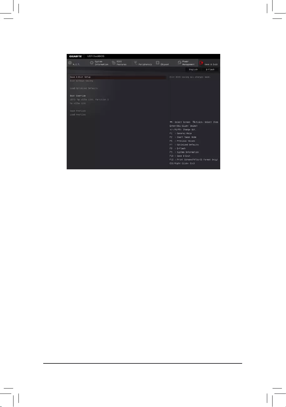
— 66 —
2-9 Save & Exit
&Save & Exit Setup
Press <Enter> on this item and select Yes. This saves the changes to the CMOS and exits the BIOS Setup
program. Select No or press <Esc> to return to the BIOS Setup Main Menu.
&Exit Without Saving
Press <Enter> on this item and select Yes. This exits the BIOS Setup without saving the changes made
in BIOS Setup to the CMOS. Select No or press <Esc> to return to the BIOS Setup Main Menu.
&Load Optimized Defaults
Press <Enter> on this item and select Yes to load the optimal BIOS default settings. The BIOS defaults
settings help the system to operate in optimum state. Always load the Optimized defaults after updating
the BIOS or after clearing the CMOS values.
&Boot Override
Allows you to select a device to boot immediately. Press <Enter> on the device you select and select Yes
toconrm.Yoursystemwillrestartautomaticallyandbootfromthatdevice.
&SaveProles
ThisfunctionallowsyoutosavethecurrentBIOSsettingstoaprole.Youcancreateupto8prolesand
saveasSetupProle1~SetupProle8.Press<Enter>tocomplete.OryoucanselectSelect File in
HDD/FDD/USBtosavetheproletoyourstoragedevice.
&LoadProles
If your system becomes unstable and you have loaded the BIOS default settings, you can use this function
toloadtheBIOSsettings fromaprolecreatedbefore,withoutthehasslesofreconguring theBIOS
settings.Firstselecttheproleyouwishtoloadandthenpress<Enter>tocomplete.YoucanselectSelect
File in HDD/FDD/USBtoinputtheprolepreviouslycreatedfromyourstoragedeviceorloadtheprole
automatically created by the BIOS, such as reverting the BIOS settings to the last settings that worked
properly(lastknowngoodrecord).

— 67 —
Chapter3 ConguringaRAIDSet
To create a RAID set, follow the steps below:
A. InstallSATAharddrive(s)inyourcomputer.
B. CongureSATAcontrollermodeinBIOSSetup.
C. CongureaRAIDarrayinRAIDBIOS.(Note1)
D. InstalltheSATARAID/AHCIdriverandoperatingsystem.
Before you begin, please prepare the following items:
•At least two SATA hard drives or M.2 SSDs (Note2) (to ensure optimal performance, it is recommended that
youusetwoharddriveswithidenticalmodelandcapacity).(Note3)
•A Windows setup disk.
•Motherboard driver disk.
•A USB thumb drive.
3-1 ConguringSATAControllers
A. Installing hard drives
Connect the SATA signal cables to SATA hard drives and the Intel® ChipsetcontrolledSATAports(SATA30~5)
on the motherboard. Then connect the power connectors from your power supply to the hard drives. Or install
yourM.2SSD(s)intheM.2connector(s)onthemotherboard.
RAID Levels
RAID 0 RAID 1 RAID 5 RAID 10
Minimum
Number of Hard
Drives
≥2 2≥3 ≥4
Array Capacity Number of hard
drives*Sizeofthe
smallest drive
Size of the smallest
drive
(Number of hard
drives-1)*Sizeof
the smallest drive
(Number of hard
drives/2)*Sizeofthe
smallest drive
Fault Tolerance No Yes Yes Yes
(Note1) SkipthisstepifyoudonotwanttocreateRAIDarrayontheSATAcontroller.
(Note2) AnM.2PCIeSSDcannotbeusedtosetupaRAIDseteitherwithanM.2SATASSDoraSATAhard
drive.
(Note3) RefertoChapter1,«InternalConnectors,»»M.2Socket3Connector,»forthecongurationtablesof
SATA hard drives and M.2 SSDs.
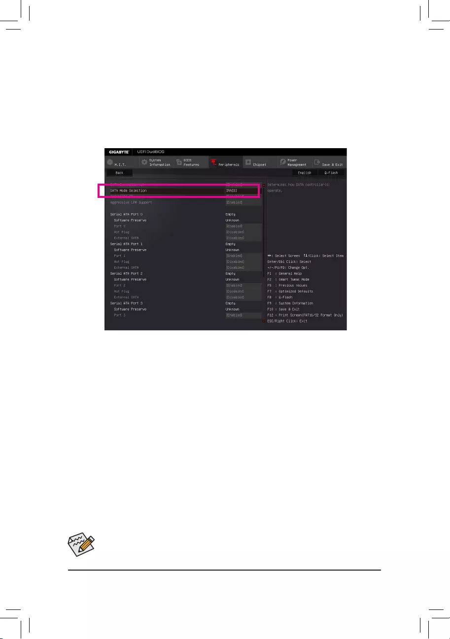
— 68 —
The BIOS Setup menus described in this section may differ from the exact settings for your motherboard.
The actual BIOS Setup menu options you will see shall depend on the motherboard you have and
the BIOS version.
B.ConguringSATAcontrollermodeinBIOSSetup
MakesuretoconguretheSATAcontrollermodecorrectlyinsystemBIOSSetup.
Step 1:
Turnonyourcomputerandpress<Delete>toenterBIOSSetupduringthePOST(Power-OnSelf-Test).Go
to Peripherals\SATAConguration, make sure SATA Controller(s)isenabled.TocreateRAID,setSATA
Mode Selection to RAID(Figure1).
Step 2:
IfyouwanttocongureUEFIRAID,followthestepsin«C-1.»ToenterthelegacyRAIDROM,savethesettings
andexitBIOSSetup.Referto»C-2″formoreinformation.
Figure 1
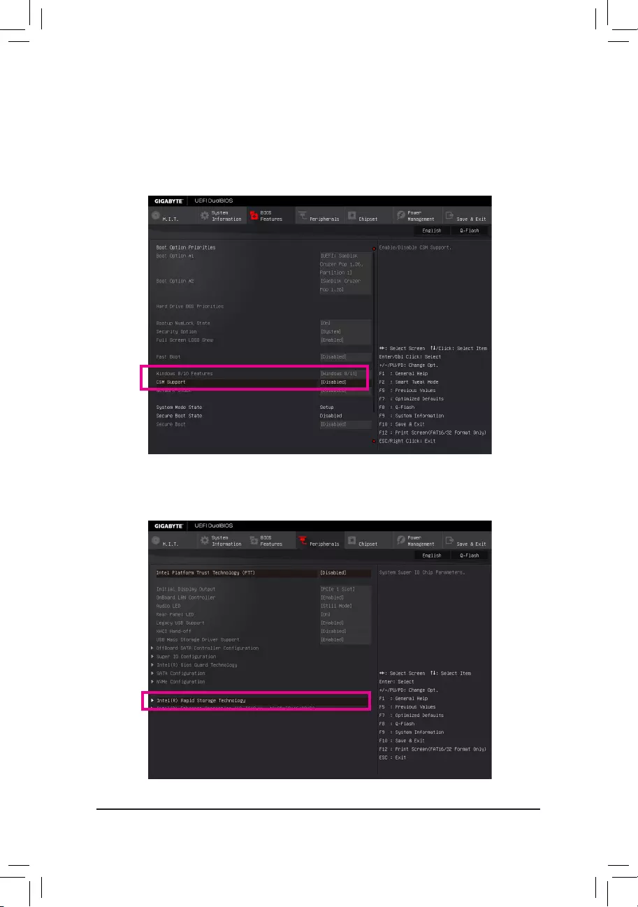
— 69 —
C-1.UEFIRAIDConguration
OnlyWindows10/8.164-bitsupportsUEFIRAIDconguration.
Step 1:
In BIOS Setup, go to BIOS Features and set Windows 8/10 Features to Windows 8/10 and CSM Support to
Disabled(Figure2).SavethechangesandexitBIOSSetup.
Step 2:
After the system reboot, enter BIOS Setup again. Then enter the Peripherals\Intel(R) Rapid Storage Technology
sub-menu(Figure3).
Figure 2
Figure 3
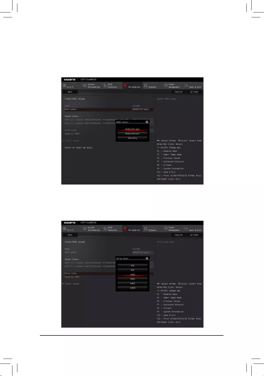
— 70 —
Step 3:
On the Intel(R) Rapid Storage Technology menu, press <Enter> on Create RAID Volume to enter the Create
RAID Volumescreen.Enteravolumenamewith1~16letters(letterscannotbespecialcharacters)underthe
Nameitemandpress<Enter>.Then,selectaRAIDlevel(Figure4).RAIDlevelssupportedincludeRAID0,
RAID1,RAID10,andRAID5(theselectionsavailabledependonthenumberoftheharddrivesbeinginstalled).
Next, use the down arrow key to move to Select Disks.
Step 4:
Under Select Disksitem,selecttheharddrivestobeincludedintheRAIDarray.Pressthe<Space>keyon
theharddrivestobeselected(selectedharddrivesaremarkedwith«X»).Thensetthestripeblocksize(Figure
5).Thestripeblocksizecanbesetfrom4KBto128KB.Onceyouhaveselectedthestripeblocksize,set
the volume capacity.
Figure 4
Figure 5
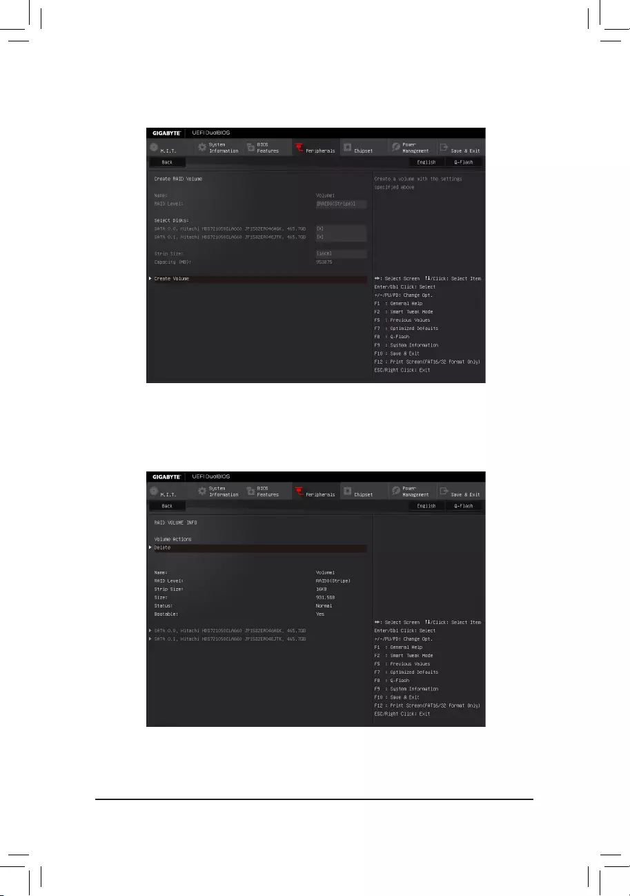
— 71 —
Step 5:
After setting the capacity, move to Create Volumeandpress<Enter>tobegin.(Figure6)
After completing, you’ll be brought back to the Intel(R) Rapid Storage Technology screen. Under RAID Volumes
youcanseethenewRAIDvolume.Toseemoredetailedinformation,press<Enter>onthevolumetocheckfor
informationonRAIDlevel,stripeblocksize,arrayname,andarraycapacity,etc.(Figure7)
Figure 6
Figure 7
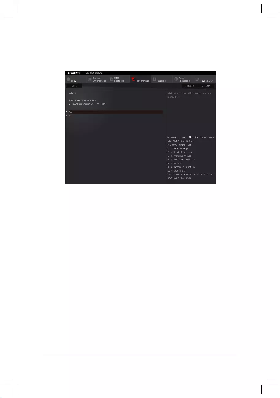
— 72 —
Delete RAID Volume
TodeleteaRAIDarray,press<Enter>onthevolumetobedeletedontheIntel(R) Rapid Storage Technology
screen. After entering the RAID VOLUME INFO screen, press <Enter> on Delete to enter the Delete screen.
Press <Enter> on Yes(Figure8).
Figure 8
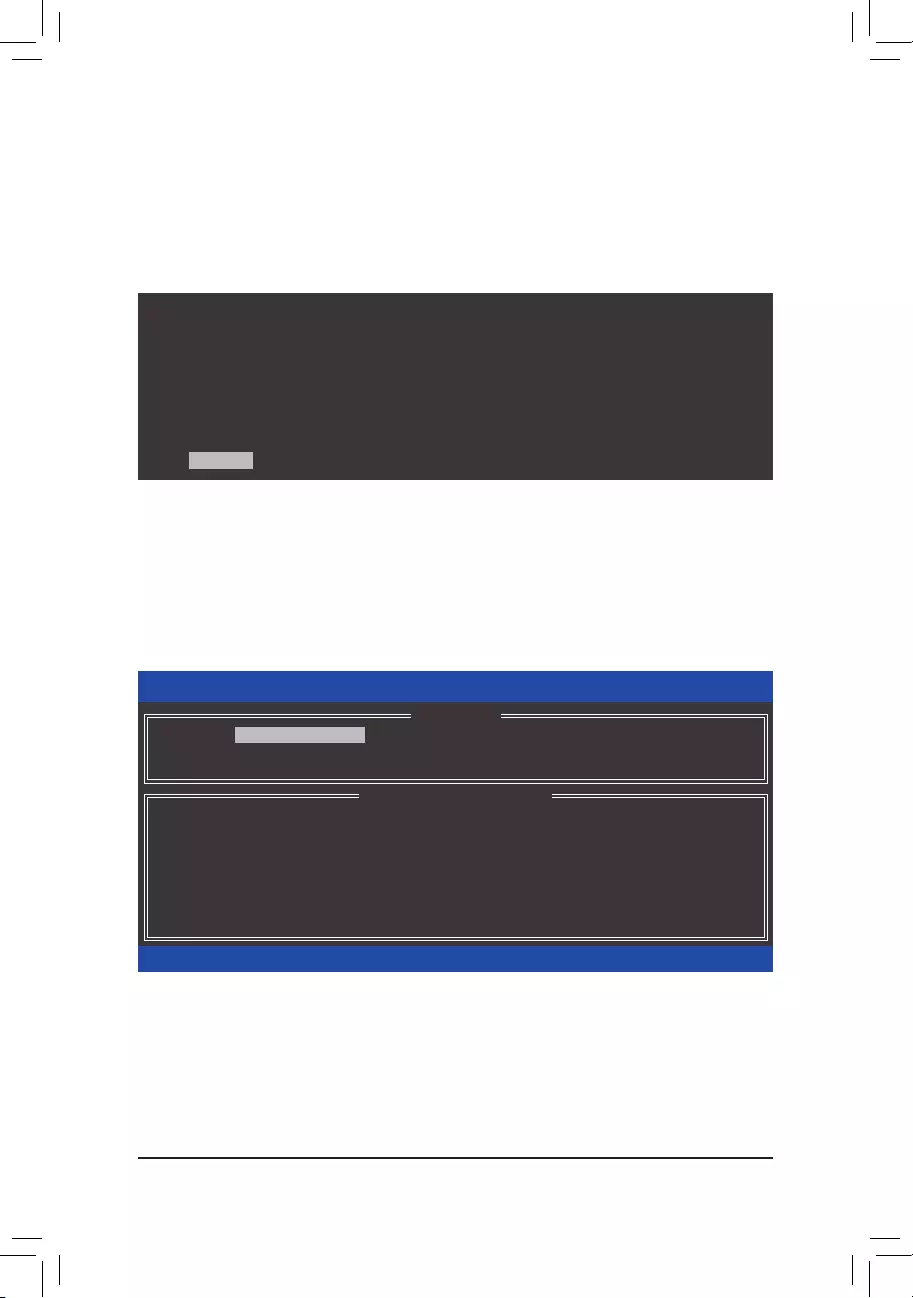
— 73 —
C-2.ConguringLegacyRAIDROM
Enter the Intel®legacyRAIDBIOSsetuputilitytocongureaRAIDarray.Skipthisstepandproceedwiththe
installationofWindowsoperatingsystemforanon-RAIDconguration.
Step 1:
After the POST memory test begins and before the operating system boot begins, look for a message which says
«Press<Ctrl-I>toenterCongurationUtility»(Figure9).Press<Ctrl>+<I>toentertheRAIDCongurationUtility.
Figure 9
Step 2:
After you press <Ctrl> + <I>, the MAIN MENUscreenwillappear(Figure10).
Create RAID Volume
IfyouwanttocreateaRAIDarray,selectCreate RAID Volume in MAIN MENU and press <Enter>.
Figure 10
Intel(R) Rapid Storage Technology — Option ROM — 14.0.0.2209
Copyright (C) Intel Corporation. All Rights Reserved.
4. Recovery Volume Options
5. Acceleration Options
6. Exit
RAID Volumes :
None dened.
Physical Deivces :
ID Device Model Serial # Size Type/Status(Vol ID)
1 Hitachi HDS72105 JP1532ER04EJTK 465.7GB Non-RAID Disk
2 Hitachi HDS72105 JP1532ER046AGK 465.7GB Non-RAID Disk
[hi]-Select [ESC]-Exit [ENTER]-Select Menu
[ DISK/VOLUME INFORMATION ]
[ MAIN MENU ]
1. Create RAID Volume
2. Delete RAID Volume
3. Reset Disks to Non-RAID
Intel(R) Rapid Storage Technology — Option ROM — 14.0.0.2209
Copyright (C) Intel Corporation. All Rights Reserved.
RAID Volumes :
None dened.
Physical Devices :
ID Device Model Serial # Size Type/Status(Vol ID)
1 Hitachi HDS72105 JP1532ER04EJTK 465.7GB Non-RAID Disk
2 Hitachi HDS72105 JP1532ER046AGK 465.7GB Non-RAID Disk
Press <CTRL — I> to enter Conguration Utility…
— 74 —
Step 3:
After entering the CREATE VOLUME MENU screen, enter a volume name with 1~16 letters (letters cannot be
specialcharacters)undertheNameitemandpress<Enter>.Then,selectaRAIDlevel(Figure11).RAIDlevels
supportedincludeRAID0,RAID1,RAID10,andRAID5(theselectionsavailabledependonthenumberofthe
harddrivesbeinginstalled).Press<Enter>toproceed.
Step 4:
Under Disksitem,selecttheharddrivestobeincludedintheRAIDarray.Ifonlytwoharddrivesareinstalled,
theywillbeautomaticallyassignedtothearray.Setthestripeblocksize(Figure12)ifnecessary.Thestripeblock
size can be set from 4 KB to 128 KB. Once you have selected the stripe block size, press <Enter>.
Figure 11
Figure 12
Intel(R) Rapid Storage Technology — Option ROM — 14.0.0.2209
Copyright (C) Intel Corporation. All Rights Reserved.
RAID 0: Stripes data (performance).
[hi]-Change [TAB]-Next [ESC]-Previous Menu [ENTER]-Select
[ HELP ]
Name : Volume0
RAID Level : RAID0(Stripe)
Disks : Select Disks
Strip Size : 16KB
Capacity : 931.5 GB
Sync : N/A
Create Volume
[ CREATE VOLUME MENU ]
Intel(R) Rapid Storage Technology — Option ROM — 14.0.0.2209
Copyright (C) Intel Corporation. All Rights Reserved.
The following are typical values:
RAID0 — 128KB
RAID10 — 64KB
RAID5 — 64KB
[hi]-Change [TAB]-Next [ESC]-Previous Menu [ENTER]-Select
[ HELP ]
[ CREATE VOLUME MENU ]
Name : Volume0
RAID Level : RAID0(Stripe)
Disks : Select Disks
Strip Size : 16KB
Capacity : 931.5 GB
Sync : N/A
Create Volume
— 75 —
Step 5:
Enter the array capacity and press <Enter>. Finally press <Enter> on the Create Volume item to begin creating
theRAIDarray.Whenprompted toconrmwhether tocreatethis volume,press<Y> toconrmor <N>to
cancel(Figure13).
Whencompleted,youcanseedetailedinformationabouttheRAIDarrayintheDISK/VOLUME INFORMATION
section,includingtheRAIDlevel,stripeblocksize,arrayname,andarraycapacity,etc.(Figure14)
ToexittheRAIDBIOSutility,press<Esc>orselect6. Exit in MAIN MENU.
Now,youcanproceedtoinstalltheSATARAID/AHCIdriverandoperatingsystem.
Figure 13
Figure 14
Intel(R) Rapid Storage Technology — Option ROM — 14.0.0.2209
Copyright(C) Intel Corporation. All Rights Reserved.
Press ENTER to create the specied volume.
[hi]-Change [TAB]-Next [ESC]-Previous Menu [ENTER]-Select
[ HELP ]
Name : Volume0
RAID Level : RAID0(Stripe)
Disks : Select Disks
Strip Size : 128 MB
Capacity : 931.5 GB
Sync : N/A
Create Volume
[ CREATE VOLUME MENU ]
WARNING : ALL DATA ON SELECTED DISKS WILL BE LOST.
Are you sure you want to create this volume? (Y/N) :
Intel(R) Rapid Storage Technology — Option ROM — 14.0.0.2209
Copyright (C) Intel Corporation. All Rights Reserved.
RAID Volumes :
ID Name Level Strip Size Status Bootable
0 Volume0 RAID0(Stripe) 128KB 931.5GB Normal Yes
Physical Devices :
ID Device Model Serial # Size Type/Status(Vol ID)
1 Hitachi HDS72105 JP1532ER04EJTK 465.7GB Member Disk(0)
2 Hitachi HDS72105 JP1532ER046AGK 465.7GB Member Disk(0)
[hi]-Select [ESC]-Exit [ENTER]-Select Menu
[ DISK/VOLUME INFORMATION ]
[ MAIN MENU ]
4. Recovery Volume Options
5. Acceleration Options
6. Exit
1. Create RAID Volume
2. Delete RAID Volume
3. Reset Disks to Non-RAID
— 76 —
Recovery Volume Options
Intel®RapidRecoverTechnologyprovidesdataprotectionbyallowinguserstoeasilyrestoredataandsystem
operationusingadesignatedrecoverydrive.WiththeRapidRecoveryTechnology, whichemploysRAID 1
functionality, users can copy the data from the master drive to the recovery drive; if needed, the data on the
recovery drive can be restored back to the master drive.
Before you begin:
•The recovery drive must have equal or greater capacity than the master drive.
•Arecoveryvolumecanbecreatedwithtwoharddrivesonly.ArecoveryvolumeandaRAIDarraycannot
co-exist in the system at the same time, that is, if you have already created a recovery volume, you are
unabletocreateaRAIDarray.
•By default, only the master drive can be viewed in the operating system; the recovery drive is hidden.
Step 1:
Select Create RAID Volume in MAIN MENUandpress<Enter>(Figure15).
Figure 15
Figure 16
Step 2:
After entering the volume name, select Recovery under the RAID Levelitemandpress<Enter>(Figure16).
Intel(R) Rapid Storage Technology — Option ROM — 14.0.0.2209
Copyright (C) Intel Corporation. All Rights Reserved.
RAID Volumes :
None dened.
Physical Disks :
ID Drive Model Serial # Size Type/Status(Vol ID)
1 Hitachi HDS72105 JP1532ER04EJTK 465.7GB Non-RAID Disk
2 Hitachi HDS72105 JP1532ER046AGK 465.7GB Non-RAID Disk
[hi]-Select [ESC]-Exit [ENTER]-Select Menu
[ DISK/VOLUME INFORMATION ]
[ MAIN MENU ]
4. Recovery Volume Options
5. Acceleration Options
6. Exit
1. Create RAID Volume
2. Delete RAID Volume
3. Reset Disks to Non-RAID
Intel(R) Rapid Storage Technology — Option ROM — 14.0.0.2209
Copyright (C) Intel Corporation. All Rights Reserved.
Recovery: Copies data between a master and a recovery disk.
[hi]-Change [TAB]-Next [ESC]-Previous Menu [ENTER]-Select
[ HELP ]
Name : Volume0
RAID Level : Recovery
Disks : Select Disks
Strip Size : N/A
Capacity : 465.7 GB
Sync : Continuous
Create Volume
[ CREATE VOLUME MENU ]
— 77 —
Figure 17
Step 3:
Press <Enter> under the Select Disks item. In the SELECT DISKS box, press <Tab> on the hard drive you want
to use for the master drive and press <Space> on the hard drive you want to use for the recovery drive. (Make sure
therecoverydrivehasequalorlargercapacitythanthemasterdrive.)Thenpress<Enter>toconrm(Figure17).
Step 4:
Under Sync, select Continuous or On Request(Figure18).WhensettoContinuous, changes made to the
data on the master drive will be automatically and continuously copied to the recovery drive when both hard
drives are installed in the system. On Request allows users to update data from the master drive to the recovery
drive manually using the Intel®RapidStorageTechnologyutilityintheoperatingsystem.On Request also allows
users to restore the master drive to a previous state.
Figure 18
Step 5:
Finally press <Enter> on the Create VolumeitemtobegincreatingtheRecoveryVolumeandfollowtheon-
screen instructions to complete.
Intel(R) Rapid Storage Technology — Option ROM — 14.0.0.2209
Copyright (C) Intel Corporation. All Rights Reserved.
Choose the RAID level:
RAID0: Stripes data (performance).
RAID1: Mirrors data (redundancy).
Recovery: Copies data between a master and a recovery disk.
RAID10: Mirrors data and stripes the mirror.
RAID5: Stripes data and parity.
[hi]-Change [TAB]-Next [ESC]-Previous Menu [ENTER]-Select
[ HELP ]
[ CREATE VOLUME MENU ]
Name : Volume0
RAID Level : Recovery
Disks : Select Disks
Strip Size : 128KB
Capacity : 223.6 GB
Create Volume
[ SELECT DISKS ]
[hi]-Prev/Next [TAB]-(M)aster [SPACE]-(R)ecovery [ENTER]-Done
ID Drive Model Serial # Size Status
M1 Hitachi HDS72105 JP1532ER04EJTK 465.7GB Non-RAID Disk
R2 Hitachi HDS72105 JP1532ER046AGK 465.7GB Non-RAID Disk
Select 1 Master and 1 Recovery disk to create volume.
Intel(R) Rapid Storage Technology — Option ROM — 14.0.0.2209
Copyright (C) Intel Corporation. All Rights Reserved.
Select a sync option:
On Request: volume is updated manually
Continuous: volume is updated automatically
[hi]-Change [TAB]-Next [ESC]-Previous Menu [ENTER]-Select
[ HELP ]
Name : Volume0
RAID Level : Recovery
Disks : Select Disks
Strip Size : N/A
Capacity : 0.0 GB
Sync : Continuous
Create Volume
[ CREATE VOLUME MENU ]
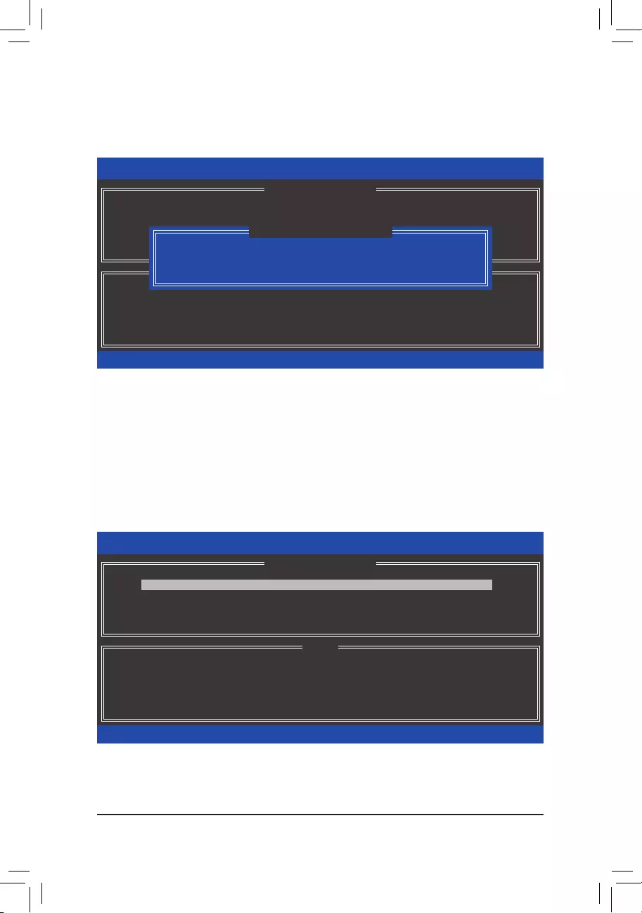
— 78 —
Delete RAID Volume
To delete a RAID array, select Delete RAID Volume in MAIN MENU and press <Enter>. In the DELETE
VOLUME MENU section, use the up or down arrow key to select the array to be deleted and press <Delete>.
Whenpromptedtoconrmyourselection(Figure19),press<Y>toconrmor<N>toabort.
Figure 19
Acceleration Options
Thisoptionallowsyoutoviewthestatusofyouraccelerateddrive/volume(Figure20)createdusingtheIntel®
IRSTutility.IncaseyouareunabletoruntheIntel® IRSTutilityduetoanapplicationerrororoperatingsystem
issue,youwillneedtoremoveaccelerationormanuallyenablesynchronization(Maximizedmodeonly)using
thisoptionintheRAIDROMutility.
Steps:
Select Acceleration Options in MAIN MENU and press <Enter>.
Toremovetheacceleration,selecttheaccelerateddrive/volume,press<R>,andpress<Y>toconrm.
Tosynchronizedatafromthecachedevicetotheaccelerateddrive/volume,press<S>andpress<Y>toconrm.
Figure 20
Intel(R) Rapid Storage Technology — Option ROM — 14.0.0.2209
Copyright (C) Intel Corporation. All Rights Reserved.
Deleting a volume will reset the disks to non-RAID.
WARNING: ALL DISK DATA WILL BE DELETED.
(This does not apply to Recovery volumes)
[hi]-Select [ESC]-Previous Menu [DEL]-Delete Volume
[ HELP ]
[ DELETE VOLUME MENU ]
Name Level Drives Capacity Status Bootable
Volume0 RAID0(Stripe) 2 931.5GB Normal Yes
ALL DATA IN THE VOLUME WILL BE LOST!
(This does not apply to Recovery volumes)
Are you sure you want to delete «Volume0″? (Y/N) :
[ DELETE VOLUME VERIFICATION ]
Intel(R) Rapid Storage Technology — Option ROM — 14.0.0.2209
Copyright (C) Intel Corporation. All Rights Reserved.
Press ‘s’ to synchronize data from the cache device to
the Accelerated Disk/Volume
Press ‘r’ to remove the Disk/Volume Acceleration
WARNING: IT IS RECOMMENDED THAT YOU PERFORM A SYNCHRONIZATION
BEFORE REMOVING ACCELERATION
[hi]-Select [ESC]- Previous Menu
[ HELP ]
[ ACCELERATION OPTIONS ]
Name Type Capacity Mode Status
DISK PORT 3 Non-RAID Disk 465.7GB Enhanced In Sync
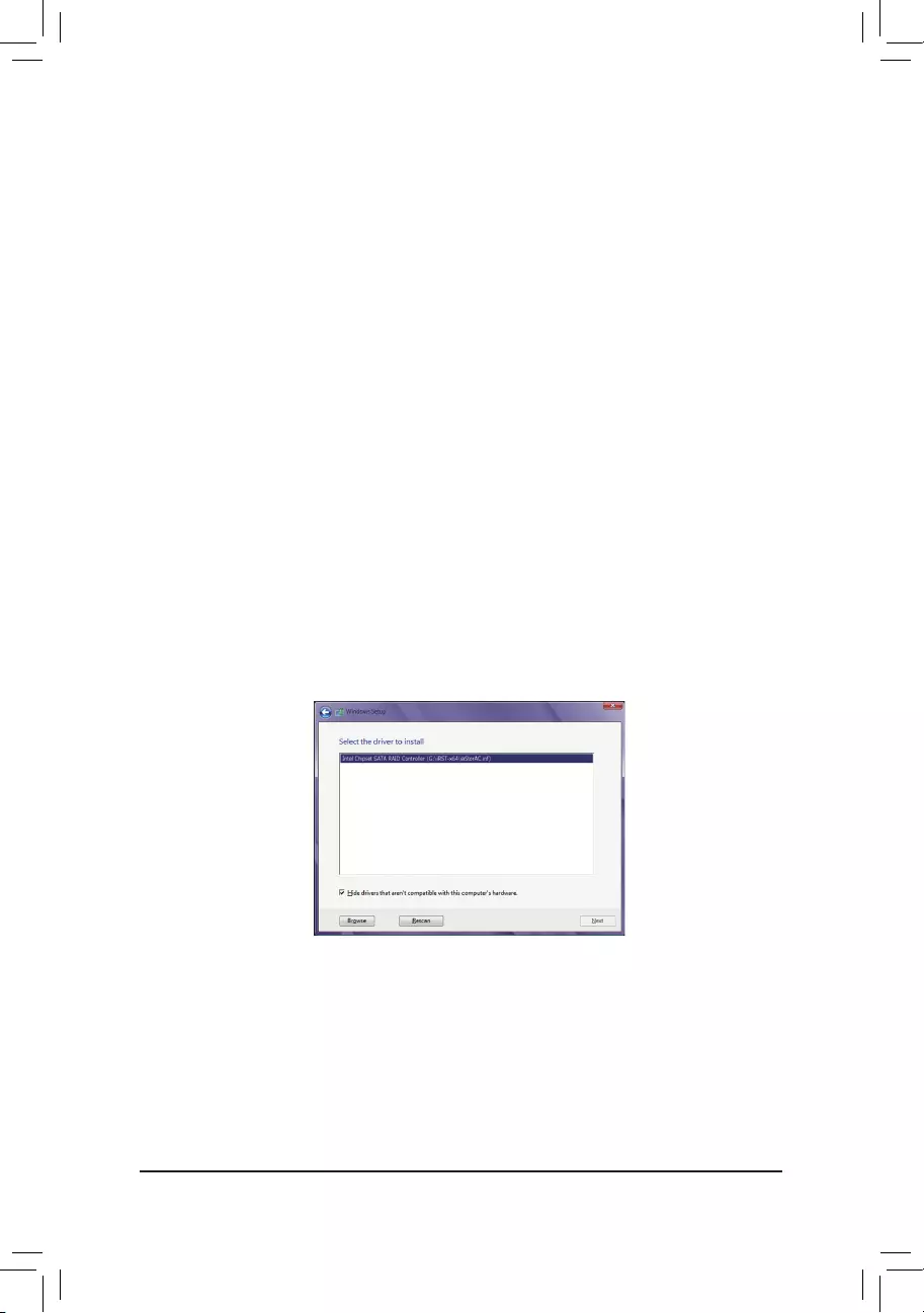
— 79 —
3-2 Installing the SATA RAID/AHCI Driver and Operating System
With the correct BIOS settings, you are ready to install the operating system.
A. Installing Windows
As some operating systems already include Intel®SATARAID/AHCIdriver,youdonotneedtoinstallseparate
RAID/AHCIdriverduringtheWindowsinstallationprocess.Aftertheoperatingsystemisinstalled,werecommend
that you install all required drivers from the motherboard driver disk using «Xpress Install» to ensure system
performance and compatibility. If the operating system to be installed requires that you provide additional SATA
RAID/AHCIdriverduringtheOSinstallationprocess,pleaserefertothestepsbelow:
Step 1:
Copy the IRST-x64 or IRST-x86 folder(dependingonyourOSversion)undertheBoot folder in the driver disk
to your USB thumb drive.
Step 2:
Boot from the Windows setup disk and perform standard OS installation steps. When the screen requesting you
to load the driver appears, select Browse.
Step 3:
Insert the USB thumb drive and then browse to the folder (IRST-x64 or IRST-x86) that you previously copied.
Step 4:
When a screen as shown in Figure 1 appears, select Intel Chipset SATA RAID Controller and click Next to
load the driver and continue the OS installation.
Figure 1
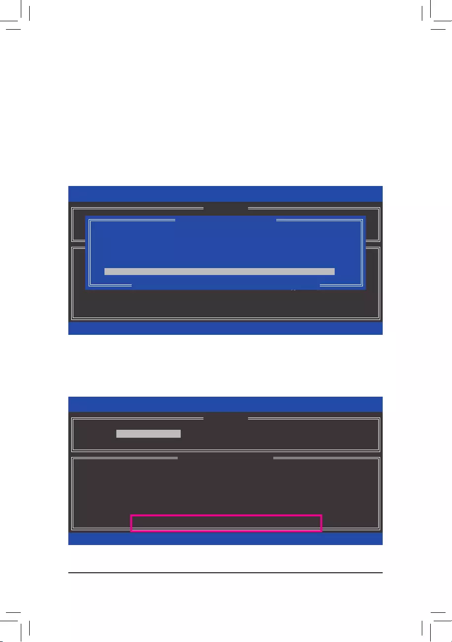
— 80 —
B. Rebuilding an Array
Rebuildingistheprocessofrestoringdatatoaharddrivefromotherdrivesinthearray.Rebuildingappliesonly
tofault-tolerantarrayssuchasRAID1,RAID5orRAID10arrays.Theproceduresbelowassumeanewdrive
isaddedtoreplaceafaileddrivetorebuildaRAID1array.(Note:Thenewdrivemusthaveequalorgreater
capacitythantheoldone.)
Turnoffyourcomputerandreplacethefailedharddrivewithanewone.Restartyourcomputer.
•Enabling Automatic Rebuild
Step 1:
Whenthemessage»Press<Ctrl-I>toenterCongurationUtility»appears,press<Ctrl>+<I>toentertheRAID
CongurationUtility.ThefollowingscreenappearsafteryouentertheRAIDCongurationUtility.
Step 2:
Select the new hard drive to add into the array to be rebuilt and press <Enter>. The following screen appears,
indicating that an automatic rebuild will be performed after you enter the operating system. If you do not enable
automatic rebuild on this stage, you have to manually rebuild the array in the operating system (see the next
pageformoredetails).
Intel(R) Rapid Storage Technology — Option ROM — 14.0.0.2209
Copyright (C) Intel Corporation. All Rights Reserved.
3. Reset Disks to Non-RAID
4. Exit
RAID Volumes :
None dened.
Physical Disks :
ID Drive Model Serial # Size Type/Status(Vol ID)
4 Hitachi HDS72105 JP1532ER04EJTK 465.7GB Member Disk (0)
5 Hitachi HDS72105 JP1532FR046M2K 465.7GB Non-RAID Disk
[hi]-Select [ESC]-Exit [ENTER]-Select Menu
[ DISK/VOLUME INFORMATION ]
[ MAIN MENU ]
1. Create RAID Volume
2. Delete RAID Volume
[ DEGRADED VOLUME DETECTED ]
[hi]-Previous/Next [ENTER]-Select [ESC]-Exit
«Degraded volume and disk available for rebuilding detected. Selecting
a disk initiates a rebuild. Rebuild completes in the operating system.
Select the port of the destination disk for rebuilding (ESC to exit):
ID Drive Model Serial # Size
5 Hitachi HDS721050CLA JP1532FR046M2K 465.7GB
Intel(R) Rapid Storage Technology — Option ROM — 14.0.0.2209
Copyright (C) Intel Corporation. All Rights Reserved.
RAID Volumes :
ID Name Level Strip Size Status Bootable
0 Volume0 RAID1(Mirror) N/A 465.7GB Rebuild Yes
Physical Devices :
ID Devices Model Serial # Size Type/Status(Vol ID)
4 Hitachi HDS72105 JP1532ER04EJTK 465.7GB Member Disk (0)
5 Hitachi HDS72105 JP1532FR046M2K 465.7GB Non-RAID Disk
[hi]-Select [ESC]-Exit [ENTER]-Select Menu
[ DISK/VOLUME INFORMATION ]
Volumes with «Rebuild» status will be rebuilt within the operating system.
[ MAIN MENU ]
4. Recovery Volume Options
5. Acceleration Options
6. Exit
1. Create RAID Volume
2. Delete RAID Volume
3. Reset Disks to Non-RAID
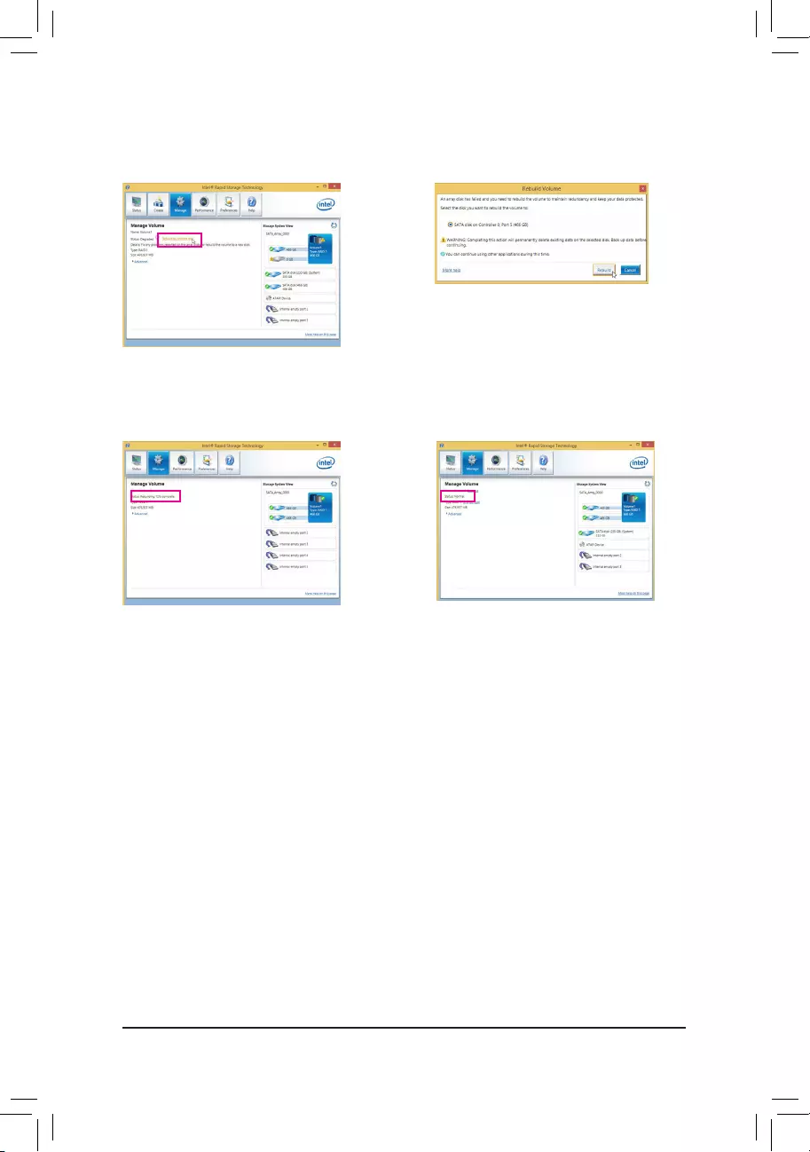
— 81 —
•Performing the Rebuild in the Operating System
While in the operating system, make sure the chipset driver has been installed from the motherboard driver
disk. Then launch the Intel®RapidStorageTechnologyutilityfromthedesktop.
Step 1:
Go to the Manage menu and click Rebuild to
another disk in Manage Volume.
The Status item on the left of the screen displays
the rebuild progress.
Step 2:
SelectanewdrivetorebuildtheRAIDandclick
Rebuild.
Step 3:
AftertheRAID1volumerebuilding,theStatus will
display as Normal.
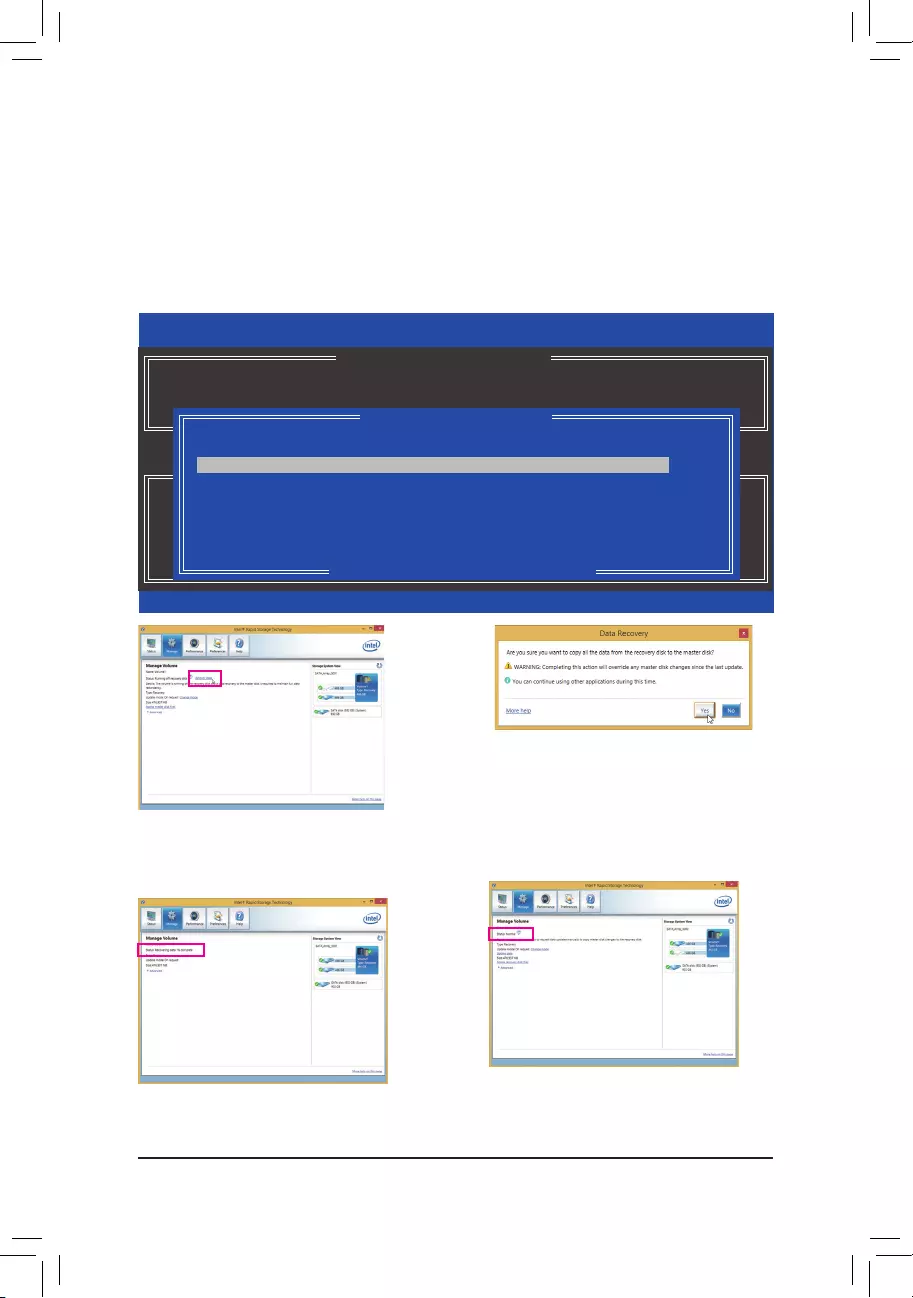
— 82 —
Step 2:
Go to the Manage menu of the Intel®Rapid
Storage Technology utility and click Recover data
in Manage Volume.
The Status item on the left of the screen displays
the rebuild progress.
Step 3:
Click Yes to begin the data recovery.
Step 4:
After the recovery volume is completed, the Status
will display as Normal.
•Restoring the Master Drive to a Previous State (for Recovery Volume only)
WhentwoharddrivesaresettoRecoveryVolumeinUpdateonRequestmode,youcanrestorethemaster
drive data to the last backup state when needed. For example, in case the master drive detects a virus, you
can restore the recovery drive data to the master drive.
Step 1:
Select 4. Recovery Volume Options in the MAIN MENU of the Intel®RAID Conguration Utility. Onthe
RECOVERY VOLUMES OPTIONS menu, select Enable Only Recovery Disk to show the recovery drive in
theoperatingsystem.Followtheon-screeninstructionstocompleteandexittheRAIDCongurationUtility.
Intel(R) Rapid Storage Technology — Option ROM — 13.1.0.2126
Copyright (C) Intel Corporation. All Rights Reserved.
Choose the RAID level:
RAID0: Stripes data (performance).
RAID1: Mirrors data (redundancy).
Recovery: Copies data between a master and a recovery disk.
RAID10: Mirrors data and stripes the mirror.
RAID5: Stripes data and parity.
[hi]-select [ESC]-Previous Menu [ENTER]-Select
[ HELP ]
[ RECOVERY VOLUME OPTIONS ]
1. Enable Only Recovery Disk
2. Enable Only Master Disk
[ SELECT RECOVERY VOLUME ]
[hi]-Up/Down [SPACE]-Selects [ENTER]-Done
Name Level Capacity Status Bootable
`
Volume0 Recovery(OnReq) 465.7GB NeedsUpdate Yes
Select a Recovery volume to do the operation.
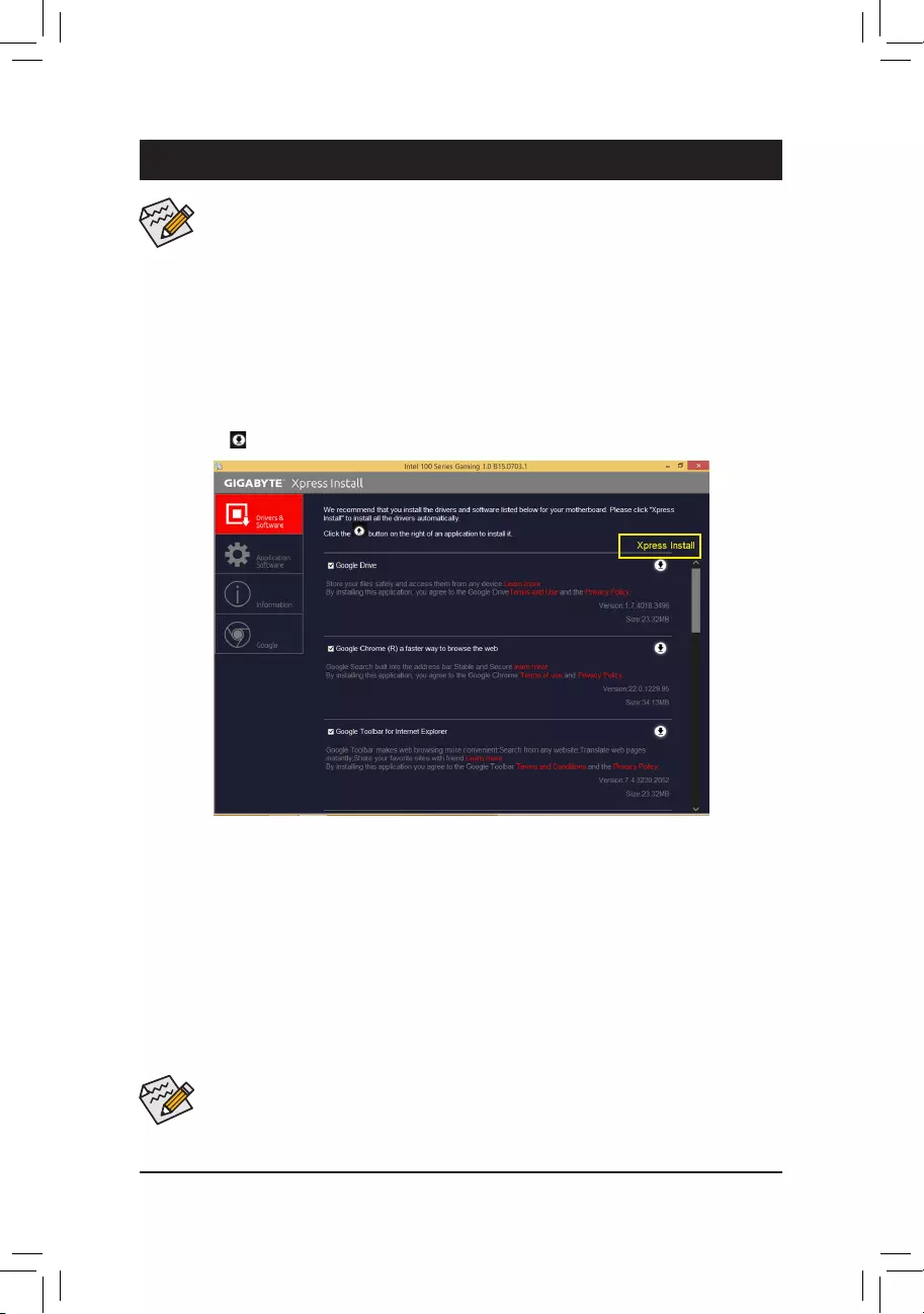
— 83 —
4-1 Drivers & Software
Chapter 4 Drivers Installation
• Beforeinstallingthe drivers, rst installtheoperating system. (The following instructionsuse
Windows8.1astheexampleoperatingsystem.)
• After installing the operating system, insert the motherboard driver disk into your optical drive.
Click on the message «Tap to choose what happens with this disc» on the top-right corner of the
screenandselect«RunRun.exe.» (Or go to My Computer, double-click the optical drive and ex-
ecutetheRun.exeprogram.)
«Xpress Install» will automatically scan your system and then list all of the drivers that are recommended to
install. You can click the Xpress Install button and «Xpress Install» will install all of the selected drivers. Or
click the arrow icon to individually install the drivers you need.
• Pleaseignorethepopupdialogbox(es)(e.g.the Found New Hardware Wizard)displayed
when «Xpress Install» is installing the drivers. Failure to do so may affect the driver installation.
• Some device drivers will restart your system automatically during the driver installation. After the
system restart, «Xpress Install» will continue to install other drivers.
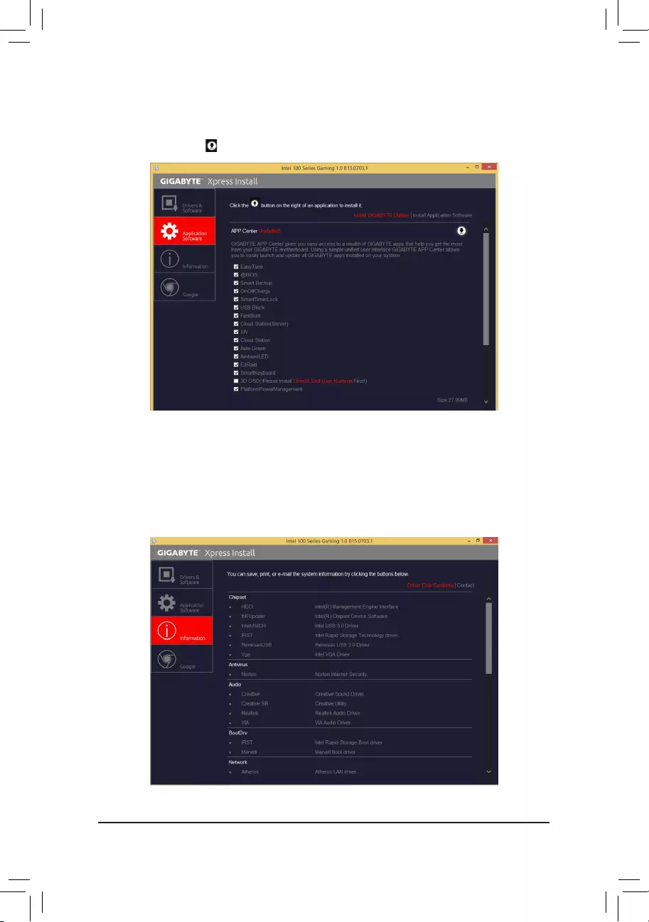
— 84 —
4-2 Application Software
This page displays the apps that GIGABYTE develops and some free software. You can select the apps you
want and click the Install icon to begin the installation.
4-3 Information
This page provides detailed information on the drivers on the driver disk. The Contact page provides contact
informationoftheGIGABYTETaiwanheadquarter.YoucanclicktheURLonthispagetolinktotheGIGA—
BYTEwebsitetocheckmoreinformationontheGIGABYTEheadquarterorworldwidebranchofces.

— 85 —
Chapter 5 Unique Features
BecauseBIOSashingispotentiallyrisky,pleasedoitwithcaution.InadequateBIOSashingmay
result in system malfunction.
5-1-1 Updating the BIOS with the Q-Flash Utility
A. Before You Begin
1. FromGIGABYTE’swebsite,downloadthelatestcompressedBIOSupdatelethatmatchesyourmotherboard
model.
2. ExtracttheleandsavethenewBIOSle(e.g.Z170XGaming7.F1)toyourUSBashdrive,orharddrive.
Note:TheUSBashdriveorharddrivemustuseFAT32/16/12lesystem.
3. Restartthesystem.DuringthePOST,pressthe<End>keytoenterQ-Flash.Note:YoucanaccessQ-Flash
by either pressing the <End> key during the POST or pressing the <F8> key in BIOS Setup. However, if the
BIOSupdateleissavedtoaharddriveinRAID/AHCImodeoraharddriveattachedtoanindependent
SATA controller, use the <End> key during the POST to access Q-Flash.
5-1 BIOS Update Utilities
GIGABYTE motherboards provide two unique BIOS update tools, Q-Flash™ and @BIOS™. GIGABYTE Q-Flash
and @BIOS are easy-to-use and allow you to update the BIOS without the need to enter MS-DOS mode.
Additionally, this motherboard features the DualBIOS™ design, providing multiple protection for the safety and
stability of your computer.
What is DualBIOS™?
Motherboards that support DualBIOS have two BIOS onboard, a main BIOS and a backup BIOS. Normally, the
system works on the main BIOS. However, if the main BIOS is corrupted or damaged, the backup BIOS will
takeoveronthenextsystembootandcopytheBIOSletothemainBIOStoensurenormalsystemoperation.
For the sake of system safety, users cannot update the backup BIOS manually.
What is Q-Flash™?
With Q-Flash you can update the system BIOS without having to enter operating systems like MS-DOS or
Windowrst.EmbeddedintheBIOS,theQ-Flashtoolfreesyoufromthehasslesofgoingthroughcomplicated
BIOSashingprocess.
What is @BIOS™?
@BIOS allows you to update the system BIOS while in the Windows environment. @BIOS will download the
latestBIOSlefromthenearest@BIOSserversiteandupdatetheBIOS.
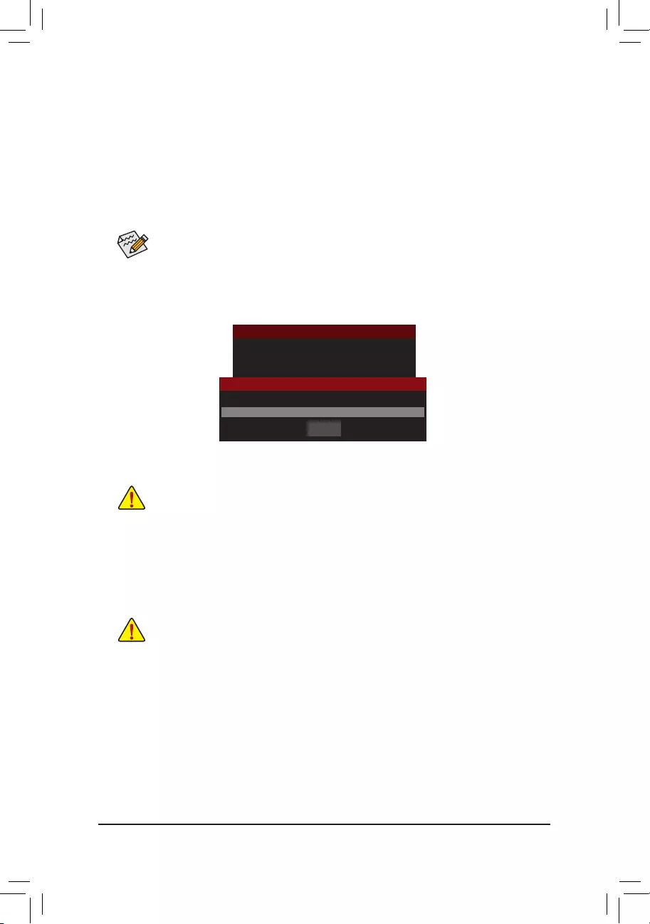
— 86 —
B. Updating the BIOS
In the main menu of Q-Flash, use the keyboard or mouse to select an item to execute. When updating the
BIOS,choosethelocationwheretheBIOSleissaved.Thefollowingprocedureassumesthatyousavethe
BIOSletoaUSBashdrive.
Step 1:
1. InserttheUSBashdrivecontainingtheBIOSleintothecomputer.InthemainmenuofQ-Flash,select
Update BIOS From Drive.
Step 2:
ThescreenwillshowthattheBIOSleisbeingreadfromyourUSBashdrive.PleaseselectQuick Update or
Normal Update to begin the BIOS update. The screen will then display the update process.
Step 3:
The system will restart after the update process is complete.
2. Select USB Flash Drive.
3.SelecttheBIOSupdatele.
•The Save BIOS to DriveoptionallowsyoutosavethecurrentBIOSle.
•Q-FlashonlysupportsUSBashdriveorharddrivesusingFAT32/16/12lesystem.
•IftheBIOSupdateleissavedtoaharddriveinRAID/AHCImodeoraharddriveattached
to an independent SATA controller, use the <End> key during the POST to access Q-Flash.
MakesuretheBIOSupdatelematchesyourmotherboardmodel.
•Do not turn off or restart the system when the system is reading/updating the BIOS.
•DonotremovetheUSBashdriveorharddrivewhenthesystemisupdatingtheBIOS.
Model Name : Z170X-Gaming 7
BIOS Version : D20
BIOS Date : 06/18/2015
Flash Type/Size : MXIC 25L/U Series 16MB
Q-Flash
Update BIOS From Drive
Save BIOS to Drive
Exit Q-FLASH
Please select drvice
Update BIOS From Drive
USB Flash Drive
Close
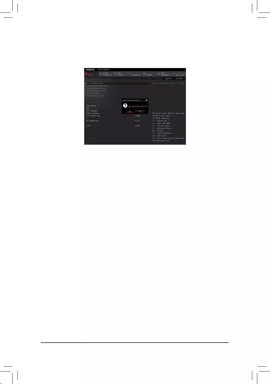
— 87 —
Step 4:
During the POST, press <Delete> to enter BIOS Setup. Select Load Optimized Defaults on the Save & Exit
screen and press <Enter> to load BIOS defaults. System will re-detect all peripheral devices after a BIOS update,
so we recommend that you reload BIOS defaults.
Step 5:
Select Save & Exit Setup and press <Enter>. And then select Yes to save settings to CMOS and exit BIOS
Setup. The procedure is complete after the system restarts.
Select Yes to load BIOS defaults
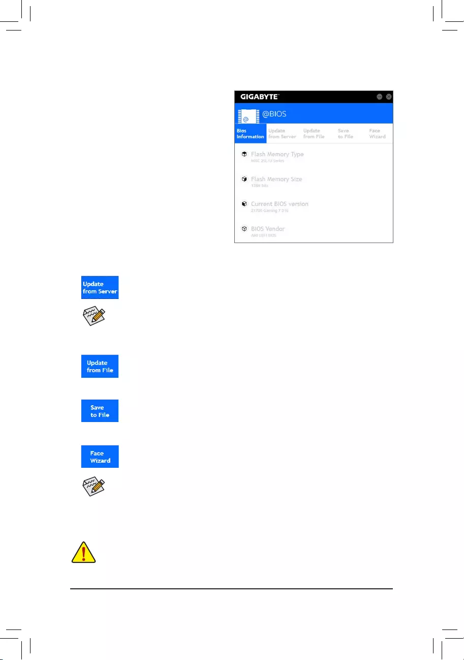
— 88 —
5-1-2 Updating the BIOS with the @BIOS Utility
A. Before You Begin
1. In Windows, close all applications and TSR
(Terminate and Stay Resident) programs.This
helps prevent unexpected failures when performing
a BIOS update.
2. If the BIOS is being updated via the Internet, ensure
the Internet connection is stable and do NOT
interrupt the Internet connection (for example, avoid
apowerlossorswitchingofftheInternet).Failureto
do so may result in a corrupted BIOS or a system
that is unable to start.
3. GIGABYTE product warranty does not cover any
BIOS damage or system failure resulting from an
inadequateBIOSashing.
B. Using @BIOS
•MakesurethattheBIOSletobeashedmatchesyourmotherboardmodel.UpdatingtheBIOS
withanincorrectBIOSlecouldcauseyoursystemnottoboot.
•Do not turn off the system or remove the power during the BIOS update process, or the BIOS may
corrupt and the system may not boot.
IftheBIOSupdateleforyourmotherboardisnotpresentonthe@BIOSserversite,please
manuallydownloadtheBIOSupdatelefromGIGABYTE’swebsiteandfollowtheinstructionsin
«Update the BIOS without Using the Internet Update Function» below.
Supported image formats include jpg, bmp, and gif.
C. After Updating the BIOS
RestartyoursystemafterupdatingtheBIOS.
1. Update the BIOS Using the Internet Update Function:
Click Update from Server, select the @BIOS server site closest to your location and
thendownloadtheBIOSlethatmatchesyourmotherboardmodel.Followtheon-screen
instructions to complete.
2. Update the BIOS without Using the Internet Update Function:
Click Update from File,thenselectthelocationwhereyousavetheBIOSupdateleobtained
from the Internet or through other source. Follow the on-screen instructions to complete.
3. Save the Current BIOS File:
Click Save to FiletosavethecurrentBIOSle.
4. Change the Boot-up Logo:
Click Upload new image in Face-Wizard and you will be able to change the boot-up logo
with your own picture, creating a personalized boot-up screen. Click Backup current image
to save the current boot-up logo.
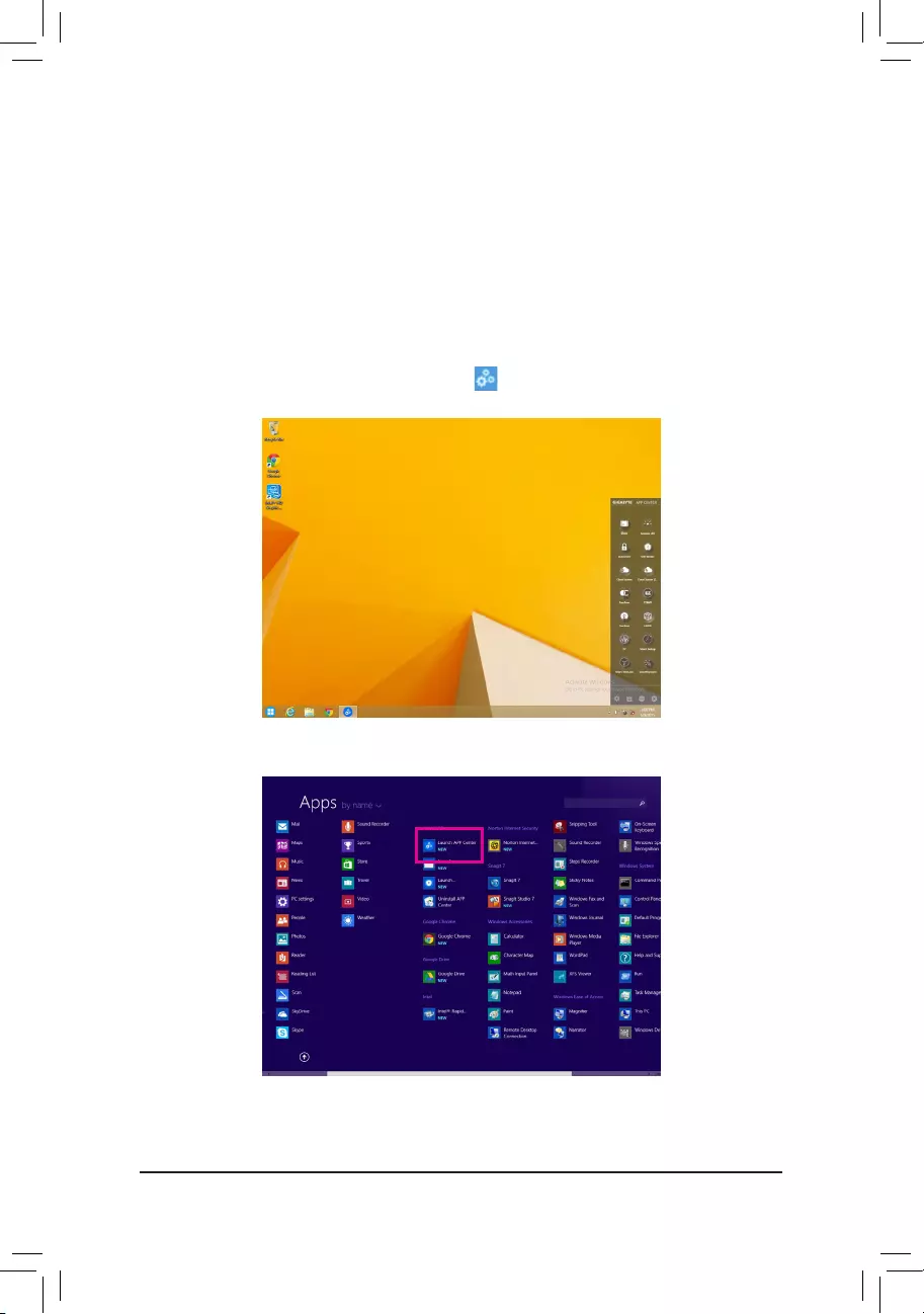
— 89 —
5-2 APP Center
GIGABYTE App Center gives you easy access to a wealth of GIGABYTE apps that help you get the most from
your GIGABYTE motherboard(Note).Usingasimple,unieduserinterface,GIGABYTEAppCenterallowsyou
to easily launch all GIGABYTE apps installed on your system, check related updates online, and download the
apps, drivers, and BIOS.
Running the APP Center
Insert the motherboard driver disk. On the Autorun screen, go to Application Software\Install GIGABYTE
UtilitiestoinstallGIGABYTEAppCenterandtheselectedapps.Restartyourcomputeraftertheinstallation
is complete. In Desktop mode, click the App Center icon inthenoticationareatolaunchtheAppCenter
utility(Figure1).Onthemainmenu,youcanselectanapptorunorclickLiveUpdate to update an app online.
IftheAppCenterisclosed,youcanrestartitbyclickingtheLaunchAppCentericonontheAppsmenu(Figure2).
Figure 2
Figure 1
(Note) AvailableapplicationsinAPPCentermaydifferbymotherboardmodel.Supportedfunctionsofeach
applicationmayalsovarydependingonmotherboardspecications.
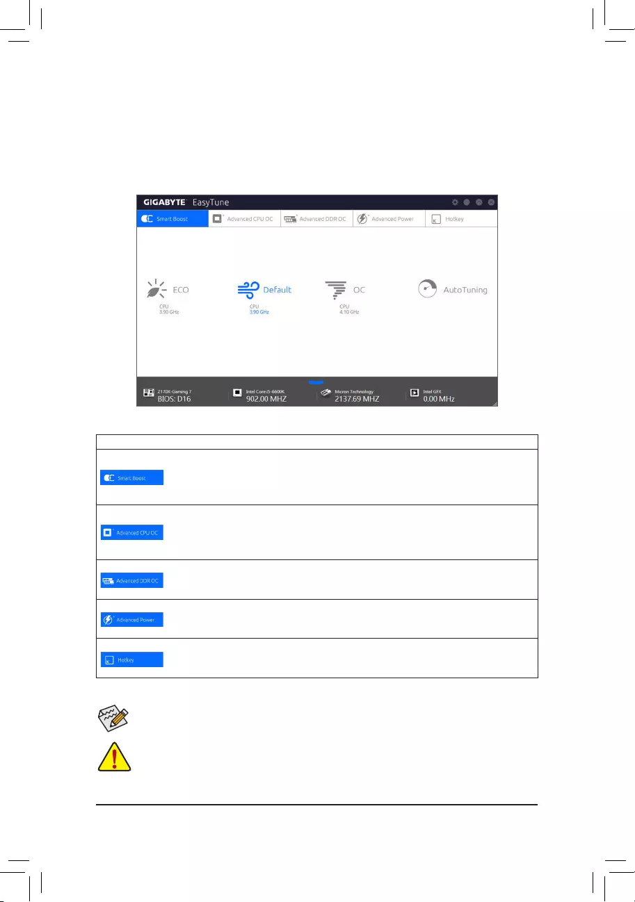
— 90 —
5-2-1 EasyTune
GIGABYTE’sEasyTuneisasimpleandeasy-to-useinterfacethatallowsuserstone-tunetheirsystemsettings
or do overclock/overvoltage in Windows environment.
The EasyTune Interface
Tabs Information
Tab Description
The Smart Boost tab provides you with different levels of CPU frequency to choose to
achieve desired system performance. After making changes, be sure to restart your system
for these changes to take effect.
The Advanced CPU OC tab allows you to set CPU base clock, frequency, and voltages,
andintegratedgraphicsfrequency.Youcansavethecurrentsettingstoaprole.Youcan
createupto2proles.
The Advanced DDR OC tab allows you to set the memory clock.
The Advanced Power tab allows you to adjust voltages.
The HotKeytaballowsyoutosethotkeysforyourproles.
Incorrectly doing overclock/overvoltage may result in damage to the hardware components such
as CPU, chipset, and memory and reduce the useful life of these components. Before you do the
overclock/overvoltage, make sure that you fully know each function of EasyTune, or system instability
or other unexpected results may occur.
Availablefunctionsin EasyTunemay vary by motherboard model and CPU.Grayed-out area(s)
indicatesthattheitemisnotcongurableorthefunctionisnotsupported.
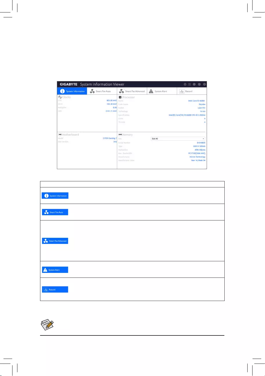
— 91 —
5-2-2 System Information Viewer
GIGABYTE System Information Viewer allows you to monitor and adjust the fan speed in the operating system.
You can also display the hardware monitor information on the desktop to view the system status at any time.
The System Information Viewer Interface
Tabs Information
Tab Description
The System Information tab provides information on the installed CPU, motherboard, and
the BIOS version.
The Smart Fan Auto tab allows you to specify a Smart Fan mode.
The Smart Fan Advance tab allows you to adjust the smart fan speed. The fans will run at
different speeds according to system temperatures. Using the Smart Fan option you can
adjustthefan’sworkloadaccordingsystemtemperaturesoryoucanxthefanspeedsusing
the RPM Fixed Mode option. Click the Calibrate button and the fan speed will be shown in
relation to overall fan workload after calibration. The Reset button can revert the fan settings
back to the last saved values.
The System Alerts tab allows you to monitor hardware temperature, voltage and fan speed,
and set temperature/fan speed alarm.
The Record tab allows you to record changes in system voltages, temperatures, and fan
speeds. Please note, the recording will stop if you exit the Record tab during the recording
process.
The speed control function requires the use of a fan with fan speed control design.
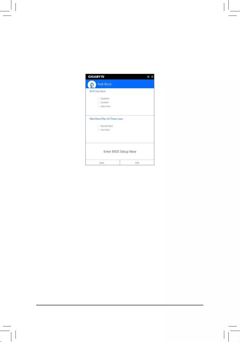
— 92 —
5-2-3 Fast Boot
Through the simple GIGABYTE Fast Boot(Note1) interface, you can enable or change the Fast Boot or Next Boot
After AC Power Loss setting right in the operating system.
The Fast Boot Interface
Using Fast Boot
•BIOS Fast Boot:
This option is the same as the Fast Boot option(Note2) in BIOS Setup. It allows you to enable or disable the
fast boot function to shorten OS boot time.
•Next Boot After AC Power Loss:
This option is the same as the Next Boot After AC Power Loss option(Note2) in BIOS Setup. It allows you to
selectthesystembootupmodeuponthereturnofanACpowerloss.(Thismodeiscongurableonlywhen
BIOS Fast Boot is set to Enabled or Ultra Fast.)
Afteryoucongurethesetting,clickSave to save and click Exit. The settings will take effect on next boot. If you
click the Enter BIOS Setup Now button, the system will restart and enter BIOS Setup immediately.
(Note1) ThisfunctionissupportedbyWindows10/8.1only.
(Note2) Formoredetailsaboutthisfunction,refertoChapter2,»BIOSFeatures.»
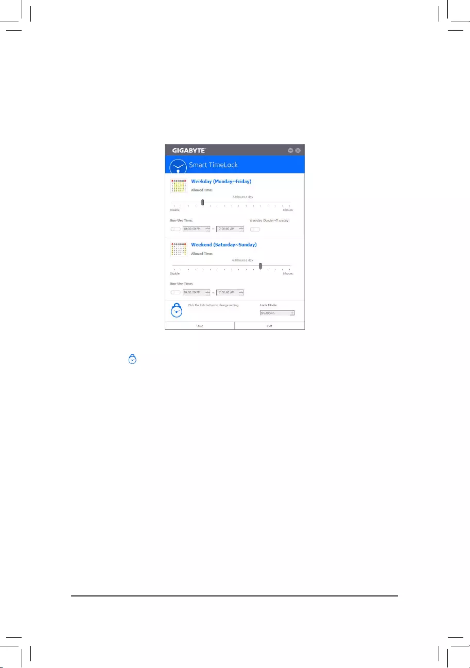
— 93 —
5-2-4 Smart TimeLock
GIGABYTE Smart TimeLock allows you to effectively manage computer or Internet usage time with simple
rules and options.
The Smart TimeLock Interface
Using Smart TimeLock
Click the lock icon on the bottom left corner and enter the password(Note). Set the time when a user can or
cannot use your computer for weekdays and weekends. The Lock Mode on the bottom right corner allows you
tochoosetoturnoffthecomputeroronlyclosetheInternetconnectionduringthespeciedtimeperiod.Click
Save to save the settings and click Exit to exit.
An alert will appear 15 minutes and 1 minute prior to the default shutdown time. When the alert appears, you
can enter the password to extend the usage time or click Cancel to close the alert. If you respond Cancel, you
will be requested to enter the password to extend the usage time again when the default shutdown time arrives,
or the computer will shutdown right away.
(Note) YoucansettheUserPasswordinthesystemBIOSSetupprogramtopreventthesystemtimebeing
changed by other users.
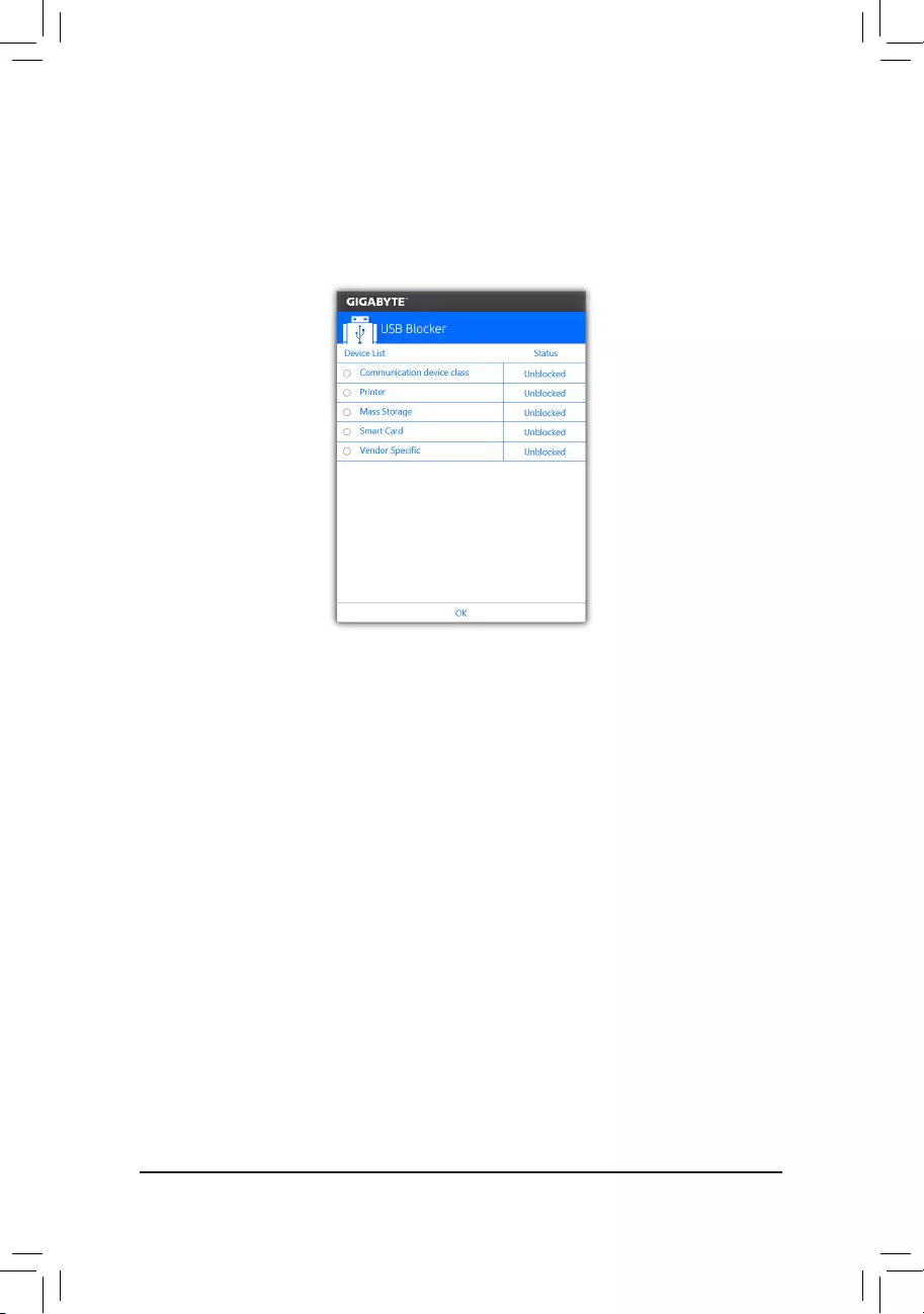
— 94 —
5-2-5 USB Blocker
GIGABYTE USB Blocker provides you with an easy-to-use interface that allows you to block certain USB device
types on your PC. Devices classes that are blocked will be ignored by the operating system.
The USB Blocker Interface
Using USB Blocker
Select the class of USB device that you would like to block or unblock. Double left-click to change the Blocked
or Unblocked status and click OK. Then enter your password and click OK to complete.
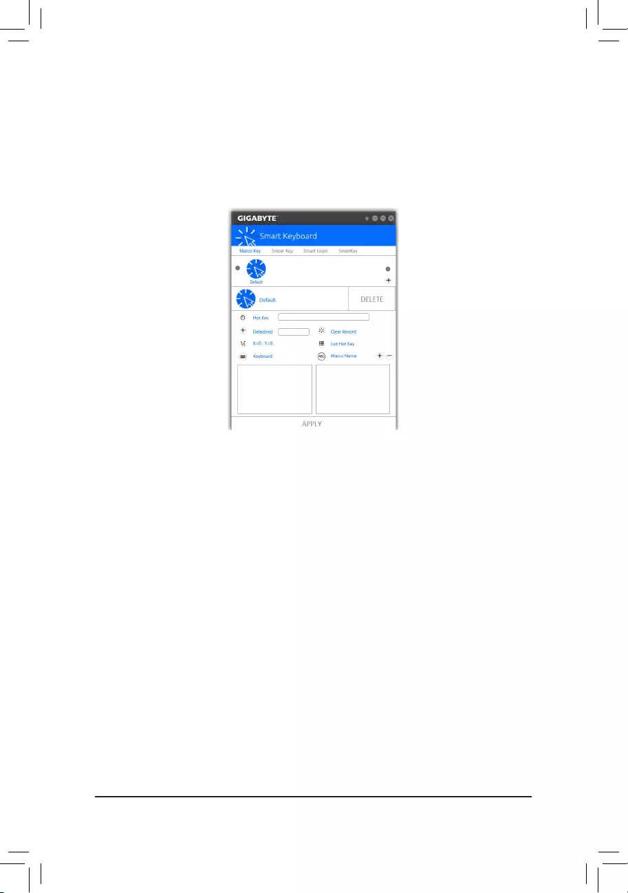
— 95 —
5-2-6 Smart Keyboard
GIGABYTESmartKeyboardallowsyoutodeneyourowncommands/hotkeys,changethemousesensitivity,
andcreateshortcutandpasswordtoopenawebpageordocumentle,helpingyoumakethemostoutofyour
keyboard and mouse.
The Smart Keyboard Interface
Using Smart Keyboard:
•Marco Key:
Createmacrocommandsanddeneyourownhotkeystoquicklyperformthefunctionyourwant.
•Sniper Key:
Using the Sniper key you can switch the mouse sensitivity when you are in sniper mode for better sniper
accuracy.
•Smart Login:
Create shortcut and password to open a web page or document le.
•Smart Key:
Enable or disable hotkeys for activating overclocking and power-saving features.
(Note) ItisrecommendedthatSmartKeyboardbeclosedifitviolatestheenduserlicenseagreementofyour
game.
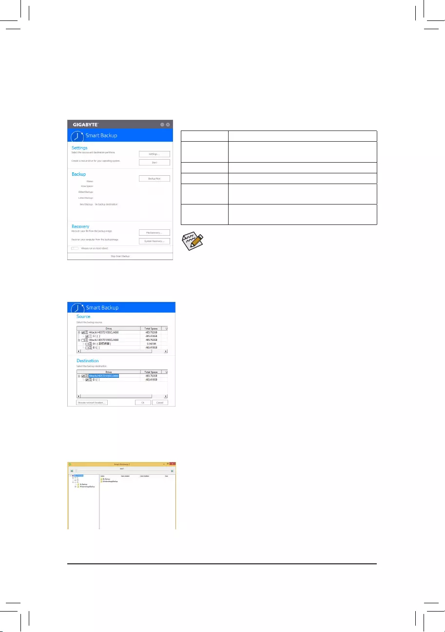
— 96 —
5-2-7 Smart Backup
SmartBackupallowsyoutobackupapartitionasanimageleeveryhour.Youcanusetheseimagestorestore
yoursystemorleswhenneeded.
•SmartBackuponlysupportsNTFSlesystem.
•You need to select the destination partition in Settingsthersttime
you use Smart Backup.
•The Backup Now button will be available only after 10 minutes you
have logged in Windows.
•Select the Always run on next reboot checkbox to automatically
enable Smart Backup after system reboot.
Creating a backup:
Click the Settings button on the main menu. In the Settings dialog
box, select the source partition and destination partition and click OK.
The initial backup will start after 10 minutes and regular backup will be
performed hourly. Note: By default, all partitions on the system drive
are selected as the backup source. The backup destination cannot be
on the same partition as the backup source.
Saving the backup to a network location:
If you want to save the backup to a network location, select Browse
network location. Make sure your computer and the computer where
you want to save the backup are in the same domain. Choose the
network location where you want to store the backup and enter the user
name and password. Follow the on-screen instructions to complete.
Recoveringale:
Click the File Recovery button on the main menu. Use the time slider on
the top of the popped out window to select a previous backup time. The
right pane will display the backed-up partitions in the backup destination
(in the My Backupfolder).Browsetotheleyouwantandcopyit.
The Smart Backup main menu:
Button Description
Settings Allows you to select the source and destination
partition
Start Allows you to create a rescue drive
Backup Now Allows you to perform the backup immediately
File
Recovery…
Allowsyoutorecoveryourlesfromthebackup
image
System
Recovery…
Allows you to recover your system from the
backup image
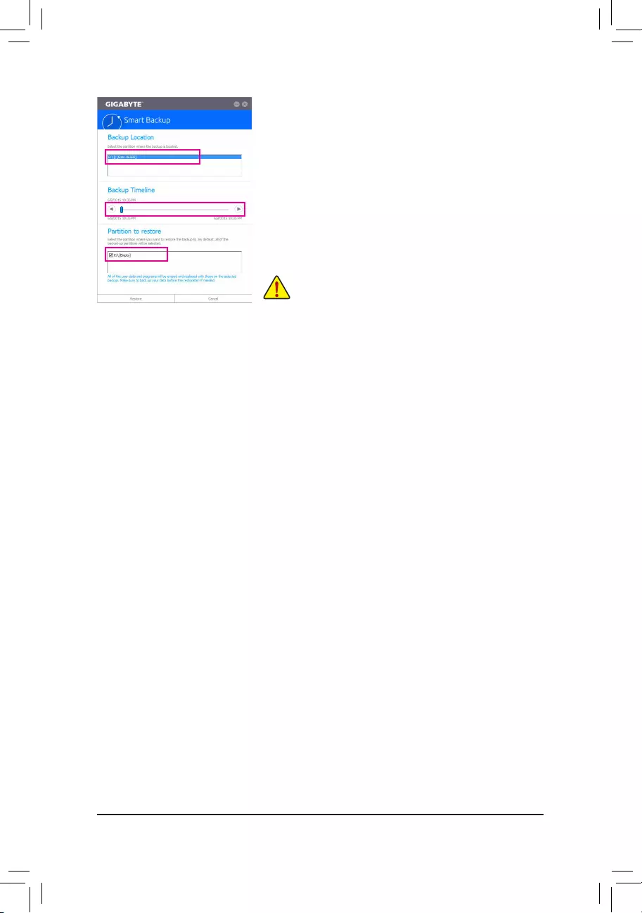
— 97 —
Recovering your system with Smart Backup:
Steps:
1. Click the System Recovery button on the main menu.
2. Select the location where your backup is saved.
3. Use the time slider to select a time point.
4. Select a partition backup created on the selected time point and
click Restore.
5. Conrmwhethertorestartyoursystemtoproceedwiththerestore
immediately or later. Once you respond «Yes» the system will restart to
the Windows recovery environment. Follow the onscreen instructions
to restore your system.
Allofyourlesandprogramswillbedeletedandreplacedwith
those on the selected backup. If needed, be sure to make a
copy of your data before the restore.
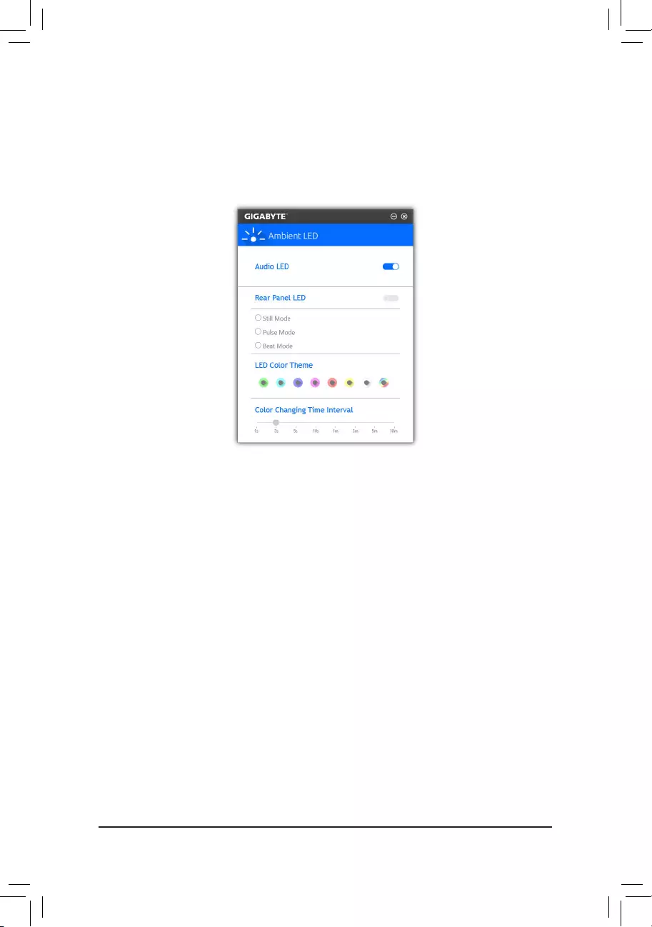
— 98 —
5-2-8 Ambient LED
GIGABYTE Ambient LED allows you to enable or change the display mode for the onboard audio LEDs and
rear panel I/O shield(Note) LEDs while in the Windows environment.
The Ambient LED Interface
Using Ambient LED
•Audio LED:
Allows you to enable or disable the onboard audio LEDs.
•Rear panel LED (Note):
Allows to you enable or disable the real panel LEDs and specify the LED behavior.
Still Mode — LEDs are constantly lit.
Beat Mode — LEDs will blink according to the rhythm of the music played on your system.
Pulse Mode — LEDs will blink slowly and smoothly like breath.
•LED Color Theme:
Allows to you specify the display color of the LEDs.
•LED Changing Time Interval:
Allows you to specify the color-changing interval if you select the color loop option.
(Note) ThisfunctiononlyworksformotherboardswithanI/OshieldthathasaudioLEDs.
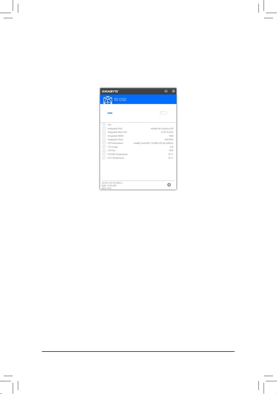
— 99 —
5-2-9 3D OSD
3D OSD(Note) automatically detects and displays your system information during games, allowing you to easily
get hold of your system information without switching between screens.
The 3D OSD Interface
Using 3D OSD
Main Menu:
Allows you to enable or disable the 3D OSD feature and to select the type of real-time system information you
wish to display. 3D OSD will detect and display a list of available options.
Conguration Menu:
Allows you to set a hotkey for enabling /disabling 3D OSD and specify the font size/location/color of the displayed
information.
(Note) Please ensure that DirectX End-User Runtime has been installed on your system prior to installing
3D OSD.
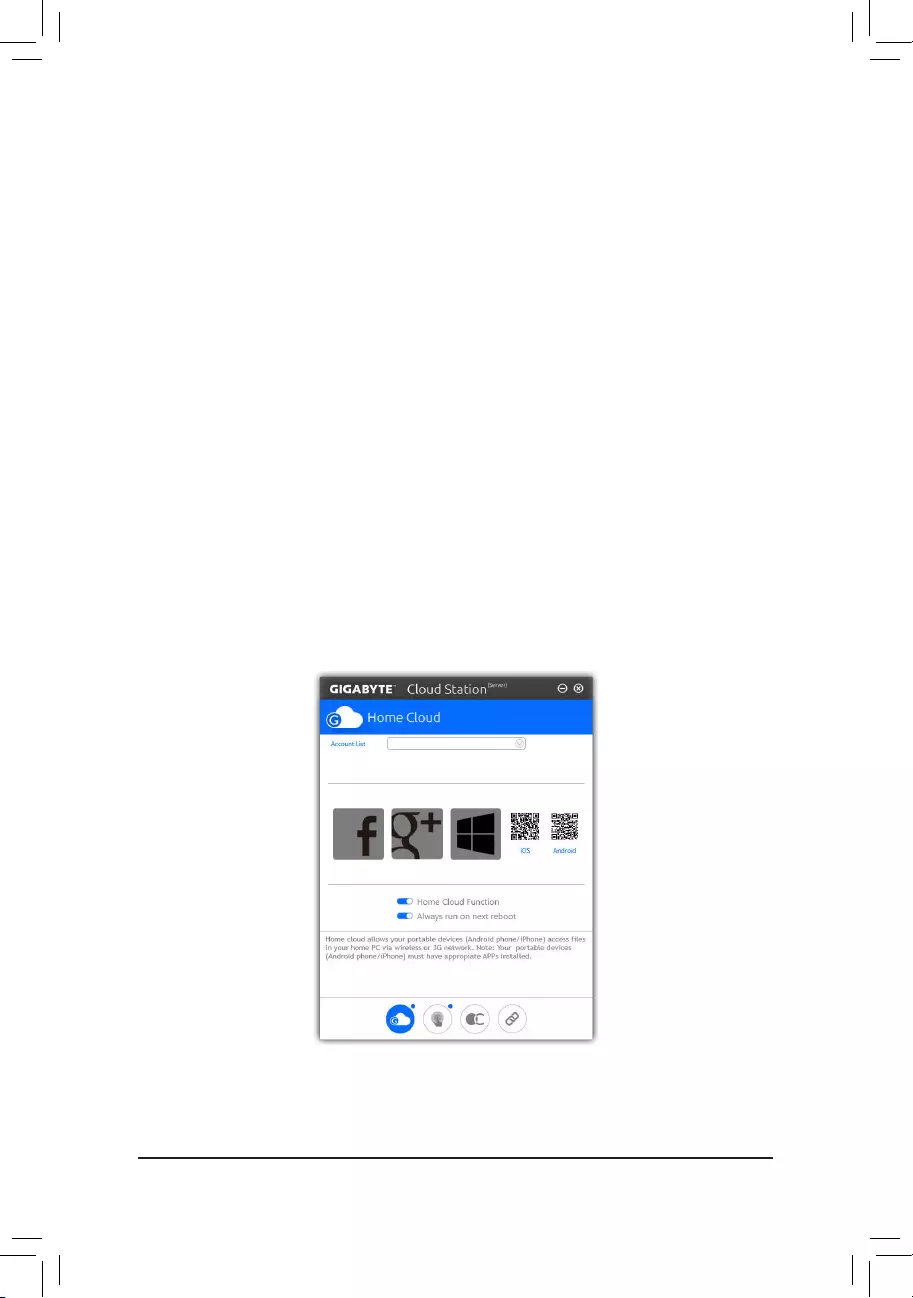
— 100 —
5-2-10 Cloud Station
GIGABYTECloudStation(Server)iscomposedofHomeCloud,GIGABYTERemote,RemoteOC,andHotSpot,
which allow your smart phone, tablet device, and remote computer to communicate, share resources, and control
thehostcomputerviawirelessconnection.CloudStation allows your computer to share les withanother
computerthathasCloudStation(Server)installed.
Before You Begin:
•TouseHomeCloud,GIGABYTERemote,andRemoteOC,youmustinstallGIGABYTECloudStationon
your smart phone/tablet device. (For Android systems, please download the app from Google Play; for iOS
systems,pleasedownloaditfromAppStore.)(Note1)
•ToshareHomeCloudlesbetweencomputers,youneedtoinstallCloudStation(Server)onthehostcomputer
and Cloud Station on the remote computer.
•Your smart phone/tablet device must have Android 4.0/iOS 6.0 or above version.
•ThersttimeyouuseHomeCloud,GIGABYTERemote,andRemoteOC,youmustsigninwithyourGoogle/
Facebook/Windows Live account. Be sure to use the same account to sign in on your smart phone/tablet
device and computers.
HomeCloud
HomeCloudallowsyoutoupload/download/backuples(Note2) from your smart phone/tablet device/computer
to the host computer.
The HomeCloud Interface
CloudStation(Server):
(Note1) Youcanuseyoursmartphone/tabletdevicetoscantheQRcodeontheHomeCloudUItolinktothe
download page of the GIGABYTE Cloud Station on App Store or Google Play.
(Note2) ForiOSsystems,theletypesarelimitedtoimage/videoles.
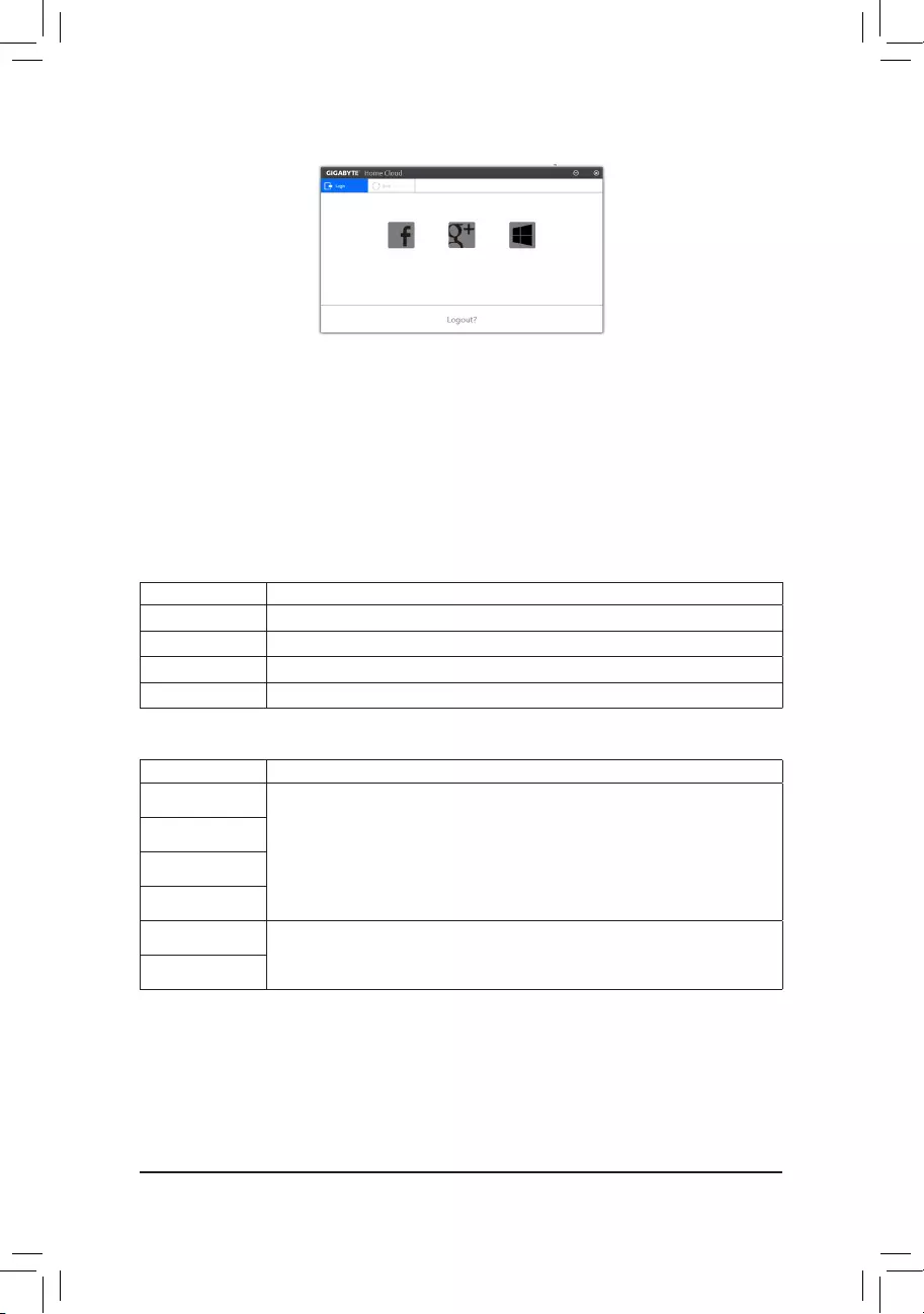
— 101 —
On the Host Computer:
Option Function
Account List Displayscurrentlysignedinaccount(s).
Remove Removetheselectedaccount.
Share Folder Displays the shared folder directory of the currently signed in account.
Open Folder Access the shared folder of the currently signed in account.
On the Smart Phone/Tablet Device/Remote Computer:
Option Function
All Picture Files FileUpload:Taponthefolder,browseandselectthelesinside.Taponthemenuicon
and select Upload selected Filestouploadthelestoyourcomputer.
File Download: Tap on the folder and then tap on the menu icon, select Download
Files.Youcanbrowsethelesandselectthelesthatyouwanttodownloadtoyour
smart phone/tablet device.
All Music Files
All Video Files
All Files
User Contacts Tap on the folder and then tap on the menu icon to use the options including Backup
to remote, Restore From remote, View Remote Contact, and Reselect Computers.
Call Log
Using HomeCloud
Step 1:
LaunchHomeCloudonthehostcomputer(installedwithCloudStation(Server)),signinwithyourGoogle/
Facebook/Windows Live account or select the account on the Account List. Then enable HomeCloud Function.
To automatically enable this function after system reboot, enable Always run on next reboot.
Step 2:
RunCloudStationonyoursmartphone/tabletdevice/remotecomputer,signinwiththesameaccountyouuse
for HomeCloud on your host computer. Tap on HomeCloud to perform the following functions:
Cloud Station:
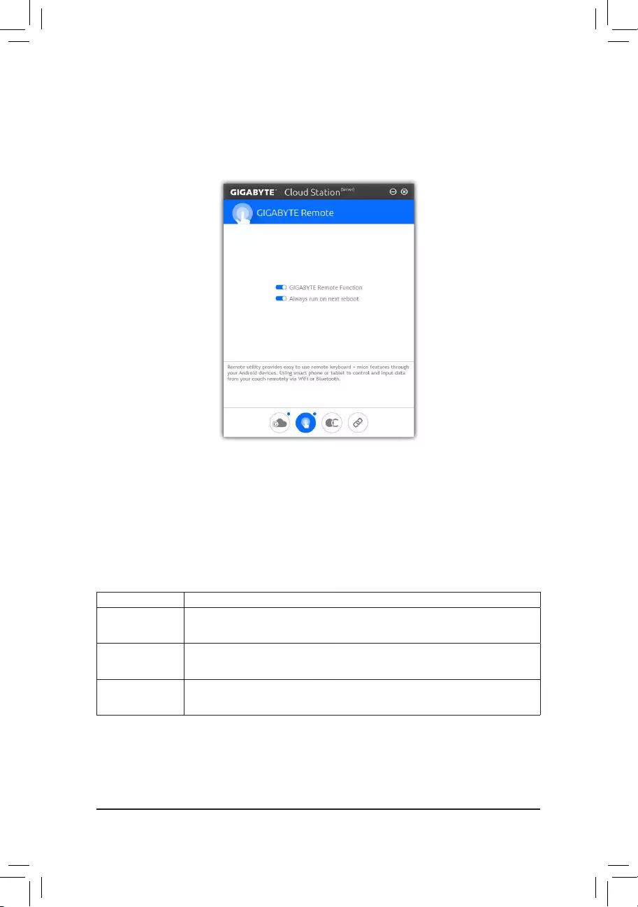
— 102 —
GIGABYTE Remote
GIGABYTERemoteallowsyoutouseyoursmartphone/tabletdevicetoremotelycontrolthemouse/keyboard/
Windows Media Player on your computer.
The GIGABYTE Remote Interface
Using GIGABYTE Remote
Step 1:
Onthehostcomputer,launchGIGABYTERemoteandenableGIGABYTE Remote Function. To automatically
enable this function after system reboot, enable Always run on next reboot.
Step 2:
RunGIGABYTECloudStationonyoursmartphone/tabletdevice,signinwiththesameaccountyouusefor
HomeCloud on your computer. Tap on Remote Control to perform the following remote controls:
On the Smart Phone/Tablet Device:
Option Function
Mouse Remotelyperform mouse functionalities including dragging,right/left-clicking, and
holding the mouse left button.
Keyboard Remotelycontrolyourkeyboardsuchastextinput(taponReal-TimeModetotype
texts)ordeletion.
Media RemotelycongureandcontrolthecurrentlyrunningWindowsMediaPlayerapplication
on your computer.
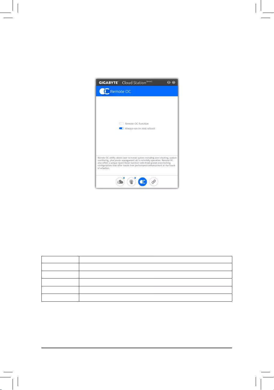
— 103 —
Remote OC
RemoteOC provides you with remotecontroloptionsincludingoverclockingandsystemtweaking,system
monitoring plus the ability to also remotely power down/reset the PC when needed.
The Remote OC Interface
Using Remote OC
Step 1:
Onthehostcomputer,launchRemoteOCandenableRemote OC Function. To automatically enable this
function after system reboot, enable Always run on next reboot.
Step 2:
RunGIGABYTECloudStationonyoursmartphone/tabletdevice,signinwiththesameaccountyouusefor
HomeCloud on your computer. Tap on Remote OC to perform the following functions:
On the Smart Phone/Tablet Device:
Option Function
Tuner Allows you to change CPU/memory frequency and voltage settings.
INFO Displays the system information, including the CPU, motherboard, and memory.
HW MONIT Allows you to monitor system temperatures, voltages, and fan speeds.
QUICK BOOST Providesyouwiththreepresetoverclockingcongurations.
CONTROL Allows you to remotely reboot or shut down your computer.
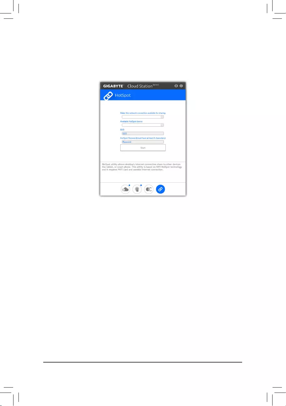
— 104 —
HotSpot
HotSpot turns your computer into a virtual wireless access point and allows you to share your connection with
your other wireless devices. Make sure your computer has been connected to a network and Wi-Fi is enabled.
The HotSpot Interface
Using HotSpot:
Conguringyourhostcomputer:
The options are as follows. Make sure to click Start to complete.
•Make this network connection available for sharing:
Select a currently running network connection you want to share.
•Available HotSpot device:
Select a network virtual adapter. If there are more than one Wi-Fi card on your computer, you need to select
the one you want to use from the list.
•SSID:
The hotspot SSID name. You can keep the default name or create your own one.
•HotSpot Password(must have at least 8 characters):
The password is required when other wireless devices want to access the Internet through the virtual wireless
access point. You can keep the default name or create your own one. The password must have at least 8
characters and cannot be empty.
Sharing your connection with other wireless devices:
FirstmakesureWi-Fiisenabledonthewirelessdevices.Thenbrowsetothenetworkcongurationscreen,
search for available Wi-Fi networks, and tap the name of your virtual wireless access point, enter the password,
andconrm.
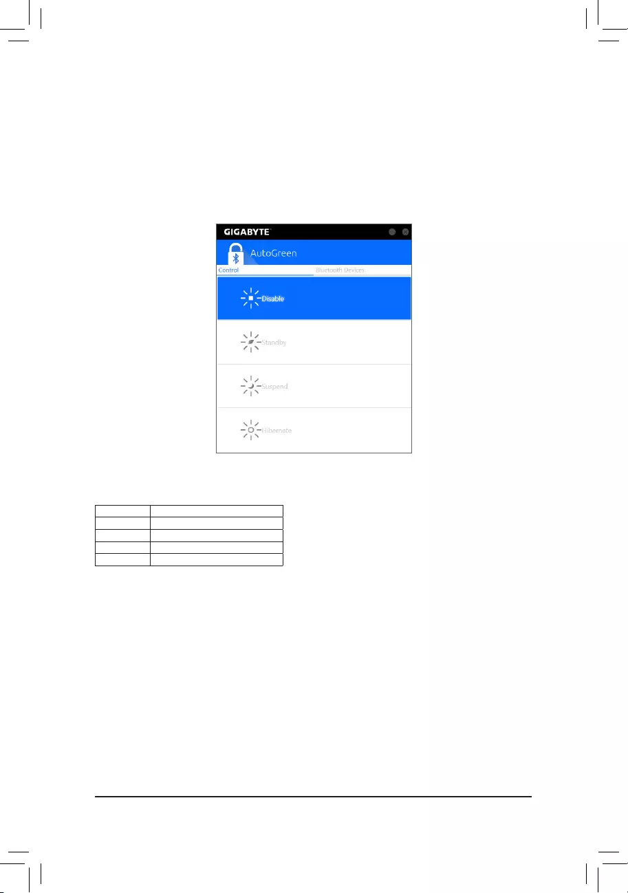
— 105 —
Control Tab:
The Control tab allows you to select a system power saving mode.
Button Description
Disable Disables this function
Standby Enters Power on Suspend mode
Suspend EntersSuspendtoRAMmode
Hibernate Enters Suspend to Disk mode
(Note) Onceyoursmartphone/tabletdevicehasbeenpairedwithyourAutoGreen-enabledcomputer,you’ll
notbeabletouseittoconnecttootherBluetoothdevice(s).
Bluetooth Devices Tab:
The Bluetooth tab allows you to pair your smart phone/tablet device with the Bluetooth receiver on your computer.
Press Refresh to let AutoGreen search for the Bluetooth devices around you. A message will appear on both
your computer and smart phone/tablet device prompting you to compare the passcodes on the two devices.
Conrmtocompletethepairingprocess.
5-2-11 AutoGreen
AutoGreen(Note) is an easy-to-use tool that provides users with simple options to enable system power savings
via a Bluetooth-enabled smart phone/tablet device. When the device is out of the range of the computer’s
Bluetoothreceiver,thesystemwillenterthespeciedpowersavingmode.Beforeusingthisapp,youneedto
turn on Bluetooth on both your computer and smart phone/tablet device.
The AutoGreen Interface
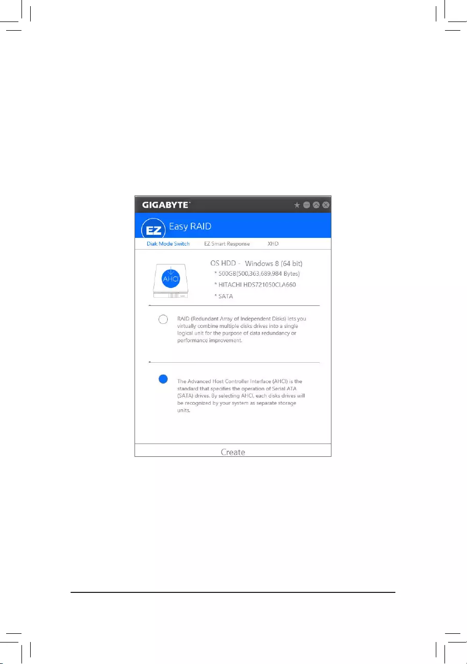
— 106 —
5-2-12 Easy RAID
TheGIGABYTEEasyRAIDutilityincludesthefollowing‘EZ’setupsapplicationsthatwilloffergreatlysimplied
installandcongurationprocedures:DiskModeSwitch,EZSmartResponse,andXHD.
Disk Mode Switch
DiskModeSwitchallowsyoutochangetheSATAcontrollerdiskmodefromAHCItoRAIDmodeevenafterthe
hard drive has been installed with an operating system. After switching the operating mode, please restart your
computer and make sure the Intel®RapidStorageTechnologyutilitycanworkproperly.
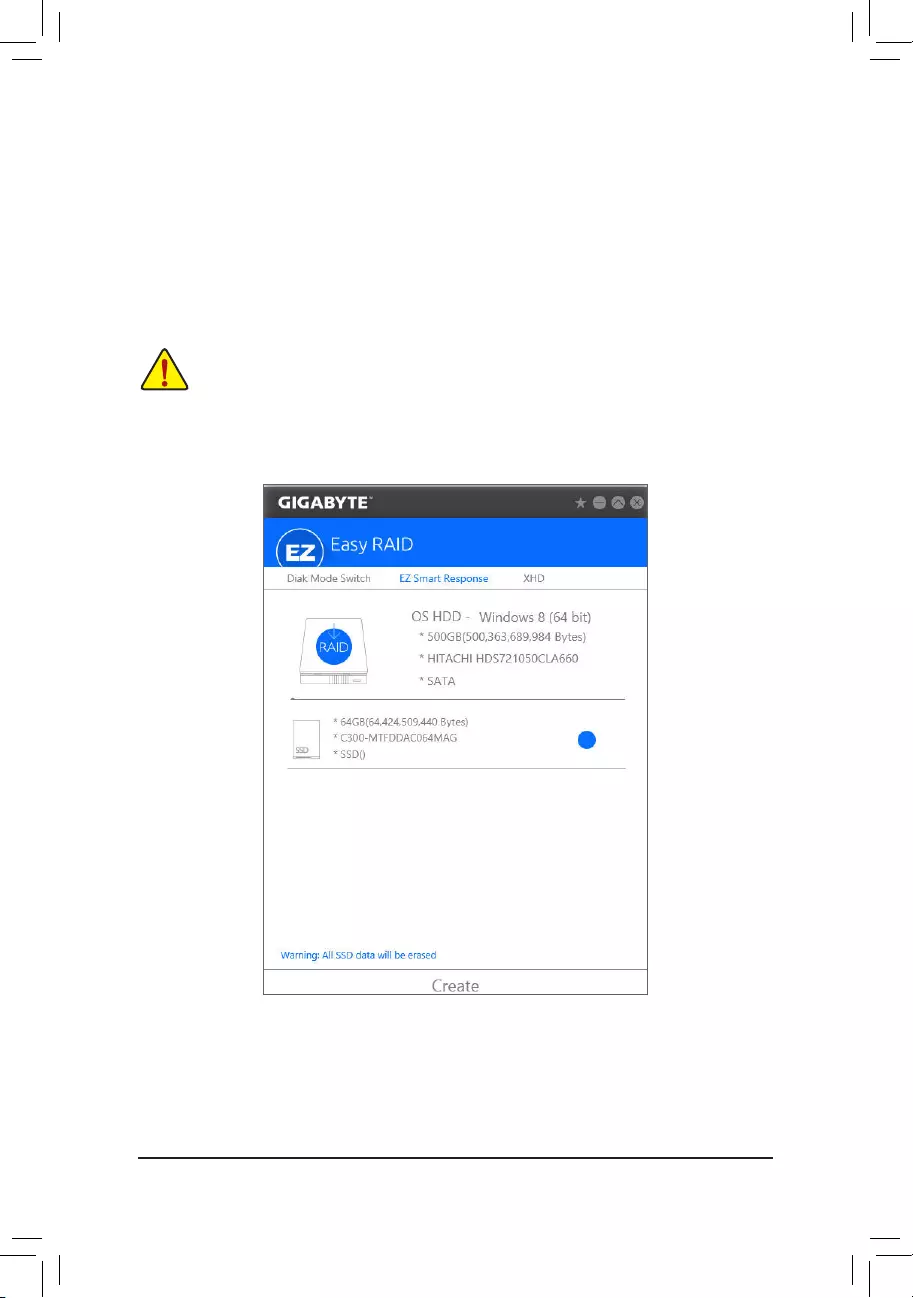
— 107 —
EZ Smart Response
A. System Requirements
1. An Intel® Chipset-based motherboard supporting this feature
2. Intel® Core series processor
3. Intel®SATAcontrollerssettoRAIDmode
4. Intel®RapidStorageTechnologyutilityinstalled(Note1)
5. A conventional SATA disk and an SSD(Note2)
6. Windows 7 with SP1/Windows 8.1/Windows 10(Note3)
B. Using EZ Smart Response
Select EZ Smart Response and click Create.
To disable this function, click Delete.
IfyouhaveinstalledtheoperatingsystembeforeconguringtheSmartResponseTechnology,all
originaldataontheSSDwillbelostonceyouenableRAIDmode(Note4). It is recommended that you
backuptheharddiskbeforeenablingtheSmartResponseTechnology.
(Note1) Beforestart,makesureyouhaveinstalledtheIntel®RapidStorageTechnologyutility(version14.5
orabove).
(Note2) TheSSDworksasacacheoftheharddisk.Themaximumcachememorysizeis64GB.Ifyouuse
an SSD larger than 64 GB, the space beyond 64 GB can still be used for storing your data.
(Note3) TheoperatingsystemmustbeinstalledtotheSATAdisk.
(Note4) IftheSATAcontrollersaresettoAHCImodeinBIOSSetup,theywillbeforcedtoRAIDmode.
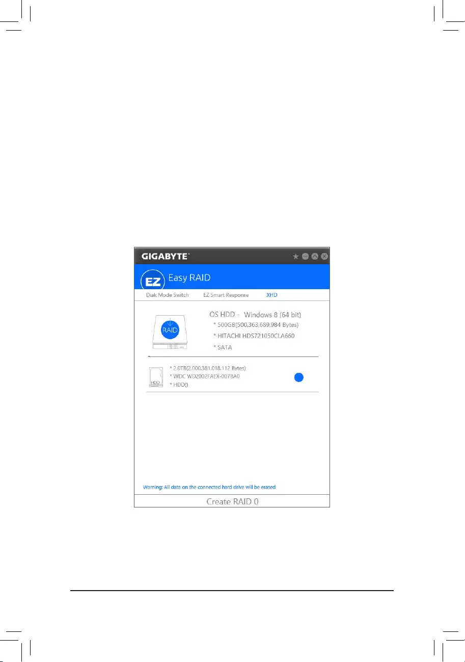
— 108 —
XHD
With GIGABYTE XHD(Note1),userscanquicklycongureaRAID-readysystemforRAID0whenanewSATA
drive is added. All with a simple click of a button, XHD helps to enhance your hard drive read/write performance
withouttheneedforcomplexandtime-consumingcongurations.
A. System Requirements
1. An Intel®ChipsetmotherboardsupportingRAID
2. Intel®SATAcontrollerssettoRAIDmode
3. Intel®RapidStorageTechnologyutilityinstalled
4. Windows 7 with SP1/Windows 8.1/Windows 10
5. Intel® SATA controller driver installed
B. Using XHD
Select XHD and click Create RAID 0 based on your need(Note2).
(Note1) TheXHDutilityonlysupportstheSATAconnectorscontrolledbytheIntel® Chipset.
(Note2) Exceptfortheoperatingsystemdrive,alldataonotherharddrivewillbedeleted.Backupyourdata
before using the XHD utility.
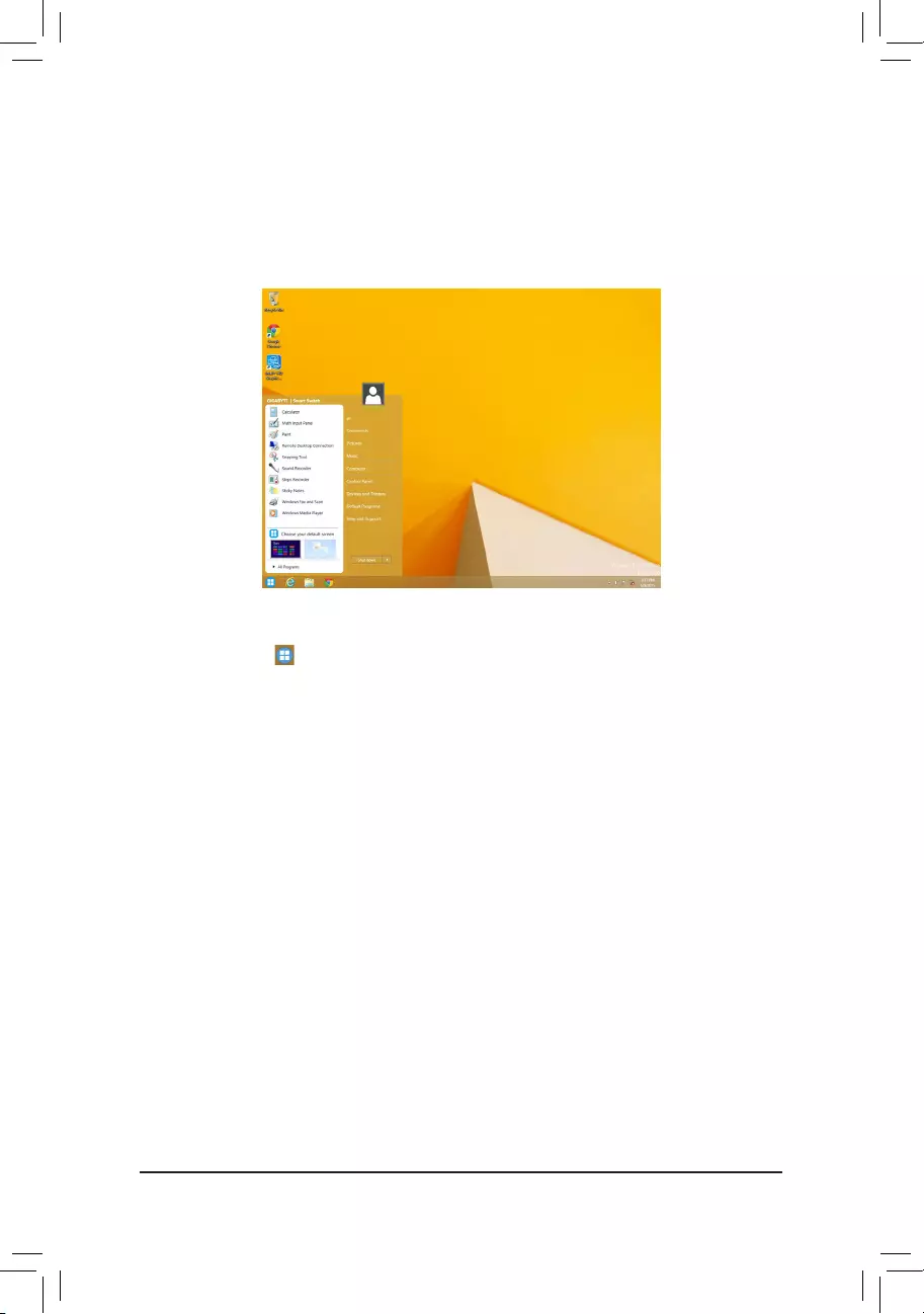
— 109 —
5-3 Smart Switch
GIGABYTE Smart Switch provides you with the conventional Windows start menu, allowing you to easily access
to the apps that you frequently use. You can also select the default screen displayed after you enter Windows.
The Smart Switch Interface
Using Smart Switch
The Smart Switch icon will appear on the bottom left corner of the traditional Windows desktop screen after
Smart Switch is installed. Left-click the icon to see the screen as that shown above and you can set the default
screen displayed after you enter Windows.

— 110 —
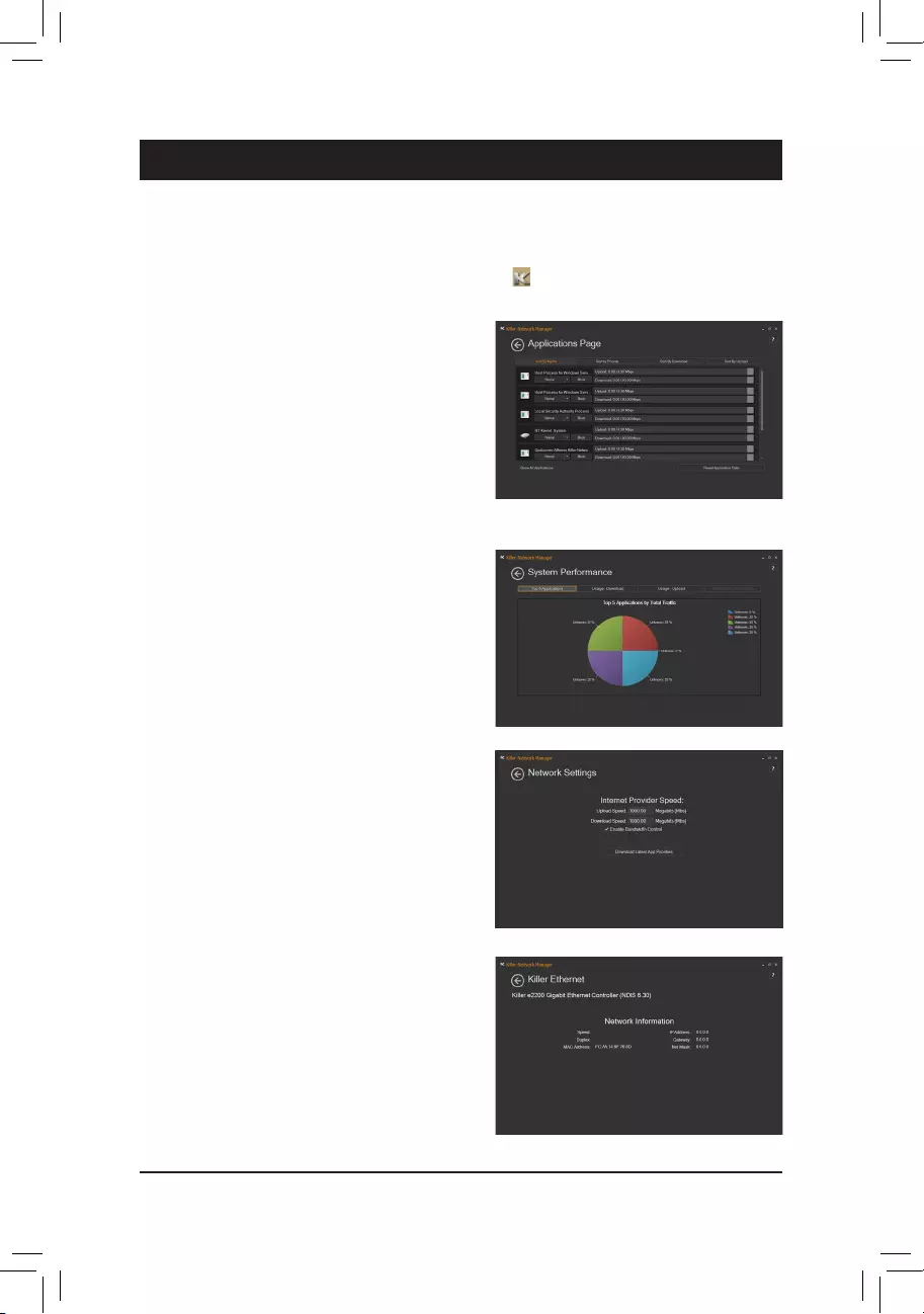
— 111 —
Chapter 6 Appendix
6-1 Killer Network Manager
The Killer Network Manager allows you to view your network connection status and Internet bandwidth and to
congureyournetworksettings.AfterinstallingtheLANdriver,youcanaccesstheKillerNetworkManagerin
Apps>Killer Networking>Killer Network Manager or click on the iconinthenoticationarea.
Network Settings
Thispage allows you to congure your wirednetwork
connection and Internet provider speed.
Applications Page
On the Applications Pagecongurationscreen,youcan
set the priority for an application or online game to use the
bandwidth to access the Internet. To change the priority,
use the drop-down menu below the application’s/game’s
icon to select a priority level. You can change the upload
and download bandwidth for each application as well.
Drag the gray square on the right end of an application
to change the bandwidth.
System Performance
Thispageallowsyoutoviewapplicationtrafcofyour
system.
Killer Ethernet
This page allows you to check the current status of your
network connection.
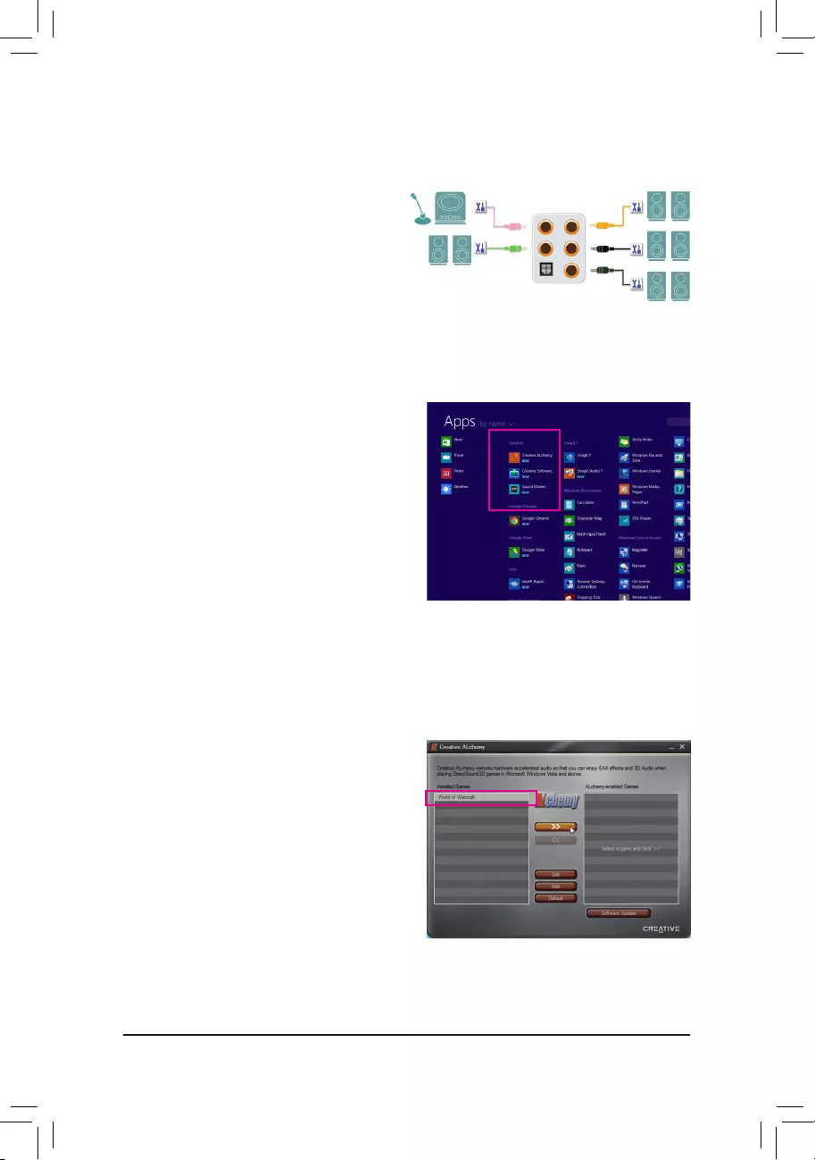
— 112 —
6-2-1 Conguring2/5.1-ChannelAudio
The motherboard supports 2/5.1-channel audio.Refer
tothefollowingforspeakercongurations.
•2-channel audio: Headphone or Line out.
•5.1-channelaudio:Frontspeakerout,Rearspeaker
out, and Center/Subwoofer speaker out.
6-2 ConguringAudioInputandOutput
Center/Subwoofer
Speaker Out
Line In/Mic In
RearSpeakerOut
Front Speaker
Out
Headphone
6-2-2 Creative Software Suite
Afterinstallingtheaudiodriver,youcanndtheCreative
Software Suite in Apps>Creative.
The Creative Software Suite includes Creative Alchemy
andSoundBlasterRecon3Di.
Creative Alchemy
Through the Creative Alchemy, you can enable EAX effects for your games to obtain the most realistic gaming
experience.
Steps:
Go to Apps>Creative to launch Creative Alchemy. On the
left panel, select the game for which you want to enable
the EAX effects and add it to the right panel. You will see
the EAX effects are enabled when the game is launched.
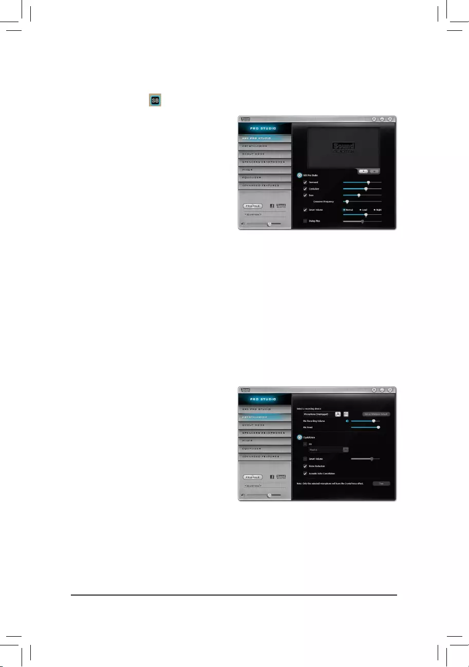
— 113 —
Sound Blaster Recon3Di
TolaunchtheSoundBlasterRecon3DiControlPanel,gotoApps>CreativeandselectSound Blaster Recon3Di
Control Panel or click the iconinthenoticationarea.
SBX PRO STUDIO:
ClicktheSBXPROSTUDIOicontoenableordisable
it. The sliders on the right side allow you to adjust the
enhancement level for each feature.
• Surround:
Provides immersion control to enhance the
natural sense of audio depth and spaciousness
by creating virtual surround sound channels.
• Crystalizer:
Makes the music sound as good as the artist
originally intended and adds an enhanced level
of realism for movies and games.
• Bass:
Thisfeatureisavailableonlywhenastereospeakerorheadphoneisinstalled.Itllsinthemissinglow
frequency tones and gives the extra impact for a better entertainment experience. The Crossover Frequency
feature is available only when a 2-channel stereo speaker system is installed.
• Smart Volume:
Addresses the problem of abrupt volume level changes during playback and between songs by automatically
and continuously measuring volume, and intelligently applying gain and attenuation to compensate for
those changes.
• Dialog Plus:
Enhances the voices in movies for clearer dialog, allowing the listener to hear the dialog over the rest of
the soundtrack and over ambient noise in the listening environment.
CRYSTALVOICE:
This page allows you to select a recording device and
adjust microphone volume/boost and related settings.
ItalsoallowsyoutocongureCrystalVoicefeatures.
• FX:
Morphs your voice into different characters and
accents.
• Smart Volume:
Automatically adjusts the loudness of the
speaker’s voice to maintain a consistent volume
level.
• NoiseReduction:
Eliminates unwanted background noise in your
conversations.
• Acoustic Echo Cancellation:
Eliminates echoes that interfere with your
conversation.
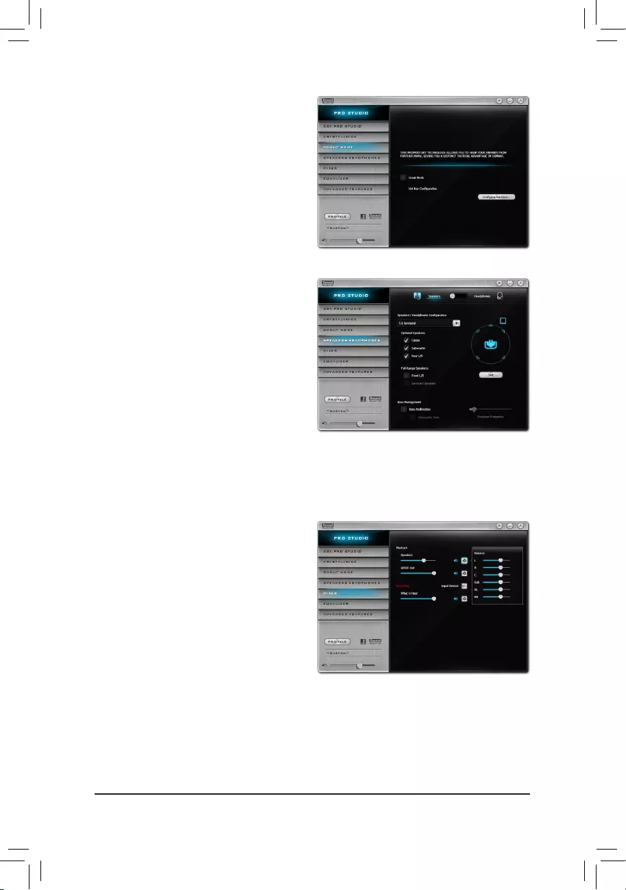
— 114 —
SCOUT MODE:
This page allows you to enable or disable Scout Mode.
This feature enables you to hear your opponents
from further away in FPS games, giving you a distinct
tactical advantage in combat. You can set hot keys
which can be used enable or disable this feature
during games.
SPEAKERS/HEADPHONES:
This page allows you to set the output device to
speakers or headphones and set up your speaker/
headphone configurations. (Note: Speakers and
headphones cannot be used at the same time. When
the headphone function is selected, the sound will
come out only from the front line out or rear headphone
jack.)
Speaker/HeadphoneCongurations:
Depending on the connected devices, you can
select 5.1 Surround, Stereo, or Headphones. If a
5.1-channelconguration is set, you can cancel or
openaspecicspeakermanually.
MIXER:
This page allows you to increase or decrease the
playback and recording volumes for your input/output
device.
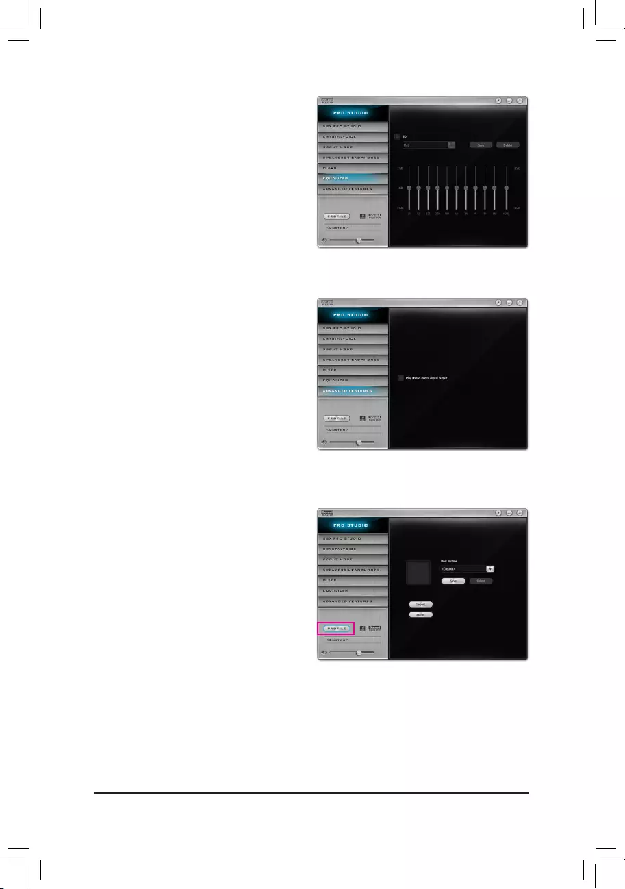
— 115 —
EQUALIZER:
This panel allows you to adjust the strength of certain
frequencies for your audio signals.
ADVANCED FEATURES:
This page allows you to play stereo mix to digital
output. You can output the mixed audio signals
simultaneously to the speakers and S/PDIF out to
obtain 2-channel sound.
Note: When using this feature, the default playback
device must be set to Speaker, not SPDIF Out in
Windows Control Panel.
Other Features:
The Prole button allows you to save your settings
on the SPEAKERS/HEADPHONES, MIXER, or
ADVANCED FEATURESpagetoaprole.Youcan
export your custom settings and share them with others
or import others’ custom settings.
(Note) FormoreinformationonSoundBlasterRecon3Di,pleasevisittheCREATIVE® website.
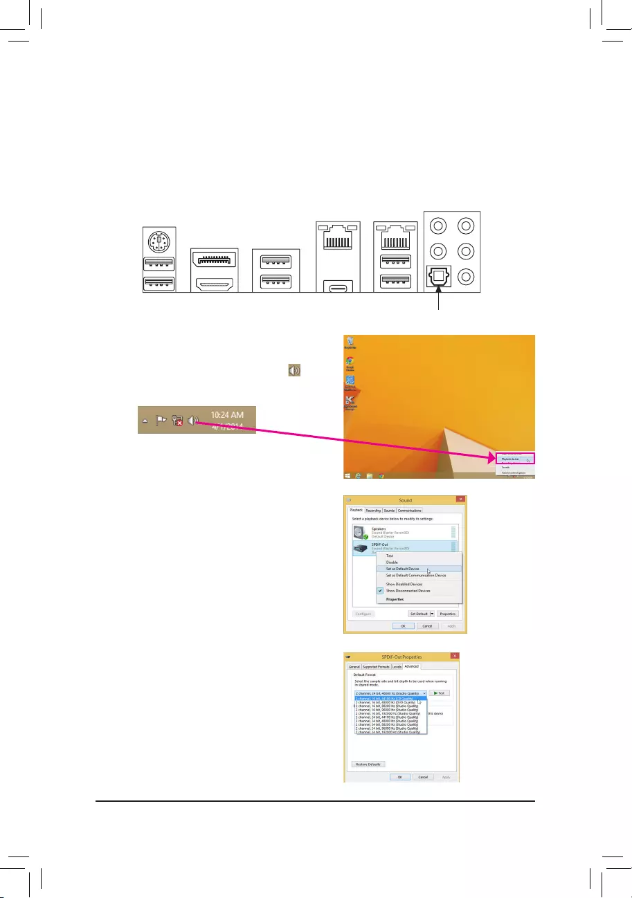
— 116 —
6-2-3 ConguringS/PDIFOut
The S/PDIF Out jack can transmit audio signals to an external decoder for decoding to get the best audio
quality.
1. Connecting a S/PDIF Out Cable:
Connect a S/PDIF optical cable to an external decoder for transmitting the S/PDIF digital audio signals.
2.ConguringS/PDIFOut:
Step 1:
While in the operating system, right-click on the icon
inthenoticationareaandselectPlayback devices.
Step 2:
On the Playback tab, right-click on SPDIF Out, select
Set as Default Device, and then open the Properties
dialog box.
Step 3:
You can go to the Supported Formats tab to select the
formats to be decoded or the Advanced tab to select the
sample rate and bit depth.
Connects to a S/PDIF optical cable
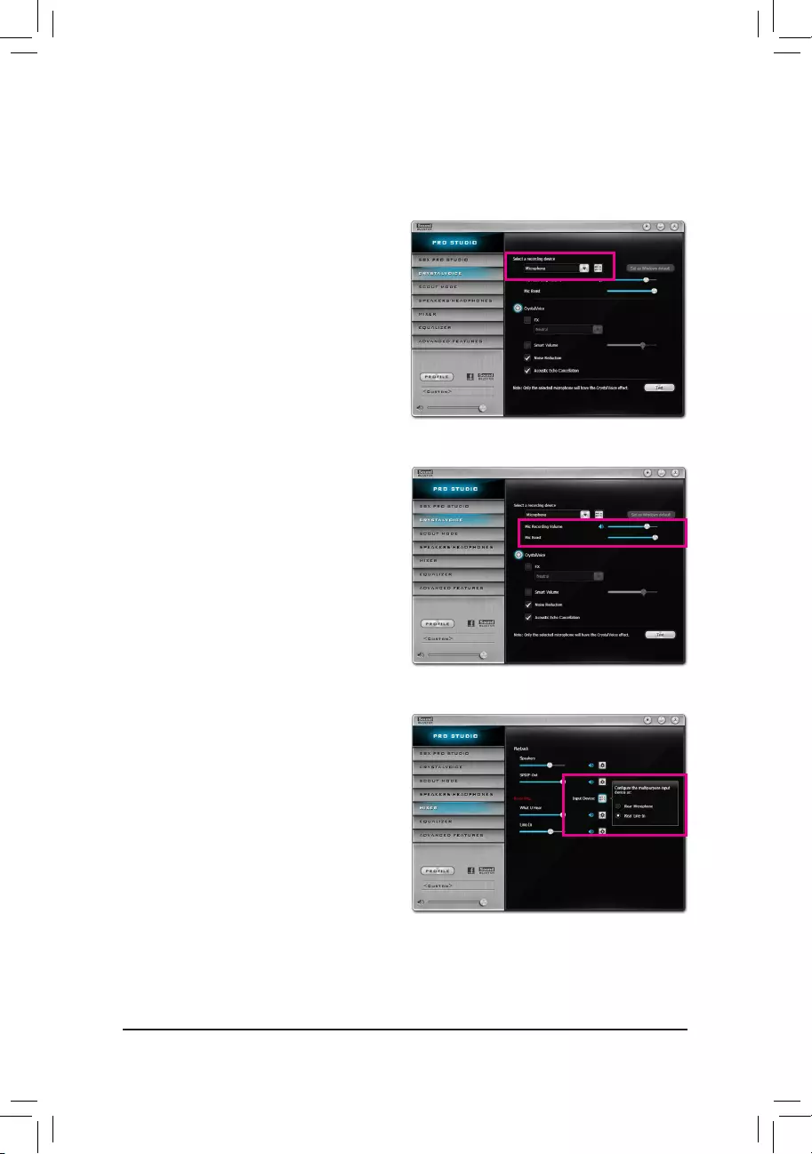
— 117 —
6-2-4 ConguringAudioRecording
You can record the sound from the microphone or Line in device or record the sound from your computer.
Step 2:
To hear the sound being recorded during the recording
process, it is recommended that you set the Mic
volume at a middle level. Do not mute the recording
volume, or you’ll not be able to record the sound.
To raise the recording and playback volume for the
microphone, use the Mic Boost slider and set the
microphone boost level.
1.Conguringyourmicrophone:
Step 1:
Connect your microphone to the Mic in jack on the back
panel or the Mic in jack on the front panel.
Note: The microphone functions on the front panel and
back panel cannot be used at the same time.
Open the Sound Blaster Recon3Di control panel
and go to the CRYSTALVOICE page. Make sure your
microphone is correctly connected.
2.ConguringyourLineindevice:
Step 1:
Open the Sound Blaster Recon3Di control panel
and go to the MIXER page. In the Recording section,
click the Input Device icon and select Rear Line-In.
Later you can use the Line-In slider to set the volume.
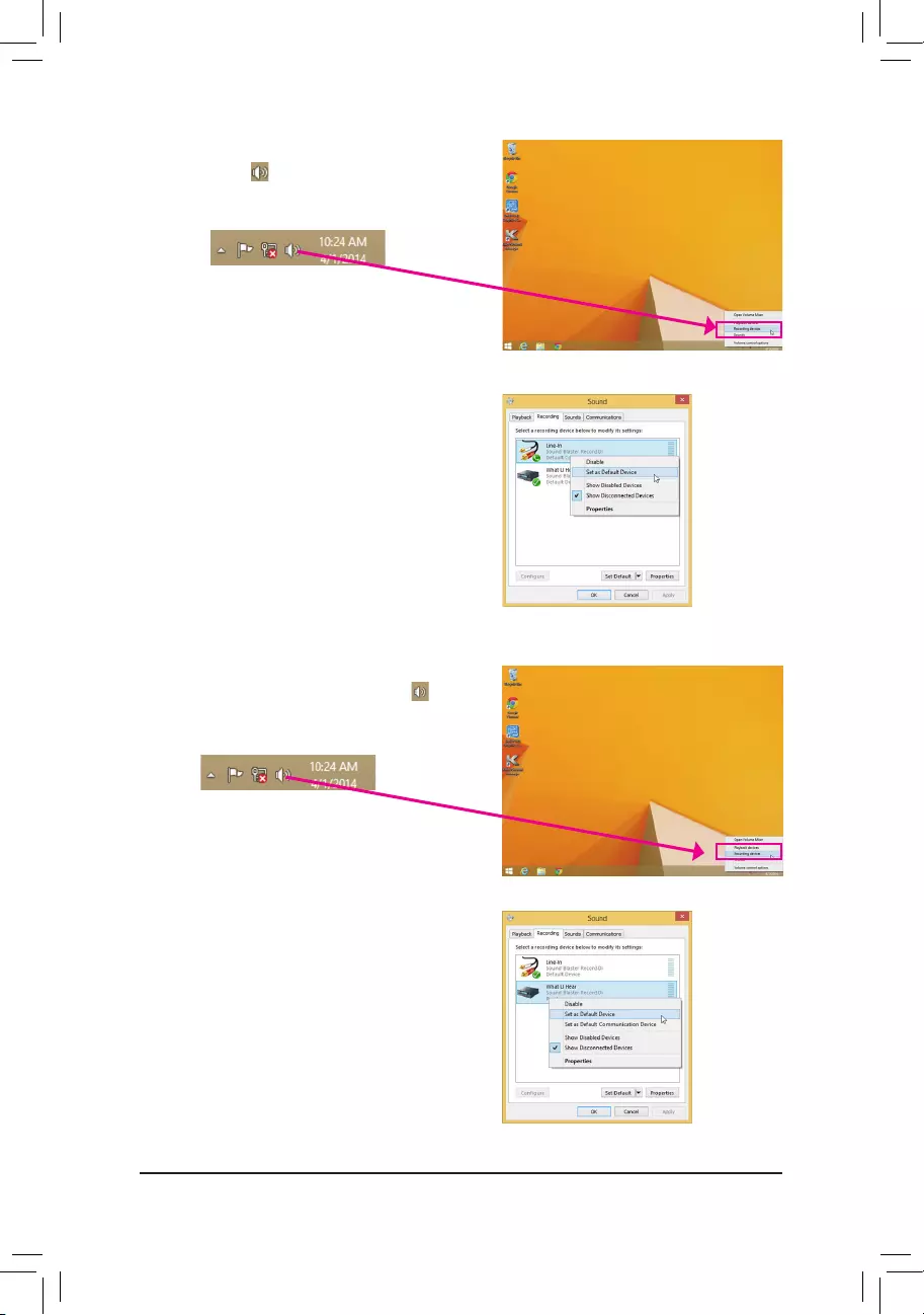
— 118 —
Step 2:
Right-clickon the icon in thenotication area and
select Recording devices.
Step 3:
On the Recording tab, right-click on Line-In, and select
Set as Default Device.
3. Recording the sound from your computer:
Step 1:
While in the operating system, right-click on the icon
inthenoticationareaandselectRecording devices.
Step 2:
On the Recording tab, right-click on What U Hear and
select Set as Default Device.
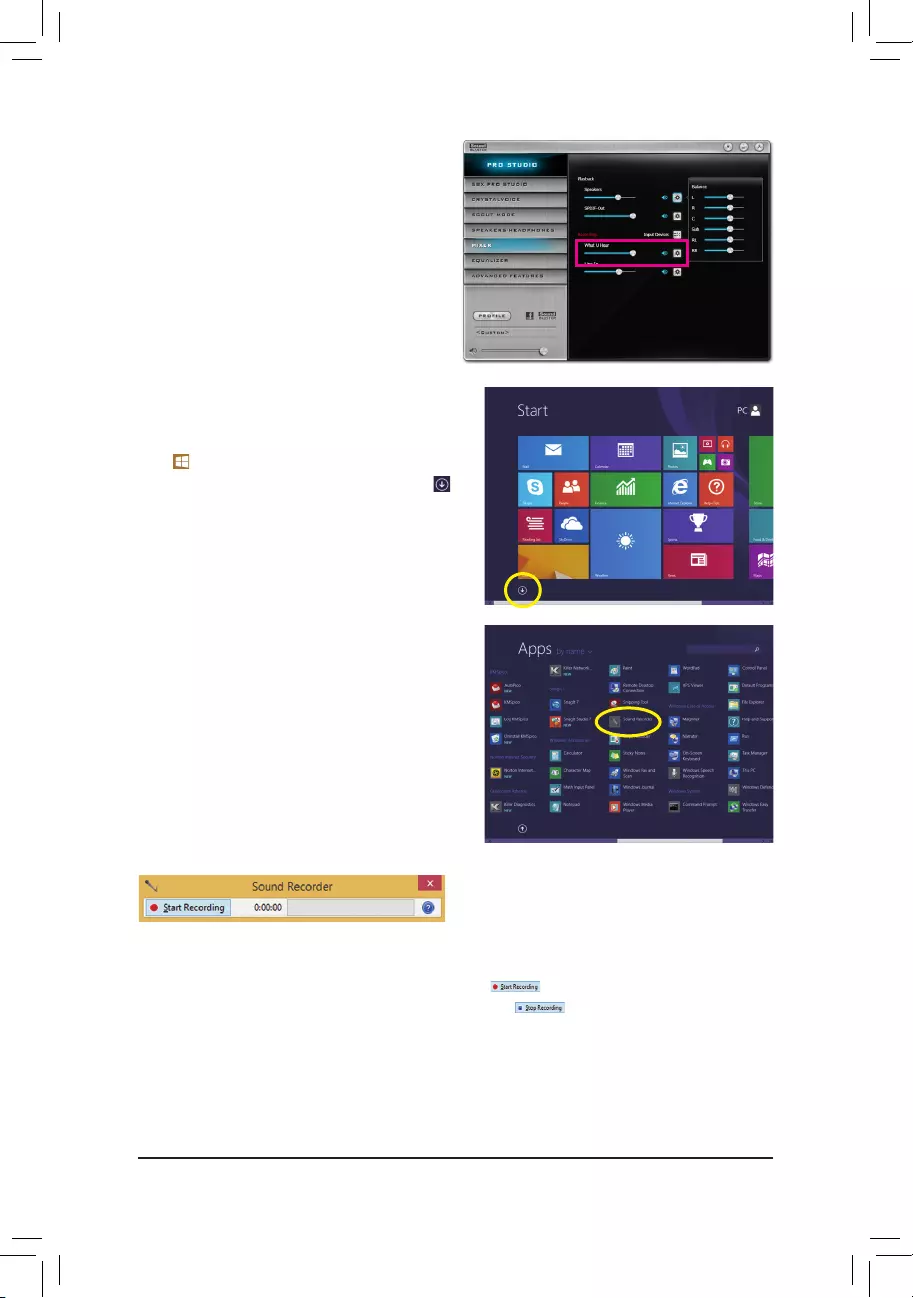
— 119 —
Step 3:
OpentheSoundBlasterRecon3DiControlPaneland
go to the Mixer page. In the REC section, you can use
the What U Hear slider to set the volume.
6-2-5 Using the Sound Recorder
A. Recording Sound
1. Makesureyouhaveconnectedthesoundinputdevice(e.g.microphone)tothecomputer.
2. To record the audio, click the Start Recording button .
3. To stop recording audio, click the Stop Recording button .
Besuretosavetherecordedaudioleuponcompletion.
B. Playing the Recorded Sound
Youcanplayyourrecordinginadigitalmediaplayerprogramthatsupportsyouraudioleformat.
Step 4:
To open the Sounder Recorder, move the mouse
cursor to the bottom left corner of the screen, click the
Start icon to switch to the Start screen (or press
theWindows button onthe keyboard). Click the
icon on the bottom left corner of the screen to access
the Apps screen.
Step 5:
On this screen, click Sound Recorder for audio recording.

— 120 —
6-3 Troubleshooting
6-3-1 Frequently Asked Questions
To read more FAQs for your motherboard, please go to the Support\FAQ page on GIGABYTE’s website.
Q: Why is the light of my keyboard/optical mouse still on after the computer shuts down?
A: Some motherboards provide a small amount of standby power after the computer shuts down and that’s why the light is still
on.
Q: How do I clear the CMOS values?
A: For motherboards that have a Clear CMOS button, press this button to clear the CMOS values (before doing this, please turn
offthecomputerandunplugthepowercord).FormotherboardsthathaveaClearCMOSjumper,refertotheinstructionsin
Chapter 1 to short the jumper to clear the CMOS values. If your board doesn’t have this jumper/button, refer to the instructions
on the motherboard battery in Chapter 1. You can temporarily remove the battery from the battery holder to stop supplying
power to the CMOS, which will clear the CMOS values after about one minute.
Q: Why do I still get a weak sound even though I have turned my speaker to the maximum volume?
A: Makesureyourspeakerisequippedwithaninternalamplier.Ifnot,tryaspeakerwithpower/amplier.
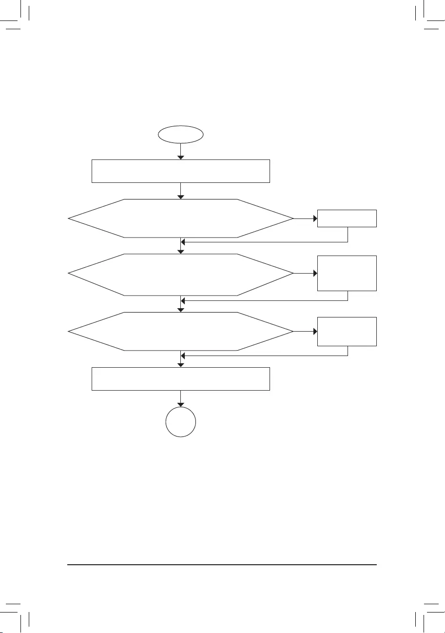
— 121 —
6-3-2 Troubleshooting Procedure
If you encounter any troubles during system startup, follow the troubleshooting procedure below to solve the
problem.
START
A
Turnoffthe power.Remove allperipherals, connectingcables, and
power cord etc.
Isolate the short circuit.
Secure the CPU cooler
on the CPU. Connect the
CPU cooler power cable
to the motherboard.
Correctly insert the
memory into the memory
socket.
(Continued…)
Yes
Theproblemisveriedandsolved.
Theproblemisveriedandsolved.
Theproblemisveriedandsolved.
No
No
No
Yes
Yes
Insert the graphics card. Connect the ATX main power cable and the
12V power cable. Turn on the power to start the computer.
Make sure the motherboard does not short-circuit with the chassis or
other metal objects.
Check if the CPU cooler is attached to the CPU securely. Is the power
connector of the CPU cooler connected to the CPU_FAN header
properly?
Check if the memory is installed properly on the memory slot.
Make sure the graphics card is securely seated in the
expansionslotandpowerconnectorsarermlyattached.
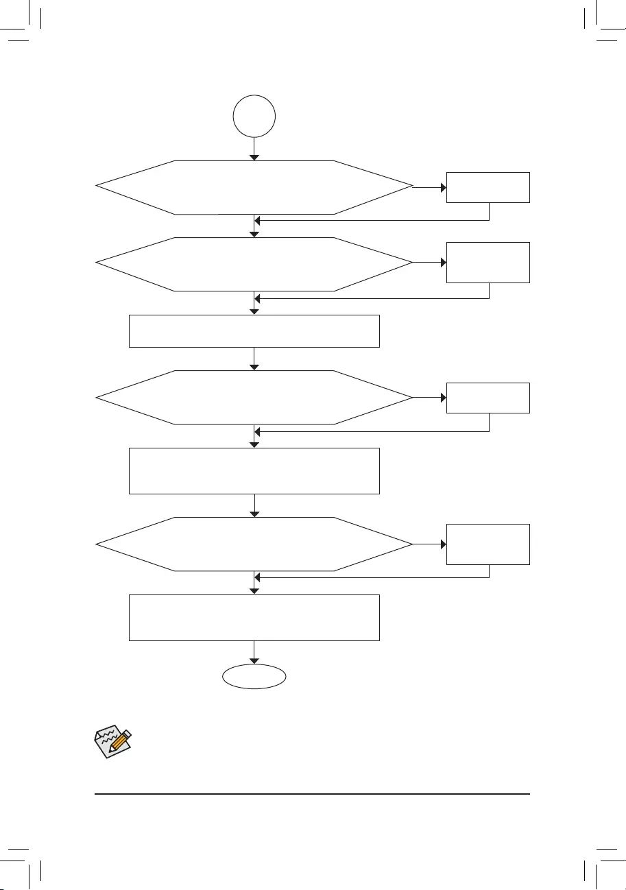
— 122 —
If the procedure above is unable to solve your problem, contact the place of purchase or local dealer
for help. Or go to the Support\Technical Support page to submit your question. Our customer service
staff will reply you as soon as possible.
The power supply, CPU or
CPU socket might fail.
The keyboard or keyboard
connector might fail.
END
A
Turn off the computer. Plug in the keyboard and mouse and restart
the computer.
The graphics card,
expansion slot, or monitor
might fail.
The hard drive, connector,
or cable might fail.
No
Theproblemisveriedandsolved.
Theproblemisveriedandsolved.
Theproblemisveriedandsolved.
No
No
Yes
Yes
Yes
Reinstallthe operating system. Reinstall other devices one by one
(install one device at one time and then boot the system to see if the
deviceworkssuccessfully).
Press <Delete> to enter BIOS Setup. Select «Load Optimized Defaults.»
Select «Save & Exit Setup» to save changes and exit BIOS Setup.
Check if there is display on your monitor.
When the computer is turned on, is the CPU cooler running?
Check if the keyboard is working properly.
No
Theproblemisveriedandsolved.
Yes
Turnoffthecomputerandconnecttheharddrive(s).Checkifthesystem
can boot successfully.

— 123 —
6-4 Debug LED Codes
Code Description
10 PEI Core is started.
11 Pre-memory CPU initialization is started.
12~14 Reserved.
15 Pre-memory North-Bridge initialization is started.
16~18 Reserved.
19 Pre-memory South-Bridge initialization is started.
1A~2A Reserved.
2B~2F Memory initialization.
31 Memory installed.
32~36 CPU PEI initialization.
37~3A IOH PEI initialization.
3B~3E PCH PEI initialization.
3F~4F Reserved.
60 DXE Core is started.
61 NVRAMinitialization.
62 Installation of the PCH runtime services.
63~67 CPU DXE initialization is started.
68 PCI host bridge initialization is started.
69 IOH DXE initialization.
6A IOH SMM initialization.
6B~6F Reserved.
70 PCH DXE initialization.
71 PCH SMM initialization.
72 PCH devices initialization.
73~77 PCHDXEinitialization(PCHmodulespecic).
78 ACPI Core initialization.
79 CSM initialization is started.
7A~7F ReservedforAMIuse.
80~8F ReservedforOEMuse(OEMDXEinitializationcodes).
90 PhasetransfertoBDS(BootDeviceSelection)fromDXE.
91 Issue event to connect drivers.
Regular Boot

— 124 —
Code Description
92 PCI Bus initialization is started.
93 PCI Bus hot plug initialization.
94 PCI Bus enumeration for detecting how many resources are requested.
95 Check PCI device requested resources.
96 Assign PCI device resources.
97 ConsoleOutputdevicesconnect(ex.Monitorislighted).
98 Consoleinputdevicesconnect(ex.PS2/USBkeyboard/mouseareactivated).
99 Super IO initialization.
9A USB initialization is started.
9B Issue reset during USB initialization process.
9C Detect and install all currently connected USB devices.
9D Activated all currently connected USB devices.
9E~9F Reserved.
A0 IDE initialization is started.
A1 Issue reset during IDE initialization process.
A2 Detect and install all currently connected IDE devices.
A3 Activated all currently connected IDE devices.
A4 SCSI initialization is started.
A5 Issue reset during SCSI initialization process.
A6 Detect and install all currently connected SCSI devices.
A7 Activated all currently connected SCSI devices.
A8 Verify password if needed.
A9 BIOS Setup is started.
AA Reserved.
AB Wait user command in BIOS Setup.
AC Reserved.
AD IssueReadyToBooteventforOSBoot.
AE Boot to Legacy OS.
AF Exit Boot Services.
B0 RuntimeAPinstallationbegins.
B1 RuntimeAPinstallationends.
B2 LegacyOptionROMinitialization.
B3 System reset if needed.
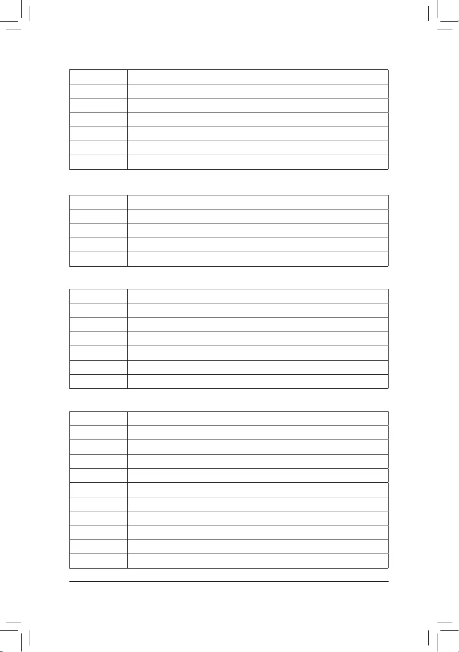
— 125 —
Code Description
B4 USB device hot plug-in.
B5 PCI device hot plug.
B6 Clean-upofNVRAM.
B7 RecongureNVRAMsettings.
B8~BF Reserved.
C0~CF Reserved.
Code Description
E0 S3Resumeisstarted(calledfromDXEIPL).
E1 Fill boot script data for S3 resume.
E2 Initializes VGA for S3 resume.
E3 OS S3 wake vector call.
S3 Resume
Code Description
F0 Recoverymodewillbetriggeredduetoinvalidrmwarevolumedetection.
F1 Recoverymodewillbetriggeredbyuserdecision.
F2 Recoveryisstarted.
F3 Recoveryrmwareimageisfound.
F4 Recoveryrmwareimageisloaded.
F5~F7 ReservedforfutureAMIprogresscodes.
Recovery
Code Description
50~55 Memory initialization error occurs.
56 Invalid CPU type or speed.
57 CPU mismatch.
58 CPU self test failed or possible CPU cache error.
59 CPU micro-code is not found or micro-code update is failed.
5A Internal CPU error.
5B ResetPPIisfailed.
5C~5F Reserved.
D0 CPU initialization error.
D1 IOH initialization error.
Error

— 126 —
Code Description
D2 PCH initialization error.
D3 Some of the Architectural Protocols are not available.
D4 PCIresourceallocationerror.OutofResources.
D5 NoSpaceforLegacyOptionROMinitialization.
D6 No Console Output Devices are found.
D7 No Console Input Devices are found.
D8 It is an invalid password.
D9~DA Can’t load Boot Option.
DB Flash update is failed.
DC Resetprotocolisfailed.
DE~DF Reserved.
E8 S3 resume is failed.
E9 S3ResumePPIisnotfound.
EA S3ResumeBootScriptisinvalid.
EB S3 OS Wake call is failed.
EC~EF Reserved.
F8 RecoveryPPIisinvalid.
<F9> Recoverycapsuleisnotfound.
FA Invalid recovery capsule.
FB~FF Reserved.

— 127 —
Regulatory Statements
Regulatory Notices
This document must not be copied without our written permission, and the contents there of must not be imparted
to a third party nor be used for any unauthorized purpose. Contravention will be prosecuted. We believe that the
information contained herein was accurate in all respects at the time of printing. GIGABYTE cannot, however,
assume any responsibility for errors or omissions in this text. Also note that the information in this document is
subject to change without notice and should not be construed as a commitment by GIGABYTE.
Our Commitment to Preserving the Environment
Inaddition to high-efciency performance, allGIGABYTE motherboards fulllEuropean Union regulations
forRoHS(RestrictionofCertainHazardousSubstancesinElectricalandElectronicEquipment)andWEEE
(WasteElectricalandElectronicEquipment)environmentaldirectives,aswellasmostmajorworldwidesafety
requirements. To prevent releases of harmful substances into the environment and to maximize the use of our
natural resources, GIGABYTE provides the following information on how you can responsibly recycle or reuse
most of the materials in your «end of life» product.
Restriction of Hazardous Substances (RoHS) Directive Statement
GIGABYTE products have not intended to add and safe from hazardous substances (Cd, Pb, Hg, Cr+6, PBDE
andPBB).ThepartsandcomponentshavebeencarefullyselectedtomeetRoHSrequirement.Moreover,weat
GIGABYTE are continuing our efforts to develop products that do not use internationally banned toxic chemicals.
Waste Electrical & Electronic Equipment (WEEE) Directive Statement
GIGABYTEwillfulllthenationallawsasinterpretedfromthe2002/96/ECWEEE(WasteElectricalandElectronic
Equipment)directive.TheWEEEDirectivespeciesthetreatment,collection,recyclinganddisposalofelectric
and electronic devices and their components. Under the Directive, used equipment must be marked, collected
separately, and disposed of properly.
WEEE Symbol Statement
The symbol shown below is on the product or on its packaging, which indicates that this product
must not be disposed of with other waste. Instead, the device should be taken to the waste collection
centers for activation of the treatment, collection, recycling and disposal procedure. The separate
collection and recycling of your waste equipment at the time of disposal will help to conserve natural
resources and ensure that it is recycled in a manner that protects human health and the environment.
For more information about where you can drop off your waste equipment for recycling, please contact your
localgovernmentofce,yourhouseholdwastedisposalserviceorwhereyoupurchasedtheproductfordetails
of environmentally safe recycling.
When your electrical or electronic equipment is no longer useful to you, «take it back» to your local or regional
waste collection administration for recycling.
If you need further assistance in recycling, reusing in your «end of life» product, you may contact us at the
Customer Care number listed in your product’s user’s manual and we will be glad to help you with your effort.
Finally, we suggest that you practice other environmentally friendly actions by understanding and using the
energy-savingfeaturesofthisproduct(whereapplicable),recyclingtheinnerandouterpackaging(including
shippingcontainers)thisproductwasdeliveredin,andbydisposingoforrecyclingusedbatteriesproperly.
With your help, we can reduce the amount of natural resources needed to produce electrical and electronic
equipment,minimizetheuseoflandllsforthedisposalof«endoflife»products,andgenerallyimproveour
quality of life by ensuring that potentially hazardous substances are not released into the environment and are
disposed of properly.

— 128 —
FCC Notice (U.S.A. Only)
This equipment has been tested and found to comply with the limits for a Class B digital device, pursuant to Part
15oftheFCCRules.Theselimitsaredesignedtoprovidereasonableprotectionagainstharmfulinterference
in a residential installation. This equipment generates, uses, and can radiate radio frequency energy and, if not
installed and used in accordance with the instructions, may cause harmful interference to radio communications.
However, there is no guarantee that interference will not occur in a particular installation. If this equipment does
cause harmful interference to radio or television reception, which can be determined by turning the equipment
off and on, the user is encouraged to try to correct the interference by one or more of the following measures:
Reorientorrelocatethereceivingantenna.
Increase the separation between the equipment and receiver.
Connect the equipment into an outlet on a circuit different from that to which the receiver is connected.
Consult a dealer or experienced TV/radio technician for help.
Canada, Industry Canada (IC) Notices / Canada, avis d’Industry Canada (IC)
ThisClassBdigitalapparatuscomplieswithCanadianICES-003andRSS-210.
Operationissubjecttothefollowingtwoconditions:(1)thisdevicemaynotcauseinterference,and(2)this
device must accept any interference, including interference that may cause undesired operation of the device.
CetappareilnumériquedeclasseBestconformeauxnormescanadiennesICES-003etRSS-210.
Sonfonctionnement est soumisaux deux conditionssuivantes : (1) cet appareilne doit pascauser
d’interférenceet(2)cetappareildoitacceptertouteinterférence,notammentlesinterférencesquipeuvent
affecter son fonctionnement.

— 129 —

— 130 —

— 131 —
Contact Us
•GIGA-BYTE TECHNOLOGY CO., LTD.
Address:No.6,BaoqiangRd.,XindianDist.,
New Taipei City 231, Taiwan
TEL: +886-2-8912-4000
FAX: +886-2-8912-4005
Tech.andNon-Tech.Support(Sales/Marketing):
http://esupport.gigabyte.com
WEBaddress(English):http://www.gigabyte.com
WEBaddress(Chinese):http://www.gigabyte.tw
•G.B.T. INC. — U.S.A.
TEL: +1-626-854-9338
FAX: +1-626-854-9326
Tech. Support: http://esupport.gigabyte.com
Warranty Info: http://rma.gigabyte.us
Web address: http://www.gigabyte.us
•G.B.T. INC (USA) — Mexico
Tel:+1-626-854-9338x215(Soportedehablahispano)
FAX: +1-626-854-9326
Correo: soporte@gigabyte-usa.com
Tech. Support: http://rma.gigabyte.us
Web address: http://latam.giga-byte.com
•Giga-Byte SINGAPORE PTE. LTD. — Singapore
WEB address : http://www.gigabyte.sg
•Thailand
WEB address : http://th.giga-byte.com
•Vietnam
WEB address : http://www.gigabyte.vn
•NINGBO G.B.T. TECH. TRADING CO., LTD. — China
WEB address : http://www.gigabyte.cn
Shanghai
TEL: +86-21-63400912
FAX: +86-21-63400682
Beijing
TEL: +86-10-62102838
FAX: +86-10-62102848
Wuhan
TEL: +86-27-87685981
FAX: +86-27-87579461
GuangZhou
TEL: +86-20-87540700
FAX: +86-20-87544306
Chengdu
TEL: +86-28-85483135
FAX: +86-28-85256822
Xian
TEL: +86-29-85531943
FAX: +86-29-85510930
Shenyang
TEL: +86-24-83992342
FAX: +86-24-83992102
•GIGABYTE TECHNOLOGY (INDIA) LIMITED — India
WEB address : http://www.gigabyte.in
•Saudi Arabia
WEB address : http://www.gigabyte.com.sa
•Gigabyte Technology Pty. Ltd. — Australia
WEB address : http://www.gigabyte.com.au
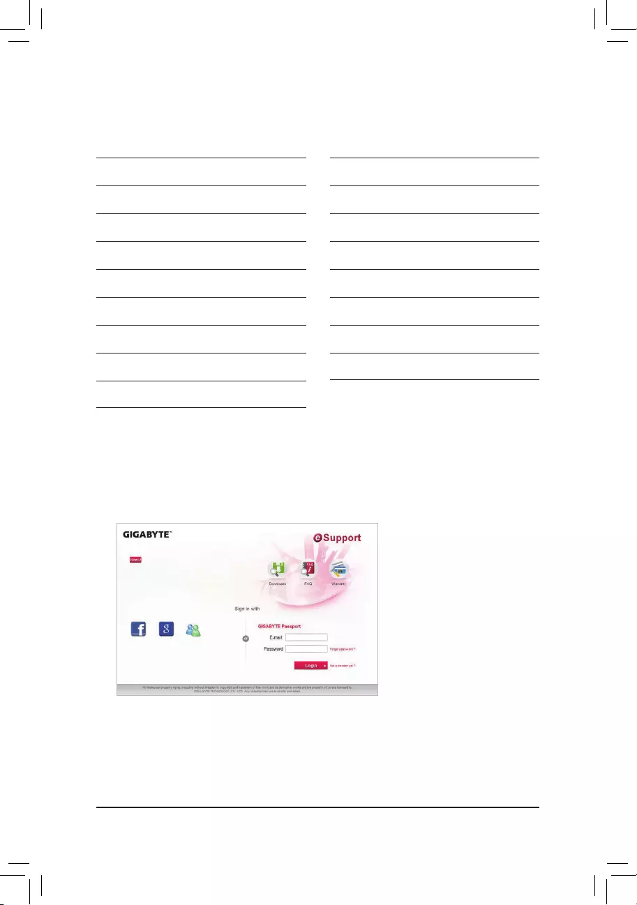
— 132 —
•G.B.T. TECHNOLOGY TRADING GMBH — Germany
WEB address : http://www.gigabyte.de
•G.B.T. TECH. CO., LTD. — U.K.
WEB address : http://www.giga-byte.co.uk
•Giga-Byte Technology B.V. — The Netherlands
WEB address : http://www.giga-byte.nl
•GIGABYTE TECHNOLOGY FRANCE — France
WEB address : http://www.gigabyte.fr
•Sweden
WEB address : http://www.gigabyte.se
•Italy
WEB address : http://www.giga-byte.it
•Spain
WEB address : http://www.giga-byte.es
•Greece
WEB address : http://www.gigabyte.com.gr
•Czech Republic
WEB address : http://www.gigabyte.cz
•Hungary
WEB address : http://www.giga-byte.hu
•Turkey
WEB address : http://www.gigabyte.com.tr
•Russia
WEB address : http://www.gigabyte.ru
•Poland
WEB address : http://www.gigabyte.pl
•Ukraine
WEB address : http://www.gigabyte.ua
•Romania
WEB address : http://www.gigabyte.com.ro
•Serbia
WEB address : http://www.gigabyte.co.rs
•Kazakhstan
WEB address : http://www.gigabyte.kz
•GIGABYTE eSupport
Tosubmitatechnicalornon-technical(Sales/Marketing)question,pleaselinkto:
http://esupport.gigabyte.com
![]()
GA-Z170X-Gaming 7
User’s Manual
Rev. 1001
12ME-Z17XGE7-1001R
For more product details, please visit GIGABYTE’s website.
To reduce the impacts on global warming, the packaging materials of this product are recyclable and reusable. GIGABYTE works with you to protect the environment.

Motherboard
GA-Z170X-Gaming 7
Jul. 24, 2015
Motherboard
GA-Z170X-Gaming 7
Jul. 24, 2015

Copyright
© 2015 GIGA-BYTE TECHNOLOGY CO., LTD. All rights reserved.
The trademarks mentioned in this manual are legally registered to their respective owners.
Disclaimer
Information in this manual is protected by copyright laws and is the property of GIGABYTE.
Changes to the specifications and features in this manual may be made by GIGABYTE without prior notice.
No part of this manual may be reproduced, copied, translated, transmitted, or published in any form or by any means without GIGABYTE’s prior written permission.
Documentation Classifications
In order to assist in the use of this product, GIGABYTE provides the following types of
documentations:
For quick set-up of the product, read the Quick Installation Guide included with the product.For detailed product information, carefully read the User’s Manual.
For product-related information, check on our website at: http://www.gigabyte.com
Identifying Your Motherboard Revision
The revision number on your motherboard looks like this: «REV: X.X.» For example, «REV: 1.0» means the revision of the motherboard is 1.0. Check your motherboard revision before updating motherboard BIOS, drivers, or when looking for technical information.
Example:

Table of Contents
|
Box Contents…………………………………………………………………………………………………….. |
6 |
||
|
Optional Items…………………………………………………………………………………………………… |
6 |
||
|
GA-Z170X-Gaming 7 Motherboard Layout……………………………………………………………. |
7 |
||
|
Chapter 1 Hardware Installation………………………………………………………………………….. |
9 |
||
|
1-1 |
Installation Precautions…………………………………………………………………………. |
9 |
|
|
1-2 |
Product Specifications………………………………………………………………………… |
10 |
|
|
1-3 |
Installing the CPU and CPU Cooler………………………………………………………. |
14 |
|
|
1-3-1 |
Installing the CPU……………………………………………………………………………………… |
14 |
|
|
1-3-2 Installing the CPU Cooler……………………………………………………………………………. |
16 |
||
|
1-4 |
Installing the Memory………………………………………………………………………….. |
17 |
|
|
1-4-1 Dual Channel Memory Configuration……………………………………………………………. |
17 |
||
|
1-4-2 |
Installing a Memory……………………………………………………………………………………. |
18 |
|
|
1-5 |
Installing an Expansion Card……………………………………………………………….. |
19 |
|
|
1-6 |
Setting up AMD CrossFire™/NVIDIA® SLI™ Configuration…………………………. |
20 |
|
|
1-7 |
Back Panel Connectors………………………………………………………………………. |
21 |
|
|
1-8 |
Onboard Buttons and Switches……………………………………………………………. |
23 |
|
|
1-9 |
Changing the Operational Amplifier………………………………………………………. |
25 |
|
|
1-10 |
Internal Connectors……………………………………………………………………………. |
26 |
|
|
Chapter 2 BIOS Setup……………………………………………………………………………………… |
39 |
||
|
2-1 |
Startup Screen…………………………………………………………………………………… |
40 |
|
|
2-2 |
The Main Menu………………………………………………………………………………….. |
41 |
|
|
2-3 |
M.I.T…………………………………………………………………………………………………. |
43 |
|
|
2-4 |
System Information…………………………………………………………………………….. |
56 |
|
|
2-5 |
BIOS Features…………………………………………………………………………………… |
57 |
|
|
2-6 |
Peripherals………………………………………………………………………………………… |
60 |
|
|
2-7 |
Chipset……………………………………………………………………………………………… |
63 |
|
|
2-8 |
Power Management……………………………………………………………………………. |
64 |
|
|
2-9 |
Save & Exit……………………………………………………………………………………….. |
66 |
|
|
Chapter 3 Configuring a RAID Set…………………………………………………………………….. |
67 |
||
|
3-1 |
Configuring SATA Controllers………………………………………………………………. |
67 |
|
|
3-2 |
Installing the SATA RAID/AHCI Driver and Operating System………………….. |
79 |
|
|
Chapter 4 Drivers Installation……………………………………………………………………………. |
83 |
||
|
4-1 |
Drivers & Software……………………………………………………………………………… |
83 |
— 4 —

|
4-2 |
Application Software…………………………………………………………………………… |
84 |
|
4-3 |
Information………………………………………………………………………………………… |
84 |
|
Chapter 5 Unique Features………………………………………………………………………………. |
85 |
||
|
5-1 |
BIOS Update Utilities………………………………………………………………………….. |
85 |
|
|
5-1-1 |
Updating the BIOS with the Q-Flash Utility……………………………………………………. |
85 |
|
|
5-1-2 |
Updating the BIOS with the @BIOS Utility…………………………………………………….. |
88 |
|
|
5-2 |
APP Center……………………………………………………………………………………….. |
89 |
|
|
5-2-1 |
EasyTune…………………………………………………………………………………………………. |
90 |
|
|
5-2-2 |
System Information Viewer…………………………………………………………………………. |
91 |
|
|
5-2-3 |
Fast Boot………………………………………………………………………………………………….. |
92 |
|
|
5-2-4 |
Smart TimeLock………………………………………………………………………………………… |
93 |
|
|
5-2-5 |
USB Blocker……………………………………………………………………………………………… |
94 |
|
|
5-2-6 |
Smart Keyboard………………………………………………………………………………………… |
95 |
|
|
5-2-7 |
Smart Backup……………………………………………………………………………………………. |
96 |
|
|
5-2-8 |
Ambient LED…………………………………………………………………………………………….. |
98 |
|
|
5-2-9 |
3D OSD……………………………………………………………………………………………………. |
99 |
|
|
5-2-10 |
Cloud Station…………………………………………………………………………………………… |
100 |
|
|
5-2-11 |
AutoGreen………………………………………………………………………………………………. |
105 |
|
|
5-2-12 |
Easy RAID………………………………………………………………………………………………. |
106 |
|
|
5-3 |
Smart Switch……………………………………………………………………………………. |
109 |
|
Chapter 6 Appendix……………………………………………………………………………………….. |
111 |
||
|
6-1 |
Qualcomm® Atheros Killer Network Manager |
…………………………………………111 |
|
|
6-2 |
Configuring Audio Input and Output…………………………………………………….. |
112 |
|
|
6-2-1 |
Configuring 2/5.1-Channel Audio……………………………………………………………….. |
112 |
|
|
6-2-2 |
Creative Software Suite……………………………………………………………………………. |
112 |
|
|
6-2-3 |
Configuring S/PDIF Out……………………………………………………………………………. |
116 |
|
|
6-2-4 |
Configuring Audio Recording…………………………………………………………………….. |
117 |
|
|
6-2-5 Using the Sound Recorder………………………………………………………………………… |
119 |
||
|
6-3 |
Troubleshooting……………………………………………………………………………….. |
120 |
|
|
6-3-1 |
Frequently Asked Questions …………………………………………………………………….. |
120 |
|
|
6-3-2 |
Troubleshooting Procedure……………………………………………………………………….. |
121 |
|
|
6-4 |
Debug LED Codes……………………………………………………………………………. |
123 |
|
|
Regulatory Statements……………………………………………………………………………….. |
127 |
||
|
Contact Us………………………………………………………………………………………………… |
131 |
— 5 —

Box Contents
55 GA-Z170X-Gaming 7 motherboard
55 Motherboard driver disk
55 User’s Manual
55 Quick Installation Guide
55 Four SATA cables
55 I/O Shield
55 One 2-Way SLI bridge connector
55 One G Connector
55 One pack of back I/O dust covers
The box contents above are for reference only and the actual items shall depend on the product package you obtain. The box contents are subject to change without notice.
Optional Items
2-port USB 2.0 bracket (Part No. 12CR1-1UB030-6*R)eSATA bracket (Part No. 12CF1-3SATPW-4*R)
3.5″ Front Panel with 2 USB 3.0/2.0 ports (Part No. 12CR1-FPX582-2*R)HDMI-to-DVI adapter (Part No. 12CT2-HDMI01-1*R)
COM port cable (Part No. 12CF1-1CM001-3*R)
— 6 —
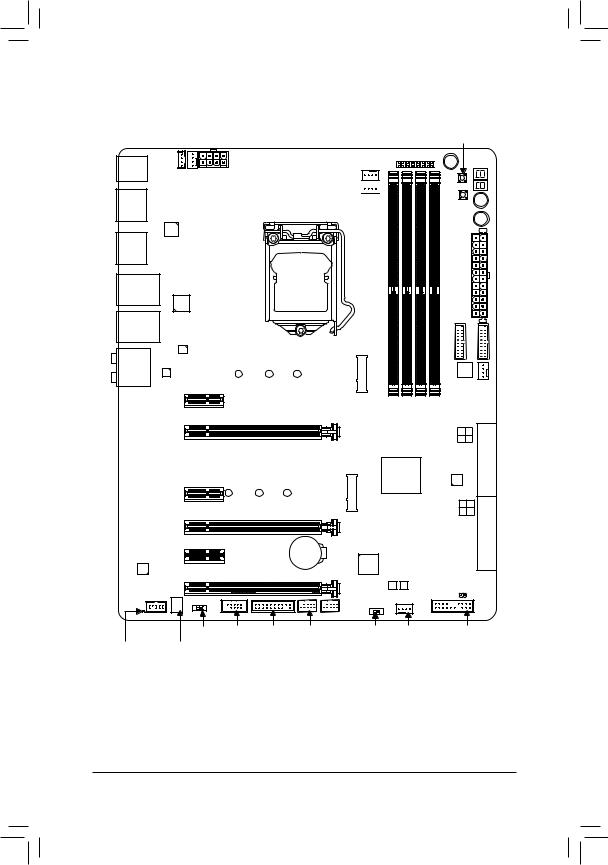
GA-Z170X-Gaming 7 Motherboard Layout
KB_MS_USB30
DP_HDMI
R_USB30
ATX_12V_2X4
SYS_FAN1
LED_IO
LGA1151
MegaChips
MCDP2800
RST_SW
PW_SW
Debug LED (Note)
LAN2
TYPEC Intel®
Thunderbolt™ 3
Controller
USB30_LAN1
Qualcomm®
Atheros Killer
E2400 LAN
|
AUDIO |
Intel® |
M2D_32G |
|||
|
GbE LAN |
80D |
60D |
42D |
3.0 Hub |
|
|
DDR44 DDR42 DDR43 DDR41 |
|||||
|
PCIEX1_1 |
USBRenesas® FAN3SYS |
||||
PCIEX16
|
PCIEX1_2 |
|
|
80H |
|
|
PCIEX8 |
|
|
Creative® |
PCIEX1_3 |
|
Sound Core 3D |
|
|
PCIEX4 |
|
|
F_AUDIO |
CAP_SW COMA
System Temperature TI Burr Brown®
Sensor OPA2134
7 6 3 2
|
GA-Z170X-Gaming 7 |
SATA3 |
EXPRESS |
||||
|
Intel® Z170 |
ASMedia® |
|||||
|
M2H_32G |
ASM1061 |
SATA |
||||
|
60H |
42H |
4 0 |
||||
|
5 1 |
EXPRESS |
|||||
|
iTE® |
SATA3 |
|||||
|
BAT |
Super I/O |
SATA |
||||
|
M BIOS B BIOS |
||||||
|
CLR_CMOS |
||||||
|
F_USB1 |
||||||
|
TPM |
F_USB2 |
SB SYS_FAN2 |
F_PANEL |
(Note) For debug code information, please refer to Chapter 6.
— 7 —

— 8 —

Chapter 1 Hardware Installation
1-1 Installation Precautions
The motherboard contains numerous delicate electronic circuits and components which can become damaged as a result of electrostatic discharge (ESD). Prior to installation, carefully read the user’s manual and follow these procedures:
•• Prior to installation, make sure the chassis is suitable for the motherboard.
•• Prior to installation, do not remove or break motherboard S/N (Serial Number) sticker or warranty sticker provided by your dealer. These stickers are required for warranty validation.
•• Always remove the AC power by unplugging the power cord from the power outlet before installing or removing the motherboard or other hardware components.
•• When connecting hardware components to the internal connectors on the motherboard, make sure they are connected tightly and securely.
•• When handling the motherboard, avoid touching any metal leads or connectors.
•• It is best to wear an electrostatic discharge (ESD) wrist strap when handling electronic components such as a motherboard, CPU or memory. If you do not have an ESD wrist strap, keep your hands dry and first touch a metal object to eliminate static electricity.
•• Prior to installing the motherboard, please have it on top of an antistatic pad or within an electrostatic shielding container.
•• Before connecting or unplugging the power supply cable from the motherboard, make sure the power supply has been turned off.
•• Before turning on the power, make sure the power supply voltage has been set according to the local voltage standard.
•• Before using the product, please verify that all cables and power connectors of your hardware components are connected.
•• To prevent damage to the motherboard, do not allow screws to come in contact with the motherboard circuit or its components.
•• Make sure there are no leftover screws or metal components placed on the motherboard or within the computer casing.
•• Do not place the computer system on an uneven surface.
•• Do not place the computer system in a high-temperature or wet environment.
•• Turning on the computer power during the installation process can lead to damage to system components as well as physical harm to the user.
•• If you are uncertain about any installation steps or have a problem related to the use of the product, please consult a certified computer technician.
•• If you use an adapter, extension power cable, or power strip, ensure to consult with its installation and/or grounding instructions.
|
— 9 — |
Hardware Installation |
|
1-2 |
Product Specifications |
|
|
CPU |
Support for Intel® Core™ i7 processors/Intel® Core™ i5 processors/ |
|
|
Intel® Core™ i3 processors/Intel® Pentium® processors/ |
||
|
Intel® Celeron® processors in the LGA1151 package |
||
|
(Go to GIGABYTE’s website for the latest CPU support list.) |
||
|
L3 cache varies with CPU |
||
|
Chipset |
Intel® Z170 Express Chipset |
|
|
Memory |
4 x DDR4 DIMM sockets supporting up to 64 GB of system memory |
* DuetoaWindows32-bitoperatingsystemlimitation,whenmorethan4GBofphysical memory is installed, the actual memory size displayed will be less than the size of the physical memory installed.
Dual channel memory architecture
Support for DDR4 2133 MHz memory modules
Support for ECC UDIMM 1Rx8/2Rx8 memory modules (operate in non-ECC mode)Support for non-ECC UDIMM 1Rx8/2Rx8/1Rx16 memory modules
Support for Extreme Memory Profile (XMP) memory modules
(Go to GIGABYTE’s website for the latest supported memory speeds and memory modules.)
|
Onboard |
Integrated Graphics Processor-Intel® HD Graphics support: |
|||
|
Graphics |
— |
1 x DisplayPort, supporting a maximum resolution of 4096×2160@24 Hz or |
||
|
3840×2160@60 Hz |
||||
|
* Support for DisplayPort 1.2 version. |
||||
|
Integrated Graphics Processor+MegaChips MCDP2800 chip: |
||||
|
— |
1 x HDMI port |
|||
|
* HDMI feature is currently limited. Visit GIGABYTE website for future updates. |
||||
|
Maximum shared memory of 512 MB |
||||
|
Audio |
Creative® Sound Core 3D chip |
|||
|
Support for Sound Blaster Recon3Di |
||||
|
TI Burr Brown® OPA2134 operational amplifier |
||||
|
High Definition Audio |
||||
|
2/5.1-channel |
||||
|
Support for S/PDIF Out |
||||
|
LAN |
1 x Intel® GbE LAN chip (10/100/1000 Mbit)(LAN1) |
|||
|
1 x Qualcomm® Atheros Killer E2400 chip (10/100/1000 Mbit) (LAN2) |
||||
|
* Teaming is not supported. |
||||
|
Expansion Slots |
1 x PCI Express x16 slot, running at x16 (PCIEX16) |
|||
|
* For optimum performance, if only one PCI Express graphics card is to be installed, |
||||
|
be sure to install it in the PCIEX16 slot. |
||||
|
1 x PCI Express x16 slot, running at x8 (PCIEX8) |
||||
|
* The PCIEX8 slot shares bandwidth with the PCIEX16 slot. When the PCIEX8 slot |
||||
|
is populated, the PCIEX16 slot will operate at up to x8 mode. |
||||
|
1 x PCI Express x16 slot, running at x4 (PCIEX4) |
||||
|
* The PCIEX4 slot shares bandwidth with the M2H_32G connector. The PCIEX4 slot |
||||
|
will become unavailable when an SSD is installed in the M2H_32G connector. |
||||
|
3 x PCI Express x1 slots |
||||
|
(All of the PCI Express slots conform to PCI Express 3.0 standard.) |
||||
|
Multi-Graphics |
Support for 3-Way/2-Way AMD CrossFire™ and 2-Way NVIDIA® SLI™ Technology |
|||
|
Technology |
||||
|
Hardware Installation |
— 10 — |
![]()
|
Storage Interface |
Chipset: |
|
|
— 2 x M.2 Socket 3 connectors |
||
|
— 3 x SATA Express connectors |
||
|
— 6 x SATA 6Gb/s connectors (SATA3 0~5) |
||
|
— Support for RAID 0, RAID 1, RAID 5, and RAID 10 |
||
|
* Refer to «1-10 Internal Connectors,» for the supported configurations with the M.2, |
||
|
SATA Express, and SATA connectors. |
||
|
ASMedia® ASM1061 chip: |
||
|
— 2 x SATA 6Gb/s connectors (SATA3 6~7), supporting AHCI mode only |
||
|
USB |
Chipset: |
|
|
— 5 x USB 3.0/2.0 ports on the back panel |
||
|
— 4 x USB 2.0/1.1 ports (available through the internal USB headers) |
||
|
Chipset+Renesas® USB 3.0 Hub: |
||
|
— 4 x USB 3.0/2.0 ports (available through the internal USB headers) |
||
|
Chipset+Intel® Thunderbolt™ 3 Controller: |
||
|
— 1 x USB Type-C™ port on the back panel, with USB 3.1 support |
||
|
— 1 x USB 3.1 port on the back panel |
||
|
Internal |
1 x 24-pin ATX main power connector |
|
|
Connectors |
1 x 8-pin ATX 12V power connector |
|
|
2 x M.2 Socket 3 connectors |
||
|
3 x SATA Express connectors |
||
|
8 x SATA 6Gb/s connectors |
||
|
1 x I/O shield audio LED power connector |
||
|
1 x CPU fan header |
||
|
1 x water cooling fan header (CPU_OPT) |
||
|
3 x system fan headers |
||
|
1 x front panel header |
||
|
1 x front panel audio header |
||
|
2 x USB 3.0/2.0 headers |
||
|
2 x USB 2.0/1.1 headers |
||
|
1 x Trusted Platform Module (TPM) header |
||
|
1 x serial port header |
||
|
1 x Clear CMOS jumper |
||
|
1 x power button |
||
|
1 x reset button |
||
|
1 x Clear CMOS button |
||
|
1 x ECO button |
||
|
1 x OC button |
||
|
1 x audio gain control switch |
||
|
Voltage Measurement Points |
||
|
1 x BIOS switch |
|
— 11 — |
Hardware Installation |
|
Back Panel |
1 x PS/2 keyboard/mouse port |
||
|
Connectors |
1 x DisplayPort |
||
|
1 x HDMI port |
|||
|
1 x USB Type-C™ port, with USB 3.1 support |
|||
|
1 x USB 3.1 port |
|||
|
5 x USB 3.0/2.0 ports |
|||
|
2 x RJ-45 ports |
|||
|
1 x optical S/PDIF Out connector |
|||
|
5 x audio jacks (Center/Subwoofer Speaker Out, Rear Speaker Out, Line In/Mic |
|||
|
In, Line Out, Headphone) |
|||
|
I/O Controller |
iTE® I/O Controller Chip |
||
|
Hardware |
System voltage detection |
||
|
Monitor |
CPU/System/Chipset temperature detection |
||
|
CPU/CPU OPT/System fan speed detection |
|||
|
CPU/System/Chipset overheating warning |
|||
|
CPU/CPU OPT/System fan fail warning |
|||
|
CPU/CPU OPT/System fan speed control |
|||
|
* Whether the fan speed control function is supported will depend on the cooler you |
|||
|
install. |
|||
|
BIOS |
2 x 128 Mbit flash |
||
|
Use of licensed AMI UEFI BIOS |
|||
|
Support for DualBIOS™ |
|||
|
PnP 1.0a, DMI 2.7, WfM 2.0, SM BIOS 2.7, ACPI 5.0 |
|||
|
Unique Features |
Support for APP Center |
||
|
* Available applications in APP Center may vary by motherboard model. Supported |
|||
|
functionsofeachapplicationmayalsovarydependingonmotherboardspecifications. |
|||
|
— |
3D OSD |
||
|
— |
@BIOS |
||
|
— |
Ambient LED |
||
|
— |
AutoGreen |
||
|
— |
Cloud Station |
||
|
— |
EasyTune |
||
|
— |
Easy RAID |
||
|
— |
Fast Boot |
||
|
— |
Smart TimeLock |
||
|
— |
Smart Keyboard |
||
|
— |
Smart Backup |
||
|
— |
System Information Viewer |
||
|
— |
USB Blocker |
||
|
Support for Q-Flash |
|||
|
Support for Smart Switch |
|||
|
Support for Xpress Install |
|
Hardware Installation |
— 12 — |
|
Bundled |
Norton® Internet Security (OEM version) |
|
|
Software |
Intel® Smart Response Technology |
|
|
Operating |
Support for Windows 10/8.1/7 |
|
|
System |
||
|
Form Factor |
ATX Form Factor; 30.5cm x 24.4cm |
*GIGABYTE reserves the right to make any changes to the product specifications and product-related information without prior notice.
Please visit GIGABYTE’s website for support lists of CPU, memory modules, SSDs, and M.2 devices.
Please visit the Support & Downloads\Utility page on GIGABYTE’s website to download the latest version of apps.
|
— 13 — |
Hardware Installation |
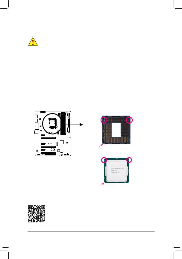
|
1-3 |
Installing the CPU and CPU Cooler |
|
|
Read the following guidelines before you begin to install the CPU: |
||
|
•• |
Make sure that the motherboard supports the CPU. |
|
|
(Go to GIGABYTE’s website for the latest CPU support list.) |
||
|
•• |
Always turn off the computer and unplug the power cord from the power outlet before installing the |
|
|
CPU to prevent hardware damage. |
||
|
•• |
Locate the pin one of the CPU. The CPU cannot be inserted if oriented incorrectly. (Or you may |
|
|
locate the notches on both sides of the CPU and alignment keys on the CPU socket.) |
||
|
•• |
Apply an even and thin layer of thermal grease on the surface of the CPU. |
|
|
•• |
Do not turn on the computer if the CPU cooler is not installed, otherwise overheating and damage |
|
|
of the CPU may occur. |
||
|
•• |
Set the CPU host frequency in accordance with the CPU specifications. It is not recommended |
|
|
that the system bus frequency be set beyond hardware specifications since it does not meet the |
||
|
standard requirements for the peripherals. If you wish to set the frequency beyond the standard |
||
|
specifications, please do so according to your hardware specifications including the CPU, graphics |
||
|
card, memory, hard drive, etc. |
1-3-1 Installing the CPU
A. Locate the alignment keys on the motherboard CPU socket and the notches on the CPU.
LGA1151 CPU Socket
|
Alignment Key |
Alignment Key |
Pin One Corner of the CPU Socket
Triangle Pin One Marking on the CPU
Please visit GIGABYTE’s website for details on hardware installation.
|
Hardware Installation |
— 14 — |

B. Follow the steps below to correctly install the CPU into the motherboard CPU socket.
•• Before installing the CPU, make sure to turn off the computer and unplug the power cord from the power outlet to prevent damage to the CPU.
•• To protect the socket contacts, do not remove the protective plastic cover unless the CPU is inserted into the CPU socket. Save the cover properly and replace it if the CPU is removed.
Step 1:
Gently press the CPU socket lever handle down and away from the socket with your finger. Then completely lift the CPU socket lever and the metal load plate/plastic cover will be lifted as well.
Step 3:
Once the CPU is properly inserted, carefully replace the load plate. When replacing the load plate, make sure the front end of the load plate is under the shoulder screw. Then press the CPU socket lever. The protective plastic cover may pop off from the load plate during the process of engaging the lever. Remove the cover. (Save the cover properly and always replace it when the
CPU is not installed.)
Step 2:
Hold the CPU with your thumb and index fingers. Align the CPU pin one marking (triangle) with the pin one corner of the CPU socket (or you may align the CPU notches with the socket alignment keys) and gently insert the CPU into position.
Step 4:
Finally, secure the lever under its retention tab to complete the installation of the CPU.
NOTE:
Hold the CPU socket lever by the handle, not the lever base portion.
|
— 15 — |
Hardware Installation |
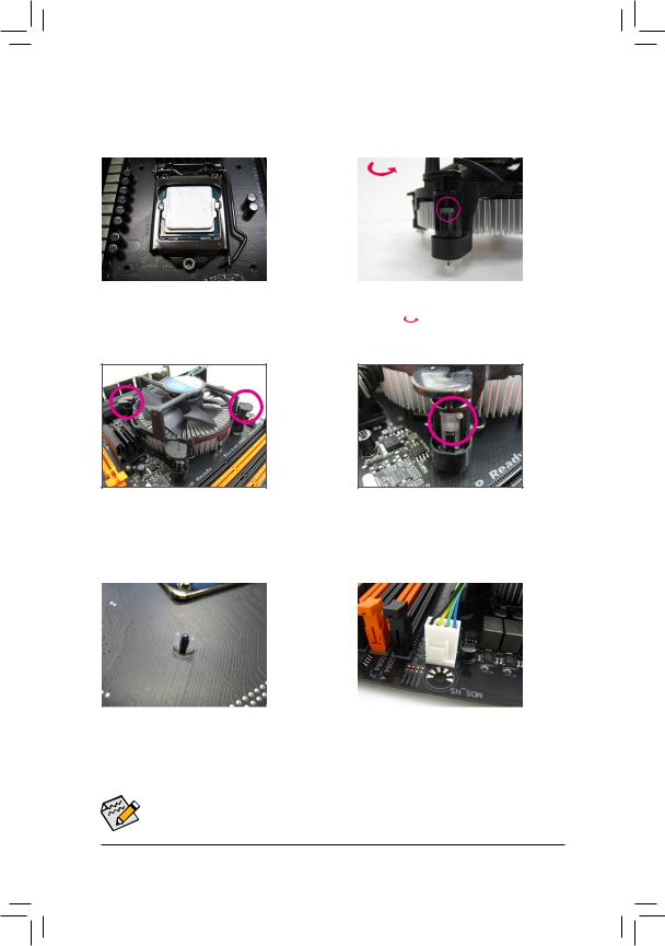
1-3-2 Installing the CPU Cooler
Refer to the steps below to correctly install the CPU cooler on the motherboard. (Actual installation process may differ depending the CPU cooler to be used. Refer to the user’s manual for your CPU cooler.)
|
Male |
||||||||
|
Direction of |
Push Pin |
|||||||
|
the Arrow Sign |
||||||||
|
on the Male |
The Top |
|||||||
|
Push Pin |
||||||||
|
of Female |
||||||||
|
Push Pin |
||||||||
|
Female |
||||||||
|
Push Pin |
||||||||
|
Step 1: |
Step 2: |
|||||||
|
Apply an even and thin layer of thermal grease on |
Before installing the cooler, note the direction of the |
|||||||
|
the surface of the installed CPU. |
arrow sign |
on the male push pin. (Turning the |
push pin along the direction of arrow is to remove the cooler, on the contrary, is to install.)
|
Step 3: |
Step 4: |
||
|
Place the cooler atop the CPU, aligning the |
You should hear a «click» when pushing down each |
||
|
four push pins through the pin holes on the |
push pin. Check that the Male and Female push |
||
|
motherboard. Push down on the push pins |
pins are joined closely. |
||
|
diagonally. |
(Refer to your CPU cooler installation manual for |
||
|
instructions on installing the cooler.) |
|||
|
Step 5: |
Step 6: |
|
After the installation, check the back of the |
Finally, attach the power connector of the CPU |
|
motherboard. If the push pin is inserted as the |
cooler to the CPU fan header (CPU_FAN) on the |
|
picture above shows, the installation is complete. |
motherboard. |
 Use extreme care when removing the CPU cooler because the thermal grease/tape between the CPU cooler and CPU may adhere to the CPU. Inadequately removing the CPU cooler may damage the CPU.
|
Hardware Installation |
— 16 — |
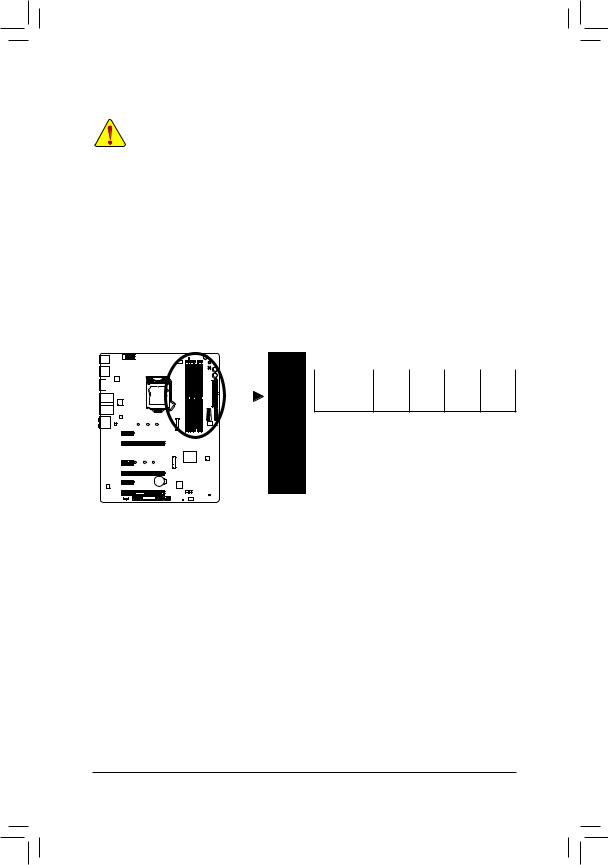
1-4 Installing the Memory
Read the following guidelines before you begin to install the memory:
•• Make sure that the motherboard supports the memory. It is recommended that memory of the same capacity, brand, speed, and chips be used.
(Go to GIGABYTE’s website for the latest supported memory speeds and memory modules.)
•• Always turn off the computer and unplug the power cord from the power outlet before installing the memory to prevent hardware damage.
•• Memory modules have a foolproof design. A memory module can be installed in only one direction. If you are unable to insert the memory, switch the direction.
1-4-1 Dual Channel Memory Configuration
This motherboard provides four memory sockets and supports Dual Channel Technology. After the memory is installed, the BIOS will automatically detect the specifications and capacity of the memory. Enabling Dual
Channel memory mode will double the original memory bandwidth.
The four memory sockets are divided into two channels and each channel has two memory sockets as following:
Channel A: DDR4_2, DDR4_4Channel B: DDR4_1, DDR4_3
Dual Channel Memory Configurations Table
|
DDR4_4 |
DDR4_2 |
DDR4_3 |
DDR4_1 |
|
|
2 Modules |
— — |
DS/SS |
— — |
DS/SS |
|
DS/SS |
— — |
DS/SS |
— — |
|
|
4 Modules |
DS/SS |
DS/SS |
DS/SS |
DS/SS |
(SS=Single-Sided, DS=Double-Sided, «- -«=No Memory)
DDR4_1
DDR4_3
DDR4_2
DDR4_4
Due to CPU limitations, read the following guidelines before installing the memory in Dual Channel mode.
1.Dual Channel mode cannot be enabled if only one memory module is installed.
2.When enabling Dual Channel mode with two or four memory modules, it is recommended that memory of the same capacity, brand, speed, and chips be used and installed in the same colored sockets.
|
— 17 — |
Hardware Installation |
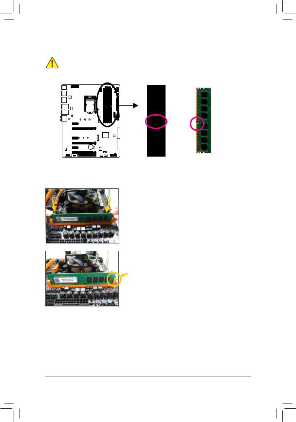
1-4-2 Installing a Memory
Before installing a memory module, make sure to turn off the computer and unplug the power cord from the power outlet to prevent damage to the memory module. DDR4 and DDR3 DIMMs are not compatible to each other or DDR2 DIMMs. Be sure to install DDR4 DIMMs on this motherboard.
Notch
DDR4 DIMM
ADDR4 memory module has a notch, so it can only fit in one direction. Follow the steps below to correctly install your memory modules in the memory sockets.
Step 1:
Note the orientation of the memory module. Spread the retaining clip at the right end of the memory socket. Place the memory module on the socket. As indicated in the picture on the left, place your fingers on the top edge of the memory, push down on the memory and insert it vertically into the memory socket.
Step 2:
The clip at the right end of the socket will snap into place when the memory module is securely inserted.
|
Hardware Installation |
— 18 — |
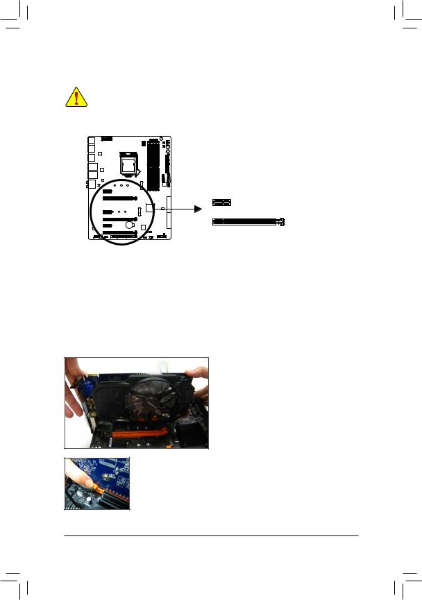
1-5 Installing an Expansion Card
Read the following guidelines before you begin to install an expansion card:
•• Make sure the motherboard supports the expansion card. Carefully read the manual that came with your expansion card.
•• Always turn off the computer and unplug the power cord from the power outlet before installing an expansion card to prevent hardware damage.
PCI Express x1 Slot
PCI Express x16 Slot
Follow the steps below to correctly install your expansion card in the expansion slot.
1.Locate an expansion slot that supports your card. Remove the metal slot cover from the chassis back panel.
2.Align the card with the slot, and press down on the card until it is fully seated in the slot.
3.Make sure the metal contacts on the card are completely inserted into the slot.
4.Secure the card’s metal bracket to the chassis back panel with a screw.
5.After installing all expansion cards, replace the chassis cover(s).
6.Turn on your computer. If necessary, go to BIOS Setup to make any required BIOS changes for your expansion card(s).
7.Install the driver provided with the expansion card in your operating system.
Example: Installing and Removing a PCI Express Graphics Card:
•• Installing a Graphics Card:
Gently push down on the top edge of the card until it is fully inserted into the PCI Express slot. Make sure the card is securely seated in the slot and does not rock.
•• Removing the Card:
Gently push back on the lever on the slot and then lift the card straight out from the slot.
|
— 19 — |
Hardware Installation |
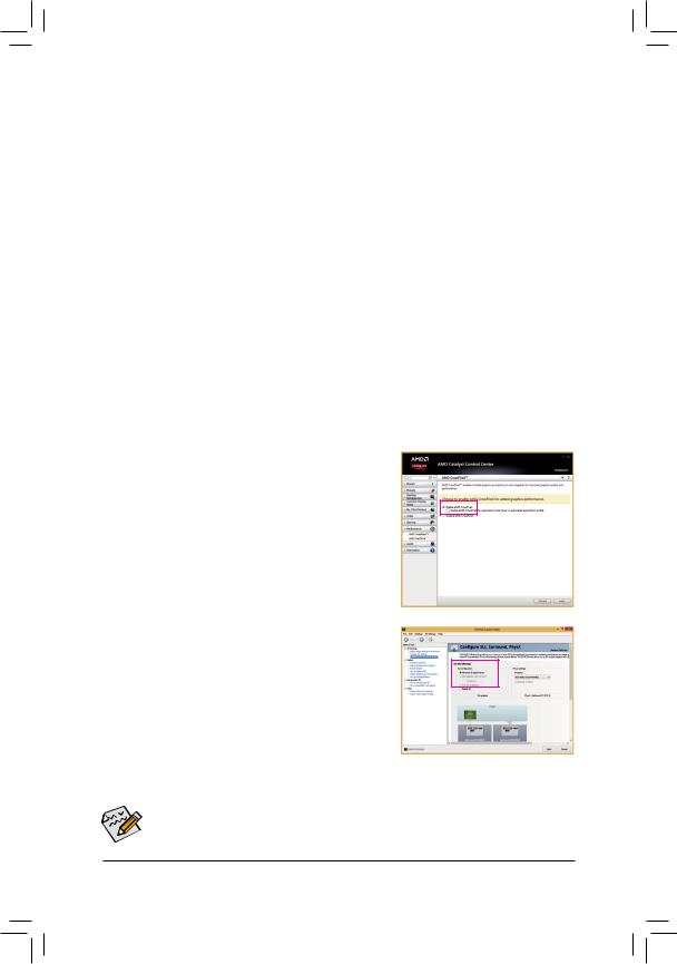
1-6 Setting up AMD CrossFire™/NVIDIA® SLI™ Configuration
A.System Requirements
— Windows 10/8.1/7 operating system
— A CrossFire/SLI-supported motherboard with two or more PCI Express x16 slots and correct driver — CrossFire/SLI-ready graphics cards of identical brand and chip and correct driver
(Current GPUs that support 3-Way CrossFire technology include theATI Radeon™ HD 3800, HD 4800, HD
5800 series, and AMD Radeon™ HD 6800, HD 6900, HD 7800, and HD 7900 series. For the latest GPU support information, please refer to the AMD/NVIDIA® website.)
— CrossFire(Note)/SLI bridge connectors
— A power supply with sufficient power is recommended (Refer to the manual of your graphics cards for the power requirement)
B.Connecting the Graphics Cards
Step 1:
Observe the steps in «1-5 Installing an Expansion Card» and install CrossFire/SLI graphics cards on the PCI Express x16 slots.
Step 2:
Insert the CrossFire(Note)/SLI bridge connectors in the CrossFire/SLI gold edge connectors on top of the cards.
Step 3:
Plug the display cable into the graphics card on the PCIEX16 slot.
C. Configuring the Graphics Card Driver
C-1. To Enable CrossFire Function
After installing the graphics card driver in the operating system, go to the AMD Catalyst Control Center. Browse to Performance\ AMD CrossFireX™ and ensure the Enable AMD CrossFireX check box is selected. If your system has more than two CrossFire cards, select the GPU combination you want to use and click Apply. (Available combination options are dependent on the number of graphics cards.)
C-2. To Enable SLI Function
After installing the graphics card driver in the operating system, go to the NVIDIA Control Panel. Browse to the ConfigureSLI,Surround,
Physx screen and ensure Maximize 3D performance is enabled.
|
(Note) |
The bridge connector(s) may be needed or not depending on your graphics cards. |
Procedure and driver screen for enabling CrossFire/SLI technology may differ by graphics cards and driver version.
RefertothemanualthatcamewithyourgraphicscardsformoreinformationaboutenablingCrossFire/SLItechnology.
|
Hardware Installation |
— 20 — |
![]()
1-7 Back Panel Connectors
PS/2 Keyboard/Mouse Port
Use this port to connect a PS/2 mouse or keyboard.
USB 3.0/2.0 Port
The USB 3.0 port supports the USB 3.0 specification and is compatible to the USB 2.0/1.1 specification.
You can connect a USB DAC to this port or use this port for USB devices.
DisplayPort
DisplayPort delivers high quality digital imaging and audio, supporting bi-directional audio transmission. DisplayPort can support both DPCP and HDCP content protection mechanisms. You can use this port to connect your DisplayPort-supported monitor. The maximum supported resolution is 4096×2160@24 Hz or 3840×2160@60 Hz, but the actual resolutions supported are dependent on the monitor being used.
HDMI Port
 The HDMI port is HDCP compliant and supports Dolby True HD and DTS HD


 Master Audio formats. It also supports up to 192KHz/24bit 8-channel LPCM audio output. You can use this port to connect your HDMI-supported monitor.
After installing the HDMI/DisplayPort device, make sure to set the default sound playback device to
HDMI/DisplayPort. (The item name may differ depending on your operating system.)
In Windows 8.1, select Apps>Control Panel>Hardware and Sound>Sound>Playback, set Intel(R) DisplayAudio to the default playback device.
USB 3.0/2.0 Port
The USB 3.0 port supports the USB 3.0 specification and is compatible to the USB 2.0/1.1 specification.
Use this port for USB devices.
•• When removing the cable connected to a back panel connector, first remove the cable from your device and then remove it from the motherboard.
•• When removing the cable, pull it straight out from the connector. Do not rock it side to side to prevent an electrical short inside the cable connector.
|
— 21 — |
Hardware Installation |

RJ-45 LAN Port (LAN2)
The Gigabit Ethernet LAN port provides Internet connection at up to 1 Gbps data rate. The following describes the states of the LAN port LEDs.
|
Connection/ |
Activity LED |
||||||||||||||||||
|
Speed LED |
|||||||||||||||||||
|
State |
Description |
State |
Description |
||||||||||||||||
|
Orange |
1 Gbps data rate |
Blinking |
Data transmission or receiving is occurring |
||||||||||||||||
|
Green |
100 Mbps data rate |
Off |
No data transmission or receiving is occurring |
||||||||||||||||
|
Off |
10 Mbps data rate |
||||||||||||||||||
|
LAN Port |
|||||||||||||||||||
USB Type-C™ Port
The reversible USB port supports the USB 3.1 specification and is compatible to the USB 3.0/2.0 specification. Use this port for USB devices.
RJ-45 LAN Port (LAN1)
The Gigabit Ethernet LAN port provides Internet connection at up to 1 Gbps data rate. The following describes the states of the LAN port LEDs.
|
Connection/ |
Connection/Speed LED: |
Activity LED: |
|||||||||||||||||
|
Speed LED |
Activity LED |
||||||||||||||||||
|
State |
Description |
State |
Description |
||||||||||||||||
|
Orange |
1 Gbps data rate |
Blinking |
Data transmission or receiving is occurring |
||||||||||||||||
|
Green |
100 Mbps data rate |
On |
No data transmission or receiving is occurring |
||||||||||||||||
|
Off |
10 Mbps data rate |
||||||||||||||||||
|
LAN Port |
|||||||||||||||||||
USB 3.1 Port
TheUSB3.1portsupportstheUSB3.1specification andiscompatibletotheUSB3.0/2.0/1.1specification.
Use this port for USB devices.
Line In/Mic In
The line in/Mic in jack. Use this audio jack for line in devices such as optical drive, walkman, microphone, etc.
Line Out
The line out jack. Use this audio jack for a 2-channel speaker. This jack can be used to connect front speakers in a 5.1-channel audio configuration.
Optical S/PDIF Out Connector
This connector provides digital audio out to an external audio system that supports digital optical audio. Before using this feature, ensure that your audio system provides an optical digital audio in connector.
Center/Subwoofer Speaker Out
Use this audio jack to connect center/subwoofer speakers in a 5.1-channel audio configuration.
Rear Speaker Out
Use this audio jack to connect rear speakers in a 5.1-channel audio configuration.
Headphone/Speaker Out
This audio output jack supports audio amplifying function. For better sound quality, it is recommended that you connect your headphone/speaker to this jack.

 Refer to the instructions on setting up a 2/5.1-channel audio configuration in Chapter 6, «Configuring
2/5.1-Channel Audio.»
|
Hardware Installation |
— 22 — |
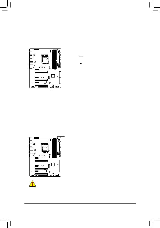
1-8 Onboard Buttons and Switches
BIOS Switch
The SB switch allows enabling or disabling of the Dual BIOS function.
2  1 1: Dual BIOS
SB
Quick Buttons
This motherboard has 3 quick buttons: power button, reset button and clear CMOS button. The power button and reset button allow users to quickly turn on/off or reset the computer in an open-case environment when they want to change hardware components or conduct hardware testing. Use this button to clear the BIOS configuration and reset the CMOS values to factory defaults when needed.
PW_SW: Power Button
RST_SW: Reset Button
CMOS_SW: Clear CMOS Button
•• Always turn off your computer and unplug the power cord from the power outlet before clearing the CMOS values.
•• NOTE: Do not use the clear CMOS button when the system is on, or the system may shutdown and data loss or damage may occur.
•• Aftersystemrestart,gotoBIOSSetuptoloadfactorydefaults(selectLoadOptimizedDefaults)or manuallyconfiguretheBIOSsettings(refertoChapter2,»BIOSSetup,»forBIOSconfigurations).
|
— 23 — |
Hardware Installation |
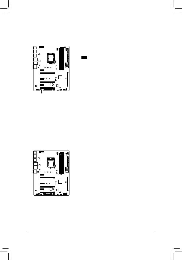
Audio Gain Control Switches
The switch allows for audio gain control for the headphone/speaker out jack on the back panel. Please set it according to your headphone specification (actual effects may vary by the device being used).
|
2 |
1 |
1: 2.5x (Default) |
|
2: 6x |
CAP_SW
ECO Button and OC Button
GIGABYTE’s unique ECO button provides power-saving features by automatically reducing the overall power consumption according to current system load. The OC button helps enthusiasts and overclockers not only get the most performance from their hardware, but also the absolute most enjoyable OC experience.
|
Hardware Installation |
— 24 — |
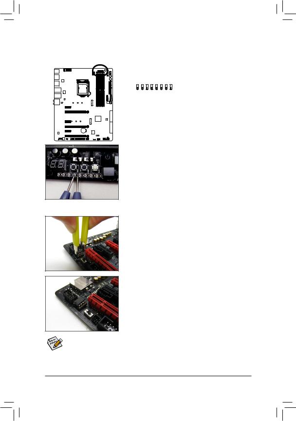
Voltage Measurement Points
Use a multimeter to measure the following motherboard voltages. You can employ following way to measure component voltages.
|
VCCIO VAXG VDIMM DDRVTT PCHIO VSA VCORE VPP 25V |
||||||||||
|
Pin No. |
Definition |
|||||||||
|
1 |
Power |
|||||||||
|
2 |
GND |
|||||||||
|
1 1 1 1 1 1 1 1 |
||||||||||
|
Pin Pin Pin Pin Pin Pin Pin Pin |
Steps:
Connect theredleadofthemultimeter tothepin1(Power)ofavoltage measurement point and the black lead to the pin 2 (ground).
1-9 Changing the Operational Amplifier
Step 1:
Use an IC extractor to carefully grip the IC’s sides and extract it from the socket.
Step 2:
Align the notch on your OP chip with the notch on the socket and gently press the chip into the socket until seated.
For purchasing the IC extractor and OP Chip, please contact the local dealer.
|
— 25 — |
Hardware Installation |
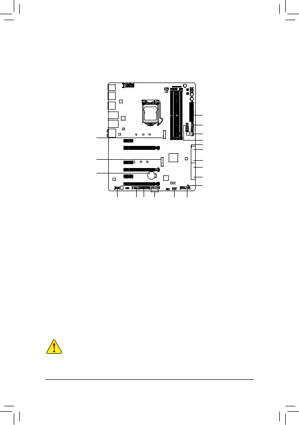
1-10 Internal Connectors
|
6 |
4 |
1 |
5 |
3 |
||||||||||||
|
2 |
||
|
13 |
||
|
10 |
4 |
|
|
13 |
||
|
9 |
||
|
8 |
||
|
10 |
7 |
|
|
17 |
8 |
|
|
7 |
||
|
18 |
|
12 |
16 |
15 |
14 |
4 |
11 |
|
1) |
ATX_12V_2X4 |
10) |
M2D_32G/M2H_32G |
|
2) |
ATX |
11) |
F_PANEL |
|
3) |
CPU_FAN |
12) |
F_AUDIO |
|
4) |
SYS_FAN1/2/3 |
13) |
F_USB30_1/F_USB30_2 |
|
5) |
CPU_OPT |
14) |
F_USB1/F_USB2 |
|
6) |
LED_IO |
15) |
TPM |
|
7) |
SATA EXPRESS |
16) |
COMA |
|
|
SATA3 0/1/2/3/4/5 |
17) |
BAT |
|
9) |
SATA3 6/7 |
18) |
CLR_CMOS |
Read the following guidelines before connecting external devices:
•• First make sure your devices are compliant with the connectors you wish to connect.
•• Before installing the devices, be sure to turn off the devices and your computer. Unplug the power cord from the power outlet to prevent damage to the devices.
•• After installing the device and before turning on the computer, make sure the device cable has been securely attached to the connector on the motherboard.
|
Hardware Installation |
— 26 — |
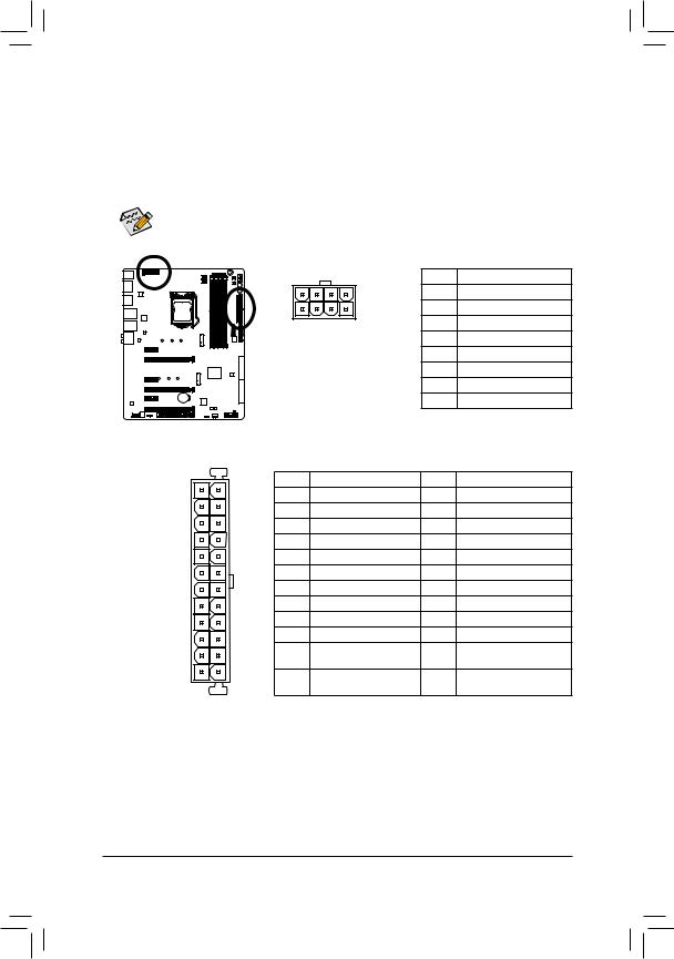
1/2) ATX_12V_2X4/ATX (2×4 12V Power Connector and 2×12 Main Power Connector)
With the use of the power connector, the power supply can supply enough stable power to all the components on the motherboard. Before connecting the power connector, first make sure the power supply is turned off and all devices are properly installed. The power connector possesses a foolproof design. Connect the power supply cable to the power connector in the correct orientation.
The 12V power connector mainly supplies power to the CPU. If the 12V power connector is not connected, the computer will not start.
To meet expansion requirements, it is recommended that a power supply that can withstand high power consumption be used (500W or greater). If a power supply is used that does not provide the required power, the result can lead to an unstable or unbootable system.
|
ATX_12V_2X4: |
||||
|
Pin No. |
Definition |
|||
|
5 |
8 |
1 |
GND (Only for 2×4-pin 12V) |
|
|
1 |
4 |
2 |
GND (Only for 2×4-pin 12V) |
|
|
ATX_12V_2X4 |
3 |
GND |
||
|
4 |
GND |
|||
|
5 |
+12V (Only for 2×4-pin 12V) |
|||
|
6 |
+12V (Only for 2×4-pin 12V) |
|||
|
7 |
+12V |
|||
|
8 |
+12V |
|||
|
ATX: |
||||
|
Pin No. |
Definition |
Pin No. |
Definition |
|
|
1 |
3.3V |
13 |
3.3V |
|
|
2 |
3.3V |
14 |
-12V |
|
|
3 |
GND |
15 |
GND |
|
|
4 |
+5V |
16 |
PS_ON (soft On/Off) |
|
|
5 |
GND |
17 |
GND |
|
|
6 |
+5V |
18 |
GND |
|
|
7 |
GND |
19 |
GND |
|
|
8 |
Power Good |
20 |
-5V |
|
|
9 |
5VSB (stand by +5V) |
21 |
+5V |
|
|
10 |
+12V |
22 |
+5V |
|
|
11 |
+12V (Only for 2×12-pin |
23 |
+5V (Only for 2×12-pin ATX) |
|
|
ATX) |
||||
|
12 |
3.3V (Only for 2×12-pin |
24 |
GND (Only for 2×12-pinATX) |
|
|
ATX) |
|
— 27 — |
Hardware Installation |
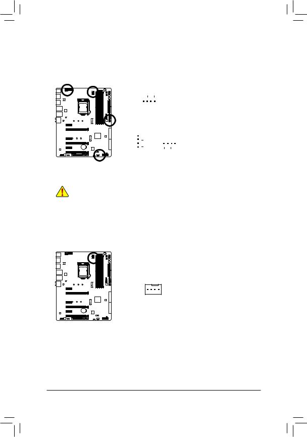
3/4) CPU_FAN/SYS_FAN1/2/3 (Fan Headers)
All fan headers on this motherboard are 4-pin. Most fan headers possess a foolproof insertion design. When connecting a fan cable, be sure to connect it in the correct orientation (the black connector wire is the ground wire). The speed control function requires the use of a fan with fan speed control design. For optimum heat dissipation, it is recommended that a system fan be installed inside the chassis.
|
CPU_FAN: |
|||||||||||||
|
1 |
Pin No. |
Definition |
|||||||||||
|
1 |
GND |
||||||||||||
|
CPU_FAN |
|||||||||||||
|
2 |
+12V |
||||||||||||
|
3 |
Sense |
||||||||||||
|
4 |
Speed Control |
||||||||||||
|
SYS_FAN1/2/3: |
|||||||||||||
|
1 |
1 |
Pin No. |
Definition |
||||||||||
|
1 |
GND |
||||||||||||
|
SYS_FAN2 |
|||||||||||||
|
SYS_FAN1/3 |
|||||||||||||
|
2 |
Speed Control |
||||||||||||
|
3 |
Sense |
||||||||||||
|
4 |
VCC |
•• Be sure to connect fan cables to the fan headers to prevent your CPU and system from overheating. Overheating may result in damage to the CPU or the system may hang.
•• Thesefanheadersarenotconfigurationjumperblocks.Donotplaceajumpercapontheheaders.
5)CPU_OPT (Water Cooling CPU Fan Header)
The fan header is 4-pin and possesses a foolproof insertion design. When connecting a fan cable, be sure to connect it in the correct orientation (the black connector wire is the ground wire). The speed control function requires the use of a fan with fan speed control design.
|
Pin No. |
Definition |
|
|
1 |
GND |
|
|
1 |
2 |
Speed Control |
|
3 |
Sense |
|
|
4 |
VCC |
|
Hardware Installation |
— 28 — |
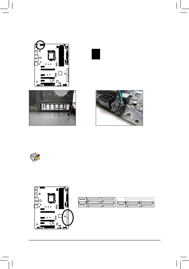
6)LED_IO (I/O Shield Audio LED Power Connector)
The power connector provides power to the LEDs on the I/O shield on the motherboard back panel.
|
1 |
||||
|
Pin No. |
Definition |
|||
|
1 |
+5V |
|||
|
2 |
Red |
|||
|
3 |
Green |
|||
|
4 |
Blue |
Step 1:
Install the included I/O shield into the chassis. (For actual installation, please refer to the user guide for your chassis.)
Step 2:
Place the motherboard into the chassis, aligning the back panel connectors with the installed I/O shield. Connect the power cable from the I/O shield to the LED_IO connector on the motherboard.
For how to turn on/off the I/O shield LED indicators, refer to the instructions on in Chapter 2, «BIOS Setup,» «Peripherals,» or Chapter 5, «Unique Features,» «APP Center\Ambient LED.»
7)SATA EXPRESS (SATA Express Connectors)
Each SATA Express connector supports a single SATA Express device.
|
— 29 — |
Hardware Installation |
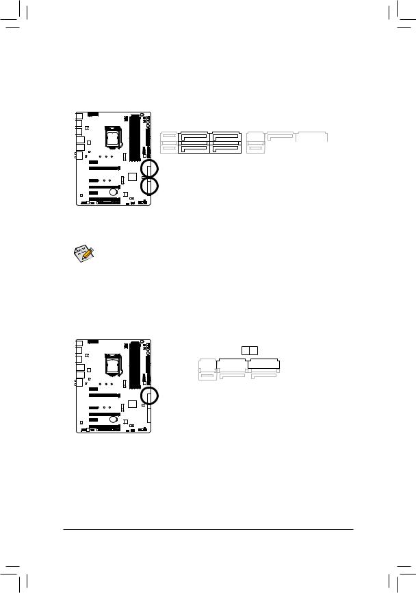
SATA3 0/1/2/3/4/5 (SATA 6Gb/s Connectors, Controlled by Intel® Z170 Chipset)
The SATA connectors conform to SATA 6Gb/s standard and are compatible with SATA 3Gb/s and SATA 1.5Gb/s standard. Each SATA connector supports a single SATA device. The Intel® ChipsetsupportsRAID0, RAID 1, RAID 5, and RAID 10. Refer to Chapter 3, «Configuring a RAID Set,» for instructions on configuring a RAID array.
|
SATA3 |
5 |
4 |
SATA3 |
|||||||||||||||||
|
3 |
2 |
|||||||||||||||||||
|
1 |
0 |
|||||||||||||||||||
|
7 |
1 |
|||||||||||||||||||
|
7 |
1 |
|||||||||||||||||||
|
Pin No. |
Definition |
|||||||||||||||||||
|
1 |
GND |
|||||||||||||||||||
|
2 |
TXP |
|||||||||||||||||||
|
3 |
TXN |
|||||||||||||||||||
|
4 |
GND |
|||||||||||||||||||
|
5 |
RXN |
|||||||||||||||||||
|
6 |
RXP |
|||||||||||||||||||
|
7 |
GND |
To enable hot-plugging for the SATA ports, refer to Chapter 2, «BIOS Setup,» «Peripherals\SATA
Configuration,» for more information.
9)SATA3 6/7 (SATA 6Gb/s Connectors, Controlled by ASMedia® ASM1061 Chip)
The SATA connectors conform to SATA 6Gb/s standard and are compatible with SATA 3Gb/s and SATA 1.5Gb/s standard. Each SATA connector supports a single SATA device.
SATA3 7 6
|
7 |
1 |
||||||||||||||||||
|
7 |
1 |
||||||||||||||||||
|
Pin No. |
Definition |
||||||||||||||||||
|
1 |
GND |
||||||||||||||||||
|
2 |
TXP |
||||||||||||||||||
|
3 |
TXN |
||||||||||||||||||
|
4 |
GND |
||||||||||||||||||
|
5 |
RXN |
||||||||||||||||||
|
6 |
RXP |
||||||||||||||||||
|
7 |
GND |
|
Hardware Installation |
— 30 — |
![]()
10)M2D_32G/M2H_32G (M.2 Socket 3 Connectors)
The M.2 connectors support M.2 SATASSDs and M.2 PCIe SSDs and support RAID configuration through the Intel® Chipset. Please note that an M.2 PCIe SSD cannot be used to create a RAID set either with an M.2 SATASSD or a SATAhard drive and can only be used to build a RAID set with UEFI. Refer to Chapter 3, «Configuring a RAID Set,» for instructions on configuring a RAID array.
M2D_32G
80D 60D 42D
M2H_32G
80H 60H 42H
Follow the steps below to correctly install an M.2 SSD in the M.2 connector.
Step 1:
Use a screw driver to unfasten the screw and nut from the motherboard. Locate the proper mounting hole for the M.2 SSD to be installed and then screw the nut first.
Step 3:
Press the M.2 SSD down and then secure it with the screw.
Step 2:
Slide the M.2 SSD into the connector at an angle.
Step 4:
The installation is completed, as shown in the picture above.
On the motherboard there are three length adjustment holes for the M.2 SSD. Select the proper hole for the M.2 SSD to be installed and refasten the screw and nut.
|
— 31 — |
Hardware Installation |

When installing different types of M.2 SSDs (including SATA SSDs, PCIe x4 SSDs, and PCIe x2 SSDs), be sure to refer to the supported configurations in the tables below according to the operating mode of your SATA controller (AHCI mode or RAID mode).
|
•• AHCI mode: |
||||||
|
M2D_32G M.2 connector |
||||||
|
Connector |
SATA3_0 |
SATA3_1 |
SATA3_2 |
SATA3_3 |
SATA3_4 |
SATA3_5 |
|
Type of SSD |
SATA Express |
SATA Express |
SATA Express |
|||
|
SATA SSD |
a |
a |
a |
r |
a |
a |
|
a |
r |
a |
||||
|
PCIe x4 SSD |
r |
r |
r |
r |
a |
a |
|
a(Note) |
r |
a |
||||
|
PCIe x2 SSD |
a |
a |
r |
r |
a |
a |
|
a |
r |
a |
||||
|
a: Supported, r: Not supported. |
|
M2H_32G M.2 connector |
||||||
|
Connector |
SATA3_0 |
SATA3_1 |
SATA3_2 |
SATA3_3 |
SATA3_4 |
SATA3_5 |
|
Type of SSD |
SATA Express |
SATA Express |
SATA Express |
|||
|
SATA SSD |
r |
a |
a |
a |
a |
a |
|
a |
a |
a |
||||
|
PCIe x4 SSD |
a |
a |
a |
a |
a |
a |
|
a |
a |
a |
||||
|
PCIe x2 SSD |
a |
a |
a |
a |
a |
a |
|
a |
a |
a |
||||
|
a: Supported, r: Not supported. |
•• RAID mode:
M2D_32G M.2 connector
|
Connector |
SATA3_0 |
SATA3_1 |
SATA3_2 |
SATA3_3 |
SATA3_4 |
SATA3_5 |
|||
|
Type of SSD |
SATA Express |
SATA Express |
SATA Express |
||||||
|
SATA SSD |
a |
a |
a |
r |
a |
a |
|||
|
a |
r |
a |
|||||||
|
PCIe x4 SSD |
r |
r |
r |
r |
a |
r |
|||
|
a(Note) |
r |
r |
|||||||
|
PCIe x2 SSD |
a |
a |
r |
r |
a |
r |
|||
|
a |
r |
r |
|||||||
|
No SSDs |
a |
a |
a |
a |
a |
a |
|||
|
Installed |
a |
a |
a |
a: Supported, r: Not supported.
M2H_32G M.2 connector
|
Connector |
SATA3_0 |
SATA3_1 |
SATA3_2 |
SATA3_3 |
SATA3_4 |
SATA3_5 |
|||
|
Type of SSD |
SATA Express |
SATA Express |
SATA Express |
||||||
|
SATA SSD |
r |
a |
a |
a |
a |
a |
|||
|
a |
a |
a |
|||||||
|
PCIe x4 SSD |
a |
a |
a |
a |
a |
r |
|||
|
a |
a |
r |
|||||||
|
PCIe x2 SSD |
a |
a |
a |
a |
a |
r |
|||
|
a |
a |
r |
|||||||
|
No SSDs |
a |
a |
a |
a |
a |
a |
|||
|
Installed |
a |
a |
a |
||||||
|
a: Supported, r: Not supported. |
|
(Note) The PCIe x4 SSD runs at x2 speed. |
|
|
Hardware Installation |
— 32 — |

11)F_PANEL (Front Panel Header)
Connect the power switch, reset switch, speaker, chassis intrusion switch/sensor and system status indicator on the chassis to this header according to the pin assignments below. Note the positive and negative pins before connecting the cables.
Power LED 
 Power Switch
 Speaker
|
PLED+ PLED |
—PW |
SPEAK+ NC NC -SPEAK |
||||||||||||||
|
PW+ |
||||||||||||||||
|
— |
||||||||||||||||
|
2 |
20 |
|||||||||||||||
|
1 |
19 |
|||||||||||||||
|
HD- |
CI+ |
— |
||||||||||||||
|
LED+ LED LED- |
||||||||||||||||
|
— |
||||||||||||||||
|
RES+ |
_ _ |
|||||||||||||||
|
HD+ RES- |
CI |
PWR PWR PWR_ |
||||||||||||||
|
Hard Drive |
Reset |
Power LED |
||||||||||||||
|
Activity LED |
Switch |
Chassis Intrusion |
||||||||||||||
|
Header |
•• PLED/PWR_LED (Power LED, Yellow/Purple):
|
System Status |
LED |
|
S0 |
On |
|
S3/S4/S5 |
Off |
Connects to the power status indicator on the chassis front panel. The LED is on when the system is operating. The LED is off when the system is in S3/
S4 sleep state or powered off (S5).
•• PW (Power Switch, Red):
Connects to the power switch on the chassis front panel. You may configure the way to turn off your system using the power switch (refer to Chapter 2, «BIOS Setup,» «Power Management,» for more information).
•• SPEAK (Speaker, Orange):
Connects to the speaker on the chassis front panel. The system reports system startup status by issuing a beep code. One single short beep will be heard if no problem is detected at system startup.
•• HD (Hard Drive Activity LED, Blue):
Connects to the hard drive activity LED on the chassis front panel. The LED is on when the hard drive is reading or writing data.
•• RES (Reset Switch, Green):
Connects to the reset switch on the chassis front panel. Press the reset switch to restart the computer if the computer freezes and fails to perform a normal restart.
•• CI (Chassis Intrusion Header, Gray):
Connects to the chassis intrusion switch/sensor on the chassis that can detect if the chassis cover has been removed. This function requires a chassis with a chassis intrusion switch/sensor.
•• NC (Orange): No Connection.
The front panel design may differ by chassis. A front panel module mainly consists of power switch, reset switch, power LED, hard drive activity LED, speaker and etc. When connecting your chassis front panel module to this header, make sure the wire assignments and the pin assignments are matched correctly.
|
— 33 — |
Hardware Installation |

12)F_AUDIO (Front Panel Audio Header)
The front panel audio header supports Intel High Definition audio (HD) andAC’97 audio. You may connect your chassis front panel audio module to this header. Make sure the wire assignments of the module connector match the pin assignments of the motherboard header. Incorrect connection between the module connector and the motherboard header will make the device unable to work or even damage it.
|
For HD Front Panel Audio: |
For AC’97 Front Panel Audio: |
|||||||
|
Pin No. |
Definition |
Pin No. |
Definition |
|||||
|
9 |
1 |
1 |
MIC2_L |
1 |
MIC |
|||
|
2 |
GND |
2 |
GND |
|||||
|
3 |
MIC2_R |
3 |
MIC Power |
|||||
|
10 |
2 |
|||||||
|
4 |
-ACZ_DET |
4 |
NC |
|||||
|
5 |
LINE2_R |
5 |
Line Out (R) |
|||||
|
6 |
Sense |
6 |
NC |
|||||
|
7 |
FAUDIO_JD |
7 |
NC |
|||||
|
8 |
No Pin |
8 |
No Pin |
|||||
|
9 |
LINE2_L |
9 |
Line Out (L) |
|||||
|
10 |
Sense |
10 |
NC |

 Some chassis provide a front panel audio module that has separated connectors on each wire
  instead of a single plug. For information about connecting the front panel audio module that has different wire assignments, please contact the chassis manufacturer.
13)F_USB30_1/F_USB30_2 (USB 3.0/2.0 Headers)
The headers conform to USB 3.0/2.0 specification and each header can provide two USB ports. For purchasing the optional 3.5″ front panel that provides two USB 3.0/2.0 ports, please contact the local dealer.
|
Pin No. |
Definition |
Pin No. |
Definition |
|||
|
20 |
1 |
1 |
VBUS |
11 |
D2+ |
|
|
2 |
SSRX1- |
12 |
D2- |
|||
|
3 |
SSRX1+ |
13 |
GND |
|||
|
4 |
GND |
14 |
SSTX2+ |
|||
|
5 |
SSTX1- |
15 |
SSTX2- |
|||
|
6 |
SSTX1+ |
16 |
GND |
|||
|
11 |
10 |
7 |
GND |
17 |
SSRX2+ |
|
|
8 |
D1- |
18 |
SSRX2- |
|||
|
9 |
D1+ |
19 |
VBUS |
|||
|
10 |
NC |
20 |
No Pin |
Prior to installing the USB front panel, be sure to turn off your computer and unplug the power cord from the power outlet to prevent damage to the USB front panel.
|
Hardware Installation |
— 34 — |

14)F_USB1/F_USB2 (USB 2.0/1.1 Headers)
The headers conform to USB 2.0/1.1 specification. Each USB header can provide two USB ports via an optional USB bracket. For purchasing the optional USB bracket, please contact the local dealer.
|
Pin No. |
Definition |
|||
|
1 |
Power (5V) |
|||
|
9 |
1 |
2 |
Power (5V) |
|
|
10 |
2 |
3 |
USB DX- |
|
|
4 |
USB DY- |
|||
|
5 |
USB DX+ |
|||
|
6 |
USB DY+ |
|||
|
7 |
GND |
|||
|
8 |
GND |
|||
|
9 |
No Pin |
|||
|
10 |
NC |
|||
|
•• |
Do not plug the IEEE 1394 bracket (2×5-pin) cable into the USB 2.0/1.1 header. |
|||
|
•• |
Prior to installing the USB bracket, be sure to turn off your computer and unplug the power cord |
|||
|
from the power outlet to prevent damage to the USB bracket. |
15)TPM (Trusted Platform Module Header)
You may connect a TPM (Trusted Platform Module) to this header.
|
19 |
1 |
|||
|
20 |
2 |
|||
|
Pin No. |
Definition |
Pin No. |
Definition |
|
|
1 |
LCLK |
11 |
LAD0 |
|
|
2 |
GND |
12 |
GND |
|
|
3 |
LFRAME |
13 |
NC |
|
|
4 |
No Pin |
14 |
NC |
|
|
5 |
LRESET |
15 |
SB3V |
|
|
6 |
NC |
16 |
SERIRQ |
|
|
7 |
LAD3 |
17 |
GND |
|
|
8 |
LAD2 |
18 |
NC |
|
|
9 |
VCC3 |
19 |
NC |
|
|
10 |
LAD1 |
20 |
SUSCLK |
|
— 35 — |
Hardware Installation |

16)COMA (Serial Port Header)
The COM header can provide one serial port via an optional COM port cable. For purchasing the optional COM port cable, please contact the local dealer.
|
Pin No. |
Definition |
|||||
|
1 |
NDCD- |
|||||
|
2 |
NSIN |
|||||
|
9 |
1 |
3 |
NSOUT |
|||
|
10 |
2 |
4 |
NDTR- |
|||
|
5 |
GND |
|||||
|
6 |
NDSR- |
|||||
|
7 |
NRTS- |
|||||
|
8 |
NCTS- |
|||||
|
9 |
NRI- |
|||||
|
10 |
No Pin |
17)BAT (Battery)
The battery provides power to keep the values (such as BIOS configurations, date, and time information) in the CMOS when the computer is turned off. Replace the battery when the battery voltage drops to a low level, or the CMOS values may not be accurate or may be lost.
You may clear the CMOS values by removing the battery: 1. Turn off your computer and unplug the power cord.
2. Gently remove the battery from the battery holder and wait for one minute. (Or use a metal object like a screwdriver to touch the positive and negative terminals of the battery holder, making them short for 5 seconds.)
3. Replace the battery.
4. Plug in the power cord and restart your computer.
|
•• |
Always turn off your computer and unplug the power cord before replacing the battery. |
|
|
•• |
Replace the battery with an equivalent one. Danger of explosion if the battery is replaced with |
|
|
an incorrect model. |
||
|
•• Contact the place of purchase or local dealer if you are not able to replace the battery by yourself |
||
|
or uncertain about the battery model. |
||
|
•• |
When installing the battery, note the orientation of the positive side (+) and the negative side (-) |
|
|
of the battery (the positive side should face up). |
||
|
•• |
Used batteries must be handled in accordance with local environmental regulations. |
|
|
Hardware Installation |
— 36 — |

18)CLR_CMOS (Clear CMOS Jumper)
Use this jumper to clear the BIOS configuration and reset the CMOS values to factory defaults. To clear the CMOS values, use a metal object like a screwdriver to touch the two pins for a few seconds.
Open: Normal
Short: Clear CMOS Values
•• Always turn off your computer and unplug the power cord from the power outlet before clearing the CMOS values.
•• Aftersystemrestart,gotoBIOSSetuptoloadfactorydefaults(selectLoadOptimizedDefaults)or manuallyconfiguretheBIOSsettings(refertoChapter2,»BIOSSetup,»forBIOSconfigurations).
|
— 37 — |
Hardware Installation |

|
Hardware Installation |
— 38 — |

Chapter 2 BIOS Setup
BIOS (Basic Input and Output System) records hardware parameters of the system in the CMOS on the motherboard. Its major functions include conducting the Power-On Self-Test (POST) during system startup, saving system parameters and loading operating system, etc. BIOS includes a BIOS Setup program that allows the user to modify basic system configuration settings or to activate certain system features.
When the power is turned off, the battery on the motherboard supplies the necessary power to the CMOS to keep the configuration values in the CMOS.
To access the BIOS Setup program, press the <Delete> key during the POST when the power is turned on.
To upgrade the BIOS, use either the GIGABYTE Q-Flash or @BIOS utility.
•• Q-Flash allows the user to quickly and easily upgrade or back up BIOS without entering the operating system.
•• @BIOS is a Windows-based utility that searches and downloads the latest version of BIOS from the Internet and updates the BIOS.
For instructions on using the Q-Flash and @BIOS utilities, refer to Chapter 5, «BIOS Update Utilities.»
•• Because BIOS flashing is potentially risky, if you do not encounter problems using the current version of BIOS, it is recommended that you not flash the BIOS. To flash the BIOS, do it with caution. Inadequate BIOS flashing may result in system malfunction.
•• It is recommended that you not alter the default settings (unless you need to) to prevent system instability or other unexpected results. Inadequately altering the settings may result in system’s failure to boot. If this occurs, try to clear the CMOS values and reset the board to default values.
(Refer to the «Load Optimized Defaults» section in this chapter or introductions of the battery or the clear CMOS jumper/button in Chapter 1 for how to clear the CMOS values.)

2-1 Startup Screen
The following startup Logo screen will appear when the computer boots.
 Function Keys
Function Keys:
<DEL>: BIOS SETUP\Q-FLASH
Press the <Delete> key to enter BIOS Setup or to access the Q-Flash utility in BIOS Setup.
<F9>: SYSTEM INFORMATION
Press the <F9> key to display your system information.
<F12>: BOOT MENU
Boot Menu allows you to set the first boot device without entering BIOS Setup. In Boot Menu, use the up arrow key <h> or the down arrow key <i> to select the first boot device, then press <Enter> to accept.
The system will boot from the device immediately.
Note: The setting in Boot Menu is effective for one time only. After system restart, the device boot order
will still be based on BIOS Setup settings.
<END>: Q-FLASH
Press the <End> key to access the Q-Flash utility directly without having to enter BIOS Setup first.
 Loading…
-
Драйверы
29
-
Инструкции по эксплуатации
5
Языки:

Gigabyte GA-Z170X-Gaming 7 инструкция по эксплуатации
(132 страницы)
- Языки:Английский
-
Тип:
PDF -
Размер:
33.98 MB
Просмотр

Gigabyte GA-Z170X-Gaming 7 инструкция по эксплуатации
(132 страницы)
- Языки:Английский
-
Тип:
PDF -
Размер:
33.99 MB
Просмотр

Gigabyte GA-Z170X-Gaming 7 инструкция по эксплуатации
(132 страницы)
- Языки:Китайский
-
Тип:
PDF -
Размер:
34.46 MB
Просмотр

Gigabyte GA-Z170X-Gaming 7 инструкция по эксплуатации
(132 страницы)
- Языки:Китайский
-
Тип:
PDF -
Размер:
36.26 MB
Просмотр

Gigabyte GA-Z170X-Gaming 7 инструкция по эксплуатации
(132 страницы)
- Языки:Японский
-
Тип:
PDF -
Размер:
33.91 MB
Просмотр
На NoDevice можно скачать инструкцию по эксплуатации для Gigabyte GA-Z170X-Gaming 7. Руководство пользователя необходимо для ознакомления с правилами установки и эксплуатации Gigabyte GA-Z170X-Gaming 7. Инструкции по использованию помогут правильно настроить Gigabyte GA-Z170X-Gaming 7, исправить ошибки и выявить неполадки.
- Производитель
- Gigabyte
- Модель
- GA-Z170X-Gaming 7-EU
- Операционная система
-
- Неизвестная ОС
- Тип файла
-
- Инструкция
- Версия
-
1001
32-bit
Просмотреть содержимое архива
Вы нашли то, что искали?
Дополнительная информация
Traditional Chinese
Полезно
0 %
0
Commentary
Ваше имя