
Материнская плата GIGABYTE Z690M AORUS ELITE AX DDR4
LGA 1700, Intel Z690, 4xDDR4-3200 МГц, 2xPCI-Ex16, 3xM.2, Micro-ATX
подробнее

123
Код товара: 4886084
Z790 AORUS Elite AX – самая доступная материнская плата AORUS в формате ATX из тех, что обладают поддержкой оперативной памяти DDR5 и предустановленным Wi-Fi модулем. Эта плата вполне может работать и с флагманом 13-го поколения в лице Core i9-13900K, но на какие компромиссы пошёл производитель, чтобы предложить нам относительно недорогую, но продвинутую с точки зрения производительности основу для игровой системы?
Упаковка и комплект поставки
Дизайн оформления коробок производитель изменил для всех материнских плат, основанных на 700-х чипсетах Intel и 600-х чипсетах AMD. Для серии AORUS на лицевой стороне информации минимум (только очевидная), а на обратной стороне – зависит от конкретной модели платы. В случае с Elite AX особо выделена система охлаждения подсистемы питания процессора, сама подсистема питания процессора, поддержка PCIe 5.0, удобная защёлка основного (х16) слота (EZ-Latch), безвинтовое крепление M.2 и наличие Wi-Fi 6E модуля, что можно понять и по названию модели платы.
Комплект поставки минимален. Пожалуй, меньше его делать уже и некуда, хотя попробовать можно – в коробке можно найти пару SATA кабелей, антенну для Wi-Fi модуля и переходник, который упрощает подключение передней панели корпуса к плате. Всё верно – более ничего в коробке нет.

Визуальный осмотр
На данный момент платы Elite являются младшими в серии AORUS среди решений на базе чипсета Z790. Во множественном числе это прозвучало не просто так – модификаций доступно целых шесть: четыре ATX с DDR4/DDR5 с Wi-Fi и без, а также две mATX – обе с поддержкой DDR5 памяти, но без Wi-Fi и с таковым. За исключением этих моментов отличий в ATX платах нет – дизайн полностью идентичен: чёрно-серые цвета, минимум подсветки (только в области чипсета), расстановка всяческих портов и слотов одинакова.

Два слайда с официального сайта производителя и блок-схема из руководства пользователя позволяют оценить возможности платы до её покупки.
Никаких изысков на обратной стороне платы нет – ни в плане электронных компонентов, ни в плане охлаждения или усиления – бэкплейта нет.

По PCIe слотам расширения ситуация стандартная – основной Gen5 x16 и пара x4 электрически в формате x16. Gen5 – от процессора, два других (Gen4 и Gen3) – от чипсета (блок-схема, которая была продемонстрирована выше, не совсем корректная).

Основной PCIe слот обладает защёлкой увеличенного размера, которая позволяет изымать видеокарты с массивными системами охлаждения. На старших моделях AORUS реализована кнопка, а младшая обошлась вот таким решением.

Панель ввода/вывода предлагает нам набор из четырёх USB 2.0 портов, двух USB 3.2 Gen2 портов, трёх USB 3.2 Gen1 портов, USB Type-C (20 Гбит/с) порт, видео выходы DP и HDMI, коннекторы для подключения внешней антенны, RJ-45 сеть, пару аудио разъёмов и S/PDIF (оптический выход).

Нижняя часть платы достаточно богата по возможностям подключения периферии – здесь размещены колодка для подключения аудио портов корпуса, пара RGB коннекторов (разные типы – с питанием 12 В и 5 В), две колодки для подключения суммарно четырёх портов USB (2.0), четыре коннектора для вентиляторов и помпы, а также кнопка для активации функции восстановления BIOS.

Ещё один компромисс после скромного комплекта поставки – звуковая подсистема, в основе которой лежит кодек Realtek ALC897, хоть и с использованием конденсаторов WIMA.

Разъёмы для подключения двух USB 3.2 Gen1 и одного Type-C Gen2 портов размещены в привычном для этого месте. Неподалёку производитель разместил набор светодиодов, которые, если система неисправна, помогут определить в чём проблема – в процессоре, оперативной памяти, видеокарте или системном диске.

Два коннектора для вентиляторов системы охлаждения ЦП размещены сверху платы. Рядом с ними находятся ещё два коннектора для RGB устройств с разным питанием.

SATA портов доступно 6. Слева от них размещена кнопка перезагрузки системы, а справа – кнопка сброса настроек BIOS.

Для M.2 SSD-накопителей доступны 4 соответствующих разъёма, один из которых находится недалеко от процессора (M2A_CPU – 2280/22110 формат, PCIe 4.0 x4/x2), а ещё три – между основным PCIe x16 и вторым PCIe x16 (который электрически х4) слотами — M2P_SB и M2Q_SB для 2280/22110 накопителей (PCIe 4.0 (x4/x2)) и M2M_SB для накопителей формата 2260/2280/22110 (PCIe 4.0 (x4/x2) или SATA).

Тепло отводится от накопителей двумя радиаторами – один из них охлаждает сразу три накопителя.

А основному накопителю повезло больше – у него свой собственный радиатор, да ещё и внушительного размера.

Даже с учётом того, что в нашем распоряжении одна из самых простых плат AORUS, система охлаждения силовой части выглядит внушительно.

Это две достаточно большие алюминиевые секции, которые объединены тепловой трубкой. Взаимодействие оснований секция с силовой частью происходит при помощи термопрокладок.

Подсистема питания процессора выполнена по схеме 8+8 для ядер, 1 для графического ядра и две для AUX (PCIe + RAM). Основные 16 фаз включают в себя 70 А сборки FDMF5062, для графики установлена 55 А сборка NCP302155, а для AUX используются 60 А сборки NCP303160. Схема 16+1 управляется контроллером NCP81530R, а остальные две фазы функционируют под руководством M2940A.

Для стабильной работы процессора требуется подключение двух 8-контактных кабелей в соответствующие коннекторы со стальным корпусом.

BIOS и Gigabyte Control Center
Как и в случае с новыми материнскими платами AORUS для процессоров AMD 7000-й серии интерфейс UEFI BIOS не изменился относительно предыдущих решений. В нашем распоряжении два режима – упрощённый и продвинутый. Настроек много, структура разделов не изменилась, логика в некоторых случаях не просматривается. Но, в целом, явных нареканий к интерфейсу нет.
Фирменное программное обеспечение для Windows, наоборот, было полностью изменено. Точнее – заменено. Теперь это единый программный комплекс Gigabyte Control Center, который пока ещё находится в стадии разработки, но с новыми платами на базе Intel он уже более функционален, чем с AMD решениями. Изменения относительно предыдущего ПО заметны сразу – программа работает быстро, весит немного, интерфейс интуитивно понятен.
Тестирование
Тестирование подобных материнских плат в домашних условиях мало чем интересно в плане производительности – плюс-минус на воздухе/воде всё и так понятно.
Официально материнская плата поддерживает память с частотой свыше 7000 МГц (обязательно – с процессором 13-го поколения), поэтому «какие-то» 6000 МГц для неё вообще не проблема.
А вот как прогревается подсистема питания – это уже действительно интересно. А особенно – если она отводит тепло в полностью пассивном режиме, когда на процессоре стоит «вода». И с задачей отвода тепла от силовой части (процессор Core i9-13900K в автоматическом режиме) система охлаждения справилась вполне хорошо: в видимой области спустя 2 часа нагрузочного тестирования температура подсистемы питания в видимой области составила около 82°С, а радиаторы прогрелись до 62°С. Чипсет охлаждается тоже пассивно – его радиатор продемонстрировал около 35°С.
Заключение
Z790 AORUS Elite AX вполне можно назвать платой, минимально необходимой для работы с любыми существующими процессорами Intel Core 12-го и 13-го поколений. Последних – особенно, ведь именно с ними можно использовать высокочастотную DDR5 память, цены на которую снижаются каждый месяц. Эта материнская плата достойна внимания тем, что она может обеспечить стабильную работу указанных выше процессоров без каких-либо проблем с температурой подсистемы питания, позволяет использовать модули памяти с частотой свыше 7000 МГц, высокоскоростные M.2 SSD-накопители и периферию, требующую от USB портов пропускную способность до 20 Гбит/с. Но главное – относительно невысокая стоимость. Существуют, конечно, варианты и дешевле, но в данном случае речь идёт именно про бренд AORUS, решения под которым изначально ориентированы на энтузиастов. Стоимость обусловлена некоторыми компромиссами, в число которых входит несколько устаревшая звуковая подсистема и экстремально скромный комплект поставки – в нём даже руководства пользователя нет. Но для многих последнее может быть только достоинством. Главное то, что за адекватные деньги можно получить достойный продукт без излишеств, что и является главной особенностью Z790 AORUS Elite AX.
For more product details, please visit GIGABYTE’s website.
To reduce the impacts on global warming, the packaging materials of this product
are recyclable and reusable. GIGABYTE works with you to protect the environment.
Z690M A ELITE AX DDR4
(Z690M AORUS ELITE AX DDR4)
Z690M A ELITE DDR4
(Z690M AORUS ELITE DDR4)
User’s Manual
Rev. 1001
12ME-Z69MLT4-1001R
Z690M A ELITE
DDR4
Z690M A ELITE
AX DDR4
Copyright
© 2021 GIGA-BYTE TECHNOLOGY CO., LTD. All rights reserved.
The trademarks mentioned in this manual are legally registered to their respective owners.
Disclaimer
Information in this manual is protected by copyright laws and is the property of GIGABYTE.
Changes to the specications and features in this manual may be made by GIGABYTE without
prior notice. No part of this manual may be reproduced, copied, translated, transmitted, or
published in any form or by any means without GIGABYTE’s prior written permission.
In order to assist in the use of this product, carefully read the User’s Manual.
For product-related information, check on our website at: https://www.gigabyte.com
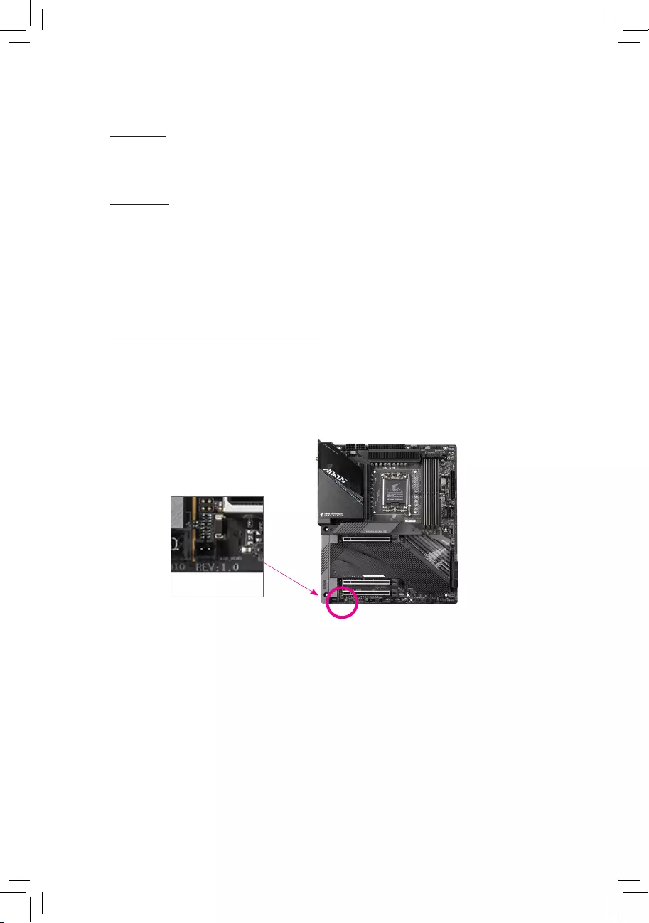
Identifying Your Motherboard Revision
The revision number on your motherboard looks like this: «REV: X.X.» For example, «REV: 1.0″
means the revision of the motherboard is 1.0. Check your motherboard revision before updating
motherboard BIOS, drivers, or when looking for technical information.
Example:

— 3 —
Table of Contents
Chapter 1 Product Introduction ……………………………………………………………………………4
1-1 Motherboard Layout …………………………………………………………………………….. 4
1-2 Motherboard Block Diagram …………………………………………………………………. 5
1-3 Box Contents ………………………………………………………………………………………. 6
Chapter 2 Hardware Installation ………………………………………………………………………….7
2-1 Installation Precautions ………………………………………………………………………… 7
2-2 Product Specications ………………………………………………………………………….. 8
2-3 Installing the CPU and CPU Cooler ……………………………………………………… 12
2-4 Installing the Memory …………………………………………………………………………. 15
2-5 Installing an Expansion Card ………………………………………………………………. 16
2-6 Back Panel Connectors ………………………………………………………………………. 17
2-7 Internal Connectors ……………………………………………………………………………. 19
Chapter 3 BIOS Setup ……………………………………………………………………………………..32
Chapter 4 Installing the Operating System and Drivers ………………………………………… 34
4-1 Operating System Installation ……………………………………………………………… 34
4-2 Drivers Installation ……………………………………………………………………………… 35
Chapter 5 Appendix …………………………………………………………………………………………36
5-1 Conguring a RAID Set ………………………………………………………………………. 36
Regulatory Notices ………………………………………………………………………………………. 37
Contact Us …………………………………………………………………………………………………. 40
— 4 —
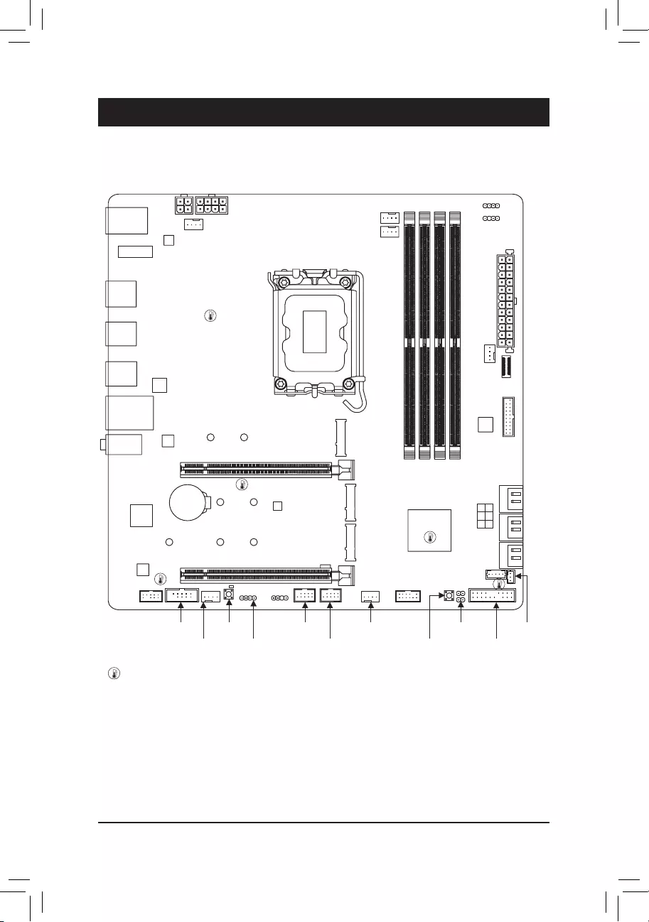
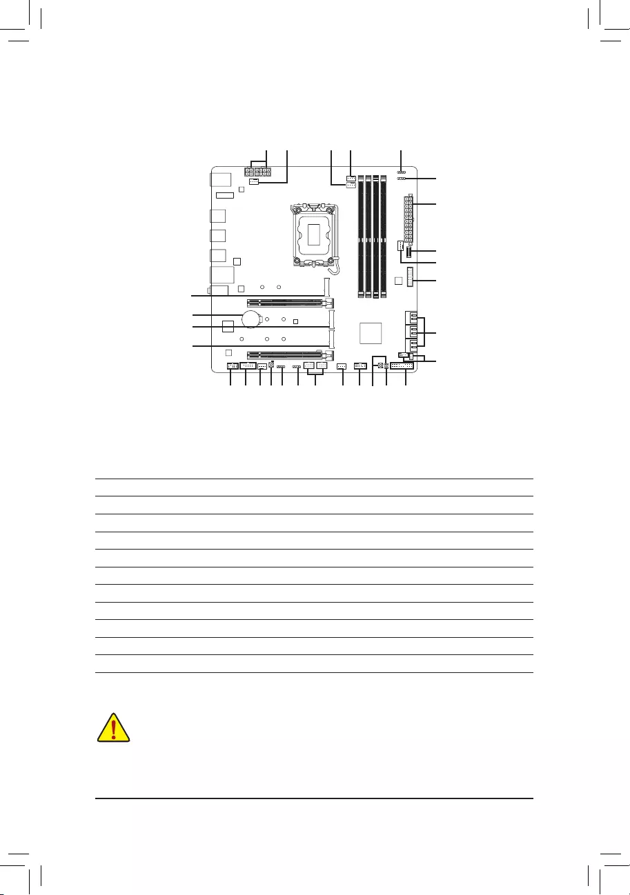
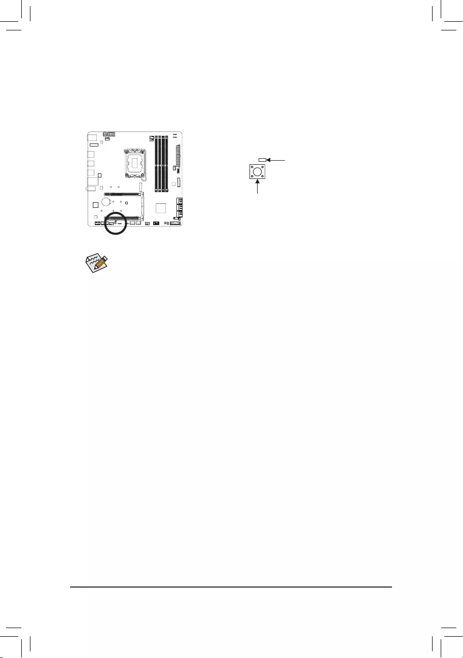
1-1 Motherboard Layout
Chapter 1 Product Introduction
Temperature sensor
SYS_FAN1
DP_HDMI20
U320G
U32G2
U32_LAN
LGA1700
ATX
AUDIO
DDR4_A1
DDR4_A2
DDR4_B1
DDR4_B2
BAT
Intel® Z690
CLR_CMOS
M_BIOS
THB_C1
THB_C2
CODEC
PCIEX16
PCIEX4
F_U32
F_U32C
SYS_FAN3
U32
6080
M2A_CPU
F_AUDIO
SPI_TPM
F_PANEL
CPU_FAN
CPU_OPT
iTE®
Super I/O
D_LED2
LED_C2
ATX_12V_2X4ATX_12V_2X2
USB 3.2 Gen 1 Hub
USB 3.2
Gen 1 Hub
SATA3 135
024
R_USB20
Intel®
2.5GbE LAN
RST_SW
RST
6080
M2Q_SB
6080110
M2P_SB
F_USB2
D_LED1
F_USB1LED_C1
SYS_FAN4_PUMP
SYS_FAN2
QFLED
QFLASH_PLUS
COM
USB 2.0 Hub
M2_WIFIj
Z690M A ELITE AX DDR4
Z690M A ELITE DDR4
j Only for Z690M A ELITE AX DDR4.
USB 2.0 Hub
— 5 —
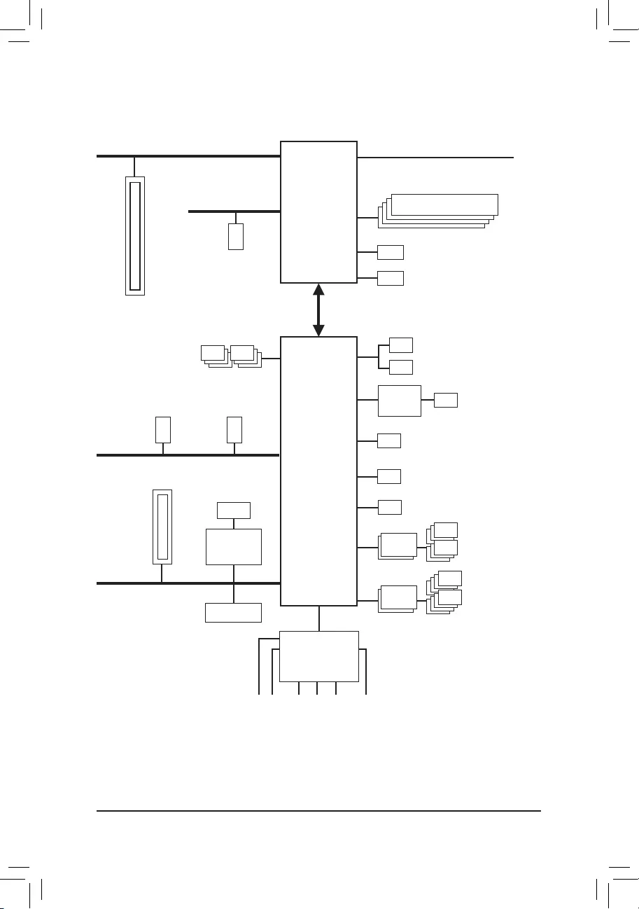
1-2 Motherboard Block Diagram
CPU CLK+/- (80~800 MHz)
DDR4 3200/3000/2933/2666/2400/2133 MHz
DMI 4.0
6 SATA 6Gb/s
(SATA3 0~5)
eSPI
Bus
SPI
Bus
iTE®
Super I/O
6 USB 3.2 Gen 1
8 USB 2.0/1.1
1 USB 3.2 Gen 2 Type-A
Intel® Z690
DDI DisplayPort
USB 3.2
Gen 1 Hub
BIOS
TPM
PCI Express 5.0 Bus
1 PCI Express x16
x16
USB 2.0
Hub
LGA1700 CPU
PCI Express 4.0 Bus
1 M.2 Socket 3
(M2Q_SB)
PCI Express 4.0 Bus
1 M.2 Socket 3
(M2A_CPU) DDI HDMI 2.0
1 M.2 Socket 3
(M2P_SB)
Center/Subwoofer
Speaker Out
Line Out
MIC
Line In
S/PDIF Out
Rear Speaker Out
CODEC
1 USB Type-C®,
with USB 3.2 Gen 2×2 support
1 USB Type-C®,
with USB 3.2 Gen 2 support
COM
j Only for Z690M A ELITE AX DDR4.
LAN
RJ45
PCI Express 3.0 Bus
x4 x1
PCI Express x4
Intel®
2.5GbE LAN
x1
M.2 WIFIj

— 6 —
1-3 Box Contents
5Z690M A ELITE AX DDR4 or Z690M A ELITE DDR4 motherboard
5User’s Manual
5Two SATA cables
5One antennaj
5M.2 screw(s)/M.2 standoff(s)
* The box contents above are for reference only and the actual items shall depend on the product package you obtain.
The box contents are subject to change without notice.
j Only for Z690M A ELITE AX DDR4.

— 7 —
2-1 Installation Precautions
The motherboard contains numerous delicate electronic circuits and components which can become
damaged as a result of electrostatic discharge (ESD). Prior to installation, carefully read the user’s
manual and follow these procedures:
•Prior to installation, make sure the chassis is suitable for the motherboard.
•Prior to installation, do not remove or break motherboard S/N (Serial Number) sticker or
warranty sticker provided by your dealer. These stickers are required for warranty validation.
•Always remove the AC power by unplugging the power cord from the power outlet before
installing or removing the motherboard or other hardware components.
•When connecting hardware components to the internal connectors on the motherboard, make
sure they are connected tightly and securely.
•When handling the motherboard, avoid touching any metal leads or connectors.
•It is best to wear an electrostatic discharge (ESD) wrist strap when handling electronic
components such as a motherboard, CPU or memory. If you do not have an ESD wrist strap,
keep your hands dry and rst touch a metal object to eliminate static electricity.
•Prior to installing the motherboard, please have it on top of an antistatic pad or within an
electrostatic shielding container.
•Before connecting or unplugging the power supply cable from the motherboard, make sure
the power supply has been turned off.
•Before turning on the power, make sure the power supply voltage has been set according to
the local voltage standard.
•Before using the product, please verify that all cables and power connectors of your hardware
components are connected.
•To prevent damage to the motherboard, do not allow screws to come in contact with the
motherboard circuit or its components.
•Make sure there are no leftover screws or metal components placed on the motherboard or
within the computer casing.
•Do not place the computer system on an uneven surface.
•Do not place the computer system in a high-temperature or wet environment.
•Turning on the computer power during the installation process can lead to damage to system
components as well as physical harm to the user.
•If you are uncertain about any installation steps or have a problem related to the use of the
product, please consult a certied computer technician.
•If you use an adapter, extension power cable, or power strip, ensure to consult with its
installation and/or grounding instructions.
Chapter 2 Hardware Installation
— 8 —
2-2 ProductSpecications
CPU LGA1700 socket: Support for 12th Generation Intel® Core™ i9 processors/Intel®
Core™ i7 processors/Intel® Core™ i5 processors
(Go to GIGABYTE’s website for the latest CPU support list.)
L3 cache varies with CPU
Chipset Intel® Z690 Express Chipset
Memory Support for DDR4 3200/3000/2933/2666/2400/2133 MHz memory modules
4 x DDR4 DIMM sockets supporting up to 128 GB (32 GB single DIMM capacity)
of system memory
Dual channel memory architecture
Support for ECC Un-buffered DIMM 1Rx8/2Rx8 memory modules (operate in
non-ECC mode)
Support for non-ECC Un-buffered DIMM 1Rx8/2Rx8/1Rx16 memory modules
Support for Extreme Memory Prole (XMP) memory modules
(Go to GIGABYTE’s website for the latest supported memory speeds and memory
modules.)
Onboard
Graphics
Integrated Graphics Processor-Intel® HD Graphics support:
— 1 x HDMI port, supporting a maximum resolution of 4096×2160@60 Hz
* Support for HDMI 2.0 version and HDCP 2.3.
— 1 x DisplayPort, supporting a maximum resolution of 4096×2304@60 Hz
* Support for DisplayPort 1.2 version and HDCP 2.3
(Graphics specications may vary depending on CPU support.)
Audio Realtek® Audio CODEC
High Denition Audio
2/4/5.1/7.1-channel
* To congure 7.1-channel audio, you need to open the audio software and select
Device advanced settings > Playback Device to change the default setting rst.
Please visit GIGABYTE’s website for details on conguring the audio software.
Support for S/PDIF Out
LAN Intel® 2.5GbE LAN chip (2.5 Gbps/1 Gbps/100 Mbps)
Wireless
Communication
Modulej
Intel® Wi-Fi 6 AX201
— WIFI a, b, g, n, ac, ax, supporting 2.4/5 GHz Dual-Band
— BLUETOOTH 5.2
— Support for 11ax 160MHz wireless standard and up to 2.4 Gbps data rate
* Actual data rate may vary depending on environment and equipment.
Expansion Slots 1 x PCI Express x16 slot, running at x16 (PCIEX16)
(The PCIEX16 slot conforms to PCI Express 5.0 standard.)
1 x PCI Express x16 slot, running at x4 (PCIEX4)
(The PCIEX4 slot conforms to PCI Express 3.0 standard.)
Multi-Graphics
Technology Support for AMD Quad-GPU CrossFire™ and 2-Way AMD CrossFire™ technologies
j Only for Z690M A ELITE AX DDR4.
— 9 —
Storage Interface CPU:
— 1 x M.2 connector (Socket 3, M key, type 2260/2280 PCIe 4.0 x4/x2 SSD
support) (M2A_CPU)
Chipset:
— 1 x M.2 connector (Socket 3, M key, type 2260/2280 PCIe 4.0 x4/x2 SSD
support) (M2Q_SB)
— 1 x M.2 connector (Socket 3, M key, type 2260/2280/22110 PCIe 4.0 x4/x2
SSD support) (M2P_SB)
— 6 x SATA 6Gb/s connectors
Support for RAID 0, RAID 1, RAID 5, and RAID 10
Intel® Optane™ Memory Ready
* System acceleration with Intel® Optane™ Memory can only be enabled on the M.2
connectors supported by the Chipset.
USB Chipset:
— 1 x USB Type-C® port on the back panel, with USB 3.2 Gen 2×2 support
— 1 x USB Type-C® port with USB 3.2 Gen 2 support, available through the
internal USB header
— 1 x USB 3.2 Gen 2 Type-A port (red) on the back panel
Chipset+2 USB 3.2 Gen 1 Hubs:
— 6 x USB 3.2 Gen 1 ports (4 ports on the back panel, 2 ports available through
the internal USB header)
Chipset+2 USB 2.0 Hubs:
— 8 x USB 2.0/1.1 ports (4 ports on the back panel, 4 ports available through
the internal USB headers)
Internal
Connectors
1 x 24-pin ATX main power connector
1 x 8-pin ATX 12V power connector
1 x 4-pin ATX 12V power connector
1 x CPU fan header
1 x water cooling CPU fan header
3 x system fan headers
1 x system fan/water cooling pump header
2 x addressable LED strip headers
2 x RGB LED strip headers
3 x M.2 Socket 3 connectors
6 x SATA 6Gb/s connectors
1 x front panel header
1 x front panel audio header
1 x USB Type-C® header, with USB 3.2 Gen 2 support
1 x USB 3.2 Gen 1 header
2 x USB 2.0/1.1 headers
2 x Thunderbolt™ add-in card connectors
1 x Trusted Platform Module header (For the GC-TPM2.0 SPI/GC-TPM2.0 SPI
2.0 module only)
1 x serial port header
1 x reset button
1 x Q-Flash Plus button
1 x reset jumper
1 x Clear CMOS jumper
— 10 —
Back Panel
Connectors
1 x USB Type-C® port, with USB 3.2 Gen 2×2 support
1 x USB 3.2 Gen 2 Type-A port (red)
4 x USB 3.2 Gen 1 ports
4 x USB 2.0/1.1 ports
2 x SMA antenna connectors (2T2R)j
1 x HDMI port
1 x DisplayPort
1 x RJ-45 port
1 x optical S/PDIF Out connector
2 x audio jacks
I/O Controller iTE® I/O Controller Chip
Hardware
Monitor
Voltage detection
Temperature detection
Fan speed detection
Water cooling ow rate detection
Fan fail warning
Fan speed control
* Whether the fan (pump) speed control function is supported will depend on the fan
(pump) you install.
BIOS 1 x 256 Mbit ash
Use of licensed AMI UEFI BIOS
PnP 1.0a, DMI 2.7, WfM 2.0, SM BIOS 2.7, ACPI 5.0
Unique Features Support for APP Center
* Available applications in APP Center may vary by motherboard model. Supported
functions of each application may also vary depending on motherboard specications.
— @BIOS
— EasyTune
— Fast Boot
— Game Boost
— ON/OFF Charge
— RGB Fusion
— Smart Backup
— System Information Viewer
Support for Q-Flash Plus
Support for Q-Flash
Support for Xpress Install
j Only for Z690M A ELITE AX DDR4.
— 11 —
Please visit GIGABYTE’s website for support lists of CPU, memory modules,
SSDs, and M.2 devices.
Please visit the Support\Utility List page on GIGABYTE’s website to download the latest
version of apps.
Z690M A ELITE
DDR4
Z690M A ELITE
AX DDR4
Bundled
Software
Norton® Internet Security (OEM version)
cFosSpeed
Operating
System Support for Windows 10 64-bit
Form Factor Micro ATX Form Factor; 24.4cm x 24.4cm
* GIGABYTE reserves the right to make any changes to the product specications and product-related information without
prior notice.
— 12 —
2-3 Installing the CPU and CPU Cooler
Read the following guidelines before you begin to install the CPU:
•Make sure that the motherboard supports the CPU.
(Go to GIGABYTE’s website for the latest CPU support list.)
•Always turn off the computer and unplug the power cord from the power outlet before installing the
CPU to prevent hardware damage.
•Locate the pin one of the CPU. The CPU cannot be inserted if oriented incorrectly. (Or you may
locate the notches on both sides of the CPU and alignment keys on the CPU socket.)
•Apply an even and thin layer of thermal grease on the surface of the CPU.
•Do not turn on the computer if the CPU cooler is not installed, otherwise overheating and damage
of the CPU may occur.
•Set the CPU host frequency in accordance with the CPU specications. It is not recommended
that the system bus frequency be set beyond hardware specications since it does not meet the
standard requirements for the peripherals. If you wish to set the frequency beyond the standard
specications, please do so according to your hardware specications including the CPU, graphics
card, memory, hard drive, etc.
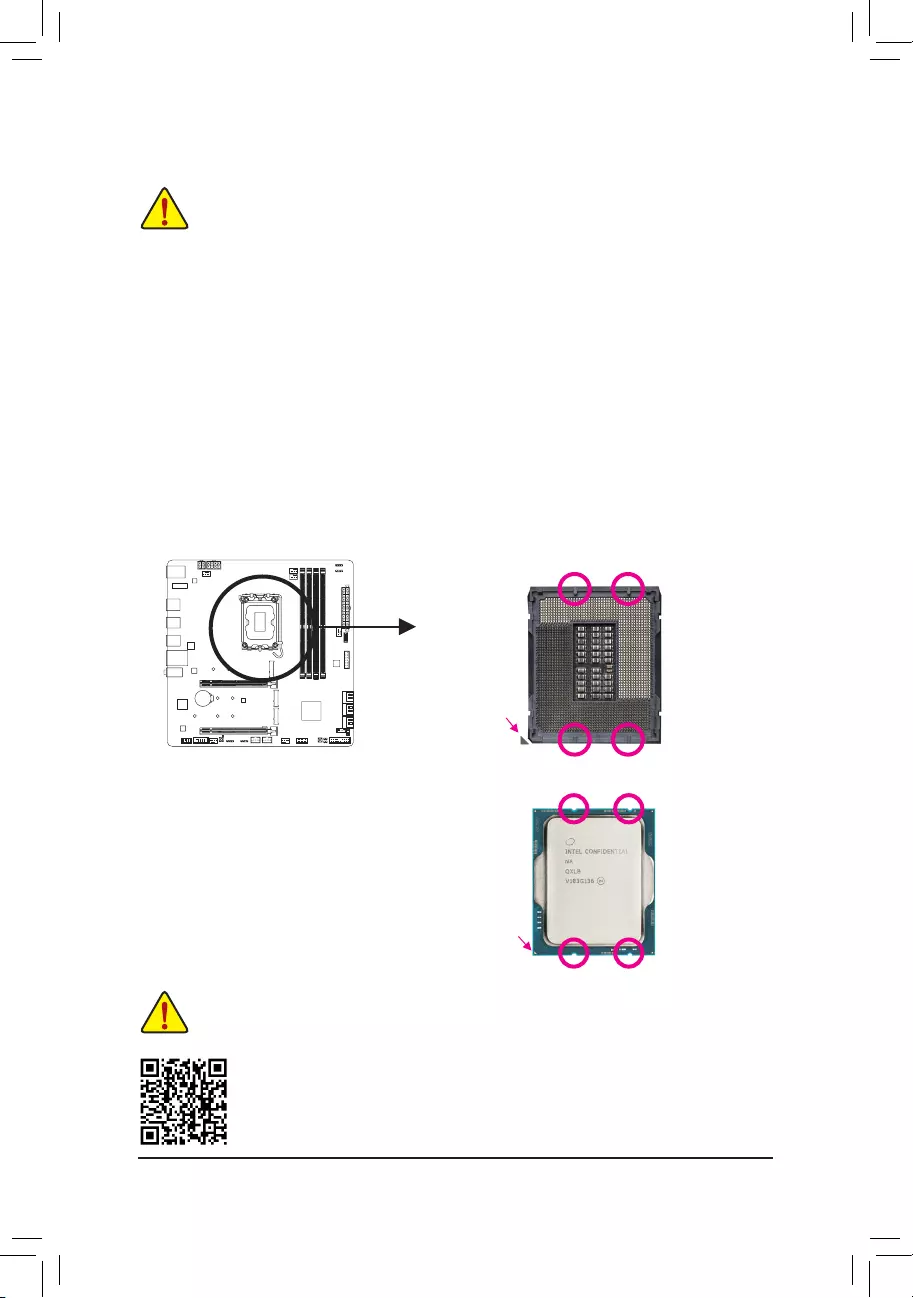
A. Note the CPU Orientation
Note the alignment keys on the motherboard CPU socket and the notches on the CPU.
Please visit GIGABYTE’s website for details on hardware installation.
Do not remove the CPU socket cover before inserting the CPU. It may pop off from the load
plate automatically after you insert the CPU and close the load plate.
Notch
Notch
LGA1700 CPU
Triangle Pin One Marking
on the CPU
Alignment Key
LGA1700 CPU Socket
Triangle Pin One Marking
of the CPU Socket
Alignment Key
— 13 —
Do not force to engage the CPU socket locking lever when the CPU is not installed correctly
as this would damage the CPU and CPU socket.
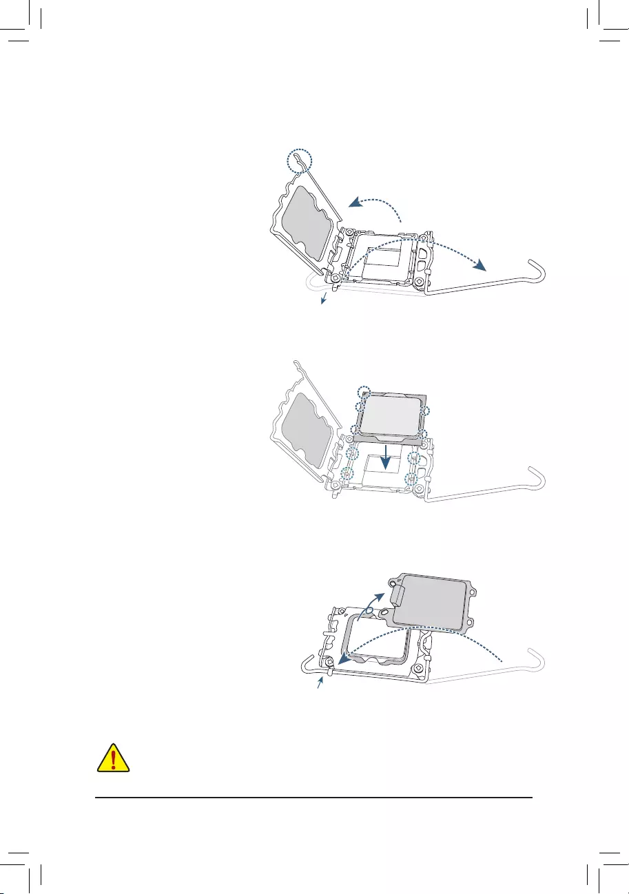
B. Installing the CPU
Follow the steps below to correctly install the CPU into the motherboard CPU socket.
w
u
v
jGently press the CPU socket lever handle
down and away from the socket.
kCompletely lift up the CPU socket lock—
ing lever.
lUse the finger tab on the side of the
metal load plate to lift open the metal
load plate with the plastic protective cover
attached to it.
Hold the CPU with your ngers by the edges.
Align the CPU pin one marking (triangle) with
the pin one corner of the CPU socket (or you
may align the CPU notches with the socket
alignment keys) and gently insert the CPU
into position.
Make sure the CPU is properly installed and
then close the load plate. The plastic protec-
tive cover will pop off, just remove it. Secure
the lever under its retention tab to complete
the installation of the CPU.
* Always replace the plastic protective cover
when the CPU is not installed to protect the
CPU socket.
j
k
l
Finger Tab
Pin One
j
k
l
— 14 —
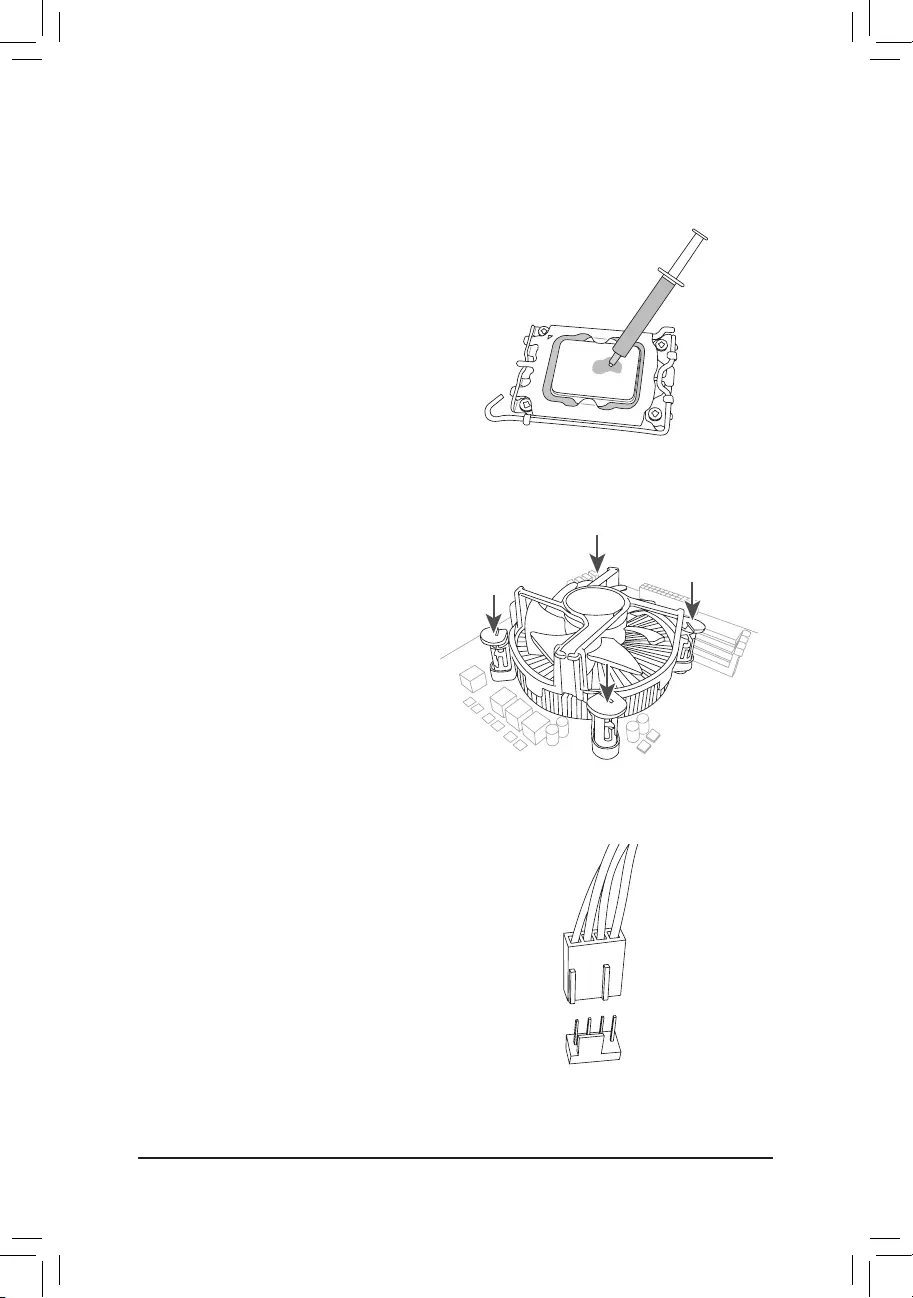
C. Installing the CPU Cooler
Be sure to install the CPU cooler after installing the CPU. (Actual installation process may differ depending the
CPU cooler to be used. Refer to the user’s manual for your CPU cooler.)
u
v
Apply an even and thin layer of thermal
grease on the surface of the installed CPU.
Place the cooler atop the CPU, aligning the
four push pins through the pin holes on the
motherboard. Push down on the push pins
diagonally.
j
j
kk
w
Finally, attach the power connector of
the CPU cooler to the CPU fan header
(CPU_FAN) on the motherboard.
CPU_FAN
— 15 —
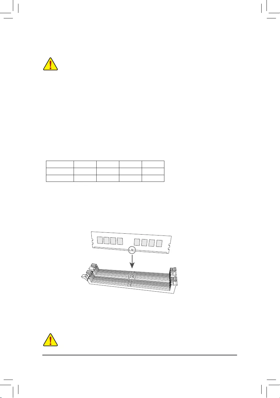
2-4 Installing the Memory
Read the following guidelines before you begin to install the memory:
•Make sure that the motherboard supports the memory. It is recommended that memory of the same
capacity, brand, speed, and chips be used. (Go to GIGABYTE’s website for the latest supported
memory speeds and memory modules.)
•Always turn off the computer and unplug the power cord from the power outlet before installing the
memory to prevent hardware damage.
•Memory modules have a foolproof design. A memory module can be installed in only one direction.
If you are unable to insert the memory, switch the direction.
DualChannelMemoryConguration
This motherboard provides four memory sockets and supports Dual Channel Technology. After the memory
is installed, the BIOS will automatically detect the specications and capacity of the memory. Enabling Dual
Channel memory mode will double the original memory bandwidth.
The four memory sockets are divided into two channels and each channel has two memory sockets as following:
Channel A: DDR4_A1, DDR4_A2
Channel B: DDR4_B1, DDR4_B2
* Recommanded Dual Channel Memory Conguration:
DDR4_A1 DDR4_A2 DDR4_B1 DDR4_B2
2 Modules — — DS/SS — — DS/SS
4 Modules DS/SS DS/SS DS/SS DS/SS
(SS=Single-Sided, DS=Double-Sided, «- -«=No Memory)
Due to CPU limitations, read the following guidelines before installing the memory in Dual Channel mode.
1. Dual Channel mode cannot be enabled if only one memory module is installed.
2. When enabling Dual Channel mode with two or four memory modules, it is recommended that memory of
the same capacity, brand, speed, and chips be used.
When installing a single memory module, we recommend that you install it in the DDR4_A2
socket.
DDR4_ A1
DDR4_A2
DDR4_B1
DDR4_B2
— 16 —
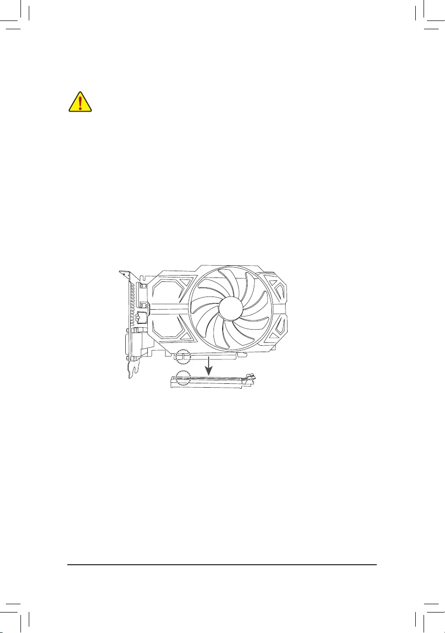
2-5 Installing an Expansion Card
Read the following guidelines before you begin to install an expansion card:
•Make sure the motherboard supports the expansion card. Carefully read the manual that came
with your expansion card.
•Always turn off the computer and unplug the power cord from the power outlet before installing an
expansion card to prevent hardware damage.
Follow the steps below to correctly install your expansion card in the expansion slot.
1. Locate an expansion slot that supports your card. Remove the metal slot cover from the chassis back panel.
2. Align the card with the slot, and press down on the card until it is fully seated in the slot.
3. Make sure the metal contacts on the card are completely inserted into the slot.
4. Secure the card’s metal bracket to the chassis back panel with a screw.
5. After installing all expansion cards, replace the chassis cover(s).
6. Turn on your computer. If necessary, go to BIOS Setup to make any required BIOS changes for your
expansion card(s).
7. Install the driver provided with the expansion card in your operating system.
PCIEX16 Slot
— 17 —
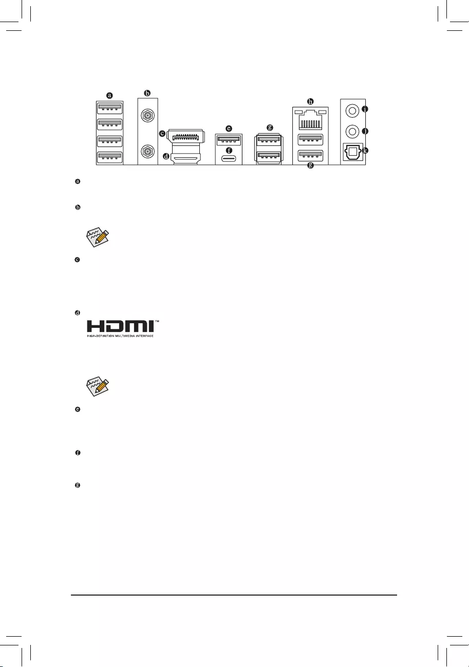
2-6 Back Panel Connectors
USB 2.0/1.1 Port
The USB port supports the USB 2.0/1.1 specication. Use this port for USB devices.
SMA Antenna Connectors (2T2R)j
Use this connector to connect an antenna.
DisplayPort
DisplayPort delivers high quality digital imaging and audio, supporting bi-directional audio transmission.
DisplayPort can support HDCP 2.3 content protection mechanisms. You can use this port to connect your
DisplayPort-supported monitor. Note: The DisplayPort Technology can support a maximum resolution of
4096×2304@60 Hz but the actual resolutions supported depend on the monitor being used.
HDMI 2.0 Port
The HDMI port supports HDCP 2.3 and Dolby TrueHD and DTS HD Master
Audio formats. It also supports up to 192KHz/24bit 7.1-channel LPCM audio
output. You can use this port to connect your HDMI-supported monitor. The maximum supported
resolution is 4096×2160@60 Hz, but the actual resolutions supported are dependent on the monitor
being used.
After installing the HDMI/DisplayPort device, make sure to set the default sound playback device
to HDMI/DisplayPort. (The item name may differ depending on your operating system.)
(Note) To enable the Q-Flash Plus function, please navigate to the «Unique Features» page of GIGABYTE’s
website for more information.
Tighten the antennas to the antenna connectors and then aim the antennas correctly for better
signal reception.
USB 3.2 Gen 2 Type-A Port (Red) (Q-Flash Plus Port)
The USB 3.2 Gen 2 port supports the USB 3.2 Gen 2 specication and is compatible to the USB 3.2 Gen 1
and USB 2.0 specication. Use this port for USB devices. Before using Q-Flash Plus (Note), make sure to insert
the USB ash drive into this port rst.
USB Type-C® Port
The reversible USB port supports the USB 3.2 Gen 2×2 specication and is compatible to the USB 3.2
Gen 2, USB 3.2 Gen 1, and USB 2.0 specications. Use this port for USB devices.
USB 3.2 Gen 1 Port
The USB 3.2 Gen 1 port supports the USB 3.2 Gen 1 specication and is compatible to the USB 2.0
specication. Use this port for USB devices.
j Only for Z690M A ELITE AX DDR4.
— 18 —
Please visit GIGABYTE’s website for details on conguring the audio software.
•When removing the cable connected to a back panel connector, rst remove the cable from
your device and then remove it from the motherboard.
•When removing the cable, pull it straight out from the connector. Do not rock it side to side
to prevent an electrical short inside the cable connector.
Audio Jack Congurations:
Jack Headphone/
2-channel 4-channel 5.1-channel 7.1-channel
Line Out/Front Speaker Out a a a a
Mic In/Rear Speaker Out a a a
Front Panel Line Out/Side Speaker Out a
Front Panel Mic In/Center/Subwoofer
Speaker Out a
•You can change the functionality of an audio jack using the audio software.
•To congure 7.1-channel audio, you need to open the audio software and select Device
advanced settings > Playback Device to change the default setting rst.
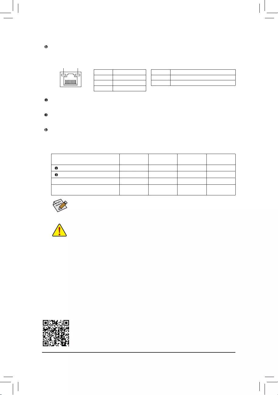
Activity LEDSpeed LED
LAN Port
Speed LED:
State Description
Green 2.5 Gbps data rate
Orange 1 Gbps data rate
Off 100 Mbps data rate
Activity LED:
State Description
Blinking Data transmission or receiving is occurring
On No data transmission or receiving is occurring
RJ-45 LAN Port
The Gigabit Ethernet LAN port provides Internet connection at up to 2.5 Gbps data rate. The following
describes the states of the LAN port LEDs.
Line Out/Front Speaker Out
The line out jack.
Mic In/Rear Speaker Out
The Mic in jack.
Optical S/PDIF Out Connector
This connector provides digital audio out to an external audio system that supports digital optical audio.
Before using this feature, ensure that your audio system provides an optical digital audio in connector.
— 19 —
2-7 Internal Connectors
Read the following guidelines before connecting external devices:
•First make sure your devices are compliant with the connectors you wish to connect.
•Before installing the devices, be sure to turn off the devices and your computer. Unplug the power
cord from the power outlet to prevent damage to the devices.
•After installing the device and before turning on the computer, make sure the device cable has
been securely attached to the connector on the motherboard.
1) ATX_12V_2X2/ATX_12V_2X4
2) ATX
3) CPU_FAN
4) SYS_FAN1/2/3
5) SYS_FAN4_PUMP
6) CPU_OPT
7) LED_C1/LED_C2
 D_LED1/D_LED2
9) SATA3 0/1/2/3/4/5
10) M2A_CPU/M2Q_SB/M2P_SB
11) F_PANEL
12) F_AUDIO
13) F_U32C
14) F_U32
15) F_USB1/F_USB2
16) SPI_TPM
17) COM
18) THB_C1/THB_C2
19) BAT
20) CLR_CMOS
21) RST_SW/RST
22) QFLASH_PLUS
11
14
13
2
8
18
9
15412 16
71
87 20
36
10
10
10
5
4
4
17
19
21
22
— 20 —
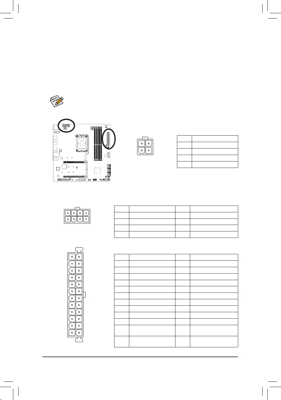
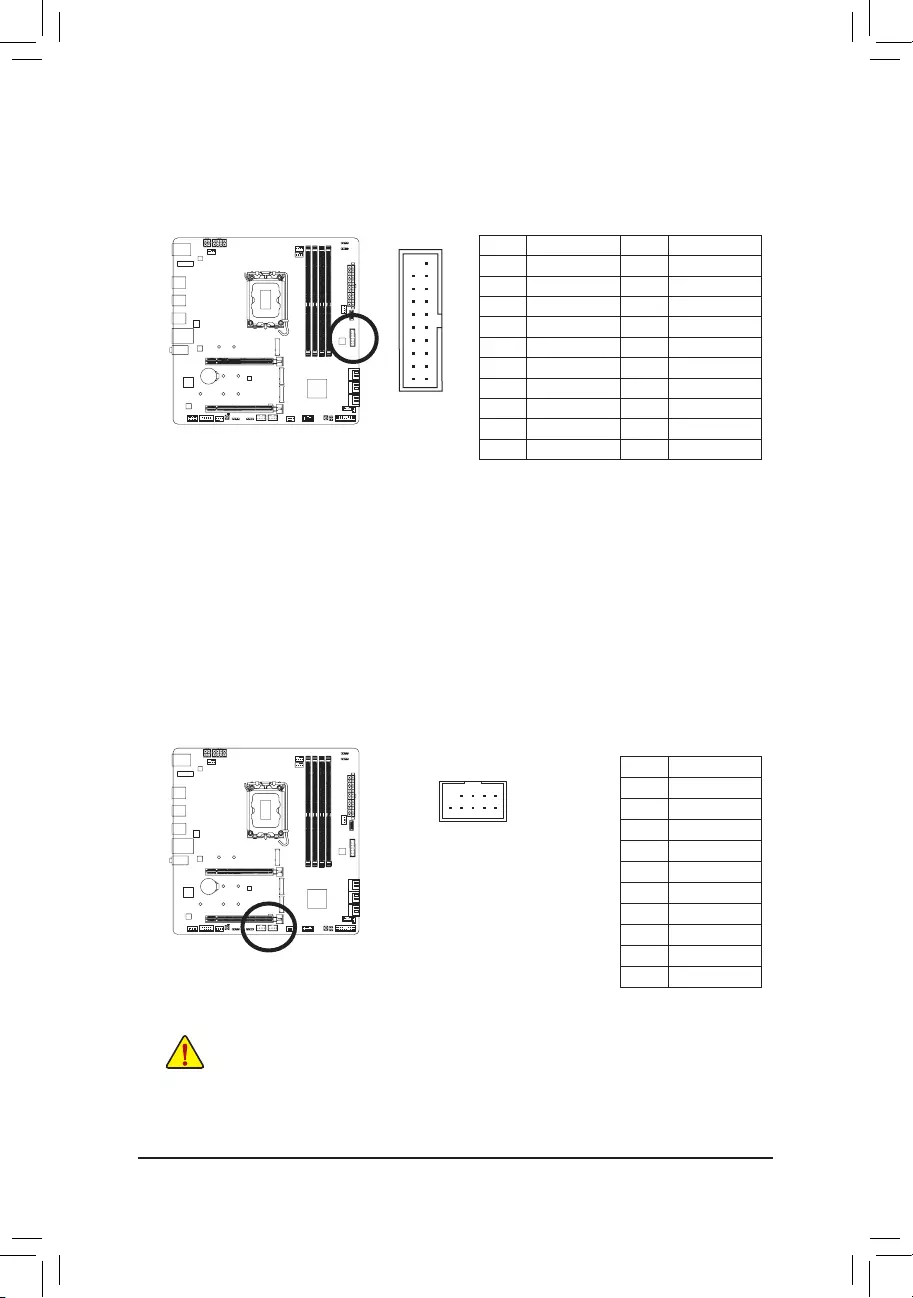
1/2) ATX_12V_2X2/ATX_12V_2X4/ATX (2×2, 2×4, 12V Power Connectors and 2×12 Main
Power Connector)
With the use of the power connector, the power supply can supply enough stable power to all the components
on the motherboard. Before connecting the power connector, rst make sure the power supply is turned
off and all devices are properly installed. The power connector possesses a foolproof design. Connect the
power supply cable to the power connector in the correct orientation.
The 12V power connector mainly supplies power to the CPU. If the 12V power connector is not connected,
the computer will not start.
To meet expansion requirements, it is recommended that a power supply that can withstand high
power consumption be used (500W or greater). If a power supply is used that does not provide the
required power, the result can lead to an unstable or unbootable system.
ATX_12V_2X4
ATX:
Pin No. Denition Pin No. Denition
1 3.3V 13 3.3V
2 3.3V 14 -12V
3 GND 15 GND
4 +5V 16 PS_ON (soft On/Off)
5 GND 17 GND
6 +5V 18 GND
7 GND 19 GND
8 Power Good 20 NC
9 5VSB (stand by +5V) 21 +5V
10 +12V 22 +5V
11 +12V (Only for 2×12-pin
ATX)
23 +5V (Only for 2×12-pin ATX)
12 3.3V (Only for 2×12-pin
ATX)
24 GND (Only for 2×12-pin ATX)
41
8
5
131
2412
ATX
ATX_12V_2X2
21
3 4
ATX_12V_2X4:
Pin No. Denition Pin No. Denition
1GND (Only for 2×4-pin 12V) 5 +12V (Only for 2×4-pin 12V)
2GND (Only for 2×4-pin 12V) 6 +12V (Only for 2×4-pin 12V)
3 GND 7 +12V
4 GND 8 +12V
ATX_12V_2X2:
Pin No. Denition
1 GND
2 GND
3 +12V
4 +12V
— 21 —
•Be sure to connect fan cables to the fan headers to prevent your CPU and system from
overheating. Overheating may result in damage to the CPU or the system may hang.
•These fan headers are not conguration jumper blocks. Do not place a jumper cap on the headers.
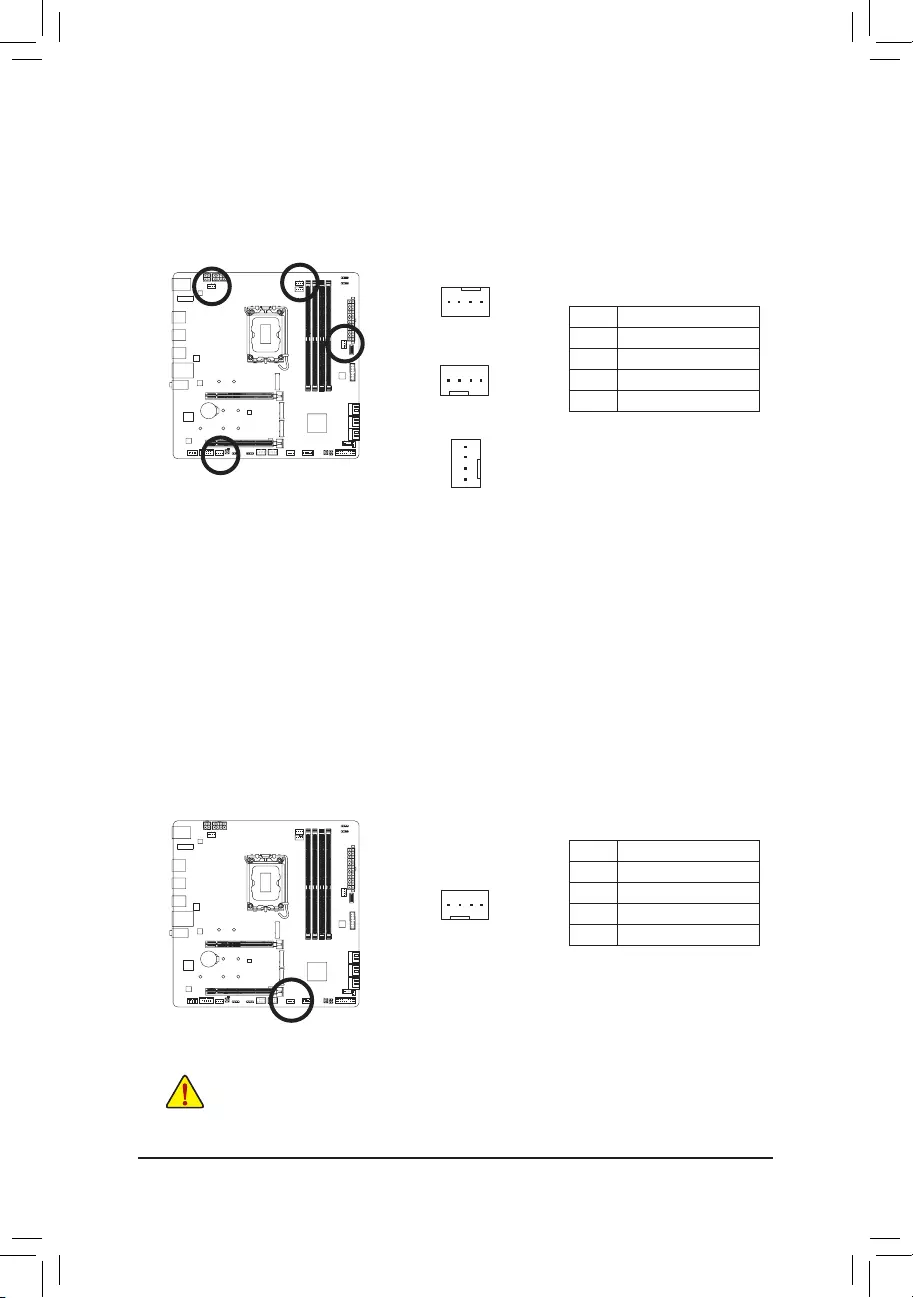
3/4) CPU_FAN/SYS_FAN1/2/3 (Fan Headers)
All fan headers on this motherboard are 4-pin. Most fan headers possess a foolproof insertion design.
When connecting a fan cable, be sure to connect it in the correct orientation (the black connector wire is
the ground wire). The speed control function requires the use of a fan with fan speed control design. For
optimum heat dissipation, it is recommended that a system fan be installed inside the chassis.
Pin No. Denition
1 GND
2 Voltage Speed Control
3 Sense
4 PWM Speed Control
5) SYS_FAN4_PUMP (System Fan/Water Cooling Pump Header)
The fan/pump header are 4-pin. Most fan headers possess a foolproof insertion design. When connecting
a fan cable, be sure to connect it in the correct orientation (the black connector wire is the ground wire).
The speed control function requires the use of a fan with fan speed control design. For optimum heat
dissipation, it is recommended that a system fan be installed inside the chassis. The header also provides
speed control for a water cooling pump. Please navigate to the «BIOS Setup» page of GIGABYTE’s website
and search for «Smart Fan 6» for more information.
Pin No. Denition
1 GND
2 Voltage Speed Control
3 Sense
4 PWM Speed Control
CPU_FAN/SYS_FAN1
1
1
SYS_FAN2
1
SYS_FAN3
1
— 22 —
6) CPU_OPT (Water Cooling CPU Fan Header)
The fan header is 4-pin and possesses a foolproof insertion design. Most fan headers possess a foolproof
insertion design. When connecting a fan cable, be sure to connect it in the correct orientation (the black
connector wire is the ground wire). The speed control function requires the use of a fan with fan speed
control design.
Pin No. Denition
1 GND
2 Voltage Speed Control
3 Sense
4 PWM Speed Control
Connector CPU_FAN SYS_FAN1~3 SYS_FAN4_PUMP CPU_OPT
Maximum Current 2A 2A 2A 2A
Maximum Power 24W 24W 24W 24W
1
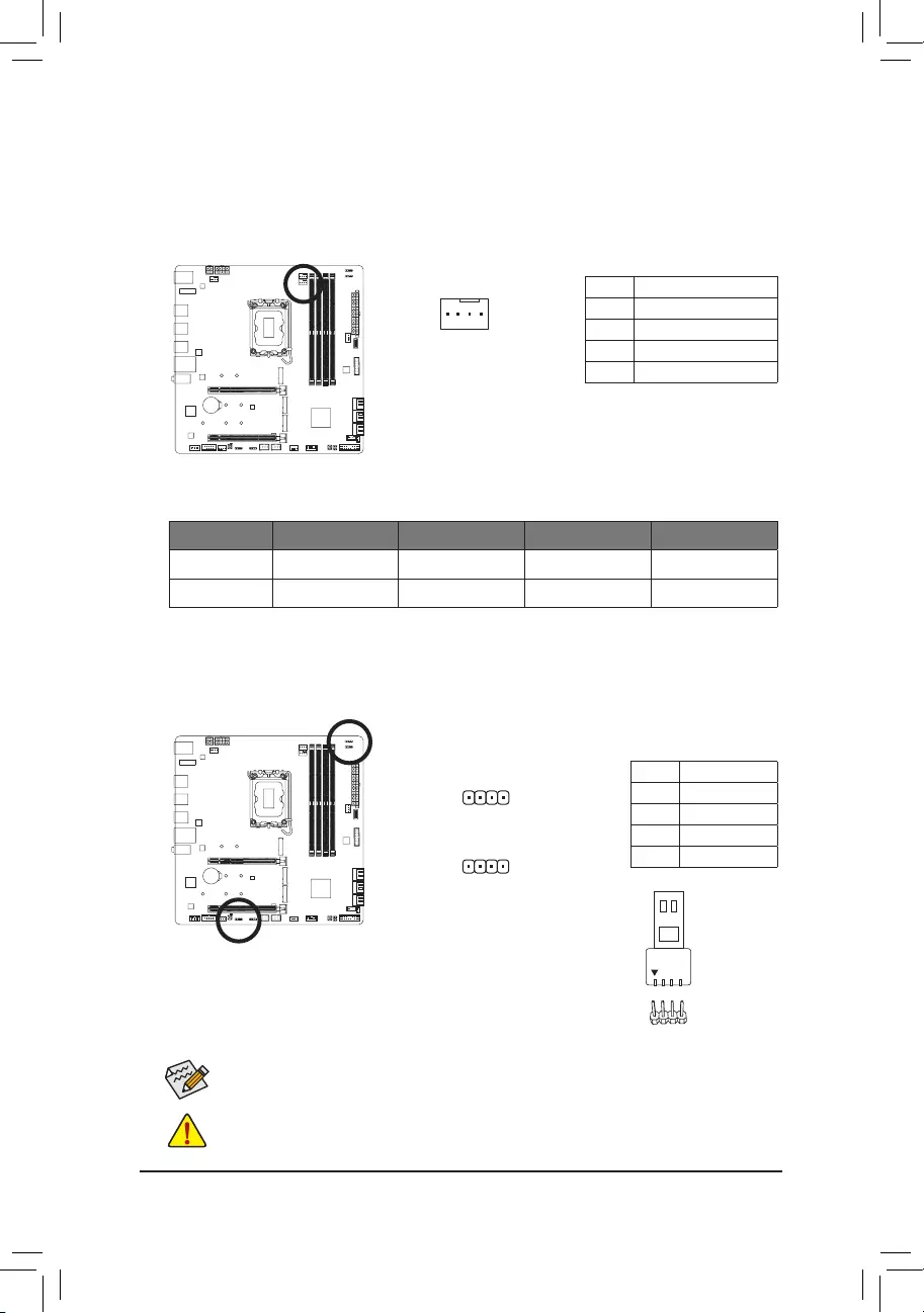
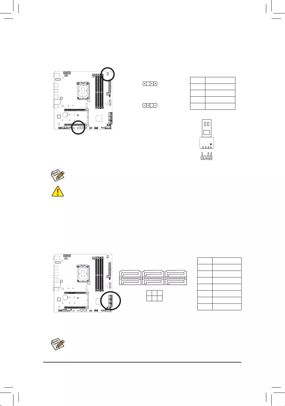
7) LED_C1/LED_C2 (RGB LED Strip Headers)
The headers can be used to connect a standard 5050 RGB LED strip (12V/G/R/B), with maximum power
rating of 2A (12V) and maximum length of 2m.
Connect your RGB LED strip to the header. The power pin (marked with a
triangle on the plug) of the LED strip must be connected to Pin 1 (12V) of
this header. Incorrect connection may lead to the damage of the LED strip.
Pin No. Denition
1 12V
2 G
3 R
4 B
1
LED_C2
1
LED_C1
RGB LED Strip
1
12V
Before installing the devices, be sure to turn off the devices and your computer. Unplug the power
cord from the power outlet to prevent damage to the devices.
For how to turn on/off the lights of the LED strip, please navigate to the «Unique Features» page
of GIGABYTE’s website.
— 23 —
D_LED1/D_LED2 (Addressable LED Strip Headers)
The headers can be used to connect a standard 5050 addressable LED strip, with maximum power rating
of 5A (5V) and maximum number of 1000 LEDs.
Before installing the devices, be sure to turn off the devices and your computer. Unplug the power
cord from the power outlet to prevent damage to the devices.
For how to turn on/off the lights of the LED strip, please navigate to the «Unique Features» page
of GIGABYTE’s website.
1
D_LED1
Pin No. Denition
1 V (5V)
2 Data
3 No Pin
4 GND
Connect your addressable LED strip to the header. The power pin (marked
with a triangle on the plug) of the LED strip must be connected to Pin 1 of
the addressable LED strip header. Incorrect connection may lead to the
damage of the LED strip.
1
D_LED2
Addressable LED
Strip
1
F_USB30 F_U
B_
F_ F_
_
B
BS_
B
SB_
B
_S
S_
_
B
_U
_
B
S
123
123
123
123
1
1
1
1
BSS
S
_S
SSU
1 2 3
S3 BSSS
U
__ 3
F_USB3F
S _
S _
S _
SF
B_
B_
F
_0
S
S
_0F
_F
_
_
__B
U
S _S
_ SF_
B
USB0_B
B_
B_
F_USB3
F_USB303
_
_3U
S_
_S
SS_F
_
_
F_USB30 F_U
B_
F_ F_
_
B
BS_
B
SB_
B
_S
S_
_
B
_U
_
B
S
123
123
123
123
1
1
1
1
BSS
S
_S
SSU
1 2 3
S3 BSSS
U
__ 3
F_USB3F
S _
S _
S _
SF
B_
B_
F
_0
S
S
_0F
_F
_
_
__B
U
S _S
_ SF_
B
USB0_B
B_
B_
F_USB3
F_USB303
_
_3U
S_
_S
SS_F
_
_
9) SATA3 0/1/2/3/4/5 (SATA 6Gb/s Connectors)
The SATA connectors conform to SATA 6Gb/s standard and are compatible with SATA 3Gb/s and SATA 1.5Gb/s
standard. Each SATA connector supports a single SATA device. The Intel® Chipset supports RAID 0, RAID 1,
RAID 5, and RAID 10. Please navigate to the «Conguring a RAID Set» page of GIGABYTE’s website for
instructions on conguring a RAID array.
Pin No. Denition
1 GND
2 TXP
3 TXN
4 GND
5 RXN
6 RXP
7 GND
To enable hot-plugging for the SATA ports, please navigate to the «BIOS Setup» page of GIGABYTE’s
website and search for «SATA Conguration» for more information.
SATA3
1
1
7
7
1 3 5
0 2 4
— 24 —
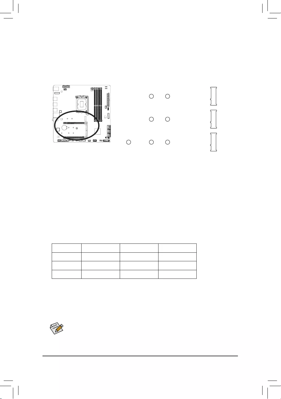
10) M2A_CPU/M2Q_SB/M2P_SB (M.2 Socket 3 Connectors)
There are two types of M.2 SSDs: M.2 SATA SSDs and M.2 PCIe SSDs. This motherboard only supports
M.2 PCIe SSDs. Be sure to verify the type of M.2 SSDs you want to use. Please note that an M.2 PCIe
SSD cannot be used to create a RAID set with a SATA hard drive. Please navigate to the «Conguring a
RAID Set» page of GIGABYTE’s website for instructions on conguring a RAID array.
Follow the steps below to correctly install an M.2 SSD in the M.2 connector.
Step 1:
Locate the M.2 connector where you will install the M.2 SSD, use a screwdriver to unfasten the screw on
the heatsink and then remove the heatsink. (Only the M2A_CPU connector has the heatsink)
Step 2:
Locate the proper mounting hole based on the length of your M.2 SSD drive. If needed, move the standoff
to the desired mounting hole. Insert the M.2 SSD into the M.2 connector at an angle.
Step 3:
Press the M.2 SSD down and then use the included screw to secure it in the connector. Remove the
protective lm from the bottom of the heatsink. Then replace the heatsink and secure it to the original hole.
* Types of M.2 SSDs supported by each M.2 connector:
M.2 PCIe x4 SSD M.2 PCIe x2 SSD M.2 SATA SSD
M2A_CPU a a r
M2P_SB a a r
M2Q_SB a a r
M2P_SB
F_USB30 F_U
B_
F_ F_
_
B
BS_
B
SB_
B
_S
S_
_
B
_U
_
B
S
123
123
123
123
1
1
1
1
BSS
S
_S
SSU
1 2 3
S3 BSSS
U
__ 3
F_USB3F
S _
S _
S _
SF
B_
B_
F
_0
S
S
_0F
_F
_
_
__B
U
S _S
_ SF_
B
USB0_B
B_
B_
F_USB3
F_USB303
_
_3U
S_
_S
SS_F
_
_
80110 60
M2A_CPU
F_USB30 F_U
B_
F_ F_
_
B
BS_
B
SB_
B
_S
S_
_
B
_U
_
B
S
123
123
123
123
1
1
1
1
BSS
S
_S
SSU
1 2 3
S3 BSSS
U
__ 3
F_USB3F
S _
S _
S _
SF
B_
B_
F
_0
S
S
_0F
_F
_
_
__B
U
S _S
_ SF_
B
USB0_B
B_
B_
F_USB3
F_USB303
_
_3U
S_
_S
SS_F
_
_
80 60
F_USB30 F_U
B_
F_ F_
_
B
BS_
B
SB_
B
_S
S_
_
B
_U
_
B
S
123
123
123
123
1
1
1
1
BSS
S
_S
SSU
1 2 3
S3 BSSS
U
__ 3
F_USB3F
S _
S _
S _
SF
B_
B_
F
_0
S
S
_0F
_F
_
_
__B
U
S _S
_ SF_
B
USB0_B
B_
B_
F_USB3
F_USB303
_
_3U
S_
_S
SS_F
_
_
80 60
M2Q_SB
If you want to install an operating system on an M.2 PCIe SSD, you need to install the Intel® RST
VMD Controller driver rst. Refer to Chapter 4 for more instructions.
— 25 —
The front panel design may differ by chassis. A front panel module mainly consists of power switch,
reset switch, power LED, hard drive activity LED, speaker and etc. When connecting your chassis
front panel module to this header, make sure the wire assignments and the pin assignments are
matched correctly.
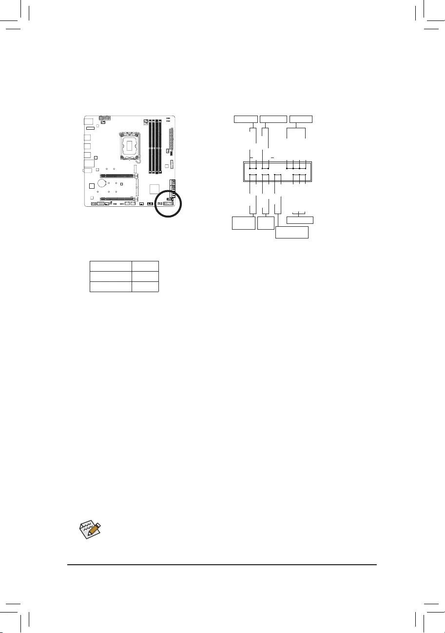
11) F_PANEL (Front Panel Header)
Connect the power switch, reset switch, speaker, chassis intrusion switch/sensor and system status indicator
on the chassis to this header according to the pin assignments below. Note the positive and negative pins
before connecting the cables.
•PW (Power Switch):
Connects to the power switch on the chassis front panel. You may congure the way to turn off your
system using the power switch (please navigate to the «BIOS Setup» page of GIGABYTE’s website and
search for «Soft-Off by PWR-BTTN» for more information).
•SPEAK (Speaker):
Connects to the speaker on the chassis front panel. The system reports system startup status by issuing
a beep code. One single short beep will be heard if no problem is detected at system startup.
•HD (Hard Drive Activity LED):
Connects to the hard drive activity LED on the chassis front panel. The LED is on when the hard drive
is reading or writing data.
•RES (Reset Switch):
Connects to the reset switch on the chassis front panel. Press the reset switch to restart the computer
if the computer freezes and fails to perform a normal restart.
•CI (Chassis Intrusion Header):
Connects to the chassis intrusion switch/sensor on the chassis that can detect if the chassis cover has
been removed. This function requires a chassis with a chassis intrusion switch/sensor.
•NC: No connection.
•PLED/PWR_LED (Power LED):
Connects to the power status indicator on the chassis front panel. The LED
is on when the system is operating. The LED is off when the system is in S3/
S4 sleep state or powered off (S5).
System Status LED
S0 On
S3/S4/S5 Off
NC
NC
Power LED
1
2
19
20
CI-
CI+
PWR_LED-
PWR_LED+
PLED-
PW-
SPEAK+
SPEAK-
PLED+
PW+
Power LED
HD-
RES+
HD+
RES-
Hard Drive
Activity LED
Reset
Switch Chassis Intrusion
Header
Power Switch Speaker
PWR_LED-
— 26 —
12) F_AUDIO (Front Panel Audio Header)
The front panel audio header supports High Denition audio (HD). You may connect your chassis front
panel audio module to this header. Make sure the wire assignments of the module connector match the
pin assignments of the motherboard header. Incorrect connection between the module connector and the
motherboard header will make the device unable to work or even damage it.
Pin No. Denition
1 MIC2_L
2 GND
3 MIC2_R
4 NC
5 LINE2_R
6 Sense
7 GND
8 No Pin
9 LINE2_L
10 Sense
F_USB30 F_U
B_
F_ F_
_
B
BS_
B
SB_
B
_S
S_
_
B
_U
_
B
S
123
123
123
123
1
1
1
1
BSS
S
_S
SSU
1 2 3
S3 BSSS
U
__ 3
F_USB3F
S _
S _
S _
SF
B_
B_
F
_0
S
S
_0F
_F
_
_
__B
U
S _S
_ SF_
B
USB0_B
B_
B_
F_USB3
F_USB303
_
_3U
S_
_S
SS_F
_
_
9 1
10 2
Some chassis provide a front panel audio module that has separated connectors on each wire
instead of a single plug. For information about connecting the front panel audio module that has
different wire assignments, please contact the chassis manufacturer.
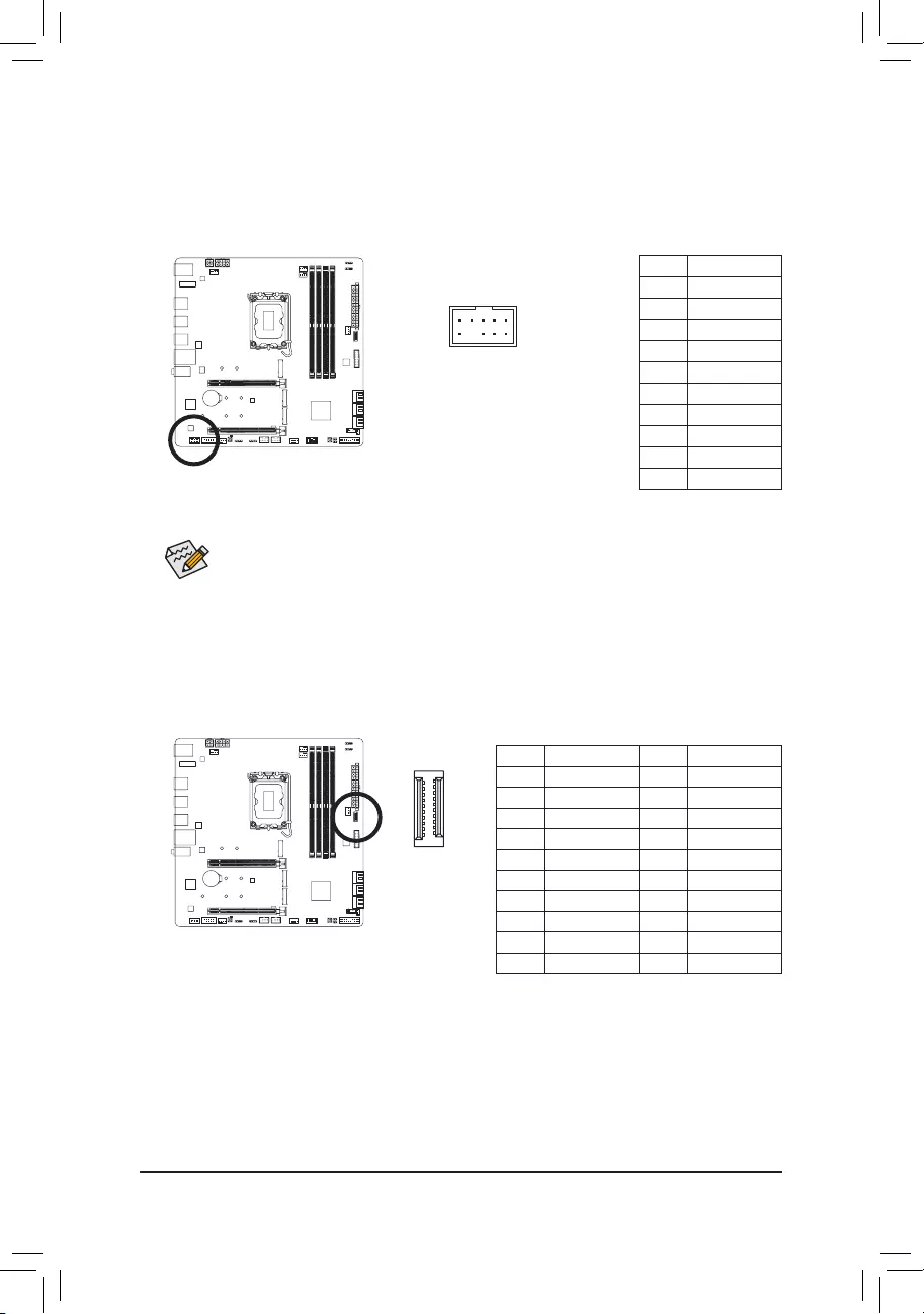
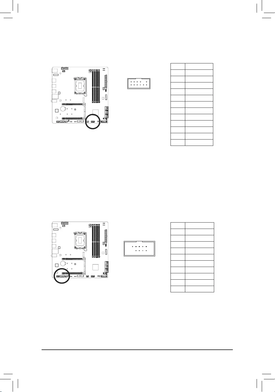
13) F_U32C (USB Type-C® Header with USB 3.2 Gen 2 Support)
The header conforms to USB 3.2 Gen 2 specication and can provide one USB port.
Pin No. Denition Pin No. Denition
1 VBUS 11 VBUS
2 TX1+ 12 TX2+
3 TX1- 13 TX2-
4 GND 14 GND
5 RX1+ 15 RX2+
6 RX1- 16 RX2-
7 VBUS 17 GND
8 CC1 18 D-
9 SBU1 19 D+
10 SBU2 20 CC2
F_USB30 F_U
B_
F_ F_
_
B
BS_
B
SB_
B
_S
S_
_
B
_U
_
B
S
123
123
123
123
1
1
1
1
BSS
S
_S
SSU
1 2 3
S3 BSSS
U
__ 3
F_USB3F
S _
S _
S _
SF
B_
B_
F
_0
S
S
_0F
_F
_
_
__B
U
S _S
_ SF_
B
USB0_B
B_
B_
F_USB3
F_USB303
_
_3U
S_
_S
SS_F
_
_
20
10 11
1
— 27 —
14) F_U32 (USB 3.2 Gen 1 Header)
The header conforms to USB 3.2 Gen 1 and USB 2.0 specication and can provide two USB ports. For
purchasing the optional 3.5″ front panel that provides two USB 3.2 Gen 1 ports, please contact the local
dealer.
Pin No. Denition Pin No. Denition
1 VBUS 11 D2+
2 SSRX1- 12 D2-
3 SSRX1+ 13 GND
4 GND 14 SSTX2+
5 SSTX1- 15 SSTX2-
6SSTX1+ 16 GND
7 GND 17 SSRX2+
8 D1- 18 SSRX2-
9 D1+ 19 VBUS
10 NC 20 No Pin
F_USB30 F_U
B_
F_ F_
_
B
BS_
B
SB_
B
_S
S_
_
B
_U
_
B
S
123
123
123
123
1
1
1
1
BSS
S
_S
SSU
1 2 3
S3 BSSS
U
__ 3
F_USB3F
S _
S _
S _
SF
B_
B_
F
_0
S
S
_0F
_F
_
_
__B
U
S _S
_ SF_
B
USB0_B
B_
B_
F_USB3
F_USB303
_
_3U
S_
_S
SS_F
_
_
20 1
1011
15) F_USB1/F_USB2 (USB 2.0/1.1 Headers)
The headers conform to USB 2.0/1.1 specication. Each USB header can provide two USB ports via an
optional USB bracket. For purchasing the optional USB bracket, please contact the local dealer.
Pin No. Denition
1 Power (5V)
2 Power (5V)
3 USB DX-
4 USB DY—
5 USB DX+
6 USB DY+
7 GND
8 GND
9 No Pin
10 NC
10
9
2
1
•Do not plug the IEEE 1394 bracket (2×5-pin) cable into the USB 2.0/1.1 header.
•Prior to installing the USB bracket, be sure to turn off your computer and unplug the power cord
from the power outlet to prevent damage to the USB bracket.
— 28 —
Pin No. Denition
1Data Output
2Power (3.3V)
3No Pin
4NC
5Data Input
6CLK
7Chip Select
8GND
9IRQ
10 NC
11 NC
12 RST
16) SPI_TPM (Trusted Platform Module Header)
You may connect an SPI TPM (Trusted Platform Module) to this header.
12
11
2
1
F_USB30 F_U
B_
F_ F_
_
B
BS_
B
SB_
B
_S
S_
_
B
_U
_
B
S
123
123
123
123
1
1
1
1
BSS
S
_S
SSU
1 2 3
S3 BSSS
U
__ 3
F_USB3F
S _
S _
S _
SF
B_
B_
F
_0
S
S
_0F
_F
_
_
__B
U
S _S
_ SF_
B
USB0_B
B_
B_
F_USB3
F_USB303
_
_3U
S_
_S
SS_F
_
_
17) COM (Serial Port Header)
The COM header can provide one serial port via an optional COM port cable. For purchasing the optional
COM port cable, please contact the local dealer.
Pin No. Denition
1 NDCD-
2 NSIN
3 NSOUT
4 NDTR-
5 GND
6 NDSR-
7 NRTS-
8 NCTS-
9 NRI-
10 No Pin
2
1
10
9
— 29 —
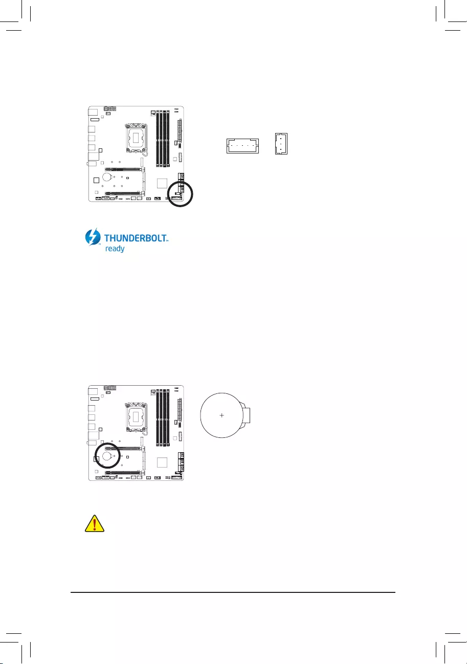
18) THB_C1/THB_C2 (Thunderbolt™ Add-in Card Connectors)
The connectors are used to connect to a GIGABYTE Thunderbolt™ add-in card.
Supports a Thunderbolt™ add-in card.
F_USB30 F_U
B_
F_ F_
_
B
BS_
B
SB_
B
_S
S_
_
B
_U
_
B
S
123
123
123
123
1
1
1
1
BSS
S
_S
SSU
1 2 3
S3 BSSS
U
__ 3
F_USB3F
S _
S _
S _
SF
B_
B_
F
_0
S
S
_0F
_F
_
_
__B
U
S _S
_ SF_
B
USB0_B
B_
B_
F_USB3
F_USB303
_
_3U
S_
_S
SS_F
_
_
F_USB30 F_U
B_
F_ F_
_
B
BS_
B
SB_
B
_S
S_
_
B
_U
_
B
S
123
123
123
123
1
1
1
1
BSS
S
_S
SSU
1 2 3
S3 BSSS
U
__ 3
F_USB3F
S _
S _
S _
SF
B_
B_
F
_0
S
S
_0F
_F
_
_
__B
U
S _S
_ SF_
B
USB0_B
B_
B_
F_USB3
F_USB303
_
_3U
S_
_S
SS_F
_
_
1
1
THB_C2THB_C1
19) BAT (Battery)
The battery provides power to keep the values (such as BIOS congurations, date, and time information)
in the CMOS when the computer is turned off. Replace the battery when the battery voltage drops to a low
level, or the CMOS values may not be accurate or may be lost.
You may clear the CMOS values by removing the battery:
1. Turn off your computer and unplug the power cord.
2. Gently remove the battery from the battery holder and wait for one minute.
(Or use a metal object like a screwdriver to touch the positive and negative
terminals of the battery holder, making them short for 5 seconds.)
3. Replace the battery.
4. Plug in the power cord and restart your computer.
•Always turn off your computer and unplug the power cord before replacing the battery.
•Replace the battery with an equivalent one. Damage to your devices may occur if the battery is
replaced with an incorrect model.
•Contact the place of purchase or local dealer if you are not able to replace the battery by yourself
or uncertain about the battery model.
•When installing the battery, note the orientation of the positive side (+) and the negative side (-)
of the battery (the positive side should face up).
•Used batteries must be handled in accordance with local environmental regulations.
— 30 —
21) RST_SW/RST (Reset Button/Reset Jumper)
The reset button (RST_SW) allows users to quickly turn on/off the computer in an open-case environment
when they want to change hardware components or conduct hardware testing. The reset jumper (RST)
can connect to the reset switch on the chassis front panel. Press the reset switch to restart the computer
if the computer freezes and fails to perform a normal restart.
Pin No. Denition
1 Reset
2 GND
The reset jumper provides you with several functions to use. To remap the button to perform different
tasks, please navigate to the «BIOS Setup» page of GIGABYTE’s website and search for «RST_SW
(MULTIKEY)» for more information.
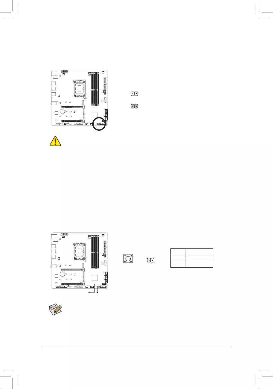
20) CLR_CMOS (Clear CMOS Jumper)
Use this jumper to clear the BIOS conguration and reset the CMOS values to factory defaults. To clear
the CMOS values, use a metal object like a screwdriver to touch the two pins for a few seconds.
•Always turn off your computer and unplug the power cord from the power outlet before clearing
the CMOS values.
•After system restart, go to BIOS Setup to load factory defaults (select Load Optimized Defaults) or
manually congure the BIOS settings (please navigate to the «BIOS Setup» page of GIGABYTE’s
website for more information).
Open: Normal
Short: Clear CMOS Values
RST_SW
RST
1
RSTRST_SW
— 31 —
22) QFLASH_PLUS (Q-Flash Plus Button)
Q-Flash Plus allows you to update the BIOS when your system is off (S5 shutdown state). Save the latest
BIOS on a USB thumb drive and plug it into the dedicated port, and then you can now ash the BIOS
automatically by simply pressing the Q-Flash Plus button. The QFLED will ash when the BIOS matching
and ashing activities start and will stop ashing when the main BIOS ashing is complete.
To enable the Q-Flash Plus function, please navigate to the «Unique Features» page of GIGABYTE’s
website for more information.
QFLASH_PLUS
QFLED
— 32 —
BIOS (Basic Input and Output System) records hardware parameters of the system in the CMOS on the
motherboard. Its major functions include conducting the Power-On Self-Test (POST) during system startup,
saving system parameters and loading operating system, etc. BIOS includes a BIOS Setup program that allows
the user to modify basic system conguration settings or to activate certain system features.
When the power is turned off, the battery on the motherboard supplies the necessary power to the CMOS to
keep the conguration values in the CMOS.
To access the BIOS Setup program, press the <Delete> key during the POST when the power is turned on.
To upgrade the BIOS, use either the GIGABYTE Q-Flash or @BIOS utility.
•Q-Flash allows the user to quickly and easily upgrade or back up BIOS without entering the operating system.
•@BIOS is a Windows-based utility that searches and downloads the latest version of BIOS from the Internet
and updates the BIOS.
For instructions on using the Q-Flash and @BIOS utilities, please navigate to the «Unique Features» page of
GIGABYTE’s website and search for «BIOS Update Utilities.»
Chapter 3 BIOS Setup
•Because BIOS ashing is potentially risky, if you do not encounter problems using the current
version of BIOS, it is recommended that you not ash the BIOS. To ash the BIOS, do it with
caution. Inadequate BIOS ashing may result in system malfunction.
•It is recommended that you not alter the default settings (unless you need to) to prevent system
instability or other unexpected results. Inadequately altering the settings may result in system’s
failure to boot. If this occurs, try to clear the CMOS values and reset the board to default values.
•Refer to the introductions of the battery/clear CMOS jumper in Chapter 2 or navigate to the «BIOS
Setup» page of GIGABYTE’s website and search for «Load Optimized Defaults» for how to clear
the CMOS values.
Please visit GIGABYTE’s website for details on conguring BIOS Setup.
— 33 —
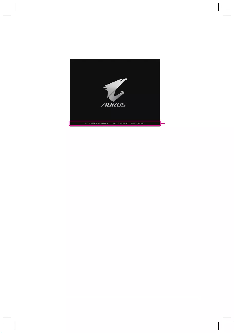
Startup Screen:
Function Keys:
<DEL>: BIOS SETUP\Q-FLASH
Press the <Delete> key to enter BIOS Setup or to access the Q-Flash utility in BIOS Setup.
<F12>: BOOT MENU
Boot Menu allows you to set the rst boot device without entering BIOS Setup. In Boot Menu, use the up
arrow key <h> or the down arrow key <i> to select the rst boot device, then press <Enter> to accept.
The system will boot from the device immediately.
Note: The setting in Boot Menu is effective for one time only. After system restart, the device boot order
will still be based on BIOS Setup settings.
<END>: Q-FLASH
Press the <End> key to access the Q-Flash utility directly without having to enter BIOS Setup rst.
Function Keys
The following startup Logo screen will appear when the computer boots.
— 34 —
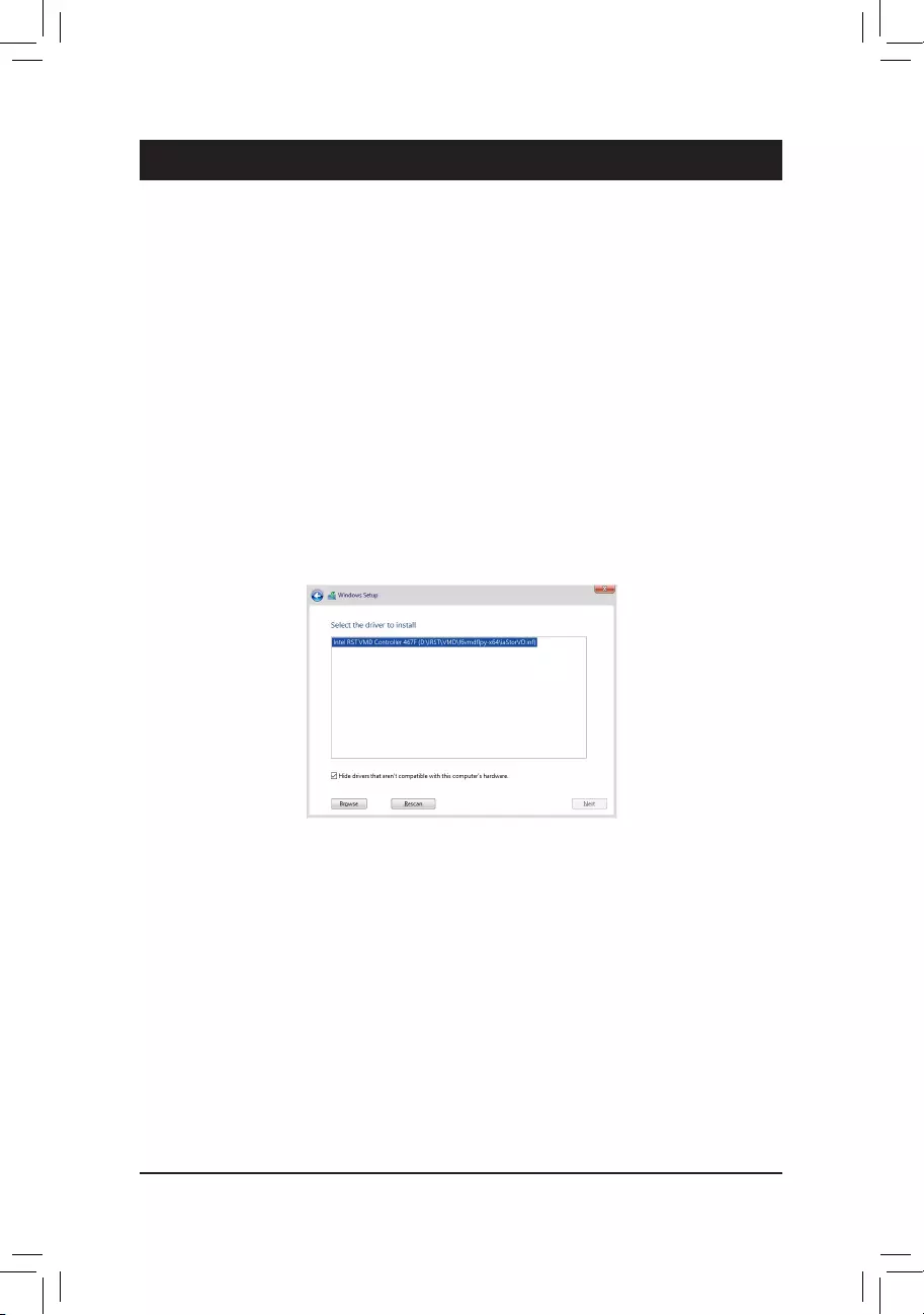
Chapter 4 Installing the Operating System and Drivers
4-1 Operating System Installation
With the correct BIOS settings, you are ready to install the operating system.
If you want to install an operating system on an M.2 PCIe SSD or a RAID volume, you need to install the Intel®
RST VMD Controller driver rst during the OS installation process. Refer to the steps below:
Step 1:
Go to GIGABYTE’s website, browse to the motherboard model’s web page, download the Intel SATA Preinstall
driver le on the Support\Download\SATA RAID/AHCI page, unzip the le and copy the les to your USB
thumb drive.
Step 2:
Boot from the Windows setup disc and perform standard OS installation steps. When the screen requesting you
to load the driver appears, select Browse.
Step 3:
Insert the USB thumb drive and then browse to the location of the driver. When a screen as shown below
appears, select Intel RST VMD Controller 467F and click Next to load the driver and continue the OS installation.
— 35 —
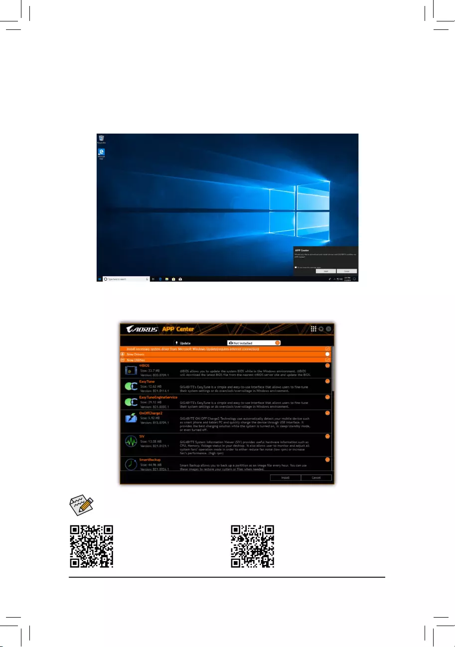
4-2 Drivers Installation
After you install the operating system, a dialog box will appear on the bottom-right corner of the desktop asking
if you want to download and install the drivers and GIGABYTE applications via APP Center. Click Install to
proceed with the installation. (In BIOS Setup, make sure Settings\IO Ports\APP Center Download & Install
Conguration\APP Center Download & Install is set to Enabled.)
Please visit GIGABYTE’s website for
more software information.
Please visit GIGABYTE’s website for
more troubleshooting information.
Before the installation, make sure the system is connected to the Internet.
When the End User License Agreement dialog box appears, press <Accept> to install APP Center. On the APP
Center screen, select the drivers and applications you want to install and click Install.
— 36 —
Chapter 5 Appendix
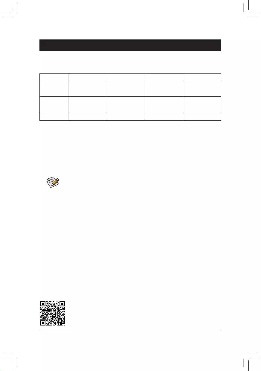
5-1 ConguringaRAIDSet
RAID Levels
Before you begin, please prepare the following items:
This motherboard supports RAID 0, RAID 1, RAID 5, and RAID 10. Prepare the correct number of hard drives
as indicated in the table above before conguring a RAID array.
•SATA hard drives or SSDs. To ensure optimal performance, it is recommended that you use two hard drives
with identical model and capacity.
•Windows setup disc.
•An Internet connected computer.
•A USB thumb drive.
Please visit GIGABYTE’s website for details on conguring a RAID array.
An M.2 PCIe SSD cannot be used to set up a RAID set a SATA hard drive.
RAID 0 RAID 1 RAID 5 RAID 10
Minimum
Number of Hard
Drives
≥2 2≥3 4
Array Capacity
Number of hard
drives * Size of the
smallest drive
Size of the smallest
drive
(Number of hard
drives -1) * Size of
the smallest drive
(Number of hard
drives/2) * Size of the
smallest drive
Fault Tolerance No Yes Yes Yes
— 37 —
Supplier’s Declaration of Conformity
47 CFR § 2.1077 Compliance Information
Product Name: Motherboard
Trade Name: GIGABYTE
Model Number: Z690M A ELITE AX DDR4/Z690M A ELITE DDR4
Responsible Party – U.S. Contact Information: G.B.T. Inc.
Address: 17358 Railroad street, City Of Industry, CA91748
Tel.: 1-626-854-9338
Internet contact information: https://www.gigabyte.com
FCC Compliance Statement:
This device complies with Part 15 of the FCC Rules, Subpart B, Unintentional Radiators.
Operation is subject to the following two conditions: (1) This device may not cause harmful interference, and (2) this
device must accept any interference received, including interference that may cause undesired operation.
Antenna use:
In order to comply with FCC RF exposure limits, low gain integrated
antennas should be located at a minimum distance of 7.9 inches (20 cm)
or more from the body of all persons.
Explosive Device Proximity Warning
Warning: Do not operate a portable transmitter (such as a wireless network
device) near unshielded blasting caps or in an explosive environment
unless the device has been modied to be qualied for such use.
Antenna Warning
The wireless adapter is not designed for use with high-gain antennas.
Use On Aircraft Caution
Caution: Regulations of the FCC and FAA prohibit airborne operation of
radio-frequency wireless devices because their signals could interfere with
critical aircraft instruments.
Other Wireless Devices
Safety Notices for Other Devices in the Wireless Network: Refer to the
documentation supplied with wireless Ethernet adapters or other devices
in the wireless network.
Canada, Canada-Industry Notice:
This device complies with Industry Canada license-exempt RSS
standard(s). Operation is subject to the following two conditions:
(1) this device may not cause interference, and
(2) this device must accept any interference, including interference that
may cause undesired operation of the device.
Cet appareil est conforme aux normes Canada d’Industrie de RSS
permis-exempt. L’utilisation est assujetti aux deux conditions suivantes:
(1) le dispositif ne doit pas produire de brouillage préjudiciable, et
(2) ce dispositif doit accepter tout brouillage reçu, y compris un brouillage
susceptible de provoquer un fonctionnement indésirable.
Caution: When using IEEE 802.11a wireless LAN, this product is restricted
to indoor use due to its operation in the 5.15-to 5.25-GHz frequency
range. Industry Canada requires this product to be used indoors for the
frequency range of 5.15 GHz to 5.25 GHz to reduce the potential for
harmful interference to co-channel mobile satellite systems. High power
radar is allocated as the primary user of the 5.25-to 5.35-GHz and 5.65 to
5.85-GHz bands. These radar stations can cause interference with and/or
damage to this device. The maximum allowed antenna gain for use with
this device is 6dBi in order tocomply with the E.I.R.P limit for the 5.25-to
5.35 and 5.725 to 5.85 GHz frequency range in point-to-point operation. To
comply with RF exposure requirements all antennas should be located at a
minimum distance of 20cm, or the minimum separation distance allowed
by the module approval, from the body of all persons.
Attention: l’utilisation d’un réseau sans l IEEE802.11a est restreinte à
une utilisation en intérieur à cause du fonctionnement dansla bande de
fréquence 5.15-5.25 GHz. Industry Canada requiert que ce produit soit
utilisé à l’intérieur des bâtiments pour la bande de fréquence 5.15-5.25
GHz an de réduire les possibilités d’interférences nuisibles aux canaux
co-existants des systèmes de transmission satellites. Les radars de
puissances ont fait l’objet d’une allocation primaire de fréquences dans
les bandes 5.25-5.35 GHz et 5.65-5.85 GHz. Ces stations radar peuvent
créer des interférences avec ce produit et/ou lui être nuisible. Le gain
d’antenne maximum permissible pour une utilisation avec ce produit est de
6 dBi an d’être conforme aux limites de puissance isotropique rayonnée
équivalente (P.I.R.E.) applicable.
dans les bandes 5.25-5.35 GHz et 5.725-5.85 GHz en fonctionnement
point-à-point. Pour se conformer aux conditions d’exposition de RF toutes
les antennes devraient être localisées à une distance minimum de 20
cm, ou la distance de séparation minimum permise par l’approbation du
module, du corps de toutes les personnes.
Regulatory Notices
United States of America, Federal Communications Commission Statement
The FCC with its action in ET Docket 96-8 has adopted a safety standard for human exposure to radio frequency (RF) electromagnetic energy emitted
by FCC certied equipment. The Intel PRO/Wireless 5000 LAN products meet the Human Exposure limits found in OET Bulletin 65, 2001, and ANSI/
IEEE C95.1, 1992. Proper operation of this radio according to the instructions found in this manual will result in exposure substantially below the FCC’s
recommended limits.
The following safety precautions should be observed:
•Do not touch or move antenna while the unit is transmitting or receiving.
•Do not hold any component containing the radio such that the antenna is very close or touching any exposed parts of the body, especially the face
or eyes, while transmitting.
•Do not operate the radio or attempt to transmit data unless the antenna is connected; if not, the radio may be damaged.
•Use in specic environments:
— The use of wireless devices in hazardous locations is limited by the constraints posed by the safety directors of such environments.
— The use of wireless devices on airplanes is governed by the Federal Aviation Administration (FAA).
— The use of wireless devices in hospitals is restricted to the limits set forth by each hospital.
— 38 —
European Union (EU) CE Declaration of Conformity
This device complies with the following directives: Electromagnetic
Compatibility Directive 2014/30/EU, Low-voltage Directive 2014/35/EU,
Radio Equipment Directive 2014/53/EU, ErP Directive 2009/125/EC, RoHS
directive (recast) 2011/65/EU & the 2015/863 Statement.
This product has been tested and found to comply with all essential
requirements of the Directives.
European Union (EU) RoHS (recast) Directive 2011/65/EU & the
European Commission Delegated Directive (EU) 2015/863 Statement
GIGABYTE products have not intended to add and safe from hazardous
substances (Cd, Pb, Hg, Cr+6, PBDE, PBB, DEHP, BBP, DBP and DIBP).
The parts and components have been carefully selected to meet RoHS
requirement. Moreover, we at GIGABYTE are continuing our efforts to
develop products that do not use internationally banned toxic chemicals.
European Union (EU) Community Waste Electrical & Electronic
Equipment (WEEE) Directive Statement
GIGABYTE will fulll the national laws as interpreted from the 2012/19/
EU WEEE (Waste Electrical and Electronic Equipment) (recast) directive.
The WEEE Directive species the treatment, collection, recycling and
disposal of electric and electronic devices and their components. Under
the Directive, used equipment must be marked, collected separately, and
disposed of properly.
WEEE Symbol Statement
The symbol shown below is on the product or on its
packaging, which indicates that this product must not be
disposed of with other waste. Instead, the device should be
taken to the waste collection centers for activation of the
treatment, collection, recycling and disposal procedure.
For more information about where you can drop off your waste equipment
for recycling, please contact your local government ofce, your household
waste disposal service or where you purchased the product for details of
environmentally safe recycling.
End of Life Directives-Recycling
The symbol shown below is on the product or on its packaging,
which indicates that this product must not be disposed of with
other waste. Instead, the device should be taken to the waste
collection centers for activation of the treatment, collection,
recycling and disposal procedure.
Déclaration de Conformité aux Directives de l’Union européenne (UE)
Cet appareil portant la marque CE est conforme aux directives de l’UE
suivantes: directive Compatibilité Electromagnétique 2014/30/UE, directive
Basse Tension 2014/35/UE, directive équipements radioélectriques
2014/53/UE, la directive RoHS II 2011/65/UE & la déclaration 2015/863.
La conformité à ces directives est évaluée sur la base des normes
européennes harmonisées applicables.
European Union (EU) CE-Konformitätserklärung
Dieses Produkte mit CE-Kennzeichnung erfüllen folgenden EU-Richtlinien:
EMV-Richtlinie 2014/30/EU, Niederspannungsrichtlinie 2014/35/EU,
Funkanlagen Richtlinie 2014/53/EU, RoHS-Richtlinie 2011/65/EU erfüllt
und die 2015/863 Erklärung.
Die Konformität mit diesen Richtlinien wird unter Verwendung der
entsprechenden Standards zurEuropäischen Normierung beurteilt.
CE declaração de conformidade
Este produto com a marcação CE estão em conformidade com das
seguintes Diretivas UE: Diretiva Baixa Tensão 2014/35/EU; Diretiva
CEM 2014/30/EU; Diretiva RSP 2011/65/UE e a declaração 2015/863.
A conformidade com estas diretivas é vericada utilizando as normas
europeias harmonizadas.
CE Declaración de conformidad
Este producto que llevan la marca CE cumplen con las siguientes
Directivas de la Unión Europea: Directiva EMC 2014/30/EU, Directiva de
bajo voltaje 2014/35/EU, Directiva de equipamentos de rádio 2014/53/EU,
Directiva RoHS 2011/65/EU y la Declaración 2015/863.
El cumplimiento de estas directivas se evalúa mediante las normas
europeas armonizadas.
CE Dichiarazione di conformità
I prodotti con il marchio CE sono conformi con una o più delle seguenti
Direttive UE, come applicabile: Direttiva EMC 2014/30/UE, Direttiva sulla
bassa tensione 2014/35/UE, Direttiva di apparecchiature radio 2014/53/
UE, Direttiva RoHS 2011/65/EU e Dichiarazione 2015/863.
La conformità con tali direttive viene valutata utilizzando gli Standard
europei armonizzati applicabili.
DeklaracjazgodnościUEUniiEuropejskiej
Urządzenie jest zgodne z następującymi dyrektywami: Dyrektywa
kompatybilności elektromagnetycznej 2014/30/UE, Dyrektywa
niskonapięciowej 2014/35/UE, Dyrektywa urządzeń radiowych 2014/53/
UE, Dyrektywa RoHS 2011/65/UE i dyrektywa2015/863.
Niniejsze urządzenie zostało poddane testom i stwierdzono jego zgodność
z wymaganiami dyrektywy.
ESProhlášeníoshodě
Toto zařízení splňuje požadavky Směrnice o Elektromagnetické
kompatibilitě 2014/30/EU, Směrnice o Nízkém napětí 2014/35/EU,
Směrnice o rádiových zařízeních 2014/53/EU, Směrnice RoHS 2011/65/
EU a 2015/863.
Tento produkt byl testován a bylo shledáno, že splňuje všechny základní
požadavky směrnic.
EKmegfelelőséginyilatkozata
A termék megfelelnek az alábbi irányelvek és szabványok
követelményeinek, azok a kiállításidőpontjában érvényes, aktuális
változatában: EMC irányelv 2014/30/EU, Kisfeszültségű villamos
berendezésekre vonatkozó irányelv 2014/35/EU, rádióberendezések
irányelv 2014/53/EU, RoHS irányelv 2011/65/EU és 2015/863.
ΔήλωσησυμμόρφωσηςΕΕ
Είναι σε συμμόρφωση με τις διατάξεις των παρακάτω Οδηγιών
της Ευρωπαϊκής Κοινότητας: Οδηγία 2014/30/ΕΕ σχετικά με την
ηλεκτρομαγνητική συμβατότητα, Οοδηγία χαμηλή τάση 2014/35/EU,
Οδηγία 2014/53/ΕΕ σε ραδιοεξοπλισμό, Οδηγία RoHS 2011/65/ΕΕ
και 2015/863.
Η συμμόρφωση με αυτές τις οδηγίες αξιολογείται χρησιμοποιώντας τα
ισχύοντα εναρμονισμένα ευρωπαϊκά πρότυπα.
Under Industry Canada regulations, this radio transmitter may only operate
using an antenna of a type and maximum (or lesser) gain approved for
the transmitter by Industry Canada. To reduce potential radio interference
to other users, the antenna type and its gain should be chosen so that
the equivalent isotropically radiated power (e.i.r.p.) is not more than that
necessary for successful communication.
Conformément à la réglementation d’Industrie Canada, le présent émetteur
radio peut fonctionner avec une antenne d’un type et d’un gain maximal
(ou inférieur) approuvé pour l’émetteur par Industrie Canada. Dans le
but de réduire les risques de brouillage radio électrique à l’intention des
autres utilisateurs, il faut choisir le type d’antenne et son gain de sorte
que la puissance isotrope rayonnée équivalente (p.i.r.e.) ne dépasse pas
l’intensité nécessaire à l’établissement d’une communication satisfaisante.
— 39 —
European Community Radio Equipment Directive Compliance Statement:
This equipment complies with all the requirements and other relevant provisions of Radio Equipment Directive 2014/53/EU.
This equipment is suitable for home and ofce use in all the European Community Member States and EFTA Member States.
The low band 5.15 -5.35 GHz is for indoor use only.
AT BE BG CH CY CZ DE
DK EE EL ES FI FR HR
HU IE IS IT LI LT LU
LV MT NL PL PT RO SE
SI SK TR UK
Wireless module manufacturer: Intel® Corporation SAS
Wireless module model name: AX201NGW
Taiwan NCC Wireless Statements / 無線設備警告聲明:
低功率電波輻射性電機管理辦法
(1) 取得審驗證明之低功率射頻器材,非經核准,公司、商號或使用者均不得擅自變更頻率、加大功率或變更原設計之特
性及功能。低功率射頻器材之使用不得影響飛航安全及干擾合法通信;經發現有干擾現象時,應立即停用,並改善至
無干擾時方得繼續使用。前述合法通信,指依電信管理法規定作業之無線電通信。低功率射頻器材須忍受合法通信或
工業、科學及醫療用電波輻射性電機設備之干擾。
(2) 應避免影響附近雷達系統之操作。
Korea KCC NCC Wireless Statement:
5,25GHz — 5,35 GHz 대역을 사용하는 무선 장치는 실내에서만 사용하도록 제한됩니다.
Japan Wireless Statement:
5.15 GHz 帯 ~ 5.35 GHz 帯: 屋内のみの使用。
Wireless module country approvals:
Wireless module manufacturer: Intel® Corporation
Wireless module model name: AX201NGW
— 40 —
Contact Us
GIGA-BYTE TECHNOLOGY CO., LTD.
Address: No.6, Baoqiang Rd., Xindian Dist., New Taipei City 231, Taiwan
TEL: +886-2-8912-4000, FAX: +886-2-8912-4005
Tech. and Non-Tech. Support (Sales/Marketing) : https://esupport.gigabyte.com
WEB address (English): https://www.gigabyte.com
WEB address (Chinese): https://www.gigabyte.com/tw
•GIGABYTE eSupport
To submit a technical or non-technical (Sales/Marketing) question, please link to:
https://esupport.gigabyte.com
Downloads
-
-
Audio
Realtek HD Audio Driver
OS:
Windows 11 64bit,Windows 10 64bit[6.0.9313.1]
19.74 MB
Sep 07, 2023

-
Chipset
Intel® GNA Scoring Accelerator
OS:
Windows 11 64bit,Windows 10 64bit[03.00.00.1457]
1.36 MB
Nov 17, 2023
Intel® Dynamic Tuning Technology (APO) Driver
OS:
Windows 11 64bit,Windows 10 64bit[9.0.11401.39039]
7.21 MB
Nov 17, 2023
Intel Serial I/O driver
OS:
Windows 11 64bit,Windows 10 64bit[30.100.2237.26]
2.38 MB
Sep 07, 2023
Intel HID Event Filter
OS:
Windows 11 64bit,Windows 10 64bit[2.2.2.5]
0.80 MB
Sep 07, 2023
Intel Management Engine Firmware
OS:
Windows 11 64bit,Windows 10 64bit[2331.5.20.0]
197.10 MB
Sep 07, 2023
Intel Chipset Device Software
OS:
Windows 11 64bit,Windows 10 64bit[10.1.19502.8391]
3.26 MB
Sep 07, 2023
-
LAN
[1.1.4.42]
0.34 MB
Sep 07, 2023
[2.1.3.3]
0.41 MB
Mar 03, 2023
Intel i225 LAN Preinstall driver
[B23.02.23.01]
0.31 MB
Feb 27, 2023
-
SATA RAID/AHCI
Intel SATA Preinstall driver
(For AHCI / RAID Mode)
(Note) Windows setup to read from USB thumb drive.OS:
Windows 11 64bit,Windows 10 64bit[19.5.7.1058]
1.59 MB
Sep 07, 2023
Intel Rapid Storage Technology
OS:
Windows 11 64bit,Windows 10 64bit[19.5.7.1058]
2.95 MB
Sep 07, 2023
-
VGA
Intel Graphic Driver
OS:
Windows 11 64bit,Windows 10 64bit[31.0.101.4575]
537.22 MB
Sep 07, 2023
-
Audio
-
BIOS(+3)
-
F4d
9.00 MB
Nov 09, 2023
- Checksum : 1086
- Add «GNA (Gaussian & Neural Accelerator)» Option
- Add «SPD Write Disable» Option
F3
8.99 MB
Sep 19, 2023
- Checksum : 6199
- Follow Intel to upgrade Microcode CPUID ver. 0x11D
F2
9.00 MB
Aug 28, 2023
- Checksum : AB00
- First Launch Release
-
-
-
GIGABYTE Control Center Full Installation Package
Release Note:- Bug Fix : Fix AORUS M.2 detect fail issue on intel platform
- Bug Fix : Fix Gigabyte M.2 RGB control fail issue
- Bug Fix : Fix RGB FUSION issues on laptop products
- Support : Improve the mutex process
- Support : Modify the MEM UI of RGB FUSION function
OS:
Windows 11 64bit,Windows 10 64bit23.10.23.01
708.14 MB
Nov 01, 2023
GIGABYTE Control Center Full Installation Package
Release Note:- Bug Fix : Fix M27Q P firmware Gamma default issue
- Bug Fix : Fix Monitor G27F 2_1 issue
- Support : Modify live update process to enhance user experience
OS:
Windows 11 64bit,Windows 10 64bit23.09.28.01
707.05 MB
Oct 03, 2023
-

- Support List
-
Support List(+2)
-
SSD Support List
0.22 MB
Aug 31, 2023
M.2 Support List
0.26 MB
Aug 31, 2023
-
- Manual
-
Manual(+20)-
Simplified Chinese
1201
16.75 MB
Nov 22, 2023
Korean
1201
16.46 MB
Nov 09, 2023
Japanese
1201
16.49 MB
Nov 09, 2023
English
1201
16.34 MB
Nov 09, 2023
Traditional Chinese
1201
16.98 MB
Nov 09, 2023
Traditional Chinese
2.39 MB
Oct 19, 2023
Unique Features Introduction
English
2.11 MB
Oct 19, 2023
Unique Features Introduction
Japanese
2.19 MB
Oct 19, 2023
Unique Features Introduction
Korean
2.20 MB
Oct 19, 2023
Unique Features Introduction
Simplified Chinese
2.21 MB
Oct 19, 2023
Unique Features Introduction
Traditional Chinese
3.15 MB
Oct 19, 2023
BIOS Setup Guide
English
2.71 MB
Oct 19, 2023
BIOS Setup Guide
Japanese
2.83 MB
Oct 19, 2023
BIOS Setup Guide
Korean
2.86 MB
Oct 19, 2023
BIOS Setup Guide
Simplified Chinese
2.94 MB
Oct 19, 2023
BIOS Setup Guide
Traditional Chinese
1.83 MB
Oct 19, 2023
RAID Setup Guide
English
1.63 MB
Oct 19, 2023
RAID Setup Guide
Japanese
1.69 MB
Oct 19, 2023
RAID Setup Guide
Korean
1.69 MB
Oct 19, 2023
RAID Setup Guide
Simplified Chinese
1.72 MB
Oct 19, 2023
RAID Setup Guide
-
CPU Support
Memory Support List
Обзор и тестирование материнской платы Z790 AORUS Elite AX
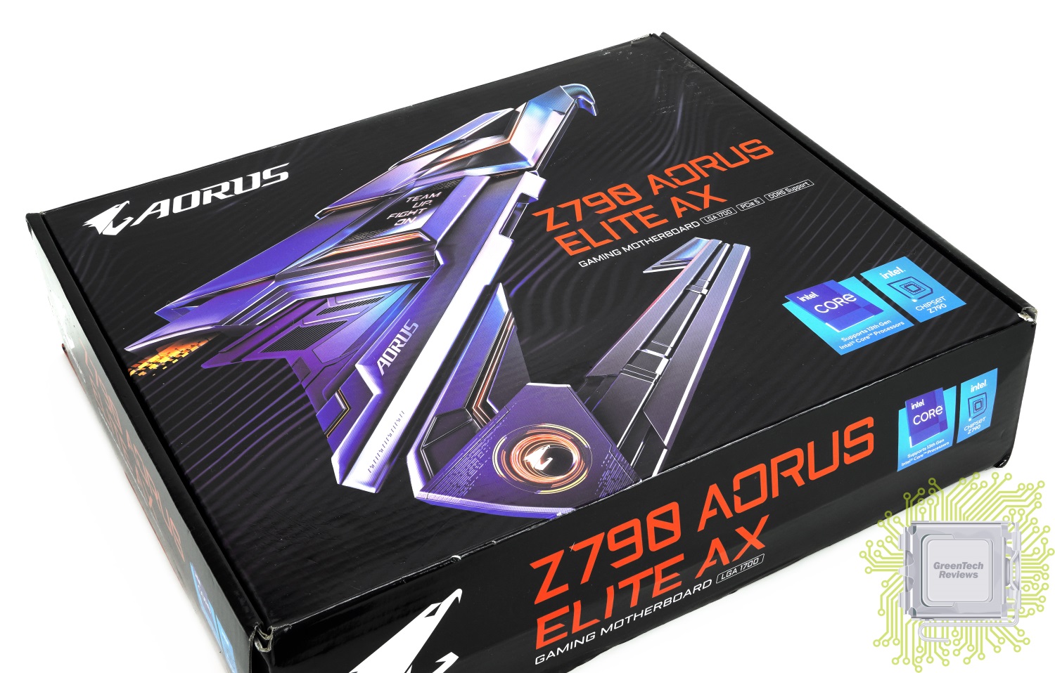
Процессоры Intel Core 13-го поколения не сильно отличаются в плане возможностей расширения от 12-го поколения, но вот требования к питанию у них куда выше. К этому стоит добавить ещё и поддержку намного более скоростной памяти DDR5, что требует от производителей материнских плат учесть и этот момент. Новые процессоры можно использовать и в платах с чипсетом Z690, но тогда вы будете ограничены не только в частоте оперативной памяти, но и, возможно, в разгоне — подсистемы питания были проще, как и их системы охлаждения. Именно поэтому рекомендуется при сборке новой системы в первую очередь обратить внимание на новые материнские платы. Начнём мы с одной из недорогих — Z790 AORUS Elite AX.
Стоимость Z790 AORUS Elite AX в московской рознице на момент публикации материала составляет около 24000 рублей.
Содержание:
1. Обзор платы, техническая часть
2. Обзор UEFI BIOS и программного обеспечения
3. Тестирование, тепловизор, заключение
Z790 AORUS Elite AX поставляется в коробке среднего размера с обновлённым дизайном — на фронтальной стороне размещены логотипы бренда и используемых технологий, а также указано название платы.
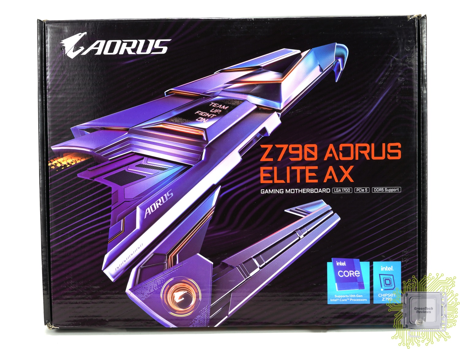
На обратной стороне коробки интересного гораздо больше. Здесь производитель разместил изображения платы рассказывает о некоторых ключевых особенностях этой модели, в число которых вошли:
— продвинутая цифровая подсистема питания по схеме 16+1+2 с использованием 90A сборок DrMOS;
— полная поддержка PCIe 5.0 и DDR5 (XMP 3.0)
— высокоэффективная система охлаждения подсистемы питания процессора и M.2 SSD-накопителей;
— наличие модуля Wi-Fi 6E.
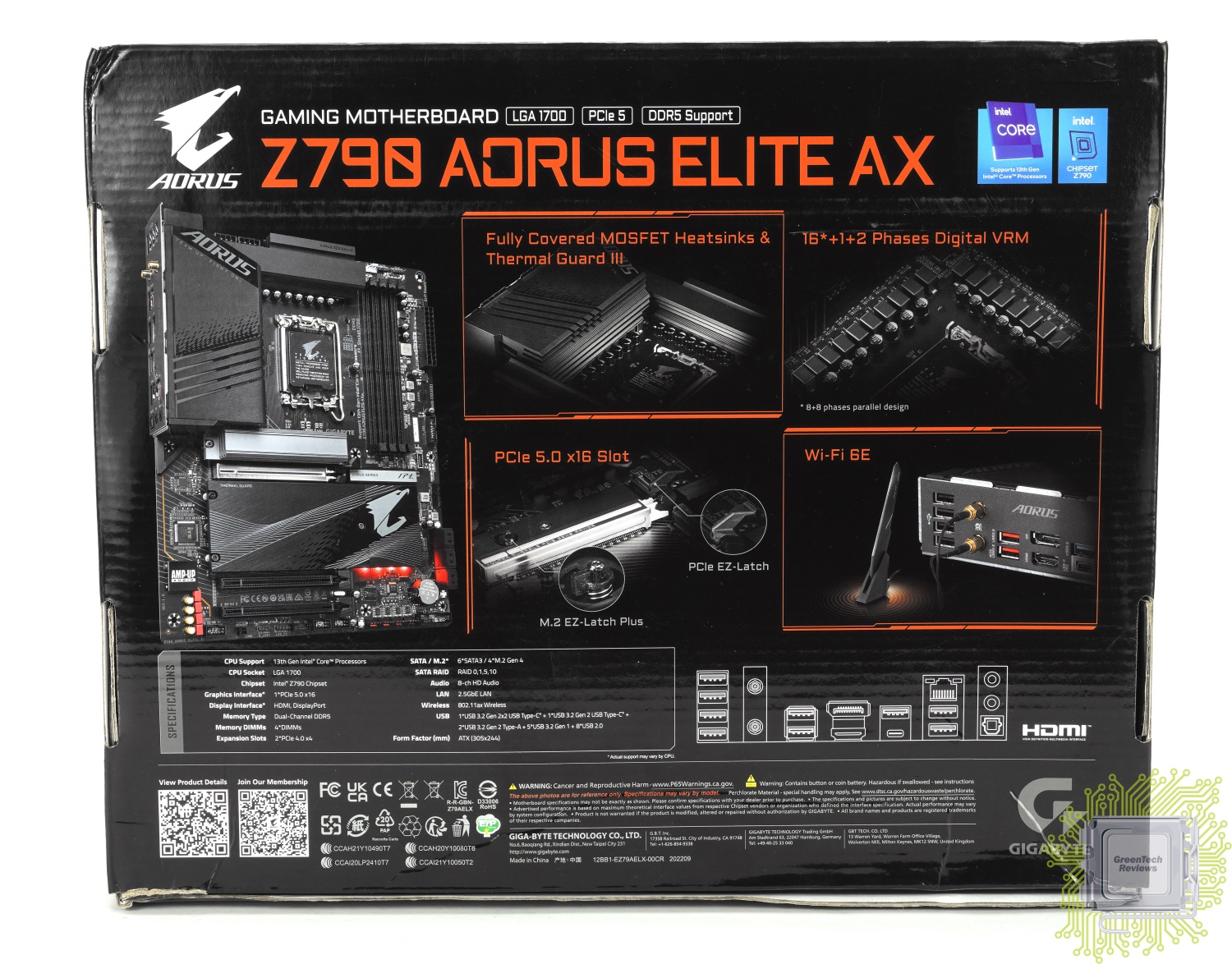
Комплект поставки минимальный настолько, что ранее такого даже и не встречалось за последние годы:
— два SATA кабеля;
— внешняя антенна Wi-Fi модуля;
— переходник для подключения проводов передней панели корпуса.
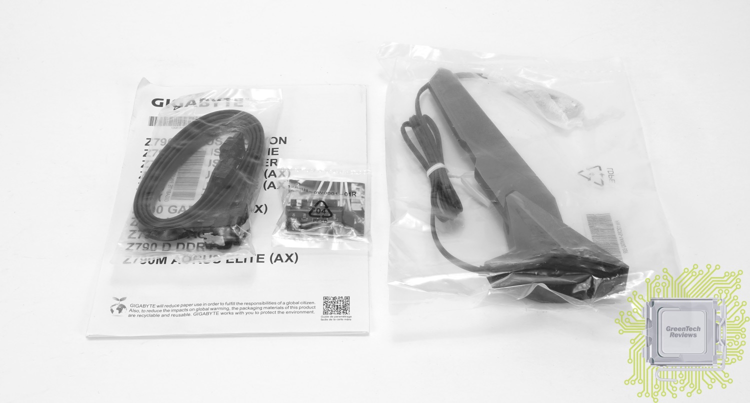
Материнская плата изготовлена на основе 6-слойной печатной платы чёрного цвета в стандартном формате ATX. В оформлении преимущественно используются элементы чёрного и серого цветов, разве что есть хромированный элемент в виде корпуса основного PCIe слота и цветные электронные элементы. В плане дизайна отличий от предшественницы много, а вот основные разъёмы остались на тех же местах.

Основные ключевые особенности производитель выделил на двух официальных слайдах:
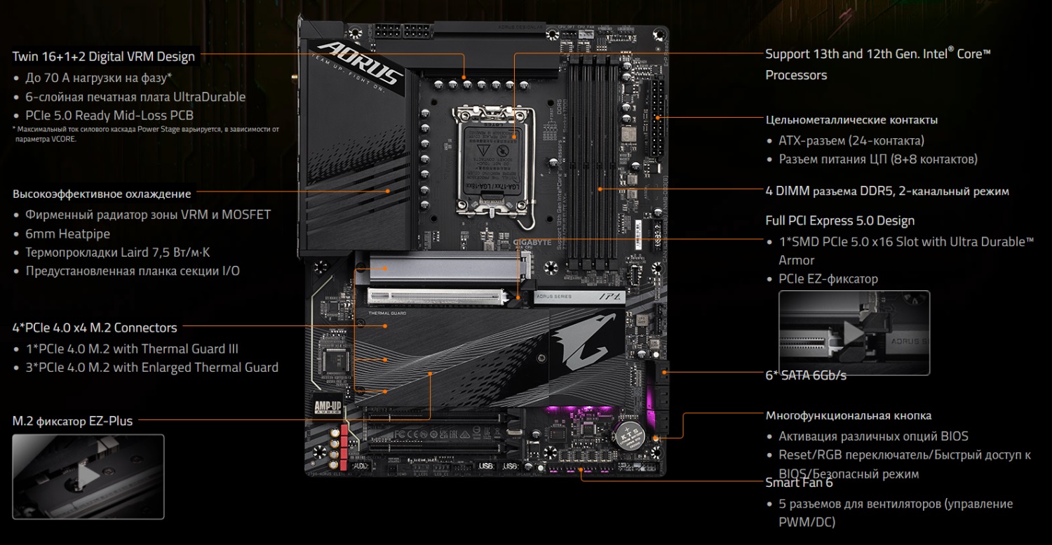
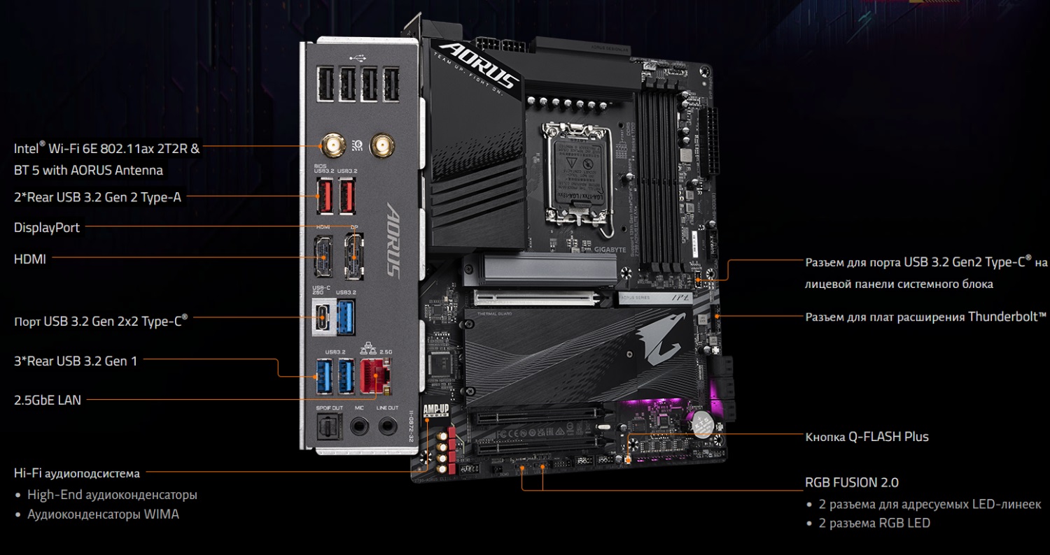
Блок-схема, взятая из руководства пользователя, актуальна для четырёх моделей Elite одновременно:
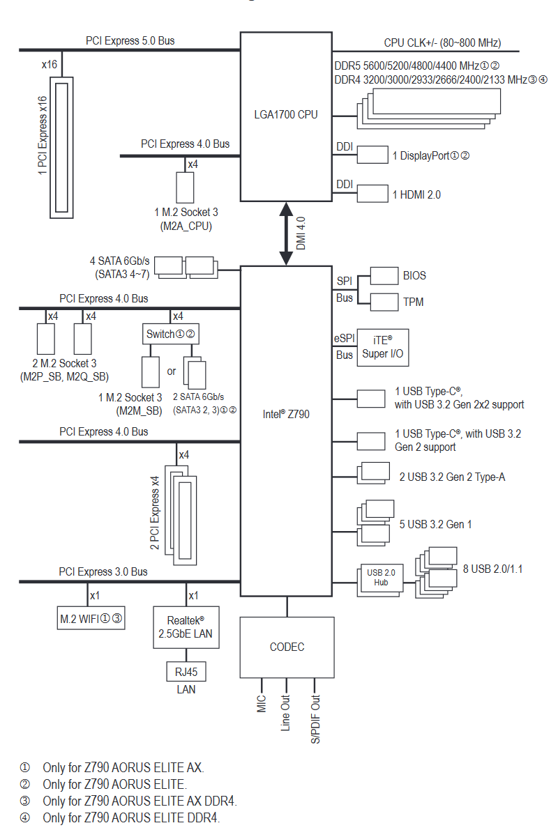
Плата с обратной стороны. Ничего примечательного для нас нет, разве что — разводка PCIe слотов. Основной PCIe x16 (Gen5) слот устанавливается методом поверхностного монтажа, как и на других платах для процессоров 12-го и 13-го поколений.
На панели ввода/вывода нам доступны:
— четыре USB 2.0 порта;
— коннекторы для подключения внешней антенны Wi-Fi;
— два порта USB 3.2 Gen2 порта (10 Гбит/с);
— DisplayPort видео выход;
— HDMI видео выход;
— три порта USB 3.2 Gen1 порта (5 Гбит/с);
— порт Type-C Gen2x2 (20 Гбит/с);
— сетевой порт RJ-45 (2.5 Гбит/с);
— два аудио разъёма 3.5 мм;
— оптический выход S/PDIF.
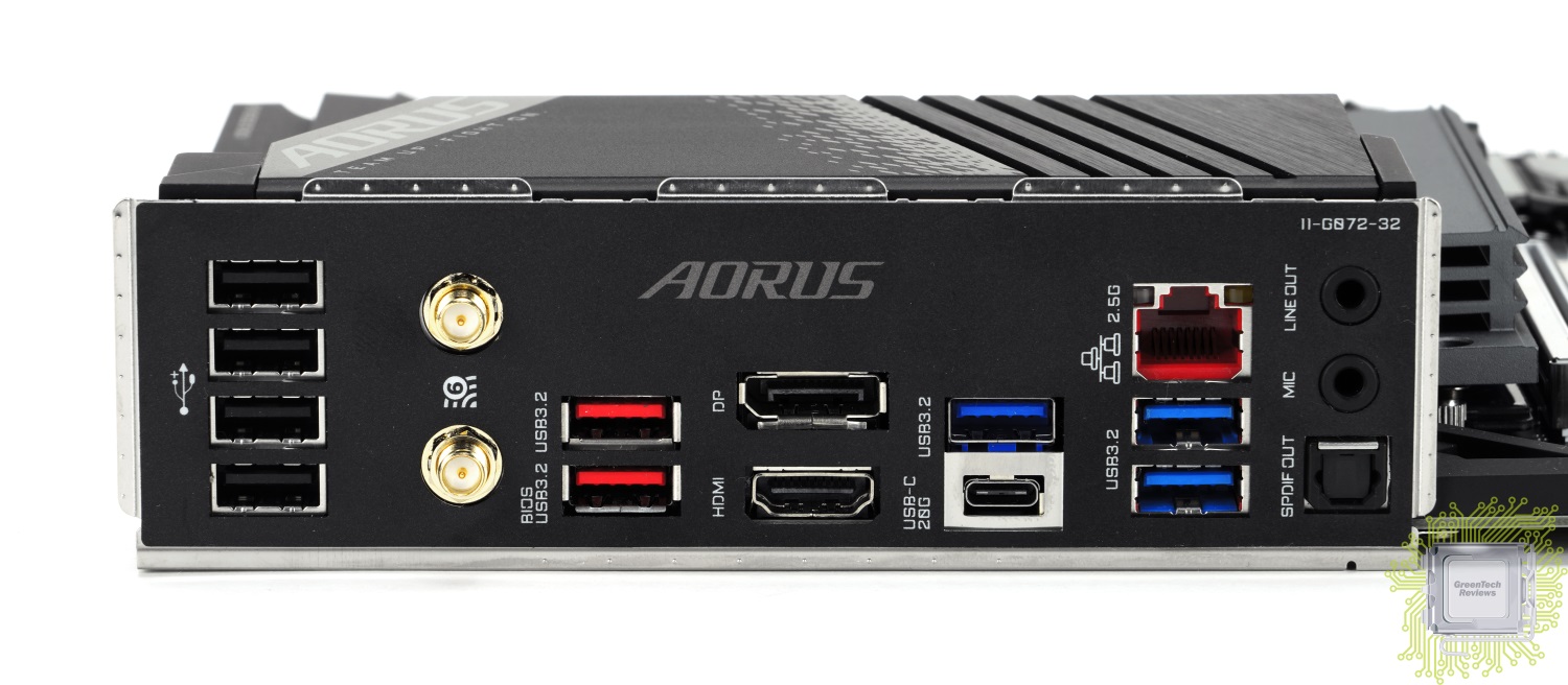
Для установки видеокарт и иных плат расширения нам доступны:
— один x16 слот (стандарт 5.0 — от процессора);
— два x4 слота (физически х16, один стандарта 4.0 и один 3.0 — от чипсета).
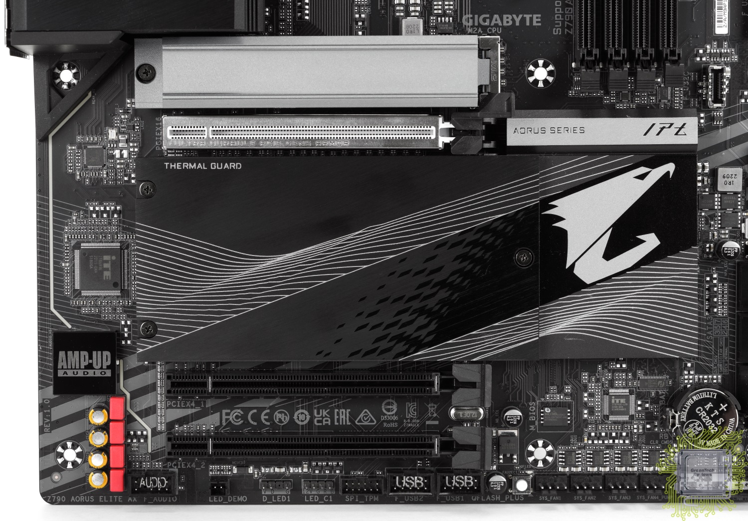
В отличие от старших моделей, где реализована кнопка разблокировки основного PCIe слота, у младших моделей используется просто удлинённая защёлка. Но и за это спасибо — с учётом массивного радиатора основного M.2 SSD-накопителя и видеокарт с бэкплейтами, это очень помогает.
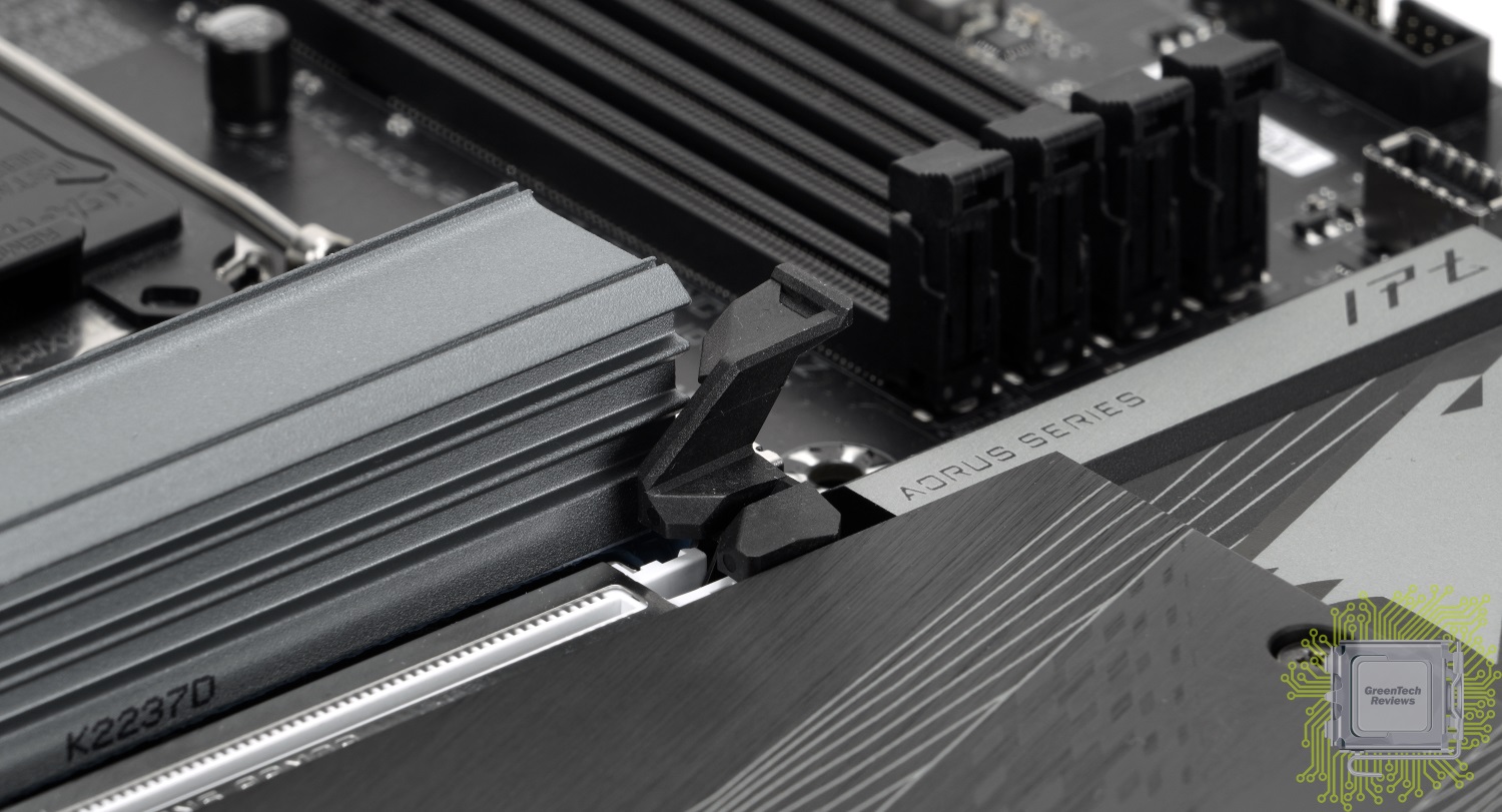
Звуковая подсистема построена на базе аудио кодека Realtek ALC897 и дополнена набором профессиональных конденсаторов WIMA.
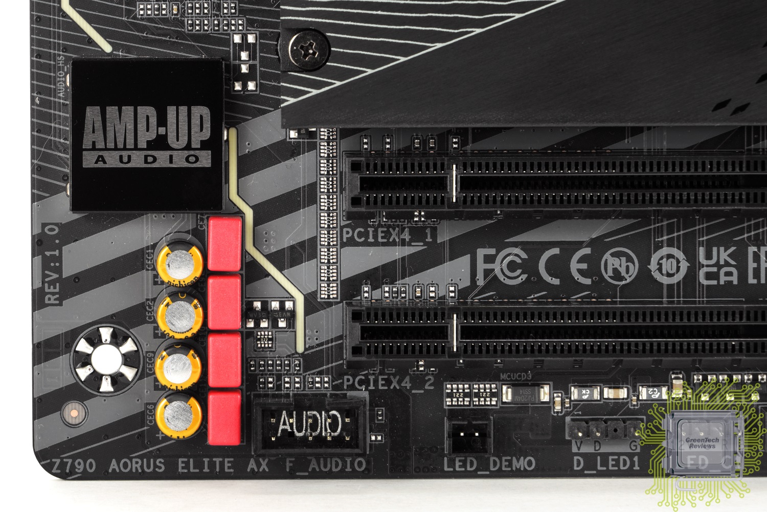
В этом же углу можно найти два из четырёх коннекторов для подключения RGB устройств разных типов.
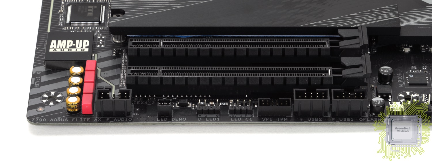
В правом нижнем углу платы размещена колодка для подключения проводов передней панели корпуса, четыре 4-контактных коннектора для вентиляторов и кнопка для прошивки BIOS (Q-Flash Plus).

Возле SATA портов размещены две колодки для подключения дополнительных плат Thunderbolt. Правее — разъём для подключения USB 3.2 Gen2x2 Type-C (20 Гбит/с) порта и разъём для подключения USB 3.0 портов.
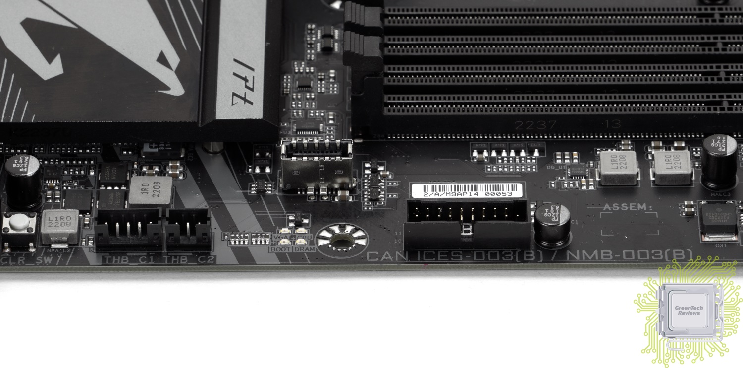
Верхний правый угол платы характерен наличием двух 4-контактных коннекторов вентиляторов и ещё двух коннекторов для RGB устройств.
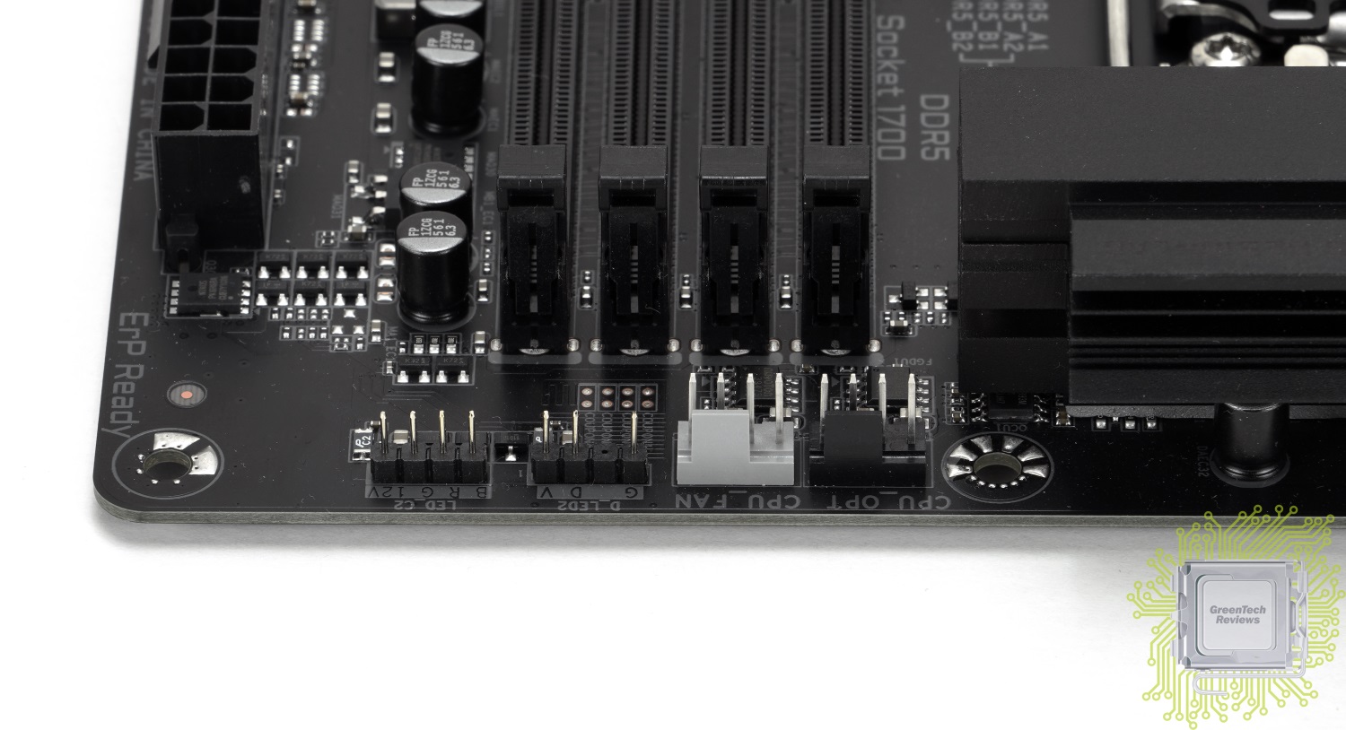
Для питания процессора реализовано два 8-контактных разъёма.
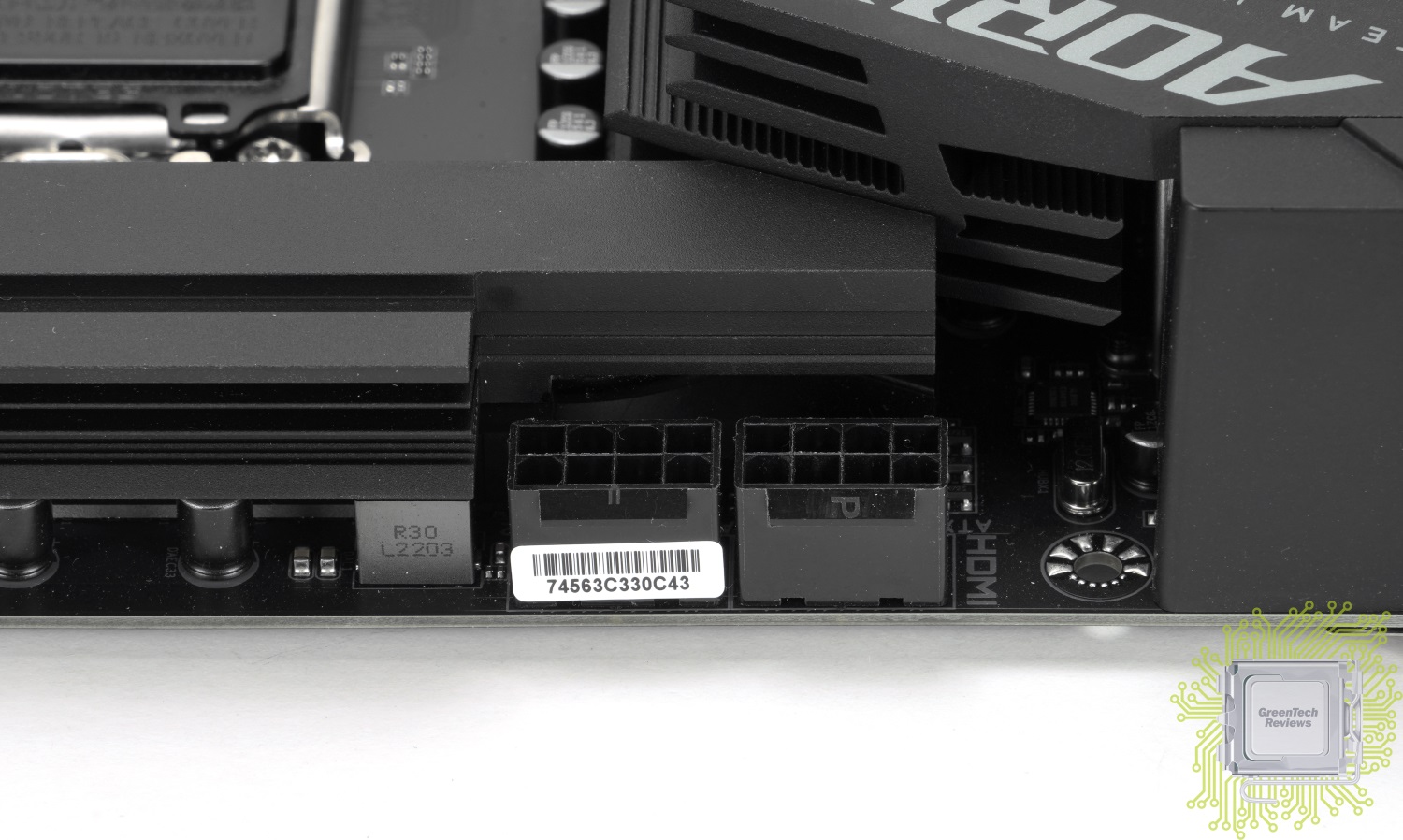
Для подключения SATA устройств доступно шесть портов. Слева от них размещена кнопка перезагрузки системы, а справа — сброса настроек.
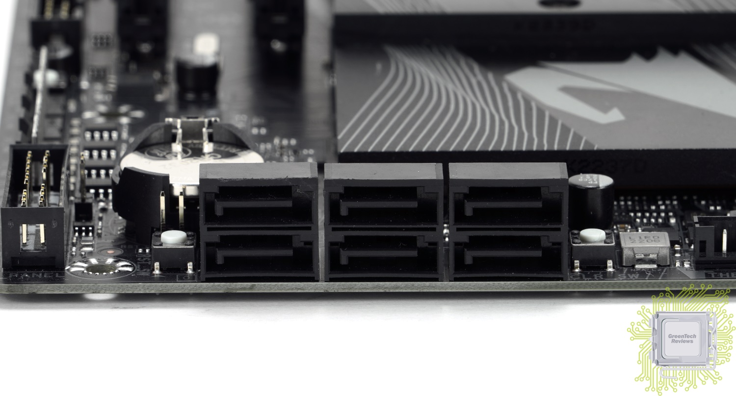
Разъёмы для M.2 накопителей скрыты радиаторами.
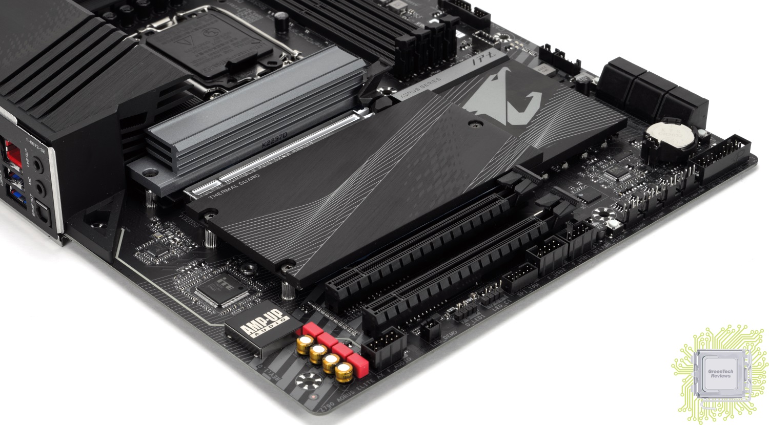
Радиатор основного SSD-накопителя достаточно массивный и обладает глубоким оребрением.
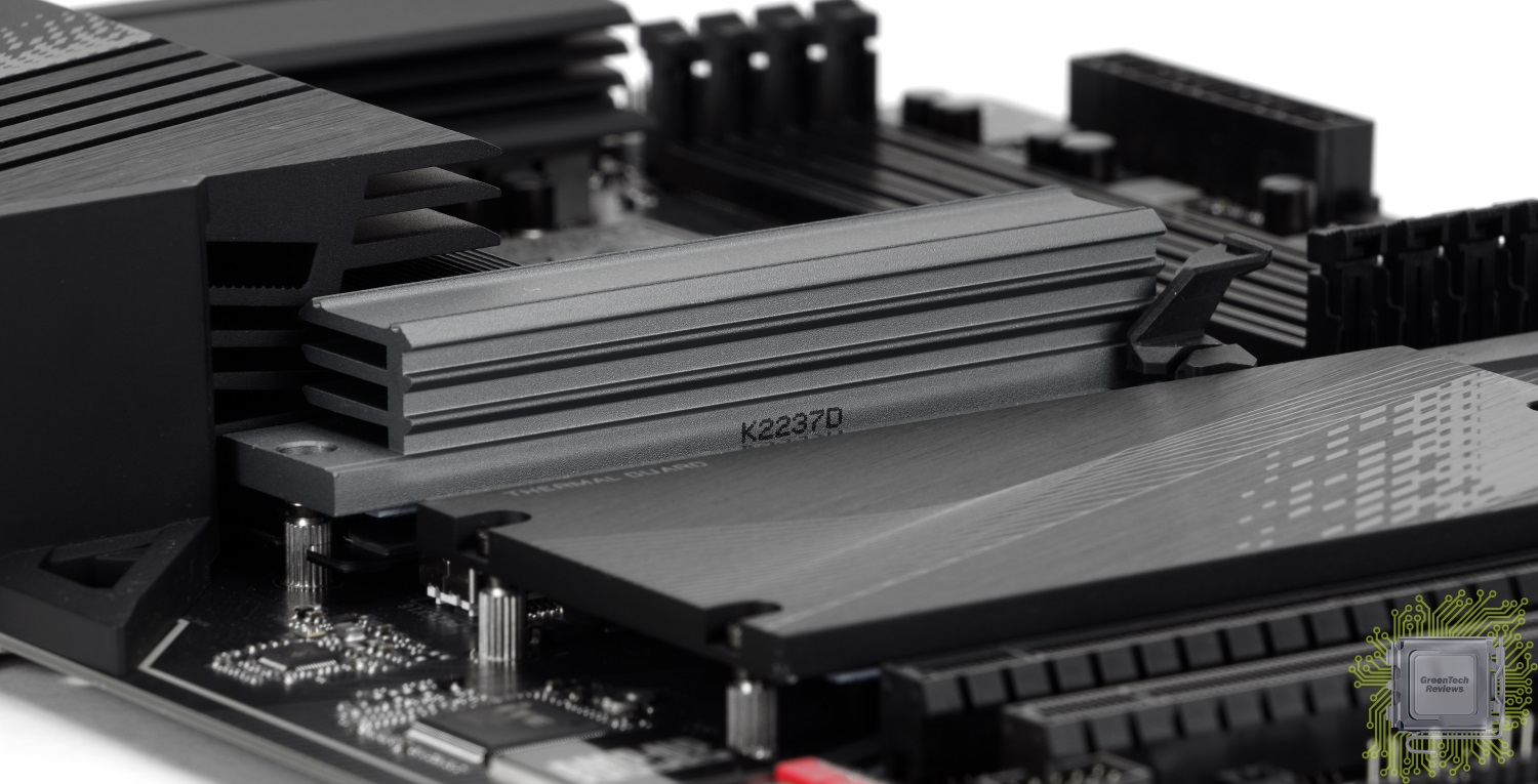
Под ним скрывается разъём M2A_CPU. Он поддерживает накопители 22110/2280 стандарта PCIe 4.0 x2/x4. Реализован он силами процессора.

Также нам доступны ещё три M.2 разъёма, которые реализованы силами чипсета:
— M2P_SB поддерживает накопители формата 2280/22110 с интерфейсом PCIe 4.0 (x2/x4);
— M2Q_SB поддерживает накопители формата 2280/22110 с интерфейсом PCIe 4.0 (x2/x4);
— M2M_SB поддерживают накопители формата 2260/2280/22110 с интерфейсом SATA или PCIe 4.0 (x2/x4).
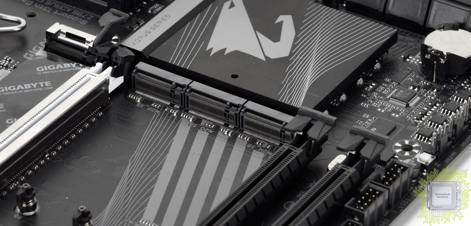
С самими накопителями радиаторы соприкасаются при помощи термопрокладок. Отдельный радиатор — для одного накопителя, а второй — сразу для трёх.
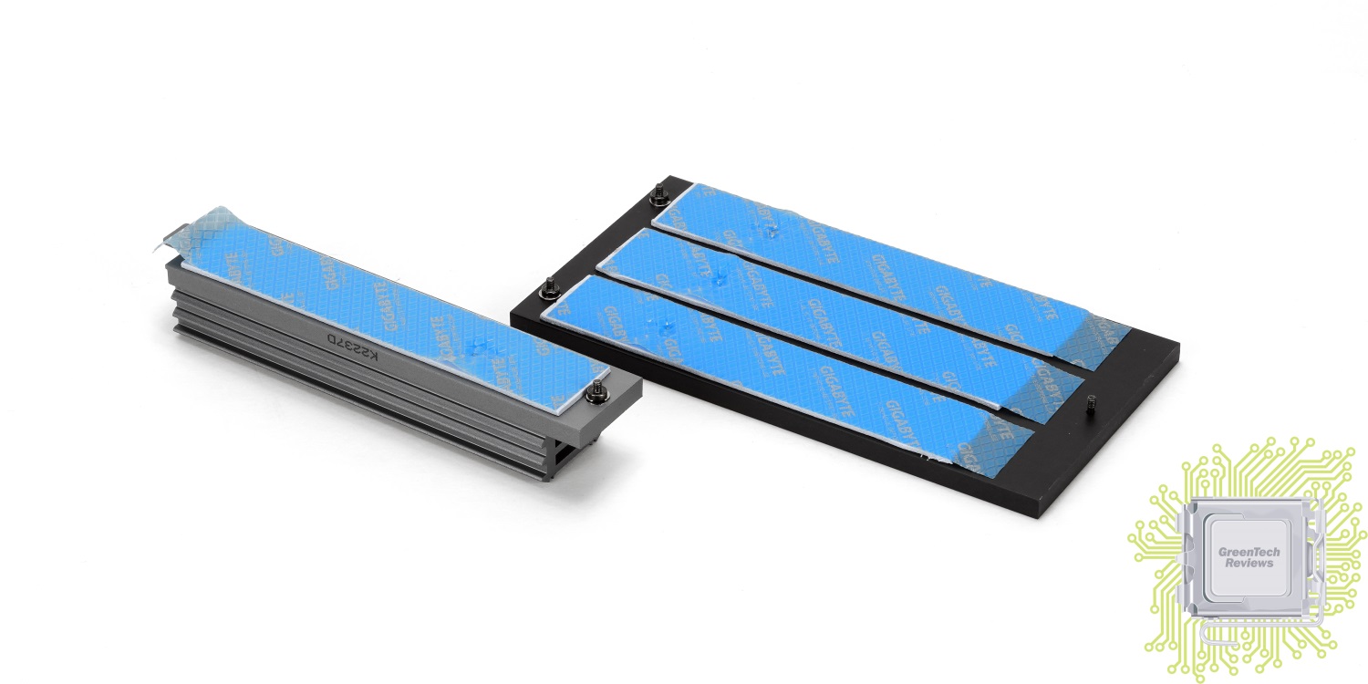
Форма радиаторов подсистемы питания процессора претерпела некоторые изменения — сами по себе их габариты остались прежними, но оребрение изменилось — теперь площадь поверхности для рассеивания тепла стала гораздо больше.
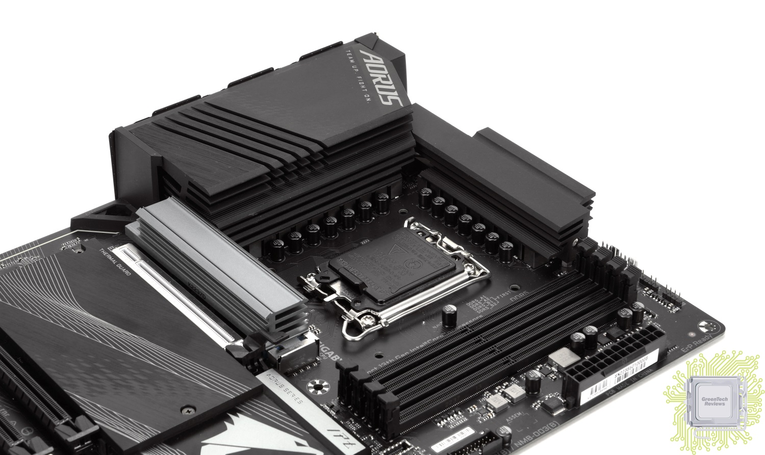
У предшествующей модели нижняя правая часть была сплошной.
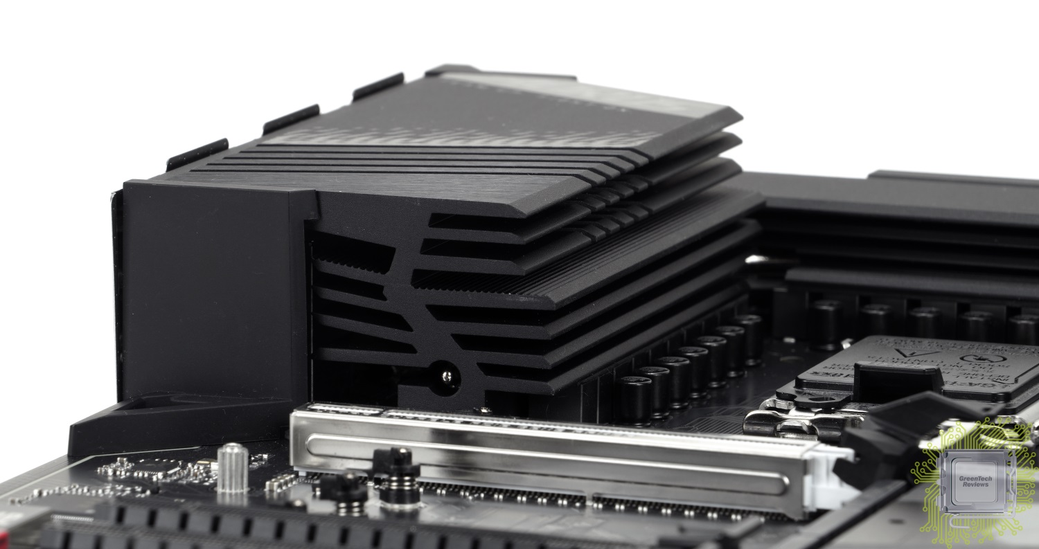
Для отвода тепла используется пара термопрокладок для каждого радиатора. Секции радиатора объединены одной тепловой трубкой.
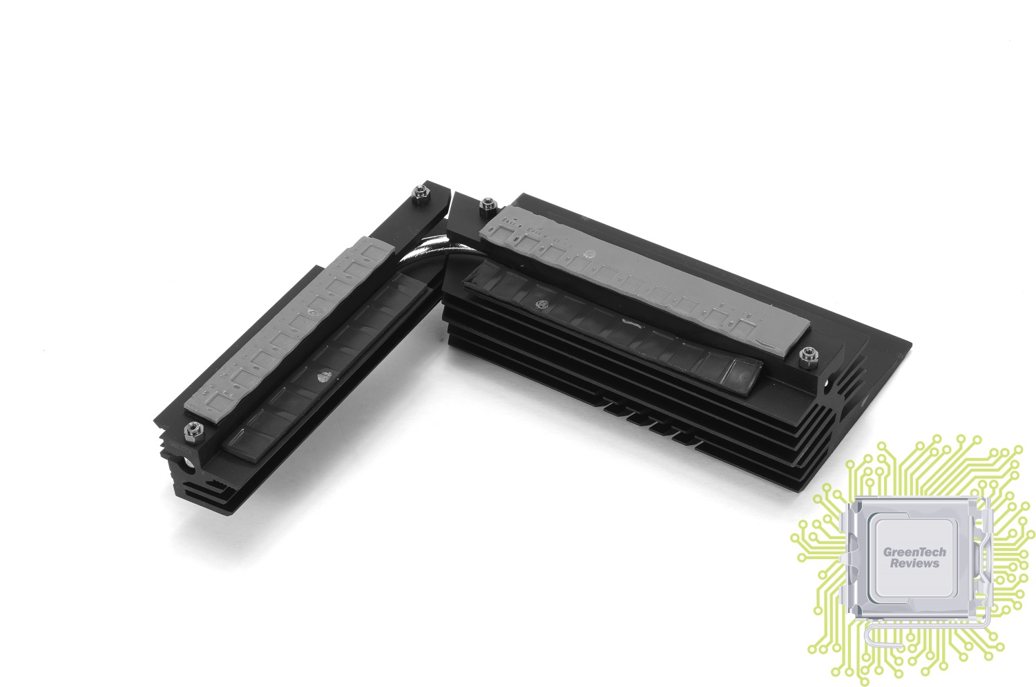
Подсистема питания процессорных ядер реализовано 16 фаз (FDMF5062 — 70 А), ещё 1 — для графического ядра (NCP302155 — 55 А). Работает всё это добро под управлением контроллера NCP81530R . Две дополнительные фазы (контроллеры PCIe и оперативной памяти) характерны иной компоновкой — каждая укомплектована мосфетом NCP303160 (60 A), а работают они под управлением контроллера M2940A.

Читать далее: обзор UEFI BIOS и программного обеспечения
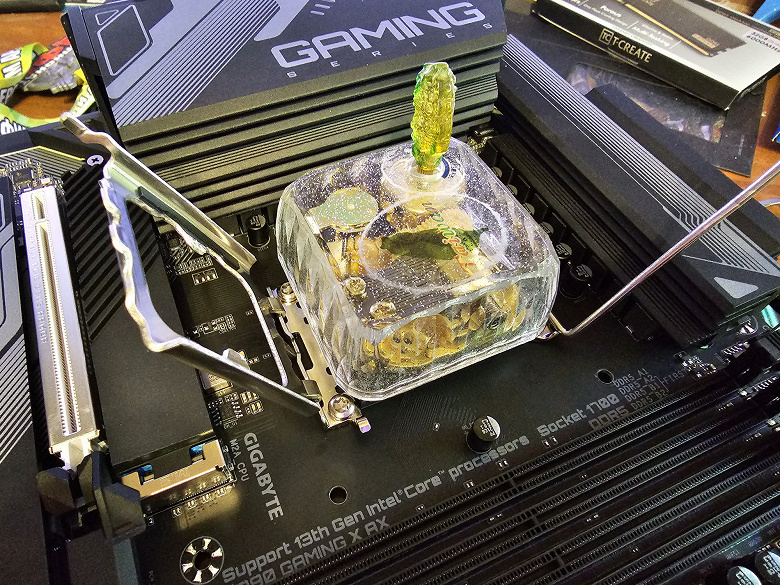
Всю детальную информацию о новом семействе процессоров 13-го поколения от Intel (на примере i9-13900K) можно найти в материале от Алексея Берилло.
А мы продолжаем знакомиться с материнскими платами последних поколений, в частности, сейчас мы изучим очередной продукт на базе Intel Z790. Он интересен прежде всего тем, что, несмотря на базирование на топовом чипсете Z790, относится к среднебюджетному ценовому сегменту.
Напомним различия между системными чипсетами последних 4х поколений.
| Особенности | Z790 | Z690 | Z590 | Z490 |
|---|---|---|---|---|
| Совместимость с процессорами Intel | 13th/12th Gen Core | 13th/12th Gen Core | 10th & 11th Gen Core | 10th & 11th Gen Core |
| Версия PCIe (процессор) | 4.0 & 5.0 | 4.0 & 5.0 | 3.0 (10th Gen) or 4.0 (11th Gen) | 3.0 (10th Gen) or 4.0 (11th Gen) |
| Количество линий PCIe (процессор) | 20 | 20 | 16 (10th Gen) or 20 (11th Gen) | 16 |
| Версия PCIe (чипсет) | 3.0 & 4.0 | 3.0 & 4.0 | 3.0 | 3.0 |
| Количество линий PCIe (чипсет) | 28 (20 x 4.0 & 8 x 3.0) | 28 (12 x 4.0 & 16 x 3.0) | 24 | 24 |
| Версия DMI | 4.0 | 4.0 | 3.0 | 3.0 |
| Количество линий DMI | x8 | x8 | x8 | x4 |
| Поколение ОЗУ | DDR4 & DDR5 | DDR4 & DDR5 | DDR4 | DDR4 |
| Количество каналов ОЗУ | 2 | 2 | 2 | 2 |
| Максимальное количество слотов ОЗУ | 4 | 4 | 4 | 4 |
| Максимальный объем ОЗУ | 128 ГБ | 128 ГБ | 128 ГБ | 128 ГБ |
| Количество портов SATA 6.0 Gb/s до | 8 | 8 | 6 | 6 |
| Порты USB 3.2 Gen 2×2 (20Gbps) до | 5 | 4 | 3 | 0 |
| Порты USB 3.2 Gen 2×1 (10Gbps) до | 10 | 10 | 10 | 6 |
| Порты USB 3.2 Gen 1×1 (5Gbps) до | 10 | 10 | 10 | 10 |
| Порты USB 2.0 до | 14 | 14 | 14 | 14 |
| Встроенная поддержка Wi-Fi | Wi-Fi 6E | Wi-Fi 6E | Wi-Fi 6 | Wi-Fi 6 |
Как я ранее уже сообщал, Z790 от Z690 отличается мало: увеличение количества линий PCIe 4.0 до 20 (с соответствующим уменьшением числа линий PCIe 3.0, в сумме – 28), а также поддержка уже пяти портов USB 3.2 Gen2x2, собственно и все.
Чипсет Z790, как и его предшественник, получил 38 высокоскоростных портов (High Speed In Out, HSIO): ранее почти всегда у материнских плат на чипсетах Intel Z390/490/590 были какие-то порты/слоты, делящие делят ресурсы меж собой, ибо уложить всю периферию в 30 HSIO (плюс идущие по умолчанию 14 портов USB 2.0, но расходуемые на поддержку USB 3.2) – очень тяжело. С выходом Z690 стало попроще в этом плане.
Также у Z790 мы видим поддержку до 5х интегрированных USB 3.2 Gen2x2 (до 20 Gb/s) портов (правда каждый из них требует поддержки со стороны двух USB 3.2 Gen2, неважно, от самого Z790 или сторонних хабов).
Также 12е и 13е поколения процессоров имеет поддержку PCIe 5.0 в виде 16 линий (расходуемые на слоты PCIe x16), плюс 4 линии PCIe 4.0, идущие на М.2 слот, получающий данные непосредственно от процессора. По поводу памяти : 13е поколение (как и 12е) процессоров может работать как с DDR5, так и с DDR4
Переходим к герою нынешнего материала – материнской плате Gigabyte Z790 Gaming X AX, которая, как я уже ранее отмечал, относится к среднебюджетной линейке Gaming.
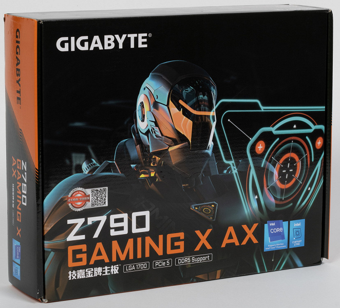
Gigabyte Z790 Gaming X AX поставляется в стандартной коробке с фирменной оранжево-черной раскраской. Комплект размещен под платой в отдельном отсеке.
Комплект поставки очень скромен: кроме традиционных элементов типа руководства пользователя и кабелей SATA, имеется только антенна встроенного Wi-Fi-модуля.
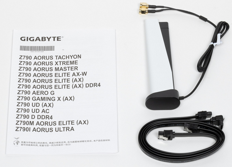
ПО не поставляется (все равно последние версии надо скачивать с вебсайта производителя).
«Заглушка» на заднюю панель с разъемами уже смонтирована на самой плате.
Форм-фактор
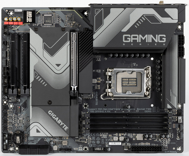
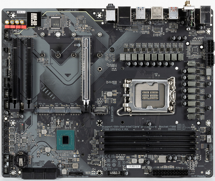
Форм-фактор ATX имеет размеры до 305×244 мм, а E-ATX — до 305×330 мм. Материнская плата Gigabyte Z790 Gaming X AX имеет размеры 305×244 мм, поэтому выполнена в форм-факторе ATX, и на ней имеются 9 монтажных отверстий для установки в корпус.
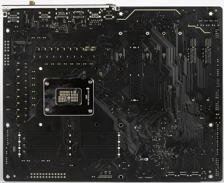
На оборотной стороне практически ничего нет. Текстолит обработан хорошо: во всех точках пайки не только острые концы срезаны, но и все неплохо отшлифовано. Бэкплейта нет.
Технические характеристики
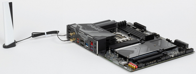
Традиционная таблица с перечнем функциональных особенностей.
| Поддерживаемые процессоры | Intel Core 12/13-го поколений |
|---|---|
| Процессорный разъем | LGA 1700 |
| Чипсет | Intel Z790 |
| Память | 4 × DDR5, до 7600 МГц (XMP), до 128 ГБ, два канала |
| Аудиоподсистема | 1 × Realtek ALC1220 (5.1) |
| Сетевые контроллеры | 1 × Realtek RTL8125BG Ethernet 2,5 Гбит/с 1 × Intel Dual band Wireless AX211NGW (Wi-Fi 802.11a/b/g/n/ac/ax (2,4/6 ГГц) + Bluetooth 5.2) |
| Слоты расширения | 1 × PCIe 5.0 x16 (режим x16) 1 × PCIe 4.0 x16 (режим x4) 1 × PCIe 3.0 x16 (режим x4) |
| Разъемы для накопителей | 6 × SATA 6 Гбит/с (Z790) 1 × M.2 (M2A_CPU, CPU, PCIe 4.0 x4 для устройств формата 2280/22110) 1 × M.2 (M2Q_SB, Z790, PCIe 4.0 x4 для устройств формата 2280/22110) 1 × M.2 (M2P_SB, Z790, PCIe 4.0 x4 для устройств формата 2280/22110) 1 × M.2 (M2M_SB, Z790, PCIe 3.0 x4/SATA для устройств формата 2280/22110) |
| USB-порты | 4 × USB 2.0: 2 внутренних разъема на 4 порта (GL850G) 4 × USB 2.0: 4 порта Type-A (GL850G) 2 × USB 3.2 Gen1: 1 внутренний разъем на 2 порта (Z790) 3 × USB 3.2 Gen1: 3 порта Type-A (Z790) 1 × USB 3.2 Gen2: 1 внутренний разъем Type-C (Z790) 1 × USB 3.2 Gen2x2: 1 порт Type-C (Z790) 2 × USB 3.2 Gen2: 2 порта Type-A (красные) (Z790) |
| Разъемы на задней панели | 1 × USB 3.2 Gen2x2 (Type-C) 2 × USB 3.2 Gen2 (Type-A) 3 × USB 3.2 Gen1 (Type-A) 4 × USB 2.0 (Type-A) 1 × RJ-45 2 аудиоразъема типа миниджек 1 × S/PDIF (оптический, выход) 1 × DP 1 × HDMI 2 антенных разъема |
| Прочие внутренние элементы | 24-контактный разъем питания ATX 2 8-контактный разъем питания EPS12V 1 слот M.2 (E-key), занят адаптером беспроводных сетей 1 разъем для подключения порта USB 3.2 Gen2 Type-C 1 разъем для подключения 2 портов USB 3.2 Gen1 2 разъема для подключения 4 портов USB 2.0 6 разъемов для подключения 4-контактных вентиляторов и помп ЖСО 2 разъема для подключения неадресуемой RGB-ленты 2 разъема для подключения адресуемой ARGB-ленты 1 разъем аудио для передней панели корпуса 1 разъем сброса CMOS 1 разъем для устройств безопасности TPM 2 разъема для дискретных карт Thunderbolt 1 разъем для подключения управления с передней панели корпуса 1 кнопка перепрошивки BIOS — Q Flash Plus 1 кнопка перезагрузки Reset |
| Форм-фактор | ATX (305×244 мм) |
| Розничные предложения |
узнать цену |
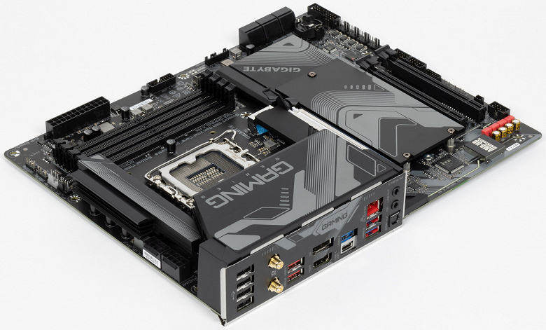
Основная функциональность: чипсет, процессор, память
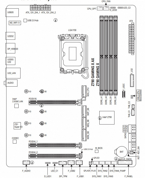
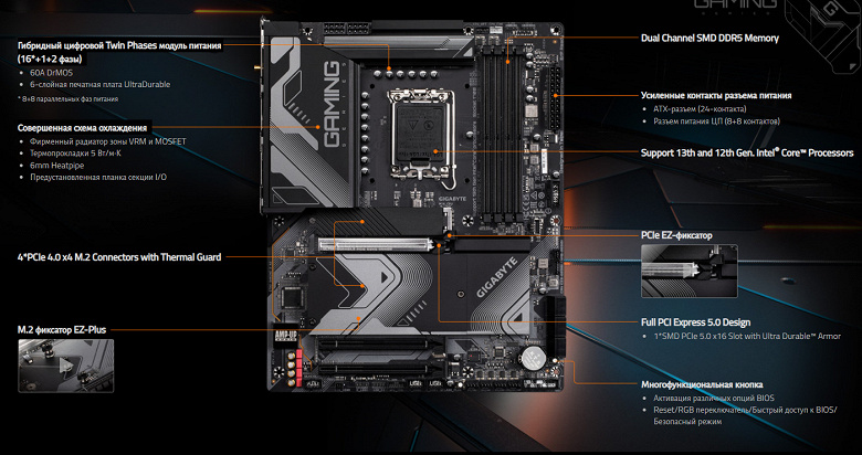
Схема работы связки чипсет+процессор.
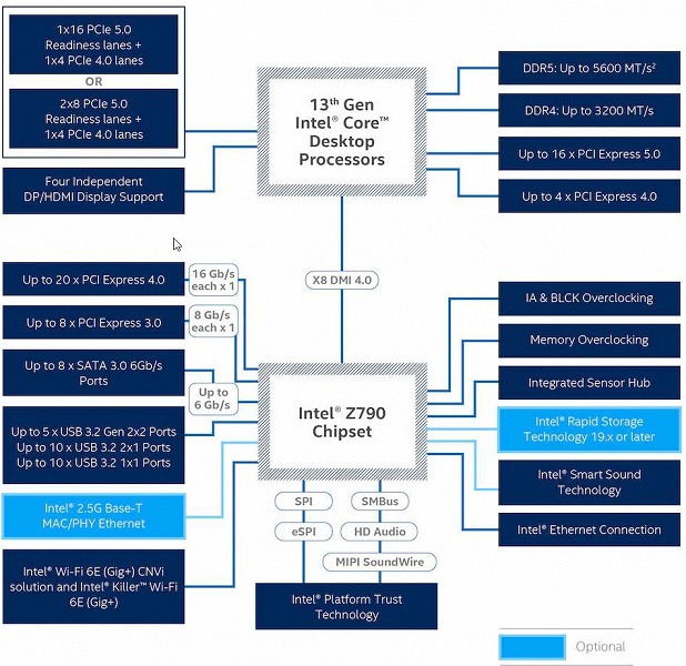
Формально имеется поддержка памяти DDR5 до 5600 МГц, однако всем хорошо известно, и производители материнских плат это активно рекламируют: через XMP-профили сейчас можно использовать частоты до 7000 и выше МГц. В частности данная плата поддерживает частоты до 7600 МГц.
Процессоры Intel Core 13/12-го поколений (совместимые с сокетом LGA1700 и поддерживаемые Z790) имеют 20 линий ввода-вывода (16 PCIe 5.0, 4 PCIe 4.0), не имеют USB и SATA портов. При этом взаимодействие с Z790 идет по особому каналу Digital Media Interface 4.0 (DMI 4.0 x8). Все PCIe линии процессора идут на слоты расширения PCIe и порт М.2. Serial Peripheral Interface (SPI) используется для взаимодействия с системой UEFI/BIOS, а шина Low Pin Count (LPC) — для связи с устройствами ввода/вывода, не требующими высокой пропускной способности (контроллерами вентиляторов, TPM, старой периферии).
В свою очередь чипсет Z790 поддерживает в сумме 38 линий ввода/вывода, которые распределяться могут так:
- до 14 портов USB (из которых до 5 портов USB 3.2 Gen2х2, 10 портов USB 3.2 Gen2, до 10 портов USB 3.2 Gen1, до 14 портов USB 2.0, линии USB 2.0 используются в том числе и для поддержки 3.2 портов, а каждый порт USB 3.2 Gen2х2 требует поддержки со стороны двух USB 3.2 Gen2);
- до 8 портов SATA 6Гбит/с;
- до 28 линий PCIe (8 версии 3.0 и 20 версии 4.0).
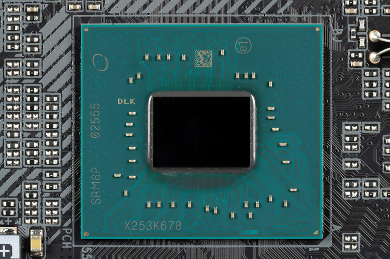
Еще раз надо напомнить, что Gigabyte Z790 Gaming X AX поддерживает процессоры Intel Core 12/13-го поколений, выполненные под разъем (сокет) LGA1700.
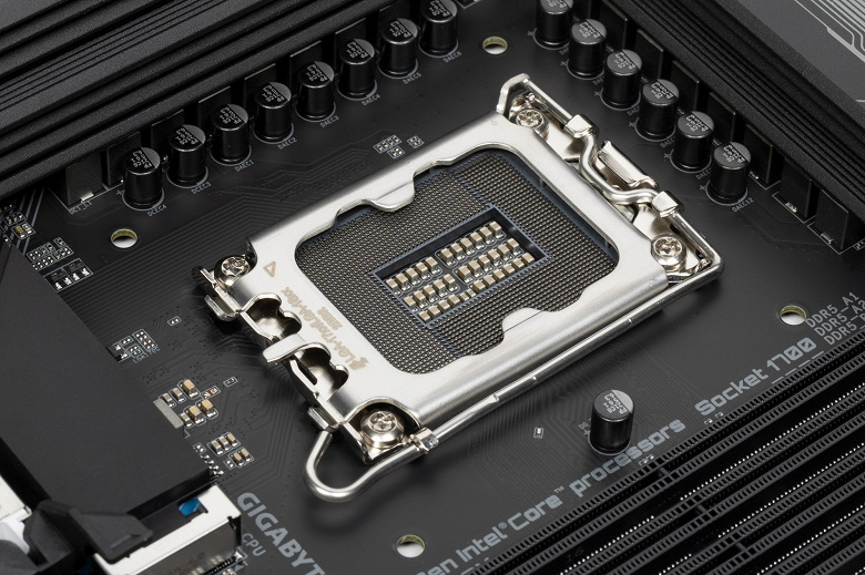
Для установки модулей памяти на плате Gigabyte имеется четыре DIMM-слота (для работы памяти в Dual Channel в случае использования всего 2 модулей их следует устанавливать в А2 и B2.
Плата поддерживает небуферизованную память DDR5 (non-EСС), а максимальный объем памяти составляет 128 ГБ.
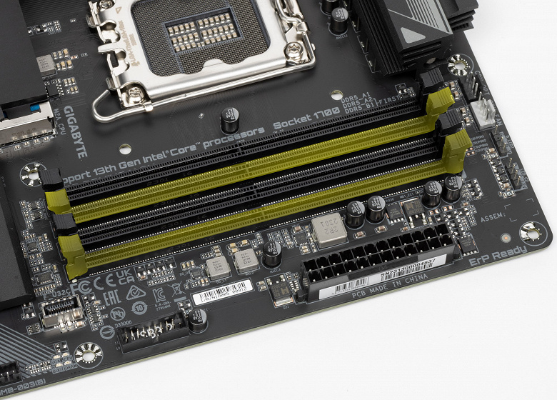
Слоты DIMM не имеют металлической окантовки, препятствующей деформации слотов и печатной платы при установке модулей памяти, однако при этом проводники к ОЗУ тщательно экранированы и защищены от электромагнитных помех.
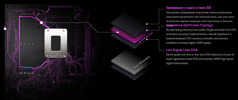
Периферийная функциональность: PCIe, SATA, разные «фенечки»
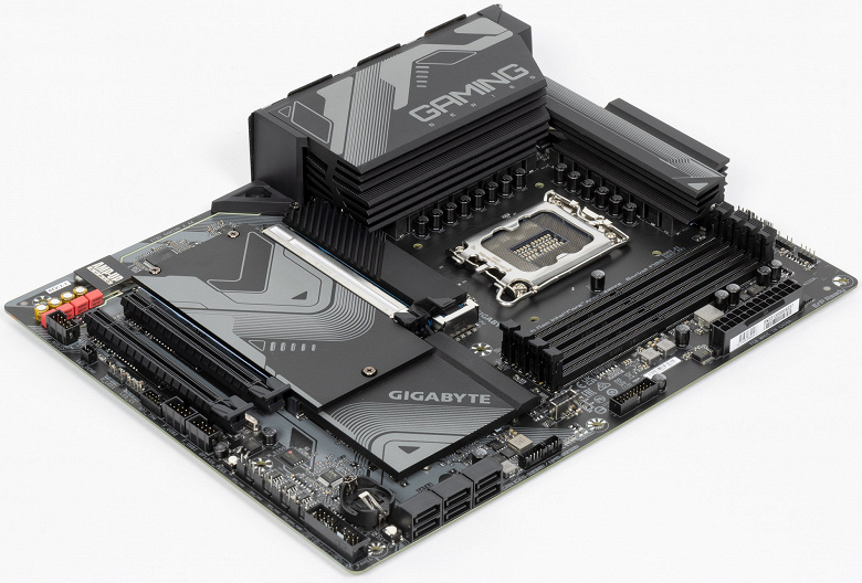
Выше мы изучили потенциальные возможности тандема Z790+Core, а теперь посмотрим, что из этого и как реализовано в данной материнской плате.
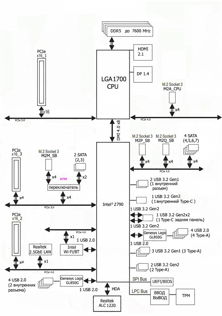
Кроме USB-портов, к которым мы подойдем позже, чипсет Z790 обладает 28 PCIe линиями. Считаем, сколько линий уходит на поддержку (связь) с тем или иным элементом (надо учитывать, что 28 линий не единой версии, а 20 линий PCIe 4.0 и 8 линий PCIe 3.0):
- Слот PCIe x16_2 (4 линии PCIe 4.0);
- Слот PCIe x16_3 (4 линии PCIe 3.0);
- порты SATA_4/5/6/7: (4 линии PCIe 4.0);
- Слот M.2 (M2Q_SB) (4 линии PCIe 4.0);
- Слот M.2 (M2P_SB) (4 линии PCIe 4.0);
- Переключатель: или слот M.2 (M2M_SB) (4 линии PCIe 3.0), или порты SATA_2/3 (2 линии PCIe 3.0) (максимум 4 линии PCIe 3.0);
- Realtek RTL8125GB (Ethernet 2,5Gb/s) (1 линия PCIe 4.0);
- Intel AX211NGW WIFI/BT (Wireless) (1 линия PCIe 4.0)
26 линий PCIe оказались занятыми (18 PCIe 4.0 + 8 PCIe 3.0). Связь с аудиокодеками уровня Realtek RTL408x идет через USB 2.0, а с кодеками уровня RTL1220 и ниже – через HDA (эмуляцию шины PCI), так что в данном случае линия USB 2.0 не расходуется. Но один USB 2.0 расходуется на поддержку BT, а также 2 контроллера GL850G для своих нужд используют сигнальные линии USB 2.0 Детально об этом ниже в разделе USB-портов.
Теперь посмотрим выше на то, как работают процессоры в данной конфигурации. У CPU 13/12-го поколений всего 20 линий PCIe, 4 из них версии PCIe 4.0 отведены на порт М.2 (M2A_CPU). Оставшиеся 16 линий PCIe 5.0 идут на слот PCIe x16_1.
Теперь в целом про слоты PCIe.
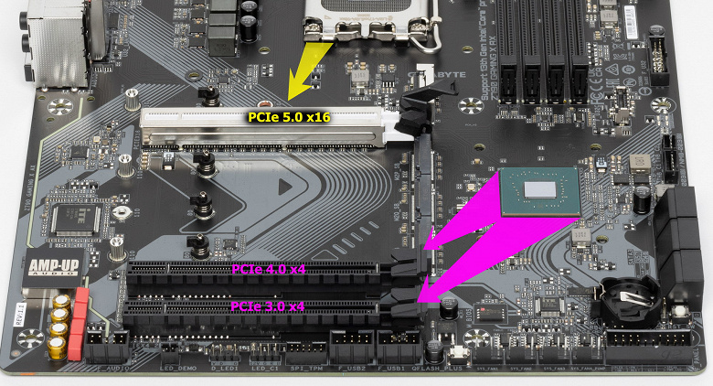
Всего на плате есть 3 слота: один PCIe x16_1 (для видеокарт или других устройств) и два PCIe x16_2/3 (но фактически имеющие по 4 линии соответственно, но разных версий PCIe).
Как видим, перераспределений линий PCIe 5.0 нет, поэтому и мультиплексоров нет. Выше я вел речь про первый PCIe x16_1, подключенный к процессору. Остальные два PCIe x16 подключены к Z790, и, несмотря на их форм-фактор, работают в режимах x4.
Первый слот PCIe x16 имеет металлическое армирование из нержавеющей стали, которое увеличивает надежность. Кроме того, такая защита предохраняет слот от электромагнитных помех.
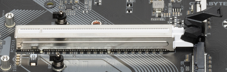
Для удобного извлечения видеокарт из слота имеется специальный удлиненный «хвостик» на замке PCIe x16_1, ведь подчас неудобно дотягиваться до обычного «хвоста» слота, где требуется нажать на защелку для разблокирования карты в слоте: ведь как правило, выше первого слота PCIe имеется M.2 слот с высоким радиатором, и до защелки даже пальцем не дотянуться.
Матплата позволяет смонтировать СО любого размера.
Плата относится к среднебюджетным решениям, поэтому нет ни внешнего тактового генератора, ни усилителей (ре-драйверов) сигнала PCIe 4.0/5.0.
На очереди — накопители.
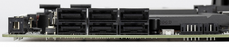
Всего у платы 6 разъемов Serial ATA 6 Гбит/с + 4 слота для накопителей в форм-факторе M.2. Все порты SATA 2,3,4,5,6,7 реализованы через чипсет Z790 и поддерживают создание RAID.
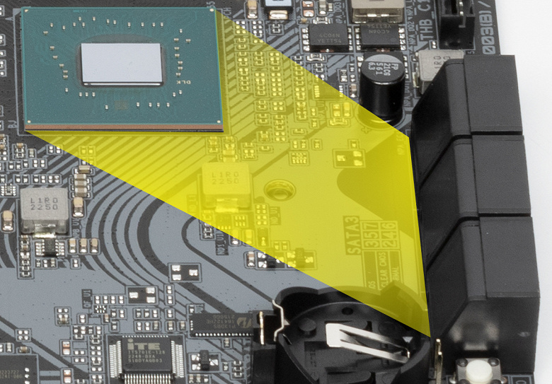
При этом 2 порта SATA 2/3 делят ресурсы с одним из слотов М.2, так что перейдем к последним.
Материнская плата имеет 4 гнезда форм-фактора М.2.
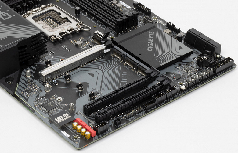
Второй, третий и четвертый слоты M.2 (M2Q_SB, M2P_SB, M2M_SB) получают данные от чипсета Z790, а первый M2A_CPU — от CPU, получая от процессора PCIe 4.0.
И только М2M_SB поддерживает модули с любым интерфейсом, а все остальные работают с модулями только с PCIe интерфейсом. Слот M2M_SB делит ресурсы с двумя портами SATA: 2 и 3.
Все слоты M.2 поддерживают модули с размерами 2280 и 22110.
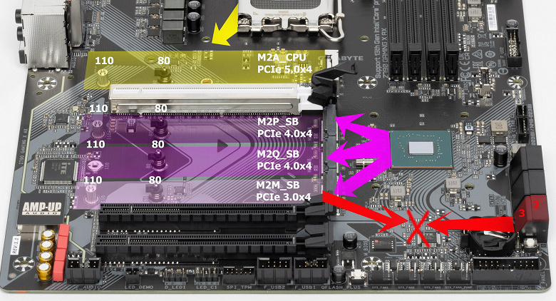
На всех M.2 можно организовать RAID. Следует особо отметить способ крепления накопителей М.2 в слотах через установленные на стойках поворотные замки, что позволяет обойтись без тех самых очень маленьких винтиков.
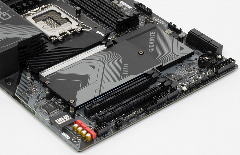
Все M.2 слоты имеют радиаторы. Верхний M2A_CPU обладает отдельным радиатором, когда как остальные все слоты M.2 имеют общий радиатор.
Другие особенности («фенечки») на плате
Периферийная функциональность: USB-порты, сетевые интерфейсы, ввод-вывод
Теперь на очереди USB-порты и прочие вводы-выводы. И начнем с задней панели, куда выведены большинство из них.
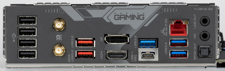
Повторим: чипсет Z790 способен реализовать не более 14 портов USB, из которых может быть до 10 портов USB 3.2 Gen1, до 10 портов USB 3.2 Gen2, до 5 портов USB 3.2 Gen2x2, и/или до 14 портов USB 2.0.
Также мы помним и про 28 линий PCIe, которые идут на поддержку накопителей, сетевых и иных контроллеров (я выше уже показал на что и как расходуются 26 линий из 28).
И что мы имеем? Всего на материнской плате — 17 портов USB:
Таким образом, у нас 3 контроллера используют USB линии от Z790:
- Genesys Logic GL850G (4 USB 2.0 через 2 внутренних разъема) (1 линия USB 2.0);
- Genesys Logic GL850G (4 USB 2.0 через 4 порта Type-A) (1 линия USB 2.0);
- Bluetooth (AX211) (1 линия USB 2.0).
Итак, через чипсет Z790 реализовано высокоскоростных портов USB:
- 1 выделенный USB 3.2 Gen2x2 (не в счет, ибо получен засчет других HSIO);
- + 3 выделенных USB 3.2 Gen2
- + 5 выделенных USB 3.2 Gen1
- + 2 USB 3.2 Gen2 на обеспечение USB 3.2 Gen2x2
= 10 высокоскоростных портов. Не забываем, что каждый высокоскоростной порт USB обеспечен портом USB 2.0, то есть уже 10 портов USB 2.0 также занято. Плюс 3 порта USB 2.0 на обеспечение контроллеров. Всего 13 USB портов реализовано.
Ну и 26 линий PCIe, выделенных на поддержку иной периферии.
Итого у Z790 в данном случае реализовано 36 высокоскоростных портов из 38.
Все быстрые USB порты Type-C оснащены ре-драйверами, дающими устойчивый вольтаж, способный обеспечить быструю зарядку мобильных гаджетов через них.
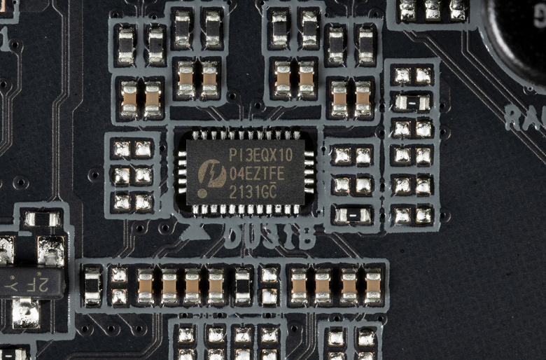


Теперь о сетевых делах.
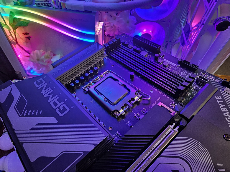
Материнская плата оснащена средствами связи неплохо. Имеется скоростной Ethernet-контроллер Realtek RTL8125BG, способный работать по стандарту 2,5 Гбит/с.
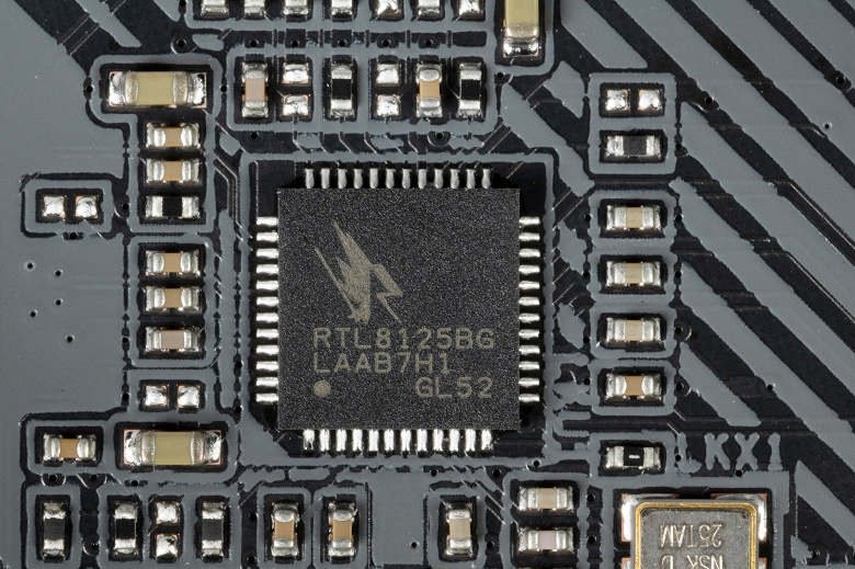
Имеется и комплексный беспроводной адаптер на контроллере Intel AX211NGW, через который реализованы Wi-Fi 6E (802.11a/b/g/n/ac/ax) и Bluetooth 5.2. Он установлен в слот M.2 (E-key), и его разъемы для привинчивания выносных антенн выведены на заднюю панель.
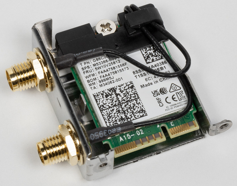
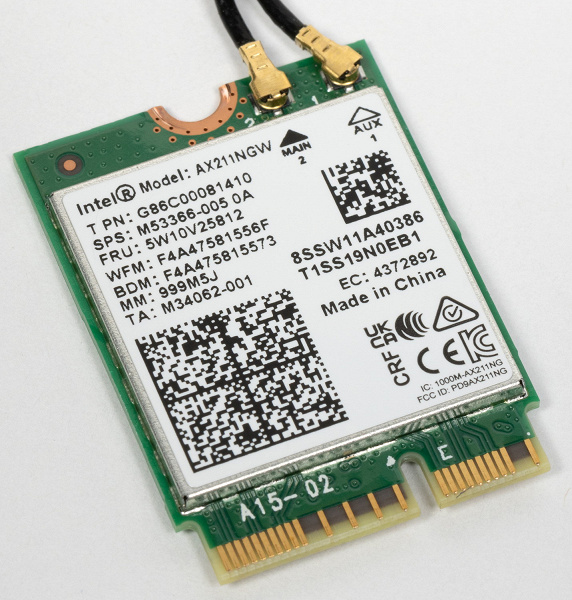
Заглушка, традиционно надеваемая на заднюю панель, в данном случае уже надета, и изнутри экранирована для снижения электромагнитных помех.
Блок ввода-вывода, вентиляторы и т. п.
Аудиоподсистема
Мы знаем, что уже достаточно давно в большинстве современных материнских платах звуком заведовал аудиокодек Realtek ALC1220. В целом обеспечивает вывод звука по схемам до 7.1 с разрешением до 24 бит / 192 кГц. Мы видели уже и ALC4082 того же производителя с улучшенными характеристиками 32 бит / 384 кГц. Однако в данном случае мы видим возврат к прежнему ALC1220, а также схема вывода упрощена до 5.1. Сам чип накрыт металлической крышкой.
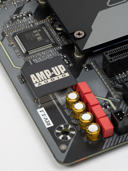
В аудиоцепях платы применяются «аудиофильские» конденсаторы.
Аудиотракт вынесен на угловую часть платы, не пересекается с другими элементами. У карты два универсальных разъема с позолоченным покрытием по приему и выводу сигналов плюс оптический S/PDIF. Вывод по схеме 5.1 возможен только через S/PDIF (аналоговая схема упрощена до стерео).
Результаты тестирования звукового тракта в RMAA
Питание, охлаждение
Для питания платы на ней предусмотрены 3 разъема: в дополнение к 24-контактному ATX (он на правой стороне платы (на фото — слева) здесь есть еще два 8-контактных EPS12V.
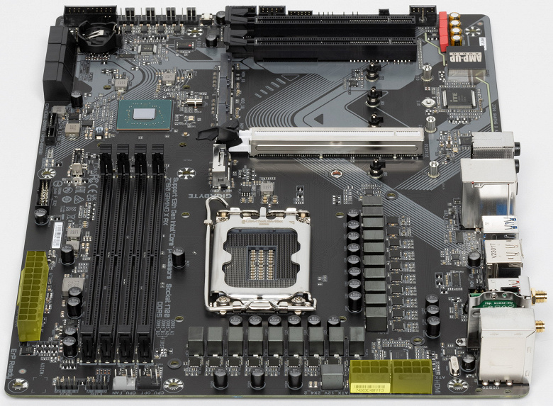
Схема питания процессора выполнена по схеме 16+2+1 (всего 19 фаз, 16 на VCore, 2 на VCCIO и 1 на интегрированное графическое ядро).

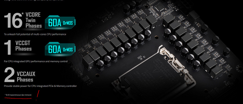
Каждый канал фазы VCore и iGPU имеет суперферритовый дроссель и DrMOS NCP302155 (55 A) On Semi.
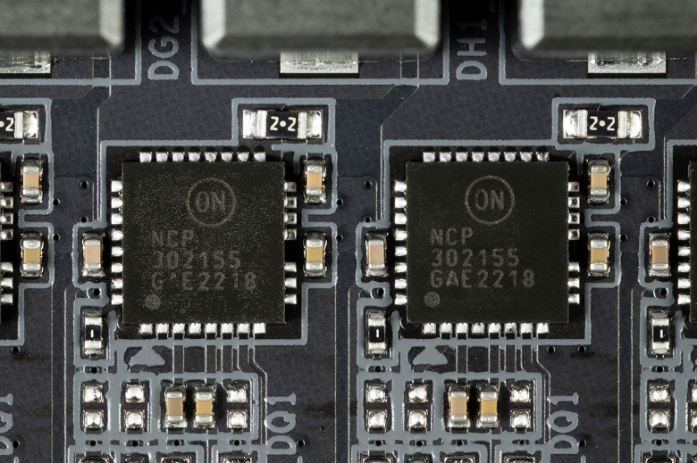
Управляет схемой ШИМ-контроллер NCP81530 от On Semi, он рассчитан максимум на 10 фаз. Поэтому фактически идет параллельная обработка 16-ти фаз питания VCore: 8+8, и в целом получается (8*2) VCore+1 iGPU = 9 фаз.

Блок VCCIO имеет свою двухфазную схему питания (с мосфетами Om Semi, до 60 А), управляемую ШИМ-контроллером MP2940A (Monolithic Power Systems).
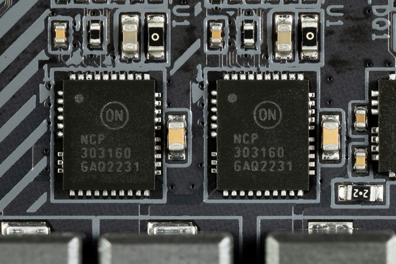
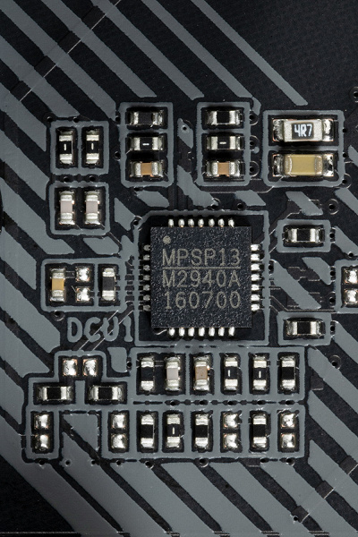
Теперь про охлаждение.
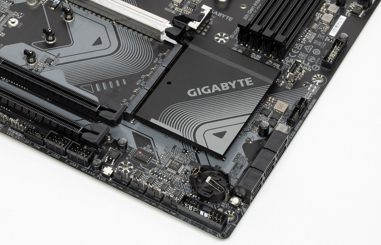
Все потенциально сильно греющиеся элементы имеют свои собственные радиаторы.
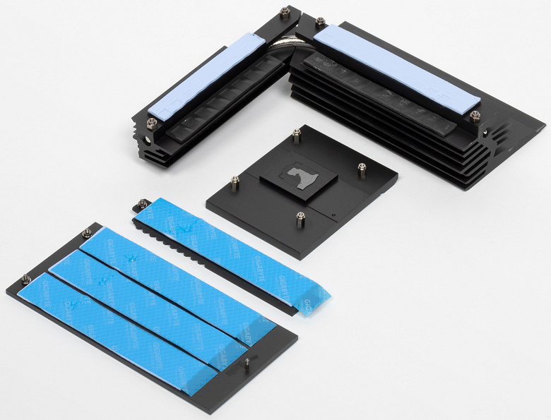
Как мы видим, охлаждение чипсета (один радиатор) организовано отдельно от силовых преобразователей. VRM-секция имеет свои два радиатора, соединенные тепловой трубкой под прямым углом.
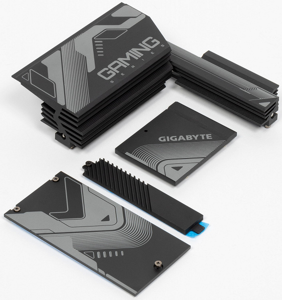
Как я уже упоминал ранее, M.2 слоты также имеют радиаторы: у верхнего — свой персональный радиатор, у остальных — общий.
Материнская плата не имеет бэкплейта, защитной пластины на оборотной стороне.
Подсветка
Программное обеспечение под Windows
Настройки BIOS
Что нам дают тонкости настроек в BIOS
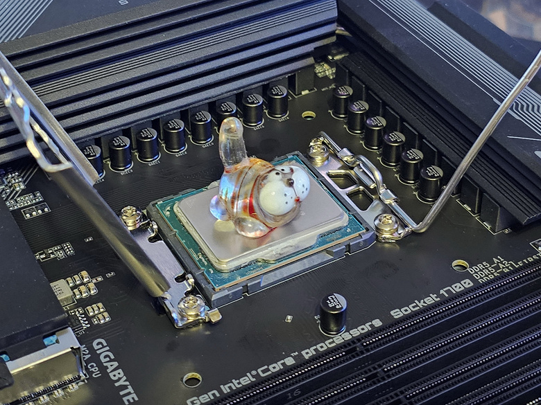
Работоспособность (и разгон)
Конфигурация тестовой системы
Запускаем все в режиме по умолчанию (MCE находится в автоматическом режиме). Затем нагружаем тестами.

В режиме авторазгона мы получили от 5 до 5,5 ГГц по P-ядрам, и 4.3 ГГц по всем Е-ядрам. Напомню, что Р-ядра — это обычные всем привычные ядра, имеющие по 2 потока каждый, «Р» — означает Performance, то есть производительные. «Е» — это энергоэффективные ядра, так называемые, малые ядра, у них по 1 потоку.
Скажу, что авторазгон не самый высокий, что мы видели ранее. Да, система по умолчанию, определив мощное питание матплаты, выставила приличные частоты, но я видел и 5,5 ГГц по всем P-ядрам. Что касается остальных параметров работы компонентов по нагреву, то все они были в норме. Потребление CPU переваливало за 220 Вт.
Ранее в разделе настроек BIOS я отмечал, что инженеры ввели новый параметр настроек – PerfDrive.
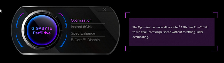
Как мы видим, отключить эту технологию никак нельзя, она:
- находится либо в режиме самооптимизации (выше мы уже видели, что эта «оптимизация» привела по сути к отключению MCE, и автоматический рост частот по TurboBoost уже не по всем ядрам, да и не такой приличный, какого следовало бы ожидать от матплаты с очень мощной системой питания),
- либо пытается достичь 6 ГГц хотя бы одним ядром на короткое время (ну типа зафиксировали «рекорд» и хватит),
- либо пытается как-то выйти на уровень MCE по всем ядрам, но опять же нужные нам частоты работы ядер вручную задать мы не можем (PerfDrive извещает, что или ручной разгон, или эта технология будет «самооптимизироваться», мешая тем самым ручному разгону).
Как по мне – так это совершенно ненужная вещь, и лучше бы оставили все как было: MCE включено, и автооверклокинг сам выставляет максимально возможные частоты по всем ядрам. А ручной разгон – уже без вмешательств «оптимизаторов».
В целом, хотите, чтобы автооверклокинг был примерно как раньше – выставляйте Spec Enhance.
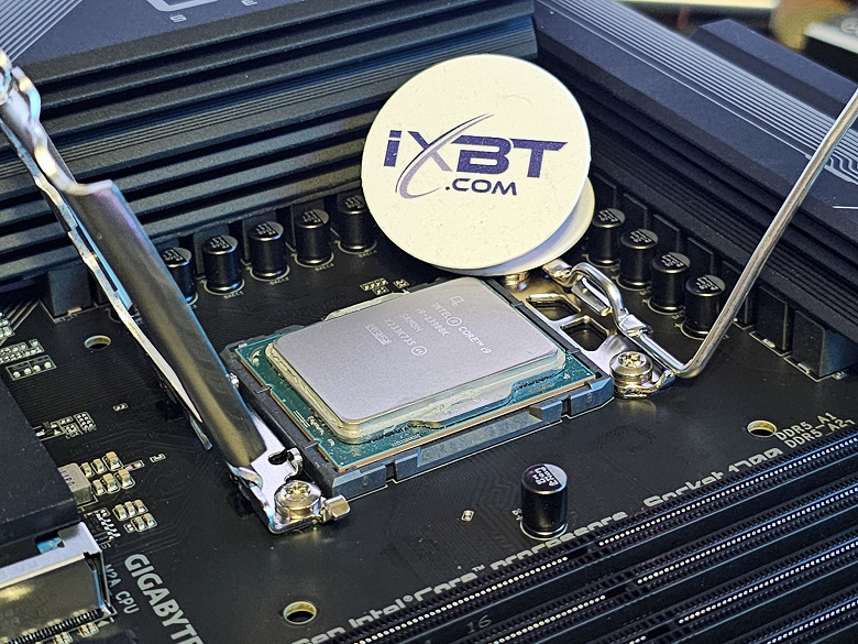
Выводы
Материнская плата Gigabyte Z790 Gaming X AX основана на топовом чипсете Intel Z790, однако имеет стоимость от 20 тысяч рублей на момент публикации обзора, так что это одна из самых дешевых моделей на данном чипсете. Плата поддерживает установку процессоров Intel Core 12-го и 13-го поколений, формально относится к игровой серии Gaming.
У платы 17 портов USB разных видов, включая 3 очень быстрых USB 3.2 Gen2, а также один USB 3.2 Gen2×2 в виде порта Type-C, 3 слота PCIe х16, один из них получает от процессора 16 линий PCIe версии 5.0, два других работают в режиме x4 (подключены к Z790), а также 4 слота M.2: один слот подключен напрямую к процессору линиями PCIe 4.0, три других подключены к чипсету, при этом два — линиями PCIe 4.0, а последний — линиями PCIe 3.0 (он делит ресурсы с двумя портами SATA). В арсенале платы есть 6 портов SATA и 6 разъемов для вентиляторов. Система питания процессора достаточно мощная, способная обеспечить работу любых совместимых процессоров с некоторым запасом на разгон (надо лишь включить нужные настройки в BIOS Setup). Плата имеет грамотную систему охлаждения каждого потенциально греющегося элемента, включая накопители в слотах M.2. Сетевые возможности неплохие: быстрый проводной контроллер 2,5 Гбит/с и один современный беспроводной. В числе плюсов платы можно упомянуть возможности для подключения подсветки в виде дополнительных ARGB/RGB-устройств.