
- Инструкции и руководства
- Бренды
- Garmin
- gps 500
- Руководство Пользователя
![]()
GPS 500
Pilot’s Guide
& Reference
front_cover.p65
5/13/03, 11:04 AM
1
-
Страница 1
The user is responsible for operating this product wisely . The product is intended for use only as a navigational aid and should not be used when precise measurement of direction, location, distance or topography is required. GPS (Global Positioning System) is operated by the U.S. government, which is solely responsible for its accuracy and mainte[…]
-
Страница 2
Congratulations! Y ou’ve made a smart choice by purchasing the GPS 500 Global Positioning System receiver from Cobra ® . Designed to give you access to the most advanced satellite navigation technology available, your GPS 500 offers you these sophisticated features and capabilities: Features: • Cobra ® EXCLUSIVE 18- channel technology gives y[…]
-
Страница 3
1 2 3 4 5 6 7 8 9 T ABLE OF CONTENTS Important Information ………………………………………………………………………………………….. A1 Product Features ………………………………………………………………………………………………… A2–A3 W elcome ……………………………….[…]
-
Страница 4
GPS GENERAL INFORMA TION 2 GPS Basics The Global Positioning System (GPS) is a space-based radio- navigation system. It consists of 24 satellites, which orbit the earth at an altitude of approximately 11,000 miles, and ground stations. GPS provides users with accurate information on position, velocity and time. This is available anywhere in the wor[…]
-
Страница 5
GPS GENERAL INFORMA TION Data Field Choices Descriptions Y our Cobra ® GPS 500 has the ability to display various types of information to you. In order to take advantage of the rich information available to you, it is important that you understand the meaning of certain terms. Below is a list of terms that will aid you in using your Cobra ® GPS 5[…]
-
Страница 6
Installing Batteries Y our GPS 500 operates on two standard AA batteries (not included). Always use high-quality alkaline batteries. T o install batteries, twist the D-ring connector counterclockwise (anticlockwise) and remove the battery compartment cover. Insert two AA batteries ensuring correct polarity alignment. Replace the battery com[…]
-
Страница 7
1 BASIC OPERA TION 7 Navigating with the GPS 500 Y our GPS 500 receives signals from Global Positioning System satellites that are in fixed orbits (stationary relative to the ground) around the earth. By acquiring – or locking on to – the signals from at least three satellites, your unit can use triangulation to precisely determine your current[…]
-
Страница 8
2 THE FIVE MAIN P AGES 9 10 2. 1 MAP P AGE Map Page The Map page displays a graphic representation of the navigation currently in progress. Y ou can choose to display or hide any waypoints; cities/towns; continental U.S. state, Canadian provincial and European country boundaries; points of interest; routes or tracks that you are using. A black […]
-
Страница 9
12 2.1 MAP P AGE 2.1 MAP P AGE 11 Using the Map Page Moving Around: Panning Moving Around the Map Image From the Map page, you can zoom in or zoom out on the map image by pressing the ZOOM IN/OUT button. The data field on the map image can be hidden by selecting FULL MAP (see “Set Data Option”, page 10). A section of map outside the current vie[…]
-
Страница 10
2.1 MAP P AGE 13 14 2.2 GAUGES P AGE Moving Around: Details Compass Select Options Bearing Pointer Settings Gauges Page The Gauges page displays a compass that indicates direction of travel. It can show the direction you are currently traveling or the direction from your current position to the next waypoint in your navigation. […]
-
Страница 11
2.3 TRIP METER P AGE 2.2 GAUGES P AGE Using the Gauges Page T rip Meter Info Option Settings Reset Values T rip Meter Page The T rip Meter page displays information about your current position, the navigation in progress and other available data. It can display up to 5 fields that you can select from a total of 15 choices. Selecting[…]
-
Страница 12
Nav Data Page The Nav Data page gives you access to the powerful navigational features of your GPS 500. From this page, you can create and store up to 500 waypoints. For each one, you can choose a name and assign a symbol. Using the navigational features, you can ask the unit to show you the “GoT o” direction of travel to reach a selected w[…]
-
Страница 13
20 2.4 NA V DA T A P AGE 2.4 NA V DA T A P AGE Add New Waypoint Information Screen Information Screen New Option Highlight and select NEW to add a new waypoint to the list. Highlight and select MARK CURRENT to save the coordinates for your current location as a waypoint. The default name (a 3-digit number) and symbol (a […]
-
Страница 14
2.4 NA V DA T A P AGE 2.4 NA V DA T A P AGE Waypoints: Creating New Waypoints: GoT o 22 “GoT o” a Selected W aypoint T o make the map show the navigational path to a selected waypoint: 1. From the Nav Data page, highlight using the JOYSTICK and select WA YPOINTS by pressing the ENTER button . Highlight and select SELECT . 2. Highlight a[…]
-
Страница 15
2.4 2.4 NA V DA T A P AGE T racks When you select TRACKS from the Nav Data page (see ), your GPS 500 will display a list of the tracks currently stored. Y our unit will automatically record a track as you travel. Y ou can store up to 10 tracks and later recall any of those tracks to use for navigation. Y our unit can guide you along a selected […]
-
Страница 16
26 2.4 NA V DA T A P AGE 2.4 NA V DA T A P AGE Navigate a Selected T rack T o make the map show the navigational path along a selected track: 1. From the Nav Data page, highlight using the JOYSTICK and select TRACKS by pressing the ENTER button . 2. Highlight and select the track you want to navigate . A map of the selected track appears wi[…]
-
Страница 17
28 2.4 NA V DA T A P AGE 2.4 NA V DA T A P AGE 27 Creating a New Route T o create a new route consisting of up to 50 waypoints and/or points of interest: 1. From the Nav Data page, highlight and select ROUTES . Highlight and select the line of empty spaces at the end of the list of routes . A blank New Route screen appears with the current […]
-
Страница 18
30 2.4 NA V DA T A P AGE 2.4 NA V DA T A P AGE Routes: Editing Editing a Route Inserting a Waypoint/POI into a Route T o add a waypoint or point of interest to an existing route: 1. From the Nav Data page , highlight and select ROUTES. Highlight and select the route you wish to add a point to . The selected route ‘ s screen appears . […]
-
Страница 19
32 31 2.4 NA V DA T A P AGE Routes: Navigation Information NA V DA T A P AGE Routes: Navigate Route List Points Not Y et Reached Points Already Reached Nav Data Page Current Point 2.4 Viewing Information for a Route Being Navigated By selecting a route which is currently being navigated, you can view information for any of the p[…]
-
Страница 20
34 2.4 NA V DA T A P AGE NA V DA T A P AGE 33 Cities/T owns: Summary Cities/T owns: GoT o Cities/T owns When you select CITIES from the Nav Data page, you have access to the coordinates for hundreds of cities/towns worldwide already stored in your GPS 500’ s memory . Y ou can ask the unit to show you the «GoTo» direction of travel to re[…]
-
Страница 21
36 2.4 NA V DA T A P AGE 2.4 NA V DA T A P AGE 35 Points of Interest: Summary Sort Option Highlight and select SORT to sort the list of POIs according to name, symbol, or nearest POI. Highlight and select NAME to sort the POIs in alphabetical order . Highlight and select SYMBOL to sort the POIs with the symbol you chose listed first. (G[…]
-
Страница 22
38 2.4 NA V DA T A P AGE 2.4 NA V DA T A P AGE 37 “GoT o” a Selected POI T o make the map show the navigational path to a selected POI: 1. From the Nav Data page , push the JOYSTICK up or down to highlight POINTS OF INTEREST and press the ENTER button to display the POI screen . 2. Highlight and select SELECT . Highlight and select […]
-
Страница 23
40 2.4 NA V DA T A P AGE 2.4 NA V DA T A P AGE 39 Routes Option Highlight and select ROUTES to delete any or all of the routes you have stored. Highlight and select ONE-BY -ONE to delete routes individually (see “Deleting Individual Waypoints, T racks, Routes, or Points of Interest,” page 40). Highlight and select ALL to delete all rout[…]
-
Страница 24
42 2.4 NA V DA T A P AGE 2.4 NA V DA T A P AGE 41 Editing T ext T o enter or change the information displayed for a waypoint, track or route: 1. From any screen that allows you to enter letters, numbers or symbols (names of waypoints/tracks/routes, dates, etc.), push the JOYSTICK up or down to move to the field you want to edit and press the EN[…]
-
Страница 25
44 2.5 SYSTEM P AGE 2.4 NA V DA T A P AGE 43 Search Option T o search any list of waypoints or points of interest for a particular name: 1. From any screen with the SEARCH option, highlight and select SEARCH . 2. Select (by pressing the ENTER button) the highlighted blank space to enter the first letter of the name you are searching for (see ?[…]
-
Страница 26
Map Page Defaults Function Default Orient North Up Data Field Speed Details Shown Names (show) Symbols (show) Waypoints (show) Cities/T owns (show) POI (show) T rack (show) Route (show) States (show) Auto Zoom On 2.5 SYSTEM P AGE 2.5 T urning GPS Off and On When indoors, you can turn GPS navigation off, allowing you to use the non-navigational feat[…]
-
Страница 27
2.5 SYSTEM P AGE 2.5 SYSTEM P AGE Adjusting the Display System Page Interface Display Using the Data Interface Y our GPS 500 is designed to let you exchange data with computer mapping programs. With optional software and interface cable (see “Optional Accessories,” page 63) you will be able to: • Upload points of interest from the com[…]
-
Страница 28
50 2.5 SYSTEM P AGE 2.5 SYSTEM P AGE 49 Language Options Measurement Return to System Page Setting Screen Using the Settings Screen From the Settings screen, you can change the various settings listed below. T o change settings: 1. From the System page , push the JOYSTICK up or down to highlight and select SETTINGS by pressing th[…]
-
Страница 29
52 2.5 SYSTEM P AGE 2.5 SYSTEM P AGE 51 Using the Advanced Screen From the Advanced screen, you can change the advanced operational parameters used by your GPS 500. T o change advanced parameters: 1. From the System page , push the JOYSTICK up or down to highlight and select ADVANCED by pressing the ENTER button. A menu of advanced parameters a[…]
-
Страница 30
3 ALERTS 53 54 3 ALERTS WARNING BA TTERIES LOW! This message appears approximately 30 minutes before your batteries need to be replaced. Select OK or the PAGE button to clear the message. Replace the batteries as soon as possible. The message will reappear every 10 minutes until the batteries are replaced. NOTICE GPS IS OFF! This message is[…]
-
Страница 31
4 GENERAL INFORMA TION 55 4 GENERAL INFORMA TION W orld City Time Zones Longitudinal Zone Offset E172.50 to W172.50 …………………………-12 IDL W (International Date Line West) W172.50 to W157.50 ……………………….-11 Nome W157.50 to W142.50 ……………………….-10 Honolulu W142.50 to W127.50 ……………………….[…]
-
Страница 32
58 4 GENERAL INFORMA TION What is W AAS? Wide Area Augmentation System (WAAS) is a GPS-based navigation system that provides precision above and beyond what GPS can do on its own. WAAS was designed to improve the accuracy and ensure the integrity of information coming from GPS satellites. WAAS is a network of 25 ground reference stations that cover[…]
-
Страница 33
60 6 MAINTENANCE & SERVICE Maintenance of Y our GPS 500 Y our GPS 500 is designed and built to give you years of trouble-free performance without the need for service. No routine maintenance is required. If your unit does not appear to be operating properly , please follow these trouble-shooting steps: Make sure you are using fresh batteries an[…]
-
Страница 34
62 7 INDEX M Magnetic North …………………………..52 Maintenance ……………………………60 Map Data Option ………………………10 Map Datum…………………….45, 51, 57 Map Defaults ……………………………..11 Map Detail Option ……………………….11 Map Display ………………………….10-11[…]
-
Страница 35
64 9 U.S. ORDER FORM Item No. Description Cost Ea. Qty . Amount For credit card orders fill out order form and fax to: 773.622.2269 or call 773.889.3087 (Press 1 from the main menu) 8:00 am — 6:00 pm, Monday -Friday CST . Make check or money order payable to: Cobra Electronics 6500 West Cortland Street Chicago, IL 60707 USA A TTN: Accessories Dept.[…]
-
Страница 36
The Cobra ® line of quality products includes: CB radios microT ALK ® radios Radar/Laser Detectors GPS Safety Alert ® T raffic W ar ning Systems Accessories HighGear ® Accessories VHF Marine Radios Power Inverters For more information or to order any of our products, please visit our website: www .cobra.com Nothing comes close to a Cobra ® Pri[…]

|
20 |
30 |
40 |
50 |
GPS System 500 |
Technical Reference Manual
Version 4.0
English

System GPS500
Congratulations on your purchase of Leica System 500
To use equipment in the permitted manner, please refer to the detailed safety instructions in the User Manual.
|
2 |
Technical Reference Manual-4.0.0en |

Technical Support
Technical Support is provided by Leica Geosystem’s worldwide network of representatives. We are represented in almost every country in the world. A representative directory is available at:
www.leica-geosystems.com
|
Technical Reference Manual-4.0.0en |
3 |

Symbols used in this manual
Important paragraphs which must be adhered to in practice as they enable the product to be used in a technically correct and efficient manner.
|
Symbols used in this manual |
4 |
Technical Reference Manual-4.0.0en |

View of chapters
|
Chapter 1 |
— Introduction |
11 |
||||
|
Chapter 2 |
— Equipment Setup and Connection |
20 |
||||
|
Chapter 3 |
— Using System 500 without a Terminal |
70 |
||||
|
Chapter 4 |
— TR500 Terminal Overview |
74 |
||||
|
Chapter 5 |
— Configuring the Receiver |
86 |
||||
|
Chapter 6 |
— Jobs and Points |
156 |
||||
|
Chapter 7 |
— Measuring with System 500 |
158 |
||||
|
Chapter 8 |
— Coding |
232 |
||||
|
Chapter 9 |
— The CONFIG key |
241 |
||||
|
Chapter 10 |
— Status |
259 |
||||
|
Chapter 11 |
— Applications |
273 |
||||
|
Chapter 12 |
||||||
|
— Utilities |
307 |
|||||
|
Chapter 13 |
||||||
|
— Transfer |
310 |
|||||
|
Appendices |
||||||
|
321 |
||||||
|
Technical Reference Manual-4.0.0en |
5 |
View of chapters |

Contents
|
1. Introduction ………………………………………. |
11 |
2.10 Equipment Setup — Real-Time Rover, |
||||
|
1.1 The GPS Antenna ……………………………………….. |
12 |
All on Pole, direct clip of TR500 on to Sensor ……. |
48 |
|||
|
1.2 The GPS Receiver ……………………………………….. |
13 |
2.11 Equipment Setup — Real-Time Rover, |
||||
|
1.3 The TR500 Terminal …………………………………….. |
15 |
All on Pole, TR500 and Sensor separated ………… |
51 |
|||
|
1.4 Data Storage ………………………………………………. |
16 |
2.12 Equipment Setup — Real Time Rover, GIS Rover . 54 |
||||
|
1.5 Batteries/Power Supply …………………………………. |
18 |
2.13 Equipment Setup — Repeater Station and |
||||
|
1.5.1 Charging the Batteries ………………………………….. |
19 |
Repeater Box ……………………………………………… |
58 |
|||
|
2. Equipment Set Up and Connection |
20 |
2.14 Using the Minipack …………………………………….. |
61 |
|||
|
2.15 Measuring Antenna Heights |
63 |
|||||
|
2.1 GPS Receiver ports |
21 |
|||||
|
2.15.1 Mechanical Reference Planes ……………………… |
64 |
|||||
|
2.2 Equipment Setup — Post Processed Static/Rapid |
2.15.2 Antenna Height components ……………………….. |
65 |
||||
|
Static/Reference on Pillar ……………………………… |
22 |
2.15.3 Measuring Slope Heights …………………………….. |
69 |
|||
|
2.3 Equipment Setup — Post Processed Static/Rapid |
3. Using System 500 without a Terminal |
70 |
||||
|
Static/Reference on Tripod |
25 |
|||||
|
3.1 Setting up the Equipment |
71 |
|||||
|
2.4 Equipment Setup — Post Processed Kinematic, |
||||||
|
3.2 Operation |
71 |
|||||
|
Minipack and Pole |
28 |
|||||
|
3.3 Shut Down |
71 |
|||||
|
2.5 Equipment Setup — Post Processed Kinematic, |
||||||
|
3.4 LED Indicators |
72 |
|||||
|
All on Pole, Direct Clip of TR500 on to Sensor |
32 |
|||||
|
3.4.1 Power LED |
72 |
|||||
|
2.6 Equipment Setup — Post Processed Kinematic, |
||||||
|
3.4.2 Satellite Status LED |
72 |
|||||
|
All on Pole, TR500 and Sensor separated |
35 |
|||||
|
3.4.3 Memory Status LED |
73 |
|||||
|
2.7 Equipment Setup — Real Time Reference, |
||||||
|
3.5 Field Record Sheet |
73 |
|||||
|
single tripod |
38 |
|||||
|
4. TR500 Terminal Overview |
74 |
|||||
|
2.8 Equipment Setup — Real-Time Reference, |
||||||
|
Two Tripods ……………………………………………… |
41 |
4.1 Screen Layout …………………………………………….. |
75 |
|||
|
2.9 Equipment Setup — Real-Time Rover, |
4.2 Status Icons ……………………………………………….. |
77 |
||||
|
Pole and Minipack ……………………………………….. |
44 |
4.3 Keyboard ……………………………………………………. |
82 |
|||
|
4.4 General Operating Principles …………………………. |
83 |
|||||
|
Contents |
6 |
Technical Reference Manual-4.0.0en |

Contents, continued
|
5. Configuring the Receiver …………………… |
86 |
|
5.1 Configuring the Receiver for Static and Rapid Static |
|
|
Operations …………………………………………………. |
88 |
|
5.1.1 Advanced Operation Mode for Static and Rapid |
|
|
Static ………………………………………………………….. |
95 |
|
5.2 Configuring the Receiver for Post-Processed |
|
|
Kinematic Operations …………………………………… |
99 |
|
5.2.1 Advanced Operation Mode for Post-Processed |
|
|
Kinematic ………………………………………………….. |
112 |
|
5.3 Configuring the Receiver for Real-Time Reference |
|
|
Operations ………………………………………………… |
116 |
|
5.3.1 Advanced Operation Mode for Real Time |
|
|
Reference Stations ……………………………………… |
124 |
|
5.4 Configuring the Receiver for Real-Time Rover |
|
|
Operations ……………………………………………….. |
127 |
|
5.4.1 Advanced Operation Mode for Real Time Rover 148 |
|
|
6. Jobs and Points………………………………. |
156 |
|
6.1 Management of Jobs ………………………………….. |
156 |
|
7. Measuring with System 500 …………….. |
158 |
|
7.1 Static and Rapid Static Survey, Post-Processed |
|
|
Kinematic Reference ………………………………….. |
159 |
|
7.1.1 Overview of Procedure ……………………………….. |
160 |
|
7.1.2 Adding the Point Id …………………………………….. |
160 |
|
7.1.3 Adding the Antenna Height ………………………….. |
161 |
|
7.1.4 Adding a Code …………………………………………… |
161 |
|
7.1.5 Adding a Starting Time ……………………………….. |
163 |
|
7.1.6 Measuring procedure ………………………………….. |
163 |
|
7.1.7 Using the ADD key …………………………………….. |
166 |
|
7.2 Post-processed Kinematic Survey (Rover) ……… |
167 |
|
7.2.1 Overview of Procedure ……………………………….. |
168 |
|
7.2.2 Adding the Point Id …………………………………….. |
168 |
|
7.2.3 Adding the Antenna Height ………………………….. |
169 |
|
7.2.4 Adding a Code …………………………………………… |
170 |
|
7.2.5 Adding a Starting Time ……………………………….. |
171 |
|
7.2.6 Measuring Procedure …………………………………. |
172 |
|
7.2.7 Using the AUTO key …………………………………… |
174 |
|
7.2.8 Using the ADD key …………………………………….. |
174 |
|
7.3 Real-Time Reference Stations ……………………… |
176 |
|
7.3.1 Measuring procedure ………………………………….. |
177 |
|
7.3.2 Using the ADD key …………………………………….. |
180 |
|
7.4 Real-Time Rover, Surveying New Points ………… |
181 |
|
7.4.1 Overview of Procedure ……………………………….. |
182 |
|
7.4.2 Adding the Point Id …………………………………….. |
182 |
|
7.4.3 Adding the Antenna Height ………………………….. |
183 |
|
7.4.4 Adding a Code …………………………………………… |
184 |
|
7.4.5 Adding a Starting Time ……………………………….. |
185 |
|
7.4.6 Measurement Procedure …………………………….. |
186 |
|
7.4.7 Using the AUTO key …………………………………… |
190 |
|
7.4.8 Using the INIT key ……………………………………… |
193 |
|
7.4.9 Using the ADD key …………………………………….. |
194 |
|
7.4.10 Using the NEAR key …………………………………. |
206 |
|
7.4.11 Radio Down Infill ………………………………………. |
206 |
|
Technical Reference Manual-4.0.0en |
7 |
Contents |

Contents, continued
|
7.5 Real-Time Rover, Staking Out ………………………. |
208 |
|
7.5.1 Entering Stakeout ………………………………………. |
208 |
|
7.5.2 Stake-Out Types ………………………………………… |
209 |
|
7.5.3 The Stake-Out Screen ………………………………… |
210 |
|
7.5.4 Orientation ………………………………………………… |
211 |
|
7.5.5 Polar and Orthogonal …………………………………. |
215 |
|
7.5.6 Using the Reverse function ………………………….. |
216 |
|
7.5.7 Using the Redraw function …………………………… |
217 |
|
7.5.8 Picking up a new point ………………………………… |
217 |
|
7.5.9 Using the INIT key ……………………………………… |
217 |
|
7.5.10 Using the NEAR key …………………………………. |
218 |
|
7.5.11 Graph …………………………………………………….. |
218 |
|
7.5.12 Aux Pt …………………………………………………….. |
219 |
|
7.5.13 Point Stake-Out — Procedure ………………………. |
220 |
|
7.5.14 Slope Stake-Out — Procedure ……………………… |
222 |
|
7.5.15 Grid Stake-Out — Procedure ……………………….. |
226 |
|
8. Coding ……………………………………………. |
232 |
|
8.1 Thematical Coding ……………………………………… |
232 |
|
8.1.1 Importing, Selecting and Defining a |
|
|
Thematical Codelist …………………………………….. |
233 |
|
8.1.2 Defining New Codes and Attributes ………………. |
234 |
|
8.1.3 Defining and Activating/Deactivating Layers …… |
235 |
|
8.1.4 Adding a Thematical Code to a Point …………….. |
236 |
|
8.2 Free Coding ……………………………………………… |
237 |
|
8.2.1 Importing, Selecting and Defining a |
|
|
Free Codelist ……………………………………………… |
237 |
|
8.2.2 Defining New Codes …………………………………… |
238 |
|
8.2.3 Adding a Free Code …………………………………… |
239 |
|
9. The CONFIG Key …………………………….. |
241 |
|
9.1 Survey — Satellite ………………………………………… |
242 |
|
9.2 General — Units ………………………………………….. |
243 |
|
9.3 General — Language ……………………………………. |
244 |
|
9.4 General — Hot Keys …………………………………….. |
244 |
|
9.5 General — Time and Initial Position …………………. |
245 |
|
9.6 General — Start-Up ……………………………………… |
245 |
|
9.7 General — TR500 ………………………………………… |
246 |
|
9.8 General — Identification ………………………………… |
247 |
|
9.9 Interfaces ………………………………………………… |
247 |
|
9.10 Interfaces — Real-Time ………………………………. |
247 |
|
9.11 Interfaces — NMEA Output ………………………….. |
248 |
|
9.12 Interfaces — ASCII Input ……………………………… |
249 |
|
9.13 Interfaces — Hidden Point ……………………………. |
253 |
|
9.14 Interfaces — GSI/User Out …………………………… |
253 |
|
9.15 Interfaces — Remote ………………………………….. |
254 |
|
9.16 Interfaces — PPS Out …………………………………. |
255 |
|
9.17 Interfaces — Event Input ……………………………… |
256 |
|
10. Status …………………………………………… |
259 |
|
10.1 Real-Time Input Status ……………………………… |
259 |
|
10.2 Stop and Go Indicator ……………………………….. |
261 |
|
10.3 Position ………………………………………………….. |
263 |
|
10.4 Logging Status …………………………………………. |
266 |
|
10.5 Satellite Status …………………………………………. |
267 |
|
10.6 Point Log Status ………………………………………. |
269 |
|
Contents |
8 |
Technical Reference Manual-4.0.0en |

Contents, continued
|
10.7 Code Log Status ………………………………………. |
270 |
|
10.8 Message Log Status …………………………………. |
270 |
|
10.9 Memory/Battery Status ………………………………. |
270 |
|
10.10 Sensor Status ………………………………………… |
271 |
|
10.11 Software Version Status …………………………… |
271 |
|
10.12 Interfaces Status …………………………………….. |
272 |
|
11. Applications ………………………………….. |
273 |
|
11.1 Determining a Coordinate System ……………….. |
273 |
|
11.2 Adding Points to Existing Coordinate Systems .. |
283 |
|
11.3 Point Management ……………………………………. |
284 |
|
11.4 Calculator ……………………………………………….. |
288 |
|
11.5 Wake-up Sessions ……………………………………. |
288 |
|
11.6 COGO ……………………………………………………. |
290 |
|
11.7 Area ………………………………………………………. |
303 |
|
11.8 Line Division ……………………………………………. |
304 |
|
12. Utilities …………………………………………. |
307 |
|
12.1 Directory of Memory Device ……………………….. |
307 |
|
12.2 Format Memory Module …………………………….. |
308 |
|
12.3 Enter Security Code ………………………………….. |
309 |
|
12.4 Self Test …………………………………………………. |
309 |
|
13. Transfer ………………………………………… |
310 |
|
13.1 Job ………………………………………………………… |
310 |
|
13.2 Config Set ………………………………………………. |
310 |
|
13.3 Coordinate System ……………………………………. |
311 |
|
13.4 Antenna Info …………………………………………….. |
311 |
|
13.5 Codelist …………………………………………………… |
311 |
|
13.6 ASCII/GSI to Job …………………………………….. |
312 |
|
13.7 GSI / User ………………………………………………. |
314 |
|
13.8 Geoid Field File ………………………………………… |
316 |
|
13.9 CSCS Field File ……………………………………….. |
316 |
|
13.10 Firmware ………………………………………………. |
316 |
|
13.11 Firmware TR500 …………………………………….. |
317 |
|
13.12 Language Version …………………………………… |
317 |
|
13.13 Application Text ………………………………………. |
317 |
|
13.14 Almanac ……………………………………………….. |
318 |
|
13.15 Account File …………………………………………… |
318 |
|
13.16 CFC Log Mask File …………………………………. |
318 |
|
13.17 Beacon Station List ………………………………… |
319 |
|
13.18 Modem/GSM Station List …………………………. |
319 |
|
13.19 System ………………………………………………… |
319 |
|
13.20 Any File Type …………………………………………. |
320 |
|
Appendix A — Operating and Storage |
|
|
Temperatures ……………………………………… |
321 |
|
Appendix B — Observation Times …………. |
322 |
|
Appendix C — Seismic Record Format ….. |
323 |
|
Appendix D — Defined Line File Format … |
324 |
|
Technical Reference Manual-4.0.0en |
9 |
Contents |

Contents, continued
|
Appendix E — NMEA Message Formats …. |
325 |
|
GGA — Global Positioning System Fix Data …………… |
327 |
|
GGK — Real-Time Position with DOP …………………… |
328 |
|
GGK(PT) — Real-Time Position with DOP …………….. |
328 |
|
GGQ — Real-Time Position with CQ …………………….. |
329 |
|
GLL — Geodetic Position — Latitude, Longitude ……….. |
329 |
|
GNS — GNSS Fix Data ……………………………………… |
330 |
|
GSA — GPS DOP and Active Satellites ………………… |
330 |
|
GSV — GPS Satellites in View …………………………….. |
331 |
|
LLK — Leica Local Position and GDOP …………………. |
331 |
|
LLQ — Leica Local Position and Quality ………………… |
332 |
|
VTG — Course Over Ground and Ground Speed ……. |
332 |
|
ZDA — Time and Date ……………………………………….. |
333 |
|
Appendix F — Pin Assignments and |
|
|
Sockets ……………………………………………… |
334 |
|
Appendix G — Data Device Directory |
|
|
Structure ……………………………………………. |
336 |
|
Appendix H — External Devices…………….. |
338 |
|
RS232 ………………………………………………………….. |
339 |
|
Radio and Repeaters ……………………………………….. |
340 |
|
GSM …………………………………………………………….. |
344 |
|
Modem …………………………………………………………. |
350 |
|
RTB Module (CSI) …………………………………………… |
352 |
|
RTS Module (Racal) ………………………………………… |
354 |
|
SAPOS …………………………………………………………. |
356 |
|
Using a SAPOS decoder box ………………………………. |
356 |
|
Using a SMARTgate box …………………………………….. |
357 |
|
Using the Telemax Service ………………………………….. |
359 |
|
Hidden Point ………………………………………………….. |
361 |
|
Appendix I — MC500 …………………………….. |
364 |
|
Appendix J — RS500 …………………………….. |
369 |
|
Appendix K- GS50 / GS50+ and GIS Data |
|
|
Collection …………………………………………… |
377 |
|
Hardware and Accessories ……………………………….. |
378 |
|
Compact Flash and Sensor Transfer…………………… |
382 |
|
Operation and Configuration ……………………………… |
383 |
|
The CONFIG Key ……………………………………………. |
384 |
|
The STATUS Key ……………………………………………. |
388 |
|
Data Collection with the GS50 and GS50+ …………… |
389 |
|
10 |
Technical Reference Manual-4.0.0en |
![]()
1. Introduction
System 500 is used to receive signals from GPS satellites which are then processed to obtain a position on the earth’s surface.
It can be used in many applications, the main ones being Land Survey, Stakeout and Hydrographic Survey.
The main components of System 500 are the GPS Antenna and GPS Receiver. Ancilliary components are the Terminal, Batteries, PC Cards and cables.
SKI-Pro, a PC based software is also used in conjunction with the hardware listed above for post-processing GPS data and for downloading coordinates
recorded in the field. Instructions for System 500 — main hardware components using SKI-Pro can be found in the
accompanying printed guides and online help.
|
Technical Reference Manual-4.0.0en |
11 |
1. Introduction |

1.1 The GPS Antenna
There are several System 500 GPS Antennas available. These are:
•AT501 Single Frequency Antenna.
•AT502 Dual Frequency Antenna.
•AT503 Dual Frequency Choke Ring Antenna.
•AT504 JPL Design Dual Frequency Choke Ring Antenna.
•Single Frequency Choke Ring Antenna.
The GPS Antenna is selected for use based upon the application. The vast majority of applications will require the AT501 or AT502 Antenna.
The AT501 is a L1 single frequency antenna. Use it with the SR510 Receiver. The AT502 is a dual frequency antenna. Use it with the SR520 or SR530 Receiver.
The Choke Ring Antennas are designed for use where the utmost precision is required. Typical applications include Static Surveys of long baselines, Tectonic Plate monitoring, Reference Stations, etc.
Use the AT503 and AT504 with the SR520 or SR530 Receiver. Use the Single Frequency Choke Ring with the SR510 Receiver.
Also available is a combined GPS/
AT502 Antenna
RTB or GPS/ RTS antenna. Refer to Appendix K for further information.
AT504 Antenna
|
1. Introduction |
12 |
Technical Reference Manual-4.0.0en |

1.2 The GPS Receiver
The GPS Receiver is the instrument that processes the GPS signals received by the GPS Antenna.
There are six different models of GPS receiver in System 500. The model number is printed on the PC card lid.
See the detailed descriptions of each of these receivers given down below.
SR510 — Tracks the L1 C/A code and uses it to reconstruct the carrier phase. Data can be stored for postprocessing in SKI-Pro. Baselines can be calculated with a precision of up to about 5-10mm +2ppm.
With a radio modem attached the receiver can be used for real-time measurements accepting RTCM code corrections. Coordinates can be calculated with a precision of up to about 0.5m.
SR520 — Tracks the L1 C/A code and L2 P-code to reconstruct the carrier phase. When Anti-Spoofing (A-S) is activated, the receiver switches to a patented P-code aided tracking technique that provides full L2 carrier measurements and L2 pseudoranges. Data can be stored for post-processing. Baselines can be calculated with a precision of up to about 3-10mm +1ppm.
With a radio modem attached the receiver can be used for real-time measurements accepting RTCM code corrections. Coordinates can be calculated with a precision of up to about 0.5m.
SR530 — Tracks the L1 C/A code and L2 P-code to reconstruct the carrier phase. When Anti-Spoofing (A-S) is activated, the receiver switches to a patented P-code aided tracking technique that provides full L2 carrier
measurements and L2 pseudoranges. A radio modem attaches and the receiver can be used for RTK operations. Coordinates can be calculated with a precision of up to about 1cm
Data can also be stored for postprocessing. Baselines can be calculated with a precision of up to about 3-10mm +1ppm.
System 500 GPS Receivers can be operated with or without the TR500 Terminal (see section 1.3). The TR500 is used for field data acquisition and for configuring the receiver.
Details of using the Receiver without a Terminal are given in Chapter 3.
|
Technical Reference Manual-4.0.0en |
13 |
1. Introduction |

MC500 — A ruggedized version of the SR530 designed specifically for Machine Control. Can also be utilised as a dedicated GPS Reference Station. Please refer to Appendix I for specific details.
RS500 — A dedicated GPS Reference Sation receiver designed for permanent installation. Please refer to Appendix J for specific details.
GS50 — This receiver has been specifically designed for GIS applications. Please refer to Appendix K for more information that is specific to the GS50 and the corresponding PCsoftware GIS DataPRO.
|
1. Introduction |
14 |
Technical Reference Manual-4.0.0en |
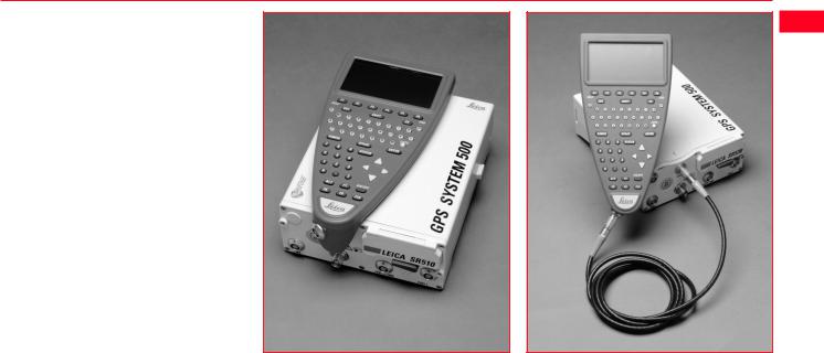
1.3 The TR500 Terminal
The TR500 Terminal provides a full user interface to all System 500 GPS Receivers.
It can be used to set parameters in the receiver and to steer the GPS measurement operation.
The TR500 can be used to set and store parameters in one GPS receiver and then removed and used to set parameters in another System 500 receiver. The receiver can then be used in the field without the TR500 attached. Note that whilst this is possible when measuring in any mode, for a Reference or Rover, it is recommended that the Receiver only be used without a TR500 at Reference stations or with Static/Rapid Static Rovers.
|
The TR500 is connected either |
TR500 mounted on the Receiver |
TR500 connected using the cable |
||
|
directly to the receiver or via a cable. |
||||
|
Data input is via a fully alphanumeric |
||||
|
QWERTY keyboard and an LCD |
||||
|
display of 32 x 12 characters which |
||||
|
may be illuminated. |
||||
|
Technical Reference Manual-4.0.0en |
15 |
1. Introduction |

1.4 Data Storage
Data is stored on either an Internal Memory or PC Card. The PC Card is the preferred data storage medium. The Internal Memory is an option.
The PC Card is inserted into the slot on the front of the GPS Receiver. PC Cards are available from Leica with varying capacities. Note that whilst other PC Cards may be used, Leica recommend Leica PC cards only and cannot be held responsible for data loss or any other error that may occur whilst using a non-Leica card.
To insert the PC Card in the GPS Receiver, open the card slot door, with the Leica Logo uppermost and facing you, slide the card into the slot firmly until it clicks into position. Press the eject button at the side of the card to remove it.
|
The Internal Memory is available in |
|
|
8MB or 16MB capacities and resides |
|
|
in the Receiver. When data has to be |
|
|
downloaded to SKI-Pro, connection is |
|
|
made between port 2 on the Receiver |
|
|
and a serial port on the PC. |
|
|
The memory device is checked |
|
|
before starting a survey. If it is more |
|
|
than 80% full, an information mes- |
|
|
sage appears. |
|
|
Inserting the PC Card |
|
|
Follow the care instructions shown on |
|
|
the rear of the card. Keep the card |
|
|
dry, only use within the specified |
|
|
temperature range, do not bend the |
|
|
card and protect it from direct shock. |
|
|
Failure to follow these instructions |
|
|
could result in data loss and/or |
|
|
permanent damage to the card. |
|
|
The card can become very hot during |
|
|
use. Avoid touching the metal parts of |
|
|
the card after prolonged use. |
|
1. Introduction |
16 |
Technical Reference Manual-4.0.0en |

PC Card versus Internal Memory
The PC Card is the preferred data storage medium as it has the following advantages over internal memory:
•Faster download times. A PC Card download using a PC Card Reader or PCMCIA port is virtually instantaneous. Internal memory has to download through a serial connection and can take time.
•Flexibility / no downtime of GPS Receiver. A PC Card can be removed from a receiver when it is full and replaced with a spare. The Receiver does not
have to be taken back to the office for downloading.
Using an Internal Memory means however that the data has less chance of being misplaced or lost. This can happen when multiple PC Cards are used for the same project.
If you are not sure about which type of memory to use, try using a PC card but don’t remove it from the Receiver. You can still download as if it were Internal Memory through any port.
|
Technical Reference Manual-4.0.0en |
17 |
1. Introduction |
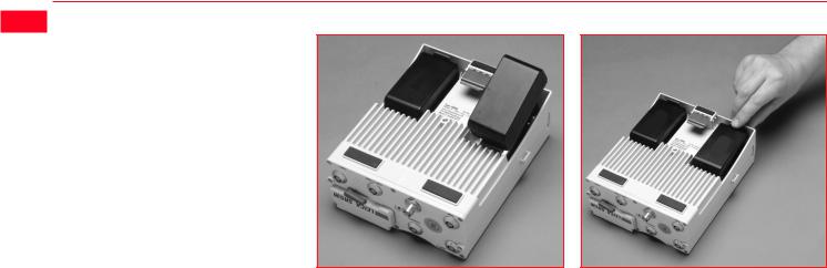
1.5 Batteries/Power Supply
|
Connecting a GEB121 Battery |
Removing a GEB121 Battery |
System 500 will normally be powered by two GEB121 camcorder type batteries. which plug into the underside of the GPS receiver.
Two batteries, fully charged, will power the SR510 and TR500 for about 7.5 hours continuously and the SR520/530 for about 6 hours continuously.
Operating times will be shorter when working in cold weather and when a radio modem is connected.
Plug in and remove the GEB121 batteries as shown opposite.
System 500 can also be powered by the GEB71 7Ah battery or any 12V DC power supply via either power port, on the front face of the receiver using an appropriate cable.
With the Receiver upside down and the Leica logo on the battery facing you, locate one end into the battery bay. Press the opposite end of the battery down until it audibly clicks into place.
Pull and hold the battery catch. Withdraw the battery with the other hand.
The battery contains toxic material and must be disposed of in an environmentally friendly manner. Do not dispose of the battery in normal household or office waste.
|
1. Introduction |
18 |
Technical Reference Manual-4.0.0en |

1.5.1 Charging the Batteries
|
GEB121 Batteries |
Chargers |
The batteries are delivered |
||
|
GEB121 Batteries can be charged |
The GKL122 is an intelligent charger. |
from the factory totally |
||
|
discharged. They will require a full |
||||
|
using the GKL122 or GKL111 battery |
It will charge the batteries by the |
|||
|
charging cycle before the equipment |
||||
|
chargers. The preferred model is the |
exact amount required. This maxi- |
|||
|
can be used. For full instructions on |
||||
|
GKL122. |
mizes battery life. The GKL122 can |
|||
|
battery charging, refer to the manual |
||||
|
charge up to 2 GEB121 batteries at |
||||
|
accompanying the charger you are |
||||
|
once. The GDI121 extension plate |
||||
|
GEB71 Batteries |
using. |
|||
|
enables a further two batteries to be |
||||
|
GEB71 Batteries can be charged |
charged from the same charger at the |
|||
|
using the GKL122 battery charger |
same time. |
|||
|
only. |
Additionally, the GKL122 can charge |
|||
|
up to two GEB71 batteries. |
||||
|
The GKL111 battery charger is a |
||||
|
simple charger. It will charge one |
||||
|
GEB121 battery at a time. It will |
||||
|
charge the batteries by the exact |
||||
|
amount required. This maximizes |
||||
|
battery life. |
|
Technical Reference Manual-4.0.0en |
19 |
1. Introduction |
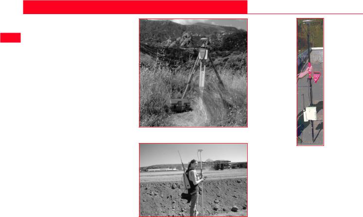
2. Equipment Set Up and Connection
The type of equipment set up that is used will vary with the type of site occupation and the measuring mode. This also applies to the way in which the various components are connected together. There are optimal solutions for setting up the equipment on a tripod, in a backpack and on the pole.
Set up on Tripod
Set up on Unipole
Set up on pole with Minipack
|
2. Set-up and Connection |
20 |
Technical Reference Manual-4.0.0en |
![]()
2.1 GPS Receiver ports
All other components of System 500 connect to the GPS Receiver.
The TR500 Terminal fits either directly on the Receiver or can be connected to the Terminal port using a cable.
A Radio Modem in a housing can also be fitted directly to the Receiver. Alternatively, if the housing is not being used, the radio modem can be connected to Port 1 or Port 3 using a cable.
The Antenna is connected to the Receiver via the ANT Port.
External power can be connected via a cable through Port 2.
|
PORT 3 |
||
|
1 |
||
|
2 |
ON |
TERMINAL |
|
EVENT1 |
OFF |
|
|
3 |
||
|
PPS |
||
|
PWR |
ANT |
|
|
4 |
5 |
6 |
1.Port 3. 8 pin Lemo.Power/data in/out
2.Event Input 1 (Optional)
3.5 pin Lemo. Power
4.Power ON/OFF
5.PPS Output (Optional)
6.GPS Antenna in
7.Event Input 2 (Optional)
 LEICA SR530
EVENT2
|
PORT 2/PWR |
PORT 1 |
||
|
7 |
8 |
9 |
10 |
8.Port 2. 5 pin Lemo. Power/data in/out.
9.Pressure equalisation vent.
10.Port 1. 8 pin Lemo. Power/data in/out.
11.PC Card door.
12.Terminal in/out or Remote Interface in/out.
SR530 Receiver, front panel
|
Technical Reference Manual-4.0.0en |
21 |
2. Set-up and Connection |

2.2 Equipment Setup — Post Processed Static/Rapid Static/Reference on Pillar
 Use
Use
Static/Rapid Static operations or as Reference for Kinematic.
The Receiver and TR500 (if used) can be assembled to make one unit. One connection is made to the GPS Antenna which is mounted on the Pillar. The Receiver and TR500 can be kept in the case. Note that the Receiver can be programmed with the TR500 prior to use which can then be omitted from the set up.
Assumptions
1.GPS Antenna is mounted directly using screw fitting. If using stub and GAD 31 adapter, procedures may vary slightly.
2.GPS Antennas are AT501 or AT502. Procedures/ setup may vary if AT503, 504 or single frequency choke ring are used.
|
2. Set-up and Connection |
22 |
Technical Reference Manual-4.0.0en |

Equipment Checklist
1.GPS Antenna AT501, 502, 503, 504 or 505
2.GRT146 Carrier
3. GDF122 or GDF112 Tribrach
4. Pillar Plate (if required)
5. GEV120 2.8m Antenna Cable
6. 2, GEB121 Batteries
7. SR510/520/530 GPS Receiver
8. TR500 Terminal (if required)
9. MCF XMB-3 PC Flash Card.
10.GVP602 System 500 Transport Case.
|
Technical Reference Manual-4.0.0en |
23 |
2. Set-up and Connection |

 Procedure
1.If a pillar plate is being used, locate it on the pillar.
2.Screw the tribrach to the pillar plate or the pillar. Level the tribrach.
3.Place and lock the GRT146 Carrier in the Tribrach.
4.Screw the Antenna onto the Carrier.
5.Check that the Tribrach is still level.
6.Connect the GPS Receiver to the Antenna using the GEV120 Antenna cable.
7.Plug the GEB121 batteries into the GPS Receiver.
8.Attach the TR500 Terminal to the Receiver if required.
9.Insert the PCMCIA Flash Card into the Receiver.
10.Switch on the system using the ON/OFF button.
11.The Receiver can be placed in the Transport Case for additional protection.
The Next Steps
If the Receiver has been pre-pro- grammed and the TR500 is not being used, further guidance is available in Chapter 3.
If the Receiver has been pre-pro- grammed and the TR500 is being used, further guidance is available in Chapter 7.
If the Receiver requires programming with the TR500, further guidance is available in Chapter 5.
When Using the GAD31 adapter and GRT144 carrier,
ensure that the Antenna and GAD31 assembly slide down the full length of the GRT144 stub. An incorrectly mounted Antenna will have a direct effect on your results.
In wet conditions the Receiver can be placed in the
transport case during use for extra protection. Try to shut the case as completely as possible.
If the Receiver is left in the case during use in tempera-
tures exceeding 25°C, the lid should be left open. Refer to Appendix A for operating and storage temperatures.
Use an external battery such as GEB71 to extend the
operating time past 6 hours.
|
2. Set-up and Connection |
24 |
Technical Reference Manual-4.0.0en |

2.3 Equipment Setup — Post Processed Static/Rapid Static/Reference on Tripod
Use
Static/Rapid Static operations or as Reference for Kinematic.
The Receiver and TR500 (if used) can be assembled to make one unit. This clips to the tripod leg or is placed in the transport container. One connection is made to the Antenna. Note that the Receiver can be programmed with the TR500 prior to use which can then be omitted from the set up.
Assumptions
1.GPS Antenna is mounted directly using screw fitting. If using stub and GAD 31 adapter, procedures may vary slightly.
2.GPS Antennas are AT501 or AT502. Procedures/ setup may vary if AT503, 504 or single frequency choke ring are used.
|
Technical Reference Manual-4.0.0en |
25 |
2. Set-up and Connection |
|
Equipment Checklist |
|||
|
1. |
GPS Antenna AT501 or AT502 |
||
|
2. |
GRT146 Carrier |
||
|
3. |
GDF122 or GDF112 Tribrach |
||
|
4. |
GST20, GST05 or GST05L |
||
|
Tripod |
|||
|
5. |
GZS4 Height Hook |
||
|
6. |
GEV120 2.8m Antenna Cable |
||
|
7. |
2, GEB121 Batteries |
||
|
8. |
SR510/520/530 GPS Receiver |
||
|
9. |
TR500 Terminal (if required) |
||
|
10.MCF XMB-3 PCMCIA Flash |
|||
|
Card. |
|||
|
11.GVP602 System 500 Transport |
|||
|
Case. |
|||
|
2. Set-up and Connection |
26 |
Technical Reference Manual-4.0.0en |

Procedure
1.Set up the tripod.
2.Mount and level the tribrach on the tripod.
3.Place and lock the GRT146 Carrier in the Tribrach.
4.Screw the Antenna onto the Carrier.
5.Check that the Tribrach is still level.
5.Insert the Height Hook into the Carrier.
6.Connect the GPS Receiver to the Antenna using the GEV120 Antenna cable.
7.Plug the GEB121 batteries into the GPS Receiver.
8.Attach the TR500 Terminal to the Receiver if required.
9.Insert the PCMCIA Flash Card into the Receiver.
10.Using the hook on the rear of the unit, hang it on the Tripod leg or place it in the box.
11.Switch on the system using the ON/OFF button on the Receiver.
The Next Steps
If the Receiver has been pre-pro- grammed and the TR500 is not being used, further guidance is available in Chapter 3.
If the Receiver has been pre-pro- grammed and the TR500 is being used, further guidance is available in Chapter 7.
If the Receiver requires programming with the TR500, further guidance is available in Chapter 5.
When Using the GAD31 adapter and GRT144 carrier,
ensure that the Antenna and GAD31 assembly slide down the full length of the GRT144 stub. An incorrectly mounted Antenna will have a direct effect on your results.
In wet conditions the Receiver can be placed in the
transport case during use for extra protection. Try to shut the case as completely as possible.
If the Receiver is left in the case during use in tempera-
tures exceeding 25°C, the lid should be left open. Refer to Appendix A for operating and storage temperatures.
Use an external battery such as GEB71 to extend the
operating time past 6 hours.
|
Technical Reference Manual-4.0.0en |
27 |
2. Set-up and Connection |

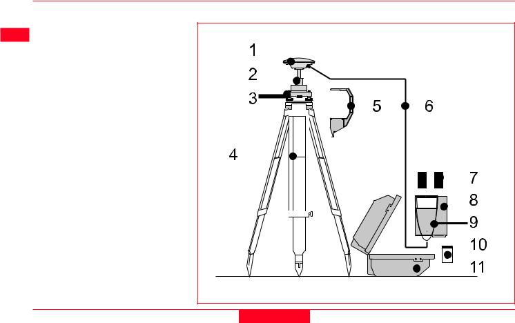
2.4 Equipment Setup — Post Processed Kinematic, Minipack and Pole
 Use
Use
Post Processed Kinematic Rover.
The Receiver is placed in the Minipack. Connections are made to the Antenna and TR500. Recommended for extended periods of use in the field.
Assumptions
1.GPS Antenna is mounted directly using screw fitting. If using stub and GAD 31 adapter, procedures may vary slightly.
2.Aluminium poles are used. You may replace them with their Carbon Fiber equivalents without any change to these instructions.
|
2. Set-up and Connection |
28 |
Technical Reference Manual-4.0.0en |
Equipment Checklist
1. GPS Antenna AT501 or 502
2. GLS21 Upper half aluminium pole with screw
3. GHT25 Grip for pole
4. GHT27 Holder for TR500
5.GLS20 Lower half aluminium pole
6. GEV141 1.2m Antenna cable
7. GEV142 1.6m Antenna cable
8. TR500 Terminal
9. 2, GEB121 Batteries
10. SR510, 520 or 530 GPS Receiver
11. GVP603 Minipack
12. MCF XMB-3 PCMCIA flash card
13. GEV97 1.8m, 5pin Lemo cable
|
Technical Reference Manual-4.0.0en |
29 |
2. Set-up and Connection |
 How to set up the equipment
1.Screw the two halves of the pole together.
2.Slide the grip onto the pole. Attach the TR500 holder and tighten the screw.
3.Screw the GPS Antenna to the top of the pole.
4.Slide the TR500 into the holder until it clicks into place.
5.Insert the PC Card into the Receiver and plug in the GEB121 batteries.
6.Place the Receiver front panel up in the Minipack with the batteries facing outwards. Fasten the strap around the Receiver
7.Connect the GPS Antenna to the Receiver using the two Antenna cables. Connect the longest cable to the Receiver, pass the cable through the cable brake and down through the opening in the bottom corner of the Minipack flap. Draw the required
amount of cable out of the Minipack and tighten the cable brake. Refer to the diagram.
8. Connect the TR500 to the port labelled “Terminal” on the Receiver using the 1.8m cable. Pass it through the opening in the bottom of the Minipack flap, down through a cable brake and then plug into the Receiver. Refer to the diagram.
10. Switch on the system using the ON/OFF button on the Receiver.
 To GPS Antenna
To Terminal
Connecting the TR500 Terminal and GPS
Antenna in the Minipack
|
2. Set-up and Connection |
30 |
Technical Reference Manual-4.0.0en |
![]()
The Next Steps
If the Receiver has been pre-pro- grammed and the TR500 is being used, further guidance is available in Chapter 7.
If the Receiver requires programming with the TR500, further guidance is available in Chapter 5.
Ensure a dry plastic weather protection cap is fitted to the
socket on the TR500 that is not connected to the sensor.
If moisture or water should appear in the socket that is
not used on the TR500, allow the socket and plastic weather protection cap to dry naturally.
When using the upper pole halves with stub, ensure that
the Antenna and GAD31 screw/stub adapter slide down the full length of the stub before tightening the locking ring. An incorrectly mounted Antenna will have a direct effect on your results.
Advice on using the Minipack is given in Section 2.14.
|
Technical Reference Manual-4.0.0en |
31 |
2. Set-up and Connection |

2.5 Equipment Setup — Post Processed Kinematic, All on Pole, Direct Clip of TR500 on to Sensor
 Use
Use
Post-processed Kinematic Rover.
The TR500 is mounted on the Receiver which is screwed onto the pole grip. One connection is made from the Receiver to the Antenna. Recommended for short periods of use, especially where there are many obstacles (fences etc.).
Assumptions
1.GPS Antenna is mounted directly using screw fitting. If using stub and GAD 31 adapter, procedures may vary slightly.
2.Aluminium poles are used. You may replace them with their Carbon Fiber equivalents without any change to these instructions.
|
2. Set-up and Connection |
32 |
Technical Reference Manual-4.0.0en |

Equipment Checklist
1. GPS Antenna AT501 or 502
2. GLS18 Upper half aluminium pole with screw
3. GHT25 Grip for pole
4. GHT26 Holder for GPS Receiver
5. GLS17 Lower half aluminium pole
6. GEV141 1.2m Antenna cable
7. 2, GEB121 Batteries
8. TR500 Terminal
9. SR510, 520 or 530 GPS Receiver
10. MCF XMB-3 PCMCIA flash card
|
Technical Reference Manual-4.0.0en |
33 |
2. Set-up and Connection |

 How to set up the equipment
1.Screw the two halves of the pole together.
2.Slide the grip onto the pole. Attach the GPS Receiver holder and tighten the screw.
3.Screw the GPS Antenna onto the top of the pole.
4.Attach the TR500 to the GPS Receiver. Screw the GPS Receiver to the GPS Receiver holder.
5.Insert the PC Card into the Receiver and plug in the GEB121 batteries.
6.Connect the GPS Antenna to the Receiver using the 1.2m antenna cable.
7.Switch on the system using the ON/OFF button on the TR500.
The Next Steps
If the Receiver has been pre-pro- grammed and the TR500 is being used, further guidance is available in Chapter 7.
If the Receiver requires programming with the TR500, further guidance is available in Chapter 5.
When using the upper pole halves with stub, ensure that
the Antenna and GAD31 screw/stub adapter slide down the full length of the stub before tightening the locking ring. An incorrectly mounted Antenna will have a direct effect on your results.
|
2. Set-up and Connection |
34 |
Technical Reference Manual-4.0.0en |

2.6 Equipment Setup — Post Processed Kinematic, All on Pole, TR500 and Sensor separated
Use
Post-processed Kinematic Rover.
The TR500 is fixed to the pole grip with a holder. With another metallic holder and a holder piece, the receiver is fixed to the pole. One connection is made from the Receiver to the Antenna. Another connection is made from the Receiver to the TR500. Recommended for short periods of use, especially where there are many obstacles (fences etc.).
Assumptions
1.GPS Antenna is mounted directly using screw fitting. If using stub and GAD 31 adapter, procedures may vary slightly.
2.Aluminium poles are used. You may replace them with their Carbon Fiber equivalents without any change to these instructions.
|
Technical Reference Manual-4.0.0en |
35 |
2. Set-up and Connection |

|
Equipment Checklist |
||
|
1. |
GPS Antenna AT501 or 502 |
1 |
|
2. |
GLS18 Upper half aluminium |
|
|
3. |
pole with screw |
2 |
|
GHT25 Grip for pole |
||
|
4. |
GHT27 Holder for TR500 |
|
5. |
GLS17 Lower half aluminium |
8 |
|
6. |
pole |
|
|
GHT37 Holder piece for GPS |
3 |
|
|
Receiver with antenna cable and |
||
|
9 |
||
|
5pin Lemo cable |
||
|
4 |
||
|
7. |
GHT26 Holder for GPS Receiver |
|
|
8. |
TR500 Terminal |
L |
|
9. |
2, GEB121 Batteries |
5 |
|
10. |
SR510, 520 or 530 GPS Re- |
10 |
|
ceiver |
||
|
11. |
MCF XMB-3 PCMCIA flash card |
11 |
7
6
|
2. Set-up and Connection |
36 |
Technical Reference Manual-4.0.0en |

How to set up the equipment
1.Screw the two halves of the pole together.
2.Slide the grip onto the pole. Attach the TR500 holder to the grip and tighten the screw.
3.Slide the holder piece for the GPS Receiver onto the pole. Attach the GPS Receiver holder and tighten the screw.
4.Screw the GPS Antenna onto the top of the pole.
5.Slide the TR500 into the holder until it clicks into place.
6.Screw the GPS Receiver to the GPS Receiver holder.
7.Insert the PC Card into the Receiver and plug in the GEB121 batteries.
8.Connect the GPS Antenna to the Receiver using the antenna cable supplied with the GPS receiver holder piece.
9.Connect the TR500 to the port labelled “Terminal” on the Receiver using the 5 pin Lemo cable.
10.Switch on the system using the ON/OFF button on the TR500.
The Next Steps
If the Receiver has been pre-pro- grammed and the TR500 is being used, further guidance is available in Chapter 7.
If the Receiver requires programming with the TR500, further guidance is available in Chapter 5.
When using the upper pole halves with stub, ensure that
the Antenna and GAD31 screw/stub adapter slide down the full length of the stub before tightening the locking ring. An incorrectly mounted Antenna will have a direct effect on your results.
|
Technical Reference Manual-4.0.0en |
37 |
2. Set-up and Connection |

2.7 Equipment Setup — Real Time Reference, single tripod
 Use
Use
Real Time Reference Station. May also collect raw observation data for post-processing.
The Receiver and TR500 (if used) can be assembled to make one unit. This clips to the tripod leg. Connections are made to the GPS and Radio Antenna. Note that the Receiver can be programmed with the TR500 prior to use which can then be omitted from the set up.
The Radio Antenna is mounted on the Antenna Arm which clips to the GPS Antenna.
The SR510 and SR520 can only be used as a DGPS reference station if they are fitted with the DGPS option. They cannot be used as a Real-Time Reference station.
The SR530 can be used as either a DGPS or Real-Time reference station. Real-Time and DGPS are fitted as standard on the SR530.
Assumptions
1.GPS Antenna is mounted directly using screw fitting. If using stub and GAD 31 adapter, procedures may vary slightly.
2.Standard Radio modem is used. (Mounted in Radio Housing).
|
2. Set-up and Connection |
38 |
Technical Reference Manual-4.0.0en |

Equipment Checklist
1.GPS Antenna AT501, 502
2.GRT146 Carrier
3.GDF122 or GDF112 Tribrach
4. SR510/520/530 GPS Receiver
5. TR500 Terminal (if required)
6. GEV141 1.2m Antenna Cable
7. GST20/GST05/05L Tripod
8. GAT1/GAT2 Radio Antenna
9. GAD33 Radio Antenna Arm
10. GEV141 1.2m Antenna Cable
11. GZS4 Height Hook
12. Radio Modem in GFU 5/6 Housing
13. MCF XMB-3 PC card
14. 2, GEB121 Batteries
15. GVP602 Transport Case
|
Technical Reference Manual-4.0.0en |
39 |
2. Set-up and Connection |

 How to set up the equipment
Follow steps 1-10 as described in section 2.3.
11.Clip the Antenna Arm to the GPS Antenna. Screw the Radio Antenna onto the Arm.
12.Attach the Radio Modem in its housing to the GPS Receiver.
13.Connect the Radio Antenna to the Radio Modem using the 1.2m Antenna Cable.
14.Switch the System On using the On/Off button on the Receiver.
The Next Steps
If the Receiver has been pre-pro- grammed and the TR500 is not being used, further guidance is available in Chapter 3.
If the Receiver has been pre-pro- grammed and the TR500 is being used, further guidance is available in Chapter 7.
If the Receiver requires programming with the TR500, further guidance is available in Chapter 5.
When Using the GAD31 adapter and GRT144 carrier,
ensure that the Antenna and GAD31 assembly slide down the full length of the GRT144 stub. An incorrectly mounted Antenna will have a direct effect on your results.
In wet conditions the Receiver can be placed in the
transport case during use for extra protection. Try to shut the case as completely as possible.
If the Receiver is left in the case during use in tempera-
tures exceeding 25°C, the lid should be left open. Refer to Appendix A for operating and storage temperatures.
Use an external battery such as GEB71 to extend the
operating time past 6 hours.
|
2. Set-up and Connection |
40 |
Technical Reference Manual-4.0.0en |
![]()
2.8 Equipment Setup — Real-Time Reference, Two Tripods
Use
The Receiver and TR500 (if used) can be assembled to make one unit. This clips to the tripod leg. Connections are made to the GPS and Radio Antenna. Note that the Receiver can be programmed with the TR500 prior to use which can then be omitted from the set up.
The Radio Antenna is mounted on the second tripod. This increases the height of the Radio Antenna and therefore maximizes radio coverage.
The SR510 and SR520 can only be used as a DGPS reference station if they are fitted with the DGPS option. They cannot be used as a Real-Time Reference station.
The SR530 can be used as either a DGPS or Real-Time reference station. Real-Time and DGPS are fitted as standard on the SR530.
Assumptions
1.GPS Antenna is mounted directly using screw fitting. If using stub and GAD 31 adapter, procedures may vary slightly.
2.Standard Radio modem is used. (Mounted in Radio Housing).
|
Technical Reference Manual-4.0.0en |
41 |
2. Set-up and Connection |

 Equipment Checklist
1.GPS Antenna AT501/502
2.GRT146 Carrier
3.GDF122 or GDF112 Tribrach
4.SR510/520/530 GPS Receiver
5.TR500 Terminal (if required)
6.GEV141 1.2m Antenna Cable
7.GST20\GST05\05L Tripod
8.GZS4 Height Hook
9.Radio Modem in GFU5/6 Housing
10.MCF XMB-3 PC Card
11.GEB121 Batteries
12.GST20\GST05\05L Tripod
13.GHT36 Base for Telescopic Rod
14.GEV120 2.8m Antenna Cable
15.GAT1\GAT2 Radio Antenna
16.GAD34 Short Antenna Arm
17.GAD32 Telescopic Rod
18.GVP602 Transport Case
|
15 |
16 |
|||
|
1 |
14 |
|||
|
17 |
||||
|
2 |
||||
|
3 |
8 |
13 |
||
|
4 |
||||
|
18 |
||||
|
5 |
9 |
12 |
||
|
6 |
10 |
11 |
||
|
7 |
|
2. Set-up and Connection |
42 |
Technical Reference Manual-4.0.0en |

How to set up the equipment
Follow steps 1-10 as described in section 2.3.
11.Attach the Radio Modem in its housing to the GPS Receiver.
12.Set up the second Tripod nearby. Screw the Base onto the Tripod. Push the Telescopic Rod into the Base.
13.Screw the Short Antenna Arm onto the telescopic Rod. Screw the Radio Antenna onto the Arm.
14.Connect the Radio modem to the Radio Antenna using the 2.8m Antenna cable.
15.Switch the System On using the On/Off button on the Receiver or Terminal.
The Next Steps
If the Receiver has been pre-pro- grammed and the TR500 is not being used, further guidance is available in Chapter 3.
If the Receiver has been pre-pro- grammed and the TR500 is being used, further guidance is available in Chapter 7.
If the Receiver requires programming with the TR500, further guidance is available in Chapter 5.
When Using the GAD31 adapter and GRT144 carrier,
ensure that the Antenna and GAD31 assembly slide down the full length of the GRT144 stub. An incorrectly mounted Antenna will have a direct effect on your results.
In wet conditions the Receiver can be placed in the
transport case during use for extra protection. Try to shut the case as completely as possible.
If the Receiver is left in the case during use in tempera-
tures exceeding 25°C, the lid should be left open. Refer to Appendix A for operating and storage.
|
Technical Reference Manual-4.0.0en |
43 |
2. Set-up and Connection |

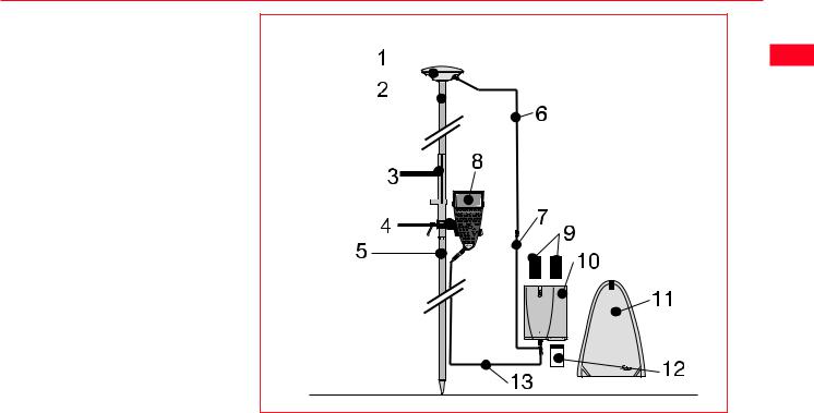
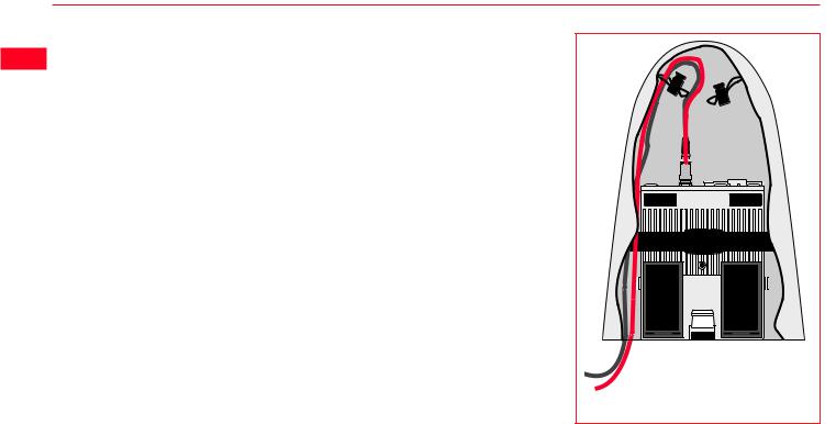
2.9 Equipment Setup — Real-Time Rover, Pole and Minipack
 Use
Use
The Radio Modem attaches to the Receiver and is placed in the Minipack. Connections are made to the GPS Antenna, Radio Antenna and TR500. Recommended for extended periods of use in the field.
The cables coming from the Minipack can be disconnected in the event that an obstacle (E.g. a fence) has to be crossed.
Assumptions
1.GPS Antenna is mounted directly using screw fitting. If using stub and GAD 31 adapter, procedures may vary slightly.
2.Aluminium poles are used. You may replace them with their Carbon Fiber equivalents without any change to these instructions.
|
2. Set-up and Connection |
44 |
Technical Reference Manual-4.0.0en |

Equipment Checklist
1. GPS Antenna AT501 or 502
2. GLS21 Upper half aluminium pole with screw or stub
3.GHT25 Grip for pole
4.GHT27 Holder for TR500
5. GLS20 Lower half aluminium pole
6. GEV141 1.2m Antenna cable
7. GEV142 1.6m Antenna cable
8. TR500 Terminal
9. 2, GEB121 Batteries
10. SR510, 520 or 530 GPS Receiver
11. Radio Modem in GFU5/6 Housing
12. MCF XMB-3 PCMCIA flash card
13. GEV97 1.8m, 5pin Lemo cable
14. GEV141 1.2m Antenna cable
15. GAT1/GAT2 Radio Antenna
16. GAD34 Small Antenna Arm
17. GAD32 Telescopic Rod
18. GVP603 Minipack
|
Technical Reference Manual-4.0.0en |
45 |
2. Set-up and Connection |

 How to set up the equipment
Follow steps 1-5 as described in section 2.4.
6.Attach the Radio Modem Housing containing the Radio Modem to the GPS Receiver.
7.Place the GPS Receiver front panel up in the Minipack with the batteries facing outwards. Fasten the strap around the Receiver (refer to diagram)
8.Push the Telescopic Rod through the slit in the top of the Minipack. Ensure it is located in the sleeve inside the Minipack and push it all the way to the bottom. Adjust the height of the Telescopic Rod to suit.
9.Screw the Short Antenna Arm onto the Telescopic Rod. Screw the Radio Antenna onto the Short Antenna Arm.
10.Connect the Radio Modem to the Radio Antenna using a 1.2m Antenna Cable. The cable should pass down underneath
|
the Receiver and then up through |
To Radio Antenna |
|
|
the slit in the top of the Minipack. |
||
|
11. |
Connect the GPS Antenna to the |
|
|
Receiver using the two Antenna |
||
|
Cables. The longest Cable |
||
|
should be connected to the |
||
|
Receiver. Pass this cable |
||
|
through a cable brake and down |
||
|
through the slit under one of the |
||
|
reflective strips at the bottom of |
||
|
the Minipack. Draw the required |
||
|
amount of cable out of the |
||
|
Minipack and tighten the cable |
||
|
brake. Refer to the diagram. |
||
|
12. |
Connect the TR500 to the port |
|
|
labelled “Terminal”on the Re- |
||
|
ceiver using the 1.8m |
||
|
cable.Pass it through the open- |
||
|
ing under one of the reflective |
||
|
strips at the bottom of the |
||
|
Minipack, up through a cable |
To GPS Antenna |
|
|
brake and then plug into the |
||
|
13. |
Receiver. Refer to the diagram. |
To Terminal |
|
Switch the System ON using the |
||
|
ON/OFF key on the Terminal. |
|
2. Set-up and Connection |
46 |
Technical Reference Manual-4.0.0en |

The Next Steps
If the Receiver has been pre-pro- grammed and the TR500 is being used, further guidance is available in Chapter 7.
If the Receiver requires programming with the TR500, further guidance is available in Chapter 5.
Ensure a dry plastic weather protection cap is fitted to the
socket on the TR500 that is not connected to the sensor.
If moisture or water should appear in the socket that is
not used on the TR500, allow the socket and plastic weather protection cap to dry naturally.
When using the upper pole halves with stub, ensure that
the Antenna and GAD31 screw/stub adapter slide down the full length of the stub before tightening the locking ring. An incorrectly mounted Antenna will have a direct effect on your results.
Advice on using the Minipack is given in Section 2.14.
|
Technical Reference Manual-4.0.0en |
47 |
2. Set-up and Connection |

2.10 Equipment Setup — Real-Time Rover, All on Pole, direct clip of TR500 on to Sensor
 Use
Use
The TR500 is mounted on the Receiver which is clipped to the grip. Connections are made from the Receiver to the GPS and Radio Antennas. Recommended for short periods of use, especially where there are many obstacles (fences etc.).
Assumptions
1.GPS Antenna is mounted directly using screw fitting. If using stub and GAD 31 adapter, procedures may vary slightly.
2.Aluminium poles are used. You may replace them with their Carbon Fiber equivalents without any change to these instructions.
|
2. Set-up and Connection |
48 |
Technical Reference Manual-4.0.0en |

Equipment Checklist
1.GPS Antenna AT501 or 502
2.GLS21 Upper half aluminium
pole with screw or stub 3. GHT25 Grip for pole
4. GHT27 Holder for GPS Receiver
5. GLS17 Lower half aluminium pole
6. GAT1/GAT2 Radio Antenna
7. GAD33 Antenna Arm
8. GEV141 1.2m Antenna Cable
9. 2, GEB121 Batteries
10. TR500 Terminal
11. SR510/520/530 GPS Receiver
12. Radio Modem in GFU5/6 Housing
13. MCF XMB-3 PC Card
14. GEV141 1.2m Antenna Cable
|
Technical Reference Manual-4.0.0en |
49 |
2. Set-up and Connection |

 How to set up the equipment
Follow steps 1-6 described in section 2.5.
7.Clip the Antenna Arm to the GPS Antenna. Screw the Radio Antenna onto the Arm.
8.Attach the Radio Modem in its housing to the GPS Receiver.
9.Connect the Radio Antenna to the Radio Modem using a 1.2m Antenna Cable.
10.Switch the System ON using the ON/OFF key on the Terminal.
The Next Steps
If the Receiver has been pre-pro- grammed and the TR500 is being used, further guidance is available in Chapter 7.
If the Receiver requires programming with the TR500, further guidance is available in Chapter 5.
When using the upper pole halves with stub, ensure that
the Antenna and GAD31 screw/stub adapter slide down the full length of the stub before tightening the locking ring. An incorrectly mounted Antenna will have a direct effect on your results.
The Radio Antenna may also be connected directly to the
Radio Housing. Note however that range and quality of signal received may be affected.
|
2. Set-up and Connection |
50 |
Technical Reference Manual-4.0.0en |
 Loading…
-
Cobra GPS 500 — page 1
The user is responsible for operating this product wisely . The product is intended for use only as a navigational aid and should not be used when precise measurement of direction, location, distance or topography is required. GPS (Global Positioning System) is operated by the U.S. government, which is solely responsible for its accuracy and mainte …
-
Cobra GPS 500 — page 2
Congratulations! Y ou’ve made a smart choice by purchasing the GPS 500 Global Positioning System receiver from Cobra ® . Designed to give you access to the most advanced satellite navigation technology available, your GPS 500 offers you these sophisticated features and capabilities: Features: • Cobra ® EXCLUSIVE 18- channel technology gives y …
-
Cobra GPS 500 — page 3
1 2 3 4 5 6 7 8 9 T ABLE OF CONTENTS Important Information ………………………………………………………………………………………….. A1 Product Features ………………………………………………………………………………………………… A2–A3 W elcome ………………………………. …
-
Cobra GPS 500 — page 4
GPS GENERAL INFORMA TION 2 GPS Basics The Global Positioning System (GPS) is a space-based radio- navigation system. It consists of 24 satellites, which orbit the earth at an altitude of approximately 11,000 miles, and ground stations. GPS provides users with accurate information on position, velocity and time. This is available anywhere in the wor …
-
Cobra GPS 500 — page 5
GPS GENERAL INFORMA TION Data Field Choices Descriptions Y our Cobra ® GPS 500 has the ability to display various types of information to you. In order to take advantage of the rich information available to you, it is important that you understand the meaning of certain terms. Below is a list of terms that will aid you in using your Cobra ® GPS 5 …
-
Cobra GPS 500 — page 6
Installing Batteries Y our GPS 500 operates on two standard AA batteries (not included). Always use high-quality alkaline batteries. T o install batteries, twist the D-ring connector counterclockwise (anticlockwise) and remove the battery compartment cover. Insert two AA batteries ensuring correct polarity alignment. Replace the battery com …
-
Cobra GPS 500 — page 7
1 BASIC OPERA TION 7 Navigating with the GPS 500 Y our GPS 500 receives signals from Global Positioning System satellites that are in fixed orbits (stationary relative to the ground) around the earth. By acquiring – or locking on to – the signals from at least three satellites, your unit can use triangulation to precisely determine your current …
-
Cobra GPS 500 — page 8
2 THE FIVE MAIN P AGES 9 10 2. 1 MAP P AGE Map Page The Map page displays a graphic representation of the navigation currently in progress. Y ou can choose to display or hide any waypoints; cities/towns; continental U.S. state, Canadian provincial and European country boundaries; points of interest; routes or tracks that you are using. A black …
-
Cobra GPS 500 — page 9
12 2.1 MAP P AGE 2.1 MAP P AGE 11 Using the Map Page Moving Around: Panning Moving Around the Map Image From the Map page, you can zoom in or zoom out on the map image by pressing the ZOOM IN/OUT button. The data field on the map image can be hidden by selecting FULL MAP (see “Set Data Option”, page 10). A section of map outside the current vie …
-
Cobra GPS 500 — page 10
2.1 MAP P AGE 13 14 2.2 GAUGES P AGE Moving Around: Details Compass Select Options Bearing Pointer Settings Gauges Page The Gauges page displays a compass that indicates direction of travel. It can show the direction you are currently traveling or the direction from your current position to the next waypoint in your navigation. …
-
Cobra GPS 500 — page 11
2.3 TRIP METER P AGE 2.2 GAUGES P AGE Using the Gauges Page T rip Meter Info Option Settings Reset Values T rip Meter Page The T rip Meter page displays information about your current position, the navigation in progress and other available data. It can display up to 5 fields that you can select from a total of 15 choices. Selecting …
-
Cobra GPS 500 — page 12
Nav Data Page The Nav Data page gives you access to the powerful navigational features of your GPS 500. From this page, you can create and store up to 500 waypoints. For each one, you can choose a name and assign a symbol. Using the navigational features, you can ask the unit to show you the “GoT o” direction of travel to reach a selected w …
-
Cobra GPS 500 — page 13
20 2.4 NA V DA T A P AGE 2.4 NA V DA T A P AGE Add New Waypoint Information Screen Information Screen New Option Highlight and select NEW to add a new waypoint to the list. Highlight and select MARK CURRENT to save the coordinates for your current location as a waypoint. The default name (a 3-digit number) and symbol (a …
-
Cobra GPS 500 — page 14
2.4 NA V DA T A P AGE 2.4 NA V DA T A P AGE Waypoints: Creating New Waypoints: GoT o 22 “GoT o” a Selected W aypoint T o make the map show the navigational path to a selected waypoint: 1. From the Nav Data page, highlight using the JOYSTICK and select WA YPOINTS by pressing the ENTER button . Highlight and select SELECT . 2. Highlight a …
-
Cobra GPS 500 — page 15
2.4 2.4 NA V DA T A P AGE T racks When you select TRACKS from the Nav Data page (see ), your GPS 500 will display a list of the tracks currently stored. Y our unit will automatically record a track as you travel. Y ou can store up to 10 tracks and later recall any of those tracks to use for navigation. Y our unit can guide you along a selected …
-
Cobra GPS 500 — page 16
26 2.4 NA V DA T A P AGE 2.4 NA V DA T A P AGE Navigate a Selected T rack T o make the map show the navigational path along a selected track: 1. From the Nav Data page, highlight using the JOYSTICK and select TRACKS by pressing the ENTER button . 2. Highlight and select the track you want to navigate . A map of the selected track appears wi …
-
Cobra GPS 500 — page 17
28 2.4 NA V DA T A P AGE 2.4 NA V DA T A P AGE 27 Creating a New Route T o create a new route consisting of up to 50 waypoints and/or points of interest: 1. From the Nav Data page, highlight and select ROUTES . Highlight and select the line of empty spaces at the end of the list of routes . A blank New Route screen appears with the current …
-
Cobra GPS 500 — page 18
30 2.4 NA V DA T A P AGE 2.4 NA V DA T A P AGE Routes: Editing Editing a Route Inserting a Waypoint/POI into a Route T o add a waypoint or point of interest to an existing route: 1. From the Nav Data page , highlight and select ROUTES. Highlight and select the route you wish to add a point to . The selected route ‘ s screen appears . …
-
Cobra GPS 500 — page 19
32 31 2.4 NA V DA T A P AGE Routes: Navigation Information NA V DA T A P AGE Routes: Navigate Route List Points Not Y et Reached Points Already Reached Nav Data Page Current Point 2.4 Viewing Information for a Route Being Navigated By selecting a route which is currently being navigated, you can view information for any of the p …
-
Cobra GPS 500 — page 20
34 2.4 NA V DA T A P AGE NA V DA T A P AGE 33 Cities/T owns: Summary Cities/T owns: GoT o Cities/T owns When you select CITIES from the Nav Data page, you have access to the coordinates for hundreds of cities/towns worldwide already stored in your GPS 500’ s memory . Y ou can ask the unit to show you the «GoTo» direction of travel to re …
-
Cobra GPS 500 — page 21
36 2.4 NA V DA T A P AGE 2.4 NA V DA T A P AGE 35 Points of Interest: Summary Sort Option Highlight and select SORT to sort the list of POIs according to name, symbol, or nearest POI. Highlight and select NAME to sort the POIs in alphabetical order . Highlight and select SYMBOL to sort the POIs with the symbol you chose listed first. (G …
-
Cobra GPS 500 — page 22
38 2.4 NA V DA T A P AGE 2.4 NA V DA T A P AGE 37 “GoT o” a Selected POI T o make the map show the navigational path to a selected POI: 1. From the Nav Data page , push the JOYSTICK up or down to highlight POINTS OF INTEREST and press the ENTER button to display the POI screen . 2. Highlight and select SELECT . Highlight and select …
-
Cobra GPS 500 — page 23
40 2.4 NA V DA T A P AGE 2.4 NA V DA T A P AGE 39 Routes Option Highlight and select ROUTES to delete any or all of the routes you have stored. Highlight and select ONE-BY -ONE to delete routes individually (see “Deleting Individual Waypoints, T racks, Routes, or Points of Interest,” page 40). Highlight and select ALL to delete all rout …
-
Cobra GPS 500 — page 24
42 2.4 NA V DA T A P AGE 2.4 NA V DA T A P AGE 41 Editing T ext T o enter or change the information displayed for a waypoint, track or route: 1. From any screen that allows you to enter letters, numbers or symbols (names of waypoints/tracks/routes, dates, etc.), push the JOYSTICK up or down to move to the field you want to edit and press the EN …
-
Cobra GPS 500 — page 25
44 2.5 SYSTEM P AGE 2.4 NA V DA T A P AGE 43 Search Option T o search any list of waypoints or points of interest for a particular name: 1. From any screen with the SEARCH option, highlight and select SEARCH . 2. Select (by pressing the ENTER button) the highlighted blank space to enter the first letter of the name you are searching for (see ? …
-
Cobra GPS 500 — page 26
Map Page Defaults Function Default Orient North Up Data Field Speed Details Shown Names (show) Symbols (show) Waypoints (show) Cities/T owns (show) POI (show) T rack (show) Route (show) States (show) Auto Zoom On 2.5 SYSTEM P AGE 2.5 T urning GPS Off and On When indoors, you can turn GPS navigation off, allowing you to use the non-navigational feat …
-
Cobra GPS 500 — page 27
2.5 SYSTEM P AGE 2.5 SYSTEM P AGE Adjusting the Display System Page Interface Display Using the Data Interface Y our GPS 500 is designed to let you exchange data with computer mapping programs. With optional software and interface cable (see “Optional Accessories,” page 63) you will be able to: • Upload points of interest from the com …
-
Cobra GPS 500 — page 28
50 2.5 SYSTEM P AGE 2.5 SYSTEM P AGE 49 Language Options Measurement Return to System Page Setting Screen Using the Settings Screen From the Settings screen, you can change the various settings listed below. T o change settings: 1. From the System page , push the JOYSTICK up or down to highlight and select SETTINGS by pressing th …
-
Cobra GPS 500 — page 29
52 2.5 SYSTEM P AGE 2.5 SYSTEM P AGE 51 Using the Advanced Screen From the Advanced screen, you can change the advanced operational parameters used by your GPS 500. T o change advanced parameters: 1. From the System page , push the JOYSTICK up or down to highlight and select ADVANCED by pressing the ENTER button. A menu of advanced parameters a …
-
Cobra GPS 500 — page 30
3 ALERTS 53 54 3 ALERTS WARNING BA TTERIES LOW! This message appears approximately 30 minutes before your batteries need to be replaced. Select OK or the PAGE button to clear the message. Replace the batteries as soon as possible. The message will reappear every 10 minutes until the batteries are replaced. NOTICE GPS IS OFF! This message is …
-
Cobra GPS 500 — page 31
4 GENERAL INFORMA TION 55 4 GENERAL INFORMA TION W orld City Time Zones Longitudinal Zone Offset E172.50 to W172.50 …………………………-12 IDL W (International Date Line West) W172.50 to W157.50 ……………………….-11 Nome W157.50 to W142.50 ……………………….-10 Honolulu W142.50 to W127.50 ………………………. …
-
Cobra GPS 500 — page 32
58 4 GENERAL INFORMA TION What is W AAS? Wide Area Augmentation System (WAAS) is a GPS-based navigation system that provides precision above and beyond what GPS can do on its own. WAAS was designed to improve the accuracy and ensure the integrity of information coming from GPS satellites. WAAS is a network of 25 ground reference stations that cover …
-
Cobra GPS 500 — page 33
60 6 MAINTENANCE & SERVICE Maintenance of Y our GPS 500 Y our GPS 500 is designed and built to give you years of trouble-free performance without the need for service. No routine maintenance is required. If your unit does not appear to be operating properly , please follow these trouble-shooting steps: Make sure you are using fresh batteries an …
-
Cobra GPS 500 — page 34
62 7 INDEX M Magnetic North …………………………..52 Maintenance ……………………………60 Map Data Option ………………………10 Map Datum…………………….45, 51, 57 Map Defaults ……………………………..11 Map Detail Option ……………………….11 Map Display ………………………….10-11 …
-
Cobra GPS 500 — page 35
64 9 U.S. ORDER FORM Item No. Description Cost Ea. Qty . Amount For credit card orders fill out order form and fax to: 773.622.2269 or call 773.889.3087 (Press 1 from the main menu) 8:00 am — 6:00 pm, Monday -Friday CST . Make check or money order payable to: Cobra Electronics 6500 West Cortland Street Chicago, IL 60707 USA A TTN: Accessories Dept. …
-
Cobra GPS 500 — page 36
The Cobra ® line of quality products includes: CB radios microT ALK ® radios Radar/Laser Detectors GPS Safety Alert ® T raffic W ar ning Systems Accessories HighGear ® Accessories VHF Marine Radios Power Inverters For more information or to order any of our products, please visit our website: www .cobra.com Nothing comes close to a Cobra ® Pri …