
Руководство по ремонту хэш-платы Antminer T17 [EN]
Editor-in-Chief: Li Yan
Version date: 2019.7.2
File Category: Maintenance Plan
Content of this Volume: It mainly describes the troubleshooting of various faults of T17, and how to use the test
tool for accurate positioning.
I. Maintenance Tools
1. General electric screwdriver
2. Fluke 15b+ Multimeter, tweezers, V9-v1.2 test jig, T17 chassis with power set
3. Hot air gun (welding temperature is 260 degrees±2 degrees)
4. Constant temperature soldering iron (welding temperature is 300-350 degrees)
5. Environmentally friendly flux solder paste, lead-free low temperature (melting point at 150 degrees) solder wire, anhydrous alcohol, water for cleaning panel,
6. OM550 low temperature solder paste, BM1397AE tinning steel mesh jig
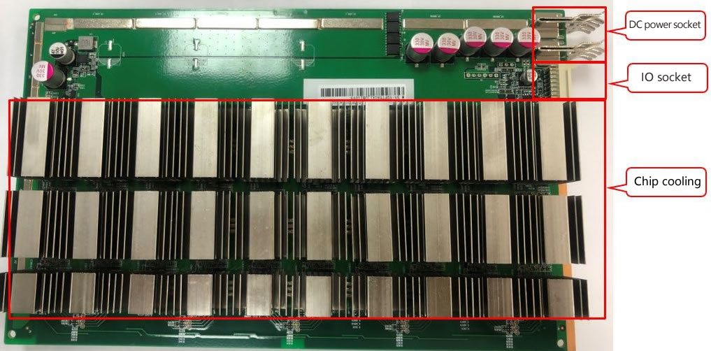
II. Component Structure of the Hash Board

III. Signal Transmission Circuit
1. Signal transmission channel, signal CLK-RST-BO-CO is transmitted from the first chip to the second, and till the 72nd, RI signal is reversely transmitted from the 72ndchips to the first chip, as the figure below:

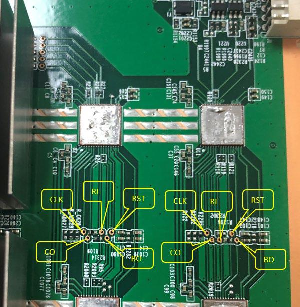
2. Signal test point identification and test point arrangement order (there are a total of 48 chips on the hash board, and 12 voltage domains), as shown below:

Distribution of test points in voltage domain


3. Signal communication circuit from IO socket to chip

Picture of J1-IO socket
 Schematic diagram of J1-IO socket


IV. Power Circuit
1. The power supply voltage of each board is (T17 jig test voltage output is 17V). There are 10 voltage domains, and the voltage of each two voltage domains is 1.7V.

V. Cases of Single Board Test Troubleshooting
5.1 Single board jig test asic=0
Failure analysis:
1. Whether the jig cable and hash board are in good contact.
2. The T17 hash board J6-J7 should have a voltage of 17V when testing the jig.
3. When testing the jig, measure whether there is voltage between the 10 voltage domains.
3.1 If there is no voltage in the voltage domain, it is necessary to see whether the normal working voltage of the pin 4 of Q7, Q8, Q9, Q11 is low level of 0V. If it is high level, then it depends on whether the pin 1 of Q10 is high level of 3.3v, if Q10 does not have 3.3V Voltage, that is, U3-PIC loses firmware or there is no power supply.

Schematic diagram of PIC

17V output control circuit

3.2. If the power supply is normal and there is voltage in voltage domain, then the RI signal of the chip should be measured to see if the RI signal has a voltage of 1.8V. When measuring the RI signal, it should start from the test point of the last chip. If there is voltage in the last chip, measure whether the 20th chip has RI -1.8v, and the rest can be done in the same manner, when finding the chip that does not have RI output voltage, first measure the 1.8V power supply of this chip, if there is no power supply of 1.8V, then check the 1.8V power supply circuit. The 1.8V power supply circuit is supply powers to the LDO pin 1 through the voltage division of the voltage domain. The pin 5 of LDO outputs voltage of 1.8V. (Each voltage domain has -1.8 V LDO to supply power to chip). If there is no output, this LDO should have a problem. If 1.8V is normal, measure the ground resistance of the test point after the power is cut off and compare with the OK board to see if there is any resistance abnormality; if the resistance value is normal, and there is no problem with soldering. This chip should have a problem. (Re-tin the removed chip and solder it to a good board to verify it. If there is no RI signal, it proves that the chip is damaged, replace the chip.)
1.8V power supply circuit


5.2 Fault phenomenon is ASIC=7
Analysis: ASIC=7,
1. In a single board test, 7 chips can be found. It can be judged that the RI signal is normal. If the 8th chip cannot be found, we will directly measure the voltage of the 7th chip U198-CLK-RST-CO to see if the power supply is normal. If CLK does not have a voltage of 0.8V, then it depends on the power supply circuit of CLK.
2-CLK circuit analysis: If CLK does not have 0.8V, first check whether the 0.8V power supply of the bad chip voltage domain is normal, the 0.8V power supply circuit is obtained by voltage domain division, and 1.8V power supply mode is the same, as for the maintenance method for pin 5 output 0.8V, refer to the 1.8V maintenance method (note that there are 2 out of 3 chips outputting 0.8V LDO power supply in each chip in each domain of T17, and each LDO supplies to 2 chips).
0.8v power supply schematic


If the 0.8V power supply circuit does not have a 0.8V output, then see if the 0.8V LDO power supply has a supply voltage of about 3.2V. If it has, see if the LDO is soldered insufficiently or short-circuited. If there is a 0.8V output, then see the ground resistance of the chip, if the resistance is correct, it should be a bad chip.
По вопросам приобретения продукции обращайтесь к нашему менеджеру по продажам:![]() [email protected]
[email protected]
По вопросам ремонта майнера и послепродажного обслуживания обращайтесь к менеджеру по ремонту:![]() [email protected]
[email protected]
По вопросам делового сотрудничества обращайтесь:![]() [email protected]
[email protected]
ЖАЛОБЫ И ПРЕДЛОЖЕНИЯ
Если вы недовольны транзакцией или у вас есть ценные предложения для нас, свяжитесь с нами по этому адресу электронной почты:![]() [email protected]
[email protected]
Скачать и просмотреть руководство по ремонту, запуску и обслуживанию асик майнеров AntMiner, Whatsminer, Innosilicon, Avalon онлайн
На этой странице вы можете прочесть и скачать все необходимые руководства.
Но, конечно, вы всегда можете связаться с нами по WhatsApp +79275104327, по электронной почте Этот адрес электронной почты защищен от спам-ботов. У вас должен быть включен JavaScript для просмотра. или оставить сообщение в чате, если у вас есть какие-либо (технические) вопросы о наших продуктах.
Руководство по ремонту [PDF] Antminer
Руководство по ремонту хэш-платы Antminer D3
Руководство по ремонту хэш-платы Antminer S9
Руководство по ремонту хэш-платы Antminer S9K
Руководство по ремонту хэш-платы Antminer S11
Руководство по ремонту хэш-платы Antminer S15 T15
Руководство по ремонту хэш-платы Antminer S17+
Руководство по ремонту хэш-платы Antminer S17E
Руководство по ремонту хэш-платы Antminer S17
Руководство по ремонту хэш-платы Antminer T9
Руководство по ремонту хэш-платы Antminer T17+
Руководство по ремонту хэш-платы Antminer T17
Руководство по ремонту хэш-платы Innosilicon miner
Руководство по ремонту хэш-платы Antminer WhatsMiner M10
Руководство по ремонту хэш-платы Antminer Whatsminer M20S
Инструкция по установке [PDF]
Antminer
Руководство Antminer D3
Руководство Antminer DR3
Руководство Antminer DR5
Руководство Antminer E3
Руководство Antminer L3
Руководство Antminer R4
Руководство Antminer S1
Руководство Antminer S2
Руководство Antminer S3
Руководство Antminer S4+
Руководство Antminer S5+
Руководство Antminer D3
Руководство Antminer S7
Руководство Antminer S9 Hydro
Руководство Antminer S9
Руководство Antminer S9k
Руководство Antminer S9SE
Руководство Antminer S11
Руководство Antminer S15
Руководство Antminer S17+
Руководство Antminer S17E
Руководство Antminer S17
Руководство Antminer S17Pro
Руководство Antminer T17
Руководство Antminer S19
Руководство Antminer S19Pro
Руководство Antminer T9
Руководство Antminer T15
Руководство Antminer T17+
Руководство Antminer T17E
Руководство Antminer T19
Руководство Antminer X3
Руководство Antminer Z9 Mini
Руководство Antminer Z9
Руководство Antminer Z11
Руководство Antminer Z15
Avalon
Avalonminer 1047 Manual
Avalonminer 1066 Manual
Avalonminer 1026 Manual
Avalonminer 1066 Pro Manual
Avalonminer 1146 Pro Manual
Innosilicon
Innosilicon A4+Manual
Innosilicon A6 Manual
Innosilicon A9 Manual
Innosilicon D9 DCR Manual
Innosilicon S11 Sia Manual
Innosilicon T2T 32T Manual
Innosilicon T2TZ 30T Manual
Innosilicon T3+57T Manual
Loveminer
Loveminer A1 Manual
Whatsminer
WhatsMiner D1 Manual
WhatsMiner M3 Manual
WhatsMiner M10 Manual
WhatsMiner M20S Manual
WhatsMiner M21 Manual
WhatsMiner M21S Manual
WhatsMiner M30S Manual
WhatsMiner M31S Manual
WhatsMiner M32 Manual
руководство по блоку питания и руководство по ремонту [PDF]
Руководство Antminer APW3
Руководство Antminer APW5
Руководство по ремонту блоков питания Antminer APW9 и APW9+
Руководства по Antminer, ремонт antminer , ремонт whatsminer, ремонт innosilicon, ремонт avalon, руководство по ремонту асиков
Руководство по ремонту [PDF]
Antminer
- Руководство по ремонту хэш-платы Antminer D3
- Руководство по ремонту хэш-платы Antminer S9
- Руководство по ремонту хэш-платы Antminer S9 K
- Руководство по ремонту хэш-платы Antminer S11
- Руководство по ремонту хэш-платы Antminer S15 T15
- Руководство по ремонту хэш-платы Antminer S17+
- Руководство по ремонту хэш-платы Antminer S17E
- Руководство по ремонту хэш-платы Antminer S17
- Руководство по ремонту хэш-платы Antminer T9
- Руководство по ремонту хэш-платы Antminer T17+
- Руководство по ремонту хэш-платы Antminer T17
- Руководство по ремонту хэш-платы Innosilicon miner
- Руководство по ремонту хэш-платы Antminer WhatsMiner M10
- Руководство по ремонту хэш-платы Antminer Whatsminer M20S
Инструкция по установке [PDF]
Antminer
- Руководство Antminer D3
- Руководство Antminer DR3
- Руководство Antminer DR5
- Руководство Antminer E3
- Руководство Antminer L3
- Руководство Antminer R4
- Руководство Antminer S1
- Руководство Antminer S2
- Руководство Antminer S3
- Руководство Antminer S4+
- Руководство Antminer S5+
- Руководство Antminer D3
- Руководство Antminer S7
- Руководство Antminer S9 Hydro
- Руководство Antminer S9
- Руководство Antminer S9 k
- Руководство Antminer S9 SE
- Руководство Antminer S11
- Руководство Antminer S15
- Руководство Antminer S17+
- Руководство Antminer S17 E
- Руководство Antminer S17
- Руководство Antminer S17 Pro
- Руководство Antminer T17
- Руководство Antminer S19
- Руководство Antminer S19 Pro
- Руководство Antminer T9
- Руководство Antminer T15
- Руководство Antminer T17+
- Руководство Antminer T17 E
- Руководство Antminer T19
- Руководство Antminer X3
- Руководство Antminer Z9 Mini
- Руководство Antminer Z9
- Руководство Antminer Z11
- Руководство Antminer Z15
Avalon
- Avalonminer 1047 Manual
- Avalonminer 1066 Manual
- Avalonminer 1026 Manual
- Avalonminer 1066 Pro Manual
- Avalonminer 1146 Pro Manual
Innosilicon
- Innosilicon A4+Manual
- Innosilicon A6 Manual
- Innosilicon A9 Manual
- Innosilicon D9 DCR Manual
- Innosilicon S11 Sia Manual
- Innosilicon T2T 32T Manual
- Innosilicon T2TZ 30T Manual
- Innosilicon T3+57T Manual
Loveminer
- Loveminer A1 Manual
Whatsminer
- WhatsMiner D1 Manual
- WhatsMiner M3 Manual
- WhatsMiner M10 Manual
- WhatsMiner M20S Manual
- WhatsMiner M21 Manual
- WhatsMiner M21S Manual
- WhatsMiner M30S Manual
- WhatsMiner M31S Manual
- WhatsMiner M32 Manual
руководство по блоку питания и руководство по ремонту [PDF]
- Руководство Antminer APW3
- Руководство Antminer APW5
- Руководство по ремонту блоков питания Antminer APW9 и APW9+

Муравьиный майнер
- Руководство по ремонту хэшборда Antminer D3
- Хэшборд Antminer L3+ Ремонт Гид
- Хэшборд Antminer S9 S9i S9j Ремонт Гид
- Хэшборд Antminer S9K S9se Ремонт Гид
- Хэшборд Antminer T9 T9+ Ремонт Гид
- Хэшборд Antminer Z11 Ремонт Гид
- Хэшборд Antminer S11 Ремонт Гид
- Хэшборд Antminer S15 T15 Ремонт Гид
- Антмайнер S17+ Хэшборд Ремонт Гид
- Хэшборд Antminer S17e T17e Ремонт Гид
- Хэшборд Antminer S17 Ремонт Гид
- Хэшборд Antminer T17+ Ремонт Гид
- Хэшборд Antminer T17 Ремонт Гид
- Руководство по ремонту HashBoard Antminer S19
- Руководство по ремонту хэш-платы Antminer S19j Pro
- Руководство по ремонту хеш-платы Antminer S19 Pro
Whatsminer
- Руководство по ремонту хэшборда WhatsMiner M3
- Руководство по ремонту хэшборда Whatsminer M20S M21S
- Руководство по ремонту хэшборда WhatsMiner M10
Источник питания
- Антмайнер APW3
- Антмайнер APW3+
- Антмайнер APW7
- Антмайнер APW8
- антмайнер APW9
- Антмайнер APW9+
- Антмайнер APW12
- WhatsMiner P21
Контрольный список
- Антмайнер L3+
- Антмайнер S9 S9i S9j
- Антмайнер L7
- Антмайнер S17e T17e
Связаться с нами
Что вам не хватает? Не уверен, что вам нужно? В любом случае, пожалуйста, свяжитесь с нашей фантастической службой поддержки, чтобы помочь вам.
Пожалуйста, оставьте свои контактные данные, чтобы мы могли связаться с вами как можно скорее..
It mainly describes the troubleshooting of various faults of T17, and explains how to use the Antminer test fixture sold by ThanosMining for accurate positioning.
New version of test fixture: Antminer T17 test fixture
I. Maintenance Tools
1. General electric screwdriver
2. Multimeter, tweezers, V9-v1.2 test jig, S17 chassis with power set
3. Hot air gun (welding temperature is 260 degrees±2 degrees)
4. Constant temperature soldering iron (welding temperature is 300-350 degrees)
5. Environmentally friendly flux, lead-free low temperature (melting point at 150 degrees) solder wire, anhydrous alcohol, water for cleaning panel,
6. OM550 low temperature solder paste, BM1397AE tinning steel mesh jig
II. Component Structure of the Hash Board
III. Signal Transmission Circuit
1. Signal transmission channel, signal CLK-RST-BO-CO is transmitted from the first chip to the second, and till the 72nd, RI signal is reversely transmitted from the 72ndchips to the first chip, as the figure below:

2. Signal test point identification and test point arrangement order (there are a total of 48 chips on the hash board, and 12 voltage domains), as shown below:

Distribution of test points in voltage domain


3. Signal communication circuit from IO socket to chip
Picture of J1-IO socket


Schematic diagram of J1-IO socket


IV. Power Circuit
1. The power supply voltage of each board is (T17 jig test voltage output is 17V). There are 10 voltage domains, and the voltage of each two voltage domains is 1.7V.
V. Cases of Single Board Test Troubleshooting
5.1 Single board jig test asic=0
Failure analysis:
1. Whether the jig cable and hash board are in good contact.
2. The T17 hash board J6-J7 should have a voltage of 17V when testing the jig
3. When testing the jig, measure whether there is voltage between the 10 voltage domains.
3.1 If there is no voltage in the voltage domain, it is necessary to see whether the normal working voltage of the pin 4 of Q7Q8Q9Q11 is low level of 0V. If it is high level, then it depends on whether the pin 1 of Q10 is high level of 3.3v, if Q10 does not have 3.3V Voltage, that is, U3-PIC loses firmware or there is no power supply

Schematic diagram of PIC

17V output control circuit

3.2. If the power supply is normal and there is voltage in voltage domain, then the RI signal of the chip should be measured to see if the RI signal has a voltage of 1.8V. When measuring the RI signal, it should start from the test point of the last chip. If there is voltage in the last chip, measure whether the 20th chip has RI -1.8v, and the rest can be done in the same manner, when finding the chip that does not have RI output voltage, first measure the 1.8V power supply of this chip, if there is no power supply of 1.8V, then check the 1.8V power supply circuit. The 1.8V power supply circuit is supply powers to the LDO pin 1 through the voltage division of the voltage domain. The pin 5 of LDO outputs voltage of 1.8V. (Each voltage domain has -1.8 V LDO to supply power to chip). If there is no output, this LDO should have a problem. If 1.8V is normal, measure the ground resistance of the test point after the power is cut off and compare with the OK board to see if there is any resistance abnormality; if the resistance value is normal, and there is no problem with soldering. This chip should have a problem. (Re-tin the removed chip and solder it to a good board to verify it. If there is no RI signal, it proves that the chip is damaged, replace the chip. )
1.8V power supply circuit


5.2 Fault phenomenon is ASIC=7
Analysis: ASIC=7,
1. In a single board test, 7 chips can be found. It can be judged that the RI signal is normal. If the 8th chip cannot be found, we will directly measure the voltage of the 7th chip U198-CLK-RST-CO to see if the power supply is normal. If CLK does not have a voltage of 0.8V, then it depends on the power supply circuit of CLK.
2. CLK circuit analysis: If CLK does not have 0.8V, first check whether the 0.8V power supply of the bad chip voltage domain is normal, the 0.8V power supply circuit is obtained by voltage domain division, and 1.8V power supply mode is the same, as for the maintenance method for pin 5 output 0.8V, refer to the 1.8V maintenance method (note that there are 2 out of 3 chips outputting 0.8V LDO power supply in each chip in each domain of T17, and each LDO supplies to 2 chips)
0.8v power supply schematic


If the 0.8V power supply circuit does not have a 0.8V output, then see if the 0.8V LDO power supply has a supply voltage of about 3.2V. If it has, see if the LDO is soldered insufficiently or short-circuited. If there is a 0.8V output, then see the ground resistance of the chip, if the resistance is correct, it should be a bad chip.
Your email address will not be published.Required fields are marked. *
The Bitmain Antminer T17+ Hash Board is a powerful mining tool that consists of 44 BM1397 chips and 11 voltage domains. This board works on 1.55V and provides power supply through LDO to VDDIO 1.8V, VDDPLL 0.8V power supply for optimal performance. It also features a 25M crystal oscillator clock which transmits from the first chip to the 44th one for improved efficiency in operations. Additionally, it has TX (CI, CO), RX (RI, RO) and BO (BI, BO) signals which are transmitted from chip 01 to chip 44 with RST signal being input from pin 3 of IO port before transmission from chip 01 to chip 44 as well. All these features combine together make this hashboard an ideal choice for miners looking for high-performance hardware solutions at competitive prices.
Tips For Successfully Repairing ASIC Mining Hardware
Repairing ASIC mining hardware can be a daunting and expensive task, but with the right knowledge and tools, it doesn’t have to be. Having a clear understanding of the components and their functions is essential for successful repairs. Knowing how to troubleshoot issues quickly is also key in order to minimize downtime and maximize profits. Fortunately, there are some simple tips that can help you repair ASIC mining hardware more successfully. Make sure to use the appropriate tools and always follow the manufacturer’s instructions when handling components. Additionally, it is a good idea to invest in some quality thermal protection technologies and noise reduction measures, as these can help keep your hardware running optimally. Finally, don’t forget to take advantage of D-Central’s services – they have all the knowledge and expertise required for successful repairs! Their reliable and trusted technicians will ensure that your mining rig is repaired quickly and correctly, so you can get back to what really matters – mining cryptocurrencies.
What You Need To Know About the T17+ Mining Hardware
The T17+ mining hardware is a powerful and reliable ASIC (application-specific integrated circuit) for mining cryptocurrencies such as Bitcoin. It features the latest BM1397 chip with four chips per group, 11 voltage domains, and a 25M crystal oscillator clock. To make sure your T17+ runs smoothly you should be aware of the working voltages of each component as well as key circuits like CLK (XIN), TX (CI/CO), RX (RI/RO), BO (BI/BO) signals direction; LDO 1.8V or PLL 0.8V abnormal situation; core voltage abnormality etc., which could lead to malfunctions or poor performance in your miner if not properly taken care of.
Principle Description of T17+ Hash Board Signal Direction
The T17+ hash board signal direction is an important factor in ensuring the miner’s performance and stability. The CLK (XIN) signal direction runs from chip 01 to chip 44, and its voltage during operation is 1.6-1.8V. The TX (CI/CO) signal direction runs from chip 44 to chip 01, with a 0V voltage when the IO line is not inserted, and the voltage during operation is 1.8V. The RX (RI/RO) signal direction also runs from chip 44 to chip 01 but returns to pin 8 of the signal cable terminal via U1 and return to the control board; its voltage is 0.3V when the IO line is not inserted, and 1.8V during operation. BO (BI/BO) signals run from chip 01 to chip 44 with a 0V measurement value when measuring with a multimeter, while RST signals run input from pin 3 of the IO port before being transmitted from chip 01 to chip 44; its voltage is 0V without IO signal or in standby mode and 1.8V in operation. Furthermore, power supply monitoring circuits are connected between chips 44-01, chips 00-45, chips 46-03, chips 04-47 and chips 48-05 which help regulate their respective working voltages as well as providing overheat protection for these components should they exceed their operational limits. Additionally, there are current limiting resistors connected between all four groups of pins on each side of the ICs that helps prevent excessive current draw that could lead to severe damage on your hardware if left unchecked for too long.
Step-by-Step Guide to Troubleshooting and Repairing Antminer T17+
1. Perform visual inspection on the hash board to be repaired, observe whether the PCB is deformed or burnt.
2. Test the impedance of each voltage domain to detect whether there is a short circuit or an open circuit.
3. Check whether the voltage of each domain is about 1.6 V
4. Use test fixture to perform chip detection and determine positioning based on test results
5. Test voltages of chip test points (CO / NRST / RO / XIN / BI), VDD0V8, and VDD1V8 starting from vicinity of faulty chip
6 Re-solder chips if necessary by adding flux around it and heating solder joints until dissolved state is achieved
7 Perform fixture tests twice; once after replacement accessories are complete, then again when hash board has cooled down completely
8 Prepare relevant maintenance/ analysis records for feedback to production, after-sales, research & development departments
9 Install entire miner for conventional aging.
10 Check if all miner components are functioning correctly and conduct final tests with an electrical load.
Common Malfunctions and Poor Performance Issues With T17+ Miners
When it comes to mining hardware, the T17+ miner is one of the best on the market. However, like any piece of technology, there may be common malfunctions and poor performance issues that miners should be aware of. The most typical malfunctions include LDO 1.8V or PLL 0.8V being abnormal, core voltage abnormalities, and short circuits in MOSs corresponding to a group. Poor performance issues can arise from incomplete chip readings due to low voltages or few chips appearing because of PIC soldering errors or programming problems. To ensure your miner runs as smoothly as possible, it’s important to understand these potential pitfalls and take steps to prevent them before they occur.
Common malfunctions and poor performance with hash boards can include low voltage, reset signal issues, chip signal pin output problems, temperature reading abnormalities, and insufficient nonce return. Low voltage is a common issue for ASIC miners; when no operation is performed, the voltage should be 0V and during operation it should be 1.8V. Reset signal issues can occur when the test button of the fixture is pressed, resulting in an output signal again, and when status or voltage of the test points are abnormal. Chip signal pin output problems can be further determined by measuring impedance to ground after power has been turned off. Temperature reading abnormalities can occur when the temperature sensor model or welding of surrounding parts is faulty, while insufficient nonce return may result from chips that have not been soldered correctly or need to be replaced due to bad soldering around them. To maintain hash boards effectively, users should inspect PIC soldering and programming
Tips for Maintaining Your ASIC Mining Equipment
Maintaining your ASIC mining equipment is essential for optimal performance, so it’s important to be aware of the proper techniques. The most important steps for successful maintenance include regularly checking the voltages of all test points, verifying no short circuits exist in the MOSs associated with a group, and ensuring that the PIC soldering and programming are up-to-date. Additionally, it may be beneficial to use an escrow service to ensure secure transactions when buying or selling any mining hardware.
Conclusion
Maintaining ASIC mining hardware is essential for successful operations and can help miners ensure that they are getting the most out of their equipment. By regularly checking voltages, verifying no short circuits exist in MOSs associated with a group, and confirming PIC soldering and programming are up-to-date, miners can maximize efficiency while avoiding common malfunctions or poor performance issues. Additionally, using an escrow service when buying or selling any mining hardware provides extra security to guarantee secure transactions. With these tips in mind, you’ll be better equipped to maintain your ASIC miner so it runs at peak performance.
FAQ
What is the Bitmain Antminer T17+ Hashboard?
The Bitmain Antminer T17+ Hash Board is a powerful mining hardware component consisting of 44 BM1397 chips and 11 voltage domains. It works on 1.55V and provides power supply for optimal performance. It effectively transmits signals from chip 01 to chip 44 for improved efficiency in operations.
What are some tips for repairing ASIC mining hardware?
Some tips for successful ASIC mining hardware repairs include having a clear understanding of the components and their functions, knowing how to troubleshoot promptly, using appropriate tools, following the manufacturer’s instructions diligently, investing in thermal protection technologies and noise reduction measures, and taking advantage of D-Central’s repair services.
What is the T17+ Mining Hardware?
The T17+ Mining Hardware is a reliable ASIC for mining cryptocurrencies such as Bitcoin. It features the latest BM1397 chip with 11 voltage domains and a 25M crystal oscillator clock. Understanding the working voltages of each component is crucial to ensuring smooth operation.
What is the principle description of T17+ Hash Board Signal Direction?
The T17+ hash board signal direction plays a crucial role in ensuring the miner’s performance and stability. The various signals are transmitted between different chips in specific directions. Each signal operates at specific voltages which are vital in ensuring the optimal performance of the miner.
What is the step-by-step guide to troubleshooting and repairing Antminer T17+?
Repairing Antminer T17+ involves steps such as visual inspection, testing the impedance of voltage domains, checking individual voltages, performing chip detection using test fixture, testing voltages of chip test points, re-soldering chips if necessary, and carrying out fixture tests. Keeping a proper record of maintenance and analysis is also crucial.
What are common malfunctions and poor performance issues with T17+ Miners?
Common malfunctions in T17+ Miners include abnormalities in LDO 1.8V or PLL 0.8V, core voltage abnormalities, and short circuits in MOSs. Poor performance issues can arise from incomplete chip readings due to low voltages or few chips appearing because of PIC soldering errors or programming problems.
What are tips for maintaining your ASIC Mining Equipment?
Effective maintenance of ASIC Mining Equipment requires regular checks of voltages of all test points, verifying no short circuits exist in the MOSs associated with a group, and ensuring PIC soldering and programming are up-to-date. Using an escrow service when buying or selling mining hardware can also ensure secure transactions.
Условия доставки
Доставляем по всей России
Транспортными компаниями от 2 дней
Условия возврата
-
Описание
-
Отзывы
-
Руководство по ремонту хэшплат Bitmain T17
от клиентов
отзывы о наших товарах

Новичок в майнинге
Вчера получил 4 посылку. Как всегда всё отлично. Ребята в Aslc-service.pro знают своё дело. Заказывал универсальный тестер для хеш плат чипы на с9 и процессор на контрольную плату. Весь товар как всегда отличного качества. От души благодарю всю команду Aslc-service.pro за отличный сервис и порядочность. И отдельная благодарность саппорту в телеге @AsicSupport за оперативную работу и помощь по любым вопросам касательно магазина Aslc-service.pro. Однозначно буду заказывать только у этих ребят. Доставка в Казахстан 6-7 дней сдэк.
Sabotage
Новичок в майнинге
В очередной раз от души благодарю всю команду asic-service.pro за отличный сервис и порядочность! Как всегда всё на высоте! Получил уже 3 заказа и со дня на день жду четвёртый! Ребята работают отлично! Качество товара всегда на высоте! Отправляют в день заказа если не выходные. Менеджер продаж всегда на связи в телеге! А вот менеджеру по продажам @AsicSupport отдельная благодарность! Всегда подскажет объяснит и поможет если что не понятно! Короче приятно иметь дело с такими людьми! И ещё в последнем заказе прислали не дешёвый такой бонус в виде 4х 5гр шприцев термопасты! Короче заказывать буду теперь только в asic-service.pro однозначно!
Доставка в Казахстан 6-7 дней Сдэк.
Михаил
Новичок в майнинге
От души благодарю всю команду Asic Service Pro за отличную работу и порядочность
Denis
Майнер со стажем
Всё чётко, заказывал в Иркутск себе сдеком, всё пришло что нужно
Благодарю
Арсений
Новичок в майнинге
Всё отлично. Заказывал разъемы и резисторы. Пришли сдэком за 3 дня. Хороших клиентов!
Дмитрий
Майнер со стажем
Сделка состоялась по «Вентилятор для L3+ и S9 6000 об./мин»
Все ок +1 , отправлял в Сибирь !
Пользователь
Майнер со стажем
Всё чётко, как и договаривались
Андрей

Майнер со стажем
Грамотно ответили и оперативно отправили
Денис
Новичок в майнинге
Все супер. Брал разные разъемы, ждал пока придут из Китая. После оплаты сразу отправили СДЭКом,как и просил. Все пришло,все как и заказывал.
Майнер со стажем
Заказывал хеш плату на асик s9, продавец в тот же день отправил, через 5 дней получил посылку, плата работает проблем нет.
Без опыта
Отправляют оперативно, заказывал разъёмы питания и косы БП. Общение радует. Всё отлично
Майнер со стажем
Часто беру у ребят комплектующие, качество хорошое, могут быстро привезти то чего здесь не достать. Спасибо
На этом сайте используются файлы cookie. Продолжая просмотр сайта, вы разрешаете их использование. Подробнее. Закрыть