|
Title |
File Size |
Download Links |
|
Detroit Diesel Electronic Control [PNG] |
361kb |
Download |
|
Detroit Diesel Application User’s Manual — Suite 8.3 [PDF] |
3.3Mb |
Download |
|
Detroit Diesel — Electronic Tools for DDEC VI — Using DDDL 7.0 |
5.8Mb |
Download |
|
Detroit Diesel — Unit Injectors and Unit Pumps Technicians Guide |
2.9Mb |
Download |
|
Detroit Diesel calibration tool user guide [PDF] |
31.9kb |
Download |
|
Detroit Diesel DDEC IV Application and Installation [PDF] |
1.7Mb |
Download |
|
Detroit Diesel DDEC Multi-ECM Troubleshooting Manual [PDF] |
6.2Mb |
Download |
|
Detroit Diesel DDEC V Vehicle Interface Harness [PDF] |
226.9kb |
Download |
|
Detroit Diesel DDEC VI On-Highway — Application and Installation |
5Mb |
Download |
|
Detroit Diesel Engine DDFP Series Service Manual [PDF] |
1.3Mb |
Download |
|
Detroit Diesel Engine Series V-149 Service Manual [PDF] |
219.9kb |
Download |
|
Detroit Diesel GHG17 DD Medium Duty Operators Manual [PDF] |
6.8Mb |
Download |
|
Detroit Diesel MBE 4000 Service Manual [PDF] |
4.9Mb |
Download |
|
Detroit Diesel MBE 4000 Workshop Service Manual [PDF] |
12.7Mb |
Download |
|
Detroit Diesel MBE 900 Operators Manual [PDF] |
960.4kb |
Download |
|
Detroit Diesel MBE 900 Troubleshooting Manual [PDF] |
2Mb |
Download |
|
Detroit Diesel MBE EGR Technicians Guide [PDF] |
13.1Mb |
Download |
|
Detroit Diesel MBE Electronic Controls Troubleshooting Guide |
2.2Mb |
Download |
|
Detroit Diesel Series 40 Specifications [PDF] |
139.2kb |
Download |
|
Detroit Diesel Series 40 Troubleshooting [PDF] |
3.4Mb |
Download |
|
Detroit Diesel Series 4000 MTU Service Manual [PDF] |
5.3Mb |
Download |
|
Detroit Diesel V-71 Service Manual [PDF] |
8Mb |
Download |
|
Detroit Diesel V-71 Technical Manual [PDF] |
34.8Mb |
Download |
|
Diagrama de Arneses DDEC [PDF] |
2.6Mb |
Download |
![]()
Detroit Diesel Engine DDFP Series Service Manual
Detroit Diesel Engine DDFP Series Servic
Adobe Acrobat Document
1.7 MB
![]()
Detroit Diesel Engine Series 53 Service Manual
Detroit Diesel Engine Series 53 Service
Adobe Acrobat Document
4.9 MB
![]()
Detroit Diesel Engine Series 50 Service Manual
Detroit Diesel Engine Series 50 Service
Adobe Acrobat Document
1.5 MB
![]()
Detroit Diesel Engine Series 60 Service Manual
Detroit Diesel Engine Series 60 Service
Adobe Acrobat Document
2.9 MB
![]()
Detroit Diesel Engine Series 71 Service Manual
Detroit Diesel Engine Series 71 Service
Adobe Acrobat Document
20.9 MB
![]()
Detroit Diesel Series 60 Tier 3 Technical Specification
Detroit Diesel Series 60 Tier 3 Technica
Adobe Acrobat Document
2.0 MB
![]()
Detroit Diesel Engine Series V-149 Service Manual PDF
Detroit Diesel Engine Series V-149 Servi
Adobe Acrobat Document
225.3 KB
|
Title |
File Size |
Download Links |
|
Detroit Diesel DDC-DDEC II Wiring Diagram [PDF] |
63.2kb |
Download |
|
Detroit Diesel DDEC II and III Wiring Diagrams [PDF] |
979.5kb |
Download |
![]()
Detroit DDEC III-IV Series 60 Wiring diagram
Detroit DDEC III-IV Series 60 Wiring dia
Portable Network Image Format
281.3 KB
![]()
Detroit Diesel DDEC III-IV Series 60 Injector Harness Schematic Wiring diagram
Detroit Diesel DDEC III-IV Series 60 Inj
Portable Network Image Format
350.1 KB
![]()
Detroit Diesel DDEC IV Series 60 MY2003 EGR Vehicle Interface Harness Wiring Diagram
Detroit Diesel DDEC IV Series 60 MY2003
Portable Network Image Format
336.2 KB
![]()
Detroit Diesel DDEC V Series 60 EGR Engine Harness Wiring Diagram
Detroit Diesel DDEC V Series 60 EGR Engi
Portable Network Image Format
304.1 KB
![]()
Detroit Diesel DDEC VI Series 60 MCM EGR EPA07 (CPC) Vehicle Interface Harness (VIH) Wiring Diagram
Detroit Diesel DDEC VI Series 60 MCM EGR
Portable Network Image Format
418.2 KB
![]()
Detroit Diesel Electronic Control
Detroit Diesel Electronic Control.png
Portable Network Image Format
361.0 KB
![]()
Detroit Diesel 60 Engine sensors positions diagram
Detroit Diesel 60 Engine sensors positio
JPG Image
559.0 KB
![]()
Detroit Diesel DDEC IV Series 60 MY2003 EGR engine sensor harness Wiring Diagram
Detroit Diesel DDEC IV Series 60 MY2003
Portable Network Image Format
308.7 KB
![]()
Detroit Diesel DDEC IV Series 60 MY2003 EGR Vehicle Interface Harness Wiring Diagram
Detroit Diesel DDEC IV Series 60 MY2003
Portable Network Image Format
336.2 KB
![]()
Detroit Diesel DDEC V Series 60 Vehicle Interface Harness Wiring Diagram
Detroit Diesel DDEC V Series 60 Vehicle
Portable Network Image Format
363.2 KB
![]()
Detroit Diesel DDEC VI Series 60 MCM EGR EPA07 Common powertrain controller (CPC) Wiring Diagram
Detroit Diesel DDEC VI Series 60 MCM EGR
Portable Network Image Format
396.9 KB

The history of Detroit Diesel began in 1938. It was then that within the well-known corporation General Motors, a division for the production of diesel engines «Diesel Division»
was formed.
Compact diesel engines GM Diesel were actively used on landing ships, tanks and on standby generators during the Second World War.
In 1965 there were significant changes. The GM Diesel Division was transformed into the Detroit Diesel Engine Division. And in five years, in connection with the merger with the American
manufacturer Allison Division, which produces gas turbines and transmissions, a company called Detroit Diesel Allison Division appeared.
Today, Detroit Diesel Corporation is actively developing and is part of the concern DaimlerChrysler AG. The company offers a wide range of engines for various fields: buses,
power engineering, construction machinery, oil production equipment, cars, marine transport. In addition, the company holds a leading position in the US market, related to the sale of engines for
trucks.
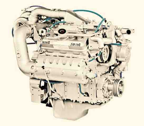
Six-cylinder diesel engines series S60, designed for buses and trucks, are well proven. These products are characterized by reliability and unpretentiousness. Diesel engines have a working volume
of 12.7 liters and develop from 380 to 450 horsepower. There are also 14-liter engines with a power from 450 to 600 hp.
Such a company started production in 1987. In those days, these were the first motors of this class, having an integrated electronic control system DDEC (abbreviation stands for Detroit Diesel
Electronic Controls). Moreover, this complex not only controls the operation of the engine, but also performs diagnostic, protective functions. In the driver’s cab, important information is
displayed on the special screen, namely, oil level, fuel consumption, distance traveled, fault data.
The range of engines that the manufacturer offers to consumers is broad:
At the present stage of production, a world-famous company produces high-quality engines for heavy and medium-sized trucks. Their power varies between 170-560 hp. Series 60 and MBE 4000 since
1992 are rightly considered the leaders in sales.
Here are some service, repair and workshop manuals for MBE 4000, MBE 900, Detroit Diesel Series 40, Detroit Diesel V-71 and others. Detroit Diesel Engines – Workshop Repair Manuals, Parts Catalog, Fault codes and Wiring Diagrams free download PDF.
![]()
Detroit Diesel logo
| Title | File Size | Download Links |
| Detroit Diesel Electronic Control [PNG] | 361kb | Download |
| Detroit Diesel Application User’s Manual – Suite 8.3 [PDF] | 3.3Mb | Download |
| Detroit Diesel – Electronic Tools for DDEC VI – Using DDDL 7.0 [PDF] | 5.8Mb | Download |
| Detroit Diesel – Unit Injectors and Unit Pumps Tecnhicians Guide [PDF] | 2.9Mb | Download |
| Detroit Diesel calibration tool user guide [PDF] | 31.9kb | Download |
| Detroit Diesel DDEC IV Application and Installation [PDF] | 1.7Mb | Download |
| Detroit Diesel DDEC Multi-ECM Troubleshooting Manual [PDF] | 6.2Mb | Download |
| Detroit Diesel DDEC V Vehicle Interface Harness [PDF] | 226.9kb | Download |
| Detroit Diesel DDEC VI On-Highway – Application and Installation [PDF] | 5Mb | Download |
| Detroit Diesel Engine DDFP Series Service Manual [PDF] | 1.3Mb | Download |
| Detroit Diesel Engine Series V-149 Service Manual [PDF] | 219.9kb | Download |
| Detroit Diesel GHG17 DD Medium Duty Operators Manual [PDF] | 6.8Mb | Download |
| Detroit Diesel MBE 4000 Service Manual [PDF] | 4.9Mb | Download |
| Detroit Diesel MBE 4000 Workshop Service Manual [PDF] | 12.7Mb | Download |
| Detroit Diesel MBE 900 Operators Manual [PDF] | 960.4kb | Download |
| Detroit Diesel MBE 900 Troubleshooting Manual [PDF] | 2Mb | Download |
| Detroit Diesel MBE EGR Technicians Guide [PDF] | 13.1Mb | Download |
| Detroit Diesel MBE Electronic Controls Troubleshooting Guide [PDF] | 2.2Mb | Download |
| Detroit Diesel Series 40 Specifications [PDF] | 139.2kb | Download |
| Detroit Diesel Series 40 Troubleshooting [PDF] | 3.4Mb | Download |
| Detroit Diesel Series 4000 MTU Service Manual [PDF] | 5.3Mb | Download |
| Detroit Diesel V-71 Service Manual [PDF] | 8Mb | Download |
| Detroit Diesel V-71 Technical Manual [PDF] | 34.8Mb | Download |
| Diagrama de Arneses DDEC [PDF] | 2.6Mb | Download |
Spare Parts Catalogs and Manuals
| Title | File Size | Download Links |
| Detroit Diesel (All) FP Parts Manual [PDF] | 18.1Mb | Download |
| Detroit Diesel Series 40 Parts Catalogue [PDF] | 1.1Mb | Download |
| Detroit Diesel Spare Parts Catalog [PDF] | 971.7kb | Download |
Electrical Wiring Diagrams
| Title | File Size | Download Links |
| Detroit Diesel DDC-DDEC II Wiring Diagram [PDF] | 63.2kb | Download |
| Detroit Diesel DDEC II and III Wiring Diagrams [PDF] | 979.5kb | Download |
See also: Detroit Diesel Fault Codes and DTCs
Detroit Diesel is an American manufacturer of automotive, stationary and industrial diesel engines, bridges and gearboxes. Since its founding in 1938, Detroit Diesel has produced more than 5 million units, of which at least 1 million is still in operation.
The company was born as a division of General Motors, focused exclusively on the development of diesel equipment. In 1965, Detroit Diesel went into “free swimming”, and in 1970 entered a new stage of development, merging with the developer of gas turbines Allison Division. In 1987, the company revolutionized the market by launching a series of power units with electronic control system (DDEC). The innovation allowed to reduce the consumption of oil and fuel, and automate the work of engines.
Detroit Diesel works closely with the German developer Bosch – together with it the company has released a series of engines with the technology of supply and injection of common rail fuel. The brand also has its own novelties: a water pump with electronic control, generators with water cooling (one hinged, the other – built into the cylinder block).
Today, Detroit Diesel is part of the Daimler AG concern and is focused on the production of diesel units for heavy trucks, buses, construction equipment. Some series (for example, S50, S149) are no longer produced, but the company continues their service. The most popular among the manufacturers of equipment are the following product lines:
S60 – started in 1987, the power range of 400-600 hp, the working volume of 12700-14000 cm³.
S40E – production began in 1991th. The series immediately received electronic control and is characterized by economy and low level of vibration. The maximum power is 175-250 hp, the working volume is 7600 cm³.
S4000 – the most powerful series, developed in conjunction with specialists MTU. The power range is 951-5846 hp.
Detroit Diesel closely cooperates with manufacturers of Volvo Penta, Daimler Chrysler, Koler, and invests huge funds in researching new technologies. For this purpose, the company has about 200 dynamometer stands in Europe and the USA. Priority of the brand has not changed since 2000 – these are engines for heavy trucks. In this segment, Detroit Diesel achieved phenomenal success.
Проектируемый проезд № 253, к610, Видное, Ленинский городской округ, Московская область, 142700
![]()
- Грузовики
- Mack
- Volvo
- Sterling
- International
- Freightliner
- Kenworth & Peterbilt
- Ford F250, F650, F750
- Запчасти для прицепов
- Двигатель
- Cummins
- Detroit Diesel
- Caterpillar C7, C9, C12, C15
- Volvo D12 / D13
- International DT-466 DT-530 VT-365
- Запчасти
- Для индустриальной и промышленной техники
- Ремкомплекты седел
- Ремкомплекты компрессоров
- Запчасти для КПП
- Фильтра и осушители
- Тормозная система
- Запчасти для редукторов и мостов
- Инструмент
- Каталоги PDF
- Трансмиссия
- Eaton FS-5205A Transmissions
- Eaton RTO-11715
- Eaton FRO-15210C
- Eaton RTO-16908LL
- Meritor 10-Speed
- Meritor 9-10-Speed
- Meritor 9-10-13-Speed
- Meritor (G series) 9-10-Speed
- ZF Meritor Automatic
- Воздушная система
- Compressor Bendix Tu-Flo 550
- Compressor Bendix Tu-Flo 750
- Compressor Bendix BA-921
- Мосты и редуктора
- Meritor 180, 185, 186 & 380
- Meritor 140, 141, 143 & 145
- Meritor 160, 161 & 164
- Dana Spicer Axles 404
- Dana Spicer Axles N-400
- Dana Spicer Axles S-400
- Dana Spicer Axles
- Сцепные устройства
- fifth wheel HOLLAND
- fifth wheel FONTAINE
- Муфты вентилятора
- Fan clutch
- Kysor Fan clutch Service Guide
- Каталог стекол
- Service manual двигателей
- Manual Cummins N14
- Manual Cummins ISX QSX
- Manual Cummins ISM QSM11
- Manual Detroit Serie 60
- Manual Volvo D12D
- Manual Navistar DT466E
- Manual Navistar VT365
- Тормозная система
- Eaton Brake system
- Трансмиссия
- Коды ошибок
- Detroit Deisel
- Cummins
- Caterpillar
- Прайс
- Контакты
- Вы здесь:
-
РокАвто
-
Каталоги PDF
-
Service manual двигателей
-
Manual Detroit Serie 60
Мы лучшие
Мы много лет на рынке автозапчастей для американских и европейских грузовиков и тягачей и спецтехники.
Любые запчасти в наличии для ремонта двигателей.
В наличии всегда много запчастей для автомобилей Freighliner, Volvo, International, Kenworth, Peterbilt, Mack и Sterling.
Detroit Diesel,
Cummins,
Caterpillar,
International DT-466
Осуществляем доставку любых запчастей из США и Канады.
Работаем строго с НДС и 50% предоплатой на заказные товары.
©2011-2022 Part-torg.ru — All Rights Reserved
Автозапчасти для американских грузовых автомобилей и тягачей.
![]()
TM 5-4210-227-24&P-2
TECHNICAL MANUAL
ORGANIZATIONAL, DIRECT SUPPORT, AND GENERAL SUPPORT MAINTENANCE MANUAL (INCLUDING REPAIR PARTS AND
SPECIAL TOOLS LIST)
FOR
85′ AERIAL LADDER FIRE FIGHTING TRUCK
NSN 4210-00-965-1254
HEADQUARTERS, DEPARTMENT OF THE ARMY
7 NOVEMBER 1986

COMPLETE MANUAL TABLE OF CONTENTS
|
Publication |
Section |
Section Title |
|
TM 5-4210-227-24&P-1 |
1 |
Introduction/Tabulated Data |
|
2 |
Chassis Assembly |
|
|
3 |
Pump Assembly |
|
|
4 |
Ladder Assembly |
|
|
5 |
Hydraulic System |
|
|
6 |
Electrical System |
|
|
7 |
Pneumatic System |
|
|
8 |
Ladder Calibration and Adjustments |
|
|
9 |
Illustrations |
|
|
TM 5-4210-227-24&P-2 |
General Information |
|
|
1 |
Engine (less major assemblies) |
|
|
2 |
Fuel System and Governors |
|
|
3 |
Air Intake Systems |
|
|
4 |
Lubrication System |
|
|
5 |
Cooling System |
|
|
6 |
Exhaust System |
|
|
7 |
Electrical Equipment, Instruments and |
|
|
Protective Systems (Sections 8 through |
||
|
11 not included) |
||
|
12 |
Special Equipment |
|
|
13 |
Operation |
|
|
14 |
Tune-up |
|
|
15 |
Preventive Maintenance, Troubleshooting |
|
|
and Storage |
||
|
TM 5-4210-227-24&P-3 |
1 |
General Information |
|
2 |
Description and Operation |
|
|
3 |
Preventive Maintenance |
|
|
4 |
General Overhaul Information |
|
|
5 |
Disassembly of Transmission |
|
|
6 |
Rebuild of Subassemblies |
|
|
7 |
Assembly of Transmission |
|
|
8 |
Wear Limits and Spring Data |
|
|
TM 5-4210-227-24&P-4 |
1 |
Allison Automatic Transmission HT 700 |
|
Series Parts Catalog |
||
|
2 |
Supplemental Parts Information |
|
|
TM 5-4210-227-24&P-5 |
1 |
Drive Line |
|
2 |
Front Axle |
|
|
3 |
Rear Axle |
|
|
4 |
Steering System |
|
|
5 |
Fuel System |
|
|
6 |
Brake System |
|
|
7 |
Electrical System |
|
|
8 |
Miscellaneous |
A

COMPLETE MANUAL TABLE OF CONTENTS
|
Publication |
Section |
Section Title |
|
TM 5-4210-227-24&P-5 |
9 |
General Information |
|
(continued) |
10 |
Installation Instructions |
|
11 |
Troubleshooting and Service |
|
|
TM 5-4210-227-24&P-7 |
General Information |
|
|
1 |
Engine (less major assemblies) |
|
|
2 |
Fuel System and Governors |
|
|
3 |
Air Intake System |
|
|
4 |
Lubricator System |
|
|
5 |
Cooling System |
|
|
6 |
Exhaust System |
|
|
7 |
Electrical Equipment, Instruments and |
|
|
Protective Systems |
||
|
8 |
Power Take-off and Torque Converter |
|
|
9 |
Transmissions (Sections 10 and 11 not |
|
|
included) |
||
|
12 |
Special Equipment |
|
|
13 |
Operation |
|
|
14 |
Tune-up |
|
|
15 |
Preventive Maintenance, Troubleshooting |
|
|
and Storage |
||
|
TM 5-4210-227-24&P-8 |
Parts List and Foldouts |
|
|
Tools and Equipment |
||
|
TM 5-4210-227-10 |
1 |
Introduction/Tabulated Data |
|
2 |
Operator’s Instructions |
|
|
3 |
Operator Maintenance |
|
|
4 |
Illustrations |
|
|
5 |
Operator’s Manual, Series 92 Engines |
|
|
6 |
Operator’s Manual, Series V-71 Engines |
|
|
7 |
Built-in Parts Book for Detroit Diesel |
|
|
Engines |
||
|
8 |
Operator’s Manual, Fire Apparatus Chassis |
B
FOREWORD
Descriptions, instructions and parts listing pertaining to the Model QWT 85 are discussed throughout this manual under the general headings Chassis, Pump and Ladder. Foldout illustrations and schematics are located at the rear of this volume. The foldout format is provided in order that illustrations and schematics may be referred to while the supporting text is being examined and studied.
A detailed description is given in the Introduction of each volume to assist the user in finding the information required to maintain the equipment.
∙Operator’s Manual (TM 5-4210-227-10)
This manual is designed to provide the information necessary for a fire
fighter or mechanic to properly operate the truck, the pump and the ladder.
∙Maintenance Manual (TM 5-4210-227-24&P)
This manual is divided into 8 volumes and contains the information necessary
for an experienced mechanic to-maintain and repair all facets of the appa-
ratus. Each volume is individually indexed for ease of reference. This
manual contains all the information necessary to obtain assemblies and sub-
assemblies or individual parts, required to repair and maintain the fire
truck.
i/(ii blank)
TABULATED DATA
a)Fire Truck
|
Federal Stock Number: |
4210-00-965-1254 |
|
|
Manufacturer ‘s Serial No.: |
||
|
Registration Nos.: |
CM3653 through CM3664 |
|
|
Manufacturer: |
Pierre Thibault Inc. |
|
|
Model: |
QWT 85 |
|
|
Contract Number: |
DAAJ10-84-A218 |
|
|
Truck Length: |
459″ |
|
|
Truck Width: |
108″ |
|
|
Truck Height: |
138″ |
|
|
Capacity or Payload: |
51,000 GVWR |
|
|
Shipping Weight: |
43,880 |
|
|
Ground Clearance: |
10.25″ |
|
|
Weight Loaded: |
45,940 |
|
|
Front Axle |
19,740 |
|
|
Rear Axle |
26,200 |
|
|
b) |
Chassis |
|
|
Manufacturer: |
Duplex |
|
|
I.D. Number: |
I.C. lD91 D31 |
|
|
D6F 1008468 |
||
|
Model: |
D350 |
|
|
Wheel Base |
230″ |
|
|
c) |
Engine |
|
|
Manufacturer: |
Detroit Diesel |
|
|
Model: |
8V-71 Turbo |
|
|
Serial Number: |
8VA437868 |
|
|
Fuel: |
Diesel |
iii
|
d) |
Transmission |
|
|
Manufacturer: |
Allison |
|
|
Model: |
HT-740 |
|
|
Serial No.: |
2510087501 |
|
|
Capacity: |
7 1/2 Gals |
e)Firefighting Water Pump
|
Manufacturer: |
Hale |
|
|
Model: |
QSM FHD100 |
|
|
Capacity: |
1000 GPM @ 150 psi |
|
|
f) |
Front Axle |
|
|
Manufacturer: |
Rockwell International |
|
|
Model: |
FL 941 QX-70 |
|
|
Capacity: |
20,000 lbs. |
|
|
Serial No.: |
N766718 |
f)1. Front Shock Absorbers
|
Manufacturer: |
Duplex |
|
Model: |
7605-1258 |
f)2. Front Springs
|
Manufacturer |
Duplex |
|
|
Model: |
7804-6731 |
|
|
g) |
Rear Axle |
|
|
Manufacturer: |
Rockwell International |
|
|
Model: |
U-170 PX-99 |
|
|
Capacity: |
31,000 lbs. |
|
|
Serial No.: |
NW845892 |
g)1. Rear Suspension
|
Manufacturer: |
Hendrickson |
|
Model: |
Single Axle RS-SA-340 |
iv
|
h ) |
Alternator |
|
|
Manufacturer: |
Delco Remy |
|
|
Model: |
||
|
Amp. |
145 |
|
|
i) |
Batteries |
|
|
Manufacturer: |
Harris |
|
|
Model: |
7605-0670 |
|
|
Voltage: |
12 |
j)Battery Isolator
|
Manufacturer: |
Sure Power |
|
Model: |
1602 |
|
Rated Power: |
3709 BHP @ 2,100 rpm |
k)Steering Gear
|
Manufacturer: |
Sheppard |
|
Model: |
7605-5478 |
1)Power Steering Pump
|
Manufacturer: |
Vickers |
|
Model: |
7605-5256 |
m)Windshield Wipers
|
Manufacturer: |
American Bosch |
|
Model: |
WWC-12L |
|
Type: |
Electric |
n)Radiator
|
Manufacturer: |
Blackstone |
|
|
Model: |
7605-3750 |
|
|
o) |
Air Cleaner |
|
|
Manufacturer: |
FAAR |
|
|
Model: |
62891-3 |
v
p)Driver’s Seat
|
Manufacturer: |
Bostrom |
|
|
Model: |
Four-way Adjustable |
|
|
Type: |
Standard |
|
|
q) |
Wheels |
|
|
Front: |
||
|
Manufacturer: |
Firestone |
|
|
Size: |
22.5 x 16.5 |
|
|
Rear: |
||
|
Manufacturer: |
Firestone |
|
|
Size: |
20 x 8.5 |
|
r) |
Tires |
|
|
Front: |
||
|
Manufacturer: |
Goodyear |
|
|
Size: |
16.5 R 22.5 — 18 P.R. |
|
|
Capacity: |
20,000 lbs |
|
|
Rear: |
||
|
Manufacturer: |
Michelin |
|
|
Size: |
12:00 R 20X — 18 P.R. |
|
|
Capacity |
31,000 lbs. |
|
|
s) |
Muffler |
|
|
Manufacturer: |
Nelson |
|
|
Model: |
86130-21 |
t)AC Inverter
|
Manufacturer: |
Dynamote |
|
|
Model: |
A40-120 |
|
|
u) |
Siren/PA |
|
|
Manufacturer: |
Code 3 |
|
|
Model: |
3100 |
vi
CAPABILITIES
Fire Truck
Turning Radius — Inside 31.5′ — Outside 42.25′ Rated Power: 370 BHP @ 2,100 rpm
Engine Governor Setting: No Load — 2,100; Top Speed 58 mph
Acceleration: 0 — 35 mph — 14 Seconds Braking: 20 to 0 mph — 15 feet
Angle of Departure: Front — 15 degrees; Rear — 15 degrees
Pump
Single Stage Centrifugal Midship Mounted
Driven by the truck engine from the output shaft of transmission
Min discharge — 1000 gpm @ 150 psi Min discharge — 100 gpm @ 200 psi Min discharge — 500 gpm @ 250 psi
From dry condition — take suction and discharge water in 30 sec. with a lift of 10 deg. through 20′ of 6″ suction hose
12 VDC Priming Pump Water Tank — 200 gals.
Ladder
Basic Weight — 11,560 lbs., Outrigger Operation Speed
Lower: Front — 9 sec. Rear — 18 sec. Raise: Front — 9 sec. Rear — 18 sec.
Complete extension, elevation and 90 degrees rotation within 60 sec.
Hydraulic Tank: 45 gals. (Imp.)
vii
MAINTENANCE MANUAL
SECTION I
1. INTRODUCTION/TABULATED DATA
1.1INTRODUCTION
1.1.1.TM 5-4210-227-24&P, Organizational, Direct Support, and General Support Maintenance Manual for the 85′ Aerial Ladder Fire Fighting Truck is divided into eight volumes. These eight volumes are further subdivided into specific sections consisting of both Government and commercial literature. TM 5-4210-227-10, Operator’s Manual for the 85′ Aerial Ladder Fire Fighting Truck is one separate manual consisting of four separate sections.
1.1.2.This volume consists of 12 sections and is arranged as follows: GENERAL INFORMATION
1.Engine (less major assemblies)
2.Fuel System and Governors
3.Air Intake Systems
4.Lubrication System
5.Cooling System
6.Exhaust System
7.Electrical Equipment, Instruments and Protective Systems
12.Special Equipment
13.Operation
14.Tune-Up
15.Preventive Maintenance, Troubleshooting and Storage
NOTE
For the Parts List for the 3V-71 Turbo Engine refer to duplex «Engine — Common-Parts» (on the following page) and «DETROIT DIESEL ENGINES — V71 OPERATORS’ MANUAL,» Section 8, «BUILT IN PARTS BOOK.1»
viii
![]()
IMPORTANT SAFETY NOTICE
Proper service and repair is important to the safe, reliable operation of all motor vehicles. The service procedures recommended by Detroit Diesel Allison and described in this service manual are effective methods for performing service operations. Some of these service operations require the use of tools specially designed for the purpose. The special tools should be used when and as recommended. It is important to note that some warnings against the use of specific service methods that can damage the vehicle or render it unsafe are stated in this service manual. It is also important to understand these warnings are not exhaustive. Detroit Diesel Allison could not possibly know, evaluate and advise the service trade of all conceivable ways in which service might be done or of the possible hazardous consequences of each way. Consequently, Detroit Diesel Allison has not undertaken any such broad evaluation. Accordingly, anyone who uses a service procedure or tool which is not recommended by Detroit Diesel Allison must first satisfy himself thoroughly that neither his safety nor vehicle safety will be jeopardized by the service method he selects.
6SE228 (Rev. 7/82)
|
Printed in U.S.A. |
c 1982 General Motors Corp. |
FOREWORD
This manual contains instructions on the overhaul, maintenance and operation of the basic V-71 Detroit Diesel Engines.
Full benefit of the long life and dependability built into these engines can be realized through proper operation and maintenance. Of equal importance is the use of proper procedures during engine overhaul.
Personnel responsible for engine operation and maintenance should study the sections of the manual pertaining to their particular duties. Similarly, before beginning a repair or overhaul job, the serviceman should read the manual carefully to familiarize himself with the parts or sub-assemblies of the engine with which he will be concerned.
The information, specifications and illustrations in this publication are based on the information in effect at the time of approval for printing. This publication is revised and reprinted periodically. It is recommended that users contact an authorized Detroit Diesel Service Outlet for information on the latest revisions. The right is reserved to make changes at any time without obligation.
|
TABLE OF CONTENTS |
|
|
SUBJECT |
|
|
GENERAL INFORMATION |
1 |
|
ENGINE (less major assemblies) |
|
|
2 |
|
|
FUEL SYSTEM AND GOVERNORS |
|
|
3 |
|
|
AIR INTAKE SYSTEM |
|
|
4 |
|
|
LUBRICATION SYSTEM |
|
|
5 |
|
|
COOLING SYSTEM |
|
|
6 |
|
|
EXHAUST SYSTEM |
|
|
7 |
|
|
ELECTRICAL EQUIPMENT, INSTRUMENTS AND PROTECTIVE SYSTEMS |
|
|
12 |
|
|
SPECIAL EQUIPMENT |
|
|
13 |
|
|
OPERATION |
|
|
14 |
|
|
TUNE-UP |
|
|
15 |
|
|
PREVENTIVE MAINTENANCE, TROUBLE SHOOTING AND STORAGE |
|
1980 General Motors Corporation |
Sept., 1980 |

|
General Information |
DETROIT DIESEL V-71 (Vehicle) |
SCOPE AND USE OF THE MANUAL
This manual covers the basic V-71 on-highway vehicle diesel engines built by the Detroit Diesel Allison Division of General Motors Corporation. Complete instructions on operation, adjustment (tune-up), preventive maintenance and lubrication, and repair (including complete overhaul) are covered. The manual was written primarily for persons servicing and overhauling the engine and, in addition, contains all of the instructions essential to the operators and users. Basic maintenance and overhaul procedures are common to all V-71 engines and therefore apply to all engine models.
The manual is divided into numbered sections. The first section covers the engine (less major assemblies). The following sections cover a complete system such as the fuel system, lubrication system or air system. Each section is divided into subsections which contain complete maintenance and operating instructions for a specific subassembly on the engine. For example, Section 1, which covers the basic engine, contains subsection 1.1 pertaining to the cylinder block, subsection 1.2 covering the cylinder head, etc. The subjects and sections are listed in the Table of Contents on the preceding page. Pages are numbered consecutively, starting with a new Page I at the beginning of each subsection. The illustrations are also numbered consecutively, beginning with a new Figure I at the start of each subsection.
Information regarding a general subject, such as the lubrication system, can best be located by using the Table of Contents. Opposite each subject in the Table of Contents is a section number which registers with a tab printed on the first page of each section throughout the manual. Information on a specific subassembly or accessory can then be found by consulting the list of contents on the first page of the section. For example, the cylinder liner is part of the basic engine, therefore, it will be found in Section 1. Looking down the list of contents on the first page of Section 1, the cylinder liner is found to be in subsection 1.6.3. An Alphabetical Index at the back of the manual has been provided as an additional aid for locating information.
SERVICE PARTS AVAILABILITY
Genuine Detroit Diesel Allison service parts are available in the United States from authorized distributors and service dealers throughout the world. A complete list of all distributors and dealers is available in the World Wide Parts and Service Directory, 6SE280. This publication can be ordered from any authorized distributor.
CLEARANCES AND TORQUE SPECIFICATIONS
Clearances of new parts and wear limits on used parts are listed in tabular form at the end of each section throughout the manual. It should be specifically noted that the «New Parts» clearances apply only when all new parts are used at the point where the various specifications apply. This also applies to references within the text of the manual. The column entitled «Limits» lists the amount of wear or increase in clearance which can be tolerated in used engine parts and still assure satisfactory performance. It should be emphasized that the figures given as «Limits» must be qualified by the judgment of personnel responsible for installing new parts. These wear limits are, in general, listed only for the parts more frequently replaced in engine overhaul work. For additional information, refer to the paragraph entitled Inspection under General Procedures in this section.
Bolt, nut and stud torque specifications are also listed in tabular form at the end of each section.
|
Page 4 |
© 1980 General Motors Corp. |

|
General Information |
DETROIT DIESEL V-71 (Vehicle) |
PRINCIPLES OF OPERATION
The diesel engine is an internal combustion power unit, in which the heat of fuel is converted into work in the cylinder of the engine.
In the diesel engine, air alone is compressed in the cylinder; then, after the air has been compressed, a charge of fuel is sprayed into the cylinder and ignition is accomplished by the heat of compression.
The Two-Cycle Principle
In the two-cycle engine, intake and exhaust take place during part of the compression and power strokes respectively as shown in Fig. 1. In contrast, a four cycle engine requires four piston strokes to complete an operating cycle; thus, during one half of its operation, the four-cycle engine functions merely as an air pump.
A blower is provided to force air into the cylinders for expelling the exhaust gases and to supply the cylinders with fresh air for combustion. The cylinder wall contains a row of ports which are above the piston when it is at the bottom of its stroke. These ports admit the air from the blower into the cylinder as soon as the rim of the piston uncovers the ports as shown in Fig. 1 (scavenging).
The unidirectional flow of air toward the exhaust valves produces a scavenging effect, leaving the cylinders full of clean air when the piston again covers the inlet ports.
As the piston continues on the upward stroke, the exhaust valves close and the charge of fresh air is subjected to compression as shown in Fig. 1 (compression).
Shortly before the piston reaches its highest position, the required amount of fuel is sprayed into the combustion chamber by the unit fuel injector as shown in Fig. 1 (power). The intense heat generated during the high compression of the air ignites the fine fuel spray immediately. The combustion continues until the fuel injected has been burned.
The resulting pressure forces the piston downward on its power stroke. The exhaust valves are again opened when the piston is about half way down, allowing the burned gases to escape into the exhaust manifold as shown in Fig. 1 (exhaust). Shortly thereafter, the downward moving piston uncovers the inlet ports and the cylinder is again swept with clean scavenging air. This entire combustion cycle is completed in each cylinder for each revolution of the crankshaft, or, in other words, in two strokes; hence, it is a «two-stroke cycle».
FIG. 1 — The Two-Stroke Cycle
Page 5 © 1976 General Motors Corp. June 1976

|
General Information |
DETROIT DIESEL V-71 (Vehicle) |
GENERAL DESCRIPTION
The two-cycle diesel engines covered in this manual are produced in 6, 8 and 12 cylinder models having the same bore and stroke and many of the major working parts such as injectors, pistons, connecting rods, cylinder liners and other parts that are interchangeable.
All cylinder blocks are symmetrical in design thus permitting oil cooler or starter installation on the same side or on opposite sides of the engine, depending upon the installation requirements. The engines are built with right-hand or lefthand crankshaft rotation. For example, the crankshaft in an RC engine, viewed from the flywheel end, will rotate counterclockwise, the oil cooler will be mounted on the right-hand side of the engine and the starter will be on the lefthand side (Fig. 2).
The meaning of each digit in the model numbering system is shown in Fig. 2. The letter L or R indicates left or righthand engine rotation as viewed from the front of the engine. The letter A, B, C or D designates the location of the starter and oil cooler as viewed from the rear of the engine.
Cylinder heads with either two valves or four valves per cylinder are used, as designated by the engine model.
Each engine is equipped with an oil cooler, lubricating oil filter, fuel oil strainer, fuel oil filter, air cleaner, governor, fan and radiator, and starting motor.
Full pressure lubrication is supplied to all main, connecting rod and camshaft bearings, and to other moving parts within the engine. A gear-type pump draws oil from the oil pan through an intake screen, through the oil filter and then to the oil cooler. From the oil cooler, the oil’ flows through passages that connect with the oil galleries in the cylinder block and cylinder heads for distribution to the bearings, rocker arm mechanism and other functional parts.
Coolant is circulated through the engine by a centrifugal-type water pump. Heat is removed from the coolant, which circulates in a closed systern, by the radiator. Control of the engine temperature is accomplished by thermostats which regulate the flow of the coolant within the cooling system. Fuel is drawn from the supply tank through the fuel strainer by a gear-type fuel pump. It is then forced through a filter and into the fuel inlet manifolds in the cylinder heads and to the injectors. Excess fuel is returned to the supply tank through the fuel outlet manifolds and connecting lines. Since the fuel is constantly circulating through the injectors, it serves to cool the injectors and also carries off any air in the fuel system.
Air for scavenging and combustion is supplied by a blower which pumps air into the engine cylinders via the air box and cylinder liner ports. All air entering the blower first passes through an air cleaner. Engine starting is provided by an electric starting motor energized by a storage battery. A batterycharging generator, with a suitable voltage regulator, serves to keep the battery charged.
Engine speed is regulated by a mechanical governor.
|
Page 6 |
© 1976 General Motors Corp. |

|
General Information |
DETROIT DIESEL V-71 (Vehicle) |
FIG. 2 — Model Numbering, Rotation and Accessory Arrangement
Page 7 © 1980 General Motors Corp. SEPTEMBER 1980

|
General Information |
DETROIT DIESEL V-71 (Vehicle) |
FIG. 3 — V-71 Engine Cylinder Designation and Firing Order
GENERAL SPECIFICATIONS
|
6V |
8V |
12V |
|
|
Type ………………………………………………………………………………………… |
2 Cycle |
2 Cycle |
2 Cycle |
|
Number of Cylinders …………………………………………………………………… |
6 |
8 |
12 |
|
Bore (inches) ……………………………………………………………………………… |
4.25 |
4.25 |
4.25 |
|
Bore (mm) ………………………………………………………………………………… |
108 |
108 |
108 |
|
Stroke (inches) …………………………………………………………………………… |
5 |
5 |
5 |
|
Stroke (mm) ………………………………………………………………………………. …. |
127 |
127 |
127 |
|
Compression Ratio (Nominal) (Std. & Turbo. Engines) ……………………. …. |
17 to 1 |
17 to 1 |
17 to 1 |
|
Compression Ratio (Nominal) («N» Engines) …………………………………… |
18.7 to 1 |
18.7 to 1 |
18.7 to 1 |
|
Total Displacement — cubic inches …………………………….. …………………. |
426 |
568 |
852 |
|
Total Displacement — litres ……………………………………………………………. |
6.99 |
9.32 |
13.97 |
|
Number of Main Bearings …………………………………………………………….. |
4 |
5 |
7 |
|
Page 8 |
© 1980 General Motors Corp. |
|
General Information |
DETROIT DIESEL V-71 (Vehicle) |
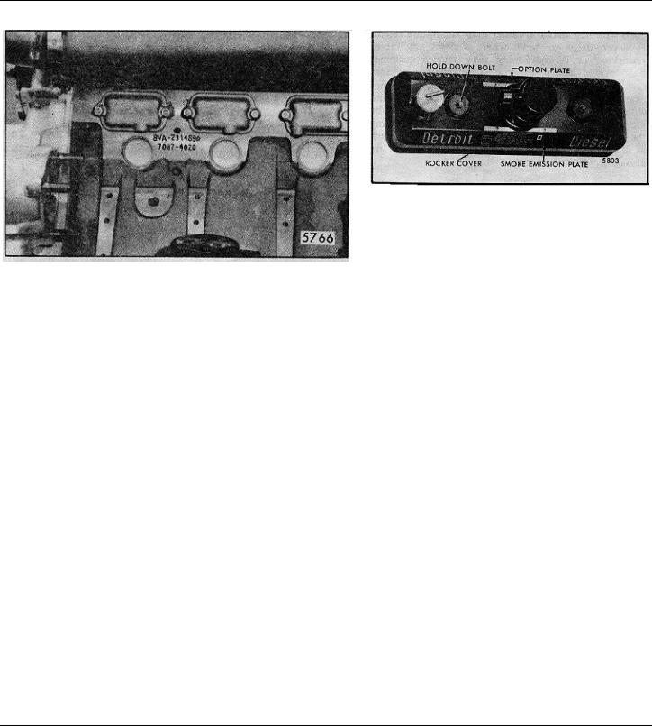
ENGINE MODEL, SERIAL NUMBER AND OPTION PLATE
FIG. 4 — Typical Engine Serial Number and
Model Number As Stamped on Cylinder Block
The engine serial number and the engine model number are stamped on the right rear side of the cylinder block (Fig. 4). This applies to former 6 and 8V-71 engines and current 12V-71 engines. To allow for easier engine serial number and model number identification on 6 and 8V-71 engines the location has been moved to the upper right front corner of the block.
NOTE: The 12V and 16V-71 engine identification will continue to be stamped at the former location, the right rear side of the cylinder block.
An option plate, attached to one of the valve rocker covers, is also stamped with the engine serial number and model number and. in addition, lists any optional
FIG. 5 — Option Plate
equipment used on the engine (Fig. 5).
An exhaust emission certification label. separate from the option plate. is mounted permanently in the option plate retainer. The current label includes information relating to an engine family for the maximum fuel injector size and maximum speed. Due to Federal regulations, the exhaust emission plate should not be removed. from the rocker cover. Refer to Section 14 for further information regarding emission regulations.
With any order for parts, the engine model number and serial number must be given. In addition, if a type number is shown on the option plate covering the equipment required, this number should also be included on the parts order.
All groups of parts used on an engine are standard for the engine model unless otherwise listed on the option plate.
Page 9 © 1980 General Motors Corp. SEPTEMBER 1980
![]()
|
General Information |
DETROIT DIESEL V-71 (Vehicle) |
GENERAL PROCEDURE
In many cases, a serviceman is justified in replacing parts with new material rather than attempting repair. However, there are times where a slight amount of reworking or reconditioning may save a customer considerable added expense. Crankshafts, cylinder liners and other parts are in this category. For example, if a cylinder liner is only slightly worn and within usable limits, a honing operation to remove the glaze may make it suitable for reuse, thereby saving the expense of a new part. Exchange assemblies such as injectors, fuel pumps, water pumps and blowers are also desirable service items.
Various factors such as the type of operation of the engine, hours in service and next overhaul period must be considered when determining whether new parts are installed or used parts are reconditioned to provide trouble-free operation.
For convenience and logical order in disassembly and assembly, the various subassemblies and other related parts mounted on the cylinder block will be treated as separate items in the various sections of the manual.
DISASSEMBLY
Before any major disassembly, the engine must be drained of lubricating oil, water and fuel. Lubricating oil should also be drained from any transmission attached to the engine.
To perform a major overhaul or other extensive repairs. the complete engine assembly, after removal from the vehicle and transmission, should be mounted on an engine overhaul stand; then the various subassemblies should be removed from the engine. When only a few items need replacement, it is not always necessary to mount the engine -on an overhaul stand.
Parts removed from an individual engine should be kept together so they will be available for inspection and assembly. Those items having machined faces, which might be easily damaged by steel or concrete, should be stored on suitable wooden racks or blocks, or a parts dolly.
CLEANING
Before removing any of the subassemblies from the engine (but after removal of the electrical equipment), the exterior of the engine should be thoroughly cleaned. Then, after each subassembly is removed and disassembled, the individual parts should be cleaned. Thorough cleaning of each part is absolutely necessary before it can be satisfactorily inspected. Various items of equipment needed for general cleaning are listed below.
The cleaning procedure used for all ordinary cast iron parts is outlined under Clean Cylinder Block in Section 1.1; any special cleaning procedures will be mentioned in the text wherever required.
Steam Cleaning
A steam cleaner is a necessary item in a large shop and is most useful for removing heavy accumulations of grease and dirt from the exterior of the engine and its subassemblies.
Solvent Tank Cleaning
A tank of sufficient size to accomodate the largest part that will require cleaning (usually the cylinder block) should be provided and provisions made for heating the cleaning solution to 180 °-200 0 F (82 °-93 °C).
Fill the tank with a commercial heavy-duty solvent which is heated to the above temperature. Lower large parts directly into the tank with a hoist. Place small parts in a wire mesh basket and lower them into the tank. Immerse the parts long enough to loosen all of the grease and dirt.
Rinsing Bath
Provide another tank of similar size containing hot water for rinsing the parts.
Drying
Parts may be dried with compressed air. The heat from the hot tanks will quite frequently complete the drying of the parts without the use of compressed air.
Page 10 © 1980 General Motors Corp. SEPTEMBER 1980

|
DETROIT DIESEL V-71 (Vehicle) |
General Information |
Rust Preventive
If parts are not to be used immediately after cleaning, dip them in a suitable rust preventive compound. The rust
preventive compound should be removed before installing the parts in an engine.
INSPECTION
The purpose of parts inspection is to determine which parts can be used and which must be replaced.
Although the engine overhaul specifications given throughout the text will aid in determining which parts should be replaced, considerable judgment must be exercised by the inspector.
The guiding factors in determining the usability of worn parts, which are otherwise in good condition, is the clearance between the mating parts and the rate of wear on each of the parts. If it is determined that the rate of wear will maintain the clearances within the specified maximum allowable until the next overhaul period, the reinstallation of used parts may be justified. Rate of wear of a part is determined by dividing the amount the part has worn by the hours it has operated.
Many service replacement parts are available in various undersize and/or oversize as well as standard sizes. Also, service kits for reconditioning certain parts and service sets which include all of the parts necessary to complete a particular repair job are available.
A complete discussion of the proper methods of precision measuring and inspection are outside the scope of this manual. However, every shop should be equipped with standard gages, such as dial bore gages, dial indicators, and inside and outside micrometers.
In addition to measuring the used parts after cleaning, the parts should be carefully inspected for cracks, scoring, chipping and other defects. Following cleaning and inspection, the engine should be assembled using new parts as determined by the inspection.
ASSEMBLY
Following cleaning and inspection, the engine should be assembled using new parts as determined by the inspection.
Use of the proper equipment and tools makes the job progress faster and produces better results. Likewise, a suitable working space with proper lighting must be provided. The time and money invested in providing the proper tools, equipment and space will be repaid many times.
Keep the working space, the equipment, tools and engine assemblies and parts clean at all times. The area where assembly operations take place should, if possible, be located away from the disassembly and cleaning operation. Also, any machining operations should be removed as far as possible from the assembly area.
Particular attention should be paid to storing of parts and sub-assemblies, after removal and cleaning and prior to assembly, in such a place or manner as to keep them clean. If there is any doubt as to the cleanliness of such parts, they should be recleaned.
When assembling an engine or any part thereof, refer to the table of torque specifications at the end of each section for proper bolt, nut and stud torques.
To ensure a clean engine at time of rebuild, it is important that any plug, fitting or fastener (including studs) that intersects with a through hole and comes in contact with oil, fuel or coolant must have a sealer
applied to the threads. A number of universal sealers are commercially available. It is recommended that Loctite J 26558-92 pipe sealer with teflon, or equivalent, be used.
NOTE: Certain plugs, fittings and fastener available from the Parts Depot already have a sealer applied to the threads. This pre-coating will not be affected when the pipe sealer with teflon is also applied.
IMPORTANT: The sealer information above must not be confused with International Compound No. 2, which is a lubricant applied before tightening certain bolts. Use International Compound No. 2 only where specifically stated in the manual.
|
© 1978 General Motors Corp. |
October, 1978 |
Page 11

|
DETROIT DIESEL V-71 (Vehicle) |
General Information |
WORK SAFELY
A serviceman can be severely injured if caught in the pulleys, belts or fan of an engine that is accidentally started. To avoid such a misfortune, take these precautions before starting to work on an engine:
Disconnect the battery from the starting system by removing one or both of the battery cables. With the electrical circuit disrupted, accidental contact with the
Some Safety Precautions To Observe When Working
On The Engine
1.Consider the hazards of the job and wear protective gear such as safety glasses, safety shoes, hard hat, etc. to provide adequate protection.
2.When lifting an engine, make sure the lifting device is fastened securely. Be sure the item to be lifted does not exceed the capacity of the lifting device.
3.Always use caution when using power tools.
4.When using compressed air to clean a component, such as flushing a radiator or cleaning an air cleaner element, use a safe amount of air. Recommendations regarding the use of air are indicated throughout the manual. Too much air can rupture or in some other way damage a component and create a hazardous situation that can lead to personal injury.
5.Avoid the use of carbon tetrachloride as a cleaning
starter button will not produce an engine start.
Make sure the mechanism provided at the governor for stopping the engine is in the stop position. This will mean the governor is in the no-fuel position. The possibility of the engine firing by accidentally turning the fan or by being bumped by another vehicle is minimized.
agent because of the harmful vapors that it releases. Use perchlorethylene or trichlorethylene. However, while less toxic than other chlorinated solvents, use these cleaning agents with caution. Be sure the work area is adequately ventilated and use protective gloves, goggles or face shield and an apron. Exercise caution against burns when using oxalic acid to clean the cooling passages of the engine.
6.Use caution when welding on or near the fuel tank. Possible explosion could result if heat build-up inside the tank is sufficient.
7.Avoid excessive injection of ether into the engine during start attempts. Follow the instructions on the container or by the manufacturer of the starting aid.
8.When working on an engine that is running, accidental contact with the hot exhaust manifold can cause severe burns. Remain alert to the location of the rotating fan, pulleys and belts. Avoid making contact across the two terminals of a battery which can result in severe arcing.
© 1978 General Motors Corp.
Page 12

|
DETROIT DIESEL V-71 (Vehicle) |
General Information |
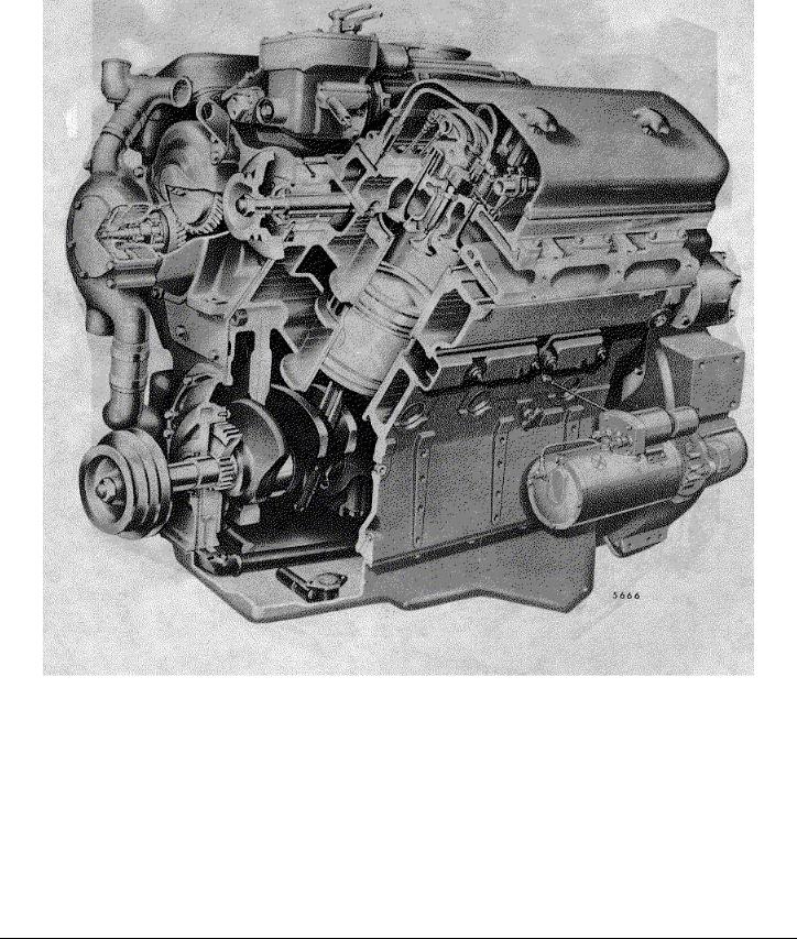
Three-Quarter Cutaway View of V-71 Engine (Dry Block)
|
© 1978 General Motors Corp. |
October, 1978 |
Page 13
|
DETROIT DIESEL V-71 (Vehicle) |
General Information |
Three-Quarter Cutaway View of V-71 engine (Water-Below-Port Block)
|
© 1978 General Motors Corp. |
October, 1978 |
Page 14

|
DETROIT DIESEL V-71 (Vehicle) |
General Information |
|
© 1978 General Motors Corp. |
October, 1978 |
Page 15

|
DETROIT DIESEL V-71 (Vehicle) |
1 |
|
SECTION 1 |
|
|
ENGINE (less major assemblies) |
|
|
CONTENTS |
|
|
Cylinder Block…………………………………………………………………………….. |
1.1 |
|
Cylinder Block End Plates . …………………………………………………………… |
1.1.1 |
|
Air Box Drains ……………………………………………………………………………. |
1.1.2 |
|
Cylinder Head …………………………………………………………………………….. |
1.2 |
|
Valve and Injector Operating Mechanism ………………………………………… |
1.2.1 |
|
Exhaust Valves .. ………………………………………………………………………… |
1.2.2 |
|
Valve Rocker Cover …………………………………………………………………….. |
1.2.4 |
|
Crankshaft …………………………………………………………………………………. |
1.3 |
|
Crankshaft Oil Seals ……………………………………………………………………. |
1.3.2 |
|
Crankshaft Main Bearings . …………………………………………………………… |
1.3.4 |
|
Engine Front Cover (Lower) ………………………………………………………….. |
1.3.5 |
|
Crankshaft Vibration Damper ………………………………………………………… |
1.3.6 |
|
Crankshaft Pulley………………………………………………………………………… |
1.3.7 |
|
Flywheel ……………………………………………………………………………………. |
1.4 |
|
Clutch Pilot Bearing .. ………………………………………………………………….. |
1.4.1 |
|
Flywheel Housing ……………………………………………………………………….. |
1.5 |
|
Piston and Piston Rings .. …………………………………………………………….. |
1.6 |
|
Connecting Rod .. ……………………………………………………………………….. |
1.6.1 |
|
Connecting Rod Bearings …………………………………………………………….. |
1.6.2 |
|
Cylinder Liner……………………………………………………………………………… |
1.6.3 |
|
Engine Balance and Balance Weights…………………………………………….. |
1.7 |
|
Gear Train and Engine Timing .. ……………………………………………………. |
1.7.1 |
|
Camshafts and Bearings ………………………………………………………………. |
1.7.2 |
|
Camshaft Gears …………………………………………………………………………. |
1.7.3 |
|
Idler Gear and Bearing Assembly ………………………………………………….. |
1.7.4 |
|
Crankshaft Timing Gear ……………………………………………………………….. |
1.7.5 |
|
Blower Drive Gear and Support Assembly……………………………………….. |
1.7.6 |
|
Accessory Drives .. ……………………………………………………………………… |
1.7.7 |
|
Balance Weight Cover .. ………………………………………………………………. |
1.7.8 |
|
Shop Notes — Trouble Shooting — Specifications — Service Tools ………….. |
1.0 |
|
© 1974 General Motors Corp. |
September, 1974 SEC 1 |
Page 1
|
DETROIT DIESEL V-71 (Vehicle) |
1.1 |
CYLINDER BLOCK
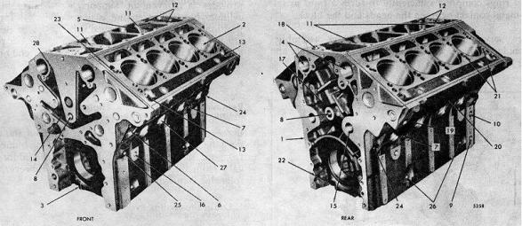
The cylinder block (Fig. 1) serves as the main structural part of the engine. Transverse webs provide rigidity and strength and ensure alignment of the block bores and bearings under load.
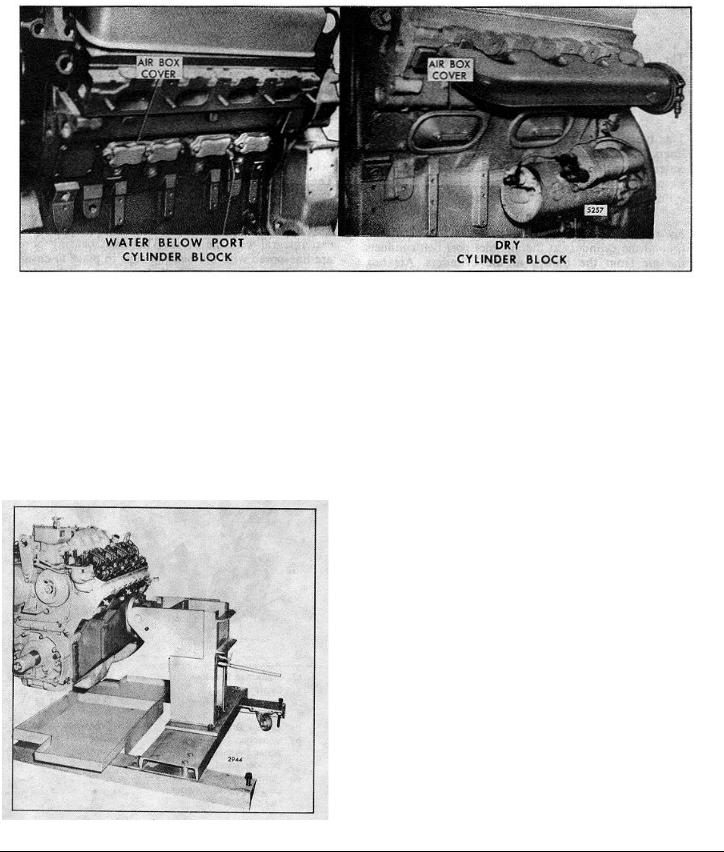
The block is bored to receive replaceable cylinder liners. The current cylinder block is designated as a water-below- port block and is designed to provide water cooling below the air inlet port belt. The former cylinder block was designated as a dry block.
An air box between the cylinder banks and extending around the cylinders at the air inlet port belt conducts the air from the blower to the cylinders. Air box openings on each side of the block permit inspection of the pistons and compression rings through the air inlet ports in the cylinder liners. The air box openings in the current cylinder block assembly are approximately 1 7/8″ x 3 1/8″ and are covered with cast covers (Fig. 2). The stamped steel covers used on the former cylinder block covered openings which were approximately 3″ x 6 1/2″. To prevent leakage at the air box covers, new gaskets and
bolts are now being used. The new polyacrylic and cork gaskets replace the former asbestos gaskets. The
new lock and seal coated bolt replaces a stud, nut, flat washer and lock washer. The former and new gaskets are interchangeable on an engine, but only the new gaskets are serviced.
The camshaft bores are located on the inner side of each cylinder bank near the top of the block.
The upper halves of the main bearing supports are cast integral with the block. The main bearing bores are linebored with the bearing caps in place to ensure longitudinal alignment. Drilled passages in the block carry the lubricating oil to all moving parts of the engine, eliminating the need for external piping.
The top surface of each cylinder bank is grooved to accommodate a block-to-head oil seal ring. Also, each water or oil hole is counterbored to provide for individual seal rings.
|
1. |
Cylinder Block |
11. |
Oil Drain Passages to |
17. |
Crankcase Breather |
24. |
Oil Gallery |
||
|
2. |
Bore for Cylinder Liner |
Blower |
Cavity |
25. |
Oil Gallery |
||||
|
3. |
Front Main Bearing Cap |
12. |
Oil Drain Passages |
18. |
Crankcase Breather |
26. |
Dipstick Hole or Oil |
||
|
4. |
Bores for Camshafts |
from Blower |
Outlet |
Return Passage to |
|||||
|
5. |
Air Box |
13. |
Oil Drain from Cylinder |
19. |
Air Box Drain |
Crankcase |
|||
|
6. |
Water into Block |
Head |
20. |
Inspection Hole |
27. |
Core Hole for Water |
|||
|
Opening |
Jacket |
||||||||
|
7. |
Water Drain |
14. |
Oil Drain Passages |
21. |
Water Passages to |
28. |
Oil Tube |
||
|
8. |
Main Oil Gallery |
15. |
Oil Passage (Idler Gear |
Cylinder Head |
|||||
|
9. |
Oil Passage from Pump |
Bearing) |
22. |
Rear Main Bearing Cap |
|||||
|
to Oil Filter |
16. |
Oil Return Passages to |
23. |
Oil Passage to Cylinder |
|||||
|
10. |
Oil Passage from Oil |
Crankcase |
Head |
||||||
|
Cooler |
|||||||||
|
FIG. 1 — Cylinder Block (8V Engine) |
|||||||||
|
© 1980 General Motors Corp. |
Page 1 |
September, 1980 SEC 1.1 |
|||||||
|
DETROIT DIESEL V-71 (Vehicle) |
1.1 Cylinder Block |
FIG. 2 Comparison of Current and former Cylinder Blocks
Each cylinder liner is retained in the block by a flange at its upper end. The liner flange rests on an insert located in the counterbore in the block bore. An individual compression gasket is used at each cylinder.
When the cylinder heads are installed, the gaskets and seal rings compress sufficiently to form a tight metal-to- metal contact between the heads and the block.
New service replacement cylinder block assemblies include the main bearing caps and bolts, dowels and the
FIG. 3 Engine Mounted on Overhaul Stand
necessary plugs. Since the cylinder block is the main structural part of the engine, the various subassemblies must be removed from the cylinder block when an engine is overhauled.
The hydraulically operated overhaul stand (Fig. 3) provides a convenient support when stripping a cylinder block. The engine is mounted in an upright position. It may then be tipped on its side, rotated in either direction 90°or 180°where it is locked in place and then, if desired, tipped back with either end or the oil pan side up.
Remove and Disassemble Engine
Before mounting an engine on an overhaul stand, it must be removed from the vehicle and disconnected from the transmission. Details of this procedure will vary from one application to another. However, the following steps will be necessary.
1.Drain the cooling system.
2.Drain the lubricating oil.
3.Disconnect the fuel lines.
4.Remove the air cleaner and mounting brackets.
5.Remove the turbocharger, if used.
6.Disconnect the exhaust piping and remove the exhaust manifolds.
7.Disconnect the throttle controls.
© 1980 General Motors Corp.
Page 2
![]()
|
DETROIT DIESEL V-71 (Vehicle) |
Cylinder Block 1.1 |
8.Disconnect and remove the starting motor, batterycharging generator or alternator and other electrical equipment.
9.Remove the air compressor, if used.
10.Remove the radiator and fan guard and other related cooling system parts.
11.Remove the air box drain tubes and fittings
12.Remove the air box covers.
13.Disconnect any other lubricating oil lines, fuel lines or electrical connections.
14.Separate the engine from the transmission
15.Remove the engine mounting bolts.
16.Use a spreader bar with a suitable sling and adequate chain hoist to lift the engine from its base (Fig. 4). To prevent bending of the engine lifter brackets the lifting device should be adjusted so the lifting hooks are vertical. To ensure proper weight distribution, all engine lifter brackets should be used to lift the engine
NOTE: Do not lift the engine by the webs in the air inlet opening at the top of the cylinder block.
17. Mount the engine on the overhaul stand. For 6V and 8V engines, use overhaul stand J 6837-C with adaptor J 860101. For 12V engines, use overhaul stand J 9389-04 and adaptor J 8650.
CAUTION: Check the fastenings carefully to be sure the engine is securely mounted to the overhaul stand before releasing the lifting sling. Severe injury to personnel and destruction of engine parts will result if the engine breaks away from the overhaul stand.
18. With the engine mounted on the overhaul stand, remove all of the remaining subassemblies and parts from the cylinder block.
The procedure for removing each subassembly from the cylinder block, together with disassembly, inspection, repair and reassembly of each, will be found in the various sections of this manual.
After stripping, the cylinder block must be thoroughly cleaned and inspected.
|
FIG. 4 — Lifting Engine with Spreader and Sling |
|
|
© 1982 General Motors Corp. |
April, 1982 SEC. 1.1 Page 3 |

|
1.1 Cylinder Block |
DETROIT DIESEL V-71 (Vehicle) |
Clean Cylinder Block
Scrape all gasket material from the cylinder block. Then remove all oil gallery plugs and core hole plugs (except cup plugs) to allow the cleaning solution to contact the inside of the oil and water passages. This permits more efficient cleaning and eliminates the possibility of’ the cleaning solution attacking the aluminum core hole plug gaskets (if used).
If a core hole plug is difficult to remove, hold a 3/4″ drift against the plug and give it a few sharp blows with a one pound hammer. With a 1/2″ flexible handle and a short extension placed in the countersunk hole in the plug, turn the plug slightly in the direction of tightening. Then turn it in the opposite direction and back the plug out.
Clean the cylinder block as follows:
1.Remove the grease by agitating the cylinder block in a hot bath of commercial heavy-duty alkaline solution.
2.Wash the block in hot water or steam clean it to remove the alkaline solution.
3.It the water jackets are heavily scaled, proceed as s: follow
a.Agitate the block in a bath of inhibited commercial pickling acid.
b.Allow the block to remain in the acid bath until the bubbling stops (approximately 30 minutes).
c.Lift the block, drain it and reimmerse it in the same acid solution for 10 minutes.
d.Repeat Step «C» until all scale is removed.
e.Rinse the block in clear hot water to remove the acid solution
f.Neutralize the acid that may cling to the casting by immersing the block in an alkaline bath.
g.Wash the block in clean water or steam clean it.
4.Dry the cylinder block with compressed air
5.Make certain that all water passages, oil galleries and air box drain openings have been thoroughly cleaned.
NOTE: The above cleaning procedure may be used on all ordinary cast iron and steel parts of the engine. Mention will be made of special cleaning procedures whenever necessary.
6. After the block has been cleaned and dried, coat the threads of the plugs and the gaskets with clean engine oil and reinstall the air box core hole plugs or adaptor plug. Tighten the 1 3/4″-16 plugs to 150-180 Ib-ft (204-244 Nm) torque. Tighten the 2 1/2″-16 plugs or water inlet adaptor plug (if used) to 230-270 Ib-ft (312366 Nm) torque using tool J 23019.
A water inlet adaptor plug and gasket replaces the rear (flywheel housing end) 2 1/2″ core hole plug in the cylinder block air box floor on engines built with an aftercooler (refer to Section 3.5.3). Use tool J 25275 to install or remove this adaptor plug. Lubricate with clean engine oil and tighten the adaptor plug to 230270 Ib-ft (312-366 Nm) torque.
NOTE: Excessive torque applied to the core hole plugs may result in cracks in the water jacket.
If for any reason the cup plugs in the water jackets were removed, install new plugs as follows:
a.Clean the cup plug holes and apply Permatex No. I sealant, or equivalent, to the outer diameter of the plugs.
b.Drive the plugs in place with handle J 7079-2 and adaptor J 24597 (2 1/2″ diameter plugs, Fig. 5) adaptor J 21849 (for 2″ diameter plugs) or adaptor J 21850 (for I 5/8″ diameter plugs).
c.Drive the aftercooler adaptor plug in place, using tool J 28711.
Pressure Test Cylinder Block
After the cylinder block has been cleaned, it must be pressure tested for cracks or leaks by either one of two methods.
FIG. 5 — Installing Aftercooler Water Plug
|
Page 4 |
© 1982 General Motors Corp. |

|
DETROIT DIESEL V-71 (Vehicle) |
Cylinder Block 1.1 |
METHOD «A»
This method may be used when a large enough water tank is available and the cylinder block is completely stripped of all parts.
1. Seal off the water inlet and outlet holes air tight. This can be done by using steel plates and suitable rubber gaskets held in place by bolts. Drill and tap one cover plate to provide a connection for an air line.
NOTE: A new service tool (J 29571) has been released to aid in pressure testing V-71 aftercooled engine cylinder blocks. When properly installed, the new tool sealsoff the aftercooler water inlet adaptor plug in the air box floor.
2.Immerse the block for twenty minutes in a tank of water heated to 180-200 F (82-93 °C).
3.Apply 40 psi (276 kPa) air pressure to the water jacket and observe the water in the tank for bubbles which’ indicate the presence of cracks or leaks in the block. A cracked cylinder block must be replaced by a new block.
4.After the pressure test is completed, remove the block from the water tank. Then remove the plates and gaskets and dry the block with compressed air.
METHOD «B»
This method may be used when a large water tank is unavailable, or when it is desired to check the block for cracks without removing the engine from the
vehicle. However, it is necessary to remove the cylinder heads, blower, oil cooler, air box covers and oil pan.
1.Attach sealing plates and gaskets as in Method «A». However, before attaching the last sealing plate, fill the water jacket with a mixture of water and one gallon of antifreeze. The antifreeze will penetrate small cracks and its color will aid in detecting their presence.
2.Install the remaining sealing plate and tighten it securely.
3.Apply 40 psi (276 kPa) air pressure to the water jacket and maintain this pressure for at least two hours to give the water and antifreeze mixture ample time to work its way through any cracks which may exist.
4.At the end of the test period, examine the cylinder bores, air box, oil passages, crankcase and exterior of the block for presence of the water and antifreeze mixture which will indicate the presence of cracks. A cracked cylinder block must be replaced by a new block.
FIG. 6 Honing Cylinder Block Bore
5. After the test is completed, remove the plates, drain the water jacket and blow out all of the passages in the block with compressed air.
Inspect Cylinder Block
After cleaning and pressure testing, inspect the cylinder block.
Since most of the engine cooling is accomplished by heat transfer through the cylinder liners to the water jacket, a good liner-to-block contact must exist when the engine is operating. Whenever the cylinder liners are removed from an engine, the block bores must be inspected.
NOTE: Before attempting to check the block bores, hone them throughout their entire length until about 75% of the area above the ports has been «cleaned-up».
1. Hone the block bores as follows:
a.Use a hone in which the cutting radius of the stones can be set in a fixed position to remove
irregularities in the bore rather than following the irregularities as with a spring-loaded hone. Clean
the stones frequently with a wire brush to prevent
|
© 1982 General Motors Corp. |
April, 1982 SEC. 1.1 Page 5 |

|
1.1 Cylinder Block |
DETROIT DIESEL V-71 (Vehicle) |
FIG. 8 — Checking Bore of Cylinder Block with Tool J 5347O01
FIG. 7 — High Pressure Areas on Cylinder Liner
stone loading. Follow the hone manufacturer’s instructions regarding the use of oil or kerosene on the stones. Do not use such cutting agents with a dry hone. Use 120 grit stones J 5902-14.
b.Insert the hone in the bore and adjust the stones snugly to the narrowest section (Fig. 6). When correctly adjusted, the hone will not shake in the bore, but will drag freely up and down the bore when the hone is not running.
c.Start the hone and «feel out» the bore for high spots which will cause an increased drag on the stones. Move the hone up and down the bore with short overlapping strokes about I » long. Concentrate on the high spots in the first cut. As these are removed, the drag on the hone will become lighter and smoother. Do not hone as long at the air inlet port area as in the rest of the bore because this area, as a rule, cuts away more rapidly. Feed lightly to avoid an excessive increase in the bore diameter. Some stones cut rapidly even under low tension.
the hone and makes it difficult to feel the high spots. Therefore, use a light cut with frequent stone adjustments.
e.Wash the cylinder block thoroughly after the honing operation is completed.
2. The cylinder liner is alternately expanding and contracting, during engine operation, due to temperature variations. This may result in irregularities in the block bores (out-of-round and taper), the effects of which will be seen as high pressure areas on the outside diameter of the cylinder liner (Fig. 7). A slight increase in block bore size is normal with high mileage or long periods of engine operation.
If a new liner and piston is installed in the block without properly fitting the liner, galling and seizing of the piston may result. This is caused by the new piston having to travel over the irregularities without time to conform to the particular shape of the block bore.
d.When the bore is fairly clean, remove the hone, inspect the stones and measure the bore. Determine which spots must be honed most. Moving the hone from the top to the bottom of the bore will not correct an out-of-round condition. To remain in one spot too long will cause the bore to become irregular. Where and how much to hone can be judged by feel. A heavy cut in a distorted bore produces a steady drag on
Check the cylinder block bores as follows:
a.Visually check the contact area as revealed by the honed surface. There must not be any low spots which are larger in area than a half dollar.
|
Page 6 |
© 1982 General Motors Corp |

|
DETROIT DIESEL V-71 (Vehicle) |
Cylinder Block 1.1 |
FIG. 9 Cylinder Block Bore Measurement
Diagram
b.Measure the entire bore of each cylinder with cylinder bore gage J 5347-01 (Fig.  which has a dial indicator calibrated in .0001 “increments. The standard block bore is 4.6260”to 4.6275”. Place the bore gage in the master ring gage
J 8386-01 which has an I.D. of 4.6270”and set the dial to zero. Take measurements on the cleaned-up surface only at positions A, B, C, D, E and F in the bore on axes 45°apart (Fig. 9). Read the measurements from the zero mark on the gage. The readings may be recorded on a form similar to the one illustrated (Fig. 10).
NOTE: Dial bore gage setting master tool
J 23059-01 may be used in place of the master ring gage.
3. The liner-to-block clearance with new parts is zero to .0015”. With used parts, the maximum clearance is
.0025”. After measuring the block bores, measure the outside diameter of the cylinder liners (Section 1.6.3). Then determine the block-to-liner clearance (refer to
FIG. 10 Block Bore Measurement Record
Form
Section 1.0 for the specified clearances) and whether it will be necessary to bore the block for oversize cylinder liners.
4. If necessary, bore the cylinder block as follows:
a.Each bore in a used block must not be out-of- round or tapered more than .002”. If the average block bore is over 4.6285”, the block should be bored oversize (refer to Tables I and 2).
TABLE 1
TABLE 2
b.A typical commercially available portable boring bar is illustrated in Fig. 11. Instructions on correct use of the boring bar are provided by the manufacturer.
c.After boring the block for an oversize cylinder liner, check the bore finish to be sure it is smooth (120 RMS). Heat transfer from the cylinder liner to the block will be adversely affected if the block isn’t smooth.
d.Wash the block thoroughly after the boring operation.
e.When an oversize liner is used, stamp the size of the liner on the top deck of the block adjacent to the liner counterbore. An oversize liner insert
|
© 1980 General Motors Corp. |
September, 1980 SEC. 1.1 Page 7 |

|
Cylinder Block 1.1 |
DETROIT DIESEL V-71 (Vehicle) |
FIG. 11 — Portable Boring Bar
must be installed whenever an oversize liner is used (Section 1.6.3).
5. Check the top of the block (cylinder head contact surfaces) for flatness with an accurate straight edge and a feeler gage (Fig. 12).
a.The cylinder head contact surfaces of the block must not vary more than .003″ transversely and not over .006″ (6V), .007″ (8V) or .009″ (12V) longitudinally. It will be difficult to prevent water, oil and compression leaks if these surfaces exceed these tolerances.
b.If it is necessary to machine these surfaces to correct for the above conditions, do not remove more than .008″ of metal. Stamp the amount of stock removed on the face of the block. The distance from the centerline of the crankshaft to the top of the cylinder head surface of the block must not be less than 16.176″ (Fig. 13).
c.If stock is removed from the cylinder head contact surfaces of the block, check the depth of the seal
FIG. 12 — Checking Top Surface of Cylinder
Block
ring grooves and counterbores. The cylinder head seal strip grooves must be .092″ — .107″ deep. The large water hole counterbores (between the
FIG. 13 — Minimum Distance from Centerline of Crankshaft to Top of Cylinder Block
|
Page 8 |
©1980 General Motors Corp. |

|
DETROIT DIESEL V-71 (Vehicle) |
Cylinder Block 1.1 |
FIG. 14 Checking Depth of Counterbore with Toot J 22273
cylinders) must be .109″ — .120″ deep, and the combination water and oil hole counterbores and small water hole counterbores must be .087″ —
.098″ deep. If necessary, deepen the grooves or counterbores to the specified limits to retain the proper «crush» on the seal rings. It is not necessary to deepen the counterbores for the cylinder liners since .004″ and .008″ undersize thickness inserts are available for adjusting the liner position as outlined in Section 1.6.3 under
Fitting Cylinder Liner in Block Bore.
6. Make sure the cylinder liner counterbores in the block are clean and free of dirt. Then check the depth
FIG. 15 — Cylinder Block Markings
(Fig. 14). The depth must be .4770″ to .4795’a and must not vary more than .0015″ throughout the entire circumference. The counterbored surfaces must be smooth and square with the cylinder bore within .001 » total indicator reading. There must not be over .001″ difference between any two adjacent cylinder counterbores when measured along the cylinder longitudinal centerline of the cylinder block.
7. Check the main bearing bores as follows:
a.Check the bore diameters with the main bearing caps in their original positions. Bearing caps are numbered to correspond with their respective positions in the cylinder block. It is imperative that the bearing caps are reinstalled in their original positions to maintain the main bearing bore alignment. The number of the front main bearing cap is also stamped on the face of the oil pan mounting flange of the cylinder block, adjacent to its permanent location in the engine as established at the time of manufacture. The No. I main bearing cap is always located at the end opposite the flywheel end of the cylinder block (Fig. 15). Lubricate the bolt threads and bolt head contact areas with a small quantity of International Compound No. 2, or equivalent. Then install and tighten the bolts to 165-175 Ib-ft (224-238 Nm) torque. When making this check, do not install the main bearing cap stabilizers. The specified bore diameter is 4.812″, to 4.813′. If the bores do not fall within these limits, the cylinder block must be rejected.
NOTE: Main bearing cap bolts are especially designed for this purpose and must not be replaced by ordinary bolts.
b.Finished and unfinished main bearing caps are available for replacing broken or damaged caps. When fitting a finished replacement bearing cap, it may be necessary to try several caps before one will be found to provide the correct bore diameter and bore alignment. If a replacement bearing cap is installed, be sure to stamp the correct bearing position number on the cap.
NOTE: Use the unfinished bearing caps for the front and intermediate bearing positions. The finished bearing caps, machined for the crankshaft thrust washers, are to be used in the rear bearing position.
c.Main bearing bores are line-bored with the bearing caps in place and thus are in longitudinal alignment. If a main bearing bore is more than
.001″ maximum overall misalignment or .0005″ maximum misalignment between adjacent bores the block must be line-bored (see Section 1.0) or scrapped. Misalignment may be caused by a broken crankshaft, excessive heat or other damage.
d.If the main bearing bores are not in alignment
|
© 1982 General Motors Corp. |
April, 1982 SEC. 1.1 Page 9 |

|
1.1 Cylinder Block |
DETROIT DIESEL V-71 (Vehicle) |
when a replacement bearing cap is used, the block must be line-bored (see Section 1.0).
8.Refer to the Cylinder Block Plugging Chart shown as a fold-out at the end of this manual and install the necessary plugs and dowels.
9.Replace loose or damaged dowel pins. The dowels at the ends of the cylinder block must extend .630″.
The dowels used to retain the crankshaft thrust washers on the rear main bearing cap must extend
.110″ to .120 » from the surface of the bearing cap.
NOTE: A stepped dowel pin is available to replace loose pins in the rear main bearing cap. Before installing the stepped pins, rebore the dowel holes in the bearing cap with a No. II (.1910″) or No. 12 (.1890″) drill. After pressing the pins into the bearing cap, remove all burrs from the base of the dowel pins to ensure proper seating of the thrust washers.
10. If used, replace damaged or broken cylinder head studs. Drive new studs to a height of 4 3/8″ ± 1/32″ above the block at a minimum of 75 Ib-ft (102 Nm) torque. Also examine the cylinder head retaining bolt holes. If the threads are damaged, use a tap to «cleanup» the threads or install a helical thread insert.
I 1. The tapped holes in the water-below-port cylinder blocks may be tapped with a 5/8″-l I UNC3B thread tap. The stud holes and unplugged bolt holes must have the thread extending 1.850″ below the block surface. If the bolt hole in the block is plugged, the plug must be a minimum of 2.040″ below the surface of the block and threaded the full distance (1.920″ on blocks prior to January, 1975). When replacing a bolt hole plug in the current water-below-port block, refer to Shop Notes in Section 1.0.
12.Check the remaining cylinder block surfaces and threaded holes. Check all of the mating surfaces, or mounting pads, for flatness, nicks and burrs. Clean-up damaged threads in tapped holes with a tap or install helical thread inserts, if necessary.
13.After inspection, if the cylinder block is not to be used immediately, spray the machined surfaces with engine oil. If the block is to be stored for an extended period of time, spray or dip it in a polar type rust preventive such as Valvoline Oil Company’s «Tectyl 502-C», or equivalent. Castings free of grease or oil will rust when exposed to the atmosphere.
Assemble and Install Engine
After the cylinder block has been cleaned and inspected, assemble the engine as follows:
NOTE: Before a reconditioned or new service replacement cylinder block is used, steam clean it to remove the rust preventive and blow out the oil galleries with compressed air.
1.Mount the cylinder block on the overhaul stand.
2.If a new service replacement block is used, stamp the engine serial number and model number on the right-hand side of the cylinder block. Also stamp the position numbers on the main bearing caps (Fig. 15) and the position of the No. I bearing on the oil pan mounting flange of the block.
3.Install all of the required cylinder block plugs and drain cocks. Use a good grade of non-hardening sealant on the threads of the plugs and drain cocks. Install the plugs flush with or below the surface of the block.
NOTE: Make sure the cup plug, which blocks the oil cooler adaptor inlet from the adaptor outlet, is installed in the vertical passage.
4.Check the cam pocket drain hole spring pin (if used) in the front end of the block to be sure it is installed with the slot up.
5.Clean and inspect all engine parts and subassemblies and, using new parts as required, install them on the cylinder block by reversing the sequence of disassembly. The procedures for inspecting and installing the various parts and subassemblies are outlined in the following sections of this manual.
6.Use a chain hoist and suitable sling to transfer the engine to a dynamometer test stand.
7.Complete the engine build-up by installing all remaining accessories, fuel lines, electrical connections, controls etc.
8.Operate the engine on a dynamometer, following
the run-in procedure outlined in Section 13.2.1.
9. Reinstall the engine in the vehicle.
|
Page 10 |
©1982 General Motors Corp. |

|
DETROIT DIESEL V-71 (Vehicle) |
1.1.1 |
CYLINDER BLOCK END PLATES
A flat steel plate, one bolted to each end of the cylinder block, provides a support for the flywheel housing at the rear and the balance weight cover at the front of the engine. Gaskets are used between the block and each end plate.
Inspection
When an end plate is removed, it is essential that all of the old gasket material be removed from both surfaces of the end plate and the cylinder block. Clean the end plate as outlined under Clean Cylinder Block in Section 1. 1.
Inspect both surfaces of each end plate for nicks, dents, scratches or score marks and check the end plates for warpage. Check the plug nuts in the end plates for cracks or damaged threads. If nicks or scratches on the sealing surfaces of the end plates are too deep to be cleaned up, or the plug nuts are damaged, replace the end plates or plug nuts.
When installing a plug nut, support the end plate on a solid flat surface to avoid distorting the plate. Then press the nut in the end plate until the head on the nut seats on the end plate.
Install Cylinder Block Breather Pads
A new breather pad, designed to improve crankcase ventilation, was used beginning with engine 6VA16943, 8VA-7508 and 12VA-2332.
The new pad differs from the two former pads in width only. To compensate for the decrease in width,
two retainers have been provided to hold the new pads in the cavities behind the cylinder block rear end plate (Fig. 2).
NOTE: Turbocharged engines do not require breather pads.
After cleaning the breather pads and prior to installing the cylinder block rear end plate, reinstall the breather pads and retainers, if used, in the block as shown in Fig. 2.
NOTE: Since the former breather pads were not the same size, be sure to reinstall them in their original locations.
The end plates, when assembled to -the block, will apply pressure on the retainers and hold the pads in position.
FIG. 1 — Cylinder Block End Plates and Relative Location of Parts
|
©1981 General Motors Corp. |
January , 1981 SEC. 1.1.1 Page 1 |

|
1.1.1 End Plates |
DETROIT DIESEL V-71 (Vehicle) |
FIG. 2 — Current Breather Pads and Retainers
Installed in Cylinder Block
Install End Plates
1.Affix new gaskets to the ends of the cylinder block, using a non-hardening gasket cement. Also apply an even coating of gasket cement to the outer surface of each gasket (the surface next to the end plate). Also attach the small round gasket to the corner at the front end of the cylinder block (Fig. 1).
∙NOTE: Do not use the V-92 gasket on engines built prior to January, 1977. Use the V-71 front end plate gasket that has been reinstated for service.
2.Attach the front end plate to the cylinder block with bolts and lock washers. Tighten the bolts finger tight.
3.Wipe the excess gasket cement from the bores in the end plate and the cylinder block.
4.Insert the right bank camshaft end bearing through the SMALL bearing bore in the end plate and into the bore of the block to accurately align the end plate with the cylinder block as shown in Fig. 3.
FIG. 3 — Installing Front End Plate (8V Engine)
NOTE: The holes in the front and rear end plates for the camshaft end bearings are not the same size. The smaller hole is accurately machined for alignment purposes and is always located on the right side of the engine as viewed from the rear.
5. With the bearing in place. tighten the 1/2″-13 end plate-to-cylinder block bolts to 71-75 Ib-ft (96-102 Nm) torque. Tighten the 3/8″-16 bolts to 3(0-35 Ib-ft (41-47 Nm) torque. Then remove the camshaft bearing which served as a pilot while attaching the front end plate.
NOTE: On former blocks, tighten the 3/8″-16 bolts which thread into the special water jacket plugs in the cylinder block to 20-25 lb-ft (27-34 Nm) torque. On certain engines, a special washer is used with these bolts.
6. Install the rear end plate in the same manner as outlined above for the front end plate.
NOTE: If used, attach the small cover to the cylinder block side of the rear end plate with two bolts and copper washers prior to installing the end plate. Use a new gasket between the cover and the end plate.
7. Trim off any excess gasket material.
|
Page 2 |
©1981 General Motors Corp. |
![]()
|
DETROIT DIESEL V-71 (Vehicle) |
1.1.2 |
AIR BOX DRAINS
During normal engine operation, water vapor from the air charge, as well as a slight amount of fuel and lubricating oil fumes, condenses and settles on the bottom of the air box. This condensation is removed by the air box pressure through air box drain tubes mounted on the sides of the cylinder block (Fig. 1, 2 or 3).
Air box drains must be kept open at all times, otherwise water and oil that may accumulate will be drawn into the cylinders.
Certain 6 and 8V upright engines have the air box drain tubes routed to the crankcase at the rear dipstick holes at each side of the engine, rather than to the atmosphere (Fig. 2).
In conjunction with the new drain tubes, a check (control) valve has been installed in the air box drain fitting on each side of the engine to allow drainage only at Iow air box pressures.
The check valve cutaway shows the valve operating at engine idle speed (Figs. 2 and 3). As the engine speed and air box pressure increase, the valve moves forward and seats, blocking air-flow. The check valve is only serviced as an assembly.
Effective with engines built approximately June, 1981,
the air box drains are being routed to the atmosphere (Fig. 3). Engines which have a closed air box drain system (Fig. 2) can be equipped with an open air box system (Fig. 3) — see Shop Notes in Section I.0.
Inspection
A periodic check for air flow from the air box drain tubes should be made (refer to Section 15. 1).
NOTE: Engines built prior to January 18, 1979 which use a 1/8″-18 pipe nipple in the sides of the air box drain system should be kept open. If plugged, this could cause a loss of engine lubricating oil.
Inspect the check valve for proper operation as follows:
1.Disconnect the drain tube from the check valve.
2.Run the engine and note the airflow through the valve at idle speed.
3.If the check valve is operating properly, there will be no airflow at engine speeds above idle.
To check the air box pressures on an engine with a closed air box drain system, use an air box cover with a tapped hole for a fitting.
FIG. 1 — Air Box Drain Tube
FIG. 2 — Closed Design Air Box Drain Tube and
Check Valve System (6 and 8V Engines)
|
© 1982 General Motors Corp. |
April, 1982 SEC. 1.1.2 Page 1 |

|
1.1.2 Air Box Drains |
DETROIT DIESEL V-71 (Vehicle) |
1. Remove the plug in the cover.
2. Install a fitting and short drain tube.
3. Attach a manometer to the end of the drain tube and check the air box pressure as stated in Section 13.2.
FIG. 3 — Open Design Air Box Drain Tube and
Check Valve System
|
Page 2 |
©1982 General Motors Corp. |

|
DETROIT DIESEL V-71 (Vehicle) |
1.2 |
CYLINDER HEAD
The cylinder head (Figs. 1, 2 and 3), one on each cylinder bank, is a one-piece casting securely held to the cylinder block by special bolts.
The exhaust valves, fuel injectors and the valve and injector operating mechanism are located in the cylinder head.
Depending upon the engine application, either two or four exhaust valves are provided for each cylinder.
Exhaust valve seat inserts, pressed into the cylinder head, permit accurate seating of valves under varying conditions of temperature and materially prolong the life of the cylinder head.
To ensure efficient cooling, each fuel injector is inserted into a thin-walled tube (Fig. 4) which passes through the water space in the cylinder head. The lower end of the injector tube is pressed into the cylinder head and flared over; the upper end is flanged and sealed with a neoprene seal. The sealed
FIG. 1 — Typical Cylinder Head Assembly (Two-Valve)
|
(c) 1980 General Motors Corp. |
March, 1980 |
SEC. 1.2 Page 1 |

|
1.2 |
Cylinder Head |
DETROIT DIESEL V-71(Vehicle) |
FIG. 2 — Typical Cylinder Head Assembly (Four-Valve)
upper end and flared lower end of the injector tube prevent water and compression leaks.
The exhaust passages from the exhaust valves of each cylinder lead through a single port to the exhaust manifold. The exhaust passages and the injector tubes are surrounded by engine coolant.
In addition, cooling of the above areas is further ensured by the use of water nozzles (Figs. 5 and 6) pressed into the water inlet ports in the cylinder head.
The nozzles direct, the comparatively cool engine coolant at high velocity toward the sections of the cylinder head which are subjected to the greatest heat.
The fuel inlet and outlet manifolds are cast as an integral part of the cylinder heads. Tapped holes are Page 2 provided for connection of the fuel lines at various points along each manifold.
The water manifold is also cast as an integral part of the cylinder head for 6V and 8V engines and certain current 12V engines.
To seal compression between the cylinder head and the cylinder liner,, separate laminated metal gaskets are provided at each cylinder. Water and oil passages between the cylinder head and cylinder block are sealed with synthetic rubber seal rings which fit into counterbored holes in the block. A synthetic rubber seal fits into a milled groove near the perimeter of the block. When the cylinder head is drawn down, a positive leakproof metal-to-metal contact is assured between the head and the block.
|
Page 2 |
(C) 1980 General Motors Corp. |

|
DETROIT DIESEL V-71 (Vehicle) |
Cylinder Head |
1.2 |
FIG. 3 — Cylinder Head Mounting
To make the cylinder heads more tolerant of abnormal coolant temperature, relief areas have been cast in the current four valve cylinder heads. These stress relief areas, which are shaped like a «dog bone», are cast in the fire deck of the cylinder head between the cylinders (Fig. 7). For visual identification of the current cylinder head on an engine, two bosses (at a later date a raised boss the shape of a «dog bone») are cast on the fuel manifold side of the three cylinder heads (6V engines) and a raised boss the shape of a «dog bone» is cast on the exhaust manifold side of the four (8V engines) and six (12V engines) cylinder heads
FIG. 4 — Coolant Passages Around Exhaust Valves and Fuel Injectors (C 1980 General Motors Corp.
FIG. 5 — Water Nozzles in Two-Valve Cylinder Head
(Fig. 8). The current service cylinder heads which include the stress relief areas in the fire deck also include the nonmagnetic turbo exhaust valve inserts identified by the letter «T» stamped on the face of the cylinder head.
NOTE: Production non-turbocharged cylinder heads include cast steel exhaust valve seat inerts which have magnetic qualities. An easy method for determining the type of exhaust valve seat insert in a cylinder head is with a magnet. The magnet will be attracted to the non-turbo insert (will stick). The magnet will not be attracted to the turbo insert, it will jump to the cyliner head.
Cylinder Head Maintenance
The engine operating temperature should be maintained between 160 ‘-185 °F (71 °-85 °C) and the cooling system should be inspected daily and kept full at all times. The cylinder head fire deck will overheat and crack in a short time if the coolant does not cover the fire deck surface. When necessary, add coolant slowly to a hot engine to avoid rapid cooling which can result in distortion and cracking of the cylinder head (and cylinder block).
|
(c) 1980 General Motor Corp. |
March, 1980 SEC. 1.2 Page 3 |

|
1.2 |
Cylinder Head |
DETROIT DIESEL V-71(Vehicle) |
FIG. 6 — Water Nozzles in Four-Valve Cylinder Head
Abnormal operating conditions or neglect of certain maintenance items may cause cracks to develop in the cylinder head. If this type of failure occurs, a careful inspection should be made to find the cause and avoid a recurrence of the failure.
Unsuitable water in the cooling system may result in lime and scale formation and prevent proper cooling. The cylinder head should be inspected around the exhaust valve water jackets. This can be done by removing an injector tube. Where inspection discloses such deposits, use a reliable non-corrosive scale remover to remove the deposits from the cooling system of the engine, since a similar condition will exist in the cylinder block and other components of the engine. Refer to Section 13.3 for engine coolant recommendations.
Loose or improperly seated injector tubes may result in compression leaks into the cooling system and also result in loss of engine coolant. The tubes must be tight to be properly seated. Refer to Section 2.1.4.
Overtightened injector clamp bolts may also cause head cracks. Always use a torque wrench to tighten the bolts to the specified torque.
FIG. 7 — Current Four Valve Cylinder Head
Other conditions which may eventually result in cylinder head cracks are:
1.Excess fuel in the cylinders caused by leaking injectors.
2.Slipping fan belts can cause overheating by reducing air flow through the radiator.
3.Accumulation of dirt on the radiator core which will reduce the flow of air and slow the transfer of heat from the coolant to the air.
4.Inoperative radiator cap which will result in loss of coolant.
Remove Cylinder Head
Certain service operations on the engine require removal of the cylinder head:
1.Remove and install pistons.
2.Remove and install cylinder liners.
3.Remove and install exhaust valves.
FIG. 8 — Current Four Valve Cylinder Head Identification
|
Page 4 |
(C) 1980 General Motors Corp. |

|
DETROIT DIESEL V-71 (Vehicle) |
Cylinder Head |
1.2 |
4.Remove and install exhaust valve guides.
5.Recondition exhaust valves and valve seat inserts.
6.Replace fuel injector tubes.
7.Install new cylinder head gaskets and seals.
8.Remove and install camshaft.
Due to the various optional and accessory equipment used, only the general steps for removal of the cylinder head are covered. If the engine is equipped with accessories that affect cylinder head removal, note the position of each before disconnecting or removing them to ensure correct reinstallation. Then remove the cylinder head as follows:
1.Drain the cooling system.
2.Disconnect the exhaust piping at the exhaust manifold. On turbocharged engines, remove the connections from the exhaust manifold to the turbocharger. Remove the turbocharger, if necessary.
3.Disconnect the fuel lines at the cylinder head.
4.Loosen the hose clamps and remove the hose attached to the thermostat housing cover.
5.Loosen the hose clamps at each end of the water bypass tube and remove the tube.
6.Remove the thermostat housing assembly.
7.Clean and remove the valve rocker cover and governor cover.
8.Disconnect the fuel rod from the injector control tube lever and the governor. Remove the fuel rod.
9.Loosen the fuel rod cover hose clamps. Then slide the hose up on the fuel rod cover toward the governor.
10.Remove the exhaust manifold.
11.Remove the water manifold, if used.
12.Remove the injector control tube and brackets as an assembly.
13.If the cylinder head is to be disassembled for reconditioning of the exhaust valves and valve seat inserts or for a complete overhaul, remove the fuel pipes and injectors at this time. Refer to Section 2.1 or 2.1.1 for removal of the injectors.
14.Check the torque on the cylinder head bolts and stud nuts (if used) before removing the head. Then remove the bolts and stud nuts (if used) and lift the cylinder head from the cylinder block with tool
FIG. 9 Removing or Installing Cylinder Head with Tool J 22062-01
J 22062-01 (Fig. 9). If interference is encountered between the rear end of the right-bank cylinder head and any of the flywheel housing attaching bolts, loosen the bolts. Checking the torque before removing the head bolts and’ examining the condition of the compression gaskets and seals after the head is removed may reveal the causes of any cylinder head problems.
NOTE: When placing the cylinder head assembly on a bench, protect the cam followers and injector spray tips, if the injectors were not
FIG. 10 — Cylinder Head Mounted on Holding
Plates (J 3087-01)
|
(c) 1982 General Motor Corp. |
April, 1982 SEC. 1.2 Page 5 |

|
1.2 |
Cylinder Head |
DETROIT DIESEL V-71(Vehicle) |
FIG. 11 — Cylinder Head Prepared for Pressure Testing using Tool J 28454
removed, by resting the valve side of the head on 2 » wood blocks.
15.Place the cylinder head on its side and remove the engine lifter brackets and gaskets. Then attach the cylinder head holding plates J 3087-01 (Fig. 10) to raise the head above the work bench.
16.Remove and discard the cylinder head compression gaskets, oil seals and water seals.
17.After the cylinder head has been removed, drain the lubricating oil from the engine. Draining the oil at this time will remove any coolant that may have worked its way to the oil pan when the head was removed.
Disassemble Cylinder Head
If complete disassembly of the cylinder head is necessary, refer to Sections 1.2.1 and 1.2.2 for removal of the exhaust valve and injector operating mechanism.
Clean Cylinder Head
After the cylinder head has been disassembled and all of the plugs (except cup plugs) have been removed, thoroughly steam clean the head. If the water passages are heavily coated with scale, remove the injector tubes and water nozzles. Then clean the cylinder head in the same manner as outlined for cleaning the cylinder block (Section 1.1).
Clean all of the cylinder head components with fuel oil and dry them with compressed air.
Inspect Cylinder Head
1. Before a cylinder head can be reused, it must be inspected for cracks. Five prescribed methods for checking a cylinder head for cracks are as follows:
NOTE: If any method reveals cracks, the cylinder head should be considered unacceptable for reuse.
Magnetic Particle Method: The cylinder head is magnetized and then covered with a fine magnetic powder or solution. Flaws, such as cracks, form a small local magnet which cause the magnetic particles in the powder or solution to gather there, effectively marking the crack. The cylinder head must be demagnetized after the test.
FIG. 12 — Checking Bottom Face of Cylinder Head
|
Page 6 |
(C) 1982 General Motors Corp. |

|
DETROIT DIESEL V-71 (Vehicle) |
Cylinder Head |
1.2 |
Fluorescent Magnetic Particle Method: This method is similar to the magnetic particle method, but is more
sensitive since it uses fluorescent magnetic particles which glow under a «Black Light». Very fine cracks, especially on discolored or dark surfaces, that may be missed using the Magnetic Particle Method will be disclosed under the «Black Light».
Fluorescent Penetrant Method: A highly fluorescent liquid penetrant is applied to the area in question. Then the excess penetrant is wiped off the surface and
the part is dried. A developing powder is then applied which helps to draw the penetrant out of the flaws by capillary action. Inspection to find the crack is carried out using a «Black Light».
Non-Fluorescent Penetrant Method: The test area being inspected is sprayed with «Spotcheck» or Dye Check. Allow one to thirty minutes to dry. Remove the excess surface penetrant with clean cloths premoisened with cleaner / remover. DO NOT flush surface with cleaner / remover because this will impair -sensitivity. Repeat this procedure with additional wipings until residual surface penetrant has been removed. Shake developer thoroughly until agaitator rattles. Invert spray can and spray short bursts to clear valve. Then spray this developer film evenly over the test area being inspected. Allow developer film to dry completely before inspecting. Recommended developing time is 5 to 15 minutes.
The above four methods provide basic instructions. Specific details should be obtained from the supplier of the equipment or material.
Pressure Check Method: Pressure check the cylinder head as follows:
a.To seal off the water holes in the cylinder head. assemble tool set J 28454 as follows (Fig. 11):
FIG. 13 — Minimum Distance Between Top and
Bottom Faces of Cylinder Head
1.Install the rubber stoppers on the bridges.
a.Large stoppers are installed on the long center bridge feet opposite the notch and on the long end bridge feet closest together.
b.Small stoppers are installed opposite the large stoppers on center bridge and end bridge feet and on all short bridges.
2.Install the necessary parts, loosely, on the cylinder head.
3.Tighten the hold down bolts until the stoppers start to distort. A 5 Ib-ft (7 Nm) torque is usually sufficient.
NOTE: Do not overtighten the hold down bolts. The rubber stopper could distort enough to seal both the inner and outer diameter of the water nozzles. If the outer diameter is sealed, a leak from the outer diameter would not be detected.
4. Install the air supply plate.
NOTE: Do not hook onto the pressure checking tool, or any part of it, to move the cylinder head from one location to another. If this is done it could result in permanent damage to the tool.
b.Install scrap or dummy injectors to ensure proper seating of the injector tubes. Dummy injectors may be made from old injector nuts and bodies —the injector spray tips are not necessary. Tighten the injector clamp bolts to 20-25 Ib-ft (27-34 Nm) torque.
c.Apply 40 psi (276 kPa) air pressure to the water jacket. Then immerse the cylinder head in a tank of water, previously heated to 180°-200 F (82′ -93°C), for about twenty minutes to thoroughly heat the head. Observe the water in the tank for bubbles which indicate a leak or crack. Check for leaks at the top and bottom of the injector tubes, oil gallery, exhaust ports, fuel manifolds and at the top and bottom of the cylinder head.
d.Relieve the air pressure and remove the cylinder head from the water tank. Then remove the palates, gaskets and injectors and dry the head with compressed air.
2.Check the bottom (fire deck) of the cylinder head f(or flatness:
|
(c) 1982 General Motor Corp. |
April, 1982 SEC. 1.2 Page 7 |

|
1.2 |
Cylinder Head |
DETROIT DIESEL V-71(Vehicle) |
|||
|
Maximum |
Maximum |
||||
|
Engine |
Longitudinal |
Transverse |
|||
|
Warpage |
Warpage |
||||
|
6V |
.0055″ |
.004″ |
|||
|
8V |
.008″ |
.00411 |
|||
|
12V |
.010″ |
.004″ |
TABLE 1
FIG. 14 — Correct Installation of Water Nozzles
in Two-Valve Cylinder Head
a.Use a hedvy, accurate straight-edge and feeler gages, tool J 3172, to check for transverse warpage at each end and between all cylinders. Also check for longitudinal warpage in six places as shown in Fig. 12. Refer to Table I for maximum allowable warpage.
b.Use the measurements obtained and the limits given in Table I as a guide to determine the
FIG. 15 — Correct Installation of Water Nozzles
in Four-Valve Cylinder Head
advisability of reinstalling the head on the engine or of refacing it. The number of times a cylinder head may be refaced will depend upon the amount of stock previously removed.
c.If the cylinder head is to be refaced, remove the injector tubes prior to machining. Do not remove more metal from the fire deck of any cylinder head below the minimum distance of 3.536″ (Fig. 13).
NOTE: When a cylinder head has been refaced, critical dimensions such as the protrusion of valve seat inserts, exhaust valves, injector tubes and injector spray tips must be checked and corrected. The push rods must also be adjusted to prevent the exhaust valves from striking the pistons after the cylinder head is reinstalled in the engine. Also, deburr the water nozzles.
3.Install new injector tubes (Section 2.1.4) if the old tubes leaked or the cylinder head was refaced.
4.Inspect the exhaust valve seat inserts and valve guides (refer to Section 1.2.2).
5.Inspect the cam follower bores in the cylinder head for scoring or wear. Light score marks may be cleaned up with crocus cloth wet with fuel oil. Measure the bore diameters with a telescope gage and micrometer and record the readings. Measure the diameter of the cam followers with a micrometer. Record and compare the readings of the followers and bores to determine the can follower-to-bore clearances. The clearance must not exceed .006″ with used parts (refer to Section 1.() for specifications). If the bores are excessively scored or worn, replace the cylinder head.
6.Check the water hole nozzles to be sure they are not loose.
If necessary, replace the nozzles as follows:
a.Remove the old nozzles.
b.Make sure the water inlet ports in the cylinder head are clean and free of scale. The water holes at each end of the head may be cleaned up with a 1/2″ drill and the intermediate holes may be cleaned up with a 13/16″ drill. Break the edges of the holes slightly.
c.Press the nozzles in place with the nozzle openings
|
Page 8 |
(C) 1982 General Motors Corp. |
 Loading…
- Прочие товары
- Abarth
- Acura
- Alfa Romeo
- Audi
- Avia
- BAW
- BMW
- BYD
- Beifang Benchi
- Brilliance
- Buick
- Cadillac
- Chana
- Changan
- Chery
- Chevrolet
- Chrysler
- Citroen
- DAF
- Dacia
- Dadi
- Daewoo
- Daihatsu
- Datsun
- Derways
- Dodge
- Dong Feng
- Eagle
- FAW
- Fiat
- Ford
- Foton
- Freightliner
- GMC
- Geely
- Great Wall
- Groz
- Hafei
- Haima
- Hania
- Hino
- Holden
- Honda
- Howo
- Hummer
- Hyundai
- Infiniti
- International
- Iran Khodro
- Isuzu
- Iveco
- JAC
- Jaguar
- Jeep
- Kenworth
- Kia
- LDV
- Lancia
- Land Rover / Range Rover
- Lexus
- Lifan
- Lincoln
- MAN
- MG Cars
- Maserati
- Mazda
- Mercedes-Benz
- Mercury
- Mini
- Mitsubishi
- Nissan
- Oldsmobile
- Opel
- Peterbilt
- Peugeot
- Plymouth
- Pontiac
- Porsche
- Ravon
- Renault
- Rover
- Saab
- Samsung
- Saturn
- Scania
- Scion
- SEAT
- Setra
- Shaanxi
- Shacman
- Skoda
- Smart
- SsangYong
- Subaru
- Suzuki
- Tata
- Tatra
- Tesla
- Tianye
- Toyota
- Vauxhall
- Volkswagen
- Volvo
- ZhongXing
- Zotye
- АЗЛК (Москвич)
- БелАЗ
- Богдан
- ВАЗ (Лада)
- ГАЗ
- Донинвест
- ЗАЗ
- ЗИЛ
- ИЖ
- КамАЗ
- КрАЗ
- ЛуАЗ
- МАЗ
- МоАЗ
- ПАЗ
- ТагАЗ
- УАЗ
- Урал
- Автобусы
- Грузовые импортные
- Грузовые отечественные
- Двигатели импортные
- Двигатели отечественные
- Карбюраторы
- Мотоциклы, Мопеды, Квадроциклы, Велосипеды
- Скутеры
- Спецтехника
- Тракторы
- Автокаталоги
- Автонаклейки
- Атласы
- Военная литература
- Профессиональная автолитература
- Прочая литература
- Словари
- Справочники
- Учебная литература, CD, DVD
- Учебные плакаты
- Фильмы автомобильные
-
Содержания книг
- Руководство по ремонту двигателей Detroit Diesel
ОБЩИЕ СВЕДЕНИЯ
СИСТЕМА DDECI 3
СИСТЕМА DDEC II 5
СИСТЕМЫ DDEC III / IV 6
ОСНОВНЫЕ ТЕХНИЧЕСКИЕ ДАННЫЕ 7
МОДЕЛЬ ДВИГАТЕЛЯ, ЗАВОДСКОЙ НОМЕР И ТАБЛИЧКА ОПЦИЙ 7
ЗАМЕНА И РЕМОНТ 8
РАЗБОРКА ДВИГАТЕЛЯ 8
МОЙКА 8
ПОДГОТОВКА К ПЕРВОМУ ЗАПУСКУ 10
ЗАПУСК 11
ТЕХНИЧЕСКОЕ ОБСЛУЖИВАНИЕ ДВИГАТЕЛЯ
ЕЖЕДНЕВНОЕ ТЕХОБСЛУЖИВАНИЕ 12
СИСТЕМА СМАЗКИ 13
ТОПЛИВНЫЕ БАКИ 14
ТОПЛИВОПРОВОДЫ 15
СИСТЕМА ОХЛАЖДЕНИЯ 15
ТУРБОНАГНЕТАТЕЛЬ 19
АККУМУЛЯТОРНАЯ БАТАРЕЯ 19
ПРИВОДНЫЕ РЕМНИ 19
ВОЗДУШНЫЙ КОМПРЕССОР 21
ВОЗДУШНЫЙ ФИЛЬТР 21
ФИЛЬТР И НАСОС СИСТЕМЫ ОХЛАЖДЕНИЯ 21
СИСТЕМА ВПУСКА 22
СИСТЕМА ВЫПУСКА 22
ДВИГАТЕЛЬ (МОЙКА ПАРОМ) 22
РАДИАТОР 22
ДАВЛЕНИЕ МАСЛА 22
ГЕНЕРАТОР СИСТЕМЫ ЗАРЯДКИ АККУМУЛЯТОРНОЙ БАТАРЕИ 22
ОПОРЫ СИЛОВОГО АГРЕГАТА 22
ДАВЛЕНИЕ КАРТЕРНЫХ ГАЗОВ 22
МУФТА ВЕНТИЛЯТОРА 23
УТЕПЛИТЕЛИ И УПЛОТНИТЕЛИ 23
МАСЛООТДЕЛИТЕЛЬ СИСТЕМЫ ВЕНТИЛЯЦИИ КАРТЕРА 24
РЕГУЛИРОВКИ ДВИГАТЕЛЯ 24
ИНТЕРКУЛЕР НАПОРНОГО ВОЗДУХА/ВСПОМОГАТЕЛЬНЫЙ НАСОС 24
ТЕПЛООБМЕННИК 24
ТОПЛИВНЫЙ ТЕПЛООБМЕННИК (ОХЛАДИТЕЛЬ ТОПЛИВА) 24
ТОПЛИВНЫЕ ФОРСУНКИ 24
ГАСИТЕЛЬ ВИБРАЦИЙ (ДЕМПФЕР) 24
ГЕНЕРАТОР И ЕГО КРЕПЛЕНИЯ 25
КОМПРЕССОР КОНДИЦИОНЕРА ВОЗДУХА И ЕГО КРЕПЛЕНИЕ 25
ВОЗДУШНЫЙ КОМПРЕССОР И ЕГО КРЕПЛЕНИЕ 25
ПЕРИОДИЧЕСКОЕ ОБСЛУЖИВАНИЕ АВТОМОБИЛЬНЫХ ДВИГАТЕЛЕЙ 25
СИСТЕМА ЭЛЕКТРОННОГО УПРАВЛЕНИЯ DDEC
ОПИСАНИЕ СИСТЕМЫ 28
ФУНКЦИИ СИСТЕМЫ 28
КОМПОНЕНТЫ СИСТЕМЫ 28
РАСПОЛОЖЕНИЕ КОМПОНЕНТОВ СИСТЕМЫ 32
ДИАГНОСТИКА СИСТЕМЫ 32
ОБЩАЯ ИНФОРМАЦИЯ 32
СЧИТЫВАНИЕ КОДОВ ПРИ ПОМОЩИ КОНТРОЛЬНЫХ ЛАМП 33
СЧИТЫВАНИЕ КОДОВ ПРИ ПОМОЩИ ДИАГНОСТИЧЕСКОГО ПУЛЬТА 33
ТАБЛИЦА КОДОВ НЕИСПРАВНОСТЕЙ 34
ПОДГОТОВКА К ПОИСКУ НЕИСПРАВНОСТЕЙ 39
ПОИСК НЕИСПРАВНОСТЕЙ ПО КОДАМ 42
ЭЛЕКТРИЧЕСКИЕ РАЗЪЕМЫ И СХЕМЫ 50
ЭЛЕКТРОННЫЙ МОДУЛЬ 50
РАЗЪЕМ ЖГУТА ПРОВОДОВ ДВИГАТЕЛЯ 51
СХЕМА ЖГУТА ПРОВОДОВ ДВИГАТЕЛЯ 51
РАЗЪЕМ ЖГУТА ПРОВОДОВ ИНТЕРФЕЙСА АВТОМОБИЛЯ 55
СХЕМА ЖГУТА ПРОВОДОВ ИНТЕРФЕЙСА АВТОМОБИЛЯ 56
РАЗЪЕМ И СХЕМА ЖГУТА ПРОВОДОВ ПИТАНИЯ ЕСМ С ОДНИМ ПРЕДОХРАНИТЕЛЕМ 61
РАЗЪЕМ И СХЕМА ЖГУТА ПРОВОДОВ ПИТАНИЯ ЕСМ С ДВУМЯ ПРЕДОХРАНИТЕЛЯМИ 62
РАЗЪЕМ ЖГУТА ПРОВОДОВ КОММУНИКАЦИИ 63
РАЗЪЕМ И СХЕМА ЖГУТА ПРОВОДОВ ФОРСУНКИ 63
РАЗЪЕМ И СХЕМА МОТОРНОГО ТОРМОЗА С ЕСМ 64
ДИАГНОСТИЧЕСКИЙ ПУЛЬТ 66
ФУНКЦИИ ЭЛЕКТРОННОГО МОДУЛЯ 66
БЛОКИРОВКА ФУНКЦИИ 66
ОБЛАСТИ БЛОКИРОВКИ ФУНКЦИИ 66
ПАРОЛЬ БЛОКИРОВКИ ФУНКЦИИ 67
РАБОТА С ДИАГНОСТИЧЕСКИМ ПУЛЬТОМ 67
КОДЫ ДИАГНОСТИКИ 67
ПОСЛЕДОВАТЕЛЬНОСТЬ ОТКЛЮЧЕНИЯ ЦИЛИНДРОВ 67
ОБНОВЛЕНИЕ КАЛИБРОВКИ ФОРСУНКИ 67
ПЕРЕПРОГРАММИРОВАНИЕ КАЛИБРОВКИ 68
ФУНКЦИЯ МОМЕНТАЛЬНОЙ ФИКСАЦИИ 68
ПЕЧАТЬ 68
КОНТРОЛЬНЫЕ ЛАМПЫ 68
ЖЕЛТАЯ КОНТРОЛЬНАЯ ЛАМПА НЕ РАБОТАЕТ 68
ЖЕЛТАЯ КОНТРОЛЬНАЯ ЛАМПА ОСТАЕТСЯ ГОРЕТЬ 69
ЖЕЛТАЯ КОНТРОЛЬНАЯ ЛАМПА БЕСПОРЯДОЧНО И ПРЕРЫВИСТО МИГАЕТ 69
ЖЕЛТАЯ КОНТРОЛЬНАЯ ЛАМПА ЗАГОРАЕТСЯ НА ВРЕМЯ ДО 5 СЕКУНД 69
ЖЕЛТАЯ КОНТРОЛЬНАЯ ЛАМПА НЕ ЗАГОРАЕТСЯ 69
ПОИСК НЕИСПРАВНОСТЕЙ ПО ПРИЗНАКАМ 69
ДИАГНОСТИЧЕСКОЕ ОБОРУДОВАНИЕ ДЛЯ DDEC IV И DDEC V 70
ОПИСАНИЕ 70
КОДЫ НЕИСПРАВНОСТЕЙ В СИСТЕМЕ DDEC IV 70
КОДЫ НЕИСПРАВНОСТЕЙ В СИСТЕМЕ DDEC V 74
АББРЕВИАТУРЫ И ТЕРМИНЫ 82
РУКОВОДСТВО ПО РЕМОНТУ
СНЯТИЕ ДВИГАТЕЛЯ 84
КЛАПАННАЯ КРЫШКА 84
СНЯТИЕ ОБЫЧНОЙ КЛАПАННОЙ КРЫШКИ 85
СНЯТИЕ КЛАПАННОЙ КРЫШКИ С ОСНОВАНИЕМ 85
СНЯТИЕ КЛАПАННОЙ КРЫШКИ С ОСНОВАНИЕМ И ПРОСТАВКОЙ 86
УСТАНОВКА КЛАПАННОЙ КРЫШКИ 86
УСТАНОВКА КЛАПАННОЙ КРЫШКИ С ОСНОВАНИЕМ И ПРОСТАВКОЙ 86
ГОЛОВКА БЛОКА ЦИЛИНДРОВ 88
СНЯТИЕ ГОЛОВКИ БЛОКА ЦИЛИНДРОВ 88
МАСЛЯНЫЕ ТРУБОПРОВОДЫ ТУРБОНАГНЕТАТЕЛЯ 89
ПРОВЕРКА НА ГЕРМЕТИЧНОСТЬ 90
ПРОВЕРКА НА ПЛОСКОТНОСТЬ ГОЛОВКИ БЛОКА 91
УСТАНОВКА ГОЛОВКИ БЛОКА ЦИЛИНДРОВ 92
БЛОК ЦИЛИНДРОВ 92
ШАТУННО-ПОРШНЕВАЯ ГРУППА 93
СНЯТИЕ ПОРШНЕЙ И ШАТУНОВ 93
РАЗБОРКА 94
ЧУГУННЫЕ ПОРШНИ 94
СТАЛЬНЫЕ ПОРШНИ 94
СБОРКА 95
ЧУГУННЫЕ ПОРШНИ 95
СТАЛЬНЫЕ ПОРШНИ 95
УСТАНОВКА ШАТУНА С ПОРШНЕМ В ДВИГАТЕЛЬ 95
УСТАНОВКА ПОРШНЕЙ В 14 Л ДВИГАТЕЛЬ 97
ПОРШНИ И ПОРШНЕВЫЕ КОЛЬЦА 99
РАЗБОРКА ПОРШНЯ 100
СВОРКА ПОРШНЯ 101
УСТАНОВКА ПОРШНЕВЫХ КОЛЕЦ 102
ШАТУНЫ 102
ШАТУН С ЗАКРЫТОЙ ГОЛОВКОЙ 103
ПРОВЕРКА ШАТУНА 104
ПРОВЕРКА ПОДШИПНИКОВ 104
ГИЛЬЗЫ ЦИЛИНДРОВ 104
СНЯТИЕ ГИЛЬЗЫ 105
ОЧИСТКА И ПРОВЕРКА ГИЛЬЗ ЦИЛИНДРОВ 106
УСТАНОВКА 106
КОРЕННЫЕ ПОДШИПНИКИ КОЛЕНВАЛА 107
СНЯТИЕ 108
ПРОВЕРКА КОРЕННЫХ ПОДШИПНИКОВ 110
УСТАНОВКА 111
КОЛЕНЧАТЫЙ ВАЛ 111
СНЯТИЕ КОЛЕНВАЛА 112
ПРОВЕРКА 112
ИЗМЕРЕНИЕ БИЕНИЯ 113
ИЗМЕРЕНИЕ ДИАМЕТРА ШЕЕК 113
МЕТОД С ПРИМЕНЕНИЕМ МАГНИТНЫХ ЧАСТИЦ 114
МЕТОД С ПРИМЕНЕНИЕМ ФЛУОРЕСЦЕНТНЫХ МАГНИТНЫХ ЧАСТИЦ 114
МЕТОД С ПРИМЕНЕНИЕМ ЖИДКОСТИ С ЛЮМИНОФОРОМ 114
УСТАЛОСТЬ ПРИ ИЗГИБЕ 114
УСТАЛОСТЬ ПРИ КРУЧЕНИИ 114
ТРЕЩИНЫ НА КОЛЕНВАЛЕ 115
УСТАНОВКА 115
МАСЛЯНЫЕ УПЛОТНЕНИЯ КОЛЕНВАЛА 116
СНЯТИЕ ПЕРЕДНЕГО САЛЬНИКА 117
СНЯТИЕ ЗАДНЕГО САЛЬНИКА (ПРИ УСТАНОВЛЕННОМ КОЖУХЕ МАХОВИКА) 118
УПЛОТНЕНИЕ FEDERAL MOGUL 118
УПЛОТНЕНИЕ МАРКИ CR 118
УСТАНОВКА ПЕРЕДНЕГО И ЗАДНЕГО САЛЬНИКА КОЛЕНВАЛА 118
КОЖУХ МАХОВИКА 120
СНЯТИЕ 120
УСТАНОВКА 121
МАХОВИК 121
СНЯТИЕ 121
ПРОВЕРКА 122
УСТАНОВКА 122
ЗАМЕНА ЗУБЧАТОГО ВЕНЦА 123
СНЯТИЕ 123
УСТАНОВКА 123
ШКИВ КОЛЕНВАЛА 123
СНЯТИЕ ШКИВА КОЛЕНВАЛА 124
ПРОВЕРКА 124
УСТАНОВКА 124
ДЕМПФЕР 125
ПРОВЕРКА ДЕМПФЕРА КОЛЕБАНИЙ 126
УСТАНОВКА ДЕМПФЕРА 126
МЕХАНИЗМ ПРИВОДА КЛАПАНОВ И ФОРСУНОК 126
СНЯТИЕ КОРОМЫСЕЛ 128
ОСМОТР 129
УСТАНОВКА 129
РЕГУЛИРОВКА ЗАЗОРОВ КЛАПАНОВ, МОТОРНОГО ТОРМОЗА И ВЫСОТЫ ФОРСУНОК 130
ПОРЯДОК РЕГУЛИРОВКИ КЛАПАНОВ И УСТАНОВКА ВЫСОТЫ ФОРСУНОК 130
КОНТРОЛЬНЫЕ ПАРАМЕТРЫ 130
КЛАПАНЫ, ПРУЖИНЫ, НАПРАВЛЯЮЩИЕ, СЕДЛА КЛАПАНОВ, КОЛПАЧКИ И МЕХАНИЗМЫ ПОВОРОТА КЛАПАНОВ 132
СНЯТИЕ КЛАПАНОВ 133
СНЯТИЕ НАПРАВЛЯЮЩИХ 134
СНЯТИЕ СЕДЛА ВПУСКНОГО И ВЫПУСКНОГО КЛАПАНОВ 134
ПРОВЕРКА КЛАПАНА 134
ПРОВЕРКА ПРУЖИН 135
ПРОВЕРКА НАПРАВЛЯЮЩИХ И СЕДЕЛ 135
УСТАНОВКА СЕДЕЛ ВПУСКНЫХ И ВЫПУСКНЫХ КЛАПАНОВ 135
УСТАНОВКА НАПРАВЛЯЮЩИХ КЛАПАНОВ 136
УСТАНОВКА КЛАПАНА, ПРУЖИНЫ, КОЛПАЧКА И МЕХАНИЗМА ПОВОРОТА КЛАПАНОВ 136
КРЫШКА КАРТЕРА ГРМ 137
СНЯТИЕ КРЫШКИ ГРМ 138
ПРОВЕРКА 140
УСТАНОВКА КРЫШКИ КАРТЕРА ГРМ 140
УСТАНОВКА ШУМОИЗОЛЯЦИИ 142
КАРТЕР ШЕСТЕРЕН ГРМ 142
СНЯТИЕ КАРТЕРА ШЕСТЕРЕН 144
УСТАНОВКА КАРТЕРА ШЕСТЕРЕН 144
ШЕСТЕРНИ МЕХАНИЗМА ГАЗОРАСПРЕДЕЛЕНИЯ И СИНХРОНИЗАЦИЯ ДВИГАТЕЛЯ 147
СИНХРОНИЗАЦИЯ ШЕСТЕРЕН 148
ПРОВЕРКА СИНХРОНИЗАЦИИ ДВИГАТЕЛЯ 149
ЗАЗОР ЗАЦЕПЛЕНИЯ ШЕСТЕРНИ ВСПОМОГАТЕЛЬНОГО ПРИВОДА И ГЛАВНОЙ ШЕСТЕРНИ 152
ЗАЗОР ЗАЦЕПЛЕНИЯ ГЛАВНОЙ ШЕСТЕРНИ И ШЕСТЕРНИ ВОДЯНОГО НАСОСА 152
ЗАЗОР ЗАЦЕПЛЕНИЯ ГЛАВНОЙ ШЕСТЕРНИ И ШЕСТЕРНИ ВОЗДУШНОГО КОМПРЕССОРА 152
СБОРКА 152
УПЛОТНЕНИЕ УПОРНОГО ДИСКА РАСПРЕДВАЛА 153
СНЯТИЕ 153
УСТАНОВКА 154
РАСПРЕДВАЛ И ПОДШИПНИКИ РАСПРЕДВАЛА 154
СНЯТИЕ РАСПРЕДВАЛА И ПОДШИПНИКОВ 156
УСТАНОВКА РАСПРЕДВАЛА 159
ПРОВЕРКА ОСЕВОГО ЛЮФТА РАСПРЕДВАЛА 160
УСТАНОВКА 160
КОНТРОЛЬ ФАЗ ГАЗОРАСПРЕДЕЛЕНИЯ 161
ШЕСТЕРНЯ РАСПРЕДЕЛИТЕЛЬНОГО ВАЛА 162
СНЯТИЕ ШЕСТЕРНИ РАСПРЕДВАЛА 163
ПРОВЕРКА 164
УСТАНОВКА 164
ГЛАВНАЯ ШЕСТЕРНЯ И ПРОМЕЖУТОЧНЫЕ ШЕСТЕРНИ РАСПРЕДЕЛИТЕЛЬНОГО ВАЛА 165
СНЯТИЕ ГЛАВНОЙ И ПРОМЕЖУТОЧНОЙ ШЕСТЕРЕН 166
ПРОВЕРКА 166
УСТАНОВКА 167
РЕГУЛИРУЕМАЯ ПРОМЕЖУТОЧНАЯ ШЕСТЕРНЯ 167
СНЯТИЕ 168
ПРОВЕРКА 169
УСТАНОВКА 169
ШЕСТЕРНЯ И ЗУБЧАТОЕ КОЛЕСО КОЛЕНВАЛА 170
СНЯТИЕ 170
ПРОВЕРКА 172
УСТАНОВКА ШЕСТЕРНИ КОЛЕНВАЛА 172
ВСПОМОГАТЕЛЬНЫЙ ПРИВОД 174
СНЯТИЕ 174
РАЗБОРКА 174
ПРОВЕРКА 176
СБОРКА 176
МОТОРНЫЙ ТОРМОЗ 178
СНЯТИЕ МОТОРНОГО ТОРМОЗА (МОДЕЛЬ 790) 180
УСТАНОВКА МОТОРНОГО ТОРМОЗА 181
УСТАНОВКА ЗАЗОРА ВСПОМОГАТЕЛЬНОГО ПОРШНЯ 181
МОТОРНЫЙ ТОРМОЗ 182
ФОРСУНКИ 183
СНЯТИЕ ФОРСУНКИ 184
РАЗБОРКА 185
ПРОВЕРКА 185
РЕМОНТ 185
УСТАНОВКА ФОРСУНКИ 186
СТАКАН И УПЛОТНИТЕЛЬНОЕ КОЛЬЦО ТОПЛИВНОЙ ФОРСУНКИ 187
УСТАНОВКА ДОПОЛНИТЕЛЬНОГО УПЛОТНЕНИЯ 187
УСТАНОВКА СТАКАНА И УПЛОТНИТЕЛЬНОГО КОЛЬЦА 188
ПРОВЕРКА 189
ТОПЛИВНЫЙ НАСОС 190
СНЯТИЕ 192
РАЗБОРКА 192
ПРОВЕРКА 192
СБОРКА 193
УСТАНОВКА ТОПЛИВНОГО НАСОСА 194
УСТАНОВКА ТОПЛИВНОГО НАСОСА С ПРИВОДОМ ОТ ВОЗДУШНОГО КОМПРЕССОРА 194
ПРИВОД ТОПЛИВНОГО НАСОСА 195
СНЯТИЕ ПРИВОДА 195
УСТАНОВКА ПРИВОДА 195
ТОПЛИВНЫЕ ФИЛЬТРЫ 195
ЗАМЕНА ТОПЛИВНОГО ФИЛЬТРА 196
СНЯТИЕ/УСТАНОВКА 196
ЗАМЕНА ВОДООТДЕЛИТЕЛЯ 197
ТОПЛИВНЫЙ ФИЛЬТР ТОНКОЙ ОЧИСТКИ FUEL PRO 380/380E 197
ТОПЛИВНЫЙ ФИЛЬТР И ВОДООТДЕЛИТЕЛЬ 197
КОНТРОЛЬНЫЙ КЛАПАН СИСТЕМЫ ВОЗВРАТА ТОПЛИВА 198
БЛОК ЭЛЕКТРОННОГО УПРАВЛЕНИЯ (ЕСМ) ДВИГАТЕЛЕМ DDEC III / IV 198
ЗАМЕНА БЛОКА ЭЛЕКТРОННОГО УПРАВЛЕНИЯ DDEC III / IV 198
СНЯТИЕ БЛОКА УПРАВЛЕНИЯ 198
УСТАНОВКА 199
ДАТЧИК ДАВЛЕНИЯ ТУРБОНАДДУВА 199
ДАТЧИК ДАВЛЕНИЯ МАСЛА 200
ДАТЧИК ТЕМПЕРАТУРЫ МАСЛА 200
ДАТЧИК ТЕМПЕРАТУРЫ ВОЗДУХА 200
СНЯТИЕ ДАТЧИКА ТЕМПЕРАТУРЫ ВОЗДУХА 200
ДАТЧИК ТЕМПЕРАТУРЫ ОХЛАЖДАЮЩЕЙ ЖИДКОСТИ 200
ДАТЧИК ЧАСТОТЫ ВРАЩЕНИЯ 200
ДАТЧИК ПОЛОЖЕНИЯ КОЛЕНВАЛА 201
ДАТЧИК УРОВНЯ ОХЛАЖДАЮЩЕЙ ЖИДКОСТИ 201
ДАТЧИК ТЕМПЕРАТУРЫ ТОПЛИВА 201
МОМЕНТЫ ЗАТЯЖКИ 201
СИСТЕМА СМАЗКИ 202
МАСЛЯНЫЙ НАСОС 202
СНЯТИЕ МАСЛЯНОГО НАСОСА 202
РАЗБОРКА 203
СБОРКА 203
УСТАНОВКА 204
КЛАПАН РЕГУЛИРОВКИ ДАВЛЕНИЯ МАСЛА 205
СНЯТИЕ 205
РАЗБОРКА 205
СБОРКА 205
УСТАНОВКА 206
РЕДУКЦИОННЫЙ КЛАПАН ДАВЛЕНИЯ МАСЛА 206
МАСЛЯНЫЙ ФИЛЬТР 206
ОПОРА МАСЛЯНЫХ ФИЛЬТРОВ 206
ТЕРМОРЕГУЛИРУЮЩИЙ КЛАПАН 207
МАСЛЯНЫЙ ОХЛАДИТЕЛЬ 207
МАСЛЯНЫЙ ЩУП 208
МАСЛЯНЫЙ ПОДДОН 208
СНЯТИЕ МАСЛЯНОГО ПОДДОНА 209
УСТАНОВКА 209
СИСТЕМА ВЕНТИЛЯЦИИ КАРТЕРА 209
СНЯТИЕ 210
УСТАНОВКА 210
СИСТЕМА ОХЛАЖДЕНИЯ 211
ВОДЯНОЙ НАСОС 211
СНЯТИЕ И РАЗБОРКА ВОДЯНОГО НАСОСА 212
УСТАНОВКА 216
ТЕРМОСТАТ 216
СНЯТИЕ ТЕРМОСТАТОВ 216
ТЕМПЕРАТУРА НАЧАЛА ОТКРЫТИЯ И ПОЛНОГО ОТКРЫТИЯ 217
ВЕНТИЛЯТОР 217
СНЯТИЕ СТУПИЦЫ ВЕНТИЛЯТОРА 219
УСТАНОВКА 219
РАДИАТОР 219
ВОЗДУШНАЯ СИСТЕМА 219
ВОЗДУШНЫЙ ФИЛЬТР 219
ВОЗДУШНЫЙ СЕПАРАТОР 220
ВПУСКНОЙ КОЛЛЕКТОР 220
СНЯТИЕ ВПУСКНОГО КОЛЛЕКТОРА 220
УСТАНОВКА ВПУСКНОГО КОЛЛЕКТОРА 221
ТУРБОКОМПРЕССОР 221
СНЯТИЕ 223
РАЗБОРКА 224
ПРОВЕРКА 224
СНЯТИЕ ПРИВОДА ПЕРЕПУСКНОГО КЛАПАНА 226
УСТАНОВКА ПРИВОДА 226
УСТАНОВКА ПЕРЕПУСКНОГО КЛАПАНА 226
СБОРКА ТУРБОКОМПРЕССОРА 226
УСТАНОВКА 227
ПРОМЕЖУТОЧНЫЙ ВОЗДУХООХЛАДИТЕЛЬ 227
ВЫПУСКНОЙ КОЛЛЕКТОР 227
СНЯТИЕ ВЫПУСКНОГО КОЛЛЕКТОРА 228
УСТАНОВКА ВЫПУСКНОГО КОЛЛЕКТОРА 229
ЭЛЕКТРООБОРУДОВАНИЕ 230
ГЕНЕРАТОР 230
СНЯТИЕ ГЕНЕРАТОРА 230
УСТАНОВКА ГЕНЕРАТОРА 230
АККУМУЛЯТОРНАЯ БАТАРЕЯ 232
СНЯТИЕ 232
УСТАНОВКА 232
СТАРТЕР 232
СНЯТИЕ СТАРТЕРА 233
УСТАНОВКА 233
ПРИВОД ТАХОМЕТРА 233
ВАЛ ОТБОРА МОЩНОСТИ 234
ВОЗДУШНЫЙ КОМПРЕССОР 235
СНЯТИЕ КОМПРЕССОРА 235
УСТАНОВКА 236
СПЕЦИФИКАЦИИ 236
БЛОК ЦИЛИНДРОВ (РАЗМЕРЫ В ММ) 236
ГИЛЬЗА 236
ПОРШЕНЬ И КОЛЬЦА 236
ПОРШЕНЬ И КОЛЬЦА (ДВИГАТЕЛЬ 14 Л) 237
КОЛЕНЧАТЫЙ ВАЛ 237
ШАТУННЫЕ ПОДШИПНИКИ 237
КОРЕННЫЕ ПОДШИПНИКИ 237
РАПРЕДЕЛИТЕЛЬНЫЙ ВАЛ 237
ПОДШИПНИКИ РАСПРЕДЕЛИТЕЛЬНОГО ВАЛА 237
ШЕСТЕРНЯ РАСПРЕДЕЛИТЕЛЬНОГО ВАЛА 237
ШЕСТЕРНЯ КОЛЕНЧАТОГО ВАЛА 238
ГЛАВНАЯ ШЕСТЕРНЯ 238
СЕДЛА ВЫПУСКНЫХ КЛАПАНОВ 238
ВПУСКНЫЕ КЛАПАНЫ 238
ВЫПУСКНЫЕ КЛАПАНЫ 238
НАПРАВЛЯЮЩИЕ КЛАПАНОВ 238
КОРОМЫСЛА И ОСИ 238
РОЛИКИ КОРОМЫСЕЛ 238
МОМЕНТЫ ЗАТЯЖКИ 238
КАТАЛОГ ДЕТАЛЕЙ ДВИГАТЕЛЯ ДЕТОЙТ ДИЗЕЛЬ СЕРИИ 60
МОДЕЛИ И СЕРИЙНЫЕ НОМЕРА ДВИГАТЕЛЕЙ 240
ТАБЛИЦА СООТВЕТСТВИЯ НОМЕРОВ МОДЕЛЕЙ И СЕРИЙНЫХ НОМЕРОВ ДВИГАТЕЛЕЙ НОМЕРАМ ГРУПП И ТИПАМ ИСПОЛЬЗУЕМЫХ В НИХ ДЕТАЛЕЙ 241
КАТАЛОГ ДЕТАЛЕЙ 254
On this page, you can find and download PDF manuals related to Detroit Diesel engines, including wiring diagrams, parts catalogs, and troubleshooting guides. These resources cover a wide range of
Detroit Diesel engine series, including the Series 60, Series 53, Series 92, Series 149, Series 50, DD13, DD15, and more. In addition, they offer information on topics such as engine operation,
maintenance, service procedures, electrical systems, fuel systems, and sensor positions.
|
|
|
|
|
|
|
|
|
|
|
|
|
|
|
|
|
|
|
|
|
|
|
|
|
|
|
|
|
|
|
|
|
|
|
|
|
|
|
|
|
|
|
|
|
|
|
|
|
|
|
|
|
|
|
|
|
|
|
|
|
|
|
|
|
|
|
|
|
|
|
|
|
|
|
|
|
|
|
|
|
|
|
|
|
|
|
|
|
|
|
|
|
|
|
|
|
|
|
|
|
|
|
|
|
|
|
|
|
|
|
|
|
|
|
|
|
|
|
|
|
|
|
|
|
Title |
File Size |
Download Links |
|
Detroit DD15 Valve Adjustment [PDF] |
40.4kb |
Download |
|
Detroit Diesel DD 13 / 15 Fuel System [PDF] |
735.8kb |
Download |
|
Detroit Diesel DD13-DD15 Application / Installation Manual [PDF] |
10.7Mb |
Download |
|
Detroit Diesel DD15 — EPA07 and EPA10 DD Platform, EGR Delta Pressure Sensor Update [PDF] |
366.3kb |
Download |
|
Detroit Diesel DD15 Engine Workshop Manual [PDF] |
11.6Mb |
Download |
|
Detroit Diesel Dd15 Manual Del Usuario [PDF] |
16.8Mb |
Download |
|
Detroit Diesel service manual dd15 [PDF] |
1.8Mb |
Download |
|
|
|
|
|
|
|
|
|
|
|
|
|
|
|
|
|
Title |
File Size |
Download Links |
|
Detroit Diesel Serie 50 [PDF] |
667.7kb |
Download |
|
Detroit Diesel Series 50 Diesel and Natural Gas-Fueled Engines Service Manual [PDF] |
13.2Mb |
Download |
|
Detroit Diesel Series 50 Service Manual [PDF] |
1.3Mb |
Download |
|
Title |
File Size |
Download Links |
|
Detroit Diesel 53 Series Engine Operator’s Manual [PDF] |
1.8Mb |
Download |
|
Detroit Diesel Series 53 Operators Manual [PDF] |
18Mb |
Download |
|
Detroit Diesel Series 53 Service Manual 06 [PDF] |
4.7Mb |
Download |
|
Detroit Diesel Series 53 Service Manual [PDF] |
4.8Mb |
Download |
|
|
|
|
|
|
|
|
|
|
|
|
|
|
|
|
|
|
|
|
|
|
|
|
|
|
|
|
|
|
|
|
|
|
|
|
|
|
|
|
|
|
|
|
|
|
|
|
|
|
|
|
|
|
|
|
|
|
|
|
|
|
|
|
|
|
|
|
|
|
|
|
|
|
|
|
|
|
|
|
|
|
|
|
|
|
|
|
|
|
|
|
|
|
|
|
|
|
|
|
|
|
|
|
|
|
|
|
|
|
|
|
|
|
|
|
|
Title |
File Size |
Download Links |
|
Detroit Diesel 92 Series Service Manual [PDF] |
55.5kb |
Download |
|
Detroit Diesel Series 92 Engine Operator / s Guide [PDF] |
756.1kb |
Download |
|
Detroit Diesel Series 92 Service Manual [PDF] |
19.8Mb |
Download |
These manuals are intended for technicians, operators, and individuals working with Detroit Diesel engines. They provide technical information and guidance for installation, maintenance, repair,
and troubleshooting.
Detroit Diesel is a well-known American manufacturer of heavy-duty diesel engines. The company has a long history dating back to 1938 and has been a subsidiary of various parent companies.
Detroit Diesel is a brand under the Daimler Trucks North America LLC division of the German automotive corporation Daimler AG.
Detroit Diesel is renowned for producing a range of engines primarily used in commercial trucks, buses, and other heavy-duty applications. Over the years, they have developed several series of
engines that have gained widespread popularity in the industry. Here are some notable series of engines manufactured by Detroit Diesel:
- Detroit Diesel DD13: The DD13 engine is another popular offering from Detroit Diesel. Introduced in 2007, it is a smaller displacement engine than the DD15, making it suitable for regional
haul, vocational, and less-than-truckload applications. In addition, the DD13 engine combines performance, reliability, and fuel efficiency. - Detroit Diesel DD15: The DD15 engine was introduced in 2008 as a successor to the Series 60. It is designed for heavy-duty applications and is commonly found in long-haul trucks and other
demanding vocational vehicles. The DD15 engine incorporates advanced technologies to improve fuel economy, reduce emissions, and enhance overall performance. - Detroit Diesel DD16: The DD16 engine is the largest displacement engine produced by Detroit Diesel. It is designed for heavy-duty and extreme hauling applications, such as heavy-haul trucks
and off-highway vehicles. The DD16 engine provides exceptional power, torque, and reliability to meet the demands of challenging operating conditions. - Detroit Diesel Series 149: The Series 149 engines were a popular line of two-stroke V16 engines produced by Detroit Diesel. These engines were widely used in heavy-duty applications,
including marine vessels, power generation, and locomotives. The Series 149 engines were known for their robust construction, high torque output, and reliability. However, it’s important to note
that production of the Series 149 engines ceased in the late 1990s, and they are no longer manufactured. - Detroit Diesel Series 2000: The Series 2000 engines are a family of four-stroke, inline six-cylinder engines developed by Detroit Diesel. These engines are designed for heavy-duty
applications in various industries, including power generation, marine propulsion, and industrial equipment. The Series 2000 engines are known for their power, reliability, and fuel efficiency.
In addition, they incorporate advanced technologies such as electronic controls, common-rail fuel injection, and turbocharging to optimize performance and meet emissions standards. - Detroit Diesel Series 40: The Series 40 engines were introduced in the late 1990s and were designed for medium-duty applications. These four-stroke engines offered a balance of performance
and fuel efficiency. They were commonly used in buses, delivery trucks, and specialty vehicles. - Detroit Diesel Series 4000: The Series 4000 engines are a line of heavy-duty, four-stroke engines produced by Detroit Diesel. These engines are designed for demanding applications such as
power generation, marine propulsion, and locomotives. The Series 4000 engines are available in V6, V8, V12, and V16 configurations, providing a wide range of power options. In addition, they
feature advanced technologies like electronic controls, high-pressure fuel injection, and enhanced cooling systems to deliver exceptional performance, durability, and efficiency. - Detroit Diesel Series 50: The Series 50 engines were introduced in the early 1990s as a smaller displacement option for medium-duty applications. These four-stroke engines were designed for
fuel efficiency and reduced emissions. They were commonly used in buses, motorhomes, and vocational trucks. - Detroit Diesel Series 53: Introduced in the 1950s, the Series 53 engines were compact and lightweight, making them suitable for various applications, including trucks, buses, and industrial
equipment. These two-stroke engines were available in two, three, four, and six-cylinder configurations. - Detroit Diesel Series 60: This is one of the most successful and recognizable engine series produced by Detroit Diesel. Introduced in 1987, the Series 60 engines have been widely used in
various applications, including on-highway trucks, marine vessels, and industrial equipment. These engines are known for their durability, fuel efficiency, and electronic controls. - Detroit Diesel Series 71: The Series 71 engines, introduced in 1938, were a breakthrough for Detroit Diesel. These two-stroke engines gained popularity and were widely used in various
applications, including trucks, buses, boats, and generators. In addition, they were available in multiple configurations, ranging from two to sixteen cylinders. - Detroit Diesel Series 92: The Series 92 engines were introduced in the 1970s and evolved Series 71. These two-stroke engines featured improved performance and reduced emissions. They were
available in six, eight, twelve, and sixteen-cylinder configurations and found applications in trucks, buses, and off-highway vehicles.