
Introduction
keyestudio super learning kit is suitable for Arduino enthusiasts. This kit includes 32 projects with detailed tutorials, starting from the basics to more complex projects.
Different from other kits, it adds some functional modules, such as RFID, temperature and humidity module. There is connection diagram and code for each project, making it easy for you to learn.
At the same time, each project has Scratch graphic programming and Arduino C language programming, so that you can access the underlying code.
Component List
NOTE: KS0077 Kit doesn’t include a mainboard; KS0078 Kit includes V4.0 board; KS0079 Kit includes MEGA 2560 board:
Install Arduino IDE and Driver
Download software
When we get control board, we need to download Arduino IDE and driver firstly.
You could download Arduino IDE from the official website:
https://www.arduino.cc/, click the SOFTWARE on the browse bar, click “DOWNLOADS” to enter download page, as shown below:

There are various versions for Arduino, just download a suitable version for your system, we will take WINDOWS system as an example to show you how to download and install.

There are two versions for WINDOWS system, one is installed version, another one is download version, you just need to download file to computer directly and unzip it. These two versions can be used normally. Choose one and download on your computer.

You just need to click JUST DOWNLOAD, then click the downloaded file to install it. And when the ZIP file is downloaded, you can directly unzip and start it.
Keyestudio V4.0 Development Board
We need to know keyestudio V4.0 development board, as a core of this smart car.
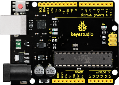
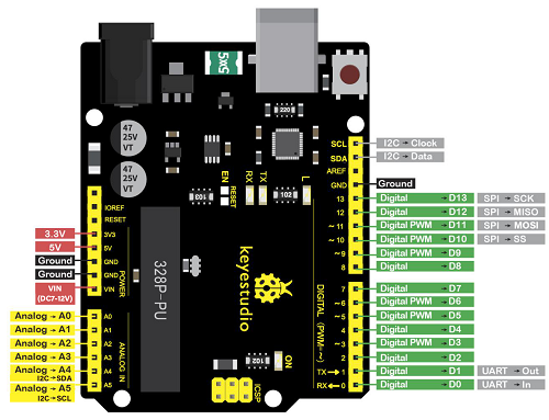
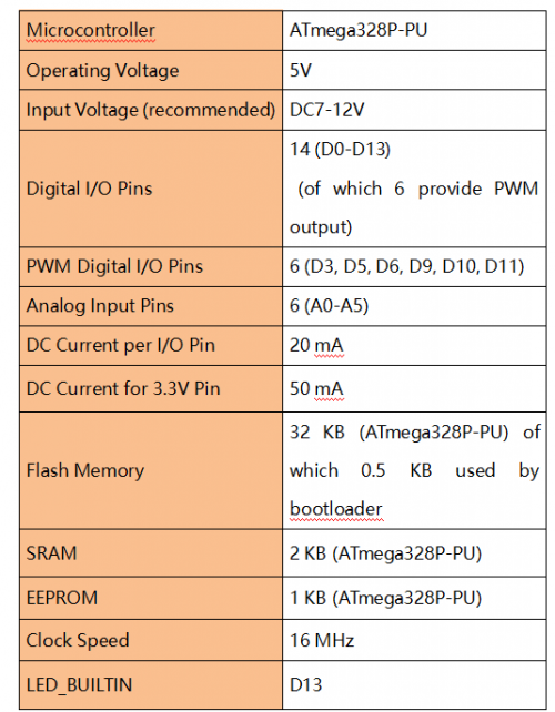
keyestudio V4.0 development board is an Arduino uno-compatible board, which is based on ATmega328P MCU, and with a cp2102 Chip as a UART-to-USB converter.
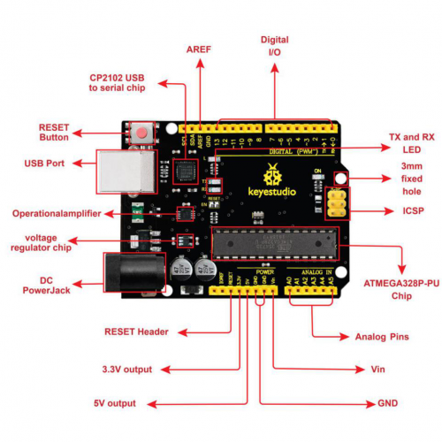
It has 14 digital input/output pins (of which 6 can be used as PWM outputs), 6 analog inputs, a 16 MHz quartz crystal, a USB connection, a power jack, 2 ICSP headers and a reset button.
It contains everything needed to support the microcontroller; simply connect it to a computer with a USB cable or power it via an external DC power jack (DC 7-12V) or via female headers Vin/ GND(DC 7-12V) to get started.
Keyestudio MEGA 2560 Board
Keyestudio Mega 2560 R3 is a microcontroller board based on the ATMEGA2560-16AU , fully compatible with ARDUINO MEGA 2560 R3.
It has 54 digital input/output pins (of which 15 can be used as PWM outputs), 16 analog inputs, 4 UARTs (hardware serial ports), a 16 MHz crystal oscillator, a USB connection, a power jack, 1 ICSP header, and a reset button. The built-in ICSP port can burn the firmware for ATMEGA2560-16AU directly. This chip is burnt the firmware well before leaving the factory, therefore, we hardly use it. We can power on by USB wire, DC head and Vin GND pins. To facilitate wiring, a 0.5 m USB wire is provided for you.
Specialized Functions of Some Pins:
1. Serial Communication: D0 (RX0) and D1 (TX1); Serial 1: D19 (RX1) and D18 (TX1); Serial 2: D17 (RX2) and D16 (TX2); Serial 3: D15 (RX3) and D14 (TX3). Used to receive (RX) and transmit (TX) TTL serial data. Pins 0 and 1 are also connected to the corresponding pins of the CP2102 USB-to-TTL Serial chip.
2. PWM Pins (Pulse-Width Modulation): D2 to D13, and D44 to D46. Provide 8-bit PWM output with the analogWrite() function.
3. External Interrupts: D2 (interrupt 0), D3 (interrupt 1), D18 (interrupt 5), D19 (interrupt 4), D20 (interrupt 3), and D21 (interrupt 2). These pins can be configured to trigger an interrupt on a low level, a rising or falling edge, or a change in level. See the attachInterrupt() function for details.
4. SPI communication: D53 (SS), D52 (SCK), D51 (MOSI), D50 (MISO). These pins support SPI communication using theSPI library. The SPI pins are also broken out on the ICSP header, which is physically compatible with the Arduino Uno.
5. IIC communication: D20 (SDA); D21 (SCL). Support TWI communication using the Wire library.
Installing driver
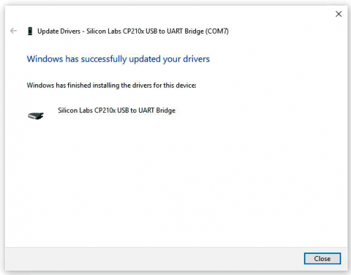
Let’s install the driver of keyestudio PLUS control board. The USB-TTL chip on PLUS board adopts CP2102 serial chip. The driver program of this chip is included in Arduino 1.8 version and above, which is convenient. Plug on USB port of board, the computer can recognize the hardware and automatically install the driver of CP2102.
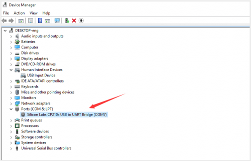
If install unsuccessfully, or you intend to install manually, open the device manager of computer. Right click Computer—— Properties—— Device Manager.
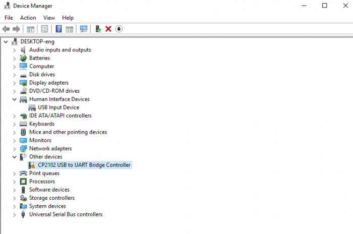
There is a yellow exclamation mark on the page, which implies installing the driver of CP2102 unsuccessfully. Then we double click the hardware and update the driver.
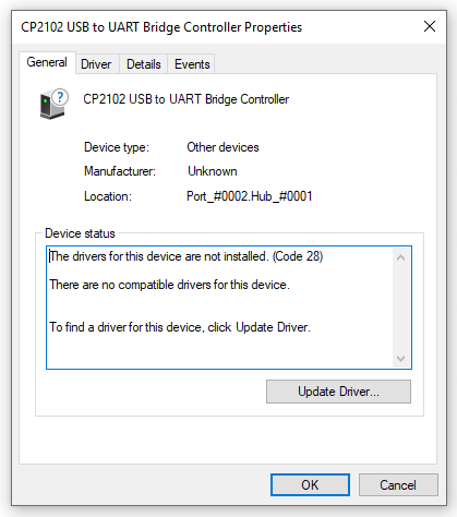
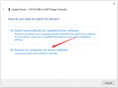
Click “OK” to enter the following page, click “browse my computer for updated driver software”, find out the installed or downloaded ARDUINO software. As shown below:
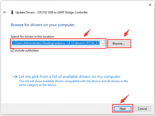
There is a DRIVERS folder in Arduino software installed package(![]() ), open driver folder and you can see the driver of CP210X series chips.
), open driver folder and you can see the driver of CP210X series chips.
We click “Browse”, then find out the driver folder, or you could enter “driver” to search in rectangular box, then click “next”, the driver will be installed successfully. (I place Arduino software folder on the desktop, you could follow my way)
Open device manager, we will find the yellow exclamation mark disappear. The driver of CP2102 is installed successfully.
Arduino IDE Setting
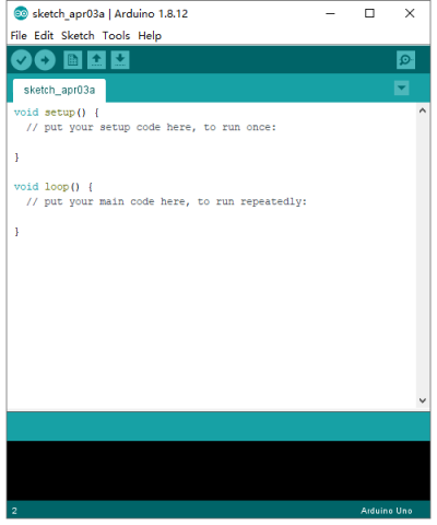
Click icon,open Arduino IDE.
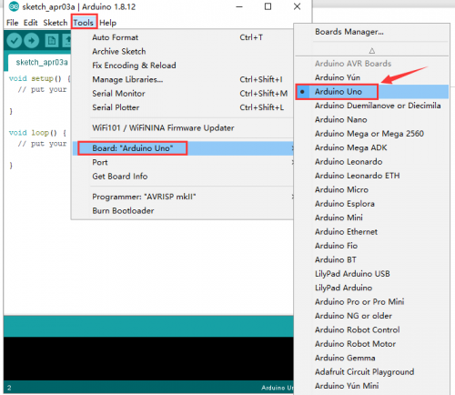
To avoid the errors when uploading the program to the board, you need to select the correct Arduino board that matches the board connected to your computer.
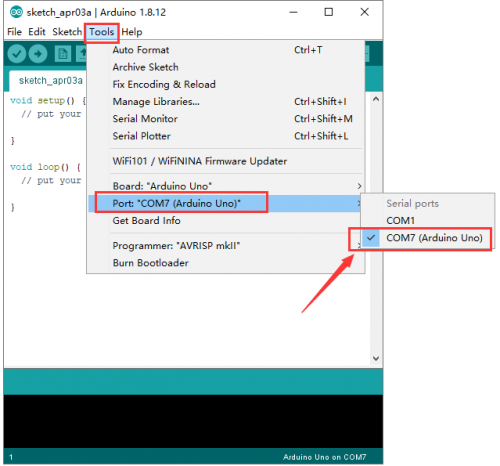
Then come back to the Arduino software, you should click Tools→Board, select the board. (as shown below)
Then select the correct COM port (you can see the corresponding COM port after the driver is successfully installed)
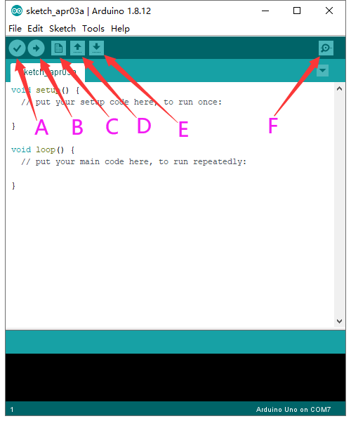
Before uploading the program to the board, let’s demonstrate the function of each symbol in the Arduino IDE toolbar.
A- Used to verify whether there is any compiling mistakes or not.
B- Used to upload the sketch to your Arduino board.
C- Used to create shortcut window of a new sketch.
D- Used to directly open an example sketch.
E- Used to save the sketch.
F- Used to send the serial data received from board to the serial monitor.
Start your first program
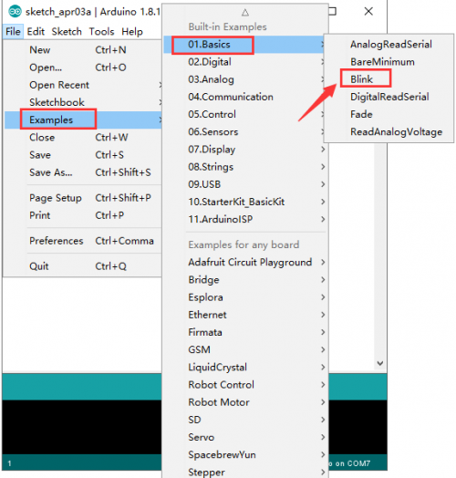
Open the file to select Example, choose BLINK from BASIC, as shown below:
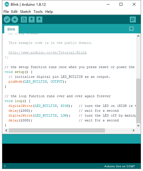
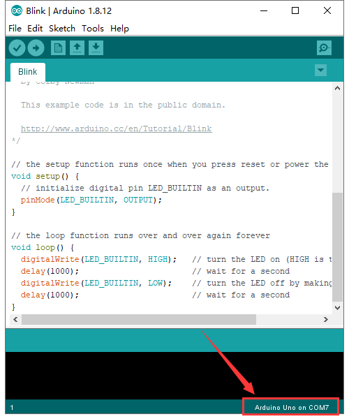
Set board and COM port, the corresponding board and COM port are shown on the lower right of IDE.
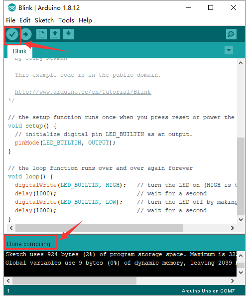
Click ![]() to start compiling the program, check errors.
to start compiling the program, check errors.
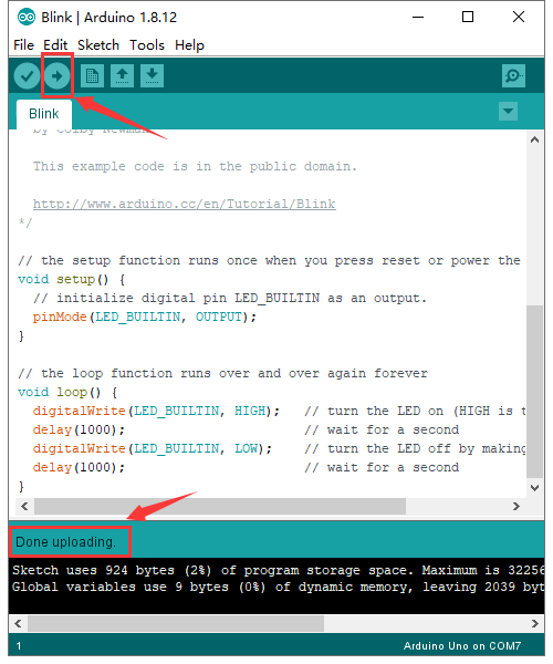
Click ![]() to upload the program, upload successfully.
to upload the program, upload successfully.
Upload the program successfully, the onboard LED lights on for 1s, lights off for 1s. Congratulation, you finish the first program.
Add Project Libraries
What are Libraries ?
Libraries are a collection of code that makes it easy for you to connect to a sensor,display, module, etc.
For example, the built-in LiquidCrystal library helps talk to LCD displays. There are hundreds of additional libraries available on the Internet for download.
The built-in libraries and some of these additional libraries are listed in the reference.
How to Install a Library ?
Here we will introduce the most simple way for you to add libraries.
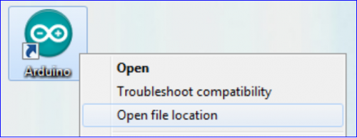
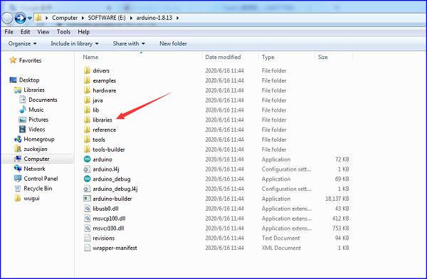
Step 1:After downloading well the Arduino IDE, you can right-click the icon of Arduino IDE.
Find the option «Open file location» shown as below:
Step 2: Enter it to find out libraries folder which is the library file of Arduino.
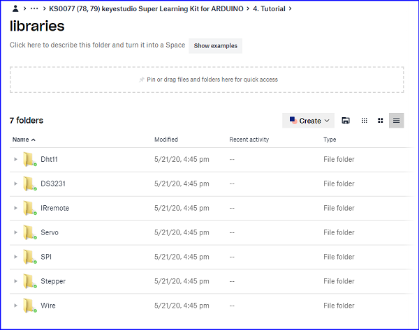
Step 3 Next to find out the “libraries” folder of this kit(seen in the link https://fs.keyestudio.com/KS0077-78-79)


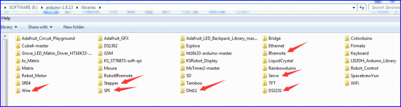
You just need to replicate and paste above libraries into the libraries folder of Arduino IDE.
Then the libraries of this kit are installed successfully, as shown below
Note the Arduino software download and the driver installation of keyetudio Mega 2560 R3 board is similar to arduino V4.0 board.
Project Details
Project 1: Hello World

1.Introduction
As for starters, we will begin with something simple. In this project, you only need an Arduino and a USB Cable to start the «Hello World!» experiment. It is not only a communication test of your Arduino and PC, but also a primer project for you to have your first try in the Arduino world!
2.Hardware Required
- V4.0 Board or MEGA 2650 Board*1
- USB cable*1
3.Sample Code
After installing driver for Arduino, let’s open Arduino software and compile code that enables Arduino to print «Hello World!» under your instruction. Of course, you can compile code for Arduino to continuously echo «Hello World!» without instruction.
A simple If () statement will do the instruction trick. when Arduino gets an instruction and then to print «Hello World!”.
/*
keyestudio super learning kit
Project 1
Hello World
http//www.keyestudio.com
- /
int val;//define variable val
void setup()
{
Serial.begin(9600);// set the baud rate at 9600 .
}
void loop()
{
 val=Serial.read();// read the instruction or character from PC to Arduino, and assign them to Val.
 if(val=='R')// determine if the instruction or character received is “R”.
 {  // if it’s “R”,
    Serial.println("Hello World!");// display“Hello World!”string.
 }}//
///////////////////////////////////////////////////////////////
4.Test Result
Click to open the serial monitor, input an “R”, PC will receive the information from Arduino Hello World!

After choosing the proper port, the experiment is easy for you!
Project 2: LED Blinking

1.Introduction
Blinking LED experiment is quite simple. In the «Hello World!» program, we have come across LED. This time, we are going to connect an LED to one of the digital pins rather than using LED13 soldered to the board. Apart from an Arduino and a USB cable, you will need extra parts as below
2.Hardware Required
- V4.0 Board or MEGA 2650 Board*1
- Red M5 LED*1
- 220Ω Resistor*1
- Breadboard*1
- Breadboard Jumper Wire*2
- USB cable*1
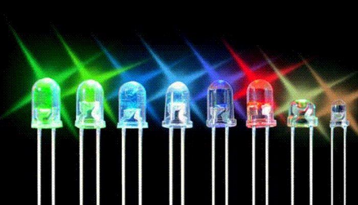
3.Little Knowledge
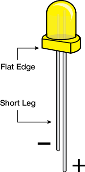
LED is a type of semiconductor called «Light Emitting Diode «which is an electronic device made of semiconductor materials (silicon, selenium, germanium, etc.). It is dubbed indicator, digital and word display in circuit and device. It has positive and negative poles. The short leg is negative pole, the long one is positive pole.
Resistor:Resistor is the electronic component in the circuit, which limits and regulates current flow. Its unit is (Ω).
The units larger than ohms are kiloohms (KΩ) and megaohms (MΩ). When in use, in addition to the size of the resistance, you must also pay attention to its power. In the project, the leads at both ends of the resistor should be bent at a 90° angle to fit the breadboard properly. If the lead is too long, it can be cut to an appropriate length.

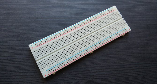
A breadboard is used to build and test circuits quickly before finalizing any circuit design. The breadboard has many holes into which circuit components like ICs and resistors can be inserted. A typical breadboard is shown below:
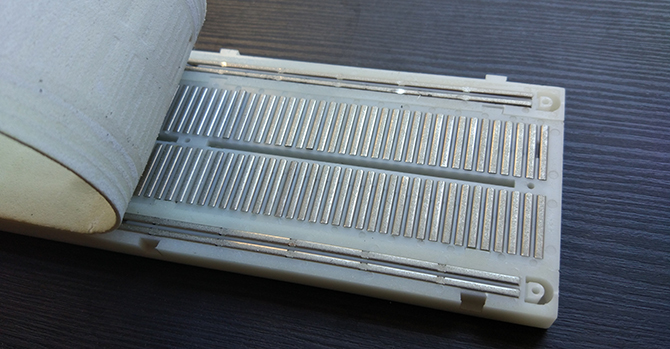
The bread board has strips of metal which run underneath the board and connect the holes on the top of the board. The metal strips are laid out as shown below. Note that the top and bottom rows of holes are connected horizontally while the remaining holes are connected vertically.
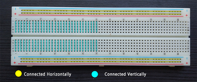
To use the bread board, the legs of components are placed in the holes. Each set of holes connected by a metal a strip underneath forms anode
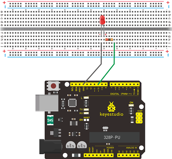
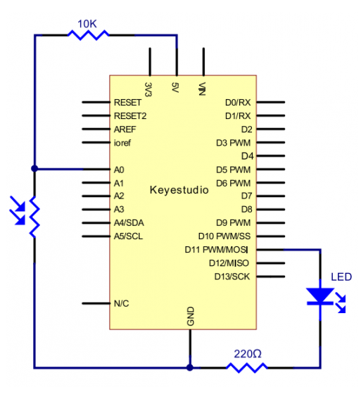
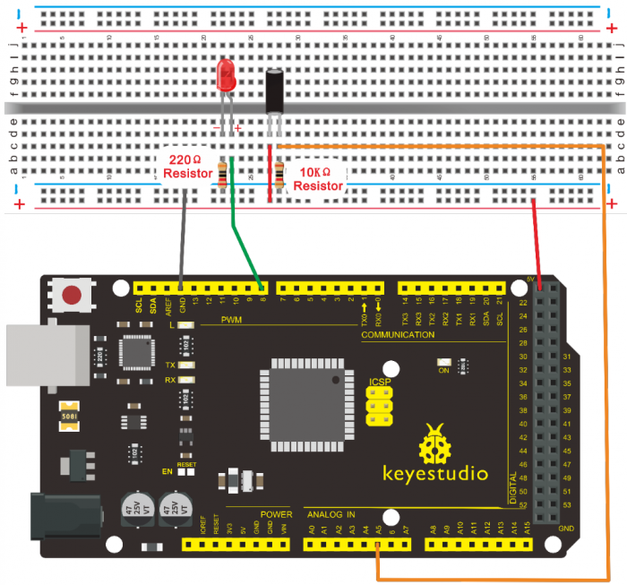
4.Circuit Connection
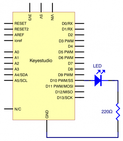
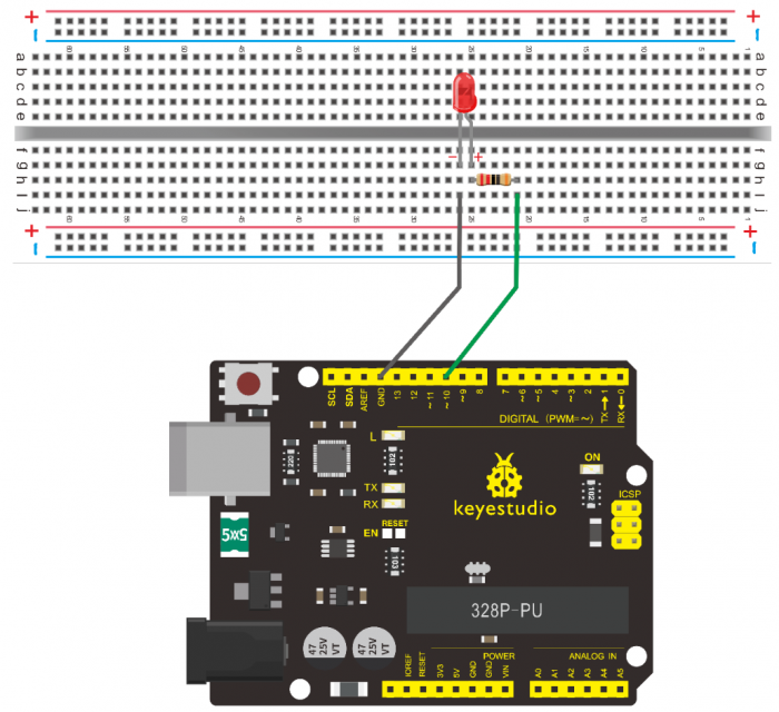
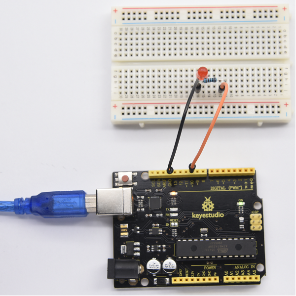
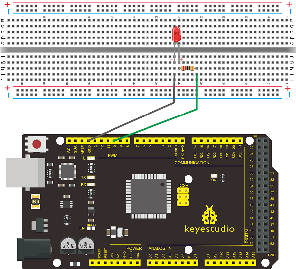
We follow below diagram from the experimental schematic link. Here we use digital pin 10. We connect LED to a 220 ohm resistor to avoid high current damaging the LED.
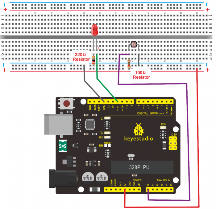
Connection for V4.0
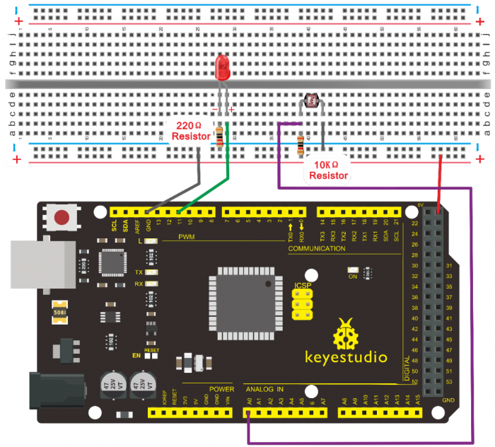
Connection for 2560

5.Sample Code
/*
keyestudio super learning kit
Project 2
Blink
http//www.keyestudio.com
- /
int ledPin = 10; // define digital pin 10.
void setup()
{
pinMode(ledPin, OUTPUT);// define pin with LED connected as output.
}
void loop()
{
digitalWrite(ledPin, HIGH); // set the LED on.
delay(1000); // wait for a second.
digitalWrite(ledPin, LOW); // set the LED off.
delay(1000); // wait for a second
}
//////////////////////////////////////////////////////////////////
6.Test Result
After uploading this program, in the experiment, you will see the LED connected to pin 10 turning on and off, with an interval of approximate one second.
In this way, blinking LED experiment is now completed. Thank you!
Project 3: PWM
1.Introduction
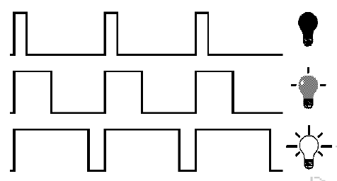
PWM, short for Pulse Width Modulation, is a technique used to encode analog signal level into digital ones. A computer cannot output analog voltage but only digital voltage values such as 0V or 5V. So we use a high resolution counter to encode a specific analog signal level by modulating the duty cycle of PMW.
2.Working Principle
The PWM signal is also digitalized because in any given moment, fully on DC power supply is either 5V (ON), or 0V (OFF). The voltage or current is fed to the analog load (the device that uses the power) by repeated pulse sequence being ON or OFF. Being on, the current is fed to the load; being off, it’s not. With adequate bandwidth, any analog value can be encoded using PWM. The output voltage value is calculated via the on and off time.
Output voltage = (turn on time/pulse time) * maximum voltage value.

PWM has many applications lamp brightness regulating, motor speed regulating, sound making, etc.
The following are the three basic parameters of PMW.
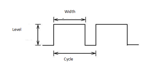
- 1.The amplitude of pulse width (minimum / maximum)
- 2. The pulse period (The reciprocal of pulse frequency in one second)
- 3. The voltage level(such as 0V-5V)
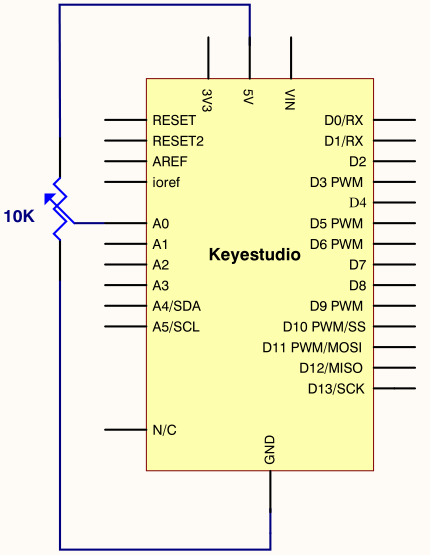
- There are 6 PMW interfaces on Arduino, namely digital pin 3, 5, 6, 9, 10, and 11.
- In previous experiments, we have done «button-controlled LED», using digital signal to control digital pin, also one about potentiometer.
- This time, we will use a potentiometer to control the brightness of the LED.
3.Hardware Required
- V4.0 Board or MEGA 2650 Board*1
- Red M5 LED*1
- 220Ω Resistor
- Breadboard*1
- Breadboard Jumper Wire*6
- USB cable*1
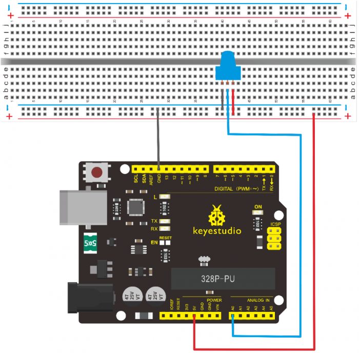
4.Circuit Connection
Connection for V4.0
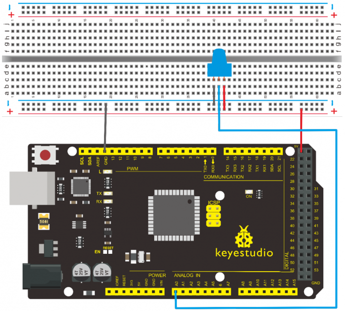
Connection for 2560 R3
5.Sample Code
/*
keyestudio super learning kit
Project 3
pwm
http//www.keyestudio.com
*/
int ledPin = 10;
 void setup() {
     pinMode(ledPin,OUTPUT);
}
void loop(){
  for (int value = 0 ; value < 255; value=value+1){
    analogWrite(ledPin, value);
    delay(5);
  }
  for (int value = 255; value >0; value=value-1){
    analogWrite(ledPin, value);
    delay(5);
  }
}
//////////////////////////////////////////////////////////////////
6.Test Result
Hook up via connection diagram, upload the code and plug in power. The external LED lights up then gets dark gradually, which looks like human breath.
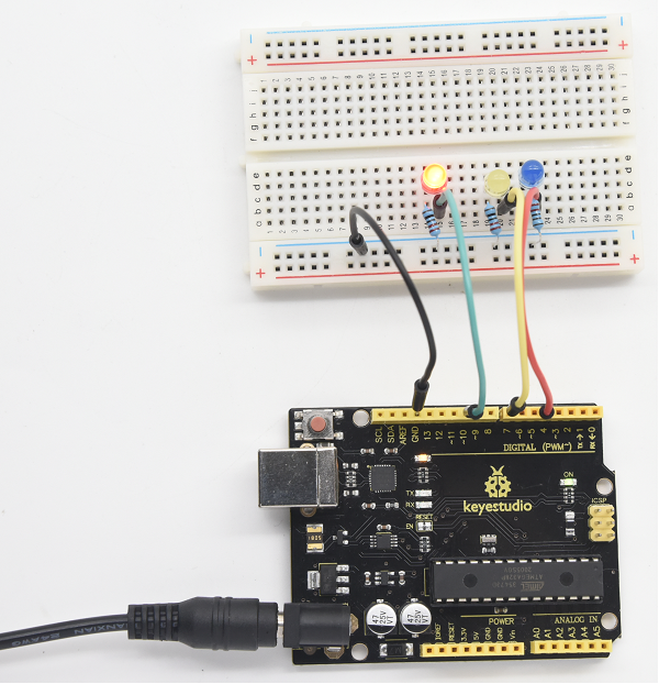
Project 4: Traffic Light

1.Introduction
In the previous program, we have done the LED blinking experiment with one LED. Now, it’s time to up the stakes to do a bit more complicated experiment-traffic light. Actually, these two experiments are similar. While in this traffic light experiment, we use three LEDs with different colors rather than an LED.
2.Hardware Required
- V4.0 Board or MEGA 2650 Board*1
- USB Cable *1
- Red M5 LED*1
- Yellow M5 LED*1
- Blue M5 LED*1
- 220Ω Resistor *3
- Breadboard*1
- Breadboard Jumper Wire *4
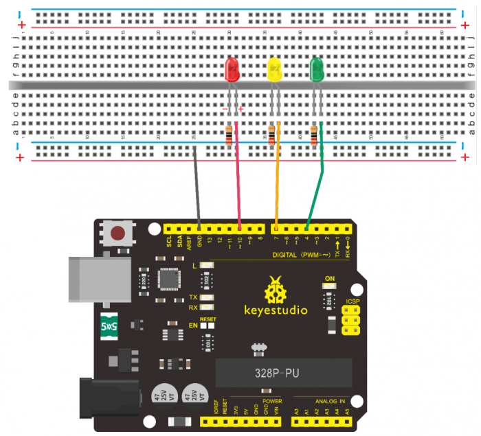
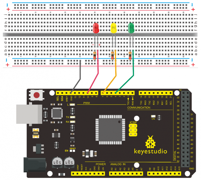
3.Circuit Connection

Connection for V4.0
Connection for 2560
4.Sample Code
Since it is a simulation of traffic lights, the blinking time of each LED should be the same with those in traffic lights system.
In this program, we use Arduino delay () function to control delay time, which is much simpler than C language.
/*
 keyestudio super learning kit
 Project 4
 traffic light
 http//www.keyestudio.com
*/
int redled =10; // initialize digital pin 10.
int yellowled =7; // initialize digital pin 7.
int blueled =4; // initialize digital pin 4.
void setup()
{
pinMode(redled, OUTPUT);// set the pin with red LED as “output”
pinMode(yellowled, OUTPUT); // set the pin with yellow LED as “output”
pinMode(blueled, OUTPUT); // set the pin with blue LED as “output”
}
void loop()
{
digitalWrite(blueled, HIGH);//// turn on blue LED
delay(5000);// wait 5 seconds
digitalWrite(blueled, LOW); // turn off blue LED
for(int i=0;i<3;i++)// blinks for 3 times
{
delay(500);// wait 0.5 second
digitalWrite(yellowled, HIGH);// turn on yellow LED
delay(500);// wait 0.5 second
digitalWrite(yellowled, LOW);// turn off yellow LED
}
delay(500);// wait 0.5 second
digitalWrite(redled, HIGH);// turn on red LED
delay(5000);// wait 5 second
digitalWrite(redled, LOW);// turn off red LED
}
//////////////////////////////////////////////////////////////////
5.Test Result
When the uploading process is completed, you can see traffic lights of your own design. Note this circuit design is very similar with the one in LED chasing effect.
The blue light will be on for 5 seconds, and then off, followed by the yellow light blinking for 3 times, and then the red light is on for 5 seconds, repeatedly forming a cycle.
Experiment is now completed, thank you!
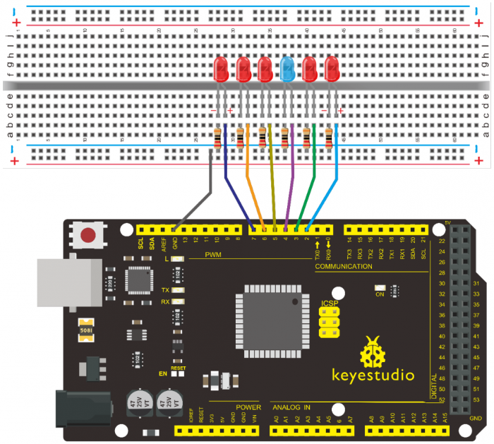
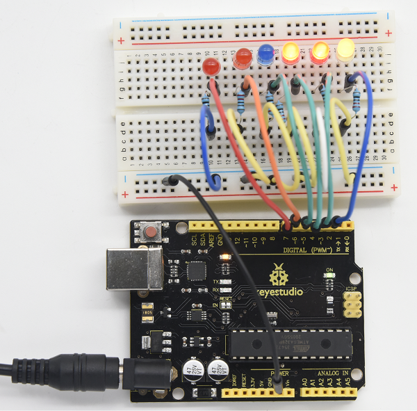
Project 5: LED Chasing Effect
1.Introduction
We can see many billboards composed of colorful LEDs. They are constantly changing to form various effects. In this experiment, we compile a program to simulate chase effect.
2.Hardware Required
- V4.0 Board or MEGA 2650 Board*1
- Red LED*6
- 220Ω Resistor *6
- Breadboard Jumper Wire*12
- USB cable*1
3.Circuit Connection
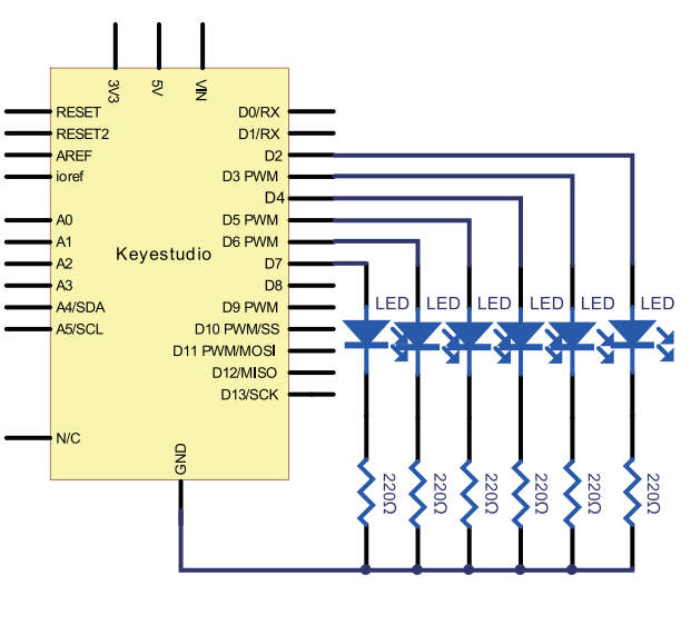
Connection for V4.0
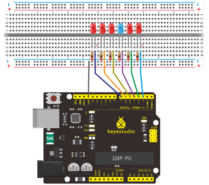
Connection for 2560
4.Sample Code
/*
 keyestudio super learning kit
 Project 5
 LED Chasing Effect
 http//www.keyestudio.com
*/
int BASE = 2 ;  // the I/O pin for the first LED
int NUM = 6;   // number of LEDs
void setup()
{
   for (int i = BASE; i < BASE + NUM; i ++)
   {
     pinMode(i, OUTPUT);   // set I/O pins as output
   }
}
void loop()
{
   for (int i = BASE; i < BASE + NUM; i ++)
   {
     digitalWrite(i, LOW);    // set I/O pins as “low”, turn off LEDs one by one.
     delay(200);        // delay
   }
   for (int i = BASE; i < BASE + NUM; i ++)
   {
     digitalWrite(i, HIGH);    // set I/O pins as “high”, turn on LEDs one by one
     delay(200);        // delay
   }
}
//////////////////////////////////////////////////////////////////
5.Test Result
You can see the LEDs blink by sequence.
Project 6: Button-Controlled LED
1.Introduction
I/O port means interface for INPUT and OUTPUT. Up to now, we have only used the OUTPUT function.
In this experiment, we will try to use the INPUT function, which is to read the output value of device connecting to it.
We use 1 button and 1 LED using both input and output to give you a better understanding of the I/O function.
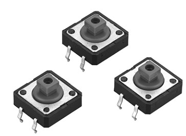
Button switch, familiar to most of us, is a switch value (digital value) component. When it’s pressed, the circuit is in closed (conducting) state.
2.Hardware Required
- V4.0 Board or MEGA 2650 Board*1
- Button switch*1
- Red M5 LED*1
- 220ΩResistor*1
- 10KΩ Resistor*1
- Breadboard*1
- Breadboard Jumper Wire*6
- USB cable*1
3. Little Knowledge
I believe that button switch is common and popular for people. It belongs to switch quantity( digital quantity)component. Composed of normally open contact and normally closed contact,its working principle is similar with ordinary switch.
When the normally open contact bears pressure, the circuit is on state ; however, when this pressure disappears, the normally open contact goes back to initial state, that is, off state. The pressure is the act we switch the button.
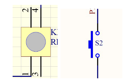
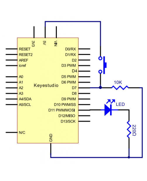
Schematic Diagrams:
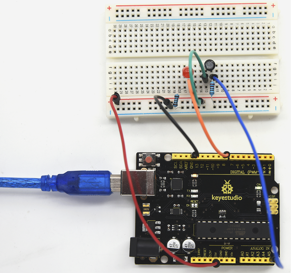
4. Circuit Connection
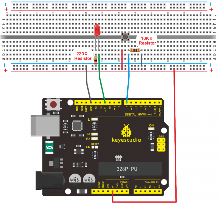
Connection for V4.0
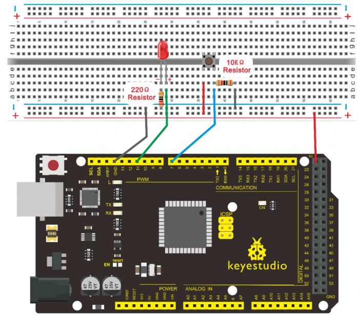
Connection for 2560
5.Sample Code
Now, let’s begin the compiling. When the button is pressed, the LED will be on. Based on the previous study, the coding should be easy for you.
In this program, we add a statement of judgment. Here, we use an if () statement.
Arduino IDE is based on C language, so statements of C language such as while, switch etc. can certainly be used for Arduino program.
When we press the button, pin 7 will output high level. We can program pin 11 to output high level and turn on the LED. When pin 7 outputs low level, pin 11 also outputs low level and the LED remains off.
/*
 keyestudio super learning kit
 Project 6
 Button
 http//www.keyestudio.com
*/
int ledpin=11;// initialize pin 11
int inpin=7;// initialize pin 7
int val;// define val
void setup()
{
pinMode(ledpin,OUTPUT);// set LED pin as “output”
pinMode(inpin,INPUT);// set button pin as “input”
}
void loop()
{
val=digitalRead(inpin);// read the level value of pin 7 and assign if to val
if(val==LOW)// check if the button is pressed, if yes, turn on the LED
{ digitalWrite(ledpin,LOW);}
else
{ digitalWrite(ledpin,HIGH);}
}
//////////////////////////////////////////////////////////////////
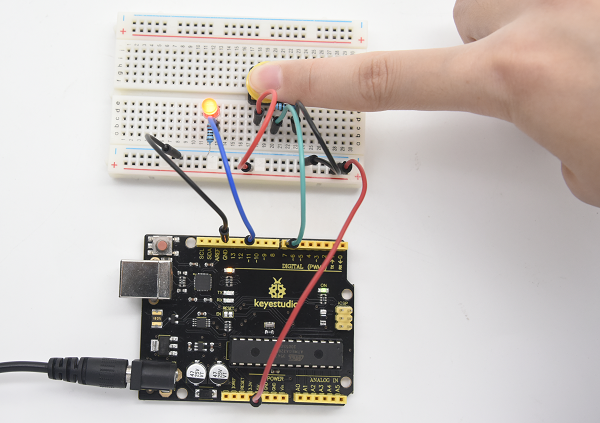
6.Test Result
When the button is pressed, LED is on, otherwise, LED remains off. In this way, the button controlled LED experiment is completed.
The simple principle of this experiment is widely used in a variety of circuit and electric appliances. You can easily come across it in your daily life. One typical example is when you press a certain key on your phone, the backlight will be on.
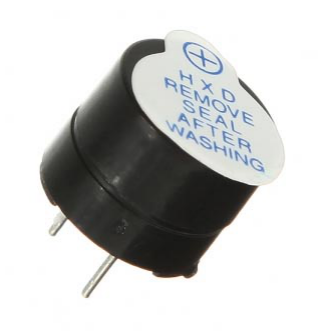
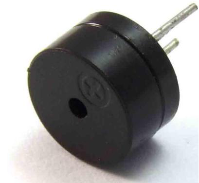
Project 7: Active Buzzer
1.Introduction
Active buzzer is widely used as a sound making element on computer, printer, alarm, electronic toy, telephone, timer and more. It has an inner vibration source. Simply connect it with 5V power supply, it can buzz continuously.
2.Hardware Required
- V4.0 Board or MEGA 2650 Board*1
- Buzzer*1
- Breadboard*1
- Breadboard Jumper Wire*2
- USB cable*1
3. Little Knowledge
There are two kinds of buzzer, active buzzer and passive buzzer. In this lesson, we will use Micro:bit to drive an active buzzer. The active buzzer inside has a simple oscillator circuit which can convert constant direct current into a certain frequency pulse signal. Once active buzzer receives a high level, it will produce an audible beep.
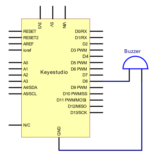
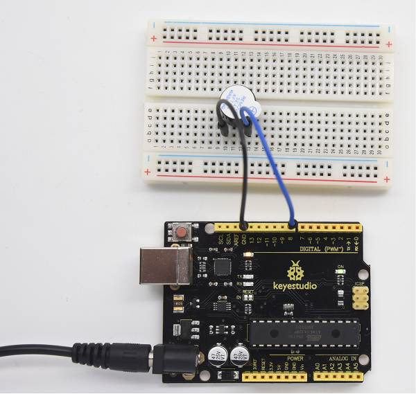
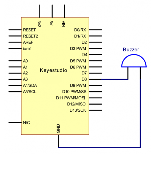
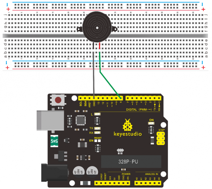
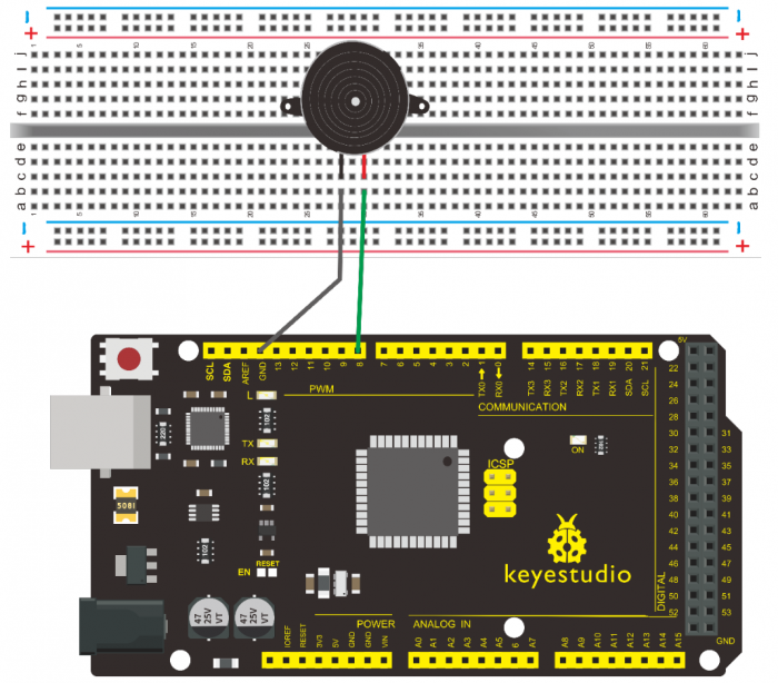
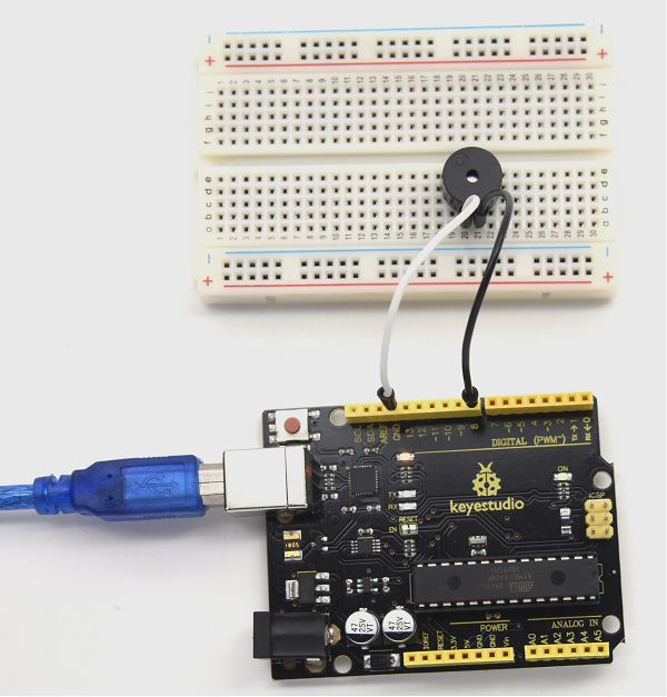
4.Circuit Connection
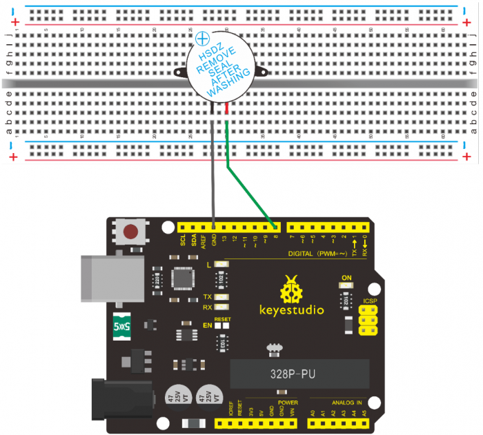
Connection for V4.0
Connection for 2560
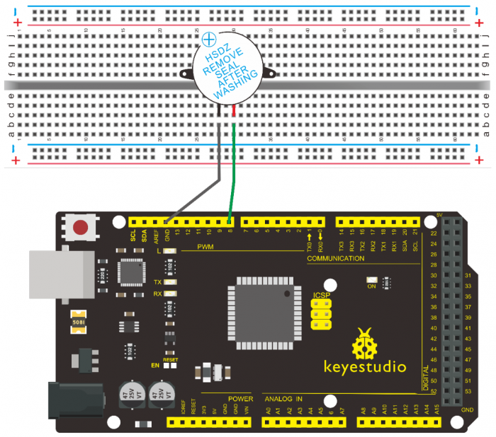
When connecting the circuit, pay attention to the positive and negative poles of the buzzer. In the photo, you can see there are red and black lines. When the circuit is finished, you can begin the programming.
5.Sample Code
Program is simple. You control the buzzer by outputting high/low level.
/*
 keyestudio super learning kit
 Project 7
 Active Buzzer
 http//www.keyestudio.com
*/
int buzzer=8;// initialize digital IO pin that controls the buzzer
void setup()
{
  pinMode(buzzer,OUTPUT);// set pin mode as “output”
}
void loop()
{
digitalWrite(buzzer, HIGH); // produce sound
}
//////////////////////////////////////////////////////////////////
6.Test Result
After uploading the program, the buzzer experiment is completed. You can see the buzzer is ringing.
Project 8: Passive Buzzer
1.Introduction
We can use Arduino to make many interactive works. The most commonly used one is acoustic-optic display. All the previous experiment has something to do with LED. However, the circuit in this experiment can produce sound. Normally, the experiment is done with a buzzer but not a speaker while buzzer is more simpler and easier to use.
The buzzer we introduced here is a passive buzzer. It cannot be actuated by itself, but by external pulse frequencies. Different frequency produces different sound. We can use Arduino to code the melody of a song, which is quite fun and simple.
2.Hardware Required
- V4.0 Board or MEGA 2650 Board*1
- Passive Buzzer*1
- Breadboard*1
- Breadboard Jumper Wire*2
- USB cable*1
3. Little knowledge
Passive buzzer is an integrated electronic buzzer without vibration source inside. It must be driven by 2K-5K square wave instead of direct current signals. There is little difference between the two buzzers, but when the pins of the two buzzers are placed up, the passive buzzer comes with green circuit board, and the one sealed with vinyl is an active buzzer.
4.Circuit Connection
Connection for V4.0
Connection for 2560
5.Sample Code
/*
keyestudio super learning kit
Project 8
Passive Buzzer
http//www.keyestudio.com
*/
int buzzer=8;// select digital IO pin for the buzzer
void setup()
{
pinMode(buzzer,OUTPUT);// set digital IO pin pattern, OUTPUT to be output
}
void loop()
{ unsigned char i,j;//define variable
while(1)
{ for(i=0;i<80;i++)// output a frequency sound
{ digitalWrite(buzzer,HIGH);// sound
delay(1);//delay1ms
digitalWrite(buzzer,LOW);//not sound
delay(1);//ms delay
}
for(i=0;i<100;i++)// output a frequency sound
{ digitalWrite(buzzer,HIGH);// sound
delay(2);//2ms delay
digitalWrite(buzzer,LOW);//not sound
delay(2);//2ms delay
}}}
//////////////////////////////////////////////////////////////////
6.Test Result
After uploading the program, buzzer experiment is finished, you can hear the buzzer sound.
Project 9: RGB LED
1.Introduction
The RGB color mode is a color standard in the industry. It obtains various colors by changing the three color channels of red (R), green (G), and blue (B) and integrating them. RGB denotes the three colors of red, green and blue.
In this project, we use Arduino to mix these three colors in equal amounts to produce white light.
2.Hardware Required
- V4.0 Board or MEGA 2650 Board*1
- USB Cable * 1
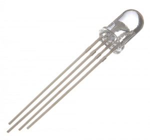
- RGB LED * 1
- Resistor *3
- Breadboard jumper wire*5
3. Little Knowledge
The monitors mostly adopt the RGB color standard, and all the colors on the computer screen are composed of the three colors of red, green and blue mixed in different proportions.
RGB is inclusive of common cathode RGB and common anode RGB.
And we could adjust the LED brightness by PWM
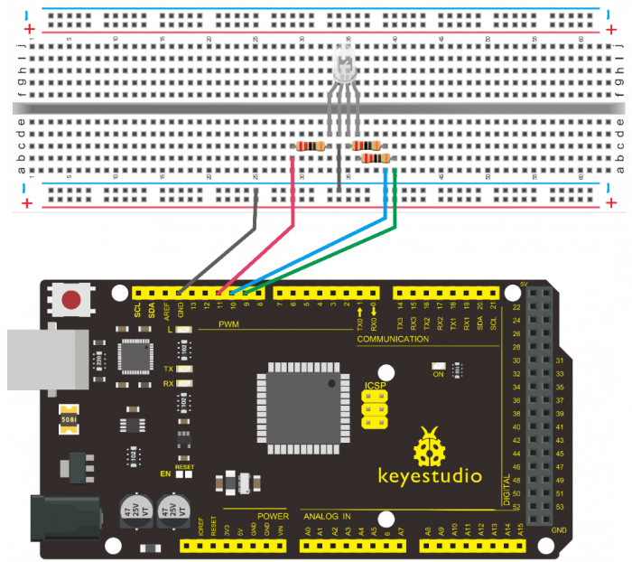
4.Circuit Connection
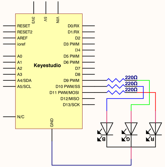
Connection for V4.0
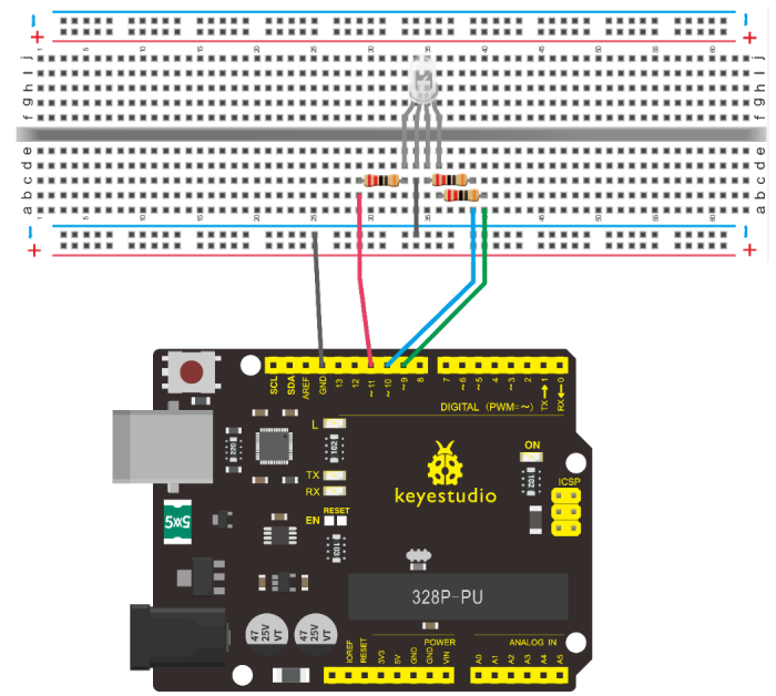
Connection for 2560
5.Sample Code
/*
 keyestudio super learning kit
 Project 9
 RGB
 http//www.keyestudio.com
*/
int redpin = 11; //select the pin for the red LED
int bluepin =10; // select the pin for the blue LED
int greenpin =9;// select the pin for the green LED
int val;
void setup() {
  pinMode(redpin, OUTPUT);
  pinMode(bluepin, OUTPUT);
  pinMode(greenpin, OUTPUT);
  Serial.begin(9600);
}
void loop()
{
for(val=255; val>0; val--)
  {
   analogWrite(11, val);
   analogWrite(10, 255-val);
   analogWrite(9, 128-val);
   delay(1);
  }
for(val=0; val<255; val++)
  {
   analogWrite(11, val);
   analogWrite(10, 255-val);
   analogWrite(9, 128-val);
   delay(1);
  }
 Serial.println(val, DEC);
}
//////////////////////////////////////////////////////////////////
6.Test Result
Directly copy the above code into arduino IDE, and click upload, wait for a few seconds, you can see a full-color LED.
Project 10: Photo Resistor
1.Introduction
After completing all the previous experiments, you may acquire some basic understanding and knowledge about Arduino application. We have introduced digital input and output, analog input and PWM.
Now, let’s begin the learning of sensor applications.
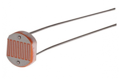
Photo Resistor (Photovaristor) is a resistor whose resistance varies from different incident light strength. It’s based on the photoelectric effect of semiconductor. If the incident light is intense, its resistance reduces; if the incident light is weak, the resistance increases.
2.Hardware Required
- V4.0 Board or MEGA 2650 Board*1
- Photo Resistor*1
- Red M5 LED*1
- 10KΩ Resistor*1
- 220Ω Resistor*1
- Breadboard*1
- Breadboard Jumper Wire*5
- USB cable*1
3.Little Knowledge
Photovaristor is commonly applied in the measurement of light, light control and photovoltaic conversion (convert the change of light into the change of electricity).
Photo resistor is also being widely applied to various light control circuit, such as light control and adjustment, optical switches, etc.
We will start with a relatively simple experiment regarding to photovaristor application.
Photovaristor is an element that can change its resistance as light strength changes. So need to read the analog value. You can refer to the PWM experiment, replacing the potentiometer with photovaristor. When there is change in light strength, it will make corresponding change on the LED.
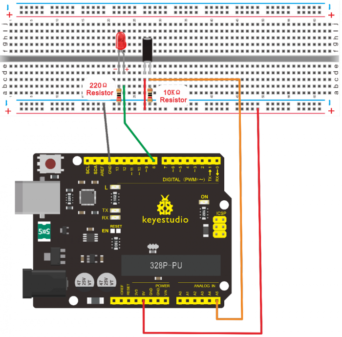
4.Circuit Connection
Connection for V4.0
Connection for 2560
5.Sample Code
After wiring, let’s begin the program compiling. The program is similar to the PWM.
For change detail, please refer to the Sample Code below.
/*
 keyestudio super learning kit
 Project 10
 Photo Resistor
 http//www.keyestudio.com
*/
int potpin=0;// initialize analog pin 0, connected with photovaristor
int ledpin=11;// initialize digital pin 11,
int val=0;// initialize variable va
void setup()
{
pinMode(ledpin,OUTPUT);// set digital pin 11 as “output”
Serial.begin(9600);// set baud rate at “9600”
}
void loop()
{
val=analogRead(potpin);// read the value of the sensor and assign it to val
Serial.println(val);// display the value of val
analogWrite(ledpin,val/4);// set up brightness(maximum value 255)
delay(10);// wait for 0.01
}
//////////////////////////////////////////////////////////////////
6.Test Result
After downloading the program, you can change the light strength around the photovaristor, and see the corresponding brightness change of the LED.
Photovaristors has various applications in our everyday. You can make other interesting interactive projects based on this one.
Project 11: Flame Sensor
1.Introduction
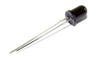
Flame sensor (infrared receiving triode) is specially used for robots to find the fire source. This sensor is of high sensitivity to flame.
2.Hardware Required
- V4.0 Board or MEGA 2650 Board*1
- Flame Sensor *1
- Buzzer *1
- 10K Resistor *1
- Breadboard Jumper Wire*6
- USB cable*1
3. Little Knowledge
Flame sensor is based on the principle that infrared ray is highly sensitive to flame. It has an infrared receiving tube specially designed to detect fire, and then to convert the flame brightness into fluctuating level signal. The signals are then input into the central processor and be dealt with accordingly.
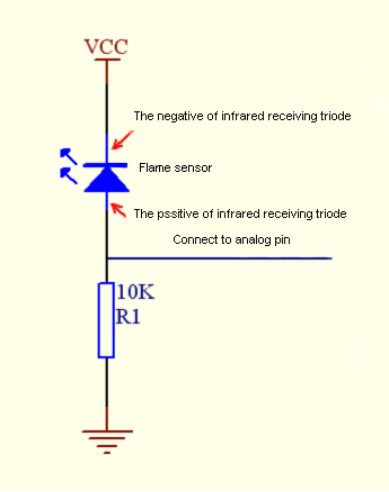
The shorter lead of the receiving triode is for negative, the other one for positive. Connect negative to 5V pin, positive to resistor; connect the other end of the resistor to GND, connect one end of a jumper wire to a clip which is electrically connected to sensor positive, the other end to analog pin. As shown below
4.Experiment Principle
When it’s approaching a fire, the voltage value read from the analog port will differ. If you use a multimeter, you can see that when there is no fire approaching, the voltage it reads is around 0.3V; when there is fire approaching, the voltage it reads is around 1.0V. The nearer the fire is, the higher the voltage is.
So in the beginning of the program, you can initialize voltage value i (no fire value); Then, continuously read the analog voltage value j and obtain difference value k=j-i; compare k with 0.6V (123 in binary) to determine whether there is a fire approaching or not; if yes, the buzzer will buzz.
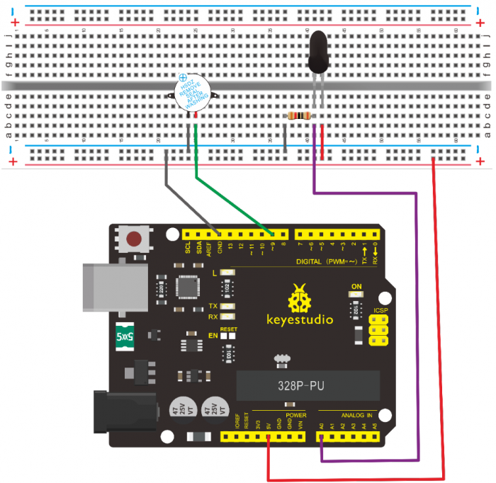
5.Circuit Connection
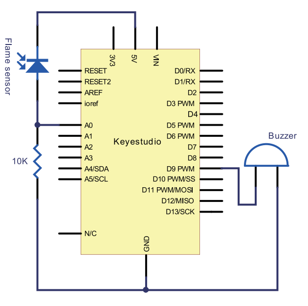
Connection for V4.0
Connection for MEGA 2560
6.Sample Code
/*
keyestudio super learning kit
Project 11
Flame
http//www.keyestudio.com
*/
int flame=0;// select analog pin 0 for the sensor
int Beep=9;// select digital pin 9 for the buzzer
int val=0;// initialize variable
 void setup()
{
  pinMode(Beep,OUTPUT);// set LED pin as “output”
 pinMode(flame,INPUT);// set buzzer pin as “input”
 Serial.begin(9600);// set baud rate at “9600”
 }
void loop()
{
  val=analogRead(flame);// read the analog value of the sensor
  Serial.println(val);// output and display the analog value
  if(val>=600)// when the analog value is larger than 600, the buzzer will buzz
  {
   digitalWrite(Beep,HIGH);
   }else
   {
     digitalWrite(Beep,LOW);
    }
   delay(500);
}
//////////////////////////////////////////////////////////////////
7.Test Result
This program can simulate an alarm when there is a fire. Everything is normal when there is no fire; when there is fire, the alarm will be set off immediately.
Project 12: LM35 Temperature Sensor
1.Introduction
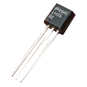
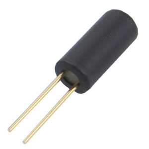
LM35 is a common and easy-to-use temperature sensor. It does not require other hardware. You just need an analog port to make it work. The difficulty lies in compiling the code to convert the analog value it reads into Celsius temperature. In this project, we will guide you how to use LM35 temperature sensor.
2. Working Principle
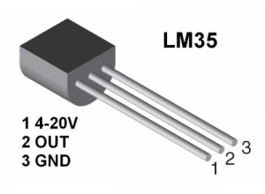
LM35 is a widely used temperature sensor with many different package types. At room temperature, it can achieve the accuracy of ±1/4°C without additional calibration processing.
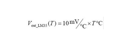
LM35 temperature sensor can produce different voltage by different temperature
When temperature is 0 ℃, it outputs 0V; if increasing 1 ℃, the output voltage will increase 10 mv.
The output temperature is 0℃~100℃, the conversion formula is as follows:
3.Hardware Required
- V4.0 Board or MEGA 2650 Board*1
- LM35*1
- Breadboard*1
- Breadboard Jumper Wire*5
- USB cable*
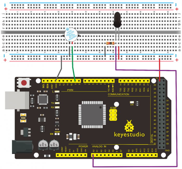
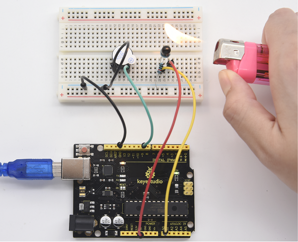
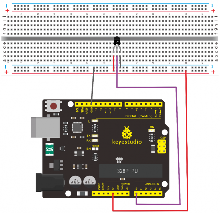
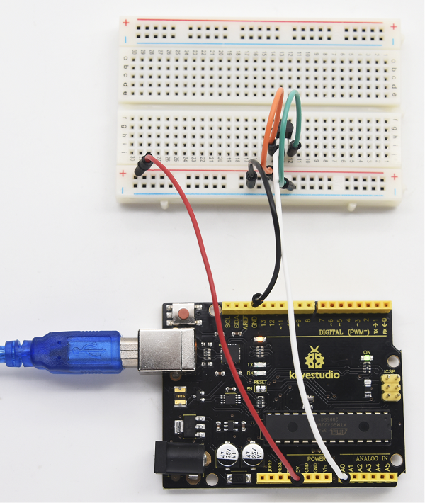
4.Circuit Connection
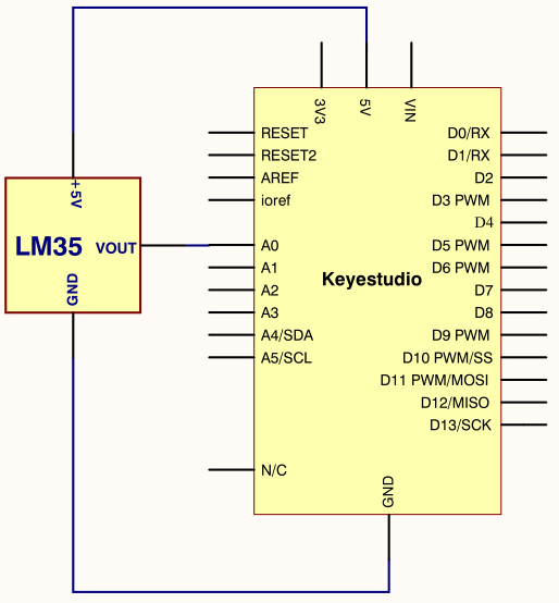
Connection for V4.0
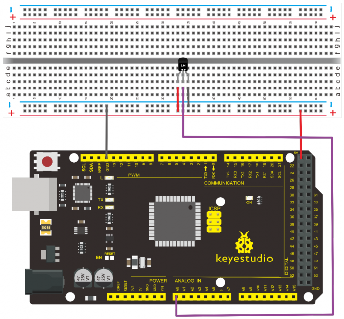
Connection for 2560
5.Sample Code
/*
keyestudio super learning kit
Project 12
LM35
http//www.keyestudio.com
*/
int potPin = 0; // initialize analog pin 0 for LM35 temperature sensor
void setup()
{
Serial.begin(9600);// set baud rate at”9600”
}
void loop()
{
int val;// define variable
int dat;// define variable
val=analogRead(0);// read the analog value of the sensor and assign it to val
dat=(125*val)>>8;// temperature calculation formula
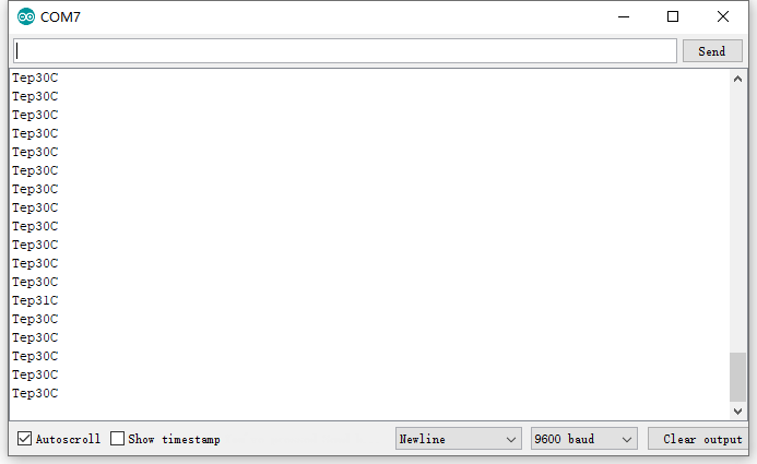
Serial.print("Tep");// output and display characters beginning with Tep
Serial.print(dat);// output and display value of dat
Serial.println("C");// display “C” characters
delay(500);// wait for 0.5 second
}
//////////////////////////////////////////////////////////////////
6.Test Result
After uploading the program, you can open the monitoring window to see the current temperature.
Project 13: Tilt Switch
1.Introduction
This is a ball switch experiment . The ball switch is also dubbed a steel ball switch. It controls the circuit by connecting guide pin with rolling ball. In this project, we control the LED light by reading the state of the ball switch.
2.Working Principle
When one end of the switch is below horizontal position, the switch is on. The voltage of the analog port is about 5V (1023 in binary). The LED will be on.
When the other end of the switch is below horizontal position, the switch is off. The voltage of the analog port is about 0V (0 in binary). The LED will be off.
In the program, we determine whether the switch is on or off according to the voltage value of the analog port, whether it’s above 2.5V (512 in binary) or not.
3.Hardware Required
- V4.0 Board or MEGA 2650 Board*1
- Ball switch*1
- Led *1
- 220Ω Resistor*1
- 10KΩ resistor*1
- Breadboard Jumper Wire*5
- USB cable*1
4.Circuit Connection

Connection for V4.0
Connection for 2560
5.Sample Code
/*
 keyestudio super learning kit
 Project 13
 Tilt Switch
 http//www.keyestudio.com
*/
void setup()
{
  pinMode(8,OUTPUT);// set digital pin 8 as “output”
}
void loop()
{
int i;// define variable i
while(1)
{
  i=analogRead(5);// read the voltage value of analog pin 5
  if(i>512)// if larger that 512(2.5V)
  {
    digitalWrite(8,LOW);// turn on LED
  }
  else// otherwise
  {
    digitalWrite(8,HIGH);// turn off LED
  } } }
//////////////////////////////////////////////////////////////////
6.Test Result
Hold the breadboard with your hand. Tilt it to a certain extent, the LED will be on. If there is no tilt, the LED will be off.
The principle of this experiment can be also applied to relay control.
Experiment now is completed. Thank you!
Project 14: IR Remote Control
1.Introduction

What is an infrared receiver?
The signal from the infrared remote controller is a series of binary pulse code. To avoid the other infrared signal interference during the wireless transmission, the signal is pre-modulated at a specific carrier frequency and then send out by an infrared emission diode.
The infrared receiving device needs to filter out other waves and receive signals at that specific frequency and to modulate it back to binary pulse code, known as demodulation.
2.Working Principle
The built-in receiver converts the light signal it received from the sender into feeble electrical signal. The signal will be amplified by the IC amplifier. After automatic gain control, band-pass filtering, demodulation, wave shaping, it returns to the original code. The code is then input to the code identification circuit by the receiver’s signal output pin.
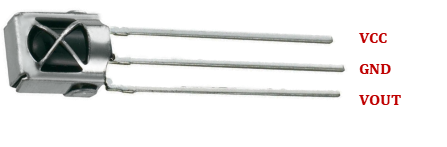
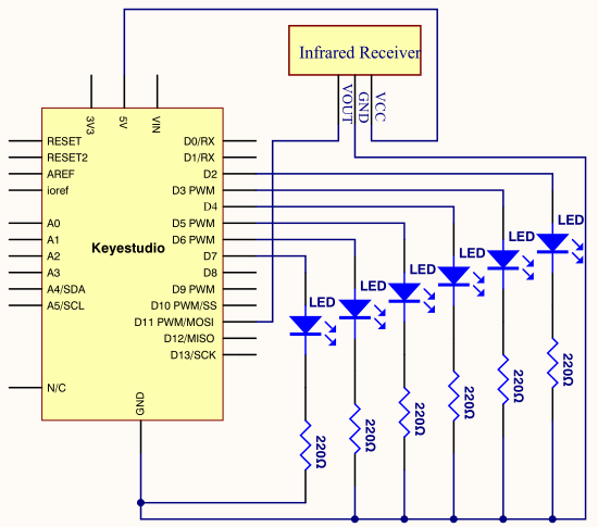
3.Pin and Wiring for Infrared Receiver
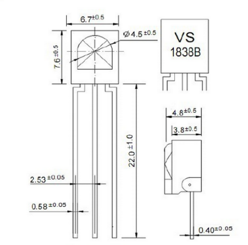
Infrared receiver has 3 pins. When you use it, connect VOUT to analog pin, GND to GND, VCC to +5V.
4.Hardware Required
- V4.0 Board or MEGA 2650 Board*1
- Infrared Remote Controller *1
- Infrared Receiver *1
- LED *6
- 220ΩResistor *6
- Breadboard Wire *11
- USB cable*1
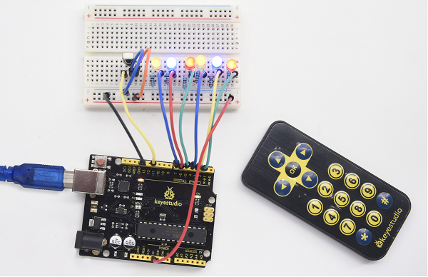
5.Circuit Connection
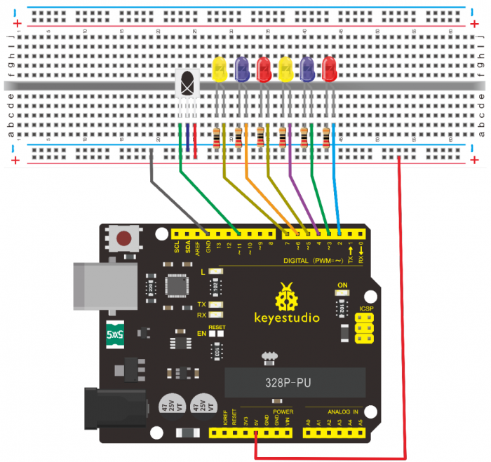
First, connect the controller board; then connect the infrared receiver as the above mentioned, connect VOUT to digital pin 11, connect the LEDs with resistors and connect the resistors to pin 2,3,4,5,6,7.
Connection for V4.0
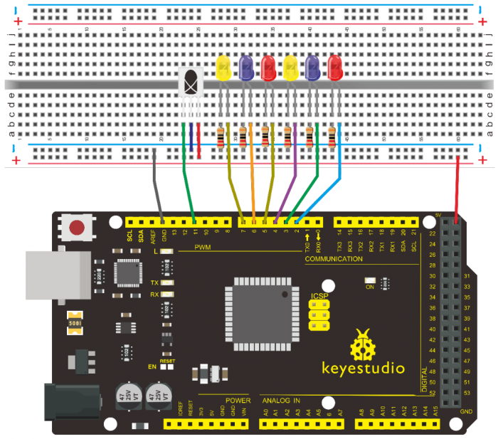
Connection for 2560
6.Experimental Principle
If you want to decode the code from the remote controller, you must first know how it’s coded. The coding method we use here is NEC protocol. Below is a brief introduction.
• NEC protocol
7.Features
- (1)8 bit address and 8 bit command length
- (2) address and command are transmitted twice for reliability
- (3) pulse distance modulation
- (4) carrier frequency of 38 KHZ
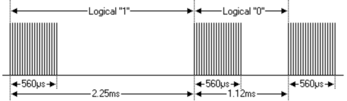
- (5) bit time of 1.125ms or 2.25ms
8.Protocol is as below
• Definition of logical 0 and 1 is as below
• Pulse transmitted when button is pressed and immediately released
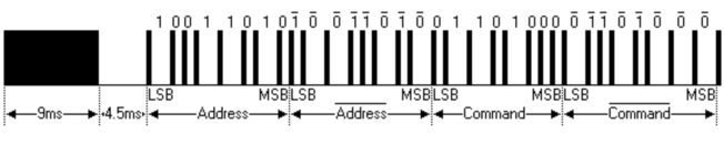
The picture above shows a typical pulse train of the NEC protocol. With this protocol the LSB is transmitted first. In this case Address $59 and Command $16 is transmitted. A message is started by a 9ms AGC burst, which was used to set the gain of the earlier IR receivers. This AGC burst is then followed by a 4.5ms space, which is then followed by the address and command. Address and Command are transmitted twice. The second time all bits are inverted and can be used for verification of the received message. The total transmission time is constant because every bit is repeated with its inverted length. If you are not interested in this reliability, you can ignore the inverted values, or you can expend the Address and Command to 16 bits each!
• Pulse transmitted when button is pressed and released after a period of time
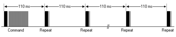
A command is transmitted only once, even when the key on the remote
control remains pressed. Every 110ms a repeat code is transmitted for as long as the key remains down. This repeat code is simply a 9ms AGC pulse followed by a 2.25ms space and a 560µs burst.
• Repeat pulse
Note when the pulse enters the integrated receiver, there will be decoding, signal amplifying and wave shaping process. So you need to make sure the level of the output is just the opposite from that of the signal sending end.
That is when there is no infrared signal, the output end is in high level; when there is infrared signal, the output end is in low level. You can see the pulse of the receiving end in the oscilloscope. Try to better understand the program based on what you see.
9.Sample Code
/*
 keyestudio super learning kit
 Project 14
 Remote
 http//www.keyestudio.com
*/
#include <IRremote.h>
int RECV_PIN = 11;
int LED1 = 2;
int LED2 = 3;
int LED3 = 4;
int LED4 = 5;
int LED5 = 6;
int LED6 = 7;
long on1  = 0x00FF6897;
long off1 = 0x00FF9867;
long on2 = 0x00FFB04F;
long off2 = 0x00FF30CF;
long on3 = 0x00FF18E7;
long off3 = 0x00FF7A85;
long on4 = 0x00FF10EF;
long off4 = 0x00FF38C7;
long on5 = 0x00FF5AA5;
long off5 = 0x00FF42BD;
long on6 = 0x00FF4AB5;
long off6 = 0x00FF52AD;
IRrecv irrecv(RECV_PIN);
decode_results results;
// Dumps out the decode_results structure.
// Call this after IRrecv::decode()
// void * to work around compiler issue
//void dump(void *v) {
//  decode_results *results = (decode_results *)v
void dump(decode_results *results) {
  int count = results->rawlen;
  if (results->decode_type == UNKNOWN)
    {
     Serial.println("Could not decode message");
    }
  else
   {
    if (results->decode_type == NEC)
      {
       Serial.print("Decoded NEC: ");
      }
    else if (results->decode_type == SONY)
      {
       Serial.print("Decoded SONY: ");
      }
    else if (results->decode_type == RC5)
      {
       Serial.print("Decoded RC5: ");
      }
    else if (results->decode_type == RC6)
      {
       Serial.print("Decoded RC6: ");
      }
     Serial.print(results->value, HEX);
     Serial.print(" (");
     Serial.print(results->bits, DEC);
     Serial.println(" bits)");
   }
     Serial.print("Raw (");
     Serial.print(count, DEC);
     Serial.print("): ");
 for (int i = 0; i < count; i++)
     {
      if ((i % 2) == 1) {
      Serial.print(results->rawbuf[i]*USECPERTICK, DEC);
     }
    else
     {
      Serial.print(-(int)results->rawbuf[i]*USECPERTICK, DEC);
     }
    Serial.print(" ");
     }
      Serial.println("");
     }
void setup()
 {
  pinMode(RECV_PIN, INPUT);
  pinMode(LED1, OUTPUT);
  pinMode(LED2, OUTPUT);
  pinMode(LED3, OUTPUT);
  pinMode(LED4, OUTPUT);
  pinMode(LED5, OUTPUT);
  pinMode(LED6, OUTPUT);
  pinMode(13, OUTPUT);
  Serial.begin(9600);
   irrecv.enableIRIn(); // Start the receiver
 }
int on = 0;
unsigned long last = millis();
void loop()
{
  if (irrecv.decode(&results))
   {
    // If it's been at least 1/4 second since the last
    // IR received, toggle the relay
    if (millis() - last > 250)
      {
       on = !on;
//       digitalWrite(8, on ? HIGH : LOW);
       digitalWrite(13, on ? HIGH : LOW);
       dump(&results);
      }
    if (results.value == on1 )
       digitalWrite(LED1, HIGH);
    if (results.value == off1 )
       digitalWrite(LED1, LOW);
    if (results.value == on2 )
       digitalWrite(LED2, HIGH);
    if (results.value == off2 )
       digitalWrite(LED2, LOW);
    if (results.value == on3 )
       digitalWrite(LED3, HIGH);
    if (results.value == off3 )
       digitalWrite(LED3, LOW);
    if (results.value == on4 )
       digitalWrite(LED4, HIGH);
    if (results.value == off4 )
       digitalWrite(LED4, LOW);
    if (results.value == on5 )
       digitalWrite(LED5, HIGH);
    if (results.value == off5 )
       digitalWrite(LED5, LOW);
    if (results.value == on6 )
       digitalWrite(LED6, HIGH);
    if (results.value == off6 )
       digitalWrite(LED6, LOW);
    last = millis();
irrecv.resume(); // Receive the next value
  }
}
//////////////////////////////////////////////////////////////////
Note: add IRremote folder into installation directory \Arduino\compiler libraries, or you will fail to compile it.
Infrared remote library https//github.com/shirriff/Arduino-IRremote
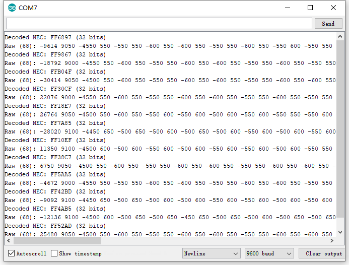
10.Test Result
Decode the coded pulse signal emitted by the remote controller, then execute corresponding action according to the results of the decoding. In this way, you will be able to control your device with remote controller.
Done uploading, open the serial monitor, you can see the result as below.
Project 15: Analog Value Reading
1.Introduction
In this experiment, we will begin the study of analog I/O interfaces. On an Arduino, there are 6 analog interfaces numbered from A0 to A5. Next, let’s begin our project. Potentiometer used here is a typical output component of analog value that is familiar to us.
2.Hardware Required
V4.0 Board or MEGA 2650 Board*1
Potentiometer *1
Breadboard*1
Breadboard Jumper Wire*3
USB cable*1
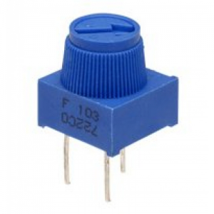
3.Potentiometer Features
Adjustable potentiometer is just a kind of resistor. The resistance is changed by rotating the potentiometer, so is the voltage, speed, brightness and temperature. It is an analog electronic component, which has two states of 0 and 1(high level and low level). The analog quantity is different. Its data state presents a linear state such as 1 to 1000.
4.Circuit Connection
In this experiment, we will convert the resistance value of the potentiometer to analog ones and display it on the screen.
This is an application you need to master well for our future experiments.
Connection for V4.0
Connection for 2560
5.Sample Code
The program compiling is simple. An analogRead () Statement can read the value of the interface. The A/D acquisition of Arduino 328 is in 10 bits, so the value it reads is among 0 to 1023.
One difficulty in this project is to display the value on the screen, which is actually easy to learn.
First, you need to set the baud rate in voidsetup (). Displaying the value is a communication between Arduino and PC, so the baud rate of the Arduino should match the one in the PC’s software set up. Otherwise, the display will be messy codes or no display at all.
In the lower right corner of the Arduino software monitor window, there is a button for baud rate set up. The set up here needs to match the one in the program. The statement in the program is Serial.begin(); enclosed is the baud rate value, followed by statement for displaying. You can either use Serial.print() or Serial.println() statement.
/*
 keyestudio super learning kit
 Project 15
 Potentiometer
 http//www.keyestudio.com
*/
int potpin=0;// initialize analog pin 0
int ledpin=13;// initialize digital pin 13
int val=0;// define val, assign initial value 0
void setup()
{
pinMode(ledpin,OUTPUT);// set digital pin as “output”
Serial.begin(9600);// set baud rate at 9600
}
void loop()
{
digitalWrite(ledpin,HIGH);// turn on the LED on pin 13
delay(50);// wait for 0.05 second
digitalWrite(ledpin,LOW);// turn off the LED on pin 13
delay(50);// wait for 0.05 second
val=analogRead(potpin);// read the analog value of analog pin 0, and assign it to val
Serial.println(val);// display val’s value
}
//////////////////////////////////////////////////////////////////
6.Test Result
The Sample Code uses the built-in LED connected to pin 13.
Each time the device reads a value, the LED blinks. When you rotate the potentiometer knob, you can see the displayed value change. The reading of analog value is a very common function since most sensors output analog value. After calculation, you can get the corresponding value you need.
Below figure shows the analog value it reads.
The experiment is now completed. Thank you!
Project 16: 74HC595 chip
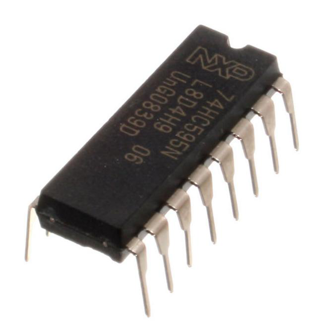
1.Introduction
74HC595 chip is a serial output and parallel output device. To put it simply, 74HC595 chip is a combination of 8-digit shifting register, memorizer and equipped with tri-state output.
Here, we use it to control 8 LEDs. You may wonder why use a 74HC595 to control LED? Well, think about how many I/O it takes for an Arduino to control 8 LEDs? Yes, 8.
For an Arduino 328, it has only 20 I/O including analog ports. To save port resources, using 74HC595 enables us to use 3 digital I/O ports to control 8 LEDs!
2.Hardware Required
- V4.0 Board or MEGA 2650 Board*1
- 74HC595 chip*1
- Red M5 LED*4
- Green M5 LED*4
- 220Ω Resistor*8
- Breadboard*1
- Breadboard Jumper Wires
- USB cable*1
3.Pins Description:
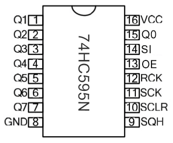
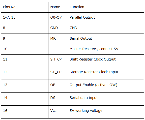
- VCC and GND are used to supply power for chip, the working voltage is 5V.
- Q0~Q7:This eight pins are output pins.
- DS pin is serial input pin, we need to write data into this pin by bit.
- STCP is a latch pin. The data can be copied to latch and output in parallel after 8-digit data of latch is all transmitted.
- SHCP is a clock pin. The data can be written into storage register.
- OE is an output enable pin, which is used to make sure if the data of latch is input into Q0-Q7 pins. When in low level, high level is not output. In this experiment, we directly connect to GND to keep low level output data.
- MR is a pin to initialize the pin of storage register. Initialize the internal storage register when low level. In this experiment, we connect to VCC to keep high level.
- Q7S pin is a serial output pin, which is specially used for chip cascade.
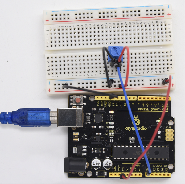
4.Circuit Connection
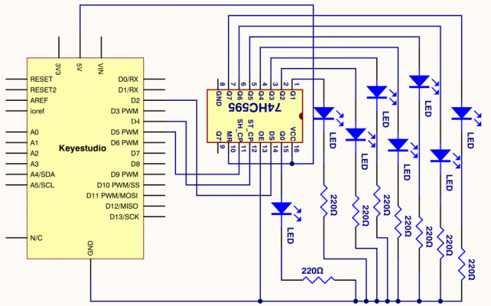
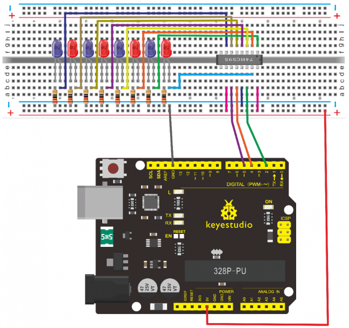
Connection for V4.0
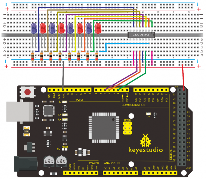
Connection for 2560 R3
The circuit may seem complicated, but once you wire it in order, you will find it more easier!
5.Sample Code
/*
 keyestudio super learning kit
 Project 16
 74hc595
 http//www.keyestudio.com
*/
int data = 2;// set pin 14 of 74HC595as data input pin SI
int clock = 5;// set pin 11 of 74hc595 as clock pin SCK
int latch = 4;// set pin 12 of 74hc595 as output latch RCK
int ledState = 0;
const int ON = HIGH;
const int OFF = LOW;
void setup()
{
pinMode(data, OUTPUT);
pinMode(clock, OUTPUT);
pinMode(latch, OUTPUT);
}
void loop()
{
for(int i = 0; i < 256; i++)
{
updateLEDs(i);
delay(500);
}
}
void updateLEDs(int value)
{
digitalWrite(latch, LOW);//
shiftOut(data, clock, MSBFIRST, ~value);// serial data “output”, high level first
digitalWrite(latch, HIGH);// latch
}
//////////////////////////////////////////////////////////////////
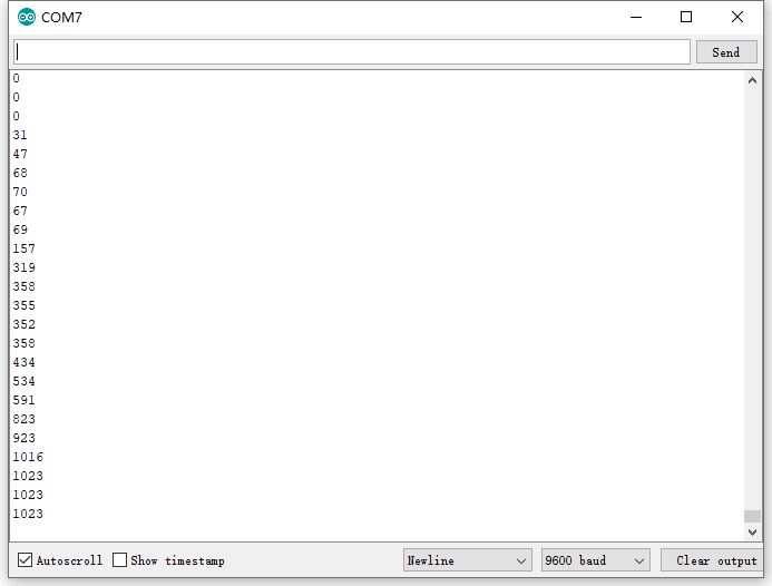
6.Test Result
After downloading the program, you can see 8 LEDs display 8-bit binary number.
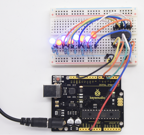
Project 17: 1-digit LED Segment Display
1.Introduction
LED segment displays are common for displaying numerical information. It’s widely applied on displays of electromagnetic oven, full automatic washing machine, water temperature display, electronic clock, etc. It is necessary for us to learn how it works.
2.Hardware Required
- V4.0 Board or MEGA 2650 Board*1
- 1-digit LED Segment Display*1
- 220Ω Resistor*8
- Breadboard*1
- Breadboard Jumper Wires *several
- USB cable*1
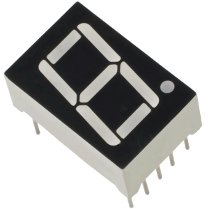
3.The display principle of the 1-digit LED Segment Display
LED segment display is a semiconductor light-emitting device. Its basic unit is a light-emitting diode (LED).
LED segment display can be divided into 7-segment display and 8-segment display according to the number of segments. 8-segment display has one more LED unit ( for decimal point display) than 7-segment one.
According to the wiring method of LED units, LED segment display can be divided into common anode display and common cathode display. Common anode display refers to the one that combine all the anodes of LED units into one common anode (COM).
For the common anode display, connect the common anode (COM) to +5V. When the cathode level of a certain segment is low, the segment is on; when the cathode level of a certain segment is high, the segment is off.
For the common cathode display, connect the common cathode (COM) to GND. When the anode level of a certain segment is high, the segment is on; when the anode level of a certain segment is low, the segment is off.
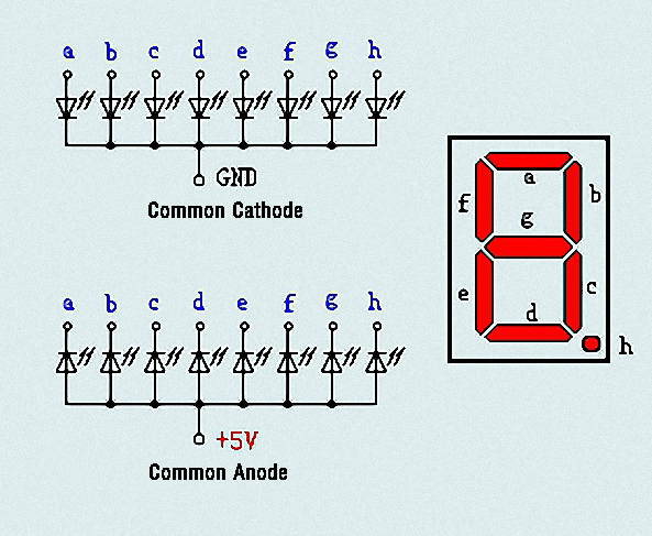
Each segment of the display consists of an LED. So when you use it, you also need to use a current-limiting resistor. Otherwise, LED will be burnt out.
In this experiment, we use a common cathode display. As we mentioned above, for common cathode display, connect the common cathode (COM) to GND. When the anode level of a certain segment is high, the segment is on; when the anode level of a certain segment is low, the segment is off.
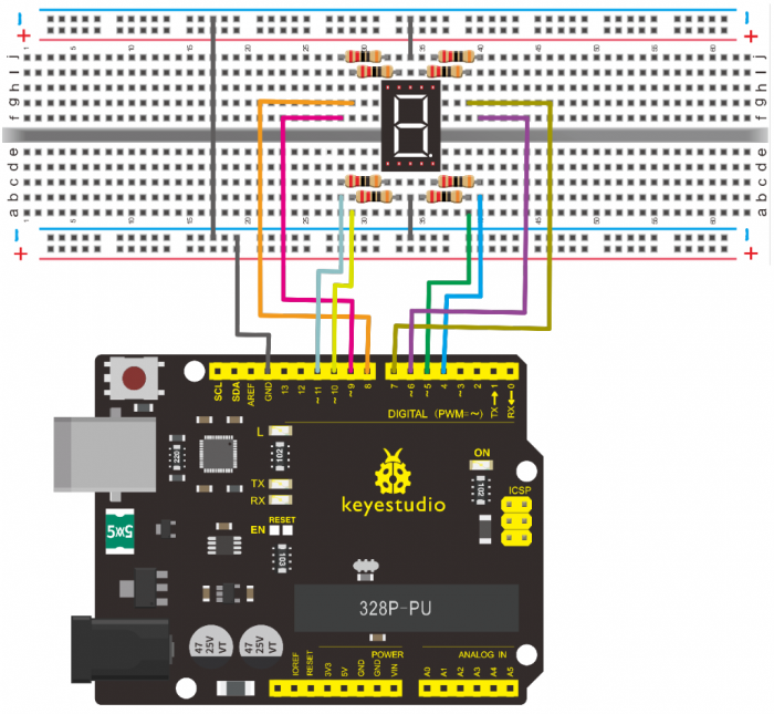
4.Circuit Connection

Connection for V4.0
Connection for 2560
5.Sample Code
There are seven segments for numerical display, one for decimal point display. Corresponding segments will be turned on when displaying certain numbers.
For example, when displaying number 1, b and c segments will be turned on. We compile a subprogram for each number, and compile the main program to display one number every 2 seconds, cycling display number 0 ~ 9.
The displaying time for each number is subject to the delay time, the longer the delay time, the longer the displaying time.
/*
keyestudio super learning kit
Project 17
1-digit LED Segment Display
http//www.keyestudio.com
*/
// set the IO pin for each segment
int a=7;// set digital pin 7 for segment a
int b=6;// set digital pin 6 for segment b
int c=5;// set digital pin 5 for segment c
int d=10;// set digital pin 10 for segment d
int e=11;// set digital pin 11 for segment e
int f=8;// set digital pin 8 for segment f
int g=9;// set digital pin 9 for segment g
int dp=4;// set digital pin 4 for segment dp
void digital_0(void) // display number 5
{
unsigned char j;
digitalWrite(a,HIGH);
digitalWrite(b,HIGH);
digitalWrite(c,HIGH);
digitalWrite(d,HIGH);
digitalWrite(e,HIGH);
digitalWrite(f,HIGH);
digitalWrite(g,LOW);
digitalWrite(dp,LOW);
}
void digital_1(void) // display number 1
{
unsigned char j;
digitalWrite(c,HIGH);// set level as “high” for pin 5, turn on segment c
digitalWrite(b,HIGH);// turn on segment b
for(j=7;j<=11;j++)// turn off other segments
digitalWrite(j,LOW);
digitalWrite(dp,LOW);// turn off segment dp
}
void digital_2(void) // display number 2
{
unsigned char j;
digitalWrite(b,HIGH);
digitalWrite(a,HIGH);
for(j=9;j<=11;j++)
digitalWrite(j,HIGH);
digitalWrite(dp,LOW);
digitalWrite(c,LOW);
digitalWrite(f,LOW);
}
void digital_3(void) // display number 3
{digitalWrite(g,HIGH);
digitalWrite(a,HIGH);
digitalWrite(b,HIGH);
digitalWrite(c,HIGH);
digitalWrite(d,HIGH);
digitalWrite(dp,LOW);
digitalWrite(f,LOW);
digitalWrite(e,LOW);
}
void digital_4(void) // display number 4
{digitalWrite(c,HIGH);
digitalWrite(b,HIGH);
digitalWrite(f,HIGH);
digitalWrite(g,HIGH);
digitalWrite(dp,LOW);
digitalWrite(a,LOW);
digitalWrite(e,LOW);
digitalWrite(d,LOW);
}
void digital_5(void) // display number 5
{
unsigned char j;
digitalWrite(a,HIGH);
digitalWrite(b, LOW);
digitalWrite(c,HIGH);
digitalWrite(d,HIGH);
digitalWrite(e, LOW);
digitalWrite(f,HIGH);
digitalWrite(g,HIGH);
digitalWrite(dp,LOW);
}
void digital_6(void) // display number 6
{
unsigned char j;
for(j=7;j<=11;j++)
digitalWrite(j,HIGH);
digitalWrite(c,HIGH);
digitalWrite(dp,LOW);
digitalWrite(b,LOW);
}
void digital_7(void) // display number 7
{
unsigned char j;
for(j=5;j<=7;j++)
digitalWrite(j,HIGH);
digitalWrite(dp,LOW);
for(j=8;j<=11;j++)
digitalWrite(j,LOW);
}
void digital_8(void) // display number 8
{
unsigned char j;
for(j=5;j<=11;j++)
digitalWrite(j,HIGH);
digitalWrite(dp,LOW);
}
void digital_9(void) // display number 5
{
unsigned char j;
digitalWrite(a,HIGH);
digitalWrite(b,HIGH);
digitalWrite(c,HIGH);
digitalWrite(d,HIGH);
digitalWrite(e, LOW);
digitalWrite(f,HIGH);
digitalWrite(g,HIGH);
digitalWrite(dp,LOW);
}
void setup()
{
int i;// set variable
for(i=4;i<=11;i++)
pinMode(i,OUTPUT);// set pin 4-11as “output”
}
void loop()
{
while(1)
{
digital_0();// display number 0
delay(1000);// wait for 1s
digital_1();// display number 1
delay(1000);// wait for 1s
digital_2();// display number 2
delay(1000); // wait for 1s
digital_3();// display number 3
delay(1000); // wait for 1s
digital_4();// display number 4
delay(1000); // wait for 1s
digital_5();// display number 5
delay(1000); // wait for 1s
digital_6();// display number 6
delay(1000); // wait for 1s
digital_7();// display number 7
delay(1000); // wait for 1s
digital_8();// display number 8
delay(1000); // wait for 1s
digital_9();// display number 9
delay(1000); // wait for 1s
}}
//////////////////////////////////////////////////////////////////
6.Test Result
LED segment display will show the number from 0 to 9.
Project 18: 4-digit LED Segment Display
1.Introduction
In this experiment, we use an Arduino to drive a common cathode, 4-digit, 7-segment LED display.
For LED display, current-limiting resistors are indispensable.
There are two wiring methods for Current-limiting resistor. One is to connect one resistor for each cathode end, 4 in total for d1-d4 cathode. An advantage for this method is that it requires fewer resistors, only 4. But it cannot maintain consistent brightness, 1, the brightest; 8, the least bright.
Another method is to connect one resistor to each pin. It guarantees consistent brightness, but requires more resistors.
In this experiment, we use 8 Resistors (220Ω). We use 220ΩResistors because of no 100Ω resistor available. If you use 100Ω, the displaying is more brighter.
2.Hardware Required
- V4.0 Board or MEGA 2650 Board*1
- 4-digit LED Segment Display*1
- 220Ω Resistor*8
- Breadboard*1
- Breadboard Jumper Wires *several
- USB cable*1
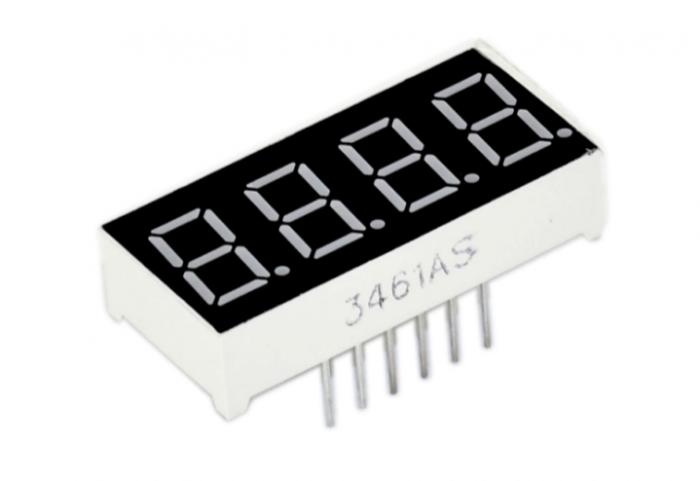
3.The display principle of the 4-digit display
For 4-digit display, there are 12 pins in total. When you place the decimal point downward, the pin on the lower left part is refer to as 1, the upper left part 12. Shown below.


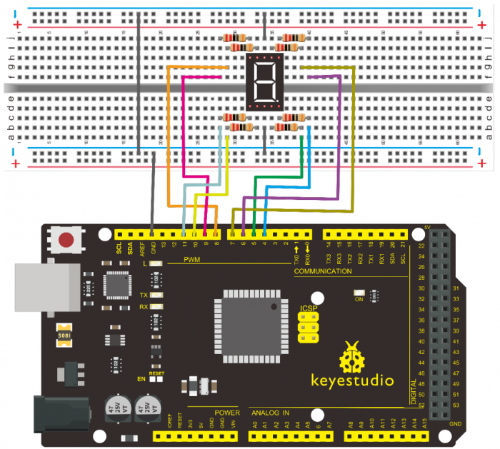
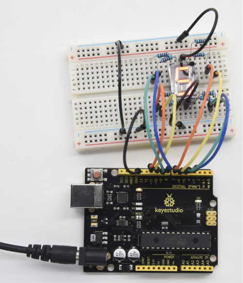
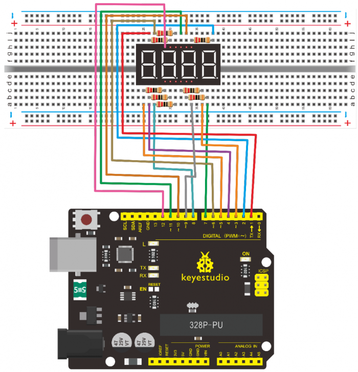
4.Circuit Connection
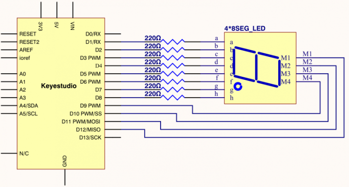
Connection for V4.0
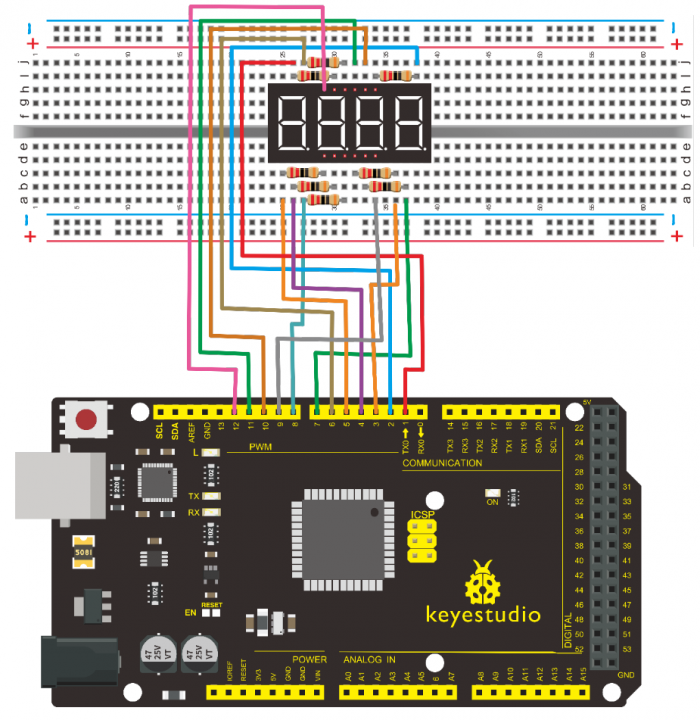
Connection for 2560 R3
5.Sample Code
/*
 keyestudio super learning kit
 Project 18
 4-digit LED Segment Display
 http//www.keyestudio.com
*/
// display 1234
  // select pin for cathode
  int a = 1;
  int b = 2;
  int c = 3;
  int d = 4;
  int e = 5;
  int f = 6;
  int g = 7;
  int dp = 8;
  // select pin for anode
  int d4 = 9;
  int d3 = 10;
  int d2 = 11;
  int d1 = 12;
  // set variable
  long n = 1230;
  int x = 100;
  int del = 55;  // fine adjustment for clock

  void setup()
  {
    pinMode(d1, OUTPUT);
    pinMode(d2, OUTPUT);
    pinMode(d3, OUTPUT);
    pinMode(d4, OUTPUT);
    pinMode(a, OUTPUT);
    pinMode(b, OUTPUT);
    pinMode(c, OUTPUT);
    pinMode(d, OUTPUT);
    pinMode(e, OUTPUT);
    pinMode(f, OUTPUT);
    pinMode(g, OUTPUT);
    pinMode(dp, OUTPUT);
  }
/////////////////////////////////////////////////////////////
void loop()
{
 Display(1, 1);
 Display(2, 2);
 Display(3, 3);
 Display(4, 4);

}
///////////////////////////////////////////////////////////////
void WeiXuan(unsigned char n)//
{
    switch(n)
     {
  case 1:
    digitalWrite(d1,LOW);
    digitalWrite(d2, HIGH);
    digitalWrite(d3, HIGH);
    digitalWrite(d4, HIGH);
   break;
   case 2:
    digitalWrite(d1, HIGH);
    digitalWrite(d2, LOW);
    digitalWrite(d3, HIGH);
    digitalWrite(d4, HIGH);
      break;
    case 3:
      digitalWrite(d1,HIGH);
     digitalWrite(d2, HIGH);
     digitalWrite(d3, LOW);
     digitalWrite(d4, HIGH);
      break;
    case 4:
     digitalWrite(d1, HIGH);
     digitalWrite(d2, HIGH);
     digitalWrite(d3, HIGH);
     digitalWrite(d4, LOW);
      break;
        default :
           digitalWrite(d1, HIGH);
     digitalWrite(d2, HIGH);
     digitalWrite(d3, HIGH);
     digitalWrite(d4, HIGH);
        break;
    }
}
void Num_0()
{
  digitalWrite(a, HIGH);
  digitalWrite(b, HIGH);
  digitalWrite(c, HIGH);
  digitalWrite(d, HIGH);
  digitalWrite(e, HIGH);
  digitalWrite(f, HIGH);
  digitalWrite(g, LOW);
  digitalWrite(dp,LOW);
}
void Num_1()
{
  digitalWrite(a, LOW);
  digitalWrite(b, HIGH);
  digitalWrite(c, HIGH);
  digitalWrite(d, LOW);
  digitalWrite(e, LOW);
  digitalWrite(f, LOW);
  digitalWrite(g, LOW);
  digitalWrite(dp,LOW);
}
void Num_2()
{
  digitalWrite(a, HIGH);
  digitalWrite(b, HIGH);
  digitalWrite(c, LOW);
  digitalWrite(d, HIGH);
  digitalWrite(e, HIGH);
  digitalWrite(f, LOW);
  digitalWrite(g, HIGH);
  digitalWrite(dp,LOW);
}
void Num_3()
{
  digitalWrite(a, HIGH);
  digitalWrite(b, HIGH);
  digitalWrite(c, HIGH);
  digitalWrite(d, HIGH);
  digitalWrite(e, LOW);
  digitalWrite(f, LOW);
  digitalWrite(g, HIGH);
  digitalWrite(dp,LOW);
}
void Num_4()
{
  digitalWrite(a, LOW);
  digitalWrite(b, HIGH);
  digitalWrite(c, HIGH);
  digitalWrite(d, LOW);
  digitalWrite(e, LOW);
  digitalWrite(f, HIGH);
  digitalWrite(g, HIGH);
  digitalWrite(dp,LOW);
}
void Num_5()
{
  digitalWrite(a, HIGH);
  digitalWrite(b, LOW);
  digitalWrite(c, HIGH);
  digitalWrite(d, HIGH);
  digitalWrite(e, LOW);
  digitalWrite(f, HIGH);
  digitalWrite(g, HIGH);
  digitalWrite(dp,LOW);
}
void Num_6()
{
  digitalWrite(a, HIGH);
  digitalWrite(b, LOW);
  digitalWrite(c, HIGH);
  digitalWrite(d, HIGH);
  digitalWrite(e, HIGH);
  digitalWrite(f, HIGH);
  digitalWrite(g, HIGH);
  digitalWrite(dp,LOW);
}
void Num_7()
{
  digitalWrite(a, HIGH);
  digitalWrite(b, HIGH);
  digitalWrite(c, HIGH);
  digitalWrite(d, LOW);
  digitalWrite(e, LOW);
  digitalWrite(f, LOW);
  digitalWrite(g, LOW);
  digitalWrite(dp,LOW);
}
void Num_8()
{
  digitalWrite(a, HIGH);
  digitalWrite(b, HIGH);
  digitalWrite(c, HIGH);
  digitalWrite(d, HIGH);
  digitalWrite(e, HIGH);
  digitalWrite(f, HIGH);
  digitalWrite(g, HIGH);
  digitalWrite(dp,LOW);
}
void Num_9()
{
  digitalWrite(a, HIGH);
  digitalWrite(b, HIGH);
  digitalWrite(c, HIGH);
  digitalWrite(d, HIGH);
  digitalWrite(e, LOW);
  digitalWrite(f, HIGH);
  digitalWrite(g, HIGH);
  digitalWrite(dp,LOW);
}
void Clear()  // clear the screen
{
  digitalWrite(a, LOW);
  digitalWrite(b, LOW);
  digitalWrite(c, LOW);
  digitalWrite(d, LOW);
  digitalWrite(e, LOW);
  digitalWrite(f, LOW);
  digitalWrite(g, LOW);
  digitalWrite(dp,LOW);
}
void pickNumber(unsigned char n)// select number
{
  switch(n)
  {
   case 0:Num_0();
   break;
   case 1:Num_1();
   break;
   case 2:Num_2();
   break;
   case 3:Num_3();
   break;
   case 4:Num_4();
   break;
   case 5:Num_5();
   break;
   case 6:Num_6();
   break;
   case 7:Num_7();
   break;
   case 8:Num_8();
   break;
   case 9:Num_9();
   break;
   default:Clear();
   break;
  }
}
void Display(unsigned char x, unsigned char Number)//  take x as coordinate and display number
{
  WeiXuan(x);
  pickNumber(Number);
 delay(1);
 Clear() ; // clear the screen
}
//////////////////////////////////////////////////////////
6.Test Result
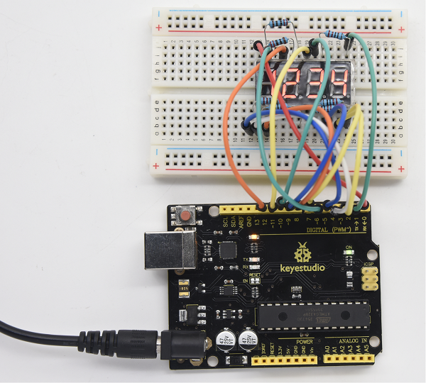
Download the above code to the controller board, you can see the LED display shows the number 1234.
Note if it’s not displaying correctly, check the wiring.
Project 19: 8*8 LED Matrix
1.Introduction
LED dot-matrix display can meet the needs of different applications, thus has a broad development prospect. With low-voltage scanning, LED dot-matrix has some advantages such as power saving, long service life, low cost, high brightness, wide angle of view, long visual range, waterproof, and numerous specifications.
This project, we will conduct an LED dot-matrix experiment to experience its charm firsthand.
2.Hardware Required
- V4.0 Board or MEGA 2650 Board*1
- 1 * 8*8 Dot Matrix
- 8 * Resistor (220Ω)
- 1 * Breadboard
- 1 * USB Cable
- Several* Jumper Wires
3.The display principle of the 8*8 dot-matrix
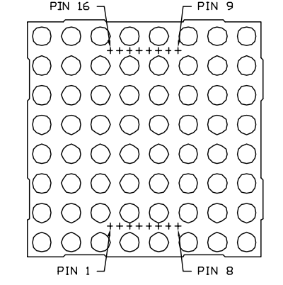
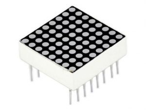
The external view of a dot-matrix is shown as follows
The 8*8 dot-matrix is made up of sixty-four LEDs, and each LED is placed at the cross point of a row and a column.
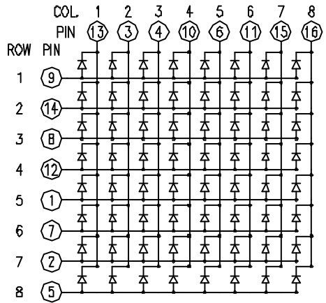
When the electrical level of a certain row is 1 and the electrical level of a certain column is 0, the corresponding LED will lighten. If you want to light the LED on the first dot, you should set pin 9 to high level and pin 13 to low level.
If you want to light LEDs on the first row, you should set pin 9 to high level and pins 13, 3, 4, 10, 6, 11, 15 and 16 to low level.
If you want to light the LEDs on the first column, set pin 13 to low level and pins 9, 14, 8, 12, 1, 7, 2 and 5 to high level.
The internal view of a dot-matrix is shown as follows
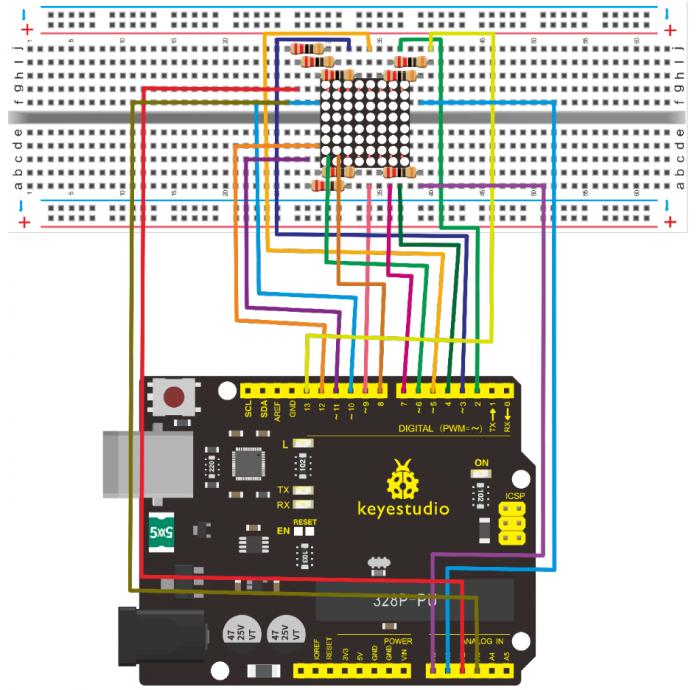
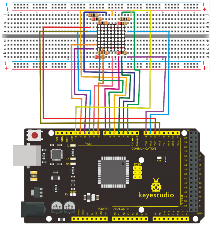
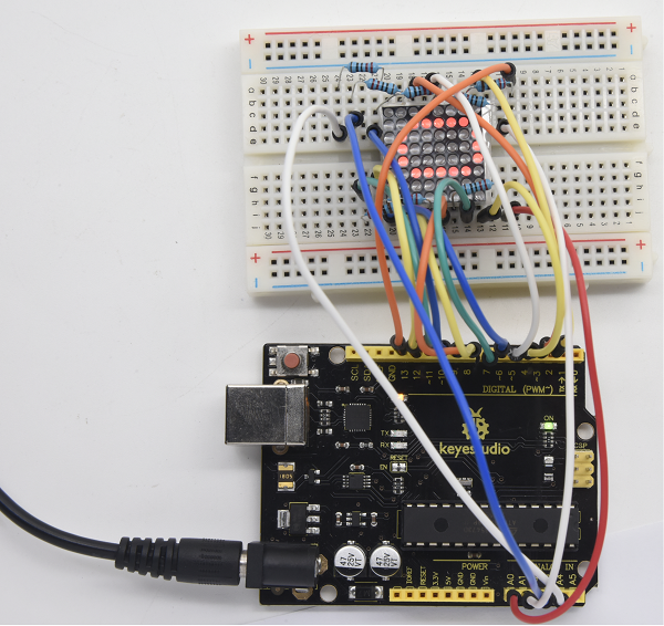
4.Circuit Connection
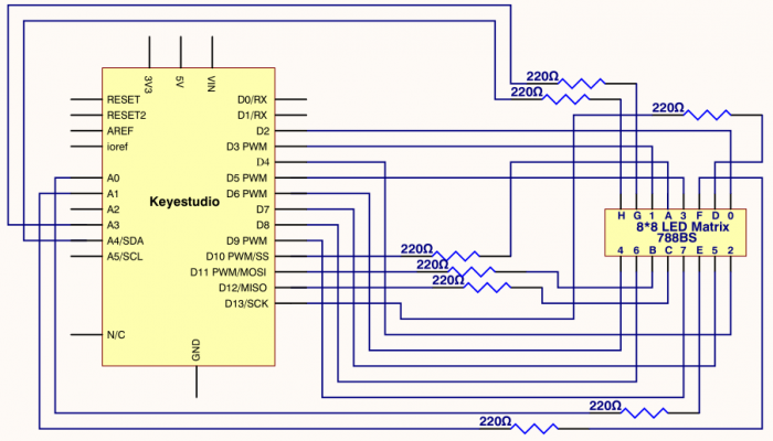
Connection for V4.0
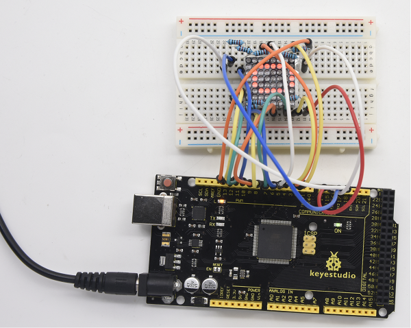
Connection for 2560 R3
5.Sample Code for displaying “0”
/*
 keyestudio super learning kit
 Project 19
 8*8 dot-matrix
 http//www.keyestudio.com
*/
// set an array to store character of “0”
unsigned char Text[]={0x00,0x1c,0x22,0x22,0x22,0x22,0x22,0x1c};
void Draw_point(unsigned char x,unsigned char y)// point drawing function
{ clear_();
   digitalWrite(x+2, HIGH);
   digitalWrite(y+10, LOW);
   delay(1);
}
void show_num(void)// display function, call point drawing function
{
  unsigned char i,j,data;
  for(i=0;i<8;i++)
  {
    data=Text[i];
    for(j=0;j<8;j++)
    {
      if(data & 0x01)Draw_point(j,i);
      data>>=1;
    }
  }
}
void setup(){
int i = 0 ;
for(i=2;i<18;i++)
 {
   pinMode(i, OUTPUT);
  }
  clear_();
}
void loop()
{ show_num();
}
void clear_(void)// clear screen
{for(int i=2;i<10;i++)
  digitalWrite(i, LOW);
  for(int i=0;i<8;i++)
  digitalWrite(i+10, HIGH);
}
//////////////////////////////////////////////////////////
6.Test Result
Burn the program into V4.0 board, the dot-matrix will display 0.
Project 20: 1602 LCD
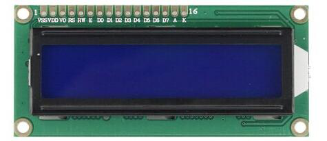
1.Introduction
In this experiment, we use an Arduino to drive the 1602 LCD.
1602 LCD has wide applications. In the beginning, 1602 LCD uses a HD44780 controller.
Now, almost all 1602 LCD module uses a compatible IC, so their features are basically the same.
2.1602LCD Main Parameters
- V4.0 Board or MEGA 2650 Board*1
- Display capacity 16 * 2 characters
- Chip operating voltage 4.5 ~ 5.5V
- Working current 2.0mA (5.0V)
- Optimum working voltage of the module is 5.0V
- Character size 2.95 * 4.35 (W * H) mm
3.Pin description of 1602 LCD
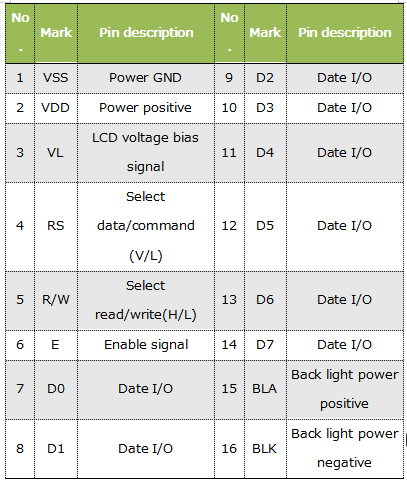
4.Interface Description
- 1.Two power pins, one for module power, another one for back light, generally use 5V. In this project, we use 3.3V for backlight.
- 2.VL is the pin for adjusting contrast ratio. It usually connects a potentiometer(no more than 5KΩ) in series for its adjustment.
- In this experiment, we use a 1KΩ resistor. For its connection, it has two methods, namely high potential and low potential. Here, we use low potential method; connect the resistor and then the GND.
- 3.RS is a very common pin in LCD. It’s a selecting pin for command/data. When the pin is in high level, it’s in data mode; when it’s in low level, it’s in command mode.
- 4.RW pin is also very common in LCD. It’s a selecting pin for read/write. When the pin is in high level, it’s in read operation; if in low level, it’s in write operation.
- 5.E pin is also very common in LCD. Usually, when the signal in the bus is stabilized, it sends out a positive pulse requiring read operation. When this pin is in high level, the bus is not allowed to have any change.
- 6.D0-D7 is 8-bit bidirectional parallel bus, used for command and data transmission.
- 7.BLA is anode for back light; BLK, cathode for back light.
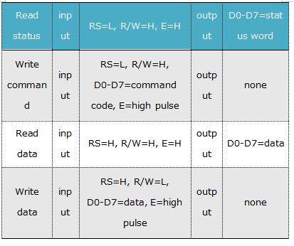
5.Four Basic Operations for 1602LCD
6.Hardware Required
- V4.0 Board or MEGA 2650 Board*1
- 1 * 1602 LCD
- 1 * Potentiometer
- 1 * Breadboard
- 1 * USB Cable
- Several* Jumper Wires
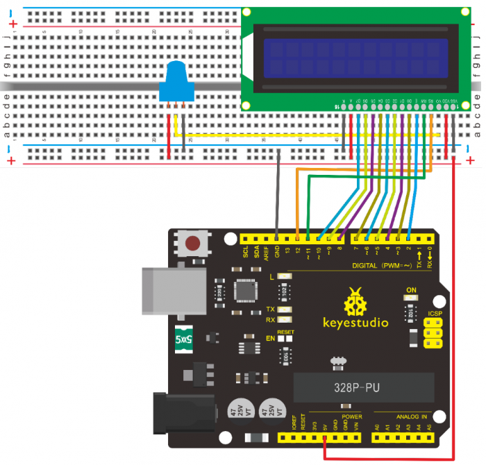
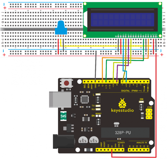
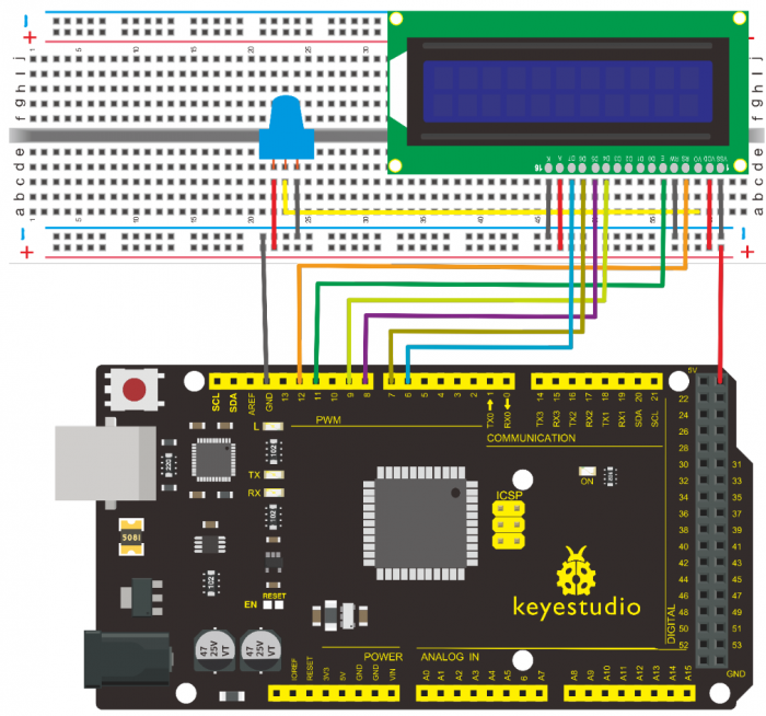
7.Connection
1602 can directly communicate with Arduino. According to the product manual, it has two connection methods, namely 8-bit connection and 4-bit connection.
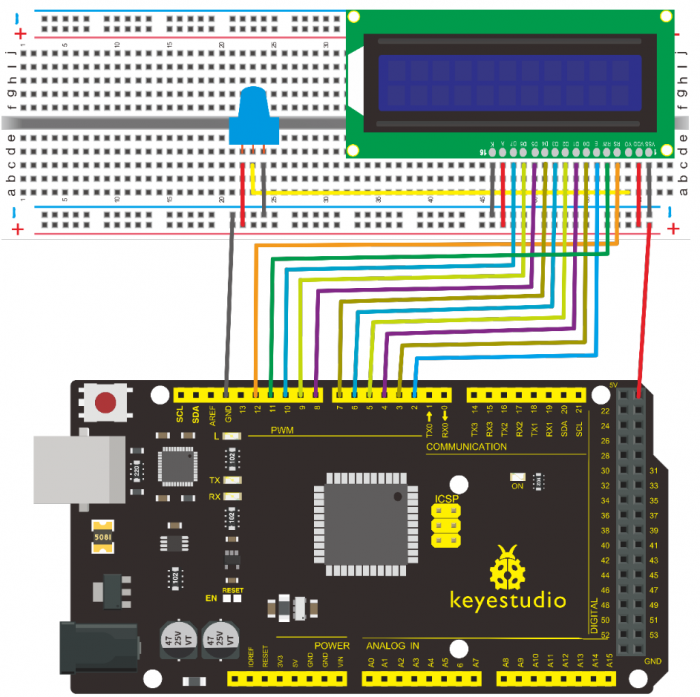
8-bit Connection Method

Connection for V4.0
Connection for 2560 R3
8.Sample Code A
/*
keyestudio super learning kit
Project 20.1
LCD1602
http//www.keyestudio.com
*/
int DI = 12;
int RW = 11;
int DB[] = {3, 4, 5, 6, 7, 8, 9, 10};// use array to select pin for bus
int Enable = 2;
void LcdCommandWrite(int value) {
// define all pins
int i = 0;
for (i=DB[0]; i <= DI; i++) // assign value for bus
{
digitalWrite(i,value & 01);// for 1602 LCD, it uses D7-D0( not D0-D7) for signal identification; here, it’s used for signal inversion.
value >>= 1;
}
digitalWrite(Enable,LOW);
delayMicroseconds(1);
digitalWrite(Enable,HIGH);
delayMicroseconds(1); // wait for 1ms
digitalWrite(Enable,LOW);
delayMicroseconds(1); // wait for 1ms
}
void LcdDataWrite(int value) {
// initialize all pins
int i = 0;
digitalWrite(DI, HIGH);
digitalWrite(RW, LOW);
for (i=DB[0]; i <= DB[7]; i++) {
digitalWrite(i,value & 01);
value >>= 1;
}
digitalWrite(Enable,LOW);
delayMicroseconds(1);
digitalWrite(Enable,HIGH);
delayMicroseconds(1);
digitalWrite(Enable,LOW);
delayMicroseconds(1); // wait for 1ms
}
void setup (void) {
int i = 0;
for (i=Enable; i <= DI; i++) {
pinMode(i,OUTPUT);
}
delay(100);
// initialize LCD after a brief pause
// for LCD control
LcdCommandWrite(0x38); // select as 8-bit interface, 2-line display, 5x7 character size
delay(64);
LcdCommandWrite(0x38); // select as 8-bit interface, 2-line display, 5x7 character size
delay(50);
LcdCommandWrite(0x38); // select as 8-bit interface, 2-line display, 5x7 character size
delay(20);
LcdCommandWrite(0x06); // set input mode
// auto-increment, no display of shifting
delay(20);
LcdCommandWrite(0x0E); // display setup
// turn on the monitor, cursor on, no flickering
delay(20);
LcdCommandWrite(0x01); // clear the scree, cursor position returns to 0
delay(100);
LcdCommandWrite(0x80); // display setup
// turn on the monitor, cursor on, no flickering
delay(20);
}
void loop (void) {
LcdCommandWrite(0x01); // clear the scree, cursor position returns to 0
delay(10);
LcdCommandWrite(0x80+3);
delay(10);
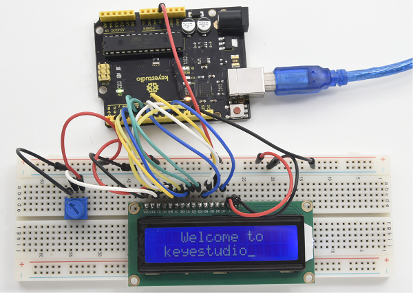
// write in welcome message
LcdDataWrite('W');
LcdDataWrite('e');
LcdDataWrite('l');
LcdDataWrite('c');
LcdDataWrite('o');
LcdDataWrite('m');
LcdDataWrite('e');
LcdDataWrite(' ');
LcdDataWrite('t');
LcdDataWrite('o');
delay(10);
LcdCommandWrite(0xc0+1); // set cursor position at second line, second position
delay(10);
LcdDataWrite('k');
LcdDataWrite('e');
LcdDataWrite('y');
LcdDataWrite('e');
LcdDataWrite('s');
LcdDataWrite('t');
LcdDataWrite('u');
LcdDataWrite('d');
LcdDataWrite('i');
LcdDataWrite('o');
delay(5000);
LcdCommandWrite(0x01); // clear the screen, cursor returns to 0
delay(10);
LcdDataWrite('I');
LcdDataWrite(' ');
LcdDataWrite('a');
LcdDataWrite('m');
LcdDataWrite(' ');
LcdDataWrite('h');
LcdDataWrite('u');
LcdDataWrite('n');
LcdDataWrite('t');
LcdDataWrite('e');
LcdDataWrite('r');
delay(3000);
LcdCommandWrite(0x02); // set mode as new characters replay old ones, where there is no new ones remain the same
delay(10);
LcdCommandWrite(0x80+5); // set cursor position at first line, sixth position
delay(10);
LcdDataWrite('t');
LcdDataWrite('h');
LcdDataWrite('e');
LcdDataWrite(' ');
LcdDataWrite('w');
LcdDataWrite('o');
LcdDataWrite('r');
LcdDataWrite('l');
LcdDataWrite('d');
delay(5000);
}
//////////////////////////////////////////////////////////
4-bit Connection Method
When using this module, 8-bit connection uses all the digital pins of the Arduino, leaving no pin for sensors. What then? You can use 4-bit connection.
Connection for V4.0
Connection for 2560 R3
After the connection, upload below code to the controller board and see how it goes.
9.Sample Code B
/*
keyestudio super learning kit
Project 20.2
LCD1602
http//www.keyestudio.com
*/
/* LCD RS pin to digital pin 12
* LCD Enable pin to digital pin 11
* LCD D4 pin to digital pin 9
* LCD D5 pin to digital pin 8
* LCD D6 pin to digital pin 7
* LCD D7 pin to digital pin 6
* LCD R/W pin to ground
* LCD VSS pin to ground
* LCD VCC pin to 5V
* 10K resistor
* ends to +5V and ground
* wiper to LCD VO pin (pin 3)
This example code is in the public domain.
http//www.arduino.cc/en/Tutorial/LiquidCrystal
*/
// include the library code
#include <LiquidCrystal.h>
// initialize the library with the numbers of the interface pins
LiquidCrystal lcd(12, 11, 9, 8, 7, 6);
void setup() {
// set up the LCD's number of columns and rows
lcd.begin(16, 2);
// Print a message to the LCD.
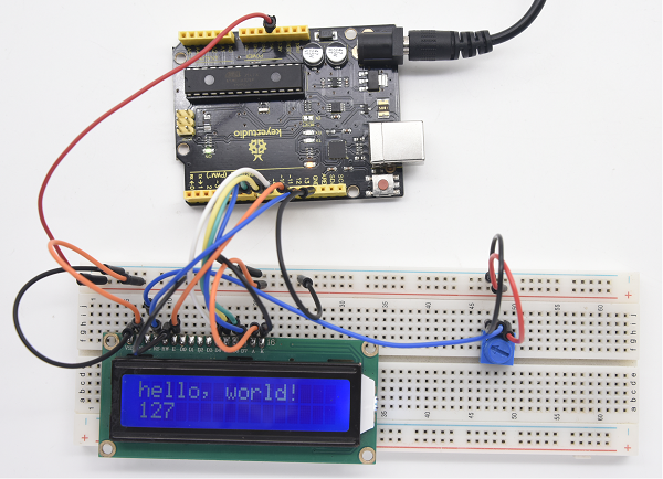
lcd.print("hello, world!");
}
void loop() {
// set the cursor to column 0, line 1
// (note line 1 is the second row, since counting begins with 0)
lcd.setCursor(0, 1);
// print the number of seconds since reset
lcd.print(millis() / 1000);
}
//////////////////////////////////////////////////////////
10. Test Result
Project 21: Servo Control
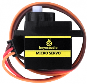
1.Introduction
Servomotor is a position control rotary actuator. It mainly consists of housing, circuit board, core-less motor, gear and position sensor. For this lesson, we will introduce servo to you.
2.Working Principle
The MCU outputs a signal to the servomotor. The motor has a built-in reference circuit that gives out reference signal, cycle of 20ms and width of 1.5ms. The motor compares the acquired DC bias voltage to the voltage of the potentiometer and outputs a voltage difference. The IC on the circuit board will decide the rotate direction accordingly and drive the core-less motor. The gear then pass the force to the shaft. The sensor will determine whether it has reached the commanded position according to the feedback signal.
Servomotors are used in control systems that require to have and maintain different angles. When the motor speed is definite, the gear will drive the potentiometer to rotate. When the voltage difference reduces to zero, the motor stops. Normally, the rotation angle range is among 0-180 degrees.
Servomotor comes with many specifications. But all of them have three connection wires, distinguished by brown, red, orange (different brand may have different color).
Brown one is for GND, red one for power positive, orange one for signal line.
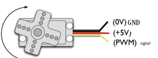
The rotation angle of the servo motor is controlled by regulating the duty cycle of the PWM(Pulse-Width Modulation) signal.
The standard cycle of the PWM signal is 20ms(50Hz). Theoretically, the width is distributed between 1ms-2ms. The width corresponds the rotation angle from 0° to 90°.
But note that for different brand motor, the same signal may have different rotating angle.
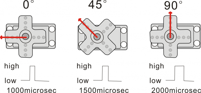
With some basic knowledge, let’s learn how to control a servomotor. In this experiment, you only need a servo motor and several jumper wires.
3.Hardware Required
- V4.0 Board or MEGA 2650 Board*1
- 9G Servo Motor*1
- Breadboard Jumper Wire*3
- USB cable*1
Connection & Sample Code
There are two ways to control a servomotor with Arduino.
One is to use a common digital sensor port of Arduino to produce square wave with different duty cycle to simulate PWM signal and use that signal to control the positioning of the motor.
Another way is to directly use the Servo function of the Arduino to control the motor. In this way, the program will be more easier but it can only control two-contact motor because of the servo function, only digital pin 9 and 10 can be used.
The Arduino drive capacity is limited. So if you need to control more than one motor, you will need external power.
4.Method 1
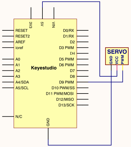
Connection for V4.0
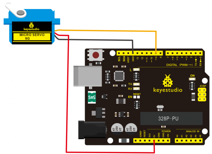
Connection for 2560 R3
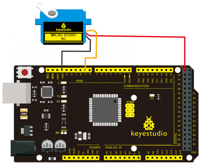
Connect the motor to digital pin 9.
Compile a program to control the motor to rotate in the commanded angle, and display the angle on the screen.
Sample Code A
/*
 keyestudio super learning kit
 Project 21.1
 servo
 http//www.keyestudio.com
*/
int servopin=9;// select digital pin 9 for servomotor signal line
int myangle;// initialize angle variable
int pulsewidth;// initialize width variable
int val;
void servopulse(int servopin,int myangle)// define a servo pulse function
{
pulsewidth=(myangle*11)+500;// convert angle to 500-2480 pulse width
digitalWrite(servopin,HIGH);// set the level of servo pin as “high”
delayMicroseconds(pulsewidth);// delay microsecond of pulse width
digitalWrite(servopin,LOW);// set the level of servo pin as “low”
delay(20-pulsewidth/1000);
}
void setup()
{
pinMode(servopin,OUTPUT);// set servo pin as “output”
Serial.begin(9600);// connect to serial port, set baud rate at “9600”
Serial.println("servo=o_seral_simple ready" ) ;
}
void loop()// convert number 0 to 9 to corresponding 0-180 degree angle, LED blinks corresponding number of time
{
val=Serial.read();// read serial port value
if(val>='0'&&val<='9')
{
val=val-'0';// convert characteristic quantity to numerical variable
val=val*(180/9);// convert number to angle
Serial.print("moving servo to ");
Serial.print(val,DEC);
Serial.println();
for(int i=0;i<=50;i++) // giving the servo time to rotate to commanded position
{
servopulse(servopin,val);// use the pulse function
}}}
//////////////////////////////////////////////////////////
5.Method 2
Let’s first take a look at the Arduino built-in servo function and some common statements.
1. attach(interface)——select pin for servo, can only use pin 9 or 10.
2. write(angle)——used to control the rotate angle of the servo, can set the angle among 0 degree to 180 degree.
3. read()——used to read the angle of the servo, consider it a function to read the value in the write() function.
4. attached()——determine whether the parameter of the servo is sent to the servo pin.
5. detach()—— disconnect the servo and the pin, and the pin (digital pin 9 or 10) can be used for PWM port.
Note the written form of the above statements are » servo variable name. specific statement ()», e.g. myservo. Attach (9).
Still, connect the servo to pin 9.
Sample Code B
/*
 keyestudio super learning kit
 Project 21.2
 servo
 http//www.keyestudio.com
*/
#include <Servo.h>
Servo myservo;// define servo variable name
void setup()
{
myservo.attach(9);// select servo pin(9 or 10)
}
void loop()
{
myservo.write(90);// set rotate angle of the motor
}
//////////////////////////////////////////////////////////
Above are the two methods to control the servo. You can choose either one according to your liking or actual need.
6.Test Result
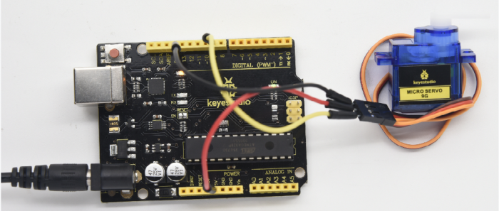
Project 22: Stepper Motor
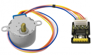
1.Introduction
A stepper motor is an electromechanical device which can convert electrical pulses into discrete mechanical movements. The shaft or spindle of a stepper motor rotates in discrete step increments when electrical command pulses are applied to it in the proper sequence.
The motors rotation has several direct relationships to these applied input pulses. The sequence of the applied pulses is directly related to the direction of motor shafts rotation. The speed of the motor shafts rotation is directly related to the frequency of the input pulses and the length of rotation is directly related to the number of input pulses applied.
One of the most significant advantages of a stepper motor is its ability to be accurately controlled in an open loop system. Open loop control means no feedback information about position is needed. This type of control eliminates the need for expensive sensing and feedback devices such as optical encoders. Your position is known simply by keeping track of the input step pulses.
2.Hardware Required
- V4.0 Board or MEGA 2650 Board*1
- Stepper Motor*1
- Stepper Motor driver*1
- Jumper Wire *1
- USB cable*1
3.Features
- •The rotation angle of the motor is proportional to the input pulse.
- •The motor has full torque at standstill(if the windings are energized)
- •Precise positioning and repeatability of movement since good stepper motors have an accuracy of – 5% of a step and this error is non cumulative from one step to the next.
- •Excellent response to starting/stopping/reversing.
- •Very reliable since there are no contact brushes in the motor. Therefore the life of the motor is simply dependant on the life of the bearing.
- •The motors response to digital input pulses provides open-loop control, making the motor simpler and less costly to control.
- •It is possible to achieve very low speed synchronous rotation with a load that is directly coupled to the shaft.
- •A wide range of rotational speeds can be realized as the speed is proportional to the frequency of the input pulses.
4.Parameters of Stepper Motor 28BYJ-48
•Model 28BYJ-48
•Rated Voltage 5VDC
•Number of Phase 4
•Speed Variation Ratio 1/64
•Stride Angle 5.625° /64
•Frequency 100Hz
•DC Resistance 50Ω±7%(25℃)
•Idle In-traction Frequency > 600Hz
•Idle Out-traction Frequency > 1000Hz
•In-traction Torque >34.3mN.m(120Hz)
•Self-positioning Torque >34.3mN.m
•Friction Torque 600-1200 gf.cm
•Pull in Torque 300 gf.cm
•Insulated Resistance >10MΩ(500V)
•Insulated Electricity Power 600VAC/1mA/1s
•Insulation Grade A
•Rise in Temperature <40K(120Hz)
•Noise <35dB(120Hz,No load,10cm)
5.Circuit Connection
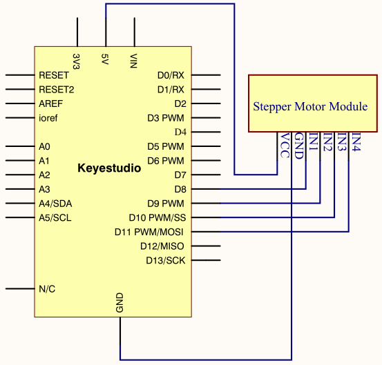
Connection for V4.0
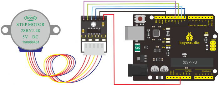
Connection for 2560 R3
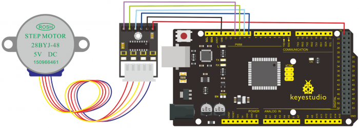
6.Sample Code
/*
 keyestudio super learning kit
 Project 22
 Stepper Motor
 http//www.keyestudio.com
*/
#include <Stepper.h>
#define STEPS 100
Stepper stepper(STEPS, 8, 9, 10, 11);
int previous = 0;
void setup()
{
  stepper.setSpeed(90);
 }
 void loop()
 {
   int val = analogRead(0);
   stepper.step(val - previous);
   previous = val;
 }
//////////////////////////////////////////////////////////
7.Test Result
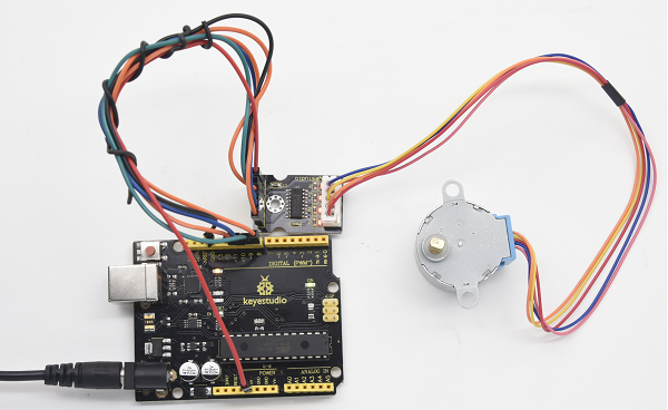
Project 23: PIR Motion Sensor
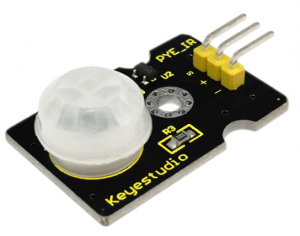
1.Introduction
Pyroelectric infrared motion sensor can detect infrared signals from a moving person or moving animal, and output switching signals.
It can be applied to a variety of occasions to detect the movement of human body.
Conventional pyroelectric infrared sensors require body pyroelectric infrared detector, professional chip, complex peripheral circuit, so it is more bigger with complex circuit, and lower reliability.
Now we launch this new pyroelectric infrared motion sensor, which is specially designed for Arduino.
It uses an integrated digital body pyroelectric infrared sensor, and has smaller size, higher reliability, lower power consumption as well as simpler peripheral circuit.
2.Hardware Required
- V4.0 Board or MEGA 2650 Board*1
- PIR Motion Sensor*1
- Jumper Wire *1
- USB cable*1
3.Specification
•Input Voltage 3.3 ~ 5V (6V Maximum)
•Working Current 15uA
•Working Temperature -20 ~ 85 ℃
•Output Voltage High 3V, Low 0V
•Output Delay Time (High Level) About 2.3 to 3 Seconds
•Detection Angle 100 °
•Detection Distance 7 meters
•Output Indicator LED (When output HIGH, it will be ON)
•Pin limit Current 100mA
4.Circuit Connection
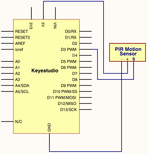
Connection for V4.0

Connection for MEGA 2560 R3
thumb
5.Sample Code
/*
 keyestudio super learning kit
 Project 23
 PIR
 http//www.keyestudio.com
*/
byte sensorPin = 3;
byte indicator = 13;
void setup()
{
  pinMode(sensorPin,INPUT);
  pinMode(indicator,OUTPUT);
  Serial.begin(9600);
}
void loop()
{
  byte state = digitalRead(sensorPin);
  digitalWrite(indicator,state);
  if(state == 1)Serial.println("Somebody is in this area!");
  else if(state == 0)Serial.println("No one!");
  delay(500);
}
//////////////////////////////////////////////////////////
6.Test Result
If the sensor detects someone moving nearby, D13 indicator on V4.0 board will light up, and «Somebody is in this area!» is displayed on the serial monitor.
If no detecting the movement, D13 indicator on V4.0 board will be off, and «No one!» is displayed on the serial monitor.
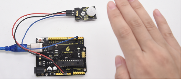
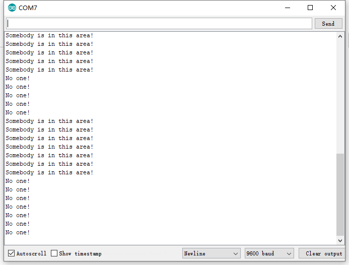
Project 24: Analog Gas Sensor
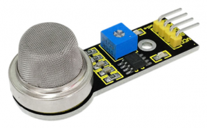
1.Introduction
This analog gas sensor — MQ2 is used in gas leakage detecting equipment in consumer electronics and industrial markets.
This sensor is suitable for LPG, I-butane, propane, methane, alcohol, Hydrogen and smoke detection. It has high sensitivity and quick response. In addition, the sensitivity can be adjusted by the potentiometer.
2.Hardware Required
- V4.0 Board or MEGA 2650 Board*1
- Analog Gas Sensor*1
- Jumper Wire *1
- USB cable*1
3.Specification
•Power Supply 5V
•Interface Type Analog
•Wide detecting scope
•Quick response and high sensitivity
•Simple drive circuit
•Stable and long lifespan
4.Circuit Connection
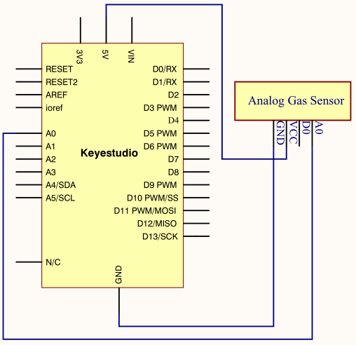
Connection for V4.0
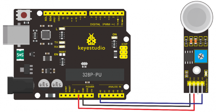
Connection for MEGA 2560 R3
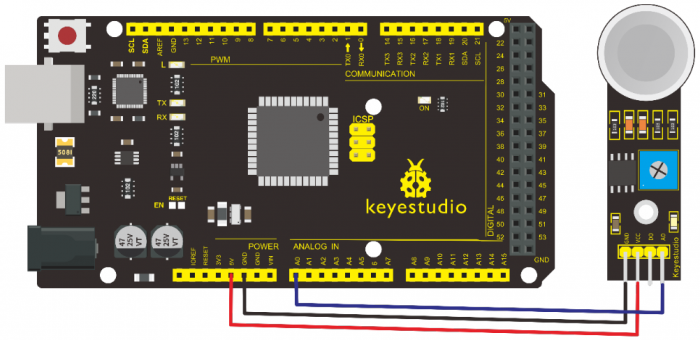
5.Sample Code
/*
 keyestudio super learning kit
 Project 24
 Gas
 http//www.keyestudio.com
*/
void setup()
{
  Serial.begin(9600); //Set serial baud rate to 9600 bps
}
void loop()
{int val;
val=analogRead(0);//Read Gas value from analog 0
Serial.println(val,DEC);//Print the value to serial port
delay(100);
}
//////////////////////////////////////////////////////////
6.Test Result
Project 25: ADXL345 Three Axis Acceleration

1.Introduction
The ADXL345 is a small, thin, low power, 3-axis MEMS accelerometer with high resolution (13-bit) measurement at up to +-16 g. Digital output data is formatted as 16-bit twos complement and is accessible through either a SPI (3- or 4-wire) or I2C digital interface.
The ADXL345 is well suited to measure the static acceleration of gravity in tilt-sensing applications, as well as dynamic acceleration resulting from motion or shock. Its high resolution (4 mg/LSB) enables measurement of inclination change less than 1.0 degrees.
2.Hardware Required
- V4.0 Board or MEGA 2650 Board*1
- ADXL345 Sensor*1
- Jumper Wire *1
- USB cable*1
3.Specification
•2.0-3.6V DC Supply Voltage
•Ultra Low Power 40uA in measurement mode, 0.1uA in standby@ 2.5V
•Tap/Double Tap Detection
•Free-Fall Detection
•SPI and I2C interfaces
4.Circuit Connection
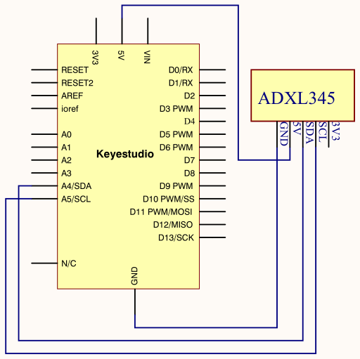
Connection for V4.0
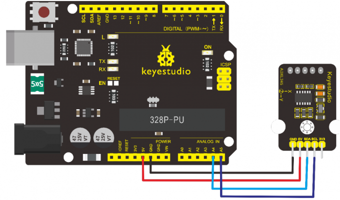
Connection for MEGA 2560 R3
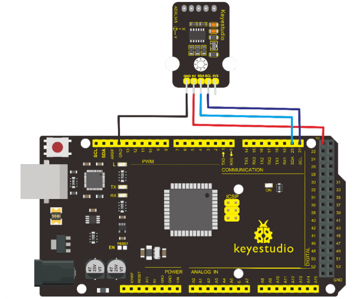
5.Sample Code
/*
keyestudio super learning kit
Project 25
ADXL345
http//www.keyestudio.com
*/
#include <Wire.h>
// Registers for ADXL345
#define ADXL345_ADDRESS (0xA6 >> 1)  // address for device is 8 bit but shift to the
                                     // right by 1 bit to make it 7 bit because the
                                     // wire library only takes in 7 bit addresses
#define ADXL345_REGISTER_XLSB (0x32)

int accelerometer_data[3];
// void because this only tells the cip to send data to its output register
// writes data to the slave's buffer
void i2c_write(int address, byte reg, byte data) {
  // Send output register address
  Wire.beginTransmission(address);
  // Connect to device
  Wire.write(reg);
  // Send data
  Wire.write(data); //low byte
  Wire.endTransmission();
}

// void because using pointers
// microcontroller reads data from the sensor's input register
void i2c_read(int address, byte reg, int count, byte* data) {
  // Used to read the number of data received
  int i = 0;
  // Send input register address
  Wire.beginTransmission(address);
  // Connect to device
  Wire.write(reg);
  Wire.endTransmission();

  // Connect to device
  Wire.beginTransmission(address);
  // Request data from slave
  // Count stands for number of bytes to request
  Wire.requestFrom(address, count);
  while(Wire.available()) // slave may send less than requested
  {
    char c = Wire.read(); // receive a byte as character
    data[i] = c;
    i++;
  }
  Wire.endTransmission();
}

void init_adxl345() {
  byte data = 0;

  i2c_write(ADXL345_ADDRESS, 0x31, 0x0B);   // 13-bit mode  +_ 16g
  i2c_write(ADXL345_ADDRESS, 0x2D, 0x08);   // Power register

  i2c_write(ADXL345_ADDRESS, 0x1E, 0x00);   // x
  i2c_write(ADXL345_ADDRESS, 0x1F, 0x00);   // Y
  i2c_write(ADXL345_ADDRESS, 0x20, 0x05);   // Z

  // Check to see if it worked!
  i2c_read(ADXL345_ADDRESS, 0X00, 1, &data);
  if(data==0xE5)
    Serial.println("it work Success");
  else
    Serial.println("it work Fail");
}

void read_adxl345() {
  byte bytes[6];
  memset(bytes,0,6);

  // Read 6 bytes from the ADXL345
  i2c_read(ADXL345_ADDRESS, ADXL345_REGISTER_XLSB, 6, bytes);
  // Unpack data
  for (int i=0;i<3;++i) {
    accelerometer_data[i] = (int)bytes[2*i] + (((int)bytes[2*i + 1]) << 8);
  }
}
// initialise and start everything
void setup() {
  Wire.begin();
  Serial.begin(9600);
  for(int i=0; i<3; ++i) {
    accelerometer_data[i]  = 0;
  }
  init_adxl345();
}


void loop() {
  read_adxl345();
  Serial.print("ACCEL ");
  Serial.print(float(accelerometer_data[0])*3.9/1000);//3.9mg/LSB scale factor in 13-bit mode
  Serial.print("\t");
  Serial.print(float(accelerometer_data[1])*3.9/1000);
  Serial.print("\t");
  Serial.print(float(accelerometer_data[2])*3.9/1000);
  Serial.print("\n");
  delay(100);
}
//////////////////////////////////////////////////////////////////
6.Test Result
Wiring as the above diagram and power on, then upload the code and open the serial monitor, it will display the triaxial acceleration of sensor and its status, as the graph shown below.
Project 26: HC-SR04 Ultrasonic Sensor
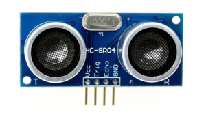
1.Introduction
The HC-SR04 Ultrasonic Sensor is a very affordable proximity/distance sensor that is mainly used for object avoidance in various robotics projects.
It essentially gives your Arduino eyes / spacial awareness and can prevent your robot from crashing or falling off a table. It has also been used in turret applications, water level sensing, and even as a parking sensor.
This simple project will use the HC-SR04 sensor with an Arduino and a Processing sketch to provide a more interactive display on your computer screen.
2.Hardware Required
- V4.0 Board or MEGA 2650 Board*1
- Ultrasonic Sensor*1
- Jumper Wire *1
- USB cable*1
3.Specification
•Working Voltage DC 5V
•Working Current 15mA
•Working Frequency 40KHz
•Max Range 4m
•Min Range 2cm
•Measuring Angle 15 degree
•Trigger Input Signal 10µS TTL pulse
•Echo Output Signal Input TTL lever signal and the range in proportion
4.Circuit Connection
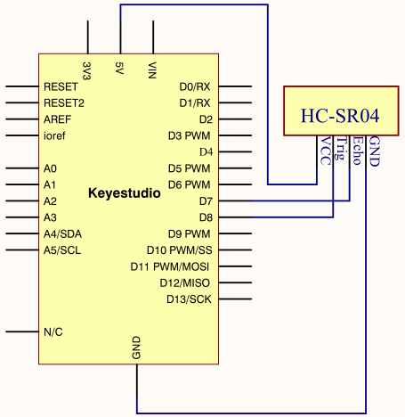
Connection for V4.0
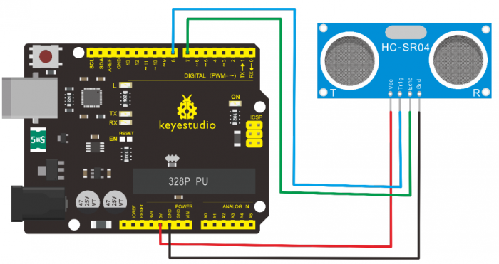
Connection for MEGA 2560 R3
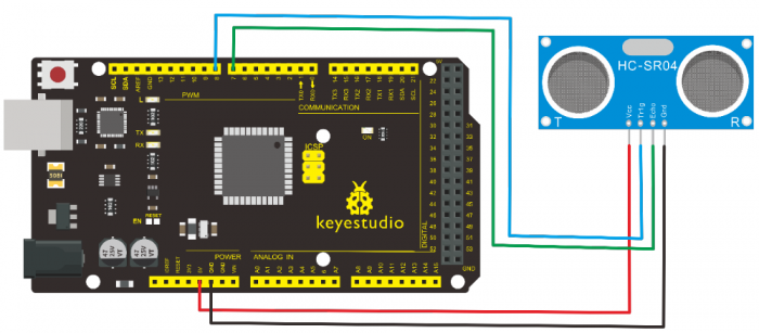
5.Sample Code
/*
 keyestudio super learning kit
 Project 26
 Ultrasonic
 http//www.keyestudio.com
*/
#define echoPin 7 // Echo Pin
#define trigPin 8 // Trigger Pin
#define LEDPin 13 // Onboard LED
int maximumRange = 200; // Maximum range needed
int minimumRange = 0; // Minimum range needed
long duration, distance; // Duration used to calculate distance
void setup() {
 Serial.begin (9600);
 pinMode(trigPin, OUTPUT);
 pinMode(echoPin, INPUT);
 pinMode(LEDPin, OUTPUT); // Use LED indicator (if required)
}
void loop() {
/* The following trigPin/echoPin cycle is used to determine the
 distance of the nearest object by bouncing soundwaves off of it. */
 digitalWrite(trigPin, LOW);
 delayMicroseconds(2);
 digitalWrite(trigPin, HIGH);
 delayMicroseconds(10);
 digitalWrite(trigPin, LOW);
 duration = pulseIn(echoPin, HIGH);
 //Calculate the distance (in cm) based on the speed of sound.
 distance = duration/58.2;

 if (distance >= maximumRange || distance <= minimumRange){
 /* Send a negative number to computer and Turn LED ON
 to indicate "out of range" */
 Serial.println("-1");
 digitalWrite(LEDPin, HIGH);
 }
 else {
 /* Send the distance to the computer using Serial protocol, and
 turn LED OFF to indicate successful reading. */
 Serial.println(distance);
 digitalWrite(LEDPin, LOW);
 }
 //Delay 50ms before next reading.
 delay(50);
}
//////////////////////////////////////////////////////////
6.Test Result
After upload well the code to V4.0 board, then open the serial monitor.
When place an object in front of the ultrasonic sensor (from near and far), it will detect the distance of object. The value will be displayed on the monitor.
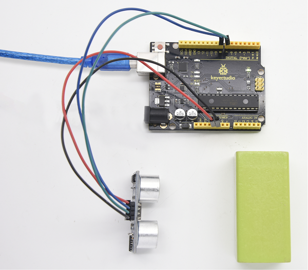
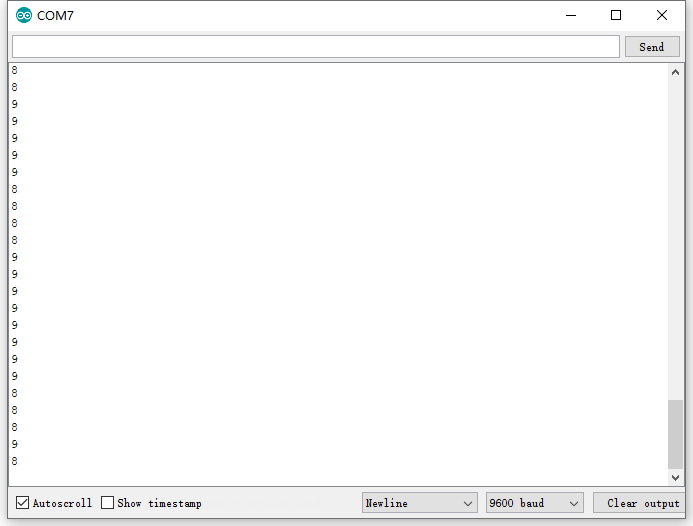
Project 27: Joystick Module

1.Introduction
Lots of robot projects need joystick. This module provides an affordable solution. By simply connecting to two analog inputs, the robot is at your commands with X, Y control. It also has a switch that is connected to a digital pin.
This joystick module can be easily connected to Arduino by IO Shield. This module is for Arduino(V5) with cable supplied.
2.Hardware Required
- V4.0 Board or MEGA 2650 Board*1
- Joystick Module*1
- USB cable*1
3.Specification
•Supply Voltage 3.3V to 5V
•Interface Analog x2, Digital x1
4.Circuit Connection
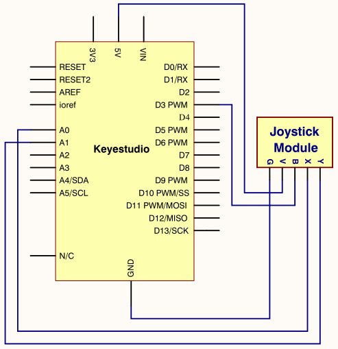
Connection for V4.0

Connection for MEGA 2560 R3
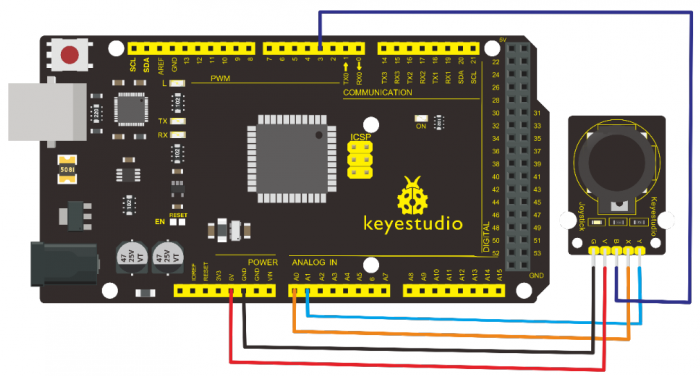
5.Sample Code
/*
 keyestudio super learning kit
 Project 27
 joystick
 http//www.keyestudio.com
*/
int JoyStick_X = 0; //x
int JoyStick_Y = 1; //y
int JoyStick_Z = 3; //key
  void setup()
{
  pinMode(JoyStick_Z, INPUT);
  Serial.begin(9600); // 9600 bps
}
void loop()
{
  int x,y,z;
  x=analogRead(JoyStick_X);
  y=analogRead(JoyStick_Y);
  z=digitalRead(JoyStick_Z);
  Serial.print(x ,DEC);
  Serial.print(",");
  Serial.print(y ,DEC);
  Serial.print(",");
  Serial.println(z ,DEC);
  delay(100);
}
//////////////////////////////////////////////////////////
6.Test Result
Wiring well and uploading the code, open the serial monitor and set the baud rate to 9600, push the joystick, you will see the value shown below.
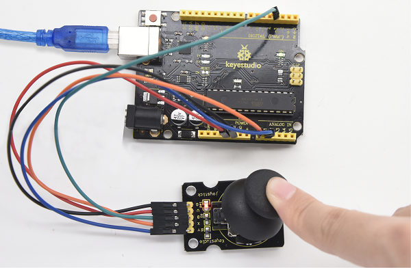
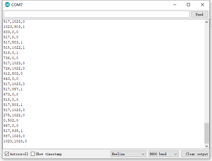
Project 28: 5V Relay Module
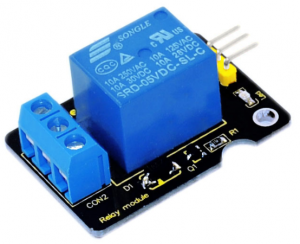
1.Introduction
This single relay module can be used in interactive projects. This module uses SONGLE 5v high-quality relay.
It can also be used to control the lighting, electrical and other equipment. The modular design makes it easy to expand with the Arduino Board (not included).
The Relay output is by a light-emitting diode. It can be controlled through digital IO port, such as solenoid valves, lamps, motors and other high current or high voltage devices.
2.Hardware Required
- V4.0 Board or MEGA 2650 Board*1
- Relay Module*1
- Jumper Wire *1
- USB cable*1
3.Specification
•Type Digital
•Rated Current 10A (NO) 5A (NC)
•Maximum Switching Voltage 150VAC 24VDC
•Digital Interface
•Control Signal TTL level
•Rated Load 8A 150VAC (NO) 10A 24VDC (NO), 5A 250VAC (NO/NC) 5A 24VDC (NO/NC)
•Maximum Switching Power AC1200VA DC240W (NO) AC625VA DC120W (NC)
•Contact Action Time 10ms
4.Circuit Connection
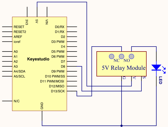
Connection for V4.0
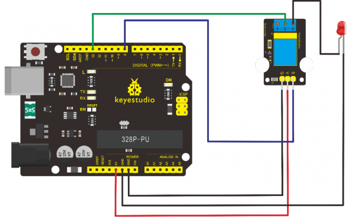
Connection for MEGA 2560 R3
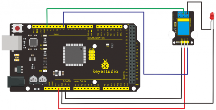
5.Sample Code
/*
 keyestudio super learning kit
 Project 28
 Relay
 http//www.keyestudio.com
*/
 int Relay = 8;
  void setup()
{
  pinMode(13, OUTPUT);         //Set Pin13 as output
  digitalWrite(13, HIGH);     //Set Pin13 High
  pinMode(Relay, OUTPUT);     //Set Pin8 as output
}
void loop()
{
          digitalWrite(Relay, HIGH);   //Turn off relay
          delay(2000);
          digitalWrite(Relay, LOW);    //Turn on relay
          delay(2000);
}
//////////////////////////////////////////////////////////
6.Test Result
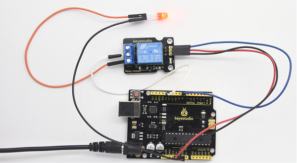
Project 29: DS3231 Clock Module

1.Introduction
DS3231 is equipped with integrated TCXO and crystal, which makes it a cost-effective I2C real time clock with high precision.
The device carries a battery input, so even if you disconnect the main power supply, it can still maintain accurate timing. The integrated oscillator ensures the long-term accuracy of the device and reduces the number of components.
DS3231 provides both commercial and industrial temperature range and supports 16 pins small-outline package (300mil).
The module itself can adapt to the system of 3.3V and 5V without level switch, which is quite convenient!
2.Hardware Required
- V4.0 Board or MEGA 2650 Board*1
- DS3231 Clock Module*1
- Jumper Wire *1
- USB cable*1
3.Specification
•Temperature Range -40 to +85;
•Timing Accuracy ± 5ppm (±0.432 seconds / day)
•Provide battery backup for continuous timing
•Low power consumption
•Device package and function compatible with DS3231
•Complete clock calendar function contains seconds and minutes, hour, week, date, month, and year timing and provides leap year compensation until 2100.
•Two calendar clock
•Output 1Hz and 32.768kHz
•Reset output and Input Debounce of Pushbutton
•High speed (400kHz), I2C serial bus
•Supply voltage +3.3V to +5.5V
•Digital temperature sensor with a precision of±3℃
•Working temperature -40 ~ C to +85 ~ C
•16 pins Small Outline Package (300mil)
4.Circuit Connection
This module adopts the IIC test method, so only need to connect ‘SDA’ to Arduino A4, ‘SCL’ to A5, ‘+’ to VCC and ‘-’ to GND as follows
Connection for V4.0
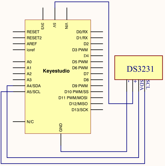
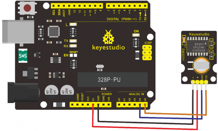
Connection for MEGA 2560 R3
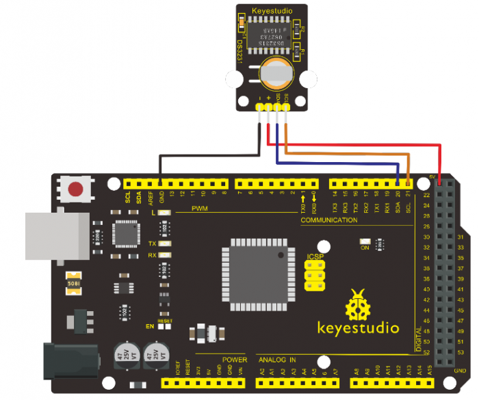
5.Sample Code
Before compiling the code, you’d better put DS3231 library under file into Arduino catalogue.
/*
 keyestudio super learning kit
 Project 29
 clock
 http//www.keyestudio.com
*/
#include <Wire.h>
#include "DS3231.h"
DS3231 RTC; //Create the DS3231 object
char weekDay[][4] = {"Sun", "Mon", "Tue", "Wed", "Thu", "Fri", "Sat" };
//year, month, date, hour, min, sec and week-day(starts from 0 and goes to 6)
//writing any non-existent time-data may interfere with normal operation of the RTC.
//Take care of week-day also.
DateTime dt(2011, 11, 10, 15, 18, 0, 5);//open the series port and you can check time here or make a change to the time as needed.
void setup ()
{   Serial.begin(57600);//set baud rate to 57600
    Wire.begin();
    RTC.begin();
    RTC.adjust(dt); //Adjust date-time as defined 'dt' above
}
void loop ()
{
 DateTime now = RTC.now(); //get the current date-time
    Serial.print(now.year(), DEC);
    Serial.print("/");
    Serial.print(now.month(), DEC);
    Serial.print("/");
    Serial.print(now.date(), DEC);
    Serial.print(" ");
    Serial.print(now.hour(), DEC);
    Serial.print(":");
    Serial.print(now.minute(), DEC);
    Serial.print(":");
    Serial.print(now.second(), DEC);
    Serial.println();
    Serial.print(weekDay[now.dayOfWeek()]);
    Serial.println();
    delay(1000);
}
//////////////////////////////////////////////////////////
6.Test Result
Done uploading the code to arduino, open the serial monitor and get the following results
Project 30: DHT11 Temperature and Humidity Sensor
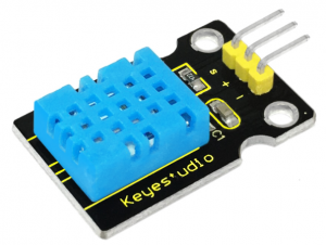
1.Introduction
This DHT11 Temperature and Humidity Sensor features calibrated digital signal output with the temperature and humidity sensor complex. Its technology ensures high reliability and excellent long-term stability. A high-performance 8-bit microcontroller is connected.
This sensor includes a resistive element and a sense of wet NTC temperature measuring devices. It has the advantages of excellent quality, fast response, anti-interference ability and high cost performance.
Each DHT11 sensor features extremely accurate calibration data of humidity calibration chamber. The calibration coefficients stored in the OTP program memory, internal sensors detect signals in the process, and we should call these calibration coefficients.
The single-wire serial interface system is integrated to make it quick and easy. Qualities of small size, low power, and 20-meter signal transmission distance make it a widely applied application and even the most demanding one. Convenient connection and special package can be provided according to your need.
2.Hardware Required
- V4.0 Board or MEGA 2650 Board*1
- DHT11 sensor*1
- Jumper Wire *1
- USB cable*1
3.Specification
•Supply Voltage +5 V
•Temperature Range 0-50 °C error of ± 2 °C
•Humidity 20-90% RH ± 5% RH error
•Interface digital
4.Circuit Connection
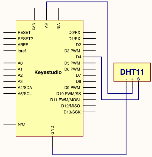
Connection for V4.0

Connection for MEGA 2560 R3
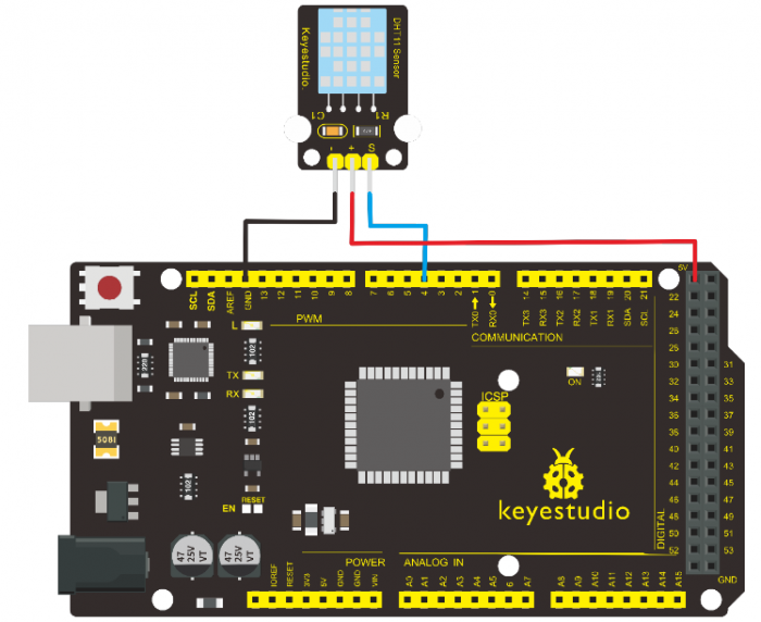
5.Sample Code
Please download the DHT11Lib firstly. Or see the website
/*
 keyestudio super learning kit
 Project 30
 DHT11
 http//www.keyestudio.com
*/
#include <dht11.h>
dht11 DHT;
#define DHT11_PIN 4

void setup(){
  Serial.begin(9600);
  Serial.println("DHT TEST PROGRAM ");
  Serial.print("LIBRARY VERSION: ");
  Serial.println(DHT11LIB_VERSION);
  Serial.println();
  Serial.println("Type,\tstatus,\tHumidity (%),\tTemperature (C)");
}

void loop(){
  int chk;
  Serial.print("DHT11, \t");
  chk = DHT.read(DHT11_PIN);    // READ DATA
  switch (chk){
    case DHTLIB_OK:
                Serial.print("OK,\t");
                break;
    case DHTLIB_ERROR_CHECKSUM:
                Serial.print("Checksum error,\t");
                break;
    case DHTLIB_ERROR_TIMEOUT:
                Serial.print("Time out error,\t");
                break;
    default:
                Serial.print("Unknown error,\t");
                break;
  }
 // DISPLAT DATA
  Serial.print(DHT.humidity,1);
  Serial.print(",\t");
  Serial.println(DHT.temperature,1);

  delay(1000);
}
//////////////////////////////////////////////////////////
6.Test Result
Wire it up well and upload the above code to V4.0 board.
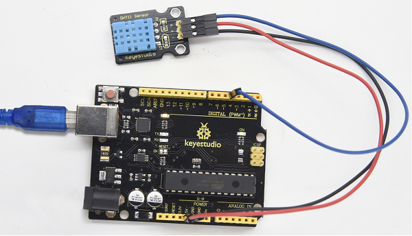
Then open the serial monitor and set the baud rate to 9600, you will see the current temperature and humidity value.

Project 31: Soil Humidity Sensor
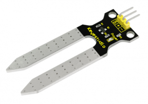
1.Introduction
This is a simple soil humidity sensor aims to detect the soil humidity. If the soil is lack of water, the analog value output by the sensor will decrease; otherwise, it will increase.
If you use this sensor to make an automatic watering device, it can detect whether your botany is thirsty so as to prevent it from withering when you go out. Using the sensor with Arduino controller makes your plant more comfortable and your garden smarter.
The soil humidity sensor module is not as complicated as you might think, and if you need to detect the soil in your project, it will be your best choice.
The sensor is set with two probes inserted into the soil, then with the current go through the soil, the sensor will get resistance value by reading the current changes between the two probes and convert such resistance value into moisture content.
The higher the moisture (less resistance) is, the higher conductivity the soil has.
The surface of the sensor have undergone metallization process to prolong its service life. Insert it into the soil and then use the AD converter to read it. With the help of this sensor, the plant can remind of you I need water.
2.Hardware Required
- V4.0 Board or MEGA 2650 Board*1
- Soil Humidity Sensor*1
- Jumper Wire *1
- USB cable*1
3.Specification
•Power Supply Voltage 3.3V or 5V
•Working Current ≤ 20mA
•Output Voltage 0-2.3V (When the sensor is totally immersed in water, the voltage will be 2.3V)
•5V power supply (the higher humidity, the higher the output voltage)
•Sensor Type Analog output
•Interface Definition Pin1- signal, pin2- GND, pin3 — VCC
4.Circuit Connection
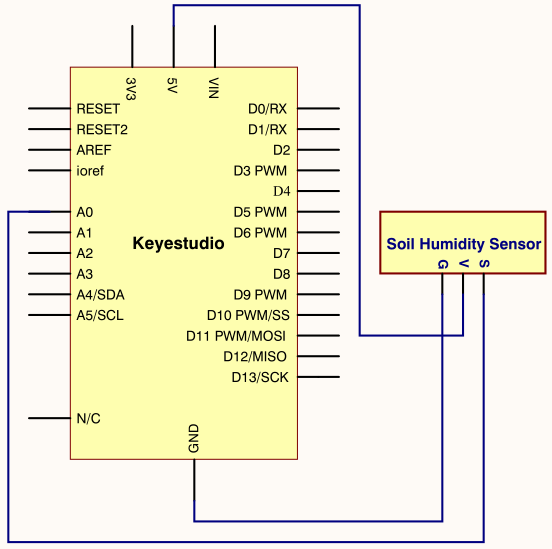
Connection for V4.0

Connection for MEGA 2560 R3

5.Sample Code
/*
keyestudio super learning kit
Project 31
soil humidity sensor
http//www.keyestudio.com
*/
 void setup(){
 Serial.begin(57600);
 }
 void loop(){
  Serial.print("Moisture Sensor Value");
  Serial.println(analogRead(0));
  delay(100);
}
//////////////////////////////////////////////////////////
6.Test Result
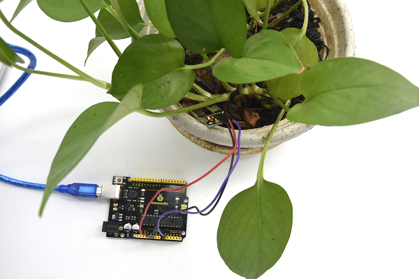
Project 32: RC522 RFID Module
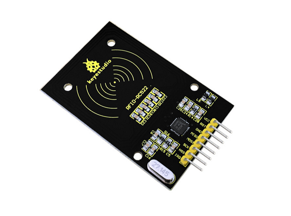
1.Introduction
MF522-AN module adopts Philips MFRC522 original reader circuit chip design, easy to use, low cost, suitable for equipment development, development of advanced applications, the need for the user of RF card terminal design / production. It can be loaded directly into a variety of readers molds.
Module uses voltage of 3.3V, through the SPI interface using simple few lines, it can be directly connected to any CPU board communication modules to guarantee stable and reliable work and reader distance.
2.Hardware Required
- V4.0 Board or MEGA 2650 Board*1
- RFID Module*1
- Jumper Wire *1
- USB cable*1
3.Specification
1.Current 13-26mA / DC 3.3V
2.Idle Current 10-13mA / DC 3.3V
3.Sleep Current <80uA
4.Peak Current <30mA
5.Operating Frequency 13.56MHz
6.Supported card types mifare1 S50, mifare1 S70, mifare UltraLight, mifare Pro, mifare Desfire
7.Environmental Operating Temperature -20-80 degrees Celsius
8.Environment Storage Temperature -40-85 degrees Celsius
9.Relative Humidity 5% -95%
4.Circuit Connection

Connection for V4.0
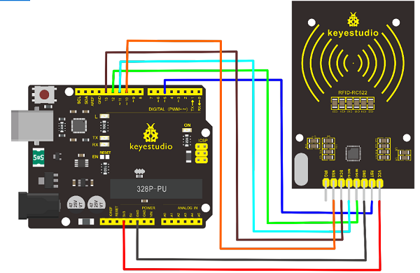
Connection for 2560 R3
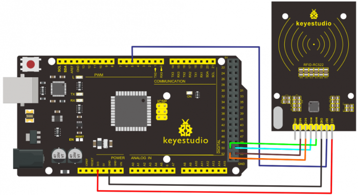
5.Sample Code
/*
 keyestudio super learning kit
 Project 32
 RFID
 http//www.keyestudio.com
*/
#include <SPI.h>
#define  uchar unsigned char
#define uint  unsigned int
#define MAX_LEN 16
const int chipSelectPin = 10;//if the controller is UNO,328,168
const int NRSTPD = 5;

//MF522command word
#define PCD_IDLE              0x00               //NO action;concel current command
#define PCD_AUTHENT           0x0E               //verify key
#define PCD_RECEIVE           0x08               //receive data
#define PCD_TRANSMIT          0x04               //send data
#define PCD_TRANSCEIVE        0x0C               //receive and send data
#define PCD_RESETPHASE        0x0F               //reset
#define PCD_CALCCRC           0x03               //CRC calculation

//Mifare_One Card command word
#define PICC_REQIDL           0x26               // line-tracking area is dormant #define PICC_REQALL           0x52                     //line-tracking area is interfered
#define PICC_ANTICOLL         0x93               //Anti collision
#define PICC_SElECTTAG        0x93               //choose cards
#define PICC_AUTHENT1A        0x60               //Verify A key
#define PICC_AUTHENT1B        0x61               //Verify B key
#define PICC_READ             0x30               // Reader Module
#define PICC_WRITE            0xA0               // letter block
#define PICC_DECREMENT        0xC0
#define PICC_INCREMENT        0xC1
#define PICC_RESTORE          0xC2               //Transfer data to buffer
#define PICC_TRANSFER         0xB0               //Save buffer data
#define PICC_HALT             0x50               //Dormancy


//MF522 Error code returned when communication
#define MI_OK                 0
#define MI_NOTAGERR           1
#define MI_ERR                2


//------------------MFRC522 Register---------------
//Page 0:Command and Status
#define     Reserved00            0x00
#define     CommandReg            0x01
#define     CommIEnReg            0x02
#define     DivlEnReg             0x03
#define     CommIrqReg            0x04
#define     DivIrqReg             0x05
#define     ErrorReg              0x06
#define     Status1Reg            0x07
#define     Status2Reg            0x08
#define     FIFODataReg           0x09
#define     FIFOLevelReg          0x0A
#define     WaterLevelReg         0x0B
#define     ControlReg            0x0C
#define     BitFramingReg         0x0D
#define     CollReg               0x0E
#define     Reserved01            0x0F
//Page 1:Command
#define     Reserved10            0x10
#define     ModeReg               0x11
#define     TxModeReg             0x12
#define     RxModeReg             0x13
#define     TxControlReg          0x14
#define     TxAutoReg             0x15
#define     TxSelReg              0x16
#define     RxSelReg              0x17
#define     RxThresholdReg        0x18
#define     DemodReg              0x19
#define     Reserved11            0x1A
#define     Reserved12            0x1B
#define     MifareReg             0x1C
#define     Reserved13            0x1D
#define     Reserved14            0x1E
#define     SerialSpeedReg        0x1F
//Page 2:CFG
#define     Reserved20            0x20
#define     CRCResultRegM         0x21
#define     CRCResultRegL         0x22
#define     Reserved21            0x23
#define     ModWidthReg           0x24
#define     Reserved22            0x25
#define     RFCfgReg              0x26
#define     GsNReg                0x27
#define     CWGsPReg            0x28
#define     ModGsPReg             0x29
#define     TModeReg              0x2A
#define     TPrescalerReg         0x2B
#define     TReloadRegH           0x2C
#define     TReloadRegL           0x2D
#define     TCounterValueRegH     0x2E
#define     TCounterValueRegL     0x2F
//Page 3:TestRegister
#define     Reserved30            0x30
#define     TestSel1Reg           0x31
#define     TestSel2Reg           0x32
#define     TestPinEnReg          0x33
#define     TestPinValueReg       0x34
#define     TestBusReg            0x35
#define     AutoTestReg           0x36
#define     VersionReg            0x37
#define     AnalogTestReg         0x38
#define     TestDAC1Reg           0x39
#define     TestDAC2Reg           0x3A
#define     TestADCReg            0x3B
#define     Reserved31            0x3C
#define     Reserved32            0x3D
#define     Reserved33            0x3E
#define     Reserved34        0x3F
uchar serNum[5];
uchar  writeDate[16] ={'T', 'e', 'n', 'g', ' ', 'B', 'o', 0, 0, 0, 0, 0, 0, 0, 0,0};
uchar sectorKeyA[16][16] = {{0xFF, 0xFF, 0xFF, 0xFF, 0xFF, 0xFF},
                             {0xFF, 0xFF, 0xFF, 0xFF, 0xFF, 0xFF},
                             {0xFF, 0xFF, 0xFF, 0xFF, 0xFF, 0xFF},
                            };
 uchar sectorNewKeyA[16][16] = {{0xFF, 0xFF, 0xFF, 0xFF, 0xFF, 0xFF},
                                {0xFF, 0xFF, 0xFF, 0xFF, 0xFF, 0xFF, 0xff,0x07,0x80,0x69, 0xFF, 0xFF, 0xFF, 0xFF, 0xFF, 0xFF},
                                {0xFF, 0xFF, 0xFF, 0xFF, 0xFF, 0xFF, 0xff,0x07,0x80,0x69, 0xFF, 0xFF, 0xFF, 0xFF, 0xFF, 0xFF},
                               };

void setup() {
   Serial.begin(9600);                       // RFID reader SOUT pin connected to Serial RX pin at 2400bps
 // start the SPI library:
  SPI.begin();

  pinMode(chipSelectPin,OUTPUT);             // Set digital pin 10 as OUTPUT to connect it to the RFID /ENABLE pin
    digitalWrite(chipSelectPin, LOW);          // Activate the RFID reader
  pinMode(NRSTPD,OUTPUT);               // Set digital pin 10 , Not Reset and Power-down
    digitalWrite(NRSTPD, HIGH);

  MFRC522_Init();
}

void loop()
{
    uchar i,tmp;
  uchar status;
        uchar str[MAX_LEN];
        uchar RC_size;
        uchar blockAddr;  //Select the address of the operation 0~63


    // searching card, return card type
    status = MFRC522_Request(PICC_REQIDL, str);
    if (status == MI_OK)
    {
    }


    status = MFRC522_Anticoll(str);
    memcpy(serNum, str, 5);
    if (status == MI_OK)
    {
                        Serial.println("The card's number is  : ");
      Serial.print(serNum[0],BIN);
      Serial.print(serNum[1],BIN);
      Serial.print(serNum[2],BIN);
      Serial.print(serNum[3],BIN);
      Serial.print(serNum[4],BIN);
                        Serial.println(" ");
    }

    // select card, return card capacity
    RC_size = MFRC522_SelectTag(serNum);
    if (RC_size != 0)
    {}

    // write data card
    blockAddr = 7;    // data block 7
    status = MFRC522_Auth(PICC_AUTHENT1A, blockAddr, sectorKeyA[blockAddr/4], serNum);  // authentication
    if (status == MI_OK)
    {
      // write data
      status = MFRC522_Write(blockAddr, sectorNewKeyA[blockAddr/4]);
                        Serial.print("set the new card password, and can modify the data of the Sector: ");
                        Serial.print(blockAddr/4,DEC);

                        // write data
                        blockAddr = blockAddr - 3 ;
                        status = MFRC522_Write(blockAddr, writeDate);
                        if(status == MI_OK)
                        {
                           Serial.println("OK!");
                        }
    }

    // read card
    blockAddr = 7;    // data block 7
    status = MFRC522_Auth(PICC_AUTHENT1A, blockAddr, sectorNewKeyA[blockAddr/4], serNum); // authentication
    if (status == MI_OK)
    {
      // read data
                        blockAddr = blockAddr - 3 ;
                        status = MFRC522_Read(blockAddr, str);
      if (status == MI_OK)
      {
                                Serial.println("Read from the card ,the data is : ");
        for (i=0; i<16; i++)
        {
                          Serial.print(str[i]);
        }
                                Serial.println(" ");
      }
    }
                Serial.println(" ");
    MFRC522_Halt();     // command card to enter standby mode

}

void Write_MFRC522(uchar addr, uchar val)
{
  digitalWrite(chipSelectPin, LOW);

  SPI.transfer((addr<<1)&0x7E);
  SPI.transfer(val);

  digitalWrite(chipSelectPin, HIGH);
}


uchar Read_MFRC522(uchar addr)
{
  uchar val;

  digitalWrite(chipSelectPin, LOW);

  // address format: 1XXXXXX0
  SPI.transfer(((addr<<1)&0x7E) | 0x80);
  val =SPI.transfer(0x00);

  digitalWrite(chipSelectPin, HIGH);

  return val;
}


void SetBitMask(uchar reg, uchar mask)
{
    uchar tmp;
    tmp = Read_MFRC522(reg);
    Write_MFRC522(reg, tmp | mask);  // set bit mask
}


void ClearBitMask(uchar reg, uchar mask)
{
    uchar tmp;
    tmp = Read_MFRC522(reg);
    Write_MFRC522(reg, tmp & (~mask));  // clear bit mask
}


void AntennaOn(void)
{
  uchar temp;

  temp = Read_MFRC522(TxControlReg);
  if (!(temp & 0x03))
  {
    SetBitMask(TxControlReg, 0x03);
  }
}

void AntennaOff(void)
{
  ClearBitMask(TxControlReg, 0x03);
}

void MFRC522_Reset(void)
{
    Write_MFRC522(CommandReg, PCD_RESETPHASE);
}

void MFRC522_Init(void)
{
  digitalWrite(NRSTPD,HIGH);

  MFRC522_Reset();

  //Timer: TPrescaler*TreloadVal/6.78MHz = 24ms
    Write_MFRC522(TModeReg, 0x8D);    //Tauto=1; f(Timer) = 6.78MHz/TPreScaler
    Write_MFRC522(TPrescalerReg, 0x3E); //TModeReg[3..0] + TPrescalerReg
    Write_MFRC522(TReloadRegL, 30);
    Write_MFRC522(TReloadRegH, 0);

  Write_MFRC522(TxAutoReg, 0x40);   //100%ASK
  Write_MFRC522(ModeReg, 0x3D);   //CRC initial value


  AntennaOn();    // open antenna
}
uchar MFRC522_Request(uchar reqMode, uchar *TagType)
{
  uchar status;
  uint backBits;      // received data bits

  Write_MFRC522(BitFramingReg, 0x07);   //TxLastBists = BitFramingReg[2..0] ???

  TagType[0] = reqMode;
  status = MFRC522_ToCard(PCD_TRANSCEIVE, TagType, 1, TagType, &backBits);

  if ((status != MI_OK) || (backBits != 0x10))
  {
    status = MI_ERR;
  }

  return status;
}

uchar MFRC522_ToCard(uchar command, uchar *sendData, uchar sendLen, uchar *backData, uint *backLen)
{
    uchar status = MI_ERR;
    uchar irqEn = 0x00;
    uchar waitIRq = 0x00;
    uchar lastBits;
    uchar n;
    uint i;

    switch (command)
    {
        case PCD_AUTHENT:   // card key authentication
    {
      irqEn = 0x12;
      waitIRq = 0x10;
      break;
    }
    case PCD_TRANSCEIVE:  // send data in FIFO
    {
      irqEn = 0x77;
      waitIRq = 0x30;
      break;
    }
    default:
      break;
    }

    Write_MFRC522(CommIEnReg, irqEn|0x80);  // Allow interrupt request
    ClearBitMask(CommIrqReg, 0x80);     // clear bits of all interrupt request
    SetBitMask(FIFOLevelReg, 0x80);     //FlushBuffer=1, FIFO initialization


  Write_MFRC522(CommandReg, PCD_IDLE);  //NO action; cancel current command ???

  // write data into FIFO
    for (i=0; i<sendLen; i++)
    {
    Write_MFRC522(FIFODataReg, sendData[i]);
  }

  // execute command
  Write_MFRC522(CommandReg, command);
    if (command == PCD_TRANSCEIVE)
    {
    SetBitMask(BitFramingReg, 0x80);    //StartSend=1,transmission of data starts
  }

  // wait for the completion of data receiving
  i = 2000; // adjust i according to clock frequency, maximum waiting time of operating M1 is 25ms  ???
    do
    {
    //CommIrqReg[7..0]
    //Set1 TxIRq RxIRq IdleIRq HiAlerIRq LoAlertIRq ErrIRq TimerIRq
        n = Read_MFRC522(CommIrqReg);
        i--;
    }
    while ((i!=0) && !(n&0x01) && !(n&waitIRq));

    ClearBitMask(BitFramingReg, 0x80);      //StartSend=0

    if (i != 0)
    {
        if(!(Read_MFRC522(ErrorReg) & 0x1B))  //BufferOvfl Collerr CRCErr ProtecolErr
        {
            status = MI_OK;
            if (n & irqEn & 0x01)
            {
        status = MI_NOTAGERR;     //??
      }

            if (command == PCD_TRANSCEIVE)
            {
                n = Read_MFRC522(FIFOLevelReg);
                lastBits = Read_MFRC522(ControlReg) & 0x07;
                if (lastBits)
                {
          *backLen = (n-1)*8 + lastBits;
        }
                else
                {
          *backLen = n*8;
        }

                if (n == 0)
                {
          n = 1;
        }
                if (n > MAX_LEN)
                {
          n = MAX_LEN;
        }

        // read data which FIFO received
                for (i=0; i<n; i++)
                {
          backData[i] = Read_MFRC522(FIFODataReg);
        }
            }
        }
        else
        {
      status = MI_ERR;
    }

    }

    //SetBitMask(ControlReg,0x80);           //timer stops
    //Write_MFRC522(CommandReg, PCD_IDLE);

    return status;
}

uchar MFRC522_Anticoll(uchar *serNum)
{
    uchar status;
    uchar i;
  uchar serNumCheck=0;
    uint unLen;

  Write_MFRC522(BitFramingReg, 0x00);   //TxLastBists = BitFramingReg[2..0]

    serNum[0] = PICC_ANTICOLL;
    serNum[1] = 0x20;
    status = MFRC522_ToCard(PCD_TRANSCEIVE, serNum, 2, serNum, &unLen);

    if (status == MI_OK)
  {
    // verify card sequence number
    for (i=0; i<4; i++)
    {
      serNumCheck ^= serNum[i];
    }
    if (serNumCheck != serNum[i])
    {
      status = MI_ERR;
    }
    }

    //SetBitMask(CollReg, 0x80);    //ValuesAfterColl=1

    return status;
}

void CalulateCRC(uchar *pIndata, uchar len, uchar *pOutData)
{
    uchar i, n;

    ClearBitMask(DivIrqReg, 0x04);      //CRCIrq = 0
    SetBitMask(FIFOLevelReg, 0x80);     // clear FIFO pointer
    //Write_MFRC522(CommandReg, PCD_IDLE);

  // write data into FIFO
    for (i=0; i<len; i++)
    {
    Write_MFRC522(FIFODataReg, *(pIndata+i));
  }
    Write_MFRC522(CommandReg, PCD_CALCCRC);

  // wait for the completion of CRC calculation
    i = 0xFF;
    do
    {
        n = Read_MFRC522(DivIrqReg);
        i--;
    }
    while ((i!=0) && !(n&0x04));      //CRCIrq = 1

  // read CRC calculation result
    pOutData[0] = Read_MFRC522(CRCResultRegL);
    pOutData[1] = Read_MFRC522(CRCResultRegM);
}

uchar MFRC522_SelectTag(uchar *serNum)
{
    uchar i;
  uchar status;
  uchar size;
    uint recvBits;
    uchar buffer[9];

  //ClearBitMask(Status2Reg, 0x08);     //MFCrypto1On=0

    buffer[0] = PICC_SElECTTAG;
    buffer[1] = 0x70;
    for (i=0; i<5; i++)
    {
      buffer[i+2] = *(serNum+i);
    }
  CalulateCRC(buffer, 7, &buffer[7]);   //??
    status = MFRC522_ToCard(PCD_TRANSCEIVE, buffer, 9, buffer, &recvBits);

    if ((status == MI_OK) && (recvBits == 0x18))
    {
    size = buffer[0];
  }
    else
    {
    size = 0;
  }

    return size;
}

uchar MFRC522_Auth(uchar authMode, uchar BlockAddr, uchar *Sectorkey, uchar *serNum)
{
    uchar status;
    uint recvBits;
    uchar i;
  uchar buff[12];

  // Verification commands + block address + sector password + card sequence number
    buff[0] = authMode;
    buff[1] = BlockAddr;
    for (i=0; i<6; i++)
    {
    buff[i+2] = *(Sectorkey+i);
  }
    for (i=0; i<4; i++)
    {
    buff[i+8] = *(serNum+i);
  }
    status = MFRC522_ToCard(PCD_AUTHENT, buff, 12, buff, &recvBits);

    if ((status != MI_OK) || (!(Read_MFRC522(Status2Reg) & 0x08)))
    {
    status = MI_ERR;
  }

    return status;
}

uchar MFRC522_Read(uchar blockAddr, uchar *recvData)
{
    uchar status;
    uint unLen;

    recvData[0] = PICC_READ;
    recvData[1] = blockAddr;
    CalulateCRC(recvData,2, &recvData[2]);
    status = MFRC522_ToCard(PCD_TRANSCEIVE, recvData, 4, recvData, &unLen);

    if ((status != MI_OK) || (unLen != 0x90))
    {
        status = MI_ERR;
    }

    return status;
}

uchar MFRC522_Write(uchar blockAddr, uchar *writeData)
{
    uchar status;
    uint recvBits;
    uchar i;
  uchar buff[18];

    buff[0] = PICC_WRITE;
    buff[1] = blockAddr;
    CalulateCRC(buff, 2, &buff[2]);
    status = MFRC522_ToCard(PCD_TRANSCEIVE, buff, 4, buff, &recvBits);

    if ((status != MI_OK) || (recvBits != 4) || ((buff[0] & 0x0F) != 0x0A))
    {
    status = MI_ERR;
  }

    if (status == MI_OK)
    {
        for (i=0; i<16; i++)    // write 16Byte data into FIFO
        {
          buff[i] = *(writeData+i);
        }
        CalulateCRC(buff, 16, &buff[16]);
        status = MFRC522_ToCard(PCD_TRANSCEIVE, buff, 18, buff, &recvBits);

    if ((status != MI_OK) || (recvBits != 4) || ((buff[0] & 0x0F) != 0x0A))
        {
      status = MI_ERR;
    }
    }

    return status;
}

void MFRC522_Halt(void)
{
  uchar status;
    uint unLen;
    uchar buff[4];

    buff[0] = PICC_HALT;
    buff[1] = 0;
    CalulateCRC(buff, 2, &buff[2]);

    status = MFRC522_ToCard(PCD_TRANSCEIVE, buff, 4, buff,&unLen);
}
//////////////////////////////////////////////////////////
Note if you want to use MEGA 2560 R3, please in the code change
const int chipSelectPin = 10;//if the controller is V4.0
const int chipSelectPin = 53;//if the controller is MEGA2560
6.Test Result
In this experiment, when the IC card approaches, RFID module will write data to the IC card and read the card’s data, you can see the data on the monitor window. Shown below.
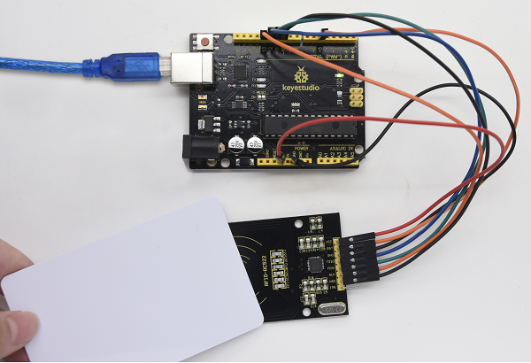
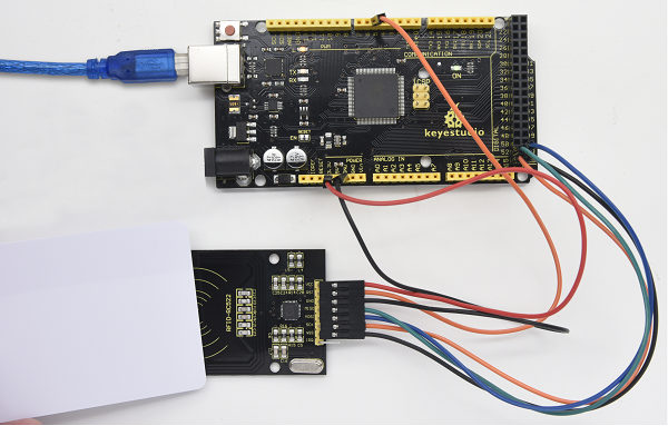
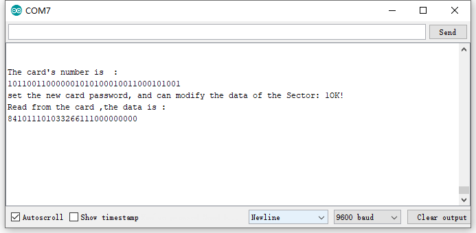
7. Resources
Download code, driver and library:
https://fs.keyestudio.com/KS0077-78-79
Introduction
keyestudio super learning kit is suitable for Arduino enthusiasts. This kit includes 32 projects with detailed tutorials, starting from the basics to more complex projects.
Different from other kits, it adds some functional modules, such as RFID, temperature and humidity module. There is connection diagram and code for each project, making it easy for you to learn.
At the same time, each project has Scratch graphic programming and Arduino C language programming, so that you can access the underlying code.
Component List
NOTE: KS0077 Kit doesn’t include a mainboard; KS0078 Kit includes V4.0 board; KS0079 Kit includes MEGA 2560 board:
Install Arduino IDE and Driver
Download software
When we get control board, we need to download Arduino IDE and driver firstly.
You could download Arduino IDE from the official website:
https://www.arduino.cc/, click the SOFTWARE on the browse bar, click “DOWNLOADS” to enter download page, as shown below:
There are various versions for Arduino, just download a suitable version for your system, we will take WINDOWS system as an example to show you how to download and install.
There are two versions for WINDOWS system, one is installed version, another one is download version, you just need to download file to computer directly and unzip it. These two versions can be used normally. Choose one and download on your computer.
You just need to click JUST DOWNLOAD, then click the downloaded file to install it. And when the ZIP file is downloaded, you can directly unzip and start it.
Keyestudio V4.0 Development Board
We need to know keyestudio V4.0 development board, as a core of this smart car.
keyestudio V4.0 development board is an Arduino uno-compatible board, which is based on ATmega328P MCU, and with a cp2102 Chip as a UART-to-USB converter.
It has 14 digital input/output pins (of which 6 can be used as PWM outputs), 6 analog inputs, a 16 MHz quartz crystal, a USB connection, a power jack, 2 ICSP headers and a reset button.
It contains everything needed to support the microcontroller; simply connect it to a computer with a USB cable or power it via an external DC power jack (DC 7-12V) or via female headers Vin/ GND(DC 7-12V) to get started.
Keyestudio MEGA 2560 Board
Keyestudio Mega 2560 R3 is a microcontroller board based on the ATMEGA2560-16AU , fully compatible with ARDUINO MEGA 2560 R3.
It has 54 digital input/output pins (of which 15 can be used as PWM outputs), 16 analog inputs, 4 UARTs (hardware serial ports), a 16 MHz crystal oscillator, a USB connection, a power jack, 1 ICSP header, and a reset button. The built-in ICSP port can burn the firmware for ATMEGA2560-16AU directly. This chip is burnt the firmware well before leaving the factory, therefore, we hardly use it. We can power on by USB wire, DC head and Vin GND pins. To facilitate wiring, a 0.5 m USB wire is provided for you.
Specialized Functions of Some Pins:
1. Serial Communication: D0 (RX0) and D1 (TX1); Serial 1: D19 (RX1) and D18 (TX1); Serial 2: D17 (RX2) and D16 (TX2); Serial 3: D15 (RX3) and D14 (TX3). Used to receive (RX) and transmit (TX) TTL serial data. Pins 0 and 1 are also connected to the corresponding pins of the CP2102 USB-to-TTL Serial chip.
2. PWM Pins (Pulse-Width Modulation): D2 to D13, and D44 to D46. Provide 8-bit PWM output with the analogWrite() function.
3. External Interrupts: D2 (interrupt 0), D3 (interrupt 1), D18 (interrupt 5), D19 (interrupt 4), D20 (interrupt 3), and D21 (interrupt 2). These pins can be configured to trigger an interrupt on a low level, a rising or falling edge, or a change in level. See the attachInterrupt() function for details.
4. SPI communication: D53 (SS), D52 (SCK), D51 (MOSI), D50 (MISO). These pins support SPI communication using theSPI library. The SPI pins are also broken out on the ICSP header, which is physically compatible with the Arduino Uno.
5. IIC communication: D20 (SDA); D21 (SCL). Support TWI communication using the Wire library.
Installing driver
Let’s install the driver of keyestudio PLUS control board. The USB-TTL chip on PLUS board adopts CP2102 serial chip. The driver program of this chip is included in Arduino 1.8 version and above, which is convenient. Plug on USB port of board, the computer can recognize the hardware and automatically install the driver of CP2102.
If install unsuccessfully, or you intend to install manually, open the device manager of computer. Right click Computer—— Properties—— Device Manager.
There is a yellow exclamation mark on the page, which implies installing the driver of CP2102 unsuccessfully. Then we double click the hardware and update the driver.
Click “OK” to enter the following page, click “browse my computer for updated driver software”, find out the installed or downloaded ARDUINO software. As shown below:
There is a DRIVERS folder in Arduino software installed package(![]() ), open driver folder and you can see the driver of CP210X series chips.
), open driver folder and you can see the driver of CP210X series chips.
We click “Browse”, then find out the driver folder, or you could enter “driver” to search in rectangular box, then click “next”, the driver will be installed successfully. (I place Arduino software folder on the desktop, you could follow my way)
Open device manager, we will find the yellow exclamation mark disappear. The driver of CP2102 is installed successfully.
Arduino IDE Setting
Click icon,open Arduino IDE.
To avoid the errors when uploading the program to the board, you need to select the correct Arduino board that matches the board connected to your computer.
Then come back to the Arduino software, you should click Tools→Board, select the board. (as shown below)
Then select the correct COM port (you can see the corresponding COM port after the driver is successfully installed)
Before uploading the program to the board, let’s demonstrate the function of each symbol in the Arduino IDE toolbar.
A- Used to verify whether there is any compiling mistakes or not.
B- Used to upload the sketch to your Arduino board.
C- Used to create shortcut window of a new sketch.
D- Used to directly open an example sketch.
E- Used to save the sketch.
F- Used to send the serial data received from board to the serial monitor.
Start your first program
Open the file to select Example, choose BLINK from BASIC, as shown below:
Set board and COM port, the corresponding board and COM port are shown on the lower right of IDE.
Click ![]() to start compiling the program, check errors.
to start compiling the program, check errors.
Click ![]() to upload the program, upload successfully.
to upload the program, upload successfully.
Upload the program successfully, the onboard LED lights on for 1s, lights off for 1s. Congratulation, you finish the first program.
Add Project Libraries
What are Libraries ?
Libraries are a collection of code that makes it easy for you to connect to a sensor,display, module, etc.
For example, the built-in LiquidCrystal library helps talk to LCD displays. There are hundreds of additional libraries available on the Internet for download.
The built-in libraries and some of these additional libraries are listed in the reference.
How to Install a Library ?
Here we will introduce the most simple way for you to add libraries.
Step 1:After downloading well the Arduino IDE, you can right-click the icon of Arduino IDE.
Find the option «Open file location» shown as below:
Step 2: Enter it to find out libraries folder which is the library file of Arduino.
Step 3 Next to find out the “libraries” folder of this kit(seen in the link https://fs.keyestudio.com/KS0077-78-79)
You just need to replicate and paste above libraries into the libraries folder of Arduino IDE.
Then the libraries of this kit are installed successfully, as shown below
Note the Arduino software download and the driver installation of keyetudio Mega 2560 R3 board is similar to arduino V4.0 board.
Project Details
Project 1: Hello World
1.Introduction
As for starters, we will begin with something simple. In this project, you only need an Arduino and a USB Cable to start the «Hello World!» experiment. It is not only a communication test of your Arduino and PC, but also a primer project for you to have your first try in the Arduino world!
2.Hardware Required
- V4.0 Board or MEGA 2650 Board*1
- USB cable*1
3.Sample Code
After installing driver for Arduino, let’s open Arduino software and compile code that enables Arduino to print «Hello World!» under your instruction. Of course, you can compile code for Arduino to continuously echo «Hello World!» without instruction.
A simple If () statement will do the instruction trick. when Arduino gets an instruction and then to print «Hello World!”.
/*
keyestudio super learning kit
Project 1
Hello World
http//www.keyestudio.com
- /
int val;//define variable val
void setup()
{
Serial.begin(9600);// set the baud rate at 9600 .
}
void loop()
{
 val=Serial.read();// read the instruction or character from PC to Arduino, and assign them to Val.
 if(val=='R')// determine if the instruction or character received is “R”.
 {  // if it’s “R”,
    Serial.println("Hello World!");// display“Hello World!”string.
 }}//
///////////////////////////////////////////////////////////////
4.Test Result
Click to open the serial monitor, input an “R”, PC will receive the information from Arduino Hello World!
After choosing the proper port, the experiment is easy for you!
Project 2: LED Blinking
1.Introduction
Blinking LED experiment is quite simple. In the «Hello World!» program, we have come across LED. This time, we are going to connect an LED to one of the digital pins rather than using LED13 soldered to the board. Apart from an Arduino and a USB cable, you will need extra parts as below
2.Hardware Required
- V4.0 Board or MEGA 2650 Board*1
- Red M5 LED*1
- 220Ω Resistor*1
- Breadboard*1
- Breadboard Jumper Wire*2
- USB cable*1
3.Little Knowledge
LED is a type of semiconductor called «Light Emitting Diode «which is an electronic device made of semiconductor materials (silicon, selenium, germanium, etc.). It is dubbed indicator, digital and word display in circuit and device. It has positive and negative poles. The short leg is negative pole, the long one is positive pole.
Resistor:Resistor is the electronic component in the circuit, which limits and regulates current flow. Its unit is (Ω).
The units larger than ohms are kiloohms (KΩ) and megaohms (MΩ). When in use, in addition to the size of the resistance, you must also pay attention to its power. In the project, the leads at both ends of the resistor should be bent at a 90° angle to fit the breadboard properly. If the lead is too long, it can be cut to an appropriate length.
A breadboard is used to build and test circuits quickly before finalizing any circuit design. The breadboard has many holes into which circuit components like ICs and resistors can be inserted. A typical breadboard is shown below:
The bread board has strips of metal which run underneath the board and connect the holes on the top of the board. The metal strips are laid out as shown below. Note that the top and bottom rows of holes are connected horizontally while the remaining holes are connected vertically.
To use the bread board, the legs of components are placed in the holes. Each set of holes connected by a metal a strip underneath forms anode
4.Circuit Connection
We follow below diagram from the experimental schematic link. Here we use digital pin 10. We connect LED to a 220 ohm resistor to avoid high current damaging the LED.
Connection for V4.0
Connection for 2560
5.Sample Code
/*
keyestudio super learning kit
Project 2
Blink
http//www.keyestudio.com
- /
int ledPin = 10; // define digital pin 10.
void setup()
{
pinMode(ledPin, OUTPUT);// define pin with LED connected as output.
}
void loop()
{
digitalWrite(ledPin, HIGH); // set the LED on.
delay(1000); // wait for a second.
digitalWrite(ledPin, LOW); // set the LED off.
delay(1000); // wait for a second
}
//////////////////////////////////////////////////////////////////
6.Test Result
After uploading this program, in the experiment, you will see the LED connected to pin 10 turning on and off, with an interval of approximate one second.
In this way, blinking LED experiment is now completed. Thank you!
Project 3: PWM
1.Introduction
PWM, short for Pulse Width Modulation, is a technique used to encode analog signal level into digital ones. A computer cannot output analog voltage but only digital voltage values such as 0V or 5V. So we use a high resolution counter to encode a specific analog signal level by modulating the duty cycle of PMW.
2.Working Principle
The PWM signal is also digitalized because in any given moment, fully on DC power supply is either 5V (ON), or 0V (OFF). The voltage or current is fed to the analog load (the device that uses the power) by repeated pulse sequence being ON or OFF. Being on, the current is fed to the load; being off, it’s not. With adequate bandwidth, any analog value can be encoded using PWM. The output voltage value is calculated via the on and off time.
Output voltage = (turn on time/pulse time) * maximum voltage value.
PWM has many applications lamp brightness regulating, motor speed regulating, sound making, etc.
The following are the three basic parameters of PMW.
- 1.The amplitude of pulse width (minimum / maximum)
- 2. The pulse period (The reciprocal of pulse frequency in one second)
- 3. The voltage level(such as 0V-5V)
- There are 6 PMW interfaces on Arduino, namely digital pin 3, 5, 6, 9, 10, and 11.
- In previous experiments, we have done «button-controlled LED», using digital signal to control digital pin, also one about potentiometer.
- This time, we will use a potentiometer to control the brightness of the LED.
3.Hardware Required
- V4.0 Board or MEGA 2650 Board*1
- Red M5 LED*1
- 220Ω Resistor
- Breadboard*1
- Breadboard Jumper Wire*6
- USB cable*1
4.Circuit Connection
Connection for V4.0
Connection for 2560 R3
5.Sample Code
/*
keyestudio super learning kit
Project 3
pwm
http//www.keyestudio.com
*/
int ledPin = 10;
 void setup() {
     pinMode(ledPin,OUTPUT);
}
void loop(){
  for (int value = 0 ; value < 255; value=value+1){
    analogWrite(ledPin, value);
    delay(5);
  }
  for (int value = 255; value >0; value=value-1){
    analogWrite(ledPin, value);
    delay(5);
  }
}
//////////////////////////////////////////////////////////////////
6.Test Result
Hook up via connection diagram, upload the code and plug in power. The external LED lights up then gets dark gradually, which looks like human breath.
Project 4: Traffic Light
1.Introduction
In the previous program, we have done the LED blinking experiment with one LED. Now, it’s time to up the stakes to do a bit more complicated experiment-traffic light. Actually, these two experiments are similar. While in this traffic light experiment, we use three LEDs with different colors rather than an LED.
2.Hardware Required
- V4.0 Board or MEGA 2650 Board*1
- USB Cable *1
- Red M5 LED*1
- Yellow M5 LED*1
- Blue M5 LED*1
- 220Ω Resistor *3
- Breadboard*1
- Breadboard Jumper Wire *4
3.Circuit Connection
Connection for V4.0
Connection for 2560
4.Sample Code
Since it is a simulation of traffic lights, the blinking time of each LED should be the same with those in traffic lights system.
In this program, we use Arduino delay () function to control delay time, which is much simpler than C language.
/*
 keyestudio super learning kit
 Project 4
 traffic light
 http//www.keyestudio.com
*/
int redled =10; // initialize digital pin 10.
int yellowled =7; // initialize digital pin 7.
int blueled =4; // initialize digital pin 4.
void setup()
{
pinMode(redled, OUTPUT);// set the pin with red LED as “output”
pinMode(yellowled, OUTPUT); // set the pin with yellow LED as “output”
pinMode(blueled, OUTPUT); // set the pin with blue LED as “output”
}
void loop()
{
digitalWrite(blueled, HIGH);//// turn on blue LED
delay(5000);// wait 5 seconds
digitalWrite(blueled, LOW); // turn off blue LED
for(int i=0;i<3;i++)// blinks for 3 times
{
delay(500);// wait 0.5 second
digitalWrite(yellowled, HIGH);// turn on yellow LED
delay(500);// wait 0.5 second
digitalWrite(yellowled, LOW);// turn off yellow LED
}
delay(500);// wait 0.5 second
digitalWrite(redled, HIGH);// turn on red LED
delay(5000);// wait 5 second
digitalWrite(redled, LOW);// turn off red LED
}
//////////////////////////////////////////////////////////////////
5.Test Result
When the uploading process is completed, you can see traffic lights of your own design. Note this circuit design is very similar with the one in LED chasing effect.
The blue light will be on for 5 seconds, and then off, followed by the yellow light blinking for 3 times, and then the red light is on for 5 seconds, repeatedly forming a cycle.
Experiment is now completed, thank you!
Project 5: LED Chasing Effect
1.Introduction
We can see many billboards composed of colorful LEDs. They are constantly changing to form various effects. In this experiment, we compile a program to simulate chase effect.
2.Hardware Required
- V4.0 Board or MEGA 2650 Board*1
- Red LED*6
- 220Ω Resistor *6
- Breadboard Jumper Wire*12
- USB cable*1
3.Circuit Connection
Connection for V4.0
Connection for 2560
4.Sample Code
/*
 keyestudio super learning kit
 Project 5
 LED Chasing Effect
 http//www.keyestudio.com
*/
int BASE = 2 ;  // the I/O pin for the first LED
int NUM = 6;   // number of LEDs
void setup()
{
   for (int i = BASE; i < BASE + NUM; i ++)
   {
     pinMode(i, OUTPUT);   // set I/O pins as output
   }
}
void loop()
{
   for (int i = BASE; i < BASE + NUM; i ++)
   {
     digitalWrite(i, LOW);    // set I/O pins as “low”, turn off LEDs one by one.
     delay(200);        // delay
   }
   for (int i = BASE; i < BASE + NUM; i ++)
   {
     digitalWrite(i, HIGH);    // set I/O pins as “high”, turn on LEDs one by one
     delay(200);        // delay
   }
}
//////////////////////////////////////////////////////////////////
5.Test Result
You can see the LEDs blink by sequence.
Project 6: Button-Controlled LED
1.Introduction
I/O port means interface for INPUT and OUTPUT. Up to now, we have only used the OUTPUT function.
In this experiment, we will try to use the INPUT function, which is to read the output value of device connecting to it.
We use 1 button and 1 LED using both input and output to give you a better understanding of the I/O function.
Button switch, familiar to most of us, is a switch value (digital value) component. When it’s pressed, the circuit is in closed (conducting) state.
2.Hardware Required
- V4.0 Board or MEGA 2650 Board*1
- Button switch*1
- Red M5 LED*1
- 220ΩResistor*1
- 10KΩ Resistor*1
- Breadboard*1
- Breadboard Jumper Wire*6
- USB cable*1
3. Little Knowledge
I believe that button switch is common and popular for people. It belongs to switch quantity( digital quantity)component. Composed of normally open contact and normally closed contact,its working principle is similar with ordinary switch.
When the normally open contact bears pressure, the circuit is on state ; however, when this pressure disappears, the normally open contact goes back to initial state, that is, off state. The pressure is the act we switch the button.
Schematic Diagrams:
4. Circuit Connection
Connection for V4.0
Connection for 2560
5.Sample Code
Now, let’s begin the compiling. When the button is pressed, the LED will be on. Based on the previous study, the coding should be easy for you.
In this program, we add a statement of judgment. Here, we use an if () statement.
Arduino IDE is based on C language, so statements of C language such as while, switch etc. can certainly be used for Arduino program.
When we press the button, pin 7 will output high level. We can program pin 11 to output high level and turn on the LED. When pin 7 outputs low level, pin 11 also outputs low level and the LED remains off.
/*
 keyestudio super learning kit
 Project 6
 Button
 http//www.keyestudio.com
*/
int ledpin=11;// initialize pin 11
int inpin=7;// initialize pin 7
int val;// define val
void setup()
{
pinMode(ledpin,OUTPUT);// set LED pin as “output”
pinMode(inpin,INPUT);// set button pin as “input”
}
void loop()
{
val=digitalRead(inpin);// read the level value of pin 7 and assign if to val
if(val==LOW)// check if the button is pressed, if yes, turn on the LED
{ digitalWrite(ledpin,LOW);}
else
{ digitalWrite(ledpin,HIGH);}
}
//////////////////////////////////////////////////////////////////
6.Test Result
When the button is pressed, LED is on, otherwise, LED remains off. In this way, the button controlled LED experiment is completed.
The simple principle of this experiment is widely used in a variety of circuit and electric appliances. You can easily come across it in your daily life. One typical example is when you press a certain key on your phone, the backlight will be on.
Project 7: Active Buzzer
1.Introduction
Active buzzer is widely used as a sound making element on computer, printer, alarm, electronic toy, telephone, timer and more. It has an inner vibration source. Simply connect it with 5V power supply, it can buzz continuously.
2.Hardware Required
- V4.0 Board or MEGA 2650 Board*1
- Buzzer*1
- Breadboard*1
- Breadboard Jumper Wire*2
- USB cable*1
3. Little Knowledge
There are two kinds of buzzer, active buzzer and passive buzzer. In this lesson, we will use Micro:bit to drive an active buzzer. The active buzzer inside has a simple oscillator circuit which can convert constant direct current into a certain frequency pulse signal. Once active buzzer receives a high level, it will produce an audible beep.
4.Circuit Connection
Connection for V4.0
Connection for 2560
When connecting the circuit, pay attention to the positive and negative poles of the buzzer. In the photo, you can see there are red and black lines. When the circuit is finished, you can begin the programming.
5.Sample Code
Program is simple. You control the buzzer by outputting high/low level.
/*
 keyestudio super learning kit
 Project 7
 Active Buzzer
 http//www.keyestudio.com
*/
int buzzer=8;// initialize digital IO pin that controls the buzzer
void setup()
{
  pinMode(buzzer,OUTPUT);// set pin mode as “output”
}
void loop()
{
digitalWrite(buzzer, HIGH); // produce sound
}
//////////////////////////////////////////////////////////////////
6.Test Result
After uploading the program, the buzzer experiment is completed. You can see the buzzer is ringing.
Project 8: Passive Buzzer
1.Introduction
We can use Arduino to make many interactive works. The most commonly used one is acoustic-optic display. All the previous experiment has something to do with LED. However, the circuit in this experiment can produce sound. Normally, the experiment is done with a buzzer but not a speaker while buzzer is more simpler and easier to use.
The buzzer we introduced here is a passive buzzer. It cannot be actuated by itself, but by external pulse frequencies. Different frequency produces different sound. We can use Arduino to code the melody of a song, which is quite fun and simple.
2.Hardware Required
- V4.0 Board or MEGA 2650 Board*1
- Passive Buzzer*1
- Breadboard*1
- Breadboard Jumper Wire*2
- USB cable*1
3. Little knowledge
Passive buzzer is an integrated electronic buzzer without vibration source inside. It must be driven by 2K-5K square wave instead of direct current signals. There is little difference between the two buzzers, but when the pins of the two buzzers are placed up, the passive buzzer comes with green circuit board, and the one sealed with vinyl is an active buzzer.
4.Circuit Connection
Connection for V4.0
Connection for 2560
5.Sample Code
/*
keyestudio super learning kit
Project 8
Passive Buzzer
http//www.keyestudio.com
*/
int buzzer=8;// select digital IO pin for the buzzer
void setup()
{
pinMode(buzzer,OUTPUT);// set digital IO pin pattern, OUTPUT to be output
}
void loop()
{ unsigned char i,j;//define variable
while(1)
{ for(i=0;i<80;i++)// output a frequency sound
{ digitalWrite(buzzer,HIGH);// sound
delay(1);//delay1ms
digitalWrite(buzzer,LOW);//not sound
delay(1);//ms delay
}
for(i=0;i<100;i++)// output a frequency sound
{ digitalWrite(buzzer,HIGH);// sound
delay(2);//2ms delay
digitalWrite(buzzer,LOW);//not sound
delay(2);//2ms delay
}}}
//////////////////////////////////////////////////////////////////
6.Test Result
After uploading the program, buzzer experiment is finished, you can hear the buzzer sound.
Project 9: RGB LED
1.Introduction
The RGB color mode is a color standard in the industry. It obtains various colors by changing the three color channels of red (R), green (G), and blue (B) and integrating them. RGB denotes the three colors of red, green and blue.
In this project, we use Arduino to mix these three colors in equal amounts to produce white light.
2.Hardware Required
- V4.0 Board or MEGA 2650 Board*1
- USB Cable * 1
- RGB LED * 1
- Resistor *3
- Breadboard jumper wire*5
3. Little Knowledge
The monitors mostly adopt the RGB color standard, and all the colors on the computer screen are composed of the three colors of red, green and blue mixed in different proportions.
RGB is inclusive of common cathode RGB and common anode RGB.
And we could adjust the LED brightness by PWM
4.Circuit Connection
Connection for V4.0
Connection for 2560
5.Sample Code
/*
 keyestudio super learning kit
 Project 9
 RGB
 http//www.keyestudio.com
*/
int redpin = 11; //select the pin for the red LED
int bluepin =10; // select the pin for the blue LED
int greenpin =9;// select the pin for the green LED
int val;
void setup() {
  pinMode(redpin, OUTPUT);
  pinMode(bluepin, OUTPUT);
  pinMode(greenpin, OUTPUT);
  Serial.begin(9600);
}
void loop()
{
for(val=255; val>0; val--)
  {
   analogWrite(11, val);
   analogWrite(10, 255-val);
   analogWrite(9, 128-val);
   delay(1);
  }
for(val=0; val<255; val++)
  {
   analogWrite(11, val);
   analogWrite(10, 255-val);
   analogWrite(9, 128-val);
   delay(1);
  }
 Serial.println(val, DEC);
}
//////////////////////////////////////////////////////////////////
6.Test Result
Directly copy the above code into arduino IDE, and click upload, wait for a few seconds, you can see a full-color LED.
Project 10: Photo Resistor
1.Introduction
After completing all the previous experiments, you may acquire some basic understanding and knowledge about Arduino application. We have introduced digital input and output, analog input and PWM.
Now, let’s begin the learning of sensor applications.
Photo Resistor (Photovaristor) is a resistor whose resistance varies from different incident light strength. It’s based on the photoelectric effect of semiconductor. If the incident light is intense, its resistance reduces; if the incident light is weak, the resistance increases.
2.Hardware Required
- V4.0 Board or MEGA 2650 Board*1
- Photo Resistor*1
- Red M5 LED*1
- 10KΩ Resistor*1
- 220Ω Resistor*1
- Breadboard*1
- Breadboard Jumper Wire*5
- USB cable*1
3.Little Knowledge
Photovaristor is commonly applied in the measurement of light, light control and photovoltaic conversion (convert the change of light into the change of electricity).
Photo resistor is also being widely applied to various light control circuit, such as light control and adjustment, optical switches, etc.
We will start with a relatively simple experiment regarding to photovaristor application.
Photovaristor is an element that can change its resistance as light strength changes. So need to read the analog value. You can refer to the PWM experiment, replacing the potentiometer with photovaristor. When there is change in light strength, it will make corresponding change on the LED.
4.Circuit Connection
Connection for V4.0
Connection for 2560
5.Sample Code
After wiring, let’s begin the program compiling. The program is similar to the PWM.
For change detail, please refer to the Sample Code below.
/*
 keyestudio super learning kit
 Project 10
 Photo Resistor
 http//www.keyestudio.com
*/
int potpin=0;// initialize analog pin 0, connected with photovaristor
int ledpin=11;// initialize digital pin 11,
int val=0;// initialize variable va
void setup()
{
pinMode(ledpin,OUTPUT);// set digital pin 11 as “output”
Serial.begin(9600);// set baud rate at “9600”
}
void loop()
{
val=analogRead(potpin);// read the value of the sensor and assign it to val
Serial.println(val);// display the value of val
analogWrite(ledpin,val/4);// set up brightness(maximum value 255)
delay(10);// wait for 0.01
}
//////////////////////////////////////////////////////////////////
6.Test Result
After downloading the program, you can change the light strength around the photovaristor, and see the corresponding brightness change of the LED.
Photovaristors has various applications in our everyday. You can make other interesting interactive projects based on this one.
Project 11: Flame Sensor
1.Introduction
Flame sensor (infrared receiving triode) is specially used for robots to find the fire source. This sensor is of high sensitivity to flame.
2.Hardware Required
- V4.0 Board or MEGA 2650 Board*1
- Flame Sensor *1
- Buzzer *1
- 10K Resistor *1
- Breadboard Jumper Wire*6
- USB cable*1
3. Little Knowledge
Flame sensor is based on the principle that infrared ray is highly sensitive to flame. It has an infrared receiving tube specially designed to detect fire, and then to convert the flame brightness into fluctuating level signal. The signals are then input into the central processor and be dealt with accordingly.
The shorter lead of the receiving triode is for negative, the other one for positive. Connect negative to 5V pin, positive to resistor; connect the other end of the resistor to GND, connect one end of a jumper wire to a clip which is electrically connected to sensor positive, the other end to analog pin. As shown below
4.Experiment Principle
When it’s approaching a fire, the voltage value read from the analog port will differ. If you use a multimeter, you can see that when there is no fire approaching, the voltage it reads is around 0.3V; when there is fire approaching, the voltage it reads is around 1.0V. The nearer the fire is, the higher the voltage is.
So in the beginning of the program, you can initialize voltage value i (no fire value); Then, continuously read the analog voltage value j and obtain difference value k=j-i; compare k with 0.6V (123 in binary) to determine whether there is a fire approaching or not; if yes, the buzzer will buzz.
5.Circuit Connection
Connection for V4.0
Connection for MEGA 2560
6.Sample Code
/*
keyestudio super learning kit
Project 11
Flame
http//www.keyestudio.com
*/
int flame=0;// select analog pin 0 for the sensor
int Beep=9;// select digital pin 9 for the buzzer
int val=0;// initialize variable
 void setup()
{
  pinMode(Beep,OUTPUT);// set LED pin as “output”
 pinMode(flame,INPUT);// set buzzer pin as “input”
 Serial.begin(9600);// set baud rate at “9600”
 }
void loop()
{
  val=analogRead(flame);// read the analog value of the sensor
  Serial.println(val);// output and display the analog value
  if(val>=600)// when the analog value is larger than 600, the buzzer will buzz
  {
   digitalWrite(Beep,HIGH);
   }else
   {
     digitalWrite(Beep,LOW);
    }
   delay(500);
}
//////////////////////////////////////////////////////////////////
7.Test Result
This program can simulate an alarm when there is a fire. Everything is normal when there is no fire; when there is fire, the alarm will be set off immediately.
Project 12: LM35 Temperature Sensor
1.Introduction
LM35 is a common and easy-to-use temperature sensor. It does not require other hardware. You just need an analog port to make it work. The difficulty lies in compiling the code to convert the analog value it reads into Celsius temperature. In this project, we will guide you how to use LM35 temperature sensor.
2. Working Principle
LM35 is a widely used temperature sensor with many different package types. At room temperature, it can achieve the accuracy of ±1/4°C without additional calibration processing.
LM35 temperature sensor can produce different voltage by different temperature
When temperature is 0 ℃, it outputs 0V; if increasing 1 ℃, the output voltage will increase 10 mv.
The output temperature is 0℃~100℃, the conversion formula is as follows:
3.Hardware Required
- V4.0 Board or MEGA 2650 Board*1
- LM35*1
- Breadboard*1
- Breadboard Jumper Wire*5
- USB cable*
4.Circuit Connection
Connection for V4.0
Connection for 2560
5.Sample Code
/*
 keyestudio super learning kit
 Project 12
 LM35
 http//www.keyestudio.com
*/
int potPin = 0; // initialize analog pin 0 for LM35 temperature sensor
void setup()
{
Serial.begin(9600);// set baud rate at”9600”
}
void loop()
{
int val;// define variable
int dat;// define variable
val=analogRead(0);// read the analog value of the sensor and assign it to val
dat=(125*val)>>8;// temperature calculation formula
Serial.print("Tep");// output and display characters beginning with Tep
Serial.print(dat);// output and display value of dat
Serial.println("C");// display “C” characters
delay(500);// wait for 0.5 second
}
//////////////////////////////////////////////////////////////////
6.Test Result
After uploading the program, you can open the monitoring window to see the current temperature.
Project 13: Tilt Switch
1.Introduction
This is a ball switch experiment . The ball switch is also dubbed a steel ball switch. It controls the circuit by connecting guide pin with rolling ball. In this project, we control the LED light by reading the state of the ball switch.
2.Working Principle
When one end of the switch is below horizontal position, the switch is on. The voltage of the analog port is about 5V (1023 in binary). The LED will be on.
When the other end of the switch is below horizontal position, the switch is off. The voltage of the analog port is about 0V (0 in binary). The LED will be off.
In the program, we determine whether the switch is on or off according to the voltage value of the analog port, whether it’s above 2.5V (512 in binary) or not.
3.Hardware Required
- V4.0 Board or MEGA 2650 Board*1
- Ball switch*1
- Led *1
- 220Ω Resistor*1
- 10KΩ resistor*1
- Breadboard Jumper Wire*5
- USB cable*1
4.Circuit Connection
Connection for V4.0
Connection for 2560
5.Sample Code
/*
 keyestudio super learning kit
 Project 13
 Tilt Switch
 http//www.keyestudio.com
*/
void setup()
{
  pinMode(8,OUTPUT);// set digital pin 8 as “output”
}
void loop()
{
int i;// define variable i
while(1)
{
  i=analogRead(5);// read the voltage value of analog pin 5
  if(i>512)// if larger that 512(2.5V)
  {
    digitalWrite(8,LOW);// turn on LED
  }
  else// otherwise
  {
    digitalWrite(8,HIGH);// turn off LED
  } } }
//////////////////////////////////////////////////////////////////
6.Test Result
Hold the breadboard with your hand. Tilt it to a certain extent, the LED will be on. If there is no tilt, the LED will be off.
The principle of this experiment can be also applied to relay control.
Experiment now is completed. Thank you!
Project 14: IR Remote Control
1.Introduction
What is an infrared receiver?
The signal from the infrared remote controller is a series of binary pulse code. To avoid the other infrared signal interference during the wireless transmission, the signal is pre-modulated at a specific carrier frequency and then send out by an infrared emission diode.
The infrared receiving device needs to filter out other waves and receive signals at that specific frequency and to modulate it back to binary pulse code, known as demodulation.
2.Working Principle
The built-in receiver converts the light signal it received from the sender into feeble electrical signal. The signal will be amplified by the IC amplifier. After automatic gain control, band-pass filtering, demodulation, wave shaping, it returns to the original code. The code is then input to the code identification circuit by the receiver’s signal output pin.
3.Pin and Wiring for Infrared Receiver
Infrared receiver has 3 pins. When you use it, connect VOUT to analog pin, GND to GND, VCC to +5V.
4.Hardware Required
- V4.0 Board or MEGA 2650 Board*1
- Infrared Remote Controller *1
- Infrared Receiver *1
- LED *6
- 220ΩResistor *6
- Breadboard Wire *11
- USB cable*1
5.Circuit Connection
First, connect the controller board; then connect the infrared receiver as the above mentioned, connect VOUT to digital pin 11, connect the LEDs with resistors and connect the resistors to pin 2,3,4,5,6,7.
Connection for V4.0
Connection for 2560
6.Experimental Principle
If you want to decode the code from the remote controller, you must first know how it’s coded. The coding method we use here is NEC protocol. Below is a brief introduction.
• NEC protocol
7.Features
- (1)8 bit address and 8 bit command length
- (2) address and command are transmitted twice for reliability
- (3) pulse distance modulation
- (4) carrier frequency of 38 KHZ
- (5) bit time of 1.125ms or 2.25ms
8.Protocol is as below
• Definition of logical 0 and 1 is as below
• Pulse transmitted when button is pressed and immediately released
The picture above shows a typical pulse train of the NEC protocol. With this protocol the LSB is transmitted first. In this case Address $59 and Command $16 is transmitted. A message is started by a 9ms AGC burst, which was used to set the gain of the earlier IR receivers. This AGC burst is then followed by a 4.5ms space, which is then followed by the address and command. Address and Command are transmitted twice. The second time all bits are inverted and can be used for verification of the received message. The total transmission time is constant because every bit is repeated with its inverted length. If you are not interested in this reliability, you can ignore the inverted values, or you can expend the Address and Command to 16 bits each!
• Pulse transmitted when button is pressed and released after a period of time
A command is transmitted only once, even when the key on the remote
control remains pressed. Every 110ms a repeat code is transmitted for as long as the key remains down. This repeat code is simply a 9ms AGC pulse followed by a 2.25ms space and a 560µs burst.
• Repeat pulse
Note when the pulse enters the integrated receiver, there will be decoding, signal amplifying and wave shaping process. So you need to make sure the level of the output is just the opposite from that of the signal sending end.
That is when there is no infrared signal, the output end is in high level; when there is infrared signal, the output end is in low level. You can see the pulse of the receiving end in the oscilloscope. Try to better understand the program based on what you see.
9.Sample Code
/*
 keyestudio super learning kit
 Project 14
 Remote
 http//www.keyestudio.com
*/
#include <IRremote.h>
int RECV_PIN = 11;
int LED1 = 2;
int LED2 = 3;
int LED3 = 4;
int LED4 = 5;
int LED5 = 6;
int LED6 = 7;
long on1  = 0x00FF6897;
long off1 = 0x00FF9867;
long on2 = 0x00FFB04F;
long off2 = 0x00FF30CF;
long on3 = 0x00FF18E7;
long off3 = 0x00FF7A85;
long on4 = 0x00FF10EF;
long off4 = 0x00FF38C7;
long on5 = 0x00FF5AA5;
long off5 = 0x00FF42BD;
long on6 = 0x00FF4AB5;
long off6 = 0x00FF52AD;
IRrecv irrecv(RECV_PIN);
decode_results results;
// Dumps out the decode_results structure.
// Call this after IRrecv::decode()
// void * to work around compiler issue
//void dump(void *v) {
//  decode_results *results = (decode_results *)v
void dump(decode_results *results) {
  int count = results->rawlen;
  if (results->decode_type == UNKNOWN)
    {
     Serial.println("Could not decode message");
    }
  else
   {
    if (results->decode_type == NEC)
      {
       Serial.print("Decoded NEC: ");
      }
    else if (results->decode_type == SONY)
      {
       Serial.print("Decoded SONY: ");
      }
    else if (results->decode_type == RC5)
      {
       Serial.print("Decoded RC5: ");
      }
    else if (results->decode_type == RC6)
      {
       Serial.print("Decoded RC6: ");
      }
     Serial.print(results->value, HEX);
     Serial.print(" (");
     Serial.print(results->bits, DEC);
     Serial.println(" bits)");
   }
     Serial.print("Raw (");
     Serial.print(count, DEC);
     Serial.print("): ");
 for (int i = 0; i < count; i++)
     {
      if ((i % 2) == 1) {
      Serial.print(results->rawbuf[i]*USECPERTICK, DEC);
     }
    else
     {
      Serial.print(-(int)results->rawbuf[i]*USECPERTICK, DEC);
     }
    Serial.print(" ");
     }
      Serial.println("");
     }
void setup()
 {
  pinMode(RECV_PIN, INPUT);
  pinMode(LED1, OUTPUT);
  pinMode(LED2, OUTPUT);
  pinMode(LED3, OUTPUT);
  pinMode(LED4, OUTPUT);
  pinMode(LED5, OUTPUT);
  pinMode(LED6, OUTPUT);
  pinMode(13, OUTPUT);
  Serial.begin(9600);
   irrecv.enableIRIn(); // Start the receiver
 }
int on = 0;
unsigned long last = millis();
void loop()
{
  if (irrecv.decode(&results))
   {
    // If it's been at least 1/4 second since the last
    // IR received, toggle the relay
    if (millis() - last > 250)
      {
       on = !on;
//       digitalWrite(8, on ? HIGH : LOW);
       digitalWrite(13, on ? HIGH : LOW);
       dump(&results);
      }
    if (results.value == on1 )
       digitalWrite(LED1, HIGH);
    if (results.value == off1 )
       digitalWrite(LED1, LOW);
    if (results.value == on2 )
       digitalWrite(LED2, HIGH);
    if (results.value == off2 )
       digitalWrite(LED2, LOW);
    if (results.value == on3 )
       digitalWrite(LED3, HIGH);
    if (results.value == off3 )
       digitalWrite(LED3, LOW);
    if (results.value == on4 )
       digitalWrite(LED4, HIGH);
    if (results.value == off4 )
       digitalWrite(LED4, LOW);
    if (results.value == on5 )
       digitalWrite(LED5, HIGH);
    if (results.value == off5 )
       digitalWrite(LED5, LOW);
    if (results.value == on6 )
       digitalWrite(LED6, HIGH);
    if (results.value == off6 )
       digitalWrite(LED6, LOW);
    last = millis();
irrecv.resume(); // Receive the next value
  }
}
//////////////////////////////////////////////////////////////////
Note: add IRremote folder into installation directory Arduinocompiler libraries, or you will fail to compile it.
Infrared remote library https//github.com/shirriff/Arduino-IRremote
10.Test Result
Decode the coded pulse signal emitted by the remote controller, then execute corresponding action according to the results of the decoding. In this way, you will be able to control your device with remote controller.
Done uploading, open the serial monitor, you can see the result as below.
Project 15: Analog Value Reading
1.Introduction
In this experiment, we will begin the study of analog I/O interfaces. On an Arduino, there are 6 analog interfaces numbered from A0 to A5. Next, let’s begin our project. Potentiometer used here is a typical output component of analog value that is familiar to us.
2.Hardware Required
V4.0 Board or MEGA 2650 Board*1
Potentiometer *1
Breadboard*1
Breadboard Jumper Wire*3
USB cable*1
3.Potentiometer Features
Adjustable potentiometer is just a kind of resistor. The resistance is changed by rotating the potentiometer, so is the voltage, speed, brightness and temperature. It is an analog electronic component, which has two states of 0 and 1(high level and low level). The analog quantity is different. Its data state presents a linear state such as 1 to 1000.
4.Circuit Connection
In this experiment, we will convert the resistance value of the potentiometer to analog ones and display it on the screen.
This is an application you need to master well for our future experiments.
Connection for V4.0
Connection for 2560
5.Sample Code
The program compiling is simple. An analogRead () Statement can read the value of the interface. The A/D acquisition of Arduino 328 is in 10 bits, so the value it reads is among 0 to 1023.
One difficulty in this project is to display the value on the screen, which is actually easy to learn.
First, you need to set the baud rate in voidsetup (). Displaying the value is a communication between Arduino and PC, so the baud rate of the Arduino should match the one in the PC’s software set up. Otherwise, the display will be messy codes or no display at all.
In the lower right corner of the Arduino software monitor window, there is a button for baud rate set up. The set up here needs to match the one in the program. The statement in the program is Serial.begin(); enclosed is the baud rate value, followed by statement for displaying. You can either use Serial.print() or Serial.println() statement.
/*
 keyestudio super learning kit
 Project 15
 Potentiometer
 http//www.keyestudio.com
*/
int potpin=0;// initialize analog pin 0
int ledpin=13;// initialize digital pin 13
int val=0;// define val, assign initial value 0
void setup()
{
pinMode(ledpin,OUTPUT);// set digital pin as “output”
Serial.begin(9600);// set baud rate at 9600
}
void loop()
{
digitalWrite(ledpin,HIGH);// turn on the LED on pin 13
delay(50);// wait for 0.05 second
digitalWrite(ledpin,LOW);// turn off the LED on pin 13
delay(50);// wait for 0.05 second
val=analogRead(potpin);// read the analog value of analog pin 0, and assign it to val
Serial.println(val);// display val’s value
}
//////////////////////////////////////////////////////////////////
6.Test Result
The Sample Code uses the built-in LED connected to pin 13.
Each time the device reads a value, the LED blinks. When you rotate the potentiometer knob, you can see the displayed value change. The reading of analog value is a very common function since most sensors output analog value. After calculation, you can get the corresponding value you need.
Below figure shows the analog value it reads.
The experiment is now completed. Thank you!
Project 16: 74HC595 chip
1.Introduction
74HC595 chip is a serial output and parallel output device. To put it simply, 74HC595 chip is a combination of 8-digit shifting register, memorizer and equipped with tri-state output.
Here, we use it to control 8 LEDs. You may wonder why use a 74HC595 to control LED? Well, think about how many I/O it takes for an Arduino to control 8 LEDs? Yes, 8.
For an Arduino 328, it has only 20 I/O including analog ports. To save port resources, using 74HC595 enables us to use 3 digital I/O ports to control 8 LEDs!
2.Hardware Required
- V4.0 Board or MEGA 2650 Board*1
- 74HC595 chip*1
- Red M5 LED*4
- Green M5 LED*4
- 220Ω Resistor*8
- Breadboard*1
- Breadboard Jumper Wires
- USB cable*1
3.Pins Description:
- VCC and GND are used to supply power for chip, the working voltage is 5V.
- Q0~Q7:This eight pins are output pins.
- DS pin is serial input pin, we need to write data into this pin by bit.
- STCP is a latch pin. The data can be copied to latch and output in parallel after 8-digit data of latch is all transmitted.
- SHCP is a clock pin. The data can be written into storage register.
- OE is an output enable pin, which is used to make sure if the data of latch is input into Q0-Q7 pins. When in low level, high level is not output. In this experiment, we directly connect to GND to keep low level output data.
- MR is a pin to initialize the pin of storage register. Initialize the internal storage register when low level. In this experiment, we connect to VCC to keep high level.
- Q7S pin is a serial output pin, which is specially used for chip cascade.
4.Circuit Connection
Connection for V4.0
Connection for 2560 R3
The circuit may seem complicated, but once you wire it in order, you will find it more easier!
5.Sample Code
/*
 keyestudio super learning kit
 Project 16
 74hc595
 http//www.keyestudio.com
*/
int data = 2;// set pin 14 of 74HC595as data input pin SI
int clock = 5;// set pin 11 of 74hc595 as clock pin SCK
int latch = 4;// set pin 12 of 74hc595 as output latch RCK
int ledState = 0;
const int ON = HIGH;
const int OFF = LOW;
void setup()
{
pinMode(data, OUTPUT);
pinMode(clock, OUTPUT);
pinMode(latch, OUTPUT);
}
void loop()
{
for(int i = 0; i < 256; i++)
{
updateLEDs(i);
delay(500);
}
}
void updateLEDs(int value)
{
digitalWrite(latch, LOW);//
shiftOut(data, clock, MSBFIRST, ~value);// serial data “output”, high level first
digitalWrite(latch, HIGH);// latch
}
//////////////////////////////////////////////////////////////////
6.Test Result
After downloading the program, you can see 8 LEDs display 8-bit binary number.
Project 17: 1-digit LED Segment Display
1.Introduction
LED segment displays are common for displaying numerical information. It’s widely applied on displays of electromagnetic oven, full automatic washing machine, water temperature display, electronic clock, etc. It is necessary for us to learn how it works.
2.Hardware Required
- V4.0 Board or MEGA 2650 Board*1
- 1-digit LED Segment Display*1
- 220Ω Resistor*8
- Breadboard*1
- Breadboard Jumper Wires *several
- USB cable*1
3.The display principle of the 1-digit LED Segment Display
LED segment display is a semiconductor light-emitting device. Its basic unit is a light-emitting diode (LED).
LED segment display can be divided into 7-segment display and 8-segment display according to the number of segments. 8-segment display has one more LED unit ( for decimal point display) than 7-segment one.
According to the wiring method of LED units, LED segment display can be divided into common anode display and common cathode display. Common anode display refers to the one that combine all the anodes of LED units into one common anode (COM).
For the common anode display, connect the common anode (COM) to +5V. When the cathode level of a certain segment is low, the segment is on; when the cathode level of a certain segment is high, the segment is off.
For the common cathode display, connect the common cathode (COM) to GND. When the anode level of a certain segment is high, the segment is on; when the anode level of a certain segment is low, the segment is off.
Each segment of the display consists of an LED. So when you use it, you also need to use a current-limiting resistor. Otherwise, LED will be burnt out.
In this experiment, we use a common cathode display. As we mentioned above, for common cathode display, connect the common cathode (COM) to GND. When the anode level of a certain segment is high, the segment is on; when the anode level of a certain segment is low, the segment is off.
4.Circuit Connection
Connection for V4.0
Connection for 2560
5.Sample Code
There are seven segments for numerical display, one for decimal point display. Corresponding segments will be turned on when displaying certain numbers.
For example, when displaying number 1, b and c segments will be turned on. We compile a subprogram for each number, and compile the main program to display one number every 2 seconds, cycling display number 0 ~ 9.
The displaying time for each number is subject to the delay time, the longer the delay time, the longer the displaying time.
/*
keyestudio super learning kit
Project 17
1-digit LED Segment Display
http//www.keyestudio.com
*/
// set the IO pin for each segment
int a=7;// set digital pin 7 for segment a
int b=6;// set digital pin 6 for segment b
int c=5;// set digital pin 5 for segment c
int d=10;// set digital pin 10 for segment d
int e=11;// set digital pin 11 for segment e
int f=8;// set digital pin 8 for segment f
int g=9;// set digital pin 9 for segment g
int dp=4;// set digital pin 4 for segment dp
void digital_0(void) // display number 5
{
unsigned char j;
digitalWrite(a,HIGH);
digitalWrite(b,HIGH);
digitalWrite(c,HIGH);
digitalWrite(d,HIGH);
digitalWrite(e,HIGH);
digitalWrite(f,HIGH);
digitalWrite(g,LOW);
digitalWrite(dp,LOW);
}
void digital_1(void) // display number 1
{
unsigned char j;
digitalWrite(c,HIGH);// set level as “high” for pin 5, turn on segment c
digitalWrite(b,HIGH);// turn on segment b
for(j=7;j<=11;j++)// turn off other segments
digitalWrite(j,LOW);
digitalWrite(dp,LOW);// turn off segment dp
}
void digital_2(void) // display number 2
{
unsigned char j;
digitalWrite(b,HIGH);
digitalWrite(a,HIGH);
for(j=9;j<=11;j++)
digitalWrite(j,HIGH);
digitalWrite(dp,LOW);
digitalWrite(c,LOW);
digitalWrite(f,LOW);
}
void digital_3(void) // display number 3
{digitalWrite(g,HIGH);
digitalWrite(a,HIGH);
digitalWrite(b,HIGH);
digitalWrite(c,HIGH);
digitalWrite(d,HIGH);
digitalWrite(dp,LOW);
digitalWrite(f,LOW);
digitalWrite(e,LOW);
}
void digital_4(void) // display number 4
{digitalWrite(c,HIGH);
digitalWrite(b,HIGH);
digitalWrite(f,HIGH);
digitalWrite(g,HIGH);
digitalWrite(dp,LOW);
digitalWrite(a,LOW);
digitalWrite(e,LOW);
digitalWrite(d,LOW);
}
void digital_5(void) // display number 5
{
unsigned char j;
digitalWrite(a,HIGH);
digitalWrite(b, LOW);
digitalWrite(c,HIGH);
digitalWrite(d,HIGH);
digitalWrite(e, LOW);
digitalWrite(f,HIGH);
digitalWrite(g,HIGH);
digitalWrite(dp,LOW);
}
void digital_6(void) // display number 6
{
unsigned char j;
for(j=7;j<=11;j++)
digitalWrite(j,HIGH);
digitalWrite(c,HIGH);
digitalWrite(dp,LOW);
digitalWrite(b,LOW);
}
void digital_7(void) // display number 7
{
unsigned char j;
for(j=5;j<=7;j++)
digitalWrite(j,HIGH);
digitalWrite(dp,LOW);
for(j=8;j<=11;j++)
digitalWrite(j,LOW);
}
void digital_8(void) // display number 8
{
unsigned char j;
for(j=5;j<=11;j++)
digitalWrite(j,HIGH);
digitalWrite(dp,LOW);
}
void digital_9(void) // display number 5
{
unsigned char j;
digitalWrite(a,HIGH);
digitalWrite(b,HIGH);
digitalWrite(c,HIGH);
digitalWrite(d,HIGH);
digitalWrite(e, LOW);
digitalWrite(f,HIGH);
digitalWrite(g,HIGH);
digitalWrite(dp,LOW);
}
void setup()
{
int i;// set variable
for(i=4;i<=11;i++)
pinMode(i,OUTPUT);// set pin 4-11as “output”
}
void loop()
{
while(1)
{
digital_0();// display number 0
delay(1000);// wait for 1s
digital_1();// display number 1
delay(1000);// wait for 1s
digital_2();// display number 2
delay(1000); // wait for 1s
digital_3();// display number 3
delay(1000); // wait for 1s
digital_4();// display number 4
delay(1000); // wait for 1s
digital_5();// display number 5
delay(1000); // wait for 1s
digital_6();// display number 6
delay(1000); // wait for 1s
digital_7();// display number 7
delay(1000); // wait for 1s
digital_8();// display number 8
delay(1000); // wait for 1s
digital_9();// display number 9
delay(1000); // wait for 1s
}}
//////////////////////////////////////////////////////////////////
6.Test Result
LED segment display will show the number from 0 to 9.
Project 18: 4-digit LED Segment Display
1.Introduction
In this experiment, we use an Arduino to drive a common cathode, 4-digit, 7-segment LED display.
For LED display, current-limiting resistors are indispensable.
There are two wiring methods for Current-limiting resistor. One is to connect one resistor for each cathode end, 4 in total for d1-d4 cathode. An advantage for this method is that it requires fewer resistors, only 4. But it cannot maintain consistent brightness, 1, the brightest; 8, the least bright.
Another method is to connect one resistor to each pin. It guarantees consistent brightness, but requires more resistors.
In this experiment, we use 8 Resistors (220Ω). We use 220ΩResistors because of no 100Ω resistor available. If you use 100Ω, the displaying is more brighter.
2.Hardware Required
- V4.0 Board or MEGA 2650 Board*1
- 4-digit LED Segment Display*1
- 220Ω Resistor*8
- Breadboard*1
- Breadboard Jumper Wires *several
- USB cable*1
3.The display principle of the 4-digit display
For 4-digit display, there are 12 pins in total. When you place the decimal point downward, the pin on the lower left part is refer to as 1, the upper left part 12. Shown below.
4.Circuit Connection
Connection for V4.0
Connection for 2560 R3
5.Sample Code
/*
 keyestudio super learning kit
 Project 18
 4-digit LED Segment Display
 http//www.keyestudio.com
*/
// display 1234
  // select pin for cathode
  int a = 1;
  int b = 2;
  int c = 3;
  int d = 4;
  int e = 5;
  int f = 6;
  int g = 7;
  int dp = 8;
  // select pin for anode
  int d4 = 9;
  int d3 = 10;
  int d2 = 11;
  int d1 = 12;
  // set variable
  long n = 1230;
  int x = 100;
  int del = 55;  // fine adjustment for clock

  void setup()
  {
    pinMode(d1, OUTPUT);
    pinMode(d2, OUTPUT);
    pinMode(d3, OUTPUT);
    pinMode(d4, OUTPUT);
    pinMode(a, OUTPUT);
    pinMode(b, OUTPUT);
    pinMode(c, OUTPUT);
    pinMode(d, OUTPUT);
    pinMode(e, OUTPUT);
    pinMode(f, OUTPUT);
    pinMode(g, OUTPUT);
    pinMode(dp, OUTPUT);
  }
/////////////////////////////////////////////////////////////
void loop()
{
 Display(1, 1);
 Display(2, 2);
 Display(3, 3);
 Display(4, 4);

}
///////////////////////////////////////////////////////////////
void WeiXuan(unsigned char n)//
{
    switch(n)
     {
  case 1:
    digitalWrite(d1,LOW);
    digitalWrite(d2, HIGH);
    digitalWrite(d3, HIGH);
    digitalWrite(d4, HIGH);
   break;
   case 2:
    digitalWrite(d1, HIGH);
    digitalWrite(d2, LOW);
    digitalWrite(d3, HIGH);
    digitalWrite(d4, HIGH);
      break;
    case 3:
      digitalWrite(d1,HIGH);
     digitalWrite(d2, HIGH);
     digitalWrite(d3, LOW);
     digitalWrite(d4, HIGH);
      break;
    case 4:
     digitalWrite(d1, HIGH);
     digitalWrite(d2, HIGH);
     digitalWrite(d3, HIGH);
     digitalWrite(d4, LOW);
      break;
        default :
           digitalWrite(d1, HIGH);
     digitalWrite(d2, HIGH);
     digitalWrite(d3, HIGH);
     digitalWrite(d4, HIGH);
        break;
    }
}
void Num_0()
{
  digitalWrite(a, HIGH);
  digitalWrite(b, HIGH);
  digitalWrite(c, HIGH);
  digitalWrite(d, HIGH);
  digitalWrite(e, HIGH);
  digitalWrite(f, HIGH);
  digitalWrite(g, LOW);
  digitalWrite(dp,LOW);
}
void Num_1()
{
  digitalWrite(a, LOW);
  digitalWrite(b, HIGH);
  digitalWrite(c, HIGH);
  digitalWrite(d, LOW);
  digitalWrite(e, LOW);
  digitalWrite(f, LOW);
  digitalWrite(g, LOW);
  digitalWrite(dp,LOW);
}
void Num_2()
{
  digitalWrite(a, HIGH);
  digitalWrite(b, HIGH);
  digitalWrite(c, LOW);
  digitalWrite(d, HIGH);
  digitalWrite(e, HIGH);
  digitalWrite(f, LOW);
  digitalWrite(g, HIGH);
  digitalWrite(dp,LOW);
}
void Num_3()
{
  digitalWrite(a, HIGH);
  digitalWrite(b, HIGH);
  digitalWrite(c, HIGH);
  digitalWrite(d, HIGH);
  digitalWrite(e, LOW);
  digitalWrite(f, LOW);
  digitalWrite(g, HIGH);
  digitalWrite(dp,LOW);
}
void Num_4()
{
  digitalWrite(a, LOW);
  digitalWrite(b, HIGH);
  digitalWrite(c, HIGH);
  digitalWrite(d, LOW);
  digitalWrite(e, LOW);
  digitalWrite(f, HIGH);
  digitalWrite(g, HIGH);
  digitalWrite(dp,LOW);
}
void Num_5()
{
  digitalWrite(a, HIGH);
  digitalWrite(b, LOW);
  digitalWrite(c, HIGH);
  digitalWrite(d, HIGH);
  digitalWrite(e, LOW);
  digitalWrite(f, HIGH);
  digitalWrite(g, HIGH);
  digitalWrite(dp,LOW);
}
void Num_6()
{
  digitalWrite(a, HIGH);
  digitalWrite(b, LOW);
  digitalWrite(c, HIGH);
  digitalWrite(d, HIGH);
  digitalWrite(e, HIGH);
  digitalWrite(f, HIGH);
  digitalWrite(g, HIGH);
  digitalWrite(dp,LOW);
}
void Num_7()
{
  digitalWrite(a, HIGH);
  digitalWrite(b, HIGH);
  digitalWrite(c, HIGH);
  digitalWrite(d, LOW);
  digitalWrite(e, LOW);
  digitalWrite(f, LOW);
  digitalWrite(g, LOW);
  digitalWrite(dp,LOW);
}
void Num_8()
{
  digitalWrite(a, HIGH);
  digitalWrite(b, HIGH);
  digitalWrite(c, HIGH);
  digitalWrite(d, HIGH);
  digitalWrite(e, HIGH);
  digitalWrite(f, HIGH);
  digitalWrite(g, HIGH);
  digitalWrite(dp,LOW);
}
void Num_9()
{
  digitalWrite(a, HIGH);
  digitalWrite(b, HIGH);
  digitalWrite(c, HIGH);
  digitalWrite(d, HIGH);
  digitalWrite(e, LOW);
  digitalWrite(f, HIGH);
  digitalWrite(g, HIGH);
  digitalWrite(dp,LOW);
}
void Clear()  // clear the screen
{
  digitalWrite(a, LOW);
  digitalWrite(b, LOW);
  digitalWrite(c, LOW);
  digitalWrite(d, LOW);
  digitalWrite(e, LOW);
  digitalWrite(f, LOW);
  digitalWrite(g, LOW);
  digitalWrite(dp,LOW);
}
void pickNumber(unsigned char n)// select number
{
  switch(n)
  {
   case 0:Num_0();
   break;
   case 1:Num_1();
   break;
   case 2:Num_2();
   break;
   case 3:Num_3();
   break;
   case 4:Num_4();
   break;
   case 5:Num_5();
   break;
   case 6:Num_6();
   break;
   case 7:Num_7();
   break;
   case 8:Num_8();
   break;
   case 9:Num_9();
   break;
   default:Clear();
   break;
  }
}
void Display(unsigned char x, unsigned char Number)//  take x as coordinate and display number
{
  WeiXuan(x);
  pickNumber(Number);
 delay(1);
 Clear() ; // clear the screen
}
//////////////////////////////////////////////////////////
6.Test Result
Download the above code to the controller board, you can see the LED display shows the number 1234.
Note if it’s not displaying correctly, check the wiring.
Project 19: 8*8 LED Matrix
1.Introduction
LED dot-matrix display can meet the needs of different applications, thus has a broad development prospect. With low-voltage scanning, LED dot-matrix has some advantages such as power saving, long service life, low cost, high brightness, wide angle of view, long visual range, waterproof, and numerous specifications.
This project, we will conduct an LED dot-matrix experiment to experience its charm firsthand.
2.Hardware Required
- V4.0 Board or MEGA 2650 Board*1
- 1 * 8*8 Dot Matrix
- 8 * Resistor (220Ω)
- 1 * Breadboard
- 1 * USB Cable
- Several* Jumper Wires
3.The display principle of the 8*8 dot-matrix
The external view of a dot-matrix is shown as follows
The 8*8 dot-matrix is made up of sixty-four LEDs, and each LED is placed at the cross point of a row and a column.
When the electrical level of a certain row is 1 and the electrical level of a certain column is 0, the corresponding LED will lighten. If you want to light the LED on the first dot, you should set pin 9 to high level and pin 13 to low level.
If you want to light LEDs on the first row, you should set pin 9 to high level and pins 13, 3, 4, 10, 6, 11, 15 and 16 to low level.
If you want to light the LEDs on the first column, set pin 13 to low level and pins 9, 14, 8, 12, 1, 7, 2 and 5 to high level.
The internal view of a dot-matrix is shown as follows
4.Circuit Connection
Connection for V4.0
Connection for 2560 R3
5.Sample Code for displaying “0”
/*
 keyestudio super learning kit
 Project 19
 8*8 dot-matrix
 http//www.keyestudio.com
*/
// set an array to store character of “0”
unsigned char Text[]={0x00,0x1c,0x22,0x22,0x22,0x22,0x22,0x1c};
void Draw_point(unsigned char x,unsigned char y)// point drawing function
{ clear_();
   digitalWrite(x+2, HIGH);
   digitalWrite(y+10, LOW);
   delay(1);
}
void show_num(void)// display function, call point drawing function
{
  unsigned char i,j,data;
  for(i=0;i<8;i++)
  {
    data=Text[i];
    for(j=0;j<8;j++)
    {
      if(data & 0x01)Draw_point(j,i);
      data>>=1;
    }
  }
}
void setup(){
int i = 0 ;
for(i=2;i<18;i++)
 {
   pinMode(i, OUTPUT);
  }
  clear_();
}
void loop()
{ show_num();
}
void clear_(void)// clear screen
{for(int i=2;i<10;i++)
  digitalWrite(i, LOW);
  for(int i=0;i<8;i++)
  digitalWrite(i+10, HIGH);
}
//////////////////////////////////////////////////////////
6.Test Result
Burn the program into V4.0 board, the dot-matrix will display 0.
Project 20: 1602 LCD
1.Introduction
In this experiment, we use an Arduino to drive the 1602 LCD.
1602 LCD has wide applications. In the beginning, 1602 LCD uses a HD44780 controller.
Now, almost all 1602 LCD module uses a compatible IC, so their features are basically the same.
2.1602LCD Main Parameters
- V4.0 Board or MEGA 2650 Board*1
- Display capacity 16 * 2 characters
- Chip operating voltage 4.5 ~ 5.5V
- Working current 2.0mA (5.0V)
- Optimum working voltage of the module is 5.0V
- Character size 2.95 * 4.35 (W * H) mm
3.Pin description of 1602 LCD
4.Interface Description
- 1.Two power pins, one for module power, another one for back light, generally use 5V. In this project, we use 3.3V for backlight.
- 2.VL is the pin for adjusting contrast ratio. It usually connects a potentiometer(no more than 5KΩ) in series for its adjustment.
- In this experiment, we use a 1KΩ resistor. For its connection, it has two methods, namely high potential and low potential. Here, we use low potential method; connect the resistor and then the GND.
- 3.RS is a very common pin in LCD. It’s a selecting pin for command/data. When the pin is in high level, it’s in data mode; when it’s in low level, it’s in command mode.
- 4.RW pin is also very common in LCD. It’s a selecting pin for read/write. When the pin is in high level, it’s in read operation; if in low level, it’s in write operation.
- 5.E pin is also very common in LCD. Usually, when the signal in the bus is stabilized, it sends out a positive pulse requiring read operation. When this pin is in high level, the bus is not allowed to have any change.
- 6.D0-D7 is 8-bit bidirectional parallel bus, used for command and data transmission.
- 7.BLA is anode for back light; BLK, cathode for back light.
5.Four Basic Operations for 1602LCD
6.Hardware Required
- V4.0 Board or MEGA 2650 Board*1
- 1 * 1602 LCD
- 1 * Potentiometer
- 1 * Breadboard
- 1 * USB Cable
- Several* Jumper Wires
7.Connection
1602 can directly communicate with Arduino. According to the product manual, it has two connection methods, namely 8-bit connection and 4-bit connection.
8-bit Connection Method
Connection for V4.0
Connection for 2560 R3
8.Sample Code A
/*
 keyestudio super learning kit
 Project 20.1
 LCD1602
 http//www.keyestudio.com
*/
int DI = 12;
int RW = 11;
int DB[] = {3, 4, 5, 6, 7, 8, 9, 10};// use array to select pin for bus
int Enable = 2;

void LcdCommandWrite(int value) {
// define all pins
int i = 0;
for (i=DB[0]; i <= DI; i++) // assign value for bus
{
   digitalWrite(i,value & 01);// for 1602 LCD, it uses D7-D0( not D0-D7) for signal identification; here, it’s used for signal inversion.
   value >>= 1;
}
digitalWrite(Enable,LOW);
delayMicroseconds(1);
digitalWrite(Enable,HIGH);
delayMicroseconds(1);  // wait for 1ms
digitalWrite(Enable,LOW);
delayMicroseconds(1);  // wait for 1ms
}

void LcdDataWrite(int value) {
// initialize all pins
int i = 0;
digitalWrite(DI, HIGH);
digitalWrite(RW, LOW);
for (i=DB[0]; i <= DB[7]; i++) {
   digitalWrite(i,value & 01);
   value >>= 1;
}
digitalWrite(Enable,LOW);
delayMicroseconds(1);
digitalWrite(Enable,HIGH);
delayMicroseconds(1);
digitalWrite(Enable,LOW);
delayMicroseconds(1);  // wait for 1ms
}

void setup (void) {
int i = 0;
for (i=Enable; i <= DI; i++) {
   pinMode(i,OUTPUT);
}
delay(100);
// initialize LCD after a brief pause
// for LCD control
LcdCommandWrite(0x38);  // select as 8-bit interface, 2-line display, 5x7 character size
delay(64);
LcdCommandWrite(0x38);  // select as 8-bit interface, 2-line display, 5x7 character size
delay(50);
LcdCommandWrite(0x38);  // select as 8-bit interface, 2-line display, 5x7 character size
delay(20);
LcdCommandWrite(0x06);  // set input mode
                         // auto-increment, no display of shifting
delay(20);
LcdCommandWrite(0x0E);  // display setup
                         // turn on the monitor, cursor on, no flickering
delay(20);
LcdCommandWrite(0x01);  // clear the scree, cursor position returns to 0
delay(100);
LcdCommandWrite(0x80);  //  display setup
                         //  turn on the monitor, cursor on, no flickering

delay(20);
}

void loop (void) {
  LcdCommandWrite(0x01);  // clear the scree, cursor position returns to 0
  delay(10);
  LcdCommandWrite(0x80+3);
  delay(10);
  // write in welcome message
  LcdDataWrite('W');
  LcdDataWrite('e');
  LcdDataWrite('l');
  LcdDataWrite('c');
  LcdDataWrite('o');
  LcdDataWrite('m');
  LcdDataWrite('e');
  LcdDataWrite(' ');
  LcdDataWrite('t');
  LcdDataWrite('o');
  delay(10);
  LcdCommandWrite(0xc0+1);  // set cursor position at second line, second position
  delay(10);
  LcdDataWrite('k');
  LcdDataWrite('e');
  LcdDataWrite('y');
  LcdDataWrite('e');
  LcdDataWrite('s');
  LcdDataWrite('t');
  LcdDataWrite('u');
  LcdDataWrite('d');
  LcdDataWrite('i');
  LcdDataWrite('o');
  delay(5000);
  LcdCommandWrite(0x01);  // clear the screen, cursor returns to 0
  delay(10);
  LcdDataWrite('I');
  LcdDataWrite(' ');
  LcdDataWrite('a');
  LcdDataWrite('m');
  LcdDataWrite(' ');
  LcdDataWrite('h');
  LcdDataWrite('u');
  LcdDataWrite('n');
  LcdDataWrite('t');
  LcdDataWrite('e');
  LcdDataWrite('r');
  delay(3000);
  LcdCommandWrite(0x02); // set mode as new characters replay old ones, where there is no new ones remain the same
  delay(10);
  LcdCommandWrite(0x80+5); // set cursor position at first line, sixth position
  delay(10);
  LcdDataWrite('t');
  LcdDataWrite('h');
  LcdDataWrite('e');
  LcdDataWrite(' ');
  LcdDataWrite('w');
  LcdDataWrite('o');
  LcdDataWrite('r');
  LcdDataWrite('l');
  LcdDataWrite('d');
  delay(5000);
}
//////////////////////////////////////////////////////////
4-bit Connection Method
When using this module, 8-bit connection uses all the digital pins of the Arduino, leaving no pin for sensors. What then? You can use 4-bit connection.
Connection for V4.0
Connection for 2560 R3
After the connection, upload below code to the controller board and see how it goes.
9.Sample Code B
/*
 keyestudio super learning kit
 Project 20.2
 LCD1602
 http//www.keyestudio.com
*/
/* LCD RS pin to digital pin 12
 * LCD Enable pin to digital pin 11
 * LCD D4 pin to digital pin 9
 * LCD D5 pin to digital pin 8
 * LCD D6 pin to digital pin 7
 * LCD D7 pin to digital pin 6
 * LCD R/W pin to ground
 * LCD VSS pin to ground
 * LCD VCC pin to 5V
 * 10K resistor
 * ends to +5V and ground
 * wiper to LCD VO pin (pin 3)
 This example code is in the public domain.
 http//www.arduino.cc/en/Tutorial/LiquidCrystal
 */
// include the library code
#include <LiquidCrystal.h>
// initialize the library with the numbers of the interface pins
LiquidCrystal lcd(12, 11, 9, 8, 7, 6);
void setup() {
  // set up the LCD's number of columns and rows
  lcd.begin(16, 2);
  // Print a message to the LCD.
  lcd.print("hello, world!");
}
void loop() {
  // set the cursor to column 0, line 1
  // (note line 1 is the second row, since counting begins with 0)
  lcd.setCursor(0, 1);
  // print the number of seconds since reset
  lcd.print(millis() / 1000);
}
//////////////////////////////////////////////////////////
10. Test Result
Project 21: Servo Control
1.Introduction
Servomotor is a position control rotary actuator. It mainly consists of housing, circuit board, core-less motor, gear and position sensor. For this lesson, we will introduce servo to you.
2.Working Principle
The MCU outputs a signal to the servomotor. The motor has a built-in reference circuit that gives out reference signal, cycle of 20ms and width of 1.5ms. The motor compares the acquired DC bias voltage to the voltage of the potentiometer and outputs a voltage difference. The IC on the circuit board will decide the rotate direction accordingly and drive the core-less motor. The gear then pass the force to the shaft. The sensor will determine whether it has reached the commanded position according to the feedback signal.
Servomotors are used in control systems that require to have and maintain different angles. When the motor speed is definite, the gear will drive the potentiometer to rotate. When the voltage difference reduces to zero, the motor stops. Normally, the rotation angle range is among 0-180 degrees.
Servomotor comes with many specifications. But all of them have three connection wires, distinguished by brown, red, orange (different brand may have different color).
Brown one is for GND, red one for power positive, orange one for signal line.
The rotation angle of the servo motor is controlled by regulating the duty cycle of the PWM(Pulse-Width Modulation) signal.
The standard cycle of the PWM signal is 20ms(50Hz). Theoretically, the width is distributed between 1ms-2ms. The width corresponds the rotation angle from 0° to 90°.
But note that for different brand motor, the same signal may have different rotating angle.
With some basic knowledge, let’s learn how to control a servomotor. In this experiment, you only need a servo motor and several jumper wires.
3.Hardware Required
- V4.0 Board or MEGA 2650 Board*1
- 9G Servo Motor*1
- Breadboard Jumper Wire*3
- USB cable*1
Connection & Sample Code
There are two ways to control a servomotor with Arduino.
One is to use a common digital sensor port of Arduino to produce square wave with different duty cycle to simulate PWM signal and use that signal to control the positioning of the motor.
Another way is to directly use the Servo function of the Arduino to control the motor. In this way, the program will be more easier but it can only control two-contact motor because of the servo function, only digital pin 9 and 10 can be used.
The Arduino drive capacity is limited. So if you need to control more than one motor, you will need external power.
4.Method 1
Connection for V4.0
Connection for 2560 R3
Connect the motor to digital pin 9.
Compile a program to control the motor to rotate in the commanded angle, and display the angle on the screen.
Sample Code A
/*
 keyestudio super learning kit
 Project 21.1
 servo
 http//www.keyestudio.com
*/
int servopin=9;// select digital pin 9 for servomotor signal line
int myangle;// initialize angle variable
int pulsewidth;// initialize width variable
int val;
void servopulse(int servopin,int myangle)// define a servo pulse function
{
pulsewidth=(myangle*11)+500;// convert angle to 500-2480 pulse width
digitalWrite(servopin,HIGH);// set the level of servo pin as “high”
delayMicroseconds(pulsewidth);// delay microsecond of pulse width
digitalWrite(servopin,LOW);// set the level of servo pin as “low”
delay(20-pulsewidth/1000);
}
void setup()
{
pinMode(servopin,OUTPUT);// set servo pin as “output”
Serial.begin(9600);// connect to serial port, set baud rate at “9600”
Serial.println("servo=o_seral_simple ready" ) ;
}
void loop()// convert number 0 to 9 to corresponding 0-180 degree angle, LED blinks corresponding number of time
{
val=Serial.read();// read serial port value
if(val>='0'&&val<='9')
{
val=val-'0';// convert characteristic quantity to numerical variable
val=val*(180/9);// convert number to angle
Serial.print("moving servo to ");
Serial.print(val,DEC);
Serial.println();
for(int i=0;i<=50;i++) // giving the servo time to rotate to commanded position
{
servopulse(servopin,val);// use the pulse function
}}}
//////////////////////////////////////////////////////////
5.Method 2
Let’s first take a look at the Arduino built-in servo function and some common statements.
1. attach(interface)——select pin for servo, can only use pin 9 or 10.
2. write(angle)——used to control the rotate angle of the servo, can set the angle among 0 degree to 180 degree.
3. read()——used to read the angle of the servo, consider it a function to read the value in the write() function.
4. attached()——determine whether the parameter of the servo is sent to the servo pin.
5. detach()—— disconnect the servo and the pin, and the pin (digital pin 9 or 10) can be used for PWM port.
Note the written form of the above statements are » servo variable name. specific statement ()», e.g. myservo. Attach (9).
Still, connect the servo to pin 9.
Sample Code B
/*
 keyestudio super learning kit
 Project 21.2
 servo
 http//www.keyestudio.com
*/
#include <Servo.h>
Servo myservo;// define servo variable name
void setup()
{
myservo.attach(9);// select servo pin(9 or 10)
}
void loop()
{
myservo.write(90);// set rotate angle of the motor
}
//////////////////////////////////////////////////////////
Above are the two methods to control the servo. You can choose either one according to your liking or actual need.
6.Test Result
Project 22: Stepper Motor
1.Introduction
A stepper motor is an electromechanical device which can convert electrical pulses into discrete mechanical movements. The shaft or spindle of a stepper motor rotates in discrete step increments when electrical command pulses are applied to it in the proper sequence.
The motors rotation has several direct relationships to these applied input pulses. The sequence of the applied pulses is directly related to the direction of motor shafts rotation. The speed of the motor shafts rotation is directly related to the frequency of the input pulses and the length of rotation is directly related to the number of input pulses applied.
One of the most significant advantages of a stepper motor is its ability to be accurately controlled in an open loop system. Open loop control means no feedback information about position is needed. This type of control eliminates the need for expensive sensing and feedback devices such as optical encoders. Your position is known simply by keeping track of the input step pulses.
2.Hardware Required
- V4.0 Board or MEGA 2650 Board*1
- Stepper Motor*1
- Stepper Motor driver*1
- Jumper Wire *1
- USB cable*1
3.Features
- •The rotation angle of the motor is proportional to the input pulse.
- •The motor has full torque at standstill(if the windings are energized)
- •Precise positioning and repeatability of movement since good stepper motors have an accuracy of – 5% of a step and this error is non cumulative from one step to the next.
- •Excellent response to starting/stopping/reversing.
- •Very reliable since there are no contact brushes in the motor. Therefore the life of the motor is simply dependant on the life of the bearing.
- •The motors response to digital input pulses provides open-loop control, making the motor simpler and less costly to control.
- •It is possible to achieve very low speed synchronous rotation with a load that is directly coupled to the shaft.
- •A wide range of rotational speeds can be realized as the speed is proportional to the frequency of the input pulses.
4.Parameters of Stepper Motor 28BYJ-48
•Model 28BYJ-48
•Rated Voltage 5VDC
•Number of Phase 4
•Speed Variation Ratio 1/64
•Stride Angle 5.625° /64
•Frequency 100Hz
•DC Resistance 50Ω±7%(25℃)
•Idle In-traction Frequency > 600Hz
•Idle Out-traction Frequency > 1000Hz
•In-traction Torque >34.3mN.m(120Hz)
•Self-positioning Torque >34.3mN.m
•Friction Torque 600-1200 gf.cm
•Pull in Torque 300 gf.cm
•Insulated Resistance >10MΩ(500V)
•Insulated Electricity Power 600VAC/1mA/1s
•Insulation Grade A
•Rise in Temperature <40K(120Hz)
•Noise <35dB(120Hz,No load,10cm)
5.Circuit Connection
Connection for V4.0
Connection for 2560 R3
6.Sample Code
/*
 keyestudio super learning kit
 Project 22
 Stepper Motor
 http//www.keyestudio.com
*/
#include <Stepper.h>
#define STEPS 100
Stepper stepper(STEPS, 8, 9, 10, 11);
int previous = 0;
void setup()
{
  stepper.setSpeed(90);
 }
 void loop()
 {
   int val = analogRead(0);
   stepper.step(val - previous);
   previous = val;
 }
//////////////////////////////////////////////////////////
7.Test Result
Project 23: PIR Motion Sensor
1.Introduction
Pyroelectric infrared motion sensor can detect infrared signals from a moving person or moving animal, and output switching signals.
It can be applied to a variety of occasions to detect the movement of human body.
Conventional pyroelectric infrared sensors require body pyroelectric infrared detector, professional chip, complex peripheral circuit, so it is more bigger with complex circuit, and lower reliability.
Now we launch this new pyroelectric infrared motion sensor, which is specially designed for Arduino.
It uses an integrated digital body pyroelectric infrared sensor, and has smaller size, higher reliability, lower power consumption as well as simpler peripheral circuit.
2.Hardware Required
- V4.0 Board or MEGA 2650 Board*1
- PIR Motion Sensor*1
- Jumper Wire *1
- USB cable*1
3.Specification
•Input Voltage 3.3 ~ 5V (6V Maximum)
•Working Current 15uA
•Working Temperature -20 ~ 85 ℃
•Output Voltage High 3V, Low 0V
•Output Delay Time (High Level) About 2.3 to 3 Seconds
•Detection Angle 100 °
•Detection Distance 7 meters
•Output Indicator LED (When output HIGH, it will be ON)
•Pin limit Current 100mA
4.Circuit Connection
Connection for V4.0
Connection for MEGA 2560 R3
thumb
5.Sample Code
/*
 keyestudio super learning kit
 Project 23
 PIR
 http//www.keyestudio.com
*/
byte sensorPin = 3;
byte indicator = 13;
void setup()
{
  pinMode(sensorPin,INPUT);
  pinMode(indicator,OUTPUT);
  Serial.begin(9600);
}
void loop()
{
  byte state = digitalRead(sensorPin);
  digitalWrite(indicator,state);
  if(state == 1)Serial.println("Somebody is in this area!");
  else if(state == 0)Serial.println("No one!");
  delay(500);
}
//////////////////////////////////////////////////////////
6.Test Result
If the sensor detects someone moving nearby, D13 indicator on V4.0 board will light up, and «Somebody is in this area!» is displayed on the serial monitor.
If no detecting the movement, D13 indicator on V4.0 board will be off, and «No one!» is displayed on the serial monitor.
Project 24: Analog Gas Sensor
1.Introduction
This analog gas sensor — MQ2 is used in gas leakage detecting equipment in consumer electronics and industrial markets.
This sensor is suitable for LPG, I-butane, propane, methane, alcohol, Hydrogen and smoke detection. It has high sensitivity and quick response. In addition, the sensitivity can be adjusted by the potentiometer.
2.Hardware Required
- V4.0 Board or MEGA 2650 Board*1
- Analog Gas Sensor*1
- Jumper Wire *1
- USB cable*1
3.Specification
•Power Supply 5V
•Interface Type Analog
•Wide detecting scope
•Quick response and high sensitivity
•Simple drive circuit
•Stable and long lifespan
4.Circuit Connection
Connection for V4.0
Connection for MEGA 2560 R3
5.Sample Code
/*
 keyestudio super learning kit
 Project 24
 Gas
 http//www.keyestudio.com
*/
void setup()
{
  Serial.begin(9600); //Set serial baud rate to 9600 bps
}
void loop()
{int val;
val=analogRead(0);//Read Gas value from analog 0
Serial.println(val,DEC);//Print the value to serial port
delay(100);
}
//////////////////////////////////////////////////////////
6.Test Result
Project 25: ADXL345 Three Axis Acceleration
1.Introduction
The ADXL345 is a small, thin, low power, 3-axis MEMS accelerometer with high resolution (13-bit) measurement at up to +-16 g. Digital output data is formatted as 16-bit twos complement and is accessible through either a SPI (3- or 4-wire) or I2C digital interface.
The ADXL345 is well suited to measure the static acceleration of gravity in tilt-sensing applications, as well as dynamic acceleration resulting from motion or shock. Its high resolution (4 mg/LSB) enables measurement of inclination change less than 1.0 degrees.
2.Hardware Required
- V4.0 Board or MEGA 2650 Board*1
- ADXL345 Sensor*1
- Jumper Wire *1
- USB cable*1
3.Specification
•2.0-3.6V DC Supply Voltage
•Ultra Low Power 40uA in measurement mode, 0.1uA in standby@ 2.5V
•Tap/Double Tap Detection
•Free-Fall Detection
•SPI and I2C interfaces
4.Circuit Connection
Connection for V4.0
Connection for MEGA 2560 R3
5.Sample Code
/*
keyestudio super learning kit
Project 25
ADXL345
http//www.keyestudio.com
*/
#include <Wire.h>
// Registers for ADXL345
#define ADXL345_ADDRESS (0xA6 >> 1)  // address for device is 8 bit but shift to the
                                     // right by 1 bit to make it 7 bit because the
                                     // wire library only takes in 7 bit addresses
#define ADXL345_REGISTER_XLSB (0x32)

int accelerometer_data[3];
// void because this only tells the cip to send data to its output register
// writes data to the slave's buffer
void i2c_write(int address, byte reg, byte data) {
  // Send output register address
  Wire.beginTransmission(address);
  // Connect to device
  Wire.write(reg);
  // Send data
  Wire.write(data); //low byte
  Wire.endTransmission();
}

// void because using pointers
// microcontroller reads data from the sensor's input register
void i2c_read(int address, byte reg, int count, byte* data) {
  // Used to read the number of data received
  int i = 0;
  // Send input register address
  Wire.beginTransmission(address);
  // Connect to device
  Wire.write(reg);
  Wire.endTransmission();

  // Connect to device
  Wire.beginTransmission(address);
  // Request data from slave
  // Count stands for number of bytes to request
  Wire.requestFrom(address, count);
  while(Wire.available()) // slave may send less than requested
  {
    char c = Wire.read(); // receive a byte as character
    data[i] = c;
    i++;
  }
  Wire.endTransmission();
}

void init_adxl345() {
  byte data = 0;

  i2c_write(ADXL345_ADDRESS, 0x31, 0x0B);   // 13-bit mode  +_ 16g
  i2c_write(ADXL345_ADDRESS, 0x2D, 0x08);   // Power register

  i2c_write(ADXL345_ADDRESS, 0x1E, 0x00);   // x
  i2c_write(ADXL345_ADDRESS, 0x1F, 0x00);   // Y
  i2c_write(ADXL345_ADDRESS, 0x20, 0x05);   // Z

  // Check to see if it worked!
  i2c_read(ADXL345_ADDRESS, 0X00, 1, &data);
  if(data==0xE5)
    Serial.println("it work Success");
  else
    Serial.println("it work Fail");
}

void read_adxl345() {
  byte bytes[6];
  memset(bytes,0,6);

  // Read 6 bytes from the ADXL345
  i2c_read(ADXL345_ADDRESS, ADXL345_REGISTER_XLSB, 6, bytes);
  // Unpack data
  for (int i=0;i<3;++i) {
    accelerometer_data[i] = (int)bytes[2*i] + (((int)bytes[2*i + 1]) << 8);
  }
}
// initialise and start everything
void setup() {
  Wire.begin();
  Serial.begin(9600);
  for(int i=0; i<3; ++i) {
    accelerometer_data[i]  = 0;
  }
  init_adxl345();
}


void loop() {
  read_adxl345();
  Serial.print("ACCEL ");
  Serial.print(float(accelerometer_data[0])*3.9/1000);//3.9mg/LSB scale factor in 13-bit mode
  Serial.print("t");
  Serial.print(float(accelerometer_data[1])*3.9/1000);
  Serial.print("t");
  Serial.print(float(accelerometer_data[2])*3.9/1000);
  Serial.print("n");
  delay(100);
}
//////////////////////////////////////////////////////////////////
6.Test Result
Wiring as the above diagram and power on, then upload the code and open the serial monitor, it will display the triaxial acceleration of sensor and its status, as the graph shown below.
Project 26: HC-SR04 Ultrasonic Sensor
1.Introduction
The HC-SR04 Ultrasonic Sensor is a very affordable proximity/distance sensor that is mainly used for object avoidance in various robotics projects.
It essentially gives your Arduino eyes / spacial awareness and can prevent your robot from crashing or falling off a table. It has also been used in turret applications, water level sensing, and even as a parking sensor.
This simple project will use the HC-SR04 sensor with an Arduino and a Processing sketch to provide a more interactive display on your computer screen.
2.Hardware Required
- V4.0 Board or MEGA 2650 Board*1
- Ultrasonic Sensor*1
- Jumper Wire *1
- USB cable*1
3.Specification
•Working Voltage DC 5V
•Working Current 15mA
•Working Frequency 40KHz
•Max Range 4m
•Min Range 2cm
•Measuring Angle 15 degree
•Trigger Input Signal 10µS TTL pulse
•Echo Output Signal Input TTL lever signal and the range in proportion
4.Circuit Connection
Connection for V4.0
Connection for MEGA 2560 R3
5.Sample Code
/*
 keyestudio super learning kit
 Project 26
 Ultrasonic
 http//www.keyestudio.com
*/
#define echoPin 7 // Echo Pin
#define trigPin 8 // Trigger Pin
#define LEDPin 13 // Onboard LED
int maximumRange = 200; // Maximum range needed
int minimumRange = 0; // Minimum range needed
long duration, distance; // Duration used to calculate distance
void setup() {
 Serial.begin (9600);
 pinMode(trigPin, OUTPUT);
 pinMode(echoPin, INPUT);
 pinMode(LEDPin, OUTPUT); // Use LED indicator (if required)
}
void loop() {
/* The following trigPin/echoPin cycle is used to determine the
 distance of the nearest object by bouncing soundwaves off of it. */
 digitalWrite(trigPin, LOW);
 delayMicroseconds(2);
 digitalWrite(trigPin, HIGH);
 delayMicroseconds(10);
 digitalWrite(trigPin, LOW);
 duration = pulseIn(echoPin, HIGH);
 //Calculate the distance (in cm) based on the speed of sound.
 distance = duration/58.2;

 if (distance >= maximumRange || distance <= minimumRange){
 /* Send a negative number to computer and Turn LED ON
 to indicate "out of range" */
 Serial.println("-1");
 digitalWrite(LEDPin, HIGH);
 }
 else {
 /* Send the distance to the computer using Serial protocol, and
 turn LED OFF to indicate successful reading. */
 Serial.println(distance);
 digitalWrite(LEDPin, LOW);
 }
 //Delay 50ms before next reading.
 delay(50);
}
//////////////////////////////////////////////////////////
6.Test Result
After upload well the code to V4.0 board, then open the serial monitor.
When place an object in front of the ultrasonic sensor (from near and far), it will detect the distance of object. The value will be displayed on the monitor.
Project 27: Joystick Module
1.Introduction
Lots of robot projects need joystick. This module provides an affordable solution. By simply connecting to two analog inputs, the robot is at your commands with X, Y control. It also has a switch that is connected to a digital pin.
This joystick module can be easily connected to Arduino by IO Shield. This module is for Arduino(V5) with cable supplied.
2.Hardware Required
- V4.0 Board or MEGA 2650 Board*1
- Joystick Module*1
- USB cable*1
3.Specification
•Supply Voltage 3.3V to 5V
•Interface Analog x2, Digital x1
4.Circuit Connection
Connection for V4.0
Connection for MEGA 2560 R3
5.Sample Code
/*
 keyestudio super learning kit
 Project 27
 joystick
 http//www.keyestudio.com
*/
int JoyStick_X = 0; //x
int JoyStick_Y = 1; //y
int JoyStick_Z = 3; //key
  void setup()
{
  pinMode(JoyStick_Z, INPUT);
  Serial.begin(9600); // 9600 bps
}
void loop()
{
  int x,y,z;
  x=analogRead(JoyStick_X);
  y=analogRead(JoyStick_Y);
  z=digitalRead(JoyStick_Z);
  Serial.print(x ,DEC);
  Serial.print(",");
  Serial.print(y ,DEC);
  Serial.print(",");
  Serial.println(z ,DEC);
  delay(100);
}
//////////////////////////////////////////////////////////
6.Test Result
Wiring well and uploading the code, open the serial monitor and set the baud rate to 9600, push the joystick, you will see the value shown below.
Project 28: 5V Relay Module
1.Introduction
This single relay module can be used in interactive projects. This module uses SONGLE 5v high-quality relay.
It can also be used to control the lighting, electrical and other equipment. The modular design makes it easy to expand with the Arduino Board (not included).
The Relay output is by a light-emitting diode. It can be controlled through digital IO port, such as solenoid valves, lamps, motors and other high current or high voltage devices.
2.Hardware Required
- V4.0 Board or MEGA 2650 Board*1
- Relay Module*1
- Jumper Wire *1
- USB cable*1
3.Specification
•Type Digital
•Rated Current 10A (NO) 5A (NC)
•Maximum Switching Voltage 150VAC 24VDC
•Digital Interface
•Control Signal TTL level
•Rated Load 8A 150VAC (NO) 10A 24VDC (NO), 5A 250VAC (NO/NC) 5A 24VDC (NO/NC)
•Maximum Switching Power AC1200VA DC240W (NO) AC625VA DC120W (NC)
•Contact Action Time 10ms
4.Circuit Connection
Connection for V4.0
Connection for MEGA 2560 R3
5.Sample Code
/*
 keyestudio super learning kit
 Project 28
 Relay
 http//www.keyestudio.com
*/
 int Relay = 8;
  void setup()
{
  pinMode(13, OUTPUT);         //Set Pin13 as output
  digitalWrite(13, HIGH);     //Set Pin13 High
  pinMode(Relay, OUTPUT);     //Set Pin8 as output
}
void loop()
{
          digitalWrite(Relay, HIGH);   //Turn off relay
          delay(2000);
          digitalWrite(Relay, LOW);    //Turn on relay
          delay(2000);
}
//////////////////////////////////////////////////////////
6.Test Result
Project 29: DS3231 Clock Module
1.Introduction
DS3231 is equipped with integrated TCXO and crystal, which makes it a cost-effective I2C real time clock with high precision.
The device carries a battery input, so even if you disconnect the main power supply, it can still maintain accurate timing. The integrated oscillator ensures the long-term accuracy of the device and reduces the number of components.
DS3231 provides both commercial and industrial temperature range and supports 16 pins small-outline package (300mil).
The module itself can adapt to the system of 3.3V and 5V without level switch, which is quite convenient!
2.Hardware Required
- V4.0 Board or MEGA 2650 Board*1
- DS3231 Clock Module*1
- Jumper Wire *1
- USB cable*1
3.Specification
•Temperature Range -40 to +85;
•Timing Accuracy ± 5ppm (±0.432 seconds / day)
•Provide battery backup for continuous timing
•Low power consumption
•Device package and function compatible with DS3231
•Complete clock calendar function contains seconds and minutes, hour, week, date, month, and year timing and provides leap year compensation until 2100.
•Two calendar clock
•Output 1Hz and 32.768kHz
•Reset output and Input Debounce of Pushbutton
•High speed (400kHz), I2C serial bus
•Supply voltage +3.3V to +5.5V
•Digital temperature sensor with a precision of±3℃
•Working temperature -40 ~ C to +85 ~ C
•16 pins Small Outline Package (300mil)
4.Circuit Connection
This module adopts the IIC test method, so only need to connect ‘SDA’ to Arduino A4, ‘SCL’ to A5, ‘+’ to VCC and ‘-’ to GND as follows
Connection for V4.0
Connection for MEGA 2560 R3
5.Sample Code
Before compiling the code, you’d better put DS3231 library under file into Arduino catalogue.
/*
 keyestudio super learning kit
 Project 29
 clock
 http//www.keyestudio.com
*/
#include <Wire.h>
#include "DS3231.h"
DS3231 RTC; //Create the DS3231 object
char weekDay[][4] = {"Sun", "Mon", "Tue", "Wed", "Thu", "Fri", "Sat" };
//year, month, date, hour, min, sec and week-day(starts from 0 and goes to 6)
//writing any non-existent time-data may interfere with normal operation of the RTC.
//Take care of week-day also.
DateTime dt(2011, 11, 10, 15, 18, 0, 5);//open the series port and you can check time here or make a change to the time as needed.
void setup ()
{   Serial.begin(57600);//set baud rate to 57600
    Wire.begin();
    RTC.begin();
    RTC.adjust(dt); //Adjust date-time as defined 'dt' above
}
void loop ()
{
 DateTime now = RTC.now(); //get the current date-time
    Serial.print(now.year(), DEC);
    Serial.print("/");
    Serial.print(now.month(), DEC);
    Serial.print("/");
    Serial.print(now.date(), DEC);
    Serial.print(" ");
    Serial.print(now.hour(), DEC);
    Serial.print(":");
    Serial.print(now.minute(), DEC);
    Serial.print(":");
    Serial.print(now.second(), DEC);
    Serial.println();
    Serial.print(weekDay[now.dayOfWeek()]);
    Serial.println();
    delay(1000);
}
//////////////////////////////////////////////////////////
6.Test Result
Done uploading the code to arduino, open the serial monitor and get the following results
Project 30: DHT11 Temperature and Humidity Sensor
1.Introduction
This DHT11 Temperature and Humidity Sensor features calibrated digital signal output with the temperature and humidity sensor complex. Its technology ensures high reliability and excellent long-term stability. A high-performance 8-bit microcontroller is connected.
This sensor includes a resistive element and a sense of wet NTC temperature measuring devices. It has the advantages of excellent quality, fast response, anti-interference ability and high cost performance.
Each DHT11 sensor features extremely accurate calibration data of humidity calibration chamber. The calibration coefficients stored in the OTP program memory, internal sensors detect signals in the process, and we should call these calibration coefficients.
The single-wire serial interface system is integrated to make it quick and easy. Qualities of small size, low power, and 20-meter signal transmission distance make it a widely applied application and even the most demanding one. Convenient connection and special package can be provided according to your need.
2.Hardware Required
- V4.0 Board or MEGA 2650 Board*1
- DHT11 sensor*1
- Jumper Wire *1
- USB cable*1
3.Specification
•Supply Voltage +5 V
•Temperature Range 0-50 °C error of ± 2 °C
•Humidity 20-90% RH ± 5% RH error
•Interface digital
4.Circuit Connection
Connection for V4.0
Connection for MEGA 2560 R3
5.Sample Code
Please download the DHT11Lib firstly. Or see the website
/*
 keyestudio super learning kit
 Project 30
 DHT11
 http//www.keyestudio.com
*/
#include <dht11.h>
dht11 DHT;
#define DHT11_PIN 4

void setup(){
  Serial.begin(9600);
  Serial.println("DHT TEST PROGRAM ");
  Serial.print("LIBRARY VERSION: ");
  Serial.println(DHT11LIB_VERSION);
  Serial.println();
  Serial.println("Type,tstatus,tHumidity (%),tTemperature (C)");
}

void loop(){
  int chk;
  Serial.print("DHT11, t");
  chk = DHT.read(DHT11_PIN);    // READ DATA
  switch (chk){
    case DHTLIB_OK:
                Serial.print("OK,t");
                break;
    case DHTLIB_ERROR_CHECKSUM:
                Serial.print("Checksum error,t");
                break;
    case DHTLIB_ERROR_TIMEOUT:
                Serial.print("Time out error,t");
                break;
    default:
                Serial.print("Unknown error,t");
                break;
  }
 // DISPLAT DATA
  Serial.print(DHT.humidity,1);
  Serial.print(",t");
  Serial.println(DHT.temperature,1);

  delay(1000);
}
//////////////////////////////////////////////////////////
6.Test Result
Wire it up well and upload the above code to V4.0 board.
Then open the serial monitor and set the baud rate to 9600, you will see the current temperature and humidity value.
Project 31: Soil Humidity Sensor
1.Introduction
This is a simple soil humidity sensor aims to detect the soil humidity. If the soil is lack of water, the analog value output by the sensor will decrease; otherwise, it will increase.
If you use this sensor to make an automatic watering device, it can detect whether your botany is thirsty so as to prevent it from withering when you go out. Using the sensor with Arduino controller makes your plant more comfortable and your garden smarter.
The soil humidity sensor module is not as complicated as you might think, and if you need to detect the soil in your project, it will be your best choice.
The sensor is set with two probes inserted into the soil, then with the current go through the soil, the sensor will get resistance value by reading the current changes between the two probes and convert such resistance value into moisture content.
The higher the moisture (less resistance) is, the higher conductivity the soil has.
The surface of the sensor have undergone metallization process to prolong its service life. Insert it into the soil and then use the AD converter to read it. With the help of this sensor, the plant can remind of you I need water.
2.Hardware Required
- V4.0 Board or MEGA 2650 Board*1
- Soil Humidity Sensor*1
- Jumper Wire *1
- USB cable*1
3.Specification
•Power Supply Voltage 3.3V or 5V
•Working Current ≤ 20mA
•Output Voltage 0-2.3V (When the sensor is totally immersed in water, the voltage will be 2.3V)
•5V power supply (the higher humidity, the higher the output voltage)
•Sensor Type Analog output
•Interface Definition Pin1- signal, pin2- GND, pin3 — VCC
4.Circuit Connection
Connection for V4.0
Connection for MEGA 2560 R3
5.Sample Code
/*
keyestudio super learning kit
Project 31
soil humidity sensor
http//www.keyestudio.com
*/
 void setup(){
 Serial.begin(57600);
 }
 void loop(){
  Serial.print("Moisture Sensor Value");
  Serial.println(analogRead(0));
  delay(100);
}
//////////////////////////////////////////////////////////
6.Test Result
Project 32: RC522 RFID Module
1.Introduction
MF522-AN module adopts Philips MFRC522 original reader circuit chip design, easy to use, low cost, suitable for equipment development, development of advanced applications, the need for the user of RF card terminal design / production. It can be loaded directly into a variety of readers molds.
Module uses voltage of 3.3V, through the SPI interface using simple few lines, it can be directly connected to any CPU board communication modules to guarantee stable and reliable work and reader distance.
2.Hardware Required
- V4.0 Board or MEGA 2650 Board*1
- RFID Module*1
- Jumper Wire *1
- USB cable*1
3.Specification
1.Current 13-26mA / DC 3.3V
2.Idle Current 10-13mA / DC 3.3V
3.Sleep Current <80uA
4.Peak Current <30mA
5.Operating Frequency 13.56MHz
6.Supported card types mifare1 S50, mifare1 S70, mifare UltraLight, mifare Pro, mifare Desfire
7.Environmental Operating Temperature -20-80 degrees Celsius
8.Environment Storage Temperature -40-85 degrees Celsius
9.Relative Humidity 5% -95%
4.Circuit Connection
Connection for V4.0
Connection for 2560 R3
5.Sample Code
/*
 keyestudio super learning kit
 Project 32
 RFID
 http//www.keyestudio.com
*/
#include <SPI.h>
#define  uchar unsigned char
#define uint  unsigned int
#define MAX_LEN 16
const int chipSelectPin = 10;//if the controller is UNO,328,168
const int NRSTPD = 5;

//MF522command word
#define PCD_IDLE              0x00               //NO action;concel current command
#define PCD_AUTHENT           0x0E               //verify key
#define PCD_RECEIVE           0x08               //receive data
#define PCD_TRANSMIT          0x04               //send data
#define PCD_TRANSCEIVE        0x0C               //receive and send data
#define PCD_RESETPHASE        0x0F               //reset
#define PCD_CALCCRC           0x03               //CRC calculation

//Mifare_One Card command word
#define PICC_REQIDL           0x26               // line-tracking area is dormant #define PICC_REQALL           0x52                     //line-tracking area is interfered
#define PICC_ANTICOLL         0x93               //Anti collision
#define PICC_SElECTTAG        0x93               //choose cards
#define PICC_AUTHENT1A        0x60               //Verify A key
#define PICC_AUTHENT1B        0x61               //Verify B key
#define PICC_READ             0x30               // Reader Module
#define PICC_WRITE            0xA0               // letter block
#define PICC_DECREMENT        0xC0
#define PICC_INCREMENT        0xC1
#define PICC_RESTORE          0xC2               //Transfer data to buffer
#define PICC_TRANSFER         0xB0               //Save buffer data
#define PICC_HALT             0x50               //Dormancy


//MF522 Error code returned when communication
#define MI_OK                 0
#define MI_NOTAGERR           1
#define MI_ERR                2


//------------------MFRC522 Register---------------
//Page 0:Command and Status
#define     Reserved00            0x00
#define     CommandReg            0x01
#define     CommIEnReg            0x02
#define     DivlEnReg             0x03
#define     CommIrqReg            0x04
#define     DivIrqReg             0x05
#define     ErrorReg              0x06
#define     Status1Reg            0x07
#define     Status2Reg            0x08
#define     FIFODataReg           0x09
#define     FIFOLevelReg          0x0A
#define     WaterLevelReg         0x0B
#define     ControlReg            0x0C
#define     BitFramingReg         0x0D
#define     CollReg               0x0E
#define     Reserved01            0x0F
//Page 1:Command
#define     Reserved10            0x10
#define     ModeReg               0x11
#define     TxModeReg             0x12
#define     RxModeReg             0x13
#define     TxControlReg          0x14
#define     TxAutoReg             0x15
#define     TxSelReg              0x16
#define     RxSelReg              0x17
#define     RxThresholdReg        0x18
#define     DemodReg              0x19
#define     Reserved11            0x1A
#define     Reserved12            0x1B
#define     MifareReg             0x1C
#define     Reserved13            0x1D
#define     Reserved14            0x1E
#define     SerialSpeedReg        0x1F
//Page 2:CFG
#define     Reserved20            0x20
#define     CRCResultRegM         0x21
#define     CRCResultRegL         0x22
#define     Reserved21            0x23
#define     ModWidthReg           0x24
#define     Reserved22            0x25
#define     RFCfgReg              0x26
#define     GsNReg                0x27
#define     CWGsPReg            0x28
#define     ModGsPReg             0x29
#define     TModeReg              0x2A
#define     TPrescalerReg         0x2B
#define     TReloadRegH           0x2C
#define     TReloadRegL           0x2D
#define     TCounterValueRegH     0x2E
#define     TCounterValueRegL     0x2F
//Page 3:TestRegister
#define     Reserved30            0x30
#define     TestSel1Reg           0x31
#define     TestSel2Reg           0x32
#define     TestPinEnReg          0x33
#define     TestPinValueReg       0x34
#define     TestBusReg            0x35
#define     AutoTestReg           0x36
#define     VersionReg            0x37
#define     AnalogTestReg         0x38
#define     TestDAC1Reg           0x39
#define     TestDAC2Reg           0x3A
#define     TestADCReg            0x3B
#define     Reserved31            0x3C
#define     Reserved32            0x3D
#define     Reserved33            0x3E
#define     Reserved34        0x3F
uchar serNum[5];
uchar  writeDate[16] ={'T', 'e', 'n', 'g', ' ', 'B', 'o', 0, 0, 0, 0, 0, 0, 0, 0,0};
uchar sectorKeyA[16][16] = {{0xFF, 0xFF, 0xFF, 0xFF, 0xFF, 0xFF},
                             {0xFF, 0xFF, 0xFF, 0xFF, 0xFF, 0xFF},
                             {0xFF, 0xFF, 0xFF, 0xFF, 0xFF, 0xFF},
                            };
 uchar sectorNewKeyA[16][16] = {{0xFF, 0xFF, 0xFF, 0xFF, 0xFF, 0xFF},
                                {0xFF, 0xFF, 0xFF, 0xFF, 0xFF, 0xFF, 0xff,0x07,0x80,0x69, 0xFF, 0xFF, 0xFF, 0xFF, 0xFF, 0xFF},
                                {0xFF, 0xFF, 0xFF, 0xFF, 0xFF, 0xFF, 0xff,0x07,0x80,0x69, 0xFF, 0xFF, 0xFF, 0xFF, 0xFF, 0xFF},
                               };

void setup() {
   Serial.begin(9600);                       // RFID reader SOUT pin connected to Serial RX pin at 2400bps
 // start the SPI library:
  SPI.begin();

  pinMode(chipSelectPin,OUTPUT);             // Set digital pin 10 as OUTPUT to connect it to the RFID /ENABLE pin
    digitalWrite(chipSelectPin, LOW);          // Activate the RFID reader
  pinMode(NRSTPD,OUTPUT);               // Set digital pin 10 , Not Reset and Power-down
    digitalWrite(NRSTPD, HIGH);

  MFRC522_Init();
}

void loop()
{
    uchar i,tmp;
  uchar status;
        uchar str[MAX_LEN];
        uchar RC_size;
        uchar blockAddr;  //Select the address of the operation 0~63


    // searching card, return card type
    status = MFRC522_Request(PICC_REQIDL, str);
    if (status == MI_OK)
    {
    }


    status = MFRC522_Anticoll(str);
    memcpy(serNum, str, 5);
    if (status == MI_OK)
    {
                        Serial.println("The card's number is  : ");
      Serial.print(serNum[0],BIN);
      Serial.print(serNum[1],BIN);
      Serial.print(serNum[2],BIN);
      Serial.print(serNum[3],BIN);
      Serial.print(serNum[4],BIN);
                        Serial.println(" ");
    }

    // select card, return card capacity
    RC_size = MFRC522_SelectTag(serNum);
    if (RC_size != 0)
    {}

    // write data card
    blockAddr = 7;    // data block 7
    status = MFRC522_Auth(PICC_AUTHENT1A, blockAddr, sectorKeyA[blockAddr/4], serNum);  // authentication
    if (status == MI_OK)
    {
      // write data
      status = MFRC522_Write(blockAddr, sectorNewKeyA[blockAddr/4]);
                        Serial.print("set the new card password, and can modify the data of the Sector: ");
                        Serial.print(blockAddr/4,DEC);

                        // write data
                        blockAddr = blockAddr - 3 ;
                        status = MFRC522_Write(blockAddr, writeDate);
                        if(status == MI_OK)
                        {
                           Serial.println("OK!");
                        }
    }

    // read card
    blockAddr = 7;    // data block 7
    status = MFRC522_Auth(PICC_AUTHENT1A, blockAddr, sectorNewKeyA[blockAddr/4], serNum); // authentication
    if (status == MI_OK)
    {
      // read data
                        blockAddr = blockAddr - 3 ;
                        status = MFRC522_Read(blockAddr, str);
      if (status == MI_OK)
      {
                                Serial.println("Read from the card ,the data is : ");
        for (i=0; i<16; i++)
        {
                          Serial.print(str[i]);
        }
                                Serial.println(" ");
      }
    }
                Serial.println(" ");
    MFRC522_Halt();     // command card to enter standby mode

}

void Write_MFRC522(uchar addr, uchar val)
{
  digitalWrite(chipSelectPin, LOW);

  SPI.transfer((addr<<1)&0x7E);
  SPI.transfer(val);

  digitalWrite(chipSelectPin, HIGH);
}


uchar Read_MFRC522(uchar addr)
{
  uchar val;

  digitalWrite(chipSelectPin, LOW);

  // address format: 1XXXXXX0
  SPI.transfer(((addr<<1)&0x7E) | 0x80);
  val =SPI.transfer(0x00);

  digitalWrite(chipSelectPin, HIGH);

  return val;
}


void SetBitMask(uchar reg, uchar mask)
{
    uchar tmp;
    tmp = Read_MFRC522(reg);
    Write_MFRC522(reg, tmp | mask);  // set bit mask
}


void ClearBitMask(uchar reg, uchar mask)
{
    uchar tmp;
    tmp = Read_MFRC522(reg);
    Write_MFRC522(reg, tmp & (~mask));  // clear bit mask
}


void AntennaOn(void)
{
  uchar temp;

  temp = Read_MFRC522(TxControlReg);
  if (!(temp & 0x03))
  {
    SetBitMask(TxControlReg, 0x03);
  }
}

void AntennaOff(void)
{
  ClearBitMask(TxControlReg, 0x03);
}

void MFRC522_Reset(void)
{
    Write_MFRC522(CommandReg, PCD_RESETPHASE);
}

void MFRC522_Init(void)
{
  digitalWrite(NRSTPD,HIGH);

  MFRC522_Reset();

  //Timer: TPrescaler*TreloadVal/6.78MHz = 24ms
    Write_MFRC522(TModeReg, 0x8D);    //Tauto=1; f(Timer) = 6.78MHz/TPreScaler
    Write_MFRC522(TPrescalerReg, 0x3E); //TModeReg[3..0] + TPrescalerReg
    Write_MFRC522(TReloadRegL, 30);
    Write_MFRC522(TReloadRegH, 0);

  Write_MFRC522(TxAutoReg, 0x40);   //100%ASK
  Write_MFRC522(ModeReg, 0x3D);   //CRC initial value


  AntennaOn();    // open antenna
}
uchar MFRC522_Request(uchar reqMode, uchar *TagType)
{
  uchar status;
  uint backBits;      // received data bits

  Write_MFRC522(BitFramingReg, 0x07);   //TxLastBists = BitFramingReg[2..0] ???

  TagType[0] = reqMode;
  status = MFRC522_ToCard(PCD_TRANSCEIVE, TagType, 1, TagType, &backBits);

  if ((status != MI_OK) || (backBits != 0x10))
  {
    status = MI_ERR;
  }

  return status;
}

uchar MFRC522_ToCard(uchar command, uchar *sendData, uchar sendLen, uchar *backData, uint *backLen)
{
    uchar status = MI_ERR;
    uchar irqEn = 0x00;
    uchar waitIRq = 0x00;
    uchar lastBits;
    uchar n;
    uint i;

    switch (command)
    {
        case PCD_AUTHENT:   // card key authentication
    {
      irqEn = 0x12;
      waitIRq = 0x10;
      break;
    }
    case PCD_TRANSCEIVE:  // send data in FIFO
    {
      irqEn = 0x77;
      waitIRq = 0x30;
      break;
    }
    default:
      break;
    }

    Write_MFRC522(CommIEnReg, irqEn|0x80);  // Allow interrupt request
    ClearBitMask(CommIrqReg, 0x80);     // clear bits of all interrupt request
    SetBitMask(FIFOLevelReg, 0x80);     //FlushBuffer=1, FIFO initialization


  Write_MFRC522(CommandReg, PCD_IDLE);  //NO action; cancel current command ???

  // write data into FIFO
    for (i=0; i<sendLen; i++)
    {
    Write_MFRC522(FIFODataReg, sendData[i]);
  }

  // execute command
  Write_MFRC522(CommandReg, command);
    if (command == PCD_TRANSCEIVE)
    {
    SetBitMask(BitFramingReg, 0x80);    //StartSend=1,transmission of data starts
  }

  // wait for the completion of data receiving
  i = 2000; // adjust i according to clock frequency, maximum waiting time of operating M1 is 25ms  ???
    do
    {
    //CommIrqReg[7..0]
    //Set1 TxIRq RxIRq IdleIRq HiAlerIRq LoAlertIRq ErrIRq TimerIRq
        n = Read_MFRC522(CommIrqReg);
        i--;
    }
    while ((i!=0) && !(n&0x01) && !(n&waitIRq));

    ClearBitMask(BitFramingReg, 0x80);      //StartSend=0

    if (i != 0)
    {
        if(!(Read_MFRC522(ErrorReg) & 0x1B))  //BufferOvfl Collerr CRCErr ProtecolErr
        {
            status = MI_OK;
            if (n & irqEn & 0x01)
            {
        status = MI_NOTAGERR;     //??
      }

            if (command == PCD_TRANSCEIVE)
            {
                n = Read_MFRC522(FIFOLevelReg);
                lastBits = Read_MFRC522(ControlReg) & 0x07;
                if (lastBits)
                {
          *backLen = (n-1)*8 + lastBits;
        }
                else
                {
          *backLen = n*8;
        }

                if (n == 0)
                {
          n = 1;
        }
                if (n > MAX_LEN)
                {
          n = MAX_LEN;
        }

        // read data which FIFO received
                for (i=0; i<n; i++)
                {
          backData[i] = Read_MFRC522(FIFODataReg);
        }
            }
        }
        else
        {
      status = MI_ERR;
    }

    }

    //SetBitMask(ControlReg,0x80);           //timer stops
    //Write_MFRC522(CommandReg, PCD_IDLE);

    return status;
}

uchar MFRC522_Anticoll(uchar *serNum)
{
    uchar status;
    uchar i;
  uchar serNumCheck=0;
    uint unLen;

  Write_MFRC522(BitFramingReg, 0x00);   //TxLastBists = BitFramingReg[2..0]

    serNum[0] = PICC_ANTICOLL;
    serNum[1] = 0x20;
    status = MFRC522_ToCard(PCD_TRANSCEIVE, serNum, 2, serNum, &unLen);

    if (status == MI_OK)
  {
    // verify card sequence number
    for (i=0; i<4; i++)
    {
      serNumCheck ^= serNum[i];
    }
    if (serNumCheck != serNum[i])
    {
      status = MI_ERR;
    }
    }

    //SetBitMask(CollReg, 0x80);    //ValuesAfterColl=1

    return status;
}

void CalulateCRC(uchar *pIndata, uchar len, uchar *pOutData)
{
    uchar i, n;

    ClearBitMask(DivIrqReg, 0x04);      //CRCIrq = 0
    SetBitMask(FIFOLevelReg, 0x80);     // clear FIFO pointer
    //Write_MFRC522(CommandReg, PCD_IDLE);

  // write data into FIFO
    for (i=0; i<len; i++)
    {
    Write_MFRC522(FIFODataReg, *(pIndata+i));
  }
    Write_MFRC522(CommandReg, PCD_CALCCRC);

  // wait for the completion of CRC calculation
    i = 0xFF;
    do
    {
        n = Read_MFRC522(DivIrqReg);
        i--;
    }
    while ((i!=0) && !(n&0x04));      //CRCIrq = 1

  // read CRC calculation result
    pOutData[0] = Read_MFRC522(CRCResultRegL);
    pOutData[1] = Read_MFRC522(CRCResultRegM);
}

uchar MFRC522_SelectTag(uchar *serNum)
{
    uchar i;
  uchar status;
  uchar size;
    uint recvBits;
    uchar buffer[9];

  //ClearBitMask(Status2Reg, 0x08);     //MFCrypto1On=0

    buffer[0] = PICC_SElECTTAG;
    buffer[1] = 0x70;
    for (i=0; i<5; i++)
    {
      buffer[i+2] = *(serNum+i);
    }
  CalulateCRC(buffer, 7, &buffer[7]);   //??
    status = MFRC522_ToCard(PCD_TRANSCEIVE, buffer, 9, buffer, &recvBits);

    if ((status == MI_OK) && (recvBits == 0x18))
    {
    size = buffer[0];
  }
    else
    {
    size = 0;
  }

    return size;
}

uchar MFRC522_Auth(uchar authMode, uchar BlockAddr, uchar *Sectorkey, uchar *serNum)
{
    uchar status;
    uint recvBits;
    uchar i;
  uchar buff[12];

  // Verification commands + block address + sector password + card sequence number
    buff[0] = authMode;
    buff[1] = BlockAddr;
    for (i=0; i<6; i++)
    {
    buff[i+2] = *(Sectorkey+i);
  }
    for (i=0; i<4; i++)
    {
    buff[i+8] = *(serNum+i);
  }
    status = MFRC522_ToCard(PCD_AUTHENT, buff, 12, buff, &recvBits);

    if ((status != MI_OK) || (!(Read_MFRC522(Status2Reg) & 0x08)))
    {
    status = MI_ERR;
  }

    return status;
}

uchar MFRC522_Read(uchar blockAddr, uchar *recvData)
{
    uchar status;
    uint unLen;

    recvData[0] = PICC_READ;
    recvData[1] = blockAddr;
    CalulateCRC(recvData,2, &recvData[2]);
    status = MFRC522_ToCard(PCD_TRANSCEIVE, recvData, 4, recvData, &unLen);

    if ((status != MI_OK) || (unLen != 0x90))
    {
        status = MI_ERR;
    }

    return status;
}

uchar MFRC522_Write(uchar blockAddr, uchar *writeData)
{
    uchar status;
    uint recvBits;
    uchar i;
  uchar buff[18];

    buff[0] = PICC_WRITE;
    buff[1] = blockAddr;
    CalulateCRC(buff, 2, &buff[2]);
    status = MFRC522_ToCard(PCD_TRANSCEIVE, buff, 4, buff, &recvBits);

    if ((status != MI_OK) || (recvBits != 4) || ((buff[0] & 0x0F) != 0x0A))
    {
    status = MI_ERR;
  }

    if (status == MI_OK)
    {
        for (i=0; i<16; i++)    // write 16Byte data into FIFO
        {
          buff[i] = *(writeData+i);
        }
        CalulateCRC(buff, 16, &buff[16]);
        status = MFRC522_ToCard(PCD_TRANSCEIVE, buff, 18, buff, &recvBits);

    if ((status != MI_OK) || (recvBits != 4) || ((buff[0] & 0x0F) != 0x0A))
        {
      status = MI_ERR;
    }
    }

    return status;
}

void MFRC522_Halt(void)
{
  uchar status;
    uint unLen;
    uchar buff[4];

    buff[0] = PICC_HALT;
    buff[1] = 0;
    CalulateCRC(buff, 2, &buff[2]);

    status = MFRC522_ToCard(PCD_TRANSCEIVE, buff, 4, buff,&unLen);
}
//////////////////////////////////////////////////////////
Note if you want to use MEGA 2560 R3, please in the code change
const int chipSelectPin = 10;//if the controller is V4.0
const int chipSelectPin = 53;//if the controller is MEGA2560
6.Test Result
In this experiment, when the IC card approaches, RFID module will write data to the IC card and read the card’s data, you can see the data on the monitor window. Shown below.
7. Resources
Download code, driver and library:
https://fs.keyestudio.com/KS0077-78-79

Instruction:

This Smart Home Learning Kit based on the Arduino platform is newly rolled out by Keyestudio DIY Robot Co. Ltd.
It simulates the real smart home and demonstrates the cozy and comfortable life for people.
This system adopts PLUS main control board and multiple modules, including 1602 LCD, photocell sensor, analog gas(MQ-2) sensor, PIR motion sensor, yellow LED, servo, steam sensor and Bluetooth.
In fact, Bluetooth controls everything in smart home: light intensity, humidity, flammable gas concentration, doors openning and closing. Everything is controlled via APPs on smart phones/IPad and will be displayed on 1602 LCD in real time.
We totally provide 3 programming languages: C language, Mixly and Scratch. These languages hit the top list in programming, which is easy and convenient to use and understand.
Kit List
Download software and install driver
Download software
When we get control board, we need to download Arduino IDE and driver firstly.
You could download Arduino IDE from the official website:
https://www.arduino.cc/, click the SOFTWARE on the browse bar, click “DOWNLOADS” to enter download page, as shown below:
There are various versions for Arduino, just download a suitable version for your system, we will take WINDOWS system as an example to show you how to download and install.
There are two versions for WINDOWS system, one is installed version, another one is download version, you just need to download file to computer directly and unzip it. These two versions can be used normally. Choose one and download on your computer.
You just need to click JUST DOWNLOAD, then click the downloaded file to install it. And when the ZIP file is downloaded, you can directly unzip and start it.
Keyestudio PLUS Control Board
Description
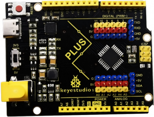
Keyestudio PLUS control board is fully compatible with Arduino IDE development environment. It contains all the functions of the Arduino UNO board. Moreover, some improvements we made highly strengthen its function. It is the best choice to learn how to build circuit and write code as well. Let’s get started!
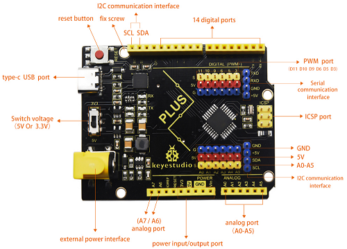
- Serial communication interface: D0 is RX, D1 is TX
- PWM interface (pulse width modulation): D3 D5 D6 D9 D10 D11
- External interrupt interface: D2 (interrupt 0) and D3 (interrupt 1)
- SPI communication interface: D10 is SS, D11 is MOSI, D12 is MISO, D13 is SCK
- IIC communication port: A4 is SDA, A5 is SCL
Installing driver
Let’s install the driver of keyestudio PLUS control board. The USB-TTL chip on PLUS board adopts CP2102 serial chip. The driver program of this chip is included in Arduino 1.8 version and above, which is convenient. Plug on USB port of board, the computer can recognize the hardware and automatically install the driver of CP2102.
If install unsuccessfully, or you intend to install manually, open the device manager of computer. Right click Computer—— Properties—— Device Manager.

There is a yellow exclamation mark on the page, which implies installing the driver of CP2102 unsuccessfully. Then we double click the hardware and update the driver.
Click “OK” to enter the following page, click “browse my computer for updated driver software”, find out the installed or downloaded ARDUINO software. As shown below:
There is a DRIVERS folder in Arduino software installed package(![]() ), open driver folder and you can see the driver of CP210X series chips.
), open driver folder and you can see the driver of CP210X series chips.
We click “Browse”, then find out the driver folder, or you could enter “driver” to search in rectangular box, then click “next”, the driver will be installed successfully. (I place Arduino software folder on the desktop, you could follow my way)
Open device manager, we will find the yellow exclamation mark disappear. The driver of CP2102 is installed successfully.
Arduino IDE Setting
Click icon,open Arduino IDE.
To avoid the errors when uploading the program to the board, you need to select the correct Arduino board that matches the board connected to your computer.
Then come back to the Arduino software, you should click Tools→Board, select the board. (as shown below)
Then select the correct COM port (you can see the corresponding COM port after the driver is successfully installed)
Before uploading the program to the board, let’s demonstrate the function of each symbol in the Arduino IDE toolbar.
A- Used to verify whether there is any compiling mistakes or not.
B- Used to upload the sketch to your Arduino board.
C- Used to create shortcut window of a new sketch.
D- Used to directly open an example sketch.
E- Used to save the sketch.
F- Used to send the serial data received from board to the serial monitor.
Start your first program
Open the file to select Example, choose BLINK from BASIC, as shown below:
Set board and COM port, the corresponding board and COM port are shown on the lower right of IDE.
Click ![]() to start compiling the program, check errors.
to start compiling the program, check errors.
Click ![]() to upload the program, upload successfully.
to upload the program, upload successfully.
Upload the program successfully, the onboard LED lights on for 1s, lights off for 1s. Congratulation, you finish the first program.
How to Add a Library?
What are Libraries ?
Libraries are a collection of code that makes it easy for you to connect to a sensor,display, module, etc.
For example, the built-in LiquidCrystal library helps talk to LCD displays. There are hundreds of additional libraries available on the Internet for download.
The built-in libraries and some of these additional libraries are listed in the reference.
Here we will introduce the most simple way for you to add libraries.
Step 1:After downloading well the Arduino IDE, you can right-click the icon of Arduino IDE.
Find the option «Open file location» shown as below:
Step 2: Enter it to find out libraries folder which is the library file of Arduino.
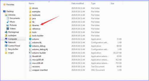
Step 3:Next to find out the“libraries”of smart home(seen in the link: https://fs.keyestudio.com/KS0085), as shown below:
You just need to replicate and paste 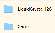 into the libraries folder of Arduino IDE.
The library of home smart is successfully installed, as shown below:
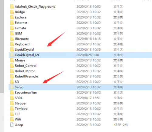
Projects

Alright, let’s get straight to our projects. In this kit, there are 14 sensors and modules included. We will start with the simple sensor to make you know the smart home deeply.
However, if you are an enthusiast with Arduino knowledge. You could skip theses steps, assemble the smart home kit directly(there is assembly video in the folder)
Note: In this course, the interface of each sensor / module marked with (G,-, GND) indicates the negative pole, G is connected to G or — or GND of sensor shield or control board; “V” implies positive pole which is linked with V or VCC or 5V.
Project 1: LED Blink
Description:

In previous lesson, we installed the driver of keystudio V4.0 development board, we start from simple projects. For this lesson we will perform “Arduion blinks LED”, which is the basic practice for starter.
We provide a test code to control LED to perform blinking effect. In the code, you could set distinct flashing scene by changing the time of lighting on and off. Power on GND and VCC, the LED will light on when signal end S is high level, on the contrary, LED will turn off when signal end S is low level.
Specifications:
- Control interface: digital port
- Working voltage: DC 3.3-5V
- Pin pitch: 2.54mm
- LED display color: white
- Size: 30 * 20mm
- Weight: 3g
Equipment:
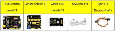
Sensor shield
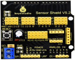
We usually combine Arduino control board with other sensors, modules and multiple sensors, which is difficult to wire. Conversely, this sensor shield cover this problem, you just need to stack on keyestudio PLUS control board when you use it.
This shield can be directly inserted into 3PIN sensors, it breaks out the common used communication ports as well, such as serial communication, IIC communication, SPI communication. What’s more, the shield comes with a reset button and 2 signal lights.
Pins Description

Connection Diagram:
Next to wire, link LED module with D13 of shield.
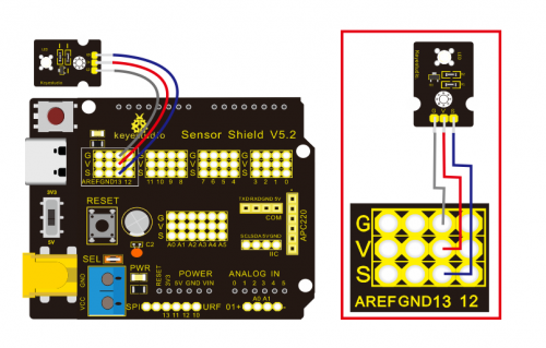
Note: G, V and S of white LED module are linked with G, V and 13 of expansion board.
Test Code:
/*
Keyestudio smart home Kit for Arduino
Project 1
Blink
http://www.keyestudio.com
*/
void setup() {
  // initialize digital pin 13 as an output.
  pinMode(13, OUTPUT);
}
// the loop function runs over and over again forever
void loop() {
  digitalWrite(13, HIGH);   // turn the LED on (HIGH is the voltage level)
  delay(1000);              // wait for a second
  digitalWrite(13, LOW);    // turn the LED off by making the voltage LOW
  delay(1000);              // wait for a second
}//
Test Result:
Upload test code successfully, white LED starts blinking, lights on for 1000ms, lights off for 1000ms, alternately.
Code Explanation
The code looks long and clutter, but most of which are comment. The grammar of Arduino is based on C.
Comments generally have two forms of expression:
/* …….*/ : suitable for long paragraph comments
// : suitable for mono line comments
So the code contains the many vital information, such as the author, the issued agreement, etc.
Most people omit comments, starter should develop a good habit of looking through code. Firstly, check comments. They contain the provided information and do help you understand test code quickly. Secondly, form the habit of writing comments
// the setup function runs once when you press reset or power the board
void setup() {
  // initialize digital pin 13 as an output.
  pinMode(13, OUTPUT);
}
According to comments, we will find that author define the D13 pin mode as digital output in setup() function. Setup() is the basic function of Arduino. It will execute once in the running of program, usually as definition pin, define and ensure the variables.
// the loop function runs over and over again forever
void loop() {
  digitalWrite(13, HIGH);   // turn the LED on (HIGH is the voltage level)
  delay(1000);              // wait for a second
  digitalWrite(13, LOW);    // turn the LED off by making the voltage LOW
  delay(1000);              // wait for a second
}
Loop() is the necessary function of Arduino, it can run and loop all the time after “setup()” executes once
In the loop()function, author uses
digitalWrite(13, HIGH); // turn the LED on (HIGH is the voltage level)
digitalWrite(): set the output voltage of pin to high or low level. We make D13 output high level, then the LED lights on.
delay(1000); // wait for a second
Delay function is used for delaying time, 1000ms is 1s, unit is ms
digitalWrite(13, LOW); // turn the LED off by making the voltage LOW
Similarly, we make D13 output low level, LED will turn off.
delay(1000); // wait for a second
Delay for 1s, light on LED—keep on 1s—light off LED—stay on 1s, iterate the process. LED flashes with 1-second interval. What if you want to make LED flash rapidly? You only need to modify the value of delay block. Reducing the delay value implies that the time you wait is shorter, that is, flashing rapidly. Conversely, you could make LED flash slowly.
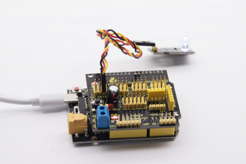
Project 2: Breathing Light

Description
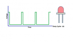
In the previous lesson, we control LED on and off and make it blink.
In this project, we will control LED brightness through PWM to simulate breathing effect. Similarly, you can change the step length and delay time in the code so as to demonstrate different breathing effect.
PWM is a means of controlling the analog output via digital means. Digital control is used to generate square waves with different duty cycles (a signal that constantly switches between high and low levels) to control the analog output.In general, the input voltage of port are 0V and 5V. What if the 3V is required? Or what if switch among 1V, 3V and 3.5V? We can’t change resistor constantly. For this situation, we need to control by PWM.
For the Arduino digital port voltage output, there are only LOW and HIGH, which correspond to the voltage output of 0V and 5V. You can define LOW as 0 and HIGH as 1, and let the Arduino output five hundred 0 or 1 signals within 1 second.
If output five hundred 1, that is 5V; if all of which is 1, that is 0V. If output 010101010101 in this way then the output port is 2.5V, which is like showing movie. The movie we watch are not completely continuous. It actually outputs 25 pictures per second. In this case, the human can’t tell it, neither does PWM. If want different voltage, need to control the ratio of 0 and 1. The more 0,1 signals output per unit time, the more accurately control.
Equipment:
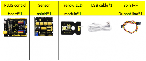
Connection Diagram:
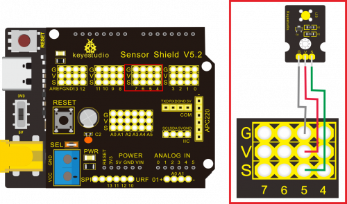
Note: on sensor shield, the G, V and S pins of yellow LED module are linked with G, V and 5.
Test Code:
 /*
Keyestudio smart home Kit for Arduino
Project 2
PWM
http://www.keyestudio.com
*/
int ledPin = 5; // Define the LED pin at D5
void setup () {
      pinMode (ledPin, OUTPUT); // initialize ledpin as an output.
}
void loop () {
for (int value = 0; value<255; value = value + 1) {
     analogWrite (ledPin, value); // LED lights gradually light up
     delay (5); // delay 5MS
   }
   for (int value = 255; value>0; value = value-1) {
     analogWrite (ledPin, value); // LED gradually goes out
     delay (5); // delay 5MS
   }}
//
Test Result:
Upload test code successfully, LED gradually becomes brighter then darker, like human breath, rather than light on and off immediately
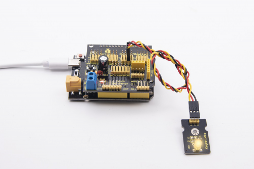
Code analysis
When we need to repeat some statements, we have to use “for” statement
For statement format as follows:
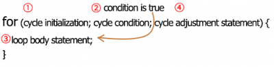
“for” cyclic sequence:
Round 1:1 → 2 → 3 → 4
Round 2:2 → 3 → 4
…
Until number 2 is not established, “for”loop is over,
After knowing this order, go back to code:
for (int value = 0; value < 255; value=value+1){
        ...
}
for (int value = 255; value >0; value=value-1){
       ...
}
The two “for”statement make value increase from 0 to 255, then reduce from 255 to 0, then increase to 255,….infinite loop
There is a new function in “for” statement —— analogWrite()
We know that digital port only has two state of 0 and 1. So how to send an analog value to a digital value? Here, we need this function, observe the Arduino board and you will find 6 pins with “~”. They are different from other pins and can output PWM signals.
Function format as follows:
analogWrite(pin,value)
analogWrite() is used to write an analog value from 0~255 for PWM port, so the value is in the range of 0~255, attention that you only write the digital pins with PWM function, such as pin 3, 5, 6, 9, 10, 11.
PWM is a technology to obtain analog quantity through digital method. Digital control forms a square wave, and the square wave signal only has two states of switching (that is, high or low levels of our digital pins). By controlling the ratio of the duration of on and off, a voltage varying from 0 to 5V can be simulated. The time taken(academically referred to as high level) is called pulse width, so PWM is also called pulse width modulation.
Through the following five square waves, let’s know more about PWM.
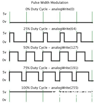
In the above figure, the green line represents a period, and value of analogWrite() corresponds to a percentage which is called Duty Cycle as well. Duty cycle implies that high-level duration is divided by low-level duration in a cycle. From top to bottom, the duty cycle of first square wave is 0% and its corresponding value is 0. The LED brightness is lowest, that is, turn off. The more time high level lasts, the brighter the LED. Therefore, the last duty cycle is 100%, which correspond to 255, LED is brightest. 25% means darker.
PWM mostly is used for adjusting the LED brightness or rotation speed of motor.
Project 3: Passive Buzzer
Description
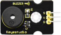
There are prolific interactive works completed by Arduino. The most common one is sound and light display. We always use LED to make experiments. For this lesson, we design circuit to emit sound. The universal sound components are buzzer and horns. Buzzer is easier to use. And buzzer includes about active buzzer and passive buzzer. In this experiment, we adopt passive buzzer.
While using passive buzzer, we can control different sound by inputting square waves with distinct frequency. During the experiment, we control code to make buzzer sound, begin with “tick, tick” sound, then make passive buzzer emit “do re mi fa so la si do”, and play specific songs.
Equipment
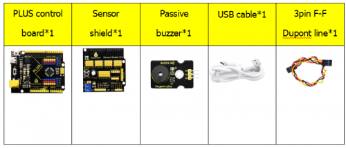
Connection Diagram:
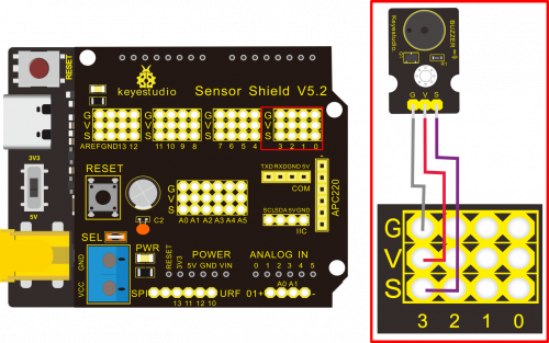
Note: The G, V, and S port of the passive buzzer module are separately connected to G, V, and 3 on the shield, power up.
Test Code:
 /*
Keyestudio smart home Kit for Arduino
Project 3.1
Buzzer
http://www.keyestudio.com
*/
int tonepin = 3; // Set the Pin of the buzzer to the digital D3
     void setup ()
     {
       pinMode (tonepin, OUTPUT); // Set the digital IO pin mode to output
     }
     void loop ()
     {
       unsigned char i, j;
       while (1)
       {
         for (i = 0; i <80; i ++) // output a frequency sound
         {
           digitalWrite (tonepin, HIGH); // Sound
           delay (1); // Delay 1ms
           digitalWrite (tonepin, LOW); // No sound
           delay (1); // Delay 1ms
         }
         for (i = 0; i <100; i ++) // output sound of another frequency
         {
           digitalWrite (tonepin, HIGH); // Sound
           delay (2); // delay 2ms
           digitalWrite (tonepin, LOW); // No sound
           delay (2); // delay 2ms
         }}}
//
Test Result:
From the above code, 80 and 100 decide frequency in “for” statement. Delay controls duration, like the beat in music.
We will play fabulous music if we control frequency and beats well, so let’s figure out the frequency of tones. As shown below:
After knowing the frequency of tone, next to control the time the note plays. The music will be produces when every note plays a certain amount of time. The note rhythm is divided into one beat, half beat, 1/4 beat, 1/8 beat, we stipulate the time for a note to be 1, half beat is 0.5, 1/4 beat is 0.25, 1/8 beat is 0.125….., Therefore, the music is played.
We will take example of “Ode to joy”

From notation, the music is 4/4 beat.
There are special notes we need to explain:
1.Normal note, like the first note 3, correspond to 350(frequency), occupy 1 beat
2.The note with underline means 0.5 beat
3.The note with dot(3.)means that 0.5 beat is added, that is 1+0.5 beat
4.The note with”—” represents that 1 beat is added, that is 1+1 beat.
5.The two successive notes with arc imply legato, you could slightly modify the frequency of the note behind legato(need to debug it yourself), such like reducing or increasing some values, the sound will be more smoother.
/*
Keyestudio smart home Kit for Arduino
Project 3.2
Buzzer music
http://www.keyestudio.com
*/
#define NTD0 -1
#define NTD1 294
#define NTD2 330
#define NTD3 350
#define NTD4 393
#define NTD5 441
#define NTD6 495
#define NTD7 556

#define NTDL1 147
#define NTDL2 165
#define NTDL3 175
#define NTDL4 196
#define NTDL5 221
#define NTDL6 248
#define NTDL7 278

#define NTDH1 589
#define NTDH2 661
#define NTDH3 700
#define NTDH4 786
#define NTDH5 882
#define NTDH6 990
#define NTDH7 112
// List all D-tuned frequencies
#define WHOLE 1
#define HALF 0.5
#define QUARTER 0.25
#define EIGHTH 0.25
#define SIXTEENTH 0.625
// List all beats
int tune [] = // List each frequency according to the notation
{
  NTD3, NTD3, NTD4, NTD5,
  NTD5, NTD4, NTD3, NTD2,
  NTD1, NTD1, NTD2, NTD3,
  NTD3, NTD2, NTD2,
  NTD3, NTD3, NTD4, NTD5,
  NTD5, NTD4, NTD3, NTD2,
  NTD1, NTD1, NTD2, NTD3,
  NTD2, NTD1, NTD1,
  NTD2, NTD2, NTD3, NTD1,
  NTD2, NTD3, NTD4, NTD3, NTD1,
  NTD2, NTD3, NTD4, NTD3, NTD2,
  NTD1, NTD2, NTDL5, NTD0,
  NTD3, NTD3, NTD4, NTD5,
  NTD5, NTD4, NTD3, NTD4, NTD2,
  NTD1, NTD1, NTD2, NTD3,
  NTD2, NTD1, NTD1
};
float durt [] = // List the beats according to the notation
{
  1,1,1,1,
  1,1,1,1,
  1,1,1,1,
  1 + 0.5,0.5,1 + 1,
  1,1,1,1,
  1,1,1,1,
  1,1,1,1,
  1 + 0.5,0.5,1 + 1,
  1,1,1,1,
  1,0.5,0.5,1,1,
  1,0.5,0.5,1,1,
  1,1,1,1,
  1,1,1,1,
  1,1,1,0.5,0.5,
  1,1,1,1,
  1 + 0.5,0.5,1 + 1,
};
int length;
int tonepin = 3; // Use interface 3
void setup ()
{
  pinMode (tonepin, OUTPUT);
  length = sizeof (tune) / sizeof (tune [0]); // Calculate length
}
void loop ()
{
  for (int x = 0; x <length; x ++)
  {
    tone (tonepin, tune [x]);
    delay (350* durt [x]); // This is used to adjust the delay according to the beat, 350 can be adjusted by yourself.
    noTone (tonepin);
  }
  delay (2000); // delay 2S
}
//
Upload test code on the development board, do you hear “Ode to joy”?
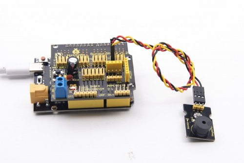
Project 4:Controlling LED by Button Module
Description:
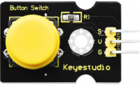
In this project, we will control LED to light on and off via button module. When the button is pressed, the signal end outputs low level (0); when released, the signal end of sensor keeps high level(1).
Equipment
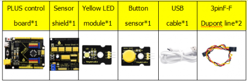
Connection Diagram:
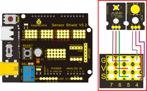
Note: The G, V, and S pins of button sensor module are separately connected to G, V, and 4 on the shield, and the G, V, and S pins of the yellow LED module are connected to G, V, and 5 on the shield.
Test Code:
Next to design the program, we make LED on by button. Comparing with previous experiments, we add a conditional judgement statement. We use if statement. The written sentences of Arduino is based on C language, therefore, the condition judgement statement of C is suitable for Arduino, like while, swich, etc.
For this lesson, we take simple “if” statement as example to demonstrate:
If button is pressed, digital 4 is low level, then we make digital 5 output high level , then LED will be on; conversely, if the button is released, digital 4 is high level, we make digital 5 output low level, then LED will go off.
As for your reference:
/ *
Keyestudio smart home Kit for Arduino
Project 4
Button
http://www.keyestudio.com
* /
int ledpin = 5; // Define the led light in D5
int inpin = 4; // Define the button in D4
int val; // Define variable val
void setup ()
{
pinMode (ledpin, OUTPUT); // The LED light interface is defined as output
pinMode (inpin, INPUT); // Define the button interface as input
}
void loop ()
{
val = digitalRead (inpin); // Read the digital 4 level value and assign it to val
if (val == LOW) // Whether the key is pressed, the light will be on when pressed
{digitalWrite (ledpin, HIGH);}
else
{digitalWrite (ledpin, LOW);}
}
//
Test Result:
This experiment is pretty simple, and widely applied to various of circuits and electrical appliances. In our life, you could find this principle on any device, such as the backlight is on when press any buttons, which is the typical appliance.
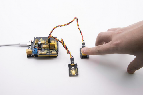
Project 5:1-channel Relay Module
Description
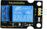
This module is an Arduino dedicated module, and compatible with arduino sensor expansion board. It has a control system (also called an input loop) and a controlled system (also called an output loop).
Commonly used in automatic control circuits, the relay module is an «automatic switch» that controls a larger current and a lower voltage with a smaller current and a lower voltage.
Therefore, it plays the role of automatic adjustment, safety protection and conversion circuit in the circuit. It allows Arduino to drive loads below 3A, such as LED light strips, DC motors, miniature water pumps, solenoid valve pluggable interface.
The main internal components of the relay module are electromagnet A, armature B, spring C, moving contact D, static contact (normally open contact) E, and static contact (normally closed contact) F, (as shown in the figure ).
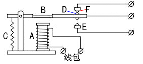
As long as a certain voltage is applied to both ends of the coil, a certain current will flow through the coil to generate electromagnetic effects, and the armature will attract the iron core against the pulling force of the return spring under the action of electromagnetic force attraction, thereby driving the moving contact and the static contact (normally open contact) to attract. When the coil is disconnected, the electromagnetic suction will also disappear, and the armature will return to the original position under the reaction force of the spring, releasing the moving contact and the original static contact (normally closed contact). This pulls in and releases, thus achieving the purpose of turning on and off in the circuit. The «normally open and closed» contacts of the relay can be distinguished in this way: the static contacts on disconnected state when the relay coil is powered off are called «normally open contacts»; the static contacts on connected state are called «normally closed contact». The module comes with 2 positioning holes for you to fix the module to other equipment.
Specifications:
- Working voltage: 5V (DC)
- Interface: G, V, S interface
- Input signal: digital signal (high level 1, low level 0)
- Contacts: static contacts (normally open contacts, normally closed contacts) and moving contacts
- Rated current: 10A (NO) 5A (NC)
- Maximum switching voltage: 150 V (AC) 24 V (DC)
- Electric shock current: less than 3A
- Weight: 15g
- Contact action time: 10ms
Equipment:
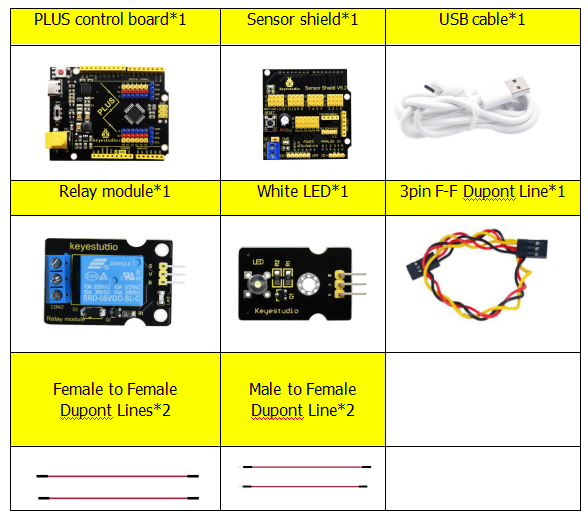
Connection Diagram:
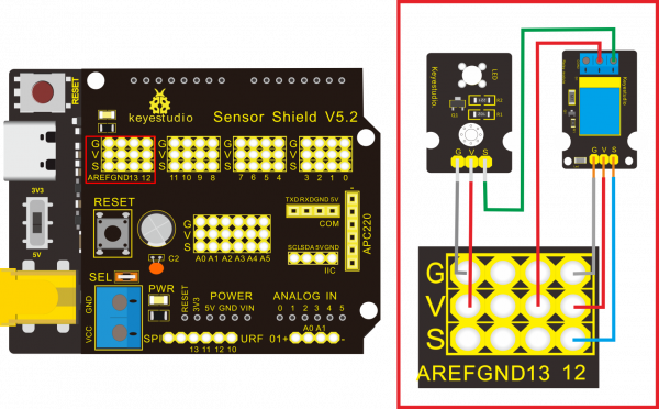
Note: On the shield, the G, V, and S pins of 1-channel relay module are connected to G, V, and 12 respectively. The NO is linked with V; the G, V, and S pins of white LED are respectively connected to G, V, and the static contact of NO on relay module.
Test Code:
/*
Keyestudio smart home Kit for Arduino
Project 5
Relay
http://www.keyestudio.com
*/
int Relay = 12; // Define the relay pin at D12
void setup ()
{
pinMode (13, OUTPUT); // Set Pin13 as output
digitalWrite (13, HIGH); // Set Pin13 High
pinMode (Relay, OUTPUT); // Set Pin12 as output
}
void loop ()
{
digitalWrite (Relay, HIGH); // Turn off relay
delay (2000);
digitalWrite (Relay, LOW); // Turn on relay
delay (2000);
}
//
Test Result:
Wire, power up and upload test code. The relay is connected(“NO” is on , NC is off) for 0.5s, then disconnected for 0.5s (NC is on, NO is off), and alternately. When the relay is connected, the white LED will be on, conversely, the white LED will go off.
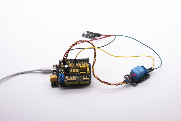
Project 6:Photocell Sensor
Description

The photocell sensor (photoresistor) is a resistor made by the photoelectric effect of a semiconductor. It is very sensitive to ambient light, thus its resistance value vary with different light intensity.
We use its features to design a circuit and generate a photoresistor sensor module. The signal end of the module is connected to the analog port of the microcontroller. When the light intensity increases, the resistance decreases, and the voltage of the analog port rises, that is, the analog value of the microcontroller also goes up. Otherwise, when the light intensity decreases, the resistance increases, and the voltage of the analog port declines. That is, the analog value of the microcontroller becomes smaller. Therefore, we can use the photoresistor sensor module to read the corresponding analog value and sense the light intensity in the environment.
It is commonly applied to light measurement, control and conversion, light control circuit as well.
Specifications:
- Working voltage: 3.3V-5V (DC)
- Interface: 3PIN interface
- Output signal: analog signal
- Weight: 2.3g
Equipment:
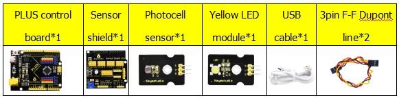
Connection Diagram:
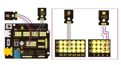
Note: On the expansion board, the G, V, and S pins of the photocell sensor module are connected to G, V, and A1; the G, V, and S pins of the yellow LED module are linked with G, V, and 5 separately.
Test Code:
/*
Keyestudio smart home Kit for Arduino
Project 6
photocell
http://www.keyestudio.com
*/
int LED = 5; // Set LED pin at D5
int val = 0; // Read the voltage value of the photodiode
void setup () {
       pinMode (LED, OUTPUT); // LED is output
       Serial.begin (9600); // The serial port baud rate is set to 9600
}
void loop () {
       val = analogRead (A1); // Read the voltage value of A1 Pin
       Serial.println (val); // Serial port to view the change of voltage value
       if (val <900)
       {// Less than 900, LED light is off
       digitalWrite (LED, LOW);
       }
       else
       {// Otherwise, the LED lights up
       digitalWrite (LED, HIGH);
       }
       delay (10); // Delay 10ms
}
//
Test Result:
LED will be on after uploading test code, point at the photocell sensor with flashlight (or the flash from cellphone), you’ll find that LED is automatically off. However, take away the flashlight, LED will be on again.
Review
For this code string, it is simply. We read value through analog port, please attention that analog quantity doesn’t need input and output mode.Read the analog value of photocell sensor by analog port.
The analog value will gradually decreases once there is light, the value is up to 1000, this value can be chosen according to brightness you need. Select method: put the whole device in the environment where LED is off, open serial monitor to check shown value, replace 1000 with this value. Read value from serial monitor is a good way to modulate code
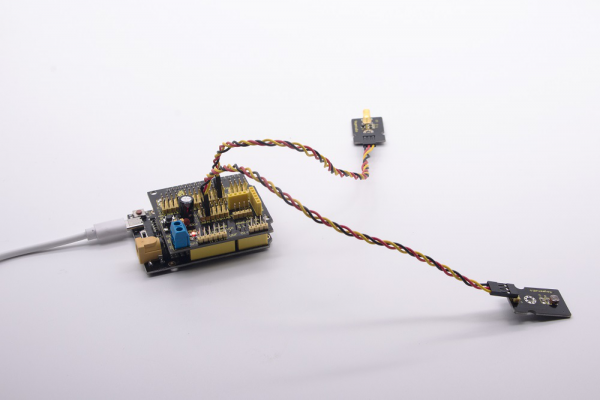
Project 7:Adjusting Motor Servo Angle
Description
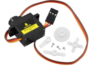
When we make this kit, we often control doors and windows with servos. In this course, we’ll introduce its principle and how to use servo motors.
Servo motor is a position control rotary actuator. It mainly consists of housing, circuit board, core-less motor, gear and position sensor. Its working principle is that the servo receives the signal sent by MCU or receiver and produces a reference signal with a period of 20ms and width of 1.5ms, then compares the acquired DC bias voltage to the voltage of the potentiometer and outputs a voltage difference.
Servo motor comes with many specifications. But all of them have three connection wires, distinguished by brown, red, orange colors (different brand may have different color).
Brown one is for GND, red one for power positive, orange one for signal line.
The rotation angle of servo motor is controlled by regulating the duty cycle of PWM (Pulse-Width Modulation) signal. The standard cycle of PWM signal is 20ms (50Hz). Theoretically, the width is distributed between 1ms-2ms, but in fact, it’s between 0.5ms-2.5ms. The width corresponds the rotation angle from 0° to 180°. But note that for different brand motor, the same signal may have different rotation angle.
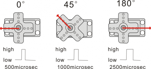
There are two ways to control a servomotor with Arduino.
One is to use a common digital sensor port of Arduino to produce square wave with different duty cycle to simulate PWM signal and use that signal to control the positioning of the motor.
Another way is to directly use the Servo function of the Arduino to control the motor. In this way, the program will be easier but it can only control two-contact motor because for the servo function, only digital pin 9 and 10 can be used.
The Arduino drive capacity is limited. So if you need to control more than one motor, you will need external power.
Specifications:
Working voltage: DC 4.8V ~ 6V
Operating angle range: about 180 ° (at 500 → 2500 μsec)
Pulse width range: 500 → 2500 μsec
No-load speed: 0.12 ± 0.01 sec / 60 (DC 4.8V) 0.1 ± 0.01 sec / 60 (DC 6V)
No-load current: 200 ± 20mA (DC 4.8V) 220 ± 20mA (DC 6V)
Stopping torque: 1.3 ± 0.01kg · cm (DC 4.8V) 1.5 ± 0.1kg · cm (DC 6V)
Stop current: ≦ 850mA (DC 4.8V) ≦ 1000mA (DC 6V)
Standby current: 3 ± 1mA (DC 4.8V) 4 ± 1mA (DC 6V)
Lead length: 250 ± 5 mm
Appearance size: 22.9 * 12.2 * 30mm
Weight: 9 ± 1 g (without servo horn)
Storage temperature: -20 ℃ ~ 60 ℃
Operating temperature: -10 ℃ ~ 50 ℃
Experiment equipment:
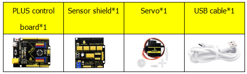
Connection Diagram:
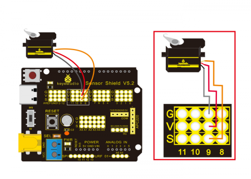
Note: The servo is connected to G (GND), V (VCC), 9. The brown wire of the servo is connected to Gnd (G), the red wire is linked with 5v (V), and the orange wire is connected to digital pin 9.
Test Code:
/*
Keyestudio smart home Kit for Arduino
Project 7
Sevro
http://www.keyestudio.com
*/
#include <Servo.h> // Servo function library
Servo myservo;
int pos = 0; // Start angle of servo
void setup ()
{
myservo.attach (9); // Define the position of the servo on D9
}
void loop ()
{
for(pos = 0; pos < 180; pos += 1)// angle from 0 to 180 degrees
{
myservo.write (pos); // The servo angle is pos
delay (15); // Delay 15ms
}
for(pos = 180; pos>=1; pos-=1) // Angle from 180 to 0 degrees
{
myservo.write (pos); // The angle of the servo is pos
delay (15); // Delay 15ms
}
}
//
Test Result:
Upload code, wire according to connection diagram, and power on. The servo rotates from 0° to 180° then from 180°~0°
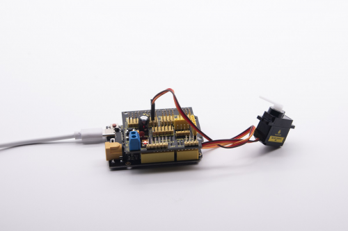
Project 8:Fan Module
Description
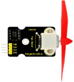
The L9110 fan module adopts L9110 motor control chip, it can control the rotation direction and speed of the motor. Moreover, this module is efficient and with high quality fan, which can put out the flame within 20cm distance. Similarly, it is an important part of fire robot as well.
Specifications:
- Fan diameter: 75mm
- Working voltage: 5V
Equipment:
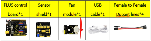
Connection Diagram:
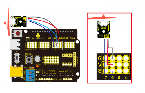
Note: On the shield, the GND, VCC, INA, and INB pins of the fan module are respectively connected to G, V, 7, 6.
Test Code:
/*
Keyestudio smart home Kit for Arduino
Project 8
Fan
http://www.keyestudio.com
*/
void setup () {
   pinMode (7, OUTPUT); //define D7 pin as output
   pinMode (6, OUTPUT); //define  D6 pin as output
}
void loop () {
   digitalWrite (7, LOW);
   digitalWrite (6, HIGH); // Reverse rotation of the motor
   delay (3000); // delay 3S
   digitalWrite (7, LOW);
   digitalWrite (6, LOW); // The motor stops rotating
   delay (1000); //delay 1S
   digitalWrite (7, HIGH);
   digitalWrite (6, LOW); // The motor rotates in the forward direction
   delay (3000); // delay 3S
}
//
Test Result:
Upload test code, wire according to connection diagram, the DIP switch is dialed to right side and power on. The fan rotates counterclockwise for 3000ms, stops for 1000ms, then rotates clockwise for 3000ms.
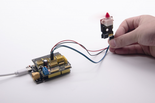
Project 9:Steam Sensor
Description
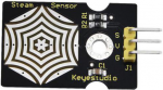
This is a commonly used steam sensor. Its principle is to detect the amount of water by bare printed parallel lines on the circuit board. The more the water is, the more wires will be connected. As the conductive contact area increases, the output voltage will gradually rise. It can detect water vapor in the air as well. The steam sensor can be used as a rain water detector and level switch. When the humidity on the sensor surface surges, the output voltage will increase.
The sensor is compatible with various microcontroller control boards, such as Arduino series microcontrollers. When using it, we provide the guide to operate steam sensor and Arduino control board. Connect the signal end of the sensor to the analog port of the microcontroller, sense the change of the analog value, and display the corresponding analog value on the serial monitor.
Note: the connect part is not waterproof, don’t immerse it in the water please.
Specifications:
- Working voltage: DC 3.3-5V
- Working current: <20mA
- Operating temperature range: -10 ℃ ~ + 70 ℃;
- Control signal: analog signal output
- Interface: 2.54mm 3pin pin interface
- Size: 35 * 20 * 8mm
- Weight: 2.2g
- S: signal output
- V (+): Power supply (VCC)
- G (-): Ground (GND)
Equipment:
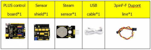
Connection Diagram:
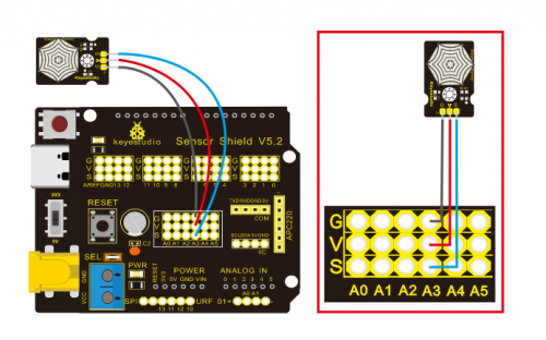
Note: On the sensor shield, the pins G,V and S of steam sensor are connected to G, V and A3; the pins G, V and S of photocell sensor are connected to G, V and A1; the pins G, V and S of yellow LED are linked with G, V and 5; the brown line is linked with G, red wire to V, orange wire to 9.
Test Code:
/*
Keyestudio smart home Kit for Arduino
Project 9
Steam
http://www.keyestudio.com
*/
void setup()
{
Serial.begin(9600); //open serial port, and set baud rate at 9600bps
}
void loop()
{
int val;
val=analogRead(3); //plug vapor sensor into analog port 3
Serial.print("Moisture is ");
Serial.println(val,DEC); //read analog value through serial port printed
delay(100); //delay 100ms
}
Test Result:
When detecting different degrees of humidity, the sensor will get the feedback of different current value. Shown as the following picture.
When the sensor detects the steam of boiled water, the moisture value is displayed on serial monitor of Arduino software.
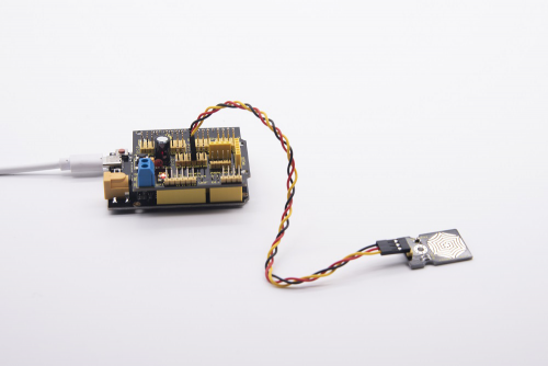
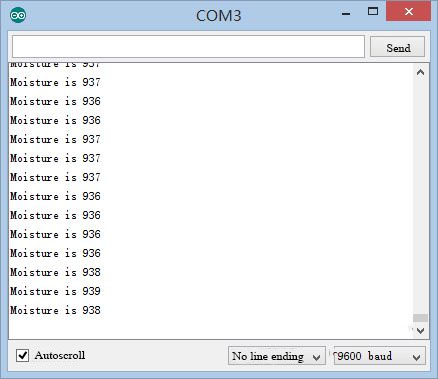
Project 10: PIR Motion Sensor
Description
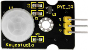
The Pyroelectric infrared motion sensor can detect infrared signals from a moving person or moving animal, and output switching signals. It can be applied to a variety of occasions to detect the movement of human body. Conventional pyroelectric infrared sensors are much more bigger, with complex circuit and lower reliability. Now we launch this new pyroelectric infrared motion sensor, specially designed for Arduino. This sensor integrates an integrated digital pyroelectric infrared sensor, and the connection pins. It features higher reliability, lower power consumption and simpler peripheral circuit.
Specifications:
- Input voltage: DC 3.3V ~ 18V
- Working current: 15uA
- Working temperature: -20 ~ 85 degrees Celsius
- Output voltage: high 3 V, low 0 V
- Output delay time (high level): about 2.3 to 3 seconds
- Detection angle: about 100 °
- Detection distance: 3-4 meters
- Output indicator LED (high-level light)
- Pin limit current: 100mA
Special note:
- 1. The maximum distance is 3-4 meters during testing.
- 2. When testing, first open the white lens, you can see the rectangular sensing part. When the long line of the rectangular sensing part is parallel to the ground, the distance is the best.
- 3. When testing, the sensor needs to be covered with white lens, otherwise it will affect the distance.
- 4. The distance is best at 25℃, and the detection distance is shortened when it exceeds 30℃.
- 5. Done powering up and uploading the code, you need to wait 5-10 seconds then start testing, otherwise it is not sensitive.
Equipment:
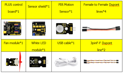
Connection Diagram:
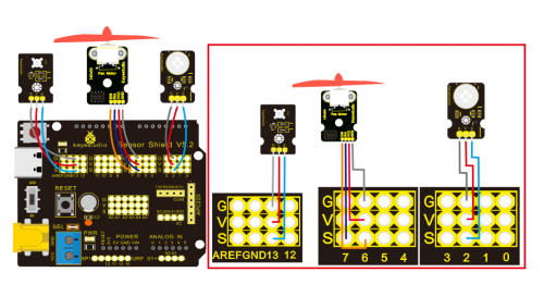
Note: On the shield, the G, V and S of PIR motion sensor are connected to G, V and 2; the GND, VCC, INA and INB of fan module are separately connected to G,V,7,6. The pin G, V and S of LED module are linked with G, V and 13.
Test Code:
/*
Keyestudio smart home Kit for Arduino
Project 10
PIR
http://www.keyestudio.com
*/

void setup () {
   Serial.begin (9600); // open serial port, and set baud rate at 9600bps
   pinMode (2, INPUT); // Define PIR as input in D2
   Serial.begin (9600);
   pinMode (13, OUTPUT); // Define LED as output in D13
   pinMode (7, OUTPUT); // Define D7 as output
   pinMode (6, OUTPUT); // Define D6 as output
}

void loop () {
   Serial.println (digitalRead (2));
   delay (500); // Delay 500ms
   if (digitalRead (2) == 1) // If someone is detected walking
  {
     digitalWrite (13, HIGH); // LED light is on
     digitalWrite (7, HIGH);
     analogWrite (6,150); // Fan rotates

   } else // If no person is detected walking
{
     digitalWrite (13, LOW); // LED light is not on
     digitalWrite (7, LOW);
     analogWrite (6,0); // The fan does not rotate
   }}
//
Test Result:
Upload test code, open serial monitor, and set baud rate to 9600. If PIR motion sensor detects the people around, the serial monitor displays “1”, the D13 and white LED light on at same time, fan rotates. If there is no person around, the serial monitor shows “0”, the D13 indicator and white LED are off. The fan stops rotating.
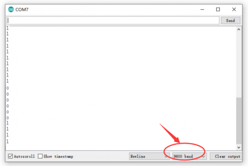
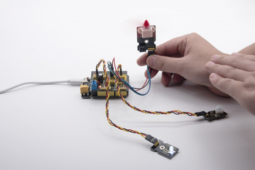
Project 11: Analog(MQ-2)Sensor
Description
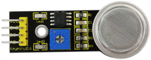
This gas sensor is used for household gas leak alarms, industrial combustible gas alarms and portable gas detection instruments. And it is suitable for the detection of liquefied gas, benzene, alkane, alcohol, hydrogen, etc., and widely used in various fire alarm systems. The MQ-2 smoke sensor can be accurately a multi-gas detector, and has the advantages of high sensitivity, fast response, good stability, long life, and simple drive circuit.
It can detect the concentration of flammable gas and smoke in the range of 300~10000ppm.Meanwhile, it has high sensitivity to natural gas, liquefied petroleum gas and other smoke, especially to alkanes smoke.
It must be heated for a period of time before using the smoke sensor, otherwise the output resistance and voltage are not accurate. However, the heating voltage should not be too high, otherwise it will cause my internal signal line to blow.
It is belongs to the tin dioxide semiconductor gas-sensitive material, and belongs to the surface ion type N-type semiconductor. At a certain temperature, tin dioxide adsorbs oxygen in the air and forms negative ion adsorption of oxygen, reducing the electron density in the semiconductor, thereby increasing its resistance value. When in contact with flammable gas in the air and smog, if the potential barrier at the grain boundary is adjusted by the smog, it will cause the surface conductivity to change. With this, information about the presence of smoke or flammable gas can be obtained. The greater the concentration of smoke or flammable gas in the air, the greater the conductivity, and the lower the output resistance, the larger the analog signal output. The sensor comes with a positioning hole, which is convenient for you to fix the sensor to other devices. In addition, the sensitivity can be adjusted by rotating the potentiometer.
Specifications:
- Working voltage: 3.3-5V (DC)
- Interface: 4 pins (VCC, GND, D0, A0)
- Output signal: digital signal and analog signal
- Weight: 7.5g
Equipment:
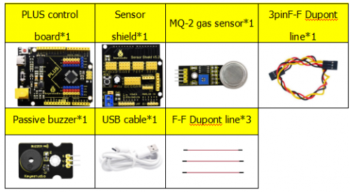
Connection Diagram:
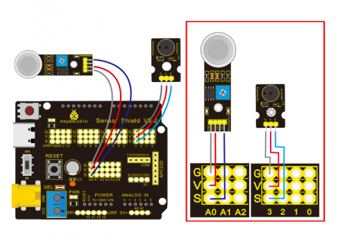
Note: On the shield, the pin GND, VCC, D0 and A0 of gas sensor are linked with pin GND, VCC, D0 and A0. Pin GND, VCC, INA and INB of fan module are connected to G,V, 7 and 6. The pin G,V and S of passive buzzer are connected to G,V and 3; the pin G, V and S of yellow LED are connected to G,V and 5.
Test Code:
/*
Keyestudio smart home Kit for Arduino
Project 11
Gas
http://www.keyestudio.com
*/
int MQ2 = A0; // Define MQ2 gas sensor pin at A0
int val = 0; // declare variable
int buzzer = 3; // Define the buzzer pin at D3
void setup ()
{
pinMode (MQ2, INPUT); // MQ2 gas sensor as input
Serial.begin (9600); // Set the serial port baud rate to 9600
pinMode (buzzer, OUTPUT); // Set the digital IO pin mode for output
}
void loop ()
{
val = analogRead (MQ2); // Read the voltage value of A0 port and assign it to val
Serial.println (val); // Serial port sends val value
if (val> 450)
{
tone (buzzer, 589);
delay(300);
}
else
{
noTone (buzzer);
}
}
//
Test Result:
Upload test code, wire according to connection diagram and power on. When gas sensor detects the flammable gas, passive buzzer will sound, fan will rotate and yellow LED will be on; when there is no flammable gas, the passive buzzer won’t sound, the fan won’t rotate and yellow LED will be off.
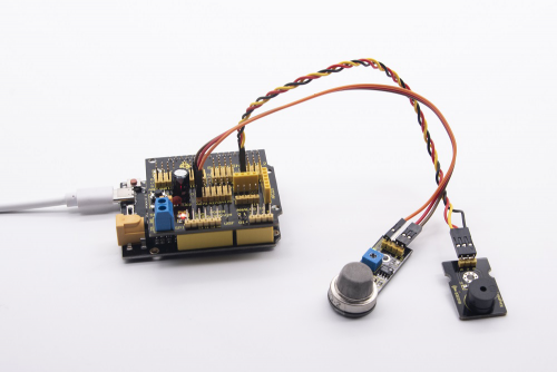
Project 12: 1602 LCD Display
Description
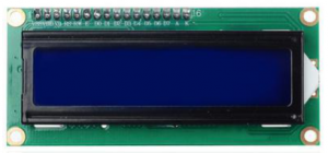
With I2C communication module, this is a display module that can show 2 lines with 16 characters per line.
It shows blue background and white word and connects to I2C interface of MCU, which highly save the MCU resources.
On the back of LCD display, there is a blue potentiometer for adjusting the backlight. The communication address defaults to 0x27.
The original 1602 LCD can start and run with 7 IO ports, but ours is built with Arduino IIC/I2C interface, saving 5 IO ports. Alternatively, the module comes with 4 positioning holes with a diameter of 3mm, which is convenient for you to fix on other devices.
Notice that when the screen gets brighter or darker, the characters will become more visible or less visible.
Specifications:
- I2C address: 0x27
- Backlight (blue, white)
- Power supply voltage: 5V
- Adjustable contrast
- GND: A pin that connects to ground
- VCC: A pin that connects to a +5V power supply
- SDA: A pin that connects to analog port A4 for IIC communication
- SCL: A pin that connects to analog port A5 for IIC communication
Equipment:
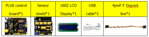
Connection Diagram:
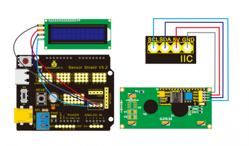
Note: there are pin GND, VCC, SDA and SCL on 1602LCD module. GND is linked with GND(-)of IIC communication, VCC is connected to 5V(+), SDA to SDA, SCL to SCL.
Test Code:
/*
Keyestudio smart home Kit for Arduino
Project 12
1602 LCD
http://www.keyestudio.com
*/
#include <Wire.h>
#include <LiquidCrystal_I2C.h>
LiquidCrystal_I2C lcd (0x27,16,2); // set the LCD address to 0x27 for a16 chars and 2 line display
void setup ()
{
lcd.init (); // initialize the lcd
lcd.init (); // Print a message to the LCD.
lcd.backlight ();
lcd.setCursor (3,0);
lcd.print ("Hello, world!"); // LED print hello, world!
lcd.setCursor (2,1);
lcd.print ("keyestudio!"); // LED print keyestudio!
}
void loop ()
{
}
//
Test Result:
After connection and uploading sample code, the first line on LCD prints «Hello, world!», second line prints «keyestudio!», with a potentiometer to adjust LCD backlight.
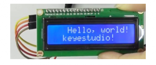
Note: Wire according to connection diagram, upload the code and after power-on, when the display doesn’t show characters, you can adjust the potentiometer behind the 1602LCD and backlight to make the 1602LCD display the corresponding character string.
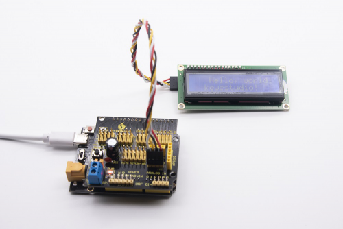
Project 13: Soil Humidity Sensor
Description
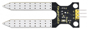
This is a simple soil humidity sensor aims to detect the soil humidity.
If the soil is in lack of water, the analog value output by the sensor will decrease; otherwise, it will increase. If you use this sensor to make an automatic watering device, it can detect whether your botany is thirsty to prevent it from withering when you go out.
Using the sensor with Arduino controller makes your plant more comfortable and your garden smarter. The soil humidity sensor module is not as complicated as you might think, and if you need to detect the soil in your project, it will be your best choice. The sensor is set with two probes inserted into the soil, then with the current go through the soil, the sensor will get resistance value by reading the current changes between the two probes and convert such resistance value into moisture content. The higher moisture (less resistance), the higher conductivity the soil has. Insert it into the soil and then use the AD converter to read it. With the help of this sensor, the plant can remind of you: I need water.
Specification
- Power Supply Voltage: 3.3V or 5V
- Working Current: ≤ 20mA
- Output Voltage: 0-2.3V (When the sensor is totally immersed in water, the voltage will be 2.3V) the higher humidity, the higher the output voltage
- Sensor type: Analog output
- Interface definition: S- signal, G- GND, V — VCC
- Packaging : Electrostatic bag sealing
- Size: 63 * 20 * 8mm
- Weight: 2.5g
Equipment
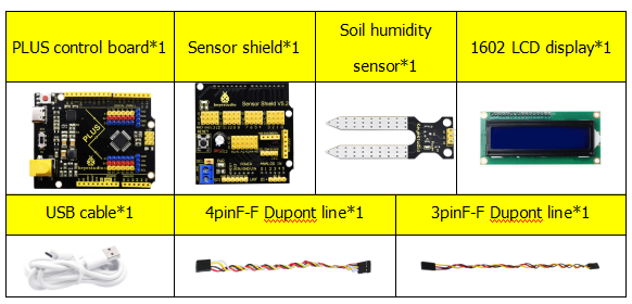
Connection Diagram
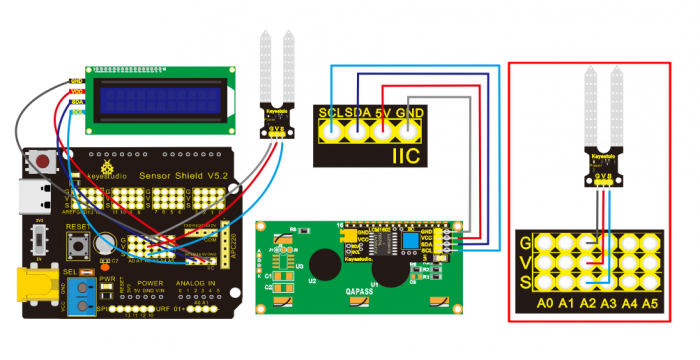
Note: On the shield, the pin G, V and S of soil humidity sensor are connected to G, V and A2; GND of 1602LCD is linked with GND of ICC communication, VCC is connected to 5V(+), SDA to SDA, SCL to SCL.
Test Code:
/*
Keyestudio smart home Kit for Arduino
Project 13
Soil Humidity
http://www.keyestudio.com
*/
#include <Wire.h>
#include <LiquidCrystal_I2C.h>
volatile int value;
LiquidCrystal_I2C mylcd (0x27,16,2); // set the LCD address to 0x27 for a16 chars and 2 line display
void setup () {
  Serial.begin (9600); // Set the serial port baud rate to 9600
  value = 0;
  mylcd.init ();
  mylcd.backlight (); // Light up the backlight
  mylcd.clear (); // Clear the screen
  Serial.begin (9600); // Set the serial port baud rate to 9600
  pinMode (A2, INPUT); // Soil sensor is at A2, the mode is input
}
void loop () {
  Serial.print ("Soil moisture value:"); // Print the value of soil moisture
  Serial.print ("");
  Serial.println (value);
  delay (500); // Delay 0.5S
  value = analogRead (A2); // Read the value of the soil sensor
  if (value <300) // If the value is less than 300
{
    mylcd.clear (); // clear screen
    mylcd.setCursor (0, 0);
    mylcd.print ("value:"); //
    mylcd.setCursor (6, 0);
    mylcd.print (value);
    mylcd.setCursor (0, 1);
    mylcd.print ("dry soil"); // LCD screen print dry soil
    delay (300); // Delay 0.3S
  }
  else if ((value>=300) && (value <= 700)) // If the value is greater than 300 and less than 700
 {
    mylcd.clear (); //clear screen
    mylcd.setCursor (0, 0);
    mylcd.print ("value:");
    mylcd.setCursor (6, 0);
    mylcd.print (value);
    mylcd.setCursor (0, 1);
    mylcd.print ("humid soil"); // LCD screen printing humid soil
    delay (300); // Delay 0.3S
  } else if (value> 700) // If the value is greater than 700
 {
    mylcd.clear ();//clear screen
    mylcd.setCursor (0, 0);
    mylcd.print ("value:");
    mylcd.setCursor (6, 0);
    mylcd.print (value);
    mylcd.setCursor (0, 1);
    mylcd.print ("in water"); /// LCD screen printing in water
    delay (300); // Delay 0.3S
  }}
//
Test Result:
Connect according to wiring diagram, and burn the program and power on. Open the serial monitor and insert the soil humidity sensor into the soil. The greater the humidity is, the bigger the number, in the range of 0-1023. The soil sensor is inserted into the soil and water with different humidity, and the 1602LCD displays the corresponding value.
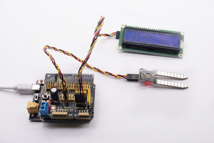
Project 14: Bluetooth Test
In 20th century, technology has changed our life. People can work at home with wireless device like mouse, earphone, printer and speaker, which highly enhances our life standard.
Bluetooth can make work at home easily, as well as the entertainment. Users can control wirelessly the audio file from PC or Apple iPod within 30 inches. Bluetooth technology can also be used in adapters, allowing people to share their daily life with friends from internet and social media.
Bluetooth Remote Control
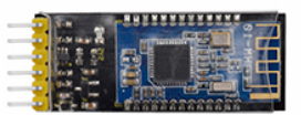
Bluetooth technology is a wireless standard technology that enables short-distance data exchange between fixed devices, mobile devices, and building personal area networks (using UHF radio waves in the ISM band of 2.4 to 2.485 GHz).
This kit is equipped with the HM-10 Bluetooth module, which is a master-slave machine. When use as the Host, it can send commands to the slave actively; when use as the Slave, it can only receive commands from the host.
The HM-10 Bluetooth module supports the Bluetooth 4.0 protocol, which not only supports Android mobile, but also supports iOS system.
In the experiment, we default use the HM-10 Bluetooth module as a Slave and the cellphone as a Host. We install the Bluetooth APP on the mobile phone, connecting the Bluetooth module; finally use the Bluetooth APP to control the parts of smart home kit.
We also provide you with 2 types of mobile APP, for Android and iOS system.
Parameters of HM-10 Bluetooth Module:
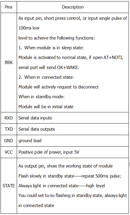
- Bluetooth protocol: Bluetooth Specification V4.0 BLE
- No byte limit in serial port Transceiving
- In open environment, realize 100m ultra-distance communication with iphone4s
- USB protocol: USB V2.0
- Working frequency: 2.4GHz ISM band
- Modulation method: GFSK(Gaussian Frequency Shift Keying)
- Transmission power: -23dbm, -6dbm, 0dbm, 6dbm, can be modified by AT command.
- Sensitivity: ≤-84dBm at 0.1% BER
- Transmission rate: Asynchronous: 6K bytes ; Synchronous: 6k Bytes
- Security feature: Authentication and encryption
- Supporting service: Central & Peripheral UUID FFE0, FFE1
- Power consumption: Auto sleep mode, stand by current 400uA~800uA, 8.5mA during transmission.
- Power supply: 5V DC
- Working temperature: –5 to +65 Centigrade
Using Bluetooth APP
Description:
In the previous lesson, we’ve introduced the basic parameter principle of HM-10 Bluetooth module. In this project, let’s show you how to use the HM-10 Bluetooth module. In order to efficiently control this kit by HM-10 Bluetooth module, we specially designed an APP, as shown below.
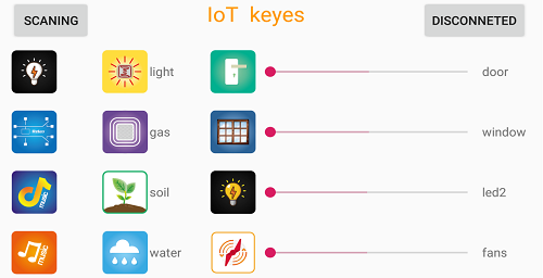
There are twelve control buttons and four sliders on App. When we connect the HM-10 Bluetooth module and app, only press control button of APP, and the Bluetooth of cellphone sends a control character. The Bluetooth module will receive a corresponding control character. When programming, we set the corresponding function of each sensor or module according to the corresponding key control character. Next, let’s test 12 buttons on app.
APP for Android mobile:
Note: Allow APP to access “location” in settings of your cellphone when connecting to Bluetooth module, otherwise, Bluetooth may not be connected.
Enter google play,search “keyes IoT”,if you can’t search it on app store, please download app in the following link:
https://play.google.com/store/apps/details?id=com.keyestudio.iot_keyes
After installing and open the app  ,the interface pops up as below:
Upload code and power on, Led of Bluetooth module blinks. Start Bluetooth and open App to click “CONNECT” to connect.
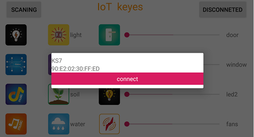
Click to “Connect”, Bluetooth is connected successfully. As shown below, the LED of Bluetooth module is normally on.
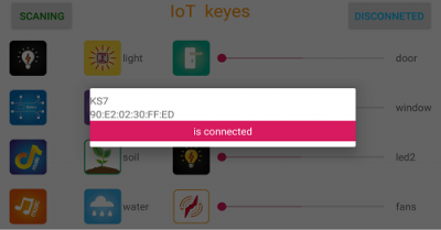
For IOS system:
(1) Open App Store 
(2) Search “IoT keyes”on APP Store,then click “downlaod”.
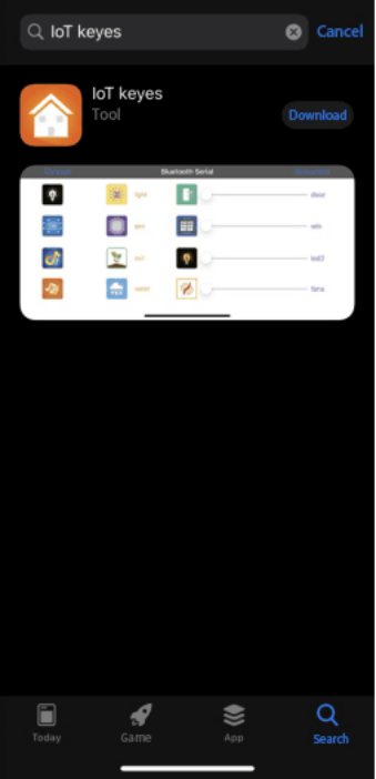
(3)After installing successfully and open ,the interface is shown below:
(4)Upload the test code successfully, insert the Bluetooth module and power on. LED of Bluetooth module is flashing. Start Bluetooth on cellphone, then click “connect” on the left to search Bluetooth and pair. After paring successfully, the LED of Bluetooth module is on.
Note: Remove the Bluetooth module please, when uploading the test code. Otherwise, the program will fail to upload. Connect the Bluetooth and Bluetooth module to pair after uploading the test code.
4.Connection Diagram
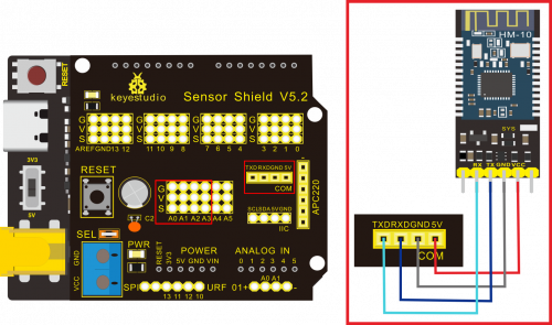
Note: On the sensor expansion board, the RXD, TXD, GND, and VCC of the Bluetooth module are respectively connected to TXD, RXD, GND, and 5V, and the STATE and BRK pins of the Bluetooth module do not need to be connected. Connect the power supply.
Test Code:
/*
Keyestudio smart home Kit for Arduino
Project 14
Bluetooth
http://www.keyestudio.com
*/
char val;
void setup()
{
Serial.begin(9600);// Set the serial port baud rate to 9600
}
void loop()
{
while (Serial.available()>0)
{
val=Serial.read();// Read the value sent by Bluetooth
Serial.print(val);// The serial port prints the read value
}
}
//
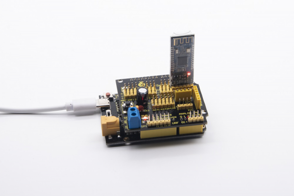
Key function on app:
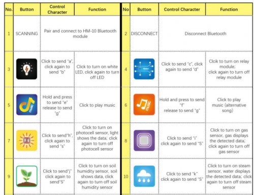
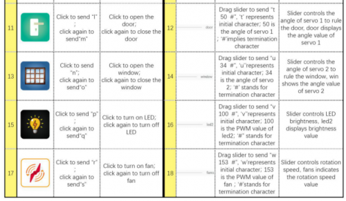
Assembled Guide
Check the board A~I and parts firstly
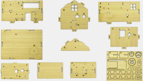
Step 1: Install sensors of A board
Prepare A board*1, M3*10MM round screw*4,M3 nickel plated nut*4;M2.5*10MM round screw*4,button sensor*2, white LED*1, PIR motion sensor*1, LCD1602 display*1, 4pin F-F dupont line*1, 3pin F-F dupont line*4
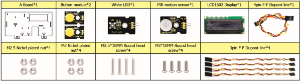
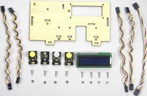
- a.Fix white LED, 2 button sensors and PIR motion sensor on the corresponding area of the A board with 4pcs M3*10MM round head screws and 4pcs M3 nuts.
- b.Then install LCD1602 display on A board with 4pcs M2.5*10MM round head screws and 4pcs M2.5 nuts.
- c.Connect them with 3pin and 4pin dupont lines.
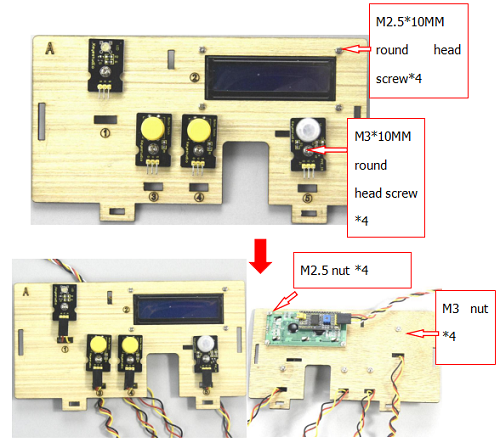
Step 2: Install the sensor of B board
Prepare a B board,a 3pin F-F Dupont line,2pcs M3*10MM round head screws,2pcs M3 nickel plated nuts and a relay module
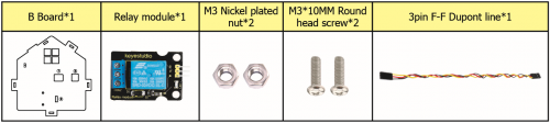
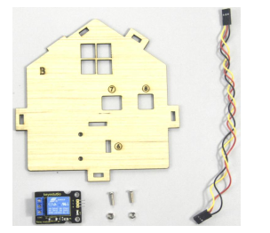
Assemble the relay module on B board with 2 pcs M3*10MM screws and 2pcs M3 nuts, link them together with 3pin dupont line
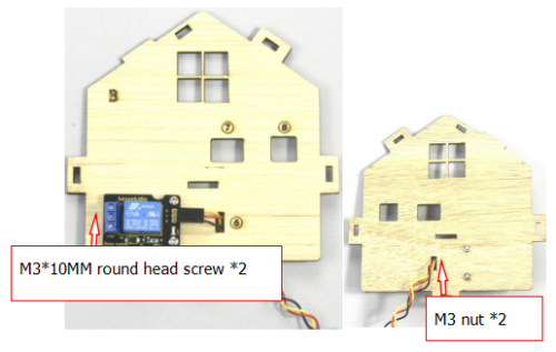
Step 3: Fix A board and B board together with a “T” bolt.
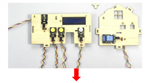

Step 4: Assemble the sensors and battery holder of C board
Prepare a C board,MQ-2 gas sensor,battery holder,2pcs M3*10MM flat head screws,a M3*10MM round head screw,3pcs M3 nickel plated nuts and 4 F-F dupont lines.
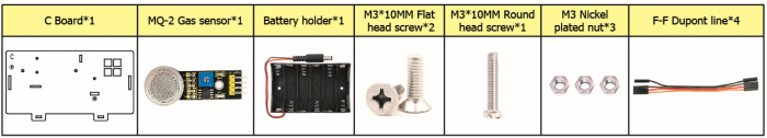
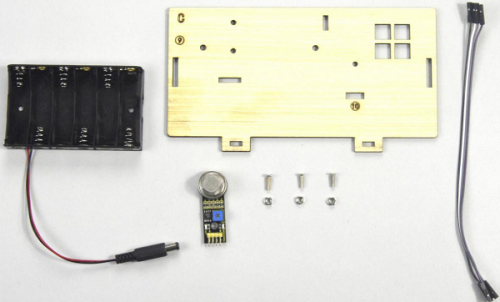
- A.Fix the battery holder on C board with 2pcs M3*10MM flat head screws and 2 pcs M2 nuts
- B.Then install the MQ-2 gas sensor on the corresponding area of C board with a M3*10MM round head screw and a M3 nut.
- C.Connect them with 4 female to female dupont lines
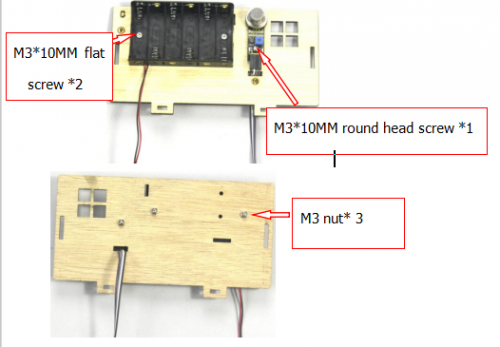
Step 5: Install the sensors and parts of D board
Prepare a servo, 4pcs M1.2*5 self-tapping screws,a white cross mount(included in servo),a M2*5 round head screw(included in servo),2pcs M2*12MM round head screws,2pcs M2 nickel plated nuts,4pcs M3*12MM round head screws,4pcs M3 stainless self-locking nuts,a D board,a gear, a board1.
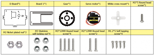
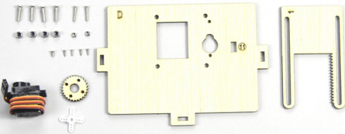
Rotate servo to 90° before installing, connect servo to keyestudio PLUS control board; upload test code on control board and make servo rotate to 90°
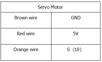
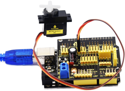
Test Code:
#include <Servo.h>
Servo servo_10;

void setup(){
  servo_10.attach(10);
}
void loop(){
  servo_10.write(90);
  delay(500);}
Upload the test code successfully, the servo rotates to 90°
- A.Fix servo on the corresponding area on D board with 2pcs M2*12MM round head screws and 2 M2 nuts.
- B.Then install the square board 1 on the D board with 4pcs M3*12MM round head screws and 4 M3 self-locking nuts.
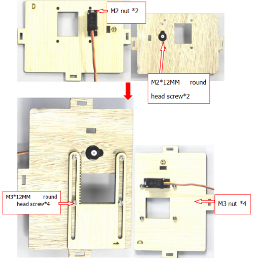
Fix the white cross mount on the gear with 4pcs M1.2*5MM self-tapping screws, and mount the gear on the servo motor with 1 M2*5MM round head screw.
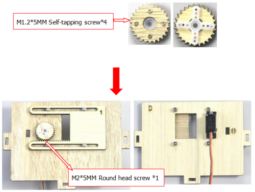
Step 6: Assemble C board with D board by a “T” type bolt.
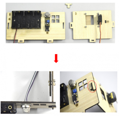
Step 7: install the sensor of E board
Prepare a yellow LED module, a E board, a M3*10MM round head screw, a M3 nickel plated nut and a 3pin F-F Dupont line
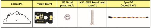
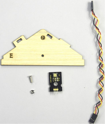
Mount the yellow LED on the corresponding area of E board with 1 M3*10MM round head screw and 1 M3 nickel plated nut,then connect with a 3pin dupont line.
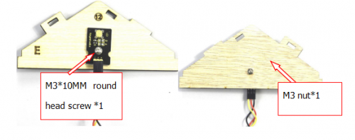
Step 8: Install control board, sensors and parts of H board
Prepare a servo, a passive buzzer, 4pcs M1.2*5 self-tapping screws, a white cross mount(included in servo), a M2*5 screw( included in servo), 2pcs M2*12MM round head screws, 2pcs M2 nickel plated nuts, a M3*10MM round screw, a M3 nickel plated nut, 8pcs M3*6MM round head screws, 4pcs M3*10MM dual-pass copper pillars, a Keyestudio PLUS control board,a sensor shield, a 3pinF-F Dupont line, a board E, 2 gears and 2pcs board 2.
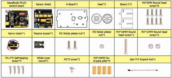
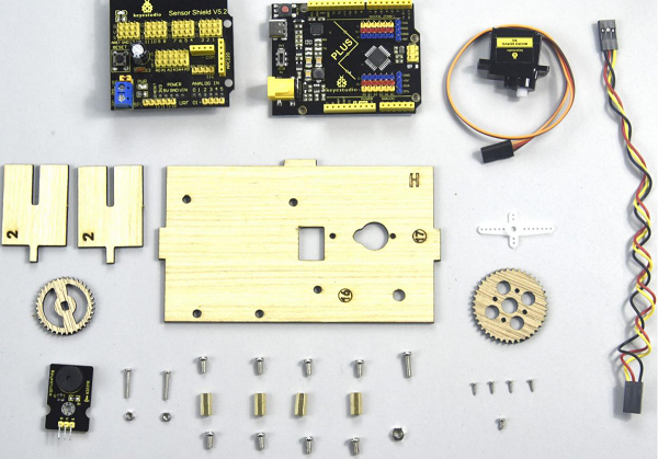
- A.Mount 4pcs dual-pass copper pillars on the H board with 4pcs M3*6MM screws
- B.Then fix the passive buzzer on H board with 1 M3*10MM round head screw and 1 MS nut.
- C.Connect them with a 3pin female to female dupont wire
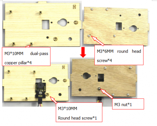
Rotate the servo to 90° before installing, the method is same as the step 6.
Fix the 4pcs M3*10MM copper pillars on the keyestudio PLUS control board with 4 M3*6MM round head screws, then fix the servo on the corresponding area of H board with 2 M2*12MM round head screws and 2 M2 nuts.
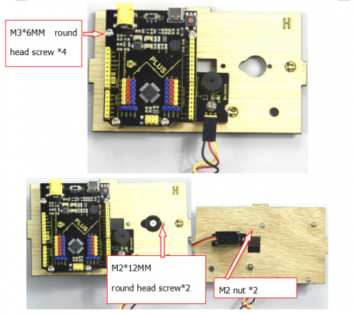
Assemble 2pcs board 2 together, then fix white cross mount on the gear with 4pcs M1.2*5 self-tapping screws
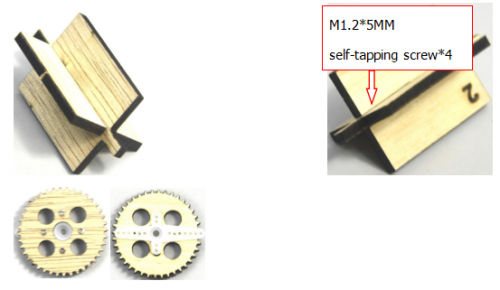
Fix the gear with white cross mount on the black servo by 1 M2*5MM screw(included in servo), then install the combination of 2pcs board 2 and another servo on the corresponding area of H board, finally stack the sensor shield on the keyestudio PLUS control board.
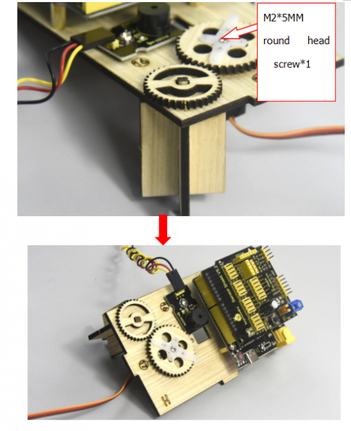
Step 9: Assemble A, B, C, D, E and H board together, then fix them with 2 “T” type bolts.
(Note: the power interface of PLUS control board is aligned with the hole ⑧ on board B, and the interface of USB cable is aligned with the hole ⑦ on board B)
Step 10: Install the sensor of F board
Prepare a steam sensor, a photocell sensor, a fan module(with fan), a board F, 2pcs 3pinF-F Dupont line, 4pcs F-F dupont lines, 3pcs M3*10MM round head screws and 3pcs M3 nickel plated nuts.
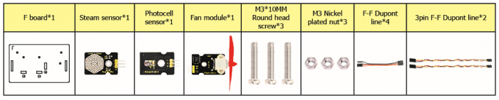
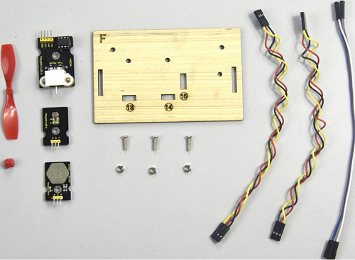
Separately fix steam sensor, photocell sensor and fan module on the F board with 3pcs M3*10MM round head screws and 3pcs M3 nuts, then connect them with 3pin and 4pin dupont lines.
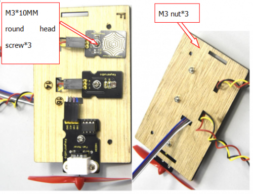
Step 11: Connect sensor/module
Connect one end of 3pin dupont line to the pin of soil humidity sensor, then link all sensors to sensor shield. (fix 2 servo and make dupont wire go through the holes of board)
Insert the Bluetooth module into sensor shield, then fix the F board with 2 M3*10MM round head screws, 2 M3 nuts and 2 pcs parts with holes in the middle, mount G board well with 2 “T” type bolts.
Step 12: Assemble the kit
Fix the board I with 6 “T” bolts
Project 15:Multi-purpose Smart Home Kit
Description
In the previous projects, we introduce how to use sensors, modules and HM-10 Bluetooth module. For this lesson, we will perform all functions
We will achieve the effect as follows:
- Photocell sensor, PIR motion sensor and LED. When at night, someone passes by, LED is on; nobody is around, the LED is off.

- There are 1602LCD display, 2 buttons, 1 servo on the board. Press button1 to enter the password(you can set password in the test code), the 1602LCD will show “*”, then press button2 to “ensure”. If the password is correct, the 1602LCD will show “open”, the door will be open. However, if the password is wrong, the “error” pops up , after 2s, “error” will turn into “again” , you can enter password again.
The door will be closed when PIR motion sensor doesn’t detect people around. What’s more, press and hold button2, buzzer will sound, LCD displays “wait”.(If the password is right, the servo will rotate to 180°, otherwise,the servo don’t rotate)
Note: The correct password is ”. — — . — .” which means that short press button1, long press button1, long press button1, short press button1, long press button1, short press button1.
”- ”means long press button1, ”.”means short press button1
Equipment:
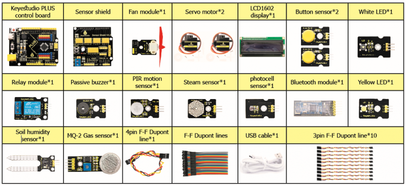
Connection Diagram:
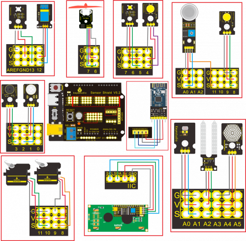
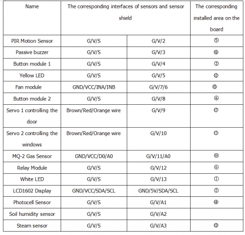
Test Code:
//call the relevant library file
#include <Servo.h>
#include <Wire.h>
#include <LiquidCrystal_I2C.h>
//Set the communication address of I2C to 0x27, display 16 characters every line, two lines in total
LiquidCrystal_I2C mylcd(0x27, 16, 2);
//set ports of two servos to digital 9 and 10
Servo servo_10;
Servo servo_9;
volatile int btn1_num;//set variable btn1_num
volatile int btn2_num;//set variable btn2_num
volatile int button1;//set variable button1
volatile int button2;//set variable button2
String fans_char;//string type variable fans_char
volatile int fans_val;//set variable fans_char
volatile int flag;//set variable flag
volatile int flag2;//set variable flag2
volatile int flag3;//set variable flag3
volatile int gas;//set variable gas
volatile int infrar;//set variable infrar
String led2;//string type variable led2
volatile int light;//set variable light
String pass;//string type variable pass
String passwd;//string type variable passwd
String servo1;//string type variable servo1
volatile int servo1_angle;//set variable light
String servo2;//string type variable servo2
volatile int servo2_angle;//set variable servo2_angle
volatile int soil;//set variable soil
volatile int val;//set variable val
volatile int value_led2;//set variable value_led2
volatile int water;//set variable water
int length;
int tonepin = 3; //set the signal end of passive buzzer to digital 3
//define name of every sound frequency
#define D0 -1
#define D1 262
#define D2 293
#define D3 329
#define D4 349
#define D5 392
#define D6 440
#define D7 494
#define M1 523
#define M2 586
#define M3 658
#define M4 697
#define M5 783
#define M6 879
#define M7 987
#define H1 1045
#define H2 1171
#define H3 1316
#define H4 1393
#define H5 1563
#define H6 1755
#define H7 1971
#define WHOLE 1
#define HALF 0.5
#define QUARTER 0.25
#define EIGHTH 0.25
#define SIXTEENTH 0.625
//set sound play frequency
int tune[] =
{
M3, M3, M4, M5,
M5, M4, M3, M2,
M1, M1, M2, M3,
M3, M2, M2,
M3, M3, M4, M5,
M5, M4, M3, M2,
M1, M1, M2, M3,
M2, M1, M1,
M2, M2, M3, M1,
M2, M3, M4, M3, M1,
M2, M3, M4, M3, M2,
M1, M2, D5, D0,
M3, M3, M4, M5,
M5, M4, M3, M4, M2,
M1, M1, M2, M3,
M2, M1, M1
};
//set music beat
float durt[] =
{
1, 1, 1, 1,
1, 1, 1, 1,
1, 1, 1, 1,
1 + 0.5, 0.5, 1 + 1,
1, 1, 1, 1,
1, 1, 1, 1,
1, 1, 1, 1,
1 + 0.5, 0.5, 1 + 1,
1, 1, 1, 1,
1, 0.5, 0.5, 1, 1,
1, 0.5, 0.5, 1, 1,
1, 1, 1, 1,
1, 1, 1, 1,
1, 1, 1, 0.5, 0.5,
1, 1, 1, 1,
1 + 0.5, 0.5, 1 + 1,
};
void setup() {
Serial.begin(9600);//set baud rate to 9600
mylcd.init();
mylcd.backlight();//initialize LCD
//LCD shows "passcord:" at first row and column
mylcd.setCursor(1 - 1, 1 - 1);
mylcd.print("passcord:");
servo_9.attach(9);//make servo connect to digital 9
servo_10.attach(10);//make servo connect to digital 10
servo_9.write(0);//set servo connected digital 9 to 0°
servo_10.write(0);//set servo connected digital 10 to 0°
delay(300);
pinMode(7, OUTPUT);//set digital 7 to output
pinMode(6, OUTPUT);//set digital 6 to output
digitalWrite(7, HIGH); //set digital 7 to high level
digitalWrite(6, HIGH); //set digital 6 to high level
pinMode(4, INPUT);//set digital 4 to input
pinMode(8, INPUT);//set digital 8 to input
pinMode(2, INPUT);//set digital 2 to input
pinMode(3, OUTPUT);//set digital 3 to output
pinMode(A0, INPUT);//set A0 to input
pinMode(A1, INPUT);//set A1 to input
pinMode(13, OUTPUT);//set digital 13 to input
pinMode(A3, INPUT);//set A3 to input
pinMode(A2, INPUT);//set A2 to input
pinMode(12, OUTPUT);//set digital 12 to output
pinMode(5, OUTPUT);//set digital 5 to output
pinMode(3, OUTPUT);//set digital 3 to output
length = sizeof(tune) / sizeof(tune[0]); //set the value of length
}
void loop() {
auto_sensor();
if (Serial.available() > 0) //serial reads the characters
{
val = Serial.read();//set val to character read by serial    Serial.println(val);//output val character in new lines
pwm_control();
}
switch (val) {
case 'a'://if val is character 'a',program will circulate
digitalWrite(13, HIGH); //set digital 13 to high level,LED 	lights up
break;//exit loop
case 'b'://if val is character 'b',program will circulate
digitalWrite(13, LOW); //Set digital 13 to low level, LED is off
break;//exit loop
case 'c'://if val is character 'c',program will circulate
digitalWrite(12, HIGH); //set digital 12 to high level,NO of relay is connected to COM
break;//exit loop
case 'd'://if val is character 'd',program will circulate
digitalWrite(12, LOW); //set digital 12 to low level,NO of relay is disconnected to COM
break;//exit loop
case 'e'://if val is character 'e',program will circulate
music1();//play birthday song
break;//exit loop
case 'f'://if val is character 'f',program will circulate
music2();//play ode to joy song
break;//exit loop
case 'g'://if val is character 'g',program will circulate
noTone(3);//set digital 3 to stop playing music
break;//exit loop
case 'h'://if val is character 'h',program will circulate
Serial.println(light);//output the value of variable light in new lines
delay(100);
break;//exit loop
case 'i'://if val is character 'i',program will circulate
Serial.println(gas);//output the value of variable gas in new lines
delay(100);
break;//exit loop
case 'j'://if val is character 'j',program will circulate
Serial.println(soil);//output the value of variable soil in new lines
delay(100);
break;//exit loop
case 'k'://if val is character 'k',program will circulate
Serial.println(water);//output the value of variable water in new lines
delay(100);
break;//exit loop
case 'l'://if val is character 'l',program will circulate
servo_9.write(180);//set servo connected to digital 9 to 180°
delay(500);
break;//exit loop
case 'm'://if val is character 'm',program will circulate
servo_9.write(0);;//set servo connected to digital 9 to 0°
delay(500);
break;//exit loop
case 'n'://if val is character 'n',program will circulate
servo_10.write(180);//set servo connected to digital 10 to 180°
delay(500);
break;//exit loop
case 'o'://if val is character 'o',program will circulate
servo_10.write(0);//set servo connected to digital 10 to 0°
delay(500);
break;//exit loop
case 'p'://if val is character 'p',program will circulate
digitalWrite(5, HIGH); //set digital 5 to high level, LED is on
break;//exit loop
case 'q'://if val is character 'q',program will circulate
digitalWrite(5, LOW); // set digital 5 to low level, LED is off
break;//exit loop
case 'r'://if val is character 'r',program will circulate
digitalWrite(7, LOW);
digitalWrite(6, HIGH); //fan rotates anticlockwise at the fastest speed
break;//exit loop
case 's'://if val is character 's',program will circulate
digitalWrite(7, LOW);
digitalWrite(6, LOW); //fan stops rotating
break;//exit loop
}
}
////////////////////////set birthday song//////////////////////////////////
void birthday()
{
tone(3, 294); //digital 3 outputs 294HZ sound
delay(250);//delay in 250ms
tone(3, 440);
delay(250);
tone(3, 392);
delay(250);
tone(3, 532);
delay(250);
tone(3, 494);
delay(500);
tone(3, 392);
delay(250);
tone(3, 440);
delay(250);
tone(3, 392);
delay(250);
tone(3, 587);
delay(250);
tone(3, 532);
delay(500);
tone(3, 392);
delay(250);
tone(3, 784);
delay(250);
tone(3, 659);
delay(250);
tone(3, 532);
delay(250);
tone(3, 494);
delay(250);
tone(3, 440);
delay(250);
tone(3, 698);
delay(375);
tone(3, 659);
delay(250);
tone(3, 532);
delay(250);
tone(3, 587);
delay(250);
tone(3, 532);
delay(500);
}
//detect gas
void auto_sensor() {
gas = analogRead(A0);//assign the analog value of A0 to gas
if (gas > 700) {
//if variable gas>700
flag = 1;//set variable flag to 1
while (flag == 1)
//if flag is 1, program will circulate
{
Serial.println("danger");//output "danger" in new lines
tone(3, 440);
delay(125);
delay(100);
noTone(3);
delay(100);
tone(3, 440);
delay(125);
delay(100);
noTone(3);
delay(300);
gas = analogRead(A0);//gas analog the value of A0 to gas
if (gas < 100)  //if variable gas is less than 100
{
flag = 0;//set variable flag to 0
break;//exit loop exist to loop
}
}
} else
//otherwise
{
noTone(3);// digital 3 stops playing music
}
light = analogRead(A1);////Assign the analog value of A1 to light
if (light < 300)//if variable light is less than 300
{
infrar = digitalRead(2);//assign the value of digital 2 to infrar
Serial.println(infrar);//output the value of variable infrar in new lines
if (infrar == 1)
// if variable infra is 1
{
digitalWrite(13, HIGH); //set digital 13 to high level, LED is on
} else//Otherwise
{
digitalWrite(13, LOW); //set digital 13 to low level, LED is off
}
}
water = analogRead(A3);//assign the analog value of A3 to variable water
if (water > 800)
// if variable water is larger than 800
{
flag2 = 1;//if variable flag 2 to 1
while (flag2 == 1)
// if flag2 is 1, program will circulate
{
Serial.println("rain");//output "rain" in new lines
servo_10.write(180);// set the servo connected to digital 10 to 180°
delay(300);//delay in 300ms
delay(100);
water = analogRead(A3);;//assign the analog value of A3 to variable water
if (water < 30)// if variable water is less than 30
{
flag2 = 0;// set flag2 to 0
break;//exit loop
}
}
} else//Otherwise
{
if (val != 'u' && val != 'n')
//if val is not equivalent 'u' either 'n'
{
servo_10.write(0);//set servo connected to digital 10 to 0°
delay(10);
}
}
soil = analogRead(A2);//assign the analog value of A2 to variable soil
if (soil > 50)
// if variable soil is greater than 50
{
flag3 = 1;//set flag3 to 1
while (flag3 == 1)
//If set flag3 to 1, program will circulate
{
Serial.println("hydropenia ");//output "hydropenia " in new lines
tone(3, 440);
delay(125);
delay(100);
noTone(3);
delay(100);
tone(3, 440);
delay(125);
delay(100);
noTone(3);//digital 3 stops playing sound
delay(300);
soil = analogRead(A2);//Assign the analog value of A2 to variable soil
if (soil < 10)//If variable soil<10
{
flag3 = 0;//set flag3 to 0
break;//exit loop
}
}
} else//Otherwise
{
noTone(3);//set digital 3 to stop playing music
}
door();//run subroutine
}
void door() {
button1 = digitalRead(4);// assign the value of digital 4 to button1
button2 = digitalRead(8);//assign the value of digital 8 to button2
if (button1 == 0)//if variablebutton1 is 0
{
delay(10);//delay in 10ms
while (button1 == 0) //if variablebutton1 is 0,program will circulate
{
button1 = digitalRead(4);// assign the value of digital 4 to button1
btn1_num = btn1_num + 1;//variable btn1_num plus 1
delay(100);// delay in 100ms
}
}
if (btn1_num >= 1 && btn1_num < 5) //1≤if variablebtn1_num<5
{
Serial.print(".");
Serial.print("");
passwd = String(passwd) + String(".");//set passwd
pass = String(pass) + String(".");//set pass
//LCD shows pass at the first row and column
mylcd.setCursor(1 - 1, 2 - 1);
mylcd.print(pass);
}
if (btn1_num >= 5)
//if variablebtn1_num ≥5
{
Serial.print("-");
passwd = String(passwd) + String("-");//Set passwd
pass = String(pass) + String("-");//set pass
//LCD shows pass at the first row and column
mylcd.setCursor(1 - 1, 2 - 1);
mylcd.print(pass);
}
if (button2 == 0) //if variablebutton2 is 0
{
delay(10);
if (button2 == 0)//if variablebutton2 is 0
{
if (passwd == ".--.-.")//if passwd is ".--.-."
{
mylcd.clear();//clear LCD screen
//LCD shows "open!" at first character on second row
mylcd.setCursor(1 - 1, 2 - 1);
mylcd.print("open!");
servo_9.write(100);//set servo connected to digital 9 to 100°
delay(300);
delay(5000);
passwd = "";
pass = "";
mylcd.clear();//clear LCD screen
//LCD shows "password:"at first character on first row
mylcd.setCursor(1 - 1, 1 - 1);
mylcd.print("password:");
} else //Otherwise
{
mylcd.clear();//clear LCD screen
//LCD shows "error!"at first character on first row
mylcd.setCursor(1 - 1, 1 - 1);
mylcd.print("error!");
passwd = "";
pass = "";
delay(2000);
//LCD shows "again" at first character on first row
mylcd.setCursor(1 - 1, 1 - 1);
mylcd.print("again");
}
}
}
infrar = digitalRead(2);//assign the value of digital 2 to infrar
if (infrar == 0 && (val != 'l' && val != 't'))
//if variable infrar is 0 and val is not 'l' either 't'
{
servo_9.write(0);//set servo connected to digital 9 to 0°
delay(50);
}
if (button2 == 0)//if variablebutton2 is 0
{
delay(10);
while (button2 == 0) //if variablebutton2 is 0,program will circulate
{
button2 = digitalRead(8);//assign the value of digital 8 to button2
btn2_num = btn2_num + 1;//variable btn2_num plus 1
delay(100);
if (btn2_num >= 15)//if variablebtn2_num ≥15
{
tone(3, 532);
delay(125);
mylcd.clear();//clear LCD screen
//LCD shows "password:" at the first character on first row
mylcd.setCursor(1 - 1, 1 - 1);
mylcd.print("password:");
//LCD shows "wait" at the first character on first row
mylcd.setCursor(1 - 1, 1 - 1);
mylcd.print("wait");
} else//Otherwise
{
noTone(3);//digital 3 stops playing music
}
}
}
btn1_num = 0;//set btn1_num to 0
btn2_num = 0;//set btn2_num to 0
}
// Birthday song
void music1() {
birthday();
}
//Ode to joy
void music2() {
Ode_to_Joy();
}
void Ode_to_Joy()//play Ode to joy song
{
for (int x = 0; x < length; x++)
{
tone(tonepin, tune[x]);
delay(300 * durt[x]);
}
}
//PWM control
void pwm_control() {
switch (val)
{
case 't'://if val is 't',program will circulate
servo1 = Serial.readStringUntil('#');
servo1_angle = String(servo1).toInt();
servo_9.write(servo1_angle);//set the angle of servo connected to digital 9 to servo1_angle
delay(300);
break;//exit loop
case 'u'://if val is 'u',program will circulate
servo2 = Serial.readStringUntil('#');
servo2_angle = String(servo2).toInt();
servo_10.write(servo2_angle);//set the angle of servo connected to digital 10 to servo2_angle
delay(300);
break;//exit loop
case 'v'://if val is 'v',program will circulate
led2 = Serial.readStringUntil('#');
value_led2 = String(led2).toInt();
analogWrite(5, value_led2); //PWM value of digital 5 is value_led2
break;//exit loop
case 'w'://if val is 'w',program will circulate
fans_char = Serial.readStringUntil('#');
fans_val = String(fans_char).toInt();
digitalWrite(7, LOW);
analogWrite(6, fans_val); //set PWM value of digital 6 to fans_val,the larger the value, the faster the fan
break;//exit loop
}
}
Upload the code and see the result!
Note: Remove the Bluetooth module please, when uploading the test code. Otherwise, the program will fail to upload. Connect the Bluetooth and Bluetooth module to pair after uploading the test code.
Test Result
Upload the test code, stack expansion board on PLUS control board, and power on. After pairing and connecting Bluetooth successfully, we can control the smart home through app.
- Wiki page: https://wiki.keyestudio.com/Main_Page
- Official website: https://keyestudio.com/
- Kidsbits website: https://wiki.kidsbits.cc/
More details about video, product file, software downlod, refer to the following link please
- https://fs.keyestudio.com/KS0085
Buy From
- [ Official website: ]
- [ Shop on aliexpress store]
KS0085 Keyestudio Smart Home Kit for Arduino

1.Overview:
This Smart Home Learning Kit based on the Arduino platform is newly rolled out by Keyestudio DIY Robot Co. Ltd.
It simulates the real smart home and demonstrates the cozy and comfortable life for people.
In fact, the logic programming, an invisible hand, controls everything in smart home: it turns on the air conditioner, boots up the water heater, secures your home with an electronic lock, and sets your LED lights and smart curtains to turn on automatically when you get home. Meanwhile, the intelligent lighting system allows you to create a comfortable, tranquil atmosphere. Everything is finished by a remote control or your own cellphone.
As Bill Gates puts it, «In the near future, a house without a smart home system will be as unfashionable as a home without Internet access today.»
So, go ahead and get started; let’s build this amazing analog smart home.
<iframe width=»700″ height=»400″ src=»https://www.youtube.com/embed/yKo0HtZbH-s» title=»YouTube video player» frameborder=»0″ allow=»accelerometer; autoplay; clipboard-write; encrypted-media; gyroscope; picture-in-picture» allowfullscreen></iframe>
2.Kit list
After getting this smart home kit, we need to make sure that there are not missing components.
| # | Name | QTY | Picture |
|---|---|---|---|
| 1 | Keyestudio PLUS Control Board (Compatible with Arduino UNO ) | 1 |  |
| 2 | Keyestudio Sensor Shield V 5.2 | 1 |  |
| 3 | Wooden Board*10 T=3MM | 1 |  |
| 4 | White LED Module | 1 |  |
| 5 | Yellow LED Module | 1 |  |
| 6 | Button Sensor | 2 |  |
| 7 | Photocell Sensor | 1 |  |
| 8 | PIR Motion Sensor | 1 |  |
| 9 | MQ-2 Gas Sensor | 1 |  |
| 10 | Relay Module | 1 |  |
| 11 | Bluetooth HM-10 Module | 1 |  |
| 12 | Passive Buzzer Sensor | 1 |  |
| 13 | Fan module | 1 |  |
| 14 | Steam Sensor | 1 |  |
| 15 | Servo Motor | 2 |  |
| 16 | LCD1602 Display Module | 1 |  |
| 17 | Soil Humidity Sensor | 1 |  |
| 18 | USB Cable | 1 |  |
| 19 | Female to Female Dupont Cables | 40 |  |
| 20 | Male to female Dupont Cables | 6 |  |
| 21 | M3 Nickel Plated Nuts | 25 |  |
| 22 | M2*12MM Round Head Screws | 6 |  |
| 23 | M2 Nickel Plated Nuts | 6 | |
| 24 | M3*10MM Dual-pass Copper Bush | 4 |  |
| 25 | M3*6MM Round Head Screws | 8 | |
| 26 | M3 304 Stainless Steel Self-locking Nuts | 4 |  |
| 27 | M3*10MM Round Head Screws | 20 | |
| 28 | M2.5*10MM Round Head Screws | 6 | |
| 29 | M2.5 Nickel Plated Nuts | 6 | |
| 30 | M3*12MM Round Head Screws | 6 | |
| 31 | M3*10MM Flat Head Screws | 2 |  |
| 32 | M1.2*5MM Round Head Self-tapping Screws | 10 |  |
| 33 | 6-Slot AA Battery Holder with DC Head and 15cm Dew Line | 1 |  |
| 34 | Black-yellow Handle 3*40MM Cross Screwdriver | 1 |  |
| 35 | 20cm 2.54 3Pin F-F Jumper Wire | 13 |  |
| 36 | 20cm 2.54 4Pin F-F Jumper Wire | 2 |  |
3.Download Software & Install Driver
Installing Arduino IDE
When you get control board, you need to download Arduino IDE and driver firstly.
You could download Arduino IDE from the official website:
https://www.arduino.cc/, click the SOFTWARE on the browse bar to enter download page, as shown below:

There are various versions of IDE for Arduino. Just download a version compatible with your system. Here we will show you how to download and install the windows version of Arduino IDE.

You can choose between the Installer (.exe) and the Zip packages. We suggest you use the first one that installs directly everything you need to use the Arduino Software (IDE), including the drivers. With the Zip package you need to install the drivers manually. The Zip file is also useful if you want to create a portable installation.

You just need to click JUST DOWNLOAD.
Keyestudio PLUS Development Board

Now, let’s get to know Keyestudio PLUS development board. It is the core of the whole kit.
Keyestudio PLUS Control Board is fully compatible with Arduino UNO R3 board. Its functions is as same as Arduino UNO R3 board. Moreover, some improvements made highly strengthen its function. Alternatively, it is the best choice to learn building the circuit and designing codes.

Serial communication interface: D0 is RX, D1 is TX
PWM interface (pulse width modulation): D3 D5 D6 D9 D10 D11
External interrupt interface: D2 (interrupt 0) and D3 (interrupt 1)
SPI communication interface: D10 is SS, D11 is MOSI, D12 is MISO, D13 is SCK
IIC communication port: A4 is SDA, A5 is SCL
Installing the driver for Windows system
Let’s install the driver of keyestudio V4.0 board. The USB-TTL chip on V4.0 board adopts CP2102 serial chip.
Windows system

You can download the driver of the CP2101 in the following link.
https://www.silabs.com/developers/usb-to-uart-bridge-vcp-drivers?tab=downloads
For Windows system, you can select the first driver to download and upzip it.


Then open the device manager of computer. Right click Computer—— Properties—— Device Manager

The yellow exclamation mark on the page implies that the driver of CP2101 isn’t installed. Next, you should double-click the hardware to update the driver.

Click“OK”to enter the following page, click“browse my computer for updated driver software”. As shown below:

Navigate to the CP210x_Universal_Windows_Driver unzip folder that you have downloaded and click Next.


Open device manager, you will find the yellow exclamation mark disappear. The driver of CP2102 is installed successfully.

Installing the driver for MAC system
MAC system

You can download the driver of the CP2101 in the following link.
https://www.silabs.com/developers/usb-to-uart-bridge-vcp-drivers?tab=downloads
For MacOS system, you can select the this driver to download and upzip it.

Open the driver folder and double-click SiLabsUSBDriverDisk.dmg file.

4.You will view following files as follows:

5. Double-click Install CP210x VCP Driver, tick Don’t warn me and click Open

Click Continue

Click Continue and Agree

Click Continue and enter your user password.


9.Select Open Security Preferences

Click the lock then enter your user’s password to authorize.


Then click Allow

12.Back to installation page, and wait to install.

Successfully installed 
Arduino IDE Setting
Click icon,open Arduino IDE.

To avoid the errors when uploading the program to the board, you need to select the correct Arduino board that matches the board connected to your computer.
Then come back to the Arduino software, you should click Tools→Board, select the board. (as shown below)

Then select the correct COM port (you can see the corresponding COM port after the driver is successfully installed)

Before uploading the program to the board, let’s demonstrate the function of each symbol in the Arduino IDE toolbar.

1- Used to verify whether there is any compiling mistakes or not.
2- Used to upload the sketch to your Arduino board.
3- Used to send the serial data received from board to the serial plottle.
4- Used to send the serial data received from board to the serial monitor.
Start First Program
Open the file to select Example, choose BLINK from BASIC, as shown below:


Set board and COM port, the corresponding board and COM port are shown on the lower right of IDE.

Click to start compiling the program, check errors.

Click to upload the program, upload successfully.

Upload the program successfully, the onboard LED lights on for 1s, lights off for 1s. Congratulation, you have finished the first program.
4.How to Add Libraries?
What are Libraries ?
Libraries are a collection of code that makes it easy for you to drive a sensor,display, module, etc.
For example, the built-in LiquidCrystal library helps talk to LCD displays. There are hundreds of additional libraries available on the Internet for download.
The built-in libraries and some of these additional libraries are listed in the reference.
https://www.arduino.cc/en/Reference/Libraries
Add ZIP Libraries
When you want to add a zip library, you need to download it as a ZIP file, put in the proper directory. The Libraries needed to run the mini tank can be found on:https://fs.keyestudio.com/KS0085


Click Sketch—->Include Library—>Add.ZIP Library,then Then navigate to the library file you downloaded and click «open.»


Import the library. You can find it in the include library list.

Then, the libraries of home smart are successfully installed.
5.Projects

Alright, let’s get straight to our projects. In this kit, there are 14 sensors and modules. We will make you know the smart home deeply from the simple sensor.
However, if you are professional with Arduino. You can skip theses steps and assemble the smart home kit directly(there is assembly video in the folder)
Note: In this course, the interface of each sensor / module marked with (G,-, GND) indicates the negative pole, G is connected to G, — or GND of sensor shield or control board; “V” is positive pole and connected with V, VCC or 5V.
Project 1: LED Blink

Description
We’ve installed the driver of Keyestudio V4.0 development board.
In this lesson, we will conduct an experiment to make LED blink.
Let’s connect GND and VCC to power. The LED will be on when signal end S is high level, on the contrary, LED will turn off when signal end S is low level.
In addition, the different blinking frequency can be presented by adjusting the delayed time.
Specifications
Control interface: digital port
Working voltage: DC 3.3-5V
Pin pitch: 2.54mm
LED display color: white
Display color: white
What You Need
| PLUS Control Board*1 | Sensor Shield*1 | White LED Module *1 | USB Cable*1 | 3pin F-F Dupont Cable*1 |
|---|---|---|---|---|
 |
 |
|
 |
|
Sensor Shield
We usually combine Arduino control board with a large number of sensors and modules. However, the pins and ports are limited on control board.
To cope with this disadvantage, we just need to stack V5 sensor board on Keyestudio PLUS control board.
This V5 shield can be directly attached to sensors with 3 pin connectors, and be extended the commonly used communication ports as well, such as serial communication, IIC communication and SPI communication ports. What’s more, the shield comes with a reset button and 2 signal lights.
Pins Description

Wiring Diagram
Connect LED module with D13 of shield.

Note: pin G, V and S of white LED module are connected with G, V and 13 of V5 board.
Test Code
<iframe src=https://create.arduino.cc/editor/keyestudio/7685b7a4-69b1-4244-a095-83093da147c9/preview?embed style=»height:510px;width:100%;margin:10px 0″ frameborder=0></iframe>
- Test Result:
After the code is uploaded, the white LED flashes for 1000ms, alternately.
8. Code Explanation
The code looks long and clutter, but most of which are comments. The grammar of Arduino is based on C.
Comments generally have two forms of expression:
/* …….*/ : suitable for long paragraph comments
// : suitable for mono line comments
The code contains many vital information, such as the author, the issued agreement, etc.
Starter must develop a good habit of looking through code.
The comments, major part of the whole code, are inclusive of significant information and do help you understand test code quickly.
// the setup function runs once when you press reset or power the board
void setup() { // initialize digital pin 13 as an output. pinMode(13, OUTPUT); } According to comments, we will find that author define the D13 pin mode as digital output in setup() function.
Setup() is the basic function of Arduino and executes once when running program.
// the loop function runs over and over again forever
void loop() { digitalWrite(13, HIGH); // turn the LED on (HIGH is the voltage level) delay(1000); // wait for a second digitalWrite(13, LOW); // turn the LED off by making the voltage LOW delay(1000); // wait for a second } Loop() is the necessary function of Arduino, it can run and loop all the time after “setup()” executes once
In the loop()function, author uses
digitalWrite(13, HIGH); // turn the LED on (HIGH is the voltage level) digitalWrite(): set the output voltage of pin to high or low level. We make D13 output high level, then the LED lights on. delay(1000); // wait for a second Delay function is used for delaying time, 1000ms is 1s, unit is ms digitalWrite(13, LOW); // turn the LED off by making the voltage LOW Similarly, we make D13 output low level, LED will turn off. delay(1000); // wait for a second Delay for 1s, light on LED—keep on 1s—light off LED—stay on 1s, iterate the process. LED flashes with 1-second interval.
What if you want to make LED flash rapidly? You only need to modify the value of delay block. Reducing the delay value implies that the time you wait is shorter, that is, flashing rapidly. Conversely, you could make LED flash slowly.

Project 2:Breathing Light

Description
In the previous lesson, we control LED on and off and make it blink.
In this project, we will control LED brightness through PWM to simulate breathing effect. Similarly, you can change the step length and delay time in the code so as to demonstrate different breathing effect.
PWM is a means of controlling the analog output via digital means. Digital control is used to generate square waves with different duty cycles (a signal that constantly switches between high and low levels) to control the analog output.In general, the input voltage of port are 0V and 5V. What if the 3V is required? Or what if switch among 1V, 3V and 3.5V? We can’t change resistor constantly. For this situation, we need to control by PWM.

For the Arduino digital port voltage output, there are only LOW and HIGH, which correspond to the voltage output of 0V and 5V. You can define LOW as 0 and HIGH as 1, and let the Arduino output five hundred 0 or 1 signals within 1 second.
If output five hundred 1, that is 5V; if all of which is 1, that is 0V. If output 010101010101 in this way then the output port is 2.5V, which is like showing movie. The movie we watch are not completely continuous. It actually outputs 25 pictures per second. In this case, the human can’t tell it, neither does PWM. If want different voltage, need to control the ratio of 0 and 1. The more 0,1 signals output per unit time, the more accurately control.
What You Need
| PLUS Control Board*1 | Sensor Shield*1 | Yellow LED Module*1 | USB Cable*1 | 3pin F-F Dupont Cable*1 |
|---|---|---|---|---|
|
|
|
|
|
Wiring Diagram

Note: on sensor shield, the G, V and S pins of yellow LED module are connected with G, V and 5.
Test Code
<iframe src=https://create.arduino.cc/editor/keyestudio/619cfe18-81c1-4f72-a02c-c90ec2fd34f7/preview?embed style=»height:510px;width:100%;margin:10px 0″ frameborder=0></iframe>
LED smoothly changes its brightness from dark to bright and back to dark, continuing to do so, which is similar to a lung breathing in and out.

Code Analysis
When we need to repeat some statements, we have to use “for” statement
For statement format as follows:

“for” cyclic sequence:
Round 1:1 → 2 → 3 → 4
Round 2:2 → 3 → 4
…
Until number 2 is not established, “for”loop is over,
After knowing this order, go back to code:
for (int value = 0; value < 255; value=value+1){
…
}
for (int value = 255; value >0; value=value-1){
…
}
The two “for”statement make value increase from 0 to 255, then reduce from 255 to 0, then increase to 255,….infinite loop
There is a new function in “for” statement —— analogWrite()
We know that digital port only has two state of 0 and 1. So how to send an analog value to a digital value? Here, we need this function, observe the Arduino board and you will find 6 pins with “~”. They are different from other pins and can output PWM signals.
Function format as follows:
analogWrite(pin,value)
analogWrite() is used to write an analog value from 0~255 for PWM port, so the value is in the range of 0~255, attention that you only write the digital pins with PWM function, such as pin 3, 5, 6, 9, 10, 11.
PWM is a technology to obtain analog quantity through digital method. Digital control forms a square wave, and the square wave signal only has two states of switching (that is, high or low levels of our digital pins). By controlling the ratio of the duration of on and off, a voltage varying from 0 to 5V can be simulated. The time taken(academically referred to as high level) is called pulse width, so PWM is also called pulse width modulation.
Through the following five square waves, let’s know more about PWM

In the above figure, the green line represents a period, and value of analogWrite() corresponds to a percentage which is called Duty Cycle as well. Duty cycle implies that high-level duration is divided by low-level duration in a cycle. From top to bottom, the duty cycle of first square wave is 0% and its corresponding value is 0. The LED brightness is lowest, that is, turn off. The more time high level lasts, the brighter the LED. Therefore, the last duty cycle is 100%, which correspond to 255, LED is brightest. 25% means darker.
PWM mostly is used for adjusting the LED brightness or rotation speed of motor.
Project 3:Passive Buzzer
Description
There are prolific interactive works completed by Arduino. The most common one is sound and light display. We always use LED to make experiments. For this lesson, we design circuit to emit sound. The universal sound components are buzzer and horns. Buzzer is easier to use. And buzzer includes about active buzzer and passive buzzer. In this experiment, we adopt passive buzzer.
While using passive buzzer, we can control different sound by inputting square waves with distinct frequency. During the experiment, we control code to make buzzer sound, begin with “tick, tick” sound, then make passive buzzer emit “do re mi fa so la si do”, and play specific songs.
What You Need
| PLUS Control Board*1 | Sensor Shield*1 | Passive Buzzer*1 | USB Cable*1 | 3pin F-F Dupont Cable*1 |
|---|---|---|---|---|
|
|
|
|
|
Wiring Diagram

The G, V and S pins of passive buzzer are connected to G, V and 3.
Test Code
<iframe src=https://create.arduino.cc/editor/keyestudio/d1be00c3-ed2d-46d6-8b7d-7aef72b37820/preview?embed style=»height:510px;width:100%;margin:10px 0″ frameborder=0></iframe>
From the above code, number 80 and 100 decide frequency in “for” statement. Delay time controls duration, like the beat in music.

We will play fabulous music if control ling frequency and beats well, so let’s figure out the frequency of tones. As shown below:
Bass:
| Tone Note | 1## | 2## | 3## | 4## | 5## | 6## | 7## |
|---|---|---|---|---|---|---|---|
| A | 221 | 248 | 278 | 294 | 330 | 371 | 416 |
| B | 248 | 278 | 294 | 330 | 371 | 416 | 467 |
| C | 131 | 147 | 165 | 175 | 196 | 221 | 248 |
| D | 147 | 165 | 175 | 196 | 221 | 248 | 278 |
| E | 165 | 175 | 196 | 221 | 248 | 278 | 312 |
| F | 175 | 196 | 221 | 234 | 262 | 294 | 330 |
| G | 196 | 221 | 234 | 262 | 294 | 330 | 371 |
Alto:
| Tone Note | 1 | 2 | 3 | 4 | 5 | 6 | 7 |
|---|---|---|---|---|---|---|---|
| A | 441 | 495 | 556 | 589 | 661 | 742 | 833 |
| B | 495 | 556 | 624 | 661 | 742 | 833 | 935 |
| C | 262 | 294 | 330 | 350 | 393 | 441 | 495 |
| D | 294 | 330 | 350 | 393 | 441 | 495 | 556 |
| E | 330 | 350 | 393 | 441 | 495 | 556 | 624 |
| F | 350 | 393 | 441 | 495 | 556 | 624 | 661 |
| G | 393 | 441 | 495 | 556 | 624 | 661 | 742 |
Treble:
| Tone Note | 1## | 2## | 3## | 4## | 5## | 6## | 7## |
|---|---|---|---|---|---|---|---|
| A | 882 | 990 | 1112 | 1178 | 1322 | 1484 | 1665 |
| B | 990 | 1112 | 1178 | 1322 | 1484 | 1665 | 1869 |
| C | 525 | 589 | 661 | 700 | 786 | 882 | 990 |
| D | 589 | 661 | 700 | 786 | 882 | 990 | 1112 |
| E | 661 | 700 | 786 | 882 | 990 | 1112 | 1248 |
| F | 700 | 786 | 882 | 935 | 1049 | 1178 | 1322 |
| G | 786 | 882 | 990 | 1049 | 1178 | 1322 | 1484 |
Next, we need to control the time the note plays. The music will be produced when every note plays a certain amount of time. The note rhythm is divided into one beat, half beat, 1/4 beat, 1/8 beat,.
The time for a note is stipulated as half beat( 0.5), 1/4 beat(0.250, 1/8 beat( 0.125)….., therefore, the music is played.
We will take an example of “Ode to joy”

From notation, the music is 4/4 beat.
There are special notes we need to explain:
- Normal note, like the first note 3, correspond to 350(frequency), occupy 1 beat
- The note with underline means 0.5 beat
- The note with dot(
 )means that 0.5 beat is added, that is 1+0.5 beat
 - The note with”—” represents that 1 beat is added, that is 1+1 beat.
- The two successive notes with arc imply legato, you could slightly modify the frequency of the note behind legato(need to debug it yourself), such like reducing or increasing some values, the sound will be more smoother.
 )means that 0.5 beat is added, that is 1+0.5 beat
<iframe src=https://create.arduino.cc/editor/keyestudio/a8bd4345-9f38-4031-a623-33527ddad95c/preview?embed style=»height:510px;width:100%;margin:10px 0″ frameborder=0></iframe>
Upload test code on the development board.
Do you hear “Ode to joy”?

Project 4:Button module
Description
In this lesson, we will use the input function of I/O port, that is, reading the output value of external device. Also, we will do an experiment with a button and an LED to know more about I/O.
The button switch is ordinary in our life. It belongs to switch quantity( digital quantity)components. Composed of normally open contact and normally closed contact, it is similar to ordinary switch.
When the normally open contact bears pressure, the circuit will be on state ; however, when this pressure disappears, the normally open contact will go back to be the initial state, that is, off state.
What You Need
| PLUS Control Board*1 | Sensor Shield*1 | Yellow LED Module*1 | Button Sensor*1 | USB Cable*1 | 3pinF-F Dupont Cable*2 |
|---|---|---|---|---|---|
|
|
|
|
|
|
Wiring Diagram

Note: The G, V, and S pins of button sensor module are separately connected to G, V, and 4 on the shield, and the G, V, and S pins of the yellow LED module are connected with G, V, and 5 on the shield.
Test Code
Then, we will design the program to make LED on by button. Comparing with previous experiments, we add a conditional judgement statement—“if” statement. The written sentences of Arduino is based on C language, therefore, the condition judgement statement of C is suitable for Arduino, like while, swich, etc.
For this lesson, we take simple “if” statement as example to demonstrate:
If button is pressed, digital 4 is low level, then we make digital 5 output high level , then LED will be on; conversely, if the button is released, digital 4 is high level, we make digital 5 output low level, then LED will go off.
As for your reference:
<iframe src=https://create.arduino.cc/editor/keyestudio/214887b4-e2fa-4a87-8f3f-3f7b94f829ea/preview?embed style=»height:510px;width:100%;margin:10px 0″ frameborder=0></iframe>
This experiment is pretty simple, and widely applied to various of circuits and electrical appliances.
The backlight will be on when the button is pressed

Project 5:1-channel Relay Module
Description:
This module is an Arduino dedicated module, compatible with Arduino sensor expansion board. It has a control system (also called an input loop) and a controlled system (also called an output loop).
Commonly used in automatic control circuits, the relay module is an «automatic switch» that controls a larger current and a lower voltage with a smaller current and a lower voltage.
Therefore, it plays the role of automatic adjustment, safety protection and conversion in the circuit. It allows Arduino to drive loads below 3A, such as LED light strips, DC motors, miniature water pumps, solenoid valve interface.
The main internal components of the relay module are electromagnet A, armature B, spring C, moving contact D, static contact (normally open contact) E, and static contact (normally closed contact) F, (as shown in the figure ).

As long as a certain voltage is applied to both ends of the coil, a certain current will flow through the coil to generate electromagnetic effects, and the armature will attract the iron core against the pulling force of the return spring under the action of electromagnetic force attraction, thereby driving the moving contact and the static contact (normally open contact) to attract. When the coil is disconnected, the electromagnetic suction will also disappear, and the armature will return to the original position under the reaction force of the spring, releasing the moving contact and the original static contact (normally closed contact). This pulls in and releases, thus achieving the purpose of turning on and off in the circuit. The «normally open and closed» contacts of the relay can be distinguished in this way: the static contacts on disconnected state when the relay coil is powered off are called «normally open contacts»; the static contacts on connected state are called «normally closed contact». The module comes with 2 positioning holes for you to fix the module to other equipment.
Specifications:
- Working voltage: 5V (DC)
- Input signal: digital signal (high level 1, low level 0)
- Contacts: static contacts (normally open contacts, normally closed contacts) and moving contacts
- Rated current: 10A (NO) 5A (NC)
- Maximum switching voltage: 150 V (AC) 24 V (DC)
- Electric shock current: less than 3A
- Contact action time: 10ms
What You Need
| PLUS Control Board*1 | Sensor Shield*1 | USB Cable*1 |
|---|---|---|
|
|
|
| Relay Module*1 | White LED Module*1 | 3pin F-F Dupont Cable*1 |
|
|
|
| Female to Female Dupont Cables*2 | Male to Female Dupont Cables*2 | |
 |
 |
Wiring Diagram:

Note: On the shield, the G, V, and S pins of 1-channel relay module are connected to G, V, and 12 respectively. The NO is connected with V; the G, V, and S pins of white LED are respectively connected to G, V, and the static contact of NO on relay module.
Test Code:
<iframe src=https://create.arduino.cc/editor/keyestudio/6fa63a31-fdeb-4c79-a926-d1ff39b415c6/preview?embed style=»height:510px;width:100%;margin:10px 0″ frameborder=0></iframe>
6. Test Result:
When the relay is connected(“NO” is on , NC is off) for 0.5s, the white LED will be on; conversely, when it is disconnected, the white LED will go off.

Project 6:Photocell Sensor
Description:
The photocell sensor (photoresistor) is a resistor made by the photoelectric effect of a semiconductor. As highly sensitive to ambient light, its resistance value vary with different light intensity.
Its signal end is connected to the analog port of the microcontroller. When the light intensity increases, the resistance will decrease, but the analog value of the microcontroller won’t. On the contrary, when the light intensity decreases, the analog value of the microcontroller will go down.
Therefore, we can use the photoresistor sensor module to read the corresponding analog value and sense the light intensity in the environment.
It is commonly applied to light measurement, control and conversion, light control circuit as well.
What You Need
| PLUS Control Board*1 | Sensor Shield*1 | Photocell Sensor*1 | Yellow LED Module*1 | USB Cable*1 | 3pin F-F Dupont Cables*2 |
|---|---|---|---|---|---|
|
|
|
|
|
|
Wiring Diagram:

Note: On the expansion board, the G, V, and S pins of the photocell sensor module are connected to G, V, and A1; the G, V, and S pins of the yellow LED module are connected with G, V, and 5 separately.
Test Code:
<iframe src=https://create.arduino.cc/editor/keyestudio/cd0cdee5-9940-45b9-82fb-31f8f229fec3/preview?embed style=»height:510px;width:100%;margin:10px 0″ frameborder=0></iframe>
LED will be on after uploading test code. If you use a flashlight to point at the photocell, LED will be automatically off. However, if you turn off flashlight, LED will be on again.
Review
For this code string, it is simple. We read value through analog port and attention that analog quantity doesn’t need input and output mode. You can read the analog value of photocell sensor by analog port.
The analog value will gradually decrease if there is light. When the value is up to 900, this value can be set up according to the brightness you choose

Project 7:Adjusting Servo Angle
Description:
Servo can control doors and windows. In this course, we’ll introduce its principle and demonstrate how to use it.
Servo motor is a position control rotary actuator. It mainly consists of housing, circuit board, core-less motor, gear and position sensor. Its working principle is that the servo receives the signal sent by MCU or receiver, and produces a reference signal with a period of 20ms and width of 1.5ms, then compares the acquired DC bias voltage to the voltage of the potentiometer and obtains the voltage difference output.
When the motor speed is constant, the potentiometer is driven to rotate through the cascade reduction gear, which leads 0 voltage difference, and the motor stops rotating. Generally, the angle range of servo rotation is 0° —180 °
The rotation angle of servo motor is controlled by regulating the duty cycle of PWM (Pulse-Width Modulation) signal. The standard cycle of PWM signal is 20ms (50Hz). Theoretically, the width is distributed between 1ms-2ms, but in fact, it’s between 0.5ms-2.5ms. The width corresponds to the rotation angle from 0° to 180°. But note that for different brand motor, the same signal may have different rotation angle.

One way is using a common digital sensor port of Arduino to produce square wave with different duty cycle and to simulate PWM signal and use that signal to control the positioning of the motor.
Another one is using the Servo function of the Arduino to control the motor. In this way, the program will be easier to design, but it can only control two-channel motor because the servo function only uses digital pin 9 and 10.
The Arduino drive capacity is limited. So if you need to control more than one motor, you will need external power.
Note that don’t supply power through USB cable, there is possibility to damage the USB cable if the current demand is greater than 500MA. We recommend the external power.
Specifications:
- Working voltage: DC 4.8V ~ 6V
- Operating angle range: about 180 ° (at 500 → 2500 μsec)
- Pulse width range: 500 → 2500 μsec
- No-load speed: 0.12 ± 0.01 sec / 60 (DC 4.8V) 0.1 ± 0.01 sec / 60 (DC 6V)
- No-load current: 200 ± 20mA (DC 4.8V) 220 ± 20mA (DC 6V)
- Stopping torque: 1.3 ± 0.01kg · cm (DC 4.8V) 1.5 ± 0.1kg · cm (DC 6V)
- Stop current: ≦ 850mA (DC 4.8V) ≦ 1000mA (DC 6V)
- Standby current: 3 ± 1mA (DC 4.8V) 4 ± 1mA (DC 6V)
- Lead length: 250 ± 5 mm
- Appearance size: 22.9 * 12.2 * 30mm
- Weight: 9 ± 1 g (without servo horn)
What You Need
| PLUS Control Board*1 | Sensor Shield*1 | Servo*1 | USB Cable*1 |
|---|---|---|---|
|
|
 |
|
Wiring Diagram:

Note: The servo is connected to G (GND), V (VCC), 9. The brown wire of the servo is connected to Gnd (G), the red wire is connected with 5v (V), and the orange wire is connected to digital pin 9.
Test Code:
<iframe src=https://create.arduino.cc/editor/keyestudio/d432de17-3745-4224-a97c-5a993550c227/preview?embed style=»height:510px;width:100%;margin:10px 0″ frameborder=0></iframe>
Test Result:
Upload code, wire up components according to connection diagram, and power on. The servo rotates from 0° to 180° then from 180°~0°

Project 8:Fan Module
Description
The L9110 fan module adopts L9110 motor control chip, and controls the rotation direction and speed of the motor. Moreover, this module is efficient, with high quality fan, which can put out the flame within 20cm distance. Similarly, it is an important part of fire robot as well.
Specifications:
- Working voltage: 5V
- Working current: 0.8A
- TTL / CMOS output level compatible,
- Control and drive integrate in IC
- Have pin high pressure protection function
- Working temperature: 0-80 °
What You Need
| PLUS Control Board*1 | Sensor Shield*1 | Fan Module*1 | USB Cable*1 | Female to Female Dupont Cables*4 |
|---|---|---|---|---|
|
|
|
|
 |
Wiring Diagram:

Note: On the shield, the GND, VCC, INA, and INB pins of the fan module are respectively connected to G, V, 7, 6.
Test Code:
<iframe src=https://create.arduino.cc/editor/keyestudio/59439b5d-c911-43d2-96f0-c84a247f4fd5/preview?embed style=»height:510px;width:100%;margin:10px 0″ frameborder=0></iframe>
Test Result:
Upload test code, hook up the components according to connection diagram, and dial the DIP switch to right side and power on. The fan rotates counterclockwise for 3000ms, stops for 1000ms, then rotates clockwise for 3000ms.

Project 9: Steam Sensor

Description:
This is a commonly used steam sensor. Its principle is to detect the amount of water by bare printed parallel lines on the circuit board. The more the water content is, the more wires will be connected. As the conductive contact coverage increases, the output voltage will gradually rise. It can detect water vapor in the air as well. The steam sensor can be used as a rain water detector and level switch. When the humidity on the sensor surface surges, the output voltage will increase.
The sensor is compatible with various microcontroller control boards, such as Arduino series microcontrollers. When using it, we provide the guide to operate steam sensor and Arduino control board.
First, connect the sensor to the analog port of the microcontroller, and display the corresponding analog value on the serial monitor.
Note: the connection part is not waterproof, therefore, don’t immerse it in the water please.
Specifications:
- Working voltage: DC 3.3-5V
- Working current: <20mA
- Operating temperature range: -10 ℃ ~ + 70 ℃;
- Control signal: analog signal output
- Interface: 3pin interface with 2.54mm in pitch
What You Need
| PLUS Control Board*1 | Sensor Shield*1 | Steam Sensor*1 | USB Cable*1 | 3pin F-F Dupont Cable*1 |
|---|---|---|---|---|
|
|
|
|
|
Wiring Diagram:

Note: On the sensor shield, the pins G,V and S of steam sensor are connected to G, V and A3
Test Code:
<iframe src=https://create.arduino.cc/editor/keyestudio/3db05abd-5da4-49b3-931c-571a50dce5bb/preview?embed style=»height:510px;width:100%;margin:10px 0″ frameborder=0></iframe>
Test Result:
When detecting different humidity, the sensor will get the feedback of different current value. As shown below;
When the sensor detects the steam of boiled water, the moisture value is displayed on serial monitor of ARDUINO software.


Project 10: PIR Motion Sensor
Description:
The Pyroelectric infrared motion sensor can detect infrared signals from moving objects, and output switching signals. Applied to a variety of occasions, it can detect movement of human body.
Conventional pyroelectric infrared sensors are much more bigger, with complex circuit and lower reliability. Yet, this new pyroelectric infrared motion sensor, is more practical. It integrates a digital pyroelectric infrared sensor and connecting pins. It features higher sensibility and reliability, lower power consumption, light weight, small size, lower voltage working mode and simpler peripheral circuit.
Specifications:
Input voltage: DC 3.3V ~ 18V
Working current: 15uA
Working temperature: -20 ~ 85 degrees Celsius
Output voltage: high 3 V, low 0 V
Output delay time (high level): about 2.3 to 3 seconds
Detection angle: about 100 °
Detection distance: 3-4 meters
Output indicator LED (high-level )
Pin limit current: 100mA
Note:
1. The maximum distance is 3-4 meters during testing.
2. In the test, open the white lens to check rectangular sensing part. When the long line of the sensing part is parallel to the ground, the distance is the best.
3. In the test, covering the sensor with white lens can sense the distance precisely.
4. The distance is best at 25℃, and the detection distance value will reduce when temperature exceeds 30℃.
5. After powering up and uploading the code, you can start testing after 5-10 seconds, otherwise the sensor is not sensitive.
What You Need
| PLUS Control Board*1 | Sensor Shield*1 | PIR Motion Sensor*1 | Female to Female Dupont Cables*4 |
|---|---|---|---|
|
|
|
|
| Fan Module*1 | White LED Module*1 | USB Cable*1 | 3pinF-F Dupont Line*2 |
|
|
|
 |
Wiring Diagram:

Note: On the shield, the G, V and S of PIR motion sensor are connected to G, V and 2; the GND, VCC, INA and INB of fan module are separately connected with G,V,7,6. The pin G, V and S of LED module are connected with G, V and 13.
Test Code:
<iframe src=https://create.arduino.cc/editor/keyestudio/5ac6b263-154d-47a0-89ad-7f8fa7717e8a/preview?embed style=»height:510px;width:100%;margin:10px 0″ frameborder=0></iframe>
Test Result:
Upload the above test code, open serial monitor, and set baud rate to 9600. If PIR motion sensor detects someone nearby, the serial monitor will display “1” , and LED and D13 will be turned on as well, and fan will rotate. If nobody is around, the serial monitor will show “0”, indicators will be off and fan will stop rotating.


Project 11: Analog Gas Sensor
Description:
This gas sensor is used for household gas leak alarms, industrial combustible gas alarms and portable gas detection instruments. Also, it is suitable for the detection of liquefied gas, benzene, alkane, alcohol, hydrogen, etc.,
The MQ-2 smoke sensor can be accurately a multi-gas detector, with the advantages of high sensitivity, fast response, good stability, long life, and simple drive circuit.
It can detect the concentration of flammable gas and smoke in the range of 300~10000ppm. Meanwhile, it has high sensitivity to natural gas, liquefied petroleum gas and other smoke, especially to alkanes smoke.
It must be heated for a period of time before using the smoke sensor, otherwise the output resistance and voltage are not accurate. However, the heating voltage should not be too high, otherwise it will cause internal signal line to blow.
It belongs to the tin dioxide semiconductor gas-sensitive material. At a certain temperature, tin dioxide adsorbs oxygen in the air and forms negative ion adsorption of oxygen, reducing the electron density in the semiconductor, thereby increasing its resistance value.
When in contact with flammable gas in the air and smog, and the potential barrier at the grain boundary is adjusted by the smog, it will cause the surface conductivity to change. With this, information about the presence of smoke or flammable gas can be obtained. The greater the concentration of smoke or flammable gas in the air, the greater the conductivity, and the lower the output resistance, the larger the analog signal output. In addition, the sensitivity can be adjusted by rotating the potentiometer.
Specifications:
Working voltage: 3.3-5V (DC)
Interface: 4 pins (VCC, GND, D0, A0)
Output signal: digital signal and analog signal
Weight: 7.5g
What you need
| PLUS control Board*1 | Sensor Shield*1 | MQ-2 Gas Sensor*1 | 3pinF-F Dupont Cable*1 |
|---|---|---|---|
|
|
|
|
| Passive Buzzer*1 | USB Cable*1 | F-F Dupont Cable*3 | |
|
|
|
Wiring Diagram:

Note: On the shield, the pin GND, VCC, D0 and A0 of gas sensor are connected with pin G, V and A0. The pin G,V and S of passive buzzer are connected to G,V and 3.
Test Code:
<iframe src=https://create.arduino.cc/editor/keyestudio/c8d72d20-6dd9-4287-bdce-734a6a86bf4f/preview?embed style=»height:510px;width:100%;margin:10px 0″ frameborder=0></iframe>
Test Result:
Upload test code, wire up components according to connection diagram and power on. When the detected value of flammable gas is greater than 70, the passive buzzer will emit sound, however, when there is no flammable gas, the passive buzzer won’t emit a sound.

Project 12: 1602 LCD Display
Description:
This is a display module, with I2C communication module, can show 2 lines with 16 characters per line.
It shows blue background and white word and is attached to I2C interface of MCU. On the back of LCD display is a blue potentiometer for adjusting the backlight. The communication default address is 0x27.
The original 1602 LCD can run with 7 IO ports, but ours is built with ARDUINOIIC/I2C interface, saving 5 IO ports. Alternatively, the module comes with 4 positioning holes with a diameter of 3mm, which is convenient for you to fix on other devices.
Notice that when the screen gets brighter or darker, the characters will become more visible or less visible.
Specifications:
I2C address: 0x27
Backlight (blue, white)
Power supply voltage: 5V
Adjustable contrast
GND: A pin that connects to ground
VCC: A pin that connects to a +5V power supply
SDA: A pin that connects to analog port A4 for IIC communication
SCL: A pin that connects to analog port A5 for IIC communication
What You Need
| PLUS Control Board*1 | Sensor Shield*1 | 1602 LCD Display*1 | USB Cable*1 | 4pinF-F Dupont Cable*1 |
|---|---|---|---|---|
|
|
|
|
 |
Wiring Diagram:

Note: there are pin GND, VCC, SDA and SCL on 1602LCD module. GND is connected with GND(-)of IIC communication, VCC is connected to 5V(+), SDA to SDA,
SCL to SCL.
Test Code:
<iframe src=https://create.arduino.cc/editor/keyestudio/de097c4b-e145-4577-9270-f1ad623db597/preview?embed style=»height:510px;width:100%;margin:10px 0″ frameborder=0></iframe>
Test Result
After hooking up components and uploading sample code, the 1602 LCD will print «Hello, world!, keyestudio!», and you can adjust LCD backlight with
a potentiometer

*****************************************************************
Note: When the display doesn’t show characters, you can adjust the potentiometer behind the 1602LCD and backlight to make the 1602LCD display the corresponding character string.

Project 13:Soil Humidity Sensor
Description
This is a sensor to detect the soil humidity.
If the soil is lack of water, the analog value output by the sensor will decrease; otherwise, the value will increase. It can be applied to prevent your household plants from being destitute of water.
The soil humidity sensor module is not as complicated as you think. It has two probes. When inserted into the soil,it will get resistance value by reading the current changes between the two probes and converting resistance value into moisture content. The higher the moisture (less resistance), the higher the conductivity.
Meanwhile, it comes with 2 positioning holes for installing on other devices.
Specification
Power Supply Voltage: 3.3V or 5V
Working Current: ≤ 20mA
Output Voltage: 0-2.3V (When the sensor is totally immersed in water, the voltage will be 2.3V) the higher humidity, the higher the output voltage
Sensor type: Analog output
Interface definition: S- signal, G- GND, V — VCC
What You Need
| PLUS control Board*1 | Sensor Shield*1 | Soil humidity Sensor*1 | 1602 LCD Display*1 |
|---|---|---|---|
|
|
|
|
| USB Cable*1 | 4pinF-F Dupont Cable*1 | 3pinF-F Dupont Cable*1 | |
|
|
 |
Wiring Diagram:

Note: On the shield, the pin G, V and S of soil humidity sensor are connected to G, V and A2; GND of 1602LCD is connected with GND of ICC communication, VCC is connected to 5V(+), SDA to SDA, SCL to SCL.
Test Code:
<iframe src=https://create.arduino.cc/editor/keyestudio/a4a54c99-aebc-4f21-ab78-3bc44317a723/preview?embed style=»height:510px;width:100%;margin:10px 0″ frameborder=0></iframe>
Test Result:
Upload code, open the serial monitor and insert the soil humidity sensor into the soil.
The greater the humidity is, the larger the value(0-1023). Also, the 1602LCD will display the corresponding value.

Project 14: Bluetooth Test

Bluetooth technology is a wireless standard technology that enables short-distance data exchange between fixed devices, mobile devices, and building personal area networks (using UHF radio waves in the ISM band of 2.4 to 2.485 GHz).
This kit is equipped with the HM-10 Bluetooth module, which is a master-slave machine. When used as the Host, it can send commands to the slave actively; when used as the Slave, it can only receive commands from the host.
The HM-10 Bluetooth module supports the Bluetooth 4.0 protocol, which not only supports Android mobile, but also supports iOS system.
In the experiment, we take the HM-10 Bluetooth module as a Slave and the cellphone as a Host. We install the Bluetooth APP on the mobile phone, connect the Bluetooth module; and use the Bluetooth APP to control the smart home kit.
We also provide you with APP for Android and iOS system.
Pins Description
| Pins | Description |
|---|---|
| BRK | As the input pin, short press control, or input single pulse of 100ms low level to achieve the following functions: When module is in sleep state: Module is activated to normal state, if open AT+NOTI, serial port will send OK+WAKE. When in connected state: Module will actively request to disconnect When in standby mode: Module will be in initial state |
| RXD | Serial data inputs |
| TXD | Serial data outputs |
| GND | ground lead |
| VCC | Positive pole of power, input 5V |
| STATE | As output pin, show the working state of module Flash slowly in standby state——repeat 500ms pulse; Always light up in connected state——high level You could set to no flashing in standby state, always light up in connected state |
Parameters:
Bluetooth protocol: Bluetooth Specification V4.0 BLE
No byte limit in serial port Transceiving
In open environment, realize 100m ultra-distance communication with iphone4s
USB protocol: USB V2.0
Working frequency: 2.4GHz ISM band
Modulation method: GFSK(Gaussian Frequency Shift Keying)
Transmission power: -23dbm, -6dbm, 0dbm, 6dbm, can be modified by AT command.
Sensitivity: ≤-84dBm at 0.1% BER
Transmission rate: Asynchronous: 6K bytes ; Synchronous: 6k Bytes
Security feature: Authentication and encryption
Supporting service: Central & Peripheral UUID FFE0, FFE1
Power consumption: Auto sleep mode, stand by current 400uA~800uA, 8.5mA during transmission.
Power supply: 5V DC
Working temperature: –5 to +65 Centigrade
Using Bluetooth APP
In the previous lesson, we’ve introduced the basic parameter principle of HM-10 Bluetooth module. In this project, let’s show you how to use the HM-10 Bluetooth module. In order to efficiently control this kit by HM-10 Bluetooth module, we specially designed an APP, as shown below.

There are twelve control buttons and four sliders on App. When we press control button on APP, the Bluetooth of cellphone will send a control character, and Bluetooth module will receive a corresponding control character. When programming, we set the corresponding function of each sensor or module according to the corresponding key control character. Next, let’s test 16 buttons on app.
APP for Android Mobile:
Note: You need to enable the location information before connecting to HM-10 Bluetooth module via cellphone, otherwise, Bluetooth may not be connected.
Enter Google play,search “keyes IoT”. If you can’t search it on app store, please download the app:
https://play.google.com/store/apps/details?id=com.keyestudio.iot_keyes
Open the app ,and the interface will pop up as below:
Upload code and power on. LED of Bluetooth module blinks.
Start Bluetooth of your cellphone and open App to click “SCANNING” to pair.

Click “Connect”, then Bluetooth is connected successfully(indicator is always on). As shown below;

iOS System:
(1) Open App store
(2) Search “IoT keyes”on APP store,then click “download”.

(3) After the app is installed successfully, tapto enter the interface as follows:

(4) After uploading the test code successfully, insert the Bluetooth module and power on.
First start the Bluetooth on cellphone, then click “connect” on app to search Bluetooth and pair. After paring successfully, the LED of Bluetooth module will be always on.
Note: Remove the Bluetooth module please when uploading the test code. Otherwise, the code will fail to be uploaded.
Remember to pair Bluetooth and Bluetooth module after uploading the test code.
Wiring Diagram:

Note: On the sensor expansion board, the RXD, TXD, GND, and VCC of the Bluetooth module are respectively connected to TXD, RXD, GND, and 5V, and the STATE and BRK pins of the Bluetooth module do not need connecting.
Test Code:
<iframe src=https://create.arduino.cc/editor/keyestudio/c739bb5c-ef07-4c76-8303-c9344cbdb271/preview?embed style=»height:510px;width:100%;margin:10px 0″ frameborder=0></iframe>

The function of corresponding character and button is shown below:

Assembly Guide
Check the board A~I and parts in the first place.

Step 1: Install sensors on A board
Prepare components as follows;
- A board*1
- M3*10MM round screw*4
- M3 nickel plated nut*4;
- M2.5*10MM round screw*4
- button sensor*2
- white LED*1
- PIR motion sensor*1
- LCD1602 display*1
- 4pin F-F dupont Cable*1
- 3pin F-F dupont cable*4


- Fix the white LED, 2 button sensors and the PIR motion sensor on the corresponding areas of the A board with 4pcs M3*10MM round head screws and 4pcs M3 nuts.
- Then install the LCD1602 display on A board with 4pcs M2.5*10MM round head screws and 4pcs M2.5 nuts.
- Connect them with 3pin and 4pin dupont cables.


Step 2: Install sensors on B board
- B board,
- 3pin F-F dupont line*1,
- M3*10MM round head screw*2,
- M3 nickel plated nut*2
- A relay module


Assemble the relay module on B board with 2 pcs M3*10MM screws and 2pcs M3 nickel plated nuts, and attach a 3pin F-F dupont cable to the relay module


Step 3: Fix A board and B board together with a “T” bolt


Step 4: Assemble sensors and a battery holder on C board
C board*1
MQ-2 gas sensor*1
A battery holder
M3*10MM flat head screw*2
M3*10MM round head screw*1
M3 nickel plated nut*3
4pin F-F dupont line*1


- Fix the battery holder on C board with 2pcs M3*10MM flat head screws and 2 pcs M3 nickel plated nuts.
- Then install the MQ-2 gas sensor on the corresponding area of C board with a M3*10MM round head screw and a M3 nickel plated nut.
- Connect a 4pin dupont line to the MQ-2 gas sensor


Step 5: Install the sensors and parts on D board
- A servo
- M1.2*5 self-tapping screw*4
- A white cross mount(included in servo)
- M2*5 round head screw(included in servo)*1
- M2*12MM round head screw*2
- M2 nickel plated nut*2
- M3*12MM round head screw*4
- M3 stainless self-locking nut*4
- D board
- A gear
- Board1


We need to set the servo to 90° before installing. Just follow the steps below
Connect servo to Keyestudio PLUS Control Board and upload test code to make servo rotate to 90°
| Servo Motor | |
|---|---|
| Brown wire | GND |
| Red wire | 5V |
| Orange wire | S(10) |

Test Code:
#include <Servo.h> Servo servo_10; void setup(){ servo_10.attach(10); } void loop(){ servo_10.write(90); delay(500);} After the test code is uploaded successfully, the servo will rotate to 90°
- Fix the servo on the corresponding area of D board with 2pcs M2*12MM round head screws and 2pcs M2 nickel plated nuts.
- Then install the square board 1 on the D board with 4pcs M3*12MM round head screws and 4 M3 self-locking nuts.


Install the white cross mount on the gear with 4pcs M1.2*5MM self-tapping screws, and mount the gear on the servo motor with 1 M2*5MM round head screw.


Step 6: Assemble C board with D board with a “T” bolt.


Step 7: Install the yellow LED on E board
- A yellow LED module
- A E board
- M3*10MM round head screw*1
- M3 nickel plated nut *1
- 3pin F-F dupont line*1


Mount the yellow LED on the corresponding area of E board with 1 M3*10MM round head screw and 1 M3 nickel plated nut,then connect a 3pin dupont line to it.


Step 8: Install control board, sensors and parts on H board
A servo
A passive buzzer
M1.2*5 self-tapping screw*4,
A white cross mount(included in servo)*1
A M2*5 screw( included in servo)
M2*12MM round head screw*2
M2 nickel plated nut*2
M3*10MM round screw*1
M3 nickel plated nut*1
M3*6MM round head screw*8
M3*10MM dual-pass copper pillar*4
A Keyestudio PLUS Control Board
A sensor shield
3pinF-F dupont line*1
H board E
2 gears
Board 2*2


- Mount 4pcs dual-pass copper pillars on the H board with 4pcs M3*6MM screws
- Then fix the passive buzzer on H board with 1 M3*10MM round head screw and 1 M3 nut.
- Connect a 3pinF-F dupont line to the passive buzzer.


Set the servo to 90° before installing, and the method is same as the step 6.
Fix the 4pcs M3*10MM copper pillars on the Keyestudio PLUS control board with 4 M3*6MM round head screws, then mount the servo on the corresponding area of H board with 2 M2*12MM round head screws and 2 M2 nuts.


Mount 2pcs board 2 together, then fix white cross mount on the gear with 4pcs M1.2*5 self-tapping screws


Fix the gear with white cross mount on the black servo with 1 M2*5MM screw(included in servo), then install the combination of 2pcs board 2 and another servo on the corresponding area of H board, finally stack the sensor shield on the Keyestudio PLUS control board.


Step 9: Assemble all boards together with 2 “T” type bolts.
(Note: the port of PLUS Control Board is aligned with the hole ⑧ on board B, and the interface of USB cable is aligned with the hole ⑦ on board B)


Step 10: Install sensors on F board
A steam sensor,
A photocell sensor
A fan module(with fan)
Board F
3pinF-F dupont line*2,
4pin F-F dupont line*1
M3*10MM round head screw*3
M3 nickel plated nut*3.


Separately fix the steam sensor, the photocell sensor and the fan module on the F board with 3pcs M3*10MM round head screws and 3pcs M3 nuts, then attach 3pin and 4pin dupont lines to sensors


Step 11: Connect sensor/module
Connect one end of a 3pin dupont line to soil humidity sensor, then connect all sensors with the sensor shield. (make dupont wires of the servo go through the holes of board)

| Name | The corresponding interfaces of sensors and sensor shield | The corresponding installed area on the board | |
|---|---|---|---|
| PIR Motion Sensor | G/V/S | G/V/2 | ⑤ |
| Passive buzzer | G/V/S | G/V/3 | ⑯ |
| Button module 1 | G/V/S | G/V/4 | ③ |
| Yellow LED | G/V/S | G/V/5 | ⑫ |
| Fan module | GND/VCC/INA/INB | G/V/7/6 | ⑮ |
| Button module 2 | G/V/S | G/V/8 | ④ |
| Servo 1 controlling the door | Brown/Red/Orange wire | G/V/9 | ⑰ |
| Servo 2 controlling the windows | Brown/Red/Orange wire | G/V/10 | ⑪ |
| MQ-2 Gas Sensor | GND/VCC/D0/A0 | G/V/11/A0 | ⑩ |
| Relay Module | G/V/S | G/V/12 | ⑥ |
| White LED | G/V/S | G/V/13 | ① |
| LCD1602 Display | GND/VCC/SDA/SCL | GND/5V/SDA/SCL | ② |
| Photocell Sensor | G/V/S | G/V/A1 | ⑭ |
| Soil humidity sensor | G/V/S | G/V/A2 | |
| Steam sensor | G/V/S | G/V/A3 | ⑬ |

Insert the Bluetooth module into sensor shield, then fix the F board with 2 M3*10MM round head screws, 2 M3 nuts and 2 pcs parts and mount G board with 2 “T” bolts.
| Bluetooth Module | Sensor shield |
|---|---|
| VCC | 5V |
| GND | GND |
| TXD | RXD |
| RXD | TXD |


Step 12: Assemble the kit
Fix the board I with 6 “T” bolts


The smart home kit is established.
Project 15:Multi-purpose Smart Home

Description
In the previous projects, we’ve introduced how to use sensors, modules and HM-10 Bluetooth module. For this lesson, we will present all functions of this smart home.
We will achieve the effect as follows:
1.Photocell sensor, PIR motion sensor and LED.
When at night, someone passes by, LED is on; nobody is around, the LED is off.
2.1602LCD display, 2 buttons, 1 servo on the board.
When button1 is pressed, you can input password(set password in the test code), and the 1602LCD will show “*”, then press button2 to “confirm”. If the password is correct, the 1602LCD will show “open” and the door will be open. However, if the password is wrong, the “error” pops up; after 2s, “error” will turn into “again” , which means that you can enter password again.
Note: The correct password is ”. — — . — .” which means that short press button1, long press button1, long press button1, short press button1, long press button1, and short press button1.
”- ”means long press button1, ”.”means short press button1
The door will be closed when PIR motion sensor doesn’t detect people around. What’s more, if you press and hold button2, the buzzer will emits a sound, and LCD display will show “wait”.
(If the password is right, the servo will rotate to 180°, otherwise,it doesn’t rotate)
3.Insert soil humidity sensor into a plant pot.
when the soil is too dry, the buzzer will alarm and you will get the notification from app.
(4) When the gas sensor detects the gas with high concentration,
the buzzer will emit a «tick,tick» alarm sound.
(5) When steam sensor detects rains,
the servo 2 will be activated and the window will be closed automatically, otherwise, the window will be open.
What You Need

Keyestudio PLUS Control Board * 1, sensor shield * 1, Bluetooth module * 1, PIR motion sensor* 1, photocell sensor * 1, button sensor * 2, white LED module * 1, Yellow LED module * 1, relay Module * 1, passive buzzer module * 1, fan module * 1, steam sensor * 1, servo module * 2, LCD1602 display module * 1, soil humidity sensor * 1 MQ-2 gas sensor* 1, 3pinF-F dupont cable * 10, 4pin F-F dupont cable * 1, several FF dupont cable, USB cable * 1
Wiring diagram:

| Name | The corresponding interfaces of sensors and sensor shield | The corresponding installed area on the board | |
|---|---|---|---|
| PIR Motion Sensor | G/V/S | G/V/2 | ⑤ |
| Passive Buzzer | G/V/S | G/V/3 | ⑯ |
| Button sensor 1 | G/V/S | G/V/4 | ③ |
| Yellow LED Module | G/V/S | G/V/5 | ⑫ |
| Fan Module | GND/VCC/ INA/INB | G/V/7/6 | ⑮ |
| Button Module 2 | G/V/S | G/V/8 | ④ |
| Servo 1 controlling the door | Brown/Red/ Orange Wire | G/V/9 | ⑰ |
| Servo 2 controlling the window | Brown/Red/ Orange Wire | G/V/10 | ⑪ |
| MQ-2 Gas Sensor | GND/VCC/ D0/A0 | G/V/11/A0 | ⑩ |
| Relay Module | G/V/S | G/V/12 | ⑥ |
| White LED | G/V/S | G/V/13 | ① |
| LCD1602 Display | GND/VCC /SDA/SCL | GND/5V /SDA/SCL | ② |
| Photocell Sensor | G/V/S | G/V/A1 | ⑭ |
| Soil Humidity Sensor | G/V/S | G/V/A2 | |
| Steam Sensor | G/V/S | G/V/A3 | ⑬ |
Test Code:
Finish wiring, let’s design the code:
<iframe src=https://create.arduino.cc/editor/keyestudio/cb57ba85-aff5-465e-9e75-703e478f1129/preview?embed style=»height:510px;width:100%;margin:10px 0″ frameborder=0></iframe>
Upload the whole code and see the result!
Note: Remove the Bluetooth module please when uploading the test code. Otherwise, the code will fail to be uploaded.
Remember to pair Bluetooth and Bluetooth module after uploading the test code.
Test Result:
Upload the test code, stack expansion board on PLUS Control Board, and power on. After pairing and connecting Bluetooth successfully, we can control the smart home through app.
6.Related Resources
Official website: https://keyestudio.com/
Wiki page: https://wiki.keyestudio.com/Main_Page
Download code, library, software and app:
https://fs.keyestudio.com/KS0085
Получил из Китая и уже успел изучить набор из Arduino UNO R3 и сенсоров к нему производства компании Keyestudio.
О том, что есть Arduino и для чего он может использоваться я писал в статье «Raspberry Pi и Arduino: в чем между ними разница и для чего они нужны».
Набор пришлось покупать на Алиэкспрессе, поскольку на любимом мною GearBest выбор оказался намного меньше.
Arduino-набор Keyestudio KS0078на AliExpress
Кстати, начиная знакомство с Arduino и домашней автоматизацией, выгоднее покупать датчики именно наборами. В составе набора датчики и сенсоры стоят намного дешевле, чем если бы их пришлось покупать поштучно у того же самого продавца.
Содержание
- 1 Оригинальный Arduino, его подделки и аналоги
- 2 Почему именно Keyestudio
- 3 Состав набора
- 4 С чего начать изучение возможностей Arduino если нет опыта
- 5 Заключение

Первым делом хотелось бы осветить вопрос «оригинальности» Arduino при заказе в Китае.
Суть в том, что есть зарегистрированная торговая марка Arduino и есть печатная плата на основе микроконтроллера Atmel, выпускаемая под торговой маркой Arduino.
Печатную плату на основе микроконтроллера Atmel может совершенно легально производить, модифицировать и продавать любой желающий, поскольку это open-source разработка и вся необходимая для производства техническая документация находится в открытом доступе.

А вот называть полученный продукт брендом Arduino могут только держатели торговой марки. Причем под брендом Arduino печатные платы продаются в официальных магазинах только на территории США, а для Европы и всего остального мира у все тех же держателей бренда Arduino имеется отдельный бренд — Genuino. Такие вот юридические оказии, понимать суть которых человеку со стороны достаточно сложно, да и бессмысленно.
По большому счету получается, что подделок Arduino не существует вообще. Ведь подделка — это нечто, имитирующее оригинальный продукт, но имеющее значительные конструктивные отличия, возникшие в результате невозможности 100% повторения чужой коммерческой разработки с закрытой документацией. Подделать же open-source невозможно: вся необходимая для сборки документация есть в открытом доступе, бери и пользуйся.
Поэтому все печатные платы на основе микроконтроллера Atmel делятся на 3 группы:
- выпущенные под брендом Arduino
- выпущенные под другим брендом (так называемые «Arduino-совместимые» или «аналоги Arduino», причем к таковым относятся и платы Genuino, выпускаемые теми же людьми, которые владеют брендом Arduino)
- Arduino-совместимые платы, выпущенные под брендом Arduino компаниями, не имеющими права пользоваться этим брендом

Аналоги Arduino производят как в США (SparkFun, Seeed Studio), так и в Китае (DFRobot, Keyestudio, Waveshare и т.п.) и даже в России (Iskra).
Выпускают аналоги непосредственно под брендом Arduino с нарушением прав на этот бренд обычно noname-производители из Китая, поскольку до них не дотягиваются руки американских правообладателей.
С точки зрения обычного потребителя абсолютно без разницы какую именно «ардуину» покупать — оригинальную, аналог, или аналог под оригинальным названием. Это будет одна и та же в техническом плане модель. Не «подделка, но почти как настоящая», а именно что одна и та же модель с одинаковым базовым функционалом.
Почему именно Keyestudio
 Вполне очевидно, почему я не стал покупать оригинальную плату Arduino.
Цена.
Во-первых, она выше среднерыночной из-за того, что производятся оригинальные платы Arduino на итальянских и американских заводах, с европейскими и американскими нормами оплаты труда.
Во-вторых, поскольку официально Arduino продается только на территории США, к базовой цене добавляется еще маржа посредников, которые покупают «ардуины» в США и перепродают в России.
Учитывая, что Arduino это по сути расходник (мы собираем устройство на базе платы Arduino и покупаем новую плату Arduino для создания на ее основе следующего устройства), к тому же производимый по open-source лицензии, не вижу смысла переплачивать за бренд.
Но почему из всех китайских производителей аналогов Arduino я выбрал Keyestudio?
Тут еще проще.
 Дело в том,что Keyestudio — единственный производитель, чьи электронные компоненты выполнены в уникальном черно-желтом фирменном оформлении, выделяясь тем самым из безликой массы аналогичных товаров.
Я подумал, что производитель, уделяющий внимание таким мелочам (по меркам Китая) как фирменный стиль, должен обеспечивать и достойный уровень качества выпускаемой продукции. Забегая наперед — так оно и оказалось.
Не буду утверждать, что другие китайские производители Arduino-компонентов выпускают плохой товар.
Но то, что у Keyestudio все в порядке с качеством — факт, проверенный мною лично.
Состав набора
 Набор Keyestudio KS0078 поставляется в пластиковом зеленом кейсе с крышкой на защелках.
 Все элементы набора разложены по многоразовым пакетикам. За качество упаковки Keyestudio заслуживает высшего балла.
Состав набора:
- Arduino-совместимая плата Keyestudio UNO R3 (аналог Arduino UNO R3)
- Светодиоды синие, 5 шт
- Светодиоды красные, 5 шт
- Светодиоды желтые, 5 шт
- Трехцветный светодиод (RGB)
- Резисторы 220 Ом, 8 шт
- Резисторы 10 кОм, 5 шт
- Резисторы 1 кОм, 5 шт
- Потенциометр 10 кОм
- Пьезоизлучатель (активный)
- Пьезоизлучатель (пассивный)
- Кнопочные выключатели, 4 шт
- Датчик наклона, 2 шт
- Фоторезистор, 3 шт
- Датчик пламени
- Температурный датчик LM35
- Сдвиговый регистр 74HC595N
- Семисегментный индикатор (1 цифра)
- Семисегментный индикатор (4 цифры)
- Светодиодная матрица 8×8
- ИК-приемник
- ИК-пульт
- Сервопривод
- Шаговый двигатель
- Драйвер шагового двигателя
- Джойстик
- Пироэлектрический инфракрасный датчик движения (PIR)
- Аналоговый датчик газа MQ-2
- Акселерометр ADXL345
- Ультразвуковой дальномер HC-SR04
- Модуль часов реального времени DS3231
- Цифровой датчик температуры и влажности DHT11
- Датчик влажности почвы
- RFID-модуль RC522
- RFID-карта
- RFID-брелок
- Пин-разъемы, 40шт
- Макетная плата на 830 отверстий
- Провода DuPont, 10шт
- Перемычки, 30шт
- Блок питания на 6 пальчиковых (AA) батарейках
- USB-кабель
 Для незнакомого с радиоэлектроникой человека может оказаться трудным отличить, скажем, датчик влажности и температуры от ультразвукового дальномера.
Очевидно, что в Keyestudio это прекрасно понимают, и потому набор сопровожден буклетом, содержащим изображения каждого элемента и подписи «что есть что».
Также в буклете расположен QR-код для скачивания 160-страничной PDF-брошюры с обучающими проектами.
 А вот и Keyestudio UNO R3 — мозг и сердце любого Arduino-проекта, аналог Arduino UNO R3. Упаковано в отдельную картонную коробочку.
 Качество изготовления на высоте. Аккуратная пайка, хороший текстолит с качественной печатью.
 В рамках одного обзора нет возможности рассмотреть по отдельности каждый из входящих в набор сенсоров.
Но вот, к примеру, RFID-модуль RC522 и две RFID-метки: карта и брелок.
Технология RFID может использоваться для создания «умных замков» и различных систем учета. Все это реализуемо на Arduino.
 Так называемая макетная плата, она же «breadboard». Позволяет собирать действующие прототипы устройств на Arduino не прибегая к пайке, посредством закрепления деталей на плате и соединения нужных контактов проводками-перемычками.
С чего начать изучение возможностей Arduino если нет опыта
Набор приобретен. От обилия всевозможных датчиков разбегается взгляд. Опыта в радиоэлектронике и программировании нет.
Встает вопрос: а что же, собственно, делать с этим набором? С чего начать?
Для начала следует пройти по ссылке на сайт http://arduino.ru/Reference и ознакомиться с кратким справочником по языку Arduino. Этого более чем достаточно, для того чтобы понимать принцип работы уже готовых программ (скетчей), созданных для Arduino.
Затем надо просто начать делать проекты из прилагаемой к набору PDF-брошюры: собирать макет по приложенной схеме и загружать в Arduino приложенный скетч. Чем хороши приведенные там проекты, так это своей простотой: в каждом используется по одному из идущих в комплекте модулей. И если не полениться ознакомиться со справочником по языку Arduino по приведенной мною выше ссылке, то уже после пары собранных по обучающей брошюре проектов начинает появляться понимание принципов работы с Arduino.
 И уже с этим пониманием можно самостоятельно усложнять проекты. Например, взять датчик влажности и температуры DHT11 и настроить вывод информации с него на ЖК-дисплей LCD1602 — уже не копируя готовые схемы и скетчи из обучающей брошюры, а адаптируя части готовых наработок под себя и собирая их в одно целое.
Затем можно усложнить проект еще больше, подключив к Arduino уже не два, а три или больше внешних устройств, и программируя взаимодействие между ними.
Заключение
Стоимость набора Keyestudio KS0078 составляет около 40 долларов или в районе 2500 рублей по нынешнему курсу. Набор мне понравился, и на мой взгляд он однозначно стоит этих денег.
На практике Arduino не так сложен, как это кажется на первый взгляд, а сам набор подойдет для изучения как взрослому человеку, так и школьнику-подростку.
При наличии всевозможных сенсоров на базе Arduino можно реализовать достаточно интересные проекты, связанные с домашней автоматизацией.
Поэтому изучение этой платформы интересно не только ради абстрактного улучшения знаний в области радиоэлектроники, но и как вполне конкретная возможность повысить уровень своего бытового комфорта в дальнейшем.
Arduino-набор Keyestudio KS0078на AliExpress
Официальный магазин Keyestudioна AliExpress
Для работы проектов iXBT.com нужны файлы cookie и сервисы аналитики.
Продолжая посещать сайты проектов вы соглашаетесь с нашей
Политикой в отношении файлов cookie
Делюсь впечатлением о том, как я увлекательно провел несколько часов за сборкой программируемого конструктора от Keyestudio. Набор представляет собой конструктор с большим количеством датчиков, который в итоге превратится в солнечную панель с автоопределением положения солнца. В целом сборка и настройка всех компонентов заняла у меня примерно 4-5 часов. Дополнительно также отмечу, что эта солнечная панель способна заряжать любое устройство, которое потребляет 5 Вольт. Конструктор точно сможет порадовать как подростков, так и взрослых, а детей окунуть в программирование.
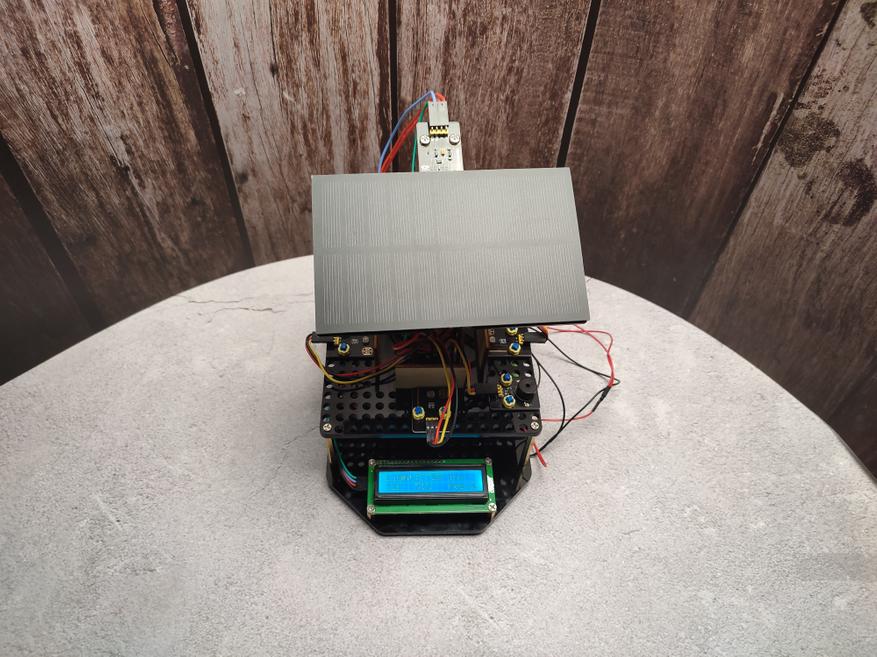
Комплектация
Кроме основной коробки, укутанной в слой пупырчатой пленки, посылка приезжает в фирменной коробке Keyestudio. К сожалению, даже такую упаковку почта смогла потрепать: видно вмятину в одном месте (предположительно, коробка упала на какой-то уголок). На лицевой стороне коробки фотография собранного конструктора и описание его особенностей. Сзади — послание от производителя (дополнительно выложил перевод, воспользовавшись программой-переводчиком по изображению).
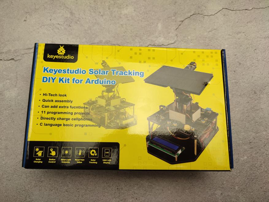


Комплект поставки полностью заполняет упаковку, поэтому детали не разбрасываются по коробке во время транспортировки
Присутствует бумажка с описанием конструктора, перечислением всех деталей, инструкцией и QR-кодом, по которому можно скачать тестовые скетчи и инструкцию в электронном виде (она же по ссылке).
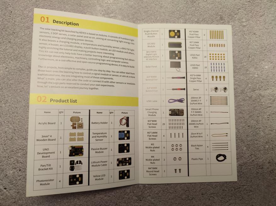
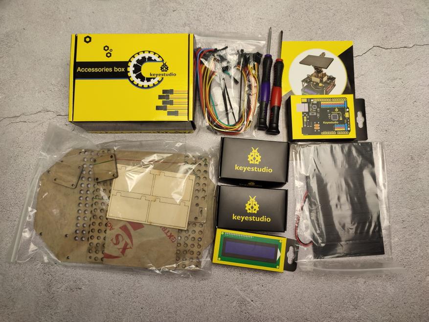
Компоненты — высочайшего качества: текстолит черного цвета с золотыми элементами, пайка высокого качества, флюс смыт.
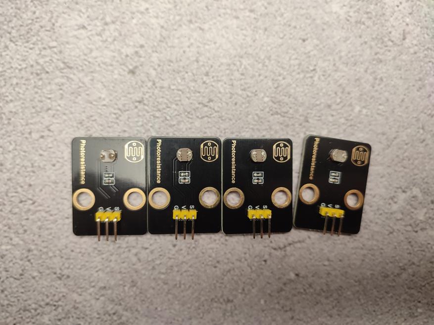
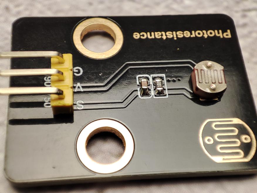
В первой коробке размещены болты, гайки и стойки.
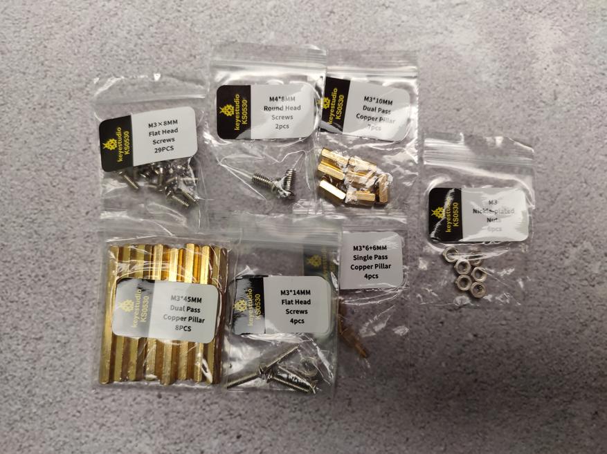
В остальных — все датчики: освещенности, фоторезисторы, пищалка (зуммер), кнопка, светодиод, датчик температуры, модуль для зарядки аккумулятора, преобразователь напряжения на 5 Вольт (можно заряжать смартфон и прочую периферию), сервоприводы в количестве 2 штук, холдер для аккумулятора (типоразмер 18 650, в комплект не входит), поворотную платформу и прочие необходимые элементы.

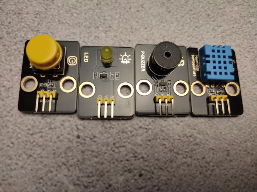
Корпус из акрила, дополнительно упакован в дополнительную пленку, которая снимается без проблем (слева фотография в пленке, справа — без). Есть 4 дополнительных элемента из дерева.
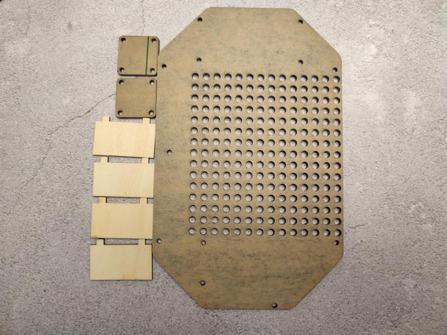
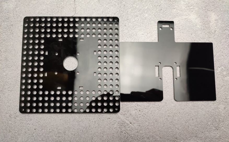
Сборка
Несмотря на очень подробную инструкцию, я решил уточнить некоторые моменты, в которых можно допустить ошибку или собрать модель неправильно. Каждый шаг в инструкции представлен фотографиями.
1 уровень:
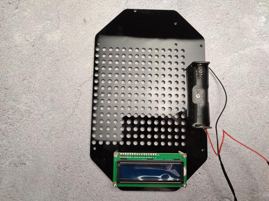
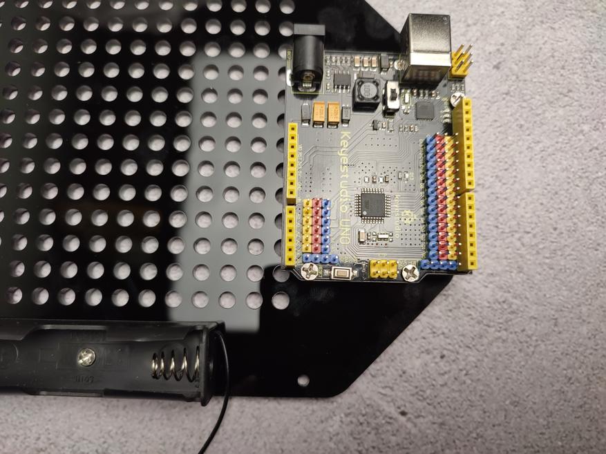
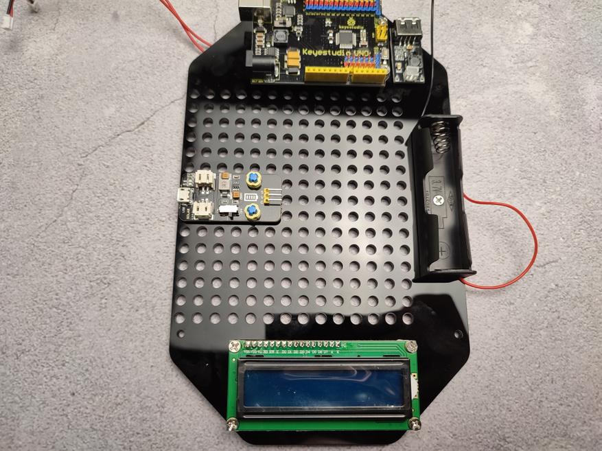
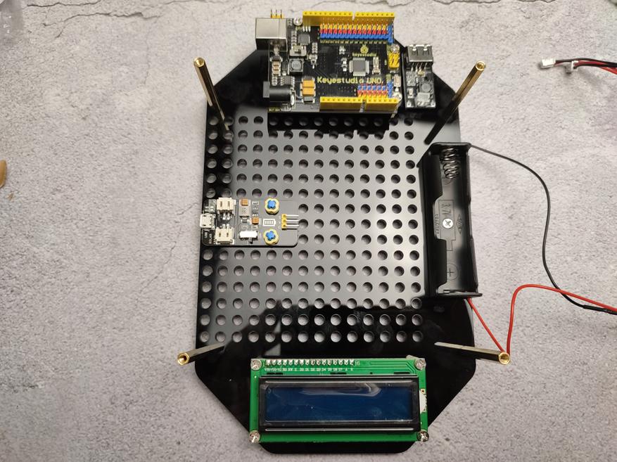
2 уровень (тут я совершил ошибку: датчик влажности нужно было перевернуть на 180 градусов, что я впоследствии и сделал):
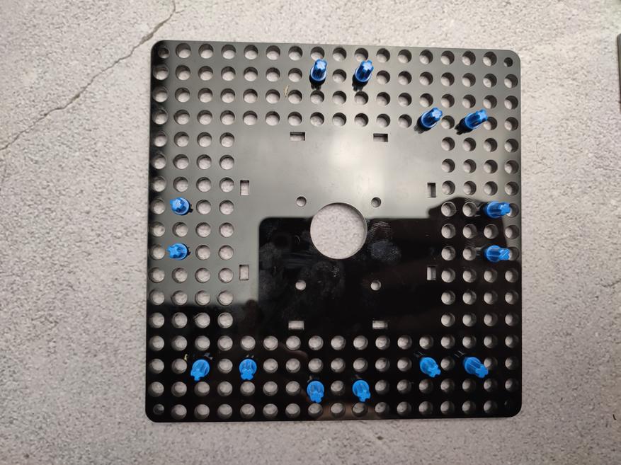
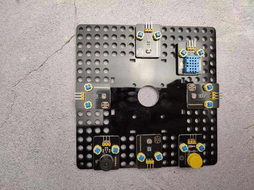
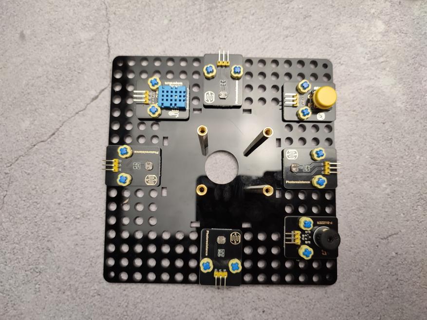
Объединение уровней на стойки:
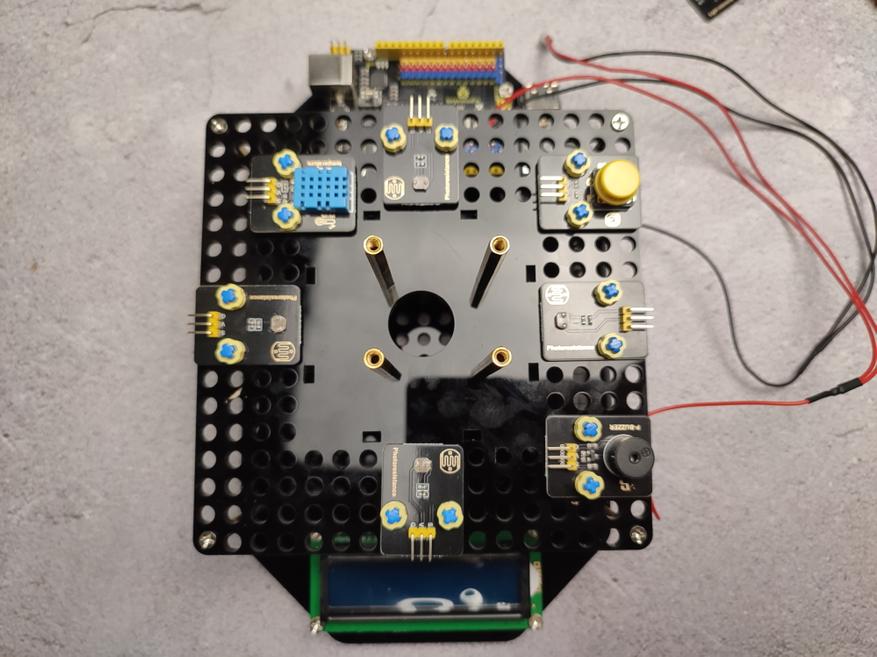
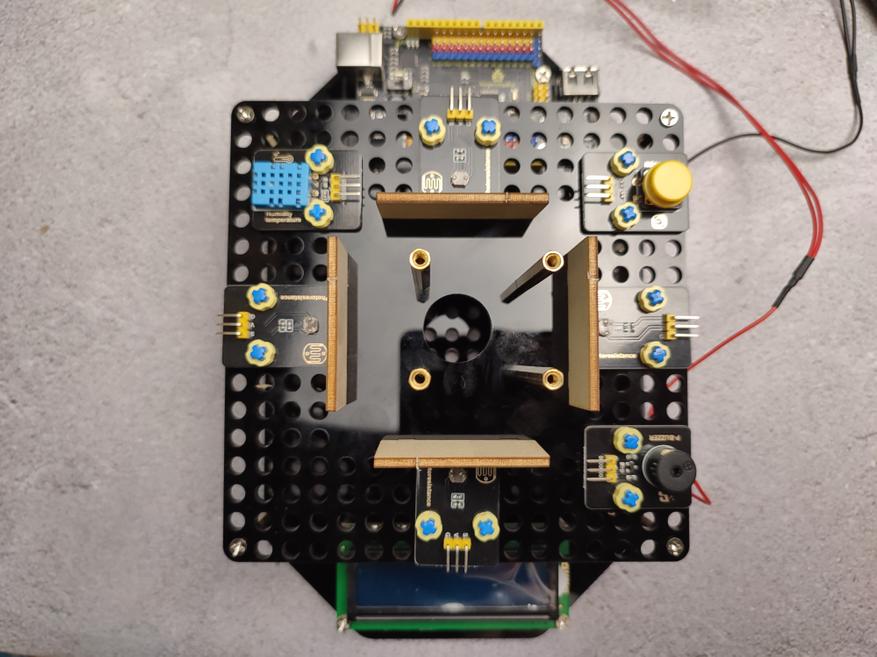
Далее поворотная платформа:
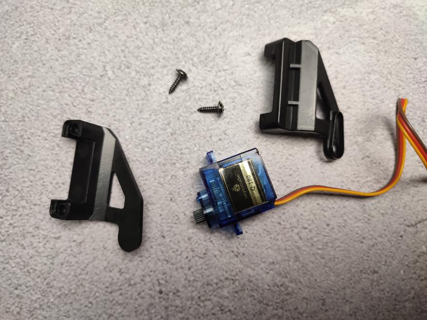
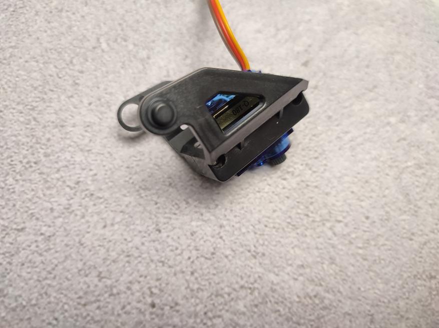
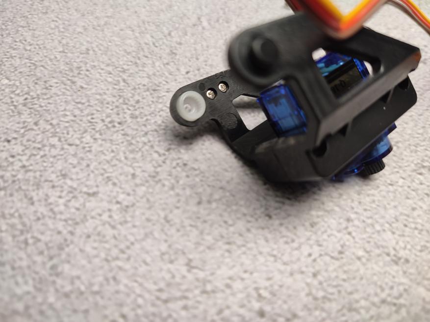
ДАЛЕЕ необходимо подсоединить ВТОРОЙ сервопривод: подключить его к контактам D10. Проводок сервопривода должен совпадать с желтым контактом на микроконтроллере.
Далее — подключить через кабель (USB Type-B — Type-A, идет в комплекте) к компьютеру и запустить среду разработки Arduino (если не установлено — в интернете неисчислимое количество уроков), после чего скачать каждую библиотеку (по ссылке — архив на Dropbox).
Установка библиотек: в программе Arduino выбрать в верхнем меню Скетч — Подключить библиотеку — Добавить .ZIP библиотеку. Такое действие совершить с каждой (необходимо 5 библиотек). ОБРАЩАЮ ВНИМАНИЕ, что библиотеки нужно ставить именно с этого сайта. У меня были установлены аналогичные, но конструктор работал некорректно. После установки библиотек необходимо написать следующий код:
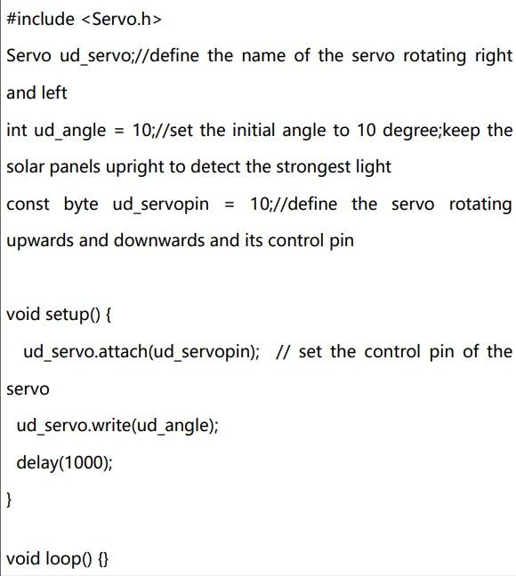
Далее выбрать в Инструменты — Порт Com (выбрать Arduino Uno) и выбрать Плата — Arduino Uno. Com порт может быть другим. В конечном итоге должно быть следующее:
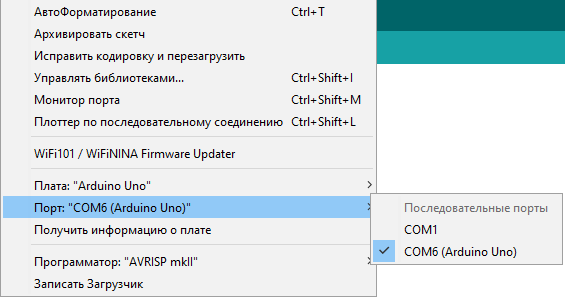
Провести компиляцию (галочка), если компиляция совершилась без ошибок — нажать на клавишу загрузки прошивки (стрелочка, направленная направо). Сервопривод должен будет повернуться на определенный угол.
Отключаем конструктор от компьютера и продолжаем собирать платформу.
В комплекте с сервоприводами идут насадки. Одну из них ставим в отведенное место, закручиваем саморезами и запрессовываем пальцами сервопривод (усилие необходимо довольно большое, но не стоит переусердствовать, чтобы не повредить зубчатое соединение). Дополнительно рекомендую закрутить болт.
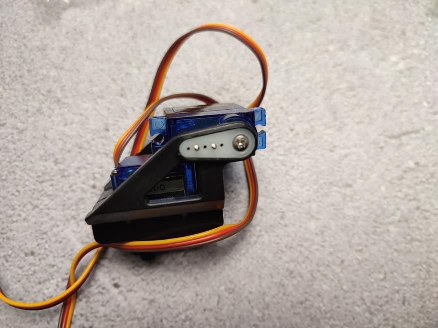
Далее закрепляем последнюю деталь платформы и затягиваем болтами
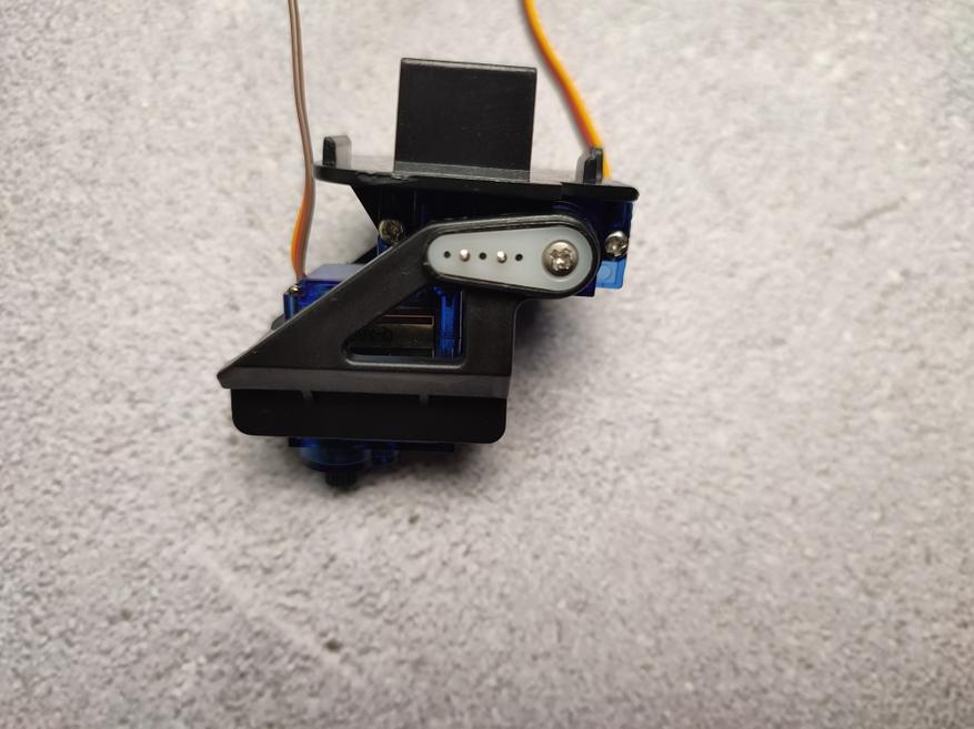
Далее повторяем действия, которые проводились со вторым сервоприводом, с первым, подключая контакты к линейке контакта D9 и используя следующий код:
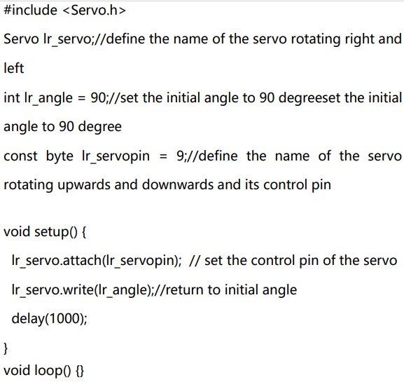
Сервопривод поворачивается на заданный угол? Отключаем конструктор от ПК и устанавливаем на платформу (на которой установлена насадка в виде +), затягиваем болтом. В конечном итоге все ставится на сам конструктор.
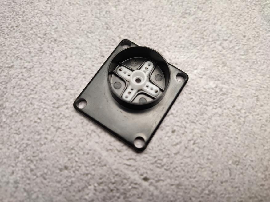
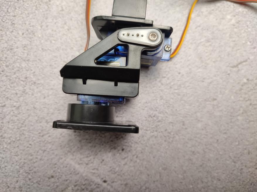
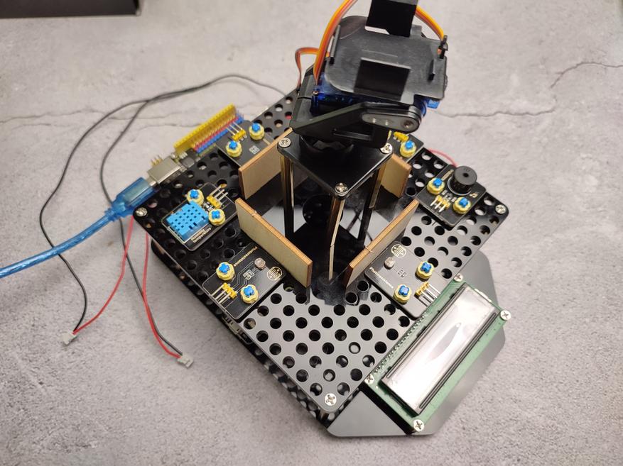
Уровень с солнечной панелью (солнечная панель клеится на двусторонний скотч):
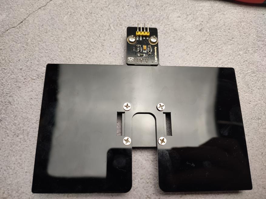
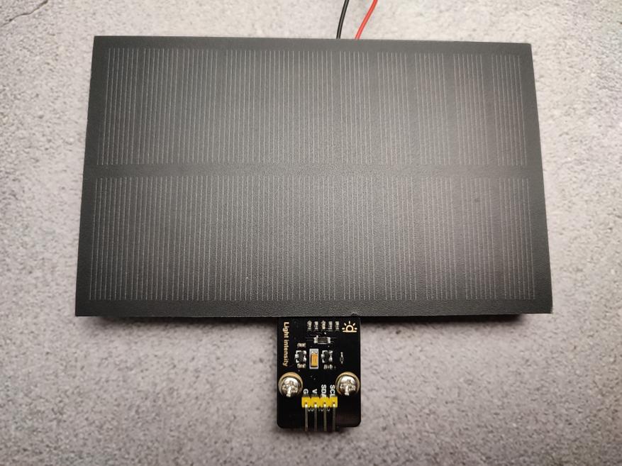
Далее часть с солнечной панелью устанавливается на поворотную платформу
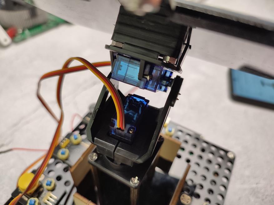
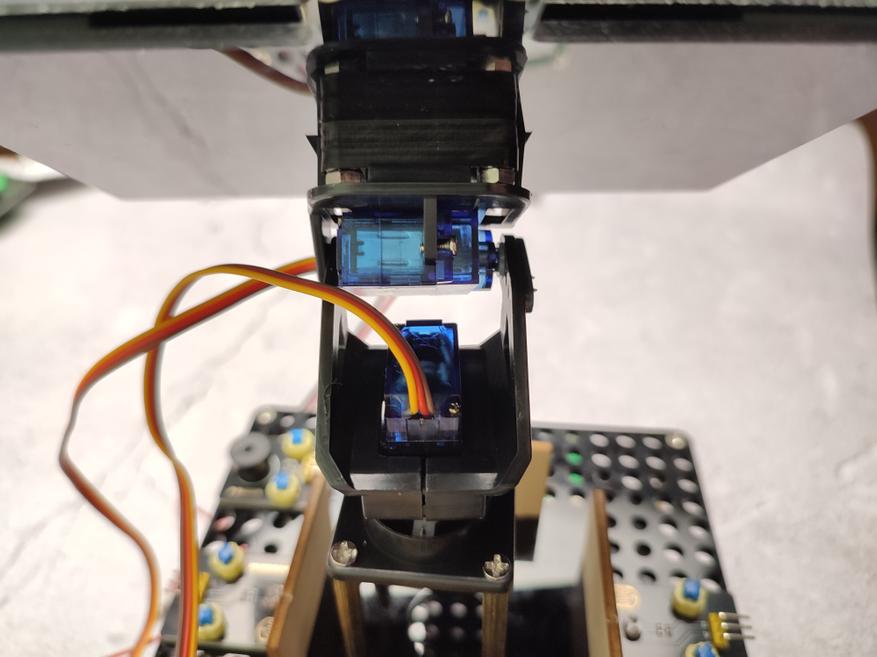
Самая неудобная часть работы — соединение проводов с определенными контактами. В инструкции крайне подробно описано, какие датчики подключать к каким контактам. ВАЖНО! Не перепутать контакты + (VCC, обычно красного цвета) с — (Ground, обычно черного цвета), так как можно спалить сами модули или микроконтроллер.
После сборки всех компонентов необходимо проверить правильность сборки и работоспособность всех датчиков и модулей, для чего скачиваются уроки (ссылка на Dropbox):
- 1-3 уроки можно пропустить. В них описывается работа с наипростейшим элементом — светодиодом;
- 4 урок — проверка зумера (писк с определенной частотой);
- 5 урок — проверка дисплея (вывод текста Hello, World на семисегментный индикатор);
- 6 урок — проверка фоторезисторов (вывод данных в монитор порта);
- 7 урок — проверка датчика влажности и температуры (вывод данных в монитор порта);
- 8 урок — проверка датчика освещенности (вывод данных в монитор порта);
- 9 урок — проверка сервоприводов;
- 11 — конечный код готового конструктора.
Если во время проверки столкнулись с проблемами — стоит перепроверить правильность подключения контактов.
В итоге имеем следующую конструкцию, которая адаптируется к источнику света. К сожалению, за последние дни солнца не было, поэтому в качестве солнечных лучей использовал фонарик и софтбокс с несколькими лампами.
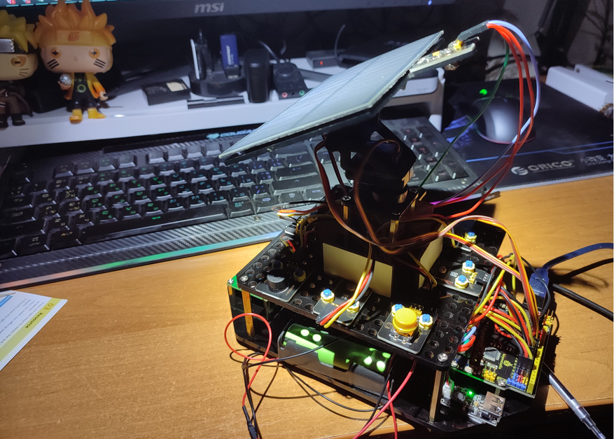

Солнечная панель довольно точно адаптируется под источник света. Скорость изменения положения можно регулировать нажатием на кнопку (на дисплее выводится значение res), чем выше значение — тем быстрее панель адаптируется под солнечные лучи, но появляется дрожание и нестабильная работа. Обращаю внимание, что солнечная панель адаптируется только под 1 источник света, при появлении нескольких — работа не совсем корректная.
Датчик температуры и влажности показывает схожий результат с гигрометром от Xiaomi.
В качестве неспешной зарядки для смартфона или наушников эта платформа также подойдет. Она выдает 0.76А, после чего напряжение значительно проседает.
Выводы
Конструктор, который подарил мне море положительных эмоций и прекрасный вечер. Нареканий никаких нет: компоненты высокого качества, инструкция очень подробная (минус — только на английском языке, что решается за несколько шагов), сопровождается иллюстрациями к каждому шагу, а также проверкой каждого элемента после сборки, чтобы разобраться, в чем может быть проблема. Очень рекомендую к покупке (на момент публикации будет неплохая скидка + купоны Aliexpress), отличный подарок на Новый Год себе любимому или ребенку.
Приобрести солнечную панель Keyestudio KS0530 можно в официальном магазине Keyestudio (кроме панели, там есть очень много различных наборов).
Дополнительно предлагаю ознакомиться с подборками похожих наборов:
- 10 программируемых электронных конструкторов с Aliexpress
- 10 электронных конструкторов на Arduino с Aliexpress
Спасибо за внимание.
5.Project Details
Project 1: Hello World

1.Introduction
As for starters, we will begin with something simple. In this project, you only need an Arduino and a USB Cable to start the “Hello World!” experiment. It is not only a communication test of your Arduino and PC, but also a primer project for you to have your first try in the Arduino world!
2.Hardware Required
-
V4.0 Board or MEGA 2650 Board*1
-
USB cable*1
3.Sample Code
After installing driver for Arduino, let’s open Arduino software and compile code that enables Arduino to print “Hello World!” under your instruction. Of course, you can compile code for Arduino to continuously echo “Hello World!” without instruction.
A simple If () statement will do the instruction trick. when Arduino gets an instruction and then to print “Hello World!”.
/*
keyestudio super learning kit
Project 1
Hello World
http//www.keyestudio.com
*/
int val;//define variable val
void setup()
{
Serial.begin(9600);// set the baud rate at 9600 .
}
void loop()
{
  val=Serial.read();// read the instruction or character from PC to Arduino, and assign them to Val.
  if(val=='R')// determine if the instruction or character received is “R”.
  {  // if it’s “R”,
     Serial.println("Hello World!");// display“Hello World!”string.
  }
}
4.Test Result
Click to open the serial monitor, input an “R”, PC will receive the information from Arduino Hello World!
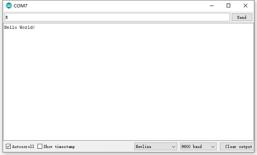
After choosing the proper port, the experiment is easy for you!
Project 2: LED Blinking
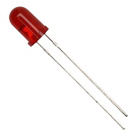
1.Introduction
Blinking LED experiment is quite simple. In the “Hello World!” program, we have come across LED. This time, we are going to connect an LED to one of the digital pins rather than using LED13 soldered to the board. Apart from an Arduino and a USB cable, you will need extra parts as below:
2. Hardware Required
-
V4.0 Board or MEGA 2650 Board*1
-
Red M5 LED*1
-
220Ω Resistor*1
-
Breadboard*1
-
Breadboard Jumper Wire*2
-
USB cable*1
3. Little Knowledge
LED is a type of semiconductor called “Light Emitting Diode “which is an electronic device made of semiconductor materials (silicon, selenium, germanium, etc.). It is dubbed indicator, digital and word display in circuit and device.
It has positive and negative poles. The short leg is negative pole, the long one is positive pole.
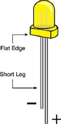
**Resistor:**Resistor is the electronic component in the circuit, which limits
and regulates current flow. Its unit is (Ω).
The units larger than ohms are kiloohms (KΩ) and megaohms (MΩ). When in use, in addition to the size of the resistance, you must also pay attention to its power. In the project, the leads at both ends of the resistor should be bent at a 90° angle to fit the breadboard properly. If the lead is too long, it can be cut to an appropriate length.
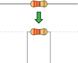
A breadboard is used to build and test circuits quickly before finalizing any circuit design. The breadboard has many holes into which circuit components like ICs and resistors can be inserted. A typical breadboard is shown below:

The bread board has strips of metal which run underneath the board and connect the holes on the top of the board. The metal strips are laid out as shown below.
Note that the top and bottom rows of holes are connected horizontally while the remaining holes are connected vertically.
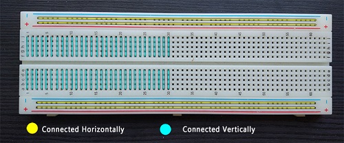
To use the bread board, the legs of components are placed in the holes. Each set of holes connected by a metal a strip underneath forms anode.
4.Circuit Connection
We follow below diagram from the experimental schematic link. Here we use digital pin 10. We connect LED to a 220 ohm resistor to avoid high current damaging the LED.
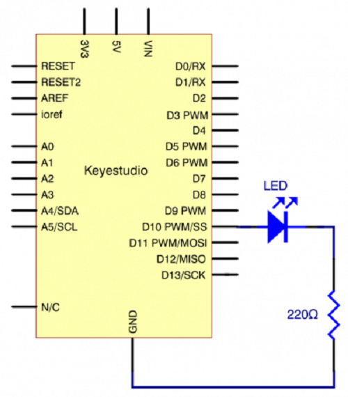
Connection for V4.0
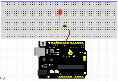
Connection for 2560
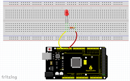
5.Sample Code
6.Test Result
After uploading this program, in the experiment, you will see the LED connected to pin 10 turning on and off, with an interval of approximate one second.
In this way, blinking LED experiment is now completed. Thank you!
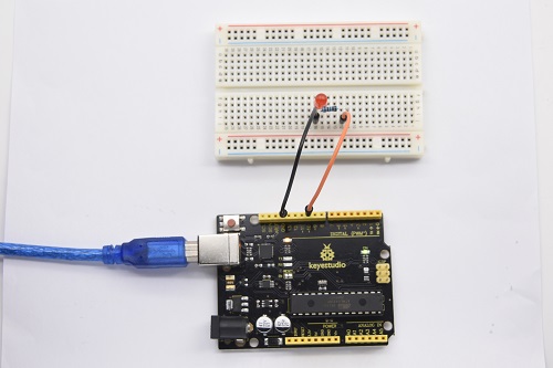
Project 3: PWM
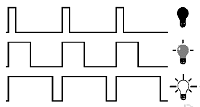
1.Introduction
PWM, short for Pulse Width Modulation, is a technique used to encode analog signal level into digital ones. A computer cannot output analog voltage but only digital voltage values such as 0V or 5V. So we use a high resolution counter to encode a specific analog signal level by modulating the duty cycle of PMW.
2.Working Principle
The PWM signal is also digitalized because in any given moment, fully on DC power supply is either 5V (ON), or 0V (OFF). The voltage or current is fed to the analog load (the device that uses the power) by repeated pulse sequence being ON or OFF. Being on, the current is fed to the load; being off, it’s not.
With adequate bandwidth, any analog value can be encoded using PWM. The output voltage value is calculated via the on and off time.
Output voltage = (turn on time/pulse time) * maximum voltage value
PWM has many applications lamp brightness regulating, motor speed regulating, sound making, etc.
The following are the three basic parameters of PMW.
-
The amplitude of pulse width (minimum / maximum)
2. The pulse period (The reciprocal of pulse frequency in one second)
3. The voltage level(such as 0V-5V)
There are 6 PMW interfaces on Arduino, namely digital pin 3, 5, 6, 9, 10, and 11.
In previous experiments, we have done “button-controlled LED”, using digital signal to control digital pin, also one about potentiometer.
This time, we will use a potentiometer to control the brightness of the LED.
3.Hardware Required
-
V4.0 Board or MEGA 2650 Board*1
-
Red M5 LED*1
-
220Ω Resistor
-
Breadboard*1
-
Breadboard Jumper Wire*6
-
USB cable*1
4.Circuit Connection
Connection for V4.0
Connection for 2560 R3
5.Sample Code
6.Test Result
Hook up via connection diagram, upload the code and plug in power. The external LED lights up then gets dark gradually, which looks like human breath.
Project 4: Traffic Light
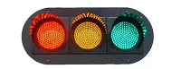
1.Introduction
In the previous program, we have done the LED blinking experiment with one LED. Now, it’s time to up the stakes to do a bit more complicated experiment-traffic light. Actually, these two experiments are similar. While in this traffic light experiment, we use three LEDs with different colors rather than an LED.
2.Hardware Required
-
V4.0 Board or MEGA 2650 Board*1
-
USB Cable *1
-
Red M5 LED*1
-
Yellow M5 LED*1
-
Blue M5 LED*1
-
220Ω Resistor *3
-
Breadboard*1
-
Breadboard Jumper Wire *4
3.Circuit Connection
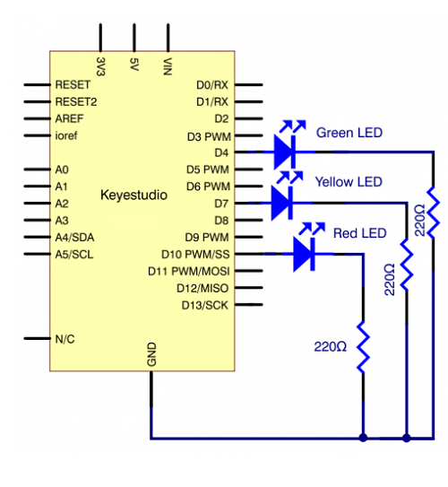
Connection for V4.0
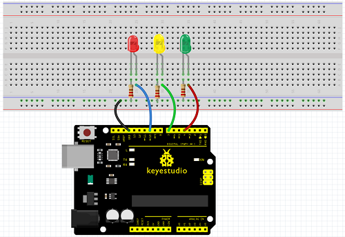
Connection for 2560
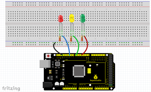
4. Sample Code
Since it is a simulation of traffic lights, the blinking time of each LED should be the same with those in traffic lights system.
In this program, we use Arduino delay () function to control delay time, which is much simpler than C language.
5.Test Result
When the uploading process is completed, you can see traffic lights of your own design. Note this circuit design is very similar with the one in LED chasing effect.
The blue light will be on for 5 seconds, and then off, followed by the yellow light blinking for 3 times, and then the red light is on for 5 seconds, repeatedly forming a cycle.
Experiment is now completed, thank you!
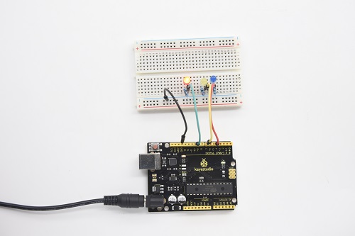
Project 5: LED Chasing Effect
1.Introduction
We can see many billboards composed of colorful LEDs. They are constantly changing to form various effects. In this experiment, we compile a program to simulate chase effect.
2.Hardware Required
-
V4.0 Board or MEGA 2650 Board*1
-
Red LED*6
-
220Ω Resistor *6
-
Breadboard Jumper Wire*12
-
USB cable*1
3.Circuit Connection
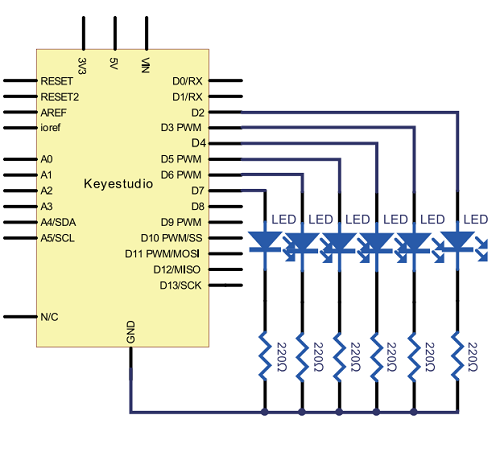
Connection for V4.0
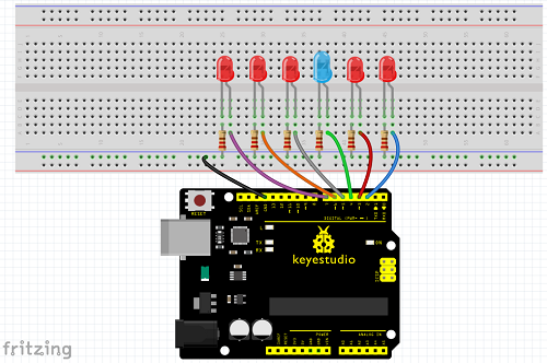
Connection for 2560
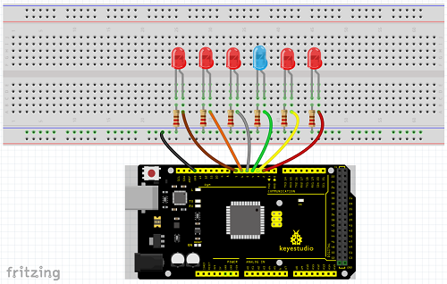
4.Sample Code
5.Test Result
You can see the LEDs blink by sequence.
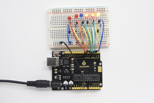
Project 6: Button-Controlled LED

1.Introduction
I/O port means interface for INPUT and OUTPUT. Up to now, we have only used the OUTPUT function.
In this experiment, we will try to use the INPUT function, which is to read the output value of device connecting to it.
We use 1 button and 1 LED using both input and output to give you a better understanding of the I/O function.
Button switch, familiar to most of us, is a switch value (digital value) component. When it’s pressed, the circuit is in closed (conducting) state.
2.Hardware Required
-
V4.0 Board or MEGA 2650 Board*1
-
Button switch*1
-
Red M5 LED*1
-
220ΩResistor*1
-
10KΩ Resistor*1
-
Breadboard*1
-
Breadboard Jumper Wire*6
-
USB cable*1
3. Little Knowledge
I believe that button switch is common and popular for people. It belongs to switch quantity( digital quantity)component. Composed of normally open contact and normally closed contact,its working principle is similar with ordinary switch.
When the normally open contact bears pressure, the circuit is on state ; however, when this pressure disappears, the normally open contact goes back to initial state, that is, off state. The pressure is the act we switch the button.
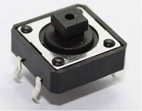
Schematic Diagrams:
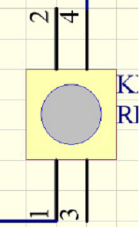
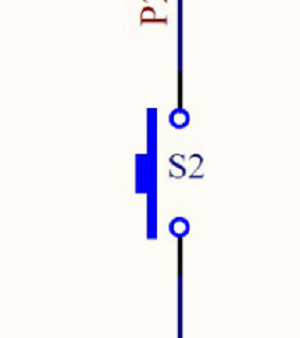
4. Circuit Connection
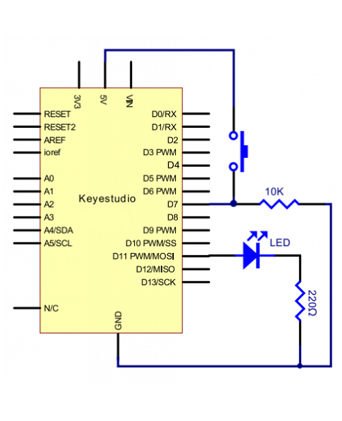
Connection for V4.0
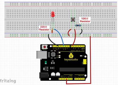
Connection for 2560
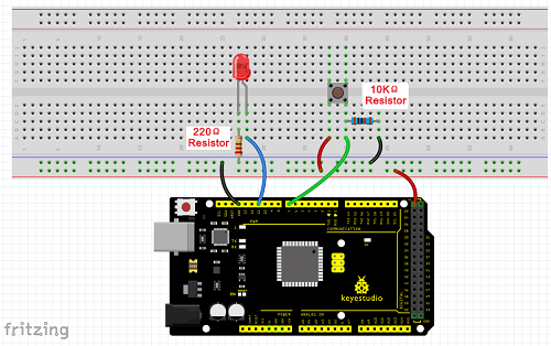
5.Sample Code
Now, let’s begin the compiling. When the button is pressed, the LED will be on. Based on the previous study, the coding should be easy for you.
In this program, we add a statement of judgment. Here, we use an if () statement.
Arduino IDE is based on C language, so statements of C language such as while, switch etc. can certainly be used for Arduino program.
When we press the button, pin 7 will output high level. We can program pin 11 to output high level and turn on the LED. When pin 7 outputs low level, pin 11 also outputs low level and the LED remains off.
6.Test Result
When the button is pressed, LED is on, otherwise, LED remains off. In this way, the button controlled LED experiment is completed.
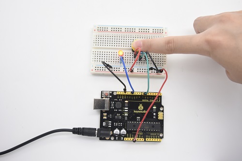
The simple principle of this experiment is widely used in a variety of circuit and electric appliances. You can easily come across it in your daily life. One typical example is when you press a certain key on your phone, the backlight will be on.
Project 7: Active Buzzer
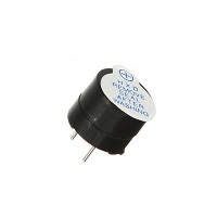
1.Introduction
Active buzzer is widely used as a sound making element on computer, printer, alarm, electronic toy, telephone, timer and more. It has an inner vibration source. Simply connect it with 5V power supply, it can buzz continuously.
2.Hardware Required
-
V4.0 Board or MEGA 2650 Board*1
-
Buzzer*1
-
Breadboard*1
-
Breadboard Jumper Wire*2
-
USB cable*1
3. Little Knowledge
There are two kinds of buzzer, active buzzer and passive buzzer. In this lesson, we will use Micro:bit to drive an active buzzer. The active buzzer inside has a simple oscillator circuit which can convert constant direct current into a certain frequency pulse signal. Once active buzzer receives a high level, it will produce an audible beep.
4.Circuit Connection
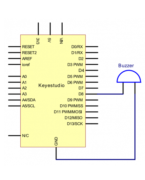
Connection for V4.0
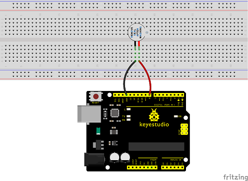
Connection for 2560
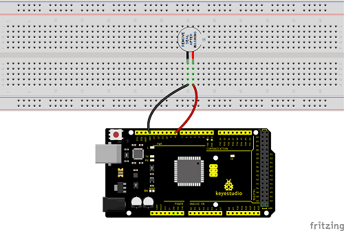
When connecting the circuit, pay attention to the positive and negative poles of the buzzer. In the photo, you can see there are red and black lines. When the circuit is finished, you can begin the programming.
5.Sample Code
Program is simple. You control the buzzer by outputting high/low level.
6.Test Result
After uploading the program, the buzzer experiment is completed. You can see the buzzer is ringing.
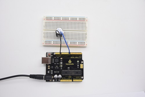
Project 8: Passive Buzzer
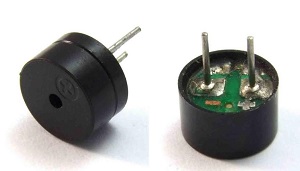
1.Introduction
We can use Arduino to make many interactive works. The most commonly used one is acoustic-optic display. All the previous experiment has something to do with LED. However, the circuit in this experiment can produce sound. Normally, the experiment is done with a buzzer but not a speaker while buzzer is more simpler and easier to use.
The buzzer we introduced here is a passive buzzer. It cannot be actuated by itself, but by external pulse frequencies. Different frequency produces different sound. We can use Arduino to code the melody of a song, which is quite fun and simple.
2.Hardware Required
-
V4.0 Board or MEGA 2650 Board*1
-
Passive Buzzer*1
-
Breadboard*1
-
Breadboard Jumper Wire*2
-
USB cable*1
3. Little knowledge
Passive buzzer is an integrated electronic buzzer without vibration source inside. It must be driven by 2K-5K square wave instead of direct current signals. There is little difference between the two buzzers, but when the pins of the two buzzers are placed up, the passive buzzer comes with green circuit board, and the one sealed with vinyl is an active buzzer.
4. Circuit Connection
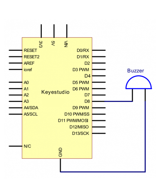
Connection for V4.0
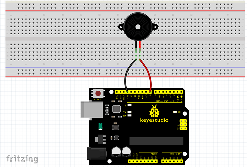
Connection for 2560
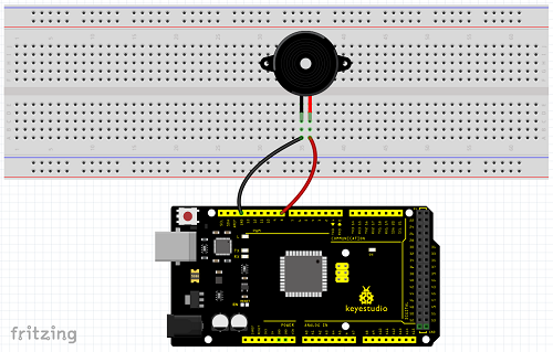
5.Sample Code
6.Test Result
After uploading the program, buzzer experiment is finished, you can hear the buzzer sound.
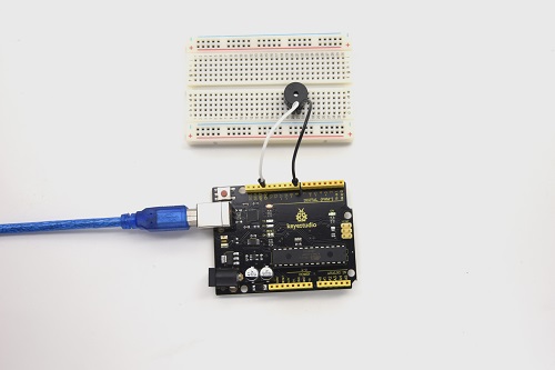
Project 9: RGB LED
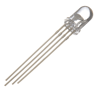
1.Introduction
The RGB color mode is a color standard in the industry. It obtains various colors by changing the three color channels of red (R), green (G), and blue (B) and integrating them. RGB denotes the three colors of red, green and blue.
In this project, we use Arduino to mix these three colors in equal amounts to produce white light.
2.Hardware Required
-
V4.0 Board or MEGA 2650 Board*1
-
USB Cable * 1
-
RGB LED * 1
-
Resistor *3
-
Breadboard jumper wire*5
3. Little Knowledge
The monitors mostly adopt the RGB color standard, and all the colors on the computer screen are composed of the three colors of red, green and blue mixed in different proportions.
RGB is inclusive of common cathode RGB and common anode RGB.
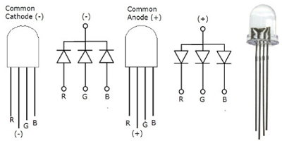
And we could adjust the LED brightness by PWM
4.Circuit Connection

Connection for V4.0
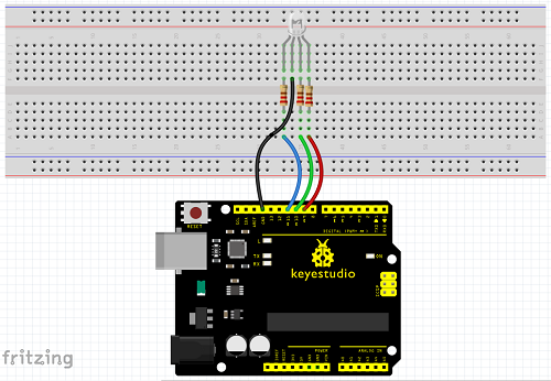
Connection for 2560
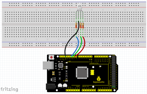
5.Sample Code
6.Test Result
Directly copy the above code into arduino IDE, and click upload, wait for a few seconds, you can see a full-color LED.
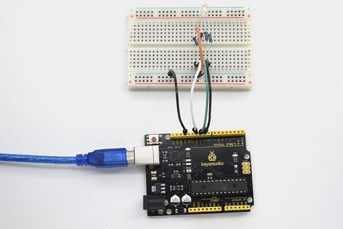
Project 10: Photo Resistor
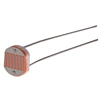
1.Introduction
After completing all the previous experiments, you may acquire some basic understanding and knowledge about Arduino application. We have introduced digital input and output, analog input and PWM.
Now, let’s begin the learning of sensor applications.
Photo Resistor (Photovaristor) is a resistor whose resistance varies from different incident light strength. It’s based on the photoelectric effect of semiconductor. If the incident light is intense, its resistance reduces; if the incident light is weak, the resistance increases.
2.Hardware Required
-
V4.0 Board or MEGA 2650 Board*1
-
Photo Resistor*1
-
Red M5 LED*1
-
10KΩ Resistor*1
-
220Ω Resistor*1
-
Breadboard*1
-
Breadboard Jumper Wire*5
-
USB cable*1
3. Little Knowledge
Photovaristor is commonly applied in the measurement of light, light control and photovoltaic conversion (convert the change of light into the change of electricity).
Photo resistor is also being widely applied to various light control circuit, such as light control and adjustment, optical switches, etc.
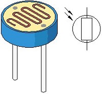
We will start with a relatively simple experiment regarding to photovaristor application.
Photovaristor is an element that can change its resistance as light strength changes. So need to read the analog value. You can refer to the PWM experiment, replacing the potentiometer with photovaristor. When there is change in light strength, it will make corresponding change on the LED.
4.Circuit Connection

Connection for V4.0
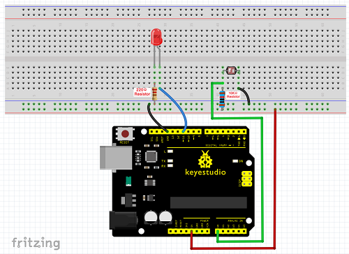
Connection for 2560
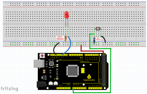
5.Sample Code
After wiring, let’s begin the program compiling. The program is similar to the PWM.
For change detail, please refer to the Sample Code below.
6.Test Result
After downloading the program, you can change the light strength around the photovaristor, and see the corresponding brightness change of the LED.
Photovaristors has various applications in our everyday. You can make other interesting interactive projects based on this one.
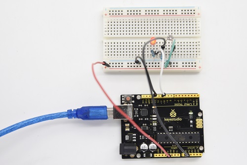
Project 11: Flame Sensor
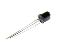
1.Introduction
Flame sensor (infrared receiving triode) is specially used for robots to find the fire source. This sensor is of high sensitivity to flame.
2.Hardware Required
-
V4.0 Board or MEGA 2650 Board*1
-
Flame Sensor *1
-
Buzzer *1
-
10K Resistor *1
-
Breadboard Jumper Wire*6
-
USB cable*1
3. Little Knowledge
Flame sensor is based on the principle that infrared ray is highly sensitive to flame. It has an infrared receiving tube specially designed to detect fire, and then to convert the flame brightness into fluctuating level signal. The signals are then input into the central processor and be dealt with accordingly.
The shorter lead of the receiving triode is for negative, the other one for positive. Connect negative to 5V pin, positive to resistor; connect the other end of the resistor to GND, connect one end of a jumper wire to a clip which is electrically connected to sensor positive, the other end to analog pin. As shown below:
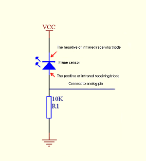
4.Experiment Principle
When it’s approaching a fire, the voltage value read from the analog port will differ. If you use a multimeter, you can see that when there is no fire approaching, the voltage it reads is around 0.3V; when there is fire approaching, the voltage it reads is around 1.0V. The nearer the fire is, the
higher the voltage is.
So in the beginning of the program, you can initialize voltage value i (no fire value); Then, continuously read the analog voltage value j and obtain difference value k=j-i; compare k with 0.6V (123 in binary) to determine whether there is a fire approaching or not; if yes, the buzzer will buzz.
5.Circuit Connection

Connection for V4.0
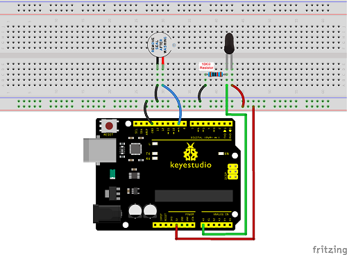
Connection for MEGA 2560
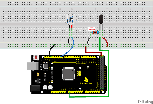
6.Sample Code
7.Test Result
This program can simulate an alarm when there is a fire. Everything is normal when there is no fire; when there is fire, the alarm will be set off immediately.
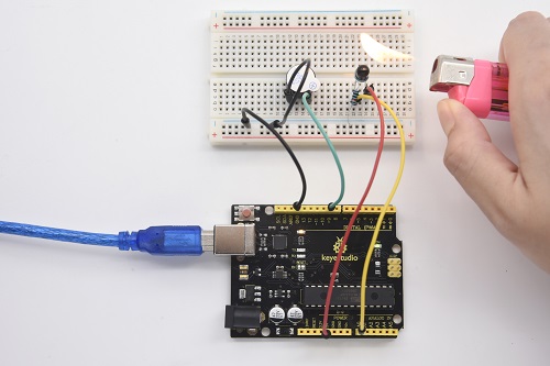
Project 12: LM35 Temperature Sensor
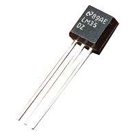
1.Introduction
LM35 is a common and easy-to-use temperature sensor. It does not require other hardware. You just need an analog port to make it work. The difficulty lies in compiling the code to convert the analog value it reads into Celsius temperature. In this project, we will guide you how to use LM35 temperature
sensor.
2. Working Principle
LM35 is a widely used temperature sensor with many different package types. At room temperature, it can achieve the accuracy of ±1/4°C without additional calibration processing.
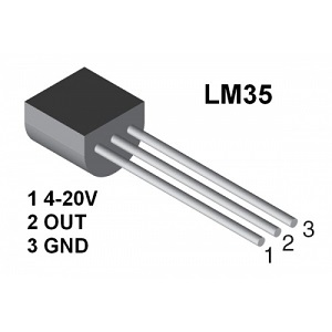
LM35 temperature sensor can produce different voltage by different temperature. When temperature is 0 ℃, it outputs 0V; if increasing 1 ℃, the output voltage will increase 10 mv.
The output temperature is 0℃~100℃, the conversion formula is as follows:
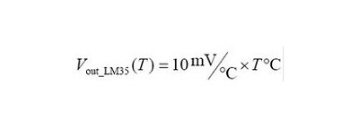
3.Hardware Required
-
V4.0 Board or MEGA 2650 Board*1
-
LM35*1
-
Breadboard*1
-
Breadboard Jumper Wire*5
-
USB cable*
4.Circuit Connection 
Connection for V4.0
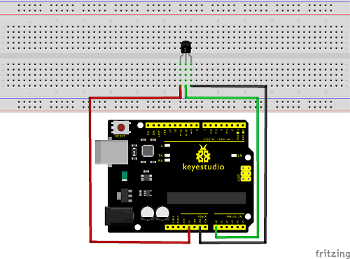
Connection for 2560
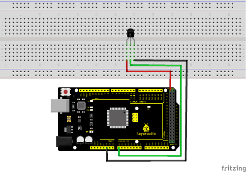
5.Sample Code
6.Test Result
After uploading the program, you can open the monitoring window to see the current temperature.
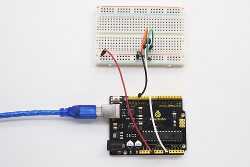
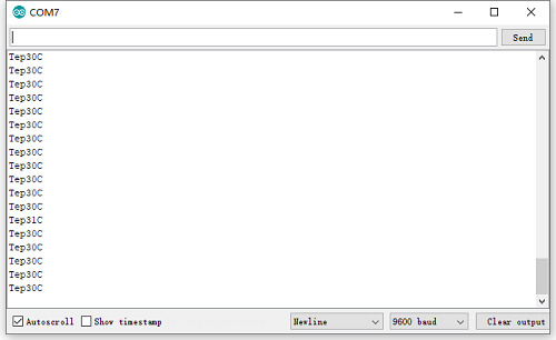
Project 13: Tilt Switch
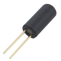
1.Introduction
This is a ball switch experiment . The ball switch is also dubbed a steel ball switch. It controls the circuit by connecting guide pin with rolling ball. In this project, we control the LED light by reading the state of the ball switch.
2.Working Principle
When one end of the switch is below horizontal position, the switch is on. The voltage of the analog port is about 5V (1023 in binary). The LED will be on.
When the other end of the switch is below horizontal position, the switch is off. The voltage of the analog port is about 0V (0 in binary). The LED will be
off.
In the program, we determine whether the switch is on or off according to the voltage value of the analog port, whether it’s above 2.5V (512 in binary) or not.
3.Hardware Required
-
V4.0 Board or MEGA 2650 Board*1
-
Ball switch*1
-
Led *1
-
220Ω Resistor*1
-
10KΩ resistor*1
-
Breadboard Jumper Wire*5
-
USB cable*1
4.Circuit Connection
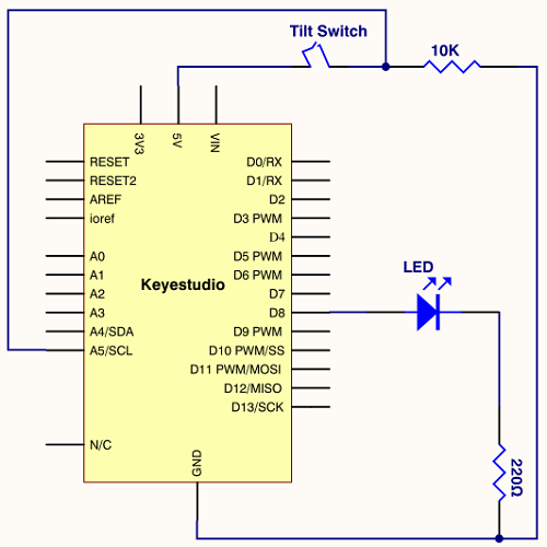
Connection for V4.0
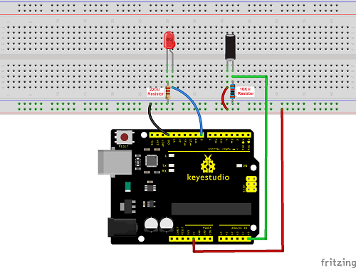
Connection for 2560
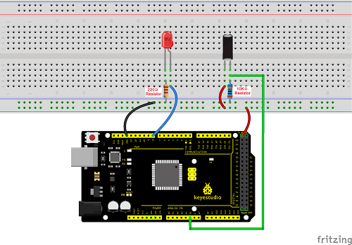
5.Sample Code
6.Test Result
Hold the breadboard with your hand. Tilt it to a certain extent, the LED will be on. If there is no tilt, the LED will be off.
The principle of this experiment can be also applied to relay control.
Experiment now is completed. Thank you!
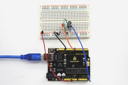
Project 14: IR Remote Control
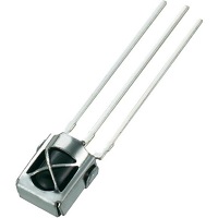
1.Introduction
What is an infrared receiver?
The signal from the infrared remote controller is a series of binary pulse code. To avoid the other infrared signal interference during the wireless transmission, the signal is pre-modulated at a specific carrier frequency and then send out by an infrared emission diode.
The infrared receiving device needs to filter out other waves and receive signals at that specific frequency and to modulate it back to binary pulse code, known as demodulation.
2.Working Principle
The built-in receiver converts the light signal it received from the sender into feeble electrical signal. The signal will be amplified by the IC amplifier. After automatic gain control, band-pass filtering, demodulation, wave shaping, it returns to the original code. The code is then input to the code identification circuit by the receiver’s signal output pin.
3.Pin and Wiring for Infrared Receiver
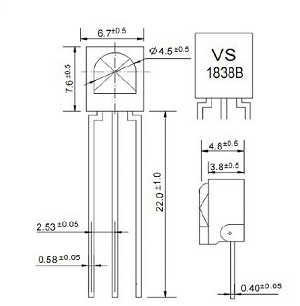
Infrared receiver has 3 pins. When you use it, connect VOUT to analog pin, GND to GND, VCC to +5V.
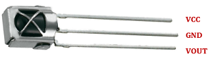
4.Hardware Required
-
V4.0 Board or MEGA 2650 Board*1
-
Infrared Remote Controller *1
-
Infrared Receiver *1
-
LED *6
-
220ΩResistor *6
-
Breadboard Wire *11
-
USB cable*1
5.Circuit Connection
First, connect the controller board; then connect the infrared receiver as the above mentioned, connect VOUT to digital pin 11, connect the LEDs with resistors and connect the resistors to pin 2,3,4,5,6,7.

Connection for V4.0
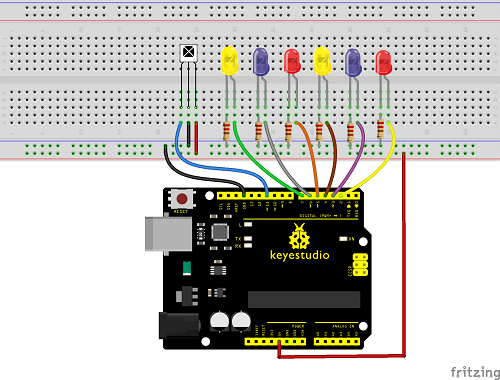
Connection for 2560
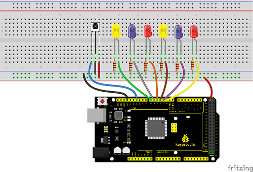
6.Experimental Principle
If you want to decode the code from the remote controller, you must first know how it’s coded. The coding method we use here is NEC protocol. Below is a brief introduction.
• NEC protocol
7.Features
-
8 bit address and 8 bit command length
(2) address and command are transmitted twice for reliability
(3) pulse distance modulation
(4) carrier frequency of 38 KHZ
(5) bit time of 1.125ms or 2.25ms
8.Protocol is as below
• Definition of logical 0 and 1 is as below
• Pulse transmitted when button is pressed and immediately released
The picture above shows a typical pulse train of the NEC protocol. With this protocol the LSB is transmitted first. In this case Address $59 and Command $16 is transmitted. A message is started by a 9ms AGC burst, which was used to set the gain of the earlier IR receivers. This AGC burst is then followed by a 4.5ms space, which is then followed by the address and command. Address and Command are transmitted twice. The second time all bits are inverted and can be used for verification of the received message. The total transmission time is constant because every bit is repeated with its inverted length. If you are not interested in this reliability, you can ignore the inverted values, or you can expend the Address and Command to 16 bits each!
• Pulse transmitted when button is pressed and released after a period of time
A command is transmitted only once, even when the key on the remote control remains pressed. Every 110ms a repeat code is transmitted for as long as the key remains down. This repeat code is simply a 9ms AGC pulse followed by a 2.25ms space and a 560µs burst.
• Repeat pulse
Note when the pulse enters the integrated receiver, there will be decoding, signal amplifying and wave shaping process. So you need to make sure the level of the output is just the opposite from that of the signal sending end.
That is when there is no infrared signal, the output end is in high level; when there is infrared signal, the output end is in low level. You can see the pulse of the receiving end in the oscilloscope. Try to better understand the program based on what you see.
9.Sample Code
Noteadd IRremote folder into installation directory \Arduino\compiler libraries, or you will fail to compile it.
Infrared remote library
https//github.com/shirriff/Arduino-IRremote
10.Test Result
Decode the coded pulse signal emitted by the remote controller, then execute corresponding action according to the results of the decoding. In this way, you will be able to control your device with remote controller.
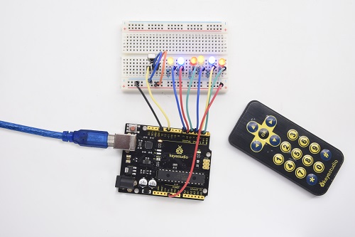
Done uploading, open the serial monitor, you can see the result as below.
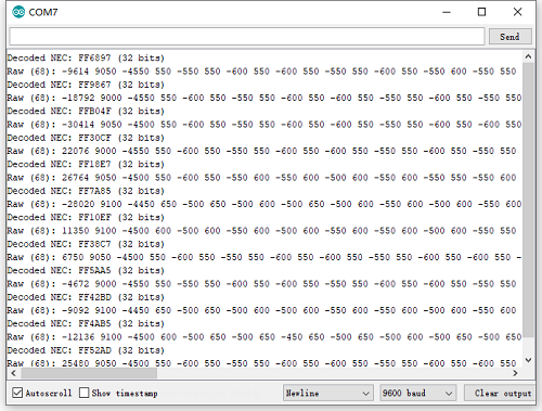
Project 15: Analog Value Reading
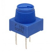
1.Introduction
In this experiment, we will begin the study of analog I/O interfaces. On an Arduino, there are 6 analog interfaces numbered from A0 to A5. Next, let’s begin our project. Potentiometer used here is a typical output component of analog value that is familiar to us.
2.Hardware Required
-
V4.0 Board or MEGA 2650 Board*1
-
Potentiometer *1
-
Breadboard*1
-
Breadboard Jumper Wire*3
-
USB cable*1
3.Potentiometer Features
Adjustable potentiometer is just a kind of resistor. The resistance is changed by rotating the potentiometer, so is the voltage, speed, brightness and temperature. It is an analog electronic component, which has two states of 0 and 1(high level and low level). The analog quantity is different. Its data state presents a linear state such as 1 to 1000.
4.Circuit Connection
In this experiment, we will convert the resistance value of the potentiometer to analog ones and display it on the screen.
This is an application you need to master well for our future experiments.
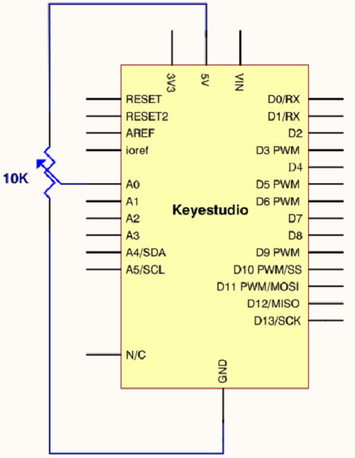
Connection for V4.0
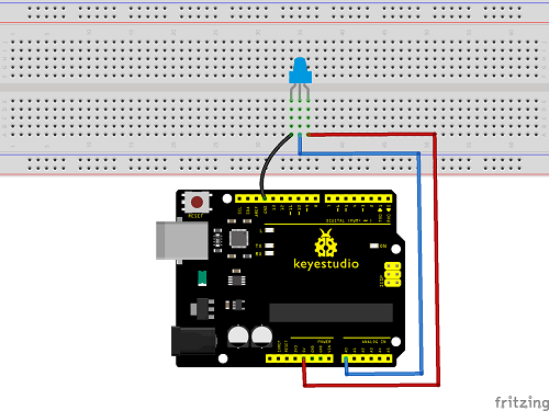
Connection for 2560
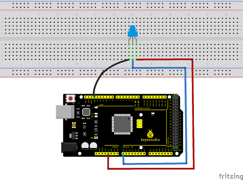
5.Sample Code
The program compiling is simple. An analogRead () Statement can read the value of the interface. The A/D acquisition of Arduino 328 is in 10 bits, so the value it reads is among 0 to 1023.
One difficulty in this project is to display the value on the screen, which is actually easy to learn.
First, you need to set the baud rate in voidsetup (). Displaying the value is a communication between Arduino and PC, so the baud rate of the Arduino should match the one in the PC’s software set up. Otherwise, the display will be messy codes or no display at all.
In the lower right corner of the Arduino software monitor window, there is a button for baud rate set up. The set up here needs to match the one in the program. The statement in the program is Serial.begin(); enclosed is the baud rate value, followed by statement for displaying. You can either use
Serial.print() or Serial.println() statement.
6.Test Result
The Sample Code uses the built-in LED connected to pin 13.
Each time the device reads a value, the LED blinks. When you rotate the potentiometer knob, you can see the displayed value change. The reading of analog value is a very common function since most sensors output analog value. After calculation, you can get the corresponding value you need.
Below figure shows the analog value it reads.
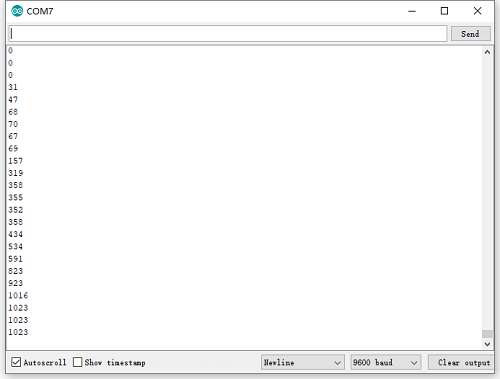
The experiment is now completed. Thank you!
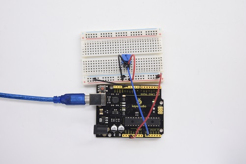
Project 16: 74HC595 chip
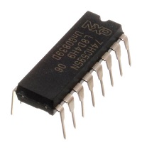
1.Introduction
74HC595 chip is a serial output and parallel output device. To put it simply, 74HC595 chip is a combination of 8-digit shifting register, memorizer and equipped with tri-state output.
Here, we use it to control 8 LEDs. You may wonder why use a 74HC595 to control LED? Well, think about how many I/O it takes for an Arduino to control 8 LEDs? Yes, 8.
For an Arduino 328, it has only 20 I/O including analog ports. To save port resources, using 74HC595 enables us to use 3 digital I/O ports to control 8 LEDs!
2. Hardware Required
-
V4.0 Board or MEGA 2650 Board*1
-
74HC595 chip*1
-
Red M5 LED*4
-
Green M5 LED*4
-
220Ω Resistor*8
-
Breadboard*1
-
Breadboard Jumper Wires
-
USB cable*1
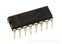
3. Description
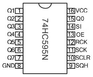
|
Pins No |
Name |
Function |
|---|---|---|
|
1-7, 15 |
Q0-Q7 |
Parallel Output |
|
8 |
GND |
GND |
|
9 |
MR |
Serial Output |
|
10 |
Master Reserve , connect 5V |
|
|
11 |
SH_CP |
Shift Register Clock Output |
|
12 |
ST_CP |
Storage Register Clock Input |
|
13 |
OE |
Output Enable (active LOW) |
|
14 |
DS |
Serial data input |
|
16 |
Vcc |
5V working voltage |
-
VCC and GND are used to supply power for chip, the working voltage is 5V.
-
Q0~Q7:This eight pins are output pins.
-
DS pin is serial input pin, we need to write data into this pin by bit.
-
STCP is a latch pin. The data can be copied to latch and output in parallel after 8-digit data of latch is all transmitted.
-
SHCP is a clock pin. The data can be written into storage register.
-
OE is an output enable pin, which is used to make sure if the data of latch is input into Q0-Q7 pins. When in low level, high level is not output. In this experiment, we directly connect to GND to keep low level output data.
-
MR is a pin to initialize the pin of storage register. Initialize the internal storage register when low level. In this experiment, we connect to VCC to keep high level.
-
Q7S pin is a serial output pin, which is specially used for chip cascade.
4. Circuit Connection
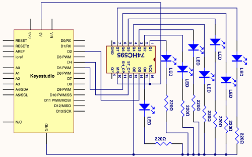
Connection for V4.0
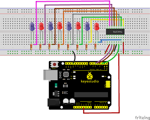
Connection for 2560 R3
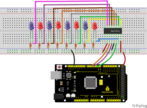
The circuit may seem complicated, but once you wire it in order, you will find it more easier!
5. Sample Code
6.Test Result
After downloading the program, you can see 8 LEDs display 8-bit binary number.
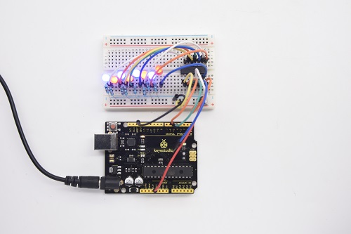
Project 17: 1-digit LED Segment Display
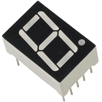
1. Introduction
LED segment displays are common for displaying numerical information. It’s widely applied on displays of electromagnetic oven, full automatic washing machine, water temperature display, electronic clock, etc. It is necessary for us to learn how it works.
2. Hardware Required
-
V4.0 Board or MEGA 2650 Board*1
-
1-digit LED Segment Display*1
-
220Ω Resistor*8
-
Breadboard*1
-
Breadboard Jumper Wires *several
-
USB cable*1
3. The display principle of the 1-digit LED Segment Display
LED segment display is a semiconductor light-emitting device. Its basic unit is a light-emitting diode (LED).
LED segment display can be divided into 7-segment display and 8-segment display according to the number of segments. 8-segment display has one more LED unit (for decimal point display) than 7-segment one.
According to the wiring method of LED units, LED segment display can be divided into common anode display and common cathode display. Common anode display refers to the one that combine all the anodes of LED units into one common anode (COM).
For the common anode display, connect the common anode (COM) to +5V. When the cathode level of a certain segment is low, the segment is on; when the cathode level of a certain segment is high, the segment is off.
For the common cathode display, connect the common cathode (COM) to GND. When the anode level of a certain segment is high, the segment is on; when the anode level of a certain segment is low, the segment is off.
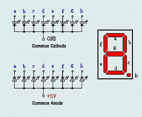
Each segment of the display consists of an LED. So when you use it, you also need to use a current-limiting resistor. Otherwise, LED will be burnt out.
In this experiment, we use a common cathode display. As we mentioned above, for common cathode display, connect the common cathode (COM) to GND. When the anode level of a certain segment is high, the segment is on; when the anode level of a certain segment is low, the segment is off.
4. Circuit Connection
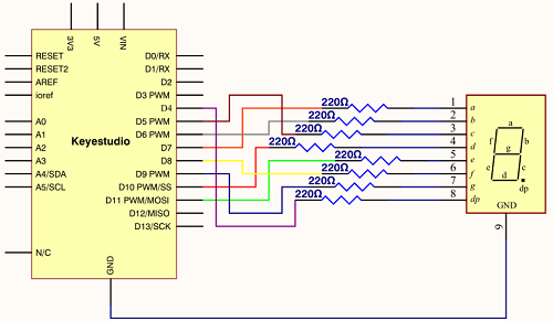
Connection for V4.0
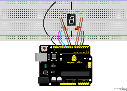
Connection for 2560
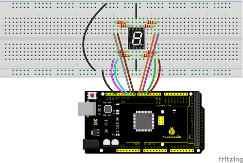
5. Sample Code
There are seven segments for numerical display, one for decimal point display. Corresponding segments will be turned on when displaying certain numbers.
For example, when displaying number 1, b and c segments will be turned on. We compile a subprogram for each number, and compile the main program to display one number every 2 seconds, cycling display number 0 ~ 9.
The displaying time for each number is subject to the delay time, the longer the delay time, the longer the displaying time.
6.Test Result
LED segment display will show the number from 0 to 9.
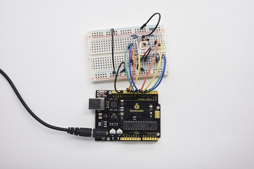
Project 18: 4-digit LED Segment Display
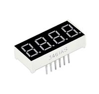
1. Introduction
In this experiment, we use an Arduino to drive a common cathode, 4-digit, 7-segment LED display.
For LED display, current-limiting resistors are indispensable.
There are two wiring methods for Current-limiting resistor. One is to connect one resistor for each cathode end, 4 in total for d1-d4 cathode. An advantage for this method is that it requires fewer resistors, only 4. But it cannot maintain consistent brightness, 1, the brightest; 8, the least bright.
Another method is to connect one resistor to each pin. It guarantees consistent brightness, but requires more resistors.
In this experiment, we use 8 Resistors (220Ω). We use 220ΩResistors because of no 100Ω resistor available. If you use 100Ω, the displaying is more brighter.
2. Hardware Required
-
V4.0 Board or MEGA 2650 Board*1
-
4-digit LED Segment Display*1
-
220Ω Resistor*8
-
Breadboard*1
-
Breadboard Jumper Wires *several
-
USB cable*1
3. The display principle of the 4-digit display
For 4-digit display, there are 12 pins in total. When you place the decimal point downward, the pin on the lower left part is refer to as 1, the upper left part 12. Shown below.
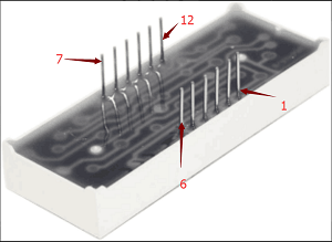
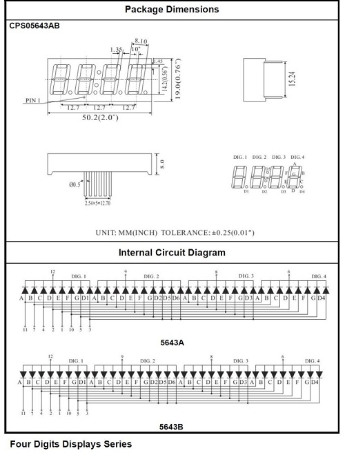
4. Circuit Connection
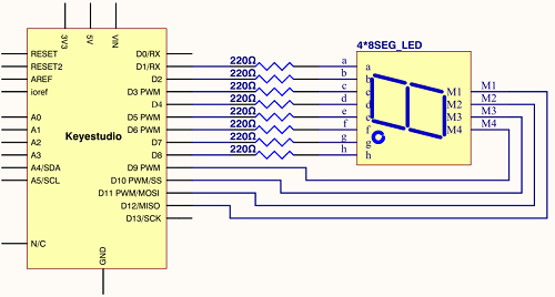
Connection for V4.0
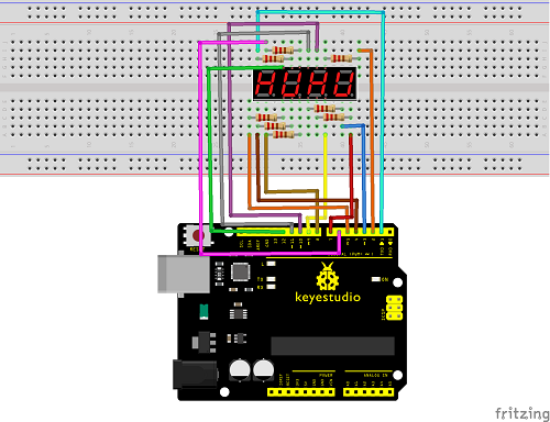
Connection for 2560 R3
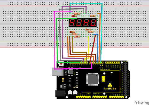
5. Sample Code
6.Test Result
Download the above code to the controller board, you can see the LED display shows the number 1234.
Note: if it’s not displaying correctly, check the wiring.
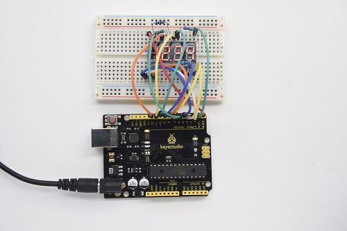
Project 19: 8*8 LED Matrix
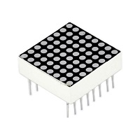
1. Introduction
LED dot-matrix display can meet the needs of different applications, thus has a broad development prospect. With low-voltage scanning, LED dot-matrix has some advantages such as power saving, long service life, low cost, high brightness, wide angle of view, long visual range, waterproof, and numerous specifications.
This project, we will conduct an LED dot-matrix experiment to experience its charm firsthand.
2. Hardware Required
-
V4.0 Board or MEGA 2650 Board*1
-
1 * 8*8 Dot Matrix
-
8 * Resistor (220Ω)
-
1 * Breadboard
-
1 * USB Cable
-
Several* Jumper Wires
3. The display principle of the 8*8 dot-matrix
The external view of a dot-matrix is shown as follows
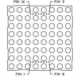
The 8*8 dot-matrix is made up of sixty-four LEDs, and each LED is placed at the cross point of a row and a column.
When the electrical level of a certain row is 1 and the electrical level of a certain column is 0, the corresponding LED will lighten. If you want to light the LED on the first dot, you should set pin 9 to high level and pin 13 to low level.
If you want to light LEDs on the first row, you should set pin 9 to high level and pins 13, 3, 4, 10, 6, 11, 15 and 16 to low level.
If you want to light the LEDs on the first column, set pin 13 to low level and pins 9, 14, 8, 12, 1, 7, 2 and 5 to high level.
The internal view of a dot-matrix is shown as follows
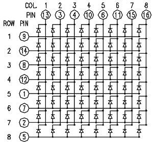
4. Circuit Connection
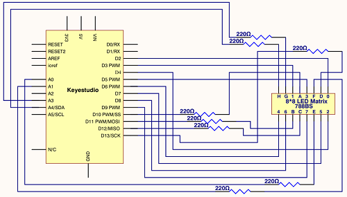
Connection for V4.0
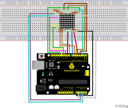
Connection for 2560 R3
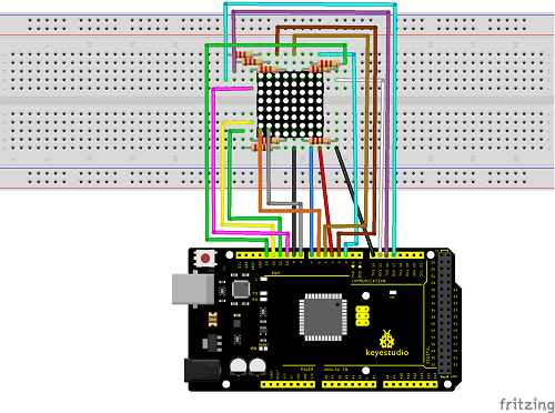
5. Sample Code for displaying “0”
6.Test Result
Burn the program into V4.0 board, the dot-matrix will display 0.
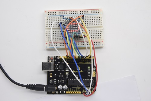
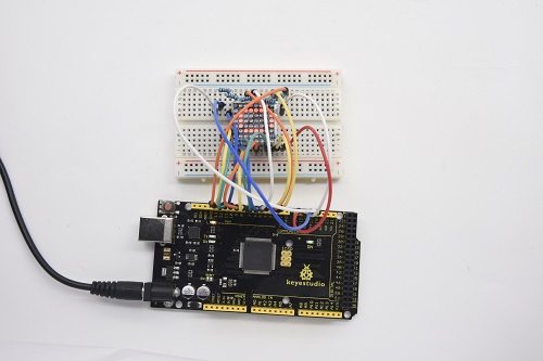
Project 20: 1602 LCD
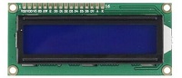
1. Introduction
In this experiment, we use an Arduino to drive the 1602 LCD. 1602 LCD has wide applications. In the beginning, 1602 LCD uses a HD44780 controller.
Now, almost all 1602 LCD module uses a compatible IC, so their features are basically the same.
2. 1602LCD Main Parameters
-
V4.0 Board or MEGA 2650 Board*1
-
Display capacity 16 * 2 characters
-
Chip operating voltage 4.5 ~ 5.5V
-
Working current 2.0mA (5.0V)
-
Optimum working voltage of the module is 5.0V
-
Character size 2.95 * 4.35 (W * H) mm
3. Pin description of 1602 LCD
|
No. |
Mark |
Pin description |
No. |
Mark |
Pin description |
|---|---|---|---|---|---|
|
1 |
VSS |
Power GND |
9 |
D2 |
Date I/O |
|
2 |
VDD |
Power positive |
10 |
D3 |
Date I/O |
|
3 |
VL |
LCD voltage bias signal |
11 |
D4 |
Date I/O |
|
4 |
RS |
Select data/command (V/L) |
12 |
D5 |
Date I/O |
|
5 |
R/W |
Select read/write(H/L) |
13 |
D6 |
Date I/O |
|
6 |
E |
Enable signal |
14 |
D7 |
Date I/O |
|
7 |
D0 |
Date I/O |
15 |
BLA |
Back light power positive |
|
8 |
D1 |
Date I/O |
16 |
BLK |
Back light power negative |
4. Interface Description
-
Two power pins, one for module power, another one for back light, generally use 5V. In this project, we use 3.3V for backlight.
-
VL is the pin for adjusting contrast ratio. It usually connects a potentiometer(no more than 5KΩ) in series for its adjustment. In this experiment, we use a 1KΩ resistor. For its connection, it has two methods, namely high potential and low potential. Here, we use low potential method; connect the resistor and then the GND.
-
RS is a very common pin in LCD. It’s a selecting pin for command/data. When the pin is in high level, it’s in data mode; when it’s in low level, it’s in command mode.
-
RW pin is also very common in LCD. It’s a selecting pin for read/write. When the pin is in high level, it’s in read operation; if in low level, it’s in write operation.
-
E pin is also very common in LCD. Usually, when the signal in the bus is stabilized, it sends out a positive pulse requiring read operation. When this pin is in high level, the bus is not allowed to have any change.
-
D0-D7 is 8-bit bidirectional parallel bus, used for command and data transmission.
-
BLA is anode for back light; BLK, cathode for back light.
5. Four Basic Operations for 1602LCD
|
Read status |
input |
RS=L, R/W=H, E=H |
output |
D0-D7=status word |
|---|---|---|---|---|
|
Write command |
input |
RS=L, R/W=H, D0-D7=command code, E=high pulse |
output |
none |
|
Read data |
input |
RS=H, R/W=H, E=H |
output |
D0-D7=data |
|
Write data |
input |
RS=H, R/W=L, D0-D7=data, E=high pulse |
output |
none |
6. Hardware Required
-
V4.0 Board or MEGA 2650 Board*1
-
1 * 1602 LCD
-
1 * Potentiometer
-
1 * Breadboard
-
1 * USB Cable
-
Several* Jumper Wires
7.Connection
It can directly communicate with Arduino. According to the product manual, it has two connection methods, namely 8-bit connection and 4-bit connection.
8-bit Connection Method
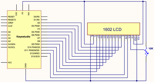
Connection for V4.0
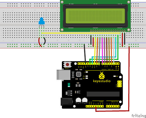
Connection for 2560 R3
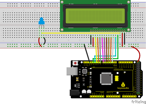
8.Sample Code A
**bit Connection Method
**When using this module, 8-bit connection uses all the digital pins of the Arduino, leaving no pin for sensors. What then? You can use 4-bit connection.
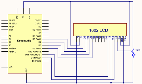
**Connection for V4.0
**

Connection for 2560 R3
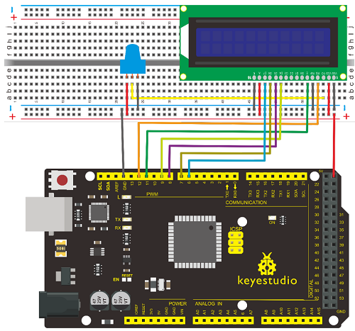
After the connection, upload below code to the controller board and see how it goes.
9.Sample Code B
10. Test Result
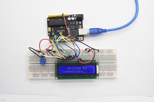
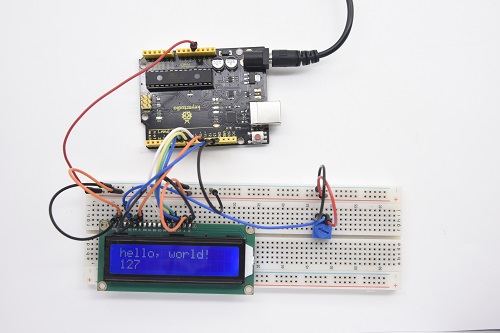
Project 21: Servo Control

1. Introduction
Servomotor is a position control rotary actuator. It mainly consists of housing, circuit board, core-less motor, gear and position sensor. For this lesson, we will introduce servo to you.
2. Working Principle
The MCU outputs a signal to the servomotor. The motor has a built-in reference circuit that gives out reference signal, cycle of 20ms and width of 1.5ms. The motor compares the acquired DC bias voltage to the voltage of the potentiometer and outputs a voltage difference. The IC on the circuit board will decide the rotate direction accordingly and drive the core-less motor. The gear then pass the force to the shaft. The sensor will determine whether it has reached the commanded position according to the feedback signal.
Servomotors are used in control systems that require to have and maintain different angles. When the motor speed is definite, the gear will drive the potentiometer to rotate. When the voltage difference reduces to zero, the motor stops. Normally, the rotation angle range is among 0-180 degrees.
Servomotor comes with many specifications. But all of them have three connection wires, distinguished by brown, red, orange (different brand may have different color).
Brown one is for GND, red one for power positive, orange one for signal line.
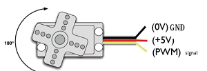
The rotation angle of the servo motor is controlled by regulating the duty cycle of the PWM(Pulse-Width Modulation) signal.
The standard cycle of the PWM signal is 20ms(50Hz). Theoretically, the width is distributed between 1ms-2ms. The width corresponds the rotation angle from 0° to 90°.
But note that for different brand motor, the same signal may have different rotating angle.
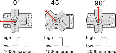
With some basic knowledge, let’s learn how to control a servomotor. In this experiment, you only need a servo motor and several jumper wires.
3. Hardware Required
-
V4.0 Board or MEGA 2650 Board*1
-
9G Servo Motor*1
-
Breadboard Jumper Wire*3
-
USB cable*1
Connection & Sample Code
There are two ways to control a servomotor with Arduino.
One is to use a common digital sensor port of Arduino to produce square wave with different duty cycle to simulate PWM signal and use that signal to control the positioning of the motor.
Another way is to directly use the Servo function of the Arduino to control the motor. In this way, the program will be more easier but it can only control two-contact motor because of the servo function, only digital pin 9 and 10 can be used.
The Arduino drive capacity is limited. So if you need to control more than one motor, you will need external power.
4. Method 1
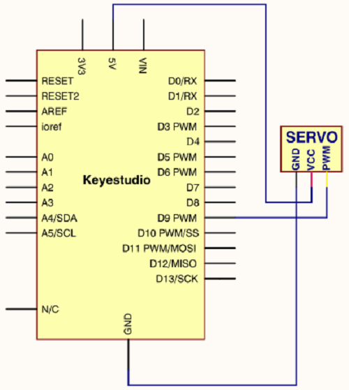
Connection for V4.0

Connection for 2560 R3
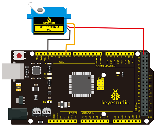
Connect the motor to digital pin 9.
Compile a program to control the motor to rotate in the commanded angle, and display the angle on the screen.
Sample Code A
5. Method 2
Let’s first take a look at the Arduino built-in servo function and some common statements.
1. attach(interface)——select pin for servo, can only use pin 9 or 10.
2. write(angle)——used to control the rotate angle of the servo, can set the angle among 0 degree to 180 degree.
3. read()——used to read the angle of the servo, consider it a function to read the value in the write() function.
4. attached()——determine whether the parameter of the servo is sent to the servo pin.
5. detach()—— disconnect the servo and the pin, and the pin (digital pin 9 or 10) can be used for PWM port.
Note the written form of the above statements are ” servo variable name. specific statement ()”, e.g. myservo. Attach (9).
Still, connect the servo to pin 9.
Sample Code B
Above are the two methods to control the servo. You can choose either one according to your liking or actual need.
6.Test Result
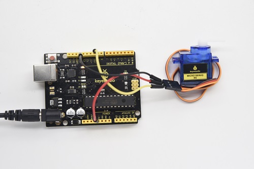
Project 22: Stepper Motor

1. Introduction
A stepper motor is an electromechanical device which can convert electrical pulses into discrete mechanical movements. The shaft or spindle of a stepper motor rotates in discrete step increments when electrical command pulses are applied to it in the proper sequence.
The motors rotation has several direct relationships to these applied input pulses. The sequence of the applied pulses is directly related to the direction of motor shafts rotation. The speed of the motor shafts rotation is directly related to the frequency of the input pulses and the length of rotation is
directly related to the number of input pulses applied.
One of the most significant advantages of a stepper motor is its ability to be accurately controlled in an open loop system. Open loop control means no feedback information about position is needed. This type of control eliminates the need for expensive sensing and feedback devices such as optical encoders.
Your position is known simply by keeping track of the input step pulses.
2. Hardware Required
-
V4.0 Board or MEGA 2650 Board*1
-
Stepper Motor*1
-
Stepper Motor driver*1
-
Jumper Wire *1
-
USB cable*1
3. Features
-
The rotation angle of the motor is proportional to the input pulse.
-
The motor has full torque at standstill(if the windings are energized)
-
Precise positioning and repeatability of movement since good stepper motors have an accuracy of – 5% of a step and this error is non cumulative from one step to the next.
-
Excellent response to starting/stopping/reversing.
-
Very reliable since there are no contact brushes in the motor. Therefore the life of the motor is simply dependant on the life of the bearing.
-
The motors response to digital input pulses provides open-loop control, making the motor simpler and less costly to control.
-
It is possible to achieve very low speed synchronous rotation with a load that is directly coupled to the shaft.
-
A wide range of rotational speeds can be realized as the speed is proportional to the frequency of the input pulses.
4.Parameters of Stepper Motor 28BYJ-48
-
Model 28BYJ-48
-
Rated Voltage 5VDC
-
Number of Phase 4
-
Speed Variation Ratio 1/64
-
Stride Angle 5.625° /64
-
Frequency 100Hz
-
DC Resistance 50Ω±7%(25℃)
-
Idle In-traction Frequency > 600Hz
-
Idle Out-traction Frequency > 1000Hz
-
In-traction Torque >34.3mN.m(120Hz)
-
Self-positioning Torque >34.3mN.m
-
Friction Torque 600-1200 gf.cm
-
Pull in Torque 300 gf.cm
-
Insulated Resistance >10MΩ(500V)
-
Insulated Electricity Power 600VAC/1mA/1s
-
Insulation Grade A
-
Rise in Temperature <40K(120Hz)
-
Noise <35dB(120Hz,No load,10cm)
5.Circuit Connection

Connection for V4.0

Connection for 2560 R3
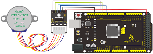
6. Sample Code
7. Test Result
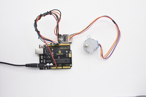
Project 23: PIR Motion Sensor

1. Introduction
Pyroelectric infrared motion sensor can detect infrared signals from a moving person or moving animal, and output switching signals.
It can be applied to a variety of occasions to detect the movement of human body.
Conventional pyroelectric infrared sensors require body pyroelectric infrared detector, professional chip, complex peripheral circuit, so it is more bigger with complex circuit, and lower reliability.
Now we launch this new pyroelectric infrared motion sensor, which is specially designed for Arduino.
It uses an integrated digital body pyroelectric infrared sensor, and has smaller size, higher reliability, lower power consumption as well as simpler peripheral circuit.
2. Hardware Required
-
V4.0 Board or MEGA 2650 Board*1
-
PIR Motion Sensor*1
-
Jumper Wire *1
-
USB cable*1
3. Specification
-
Input Voltage 3.3 ~ 5V (6V Maximum)
-
Working Current 15uA
-
Working Temperature -20 ~ 85 ℃
-
Output Voltage High 3V, Low 0V
-
Output Delay Time (High Level) About 2.3 to 3 Seconds
-
Detection Angle 100 °
-
Detection Distance 7 meters
-
Output Indicator LED (When output HIGH, it will be ON)
-
Pin limit Current 100mA
4. Circuit Connection
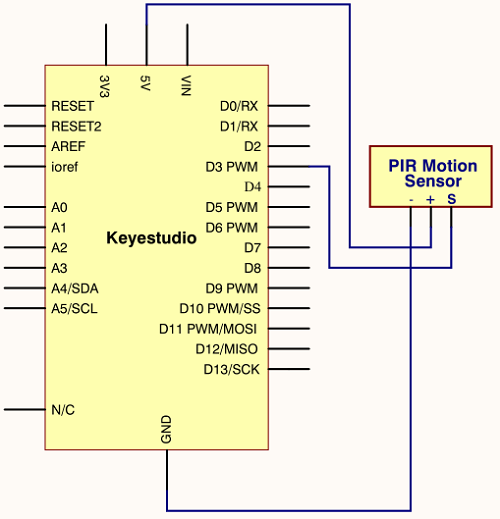
Connection for V4.0
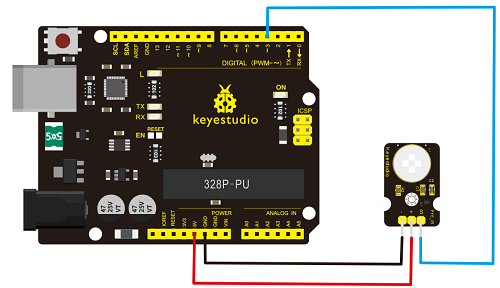
Connection for MEGA 2560 R3
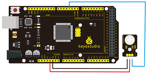
5. Sample Code
6. Test Result
If the sensor detects someone moving nearby, D13 indicator on V4.0 board will light up, and “Somebody is in this area!” is displayed on the serial monitor.
If no detecting the movement, D13 indicator on V4.0 board will be off, and “No one!” is displayed on the serial monitor.
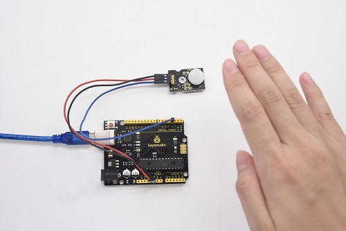
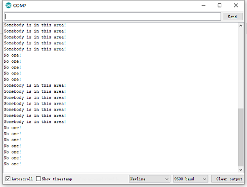
Project 24: Analog Gas Sensor
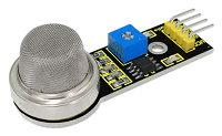
1. Introduction
This analog gas sensor — MQ2 is used in gas leakage detecting equipment in consumer electronics and industrial markets.
This sensor is suitable for LPG, I-butane, propane, methane, alcohol, Hydrogen and smoke detection. It has high sensitivity and quick response. In addition, the sensitivity can be adjusted by the potentiometer.
2. Hardware Required
-
V4.0 Board or MEGA 2650 Board*1
-
Analog Gas Sensor*1
-
Jumper Wire *1
-
USB cable*1
3. Specification
-
Power Supply 5V
-
Interface Type Analog
-
Wide detecting scope
-
Quick response and high sensitivity
-
Simple drive circuit
-
Stable and long lifespan
4. Circuit Connection

Connection for V4.0
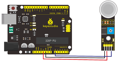
Connection for MEGA 2560 R3

5. Sample Code
6. Test Result
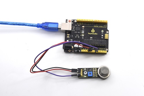
Project 25: ADXL345 Three Axis Acceleration
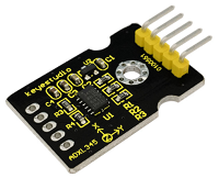
1. Introduction
The ADXL345 is a small, thin, low power, 3-axis MEMS accelerometer with high resolution (13-bit) measurement at up to +-16 g. Digital output data is formatted as 16-bit twos complement and is accessible through either a SPI (3- or 4-wire) or I2C digital interface.
The ADXL345 is well suited to measure the static acceleration of gravity in tilt-sensing applications, as well as dynamic acceleration resulting from motion or shock. Its high resolution (4 mg/LSB) enables measurement of inclination change less than 1.0 degrees.
2. Hardware Required
-
V4.0 Board or MEGA 2650 Board*1
-
ADXL345 Sensor*1
-
Jumper Wire *1
-
USB cable*1
3. Specification
-
2.0-3.6V DC Supply Voltage
-
Ultra Low Power 40uA in measurement mode, 0.1uA in standby@ 2.5V
-
Tap/Double Tap Detection
-
Free-Fall Detection
-
SPI and I2C interfaces
4. Circuit Connection
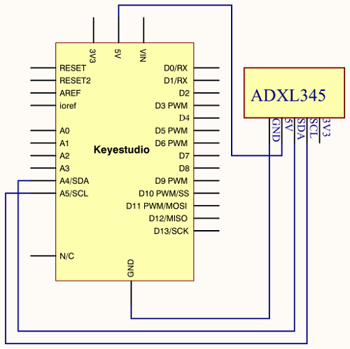
Connection for V4.0
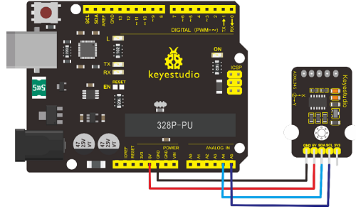
Connection for MEGA 2560 R3

5. Sample Code
6. Test Result
Wiring as the above diagram and power on, then upload the code and open the serial monitor, it will display the triaxial acceleration of sensor and its status, as the graph shown below.
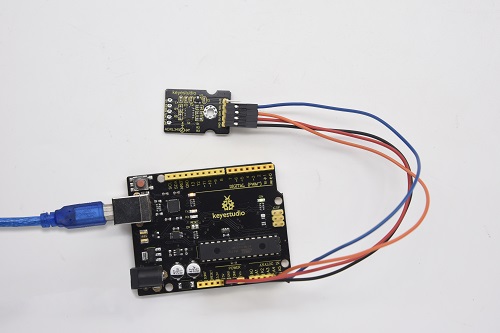
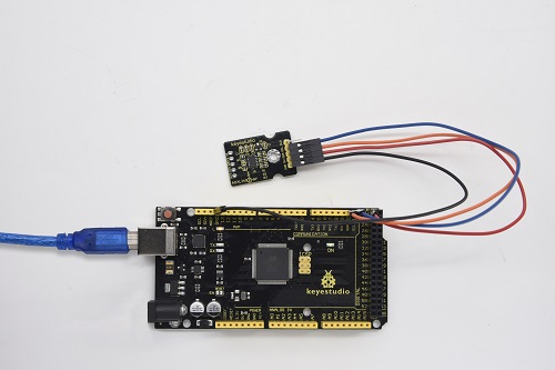
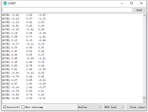
Project 26: HC-SR04 Ultrasonic Sensor
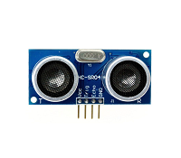
**1. Introduction
**The HC-SR04 Ultrasonic Sensor is a very affordable proximity/distance sensor that is mainly used for object avoidance in various robotics projects.
It essentially gives your Arduino eyes / spacial awareness and can prevent your robot from crashing or falling off a table. It has also been used in turret applications, water level sensing, and even as a parking sensor.
This simple project will use the HC-SR04 sensor with an Arduino and a Processing sketch to provide a more interactive display on your computer screen.
2. Hardware Required
-
V4.0 Board or MEGA 2650 Board*1
-
Ultrasonic Sensor*1
-
Jumper Wire *1
-
USB cable*1
3. Specification
-
Working Voltage DC 5V
-
Working Current 15mA
-
Working Frequency 40KHz
-
Max Range 4m
-
Min Range 2cm
-
Measuring Angle 15 degree
-
Trigger Input Signal 10µS TTL pulse
-
Echo Output Signal Input TTL lever signal and the range in proportion
4. Circuit Connection

Connection for V4.0
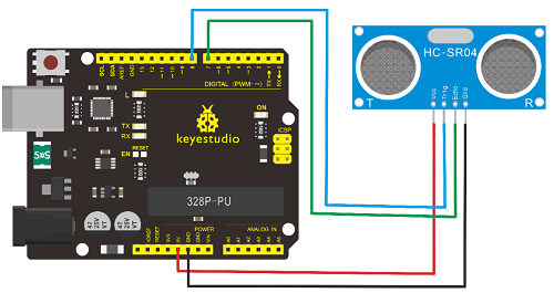
Connection for MEGA 2560 R3
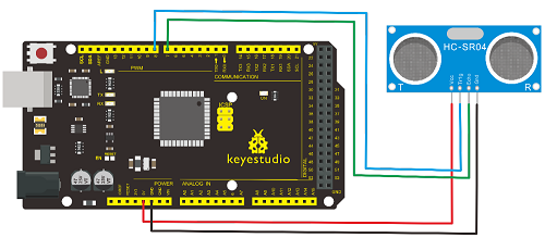
5. Sample Code
6. Test Result
After upload well the code to V4.0 board, then open the serial monitor. When place an object in front of the ultrasonic sensor (from near and far), it will detect the distance of object. The value will be displayed on the monitor.
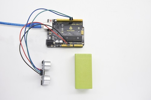
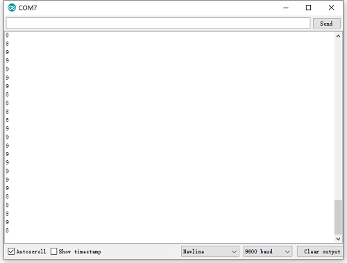
Project 27: Joystick Module
1. Introduction
Lots of robot projects need joystick. This module provides an affordable solution. By simply connecting to two analog inputs, the robot is at your commands with X, Y control. It also has a switch that is connected to a digital pin.
This joystick module can be easily connected to Arduino by IO Shield. This module is for Arduino(V5) with cable supplied.
2. Hardware Required
-
V4.0 Board or MEGA 2650 Board*1
-
Joystick Module*1
-
Jumper Wire *1
-
USB cable*1
3. Specification
-
Supply Voltage 3.3V to 5V
-
Interface Analog x2, Digital x1
4. Circuit Connection
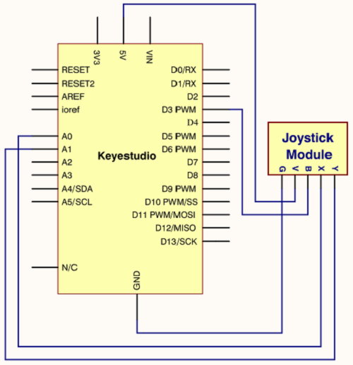
Connection for V4.0
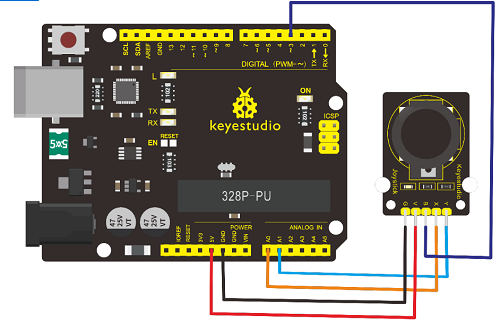
Connection for MEGA 2560 R3
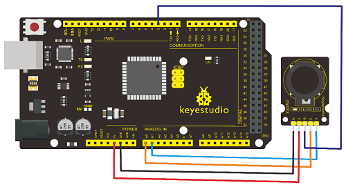
5. Sample Code
6. Test Result
Wiring well and uploading the code, open the serial monitor and set the baud rate to 9600, push the joystick, you will see the value shown below.
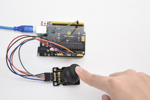
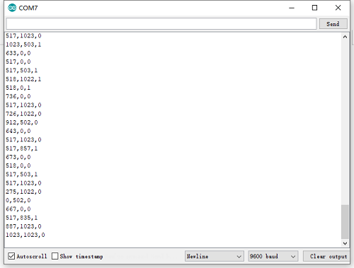
Project 28: 5V Relay Module
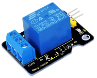
1. Introduction
This single relay module can be used in interactive projects. This module uses SONGLE 5v high-quality relay.
It can also be used to control the lighting, electrical and other equipment. The modular design makes it easy to expand with the Arduino Board (not included).
The Relay output is by a light-emitting diode. It can be controlled through digital IO port, such as solenoid valves, lamps, motors and other high current or high voltage devices.
2. Hardware Required
-
V4.0 Board or MEGA 2650 Board*1
-
Relay Module*1
-
Jumper Wire *1
-
USB Cable*1
3. Specification
-
Type Digital
-
Rated Current 10A (NO) 5A (NC)
-
Maximum Switching Voltage 150VAC 24VDC
-
Digital Interface
-
Control Signal TTL level
-
Rated Load 8A 150VAC (NO) 10A 24VDC (NO), 5A 250VAC (NO/NC) 5A 24VDC (NO/NC)
-
Maximum Switching Power AC1200VA DC240W (NO) AC625VA DC120W (NC)
-
Contact Action Time 10ms
4. Circuit Connection
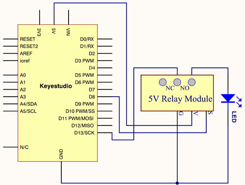
Connection for V4.0

Connection for MEGA 2560 R3
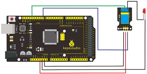
5. Sample Code
6. Test Result
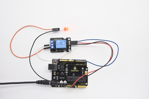
Project 29: DS3231 Clock Module
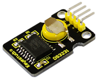
1. Introduction
DS3231 is equipped with integrated TCXO and crystal, which makes it a cost-effective I2C real time clock with high precision.
The device carries a battery input, so even if you disconnect the main power supply, it can still maintain accurate timing. The integrated oscillator ensures the long-term accuracy of the device and reduces the number of components.
DS3231 provides both commercial and industrial temperature range and supports 16 pins small-outline package (300mil).
The module itself can adapt to the system of 3.3V and 5V without level switch, which is quite convenient!
2. Hardware Required
-
V4.0 Board or MEGA 2650 Board*1
-
DS3231 Clock Module*1
-
Jumper Wire *1
-
USB cable*1
3. Specification
-
Temperature Range -40 to +85;
-
Timing Accuracy ± 5ppm (±0.432 seconds / day)
-
Provide battery backup for continuous timing
-
Low power consumption
-
Device package and function compatible with DS3231
-
Complete clock calendar function contains seconds and minutes, hour, week,date, month, and year timing and provides leap year compensation until 2100.
-
Two calendar clock
-
Output 1Hz and 32.768kHz
-
Reset output and Input Debounce of Pushbutton
-
High speed (400kHz), I2C serial bus
-
Supply voltage +3.3V to +5.5V
-
Digital temperature sensor with a precision of±3℃
-
Working temperature -40 ~ C to +85 ~ C
-
16 pins Small Outline Package (300mil)
4. Circuit Connection
This module adopts the IIC test method, so only need to connect ‘SDA’ to Arduino A4, ‘SCL’ to A5, ‘+’ to VCC and ‘-’ to GND as follows
Connection for V4.0
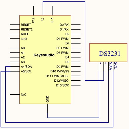
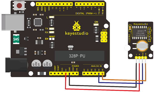
Connection for MEGA 2560 R3

5. Sample Code
Before compiling the code, you’d better put DS3231 library under file into Arduino catalogue.
6. Test Result
Done uploading the code to arduino, open the serial monitor and get the following results.
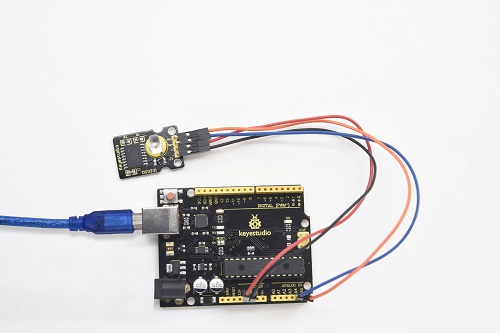
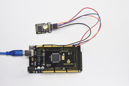
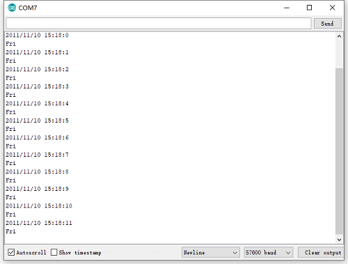
Project 30: DHT11 Temperature and Humidity Sensor
1. Introduction
This DHT11 Temperature and Humidity Sensor features calibrated digital signal output with the temperature and humidity sensor complex. Its technology ensures high reliability and excellent long-term stability. A high-performance 8-bit microcontroller is connected.
This sensor includes a resistive element and a sense of wet NTC temperature measuring devices. It has the advantages of excellent quality, fast response, anti-interference ability and high cost performance.
Each DHT11 sensor features extremely accurate calibration data of humidity calibration chamber. The calibration coefficients stored in the OTP program memory, internal sensors detect signals in the process, and we should call these calibration coefficients.
The single-wire serial interface system is integrated to make it quick and easy. Qualities of small size, low power, and 20-meter signal transmission distance make it a widely applied application and even the most demanding one. Convenient connection and special package can be provided according to your need.
2. Hardware Required
-
V4.0 Board or MEGA 2650 Board*1
-
DHT11 sensor*1
-
Jumper Wire *1
-
USB cable*1
3. Specification
-
Supply Voltage +5 V
-
Temperature Range 0-50 °C error of ± 2 °C
-
Humidity 20-90% RH ± 5% RH error
-
Interface digital
4. Circuit Connection
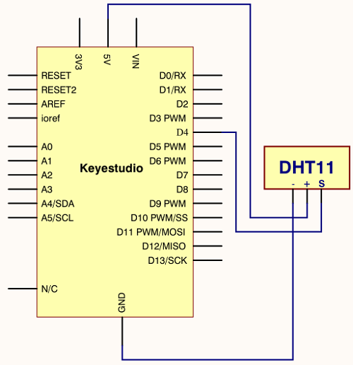
Connection for V4.0
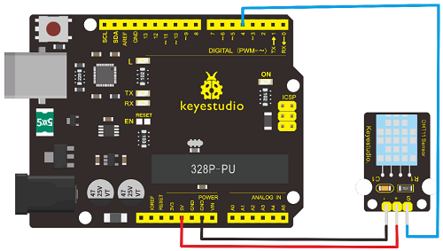
Connection for MEGA 2560 R3

5. Sample Code
Please download the DHT11Lib firstly. Or see the website
6.Test Result
Wire it up well and upload the above code to V4.0 board.
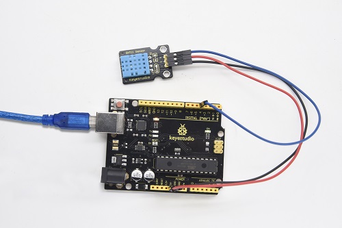
Then open the serial monitor and set the baud rate to 9600, you will see the current temperature and humidity value.
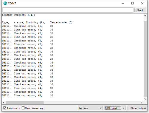
Project 31: Soil Humidity Sensor
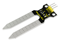
1. Introduction
This is a simple soil humidity sensor aims to detect the soil humidity. If the soil is lack of water, the analog value output by the sensor will decrease; otherwise, it will increase.
If you use this sensor to make an automatic watering device, it can detect whether your botany is thirsty so as to prevent it from withering when you go out. Using the sensor with Arduino controller makes your plant more comfortable and your garden smarter.
The soil humidity sensor module is not as complicated as you might think, and if you need to detect the soil in your project, it will be your best choice.
The sensor is set with two probes inserted into the soil, then with the current go through the soil, the sensor will get resistance value by reading the current changes between the two probes and convert such resistance value into moisture content.
The higher the moisture (less resistance) is, the higher conductivity the soil has.
The surface of the sensor have undergone metallization process to prolong its service life. Insert it into the soil and then use the AD converter to read it. With the help of this sensor, the plant can remind of you I need water.
2. Hardware Required
-
V4.0 Board or MEGA 2650 Board*1
-
Soil Humidity Sensor*1
-
Jumper Wire *1
-
USB cable*1
3. Specification
-
Power Supply Voltage 3.3V or 5V
-
Working Current ≤ 20mA
-
Output Voltage 0-2.3V (When the sensor is totally immersed in water, the voltage will be 2.3V)
-
5V power supply (the higher humidity, the higher the output voltage)
-
Sensor Type Analog output
-
Interface Definition Pin1- signal, pin2- GND, pin3 — VCC
4. Circuit Connection
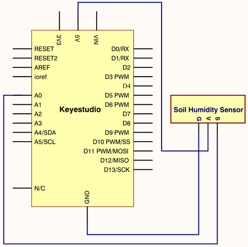
Connection for V4.0
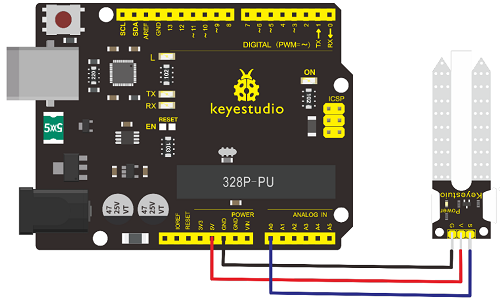
Connection for MEGA 2560 R3
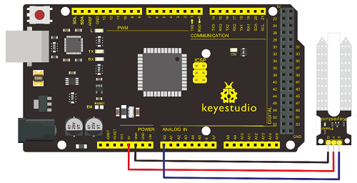
5. Sample Code
6. Test Result
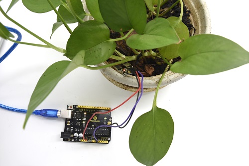
Project 32: RC522 RFID Module
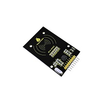
1. Introduction
MF522-AN module adopts Philips MFRC522 original reader circuit chip design, easy to use, low cost, suitable for equipment development, development of advanced applications, the need for the user of RF card terminal design / production. It can be loaded directly into a variety of readers molds.
Module uses voltage of 3.3V, through the SPI interface using simple few lines, it can be directly connected to any CPU board communication modules to guarantee stable and reliable work and reader distance.
2. Hardware Required
-
V4.0 Board or MEGA 2650 Board*1
-
RFID Module*1
-
Jumper Wire *1
-
USB cable*1
3. Specification
-
Current 13-26mA / DC 3.3V
-
Idle Current 10-13mA / DC 3.3V
-
Sleep Current <80uA
-
Peak Current <30mA
-
Operating Frequency 13.56MHz
-
Supported card types mifare1 S50, mifare1 S70, mifare UltraLight, mifare Pro, mifare Desfire
-
Environmental Operating Temperature -20-80 degrees Celsius
-
Environment Storage Temperature -40-85 degrees Celsius
-
Relative Humidity 5% -95%
4. Circuit Connection
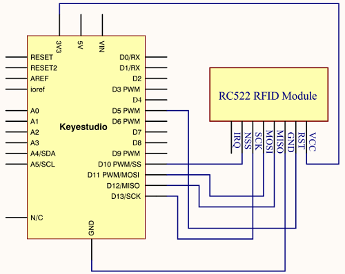
Connection for V4.0

Connection for 2560 R3
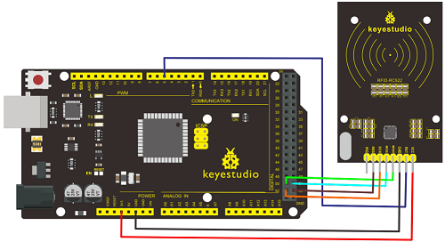
5. Sample Code
Note if you want to use MEGA 2560 R3, please in the code change
const int chipSelectPin = 10;//if the controller is V4.0
const int chipSelectPin = 53;//if the controller is MEGA2560
6. Test Result
In this experiment, when the IC card approaches, RFID module will write data to the IC card and read the card’s data, you can see the data on the monitor window. Shown below.
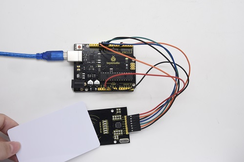
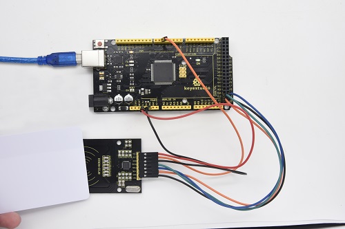
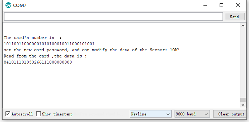
Установка программного обеспечения Arduino IDE (для Keyestudio PLUS)
Плата управления Keyestudio PLUS полностью совместима со средой разработки Arduino IDE. Она содержит все функции платы Arduino UNO. Более того, имеет некоторые улучшения, которые значительно расширили её функционал. Это один из лучших наборов, чтобы научиться собирать схемы и писать код.
Для начала нам нужно установить на свой компьютер Arduino IDE и драйвер для нашей платы. Для этого переходим на официальный сайт Arduino IDE по ссылке: https://www.arduino.cc и переходим (как на фото ниже) во вкладку «SOFTWARE».
На странице представлены различные версии для операционных систем Windows и Linux, просто загрузите подходящую версию для вашей операционной системы. Я скачал «WINDOWS zip file», хотя для WINDOWS 10 можно было скачать соответствующее ПО из самого магазина.

Т.е. для системы WINDOWS существует две версии: одна — установочная версия, другая — версия для загрузки, когда вам просто нужно загрузить файл напрямую на компьютер и разархивировать его. Во втором случае вам просто нужно после загрузки ZIP-файла его разархивировать и запустить файл с расширением exe в архиве.
Для удобства, папку из архива я перенёс в корень диска C. Вы же можете разместить её в другом удобном для вас месте, но во избежание в дальнейшем возможных ошибок, нужно что бы путь до папки не содержал русские символы.
Установка драйвера для Keyestudio PLUS
Установим драйвер платы управления Keyestudio PLUS. Чип USB-TTL на плате PLUS использует серийный чип CP2102. Программа драйвера этого чипа включена в версию Arduino 1.8 и выше, что удобно. Подключите USB-порт платы, компьютер может распознать оборудование и автоматически установить драйвер CP2102.
Если установка не удалась или вы собираетесь установить вручную, откройте диспетчер устройств компьютера. Щелкните правой кнопкой мыши Компьютер —— Свойства —— Диспетчер устройств.
На странице стоит желтый восклицательный знак, что означает неудачную установку драйвера CP2102. Затем мы дважды щелкаем оборудование и обновляем драйвер.
Нажмите «ОК», чтобы перейти на следующую страницу, нажмите «Найдите на моем компьютере обновленное программное обеспечение драйвера», найдите установленное или загруженное программное обеспечение ARDUINO. Как показано ниже:
В пакете установленного программного обеспечения Arduino () есть папка DRIVERS, откройте папку с драйверами и вы увидите драйвер микросхем серии CP210X.
Мы нажимаем «Обзор», затем находим папку с драйверами, или вы можете ввести «драйвер» для поиска в прямоугольном поле, а затем нажать «Далее», драйвер будет успешно установлен. (Я помещаю папку с программным обеспечением Arduino на рабочий стол, вы можете пойти по моему пути)
Откройте диспетчер устройств, и желтый восклицательный знак исчезнет. Драйвер CP2102 успешно установлен.
Настройка Arduino IDE
Щелкните значок , откройте Arduino IDE.
Чтобы избежать ошибок при загрузке программы на плату, вам необходимо выбрать правильную плату Arduino, которая соответствует плате, подключенной к вашему компьютеру. Затем вернитесь к программному обеспечению Arduino, вы должны нажать Инструменты → Плата, выбрать плату. (как показано ниже)
Затем выберите правильный COM-порт (вы увидите соответствующий COM-порт после успешной установки драйвера)
Прежде чем загружать программу на плату, давайте продемонстрируем функцию каждого символа на панели инструментов Arduino IDE.
A- Используется для проверки наличия ошибок компиляции.
B- Используется для загрузки эскиза на плату Arduino.
C- Используется для создания окна быстрого доступа к новому эскизу.
D- Используется для непосредственного открытия примерного скетча.
E- Используется для сохранения эскиза.
F- Используется для отправки последовательных данных, полученных с платы, на последовательный монитор.
Начни свою первую программу
Откройте файл, чтобы выбрать Пример, выберите МИГАНИЕ из ОСНОВНОГО, как показано ниже:
Установите плату и COM-порт, соответствующая плата и COM-порт показаны в правом нижнем углу IDE.
Нажмите, чтобы начать компиляцию программы, проверьте ошибки.
Нажмите, чтобы загрузить программу, загрузка прошла успешно.
Загрузите программу успешно, встроенный светодиод горит на 1 с, гаснет на 1 с. Поздравляю, вы закончили первую программу.
Как добавить библиотеку?
Что такое библиотеки? Библиотеки — это набор кода, который упрощает подключение к датчику, дисплею, модулю и т. Д. Например, встроенная библиотека LiquidCrystal помогает взаимодействовать с ЖК-дисплеями. В Интернете для загрузки доступны сотни дополнительных библиотек. Встроенные библиотеки и некоторые из этих дополнительных библиотек перечислены в справочнике.
Здесь мы познакомим вас с самым простым способом добавления библиотек.
Шаг 1. После правильной загрузки IDE Arduino вы можете щелкнуть правой кнопкой мыши значок Arduino IDE.
Найдите опцию «Открыть расположение файла», как показано ниже:
Шаг 2: Введите его, чтобы узнать папку библиотек, которая является файлом библиотеки Arduino.
Шаг 3 : Далее, чтобы узнать «библиотеки» умного дома (см. Ссылку: https://fs.keyestudio.com/KS0085 ), как показано ниже:
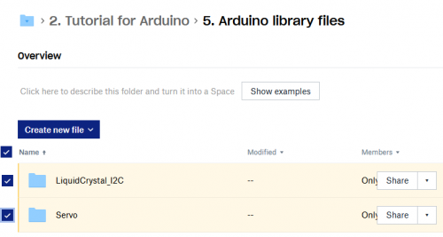
Вам просто нужно скопировать и вставить в папку с библиотеками Arduino IDE.
Библиотека домашнего смарта успешно установлена, как показано ниже: