
LAUNCH
Trademark Information
LAUNCH is a registered trademark of LAUNCH TECH.
CO., LTD. (LAUNCH for short) in China and other
countries. All other LAUNCH trademarks, service marks,
domain names, logos, and company names referred to in
this manual are either trademarks, registered trademarks,
service marks, domain names, logos, company names of
or are otherwise the property of LAUNCH or its affiliates. In
countries where any of the LAUNCH trademarks, service
marks, domain names, logos and company names are not
registered, LAUNCH claims other rights associated with
unregistered trademarks, service marks, domain names,
logos, and company names. Other products or company
names referred to in this manual may be trademarks of
their respective owners. You may not use any trademark,
service mark, domain name, logo, or company name of
LAUNCH or any third party without permission from the
owner of the applicable trademark, service mark, domain
name, logo, or company name. You may contact LAUNCH
by visiting Launch at http://www.cnlaunch.com, or writing to
LAUNCH
Industrial
Banxuegang Industrial Park, Longgang Dist., Shenzhen,
P.R. China, to request written permission to use Materials
on this manual for purposes or for all other questions
relating to this manual.
Copyright Information
Copyright © 2000 by LAUNCH TECH. CO., LTD. All rights
reserved. No part of this publication may be reproduced,
stored in a retrieval system, or transmitted in any form or
by any means, electronic, mechanical, photocopying,
recording or otherwise, without the prior written permission
of LAUNCH. The information contained herein is designed
only for the use of this unit. LAUNCH is not responsible for
any use of this information as applied to other units.
Neither LAUNCH nor its affiliates shall be liable to the
purchaser of this unit or third parties for damages, losses,
costs, or expenses incurred by purchaser or third parties
as a result of: accident, misuse, or abuse of this unit, or
unauthorized modifications, repairs, or alterations to this
unit, or failure to strictly comply with LAUNCH operating
and maintenance instructions.
LAUNCH shall not be liable for any damages or problems
arising from the use of any options or any consumable
products other than those designated as Original LAUNCH
Products or LAUNCH Approved Products by LAUNCH.
General Notice
Park,
North
Wuhe
Other product names used herein are for identification
purposes only and may be trademarks of their respective
owners. LAUNCH disclaims any and all rights in those
marks.
Disclaimer
To take full advantage of the unit, you should be
familiar with the engine.
All information, illustrations, and specifications
contained in this manual are based on the latest
information available at the time of publication. The
manufacturer resume the right of modify this manual
and the machine itself with no prior notice.
This unit is made for the purpose of persons who have
special techniques and certifications.
Safety Precautions
Read all service procedures and precautions, installation
Avenue,
instructions and equipment operating manuals thoroughly.
Failure to observe these precautions, or the improper use
of equipment, could result in property damage, serious
injury or death. Never allow improperly trained personnel
to perform these procedures or operate the equipment.
Read the operating instructions before attempting to
operate the unit. Keep this manual with the unit at
all times.
Care must be taken as burns can occur from
touching hot parts of the equipment or in the
engine.
Do not operate equipment with a damaged cord or if
the equipment has been dropped or damaged until
it has been examined by qualified service
personnel.
Do not hang cords over the edge of the table, bench
or counter, or come in contact with hot manifolds or
moving fan blades.
If an extension cord is needed, a cord with a rated
current equal to or greater than that of the
equipment should be used. Cords rated for lower
current than that of the equipment may overheat.
Always unplug equipment from electrical outlet
when the machine is not in use. Never pull the cord
when unplugging from the outlet.
Make sure the equipment cools down completely
before putting it away. Loop cord loosely around the
equipment when storing.
To protect against risk of fire, do not operate the
equipment in the vicinity of open container
containing flammable liquid (gasoline).
Make sure that the unit is in the well-ventilation area
when operating the fuel engine.
Keep lighted cigarettes, sparks, flames or other
ignition sources away from fuel systems at all times.
i
Injector Cleaner & Tester User’s Manual
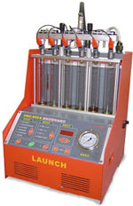
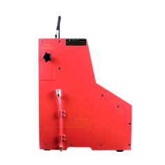
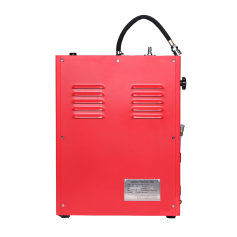
Описание LAUNCH CNC 602
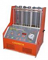
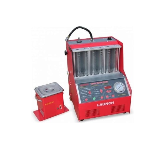
AUNCH CNC 602 – стенд для тестирования и очистки форсунок. С помощью этого устройства можно одновременно работать с 6 форсунками любого вида: электромагнитные или механические – не имеет значения. В комплекте идут все необходимые переходники для форсунок производителей Bosch, Siemens, Nipondenso, Weber, Delphi, Jecs, Hitachi и другие. В стенде CNC 602 реализованы все новейшие функции: автоматический слив тестирующей жидкости; электронная система, полностью имитирующая работу форсунок; система определения сопротивления форсунки.
Версия LAUNCH CNC 602A включает в себя специализированные адаптеры для промывки топливной системы без демонтажа с автомобиля.
Особенности стенда Launch CNC 602:
• Стенд последнего поколения с новейшими функциями;
• Совместимость как с электромагнитными, так и с механическими форсунками;
• Возможность тестировать до 6 форсунок одновременно;
• Стенд может также использоваться для очистки форсунок;
Функционал CNC 602:
• Определение динамического и статического баланса;
• Тестирование форсунок на герметичность;
• Анализ факела распыла;
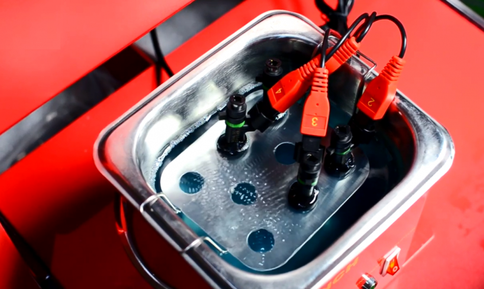
• Очистка форсунки без снятия, а также с использованием ультразвуковой ванны;
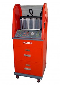
Обзор стенда Launch CNC 602:
Установка CNC-602 предназначена для тестирования и ультразвуковой очистки всех типов форсунок (до шести штук одновременно, как электромагнитных так и механических), очистки топливных систем автомобиля, а также впускных клапанов и камер сгорания при помощи сольвента без снятия форсунок.
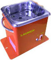
Ультразвуковая ванна для очистки форсунок в комплекте.
Бесплатная доставка до терминала транспортных компаний Деловые линии, Ратэк и ПЭК.
Возможности:
- Моделирование РЕАЛЬНЫХ параметров работы двигателя в процессе испытаний, в соответствии с особенностями конкретной системы управления двигателем (возможный диапазон числа оборотов: 1-9990 об/мин, диапазон давление топлива 0-6,5 бар, время впрыска 1-25мс)
- Имитация различных динамических режимов работы двигателя (AUTO1, AUTO 2, AUTO 3)
- Конструкция топливной рампы позволяет работать с различными форсунками – как с верхней, так и с боковой подачей топлива
- Подсветка мерных тестовых стаканов люминесцентной лампой для удобства оценки результатов испытаний
- Автоматизированный слив тестовой жидкости из мерных колб в исходную емкость по нажатию кнопки “Drain”
- Адаптивное управление током в соответствии с сопротивлением электрической обмотки форсунок. Отсутствует необходимость выяснять рабочее напряжение — 3В или 12В необходимо для форсунок. Установка определит это сама
- Адаптеры для тестирования большинства механических и электромагнитных форсунок входят в базовый комплект
Преимущества
- Компактный настольный вариант без стойки
| Питание | ~ 220 В ± 10%, 50 Гц 0.5% |
| Потребляемая мощность | 450 Вт |
| Мощность ультразвукового излучателя | 100 Вт |
| Давление тестирующей жидкости | 0 — 0.65 МПа |
| Точность установки давления | 0.004 МПа |
| Диапазон числа оборотов | 1 -9990 об/мин |
| Точность установки числа оборотов | 10 об/мин |
| Диапазон числа импульсов форсунок | 1 — 9999 1/сек |
| Длительность импульса включения форсунок: | 1 — 25 мс |
| Габаритные размеры, не более | 385 х 410 х 500 см |
| Вес, не более | 35 кг |
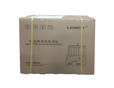
Габариты упаковки
| Размеры: | 50 x 60 x 70 см |
| Вес: | 37 кг |
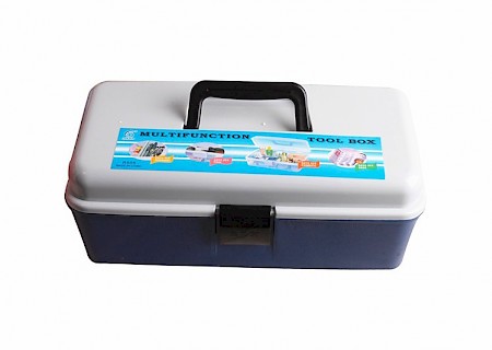
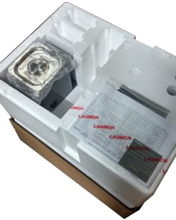
Основной блок установки тестирования и очистки форсунок (1 шт.)
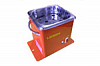
Ультразвуковая ванна (с подставкой для форсунок и крышкой) (1 шт.)
Инструкция пользователя (1 шт.) и листки с комплектацией (2шт.)
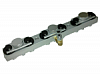
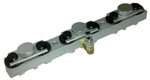
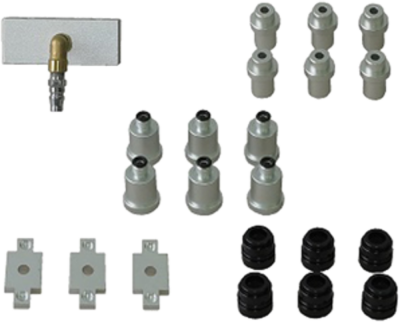
Распределитель топлива в сборе (1 шт.)
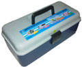
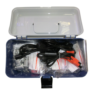
Коробка для принадлежностей (1 шт.)
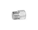
Адаптер для форсунок с верхней подачей топлива, крупная резьба (6 шт.)
Адаптер для форсунок с верхней подачей топлива, мелкая резьба (6 шт.)
Адаптер для форсунок с верхней подачей топлива, d=10,5мм, (6 шт.)

Адаптер для форсунок с верхней подачей топлива, d=13,5мм, (сразу установлен в распределитель топлива) (6 шт.)
Заглушка (6 шт.)
Адаптер для обратной промывки форсунок с верхней подачей, d=16,2мм (6 шт.) + O-ring (Φ15*2.65) (6 шт.)
Адаптер Buick (6 шт.)
Заглушка распределителя топлива (сразу установлена в распределитель топлива) (6 шт.)

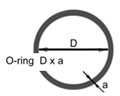
Уплотнительное кольцо O-ring (Φ23.6*1.8) (6 шт.)

Уплотнительное кольцо -ring (Φ15*2.65) (6 шт.)

Уплотнительное кольцо O-ring (Φ7.1×2.65) (6 шт.)

Уплотнительное кольцо O ring (Φ32.5*2.65) (6 шт.)
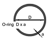
Уплотнительное кольцо O-ring (Φ23.6×2.65) (6 шт.)

Уплотнительное кольцоO-ring (Φ20*2.65) (6 шт.)

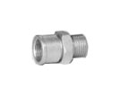
Переходники для подключения к форсункам (10 шт.)

Переходник для разъема форсунки (10 шт.)
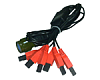
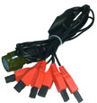
Кабель подключения форсунок (1 шт.)

Кабель питания (2 шт.)
Установка CNC-602А предназначенна для тестирования и ультразвуковой очистки всех типов форсунок (как электромагнитных так и механических), очистки топливных систем автомобиля, а также впускных клапанов и камер сгорания при помощи сольвента без снятия форсунок.
CNC-602А — позволяет производить тестирование до шести форсунок одновременно,
компактный настольный вариант;
Отличительные особенности установки CNC:
Моделирование РЕАЛЬНЫХ параметров работы двигателя в процессе испытаний,
в соответствии с особенностями конкретной системы управления двигателем
(возможный диапазон числа оборотов: 1-9990 об/мин, диапазон давление топлива 0-6,5 бар, время впрыска 1-25мс);
Имитация различных динамических режимов работы двигателя (AUTO1, AUTO 2, AUTO 3)
Конструкция топливной рампы позволяет работать с различными форсунками – как с верхней, так и с боковой подачей топлива, в том числе и с новейшими типами (GDI, HPI, FSI);
Подсветка мерных тестовых стаканов люминесцентной лампой для удобства оценки результатов испытаний;
Автоматизированный слив тестовой жидкости из мерных колб в исходную емкость по нажатию кнопки “Drain”.
Адаптивное управление током в соответствии с сопротивлением электрической обмотки форсунок. Отсутствует необходимость выяснять рабочее напряжение — 3В или 12В необходимо для форсунок. Установка вычислит это сама..
Адаптеры для тестирования большинства механических и электромагнитных форсунок входят в базовый комплект.
Набор адаптеров для промывки топливной системы (а также впускных клапанов и камер сгорания) при помощи специального сольвента прямо на автомобиле, так и образом вы можете производить, так называемую, жидкостную очистку двигателя!
Технические характеристики установоки CNC-602А
Питание: ~ 220 В ± 10%, 50 Гц 0.5%
Потребляемая мощность: 450 Вт
Мощность ультразвукового излучателя: 100 Вт
Давление тестирующей жидкости: 0 — 0.65 МПа
Точность установки давления: 0.004 МПа
Диапазон числа оборотов: 1 -9990 об/мин
Точность установки числа оборотов: 10 об/мин
Диапазон числа импульсов форсунок: 1 — 9999 1/сек
Длительность импульса включения форсунок: 1 — 25 мс
Габаритные размеры, не более: 385 х 410 х 500 мм
Вес, не более: 35 кг
Комплект адаптеров для промывки форсунок на автомобиле докупаются отдельно!
Инструкция по эксплуатации CNC-602 на русском языке.
При оформлении заказа через корзину на сайте Вы получаете дополнительную скидку 3%
Акция! при покупке Launch CNC-602A Вы получаете в подарок
- Гарантию на Launch CNC-602A 24 месяца.
Отличительные особенности:
- Моделирование РЕАЛЬНЫХ параметров работы двигателя в процессе испытаний, в соответствии с особенностями конкретной системы управления двигателем (диапазон числа оборотов: 1-9990 об/мин, давление топлива 0-6,5 бар, время впрыска 1-25мс);
- Шторка-жалюзи помогает содержать тестовую часть в чистоте и предохраняет от повреждений
- Выдвижная полка – удобный доступ к ультразвуковой ванне;
- Имитация динамических режимов работы двигателя – режимы “AUTO1, AUTO 2, AUTO 3”
- Конструкция топливной рампы позволяет работать с любыми форсунками – как с верхним, так и с боковым подводом топлива, в том числе и с новейшими типами (GDI, HPI, FSI);
- Подсветка мерных стаканов люминесцентной лампой для удобства оценки результатов испытаний;
- Автоматизированный слив тестовой жидкости из мерных колб в исходную емкость при помощи кнопки “Drain”.
- Адаптивное управление током в соответствии с сопротивлением электрической обмотки форсунок. Отсутствует необходимость выяснять на какое рабочее напряжение — 3В или 12В рассчитаны форсунки.
- Стойка с закрывающейся дверью снижает уровень шума при работе ультразвукового генератора.
- Адаптеры для тестирования подавляющего большинства механических и электромагнитных форсунок входят в базовый комплект – 96 шт.
- Набор адаптеров для промывки топливной системы (а также впускных клапанов и камер сгорания) при помощи специального сольвента прямо на автомобиле (опция).
Технические характеристики:
| Питание: | ~ 220 В ± 10%, 50 Гц 0.5% |
| Потребляемая мощность: | 450 Вт |
|
Мощность ультразвукового излучателя: |
100 Вт |
| Давление тестирующей жидкости: | 0 — 0.65 МПа |
| Точность установки давления: | 0.004 МПа |
|
Диапазон числа оборотов: |
1 -9990 об/мин |
| Точность установки числа оборотов: | 10 об/мин |
| Диапазон числа импульсов форсунок: | 1 — 9999 1/сек |
| Длительность импульса включения форсунок: | 1 — 25 мс |
| Габаритные размеры, не более: | 385 х 410 х 500 мм |
| Вес, не более: | 35 кг |
Базовая комплектация:
|
|
|
УЗ ванна с крышкой и сеткой |
Инструкция пользователя(1 шт.) |
Инструкция пользователя(1 шт.) |
Распределитель топлива в сборе |
|
|
|
адаптер для форсунок с верхней подачей топлива, крупная резьба |
адаптер для форсунок с верхней подачей топлива, d=10,5мм, |
адаптер для форсунок с верхней подачей топлива, d=10,5мм, |
адаптер для форсунок с верхней подачей топлива, d=13,5мм, (сразу установлен в распределитель топлива) |
 Заглушка (6 шт.) |
|
адаптер для обратной промывки форсунок с верхней подачей, d=16,2мм (6 шт.) + |
адаптер Buick |
адаптер Buick |
заглушка распределителя топлива (сразу установлена в распределитель топлива) |
|
уплотнительное кольцо |
уплотнительное кольцо |
уплотнительное кольцо |
|
|
уплотнительное кольцо |
|
|
|
уплотнительное кольцоO-ring (Φ20*2.65) |
|
|
переходник для разъема форсунки |
|
|
|
Кабель питания |
Коробка для принадлежностей |
Листки с комплектацией (2шт.) |


Launch
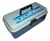
Установка для тестирования и очистки форсунок CNC 602 Launch LNC-028
Гарантия производителя 1 год
Нет в наличии
Последняя цена
51 212 р. Подобрать аналог

Спишите до 20485 р. бонусами Начислим 512 бонусов
Установка для тестирования и очистки форсунок CNC 602 Launch LNC-028 включает в себя обширный комплект вспомогательного оборудования, адаптеров и оснастки, которая позволяет подключать устройство к двигателям.
Промывка форсунок настраивается в зависимости от типа и модели двигателя. Высокая точность настройки параметров обеспечивает высокое качество промывки при минимальном времени подбора параметров.
Технические характеристики установки для тестирования и очистки форсунок Launch CNC 602 LNC-028
-
Кол-во одновременно промываемых форсунок, шт
6
- 220
- 37
Преимущества установки для тестирования и очистки форсунок Launch CNC 602 LNC-028
- Питание 220 В 10%, 50 Гц 0.5%
- Потребляемая мощность 450 Вт
- Мощность ультразвукового излучателя Launch LNC-028 100 Вт
- Давление тестирующей жидкости 0 — 0,65 МПа
- Точность установки давления 0,004 МПа
- Диапазон числа оборотов 1 — 9990 об/мин
- Точность установки числа оборотов 10 об/мин
- Диапазон числа импульсов форсунок 1 — 9999 1/сек
- Длительность импульса включения форсунок 1 — 25 мс
- Установка оптимального напряжения в соответствии с сопротивлением электрической обмотки форсунок
- Очистка форсунок при помощи ультразвуковой ванны из комплекта поставки
- Результаты испытаний видно в тестовых стаканах, подсвечиваемых люминесцентной лампой
- После завершения проверок, с помощью специальной кнопки DRAIN вся тестовая жидкость сливается в исходную емкость
- Колбы защищены от разбивания путем установки в глубине корпуса стенда CNC 602A
- Определение динамического / статического балансов форсунок на базе моделирования реальных параметров работы двигателя в динамике
- Число оборотов: 1 — 9990 об/мин
- Рабочее давление топлива 0 — 6,5 бар
- Время впрыска 1 — 25мс
- Проверка топливных магистралей на герметичность с помощью механического манометра из комплекта поставки
- Тест угла факела распыления сопла форсунки
- Возможность очистки до 6 штук электромагнитных или механических форсунок
- Переходные адаптеры для большинства типов форсунок в базовом комплекте поставки
- Топливная рампа Launch CNC-602 подходит для работы с верхним и боковым подводом топлива.
Показать все Скрыть
Гарантия производителя 1 год
на товары Launch
- *Производитель оставляет за собой право без уведомления дилера менять характеристики, внешний вид, комплектацию товара и место его производства. Указанная информация не является публичной офертой
Нашли ошибку в описании?
Сервисное обслуживание
Гарантия производителя 1 год
Отзывы
Вопросы и ответы
У этого товара еще нет ни одного вопроса — ваш может стать первым!
Расходные материалы для установки для тестирования и очистки форсунок Launch CNC 602
Specifications:1922/1922743-cnc602a.pdf file (29 Mar 2023) |
Accompanying Data:
Launch CNC-602A Diagnostic Equipment PDF Operation & User’s Manual (Updated: Wednesday 29th of March 2023 04:23:32 PM)
Rating: 4.3 (rated by 4 users)
Compatible devices: X-431 Throttle III, CR529, Creader Elite, iCarScan, Creader 629, Creader 519, Creader Professional 229, X-431 PRO GT.
Recommended Documentation:
Text Version of Operation & User’s Manual
(Ocr-Read Summary of Contents of some pages of the Launch CNC-602A Document (Main Content), UPD: 29 March 2023)
-
10, Launch CNC-602A LAUNCH Injector Cleaner & Tester User’s Manual 8 Mode I for Automatic Test Injecting for 15sec RPM: 6000 (max. rpm of multi-point injection Pulse width: 3 ms Times: 2500 RPM: 4500 Pulse width: 5 ms Times: 1700 Start …
-
5, LAUNCH Injector Cleaner & Tester User’s Manual 3 Structure Overview CNC series Injector Cleaner& Tester structure has been shown in Fig.01. Fig.01 1-Return fuel connector; 2- Outlet fuel connector; 3- Top-supply fuel distributor…
-
12, LAUNCH Injector Cleaner & Tester User’s Manual 10 On-Vehicle Cleaning After the engine has been in operation for a period of time, its fuel flow may be blocked or become un-smooth owing to buildup of dust and impurities in fuel channel. I…
-
9, Launch CNC-602A LAUNCH Injector Cleaner & Tester User’s Manual 7 the system pressure will come back to the default pressure value When the function of item section is working). 7) When the cleaning is over, Injector Cleaner & Tester will …
-
7, LAUNCH Injector Cleaner & Tester User’s Manual 5 Cleaning & testing sequences A complete cleaning and testing sequence shown below should be followed: z Ultrasonic cleaning; z Uniformity/Sprayability test; z Leakage test; z Inj…
-
2, LAUNCH Injector Cleaner & Tester User’s Manual ii z Keep hair, clothes, fingers or the other body parts away from the running parts of the unit. z In order to avoid electric shock, keep away from the damp part of a working unit and avoid exp…
-
Launch CNC-602A User Manual
-
Launch CNC-602A User Guide
-
Launch CNC-602A PDF Manual
-
Launch CNC-602A Owner’s Manuals
Recommended: HR2726, C855-S5343, KS-AR7501D — Class D Mono Amplifier 1200 Watts


-
SKF CMAS100-SL
SKF Machine Condition Advisor CMAS100-SL P/N 32150500-EN Revision A WARNING! Read this manual before using this product. Failure to follow the instructions and safety precautions in this manual can result in serious injury. Keep this manual in a safe location for future reference. Copyright © 2009 …
CMAS100-SL 41
-
Sealey TA130
INSTRUCTION MANUAL FOR: RELAY CIRCUIT DIAGNOSTIC TESTERMODEL No: TA130Your new tester is produced and manufactured to a high standard of dependability and will, if used according to these instructions and maintained properly, give you years of trouble free performance.Important: READ THESE INSTRUCTIONS CAREFULLY. N …
TA130 2
-
RIDGID Color SeeSnake KD-200 Color
Color SeeSnake™Diagnostic EquipmentPatent PendingCamera and Line LocationProducts for Pipe InspectionOPERATOR’S MANUAL• Pour français voire page 19• Para el castellano vea lapágina 39KD-200 ColorKD-325 ColorWARNING!For your own safety, read thisOperator’s Manual carefullybefore assembling or operatingthis …
Color SeeSnake KD-200 Color 61
-
RIDGID SeeSnake CS65x
Operator’s ManualCompanion Apps AvailableOriginal Instructions – English – 1WARNING!Read this Operator’s Man-ual carefully before using this tool. Failure to under-stand and follow the con-tents of this manual may result in electrical shock, fire, and/or serious per-sonal injury …
SeeSnake CS65x 19
Additional Information:
Popular Right Now:
Operating Impressions, Questions and Answers:
* Все цены на сайте указаны на условиях самовывоза товара с центрального склада в г. Москва. Стоимость доставки товара до конечного покупателя рассчитывается исходя из тарифов транспортной компании и оплачивается отдельно.
** Обращаем ваше внимание на то, что данный Интернет сайт по продаже оборудования для автосервиса носит исключительно информационный характер, и ни при каких условиях не является публичной офертой, определяемой положениями Статьи 437 Гражданского кодекса Российской Федерации. Для получения подробной информации о стоимости оборудования и запасных частей, пожалуйста, обращайтесь к менеджерам по продажам.
*** Технические характеристики и комплектация товара могут быть изменены производителем без уведомления.
**** Обратите внимание, что все товары, которые продает наша компания, относятся к категории «технически сложных товаров», которые не подлежат безусловному возврату или обмену, если они по каким-то причинам не подошли покупателю и при этом не имеют недостатков.
Описание LAUNCH CNC 602
AUNCH CNC 602 – стенд для тестирования и очистки форсунок. С помощью этого устройства можно одновременно работать с 6 форсунками любого вида: электромагнитные или механические – не имеет значения. В комплекте идут все необходимые переходники для форсунок производителей Bosch, Siemens, Nipondenso, Weber, Delphi, Jecs, Hitachi и другие. В стенде CNC 602 реализованы все новейшие функции: автоматический слив тестирующей жидкости; электронная система, полностью имитирующая работу форсунок; система определения сопротивления форсунки.
Версия LAUNCH CNC 602A включает в себя специализированные адаптеры для промывки топливной системы без демонтажа с автомобиля.
Особенности стенда Launch CNC 602:
• Стенд последнего поколения с новейшими функциями;
• Совместимость как с электромагнитными, так и с механическими форсунками;
• Возможность тестировать до 6 форсунок одновременно;
• Стенд может также использоваться для очистки форсунок;
Функционал CNC 602:
• Определение динамического и статического баланса;
• Тестирование форсунок на герметичность;
• Анализ факела распыла;
• Очистка форсунки без снятия, а также с использованием ультразвуковой ванны;
Обзор стенда Launch CNC 602:
Установка CNC-602 предназначена для тестирования и ультразвуковой очистки всех типов форсунок (до шести штук одновременно, как электромагнитных так и механических), очистки топливных систем автомобиля, а также впускных клапанов и камер сгорания при помощи сольвента без снятия форсунок.
Ультразвуковая ванна для очистки форсунок в комплекте.
Бесплатная доставка до терминала транспортных компаний Деловые линии, Ратэк и ПЭК.
Возможности:
- Моделирование РЕАЛЬНЫХ параметров работы двигателя в процессе испытаний, в соответствии с особенностями конкретной системы управления двигателем (возможный диапазон числа оборотов: 1-9990 об/мин, диапазон давление топлива 0-6,5 бар, время впрыска 1-25мс)
- Имитация различных динамических режимов работы двигателя (AUTO1, AUTO 2, AUTO 3)
- Конструкция топливной рампы позволяет работать с различными форсунками – как с верхней, так и с боковой подачей топлива
- Подсветка мерных тестовых стаканов люминесцентной лампой для удобства оценки результатов испытаний
- Автоматизированный слив тестовой жидкости из мерных колб в исходную емкость по нажатию кнопки “Drain”
- Адаптивное управление током в соответствии с сопротивлением электрической обмотки форсунок. Отсутствует необходимость выяснять рабочее напряжение — 3В или 12В необходимо для форсунок. Установка определит это сама
- Адаптеры для тестирования большинства механических и электромагнитных форсунок входят в базовый комплект
Преимущества
- Компактный настольный вариант без стойки
| Питание | ~ 220 В ± 10%, 50 Гц 0.5% |
| Потребляемая мощность | 450 Вт |
| Мощность ультразвукового излучателя | 100 Вт |
| Давление тестирующей жидкости | 0 — 0.65 МПа |
| Точность установки давления | 0.004 МПа |
| Диапазон числа оборотов | 1 -9990 об/мин |
| Точность установки числа оборотов | 10 об/мин |
| Диапазон числа импульсов форсунок | 1 — 9999 1/сек |
| Длительность импульса включения форсунок: | 1 — 25 мс |
| Габаритные размеры, не более | 385 х 410 х 500 см |
| Вес, не более | 35 кг |
Габариты упаковки
| Размеры: | 50 x 60 x 70 см |
| Вес: | 37 кг |
Основной блок установки тестирования и очистки форсунок (1 шт.)
Ультразвуковая ванна (с подставкой для форсунок и крышкой) (1 шт.)
Инструкция пользователя (1 шт.) и листки с комплектацией (2шт.)
Распределитель топлива в сборе (1 шт.)
Коробка для принадлежностей (1 шт.)
Адаптер для форсунок с верхней подачей топлива, крупная резьба (6 шт.)
Адаптер для форсунок с верхней подачей топлива, мелкая резьба (6 шт.)
Адаптер для форсунок с верхней подачей топлива, d=10,5мм, (6 шт.)
Адаптер для форсунок с верхней подачей топлива, d=13,5мм, (сразу установлен в распределитель топлива) (6 шт.)
Заглушка (6 шт.)
Адаптер для обратной промывки форсунок с верхней подачей, d=16,2мм (6 шт.) + O-ring (Φ15*2.65) (6 шт.)
Адаптер Buick (6 шт.)
Заглушка распределителя топлива (сразу установлена в распределитель топлива) (6 шт.)
Уплотнительное кольцо O-ring (Φ23.6*1.8) (6 шт.)
Уплотнительное кольцо -ring (Φ15*2.65) (6 шт.)
Уплотнительное кольцо O-ring (Φ7.1×2.65) (6 шт.)
Уплотнительное кольцо O ring (Φ32.5*2.65) (6 шт.)
Уплотнительное кольцо O-ring (Φ23.6×2.65) (6 шт.)
Уплотнительное кольцоO-ring (Φ20*2.65) (6 шт.)
Переходники для подключения к форсункам (10 шт.)
Переходник для разъема форсунки (10 шт.)
Кабель подключения форсунок (1 шт.)
Кабель питания (2 шт.)
Установка CNC-602А предназначенна для тестирования и ультразвуковой очистки всех типов форсунок (как электромагнитных так и механических), очистки топливных систем автомобиля, а также впускных клапанов и камер сгорания при помощи сольвента без снятия форсунок.
CNC-602А — позволяет производить тестирование до шести форсунок одновременно,
компактный настольный вариант;
Отличительные особенности установки CNC:
Моделирование РЕАЛЬНЫХ параметров работы двигателя в процессе испытаний,
в соответствии с особенностями конкретной системы управления двигателем
(возможный диапазон числа оборотов: 1-9990 об/мин, диапазон давление топлива 0-6,5 бар, время впрыска 1-25мс);
Имитация различных динамических режимов работы двигателя (AUTO1, AUTO 2, AUTO 3)
Конструкция топливной рампы позволяет работать с различными форсунками – как с верхней, так и с боковой подачей топлива, в том числе и с новейшими типами (GDI, HPI, FSI);
Подсветка мерных тестовых стаканов люминесцентной лампой для удобства оценки результатов испытаний;
Автоматизированный слив тестовой жидкости из мерных колб в исходную емкость по нажатию кнопки “Drain”.
Адаптивное управление током в соответствии с сопротивлением электрической обмотки форсунок. Отсутствует необходимость выяснять рабочее напряжение — 3В или 12В необходимо для форсунок. Установка вычислит это сама..
Адаптеры для тестирования большинства механических и электромагнитных форсунок входят в базовый комплект.
Набор адаптеров для промывки топливной системы (а также впускных клапанов и камер сгорания) при помощи специального сольвента прямо на автомобиле, так и образом вы можете производить, так называемую, жидкостную очистку двигателя!
Технические характеристики установоки CNC-602А
Питание: ~ 220 В ± 10%, 50 Гц 0.5%
Потребляемая мощность: 450 Вт
Мощность ультразвукового излучателя: 100 Вт
Давление тестирующей жидкости: 0 — 0.65 МПа
Точность установки давления: 0.004 МПа
Диапазон числа оборотов: 1 -9990 об/мин
Точность установки числа оборотов: 10 об/мин
Диапазон числа импульсов форсунок: 1 — 9999 1/сек
Длительность импульса включения форсунок: 1 — 25 мс
Габаритные размеры, не более: 385 х 410 х 500 мм
Вес, не более: 35 кг
Комплект адаптеров для промывки форсунок на автомобиле докупаются отдельно!
Инструкция по эксплуатации CNC-602 на русском языке.
При оформлении заказа через корзину на сайте Вы получаете дополнительную скидку 3%
Акция! при покупке Launch CNC-602A Вы получаете в подарок
- Гарантию на Launch CNC-602A 24 месяца.
Отличительные особенности:
- Моделирование РЕАЛЬНЫХ параметров работы двигателя в процессе испытаний, в соответствии с особенностями конкретной системы управления двигателем (диапазон числа оборотов: 1-9990 об/мин, давление топлива 0-6,5 бар, время впрыска 1-25мс);
- Шторка-жалюзи помогает содержать тестовую часть в чистоте и предохраняет от повреждений
- Выдвижная полка – удобный доступ к ультразвуковой ванне;
- Имитация динамических режимов работы двигателя – режимы “AUTO1, AUTO 2, AUTO 3”
- Конструкция топливной рампы позволяет работать с любыми форсунками – как с верхним, так и с боковым подводом топлива, в том числе и с новейшими типами (GDI, HPI, FSI);
- Подсветка мерных стаканов люминесцентной лампой для удобства оценки результатов испытаний;
- Автоматизированный слив тестовой жидкости из мерных колб в исходную емкость при помощи кнопки “Drain”.
- Адаптивное управление током в соответствии с сопротивлением электрической обмотки форсунок. Отсутствует необходимость выяснять на какое рабочее напряжение — 3В или 12В рассчитаны форсунки.
- Стойка с закрывающейся дверью снижает уровень шума при работе ультразвукового генератора.
- Адаптеры для тестирования подавляющего большинства механических и электромагнитных форсунок входят в базовый комплект – 96 шт.
- Набор адаптеров для промывки топливной системы (а также впускных клапанов и камер сгорания) при помощи специального сольвента прямо на автомобиле (опция).
Технические характеристики:
| Питание: | ~ 220 В ± 10%, 50 Гц 0.5% |
| Потребляемая мощность: | 450 Вт |
|
Мощность ультразвукового излучателя: |
100 Вт |
| Давление тестирующей жидкости: | 0 — 0.65 МПа |
| Точность установки давления: | 0.004 МПа |
|
Диапазон числа оборотов: |
1 -9990 об/мин |
| Точность установки числа оборотов: | 10 об/мин |
| Диапазон числа импульсов форсунок: | 1 — 9999 1/сек |
| Длительность импульса включения форсунок: | 1 — 25 мс |
| Габаритные размеры, не более: | 385 х 410 х 500 мм |
| Вес, не более: | 35 кг |
Базовая комплектация:
|
|
УЗ ванна с крышкой и сеткой |
Инструкция пользователя(1 шт.) |
Распределитель топлива в сборе |
|
|
|
адаптер для форсунок с верхней подачей топлива, d=10,5мм, |
|
| Заглушка (6 шт.) |
адаптер для обратной промывки форсунок с верхней подачей, d=16,2мм (6 шт.) + |
адаптер Buick |
|
|
уплотнительное кольцо |
уплотнительное кольцо |
|
|
|
|
|
|
|
|
|
Кабель питания |
Коробка для принадлежностей |
Листки с комплектацией (2шт.) |
Launch
Установка для тестирования и очистки форсунок CNC 602 Launch LNC-028
Гарантия производителя 1 год
Нет в наличии
Последняя цена
51 212 р. Подобрать аналог
Спишите до 20485 р. бонусами Начислим 512 бонусов
Установка для тестирования и очистки форсунок CNC 602 Launch LNC-028 включает в себя обширный комплект вспомогательного оборудования, адаптеров и оснастки, которая позволяет подключать устройство к двигателям.
Промывка форсунок настраивается в зависимости от типа и модели двигателя. Высокая точность настройки параметров обеспечивает высокое качество промывки при минимальном времени подбора параметров.
Технические характеристики установки для тестирования и очистки форсунок Launch CNC 602 LNC-028
-
Кол-во одновременно промываемых форсунок, шт
6
- 220
- 37
Преимущества установки для тестирования и очистки форсунок Launch CNC 602 LNC-028
- Питание 220 В 10%, 50 Гц 0.5%
- Потребляемая мощность 450 Вт
- Мощность ультразвукового излучателя Launch LNC-028 100 Вт
- Давление тестирующей жидкости 0 — 0,65 МПа
- Точность установки давления 0,004 МПа
- Диапазон числа оборотов 1 — 9990 об/мин
- Точность установки числа оборотов 10 об/мин
- Диапазон числа импульсов форсунок 1 — 9999 1/сек
- Длительность импульса включения форсунок 1 — 25 мс
- Установка оптимального напряжения в соответствии с сопротивлением электрической обмотки форсунок
- Очистка форсунок при помощи ультразвуковой ванны из комплекта поставки
- Результаты испытаний видно в тестовых стаканах, подсвечиваемых люминесцентной лампой
- После завершения проверок, с помощью специальной кнопки DRAIN вся тестовая жидкость сливается в исходную емкость
- Колбы защищены от разбивания путем установки в глубине корпуса стенда CNC 602A
- Определение динамического / статического балансов форсунок на базе моделирования реальных параметров работы двигателя в динамике
- Число оборотов: 1 — 9990 об/мин
- Рабочее давление топлива 0 — 6,5 бар
- Время впрыска 1 — 25мс
- Проверка топливных магистралей на герметичность с помощью механического манометра из комплекта поставки
- Тест угла факела распыления сопла форсунки
- Возможность очистки до 6 штук электромагнитных или механических форсунок
- Переходные адаптеры для большинства типов форсунок в базовом комплекте поставки
- Топливная рампа Launch CNC-602 подходит для работы с верхним и боковым подводом топлива.
Показать все Скрыть
Гарантия производителя 1 год
на товары Launch
- *Производитель оставляет за собой право без уведомления дилера менять характеристики, внешний вид, комплектацию товара и место его производства. Указанная информация не является публичной офертой
Нашли ошибку в описании?
Сервисное обслуживание
Гарантия производителя 1 год
Отзывы
Вопросы и ответы
У этого товара еще нет ни одного вопроса — ваш может стать первым!
Расходные материалы для установки для тестирования и очистки форсунок Launch CNC 602
Описание
Установки CNC-601A и CNC-602A предназначены для тестирования и ультразвуковой (УЗ) очистки всех типов форсунок (как электромагнитных так и механических), очистки топливных систем автомобиля, а также впускных клапанов и камер сгорания при помощи сольвента без снятия топливной рампы на автомобиле.
Функционально обе модели одинаковы и отличаются только типом исполнения: CNC-602A выполнена в настольном варианте, а CNC-601A смонтирована на передвижной стойке. Стойка-шкаф оснащена защитной шторкой рабочей области и имеет 2 глубоких выдвижных ящика и 4 катка с фиксаторами.
CNC-601/602 является самой «долгоиграющей» моделью в истории LAUNCH. Впервые появившись в продаже в 1999 г., она выдержала множество модификаций и продолжает оставаться востребованной на мировом рынке благодаря своей непревзойденной надежности.
Так же как LAUNCH и X-431 давно являются синонимами мультимарочного сканера, так и любую установку промывки форсунок во всем мире называют просто CNC.


Возможности
|
Технические характеристики
| ПАРАМЕТР | ЗНАЧЕНИЕ |
|---|---|
| Питание | ~ 220 В ± 10%, 50 Гц 0.5% |
| Потребляемая мощность | 230 Вт |
| Мощность УЗ излучателя ванны | 100 Вт |
| Давление тестирующей жидкости | 0 — 0.65 МПа |
| Точность установки давления | 0.004 МПа |
| Диапазон числа оборотов | 10 — 9990 об/мин |
| Точность установки числа оборотов | 10 об/мин |
| Частотный диапазон (кол-во импульсов вкл. форсунок) | 1 — 9999 1/с |
| Длительность импульса включения форсунок | 0,5 — 25 мс |
| Габаритные размеры, 601А / 602А | 500х580х1400 / 400х410х580 мм |
| Вес, 601А / 602А | 95 / 27 кг |
Элементы конструкции

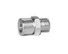
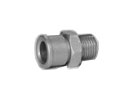
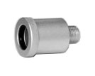
Наборы адаптеров
| Стандартный набор для форсунок с верхней подачей топлива ВПТ | |||
 |
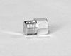
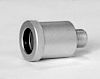
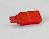
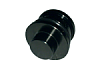
Распределитель топлива в сборе (рампа) — 1 шт. Адаптер, крупная резьба — 6 шт. Адаптер, мелкая резьба — 6 шт. Адаптер, d=10.5 мм — 6 шт. Адаптер, d=13.5 мм — 6 шт. (установлены в рампу) Заглушка — 6 шт. Адаптер для обратной промывки (ОП), d=16.2 мм — 6 шт. + резиновое кольцо, d=15/2.65 мм — 6 шт. Адаптер Buick — 6 шт. Заглушка рампы — 6 шт.(установлены в рампу) |
||
 |
 |
||
| [ERP 206010155] Набор для форсунок с боковой подачей топлива БПТ (опция) | |||
 |
Адаптер для Toyota Previa, d=23.5 мм Адаптер для Chevrolet, d=29 мм Адаптер для Nissan Maxima, d=26.3 мм Адаптер, d=22.5 мм Адаптер для Nissan 324, d=22.3 мм Адаптер для Cadillac, d=25.5 мм Адаптер для Mazda 929, d=25.9 мм Набор приспособлений для специфических форсунок Прижимная планка Шестиугольная подпорка для ОП, d=14 мм, 11 мм Держатель для ОП специфических форсунок Адаптер для ОП форсунок с ВПТ, d=16.2 мм, 21 мм. |
||
| [ERP 206010154] Набор для промывки на автомобиле ПА (опция для CNC-602A) | |||
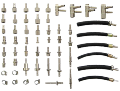 |
Вспомогательная проставка для форсунок с БПТ Адаптер для Chevrolet, d=29 мм Держатель для ОП специфических форсунок Адаптер для Toyota Previa, d=23.5 мм Адаптер для Nissan Bluebird, d=26 мм Адаптер для ОП форсунок с ВПТ, d=16.2 мм Вспомогательная проставка для форсунок с БПТ Набор для специфических форсунок Адаптер для форсунок с ВПТ, крупная резьба Шестигранная подпорка для ОП, d=14 мм, 11 мм Адаптер для форсунок с ВПТ, мелкая резьба Адаптер для Nissan 324, d=22.3 мм Адаптер для Nissan Maxima, d=26.3 мм Адаптер для форсунок с ВПТ, d=10.5 мм Адаптер для форсунок с ВПТ, d=13.5 мм Адаптер для Cadillac, d=25.5 мм Адаптер для Mazda 929, d=25.9 мм Адаптер для подключения к форсункам Распределитель топлива для форсунок GM Заглушка для распределителя топлива GM |
||
|
Адаптер AUX для БП Адаптер односторонний AUX Адаптер для разъема форсунки Адаптер AUX Прижимная планка Адаптер Ford Адаптер Nissan Адаптер для Chevrolet Cavalier Заглушка |
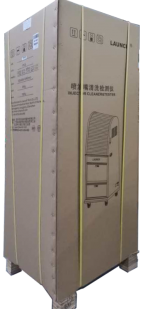
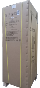
Габариты упаковки
| Модель | CNC-601А | CNC-602А |
|---|---|---|
| Размеры ДхШхВ, мм | 538х608х1546 | 695 х 495 x 600 |
| Вес брутто, кг | 105 | 26 |
| Вес, нетто | 95 | 23 |
Документация
Руководство пользователя
Рекламный проспект
Упаковочный лист
-
LAUNCH Injector Cleaner & Tester Users Manual
i
Trademark Information LAUNCH is a registered trademark of LAUNCH
TECH. CO., LTD. (LAUNCH for short) in China and other countries.
All other LAUNCH trademarks, service marks, domain names, logos,
and company names referred to in this manual are either trademarks,
registered trademarks, service marks, domain names, logos, company
names of or are otherwise the property of LAUNCH or its affiliates.
In countries where any of the LAUNCH trademarks, service marks,
domain names, logos and company names are not registered, LAUNCH
claims other rights associated with unregistered trademarks,
service marks, domain names, logos, and company names. Other
products or company names referred to in this manual may be
trademarks of their respective owners. You may not use any
trademark, service mark, domain name, logo, or company name of
LAUNCH or any third party without permission from the owner of the
applicable trademark, service mark, domain name, logo, or company
name. You may contact LAUNCH by visiting Launch at
http://www.cnlaunch.com, or writing to LAUNCH Industrial Park,
North Wuhe Avenue, Banxuegang Industrial Park, Longgang Dist.,
Shenzhen, P.R. China, to request written permission to use
Materials on this manual for purposes or for all other questions
relating to this manual.Copyright Information
Copyright 2000 by LAUNCH TECH. CO., LTD. All rights reserved. No
part of this publication may be reproduced, stored in a retrieval
system, or transmitted in any form or by any means, electronic,
mechanical, photocopying, recording or otherwise, without the prior
written permission of LAUNCH. The information contained herein is
designed only for the use of this unit. LAUNCH is not responsible
for any use of this information as applied to other units.Neither LAUNCH nor its affiliates shall be liable to the
purchaser of this unit or third parties for damages, losses, costs,
or expenses incurred by purchaser or third parties as a result of:
accident, misuse, or abuse of this unit, or unauthorized
modifications, repairs, or alterations to this unit, or failure to
strictly comply with LAUNCH operating and maintenance
instructions.LAUNCH shall not be liable for any damages or problems arising
from the use of any options or any consumable products other than
those designated as Original LAUNCH Products or LAUNCH Approved
Products by LAUNCH.General Notice
Other product names used herein are for identification purposes
only and may be trademarks of their respective owners. LAUNCH
disclaims any and all rights in those marks.Disclaimer z To take full advantage of the unit, you should
befamiliar with the engine. z All information, illustrations, and
specificationscontained in this manual are based on the latest information
available at the time of publication. The manufacturer resume the
right of modify this manual and the machine itself with no prior
notice.This unit is made for the purpose of persons who have special
techniques and certifications.Safety Precautions
Read all service procedures and precautions, installation
instructions and equipment operating manuals thoroughly. Failure to
observe these precautions, or the improper use of equipment, could
result in property damage, serious injury or death. Never allow
improperly trained personnel to perform these procedures or operate
the equipment.z Read the operating instructions before attempting to
operate the unit. Keep this manual with the unit at all
times.z Care must be taken as burns can occur from touching hot parts
of the equipment or in the engine.z Do not operate equipment with a damaged cord or if the
equipment has been dropped or damaged until it has been examined by
qualified service personnel.z Do not hang cords over the edge of the table, bench or
counter, or come in contact with hot manifolds or moving fan
blades.z If an extension cord is needed, a cord with a rated current
equal to or greater than that of the equipment should be used.
Cords rated for lower current than that of the equipment may
overheat.z Always unplug equipment from electrical outlet when the
machine is not in use. Never pull the cord when unplugging from the
outlet.z Make sure the equipment cools down completely before putting
it away. Loop cord loosely around the equipment when storing.z To protect against risk of fire, do not operate the equipment
in the vicinity of open container containing flammable liquid
(gasoline).z Make sure that the unit is in the well-ventilation area when
operating the fuel engine.z Keep lighted cigarettes, sparks, flames or other ignition
sources away from fuel systems at all times. -
LAUNCH Injector Cleaner & Tester Users Manual
ii
z Keep hair, clothes, fingers or the other body parts away from
the running parts of the unit.z In order to avoid electric shock, keep away from the damp part
of a working unit and avoid exposing it to the rain.z Please operate the unit according to the operation procedures
in the manual. Only use the accessories recommended by the
manufacturer.z Do not switch on the ultrasonic system when there is no
ultrasonic detergent in the ultrasonic cleaning chamber. Otherwise,
damage to the ultrasonic cleaner can be resulted.z Keep the unit well grounded. z Provide ventilation through an
exhaust gas removalsystem, ventilation fans or large doors. Carbon monoxide gas,
which is odorless and colorless, can cause serious illness, injury
or death.z Avoid contacting hot surfaces such as exhaust pipes, radiator,
etc.z Before testing vehicles, put the transmission lever in NEUTRAL
position, apply the parking brake, and block the front wheels.z ALWAYS WEAR SAFETY GOGGLES. Common used glasses are NOT safety
glasses.z When disconnecting any connector of the pressurized fuel hose,
wrap the connector with towel to prevent the fuel from spurting
out. Spurted fuel may cause personal injury or fire.z Test liquid is used by the main unit. Detergent is used for
on-vehicle cleaning. The ultrasonic cleaning uses specified
ultrasonic detergent (It can be replaced by detergent provided
together with the unit).Note: Specifying operations that require attention when
operating the equipment.Warning: Specifying a possible hazard that could result in
damage to the machine or personal injury.PLEASE SAVE THESE INSTRUCTIONS
-
LAUNCH Injector Cleaner & Tester Users Manual
1
Table of Contents
Introduction
……………………………………………………………..2
Functions
……………………………………………………………….2
Features
………………………………………………………………..2
Specifications
…………………………………………………………2Structure…………………………………………………………………..3
Overview………………………………………………………………..3
Control
Panel………………………………………………………….3Installation & Connection
……………………………………….4 1. CNC-602A
Installation ………………………………………….4 2.
CNC-601A/801A Installation………………………………….4
3 Ordinary
Connection……………………………………………..4Operating Procedures
……………………………………………4 Preparation
…………………………………………………………….4
Cleaning & testing sequences
…………………………………..5 Tidy up after
operating……………………………………………..5Operation
…………………………………………………………………5
Ultrasonic Cleaning
…………………………………………………5
Uniformity/Sprayability Test
………………………………………5 Leakage Test
………………………………………………………….7
Injecting Flow Test
…………………………………………………..7 Auto.
Test……………………………………………………………….7
On-Vehicle
Cleaning………………………………………………10Maintenance
………………………………………………………….
11 1. Transporting and Storing
……………………………………. 11 2. Vulnerable Parts
……………………………………………….. 11 3.
Connection Diagram of Driving Board …………………..12 4.
Troubleshooting &
Precautions…………………………….12Installation and Adjustment
………………………………………….14 1. Parts List
and Structure Diagram of Fuel Path ……….14 2. Parts List and
Structure Diagram of Fuel Distributor .15 3. Parts List and
Structure Diagram of Fuel Tank ……….15 4. Main Components and
Parts ……………………………….16Appendix 1: List of Optional Parts ………………………18
Appendix 2: Electrical Diagram …………………………..20
Appendix 3: Fuel Path Diagram ………………………….20
Appendix 4: Pressure Gauge of Injection
System………………………………………………………………………………..21 -
LAUNCH Injector Cleaner & Tester Users Manual
2
Special note: This users manual is an introduction to the
structure, functions, operations, cautions, maintenance and
troubleshooting for the proper use of the equipment, LAUNCH Company
retain the right of changing product design and specifications, The
actual configuration according to the packing list.Introduction
Thank you for purchasing the Injector Cleaner & Tester
manufactured by LAUNCH TECH CO., LTD. Developed with the technology
of ultrasonic cleaning and fuel pressure control, this equipment is
an advanced electromechanical product, which can clean and test
injectors by simulating engine working conditions. It can also
perform cleaning on the injectors and fuel supply system on
vehicle.Functions z Ultrasonic cleaning: To perform simultaneous
cleaning on several injectors and to remove the carbon deposits
on the injector completely.z Uniformity/Sprayability test: To test the uniformity of
injecting amount of each injector, and to monitor the spraying
status of each injector with the help of backlight. This test is
also for reverse flush.z Leakage test: To test the sealing and dribbling conditions of
injectors under system pressure.z Injecting flow test: To check the injecting amount of the
injector in 15 seconds of constant injection.z Auto. test: To test injectors by simulating different working
conditions.z On-vehicle cleaning: The unit is equipped with various
adaptors and couplers that facilitate cleaning on the injectors on
vehicle.Features z Adopting the powerful ultrasonic cleaning
technology, The equipment offers complete cleaning to the
injectors.z Fuel pressure control through microcomputer offers stable
pressure control and large adjustable range, which is suitable for
all EGI vehicles and can help to achieve automatic cleaning and
testing of injectors.z With the help of microcomputer control and digital display,
The equipment makes possible automatic cleaning, testing injectors
and real-time monitoring of the dynamic values.z Automatic fuel draining through preset programs for some test
items. Test liquid/detergent can also be drained by pushing a
button on the control panel after the test.z Adopting humanization design can make the system pressure fast
restored to the default values.Specifications Working conditions: z Temperature: -10~+40; z
Relative humidity: 85%; z Intensity of outer magnetic field:
400A/m;z No naked flame within 2m.
Specifications: z Main unit power supply: AC220V10%, 50/60Hz;
AC110V10%, 50/60Hz.z Main unit power: 230WCNC-601A/ 602A 280WCNC-801A
z Ultrasonic cleaner power: 100W; z Simulated RPM range: 10
9990rpm; step:10rpm; z Time range: 19999s; z Pulse width: 0.525ms; step 0.1
ms; z Fuel tank capacity: 4700ml601A/801A 4000ml602A z Dimensions:
400mm410mm580mm602A500mm580mm1400 mm601A/801A z Weight: 27kgCNC-602A
95kgCNC-601A/801A
-
LAUNCH Injector Cleaner & Tester Users Manual
3
Structure
Overview CNC series Injector Cleaner& Tester structure has
been shown in Fig.01.Fig.01
1-Return fuel connector; 2- Outlet fuel connector; 3- Top-supply
fuel distributor assembly; 4- Measuring cup; 5- Control panel; 6-
Socket for pulse signal cable; 7- Pressure gauge; 8- Power socket
& Fuse; 9- Power switch 10- Tee joint; 11- Filter; 12- Fluid
level switch; 13- Tank; 14- Return hose; 15- Fuel filler; 16- Pump;
17- Fluid level indicator/Fuel draining hose; 18- Sliding curtain;
19- Ultrasonic cleaner; 20- drawer.Note:
The illustrations in this manual may be slightly different from
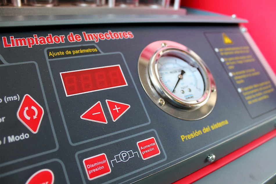
the actual product!Control Panel The control panel is shown in Fig.02 (Apart from
models signs, the CNC-601A & CNC-602A & CNC-801A control
panel is identical.).Fig.02
The control panel can be divided into five areas as shown in the
following table: Area DescriptionItem selection Select a function by pressing a key. The
corresponding indicator will light. Parameter selection Select a
parameter by pressing a key. The corresponding indicator will
light.Parameter setting After selecting function and parameter, the
user can set the parameter value by pressing/key. (key is for
increasing, key is for decreasing.) The set value will be displayed
on LED screen.System control System control area below the Item selection
& Parameter selection area, which control the draining stop and
run of the equipment.System pressure control System pressure control area below the
Parameter setting area, which can adjust the system pressure by
pressing [increase pressure] / [decrease pressure] key. -
LAUNCH Injector Cleaner & Tester Users Manual
4
Installation & Connection
1. CNC-602A Installation 1) Move the machine onto the workbench
afterunpacking and loosen the strips on the outlet hoses.
2) Mount the pulse signal cables onto the socket on the right
top side of the machine.3) Take the two adjusting bolts out from the kit and install
them to the press plate on the top of the glass tube.4) Take the two knurled nuts from the kit and install them on
the adjusting bolts.5) Take the fuel distributor from the kit and install it on the
knurled nuts and tighten them with the pressing bolts.2. CNC-601A/801A Installation 1) Take the pulse signal cables
from the box and insertit into the socket on the top right side of the machine and
tighten it.2) Take the pulse signal cables from the box and insert it into
the socket on the right upper of the ultrasonic cleaner and tighten
them.3) Take the two adjusting screws out from the box and install
them to the press plates on the top of the glass tubes.4) Take the two knurled nuts from the box and install them on
the adjusting screws.5) Take the fuel distributor from the box and install it on the
knurled nuts and tighten them with the pressing screws.Fig.03
1-Outlet hose; 2-Pulse signal cables; 3-Fuel distributor
assembly; 4-Adjusting bolts; 5-Knurling nut.Fig.04
1-Outlet hose; 2-Top-supply fuel distributor assembly;
3-Adjusting screw; 4-Knurled nut.3 Ordinary Connection 1) Take the power cables out from the kit
and insert it into the input socket at the bottom of the unit. 2)
Take the power cables out from the kit and insert it into the input
socket of the ultrasonic cleaner.Operating Procedures
Preparation 1) Remove the injector from the vehicle engine to
checkthe o-rings inside for damage. Replace the damaged O-ring with
another same type O-ring to avoid leakage during testing. Put the
outside of injectors in gasoline or detergent, and wipe them with
soft cloth after cleaning the outside oil sludge carefully.2) Check the liquid level and refill test liquid when necessary.
Fill the test liquid through the filler on the side of the unit and
observe the liquid level in the fuel level viewer. In most cases,
filled the liquid up to 1/2 of the tank capacity.3) Turn on the power switch on the right of the Cabinet. 4) Fill
ultrasonic detergent into the ultrasonic cleaninglaunder so that the needle valve of the injector is covered by
the detergent.5) Connect the injectors with the right couplers.
Note: Test liquid and detergent are provided together with the
unit. The test liquid is used for uniformity/sprayability test,
leakage test, injecting flow test and auto. test. The mixture of
fuel and detergent is used in on-vehicle cleaning. The ultrasonic
cleaning uses special injector detergent (or test liquid and
detergent that comes with by the unit). -
LAUNCH Injector Cleaner & Tester Users Manual
5
Cleaning & testing sequences A complete cleaning and testing
sequence shown below should be followed: z Ultrasonic cleaning; z
Uniformity/Sprayability test; z Leakage test; z Injecting flow
test; z Auto. test. Select the corresponding parameter and set up
according for various tests. For detailed operations, please refer
to Operation part.Tidy up after operating Tidy-up should be done after cleaning
and testing is completed: z Press [Drain] button to drain the test
liquid into fueltank. z Switch off the power and unplug from the socket. z Drain
the injector detergent to its original bottle andthen wipe the ultrasonic cleaner with soft cloth. z Clean the
Injector Cleaner & Tester control panelwith soft cloth. z Drain the test liquid from the tank into a
container toavoid volatilization. Store the test liquid in a safe place if
it can be used again, or dispose of it in accordance with relevant
regulations if it is too dirty.Operation
Ultrasonic Cleaning Injector Cleaner takes advantage of the
penetrability and cavitation impact wave caused by ultrasonic wave
traveling through the medium to provide powerful cleaning on
objects with complex shapes, cavities and pores, so that the
stubborn carbon deposits can be removed from the injectors.Procedures
1) Connect the power supply: connect one end of the power cable
to the power socket on ultrasonic cleaner and the other end to
power socket.2) Place the injectors which have gone through surface cleaning
in a launder.3) Add enough injector detergent into ultrasonic cleaner so that
the liquid level is about 20mm above the needle valve of
injectors.4) Plug the injector pulse signal wires to injectors
respectively then turn on the power switch of the ultrasonic
cleaner.5) Select [Ultrasonic cleaning] in the function column by
pressing key. Select [Timer] in the parameter column, and set the
timer (the default time is about 10 minutes) in the value column.
Press [Run] buttonto start cleaning. 6) When the time is up, Injector Cleaner
& Tester willstop automatically as the beeper rings. 7) Turn off the power of
the ultrasonic cleaner, take theinjectors out of the launder and wipe them with a dry soft
cloth. Get ready for next operation.Note: Before the injector detergent is added into
ultrasonic cleaner, do not turn on the ultrasonic cleaner.
Otherwise, damage may be incurred.Do not dip the pulse signal cables plug and the injectors body
into the detergent.Uniformity/Sprayability Test Uniformity test is to find out if
the flow of different injectors meets the requirement or
specifications under the same working condition. This test can
reflect the comprehensive influences on the injector caused by
electrical nature, bore variation and clogging. Sprayability test
is to inspect the spraying performance by observing the
injectors.Installing and testing procedures for top-supply injectors
1) Choose the fuel distributor stopper (4) from the coupler box
and mount a proper O-ring on it. Remember to apply a little
lubricating grease on the O-ring. Mount the fuel distributor
stopper (4) onto the top-supply fuel distributor.2) Mount the crescent plate (3) and tighten it with a plate bolt
(1).3) Choose a proper adaptor (5) according to the injector type
and mount it to the corresponding coupler under the top-supply fuel
distributor.4) Install the injectors in forward direction (Apply a little
lubricating grease on the O-ring.)5) Install the top-supply fuel distributor and the injector on
the fuel distributor supporter with a proper adjustable screw and
knurled nuts, and tighten two riffle screws (black). See Fig.
05.6) Connect the injector pulse signal wire. 7) Before doing this
test, press [Drain] button to drain thetest liquid from the measuring cup if there is any.
 Choose
[Uniformity/Sprayability test] on the controlpanel, set corresponding parameters (consult the appendix for
pressure setting, consult vehicle manuals for other parameters as
needed), and then press [Run] button to start the test. (The
equipment can be switched between [uniformity test] and
[sprayability test] by pressing [Drain] key when it is
running.)9) When the test is completed, the equipment will auto stop with
the ring of the buzzer. -
LAUNCH Injector Cleaner & Tester Users Manual
6
Fig. 05 for fuel top-supply injector
1-Plate bolt; 2-Riffle screw; 3-Crescent plate; 4-Fuel
distributor stopper; 5-Adapter for fuel top-supply injector;
6-Injector;7-Knurled nut; 8-Adjustable screwInstalling and testing procedures for side-supply injectors
1) Choose proper couplers for side-supply injectors (3) and
proper O-rings, and mount them together. (Remember to apply a
little lubricating grease.)2) Mount the injectors on the couplers and install them onto the
side-supply fuel distributor.3) Mount the cross plate (1) and tighten it with bolts. 4) Mount
the fuel distributor and injectors onto the fueldistributor supporter, and tighten them with two riffle screws
(black). See Fig. 06.5) Connect the injector pulse signal wire. 6) Before doing this
test, press [Drain] button to drainthe test liquid from the measuring cup if there is any. 7)
Select [Uniformity/Sprayability test] on the controlpanel, set the corresponding parameters and press [Run] button
to start the testing. (when it is running press the key then press
[run] key the system pressure will come back to the default
pressure value When the function of item section is working) When the testing is over, Injector Cleaner & Tester will
auto stop at the ring of the buzzer.Fig. 06
1- Cross plate; 2-Fuel side-supply injector; 3- Coupler for fuel
side-supply injector; 4,5-O-ring; 6-Side-supply fuel
distributorNote: While testing, Injector Cleaner & Tester can
drain fuel by pressing [Drain] key. At default, solenoid valve
is set at the closed state. Uniformity test can be done at this
state. When [drain] key is pressed, solenoid valve will drain
oil.The default cylinder number of the system is 0, which means that
all injectors are working when Injector Cleaner & Tester is
running. A specificcylinder can be selected by setting the number of the
cylinder.The system pressure can be adjusted by pressing [decrease
pressure] / [increase pressure] key when testing.Keep the fluid level to at least 30 ml while testing. Foam will
be produced in the liquid during injection. In order to prevent
spillover, set the related parameter with reference to the
following formula :Pulse width(ms)time(s)speed(rpm) / 12018000This is for checking the uniformity of each cylinder. Injecting
difference of all injectors on one vehicle should be kept within 2%
during uniformity testing.During operating, the user can select parameter, such as RPM or
PW, and then pressorkey to achieve the status of the
simulation.Good injectors may have identical injecting angle, uniform
spraying but no jet. Otherwise, replace the injector.In the sprayability test, a special electrical parameter—the
minimum injection pulse width of injector—can be tested, to
compare the injectors on the same engine. That is to set cylinder
No., start the test from minimum injection pulse width, and then
gradually increases the pulse width till the injector starts
injection (observed with the help of backlight). The value set at
this moment is the minimum injection pulse width, so the difference
of minimum injection pulse width among these injectors could be
observed.Reverse flush Injector Cleaner & Tester can also perform
reverse flush by connecting with flush-back adaptor at
[Uniformity/Sprayability test] mode. Reverse flush is a way to
clean the injectors with the test liquid flowing from the outlet to
the inlet of the injector. Reverse flush may remove the dirt inside
the injector or the injector Strainer (Only for the top fuel supply
injector).Procedures:
1) Choose a reverse flush coupler and proper O-ring, and mount
them under the fuel distributor.2) Install the injectors in reverse direction (outlet upward,
and inlet downward).3) Choose a proper coupler according to the shape of the
injector and put it under the injector.4) Install the fuel distributor and the injector on the fuel
distributor supporter with a proper adjustable screw and knurled
nuts, and tighten two riffle screws (black). See Fig. 07.5) Connect the injector pulse signal wire. 6) Set parameter, and
press [Run] button to startcleaning(Injector Cleaner & Tester can switch between
reverse flush by pressing [Drain] key when it is running press the
key then press run key -
LAUNCH Injector Cleaner & Tester Users Manual
7
the system pressure will come back to the default pressure value
When the function of item section is working).7) When the cleaning is over, Injector Cleaner & Tester will
automatically stop at the ring of the buzzer.Note: The system pressure can be adjusted by
pressing [decrease pressure]/[increase pressure] key when
performing reverse flush.It is advisable to press [Drain] key to avoid spillover of test
liquid during reverse flush.Fig. 07
1-Plate bolt; 2-Crescent plate; 3-Fuel distributor stopper;
4-Reverse adaptor; 5-Injector; 6-Knurled nut; 7-Adjustable screw;
8-Riffle screw; 9,10,11-O-ring; 12-Fuel distributor; 13-O-ring;
14-Couplers.Leakage Test Leakage test is to inspect the sealing conditions
of the injector needle valve under system pressure and to find out
if the injector is dribbling.Procedures (For installation refer to Uniformity/ Sprayability
Test):1) Before doing leakage test, please press [Drain] button to
drain the rudimental residual test liquid from the measuring
cup.2) Select [Leakage test] mode on the control panel. Press [run]
key, the machine will work. At this time the system pressure can be
adjusted by pressing [decrease pressure]/[increase pressure] key to
observe dribbling from the injector the pressure is adjusted
preferably 10% higher than manufacturers specifications(Injector
Cleaner & Tester can switch between leakage test by pressing
[Drain] key when it is running press the key then press run key the
system pressure will come back to the default pressure value When
the function of item section is working).3) When the test is over, the equipment will automatically stop
and the buzzer will ring simultaneously.Note: In general the drip of the injector should be less
than 1 drop within 1 minute (or in accordance with the
specifications). The default time of the system is 1 minute.Injecting Flow Test Injecting flow test is to check if the
injecting flow in 15 seconds meets the specifications for injecting
amount. The deviation reflects the wear or clogging in the
injector, instead of electrical parameter variation.Procedures (For installation refer to Uniformity / Sprayability
Test):1) Before this test, press [Drain] button to drain the test
liquid from the measuring cup if there is any.2) Choose [Injecting flow test] mode on the control panel, and
press [Run] button to start the test. Adjust the fuel pressure by
pressing [decrease pressure]/[increase pressure] key according to
the injector specification(Injector Cleaner & Tester can switch
between injecting flow test by pressing [Drain] key when it is
running press the key then press run key the system pressure will
come back to the default pressure value When the function of item
section is working).3) When the test is over, Injector Cleaner & Tester will
stop automatically at the ring of the buzzer.Auto. Test Auto. test contains all above-mentioned tests
(15-second injecting test, idle speed, middle speed, high speed,
varying acceleration, varying deceleration, changing pulse width
test). This function can test more comprehensive performance of
injectors by simulating the various engine working conditions.Procedures (For installation refer to Uniformity / Sprayability
Test):1) Before the test, press [Drain] button to drain all the test
liquid in the measuring cups if there is any.2) Select [Auto. test] mode on the control panel and set up the
pressure value according to the injector specifications, select the
test mode (mode 1, 2, or 3 are all available), and then press [Run]
button to start the test.3) Adjust the fuel pressure by pressing [decrease
pressure]/[increase pressure] key when testing or press the key
then press run key the system pressure will come back to the
default pressure value When the function of item section is
working)..4) When the test is over, Injector Cleaner & Tester will
auto stop at the ring of the buzzer.Whats the Model? There are three Models in the Auto. test
function Model I Model II & Model III, Model I & Model II
shown in the flow chart below, the Model III equal to the Model I
add the Model II. -
LAUNCH Injector Cleaner & Tester Users Manual
8
Mode I for Automatic Test
Injecting for 15sec
RPM: 6000 (max. rpm of multi-point injection Pulse width: 3 ms
Times: 2500RPM: 4500 Pulse width: 5 ms Times: 1700
Start the pump and adjust system pressure
to appropriate value.
Observing for 30s
RPM: 650r/min Pulse width: 3ms Times: 2000
Observing for 30s
Draining for 30s
Observing for 30s
Observing for 30s
Draining for 30s
End
Observe the injecting angle andspraying condition
Watch the blocking and dripple.
Observe the idlecondition
Drain the fuel aftertest at idle
Observe the medium speed condition
Observe the high speed condition
To drain the fuel after high speed condition
A
A
Draining for 30s Draining for 30s
Drain the fuel aftermedium speed test
-
LAUNCH Injector Cleaner & Tester Users Manual
9
Mode II for Automatic Test
Watch for 30s
Various speed test (3 times)
Accelerate from 350rpm to 6000rpm
(step: 50rpm)
Decelerate from 6000rpm to 350rpm (step: 50rpm)
Duty ratio decreases by 1/3 each time under certain speed
Draining for 30s
End
Set pressure value and start the pump to the
desired pressure
Drain fuel after various speed test.
Various speed test (3 cycles). Accelerate from 350rpm to 6000rpm
(step: 50rpm). Decelerate from 6000rpm to 350rpm (step: 50rpm). The
duty ratio decreases by 1/3 each time under certain speed.Duty ratio decreases by 1/3 each time under certain speed
-
LAUNCH Injector Cleaner & Tester Users Manual
10
On-Vehicle Cleaning After the engine has been in operation for a
period of time, its fuel flow may be blocked or become un-smooth
owing to buildup of dust and impurities in fuel channel. In
addition, the carbon deposits and gum made by combustion can easily
adhere to the injectors, inlet and outlet ports, inlet and outlet
hoses, throttle and combustion chamber. So the fuel supply system,
combustion chamber and injectors of the engine must be cleaned on a
timely basis. On-vehicle cleaning is a solution that can save your
time and labor.Procedures 1) Please check if there is test liquid or detergent
insidethe fuel tank before on-vehicle cleaning. If test liquid is in
the tank, replace it with detergent. The detailed procedure to be
followed: remove the level indicator on the left of the main unit,
and drain the test liquid inside fuel tank into a container. If the
drained test liquid contains lots of impurities and can not be
reused, please dispose it in the proper way and fill with new test
liquid. If the drained test liquid is clean, please store it for
later using.2) Blend the detergent with the fuel at a certain ratio, and
fill the mixture into the fuel tank. (Consult the users manual of
detergent for blending ratio.) Refer to the following table for
filling amount, as shown in the following table:No. of cylinders 4 cylinder 6/8 cylinder
Amount about 800~1000ml about 1500ml 3) The connection of engine
fuel pipes has been shownin Connecting below. 4) Choose [On-vehicle cleaning] function on
the controlpanel, and set the time and press [Run] button to start the
test, then start the engine with park gear.5) Refer to specifications required by various vehicle types to
adjust system pressure by pressing [decrease pressure]/[increase
pressure] key(The user can press the key then press run key the
system pressure will come back to the default pressure value When
the function of item section is working).Press [Stop] button at any
time to stop the cleaning.Fig.08
1- Fuel-return connector; 2- Fuel-return hose from engine;
3-Fuel-inlet hose to engineConnecting The hose line connection of the engine with return
hose is shown as in Fig.09. 1) Disconnect the connections of fuel
supply hoses (CD) and fuel return hoses(AB) of the engine fuel system( wrap the
connector with towel when disconnecting the connector). Choose
proper connectors and connect them to the B end and C end
separately, and then connect the other ends to corresponding return
hose and outlet hose of the unit. See Fig.09.2) Connect the disconnected other ends (AD) with proper hose, or
remove the fuel pump fuse, or disconnect the power cable of engine
fuel pump.Fig.09
1-CNC Injector Cleaner & Tester; 2-Engine; 3- Fuel-return
hose from engine; 4- Fuel-inlet hose to engine; 5-Auto filter;
6-Engine fuel supply hose; 7-Engine fuel return hose; 8- Auto fuel
pump; 9-Auto tank Without return hose connecting:The hose line connection of the engine without return hose is
shown as in Fig.10. 1) Disconnect the fuel supply hoses (E, F) of
engine fuelsystem (wrap the connector when disconnecting the connector),
and then choose a proper connector and connect it to the E end.
Reconnect the fuel outlet hose of the unit well and make the fuel
return hose hanging. See Fig.10.2) Stop the other end of the disconnected end (F) with a proper
stopper, (use when the fuel pump has the fuel return function only)
or remove the fuse of fuel pump or disconnect the power cable of
fuel pump.Fig.10
1-CNC Injector Cleaner & Tester; 2-Engine; 3-stopper; 4-
Fuel-inlet hose to engine; 5-Auto tank; 6-Auto filter; 7- Engine
fuel supply hose; 8-Auto fuel pump -
LAUNCH Injector Cleaner & Tester Users Manual
11
Tidy up after on-vehicle cleaning 1) After the on-vehicle
cleaning is completed, turn off theAuto Ignition Switches restitute the link of the Auto fuel hoses
then start the Auto to check the leakage of Auto fuel system.2) At last please clean the fuel tank and hose line with test
liquid (if there is residual detergent inside fuel tank, please.).
The detailed procedure is shown as follows: drain the liquid inside
the fuel tank out and dispose it on the clean degree, and then fill
little test liquid and turn on the power. Select Leakage test item
and press [RUN] key to run the unit for about 23 minutes. When the
unit stops, drain the test liquid from fuel tank and dispose the
liquid as related regulation.3) Tidy up and make preparation for the next cleaning.
Note: 1) When cleaning, care must be taken as the
detergent is inflammable. Prepare for a fire extinguisher.
2) Be sure that all hose lines are well connected and there is
no leakage on the hose lines before performing cleaning.Maintenance 1. Transporting and Storing
It is advisable to transport the unit by hand or forklift.
1) Transporting A. Before being packed, the liquid inside the
fueltank should be drained completely to avoid overflowing as
transporting.B. Move only by hand or lift with soft belt. C. No package no
lifting tools or long-distancetransportation. D. To prevent the unit from shocking and
knocking,make sure it is on the base seat and in the packing case during
transportation. Firstly pack the unit with the matter similar with
plastic strip and add the filling material (such as foam or sponge,
etc.) between the unit and packing case to avoid scratching the
surface when the unit shakes.E. Make sure that the maximum incline angel does not exceed 45.
Do not place the unit up-side-down.2) Storing A. Store only in dry area and keep away from
waterbefore the unit is unpacked. B. Store the machine in
well-ventilated area and donot expose it to direct sun shine or rain. 3. Installation
EnvironmentA. Keep a distance of no less than 200mm between the unit and
any wall or other substance. The unitshould be put in well-ventilated area. Make sure the temperature
is within -10~ +40 .B. The unit has been well grounded for safety operation. Please
confirm that the power socket is also well grounded.Warning! If an extension cord is used, the rated current
shouldbe equal to or greater than that of the equipment.
2. Vulnerable Parts Vulnerable Parts List Parts no. Name
Specifications Number104130016 Upper seal gasket for glass tube
40.2*22*3
104130017 Lower seal gasket for glass tube
40.2*15*3
CNC-601A/602A:6PCS
CNC-801A: 8PCS
199010019 Test liquid 4L 1PCS
199010035 Detergent MFE-101 325 ml 2PCS
103100090 Fast connector (female)
SH20 CNC-602A
1CS CNC-601A/801A:
3CS 103260003 Filter 1 PCS
Pump filter 1 PCS
Various O ring To see the Main Components and
Parts list Test Liquid and Detergent Test liquid and detergent
are shipped together with the unit. The test liquid is used in all
tests except for on-vehicle cleaning, for which the mixture of fuel
and detergent is used (the blending ratio of detergent and fuel is
1:4).The ultrasonic cleaning uses special ultrasonic detergent (or
test liquid and detergent attached by the unit).Note: Impurities can be built up in the test liquid after being
used for a period of time. Do not use contaminated test liquid,
otherwise, injector and fuel pumps can be blocked. Drain the test
liquid by removing the level indicator on the left of the main
unit. It is better to clean the fuel tank with a little test liquid
before the tank is filled in with new liquid. Replacing O-ring
Replace the O-ring when it is deformed in order to avoid leaks
during cleaning or testing. Replacing Filter & pump filter The
filter tends to accumulate impurities after a period of using.
Replace the filter periodically to ensure Injector Cleaner &
Tester work normally. Select the [Leakage test] item to check if
there is leak in the connector after -
LAUNCH Injector Cleaner & Tester Users Manual
12
replacement.
I Replacing filter
The equipment filter has been fixed behind the main unit, if you
want exchange it you must remove the back board and loose the
clamp, take the filter out and exchange a new one.Tlamp
Filter
Fig.11
I Replacing fuel pump filter
The fuel pump filter has been fixed in the pump bottom, if you
want exchange it you must remove the back board and remove the
sealing cover for fuel pump then take out fuel pump sleeve, pull
out the pump filter and exchange a new one.Fig.12
1-pump; 2- Sealing cover for fuel pump; 3- Fuel pump sleeve;
4-Pump filter; 5- Cross bulged screw; 6-Tuel tank.3. Connection Diagram of Driving Board
Fig.13
Description:
No. Part Name No. Part Name 1 Insert piece for power supply
marked — 8 Socket for solenoid valve control cable 2 Insert piece
for fuel pump marked — 9 Relay for solenoid valve 3 Insert piece
for fuel pump marked + 10 Fuse for solenoid valve 4 Insert piece
for power supply marked + 11 Insert piece for power supply marked +
5 Socket for level switch 12 Socket for injector pulse signal
cables 6 Power socket 13 Insert piece for power supply marked — 7
Extension socket4. Troubleshooting & Precautions Troubleshooting
1. The unit does not correspond when it is switched on. Check
the fuse at lower right side of the unit and replace it (AC
250V/5A) if it is damaged or broken.2. There is leakage in the fuel distributor coupler. Check the
o-rings and replace it if it is damaged or unfitted. Do not tighten
the two riffle screws too tightly; otherwise, it may cause
leakage.3. The fuel pressure drops slowly. The fuel pressure can not
drop to zero within 12minutes, slightly turn the overflow valve with inner hexagonal
spanner counterclockwise.4. The buzzer rings continually when there is no fuel pressure.
The machine has fuel-lack warning function and it will ring when
the liquid in the fuel tank is lack, and then automatically switch
off the fuel pump and injectors and returns to the stop state.
Supply the detergent or test liquid to stop ringing. At this time,
pressing [RUN] key is -
LAUNCH Injector Cleaner & Tester Users Manual
13
necessary to rerun the fuel pump and injectors. 5. Draining the
test liquid in glass tube thoroughly requirespressing the [Drain] key more times. The solenoid valves will
stop automatically after 15 seconds and it is necessary to drain
more times if there is more liquid.6. Malfunction code displaying E001. The malfunction code of
E001 is displayed when the level inside fuel tank is lower than
that of the required level. At this time, the buzzer will ring to
remind user to supply fuel. If this situation appears during
running process, the machine will stop the fuel pump ten seconds
later and make RUN indicator is on the flashing state. After the
liquid is up to the required specification(Press Drain key to drain
the liquid into the fuel tank to resume the liquid level if there
is lots of liquid, otherwise, supply the liquid.), the buzzer will
stop ringing. If you press [RUN] key, the machine will continue to
run the interrupted work.Precautions 1) Do not place anything on the control panel to
preventfrom breaking the measuring cup because it is made from
vulnerable.2) Do not disconnect hose before the system pressure reaches
0.3) Always ensure that the provided power supply is well
contacted with ground safely.4) The unit is designed with warning function. When the level
switch checks the liquid inside the tank less than the lowest line,
the unit will utter the warning sound and meanwhile stop the fuel
pump and injectors automatically, and then the unit returns to the
stop state. The unit will stop warning until the liquid is supplied
enough, at this time pressing the RUN key will run the unit
again.5) Clean the control panel in time and Keep the pulse signal
cable away from the liquid.Warning! Unauthorized repair may cause the extension of faulty
area of the unit, which will bring trouble to general repair. Under
the state of turning on the power, the electrical system inside the
unit contains the factor causing danger. Failure to comply with
these instructions could result in death or serious injury. -
LAUNCH Injector Cleaner & Tester Users Manual
14
Installation and Adjustment 1. Parts List and Structure Diagram
of Fuel PathTo fuel tank
Injector
To fuel pump
To fuel gauge
To fuel tank
Fig.14
Parts list of the fuel path
Item Part No. Part name Item Part No. Part name 1 103250008
Pressing screw 2 10 103200350 Inner hexagonal thread sleeve103250002 6-cylinder distributor 11 104130017 Lower O-ring 2
103250029 8-cylinder fuel distributor 102240040 Solenoid
valve,AC220V 103250013 Top-supply connector 1 12 102240041 Solenoid
valve,AC110V 103250014 Top-supply connector 2 13 104110009 Glass
tube103250015 Swiss thread adaptor for fuel top-supply injector 14
105020085 Navigator connector cable 3103250016 Coarse thread adaptor for fuel top-supply injector 15
103260003 Gasoline filter103250003 6-cylinder upper plate 103240284 T-type blocker for
CNC-602A 4 103250030 8-cylinder upper plate 16 103200705 T-type
blocker for CNC-601A/801A 103250004 6-cylinder lower seat plate 17
202010019 Quickly connect hose 5 103250031 8-cylinder lower seat
plate 102990017 Backlight for CNC-602A .AC110V 102040194 CNC-602A
keys film 102990023 Backlight for CNC-602A .AC220V 6 107040104
CNC-601a/801a keys film 102990020 Backlight for CNC-601,A/801A
AC110V7 Z205010263 Driving boardPCA 18
102990021 Backlight for CNC-601,A/801A AC220V 8 Z 205010084
Control boardPCA 19 103250007 Knurled nut 9 104130016 Upper O-ring
20 103240050 Quick connector(male) -
LAUNCH Injector Cleaner & Tester Users Manual
15
2. Parts List and Structure Diagram of Fuel Distributor
Fig.15
Parts list of fuel distributor: Item Part No. Part name Item
Part No. Part name1 103250002 6-cylinder fuel distributor 6 103240015 Tower
connector 2 202010019 Quick connection hose 7 103240050 Quick
connector 3 103250003 Upper plate 8 103240195 Copper hose, 2.5 4
103250004 Lower plate 9 103260003 Gasoline filter5 103240050 Quick connector (male) 10 104120026 Return fuel
viewer for on-vehicle cleaning3. Parts List and Structure Diagram of Fuel Tank Item Parts No.
Parts Name1 102990030 Fuel pump 2 X103200691 Sealing cover for fuel pump 3
X103200690 Fuel pump sleeve 4 No coding Tank filter 5 No coding
Fuel tank6 X103010124 Cross bulged screw,GB818-85 M4 x 12
7 X103010228 Screw M3x12
8 102100022 Vertical level Switch
9 104120026 PU hose for fuel level
A
Fig.16
-
LAUNCH Injector Cleaner & Tester Users Manual
16
4. Main Components and Parts Item Parts No. Parts Name Number
Specifications Remarks201020068 6-cylinder fuel distributor package 1 set 1
201021493 8-cylinder fuel distributor package 2 sets
For the Installation and fixation of injector
103250002 6-cylinder fuel distributor 1 2
103250029 8-cylinder fuel distributor 2
Distributing the fuel from the quick connector to each
injector3 103250005 Crescent plate 3(4) Tightening the fuel distributor
stopper4 103250006 Press plate bolt 3(4) Tightening the fuel
distributor assembly5 103250014 Adaptor 2 for fuel top-supply injector 6 (8) For
some top-supply injectors6 103250028 Stopper for fuel distributor 6(8) Installation of
various of top-supply injectors and accessories7 103230107 Adjusting pole 2 for reverse flush 2 Length:
80mm8 103250007 Knurled nut 2 Installation between the fuel
distributor assembly and upper press plate.9 103250008 Pressing screw 2 2 Tightening the fuel distributor
assembly10 103250013 Adaptor 1 for fuel top-supply injector 6(8) Bore:
10.511 103250015 Swiss thread adaptor for fuel top-supply
injector6(8) Be used for connecting swiss thread injector (M101).
12 103250016 Coarse thread adaptor for fuel top-supply
injector6(8) Be used for connecting coarse thread injector ( M12).
13 104990012 BUICK injector adaptor 6(8) Be used for the
connection of BUICK injector.14 103250018 Hexangular stopper 5(7) Be used when the amount of
injectors is less than 6. -
LAUNCH Injector Cleaner & Tester Users Manual
17
Item Parts No. Parts Name Number Specifications Remarks
15 105020217 pulse signal connection cable 1 10 Be used for the
connection of special injector, T=0.516 105020218 pulse signal connection cable 2 10 Be used for the
connection of special injector, T=0.8103260037 Including: main unit, bracket and cover,AC220V 17
103200583
Ultrasonic cleaner assembly 1 Including: main unit,
bracket and cover,AC220V
18 103250017 Reverse flush adaptor 6(8)
101020131 6-cylinder Injector pulse signal cables 19
105020083 8-cylinder Injector pulse signal cables
1 Provide the injectors pulse signal
20 199010019 Test liquid 1bottle 4L
21 307030024 Detergent 2 bottles MFE-101, 325mL
22 206010154 On-vehicle cleaning kit 1set Including: a set of
adaptor and 2 fuel hoses; Optional Parts to CNC-602A23 104130022 O-ring 9 32.52.65 24 104130033 O-ring 18 23.61.8 25
104130032 O-ring 9 152.6526 104130024 O-ring 18 23.62.65
27 104130023 O-ring 24 202.65
Note: Amount in the parenthesis is CNC-801A allocation
amount. -
LAUNCH Injector Cleaner & Tester Users Manual
18
Appendix 1: List of Optional Parts
No. Part No. Part Name Number Specifications Remarks
1 103250137 Aux. Support assembly for side-supply injector
1 M20
2 103250133 Adaptor B for reverse flush 6(8) Inner bore: 16.2,
Specification of the matched o-ring:152.653 103250132 Adaptor A for reverse flush 6(8) Inner bore: 18,
Specification of the matched o-ring:172.654 103250130 Adaptor for fuel top-supply Australia injector
6(8) Bore of connected hose: 8
5 103250026 Nissan Maxima adaptor 6(8) Bore: 26.3
6 103250025 Cadillac adaptor 6(8) Bore: 25.5
7 103250024 Nissan 324/Daewoo adaptor 6(8) Bore:22.3
8 103250023 Mazda 929 adaptor 6(8) Bore: 25.9
9 103250022 Previa adaptor 6(8) Bore: 23.5
10 103250021 Bluebird adaptor 6(8) Bore:26
11 103250020 Chevrolet adaptor 6(8) Injector bore:29
Specifications of O-ring: 32.52.65,23.62.6512 103250012 Cross plate 3(4) Forward cleaning for fuel
side-supply injectors.13 103250011 Hexagonal underlay for reverse flush 6(8) Bore:11
Reverse flush for fuel side-supply injectors. -
LAUNCH Injector Cleaner & Tester Users Manual
19
No. Part No. Part Name Number Specifications Remarks
14 103250010 Hexagonal underlay for reverse flush 6(8) Bore: 14
Reverse flush for fuel side-supply injectors.15 103230060 Stopper for GM fuel distributor 1
16 103230059 GM fuel distributor assembly 1 Bore of
o-ring:302.65 12.52.6517 103230058 Chevrolet Cavalier adaptor 2 Bore: 23
18 103230051 Nissan single-point adaptor for fuel top-supply
2 5
19 103230050 Ford single-point base seat 2 Inner bore: 14
20 103230049 Single-point aux. Bracket 1
21 103230048 Single-point Aux. base seat 1 G1/4
22 103230041 Reverse-flush base seat for Australia injector
6(8) Bore: 11.5
23 103230040 Ultrasonic base seat for Zhonghua injector
6(8) Bore: 14
24 103230039 Reverse-flush base seat for Zhonghua injector
6(8) Bore: 14
25 103230038 Reverse-flush adaptor for Zhonghua injector
6(8) Bore: 14
Note: Amount in the parenthesis is CNC-801A allocation
amount. -
LAUNCH Injector Cleaner & Tester Users Manual
20
Appendix 2: Electrical Diagram
8
4
T2 T1 T4T3
M
6
5
7
GND
LN
J5
J1 T6 T5
J4
J11
2
J2
J3
JA
3
L
GNDN
1-Pump; 2-Drive board; 3-Control panel; 4-Level switch;
5-Solenoid valve; 6-Injector; 7-Switching type power
supply8-Backlight; 9-Power switch; 10-Fuse; 11-Socket for power
supply; 12-Operating panel.Appendix 3: Fuel Path Diagram
11
10
D
8
7
9
A
2
1
3
4
B
C
6
5
1-Fuel distributor; 2-Injector; 3-Mesuring tube; 4-Solenoid
valve; 5-Fuel tank; 6-Level switch; 7-Fuel pump; 8-Filter; 9-return
hose connector; 10- Tee joint; 11-Pressure gauge; A-Injector pulse
signal cablesB-Control cables for solenoid valveC-Control cables
for level switch; D-Power control cables for fuel pump. -
LAUNCH Injector Cleaner & Tester Users Manual
21
Appendix 4: Pressure Gauge of Injection System COMPANY MODEL
SYSTEM PRESSURE MPaTOYOTA 3.0 0.284
PREVIA 0.270.33
LEXUS 300 400 0.2650.304
CAMRY 3.0 0.2650.304
LAND CRUISER 0.30
TOYOTA
COROLLA 0.270.31
ACCORD 2.0 2.2 0.285
CIVIC 1.5L 0.2550.285 HONDA
LEGEND 3.2L 0.270.304
BLUE BIRD 0.25
MAXIMA 0.25 NISSAN
300EX 0.2060.255
MITSUBISHI V63000 0.35
323 0.200.22
626 0.250.29 MAZDA
929 0.250.29
BMW 528 0.270.29
BUICK CENTURY 0.290.33
BUICK PARK AVENUE 0.290.33
CADILLAC 5.7 0.290.33
LUMINA 0.230.30
GM
CORSICA 0.250.30
TEMPO 2.3L 0.28 FORD
LINCOLN TOWN 0.2060.308
CHEROKEE 213 0.273 CHRYSLER DODGE 3.3L
DODGE CARAVAN 0.337
HYUNDAI SONATA 0.2650.275
DAEWOO DAEWOO 0.280.30
6 CYLINDER 0.240.27 AUDI
5, 4 CYLINDER 0.450.50
VOLKSWAGEN JETTA 0.270.29
VOLVO VOLVO 0.230.30
-
LAUNCH Injector Cleaner & Tester Users Manual
Warranty THIS WARRANTY IS EXPRESSLY LIMITED TO PERSONS WHO
PURCHASE LAUNCH PRODUCTS FOR PURPOSES OF RESALE OR USE IN THE
ORDINARY COURSE OF THE BUYERS BUSINESS.LAUNCH electronic product is warranted against defects in
materials and workmanship for one year (12 months) from date of
delivery to the user. This warranty does not cover any part that
has been abused, altered, used for a purpose other than for which
it was intended, or used in a manner inconsistent with instructions
regarding use. The exclusive remedy for any automotive meter found
to be defective is repair or replacement, and LAUNCH shall not be
liable for any consequential or incidental damages. Final
determination of defects shall be made by LAUNCH in accordance with
procedures established by LAUNCH. No agent, employee, or
representative of LAUNCH has any authority to bind LAUNCH to any
affirmation, representation, or warranty concerning LAUNCH
automotive meters, except as stated herein.Disclaimer THE ABOVE WARRANTY IS IN LIEU OF ANY OTHER WARRANTY,
EXPRESSED OR IMPLIED, INCLUDING ANY WARRANTY OF MERCHANTABILITY OR
FITNESS FOR A PARTICULAR PURPOSE.Order Information Replaceable and optional parts can be ordered
directly from your LAUNCH authorized tool supplier. Your order
should include the following information: 1. Quantity 2. Part
number 3. Item descriptionCustomer Service If you have any questions on the operation of
the unit, please contact us: Tel: 400-830-5166, Fax:
+86-755-84528830, E-mail: [email protected].If your unit requires repair service, return it to the
manufacturer with a copy of the sales receipt and a note describing
the problem. If the unit is determined to be in warranty, it will
be repaired or replaced at no charge. If the unit is determined to
be out of warranty, it will be repaired for a nominal service
charge. Send the unit pre-paid to:Attn: Overseas Department LAUNCH Industrial Park, North Wuhe
Avenue, Banxuegang Industrial Park,Longgang Dist., Shenzhen, Guangdong Province P.R. China
 Choose
Приобрел стенд для проверки и ультразвуковой очистки топливных форсунок, Launch LR602

Это аналог стенда Launch CNC 602A, только немного дешевле. Данный стенд позволяет диагностировать до 6-ти форсунок одновременно, как электромагнитных так и механических.
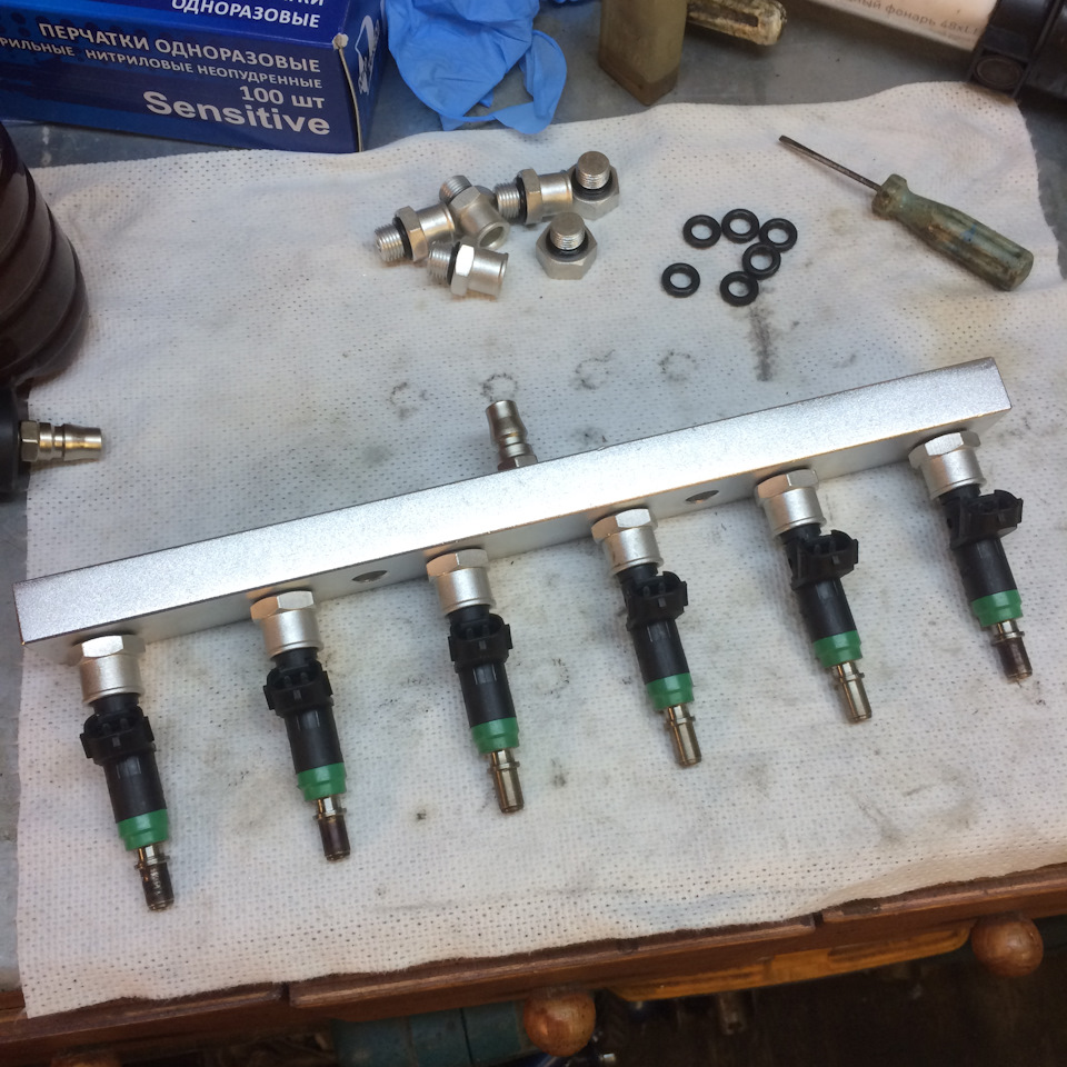
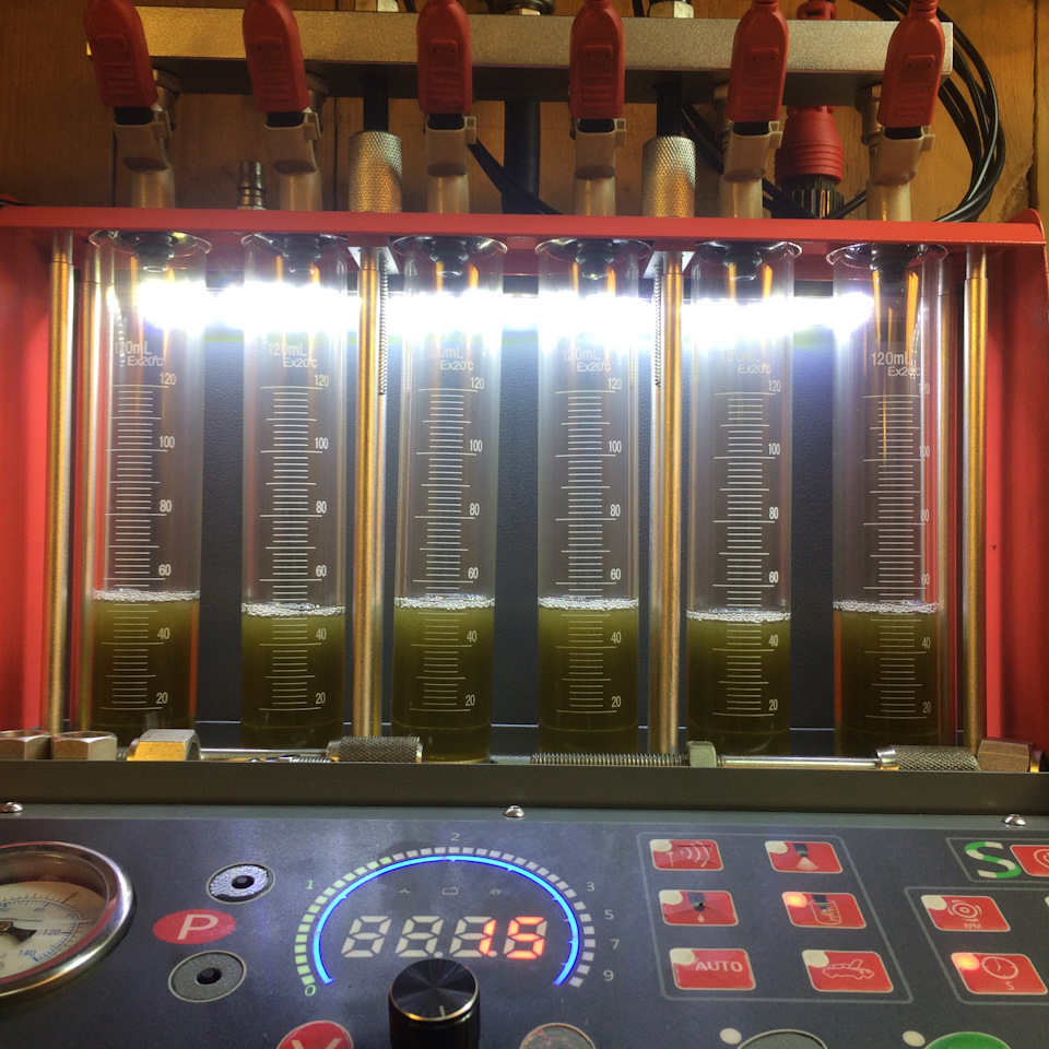
Функционал стенда:
— Имитация работы форсунок на двигателе, путем регулировки частоты и скважности открытия форсунок
— Проверка баланса производительности и факела распыла
— Тест герметичности форсунок
— Проверка расхода впрыска
— Программа ультразвуковой чистки
— Возможность промывки на автомобиле (опционально — необходимо докупить набор адаптеров)
— Автоматическая проверка
— Автоматизированный слив жидкости из мерных колб
Так-же в комплекте есть ванночка для ультразвуковой очистки форсунок ( емкость 1.3л., мощность 100Вт)
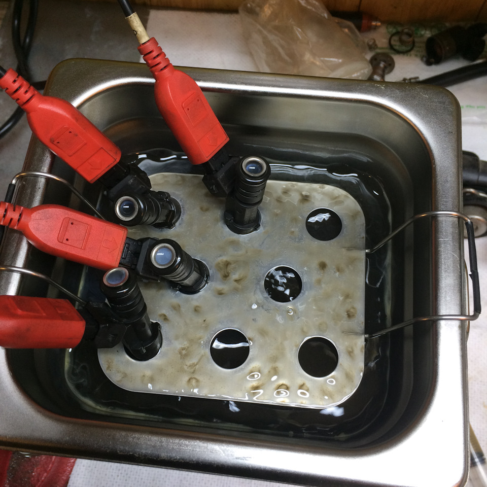
Для ультразвуковой очистки я использую жидкость Lavr Ln-2003
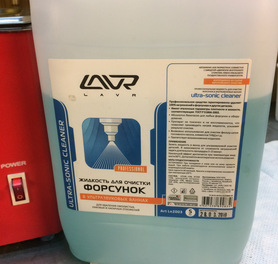
Со своей задачей справляется на отлично!
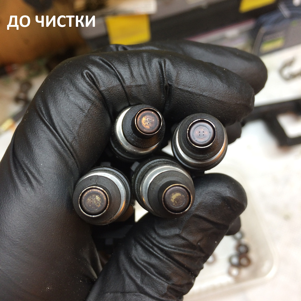
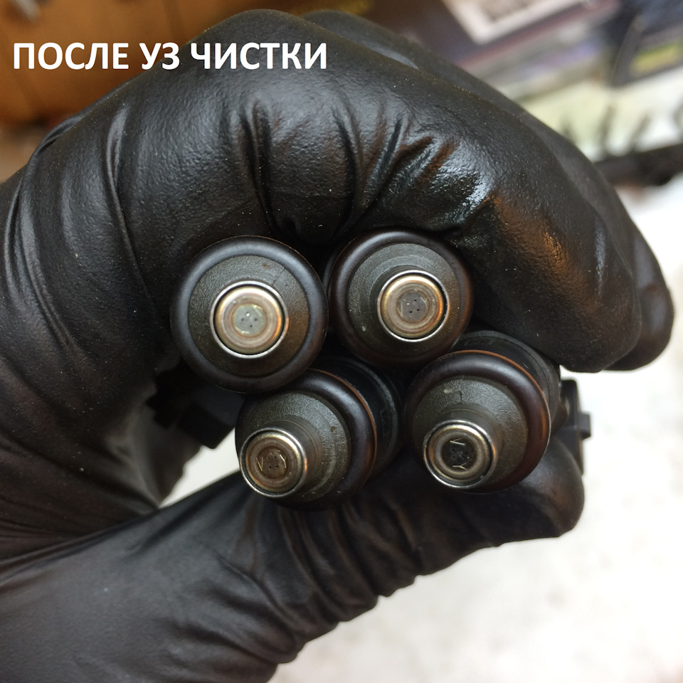
Чтобы отмыть распылители форсунок, достаточно 10-15 мин
Так-же в ванночке можно очищать любые другие предметы, я очищал серебряную цепочку 👍
Из минусов стенда могу отметить то, что спустя 2 года эксплуатации с кнопок на панели управления, отклеились и отвалились накладки
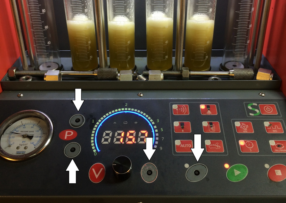
несколько раз не хотел запускаться насос, приходилось открывать заднюю крышку и принудительно подавать 12Вольт на насос, достаточно было просто сдвинуть его с места, дальше работал нормально, как будто он подклинивал после длительного простоя.
Ну а в целом стенд нормальный!
Вот мой видео обзор стенда:
Надеюсь данный материал был познавательным и интересным!
Подписывайтесь на мой блог о промывке форсунок и обращайтесь
Адрес: г. Королев, мкр. Первомайский, ул. Советская, д.40
WhatsApp
Инстаграм
Мой блог