
Всем привет!
Короткий обзор на детский микроскоп-игрушку.
Хотелось посмотреть, что же это такое, но не хотелось тратить ощутимую сумму в оффлайне.
С поинтами микроскоп вышел около 800рэ.
Микроскоп — действительно игрушка,
достаточно бюджетная
откровенно дешевая.
Что у меня вышло — смотрите под катом.
Выводы делайте самостоятельно.
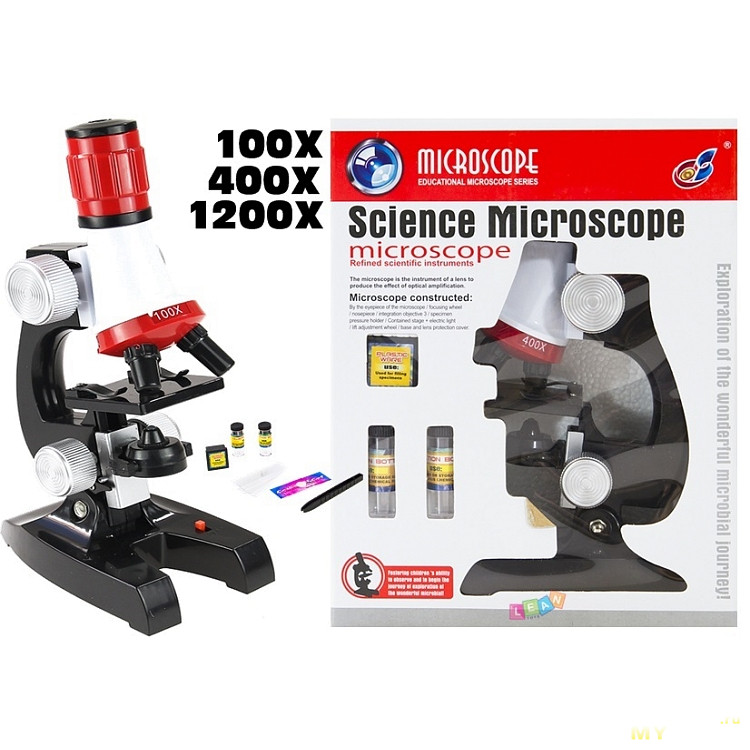
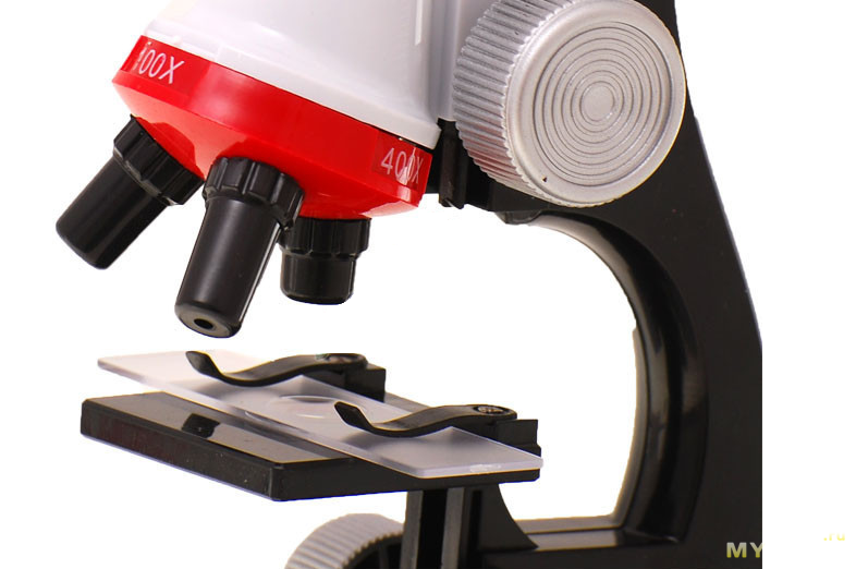
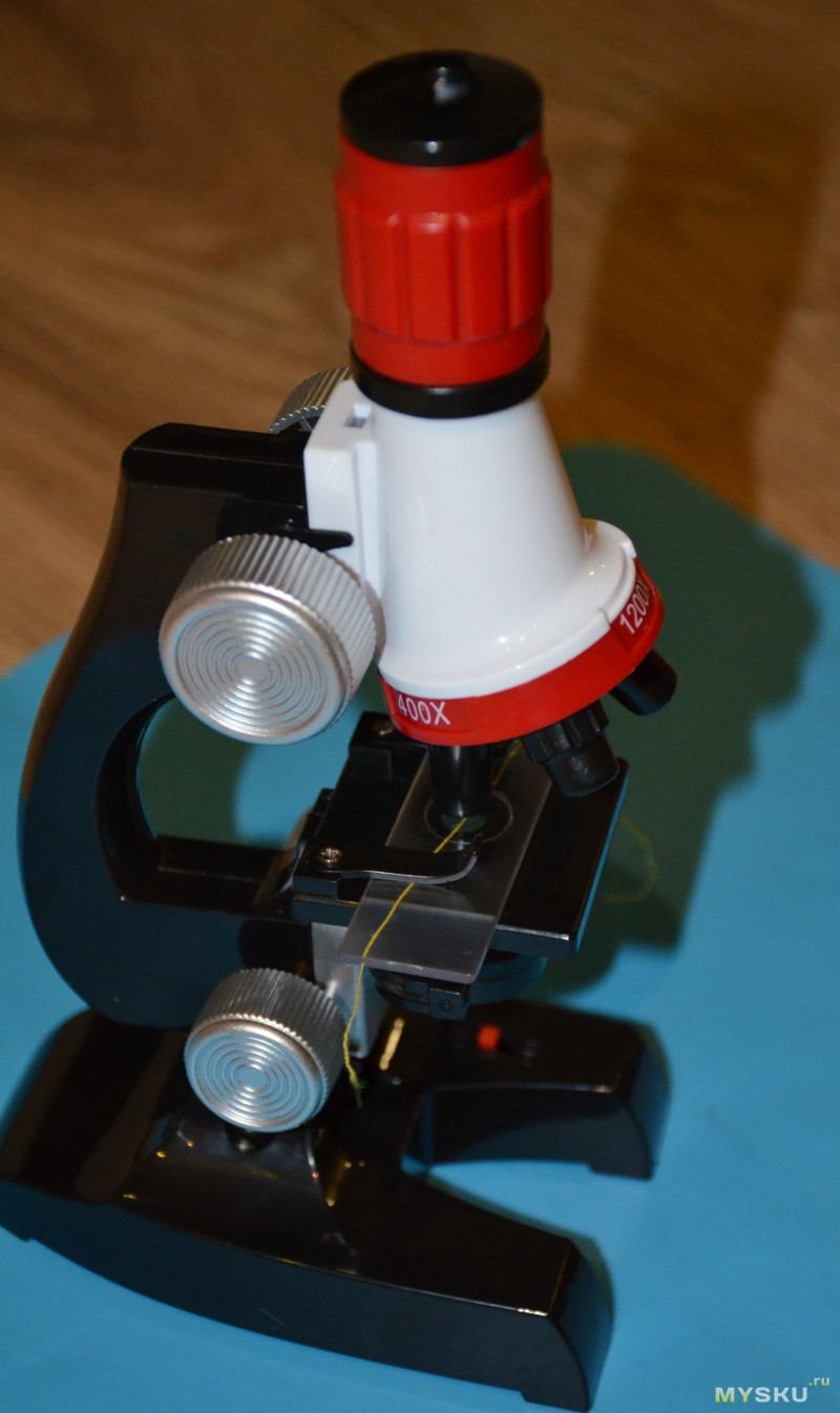
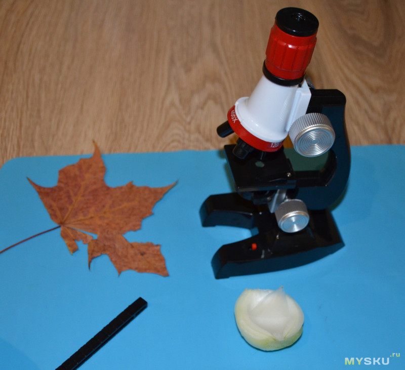
Речь пойдет про вот такой вот микроскоп.
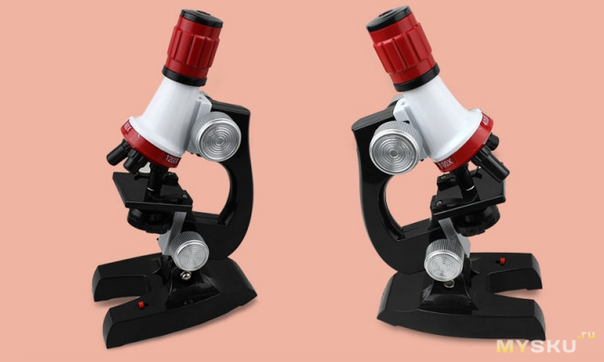
Пластиковый, с подсветкой, с регулировкой высоты окуляра. Есть 3
линзы
объектива (вращаются). И небольшой комплект.
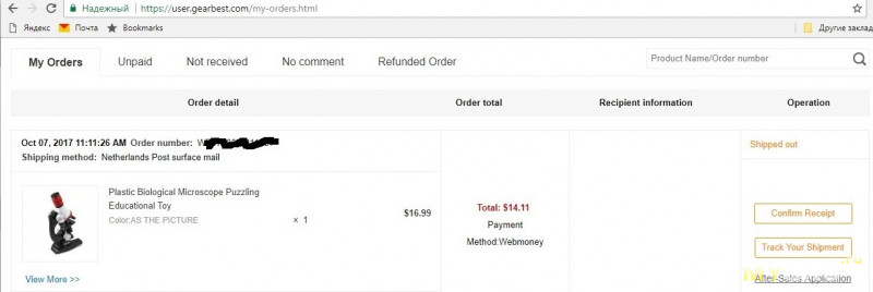
Дополнительная информация — с чем сравнивал и скрин покупки
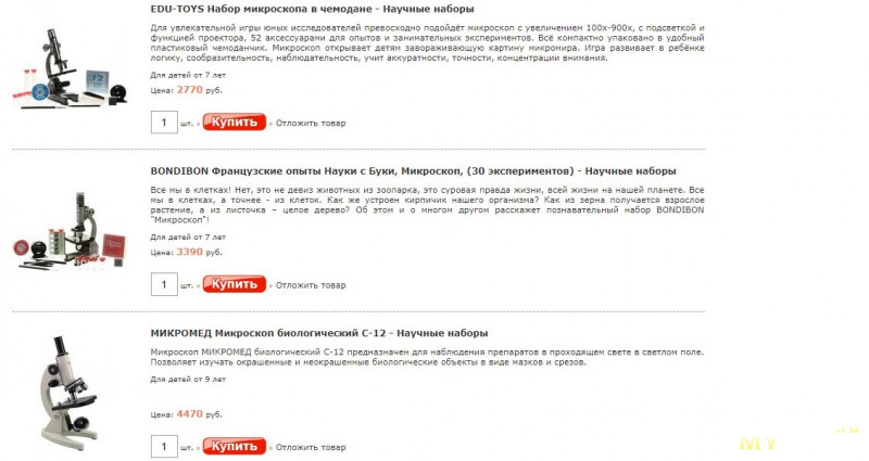
Изначально, после прогулок по детским магазинам ребенок попросил что-то типа такого.

Варианты примерно все одинаковые, отличаются слегка дизайном и комплектацией — обычно всякой ненужной фигни очень много (чашки петри, пипетки, банки-склянки), а также в дорогих наборах есть инструкции и описания опытов.
Собственно говоря, прикинув одно к другому, взял по привычке на жирбесте.
Практически такой же микроскоп обошелся около 800р (с учетом поинтов).
Обратите внимание: прибор является детской игрушкой, поэтому по сравнению с реальными лабораторными микроскопами будет в корне не верно. Данный микроскоп не следует использовать для ремонта печатных плат или каких либо других серьезных потребностей. Пластиковые линзы дают не сильно увеличенное изображение, а также небольшую четкость. Несмотря на указанные 1200х. Подсветка у него слабая, а конструкция и прочность — как у детской игрушки.
Источник света: белый светодиод
Для работы вам потребуются батарейки 2AA / LR6 (не включены)
На вскидку, могу предложить следующие варианты опытов с детьми:
Можно посмотреть листья деревьев и лепестки цветов, срезы (тонкие ломтики) фруктов и овощей, шерсть зверей и отпечатки пальцев человека, волокна ткани и бумаги. Интересны получается рассматривать тонкие срезы листика фикуса или луковицы. Если на предметное стекло капнуть масла (например, вазелинового), то будет удобнее зафиксировать объект. Например, можно положить 2-3 шерстинки.или волосинки. Еще интересно посмотреть на кристаллы соли, сахара. Ну и так далее.
Примеры опытов можно поискать в интернете, например, «Опыты для детского микроскопа».
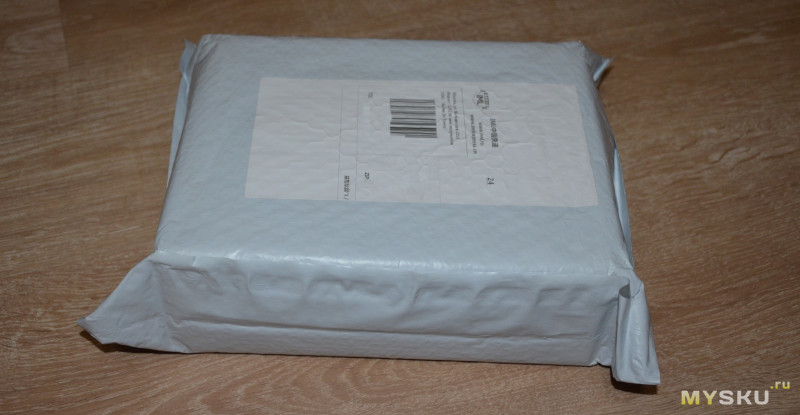
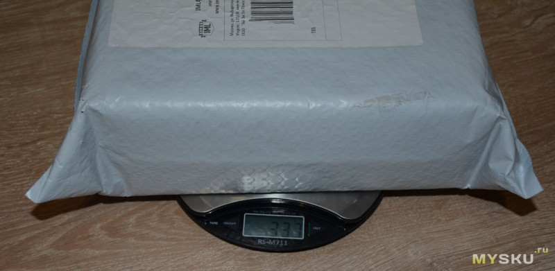
Итак, все было стандартно — упаковка-почтовый пакет.
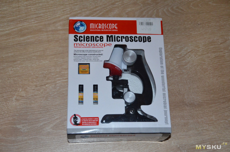
Внутри коробка.
Обычная такая коробка для детского микроскопа. У нас они точно такие же, только с плюсом в ценнике.
Внутри пенопластовая ячейка с комплектом, разложенным по своим местам.
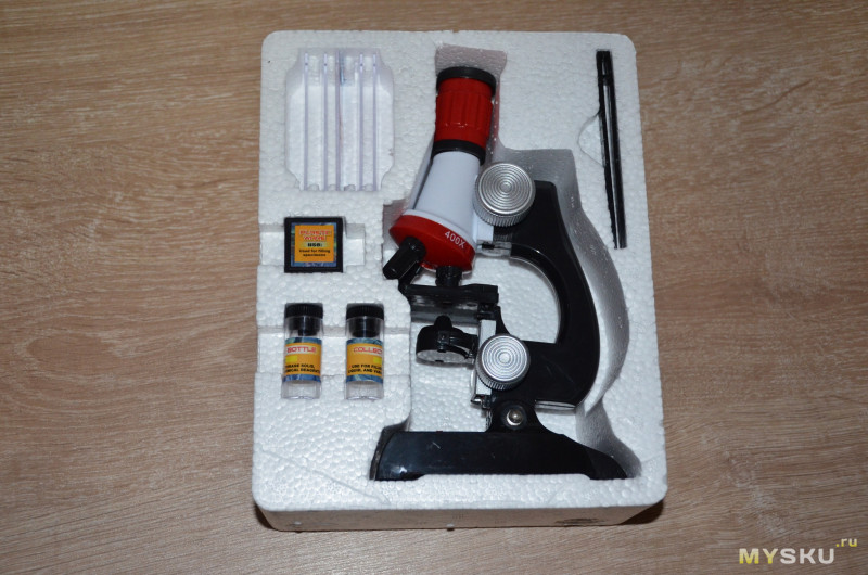
В комплекте идет:
Сам оптический микроскоп 1 шт
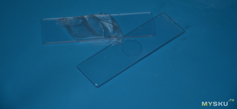
5 пластиковых предметных стекол
2 флакона для образцов
1 коробочка для хранения и несколько наклеек для надписей
1 пинцет.

Внешний вид всего этого добра.
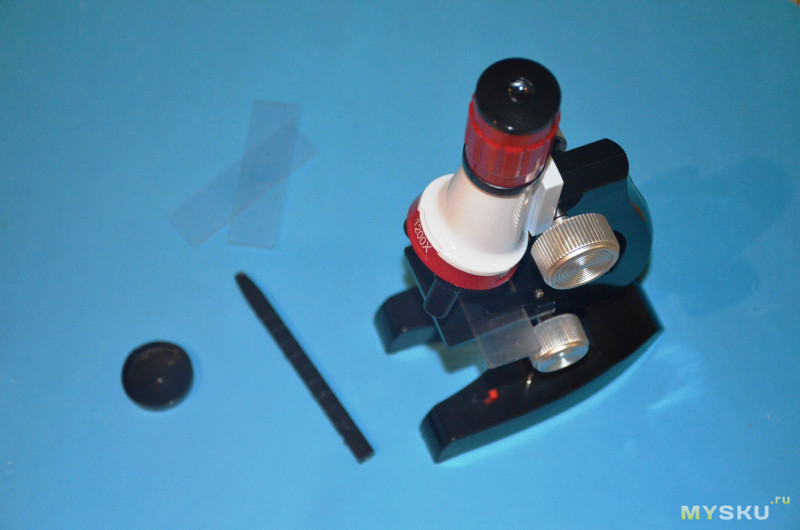
Микроскоп имеет две ручки — регулировка высоты подсветки и высоты головы. Дополнительно на окуляре регулируется фокус. Часть с объективами поворотная, можно выбирать 3 варианта увеличения: 100х, 400х, 1200х. Подсветка включается маленьким ползунком, нужно предварительно снизу установить 2 батарейки АА (нет в комплекте).
Теперь готовимся к опытам.
Сразу скажу, что передать изображение с оптического микроскопа целая проблема. Я фотографировал
на тапок
на камеру смартфона, предварительно прислонив ее к оккуляру. Не все получается четко. В живую изображение чуть чуть почетче (на камере не срабатывает автофокус на окуляр). Но все равно я постарался передать как смог.
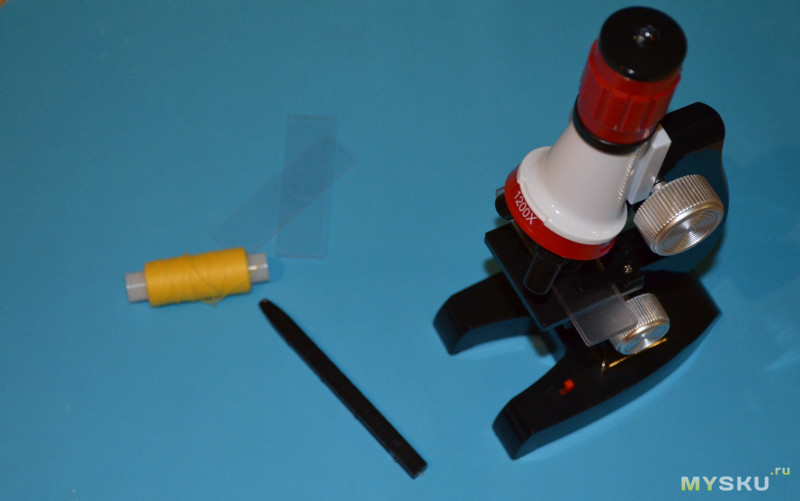
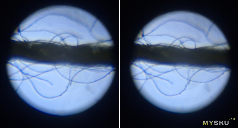
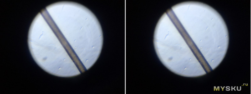
1) Нитка.
Берем самую простую хлопковую (?) нитку, отрываем кусочек и заправляем на предметное стекло.
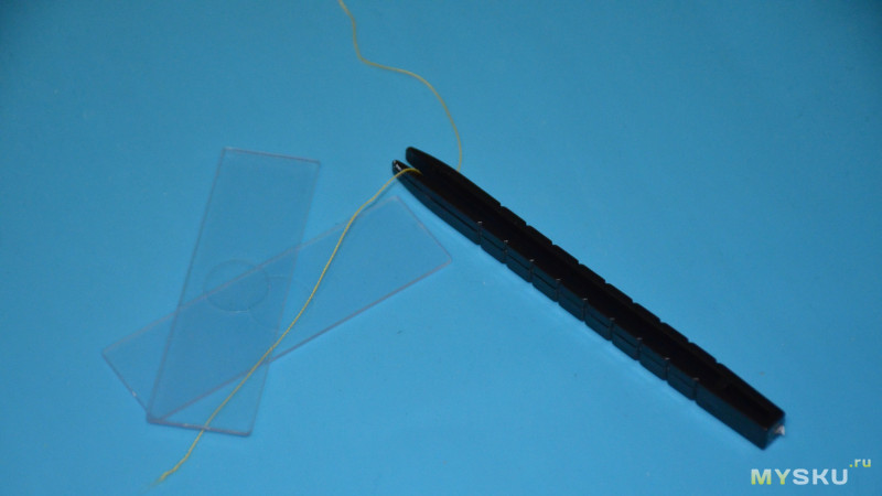
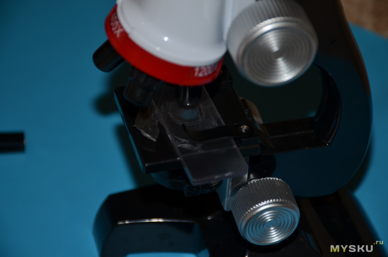
Прижимаем на предметный столик.
Вот примерно что видно при увеличении 1200х.
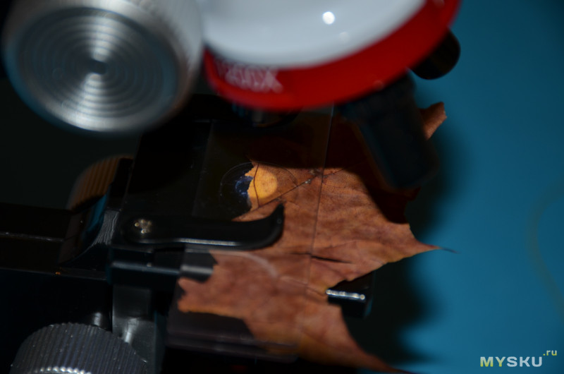
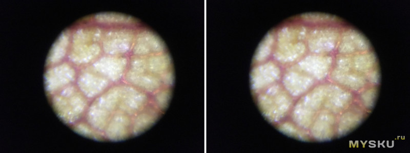
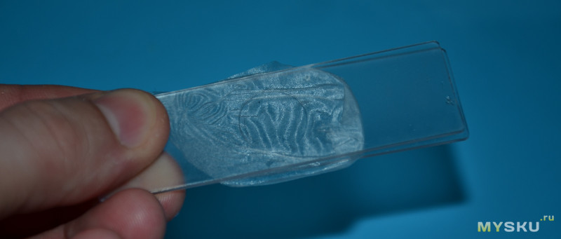
2) Кленовый лист.
Можно увидеть структуру листа, прожилки. Лист просвечивается, что очень удобно.
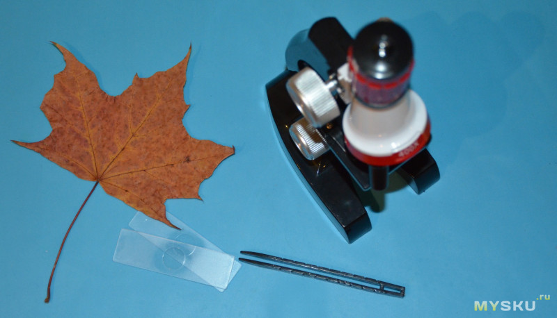
Зажимаем кусочек на стеклышке на предметном столе.
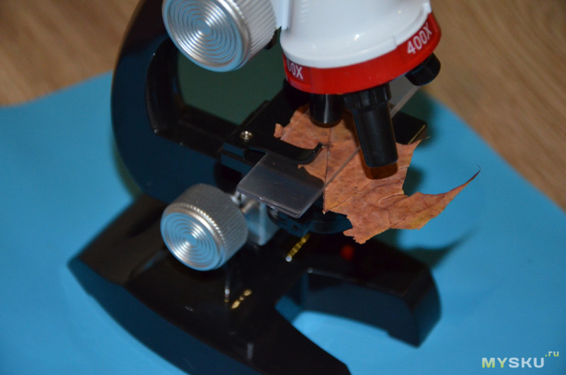
Включаем подсветку
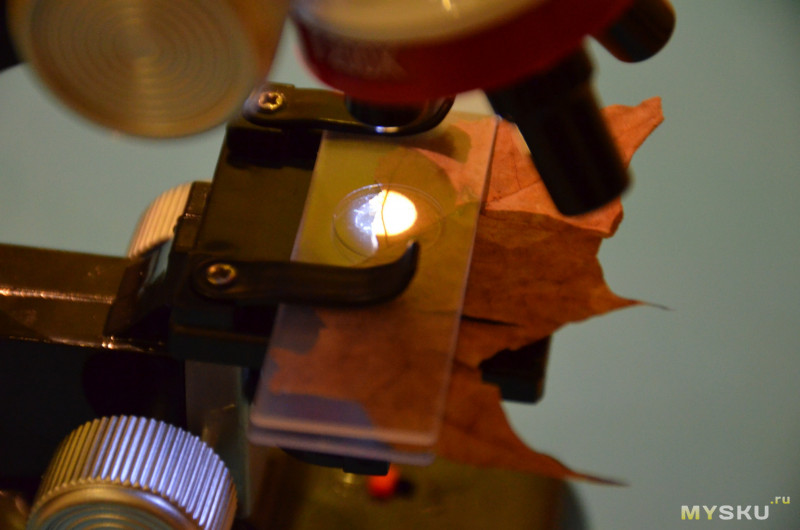
Вот что видно в окуляры
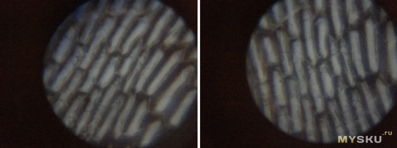
3) Срез луковицы. Вернее я рассматривал пленку от лука.
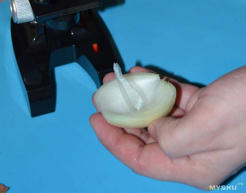
Разделяем слои лука, отрываем пленку
Расправляем на стеклышке, желательно без складок
Видны крупные клетки лука. А вот что находится внутри клеток — не видно. Да и изображение получается смазанное.
4) Волос человеческий.
Промежуточных фото нет, вот что видно в окуляре.
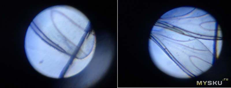
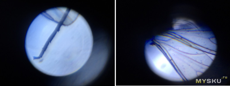
5) Муха (мошка)
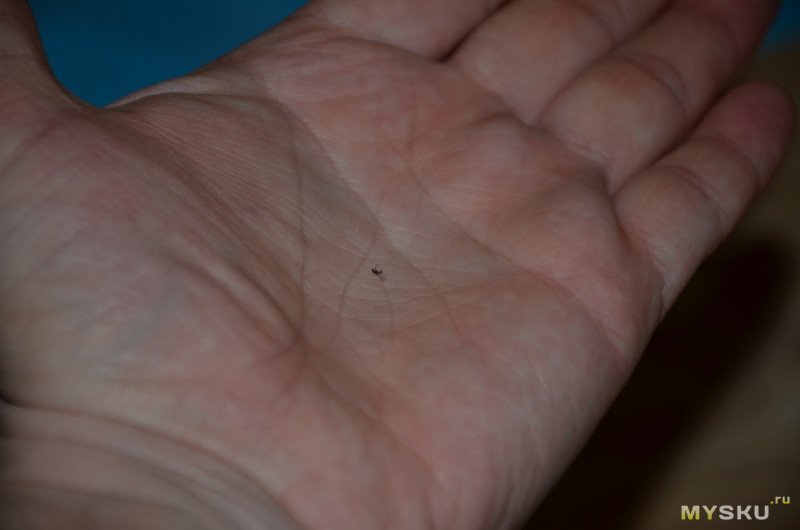
Готовим препарат)
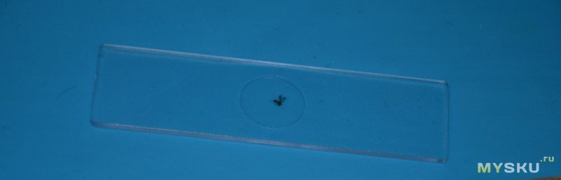
С мухой интереснее. Отлично видно конечности и крылья. А вот тушка мухи не просвечивается.
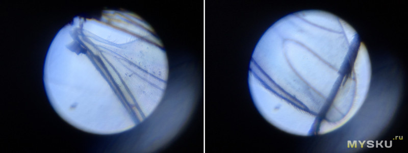
На крыльях видны маленькие волосики или чешуйки
Еще раз напоминаю, что на качество полученных снимков влияет способ их получения — прислоненная камера смартфона. В живую ощущения несколько другие, хотя пластиковые линзы особо четкой картины не дают.
Вместо вывода: покупка на жирбесте помогла мне сэкономить энную часть денег от покупки подобного же в оффлайне. Ребенок посмотрел, попробовал, успокоился. А я сделал выводы о качестве и необходимом функционале. У микроскопа из обзора небольшое увеличение, слабая подсветка. Хочется чего-то большего.
Из минусов отмечу отсутствие примеров опытов в комплекте, все приходится искать и выдумывать самостоятельно.
Могли бы вложить инструкцию. Или хотя бы ссылку на онлайн руководство по опытам.
Еще из минусов — общая хлипкость конструкции и достаточно размытое изображение.
Возможно, следующий детский микроскоп у меня будет вот такой
Помимо указанного (картинка кликабельна), вот два варианта на тао (подороже и подешевле).
В любом случае, у меня все))))
Надеюсь было полезно))))
Для использования микроскопа из серии Educational следуйте инструкциям ниже:
Шаг 1: Распакуйте микроскоп и проверьте, все ли его компоненты находятся в коробке. Обратите внимание на наличие следующих элементов: микроскоп, объективы с различным увеличением, окуляр, предметное стекло, держатель предметных стекол, источник света, кабель питания и инструкция по эксплуатации.
Шаг 2: Разместите микроскоп на ровной и стабильной поверхности. Убедитесь, что его база прочно установлена на поверхности, чтобы предотвратить падение или непрочное крепление микроскопа.
Шаг 3: Подключите кабель питания микроскопа к источнику электричества и включите его. Убедитесь, что микроскоп включен и работает.
Шаг 4: Расширьте штатив микроскопа до уровня работы. Определите, где находятся регулировочные винты и поворотные колеса на штативе, чтобы иметь возможность легко перемещаться и фокусироваться.
Шаг 5: Установите предметное стекло в держатель предметных стекол. Это место, где вы помещаете образцы, которые хотите рассмотреть под микроскопом.
Шаг 6: Передвигайте регулировочные винты и поворотные колеса на штативе, чтобы приблизить предметное стекло к объективам или отдалить его, искать нужное увеличение и достичь четкого изображения.
Шаг 7: Посмотрите в окуляр микроскопа и скорректируйте фокусировку с помощью регулировочных винтов на штативе. Придерживайтесь изображения, чтобы оно оставалось в фокусе.
Шаг 8: Поворачивайте объективы микроскопа с помощью поворотных колес, чтобы изменить увеличение. Начните с наименьшего увеличения и постепенно увеличивайте при необходимости.
Полезные советы:
— Перед использованием микроскопа проверьте, не застилает ли его линзы пыль или грязь. Очистите их тканью или специальной микрофиброй.
— Для получения наилучшего качества изображения используйте хорошо освещенное рабочее пространство или внешний осветитель. Микроскопы серии Educational обычно имеют встроенные или сменные источники освещения.
— При работе с образцами под микроскопом используйте пинцет или небольшие инструменты, чтобы избежать контакта рук с образцами и случайного повреждения или загрязнения их.
— Не загибайте или слишком быстро поворачивайте регулировочные винты или поворотные колеса, чтобы избежать повреждения механизма фокусировки и нарушения правильной настройки микроскопа.
— Периодически проверяйте и чистите объективы и окуляры микроскопа для поддержания оптимального качества изображения.
Следуя этим шагам и советам, вы сможете успешно использовать микроскоп из серии Educational и получать четкие и детальные изображения образцов.
1 INSTRUCTIONS CX21 EDUCATION MICROSCOPE This instruction manual is for the Olympus Education Microscopes Model CX21. To ensure the safety, obtain optimum performance and to familiarize yourself fully with the use of this microscope, we recommend that you study this manual thoroughly before operating the microscope. Retain this instruction manual in an easily accessible place near the work desk for future reference. A X IVD
2
3 CONTENTS CX21 IMPORTANT Be sure to read this section for safe use of the equipment STANDARD COMPONENT UNITS 4 2 NOMENCLATURE 5 3 SUMMARY OF BRIGHTFIELD OBSERVATION PROCEDURE 6 4 DETAILED OBSERVATION PROCEDURE Turning the Lamp ON Adjusting the Focus Adjusting the Diopter Placing Specimen on the Stage Adjusting the Interpupillary Distance Adjusting the Condenser Position and Aperture Iris Diaphragm Switching the Objectives Using the 100X Immersion Objective ONE-POINT ADVICE 12 6 TROUBLESHOOTING GUIDE SPECIFICATIONS 15 8 OPTICAL CHARACTERISTICS 16 9 ASSEMBLY OPTIONAL ACCESSORIES System Diagram of Optional Accessories Installation and Operation of Optional Accessories Cord Hanger CH3-CH Filter Holder CH2-FH Darkfield Ring CH2-DS Reflection Mirror CH20-MM Eyepieces WHC15X/WHC15X-H Using the eyepiece micrometer PROPER SELECTION OF THE POWER SUPPLY CORD
4 IMPORTANT SAFETY PRECAUTIONS Fig After the equipment has been used in an observation of a specimen that is accompanied with a potential of infection, clean the parts coming in contact with the specimen to prevent infection. Moving this product is accompanied with the risk of dropping the specimen. Be sure to remove the specimen before moving this product. In case the specimen is damaged by erroneous operation, promptly take the infection prevention measures. 2. To avoid potential shock hazards and burns when replacing the lamp bulb, set the main switch 1 to (OFF) then disconnect the power cord from the wall outlet in advance. Whenever you replace the bulb during use or right after use, allow the lamp socket 2 and bulb to cool before touching. (Fig. 1) Applicable lamp bulb: 6V20WHAL halogen bulb (Philips Type 7388) 3. Install the microscope on a sturdy, level table or bench so as not to block the air vents on the underside of the base. Do not place the microscope on a flexible surface, as this could result in blocking the air vents and cause overheating or a fire. 4. Always use the power cord provided by Olympus. If no power cord is provided, please select the proper power cord by referring to the section PROPER SELECTION OF THE POWER SUPPLY CORD at the end of this instruction manual. If the proper power cord is not used, product safety performance cannot be warranted. 5. When installing the microscope, route the power cord away from the microscope frame. Should the power cord come in contact with a hot part, the power cord could melt and cause electric shock. 6. Always ensure that the grounding terminal of the microscope and that of the wall outlet are properly connected. If the equipment is not grounded, Olympus can no longer warrant the electrical safety performance of the equipment. 7. Never allow metallic objects penetrate into the air vents of the microscope frame as this could result in electrical shock, personal injury and equipment damage. 8. After operation or in case of abnormality, be sure to disconnect the power cord from the connector on the microscope or from the wall power outlet. Safety Symbols The following symbols are found on the microscope. Study the meaning of the symbols and always use the equipment in the safest possible manner. Symbol Explanation Indicates that the surface becomes hot, and should not be touched with bare hands. Before use, carefully read the instruction manual. Improper use could result in personal injury to the user and/or damage to the equipment. Indicates that the main switch is ON. Indicates that the main switch is OFF. 1
5 CX21 Warning Label A warning indication label is attached to every part where special precaution is required when handling and using the microscope. Always heed the warnings. Warning label position Bottom of microscope frame [Warning against high temperature in lamp bulb replacement] If the warning label is stained or peeled off, contact Olympus. 1 Getting Ready Fig A microscope is a precision instrument. Handle it with care and avoid subjecting it to sudden or severe impact. 2. Do not use the microscope where it is subjected to direct sunlight, high temperature and humidity, dust or vibrations. (For the operating conditions, see chapter 7, SPECIFICATIONS on Page 15.) 3. Always use the tension adjustment ring to adjust the rotation tension of the coarse adjustment knob. 4. The microscope is ventilated by natural convection. Be sure to leave enough spaces (10 cm or more) around it when installing it. 5. When carrying the microscope, hold both sides around the hole of the arm as shown in Fig. 2 and carry carefully. # To prevent damage, do not hold the microscope by the stage 1 or observation tube 2. Be sure to remove the specimen; otherwise, it may fall. 2 Maintenance and Storage 1. Clean all glass components by wiping gently with gauze. To remove fingerprints or oil smudges, wipe with gauze slightly moistened with a mixture of ether (70%) and alcohol (30%). Since solvents such as ether and alcohol are highly flammable, they must be handled carefully. Be sure to keep these chemicals away from open flames or potential sources of electrical sparks for example, electrical equipment that is being switched on or off. Also remember to always use these chemicals only in a well-ventilated room. 2. Do not attempt to use organic solvents to clean the microscope components other than the glass components. To clean them, use a lint-free, soft cloth slightly moistened with a diluted neutral detergent. 3. Do not disassemble any part of the microscope as this could result in malfunction or reduced performance. 4. When not using the microscope, ensure that the frame is cooled down and store it in a dry locker or cover it with a dust cover. 5. To clean the condenser, fully loosen the securing knob 1, then remove the condenser by lowering it with the condenser height adjustment knob 2, and wipe the front lens of the condenser. The condenser can be attached by reversing the above removal procedure. 6. When disposing of the microscope. Check the regulations and rules of your local government and be sure to observe them. Fig. 3 2
6 3 Caution If the microscope is used in a manner not specified by this manual, the safety of the user may be imperiled. In addition, the equipment may also be damaged. Always use the equipment as outlined in this instruction manual. The following symbols are used to set off text in this instruction manual. : Indicates that failure to follow the instructions in the warning could result in bodily harm to the user and/or damage to equipment (including objects in the vicinity of the equipment). # : Indicates that failure to follow the instructions could result in damage to equipment. } : Indicates commentary (for ease of operation and maintenance). This device complies with the requirements of directive 98/79/EC concerning in vitro diagnostic medical devices. CE marking means the conformity to the directive. NOTE: This equipment has been tested and found to comply with the limits for a Class A digital device, pursuant to Part 15 of the FCC Rules. These limits are designed to provide reasonable protection against harmful interference when the equipment is operated in a commercial environment. This equipment generates, uses, and can radiate radio frequency energy and, if not installed and used in accordance with the instruction manual, may cause harmful interference to radio communications. Operation of this equipment in a residential area is likely to cause harmful interference in which case the user will be required to correct the interference at his own expense. FCC WARNING: Changes or modifications not expressly approved by the party responsible for compliance could void the user s authority to operate the equipment. 3
7 STANDARD COMPONENT UNITS CX21 }After opening the package, make sure that the correct component units for the selected set are present. The differences between the CX21FS1 and CX21FS2 lie in the number of objectives and presence of immersion oil. # The objectives have been screwed in tightly to prevent them from being loosened during transportation. To remove an objective, turn it counterclockwise while holding it with a rubber sheet, etc., so that your fingers don t slip. Eyepieces (Fixed at 10X) Binocular observation tube Revolving nosepiece Objectives 4X, 10X, 40X, 100X (CX21FS1) 4X, 10X, 40X (CX21FS2) Stage Microscope frame Condenser Optional Accessories Daylight (blue) filter 6V20WHAL halogen bulb Immersion oil Provided with a set including the 100X objective. Cord Hanger CH3-CH Filter Holder CH2-FH Darkfield Ring CH2-DS Reflection Mirror CH20-MM Eyepieces WHC15X WHC15X-H 4
8 NOMENCLATURE }The following items have been attached at the factory to prevent deterioration during transport. Remove these items and retain them for future use. Then loosen the observation tube clamping knob and correct the orientation of the eyepieces as shown in the illustration below. 1 Revolving nosepiece/observation tube transport band 2 Stage and specimen holder protection sheet 3 Protective pad below the stage }Attach the lamp bulb and power cord as described in chapter 9, ASSEMBLY on pages Observation tube clamping knob Pre-focusing knob (Page 9) Diopter adjustment ring (Page 9) Revolving nosepiece (Page 10) Specimen holder (Page 7) Coarse adjustment knob (Page  Fine adjustment knob (Page Aperture iris diaphragm ring (Page 10) Specimen holder Y-axis feed knob (Page 7) Filter holder (Page 20) Specimen holder X-axis feed knob (Page 7) Main switch (Page 7) : Power ON : Power OFF Light intensity adjustment knob (Page 7) }For detailed description of each control, refer to the page indicated inside parentheses. 5
9 CX21 SUMMARY OF BRIGHTFIELD OBSERVATION PROCEDURE Set the main switch to I » (ON) and adjust the brightness. (Controls Used) (Page) 1Main switch (P. 7) 2Light intensity adjustment knob (P. 7) Place the specimen on the stage. 3Specimen holder (P. 7) 4X-axis/Y-axis feed knobs (P. 7) Engage the 10X objective in the light path. 5Revolving nosepiece (P. 10) Bring the specimen in focus 6Coarse/fine focus adjustment knobs (P. Adjust the interpupillary distance. Adjust the diopter. 7Binocular tube (P. 9) 8Diopter adjustment ring (P. 9) Adjust the aperture iris diaphragm. 9Aperture iris diaphragm ring (P. 10) Engage the objective to be used in the light path and bring the specimen in focus. 5Revolving nosepiece (P. 10) 6Coarse/fine adjustment knobs (P. Engage the required filters. afilters (Diameter: 32.5 mm or 45 mm) (P. 20) Adjust the brightness. 2Light intensity adjustment knob (P. 7) Start observation a
10 DETAILED OBSERVATION PROCEDURE 1 Turning the Lamp ON (Fig. 4) 1. Set the main switch 1 to I (ON). 2. Rotating the light intensity adjustment knob 2 in the direction of the arrow increases brightness and rotating it in the opposite direction decreases brightness. The figures around the knob indicate the reference voltage values. Fig. 4 2 Placing Specimen on the Stage (Fig. 5) ³ Fig. 5 5 # Place the specimen gently. If the bow-shaped lever is returned with a strong force or the knob 1 of the bow-shaped lever is released in the middle, the slide glass may be broken. 1. Rotate the coarse adjustment knob 2 in the direction of the arrow to fully lower the stage. 2. Open the bow-shaped lever 3 outward, place the specimen by sliding the specimen glass plates on the stage from the front toward the rear. 3. After sliding the specimen glass plates all the way, return the bow-shaped lever 3 gently. 4. Rotating the upper knob which is the Y-axis feed knob 4 moves the specimen in the vertical direction. Rotating the lower knob which is the X- axis feed knob 5 moves it in the horizontal direction. #Do not move the specimen holder directly by hand, for this will damage the rotary mechanisms of the above knobs. #When the specimen holder reaches the stopper position, the rotation force of the above knobs become heavy. Stop rotating the knob at this time. Cover glass Cover glass This is the glass plate placed on the specimen. To allow the objective manifest the full performance, the cover glass thickness, which is the distance from its surface to the specimen surface, should ideally be 0.17 mm. Slide glass Placing Specimen Fig. 6 Slide glass This glass plate should ideally have a length of 76 mm, width of 26 mm and thickness between 0.9 and 1.4 mm. 7
11 CX21 Specimen holder scales (Fig. 7) }Theses scales allow the position (coordinates) being observed on the specimen to be identified. Even after the specimen is moved, it can be returned easily to the original position. 1. The horizontal coordinate can be read at position 1 on the specimen holder. 2. The vertical coordinate can be read at the position of index line 2. Fig. 7 3 Adjusting the Focus (Fig. Fig. 8 ³ Focusing Procedure 1. Rotate the coarse adjustment knob in the direction of the arrow so that the objective 3 is as close as possible to the specimen. 2. While observing the specimen through the eyepieces, slowly rotate the coarse adjustment knob 1 in the opposite direction to the arrow to lower the stage. 3. When coarse focusing of the specimen is obtained, rotate the fine adjustment knob 2 to adjust to precise focus. Working Distance (WD) }The WD refers to the distance between each objective and the specimen, when precise focus of the specimen is obtained. Objective Magnification 4X 10X 40X 100X WD (mm) Fig. 9 ³ Adjusting the Tension of the Coarse Adjustment Knob (Fig. 9) 1. The tension of the coarse focus adjustment knob has been designed adjustable with a ring. Insert the tip of a large flat-blade screwdriver into the groove 2 on the tension adjustment ring 1 and rotate the ring. Rotating it clockwise (in the direction of the arrow) increases the tension and counterclockwise decreases the tension. 2. If the stage descends on its own or if the specimen gets out of focus quickly even when it is brought into focus using the fine adjustment knob, it means that the tension of the coarse adjustment knob is too low. Turn the ring 1 in the direction of the arrow to increase the tension. 8
12 Fig. 10 Pre-focusing Knob (Fig. 10) }The pre-focusing knob controls the mechanism for preventing collision between the specimen and objective. 1. After bringing the specimen into focus, turn the pre-focusing knob 1 inside the hole of the arm so that the pre-focusing mechanism hits the stage guide. 2. To provide a certain margin for focusing, rotate the knob by about half turn backward from the stopped position. # If the function of this mechanism is not required, set the pre-focusing knob 1 at the highest position. 4 Adjusting the Interpupillary Distance (Fig. 11) }The interpupillary distance adjustment consists of regulating the two eyepieces according to that between your eyes so that you can observe a single microscopic image through two eyepieces. This greatly helps to reduce fatigue during observation. While looking through the eyepieces, move both eyepieces until the left and right fields of view coincide completely. The position of index dot indicates the interpupillary distance value. }Note your interpupillary distance so that it can be quickly duplicated. Fig Adjusting the Diopter (Fig. 12) }The diopter adjustment consists of compensating for the difference in eyesight between your eyes. 1. While looking through the right eyepiece with your right eye, rotate the coarse and fine focus adjustment knobs to bring the specimen into focus. 2. While looking through the left eyepiece with your left eye, rotate only the diopter adjustment ring 1 to focus on the specimen. Fig. 12 Using the Eye Shades (Fig. 13) When Wearing Eyeglasses Use with the eye shades in the normal, folded-down position. This will prevent the eyeglasses from being scratched. When Not Wearing Eyeglasses Extend the folded eye shades in the direction of the arrow to prevent extraneous light from entering between the eyepieces and eyes. 9 Fig. 13
13 CX21 6 Adjusting the Condenser Position and Aperture Iris Diaphragm (Fig. 14) }The condenser is usually used in the highest position. If the entire observed field of view is not bright enough, brightness may be improved by lowering the condenser slightly. 1. Rotate the condenser height adjustment knob 1 to move the condenser to the highest position. 2. The aperture iris diaphragm ring 2 has an objective magnification scale (4X, 10X, 40X, 100X). Rotate the ring so that the magnification of the objective in use faces frontward. Fig Switching the Objectives (Fig. 15) Hold and rotate the revolving nosepiece 1 so that the objective to be used come exactly above the specimen. Fig
14 8 Using the 100X Immersion Objective (Fig. 16) Fig. 16 }The designated immersion oil should be attached to the top lens of the 100X immersion objective. Otherwise, the observed image will be unable to be focused on. # Always use immersion oil supplied by Olympus. 1. Focus on the specimen using all objectives, starting from the lowestpower objective to higher-power objective. 2. Before engaging the immersion objective in the light path, place a drop of provided immersion oil onto the specimen at the area to be observed. 3. Rotate the revolving nosepiece to engage the immersion objective and rotate the fine adjustment knob to bring the specimen into focus. # Since air bubbles in the oil will affect the image quality, make sure that the oil is free of bubbles. To remove bubbles, rotate the revolving nosepiece slightly to move the oil-immersed objective by one reciprocation or two. }The condenser of this microscope manifests the full performance when oil is placed between the slide glass and the front lens of condenser. If oil is not attached there, the observation image may become slightly dark. 4. After use, remove oil from the objective front lens by wiping with gauze slightly moistened with an ether (70%)/alcohol (30%) mixture. Caution in use of immersion oil If immersion oil enters your eyes or contacts your skin, immediately take the following treatment. Eyes: Rinse with fresh water (for 15 minutes or more). Skin : Rise with water and soap. If the appearance of the eyes or skin is altered or pain persists, immediately see your doctor. 11
15 ONE-POINT ADVICE CX21 How To Track a Microscopic Image To track an image moving leftwards (or to move the specimen image rightwards): Move the slide glass to the left. Direction of moving the image To move the specimen image upward: Move the slide glass down. }The image observed through the microscope moves in directions opposite to the actual up-down and left-right movements of the specimen. Total Magnification The size of the specimen image for observation is obtained by multiplying the eyepiece magnification by the objective magnification. This value is referred to as total magnification. Example: Eyepiece (10X) x Objective (40X) = 400X Resolution Resolution determines how finely a lens is able to distinguish the details of a specimen. The resolution of a microscope is mainly determined by the ability of the objective and is scarcely related to that of the eyepieces. The only function of the eyepieces is to magnify an image already resolved by the objective. Although both configurations above provide the same total magnification, the higher magnification of the objective yields a better specimen resolution. Field Number (FN) The field number is the diameter of the image observed through an eyepiece, represented in millimeters. 10X eyepiece: 18 mm WHC15X: 12 mm Approx. 0.9 mm, about half of actual Actual Field of View field of view. The actual field of view is the size on the specimen actually observed in the microscope. This yields approximate size of the actual specimen. Actual field of view = Field number/objective magnification When the 10X eyepiece above and 10X objective are used, the actual field of view is equal to: Actual field of view = 18/10 = 1.8 mm Actual field of view: 1.8 mm 12
16 TROUBLESHOOTING GUIDE Under certain conditions, performance of the unit may be adversely affected by factors other than defects. If problems occur, please review the following list and take remedial action as needed. If you cannot solve the problem after checking the entire list, please contact Olympus for assistance. Problem Cause Remedy Page 1. Uneven brightness in observation field. 2. Dust or stains are visible in observation field. The objective is not engaged in the light path. The condenser is too low. The objective, eyepiece, condenser and/ or window lens are dirty. The eyepiece, condenser, window lens and/or specimen glasses are dirty. 3. Observation image glares. The condenser is too low. Raise it. 4. Observation image is whitishblurred or unclear. 5. Part of image is defocused or image looks like it s flowing. 6. High-magnification objective touches specimen just before coming into focus. 7. The tension of coarse adjustment knob it too high. 8. Focusing is impossible (because the stage cannot be raised). 9. The stage lowers by its own weight or focusing is lost due to slippage of the knob. 10. Coarse focus adjustment cannot lower the stage low enough. 11. Fields of view of two eyes do not match. The condenser iris diaphragm ring is stopped down excessively. The objective is not engaged in the light path. The objective, eyepiece, condenser and/ or specimen glasses are dirty. Immersion oil is not used with an immersion objective. Bubbles are mixed in the immersion oil. The specified immersion oil is not used. The objective is not properly engaged in the light path. The specimen is not set properly on the stage. The specimen is upside down. The coarse adjustment knob tension adjustment ring is set too tight. The pre-focusing knob is positioned too low. The coarse adjustment knob tension adjustment ring is set too loose. The condenser is too low. The interpupillary distance is not adjusted properly. Diopter compensation for the two eyes is not set. Engage the objective into position until it clicks. Raise it to the upper limit. Clean them thoroughly. Clean them thoroughly. Adjust the aperture according to the objective magnification. Engage the objective into position until it clicks. Clean them thoroughly. Use immersion oil. Remove the bubbles. Use the immersion oil supplied by Olympus. Engage the objective into position until it clicks. Set the specimen correctly on the stage and secure using the specimen holder. Set the specimen correctly with the cover glass on the top. Loosen the ring to adjust to proper tension. Raise its position. Tighten the ring to adjust to proper tension. Raise it. Adjust it properly. Adjust it correctly. The left and right eyepieces are different. Replace one of them so that the left and right eyepieces are identical
17 CX21 Problem Cause Remedy Page 12. Objective hits the specimen when an objective is switched to a highermagnification objective. The specimen is upside down. The cover glass is too thick. 13. Lamp bulb does not light. Lamp bulb is not mounted. Attach a bulb. Set the specimen correctly with the cover glass on the top. Use a cover glass with thickness of 0.17 mm. Lamp bulb is blown. Replace the bulb. The power cord is unplugged. Plug it securely. 14. Lamp bulb blows easily. The specified bulb is not used. Replace with a specified bulb
18 SPECIFICATIONS Item Specifications 1. Optical system UIS (Universal Infinity System) optical system 2. Illumination Built-in illumination system. 6 V, 20 W halogen bulb 6V20WHAL (PHILIPS 7388) (Average life time: Approx. 100 hr. when used as directed) / V 0.42/0.25A, 50/60 Hz 3. Focusing mechanism Stage height adjustment mechanism. Fine adjustment scale: 2.5 µm per graduation Fine adjustment stroke: 0.3 mm per turn Total stroke: 20 mm. Pre-focusing knob provided, coarse adjustment knob tension adjustable. 4. Revolving nosepiece Quadruple positions fixed (Front oriented) 5. Binocular observation tube Field number 18 Tube tilting angle 30 Interpupillary distance adjustment range 48 to 75 mm 6. Stage Size 120 x 132 mm (with mechanical stage) Movement range 76 (X-axis) x 30 (Y-axis) mm Specimen holder Holds a single specimen. 7. Condenser Type Abbe condenser (daylight filter detachable) N. A (when immersed in oil) Aperture iris diaphragm Built in 8. Dimensions & weight 154(W) x 391(H) x 238(D) mm, approx. 5.9 kg 9. Operating environment Indoor use. Altitude: Max meters Ambient temperature: 5 to 40 C (41 to 104 F) Maximum relative humidity: 80% for temperatures up to 31 C (88 F), decreasing linearly through 70% at 34 C (93 F), 60% at 37 C (99 F), to 50% relative humidity at 40 C (104 F). Supply voltage fluctuations; Not to exceed ±10% of the normal voltage. Pollution degree: 2 (in accordance with IEC60664) Installation/Overvoltage category: II (in accordance with IEC60664) 15
19 OPTICAL CHARACTERISTICS CX21 The following table shows the optical characteristics of combinations of eyepieces and objectives. The figure on the right shows the performance data engraved on the objectives. Magnification Mechanical tube length Color band Number of aperture Cover glass thickness Objective type (on the back side) Plan Objective Objectives Optical Characteristics Power N.A. W.D. (mm) Cover Glass Thickness Resolution (µm) 10X Eyepieces (FN 18) Total Power Focal Depth (µm) Actual Field of View Remark Plan objective (FN 22) 4X X X X X X XO X Oil immersed Legend Working distance (WD) : Distance between the top surface of cover glass and the objective extremity. Number of aperture (NA) : The figure corresponding to the F-number of the camera. This is associated with the resolution and larger NA means higher resolution. Resolution : Ability of an objective for identifying adjacent two lines in the image, which is expressed in terms of the minimum distance between two points on the specimen surface. Focal depth : The depth range of a specimen, in which focusing is obtained at a time. Stopping down the (Object side) : aperture iris diaphragm increases the focal depth and increasing the objective NA decreases it. Field number (FN) : The diameter of the image observed through an eyepiece, represented in millimeters. Actual field of view : Diameter of the field of view, expressed as the size on the specimen surface. Total power : Objective magnification x Eyepiece magnification. (Total magnification) 16
20 ASSEMBLY }Each standard set can be assembled by simply attaching the lamp bulb, daylight (blue) filter and power cord. 1 Installing/Replacing the Lamp Bulb (Fig. 17) Fig. 17 ³ # Before attaching the lamp bulb, remove the parts that may drop such as the filter and specimen from the microscope frame, and place it on the back so that the bottom can be seen from the front. 1. Pull the lock knob 1 on the bottom to open the lamp bulb replacement cover. 2. Hold the halogen lamp bulb 2 without taking it out of the polyethylene bag so as not to stain the bulb with fingerprints or stains, and push the bulb into the pin holes on the socket 3. After attaching, remove the polyethylene bag from it. < Applicable lamp bulb > 6 V, 20 W halogen bulb: 6V20WHAL (Philips Type 7388) Always use the designated bulb. Using a bulb other than a specified one may lead to a fire hazard. Fingerprints or stains on the lamp bulb reduce its service life. When it is contaminated, wipe with a cloth slightly moistened with alcohol. 3. With the lock knob left in the pulled-out position, close the lamp bulb replacement cover. Then push in the lock knob to lock the cover. #The cover cannot be closed if the lock knob is in the pushed-in position. Make sure that it is in the pulled-out position before closing the cover. Caution for Bulb Replacement During Use or Right After Use The bulb, lamp socket and areas near these will be extremely hot during and right after use. Set the main switch to (OFF), disconnect the power cord from the wall outlet, then allow the old bulb and lamp socket to cool before replacing the bulb with a new bulb of the designated type. 2 Mounting the Daylight (Blue) Filter (Fig. 18) }This filter modifies the color of observation light into a natural color (daylight color). Slide the daylight filter 1 into the bottom of the condenser 2 until it clicks into place. Fig
21 CX21 3 Connecting the Power Cord (Figs. 19 & 20) ³ Fig The power cord is vulnerable when bent or twisted. Never subject it to excessive force. Make sure that the main switch 1 is set to (OFF) before connecting the power cord. Always use the power cord provided by Olympus. If no power cord is provided, please select the proper power cord by referring to the section PROPER SELECTION OF THE POWER SUPPLY CORD at the end of this instruction manual. 1. Connect the power cord s connector 2 to connector 3 firmly. Be sure to supply power from a grounded, 3-conductor power outlet using the proper power cord. If the power outlet is not grounded properly, Olympus can no longer warrant the electrical safety performance of the equipment. 2. Connect the power cord s plug to a wall power outlet 5. Fig
22 OPTIONAL ACCESSORIES 10-1 System Diagram of Optional Accessories Eyepieces WHC15X WHC15X-H Eyepiece micrometer Cord Hanger CH3-CH Filter Holder CH2-FH Microscope Frame CX mm filter Darkfield Ring CH2-DS Reflection Mirror CH20-MM 45 mm filter 10-2 Installation and Operation of Optional Accessories 1 Cord Hanger CH3-CH (Figs. 21 & 22) ³ }When the CH3-CH cord hanger is attached on the back of the microscope frame, the power cord can be wound around it for storing. Align the hooks 2 of the cord hanger 1 with the cord hanger mounting position 3, insert the cord hanger, push it firmly against the microscope frame and slide it down to lock it. # Do not carry the microscope by holding it by the cord hanger. If it is detached during transport, the microscope may drop and human injury may result. Fig. 21 Removal 5 First remove the power cord from the cord hanger to prevent electric shock.then,move the microscope to an edge of the table. While pushing the cord hanger in the directions 1 and 2, insert the tip of a flat-blade screwdriver 5 or similar tool into the lower part of the hanger and slide it up to remove. 19 Fig. 22
23 CX21 2 Filter Holder CH2-FH (Fig. 23) This accessory accommodates a filter with a diameter of 32.5 mm or the CH2-DS darkfield ring. 1. Remove the daylight filter if it has been attached. 2. Push the filter holder 2 containing the desired filter 1 into the bottom of the condenser until it clicks into place. Fig. 23 Filter Application 32.5C Changes the light of the built-in lamp bulb (which is yellowish) to natural light. 32.5G533 Reduces fatigue or provides specimen with contrast. 32.5LB45, 150, 200 Converts the color of light for color photography (with a daylight film). For other filters, contact Olympus. Filters similar to the above having a diameter of 45 mm are also available for insertion in the window lens. 3 Darkfield Ring CH2-DS (Fig. 24) 1. Insert the darkfield ring in the CH2-FH filter holder in the same way as inserting a filter. 2. The darkfield ring enables darkfield observation using an objective from 4X to 40X. CH2-DS Fig Reflection Mirror CH20-MM (Fig. 25) }The reflection mirror is designed to be used in microscopic observation in a location where power supply is not available. It makes it possible to use the natural light in place of the lamp bulb. Fig. 25 # The microscope should be installed near a window, in a place that is not exposed to direct sunlight. The eyepieces should be oriented toward the rear so that the reflection mirror receives the bright light. Loosen the observation tube clamping knob and rotate the tube by Fit the reflection mirror in the window lens of the microscope frame by aligning the mounting tab. 2. Remove the daylight filter because it renders the image bluish under natural light. 3. The reflection mirror 1 should be pointed toward the bright area. While observing the image through eyepieces, adjust the orientation of the reflection mirror. }A planar reflection mirror is used normally. However, if the image brightness is uneven or the outside view is visible in the image, use a concave reflection mirror. 20
24 5 Eyepieces WHC15X/WHC15X-H (Fig. 26) }The standard 10X eyepieces are clamped using screws. 1. Using a small flat-blade screwdriver, loosen the clamping screw 1 of a 10X eyepiece and remove it. 2. Insert the WHC15X or WHC15X-H into the eyepiece sleeve and tighten the clamping screw 1. Fig Using the eyepiece micrometer (Fig. 27) }The eyepiece micrometer can be inserted in a standard 10X eyepiece as well as the WHC15X and WHC15X-H. However, unless the WHC15X-H is used, helicoid adjustment cannot be performed, so those with poor eyesight will have trouble in bringing the micrometer into focus. Get a micrometer with diameter of 19 mm and thickness of 1 mm. Remove the micrometer sleeve and fit the micrometer into the eyepiece with the indication side facing down as shown in Fig. 27. Replace the micrometer sleeve to use the micrometer. Fig
25 CX21 PROPER SELECTION OF THE POWER SUPPLY CORD If no power supply cord is provided, please select the proper power supply cord for the equipment by referring to Specifications and Certified Cord below: CAUTION: In case you use a non-approved power supply cord for Olympus products, Olympus can no longer warrant the electrical safety of the equipment. Specifications Voltage Rating Current Rating Temperature Rating Length Fittings Configuration 125V AC (for V AC area) or, 250V AC (for V AC area) 6A minimum 60 C minimum 3.05 m maximum Grounding type attachment plug cap. Opposite terminates in molded-on IEC configuration appliance coupling. Table 1 Certified Cord A power supply cord should be certified by one of the agencies listed in Table 1, or comprised of cordage marked with an agency marking per Table 1 or marked per Table 2. The fittings are to be marked with at least one of agencies listed in Table 1. In case you are unable to buy locally in your country the power supply cord which is approved by one of the agencies mentioned in Table 1, please use replacements approved by any other equivalent and authorized agencies in your country. Country Agency Certification Mark Country Agency Certification Mark Argentina IRAM Italy IMQ Australia SAA Japan JET, JQA, TÜV, UL-APEX / MITI Austria ÖVE Netherlands KEMA Belgium CEBEC Norway NEMKO Canada CSA Spain AEE Denmark DEMKO Sweden SEMKO Finland FEI Switzerland SEV France UTE United Kingdom ASTA BSI Germany VDE U.S.A. UL Ireland NSAI 22
26 Table 2 HAR Flexible Cord APPROVAL ORGANIZATIONS AND CORDAGE HARMONIZATION MARKING METHODS Approval Organization Printed or Embossed Harmonization Marking (May be located on jacket or insulation of internal wiring) Alternative Marking Utilizing Black-Red-Yellow Thread (Length of color section in mm) Black Red Yellow Comite Electrotechnique Belge (CEBEC) CEBEC Verband Deutscher Elektrotechniker (VDE) e.v. Prüfstelle <VDE> Union Technique de l Electricite (UTE) USE Instituto Italiano del Marchio di Qualita (IMQ) IEMMEQU British Approvals Service for Electric Cables (BASEC) BASEC N.V. KEMA KEMA-KEUR SEMKO AB Svenska Elektriska Materielkontrollanstalter SEMKO Österreichischer Verband für Elektrotechnik (ÖVE) <ÖVE> Danmarks Elektriske Materialkontroll (DEMKO) <DEMKO> National Standards Authority of Ireland (NSAI) <NSAI> Norges Elektriske Materiellkontroll (NEMKO) NEMKO Asociacion Electrotecnica Y Electronica Espanola (AEE) <UNED> Hellenic Organization for Standardization (ELOT) ELOT Instituto Portages da Qualidade (IPQ) np Schweizerischer Elektro Technischer Verein (SEV) SEV Elektriska Inspektoratet SETI Underwriters Laboratories Inc. (UL) Canadian Standards Association (CSA) SV, SVT, SJ or SJT, 3 X 18AWG SV, SVT, SJ or SJT, 3 X 18AWG 23
27
28 Shinjuku Monolith, 3-1, Nishi Shinjuku 2-chome, Shinjuku-ku, Tokyo, Japan Postfach , 20034, Hamburg, Germany 2 Corporate Center Drive, Melville, NY , U.S.A. 491B River Valley Road, #12-01/04 Valley Point Office Tower, Singapore Honduras Street, London EC1Y OTX, United Kingdom. 31 Gilby Road, Mt. Waverley, VIC 3149, Melbourne, Australia Blue Lagoon Drive, Suite 390 Miami, FL , U.S.A. Printed in China M 150 1
Всем привет!
Короткий обзор на детский микроскоп-игрушку.
Хотелось посмотреть, что же это такое, но не хотелось тратить ощутимую сумму в оффлайне.
С поинтами микроскоп вышел около 800рэ.
Микроскоп — действительно игрушка,
достаточно бюджетная
откровенно дешевая.
Что у меня вышло — смотрите под катом.
Выводы делайте самостоятельно.
Речь пойдет про вот такой вот микроскоп.
Пластиковый, с подсветкой, с регулировкой высоты окуляра. Есть 3
линзы
объектива (вращаются). И небольшой комплект.
Дополнительная информация — с чем сравнивал и скрин покупки
Изначально, после прогулок по детским магазинам ребенок попросил что-то типа такого.
Варианты примерно все одинаковые, отличаются слегка дизайном и комплектацией — обычно всякой ненужной фигни очень много (чашки петри, пипетки, банки-склянки), а также в дорогих наборах есть инструкции и описания опытов.
Собственно говоря, прикинув одно к другому, взял по привычке на жирбесте.
Практически такой же микроскоп обошелся около 800р (с учетом поинтов).
Обратите внимание: прибор является детской игрушкой, поэтому по сравнению с реальными лабораторными микроскопами будет в корне не верно. Данный микроскоп не следует использовать для ремонта печатных плат или каких либо других серьезных потребностей. Пластиковые линзы дают не сильно увеличенное изображение, а также небольшую четкость. Несмотря на указанные 1200х. Подсветка у него слабая, а конструкция и прочность — как у детской игрушки.
Источник света: белый светодиод
Для работы вам потребуются батарейки 2AA / LR6 (не включены)
На вскидку, могу предложить следующие варианты опытов с детьми:
Можно посмотреть листья деревьев и лепестки цветов, срезы (тонкие ломтики) фруктов и овощей, шерсть зверей и отпечатки пальцев человека, волокна ткани и бумаги. Интересны получается рассматривать тонкие срезы листика фикуса или луковицы. Если на предметное стекло капнуть масла (например, вазелинового), то будет удобнее зафиксировать объект. Например, можно положить 2-3 шерстинки.или волосинки. Еще интересно посмотреть на кристаллы соли, сахара. Ну и так далее.
Примеры опытов можно поискать в интернете, например, «Опыты для детского микроскопа».
Итак, все было стандартно — упаковка-почтовый пакет.
Внутри коробка.
Обычная такая коробка для детского микроскопа. У нас они точно такие же, только с плюсом в ценнике.
Внутри пенопластовая ячейка с комплектом, разложенным по своим местам.
В комплекте идет:
Сам оптический микроскоп 1 шт
5 пластиковых предметных стекол
2 флакона для образцов
1 коробочка для хранения и несколько наклеек для надписей
1 пинцет.
Внешний вид всего этого добра.
Микроскоп имеет две ручки — регулировка высоты подсветки и высоты головы. Дополнительно на окуляре регулируется фокус. Часть с объективами поворотная, можно выбирать 3 варианта увеличения: 100х, 400х, 1200х. Подсветка включается маленьким ползунком, нужно предварительно снизу установить 2 батарейки АА (нет в комплекте).
Теперь готовимся к опытам.
Сразу скажу, что передать изображение с оптического микроскопа целая проблема. Я фотографировал
на тапок
на камеру смартфона, предварительно прислонив ее к оккуляру. Не все получается четко. В живую изображение чуть чуть почетче (на камере не срабатывает автофокус на окуляр). Но все равно я постарался передать как смог.
1) Нитка.
Берем самую простую хлопковую (?) нитку, отрываем кусочек и заправляем на предметное стекло.
Прижимаем на предметный столик.
Вот примерно что видно при увеличении 1200х.
2) Кленовый лист.
Можно увидеть структуру листа, прожилки. Лист просвечивается, что очень удобно.
Зажимаем кусочек на стеклышке на предметном столе.
Включаем подсветку
Вот что видно в окуляры
3) Срез луковицы. Вернее я рассматривал пленку от лука.
Разделяем слои лука, отрываем пленку
Расправляем на стеклышке, желательно без складок
Видны крупные клетки лука. А вот что находится внутри клеток — не видно. Да и изображение получается смазанное.
4) Волос человеческий.
Промежуточных фото нет, вот что видно в окуляре.
5) Муха (мошка)
Готовим препарат)
С мухой интереснее. Отлично видно конечности и крылья. А вот тушка мухи не просвечивается.
На крыльях видны маленькие волосики или чешуйки
Еще раз напоминаю, что на качество полученных снимков влияет способ их получения — прислоненная камера смартфона. В живую ощущения несколько другие, хотя пластиковые линзы особо четкой картины не дают.
Вместо вывода: покупка на жирбесте помогла мне сэкономить энную часть денег от покупки подобного же в оффлайне. Ребенок посмотрел, попробовал, успокоился. А я сделал выводы о качестве и необходимом функционале. У микроскопа из обзора небольшое увеличение, слабая подсветка. Хочется чего-то большего.
Из минусов отмечу отсутствие примеров опытов в комплекте, все приходится искать и выдумывать самостоятельно.
Могли бы вложить инструкцию. Или хотя бы ссылку на онлайн руководство по опытам.
Еще из минусов — общая хлипкость конструкции и достаточно размытое изображение.
Возможно, следующий детский микроскоп у меня будет вот такой
Помимо указанного (картинка кликабельна), вот два варианта на тао (подороже и подешевле).
В любом случае, у меня все))))
Надеюсь было полезно))))
Инструкция по использованию
цифрового микроскопа

Цифровой микроскоп – высокотехнологичное устройство, легкое и простое в
использовании. С этим устройством можно видеть уникальный и «больший» мир. Можно легко изменить масштаб изображения на монетах, бумажных деньгах, марках, насекомых, полезных ископаемых и многое другое.
|
МИКРОСКОП |
БАЗА |
АДАПТОР |
КАБЕЛЬ |
ШТАТИВ |
|
ДИСК КАЛИБРАТОР |
||||
|
1. Кнопка «Включить/Выключить» 2. DC- порт 3. Кнопка для съёмки фото 4. Нумерация каналов 5. Переключатель каналов в микроскопе 6. Переключатель каналов в базе 7. Индикатор каналов 8. USB- порт |
1.) Установка программного обеспечения
Подсоедините устройство к Вашему компьютеру до установки программы.
Вставьте диск с программным обеспечением в привод CD-ROM, и автоматически отобразится начало процесса установки.
a) Установите драйвер, кликнув курсором «USB Microscope Driver».
Следуйте советам мастера установки. Нажмите «Next» для продолжения.
б) Установите программное обеспечение, кликнув «MicroCapture software».
Следуйте советам мастера установки. В конце установки по запросу перезагрузите компьютер.
в) Кликнув курсором «User`s manual» и, выбрав язык, Вы можете открыть руководство на английском, немецком, французском и итальянском языках
г) Кликнув курсором «Browse the CD» Вы сможете открыть Проводник с отображением содержимого на диске.
2.) Начало работы.
Подсоедините устройство в Ваш компьютер в USB порт. Снимите защитный пластиковый колпачок. Запустите программное обеспечение, кликнув на иконку на Вашем рабочем столе. Если микроскоп отсоединен от USB порта, то Вы увидите надпись на мониторе “No Device detected, please connect your Microscope directly to your PC USB port.”(Устройство не подсоединено, пожалуйста, проверьте корректность подключения к USB порту)
3.) Настройки
3.1 Язык
Вы можете выбрать язык с помощью следующей операции:
3.2 Дата/Время
Вы можете включить отображение даты и времени с помощью следующей операции.
3.3 Полноэкранный режим
Вы можете устанавливать и отключать режим просмотра во весь экран кликом на иконке «Во весь экран»
4.) Фиксация изображений
4.1 Фотофиксация
Вы можете зафиксировать фотоизображение следующими способами:
а) Кликнув на кнопку с изображением фотокамеры
б) Выбрав в выпадающем меню «Захват/Фото»(Capture/Photo)
Захваченные фотоизображения сохраняются автоматически и их уменьшенные копии доступны для просмотра в правой стороне окна MicroCapture для последующего редактирования полномасштабных фотографий.
4.2 Запись видео.
Вы можете осуществить видеозапись следующими способами:
a) Кликнув на кнопку с изображением видеокамеры
б) Выбрав в выпадающем меню «Захват/Видео» (Capture/Video)
Во время осуществления видеозаписи на иконке мигает красная точка
Видео сохраняется в формате AVI
в) Остановка записи:
a) Кликните на мигающую кнопку с изображением видеокамеры
б) Выберите в выпадающем меню «Захват/Стоп» (Capture/Stop)
4.3 Timer (Photo / Video)
5.) Обработка изображений
5.1 Предпросмотр.
a) Кликните на уменьшенном изображении и выберите открыть полномасштабного изображения в новом окне «Предпросмотр/Preview». Его размер будет отображаться в левом нижнем углу.
б) Кликните дважды на уменьшенное изображение, и полномасштабное изображение откроется в новом окне.
5.2 Редактирование
Кликните дважды на изображении. Оно откроется в отдельном окне.
5.3 Сохранение фотографий
Вы можете сохранить фотографию, щелкая правой кнопкой мыши на уменьшенном изображении и затем выбрать «Сохранить»(Save).
Файл может быть сохранен или в формате JPEG или в BMP. Формат JPEG, в котором сохранена фотография, содержит максимальное качество, учитывая сжатие JPEG . Вы можете его уменьшить, регулируя степень сжатия. Как следствие уменьшится размер файла. Щелкните кнопку «Расширенный» (Advanced), чтобы рассмотреть и выбрать степень сжатия.
5.4 Удаление изображений.
Выберите изображение. Щелкните правой кнопкой мыши и затем выберите «Удалить»/(Delete).
5.5 Копирование изображений.
Щелкните правой кнопкой мыши на уменьшенной копии изображения, и затем выберите «Копировать»/(Copy).
6.) Работа с видео.
Кликните правой кнопкой мыши на уменьшенной копии видеоизображения, выделенного в правом окне Microcapture, а затем выберите «Проиграть»(Play), «Копировать»(Copy) и «Удалить»(Delete) и др.
7.) Использование функций измерения и калибровки
a) Установите микроскоп над предметом, например линейкой, и вращайте колесо фокусировки до достижения необходимой четкости изображения
б) Зафиксируйте изображение, когда фокус изображения станет четким
в) Откройте захваченную фотографию, дважды щелкните по уменьшенному изображению. Откроется окно предварительного просмотра.
г) Введите отношение усиления, записанное в рамочку, расположенную в верхнем правом углу в окне предварительного просмотра
д) Теперь Вы можете измерить предмет целиком или его часть, для которого Вы взяли использование доступных параметров. Нажмите на символы сверху окна. Выберите следующие возможные варианты:
7.1 Прямая линия : щелкните левой клавишей мыши, чтобы выбрать стартовую точку и, удерживая ее тяните, мышь к конечной точке. Убедитесь, что измерение показано. Отпустите клавишу.
7.2 Ломаная линия : щелкните левой клавишей мыши чтобы выбрать стартовую точку и, удерживая ее, тяните к конечной точке. Убедитесь, что измерение отображается по мере того, как Вы продвигаетесь от точки к точке. Отпустите клавишу. Вы можете продолжить измерять расстояние от предыдущей точки до следующей и так далее.
7.3 Радиус круга : щелкните левой клавишей мыши чтобы выбрать стартовую точку для круга; потяните круг к конечной точке, отпустите клавишу и отобразится радиус круга, длина окружности и площадь круга.
7.4 Диаметр круга : щелкните левой клавишей мыши, чтобы выбрать стартовую точку для круга; потяните круг к конечной точке, выпустите мышь, и отобразится диаметр круга, длина окружности и площадь круга.
7.5 Угол : щелкните левой клавишей мыши, чтобы выбрать стартовую точку для угла, подведите к другой точке а затем отпустите клавишу, чтобы создать одну линию. Переместите курсор и создайте другую линию угла, кликните левой клавишей и отобразится значение угла.
7.6 Единицы измерения : щелкните на панели и выберите единицы измерения. Доступные разделы включают: пикселы / дюйм / км / м / мм / см / мкр.
Также Вы можете осуществить другие операции на созданном изображении, с помощью следующих иконок на панели:
7.7 Создание заметки
7.8 Выбор шрифта
7.9 Рисование линий
7.10 Выбор цвета линий
7.11 Выбор толщины линий
7.12 Выбор типа линий
7.13 Отмена последнего действия

Условия безопасного использования
• Не подвергайте микроскоп воздействию влаги. Использования микроскопа в условиях повышенной влажности приводит к прекращению работоспособности устройства.
• Используйте микроскоп только в пределах значений температуры 5 °C — 50 °C.
• Резкое изменение температуры может образовать конденсат в устройстве. При перемещении устройства с теплого помещения в холодное и обратно не подключайте и не используйте устройство в течение получаса.
• Не направляйте линзу микроскопа на солнце или яркий свет в течение долгого времени. Сильный свет может повредить светочувствительный элемент.
• Избегайте прикосновений к линзе.
• Белые светодиоды, которые освещают отображаемую область, обладают большой яркостью. Не смотрите непосредственно на них, поскольку это может повредить Ваши глаза.
• На прозрачный пластмассовый ограничитель иногда могут попадать грязь или ядовитые вещества с поверхности исследуемого материала. Будьте осторожны. Избегайте контакта с кожей и слизистыми. По необходимости мойте или дезинфицируйте контактируемую поверхность кожи.
• Не отключайте микроскоп от порта USB, когда светодиоды включены. Это может вызвать информационную потерю или повреждение электрической цепи. После окончания работы обязательно закройте программу MicroCapture и затем отключите устройство.