
mindeo cs2x90bt – это современное устройство, предназначенное для сканирования штрих-кодов. Оно отличается надежностью, быстротой работы и простотой использования. В данной инструкции мы расскажем о том, как правильно подключить и настроить данное устройство.
Шаг 1: Подключение устройства
Для начала необходимо подключить mindeo cs2x90bt к компьютеру или другому устройству. Для этого найдите порт USB на вашем устройстве и вставьте кабель, поставляемый в комплекте, в соответствующий разъем. Затем введите свои аутентификационные данные, чтобы устройство получило доступ к вашему компьютеру или устройству.
Шаг 2: Установка драйверов
После подключения устройства необходимо установить драйверы для его работы. Для этого вам понадобится компакт-диск, поставляемый вместе с mindeo cs2x90bt. Вставьте компакт-диск в оптический привод вашего компьютера и следуйте инструкциям по установке драйверов. Если у вас нет оптического привода, вы можете найти драйверы на официальном веб-сайте mindeo cs2x90bt.
Шаг 3: Настройка устройства
После успешной установки драйверов необходимо настроить mindeo cs2x90bt для корректной работы. Для этого откройте «Панель управления» на вашем компьютере и найдите раздел «Устройства и принтеры». В списке устройств найдите mindeo cs2x90bt и нажмите на него правой кнопкой мыши. В контекстном меню выберите «Свойства» и откройте вкладку «Настройки». Здесь вы сможете задать необходимые параметры работы устройства, такие как формат штрих-кода и скорость сканирования.
Шаг 4: Готово к работе
После выполнения всех вышеуказанных шагов ваше mindeo cs2x90bt полностью готово к работе. Теперь вы можете использовать его для сканирования штрих-кодов в различных сферах деятельности, будь то торговля, логистика, складское хозяйство и т. д. Пользуйтесь устройством с удовольствием и получайте высокое качество сканирования!
Содержание
- Подключение к компьютеру
- Установка драйверов
- Настройка параметров сканирования
- Подключение и настройка беспроводной связи
Подключение к компьютеру
Перед началом настройки mindeo cs2x90bt необходимо подключить устройство к компьютеру с помощью USB-кабеля, поставляемого в комплекте. Вам потребуется свободный USB-порт на компьютере.
1. Вставьте один конец USB-кабеля в разъем на задней панели mindeo cs2x90bt.
2. Вставьте другой конец USB-кабеля в свободный USB-порт на компьютере.
3. Подождите некоторое время, пока устройство установит драйверы. Возможно, потребуется подключение к Интернету для загрузки и установки дополнительных драйверов.
4. После успешного подключения mindeo cs2x90bt будет готово к настройке и использованию. Вы можете перейти к настройке программного обеспечения для управления устройством.
Примечание: Если у вас возникли проблемы с подключением устройства, убедитесь, что USB-кабель надежно подключен и исправен. Также проверьте, что ваш компьютер распознает устройство и драйверы успешно установлены.
Установка драйверов
Для правильной работы устройства mindeo cs2x90bt необходимо установить соответствующие драйверы. Следуйте этим шагам, чтобы установить драйверы:
Шаг 1: Подключите устройство mindeo cs2x90bt к компьютеру при помощи USB-кабеля.
Шаг 2: Перейдите в «Панель управления» на вашем компьютере.
Шаг 3: Выберите раздел «Устройства и принтеры».
Шаг 4: Найдите устройство mindeo cs2x90bt в списке устройств и щелкните правой кнопкой мыши на его значке.
Шаг 5: В появившемся контекстном меню выберите опцию «Обновить драйвер».
Шаг 6: В открывшемся окне выберите опцию «Автоматически обновить драйвер».
Шаг 7: Дождитесь завершения процесса установки драйверов.
Примечание: В некоторых случаях может потребоваться скачать драйверы с официального сайта производителя устройства и установить их вручную. В этом случае следуйте инструкциям на сайте производителя.
Настройка параметров сканирования
После успешного подключения и настройки mindeo cs2x90bt, вы можете приступить к настройке параметров сканирования. Эти параметры позволяют оптимизировать процесс сканирования и получить наилучшие результаты.
Для настройки параметров сканирования выполните следующие шаги:
- Откройте программное обеспечение для работы с устройством mindeo cs2x90bt.
- Выберите режим сканирования, который наиболее подходит для ваших нужд. В зависимости от программного обеспечения, вы можете выбрать режим одностороннего или двустороннего сканирования.
- Установите разрешение сканирования. Высокое разрешение позволяет получить более детализированные изображения, но влечет увеличение размера файлов. Низкое разрешение позволяет получить более компактные файлы, но с меньшей детализацией.
- Выберите цветовой режим сканирования. В зависимости от ваших нужд, вы можете выбрать черно-белый, серый, цветной или автоматический цветовой режим.
- Настройте яркость и контраст сканируемых изображений. Это позволит вам получить наиболее четкие и качественные изображения.
- Установите формат и тип файлов, в которых будут сохраняться отсканированные документы. В зависимости от программного обеспечения, вы можете выбрать форматы JPEG, PDF или TIFF.
- Сохраните настройки параметров сканирования.
После выполнения всех указанных шагов вы можете приступить к сканированию документов с использованием заданных параметров. При необходимости настройки параметров можно изменить в любое время.
Подключение и настройка беспроводной связи
Для успешной работы mindeo cs2x90bt необходимо настроить беспроводную связь с другими устройствами. В этом разделе мы расскажем вам, как это сделать.
1. Включите устройство mindeo cs2x90bt, нажав кнопку питания. Дождитесь, пока оно полностью загрузится.
2. Перейдите в настройки устройства, нажав на значок «Настройки» на главном экране.
3. Найдите раздел «Беспроводная связь» и выберите его.
4. В меню «Беспроводная связь» найдите пункт «Wi-Fi» и включите его, переместив переключатель в положение «Включено».
5. Дождитесь, пока устройство найдет доступные Wi-Fi сети. Когда список будет отображен, выберите нужную сеть и введите пароль, если требуется.
6. Нажмите кнопку «Подключиться» и дождитесь, пока устройство установит соединение с выбранной сетью.
7. После успешного подключения к Wi-Fi сети вы сможете использовать беспроводную связь для передачи данных, просмотра веб-страниц, загрузки приложений и многое другое.
8. Если вы хотите изменить настройки беспроводной связи, вы можете вернуться в меню «Беспроводная связь» и внести необходимые изменения.
Теперь вы знаете, как подключить и настроить беспроводную связь на устройстве mindeo cs2x90bt. Пользуйтесь удобной и быстрой передачей данных!

CS2290&CS2290-BT Cordless Image
Scanner User Manual
Version: CS2290&CS2290-BT_UM_EN_V1.2.3
i
Notice
Make sure you carefully read the following information to ensure that your barcode scanner is able to
perform at the level for which it is designed.
1) All software, including firmware, furnished to the user is on a licensed basis.
2) The right is reserved to make changes to any software or product to improve reliability, function, or
design.
3) The material in this manual is subject to change without notice.
4) The manufacturer assumes no responsibility for any loss or claims by third parties which may arise
from the use of this manual.
5) A standard kit contains: a handheld unit, a cradle, a USB cable, and a CD—ROM (containing software
and electrical manuals).
6) Do not throw or drop the scanner or otherwise subject it to strong impact, which can damage the
scanner, interrupt program execution, corrupt memory contents, or otherwise interfere with proper
operation.
7) Use a blunt object to operate the stroke keys. Use of a sharp pointed object can damage stroke
keys and cause shorting of internal circuitry.
Do not remove the battery from the barcode scanner before you read the instructions carefully.
9) Sudden temperature changes can cause condensation to form on the scanner’s case. Operating
the scanner while condensation is present can interfere with proper operation. Take care to avoid
conditions that cause the formation of condensation. If condensation does form, wait until it dries
completely before using the scanner.
10) If multi—clusters are working in the same area, it is strongly recommended that different radio
frequency channel numbers are applied to different clusters. While setting up, only the radio
frequency channel number of the first handheld unit of a single cluster is required to be set. When
the first handheld unit binds to the cradle, the cradle will automatically obtain the radio frequency
channel number of the handheld unit. The consecutive joined handheld units will automatically
obtain the radio frequency channel number of the cradle.
11) In order to obtain constantly good communication quality, when in multi—clusters working mode, the
physical space between two cradles is required to be at least 2 meters.
12) In order to obtain constantly good communication quality, it is recommended to place the cradle on a
higher location, generally more than 1 meter above the ground. If working outdoor, the higher
location the better.
Note:Article 10 and 11 are only for CS2290

ii
Safety precautions – Danger!
Be sure to read the following safety precautions carefully before trying to use the barcode scanner for
the first time. Keep this manual in handy place for future reference.
1) Never allow the battery to become wet. Water can create the danger of battery heat emission,
explosion, and fire.
2) Never use or leave the battery next to open flame, near a stove, or any other area exposed to
high heat. Doing so creates the danger of battery heat emission, explosion, and fire.
3) Never use the battery with any device other than this unit. Doing so can creates the danger of
battery heat emission, explosion, and fire.
4) Note that the battery’s positive (+) and negative (—) terminals must be oriented correctly when it is
loaded into the Barcode Scanner. Connecting the battery with its terminals reversed creates the
danger of battery fluid leakage, heat emission, explosion, and fire.
5) Never dispose of the battery by incinerating it or otherwise expose it to heat. Doing so creates the
danger of battery heat emission, explosion, and fire.
6) Never allow the positive (+) and negative (—
) terminals of the battery to become connected
(shorted) by metal. Doing so create the danger of battery heat emission, explosion, and fire.
7) N
ever transport or store the battery together with a necklace, hair pins or other metal objects.
Doing so can short battery terminals, and create the danger of battery heat emission, explosion
and fire. Be sure to place the battery in its case whenever transporting or storing it.
Never throw the battery or otherwise subject it to strong impact. Dong so creates the danger of
battery heat emission, explosion, and fire.
9) Never pierce the battery with nails, hit it with a hammer, or step on it. Doing so can create the
danger of battery heat emission, explosion, and fire.
10) Never try to take apart the battery in any way. Doing so creates the danger of battery heat
emission, explosion, and fire.
11) Use only the specified charger to charge the battery. Use of other types of charger creates the
danger of battery heat emission explosion, and fire.

iii
Safety precautions – Warning!
Disassembly and modification
Never try to disassemble or modify the unit in any way. High voltage inside creates the danger of
electrical shock.
Interior parts and components
Never touch interior high—
voltage parts or components. Doing so creates the danger of electrical
shock.
Should the unit become hot or start to emit smoke or a strange odor, immediately turn off the power
and contact your original dealer. Continued use creates the danger of fire and electrical shock.
Should any foreign matter ever get into the unit, immediately turn off the power and contact your
original dealer. Continued use creates the danger of fire and electrical shock.
Should you drop the unit and damage it, immediately turn off the power and contact your original
dealer. Continue use creates the danger of fire and electrical shock.
Never look directly into the laser beam. Doing so can cause serious eye damage.
1) Do not put a battery in microwave ovens or pressure cookers. Doing so may cause the battery to
overheat, explode or burst into flames.
2) Do not use a battery that smells strange, is overheating, is a strange color, or is a strange shape.
Doing so may cause the battery to overheat, explode or burst into flames.
3) If the amount of time period the battery can serve becomes considerably short, stop using it. It
may indicate the possibility of a malfunction in the battery. Continued charging the battery creates
the danger of heat emission, explosion, and fire.
4) Stop charging the battery after the recommended time even if it is not fully charged. Continuing to
charge the battery may cause the battery to over heat, explode or burst into flames.
5) If the battery leaks fluid or emits a strange smell, remove it from near heat or flames. Burning may
cause the battery to explode or burst into flames. Should fluid from the battery accidentally get
into your eyes, do not rub them. Immediately rinse your eyes with clean water such as tap water
and then consult a physician immediately.

iv
Cradle with RS—232 cable and adaptor
1) Power the cradle only with a power outlet whose voltage matches that marked on the adaptor
specified in this manual.
2) Avoid conditions that can cause damage or breaks in the power cord. D
objects on the power cord. Keep it away from sources of heat. Any of these conditions can
damage the power cord, creating the danger of fire and electrical shock.
3) Never modify, sharply bend, twist, or pull on the power cord. Doing so creates the danger of fire
and electrical shock.
4) Use only the AC/DC adaptor and charger specified in this manual. Use of other AC/DC adaptor
models or chargers creates the danger of fire and electrical shock.
5) Should the power cord ever become severely damaged, contact your original dealer. Use of a
damaged electrical cord creates the danger of fire and electrical shock.
Keep the Basic Unit and the Barcode Scanner away from vases, planters, cups, glasses and other
containers of liquid. Also keep it away from metal. Water and metal getting into the unit creates the
danger of fire and electrical shock.

v
Safety precautions – Caution!
Take care to ensure that metal or combustible objects are not inserted into the openings of the unit.
Such objects create the danger of fire and electrical shock.
1) Do not locate the unit on a surface that is unstable or uneven. Doing so creates the danger of the
unit falling, which can cause personal injury.
2) Do not locate the unit in an area subjected to large amounts of humidity or dust. Doing so creates
the danger of fire and electrical shock.
3) Do not leave the unit for long periods in a car parked in direct sunlight.
Never place heavy objects on top of the unit. Doing so creates the risk of a loss of balance and the
object falling, which can cause personal injury.
1) Never apply strong pressure to the mirror or subject it to strong impact. Doing so can crack the
mirror and create the danger of personal injury.
2) Should the mirror ever break, never touch the mirror broken. Doing so can cause personal injury.

vi
1) Never leave the battery in an area expose to direct sunlight, in a car parked in direct sunlight, or
any other very hot area. D
oing so creates the danger of heat emission and fire, as well as
deterioration of battery performance and shortening of its service life.
2) Do not use the battery in areas where static electricity is being generated. Doing so creates the
danger of battery heat emission, explosion, and fire.
3) Temperature ranges for battery use, charging and storage are specified below. Temperatures
outside these ranges create the danger of deterioration of battery performance and shortening of
its service life as well as fluid leakage and heat generation.
4) Operating Temperature: —20℃ to 60℃.
5) Charging Temperature: 0℃ to 45℃.
6) Storage Temperature: —20℃ to 45℃.
7) Should fluid from the battery accidentally get onto clothing or your skin, immediately rinse it off
with clean tap water. Prolonged contact with battery fluid can cause skin irritation.
Keep the battery out of the reach of small children. Do not let small children remove the battery
from the charger or the unit it is powering.
Cradle with RS—232 cable and adaptor
1) Keep the power cord away from stoves and other sources of extreme heat. Heat can melt the
insulation of the power cord and create the danger of fire and electrical shock.
2) Never pull on the power cord when unplugging it. Doing so can damage the cord and create the
danger of personal injury, fire and electrical shock. Always hold onto the pug when unplugging it
from the wall outlet.
3) Never touch the plug while your hands are wet. Doing so can create the danger of electrical
shock.
4) Be sure to unplug the power cord from the wall outlet before moving the Basic Unit. Failure to do
so can result in damage to the power cord caused by pulling it, which creates the danger of fire
and electrical shock.
5) Be sure to unplug the power cord from the wall outlet before cleaning the Basic Unit and charger.
6) Be sure to turn the power off and unplug the power cord after use.
7) Unplug the power cord from the wall outlet and clean the area around the plugs at least once a
year. I
f dust collects on the AC/DC adaptor, humidity or moisture may cause a fault in the
insulation, which may result in a fire.
vii
Contents
1 Specifications ………………………………………………………………………………………………………………………. 1
1-1 Technical specifications …………………………………………………………………………………………………….. 1
1-2 Default setting for each barcode ………………………………………………………………………………………… 3
2 Get started ……………………………………………………………………………………………………………………………. 4
2-1 Cable connector pin—outs descriptions for cradle ………………………………………………………………….. 4
2-2 Dimensions ……………………………………………………………………………………………………………………… 5
2-3 Parts of the scanner …………………………………………………………………………………………………………. 6
2-4 Charge battery …………………………………………………………………………………………………………………. 7
2-5 Installation of cradle………………………………………………………………………………………………………….. 8
2-5-1 PS/2 keyboard cable ………………………………………………………………………………………………….. 8
2-5-2 USB cable …………………………………………………………………………………………………………………. 8
2-5-3 RS—232 cable …………………………………………………………………………………………………………….. 8
3 Progamming menus ……………………………………………………………………………………………………………… 9
3-1 Example 1: Single—parameter setting by scanning 1D barcodes …………………………………………….. 9
3-2 Example 2: Multiple—parameter setting by scanning a QR code barcode ………………………………. 10
3-3 CS2290 Wireless communication setting …………………………………………………………………………… 11
3-3-1 Wireless communication setting for handheld unit …………………………………………………………. 11
3-3-2 example ………………………………………………………………………………………………………………….. 12
3-4 CS2290—BT Wireless communication setting ……………………………………………………………………… 16
3-4-1 example ………………………………………………………………………………………………………………….. 16
3-5 Batch data mode ……………………………………………………………………………………………………………. 17
3-6 Keyboard wedge interface for cradle ………………………………………………………………………………… 18
3-7 RS—232 interface for cradle ……………………………………………………………………………………………… 22
3-8 USB interface for cradle ………………………………………………………………………………………………….. 24
3-9 Handheld scan & some global settings ……………………………………………………………………………… 27
3-10 Indication for handheld unit ……………………………………………………………………………………………. 32
3-11 Decode illumination and decode aiming pattern ……………………………………………………………….. 33
3-12 Single type of barcode read …………………………………………………………………………………………… 35
3-13 DPM, Multiple symbols, Structured append read, etc. ……………………………………………………….. 36
3-14 UPC-A…………………………………………………………………………………………………………………………. 38
3-15 UPC-E…………………………………………………………………………………………………………………………. 40
3-16 UPC—E1……………………………………………………………………………………………………………………….. 42
3-17 EAN—13 (ISBN/ISSN) …………………………………………………………………………………………………….. 44
3-18 EAN-8 …………………………………………………………………………………………………………………………. 46
3-19 Code 39 (Code 32, Trioptic Code 39) ……………………………………………………………………………… 48
3-20 Interleaved 2 of 5 ………………………………………………………………………………………………………….. 51
3-21 Industrial 2 of 5 …………………………………………………………………………………………………………….. 53
3-22 Matrix 2 of 5 …………………………………………………………………………………………………………………. 54
3-23 Codabar ………………………………………………………………………………………………………………………. 55
3-24 Code 128 …………………………………………………………………………………………………………………….. 57
3-25 UCC/EAN 128 ……………………………………………………………………………………………………………… 59
3-26 ISBT 128 ……………………………………………………………………………………………………………………… 61
3-27 Code 93 ………………………………………………………………………………………………………………………. 62
3-28 Code 11 ………………………………………………………………………………………………………………………. 63
3-29 MSI/Plessey …………………………………………………………………………………………………………………. 65
3-30 UK/Plessey ………………………………………………………………………………………………………………….. 67
3-31 China Post …………………………………………………………………………………………………………………… 68
3-32 China Finance ……………………………………………………………………………………………………………… 69
3-33 GS1 DataBar (GS1 DataBar Truncated) ………………………………………………………………………….. 71
3-34 GS1 DataBar Limited ……………………………………………………………………………………………………. 72
3-35 GS1 DataBar Expanded ………………………………………………………………………………………………… 73
3-36 PDF417……………………………………………………………………………………………………………………….. 74
3-37 MicroPDF417 ……………………………………………………………………………………………………………….. 75
3-38 QR Code ……………………………………………………………………………………………………………………… 76
3-39 Data Matrix ………………………………………………………………………………………………………………….. 77
3-40 Aztec Code ………………………………………………………………………………………………………………….. 78
3-41 G1—G6 & C1—C2 & FN1 substitution string setting …………………………………………………………….. 79
3-42 G1—G4 string position & Code ID position ………………………………………………………………………… 83
3-43 String transmission ……………………………………………………………………………………………………….. 84
viii
4 Test barcode symbols …………………………………………………………………………………………………………. 87
5 Maintenance ……………………………………………………………………………………………………………………….. 91
6 ASCII Table …………………………………………………………………………………………………………………………. 92
7 Barcode representing non—printable character ……………………………………………………………………. 93
8 Return default parameters…………………………………………………………………………………………………… 94
8-1 CS2290 return default parameters ……………………………………………………………………………………. 94
8-2 CS2290—BT return default parameters ………………………………………………………………………………. 95
9 Display firmware version & radio communication setting ……………………………………………………. 96
9-1 CS2290 display firmware version & radio communication setting …………………………………………. 96
9-2 CS2290—BT display firmware version ………………………………………………………………………………… 97
10 Configuration alphanumeric entry barcode ……………………………………………………………………….. 98

1
1 Specifications
1-1 Technical specifications
Handheld unit
CS2290 CS2290—BT
Radio Link
~
~
434.7 MHz
with adaptive frequency hopping
2.4—2.5GHz, Bluetooth 4.0, Class 2
100 meters (open air); 30 meters (open air)
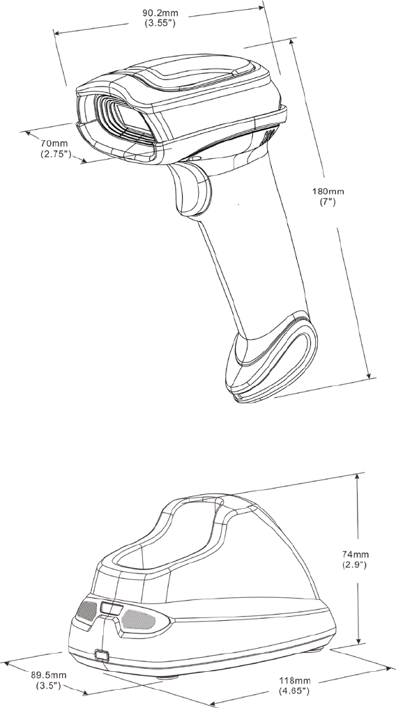
Dimensions Length × Width × Depth: 90.2 × 70 × 180 mm
225 g
Color Gray
Indicator LED, Beeper, Vibrator
Operating Mode Handheld
Manual (reading special barcode)
Program Upgrade Using Flash Utility software, while a cradle unit is required.
Input Voltage 5 ± 0.25 VDC
Current 20 mA (standby), 350 mA (scanning)
Battery 2600 mAh Lithium—ion battery
Charge Time 6 hours
Standby Time 6.5 days
Working Time 70 hours (1 scan per 5 seconds)
Image Size 1280 × 800 pixels
Field of View Horizontal: 42°, vertical: 26.5°
Scanning Angle ±70°, ±75°, 360° (Skew, Pitch, Roll)
Print Contrast 20% minimum reflectance difference
Decoding Capability
1D:
UPC—A, UPC—E, UPC—E1, EAN—13, EAN—
8, ISBN (Bookland EAN), ISSN,
Code 39, Code 39 full ASCII, Code 32, Trioptic Code 39, Interleaved 2 of 5,
Industrial 2 of 5, Matrix 2 of 5, Codabar (NW7), Code 128, UCC/EAN 128,
ISBT 128, Code 93, Code 11 (USD—8), MSI/Plessey, UK/Plessey, China Post,
China Finance, GS1 DataBar (formerly RSS) variants
2D:
PDF417, MicroPDF417, QR code, DataMatrix, Aztec Code
Minimum
HD: 1D (Code 39): 3 mil, 2D (QR): 5 mil
SR: 1D (Code 39): 4 mil, 2D (PDF417): 6.7 mil
Decoding Depth
Standard range
series (SR)
3 mil Code39 (3 chars) 10 mm – 61 mm /
4 mil Code 128 (9 chars) 5 mm – 88 mm 55 mm – 106 mm
5 mil Code39 (3 chars) 0 mm – 108 mm 43 mm – 141 mm
10 mil Code39 (3 chars) 0 mm – 167 mm 0 mm – 310 mm
13 mil UPC (6 chars) 0 mm – 179 mm 0 mm – 335 mm
20 mil Code39 (1 char) 10 mm – 253 mm 8 mm – 480 mm
5 mil QR (40 chars) 7 mm – 65 mm /
6.7 mil PDF417 (20 chars) 0 mm – 105 mm 37 mm – 145 mm

2
10 mil QR (20 chars) 0 mm – 134 mm 0 mm – 168 mm
20 mil QR (20 chars) 0 mm – 215 mm 0 mm – 345 mm
Temperature
0° to 50°C (32° to 120°F), operating
—40° to 60°C (—40° to 140°F), storage
Humidity 5% to 95% (non—condensing)
Safety
Electrical Safety: EN60950—1
Photobiological Safety: EN62471:2008
Illumination: 0~100,000 LUX
Protection Class: IP51
Drop Resistance: Withstands multiple 1.5 m (5 ft.) drops to concrete
Note: Test condition: temperature at 27°C, sunny day, and visibility of 5 kilometers. Natural
surroundings significantly affect the communication distance in practice. The distance drops quickly in
the rainy, high—humidity, or heavy haze day; radio interference also shortens the communication
distance.
Cradle
Input Voltage 5 ± 0.25 VDC
Current 60 mA (working), 500 mA (charging)
Cable Straight 2.0 m (PS/2) / Straight 1.5 m (USB) / Straight 2.0 m (RS—232 )
Dimensions Length × Width × Depth: 118 × 89.5 × 74 mm
Weight 140 g (without cable)
Indicator LED
Manual (reading special barcode)
Program Upgrade PC online using Flash Utility software.
Temperature
0° to 50°C (32° to 120°F), operating
—40° to 60°C (—40° to 140°F), storage
Humidity 5% to 95% (non—condensing)
Drop Resistance Unit functions normally after repeated 1.5 m (5 ft.) drops to concrete

3
1-2 Default setting for each barcode
Code type Read
enable Check digit
verification Check digit
transmission
length
y
AIM
code ID
UPC-A √ √ √ (12)2 A ]Em
UPC-E √ √ √ (8)2 D ]Em
UPC—E1 √ √ √ (8)2 D ]Em
EAN—13 √ √ √ (13)2 A ]Em
EAN-8 √ √ √ (8)2 C ]Em
ISBN (Bookland EAN)
/ ISSN1 √ √ √ (13)2 B ]Em
Code 39 √ — — 1 M ]Am
Interleaved 2 of 5 √ — — 6 I ]Im
Industrial 2 of 5 — — — 4 H ]Im
Matrix 2 of 5 √ — — 6 X ]Im
Codabar √ — — 4 N ]Fm
Code 128 √ √ — 1 K ]Cm
ISBT 128 √ √ — 1 K ]Cm
Code 93 √ √ — 1 L ]Gm
Code 11 — √ — 4 V —
MSI/Plessey — — — 4 O ]Mm
UK/Plessey — √ — 1 U ]Mm
UCC/EAN 128 √ √ — 1 K ]Cm
China Post √ — — (11)2 T ]Im
China Finance √ — — (10)2 Y —
GS1 DataBar √ — — (16)2 R ]em
√ — — (16)2 R ]em
GS1 DataBar Limited √ — — (16)2 R ]em
GS1 DataBar Expanded
√ — — 1 R ]em
PDF417 √ — — — — —
MicroPDF417 √ — — — — —
DataMatrix √ — — — — —
QR code √ — — — — —
Aztec Code √ — — — — —
Note: 1The settings for ISBN/ISSN and EAN—13 must be the same except the code ID.
2 Fixed-length barcodes.
3The settings for GS1 DataBar Truncated and GS1 DataBar must be the same.
4
2 Get started
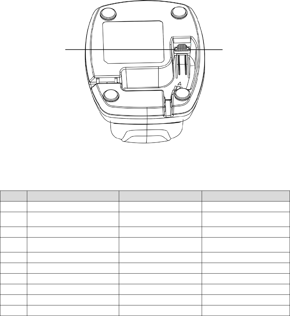
2-1 Cable connector pin—outs descriptions for cradle
Figure 2—1 Cable connector interface pin—outs
The pin—outs descriptions in Table 2-1 apply to the cable connector on the cradle and are for reference
only. Table 2-1 Cable connector pin—outs descriptions
Keyboard (PS/2)
1
Power (+5V)
2
+3.3V ( for interface auto
selection purpose)
Ground (for interface auto
selection purpose)
+3.3V ( for interface auto
selection purpose)
3
Ground
4
+3.3V ( for interface auto
selection purpose)
Reserved
Ground (for interface auto
selection purpose)
5
KeyClock
6
KeyData
7
TermClock
8
TermData
9
Reserved
10
Reserved
Note: Voltage level of all RS232 Pin—outs (RxD, TxD, CTS and RTS) is 0V for logic low and 3.3V for logic
high.
Pin 1 Pin 10
5
2-2 Dimensions
6
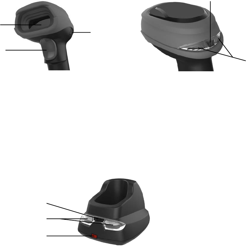
2-3 Parts of the scanner
Figure 2-2 Handheld unit
① Scan window
② Trigger (Press to triggr / Long press 3 seconds to turn on)
③ Beeper
④ On base indicator (Blue LED)
⑤ Successful decoding indicator (Green LED) / Communication fail indicator (Red LED) / Charging
indicator (Red/Green LED)
Figure 2-3 Cradle
⑥ Power indicator (Blue LED)
⑦ Communication indicator (Green LED)
⑧ Key (Long press 10 seconds to restore factory default setting of cradle)
①
②
③
⑤
④
⑥
⑦
⑧
7
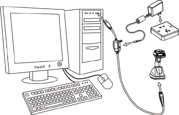
2-4 Charge battery
1. Please charge the battery before the first time of use. The charge indicator (red LED) on the
handheld unit is turned on when the charging is in process. When the charging process completes,
the red LED is turned off.
2. Charging time: 6 hours for fully charged.
3. You can charge the battery via a USB port on the device or a 5 VDC power adapter.
Note: The 5 VDC power adapter is an optional accessory.
Figure 2-4
8
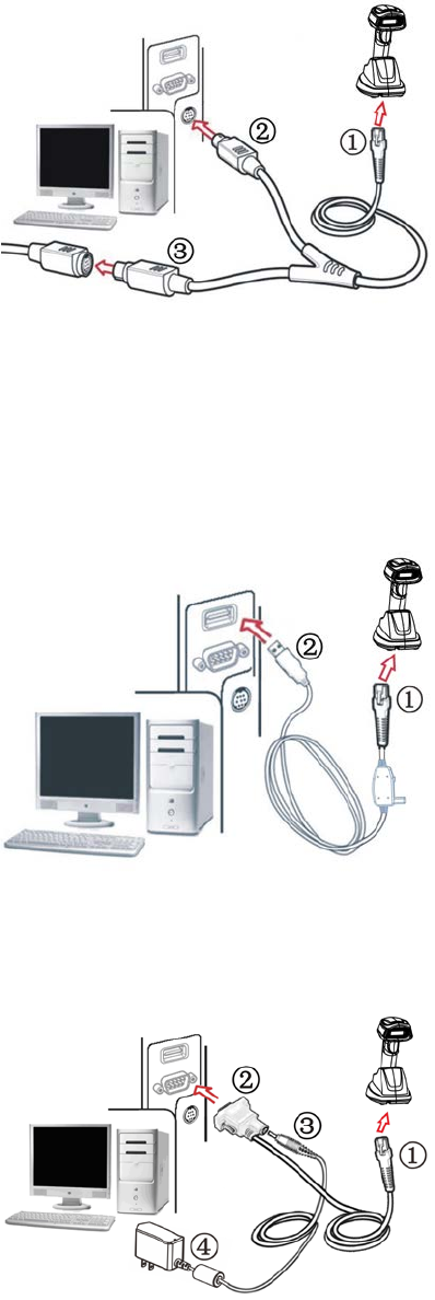
2-5 Installation of cradle
Note: If any of the below operation is incorrect, turn off the power immediately and check the scanner for
any improper connections. Go through all steps again.
2-5-1 PS/2 keyboard cable
Plug one end of the PS/2 keyboard cable to the cradle, one end to PS/2 port on PC, and one end to the
keyboard.
2-5-2 USB cable
1) Plug one end of the USB cable to the cradle. Plug the other end into the USB port of the computer.
2) Windows gives message on “new hardware found – USB HID input device found”, then driver will be
installed on request.
3) After successfully installing the new hardware, message will be given: “hardware installed
successfully and ready to use”.
4) If any problem encounters during the installation process, please unplug the USB cable from the
computer and repeat step 1) and 2).
2-5-3 RS—232 cable
1) Connect the DB9 serial communication cable with the cradle and the COM port of the computer.
2) Plug the output of the AC/DC adaptor into the power terminal of on the cradle. Plug the AC/DC
adaptor provided by the manufacturer into an electrical outlet.
9
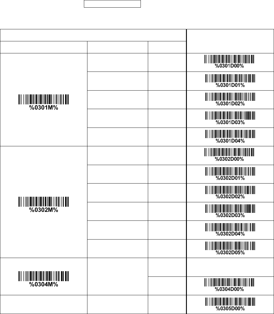
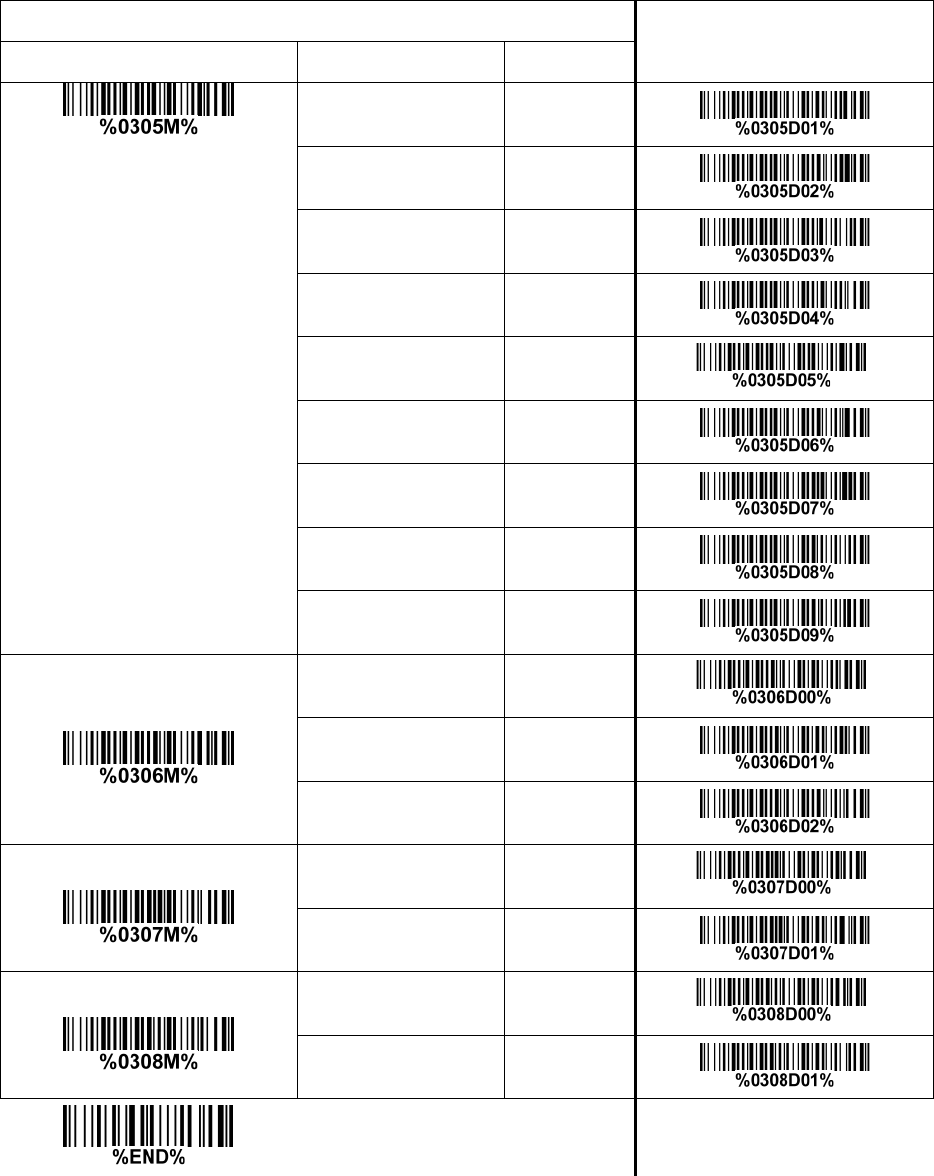
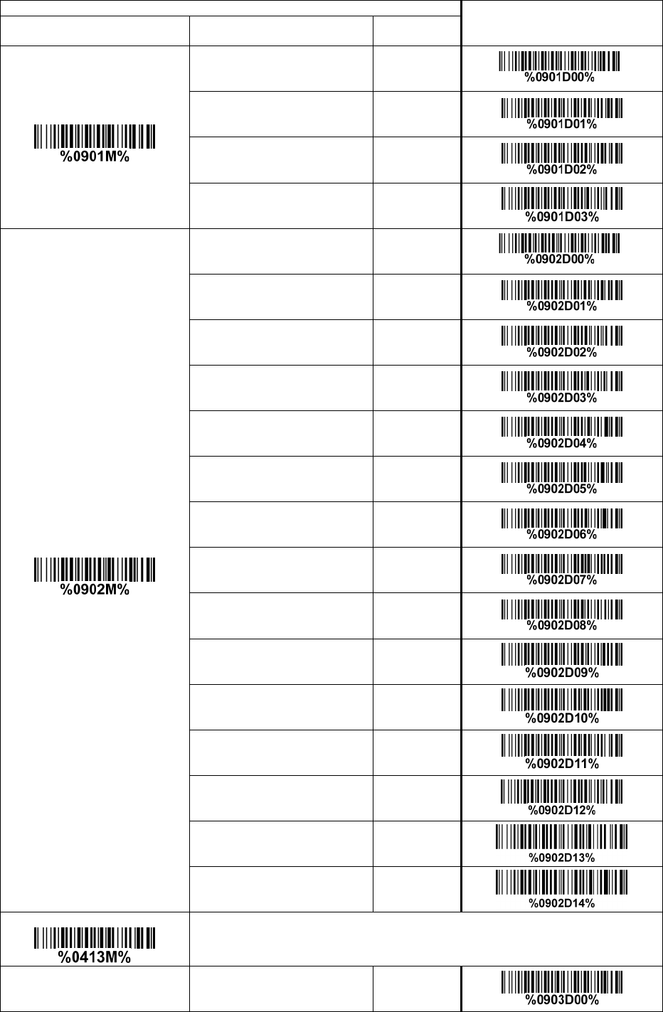
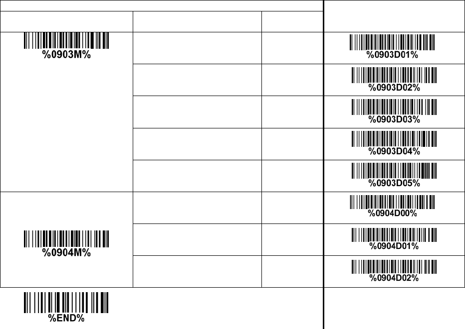
3 Progamming menus
3-1 Example 1: Single—parameter setting by scanning 1D barcodes
Important notes:
1. During the process of programming, LED is lighting to indicate the programming correctness. LED
will go off if any incorrect programming operation performed.
2. After each successful programming, LED will go off and the scanner will beep twice.
3. Throughout the programming barcode menus, the factory default settings are indicated with
asterisks (*).
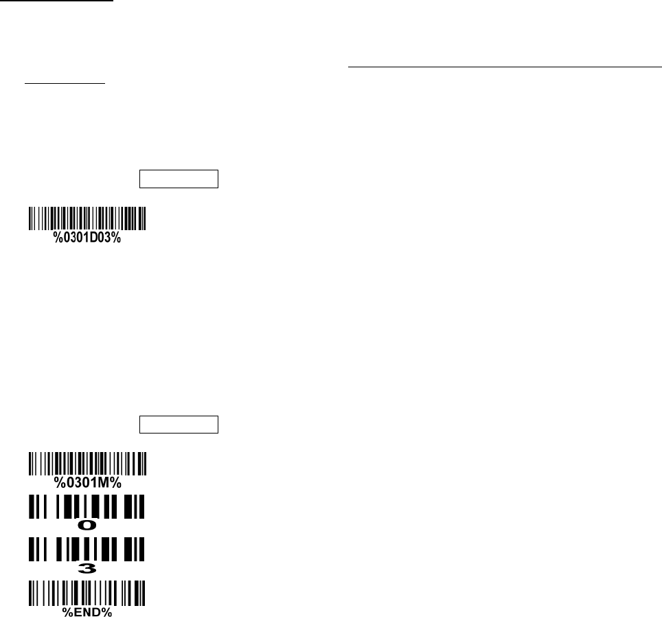
Two programming modes have been provided as bellows:
❶ Single—scan setting
Scan the appropriate Single—scan setting (e.g. %0101D00%) according to the user‘s demand.
Example: To set Flow control to be XON/XOFF.
Steps: Scan the following barcode.
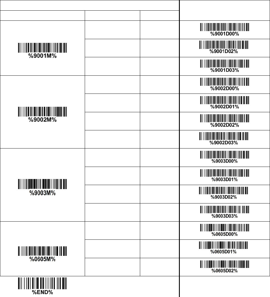
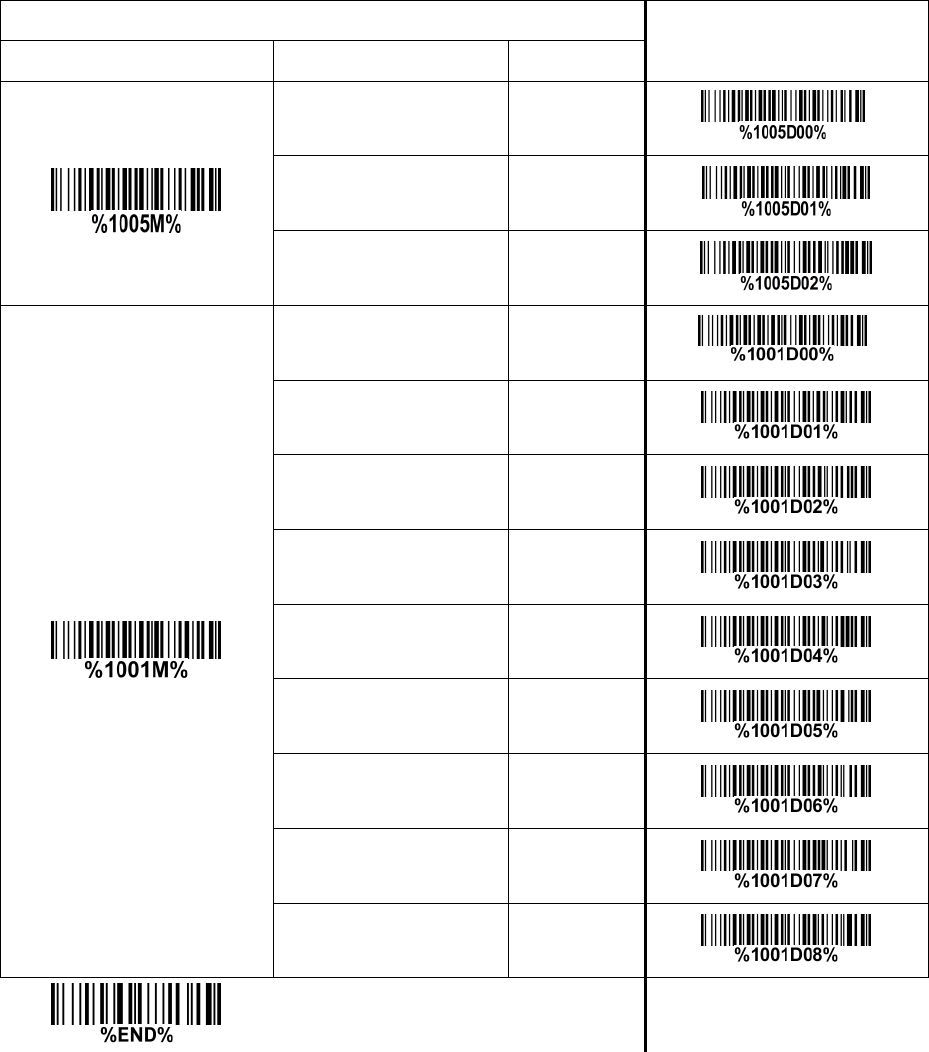
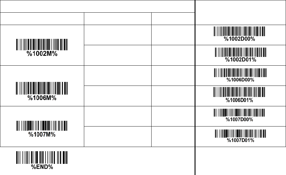
❷ Multiple—scan setting
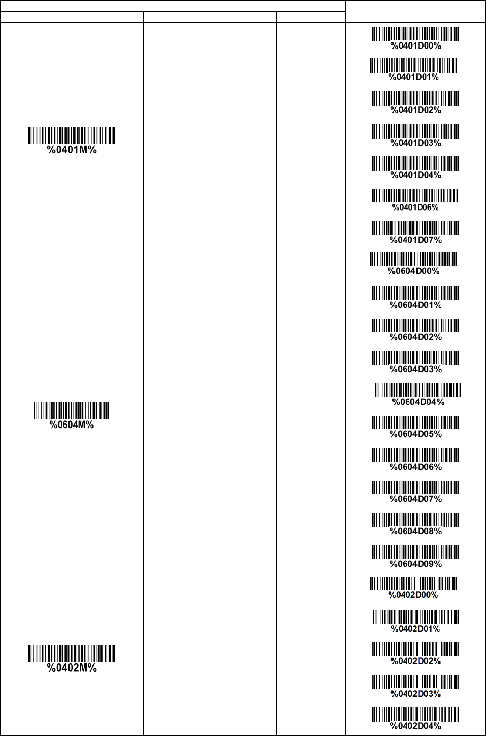
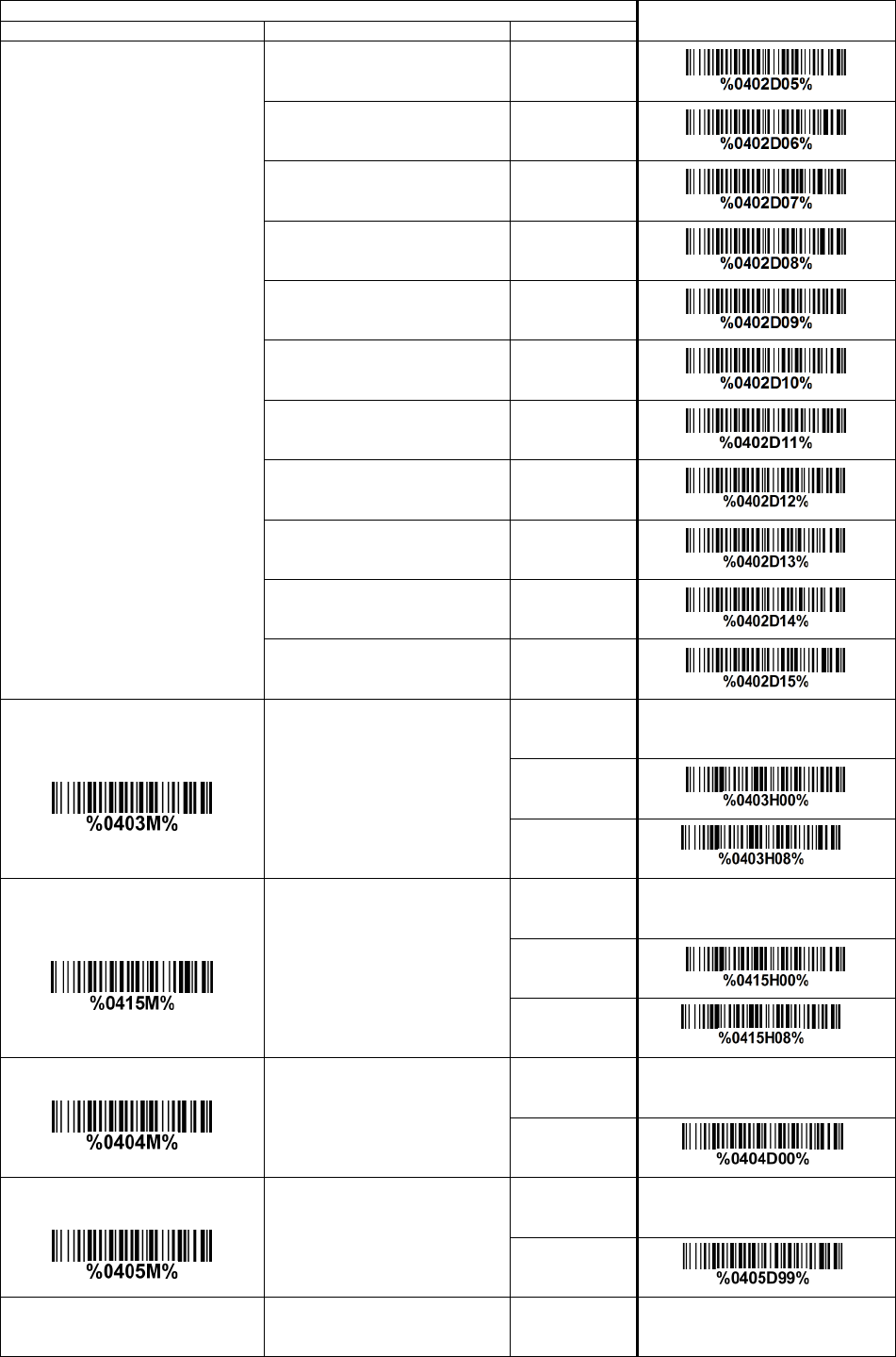
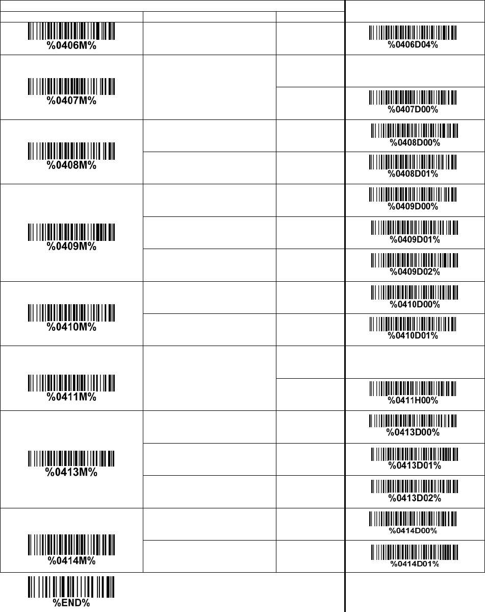
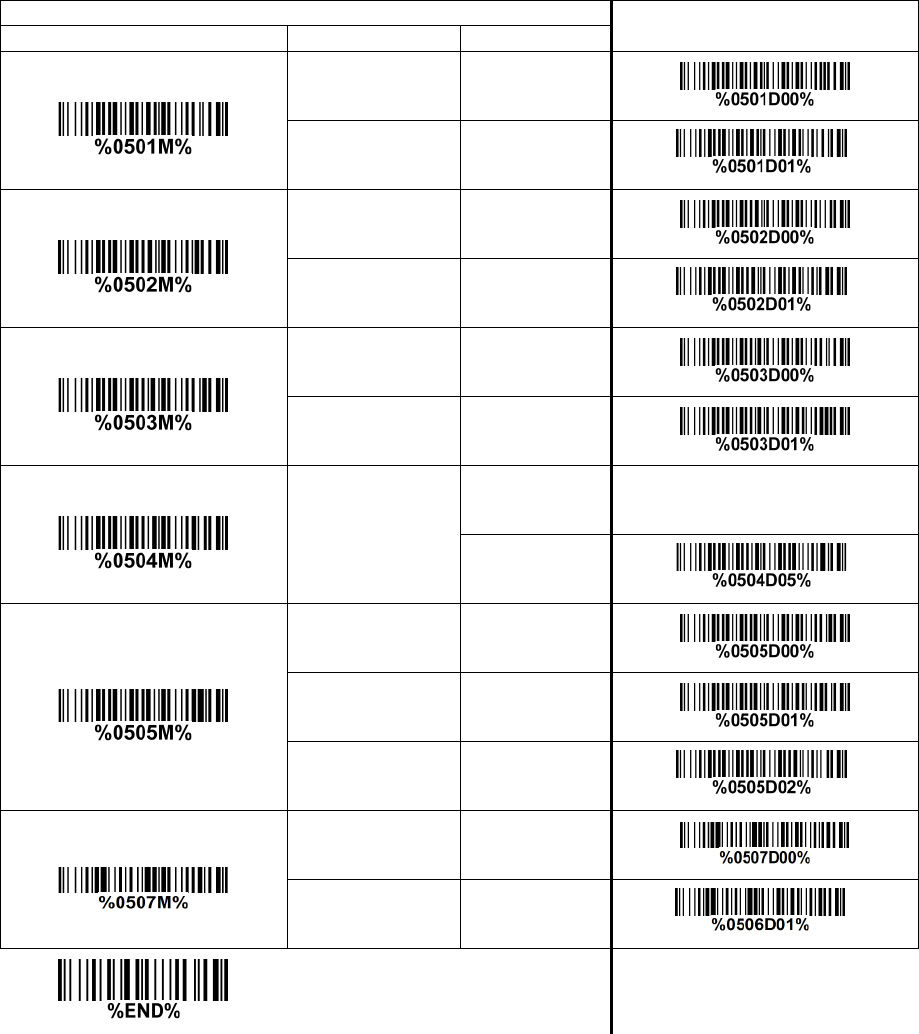
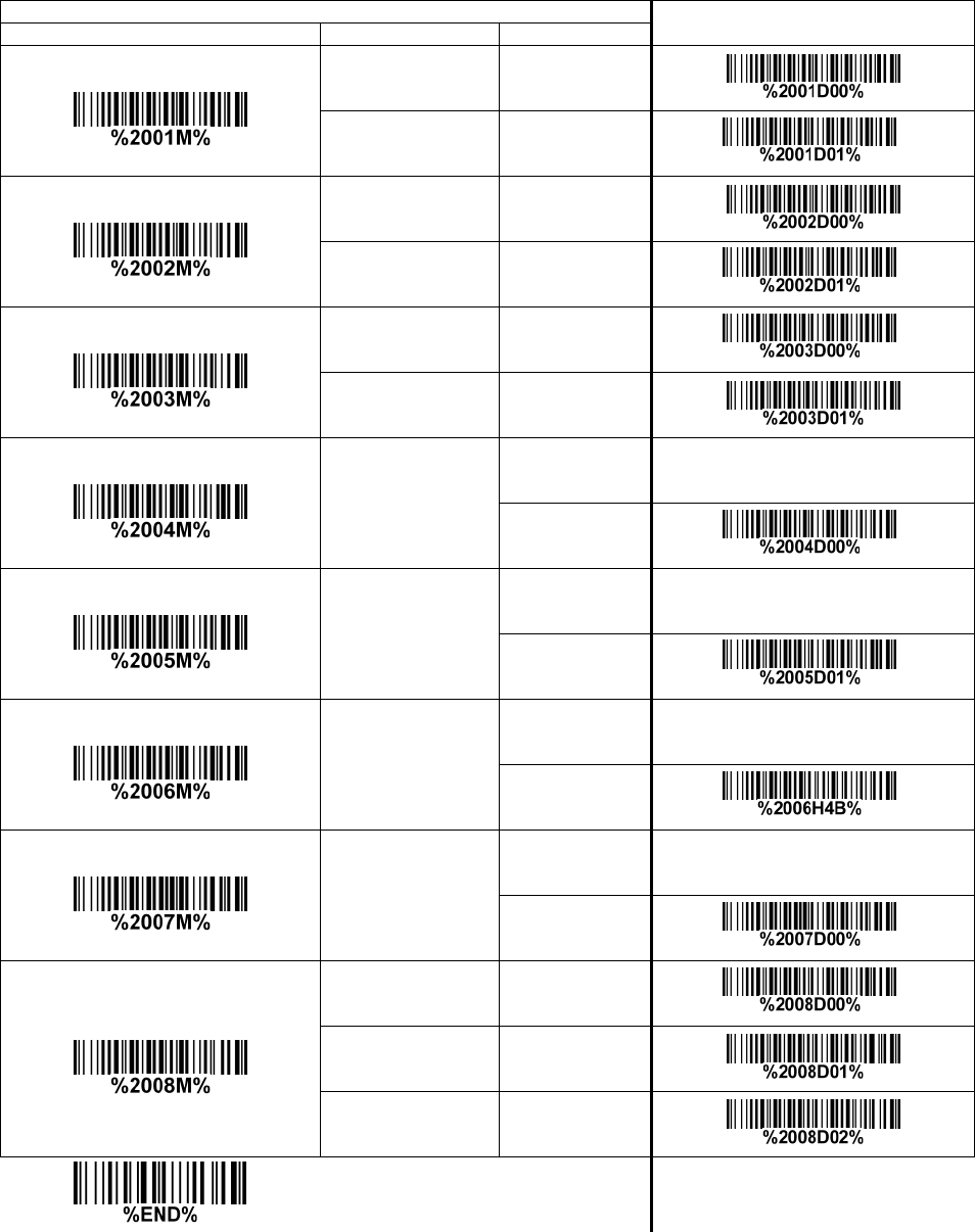
Step 1. Scan the Option barcode barcode (e.g. %0101M%) according to the user‘s demand.
Step 2. To the right of the option barcode, the necessary alphanumeric inputs are listed. Scan
two alphanumeric entries from 0 to 9 or A to F, refer to 10 Configuration alphanumeric entry
barcode.
Step 3. Repeat Step 2, if more user parameters input are required.
Step 4. Scan the %END% barcode, listed on the lower left hand corner of each parameter
setting part.
Example: To set Flow control to be XON/XOFF.
Steps: Referring to 3-7 RS—232 interface for cradle, scan the following barcodes in order.
10
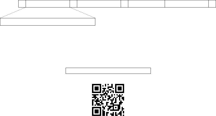
3-2 Example 2: Multiple—parameter setting by scanning a QR code
barcode
User can customize a QR code barcode to set multiple parameters. The scanner can set multiple
parameters by scanning this single QR code barcode.
1. The data format of the QR code barcode is as following.
%Param eter set 1%P aram eter set 2%P aram eter set N %
<O ption barcode index><D/H><Alpha. entries>
···
Note that:
<Option barcode index> means the corresponding 4 digits of Option barcode.
<D/H> means “D” or “H” character. D means that the type of alphanumeric entry is decimal; and H
means that the type of alphanumeric entry is hexadecimal.
<Alpha. entries> is a character string with various length of 2, 4, or other values.
Example: Set 0401—>03 (decimal); 8002—>0D0A (hexadecimal); 8202—>01 (decimal). The customized
QR code barcode contents and symbol are as following.
%0401D03%8002H0D0A%8202D01%
2. Notes of making QR code barcode
The model is chosen as M2. Other requirements, e.g. ECC level, Start mode, etc, are not specified.
Other notes
1- The contents of a QR code barcode can include several same <Option barcode index> associated
with same or different <Alpha. entries>. In the case of with different <Alpha. entries>, the latest
<Alpha. entries> is the valid one.
2- If any one of the parameter settings is invalid, the total setting is failed. The invalid setting can be
caused by one of the following problems: invalid <Option barcode index>, invalid type of <D/H>,
invalid type, length or value range of <Alpha. entries>, etc.

11
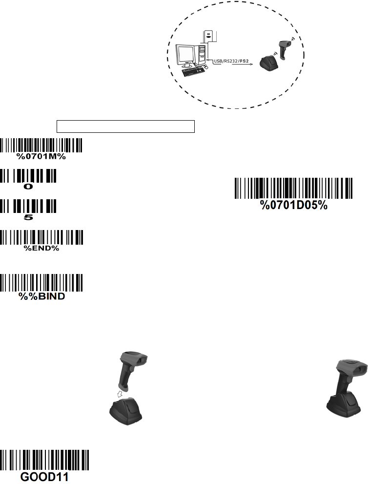
3-3 CS2290 Wireless communication setting
3-3-1 Wireless communication setting for handheld unit
Handheld unit RF channel No.: The scanner offers 16 different radio frequency channels for the data
transmission between handheld unit and cradle. The number of channel can be increased.
Single—scan setting
Handheld unit RF channel No.
02—16
02—16
06*
12
3-3-2 example
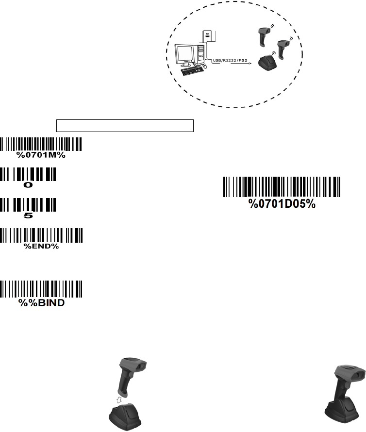
Example 1: One handheld unit and one cradle
The following takes channel No.5 for instance.
Step 1): Set Handheld unit RF channel No. of the handheld unit to 5.
or
Step 2): Scan the following barcode to bind the handheld unit with the cradle.
Firmly position the handheld unit onto the cradle. Within 10 seconds, two beeps will be emitted to
signal that the cradle has been paired to the handheld unit, and the blue LED on the handheld unit will
go off. If three beeps are emitted, it indicates unsuccessful pairing between the cradle and the
handheld unit, then repeat step 2).
Test barcode:
13
Example 2: Two handheld units and one cradle
The following takes channel No.5 for instance.
Step 1): Set Handheld unit RF channel No. of the first handheld unit to 5.
or
Step 2): Make the first handheld unit scan the following barcode to bind the handheld unit with the
cradle.
Firmly position the handheld unit onto the cradle. Within 10 seconds, two beeps will be emitted to
signal that the cradle has been paired to the handheld unit, and the blue LED on the handheld unit will
go off. If three beeps are emitted, it indicates unsuccessful pairing between the cradle and the
handheld unit, then repeat step 2).
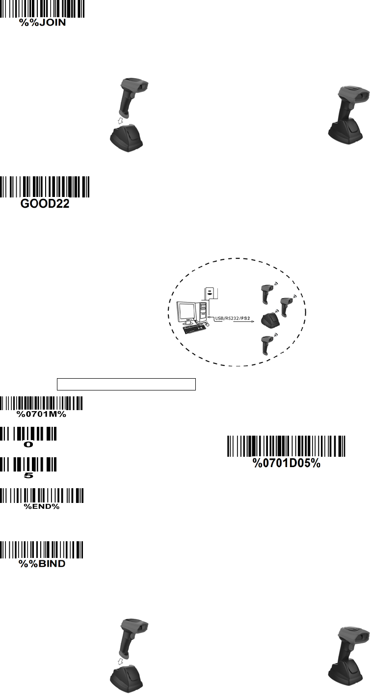
14
Step 3): Make the second huandhend unit scan %%JOIN barcode to pair the second handheld unit
with the cradle.
Firmly position the handheld unit onto the cradle. Within 10 seconds, two beeps will be emitted to
signal that the cradle has been paired to the handheld unit, and the blue LED on the handheld unit will
go off. If three beeps are emitted, it indicates unsuccessful pairing between the cradle and the
handheld unit, then repeat step 3).
Test barcode:
Example 3: Three handheld units and one cradle
The following takes channel No.5 for instance.
Step 1): Set Handheld unit RF channel No. of the first handheld unit to 5.
or
Step 2): Make the first handheld unit scan the following barcode to bind the handheld unit with the
cradle.
Firmly position the handheld unit onto the cradle. Within 10 seconds, two beeps will be emitted to
signal that the cradle has been paired to the handheld unit, and the blue LED on the handheld unit will
go off. If three beeps are emitted, it indicates unsuccessful pairing between the cradle and the
handheld unit, then repeat step 2).
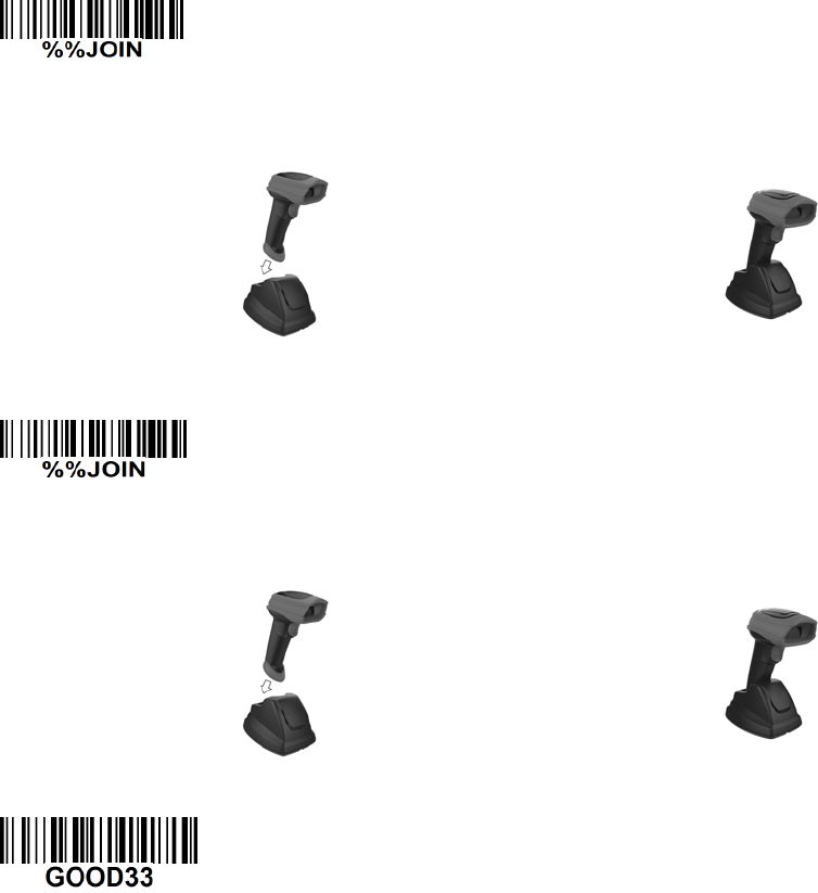
15
Step 3): Make the second huandhend unit scan %%JOIN barcode to pair the second handheld unit
with the cradle.
Firmly position the handheld unit onto the cradle. Within 10 seconds, two beeps will be emitted to
signal that the cradle has been paired to the handheld unit, and the blue LED on the handheld unit will
go off. If three beeps are emitted, it indicates unsuccessful pairing between the cradle and the
handheld unit, then repeat step 3).
Step 4): Make the third huandhend unit scan %%JOIN barcode to pair the third handheld unit with the
cradle.
Firmly position the handheld unit onto the cradle. Within 10 seconds, two beeps will be emitted to
signal that the cradle has been paired to the handheld unit, and the blue LED on the handheld unit will
go off. If three beeps are emitted, it indicates unsuccessful pairing between the cradle and the
handheld unit, then repeat step 4).
Test barcode:
16
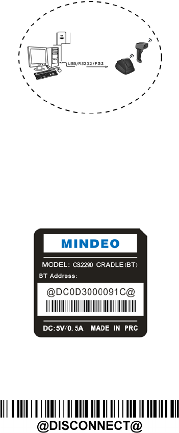
3-4 CS2290—BT Wireless communication setting
3-4-1 example
The handheld terminal shall ensure that the connection of the base and PC is successful before
communicating with the base.
Connect the base:
The handheld terminal scans the connection barcode at the bottom of the base, and the handheld
terminal will attempt to connect to the base, at the same time ,the handheld terminal will make a
beep-beep—beep sound. If the connection is successful, the handheld terminal can be used directly. If the
connection is unsuccessful, the handheld terminal will make a beep—beep— sound, and the red LED on
the handheld will blinks 2 times, and then turns off.
Disconnect:
The handheld terminal scan disconnects the bar code, and the handheld terminal can be disconnected
from the base
17
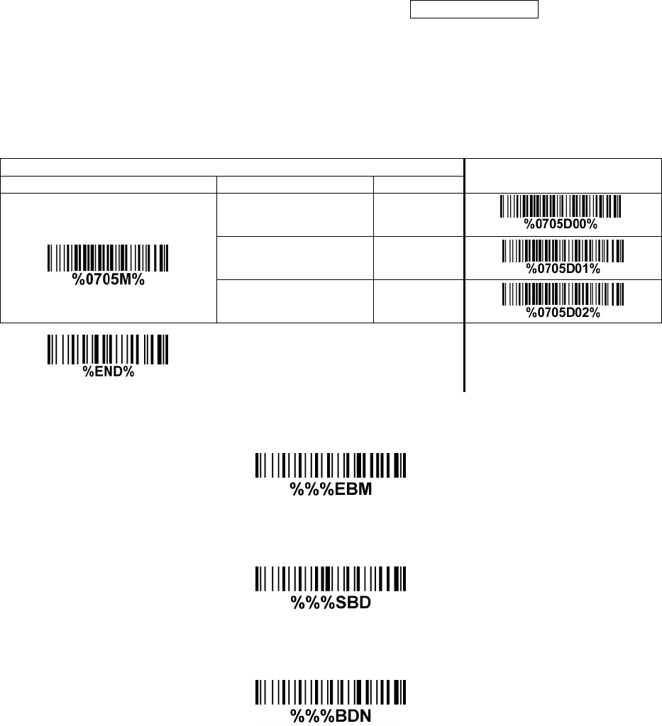
3-5 Batch data mode
Disable— Do not batch data. The handheld unit attempts to transmit every scanned barcode. If the
transmission is failed, the barcode data is ignored.
Out—of—range batch- The handheld unit starts storing barcode data when it loses its connection to a
remote device (for example, when a user holding the handheld unit walks out of range). Data
transmission is triggered by reestablishing the connection with the cradle (for example, when a user
holding the handheld unit walks back into range).
Standard batch— The handheld unit starts storing barcode data after %%%EBM” (Enter Batch Mode)
is scanned. Data transmission is triggered by scanning “%%%SBD” (Send Batch Data).
If you wish to output the total number of barcodes scanned when in Standard batch Mode, scan“%%%BDN”.
In Out—of—range batch or Standard batch modes, calculate the number of barcodes the handheld unit
can store as follows:
Number of storable barcodes = 524,288 bytes of memory / (number of characters in the barcode + 2).
Single—scan setting
Batch data mode
Disable 00* *
Out—of—range batch 01
Standard batch 02
Enter batch mode
Send batch data
Total Records

18
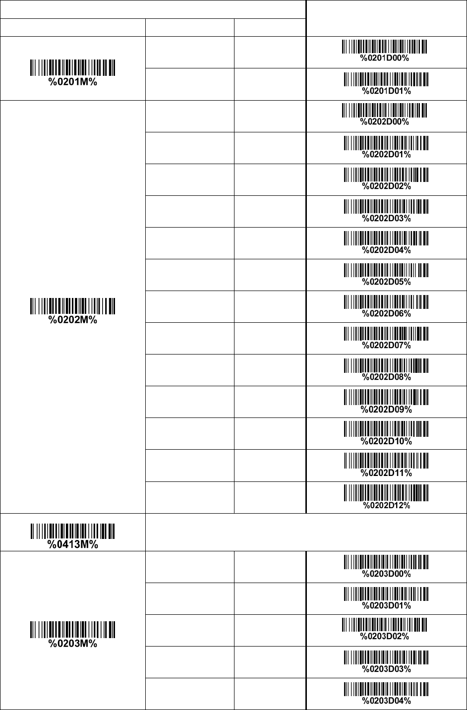
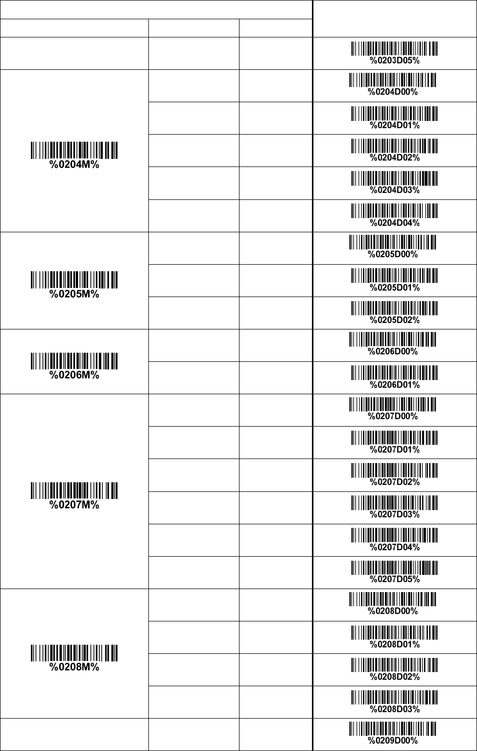
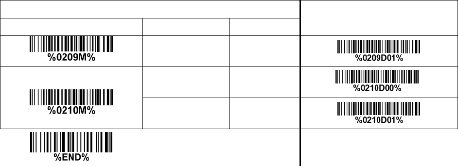
3-6 Keyboard wedge interface for cradle
Keyboard type: As a keyboard interface, the scanner supports most of the popular PCs and IBM
terminals.
Keyboard layout: The scanner supports different national keyboard layouts.
Clock period: According to the PS2 protocol, the clock is provided by the device, e.g. keyboard or
scanner, with the period between 60us to 100us.
Delay—after—compound—key: In some rare occasions, machine with low speed PS2 communication port
would require a free time gap following the press/release of the compound key (Shift, Ctrl or Alt).
Numeric key:
Alphabetic key— The scanner will output code result as alphabetic key.
Numeric key— The scanner will output code result as pressing numeric keypad ( ‘0’, ‘1’, ‘2’, ‘3’, ‘4’, ‘5’,
‘6’, ‘7’, ‘8’, ‘9’, ‘.’, ‘+’, ‘-‘, ‘/’, ‘*’ only).
Alt + keypad— The scanner will output code result as pressing Alt+ numeric key (on keypad). Note
that the Num Lock control key must be ON. This setting can be specially adapted for use with
different national keyboard layout.
Power—on simulation: All of the PCs check the keyboard status during power—on self test. It simulates
keyboard timing and passes keyboard present status to the PC during power—on.
Inter—character delay: This delay is inserted after each data character transmitted.
Inter—byte delay: This delay is inserted after each byte transmitted. Normally a character is comprised
of three or above bytes.
Block trans. delay: It is a delay timer between barcode data output. This feature is used to transfer
continually with shorter barcode data.
Caps Lock reversion: By setting enable, the status of Caps Lock key (i.e. being pressed ON or OFF) on
the keyboard is simulated in a reversion status.
Caps Lock override: If this function is enabled, on AT or AT notebook hosts, the keyboard ignores the
state of the Caps Lock key. Therefore, an ‘A’ in the bar code is sent as an ‘A’ no matter what the state of
the keyboard’s Caps Lock key.
A guide of setting while the scanned data is incorrectly displayed on the host
If some characters are missed or some additional characters are incorrectly displayed on the host,
set the Inter—byte delay (0208) to be “01” or greater value.
If some capital character (e.g. “A”) or compound-key—characters (e.g.“shift+”, “Ctrl+”, “Alt+”)are
displayed incorrectly, set the Delay—after—compound-key to be “01” or greater value.
If some digits are incorrectly displayed as some symbol characters (e.g. “1” and “2” are displayed
incorrectly as “!” and “@”), set the Clock period (0203) to be greater value (e.g. 04, 05).
19
Multiple—scan setting Single—scan setting
Option bar code Option Alpha. entry
Keyboard type
IBM AT, PS/2 00* *
Apple Mac
compatibles 01
Keyboard layout
USA 00* *
Turkish F 01
Turkish Q 02
French 03
Italian 04
Spanish 05
Slovak 06
Denmark 07
Japanese 08
German 09
Belgian 10
Russian 11
Czech 12
Character encoding system
Refer to 3-9 Handheld scan & some global settings.
Clock period
60 us 00
70 us 01
80 us 02* *
90 us 03
100 us 04
20
Multiple—scan setting Single—scan setting
Option bar code Option Alpha. entry
200 us 05
Delay—after—compound—key
0 ms 00* *
10 ms 01
20 ms 02
40 ms 03
80 ms 04
Numeric key
Alphabetic key 00* *
Numeric keypad 01
Alt + keypad 02
Power—on simulation
Disable 00* *
Enable 01
Inter—character delay
0 ms 00* *
5 ms 01
10 ms 02
20 ms 03
40 ms 04
80 ms 05
Inter—byte delay
1 ms 00* *
2 ms 01
4 ms 02
8 ms 03
Caps Lock reversion Disable 00* *
21
Multiple—scan setting Single—scan setting
Option bar code Option Alpha. entry
Enable 01
Caps Lock override
Disable 00* *
Enable 01
22
3-7 RS—232 interface for cradle
Flow control:
None—The communication only uses TxD and RxD signals without any hardware or software
handshaking protocol.
RTS/CTS-If the scanner wants to send the barcode data to host computer, it will issue the RTS signal
first, wait for the CTS signal from the host computer, and then perform the normal data communication.
If there is no replied CTS signal from the host computer after the timeout duration, the scanner will
issue an error indication. By setting (Host idle: Low RTS) or (Host idle: High RTS), the scanner can
be set to match the Serial Host RTS line.
XON/XOFF—An XOFF character turns the scanner transmission off until the scanner receives an XON
character.
ACK/NAK—After transmitting data, the scanner expects either an ACK (acknowledge) or NAK (not
acknowledge) response from the host. When a NAK is received, the scanner transmits the same
data again and waits for either an ACK or NAK. After three unsuccessful attempts to send data when
NAKs are received, the scanner issues an error indication and discards the data.
Inter—character delay: Refer to Inter—character delay of 3-6 Keyboard wedge for cradle.
Response delay: This delay is used for serial communication of the scanner when it waits for a
handshaking acknowledgment from the host.
Multiple—scan setting Single—scan setting
Option bar code Option Alpha. entry
Flow control
None 00* *
RTS/CTS
(Host idle: Low RTS) 01
RTS/CTS
(Host idle: High RTS) 02
XON/XOFF 03
ACK/NAK 04
Inter—character delay
0 ms 00* *
5 ms 01
10 ms 02
20 ms 03
40 ms 04
80 ms 05
Response delay
00—99 (100 ms)
00-99
00* *
Baud rate 300 00
23
Multiple—scan setting Single—scan setting
Option bar code Option Alpha. entry
600 01
1200 02
2400 03
4800 04
9600 05* *
19200 06
38400 07
57600 08
115200 09
Parity
None 00* *
Odd 01
Even 02
Data bit
8 bits 00* *
7 bits 01
Stop bit
1 bit 00* *
2 bits 01

24
3-8 USB interface for cradle
USB device type:
HID keyboard– By setting, the scanner is used as a USB HID keyboard emulation device. The
keyboard layout setting follows the setting of keyboard layout in 3-6 Keyboard wedge for cradle.
USB virtual COM– By setting, the scanner emulate a regular RS232—based COM port. If a Microsoft
Windows PC is connected to the scanner, a driver is required to install on the connected PC. The
driver will use the next available COM Port number. The driver and the installation guide can be
found in the associated CD and on the manufacturer’s website. A Windows—based software
COM_Text is recommended to display the barcode data in text format. COM_Text emulates some
kind of serial—key typing.
Note: When changing USB Device Type, the scanner automatically restarts.
Simple COM Port Emulation— Please contact the manufacturer for the instruction.
Keyboard layout: The scanner supports different national keyboard layouts.
Inter—character delay: This delay is inserted after each data character transmitted. By selecting, the
user can change the output speed of the scanner to match the speed of the host USB communication
port.
Numeric key:
Alphabetic key— The scanner will output code result as alphabetic key.
Numeric key— The scanner will output code result as pressing numeric keypad ( ‘0’, ‘1’, ‘2’, ‘3’, ‘4’, ‘5’,
‘6’, ‘7’, ‘8’, ‘9’, ‘.’, ‘+’, ‘-‘, ‘/’, ‘*’ only).
Alt + keypad— The scanner will output code result as pressing Alt+ numeric key (on keypad). Note
that the Num Lock control key must be ON. This setting can be specially adapted for use with
different national keyboard layout.
25
Single—scan setting
Option bar code Option
USB device type
HID keyboard 00* *
HID keyboard for Apple Mac 01
USB virtual COM 02
Simple COM Port Emulation 03
Keyboard layout
USA 00* *
Turkish F 01
Turkish Q 02
French 03
Italian 04
Spanish 05
Slovak 06
Denmark 07
Japanese 08
German 09
Belgian 10
Russian 11
Czech 12
Thailand 13
Hungary 14
Character encoding system
Refer to 3-9 Handheld scan & some global settings.
Inter—character delay 0 ms 00
26
Single—scan setting
Option bar code Option
5 ms 01* *
10 ms 02
20 ms 03
40 ms 04
60 ms 05
Numeric key
Alphabetic key 00* *
Numeric keypad 01
Alt + keypad 02

27
3-9 Handheld scan & some global settings
Scanning mode:
Good—read off—The trigger button must be pressed once to activate scanning. The scanner will stop
scanning when there is a successful reading or no code is decoded after the Stand—by duration
elapsed.
Momentary—The trigger button acts as a switch. Press button to activate scanning and release
button to stop scanning. The scanner will stop scanning when there is a successful reading or no
code is decoded after the Stand—by duration elapsed.
Alternate continue—The trigger button acts as a toggle switch. Press button to activate or stop
scanning.
Continue—The scanner always keeps scanning, and it does not matter when the trigger button is
pressed or duration is elapsed.
Timeout off—The trigger button must be pressed once to activate scanning. The scanner will stop
scanning when no code is successful decoded after the Stand—by duration elapsed.
Auto—detection— Good—read off – By setting Enable, the scanner will start operating if any nearby
object has been detected. The scanner will stop scanning when there is a successful reading or no
code is decoded after the Stand—by duration elapsed. Once the scanner stops scanning, the present
object must be removed to enable Auto—detection.
Auto—detection— Good—read on – By setting Enable, the scanner will start operating if any nearby
object has been detected. The scanner stops scanning when no code is successful decoded after the
Stand—by duration elapsed. Once the scanner stops scanning, the present object must be removed to
enable Auto—detection.
Auto—detection sensitivity: It is the sensitivity of scanner to ambient brightness change. Sensitivity is
expressed as a percentage value of ambient light change, in the range of 5% to 50%. The smaller the
percentage value, the higher the sensitivity, the easier the scanner will be triggered
Same barcode delay time: If a barcode has been scanned and output once successfully, the scan
operation should be interrupted for delay time or the focus of the scanner must be moved away from the
barcode beyond delay time to active scanning the same barcode. When this feature is set to be “0xFF”,
then the delay time is indefinite.
Double confirm: If it is enabled, the scanner will require a several times of same—decoded—data to
confirm a valid reading.
Global Max./Min. code length for 1D symbol: These two lengths are defined as the valid range of
decoded 1D barcode data length. Make sure that the minimum length setting is no greater than the
maximum length setting, or otherwise the labels of the symbol will not be readable. In particular, the
same value can be set for both minimum and maximum reading length to force the fixed length barcode
decoded.
Same barcode delay time for 2D symbol: If a 2D barcode has been scanned and output once
successfully, the scanner must output the same barcode data beyond delay time. When this feature is
set to be “0xFF”, then the delay time is indefinite.
Notes:
1. Please set the max./min. length for individual barcode in later sections, if special demand is
requested.
2. The number of check digits is included in max./min. code length.
3. These two settings have no effect on the symbols with fixed—length, e.g. UPC—A, UPC—E, EAN—13,
EAN—8 and China Post.
Global G1—G6 string selection: The scanner offer one or two string group for ALL symbols. By setting
one or two digits to indicate which string group you want to apply. You may refer to 3-41 G1—G6 & C1—C2
& FN1 substitution string setting and 3-42 G1—G4 string position & Code ID position.
Example: Group 1 → set 01 or 10. Group 2 and 4 → set 24 or 42.
All valid settings include 00, 01, 02, 03, 04, 05, 06, 10, 11, 12, 13, 14, 15, 16, 20, 21, 22, 23, 24, 25, 26,
30, 31, 32, 33, 34, 35, 36, 40, 41, 42, 43, 44, 45, 46, 50, 51, 52, 53, 54, 55, 56, 60, 61, 62, 63, 64, 65 and
66.
Element amendment: If it is enabled, the scanner can read the barcode comprised with bars and
spaces in different scale.
Character output restraint:
Printable character only— If this option is selected, the scanner will output the printable characters
only, i.e. in ASCII from 20H to 7EH.
Alphanumeric character only— If this option is selected, the scanner will output the alphanumeric
characters only, i.e. “A”-“Z”, “a”-“z”, “0”-“9”.

28
Decoder optimization: If it is enabled, the scanner will optimize the decoder with error correction. This
function is not effective for all types of barcodes.
Data output delay in continue—scan mode: If it is enabled, in the continue—scan mode, the scanner can
store the data while continue—scanning. The scanner will output the data after the predefined delay
elapsed. The maximum storage of data is 1000 characters. If this parameter is set to be “00”, the
scanner will not store data. And if the parameter is set to be “FF”, the scanner will output data after
stopping scanning.
Character encoding system: A character encoding system consists of a code that pairs each character
from a given repertoire. Common examples include Morse code, the Baudot code, the ASCII and
Unicode. If the data received does not display with the proper characters (e.g. domestic language), it
maybe because the barcode being scanned was created using a character encoding system that is
different from the one the host program is expecting. Try alternate options to find the proper one.
Complete data output before next decode attempt: This setting is active only when USB device type
is set as “HID keyboard” or “HID keyboard for Apple Mac”, refer to 3-8 USB interface for cradle. If it is
enabled, the imager will not start next decode attempt until previous data output is completed.
29
Single—scan setting
Scan mode
Good—read off 00
Momentary 01* *
Alternate continue 02
Continue 03
Good—read on 04
Auto—detection— Good—read on 06
Auto—detection— Good—read off 07
Auto-detection sensitivity
5%* 00* *
10% 01
15% 02
20% 03
25% 04
30% 05
35% 06
40% 07
45% 08
50% 09
Standby duration
4 seconds 00* *
8 seconds 01
16 seconds 02
24 seconds 03
30 seconds 04
30
Single—scan setting
1 minute 05
1.5 minutes 06
2 minutes 07
5 minutes 08
7 minutes 09
10 minutes 10
15 minutes 11
20 minutes 12
30 minutes 13
45 minutes 14
1 hour 15
Same barcode delay time for
1D symbol
00—FF16 (50 ms)
00-FF16
00
08* *
Same barcode delay time for
2D symbol
00-FF16 (50 ms)
00-FF16
00
08* *
Double confirm
00—09 (00: none )
00—09
00* *
Global max. code length for
1D symbol
04—99
04—99
99* *
Global min. code length for
1D symbol 01—99 01—99
31
Single—scan setting
04* *
Global G1—G6 string selection
00—66
(00: none )
00—66
00* *
Element amendment
Disable 00
Enable 01* *
Character output restraint
None 00* *
Printable character only 01
Alphanumeric character only 02
Decoder optimization
Disable 00
Enable 01* *
Data output delay in
continue—scan mode
00—99 (100 ms)
FF (Never)
00—FF16
00* *
Character encoding system
ASCII 00* *
UTF-8 01
Windows—1251 02
Complete data output before
next decode attempt
Disable 00* *
Enable 01
32
3-10 Indication for handheld unit
Power on alert: After power—on the scanner will generate an alert signal to indicate a successful
self—test.
LED indication: After each successful reading, the LED above the scanner will light up to indicate a
good barcode reading.
Beeper indication: After each successful reading, the scanner will beep to indicate a good barcode
reading, and its beep tone duration is adjustable.
Beep tone duration: This parameter can be adjusted for a good reading upon favorite usage.
Volume of beeper: This parameter can be adjusted for different level of the volume of the beeper.
Vibrator indication: After each successful reading, the vibrator will vibrate to indicate a good barcode
reading.
Single—scan setting
Power on alert
Disable 00
Enable 01* *
LED indication
Disable 00
Enable 01* *
Beeper indication
Disable 00
Enable 01*
Beep tone duration
01—09 (10 ms )
01—09
05* *
Volume of beeper
Low 00
Middle 01
High 02* *
Vibrator indication
Disable 00
Enable 01* *
33
3-11 Decode illumination and decode aiming pattern
Decode illumination mode: Enable illumination causes the scanner to turn on the illumination to aid
decoding. Disable illumination to turn off illumination for the scanner during decoding. Better quality
images could be obtained with illumination support. The effectiveness of the illumination decreases as
the distance to the target increases.
Decode aiming pattern: When this option is enabled, the scanner will project the aiming pattern during
the code capture.
Level of decode illumination: This parameter can be adjusted for different level of decode illumination.
Illumination mode of Auto—detection:
Always off— Illumination LED will be always turned off.
Enable illumination in low light conditions— In low light conditions, the scanner will turn on
illumination LED automatically to ensure normal work. While in other light conditions, the illumination
LED will be turned off automatically.
Always on— Illumination LED will be always turned on (Default).
Note: This function is only valid in Auto—detection mode.
34
Multiple—scan setting Single—scan setting
Option bar code Option Alpha. Entry
Decode illumination
Always Off 00
Flashing 02* *
On when reading 03
Decode aiming pattern
Always Off 00
Always On 01
On before reading 02
On when reading 03* *
Level of decode illumination
Disable decode
illumination 00
Low 01
Middle 02* *
High 03
Illumination mode of
Auto-detection
Always off 00
Enable illumination in
low light conditions 01* *
Always on 02
35
3-12 Single type of barcode read
1D symbols read: A global setting of 1D symbols readability.
2D symbols read: A global setting of 2D symbols readability.
Multiple—scan setting Single—scan setting
Option barcode Option Alpha. entry
1D symbols read
Follow respective 1D
symbol setting 00* *
All 1D Disable 01
All 1D Enable 02
2D symbols read
Follow respective 2D
symbol setting 00* *
All 2D Disable 01
All 2D Enable 02
Only PDF417 Enable 03
Only QR code Enable 04
Only Data Matrix Enable 05
Only MaxiCode Enable 06
Only Aztec Code Enable 07
Only Han Xin Code Enable 08
36
3-13 DPM, Multiple symbols, Structured append read, etc.
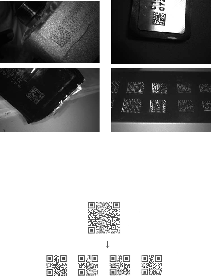
DPM format read: By setting Enable, the scanner can read 2D symbols in DPM (Direct Park Marking)
format. Some barcodes in DPM format are shown below.
Multiple symbols & structured append symbols read:
1) By setting Enable, the scanner allows to read multiple symbols with a single pull of the scanner’s
trigger. If the user pulls and holds the trigger, aiming the scanner at a series of symbols, it reads unique
symbols once, beeping for each success read. The scanner attempts to find and decode new symbols
as long as the trigger is pulled.
2) By setting Enable, the scanner will output data only when all Structured Append symbols have been
decoded. The lower part of below figure shows an example of four Structured Append symbols, with
the same data as that in the upper symbol.
3) By setting Disable, the scanner will only read the symbol closest to the aiming beam.
Single symbol (above) and Structured Append series of symbols (below) encoding
“ABCDEFGHIJKMNOPQRSTUVWXYZ0123456789ABCDEFGHIJKLMNOPQRSTUVWXYZ”
Mobile screen read: By setting enable, the scanner can read barcodes on a mobile screen better.
However, this will slow the reading speed of normal barcodes a little bit, and the decode illumination will
flash.
37
Multiple—scan setting Single—scan setting
Option bar code Option Alpha. entry
DPM format read
Disable 00* *
Enable 01
structured append
symbols read
Disable 00*
Enable 01 *
Mobile screen read
Disable 00* *
Enable 01

38
3-14 UPC-A
Read:
Format
Check digit verification: The check digit is optional.
Check digit trans.: By setting Enable, check digit will be transmitted.
Code ID setting: Code ID is a one—or—two—character string used to represent the symbol upon a
succeeding reading. If you want application to transmit Code ID, you must set Code ID transmission to
be enabled, refer to 3-43 String transmission.
Insertion group selection: Refer to Global insertion group selection of 3-9 Handheld scan & some
global settings.
Supplement digits: The Supplement digits barcode is the supplemental 2 or 5 characters.
Format
Truncation/Expansion:
Truncate leading zeros— The leading “0” digits of UPC—A data characters can be truncated when the
feature is enabled.
Expand to EAN—13— It extends to 13—digits with a “0” leading digit when the feature is enabled.
Truncate system character— The system character of UPC—A data can be truncated when the feature
is enabled.
Add country code— The country code (“0” for USA) can be added when the feature is enabled.
39
Multiple—scan setting Single—scan setting
Option barcode Option Alpha. entry
Read
Disable 00
Enable 01* *
Check digit verification
Disable 00
Enable 01* *
Check digit trans.
Disable 00
Enable 01* *
Code ID setting
00—FF16 (ASCII)
00—FF16
<A>* *
Insert group selection
00—66
00—66
00*
Supplement digits
None 00* *
2 digits 01
5 digits 02
2 or 5 digits 03
Truncation/Expansion
None 00* *
Truncate leading zeros 01
Expand to EAN—13 02
Truncate system character 03
Add country code 04

40
3-15 UPC-E
Read:
Format
Check digit verification: The check digit is optional and made as the sum of the numerical value of the
data digits.
Check digit trans.: By setting Enable, check digit will be transmitted.
Code ID setting: Refer to Code ID setting of 3-14 UPC-A.
Insertion group selection: Refer to Insertion group selection of 3-14 UPC-A.
Supplement digits:
Format
Truncation/Expansion:
Truncate leading zeros— Refer to Truncation/Expansion of 3-14 UPC-A.
Expand to EAN—13— It extends to 13—digits with “0” digits when the feature is set to be enabled.
Example: Barcode “0123654”,
Output: “0012360000057”.
Expand to UPC-A— It extends to 12-digits when the feature is set to be enabled.
Truncate system character— The system character “0” of UPC—E data can be truncated when the
feature is enabled.
41
Single—scan setting
Read
Disable 00
Enable 01* *
Check digit verification
Disable 00
Enable 01* *
Check digit trans.
Disable 00
Enable 01* *
Code ID setting
00—FF16 (ASCII)
00—FF16
<D>*
Insert group selection
00—66
00—66
00* *
Supplement digits
None 00* *
2 digits 01
5 digits 02
2 or 5 digits 03
Truncation/Expansion
None 00* *
Truncate leading zeros 01
Expand to EAN—13 02
Expand to UPC-A 03
Truncate system character 04

42
3-16 UPC-E1
Read:
Format
Check digit verification: The check digit is optional and made as the sum of the numerical value of the
data digits.
Check digit trans.: By setting Enable, check digit will be transmitted.
Code ID setting: Refer to Code ID setting of 3-14 UPC-A.
Insertion group selection: Refer to Insertion group selection of 3-14 UPC-A.
Supplement digits:
Format
Truncation/Expansion:
Expand to EAN—13— It extends to 13—digits with “0” digits when the feature is set to be enabled.
Expand to UPC-A— It extends to 12-digits when the feature is set to be enabled.
Truncate system character— The system character “1” of UPC-E1 data can be truncated when the
feature is enabled.
43
Multiple—scan setting Single—scan setting
Read
Disable 00
Enable 01* *
Check digit verification
Disable 00
Enable 01* *
Check digit trans.
Disable 00
Enable 01* *
Code ID setting
00—FF16 (ASCII)
00—FF16
<D>* *
Insert group selection
00—66
00—66
00* *
Supplement digits
None 00* *
2 digits 01
5 digits 02
2 or 5 digits 03
Truncation/Expansion
None 00* *
Expand to EAN—13 02
Expand to UPC-A 03
Truncate system character 04

44
3-17 EAN—13 (ISBN/ISSN)
Read:
Format
Check digit verification: The check digit is optional and made as the sum of the numerical value of the
data digits.
Check digit transmission: By setting Enable, check digit will be transmitted.
EAN—13 code ID setting: Refer to Code ID setting of 3-14 UPC-A.
Insertion group selection: Refer to Insertion group selection of 3-14 UPC-A.
Supplement digits:
Format
ISBN/ISSN conversion: The ISBN (International Standard Book Number, or Bookland EAN) and ISSN
(International Standard Serial Number) are two kinds of barcode for books and magazines. The ISBN is
10 digits with leading “978” and the ISSN is 8 digits with leading “977” of the EAN—13 symbol.
Example:
Barcode “9780194315104”, Output: “019431510X”.
Barcode “9771005180004”, Output: “10051805”.
ISBN/ISSN code ID setting: Refer to Code ID setting of 3-14 UPC-A.
45
Single—scan setting
Read
Disable 00
Enable 01* *
Check digit verification
Disable 00
Enable 01* *
Check digit transmission
Disable 00
Enable 01* *
EAN-13 code ID setting
00—FF16
(ASCII)
00—FF16
<A>* *
Insert group selection
00—66
00—66
00* *
Supplement digits
None 00* *
2 digits 01
5 digits 02
2 or 5 digits 03
ISBN/ISSN conversion
Disable 00* *
Enable 01
ISBN/ISSN code ID setting
00—FF16
(ASCII)
00—FF16
<B>* *

46
3-18 EAN-8
Read:
Format
Check digit verification: The check digit is optional and made as the sum of the numerical value of the
data digits.
Check digit trans.: By setting Enable, check digit will be transmitted.
Code ID setting: Refer to Code ID setting of 3-14 UPC-A.
Insertion group selection: Refer to Insertion group selection of 3-14 UPC-A.
Supplement digits:
Format
Truncation/Expansion: Refer to Truncation/Expansion of 3-14 UPC-A.
47
Single—scan setting
Read
Disable 00
Enable 01* *
Check digit verification
Disable 00
Enable 01* *
Check digit trans.
Disable 00
Enable 01* *
Code ID setting
00—FF16
(ASCII)
00—FF16
<C>* *
Insert group selection
00—66
00—66
00* *
Supplement digits
None 00* *
2 digits 01
5 digits 02
2 or 5 digits 03
Truncation/Expansion
None 00* *
Truncate leading zero 01
Expand to EAN—13 02

48
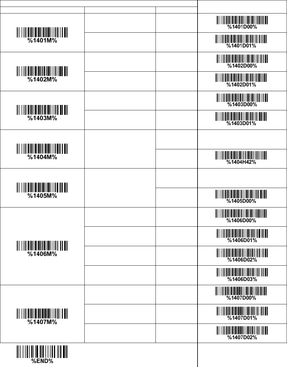
3-19 Code 39 (Code 32, Trioptic Code 39)
Read:
Format
Check digit verification: The check digit is optional and made as the sum module 43 of the numerical
value of the data digits.
Check digit transmission: By setting Enable, check digit will be transmitted.
Max./Min. code length: Each symbol has own max./min. code length. If both setting of max./min. code
length are “00”s, the setting of global max./min. code length is effective. The length is defined as to the
actual barcode data length to be sent. Label with length exceeds these limits will be rejected. Make
sure that the minimum length setting is no greater than the maximum length setting, or otherwise all the
labels of the symbol will not be readable. In particular, you can see the same value for both minimum
and maximum reading length to force the fixed length barcode decoded.
Code ID setting: Refer to Code ID setting of 3-14 UPC-A.
Insertion group selection: Refer to Insertion group selection of 3-14 UPC-A.
Start/End transmission: The start and end characters of Code 39 are “*”s. You can transmit all data
digits including two “*”s.
“*” as data character: By setting Enable, “*” can be recognized as data character.
Convert Code 39 to Code 32: Code 32 is a variant of Code 39 used by the Italian pharmaceutical
industry. Note that Code 39 must be enabled in order for this parameter to function.
Format of Code 32
Code 32 Prefix “A” transmission: By setting Enable, the prefix character “A” can be added to all Code
32 barcodes.
Trioptic Code 39 read: Trioptic Code 39 is a variant of Code 39 used in the marking of magnetic tapes
and computer cartridges. Trioptic Code 39 symbols always contain six characters.
Format
Trioptic Code 39 Start/End transmission: The start and end characters of Trioptic Code 39 are “$”
s. You can transmit all data digits including two “$”s.
49
Single—scan setting
Read
Disable 00
Enable 01* *
Check digit verification
Disable 00* *
Enable 01
Check digit transmission
Disable 00* *
Enable 01
Max. code length
00—99
00—99
00* *
Min. code length
00—99
00—99
01* *
Code ID setting
00—FF16
(ASCII)
00—FF16
<M>* *
Insert group selection
00—66
00—66
00* *
Format
Standard 00* *
Full ASCII 01
Start/End transmission
Disable 00* *
Enable 01
“*” as data character
Disable 00* *
Enable 01
Convert Code 39 to Code 32
Disable 00* *
Enable 01
50
Single—scan setting
Code 32 Prefix “A” transmission
Disable 00* *
Enable 01
Trioptic Code 39 read
Disable 00* *
Enable 01
Trioptic Code 39 Start/End
transmission
Disable 00* *
Enable 01

51
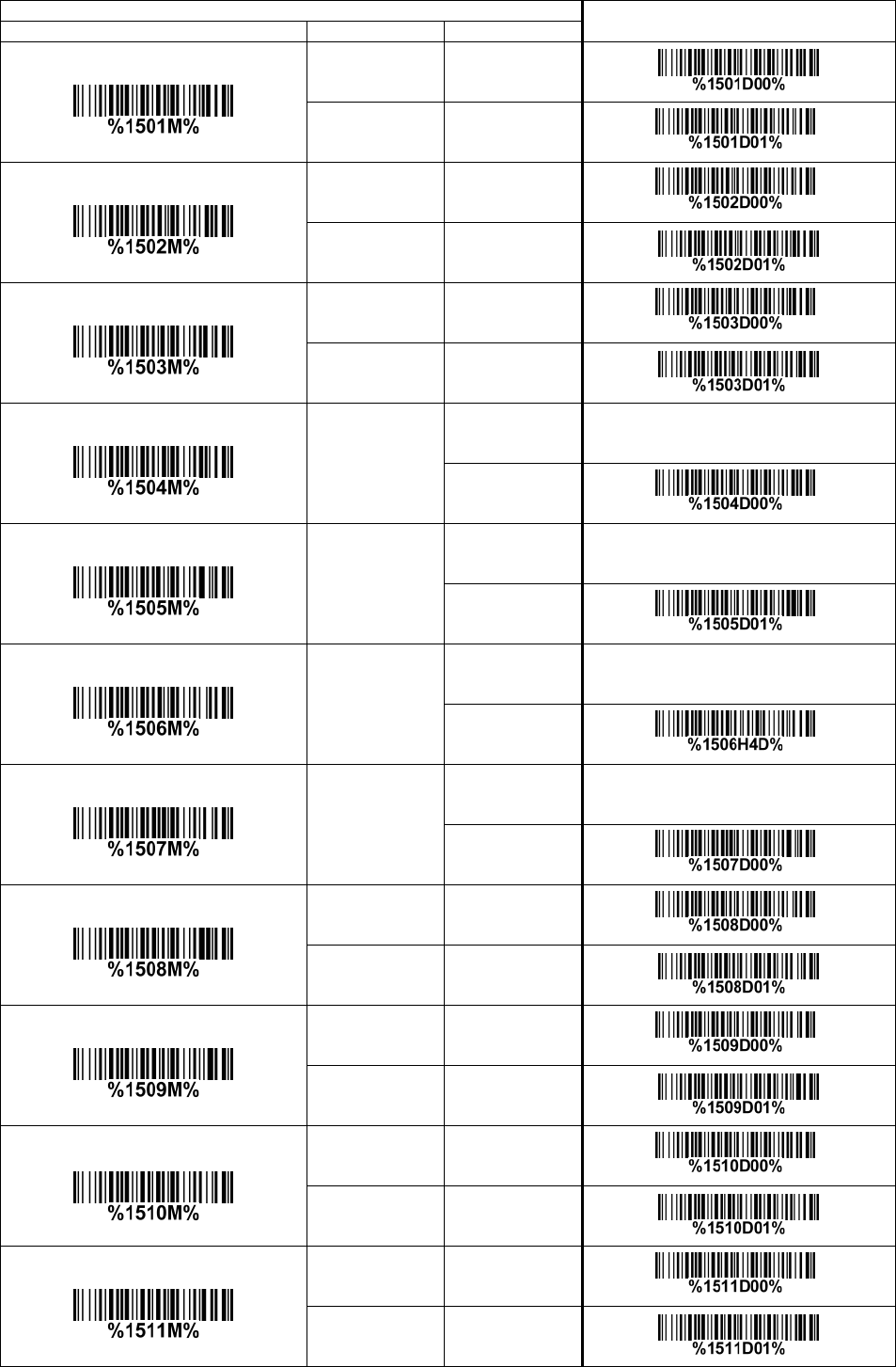
3-20 Interleaved 2 of 5
Read:
Format
Check digit verification: The check digit is made as the sum module 10 of the numerical values of all
data digits. There are two optional check digit algorithms: the specified Uniform Symbol Specification
(USS) and the Optical Product Code Council (OPCC).
Check digit transmission: By setting Enable, check digit will be transmitted.
Max./Min. code length: Refer to Max./Min. code length of 3-19 Code 39.
Code ID setting: Refer to Code ID setting of 3-14 UPC-A.
Insertion group selection: Refer to Insertion group selection of 3-14 UPC-A.
52
Single—scan setting
Read
Disable 00
Enable 01* *
Check digit verification
Disable 00* *
USS 01
OPCC 02
Check digit transmission
Disable 00* *
Enable 01
Max. code length
00—99
00—99
00* *
Min. code length
00—99
00—99
06* *
Code ID setting
00—FF16
(ASCII)
00—FF16
<I>* *
Insert group selection
00—66
00—66
00* *
53
3-21 Industrial 2 of 5
Read:
Format
Max./Min. code length: Refer to Max./Min. code length of 3-19 Code 39.
Code ID setting: Refer to Code ID setting of 3-14 UPC-A.
Insertion group selection: Refer to Insertion group selection of 3-14 UPC-A.
Single—scan setting
Read
Disable 00* *
Enable 01
Max. code length
00—99
00—99
00* *
Min. code length
00—99
00—99
00* *
Code ID setting
00—FF16
(ASCII)
00—FF16
<H>* *
Insert group selection
00—66
00—66
00* *
54
3-22 Matrix 2 of 5
Read:
Format
Check digit verification: The check digit is made as the sum module 10 of the numerical values of all
data digits.
Check digit transmission: By setting Enable, check digit will be transmitted.
Max./Min. code length: Refer to Max./Min. code length of 3-19 Code 39.
Code ID setting: Refer to Code ID setting of 3-14 UPC-A.
Insertion group selection: Refer to Insertion group selection of 3-14 UPC-A.
Single—scan setting
Read
Disable 00
Enable 01* *
Check digit verification
Disable 00* *
Enable 01
Check digit transmission
Disable 00* *
Enable 01
Max. code length
00—99
00—99
00* *
Min. code length
00—99
00—99
06* *
Code ID setting
00—FF16
(ASCII)
00—FF16
<X>* *
Insert group selection
00—66
00—66
00* *
55
3-23 Codabar
Read:
Format
Check digit verification: The check digit is made as the sum module 16 of the numerical values of all
data digits.
Check digit transmission: By setting Enable, check digit will be transmitted.
Max./Min. code length: Refer to Max./Min. code length of 3-19 Code 39.
Code ID setting: Refer to Code ID setting of 3-14 UPC-A.
Insertion group selection: Refer to Insertion group selection of 3-14 UPC-A.
Start/End type: Codabar has four pairs of Start/End pattern; you may select one pair to match your
application.
Start/End transmission: Refer to Start/End transmission of 3-19 Code 39.
Start/End character equality: By setting Enable, the start and end character of a Codabar barcode
must be the same.
Multiple—scan setting Single—scan setting
Option bar code Option Alpha. entry
Read
Disable 00
Enable 01* *
Check digit verification
Disable 00* *
Enable 01
Check digit transmission
Disable 00* *
Enable 01
Max. code length
00—99
00—99
00* *
Min. code length
00—99
00—99
00* *
Code ID setting
00—FF16
(ASCII)
00—FF16
<N>* *
Insert group selection
00—66
00—66
00* *
Start/End type ABCD/ABCD 00* *
56
Multiple—scan setting Single—scan setting
Option bar code Option Alpha. entry
abcd/abcd 01
ABCD/TN*E 02
abcd/tn*e 03
Start/End transmission
Disable 00* *
Enable 01
Start/End character equality
Disable 00* *
Enable 01

57
3-24 Code 128
Read:
Format
Check digit verification: The check digit is made as the sum module 103 of all data digits.
Check digit transmission: By setting Enable, check digit will be transmitted.
Max./Min. code length: Refer to Max./Min. code length of 3-19 Code 39.
Code ID setting: Refer to Code ID setting of 3-14 UPC-A.
Insertion group selection: Refer to Insertion group selection of 3-14 UPC-A.
Truncate leading zeros: The leading “0” digits of Code 128 barcode characters can be truncated when
the feature is enabled.
58
Single—scan setting
Read
Disable 00
Enable 01* *
Check digit verification
Disable 00
Enable 01* *
Check digit transmission
Disable 00* *
Reserved 01
Max. code length
00—99
00—99
00* *
Min. code length
00—99
00—99
01* *
Code ID setting
00—FF16
(ASCII)
00—FF16
<K>* *
Insert group selection
00—66
00—66
00* *
Truncate leading zeros
Disable 00* *
All leading “0”s 01
Only the first “0” 02

59
3-25 UCC/EAN 128
Read:
Format
Check digit verification: The check digit is made as the sum module 103 of all data digits.
Check digit transmission: By setting Enable, check digit will be transmitted.
Max. /Min. code length: Refer to Max./Min. code length of 3-19 Code 39.
Code ID setting: Refer to Code ID setting of 3-14 UPC-A.
Insertion group selection: Refer to Insertion group selection of 3-14 UPC-A.
Truncate leading zeros: Refer to Truncate leading zeros of 3-24 Code 128.
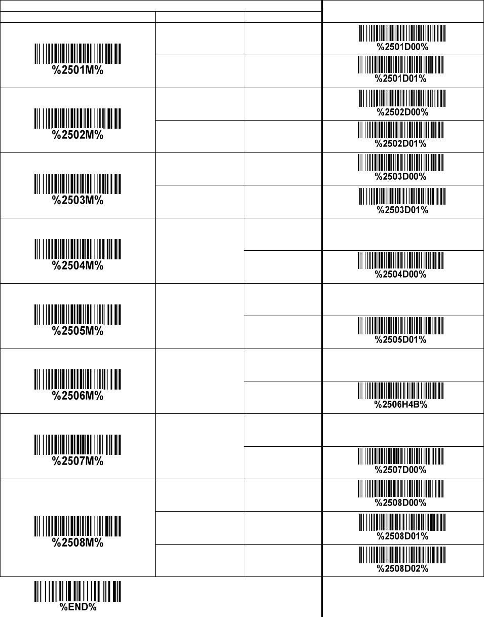
60
Single—scan setting
Read
Disable 00
Enable 01*
Check digit verification
Disable 00
Enable 01* *
Check digit transmission
Disable 00*
Reserved 01
Max. code length
00—99
00—99
00*
Min. code length
00—99
00—99
01*
Code ID setting
00—FF16
(ASCII)
00—FF16
<K>*
Insert group selection
00—66
00—66
00*
Truncate leading zeros
Disable 00*
All leading “0”s 01
Only the first “0” 02
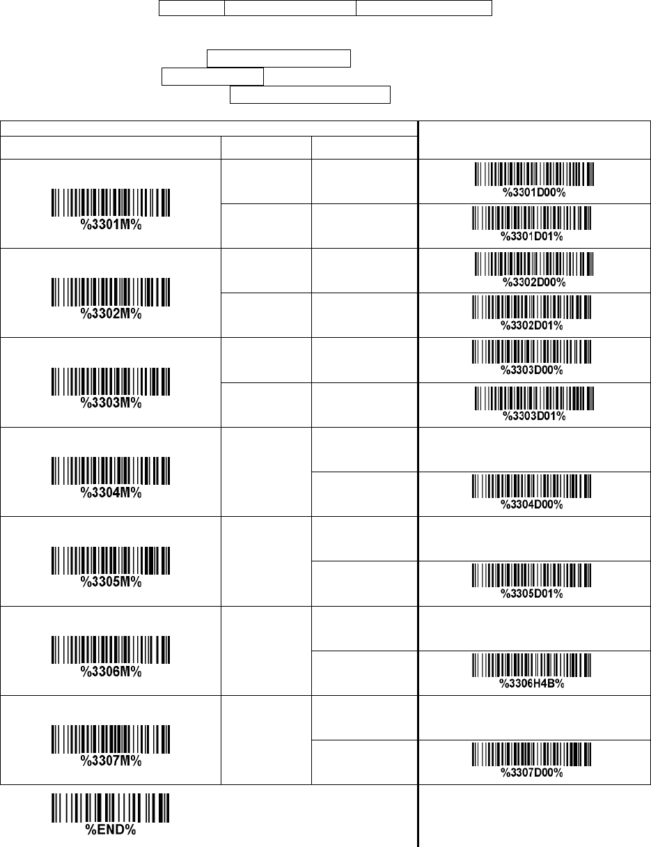
61
3-26 ISBT 128
Read:
Format
Check digit verification: The check digit is made as the sum module 103 of all data digits.
Check digit transmission: By setting Enable, check digit will be transmitted.
Max./Min. code length: Refer to Max./Min. code length of 3-19 Code 39.
Code ID setting: Refer to Code ID setting of 3-14 UPC-A.
Insertion group selection: Refer to Insertion group selection of 3-14 UPC-A.
Single—scan setting
Option bar code Option Alpha. entry
Read
Disable 00
Enable 01* *
Check digit verification
Disable 00
Enable 01* *
Check digit transmission
Disable 00* *
Reserved 01
Max. code length
00—99
00—99
00* *
Min. code length
00—99
00—99
01*
Code ID setting
00—FF16
(ASCII)
00—FF16
<K>* *
Insert group selection
00—66
00—66
00* *
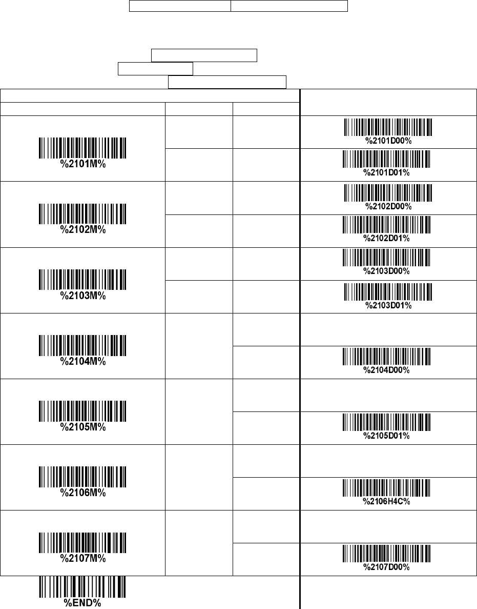
62
3-27 Code 93
Read:
Format
2 check digits (optional)
Check digit verification: The check digit is made as the sum module 47 of the numerical values of all
data digits.
Check digit transmission: By setting Enable, check digit will be transmitted.
Max./Min. code length: Refer to Max./Min. code length of 3-19 Code 39.
Code ID setting: Refer to Code ID setting of 3-14 UPC-A.
Insertion group selection: Refer to Insertion group selection of 3-14 UPC-A.
Single—scan setting
Read
Disable 00
Enable 01*
Check digit verification
Disable 00
Enable 01*
Check digit transmission
Disable 00*
Enable 01
Max. code length
00—99
00—99
00* *
Min. code length
00—99
00—99
01* *
Code ID setting
00-FF16
(ASCII)
00—FF16
<L>* *
Insert group selection
00—66
00—66
00* *

63
3-28 Code 11
Read:
Format
Check digit 1 (optional )
Check digit verification: The check digit is presented as the sum module 11 of all data digits.
Check digit transmission: By setting Enable, check digit 1 and check digit 2 will be transmitted upon
your selected check digit verification method.
Max./Min. code length: Refer to Max./Min. code length of 3-19 Code 39.
Code ID setting: Refer to Code ID setting of 3-14 UPC-A.
Insertion group selection: Refer to Insertion group selection of 3-14 UPC-A.
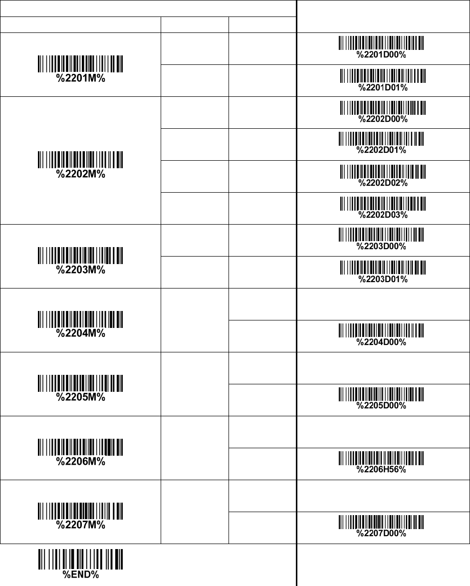
64
Multiple—scan setting Single—scan setting
Option bar code Option Alpha. entry
Read
Disable 00* *
Enable 01
Check digit verification
Disable 00
One digit 01* *
Reserved 02
Reserved 03
Check digit transmission
Disable 00* *
Enable 01
Max. code length
00—99
00—99
00* *
Min. code length
00—99
00—99
00* *
Code ID setting
00—FF16
(ASCII)
00—FF16
<V>* *
Insert group selection
00—66
00—66
00* *

65
3-29 MSI/Plessey
Read:
Format
Check digit verification: The MSI/Plessey has one or two optional check digits. There are three
methods of verifying check digits, i.e. Mod10, Mod10/10 and Mod 11/10. The check digit 1 and check
digit 2 will be calculated as the sum module 10 or 11 of the data digits.
Check digit transmission: By setting Enable, check digit 1 and check digit 2 will be transmitted upon
your selected check digit verification method.
Max./Min. code length: Refer to Max./Min. code length of 3-19 Code 39.
Code ID setting: Refer to Code ID setting of 3-14 UPC-A.
Insertion group selection: Refer to Insertion group selection of 3-14 UPC-A.
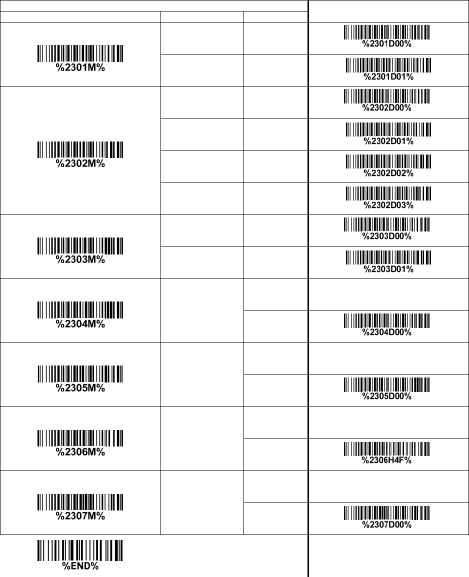
66
Single—scan setting
Read
Disable 00* *
Enable 01
Check digit verification
Disable 00* *
1 digit (mod 10) 01
Reserved 02
Reserved 03
Check digit transmission
Disable 00* *
Enable 01
Max. code length
00—99
00—99
00* *
Min. code length
00—99
00—99
00* *
Code ID setting
00—FF16
(ASCII)
00—FF16
<O>* *
Insert group selection
00—66
00—66
00* *

67
3-30 UK/Plessey
Read:
Format
2 check digits (optional)
Check digit verification: The UK/Plessey has one or two optional check digits. The check digit 1 and
check digit 2 will be calculated as the sum module 10 or 11 of the data digits.
Check digit transmission: By setting Enable, check digit will be transmitted.
Max./Min. code length: Refer to Max./Min. code length of 3-19 Code 39.
Code ID setting: Refer to Code ID setting of 3-14 UPC-A.
Insertion group selection: Refer to Insertion group selection of 3-14 UPC-A.
Single—scan setting
Read
Disable 00* *
Enable 01
Check digit verification
Disable 00
Enable 01* *
Check digit transmission
Disable 00* *
Enable 01
Max. code length
00—99
00—99
00* *
Min. code length
00—99
00—99
01* *
Code ID setting
00—FF16
(ASCII)
00—FF16
<U>* *
Insert group selection
00—66
00—66
00* *
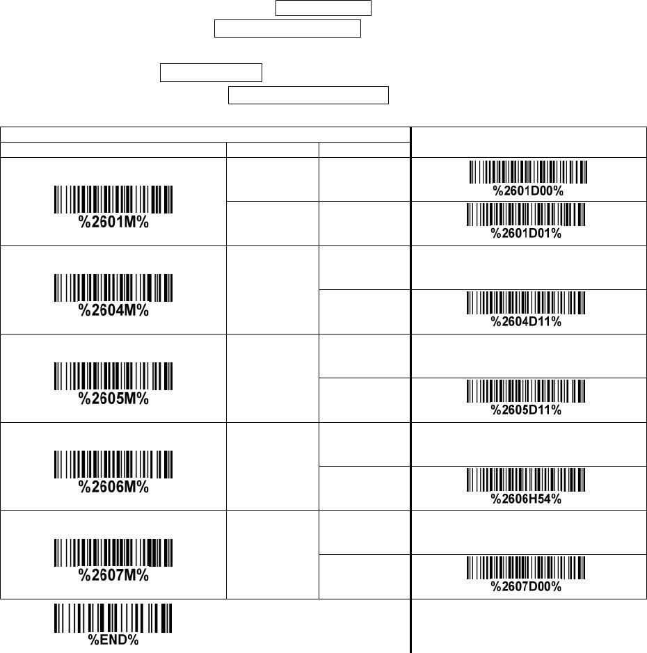
68
3-31 China Post
Read:
Format
Max. /Min. code length: Refer to Max./Min. code length of 3-19 Code 39. The code length of China
Post is 11.
Code ID setting: Refer to Code ID setting of 3-14 UPC-A.
Insertion group selection: Refer to Insertion group selection of 3-14 UPC-A.
Single—scan setting
Read
Disable 00
Enable 01*
Max. code length
00—99
00—99
11*
Min. code length
00—99
00—99
11*
Code ID setting
00—FF16
(ASCII)
00—FF16
<T>*
Insert group selection
00—66
00—66
00*
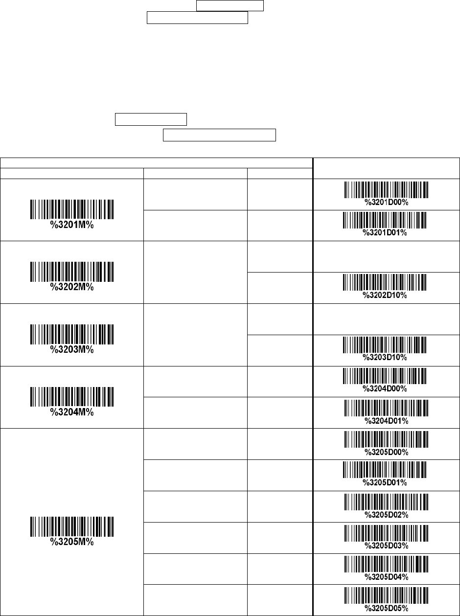
69
3-32 China Finance
Note: This type of barcode is not Omni—directionally decodable. The encodable character set includes
numeric 0 to 9. Among the symbol of 0 to 9, 0 and 2, 4 and 9, 5 and 8, 6 and 7, have the symmetrical
pattern; the pattern of 1 and 3 is symmetrical.
Read:
Format
Max./Min. code length: Refer to Max./Min. code length of 3-19 Code 39.
Check digit verification: The check digit is made as the sum module 10 of the numerical values of all
data digits.
Leading character 5/6/7/8/9 converted to A/B/C/D/E: By setting, leading character 5/6/7/8/9 can be
converted to A/B/C/D/E.
Leading character assignment: By setting, only the barcode with the assigned leading character can
be output.
Code ID setting: Refer to Code ID setting of 3-14 UPC-A.
Insertion group selection: Refer to Insertion group selection of 3-14 UPC-A.
Single—scan setting
Read
Disable 00
Enable 01* *
Max. code length
00—99
00—99
10* *
Min. code length
00—99
00—99
10*
Check digit verification
Disable 00*
Reserved 01
Leading character 5/6/7/8/9
converted to A/B/C/D/E
Disable 00
Enable 01* *
Only 5 converted to A 02
Only 6 converted to B 03
Only 7 converted to C 04
Only 8 converted to D 05
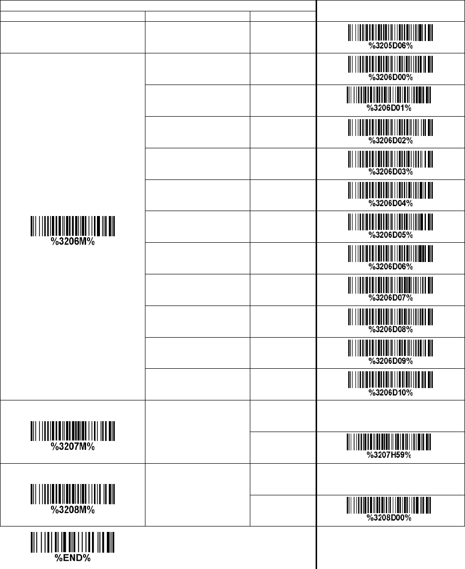
70
Single—scan setting
Only 9 converted to E 06
Leading character assignment
Disable 00
Assigned to 0 01* *
Assigned to 5(A) 02
Assigned to 6(B) 03
Assigned to 7(C) 04
Assigned to 8(D) 05
Assigned to 9(E) 06
Assigned to 1 07
Assigned to 2 08
Assigned to 3 09
Assigned to 4 10
Code ID setting
00—FF16
(ASCII)
00—FF16
<Y>*
Insert group selection
00—66
00—66
00*
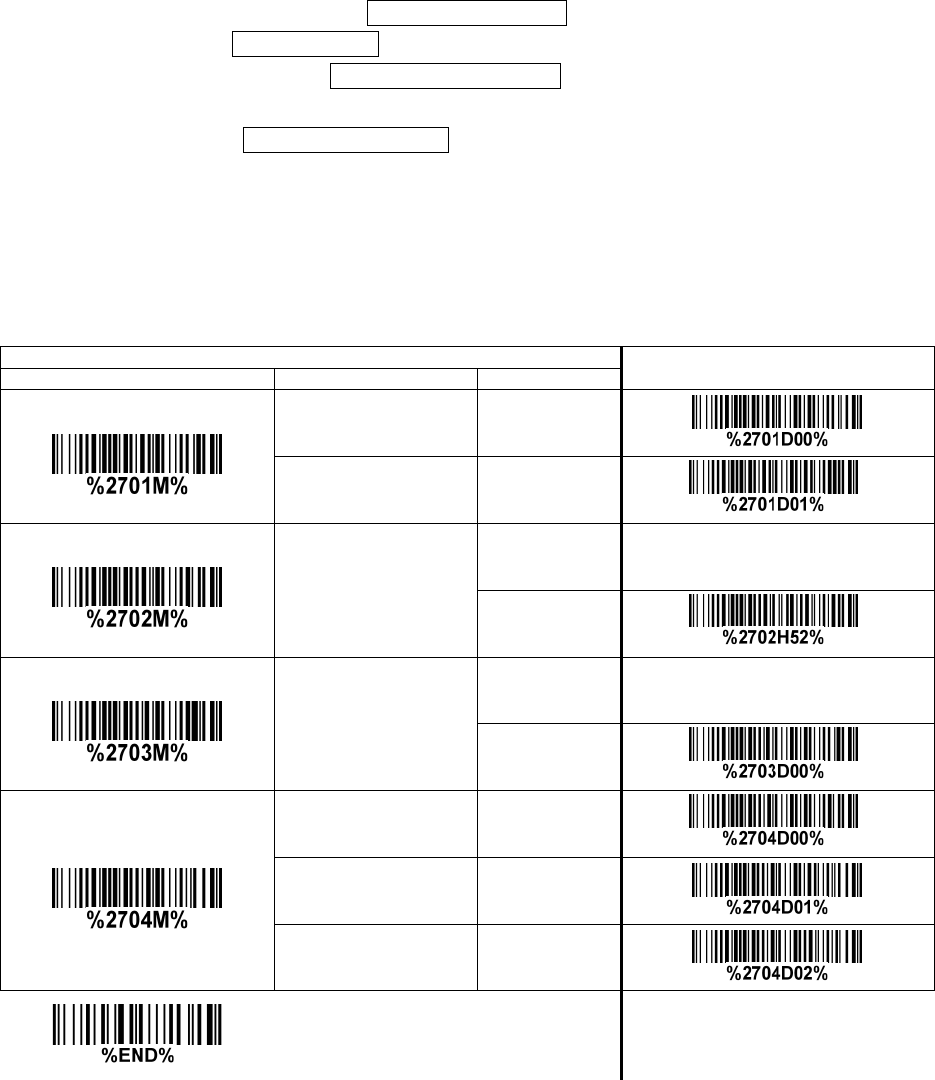
71
3-33 GS1 DataBar (GS1 DataBar Truncated)
GS1 DataBar Truncated is structured and encoded the same as the standard GS1 DataBar format,
except its height is reduced to a 13 modules minimum; while GS1 DataBar should have a height greater
than or equal to 33 modules.
Read:
Format
Code ID setting: Refer to Code ID setting of 3-14 UPC-A.
Insertion group selection: Refer to Insertion group selection of 3-14 UPC-A.
Conversion:
UCC/EAN 128— Refer to Code ID transmission of 3-43 String transmission, ]Cm will be identified as
AIM ID.
UPC—A or EAN—13— Barcode beginning with a single zero as the first digit has the leading “010”
stripped and the barcode reported as EAN—13. Barcode beginning with two or more zeros but not six
zeros has the leading “0100” stripped and the barcode reported as UPC—A.
Single—scan setting
Read
Disable 00
Enable 01* *
Code ID setting
00—FF16
(ASCII)
00—FF16
<R>* *
Insert group selection
00—66
00—66
00* *
Conversion
None 00* *
UCC/EAN 128 01
UPC—A or EAN-13 02
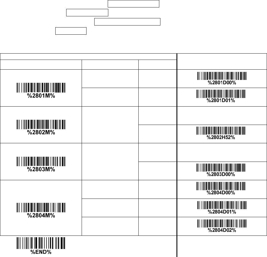
72
3-34 GS1 DataBar Limited
Read:
Format
Code ID setting: Refer to Code ID setting of 3-14 UPC-A.
Insertion group selection: Refer to Insertion group selection of 3-14 UPC-A.
Conversion: Refer to Conversion of 3-33 GS1 DataBar (GS1 DataBar Truncated).
Single—scan setting
Option bar code Option Alpha. entry
Read
Disable 00
Enable 01* *
Code ID setting
00—FF16
(ASCII)
00—FF16
<R>* *
Insert group selection
00—66
00-66
00* *
Conversion
None 00* *
UCC/EAN 128 01
UPC—A or EAN-13 02
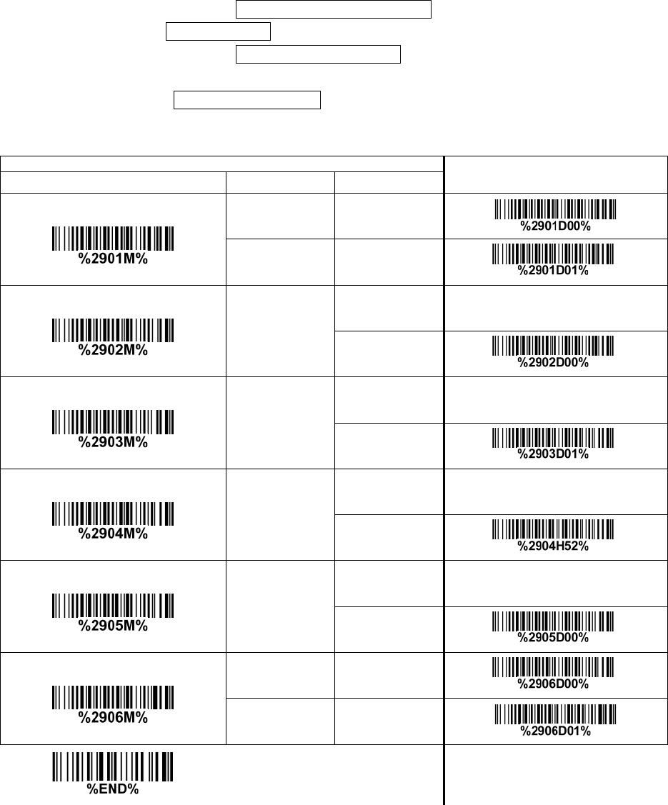
73
3-35 GS1 DataBar Expanded
Read:
Format
Data characters (variable)
Code ID setting: Refer to Code ID setting of 3-14 UPC-A.
Insertion group selection: Refer to Insertion group selection of 3-14 UPC-A.
Conversion:
UCC/EAN 128— Refer to Code ID transmission of 3-43 String transmission, ]Cm will be identified as
AIM ID.
Single—scan setting
Option bar code Option Alpha. entry
Read
Disable 00
Enable 01* *
Max. code length
00—99
00—99
00* *
Min. code length
00—99
00—99
01* *
Code ID setting
00—FF16
(ASCII)
00-FF16
<R>* *
Insert group selection
00—66
00—66
00* *
Conversion
None 00* *
UCC/EAN 128 01
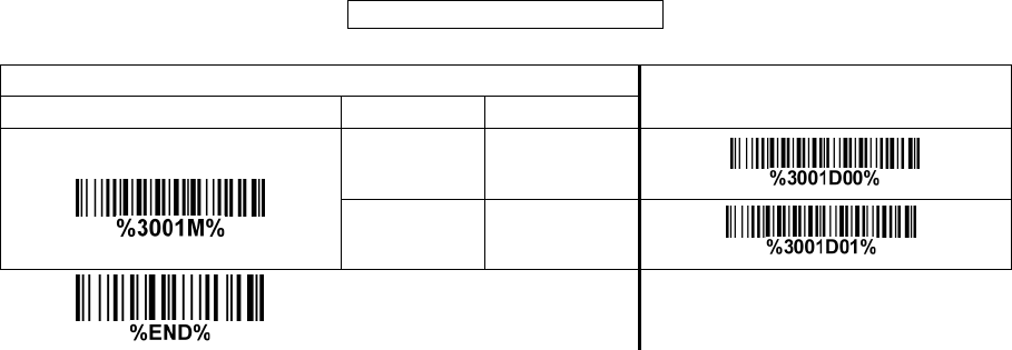
74
3-36 PDF417
Read:
Format
Data characters (variable)
Multiple—scan setting Single—scan setting
Read
Disable 00
Enable 01* *
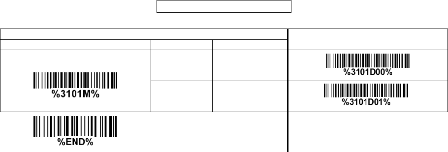
75
3-37 MicroPDF417
Read:
Format
Data characters (variable)
Single—scan setting
Read
Disable 00
Enable 01* *
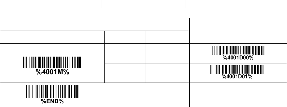
76
3-38 QR Code
Read:
Format
Data characters (variable)
Multiple—scan setting Single—scan setting
Option bar code Option Alpha. entry
Read
Disable 00
Enable 01* *
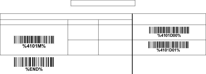
77
3-39 Data Matrix
Read:
Format
Data characters (variable)
Single—scan setting
Read
Disable 00
Enable 01* *
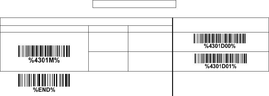
78
3-40 Aztec Code
Read:
Format
Data characters (variable)
Single—scan setting
Read
Disable 00* *
Enable 01
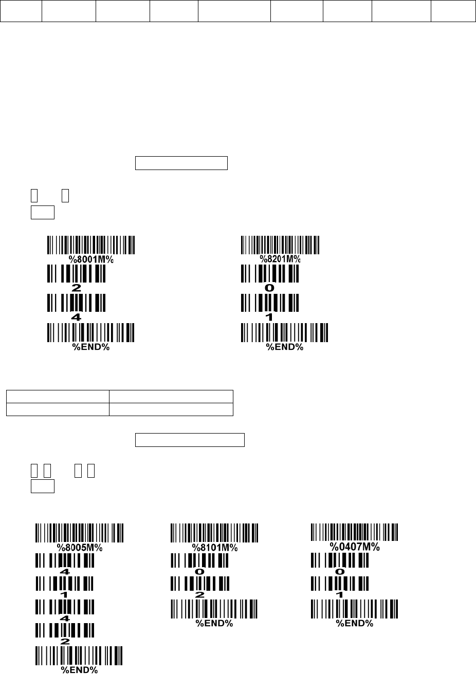
79
3-41 G1-G6 & C1—C2 & FN1 substitution string setting
Format of barcode data transmission:
Prefix Code name Preamble Code ID Code length Code data Code ID Postamble Suffix
Suffix string setting: The <enter > key is represented in different ASCII when it is applied by different
OS. For a Windows/DOS OS, <enter> is represented as <CR><LF> (0x0D 0x0A); for an Apple MAC
OS, <enter> is represented as <CR> (0x0D); for a Linux/Unix OS, <enter> is represented as <LF>
(0x0A).
Prefix/Suffix/Preamble/Postamble string setting:
They are appended to the data automatically when a barcode is decoded.
Example: Add a symbol of “$” as a prefix for all symbols.
Steps:
1) Scan the option barcode of Prefix string setting.
2) Use the ASCII table to find the value of $→24.
3) Scan 2 and 4 from the barcode on the last page.
4) Scan END barcode.
Scanning steps: Scan the following barcodes in order.
Insert G1/G2/G3/G4 string setting: The scanner offers 4 positions and 4 character strings to insert
among the symbol.
Example: Set G1 string to be “AB”.
Steps:
1) Scan the option barcode of Insert G1 string setting.
2) Use the ASCII table to find the value of A→41, B→42.
3) Scan 4, 1 and 4, 2 from the barcode on the last page.
4) Scan END barcode.
5) Refer to 3-42 G1—G4 string position & Code ID position.
6) Refer to 3-9 Handheld scan & some global settings.
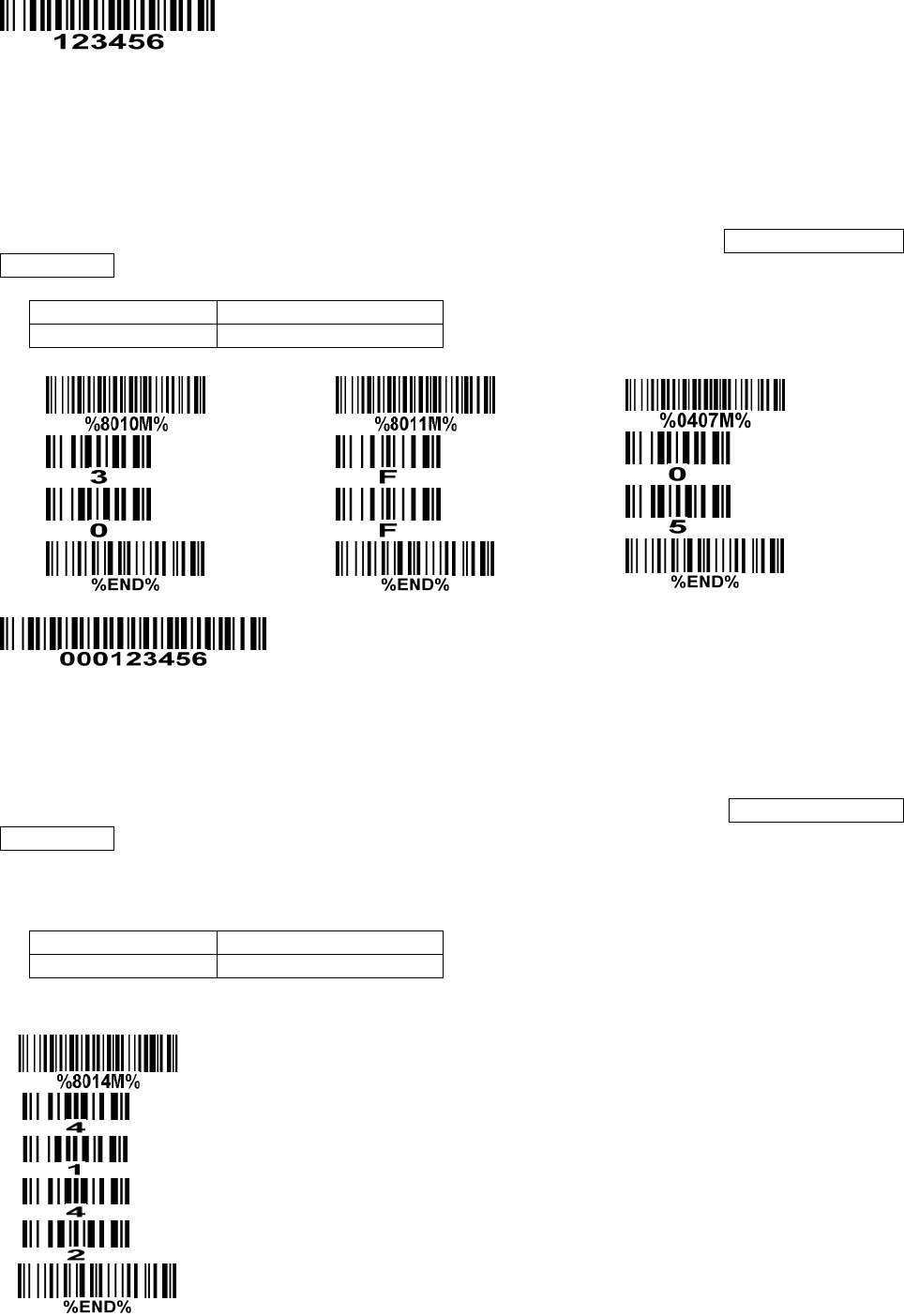
80
Testing barcode:
FN1 substitution string setting: The FN1 character (0x1D) in an UCC/EAN128 barcode, or a Code
128 barcode, or a GS1 DataBar barcode can be substituted with a defined string.
Truncate leading G5 string setting: By setting, a defined leading character or string can be truncated.
Also a single character can be un—defined.
Repeat of a G5 character setting: While G5 is set as a single defined/un—defined character, G5 can
also be set to be repeated. This setting is ignored when the truncate number is more than the barcode
data characters. The option of “FF” for this setting is not active while the option of Truncate leading G5
string setting is “00”.
Example: Truncate all leading zeros for all symbols.
Steps: scan the following data in order.
Testing barcode:
Truncate ending G6 string setting: By setting, a defined ending character or string can be truncated.
Also a single character can be un—defined.
Repeat of a G6 character setting: While G5 is set as a single defined/un—defined character, G6 can
also be set to be repeated. This setting is ignored when the truncate number is more than the barcode
data characters. The option of “FF” for this setting is not active while the option of Truncate ending G6
string setting is “00”.
Single character C1/C2 replacement: By setting, a defined character in the data string can be replaced
by another defined character. The C1 and C2 replacement are applied simultaneously.
Example: Replace all the “A” character in a data string to be “B” character.
Steps: scan the following barcodes in order. The ASCII value for “A” is 41, and the ASCII value for “B” is
42.
Testing barcode:
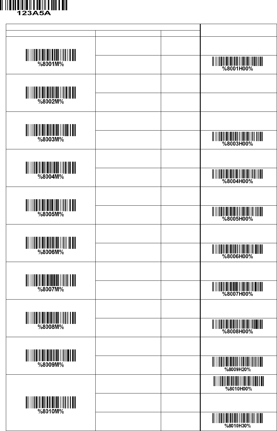
81
Single—scan setting
Prefix string setting
0-22 characters 00—FF16
None 00* *
Suffix string setting
0-22 characters 00—FF16
<ENTER> 0D0A*
Preamble string setting
0-22 characters 00—FF16
None 00* *
Postamble string setting
0-22 characters 00—FF16
None 00* *
Insert G1 string setting
0-22 characters 00—FF16
None 00* *
Insert G2 string setting
0-22 characters 00—FF16
None 00* *
Insert G3 string setting
0-22 characters 00—FF16
None 00* *
Insert G4 string setting
0-22 characters 00—FF16
None 00* *
FN1 substitution string setting
0-4 characters 00—FF16
<SP> 20* *
Truncate leading G5 string setting
A un—defined character 00
1-22 defined characters 01—7F16
<0> 30* *
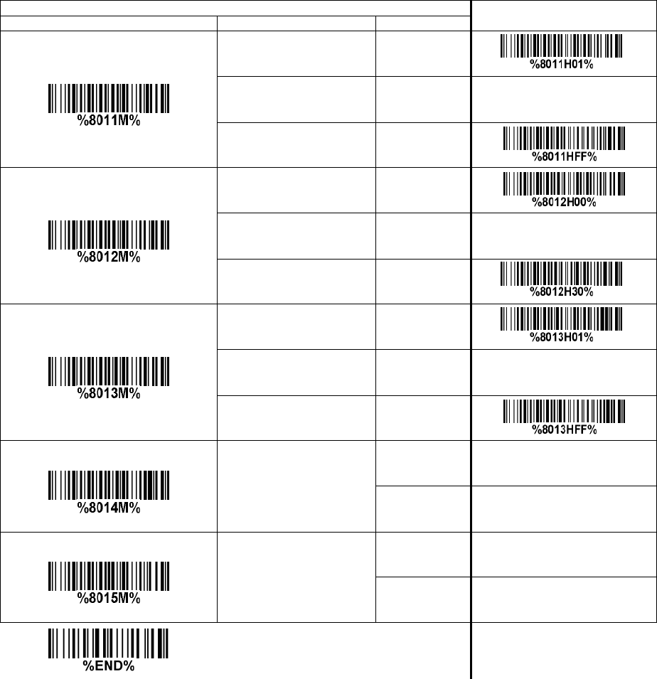
82
Single—scan setting
Repeat of a G5 character setting
Once 01* *
Defined times 01—22
Un—defined times (All) FF
Truncate ending G6 string setting
A un—defined character 00
1-22 defined characters 01—7F16
<0> 30* *
Repeat of a G6 character setting
Once 01* *
Defined times 01—22
Un—defined times (All) FF
Single character C1 replacement
<0000>
0000*
0000—FFFF 16
Single character C2 replacement
<0000>
0000*
0000—FFFF 16
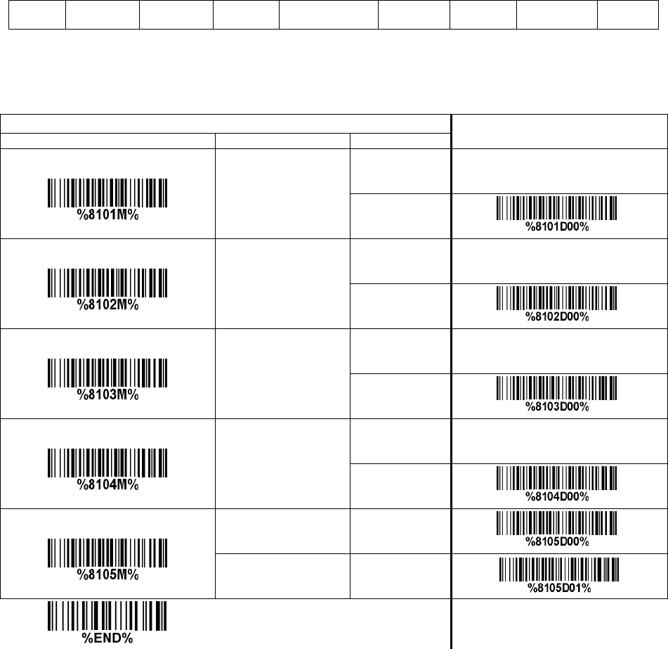
83
3-42 G1-G4 string position & Code ID position
Format of barcode data transmission:
Prefix Code name Preamble Code ID Code length Code data Code ID Postamble Suffix
Insert G1/G2/G3/G4 string position: The scanner offers 4 positions to insert strings among the symbol.
In case of the insertion position is greater than the length of the symbol, the insertion of string is not
effective.
Code ID position: It is allowed to select different positions of code ID placement.
Single—scan setting
Insert G1 string position
00—99
00—99
00* *
Insert G2 string position
00-99
00—99
00* *
Insert G3 string position
00—99
00—99
00* *
Insert G4 string position
00—99
00—99
00* *
Code ID position
Before code data 00* *
After code data 01

84
3-43 String transmission
Note: The information in this chapter is closely related to the chapter of String setting.
Format of barcode data transmission:
Prefix Code name Preamble Code ID Code length Code data Code ID Postamble Suffix
Prefix transmission: By setting Enable, prefix will be appended before the data transmitted.
Suffix transmission: By setting Enable, suffix will be appended after the data is transmitted.
Code name transmission: By setting Enable, code name will be transmitted before code data.
Preamble transmission: By setting Enable, preamble will be appended before the data transmitted.
Postamble transmission: By setting Enable, postamble will be appended after the data is transmitted.
Code ID transmission: Code ID can be transmitted in the format of either Proprietary ID or AIM ID.
Refer to the chapter of Default setting for each barcode.
Code length transmission: The length of code data string can be transmitted before the code data
when Enable is selected. The length is represented by a number with two digits.
Case conversion: The characters within code data or the whole output string can be set in either upper
case or lower case.
FN1 substitution transmission: The scanner supports a FN1 substitution feature for keyboard wedge,
USB and RS—232 interface. The replacement string of FN1 can be chosen by user (see 3-41 G1—G6 &
C1—C2 & FN1 substitution string setting).
All—non—printable—character string transmission with string setting: By setting enable, all string
settings, e.g. Preamble transmission or Insert G1 string setting, are active for an
all—non—printable—character string. Here a non—printable character means a character with ASCII value
between 0x00 to 0x1F.
Transmit the first N data characters only: The scanner supports to only transmit the first N data
characters of a barcode. The number of N can be set as a digit between 1 and 99.
Transmit the last N data characters only: The scanner supports to only transmit the last N data
characters of a barcode. The number of N can be set as a digit between 1 and 99.
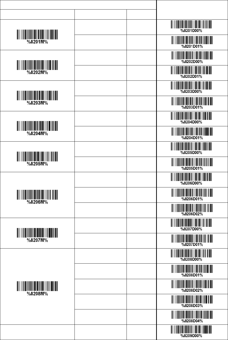
85
Multiple—scan setting Single—scan setting
Option bar code Option
Prefix transmission
Disable 00* *
Enable 01
Suffix transmission
Disable 00
Enable 01*
Code name transmission
Disable 00*
Enable 01
Preamble transmission
Disable 00*
Enable 01
Postamble transmission
Disable 00* *
Enable 01
Code ID transmission
Disable 00* *
Proprietary ID 01
AIM ID 02
Code length transmission
Disable 00* *
Enable 01
Case conversion
Disable 00* *
Upper (data only) 01
Lower (data only) 02
Upper (whole string) 03
Lower (whole string) 04
FN1 substitution transmission Disable 00* *
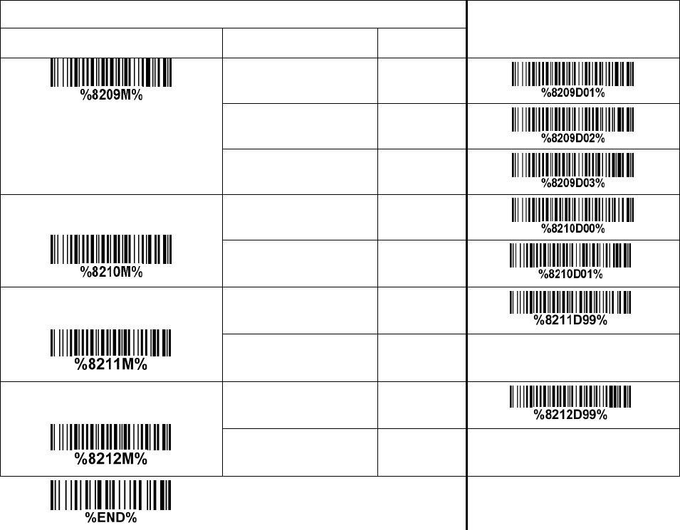
86
Multiple—scan setting Single—scan setting
Option bar code Option
Keyboard wedge/USB 01
RS—232 02
Keyboard wedge
/ USB / RS—232 03
All-non—printable—character string
transmission with string setting
Disable 00
Enable 01* *
Transmit the first N data characters
only
All 99* *
01—99
Transmit the last N data characters
only
All 99* *
01—99
87
4 Test barcode symbols
UPC-A
UPC-E
UPC—E1
EAN-8
EAN—13
Code 39
Code 32
Code 128
Interleaved 2 of 5
Industrial 2 of 5
(Default setting: Read disable)
Matrix 2 of 5
Code 93
88
UCC/EAN 128
Code 11
(Default setting: Read disable)
MSI/Plessey
(Default setting: Read disable)
UK/Plessey
ISBN/ISSN
China Post
GS1 DataBar (GS1 DataBar Truncated)
GS1 DataBar Limited
GS1 DataBar Expanded

89
PDF417
12=890ab—+%xyz
MicroPDF417
0239+-mdo
QR code
1234567890ABCD—+()&*%^@#$!XYZ
Data Matrix
123890abc—+=&*%^!mdo
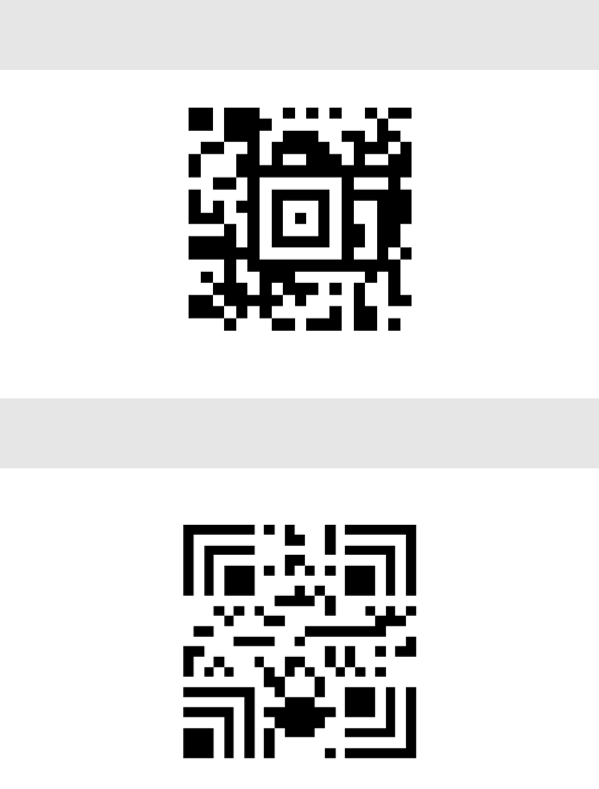
90
Aztec Code
12345678901234567890
Han Xin Code
SAMPLE
91
5 Maintenance
Cleaning the scan window is the only maintenance required. A dirty window may affect scanning
accuracy.
1) Do not allow any abrasive material to touch the window.
2) Remove any dirt particles with a damp cloth.
3) Wipe the window using a tissue moistened with water.
4) Do not spray water or other cleaning liquids directly into the window.
5) Use a piece of soft and dry cloth when cleaning the scanner.

92
6 ASCII Table
for keyboard wedge for RS—232
0 1 0 1
0 Null NUL DLE
1 Up F1 SOH DC1
2 Down F2 STX DC2
3 Left F3 ETX DC3
4 Right F4 EOT DC4
5 PgUp F5 ENQ NAK
6 PgDn F6 ACK SYN
7 F7 BEL ETB
8 Bs F8 BS CAN
9 Tab F9 HT EM
A F10 LF SUB
B Home Esc VT ESC
C End F11 FF FS
D Enter F12 CR GS
E Insert Ctrl+ SO RS
F Delete Alt+ SI US
Notes: The 2nd and the 3rd columns above are used for keyboard wedge only.
2 3 4 5 6 7
0 SP 0 @ P ` p
1 ! 1 A Q a q
2 “ 2 B R b r
3 # 3 C S c s
4 $ 4 D T d t
5 % 5 E U e u
6 & 6 F V f v
7 ‘ 7 G W g w
8 ( 8 H X h x
9 ) 9 I Y i y
A * : J Z j z
B + ; K [ k {
C , < L l |
D — = M ] m }
E . > N ^ n ~
F / ? O _ o DEL
Example: ASCII “A” = “41”.

93
7 Barcode representing non—printable character
Notes to make the following barcode:
1. According to different barcode printing software, the method of printing following barcode is different.
2. If using CODESOFT software, firstly read the information through “Help→Index→Code128→Special
input syntax”. Also refer to ASCII table. For example, if we wish to make “F1” barcode, select
“Code128”, then select “CODE A” type, and input “{DC1}” as data.
Up ↑
Down ↓
Left ←
Right →
Page Up
Page Down
Backspace
Tab
Enter
Insert
Delete
F1
F2
F3
F4
F5
F6
F7
F10
Esc
F11
F12

94
8 Return default parameters
8-1 CS2290 return default parameters
All parameters of handheld unit return to default setting
WARNING: If you wish to return all parameters of the handheld unit, including radio communication
setting, to default setting, please scan the barcode above.
All parameters of cradle return to default setting
WARNING: If you wish to return all parameters of the cradle, including radio communication
setting, to default setting, please scan the barcode above.
Some parameters of handheld unit return to default setting
WARNING: If you wish to return all parameters of the handheld unit, excluding radio
communication setting, to default setting, please scan the barcode above.
Some parameters of cradle return default value initialization
WARNING: If you wish to return all parameters of the cradle, excluding radio communication
setting, to default setting, please scan the barcode above.
Turn off handheld unit
If you wish to turn off the handheld unit, please scan the barcode above. If you want to turn on the
handheld unit again, please keep the trigger key being pressing for 2 seconds.
If you want to turn off the handheld unit via trigger key, please press and hold the trigger key, after the
laser beam turns off, wait for another 5 seconds, the handheld unit will be turned off, then you can
release the trigger key at this moment.

95
8-2 CS2290—BT return default parameters
Some parameters of handheld unit return to default setting
WARNING: If you wish to return all parameters of the handheld unit, to default setting, please scan
the barcode above.
Some parameters of cradle return default value initialization
WARNING: If you wish to return all parameters of the cradle, please scan the barcode above.
Turn off handheld unit
If you wish to turn off the handheld unit, please scan the barcode above. If you want to turn on the
handheld unit again, please keep the trigger key being pressing for 2 seconds.
If you want to turn off the handheld unit via trigger key, please press and hold the trigger key, after the
laser beam turns off, wait for another 5 seconds, the handheld unit will be turned off, then you can
release the trigger key at this moment.

96
9 Display firmware version & radio communication setting
9-1 CS2290 display firmware version & radio communication setting
Cradle firmware version display
If you wish to display the firmware version of the cradle, please scan the barcode above.
Handheld unit firmware version display
If you wish to display the firmware version of the handheld unit, please scan the barcode above.
Cradle radio communication setting display
If you wish to display the radio communication setting of the cradle, please scan the barcode above.
Handheld unit radio communication setting display
If you wish to display the radio communication setting of the handheld unit, please scan the barcode
above.

97
9-2 CS2290—BT display firmware version
Cradle firmware version display
If you wish to display the firmware version of the cradle, please scan the barcode above.
Handheld unit firmware version display
If you wish to display the firmware version of the handheld unit, please scan the barcode above.

98
10 Configuration alphanumeric entry barcode
To finish parameter setting, please scan the bar code below.
Warning:
changes or modifications not expressly approved by the party responsible for
compliance could void the user’s authority to operate the equipment.
This device complies with Part 15 of the FCC Rules. Operation is subject to the
following two conditions: (1) this device may not cause harmful interference, and
(2) this device must accept any interference received, including interference that
may cause undesired operation. changes or modifications not expressly approved
by the party responsible for compliance could void the user’s authority to operate
the equipment.
NOTE: This equipment has been tested and found to comply with the limits for a
Class B digital device, pursuant to Part 15 of the FCC Rules. These limits are
designed to provide reasonable protection against harmful interference in a
residential installation. This equipment generates, uses and can radiate radio
frequency energy and, if not installed and used in accordance with the
instructions, may cause harmful interference to radio communications. However,
there is no guarantee that interference will not occur in a particular installation.
If this equipment does cause harmful interference to radio or television reception,
which can be determined by turning the equipment off and on, the user is
encouraged to try to correct the interference by one or more of the following
measures:
— Reorient or relocate the receiving antenna.
— Increase the separation between the equipment and receiver.
—Connect the equipment into an outlet on a circuit different
from that to which the receiver is connected.
—Consult the dealer or an experienced radio/TV technician for help.
NOTE: This device and its antenna(s) must not be coÿlocated or operation in
conjunction with any other antenna or transmitter.
10
Mindeo CS2X90BT является одним из самых популярных беспроводных сканеров штрих-кода, который предлагает массу функций для максимального удобства его использования. Однако, как и с любым другим устройством, настройка и начало работы с ним могут вызывать некоторые трудности. В этой подробной инструкции мы расскажем о всех необходимых шагах, чтобы вы смогли правильно настроить mindeo cs2x90bt и использовать его без проблем.
Первым шагом в процессе настройки сканера является его физическое подключение. Вставьте беспроводной адаптер в свободный USB-порт компьютера или ноутбука. Убедитесь, что устройство правильно подключено и работает, путем проверки индикаторов на адаптере и самом сканере. Если все индикаторы горят или мигают, значит, устройство готово к работе.
Второй шаг — установка программного обеспечения для mindeo cs2x90bt. Посетите официальный веб-сайт производителя и скачайте последнюю версию драйвера для вашей операционной системы. Запустите установку и следуйте инструкциям на экране. После завершения установки перезагрузите компьютер, чтобы изменения вступили в силу.
Теперь настройте ваш mindeo cs2x90bt для работы с вашим компьютером или ноутбуком. Вам нужно будет сопрягнуть сканер с беспроводным адаптером. Для этого вставьте адаптер в USB-порт, удерживайте кнопку питания на сканере до появления звукового сигнала и подождите, пока индикатор на адаптере не начнет быстро мигать. Затем на сканере нажмите кнопку «сопряжение» (обычно она находится на нижней части устройства). В результате, индикатор на адаптере должен загореться зеленым, что означает успешное сопряжение.
Содержание
- Подготовка к настройке
- Установка драйверов и ПО
- Подключение к компьютеру
- Настройка интерфейса
- Калибровка сканера
- Настройка беспроводного соединения
- Проверка работоспособности
Подготовка к настройке
Для начала настройки mindeo cs2x90bt вам потребуется следующее:
- Убедитесь, что у вас есть все необходимые компоненты: сканер mindeo cs2x90bt, компьютер с операционной системой Windows или Mac OS, USB-кабель для подключения сканера к компьютеру.
- Установите драйвера для сканера. Драйвера можно скачать с официального сайта производителя.
- Подключите сканер к компьютеру с помощью USB-кабеля.
- Дождитесь, пока компьютер обнаружит новое устройство и установит драйверы для него. Если у вас есть диск с драйверами, вставьте его в оптический привод компьютера и следуйте инструкциям на экране.
- Убедитесь, что сканер включен и готов к работе. Обычно есть индикатор светодиодной подсветки или звуковой сигнал, указывающий на готовность сканера к сканированию.
После выполнения этих шагов вы будете готовы к настройке mindeo cs2x90bt и сможете приступить к следующим этапам.
Установка драйверов и ПО
Перед началом использования миндо cs2x90bt необходимо установить соответствующие драйверы и программное обеспечение. Это позволит обеспечить правильную работу устройства и использовать все его функции.
Для начала загрузите последнюю версию драйвера с официального сайта производителя. Распакуйте скачанный архив в удобную для вас папку.
Подключите миндо cs2x90bt к вашему компьютеру с помощью USB-кабеля. Дождитесь, пока компьютер распознает устройство. Возможно, потребуется некоторое время для установки драйвера.
После успешного распознавания устройства откройте папку с ранее скачанным драйвером. Запустите файл с расширением .exe или .msi и следуйте инструкциям установщика. В процессе установки могут быть запрошены дополнительные разрешения или подключение к Интернету.
По завершении установки драйвера перезагрузите компьютер, чтобы изменения вступили в силу.
После перезагрузки компьютера установите программное обеспечение для миндо cs2x90bt. Для этого перейдите на официальный сайт производителя и загрузите последнюю версию ПО. Распакуйте скачанный архив и запустите установщик.
Следуйте инструкциям на экране для установки программного обеспечения. При необходимости подключитесь к Интернету для загрузки дополнительных компонентов или обновлений.
По завершении установки программного обеспечения перезагрузите компьютер, чтобы изменения вступили в силу.
Теперь все готово к использованию вашего миндо cs2x90bt. Убедитесь, что устройство правильно подключено к компьютеру, запустите установленное ПО и наслаждайтесь его функциональностью.
Подключение к компьютеру
Для подключения магнитной карты Mindeo CS2X90BT к компьютеру, выполните следующие шаги:
- Убедитесь, что у вас есть соответствующий USB-кабель.
- Соедините один конец USB-кабеля с портом на задней панели сканера, а другой конец подключите к свободному порту USB на вашем компьютере.
- Дождитесь, пока операционная система распознает новое устройство и установит соответствующие драйверы.
- Проверьте, что подключение прошло успешно, включив сканер и запустив специальное программное обеспечение для работы с ним.
- Теперь вы можете использовать свой Mindeo CS2X90BT для сканирования и чтения информации с магнитных карт прямо на компьютере.
Обратите внимание, что в некоторых случаях может потребоваться дополнительная настройка и установка драйверов. Убедитесь, что вы ознакомились с инструкцией по эксплуатации и рекомендациями производителя перед использованием устройства.
Теперь вы готовы использовать свой Mindeo CS2X90BT вместе с компьютером и получить доступ к многочисленным функциям и возможностям этого сканера магнитных карт.
Настройка интерфейса
Для настройки интерфейса модели mindeo cs2x90bt вам понадобятся следующие шаги:
- Включите сканер, нажав кнопку питания на его корпусе.
- Подождите, пока сканер полностью загрузится.
- Настройте яркость и контрастность дисплея, перейдя в меню настройки.
- Выберите пункт «Интерфейс» в меню настройки сканера.
- Выберите нужный вам тип интерфейса: USB, Bluetooth или RS232.
- Настройте параметры выбранного интерфейса, например, скорость передачи данных для RS232.
- Сохраните настройки, нажав кнопку «Применить» или аналогичную.
После выполнения этих шагов интерфейс вашего mindeo cs2x90bt будет настроен в соответствии с вашими предпочтениями.
Калибровка сканера
- Подготовка к калибровке: Убедитесь, что сканер подключен к компьютеру и правильно распознается системой. Убедитесь, что его питание включено.
- Запуск программы для калибровки: Запустите программу на компьютере, предоставленную вместе с устройством.
- Выбор сканера: Если в программе требуется выбрать сканер, выберите модель Mindeo CS2X90BT.
- Выбор типа калибровки: В программе выберите тип калибровки в зависимости от требований вашей системы. Доступные варианты могут включать автоматическую и ручную калибровку.
- Подготовка штрих-кода: Убедитесь, что на экране компьютера открыт штрих-код, который будет использоваться для калибровки.
- Начало калибровки: Нажмите кнопку «Старт» или аналогичную, чтобы начать калибровку. Сканер автоматически считает штрих-код и выполнит калибровку.
- Проверка качества: Проверьте качество сканирования после завершения калибровки. Убедитесь, что штрих-коды считываются точно и без ошибок.
- Завершение калибровки: По завершении калибровки закройте программу и отключите сканер от компьютера.
По завершении этих шагов ваш сканер Mindeo CS2X90BT будет калиброван и готов к использованию с высокой точностью и надежностью.
Настройка беспроводного соединения
Mindeo CS2X90BT поддерживает беспроводное соединение посредством Bluetooth. Чтобы настроить беспроводное соединение, выполните следующие шаги:
Шаг 1: Включите сканер, нажав кнопку питания. Убедитесь, что индикатор питания горит зеленым.
Шаг 2: На вашем устройстве, откройте раздел настроек Bluetooth.
Шаг 3: Включите Bluetooth на вашем устройстве. Поиск доступных устройств может занять несколько секунд.
Шаг 4: В списке найденных устройств выберите «CS2X90BT».
Шаг 5: Если потребуется, введите пароль для соединения. По умолчанию пароль на сканере Mindeo CS2X90BT — «0000».
Шаг 6: После успешного подключения, индикатор Bluetooth на сканере будет мигать синим цветом.
Теперь вы можете использовать сканер Mindeo CS2X90BT с вашим устройством посредством беспроводного соединения Bluetooth.
Проверка работоспособности
После выполнения всех настроек и соединения устройства Mindeo CS2X90BT с компьютером, необходимо проверить его работоспособность.
Для этого можно воспользоваться специальной программой для чтения штрих-кодов или просто открыть текстовый редактор на компьютере.
Далее следует навести лазерную точку на штрих-код и нажать на кнопку для сканирования. Если устройство работает должным образом, то введенный штрих-код появится в выбранном приложении или текстовом редакторе.
Также можно проверить функциональность сканера, отсканировав штрих-код и попытавшись выключить или изменить значение его настройки на компьютере. Если устройство работает, то сканер должен считать штрих-код и отобразить его значение.
Если в процессе проверки или использования устройства возникают проблемы, рекомендуется обратиться в службу технической поддержки производителя или проконсультироваться с специалистом.
Документация
- Документация CS2290 User Manual_V2.2.5.pdf
- Инструкция по быстрой настройке: CS2290 Quick Guide_V1.1.pdf
- Драйвер COM порта USB VCOM drivers_V1.6.rar, либо на официальном сайте
Сброс на настроек
Если нужно, сбрасываем все настройки считывателя.

Привязка к кредлу
В ряде случаев может потребоваться привязка считывателя к кредлу (подставке). Надо снять считыватель с подставки, отсканировать штрих-код, и в течение 15 секунд поставить на подставку.

Подключение Mideo CS2290-HD к 1С
Переводим устройство в режим USB virtual COM, для этого сканируем штрих-код.
Перевод в режим виртуального COM-порта нужен что бы не нажимать F7 для вызова окна ввода штрих-кода.

Вернуть в клавиатурный режим

Ставим драйвер, в настройках выставляем желаемый порт, например 10

Новый интерфейс:
Добавляем оборудование в УТ через «НСИ и администрирование — РМК и оборудование — Подключаемое оборудование — Создать»
Старый интерфейс:
Компания → Настройки → Администрирование → Подключаемое оборудование → Подключаемое оборудование → Создать

Выставляем требуемый порт.
Если в поле Версия указано «Не определена», закройте вкладки использующие сканер, например Номенклатура.

Отключение передачи непечатных символов
Отключить SYN или U+0016

Проверка работы сканера
https://честныйзнак.рф/barcode/?category=1
Related Documents
| External Photo | External Photos | |
| Internal photograph | Internal Photos | |
| Label&Label Location | ID Label/Location Info | |
| user manual | Users Manual |


CS2290&CS2290-BT Cordless Image
Scanner User Manual
Version: CS2290&CS2290-BT_UM_EN_V1.2.3
Notice
Make sure you carefully read the following information to ensure that your barcode scanner is able to
perform at the level for which it is designed.
1) All software, including firmware, furnished to the user is on a licensed basis.
2) The right is reserved to make changes to any software or product to improve reliability, function, or
design.
3) The material in this manual is subject to change without notice.
4) The manufacturer assumes no responsibility for any loss or claims by third parties which may arise
from the use of this manual.
5) A standard kit contains: a handheld unit, a cradle, a USB cable, and a CD-ROM (containing software
and electrical manuals).
6) Do not throw or drop the scanner or otherwise subject it to strong impact, which can damage the
scanner, interrupt program execution, corrupt memory contents, or otherwise interfere with proper
operation.
7) Use a blunt object to operate the stroke keys. Use of a sharp pointed object can damage stroke
keys and cause shorting of internal circuitry.
8) Do not remove the battery from the barcode scanner before you read the instructions carefully.
9) Sudden temperature changes can cause condensation to form on the scanner’s case. Operating
the scanner while condensation is present can interfere with proper operation. Take care to avoid
conditions that cause the formation of condensation. If condensation does form, wait until it dries
completely before using the scanner.
10) If multi-clusters are working in the same area, it is strongly recommended that different radio
frequency channel numbers are applied to different clusters. While setting up, only the radio
frequency channel number of the first handheld unit of a single cluster is required to be set. When
the first handheld unit binds to the cradle, the cradle will automatically obtain the radio frequency
channel number of the handheld unit. The consecutive joined handheld units will automatically
obtain the radio frequency channel number of the cradle.
11) In order to obtain constantly good communication quality, when in multi-clusters working mode, the
physical space between two cradles is required to be at least 2 meters.
12) In order to obtain constantly good communication quality, it is recommended to place the cradle on a
higher location, generally more than 1 meter above the ground. If working outdoor, the higher
location the better.
Note:Article 10 and 11 are only for CS2290
Safety precautions – Danger!
Be sure to read the following safety precautions carefully before trying to use the barcode scanner for
the first time. Keep this manual in handy place for future reference.
Danger!
Lithium-ion battery
1)
Never allow the battery to become wet. Water can create the danger of battery heat emission,
explosion, and fire.
2) Never use or leave the battery next to open flame, near a stove, or any other area exposed to
high heat. Doing so creates the danger of battery heat emission, explosion, and fire.
3) Never use the battery with any device other than this unit. Doing so can creates the danger of
battery heat emission, explosion, and fire.
4) Note that the battery’s positive (+) and negative (-) terminals must be oriented correctly when it is
loaded into the Barcode Scanner. Connecting the battery with its terminals reversed creates the
danger of battery fluid leakage, heat emission, explosion, and fire.
5) Never dispose of the battery by incinerating it or otherwise expose it to heat. Doing so creates the
danger of battery heat emission, explosion, and fire.
6) Never allow the positive (+) and negative (-) terminals of the battery to become connected
(shorted) by metal. Doing so create the danger of battery heat emission, explosion, and fire.
7) Never transport or store the battery together with a necklace, hair pins or other metal objects.
Doing so can short battery terminals, and create the danger of battery heat emission, explosion
and fire. Be sure to place the battery in its case whenever transporting or storing it.
8) Never throw the battery or otherwise subject it to strong impact. Dong so creates the danger of
battery heat emission, explosion, and fire.
9) Never pierce the battery with nails, hit it with a hammer, or step on it. Doing so can create the
danger of battery heat emission, explosion, and fire.
10) Never try to take apart the battery in any way. Doing so creates the danger of battery heat
emission, explosion, and fire.
11) Use only the specified charger to charge the battery. Use of other types of charger creates the
danger of battery heat emission explosion, and fire.
ii
Safety precautions – Warning!
Warning!
Disassembly and modification
Never try to disassemble or modify the unit in any way. High voltage inside creates the danger of
electrical shock.
Interior parts and components
Never touch interior high-voltage parts or components. Doing so creates the danger of electrical
shock.
Abnormal conditions
Should the unit become hot or start to emit smoke or a strange odor, immediately turn off the power
and contact your original dealer. Continued use creates the danger of fire and electrical shock.
Foreign objects
Should any foreign matter ever get into the unit, immediately turn off the power and contact your
original dealer. Continued use creates the danger of fire and electrical shock.
Dropping and damage
Should you drop the unit and damage it, immediately turn off the power and contact your original
dealer. Continue use creates the danger of fire and electrical shock.
Laser beam
Never look directly into the laser beam. Doing so can cause serious eye damage.
Lithium-ion battery
1)
2)
3)
4)
5)
Do not put a battery in microwave ovens or pressure cookers. Doing so may cause the battery to
overheat, explode or burst into flames.
Do not use a battery that smells strange, is overheating, is a strange color, or is a strange shape.
Doing so may cause the battery to overheat, explode or burst into flames.
If the amount of time period the battery can serve becomes considerably short, stop using it. It
may indicate the possibility of a malfunction in the battery. Continued charging the battery creates
the danger of heat emission, explosion, and fire.
Stop charging the battery after the recommended time even if it is not fully charged. Continuing to
charge the battery may cause the battery to over heat, explode or burst into flames.
If the battery leaks fluid or emits a strange smell, remove it from near heat or flames. Burning may
cause the battery to explode or burst into flames. Should fluid from the battery accidentally get
into your eyes, do not rub them. Immediately rinse your eyes with clean water such as tap water
and then consult a physician immediately.
iii
Cradle with RS-232 cable and adaptor
1)
2)
3)
4)
5)
Power the cradle only with a power outlet whose voltage matches that marked on the adaptor
specified in this manual.
Avoid conditions that can cause damage or breaks in the power cord. Do not place heavy
objects on the power cord. Keep it away from sources of heat. Any of these conditions can
damage the power cord, creating the danger of fire and electrical shock.
Never modify, sharply bend, twist, or pull on the power cord. Doing so creates the danger of fire
and electrical shock.
Use only the AC/DC adaptor and charger specified in this manual. Use of other AC/DC adaptor
models or chargers creates the danger of fire and electrical shock.
Should the power cord ever become severely damaged, contact your original dealer. Use of a
damaged electrical cord creates the danger of fire and electrical shock.
Moisture
Keep the Basic Unit and the Barcode Scanner away from vases, planters, cups, glasses and other
containers of liquid. Also keep it away from metal. Water and metal getting into the unit creates the
danger of fire and electrical shock.
iv
Safety precautions – Caution!
Caution!
Foreign objects
Take care to ensure that metal or combustible objects are not inserted into the openings of the unit.
Such objects create the danger of fire and electrical shock.
Location
1)
2)
3)
Do not locate the unit on a surface that is unstable or uneven. Doing so creates the danger of the
unit falling, which can cause personal injury.
Do not locate the unit in an area subjected to large amounts of humidity or dust. Doing so creates
the danger of fire and electrical shock.
Do not leave the unit for long periods in a car parked in direct sunlight.
Heavy objects
Never place heavy objects on top of the unit. Doing so creates the risk of a loss of balance and the
object falling, which can cause personal injury.
Scan window
1)
2)
Never apply strong pressure to the mirror or subject it to strong impact. Doing so can crack the
mirror and create the danger of personal injury.
Should the mirror ever break, never touch the mirror broken. Doing so can cause personal injury.
Lithium-ion battery
1)
2)
3)
4)
5)
6)
7)
8)
Never leave the battery in an area expose to direct sunlight, in a car parked in direct sunlight, or
any other very hot area. Doing so creates the danger of heat emission and fire, as well as
deterioration of battery performance and shortening of its service life.
Do not use the battery in areas where static electricity is being generated. Doing so creates the
danger of battery heat emission, explosion, and fire.
Temperature ranges for battery use, charging and storage are specified below. Temperatures
outside these ranges create the danger of deterioration of battery performance and shortening of
its service life as well as fluid leakage and heat generation.
Operating Temperature: -20℃ to 60℃.
Charging Temperature: 0℃ to 45℃.
Storage Temperature: -20℃ to 45℃.
Should fluid from the battery accidentally get onto clothing or your skin, immediately rinse it off
with clean tap water. Prolonged contact with battery fluid can cause skin irritation.
Keep the battery out of the reach of small children. Do not let small children remove the battery
from the charger or the unit it is powering.
Cradle with RS-232 cable and adaptor
1)
2)
3)
4)
5)
6)
7)
Keep the power cord away from stoves and other sources of extreme heat. Heat can melt the
insulation of the power cord and create the danger of fire and electrical shock.
Never pull on the power cord when unplugging it. Doing so can damage the cord and create the
danger of personal injury, fire and electrical shock. Always hold onto the pug when unplugging it
from the wall outlet.
Never touch the plug while your hands are wet. Doing so can create the danger of electrical
shock.
Be sure to unplug the power cord from the wall outlet before moving the Basic Unit. Failure to do
so can result in damage to the power cord caused by pulling it, which creates the danger of fire
and electrical shock.
Be sure to unplug the power cord from the wall outlet before cleaning the Basic Unit and charger.
Be sure to turn the power off and unplug the power cord after use.
Unplug the power cord from the wall outlet and clean the area around the plugs at least once a
year. If dust collects on the AC/DC adaptor, humidity or moisture may cause a fault in the
insulation, which may result in a fire.
vi
Contents
1 Specifications ........................................................................................................................................ 1
1-1 Technical specifications .................................................................................................................... 1
1-2 Default setting for each barcode ...................................................................................................... 3
2 Get started.............................................................................................................................................. 4
2-1 Cable connector pin-outs descriptions for cradle ............................................................................. 4
2-2 Dimensions ....................................................................................................................................... 5
2-3 Parts of the scanner ......................................................................................................................... 6
2-4 Charge battery .................................................................................................................................. 7
2-5 Installation of cradle.......................................................................................................................... 8
2-5-1 PS/2 keyboard cable ................................................................................................................. 8
2-5-2 USB cable .................................................................................................................................. 8
2-5-3 RS-232 cable ............................................................................................................................. 8
3 Progamming menus .............................................................................................................................. 9
3-1 Example 1: Single-parameter setting by scanning 1D barcodes ..................................................... 9
3-2 Example 2: Multiple-parameter setting by scanning a QR code barcode ..................................... 10
3-3 CS2290 Wireless communication setting .......................................................................................11
3-3-1 Wireless communication setting for handheld unit...................................................................11
3-3-2 example ................................................................................................................................... 12
3-4 CS2290-BT Wireless communication setting................................................................................. 16
3-4-1 example ................................................................................................................................... 16
3-5 Batch data mode ............................................................................................................................ 17
3-6 Keyboard wedge interface for cradle ............................................................................................. 18
3-7 RS-232 interface for cradle ............................................................................................................ 22
3-8 USB interface for cradle ................................................................................................................. 24
3-9 Handheld scan & some global settings .......................................................................................... 27
3-10 Indication for handheld unit .......................................................................................................... 32
3-11 Decode illumination and decode aiming pattern .......................................................................... 33
3-12 Single type of barcode read ......................................................................................................... 35
3-13 DPM, Multiple symbols, Structured append read, etc. ................................................................. 36
3-14 UPC-A........................................................................................................................................... 38
3-15 UPC-E........................................................................................................................................... 40
3-16 UPC-E1......................................................................................................................................... 42
3-17 EAN-13 (ISBN/ISSN).................................................................................................................... 44
3-18 EAN-8 ........................................................................................................................................... 46
3-19 Code 39 (Code 32, Trioptic Code 39) .......................................................................................... 48
3-20 Interleaved 2 of 5 .......................................................................................................................... 51
3-21 Industrial 2 of 5 ............................................................................................................................. 53
3-22 Matrix 2 of 5 .................................................................................................................................. 54
3-23 Codabar ........................................................................................................................................ 55
3-24 Code 128 ...................................................................................................................................... 57
3-25 UCC/EAN 128 .............................................................................................................................. 59
3-26 ISBT 128 ....................................................................................................................................... 61
3-27 Code 93 ........................................................................................................................................ 62
3-28 Code 11 ........................................................................................................................................ 63
3-29 MSI/Plessey.................................................................................................................................. 65
3-30 UK/Plessey ................................................................................................................................... 67
3-31 China Post .................................................................................................................................... 68
3-32 China Finance .............................................................................................................................. 69
3-33 GS1 DataBar (GS1 DataBar Truncated) ...................................................................................... 71
3-34 GS1 DataBar Limited ................................................................................................................... 72
3-35 GS1 DataBar Expanded ............................................................................................................... 73
3-36 PDF417......................................................................................................................................... 74
3-37 MicroPDF417................................................................................................................................ 75
3-38 QR Code ....................................................................................................................................... 76
3-39 Data Matrix ................................................................................................................................... 77
3-40 Aztec Code ................................................................................................................................... 78
3-41 G1-G6 & C1-C2 & FN1 substitution string setting ....................................................................... 79
3-42 G1-G4 string position & Code ID position .................................................................................... 83
3-43 String transmission ....................................................................................................................... 84
vii
4 Test barcode symbols......................................................................................................................... 87
5 Maintenance ......................................................................................................................................... 91
6 ASCII Table ........................................................................................................................................... 92
7 Barcode representing non-printable character ............................................................................... 93
8 Return default parameters.................................................................................................................. 94
8-1 CS2290 return default parameters ................................................................................................. 94
8-2 CS2290-BT return default parameters ........................................................................................... 95
9 Display firmware version & radio communication setting ............................................................. 96
9-1 CS2290 display firmware version & radio communication setting ................................................. 96
9-2 CS2290-BT display firmware version ............................................................................................. 97
10 Configuration alphanumeric entry barcode ................................................................................... 98
viii
1 Specifications
1-1 Technical specifications
Handheld unit
CS2290
CS2290-BT
Working Range
430.0~431.9 MHz, 433.3~434.7 MHz
with adaptive frequency hopping
100 meters (open air);
Dimensions
Length × Width × Depth: 90.2 × 70 × 180 mm
Weight
225 g
Color
Gray
Indicator
LED, Beeper, Vibrator
Operating Mode
Programming
Method
Program Upgrade
Handheld
Input Voltage
5 ± 0.25 VDC
Current
20 mA (standby), 350 mA (scanning)
Battery
2600 mAh Lithium-ion battery
Charge Time
6 hours
Standby Time
6.5 days
Working Time
70 hours (1 scan per 5 seconds)
Image Size
1280 × 800 pixels
Field of View
Horizontal: 42°, vertical: 26.5°
Scanning Angle
±70°, ±75°, 360° (Skew, Pitch, Roll)
Print Contrast
20% minimum reflectance difference
Radio Link
Decoding Capability
2.4-2.5GHz, Bluetooth 4.0, Class 2
30 meters (open air)
Manual (reading special barcode)
Using Flash Utility software, while a cradle unit is required.
1D:
UPC-A, UPC-E, UPC-E1, EAN-13, EAN-8, ISBN (Bookland EAN), ISSN,
Code 39, Code 39 full ASCII, Code 32, Trioptic Code 39, Interleaved 2 of 5,
Industrial 2 of 5, Matrix 2 of 5, Codabar (NW7), Code 128, UCC/EAN 128,
ISBT 128, Code 93, Code 11 (USD-8), MSI/Plessey, UK/Plessey, China Post,
China Finance, GS1 DataBar (formerly RSS) variants
2D:
PDF417, MicroPDF417, QR code, DataMatrix, Aztec Code
Minimum
Resolution
Decoding Depth
HD: 1D (Code 39): 3 mil, 2D (QR): 5 mil
SR: 1D (Code 39): 4 mil, 2D (PDF417): 6.7 mil
High desity series
(HD)
3 mil Code39 (3 chars)
10 mm – 61 mm
Standard range
series (SR)
4 mil Code 128 (9 chars)
5 mm – 88 mm
55 mm – 106 mm
5 mil Code39 (3 chars)
0 mm – 108 mm
43 mm – 141 mm
10 mil Code39 (3 chars)
0 mm – 167 mm
0 mm – 310 mm
13 mil UPC (6 chars)
0 mm – 179 mm
0 mm – 335 mm
20 mil Code39 (1 char)
10 mm – 253 mm
8 mm – 480 mm
5 mil QR (40 chars)
7 mm – 65 mm
6.7 mil PDF417 (20 chars)
0 mm – 105 mm
37 mm – 145 mm
10 mil QR (20 chars)
0 mm – 134 mm
0 mm – 168 mm
20 mil QR (20 chars)
0 mm – 215 mm
0 mm – 345 mm
0° to 50°C (32° to 120°F), operating
Temperature
-40° to 60°C (-40° to 140°F), storage
Humidity
5% to 95% (non-condensing)
EMC: EN55022, EN55024
Electrical Safety: EN60950-1
Photobiological Safety: EN62471:2008
Safety
Illumination: 0~100,000 LUX
Protection Class: IP51
Drop Resistance: Withstands multiple 1.5 m (5 ft.) drops to concrete
Note: Test condition: temperature at 27°C, sunny day, and visibility of 5 kilometers. Natural
surroundings significantly affect the communication distance in practice. The distance drops quickly in
the rainy, high-humidity, or heavy haze day; radio interference also shortens the communication
distance.
Cradle
Input Voltage
5 ± 0.25 VDC
Current
60 mA (working), 500 mA (charging)
Cable
Straight 2.0 m (PS/2) / Straight 1.5 m (USB) / Straight 2.0 m (RS-232 )
Dimensions
Length × Width × Depth: 118 × 89.5 × 74 mm
Weight
140 g (without cable)
Indicator
Programming
Method
Program Upgrade
LED
Temperature
Manual (reading special barcode)
PC online using Flash Utility software.
0° to 50°C (32° to 120°F), operating
-40° to 60°C (-40° to 140°F), storage
Humidity
5% to 95% (non-condensing)
Drop Resistance
Unit functions normally after repeated 1.5 m (5 ft.) drops to concrete
1-2 Default setting for each barcode
Check digit Check digit
verification transmission
Min. code Proprietar
length
code ID
(12)2
AIM
code ID
Code type
Read
enable
UPC-A
√
√
√
UPC-E
√
√
√
(8)2
]Em
UPC-E1
√
√
√
(8)2
]Em
EAN-13
√
√
√
(13)2
]Em
EAN-8
√
√
√
(8)2
]Em
ISBN (Bookland EAN)
/ ISSN1
√
√
√
(13)2
]Em
Code 39
√
]Am
Interleaved 2 of 5
√
]Im
Industrial 2 of 5
]Im
Matrix 2 of 5
√
]Im
Codabar
√
]Fm
Code 128
√
√
]Cm
ISBT 128
√
√
]Cm
Code 93
√
√
]Gm
Code 11
√
MSI/Plessey
]Mm
UK/Plessey
√
]Mm
UCC/EAN 128
√
√
]Cm
China Post
√
(11)2
]Im
China Finance
√
(10)2
GS1 DataBar
√
(16)2
]em
GS1 DataBar
Truncated3
GS1 DataBar Limited
√
(16)2
]em
√
(16)2
]em
GS1 DataBar Expanded
√
]em
PDF417
√
MicroPDF417
√
DataMatrix
√
QR code
√
Aztec Code
√
Note: 1The
settings for ISBN/ISSN and EAN-13 must be the same except the code ID.
Fixed-length barcodes.
3The settings for GS1 DataBar Truncated and GS1 DataBar must be the same.
]Em
2 Get started
2-1 Cable connector pin-outs descriptions for cradle
Pin 10
Pin 1
Figure 2-1 Cable connector interface pin-outs
The pin-outs descriptions in Table 2-1 apply to the cable connector on the cradle and are for reference
only.
Table 2-1 Cable connector pin-outs descriptions
Pin
RS232
Keyboard (PS/2)
USB
Power (+5V)
Power (+5V)
Ground (for interface auto
selection purpose)
Ground
Power (+5V)
+3.3V ( for interface auto
selection purpose)
Ground
+3.3V ( for interface auto
selection purpose)
TxD
+3.3V ( for interface auto
selection purpose)
Ground
KeyClock
Ground (for interface auto
selection purpose)
Reserved
RxD
KeyData
Reserved
Reserved
TermClock
Reserved
Reserved
TermData
Reserved
CTS
Reserved
D-
Reserved
RTS
D+
10
Reserved
Note: Voltage level of all RS232 Pin-outs (RxD, TxD, CTS and RTS) is 0V for logic low and 3.3V for logic
high.
2-2 Dimensions
2-3 Parts of the scanner
④
①
③
②
⑤
Figure 2-2 Handheld unit
① Scan window
② Trigger (Press to triggr / Long press 3 seconds to turn on)
③ Beeper
④ On base indicator (Blue LED)
⑤ Successful decoding indicator (Green LED) / Communication fail indicator (Red LED) / Charging
indicator (Red/Green LED)
⑥
⑦
⑧
Figure 2-3 Cradle
⑥ Power indicator (Blue LED)
⑦ Communication indicator (Green LED)
⑧ Key (Long press 10 seconds to restore factory default setting of cradle)
2-4 Charge battery
1. Please charge the battery before the first time of use. The charge indicator (red LED) on the
handheld unit is turned on when the charging is in process. When the charging process completes,
the red LED is turned off.
2. Charging time: 6 hours for fully charged.
3. You can charge the battery via a USB port on the device or a 5 VDC power adapter.
Note: The 5 VDC power adapter is an optional accessory.
Figure 2-4
2-5 Installation of cradle
Note: If any of the below operation is incorrect, turn off the power immediately and check the scanner for
any improper connections. Go through all steps again.
2-5-1 PS/2 keyboard cable
Plug one end of the PS/2 keyboard cable to the cradle, one end to PS/2 port on PC, and one end to the
keyboard.
2-5-2 USB cable
1) Plug one end of the USB cable to the cradle. Plug the other end into the USB port of the computer.
2) Windows gives message on “new hardware found – USB HID input device found”, then driver will be
installed on request.
3) After successfully installing the new hardware, message will be given: “hardware installed
successfully and ready to use”.
4) If any problem encounters during the installation process, please unplug the USB cable from the
computer and repeat step 1) and 2).
2-5-3 RS-232 cable
1)
2)
Connect the DB9 serial communication cable with the cradle and the COM port of the computer.
Plug the output of the AC/DC adaptor into the power terminal of on the cradle. Plug the AC/DC
adaptor provided by the manufacturer into an electrical outlet.
3 Progamming menus
3-1 Example 1: Single-parameter setting by scanning 1D barcodes
Important notes:
1. During the process of programming, LED is lighting to indicate the programming correctness. LED
will go off if any incorrect programming operation performed.
2. After each successful programming, LED will go off and the scanner will beep twice.
3. Throughout the programming barcode menus, the factory default settings are indicated with
asterisks (*).
Two programming modes have been provided as bellows:
❶ Single-scan setting
Scan the appropriate Single-scan setting (e.g. %0101D00%) according to the user‘s demand.
Example: To set Flow control to be XON/XOFF.
Steps: Scan the following barcode.
❷ Multiple-scan setting
Step 1. Scan the Option barcode barcode (e.g. %0101M%) according to the user‘s demand.
Step 2. To the right of the option barcode, the necessary alphanumeric inputs are listed. Scan
two alphanumeric entries from 0 to 9 or A to F, refer to 10 Configuration alphanumeric entry
barcode.
Step 3. Repeat Step 2, if more user parameters input are required.
Step 4. Scan the %END% barcode, listed on the lower left hand corner of each parameter
setting part.
Example: To set Flow control to be XON/XOFF.
Steps: Referring to 3-7 RS-232 interface for cradle, scan the following barcodes in order.
3-2 Example 2: Multiple-parameter setting by scanning a QR code
barcode
User can customize a QR code barcode to set multiple parameters. The scanner can set multiple
parameters by scanning this single QR code barcode.
1. The data format of the QR code barcode is as following.
P aram eter set 1
P aram eter set 2
···
P aram eter set N
Note that:
*
00-66
Insert group selection
00-66
00*
Supplement digits
None
00*
2 digits
01
5 digits
02
2 or 5 digits
03
None
00*
Truncate leading zeros
01
Expand to EAN-13
02
Truncate system character
03
Add country code
04
Truncation/Expansion
39
3-15 UPC-E
Read:
Format
System character “0”
Data digits (6 digits)
Check digit
Check digit verification: The check digit is optional and made as the sum of the numerical value of the
data digits.
Check digit trans.: By setting Enable, check digit will be transmitted.
Code ID setting: Refer to Code ID setting of 3-14 UPC-A.
Insertion group selection: Refer to Insertion group selection of 3-14 UPC-A.
Supplement digits:
Format
System character “0”
Data digits (6 digits)
Check digit
Supplement digits 2 or 5
Truncation/Expansion:
Truncate leading zeros- Refer to Truncation/Expansion of 3-14 UPC-A.
Expand to EAN-13- It extends to 13-digits with “0” digits when the feature is set to be enabled.
Example: Barcode “0123654”,
Output: “0012360000057”.
Expand to UPC-A- It extends to 12-digits when the feature is set to be enabled.
Truncate system character- The system character “0” of UPC-E data can be truncated when the
feature is enabled.
40
Option barcode
Read
Check digit verification
Check digit trans.
Multiple-scan setting
Option
Alpha. entry
Disable
00
Enable
01*
Disable
00
Enable
01*
Disable
00
Enable
01*
Single-scan setting
00-FF16
Code ID setting
00-FF16 (ASCII)
*
00-66
Insert group selection
00-66
00*
Supplement digits
None
00*
2 digits
01
5 digits
02
2 or 5 digits
03
None
00*
Truncate leading zeros
01
Expand to EAN-13
02
Expand to UPC-A
03
Truncate system character
04
Truncation/Expansion
41
3-16 UPC-E1
Read:
Format
System character “1”
Data digits (5 digits)
Check digit
Check digit verification: The check digit is optional and made as the sum of the numerical value of the
data digits.
Check digit trans.: By setting Enable, check digit will be transmitted.
Code ID setting: Refer to Code ID setting of 3-14 UPC-A.
Insertion group selection: Refer to Insertion group selection of 3-14 UPC-A.
Supplement digits:
Format
System character “1”
Data digits (5 digits)
Check digit
Supplement digits 2 or 5
Truncation/Expansion:
Expand to EAN-13- It extends to 13-digits with “0” digits when the feature is set to be enabled.
Expand to UPC-A- It extends to 12-digits when the feature is set to be enabled.
Truncate system character- The system character “1” of UPC-E1 data can be truncated when the
feature is enabled.
42
Option barcode
Read
Check digit verification
Check digit trans.
Multiple-scan setting
Option
Alpha. entry
Disable
00
Enable
01*
Disable
00
Enable
01*
Disable
00
Enable
01*
Single-scan setting
00-FF16
Code ID setting
00-FF16 (ASCII)
*
00-66
Insert group selection
00-66
00*
Supplement digits
Truncation/Expansion
None
00*
2 digits
01
5 digits
02
2 or 5 digits
03
None
00*
Expand to EAN-13
02
Expand to UPC-A
03
Truncate system character
04
43
3-17 EAN-13 (ISBN/ISSN)
Read:
Format
Data digits (12 digits)
Check digit
Check digit verification: The check digit is optional and made as the sum of the numerical value of the
data digits.
Check digit transmission: By setting Enable, check digit will be transmitted.
EAN-13 code ID setting: Refer to Code ID setting of 3-14 UPC-A.
Insertion group selection: Refer to Insertion group selection of 3-14 UPC-A.
Supplement digits:
Format
Data digits (12 digits)
Check digit
Supplement digits 2 or 5
ISBN/ISSN conversion: The ISBN (International Standard Book Number, or Bookland EAN) and ISSN
(International Standard Serial Number) are two kinds of barcode for books and magazines. The ISBN is
10 digits with leading “978” and the ISSN is 8 digits with leading “977” of the EAN-13 symbol.
Example:
Barcode “9780194315104”, Output: “019431510X”.
Barcode “9771005180004”, Output: “10051805”.
ISBN/ISSN code ID setting: Refer to Code ID setting of 3-14 UPC-A.
44
Option barcode
Multiple-scan setting
Option
Read
Check digit verification
Check digit transmission
Alpha. entry
Disable
00
Enable
01*
Disable
00
Enable
01*
Disable
00
Enable
01*
Single-scan setting
00-FF16
EAN-13 code ID setting
00-FF16
(ASCII)
*
00-66
Insert group selection
00-66
00*
Supplement digits
ISBN/ISSN conversion
None
00*
2 digits
01
5 digits
02
2 or 5 digits
03
Disable
00*
Enable
01
00-FF16
ISBN/ISSN code ID setting
00-FF16
(ASCII)
*
45
3-18 EAN-8
Read:
Format
Data digits (7 digits)
Check digit
Check digit verification: The check digit is optional and made as the sum of the numerical value of the
data digits.
Check digit trans.: By setting Enable, check digit will be transmitted.
Code ID setting: Refer to Code ID setting of 3-14 UPC-A.
Insertion group selection: Refer to Insertion group selection of 3-14 UPC-A.
Supplement digits:
Format
Data digits (7 digits)
Check digit
Supplement Digits 2 or 5
Truncation/Expansion: Refer to Truncation/Expansion of 3-14 UPC-A.
46
Option barcode
Read
Check digit verification
Check digit trans.
Multiple-scan setting
Option
Alpha. entry
Disable
00
Enable
01*
Disable
00
Enable
01*
Disable
00
Enable
01*
Single-scan setting
00-FF16
Code ID setting
00-FF16
(ASCII)
*
00-66
Insert group selection
00-66
00*
Supplement digits
None
00*
2 digits
01
5 digits
02
2 or 5 digits
03
None
00*
Truncate leading zero
01
Expand to EAN-13
02
Truncation/Expansion
47
3-19 Code 39 (Code 32, Trioptic Code 39)
Read:
Format
Data digits (variable)
Check digit (optional)
Check digit verification: The check digit is optional and made as the sum module 43 of the numerical
value of the data digits.
Check digit transmission: By setting Enable, check digit will be transmitted.
Max./Min. code length: Each symbol has own max./min. code length. If both setting of max./min. code
length are “00”s, the setting of global max./min. code length is effective. The length is defined as to the
actual barcode data length to be sent. Label with length exceeds these limits will be rejected. Make
sure that the minimum length setting is no greater than the maximum length setting, or otherwise all the
labels of the symbol will not be readable. In particular, you can see the same value for both minimum
and maximum reading length to force the fixed length barcode decoded.
Code ID setting: Refer to Code ID setting of 3-14 UPC-A.
Insertion group selection: Refer to Insertion group selection of 3-14 UPC-A.
Start/End transmission: The start and end characters of Code 39 are “*”s. You can transmit all data
digits including two “*”s.
“*” as data character: By setting Enable, “*” can be recognized as data character.
Convert Code 39 to Code 32: Code 32 is a variant of Code 39 used by the Italian pharmaceutical
industry. Note that Code 39 must be enabled in order for this parameter to function.
Format of Code 32
“A” (optional)
Data digits (8 digits)
Check digit
Code 32 Prefix “A” transmission: By setting Enable, the prefix character “A” can be added to all Code
32 barcodes.
Trioptic Code 39 read: Trioptic Code 39 is a variant of Code 39 used in the marking of magnetic tapes
and computer cartridges. Trioptic Code 39 symbols always contain six characters.
Format
Data digits (6 digits)
Trioptic Code 39 Start/End transmission: The start and end characters of Trioptic Code 39 are “$”
s. You can transmit all data digits including two “$”s.
48
Multiple-scan setting
Option bar code
Option
Read
Check digit verification
Check digit transmission
Alpha. entry
Disable
00
Enable
01*
Disable
00*
Enable
01
Disable
00*
Enable
01
Single-scan setting
00-99
Max. code length
00-99
00*
00-99
Min. code length
00-99
01*
00-FF16
Code ID setting
00-FF16
(ASCII)
*
00-66
Insert group selection
00-66
00*
Format
Start/End transmission
“*” as data character
Convert Code 39 to Code 32
Standard
00*
Full ASCII
01
Disable
00*
Enable
01
Disable
00*
Enable
01
Disable
00*
Enable
01
49
Multiple-scan setting
Option bar code
Option
Code 32 Prefix “A” transmission
Trioptic Code 39 read
Trioptic Code 39 Start/End
transmission
Alpha. entry
Disable
00*
Enable
01
Disable
00*
Enable
01
Disable
00*
Enable
01
50
Single-scan setting
3-20 Interleaved 2 of 5
Read:
Format
Data digits (Variable)
Check digit (optional)
Check digit verification: The check digit is made as the sum module 10 of the numerical values of all
data digits. There are two optional check digit algorithms: the specified Uniform Symbol Specification
(USS) and the Optical Product Code Council (OPCC).
Check digit transmission: By setting Enable, check digit will be transmitted.
Max./Min. code length: Refer to Max./Min. code length of 3-19 Code 39.
Code ID setting: Refer to Code ID setting of 3-14 UPC-A.
Insertion group selection: Refer to Insertion group selection of 3-14 UPC-A.
51
Multiple-scan setting
Option bar code
Option
Read
Alpha. entry
Disable
00
Enable
01*
Disable
00*
USS
01
OPCC
02
Disable
00*
Enable
01
Single-scan setting
Check digit verification
Check digit transmission
00-99
Max. code length
00-99
00*
00-99
Min. code length
00-99
06*
00-FF16
Code ID setting
00-FF16
(ASCII)
*
00-66
Insert group selection
00-66
00*
52
3-21 Industrial 2 of 5
Read:
Format
Data digits (variable)
Max./Min. code length: Refer to Max./Min. code length of 3-19 Code 39.
Code ID setting: Refer to Code ID setting of 3-14 UPC-A.
Insertion group selection: Refer to Insertion group selection of 3-14 UPC-A.
Multiple-scan setting
Option bar code
Option
Read
Alpha. entry
Disable
00*
Enable
01
Single-scan setting
00-99
Max. code length
00-99
00*
00-99
Min. code length
00-99
00*
00-FF16
Code ID setting
00-FF16
(ASCII)
*
00-66
Insert group selection
00-66
00*
53
3-22 Matrix 2 of 5
Read:
Format
Data digits (variable)
Check digit (optional)
Check digit verification: The check digit is made as the sum module 10 of the numerical values of all
data digits.
Check digit transmission: By setting Enable, check digit will be transmitted.
Max./Min. code length: Refer to Max./Min. code length of 3-19 Code 39.
Code ID setting: Refer to Code ID setting of 3-14 UPC-A.
Insertion group selection: Refer to Insertion group selection of 3-14 UPC-A.
Multiple-scan setting
Option bar code
Option
Read
Check digit verification
Check digit transmission
Alpha. entry
Disable
00
Enable
01*
Disable
00*
Enable
01
Disable
00*
Enable
01
Single-scan setting
00-99
Max. code length
00-99
00*
00-99
Min. code length
00-99
06*
00-FF16
Code ID setting
00-FF16
(ASCII)
*
00-66
Insert group selection
00-66
00*
54
3-23 Codabar
Read:
Format
Start character
Data digits (variable)
Check digit (optional)
End character
Check digit verification: The check digit is made as the sum module 16 of the numerical values of all
data digits.
Check digit transmission: By setting Enable, check digit will be transmitted.
Max./Min. code length: Refer to Max./Min. code length of 3-19 Code 39.
Code ID setting: Refer to Code ID setting of 3-14 UPC-A.
Insertion group selection: Refer to Insertion group selection of 3-14 UPC-A.
Start/End type: Codabar has four pairs of Start/End pattern; you may select one pair to match your
application.
Start/End transmission: Refer to Start/End transmission of 3-19 Code 39.
Start/End character equality: By setting Enable, the start and end character of a Codabar barcode
must be the same.
Multiple-scan setting
Single-scan setting
Option bar code
Read
Check digit verification
Check digit transmission
Option
Alpha. entry
Disable
00
Enable
01*
Disable
00*
Enable
01
Disable
00*
Enable
01
00-99
Max. code length
00-99
00*
00-99
Min. code length
00-99
00*
00-FF16
Code ID setting
00-FF16
(ASCII)
*
00-66
Insert group selection
00-66
00*
Start/End type
ABCD/ABCD
00*
55
Multiple-scan setting
Single-scan setting
Option bar code
Start/End transmission
Start/End character equality
Option
Alpha. entry
abcd/abcd
01
ABCD/TN*E
02
abcd/tn*e
03
Disable
00*
Enable
01
Disable
00*
Enable
01
56
3-24 Code 128
Read:
Format
Data digits (variable)
Check digit (optional)
Check digit verification: The check digit is made as the sum module 103 of all data digits.
Check digit transmission: By setting Enable, check digit will be transmitted.
Max./Min. code length: Refer to Max./Min. code length of 3-19 Code 39.
Code ID setting: Refer to Code ID setting of 3-14 UPC-A.
Insertion group selection: Refer to Insertion group selection of 3-14 UPC-A.
Truncate leading zeros: The leading “0” digits of Code 128 barcode characters can be truncated when
the feature is enabled.
57
Option bar code
Multiple-scan setting
Option
Read
Check digit verification
Check digit transmission
Alpha. entry
Disable
00
Enable
01*
Disable
00
Enable
01*
Disable
00*
Reserved
01
Single-scan setting
00-99
Max. code length
00-99
00*
00-99
Min. code length
00-99
01*
00-FF16
Code ID setting
00-FF16
(ASCII)
*
00-66
Insert group selection
00-66
00*
Disable
00*
All leading “0”s
01
Only the first “0”
02
Truncate leading zeros
58
3-25 UCC/EAN 128
Read:
Format
Data digits (variable)
Check digit (optional)
Check digit verification: The check digit is made as the sum module 103 of all data digits.
Check digit transmission: By setting Enable, check digit will be transmitted.
Max. /Min. code length: Refer to Max./Min. code length of 3-19 Code 39.
Code ID setting: Refer to Code ID setting of 3-14 UPC-A.
Insertion group selection: Refer to Insertion group selection of 3-14 UPC-A.
Truncate leading zeros: Refer to Truncate leading zeros of 3-24 Code 128.
59
Option bar code
Multiple-scan setting
Option
Read
Alpha. entry
Disable
00
Enable
01*
Single-scan setting
Check digit verification
Disable
00
Enable
01*
Check digit transmission
Disable
00*
Reserved
01
Max. code length
00-99
00-99
00*
Min. code length
00-99
00-99
01*
Code ID setting
00-FF16
00-FF16
(ASCII)
*
Insert group selection
00-66
00-66
00*
Disable
00*
Truncate leading zeros
All leading “0”s
01
Only the first “0”
02
60
3-26 ISBT 128
Read:
Format
“=” or “&”
Data digits (variable)
Check digit (optional)
Check digit verification: The check digit is made as the sum module 103 of all data digits.
Check digit transmission: By setting Enable, check digit will be transmitted.
Max./Min. code length: Refer to Max./Min. code length of 3-19 Code 39.
Code ID setting: Refer to Code ID setting of 3-14 UPC-A.
Insertion group selection: Refer to Insertion group selection of 3-14 UPC-A.
Multiple-scan setting
Option bar code
Read
Option
Alpha. entry
Disable
00
Enable
01*
Single-scan setting
Check digit verification
Disable
00
Enable
01*
Check digit transmission
Disable
00*
Reserved
01
00-99
Max. code length
00-99
00*
00-99
Min. code length
00-99
01*
00-FF16
Code ID setting
00-FF16
(ASCII)
*
00-66
Insert group selection
00-66
00*
61
3-27 Code 93
Read:
Format
Data digits (variable)
2 check digits (optional)
Check digit verification: The check digit is made as the sum module 47 of the numerical values of all
data digits.
Check digit transmission: By setting Enable, check digit will be transmitted.
Max./Min. code length: Refer to Max./Min. code length of 3-19 Code 39.
Code ID setting: Refer to Code ID setting of 3-14 UPC-A.
Insertion group selection: Refer to Insertion group selection of 3-14 UPC-A.
Multiple-scan setting
Option bar code
Option
Read
Alpha. entry
Disable
00
Enable
01*
Single-scan setting
Check digit verification
Disable
00
Enable
01*
Check digit transmission
Disable
00*
Enable
01
00-99
Max. code length
00-99
00*
00-99
Min. code length
00-99
01*
00-FF16
Code ID setting
00-FF16
(ASCII)
*
00-66
Insert group selection
00-66
00*
62
3-28 Code 11
Read:
Format
Data digits (variable)
Check digit 1 (optional )
Check digit 2 (optional)
Check digit verification: The check digit is presented as the sum module 11 of all data digits.
Check digit transmission: By setting Enable, check digit 1 and check digit 2 will be transmitted upon
your selected check digit verification method.
Max./Min. code length: Refer to Max./Min. code length of 3-19 Code 39.
Code ID setting: Refer to Code ID setting of 3-14 UPC-A.
Insertion group selection: Refer to Insertion group selection of 3-14 UPC-A.
63
Multiple-scan setting
Option bar code
Read
Check digit verification
Check digit transmission
Option
Alpha. entry
Disable
00*
Enable
01
Disable
00
One digit
01*
Reserved
02
Reserved
03
Disable
00*
Enable
01
Single-scan setting
00-99
Max. code length
00-99
00*
00-99
Min. code length
00-99
00*
00-FF16
Code ID setting
00-FF16
(ASCII)
*
00-66
Insert group selection
00-66
00*
64
3-29 MSI/Plessey
Read:
Format
Data digits (variable)
Check digit 1 (optional)
Check digit 2 (optional)
Check digit verification: The MSI/Plessey has one or two optional check digits. There are three
methods of verifying check digits, i.e. Mod10, Mod10/10 and Mod 11/10. The check digit 1 and check
digit 2 will be calculated as the sum module 10 or 11 of the data digits.
Check digit transmission: By setting Enable, check digit 1 and check digit 2 will be transmitted upon
your selected check digit verification method.
Max./Min. code length: Refer to Max./Min. code length of 3-19 Code 39.
Code ID setting: Refer to Code ID setting of 3-14 UPC-A.
Insertion group selection: Refer to Insertion group selection of 3-14 UPC-A.
65
Multiple-scan setting
Option bar code
Option
Read
Check digit verification
Check digit transmission
Alpha. entry
Disable
00*
Enable
01
Disable
00*
1 digit (mod 10)
01
Reserved
02
Reserved
03
Disable
00*
Enable
01
Single-scan setting
00-99
Max. code length
00-99
00*
00-99
Min. code length
00-99
00*
00-FF16
Code ID setting
00-FF16
(ASCII)
*
00-66
Insert group selection
00-66
00*
66
3-30 UK/Plessey
Read:
Format
Data digits (variable)
2 check digits (optional)
Check digit verification: The UK/Plessey has one or two optional check digits. The check digit 1 and
check digit 2 will be calculated as the sum module 10 or 11 of the data digits.
Check digit transmission: By setting Enable, check digit will be transmitted.
Max./Min. code length: Refer to Max./Min. code length of 3-19 Code 39.
Code ID setting: Refer to Code ID setting of 3-14 UPC-A.
Insertion group selection: Refer to Insertion group selection of 3-14 UPC-A.
Multiple-scan setting
Option bar code
Option
Read
Check digit verification
Check digit transmission
Alpha. entry
Disable
00*
Enable
01
Disable
00
Enable
01*
Disable
00*
Enable
01
Single-scan setting
00-99
Max. code length
00-99
00*
00-99
Min. code length
00-99
01*
00-FF16
Code ID setting
00-FF16
(ASCII)
*
00-66
Insert group selection
00-66
00*
67
3-31 China Post
Read:
Format
11 Data digits
Max. /Min. code length: Refer to Max./Min. code length of 3-19 Code 39. The code length of China
Post is 11.
Code ID setting: Refer to Code ID setting of 3-14 UPC-A.
Insertion group selection: Refer to Insertion group selection of 3-14 UPC-A.
Multiple-scan setting
Option bar code
Option
Read
Alpha. entry
Disable
00
Enable
01*
Single-scan setting
Max. code length
00-99
00-99
11*
Min. code length
00-99
00-99
11*
Code ID setting
00-FF16
00-FF16
(ASCII)
*
Insert group selection
00-66
00-66
00*
68
3-32 China Finance
Note: This type of barcode is not Omni-directionally decodable. The encodable character set includes
numeric 0 to 9. Among the symbol of 0 to 9, 0 and 2, 4 and 9, 5 and 8, 6 and 7, have the symmetrical
pattern; the pattern of 1 and 3 is symmetrical.
Read:
Format
10 Data digits
Max./Min. code length: Refer to Max./Min. code length of 3-19 Code 39.
Check digit verification: The check digit is made as the sum module 10 of the numerical values of all
data digits.
Leading character 5/6/7/8/9 converted to A/B/C/D/E: By setting, leading character 5/6/7/8/9 can be
converted to A/B/C/D/E.
Leading character assignment: By setting, only the barcode with the assigned leading character can
be output.
Code ID setting: Refer to Code ID setting of 3-14 UPC-A.
Insertion group selection: Refer to Insertion group selection of 3-14 UPC-A.
Option bar code
Multiple-scan setting
Option
Alpha. entry
Read
Disable
00
Enable
01*
Single-scan setting
00-99
Max. code length
00-99
10*
00-99
Min. code length
00-99
10*
Check digit verification
Disable
00*
Reserved
01
Disable
00
Enable
01*
Leading character 5/6/7/8/9
converted to A/B/C/D/E
Only 5 converted to A
02
Only 6 converted to B
03
Only 7 converted to C
04
Only 8 converted to D
05
69
Option bar code
Multiple-scan setting
Option
Alpha. entry
Only 9 converted to E
06
Disable
00
Assigned to 0
01*
Single-scan setting
Assigned to 5(A)
02
Assigned to 6(B)
03
Assigned to 7(C)
04
Assigned to 8(D)
05
Assigned to 9(E)
06
Assigned to 1
07
Assigned to 2
08
Assigned to 3
09
Assigned to 4
10
Leading character assignment
00-FF16
Code ID setting
00-FF16
(ASCII)
*
00-66
Insert group selection
00-66
00*
70
3-33 GS1 DataBar (GS1 DataBar Truncated)
GS1 DataBar Truncated is structured and encoded the same as the standard GS1 DataBar format,
except its height is reduced to a 13 modules minimum; while GS1 DataBar should have a height greater
than or equal to 33 modules.
Read:
Format
16 Data digits
Code ID setting: Refer to Code ID setting of 3-14 UPC-A.
Insertion group selection: Refer to Insertion group selection of 3-14 UPC-A.
Conversion:
UCC/EAN 128- Refer to Code ID transmission of 3-43 String transmission, ]Cm will be identified as
AIM ID.
UPC-A or EAN-13- Barcode beginning with a single zero as the first digit has the leading “010”
stripped and the barcode reported as EAN-13. Barcode beginning with two or more zeros but not six
zeros has the leading “0100” stripped and the barcode reported as UPC-A.
Option bar code
Multiple-scan setting
Option
Alpha. entry
Read
Disable
00
Enable
01*
Single-scan setting
00-FF16
Code ID setting
00-FF16
(ASCII)
*
00-66
Insert group selection
00-66
00*
None
00*
Conversion
UCC/EAN 128
01
UPC-A or EAN-13
02
71
3-34 GS1 DataBar Limited
Read:
Format
16 Data digits
Code ID setting: Refer to Code ID setting of 3-14 UPC-A.
Insertion group selection: Refer to Insertion group selection of 3-14 UPC-A.
Conversion: Refer to Conversion of 3-33 GS1 DataBar (GS1 DataBar Truncated).
Multiple-scan setting
Option bar code
Read
Option
Alpha. entry
Disable
00
Enable
01*
Single-scan setting
00-FF16
Code ID setting
00-FF16
(ASCII)
*
00-66
Insert group selection
00-66
00*
None
00*
UCC/EAN 128
01
UPC-A or EAN-13
02
Conversion
72
3-35 GS1 DataBar Expanded
Read:
Format
Data characters (variable)
Code ID setting: Refer to Code ID setting of 3-14 UPC-A.
Insertion group selection: Refer to Insertion group selection of 3-14 UPC-A.
Conversion:
UCC/EAN 128- Refer to Code ID transmission of 3-43 String transmission, ]Cm will be identified as
AIM ID.
Multiple-scan setting
Option bar code
Option
Read
Alpha. entry
Disable
00
Enable
01*
Single-scan setting
00-99
Max. code length
00-99
00*
00-99
Min. code length
00-99
01*
00-FF16
Code ID setting
00-FF16
(ASCII)
*
00-66
Insert group selection
00-66
00*
Conversion
None
00*
UCC/EAN 128
01
73
3-36 PDF417
Read:
Format
Data characters (variable)
Multiple-scan setting
Option bar code
Read
Option
Alpha. entry
Disable
00
Enable
01*
74
Single-scan setting
3-37 MicroPDF417
Read:
Format
Data characters (variable)
Multiple-scan setting
Option bar code
Option
Read
Alpha. entry
Disable
00
Enable
01*
75
Single-scan setting
3-38 QR Code
Read:
Format
Data characters (variable)
Multiple-scan setting
Single-scan setting
Option bar code
Read
Option
Alpha. entry
Disable
00
Enable
01*
76
3-39 Data Matrix
Read:
Format
Data characters (variable)
Multiple-scan setting
Option bar code
Option
Read
Alpha. entry
Disable
00
Enable
01*
77
Single-scan setting
3-40 Aztec Code
Read:
Format
Data characters (variable)
Multiple-scan setting
Option bar code
Option
Read
Alpha. entry
Disable
Single-scan setting
00*
Enable
01
78
3-41 G1-G6 & C1-C2 & FN1 substitution string setting
Format of barcode data transmission:
Prefix
Code name
Preamble
Code ID
Code length
Code data
Code ID
Postamble
Suffix
Suffix string setting: The key is represented in different ASCII when it is applied by different
OS. For a Windows/DOS OS, is represented as (0x0D 0x0A); for an Apple MAC
OS, is represented as (0x0D); for a Linux/Unix OS, is represented as
(0x0A).
Prefix/Suffix/Preamble/Postamble string setting:
They are appended to the data automatically when a barcode is decoded.
Example: Add a symbol of “$” as a prefix for all symbols.
Steps:
1) Scan the option barcode of Prefix string setting.
2) Use the ASCII table to find the value of $→24.
3) Scan 2 and 4 from the barcode on the last page.
4) Scan END barcode.
Scanning steps: Scan the following barcodes in order.
Insert G1/G2/G3/G4 string setting: The scanner offers 4 positions and 4 character strings to insert
among the symbol.
Example: Set G1 string to be “AB”.
Original code data “1 2 3 4 5 6”
Output code data
“1 2 A B 3 4 5 6”
Steps:
1) Scan the option barcode of Insert G1 string setting.
2) Use the ASCII table to find the value of A→41, B→42.
3) Scan 4, 1 and 4, 2 from the barcode on the last page.
4) Scan END barcode.
5) Refer to 3-42 G1-G4 string position & Code ID position.
6) Refer to 3-9 Handheld scan & some global settings.
79
Testing barcode:
FN1 substitution string setting: The FN1 character (0x1D) in an UCC/EAN128 barcode, or a Code
128 barcode, or a GS1 DataBar barcode can be substituted with a defined string.
Truncate leading G5 string setting: By setting, a defined leading character or string can be truncated.
Also a single character can be un-defined.
Repeat of a G5 character setting: While G5 is set as a single defined/un-defined character, G5 can
also be set to be repeated. This setting is ignored when the truncate number is more than the barcode
data characters. The option of “FF” for this setting is not active while the option of Truncate leading G5
string setting is “00”.
Example: Truncate all leading zeros for all symbols.
Original code data “0 0 0 1 2 3 4 5 6”
Output code data
“1 2 3 4 5 6”
Steps: scan the following data in order.
Testing barcode:
Truncate ending G6 string setting: By setting, a defined ending character or string can be truncated.
Also a single character can be un-defined.
Repeat of a G6 character setting: While G5 is set as a single defined/un-defined character, G6 can
also be set to be repeated. This setting is ignored when the truncate number is more than the barcode
data characters. The option of “FF” for this setting is not active while the option of Truncate ending G6
string setting is “00”.
Single character C1/C2 replacement: By setting, a defined character in the data string can be replaced
by another defined character. The C1 and C2 replacement are applied simultaneously.
Example: Replace all the “A” character in a data string to be “B” character.
Original code data “1 2 3 A 5 A”
Output code data
“1 2 3 B 5 B”
Steps: scan the following barcodes in order. The ASCII value for “A” is 41, and the ASCII value for “B” is
42.
Testing barcode:
80
Option bar code
Multiple-scan setting
Option
Prefix string setting
Alpha. entry
0-22 characters
Single-scan setting
00-FF16
None
00*
Suffix string setting
Preamble string setting
0-22 characters
00-FF16
0D0A*
0-22 characters
00-FF16
None
00*
Postamble string setting
0-22 characters
00-FF16
None
00*
Insert G1 string setting
0-22 characters
00-FF16
None
00*
Insert G2 string setting
0-22 characters
00-FF16
None
00*
Insert G3 string setting
0-22 characters
00-FF16
None
00*
Insert G4 string setting
0-22 characters
00-FF16
None
00*
FN1 substitution string setting
0-4 characters
00-FF16
20*
A un-defined character
00
1-22 defined characters
01-7F16
Truncate leading G5 string setting
<0>
30*
81
Option bar code
Multiple-scan setting
Option
Alpha. entry
Once
Single-scan setting
01*
Repeat of a G5 character setting
Defined times
01-22
Un-defined times (All)
FF
A un-defined character
00
1-22 defined characters
01-7F16
Truncate ending G6 string setting
<0>
30*
Once
01*
Repeat of a G6 character setting
Defined times
01-22
Un-defined times (All)
FF
0000*
Single character C1 replacement
<0000>
0000-FFFF 16
0000*
Single character C2 replacement
<0000>
0000-FFFF 16
82
3-42 G1-G4 string position & Code ID position
Format of barcode data transmission:
Prefix
Code name
Preamble
Code ID
Code length
Code data
Code ID
Postamble
Suffix
Insert G1/G2/G3/G4 string position: The scanner offers 4 positions to insert strings among the symbol.
In case of the insertion position is greater than the length of the symbol, the insertion of string is not
effective.
Code ID position: It is allowed to select different positions of code ID placement.
Option bar code
Multiple-scan setting
Option
Alpha. entry
Single-scan setting
00-99
Insert G1 string position
00-99
00*
00-99
Insert G2 string position
00-99
00*
00-99
Insert G3 string position
00-99
00*
00-99
Insert G4 string position
00-99
00*
Code ID position
Before code data
00*
After code data
01
83
3-43 String transmission
Note: The information in this chapter is closely related to the chapter of String setting.
Format of barcode data transmission:
Prefix
Code name
Preamble
Code ID
Code length
Code data
Code ID
Postamble
Suffix
Prefix transmission: By setting Enable, prefix will be appended before the data transmitted.
Suffix transmission: By setting Enable, suffix will be appended after the data is transmitted.
Code name transmission: By setting Enable, code name will be transmitted before code data.
Preamble transmission: By setting Enable, preamble will be appended before the data transmitted.
Postamble transmission: By setting Enable, postamble will be appended after the data is transmitted.
Code ID transmission: Code ID can be transmitted in the format of either Proprietary ID or AIM ID.
Refer to the chapter of Default setting for each barcode.
Code length transmission: The length of code data string can be transmitted before the code data
when Enable is selected. The length is represented by a number with two digits.
Case conversion: The characters within code data or the whole output string can be set in either upper
case or lower case.
FN1 substitution transmission: The scanner supports a FN1 substitution feature for keyboard wedge,
USB and RS-232 interface. The replacement string of FN1 can be chosen by user (see 3-41 G1-G6 &
C1-C2 & FN1 substitution string setting).
All-non-printable-character string transmission with string setting: By setting enable, all string
settings, e.g. Preamble transmission or Insert G1 string setting, are active for an
all-non-printable-character string. Here a non-printable character means a character with ASCII value
between 0x00 to 0x1F.
Transmit the first N data characters only: The scanner supports to only transmit the first N data
characters of a barcode. The number of N can be set as a digit between 1 and 99.
Transmit the last N data characters only: The scanner supports to only transmit the last N data
characters of a barcode. The number of N can be set as a digit between 1 and 99.
84
Multiple-scan setting
Option bar code
Prefix transmission
Alpha.
entry
Option
Disable
Single-scan setting
00*
Suffix transmission
Enable
01
Disable
00
Enable
01*
Code name transmission
Disable
00*
Preamble transmission
Enable
01
Disable
00*
Postamble transmission
Enable
01
Disable
00*
Enable
01
Disable
00*
Code ID transmission
Code length transmission
Proprietary ID
01
AIM ID
02
Disable
00*
Enable
01
Disable
00*
Upper (data only)
01
Lower (data only)
02
Upper (whole string)
03
Lower (whole string)
04
Disable
00*
Case conversion
FN1 substitution transmission
85
Multiple-scan setting
Option bar code
All-non-printable-character string
transmission with string setting
Alpha.
entry
Option
Keyboard wedge/USB
01
RS-232
02
Keyboard wedge
/ USB / RS-232
03
Disable
00
Enable
01*
Single-scan setting
Transmit the first N data characters
only
All
99*
01-99
Transmit the last N data characters
only
All
99*
01-99
86
4 Test barcode symbols
UPC-A
UPC-E
UPC-E1
EAN-8
EAN-13
Code 39
Code 32
A908765439
Code 128
Interleaved 2 of 5
Industrial 2 of 5
(Default setting: Read disable)
Matrix 2 of 5
Code 93
87
UCC/EAN 128
Code 11
(Default setting: Read disable)
MSI/Plessey
(Default setting: Read disable)
UK/Plessey
ISBN/ISSN
China Post
GS1 DataBar (GS1 DataBar Truncated)
GS1 DataBar Limited
GS1 DataBar Expanded
88
PDF417
12=890ab-+%xyz
MicroPDF417
0239+-mdo
QR code
1234567890ABCD-+()&*%^@#$!XYZ
Data Matrix
123890abc-+=&*%^!mdo
89
Aztec Code
12345678901234567890
Han Xin Code
SAMPLE
90
5 Maintenance
Cleaning the scan window is the only maintenance required. A dirty window may affect scanning
accuracy.
1) Do not allow any abrasive material to touch the window.
2) Remove any dirt particles with a damp cloth.
3) Wipe the window using a tissue moistened with water.
4) Do not spray water or other cleaning liquids directly into the window.
5) Use a piece of soft and dry cloth when cleaning the scanner.
91
6 ASCII Table
for keyboard wedge
for RS-232
NUL
DLE
Null
Up
F1
SOH
DC1
Down
F2
STX
DC2
Left
F3
ETX
DC3
Right
F4
EOT
DC4
PgUp
F5
ENQ
NAK
PgDn
F6
ACK
SYN
F7
BEL
ETB
Bs
F8
BS
CAN
Tab
F9
HT
EM
F10
LF
SUB
Home
Esc
VT
ESC
End
F11
FF
FS
Enter
F12
CR
GS
Insert
Ctrl+
SO
RS
Delete
Alt+
SI
US
Notes: The 2nd and the 3rd columns above are used for keyboard wedge only.
SP
“
‘
DEL
Example: ASCII “A” = “41”.
92
7 Barcode representing non-printable character
Notes to make the following barcode:
1. According to different barcode printing software, the method of printing following barcode is different.
2. If using CODESOFT software, firstly read the information through “Help→Index→Code128→Special
input syntax”. Also refer to ASCII table. For example, if we wish to make “F1” barcode, select
“Code128”, then select “CODE A” type, and input “{DC1}” as data.
Up ↑
Down ↓
Right →
Left ←
Page Up
Page Down
Backspace
Tab
Home
End
Enter
Insert
Delete
F1
F2
F3
F4
F5
F6
F7
F8
F9
F10
Esc
F11
F12
93
8 Return default parameters
8-1 CS2290 return default parameters
All parameters of handheld unit return to default setting
WARNING: If you wish to return all parameters of the handheld unit, including radio communication
setting, to default setting, please scan the barcode above.
All parameters of cradle return to default setting
WARNING: If you wish to return all parameters of the cradle, including radio communication
setting, to default setting, please scan the barcode above.
Some parameters of handheld unit return to default setting
WARNING: If you wish to return all parameters of the handheld unit, excluding radio
communication setting, to default setting, please scan the barcode above.
Some parameters of cradle return default value initialization
WARNING: If you wish to return all parameters of the cradle, excluding radio communication
setting, to default setting, please scan the barcode above.
Turn off handheld unit
If you wish to turn off the handheld unit, please scan the barcode above. If you want to turn on the
handheld unit again, please keep the trigger key being pressing for 2 seconds.
If you want to turn off the handheld unit via trigger key, please press and hold the trigger key, after the
laser beam turns off, wait for another 5 seconds, the handheld unit will be turned off, then you can
release the trigger key at this moment.
94
8-2 CS2290-BT return default parameters
Some parameters of handheld unit return to default setting
WARNING: If you wish to return all parameters of the handheld unit, to default setting, please scan
the barcode above.
Some parameters of cradle return default value initialization
WARNING: If you wish to return all parameters of the cradle, please scan the barcode above.
Turn off handheld unit
If you wish to turn off the handheld unit, please scan the barcode above. If you want to turn on the
handheld unit again, please keep the trigger key being pressing for 2 seconds.
If you want to turn off the handheld unit via trigger key, please press and hold the trigger key, after the
laser beam turns off, wait for another 5 seconds, the handheld unit will be turned off, then you can
release the trigger key at this moment.
95
9 Display firmware version & radio communication setting
9-1 CS2290 display firmware version & radio communication setting
Cradle firmware version display
If you wish to display the firmware version of the cradle, please scan the barcode above.
Handheld unit firmware version display
If you wish to display the firmware version of the handheld unit, please scan the barcode above.
Cradle radio communication setting display
If you wish to display the radio communication setting of the cradle, please scan the barcode above.
Handheld unit radio communication setting display
If you wish to display the radio communication setting of the handheld unit, please scan the barcode
above.
96
9-2 CS2290-BT display firmware version
Cradle firmware version display
If you wish to display the firmware version of the cradle, please scan the barcode above.
Handheld unit firmware version display
If you wish to display the firmware version of the handheld unit, please scan the barcode above.
97
10 Configuration alphanumeric entry barcode
To finish parameter setting, please scan the bar code below.
98
Warning:
changes or modifications not expressly approved by the party responsible for
compliance could void the user’s authority to operate the equipment.
This device complies with Part 15 of the FCC Rules. Operation is subject to the
following two conditions: (1) this device may not cause harmful interference, and
(2) this device must accept any interference received, including interference that
may cause undesired operation. changes or modifications not expressly approved
by the party responsible for compliance could void the user's authority to operate
the equipment.
NOTE: This equipment has been tested and found to comply with the limits for a
Class B digital device, pursuant to Part 15 of the FCC Rules. These limits are
designed to provide reasonable protection against harmful interference in a
residential installation. This equipment generates, uses and can radiate radio
frequency energy and, if not installed and used in accordance with the
instructions, may cause harmful interference to radio communications. However,
there is no guarantee that interference will not occur in a particular installation.
If this equipment does cause harmful interference to radio or television reception,
which can be determined by turning the equipment off and on, the user is
encouraged to try to correct the interference by one or more of the following
measures:
-- Reorient or relocate the receiving antenna.
-- Increase the separation between the equipment and receiver.
--Connect the equipment into an outlet on a circuit different
from that to which the receiver is connected.
--Consult the dealer or an experienced radio/TV technician for help.
NOTE: This device and its antenna(s) must not be coÿlocated or operation in
conjunction with any other antenna or transmitter.
10
| Document ID | 3867133 |
| Application ID | BC4+mGBIjdoLYMaCRAki3w== |
| Document Description | user manual |
| Download: | |
| Mirror Download [FCC.gov] | |
| Short Term Confidential | No |
| Permanent Confidential | No |
| Supercede | No |
| Document Type | User Manual |
| Display Format | Adobe Acrobat PDF — pdf |
| Filesize | 298.04kB (3725502 bits) |
| Date Submitted | 2018-05-29 00:00:00 |
| Date Available | 2018-05-29 00:00:00 |
| Creation Date | 2018-05-19 11:33:29 |
| Producing Software | Adobe PDF Library 15.0 |
| Document Lastmod | 2018-05-25 14:52:06 |
| Document Title | user manual |
| Document Creator | Acrobat PDFMaker 17 Word 版 |
| Document Author: | Wenhuan Xu |
Source Exif Data [exif.tools]:
File Type                       : PDF
File Type Extension             : pdf
MIME Type                       : application/pdf
PDF Version                     : 1.6
Linearized                      : No
Author                          : Wenhuan Xu
Comments                        :
Company                         : szminde.cn
Create Date                     : 2018:05:19 11:33:29+08:00
Modify Date                     : 2018:05:25 14:52:06+08:00
Source Modified                 : D:20180519033147
Subject                         :
Tagged PDF                      : No
XMP Toolkit                     : Adobe XMP Core 5.4-c006 80.159825, 2016/09/16-03:31:08
Metadata Date                   : 2018:05:25 14:52:06+08:00
Creator Tool                    : Acrobat PDFMaker 17 Word 版
Document ID                     : uuid:f29a460f-4b2f-4384-a97c-0e9bc0edaad1
Instance ID                     : uuid:98806545-0ec9-4840-91f1-2e965c564e6f
Format                          : application/pdf
Title                           :
Description                     :
Creator                         : Wenhuan Xu
Producer                        : Adobe PDF Library 15.0
Keywords                        :
Page Layout                     : OneColumn
Page Count                      : 109
Скачать прошивки, драйверы и руководства по эксплуатации
для сканеров Mindeo
ВНИМАНИЕ! Модель и модификация сканера чувствительны к версии прошивки и приложения.
Сканер может быть поврежден в случае использования некорректного файла, гарантийный ремонт в этом случае не осуществляется.
Перед загрузкой ПО/перепрошивкой сканера проверьте, что загружаете соответствующую вашей модели сканера версию прошивки/приложения.
Mindeo MS3690
Для модели MS3690 нельзя использовать файлы от модели MS3690 Mark,
для модели с Bluetooth нельзя использовать прошивку WiFi и наоборот, для модели с 1D прошивку от 2D (и наоборот).
Mindeo MD6600 и MP725
Для модели MD6600 нельзя использовать прошивку от MD6600S, для MP725 от MP725S (и наоборот).
Прошивки для модификаций сканеров с индексом «S» имеют следующую маску Модель сканера_APP_V2.х.х_Release.bin.
Ознакомьтесь с отличиями модификаций сканеров MD6600 / 6600S и MP725 / 725S.
Нажмите, чтобы посмотреть.
При нарушении указанной в руководстве процедуры при самостоятельном обновлении пользователем встроенного программного обеспечения (перепрошивки) возможно повреждение устройства.
В этом случае его ремонт производится на платной основе.
Обновление «прошивки» сканера MINDEO MD6600
Обновление «прошивки» сканера MINDEO CS2290
Серия Mindeo MD6600
Дата обновления прошивки: 13.07.2021
Серия Mindeo MD6600S
Дата обновления прошивки: 10.08.2023
Серия Mindeo MP725
Дата обновления прошивки: 17.09.2020
Серия Mindeo MP725S
Дата обновления прошивки: 01.11.2022
Серия Mindeo MP86XX
Дата обновления прошивки: 10.08.2023
Серия Mindeo CS2290BT
Данная прошивка совместима только с Bluetooth версией CS2290 с прошивками версий _APP_V2.х.х_Release.bin
Визуально проверить поколение (модификацию) CS2290 можно аналогичным MD6600 способом – лампы подсветки для версии «S» будут ниже фотолинзы
Дата обновления прошивки: 07.09.2023
Утилита для перепрошивки сканеров серий Mindeo MD и MP
Дата обновления прошивки: 03.06.2019
Прошивки и утилита для серии Mindeo MS3690 (CITYSOFT Lite) *
Дата обновления прошивки: 20.07.2022
* Обратите внимание! Прошивка, утилита и инструкция по прошивке для серий Mindeo MS3690 и Mindeo MS3690 Mark содержатся в составе дистрибутива CTsoft Lite.
Драйвер
Драйвер виртуального COM-порта для компьютеров под управлением Windows можно скачать на сайте производителя.

Если у вас проблемы с подключением, настройкой или сканированием, посетите нашу Базу знаний
-
Наверх
-
Прошивки
-
Драйвер
-
Форум