
WATO EX-65 Anesthesia
Machine
Operator’s Manual

CE Marking
The product bears CE mark indicating its conformity with the provisions of the Council Directive 93/42/EEC concerning medical devices and fulfils the essential requirements of Annex I of this directive.
The product is in radio-interference protection Group I Class B in accordance with EN55011.
The product complies with the requirement of standard EN60601-1-2 “Electromagnetic Compatibility – Medical Electrical Equipment”.
Revision History
This manual has a revision number. This revision number changes whenever the manual is updated due to software or technical specification change. Contents of this manual are subject to change without prior notice. Revision 1.0 is the initial release of the document.
|
Revision number: |
1.0 |
|
|
Release time: |
2009-1 |
© Copyright 2009 Shenzhen Mindray Bio-Medical Electronics Co., Ltd. All rights reserved.
 WARNING
zFederal Law (USA) restricts this device to sale by or on the order of a physician.
I

Intellectual Property Statement
SHENZHEN MINDRAY BIO-MEDICAL ELECTRONICS CO., LTD. (hereinafter called Mindray) owns the intellectual property rights to this product and this manual. This manual may refer to information protected by copyrights or patents and does not convey any license under the patent rights of Mindray, nor the rights of others.
Mindray intends to maintain the contents of this manual as confidential information. Disclosure of the information in this manual in any manner whatsoever without the written permission of Mindray is strictly forbidden. Release, amendment, reproduction, distribution, rental, adaption and translation of this manual in any manner whatsoever without the written permission of Mindray is strictly forbidden
 ,
,  and WATO are the registered trademarks or trademarks owned by
Mindray in China and other countries. All other trademarks that appear in this manual are used only for editorial purposes without the intention of improperly using them. They are the property of their respective owners.
Contents of this manual are subject to changes without prior notice.
II

Manufacturer’s Responsibility
All information contained in this manual is believed to be correct. Mindray shall not be liable for errors contained herein nor for incidental or consequential damages in connection with the furnishing, performance, or use of this manual.
Mindray is responsible for the effects on safety, reliability and performance of this product only if:
all installation operations, expansions, changes, modifications and repairs of this product are conducted by Mindray authorized personnel; and
the electrical installation of the relevant room complies with the applicable national and local requirements; and
the product is used in accordance with the instructions for use.
Warranty
This warranty is exclusive and is in lieu of all other warranties, expressed or implied, including warranties of merchantability or fitness for any particular purpose.
Exemptions
Mindray’s obligation or liability under this warranty does not include any transportation or other charges or liability for direct, indirect or consequential damages or delay resulting from the improper use or application of the product or the use of parts or accessories not approved by Mindray or repairs by people other than Mindray authorized personnel.
This warranty shall not extend to
Any Mindray product which has been subjected to misuse, negligence or accident; or
Any Mindray product from which Mindray’s original serial number tag or product identification markings have been altered or removed; or
Any product of any other manufacturer.
III

Return Policy
In the event that it becomes necessary to return a unit to Mindray, follow the instructions below.
1.Return authorization.
Contact the Customer Service Department and obtain a Customer Service Authorization number. This number must appear on the outside of the shipping container. Returned shipments will not be accepted if the number is not clearly visible. Please provide the model number, serial number, and a brief description of the reason for return.
2.Freight policy
The customer is responsible for freight charges when this product is shipped to Mindray for service (this includes customs charges).
3.Return address
Please send the part(s) or equipment to the address offered by the Customer Service Department.
Contact Information
|
Manufacturer: |
Shenzhen Mindray Bio-Medical Electronics Co., Ltd. |
|
|
Address: |
Mindray Building, Keji 12th Road South, Hi-tech Industrial Park, |
|
|
Nanshan, Shenzhen 518057 P.R. China |
||
|
Tel: |
+86 755 26582479 |
+86 755 26582888 |
|
Fax: |
+86 755 26582934 |
+86 755 26582500 |
|
Website: |
www.mindray.com |
|
|
EC-Representative: |
Shanghai International Holding Corp. GmbH (Europe) |
|
|
Address: |
Eiffestraße 80, Hamburg 20537, Germany |
|
|
Tel: |
0049-40-2513175 |
|
|
Fax: |
0049-40-255726 |
IV

Preface
Manual Purpose
This manual contains the instructions necessary to operate the product safely and in accordance with its function and intended use. Observance of this manual is a prerequisite for proper product performance and correct operation and ensures patient and operator safety.
This manual is based on the maximum configuration and therefore some contents may not apply to your product. If you have any question, please contact us.
This manual is an integral part of the product. It should always be kept close to the equipment so that it can be obtained conveniently when needed.
Intended Audience
This manual is geared for clinical professionals who are expected to have a working knowledge of medical procedures, practices and terminology as required for monitoring of critically ill patients.
Illustrations
All illustrations in this manual serve as examples only. They may not necessarily reflect the setup or data displayed on your anesthesia machine.
Conventions
Italic text is used in this manual to quote the referenced chapters or sections.
[ ] is used to enclose screen texts.
→ is used to indicate operational procedures.
V

FOR YOUR NOTES
VI
Contents
|
1 Safety………………………………………………………………………………………………………………… |
1-1 |
|
|
1.1 |
Safety Information ……………………………………………………………………………………………. |
1-1 |
|
1.1.1 Dangers ……………………………………………………………………………………………….. |
1-2 |
|
|
1.1.2 Warnings………………………………………………………………………………………………. |
1-2 |
|
|
1.1.3 Cautions ………………………………………………………………………………………………. |
1-3 |
|
|
1.1.4 Notes …………………………………………………………………………………………………… |
1-4 |
|
|
1.2 |
Equipment Symbols ………………………………………………………………………………………….. |
1-5 |
|
2 The Basics …………………………………………………………………………………………………………. |
2-1 |
|
|
2.1 |
System Description …………………………………………………………………………………………… |
2-1 |
|
2.1.1 Intended Use…………………………………………………………………………………………. |
2-1 |
|
|
2.1.2 Contraindications ………………………………………………………………………………….. |
2-1 |
|
|
2.1.3 Components …………………………………………………………………………………………. |
2-2 |
|
|
2.2 |
Equipment Appearance ……………………………………………………………………………………… |
2-3 |
|
2.2.1 Front View……………………………………………………………………………………………. |
2-3 |
|
|
2.2.2 Rear View…………………………………………………………………………………………….. |
2-7 |
|
|
2.3 |
Batteries ………………………………………………………………………………………………………… |
2-12 |
|
3 System Controls and Basic Settings…………………………………………………………………….. |
3-1 |
|
|
3.1 |
Display Control ………………………………………………………………………………………………… |
3-1 |
|
3.2 |
Display Screen …………………………………………………………………………………………………. |
3-3 |
|
3.3 |
Basic Settings…………………………………………………………………………………………………… |
3-5 |
|
3.3.1 Adjust Screen Brightness ……………………………………………………………………….. |
3-5 |
|
|
3.3.2 Adjust Sound Volume…………………………………………………………………………….. |
3-5 |
|
|
3.3.3 Set System Time……………………………………………………………………………………. |
3-6 |
|
|
3.3.4 Set Language………………………………………………………………………………………… |
3-6 |
|
|
3.3.5 Set Unit ……………………………………………………………………………………………….. |
3-6 |
|
|
3.3.6 Restore Default Configurations……………………………………………………………….. |
3-6 |
|
|
3.3.7 Set the IP Address of Anesthesia Information System (CIS) ……………………….. |
3-7 |
|
4 Operations and Ventilation Setup……………………………………………………………………….. |
4-1 |
|
|
4.1 |
Turn on the System …………………………………………………………………………………………… |
4-1 |
|
4.2 |
Turn off the System…………………………………………………………………………………………… |
4-1 |
|
4.3 |
Input Fresh Gas ………………………………………………………………………………………………… |
4-2 |
|
4.3.1 Set O2, N2O and Air Inputs ……………………………………………………………………… |
4-2 |
|
|
4.3.2 Set Anesthetic Agent ……………………………………………………………………………… |
4-3 |
|
|
4.4 |
Set Ventilation Mode…………………………………………………………………………………………. |
4-4 |
|
4.4.1 Set Manual Ventilation Mode………………………………………………………………….. |
4-4 |
|
|
4.4.2 Make Settings before Starting Mechanical Ventilation Mode………………………. |
4-5 |
|
|
1 |

|
4.4.3 Volume Control Ventilation (VCV)………………………………………………………….. |
4-5 |
|
|
4.4.4 Pressure Control Ventilation (PCV) …………………………………………………………. |
4-8 |
|
|
4.4.5 Synchronized Intermittent Mandatory Ventilation (SIMV)…………………………. |
4-11 |
|
|
4.4.6 Pressure Support Ventilation (PSV) ……………………………………………………….. |
4-17 |
|
|
4.5 |
Start Mechanical Ventilation …………………………………………………………………………….. |
4-21 |
|
4.6 |
Set the Timer ………………………………………………………………………………………………….. |
4-22 |
|
4.6.1 Start the Timer…………………………………………………………………………………….. |
4-22 |
|
|
4.6.2 Stop the Timer …………………………………………………………………………………….. |
4-22 |
|
|
4.6.3 Reset the Timer …………………………………………………………………………………… |
4-22 |
|
|
4.7 |
Stop Mechanical Ventilation …………………………………………………………………………….. |
4-23 |
|
5 User Interface and Parameter Monitoring ………………………………………………………….. |
5-1 |
|
|
5.1 |
Screen Layout ………………………………………………………………………………………………….. |
5-1 |
|
5.1.1 Standby Screen……………………………………………………………………………………… |
5-2 |
|
|
5.1.2 Normal Screen………………………………………………………………………………………. |
5-3 |
|
|
5.1.3 Special Screen ………………………………………………………………………………………. |
5-4 |
|
|
5.2 |
Screen Setup…………………………………………………………………………………………………….. |
5-5 |
|
5.3 |
Parameter Monitoring ……………………………………………………………………………………….. |
5-5 |
|
5.3.1 O2 Concentration Monitoring …………………………………………………………………. |
5-5 |
|
|
5.3.2 Anesthetic Agent (AA) Concentration Monitoring …………………………………….. |
5-7 |
|
|
5.3.3 CO2 Concentration Monitoring ………………………………………………………………. |
5-8 |
|
|
5.3.4 Pressure Monitoring ………………………………………………………………………………. |
5-9 |
|
|
5.3.5 Tidal Volume Monitoring ……………………………………………………………………… |
5-10 |
|
|
5.3.6 Tidal Volume Compensation …………………………………………………………………. |
5-12 |
|
|
5.3.7 Volume Monitoring ……………………………………………………………………………… |
5-13 |
|
|
5.3.8 Breath Rate Monitoring………………………………………………………………………… |
5-13 |
|
|
5.3.9 BIS Monitoring …………………………………………………………………………………… |
5-14 |
|
|
5.4 |
Display Electronic Flowmeter…………………………………………………………………………… |
5-16 |
|
5.5 |
Spirometry Loop …………………………………………………………………………………………….. |
5-16 |
|
6 Preoperative Test……………………………………………………………………………………………….. |
6-1 |
|
|
6.1 |
Preoperative Test Schedules……………………………………………………………………………….. |
6-1 |
|
6.1.1 Test Intervals ………………………………………………………………………………………… |
6-1 |
|
|
6.2 |
Inspect the System ……………………………………………………………………………………………. |
6-2 |
|
6.3 |
Power Failure Alarm Test…………………………………………………………………………………… |
6-2 |
|
6.4 |
Pipeline Tests …………………………………………………………………………………………………… |
6-3 |
|
6.4.1 O2 Pipeline Test ……………………………………………………………………………………. |
6-3 |
|
|
6.4.2 N2O Pipeline Test …………………………………………………………………………………. |
6-4 |
|
|
6.4.3 Air Pipeline Test ……………………………………………………………………………………. |
6-4 |
|
|
6.5 |
Cylinder Tests…………………………………………………………………………………………………… |
6-4 |
|
6.5.1 Check the Cylinder in Full Status…………………………………………………………….. |
6-4 |
|
|
6.5.2 O2 Cylinder High Pressure Leak Test………………………………………………………. |
6-5 |
|
|
6.5.3 N2O Cylinder High Pressure Leak Test ……………………………………………………. |
6-5 |
|
|
6.6 |
Flow Control System Tests ………………………………………………………………………………… |
6-5 |
|
2 |
![]()
|
6.6.1 Without O2 Sensor ………………………………………………………………………………… |
6-5 |
|
|
6.6.2 With O2 Sensor …………………………………………………………………………………….. |
6-7 |
|
|
6.7 |
Vaporizer Back Pressure Test ……………………………………………………………………………… |
6-8 |
|
6.8 |
Breathing System Tests ……………………………………………………………………………………… |
6-9 |
|
6.8.1 Bellows Test …………………………………………………………………………………………. |
6-9 |
|
|
6.8.2 Breathing System Leak Test in Mechanical Ventilation Status …………………… |
6-10 |
|
|
6.8.3 Breathing System Leak Test in Manual Ventilation Status………………………….. |
6-11 |
|
|
6.8.4 APL Valve Test …………………………………………………………………………………….. |
6-11 |
|
|
6.9 Alarm Tests…………………………………………………………………………………………………….. |
6-12 |
|
|
6.9.1 Prepare for Alarm Tests………………………………………………………………………… |
6-12 |
|
|
6.9.2 Test the O2 Concentration Monitoring and Alarms…………………………………… |
6-13 |
|
|
6.9.3 Test the Low Minute Volume Alarm ………………………………………………………. |
6-13 |
|
|
6.9.4 Test the Apnea Alarm …………………………………………………………………………… |
6-14 |
|
|
6.9.5 Test the Sustained Airway Pressure Alarm………………………………………………. |
6-14 |
|
|
6.9.6 Test the High Paw Alarm………………………………………………………………………. |
6-14 |
|
|
6.9.7 Test the Low Paw Alarm ………………………………………………………………………. |
6-15 |
|
|
6.9.8 Test the AG Module Alarm …………………………………………………………………… |
6-15 |
|
|
6.10 Preoperative Preparations……………………………………………………………………………….. |
6-15 |
|
|
6.11 Inspect the AGSS ………………………………………………………………………………………….. |
6-16 |
|
|
7 User Maintenance………………………………………………………………………………………………. |
7-1 |
|
|
7.1 |
Repair Policy……………………………………………………………………………………………………. |
7-1 |
|
7.2 |
Maintenance Schedule ………………………………………………………………………………………. |
7-2 |
|
7.3 |
Breathing System Maintenance…………………………………………………………………………… |
7-3 |
|
7.4 |
Flow Sensor Calibration…………………………………………………………………………………….. |
7-3 |
|
7.5 |
O2 Sensor Calibration ……………………………………………………………………………………….. |
7-5 |
|
7.5.1 21% O2 Calibration……………………………………………………………………………….. |
7-5 |
|
|
7.5.2 100% O2 Calibration……………………………………………………………………………… |
7-6 |
|
|
7.6 |
Water Build-up in the Flow Sensor ……………………………………………………………………… |
7-7 |
|
7.6.1 Prevent Water Build-up ………………………………………………………………………….. |
7-7 |
|
|
7.6.2 Clear Water Build-up……………………………………………………………………………… |
7-8 |
|
|
7.7 Airway Pressure Gauge Zeroing …………………………………………………………………………. |
7-8 |
|
|
7.8 AGSS Transfer Tube Maintenance…………………………………………………………………….. |
7-10 |
|
|
8 CO2 Monitoring ………………………………………………………………………………………………… |
8-1 |
|
|
8.1 |
Introduction……………………………………………………………………………………………………… |
8-1 |
|
8.2 |
Identify CO2 Module ………………………………………………………………………………………… |
8-2 |
|
8.3 |
Use a Sidestream CO2 Module …………………………………………………………………………… |
8-3 |
|
8.3.1 Prepare to Measure CO2 ………………………………………………………………………… |
8-3 |
|
|
8.3.2 Make CO2 Settings ……………………………………………………………………………….. |
8-4 |
|
|
8.3.3 Measurement Limitations……………………………………………………………………….. |
8-6 |
|
|
8.3.4 Troubleshooting…………………………………………………………………………………….. |
8-6 |
|
|
8.3.5 Scavenge the Sample Gas ………………………………………………………………………. |
8-7 |
|
|
8.3.6 Zero the Sensor …………………………………………………………………………………….. |
8-7 |
|
|
3 |

|
8.3.7 Calibrate the Sensor ………………………………………………………………………………. |
8-7 |
||
|
8.4 |
Use a Microstream CO2 Module ………………………………………………………………………… |
8-8 |
|
|
8.4.1 Prepare to Measure CO2 ………………………………………………………………………… |
8-8 |
||
|
8.4.2 Make CO2 Settings ……………………………………………………………………………….. |
8-8 |
||
|
8.4.3 Measurement Limitations………………………………………………………………………. |
8-11 |
||
|
8.4.4 Scavenge the Sample Gas ……………………………………………………………………… |
8-11 |
||
|
8.4.5 Zero the Sensor …………………………………………………………………………………… |
8-12 |
||
|
8.4.6 Calibrate the Sensor …………………………………………………………………………….. |
8-12 |
||
|
8.4.7 Oridion Information …………………………………………………………………………….. |
8-12 |
||
|
8.5 |
Use a Mainstream CO2 Module………………………………………………………………………… |
8-13 |
|
|
8.5.1 Prepare to Measure CO2 ………………………………………………………………………. |
8-13 |
||
|
8.5.2 Make CO2 Settings ……………………………………………………………………………… |
8-14 |
||
|
8.5.3 Measurement Limitations……………………………………………………………………… |
8-16 |
||
|
8.5.4 Zero the Sensor …………………………………………………………………………………… |
8-16 |
||
|
8.5.5 Calibrate the Sensor …………………………………………………………………………….. |
8-16 |
||
|
9 AG and O2 Concentration Monitoring ……………………………………………………………….. |
9-1 |
||
|
9.1 |
Introduction……………………………………………………………………………………………………… |
9-1 |
|
|
9.2 |
Understand MAC Values……………………………………………………………………………………. |
9-2 |
|
|
9.3 |
Identify AG Modules…………………………………………………………………………………………. |
9-3 |
|
|
9.4 |
Prepare to Measure AG ……………………………………………………………………………………… |
9-3 |
|
|
9.5 |
Make AG Settings …………………………………………………………………………………………….. |
9-5 |
|
|
9.5.1 Set Anesthetic Agent ……………………………………………………………………………… |
9-5 |
||
|
9.5.2 Set Pump Rate………………………………………………………………………………………. |
9-5 |
||
|
9.5.3 Set O2 Compensation…………………………………………………………………………….. |
9-5 |
||
|
9.5.4 Set Working Mode…………………………………………………………………………………. |
9-5 |
||
|
9.5.5 Set CO2 Unit………………………………………………………………………………………… |
9-6 |
||
|
9.5.6 Restore Defaults……………………………………………………………………………………. |
9-6 |
||
|
9.5.7 Set CO2 Waveform ……………………………………………………………………………….. |
9-6 |
||
|
9.6 |
Change Anesthetic Agent …………………………………………………………………………………… |
9-6 |
|
|
9.7 |
Measurement Limitations…………………………………………………………………………………… |
9-7 |
|
|
9.8 Troubleshooting ……………………………………………………………………………………………….. |
9-7 |
||
|
9.9 |
Scavenge the Sample Gas ………………………………………………………………………………….. |
9-8 |
|
|
9.10 |
Calibrate the AG Module …………………………………………………………………………………. |
9-8 |
|
|
10 BIS Monitoring………………………………………………………………………………………………. |
10-1 |
||
|
10.1 |
Introduction………………………………………………………………………………………………….. |
10-1 |
|
|
10.2 |
Identify the BIS Module…………………………………………………………………………………. |
10-1 |
|
|
10.3 |
Safety Information ………………………………………………………………………………………… |
10-2 |
|
|
10.4 |
Understand BIS Parameters ……………………………………………………………………………. |
10-3 |
|
|
10.5 |
Prepare to Measure BIS …………………………………………………………………………………. |
10-4 |
|
|
10.6 |
Continuous Impedance Check…………………………………………………………………………. |
10-5 |
|
|
10.7 |
Cyclic Impedance Check………………………………………………………………………………… |
10-6 |
|
|
10.8 |
BIS Sensor Check Window…………………………………………………………………………….. |
10-6 |
|
|
4 |

|
10.9 Set BIS Smoothing Rate…………………………………………………………………………………. |
10-7 |
|
10.10 Restore Defaults………………………………………………………………………………………….. |
10-7 |
|
10.11 Set BIS Related Waveforms ………………………………………………………………………….. |
10-8 |
|
11 Alarms ……………………………………………………………………………………………………………. |
11-1 |
|
11.1 Introduction …………………………………………………………………………………………………… |
11-1 |
|
11.1.1 Alarm Categories………………………………………………………………………………… |
11-1 |
|
11.1.2 Alarm Levels ……………………………………………………………………………………… |
11-2 |
|
11.2 Alarm Indicators…………………………………………………………………………………………….. |
11-2 |
|
11.2.1 Alarm Lamp……………………………………………………………………………………….. |
11-2 |
|
11.2.2 Audible Alarm Tones…………………………………………………………………………… |
11-3 |
|
11.2.3 Alarm Message…………………………………………………………………………………… |
11-3 |
|
11.2.4 Flashing Alarm Numeric ……………………………………………………………………… |
11-3 |
|
11.2.5 Alarm Status Symbols …………………………………………………………………………. |
11-3 |
|
11.3 Set Alarm Volume ………………………………………………………………………………………….. |
11-4 |
|
11.4 Set Alarm Limits ……………………………………………………………………………………………. |
11-4 |
|
11.4.1 Set Ventilator Alarm Limits………………………………………………………………….. |
11-4 |
|
11.4.2 Set CO2 Alarm Limits…………………………………………………………………………. |
11-4 |
|
11.4.3 Set AG Alarm Limits…………………………………………………………………………… |
11-5 |
|
11.4.4 Set BIS Alarm Limits ………………………………………………………………………….. |
11-5 |
|
11.5 Set Alarm Level……………………………………………………………………………………………… |
11-5 |
|
11.6 Set Cardiopulmonary Bypass (CPB) Alarm……………………………………………………….. |
11-5 |
|
11.7 Set MV&TVe Alarm……………………………………………………………………………………….. |
11-6 |
|
11.8 Set Apnea Alarm…………………………………………………………………………………………….. |
11-6 |
|
11.9 Alarm Silence ………………………………………………………………………………………………… |
11-7 |
|
11.9.1 Set 120 s Alarm Silence……………………………………………………………………….. |
11-7 |
|
11.9.2 Cancel 120 s Alarm Silence………………………………………………………………….. |
11-7 |
|
11.10 When an Alarm Occurs …………………………………………………………………………………. |
11-7 |
|
12 Trend and Logbook………………………………………………………………………………………… |
12-1 |
|
12.1 Trend Graph …………………………………………………………………………………………………. |
12-1 |
|
12.2 Trend Table…………………………………………………………………………………………………… |
12-2 |
|
12.3 Alarm Logbook …………………………………………………………………………………………….. |
12-3 |
|
13 Installations and Connections …………………………………………………………………………. |
13-1 |
|
13.1 Install the Breathing System …………………………………………………………………………… |
13-1 |
|
13.1.1 Breathing System Diagrams………………………………………………………………… |
13-2 |
|
13.1.2 Circuit Adapter Diagram …………………………………………………………………….. |
13-3 |
|
13.1.3 Install the Breathing system ………………………………………………………………… |
13-4 |
|
13.1.4 Install the Bag Arm ……………………………………………………………………………. |
13-6 |
|
13.1.5 Install the Bellows……………………………………………………………………………… |
13-7 |
|
13.1.6 Install the Flow sensor………………………………………………………………………… |
13-9 |
|
13.1.7 Install the O2 Sensor ………………………………………………………………………… |
13-10 |
|
13.1.8 Install the Sodalime Canister……………………………………………………………… |
13-12 |
|
5 |

|
13.2 |
Install the Breathing Tubes……………………………………………………………………………. |
13-19 |
|
13.3 |
Install the Manual Bag …………………………………………………………………………………. |
13-20 |
|
13.4 |
Install the Vaporizer …………………………………………………………………………………….. |
13-21 |
|
13.4.1 Assemble the Vaporizer…………………………………………………………………….. |
13-21 |
|
|
13.4.2 Fill the Vaporizer……………………………………………………………………………… |
13-25 |
|
|
13.4.3 Drain the Vaporizer ………………………………………………………………………….. |
13-27 |
|
|
13.5 |
Install/Replace the Gas Cylinder……………………………………………………………………. |
13-29 |
|
13.6 |
Install Modules……………………………………………………………………………………………. |
13-31 |
|
13.6.1 Install the CO2 Module…………………………………………………………………….. |
13-31 |
|
|
13.6.2 Install the AG Module………………………………………………………………………. |
13-31 |
|
|
13.6.3 Install the BIS Module ……………………………………………………………………… |
13-32 |
|
|
13.7 |
Pneumatic Connectors………………………………………………………………………………….. |
13-32 |
|
13.7.1 Connect the Pipeline Gas Supplies……………………………………………………… |
13-33 |
|
|
13.7.2 Install the Gas Cylinder…………………………………………………………………….. |
13-34 |
|
|
13.8 |
CIS Connector…………………………………………………………………………………………….. |
13-34 |
|
13.9 |
Scavenging …………………………………………………………………………………………………. |
13-34 |
|
13.10 AGSS Transfer and Receiving System………………………………………………………….. |
13-35 |
|
|
13.10.1 Components…………………………………………………………………………………… |
13-35 |
|
|
13.10.2 Assemble the AGSS ……………………………………………………………………….. |
13-36 |
|
|
13.10.3 Waste Gas Disposal System …………………………………………………………….. |
13-37 |
|
|
14 Cleaning and Disinfection……………………………………………………………………………….. |
14-1 |
|
|
14.1 |
Clean and Disinfect the Anesthesia Machine Housing………………………………………… |
14-2 |
|
14.2 |
Disassemble the Breathing System Cleanable Parts …………………………………………… |
14-2 |
|
14.2.1 O2 Sensor…………………………………………………………………………………………. |
14-3 |
|
|
14.2.2 Manual Bag ………………………………………………………………………………………. |
14-4 |
|
|
14.2.3 Breathing Tubes ………………………………………………………………………………… |
14-5 |
|
|
14.2.4 Airway Pressure Gauge ………………………………………………………………………. |
14-6 |
|
|
14.2.5 Bag Arm …………………………………………………………………………………………… |
14-6 |
|
|
14.2.6 Bellows Assembly……………………………………………………………………………… |
14-7 |
|
|
14.2.7 Flow Sensor………………………………………………………………………………………. |
14-8 |
|
|
14.2.8 Expiratory Check Valve Assembly……………………………………………………….. |
14-9 |
|
|
14.2.9 Inspiratory Check Valve Assembly ………………………………………………………. |
14-9 |
|
|
14.2.10 Sodalime Canister ………………………………………………………………………….. |
14-10 |
|
|
14.2.11 Water Collection Cup ………………………………………………………………………. |
14-11 |
|
|
14.2.12 Breathing system……………………………………………………………………………. |
14-12 |
|
|
14.2.13 AGSS Transfer and Receiving System………………………………………………. |
14-13 |
|
|
14.3 |
Clean&Disinfect and Re-install the Breathing System ……………………………………… |
14-15 |
|
14.3.1 Breathing system……………………………………………………………………………… |
14-17 |
|
|
14.3.2 Water Collection Cup ……………………………………………………………………….. |
14-17 |
|
|
14.3.3 Manual Bag …………………………………………………………………………………….. |
14-17 |
|
|
14.3.4 Breathing Mask ……………………………………………………………………………….. |
14-18 |
|
|
14.3.5 Inspiratory and Expiratory Check Valves Assembly ……………………………… |
14-18 |
|
|
14.3.6 Bellows Assembly……………………………………………………………………………. |
14-18 |
|
|
6 |

|
14.3.7 Sodalime Canister ……………………………………………………………………………. |
14-19 |
|
|
14.3.8 Breathing Tubes and Y Piece……………………………………………………………… |
14-20 |
|
|
14.3.9 Flow Sensor…………………………………………………………………………………….. |
14-20 |
|
|
14.3.10 O2 Sensor……………………………………………………………………………………… |
14-21 |
|
|
14.3.11 AGSS Transfer and Receiving System ………………………………………………. |
14-21 |
|
|
15 Accessories …………………………………………………………………………………………………….. |
15-1 |
|
|
A Theory of Operation…………………………………………………………………………………………. |
A-1 |
|
|
A.1 Pneumatic Circuit System ………………………………………………………………………………… |
A-1 |
|
|
A.2 Electrical System Structure ………………………………………………………………………………. |
A-4 |
|
|
B Product Specifications……………………………………………………………………………………….. |
B-1 |
|
|
B.1 |
Safety Specifications ………………………………………………………………………………………… |
B-1 |
|
B.2 |
Environmental Specifications…………………………………………………………………………….. |
B-2 |
|
B.3 |
Power Requirements…………………………………………………………………………………………. |
B-2 |
|
B.4 |
Physical Specifications……………………………………………………………………………………… |
B-3 |
|
B.5 |
Pneumatic Circuit System Specifications…………………………………………………………….. |
B-4 |
|
B.6 |
Breathing System Specifications………………………………………………………………………… |
B-5 |
|
B.7 |
Ventilator Specifications……………………………………………………………………………………. |
B-7 |
|
B.8 |
Ventilator Accuracy ………………………………………………………………………………………….. |
B-9 |
|
B.9 Anesthetic vaporizer ……………………………………………………………………………………….. |
B-10 |
|
|
B.10 AGSS Transfer and Receiving System Specifications………………………………………… |
B-10 |
|
|
B.11 O2 Sensor Specifications……………………………………………………………………………….. |
B-11 |
|
|
B.12 CO2 Module Specifications …………………………………………………………………………… |
B-14 |
|
|
B.13 AG Module Specifications …………………………………………………………………………….. |
B-17 |
|
|
B.14 BIS Module Specifications…………………………………………………………………………….. |
B-21 |
|
|
C EMC ……………………………………………………………………………………………………………….. |
C-1 |
|
|
D Alarm Messages……………………………………………………………………………………………….. |
D-1 |
|
|
D.1 Physiological Alarm Messages………………………………………………………………………….. |
D-1 |
|
|
D.2 Technical Alarm Messages……………………………………………………………………………….. |
D-4 |
|
|
E Symbols and Abbreviations ……………………………………………………………………………….. |
E-1 |
|
|
E.1 Symbols ………………………………………………………………………………………………………….. |
E-1 |
|
|
E.2 Abbreviations…………………………………………………………………………………………………… |
E-3 |
|
|
F Factory Defaults………………………………………………………………………………………………… |
F-1 |
|
|
F.1 CO2 Module…………………………………………………………………………………………………….. |
F-1 |
|
|
F.2 AG Module………………………………………………………………………………………………………. |
F-2 |
|
|
F.3 BIS Module ……………………………………………………………………………………………………… |
F-3 |
|
|
F.4 Ventilator …………………………………………………………………………………………………………. |
F-4 |
7

FOR YOUR NOTES
8

1 Safety
1.1 Safety Information
 DANGER
zIndicates an imminent hazard that, if not avoided, will result in death or serious injury.
 WARNING
zIndicates a potential hazard or unsafe practice that, if not avoided, could result in death or serious injury.
 CAUTION
zIndicates a potential hazard or unsafe practice that, if not avoided, could result in minor personal injury or product/property damage.
NOTE
zProvides application tips or other useful information to ensure that you get the most from your product.
1-1

1.1.1 Dangers
There are no dangers that refer to the product in general. Specific “Danger” statements may be given in the respective sections of this manual.
1.1.2 Warnings
 WARNING
zBefore putting the system into operation, the operator must verify that the equipment, connecting cables and accessories are in correct working order and operating condition.
zThe equipment must be connected to a properly installed power outlet with protective earth contacts only. If the installation does not provide for a protective earth conductor, disconnect it from the power line.
zUse AC power source before the batteries are depleted.
zTo avoid explosion hazard, do not use the equipment in the presence of flammable anesthetic agent, vapors or liquids.
zDo not open the equipment housings. All servicing and future upgrades must be carried out by the personnel trained and authorized by us only.
zDo not rely exclusively on the audible alarm system for patient monitoring. Adjustment of alarm volume to a low level may result in a hazard to the patient. Remember that alarm settings should be customized according to different patient situations and always keeping the patient under close surveillance is the most reliable way for safe patient monitoring.
zThe physiological parameters and alarm messages displayed on the screen of the equipment are for doctor’s reference only and cannot be directly used as the basis for clinical treatment.
zDispose of the package material, observing the applicable waste control regulations and keeping it out of children’s reach.
zTo avoid explosion hazard, do not use flammable anesthetic agent such as ether and cyclopropane for this equipment. Only non-flammable anesthetic agents which meet the requirements specified in IEC 60601-2-13 can be applied to this equipment. This anesthesia machine can be used with halothane, enflurane, isoflurane, sevoflurane and desflurane. Only one of the five anesthetic agents can be used at a time.
zDo not touch the patient, table, or instruments during defibrillation.
1-2

 WARNING
zUse appropriate electrodes and place them according to the instructions provided by the manufacturer. The display restores to normal within 10 seconds after defibrillation.
1.1.3 Cautions
 CAUTION
zTo ensure patient safety, use only parts and accessories specified in this manual.
zAt the end of its service life, the equipment, as well as its accessories, must be disposed of in compliance with the guidelines regulating the disposal of such products.
zMagnetic and electrical fields are capable of interfering with the proper performance of the equipment. For this reason make sure that all external devices operated in the vicinity of the equipment comply with the relevant EMC requirements. Mobile phone, X-ray equipment or MRI devices are a possible source of interference as they may emit higher levels of electromagnetic radiation.
zThis system operates correctly at the electrical interference levels identified in this manual. Higher levels can cause nuisance alarms that may stop mechanical ventilation. Pay attention to false alarms caused by high-intensity electrical fields.
zBefore connecting the equipment to the power line, check that the voltage and frequency ratings of the power line are the same as tube indicated on the equipment’s label or in this manual.
zAlways install or carry the equipment properly to avoid damage caused by drop, impact, strong vibration or other mechanical force.
zThe anesthesia machine keeps stable with a 10º tilt in typical configuration. Do not hang articles on both sides of the anesthesia machine for fear of getting tilted.
1-3

1.1.4 Notes
NOTE
zPut the equipment in a location where you can easily see the screen and access the operating controls.
zKeep this manual close to the equipment so that it can be obtained conveniently when needed.
zThe software was developed in compliance with IEC 60601-1-4. The possibility of hazards arising from software errors is minimized.
zThis manual describes all features and options. Your equipment may not have all of them.
1-4
![]()
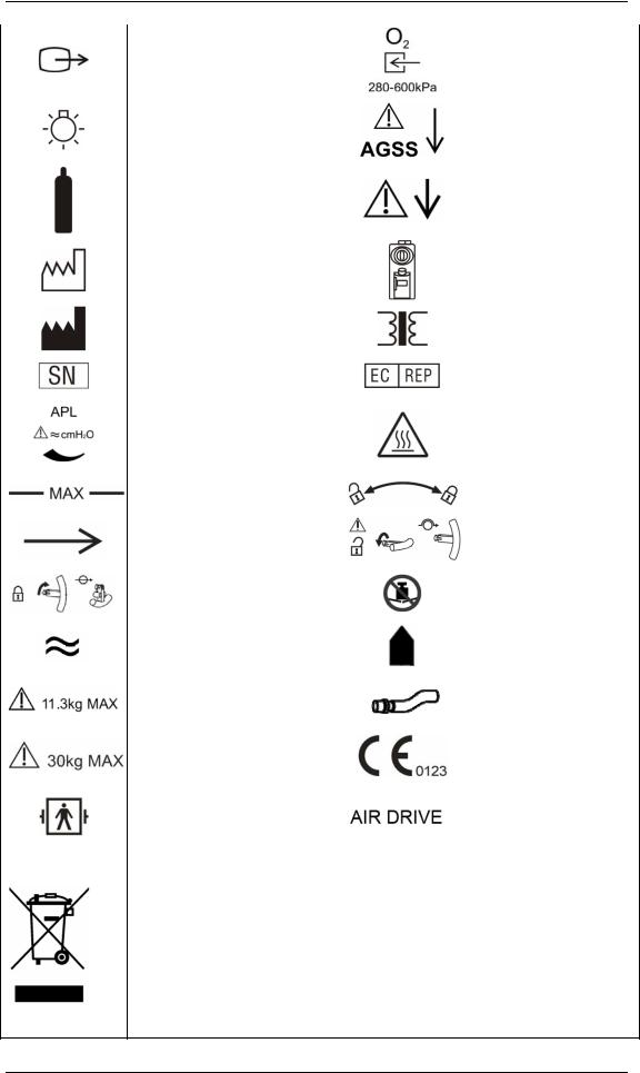
1.2 Equipment Symbols
|
Attention: Consult |
|||||||
|
accompanying documents (this |
Dangerous voltage |
||||||
|
manual) |
|||||||
|
Alternating current |
Fuse |
||||||
|
Battery |
Equipotential |
||||||
|
Operating state |
Autoclavable |
||||||
|
Material description |
Not autoclavable |
||||||
|
Power On |
Power Off |
||||||
|
Reset |
Standby |
||||||
|
Alarm silence key |
MV&TVe alarm key |
||||||
|
Normal screen key |
O2 flush button |
||||||
|
ACGO On |
ACGO Off |
||||||
|
Bag position/ manual |
Mechanical ventilation |
||||||
|
ventilation |
|||||||
|
Lock |
Unlock |
||||||
|
Network connector |
Flow control |
||||||
|
USB connector |
O2 sensor connector |
||||||
|
Air supply connector |
N2O supply connector |
||||||
|
Upward (Pop-off valve) |
Sample gas return port |
||||||
|
(to the AGSS) |
|||||||
|
1-5 |
|
VGA connector |
O2 supply connector |
|
|
Table top light |
AGSS outlet |
|
|
Cylinder |
PEEP outlet |
|
|
Manufacture date |
Vaporizer |
|
|
Manufacturer |
Isolation transformer |
|
|
Serial number |
European community |
|
|
representative |
||
|
APL valve |
CAUTION HOT |
|
|
Maximum level of the |
Lock or unlock as the |
|
|
sodalime canister |
arrow shows |
|
|
Gas input direction |
Unlock the lifting device |
|
|
Lock the lifting device |
Do Not Crush |
|
|
Approximate |
Please align! |
|
|
Max. weight: 11.3 kg |
Pipeline |
|
|
Max. weight: 30 kg |
CE marking |
|
|
Type BF applied part. |
The anesthesia machine |
|
|
Defibrillation-proof protection |
||
|
is driven by Air. |
||
|
against electric shock. |
||
The following definition of the WEEE label applies to EU member states only. This symbol indicates that this product should not be treated as household waste. By ensuring that this product is disposed of correctly, you will help prevent bringing potential negative consequences to the environment and human health. For more detailed information with regard to returning and recycling this product, please consult the distributor from whom you purchased it.
* For system products, this label may be attached to the main unit only.
1-6

2 The Basics
2.1 System Description
2.1.1 Intended Use
The anesthesia machine is intended to provide breathing anesthesia for adult, pediatric and infant patients during surgery.
The anesthesia machine must only be operated by qualified anesthesia personnel who have received adequate training in its use.
 WARNING
zThis anesthesia machine is intended for use by qualified anesthesia personnel only or under their guidance. Anyone unauthorized or untrained must not perform any operation on it.
zThis anesthesia machine is not suitable for use in an MRI environment.
2.1.2 Contraindications
The anesthesia machine is contraindicated for use on patients who suffer pneumothorax or severe pulmonary incompetence.
2-1

2.1.3 Components
The anesthesia machine consists of a main unit, vaporizer (five optional anesthetic agents: enflurane, isoflurane, sevoflurane, desflurane and halothane), anesthetic ventilator, electronic flowmeter assembly, breathing system etc.
The anesthesia machine provides monitoring and displaying of respiratory mechanics (RM) parameters (airway resistance and compliance) and spirometry loops as well. It is configured with the following ventilation modes: volume control ventilation (VCV), pressure control ventilation (PCV), pressure support ventilation (PSV), synchronized intermittent mandatory ventilation—volume control (SIMV-VC) and synchronized intermittent mandatory ventilation—pressure control (SIMV-PC).
The anesthesia machine can be externally connected to a patient monitor which is in compliance with the requirements of relevant international standard and can be configured with anesthesia information system (CIS).
The anesthesia machine features the following:
Automatic leak detection
Breathing system gas leak compensation and automatic compliance compensation
Cylinder and pipeline connections available for gas supplies
Electronic flowmeter and electronic PEEP
Timer which counts the duration between the start and end of an operation
Table top light
Information displayed in big numerics
User-adjustable display screen
Alarm events storage and review, fault status and maintenance information recording
Auxiliary O2 supply and active anesthesia gas scavenging system (AGSS)
N2O cut-off
Modular AG, CO2 and BIS modules
Sample gas return to the AGSS
Setting CPB alarm mode
2-2

2.2 Equipment Appearance
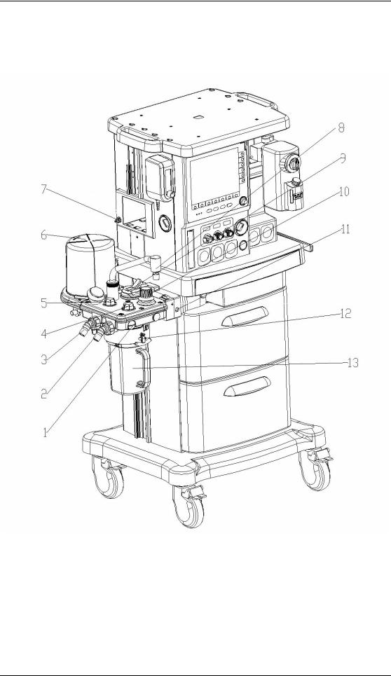
2.2.1 Front View
——Display and control panel
2-3

1.Brake
2.Pipeline pressure gauge (s)
Displays the pipeline pressure or the cylinder pressure after relief.
3.Total flowmeter
The medium level of flowtube float indicates the current flow of the mixed gas.
4Flow control (s)
When the system switch is set to the ON position:
Turn the control counterclockwise to increase the gas flow.
Turn the control clockwise to decrease the gas flow.
5Electronic flowmeter
Displays the current flow of the corresponding gas.
6.Ventilator control panel
7.Control knob
8.Display
9.Vaporizer
A.Concentration control
Push and turn the concentration control to set the concentration of anesthetic agent.
B.Locking lever
Turn the locking lever clockwise to lock the vaporizer in position.
10.Gas supply connector (s)
O2 , N2O and AIR connectors are provided.
11.System switch
Set the switch to the  position to enable gas flow and to turn on the system.
Set the switch to the  position to disable gas flow and to turn off the system.
12.Cylinder pressure gauge (s)
High-pressure pressure gauge (s) that displays cylinder pressure before relief.
13.O2 flush button
Push to supply high flows of O2 to the breathing system.
14.Auxiliary electrical outlet
Three auxiliary electrical outlets are provided when the anesthesia machine is configured with an isolation transformer.
15 Drawer lock
16. Worktable (with drawer)
2-4
——Breathing system
2-5

1.O2 sensor connector
2.Inspiration connector
3.Expiration connector
4.Inspiratory check valve
5.Expiratory check valve
6.Bellows housing
7.Sample gas return port (to the AGSS)
8.Manual bag port
9.Bag/mechanical ventilation switch
Select the  position to use bag for manual ventilation.
Select the  position to use ventilator for mechanical ventilation.
10.APL (airway pressure limit) valve
Adjusts breathing system pressure limit during manual ventilation. The scale shows approximate pressures. Above 30 cmH2O, you will feel clicks as the v turns. Turn clockwise to increase.
11.O2 sensor connector
12.Rotary handle
13.Sodalime canister
The sodalime inside the canister absorbs the CO2 the patient exhales, which enables cyclic use of the patient exhaled gas.
2-6

2.2.2 Rear View
——Power supply
2-7

1.Cylinder connector (s)
2.Equipotential stud
3.Fan
4.Mains inlet
5.Network connector
6.CIS 12 V power supply connector
7.Speaker
8.Auxiliary O2 supply
9.ACGO (Auxiliary Common Gas Outlet) switch
Set the switch to the  position to stop mechanical ventilation. Then, fresh gas is sent to the externally connected manual breathing system through the ACGO outlet and the technical alarm of [ACGO On] is triggered. The system monitors airway pressure and O2 concentration instead of volume.
Set the switch to the position to apply mechanical or manual ventilation to the patient through the breathing system.
10.Module slot
CO2, AG and BIS modules mentioned in this manual can be inserted into the slot and identified. The CO2 and AG modules cannot be used simultaneously.
11.AGSS outlet
12.AGSS Transfer and Receiving System
2-8
![]()
——Anesthesia information system (CIS)
2-9

This rear view is based on the situation that the anesthesia machine is configured with anesthesia information system (CIS).
1.Display
2.Rail
3.Mounting bracket
4.Keyboard
5.CIS main unit
A
B
C
F E D C
A.Reset key
 : Press to restart the CIS.
B.CIS switch
 : Press to switch on/off the CIS.
C.USB connector
D.Network connector
E.Electrical outlet
F.Display connector
2-10

 WARNING
zConnect to the AC mains in compliance with B.3 Power Requirements. Failure to do so may cause damage to the equipment or affect its normal operation.
zMake sure that the jacket on the electrical outlet is already fixed to avoid power cord off during surgery.
NOTE
zIf the equipment cannot be powered by the AC mains, check if the fuse inside the electrical outlet is normal. If AC mains supply still fails after the fuse is replaced, contact the service personnel.
zWhen the auxiliary electrical outlet does not work normally, check if the corresponding fuse is burned.
zEquipment connected to the auxiliary electrical outlet shall be authorized. Otherwise, leakage current above the allowable limit will result, which may endanger the patient or operator, and damage the anesthesia machine or externally connected equipment. When the anesthesia machine is configured with only one auxiliary electrical outlet, this electrical outlet is only used for connecting the adapter for Desflurane vaporizer. When the anesthesia machine is configured with multiple auxiliary electrical outlets, the equipment connected shall comply with the voltage and current specifications of the auxiliary electrical outlets.
zAll analog or digital products connected to this system must be certified passing the specified IEC standards (such as IEC 60950 for data processing equipment and IEC 60601-1 for medical electrical equipment). All configurations shall comply with the valid version of IEC 60601-1-1. The personnel who are responsible for connecting the optional equipment to the I/O signal port shall be responsible for medical system configuration and system compliance with IEC 60601-1-1 as well.
2-11

2.3 Batteries
NOTE
zUse batteries at least once every month to extend their life. Charge the batteries before their capacities are worn out.
zInspect and replace batteries regularly. Battery life depends on how frequent and how long it is used. For a properly maintained and stored lithium battery, its life expectancy is approximately 3 years. For more aggressive use models, life expectancy can be shortened. We recommend replacing lithium batteries every 3 years.
zThe operating time of a battery depends on equipment configuration and operation. For example, starting module monitoring frequently will shorten the operating time of the batteries.
zIn case of battery failure, contact us or have your service personnel replace it. Do not replace the battery without permission.
The anesthesia machine is designed to operate on battery power whenever AC power becomes interrupted. When the anesthesia machine is connected to the AC power source, the batteries are charged regardless of whether or not the anesthesia machine is currently on. In case of power failure, the anesthesia machine will automatically be powered by the internal batteries. When AC power source is restored within the specified time, power supply is switched from battery to AC automatically to ensure continuous system use.
On-screen battery icon indicates the battery statuses as follows:
 : indicates that the batteries operate normally. The solid portion represents the current charge level of the batteries in proportion to its maximum charge level.
 : indicates low battery and the batteries need to be charged.
 : indicates too low battery and the batteries need to be charged immediately.
The capacity of the internal battery is limited. If the battery capacity is too low, a high-level alarm will be triggered and the [Low Battery Voltage!] message displayed in the technical alarm area. In this case, apply AC power to the anesthesia machine.
2-12

3 System Controls and Basic Settings
3.1 Display Control
1.Alarm lamp
High level alarms: the lamp quickly flashes red.
Medium level alarms: the lamp slowly flashes yellow.
Low level alarms: the lamp turns yellow without flashing.
2.Menu shortcut key(s)
Push the menu shortcut key to access the corresponding menu.
3.Control knob
Push the control knob to select a menu option or confirm your setting. Turn the control knob clockwise or counterclockwise to scroll through the menu options or change your settings.
3-1

4.MV&TVe alarm key
In case of manual ventilation mode: Push the key to switch off MV and TVe overrange alarms and apnea alarm. Push the key again to switch on MV and TVe overrange alarms and apnea alarm.
In case of mechanical ventilation mode: Push the key to switch off MV and TVe overrange alarms. Push the key again to switch on MV and TVe overrange alarms.
5.Normal screen key
Push the key to close all menus displayed.
6.Standby key
Push the key to enter or exit standby mode.
7.Alarm silence key
To set alarm silence state, push this key to enter 120 s alarm silenced status. The alarm silence symbol  and 120 s countdown time appear in the upper right corner of the screen.
To clear alarm silence, push this key again.
8.Operating state LED
On: when the anesthesia machine is operating.
Off: when the anesthesia machine is turned off.
9.AC power LED
On: when the anesthesia machine is connected to the AC power source.
Off: when the anesthesia machine is not connected to the AC power source.
10.Battery LED
On: when the anesthesia machine is equipped with batteries and is connected to the AC power source, and the batteries are being charged.
Off: when the anesthesia machine is not equipped with batteries or is switched off.
Flash: when the anesthesia machine is being battery powered.
11.Ventilator parameter setup shortcut key(s)
Push the parameter setup shortcut key to change the corresponding setting. Turn the control knob to change the specific setting and push the control knob to activate the selected setting.
12.Display screen
Refer to 3.2Display Screen for details.
3-2

3.2 Display Screen
This anesthesia machine adopts a high-resolution color TFT LCD to display various parameters and graphs, such as ventilation parameters and pressure/flow/volume waveforms. Depending on how your anesthesia machine is configured, it may display gas module parameters and waveforms, BIS parameters, BIS trend waveform, spirometry loops etc.The following is a standard display screen. For descriptions of other screens, refer to5 User Interface and Parameter Monitoring.
|
1 |
2 |
3 |
4 |
5 |
6 |
7 |
8 |
9 |
||||||
10
11
12
18
13
14
15
17
16
1.Ventilation mode prompt area
Displays the current ventilation mode. If manual ventilation is selected for the bag/mechanical ventilation switch,  is displayed in this area. If mechanical
ventilation is selected for the bag/mechanical ventilation switch, the currently selected mechanical ventilation mode is displayed.
2.Lung icon area
The icon  is displayed when SIMV-VC or SIMV-PC mode is selected and inspiration triggering is performed currently.
3.MV&TVe alarm off icon
Displays the MV&TVe alarm off icon when MV&TVe alarm is switched off.
3-3

4.Physiological alarm area
Displays physiological alarm messages.
5.Apnea alarm off icon area
Displays apnea alarm off icon  when apnea alarm is switched off in non-mechanical ventilation mode.
6.Alarm silence icon area
Displays alarm silence icon and 120 s countdown time.
7.System time area
Displays system time of the anesthesia machine.
8.Technical alarm area
Displays technical alarm messages. When multiple alarms occur, they are displayed cyclically.
9.Power supply state icon area
Displays power source or battery icon.The icon  is displayed when the anesthesia machine is powered by AC power source. The battery icon is displayed when the anesthesia machine is battery powered to indicate battery capacity. For details, refer to2.3 Batteries.
10. [Vent Mode] shortcut key Used to select mechanical ventilation mode.
11.[Alarm Setup] shortcut key
Used to change the alarm settings for the anesthetic ventilator, gas modules or BIS module.
12.[Screens] shortcut key Used to set user screen.
13.[User Setup] shortcut key
Used to change the settings for TV compensation, O2 monitoring source, gas module, BIS module, screen, sound etc.
14.[Maintenance] shortcut key
Used to perform leak test, calibrate O2 sensor and flow sensor, view trend graph, trend table and alarm logbook, and set language, system time, pressure unit, IP address etc.
15.Timer setup shortcut key
Used to start, stop and reset the timer.
16.Parameter setup shortcut keys area
Used to set the parameters related to the selected mechanical ventilation mode. The arrangement of the shortcut keys in this area varies depending on the selected mechanical ventilation mode. For details, refer to 4 Operations and Ventilation Setup.
17 System prompt message area
3-4

Displays information about system operating state.
18Parameter&graph area
Displays the parameters, waveforms, spirometry loops, or electronic flowmeter graphs which the anesthesia ventilator, gas module or BIS module monitors. Different types of screens are displayed based on the actual system configuration or screen layout settings. For details, refer to 5 User Interface and Parameter Monitoring.
3.3Basic Settings
This chapter covers only general settings of the anesthesia machine, such as language, screen brightness, system time etc. Parameter settings and other settings can be referred to in the respective sections.
3.3.1 Adjust Screen Brightness
1.Select the [User Setup] shortcut key and select [Screen and Audio Setup >>].
2.Select [Screen Brightness] and select the appropriate value (ranging from 1 to 10) for screen brightness. The value 10 is for the brightest and 1 the least bright. If the anesthesia machine is battery powered, you can select less brightness to save battery capacity.
3.3.2 Adjust Sound Volume
3.3.2.1 Key Sound Volume
1. Select the [User Setup] shortcut key and select [Screen and Audio Setup >>].
2. Select [Key Sound Volume] and select the appropriate value (ranging from 0 to 10) for key sound volume. The value 0 is for audio off and 10 for the loudest.
3.3.2.2 Alarm Sound Volume
1.Select the [User Setup] shortcut key and select [Screen and Audio Setup >>].
2.Select [Alarm Sound Volume] and select the appropriate value (ranging from 1 to 10) for alarm sound volume. The value 1 is for the lowest and 10 for the loudest.
3-5

3.3.3 Set System Time
1.Select the [Maintenance] shortcut key → [User Maintenance >>] → [Set System Time >>].
2.Set [Date] and [Time].
3.Select [Date Format] and toggle between [YYYY-MM-DD], [MM-DD-YYYY] and [DD-MM-YYYY].
4.Select [Time Format] and toggle between [24 h] and [12 h].
 CAUTION
zChanging date and time will affect the storage of trends and log information. It may also cause loss of data.
3.3.4 Set Language
1. Select the [Maintenance] shortcut key and select [User Maintenance >>]. 2. Select [Language] and select the desired language.
3. Restart the anesthesia machine to activate the language setting.
3.3.5 Set Unit
1.Select the [Maintenance] shortcut key and select [User Maintenance >>].
2.Select [Paw Unit] and toggle between cmH2O, hPa and mbar.
If the anesthesia machine is configured with CO2 or AG module, you can set the display units of FiCO2 and EtCO2. For details, refer to 8 CO2 Monitoring.
3.3.6 Restore Default Configurations
3.3.6.1 Restore the Factory Default Configuration of the Ventilator
To restore the factory default configuration of the ventilator, do as follows:
1.Select the [Maintenance] shortcut key → [User Maintenance >>] → [Ventilator Defaults].
3-6
![]()
2.Select [Ok] from the pop-up menu.
After [Ok] is selected, the following settings restore their default values:
User screen
Ventilator parameters
Alarm limits of ventilator-related parameters
O2 monitoring source
Alarm sound volume and key sound volume
Screen brightness
Paw display unit
3.3.6.2 Restore the Factory Default Configuration of the Gas Module
If the anesthesia machine is configured with CO2 or AG module, you can directly restore the factory default configuration of the corresponding module. For details, refer to 8 CO2 Monitoring and 9 AG and O2 Concentration Monitoring.
3.3.6.3 Restore the Factory Default Configuration of the BIS Module
If the anesthesia machine is configured with BIS module, you can directly restore the factory default configuration of the corresponding module. For details, refer to 10 BIS Monitoring.
3.3.7 Set the IP Address of Anesthesia Information System
(CIS)
To set the IP address of anesthesia information system (CIS), do as follows:
1.Select the [Maintenance] shortcut key → [User Maintenance >>] → [Set IP Address >>].
2.In the [Set IP Address] menu, set the correct IP address of the CIS.
3.Select [Ok] to activate the IP address setting.
3-7

FOR YOUR NOTES
3-8

4 Operations and Ventilation Setup
 WARNING
zBefore using this anesthesia machine on the patient, make sure that the system is correctly connected and in good condition, and that all the tests described in 6 Preoperative Test are already completed. In case of test failure, do not use the system. Have a qualified service representative repair the system.
4.1Turn on the System
1.Connect the power cord to the AC power source. Make sure that the AC power LED is illuminated.
2.Set the system switch to ON. Make sure that both the operating state LED and battery LED are illuminated (the battery is being charged or fully charged).
3.The alarm lamp flashes yellow and red once in turn and then a beep is given.
4.The display shows the start-up screen and then enters the standby screen after half a minute.
 WARNING
zDo not use the anesthesia machine if it generates alarms during start-up or fails to operate normally. Contact your service personnel or us.
4.2Turn off the System
To turn off the system, do as follows:
1.Confirm that system use is finished.
2.Set the system switch to OFF.
NOTE
zFor the first mechanical ventilation of each patient, do not exit the standby screen if mechanical ventilation related parameters are not set properly. Adjust fresh gas and anesthetic agent concentrations (if necessary) on the standby screen and set ventilation parameters properly based on the patient’s conditions before applying mechanical ventilation.
4-1

4.3 Input Fresh Gas
4.3.1 Set O2, N2O and Air Inputs
1.Connect the gas supplies correctly and ensure adequate gas pressure.
2.You can control the O2, N2O and Air flows in the fresh gas through the O2, N2O and Air flow controls. Readings of the gas flow can be seen on the respective electronic flowmeter. On the left hand of the electronic flowmeters is the total flowmeter showing the flow of the mixed gas.
The O2 and N2O flow controls constitute a chain linkage:
Turn the N2O flow control counterclockwise to increase the N2O flow to some extent. Then continuing turning the N2O flow control will cause the O2 flow control to turn counterclockwise together to increase the O2 flow, keeping the O2 concentration in the mixed gas above 25%.
Turn the O2 flow control clockwise to decrease the O2 flow to some extent. Then continuing turning the O2 flow control will cause the N2O flow control to turn clockwise together to decrease the N2O flow, keeping the O2 concentration in the mixed gas above 25%.
NOTE
zThis anesthesia machine can be used alone as a ventilator. You can adjust O2 concentration in the breathing system through the O2 flow control.
zThe O2 concentration in the fresh gas may be quite different from that in the breathing system.
zThe total flowmeter is calibrated based on 100% O2. The accuracy of the flowmeter may degrade with other gas or mixed gas.
zWhen viewing the readings on the total flowmeter, keep your visual angle at the same level of the float. The reading of a same scale may vary when viewed at a different angle.
zIf the readings shown on the electronic flowmeters differ from that on the total flowmeter, the former shall prevail and the latter is an approximate value.
4-2

4.3.2 Set Anesthetic Agent
NOTE
zYou do not need to perform this operation if inspiratory anesthetic agent is not used.
zThis anesthesia machine can be mounted with vaporizers corresponding with halothane, enflurane, isoflurane, sevoflurane and desflurane. Only one of the five vaporizers can be opened at a time because the vaporizers are featured with interlock.
4.3.2.1 Select the Desired Anesthetic Agent
1.Determine the anesthetic agent to be used and then fill the vaporizer. For details, refer to
13.4.2 Fill the Vaporizer.
2.Mount the vaporizer filled with anesthetic agent onto the anesthesia machine. For details, refer to 13.4 Install the Vaporizer.
4.3.2.2 Adjust the Concentration of Anesthetic Agent
Push and turn the concentration control on the vaporizer to set the appropriate concentration of anesthetic agent.
NOTE
zInspect the color of the sodalime in the canister before using the anesthetic agent. Replace the sodalime immediately if obvious color change is detected.
zFor details about how to use the anesthetic agent, refer to the Vaporizer Instructions for Use.
4-3

4.4 Set Ventilation Mode
4.4.1 Set Manual Ventilation Mode
1.Turn the APL valve control to adjust the pressure in the breathing system within the appropriate range.
2.Set the bag/mechanical ventilation switch to the  position. The ventilation mode
prompt area displays the icon for manual ventilation mode. Besides, the system prompt message area displays [Manual Vent.].
3.Push the O2 flush button  to inflate the bag if necessary.
In the manual ventilation mode, you can use the APL valve to adjust the breathing system pressure limit and gas volume in the manual bag. When the pressure in the breathing system reaches the pressure limit set for the APL valve, the valve opens to release excess gas.
The following figures show the Paw waveform and flow waveform in the manual ventilation
mode.
4-4

NOTE
zWhen using the anesthesia machine on the patient, make sure that manual ventilation mode is available.
4.4.2 Make Settings before Starting Mechanical Ventilation
Mode
1.Make sure that the system is Standby.
2.Set the appropriate Plimit value in the parameter setup shortcut keys area.
3.Check the ACGO switch to make sure that it is OFF.
4.Set the bag/mechanical ventilation switch to the  position.
5.If necessary, push the O2 flush button  to inflate the bellows.
NOTE
zThe default mechanical ventilation mode of the anesthesia machine is VCV. Other mechanical ventilation modes are optional. For the ventilation mode not configured for your anesthesia machine, operations of the corresponding menu options are disabled.
4.4.3 Volume Control Ventilation (VCV)
4.4.3.1 Description
Volume control ventilation (hereinafter referred to as VCV) mode is a basic fully-mechanical ventilation mode. In the VCV mode, each time mechanical ventilation starts, gas is delivered to the patient at a constant flow, which reaches the preset TV within the gas delivery time. To ensure a certain amount of TV, the resulted airway pressure (Paw) changes based on patient pulmonary compliance and airway resistance. In the VCV mode, as long as Paw is less than Plimit and the gas delivery flow is kept constant, expirations starts immediately after Plimit is reached.
In the VCV mode, you need to set [Plimit] to prevent high airway pressure from injuring the patient. In this mode, you can select to set [TIP :TI] to improve patient pulmonary gas distribution and [PEEP] to improve expiration of end-tidal carbon dioxide and to increase oxygenation of breathing process.
4-5

To ensure the set tidal volume gas delivery, the ventilator adjusts gas flow based on the measured inspiratory volume, dynamically compensates for the loss of tidal volume arising from breathing system compliance and system leakage and eliminates the effect of fresh gas as well. This is called tidal volume compensation.
In the VCV mode, if tidal volume compensation is turned off or failed, the anesthesia machine can continue delivering gas stably but cannot compensate for the effects of fresh gas flow and breathing system compliance losses.
4.4.3.2 Waveforms
The following figures show the Paw waveform and flow waveform in the VCV mode.
Generally, in the VCV mode, the flow waveform is at a constant flow during inspiration and the Paw waveform rises in the same period.
4.4.3.3 Start VCV Mode
1.Select the [Vent Mode] shortcut key to open the [Vent Mode Setup] menu.
2.Select [VCV] in the [Vent Mode Setup] menu.
3.After confirming the selection, the[TV] shortcut key (the first key from the left in the parameter setup shortcut keys area) is highlighted.
4.Make sure that TV is appropriately set for the patient. Push the control knob to confirm the setting so as to start VCV mode.
4-6

NOTE
zWhen it is necessary to switch over to VCV mode, confirm the setting of TV first. Otherwise, the system works in the previous ventilation mode. If the setting of TV is not confirmed for 10 s, the screen returns to the previous mode automatically.
zBefore activating a new mechanical ventilation mode, make sure that all related parameters are set appropriately.
4.4.3.4 Parameter Setup Shortcut Keys Area in VCV Mode
When selection of VCV mode is confirmed, the parameter setup shortcut keys area at the bottom of the screen is automatically switched over to the parameter setup area in this mode. The following figure shows all related parameters to be set in VCV mode.
|
1. |
[TV]: |
Tidal volume |
|
2. |
[Rate]: |
Breath rate |
|
3. |
[I:E]: |
Ratio of inspiratory time to expiratory time |
|
4. |
[TIP:TI]: |
Percentage of inspiratory plateau time in inspiratory time |
|
5. |
[Plimit]: |
Pressure limit level |
|
6 |
[PEEP]: |
Positive end-expiratory pressure |
4.4.3.5 Set Parameters in VCV Mode
You can use the shortcut keys and control knob to set the parameters in VCV mode. The following takes setting of TV as an example.
1.Select the [TV] shortcut key.
2.Push the control knob and turn it to set [TV] to the appropriate value.
3.Push the control knob to confirm the setting.
4.Set other parameters in this mode in the similar way.
4-7

NOTE
zIf the parameter value is adjusted outside of the range, the system prompt message area displays [Parameter Settings Outside the Safety Range].
zConfirm the adjustment of one parameter before adjusting another parameter. If you want to restore the value before adjustment, you have to reset the parameter value.
4.4.3.6 Parameter Range and Default Value in VCV Mode
|
Parameter |
Range |
Step |
Default |
|
|
20 to 100 ml: 5 ml |
||||
|
TV |
20 to 1500 ml |
100 to 300 ml: 10 ml |
500 ml |
|
|
300 to 1500 ml: 25 ml |
||||
|
Rate |
4 to 100 BPM |
1 BPM |
12 BPM |
|
|
I:E |
4:1 to 1:8 |
0.5 |
1:2 |
|
|
Plimit |
10 to 100 cmH2O |
1 cmH2O |
30 cmH2O |
|
|
PEEP |
OFF, 4 to 30 cmH2O |
1 cmH2O |
OFF |
|
4.4.4 Pressure Control Ventilation (PCV)
4.4.4.1 Description
Pressure control ventilation (hereinafter referred to as PCV) mode is a basic fully-mechanical ventilation mode. In the PCV mode, each time mechanical ventilation starts, Paw rises rapidly to the preset Plimit. Then gas flow slows down through the feedback system to keep Paw constant until expiration starts at the end of inspiration. The tidal volume delivered in the PCV mode changes based on patient pulmonary compliance and airway resistance.
In the PCV mode, you need to set Plimit to prevent high airway pressure from injuring the patient.
In the PCV mode, you can also select to set [PEEP] to improve expiration of end-tidal carbon dioxide and to increase oxygenation of breathing process.
4-8
 Loading…
Your Donation Will Be Matched 1-to-1! Can You Chip In?
Dear Patron: Please don’t scroll past this. The Internet Archive is a nonprofit fighting for universal access to quality information. We build and maintain all our own systems, but we don’t charge for access, sell user information, or run ads. Instead, we’re powered by online donations averaging about $14. We’d be deeply grateful if you’d join the one in a thousand users that support us financially.
Right now, we have a matching gift campaign that will double the impact of every donation. We understand that not everyone can donate right now, but if you can afford to contribute this Tuesday, we promise it will be put to good use. Our resources are crucial for knowledge lovers everywhere—so if you find all these bits and bytes useful, please pitch in.
Your Donation Will Be Matched! Can You Chip In?
Dear Patron: Please don’t scroll past this. Right now we have a matching gift campaign that will double the impact of every donation. We understand that not everyone can give right now, but if you can afford to contribute this Tuesday, we promise it will be put to good use. If you find all these bits and bytes useful, please pitch in.
-
WATO EX-55/65 Anesthesia Machine
Service Manual
-
I
Intellectual Property Statement SHENZHEN MINDRAY BIO-MEDICAL
ELECTRONICS CO., LTD. (hereinafter called Mindray) owns the
intellectual property rights to this product and this manual. This
manual may refer to information protected by copyrights or patents
and does not convey any license under the patent rights of Mindray,
nor the rights of others. Mindray does not assume any liability
arising out of any infringements of patents or other rights of
third parties. Mindray intends to maintain the contents of this
manual as confidential information. Disclosure of the information
in this manual in any manner whatsoever without the written
permission of Mindray is strictly forbidden. Release, amendment,
reproduction, distribution, rent, adaption and translation of this
manual in any manner whatsoever without the written permission of
Mindray is strictly forbidden., and WATO are the registered trademarks or trademarks owned
byMindray in China and other countries. All other trademarks that
appear in this manual are used only for editorial purposes without
the intention of improperly using them. They are the property of
their respective owners. Contents of this manual are subject to
changes without prior notice.Revision History This manual has a revision number. This
revision number changes whenever the manual is updated due to
software or technical specification change. Contents of this manual
are subject to change without prior notice. Revision 1.0 is the
initial release of the document.Revision number: 1.1 Release time: 2009-03 Copyright 2008-2009
Shenzhen Mindray Bio-Medical Electronics Co., Ltd. All rights
reserved. -
II
FOR YOUR NOTES
-
III
Preface
Manual Purpose This manual provides detailed information about
the assembling, dissembling, testing and troubleshooting of the
equipment to support effective troubleshooting and repair. It is
not intended to be a comprehensive, in-depth explanation of the
product architecture or technical implementation. Observance of the
manual is a prerequisite for proper equipment maintenance and
prevents equipment damage and personal injury. This manual is based
on the maximum configuration. Therefore, some contents may not
apply to your monitor. If you have any question, please contact our
Customer Service Department.Intended Audience This manual is geared for biomedical
engineers, authorized technicians or service representatives
responsible for troubleshooting, repairing and maintaining the
anesthesia machines.Password A password is required to access different modes within
the anesthesia machine.Factory maintenance: 0611
-
IV
FOR YOUR NOTES
-
1
Contents
1
Safety…………………………………………………………………………………………………………………
1-1 1.1 Safety Information
…………………………………………………………………………………………….
1-11.1.1 Dangers
………………………………………………………………………………………………..
1-2 1.1.2
Warnings……………………………………………………………………………………………….
1-2 1.1.3 Cautions
……………………………………………………………………………………………….
1-2 1.1.4 Notes
……………………………………………………………………………………………………
1-31.2 Equipment Symbols
…………………………………………………………………………………………..
1-32 Theory of Operation
…………………………………………………………………………………………..
2-1 2.1 Pressure Unit Conversion Table
…………………………………………………………………………..
2-1 2.2 Gas Flow
………………………………………………………………………………………………………….
2-22.2.1 Pneumatic Circuit
Diagram……………………………………………………………………..
2-2 2.2.2 Parts List
………………………………………………………………………………………………
2-3 2.2.3 Key to Symbols
……………………………………………………………………………………..
2-4 2.2.4 Description
……………………………………………………………………………………………
2-43 Checkout and Test
………………………………………………………………………………………………
3-1 3.1 System Inspection
……………………………………………………………………………………………..
3-1 3.2 Pipeline Tests
……………………………………………………………………………………………………
3-2 3.3 Cylinder
Tests……………………………………………………………………………………………………
3-23.3.1 Check the Cylinders are Full
……………………………………………………………………
3-3 3.3.2 Cylinder High Pressure Leak
Test…………………………………………………………….
3-33.4 Flow Control System Tests
…………………………………………………………………………………
3-3 3.4.1 Without O2 Sensor
…………………………………………………………………………………
3-3 3.4.2 With O2 Sensor
……………………………………………………………………………………..
3-53.5 Vaporizer Back Pressure Test
………………………………………………………………………………
3-5 3.6 O2 Flush Test
……………………………………………………………………………………………………
3-63.6.1 In Mechanical Ventilation Mode
………………………………………………………………
3-6 3.6.2 In Manual Ventilation Mode
……………………………………………………………………
3-73.7 Breathing Circuit
Tests……………………………………………………………………………………….
3-7 3.7.1 Bellows Test
………………………………………………………………………………………….
3-8 3.7.2 Breathing System Leak Test in Mechanical Ventilation Mode
…………………….. 3-8 3.7.3 Breathing System Leak Test in
Manual Ventilation Mode…………………………. 3-12 3.7.4
APL Valve Test
…………………………………………………………………………………….
3-133.8 Pressure Relief Valve Test
…………………………………………………………………………………
3-14 3.9 Alarm
Tests……………………………………………………………………………………………………..
3-153.9.1 Prepare for Alarm
Tests…………………………………………………………………………
3-15 3.9.2 Test the O2 Concentration Monitoring and Alarms
…………………………………… 3-16 3.9.3 Test the Low
Minute Volume (MV) Alarm
……………………………………………… 3-16 -
2
3.9.4 Test the Apnea Alarm
……………………………………………………………………………
3-17 3.9.5 Test the Sustained Airway Pressure
Alarm………………………………………………. 3-17
3.9.6 Test the High Paw
Alarm……………………………………………………………………….
3-17 3.9.7 Test the Low Paw Alarm
……………………………………………………………………….
3-183.10 AGSS Inspection
……………………………………………………………………………………………
3-18 3.10.1 Check the Float
………………………………………………………………………………….
3-18 3.10.2 Check the Transfer Tube and Active Scavenging
Tube……………………………. 3-193.11 Power Failure
Test………………………………………………………………………………………….
3-20 3.12 Electrical Safety Tests
…………………………………………………………………………………….
3-214 Maintenance and Calibration
……………………………………………………………………………..
4-1 4.1 Equipment
Maintenance……………………………………………………………………………………..
4-14.1.1 One-year Replaceable Parts
…………………………………………………………………….
4-1 4.1.2 Three-year Replaceable
Parts…………………………………………………………………..
4-94.2 System Test
………………………………………………………………………………………………………
4-9 4.2.1 Check the Mechanical Ventilation Mode
………………………………………………… 4-10
4.2.2 Breathing System Leak Test in Mechanical Ventilation Mode
…………………… 4-13 4.2.3 Breathing System Leak Test in
Manual Ventilation Mode…………………………. 4-13 4.2.4
Check the Sensor Zero
Point………………………………………………………………….
4-13 4.2.5 Check the Flow Sensor
Accuracy……………………………………………………………
4-14 4.2.6 Check the Pressure Sensor Accuracy
………………………………………………………
4-15 4.2.7 Check the Electronic Flowmeter Accuracy
……………………………………………… 4-164.3 System
Calibration…………………………………………………………………………………………..
4-18 4.3.1 Flow Calibration (user)
…………………………………………………………………………
4-20 4.3.2 Flow Calibration
(factory)……………………………………………………………………..
4-21 4.3.3 Pressure Calibration (factory)
………………………………………………………………..
4-27 4.3.4 Electronic Flowmeter Calibration (factory)
…………………………………………….. 4-31 4.3.5
Pressure and Flow Zeroing
(factory)……………………………………………………….
4-34 4.3.6 Electronic Flowmeter Zeroing
(factory)…………………………………………………..
4-35 4.3.7 O2 Sensor Calibration (optional)
……………………………………………………………
4-36 4.3.8 CO2 Calibration (factory)
……………………………………………………………………..
4-37 4.3.9 AG Calibration (factory)
……………………………………………………………………….
4-39 4.3.10 O2 Module Calibration
(factory)…………………………………………………………..
4-414.4 Software Upgrade and Software Configuration
Activation……………………………………. 4-43 4.4.1
Software
Upgrade…………………………………………………………………………………
4-43 4.4.2 Software Function
Activation…………………………………………………………………
4-50 4.4.3 Change the Software Configuration of Electronic
Flowmeters…………………… 4-53 4.4.4 Load Gas Module or
BIS Module
…………………………………………………………..
4-56 4.4.5 Load O2 Sensor Monitoring
Function……………………………………………………..
4-57 4.4.6 Select the Drive
Gas……………………………………………………………………………..
4-584.5 Zero the Airway Pressure
Gauge………………………………………………………………………..
4-59 4.6 Adjust the APL Valve Accuracy
…………………………………………………………………………
4-605
Troubleshooting………………………………………………………………………………………………….
5-1 -
3
5.1
Introduction………………………………………………………………………………………………………
5-1 5.2 Technical Alarm Check
………………………………………………………………………………………
5-15.2.1 Ventilator Related Alarms
……………………………………………………………………….
5-1 5.2.2 Electronic Flowmeter Related Alarms
………………………………………………………
5-95.3 Pneumatic Circuit System Problems
……………………………………………………………………5-11
5.3.1 Tools for on-site
Maintenance…………………………………………………………………5-11
5.3.2 Gas Supplies and Drive
Gas…………………………………………………………………..
5-20 5.3.3 Anesthetic Gas Delivery System
…………………………………………………………….
5-28 5.3.4 Patient
Circuit………………………………………………………………………………………
5-42 5.3.5 Tidal Volume
……………………………………………………………………………………….
5-575.4 Troubleshoot Sensor and Valve Related Failures by Using the
Valves-test Tool ………. 5-59 5.4.1 Preparations before Using
the Valves-test
Tool………………………………………… 5-59 5.4.2
One-to-one Correspondence between the Sensors & Valves on the
Valves-test Tool Screen and the
Components……………………………………………………………………
5-60 5.4.3 Description
………………………………………………………………………………………….
5-615.5 Hardware and Electrical
Problems……………………………………………………………………..
5-666 Repair and Disassembly
……………………………………………………………………………………..
6-1 6.1 Prepare for Disassembly
…………………………………………………………………………………….
6-26.1.1
Tools…………………………………………………………………………………………………….
6-2 6.1.2
Preparations…………………………………………………………………………………………..
6-2 6.1.3 Bleed Gas
Pressure…………………………………………………………………………………
6-36.2 Disassemble the Assemblies
……………………………………………………………………………….
6-3 6.2.1 Remove the Top
Panel…………………………………………………………………………….
6-3 6.2.2 Remove the Rear Panel
…………………………………………………………………………..
6-4 6.2.3 Remove the Trolly Rear Panel
Assembly…………………………………………………..
6-5 6.2.4 Replace the System Switch
……………………………………………………………………..
6-5 6.2.5 Remove the Left Front Panel
Assembly…………………………………………………….
6-7 6.2.6 Remove the Throttling Device
…………………………………………………………………
6-8 6.2.7 Disassemble the Display
Assembly…………………………………………………………..
6-9 6.2.8 Remove the Flowmeter Control Board
…………………………………………………… 6-10
6.2.9 Remove the Total Flowmeter
…………………………………………………………………
6-10 6.2.10 Disassemble the Gas Supply Inlet Assembly
…………………………………………..6-11 6.2.11
Remove the ACGO Switch
Assembly……………………………………………………
6-13 6.2.12 Remove the O2 Flush Button Assembly
……………………………………………….. 6-14
6.2.13 Remove the Vaporizer Manifold
Assembly……………………………………………. 6-15
6.2.14 Disassemble the Pipeline Pressure Gauges
……………………………………………. 6-17 6.2.15
Disassemble the Expiratory Valve Assembly
…………………………………………. 6-18 6.2.16
Remove the Three-way Valve
………………………………………………………………
6-20 6.2.17 Remove the Auxiliary O2 Supply
Assembly………………………………………….. 6-20
6.2.18 Remove the AGSS
Assembly……………………………………………………………….
6-21 6.2.19 Remove the Main Control Board
………………………………………………………….
6-23 6.2.20 Remove the Button Board
……………………………………………………………………
6-23 6.2.21 Remove the Monitor
Board………………………………………………………………….
6-24 -
4
6.2.22 Remove the
Speaker……………………………………………………………………………
6-25 6.2.23 Remove the Power
Box……………………………………………………………………….
6-25 6.2.24 Replace the Power Board
…………………………………………………………………….
6-27 6.2.25 Replace the Fuse
………………………………………………………………………………..
6-28 6.2.26 Replace the Built-in
Battery…………………………………………………………………
6-29 6.2.27 Remove the Power Cord
……………………………………………………………………..
6-30 6.2.28 Remove the Isolation Transformer
………………………………………………………..
6-30 6.2.29 Replace the
Caster………………………………………………………………………………
6-32 6.2.30 Replace the Drawer
…………………………………………………………………………….
6-336.3 Disassemble the Breathing System
…………………………………………………………………….
6-34 6.3.1 Remove the O2
Sensor………………………………………………………………………….
6-34 6.3.2 Remove the Breathing Tubes
…………………………………………………………………
6-35 6.3.3 Remove the Flow Sensor
………………………………………………………………………
6-36 6.3.4 Remove the Manual
Bag……………………………………………………………………….
6-37 6.3.5 Disassemble the Bellows Assembly
………………………………………………………..
6-38 6.3.6 Disassemble the PoP-Off Valve
Assembly……………………………………………….
6-39 6.3.7 Disassemble the Expiratory Check Valve
Assembly…………………………………. 6-40 6.3.8
Disassemble the Inspiratory Check Valve Assembly
………………………………… 6-40 6.3.9 Remove the
Sodalime Canister
………………………………………………………………
6-41 6.3.10 Remove the Water Collection Cup
………………………………………………………..
6-42 6.3.11 Remove the Airway Pressure Gauge
…………………………………………………….. 6-43
6.3.12 Remove the Bag Arm
………………………………………………………………………….
6-43 6.3.13 Remove the Circuit
…………………………………………………………………………….
6-44 6.3.14 Remove the Sodalime Canister Connection Block
Assembly…………………… 6-45 6.3.15 Remove the Upper Cover
2 and Lower Cover 2 Assemblies ……………………. 6-47
6.3.16 Remove the Upper Cover Assembly
…………………………………………………….. 6-49
6.3.17 Remove the Median Plate
Assembly……………………………………………………..
6-49 6.3.18 Remove the Lower Cover
Assembly……………………………………………………..
6-50 6.3.19 Disassemble the Bag/mechanical Ventilation Switch
Assembly……………….. 6-50 6.3.20 Remove the APL Valve
Assembly…………………………………………………………
6-536.4 Electrical and Pneumatic
Connections………………………………………………………………..
6-53 6.4.1 Electrical
Connections…………………………………………………………………………..
6-54 6.4.2 Pneumatic Connections
…………………………………………………………………………
6-58 6.4.3 Connections between Pneumatic Circuit, Breathing System
and Monitor
Board…………………………………………………………………………………………………………………..
6-707 Parts
………………………………………………………………………………………………………………….
7-1 7.1 Main Unit
…………………………………………………………………………………………………………
7-17.1.1 Main Unit
……………………………………………………………………………………………..
7-1 7.1.2 Top Panel Assembly
……………………………………………………………………………….
7-4 7.1.3 Left Front Panel
Assembly………………………………………………………………………
7-5 7.1.4 Display
Assembly…………………………………………………………………………………..
7-7 7.1.5 Trolly Assembly (with Auxiliary Electrical Outlet/Euro
Standard/220V) ……… 7-8 7.1.6 Trolly Drawer Assembly
……………………………………………………………………….
7-10 -
5
7.1.7 Trolly Rear Panel
Assembly……………………………………………………………………7-11
7.1.8 Modular Rack Assembly
……………………………………………………………………….
7-12 7.1.9 Ground Plate Assembly of Modular
Rack……………………………………………….. 7-13
7.1.10 Circuit Bracket
Assembly…………………………………………………………………….
7-14 7.1.11 Tabletop Assembly
……………………………………………………………………………..
7-15 7.1.12 Tabletop Operation Console Assembly
…………………………………………………. 7-17
7.1.13 Isolation Transformer Mounting
Assembly……………………………………………. 7-19
7.1.14 Auxiliary Electrical Outlet Assembly (220V)
………………………………………… 7-20 7.1.15 Power
Box Assembly
………………………………………………………………………….
7-21 7.1.16 Rear Plate Assembly
…………………………………………………………………………..
7-23 7.1.17 CIS
Assembly…………………………………………………………………………………….
7-24 7.1.18 O2, N2O and AIR Supplies Inlet
Assemblies…………………………………………. 7-26
7.1.19 Auxiliary O2 Supply
Assembly…………………………………………………………….
7-27 7.1.20 O2+AIR System
Switch………………………………………………………………………
7-28 7.1.21 O2 Flush Button Assembly
………………………………………………………………….
7-29 7.1.22 ACGO
Assembly………………………………………………………………………………..
7-30 7.1.23 Gas Reservoir Assembly
……………………………………………………………………..
7-31 7.1.24 Expiratory Valve Assembly
………………………………………………………………….
7-32 7.1.25 Throttling Device
(O2+N2O+AIR)……………………………………………………….
7-34 7.1.26 O2 Cylinder Bracket
Assembly…………………………………………………………….
7-35 7.1.27 N2O Cylinder Bracket
Assembly………………………………………………………….
7-36 7.1.28 Double-vaporizer Manifold Assembly
………………………………………………….. 7-37
7.1.29 Single-vaporizer Manifold
Assembly…………………………………………………….
7-39 7.1.30 AGSS Assembly
…………………………………………………………………………………
7-407.2 Breathing
Circuit……………………………………………………………………………………………..
7-42 7.2.1 Lifting Device
Assembly……………………………………………………………………….
7-42 7.2.2 Sodalime Canister
Assembly………………………………………………………………….
7-44 7.2.3 Canister Connection Block
Assembly……………………………………………………..
7-45 7.2.4 BYPASS Upper Cover
Assembly……………………………………………………………
7-46 7.2.5 Bag Arm Assembly
………………………………………………………………………………
7-47 7.2.6 Upper Cover Assembly
…………………………………………………………………………
7-48 7.2.7 APL Valve
Assembly…………………………………………………………………………….
7-49 7.2.8 Bag/mechanical Ventilation Switch
Assembly…………………………………………. 7-51
7.2.9 Median Plate
Assembly…………………………………………………………………………
7-52 7.2.10 Lower Cover
Assembly……………………………………………………………………….
7-54 7.2.11 Expiratory Flow Sensor Assembly
………………………………………………………..
7-55 7.2.12 Inspiratory Flow Sensor Assembly
……………………………………………………….
7-56 7.2.13 Upper Cover 2 Assembly
…………………………………………………………………….
7-57 7.2.14 Folding Bag Assembly
………………………………………………………………………..
7-58 7.2.15 Lower Cover 2
Assembly…………………………………………………………………….
7-59 7.2.16 Airway Pressure Gauge Assembly
………………………………………………………..
7-60 -
6
FOR YOUR NOTES
-
1-1
1 Safety
1.1 Safety Information
DANGER
z Indicates an imminent hazard that, if not avoided, will result
in death or serious injury.WARNING
z Indicates a potential hazard or unsafe practice that, if not
avoided, could result in death or serious injury.CAUTION
z Indicates a potential hazard or unsafe practice that, if not
avoided, could result in minor personal injury or product/property
damage.NOTE
z Provides application tips or other useful information to
ensure that you get the most from your product. -
1-2
1.1.1 Dangers There are no dangers that refer to the product in
general. Specific Danger statements may be given in the respective
sections of this manual.1.1.2 Warnings
WARNING
z This equipment must be installed by factory authorized
engineers and adequate training of its use should be delivered to
its user before it is put into use.z There is high voltage inside the equipment. Never disassemble
the equipment before it is disconnected from the AC power
source.z This equipment can be disassembled by Mindray trained and
authorized personnel only.z Be sure of static discharge before disassembling the
equipment. Wear antistatic wrist straps or gloves when
disassembling the parts labelled with static-sensitive symbolsto
avoid damage to the parts.z The equipment must be connected to a properly installed power
outlet with protective earth contacts only. If the installation
does not provide for a protective earth conductor, disconnect it
from the power line.z Dispose of the packaging materials, observing the applicable
waste control regulations and keeping it out of childrens
reach.1.1.3 Cautions
CAUTION
z Make sure that no electromagnetic radiation interferes with
the performance of the equipment when preparing to carry out
performance tests. Mobile phone, X-ray equipment or MRI devices are
a possible source of interference as they may emit higher levels of
electromagnetic radiation.z Before connecting the equipment to the power source, check
that the power source conforms to the requirements specified in the
Operators Manual. -
1-3
1.1.4 Notes
NOTE
z Refer to Operators Manual for detailed operation and other
information.1.2 Equipment Symbols
Attention: Consult accompanying documents (this manual)
Dangerous voltage
Alternating current Fuse
Battery Equipotential
Operating state Autoclavable
Material description
Not autoclavable
Power On
Power Off
Reset
Standby
Alarm silence key MV&TVe alarm key
Normal screen key O2 flush button
ACGO On
ACGO Off
Bag position/ manual ventilation
Mechanical ventilation
Lock
Unlock
Network connector Flow control
-
1-4
USB connector O2 sensor connector
Air supply connector
N2O supply connector
Upward (Pop-off valve)
Sample gas return port (to the AGSS)
VGA connector
O2 supply connector
Table top light
AGSS outlet
Cylinder
PEEP outlet
Isolation transformer
Vaporizer
APL valve
CIS connector
Maximum level of the sodalime canister
CAUTION HOT
Gas input direction
Lock or unlock as the arrow shows
Lock the lifting device Unlock the lifting device
Approximate
Do Not Crush
Max. weight: 11.3 kg Please align!
Max. weight: 30 kg
Type BF applied part. Defibrillation-proof protection against
electric shock.Pipeline Driven by air
-
2-1
2 Theory of Operation
2.1 Pressure Unit Conversion Table
Pa hPa kPa MPa mmHg atm cmH2O mbar bar PSI 1 10-2 10-3 10-6
7.5X10⁻³ 9.8X10⁻⁶ 1.02X10⁻² 1X10⁻² 1X10⁻⁵ 1.45X10-41X102 1 1X10⁻¹ 1X10⁻⁴ 0.75 9.8X10⁻⁴ 1.02 1 1X10⁻³ 1.45X10⁻²
1X10⁻³ 10 1 1X10⁻³ 7.5 9.8X10⁻³ 10.2 10 1X10⁻² 0.145
1X10⁶ 1X10⁴ 1X10³ 1 7.5X10³ 9.8 1.02X10⁴ 1X10⁴ 10 145
1.33X10² 1.33 0.133 1.33X10⁻⁴ 1 1.32X10⁻³ 1.36 1.33 1.33X10⁻³
1.93X10-21.01X105 1.01X10³ 101 0.101 760 1 1.03 X10³ 1.01X10³ 1.01
14.798.1 0.98 9.8X10⁻² 9.8X10⁻⁵ 0.736 9.68X10⁻⁴ 1 0.98 9.8X10⁻⁴
1.42X10-21X102 1 0.1 1X10⁻⁴ 0.75 9.8X10⁻⁴ 1.02 1 1X10⁻³ 1.45X10⁻²
1X10⁵ 1X10³ 1X10² 0.1 750 0.98 1.02X10³ 1X10³ 1 14.5
6.89X10³ 68.9 6.89 6.89X10⁻³ 51.7 6.8X10⁻² 70.3 68.9 6.89X10⁻²
1 -
2-2
2.2 Gas Flow
2.2.1 Pneumatic Circuit Diagram
vapo
rize
r va
pori
zer
Patie
nt
Was
te g
as d
ispos
al
Patie
nt
Air
-
2-3
2.2.2 Parts List
1 O2 P-Line 28 Float flowmeter
2 O2 cylinder 29 Double-vaporizer manifold
3 Air P-Line 30 Check valve
4 N2O P-Line 31 Pressure relief valve (38 kPa)
5 N2O cylinder 32 ACGO selector switch
6 Regulator (0.4 MPa) 33 Inspiratory valve
7 Safety valve (0.7 MPa) 34 Sodalime canister
8 Filter 35 BYPASS valve
9 Regulator (0.2 MPa) 36 Expiratory valve
10 Inlet gas flow regulator 37 Inspiratory flow sensor
11 Flow sensor (Venturi) 38 Expiratory flow sensor
12 Mechanical overpressure valve (100 cmH2O)
39 O2 flow sensor
13 Pop-Off valve 40 Scavenging reservoir and noise
eliminator14 PEEP safety valve 41 Bag/mechanical ventilation switch
15 Pressure switch (140 kPa) 42 Manual bag
16 Proportional PEEP valve 43 APL valve
17 Expiratory valve 44 Modular rack (supporting gas module)
18 Pneumatic resistor 45 Bellows assembly
19 O2 flush valve 46 Auxiliary O2 supply
20 Pressure switch (37 kPa) 47 Airway pressure gauge
21 Flow restrictor 48 Pressure sensor
22 System switch 49 Water collection cup
23 Pressure switch (0.2 MPa) 50 Single-vaporizer manifold
24 Regulator (0.2 MPa) 51 Pressure relief valve (10 cmH2O)
25 O2-N2O cut-off valve0.1 MPa 52 Negative pressure valve1 cmH2O
26 Flow control assembly (flowregulator 53 Pressure sensor
27 Electronic flowmeter&throttling device
54 AGSS (AGSS transfer and receiving system)
55 Pressure relief valve (11 kPa)
-
2-4
2.2.3 Key to Symbols
Filter
Regulator
Pressure gauge
Check valve
Gas supply connector
Pressure relief valve
Flowmeter
Flow control valve
Pressure switch Flow restrictor
2.2.4 Description 2.2.4.1 Gas Supplies
The above picture shows the O2 pipeline supply inlet assembly.
The anesthesia machines pneumatic circuit starts from the gas
supplies, which functions to introduce the external pipeline or
cylinder gases into the machine. Since the pressure of external gas
is very high and the external gas contains foreign substance,
pressure reducing valves, filters and pressure relief valves are
available in the supply gas circuit. Also, check valves are
equipped in the supply gas circuit to prevent gas from flowing back
into the pipeline or cylinder. The following figures show the
supply gas circuit.O2 pipeline supply inlet
Pressure sampling connector for pipeline supply gas pressure
gaugeDrive gas connector
Fresh gas inlet
24. Regulator 23. Pressure switch
7. Safety valve
-
2-5
The anesthesia machine has pipeline and cylinder gas supplies
available. Pipeline gas supplies, which are O2, N2O and Air, go
into the pipeline gas supply inlet assemblies through pipeline
connectors 1, 3 and 4 respectively. The pipeline pressure ranges
between 280 and 600 kPa. Cylinder gas supplies, which are O2 and
N2O, go into the system through cylinder connectors 2 and 5
respectively. The O2 and N2O cylinder pressures are 6.915 MPa and
4.26 MPa respectively, which are decreased to approximately 400 kPa
through regulator 6. Each connector is clearly marked and designed
to prevent misconnection. All connectors have filters and check
valves. Color coded gauges show the pipeline and cylinder
pressures. Pressure relief valve 7 functions to prevent the supply
gas pressure from being too high. It releases excess gas when gas
pressure exceeds 750 kPa. Each supply gas is outputted after gas
pressure is decreased below 200 kPa through regulator 24. Pressure
switch 23 monitors the O2 supply pressure. When O2 supply pressure
is less than approximately 200 kPa, the ventilator gives the alarm
of O2 supply failure.O2 pipeline supply inlet assembly
Air pipeline supply inlet assembly
N2O pipeline supply inlet assembly
-
2-6
The following picture shows the output connectors of O2 pipeline
supply inlet assembly.2.2.4.2 Anesthetic Gas Delivery System
The anesthetic gas delivery system is connected to the gas
supplies, anesthetic gas delivery device (vaporizer) and breathing
system. N2O, O2 and Air supplies enter the anesthetic gas delivery
system and the mixed gas (namely fresh gas) containing these three
gases and anesthetic agent and pure O2 (for auxiliary O2 supply and
flushing O2) are outputted. The following figure shows the
pneumatic circuit of anesthetic gas delivery system.Fresh gas tube (200 kPa)
Drive gas tube
Pressure sampling tube for O2 supply gas pressure gauge
-
2-7
The following picture takes O2+N2O+Air configuration as an
example to illustrate how pipeline gas supplies are outputted. O2
is divided into two pathways (into three pathways if auxiliary O2
supply is configured: system switch 23, O2 flush valve 19 and
auxiliary O2 supply 46 respectively). One pathway of O2 flows into
system switch 23 and the other into O2 flush valve 19. N2O flows
into O2-N2O cut-off valve 25 and Air into system switch 23.N2O pipeline supply inlet assembly
O2 pipeline supply inlet assembly
Air pipeline supply inlet assembly
N2O tube
O2 tube
Air tube
25. O2-N2O cut-off valve
23.System switch
19. O2 flush valve
-
2-8
When system switch 22 is turned on, Air enters flow regulator
26. O2 is divided into two pathways. One pathway of O2 flows into
flow regulator 26 and the other into O2-N2O cut-off valve 25. If
the pressure of O2 vented into O2-N2O cut-off valve 25 is greater
than 0.1 MPa, N2O can enter flow regulator 26, as shown below.N2O tube
Air tube
O2 tube
26. Flow regulator
-
2-9
Flow regulator 26 controls gas flows. The gases passing through
flow regulator 26 enter electronic flowmeter&throttling device
27 and are then converged to enter float flowmeter 28, as shown
below.Air tube
N2O tube
O2 tube
27.Throttling device
Tube for converged gas tube
32. ACGO selector switch
-
2-10
The converged gas goes from float flowmeter 28 to the anesthetic
gas delivery device (vaporizer), forming fresh gas after mixed with
anesthetic agent. The fresh gas then goes from check valve 30
through the ACGO assembly to the breathing system. The flushing O2
also enters the breathing system through the ACGO assembly.When ACGO is turned on, the anesthesia machine stops mechanical
ventilation. The fresh gas is directly outputted through the
inspiration connector on the breathing circuit. Mechanical pressure
relief valve 55 on the ACGO prevents gas pressure at the ACGO port
from exceeding 12.5 kPa when ACGO is turned on.Gas tube from float flowmeter to anesthetic gas delivery
deviceInlet of anesthetic gas delivery device
Outlet of anesthetic gas delivery device
From anesthetic gas delivery device to ACGO
From O2 flush to ACGO
-
2-11
System Switch Assembly
The above picture shows the system switch assembly. Supply gases
of Air and O2 go into system switch 22; and Air & O2 flowing
into the flowmeter assembly and O2 into the control end of the
O2-N2O cut-off valve are outputted. System switch has an electrical
outlet which controls the power-on status of the system. When the
system switch is turned on, O2 and Air enter the anesthetic gas
delivery system and the system is powered on simultaneously. The
anesthetic ventilator starts to monitor the status of the system.
When the system switch is turned off, O2 and Air cannot enter the
anesthetic gas delivery system and the system is powered off.O2-N2O Cut-off Valve Assembly
The above picture shows the O2-N2O cut-off valve assembly.
O2-N2O cut-off valve 25 is a pneumatically controlled three-way
valve. O2 is uploaded to the control end of the O2-N2O cut-off
valve to conduct on-off control of N2O. When the O2 supply pressure
is less than 0.1 MPa (approximate value), N2O supply is cut off.
When the O2 supplyp pressure is greater than 0.1 MPa (approximate
value), N2O supply is switched on. O2-N2O cut-off valve 25 does not
affect Air supply. -
2-12
Flow Control Assembly
The above picture shows the left front panel where the flow
control assembly and flow display assembly are located. Flow
control assembly 26 (flow regulator) controls the gas flows and the
proportion between O2 and N2O as well to ensure that the gas flows
outputted are adjustable within the range of 015 L/min. O2
concentration is controlled not to be less than 25%. When N2O flow
is greater than 1.0 L/min, the minimum O2 concentration is less
than 40%. Turning flow controls counterclockwise increases the flow
and clockwise decreases the flow.Flow Display Assembly
Electronic flowmeter&throttling device 27 and float
flowmeter 28 constitute the flow display assembly. Gases from the
flow regulators enter into the flow display assembly and mixed gas
going through the anesthetic gas delivery device (vaporizer) is
outputted. Electronic flowmeter&throttling device 27 measures
and displays the flow of each gas. Float flowmeter 28 displays the
total gas flow. The flow range displayed is from 0.05 to 10 L/min
at the resolution of 0.5 L/min. The measurement accuracy is
required to be 10% of the reading. The scale starts from 0.5 L/min
and increases by 0.5 L/min when flow is within 0.5 to 2 L/min and
by 1 L/min when flow is within 2 to 10 L/min.26.Flow regulator 27.Throttling device
28.Float flowmeter
Flow sampling point and display board
-
2-13
O2 Flush Button Assembly
The above picture shows the O2 flush button assembly. When O2
flush valve 19 is depressed, O2 rushes into the pneumatic circuit
which is cut off when this valve is released. The O2 supply gas at
0.2 MPa after regulated goes through the O2 flush valve, the ACGO
assembly, and into the breathing system. The O2 flush button
assemby is not affected by the system switch. Flushing O2 can be
performed as long as O2 supply is normal. The O2 flush valve has a
slide valve structure inside which ensures automatic reset each
time the valve is depressed and released via the spring.Vaporizer Manifold
The above picture shows the single-vaporizer manifold assembly.
The anesthetic gas delivery device (vaporizer) is connected to the
anesthetic gas delivery system. The mixed gas of N2O, O2 and Air go
into the device and the fresh gas containing these three gases and
anesthetic agent is finally outputted to the ACGO assembly. The
following figure shows the pneumatic circuit of anesthetic gas
delivery device (vaporizer). -
2-14
Either double-vaporizer manifold 29 or single -vaporizer
manifold 50 is used. Both are integrated with check valve 30 which
prevents flushing O2 and fresh gas from flowing back to the
vaporizer. When a double-vaporizer manifold is used, Selectatec
mounting with interlocking function can prevent the user from
turning on two vaporizers simultaneously.ACGO Assembly
The above picture shows the ACGO assembly. The ACGO assembly
includes five parts: pressure switch 20, flow restrictor 21,
pressure relief valve 31, ACGO selector switch 32 (three-way valve)
and contact switch. Flushing O2 and fresh gas are mixed through the
three-way valve and enter the ACGO. The outputs include fresh gas
provided for the breathing system (when ACGO is turned off) and
that provided for the patient (when ACGO is turned on). Pressure
relief valve 31 at the front restricts the pressure of flushing O2
and also that of the fresh gas not to exceed 38 kPa (approximate
value). Pressure relief valve 55 at the back ensures that the
pressure of the gas outputted to the ACGO does not exceed 12.5
kPa.Auxiliary O2 Supply Assembly
Auxiliary O2 supply assembly 46 has two optional input ports (as
shown below). O2 goes from O2 supply inlet assembly, with flow
controlled by a flow regulator and displayed by a glasstube
flowmeter, into the patient. The flow range adjusted is from 0 to
15 L/min and that displayed is from 0 to 10 L/min at the resolution
of 1 L/min. Turning the flow control counterclockwise increases the
flow and clockwise decreases the flow.Vaporizer Vaporizer
-
2-15
2.2.4.3 Pneumatically-controlled Module of the Anesthetic
VentilatorThe pneumatically-controlled module of the anesthetic ventilator
provides drive gas for the patient to breathe. O2 (or Air) from the
gas supply inlet assembly enters the pneumatically-controlled
module and is outputted in three pathways: drive gas entering the
breathing system, drive gas discharged through the AGSS outlet and
drive gas discharged through the PEEP outlet. The ventilator
controls drive gas flow to prevent too high pressure inside the
pneumatic circuit from injuring the patient. The following picture
shows the gas flow direction and parts concerning the
pneumatically-controlled module.Pneumatically-controlled module
Input tube of the pneumatically-controlled module
Outputs drive gas
Gas exhaust tube
Outputs gas discharged through PEEP outlet
Two optional input ports (select either of them)
-
2-16
The following is the pneumatic circuit diagram of the
pneumatically-controlled module.Proportional electromagnetic valve 10 controls inlet gas flow.
Filter 8 filters drive gas again. Regulator 9 regulates presssure
inside the pneumatic circuit (approximately 0.2 MPa). 11 is a flow
sensor of differential pressure type which monitors gas flow in the
drive gas circuit. Mechanical overpressure valve 12 ensures that
the pressure in the drive gas circuit does not exceed safe
pressure. It releases excess gas when gas pressure exceeds 11 kPa..
17 is expiratory valve. During expiration, gas inside the bellows
is discharged from this valve. The PEEP function is performed
through expiratory valve. 16 is low-flow proportional
electromagnetic valve. When it opens, gas is bled from pneumatic
resistor 18, forming relatively stable pressure in the pneumatic
circuit between 16 and 18. Such pressure is exerted on the membrane
of expiratory valve 17 to form PEEP. To prevent too high pressure
inside the pneumatic circuit from injuring the patient and damaging
the equipment, safety valve 14, which is electromagnetic on-off
valve, is placed before the gas pathway of the expiratory valve. 15
is a pressure switch. When drive gas pressure is less than 140 kPa,
an alarm is triggered. 48 is a pressure sensor which monitors the
pressure at which the expiratory valve is closed. Pressure relief
valve 51 ensures the tube pressure after the expiratory valve is
less than 10 cmH2O. -
2-17
2.2.4.4 Breathing System
The breathing system provides a closed loop for the anesthetic
gas. The CO2 in the patients expired gas can be inspired in the
inspiration phase to maintain the temperature and humidity
conditions of the patients expired gas. During inspiration, the
drive gas depresses the bag inside the bellows to force the inside
gas to enter the patients lung. During expiration, the patients
expired gas goes into the bag inside the bellows. Sodalime canister
34 absorbs CO2 the patient expires. The following figure shows the
pneumatic circuit of breathing system.Manual and mechanical ventilation modes are selected through the
bag/mechanical ventilation switch. When manual ventilation is
selected, the doctor presses manual bag 42 to supply gas for the
breathing system. APL valve 43 is used to adjust the pressure
inside the pneumatic circuit in case of manual ventilation. When
mechanical ventilation is selected, the ventilator starts to work.
It controls the drive gas to depress the folding bag inside bellows
45 and supply gas for the breathing system as per the selected
ventilation mode. -
2-18
Connected to the anesthesia machine main unit through the
circuit adapter, the breathing system is highly integrated. Its
tubes are all built in except the tube connected to the patient and
the O2 cell cable, as shown below.Circuit adapter
43.APL valve
41.Bag/mechanical ventilation switch
45.Bellows assembly Bag arm
47.Airway pressure gauge
36.Expiratory valve
33. Inspiratory valve
36.
Patient end (built-in inspiratory and expiratory flow
sensors) -
2-19
In case of mechanical ventilation, during inspiration, gas flows
through bag/mechanical ventilation switch 41, BYPASS valve 35 or
sodalime canister 34, inspiratory valve 33, O2 sensor 39, airway
pressure gauge 47, and inspiratory flow sensor 37 to the patient.
During expiration, gas flows through expiratory flow sensor 38,
expiratory valve 36 and bag/mechanical ventilation switch 41 to the
folding bag. Airway pressure is monitored by pressure sensor 53.
The breathing system is easily disassembled and is autoclavable at
134.2.2.4.5 Anesthetic Gas Scavenging System
The anesthetic gas scavenging system (AGSS) is composed of AGSS
transfer system, AGSS receiving system and AGSS disposal system.
Waste gas goes from the exhaust port of the anesthesia machine
through the AGSS transfer system and the AGSS receiving system and
to the hospitals waste gas disposal system (AGSS disposal system),
as shown below.The following figure shows the operational theory of the AGSS.
The throttling holes reduce the effect of negative pressure at the
AGSS outlet onto the flow at the entrance. The float helps the user
to learn if the disposal system meets the requirement for minimum
pump rate. The filter filters foreign substance to prevent the
disposal system from being occluded. The gas reservoir is connected
to the air through pressure compensation openings. When
positive49. Water collection cup
34. Sodalime canister
Lifting device (built-in BYPASS valve)
-
2-20
or negative pressure occurs inside the gas reservoir, gas is
inputted or outputted to ensure pressure balance inside the
system.The AGSS transfer system is a blue tube with 30 mm conical
connectors at both ends. The inlet of the transfer system is a
female 30 mm conical connector and the outlet a male 30 mm conical
connector. The transfer system is connected to the receiving system
through the male 30 mm conical connector. The receiving system is
connected to the receiving hose through the proprietary connector.
The receiving hose is connected to the hospitals disposal system
through BS 6834 connector. The following picture shows the
structures of and the connections between the AGSS transfer system,
receiving system and disposal system.Receiving system
Receiving hose
To the disposal system
Hook
Transfer system
To the exhaust port
-
3-1
3 Checkout and Test
WARNING
z After servicing the equipment or replacing its components,
complete all the tests in this section.z Before doing the tests in this section, completely reassemble
the equipment and refer to 4Maintenance and Calibration to do
necessary calibrations.3.1 System Inspection
NOTE
z Make sure that the breathing circuit is correctly connected
and not damaged. z The top shelf weight limit is 30 kg.WARNING
z Do not leave gas cylinder valves open if the pipeline supply
is in use. Cylinder supplies could be depleted, leaving an
insufficient reserve supply in case of pipeline failure.Make sure that:
1. The equipment is not damaged.
2. All components are correctly attached.
3. The breathing circuit is correctly connected and the
breathing tubes are not damaged.4. The vaporizers are locked in position.
5. The gas supplies are connected and the pressures are
correct.6. Cylinder valves are closed on models with cylinder
supplies.7. The casters are not loose and the brake (s) is set and
prevents movement.8. Make sure the circuit is locked safely (in the position).
9. The power cord is correctly connected. The AC mains indicator
and the battery indicator work normally.10. The anesthesia machine is switched on or off normally.
-
3-2
3.2 Pipeline Tests
WARNING
z Do not leave gas cylinder valves open if the pipeline supply
is in use. Cylinder supplies could be depleted, leaving an
insufficient reserve supply in case of pipeline failure.1. Disconnect the pipeline supplies and close all cylinder
valves. Bleed all the gas inside the machine to let the pressure
gauges go to zero. f the gauge fails to go to zero, it indicates
that the gauge is faulty.2. Connect an O2 pipeline supply.
3. Set the system switch to the position.
4. Set the flow controls to mid range.
5. Check that the pressure reading on the O2 gauge is within the
range of 280 to 600 kPa (if not, adjust the O2 pipeline output
pressure). Check that other gauges go to zero.6. Disconnect the O2 pipeline supply.
7. As O2 pressure decreases, alarms for [O2 Supply Failure] and
[Drive Gas Pressure Low] should occur. The alarm for [Drive Gas
Pressure Low] occurs only when O2 is the drive gas.8. Connect other pipeline supplies. Check that the readings on
the gauges fall within the range of 280 to 600 kPa.3.3 Cylinder Tests
NOTE
z To prevent damage, open the cylinder valves slowly. z After
doing the cylinder tests, close all cylinder valves if cylinder
supplies are notused.
z Turn the flow controls slowly. Do not turn further when the
flow indicated through the flowmeter is outside of the range to
avoid damaging the control valve.This test is not required if cylinders are not configured.
-
3-3
3.3.1 Check the Cylinders are Full
1. Set the system switch to the position and connect the
cylinders to be checked.2. Open each cylinder valve.
3. Make sure that each cylinder has sufficient pressure. If not,
close the applicable cylinder valve and install a full
cylinder.4. Close all cylinder valves.
3.3.2 Cylinder High Pressure Leak Test
1. Make sure that the system switch is in the position.
2. Close the auxiliary O2 supply flowmeter if auxiliary O2
supply is configured.3. Open the cylinder valve.
4. Record the current cylinder pressure.
5. Close the cylinder valve.
6. Record the cylinder pressure after one minute. There is a
leakIf the cylinder pressure for drive gas decreases more than 5000
kPa (725 psi). If the cylinder pressure for non-drive gas decreases
more than 690 kPa (100 psi). In this case, install a new cylinder
gasket and repeat steps 1 through 6. If the leakcontinues, do not use the system.
7. Repeat 3.3.2Cylinder High Pressure Leak Test for each
cylinder.3.4 Flow Control System Tests
3.4.1 Without O2 Sensor
WARNING
z If N2O is available and flows through the system during this
test, use a safe and approved procedure to collect and remove
it.z Incorrect gas mixtures can cause patient injury. If the O2-N2O
Link system does not supply O2 and N2O in the correct proportions,
do not use the system. -
3-4
To do the flow control system tests:
1. Connect the pipeline supplies or slowly open the cylinder
valves.2. Turn all flow controls fully clockwise (minimum flow).
3. Set the system switch to the position.
4. Set the flow controls to mid range. Check that the flowtube
float moves smoothly and that the electronic flowmeter displays
normally.5. Test the Link system with N2O flow increasing:
a.Turn the O2 and N2O flow controls fully clockwise (minimum
flow).b.Turn the N2O flow control only.
c.Increase the N2O flow gradually as shown in the table. Make
sure that the O2 flow must be greater than the minimum limits.d.If the N2O flow is set crossing the limit, before continuing
the test, turn the O2 flow control clockwise till the N2O flow
decreases to the preset value.Step N2O flow (L/min) O2 flow (L/min)
1 0.6 0.2 2 1.5 0.5 3 3.0 1.0 4 7.5 2.5
6. Test the Link system with O2 flow decreasing:
a.Set the N2O flow to 9.0 L/min.
b.Set the O2 flow to more than 3 L/min.
c.Slowly turn the O2 flow control clockwise to set the N2O flow
to the rates shown in the table. Make sure that the O2 flow must be
greater than the minimum limits.d.If the O2 flow is set crossing the limit, before continuing
the test, turn the N2O flow control counterclockwise till the N2O
flow increases to the preset value.Step N2O flow (L/min) O2 flow (L/min)
1 7.5 2.5 2 3.0 1.0 3 1.5 0.5 4 0.6 0.2
7. Disconnect the O2 pipeline supply or close the O2 cylinder
valve.8. Set the system switch to the position.
-
3-5
3.4.2 With O2 Sensor Do as described in 3.9.2Test the O2
Concentration Monitoring and Alarms before testing.To do the flow
control system tests:1. Connect the pipeline supplies or slowly open the cylinder
valves.2. Turn all flow controls fully clockwise (minimum flow).
3. Set the system switch to the position.
4. Set the flow controls to mid range. Check that the flowtube
float moves smoothly and that the electronic flowmeter displays
normally.5. Test the Link system with N2O flow increasing:
a.Turn the O2 and N2O flow controls fully clockwise (minimum
flow).b.Turn the N2O flow control only.
c.Increase the N2O flow gradually and the O2 flow should
increase accordingly. The measured O2 concentration must be 25%
through the full range.6. Test the Link system with O2 flow decreasing:
a.Set the N2O flow to 9.0 L/min.
b.Set the O2 flow to more than 3 L/min.
c.Slowly turn the O2 flow control clockwise and the N2O flow
should decrease accordingly. The measured O2 concentration must be
25% through the full range.7. Turn all the flow controls fully clockwise (minimum
flow).8. Disconnect the pipeline supply or close the cylinder
valve.3.5 Vaporizer Back Pressure Test
WARNING
z Use only the Selectatec series vaporizers. Make sure that the
vaporizers are locked when doing the test.z During the test, the anesthetic agent comes out of the fresh
gas outlet. Use a safe and approved procedure to remove and collect
the agent.z To prevent damage, turn the flow controls fully clockwise
(minimum flow or OFF) before using the system. -
3-6
Before the test, make sure that the vaporizers are correctly
installed.1. Connect the O2 pipeline supply or open the O2 cylinder
valve.2. Turn the O2 flow control and set the O2 flow to 6 L/min.
3. Make sure that the O2 flow stays constant.
4. Adjust the vaporizer concentration from 0 to 1%. Make sure
that the O2 flow must not decrease more than 1 L/min through the
full range. Otherwise, install a different vaporizer and try this
step again. If the problem persists, the malfunction is in the
anesthesia system. Do not use this system.5. Test each vaporizer as per the steps above.
NOTE
z Do not perform test on the vaporizer when the concentration
control is between OFF and the first graduation above 0 (zero) as
the amount of anesthetic drug outputted is very small within this
range.3.6 O2 Flush Test
3.6.1 In Mechanical Ventilation Mode
1. Connect the O2 pipeline supply or cylinder.
2. Set the bag/mechanical ventilation switch to the mechanical
ventilation position.3. Set the system switch to the position or set the system to
Standby.4. Plug the patient connection using a test plug.
5. Turn off ACGO (if ACGO is configured).
6. Let the folding bag completely collapse.
7. Press and hold the O2 flush button . Measure the time
required for fully inflating the folding bag.8. Repeat the operation (opening patient connection to collapse
the folding bag) at least twice.9. Check that the folding bag is fully inflated within 1 to 3
seconds. -
3-7
3.6.2 In Manual Ventilation Mode
1. Set the bag/mechanical ventilation switch to the bag
position.2. Set the system switch to the position or set the system to
Standby.3. Plug the patient connection using a test plug.
4. Connect a 3 L or 1 L bag to the bag arm or manual bag
port.5. Turn off ACGO (if ACGO is configured).
6. Let the bag completely collapse.
7. Turn the APL valve to 75 cmH2O.
7. Press and hold the O2 flush button . Measure the time
required for the reading on the pressure gauge to reach 10
cmH2O.8. Repeat the operation (opening patient connection to collapse
the bag) at least twice.9. Check that
The 3 L bag is fully inflated within 3 to 6 seconds. The 1 L bag
is fully inflated within 1 to 3 seconds.3.7 Breathing Circuit Tests
WARNING
z Objects in the breathing circuit can stop gas flow to the
patient. This can cause injury or death. Make sure that there are
no test plugs or other objects in the breathing circuit.Make sure
that there are no test plugs or other objects in the breathing
circuit.z Do not use a test plug that is small enough to fall into the
breathing circuit.1. Make sure that the breathing circuit is correctly connected
and not damaged.2. Make sure that the check valves in the breathing circuit work
correctly:The inspiratory check valve opens during inspiration and closes
at the start of expiration.The expiratory check valve opens during expiration and closes at
the start of inspiration. -
3-8
3.7.1 Bellows Test
1. Set the system to Standby.
2. Set the bag/mechanical ventilation switch to the mechanical
ventilation position.3. Set all flow controls to minimum.
4. Close the breathing circuit by plugging the patient
connection.5. Push the O2 flush button to fill the bellows, folding bag
rising to the top.6. Make sure that the pressure reading on the airway pressure
gauge must not increase to more than 15 cmH2O7. The folding bag should not fall. If it falls, it indicates
that the bellows assembly has a leak. You need to reinstall the
bellows or folding bag.3.7.2 Breathing System Leak Test in Mechanical Ventilation
Mode
NOTE
z Perform leak test again each time after servicing the
anesthesia machine, replacing the components, or re-connecting the
tubes.The test aims to check if the pneumatic circuit has leaks in
mechanical ventilation mode. Test items include bellows, drive gas
circuit, sodalime canister, patient tubes, flow sensors and their
connectors.3.7.2.1 Test Procedures
NOTE
z Breathing circuit leak test must be performed when the system
is Standby. z Before doing the breathing circuit leak test, make
sure that the breathing circuit iscorrectly connected and the breathing tubes not damaged.
z Before doing the breathing system leak test, make sure that
the drive gas pressure is sufficient. During the leak test, make
sure that the test procedures are strictly followed.z During the leak test, selecting [Stop] will stop the ongoing
leak test. To continue the test, you must select [Start] to start
the leak test again. -
3-9
To do the breathing system leak test in mechanical ventilation
mode:1. Make sure that the system is Standby. If not, press the key
and select [Ok] from the pop-up menu to enter Standby.2. Connect the Y piece on the breathing tube to the leak test
plug on the manual bag port.3. Turn the O2 flow control to set the O2 flow to approximately
0.150.2 L/min. 4. Push the O2 flush button to fill the bellows,
folding bag rising to the top.5. Make sure that the bag/mechanical ventilation switch is set
to the position.6. Select the [[Maintenance] shortcut key and select [Breathing
System Leak Test >>]. Select [Start] from the [Breathing
System Leak Test] menu to start the breathing system leak test in
mechanical ventilation mode. Typically, the test requires 3 to 5
minutes.7. When the leak test is completed, the message prompting test
passed or failed is displayed. If the leak test is passed, it
indicates that the leakage of the breathing system is within 0.15
to 0.2 L/min. The breathing system has good airtightness. If the
leak test is failed, it indicates that the leakage of the breathing
system exceeds 0.15 to 0.2 L/min. In this case, you need to repair
the system.NOTE
z In case of leak test failure, check all of the possible leak
sources, including bellows, breathing system tubes and sodalime
canister. Check that they are correctly connected and their
connectors are not damaged.z If there is indeed a leak, check the pneumatic circuit system
for leakage and troubleshoot the problems as described in
5.3Pneumatic Circuit System Problems.z After leak failure is troubleshot, do the leak test again and
make sure the test is passed. -
3-10
3.7.2.2 Commonly-encountered Problems and Recommended
ActionsThe following table lists the commonly-encountered problems and
recommends actions for breathing system leak test in mechanical
ventilation mode.Failure description Possible cause Recommended action
The bag/mechanical ventilation switch is set to the bag position
and the message [Manual Vent.] is prompted.Set the bag/mechanical ventilation switch to the mechanical
ventilation position.Leak test failure is prompted immediately after [Start] is
selected (typically, the leak test requires at least 3
minutes).The reading on the drive gas (O2) pressure gauge indicates drive
gas pressure low (lower than 200 kPa) and the alarm of [Drive Gas
Pressure Low] is produced.Replace or connect gas supplies and make sure that the drive gas
pressure is at 350 to 450 kPa.When the system works normally, the machine is not leaky and the
bellows folding bag does not collapse but leak test is always
failed.Fresh gas is not provided when leak test is performed.
Make sure that fresh gas is provided.
During leak test, the pressure indicated by the airway pressure
gauge fails to reach 30 cmH2O.1. Before the leak test, the bellows folding bag is not fully
inflated. 2. The Y piece on the breathing tube is not connected to
the test plug. 3. The bellows housing is not properly
installed.Check the connections of the pneumatic circuit and re-install
the pneumatic circuit.During leak test, the pressure indicated by the airway pressure
gauge reaches 30 cmH2O but then falls rapidly.1. The bellows housing may not be installed properly. 2. The
expiratory valve assembly is leaky. 3. The circuit is not tightly
connected to the circuit adapter. 4. The connection between the
sampling line of the sensor and the board is leaky.Check the connections of the pneumatic circuit and re-install
the pneumatic circuit. -
3-11
Failure description Possible cause Recommended action
During leak test, the alarm of [Auxi Ctrl Module Error]
occurs.The auxiliary control board is faulty.
Replace the auxiliary control board.
During leak test, the alarm of [Ventilator Hardware Error 11]
occurs.Safety valve control failure by the auxiliary control board.
During leak test, the alarm of [Ventilator Hardware Error 12]
occurs.Safety valve control failure by the main control board
Restart the machine. Verify if the safety valve is controllable
by using the safety valve control command of the monitor board. If
the safety valve is damaged, replace the safety valve. If the
safety valve is in good condition, it indicates that the auxiliary
control board or the main control board is faulty regarding the
control path of the safety valve. Check the connecting lines or
replace the faulty board.NOTE
z In case of leak test failure, check the machine for leakage
and roughly assess the amount of leakage by using the following
methods.Method 1: In the default VCV mode, stop fresh gas supply. If the
folding bag rises to the top each time, it indicates that the
machine is not leaky. Otherwise, the machine is leaky. Gradually
increase fresh gas. The amount of fresh gas when the bag rises to
the top at each expiration can be roughly calculated as the amount
of leakage.Method 2: During leak test, observe the airway pressure gauge. A
period of time (about 30 s) belongs to pressure holding stage after
the airway pressure rises. If the airway pressure gauge shows that
airway pressure is gradually falling, it indicates that the machine
is leaky. Slowly increase fresh gas until airway pressure stops
falling. The amount of the then fresh gas can be calculated as
amount of leakage.z If there is indeed a leak, check the pneumatic circuit system
for leakage and troubleshoot the problems as described in
5.3Pneumatic Circuit System Problems.z After leak failure is troubleshot, do the leak test again and
make sure the test is passed. -
3-12
3.7.3 Breathing System Leak Test in Manual Ventilation Mode
NOTE
z Perform leak test again each time after servicing the
anesthesia machine, replacing the components, or re-connecting the
tubes.The test aims to check if the pneumatic circuit has leaks in
manual ventilation mode. Test items include APL valve, check valve,
sodalime canister, patient tubes, flow sensors and their
connectors. To do the breathing system leak test in manual
ventilation mode:1. Make sure that the system is Standby. If not, press the key
and select [Ok] from the pop-up menu to enter Standby.2. Set the bag/mechanical ventilation switch to the bag
position.3. Connect the manual bag to the manual bag port.
4. Turn the APL valve control to fully close the APL valve (75
cmH2O).5. Turn the O2 flow control to set the O2 flow to 0.15 to 0.2
L/min.6. Close the breathing system at the patient connection.
7. Push the O2 flush button to let the pressure increase to
approximately 30 cmH2O on the airway pressure gauge.8. Release the O2 flush button. A pressure decrease on the
airway pressure gauge indicates a leak. Look for and repair the
breathing system leak.NOTE
z If there is indeed a leak, check the pneumatic circuit system
for leakage and troubleshoot the problems as described in
5.3Pneumatic Circuit System Problems.z After leak failure is troubleshot, do the leak test again and
make sure the test is passed. -
3-13
3.7.4 APL Valve Test
1. Make sure that the system is Standby. If not, press the key
and select [Ok] from the pop-up menu to enter Standby.2. Set the bag/mechanical ventilation switch to the bag
position.3. Connect the manual bag to the manual bag port.
4. Connect the Y piece on the breathing tube to the leak test
plug on the manual bag port.5. Turn the APL valve control to let the pressure of APL valve
stay at 30 cmH2O.6. Push the O2 flush button to inflate the manual bag.
7. Make sure that the reading on the airway pressure gauge is
with the range of 20 to 40 cmH2O.8. Turn the APL valve control to the MIN position.
9. Set the O2 flow to 3 L/min. Turn any other gases off.
10. Make sure that the reading on the airway pressure gauge is
less than 5 cmH2O.11. Push the O2 flush button. Make sure that the reading on the
airway pressure gauge does not exceed 10 cmH2O.12. Turn the O2 flow control to set the O2 flow to minimum. Make
sure that the reading on the airway pressure gauge does not
decrease below 0 cmH2O.NOTE
z If the accuracy of the APL valve exceeds the range, refer to
4.6Adjust the APL Valve. -
3-14
3.8 Pressure Relief Valve Test This test can be performed if
ACGO is configured. Perform the pressure relief valve test by using
the following tools:Anesthesia machine calibration device (quantity:1) Circuit
adapter test fixture (quantity:1) Injector (100 ml) (quantity:1) 6
silicone tube (quantity:2) PU tube (6X300) (quantity:1) Y piece
(quantity:1) Test procedures:1. Turn the system switch off. Close all flow regulators. Turn
on ACGO.2. Pull out the patient circuit. Mount the circuit adapter test
fixture onto the circuit adapter.3. Connect the pressure sensor connector (positive pressure end)
on the anesthesia machine calibration device and the injector
(before mounting, pull out the push rod of the injector to the
graduation of 100 ml) connector to two connectors of the Y piece
through two6 silicone tubes. Connect the third connector of the Y
piece to No.8 connector on the circuit adapter test fixture through
the PU tube (6X300), as shown below.4. Push in the push rod of the injector to cause the pressure
reading on the anesthesia machine calibration device to rise slowly
(note to push in the rod at uniform and slow velocity to control
the time required for the pressure reading to slowly rise to 100
cmH2O more than 10 s). Continue pushing the push rod at uniform
velocity until the rod stops. During the course of pushing in the
injectors push rod, the pressure reading on the anesthesia machine
calibration device tends to be stable after the tested pressure
relief valve is opened. The pressure reading on the anesthesia
machine calibration device after the tested pressure relief valve
is opened should be within 100 to 125 cmH2O. Otherwise, the test is
failed. In this case, you need to replace the pressure relief valve
assembly (BOM number: 0621-30-69662). -
3-15
3.9 Alarm Tests
3.9.1 Prepare for Alarm Tests
1. Connect a test lung or manual bag to the Y piece patient
connection.2. Set the bag/mechanical ventilation switch to the
position.3. Set the system switch to the position.
4. Set the system to Standby.
5. Set the ventilator controls as follows:
Ventilation mode: select the [Vent Mode] shortcut key and then
[VCV]. [TV]: 500 ml. [Rate]:12 BPM. [I:E]: 1:2. [Plimit]: 30 cmH2O.
[PEEP]: OFF.6. Push the O2 flush button to fill the bellows, folding bag
rising to the top.7. Turn the O2 flow control to set the O2 flow to 0.5 to 1
L/min.8 Press the key and select [Ok] from the pop-up menu to exit
Standby.9. Make sure that:
The ventilator displays the correct data. The folding bag inside
the bellows inflates and deflates normally duringmechanical ventilation.
-
3-16
3.9.2 Test the O2 Concentration Monitoring and Alarms
NOTE
z This test is not required if O2 sensor is not configured.
1. Set the bag/mechanical ventilation switch to the
position.2. Remove the O2 sensor and make sure that the sensor measures
approximately 21% O2 in room air.3. Select the [Alarm Setup] shortcut key and then [Ventilator
>>]. Set the FiO2 low alarm limit to 50%.4. Make sure that a low FiO2 alarm occurs.
5. Set the FiO2 low alarm limit to a value less than the
measured FiO2 value and make sure that the alarm cancels.6. Put the O2 sensor back in the circuit.
7. Select the [Alarm Setup] shortcut key and then [Ventilator
>>]. Set the FiO2 high alarm limit to 50%.8. Connect the manual bag to the manual bag port. Push the O2
flush button to fill the manual bag. After two to three minutes,
make sure that the sensor measures approximately 100% O2.9. Make sure that a high FiO2 alarm occurs.
10. Set the FiO2 high alarm limit to 100% and make sure that the
alarm cancels.3.9.3 Test the Low Minute Volume (MV) Alarm
1. Make sure that MV alarm is turned on.
2. Select the [Alarm Setup] shortcut key and then [Ventilator
>>]. Set the MV low alarm limit to 8.0 L/min.3. Make sure that a low MV alarm occurs.
4. Select the [Alarm Setup] shortcut key and then [Ventilator
>>]. Set the MV low alarm limit to the default. -
3-17
3.9.4 Test the Apnea Alarm
1. Connect the manual bag to the manual bag port.
2. Set the bag/mechanical ventilation switch to the
position.3. Turn the APL valve control to set the APL valve to the
minimum position.4. Inflate the manual bag to make sure that a complete breathing
cycle occurs.5. Stop inflating the manual bag and wait for at least 20
seconds to make sure that the apnea alarm occurs.6. Inflate the manual bag to make sure that the alarm
cancels.3.9.5 Test the Sustained Airway Pressure Alarm
1. Connect the manual bag to the manual bag port.
2. Turn the O2 flow control to set the O2 flow to minimum.
3. Turn the APL valve control to set the APL valve to 30 cmH2O
position.4. Set the bag/mechanical ventilation switch to the
position.5. Push the O2 flush button for approximately 15 seconds. Make
sure that the sustained airway pressure alarm occurs.6. Open the patient connection and make sure that the alarm
cancels.3.9.6 Test the High Paw Alarm
1. Set the bag/mechanical ventilation switch to the
position.2. Select the [Alarm Setup] shortcut key and then [Ventilator
>>].3. Set the Paw low alarm limit to 0 cmH2O and Paw high alarm
limit to 5 cmH2O.4. Make sure that a high Paw alarm occurs.
5. Set the Paw high alarm limit to 40 cmH2O.
6. Make sure the high Paw alarm cancels.
-
3-18
3.9.7 Test the Low Paw Alarm
1. Set the bag/mechanical ventilation switch to the
position.2. Select the [Alarm Setup] shortcut key and then [Ventilator
>>].3. Set the Paw low alarm limit to 2 cmH2O.
4. Disconnect the manual bag from the Y piece patient
connection.5. Wait for 20 seconds. View the alarm area and make sure that a
low Paw alarm occurs.6. Connect the manual bag to the manual bag port.
7. Make sure the low Paw alarm cancels.
3.10 AGSS Inspection
3.10.1 Check the Float Install the AGSS. Check if the float
floats off and exceeds the MIN level. If the float is tacky or
damaged, re-install the AGSS or replace the float.NOTE
z Do not block the AGSS pressure compensation openings during
the inspection. If the float fails to float off, the possible
reasons are:1. The float is tacky or stuck to the guide bar. Invert the AGSS
and check if the float moves up and down freely. If not, clean
where the float and guide bar meet to remove possible foreign
substance. Replace the float or guide bar when necessary.2. The filter screen inside the top cove may be occluded. Remove
the filter screen as described below and check if the filter screen
is occluded.a.Turn the top cover counterclockwise to separate it from the
sight glass.Top cover
-
3-19
b.Take out the nut, fixed plate and filter screen by turn.
3. The waste gas disposal system is not working or the pump rate
is less than 60 L/min at which the AGSS works normally. Check if
the waste gas disposal system reaches the pump rate range of 50-80
L/min specified by the AGSS.3.10.2 Check the Transfer Tube and Active Scavenging Tube
Disconnect the tubes from other components.1. Check the transfer tube and its connectors for damage. If any
damage is detected, replace the tube (four transfer tubes are
available in the AGSS accessories for your replacement).2. Check:
1).The receiving hose and its connectors for damage.
2).If the connections between the receiving hose and its
connectors are loose.3).The nylon pad and seal for damage.
If any damage or loose connection is detected, replace the
corresponding component.Nut Fixed plate
Filter screen
Female 30 mm conical connector
Transfer tube
Male 30 mm conical connector.
-
3-20
3.11 Power Failure Test 1. Connect the anesthesia machine to the
AC power source. Both AC power LED andbattery LED should come on. If the AC power LED is not lit,
check the fuse and power board.2. Set the system switch to the position.
3. Unplug the power cord with the system turned on. The message
[Battery in Use] is displayed. Meanwhile, the AC power LED is
extinguished and the battery LED is flashing.4. Reconnect the AC power. The prompt message disappears. The AC
power LED is illuminated. The battery LED stops flashing and stays
ON.Nylon pad Connector of the disposal system
Pressing plate Receiving hose
O-ring
Receiving hose Pressing plate
Connector of the receiving system
Battery LED
AC power LED Operating state LED
-
3-21
3.12 Electrical Safety Tests
1. Perform leakage current test by using certified (such as UL,
CSA or AMAI) test devices. Make sure that the test result is not
greater than 500 A.2. Make sure that the impedance between the protective grounding
terminal of the power cord and any exposed metal enclosure is less
than 0.2. -
3-22
FOR YOUR NOTES
-
4-1
4 Maintenance and Calibration
WARNING
z When it comes to test and maintain the equipment, make sure
that the patient is disconnected from the equipment.z The equipment may have been used on patients carrying
infectious diseases. Before testing or maintaining the equipment,
wear sterile rubber gloves to reduce the risk of being
infected.z When the equipment to be maintained contains blood or other
secretion, clean, disinfect and sterilize the equipment by strictly
following the control and safety handling procedures for infectious
diseases.4.1 Equipment Maintenance To ensure the long-term reliability
and stability of the anesthesia machine, periodical maintenance of
the equipment and replacement of its parts must be performed by
authorized service personnel. For details about parts replacement,
refer to6Repair and Disassembly Periodical parts replacement can be
carried out every year or every three years. Make records of the
parts that have been replaced before the periodical
replacement.NOTE
z These schedules are the minimum frequency based on typical
usage of 2000 hours per year. You should service the equipment more
frequently if you use it more than the typical yearly usage.z To avoid equipment damage or personal injury, replace the
parts which need to be replaced periodically even if they are not
worn or damaged when the due date arrives.4.1.1 One-year Replaceable Parts List of one-year service
package (0621-30-78479):SN P/N Description Qty
1 0611-20-45600 Gas supply inlet filter 3
2 M6M-010021— Seal for gas supply inlet assembly 3
-
4-2
SN P/N Description Qty
3 M6M-010014— Seal for vaporizer manifold 4
4 M6M-010031— Seal for valve cover 2
5 M6M-010033— Valve seal 2
6 M6M-010058— Seal for bag arm 2
7 M6M-010038— Seal for water collection cup 1
8 0601-20-78843 Sealing cushion for sodalime canister outlet
19 0601-20-78842 Sealing component for sodalime canister 1
10 M6M-010032— Seal for sodalime canister support 1
11 M6M-010063— Seal for pressure sampling connector 4
12 M6M-010006— Seal for fresh gas and ACGO 2
13 M6M-010058— Seal for drive gas and APL discharge 2
14 0601-20-78848 Seal for bellows housing 1
15 0601-10-69901 Folding bag 1
16 0030-10-13077 Seal for axis of bag/mechanical ventilation
switch 217 0601-20-78840 BYPASS large sealing cushion 1
4.1.1.1 Parts Replacement
1. As required, replace the gas supply inlet filter
(0611-20-45600) and seal for gas supply inlet assembly
(M6M-010021—) every 12 months. Unscrew the gas supply inlet
counterclockwise using a wrench to disassemble the gas supply inlet
assembly as shown below (take O2 supply inlet as an example). -
4-3
2. As required, replace the seals (M6M-010014—) where
vaporizer manifold connectors meet the vaporizers every 12
monthsFilter0611-20-45600
SealM6M-010021—
Seals to be replaced
-
4-4
3. As required, replace the seal for valve cover (M6M-010031—)
and valve seal (M6M-010033—) every 12 months.4. As required, replace the seal for water collection cup
(M6M-010038—) every 12 months.SealM6M-010038—
SealM6M-010033—
SealM6M-010031—
-
4-5
5. As required, replace the sealing component for sodalime
canister outlet (0601-20-78843) and sealing component for sodalime
canister (0601-20-78842) every 12 months.6. As required, replace the seal for sodalime canister support
(M6M-010032—) every 12 months.Sealing component for sodalime canister outlet0601-20-78843
Sealing component for sodalime canister0601-20-78842
Seal (M6M-010032—)
-
4-6
7. As required, replace the seal for pressure sampling connector
(M6M-010063—), seal for fresh gas and ACGO (M6M-010006—), seal
for drive gas and APL discharge (M6M-010058—) every 12
months.8. As required, replace the seal for bellows housing
(0601-20-78848) and folding bag (0601-10-69901) every 12
months.SealM6M-010058— SealM6M-010063— SealM6M-010006—
Folding bag0601-10-69901
Seal for bellows housing0601-20-78848
-
4-7
9. As required, replace the seal for axis of bag/mechanical
ventilation switch (0030-10-13077) every 12 months. For details,
refer to 6Repair and Disassembly.Screws to be unscrewed
Pull out the pin axis after removing the seal herein
Pin axis pulled out
Seal0030-10-13077
-
4-8
10. As required, replace the BYPASS large sealing cushion
(0601-20-78840) every 12 months.4.1.1.2 Checkout and Test of the Anesthesia Machine
Perform the following maintenance procedures every 12
months:1. System inspection (refer to 3.1).
2. Pipeline test (refer to 3.2).
3. Cylinder test (refer to 3.3).
4. Flow control system test (refer to 3.4).
5. Vaporizer back pressure test (refer to 3.5).
6. O2 flush test (refer to 3.6).
7. Breathing circuit test (refer to 3.7).
8. Pressure relief valve test (refer to 3.8).
9. Alarm test (refer to 3.9).
10. AGSS inspection (refer to 3.10).
11. Power failure test (refer to 3.11).
12. Electrical safety test (refer to 3.12).
BYPASS large sealing cushion0601-20-78840
-
4-9
13. Flow sensor calibration (refer to 4.3.2).
14. O2 sensor calibration (refer to 4.3.7).
15. Airway pressure gauge zeroing (refer to4.5).
16. APL valve accuracy adjustment (refer to 4.6).
17. Low pressure leak test (refer to steps 1 through 8 of 4.Leak
test of all pipelines on the circuit adapter in 5.3.4.2Leak Test of
Low-pressure Pneumatic Circuit System).4.1.2 Three-year Replaceable Parts List of three-year service
package (0621-30-78480):SN P/N Description Qty
1 M05-010001-06 Lithium battery Li-ion 11.1V4400mAh LI23S001A
12 M05-010R03— Cell battery Lithium 3V35mAh D12.5*2.0 1
4.2 System Test Before the anesthesia machine at the client end
is maintained, some routine tests are required to check if the
current status of the anesthesia machine is normal. The following
table lists the routine tests.SN Test item Functional description Test interval
1
Check the mechanical ventilation mode
1. Check if mechanical ventilation is provided normally and if
an alarm occurs. 2. Check if the preset values of pressure and TV
are same to the measured values. 3. Check if the pressure measured
by the pressure sensor is same to that indicated by the airway
pressure gauge and if the TV measured by the flow sensor is same to
that indicated by the graduation on the bellows housing. 4. Roughly
judge if the breathing system has a significant leak by observing
how much fresh gas is compensatedt and observing if the folding bag
collapses.After each service or at the time of return visit
2
Breathing system leak test in mechanical ventilation mode
1. Check the pneumatic circuit in mechanical ventilation mode
for leaks, including bellows, drive gas circuit, sodalime canister,
patient tubes, flow sensors and their connectors. 2. Check the
control effectiveness of main control board and auxiliary control
board over PEEP safety v
 |
[Page 1] Mindray WATO EX-65 WATO EX-65 Anesthesia Machine Operator’s Manual |
 |
[Page 2] Mindray WATO EX-65 … |
 |
[Page 3] Mindray WATO EX-65 I CE Marking The product bears CE mark indicating its conformity with the provisions of the Council Directive 93/42/EEC concerning medical devices and fulfils the essential requirements of Annex I of this directive. The product is i… |
 |
[Page 4] Mindray WATO EX-65 II Intellectual Property Statement SHENZHEN MINDRAY BIO-MEDICAL ELECTRONICS CO., LTD. (hereinafter called Mindray) owns the intellectual property rights to this product and this manual. This manual may refer to information protected by cop… |
 |
[Page 5] Mindray WATO EX-65 III Manufacturer’s Responsibility All information contained in this manual is believed to be correct. Mindray shall not be liable for errors contained herein nor for incidental or consequential damages in connection with the furnishing, … |
 |
[Page 6] Mindray WATO EX-65 IV Return Policy In the event that it becomes necessary to return a unit to Mindray, follow the instructions below. 1. Return authorization. Contact the Customer Service Department and obtain a Customer Service Authorization number. Th… |
 |
[Page 7] Mindray WATO EX-65 V Preface Manual Purpose This manual contains the instructions necessary to operate the product safely and in accordance with its function and intended use. Observance of this manual is a prerequisite for proper product performance … |
 |
[Page 8] Mindray WATO EX-65 VI FOR YOUR NOTES |
 |
[Page 9] Mindray WATO EX-65 1 Contents 1 Safety………………………………………………………………………………………………………………… 1-1 1.1 Safety Information …………………………………………………………. |
 |
[Page 10] Mindray WATO EX-65 2 4.4.3 Volume Control Ventilation (VCV)………………………………………………………….. 4-5 4.4.4 Pressure Control Ventilation (PCV) …………………………………………………………. 4-8 4.4.5 Synchronized… |
 |
[Page 11] Mindray WATO EX-65 3 6.6.1 Without O2 Sensor ………………………………………………………………………………… 6-5 6.6.2 With O2 Sensor …………………………………………………………………………………….. 6… |
 |
[Page 12] Mindray WATO EX-65 4 8.3.7 Calibrate the Sensor ………………………………………………………………………………. 8-7 8.4 Use a Microstream CO2 Module ………………………………………………………………………… 8-… |
 |
[Page 13] Mindray WATO EX-65 5 10.9 Set BIS Smoothing Rate…………………………………………………………………………………. 10-7 10.10 Restore Defaults……………………………………………………………………………………. |
 |
[Page 14] Mindray WATO EX-65 6 13.2 Install the Breathing Tubes……………………………………………………………………………. 13-19 13.3 Install the Manual Bag ………………………………………………………………………………. |
 |
[Page 15] Mindray WATO EX-65 7 14.3.7 Sodalime Canister ……………………………………………………………………………. 14-19 14.3.8 Breathing Tubes and Y Piece……………………………………………………………… 14-20 14.3.9 Fl… |
 |
[Page 16] Mindray WATO EX-65 8 FOR YOUR NOTES |
 |
[Page 17] Mindray WATO EX-65 1-1 1 Safety 1.1 Safety Information DANGER z Indicates an imminent hazard that, if not avoided, will result in death or serious injury. WARNING z Indicates a potential hazard or unsafe practice that, if not avoided, could resu… |
 |
[Page 18] Mindray WATO EX-65 1-2 1.1.1 Dangers There are no dangers that refer to the product in general. Specific “Danger” statements may be given in the respective sections of this manual. 1.1.2 Warnings WARNING z Before putting the system into operatio… |
 |
[Page 19] Mindray WATO EX-65 1-3 WARNING z Use appropriate electrodes and place them according to the instructions provided by the manufacturer. The display restores to normal within 10 seconds after defibrillation. 1.1.3 Cautions CAUTION z To ensure patient sa… |
 |
[Page 20] Mindray WATO EX-65 1-4 1.1.4 Notes NOTE z Put the equipment in a location where you can easily see the screen and access the operating controls. z Keep this manual close to the equipment so that it can be obtained conveniently when needed. z The softwa… |
 |
[Page 21] Mindray WATO EX-65 1-5 1.2 Equipment Symbols Attention: Consult accompanying documents (this manual) Dangerous voltage Alternating current Fuse Battery Equipotential Operating state Autoclavable Material description Not autoclava… |
 |
[Page 22] Mindray WATO EX-65 1-6 VGA connector O 2 supply connector Table top light AGSS outlet Cylinder PEEP outlet Manufacture date Vaporizer Manufacturer Isolation transformer Serial number European community representative APL valv… |
 |
[Page 23] Mindray WATO EX-65 2-1 2 The Basics 2.1 System Description 2.1.1 Intended Use The anesthesia machine is intended to provide breathing anesthesia for adult, pediatric and infant patients during surgery. The anesthesia machine must only be operated by … |
 |
[Page 24] Mindray WATO EX-65 2-2 2.1.3 Components The anesthesia machine consists of a main unit, vaporizer (five optional anesthetic agents: enflurane, isoflurane, sevoflurane, desflurane and halothane), anesthetic ventilator, electronic flowmeter assembly, breathing… |
 |
[Page 25] Mindray WATO EX-65 2-3 2.2 Equipment Appearance 2.2.1 Front View ——Display and control panel |
 |
[Page 26] Mindray WATO EX-65 2-4 1. Brake 2. Pipeline pressure gauge (s) Displays the pipeline pressure or the cylinder pressure after relief. 3. Total flowmeter The medium level of flowtube float indicates the current flow of the mixed gas. 4 Flow control (s) … |
 |
[Page 27] Mindray WATO EX-65 2-5 ——Breathing system |
 |
[Page 28] Mindray WATO EX-65 2-6 1. O 2 sensor connector 2. Inspiration connector 3. Expiration connector 4. Inspiratory check valve 5. Expiratory check valve 6. Bellows housing 7. Sample gas return port (to the AGSS) 8. Manual bag port 9. Bag/mechanical ventil… |
 |
[Page 29] Mindray WATO EX-65 2-7 2.2.2 Rear View ——Power supply |
 |
[Page 30] Mindray WATO EX-65 2-8 1. Cylinder connector (s) 2. Equipotential stud 3. Fan 4. Mains inlet 5. Network connector 6. CIS 12 V power supply connector 7. Speaker 8. Auxiliary O2 supply 9. ACGO (Auxiliary Common Gas Outlet) switch Set the switch to … |
 |
[Page 31] Mindray WATO EX-65 2-9 ——Anesthesia information system (CIS) |
 |
[Page 32] Mindray WATO EX-65 2-10 This rear view is based on the situation that the anesthesia machine is configured with anesthesia information system (CIS). 1. Display 2. Rail 3. Mounting bracket 4. Keyboard 5. CIS main unit A. Reset key : Press to restar… |
 |
[Page 33] Mindray WATO EX-65 2-11 WARNING z Connect to the AC mains in compliance with B.3 Power Requirements. Failure to do so may cause damage to the equipment or affect its normal operation. z Make sure that the jacket on the electrical outlet is already fixed to a… |
 |
[Page 34] Mindray WATO EX-65 2-12 2.3 Batteries NOTE z Use batteries at least once every month to extend their life. Charge the batteries before their capacities are worn out. z Inspect and replace batteries regularly. Battery life depends on how frequent and ho… |
 |
[Page 35] Mindray WATO EX-65 3-1 3 System Controls and Basic Settings 3.1 Display Control 1. Alarm lamp High level alarms: the lamp quickly flashes red. Medium level alarms: the lamp slowly flashes yellow. Low level alarms: the lamp turns yell… |
 |
[Page 36] Mindray WATO EX-65 3-2 4. MV&TVe alarm key In case of manual ventilation mode: Push the key to switch off MV and TVe overrange alarms and apnea alarm. Push the key again to switch on MV and TVe overrange alarms and apnea alarm. In case of mechani… |
 |
[Page 37] Mindray WATO EX-65 3-3 3.2 Display Screen This anesthesia machine adopts a high-resolution color TFT LCD to display various parameters and graphs, such as ventilation parameters and pressure/flow/volume waveforms. Depending on how your anesthesia machine is … |
 |
[Page 38] Mindray WATO EX-65 3-4 4. Physiological alarm area Displays physiological alarm messages. 5. Apnea alarm off icon area Displays apnea alarm off icon when apnea alarm is switched off in non-mechanical ventilation mode. 6. Alarm silence icon area Displ… |
 |
[Page 39] Mindray WATO EX-65 3-5 Displays information about system operating state. 18 Parameter&graph area Displays the parameters, waveforms, spirometry loops, or electronic flowmeter graphs which the anesthesia ventilator, gas module or BIS module monitors. Dif… |
 |
[Page 40] Mindray WATO EX-65 3-6 3.3.3 Set System Time 1. Select the [Maintenance] shortcut key → [User Maintenance >>] → [Set System Time >>]. 2. Set [Date] and [Time]. 3. Select [Date Format] and toggle between [YYYY-MM-DD], [MM-DD-YYYY] and [DD-… |
 |
[Page 41] Mindray WATO EX-65 3-7 2. Select [Ok] from the pop-up menu. After [Ok] is selected, the following settings restore their default values: User screen Ventilator parameters Alarm limits of ventilator-related parameters O2 monitoring source … |
 |
[Page 42] Mindray WATO EX-65 3-8 FOR YOUR NOTES |
 |
[Page 43] Mindray WATO EX-65 4-1 4 Operations and Ventilation Setup WARNING z Before using this anesthesia machine on the patient, make sure that the system is correctly connected and in good condition, and that all the tests described in 6 Preoperative Test are alrea… |
 |
[Page 44] Mindray WATO EX-65 4-2 4.3 Input Fresh Gas 4.3.1 Set O 2, N 2 O and Air Inputs 1. Connect the gas supplies correctly and ensure adequate gas pressure. 2. You can control the O 2, N 2 O and Air flows in the fresh gas through the O 2, N 2 O and Air flow … |
 |
[Page 45] Mindray WATO EX-65 4-3 4.3.2 Set Anesthetic Agent NOTE z You do not need to perform this operation if inspiratory anesthetic agent is not used. z This anesthesia machine can be mounted with vaporizers corresponding with halothane, enflurane, isoflurane, … |
 |
[Page 46] Mindray WATO EX-65 4-4 4.4 Set Ventilation Mode 4.4.1 Set Manual Ventilation Mode 1. Turn the APL valve control to adjust the pressure in the breathing system within the appropriate range. 2. Set the bag/mechanical ventilation switch to the position. The… |
 |
[Page 47] Mindray WATO EX-65 4-5 NOTE z When using the anesthesia machine on the patient, make sure that manual ventilation mode is available. 4.4.2 Make Settings before Starting Mechanical Ventilation Mode 1. Make sure that the system is Standby. 2. Set the a… |
 |
[Page 48] Mindray WATO EX-65 4-6 To ensure the set tidal volume gas delivery, the ventilator adjusts gas flow based on the measured inspiratory volume, dynamically compensates for the loss of tidal volume arising from breathing system compliance and system leakage and el… |
 |
[Page 49] Mindray WATO EX-65 4-7 NOTE z When it is necessary to switch over to VCV mode, confirm the setting of TV first. Otherwise, the system works in the previous ventilation mode. If the setting of TV is not confirmed for 10 s, the screen returns to the previous mo… |
 |
[Page 50] Mindray WATO EX-65 4-8 NOTE z If the parameter value is adjusted outside of the range, the system prompt message area displays [Parameter Settings Outside the Safety Range]. z Confirm the adjustment of one parameter before adjusting another parameter. If yo… |
 |
[Page 51] Mindray WATO EX-65 4-9 4.4.4.2 Waveforms The following figures show the Paw waveform and flow waveform in the PCV mode. Generally, in the PCV mode, the Paw waveform rises sharply during inspiration and stays at the plateau for a relatively long time wi… |
 |
[Page 52] Mindray WATO EX-65 4-10 4.4.4.4 Parameter Setup Shortcut Keys Area in PCV Mode When selection of PCV mode is confirmed, the parameter setup shortcut keys area at the bottom of the screen is automatically switched over to the parameter setup area in this mode. … |
 |
[Page 53] Mindray WATO EX-65 4-11 4.4.4.6 Parameter Range and Default Value in PCV Mode Parameter Range Step Default Pinsp 5 to 60 cmH2O 1 cmH2O 15 cmH2O Rate 4 to 100 BPM 1 BPM 12 BPM I:E 4:1 to 1:8 0.5 1:2 Plimit 10 to 100 cmH2O 1 cmH2O 30 cmH2O … |
 |
[Page 54] Mindray WATO EX-65 4-12 4.4.5.2 Waveforms SIMV-VC: The following figures show the Paw waveform and flow waveform in the SIMV-VC mode. 【SIMV-VC】+【PSV】 SIMV-PC: The following figures show the Paw waveform and flow waveform in the SIMV-PC mo… |
 |
[Page 55] Mindray WATO EX-65 4-13 4.4.5.3 Start SIMV Mode You can select [SIMV-VC] or [SIMV-PC] as required. To start SIMV-VC, do as follows: 1. Select the [Vent Mode] shortcut key to open the [Vent Mode Setup] menu. 2. Select [SIMV-VC >>] in the [Vent Mode Setup] … |
 |
[Page 56] Mindray WATO EX-65 4-14 4.4.5.4 Parameter Setup Shortcut Keys Area in SIMV Mode When selection of SIMV mode is confirmed, the parameter setup shortcut keys area at the bottom of the screen is automatically switched over to the parameter setup area in this mode…. |
 |
[Page 57] Mindray WATO EX-65 4-15 NOTE z When SIMV mode, either SIMV-VC or SIMV-PC, is selected, pressure support ventilation (PSV) mode is used for triggering outside of the trigger window. Therefore, you also need to set the parameters in PSV mode appropriately, [Ps… |
 |
[Page 58] Mindray WATO EX-65 4-16 [Trigger Level] 1. In the SIMV-VC mode, select the [Vent Mode] shortcut key → [SIMV –VC >>] → [Trigger Level]. Or, in the SIMV-PC mode, select the [Vent Mode] shortcut key → [SIMV-PC >>] → [Trigger Level]…. |
 |
[Page 59] Mindray WATO EX-65 4-17 4.4.5.6 Parameter Range and Default Value in SIMV Mode Parameter Range Step Default SIMV mode TV TV 20 to 1500 ml 20 to 100 ml: 5 ml 100 to 300 ml: 10 ml 300 to 1500 ml: 25 ml SIMV-VC Pinsp 5 to 60 cmH2O 1 cmH2O 15 cmH2O … |
 |
[Page 60] Mindray WATO EX-65 4-18 When PSV mode is applied alone, the PCV backup mode is available. If within the preset time (Backup Mode Active), no spontaneous breathing occurs or spontaneous breathing is not strong enough to reach Trigger Level, the PCV backup mode is … |
 |
[Page 61] Mindray WATO EX-65 4-19 4.4.6.4 Parameter Setup Shortcut Keys Area in PSV Mode When selection of PSV mode is confirmed, the parameter setup shortcut keys area at the bottom of the screen is automatically switched over to the parameter setup area in this mode. … |
 |
[Page 62] Mindray WATO EX-65 4-20 In PSV mode, you also need to set: [Trigger Level] 1. Select the [Vent Mode] shortcut key → [PSV >>] → [Trigger Level]. 2. Select [Pressure] or [Flow] for trigger type. 3. Turn the control knob to set [Trigger Level… |
 |
[Page 63] Mindray WATO EX-65 4-21 4.4.6.6 Parameter Range and Default Value in PSV Mode Parameter Range Step Default Ventilation mode Pinsp 5 to 60 cmH2O 1 cmH2O 15 cmH2O Rate 4 to 60 BPM 1 BPM 10 BPM I:E 4 to 100 BPM 1 BPM 12 BPM PCV (backup ventila… |
 |
[Page 64] Mindray WATO EX-65 4-22 4.6 Set the Timer 4.6.1 Start the Timer To start the timer, select the timer setup shortcut key and select [Start]. NOTE z During timing, if you select [Start] from the [Timer Setup] menu again, timing continues normally instead of… |
 |
[Page 65] Mindray WATO EX-65 4-23 4.7 Stop Mechanical Ventilation To stop mechanical ventilation, do as follows: 1. Make sure that the breathing system is set up and the APL valve is set properly before stopping mechanical ventilation. The APL valve adjusts the br… |
 |
[Page 66] Mindray WATO EX-65 4-24 FOR YOUR NOTES |
 |
[Page 67] Mindray WATO EX-65 5-1 5 User Interface and Parameter Monitoring 5.1 Screen Layout Depending on module and functional configurations, user screens differ in parameter&graph area and parameter setup shortcut keys area. User screens fall into four categ… |
 |
[Page 68] Mindray WATO EX-65 5-2 5.1.1 Standby Screen When the anesthesia machine is not in use for a short period of time, entering standby status can help save power and extend service life of the machine. The anesthesia machine enters standby status automatically… |
 |
[Page 69] Mindray WATO EX-65 5-3 5.1.2 Normal Screen On the normal screen, parameter/graph area and waveform area are divided. Parameter/graph area Waveform area The structure of these two areas varies depending on the configurations. 5.1.2.1 Par… |
 |
[Page 70] Mindray WATO EX-65 5-4 5.1.3 Special Screen Special screen includes big numerics screen and measured values screen. The screen layout is: Parameter&graph area Big numerics/measured values sharing area 5.1.3.1 Parameter&graph A… |
 |
[Page 71] Mindray WATO EX-65 5-5 When screen layout is set to measured values screen, this area displays Paw waveform and ventilation parameters as shown below. 5.2 Screen Setup To set the desired screen style, 1. Select the [Screens] shortcut key and se… |
 |
[Page 72] Mindray WATO EX-65 5-6 5.3.1.2 Set FiO2 Alarm Limits 1. Select the [Alarm Setup] shortcut key and select [Ventilator >>]. 2. Set FiO2 high and low alarm limits in the [Ventilator Alarm Limits] menu. When the measured FiO2 exceeds the alarm limit, an ala… |
 |
[Page 73] Mindray WATO EX-65 5-7 5.3.1.4 Display O2 Waveform If the AG module which your anesthesia machine is configured with incorporates an O2 module, an O2 waveform is displayed as shown below. 5.3.2 Anesthetic Agent (AA) Concentration Monitoring If your anes… |
 |
[Page 74] Mindray WATO EX-65 5-8 NOTE z As required by the relevant international rules and regulations, anesthetic agent concentration monitoring needs to be performed when the anesthesia machine is used on the patient. If your anesthesia machine is not configured wit… |
 |
[Page 75] Mindray WATO EX-65 5-9 5.3.3.3 Other Settings For details, refer to 8CO2 Monitoring and 9AG and O2 Concentration Monitoring. NOTE z As required by the relevant international rules and regulations, CO2 concentration monitoring needs to be performed when t… |
 |
[Page 76] Mindray WATO EX-65 5-10 4. Select to exit the current menu. 5. Set waveform scale. The Paw waveform scale is automatically adjusted based on the set Plimit. You can set the Paw waveform scale appropriately by setting Plimit. 5.3.4.4 Set Paw Unit 1. Select… |
 |
[Page 77] Mindray WATO EX-65 5-11 If your anesthesia machine is not configured with CO2 or AG module, tidal volume and breath rate related parameters are displayed as shown below. [MV]: Minute ventilation [TVe]: Expired tidal volume [Rate]: Breath rat… |
 |
[Page 78] Mindray WATO EX-65 5-12 5.3.5.4 Set MV and TVe Alarm Limits 1. Select the [Alarm Setup] shortcut key and select [Ventilator >>]. 2. Set MV high and low alarm limits in the [Ventilator Alarm Limits] menu. 3. Set TVe high and low alarm limits as requir… |
 |
[Page 79] Mindray WATO EX-65 5-13 5.3.7 Volume Monitoring 5.3.7.1 Display Volume Waveform 5.3.7.2 Set Volume Waveform 1. Select the waveform area to access the waveform setup menu. 2. Select [Waveform] and select [Volume]. 3. Select [Sweep] and toggle between [6…. |
 |
[Page 80] Mindray WATO EX-65 5-14 5.3.9 BIS Monitoring 5.3.9.1 Display BIS Parameters If your anesthesia machine is configured with BIS module, on the normal screen, BIS related parameters are displayed as shown below. [BIS]: Bispectral index [SQI]: Signal… |
 |
[Page 81] Mindray WATO EX-65 5-15 5.3.9.2 Display BIS EEG Waveform If your anesthesia machine is configured with BIS module, BIS EEG and BIS Trend waveforms are displayed as shown below. BIS EEG waveform: BIS Trend waveform: 5.3.9.3 Set BIS EEG Waveform 1. … |
 |
[Page 82] Mindray WATO EX-65 5-16 5.4 Display Electronic Flowmeter Gas flow can be displayed either in a standard-resolution mode or high-resolution mode. These two resolution modes vary in scale and accuracy. Switchover between the standard-resolution mode and the hi… |
 |
[Page 83] Mindray WATO EX-65 6-1 6 Preoperative Test 6.1 Preoperative Test Schedules 6.1.1 Test Intervals Perform the preoperative tests listed below at these events: 1. Before each patient. 2. When required after a maintenance or service procedure. The following… |
 |
[Page 84] Mindray WATO EX-65 6-2 6.2 Inspect the System NOTE z Make sure that the breathing system is correctly connected and not damaged. z The top shelf weight limit is 30 kg. Make sure that: 1. The anesthesia machine is undamaged. 2. All components are cor… |
 |
[Page 85] Mindray WATO EX-65 6-3 5. Make sure that the AC mains indicator is illuminated and the battery indicator stops flashing and continues illuminated. Meanwhile, the prompt message [Battery in Use] disappears. 6. Set the system switch to the position. 6.4 P… |
 |
[Page 86] Mindray WATO EX-65 6-4 6.4.2 N2O Pipeline Test Connect an O 2 supply before doing the N 2 O pipeline test. For details, refer to 6.4.1O2 Pipeline Test NOTE z When doing the N 2 O pipeline test, connect O 2 supply first to enable N 2 O flow control. … |
 |
[Page 87] Mindray WATO EX-65 6-5 6.5.2 O2 Cylinder High Pressure Leak Test 1. Set the system switch to the position and stop O 2 pipeline supply. 2. Turn off the O 2 flowmeter. 3. Open the O 2 cylinder valve. 4. Record the current cylinder pressure. 5. Close… |
 |
[Page 88] Mindray WATO EX-65 6-6 NOTE z After doing the cylinder tests, close all cylinder valves if cylinder supplies are not used. z Turn the flow controls slowly. Do not turn further when the flow indicated on the flowmeter is outside of the range to avoid damaging … |
 |
[Page 89] Mindray WATO EX-65 6-7 NOTE z When O 2 supply is disconnected, alarms for [O2 Supply Failure] and [Drive Gas Pressure Low] occur as O 2 pressure decreases. 9. Set the system switch to the position. 6.6.2 With O2 Sensor Do as described in 6.9.2 Test… |
 |
[Page 90] Mindray WATO EX-65 6-8 Make sure that the N 2 O flow decreases. The measured O 2 concentration must be ≥21% through the full range. 8. Disconnect the O 2 pipeline supply or close the O 2 cylinder valve. 9. Make sure that: N 2 O and O 2 flows s… |
 |
[Page 91] Mindray WATO EX-65 6-9 NOTE z Do not perform test on the vaporizer when the concentration control is between “OFF” and the first graduation above “0” (zero) as the amount of anesthetic drug outputted is very small within this range. 6.8 Breathing… |
 |
[Page 92] Mindray WATO EX-65 6-10 6.8.2 Breathing System Leak Test in Mechanical Ventilation Status NOTE z Breathing system leak test must be performed when the system is in standby status. z Before doing the breathing system leak test, make sure that the breathing … |
 |
[Page 93] Mindray WATO EX-65 6-11 6.8.3 Breathing System Leak Test in Manual Ventilation Status 1. Make sure that the system is Standby. If not, press the key and select [Ok] from the pop-up menu to enter standby status. 2. Set the bag/mechanical ventilation switch… |
 |
[Page 94] Mindray WATO EX-65 6-12 6.9 Alarm Tests The anesthesia machine performs a self test after started. The alarm lamp flashes yellow and red once in turn and then a beep is given. Then the display shows the start-up screen and enters the standby screen after 30 se… |
 |
[Page 95] Mindray WATO EX-65 6-13 6.9.2 Test the O2 Concentration Monitoring and Alarms NOTE z This test is not required if no O 2 sensor is configured. 1. Set the bag/mechanical ventilation switch to the bag position. 2. Remove the O 2 sensor. After two to … |
 |
[Page 96] Mindray WATO EX-65 6-14 6.9.4 Test the Apnea Alarm 1. Connect the manual bag to the manual bag port 2. Set the bag/mechanical ventilation switch to the bag position. 3. Turn the APL valve control to set the APL valve to the minimum position. 4. Infl… |
 |
[Page 97] Mindray WATO EX-65 6-15 6.9.7 Test the Low Paw Alarm 1. Set the bag/mechanical ventilation switch to the mechanical position. 2. Select the [Alarm Setup] shortcut key and then [Ventilator >>]. 3. Set the Paw low alarm limit to 2 cmH 2 O. 4. Disconn… |
 |
[Page 98] Mindray WATO EX-65 6-16 WARNING z Before connecting a patient, flush the anesthesia machine with 5 L/min of O 2 for at least one minute. This removes unwanted mixtures and by-products from the system. 6.11 Inspect the AGSS Assemble the AGSS as descri… |
 |
[Page 99] Mindray WATO EX-65 7-1 7 User Maintenance 7.1 Repair Policy WARNING z Only use lubricants approved for anesthesia or O 2 equipment. z Do not use lubricants that contain oil or grease. They burn or explode in high O 2 concentrations. z Obey infectio… |
 |
[Page 100] Mindray WATO EX-65 7-2 7.2 Maintenance Schedule NOTE z These schedules are the minimum frequency based on typical usage of 2000 hours per year. You should service the equipment more frequently if you use it more than the typical yearly usage. Minimu… |