
Дмитрий Стрельцов
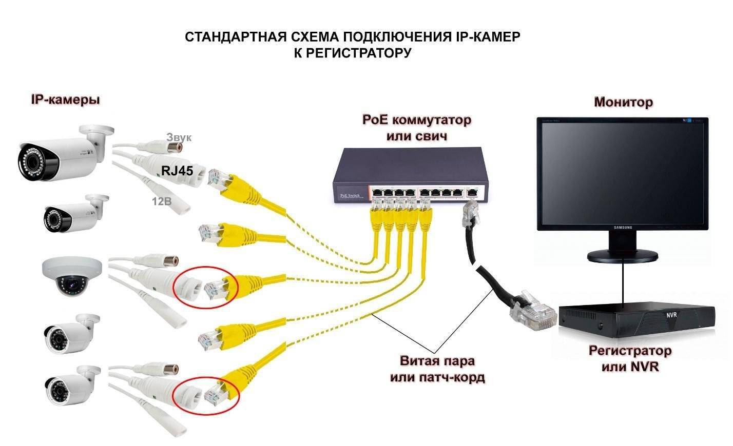
Привычная классификация объектов (крупные, средние и малые) подразумевает деление моделей регистраторов по числу каналов. Так для крупных объектов используются устройства с 16 каналами и выше, нужды средних объектов решаются оборудованием, имеющим 8-10 входных каналов; малые объекты имеют небольшое число камер, поэтому на них устанавливается регистраторы с числом каналов от 4 до 6. Отдельно необходимо выделить сегменты, где применяются одноканальные устройства.
 от MEAN WELL на DIN-рейку")

С другой стороны, существует ряд специфических объектов видеонаблюдения, которые суммарно обладают большим количеством камер, но установлены эти камеры локально небольшими группами.
К числу подобных объектов относятся небольшие магазины, отделения банков, аптеки, автозаправочные станции, банкоматы и т.д.
Как правило, топология системы видеонаблюдения на подобных объектах схожа: установленные камеры для видеонаблюдения за объектом «мониторятся» из единого центра. Сразу оговорюсь, что здесь возможны два подхода построения системы записи видеоинформации. Первый заключается в том, что расположенные в локальных местах камеры передают картинку в единый мониторинговый центр, запись которой производится здесь же на сервер или на специально выделенные сетевые регистраторы. Понятно, что сигнал от аналоговых камер на такие расстояние передать невозможно, поэтому речь идет об IP-камерах и IP- системах. Но при наличии большого количества удаленных объектов (например, у филиала территориального банка Сбербанка России могут быть сотни дополнительных офисов, разбросанных по территории всей области), администрирование такой сети может быть весьма накладным и трудоемким делом. К тому же нельзя не учитывать качество большинства российских каналов связи. Как правило, о передаче «живого» видео речь идти не может. Поэтому в настоящее время большим доверием пользуется второй способ: организация на каждом объекте локального центра записи и хранения информации с использованием цифрового регистратора. DVR также может по имеющимся сетям передавать информацию в центральный офис постоянно, если каналы связи это позволяют, или по запросу, в строго обозначенные промежутки времени, а также в случае возникновения тревожной ситуации. Здесь надо отметить, что для ряда объектов, например таких, как банкомат, наличие «живого» видео не обязательно. Эта функция необходима, так сказать, для визуальной идентификации работоспособности системы.
Еще один плюс подобного подхода в том, что гарантия сохранности архива, да и качество локальной записи будет гораздо выше, а это означает, что запись, сделанная DVR, может в случае противоправных действий помочь в работе правоохранительных органов.
Справедливости ради, стоит заметить, что, называя устройство записи DVR, мы подразумеваем использование как PC-based, так и Stand alone DVR. Решение должен принимать пользователь, исходя из функциональных требований и необходимой степени надежности системы. Stand аlone DVR – это законченное автономное устройство, выполняющее определенный набор функций и ориентированное на запись и визуализацию видеоизображения. В stand аlone DVR используются, и это – одно из главных их отличий от PC-based систем, специализированные операционные системы: Linux или Real Time Operation Systems (RTOS). Встроенные функции контроля состояния регистратора позволяют повысить надежность автономно установленного регистратора. Ведь если на объекте отсутствует оператор (например, в случае установки DVR в банкомате), некому быстро подойти и устранить неисправность, перезагрузить, если нужно, регистратор и т.д. А если нужно ехать на другой конец города или, хуже того, области? Тут надежность – определяющий фактор.
Хочется внести ясность по поводу количества используемых каналов в системе видеонаблюдения небольших распределенных объектов. Общего правила здесь нет, хотя однотипным объектам свойственны единые правила построения системы. В случае магазинов, а точнее сказать сетей магазинов, есть довольно четкая градация, сколько камер должно быть установлено на каждом объекте. Из опыта, 4-канальные регистраторы используются в малых магазинах, где имеется только один кассовый аппарат. Более крупные объекты требуют установки большего числа камер.
При организации видеонаблюдения в банкоматах еще недавно приходилось рассказывать, почему в банкомате необходимо устанавливать минимум 2 камеры: помимо портретной, необходимо иметь камеру установленную в зоне выдачи наличных. Сейчас же некоторые банки готовы инсталлировать до 5 камер для 1 банкомата: портретная, зона выдачи наличных, зона приема денег, камера внутри банкомата для регистрации действий инкассаторов и камера, фиксирующая действия вокруг банкомата.
Кровавая статистика нападений на отделения банков также заставляет пересматривать подходы к организации видеонаблюдения, так как банки приходят к пониманию, что далеко не везде можно обойтись 4 камерами, ведь необходимо фиксировать периметр вокруг отделения, события, происходящие внутри, лица всех входящих и т.д.
Отдельно хочется сказать о сетевых АЗС. Думаю, мои коллеги могут привести примеры инсталляций 4-канальных регистраторов на таких объектах. Но я, например, уверен, что даже для небольшой АЗС четырех камер явно недостаточно, — ведь нужно, чтобы камеры видели все въезжающие на заправку автомобили, обеспечивали контроль за кассой (кассами), магазином (они есть сейчас практически на каждой автозаправочной станции). Все же практика показывает, что для небольших распределенных объектов в большинстве случаев используются 4-канальные регистраторы. С другой стороны, необходимо предусматривать возможность расширения системы регистраторами с большим числом каналов, при этом должна быть полная совместимость оборудования, чтобы мониторинг производился единым программным обеспечением. Попробуем сформулировать основные требования к DVR для распределенных объектов:
- Запись информации с видеокамер для дальнейшей ее обработки.
- Возможность получения и живой картинки, и записанной ранее по сети.
- Передача по сети и сохранение отрезков видеоинформации в мониторинговом центре.
- Удаленная настройка регистратора.
- Адаптация работы регистратора к условиям сетей (регламентирование широты пропускания).
- Получение тревожных уведомлений по сети.
- Специальные возможности.
- Обеспечение надежности работы оборудования, в соответствии с возможными рисками.
Остановимся чуть более подробно на некоторых параметрах. Такие очевидные функции, как запись, передача «живого» видео и просмотр записанного ранее, а также сохранение отрезков (downloading) дополнительных комментариев не требуют.
Удаленная настройка регистраторов существенно сокращает сервисные издержки, поскольку позволяет производить данную операцию, не выезжая к месту установки устройства.
Один из часто задаваемых в России вопросов: какой должна быть минимальная полоса пропускания, чтобы регистраторы работали корректно. Когда наш японский инженер услышал этот вопрос в первый раз, он был очень удивлен. И после того, как осознал, что спрашивающего интересует не максимальная, а минимальная полоса пропускания ответил, что для нашей техники эта величина не имеет значения, главное, чтобы канал был стабильный. В любом случае ограничение полосы пропускания позволяет более точно осуществить настройку сетей, чтобы регистратор не влиял на работу других подразделений.
Получение тревожных уведомлений – это правильный путь работы с большим числом установленных регистраторов. Например, оператор не может отследить в режиме реального времени, действительно ли с карточки снимает деньги ее владелец. Но среагировать на тревожную ситуацию (потеря видеоинформации, остановка записи, выход из строя регистратора) он должен мгновенно.
Специальные возможности не являются необходимыми, но предоставляют пользователю дополнительные удобства при работе с регистраторами. К примеру, автоматическая синхронизация времени необходима для «привязки» времени DVR ко времени компьютера центрального мониторинга. Запись информации о транзакции позволяет сопоставить номер карточки с фотографией лица, осуществляющего операции с ней. При видеонаблюдении за кассовыми операциями наличие титров позволяет расследовать случаи мошенничества операторов.
Наличие зеркалирования – создания резервной копии информации – позволяет повысить степень надежности используемого оборудования. Возможны различные варианты копирования, например архивирование заданного интервала, — для этого необходимо задать начальную и конечную точки, и видеорегистратор определит размер файла и, соответственно, необходимый объем носителя информации, куда будет производиться копирование. Копирование также может производиться с начальной точки и до того момента, пока не закончится место на внешнем носителе. Такое копирование является, по сути, активным зеркалированием, поскольку объем архива может быть в много раз больше, чем объем информации, хранящийся на внутренних жестких дисках.
В подобных моделях в качестве накопителей архивной информации могут использоваться любые USB-устройства, но чаще всего применяются штатные блоки расширения от компании-производителя или устройства сетевого хранения данных.
Теперь о последнем по списку (но не по значению) параметре надежности оборудования, степень которого должна соответствовать рискам потерь на данном объекте. Согласитесь, небольшой продуктовый магазин по стоимости возможных потерь сильно отличается от ювелирного магазина или отделения банка. Инсталлятору, а тем более, заказчику иногда бывает очень трудно решить, какое оборудование выбрать для своей задачи, так как все необходимые для DVR функции присутствуют в технических характеристиках всех производителей.
Поэтому часто основным критерием при выборе является цена оборудования, по принципу «не самое дорогое и не самое дешевое». Еще раз отмечу, что важно исходить из характеристики объекта и конкретных задач, которые ставит заказчик. Например, по теории надежности/отказов можно выделить следующие периоды работы любого устройства, выполненного на основе электронных компонентов:
- период «детских болезней»;
- период устойчивой работы;
- период старения.
Первый период характеризуется достаточно высоким показателем вероятности отказа.
Важное отличие оборудования, произведенного ведущими компаниями, – в обиходе его иногда называют «брендовое», – в том, что «детские болезни» они «лечат» сами. Проводится очень жесткое дополнительное тестирование, и потребитель получает оборудование уже на этапе «устойчивой» работы.
Второй важный параметр – вероятность отказа оборудования в период «устойчивой» работы. Брендовое оборудование имеет, как правило, очень маленький показатель: в пределах 1%. И, как правило, отличается достаточной протяженностью периода безотказной работы. Между тем, длительность этого период является весьма существенным критерием для многих объектов. Такого показателя нет в характеристиках, заявленных производителем, но практическими наработками формируется список марок, у которых этот показатель достаточно высок. И в дальнейшем выбор ведется уже из этого перечня.
В заключение хотел бы отметить, что при выборе оборудования необходимо уточнять у производителя наличие поддержки линейки оборудования и совместимости новых моделей с предыдущими. Выстраивая отношения в долгосрочной перспективе надо более тщательно подходить к оценке поставщика и используемого оборудования, чтобы не остаться через несколько лет у «разбитого корыта».
Цифровой видеорегистратор SHR-5040P, SHR-5042P (Samsung)
Имеет 4 канала для записи видеосигнала с видеокамер в формате CIF со скоростью 100 изображений в секунду и 4 канала для записи звука. В видеорегистраторе для выполнения записи данных на жесткий диск или одновременного считывания их с жесткого диска применяется метод сжатия изображения MPEG-4 и метод звука ADPCM(адаптивная дифференциальная импулсьно-кодовая модуляция).
Кроме этого, видеорегистратор использует сдвоенный кодек, что обеспечивает одновременную запись и передачу видео/аудио сигнала через сеть в реальном времени и позволяет контролировать изображение и звук дистанционно с помощью персонального компьютера. Наличие порта USB 2.0 позволяет сохранять данные на внешний жесткий диск или USB флэш-память. Модель SHR-5042P имеет встроенный CD-RW привод.
Сетевой 4-канальный видеорегистратор STR-0484/MPEG-4 (Smartec)
Этот видеорегистратор использует формат сжатия MPEG-4 и позволяет записывать видео по каждому каналу с выбранным разрешением и частотой кадров, а также передавать его по IP-сети. Оператор может назначить разрешение 2CIF (720 × 288 пикс.) или CIF (352 × 288 пикс.) и записывать/воспроизводить видео со скоростью 100 к/с или разрешение Full D1 (720 × 576 пикс) с частотой 50 к/с.
Запись видеопотоков осуществляется на встроенный диск SATA емкостью 250 Гб, который можно заменить на более емкий или установить в свободный слот второй диск SATA, доведя общий объем дискового пространства до 2 Тб. При этом видеорегистратор поддерживает весь необходимый функционал для управления записью, поиском и воспроизведением видео. Для локального просмотра к STR-0484 можно подключить CRT-, LCD- или компьютерный монитор, а также Spot-монитор.
STR-0484 оснащен 4 аудиовходами и аудиовыходом, DVD/RW, RJ-45 и 3 USB-портами, детектором движения, 4 тревожными входами/выходами и интерфейсом RS-485 для управления поворотными камерами, использующими 9 различных протоколов телеметрии, включая наиболее распространенные Pelco P/D. Управление STR-0484 и камерами может осуществляться с передней панели, с ИК-пульта (в комплекте), с клавиатуры Smartec STT-CN3R1 или по сети через интерфейсы программного обеспечения RMS, которое поставляется вместе с устройством.
Видеорегистратор NDR-C400EZ (Infinity)
MPEG-4 видеорегистратор Infinity NDR-C400EZ представляет собой профессиональную систему начального уровня для ведения записи четырех каналов видео с максимальной скоростью до 100 кадров в секунду. Информация записывается на жесткий диск с возможностью последующей архивации на внешние устройства (порт USB 2.0). Удобное русифицированное меню дает возможность легко и быстро управлять регистратором непосредственно на месте установки или по сети (Ethernet 10/100 Mbit, ПО в комплекте).
Для удаленного управления через сеть используется программное обеспечение Infinity RAS plus, которое работает также и с регистраторами старших серий NDR-S, NDR-X и NDR-DLX, поэтому NDR-C400EZ может использоваться не только как автономное устройство записи, но и в качестве элемента крупной распределенной системы видеонаблюдения.
К преимуществам этой системы можно также отнести и его сравнительно невысокую стоимость, что в сочетании с богатыми функциональными возможностями делает NDR-C400EZ прекрасным решением при выборе оборудования для системы наблюдения.
Видеорегистратор BestDVR-402A-S (BestDVR)
Основное преимущество, которое делает BestDVR-402A-S отличным выбором для работы по сети и Internet, – самый эффективный на сегодняшний день алгоритм сжатия H.264., который позволяет осуществить доступ к живому видео, архиву и настройкам даже через «тонкий» (от 32 кб) канал связи.
Кстати, к регистратору можно обращаться как через клиентское ПО, так и через Internet Explorer. В регистраторе воплощен весь необходимый функционал: 4 видео, 4 синхронных аудио, индивидуальный выбор разрешения и скорости записи, детектор движения и детектор оставленных предметов, расписание, паролирование доступа, BNC и VGA видеовыходы, возможность почитать на ПК съемный диск, порт USB для архивации. Максимальное дисковое пространство в 4 Тб (4 SATA диска по 1 Тб) позволит вести многомесячную видеозапись.
Видеорегистратор V1netServer540R (V1net)
4-канальный сетевой видеосервер предназначен для организации систем видеонаблюдения на небольших объектах. С помощью бесплатного ПО (NVR-PRO) и существующей локальной или глобальной сети данные регистраторы объединяются в единую распределенную систему, включающую в себя до 64 каналов видеонаблюдения. Три независимые зоны позволяют точно настроить детектор движения по каждому каналу отдельно.
К каждому видеосерверу можно подключить до 4 тревожных датчиков и до 2 устройств сигнализации. V1netServer540R оснащен портом RS-485 для подключения поворотных камер, которые управляются по протоколам Pelco и др.
Четыре аудиовхода и один аудиовыход позволяют организовать конференц-связь в режиме реального времени. V1netServer540R записывает информацию на встроенный жесткий диск (емкостью до 750 Гб) в формате MPEG-4 с максимальным разрешением 720 × 576 и скоростью записи 25 к/с на каждый канал.
Данный видеосервер имеет компактные размеры, что упрощает скрытую установку.
Цифровой дуплексный видеорегистратор EDR-410H/M (EverFocus Electronics Corp)
Применяется в стационарных (модификация H) и нестационарных (модификация М) условиях. Стандарт видео – NTSC/PAL. Имеет дуплексный режим работы. Общая скорость записи: 25 IPS при 720 × 576; 50 IPS при 720 × 288; 100 IPS при 360 × 288.
Запись может производиться в трех режимах: непрерывном, по таймеру, по тревоге.
EDR-410H/M обеспечивает мониторинг в реальном времени, работу с 4 цветными и ч/б камерами.
Компрессия MPEG-4. В комплекте имеется HDD (500 Гб) — с «горячей заменой». USB 2.0 и слот Compact Flash для резервного копирования. Обеспечивается ведение протокола событий. Имеется детектор движения с гибкой настройкой и изменением чувствительности для каждой камеры, два аудиоканала. Вход в систему защищен многоуровневым паролем. Поддержка протоколов HTTP, TCP/IP, SMPT. Имеются программируемые тревожные входы и выходы, интерфейс пользователя на русском языке.
Видеорегистратор автоматически восстанавливает работоспособность после аварии питания.
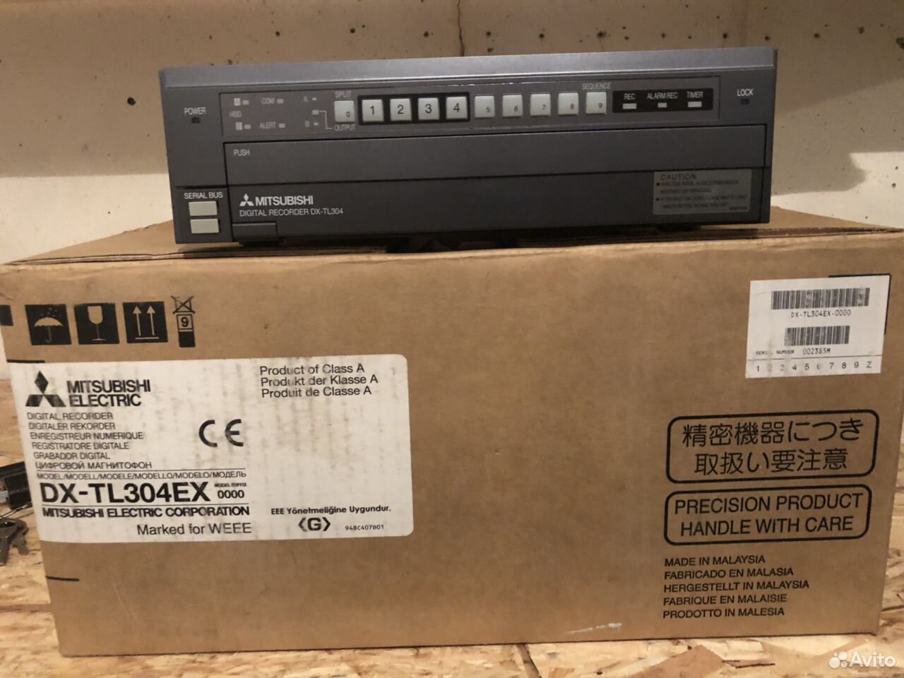
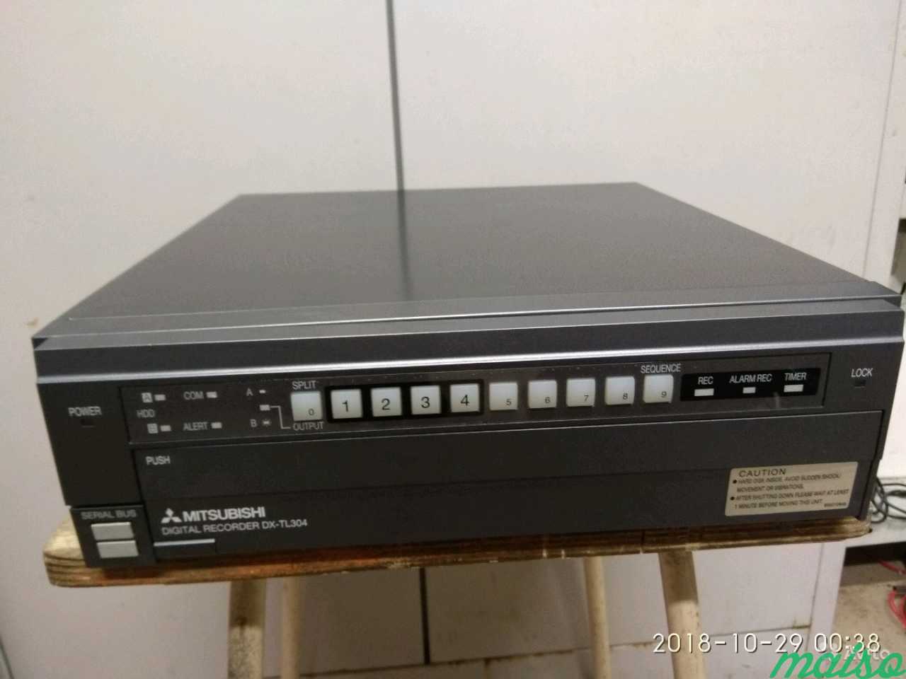
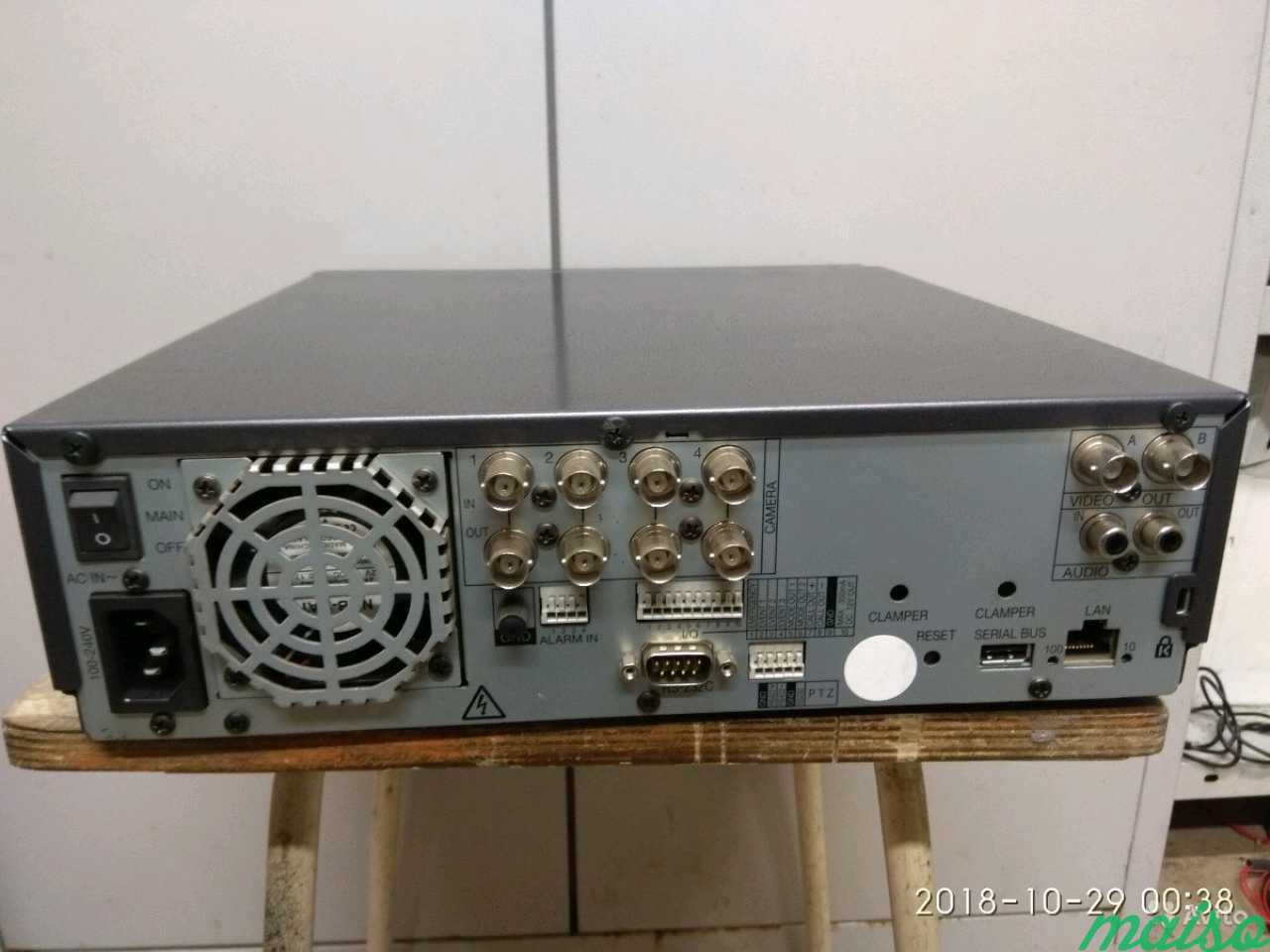
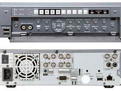
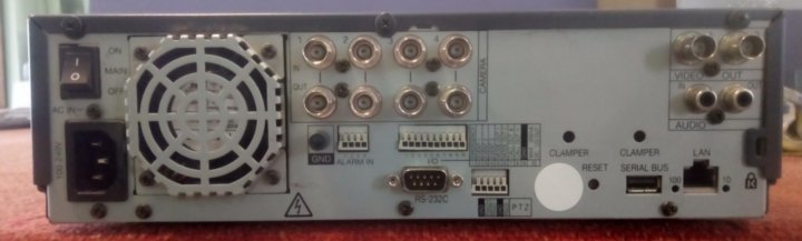
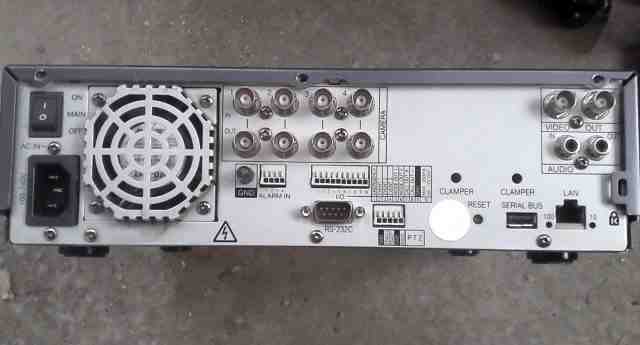
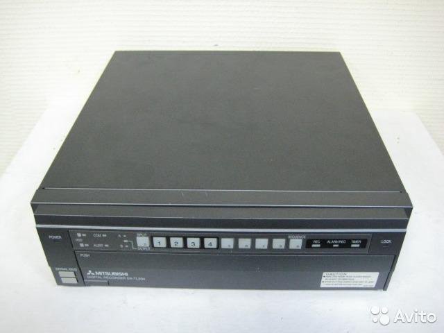
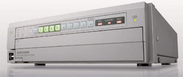
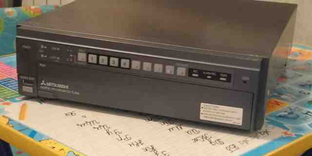
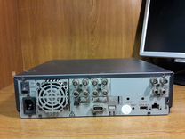
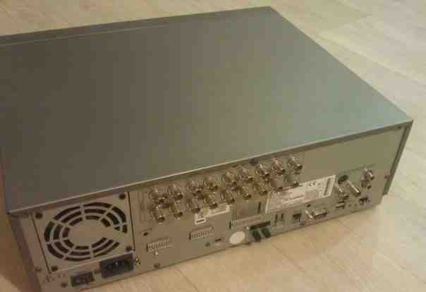
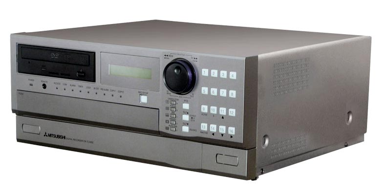
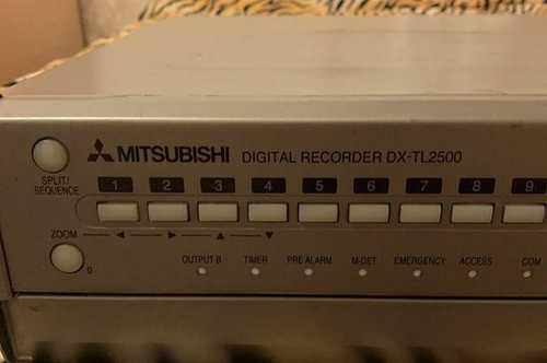
Цифровой регистратор DX-TL304E (Mitsubishi Electric)
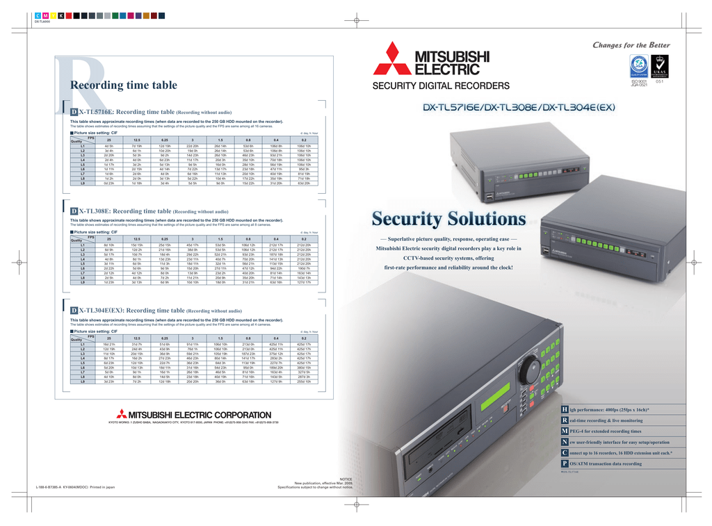
Регистратор позволяет вести запись с подключенных к нему 4 камер со скоростью до 100 полей в секунду, используя при этом формат сжатия MPEG4.
Попадающее в объектив камер изображение выводится на экране оператора системы видеонаблюдения со скоростью 200 полей в секунду при отображении на мониторе 4 камер, а благодаря функциям триплексного мультиплексора можно одновременно осуществлять просмотр на экране монитора ранее записанного изображения без остановки текущей видеозаписи.
Общий объем архива может быть легко увеличен за счет внешних блоков расширения DX-ZD6, подключаемых через последовательный порт. Таким образом, суммарный объем дискового пространства может составлять 9 Тб.
Информация с жестких дисков, установленных в блоке расширения DX-ZD6, может быть просмотрена на обычном компьютере после их соединения через USB.
DX-TL304 поддерживает запись титров, что позволяет использовать регистратор в системах видеонаблюдения банкоматов и кассовых операций.
С помощью программного обеспечения DX-PC200 видеорегистратор подключается в единую мониторинговую сеть, состоящую из любых DVR, выпускаемых Mitsubishi Electric.
tzmagazine.ru
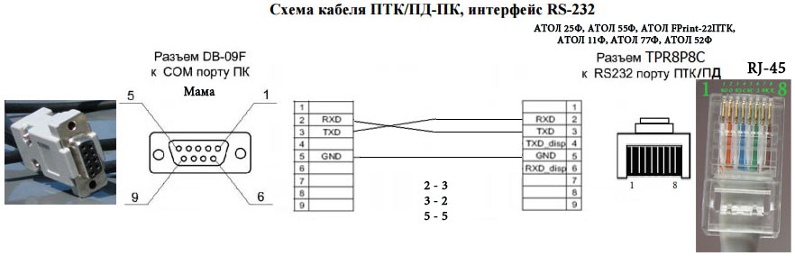
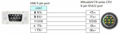
Компания Mitsubishi Electric анонсировала 4-канальный цифровой видео регистратор DX-TL304E, предназначенный для записи видео с 4 аналоговых камер в формате MPEG-4 с разрешением от CIF до 4 CIF и скоростью до 100 к/с. В корпус новинки можно установить один или два HDD, а при необходимости объем дискового пространства можно довести до 9 Тб путем подключения внешних дисков. Этот видео регистратор оснащен веб-сервером для его настройки и управления через Ethernet и детектором движения с возможностью регулировки чувствительности для каждого канала. Кроме того, регистратор имеет удобное русифицированное GUI меню, 3 входа для подключения охранных датчиков, интерфейсы RS-422 для управления поворотными камерами и RS-232C для настройки DX-TL304E с помощью клавиатуры.
Для наиболее эффективного использования дискового пространства видео регистратор позволяет записывать сжатое в формате MPEG-4 цифровое видео с одним из выбранных через меню разрешений — CIF, 2CIF или 4CIF. Воспроизведение видео производится со скоростью 200 полей в секунду. Благодаря дуплексному режиму работы видео регистратор может одновременно осуществлять воспроизведение и запись видеоизображения. Причем выводить текущее и архивное видео можно сразу на два монитора.
Для записи и хранения информации больших объемов в видео регистратор устанавливается один или два жестких диска. Максимальный объем дискового пространства DX-TL304E, включая внутренние и внешние HDD, может достигать 9 Тб. Для подключения внутренних Serial ATA дисков регистратор оснащен стандартными портами, а блоки расширения DX-ZD5UE/DX-ZD6UE со встроенными HDD соединяются с DX-TL304E через USB. При этом всю видео информацию с внешних блоков расширения DX-ZD можно посмотреть на обычном компьютере после их соединения с ПК через USB.
DX-TL304E позволяет осуществлять удаленное управление по сети через веб-браузер, поскольку видео регистратор оснащен веб-сервером, или с помощью специального программного обеспечения DX-PC200, устанавливаемого на сетевой ПК. Это ПО позволяет просматривать «живое» видео со звуком, производить копирование данных по сети и др. Для синхронизации времени с сервером видео регистратор поддерживает сетевой протокол SNTP.
DX-TL304E отличается небольшими габаритами (300х91х340) и предусматривает различные варианты его монтажа, включая установку в банкоматы и стойки. Оригинальное конструктивное решение позволяет быстро устанавливать в видео регистратор внутренние диски и осуществлять их техническое обслуживание. Жесткие диски поставляются отдельно от DX-TL304E, что позволяет подобрать регистратор, максимально отвечающий требованиям конкретной системы видео наблюдения.
В зависимости от задач системы видео наблюдения на конкретном объекте видео регистратор позволяет выбрать режим записи: ручной, по расписанию, по детектору движения или по сигналу тревоги с охранного датчика. Через аудиовход к DX-TL304E можно подключить микрофон, благодаря чему можно организовать запись и передачу по сети звука, синхронизованного с видео. С целью повышения сохранности данных можно использовать функцию «зеркальной» записи на второй жесткий диск, а при отключении электропитания регистратор активирует функцию автозапуска.
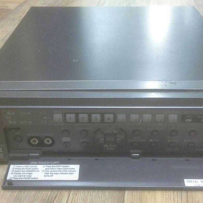
При получении сигнала тревоги с охранного датчика или встроенного детектора движения видео регистратор переходит в режим тревожной записи. Причем чувствительность видео детектора настраивается индивидуально для каждого канала. Продолжительность тревожной записи регистратор предлагает выбрать в пределах от 2 сек. до 60 мин. с одним из 3 уровней качества изображения. Функция Pre-Alarm позволяет сохранять на жесткий диск DX-TL304E кадры, предшествующие моменту тревоги, а их длительность может настраиваться от 1 секунды до 30 минут.
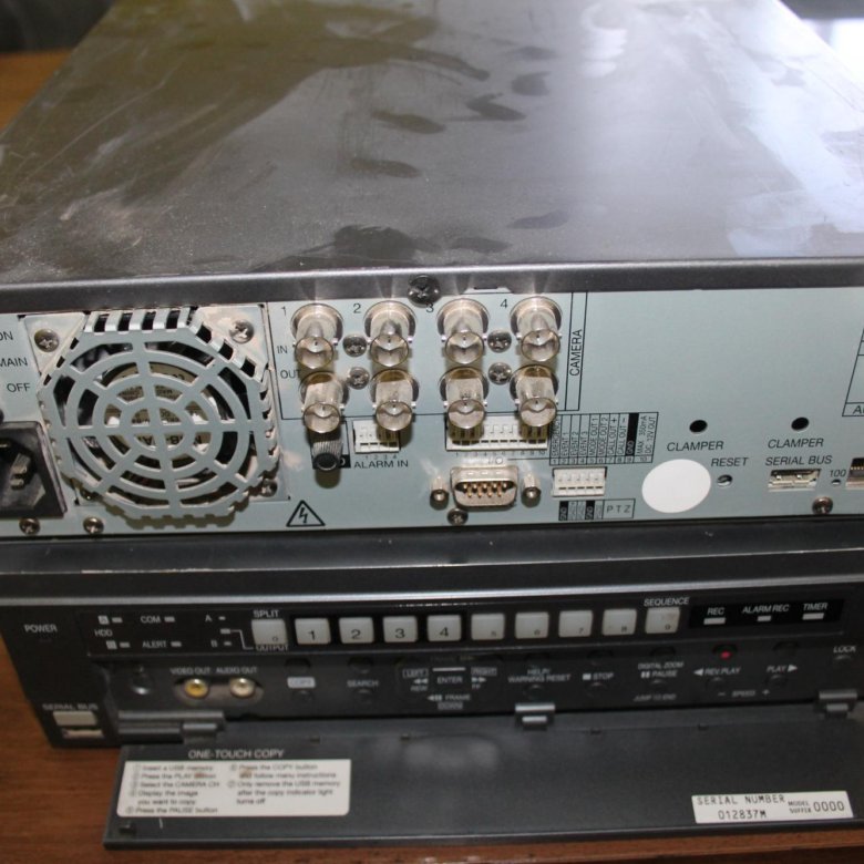
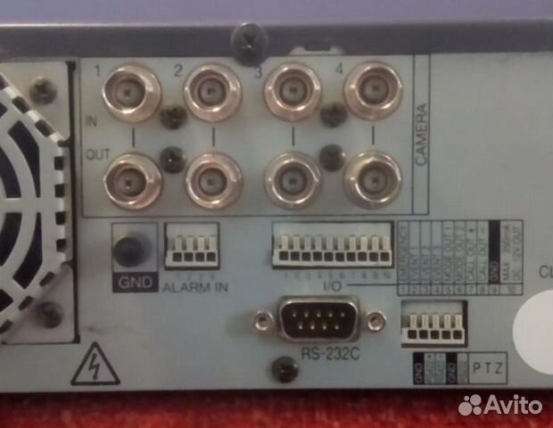
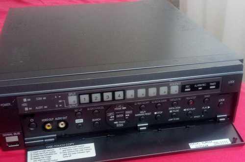
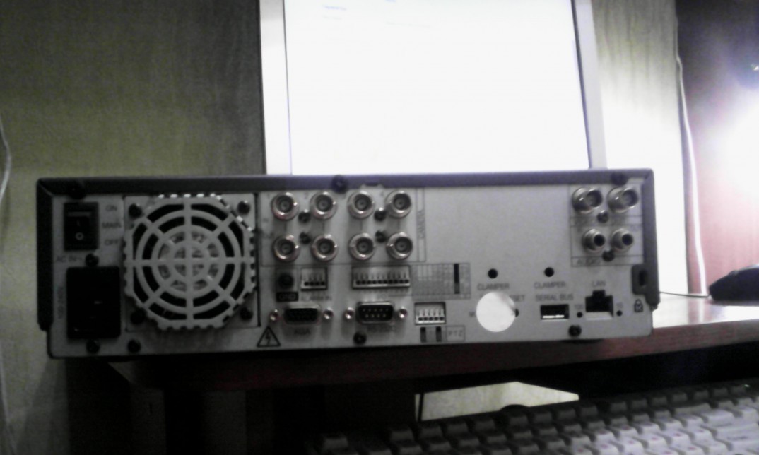
Для управления поворотными или скоростными купольными камерами видео наблюдения видео регистратор оснащен RS-232 и RS-422. Мониторы подсоединяются к DX-TL304E через два BNC разъема, а «мышь» и внешние накопители через два USB-порта на передней панели и один — на задней. Помимо этого регистратор имеет 3 тревожных входа, к которым могут быть подключены оконные или дверные магнитные или ИК-датчики, и 2 сигнальных выхода.
Компания Mitsubishi Electric является одним из крупнейших мировых производителей устройств и оборудования для систем охранного видеонаблюдения. Mitsubishi разрабатывает и производит 4-, 9- и 16-канальные цифровые видео регистраторы (DVR), сетевые видеосерверы, термосублимационные видеопринтеры и другое оборудование для работы в составе системы видео наблюдения. В компании работает более 116 тысяч человек, а ее офисы расположены в 34 странах мира. Все охранное оборудование Mitsubishi имеет российские сертификаты соответствия, а документация и интерфейсы управления русифицированы.
http://www.mitsubishi-evs.ru/news/video-recorder.ahtm
Релиз опубликован: 2008-05-15
Данный материал является частной записью члена сообщества Club.CNews.
Редакция CNews не несет ответственности за его содержание.

Автосервис «Ралли»
МЕНЮ
Обновлено: 27.11.2023


![]()


![]()


Читайте также:
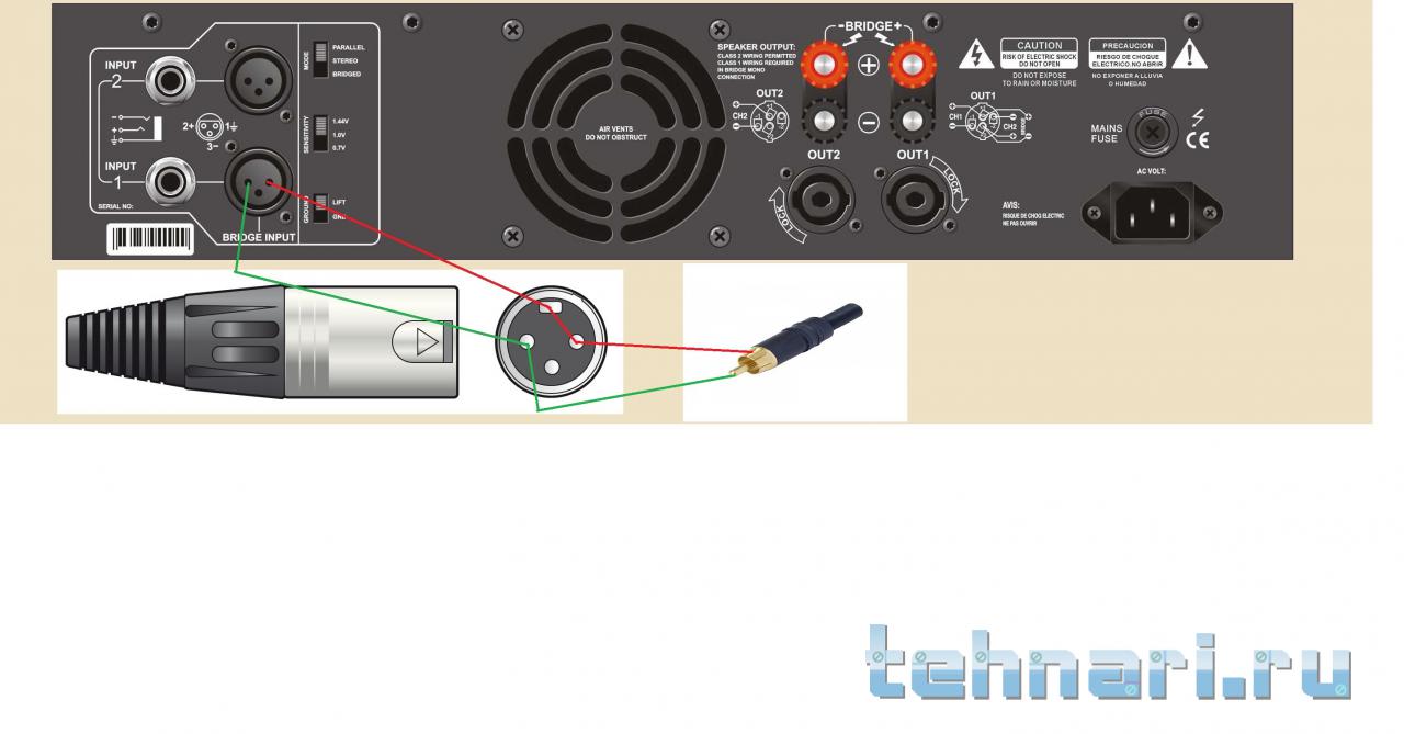
- Как подключить remote к магнитоле
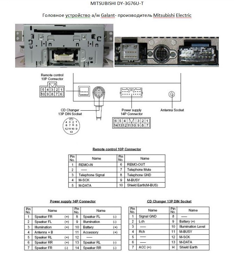
- Автосигнализация аллигатор как определить модель по брелку
- Какое масло заливать в лебедку камаз
Lastmanuals offers a socially driven service of sharing, storing and searching manuals related to use of hardware and software : user guide, owner’s manual, quick start guide, technical datasheets… DON’T FORGET : ALWAYS READ THE USER GUIDE BEFORE BUYING !!!
If this document matches the user guide, instructions manual or user manual, feature sets, schematics you are looking for, download it now. Lastmanuals provides you a fast and easy access to the user manual MITSUBISHI DX-TL304. We hope that this MITSUBISHI DX-TL304 user guide will be useful to you.
Lastmanuals help download the user guide MITSUBISHI DX-TL304.
 |
MITSUBISHI DX-TL304 INSTALLATION MANUAL: Download the complete user guide (3753 Ko) |
Manual abstract: user guide MITSUBISHI DX-TL304INSTALLATION MANUAL
Detailed instructions for use are in the User’s Guide.
[. . . ] DIGITAL RECORDER
INSTALLATION MANUAL
OTHERS
MODEL
DX-TL308E DX-TL304E
THIS INSTRUCTION MANUAL IS IMPORTANT TO YOU. PLEASE READ IT BEFORE USING YOUR DIGITAL RECORDER.
1
ENGLISH
Before use
How to use this manual
About this manual
The manual of this recorder consists of the following two manuals. Installation Manual (this manual) This manual describes connections of devices as well as functional settings and operations to use this recorder. This manual mainly describes operating procedures carried out by the mouse. [. . . ] steps 1 to 3 of «Login» on 2 Select [Configuration Menu].
Step
To determine the settings shown in a row, select [set] of that row. When you select [Batch Registration], all the settings shown under [Transmitted Image CH Settings] are determined. [Trigger]: <DX-TL308E> You can select the trigger for FTP notification from among Sensors 1 to 8 and Emergency. <DX-TL304E> You can select the trigger for FTP notification from among Sensors 1 to 4 and Emergency. [Image CH]: <DX-TL308E> You can select the camera for FTP notification from among Cameras 1 to 8. <DX-TL304E> You can select the camera for FTP notification from among Cameras 1 to 4.
The [Configuration Menu] screen appears.
Step
3 Select [FTP Settings].
The [FTP Settings] screen appears.
Notice
Step
4 Make settings of the server for FTP notification.
The current settings are shown in the [Current Settings] area. To determine the settings shown in a row, select [set] of that row. When you select [Batch Registration], all the settings shown under [FTP Settings] are determined. [FTP Transmission]: You can select whether or not to issue FTP notification. [Passive Mode]: You can send data in the passive mode. [FTP Server Address]: You can set the FTP server address. [User ID]: You can set the user name of the FTP server. [User Password]: You can set the password of the FTP server. [Remote Path]: You can set the remote path of the FTP server. [DNS Server Address 1]: You can set the primary DNS server address. [DNS Server Address 2]: You can set the secondary DNS server address. [Retry Interval]: You can set the interval of retries performed when transmission is failed. [FTP Connection Trial]: You can test the connection to the FTP server.
Due to a server connection failure or other problem, events to be notified may be accumulated in the recorder. In such a case, you cannot test the FTP connection until the accumulated events are notified. When the settings related to the notification are changed during the period between the occurrence of an event and the completion of notification, the accumulated events in the recorder may be deleted without being notified.
88
You can change the SSL settings.
Step
1 Display the [Main Menu] screen according to page 81. steps 1 to 3 of «Login» on 2 Select [Configuration Menu].
When the communication fails, set the recorder’s communication band according to the communication band used. [Image Service Policy] becomes enable only when the operation load caused by recording is light. [. . . ] Ponadto haslo naley regularnie zmienia.
Others
27
OTHERS
Others (continued)
Zrzeczenie si odpowiedzialnoci
Firma Mitsubishi nie ponosi odpowiedzialnoci ani nie gwarantuje adnych odszkodowa za bldy w dzialaniu systemu nadzoru, utrat nagranych danych lub inne szkody lub straty powstale w wyniku bldnego dzialania urzdzenia. W adnym razie Mitsubishi nie podejmuje si naprawy, przywracania lub reprodukcji nagranych danych. Firma Mitsubishi zrzeka si wszelkiej odpowiedzialnoci w nastpujcych przypadkach: (1) Demonta, naprawa lub modyfikacja urzdzenia przez uytkownika lub instalatora. (2) Bld, awaria lub uszkodzenie urzdzenia w wyniku nieprawidlowego uycia lub nieostronej obslugi przez uytkownika lub instalatora. [. . . ]
DISCLAIMER TO DOWNLOAD THE USER GUIDE MITSUBISHI DX-TL304
Lastmanuals offers a socially driven service of sharing, storing and searching manuals related to use of hardware and software : user guide, owner’s manual, quick start guide, technical datasheets…
In any way can’t Lastmanuals be held responsible if the document you are looking for is not available, incomplete, in a different language than yours, or if the model or language do not match the description. Lastmanuals, for instance, does not offer a translation service.
Click on «Download the user manual» at the end of this Contract if you accept its terms, the downloading of the manual MITSUBISHI DX-TL304 will begin.
![]()
DIGITAL RECORDER
INSTALLATION MANUAL
MODEL
DX-TL308E DX-TL304E
THIS INSTRUCTION MANUAL IS IMPORTANT TO YOU. PLEASE READ IT BEFORE USING YOUR DIGITAL RECORDER.
1

Before use
How to use this manual
 About this manual
The manual of this recorder consists of the following two manuals.
 Installation Manual (this manual)
This manual describes connections of devices as well as functional settings and operations to use this recorder.
This manual mainly describes operating procedures carried out by the mouse.
 User’s Manual
This manual is for operators of this recorder and describes the operating procedures for the basic functions only.
 Symbols
Tips 
 (Reference for operation)
Shows information to be referred to when you operate this recorder.
Notice (Point to be noted)
Shows information to be noted when you operate this recorder.
 (Reference page)
Shows the sections and pages to be referred to.
 Troubleshooting
See «Troubleshooting» ( pages 125 to 127) and take appropriate measures.
 Note
Note
The illustration in this manual shows an example of DXTL308E.
 How to locate information in this manual
You can find desired information in this manual using the following methods.
 Table of contents
 Pages 5 to 7
Reference page  Shown in the texts.
How to locate setting items
When you first set up the recorder, you can configure the minimum required settings using the Setup Wizard.
•Language setting
•Clock setting
•HDD operation setting
•Recording setting
When you configure these settings manually or configure other settings, find desired functions and pages describing those functions using the following methods.
Search based on the function you want to use
See the table of contents ( pages 5 to 7).
Search for the setting method for the connected device
See the reference pages shown by the descriptions of the devices in «Connections» ( page 24).
Search based on the items displayed on the screen
See the reference pages shown by the descriptions of the displayed items in «Screen display» ( page 22).
Search from the quick menu list
You can find the setup menus and recording setting menus as well as their setting items in the quick menu lists on  pages 46 to 49 and pages 92 to 98.
In addition, you can find the factory default setting of each setting item, too.
Using these lists, you can keep records of your settings and review them later.
2
Setup procedure
Start here when you first set up the recorder.
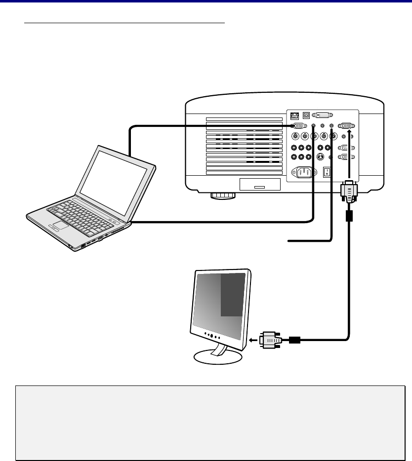
1 Connect the recorder.
Connect the cameras, monitors, and sensors to the recorder. Configure the settings of the connected devices referring to the reference pages shown in the descriptions of the devices in «Connections» on  page 24.
2 Turn on the recorder.
Turn on the main switch on the rear of the recorder. After checking the POWER indicator goes out, press the POWER button on the front panel of the recorder.
|
3 |
Select whether or not to use the Setup Wizard. |
|||
|
When you turn on the recorder first time, the Setup Wizard is activated. |
«Setup Wizard» on pages 32 and 33. |
|||
|
Using the Setup Wizard, you can set the following items automatically according to the displayed menus. |
||||
|
Language setting |
||||
|
The language used for the menu screen is selected. |
||||
|
Clock setting |
||||
|
HDD configuration |
||||
|
All the connected HDDs are registered as Main device. For details of the HDD configuration, see |
pages 34 to 37. |
|||
|
Recording setting |
||||
|
The settings for normal recording are configured. For details of the recording, see |
pages 44 to 55. |
|||
|
When using the |
||||
|
Setup Wizard |
||||
|
When not using the |
||||
|
4-1 |
Run the Setup Wizard. |
|||
|
Setup Wizard |
||||
Set the items shown above according to the displayed menus.
(To change the settings made by the Setup Wizard)
4-2 Change the settings made by the Setup Wizard.
|
As |
To manually change the settings made by the Setup Wizard: |
|||
|
Language setting |
Page 99 |
|||
|
needed |
||||
|
Clock setting |
Page 99 |
|||
|
HDD configuration |
Pages 34 to 37 |
|||
|
Recording setup |
Pages 44 to 55 |
4Make the minimum required settings manually.
 Language setting
  Page 99
Clock setting Page 99
 HDD configuration
 Pages 34 to 37 Recording setup Pages 44 to 55
Start here when you change the settings of the recorder already set up.
|
5 |
Make other settings. |
How to search for necessary settings |
||||
|
Make the necessary settings according to your desired recording operation. |
Refer to «How to locate setting items» on the left |
|||||
|
page, and find the pages describing the |
||||||
|
For example, |
functions and settings you want to use and |
|||||
|
As |
To carry out timer recording. |
Timer program setting |
pages 62 to 65 |
configure the necessary settings. |
||
|
To use the mirroring mode. |
Mirroring setting |
page 35 |
||||
|
needed |
||||||
|
To control the recorder from the personal computer. Communication setting |
pages 108 and 109 |
|||||
|
To control the camera. PTZ camera setting |
page 110 |
|||||
|
To restrict the recorder’s functions by the password lock. |
Password setting |
pages 111 to 114 |
||||
|
To make settings of screen display and rear terminals. |
Setup menu |
pages 92 to 110. |
6 Check the setup condition.
By executing recording, playback, search, and copy, check that the recorder has been set up correctly.
Beginning
ENGLISH
3

Major features
This digital recorder is able to record images captured by up to 8 (DX-TL308E)/4 (DX-TL304E) surveillance cameras and audio received by microphone to its hard disk. The recorder is equipped with the function to search for desired scenes by specifying the recording dates as well as the simultaneous recording/playback function that allows playback even during recording. In addition, using the split display function to display up to 8 (DX-TL308E)/4 (DX-TL304E) camera images on one screen, you can view more than one monitored area at the same time. This recorder facilitates to configure a monitoring system for constant surveillance.
Realizing long-term recording
By reducing the size of recorded video data using the newly developed video compression engine (MEPG 4 system), the writing capacity of HDD can be saved about 50% (compared with our conventional models). In addition, this recorder is designed to connect external HDD to expand its HDD capacity up to 8 TB (when using optionally available DX-ZD6UE). Due to this, you can construct a long-term recording system to store data for 2 years, for example.
Simple operation and USB mouse connectable
By connecting a separately available USB mouse to the serial bus terminal on the recorder, you can easily control the recorder and setting menus. For frequently used functions such as search and copy, the simple operation menu allows you to operate them by simple procedure. This recorder is equipped with the on-screen help function. By clicking the help icon or pressing the HELP button, you can view various information such as operation procedures on the screen.
«One touch copy» for easy copying with one button press
The recorder is equipped with the function to copy still playback images to a USB memory device set in the recorder or a disc in an external drive with one button press. You can select still images or moving images to copy. When selecting moving images, you can specify the recording duration.
XGA output terminal integrated (DX-TL308E only)
You can connect a general PC display monitor to this terminal to use it as a surveillance monitor.
Motion detection search function
By designating certain areas such as doors and windows shown in recorded images as detection target areas, you can search for recorded data containing scenes having variation (or motion) in those areas and display the beginning of such data. This function is useful, for example, in searching for intruders into deserted places or scenes where someone painted graffiti on the wall.
Personal information protection function
By setting passwords, you can classify the recorder operations into 3 levels. You can set a password for deleting data from HDD to protect them from unauthorized access or to use this function as misuse prevention. The recorder is equipped with the function to prohibit playback of data recorded before the number of days you specify (auto expiration setting), which facilitates data management according to your operation standard regarding the data storage period.
Alarm notification of intrusion and system errors
When an alarm signal is input to the recorder from external body sensors or when an error is detected in the system, the recorder notifies the designated personal computer via TCP/IP command or e-mail. The recorder is also capable of transferring the alarm-recorded images that is triggered by an external alarm signal to the designated FTP server.
Microsoft is either registered trademarks or trademarks of Microsoft Corporation in the United States and/or other countries.
All other company and product names appearing herein are the property of their respective owners.
4

Contents
|
Beginning |
|
|
Before use……………………………………………………………. |
2 |
|
How to use this manual ………………………………………. |
2 |
|
About this manual ……………………………………………. |
2 |
|
Symbols …………………………………………………………. |
2 |
|
Troubleshooting ………………………………………………. |
2 |
|
Note ……………………………………………………………… |
2 |
|
How to locate information in this manual …………….. |
2 |
|
How to locate setting items ………………………….. |
2 |
|
Setup procedure…………………………………………………… |
3 |
|
Major features………………………………………………………. |
4 |
|
Contents………………………………………………………………. |
5 |
|
Caution and care ………………………………………………….. |
8 |
|
Note …………………………………………………………………… |
15 |
|
Open source software……………………………………….. |
15 |
|
MPEG-4 patent ………………………………………………….. |
15 |
|
Major operations and their functions …………………… |
16 |
|
Front view…………………………………………………………. |
16 |
|
Front view (inside of door) ………………………………… |
18 |
|
Rear view………………………………………………………….. |
20 |
|
Screen display ………………………………………………….. |
22 |
|
Connections |
|
|
Connections……………………………………………………….. |
24 |
|
Connecting CCTV cameras, monitors, and sensors |
|
|
………………………………………………………………. |
24 |
|
Connection for alarm recording…………………………. |
25 |
|
Cable clamping …………………………………………………. |
26 |
|
Connecting an analog VCR ……………………………….. |
26 |
|
Optional products……………………………………………… |
26 |
|
Recommended products …………………………………… |
26 |
|
Caution for connecting additional hard disk units |
|
|
………………………………………………………………. |
27 |
|
Caution in installing multiple recorders in an EIA |
|
|
rack………………………………………………………… |
27 |
|
Menu settings/Device registration |
|
|
How to set the menus …………………………………………. |
28 |
|
Displaying the menus ……………………………………….. |
28 |
|
Operating the menus…………………………………………. |
29 |
|
Closing the menus ……………………………………………. |
29 |
|
Using the mouse operation screen…………………….. |
30 |
|
Using the Setup Wizard ………………………………………. |
32 |
|
Making the minimum required settings automatically |
|
|
<Setup Wizard>………………………………………………. |
32 |
|
Registering the devices ………………………………………. |
34 |
|
Setting Main, Copy, and Archive devices |
|
|
<HDD registration> ………………………………………… |
34 |
|
Cautions for using external devices …………….. |
34 |
|
Hookup and operation setting of HDDs………… |
34 |
|
Order of recording and playback of the internal |
|
|
and external HDDs registered as Main device |
|
|
………………………………………………………….. |
34 |
|
Registering the internal HDDs …………………………. |
35 |
|
Mirroring ………………………………………………….. |
35 |
|
Registering external HDDs ……………………………… |
36 |
|
Checking the registered devices………………………. |
37 |
|
Setting the repeat recording and partition of Main |
|
|
device <Main HDD setting>……………………………….. |
38 |
|
Setting the repeat recording…………………………….. |
38 |
|
Setting the partition ………………………………………… |
39 |
|
Viewing images |
|
|
Viewing images captured by the cameras……………… |
40 |
|
Multiplexer function…………………………………………… |
40 |
|
Single screen display ……………………………………… |
40 |
|
Split screen display ………………………………………… |
40 |
|
Sequential display………………………………………….. |
40 |
|
Switching Output A and B ……………………………….. |
41 |
|
Operating the DIGITAL ZOOM button……………….. |
41 |
|
Triplex playback …………………………………………….. |
42 |
|
Controlling the cameras ……………………………………… |
43 |
|
Controlling the cameras using the menus………….. |
43 |
|
Recording |
|
|
Recording ………………………………………………………….. |
44 |
|
Recording methods…………………………………………… |
44 |
|
Recording types………………………………………………… |
44 |
|
Before making recording settings ……………………… |
45 |
|
Playback during recording ………………………………. |
45 |
|
Procedure of configuration of recording settings.. |
46 |
|
Making recording settings automatically <Auto setting> |
|
|
………………………………………………………………. |
50 |
|
Camera check ………………………………………….. |
50 |
|
Define the normal recording cycle……………….. |
50 |
|
Confirm the recording settings ……………………. |
50 |
|
Apply new settings ……………………………………. |
50 |
|
Making recording settings manually <Manual setting> |
|
|
………………………………………………………………. |
51 |
|
Recording A to D ……………………………………………. |
51 |
|
Picture size………………………………………………. |
51 |
|
Picture quality and FPS……………………………… |
52 |
|
Alarm camera setting ………………………………… |
53 |
|
Alarm input/output …………………………………….. |
54 |
|
Supplementary explanations on recording settings |
|
|
………………………………………………………….. |
54 |
|
Supplementary explanations on preliminary |
|
|
recording…………………………………………….. |
55 |
|
Emergency recording settings <EMR recording>………… |
56 |
|
Supplementary explanations on emergency |
|
|
recording…………………………………………….. |
57 |
|
Motion detection settings <Motion detection> ……………… |
58 |
|
Cautions on motion detection setting …………… |
59 |
|
Audio recording settings <Audio recording> ……………….. |
60 |
|
Stopping alarm input…………………………………………. |
61 |
|
Beginning |
ENGLISH
5

Contents (continued)
|
Manual recording………………………………………………. |
61 |
|
Before starting manual recording ………………… |
61 |
|
Timer recording settings <Timer program>…………………. |
62 |
|
When timer programs overlap …………………….. |
65 |
|
Playback |
|
|
Playback…………………………………………………………….. |
66 |
|
Selecting the playback device <Device selection> ……….. |
66 |
|
Playing back recorded data……………………………….. |
66 |
|
Search |
|
|
Searching for images you want to view ……………….. |
68 |
|
Searching for the oldest recorded data |
|
|
<Start point search> ………………………………………….. |
68 |
|
Searching for the latest recorded data |
|
|
<End point search>…………………………………………… |
68 |
|
Setting the searching conditions……………………….. |
69 |
|
Searching images based on the designated |
|
|
data and time <Time date search> …………………….. |
70 |
|
Searching from the alarm list <Alarm list search> ………… |
70 |
|
Copying images registered in the alarm list ….. |
71 |
|
Searching for images with motion <MD search> ………. |
72 |
|
Searching for images using various playback functions .. |
73 |
|
Forward/rewind playback ………………………………… |
73 |
|
Frame-by-frame playback ……………………………….. |
73 |
|
Reverse playback ………………………………………….. |
73 |
|
Changing the playback rate …………………………….. |
73 |
|
Playing back the latest recorded image …………….. |
73 |
|
Caution in various playback functions ………….. |
73 |
|
Searching for bookmarked images ……………………… |
74 |
|
Registering a bookmark…………………………………….. |
74 |
|
Searching for bookmarked images…………………….. |
74 |
|
Copy |
|
|
Copying recorded data ……………………………………….. |
75 |
|
One-touch copy ………………………………………………… |
75 |
|
Copying data by specifying the copy range ……….. |
75 |
|
Setting the copy conditions ……………………………… |
75 |
|
Copying data by specifying the start time and |
|
|
data size………………………………………………….. |
76 |
|
Copying data by specifying the end time and |
|
|
data size………………………………………………….. |
76 |
|
Copying data by specifying the start time and |
|
|
end time ………………………………………………….. |
77 |
|
Caution in copying data……………………………… |
77 |
|
Archiving data…………………………………………………… |
78 |
|
Copying data from the recorded to videotape…….. |
79 |
|
Communication |
|
|
Using the communication functions ……………………. |
80 |
|
Communication functions of this recorder…………. |
80 |
|
Restrictions on network users………………………….. |
80 |
|
Bandwidth control ………………………………………….. |
80 |
|
Cautions in communicating by the Web browser or |
|
|
PC viewing/communication software …………… |
80 |
|
Cautions regarding the same setting items |
|
|
displayed on multiple screens …………………….. |
80 |
|
Communication by Web browser……………………….. |
80 |
|
PC system requirements…………………………………. |
80 |
|
Connections ………………………………………………….. |
81 |
|
Login …………………………………………………………… |
81 |
|
Notes on the Main Menu ……………………………. |
81 |
|
Viewing live images ……………………………………….. |
82 |
|
Playing back recorded images…………………………. |
83 |
|
Searching recorded images …………………………….. |
83 |
|
Searching for images by designating date and |
|
|
time ……………………………………………………. |
83 |
|
Searching for images using the alarm list …….. |
83 |
|
Setting the Main Menu ……………………………………. |
84 |
|
Changing user settings………………………………. |
84 |
|
Setting the titles of the recorder and cameras.. |
85 |
|
E-mail setup……………………………………………… |
86 |
|
FTP notification setup………………………………… |
88 |
|
Connection mode setup …………………………….. |
89 |
|
Clock setup………………………………………………. |
90 |
|
Logout ………………………………………………………….. |
90 |
|
E-mail notification……………………………………………… |
91 |
|
FTP notification…………………………………………………. |
91 |
|
Communication by the viewing/communication |
|
|
software …………………………………………………. |
91 |
|
Others |
|
|
Various settings………………………………………………….. |
92 |
|
How to display the Setup menu ……………………….. |
92 |
|
Quick reference chart for the Setup menu …………. |
92 |
|
How to use the quick reference chart for the |
|
|
Setup menu ………………………………………… |
92 |
|
Settings of the present time and menu language |
|
|
<Clock and language> ……………………………………….. |
99 |
|
Clock setting…………………………………………….. |
99 |
|
Language setting………………………………………. |
99 |
|
Settings related to the warning display and rear |
|
|
terminals <Warning display · EXT terminal setting> ……… |
99 |
|
Warning display · Buzzer · Call-out 1………………… |
99 |
|
Remain ……………………………………………………. |
99 |
|
Button sound ………………………………………….. |
100 |
|
Start alarm recording……………………………….. |
100 |
|
Communication ………………………………………. |
100 |
|
Warning display • Buzzer • Call-out 2 ……………… |
100 |
|
Mode-out • Remaining capacity ……………………… |
101 |
|
Mode-out 1 and 2 ……………………………………. |
101 |
|
Remain 1 and 2 ………………………………………. |
101 |
|
Event terminal ……………………………………………… |
102 |
|
On-screen display settings <Information display setting> |
|
|
…………………………………………………………….. |
102 |
|
Clock display mode and location ……………………. |
102 |
|
Recorder status and title display…………………….. |
102 |
|
Camera number and title display ……………………. |
103 |
|
Use the transparent menu …………………………….. |
103 |
|
Multiplexer settings <Multiplexer setting> …………………… |
104 |
|
Output A/Output B………………………………………… |
104 |
|
Copy Output A settings…………………………….. |
104 |
6

|
4-split and 9-split …………………………………….. |
104 |
|
Sequential display …………………………………… |
104 |
|
Alarm display ………………………………………………. |
104 |
|
Covert camera …………………………………………….. |
105 |
|
XGA output (DX-TL308E only)……………………….. |
105 |
|
Settings related to playback |
|
|
<Setting the playback functions>……………………………. |
105 |
|
Activate repeat playback ………………………….. |
105 |
|
Display a playback image in field ………………. |
106 |
|
Image originality check play ……………………… |
106 |
|
Auto expiration on the specified date …………. |
106 |
|
Settings related to the menus |
|
|
<Loading/saving/initializing the menu settings>……………… |
107 |
|
Loading the menu settings ……………………….. |
107 |
|
Save the menu settings……………………………. |
107 |
|
Initialize the menu settings ……………………….. |
107 |
|
Settings related to communication |
|
|
<Communication setting> …………………………………… |
108 |
|
RS-232C setting…………………………………………… |
108 |
|
LAN setting ………………………………………………… |
108 |
|
LAN service port settings …………………………. |
108 |
|
E-mail notification — Address setting …………… |
108 |
|
IP alarm notification — Address setting ………… |
109 |
|
FTP transmission settings ………………………… |
109 |
|
PTZ camera setting………………………………………. |
110 |
|
Restricting the operations of the recorder……………… |
111 |
|
Simple lock……………………………………………………… |
111 |
|
Enabling the simple lock…………………………… |
111 |
|
Disabling the simple lock………………………….. |
111 |
|
Password lock…………………………………………………. |
111 |
|
Registering a password ………………………………… |
112 |
|
Enabling the password lock …………………………… |
112 |
|
Disabling the password lock ………………………….. |
112 |
|
Password for restricting operations |
|
|
(Levels 1 to 3) ……………………………………. |
112 |
|
Password lock for HDD protection …………….. |
113 |
|
Changing a password …………………………………… |
113 |
|
Password for restricting operations |
|
|
(Levels 1 to 3) ……………………………………. |
113 |
|
Password for HDD protection……………………. |
113 |
|
Changing the lock mode from the password lock |
|
|
to simple lock …………………………………………. |
114 |
|
Changing the operation restriction level…………… |
114 |
|
Protecting recorded data…………………………………… |
115 |
|
Protecting recorded data …………………………………. |
115 |
|
Checking the protected data ……………………………. |
115 |
|
Disabling data protection…………………………………. |
115 |
|
Deleting recorded data ……………………………………… |
116 |
|
Deleting recorded data…………………………………….. |
116 |
|
Reducing the load on the HDD…………………………… |
117 |
|
Stopping the rotation of HDD that is not in use for |
|
|
recording <HDD sleep mode> …………………………. |
117 |
|
Displaying the device information……………………… |
118 |
|
Checking the registered devices and |
|
|
recorded data area ………………………………… |
118 |
|
Displaying the <Device information> screen…….. |
118 |
|
Displaying the Main device information …………… |
118 |
|
Displaying the Copy device information…………… |
118 |
|
Displaying the Archive device information ……….. |
118 |
|
Displaying the system log …………………………………. |
119 |
|
Displaying the system log ……………………………….. |
119 |
|
Function against power failure ………………………….. |
120 |
|
Power failure compensation circuit …………………. |
120 |
|
Power failure recovery recording ……………………. |
120 |
|
Record of turning-off of the MAIN switch on the |
|
|
rear panel ………………………………………………. |
120 |
|
RESET button ……………………………………………… |
120 |
|
Operation examples |
|
|
Operation examples ………………………………………….. |
121 |
|
Operation example 1 ……………………………………….. |
121 |
|
Operation example 2 ……………………………………….. |
122 |
|
Operation example 3 ……………………………………….. |
123 |
|
Troubleshooting |
|
|
Troubleshooting ……………………………………………….. |
124 |
|
Checking the status of the recorder <Self-check function> |
|
|
…………………………………………………………….. |
124 |
|
Error indications……………………………………………… |
128 |
|
Warning indication and call-out signal output .. |
128 |
|
Glossary/Specifications |
|
|
Glossary …………………………………………………………… |
132 |
|
Specifications …………………………………………………… |
133 |
Beginning
ENGLISH
7

Caution and care
HEAVY OBJECTS SHOULD NEVER BE PLACED ON THE UNIT (E.G., MONITOR)
NEVER TOUCH OR INSERT ANY OBJECT INSIDE THE UNIT
Touching the inside of the cabinet or inserting foreign objects of any kind through ventilation holes not only creates a safety hazard but can also cause extensive damage.
PROTECT THE POWER CORD
Damage to the power cord may cause fire or shock hazard. If the power cord is damaged, turn OFF the MAIN switch and carefully unplug the cord by holding the main plug.
If this unit is moved with the power on status, the built-in HDD may be damaged. Confirm that more than one minute have passed since the power cord and the connecting cords were disconnected, then move this unit.
UNPLUG THE POWER CORD DURING A LONG ABSENCE
Turn off the power and unplug the power cord during a long absence.
MAINTAIN GOOD VENTILATION
Do not obstruct the many ventilation holes on the unit. For maximum ventilation, leave some space around the unit and place the unit on a hard level surface only, and ensure it is not covered during use. Heavy objects should never be placed on the unit.
WHEN NOT IN USE
When not in use, always turn OFF the MAIN switch.
CABINET CARE
Never use petroleum-based cleaners. Clean with a soft cloth moistened with soap and water and wipe dry. PVC cables or leads should not be left in contact with the cabinet surface for long periods.
INSTALLATION LOCATION
For excellent performance and lasting reliability install in a location that is:-
1.Well ventilated, out of direct sunlight and away from direct heat.
2.A solid vibration-free surface.
3.Free from high humidity, excessive dust and away from magnetic fields.
4.Please ensure that the ventilation fan located on the unit’s back panel is not blocked.
UNSUITABLE LOCATIONS
Placing the unit in the following places might shorten the product life:
•Extremely cold places, such as refrigerated warehouses and ice houses
•Places where excessive hydrogen sulfide is likely to be generated, such as hot-springs areas
•Places or locations with salt air environment.
THIS EQUIPMENT DOES NOT PROVIDE CONNECTION FOR USED WITH OUTDOOR OR CABLE DISTRIBUTION SYSTEMS.
NO OBJECTS FILLED WITH LIQUIDS, SUCH AS VASES, SHALL BE PLACED ON THE APPARATUS. DO NOT PLACE HEAVY OBJECT ON THIS UNIT.
DO NOT STEP ONTO THIS UNIT.
The unit may drop or fall by losing its balance. It may cause injury or failure of the unit.
WARNING: TO PREVENT FIRE OR SHOCK HAZARD, DO NOT EXPOSE THIS APPARATUS TO RAIN OR MOISTURE. THIS APPARATUS MUST BE GROUNDED.
MAINS LEAD CONNECTION
The mains lead on this Unit is fitted with a non-rewireable mains plug, incorporating a 5A fuse. If you need to replace the fuse, use a 5A fuse approved by BSI or ASTA to BS 1362, ensuring you refit the fuse cover. If the mains plug is not suitable for the sockets in your home, and you require to remove the plug, remove the fuse, cut off the plug then dispose of the plug immediately, to avoid a possible electric shock hazard. To refit a new plug, follow these instructions; Green-and- yellow: Earth, Blue: Neutral and Brown: Live. As the colours in the mains lead of this Unit may not correspond with the coloured markings identifying the terminals in your plug, proceed as follows.
•The wire which is coloured green-and-yellow must be connected to the terminal in the plug which is marked by the letter E or by the safety earth symbol  or coloured green or green-and-yellow.
•The wire which is coloured blue must be connected to the terminal which is marked with the letter N or coloured black.
•The wire which is coloured brown must be connected to the terminal which is marked with the letter L or coloured red.
8
This unit complies with the requirements of the EC Directive 2004/108/EC, “EMC Directive” and 2006/95/EC, “Low Voltage Directive”. The requirements for the susceptibility according to EN 55024 and the requirements for interference according to EN 55022 are observed for the operation on residential areas, business, light industrial premises and in small scale enterprises, inside as well as outside of the building. All places of operation are characterised by their connection to the public low voltage power supply system. This unit is manufactured in accordance with EN 60950-1.
Warning
This is a class A product. In a domestic environment this product may cause radio interference in which case the user may be required to take adequate measures.
Note: This symbol mark is for EU countries only.
This symbol mark is according to the directive 2002/96/EC Article 10 Information for users and Annex IV, and/or to the directive 2006/66/EC Article 20 Information for end-users and Annex II.
Your MITSUBISHI ELECTRIC product is designed and manufactured with high quality materials and components which can be recycled and/or reused.
This symbol means that electrical and electronic equipment, batteries and accumulators, at their end-of-life, should be disposed of separately from your household waste.
If a chemical symbol is printed beneath the symbol shown above, this chemical symbol means that the battery or accumulator contains a heavy metal at a certain concentration. This will be indicated as follows:
Hg: mercury (0,0005%), Cd: cadmium (0,002%), Pb: lead (0,004%)
In the European Union there are separate collection systems for used electrical and electronic products, batteries and accumulators.
Please, dispose of this equipment, batteries and accumulators correctly at your local community waste collection/ recycling centre.
Please, help us to conserve the environment we live in!
About the hard disk drive (HDD)
•This unit is equipped with HDD, which is a very delicate device. Therefore, handle this unit carefully.
•Don’t expose this unit to vibrations and shocks. It may be damaged when exposed to vibrations and shocks especially during power-on or access to the HDD.
•Don’t unplug the power cord during recording/playback or power-on.
•This unit is equipped with a system that automatically resumes and continues recording in the event of a minor failure in the HDD or other components during recording. However, depending on the type of a failure in the HDD, this unit may not able to continue recording. For early detection of failures, it is recommended to have this unit inspected every year.
•In the event of a fault in the HDD, replace it immediately. For replacement of the HDD, please contact your Mitsubishi dealer. (To replace the HDD, it is required to stop recording.)
•Use recommended HDD only. For HDD supported by this unit, please contact your Mitsubishi dealer.
•When the HDD is replaced, the recorded data are deleted. To ensure stable operation of this unit, the firmware may be updated from time to time. The recorded data may be deleted in such a case.
•When you dispose of or transfer this unit, handle the video data stored in HDD carefully and take all responsibilities related to the disposal or transfer.
•In the event of a failure in the HDD during normal recording or mirroring, this unit may not be able to resume recording after rebooted, depending on the failure condition.
•When you enable the mirroring function while the recorded data are stored in the HDD, the recorded data are deleted.
•When you delete the data, the recorded images cannot be played back any more.
•It is recommended to check regularly that the recorded data are played back correctly.
Beginning
ENGLISH
9

Caution and care (continued)
Installation location and handling
•Before you first use this unit, supply power to it for at least 48 hours to charge the built-in backup battery so that the built-in power compensator circuit can be activated. When the battery isn’t charged sufficiently, the built-in clock may go wrong or the unit may not able to recover in case of a power failure.
•Don’t plug this unit and high current devices (such as copier and air conditioning) into the same wall socket.
•Place this unit on a level and stable surface. When it is used on an unstable surface, a failure may be caused.
•Don’t remove the outer covering of this unit.
•Don’t place this unit close to other devices. They may interfere with each other, disturbing video and audio.
•Don’t place this unit on a heat source. In addition, don’t place this unit near a hear source because this unit has ventilation openings in its side and bottom. Otherwise the inside temperature may rise, causing a failure.
•When this unit is placed on or under the monitor, a failure may be caused, such as image disturbance.
•Don’t place a strong magnetic object near this unit. It may affect the images adversely and cause loss of recorded data.
•Don’t expose this unit to volatile substances such as insecticide or don’t leave this unit in contact with rubber or plastic products for a long time. Otherwise the surface of the product may deteriorate or the coating may come off.
•When this unit is placed directly on the waxed floor, the adhesion may increase between the floor and the non-slip rubber pads on the bottom of the product, causing the floor coating to come off or be colored.
•The HDD and cooling fans are motor-driven parts. To ensure stable recording, it is recommended to replace them every 30,000 hours of use as a guide assuming that the ambient operating temperature is 25°C. When replacing HDD, also replace the vibration-proof rubbers at the screwed areas. (Note that this period is just for a guide of replacement interval and isn’t intended to guarantee the lifetime of the parts. They may be broken earlier because of shocks applied to the product and ambient operating temperature.)
•Be sure to use this unit within the allowable ambient temperature range (5° to 40°C) and humidity range (80% or less). When you use the unit out of this temperature range, the internal parts may be adversely affected or a malfunction may occur. In addition, when the temperature rises high, the characteristics of the HDD may deteriorate or its lifetime may be shortened. When you use the unit in a low temperature environment, supply it with power for at least 10 minutes before use.
•Clean the product regularly to prevent the ventilation openings from being covered by dust.
10
![]()
Precautions for rack-mounting
•When mounting this unit in a rack, ensure that the temperature inside the rack doesn’t rise to 40°C or higher. When installing a rack, you are recommended to install fans to keep the temperature inside the rack 30°C or lower.
•Don’t install a device that becomes hot under this unit. Otherwise the inside temperature may rise, causing a failure.
•Don’t give a shock to all HDD devices in the rack.
•Before taking this unit in or out of the rack, be sure to turn off HDD devices being energized in the rack.
•Don’t place this unit near a device that generates vibrations.
Changing installation location
•When moving this unit, be sure to turn off the MAIN switch, make sure that the unit is completely stopped, and then unplug the power cord. When this unit is exposed to excessive shock while being energized, the internal electronic parts or HDD may be damaged. Be careful especially while the power indicator or access indicator is blinking.
•Don’t move this unit for at least one minute after you turn off the power. Even after the power is turned off, the disc in the HDD keeps rotating by inertia for a while and the head is in an unstable state. This unit in such state is more vulnerable to vibrations and shocks than while being energized. Be careful not to give this unit even a slight shock for at least one minute after turning off the power. Wait at least one minute for the disc to stop, and then you can move the product.
•When moving this unit, cover it with shock absorbers to prevent shocks to the inside.
•When placing this unit on a floor, lay it gently on a soft mat or cloth.
Maintenance
•Gently wipe dirt off the cabinet with a soft cloth.
•When dirt persists, clean it off using a cloth soaked in water-diluted neutral detergent and wrung well and then wipe dry.
•When using a chemical cleaning cloth, follow its instructions.
•Don’t use solvent such as benzene and thinner. Otherwise the surface of the product may deteriorate or the coating may come off.
Beginning
ENGLISH
11

Caution and care (continued)
Notes for constructing a surveillance system using this unit
•This unit can be controlled by external devices via the external connector, RS-232C connector, or LAN connector. In addition, external devices can be controlled via the external connector, RS422 connector, or RS-232C connector. These functions allow this unit to flexibly support an advanced security system. However, depending on the settings of this unit or connection or combination with external devices, this unit or externally connected devices may operate wrongly, causing adverse effects on the entire surveillance system.
•When constructing a surveillance system using this unit, you are recommended to check its operation by connecting or combining it with other devices in advance.
•Don’t use the alarm function of this unit for the purpose of making serious decisions or for applications involving human lives.
•When this unit becomes unable to recognize an external device in recording because of a power failure, voltage drop, or other failure, the recording point may move to the HDD inside this unit or other HDD. To prevent such symptom, it is recommended to use an uninterrupted power supply or other similar device.
•When you unplug the power cord or turn off the breaker during recording, the HDD may be broken or recorded data may become unable to be played back. When you turn on and off the breaker every day, program the timer recording to be performed while the breaker is on and don’t turn off the breaker during recording.
•When the user or any third party uses external devices wrongly, or external devices are affected by electric noise or they are damaged or repaired, the saved data may be lost. Mitsubishi doesn’t take any responsibility for damages related to such data loss.
•By connecting various external HDDs to this unit, you can expand the memory or use them as a copy device. However, when you perform recording, playback, or copy at a high rate using this unit, recording or playback data dropout or other failure may occur depending on the connected device because of slow data transfer or slow response. Be sure to check for such failure before starting the practical operation of the unit.
•Don’t use the function to control the powers of external devices using the bus power of this unit.
•External devices you want to use may not be suitable for the intended application of this unit. For details, you are recommended to contact your Mitsubishi dealer.
•When connecting external devices, be sure to secure the connected cables using the supplied clamp bands. When the cables are disconnected or not connected firmly, the system may become unstable or images may not be recorded.
•Don’t disconnect the cables while this unit is running. Otherwise a failure may be caused.
For important recordings
•Be sure to perform test recording before starting the practical operation of this unit, and also check regularly that the recording is performed correctly according to the settings during the practical operation.
•Mitsubishi doesn’t compensate for data not recorded or not played back correctly because of a failure occurring in this unit or connected devices during the use of this unit.
•As a preparation for unexpected breakdown or accident, you are recommended to make regular backups of important recordings. Though digital signals don’t deteriorate, playback or recording may become impossible because of aging deterioration of discs depending on the storage conditions.
12
Copyright
• This unit records data digitally. Therefore, exercise caution in recording video images protected by copyright.
Recording time and product warranty
•Estimated recording time displayed on the menu screen is a continuous recordable time calculated in terms of the functional operation, not a product warranty period. In addition, they are not a warranty period of the operational reliability of the parts and components used in the unit.
Motion detection function
•Motion detection function in this unit may malfunction depending on the input condition of the video signal. If you connect this unit to a system that issues an alarm using the motion detection function, take care to avoid such malfunction. When the motion detection function malfunctions, connect another sensor to the ALARM IN terminal on the rear of this unit.
Supplied power cord
• The supplied power cord is designed for this unit only. Don’t use this cord for other products.
Network
•It is recommended to confirm with your network administrator about the network settings in advance.
•As this unit is operated through network, you may suffer from damage as follows.
(1)Leakage or drain of information through this unit.
(2)Unauthorized operation of this unit by malicious third parties.
(3)Disturbance or deactivation of this unit by malicious third parties.
To prevent damage listed above, take sufficient network security measures on your own responsibility.
• Set a network password that cannot be easily guessed by third parties. In addition, change the password regularly.
Beginning
ENGLISH
13

Caution and care (continued)
Disclaimer
•Mitsubishi assumes no responsibility or makes no compensation for operation error of your surveillance system, loss of recorded data, or other damages or losses due to a failure in this unit. In no event will Mitsubishi repair, restore, or reproduce recorded data.
•In no event will Mitsubishi assume responsibility or liability for the following:
(1)Disassembly, repair, or alteration of this unit by the user or installer.
(2)Failure or breakdown in or damage to this unit resulting from misuse or careless handling by the user or installer.
(3)Inconvenience or damages resulting from inability to display or record images or to operate the unit’s functions correctly due to any reason or cause including breakdown or failure in this unit.
(4)Failure in this unit due to combination with other equipment manufactured by a third party, or inconvenience or damages resulting from such failure.
(5)Inconvenience, damages, or claims arising out of breakdown in this unit or loss of recorded video data due to replacement of the built-in HDD by the user or installer.
(6)Inconvenience or damages arising out of breakdown in this unit or inability to display or record images due to natural disaster including earthquake and storm.
(7)Inconvenience, damages, or claims arising out of breakdown in the built-in HDD or loss of recorded video data due to impact or vibration or environmental factors such as temperature at the installation site.
(8)Demand for damages or claim of infringement of privacy on the ground that the video monitored or recorded by the user become public or are used for any purpose other than surveillance for whatever reason.
(9)Incidental, special, or consequential damages arising directly or indirectly related to this unit.
(10)Failure caused by any program created based on the command data provided by Mitsubishi, or inconvenience, damages, or losses resulting from such failure.
•This unit is intended for recording and playback of video monitored by cameras. Mitsubishi doesn’t assure that this unit is capable of preventing crimes.
14

Note
Open source software
Thank you for purchasing Mitsubishi digital recorder DX-TL308E/DX-TL304E (hereinafter referred to as “Product”). Before using this Product, please be sure to read the Software License Agreement on page 11 of the user’s manual with regard to the software contained in this Product (hereinafter referred to as “Licensed Software”). By using this Product, you are agreeing to be bound by the terms and conditions of the Software License Agreement.
This Product contains software programs that are covered by GNU General Public License or GNU Lesser General Public License. Such software programs are excluded from Licensed Software and not covered by the Software License Agreement. For the terms and conditions for use of the software programs covered by GNU General Public License or GNU Lesser General Public License, please see “Notice about software to which GNU GPL/LGPL is applied”*.
In addition, this Product contains “Apache” and “OpenSSL (including “Original SSLeay” library).” These software programs are also excluded from Licensed Software and not covered by the Software License Agreement. For the terms and conditions for use of these software programs, please see “Notice about Apache software”* and “Notice about OpenSSL software”*.
Other open source software contained in this product is excluded from Licensed Software and not covered by the Software License Agreement. For the terms and conditions for use of these software programs, please see “Notice about other open source software”*.
*The documents of “Notice about software to which GNU GPL/LGPL is applied,” “Notice about Apache software,” “Notice about OpenSSL software,” and “Notice about other open source software” are contained (in the format of electronic files as notice_GPL_LGPL_ja.pdf, notice_Apache_ja.pdf, notice_OpenSSL_ja.pdf, and notice_other_ja.pdf) in the “OpenSoft_License” folder in the CD supplied with this Product.
MPEG-4 patent
This Product is licensed under the MPEG-4 pool license only for the purpose of personal and non-commercial use involving the following activities:
(1)Encoding video in compliance with the MPEG-4 visual standard («MPEG-4 Video»).
(2)Decoding MPEG-4 Video that was encoded by a consumer engaged in a personal and non-commercial activity and/or was obtained from a video provider licensed by MPEG LA to provide MPEG-4 Video. For more information, visit http:// www.mpegla.com.
(3)Playback of video recorded by the recorder using a personal computer in which the PC viewing/communication software or the OCX software for Web browser is installed, or playback of video recorded by the recorder using a Web browser.
Beginning
ENGLISH
15

|
Major operations and their functions |
||||||||||
|
Front view |
||||||||||
|
1 |
2 |
3 |
4 |
5 |
6 |
7 |
8 |
9 |
10 |
11 |
* This illustration shows an example of DX-TL308E
12 13
|
1 POWER indicator |
OUTPUT A/B button |
When the POWER button is pressed while the MAIN switch on the rear of this recorder is ON, this indicator illuminates. When this recorder is in the standby status or the MAIN switch on the rear of this recorder is OFF, this indicator goes out. It takes about 1 to 2 minutes for this recorder to be ready for operation after the POWER button is pressed. When this recorder is in the process of operation transition such as startup, this indicator blinks and other operations are not acceptable.
2ACCESS indicators (HDD A, HDD B indicators)
This indicator illuminates when this recorder is accessing the internal HDD or externally connected devices. Before pressing the POWER button, wait until the indicator goes out.
3COM (COMMUNICATION) indicator
This indicator illuminates when this recorder starts communicating via LAN.
4OUTPUT A/B indicator
This indicator goes out when the multiplexer output A is selected and it illuminates when B is selected.
5SPLIT button
When this button is pressed, the screen mode changes to split display mode.
When this button is held down for 2 seconds or longer, the multiplexer output is switched between A and B. The OUTPUT A/B indicator goes out when A is selected and it illuminates when B is selected. While the multiplexer output B is selected, the menus are not displayed.
6<DX-TL308E> Camera number buttons (1 to <DX-TL304E> Camera number buttons (1 to 4)
Press these buttons to display images from the cameras connected to this recorder. The number of button corresponds to that of the CAMERA IN connector on the rear of this recorder. The button corresponding to the camera you are viewing illuminates.
Number buttons (0 to 9)
Press these buttons to input passwords.
7SEQUENCE button
Press this button to automatically switch images from cameras.
8REC indicator
This indicator illuminates when this recorder starts recording. It goes out when the recorder stops recording.
9ALARM REC indicator
This indicator blinks when this recorder starts alarm recording. It goes out when the recorder stops alarm recording.
16

10TIMER indicator
This indicator illuminates while this recorder is in the timer recording mode or timer recording standby mode. It blinks when an error is found in the timer program.
11LOCK indicator
This indicator illuminates while the simple lock or the password lock is enabled.
12SERIAL BUS ports
Input and output ports to connect a device equipped with serial bus terminal. Bus power cannot be used. When the serial bus ports are not in use, attach the serial bus port covers to keep dust from entering the recorder.
13ALERT indicator
This indicator blinks when the recorder notifies an important event such as an error occurring in it.
17
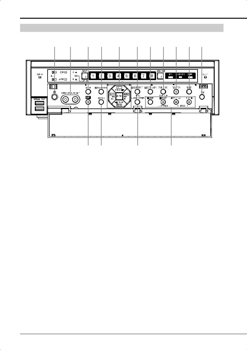
Major operations and their functions (continued)
|
Front view (inside of door) |
||||||||||
|
14 |
15 |
16 |
17 |
18 |
19 |
20 |
21 |
22 |
23 |
24 |
14POWER button
The power is turned on when this button is pressed while the MAIN switch on the rear is ON. When this button is pressed again, this recorder enters the standby mode. When this recorder is in the process of operation transition such as startup, the POWER indicator blinks and other operations are not acceptable.
15Analog output connectors
VIDEO OUT connector
RCA connector to output video signals. The same image as that from OUTPUT A is output.
AUDIO OUTPUT connector
RCA connector to output audio signals.
16SET UP button
When this button is pressed, <Main menu> is displayed.
17EXIT/CANCEL button
This button is used to set the menus.
18Direction buttons (UP, DOWN, LEFT, RIGHT buttons)
Use these buttons to move the item to be set during menu setting.
These buttons are also used to move the magnification center point while enlarging an image.
* This illustration shows an example of DX-TL308E.
REW, FF buttons
Use these buttons to adjust the playback speed, and to rewind or forward the recorded images.
ENTER button
This button is used to designate the detection target areas of the motion detection function.
It is also used to accept the menu settings.
19NEXT/START button
This button is used to set the menus.
20BOOK MARK button
When this button is pressed, <Bookmark menu> is displayed. When the playback device is designated as Copy device, Archive device, or preliminary area, <Bookmark menu> is not displayed. ( Page 74)
21TRIPLEX PB button
When this button is pressed while live images from cameras are being displayed in the split display mode, the playback image of your desired camera can be displayed. Triplex playback is possible with Output A only.
DIGITAL ZOOM button
When this button is pressed in the single screen display mode or the single screen playback mode, the displayed image is enlarged. To move the magnification center point, press the direction buttons.
FRAME buttons
Use these buttons for frame-by-frame playback.
18

22REC/STOP button
When this button is pressed, this recorder starts recording and the REC indicator illuminates. When this button is held down for 2 seconds or longer, this recorder stops recording and the REC indicator goes out. When this button is held down for 2 seconds or longer during alarm recording or emergency recording, this recorder stops recording. This recorder does not stop recording during timer recording even when this button is held down.
23TIMER button
When this button is pressed, this recorder enters the timer recording mode or standby mode and the TIMER indicator illuminates. When this button is held down for 2 seconds or longer, the timer recording mode or standby mode is canceled and the TIMER indicator goes out.
24LOCK button
When this button is pressed while the MAIN switch on the rear is ON, this recorder enters the simple lock or password lock mode. While this recorder is locked, the indicator illuminates. You can set passwords using <Password> of <Main menu>. ( Pages 111 to 114)
25COPY button
When this button is pressed, <Copy menu> is displayed. Use this button to copy or archive data.
( Pages 75 to 78)
This button illuminates during copy. It blinks at the start and end of copy operation.
26SEARCH button
When this button is pressed, <Search menu> is dis-
played. Use this button to search images. ( Pages 68 to 72)
27HELP button
When this button is pressed, the help menu showing information such as cautions on use, operating procedures, and functional descriptions is displayed.
It is also used to display the warning.
WARNING RESET button
When this button is pressed while a warning is displayed, the warning display is cleared.
28Operation buttons
STOP button
Press this button to stop playback.
PAUSE/JUMP TO END button
When this button is pressed during playback, still image playback starts and the button illuminates. When this button is pressed again, playback starts and the button goes out.
When the PAUSE/JUMP TO END button is pressed while the playback is stopped, images around the end of the latest recorded data are played back in the still image playback mode. (End point search)
REV.PLAY button
When this button is pressed, this recorder starts reverse playback and the button illuminates.
PLAY button
When this button is pressed, this recorder starts playback and the button illuminates.
SPEED (+ and -) buttons
When the playback (+) button or reverse playback (-) button is pressed during playback or reverse playback, the playback rate is changed.
Beginning
ENGLISH
19
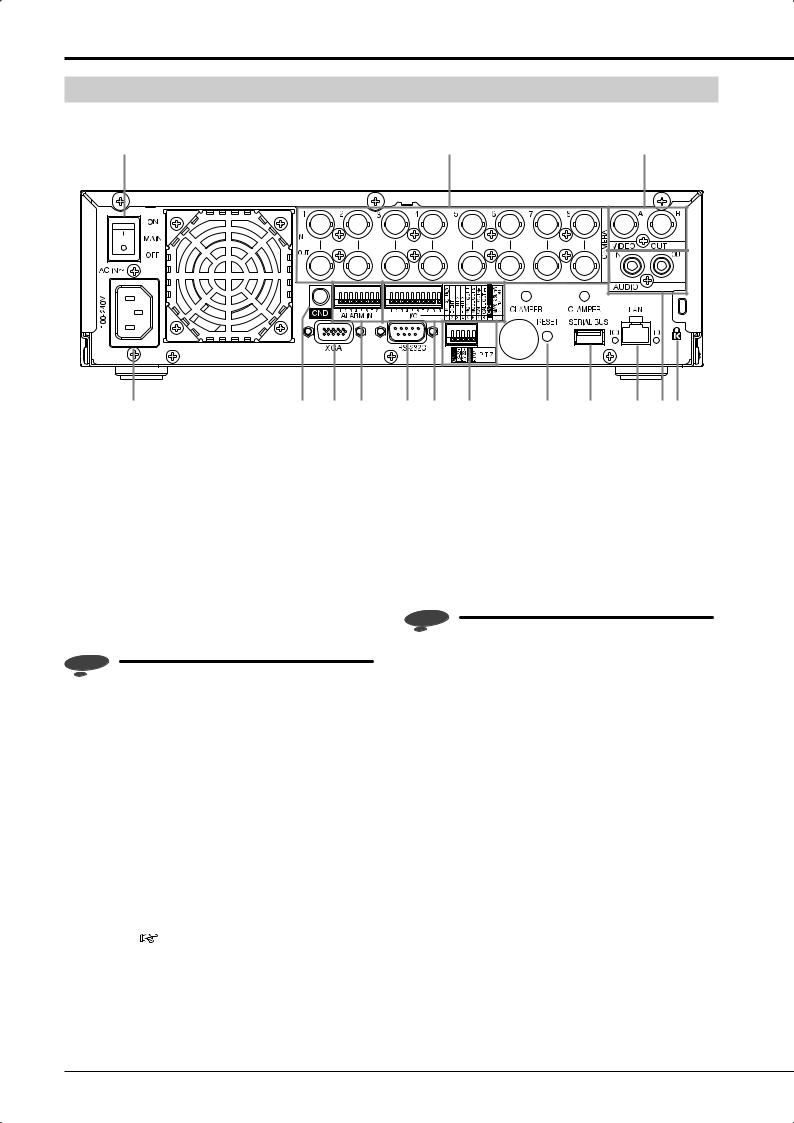
Major operations and their functions (continued)
Rear view
|
1 |
2 |
3 |
||||||||
|
4 |
5 |
6 |
7 |
8 |
9 |
10 |
11 |
12 |
13 |
14 15 |
* This illustration shows an example of DX-TL308E.
|
1 MAIN switch |
4 AC power socket |
This is the main power switch. To use this recorder, set this switch to ON. Otherwise, the POWER button on the front panel of the recorder cannot turn on or off the recorder.
2<DX-TL308E> CAMERA connectors (1 to <DX-TL304E> CAMERA connectors (1 to 4)
Notice
•Do not connect superimposed voltage cameras because they can cause damage to the recorder.
CAMERA IN connectors
BNC connectors to input camera video signals.
CAMERA OUT connectors
BNC connectors to output camera video signals. When the MAIN switch is on, the camera video signals input to CAMERA IN connectors are looped out to these connectors.
3VIDEO OUTPUT connectors
OUTPUT A VIDEO connector
BNC connector to output video signals to the monitor.
OUTPUT B VIDEO connector
BNC connector to output video signals to the second (B) monitor. ( Page 24)
Use this socket to connect the supplied power cord. Earth terminal is used for safety. Insert the power cord of this recorder to the 100 to 240 V outlet with ground terminal.
Notice
•When the power outlet does not have an earth terminal, ask your dealer for grounding work (for pay). Never connect the ground terminal of the power cord to the gas pipe, water pipe, conductor rod and so on.
•Make sure to use the supplied power cord.
5GND terminals
This terminal is used as common ground terminal.
6XGA port (DX-TL308E only)
Port to output video signals to XGA monitor.
7<DX-TL308E> ALARM IN terminals (1 to <DX-TL304E> ALARM IN terminals (1 to 4)
Terminals to input alarm signals. These terminals accept alarm signals once a second. However, when multiple signals are input at the same time, not all the signals may be accepted.
8RS-232C connector
This connector is used to connect a host device equipped with RS-232C connector (such as a personal computer). This recorder can be controlled from other devices via this connector.
20
![]()
9I/O terminals
EMERGENCY terminal
Input terminal to start emergency recording forcibly.
EVENT terminals (1 to 3)
Input terminals for activate the function configured in the <Event terminal> menu.  Page 102)
MODE OUT terminals (1 to 2)
Output terminals to notify the current recorder sta-
tus. Select the status information to be output in the <Mode-out • Remaining capacity> menu. ( Page 101)
Notice
•The MODE OUT terminal may output a signal for several seconds when the MAIN switch on the rear panel of the recorder is turned on or the recorder recovers from a power failure.
CALL OUT (+) terminal / CALL OUT (-) terminal
Output terminal to notify the trouble in the recorder and its exclusive ground terminal (isolation terminal). Information to be externally output consists of items selectable in the <Warning display • Buzzer • Call-out> menu ( pages 99 and 100) and items to be output regardless of the menu settings.
Notice
•The CALL OUT terminal may output a the signal for several seconds when the MAIN switch on the rear panel of the recorder is turned on or the recorder recovers from a power failure. Pay attention to this matter if you use peripheral devices to issue notification.
GND terminal
This terminal is used as common ground terminal.
DC 12V OUT terminal
This terminal outputs the direct voltage only when both the MAIN switch and the POWER button are on. The maximum electric current is 350 mA.
10PTZ control terminals
These terminals are used to connect a PTZ camera to control (pan, tilt and zoom) it.
11RESET button
When this button is pressed, this recorder is reset and the power is turned off. In this case, image data, menu settings, and the clock setting are retained.
12SERIAL BUS ports
Input and output ports to connect a device equipped with serial bus terminal. Don’t use the function to control the powers of external devices using the bus power of this recorder. Bus power cannot be used.
By connecting various external HDDs to this recorder, you can expand the memory or use them as a copy device. However, when you perform recording, playback, or copy at a high rate using this unit, recording or playback data dropout or other failure may occur depending on the connected device because of slow data transfer or slow response. Be sure to check for such failure before starting the practical operation of the recorder.
13LAN port
Port for communication with the special application software using a web browser.
14AUDIO connectors
AUDIO IN connector
RCA connector to input audio signals.
AUDIO OUT connector
RCA connector to output audio signals.
15Keyhole for antitheft lock
This is a hole to connect a commercially available antitheft cable manufactured by Kensington.
Beginning
ENGLISH
21

Major operations and their functions (continued)
|
Screen display |
||||||||||||||||||||||
|
1 |
2 |
|||||||||||||||||||||
|
1 |
Alarm interrupt |
|||||||||||||||||||||
|
3 |
19-01-2008 Sat |
|||||||||||||||||||||
|
15:00:45 |
||||||||||||||||||||||
|
4 |
HDD (EMR) |
|||||||||||||||||||||
|
CIF • L3 |
||||||||||||||||||||||
|
7 |
||||||||||||||||||||||
|
6 |
||||||||||||||||||||||
|
Please push the help button |
||||||||||||||||||||||
|
N |
69% |
|||||||||||||||||||||
|
5 |
Recorder title |
8 |
||||||||||||||||||||
|
REM |
A |
29% |
N [SBM08] |
[SBM08] |
SYNC |
[B] |
COPY |
ARCHIVE |
1 |
|||||||||||||
|
Camera title |
||||||||||||||||||||||
Notice
•The above figure is an example for explanation. Some items may not be displayed simultaneously.
1Camera number/Camera title
A camera number or camera title is displayed.
 is displayed on the right side of the camera number during recording. (When you select to hide the camera number, it is not displayed.)
For setting the items to be displayed, see  page 103.
For setting the camera title, see  page 103.
For setting the camera number display position, see  page 103.
2Alarm input prohibition
When alarm input is prohibited, this indication appears. For alarm input prohibition, see  page 61.
3Clock
The present time is displayed. The recording time is displayed during playback.
For setting the clock, see  page 99.
For setting the display position and display mode of the clock, see  page 102.
22

6Recorder title
The designated recorder title is displayed.
For setting the recorder title and displaying/hiding the title, see  page 102.
7Warning
Warning is displayed when a failure or error occurs in this recorder. Press the HELP button to check the details.
For setting the warning indication, see  pages 99 and 100.
For warnings, see  pages 128 to 131.
8Operation status
The current operation mode of this recorder or devices being operated are displayed.
|
Indication |
Operation status |
|
Normal recording |
|
|
Alarm recording |
|
|
Emergency recording |
|
|
Playback |
|
|
SYNC |
Synchronizing (*) |
|
COPY |
Copying |
|
ARCHIVE |
Archiving |
(*): The copy destination HDD is displayed during synchronization. (Displayed only when synchronizing with the internal HDD. When synchronizing with the external HDD, this indication does not appear.)
|
Indication |
Device being operated |
|
|
[A] |
Main recording |
Internal HDD A |
|
[B] |
device |
Internal HDD B |
|
[SBM01] — [SBM08] |
External HDD |
|
|
[SBC01] |
Copy device |
External HDD |
|
[SBC17] |
DVD/CD (in an |
|
|
external drive) |
||
|
[SBC18] |
USB memory |
|
|
[SBB01] — [SBB08] |
Archive device |
External HDD |
For displaying or hiding the operation status and HDD being operated, see  page 102.
23

Connections
Connecting CCTV cameras, monitors, and sensors
Camera
<DX-TL308E> (up to 8 cameras) <DX-TL304E> (up to 4 cameras)
RS232C integral camera
RS422
integral camera
Secure the USB cord using the supplied clamp band to prevent disconnection. ( Page 26)
Secure the power cord using the supplied clamp band to prevent disconnection. ( Page 26)
|
To CAMERA IN |
||
|
connectors |
||
|
corresponding to the |
To GND |
|
|
camera numbers |
||
|
terminal |
||
Sensor 1
For setting, see pages 53 and 54.
To ALARM IN terminals corresponding to the sensor numbers
Monitor
To VIDEO IN connector
To OUTPUT A
 VIDEO connector
To VIDEO IN
 connector
To OUTPUT B
VIDEO connector
Monitor
* This illustration shows an example of DX-TL308E.
To XGA
port 
 To SERIAL BUS port
Mouse
|
XGA (PC) monitor (DX-TL308E only) |
|||
|
For setting, see |
page 105. |
External recording device |
|
|
Power cord |
DX-ZD6UE |
||
|
Up to 4 to 8 devices can be used at the |
|||
|
PC |
same time. (The number of devices differs |
||
|
For setting, see |
depending on the operation manner.) |
||
|
For setting, see |
page 36. |
||
|
page 108. |
|
PTZ control terminals |
||
|
for the Continent |
For setting, see |
|
|
page 110. |
||
|
for U.K |
RS232C |
|
|
integral camera |
||
|
<Cable termination> |
||
|
Cable end connected to ALARM IN |
||
|
or I/O terminal and RS422 |
||
|
5-7 mm strip-off |
RS422 |
|
|
Applicable wire |
||
|
integral camera |
||
|
0.32-0.65 mm |
||
|
(AWG 28-22) |
To LAN port
PC
For setting, see pages 108 and 109.
24
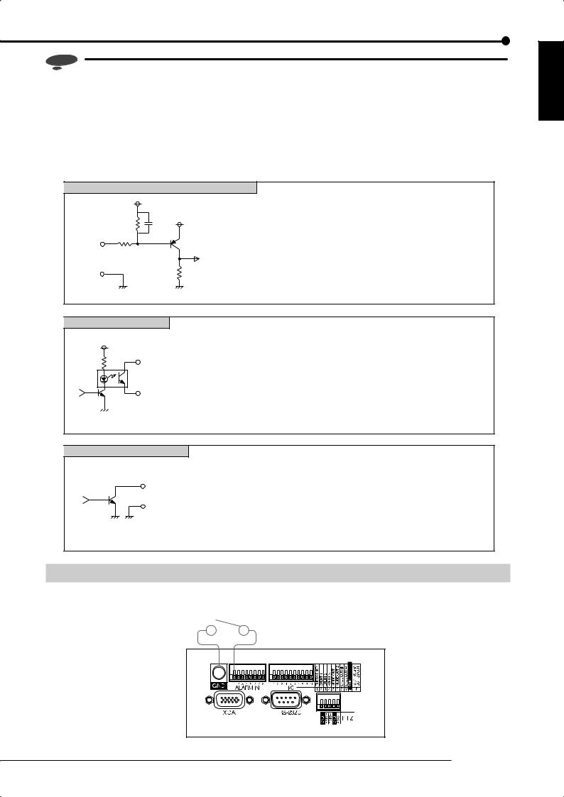
Notice
•By connecting various devices, you can control this recorder by external devices and control external devices by this recorder. However, depending on the operating condition of the recorder, its operation and control of external devices may become slow or unstable.
•Select a USB hub supporting USB 2.0. Depending on the type of the USB hub you use, when a USB 2.0 device and a USB 1.1 device are connected, both of them may operate according to the USB 1.1 standard. Avoid using such USB hub.
•Before connecting external devices, turn off the MAIN switch of the recorder. After the completion of connection, turn on the powers of the external devices first and then turn on the MAIN switch of the recorder.
EMERGENCY/ALARM IN/EVENT 1-3 input terminals
|
[Input circuit] |
5V |
[Input conditions] |
Grounding for 200 ms or longer |
|
|
10kΩ |
0.047µF |
[Input interval] |
At least 1 second |
|
|
5V |
[Specifications] |
When operating: Short-circuited to GND terminal or L-level |
||
|
22kΩ |
voltage is applied. |
|||
|
Input |
When not operating: Open |
|||
|
terminal |
||||
|
GND |
4.7kΩ |
|||
|
<Recorder’s internal circuit> |
||||
|
CALL OUT output terminal |
||||
|
[Output circuit] |
[Specifications] |
Warning alarm signal (Photocoupler output) |
||
|
When operating: Short |
|
CALL OUT (+) terminal |
Max. allowable input current is 7 mA DC. |
|
|
When not operating: Open |
||
|
Max. allowable input voltage is +24 V DC. |
||
|
CALL OUT (-) terminal |
* The terminal may output a signal for several seconds when the MAIN switch on |
|
|
the rear panel of the recorder is turned on or the recorder recovers from a |
||
|
<Recorder’s internal circuit> |
power failure. |
|
MODE OUT 1-2 output terminals
[Output circuit]
Output terminal
GND
<Recorder’s internal circuit>
[Specifications] When operating: L-level voltage is output.
Max. allowable input current is 7 mA DC. When not operating: Open
Max. allowable input voltage is +24 V DC.
*Use the recorder within the ratings shown above.
*The terminal may output a signal for several seconds when the MAIN switch on the rear panel of the recorder is turned on or the recorder recovers from a power failure.
Connection for alarm recording
Following figure shows an example of the connection of alarm signal corresponding to alarm sensor 1.
Alarm switch
* This illustration shows an example of DX-TL308E.
Connections
ENGLISH
25
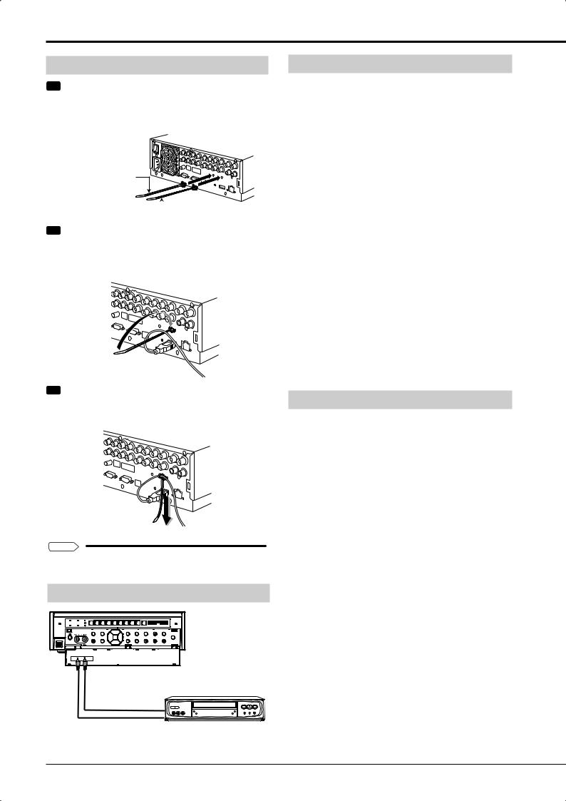
Connections (continued)
Cable clamping
Step 1 Insert the supplied clamp bands into the clamp holes in the rear of the recorder.
•One clamp hole is for the power cable and the other is for USB cables.
For power cable
 For USB cable
Step 2 Run the cable to be clamped around the clamp band as shown in the figure.
• The rough side of the band should face up.
Step 3 Pull the end of the clamp band until it is tightened.
Tips 

•Illustrations show an example of DX-TL308E.
Connecting an analog VCR
|
To VIDEO OUT |
To AUDIO OUT |
|||||||||
|
connector |
connector |
|
Audio cable |
To AUDIO IN |
|
|
(commercially available) |
connector |
|
|
Video cable |
To VIDEO IN |
|
|
(commercially available) |
connector |
Analog VCR |
Optional products
DX-ZD6UE DX-ZD5UE(Z)
Additional hard disk unit (for serial bus connection)
By connecting various external HDDs to this unit, you can expand the memory or use them as a copy device. However, when you perform recording, playback, or copy at a high rate using this unit, recording or playback data dropout or other failure may occur depending on the connected device because of slow data transfer or slow response. Be sure to check for such failure before starting the practical operation of the recorder.
Don’t use the function to control the powers of external devices using the bus power of this recorder.
When using DX-ZD6UE, you can use the mirroring and spanning functions.
DX-RM5(ZD)
Rack-mount adapter for additional hard disk unit DX- ZD6UE/DX-ZD5UE(Z)
DX-KB5UE
Keyboard for digital recorder
DX-RM3
Rack-mount adapter for digital recorder DX-TL308E/DX- TL304E series
Recommended products
For recommended external devices, contact your dealer.
External devices you want to use may not be suitable for the intended application of this recorder. For details, you are recommended to contact your dealer.
By connecting various external HDDs to this recorder, you can expand the memory or use them as a copy device. However, when you perform recording, playback, or copy at a high rate using this unit, recording or playback data dropout or other failure may occur depending on the connected device because of slow data transfer or slow response. Be sure to check for such failure before starting the practical operation of the recorder.
26

Caution for connecting additional hard disk units
When you connect 5 or more additional hard disk units to this recorder, you are recommended to connect them by USB cables as shown below in order to prevent recognition failure caused by variation in their startup time.
At the commencement of practical operation, check that they are recognized correctly even when a small number of units are connected.
|
Recorder |
||||||||||||
|
IN |
||||||||||||
|
Additional |
||||||||||||
|
unit |
||||||||||||
|
OUT |
||||||||||||
|
IN |
IN |
|||||||||||
|
Additional |
Additional |
|||||||||||
|
unit |
unit |
|||||||||||
|
OUT |
OUT |
|||||||||||
|
IN |
IN |
|||||||||||
|
Additional |
Additional |
|||||||||||
|
unit |
unit |
|||||||||||
|
OUT |
OUT |
|||||||||||
|
IN |
IN |
|||||||||||
|
Additional |
Additional |
|||||||||||
|
unit |
||||||||||||
|
unit |
||||||||||||
|
OUT |
||||||||||||
|
IN |
||||||||||||
|
Additional |
||||||||||||
|
unit |
Notice
•When you play back data stored in the extension unit during recording to the same extension unit at a rate close to the recorder’s maximum processing capacity (for example of DX-TL308E, at 12.5 FPS for all the cameras in the 2CIF picture size), noise may appear in the image or audio. In addition, when you make backups of the data to the extension unit during recording on the recorder, make sure to set the total recording rate of cameras to half or less of the upper limit of the designated picture size (<DX-TL308E> 4CIF: 25 FPS or less, 2CIF: 50 FPS or less, or CIF: 100 FPS or less, <DX-TL304E> 4CIF: 12.5 FPS or less, 2CIF: 25 FPS or less, or CIF: 50 FPS or less).
Caution in installing multiple recorders in an EIA rack
Follow the steps below to install the recorder in an EIA rack (occupying 2U space) using the rack mount adaptor (DX-RM3).
1Remove the feet from the bottom of the recorder. (4 feet)
2Fit the rack mount adaptor using the screws on both sides of the recorder. (2 screws on each side)
3Secure the recorder to the EIA rack using screws. Prepare appropriate screws for your rack.
Rack mount adaptor (DX-RM3)
 Screws on the recorder (2 screws on each side)
 Feet on the bottom of the recorder (4 feet)
ENGLISH
Connections
27
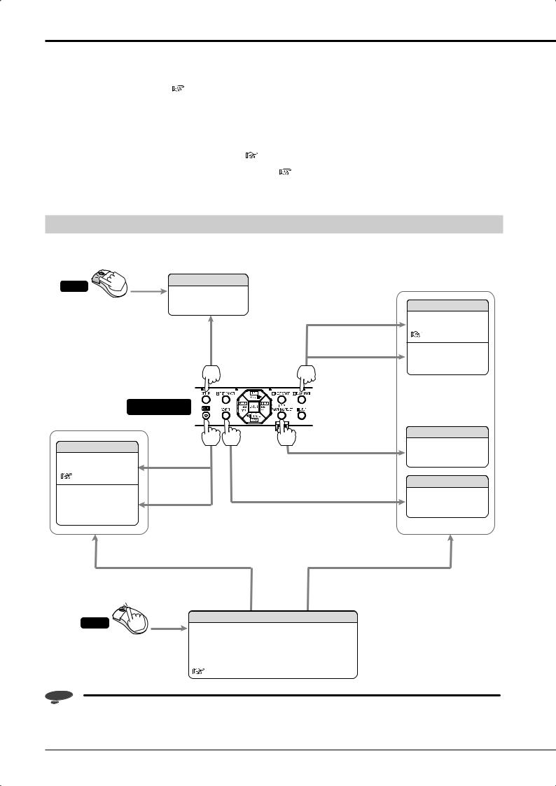
How to set the menus
You can set the operation conditions and perform various controls using the menus.
There are 3 methods to set the menus as described below.
 Set the menus automatically ( Pages 32 and 33)
When you turn on the recorder for the first time, the Setup Wizard screen is displayed and you can configure the minimum required settings according to the displayed menus.
 Set the menus manually
You can manually change the settings made by the Setup Wizard or manually configure settings other than those made by the Setup Wizard. For how to locate setting items, see page 2.
 Copy the menu settings of other DX-TL308E/DX-TL304E ( Page 107)
You can set the recorder’s menus by copying the menu settings of other DX-TL308E/DX-TL304E to externally connected media and then loading those settings.
Displaying the menus
When you press the following buttons, the corresponding menus are displayed. (Check that no other menus or warnings are displayed.)
|
Mouse |
Left-click |
Main menu |
|
|
You can set the |
|||
|
operation conditions of |
|||
|
the recorder. |
Bookmark menu
You can register bookmarks.
Page 74
Press while the single screen
playback is in pause.
You can search for bookmarked images.
 Page 74
Inside the front door of the recorder
|
Copy menu |
Press while the |
|
|
You can copy data for a |
single screen |
|
|
playback is in pause. |
||
|
short time of period. |
||
|
Page 75 |
You can copy or archive data based on the conditions you specify.  Pages 75 to 78.
You can display these menus also from the mouse operation screen.
Help menu
Detailed descriptions of the menus and warnings are displayed.
Search menu
You can search for desired images.
 Pages 68 to 72.
You can display these menus also from the mouse operation screen.
|
Mouse |
Right-click |
Mouse operation screen |
|
|
You can operate various functions of the recorder |
|||
|
using a mouse. |
|||
|
You can display the Search menu, Copy menu, |
|||
|
Bookmark menu, and Help menu also from the |
|||
|
mouse operation screen. |
|||
|
Pages 30 and 31. |
Notice
•When the multiplexer Output B is selected, menus cannot be displayed. In addition, when you operate the recorder by a mouse, the mouse cursor is displayed but no menus are displayed and you cannot configure the menu settings. You can set the menus only when Output A is selected. ( Page 41)
28

Operating the menus
You can operate the displayed menu by pressing the buttons on the front panel of the recorder or clicking the buttons displayed on the menu screens.
Notice
|
• Use a general USB mouse having two buttons as shown by the figure. Certain types |
Wheel |
|||||
|
Left button |
Right button |
|||||
|
of mouse cannot be used with this recorder. |
||||||
You are recommended to use a mouse having 800 dpi resolution.
•Mouse is not supplied with the recorder.
|
• |
Mouse wheel doesn’t work with this recorder. |
Mouse |
||||||||||||
|
Buttons on the screen |
Examples |
Descriptions |
||||||||||||
|
To set parameters. |
When you click on the button, the parameter or number |
|||||||||||||
|
, etc |
displayed on the button changes. Left-click or right-click |
|||||||||||||
|
1 |
High |
|||||||||||||
|
repeatedly until the desired item is displayed. |
||||||||||||||
|
(Disabled) |
(Enabled) |
Click the radio button of the desired parameter. |
||||||||||||
|
(Disabled) |
(Enabled) |
Select the checkbox of the desired parameter to put a |
||||||||||||
|
checkmark. |
||||||||||||||
|
To switch the selected |
10 |
100 |
You can go to the next item. For example, by pressing the [ 10 ] |
|||||||||||
|
item in the list. |
button, you can skip next 10 items. |
|||||||||||||
|
, etc |
||||||||||||||
|
In addition, this button is used to change the setting values. |
||||||||||||||
|
You can go back to the previous item. For example, by |
||||||||||||||
|
, etc |
pressing the [ 10 ] button, you can skip back previous 10 items. |
|||||||||||||
|
10 |
100 |
In addition, this button is used to change the setting values. |
||||||||||||
|
You can scroll lists. |
||||||||||||||
|
Click on |
or . |
|||||||||||||
|
You cannot scroll lists using the buttons on the front panel of |
||||||||||||||
|
the recorder. |
||||||||||||||
|
To display |
E:Return , etc |
The previous menu is displayed. |
||||||||||||
|
other menus. |
The next menu is displayed. |
|||||||||||||
|
D:Next |
Setting , etc |
|||||||||||||
|
To display the |
Help menu is displayed, showing information such as |
|||||||||||||
|
? |
operation procedures. This menu is also displayed when you |
|||||||||||||
|
Help menu. |
||||||||||||||
|
press the HELP button on the front panel of the recorder. |
||||||||||||||
|
To accept the |
E:Return |
When you set a desired item and then display other menu by |
||||||||||||
|
menu settings. |
[Return] or [Next], the setting you made is determined. |
|||||||||||||
|
D:Next Setting |
, etc |
|||||||||||||
Tips 

•To set the menus using the buttons on the front panel of the recorder
You can select a setting item using the direction buttons and determine the setting using the ENTER button.
Instead of the buttons showing letter C, D, or E, such as [D:Next], displayed on the screen, you can use the button C, D, or E on the front panel of the recorder.
Closing the menus
Step 1 Display the Main, Search, Copy, or Bookmark menu and left-click the [Exit] button.
Notice
•You cannot close the menus by pressing the SET UP button on the recorder.
Menu settings/Device registration
ENGLISH
29
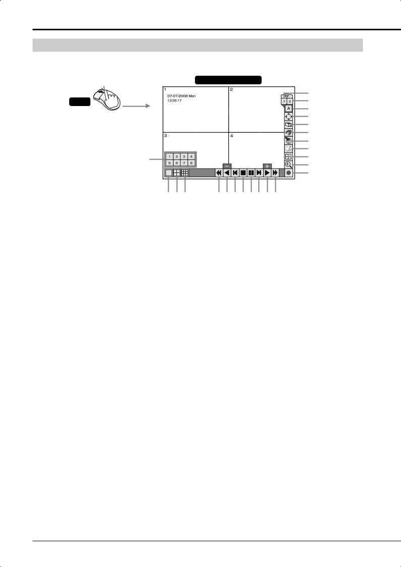
How to set the menus (continued)
Using the mouse operation screen
When you right-click the mouse, the mouse operation screen is displayed and you can control the recorder on the screen.
Mouse operation screen
23
22
21
20
19
18
17
16
15
14
13
|
2 |
3 |
4 |
5 |
6 |
7 |
8 |
9 10 11 12 |
* This illustration shows an example of DX-TL308E.
1Camera number buttons
When you click any of these buttons, the image from the corresponding camera is displayed on the entire screen. These buttons are used in the triplex playback mode, too. While the camera number buttons are displayed, the other buttons don’t work.
2Single screen button
When you click this button, the camera number buttons are displayed for 3 seconds.
34-split button
<DX-TL308E> Each time you click this button, the screen mode changes in the order of 4-split a  4-split b
  4-split a
  …
…
<DX-TL304E> When you click this button, a 4-split screen is displayed.
49-split button
<DX-TL308E> When you click this button, a 9-split screen is displayed.
<DX-TL304E> Not available.
5Reverse search button
Each time you click this button during reverse playback, the button illuminates and the playback speed changes in the order of approx. X2  approx. X4
  approx. X8
  approx. X16
  high-speed playback
  approx. X2
  …
…
6Reverse play button
When you click this button, reverse playback starts. When you click the button during playback or reverse playback, images are played or reverse-played at the lowest rate and [-] is displayed on the button. Each time you click the [Play] button while [-] is displayed, the playback speed increases.
7Reverse step button
When you click this button, reverse frame-by-frame playback starts.
8Stop button
When you click this button, playback stops.
9Pause button
When you click this button during playback, the still image playback mode starts. By clicking this button again, playback resumes.
When this button is pressed while the playback is stopped, images around the end of the latest recorded data are played back in the still image playback mode.
10Step button
When you click this button, frame-by-frame playback starts.
11Play button
When you click this button, playback starts.
When you click the button during playback or reverse playback, images are played or reverse-played at the highest rate and [+] is displayed on the button. Each time you click the [Reverse play] button while [+] is displayed, the playback speed decreases.
12Forward search button
Each time you click this button during playback, the button illuminates and the playback speed changes in the order of approx. X2  approx. X4
  approx. X8
  approx. X16
  high-speed playback
  approx. X2
  …
…
13Recording/Stop button
When you click this button, recording starts and the button illuminates. By clicking this button again, a confirmation screen is displayed. When you select [Yes], recording stops and the button goes out.
30
![]()
14Zoom button
When you click this button during single screen display or single screen playback, the displayed image is enlarged. Each time you click this button, the magnification changed in the order of X1  X2
X2  X4
X4  normal display. You cannot enlarge the image output from Output B using the mouse operation screen.
To move the magnification center point, click the shaded areas shown below.
15Triplex PB button
When you click this button while live image is displayed in the split display mode, the triplex playback mode is activated and the camera number buttons are displayed for 3 seconds. When you click any camera number button, the playback image of the corresponding camera is displayed. For notes for using the triplex playback mode, see  page 42.
16Bookmark button
When you click this button, the mouse operation screen is closed and the <Bookmark menu> is displayed. When the playback device is designated as Copy device, Archive device, or preliminary area, the <Bookmark menu> is not displayed. ( Page 74)
17Copy button
When you click this button, the mouse operation screen is closed and the <Copy menu> is displayed.
Use this button to copy or archive data. ( Pages 75 to 78)
18Search button
When you click this button, the mouse operation screen is closed and the <Search menu> is displayed. Use this button to search images. ( Pages 68 to 72)
19Sequence button
When you click this button, the sequential display screen is displayed and the button illuminates. By clicking the button again, the sequential display is canceled.
20PTZ button
When you click this button while live images are displayed, the recorder enters the PTZ mode. For operations in the PTZ mode, see  page 43.
21Output A/B button
When you click this button, the multiplexer output is switched between A and B. Each time you click this button, the multiplexer-related buttons are switched between two monitors connected to the OUTPUT A connector and OUTPUT B connector.
When Output B is selected, only the buttons for controlling the multiplexer are displayed.
22Exit button
When you click this button, the mouse operation screen is closed.
23Help button
When you click the button, the Help menu is displayed.
Notice
•When you click the  button, the hidden buttons are displayed. To hide the buttons being displayed, click the
  button.
•When the password lock is enabled, you can use the
buttons for unlocked operations only. ( Pages 111 to 114)
•The mouse operation screen automatically disappears when you don’t operate the mouse for 1 minute.
•You cannot display warnings by pressing the HELP button when they occur while the mouse operation screen is displayed. Close the mouse operation screen first.
•In forward search/reverse search, the intended playback speed may not be obtained when a heavy load is imposed on the recorder or when the highspeed data transmission is unavailable due to the use of an external DVD/CD drive, USB memory, or external HDD.
Menu settings/Device registration
ENGLISH
31

Using the Setup Wizard
Making the minimum required settings automatically
<Setup Wizard>
When you turn on the power of the recorder for the first time, the Setup Wizard screen is displayed for making the minimum required settings.
Tips 

•The Setup Wizard screen is automatically displayed only when you first turn on the power. It is not displayed from the next turn-on.
Turn on the power for the first time. Step 1
Select whether or not to use the Setup Wizard. Step 2
|
Language selection |
Step 3 |
|
Time/date adjust |
Step 4 |
|
HDD configuration |
Step 5 |
|
Recording setup |
Step 6 |
|
Step 1 Camera check |
Step 7 |
|
Step 2 Define the normal recording cycle |
Step 8 |
|
Step 3 Confirm the recording settings |
Step 9 |
|
Finish |
Step 10 |
Step 1 After connecting cameras and monitors, turn on the MAIN switch on the rear of the recorder. Check that the POWER indicator goes out and then press the POWER button on the front panel of the recorder.
• The <Setup Wizard> screen is displayed.
Notice
•While the POWER indicator is blinking, the POWER button does not work. When you turn on the MAIN switch of the rear panel of the recorder, wait for more than 5 seconds after the indicator goes out before pressing the POWER button.
Step 2 Select whether or not to use the Setup Wizard.
•Select [Next] when using the Setup Wizard and [Quit] when not. When you select [Quit], the clock starts from the initial setting.
Tips 

•When you want to cancel the Setup Wizard in midstream, cancel it according to the instructions displayed on the screen. You can cancel the Setup Wizard in step 6. In this case, the settings you made in steps 1 to 5 remain effective.
Step 3 (When you select [Next])
Select a language.
•The <Language selection> screen is displayed. Select a language used for the menus.
•Select a language and then [Next].
Step 4-1 Set the current time and select [Set].
Step 4-2 Select [Setting] and set the time zone depending on the location of the recorder, and then select [Set].
•After finishing the setting, select [Return] to return to the screen of step 4-1 and then [Next].
Tips 

•When you select [Set], the clock starts.
Step 5 Set the HDD configuration.
•When you select [Register], all the connected HDDs are automatically registered as Main device.
When the registration finishes, a confirmation screen is displayed. Check the settings and select [Next].
•For setting Copy device and Archive device, see  pages 34 to 37.
•For mirroring setting, see  page 35.
•For partition setting, see  page 39.
Step 6 Select whether or not to make recording settings.
•Select [Next] when you make recording settings and [Quit] when not.
Step 7 (When you select [Next])
When you select [Execute], the recorder automatically detects the active cameras and displays their numbers.
•When the recorder finishes detecting the cameras, select [Next].
•The detection results are applied to Recording A-D, emergency recording, and single sequential display.
Step 8 Set the recording cycle and recording hours per day.
• After finishing the setting, select [Next].
32

Step 9 Picture quality and FPS are automatically set for the cameras detected in step 7 and a confirmation screen is displayed.
•The picture quality and FPS are same among all the cameras detected in step 7. The settings made in this step are applied to normal recording of Recording A.
|
• Picture size is set to 4CIF (frame mode). ( |
Page |
|
51) |
•For how to make recording settings manually, see pages 51 to 54.
•Check the confirmation screen and select [Next].
Tips 

•Audio is not recorded by default. For how to record audio, see  page 60.
When you enable audio recording, the recording cycle becomes shorter than that when not recording audio. Check the estimated recording time in the Recording setting menu. ( Page 53)
•The estimated recording time is based on 24-hour recording per day.
Step 10 Select [Finish] to exit the Setup Wizard.
• The recorder becomes ready for operation.
ENGLISH
Menu settings/Device registration
33

Registering the devices
Setting Main, Copy, and Archive devices
<HDD registration>
You can assign the HDDs to Main, Copy, and Archive devices.
|
Device |
Application |
Usable device |
Device name |
|
Used as the |
Internal HDD |
[A], [B] |
|
|
recording destination |
External HDD |
[SBM01] — [SBM08] |
|
|
Main |
of normal recording, |
||
|
device |
alarm recording, and |
||
|
emergency recording. |
|||
|
Used as the copy |
External HDD |
[SBC01] |
|
|
Copy |
destination. |
DVD/CD (in an |
[SBC17] |
|
external drive) |
|||
|
device |
|||
|
USB memory |
[SBC18] |
||
|
Used as the archive |
External HDD |
[SBB01] — [SBB08] |
|
|
Archive |
destination. |
||
|
device |
|||
|
Not |
Not used for recording. |
||
|
assigned |
Notice
•You cannot register devices during access to the HDD such as recording and playback. In addition, you cannot start recording or playback during registration.
•Devices that can be set as Copy device are serial bus HDD, DVD/CD drive (external), and USB memory.
With this recorder, up to 4 GB USB memory devices are usable. USB memory devices with 128 MB or less capacity are not supported.
Device that can be set as Archive device is serial bus HDD.
•Up to 10 devices including DVD/CD drive and USB memory can be connected to the serial bus. This is the total number of Main, Copy, and Archive devices.
•Up to 10 HDDs including internal HDDs can be used as Main device. (This is the total number of internal HDDs and serial bus HDDs.)
•Space totaling 22 GB of the internal HDDs is assigned to the preliminary recording area. (11 GB each from Internal A and B) This space is so assigned even when the preliminary recording is disabled.
Cautions for using external devices
By connecting various external HDDs to this recorder, you can expand the memory or use them as a copy device. However, when you perform recording, playback, or copy at a high rate using this unit, recording or playback data dropout or other failure may occur depending on the connected device because of slow data transfer or slow response. Be sure to check for such failure before starting the practical operation of the recorder.
Don’t use the function to control the powers of external devices using the bus power of this recorder.
Hookup and operation setting of HDDs
When you connect an HDD to the SERIAL BUS port of the recorder, use a USB 2.0 cable.
Turn off the MAIN switch before connecting the HDD. After the completion of connection, turn on the powers of the external devices first and then turn on the MAIN switch of the recorder.
The connected HDD is recognized at the time of startup.
Order of recording and playback of the internal and external HDDs registered as Main device
Recording and playback are carried out on the internal HDDs in the following order:
Internal A  Internal B
When recording or playback on the internal HDDs is completed, it is carried on to the HDDs connected to the SERIAL BUS port. Recording is carried out in the order of number contained in the device name «SBM
 ,» 01 to 08.
When recording or playback on the serial bus HDDs is completed, it is carried on to the internal HDDs.
34

 Registering the internal HDDs
Step 1 Press the SET UP button on the front panel of the recorder or left-click the mouse.
or
• <Main menu> is displayed.
Step 2 Select [HDD registration].
HDD registration
• <HDD registration> screen is displayed.
Step 3 Select [Setting] next to [HDD registration].
Setting
• <HDD registration> screen is displayed.
Step 4 Select [Setting] next to [Register internal HDD].
Setting
•<HDD registration Internal HDD> screen is displayed.
Step 5 Check that the internal HDDs are listed on the <HDD registration Internal HDD> screen.
• A and B represent the internal HDD numbers.
Step 6 Select whether or not to register the internal HDDs as Main device.
Main Set
[Main]: HDD is registered as Main device.
[Not assigned]: HDD is not registered as Main device.
•Every time you press the button, the button’s function changes between [Main] and [Not assigned].
Step 7 Select [Set] to determine your settings.
Notice
•When no HDD is registered as Main device, you cannot use a USB memory.
Mirroring
By recording the same data on 2 HDDs that have the same capacity, you can reduce the risk of losing recorded data in the event of sudden crash of Main device. As the same data are recorded on 2 HDDs, the recordable time is halved.
Notice
•Before changing the HDD operation settings (such as turning the mirroring ON from OFF or OFF from ON and changing the partition settings), set the pre-alarm time of the alarm and emergency recording settings to 0 second. After setting the pre-alarm time to 0 second, check that the ACCESS indicator goes out and then change the HDD operation settings.
Step 1 Put a checkmark in the box of [Activate the mirroring mode].
Notice
•When you enable the mirroring function with the recorded data stored in the HDD, the recorded data are deleted.
•You can enable the mirroring function of this recorder only when both of the internal HDDs A and B are set as [Main].
•The mirroring function of this recorder can be used with the internal HDDs only. To mirror data on external HDDs, use a device having the mirroring function and refer to the operation manual of the device to be used.
•In case of a failure in either HDD during mirroring, the recorder continues recording on the normal HDD only.
When you replace the failed HDD, the data are automatically copied to the newly mounted HDD and they recover to the status before the failure. (Data synchronization) When the synchronization is interrupted by power-off, it resumes when the power is turned back on.
•Preliminary recording is not performed while the operation settings of normal, mirroring, or partition are being changed.
ENGLISH
Menu settings/Device registration
35

Registering the devices (continued)
 Registering external HDDs
Step 1 Press the SET UP button on the front panel of the recorder or left-click the mouse.
or
• <Main menu> is displayed.
Step 2 Select [HDD registration].
Notice
•Data to be archived are transferred in 2 MB units. At the end of archive, the data of the latest recording point may not be completely transferred yet. Pay attention to this matter when you change the archive source device.
•The registered information may not be displayed correctly during recording or playback.
HDD registration
• <HDD registration> screen is displayed.
Step 3 Select [Setting] next to [HDD registration].
Setting
• <HDD registration> screen is displayed.
Step 4 Select [Setting] next to [Register external HDD].
Setting
•<HDD registration External HDD> screen is displayed.
Step 5 Check that the HDDs connected to the SERIAL BUS port of the recorder are listed on the <HDD registration External HDD> screen.
•When you select [Check], the ACCESS indicator of the selected HDD illuminates and you can check the selected HDD.
Step 6 Select whether or not to register the HDDs connected to the SERIAL BUS port as Main, Copy, or Archive device.
|
Copy |
SBC01 |
Set |
||
[Main]: HDD is registered as Main device. [Copy]: HDD is registered as Copy device. [Archive]: HDD is registered as Archive device.
[Not assigned]: HDD is not registered as Main, Copy or Archive device.
•Every time you press the button, the button’s function changes among [Main], [Copy], [Archive], and [Not assigned] in order.
Step 7 Set the order of recording on the registered HDDs connected to the SERIAL BUS port.
•[SBM


 ]…………. Represents Main device. [SBC01] ………….. Represents Copy device. [SBB


 ] …………. Represents Archive device.
Set the number shown in 


 from 01 to 08. Data are saved in HDDs in the order of numbers you set.
Step 8 Select [Set] to determine your settings.
36

 Checking the registered devices
Step 1 Press the SET UP button on the front panel of the recorder or left-click the mouse.
or
• <Main menu> is displayed.
Step 2 Select [HDD registration].
HDD registration
• <HDD registration> screen is displayed.
Step 3 Select [Setting] next to [HDD registration].
Setting
• <HDD registration> screen is displayed.
Step 4 Select [Confirm] of the device you want to check under [Check the registered HDDs].
Confirm
•The HDDs registered as the selected device are listed. Regardless of the order of registration, devices are displayed in the order of recording.
•When you press the button of the device name, the ACCESS indicator of the selected HDD illuminates and you can check the selected HDD.
ENGLISH
Menu settings/Device registration
37

Registering the devices (continued)
Setting the repeat recording and partition of Main device
<Main HDD setting>
Notice
•You cannot make settings during access to the HDD such as recording and playback. In addition, you cannot start recording or playback during setting.
 Setting the repeat recording
You can set the recorder’s operation performed when the available space in Main device runs out during recording.
Step 1 Press the SET UP button on the front panel of the recorder or left-click the mouse.
or
• <Main menu> is displayed.
Step 2 Select [HDD registration].
Notice
•The repeat recording in the partitioned areas can be enabled only when the corresponding areas are set in the <Partition setting>.
•When a warning is issued, «Please push the help button» is displayed on the screen. The recorder keeps the latest 16 warnings. The warnings issued before them are reset and not displayed.
•When the repeat recording is disabled in the alarm recording area or emergency recording area and their available space runs out, the alarm recording or emergency recording stops. When an alarm or emergency signal is input after that, the indicator illuminates for a moment but recording is not performed. (You may not notice that the indicator illuminates.) In this case, enable the repeat recording or delete the recorded data to resume recording.
HDD registration
• <HDD registration> screen is displayed.
Step 3 Select [Setting] next to [Main HDD setting].
Setting
• <Main device setting> screen is displayed.
Step 4 Select whether to enable or not the repeat recording in each area.
•To enable the repeat recording, put a checkmark in the box.
[Enable]: Automatically returns to the start of the HDD and resumes recording (overwriting).
[Disable]: Stops recording at the end of the HDD. When [Warning] of [Remain] on the <Warning
display • Buzzer • Call-out 1> screen ( page 99) is selected, recording resumes as the warning is cleared.
When [Warning] of [Remain] on the <Warning
display • Buzzer • Call-out 1> screen ( page 99) is unselected, recording resumes as the recorded data are deleted or the repeat recording is enabled.
38

 Setting the partition
You can partition the Main device.
|
Partition setting |
Data to be recorded |
||
|
No partition |
Normal |
Normal recording |
|
|
Alarm recording |
|||
|
recording area |
|||
|
Emergency recording |
|||
|
Allocate alarm |
Normal |
Normal recording |
|
|
recording area |
|||
|
recording area |
Alarm recording |
||
|
Alarm recording area |
Emergency recording |
||
|
Normal |
Normal recording |
||
|
Allocate emergency |
Alarm recording |
||
|
recording area |
|||
|
recording area |
Emergency |
Emergency recording |
|
|
recording area |
|||
|
Allocate alarm |
Normal recording area |
Normal recording |
|
|
recording area and |
Alarm recording area |
Alarm recording |
|
|
emergency recording |
|||
|
area |
Emergency |
Emergency recording |
|
|
recording area |
|||
Notice
•Before changing the HDD operation settings (such as turning the mirroring ON from OFF or OFF from ON and changing the partition settings), set the pre-alarm time of the alarm and emergency recording settings to 0 second. After setting the pre-alarm time to 0 second, check that the ACCESS indicator goes out and then change the HDD operation settings.
Step 1 Press the SET UP button on the front panel of the recorder or left-click the mouse.
or
• <Main menu> is displayed.
Step 2 Select [HDD registration].
HDD registration
• <HDD registration> screen is displayed.
Step 3 Select [Setting] next to [Main HDD setting].
Setting
• <Main device setting> screen is displayed.
Step 4 Select [Setting] next to [Change partition setting].
Setting
• <Partition setting> screen is displayed.
Step 5 Create partitions in the Main device.
•Set the capacities of the normal recording area, alarm recording, area and emergency recording area.
•When you allocate the alarm recording area and emergency recording area, the specified space in the HDDs set as Main device is divided to be used for alarm recording and emergency recording independently.
Notice
•When you create partitions, mirroring cannot be used.
•Functions such as playback, search, information display, remaining capacity setting (mode-out/call-out) and deletion of recorded data can be individually set in each of the normal recording area, alarm recording area, and emergency recording area.
•When you copy or archive recorded data, you can select any of the normal recording area, alarm recording area, and emergency recording area as copy source.
•Preliminary recording is not performed while the operation settings of normal, mirroring, or partition are being changed.
Tips 

•When the sum of capacities of the normal recording area, alarm recording area, and emergency recording area is 100%, you cannot increase the capacity any more.
•You cannot set the normal recording area to 0%.
•The recording area for preliminary recording is assigned in addition to the partitions you can set. This space is assigned even when the preliminary recording is disabled.
Menu settings/Device registration
ENGLISH
39

Viewing images captured by the cameras
Multiplexer function
<DX-TL308E> You can display images captured by the connected cameras on 4-split or 9-split screen.
<DX-TL304E> You can display images captured by the connected cameras on 4-split screen.
In addition, you can arrange the positions of the displayed images on the screen.
SPLIT/OUTPUT A/B button
Camera number buttons
SEQUENCE button
DIGITAL ZOOM button
Direction buttons
* This illustration shows an example of DX-TL308E.
Notice
•You cannot switch the screen mode to the other single screen modes or split screen mode while the menu screen is displayed. To switch the screen mode, close the menu screen first and then press a camera number button or SPLIT button.
 Single screen display
A live image captured by one camera is displayed on the screen.
Step 1 <DX-TL308E> Press a camera number button (1 to 8).
<DX-TL304E> Press a camera number button (1 to 4).
•The image from the camera corresponding to the button you pressed is displayed on the entire screen.
 Split screen display
Images captured by multiple cameras are displayed on the split screen.
Step 1 Press the SPLIT button.
Every time you press the button, the screen mode changes in the order shown below.
<DX-TL308E> 4-split a  4-split b
  9-split
  4-split a …
<DX-TL304E> 4-split
Notice
•When the camera images are displayed in the split screen mode, thin black bars may appear at the top and bottom or right and left of respective images depending on the types of the cameras you use. This symptom tends to occur when the size of the camera image is smaller than that defined by the display specifications of this recorder.
Tips 

•To set the camera numbers to be displayed in each screen mode, use <Multiplexer setting> in the <Setup> menu. You can set the camera numbers to be displayed differently for Output A and Output B. ( Page 104)
 Sequential display
Images captured by cameras are displayed and switched at constant intervals.
Step 1 Press the SEQUENCE button.
•<DX-TL308E> The sequential display starts in the currently selected mode, split or single screen display mode.
Sequential display mode has the following types: Single screen sequential display
4-split sequential display
<DX-TL304E> The sequential display starts in the single screen display mode.
Sequential display mode has the following types: Single screen sequential display
Step 2 To cancel the sequential display, press the SEQUENCE button again.
•You can also cancel the sequential display by pressing the SPLIT button or the camera number button.
Notice
•Sequential display cannot be used during playback.
Tips 

•To set the order of images to be displayed and the switching interval, use <Multiplexer setting> in the <Setup> menu. ( Page 104)
40
![]()
 Switching Output A and B
You can display images captured by different cameras on two monitors separately.
Step 1 Hold down the OUTPUT A/B button for 2 seconds or longer.
•When Output A is selected, the indicator goes out. When Output B is selected, the indicator illuminates.
•When Output A is selected, the buttons for controlling the multiplexer function serve as those for controlling the monitor for Output A. When Output B is selected, they serve as buttons for controlling the monitor for Output B.
 Operating the DIGITAL ZOOM button
By pressing the DIGITAL ZOOM button during the single screen display mode, you can magnify the displayed image 1 time, 2 times, or 4 times.
Notice
•The zoom function can be used during the single screen display mode only. You can move the magnified area up, down, right, or left by pressing the direction buttons.
Step 1 Press the DIGITAL ZOOM button during the single screen display mode.
•«X1» appears on the top left of the screen and the magnification center point (X) appears.
X1
X 

Step 3 Press the DIGITAL ZOOM button.
•Every time you press the button, the magnification rate changes in the order of X2 (2 times), X4 (4 times), normal display, and X1 (1 time).
Tips 

•The magnification function can be used even during playback.
•When you pause playback of images recorded by multiple cameras in the single screen display mode and then magnify the displayed image, the screen may turn to black. In this case, you can display the magnified image by advancing the displayed image frame by frame.
•The zoom function of this recorder uses digital magnification system, and therefore, the details of the image may appears like tiny blocks when magnified.
Step 2 To move the magnified area vertically or horizontally, press the directions buttons.
Notice
•When magnifying a CIF-size image by two times, you cannot move the magnification center point.
Tips 

•The position of the magnification center point is retained even when the display screen is switched or the power is turned off by pressing the POWER button on the front panel of the recorder. This is useful when the point to magnify is determined in advance.
•Digital zoom is cancelled when the MAIN switch on the rear panel of the recorder is turned off or when a power failure occurs.
ENGLISH
Viewing images
41

Viewing images captured by the cameras (continued)
 Triplex playback
While displaying images captured by cameras, you can view playback image of the desired camera.
Step 1 Press the TRIPLEX PB button during the split screen display mode.
•When the data being played don’t contain images captured by the selected camera, the screen turns to black. In this case, the green frame does not appear.
•During triplex playback, the clock displayed on the screen shows the date and time when the data being played were recorded.
• The triplex playback mode starts.
Step 2 Within 3 seconds after step 1, press the camera number button corresponding to the camera of which playback image you want to view.
•The image and audio of the selected camera are played back. The image being played back is marked by a green frame.
•With the playback images, you can perform forward search, reverse search, and frame-by-frame playback. ( page 73)
•To change the camera for triplex playback, stop playback and then follow steps 1 and 2 above.
Step 3 Press the STOP button to stop playback.
Notice
•Triplex playback can be used with Output A only.
•When no camera number button is pressed for 3 seconds or longer after the TRIPLEX PB button is pressed, the triplex playback mode is canceled.
•You cannot display the playback image of the camera of which image is not displayed on the split screen. In this case, follow the above procedures again as the triplex playback mode is canceled.
•When you press any button other than the camera number buttons after the triplex playback mode starts, follow the above procedures again as the triplex playback mode is canceled.
•When you display a different type of split screen during the triplex playback, the triplex playback mode is canceled. (When the image captured by the camera being selected for triplex playback is displayed on a newly displayed split screen, the triplex playback continues even when you change the split screen.)
•When the alarm display function is active, you cannot use the triplex playback mode. When the alarm display function becomes active during triplex playback, the triplex playback is canceled and the normal camera images are displayed after the completion of the alarm display.
42

Controlling the cameras
You can control the connected cameras using the PTZ function.
Controlling the cameras using the menus
Step 1 Right-click the mouse.
• The mouse operation screen is displayed.
Step 2 Display the image from the camera to be controlled in the single screen display mode.
•When you press the Single screen button, the Camera number buttons are displayed. Click the desired camera number.
1 2 3 4
Camera number buttons
5 6 7 8
* This illustration shows an example of DX-TL308E.
Step 3 Click the PTZ button.
• The PTZ mode starts.
PTZ button 


Step 4-1 Pan or tilt the PTZ camera.
•Click the shaded areas on the screen shown below to adjust the camera angle.
|
Camera is tilted up. |
||
|
Camera is |
Camera is |
|
|
panned to |
panned to |
|
|
the left. |
the right. |
|
Camera is tilted down.
Step 4-2 Adjust the zoom, iris, and focus of the camera.
•Click the following buttons for adjustment. When
you click the  button, the hidden buttons are displayed.
 Button to set the camera focus near.


 Button to set the camera focus far.
Button to close the iris of the camera. Button to open the iris of the camera.
 Button for wide angle zoom.
  Button for narrow angle zoom.
Step 4-3 Register the preset positions of the camera.
•To register viewing points, click the Preset memory button and then click the Number buttons within 5 seconds. Up to 48 points can be registered.
For example, to register the current camera position to preset number 2, click the Preset memory button and then Number buttons 0 and 2 in order.
|
Register |
||||||||||
|
1 |
2 |
3 |
Number buttons |
|||||||
|
4 |
5 |
6 |
||||||||
|
(Displayed when you click the |
||||||||||
|
7 |
8 |
9 |
Preset memory button or |
|||||||
|
0 |
X |
Preset recall button.) |
||||||||
|
Auto pan button |
||||||||||
|
Preset recall button |
||||||||||
|
Preset memory button |
||||||||||
|
Single screen button |
||||||||||
Notice
•The recorder may not be able to register 48 points depending on the system configured.
Step 4-4 Move the camera to the registered preset position.
•When you click the Preset recall button and then press the number buttons within 5 seconds, the camera is moved to the registered preset position.
For example, to move the camera to the registered preset position 2, click the Preset recall button and then the Number buttons 0 and 2 in order.
Step 4-5 Activate the auto pan function.
•When you click the Auto pan button, the auto pan function of the camera is activated.
Step 5 To change the controlled camera, display the image from the camera you want to control in the single screen display mode.
•When you press the Single screen button, the Camera number buttons are displayed. Click the desired camera number.
Notice
•Operation of the camera may become impossible for some reason such as a specification change of the camera. In addition, some functions may become invalid.
Tips 

•To go back to the mouse operation screen, click [X] in the upper right corner of the screen.
•Operations or functions performed with this recorder are simplified ones. They are not equivalent to those of special control devices.
ENGLISH
Viewing images
43

Recording
Recording methods
To record images, you can use any of three methods as follows.
Manual recording ( page 61)
When you press the REC/STOP button on the front panel of the recorder, recording starts. The recording picture quality and FPS of Recording A are applied.
Press the REC/STOP button to start or stop recording.
Timer recording ( pages 62 to 65)
Recording starts or stops automatically according to the preprogrammed schedule at the recording picture quality and FPS that are preset to Recording A to Recording D.
|
00 : 00 06 : 00 |
12 : 00 |
18 : 00 |
24 : 00 |
||||||||||||
|
Sun |
Recording starts |
||||||||||||||
|
Mon |
|||||||||||||||
|
Tue |
and stops |
||||||||||||||
|
Wed |
according to the |
||||||||||||||
|
Thu |
|||||||||||||||
|
preprogrammed |
|||||||||||||||
|
Fri |
|||||||||||||||
|
schedule. |
|||||||||||||||
|
Sat |
|||||||||||||||
|
Hol |
|||||||||||||||
|
REC A |
REC B |
REC C |
REC D |
Archive |
Recording start/stop triggered by external contact signal
You can start or stop recording using the EVENT terminals of the I/O terminals on the rear panel of the recorder. ( page 102)
The settings of Recording A are used in this recording method.
This function doesn’t work during timer recording.
Recording types
Normal recording
Recording is performed at the recording picture quality and FPS you preset for normal recording.
Alarm recording
Upon receipt of a trigger for starting alarm recording, the recorder starts recording at the recording picture quality and FPS you preset for alarm recording.
You can configure advanced recording settings by making settings for normal recording and alarm recording separately. For example, you can change the FPS rate of the camera used for alarm recording while keeping the normal recording settings.
Pre-alarm recording
Pre-alarm recording is a function to start recording maximum 30 minutes before the start of alarm recording.
Emergency recording
When the EMERGENCY terminal receives a signal, the recorder starts recording images from all the selected cameras with the highest picture quality based on the FPS rate you preset for emergency recording.
Pre-emergency recording
Pre-emergency recording is a function to start recording maximum 30 minutes before the start of emergency recording.
 Alarm recording • Pre-alarm recording
Time 
Camera input
Recording
Input of a trigger for Event occurs.  starting alarm
recording
|
Pre-alarm recording |
Alarm recording |
Images before the trigger input are recorded to the HDD.
 Emergency recording • Pre-emergency recording
Time 
Camera input
Recording
|
Signal input to the |
|
|
EMERGENCY terminal |
|
|
Event occurs. |
on the rear panel |
Pre-emergency recording Emergency recording
Images before the trigger input are recorded to the HDD.
44

Before making recording settings
Notice
•Because the recorder copies or searches recorded data based on the date and time of recording, check that the recorder’s clock is correct before you start recording.
•You cannot change the recording settings during normal recording and alarm recording. To change the settings, stop recording. When alarm recording by motion detection is enabled, recording may not be stopped because of frequent alarm inputs. In this case, set [Alarm input] to [Off] on the <Recording setting> screen to temporarily prohibit alarm input (for max. 5 minutes). ( Page 61)
•It is necessary to check the repeat recording settings before you start recording. Check the repeat recording
settings and then make the recording settings. ( Page 38)
•The warning display saying “Camera image is lost or distorted” appears when the video signal is lost or an error is detected even while the recorder is not in recording. This warning is issued for the cameras set for normal, alarm, and emergency recordings. Exclude unused cameras from the recording setting.
 Playback during recording
You can play back already recorded data while continuing recording.
Notice
•Images being played back may be stopped temporarily or the audio may be interrupted.
•Noise may appear in the images during rewinding or forwarding the recorded images.
Tips 

•The layout on the split screen is saved individually for live and playback.
45

Recording (continued)
|
Procedure of configuration of recording settings |
|
|
Display the Main menu. |
Page 50 Step 1 |
|
Left-click the mouse or press the SET UP button on |
|
|
the front panel of the recorder to display the <Main |
|
|
menu>. |
or |
|
Display the Recording setting screen. |
Page 50 Step 2 |
Select [Recording setting] to display the <Recording setting> screen.
|
Recording setting |
||
|
Select [Auto setting] or [Manual setting] for the recording setting method. |
Page 50 Step 3 |
[Auto setting]: The recorder automatically detects the cameras from which the recorder is receiving video signals. Manual setting When you designate the recording duration, recording time per day, and picture size, the recorder automatically
allocates to the detected cameras the recording picture quality and FPS for normal recording.
[Manual setting]: You can configure the settings shown on the right page manually.
Auto setting
|
Camera check |
Page 50 <Auto setting> Step 4 |
The recorder automatically detects the cameras from which it is receiving video signals.
|
Define the normal recording cycle |
Page 50 <Auto setting> Step 5 |
When you designate the recording duration, recording time per day, and picture size, the recorder automatically allocates to the detected cameras the recording picture quality and FPS for normal recording.
|
Confirm the recording settings |
Page 50 <Auto setting> |
Step 6 |
|
Check the items automatically set. |
||
|
Apply new settings |
Page 50 <Auto setting> |
Step 7 |
Select the recording pattern (A to D) to which you want to apply the automatically set items. [Recording A]: Used for manual recording and timer recording.
[Recording B] to [Recording D]: Used for timer recording.
The tables on  pages 47 to 49 are the lists of setting items shown on the <Recording setting> screen. You can use these lists to check the parameters and record the menu items you set. Items in boldface type are parameters you can actually set.
For later review, you are recommended to mark on the items you set. The colored values or settings are factory defaults.
46

|
Select the recording pattern |
Page 51 <Manual setting> Step 4 |
Select the recording pattern from [Recording A] to [Recording D] that you want to set on the <Recording setting> screen. [Recording A]: Used for manual recording and timer recording.
[Recording B] to [Recording D]: Used for timer recording.
|
Recording A to D — Picture size |
Pages 51 and 52 <Manual setting> Step 5 to 8 |
Set the following items.
•Picture size
•Recording when motion is detected
•Pre-alarm recording time ( [Pre-alarm time] )
•Alarm recording time ( [Post-alarm time] )
|
Picture |
Long |
recordingalarmmode by MD |
recordingnormalmode by MD |
Alarm recording |
|||||
|
recording |
|||||||||
|
size |
mode |
Pre-alarm time |
Post-alarm time |
||||||
|
0 sec to 59 sec |
2 sec to 59 sec |
||||||||
|
1 min to 30 min |
1 min to 60 min |
||||||||
|
(The factory-default |
(The factory-default |
||||||||
|
setting is 0 sec.) |
setting is 5 sec.) |
||||||||
|
4CIF |
2CIF |
CIF |
On |
Off |
REC in |
REC in |
Manual |
||
|
[ ] min/sec |
[ ] min/sec |
||||||||
|
Recording A to D — Picture quality and FPS |
Pages 52 and 53 <Manual setting> Step 9 |
Set the following items for each camera.
•Operation on/off
•Picture quality and FPS for normal recording
•Picture quality and FPS for alarm recording
|
Active |
Normal recording |
Alarm recording |
|||
|
Quality |
FPS |
Quality |
FPS |
||
|
On Off L1 L2 L3 L4 L5 L6 |
L7 L8 L9 25 12.5 6.25 3 1.5 0.8 |
0.4 0.2 — L1 L2 L3 L4 L5 L6 L7 L8 L9 25 12.5 6.25 |
3 1.5 0.8 0.4 0.2 — |
CAM 1
CAM 2
CAM 3
CAM 4
CAM 5*
CAM 6*
CAM 7*
CAM 8*
*: Available for DX-TL308E only.
Continued to the next page.
Recording
ENGLISH
47

Recording (continued)
Continued from the previous page.
|
Recording A to D — Alarm camera setting/Alarm input/output |
Pages 53 and 54 <Manual setting> Step 10 to 12 |
Set the following items for each sensor.
•Cameras for alarm recording ([Recording camera])
•Trigger for starting alarm recording ([Input])
•Camera position when alarm signal is input ([CAM], [P.set])
|
Alarm camera setting |
Alarm input/output |
|||||||||||||||||||||||||||||||||
|
Recording camera |
Input |
Output (PTZ preset position) |
||||||||||||||||||||||||||||||||
|
CAM |
P.set |
CAM |
P.set |
CAM |
P.set |
|||||||||||||||||||||||||||||
|
1 |
2 |
3 |
4 |
5* |
6* |
7* |
8* |
EXTorMD-A |
EXTorMD-B |
EXT&MD-A |
EXT&MD-B |
EXT |
MD-A |
MD-B |
— |
<DX-TL308E> 1 to 8 <DX-TL304E> 1 to 4 |
— |
01 to 48 |
— |
<DX-TL308E> 1 to 8 <DX-TL304E> 1 to 4 |
— |
01 to 48 |
— |
<DX-TL308E> 1 to 8 |
<DX-TL304E> 1 to 4 |
— |
01 to 48 |
|||||||
|
[ |
] |
[ |
] |
[ |
] |
[ |
] |
[ |
] |
[ |
] |
|||||||||||||||||||||||
|
Sensor 1 |
||||||||||||||||||||||||||||||||||
|
Sensor 2 |
[ |
] |
[ |
] |
[ |
] |
[ |
] |
[ |
] |
[ |
] |
||||||||||||||||||||||
|
Sensor 3 |
[ |
] |
[ |
] |
[ |
] |
[ |
] |
[ |
] |
[ |
] |
||||||||||||||||||||||
|
Sensor 4 |
[ |
] |
[ |
] |
[ |
] |
[ |
] |
[ |
] |
[ |
] |
||||||||||||||||||||||
|
Sensor 5* |
[ |
] |
[ |
] |
[ |
] |
[ |
] |
[ |
] |
[ |
] |
||||||||||||||||||||||
|
Sensor 6* |
[ |
] |
[ |
] |
[ |
] |
[ |
] |
[ |
] |
[ |
] |
||||||||||||||||||||||
|
Sensor 7* |
[ |
] |
[ |
] |
[ |
] |
[ |
] |
[ |
] |
[ |
] |
||||||||||||||||||||||
|
Sensor 8* |
[ |
] |
[ |
] |
[ |
] |
[ |
] |
[ |
] |
[ |
] |
||||||||||||||||||||||
*: Available for DX-TL308E only.
|
EMR recording |
Pages 56 and 57 |
Set the items for emergency recording.
|
Picture size |
Recording cameras |
FPS |
4CIF 2CIF CIF 1 2 3 4 5* 6* 7* 8* 25 12.5 6.25 3 1.5 0.8 0.4 0.2
*: Available for DX-TL308E only.
Audio recording
Set the items for audio recording.
|
Record |
Quality |
Recording |
|||
|
audio in |
mode |
||||
|
sync with |
|||||
|
Camera 1 |
|||||
|
Normal |
Economy |
Constant |
Alarm |
||
|
On |
Off |
||||
|
Pre-alarm time |
Post-alarm time |
||
|
0 sec to 59 sec |
2 sec to 59 sec |
||
|
— |
1 min to 30 min |
1 min to 60 min |
Manual |
|
setting is 0 sec.) |
setting is 10 min.) |
||
|
(The factory-default |
(The factory-default |
||
|
[ ] min/sec |
[ ] min/sec |
||
 Page 60
48

|
Motion detection setting |
Pages 58 and 59 |
|||||||||||||||||||||||
|
Set the items for motion detection. |
||||||||||||||||||||||||
|
A |
B |
|||||||||||||||||||||||
|
Sensitivity |
MD threshold |
Ref. time |
Sensitivity |
MD threshold |
Ref. time |
|||||||||||||||||||
|
Low |
-MidLow |
Middle |
-MidHigh |
High |
(0 to 506) |
0.25sec |
0.5sec |
1sec |
2sec |
Low |
-MidLow |
Middle |
-MidHigh |
High |
(0 to 506) |
0.25sec |
0.5sec |
1sec |
2sec |
|||||
|
setting is 5.) |
setting is 5.) |
|||||||||||||||||||||||
|
(The |
(The |
|||||||||||||||||||||||
|
factory-default |
factory-default |
|||||||||||||||||||||||
|
[ |
] |
[ |
] |
|||||||||||||||||||||
|
CAM 1 |
||||||||||||||||||||||||
|
CAM 2 |
[ |
] |
[ |
] |
||||||||||||||||||||
|
CAM 3 |
[ |
] |
[ |
] |
||||||||||||||||||||
|
CAM 4 |
[ |
] |
[ |
] |
||||||||||||||||||||
|
CAM 5* |
[ |
] |
[ |
] |
||||||||||||||||||||
|
CAM 6* |
[ |
] |
[ |
] |
||||||||||||||||||||
|
CAM 7* |
[ |
] |
[ |
] |
||||||||||||||||||||
|
CAM 8* |
[ |
] |
[ |
] |
*: Available for DX-TL308E only.
|
Timer program |
Pages 62 to 65 |
||||||||||||||||||||||||||||
|
Set the items for timer recording. |
|||||||||||||||||||||||||||||
|
Day |
Mode |
MD |
|||||||||||||||||||||||||||
|
— |
Sun |
Mon |
Tue |
Wed |
Thu |
Fri |
Sat |
Every |
SPL1 |
SPL2 |
SPL3 |
Holiday |
Start |
End |
— |
AREC |
BREC |
CREC |
DREC |
Archive |
Skip ON |
OFF |
SPL1 to 3 |
||||||
|
1 |
[ |
: |
] |
[ |
: |
] |
SPL1 |
||||||||||||||||||||||
|
2 |
[ |
: |
] |
[ |
: |
] |
|||||||||||||||||||||||
|
[ |
] |
||||||||||||||||||||||||||||
|
3 |
[ |
: |
] |
[ |
: |
] |
|||||||||||||||||||||||
|
4 |
[ |
: |
] |
[ |
: |
] |
[ |
] |
|||||||||||||||||||||
|
5 |
[ |
: |
] |
[ |
: |
] |
SPL2 |
||||||||||||||||||||||
|
6 |
[ |
: |
] |
[ |
: |
] |
|||||||||||||||||||||||
|
7 |
[ |
: |
] |
[ |
: |
] |
[ |
] |
|||||||||||||||||||||
|
8 |
[ |
: |
] |
[ |
: |
] |
|||||||||||||||||||||||
|
9 |
[ |
: |
] |
[ |
: |
] |
[ |
] |
|||||||||||||||||||||
|
10 |
[ |
: |
] |
[ |
: |
] |
SPL3 |
||||||||||||||||||||||
|
11 |
[ |
: |
] |
[ |
: |
] |
|||||||||||||||||||||||
|
[ |
] |
||||||||||||||||||||||||||||
|
12 |
[ |
: |
] |
[ |
: |
] |
|||||||||||||||||||||||
|
13 |
[ |
: |
] |
[ |
: |
] |
|||||||||||||||||||||||
|
[ |
] |
||||||||||||||||||||||||||||
|
14 |
[ |
: |
] |
[ |
: |
] |
|||||||||||||||||||||||
|
15 |
[ |
: |
] |
[ |
: |
] |
|||||||||||||||||||||||
|
16 |
[ |
: |
] |
[ |
: |
] |
Holiday setting
(Date / Month)
ENGLISH
Recording
49

Recording (continued)
Making recording settings automatically
<Auto setting>
When you define the normal recording cycle, the recorder automatically sets the picture quality and FPS for normal recording.
Step 1 Press the SET UP button on the front panel of the recorder or left-click the mouse.
or
• <Main menu> is displayed.
Step 2 Select [Recording setting].
Recording setting
• The <Recording setting> screen is displayed.
Step 3 Select [Setting] next to [Auto setting].
Setting
•Select [Next] on the <Recording setting Auto> screen.
|
Camera check |
|
|
Step 4 |
Select [Execute]. |
|
• |
W h e n y o u s e l e c t [ E x e c u t e ] , t h e r e c o r d e r |
|
automatically detects the cameras from which it is |
|
|
receiving video signals. |
•When the transparent setting ( page 103) is disabled, you cannot view images. Change the setting, as needed.
•When the detection is completed, select [Next]. The <Define the normal recording cycle> screen is displayed.
Define the normal recording cycle
Step 5 Set [Recording duration], [Recording time per day], and [Picture size].
•Picture quality and FPS are automatically set for the cameras detected in step 4 and a confirmation screen is displayed.
•When you set the recording duration to 2 years, images are recorded in the long recording mode, where FPS is set to 3 or less to prolong the recording duration. However, the recording and playback picture quality decreases.
•When the setting is completed, select [Next]. The <Confirm the recording settings> screen is displayed.
Notice
•When you use the auto setting, <Audio recording> setting is not reflected. The setting values based on the designated condition are assigned to image recording only. When <Audio recording> is set to active, estimated time displayed on the screen becomes shorter.
Confirm the recording settings
Step 6 Check the recording settings and select [Next].
•The settings you make in this procedure are applied to normal recording.
•The picture quality and FPS are same among all the cameras detected in step 4.
•To change the settings, select [Return] to go back to the screen in step 5.
•When the confirmation is completed, select [Next]. The <Apply settings> screen is displayed.
Apply new settings
Step 7 Select the recording pattern from [Recording A] to [Recording D] to which you want to apply the settings and then select [Execute].
•The automatically configured settings are applied to the selected recording pattern.
[Recording A]: Used for manual recording and timer recording.
[Recording B] to [Recording D]: Used for timer recording.
50
Дмитрий Стрельцов
Привычная классификация объектов (крупные, средние и малые) подразумевает деление моделей регистраторов по числу каналов. Так для крупных объектов используются устройства с 16 каналами и выше, нужды средних объектов решаются оборудованием, имеющим 8-10 входных каналов; малые объекты имеют небольшое число камер, поэтому на них устанавливается регистраторы с числом каналов от 4 до 6. Отдельно необходимо выделить сегменты, где применяются одноканальные устройства.

С другой стороны, существует ряд специфических объектов видеонаблюдения, которые суммарно обладают большим количеством камер, но установлены эти камеры локально небольшими группами.
К числу подобных объектов относятся небольшие магазины, отделения банков, аптеки, автозаправочные станции, банкоматы и т.д.
Как правило, топология системы видеонаблюдения на подобных объектах схожа: установленные камеры для видеонаблюдения за объектом «мониторятся» из единого центра. Сразу оговорюсь, что здесь возможны два подхода построения системы записи видеоинформации. Первый заключается в том, что расположенные в локальных местах камеры передают картинку в единый мониторинговый центр, запись которой производится здесь же на сервер или на специально выделенные сетевые регистраторы. Понятно, что сигнал от аналоговых камер на такие расстояние передать невозможно, поэтому речь идет об IP-камерах и IP- системах. Но при наличии большого количества удаленных объектов (например, у филиала территориального банка Сбербанка России могут быть сотни дополнительных офисов, разбросанных по территории всей области), администрирование такой сети может быть весьма накладным и трудоемким делом. К тому же нельзя не учитывать качество большинства российских каналов связи. Как правило, о передаче «живого» видео речь идти не может. Поэтому в настоящее время большим доверием пользуется второй способ: организация на каждом объекте локального центра записи и хранения информации с использованием цифрового регистратора. DVR также может по имеющимся сетям передавать информацию в центральный офис постоянно, если каналы связи это позволяют, или по запросу, в строго обозначенные промежутки времени, а также в случае возникновения тревожной ситуации. Здесь надо отметить, что для ряда объектов, например таких, как банкомат, наличие «живого» видео не обязательно. Эта функция необходима, так сказать, для визуальной идентификации работоспособности системы.
Еще один плюс подобного подхода в том, что гарантия сохранности архива, да и качество локальной записи будет гораздо выше, а это означает, что запись, сделанная DVR, может в случае противоправных действий помочь в работе правоохранительных органов.
Справедливости ради, стоит заметить, что, называя устройство записи DVR, мы подразумеваем использование как PC-based, так и Stand alone DVR. Решение должен принимать пользователь, исходя из функциональных требований и необходимой степени надежности системы. Stand аlone DVR – это законченное автономное устройство, выполняющее определенный набор функций и ориентированное на запись и визуализацию видеоизображения. В stand аlone DVR используются, и это – одно из главных их отличий от PC-based систем, специализированные операционные системы: Linux или Real Time Operation Systems (RTOS). Встроенные функции контроля состояния регистратора позволяют повысить надежность автономно установленного регистратора. Ведь если на объекте отсутствует оператор (например, в случае установки DVR в банкомате), некому быстро подойти и устранить неисправность, перезагрузить, если нужно, регистратор и т.д. А если нужно ехать на другой конец города или, хуже того, области? Тут надежность – определяющий фактор.
Хочется внести ясность по поводу количества используемых каналов в системе видеонаблюдения небольших распределенных объектов. Общего правила здесь нет, хотя однотипным объектам свойственны единые правила построения системы. В случае магазинов, а точнее сказать сетей магазинов, есть довольно четкая градация, сколько камер должно быть установлено на каждом объекте. Из опыта, 4-канальные регистраторы используются в малых магазинах, где имеется только один кассовый аппарат. Более крупные объекты требуют установки большего числа камер.
При организации видеонаблюдения в банкоматах еще недавно приходилось рассказывать, почему в банкомате необходимо устанавливать минимум 2 камеры: помимо портретной, необходимо иметь камеру установленную в зоне выдачи наличных. Сейчас же некоторые банки готовы инсталлировать до 5 камер для 1 банкомата: портретная, зона выдачи наличных, зона приема денег, камера внутри банкомата для регистрации действий инкассаторов и камера, фиксирующая действия вокруг банкомата.
Кровавая статистика нападений на отделения банков также заставляет пересматривать подходы к организации видеонаблюдения, так как банки приходят к пониманию, что далеко не везде можно обойтись 4 камерами, ведь необходимо фиксировать периметр вокруг отделения, события, происходящие внутри, лица всех входящих и т.д.
Отдельно хочется сказать о сетевых АЗС. Думаю, мои коллеги могут привести примеры инсталляций 4-канальных регистраторов на таких объектах. Но я, например, уверен, что даже для небольшой АЗС четырех камер явно недостаточно, — ведь нужно, чтобы камеры видели все въезжающие на заправку автомобили, обеспечивали контроль за кассой (кассами), магазином (они есть сейчас практически на каждой автозаправочной станции). Все же практика показывает, что для небольших распределенных объектов в большинстве случаев используются 4-канальные регистраторы. С другой стороны, необходимо предусматривать возможность расширения системы регистраторами с большим числом каналов, при этом должна быть полная совместимость оборудования, чтобы мониторинг производился единым программным обеспечением. Попробуем сформулировать основные требования к DVR для распределенных объектов:
- Запись информации с видеокамер для дальнейшей ее обработки.
- Возможность получения и живой картинки, и записанной ранее по сети.
- Передача по сети и сохранение отрезков видеоинформации в мониторинговом центре.
- Удаленная настройка регистратора.
- Адаптация работы регистратора к условиям сетей (регламентирование широты пропускания).
- Получение тревожных уведомлений по сети.
- Специальные возможности.
- Обеспечение надежности работы оборудования, в соответствии с возможными рисками.
Остановимся чуть более подробно на некоторых параметрах. Такие очевидные функции, как запись, передача «живого» видео и просмотр записанного ранее, а также сохранение отрезков (downloading) дополнительных комментариев не требуют.
Удаленная настройка регистраторов существенно сокращает сервисные издержки, поскольку позволяет производить данную операцию, не выезжая к месту установки устройства.
Один из часто задаваемых в России вопросов: какой должна быть минимальная полоса пропускания, чтобы регистраторы работали корректно. Когда наш японский инженер услышал этот вопрос в первый раз, он был очень удивлен. И после того, как осознал, что спрашивающего интересует не максимальная, а минимальная полоса пропускания ответил, что для нашей техники эта величина не имеет значения, главное, чтобы канал был стабильный. В любом случае ограничение полосы пропускания позволяет более точно осуществить настройку сетей, чтобы регистратор не влиял на работу других подразделений.
Получение тревожных уведомлений – это правильный путь работы с большим числом установленных регистраторов. Например, оператор не может отследить в режиме реального времени, действительно ли с карточки снимает деньги ее владелец. Но среагировать на тревожную ситуацию (потеря видеоинформации, остановка записи, выход из строя регистратора) он должен мгновенно.
Специальные возможности не являются необходимыми, но предоставляют пользователю дополнительные удобства при работе с регистраторами. К примеру, автоматическая синхронизация времени необходима для «привязки» времени DVR ко времени компьютера центрального мониторинга. Запись информации о транзакции позволяет сопоставить номер карточки с фотографией лица, осуществляющего операции с ней. При видеонаблюдении за кассовыми операциями наличие титров позволяет расследовать случаи мошенничества операторов.
Наличие зеркалирования – создания резервной копии информации – позволяет повысить степень надежности используемого оборудования. Возможны различные варианты копирования, например архивирование заданного интервала, — для этого необходимо задать начальную и конечную точки, и видеорегистратор определит размер файла и, соответственно, необходимый объем носителя информации, куда будет производиться копирование. Копирование также может производиться с начальной точки и до того момента, пока не закончится место на внешнем носителе. Такое копирование является, по сути, активным зеркалированием, поскольку объем архива может быть в много раз больше, чем объем информации, хранящийся на внутренних жестких дисках.
В подобных моделях в качестве накопителей архивной информации могут использоваться любые USB-устройства, но чаще всего применяются штатные блоки расширения от компании-производителя или устройства сетевого хранения данных.
Теперь о последнем по списку (но не по значению) параметре надежности оборудования, степень которого должна соответствовать рискам потерь на данном объекте. Согласитесь, небольшой продуктовый магазин по стоимости возможных потерь сильно отличается от ювелирного магазина или отделения банка. Инсталлятору, а тем более, заказчику иногда бывает очень трудно решить, какое оборудование выбрать для своей задачи, так как все необходимые для DVR функции присутствуют в технических характеристиках всех производителей.
Поэтому часто основным критерием при выборе является цена оборудования, по принципу «не самое дорогое и не самое дешевое». Еще раз отмечу, что важно исходить из характеристики объекта и конкретных задач, которые ставит заказчик. Например, по теории надежности/отказов можно выделить следующие периоды работы любого устройства, выполненного на основе электронных компонентов:
- период «детских болезней»;
- период устойчивой работы;
- период старения.
Первый период характеризуется достаточно высоким показателем вероятности отказа.
Важное отличие оборудования, произведенного ведущими компаниями, – в обиходе его иногда называют «брендовое», – в том, что «детские болезни» они «лечат» сами. Проводится очень жесткое дополнительное тестирование, и потребитель получает оборудование уже на этапе «устойчивой» работы.
Второй важный параметр – вероятность отказа оборудования в период «устойчивой» работы. Брендовое оборудование имеет, как правило, очень маленький показатель: в пределах 1%. И, как правило, отличается достаточной протяженностью периода безотказной работы. Между тем, длительность этого период является весьма существенным критерием для многих объектов. Такого показателя нет в характеристиках, заявленных производителем, но практическими наработками формируется список марок, у которых этот показатель достаточно высок. И в дальнейшем выбор ведется уже из этого перечня.
В заключение хотел бы отметить, что при выборе оборудования необходимо уточнять у производителя наличие поддержки линейки оборудования и совместимости новых моделей с предыдущими. Выстраивая отношения в долгосрочной перспективе надо более тщательно подходить к оценке поставщика и используемого оборудования, чтобы не остаться через несколько лет у «разбитого корыта».
Цифровой видеорегистратор SHR-5040P, SHR-5042P (Samsung)
Имеет 4 канала для записи видеосигнала с видеокамер в формате CIF со скоростью 100 изображений в секунду и 4 канала для записи звука. В видеорегистраторе для выполнения записи данных на жесткий диск или одновременного считывания их с жесткого диска применяется метод сжатия изображения MPEG-4 и метод звука ADPCM(адаптивная дифференциальная импулсьно-кодовая модуляция).
Кроме этого, видеорегистратор использует сдвоенный кодек, что обеспечивает одновременную запись и передачу видео/аудио сигнала через сеть в реальном времени и позволяет контролировать изображение и звук дистанционно с помощью персонального компьютера. Наличие порта USB 2.0 позволяет сохранять данные на внешний жесткий диск или USB флэш-память. Модель SHR-5042P имеет встроенный CD-RW привод.
Сетевой 4-канальный видеорегистратор STR-0484/MPEG-4 (Smartec)
Этот видеорегистратор использует формат сжатия MPEG-4 и позволяет записывать видео по каждому каналу с выбранным разрешением и частотой кадров, а также передавать его по IP-сети. Оператор может назначить разрешение 2CIF (720 × 288 пикс.) или CIF (352 × 288 пикс.) и записывать/воспроизводить видео со скоростью 100 к/с или разрешение Full D1 (720 × 576 пикс) с частотой 50 к/с.
Запись видеопотоков осуществляется на встроенный диск SATA емкостью 250 Гб, который можно заменить на более емкий или установить в свободный слот второй диск SATA, доведя общий объем дискового пространства до 2 Тб. При этом видеорегистратор поддерживает весь необходимый функционал для управления записью, поиском и воспроизведением видео. Для локального просмотра к STR-0484 можно подключить CRT-, LCD- или компьютерный монитор, а также Spot-монитор.
STR-0484 оснащен 4 аудиовходами и аудиовыходом, DVD/RW, RJ-45 и 3 USB-портами, детектором движения, 4 тревожными входами/выходами и интерфейсом RS-485 для управления поворотными камерами, использующими 9 различных протоколов телеметрии, включая наиболее распространенные Pelco P/D. Управление STR-0484 и камерами может осуществляться с передней панели, с ИК-пульта (в комплекте), с клавиатуры Smartec STT-CN3R1 или по сети через интерфейсы программного обеспечения RMS, которое поставляется вместе с устройством.
Видеорегистратор NDR-C400EZ (Infinity)
MPEG-4 видеорегистратор Infinity NDR-C400EZ представляет собой профессиональную систему начального уровня для ведения записи четырех каналов видео с максимальной скоростью до 100 кадров в секунду. Информация записывается на жесткий диск с возможностью последующей архивации на внешние устройства (порт USB 2.0). Удобное русифицированное меню дает возможность легко и быстро управлять регистратором непосредственно на месте установки или по сети (Ethernet 10/100 Mbit, ПО в комплекте).
Для удаленного управления через сеть используется программное обеспечение Infinity RAS plus, которое работает также и с регистраторами старших серий NDR-S, NDR-X и NDR-DLX, поэтому NDR-C400EZ может использоваться не только как автономное устройство записи, но и в качестве элемента крупной распределенной системы видеонаблюдения.
К преимуществам этой системы можно также отнести и его сравнительно невысокую стоимость, что в сочетании с богатыми функциональными возможностями делает NDR-C400EZ прекрасным решением при выборе оборудования для системы наблюдения.
Видеорегистратор BestDVR-402A-S (BestDVR)
Основное преимущество, которое делает BestDVR-402A-S отличным выбором для работы по сети и Internet, – самый эффективный на сегодняшний день алгоритм сжатия H.264., который позволяет осуществить доступ к живому видео, архиву и настройкам даже через «тонкий» (от 32 кб) канал связи.
Кстати, к регистратору можно обращаться как через клиентское ПО, так и через Internet Explorer. В регистраторе воплощен весь необходимый функционал: 4 видео, 4 синхронных аудио, индивидуальный выбор разрешения и скорости записи, детектор движения и детектор оставленных предметов, расписание, паролирование доступа, BNC и VGA видеовыходы, возможность почитать на ПК съемный диск, порт USB для архивации. Максимальное дисковое пространство в 4 Тб (4 SATA диска по 1 Тб) позволит вести многомесячную видеозапись.
Видеорегистратор V1netServer540R (V1net)
4-канальный сетевой видеосервер предназначен для организации систем видеонаблюдения на небольших объектах. С помощью бесплатного ПО (NVR-PRO) и существующей локальной или глобальной сети данные регистраторы объединяются в единую распределенную систему, включающую в себя до 64 каналов видеонаблюдения. Три независимые зоны позволяют точно настроить детектор движения по каждому каналу отдельно.
К каждому видеосерверу можно подключить до 4 тревожных датчиков и до 2 устройств сигнализации. V1netServer540R оснащен портом RS-485 для подключения поворотных камер, которые управляются по протоколам Pelco и др.
Четыре аудиовхода и один аудиовыход позволяют организовать конференц-связь в режиме реального времени. V1netServer540R записывает информацию на встроенный жесткий диск (емкостью до 750 Гб) в формате MPEG-4 с максимальным разрешением 720 × 576 и скоростью записи 25 к/с на каждый канал.
Данный видеосервер имеет компактные размеры, что упрощает скрытую установку.
Цифровой дуплексный видеорегистратор EDR-410H/M (EverFocus Electronics Corp)
Применяется в стационарных (модификация H) и нестационарных (модификация М) условиях. Стандарт видео – NTSC/PAL. Имеет дуплексный режим работы. Общая скорость записи: 25 IPS при 720 × 576; 50 IPS при 720 × 288; 100 IPS при 360 × 288.
Запись может производиться в трех режимах: непрерывном, по таймеру, по тревоге.
EDR-410H/M обеспечивает мониторинг в реальном времени, работу с 4 цветными и ч/б камерами.
Компрессия MPEG-4. В комплекте имеется HDD (500 Гб) — с «горячей заменой». USB 2.0 и слот Compact Flash для резервного копирования. Обеспечивается ведение протокола событий. Имеется детектор движения с гибкой настройкой и изменением чувствительности для каждой камеры, два аудиоканала. Вход в систему защищен многоуровневым паролем. Поддержка протоколов HTTP, TCP/IP, SMPT. Имеются программируемые тревожные входы и выходы, интерфейс пользователя на русском языке.
Видеорегистратор автоматически восстанавливает работоспособность после аварии питания.
Цифровой регистратор DX-TL304E (Mitsubishi Electric)
Регистратор позволяет вести запись с подключенных к нему 4 камер со скоростью до 100 полей в секунду, используя при этом формат сжатия MPEG4.
Попадающее в объектив камер изображение выводится на экране оператора системы видеонаблюдения со скоростью 200 полей в секунду при отображении на мониторе 4 камер, а благодаря функциям триплексного мультиплексора можно одновременно осуществлять просмотр на экране монитора ранее записанного изображения без остановки текущей видеозаписи.
Общий объем архива может быть легко увеличен за счет внешних блоков расширения DX-ZD6, подключаемых через последовательный порт. Таким образом, суммарный объем дискового пространства может составлять 9 Тб.
Информация с жестких дисков, установленных в блоке расширения DX-ZD6, может быть просмотрена на обычном компьютере после их соединения через USB.
DX-TL304 поддерживает запись титров, что позволяет использовать регистратор в системах видеонаблюдения банкоматов и кассовых операций.
С помощью программного обеспечения DX-PC200 видеорегистратор подключается в единую мониторинговую сеть, состоящую из любых DVR, выпускаемых Mitsubishi Electric.
tzmagazine.ru