
![]()
Quick Start
Thank you for purchasing the MSI® B450 GAMING PLUS MAX motherboard. This Quick Start section provides demonstration diagrams about how to install your computer. Some of the installations also provide video demonstrations. Please link to the URL to watch it with the web browser on your phone or tablet. You may have even link to the URL by scanning the QR code
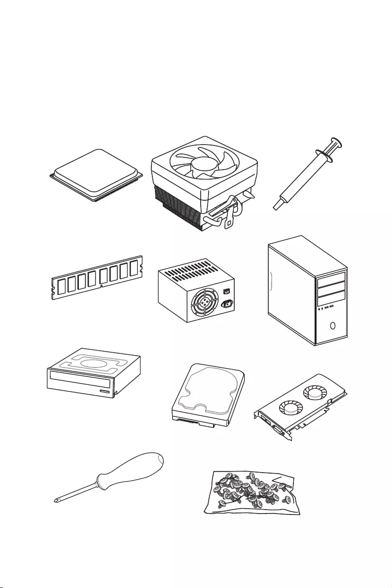
Preparing Tools and Components
|
AMD® AM4 CPU |
Thermal Paste |
|
CPU Fan |
DDR4 Memory
Power Supply Unit
Chassis
SATA DVD Drive
SATA Hard Disk Drive
Graphics Card
Phillips Screwdriver
A Package of Screws
Quick Start 1

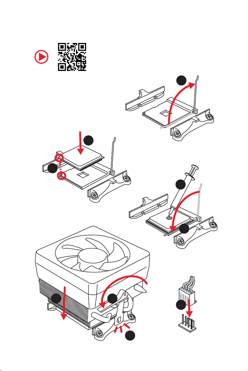
Installing a Processor
1 
3
2 

5
 4
4
2 Quick Start
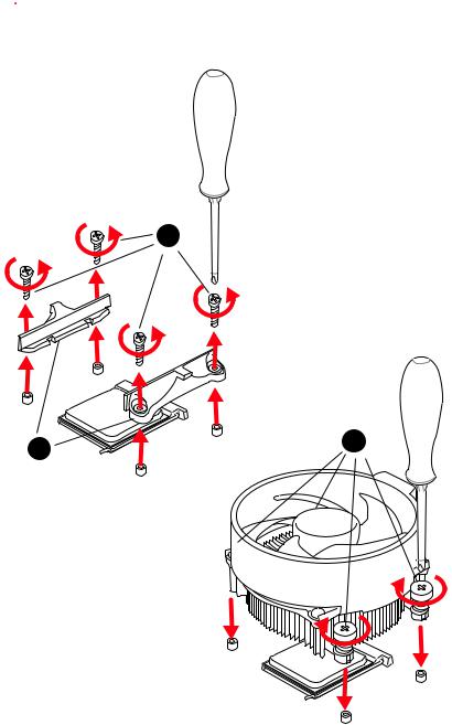
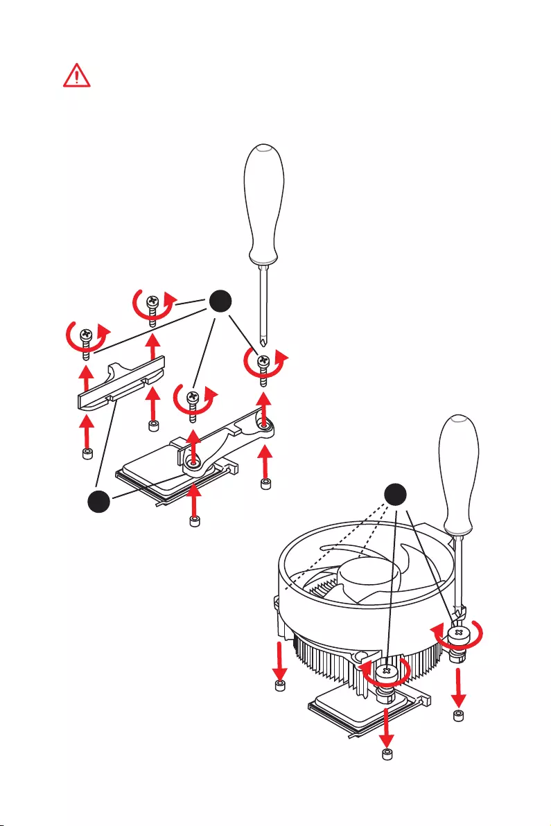
 Important
If you are installing the screw-type CPU heatsink, please follow the figure below to remove the retention module first and then install the heatsink.
1
Quick Start 3

Installing DDR4 memory
1
1 
2
 3 2
3 2 


3 


|
DIMMB2 |
DIMMB2 |
|
|
DIMMB1 |
||
|
DIMMA2 |
DIMMA2 |
DIMMA2 |
|
DIMMA1 |
4 Quick Start
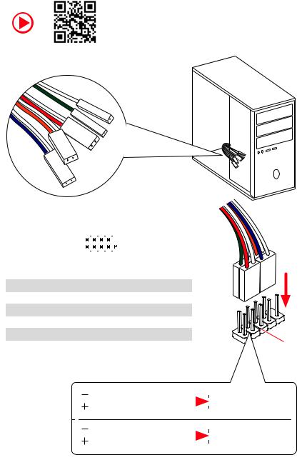
Connecting the Front Panel Header
|
— |
|||
|
LED |
|||
|
LED+ |
POWER |
||
|
POWER |
|||
|
LED |
|||
|
SW |
HDD |
||
|
POWER |
|||
|
SW |
|||
|
RESET |
|
Power LED |
Power Switch |
||||||||||||||||
|
+ — + — |
|||||||||||||||||
|
JFP1 |
2 |
10 |
|||||||||||||||
|
1 |
9 |
||||||||||||||||
|
+ — — + |
Reserved |
||||||||||||||||
|
HDD LED |
Reset Switch |
||||||||||||||||
|
1 |
HDD LED + |
2 |
Power LED + |
||||||||||||||
|
3 |
HDD LED — |
4 |
Power LED — |
||||||||||||||
|
5 |
Reset Switch |
6 |
Power Switch |
||||||||||||||
|
7 |
Reset Switch |
8 |
Power Switch |
||||||||||||||
|
9 |
Reserved |
10 |
No Pin |
||||||||||||||
|
HDD LED |
HDD LED — |
||||||
|
HDD LED + |
|||||||
|
POWER LED — |
|||||||
|
POWER LED |
POWER LED + |
||||||
Quick Start 5
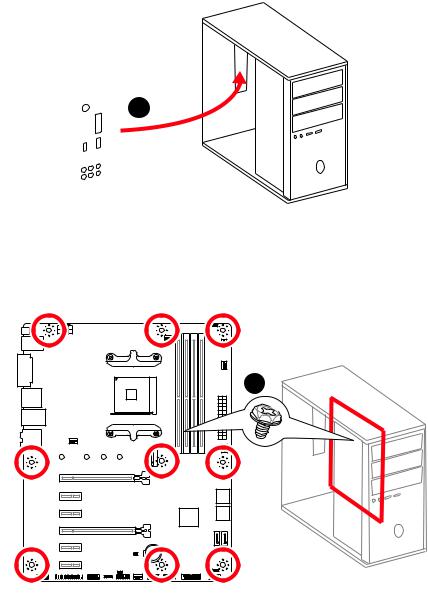
Installing the Motherboard
1
2
BAT1
6 Quick Start
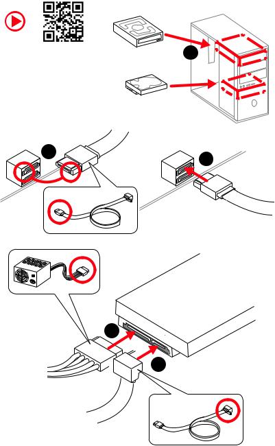
Installing SATA Drives
|
1 |
|
5
 4
4
Quick Start 7
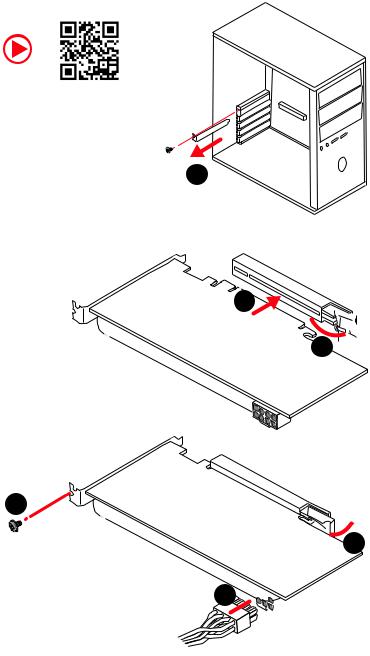
Installing a Graphics Card
1
3
2 
5
 4
4
6 

8 Quick Start
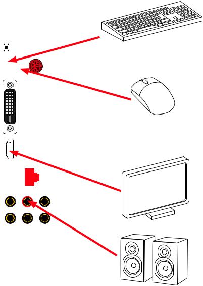
Connecting Peripheral Devices
|
Processor |
||||||||||||
|
graphics |
with |
|||||||||||
|
integrated |
||||||||||||
Quick Start 9
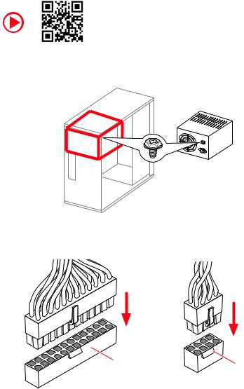
Connecting the Power Connectors
10 Quick Start
![]()
Power On
 1
1
2
3
4
Quick Start 11
|
Contents |
|
|
Quick Start ………………………………………………………………………………………………. |
1 |
|
Preparing Tools and Components……………………………………………………………….. |
1 |
|
Installing a Processor………………………………………………………………………………… |
2 |
|
Installing DDR4 memory ……………………………………………………………………………. |
4 |
|
Connecting the Front Panel Header…………………………………………………………….. |
5 |
|
Installing the Motherboard…………………………………………………………………………. |
6 |
|
Installing SATA Drives………………………………………………………………………………… |
7 |
|
Installing a Graphics Card ………………………………………………………………………….. |
8 |
|
Connecting Peripheral Devices …………………………………………………………………… |
9 |
|
Connecting the Power Connectors…………………………………………………………….. |
10 |
|
Power On………………………………………………………………………………………………… |
11 |
|
Safety Information………………………………………………………………………………….. |
15 |
|
Specifications…………………………………………………………………………………………. |
16 |
|
Package contents …………………………………………………………………………………… |
20 |
|
Block Diagram ………………………………………………………………………………………. |
21 |
|
Rear I/O Panel ……………………………………………………………………………………….. |
22 |
|
LAN Port LED Status Table……………………………………………………………………….. |
22 |
|
Audio Ports Configuration ………………………………………………………………………… |
22 |
|
Realtek Audio Console …………………………………………………………………………….. |
23 |
|
Overview of Components ………………………………………………………………………… |
25 |
|
Processor Socket…………………………………………………………………………………….. |
27 |
|
DIMM Slots……………………………………………………………………………………………… |
28 |
|
PCI_E1~6: PCIe Expansion Slots……………………………………………………………….. |
29 |
|
M2_1: M.2 Slot (Key M) …………………………………………………………………………….. |
30 |
|
SATA1~6: SATA 6Gb/s Connectors …………………………………………………………….. |
31 |
|
JFP1, JFP2: Front Panel Connectors …………………………………………………………. |
31 |
|
CPU_PWR1, ATX_PWR1: Power Connectors ………………………………………………. |
32 |
|
JAUD1: Front Audio Connector …………………………………………………………………. |
32 |
|
JUSB1~2: USB 2.0 Connectors………………………………………………………………….. |
33 |
|
JUSB3: USB 3.2 Gen1 Connector ………………………………………………………………. |
33 |
|
CPU_FAN1, PUMP_FAN1, SYS_FAN1~4: Fan Connectors…………………………….. |
34 |
|
JCOM1: Serial Port Connector ………………………………………………………………….. |
34 |
|
JCI1: Chassis Intrusion Connector…………………………………………………………….. |
35 |
|
JTPM1: TPM Module Connector………………………………………………………………… |
35 |
|
JLPT1: Parallel Port Connector ………………………………………………………………… |
36 |
12 Contents
|
JBAT1: Clear CMOS (Reset BIOS) Jumper ………………………………………………….. |
36 |
|
JRGB1~2: RGB LED connectors ………………………………………………………………… |
37 |
|
EZ Debug LEDs ……………………………………………………………………………………….. |
37 |
|
BIOS Setup…………………………………………………………………………………………….. |
38 |
|
Entering BIOS Setup………………………………………………………………………………… |
38 |
|
Resetting BIOS………………………………………………………………………………………… |
39 |
|
Updating BIOS…………………………………………………………………………………………. |
39 |
|
EZ Mode …………………………………………………………………………………………………. |
41 |
|
Advanced Mode ………………………………………………………………………………………. |
43 |
|
SETTINGS……………………………………………………………………………………………….. |
44 |
|
Advanced………………………………………………………………………………………………… |
44 |
|
Boot……………………………………………………………………………………………………….. |
49 |
|
Security………………………………………………………………………………………………….. |
50 |
|
Save & Exit……………………………………………………………………………………………… |
51 |
|
OC………………………………………………………………………………………………………….. |
53 |
|
M-FLASH ……………………………………………………………………………………………….. |
57 |
|
OC PROFILE……………………………………………………………………………………………. |
58 |
|
HARDWARE MONITOR……………………………………………………………………………… |
59 |
|
Software Description………………………………………………………………………………. |
60 |
|
Installing Windows® 10…………………………………………………………………………….. |
60 |
|
Installing Drivers …………………………………………………………………………………….. |
60 |
|
Installing Utilities ……………………………………………………………………………………. |
60 |
|
APP MANAGER ……………………………………………………………………………………….. |
61 |
|
LIVE UPDATE 6………………………………………………………………………………………… |
62 |
|
COMMAND CENTER ………………………………………………………………………………… |
64 |
|
GAMING APP…………………………………………………………………………………………… |
68 |
|
X-BOOST ………………………………………………………………………………………………… |
73 |
|
MYSTIC LIGHT…………………………………………………………………………………………. |
75 |
|
MYSTIC LIGHT PARTY ………………………………………………………………………………. |
79 |
|
SMART TOOL…………………………………………………………………………………………… |
83 |
|
RAMDISK………………………………………………………………………………………………… |
85 |
|
Nahimic 3……………………………………………………………………………………………….. |
86 |
|
RAID Configuration…………………………………………………………………………………. |
89 |
|
Using AMD RAID Controller BIOS Configuration Utility………………………………… |
89 |
|
Initialize Disks ………………………………………………………………………………………… |
91 |
|
Create Arrays………………………………………………………………………………………….. |
92 |
|
Delete Arrays ………………………………………………………………………………………….. |
93 |
Contents 13
|
Swap Arrays……………………………………………………………………………………………. |
94 |
|
Manage Spares ……………………………………………………………………………………….. |
95 |
|
Change the Controller Options………………………………………………………………….. |
96 |
|
Booting the system from an array……………………………………………………………… |
96 |
|
Pausing the boot sequence for warning messages ……………………………………… |
96 |
|
Change the Staggered Spinup Count …………………………………………………………. |
97 |
|
Using UEFI to create a 2.2TB RAID ……………………………………………………………. |
98 |
|
Installing RAID Driver………………………………………………………………………………. |
99 |
|
Troubleshooting …………………………………………………………………………………… |
100 |
|
Regulatory Notices……………………………………………………………………………….. |
101 |
14 Contents
Safety Information
yThe components included in this package are prone to damage from electrostatic discharge (ESD). Please adhere to the following instructions to ensure successful computer assembly.
yEnsure that all components are securely connected. Loose connections may cause the computer to not recognize a component or fail to start.
yHold the motherboard by the edges to avoid touching sensitive components.
yIt is recommended to wear an electrostatic discharge (ESD) wrist strap when handling the motherboard to prevent electrostatic damage. If an ESD wrist strap is not available, discharge yourself of static electricity by touching another metal object before handling the motherboard.
yStore the motherboard in an electrostatic shielding container or on an anti-static pad whenever the motherboard is not installed.
yBefore turning on the computer, ensure that there are no loose screws or metal components on the motherboard or anywhere within the computer case.
yDo not boot the computer before installation is completed. This could cause permanent damage to the components as well as injury to the user.
yIf you need help during any installation step, please consult a certified computer technician.
yAlways turn off the power supply and unplug the power cord from the power outlet before installing or removing any computer component.
yKeep this user guide for future reference.
yKeep this motherboard away from humidity.
yMake sure that your electrical outlet provides the same voltage as is indicated on the PSU, before connecting the PSU to the electrical outlet.
yPlace the power cord such a way that people can not step on it. Do not place anything over the power cord.
yAll cautions and warnings on the motherboard should be noted.
yIf any of the following situations arises, get the motherboard checked by service personnel:
Liquid has penetrated into the computer.
The motherboard has been exposed to moisture.
The motherboard does not work well or you can not get it work according to user guide.
The motherboard has been dropped and damaged.
The motherboard has obvious sign of breakage.
yDo not leave this motherboard in an environment above 60°C (140°F), it may damage the motherboard.
Safety Information 15

Specifications
|
Supports 1st, 2nd and 3rd Gen AMD Ryzen™, Ryzen™ |
||
|
CPU |
with Radeon™ Vega Graphics, 2nd Gen AMD Ryzen™ with |
|
|
Radeon™ Graphics and Athlon™ with Radeon™ Vega |
||
|
Graphics Desktop Processors for Socket AM4 |
||
|
Chipset |
AMD® B450 Chipset |
|
|
y4x DDR4 memory slots, support up to 64GB* |
||
|
Supports 1866/ 2133/ 2400/ 2667Mhz (by JEDEC) |
||
|
Supports 2667/ 2800/ 2933/ 3000/ 3066/ 3200/ 3466 MHz |
||
|
Memory |
(by A-XMP OC MODE) |
|
|
yDual channel memory architecture |
||
|
ySupports non-ECC UDIMM memory |
||
|
ySupports ECC UDIMM memory (non-ECC mode) |
||
|
* Please refer www.msi.com for more information on compatible memory. |
||
|
y1x PCIe 3.0 x16 slot (PCI_E1) |
||
|
1st, 2nd and 3rd Gen AMD Ryzen™ support x16 mode |
||
|
Ryzen™ with Radeon™ Vega Graphics and 2nd Gen AMD |
||
|
Ryzen™ with Radeon™ Graphics support x8 mode |
||
|
Expansion Slots |
Athlon™ with Radeon™ Vega Graphics support x4 mode |
|
|
y1x PCIe 2.0 x16 slot (PCI_E4, supports x4 mode)* |
||
|
y4x PCIe 2.0 x1 slots* |
||
|
* PCI_E4 will run x1 speed when installing devices in PCI_E2/ PCI_E3/ PCI_E5 |
||
|
slot. |
||
|
y1x DVI-D port, support a maximum resolution of 1920×1200 |
||
|
@60Hz* |
||
|
y1x HDMI™ 1.4 port, supports a maximum resolution of |
||
|
Onboard Graphics |
4096×2160 @30Hz, 2560×1600 @60Hz* |
|
|
* Only support when using Ryzen™ with Radeon™ Vega Graphics, 2nd Gen AMD |
||
|
Ryzen™ with Radeon™ Graphics and Athlon™ with Radeon™ Vega Graphics |
||
|
processors |
||
|
* Maximum shared memory of 2048 MB |
||
|
Multi-GPU |
ySupports 2-Way AMD® CrossFire™ Technology |
|
|
LAN |
y1x Realtek® 8111H Gigabit LAN controller |
|
|
Audio |
yRealtek® ALC892 Codec |
|
|
y7.1-Channel High Definition Audio |
||
|
Continued on next page |
16 Specifications

Continued from previous page
|
AMD® CPU |
||
|
y2x SATA 6Gb/s ports* |
||
|
y1x M.2 slot (Key M)* |
||
|
Supports PCIe 3.0 x4 (1st, 2nd and 3rd Gen AMD |
||
|
Ryzen™, Ryzen™ with Radeon™ Vega Graphics and 2nd |
||
|
Storage |
Gen AMD Ryzen™ with Radeon™ Graphics) or PCIe 3.0 x2 |
|
|
(Athlon™ with Radeon™ Vega Graphics) and SATA 6Gb/s |
||
|
2242/ 2260/ 2280/ 22110 storage devices |
||
|
AMD® B450 Chipset |
||
|
y4x SATA 6Gb/s ports |
||
|
* SATA5 and SATA6 ports will be unavailable when installing a M.2 device in M.2 |
||
|
slot. |
||
|
AMD® B450 Chipset |
||
|
RAID |
ySupports RAID 0, RAID1 and RAID 10 for SATA storage |
|
|
devices |
||
|
yAMD® B450 Chipset |
||
|
2x USB 3.2 Gen2 (SuperSpeed USB 10Gbps) Type-A |
||
|
ports on the back panel |
||
|
2x USB 3.2 Gen1 (SuperSpeed USB) ports available |
||
|
through the internal USB 3.2 Gen1 connector |
||
|
USB |
6x USB 2.0 (High-speed USB) ports (2 Type-A ports on |
|
|
the back panel, 4 ports available through the internal |
||
|
USB 2.0 connectors) |
||
|
yAMD® CPU |
||
|
2x USB 3.2 Gen1 (SuperSpeed USB) Type-A ports on the |
||
|
back panel |
||
|
y1x Flash BIOS Button |
||
|
y1x PS/2 keyboard/ mouse combo port |
||
|
y2x USB 2.0 Type-A ports |
||
|
Back Panel |
y1x DVI-D port |
|
|
y1x HDMI™ port |
||
|
Connectors |
y2x USB 3.2 Gen1 Type-A ports |
|
|
y1x LAN (RJ45) port |
||
|
y2x USB 3.2 Gen2 Type-A ports |
||
|
y6x audio jacks |
||
|
Continued on next page |
Specifications 17

Continued from previous page
y1x 24-pin ATX main power connector
y1x 8-pin ATX 12V power connector
y6x SATA 6Gb/s connectors
y2x USB 2.0 connectors (support additional 4 USB 2.0 ports)
y1x USB 3.2 Gen1 connectors (support additional 2 USB 3.2 Gen1 ports)
y1x 4-pin CPU fan connector
y1x 4-pin water-pump-fan connector
Internal Connectors y4x 4-pin system fan connectors
y1x TPM module connector
y1x Front panel audio connector
y2x System panel connectors
y1x Serial port connector
y1x Parallel port connector
y1x Chassis Intrusion connector
y1x Clear CMOS jumper
y2x 5050 RGB LED strip 12V connectors
|
I/O Controller |
NUVOTON NCT6797 Controller Chip |
|
|
yCPU/System temperature detection |
||
|
Hardware Monitor |
yCPU/System fan speed detection |
|
|
yCPU/System fan speed control |
||
|
Form Factor |
yATX Form Factor |
|
|
y12 in. x 9.6 in. (30.5 cm x 24.4 cm) |
||
|
y1x 256 Mb flash |
||
|
BIOS Features |
yUEFI AMI BIOS |
|
|
yACPI 6.1, SM BIOS 2.8 |
||
|
yMulti-language |
||
|
Continued on next page |
18 Specifications

Continued from previous page
|
yDrivers |
|
|
yAPP MANAGER |
|
|
ySUPER CHARGER |
|
|
yCOMMAND CENTER |
|
|
yLIVE UPDATE 6 |
|
|
ySMART TOOL |
|
|
yRAMDISK |
|
|
Software |
yX-BOOST |
|
yGAMING APP |
|
|
yMYSTIC LIGHT |
|
|
yNahimic Audio |
|
|
yOpen Broadcaster Software (OBS) |
|
|
yCPU-Z MSI GAMING |
|
|
yNorton™ Internet Security Solution |
|
|
yGoogle Chrome™, Google Toolbar, Google Drive |
|
|
yAudio |
|
|
Audio Boost |
|
|
Nahimic 3 |
|
|
Voice Boost |
|
|
yStorage |
|
|
Turbo M.2 |
|
|
StoreMI |
|
|
Special Features |
yFan |
|
Pump Fan |
|
|
GAMING Fan Control |
|
|
yLED |
|
|
Mystic Light |
|
|
Mystic Light Extension (RGB) |
|
|
Mystic light SYNC |
|
|
EZ DEBUG LED |
|
|
Continued on next page |
Specifications 19

Continued from previous page
|
yProtection |
||
|
PCIe Steel Armor |
||
|
PCIe Steel Slot |
||
|
yPerformance |
||
|
Multi GPU-CrossFire Technology |
||
|
DDR4 Boost |
||
|
GAME Boost |
||
|
AMD Turbo USB 3.2 Gen 2 |
||
|
Special Features |
CORE Boost |
|
|
yVR |
||
|
VR Ready |
||
|
yGamer Experience |
||
|
GAMING HOTKEY |
||
|
GAMING MOUSE Control |
||
|
yBIOS |
||
|
Click BIOS 5 |
||
|
yCertification |
||
|
GAMING Certified |
||
Package contents
Please check the contents of your motherboard package. It should contain:
yMotherboard
yDriver DVD
yUser Manual
yQuick Installation Guide
yCase Stand-off Notification
ySATA 6G Cable x2
yProduct Registration Card
yCase Badge
yI/O Shielding
yM.2 Screw x1
Important
If any of the above items are damaged or missing, please contact your retailer.
20 Package contents
![]()
Block Diagram
|
2 Channel DDR4 Memory |
||||
|
CPU |
||||
|
2x USB 3.2 Gen1 |
||||
|
PCI Express Bus |
Realtek |
|||
|
ALC892 |
||||
|
NV6797 |
PCI |
Audio Jacks |
||
|
Super I/O |
||||
|
PCIe x1 |
||||
|
PS/2 Mouse / Keyboard |
Express |
Switch |
||
|
PCIe x1 |
||||
|
Bus |
PCIe x1 |
|||
|
PCIe x4 |
||||
|
1 x M.2 |
||||
|
Switch |
PCIe x1 |
|||
|
CHIPSET |
|
2x SATA 6Gb/s |
|
|
4x SATA 6Gb/s |
2 x USB 3.2 Gen2 |
|
6 x USB 2.0 |
2 x USB 3.2 Gen1 |
Block Diagram 21
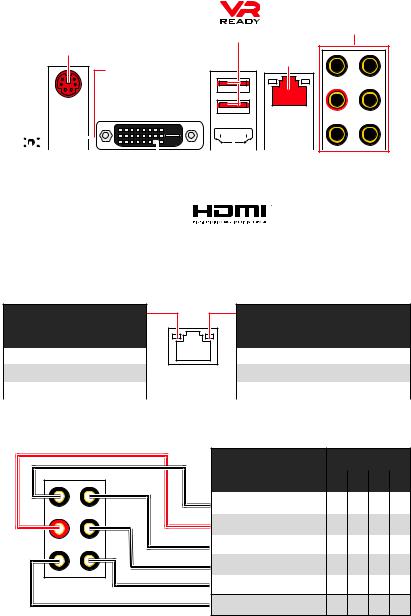
Rear I/O Panel
|
USB 3.2 Gen1 Type-A |
Audio Ports |
|
PS/2 |
|
|
LAN |
|
|
Flash BIOS Port |
|
DVI-D |
||||||||||||||||||
|
USB |
2.0 Type-A |
USB 3.2 Gen2 |
||||||||||||||||
|
Type-A |
||||||||||||||||||
|
Flash BIOS Button |
yFlash BIOS Port/ Button — Please refer to page 40 for Updating BIOS with Flash BIOS Button.
LAN Port LED Status Table
Link/ Activity LED
|
Status |
Description |
|
Off |
No link |
|
Yellow |
Linked |
|
Blinking |
Data activity |
Speed LED
|
Status |
Description |
|
Off |
10 Mbps connection |
|
Green |
100 Mbps connection |
|
Orange |
1 Gbps connection |
Audio Ports Configuration
|
Audio Ports |
Channel |
||
|
2 |
4 |
6 |
8 |
|
Line-In |
|||
|
Line-Out/ Front Speaker Out ● |
● |
● |
● |
|
Rear Speaker Out |
● |
● |
● |
|
Center/ Subwoofer Out |
● |
● |
|
|
Side Speaker Out |
● |
Mic In
(●: connected, Blank: empty)
22 Rear I/O Panel
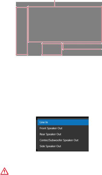
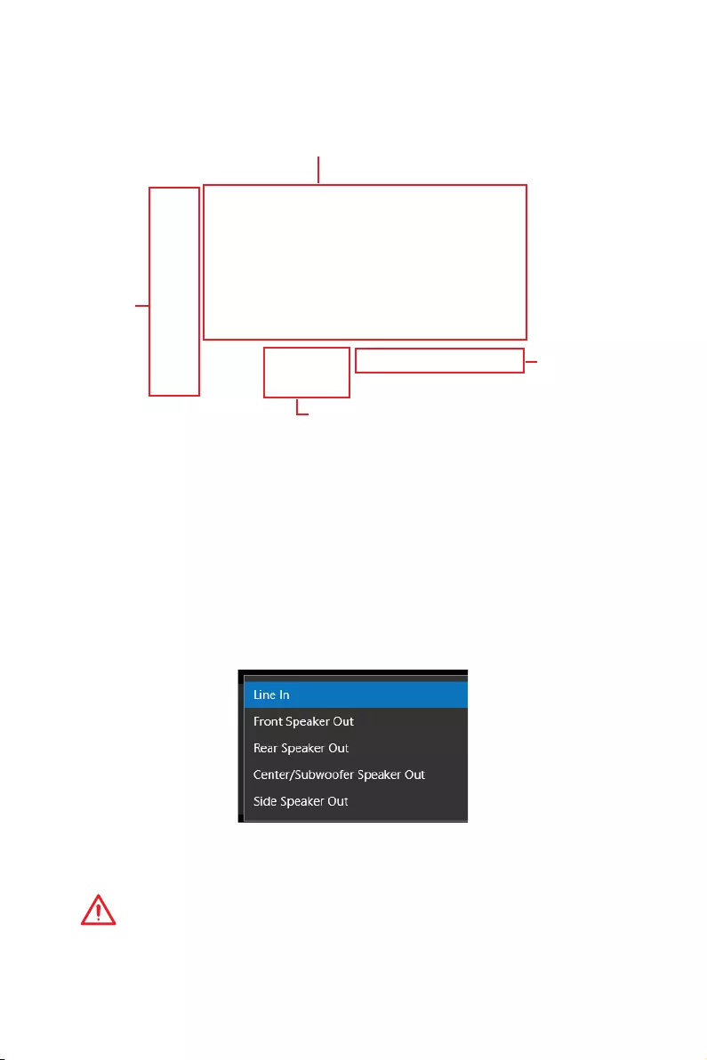
Realtek Audio Console
After Realtek Audio Console is installed. You can use it to change sound settings to get better sound experience.
Application Enhancement
Device 
Selection
 Main Volume
 Jack Status
yDevice Selection — allows you to select a audio output source to change the related options. The check sign indicates the devices as default.
yApplication Enhancement — the array of options will provide you a complete guidance of anticipated sound effect for both output and input device.
yMain Volume — controls the volume or balance the right/left side of the speakers that you plugged in front or rear panel by adjust the bar.
yJack Status — depicts all render and capture devices currently connected with your computer.
Auto popup dialog
When you plug into a device at an audio jack, a dialogue window will pop up asking you which device is current connected.
Each jack corresponds to its default setting as shown on the next page.
Important
The pictures above for reference only and may vary from the product you purchased.
Rear I/O Panel 23

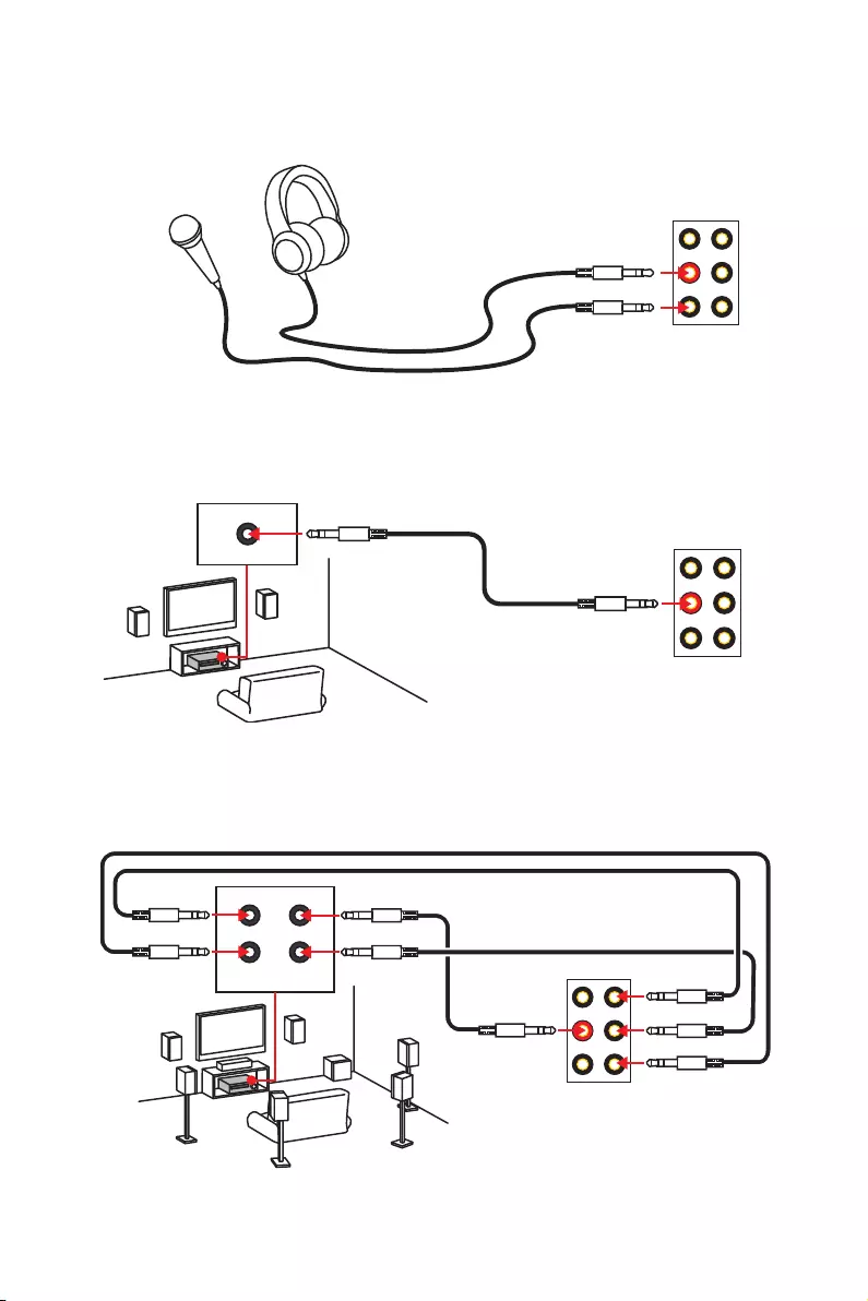
Audio jacks to headphone and microphone diagram
Audio jacks to stereo speakers diagram
AUDIO INPUT
Audio jacks to 7.1-channel speakers diagram
AUDIO INPUT
|
Rear |
Front |
|
Side |
Center/ |
|
Subwoofer |
24 Rear I/O Panel

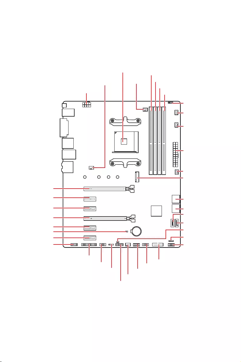
Overview of Components
PCI_E1
PCI_E2
PCI_E3
PCI_E4
PCI_E5 JBAT1
PCI_E6 JAUD1
|
Processor |
||
|
Socket |
||
|
DIMMA1 |
||
|
SYS_FAN1 |
CPU_FAN1 |
DIMMA2 |
|
DIMMB1 |
||
|
CPU_PWR1 |
||
|
DIMMB2 |
||
|
JRGB1 |
||
|
PUMP_FAN1 |
||
|
SYS_FAN3 |
||
|
ATX_PWR1 |
||
|
SYS_FAN4 |
||
|
M2_1 |
|
SATA▼5▲6 |
|||||||||||||||||||||||||||||||||
|
SATA▼3▲4 |
|||||||||||||||||||||||||||||||||
|
SATA2 |
|||||||||||||||||||||||||||||||||
|
SATA1 |
|||||||||||||||||||||||||||||||||
|
BAT1 |
JCI1 |
||||||||||||||||||||||||||||||||
|
JFP2 |
|||||||||||||||||||||||||||||||||
|
JFP1 |
|||||||||||||||||||||||||||||||||
|
JLPT1 |
|||||||||||||||||||||||||||||||||
|
JUSB3 |
|||||||||||||||||||||||||||||||||
|
JCOM1 |
JUSB2 |
||||||||||||||||||||||||||||||||
|
JRGB2 |
JUSB1 |
||||||||||||||||||||||||||||||||
|
SYS |
_FAN2 |
JTPM1
Overview of Components 25

Component Contents
|
Port Name |
Port Type |
Page |
|
CPU_FAN1, PUMP_FAN1, SYS_FAN1~4 |
Fan Connectors |
34 |
|
CPU_PWR1, ATX_PWR1 |
Power Connectors |
32 |
|
DIMMA1, DIMMA2, DIMMB1, DIMMB2 |
DIMM Slots |
28 |
|
JAUD1 |
Front Audio Connector |
32 |
|
JBAT1 |
Clear CMOS Jumper |
36 |
|
JCI1 |
Chassis Intrusion Connector |
35 |
|
JCOM1 |
Serial Port Connector |
34 |
|
JFP1, JFP2 |
Front Panel Connectors |
31 |
|
JLPT1 |
Parallel Port Connector |
36 |
|
JRGB1~2 |
RGB LED connectors |
37 |
|
JTPM1 |
TPM Module Connector |
35 |
|
JUSB1~2 |
USB 2.0 Connectors |
33 |
|
JUSB3 |
USB 3.2 Gen1 Connector |
33 |
|
M2_1 |
M.2 Slot (Key M) |
30 |
|
PCI_E1~6 |
PCIe Expansion Slots |
29 |
|
Processor Socket |
AM4 socket |
27 |
|
SATA1~6 |
SATA 6Gb/s Connectors |
31 |
26 Overview of Components
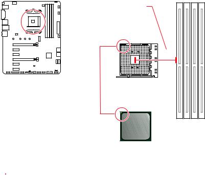
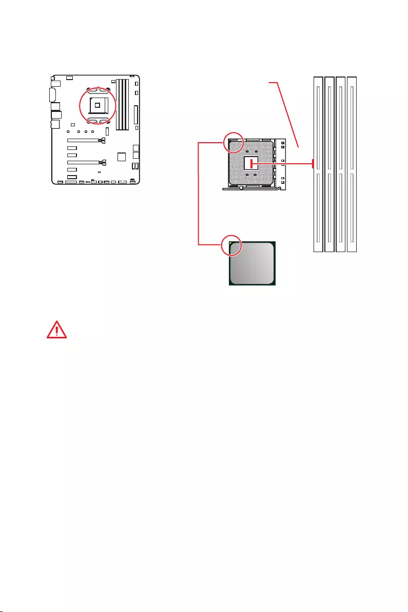
Processor Socket
Distance from the center of the
CPU to the nearest DIMM slot.
53.43 mm
Introduction to the AM4 CPU
The surface of the AM4 CPU has a yellow triangle to assist in correctly lining up the CPU for motherboard placement. The yellow triangle is the Pin 1 indicator.
 Important
yWhen changing the processor, the system configuration could be cleared and reset BIOS to default values, due to the AM4 processor’s architecture.
yAlways unplug the power cord from the power outlet before installing or removing the CPU.
yWhen installing a CPU, always remember to install a CPU heatsink. A CPU heatsink is necessary to prevent overheating and maintain system stability.
yConfirm that the CPU heatsink has formed a tight seal with the CPU before booting your system.
yOverheating can seriously damage the CPU and motherboard. Always make sure the cooling fans work properly to protect the CPU from overheating. Be sure to apply an even layer of thermal paste (or thermal tape) between the CPU and the heatsink to enhance heat dissipation.
yIf you purchased a separate CPU and heatsink/ cooler, Please refer to the documentation in the heatsink/ cooler package for more details about installation.
yThis motherboard is designed to support overclocking. Before attempting to overclock, please make sure that all other system components can tolerate overclocking. Any attempt to operate beyond product specifications is not recommended. MSI® does not guarantee the damages or risks caused by inadequate operation beyond product specifications.
Overview of Components 27
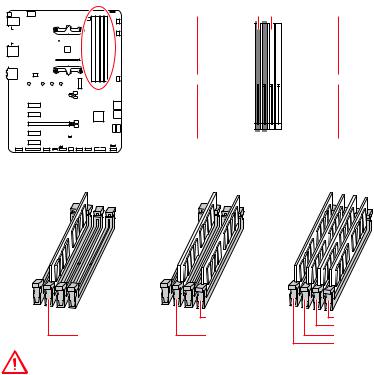
DIMM Slots
 DIMMA1
 DIMMB1
|
Channel A |
Channel B |
|||||||||||||||||||||
 DIMMA2
 DIMMB2
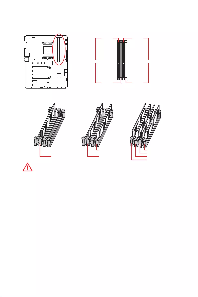
Memory module installation recommendation
|
DIMMB2 |
DIMMB2 |
|
|
DIMMB1 |
||
|
DIMMA2 |
DIMMA2 |
DIMMA2 |
|
DIMMA1 |
Important
yAlways insert memory modules in the DIMMA2 slot first.
yDue to chipset resource usage, the available capacity of memory will be a little less than the amount of installed.
yBased on processor specification, the Memory DIMM voltage below 1.35V is suggested to protect the processor.
ySome memory modules may operate at a lower frequency than the marked value when overclocking due to the memory frequency operates dependent on its Serial Presence Detect (SPD). Go to BIOS and find the DRAM Frequency! to set the memory frequency if you want to operate the memory at the marked or at a higher frequency.
yIt is recommended to use a more efficient memory cooling system for full DIMMs installation or overclocking.
yThe stability and compatibility of installed memory module depend on installed CPU and devices when overclocking.
yDue to AM4 processor/memory controller official specification limitation, the frequency of memory modules may operate lower than the marked value under the default state. Please refer www.msi.com for more information on compatible memory.
28 Overview of Components
PCI_E1~6: PCIe Expansion Slots
BAT1
PCI_E1: PCIe 3.0 x16*/ x8**/ x4*** PCI_E2: PCIe 2.0 x1
PCI_E3: PCIe 2.0 x1
PCI_E4: PCIe 2.0 x4
PCI_E5: PCIe 2.0 x1
PCI_E6: PCIe 2.0 x1
*For 1st, 2nd and 3rd Gen AMD Ryzen™ processors
**For Ryzen™ with Radeon™ Vega Graphics and 2nd Gen AMD Ryzen™ with Radeon™ Graphics processors
***For Athlon™ with Radeon™ Vega Graphics processor
Important
yIf you install a large and heavy graphics card, you need to use a tool such as MSI Gaming Series Graphics Card Bolster to support its weight to prevent deformation of the slot.
yFor a single PCIe x16 expansion card installation with optimum performance, using the PCI_E1 slot is recommended.
yWhen adding or removing expansion cards, always turn off the power supply and unplug the power supply power cable from the power outlet. Read the expansion card’s documentation to check for any necessary additional hardware or software changes.
yPCI_E4 will run x1 speed when installing devices in PCI_E2/ PCI_E3/ PCI_E5 slot.
PCIe bandwidth of Multiple graphics cards
|
Slot |
Single |
2-Way |
||||
|
@ 3.0 x16* |
@ 3.0 x16* |
|||||
|
PCI_E1 (CPU) |
or @ 3.0 x8** |
or @ 3.0 x8** |
||||
|
or @ 3.0 x4*** |
or @ 3.0 x4*** |
|||||
|
PCI_E2 (PCH) |
2.0 x1 |
2.0 x1 |
Empty |
Empty |
― |
|
|
PCI_E3 (PCH) |
2.0 x1 |
Empty |
2.0 x1 |
Empty |
― |
|
|
PCI_E4 (PCH) |
2.0 x1 |
2.0 x1 |
2.0 x1 |
2.0 x1 |
@2.0 x4 |
|
|
PCI_E5 (PCH) |
2.0 x1 |
Empty |
Empty |
2.0 x1 |
― |
|
|
PCI_E6 (PCH) |
2.0 x1 |
2.0×1 |
||||
|
M2_1 (CPU) |
3.0 x4*/** |
3.0 x4*/** |
||||
|
or 3.0 x2*** |
or 3.0 x2*** |
|||||
|
(─: unavailable, @: graphics card, *: for 1st, 2nd and 3rd Gen AMD Ryzen™ processors, |
**: for Ryzen™ with Radeon™ Vega Graphics and 2nd Gen AMD Ryzen™ with Radeon™ Graphics processors, ***: for Athlon™ with Radeon™ Vega Graphics processor)
Overview of Components 29
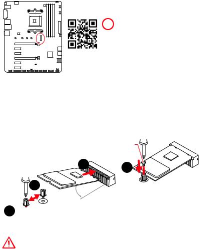
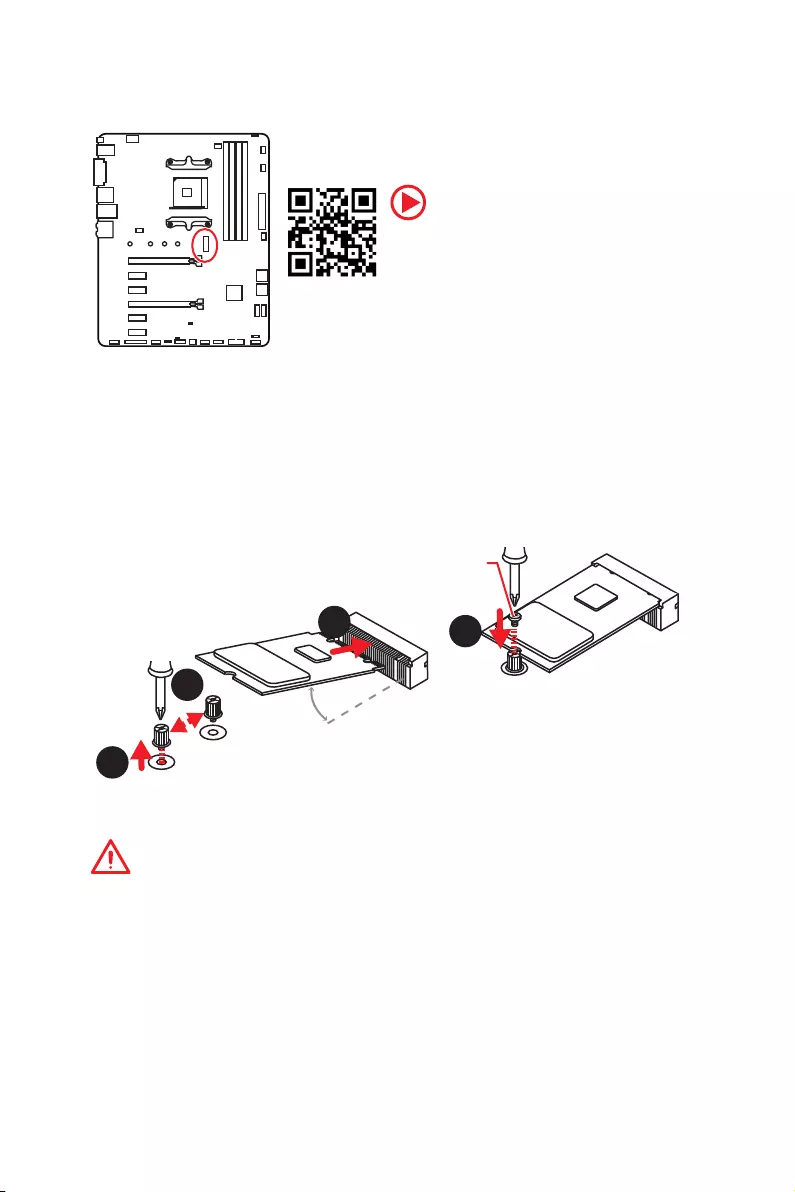
M2_1: M.2 Slot (Key M)
 Video Demonstration
Watch the video to learn how to Install M.2 module.
Installing M.2 SSD
1.Loosen the M.2 riser screw from the motherboard.
2.Move and fasten the M.2 riser screw to the appropriate location for your M.2 SSD.
3.Insert your M.2 SSD into the M.2 slot at a 30-degree angle.
4.Secure the M.2 SSD in place with the supplied M.2 screw.
|
Supplied |
|
|
M.2 screw |
|
|
3 |
4 |
|
2 |
|
|
30° |
1 
Important
SATA5 and SATA6 ports will be unavailable when installing a M.2 device in M.2 slot.
30 Overview of Components
![]()
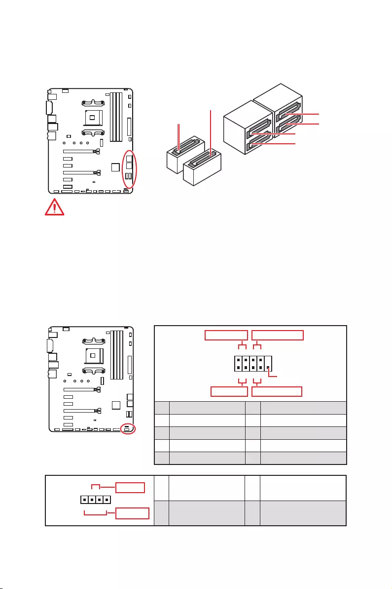
SATA1~6: SATA 6Gb/s Connectors
These connectors are SATA 6Gb/s interface ports. Each connector can connect to one SATA device.
SATA1
|
SATA2 |
SATA6 |
|
|
SATA5 |
||
|
SATA4 |
||
|
SATA3 |
Important
yPlease do not fold the SATA cable at a 90-degree angle. Data loss may result during transmission otherwise.
ySATA cables have identical plugs on either sides of the cable. However, it is recommended that the flat connector be connected to the motherboard for space saving purposes.
ySATA5 and SATA6 ports will be unavailable when installing a M.2 device in M.2 slot.
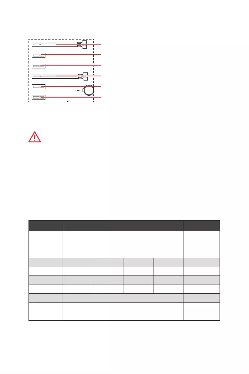
JFP1, JFP2: Front Panel Connectors
These connectors connect to the switches and LEDs on the front panel.
|
Power LED |
Power Switch |
|||||||||||||||||||||||||||||||||||||||||
|
+ — + — |
||||||||||||||||||||||||||||||||||||||||||
|
JFP1 |
2 |
10 |
||||||||||||||||||||||||||||||||||||||||
|
1 |
9 |
|||||||||||||||||||||||||||||||||||||||||
|
+ — — + |
Reserved |
|||||||||||||||||||||||||||||||||||||||||
|
HDD LED |
Reset Switch |
|||||||||||||||||||||||||||||||||||||||||
|
1 |
HDD LED + |
2 |
Power LED + |
|||||||||||||||||||||||||||||||||||||||
|
3 |
HDD LED — |
4 |
Power LED — |
|||||||||||||||||||||||||||||||||||||||
|
5 |
Reset Switch |
6 |
Power Switch |
|||||||||||||||||||||||||||||||||||||||
|
7 |
Reset Switch |
8 |
Power Switch |
|||||||||||||||||||||||||||||||||||||||
|
9 |
Reserved |
10 |
No Pin |
|||||||||||||||||||||||||||||||||||||||
|
Buzzer |
1 |
Speaker — |
2 |
Buzzer + |
||
|
Speaker |
3 |
Buzzer — |
4 |
Speaker + |
||
Overview of Components 31

CPU_PWR1, ATX_PWR1: Power Connectors
These connectors allow you to connect an ATX power supply.
|
8 |
5 |
CPU_PWR1 |
||||
|
4 |
1 |
|||||
|
1 |
Ground |
5 |
+12V |
|||
|
2 |
Ground |
6 |
+12V |
|||
|
3 |
Ground |
7 |
+12V |
|||
|
4 |
Ground |
8 |
+12V |
|||
|
1 |
+3.3V |
13 |
+3.3V |
|||
|
2 |
+3.3V |
14 |
-12V |
|||
|
3 |
Ground |
15 |
Ground |
|||
|
12 |
24 |
4 |
+5V |
16 |
PS-ON# |
|
|
5 |
Ground |
17 |
Ground |
|||
|
6 |
+5V |
18 |
Ground |
|||
|
ATX_PWR1 |
||||||
|
7 |
Ground |
19 |
Ground |
|||
|
8 |
PWR OK |
20 |
Res |
|||
|
1 |
13 |
9 |
5VSB |
21 |
+5V |
|
|
10 |
+12V |
22 |
+5V |
|||
|
11 |
+12V |
23 |
+5V |
|||
|
12 |
+3.3V |
24 |
Ground |
 Important
Make sure that all the power cables are securely connected to a proper ATX power supply to ensure stable operation of the motherboard.
JAUD1: Front Audio Connector
This connector allows you to connect audio jacks on the front panel.
|
2 |
10 |
||||||||||||||||||||||||||||||
|
1 |
9 |
||||||||||||||||||||||||||||||
|
1 |
MIC L |
2 |
Ground |
||||||||||||||||||||||||||||
|
3 |
MIC R |
4 |
NC |
||||||||||||||||||||||||||||
|
5 |
Head Phone R |
6 |
MIC Detection |
||||||||||||||||||||||||||||
|
7 |
SENSE_SEND |
8 |
No Pin |
||||||||||||||||||||||||||||
|
9 |
Head Phone L |
10 |
Head Phone Detection |
||||||||||||||||||||||||||||
32 Overview of Components
 Loading…
1
Quick Start
DDR4 Memory
Graphics Card
SATA Hard Disk Drive
SATA DVD Drive
Phillips Screwdriver
Chassis
Power Supply Unit
A Package of Screws
Thermal Paste
Quick Start
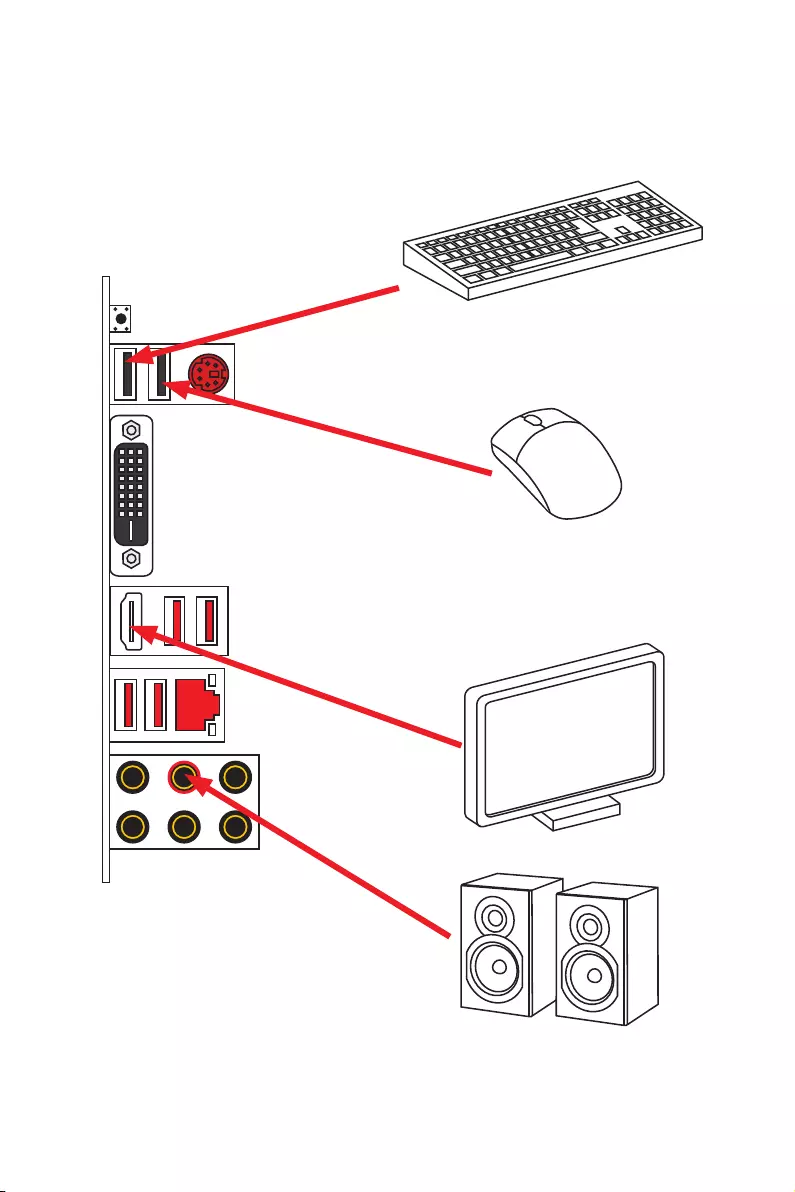
Thank you for purchasing the MSI® B450 GAMING PLUS MAX motherboard. This Quick
Start section provides demonstration diagrams about how to install your computer.
Some of the installations also provide video demonstrations. Please link to the URL to
watch it with the web browser on your phone or tablet. You may have even link to the
URL by scanning the QR code
Preparing Tools and Components
AMD® AM4 CPU
CPU Fan
2Quick Start
Installing a Processor
1
2
3
6
4
5
7
8
9
3
Quick Start
1
23
Important
If you are installing the screw-type CPU heatsink, please follow the figure below to
remove the retention module first and then install the heatsink.
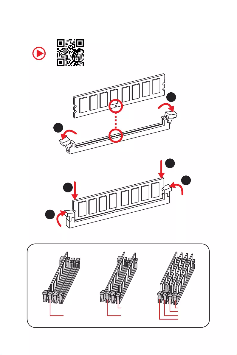
4Quick Start
Installing DDR4 memory
DIMMB2 DIMMB2
DIMMB1
DIMMA2 DIMMA2 DIMMA2
DIMMA1
1
1
2
2
3
3
5
Quick Start
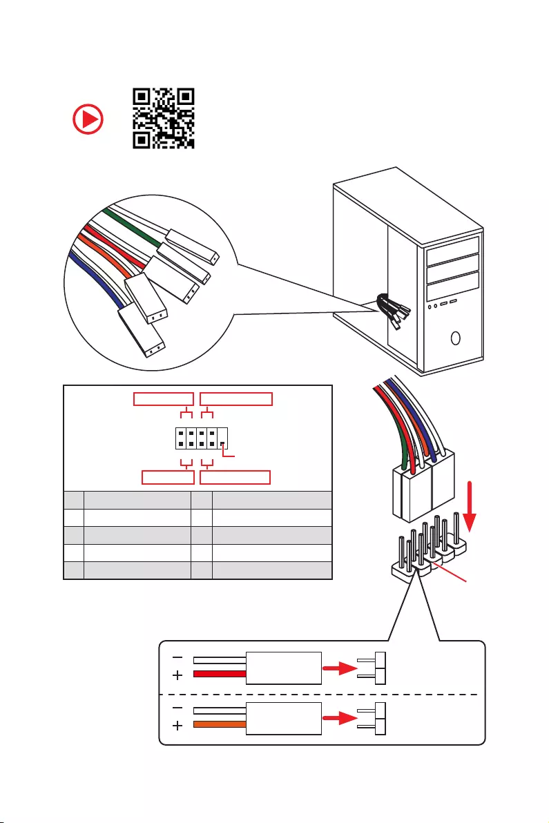
Connecting the Front Panel Header
RESET SW
POWER SW
POWER LED+
POWER LED-
HDD LED
HDD LED
RESET SW
JFP1
HDD LED HDD LED —
HDD LED +
POWER LED —
POWER LED +
POWER LED
1
2 10
9
+
+
+— ——
—
+
Power LED
HDD LED Reset Switch
Reserved
Power Switch
JFP1
1 HDD LED + 2 Power LED +
3 HDD LED — 4 Power LED —
5 Reset Switch 6 Power Switch
7 Reset Switch 8 Power Switch
9 Reserved 10 No Pin

6Quick Start
BAT1
Installing the Motherboard
1
2
7
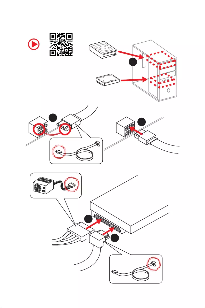
Quick Start
Installing SATA Drives
1
23
4
5
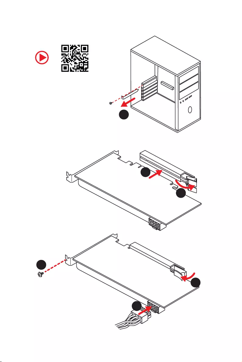
8Quick Start
1
Installing a Graphics Card
2
3
4
5
6
9
Quick Start
Connecting Peripheral Devices
Processor with integrated
graphics
10 Quick Start
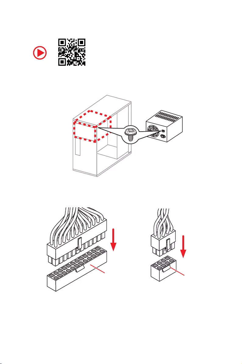
Connecting the Power Connectors
ATX_PWR1 CPU_PWR1

11
Quick Start
Power On
1
4
2
3

12 Contents
Contents
Quick Start ………………………………………………………………………………………………. 1
Preparing Tools and Components ……………………………………………………………….. 1
Installing a Processor ………………………………………………………………………………… 2
Installing DDR4 memory ……………………………………………………………………………. 4
Connecting the Front Panel Header …………………………………………………………….. 5
Installing the Motherboard …………………………………………………………………………. 6
Installing SATA Drives………………………………………………………………………………… 7
Installing a Graphics Card ………………………………………………………………………….. 8
Connecting Peripheral Devices …………………………………………………………………… 9
Connecting the Power Connectors …………………………………………………………….. 10
Power On………………………………………………………………………………………………… 11
Safety Information ………………………………………………………………………………….. 15
Specifications …………………………………………………………………………………………. 16
Package contents …………………………………………………………………………………… 20
Block Diagram ………………………………………………………………………………………. 21
Rear I/O Panel ……………………………………………………………………………………….. 22
LAN Port LED Status Table……………………………………………………………………….. 22
Audio Ports Configuration ………………………………………………………………………… 22
Realtek Audio Console …………………………………………………………………………….. 23
Overview of Components ………………………………………………………………………… 25
Processor Socket …………………………………………………………………………………….. 27
DIMM Slots ……………………………………………………………………………………………… 28
PCI_E1~6: PCIe Expansion Slots ……………………………………………………………….. 29
M2_1: M.2 Slot (Key M) …………………………………………………………………………….. 30
SATA1~6: SATA 6Gb/s Connectors …………………………………………………………….. 31
JFP1, JFP2: Front Panel Connectors …………………………………………………………. 31
CPU_PWR1, ATX_PWR1: Power Connectors ………………………………………………. 32
JAUD1: Front Audio Connector …………………………………………………………………. 32
JUSB1~2: USB 2.0 Connectors ………………………………………………………………….. 33
JUSB3: USB 3.2 Gen1 Connector ………………………………………………………………. 33
CPU_FAN1, PUMP_FAN1, SYS_FAN1~4: Fan Connectors …………………………….. 34
JCOM1: Serial Port Connector ………………………………………………………………….. 34
JCI1: Chassis Intrusion Connector …………………………………………………………….. 35
JTPM1: TPM Module Connector ………………………………………………………………… 35
JLPT1: Parallel Port Connector ………………………………………………………………… 36

13
Contents
JBAT1: Clear CMOS (Reset BIOS) Jumper ………………………………………………….. 36
JRGB1~2: RGB LED connectors ………………………………………………………………… 37
EZ Debug LEDs ……………………………………………………………………………………….. 37
BIOS Setup …………………………………………………………………………………………….. 38
Entering BIOS Setup ………………………………………………………………………………… 38
Resetting BIOS ………………………………………………………………………………………… 39
Updating BIOS …………………………………………………………………………………………. 39
EZ Mode …………………………………………………………………………………………………. 41
Advanced Mode ………………………………………………………………………………………. 43
SETTINGS ……………………………………………………………………………………………….. 44
Advanced ………………………………………………………………………………………………… 44
Boot ……………………………………………………………………………………………………….. 49
Security ………………………………………………………………………………………………….. 50
Save & Exit ……………………………………………………………………………………………… 51
OC ………………………………………………………………………………………………………….. 53
M-FLASH ……………………………………………………………………………………………….. 57
OC PROFILE ……………………………………………………………………………………………. 58
HARDWARE MONITOR ……………………………………………………………………………… 59
Software Description ………………………………………………………………………………. 60
Installing Windows® 10 …………………………………………………………………………….. 60
Installing Drivers …………………………………………………………………………………….. 60
Installing Utilities ……………………………………………………………………………………. 60
APP MANAGER ……………………………………………………………………………………….. 61
LIVE UPDATE 6 ………………………………………………………………………………………… 62
COMMAND CENTER ………………………………………………………………………………… 64
GAMING APP …………………………………………………………………………………………… 68
X-BOOST ………………………………………………………………………………………………… 73
MYSTIC LIGHT …………………………………………………………………………………………. 75
MYSTIC LIGHT PARTY ………………………………………………………………………………. 79
SMART TOOL …………………………………………………………………………………………… 83
RAMDISK………………………………………………………………………………………………… 85
Nahimic 3 ……………………………………………………………………………………………….. 86
RAID Configuration …………………………………………………………………………………. 89
Using AMD RAID Controller BIOS Configuration Utility ………………………………… 89
Initialize Disks ………………………………………………………………………………………… 91
Create Arrays ………………………………………………………………………………………….. 92
Delete Arrays ………………………………………………………………………………………….. 93

14 Contents
Swap Arrays ……………………………………………………………………………………………. 94
Manage Spares ……………………………………………………………………………………….. 95
Change the Controller Options ………………………………………………………………….. 96
Booting the system from an array ……………………………………………………………… 96
Pausing the boot sequence for warning messages ……………………………………… 96
Change the Staggered Spinup Count …………………………………………………………. 97
Using UEFI to create a 2.2TB RAID ……………………………………………………………. 98
Installing RAID Driver ………………………………………………………………………………. 99
Troubleshooting …………………………………………………………………………………… 100
Regulatory Notices ……………………………………………………………………………….. 101

15
Safety Information
Safety Information
yThe components included in this package are prone to damage from electrostatic
discharge (ESD). Please adhere to the following instructions to ensure successful
computer assembly.
yEnsure that all components are securely connected. Loose connections may cause
the computer to not recognize a component or fail to start.
yHold the motherboard by the edges to avoid touching sensitive components.
yIt is recommended to wear an electrostatic discharge (ESD) wrist strap when
handling the motherboard to prevent electrostatic damage. If an ESD wrist strap is
not available, discharge yourself of static electricity by touching another metal object
before handling the motherboard.
yStore the motherboard in an electrostatic shielding container or on an anti-static pad
whenever the motherboard is not installed.
yBefore turning on the computer, ensure that there are no loose screws or metal
components on the motherboard or anywhere within the computer case.
yDo not boot the computer before installation is completed. This could cause
permanent damage to the components as well as injury to the user.
yIf you need help during any installation step, please consult a certified computer
technician.
yAlways turn off the power supply and unplug the power cord from the power outlet
before installing or removing any computer component.
yKeep this user guide for future reference.
yKeep this motherboard away from humidity.
yMake sure that your electrical outlet provides the same voltage as is indicated on the
PSU, before connecting the PSU to the electrical outlet.
yPlace the power cord such a way that people can not step on it. Do not place anything
over the power cord.
yAll cautions and warnings on the motherboard should be noted.
yIf any of the following situations arises, get the motherboard checked by service
personnel:
Liquid has penetrated into the computer.
The motherboard has been exposed to moisture.
The motherboard does not work well or you can not get it work according to user
guide.
The motherboard has been dropped and damaged.
The motherboard has obvious sign of breakage.
yDo not leave this motherboard in an environment above 60°C (140°F), it may damage
the motherboard.

16 Specifications
Specifications
CPU
Supports 1st, 2nd and 3rd Gen AMD Ryzen™, Ryzen™
with Radeon™ Vega Graphics, 2nd Gen AMD Ryzen™ with
Radeon™ Graphics and Athlon™ with Radeon™ Vega
Graphics Desktop Processors for Socket AM4
Chipset AMD® B450 Chipset
Memory
y4x DDR4 memory slots, support up to 64GB*
Supports 1866/ 2133/ 2400/ 2667Mhz (by JEDEC)
Supports 2667/ 2800/ 2933/ 3000/ 3066/ 3200/ 3466 MHz
(by A-XMP OC MODE)
yDual channel memory architecture
ySupports non-ECC UDIMM memory
ySupports ECC UDIMM memory (non-ECC mode)
* Please refer www.msi.com for more information on compatible memory.
Expansion Slots
y1x PCIe 3.0 x16 slot (PCI_E1)
1st, 2nd and 3rd Gen AMD Ryzen™ support x16 mode
Ryzen™ with Radeon™ Vega Graphics and 2nd Gen AMD
Ryzen™ with Radeon™ Graphics support x8 mode
Athlon™ with Radeon™ Vega Graphics support x4 mode
y1x PCIe 2.0 x16 slot (PCI_E4, supports x4 mode)*
y4x PCIe 2.0 x1 slots*
* PCI_E4 will run x1 speed when installing devices in PCI_E2/ PCI_E3/ PCI_E5
slot.
Onboard Graphics
y1x DVI-D port, support a maximum resolution of 1920×1200
@60Hz*
y1x HDMI™ 1.4 port, supports a maximum resolution of
4096×2160 @30Hz, 2560×1600 @60Hz*
* Only support when using Ryzen™ with Radeon™ Vega Graphics, 2nd Gen AMD
Ryzen™ with Radeon™ Graphics and Athlon™ with Radeon™ Vega Graphics
processors
* Maximum shared memory of 2048 MB
Multi-GPU ySupports 2-Way AMD® CrossFire™ Technology
LAN y1x Realtek® 8111H Gigabit LAN controller
Audio yRealtek® ALC892 Codec
y7.1-Channel High Definition Audio
Continued on next page

17
Specifications
Continued from previous page
Storage
AMD® CPU
y2x SATA 6Gb/s ports*
y1x M.2 slot (Key M)*
Supports PCIe 3.0 x4 (1st, 2nd and 3rd Gen AMD
Ryzen™, Ryzen™ with Radeon™ Vega Graphics and 2nd
Gen AMD Ryzen™ with Radeon™ Graphics) or PCIe 3.0 x2
(Athlon™ with Radeon™ Vega Graphics) and SATA 6Gb/s
2242/ 2260/ 2280/ 22110 storage devices
AMD® B450 Chipset
y4x SATA 6Gb/s ports
* SATA5 and SATA6 ports will be unavailable when installing a M.2 device in M.2
slot.
RAID
AMD® B450 Chipset
ySupports RAID 0, RAID1 and RAID 10 for SATA storage
devices
USB
yAMD® B450 Chipset
2x USB 3.2 Gen2 (SuperSpeed USB 10Gbps) Type-A
ports on the back panel
2x USB 3.2 Gen1 (SuperSpeed USB) ports available
through the internal USB 3.2 Gen1 connector
6x USB 2.0 (High-speed USB) ports (2 Type-A ports on
the back panel, 4 ports available through the internal
USB 2.0 connectors)
yAMD® CPU
2x USB 3.2 Gen1 (SuperSpeed USB) Type-A ports on the
back panel
Back Panel
Connectors
y1x Flash BIOS Button
y1x PS/2 keyboard/ mouse combo port
y2x USB 2.0 Type-A ports
y1x DVI-D port
y1x HDMI™ port
y2x USB 3.2 Gen1 Type-A ports
y1x LAN (RJ45) port
y2x USB 3.2 Gen2 Type-A ports
y6x audio jacks
Continued on next page

18 Specifications
Continued from previous page
Internal Connectors
y1x 24-pin ATX main power connector
y1x 8-pin ATX 12V power connector
y6x SATA 6Gb/s connectors
y2x USB 2.0 connectors (support additional 4 USB 2.0 ports)
y1x USB 3.2 Gen1 connectors (support additional 2 USB 3.2
Gen1 ports)
y1x 4-pin CPU fan connector
y1x 4-pin water-pump-fan connector
y4x 4-pin system fan connectors
y1x TPM module connector
y1x Front panel audio connector
y2x System panel connectors
y1x Serial port connector
y1x Parallel port connector
y1x Chassis Intrusion connector
y1x Clear CMOS jumper
y2x 5050 RGB LED strip 12V connectors
I/O Controller NUVOTON NCT6797 Controller Chip
Hardware Monitor
yCPU/System temperature detection
yCPU/System fan speed detection
yCPU/System fan speed control
Form Factor yATX Form Factor
y12 in. x 9.6 in. (30.5 cm x 24.4 cm)
BIOS Features
y1x 256 Mb flash
yUEFI AMI BIOS
yACPI 6.1, SM BIOS 2.8
yMulti-language
Continued on next page

19
Specifications
Continued from previous page
Software
yDrivers
yAPP MANAGER
ySUPER CHARGER
yCOMMAND CENTER
yLIVE UPDATE 6
ySMART TOOL
yRAMDISK
yX-BOOST
yGAMING APP
yMYSTIC LIGHT
yNahimic Audio
yOpen Broadcaster Software (OBS)
yCPU-Z MSI GAMING
yNorton™ Internet Security Solution
yGoogle Chrome™, Google Toolbar, Google Drive
Special Features
yAudio
Audio Boost
Nahimic 3
Voice Boost
yStorage
Turbo M.2
StoreMI
yFan
Pump Fan
GAMING Fan Control
yLED
Mystic Light
Mystic Light Extension (RGB)
Mystic light SYNC
EZ DEBUG LED
Continued on next page

20 Package contents
Continued from previous page
Special Features
yProtection
PCIe Steel Armor
PCIe Steel Slot
yPerformance
Multi GPU-CrossFire Technology
DDR4 Boost
GAME Boost
AMD Turbo USB 3.2 Gen 2
CORE Boost
yVR
VR Ready
yGamer Experience
GAMING HOTKEY
GAMING MOUSE Control
yBIOS
Click BIOS 5
yCertification
GAMING Certified
Package contents
Please check the contents of your motherboard package. It should contain:
yMotherboard
yDriver DVD
yUser Manual
yQuick Installation Guide
yCase Stand-off Notification
ySATA 6G Cable x2
yProduct Registration Card
yCase Badge
yI/O Shielding
yM.2 Screw x1
Important
If any of the above items are damaged or missing, please contact your retailer.
21
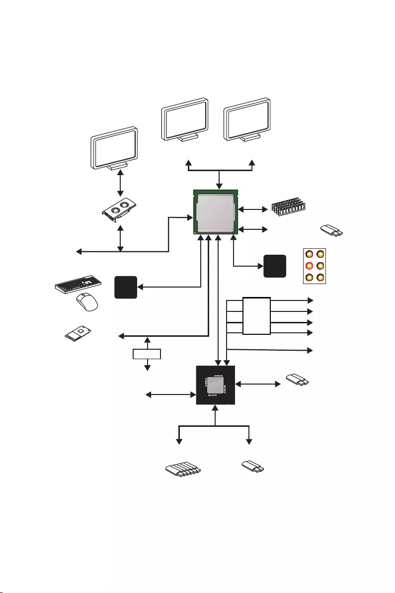
Block Diagram
Block Diagram
2 x USB 3.2 Gen2
2 Channel DDR4 Memory
2 x USB 3.2 Gen1
1 x M.2
6 x USB 2.0
PCI Express Bus
PS/2 Mouse / Keyboard
Audio Jacks
CHIPSET
CPU
NV6797
Super I/O
Realtek
ALC892
PCI Express Bus
HDMI DVI-D
SwitchSwitch
PCIe x1
2x SATA 6Gb/s
4x SATA 6Gb/s
PCIe x1
PCIe x1
PCIe x1
PCIe x4
2x USB 3.2 Gen1
Switch
22 Rear I/O Panel
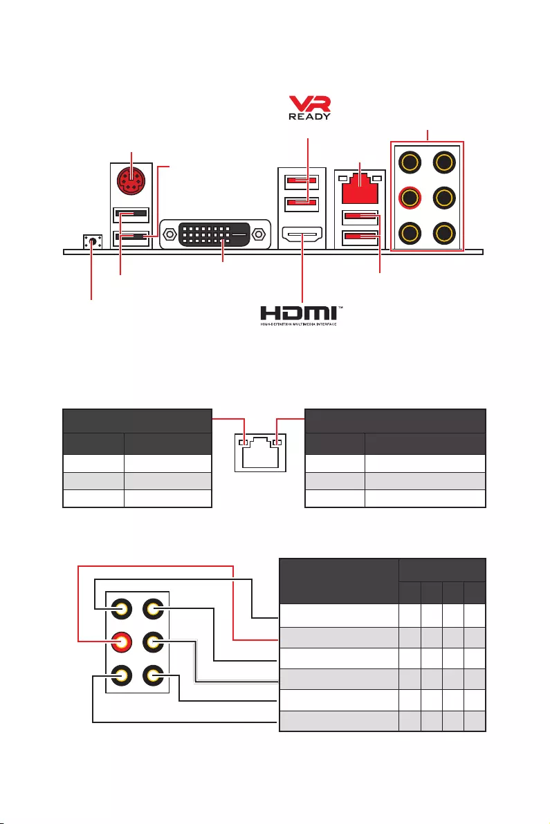
Link/ Activity LED
Status Description
Off No link
Yellow Linked
Blinking Data activity
Speed LED
Status Description
Off 10 Mbps connection
Green 100 Mbps connection
Orange 1 Gbps connection
LAN Port LED Status Table
Audio Ports Configuration
Audio Ports Channel
2468
Line-In
Line-Out/ Front Speaker Out ●●●●
Rear Speaker Out ●●●
Center/ Subwoofer Out ● ●
Side Speaker Out ●
Mic In
(●: connected, Blank: empty)
Rear I/O Panel
PS/2 LAN
USB 2.0 Type-A
Audio Ports
DVI-D
USB 3.2 Gen1 Type-A
USB 3.2 Gen2
Type-A
Flash BIOS Button
yFlash BIOS Port/ Button — Please refer to page 40 for Updating BIOS with Flash BIOS
Button.
Flash BIOS Port
23
Rear I/O Panel
Realtek Audio Console
After Realtek Audio Console is installed. You can use it to change sound settings to get
better sound experience.
yDevice Selection — allows you to select a audio output source to change the related
options. The check sign indicates the devices as default.
yApplication Enhancement — the array of options will provide you a complete guidance
of anticipated sound effect for both output and input device.
yMain Volume — controls the volume or balance the right/left side of the speakers that
you plugged in front or rear panel by adjust the bar.
yJack Status — depicts all render and capture devices currently connected with your
computer.
Auto popup dialog
When you plug into a device at an audio jack, a dialogue window will pop up asking you
which device is current connected.
Each jack corresponds to its default setting as shown on the next page.
Jack Status
Device
Selection
Main Volume
Application Enhancement
Important
The pictures above for reference only and may vary from the product you purchased.
24 Rear I/O Panel
Audio jacks to headphone and microphone diagram
Audio jacks to stereo speakers diagram
Audio jacks to 7.1-channel speakers diagram
AUDIO INPUT
Rear Front
Side Center/
Subwoofer
AUDIO INPUT
25
Overview of Components
BAT1
Overview of Components
JLPT1
SATA▼5▲6
SATA▼3▲4
CPU_FAN1
SYS_FAN1
PUMP_FAN1
JRGB1
PCI_E1
PCI_E2
PCI_E3
PCI_E4
PCI_E5
PCI_E6
JBAT1
JAUD1
JTPM1
Processor
Socket
CPU_PWR1
DIMMA1
SYS_FAN4
M2_1
DIMMA2
DIMMB1
DIMMB2
JUSB3
JUSB2
JUSB1
SATA1
JCI1
JFP1
SATA2
JFP2
JRGB2
SYS_FAN2
JCOM1
ATX_PWR1
SYS_FAN3

26 Overview of Components
Component Contents
Port Name Port Type Page
CPU_FAN1, PUMP_FAN1, SYS_FAN1~4 Fan Connectors 34
CPU_PWR1, ATX_PWR1 Power Connectors 32
DIMMA1, DIMMA2, DIMMB1, DIMMB2 DIMM Slots 28
JAUD1 Front Audio Connector 32
JBAT1 Clear CMOS Jumper 36
JCI1 Chassis Intrusion Connector 35
JCOM1 Serial Port Connector 34
JFP1, JFP2 Front Panel Connectors 31
JLPT1 Parallel Port Connector 36
JRGB1~2 RGB LED connectors 37
JTPM1 TPM Module Connector 35
JUSB1~2 USB 2.0 Connectors 33
JUSB3 USB 3.2 Gen1 Connector 33
M2_1 M.2 Slot (Key M) 30
PCI_E1~6 PCIe Expansion Slots 29
Processor Socket AM4 socket 27
SATA1~6 SATA 6Gb/s Connectors 31
27
Overview of Components
Processor Socket
Important
y
When changing the processor, the system configuration could be cleared and reset
BIOS to default values, due to the AM4 processor’s architecture.
y
Always unplug the power cord from the power outlet before installing or removing
the CPU.
y
When installing a CPU, always remember to install a CPU heatsink. A CPU heatsink
is necessary to prevent overheating and maintain system stability.
y
Confirm that the CPU heatsink has formed a tight seal with the CPU before booting
your system.
y
Overheating can seriously damage the CPU and motherboard. Always make sure
the cooling fans work properly to protect the CPU from overheating. Be sure to apply
an even layer of thermal paste (or thermal tape) between the CPU and the heatsink to
enhance heat dissipation.
y
If you purchased a separate CPU and heatsink/ cooler, Please refer to the
documentation in the heatsink/ cooler package for more details about installation.
y
This motherboard is designed to support overclocking. Before attempting to
overclock, please make sure that all other system components can tolerate
overclocking. Any attempt to operate beyond product specifications is not
recommended. MSI
®
does not guarantee the damages or risks caused by inadequate
operation beyond product specifications.
Introduction to the AM4 CPU
The surface of the AM4 CPU has a
yellow triangle to assist in correctly
lining up the CPU for motherboard
placement. The yellow triangle is
the Pin 1 indicator.
53.43 mm
Distance from the center of the
CPU to the nearest DIMM slot.
28 Overview of Components
DIMM Slots
DIMMA1 DIMMB1
Channel A Channel B
DIMMA2 DIMMB2
Memory module installation recommendation
DIMMB2 DIMMB2
DIMMB1
DIMMA2 DIMMA2 DIMMA2
DIMMA1
Important
y
Always insert memory modules in the DIMMA2 slot first.
y
Due to chipset resource usage, the available capacity of memory will be a little less
than the amount of installed.
y
Based on processor specification, the Memory DIMM voltage below 1.35V is
suggested to protect the processor.
y
Some memory modules may operate at a lower frequency than the marked value
when overclocking due to the memory frequency operates dependent on its Serial
Presence Detect (SPD). Go to BIOS and find the DRAM Frequency! to set the memory
frequency if you want to operate the memory at the marked or at a higher frequency.
y
It is recommended to use a more efficient memory cooling system for full DIMMs
installation or overclocking.
y
The stability and compatibility of installed memory module depend on installed CPU
and devices when overclocking.
y
Due to AM4 processor/memory controller official specification limitation, the
frequency of memory modules may operate lower than the marked value under the
default state. Please refer www.msi.com for more information on compatible memory.
29
Overview of Components
BAT1
PCI_E1~6: PCIe Expansion Slots
PCI_E1: PCIe 3.0 x16*/ x8**/ x4***
PCI_E2: PCIe 2.0 x1
PCI_E3: PCIe 2.0 x1
PCI_E4: PCIe 2.0 x4
PCI_E5: PCIe 2.0 x1
PCI_E6: PCIe 2.0 x1
Important
y
If you install a large and heavy graphics card, you need to use a tool such as MSI
Gaming Series Graphics Card Bolster to support its weight to prevent deformation of
the slot.
y
For a single PCIe x16 expansion card installation with optimum performance, using
the PCI_E1 slot is recommended.
y
When adding or removing expansion cards, always turn off the power supply and
unplug the power supply power cable from the power outlet. Read the expansion
card’s documentation to check for any necessary additional hardware or software
changes.
y
PCI_E4 will run x1 speed when installing devices in PCI_E2/ PCI_E3/ PCI_E5 slot.
* For 1st, 2nd and 3rd Gen AMD Ryzen™ processors
** For Ryzen™ with Radeon™ Vega Graphics and 2nd Gen AMD Ryzen™ with Radeon™
Graphics processors
*** For Athlon™ with Radeon™ Vega Graphics processor
PCIe bandwidth of Multiple graphics cards
Slot Single 2-Way
PCI_E1 (CPU)
@ 3.0 x16*
or @ 3.0 x8**
or @ 3.0 x4***
@ 3.0 x16*
or @ 3.0 x8**
or @ 3.0 x4***
PCI_E2 (PCH) 2.0 x1 2.0 x1 Empty Empty ―
PCI_E3 (PCH) 2.0 x1 Empty 2.0 x1 Empty ―
PCI_E4 (PCH) 2.0 x1 2.0 x1 2.0 x1 2.0 x1 @2.0 x4
PCI_E5 (PCH) 2.0 x1 Empty Empty 2.0 x1 ―
PCI_E6 (PCH) 2.0 x1 2.0×1
M2_1 (CPU) 3.0 x4*/**
or 3.0 x2***
3.0 x4*/**
or 3.0 x2***
(─: unavailable, @: graphics card, *: for 1st, 2nd and 3rd Gen AMD Ryzen™ processors,
**: for Ryzen™ with Radeon™ Vega Graphics and 2nd Gen AMD Ryzen™ with Radeon™
Graphics processors, ***: for Athlon™ with Radeon™ Vega Graphics processor)
30 Overview of Components
M2_1: M.2 Slot (Key M)
1
2
3
30°
Installing M.2 SSD
1. Loosen the M.2 riser screw from the
motherboard.
2. Move and fasten the M.2 riser screw to
the appropriate location for your M.2
SSD.
3. Insert your M.2 SSD into the M.2
slot at a 30-degree angle.
4. Secure the M.2 SSD in place with
the supplied M.2 screw.
4
Supplied
M.2 screw
Video Demonstration
Watch the video to learn how to Install M.2
module.
http://youtu.be/JCTFABytrYA
Important
SATA5 and SATA6 ports will be unavailable when installing a M.2 device in M.2 slot.
31
Overview of Components
SATA1~6: SATA 6Gb/s Connectors
These connectors are SATA 6Gb/s interface ports. Each connector can connect to one
SATA device.
SATA5
SATA3
SATA6
SATA4
SATA2
SATA1
Important
y
Please do not fold the SATA cable at a 90-degree angle. Data loss may result during
transmission otherwise.
y
SATA cables have identical plugs on either sides of the cable. However, it is
recommended that the flat connector be connected to the motherboard for space
saving purposes.
y
SATA5 and SATA6 ports will be unavailable when installing a M.2 device in M.2 slot.
JFP1, JFP2: Front Panel Connectors
These connectors connect to the switches and LEDs on the front panel.
1
JFP2
+
+—
—
Speaker
Buzzer 1 Speaker — 2 Buzzer +
3 Buzzer — 4 Speaker +
1
2 10
9
+
+
+— ——
—
+
Power LED
HDD LED Reset Switch
Reserved
Power Switch
JFP1
1 HDD LED + 2 Power LED +
3 HDD LED — 4 Power LED —
5 Reset Switch 6 Power Switch
7 Reset Switch 8 Power Switch
9 Reserved 10 No Pin
32 Overview of Components
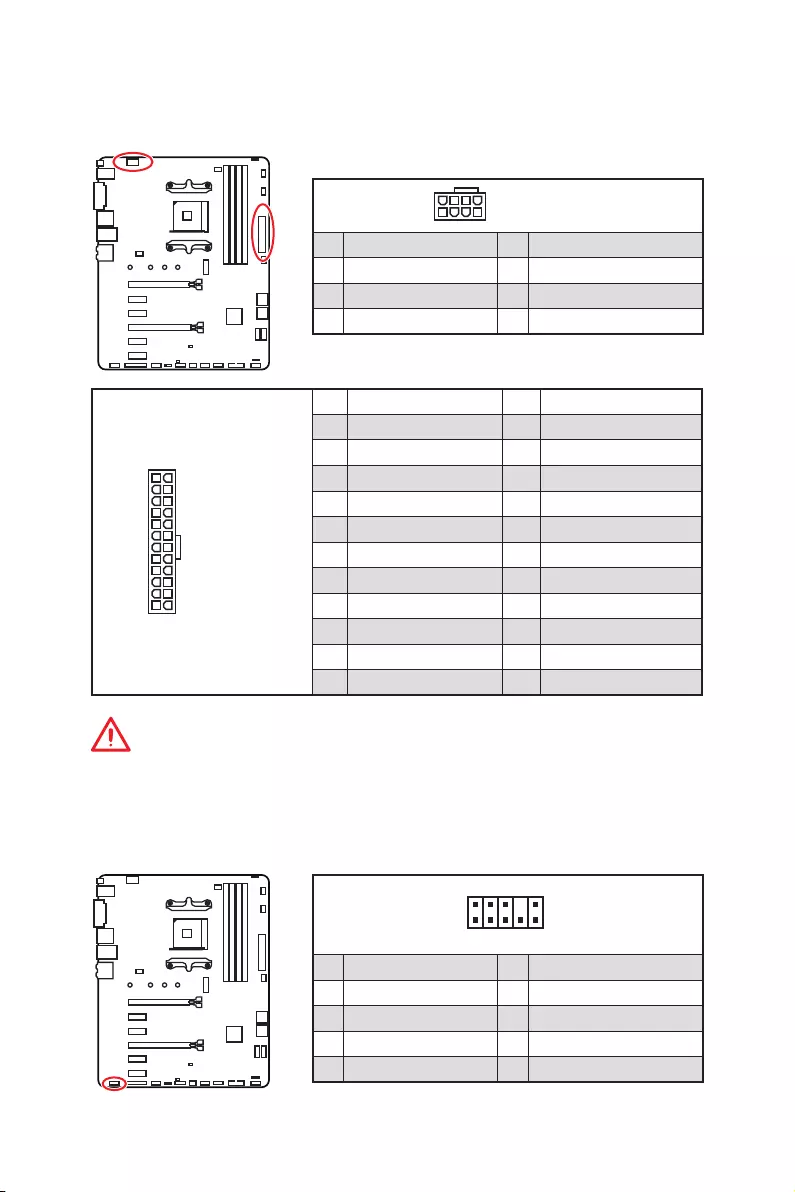
24
131
12
ATX_PWR1
1 +3.3V 13 +3.3V
2 +3.3V 14 -12V
3 Ground 15 Ground
4 +5V 16 PS-ON#
5 Ground 17 Ground
6 +5V 18 Ground
7 Ground 19 Ground
8 PWR OK 20 Res
9 5VSB 21 +5V
10 +12V 22 +5V
11 +12V 23 +5V
12 +3.3V 24 Ground
5
4 1
8CPU_PWR1
1 Ground 5 +12V
2 Ground 6 +12V
3 Ground 7 +12V
4 Ground 8 +12V
Important
Make sure that all the power cables are securely connected to a proper ATX power
supply to ensure stable operation of the motherboard.
CPU_PWR1, ATX_PWR1: Power Connectors
These connectors allow you to connect an ATX power supply.
JAUD1: Front Audio Connector
This connector allows you to connect audio jacks on the front panel.
1
2 10
9
1 MIC L 2 Ground
3 MIC R 4 NC
5 Head Phone R 6 MIC Detection
7 SENSE_SEND 8 No Pin
9 Head Phone L 10 Head Phone Detection
33
Overview of Components
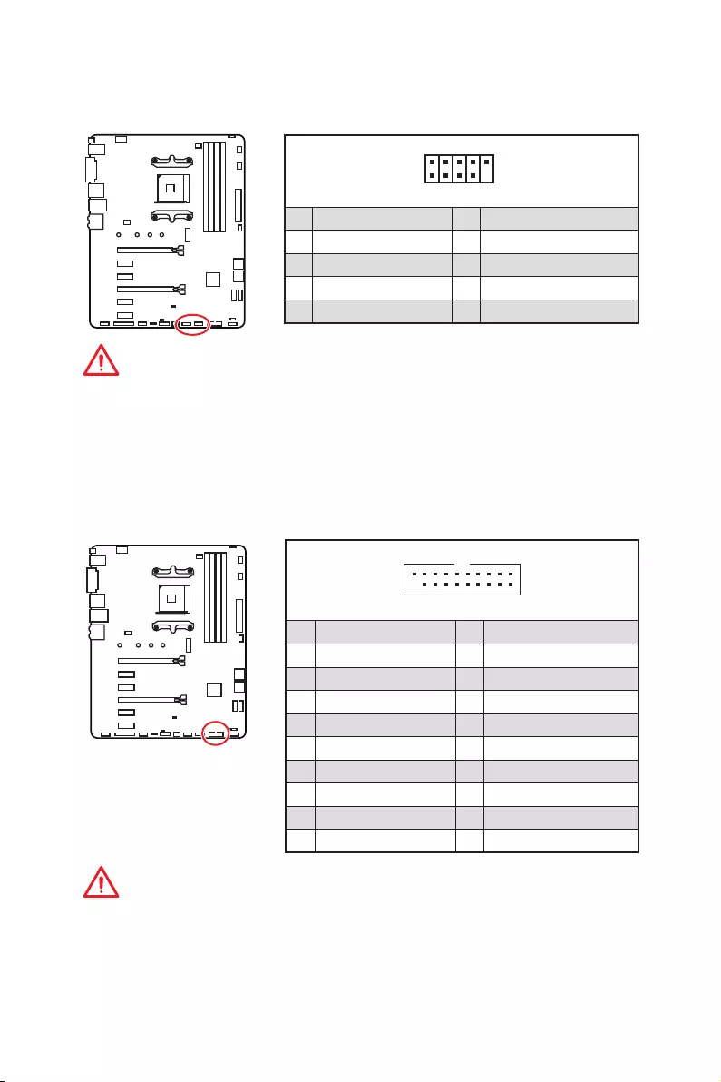
JUSB1~2: USB 2.0 Connectors
These connectors allow you to connect USB 2.0 ports on the front panel.
1
2 10
9
1VCC 2VCC
3 USB0- 4 USB1-
5 USB0+ 6 USB1+
7 Ground 8 Ground
9 No Pin 10 NC
Important
y
Note that the VCC and Ground pins must be connected correctly to avoid possible
damage.
y
In order to recharge your iPad,iPhone and iPod through USB ports, please install
MSI
®
SUPER CHARGER utility.
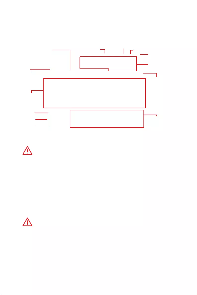
JUSB3: USB 3.2 Gen1 Connector
This connector allows you to connect USB 3.2 Gen1 ports on the front panel.
Important
Note that the Power and Ground pins must be connected correctly to avoid possible
damage.
110
11
20
1Power 11 USB2.0+
2 USB3_RX_DN 12 USB2.0-
3 USB3_RX_DP 13 Ground
4 Ground 14 USB3_TX_C_DP
5 USB3_TX_C_DN 15 USB3_TX_C_DN
6 USB3_TX_C_DP 16 Ground
7 Ground 17 USB3_RX_DP
8 USB2.0- 18 USB3_RX_DN
9 USB2.0+ 19 Power
10 NC 20 No Pin
34 Overview of Components
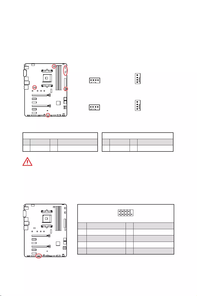
1
2 10
9
1 DCD 2 SIN
3 SOUT 4 DTR
5 Ground 6 DSR
7 RTS 8 CTS
9 RI 10 No Pin
JCOM1: Serial Port Connector
This connector allows you to connect the optional serial port with bracket.
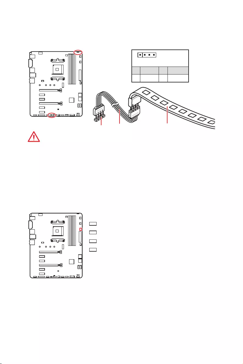
CPU_FAN1, PUMP_FAN1, SYS_FAN1~4: Fan Connectors
Fan connectors can be classified as PWM (Pulse Width Modulation) Mode or DC Mode.
PWM Mode fan connectors provide constant 12V output and adjust fan speed with
speed control signal. DC Mode fan connectors control fan speed by changing voltage.
When you plug a 3-pin (Non-PWM) fan to a fan connector in PWM mode, the fan speed
will always maintain at 100%, which might create a lot of noise. You can follow the
instruction below to adjust the fan connector to PWM or DC Mode. However, with auto-
detection mode fan connectors, the system will auto detect the fan mode.
Default DC Mode fan connectors
Default PWM Mode fan connectors
1
CPU_FAN1
1
SYS_FAN3/ SYS_FAN4
1
PUMP_FAN1
1
SYS_FAN1/ SYS_FAN2
PWM Mode pin definition
1 Ground 2 +12V
3 Sense 4 Speed Control Signal
DC Mode pin definition
1 Ground 2 Voltage Control
3 Sense 4 NC
Important
y
You can switch between PWM mode and DC mode and adjust fan speed in BIOS >
HARDWARE MONITOR.
y
Make sure fans are working properly after switching the PWM/ DC mode.
Pin definition of fan connectors
35
Overview of Components
JCI1: Chassis Intrusion Connector
This connector allows you to connect the chassis intrusion switch cable.
Normal
(default) Trigger the chassis
intrusion event
Using chassis intrusion detector
1. Connect the JCI1 connector to the chassis intrusion switch/ sensor on the chassis.
2. Close the chassis cover.
3. Go to BIOS > SETTINGS > Security > Chassis Intrusion Configuration.
4. Set Chassis Intrusion to Enabled.
5. Press F10 to save and exit and then press the Enter key to select Yes.
6. Once the chassis cover is opened again, a warning message will be displayed on
screen when the computer is turned on.
Resetting the chassis intrusion warning
1. Go to BIOS > SETTINGS > Security > Chassis Intrusion Configuration.
2. Set Chassis Intrusion to Reset.
3. Press F10 to save and exit and then press the Enter key to select Yes.
1
2 14
13
1 LPC Clock 2 3V Standby power
3 LPC Reset 4 3.3V Power
5 LPC address & data pin0 6 Serial IRQ
7 LPC address & data pin1 8 5V Power
9 LPC address & data pin2 10 No Pin
11 LPC address & data pin3 12 Ground
13 LPC Frame 14 Ground
JTPM1: TPM Module Connector
This connector is for TPM (Trusted Platform Module). Please refer to the TPM security
platform manual for more details and usages.
36 Overview of Components
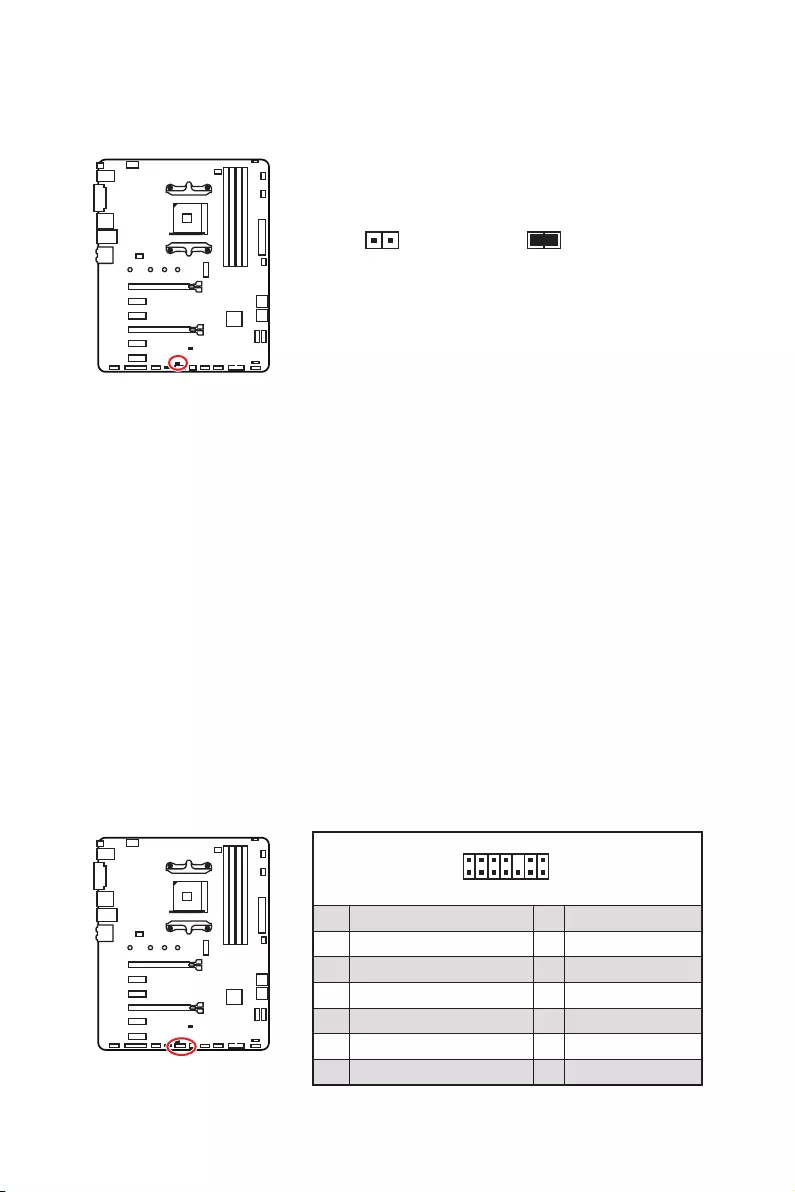
1
2 26
25
1 RSTB# 2 AFD# 3 PRND0
4 ERR# 5 PRND1 6 PINIT#
7 PRND2 8 LPT_SLIN# 9 PRND3
10 Ground 11 PRND4 12 Ground
13 PRND5 14 Ground 15 PRND6
16 Ground 17 PRND7 18 Ground
19 ACK# 20 Ground 21 BUSY
22 Ground 23 PE 24 Ground
25 SLCT 26 No Pin
JLPT1: Parallel Port Connector
This connector allows you to connect the optional parallel port with bracket.
JBAT1: Clear CMOS (Reset BIOS) Jumper
There is CMOS memory onboard that is external powered from a battery located on
the motherboard to save system configuration data. If you want to clear the system
configuration, set the jumper to clear the CMOS memory.
Keep Data
(default) Clear CMOS/
Reset BIOS
Resetting BIOS to default values
1. Power off the computer and unplug the power cord.
2. Use a jumper cap to short JBAT1 for about 5-10 seconds.
3. Remove the jumper cap from JBAT1.
4. Plug the power cord and Power on the computer.
37
Overview of Components
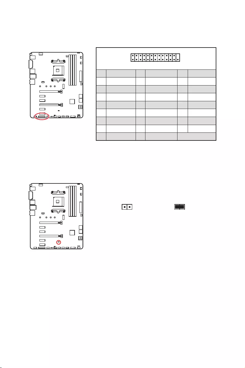
JRGB1~2: RGB LED connectors
The JRGB1/2 connectors allow you to connect the 5050 RGB LED strips 12V.
Important
y
The JRGB1/ JRGB2 connector supports up to 2 meters continuous 5050 RGB LED
strips (12V/G/R/B) with the maximum power rating of 3A (12V).
y
Always turn off the power supply and unplug the power cord from the power outlet
before installing or removing the RGB LED strip.
y
Please use MSI’s software to control the extended LED strip.
1
JRGB1/2
JRGB2
Extension cable 5050 RGB LED strips 12V
1
JRGB1/2
1 +12V 2 G
3 R 4 B
JRGB1
EZ Debug LEDs
These LEDs indicate the status of key components during booting process. When an
error is occurred, the corresponding LED stays lit until the problem is solved.
CPU — indicates CPU is not detected or fail.
DRAM — indicates DRAM is not detected or fail.
VGA — indicates GPU is not detected or fail.
BOOT — indicates the booting device is not detected
or fail.

38 BIOS Setup
BIOS Setup
The default settings offer the optimal performance for system stability in normal
conditions. You should always keep the default settings to avoid possible system
damage or failure booting unless you are familiar with BIOS.
Important
y
BIOS items are continuously update for better system performance. Therefore, the
description may be slightly different from the latest BIOS and should be for reference
only. You could also refer to the HELP information panel for BIOS item description.
y
The pictures in this chapter are for reference only and may vary from the product you
purchased.
y
The BIOS items will vary with the processor.
Entering BIOS Setup
Press Delete key, when the Press DEL key to enter Setup Menu, F11 to enter Boot
Menu message appears on the screen during the boot process.
Function key
F1: General Help list
F2: Add/ Remove a favorite item
F3: Enter Favorites menu
F4: Enter CPU Specifications menu
F5: Enter Memory-Z menu
F6: Load optimized defaults
F7: Switch between Advanced mode and EZ mode
F8: Load Overclocking Profile
F9: Save Overclocking Profile
F10: Save Change and Reset*
F12: Take a screenshot and save it to USB flash drive (FAT/ FAT32 format only).
Ctrl+F: Enter Search page
* When you press F10, a confirmation window appears and it provides the modification
information. Select between Yes or No to confirm your choice.

39
BIOS Setup
Resetting BIOS
You might need to restore the default BIOS setting to solve certain problems. There are
several ways to reset BIOS:
yGo to BIOS and press F6 to load optimized defaults.
yShort the Clear CMOS jumper on the motherboard.
Important
Be sure the computer is off before clearing CMOS data. Please refer to the Clear
CMOS jumper section for resetting BIOS.
Updating BIOS
Updating BIOS with M-FLASH
Before updating:
Please download the latest BIOS file that matches your motherboard model from MSI
website. And then save the BIOS file into the USB flash drive.
Updating BIOS:
1. Press Del key to enter the BIOS Setup during POST.
2. Insert the USB flash drive that contains the update file into the computer.
3. Select the M-FLASH tab and click on Yes to reboot the system and enter the flash
mode.
4. Select a BIOS file to perform the BIOS update process.
5. After the flashing process is 100% completed, the system will reboot
automatically.
Updating the BIOS with Live Update 6
Before updating:
Make sure the LAN driver is already installed and the internet connection is set
properly.
Updating BIOS:
1. Install and launch MSI LIVE UPDATE 6.
2. Select BIOS Update.
3. Click on Scan button.
4. Click on Download icon to download and install the latest BIOS file.
5. Click Next and choose In Windows mode. And then click Next and Start to start
updating BIOS.
6. After the flashing process is 100% completed, the system will restart
automatically.

40 BIOS Setup
Updating BIOS with Flash BIOS Button
Before updating:
Please download the latest BIOS file that matches your motherboard model from MSI®
website and rename the BIOS file to MSI.ROM. And then, save the MSI.ROM file to the
root of USB flash drive.
Important
Only the FAT32 format USB flash drive supports updating BIOS by Flash BIOS Button.
1. Connect power supply to CPU_PWR1 and ATX_PWR1. (No other components are
necessary but power supply.)
2. Plug the USB flash drive that contains the MSI.ROM file into the Flash BIOS Port
on rear I/O panel.
3. Press the Flash BIOS Button to flash BIOS, and the LED next to the button starts
flashing.
4. After the flashing BIOS process is 100% completed, the LED would be off
simultaneously.
41
BIOS Setup
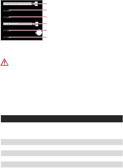
EZ Mode
At EZ mode, it provides the basic system information and allows you to configure the
basic setting. To configure the advanced BIOS settings, please enter the Advanced
Mode by pressing the Setup Mode switch or F7 function key.
A-XMP switch
Information
display
System
information
Boot device
priority bar
Function
buttons
Language
GAME BOOST
switch
Search
Screenshot
Setup Mode switch
M-Flash
Hardware
Monitor
Favorites
yGAME BOOST switch — click on it to toggle the GAME BOOST for OC.
Important
Please don’t make any changes in OC menu and don’t load defaults to keep the
optimal performance and system stability after activating the GAME BOOST function.
yA-XMP switch (optional) — click on the inner circle to enable/ disable the A-XMP.
Switch the outer circle to select the memory profile if any. This switch will only be
available if the installed processor and memory modules support XMP function.
ySetup Mode switch — press this tab or the F7 key to switch between Advanced mode
and EZ mode.
yScreenshot — click on this tab or the F12 key to take a screenshot and save it to USB
flash drive (FAT/ FAT32 format only).
ySearch — click on this tab or the Ctrl+F keys and the search page will show. It allows
you to search by BIOS item name, enter the item name to find the item listing. Move
the mouse over a blank space and right click the mouse to exit search page.
Important
In search page, only the F6, F10 and F12 function keys are available.
yLanguage — allows you to select the language of BIOS setup.
ySystem information — shows the CPU/ DDR speed, CPU/ MB temperature, MB/ CPU
type, memory size, CPU/ DDR voltage, BIOS version and build date.
yBoot device priority bar — you can move the device icons to change the boot priority.
The boot priority from high to low is left to right.

42 BIOS Setup
yInformation display — click on the CPU, Memory, Storage, Fan Info and Help buttons
on left side to display related information.
yFunction buttons — enable or disable the LAN Option ROM, HD audio controller,
AHCI/RAID, CPU Fan Fail Warning Control, Windows 10 WHQL support and BIOS Log
Review by clicking on their respective button.
yM-Flash — click on this button to display the M-Flash menu that provides the way to
update BIOS with a USB flash drive.
yHardware Monitor — click on this button to display the Hardware Monitor menu that
allows you to manually control the fan speed by percentage.
yFavorites menu — press the F3 key to enter Favorites menu. It allows you to create
personal BIOS menu where you can save and access favorite/ frequently-used BIOS
setting items.
Default HomePage — allows you to select a BIOS menu (e.g. SETTINGS, OC…,etc)
as the BIOS home page.
Favorite1~5 — allows you to add the frequently-used/ favorite BIOS setting items
in one page.
To add a BIOS item to a favorite page (Favorite 1~5)
1. Move the mouse over a BIOS item not only on BIOS menu but also on search
page.
2. Right-click or press F2 key.
3. Choose a favorite page and click on OK.
To delete a BIOS item from favorite page
1. Move the mouse over a BIOS item on favorite page (Favorite 1~5)
2. Right-click or press F2 key.
3. Choose Delete and click on OK.

43
BIOS Setup
Advanced Mode
Press Setup Mode switch or F7 function key can switch between EZ Mode and
Advanced Mode in BIOS setup.
A-XMP switch
GAME BOOST
switch
System
information
Boot device
priority bar
BIOS menu
selection
Language
Search
Screenshot
Setup Mode switch
Menu display
BIOS menu
selection
yGAME BOOST switch/ Setup Mode switch/ Screenshot/ Language/ System
information/ Boot device priority bar — please refer to the descriptions of EZ Mode
Overview section.
yBIOS menu selection — the following options are available:
SETTINGS — allows you to specify the parameters for chipset and boot devices.
OC — allows you to adjust the frequency and voltage. Increasing the frequency may
get better performance.
M-FLASH — provides the way to update BIOS with a USB flash drive.
OC PROFILE — allows you to manage overclocking profiles.
HARDWARE MONITOR — allows you to set the speeds of fans and monitor voltages
of system.
BOARD EXPLORER — provides the information of installed devices on this
motherboard.
yMenu display — provides BIOS setting items and information to be configured.

44 BIOS Setup
SETTINGS
System Status
fSystem Date
Sets the system date. Use tab key to switch between date elements.
The format is <day> <month> <date> <year>.
<day> Day of the week, from Sun to Sat, determined by BIOS. Read-only.
<month> The month from Jan. through Dec.
<date> The date from 1 to 31 can be keyed by numeric function keys.
<year> The year can be adjusted by users.
fSystem Time
Sets the system time. Use tab key to switch between time elements.
The time format is <hour> <minute> <second>.
fSATA PortX
Shows the information of connected SATA device.
Important
If the connected SATA device is not displayed, turn off computer and re-check SATA
cable and power cable connections of the device and motherboard.
fSystem Information
Shows detailed system information, including CPU type, BIOS version, and Memory
(read only).
fDMI Information
Shows system information, desktop Board Information and chassis Information. (Read
only).
Advanced
fPCI Subsystem Settings
Sets PCI, PCI express interface protocol and latency timer. Press Enter to enter the
sub-menu.

45
BIOS Setup
fAbove 4G memory/ Crypto Currency mining [Disabled]
Enables or disables 64-bit capable devices to be decoded in above 4G address
space. It is only available if the system supports 64-bit PCI decoding.
[Enabled] Allows you to utilize more than 4x GPUs.
[Disabled] Disables this function.
fPCIe SlotX Lanes Configuration
PCIe lanes configuration is for MSI M.2 Xpander / MSI M.2 Xpander-Z / Other M.2
PCIe storage card. The options in this item will vary with the installed processor.
fACPI Settings
Sets ACPI parameters of onboard power LED behaviors. Press Enter to enter the sub-
menu.
fPower LED [Blinking]
Sets shining behaviors of the onboard Power LED.
[Dual Color] The power LED turns to another color to indicate the S3 state.
[Blinking] The power LED blinks to indicate the S3 state.
fIntegrated Peripherals
Sets integrated peripherals’ parameters, such as LAN, HDD, USB and audio. Press
Enter to enter the sub-menu.
fOnboard LAN Controller [Enabled]
Enables or disables the onboard LAN controller.
fLAN Option ROM [Disabled]
Enables or disables the legacy network Boot Option ROM for detailed settings. This
item will appear when Onboard LAN Controller is enabled.
[Enabled] Enables the onboard LAN Boot ROM.
[Disabled] Disables the onboard LAN Boot ROM.
fNetwork Stack [Disabled]
Sets UEFI network stack for optimizing IPv4 / IPv6 function. This item is available
when Onboard LAN Controller is Enabled.
[Enabled] Enables UEFI network stack.
[Disabled] Disables UEFI network stack.
fIpv4 PXE Support [Enabled]
When Enabled, the system UEFI network stack will support Ipv4 protocol. This item
will appear when Network Stack is Enabled.
[Enabled] Enables the Ipv4 PXE boot support.
[Disabled] Disables the Ipv4 PXE boot support.
fIpv6 PXE Support [Enabled]
When Enabled, the system UEFI network stack will support Ipv6 protocol. This item
will appear when Network Stack is enabled.
[Enabled] Enables the Ipv6 PXE boot support.
[Disabled] Disables the Ipv6 PXE boot support.

46 BIOS Setup
fSATA Mode [AHCI Mode]
Sets the operation mode of the onboard SATA controller.
[AHCI Mode] Specify the AHCI mode for SATA storage devices. AHCI (Advanced
Host Controller Interface) offers some advanced features to enhance
the speed and performance of SATA storage device, such as Native
Command Queuing (NCQ) and hot-plugging.
[RAID Mode] Enables RAID function for SATA storage devices.
fSATAx Hot Plug [Disabled]
Allows user to enable or disable the SATA hot plug support.
[Enabled] Enables hot plug support for the SATA ports.
[Disabled] Disables hot plug support for the SATA ports.
fHD Audio Controller [Enabled]
Enables or disables the onboard High Definition Audio controller.
fIntegrated Graphics Configuration (optional)
Adjusts integrated graphics settings for optimum system. Press Enter to enter the
sub-menu.
fInitiate Graphic Adapter [PEG] (optional)
Selects a graphics device as the primary boot device.
[IGD] Integrated Graphics Display.
[PEG] PCI-Express Graphics Device.
fIntegrated Graphics [Auto] (optional)
If set to Force, BIOS will enable the integrated graphics controller.
fUMA Frame Buffer Size [Auto] (optional)
Selects a fixed amount of system memory allocated to the onboard graphics. This
item will be available when Integrated Graphics is enabled.
fUSB Configuration
Sets the onboard USB controller and device function. Press Enter to enter the sub-
menu.
fXHCI Hand-off [Enabled]
Enables or disables XHCI hand-off support for the operating system without XHCI
hand-off feature.
fLegacy USB Support [Enabled]
Sets Legacy USB function support.
[Auto] The system will automatically detect if any USB device is connected
and enable the legacy USB support.
[Enabled] Enable the USB support under legacy mode.
[Disabled] The USB devices will be unavailable under legacy mode.

47
BIOS Setup
fSuper IO Configuration
Sets system Super I/O chip parameters including LPT and COM ports. Press Enter to
enter the sub-menu.
fSerial (COM) Port 0 Configuration
Sets detailed configuration of serial(COM) port 0. Press Enter to enter the sub-
menu.
fSerial Port [Enabled]
Enables or disables serial port.
fSerial (COM) Port0 Settings [Auto]
Sets serial port 0. If set to Auto, BIOS will optimize the IRQ automatically or you
can set it manually.
fParallel (LPT) Port Configuration
Sets detailed configuration of parallel port (LPT/ LPTE). Press Enter to enter the
sub-menu.
fParallel (LPT) Port [Enabled]
Enables or disables parallel(LPT/ LPTE) port.
fParallel (LPT) Port Settings [Auto]
Sets parallel port (LPT). If set to Auto, BIOS will optimize the IRQ automatically or
you can set it manually.
fDevice Mode [STD Printer Mode]
Selects an operating mode for parallel port.
[STD Printer Mode] Printer port mode
[SPP] Standard Parallel Port mode
[EPP-1.9 and SPP Mode] Enhanced Parallel Port-1.9 mode + Standard
Parallel Port mode.
fPower Management Setup
Sets system Power Management of ErP and AC Power Loss behaviors. Press Enter to
enter the sub-menu.
fErP Ready [Disabled]
Enables or disables the system power consumption according to ErP regulation.
[Enabled] Optimize the system power consumption according to ErP
regulation. It will not support S4 & S5 wake up by USB, PCI and PCIe
devices.
[Disabled] Disables this function.
fRestore after AC Power Loss [Power Off]
Sets the system behaviors while encountering the AC power loss.
[Power Off] Leaves the system in power off state after restoring AC power.
[Power On] Boot up the system after restoring AC power.
[Last State] Restores the system to the previous state (power on/ power off)
before AC power loss.

48 BIOS Setup
fSystem Power Fault Protection [Disabled]
Enables or disables the system to boot up when detecting abnormal voltage input.
[Enabled] Protect the system from unexpected power operating and remain
the shut down status.
[Disabled] Disables this function.
fWindows OS Configuration
Sets Windows detailed configuration and behaviors. Press Enter to enter the sub-
menu.
fWindows 10 WHQL Support [Disabled]
Enables the supports for Windows 10 or disables for other operating systems.
Before enabling this item, make sure all installed devices & utilities (hardware &
software) should meet the Windows 10 requirements.
[Enabled] The system will switch to UEFI mode to meet the Windows
requirement.
[Disabled] Disables this function.
fInternal GOP Configuration
Manages the onboard Graphics Output Protocol (GOP). Press Enter to enter
the sub-menu. This sub-menu will appear when Windows 10 WHQL Support is
enabled.
fSecure Boot
Sets the Windows secure boot to prevent the unauthorized accessing. Press Enter
to enter the sub-menu. This sub-menu will appear when Windows 10 WHQL
Support is enabled.
fWake Up Event Setup
Sets system wake up behaviors for different sleep modes. Press Enter to enter the
sub-menu.
fWake Up Event By [BIOS]
Selects the wake up event by BIOS or operating system.
[BIOS] Activates the following items, set wake up events of these items.
[OS] The wake up events will be defined by OS.
fResume By RTC Alarm [Disabled]
Disables or enables the system wake up by RTC Alarm.
[Enabled] Enables the system to boot up on a scheduled time/ date.
[Disabled] Disables this function.
fDate (of month) Alarm/ Time (hh:mm:ss) Alarm
Sets RTC alarm date/ Time. If Resume By RTC Alarm is set to [Enabled], the system
will automatically resume (boot up) on a specified date/hour/minute/second in
these fields (using the + and — keys to select the date & time settings).

49
BIOS Setup
fResume By PCI-E Device [Disabled]
Enables or disables the wake up function of installed PCI-E expansion cards,
integrated LAN controllers or USB devices which are supported by third party
integrated chips.
[Enabled] Enables the system to be awakened from the power saving modes
when activity or input signal of PCIe device is detected.
[Disabled] Disables this function.
fResume by USB Device [Disabled]
Disables or enables system wake up from S3/S4 by USB device.
[Enabled] Enables the system to be awakened from sleep state when activity of
USB device is detected.
[Disabled] Disables this function.
fResume From S3/S4/S5 by PS/2 Mouse [Disabled]
Enables or disables the system wake up by PS/2 mouse.
[Enabled] Enables the system to be awakened from S3/ S4/ S5 state when
activity of PS/2 mouse is detected.
[Disabled] Disables this function.
fResume From S3/S4/S5 by PS/2 Keyboard [Disabled]
Enables or disables the system wake up by PS/2 keyboard.
[Any Key] Enables the system to be awakened from S3/ S4/ S5 state when
activity of any key on PS/2 keyboard is detected.
[Hot Key] Enables the system to be awakened from S3/ S4/ S5 state when
activity of hot key on PS/2 keyboard is detected.
[Disabled] Disables this function.
fHot Key [Ctrl+Space]
Selects a combination of keys as a hot key to wake the system. This item appears
when you set the Resume From S3/S4/S5 by PS/2 Keyboard to Hot Key.
fSecure Erase+
Enables or disables Secure Erase+ function. Secure Erase+ is the best way to
effectively wipe all data from a SSD. Please note that data of SSD will be erased after
enabling Secure Erase+.
fRealtek PCIe GBE Family Controller
Shows driver information and configuration of the ethernet controller parameter.
Boot
Sets the sequence of system boot devices.
fFull Screen Logo Display [Enabled]
Enables or disables to show the full screen logo while system POST.
[Enabled] Shows the logo in full screen.
[Disabled] Shows the POST messages.

50 BIOS Setup
fBootup NumLock State [On]
Select the keyboard NumLock state upon bootup.
fInfo Block effect [Unlock]
Sets the state of Help information block.
[Unlock] Sliding effect.
[Lock] Fix the Help information block on the screen.
fPOST Beep [Disabled]
Enables or disables POST beep.
fAUTO CLR_CMOS [Disabled]
Enables or disables the CMOS data to be resumed automatically when the system
cannot boot to OS and reboot repeatedly.
fBoot Mode Select [LEGACY+UEFI]
Sets the system boot mode from legacy or UEFI architecture depending on OS
installation requirement. This item will become un-selectable and will be configured
automatically by BIOS when Windows 10 WHQL Support is enabled.
[UEFI] Enables UEFI BIOS boot mode support only.
[LEGACY+UEFI] Enables both Legacy BIOS boot mode and UEFI BIOS boot
mode.
fFIXED BOOT ORDER Priorities/ UEFI USB Key Drive BBS Priorities/ USB Key Drive
BBS Priorities
Sets device priority for system boot.
fBoot Option Priorities
These items are used to prioritize the installed boot devices.
Security
fAdministrator Password
Sets administrator password for system security. User has full rights to change the
BIOS items with administrator password. After setting the administrator password, the
state of this item will show Installed.
fUser Password
Sets User Password for system security. User has limited rights to change the BIOS
items with user password. This item will be available when administrator password is
set. After setting the user password, the state of this item will show Installed.
fPassword Check [Setup]
Selects a condition that will request the password.
[Setup] A password will be requested for entering the BIOS Setup.
[Boot] A password will be requested for booting the system.

51
BIOS Setup
fPassword Clear [Enabled]
Enables or disables the clear CMOS behavior to clear a set password.
[Enabled] The password will be erased after clear CMOS.
[Disabled] The password will always be kept.
Important
When selecting the Administrator / User Password items, a password box will appear
on the screen. Type the password then press Enter. The password typed now will
replace any previous set password from CMOS memory. You will be prompted to
confirm the password. You may also press Esc key to abort the selection.
To clear a set password, press Enter when you are prompted to enter a new password.
A message will confirm the password is being disabled. Once the password is disabled,
you can enter the setup and OS without authorization.
fTrusted Computing
Sets TPM (Trusted Platform Module) function.
fSecurity Device Support [Disabled]
Enables or disables the TPM function to build the endorsement key for accessing
the system.
fAMD fTPM switch [AMD CPU fTPM]
Selects TPM device. This item will appear when Security Device Support is
enabled.
[AMD CPU fTPM] Select it for AMD Firmware TPM.
[AMD CPU fTPM Disabled] Select it for Discrete TPM.
fDevice Select [Auto]
Sets the version of the TPM device. The version must be identical with the device.
Sets to Auto, system will detect the TPM 2.0 or TPM 1.2 model automatically.
fChassis Intrusion Configuration
Press Enter to enter the sub-menu.
fChassis Intrusion [Disabled]
Enables or disables recording messages while the chassis is opened. This function
is ready for the chassis equips a chassis intrusion switch.
[Enabled] Once the chassis is opened, the system will record and issue a
warning message.
[Reset] Clear the warning message. After clearing the message, please
return to Enabled or Disabled.
[Disabled] Disables this funcion.
Save & Exit
fDiscard Changes and Exit
Exit BIOS setup without saving any change.

52 BIOS Setup
fSave Changes and Reboot
Save all changes and reboot the system.
fSave Changes
Save current changes.
fDiscard Changes
Discard all changes and restore to the previous values.
fRestore Defaults
Restore or load all default values.
fBoot Override
The installed boot-able devices will appear on this menu, you can select one of them to
be the boot device.

53
BIOS Setup
OC
Important
y
Overclocking your PC manually is only recommended for advanced users.
y
Overclocking is not guaranteed, and if done improperly, it could void your warranty or
severely damage your hardware.
y
If you are unfamiliar with overclocking, we advise you to use GAME BOOST function
for easy overclocking.
y
The BIOS items in OC menu will vary with the processor.
fOC Explore Mode [Normal]
Enables or disables to show the normal or expert version of OC settings.
[Normal] Provides the regular OC settings in BIOS setup.
[Expert] Provides the advanced OC settings for OC expert to configure in BIOS
setup.
Note: We use * as the symbol for the OC settings of Expert mode.
fCPU Ratio [Auto]
Sets the CPU ratio that is used to determine CPU clock speed. This item can only be
changed if the processor supports this function.
fCore Performance Boost [Auto]
Enables or disables the Core Performance Boost (CPB). This item appears when the
installed CPU supports this function.
fDowncore Control [Auto] (optional)
Sets the number of processor cores to be used. This item appears when the installed
CPU supports this function.
fA-XMP [Disabled]
Please enable A-XMP or select a profile of memory module for overclocking the
memory. This item will be available when the installed processor, memory modules
and motherboard support this function.

54 BIOS Setup
fDRAM Frequency [Auto]
Sets the DRAM frequency. Please note the overclocking behavior is not guaranteed.
fAdjusted DRAM Frequency
Shows the adjusted DRAM frequency. Read-only.
fMemory Try It ! [Disabled]
It can improve memory compatibility or performance by choosing optimized memory
preset.
fMemory Retry Count [5]
Sets the count of memory retry. When memory retry fails reach the count, the memory
will go back to the last available setting.
fAdvanced DRAM Configuration
Press Enter to enter the sub-menu. User can set the memory timing for each/ all
memory channel. The system may become unstable or unbootable after changing
memory timing. If it occurs, please clear the CMOS data and restore the default
settings. (Refer to the Clear CMOS jumper section to clear the CMOS data, and enter
the BIOS to load the default settings.)
fDigitALL Power
Press Enter to enter the sub-menu. Controls the digital powers related to CPU PWM.
fCPU Loadline Calibration Control [Auto]
The CPU voltage will decrease proportionally according to CPU loading. Higher
load-line calibration could get higher voltage and good overclocking performance,
but increase the temperature of the CPU and VRM. If set to Auto, BIOS will
configure this setting automatically.
fCPU NB Loadline Calibration Control [Auto]
The CPU-NB voltage will decrease proportionally according to CPU-NB loading.
Higher load-line calibration could get higher voltage and good overclocking
performance, but increase the temperature. If set to Auto, BIOS will configure this
setting automatically.
fCPU Over Voltage Protection [Auto]
Sets the voltage limit for CPU over-voltage protection. If set to Auto, BIOS will
configure this setting automatically. Higher voltage provides less protection and
may damage the system.
fCPU Under Voltage Protection [Auto]
Sets the voltage limit for CPU under-voltage protection. If set to Auto, BIOS will
configure this setting automatically. Higher voltage provides less protection and
may damage the system.
fCPU Over Current Protection [Auto]
Sets the current limit for CPU over-current protection. If set to Auto, BIOS will
configure this setting automatically.
[Auto] This setting will be configured automatically by BIOS.
[Enhanced] Extends the current range for over-current protection.

55
BIOS Setup
fVR 12VIN OCP Expander [Auto]
Expands the limitation of VR Over Current Protection with 12V input voltage. The
higher expanding value indicates less protection. Therefore, please adjust the
current carefully if needed, or it may damage the CPU/ VR MOS. If set to «Auto»,
BIOS will configure this setting automatically.
fCPU Voltages control [Auto]
These options allows you to set the voltages related to CPU. If set to Auto, BIOS will
set these voltages automatically or you can set it manually.
fDRAM Voltages control [Auto]
These options allows you to set the voltages related to memory. If set to Auto, BIOS
will set these voltages automatically or you can set it manually.
fMemory Changed Detect [Enabled]*
Enables or disables the system to issue a warning message during boot when the
memory has been replaced.
[Enabled] The system will issue a warning message during boot and then you have
to load the default settings for new devices.
[Disabled] Disables this function and keeps the current BIOS settings.
fCPU Specifications
Press Enter to enter the sub-menu. This sub-menu displays the information of
installed CPU. You can also access this information menu at any time by pressing [F4].
Read only.
fCPU Technology Support
Press Enter to enter the sub-menu. The sub-menu shows the key features of
installed CPU. Read only.
fMEMORY-Z
Press Enter to enter the sub-menu. This sub-menu displays all the settings and
timings of installed memory. You can also access this information menu at any time by
pressing [F5].
fDIMMx Memory SPD
Press Enter to enter the sub-menu. The sub-menu displays the information of
installed memory. Read only.
fCPU Features
Press Enter to enter the sub-menu.
fGlobal C-state Control [Enabled] (optional)
Enables/ disables IO based C-state generation and DF C-states.
fSimultaneous Multi-Threading [Enabled] (optional)
Enables/ disables the AMD Simultaneous Multi-Threading. This item appears when
the installed CPU supports this technology.
fOpcache Control [Auto] (optional)
Enables/ disables Opcache. Opcache stores recent decode instruction to save
the decoding time when the instruction is repeated. And it may increase the CPU
performance and reduce the power consumption slightly.

56 BIOS Setup
fIOMMU Mode (optional)
Enables/disables the IOMMU (I/O Memory Management Unit) for I/O Virtualization.
fSpread Spectrum (optional)
This function reduces the EMI (Electromagnetic Interference) generated by
modulating clock generator pulses.
[Enabled] Enables the spread spectrum function to reduce the EMI
(Electromagnetic Interference) problem.
[Disabled] Enhances the overclocking ability of CPU Base clock.
Important
y
If you do not have any EMI problem, leave the setting at [Disabled] for optimal system
stability and performance. But if you are plagued by EMI, select the value of Spread
Spectrum for EMI reduction.
y
The greater the Spread Spectrum value is, the greater the EMI is reduced, and the
system will become less stable. For the most suitable Spread Spectrum value, please
consult your local EMI regulation.
y
Remember to disable Spread Spectrum if you are overclocking because even a
slight jitter can introduce a temporary boost in clock speed which may just cause your
overclocked processor to lock up.
fRelaxed EDC throttling [Auto] (optional)
Relaxed EDC throttling reduces the amount of time the processor will throttle the
cores.
[Auto] AMD’s recommendation
[Enabled] Reduce the amount of time the processor will throttle.
[Disabled] Part-specific EDC throttling protection enabled.
fAMD Cool’n’Quiet [Enabled]
The Cool’n’Quiet technology can effectively and dynamically lower CPU speed and
power consumption.
fSVM Mode [Enabled]
Enables/ disables the AMD SVM (Secure Virtual Machine) Mode.
fBIOS PSP Support [Enabled] (optional)
Enables/ disables the BIOS PSP support. It manages PSP sub-items including all
C2P/P2C mailbox, Secure S3, fTPM support.
fPower Supply Idle Control [Auto] (optional)
It allows you to select the power-saving control mode for the CPU when all cores
are in a non-CO state. If set to Auto, BIOS will configure these settings.
fCPU VDD_SoC Current Optimization [Auto] (optional)
Sets the currents of CPU VDD and SoC. If set to Auto, BIOS will configure this
setting automatically.
[Auto] This setting will be configured automatically by BIOS.
[Custom Setting] Allows you to set the currents manually.
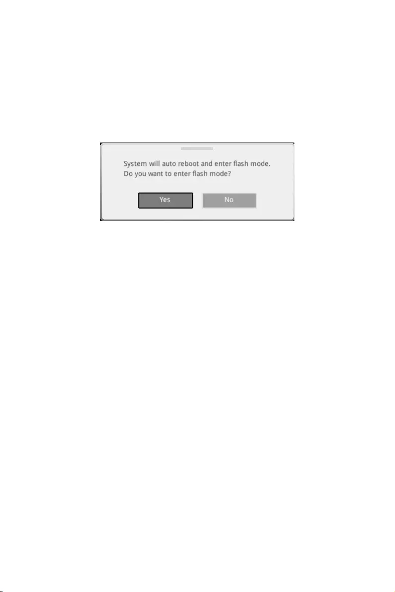
57
BIOS Setup
M-FLASH
M-FLASH provides the way to update BIOS with a USB flash drive. Please download
the latest BIOS file that matches your motherboard model from MSI website, save the
BIOS file into your USB flash drive. And then follow the steps below to update BIOS.
1. Insert the USB flash drive that contains the update file into the computer.
2. Click on M-FLASH tab, a demand message will be prompted. Click on Yes to
reboot and enter the flash mode.
3. The system will enter the flash mode and a file selection menu will appear after
rebooting.
4. Select a BIOS file to perform the BIOS update process.
5. After the flashing process is 100% completed, the system will reboot
automatically.

58 BIOS Setup
OC PROFILE
fOverclocking Profile 1/ 2/ 3/ 4/ 5/ 6
Overclocking Profile 1/ 2/ 3/ 4/ 5/ 6 management. Press Enter to enter the sub-menu.
fSet Name for Overclocking Profile 1/ 2/ 3/ 4/ 5/ 6
Name the current overclocking profile.
fSave Overclocking Profile 1/ 2/ 3/ 4/ 5/ 6
Save the current overclocking profile.
fLoad Overclocking Profile 1/ 2/ 3/ 4/ 5/ 6
Load the current overclocking profile.
fClear Overclocking Profile 1/ 2/ 3/ 4/ 5/ 6
Clear the current overclocking profile.
fOC Profile Load from ROM
Load OC profile from BIOS ROM.
fOC Profile Save to USB
Save OC profile to the USB flash drive. The USB flash drive should be FAT/ FAT32
format only.
fOC Profile Load from USB
Load OC profile from the USB flash drive. The USB flash drive should be FAT/ FAT32
format only.
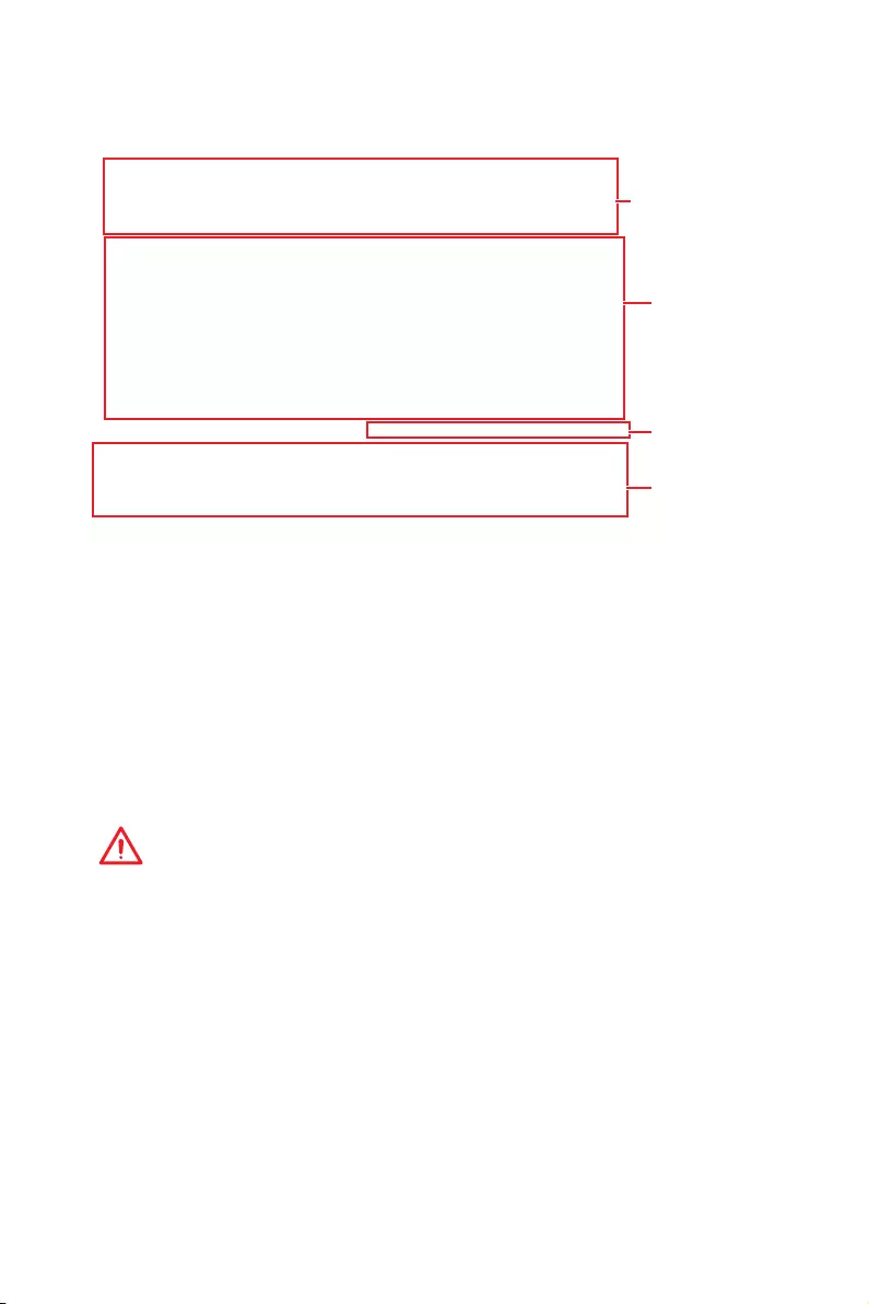
59
BIOS Setup
HARDWARE MONITOR
Temperature
& Speed
Fan Manage
Temperature/
Voltage display
Setting
Buttons
fTemperature & Speed
Shows the current CPU temperature, system temperature and fans’ speeds.
fFan Manage
PWM — allows you to select the PWM mode for fan operation.
DC — allows you to select the DC mode for fan operation.
Fan step up/ down time — allows you to set the period of fan step up/ down.
Smart Fan Mode field — allows you to drag the gradient points to configure
the fan target values for Smart Fan mode. Smart Fan can control the fan speed
automatically depending on the CPU temperature to keep it with in a specific range.
If the current CPU temperature reaches to the target value, the Smart Fan function
will be activated.
Important
y
The changing will achieve after you save the changes and reboot the system.
y
Make sure fans are working properly after switching the PWM/ DC mode.
fSettings Buttons
All Full Speed — configures all fans to run at full operating speed.
All Set Default — configures all fans to run at default operating speed.
All Set Cancel — discards current changes and restores previous operating fan
speeds .
fTemperature/ Voltage display
Shows CPU/ system temperature and the current voltages of CPU, system and
memory.

60 Software Description
Software Description
Please download and update the latest utilities and drivers at www.msi.com
Installing Windows® 10
1. Power on the computer.
2. Insert the Windows® 10 disc into your optical drive.
3. Press the Restart button on the computer case.
4. Press F11 key during the computer POST (Power-On Self Test) to get into Boot
Menu.
5. Select your optical drive from the Boot Menu.
6. Press any key when screen shows Press any key to boot from CD or DVD…
message.
7. Follow the instructions on the screen to install Windows® 10.
Installing Drivers
1. Start up your computer in Windows® 10.
2. Insert MSI® Driver Disc into your optical drive.
3. The installer will automatically appear and it will find and list all necessary
drivers.
4. Click Install button.
5. The software installation will then be in progress, after it has finished it will
prompt you to restart.
6. Click OK button to finish.
7. Restart your computer.
Installing Utilities
Before you install utilities, you must complete drivers installation.
1. Insert MSI® Driver Disc into your optical drive.
2. The installer will automatically appear.
3. Click Utilities tab.
4. Select the utilities you want to install.
5. Click Install button.
6. The utilities installation will then be in progress, after it has finished it will prompt
you to restart.
7. Click OK button to finish.
8. Restart your computer.
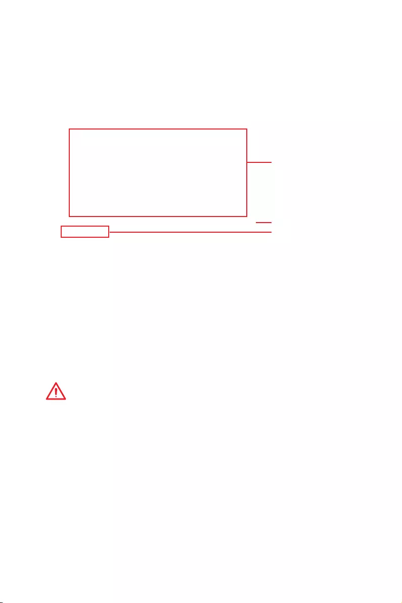
61
Software Description
APP MANAGER
APP MANAGER is a handy management application for integration of MSI applications
and software interface. Providing easy shortcut entrance and real-time update
information of all the MSI software and applications.
APP list
Total Install/ Update
Motherboard
Information
yAPP list — shows all the applications and software be supported by this motherboard.
An icon represents a entrance to the application.
Colorful icon — a colorful icon means that the application had have been
installed successfully and it is available. Double click on desired icon to access
the application. A refresh icon shows to inform you that the application has a
update version.
Gray icon — the icon with gray painting means that the application is not available
and you have to install it if necessary. Double click on the gray icon and the update
information will show. Click on the INSTALL button to install the application.
yMotherboard Information — shows the model name of motherboard.
yTotal Install/ Update — click on this tab to update/ install all the applications.
Important
Please note that, once you uninstall the APP MANAGER, all the MSI applications and
software will be uninstalled simultaneously.
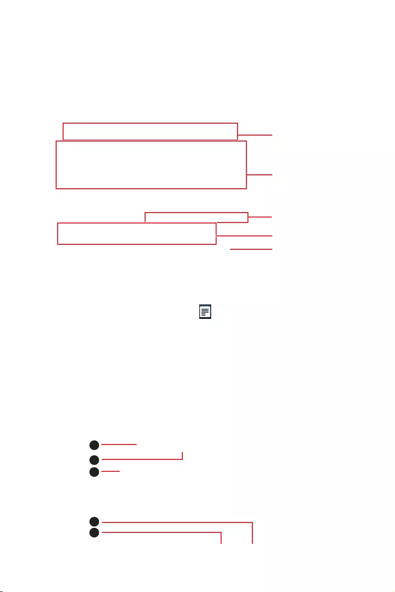
62 Software Description
LIVE UPDATE 6
LIVE UPDATE 6 is an application for the MSI® system to scan and download the latest
drivers, BIOS and utilities. With LIVE UPDATE 6, you don’t need to search the drivers
on websites, and don’t need to know the models of motherboard and graphics cards.
LIVE UPDATE 6 will download the appropriate drivers automatically.
Download Options
Download List
Scan / Download / Total
Installer button
System Information
Last Scanned Date
There are Live Update, History, Setting and System Information tabs at the top. You
can click the tab to switch the control panel.
yLive Update — When you launch LIVE UPDATE 6, you will see the Live update tab at
first. This tab allows you to select files to download. You can also read the relevant
information by clicking the information icon on the right of the item listed.
yHistory — shows the downloading history.
ySetting — allows you to specify the frequency that LIVE UPDATE 6 remind you to
update.
ySystem Information — displays the information of the system.
yFAQ — shows Frequently Asked Questions.
yOnline Help — shows Online Help information.
Updating The System
This section describes how to update your system with LIVE UPDATE 6. Please follow
the steps below:
1
2
4
5
3

63
Software Description
1. Select the Live Update tab.
2. Choose Automatic scan, system will automatically scan all the items and search
for the latest update files. Or you can choose Manual scan and select the items you
wish to scan.
3. Click the Scan button at the bottom. It may take several moments to complete the
process.
4. When the download list appears, please select the items you intend to update.
5. Click Download button at the bottom.
6. When Save Path prompt, you can specify a download directory.
7. When downloading you will see the screen below. It may take several moments to
complete the process.
8. To install the applications, simply unpack the packages and install.
Total Installer
Total Installer is a convenient feature to simplify frequent installing procedure. To use
Total Installer:
1
2
3
1. Scan updates in Live Update tab.
2. Check the Select All check-box you intend to update.
3. Click the Total Installer button. LIVE UPDATE 6 will automatically install them.
4. When prompted, click OK to complete the Total Installer procedure
5. Reboot your system.
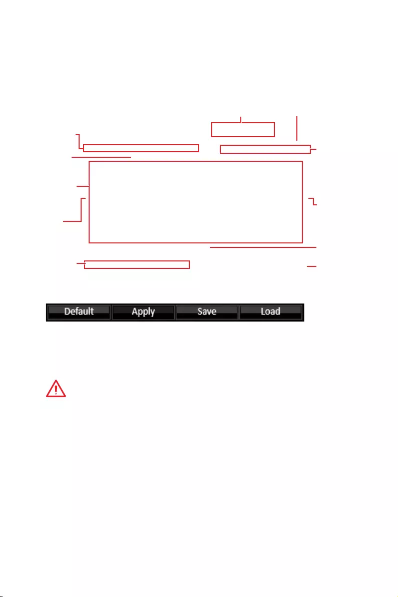
64 Software Description
COMMAND CENTER
COMMAND CENTER is an user-friendly software and exclusively developed by MSI,
helping users to adjust system settings and monitor status under OS. With the help
of COMMAND CENTER, making it possible to achieve easier and efficient monitoring
process and adjustments than that under BIOS. In addition, the COMMAND CENTER
can be a server for mobile remote control application.
Feature Menu
CPU TemperatureSystem Information
Feature Title
Feature
Control Panel
Previous
Feature
Next Feature
Profile
Buttons
Option Buttons
Page Indicator
Resize Corner
Profile Buttons
yDefault — load the default values for the current feature.
yApply — apply your changes.
ySave — store values in the file with individual file extension.
yLoad — load the values from the file.
Important
Every time you shut down the system, the configured setting will be restored to the
factory default. If you want to use the saved settings, you have to load it every time by
clicking the Load and Apply buttons.
CPU Frequency
CPU Frequency control panel allows you to change
CPU Ratio and Base clock. You can see the current
frequency of each CPU core on the top of the panel.

65
Software Description
CPU Fan
CPU Fan control panel provides Smart mode and
Manual Mode. You can switch the control mode by
clicking the Smart Mode and Manual Mode buttons
on the top of the CPU Fan control panel.
yManual Mode — allows you to manually control the
CPU fan speed by percentage.
ySmart Mode — a linear fan speed control feature.
The control panel contains 4 dots allows you to
drag and adjust the Smart Speed slopes. The fan
speed will be changed along these lines with CPU
temperature. The white dot will create strip chart in
real time.
ySystem Fan Button — to open the system fan control
panel in new window.
yFan Tune Button — to automatically optimize the
smart fan setting.
Manual Mode
Smart Mode
IGP Frequency & GT Voltage
yIGP Frequency — Allows you to adjust the IGP ratio,
and shows the IGP clock, ratio and frequency.
yGT Voltage — Allows you to adjust the GT voltage.
The risky values are displayed in red.
DRAM Frequency & DRAM Voltage
yDRAM Frequency — Shows the DRAM clock, ratio
and frequency.
yDRAM Voltage — Allows you to adjust the DRAM
voltage. The risky values are displayed in red.
CPU Voltage
CPU Voltage control panel allows you to control the
CPU voltage.

66 Software Description
Option Buttons — Advanced
When click the Advanced button, The Voltage, Fan and DRAM icons will appear.
yVoltage — allows you to adjust advanced voltage values of CPU and chipset.
yFan — allows you to control the system fans speed.
yDRAM — shows the current Advanced DRAM parameters, and allows you to change
the settings by selecting values from the drop-down menu on the right hand side.
Option Buttons — Setting
When click the Setting button, The Record, Warning and Mobile Control icons will
appear.
yRecord — allows you to monitor the status of voltage, fan speed and temperature in
real time.
To filter record charts, select the check box next to the items.
When click the Play button, the chart pane will start to show the recording chart.
If you want to check the value of a specific spot on chart, please move the orange
vertical line to the spot.
History Record stores the data and names with date and time.
To make a history record: Select items and click the Record button. When
finished, click the Record button again. The data will be stored in the drop-down
menu.
To load a record, click the drop-down menu and select one from the list.
To delete a record, select the record that you want to delete, and click the Trash
Can icon.

67
Software Description
yWarning — contains fields of voltage, fan speed and temperature for you to set the
threshold values. When system detects the status over your settings, a warning
message will pop-up.
yMobile Control — is only available for the motherboard with the built-in WiFi module.
It allows you to enable/disable the COMMAND CENTER Remote Server. Please refer to
the instruction on the Mobile Control control panel.
yTo start remote control: (optional)
1. Download and install MSI® COMMAND CENTER APP to your mobile device.
2. Enable COMMAND CENTER Remote Server on the Mobile Control panel.
3. Enable SoftAP Management.
4. Enter SSID and Password, and then click the Apply button.
5. Activate Wi-Fi® on your mobile device and connect to SoftAP with the SSID.
6. Run MSI® COMMAND CENTER APP on your mobile device.
7. Find the IP address on the SoftAP Management Setting area, and enter the IP
address on your MSI® COMMAND CENTER APP to link your system.
8. Press Refresh on the MSI® COMMAND CENTER APP to verify that monitoring and
OC functions are working properly.
Option Buttons — Information
When click the Information button, The Motherboard, CPU, Memory and HW monitor
icons will appear.
You can click the icons to open the related information.
Gadget Mode
COMMAND CENTER provides a gadget mode to
monitor the system status. You can switch between
gadget mode and full mode by clicking the arrow
icon on the top left.
yTo arrange gadgets:
1. Click the Spanner icon on the Gadget mode,
a configuration panel will slide out.
2. Select the check box next to the items.
3. Click the Close button.

68 Software Description
GAMING APP
GAMING APP is an application designed to quickly control your system for improving
gaming performance.
Information Button
Setting Button
Control Mode Buttons
Gaming Function
Buttons
CPU Frequency GPU Frequency
Cooler Boost
Peripheral Device
Function Buttons
Remote Control Setting Button
ySetting Button — allows you to choose running GAMING APP when Windows starts or
let GAMING APP to overwrite the VGA fan control function.
yInformation Button — shows the information of this application.
yCPU Frequency — shows the current CPU frequency.
yGPU Frequency — shows the current GPU frequency.
yControl Mode Buttons
OC Mode — apply turbo frequency to CPU and OC frequency to GPU.
Gaming Mode — automatically optimize the CPU ratio and the GPU clock.
Silent Mode — reverts the CPU ratio and GPU clock to the default values.
yGaming Function Buttons — allows you to use OSD and Eye Rest functions.
yPeripheral Device Function Buttons — allows you to set the Gaming Hotkey, Mouse
Master, VR Ready and Voice Boost functions.
yRemote Control Setting Button — available for the motherboards with built-in or
discrete WiFi module. It allows you to set up Name and Password to link the android
device and the motherboard. Please follow the steps below to complete the remote
control setting.
1. Download and install the MSI® GAMING APP APP to your android device.
2. Set up a set of Name and Password on the Remote Control Setting panel, and
then click the Apply button.
3. Connect your android device and motherboard to the same local area network.
4. Run MSI® GAMING APP APP on your android device.
5. Press the Remote Control Setting icon on the MSI® GAMING APP APP to find the
paired device Name you set in the Remote Control Setting panel.
6. Enter the Password you set in the Remote Control Setting panel.
7. Finally, you can use the MSI® GAMING APP APP to control your motherboard with
the android device.

69
Software Description
Eye Rest
Eye Rest allows you to optimize the display on your monitor.
yEyeRest — reduces blue-light of your LED backlit screen, in order to protect your
eyes.
yGaming — automatically increase contrast ratio of your screen.
yMovie — automatically increase dynamic contrast ratio of your screen.
yCustomize — allows you to adjust gamma, contrast and color balance for your screen.
yDefault — loads the default settings.
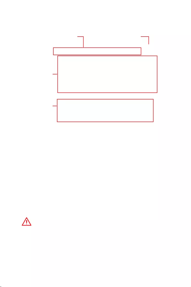
70 Software Description
Gaming Hotkey
Gaming Hotkey provides instant control of the system through user defined hotkeys.
Categories Toggle
Hotkey Manager
Current Hotkeys
Gaming Hotkey ON/OFF
yGaming Hotkey ON/OFF — allows you to turn ON/OFF the Gaming Hotkey function.
yCategories Toggle — allows you to toggle over the Hotkey categories.
Macro Genie — provides the keyboard and mouse macro record function and
allows you to define the hotkeys for the macro recorder.
1. Click on the Record button to start the keyboard and mouse macro recorder.
2. Click on the Stop button to stop the recorder.
3. Key-in a file name and set-up the parameter for the macro.
4. Finally, click on the Save button to save the recorded macro.
Windows Keys — allows you to define hotkeys to replace Windows default
keyboard shortcuts.
Login Keys — provides hotkey login function.
MSI Smart Keys — allows you to define hotkeys for MSI Smart Keys.
yHotkey Manager — allows you to create, edit and delete hotkeys.
yCurrent Hotkeys — shows all existing hotkeys.
Important
y
The Caps Lock, Num Lock, Scroll Lock, Window Home, Application and BackSpace
keys can not be used as Hotkeys.
y
Some key combinations are reserved for use by Microsoft Windows and can not be
assigned as a hotkey.

71
Software Description
Mouse Master
Mouse Master provides mouse macro function. You can also use it to change DPI of
your mouse.
Delay Time
Macro Hot Key DPI Hot Key
Test Area
Clear Button
Mouse Action
DPI Setting
Default Button
Action List
Edit Buttons
Load Button
Save Button
yDelay Time — allows you to apply a delay time in mouse macro.
yMacro Hot Key — allows you to assign a hotkey from A to Z to activate the macro.
yMouse Action — assigns mouse actions to the macro.
New — captures the mouse coordinate and add to the macro.
Left — add a left-click to the macro.
Middle — add a middle-click to the macro.
Left — add a left-click to the macro.
yAction List — shows the actions of the current macro.
yEdit Buttons — there 3 buttons for editing the macro.
Run — activates the macro.
Delete — removes the selected action from the macro.
Clear — removes all actions from the macro.
yLoad Button — allows you to load a macro.
ySave Button — allows you to save the macro to a file.
yDPI Setting — allows you select the mouse DPI from the drop-down menu.
yDefault Button — reverts to the default DPI setting.
yDPI Hot Key — allows you to assign a hotkey from A to Z to activate the DPI setting.
Please note that you muse hold the hotkey to keep the DPI setting. When you release
the hotkey, the DPI setting will be reverted to default.
yTest Area — allows you to test the mouse movement.
yClear Button — clears the test area.
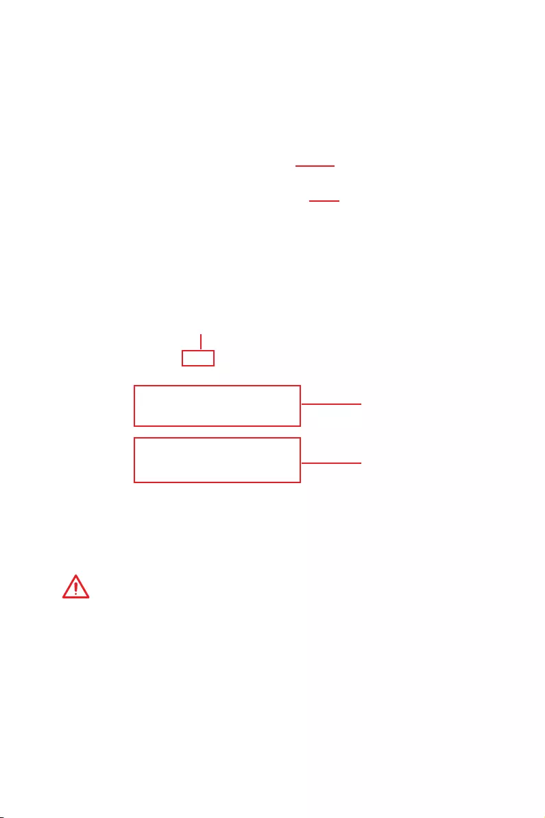
72 Software Description
VR Ready
It will optimize the performance of your system to ensure everything is VR Ready.
Applications
VR ON/ OFF
yVR ON/ OFF -enables or disables VR settings.
yApplications — appears when you turn on the VR support. It allows you to close some
applications to optimize the system for better VR experience.
Voice Boost
Voice Boost function allows you to boost volume in voice communication tools.
ON/ OFF toggle
VoIP Selection
VoIP Setting
yON/ OFF toggle -enables or disables Voice Boost function.
yVOIP Selection — selects your voice communication tool.
yVOIP Setting — adjust the volume ratio in voice communication tool.
Important
The Voice Boost function is only available with Nahimic 2.5/ 3 and voice communication
tools (TeamSpeak, Raidcall, Skype, SkypeHost and Discord).
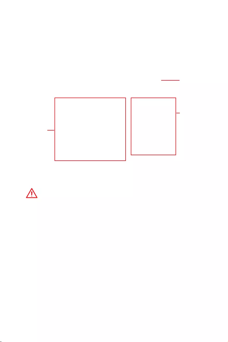
73
Software Description
yPerformance information — displays the system performance diagram of enabled
mode.
ySetting — enables or disables Run X-BOOST when windows starts.
X-BOOST
The MSI X-BOOST allows you to select the system performance mode to meet your
current system environment or support faster storage access speed for your external
storage or memory cards.
Easy
In Easy page, you can select one system performance mode to meet the current
system environment.
Setting
Performance
information
Performance
mode
yPerformance mode — moves over the mouse to any one of performance mode and
click on the ON button to enable it.
Important
The Customize mode is the default of system performance.

74 Software Description
Advance
In Advance page, you can enable the USB SPEED UP, the STORAGE BOOST and VR
BOOST.
Setting
Device
information
yDevice information — displays the information and current transfer rates/ access
speeds of USB/ storage devices.
ySetting — enables or disables Run X-BOOST when windows starts.
yUSB SPEED UP — supports faster data transfer rates of the USB storage devices.
ySTORAGE BOOST — supports faster access speed of storage device.
Important
y
Please note that you can only select one mode at a time from Easy or Advance page
as MSI X-BOOST function.
y
The improved transfer rate/ access speed will vary with the USB/ storage device.
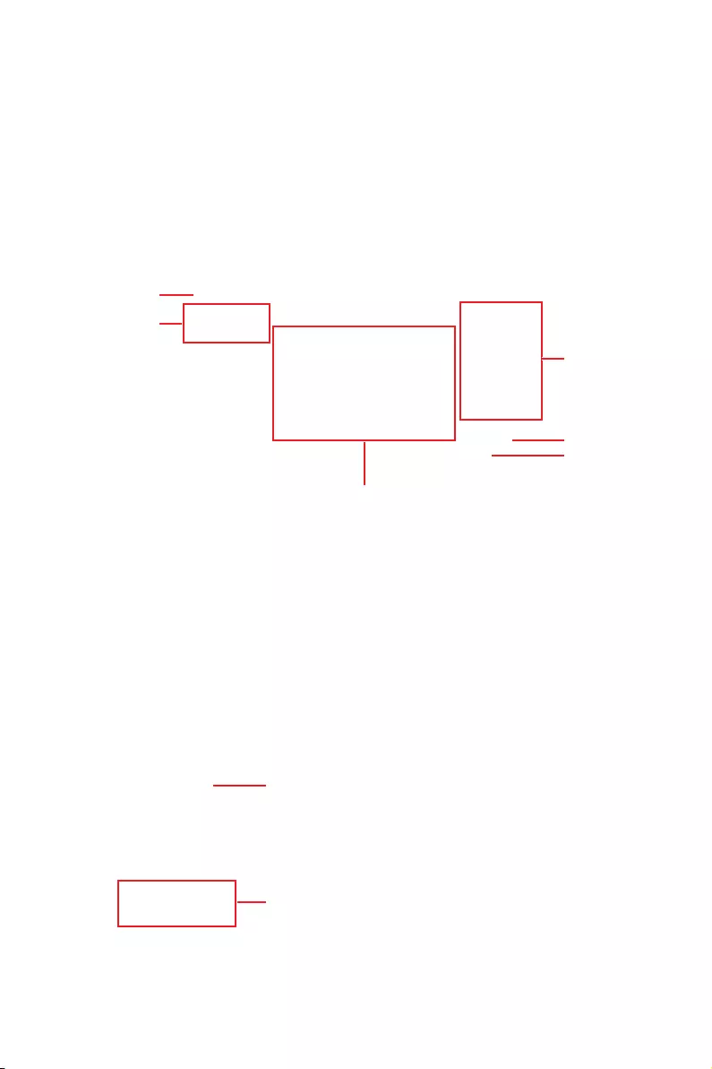
75
Software Description
ySYNC PROFILE — In this section, you may apply different LED setting to your device.
All Sync — Default: All the Sync device bubble would appear red.
MYSTIC LIGHT
MYSTIC LIGHT is an application allows you to control LED lights of MSI products.
For some earlier products, you can go to product download page to download the
applicable LED control software.
Main Screen
The Main screen is used to configure what devices need to be synchronized and LED
light effect options.
Right hand
side panel
ON/ OFF All LED
SYNC PROFILE
Live Preview
Apply Button
Save Button
Please noted that for light effect, the option would be
more or less depending on the devices you have, it will
only list the light effects which are available for all
included devices.
yON/OFF All LED — By toggling Off/On here, you
disable/enable all the LED on supported gaming gear,
memory, graphics card and motherboard etc.
For the color section, you can always select a different
color but it won’t apply to the device that does not have
such color.
To change the LED color & effect, use the panel on the right hand side to switch to
different settings.

76 Software Description
You can save the current settings by clicking Save.
You can also change settings for single device. To do that, you have to click the
sync bubble twice and make it turn gray as below.
Then you go to DEVICE SETTING and click SETTING.
To change color for individual device, use the device setting panel below to lock on
any device and click SETTING to customize the LED color/effect on it.
After that, the computer will open a different windows and you can modify LED
there individually.
Individual — Default: All the Sync device bubble would appear black.
Note: The
motherboard
picture and
name may
vary according
to different
models.
click SETTING
click SETTING

77
Software Description
If you wish to customize multiple device at the same time, click the bubble until it
turn red like below.
Use the LIGHT EFFECT & COLOR section on the main menu to make change.
Note:
Currently only GTX 1080 Ti Lightning -/X/Z and GTX 1080
Ti Gaming -/X Trio supports Light Speed/Brightness and
no device supports Direction.
Profile01~03 — Save Sync profile settings.
ySave Button — saves sync device settings and lighting effect settings to the current
Sync Profile.

78 Software Description
Motherboard Screen
The motherboard screen is used to configure the LED light effect of the motherboard.
Light Effect
Options
Motherboard
Name
PROFILE
Return Button
LED AREA
SYNC ALL
Live Preview
Apply Button
Save Button
yReturn Button — returns to the main screen.
yON/OFF ALL LED — allows you to turn ON/ OFF all LED lights of the motherboard.
ySYNC ALL — allows you to synchronize all LED light effect of the motherboard.
yMotherboard Name — shows the name of the motherboard.
yLive Preview — gives you the full experience of your configuration’s look, feel while
you are editing it.
yLight Effect Options — allow you to customize lighting effect of the sync devices.
LIGHT EFFECT — allows you to change LED light effect.
LIGHT SPEED — allows you to change LED light speed.
BRIGHTNESS — allows you to change LED light brightness.
Note:
Currently only Z370 GODLIKE GAMING, H370 GAMING PRO CARBON and B360
GAMING PRO CARBON support Light Speed/Brightness.
COLOR — allows you to select the color for single light effects (Stack, Breathing,
Flashing etc.).
yApply Button — applies lighting effect settings.
yPROFILE — manages sets of motherboard LED light effect settings.
ySave Button — saves sync device settings and lighting effect settings to the current
profile.
yLED AREA — switches to the other LED area on the motherboard.
ON/ OFF ALL LED
Note: The motherboard picture and name may vary according to different models.

79
Software Description
MYSTIC LIGHT PARTY
This section allows you to control LED across different platform. The pre-requisite is
that the platforms should all be connected within the same local network. Refer to
device support list web page. https://www.msi.com/Landing/Mystic-Light-Party.
PARTY
Upon clicking PARTY, this window would pop out. On your master platform, click + to
create a host group.
Click + to create a host group
Enter the group name (3~15 characters) and group array (13~30 columns, 5~30 rows)
and click the CREATE button.

80 Software Description
The group has been created. The other computers in the same local network are able
to join the group with MYSTIC LIGHT software.
DELETE Group Button
Control Group Button
Group In/Out Status
Invitation Status Indicator
DELETE Group Button — deletes the group.
Control Group Button — enters the group control panel.
Invitation Status Indicator — appears when receive an invitation to a group.
Group In/Out Status — shows Group In/Out status.
Joining Group
On your slave platform, click PARTY to open MYSTIC LIGHT PARTY interface and click
In to join the network.
JOIN Button

81
Software Description
Group Control Panel
If everything is set up properly, you can see your slave platform on master platform
MYSTIC LIGHT PARTY window.
APPLY button
Group Members Icon
Light Effect Options
Color Selection
Invite Button
At the panel below, you may apply different LED settings and color to the selected
platform.
Please be aware of certain limitation on the devices such as if you apply green color
to a red-only device, the LED will stay off since it has on such color or if you apply
rainbow to a no-rainbow mode device, the LED will stay on constantly.
yGroup Member Icons — displays members status, and you can select a member to
delete it in the DELETE pop-up window.
Light Color
Member Serial Number
Selected Indicator (The red border)
Wi-Fi Indicator (Indicates that the device is connected over Wi-Fi)
DELETE the member

82 Software Description
yInvite Button — enters the INVITE screen.
yLight Effect Options — allow you to customize lighting effect.
Off Always on Breathe
Flash Double flash
Rainbow Sound beat
Random
Marquee
yColor Selection — allows you to change color.
Inviting Member
Click the Invite button in the Group Control Panel to enter the INVITE screen. Select
the device you want to invite and click the INVITE button.
INVITE Button

83
Software Description
SMART TOOL
SMART TOOL is a convenient tool that can help you to create your Windows installation
USB flash drive, and it can also create a super RAID.
Main menu
After installing and activating SMART TOOL, it will display a main menu for you to
choose Smart Tool or SUPER RAID. Note that the SUPER RAID is only available when
your system equipped with at least 3 hard-disk drives (1 system disk and 2 data disks).
SMART TOOL
Before you can create your Windows installation USB flash drive, you’ll need to have
your Windows Installation DVD or ISO file, and also have a minimum of a 8GB USB
flash drive to create your installer. Be sure to backup files on the USB drive, this
process will erase it.
To create the Windows installation USB drive:
Step1. Choose source folder
yIn the Source folder box, click Browse button and select the file from the dialog box.
(This option will copy all Windows installation files.)
yAdd USB drivers to USB pan driver option allows you to add USB driver on the USB
pen drive. This option appears depend on the motherboard you purchased.
Step2. Choose Storage device
yChoose USB storage and select your USB flash drive in the drop-down list. In case
the USB flash drive is not listed, click the Refresh Drive button.
yIf you want to install Windows on the RAID drive, select the RAID driver version from
the drop-down menu.
yIf you want to add NVMe drive for your NVMe SSD drive, check the Add NVMe driver
checkbox.
Important
You can also create an installer ISO image file by selecting the ISO destination in
Step2, and then burn it onto the DVD. However, this method does not support RAID
driver.
Step3. Click the Start buton.

84 Software Description
SUPER RAID
This utility allows you to create a super RAID in Windows system.
To create a super RAID:
1. Use checkboxs to select the disks you want included in your RAID.
2. Choose Speed Up or Backup for RAID type.
ySpeed Up = RAID0
yBackup = RAID1
3. Click Start.
4. When prompt Finish!, click OK.
Important
SUPER RAID can’t includ the system disk.
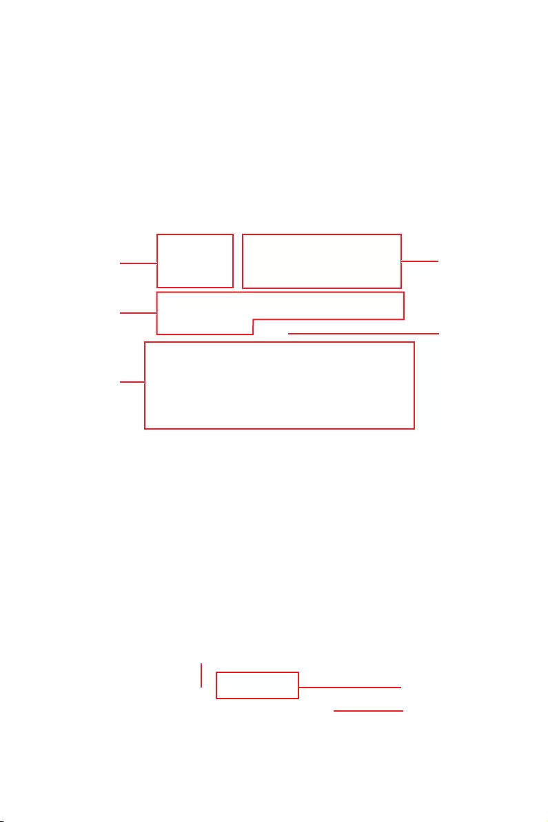
85
Software Description
RAMDISK
RAMDISK creates a virtual RAM drive using the available memory in your computer,
the performance of the RAMDISK is faster than an SSD and hard drive. RAMDISK
allows you to store any temporary information on it. Furthermore, using the RAMDISK
will extend your SSD’s life by sparing it from excessive reading and writing.
Creating a RAM Disk
When RAMDISK is started, it will create a default RAM disk. If you want to change
settings, refer to following instructions.
Setting
Backup
Management
Option
Apply
Button
ySetting — specify Letter, Name, Size and Format of the RAM disk.
yOption — select browser temporary files to save/load on the RAM disk. You can also
add software files to improve reading speed.
yBackup — specify backup and restore settings to prevent data loss. All files will be lost
each time the RAMDISK is stopped if you do not backup.
Browse Button — set the path to the image file.
Backup Right Now Button — manually backup files.
Restore On Boot — check this box to have the image file loaded automatically when
RAMDISK starts.
Auto Backup — check this box to backup automatically over a period of time.
yApply Button — allows you to apply changes.
yManagement — shows RAMDISK information and allows you to delete files.
Dislpay
information
Delete files
in the RAM
disk.
Remove the RAM disk
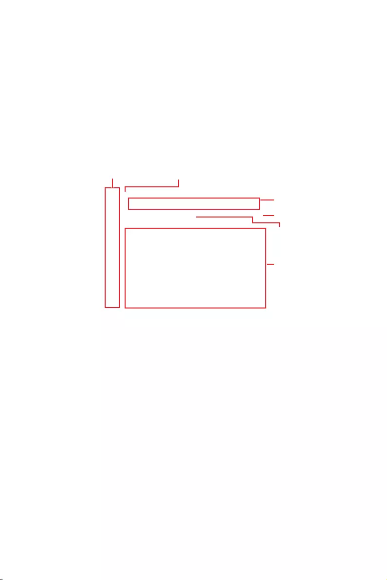
86 Software Description
Nahimic 3
Nahimic 3 is designed to offer the best audio experience it contains audio effects,
microphone effects and Sound Tracker.
Installation and Update
Nahimic 3 is included in the audio driver. If you need to install it or update it, please
use the Driver Disc with your motherboard or download the driver from MSI’s official
website.
Audio Tab
From this tab, you can access all of Nahimic 3’s audio effects, audio profiles and
settings.
Audio Profiles
Audio Effects
Reset Button
Try Button
On/Off Button
Device display & Volume
yDevice display & Volume — displays the type of audio device currently being used as
output, as well as its current volume.
Mute — mutes the current audio output device.
yAudio profiles — allows you to choose between 4 factory audio profiles to fit your
multimedia experience (Music, Gaming, Movie or Communication). All profiles can be
modified as you wish.
yOn/Off Button — allows you to turn all of Nahimic 3’s audio effects in one click.
yAudio Effects — allows you to separately control any of the 5 audio effects.
Surround Sound — it is an audio effect mainly dedicated to headphones acoustic
experience.
Gaming and Movies — virtualizes the multichannel audio stream from the
game engine or the movie soundtrack and downmixes it in order to retrieve a
multichannel listening experience over your stereo headphones or speakers.
Music — expands the stereo for a wider sound stage.
Volume Stabilizer — it maintains a constant volume for all elements of the audio
experience (dialogs, soundtrack, explosions, etc.) to make them all sound softer,
balanced or louder. The Quiet On / Off option allows to enter a night mode by
removing some basses. This way, you won’t disturb people around you if you’re
using speakers to play your media.

87
Software Description
Voices — it boosts (or removes) the speech in movies, video games and incoming
communication from -12 to +12 dB.
Bass — increases (or decreases) the energy in low frequencies from -12 to +12 dB.
Treble — increases (or decreases) the energy in high frequencies from -12 to +12
dB.
yReset Button — restores the current profile to its default values.
yTry Button — launches an audio sample that allows to test audio settings.
Microphone Tab
From this tab, you can access all of Nahimic 3’s microphone effects and settings.
Microphone
Profiles
Microphone
Effects
Reset Button
Try Button
On/Off Button
Device display & Volume
yDevice display and volume — displays the type of recording device currently being
used as input, as well as its current volume..
Mute — mutes the current mic device.
yMic profiles — allows you to choose between 2 factory mic profiles to fit your
experience (Chat or Conference). All profiles can be modified as you wish.
yOn / Off button — allows you to turn on and off all Nahimic 3’s microphone effects in
one click.
yMicrophone Effects — allows you to separately control any of the 4 microphone
effects.
Static Noise Suppression — it removes the static noises like the ones coming from
your computer fans.
Echo Cancellation — improves the voice quality by cancelling the echo.
Lateral Sound Cancellation — it only records the sound coming from the front of
your microphone.
Voice Stabilizer — Levels the volume of your voice in order to avoid any saturation
and maintains a constant and clear communication.
yReset Button — restores the current profile to its default values.
yTry Button — Turns the microphone loopback On/Off.

88 Software Description
Sound Tracker Tab
The Sound Tracker is an FPS oriented feature that provides a visual indication
localizing the sources of the sounds while in a game. These are represented by
dynamic segments pointing the direction of the sounds: the more opaque they are,
the stronger the sounds are. Thanks to this feature, players are able to pick up an
approaching threat more definitively and easily, thereby being even more dynamic.
The Sound Tracker captures the 5.1 and 7.1 sound streams processed by your audio
system, and is displayed in the applications and games using DirectX 9, 9c, 10 and 11.
Sound Tracker
Effects
Sound Tracker
Compatible
games
Try ButtonOn/Off Button
yON / OFF Button — allows you to enable/ disable the Sound Tracker by switching this
option ON/ OFF.
yTry Button — launch a 7.1 audio sample allowing you to preview how the radar will
react in your game.
ySound Tracker Effects
Size — allows you to adjust the scale of the Sound Tracker, making it look bigger or
smaller.
Transparency — allows you to adjust the transparency of the Sound Tracker,
making it look more or less discrete.
Color — click the colored circle to open the color edition window. You can apply the
color you want to the dynamic segments.
yCompatible games — clicking this link opens the official Nahimic website, and leads
to the list of compatible games able to display the Sound Tracker.
Settings Tab
In this section, it allows you to select the language of Nahimic 3’s UI.
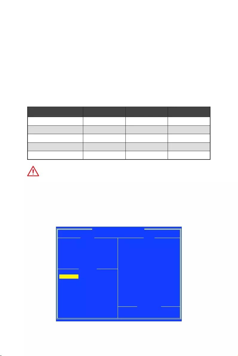
89
RAID Configuration
RAID Configuration
Below are the different types of a RAID.
RAID 0 breaks the data into blocks which are written to separate hard drives.
Spreading the hard drive I/O load across independent channels greatly
improves I/O performance.
RAID 1 provides data redundancy by mirroring data between the hard drives and
provides enhanced read performance.
RAID 10 uses four hard drives to create a combination of RAID 0 and 1 by forming a
RAID 0 array from two RAID 1 arrays.
RAID level comparison
RAID 0 RAID 1 RAID 10
Minimum # drives 2 2 4
Data protection None Excellent Excellent
Read performance Excellent OK OK
Write performance Excellent Good Good
Capacity utilization 100% 50% 50%
Important
All the information/ volumes/ pictures listed in your system might differ from the
illustrations in this appendix.
Using AMD RAID Controller BIOS Configuration Utility
Enter BIOS and change the SATA Mode setting to RAID Mode, press F10 to save the
changing, and then reboot. When booting the system, press Ctrl+R when the BIOS
banner displays. After entering AMD RAID Controller BIOS Configuration Utility, the
following screen is displayed.
AMD-RAID Array Configuration
Creates an array from the connected disks
Arrays Disks
1—-RAID5, 999GB, Ready(R/W) 0-00,500GB,Online
0-01,500GB,Online
0-02,500GB,Online
0-03,500GB,Online
Main Menu
Initialize Disk(s)
Create Array
Delete Array(s)
Swap Two Arrays
Manage Hot Spare(s)
View Disk Details
View Array Details
Rescan All Channels
Controller Options
Continue to Boot Available Keys
<↑><↓><→><←>=Choose, <Esc>=Back
Enter=Select Menu Item

90 RAID Configuration
Using the utility to accomplish the procedures
yInitialize Disk(s) — To initialize a new disk drive for data storage.
yCreate Array — Create arrays at different RAID levels (depending on the license level
for the system)
yDelete Array(s) — Delete an array.
ySwap Two Arrays — Change the array order, especially for the AMD-RAID bootable
array.
yManage Hot Spare(s) — Allows selection of global and dedicated hot spares.
yView Disk Details — View information about each disk.
yView Array Details — View information about each array.
yRescan All Channels — Rescan all channels to detect new or removed disks and
arrays.
yController Options — Change INT13 boot support, turn off Critical arrays or warning
for Offline arrays while booting, or change the number of disks that can be spun-up
when the system is powered-on.
yContinue to Boot — Exit the BIOS Configuration Utility and continue booting the
system.
Understanding the Colour Code
Colour codes indicate the type or status of information at the BIOS Configuration
Utility.
yWhite text — Indicates an available option or informational text.
yBlack text, yellow highlighting — Indicates an option or device for which action might
be taken.
yYellow text — Indicates information about the yellow-highlighted option.
yGreen text — Indicates an item that has been selected.
yLight blue text — Indicates that the item cannot be selected.
yMagenta text — Indicates items that are related to spares or boot options.
yRed text — Indicates a failed virtual or physical disk or a warning. For example,
informational text might be red if an option is not available.
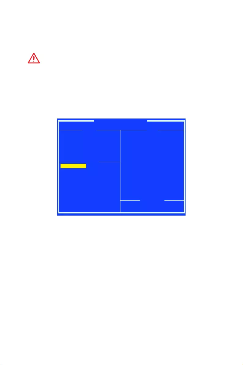
91
RAID Configuration
Initialize Disks
New disks and legacy disks must be initialized before they can be used to create an
AMD-RAID array. Initialization writes AMD-RAID configuration information (metadata)
to a disk.
Important
y
If a disk is part of an AMD-RAID array, the disk cannot be selected for initialization.
To initialize the disk anyway, delete the AMD-RAID array. Data on the disk is deleted
during initialization so ensure the correct disks are chosen to initialize.
y
A legacy disk can contain valid data. When a legacy disk is initialized, all data on the
disk is lost.
To initialize disks
1. At the Main Menu, use the arrow keys to highlight Initialize Disk(s).
AMD-RAID Array Configuration
Initializes one or more disks so that arrays can be created
Arrays Disks
0-00,640GB,Ready
0-01,640GB,Ready
Main Menu
Initialize Disk(s)
Create Array
Delete Array(s)
Swap Two Arrays
Manage Hot Spare(s)
View Disk Details
View Array Details
Rescan All Channels
Controller Options
Continue to Boot Available Keys
<↑><↓><→><←>=Choose, <Esc>=Back
Enter=Select Menu Item
2. Press Enter to select Initialize Disk(s).
3. Select the disks to initialize by pressing Insert key.
4. Press Enter to initialize the selected disks.
5. Press the C key to confirm the initialization.
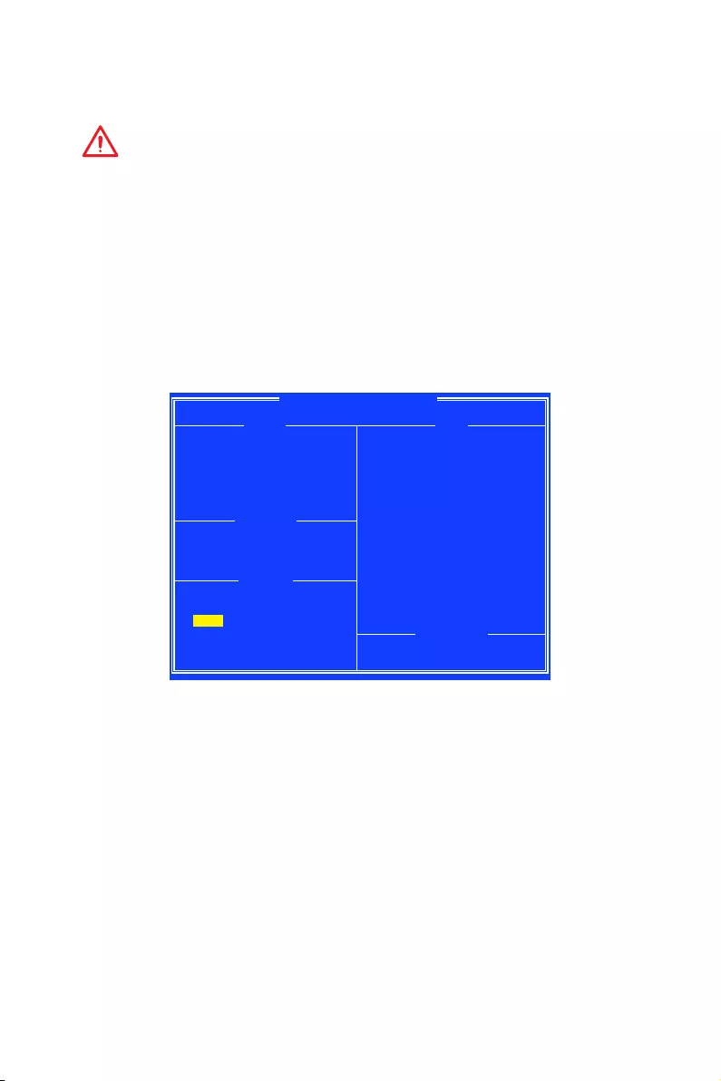
92 RAID Configuration
Create Arrays
Arrays can be created after the disks are initialized.
Important
y
For redundant arrays, the Create process is not finished until after the operating
system and AMD-RAID OS drivers have been installed and the system has booted to
the operating system. However, the arrays are immediately available to use for either a
bootable array or a data array.
y
If the system is booted from an AMD-RAID bootable array, the first array in the
Arrays section must be the bootable array. The system boots only from the first array
in the Arrays section. As necessary, use the Swap Two Arrays feature to swap arrays
and place the bootable array in the first position.
To create an array
1. At the Main Menu, use the arrow keys to highlight Create Array and press Enter.
2. Select the disks with which to create the array by pressing Insert key.
AMD-RAID Array Configuration
RAID0: Stripe set — distributes space across disks for higher performance
Arrays Disks
0-00,640GB,Ready
0-01,640GB,Ready
Create Array
User Input
Select Array Type to Create
RAID5 RAID10N
RAID0 RAID1N
RAID1 Volume
RAID10 RAIDABLE
RAID50
Disk: 0,2
Type: RAID0
Available Keys
<↑><↓><→><←>=Choose, <Esc>=Back
Enter=Select Menu Item
3. Press Enter to include the selected disks in the array.
4. In the User Input section, use the arrow keys to select an array type. Only array
types that can be created with the selected disks are available.
5. Press Enter.
6. Select an array size.
7. Press Enter when either the desired size or the maximum available size is
reached.
8. Select a caching level using the arrow keys and press Enter.
9. Press C to confirm the array settings.
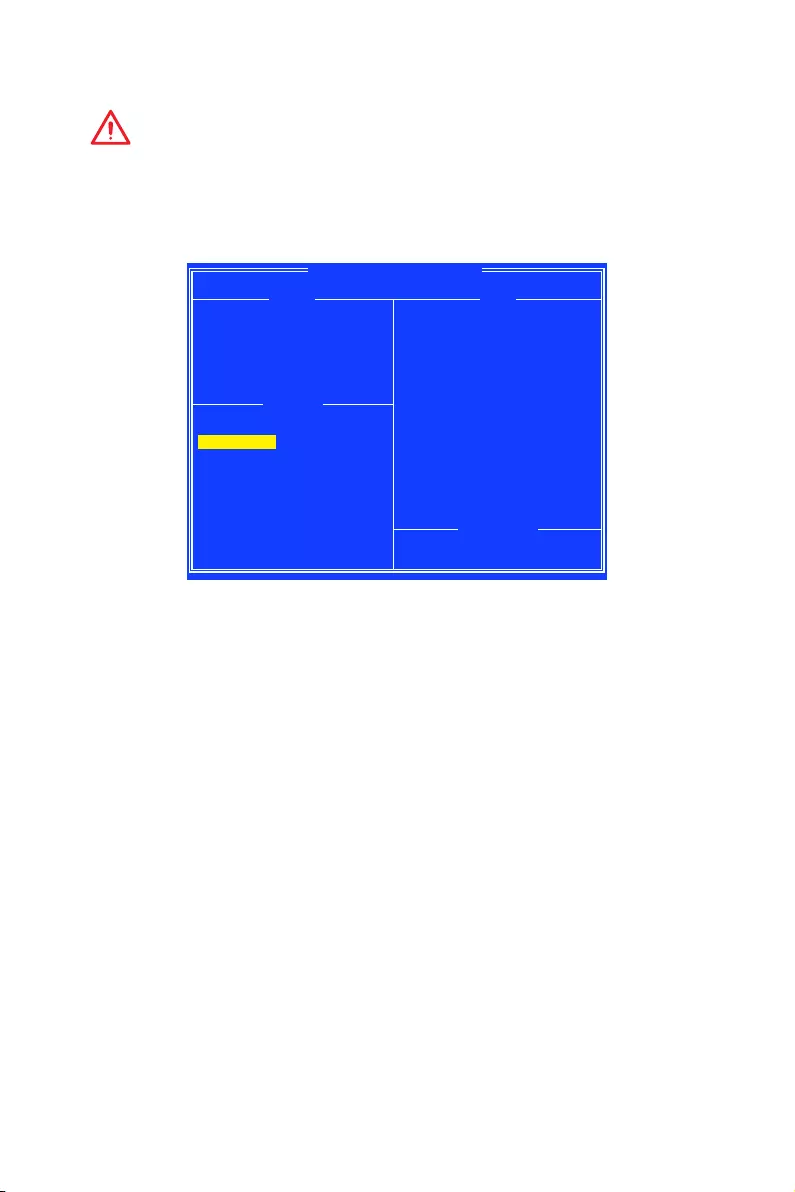
93
RAID Configuration
Delete Arrays
Important
Deleting an array permanently destroys all data that is on the array. This action cannot
be undone and it is very unlikely the data can be recovered.
To delete an array
1. At the Main Menu, use the arrow keys to highlight Delete Array and press Enter.
AMD-RAID Array Configuration
Deletes one or more arrays that are configured on this controller
Arrays Disks
1—-RAID0, 1.2TB, Normal(R/W) 0-00,640GB,Online
0-01,640GB,Online
Main Menu
Initialize Disk(s)
Create Array
Delete Array(s)
Swap Two Arrays
Manage Hot Spare(s)
View Disk Details
View Array Details
Rescan All Channels
Controller Options
Continue to Boot Available Keys
<↑><↓><→><←>=Choose, <Esc>=Back
Enter=Select Menu Item
2. Select the arrays to delete by pressing Insert key.
3. Press Enter to delete the selected arrays.
4. Press C to confirm the deletion.

94 RAID Configuration
Swap Arrays
Use the Swap Two Arrays option to arrange arrays in a different order.
Important
If more than one array is created, install the operating system to any of them.
However, a small amount of boot information is always written to a disk(s) in the first
array (Array 1) of the Array section, regardless on which array the operating system is
installed.
If anything happens to a disk in Array 1, the system might not be able to boot. It is
recommended that the user install the operating system on an AMD-RAID bootable
array at a redundant RAID level such as RAID1 or RAID5 and swap the array into the
first position, if it is not already Array 1.
To swap arrays
1. At the Main Menu, use the arrow keys to highlight Swap Two Array and press
Enter.
AMD-RAID Array Configuration
Swaps arrays to allow them to load in any order (Boot array is first)
Arrays Disks
1—-RAID0, 1.2TB, Ready(R/W)
2—-RAID0, 1.2TB, Ready(R/W) 0-00,640GB,Online
0-01,640GB,Online
0-02,640GB,Online
0-03,640GB,Online
Main Menu
Initialize Disk(s)
Create Array
Delete Array(s)
Swap Two Arrays
Manage Hot Spare(s)
View Disk Details
View Array Details
Rescan All Channels
Controller Options
Continue to Boot Available Keys
<↑><↓><→><←>=Choose, <Esc>=Back
Enter=Select Menu Item
2. Select the arrays to swap by pressing Insert key.
3. Press Enter to swap the arrays.

95
RAID Configuration
Manage Spares
This option allows the user to assign or unassign global or dedicated spares.
At the Main Menu, use the arrow keys to highlight Manage Host Spare(s) and press
Enter to enter submenu.
AMD-RAID Array Configuration
Assign Global Hot Spare(s)
Arrays Disks
1—-RAID0, 999GB, Normal(R/W) 0-00,500GB,Online
0-01,500GB,Online
0-02,1000GB,Ready
0-03,1000GB,Ready
Manage Hot Spare(s)
Assign Global Hot Spare(s)
Assign Dedicated Hot Spare(s)
Unassign Hot Spare(s)
Available Keys
<↑><↓><→><←>=Choose, <Esc>=Back
Enter=Select Menu Item
To assign global spares
1. At the Manage Host Spare(s) submenu, use the arrow keys to highlight Assign
Global Hot Spare(s) and press Enter.
2. Select the disks to assign as global spares by pressing Insert key.
3. Press Enter to assign the selected disks as global spares.
To assign dedicated spares
1. At the Manage Host Spare(s) submenu, use the arrow keys to highlight Assign
Dedicated Hot Spare(s) and press Enter.
2. Select the disks to assign as dedicated spares by pressing Insert key.
3. Press Enter to assign dedicated spares.
4. Press C to continue.
To unassign spares
1. At the Manage Host Spare(s) submenu, use the arrow keys to highlight Unassign
Hot Spare(s) and press Enter.
2. Select the disks to unassign as spares by pressing Insert key.
3. Press Enter to unassign the selected disks.
4. Press C to continue.

96 RAID Configuration
Change the Controller Options
Controller Options allows the user to configure options for the boot sequence.
At the Main Menu, use the arrow keys to highlight Controller Options and press Enter
to enter submenu.
AMD-RAID Array Configuration
Toggles whether BIOS installs INT13 support
Arrays Disks
1—-RAID0, 999GB, Normal(R/W) 0-00,500GB,Online
0-01,500GB,Online
0-02,1000GB,Ready
0-03,1000GB,Ready
Controller Options
Toggle INT13 Boot Support [ON]
Toggle Pause if Critical [OFF]
Toggle Pause if Offline [OFF]
Toggle HIPM [OFF]
Toggle DIPM [OFF]
Set Staggered Spinup Count [2]
Available Keys
<↑><↓><→><←>=Choose, <Esc>=Back
Enter=Select Menu Item
Booting the system from an array
This option allows the user to enable boot support.
It is recommended that this option be disabled only if the system is booted from
another device.
1. At the Controller Options submenu, use the arrow keys to highlight Toggle INT13
Boot Support.
2. Press Enter to toggle between On and Off.
Pausing the boot sequence for warning messages
When the Pause feature is enabled and an array goes critical, offline, or there is
another problem with the system, the boot process stops and an error message is
displayed on the screen. The user must press Enter to continue booting.
If the Pause feature is disabled, error messages are displayed briefly, but the system
continues to boot.
1. At the Controller Options submenu, use the arrow keys to highlight Toggle Pause
if Critical and press Enter.
2. Set pauses to the boot sequence for critical/ offline warnings. Use the arrow keys
to highlight Toggle Pause if Critical/ Toggle Pause if Offline.
3. Press Enter to toggle between On and Off.

97
RAID Configuration
Change the Staggered Spinup Count
Depending on a system’s power supply load-rating, you might want to limit the
number of disks that are spun-up together when a system is powered on.
1. At the Controller Options submenu, use the arrow keys to highlight Set Staggered
Spinup Count and press Enter. The number within the brackets changes colour to
indicate it is selected.
2. Use the arrow keys to change the number within the brackets. The minimum is 1
and the maximum is 8.
3. Press Enter to save the setting.

98 RAID Configuration
Using UEFI to create a 2.2TB RAID
If you plan to create a RAID volume greater than 2.2TB, you can only manually create
the RAID array in UEFI mode. The steps are described below.
WARNING
Create raid array will erase all the data stored on hard drives! Make sure to back up
your files! There is no way to reverse the process!
1. Power on and press Delete key to enter BIOS Setup menu.
2. Press F7 to switch to Advanced mode from EZ mode.
3. Go to BIOS > SETTINGS > Advanced > Integrated Peripherals > SATA Mode and
change setting to RAID Mode.
4. Go to BIOS > SETTINGS > Advanced > Windows OS Configuration > Windows 10
WHQL Support and change setting to Enabled.
5. Press F10 to save configuration and exit, and then reboot and press Delete key to
enter BIOS Setup menu.
6. Go to BIOS > SETTINGS > Advanced > RAIDXpert2 Configuration Utility > Array
Management > Create Array sub-menu.
7. Select RAID Level for disk arrays.
8. Enter Select Physical Disks sub-menu, select member disks by changing the
Physical Disk setting to Enabled.
9. Select Apply Changes to apply and go back to previous sub-menu.
10. Select Create Array to create the RAID volume.

99
RAID Configuration
Installing RAID Driver
New Operating System Installation
The following details the installation of the drivers while installing operating system.
1. During the operating system installation, after selecting the location to install
Windows click on Load driver button to install a third party RAID driver.
2. When prompted, insert the USB flash drive with AMD RAID Drivers and then click
Browse.
To make an AMD RAID Drivers USB flash drive. Insert the MSI Driver Disc into
the optical drive. Copy all the contents in \\Chipset\Packages\Drivers\SBDrv\
RAID_AM4
3. Navigate to the directory containing the saved AMD RAID drivers, then click OK.
4. Select the (rcbottom.inf) driver, click Next.
5. When prompted, click OK.
6. Click Browse and navigate to the directory containing the saved AMD RAID drivers
again, then click OK.
7. Select the (rcraid.inf) driver, click Next.
8. You have successfully installed the RAID driver, and Windows setup should
continue.
9. Leave the disk/ USB drive in the computer until the system reboots itself. Windows
setup will need to copy the files after the RAID volume is formatted, and Windows
setup starts copying files.
Existing Windows Driver Installation
1. Insert the MSI Driver Disc into the optical drive.
2. The Disc will auto-run and the setup screen will appear.
3. Under the Driver tab, click on AMD chipset drivers by your need. The AMD chipset
drivers includes RAID Driver.
4. The drivers will be automatically installed.
Confirming Windows Driver Installation
1. From Windows, open the Control Panel from My Computer followed by the System
icon.
2. Choose the Hardware tab, then click the Device Manager tab.
3. Click the + in front of the RAID Controllers hardware type. The driver AMD RAID
Controller should appear.

100 Troubleshooting
Troubleshooting
Before sending the motherboard for RMA
repair, try to go over troubleshooting
guide first to see if your got similar
symptoms as mentioned below.
The power is not on.
yConnect the AC power cord to an
electrical outlet securely.
yCheck if all ATX power connectors
like ATX_PWR1, CPU_PWR1 are
connected from the power supply to the
motherboard?
ySome power supply units have a power
button on the rear side, make sure the
button is turned on.
yCheck if the power switch cable is
connected to JFP1 pin header properly.
yVerify the Clear CMOS jumper JBAT1 is
set to Keep DATA.
yTest with another known working power
supply of equal or greater wattage.
The power is on, but no signal to
monitor
yConnect the monitor power cord to a
electrical outlet securely.
yMake sure the monitor is turned on.
ySelect different inputs on the monitor.
yIf 3 long beeps are heard, remove all
memory modules and try to install only
one memory module in the DIMMA2 slot
first and then restart the computer.
yIf 1 long 2 short beeps are heard,
remove and reinstall the graphics card
and then restart the computer.
yTest with another known working
graphics card.
The computer does not boot after
updating the BIOS
yClear the CMOS.
yUse the secondary BIOS to bootup the
system (Only for motherboard with Dual
BIOS)
Lost BIOS password
yClear the CMOS, but that will cause
you to lose all customized settings in the
BIOS.
There is no audio
yAdjust the volume.
yConnect the speakers/headphones to
audio ports on the motherboard rear IO
panel.
yRemove secondary speakers/
headphones, HDMI cables, USB audio
devices.
yTest with another known working
speaker or headphone.
There is no network
yMake sure the network chipset driver
has been installed.
yVerify if the network cable is properly
connected and make sure the LAN port
LEDs are properly illuminated.
yVerify your TCP/IP settings.
yRestart or reset your router.
yTest with another known working LAN
cable.
The USB device is not working
yMake sure your USB drive driver has
been installed.
yVerify if USB device is listed in
Windows® Device Manager.
yConnect the USB device to other USB
port on the motherboard rear IO panel.
101
Regulatory Notices
FCC Compliance Statement
Note: This equipment has been tested and found to
comply with the limits for a Class B digital device,
pursuant to part 15 of the FCC Rules. These limits
are designed to provide reasonable protection against
harmful interference in a residential installation. This
equipment generates, uses and can radiate radio
frequency energy and, if not installed and used in
accordance with the instructions, may cause harmful
interference to radio communications. However, there
is no guarantee that interference will not occur in a
particular installation. If this equipment does cause
harmful interference to radio or television reception,
which can be determined by turning the equipment
off and on, the user is encouraged to try to correct the
interference by one or more of the following measures:
yReorient or relocate the receiving antenna.
yIncrease the separation between the equipment
and receiver.
yConnect the equipment into an outlet on a circuit
different from that to which the receiver is
connected.
yConsult the dealer or an experienced radio/TV
technician for help.
Caution: Changes or modifications not expressly
approved by the party responsible for compliance could
void the user’s authority to operate the equipment.
Tested to comply with FCC standards
FOR HOME OR OFFICE USE
This device complies with part 15 of the FCC Rules.
Operation is subject to the following two conditions:
(1) This device may not cause harmful interference, and
(2) this device must accept any interference received,
including interference that may cause undesired
operation.
CE Conformity
Products bearing the CE marking comply
with one or more of the following EU
Directives as may be applicable:
RED 2014/53/EU; Low Voltage Directive 2014/35/EU;
EMC Directive 2014/30/EU; RoHS Directive 2011/65/EU.
Compliance with these directives is assessed using
applicable European Harmonized Standards.
The point of contact for regulatory matters is MSI,
MSI-NL Eindhoven 5706 5692 ER Son.
B급 기기 (가정용 방송통신기자재)
이 기기는 가정용(B급) 전자파적합기기로서 주
로 가정에서 사용하는 것을 목적으로 하며, 모
든 지역에서 사용할 수 있습니다.
クラスB情報技術装置
この装置は、クラスB情報技術装置です。この
装置は、家庭環境で使用することを目的として
い ま す が、こ の 装 置 が ラ ジ オ や テ レ ビ ジ ョ ン 受
信機に近接して使用されると、受信障害を引き起こすこと
があります。取扱説明書に従って
正しい取り扱いをして下さい
VCCI-B
C-Tick Compliance
Battery Information
European Union:
Batteries, battery packs, and
accumulators should not be disposed of as
unsorted household waste. Please use the
public collection system to return, recycle,
or treat them in compliance with the local
regulations.
Taiwan:
廢電池請回收
For better environmental protection, waste
batteries should be collected separately
for recycling or special disposal.
California, USA:
The button cell battery may contain
perchlorate material and requires special
handling when recycled or disposed of in
California.
For further information please visit:
http://www.dtsc.ca.gov/hazardouswaste/perchlorate/
CAUTION: There is a risk of explosion, if battery is
incorrectly replaced.
Replace only with the same or equivalent type
recommended by the manufacturer.
Chemical Substances Information
In compliance with chemical substances regulations,
such as the EU REACH Regulation (Regulation EC
No. 1907/2006 of the European Parliament and the
Council), MSI provides the information of chemical
substances in products at:
http://www.msi.com/html/popup/csr/evmtprtt_pcm.
html
Environmental Policy
yThe product has been designed to
enable proper reuse of parts and
recycling and should not be thrown
away at its end of life.
yUsers should contact the local
authorized point of collection for
recycling and disposing of their end-of-life products.
yVisit the MSI website and locate a nearby distributor
for further recycling information.
yUsers may also reach us at gpcontdev@msi.com for
information regarding proper Disposal, Take-back,
Recycling, and Disassembly of MSI products.
WEEE (Waste Electrical and
Electronic Equipment) Statement
ENGLISH
To protect the global environment and as
an environmentalist, MSI must remind
you that…
Regulatory Notices

102 Regulatory Notices
Under the European Union (“EU”) Directive on Waste
Electrical and Electronic Equipment, Directive 2002/96/
EC, which takes effect on August 13, 2005, products
of “electrical and electronic equipment” cannot
be discarded as municipal wastes anymore, and
manufacturers of covered electronic equipment will
be obligated to take back such products at the end of
their useful life. MSI will comply with the product take
back requirements at the end of life of MSI-branded
products that are sold into the EU. You can return these
products to local collection points.
DEUTSCH
Hinweis von MSI zur Erhaltung und Schutz unserer
Umwelt
Gemäß der Richtlinie 2002/96/EG über Elektro- und
Elektronik-Altgeräte dürfen Elektro- und Elektronik-
Altgeräte nicht mehr als kommunale Abfälle entsorgt
werden. MSI hat europaweit verschiedene Sammel-
und Recyclingunternehmen beauftragt, die in die
Europäische Union in Verkehr gebrachten Produkte,
am Ende seines Lebenszyklus zurückzunehmen.
Bitte entsorgen Sie dieses Produkt zum gegebenen
Zeitpunkt ausschliesslich an einer lokalen
Altgerätesammelstelle in Ihrer Nähe.
FRANÇAIS
En tant qu’écologiste et afin de protéger
l’environnement, MSI tient à rappeler ceci…
Au sujet de la directive européenne (EU) relative aux
déchets des équipement électriques et électroniques,
directive 2002/96/EC, prenant effet le 13 août 2005, que
les produits électriques et électroniques ne peuvent
être déposés dans les décharges ou tout simplement
mis à la poubelle. Les fabricants de ces équipements
seront obligés de récupérer certains produits en fin
de vie. MSI prendra en compte cette exigence relative
au retour des produits en fin de vie au sein de la
communauté européenne. Par conséquent vous pouvez
retourner localement ces matériels dans les points de
collecte.
РУССКИЙ
Компания MSI предпринимает активные действия
по защите окружающей среды, поэтому напоминаем
вам, что….
В соответствии с директивой Европейского
Союза (ЕС) по предотвращению загрязнения
окружающей среды использованным электрическим
и электронным оборудованием (директива
WEEE 2002/96/EC), вступающей в силу 13
августа 2005 года, изделия, относящиеся к
электрическому и электронному оборудованию,
не могут рассматриваться как бытовой мусор,
поэтому производители вышеперечисленного
электронного оборудования обязаны принимать
его для переработки по окончании срока службы.
MSI обязуется соблюдать требования по приему
продукции, проданной под маркой MSI на территории
EC, в переработку по окончании срока службы. Вы
можете вернуть эти изделия в специализированные
пункты приема.
ESPAÑOL
MSI como empresa comprometida con la protección
del medio ambiente, recomienda:
Bajo la directiva 2002/96/EC de la Unión Europea
en materia de desechos y/o equipos electrónicos,
con fecha de rigor desde el 13 de agosto de 2005,
los productos clasificados como “eléctricos y
equipos electrónicos” no pueden ser depositados
en los contenedores habituales de su municipio, los
fabricantes de equipos electrónicos, están obligados
a hacerse cargo de dichos productos al termino de
su período de vida. MSI estará comprometido con los
términos de recogida de sus productos vendidos en
la Unión Europea al final de su periodo de vida. Usted
debe depositar estos productos en el punto limpio
establecido por el ayuntamiento de su localidad o
entregar a una empresa autorizada para la recogida de
estos residuos.
NEDERLANDS
Om het milieu te beschermen, wil MSI u eraan
herinneren dat….
De richtlijn van de Europese Unie (EU) met betrekking
tot Vervuiling van Electrische en Electronische
producten (2002/96/EC), die op 13 Augustus 2005 in
zal gaan kunnen niet meer beschouwd worden als
vervuiling. Fabrikanten van dit soort producten worden
verplicht om producten retour te nemen aan het
eind van hun levenscyclus. MSI zal overeenkomstig
de richtlijn handelen voor de producten die de
merknaam MSI dragen en verkocht zijn in de EU. Deze
goederen kunnen geretourneerd worden op lokale
inzamelingspunten.
SRPSKI
Da bi zaštitili prirodnu sredinu, i kao preduzeće koje
vodi računa o okolini i prirodnoj sredini, MSI mora da
vas podesti da…
Po Direktivi Evropske unije (“EU”) o odbačenoj
ekektronskoj i električnoj opremi, Direktiva 2002/96/
EC, koja stupa na snagu od 13. Avgusta 2005, proizvodi
koji spadaju pod “elektronsku i električnu opremu”
ne mogu više biti odbačeni kao običan otpad i
proizvođači ove opreme biće prinuđeni da uzmu natrag
ove proizvode na kraju njihovog uobičajenog veka
trajanja. MSI će poštovati zahtev o preuzimanju ovakvih
proizvoda kojima je istekao vek trajanja, koji imaju MSI
oznaku i koji su prodati u EU. Ove proizvode možete
vratiti na lokalnim mestima za prikupljanje.
POLSKI
Aby chronić nasze środowisko naturalne oraz jako
firma dbająca o ekologię, MSI przypomina, że…
Zgodnie z Dyrektywą Unii Europejskiej (“UE”) dotyczącą
odpadów produktów elektrycznych i elektronicznych
(Dyrektywa 2002/96/EC), która wchodzi w życie 13
sierpnia 2005, tzw. “produkty oraz wyposażenie
elektryczne i elektroniczne “ nie mogą być traktowane
jako śmieci komunalne, tak więc producenci tych
produktów będą zobowiązani do odbierania ich w
momencie gdy produkt jest wycofywany z użycia.
MSI wypełni wymagania UE, przyjmując produkty
(sprzedawane na terenie Unii Europejskiej) wycofywane
z użycia. Produkty MSI będzie można zwracać w
wyznaczonych punktach zbiorczych.
TÜRKÇE
Çevreci özelliğiyle bilinen MSI dünyada çevreyi
korumak için hatırlatır:
Avrupa Birliği (AB) Kararnamesi Elektrik ve Elektronik
Malzeme Atığı, 2002/96/EC Kararnamesi altında 13
Ağustos 2005 tarihinden itibaren geçerli olmak üzere,
elektrikli ve elektronik malzemeler diğer atıklar
gibi çöpe atılamayacak ve bu elektonik cihazların
üreticileri, cihazların kullanım süreleri bittikten sonra
ürünleri geri toplamakla yükümlü olacaktır. Avrupa
Birliği’ne satılan MSI markalı ürünlerin kullanım

103
Regulatory Notices
süreleri bittiğinde MSI ürünlerin geri alınması isteği ile
işbirliği içerisinde olacaktır. Ürünlerinizi yerel toplama
noktalarına bırakabilirsiniz.
ČESKY
Záleží nám na ochraně životního prostředí — společnost
MSI upozorňuje…
Podle směrnice Evropské unie (“EU”) o likvidaci
elektrických a elektronických výrobků 2002/96/
EC platné od 13. srpna 2005 je zakázáno likvidovat
“elektrické a elektronické výrobky” v běžném
komunálním odpadu a výrobci elektronických
výrobků, na které se tato směrnice vztahuje, budou
povinni odebírat takové výrobky zpět po skončení
jejich životnosti. Společnost MSI splní požadavky na
odebírání výrobků značky MSI, prodávaných v zemích
EU, po skončení jejich životnosti. Tyto výrobky můžete
odevzdat v místních sběrnách.
MAGYAR
Annak érdekében, hogy környezetünket megvédjük,
illetve környezetvédőként fellépve az MSI emlékezteti
Önt, hogy …
Az Európai Unió („EU”) 2005. augusztus 13-án hatályba
lépő, az elektromos és elektronikus berendezések
hulladékairól szóló 2002/96/EK irányelve szerint
az elektromos és elektronikus berendezések
többé nem kezelhetőek lakossági hulladékként,
és az ilyen elektronikus berendezések gyártói
kötelessé válnak az ilyen termékek visszavételére
azok hasznos élettartama végén. Az MSI betartja a
termékvisszavétellel kapcsolatos követelményeket
az MSI márkanév alatt az EU-n belül értékesített
termékek esetében, azok élettartamának végén. Az
ilyen termékeket a legközelebbi gyűjtőhelyre viheti.
ITALIANO
Per proteggere l’ambiente, MSI, da sempre amica della
natura, ti ricorda che….
In base alla Direttiva dell’Unione Europea (EU) sullo
Smaltimento dei Materiali Elettrici ed Elettronici,
Direttiva 2002/96/EC in vigore dal 13 Agosto 2005,
prodotti appartenenti alla categoria dei Materiali
Elettrici ed Elettronici non possono più essere eliminati
come rifiuti municipali: i produttori di detti materiali
saranno obbligati a ritirare ogni prodotto alla fine
del suo ciclo di vita. MSI si adeguerà a tale Direttiva
ritirando tutti i prodotti marchiati MSI che sono stati
venduti all’interno dell’Unione Europea alla fine del
loro ciclo di vita. È possibile portare i prodotti nel più
vicino punto di raccolta
日本JIS C 0950材質宣言
日本工業規格JIS C 0950に よ り、 2006年7月1日以降に販
売される特定分野の電気および電子機器について、製造
者による含有物質の表示が義務付けられます。
http://www.msi.com/html/popup/csr/cemm_jp.html
http://tw.msi.com/html/popup/csr_tw/cemm_jp.html
India RoHS
This product complies with the “India E-waste
(Management and Handling) Rule 2011” and
prohibits use of lead, mercury, hexavalent chromium,
polybrominated biphenyls or polybrominated diphenyl
ethers in concentrations exceeding 0.1 weight % and
0.01 weight % for cadmium, except for the exemptions
set in Schedule 2 of the Rule.
Türkiye EEE yönetmeliği
Türkiye Cumhuriyeti: EEE Yönetmeliğine Uygundur
Україна обмеження на наявність
небезпечних речовин
Обладнання відповідає вимогам Технічного
регламенту щодо обмеження використання
деяких небезпечних речовин в електричному та
електронному обладнані, затвердженого постановою
Кабінету Міністрів України від 3 грудня 2008 № 1057.
Việt Nam RoHS
Kể từ ngày 01/12/2012, tất cả các sản phẩm do công
ty MSI sản xuất tuân thủ Thông tư số 30/2011/TT-BCT
quy định tạm thời về giới hạn hàm lượng cho phép của
một số hóa chất độc hại có trong các sản phẩm điện,
điện tử”
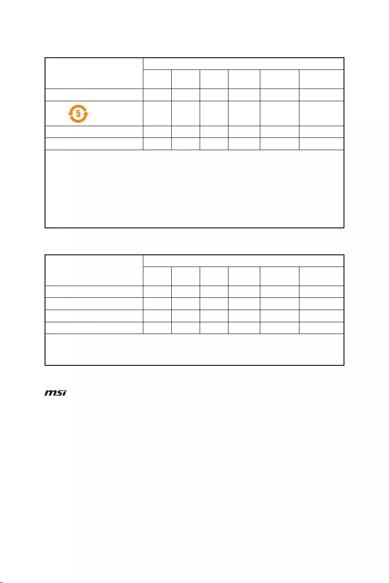
104 Regulatory Notices
Copyright
Micro-Star Int’l Co.,Ltd.
Copyright © 2019 All rights reserved.
The MSI logo used is a registered trademark of
Micro-Star Int’l Co., Ltd. All other marks and names
mentioned may be trademarks of their respective
owners. No warranty as to accuracy or completeness
is expressed or implied. MSI reserves the right to make
changes to this document without prior notice.
Technical Support
If a problem arises with your system and no solution
can be obtained from the user guide, please
contact your place of purchase or local distributor.
Alternatively, please try the following help resources
for further guidance.
yVisit the MSI website for technical guide, BIOS
updates, driver updates, and other information:
http://www.msi.com
yRegister your product at: http://register.msi.com
Revision History
Version 3.0, 2019/05, First release.
产品中有害物质的名称及含量
部件名称
有害物质
铅
(Pb)
汞
(Hg)
镉
(Cd)
六价铬
(Cr(VI))
多溴联苯
(PBB)
多溴二苯醚
(PBDE)
印刷电路板组件*╳ ○ ○ ○ ○ ○
电池** ╳ ○ ○ ○ ○ ○
外部信号连接头 ╳ ○ ○ ○ ○ ○
线材 ╳ ○ ○ ○ ○ ○
本表格依据 SJ/T 11364 的规定编制。
○: 表示该有害物质在该部件所有均质材料中的含量均在 GB/T 26572 规定的限量要求以下。
╳: 表示该有害物质至少在该部件的某一均质材料中的含量超出 GB/T 26572 规定的限量要求,但所有部件都符合
欧盟RoHS要 求。
* 印刷电路板组件: 包括印刷电路板及其构成的零部件。
** 电池本体上如有环保使用期限标识,以本体标识为主。
■ 上述有毒有害物质或元素清单会依型号之部件差异而有所增减。
■ 產品部件本体上如有环保使用期限标识,以本体标识为主。
限用物質含有情況標示聲明書
單元
限用物質及其化學符號
鉛
(Pb)
汞
(Hg)
鎘
(Cd)
六價鉻
(Cr+6)
多溴聯苯
(PBB)
多溴二苯醚
(PBDE)
電路板 ○ ○ ○ ○ ○ ○
電子元件 - ○ ○ ○ ○ ○
金屬機構件 - ○ ○ ○ ○ ○
塑膠機構件 ○ ○ ○ ○ ○ ○
備考1. “超出0.1 wt %” 及 “超出0.01 wt %” 係指限用物質之百分比含量超出百分比含量基準值。
備考2. “○” 係指該項限用物質之百分比含量未超出百分比含量基準值。
備考3. “-” 係指該項限用物質為排除項目。
- Инструкции и руководства
- Бренды
- MSI
- B450 GAMING PLUS MAX
- Инструкция
![]()
I
B450 GAMING PLUS MAX
Motherboard
User Guide
Benutzerhandbuch
Manuel d’utilisation
Руководство пользователя
取扱説明書
사용 명서
使用手冊
使用手册
Посмотреть инструкция для MSI B450 Gaming Plus Max бесплатно. Руководство относится к категории материнские платы, 6 человек(а) дали ему среднюю оценку 8.5. Руководство доступно на следующих языках: английский. У вас есть вопрос о MSI B450 Gaming Plus Max или вам нужна помощь? Задайте свой вопрос здесь
Материнская плата MSI B450 Gaming Plus Max представляет собой универсальный компонент для компьютеров. Она подходит для установки различных процессоров и графических карт. Плата оснащена PCI Express x16 (Gen 3.x) слотом и PCI Express x16 (Gen 2.x) слотом для подключения видеокарт, а также 4 слотами PCI Express x1 (Gen 2.x) для установки других компонентов. Кроме того, на плате есть 1 разъем для параллельного ATA устройства и подключение SATA кабелей.
В комплект поставки входят SАТА кабели, краткое руководство по установке и драйверы, что облегчает установку и настройку материнской платы. Плата выполнена в стандартном размере 305 мм в ширину и 244 мм в глубину. Для подключения к сети имеется интерфейс Ethernet, который обеспечивает высокую скорость передачи данных. Он основан на контроллере Realtek RTL8111H и поддерживает Gigabit Ethernet.
Плата не имеет Wi-Fi интерфейса, что может быть недостатком для пользователей, зависимых от беспроводного соединения. Однако, на плате есть один порт DVI-D для подключения к монитору. Этот порт может обеспечить качественное отображение на мониторе в разрешении до Full HD 1080p.
Материнская плата MSI B450 Gaming Plus Max является универсальным и надежным решением для установки в компьютеры. Она предоставляет необходимое количество разъемов и возможностей для установки компонентов, в том числе и видеокарт, а также гарантирует быструю скорость передачи данных.

Главная
| MSI | |
| B450 Gaming Plus Max | B450 GAMING PLUS MAX | |
| материнская плата | |
| 0824142194799, 4719072658557 | |
| английский | |
| Руководство пользователя (PDF) |
Слоты расширения
| Слоты PCI Express x16 (поколение 3.x) | 1 |
| Слоты PCI Express x16 (поколение 2.x) | 1 |
| Слоты PCI Express x1 (поколение 2.x) | 4 |
| Количество M.2 (M) слотов | 1 |
Внутренние порты
| Количество параллельных разъемов ATA (PATA) | 1 |
| 12В разъем питания | Да |
| RGB LED контактный разъем | Да |
| Коннекторы последовательного порта | 1 |
| TPM коннектор | Да |
| Аудиоразъем передней панели | Да |
| Разъем передней панели | Да |
| Разъем питания ATX (24-конт.) | Да |
| Разъем вентилятора центрального процессора | Да |
| Количество разъемов вентилятора корпуса | 4 |
| Разъем Chassis intrusion | Да |
| Количество разъемов SATA II | 0 |
| Количество разъемов SATA III | 6 |
| Разъемы USB 3.2 Gen 2 (3.1 Gen 2) | 0 |
| Разъемы USB 3.2 Gen 1 (3.1 Gen 1) | 1 |
| Разъемы USB 2.0 | 2 |
Содержимое упаковки
| Поставляемые кабели | SATA |
| Драйвера в комплекте | Да |
Прочие свойства
| Краткое руководство по установке | Да |
Вес и размеры
| Ширина | 305 mm |
| Глубина | 244 mm |
Сеть
| Подключение Ethernet | Да |
| Тип Ethernet интерфейса | Гигабитный Ethernet |
| Контроллер LAN | Realtek RTL8111H |
| Wi-Fi | Нет |
Свойства
| Комплектующие для | ПК |
| Поддерживаемые операционные системы Windows | Windows 10 Education x64, Windows 10 Enterprise x64, Windows 10 Home x64, Windows 10 Pro x64, Windows 10 x64, Windows 7 Enterprise x64, Windows 7 Home Basic x64, Windows 7 Home Premium x64, Windows 7 Professional x64, Windows 7 Starter x64, Windows 7 Ultimate x64, Windows 7 x64 |
| Количество отверстий для монтажа | 9 |
| Формат материнской платы | ATX |
| Семейство чипсета материнской платы | AMD |
| Чипсет материнской платы | AMD B450 |
| Аудио чип | Realtek ALC892 |
| Выходные звуковые каналы | 7.1 канала |
| Мониторинг состояния ПК | CPU, FAN, Temperature |
Порты на задней панели
| Количество портов DVI-D | 1 |
| Версия HDMI | 1.4 |
| Количество HDMI портов | 1 |
| Количество портов VGA (D-Sub) | 0 |
| Порты FireWire | 0 |
| Количество портов PS/2 | 1 |
| Количество портов eSATA | 0 |
| Количество портов Ethernet LAN ( RJ-45) | 1 |
| Количество портов USB 3.2 Gen 2 (3.1 Gen 2) Type-С | 1 |
| Количество портов USB 3.2 Gen 2 (3.1 Gen 2) Type-A | 1 |
| Количество портов USB 3.2 Gen 1 (3.1 Gen 1) Type-С | 0 |
| Количество портов USB 3.2 Gen 1 (3.1 Gen 1) Type-A | 2 |
| Количество портов USB 2.0 | 2 |
BIOS
| Тип BIOS | UEFI AMI |
| Размер памяти BIOS | 256 Mbit |
| Версия ACPI | 6.1 |
| Версия BIOS (SMBIOS) | 2.8 |
| Перемычка Clear CMOS | Да |
Графический адаптер
| Объём памяти графического адаптера | 2048 MB |
| Поддержка технологии параллельной обработки | 2-Way CrossFireX |
| Максимальное разрешение | 4096 x 2160 пикселей |
Контроллеры хранения данных
| Поддерживаемые интерфейсы носителя | SATA III |
| Уровни RAID | 0, 1,10 |
Память
| Поддерживаемые типы памяти | DDR4-SDRAM |
| Количество слотов памяти | 4 |
| Тип слотов памяти | DIMM |
| Каналы памяти | Dual-channel |
| Error-correcting code (ECC) | Да |
| без функции коррекции ошибок | Да |
| Максимальная внутренняя память | 64 GB |
| Поддерживаемые частоты памяти | 2667,2800,2933,3000,3066,3200,3466,4100,4133 MHz |
Процессор
| Совместимые серии процессоров | AMD Athlon, AMD Ryzen 3, AMD Ryzen 3 2nd Gen, AMD Ryzen 3 3rd Gen, AMD Ryzen 5, AMD Ryzen 5 2nd Gen, AMD Ryzen 5 3rd Gen, AMD Ryzen 7, AMD Ryzen 7 2nd Gen, AMD Ryzen 7 3rd Gen, AMD Ryzen 9 3rd Gen |
| Сокет процессора | Разъем AM4 |
| Производитель процессора | AMD |
| Максимальное число процессоров для SMP | 1 |
Логистические данные
| Код гармонизированной системы описания (HS) | 84733020 |
показать больше
Не можете найти ответ на свой вопрос в руководстве? Вы можете найти ответ на свой вопрос ниже, в разделе часто задаваемых вопросов о MSI B450 Gaming Plus Max.
Какая ширина MSI B450 Gaming Plus Max?
MSI B450 Gaming Plus Max имеет ширину 305 mm.
Какая толщина MSI B450 Gaming Plus Max?
MSI B450 Gaming Plus Max имеет толщину 244 mm.
Инструкция MSI B450 Gaming Plus Max доступно в русский?
К сожалению, у нас нет руководства для MSI B450 Gaming Plus Max, доступного в русский. Это руководство доступно в английский.
Не нашли свой вопрос? Задайте свой вопрос здесь
-
MSI B450 GAMING PLUS MAX Owner’s manual

- Type
- Owner’s manual
- Brand
- MSI
- Size
- 14.20 MB
- Category
- motherboards
- Pages
- 186
- Language
- English, Japanese, Korean, Chinese
View document
-
MSI B450 GAMING PLUS MAX Owner’s manual
- Type
- Owner’s manual
- Brand
- MSI
- Size
- 7.99 MB
- Category
- motherboards
- Pages
- 104
- Language
- English
View document
-
MSI B450 GAMING PLUS MAX User manual
- Type
- User manual
- Brand
- MSI
- Size
- 5.52 MB
- Category
- motherboards
- Pages
- 104
- Language
- English
View document
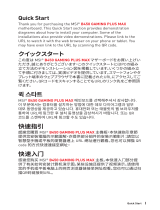
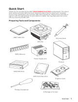


I
Quick Start
Quick Start
Thank you for purchasing the MSI
®
B450 GAMING PLUS
motherboard. This Quick Start section provides demonstration
diagrams about how to install your computer. Some of the
installations also provide video demonstrations. Please link to the
URL to watch it with the web browser on your phone or tablet. You
may have even link to the URL by scanning the QR code.
Kurzanleitung
Danke, dass Sie das MSI
®
B450 GAMING PLUS Motherboard gewählt
haben. Dieser Abschnitt der Kurzanleitung bietet eine Demo zur
Installation Ihres Computers. Manche Installationen bieten auch
die Videodemonstrationen. Klicken Sie auf die URL, um diese
Videoanleitung mit Ihrem Browser auf Ihrem Handy oder Table
anzusehen. Oder scannen Sie auch den QR Code mit Ihrem Handy,
um die URL zu öffnen.
Présentation rapide
Merci d’avoir choisi la carte mère MSI
®
B450 GAMING PLUS. Ce
manuel fournit une rapide présentation avec des illustrations
explicatives qui vous aideront à assembler votre ordinateur. Des
tutoriels vidéo sont disponibles pour certaines étapes. Cliquez sur
le lien fourni pour regarder la vidéo sur votre téléphone ou votre
tablette. Vous pouvez également accéder au lien en scannant le QR
code qui lui est associé.
Быстрый старт
Благодарим вас за покупку материнской платы MSI
®
B450
GAMING PLUS. В этом разделе представлена информация,
которая поможет вам при сборке комьютера. Для некоторых
этапов сборки имеются видеоинструкции. Для просмотра
видео, необходимо открыть соответствующую ссылку в
веб—браузере на вашем телефоне или планшете. Вы также
можете выполнить переход по ссылке, путем сканирования
QR-кода.
II
Quick Start
Installing a Processor/ Installation des Prozessors/ Installer un
processeur/ Установка процессора
1
2
3
6
4
5
7
8
9
CPU_FAN1
III
Quick Start
If you are installing the screw-type CPU heatsink, please follow the figure below
to remove the retention module first and then install the heatsink.
Wenn Sie einen CPU-Kühler mit Schraubenbefestigung einsetzen, folgen Sie bitte
den Anweisungen unten um das Retention-Modul zu entfernen und den Kühler zu
installieren.
Si vous voulez installer un ventirad pour processeur à vis, veuillez suivre les
instructions ci-dessous pour d’abord retirer le module de rétention puis installer le
ventirad.
В случае установки процессорного кулера с системой крепления на винтах,
следуйте указаниям на рисунке ниже для снятия пластикового модуля
крепления. Затем установите кулер.
1
2
3
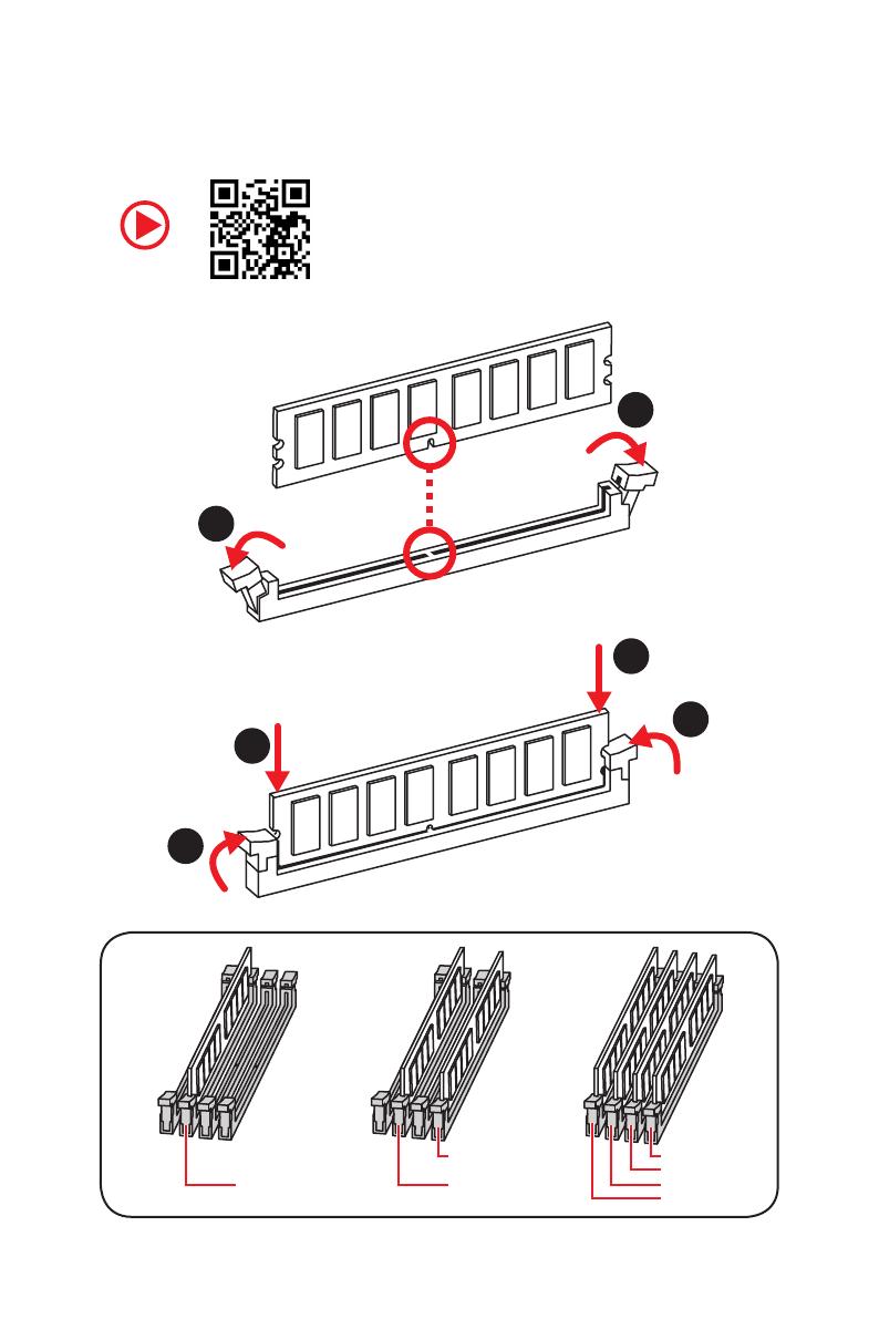
IV
Quick Start
Installing DDR4 memory/ Installation des DDR4-Speichers/
Installer une mémoire DDR4/ Установка памяти DDR4
DIMMB2 DIMMB2
DIMMB1
DIMMA2 DIMMA2 DIMMA2
DIMMA1
1
1
2
2
3
3
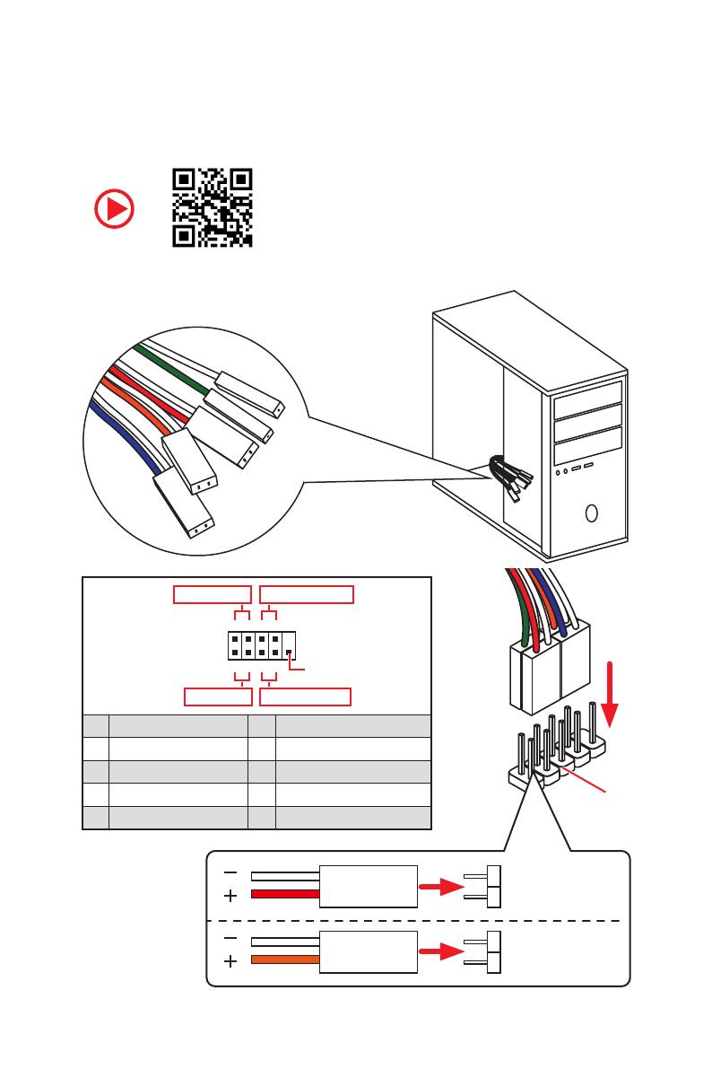
V
Quick Start
Connecting the Front Panel Header/ Anschließen der
Frontpanel-Stiftleiste/ Connecter un connecteur du panneau
avant/ Подключение разъемов передней панели
RESET SW
POWER SW
POWER LED+
POWER LED-
HDD LED
HDD LED
RESET SW
JFP1
HDD LED
HDD LED —
HDD LED +
POWER LED —
POWER LED +
POWER LED
1
2 10
9
+
+
+—
——
—
+
Power LED
HDD LED Reset Switch
Reserved
Power Switch
JFP1
1 HDD LED + 2 Power LED +
3 HDD LED — 4 Power LED —
5 Reset Switch 6 Power Switch
7 Reset Switch 8 Power Switch
9 Reserved 10 No Pin
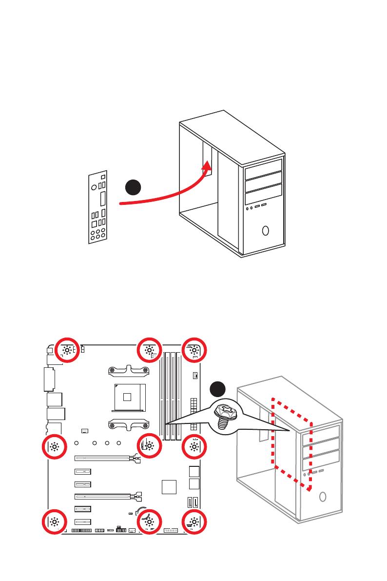
VI
Quick Start
Installing the Motherboard/ Installation des Motherboards/
Installer la carte mère/ Установка материнской платы
BAT1
1
2
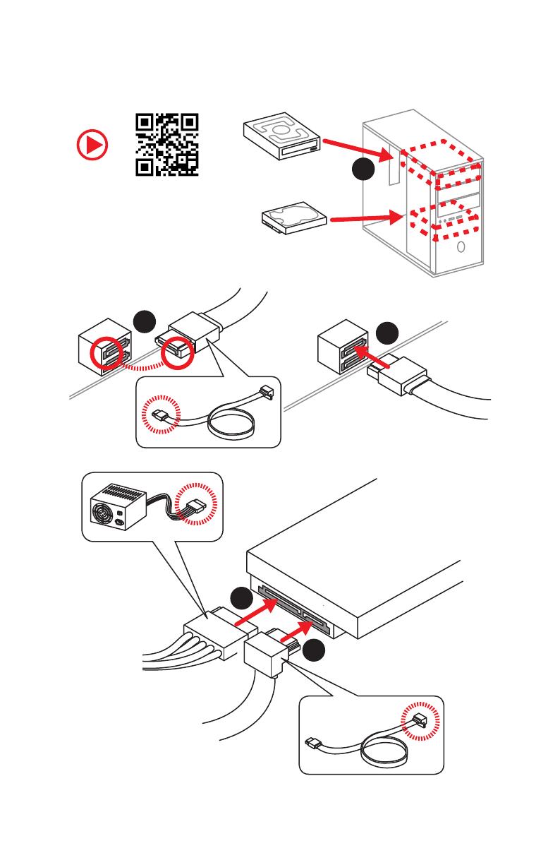
VII
Quick Start
1
2
3
4
5
Installing SATA Drives/ Installation der SATA-Laufwerke/
Installer le disque dur SATA/ Установка дисков SATA
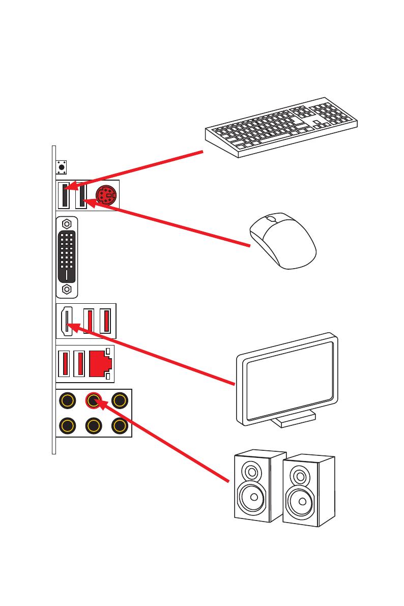
IX
Quick Start
Connecting Peripheral Devices/ Peripheriegeräte/
Connecter un périphérique anschliessen/ Подключение
периферийных устройств
Ryzen™ with Radeon Vega
Graphics Processors
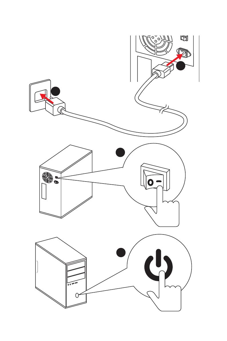
XI
Quick Start
Power On/ Einschalten/ Mettre sous-tension/ Включение
питания
1
4
2
3

4
Specifications
Continued from previous page
Storage
AMD
®
CPU
y 2x SATA 6Gb/s ports*
y 1x M.2 slot (Key M)*
Supports PCIe 3.0 x4 and SATA 6Gb/s 2242/ 2260 /2280/
22110 storage devices
AMD
®
B450 Chipset
y 4x SATA 6Gb/s ports
* SATA5 and SATA6 ports will be unavailable when installing a M.2 device in M.2
slot.
RAID
AMD
®
B450 Chipset
y Supports RAID 0, RAID1 and RAID 10 for SATA storage
devices
USB
y AMD
®
B450 Chipset
2x USB 3.1 Gen2 (SuperSpeed USB 10Gbps) Type-A
ports on the back panel
2x USB 3.1 Gen1 (SuperSpeed USB) ports available
through the internal USB 3.1 Gen1 connector
6x USB 2.0 (High-speed USB) ports (2 Type-A ports on
the back panel, 4 ports available through the internal
USB 2.0 connectors)
y AMD
®
CPU
2x USB 3.1 Gen1 (SuperSpeed USB) Type-A ports on the
back panel
Back Panel
Connectors
y 1x Flash BIOS button
y 1x PS/2 keyboard/ mouse combo port
y 2x USB 2.0 Type-A ports
y 1x DVI-D port
y 1x HDMI
™
port
y 2x USB 3.1 Gen1 Type-A ports
y 1x LAN (RJ45) port
y 2x USB 3.1 Gen2 Type-A ports
y 6x audio jacks
Continued on next page
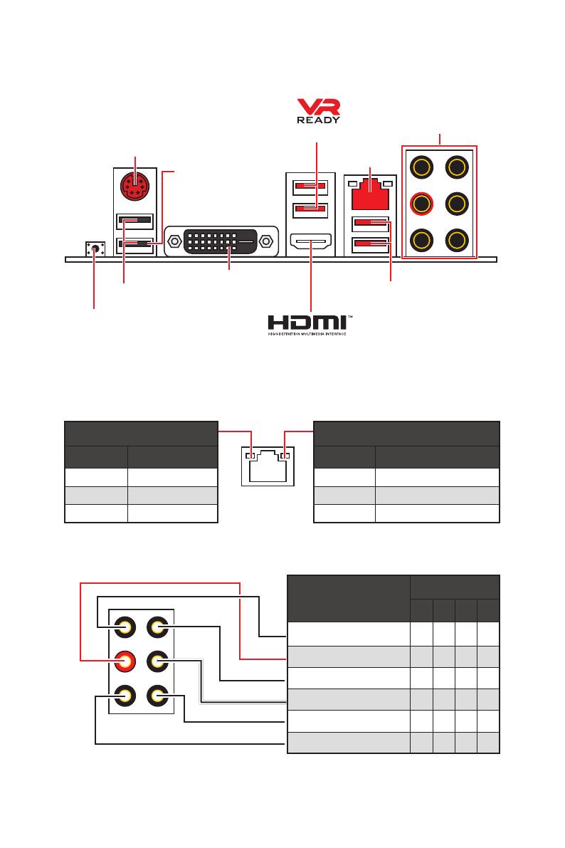
8
Rear I/O Panel
Link/ Activity LED
Status Description
Off No link
Yellow Linked
Blinking Data activity
Speed LED
Status Description
Off 10 Mbps connection
Green 100 Mbps connection
Orange 1 Gbps connection
LAN Port LED Status Table
Audio Ports Configuration
Audio Ports
Channel
2 4 6 8
Line-In
Line-Out/ Front Speaker Out ● ● ● ●
Rear Speaker Out ● ● ●
Center/ Subwoofer Out ● ●
Side Speaker Out ●
Mic In
(●: connected, Blank: empty)
Rear I/O Panel
PS/2
LAN
USB 2.0 Type-A
Audio Ports
DVI-D
USB 3.1 Gen1 Type-A
USB 3.1 Gen2
Type-A
Flash BIOS button
y Flash BIOS port/ button — Please refer to page 25 for Updating BIOS with Flash BIOS
button.
Flash BIOS port
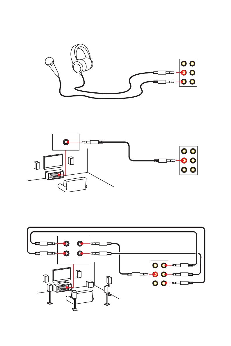
10
Rear I/O Panel
Audio jacks to headphone and microphone diagram
Audio jacks to stereo speakers diagram
Audio jacks to 7.1-channel speakers diagram
AUDIO INPUT
Rear Front
Side Center/
Subwoofer
AUDIO INPUT
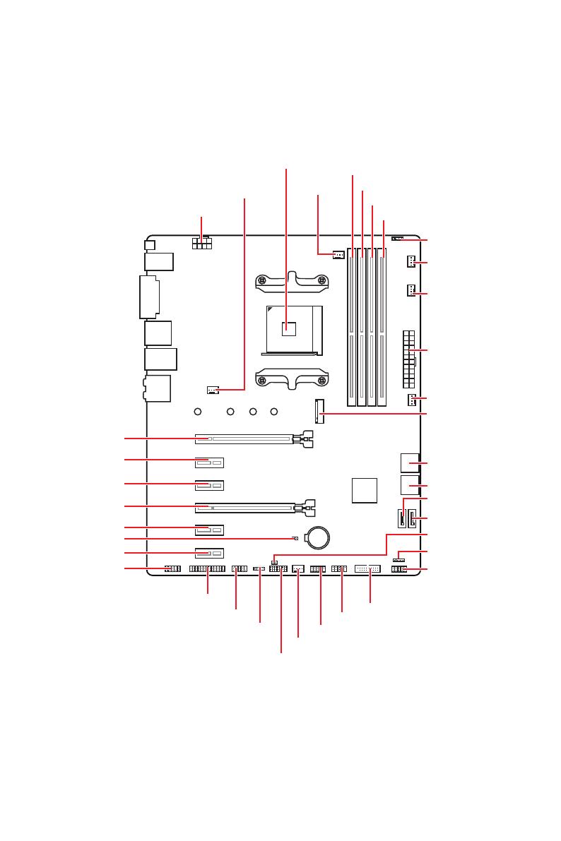
11
Overview of Components
BAT1
Overview of Components
JLPT1
SATA▼5▲6
SATA▼3▲4
CPU_FAN1
SYS_FAN1
PUMP_FAN1
JRGB1
PCI_E1
PCI_E2
PCI_E3
PCI_E4
PCI_E5
PCI_E6
JBAT1
JAUD1
JTPM1
Processor
Socket
CPU_PWR1
DIMMA1
SYS_FAN4
M2_1
DIMMA2
DIMMB1
DIMMB2
JUSB3
JUSB2
JUSB1
SATA1
JCI1
JFP1
SATA2
JFP2
JRGB2
SYS_FAN2
JCOM1
ATX_PWR1
SYS_FAN3
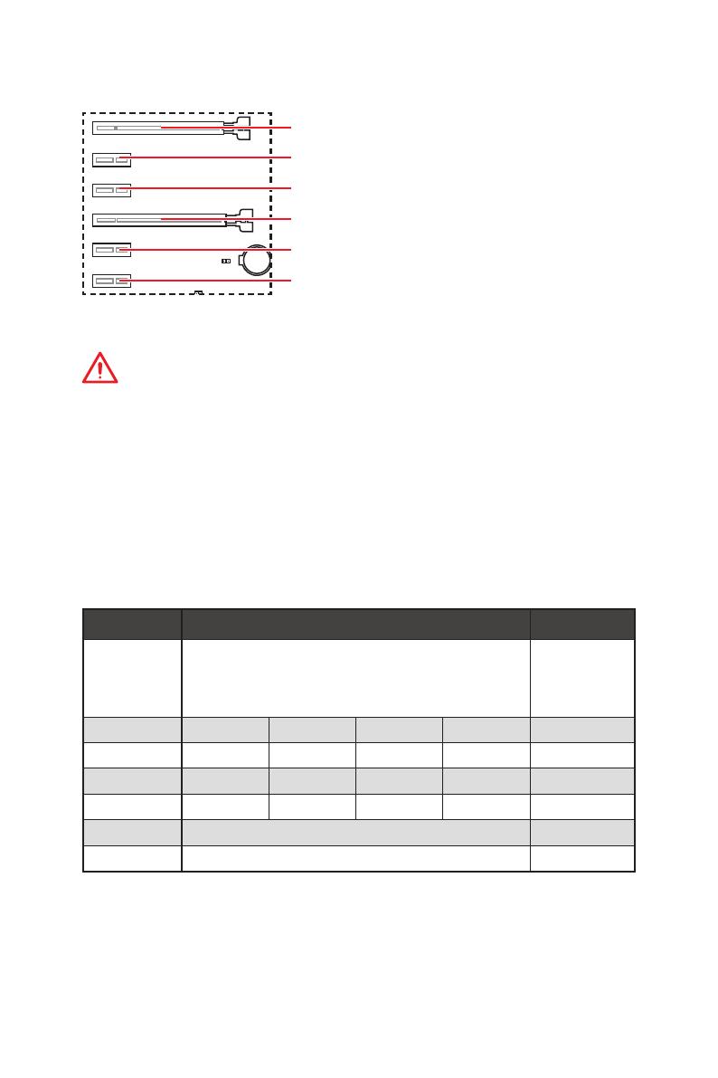
14
Overview of Components
BAT1
PCI_E1~6: PCIe Expansion Slots
PCI_E1: PCIe 3.0 x16*/ PCIe 3.0 x8**
PCI_E2: PCIe 2.0 x1
PCI_E3: PCIe 2.0 x1
PCI_E4: PCIe 2.0 x4
PCI_E5: PCIe 2.0 x1
PCI_E6: PCIe 2.0 x1
Important
y
If you install a large and heavy graphics card, you need to use a tool such as MSI
Gaming Series Graphics Card Bolster to support its weight to prevent deformation of
the slot.
y
For a single PCIe x16 expansion card installation with optimum performance, using
the PCI_E1 slot is recommended.
y
When adding or removing expansion cards, always turn off the power supply and
unplug the power supply power cable from the power outlet. Read the expansion
card’s documentation to check for any necessary additional hardware or software
changes.
y
PCI_E4 will run x1 speed when installing devices in PCI_E2/ PCI_E3/ PCI_E5 slot.
* For Ryzen™ 1st and 2nd Generation processors
** For Ryzen™ with Radeon Vega Graphics processors
PCIe bandwidth of Multiple graphics cards
Slot Single 2-Way
PCI_E1 (CPU)
3.0 x16*
/1
or
3.0 x8*
/2
3.0 x16*
/1
or
3.0 x8*
/2
PCI_E2 (PCH) 2.0 x1 2.0 x1 Empty Empty ―
PCI_E3 (PCH) 2.0 x1 Empty 2.0 x1 Empty ―
PCI_E4 (PCH) 2.0 x1 2.0 x1 2.0 x1 2.0 x1 2.0 x4*
PCI_E5 (PCH) 2.0 x1 Empty Empty 2.0 x1 ―
PCI_E6 (PCH) 2.0 x1 2.0×1
M2_1 (CPU) 3.0 x4 3.0 x4
(─: unavailable, *: graphics card,
1
: for Ryzen™ 1st and 2nd Generation processors,
2
: for Ryzen™ with Radeon Vega Graphics processors)
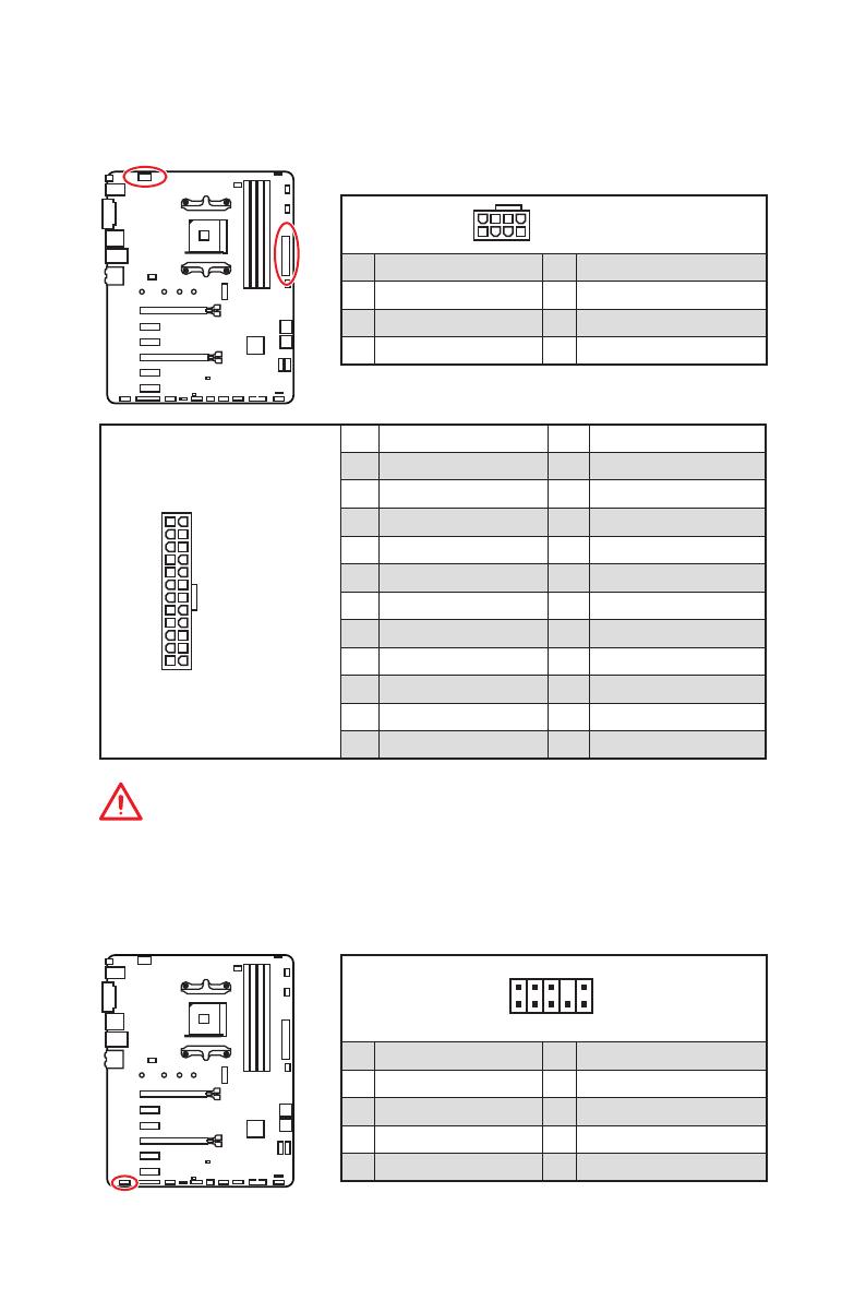
17
Overview of Components
24
131
12
ATX_PWR1
1 +3.3V 13 +3.3V
2 +3.3V 14 -12V
3 Ground 15 Ground
4 +5V 16 PS-ON#
5 Ground 17 Ground
6 +5V 18 Ground
7 Ground 19 Ground
8 PWR OK 20 Res
9 5VSB 21 +5V
10 +12V 22 +5V
11 +12V 23 +5V
12 +3.3V 24 Ground
5
4 1
8
CPU_PWR1
1 Ground 5 +12V
2 Ground 6 +12V
3 Ground 7 +12V
4 Ground 8 +12V
Important
Make sure that all the power cables are securely connected to a proper ATX power
supply to ensure stable operation of the motherboard.
CPU_PWR1, ATX_PWR1: Power Connectors
These connectors allow you to connect an ATX power supply.
JAUD1: Front Audio Connector
This connector allows you to connect audio jacks on the front panel.
1
2 10
9
1 MIC L 2 Ground
3 MIC R 4 NC
5 Head Phone R 6 MIC Detection
7 SENSE_SEND 8 No Pin
9 Head Phone L 10 Head Phone Detection
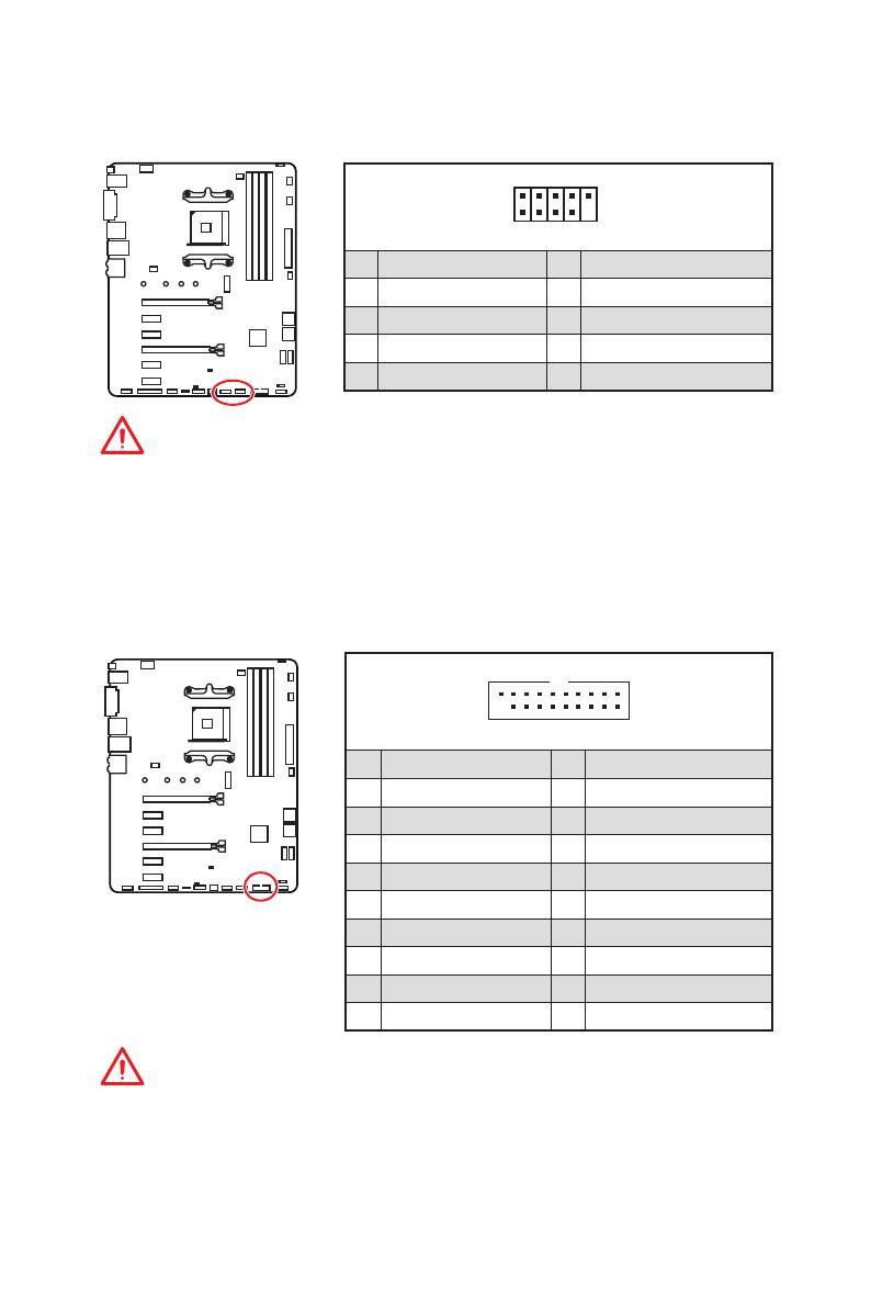
18
Overview of Components
JUSB1~2: USB 2.0 Connectors
These connectors allow you to connect USB 2.0 ports on the front panel.
1
2 10
9
1 VCC 2 VCC
3 USB0- 4 USB1-
5 USB0+ 6 USB1+
7 Ground 8 Ground
9 No Pin 10 NC
Important
y
Note that the VCC and Ground pins must be connected correctly to avoid possible
damage.
y
In order to recharge your iPad,iPhone and iPod through USB ports, please install
MSI
®
SUPER CHARGER utility.
JUSB3: USB 3.1 Gen1 Connector
This connector allows you to connect USB 3.1 Gen1 ports on the front panel.
Important
Note that the Power and Ground pins must be connected correctly to avoid possible
damage.
1
10
11
20
1 Power 11 USB2.0+
2 USB3_RX_DN 12 USB2.0-
3 USB3_RX_DP 13 Ground
4 Ground 14 USB3_TX_C_DP
5 USB3_TX_C_DN 15 USB3_TX_C_DN
6 USB3_TX_C_DP 16 Ground
7 Ground 17 USB3_RX_DP
8 USB2.0- 18 USB3_RX_DN
9 USB2.0+ 19 Power
10 NC 20 No Pin
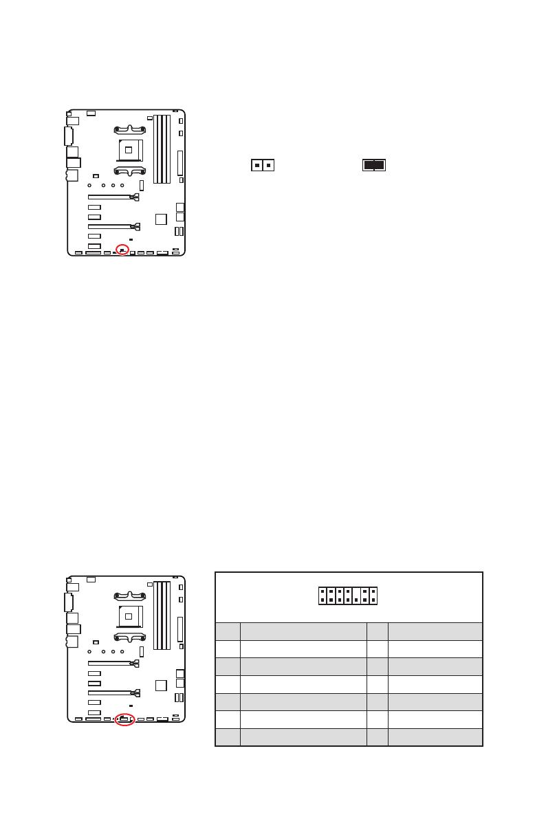
20
Overview of Components
JCI1: Chassis Intrusion Connector
This connector allows you to connect the chassis intrusion switch cable.
Normal
(default)
Trigger the chassis
intrusion event
Using chassis intrusion detector
1. Connect the JCI1 connector to the chassis intrusion switch/ sensor on the chassis.
2. Close the chassis cover.
3. Go to BIOS > SETTINGS > Security > Chassis Intrusion Configuration.
4. Set Chassis Intrusion to Enabled.
5. Press F10 to save and exit and then press the Enter key to select Yes.
6. Once the chassis cover is opened again, a warning message will be displayed on
screen when the computer is turned on.
Resetting the chassis intrusion warning
1. Go to BIOS > SETTINGS > Security > Chassis Intrusion Configuration.
2. Set Chassis Intrusion to Reset.
3. Press F10 to save and exit and then press the Enter key to select Yes.
1
2 14
13
1 LPC Clock 2 3V Standby power
3 LPC Reset 4 3.3V Power
5 LPC address & data pin0 6 Serial IRQ
7 LPC address & data pin1 8 5V Power
9 LPC address & data pin2 10 No Pin
11 LPC address & data pin3 12 Ground
13 LPC Frame 14 Ground
JTPM1: TPM Module Connector
This connector is for TPM (Trusted Platform Module). Please refer to the TPM security
platform manual for more details and usages.
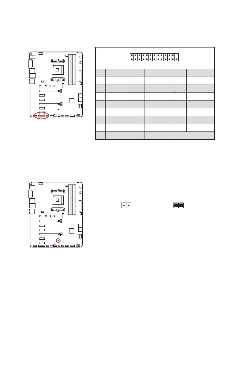
21
Overview of Components
1
2 26
25
1 RSTB# 2 AFD# 3 PRND0
4 ERR# 5 PRND1 6 PINIT#
7 PRND2 8 LPT_SLIN# 9 PRND3
10 Ground 11 PRND4 12 Ground
13 PRND5 14 Ground 15 PRND6
16 Ground 17 PRND7 18 Ground
19 ACK# 20 Ground 21 BUSY
22 Ground 23 PE 24 Ground
25 SLCT 26 No Pin
JLPT1: Parallel Port Connector
This connector allows you to connect the optional parallel port with bracket.
JBAT1: Clear CMOS (Reset BIOS) Jumper
There is CMOS memory onboard that is external powered from a battery located on
the motherboard to save system configuration data. If you want to clear the system
configuration, set the jumper to clear the CMOS memory.
Keep Data
(default)
Clear CMOS/
Reset BIOS
Resetting BIOS to default values
1. Power off the computer and unplug the power cord.
2. Use a jumper cap to short JBAT1 for about 5-10 seconds.
3. Remove the jumper cap from JBAT1.
4. Plug the power cord and Power on the computer.


10
Rückseite E/A
Audiobuchsen für den Anschluss von einem Kopfhörer und Mikrofon
Audiobuchsen für Stereo-Lautsprecher
Audiobuchsen für 7.1 Kanal Anlage
AUDIO INPUT
Rear Front
Side Center/
Subwoofer
AUDIO INPUT
/
![]() Материнская плата B450 Gaming Plus Max
Материнская плата B450 Gaming Plus Max
Руководство пользователя

Материнская плата B450 Gaming Plus Max
Быстрое начало
Благодарим вас за покупку материнской платы MSI®. В этом разделе «Быстрый старт» представлены демонстрационные схемы установки компьютера. Некоторые из инсталляций также обеспечивают видеодемонстрации. Пожалуйста, дайте ссылку на URL смотреть это с web браузер на вашем телефоне или планшете. У вас может быть даже ссылка на URL путем сканирования QR-кода.
Установка процессора
YouTube
 https://youtu.be/Xv89nhFk1vc
 http://v.youku.com/v_show/id_XMTg2MjMwOTE2NA==.html

![]() Важнo
Важнo
Если вы устанавливаете радиатор ЦП винтового типа, следуйте приведенному ниже рисунку, чтобы сначала снять фиксирующий модуль, а затем установить радиатор.

Установка памяти DDR4
YouTube
 http://youtu.be/T03aDrJPyQs
 http://v.youku.com/v_show/id_XNzUyMTI5ODI4.html

Подключение заголовка передней панели
Вы трубка
 http://youtu.be/DPELIdVNZUI
 http://v.youku.com/v_show/id_XNjcyMTczMzM2.html

 |
|||
| 1 | Светодиод жесткого диска + | 2 | Светодиод питания + |
| 3 | Светодиод жесткого диска — | 4 | Светодиод питания — |
| 5 | Сбросить переключатель | 6 | Выключатель |
| 7 | Сбросить переключатель | 8 | Выключатель |
| 9 | Зарезервированный | 10 | Нет PIN-кода |
Установка материнской платы

Подключение разъемов питания
Вы трубка
 http://youtu.be/gkDYyR_83I4
 http://v.youku.com/v_show/id_XNDkzODU0MDQw.html

Установка дисков SATA
Вы трубка
 http://youtu.be/RZsMpqxythc
 http://v.youku.com/v_show/id_XNDkzODU5MTky.html

Установка графической карты
Вы трубка
 http://youtu.be/mG0GZpr9w_A
 http://v.youku.com/v_show/id_XNDkyOTc3MzQ4.html

Подключение периферийных устройств

Включение

Информация по технике безопасности
- Компоненты, входящие в этот комплект, подвержены повреждению электростатическим разрядом (ESD). Пожалуйста, придерживайтесь следующих инструкций, чтобы обеспечить успешную сборку компьютера.
- Убедитесь, что все компоненты надежно подключены. Плохое соединение может привести к тому, что компьютер не распознает компонент или не запустится.
- Держите материнскую плату за края, чтобы не прикасаться к чувствительным компонентам.
- При обращении с материнской платой рекомендуется носить браслет с защитой от электростатического разряда (ESD), чтобы предотвратить электростатическое повреждение. Если браслет для защиты от электростатического разряда недоступен, снимите с себя статическое электричество, прикоснувшись к другому металлическому предмету, прежде чем брать в руки материнскую плату.
- Храните материнскую плату в контейнере для защиты от статического электричества или на антистатической прокладке, если материнская плата не установлена.
- Перед включением компьютера убедитесь, что на материнской плате или где-либо в корпусе компьютера нет незакрепленных винтов или металлических компонентов.
- Не загружайте компьютер до завершения установки. Это может привести к необратимому повреждению компонентов, а также к травмам пользователя.
- Если вам потребуется помощь на любом этапе установки, обратитесь к сертифицированному специалисту по компьютерам.
- Всегда выключайте источник питания и отсоединяйте шнур питания от розетки перед установкой или извлечением каких-либо компонентов компьютера.
- Сохраните это руководство для использования в будущем.
- Берегите материнскую плату от влаги.
- Убедитесь, что ваша электрическая розетка обеспечивает такую же мощность.tage, как указано на блоке питания, перед подключением блока питания к электрической розетке.
- Разместите шнур питания таким образом, чтобы на него нельзя было наступить. Не кладите ничего на шнур питания.
- Следует отметить все предостережения и предупреждения на материнской плате.
- При возникновении любой из следующих ситуаций обратитесь к обслуживающему персоналу для проверки материнской платы:
• В компьютер попала жидкость.
• Материнская плата подверглась воздействию влаги.
• Материнская плата работает неправильно или вы не можете заставить ее работать в соответствии с руководством пользователя.
• Материнская плата упала и была повреждена.
• Материнская плата имеет явные признаки поломки. - Не оставляйте материнскую плату при температуре выше 60 ° C (140 ° F), это может повредить материнскую плату.
Характеристики
| ЦП | Поддерживает процессоры AMD Ryzen™ 1-го, 2-го и 3-го поколения, Ryzen™ с графикой Radeon™ Vega, процессоры AMD Ryzen™ 2-го поколения с графикой Radeon™ и Athlon™ с графикой Radeon™ Vega для настольных ПК для Socket AM4. |
| Набор микросхем | Набор микросхем AMD® B450 |
| Память | • 4 слота памяти DDR4, поддержка до 64 ГБ * • Двухканальная архитектура памяти • Поддерживает память UDIMM без ECC • Поддерживает память ECC UDIMM (режим без ECC) * Пожалуйста, обратитесь www.msi.com для получения дополнительной информации о совместимой памяти. |
| Слоты расширения | • 1 слот PCIe 3.0 x 16 (PCI_E1) • 1 слот PCIe 2.0 x 16 (PCI_E4, поддерживает режим x4)* • 4 слота PCIe 2.0 x1* * PCI_E4 будет работать на скорости x1 при установке устройств в разъем PCI_E2/PCI_E3/PCI_E5. |
| На борту Graphics | • 1 порт DVI-D, поддержка максимального разрешения 1920 x 1200 при 60 Гц* • 1x порт HDMI™ 1.4, поддерживает максимальное разрешение 4096×2160 при 30 Гц, 2560 x 1600 при 60 Гц* * Поддерживается только при использовании процессоров Ryzen™ с Radeon™ Vega Graphics, AMD Ryzen™ 2-го поколения с Radeon™ Graphics и Athlon™ с графическими процессорами Radeon™ Vega Graphics. * Максимальный объем общей памяти 2048 МБ |
| Multi-GPU | • Поддерживает двухстороннюю технологию AMD® Cross Fire™ |
| ЛВС | • 1 гигабитный сетевой контроллер Realtek® 8111H |
| Аудио | • Кодек Realtek® ALC892/ALC897 • 7.1-канальный звук высокой четкости |
| Хранилище | ЦП AMD® • 2 порта SATA 6 Гбит/с* • 1 слот M.2 (ключ M)* Устройства хранения данных AMD Ryzen™ поколения с графикой Radeon™ или PCIe 3.0 x2 (Athlon™ с графикой Radeon™ Vega) и SATA 6 Гбит/с 2242/2260/2280/22110 Чипсет AMD® B450 • 4 порта SATA 6 Гбит/с * Порты SATA5 и SATA6 будут недоступны при установке устройства M.2 в слот M.2. |
| RAID | Набор микросхем AMD® B450 • Поддерживает RAID 0, RAID1 и RAID 10 для устройств хранения SATA. |
| USB | • Чипсет AMD® B450 разъемы USB 2.0) • ЦП AMD® |
| Разъемы задней панели | • 1x кнопка Flash BIOS • 1 комбинированный порт PS/2 для клавиатуры/мыши • 2 порта USB 2.0 Type-A • 1 порт DVI-D • 1 порт HDMI™ • 2 порта USB 3.2 Gen1 Type-A • 1x порт LAN (RJ45) • 2 порта USB 3.2 Gen2 Type-A • 6 аудиоразъемов |
| Внутренние разъемы | • 1x 24-контактный основной разъем питания ATX • 1x 8-контактный разъем питания ATX 12 В • 6 разъемов SATA 6 Гбит / с • 2 разъема USB 2.0 (поддержка дополнительных 4 портов USB 2.0) • 1 разъем USB 3.2 Gen1 (поддерживает 2 дополнительных порта USB 3.2 Gen1) • 1x 4-контактный разъем вентилятора ЦП • 1x 4-контактный разъем водяного насоса-вентилятора • 4 4-контактных разъемов для системных вентиляторов • 1x разъем для модуля TPM • 1x аудиоразъем на передней панели • 2x разъема системной панели • 1x разъем последовательного порта • 1 разъем параллельного порта • 1x разъем для вскрытия корпуса • 1x перемычка очистки CMOS • 2x 5050 RGB светодиодная лента 12В разъемы |
| Контроллер ввода / вывода | Микросхема контроллера NUVOTON NCT6797 |
| Монитор оборудования | • Определение температуры процессора/системы • Определение скорости вентилятора процессора/системы • Управление скоростью вентилятора процессора/системы |
| Форм-фактор | • Форм-фактор ATX • 12 in. X 9.6 in. (30.5 см x 24.4 см) |
| Возможности BIOS | • 1x 256 Мб флэш-памяти • UEFI AMI BIOS • ACPI 6.1, СМ BIOS 2.8 • Многоязычный |
| Software | • Драйверы • МЕНЕДЖЕР ПРИЛОЖЕНИЙ • СУПЕР ЗАРЯДНОЕ УСТРОЙСТВО • КОМАНДНЫЙ ЦЕНТР • ОБНОВЛЕНИЕ 6 • УМНЫЙ ИНСТРУМЕНТ • РАМДИСК • Х-УСИЛЕНИЕ • ИГРОВОЕ ПРИЛОЖЕНИЕ • МИСТИЧЕСКИЙ СВЕТ • Нахимическое аудио • Программное обеспечение Open Broadcaster (OBS) yCPU-Z MSI GAMING • Решение Norton ™ для обеспечения безопасности в Интернете • Google Chrome™, панель инструментов Google, Google Диск |
| Особые возможности | • Аудио • Место хранения • Вентилятор • ВЕЛ |
| Особые возможности | • защита • Производительность • VR • Игровой опыт • БИОС • Сертификация |
Содержимое пакета
Пожалуйста, проверьте содержимое упаковки материнской платы. Он должен содержать:
- Материнская плата
- DVD с драйверами
- Руководство по быстрой установке
- Уведомление о задержке рассмотрения дела
- Кабель SATA 6G x2
- Карточка регистрации продукта
- Значок случая
- Экранирование ввода / вывода
- Винт M.2 x1
![]() Важнo
Важнo
Если что-либо из вышеперечисленного повреждено или отсутствует, обратитесь к продавцу.
Задняя панель ввода-вывода

- Порт/кнопка Flash BIOS — см. стр. 25 для получения информации об обновлении BIOS с помощью кнопки Flash BIOS.
Таблица состояния индикатора порта LAN

Конфигурация аудиопортов

Аудиоконсоль Realtek
После установки Realtek Audio Console. Вы можете использовать его для изменения настроек звука, чтобы улучшить качество звука.

- Выбор устройства — позволяет выбрать источник аудиовыхода для изменения соответствующих параметров. Знак галочки указывает на устройства по умолчанию.
- Улучшение приложения — набор опций предоставит вам полное руководство по ожидаемому звуковому эффекту как для устройства вывода, так и для устройства ввода.
- Основная громкость — регулирует громкость или балансирует правую/левую сторону динамиков, подключенных к передней или задней панели, с помощью регулятора.
- Состояние разъема — отображает все устройства рендеринга и захвата, подключенные в данный момент к вашему компьютеру.
Автоматическое всплывающее диалоговое окно
Когда вы подключаете устройство к аудиоразъему, появляется диалоговое окно с вопросом, какое устройство подключено в данный момент.

Каждый разъем соответствует своей настройке по умолчанию, как показано на следующей странице.![]() Важнo
Важнo
Изображения выше приведены только для справки и могут отличаться от приобретенного вами продукта.
Аудиоразъемы для наушников и микрофона схема

Схема аудиоразъемов на стереодинамики

Схема аудиоразъемов на 7.1-канальные динамики

Болееview компонентов

Разъем процессора

Введение в процессор AM4
Поверхность ЦП AM4 имеет желтый треугольник, помогающий правильно выровнять ЦП для размещения материнской платы. Желтый треугольник — это индикатор Pin 1.
![]() Важнo
Важнo
- При смене процессора конфигурация системы могла быть очищена и сброшена BIOS до значений по умолчанию из-за архитектуры процессора AM4.
- Всегда отключайте шнур питания от розетки перед установкой или снятием ЦП.
- При установке ЦП всегда не забывайте устанавливать радиатор ЦП. Радиатор процессора необходим для предотвращения перегрева и поддержания стабильности системы.
- Перед загрузкой системы убедитесь, что радиатор ЦП плотно прилегает к ЦП.
- Перегрев может серьезно повредить процессор и материнскую плату. Всегда проверяйте, правильно ли работают охлаждающие вентиляторы, чтобы защитить ЦП от перегрева. Обязательно нанесите ровный слой термопасты (или термоленты) между процессором и радиатором, чтобы улучшить отвод тепла.
- Если вы приобрели отдельный ЦП и радиатор / кулер, пожалуйста, обратитесь к документации в комплекте радиатора / кулера для получения более подробной информации об установке.
- Эта материнская плата предназначена для разгона. Перед попыткой разгона убедитесь, что все остальные системные компоненты допускают разгон. Любая попытка работать за пределами технических характеристик продукта не рекомендуется. MSI® не гарантирует ущерб или риски, вызванные неправильной эксплуатацией, не соответствующей спецификациям продукта.
Слоты DIMM

Рекомендации по установке модуля памяти

![]() Важнo
Важнo
- Всегда сначала вставляйте модули памяти в слот DIMMA2.
- Из-за использования ресурсов чипсета доступный объем памяти будет немного меньше установленного.
- В зависимости от спецификации процессора объем памяти DIMMtagДля защиты процессора рекомендуется напряжение ниже 1.35 В.
- Некоторые модули памяти могут работать на более низкой частоте, чем отмеченное значение, при разгоне из-за того, что частота памяти работает в зависимости от ее Serial Presence Detect (SPD). Зайдите в BIOS и найдите частоту DRAM! чтобы установить частоту памяти, если вы хотите, чтобы память работала на отмеченной или на более высокой частоте.
- Рекомендуется использовать более эффективную систему охлаждения памяти для полной установки или разгона модулей DIMM.
- Стабильность и совместимость установленного модуля памяти зависит от установленного процессора и устройств при разгоне.
- Из-за ограничений официальной спецификации процессора/контроллера памяти AM4 частота модулей памяти может работать ниже указанного значения в состоянии по умолчанию. Пожалуйста, обратитесь www.msi.com для получения дополнительной информации о совместимой памяти.
PCI_E1 ~ 6: Слоты расширения PCIe

* Для процессоров AMD Ryzen™ 1-го, 2-го и 3-го поколения
** Для процессоров Ryzen™ с Radeon™ Vega Graphics и AMD Ryzen™ 2-го поколения с графическими процессорами Radeon™.
*** Для Athlon™ с графическим процессором Radeon™ Vega Graphics
![]() Важнo
Важнo
- Если вы устанавливаете большую и тяжелую видеокарту, вам необходимо использовать такой инструмент, как крепление графической карты MSI Gaming Series, чтобы выдержать ее вес и предотвратить деформацию слота.
- Для установки одной карты расширения PCIe x 16 с оптимальной производительностью рекомендуется использовать слот PCI_E1.
- При добавлении или удалении карт расширения всегда выключайте источник питания и отсоединяйте кабель питания от розетки. Прочтите документацию карты расширения, чтобы проверить наличие необходимых дополнительных изменений оборудования или программного обеспечения.
y PCI_E4 будет работать на скорости x1 при установке устройств в разъем PCI_E2/PCI_E3/PCI_E5.
Пропускная способность PCIe нескольких видеокарт
| слот | Один | 2-Way | |||
| PCI_E2 (ПЧ) | @ 3.0×16* или @ 3.0 x 8** или @ 3.0×4*** |
@ 3.0×16* или @ 3.0 x 8** или @ 3.0×4*** |
|||
| PCI_E1 (ЦП) | 2.0 x1 | 2.0 x1 | пустой | пустой | — |
| PCI_E3 (ПЧ) | 2.0 x1 | пустой | 2.0 x1 | пустой | — |
| PCI_E4 (ПЧ) | 2.0 x1 | 2.0 x1 | 2.0 x1 | 2.0 x1 | @2.0×4 |
| PCI_E5 (ПЧ) | 2.0 x1 | пустой | пустой | 2.0 x1 | — |
| PCI_E6 (ПЧ) | 2.0 x1 | 2.0 × 1 | |||
| M2_1 (ЦП) | 3.0 х 4*/** или 3.0х2*** |
3.0 х 4*/** или 3.0х2*** |
(─: недоступно, @: видеокарта,
*: для процессоров AMD Ryzen™ 1-го, 2-го и 3-го поколения,
**: для процессоров Ryzen™ с Radeon™ Vega Graphics и AMD Ryzen™ 2-го поколения с графическими процессорами Radeon™ Graphics,
***: для Athlon™ с графическим процессором Radeon™ Vega)
M2_1: слот M.2 (клавиша M)
![]() Видео демонстрация
Видео демонстрация
Посмотрите видео, чтобы узнать, как установить модуль M.2.
http://youtu.be/JCTFABytrYA

Установка твердотельного накопителя M.2
- Ослабьте вертикальный винт M.2 на материнской плате.
- Переместите и закрепите вертикальный винт M.2 в соответствующем месте для твердотельного накопителя M.2.
- Вставьте твердотельный накопитель M.2 в слот M.2 под углом 30 градусов.
- Закрепите твердотельный накопитель M.2 с помощью прилагаемого винта M.2.


![]() Важнo
Важнo
Порты SATA5 и SATA6 будут недоступны при установке устройства M.2 в слот M.2.
SATA1 ~ 6: Разъемы SATA 6 Гбит / с
Эти разъемы представляют собой интерфейсные порты SATA 6 Гбит / с. Каждый разъем может подключаться к одному устройству SATA.

![]() Важнo
Важнo
- Не складывайте кабель SATA под углом 90 градусов. В противном случае во время передачи может произойти потеря данных.
- Кабели SATA имеют одинаковые разъемы с обеих сторон кабеля. Однако рекомендуется подключать плоский разъем к материнской плате в целях экономии места.
- Порты SATA5 и SATA6 будут недоступны при установке устройства M.2 в слот M.2.
JFP1, JFP2: разъемы передней панели
Эти разъемы подключаются к переключателям и светодиодам на передней панели.

 |
|||
| 1 | Светодиод жесткого диска + | 2 | Светодиод питания + |
| 3 | Светодиод жесткого диска — | 4 | Светодиод питания — |
| 5 | Сбросить переключатель | 6 | Выключатель |
| 7 | Сбросить переключатель | 8 | Выключатель |
| 9 | Зарезервированный | 10 | Нет PIN-кода |
 |
1 | Оратор — | 2 | Зуммер + |
| 3 | Зуммер — | 4 | Спикер + |
CPU_PWR1, ATX_PWR1: разъемы питания
Эти разъемы позволяют подключать блок питания ATX.

| 1 | земля | 5 | + 12V |
| 2 | земля | 6 | + 12V |
| 3 | земля | 7 | + 12V |
| 4 | земля | 8 | + 12V |
| 1 | + 3.3V | 13 | + 3.3V | |
| 2 | + 3.3V | 14 | -12V | |
| 3 | земля | 15 | земля | |
| 4 | + 5V | 16 | PS-ON # | |
| 5 | земля | 17 | земля | |
| 6 | + 5V | 18 | земля | |
| 7 | земля | 19 | земля | |
| 8 | PWR ОК | 20 | Res | |
| 9 | 5VSB | 21 | + 5V | |
| 10 | + 12V | 22 | + 5V | |
| 11 | + 12V | 23 | + 5V | |
| 12 | + 3.3V | 24 | земля |
![]() Важнo
Важнo
Убедитесь, что все кабели питания надежно подключены к соответствующему блоку питания ATX, чтобы обеспечить стабильную работу материнской платы.
JAUD1: Передний аудиоразъем
Этот разъем позволяет подключать аудиоразъемы на передней панели.

| 1 | МИК Л | 2 | земля |
| 3 | микрофон р | 4 | NC |
| 5 | Головной телефон R | 6 | Обнаружение микрофона |
| 7 | SENSE_SEND | 8 | Нет PIN-кода |
| 9 | Головной телефон L | 10 | Обнаружение головного телефона |
JUSB1 ~ 2: Разъемы USB 2.0
Эти разъемы позволяют подключать порты USB 2.0 на передней панели.

| 1 | VCC | 2 | VCC |
| 3 | USB0- | 4 | USB1- |
| 5 | USB0 + | 6 | USB1 + |
| 7 | земля | 8 | земля |
| 9 | Нет PIN-кода | 10 | NC |
![]() Важнo
Важнo
- Обратите внимание, что контакты VCC и заземления должны быть подключены правильно, чтобы избежать возможных повреждений.
- Чтобы зарядить iPad, iPhone и iPod через порты USB, установите утилиту MSI® SUPER CHARGER.
JUSB3: Разъем USB 3.2 Gen1
Этот разъем позволяет подключать порты USB 3.2 Gen1 на передней панели.

| 1 | Питания | 11 | USB2.0 + |
| 2 | USB3_RX_DN | 12 | USB2.0- |
| 3 | USB3_RX_DP | 13 | земля |
| 4 | земля | 14 | USB3_TX_C_DP |
| 5 | USB3_TX_C_DN | 15 | USB3_TX_C_DN |
| 6 | USB3_TX_C_DP | 16 | земля |
| 7 | земля | 17 | USB3_RX_DP |
| 8 | USB2.0- | 18 | USB3_RX_DN |
| 9 | USB2.0 + | 19 | Питания |
| 10 | NC | 20 | Нет PIN-кода |
![]() Важнo
Важнo
Обратите внимание, что контакты питания и заземления должны быть подключены правильно, чтобы избежать возможных повреждений.
CPU_FAN1, PUMP_FAN1, SYS_FAN1 ~ 4: Разъемы вентилятора
Разъемы вентилятора можно разделить на режим ШИМ (широтно-импульсной модуляции) или режим постоянного тока. Разъемы вентилятора в режиме ШИМ обеспечивают постоянное выходное напряжение 12 В и регулируют скорость вентилятора с помощью сигнала управления скоростью. Разъемы вентилятора в режиме постоянного тока управляют скоростью вращения вентилятора путем изменения громкости.tagе. Когда вы подключаете 3-контактный (не ШИМ) вентилятор к разъему вентилятора в режиме ШИМ, скорость вентилятора всегда будет поддерживаться на уровне 100%, что может создавать много шума. Вы можете следовать приведенным ниже инструкциям, чтобы настроить разъем вентилятора на режим PWM или DC. Однако при использовании разъемов вентилятора режима автоматического определения система автоматически определяет режим вентилятора.

Разъемы вентилятора в режиме PWM по умолчанию

Разъемы вентилятора режима постоянного тока по умолчанию
![]()
Определение контактов разъемов вентилятора
| Определение контакта режима ШИМ | |||
| 1 | земля | 2 | + 12V |
| 3 | Смысл | 4 | Сигнал управления скоростью |
| Определение контакта режима постоянного тока | |||
| 1 | земля | 2 | Voltage Контроль |
| 3 | Смысл | 4 | NC |
![]() Важнo
Важнo
- Вы можете переключаться между режимом PWM и режимом постоянного тока и регулировать скорость вращения вентилятора в BIOS > HARDWARE MONITOR.
- Убедитесь, что вентиляторы работают правильно после переключения режима PWM / DC.
JCOM1: Разъем последовательного порта
Этот разъем позволяет подключать дополнительный последовательный порт с помощью планки.

| 1 | DCD | 2 | SIN |
| 3 | ЮГ | 4 | DTR |
| 5 | земля | 6 | DSR |
| 7 | РТС | 8 | CTS |
| 9 | RI | 10 | Нет PIN-кода |
JCI1: Разъем обнаружения вторжения в корпус
Этот разъем позволяет подключать кабель переключателя вскрытия корпуса.

Использование детектора вскрытия корпуса
- Подключите разъем JCI1 к переключателю / датчику вскрытия корпуса на корпусе.
- Закройте крышку корпуса.
- Перейдите в BIOS> НАСТРОЙКИ> Безопасность> Конфигурация вскрытия корпуса.
- Установите для параметра Chassis Intrusion значение Enabled.
- Нажмите F10, чтобы сохранить и выйти, а затем нажмите клавишу Enter, чтобы выбрать Да.
- После того, как крышка корпуса снова откроется, при включении компьютера на экране отобразится предупреждающее сообщение.
Сброс предупреждения о вторжении в корпус
- Перейдите в BIOS> НАСТРОЙКИ> Безопасность> Конфигурация вскрытия корпуса.
- Установите для параметра Chassis Intrusion значение Reset.
- Нажмите F10, чтобы сохранить и выйти, а затем нажмите клавишу Enter, чтобы выбрать Да.
JTPM1: Разъем модуля TPM
Этот разъем предназначен для TPM (доверенного платформенного модуля). Дополнительные сведения и способы использования см. В руководстве по платформе безопасности TPM.

| 1 | Часы LPC | 2 | 3 В в режиме ожидания |
| 3 | Сброс LPC | 4 | Мощность 3.3V |
| 5 | Адрес и данные LPC pin0 | 6 | Последовательный IRQ |
| 7 | Адрес и данные LPC pin1 | 8 | Мощность 5V |
| 9 | Адрес и данные LPC pin2 | 10 | Нет PIN-кода |
| 11 | Адрес и данные LPC pin3 | 12 | земля |
| 13 | Рама LPC | 14 | земля |
JLPT1: разъем параллельного порта
Этот разъем позволяет подключить дополнительный параллельный порт с помощью кронштейна.

| 1 | РСТБ# | РСТБ# | преобразователь частоты # | 3 | PRND0 |
| 4 | ОШИБКА# | ОШИБКА# | PRND1 | 6 | ПРИКОЛИ ЭТО# |
| 7 | PRND2 | PRND2 | LPT_SLIN# | 9 | PRND3 |
| 10 | земля | земля | PRND4 | 12 | земля |
| 13 | PRND5 | PRND5 | земля | 15 | PRND6 |
| 16 | земля | земля | PRND7 | 18 | земля |
| 19 | ПОДТВЕРЖДЕНИЕ # | ПОДТВЕРЖДЕНИЕ # | земля | 21 | BUSY |
| 22 | земля | земля | PE | 24 | земля |
| 25 | SLCT | SLCT | Нет PIN-кода |
JBAT1: перемычка очистки CMOS (сброса BIOS)
На плате имеется память CMOS, которая питается от батареи, расположенной на материнской плате, для сохранения данных конфигурации системы. Если вы хотите очистить конфигурацию системы, установите перемычку для очистки памяти CMOS.
![]()
Сброс BIOS до значений по умолчанию
- Выключите компьютер и отсоедините шнур питания.
- Используйте перемычку, чтобы замкнуть JBAT1 примерно на 5-10 секунд.
- Снимите перемычку с JBAT1.
- Подключите шнур питания и включите компьютер.
JRGB1~2: разъемы RGB-светодиодов
Разъемы JRGB1/2 позволяют подключать светодиодные ленты 5050 RGB 12 В.

![]() Важнo
Важнo
- Разъем JRGB1/JRGB2 поддерживает до 2 метров непрерывных светодиодных лент 5050 RGB (12 В/G/R/B) с максимальной номинальной мощностью 3 А (12 В).
- Всегда выключайте источник питания и отсоединяйте шнур питания от розетки перед установкой или снятием светодиодной ленты RGB.
- Пожалуйста, используйте программное обеспечение MSI для управления расширенной светодиодной лентой.
Светодиоды отладки EZ
Эти светодиоды показывают состояние ключевых компонентов во время процесса загрузки. При возникновении ошибки соответствующий светодиод горит до тех пор, пока проблема не будет решена.

![]() ЦП — указывает на то, что ЦП не обнаружен или неисправен.
ЦП — указывает на то, что ЦП не обнаружен или неисправен.![]() Динамическое ОЗУ — указывает, что DRAM не обнаружен или неисправен.
Динамическое ОЗУ — указывает, что DRAM не обнаружен или неисправен.![]() VGA — указывает на то, что графический процессор не обнаружен или неисправен.
VGA — указывает на то, что графический процессор не обнаружен или неисправен.![]() BOAT – указывает на то, что загрузочное устройство не обнаружено или не работает.
BOAT – указывает на то, что загрузочное устройство не обнаружено или не работает.
Настройка биоса
Настройки по умолчанию обеспечивают оптимальную производительность для стабильности системы в нормальных условиях. Вы всегда должны сохранять настройки по умолчанию, чтобы избежать возможного повреждения системы или сбоя загрузки, если вы не знакомы с BIOS.![]() Важнo
Важнo
- Элементы BIOS постоянно обновляются для повышения производительности системы. Поэтому описание может немного отличаться от последней версии BIOS и предназначено только для справки. Вы также можете обратиться к информационной панели HELP для описания элемента BIOS.
- Изображения в этой главе приведены только для справки и могут отличаться от приобретенного вами продукта.
- Элементы BIOS зависят от процессора.
Вход в программу настройки BIOS
Нажмите клавишу Delete, когда нажмите клавишу DEL для входа в меню настройки, F11 для входа в меню загрузки сообщение появляется на экране во время процесса загрузки.
Функциональная клавиша
F1: Общий список справки
F2: Добавить / удалить любимый элемент
F3: Войдите в меню избранного
F4: Войдите в меню характеристик процессора
F5: Войдите в меню Memory-Z
F6: Загрузите оптимальные настройки по умолчанию
F7: Переключение между расширенным режимом и режимом EZ
F8: Загрузить Overclocking Profile
F9: Сохранить Overclocking Profile
F10: Сохранить изменения и сбросить *
F12: Сделайте снимок экрана и сохраните его на USB-накопитель (только в формате FAT / FAT32).
Ctrl + F: Войти на страницу поиска
* Когда вы нажимаете F10, появляется окно подтверждения с информацией об изменении. Выберите «Да» или «Нет», чтобы подтвердить свой выбор.
Сброс BIOS
Для решения определенных проблем может потребоваться восстановить настройки BIOS по умолчанию. Сбросить BIOS можно несколькими способами:
- Перейдите в BIOS и нажмите F6, чтобы загрузить оптимизированные настройки по умолчанию.
- Замкните перемычку Clear CMOS на материнской плате.
![]() Важнo
Важнo
Перед очисткой данных CMOS убедитесь, что компьютер выключен. Пожалуйста, обратитесь к разделу перемычки Clear CMOS для сброса BIOS.
Обновление BIOS
Обновление BIOS с помощью M-FLASH
Перед обновлением:
Загрузите последнюю версию BIOS file соответствует модели вашей материнской платы от MSI webсайт. А затем сохраните BIOS file на USB-накопитель.
Обновление BIOS:
- Нажмите клавишу Del, чтобы войти в программу настройки BIOS во время процедуры POST.
- Вставьте USB-накопитель с обновлением. file в компьютер.
- Выберите вкладку M-FLASH и нажмите Да, чтобы перезагрузить систему и войти в режим прошивки.
- Выберите BIOS file для выполнения процесса обновления BIOS.
- После того, как процесс прошивки будет на 100% завершен, система автоматически перезагрузится.
Обновление BIOS с помощью Live Update 6
Перед обновлением:
Убедитесь, что драйвер LAN уже установлен и подключение к Интернету установлено правильно.
Обновление BIOS:
- Установите и запустите MSI LIVE UPDATE 6.
- Выберите Обновление BIOS.
- Нажмите кнопку «Сканировать».
- Щелкните значок «Загрузить», чтобы загрузить и установить последнюю версию BIOS. file.
- Нажмите «Далее» и выберите «В режиме Windows». Затем нажмите «Далее» и «Пуск», чтобы начать обновление BIOS.
- После того, как процесс прошивки будет завершен на 100%, система автоматически перезагрузится.
Обновление BIOS с помощью кнопки Flash BIOS
Перед обновлением:
Загрузите последнюю версию BIOS file соответствующий модели вашей материнской платы от MSI® website и переименуйте BIOS file на MSI.ROM. А затем сохраните MSI.ROM file в корень флешки.![]() Важнo
Важнo
Только флэш-накопитель USB формата FAT32 поддерживает обновление BIOS с помощью кнопки Flash BIOS.
- Подключите источник питания к CPU_PWR1 и ATX_PWR1. (Никаких других компонентов, кроме источника питания, не требуется.)
- Подключите USB-накопитель, содержащий MSI.ROM. file в порт Flash BIOS на задней панели ввода-вывода.
- Нажмите кнопку Flash BIOS, чтобы обновить BIOS, и светодиод рядом с кнопкой начнет мигать.
- После того, как процесс перепрошивки BIOS будет завершен на 100%, светодиод одновременно погаснет.
Режим EZ
В режиме EZ он предоставляет основную системную информацию и позволяет настраивать базовые параметры. Чтобы настроить расширенные параметры BIOS, войдите в расширенный режим, нажав переключатель режима настройки или функциональную клавишу F7.

- Переключатель GAME BOOST — нажмите на него, чтобы переключить GAME BOOST для OC.
![]() Важнo
Важнo
Пожалуйста, не вносите никаких изменений в меню OC и не загружайте настройки по умолчанию, чтобы сохранить оптимальную производительность и стабильность системы после активации функции GAME BOOST.
- Переключатель A-XMP (дополнительно) – нажмите на внутренний круг, чтобы включить/отключить A-XMP. Переключите внешний круг, чтобы выбрать память profile если есть. Этот переключатель будет доступен только в том случае, если установленный процессор и модули памяти поддерживают функцию XMP.
- Переключатель режима настройки – нажмите эту вкладку или клавишу F7 для переключения между расширенным режимом и режимом EZ.
- Скриншот – щелкните эту вкладку или клавишу F12, чтобы сделать снимок экрана и сохранить его на USB-накопителе (только в формате FAT/FAT32).
- Найти – нажмите на эту вкладку или клавиши Ctrl+F, и откроется страница поиска. Это позволяет выполнять поиск по имени элемента BIOS, введите имя элемента, чтобы найти его список. Наведите указатель мыши на пустое место и щелкните правой кнопкой мыши, чтобы выйти из страницы поиска.
![]() Важнo
Важнo
На странице поиска доступны только функциональные клавиши F6, F10 и F12.
- Язык – позволяет выбрать язык настройки BIOS.
- информационная система – показывает скорость ЦП/DDR, температуру ЦП/МБ, тип МБ/ЦП, объем памяти, объем ЦП/DDRtage, версия BIOS и дата сборки.
- Панель приоритета загрузочного устройства — вы можете перемещать значки устройств, чтобы изменить приоритет загрузки. Приоритет загрузки от высокого к низкому слева направо.
- Информационный дисплей – нажмите кнопки «ЦП», «Память», «Хранилище», «Информация о вентиляторе» и «Справка» с левой стороны, чтобы отобразить соответствующую информацию.
- Функциональные кнопки — включить или отключить дополнительное ПЗУ LAN, аудиоконтроллер HD, AHCI/RAID, управление предупреждением о сбое вентилятора ЦП, поддержку Windows 10 WHQL и BIOS Log Review нажав соответствующую кнопку.
- М-вспышка – нажмите эту кнопку, чтобы отобразить меню M-Flash, в котором можно обновить BIOS с помощью флэш-накопителя USB.
- Монитор оборудования – нажмите эту кнопку, чтобы отобразить меню «Монитор оборудования», позволяющее вручную управлять скоростью вращения вентилятора в процентах.tage.
- Меню Избранное – нажмите клавишу F3, чтобы войти в меню Избранное. Это позволяет вам создать персональное меню BIOS, в котором вы можете сохранять и получать доступ к избранным/часто используемым элементам настроек BIOS.
 Домашняя страница по умолчанию – позволяет выбрать меню BIOS (например, SETTINGS, OC… и т. д.) в качестве домашней страницы BIOS. Избранное 1~5 – позволяет добавлять часто используемые/избранные элементы настроек BIOS на одной странице.
![]() Чтобы добавить элемент BIOS на избранную страницу (Избранное 1~5)
Чтобы добавить элемент BIOS на избранную страницу (Избранное 1~5)
- Наведите указатель мыши на пункт BIOS не только в меню BIOS, но и на странице поиска.
- Щелкните правой кнопкой мыши или нажмите клавишу F2.
- Выберите любимую страницу и нажмите OK.
![]() Чтобы удалить элемент BIOS со страницы избранного
Чтобы удалить элемент BIOS со страницы избранного
- Наведите указатель мыши на элемент BIOS на избранной странице (Избранное 1–5)
- Щелкните правой кнопкой мыши или нажмите клавишу F2.
- Выберите «Удалить» и нажмите «ОК».
Расширенный режим
Нажмите переключатель режима настройки или функциональную клавишу F7, чтобы переключиться между режимом EZ и расширенным режимом в настройках BIOS.

Меню ОС
Это меню предназначено для опытных пользователей, желающих разогнать материнскую плату.

![]() Важнo
Важнo
- Разгонять компьютер вручную рекомендуется только опытным пользователям.
- Разгон не гарантируется, и, если он будет выполнен неправильно, это может привести к аннулированию гарантии или серьезному повреждению вашего оборудования.
- Если вы не знакомы с разгоном, мы советуем вам использовать функцию GAME BOOST для легкого разгона.
- Элементы BIOS в меню OC зависят от процессора.
![]() Режим исследования OC [Нормальный]
Режим исследования OC [Нормальный]
Включает или отключает отображение обычной или экспертной версии настроек OC.
[Обычный] Обеспечивает стандартные настройки OC в настройках BIOS.
[Эксперт] Предоставляет расширенные настройки OC для настройки эксперта OC в программе настройки BIOS.
Примечание: Мы используем * в качестве символа для настроек разгона экспертного режима.
![]() Соотношение ЦП [Авто]
Соотношение ЦП [Авто]
Устанавливает соотношение ЦП, которое используется для определения тактовой частоты ЦП. Этот пункт можно изменить только в том случае, если процессор поддерживает эту функцию.![]() Повышение производительности ядра [Авто]
Повышение производительности ядра [Авто]
Включает или отключает Core Performance Boost (CPB). Этот пункт появляется, когда установленный ЦП поддерживает эту функцию.![]() Downcore Control [Авто] (опционально)
Downcore Control [Авто] (опционально)
Устанавливает количество ядер процессора, которые будут использоваться. Этот пункт появляется, когда установленный ЦП поддерживает эту функцию.![]() A-XMP [Отключено]
A-XMP [Отключено]
Включите A-XMP или выберите профессиональныйfile модуля памяти для разгона памяти. Этот элемент будет доступен, если установленный процессор, модули памяти и материнская плата поддерживают эту функцию.![]() Частота DRAM [Авто]
Частота DRAM [Авто]
Устанавливает частоту DRAM. Обратите внимание, что поведение при разгоне не гарантируется.![]() Скорректированная частота DRAM
Скорректированная частота DRAM
Показывает скорректированную частоту DRAM. Только для чтения.![]() Память Попробуйте! [Неполноценный]
Память Попробуйте! [Неполноценный]
Это может улучшить совместимость памяти или производительность, выбрав оптимизированную предустановку памяти.![]() Счетчик повторных попыток памяти [5]
Счетчик повторных попыток памяти [5]
Устанавливает количество повторных попыток памяти. Когда повторная попытка памяти не достигает счетчика, память возвращается к последней доступной настройке.![]() Расширенная конфигурация DRAM
Расширенная конфигурация DRAM
Нажмите Enter, чтобы войти в подменю. Пользователь может установить время памяти для каждого/всех каналов памяти. Система может стать нестабильной или несчетной после изменения таймингов памяти. В этом случае очистите данные CMOS и восстановите настройки по умолчанию. (Обратитесь к разделу «Очистить перемычку CMOS», чтобы очистить данные CMOS, и войдите в BIOS, чтобы загрузить настройки по умолчанию.)![]() Цифровая мощность
Цифровая мощность
Нажмите Enter, чтобы войти в подменю. Управляет цифровыми мощностями, связанными с ШИМ процессора.
- Управление калибровкой нагрузки ЦП [Авто]
Объем процессораtage будет уменьшаться пропорционально загрузке процессора. Более высокая калибровка линии нагрузки может привести к более высокому объемуtagе и неплохой разгон, но повышают температуру процессора и VRM. Если установлено значение «Авто», BIOS настроит этот параметр автоматически. - CPU NB Loadline Calibration Control [Auto]
CPU-NB vol.tage будет уменьшаться пропорционально загрузке CPU-NB. Более высокая калибровка линии нагрузки может привести к более высокому объемуtagе и хорошие показатели разгона, но повышают температуру. Если установлено значение «Авто», BIOS настроит этот параметр автоматически. - CPU Over Voltage Защита [Авто]
Устанавливает объемtage предел для CPU over-voltagэлектронная охрана. Если установлено значение «Авто», BIOS настроит этот параметр автоматически. Высший объемtage обеспечивает меньшую защиту и может повредить систему. - ЦП под объемомtage Защита [Авто]
Устанавливает объемtage предел для CPU under-voltagэлектронная охрана. Если установлено значение «Авто», BIOS настроит этот параметр автоматически. Высший объемtage обеспечивает меньшую защиту и может повредить систему. - Защита процессора от перегрузки по току [Авто]
Устанавливает ограничение тока для защиты ЦП от перегрузки по току. Если установлено значение Auto, BIOS настроит этот параметр автоматически.
[Авто] Этот параметр будет автоматически настроен BIOS.
[Повышенная] Расширяет диапазон тока для защиты от перегрузки по току. - VR 12VIN Расширитель OCP [Авто]
Расширяет ограничение защиты от перегрузки по току VR с входным напряжением 12 В.tagе. Более высокое значение расширения указывает на меньшую защиту. Поэтому при необходимости осторожно отрегулируйте ток, иначе это может привести к повреждению CPU / VR MOS. Если установлено «Авто», BIOS настроит этот параметр автоматически.
![]() Объем процессораtages управления [Авто]
Объем процессораtages управления [Авто]
Эти параметры позволяют установить громкостьtages, связанные с процессором. Если установлено значение Auto, BIOS установит эти значения громкости.tages автоматически или вы можете установить его вручную.![]() Объем DRAMtages управления [Авто]
Объем DRAMtages управления [Авто]
Эти параметры позволяют установить громкостьtagЭто связано с памятью. Если установлено значение Auto, BIOS установит эти значения громкости.tages автоматически или вы можете установить его вручную.![]() Обнаружение изменения памяти [Включено]*
Обнаружение изменения памяти [Включено]*
Включает или отключает систему для выдачи предупреждающего сообщения во время загрузки при замене памяти.
[Включено] Система выдаст предупреждающее сообщение во время загрузки, а затем вам придется загрузить настройки по умолчанию для новых устройств.
[Неполноценный] Отключает эту функцию и сохраняет текущие настройки BIOS.![]() Технические характеристики процессора
Технические характеристики процессора
Нажмите Enter, чтобы войти в подменю. В этом подменю отображается информация об установленном процессоре. Вы также можете получить доступ к этому информационному меню в любое время, нажав [F4]. Только чтение.
- Поддержка процессорных технологий
Нажмите Enter, чтобы войти в подменю. Подменю показывает основные характеристики установленного процессора. Только чтение.
![]() ПАМЯТЬ-Z
ПАМЯТЬ-Z
Нажмите Enter, чтобы войти в подменю. В этом подменю отображаются все настройки и тайминги установленной памяти. Вы также можете получить доступ к этому информационному меню в любое время, нажав [F5].
- SPD памяти DIMMx
Нажмите Enter, чтобы войти в подменю. В подменю отображается информация об установленной памяти. Только чтение.
![]() Особенности процессора
Особенности процессора
Нажмите Enter, чтобы войти в подменю.
- Global C-state Control [Включено] (опционально)
Включает/отключает генерацию C-состояний на основе ввода-вывода и C-состояний DF. - Одновременная многопоточность [Включено] (необязательно)
Включает/отключает одновременную многопоточность AMD. Этот пункт появляется, когда установленный ЦП поддерживает эту технологию. - Opcache Control [Авто] (опционально)
Включает/отключает Opcache. Opcache хранит последнюю инструкцию декодирования, чтобы сэкономить время декодирования при повторении инструкции. И это может увеличить производительность процессора и немного снизить энергопотребление. - Режим IOMMU (опционально)
Включает/отключает 10MMU (модуль управления памятью ввода-вывода) для виртуализации ввода-вывода. - Расширенный спектр (необязательно)
Эта функция снижает EMI (электромагнитные помехи), генерируемые модуляцией импульсов тактового генератора.
[Включено] Включает функцию расширения спектра для уменьшения проблемы EMI (электромагнитных помех).
[Неполноценный] Улучшает возможности разгона базовой частоты процессора.
![]() Важнo
Важнo
- Если у вас нет проблем с электромагнитными помехами, оставьте значение [Disabled] для оптимальной стабильности и производительности системы. Но если вас мучают электромагнитные помехи, выберите значение Spread Spectrum для уменьшения электромагнитных помех.
- Чем больше значение Spread Spectrum, тем больше уменьшается EMI, и система становится менее стабильной. Чтобы узнать наиболее подходящее значение спектра расширения, обратитесь к местному законодательству по электромагнитным помехам.
- Не забудьте отключить Spread Spectrum, если вы занимаетесь разгоном, потому что даже небольшое дрожание может привести к временному повышению тактовой частоты, что может привести к зависанию вашего разогнанного процессора.
![]() Расслабленное дросселирование EDC [Авто] (опционально)
Расслабленное дросселирование EDC [Авто] (опционально)
Ослабленное регулирование EDC сокращает время, в течение которого процессор будет регулировать количество ядер.
[Авто] Рекомендация AMD
[Включено] Уменьшите время, в течение которого процессор будет дросселировать.
[Отключено] Включена защита от дросселирования EDC для отдельных деталей.![]() AMD Cool’n’Quiet [Включено]
AMD Cool’n’Quiet [Включено]
Технология Cool’n’Quiet позволяет эффективно и динамично снижать скорость процессора и энергопотребление.![]() Режим SVM [включен]
Режим SVM [включен]
Включает/отключает режим AMD SVM (Secure Virtual Machine).![]() Поддержка BIOS PSP [Включено] (опционально)
Поддержка BIOS PSP [Включено] (опционально)
Включает/отключает поддержку BIOS PSP. Он управляет подэлементами PSP, включая все почтовые ящики C2P/P2C, Secure S3, поддержку fTPM.![]() Управление холостым ходом источника питания [Авто] (дополнительно)
Управление холостым ходом источника питания [Авто] (дополнительно)
Позволяет выбрать энергосберегающий режим управления ЦП, когда все ядра находятся в не-СО состоянии. Если установлено значение Auto, BIOS настроит эти параметры.![]() Текущая оптимизация ЦП VDD_SoC [Авто] (опционально)
Текущая оптимизация ЦП VDD_SoC [Авто] (опционально)
Устанавливает токи CPU VDD и SoC. Если установлено значение Auto, BIOS настроит этот параметр автоматически.
[Авто] Этот параметр будет автоматически настроен BIOS.
[Пользовательская настройка] Позволяет устанавливать токи вручную.
Описание программного обеспечения
Загрузите и обновите последние версии утилит и драйверов по адресу www.msi.com
Установка Windows® 10
- Включите компьютер.
- Вставьте диск Windows® 10 в дисковод для оптических дисков.
- Нажмите кнопку перезагрузки на корпусе компьютера.
- Нажмите клавишу F11 во время POST (самотестирования при включении) компьютера, чтобы войти в меню загрузки.
- Выберите оптический привод в меню загрузки.
- Нажмите любую клавишу, когда на экране отображается сообщение «Нажмите любую клавишу для загрузки с компакт-диска или DVD…».
- Следуйте инструкциям на экране, чтобы установить Windows® 10.
Установка драйверов
- Загрузите компьютер в Windows® 10.
- Вставьте диск с драйверами MSI® в оптический привод.
- Установщик появится автоматически, и он найдет и перечислит все необходимые драйверы.
- Нажмите кнопку «Установить».
- После этого будет запущена установка программного обеспечения, после завершения которой вам будет предложено перезагрузить компьютер.
- Нажмите кнопку ОК, чтобы закончить.
- Перезагрузите компьютер.
Установка утилит
Перед установкой утилит необходимо завершить установку драйверов.
- Вставьте диск с драйверами MSI® в оптический привод.
- Программа установки появится автоматически.
- Щелкните вкладку «Утилиты».
- Выберите утилиты, которые хотите установить.
- Нажмите кнопку «Установить».
- После этого установка утилит будет продолжена, после ее завершения вам будет предложено перезагрузить компьютер.
- Нажмите кнопку ОК, чтобы закончить.
- Перезагрузите компьютер.
Нормативные уведомления
Заявление FCC-B о радиочастотных помехах![]() Это оборудование было протестировано и признано соответствующим ограничениям для цифровых устройств класса B согласно части 15 правил FCC. Эти ограничения разработаны для обеспечения разумной защиты от вредных помех при установке в жилых помещениях. Это оборудование генерирует, использует и излучает радиочастотную энергию и, если оно установлено и используется не в соответствии с инструкциями, может создавать вредные помехи для радиосвязи. Однако нет гарантии, что помехи не возникнут при конкретной установке. Если это оборудование действительно создает недопустимые помехи для приема радио или телевидения, что можно определить путем включения и выключения оборудования, пользователю рекомендуется попытаться устранить помехи одним или несколькими из следующих способов:
Это оборудование было протестировано и признано соответствующим ограничениям для цифровых устройств класса B согласно части 15 правил FCC. Эти ограничения разработаны для обеспечения разумной защиты от вредных помех при установке в жилых помещениях. Это оборудование генерирует, использует и излучает радиочастотную энергию и, если оно установлено и используется не в соответствии с инструкциями, может создавать вредные помехи для радиосвязи. Однако нет гарантии, что помехи не возникнут при конкретной установке. Если это оборудование действительно создает недопустимые помехи для приема радио или телевидения, что можно определить путем включения и выключения оборудования, пользователю рекомендуется попытаться устранить помехи одним или несколькими из следующих способов:
- Изменить ориентацию или местоположение приемной антенны.
- Увеличьте расстояние между оборудованием и приемником.
- Подключить оборудование к розетке в цепи, отличной от той, к которой подключен приемник.
ЗАМЕТКА
- Изменения или модификации, явно не одобренные стороной, ответственной за соответствие, могут лишить пользователя права на эксплуатацию оборудования.
- Экранированные интерфейсные кабели и шнур питания переменного тока, если таковой имеется, должны использоваться для соответствия ограничениям на излучение.
Условия FCC
Это устройство соответствует требованиям части 15 правил FCC. Эксплуатация возможна при соблюдении следующих двух условий:
- Это устройство не может создавать вредные помехи.
- Это устройство должно принимать любые помехи, включая помехи, которые могут вызвать сбои в работе.
Компьютерная корпорация MSI.
901 Canada Court, City of Industry, CA 91748, США
(626) 913-0828
www.msi.com
Соответствие CE![]() Продукты с маркировкой CE соответствуют одной или нескольким из следующих директив ЕС, которые могут быть применимы:
Продукты с маркировкой CE соответствуют одной или нескольким из следующих директив ЕС, которые могут быть применимы:
- КРАСНЫЙ 2014/53 / ЕС
- Низкая громкостьtage Директива 2014/35 / ЕС
- Директива по электромагнитной совместимости 2014/30 / EU
- Директива RoHS 2011/65 / ЕС
- Директива ErP 2009/125 / EC
Соответствие этим директивам оценивается с использованием применимых Европейских гармонизированных стандартов.
По вопросам регулирования обращайтесь в компанию MSI, MSI-NL Eindhoven 5706 5692 ER Son.
Заявление о соответствии Министерства инноваций, науки и экономического развития Канады (ISED)
КАНАЛА ICES-003 (B) / NMB-003 (B)
информация о батарее
Европейский Союз:![]() Батареи, батарейные блоки и аккумуляторы не следует выбрасывать вместе с несортированными бытовыми отходами. Воспользуйтесь общественной системой сбора, чтобы вернуть, утилизировать или обработать их в соответствии с местными правилами.
Батареи, батарейные блоки и аккумуляторы не следует выбрасывать вместе с несортированными бытовыми отходами. Воспользуйтесь общественной системой сбора, чтобы вернуть, утилизировать или обработать их в соответствии с местными правилами.
Тайвань:![]() Для лучшей защиты окружающей среды отработанные батареи следует собирать отдельно для вторичной переработки или специальной утилизации.
Для лучшей защиты окружающей среды отработанные батареи следует собирать отдельно для вторичной переработки или специальной утилизации.
Калифорния, США:![]() Батарейка таблеточного типа может содержать просочившийся материал и требует особого обращения при переработке или утилизации в Калифорнии.
Батарейка таблеточного типа может содержать просочившийся материал и требует особого обращения при переработке или утилизации в Калифорнии.
Для получения дополнительной информации посетите: http://www.dtsc.ca.gov/hazardouswaste/perchlorate/
ВНИМАНИЕ: При неправильной замене батареи существует опасность взрыва. Заменяйте только на тот же или эквивалентный тип, рекомендованный производителем.
Информация о химических веществах
В соответствии с положениями о химических веществах, такими как Постановление ЕС REACH (Постановление ЕС № 1907/2006 Европейского парламента и Совета), MSI предоставляет информацию о химических веществах в продуктах по адресу: https://csr.msi.com/global/index
Экологическая политика
- Изделие разработано с учетом возможности повторного использования деталей и переработки, и его нельзя выбрасывать по окончании срока службы.
 Пользователи должны обратиться в местный авторизованный пункт сбора для переработки и утилизации отслуживших свой срок продуктов.
- Посетите MSI webи найдите ближайшего дистрибьютора для получения дополнительной информации об утилизации.
- Пользователи также могут связаться с нами по адресу gpcontdev@msi.com для получения информации о правильной утилизации, возврате, переработке и разборке продуктов MSI.
Заявление WEEE (Отходы электрического и электронного оборудования)
Чтобы защитить глобальную окружающую среду и как защитник окружающей среды, MSI должна напомнить вам, что…![]() В соответствии с Директивой Европейского союза («ЕС») об отходах электрического и электронного оборудования, Директива 2002/96/EC, которая вступает в силу 13 августа 2005 г., продукты «электрического и электронного оборудования» больше не могут выбрасываться как бытовые отходы, и производители защищенного электронного оборудования будут обязаны забрать такие продукты по истечении срока их полезного использования. MSI обязуется соблюдать требования о возврате продукции по истечении срока службы продуктов под брендом MSI, которые продаются в ЕС. Вы можете вернуть эти продукты в местные пункты сбора.
В соответствии с Директивой Европейского союза («ЕС») об отходах электрического и электронного оборудования, Директива 2002/96/EC, которая вступает в силу 13 августа 2005 г., продукты «электрического и электронного оборудования» больше не могут выбрасываться как бытовые отходы, и производители защищенного электронного оборудования будут обязаны забрать такие продукты по истечении срока их полезного использования. MSI обязуется соблюдать требования о возврате продукции по истечении срока службы продуктов под брендом MSI, которые продаются в ЕС. Вы можете вернуть эти продукты в местные пункты сбора.
RoHS для Индии
Этот продукт соответствует «Правилам Индии об электронных отходах (управление и обращение) 2011 г.» и запрещает использование свинца, ртути, шестивалентного хрома, преимущественно фенитоина или дифениловых эфиров в концентрациях, превышающих 0.1 % по массе и 0.01 % по массе для кадмия, за исключением исключения, установленные в Приложении 2 Правил.
Уведомление об авторских правах и товарных знаках![]() Авторские права © Micro-Star Int’l Co., Ltd. Все права защищены. Используемый логотип MSI является зарегистрированным товарным знаком Micro-Star Int’l Co., Ltd. Все другие упомянутые товарные знаки и названия могут быть товарными знаками соответствующих владельцев. Нет никаких гарантий относительно точности или полноты, явно выраженных или подразумеваемых. MSI оставляет за собой право вносить изменения в этот документ без предварительного уведомления.
Авторские права © Micro-Star Int’l Co., Ltd. Все права защищены. Используемый логотип MSI является зарегистрированным товарным знаком Micro-Star Int’l Co., Ltd. Все другие упомянутые товарные знаки и названия могут быть товарными знаками соответствующих владельцев. Нет никаких гарантий относительно точности или полноты, явно выраженных или подразумеваемых. MSI оставляет за собой право вносить изменения в этот документ без предварительного уведомления.
Техподдержка
Если возникает проблема с вашей системой, и решение не может быть найдено в руководстве пользователя, обратитесь по месту покупки или к местному дистрибьютору. В качестве альтернативы, пожалуйста, попробуйте следующие справочные ресурсы для получения дополнительных указаний.
- Посетите MSI webсайт для технического руководства, обновлений BIOS, обновлений драйверов и другой информации: http://www.msi.com
- Зарегистрируйте свой продукт по адресу: http://register.msi.com
лист регистраций изменений
- Версия 3.0, 2019, Первый выпуск.
- Версия 3.1, 2020/10, Обновленный выпуск.
- Версия 3.2, 2022/03, Обновленный список.
![]()