
![]()
Thank you for purchasing the MSI® B450M PRO-VDH MAX motherboard. This User Guide gives information about board layout, component overview, BIOS setup and software installation.
|
Contents |
|
|
Safety Information………………………………………………………………………………. |
2 |
|
Specifications……………………………………………………………………………………… |
3 |
|
Package contents ……………………………………………………………………………….. |
6 |
|
Rear I/O Panel ……………………………………………………………………………………. |
7 |
|
LAN Port LED Status Table……………………………………………………………………… |
7 |
|
Overview of Components …………………………………………………………………….. |
8 |
|
CPU Socket …………………………………………………………………………………………… |
9 |
|
DIMM Slots………………………………………………………………………………………….. |
10 |
|
PCI_E1~3: PCIe Expansion Slots ……………………………………………………………. |
11 |
|
JFP1, JFP2: Front Panel Connectors ……………………………………………………… |
12 |
|
SATA1~4: SATA 6Gb/s Connectors………………………………………………………….. |
12 |
|
M2_1: M.2 Slot (Key M) …………………………………………………………………………. |
13 |
|
ATX_PWR1, CPU_PWR1: Power Connectors……………………………………………. |
13 |
|
JUSB1~2: USB 2.0 Connectors………………………………………………………………. |
14 |
|
JUSB3: USB 3.2 Gen1 Connector …………………………………………………………… |
14 |
|
CPU_FAN1, SYS_FAN1~2: Fan Connectors……………………………………………… |
15 |
|
JTPM1: TPM Module Connector …………………………………………………………….. |
16 |
|
JCI1: Chassis Intrusion Connector…………………………………………………………. |
16 |
|
JAUD1: Front Audio Connector………………………………………………………………. |
17 |
|
JCOM1: Serial Port Connector ………………………………………………………………. |
17 |
|
JLPT1: Parallel Port Connector……………………………………………………………… |
17 |
|
JBAT1: Clear CMOS (Reset BIOS) Jumper ………………………………………………. |
18 |
|
EZ Debug LED: Debug LED indicators…………………………………………………….. |
18 |
|
JRGB1: RGB LED strip connector…………………………………………………………… |
18 |
|
BIOS Setup……………………………………………………………………………………….. |
19 |
|
Entering BIOS Setup …………………………………………………………………………….. |
19 |
|
Resetting BIOS…………………………………………………………………………………….. |
20 |
|
Updating BIOS……………………………………………………………………………………… |
20 |
|
Software Description…………………………………………………………………………. |
21 |
|
Installing Windows® 10 …………………………………………………………………………. |
21 |
|
Installing Drivers …………………………………………………………………………………. |
21 |
|
Installing Utilities…………………………………………………………………………………. |
22 |
Contents 1
Safety Information
yThe components included in this package are prone to damage from electrostatic discharge (ESD). Please adhere to the following instructions to ensure successful computer assembly.
yEnsure that all components are securely connected. Loose connections may cause the computer to not recognize a component or fail to start.
yHold the motherboard by the edges to avoid touching sensitive components.
yIt is recommended to wear an electrostatic discharge (ESD) wrist strap when handling the motherboard to prevent electrostatic damage. If an ESD wrist strap is not available, discharge yourself of static electricity by touching another metal object before handling the motherboard.
yStore the motherboard in an electrostatic shielding container or on an anti-static pad whenever the motherboard is not installed.
yBefore turning on the computer, ensure that there are no loose screws or metal components on the motherboard or anywhere within the computer case.
yDo not boot the computer before installation is completed. This could cause permanent damage to the components as well as injury to the user.
yIf you need help during any installation step, please consult a certified computer technician.
yAlways turn off the power supply and unplug the power cord from the power outlet before installing or removing any computer component.
yKeep this user guide for future reference.
yKeep this motherboard away from humidity.
yMake sure that your electrical outlet provides the same voltage as is indicated on the PSU, before connecting the PSU to the electrical outlet.
yPlace the power cord such a way that people can not step on it. Do not place anything over the power cord.
yAll cautions and warnings on the motherboard should be noted.
yIf any of the following situations arises, get the motherboard checked by service personnel:
Liquid has penetrated into the computer.
The motherboard has been exposed to moisture.
The motherboard does not work well or you can not get it work according to user guide.
The motherboard has been dropped and damaged.
The motherboard has obvious sign of breakage.
yDo not leave this motherboard in an environment above 60°C (140°F), it may damage the motherboard.
2 Safety Information

Specifications
|
Supports 1st, 2nd and 3rd Gen AMD Ryzen™/ Ryzen™ with |
||
|
CPU |
Radeon™ Vega Graphics and 2nd Gen AMD Ryzen™ with |
|
|
Radeon™ Graphics/ Athlon™ with Radeon™ Vega Graphics |
||
|
Desktop Processors for Socket AM4 |
||
|
Chipset |
AMD® B450 chipset |
|
|
y 4x DDR4 memory slots, support up to 64GB* |
||
|
Supports 1866/ 2133/ 2400/ 2667Mhz (by JEDEC) |
||
|
Supports 2667/ 2800/ 2933/ 3000/ 3066/ 3200/ 3466 MHz |
||
|
(by A-XMP OC MODE) |
||
|
Memory |
y Dual channel memory architecture |
|
|
y Supports ECC UDIMM memory (non-ECC mode) |
||
|
y Support non-ECC UDIMM memory |
||
|
* Please refer www.msi.com for more information on |
||
|
compatible memory. |
y1x PCIe 3.0 x16 slot
1st, 2nd and 3rd Gen AMD Ryzen™ support x16 mode
|
Expansion Slots |
Ryzen™ with Radeon™ Vega Graphics and 2nd Gen AMD |
|
|
Ryzen™ with Radeon™ Graphics support x8 mode |
||
|
Athlon™ with Radeon™ Vega Graphics support x4 mode |
y2x PCIe 2.0 x1 slots
y1x VGA port, supports a maximum resolution of 2048×1280@60Hz, 1920×1200@60Hz*
y1x DVI-D port, supports a maximum resolution of 1920×1200@60Hz*
|
Onboard |
y 1x HDMI™ 1.4 port, supports a maximum resolution of |
|
Graphics |
4096×2160 @30Hz, 2560×1600 @60Hz* |
|
* Only support when using Ryzen™ with Radeon™ Vega |
|
|
Graphics, 2nd Gen AMD Ryzen™ with Radeon™ Graphics and |
|
|
Athlon™ with Radeon™ Vega Graphics processors |
|
|
* Maximum shared memory of 2048 MB |
|
|
AMD® B450 Chipset |
|
|
y 4x SATA 6Gb/s ports |
|
|
Supports RAID 0, RAID1 and RAID 10 |
|
|
Storage |
y 1x M.2 slot (Key M) |
|
Supports PCIe 3.0 x4 (1st, 2nd and 3rd Gen AMD |
|
|
Ryzen™/ Ryzen™ with Radeon™ Vega Graphics and 2nd |
|
|
Gen AMD Ryzen™ with Radeon™ Graphics) or PCIe 3.0 x2 |
|
|
(Athlon™ with Radeon™ Vega Graphics) and SATA 6Gb/s |
|
|
Supports 2242/ 2260 /2280 storage devices |
|
|
Continued on next page |
Specifications 3

|
Continued from previous page |
||
|
Audio |
Realtek® ALC892 Codec |
|
|
y 7.1-Channel High Definition Audio |
||
|
LAN |
1x Realtek® 8111H Gigabit LAN controller |
|
|
AMD® B450 Chipset |
||
|
y 2x USB 3.2 Gen1 (SuperSpeed USB) ports through the |
||
|
internal USB 3.2 Gen1 connector |
||
|
USB |
y 8x USB 2.0 (High-speed USB) ports (4 ports on the back |
|
|
panel, 4 ports available through the internal USB connectors) |
||
|
y AMD® processor |
||
|
y 4x USB 3.2 Gen1 (SuperSpeed USB) Type-A ports on the |
||
|
back panel |
||
|
I/O Controller |
NUVOTON 6795D Controller Chip |
|
|
Hardware |
y CPU/System temperature detection |
|
|
y CPU/System fan speed detection |
||
|
Monitor |
||
|
y CPU/System fan speed control |
||
|
Form Factor |
y m-ATX Form Factor |
|
|
y 9.6 in. x 9.6 in. (24.4 cm x 24.4 cm) |
||
|
y 1x 256 Mb flash |
||
|
BIOS Features |
y UEFI AMI BIOS |
|
|
y ACPI 6.1, SM BIOS 2.8 |
||
|
y Multi-language |
||
|
y 1x PS/2 keyboard/ mouse combo port |
||
|
y 4x USB 2.0 Type-A ports |
||
|
y 1x VGA port |
||
|
Back Panel |
y 1x DVI-D port |
|
|
Connectors |
y 1x HDMI™ port |
|
|
y 4x USB 3.2 Gen1 Type-A ports |
||
|
y 1x LAN (RJ45) port |
||
|
y 3x audio jacks |
||
|
y 1x 24-pin ATX main power connector |
||
|
Internal |
y 1x 8-pin ATX 12V power connector |
|
|
y 4x SATA 6Gb/s connectors |
||
|
Connectors |
y 2x USB 2.0 connectors (supports additional 4 USB 2.0 ports) |
|
|
y 1x USB 3.2 Gen1 connector (supports additional 2 USB 3.2 |
||
|
Gen1 ports) |
||
|
Continued on next page |
4 Specifications

|
Continued from previous page |
||
|
y 1x 4-pin CPU fan connector |
||
|
y 2x 4-pin system fan connectors |
||
|
y 1x Front panel audio connector |
||
|
y 2x Front panel connectors |
||
|
Internal |
y 1x TPM module connector |
|
|
Connectors |
y 1x Chassis Intrusion connector |
|
|
y 1x Serial port connector |
||
|
y 1x Parallel port connector |
||
|
y 1x RGB LED strip connector |
||
|
y 1x Clear CMOS jumper |
||
|
y Drivers |
||
|
y APP MANAGER |
||
|
y SUPER CHARGER |
||
|
y COMMAND CENTER |
||
|
y LIVE UPDATE 6 |
||
|
Software |
y MYSTIC LIGHT |
|
|
y SMART TOOL |
||
|
y X-BOOST |
||
|
y RAMDISK |
||
|
y Norton™ Security |
||
|
y Google Chrome™,Google Toolbar, Google Drive |
||
|
y CPU-Z MSI GAMING |
||
Specifications 5

Package contents
Please check the contents of your motherboard package. It should contain:
yMotherboard
yDriver DVD
yQuick Installation Guide
yI/O Shielding
ySATA 6G Cable x2
yCase Badge
yProduct registration card
yM.2 Screw x1
 Important
If any of the above items are damaged or missing, please contact your retailer.
6 Package contents
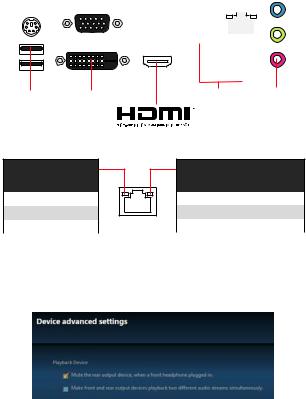
Rear I/O Panel
|
Line-out |
Line-in |
||||||||||||||||||||||||||||||||
|
PS/2 |
VGA |
USB 2.0 |
|||||||||||||||||||||||||||||||
|
LAN |
|||||||||||||||||||||||||||||||||
|
USB 2.0 |
DVI-D |
USB 3.2 Gen1 |
Mic in |
LAN Port LED Status Table
Link/ Activity LED
|
Status |
Description |
|
Off |
No link |
|
Yellow |
Linked |
|
Blinking |
Data activity |
Speed LED
|
Status |
Description |
|
Off |
10 Mbps connection |
|
Green |
100 Mbps connection |
|
Orange |
1 Gbps connection |
Audio 7.1-channel Configuration
To configure 7.1-channel audio, you have to connect front audio I/O module to JAUD1 connector and follow the below steps.
1.Click on the Realtek HD Audio Manager > Advanced Settings to open the dialog below.
2.Select Mute the rear output device, when a front headphone plugged in.
3.Plug your speakers to audio jacks on rear and front I/O panel. When you plug into a device at an audio jack, a dialogue window will pop up asking you which device is current connected.
Rear I/O Panel 7
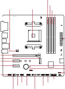
Overview of Components
PCI_E1
M2_1
PCI_E2
PCI_E3
JAUD1
|
CPU_PWR1 |
DIMMA1 |
|||||||||||||||
|
CPU_FAN1 |
||||||||||||||||
|
DIMMA2 |
||||||||||||||||
|
SYS_FAN1 |
CPU Socket |
DIMMB1 |
||||||||||||||
|
DIMMB2 |
||||||||||||||||
 EZ Debug LED
ATX_PWR1


 SATA1
SATA1


 SATA2
SATA2
 SATA▼3▲4
JBAT1
JCI1
JFP2


 JFP1
JFP1
JUSB3
|
JCOM1 |
JUSB2 |
|
|
JRGB1 |
JTPM1 |
JUSB1 |
|
SYS_FAN2 |
JLPT1 |
8 Overview of Components
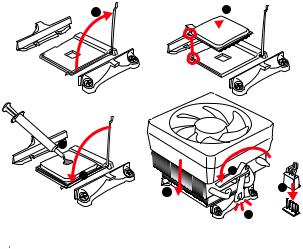
CPU Socket
Please install the CPU into the CPU socket as shown below.
 2
2
3
 Important
yWhen changing the processor, the system configuration could be cleared and reset BIOS to default values due to the AM4 processor’s architecture.
yAlways unplug the power cord from the power outlet before installing or removing the CPU.
yWhen installing a CPU, always remember to install a CPU heatsink. A CPU heatsink is necessary to prevent overheating and maintain system stability.
yConfirm that the CPU heatsink has formed a tight seal with the CPU before booting your system.
yOverheating can seriously damage the CPU and motherboard. Always make sure the cooling fans work properly to protect the CPU from overheating. Be sure to apply an even layer of thermal paste (or thermal tape) between the CPU and the heatsink to enhance heat dissipation.
yIf you purchased a separate CPU and heatsink/ cooler, Please refer to the documentation in the heatsink/ cooler package for more details about installation.
Overview of Components 9

DIMM Slots
Please install the memory module into the DIMM slot as shown below.
2
Memory module installation recommendation
 DIMMB2
|
DIMMA2 |
DIMMA2 |
|||
 DIMMB2
 DIMMB1
DIMMA2
DIMMA1
10 Overview of Components
![]()
 Important
yAlways insert memory modules in the DIMMA2 slot first.
yDue to chipset resource usage, the available capacity of memory will be a little less than the amount of installed.
yBased on processor specification, the Memory DIMM voltage below 1.35V is suggested to protect the processor.
yDue to AM4 CPU/memory controller official specification limitation, the frequency of memory modules may operate lower than the marked value under the default state. Please refer www.msi.com for more information on compatible memory.
PCI_E1~3: PCIe Expansion Slots
|
Processors |
Ryzen™ with Radeon™ |
Athlon™ with |
||
|
1st, 2nd and |
||||
|
Vega Graphics and 2nd |
Radeon™ Vega |
|||
|
3rd Gen AMD |
||||
|
Gen AMD Ryzen™ with |
||||
|
Ryzen™ |
Graphics |
|||
|
Radeon™ Graphics |
||||
|
Slots |
||||
|
PCI_E1 |
PCIe 3.0 x16 |
PCIe 3.0 x8 |
PCIe 3.0 x4 |
|
|
PCI_E2 |
PCIe 2.0 x1 |
PCIe 2.0 x1 |
PCIe 2.0 x1 |
|
|
PCI_E3 |
PCIe 2.0 x1 |
PCIe 2.0 x1 |
PCIe 2.0 x1 |
 Important
yWhen adding or removing expansion cards, always turn off the power supply and unplug the power supply power cable from the power outlet. Read the expansion card’s documentation to check for any necessary additional hardware or software changes.
yIf you install a large and heavy graphics card, you need to use a tool such as MSI Gaming Series Graphics Card Bolster to support its weight to prevent deformation of the slot.
Overview of Components 11

JFP1, JFP2: Front Panel Connectors
These connectors connect to the switches and LEDs on the front panel.
|
Power LED |
Power Switch |
1 |
HDD LED + |
2 |
Power LED + |
|
|
+ — + — |
3 |
HDD LED — |
4 |
Power LED — |
||
|
2 |
10 |
5 |
Reset Switch |
6 |
Power Switch |
|
|
1 |
9 |
|||||
|
7 |
Reset Switch |
8 |
Power Switch |
|||
|
+ — — + |
Reserved |
|||||
|
HDD LED |
Reset Switch |
9 |
Reserved |
10 |
No Pin |
|
|
HDDLED |
RESETSW |
||
|
JFP1 |
|||
|
+ — |
Buzzer |
1 |
|
|
JFP2 1 |
+ |
||
|
— |
Speaker |
3 |
|
|
HDD LED |
HDD LED — |
||||||
|
HDD LED + |
|||||||
|
POWER LED — |
|||||||
|
POWER LED |
POWER LED + |
||||||
|
Speaker — |
2 |
Buzzer + |
|
Buzzer — |
4 |
Speaker + |
SATA1~4: SATA 6Gb/s Connectors
These connectors are SATA 6Gb/s interface ports. Each connector can connect to one SATA device.
SATA1
 SATA4
SATA4
SATA2
SATA3
 Important
yPlease do not fold the SATA cable at a 90-degree angle. Data loss may result during transmission otherwise.
ySATA cables have identical plugs on either sides of the cable. However, it is recommended that the flat connector be connected to the motherboard for space saving purposes.
12 Overview of Components
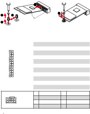
M2_1: M.2 Slot (Key M)
Please install the M.2 solid-state drive (SSD) into the M.2 slot as shown below.
|
4 |
|||
|
1 |
3 |
5 |
|
|
30° |
|||
|
2 |
ATX_PWR1, CPU_PWR1: Power Connectors
These connectors allow you to connect an ATX power supply.
|
1 |
+3.3V |
13 |
+3.3V |
|||||
|
2 |
+3.3V |
14 |
-12V |
|||||
|
12 |
24 |
3 |
Ground |
15 |
Ground |
|||
|
4 |
+5V |
16 |
PS-ON# |
|||||
|
5 |
Ground |
17 |
Ground |
|||||
|
ATX_PWR1 |
6 |
+5V |
18 |
Ground |
||||
|
7 |
Ground |
19 |
Ground |
|||||
|
8 |
PWR OK |
20 |
Res |
|||||
|
1 |
13 |
9 |
5VSB |
21 |
+5V |
|||
|
10 |
+12V |
22 |
+5V |
|||||
|
11 |
+12V |
23 |
+5V |
|||||
|
12 |
+3.3V |
24 |
Ground |
|
8 |
5 |
1 |
Ground |
5 |
+12V |
|
|
CPU_PWR1 |
2 |
Ground |
6 |
+12V |
||
|
3 |
Ground |
7 |
+12V |
|||
|
4 |
1 |
|||||
|
4 |
Ground |
8 |
+12V |
|||
 Important
Make sure that all the power cables are securely connected to a proper ATX power supply to ensure stable operation of the motherboard.
Overview of Components 13

JUSB1~2: USB 2.0 Connectors
These connectors allow you to connect USB 2.0 ports on the front panel.
|
1 |
VCC |
2 |
VCC |
|||||||
|
2 |
10 |
3 |
USB0- |
4 |
USB1- |
|||||
|
5 |
USB0+ |
6 |
USB1+ |
|||||||
|
1 |
9 |
7 |
Ground |
8 |
Ground |
|||||
|
9 |
No Pin |
10 |
NC |
 Important
yNote that the VCC and Ground pins must be connected correctly to avoid possible damage.
yIn order to recharge your iPad,iPhone and iPod through USB ports, please install MSI® SUPER CHARGER utility.
JUSB3: USB 3.2 Gen1 Connector
This connector allows you to connect USB 3.2 Gen1 ports on the front panel.
|
1 |
Power |
11 |
USB2.0+ |
|||
|
2 |
USB3_RX_DN |
12 |
USB2.0- |
|||
|
3 |
USB3_RX_DP |
13 |
Ground |
|||
|
10 |
4 |
Ground |
14 |
USB3_TX_C_DP |
||
|
5 |
USB3_TX_C_DN |
15 |
USB3_TX_C_DN |
|||
|
11 |
6 |
USB3_TX_C_DP |
16 |
Ground |
||
|
7 |
Ground |
17 |
USB3_RX_DP |
|||
|
8 |
USB2.0- |
18 |
USB3_RX_DN |
|||
|
9 |
USB2.0+ |
19 |
Power |
|||
|
10 |
NC |
20 |
No Pin |
|||
 Important
Note that the Power and Ground pins must be connected correctly to avoid possible damage.
14 Overview of Components

CPU_FAN1, SYS_FAN1~2: Fan Connectors
Fan connectors can be classified as PWM (Pulse Width Modulation) Mode or DC Mode. PWM Mode fan connectors provide constant 12V output and adjust fan speed with speed control signal. DC Mode fan connectors control fan speed by changing voltage. When you plug a 3-pin (Non-PWM) fan to a fan connector in PWM mode, the fan speed will always maintain at 100%, which might create a lot of noise. You can follow the instruction below to adjust the fan connector to PWM or DC Mode.
|
Default PWM Mode |
Default DC Mode fan |
1 |
||||||||
|
fan connector |
1 |
connector |
||||||||
|
SYS_FAN1/ 2 |
||||||||||
|
CPU_FAN1 |
||||||||||
Switching fan mode and adjusting fan speed
You can switch between PWM mode and DC mode and adjust fan speed in BIOS > HARDWARE MONITOR.
Select PWM mode or DC mode
There are gradient points of the fan speed that allow you to adjust fan speed in relation to CPU temperature.
 Important
Make sure fans are working properly after switching the PWM/ DC mode.
Pin definition of fan connectors
PWM Mode pin definition
|
1 |
Ground |
2 |
+12V |
|
3 |
Sense |
4 |
Speed Control Signal |
DC Mode pin definition
|
1 |
Ground |
2 |
Voltage Control |
|
3 |
Sense |
4 |
NC |
Overview of Components 15

JTPM1: TPM Module Connector
This connector is for TPM (Trusted Platform Module). Please refer to the TPM security platform manual for more details and usages.
|
1 |
LPC Clock |
2 |
3V Standby power |
|||||||||
|
3 |
LPC Reset |
4 |
3.3V Power |
|||||||||
|
2 |
14 |
5 |
LPC address & data pin0 |
6 |
Serial IRQ |
|||||||
|
7 |
LPC address & data pin1 |
8 |
5V Power |
|||||||||
|
1 |
13 |
9 |
LPC address & data pin2 |
10 |
No Pin |
|||||||
|
11 |
LPC address & data pin3 |
12 |
Ground |
|||||||||
|
13 |
LPC Frame |
14 |
Ground |
JCI1: Chassis Intrusion Connector
This connector allows you to connect the chassis intrusion switch cable.
|
Normal |
Trigger the chassis |
|||||
|
(default) |
intrusion event |
Using chassis intrusion detector
1.Connect the JCI1 connector to the chassis intrusion switch/ sensor on the chassis.
2.Close the chassis cover.
3.Go to BIOS > SETTINGS > Security > Chassis Intrusion Configuration.
4.Set Chassis Intrusion to Enabled.
5.Press F10 to save and exit and then press the Enter key to select Yes.
6.Once the chassis cover is opened again, a warning message will be displayed on screen when the computer is turned on.
Resetting the chassis intrusion warning
1.Go to BIOS > SETTINGS > Security > Chassis Intrusion Configuration.
2.Set Chassis Intrusion to Reset.
3.Press F10 to save and exit and then press the Enter key to select Yes.
16 Overview of Components

JAUD1: Front Audio Connector
This connector allow you to connect audio jacks on the front panel.
|
1 |
MIC L |
2 |
Ground |
|||||||
|
2 |
10 |
3 |
MIC R |
4 |
NC |
|||||
|
5 |
Head Phone R |
6 |
MIC Detection |
|||||||
|
1 |
9 |
7 |
SENSE_SEND |
8 |
No Pin |
|||||
|
9 |
Head Phone L |
10 |
Head Phone Detection |
JCOM1: Serial Port Connector
This connector allows you to connect the optional serial port with bracket.
|
1 |
DCD |
2 |
SIN |
|||||||
|
2 |
10 |
3 |
SOUT |
4 |
DTR |
|||||
|
5 |
Ground |
6 |
DSR |
|||||||
|
1 |
9 |
7 |
RTS |
8 |
CTS |
|||||
|
9 |
RI |
10 |
No Pin |
JLPT1: Parallel Port Connector
This connector allows you to connect the optional parallel port with bracket.
|
2 |
26 |
|||||||||||||||||
|
1 |
25 |
|||||||||||||||||
|
1 |
RSTB# |
2 |
AFD# |
3 |
PRND0 |
|||||||||||||
|
4 |
ERR# |
5 |
PRND1 |
6 |
PINIT# |
|||||||||||||
|
7 |
PRND2 |
8 |
LPT_SLIN# |
9 |
PRND3 |
|||||||||||||
|
10 |
Ground |
11 |
PRND4 |
12 |
Ground |
|||||||||||||
|
13 |
PRND5 |
14 |
Ground |
15 |
PRND6 |
|||||||||||||
|
16 |
Ground |
17 |
PRND7 |
18 |
Ground |
|||||||||||||
|
19 |
ACK# |
20 |
Ground |
21 |
BUSY |
|||||||||||||
|
22 |
Ground |
23 |
PE |
24 |
Ground |
|||||||||||||
|
25 |
SLCT |
26 |
No Pin |
Overview of Components 17
JBAT1: Clear CMOS (Reset BIOS) Jumper
There is CMOS memory onboard that is external powered from a battery located on the motherboard to save system configuration data. If you want to clear the system configuration, set the jumpers to clear the CMOS memory.
|
Keep Data |
Clear CMOS/ Reset |
|||||
|
(default) |
BIOS |
Resetting BIOS to default values
1.Power off the computer and unplug the power cord.
2.Use a jumper cap to short JBAT1 for about 5-10 seconds.
3.Remove the jumper cap from JBAT1.
4.Plug the power cord and power on the computer.
EZ Debug LED: Debug LED indicators
These LEDs indicate the status of the motherboard.

 CPU — indicates CPU is not detected or fail.

 DRAM — indicates DRAM is not detected or fail.

 VGA — indicates GPU is not detected or fail.

 BOOT — indicates booting device is not detected or fail.
JRGB1: RGB LED strip connector
This connector allows you to connect the 5050 RGB LED strip.
|
1 |
5050 LED strip |
|||
|
1 |
+12V |
2 |
G |
|
|
3 |
R |
4 |
B |
|
|
1 JRGB1 |
Extension cable (optional) |
 Important
yThis connector supports 5050 RGB multi-color LED strips (12V/G/R/B) with the maximum power rating of 3A (12V). Please keeping the LED strip shorter than 2 meters to prevent dimming.
yAlways turn off the power supply and unplug the power cord from the power outlet before installing or removing the RGB LED strip.
yPlease use MSI’s software to control the extended LED strip.
18 Overview of Components

BIOS Setup
The default settings offer the optimal performance for system stability in normal conditions. You should always keep the default settings to avoid possible system damage or failure booting unless you are familiar with BIOS.
 Important
yBIOS items are continuous update for better system performance. Therefore, the description may be slightly different from the latest BIOS and should be held for reference only. You could also refer to the HELP information panel for BIOS item description.
yThe pictures in this chapter are for reference only and may vary from the product you purchased.
yThe BIOS items will vary with the processor.
Entering BIOS Setup
Press Delete key, when the Press DEL key to enter Setup Menu, F11 to enter Boot Menu message appears on the screen during the boot process.
Function key
F1: General Help
F2: Add/ Remove a favorite item
F3: Enter Favorites menu
F4: Enter CPU Specifications menu
F5: Enter Memory-Z menu
F6: Load optimized defaults
F7: Switch between Advanced mode and EZ mode
F8: Load Overclocking Profile
F9: Save Overclocking Profile
F10: Save Change and Reset*
F12: Take a screenshot and save it to USB flash drive (FAT/ FAT32 format only).
* When you press F10, a confirmation window appears and it provides the modification information. Select between Yes or No to confirm your choice.
BIOS Setup 19

Resetting BIOS
You might need to restore the default BIOS setting to solve certain problems. There are several ways to reset BIOS:
yGo to BIOS and press F6 to load optimized defaults.
yShort the Clear CMOS jumper on the motherboard.
 Important
Please refer to the Clear CMOS jumper section for resetting BIOS.
Updating BIOS
Updating BIOS with M-FLASH
Before updating:
Please download the latest BIOS file that matches your motherboard model from MSI website. And then save the BIOS file into the USB flash drive.
Updating BIOS:
1.Press Del key to enter the BIOS Setup during POST.
2.Insert the USB flash drive that contains the update file into the computer.
3.Select the M-FLASH tab and click on Yes to reboot the system and enter the flash mode.
4.Select a BIOS file to perform the BIOS update process.
5.After the flashing process is 100% completed, the system will reboot automatically.
Updating the BIOS with Live Update 6
Before updating:
Make sure the LAN driver is already installed and the Internet connection is set properly.
Updating BIOS:
1.Install and launch MSI LIVE UPDATE 6.
2.Select BIOS Update.
3.Click on Scan button.
4.Click on Download icon to download and install the latest BIOS file.
5.Click Next and choose In Windows mode. And then click Next and Start to start updating BIOS.
6.After the flashing process is 100% completed, the system will restart automatically.
20 BIOS Setup
Software Description
Please download and update the latest utilities and drivers at www.msi.com
Installing Windows® 10
1.Power on the computer.
2.Insert the Windows® 10 disc into your optical drive.
3.Press the Restart button on the computer case.
4.Press F11 key during the computer POST (Power-On Self Test) to get into Boot Menu.
5.Select your optical drive from the Boot Menu.
6.Press any key when screen shows Press any key to boot from CD or DVD…
message.
7.Follow the instructions on the screen to install Windows® 10.
Installing Drivers
1.Start up your computer in Windows® 10.
2.Insert MSI® Driver Disc into your optical drive.
3.The installer will automatically appear and it will find and list all necessary drivers.
4.Click Install button.
5.The software installation will then be in progress, after it has finished it will prompt you to restart.
6.Click OK button to finish.
7.Restart your computer.
Software Description 21
Installing Utilities
Before you install utilities, you must complete drivers installation.
1.Insert MSI® Driver Disc into your optical drive.
2.The installer will automatically appear.
3.Click Utilities tab.
4.Select the utilities you want to install.
5.Click Install button.
6.The utilities installation will then be in progress, after it has finished it will prompt you to restart.
7.Click OK button to finish.
8.Restart your computer.
22 Software Description

MSI® B450M PRO-VDH MAX. , , BIOS.
|
…………………………………………………………………………………………….. |
2 |
|||
|
……………………………………………………………………………………………………. |
3 |
|||
|
………………………………………………………………………………………….. |
6 |
|||
|
I/O ……………………………………………………………………………………….. |
7 |
|||
|
LAN |
LED ……………………………………………………………………….. |
7 |
||
|
………………………………………………………………………………………….. |
8 |
|||
|
CPU |
……………………………………………………………………………………………….. |
9 |
||
|
DIMM …………………………………………………………………………………………… |
10 |
|||
|
PCI_E1~3: PCIe ………………………………………………………………………. |
11 |
|||
|
JFP1, JFP2: …………………………………………………………………. |
12 |
|||
|
SATA1~4: SATA 6Gb/s …………………………………………………………………. |
12 |
|||
|
M2_1: M.2 (Key M)…………………………………………………………………………. |
13 |
|||
|
ATX_PWR1, CPU_PWR1: ………………………………………………………. |
13 |
|||
|
JUSB1~2: USB 2.0 ………………………………………………………………………. |
14 |
|||
|
JUSB3: USB 3.2 Gen1 …………………………………………………………………. |
14 |
|||
|
CPU_FAN1, SYS_FAN1~2: ……………………………………………………….. |
15 |
|||
|
JTPM1: TPM ……………………………………………………………………….. |
16 |
|||
|
JCI1: |
……………………………………………………………………………. |
16 |
||
|
JAUD1: |
…………………………………………………………………….. |
17 |
||
|
JCOM1: |
…………………………………………………………………….. |
17 |
||
|
JLPT1: ……………………………………………………………………… |
17 |
|||
|
JBAT1: CMOS (Reset BIOS) …………………………………………………… |
18 |
|||
|
EZ LED: LED ………………………………………………………….. |
18 |
|||
|
JRGB1: RGB LED ……………………………………………………………… |
18 |
|||
|
BIOS ………………………………………………………………………………………….. |
19 |
|||
|
BIOS |
…………………………………………………………………………………………….. |
19 |
||
|
BIOS |
…………………………………………………………………………………………….. |
20 |
||
|
BIOS |
………………………………………………………………………………………. |
20 |
||
|
………………………………………………………………………………….. |
21 |
|||
|
Windows® 10 …………………………………………………………………………… |
21 |
|||
|
…………………………………………………………………………………. |
21 |
|||
|
…………………………………………………………………………………. |
22 |
1
y (ESD).
y . ,.
y .
y ESD. ESD ,.
y .
y .
y . ,.
y .
y .
y . y .
y PSU PSU.
y . . y .
y , ..
.
..
.
y 60°C (140°F) . .
2

|
AM4 1,2 3 AMD Ryzen™/ Radeon™ |
|||
|
CPU |
Ryzen™/ Radeon™ 2 |
||
|
AMD Ryzen™ / Radeon™ Athlon™ |
|||
|
AMD® B450 |
|||
|
y |
DDR4 4 , 64GB* |
||
|
1866/ 2133/ 2400/ 2667Mhz (by JEDEC) |
|||
|
2667/ 2800/ 2933/ 3000/ 3066/ 3200/ 3466 MHz (by |
|||
|
A-XMP OC ) |
|||
|
y |
|||
|
y |
ECC UDIMM |
(non-ECC ) |
|
|
y non-ECC UDIMM |
|||
|
* www.msi. |
|||
|
com . |
|||
|
y PCIe 3.0 x16 1 |
|||
|
1,2 3 AMD Ryzen™ x16 |
|||
|
Radeon™ Ryzen™ Radeon™ |
|||
|
2 AMD Ryzen™ x8 |
|||
|
Radeon™ Athlon™ x4 |
|||
|
y PCIe 2.0 x1 2 |
|||
|
y VGA 1 , 2048×1280@60Hz, 1920×1200@60Hz* |
|||
|
y DVI-D 1 , 1920×1200@60Hz* |
|||
|
y HDMI™ 1.4 1 , 4096×2160 @30Hz, 2560×1600 |
|||
|
@60Hz* |
|||
|
* Radeon ™ Ryzen ™ Radeon ™ |
|||
|
2 AMD Ryzen ™ / Radeon ™ |
|||
|
Athlon ™ . |
|||
|
* |
2048 MB |
||
3

|
AMD® B450 |
||
|
y SATA 6Gb/s 4 |
||
|
RAID 0, RAID1 RAID 10 |
||
|
PCIe 3.0 x4 (1,2 3 AMD Ryzen™/ Radeon™ |
||
|
y M.2 1 (Key M) |
||
|
Ryzen™ Radeon™ |
||
|
2 AMD Ryzen™ ) PCIe 3.0 |
x2(Radeon™ |
|
|
Athlon™) SATA 6Gb/s |
||
|
2242/ 2260 /2280 |
||
|
Realtek® ALC892 |
||
|
y 7.1- HD |
||
|
LAN |
Realtek® 8111H Gigabit LAN 1 |
|
|
AMD® B450 |
||
|
y USB 3.2 Gen1 ( USB) USB 3.2 Gen1 |
||
|
2 |
||
|
USB |
y USB 2.0 ( USB) 8 ( 4 , USB |
|
|
4 ) |
||
|
AMD® |
||
|
y USB 3.2 Gen1 ( USB) A 4 |
||
|
I/O |
NUVOTON 6795D |
yCPU/y CPU/
yCPU/
|
y m-ATX |
|
|
y 9.6 in. x 9.6 in. (24.4 cm x 24.4 cm) |
|
|
y 256 Mb 1 |
|
|
BIOS |
y UEFI AMI BIOS |
|
y ACPI 6.1, SM BIOS 2.8 |
|
|
y |
|
4

|
y PS/2 / 1 |
|||
|
y USB 2.0 A 4 |
|||
|
y VGA |
1 |
||
|
y DVI-D 1 |
|||
|
y HDMI™ 1 |
|||
|
y USB 3.2 Gen1 A 4 |
|||
|
y LAN (RJ45) 1 |
|||
|
y |
3 |
||
|
y 24 ATX 1 |
|||
|
y 8 ATX 12V 1 |
|||
|
y SATA 6Gb/s 4 |
|||
|
y USB 2.0 2 ( USB 2.0 4 ) |
|||
|
y USB 3.2 Gen1 1 ( USB 3.2 Gen1 2 ) |
|||
|
y 4 CPU 1 |
|||
|
y 4 2 |
|||
|
y 1 |
|||
|
y 2 |
|||
|
y TPM 1 |
|||
|
y 1 |
|||
|
y |
1 |
||
|
y |
1 |
||
|
y RGB LED |
1 |
||
|
y CMOS |
1 |
||
|
y |
|||
|
y |
|||
|
y |
|||
|
y |
|||
|
y 6 |
|||
|
y |
|||
|
y |
|||
|
y X- |
|||
|
y |
|||
|
y ™ |
|||
|
y : , , |
|||
|
y CPU-Z MSI |
5

. .: y
y DVD y y I/O
y SATA 6G 2 y
y y M.2 1

.
6

I/O
|
PS/2 |
VGA |
USB 2.0 |
Line |
Line |
||||||||||||||||||||||||||||||||
|
LAN |
||||||||||||||||||||||||||||||||||||
|
DVI-D |
Mic |
|||
|
USB 2.0 |
USB 3.2 Gen1 |
LAN LED 


|
LED |
||
|
10 Mbps |
||
|
. |
||
|
100 Mbps |
||
|
. |
||
|
1 Gbps |
||
|
. |
7.1-
7.1 I/O JAUD1 ..
1.Realtek HD Audio Manager(Realtek HD ) > Advanced Settings() .
2.Mute the rear output device, when a front headphone plugged in () .
3.I/O ..
I/O 7

PCI_E1
M2_1
PCI_E2
PCI_E3
JAUD1
|
CPU_PWR1 |
DIMMA1 |
|||||||||||||||
|
CPU_FAN1 |
||||||||||||||||
|
DIMMA2 |
||||||||||||||||
|
SYS_FAN1 |
CPU |
DIMMB1 |
||||||||||||||
|
DIMMB2 |
||||||||||||||||
 EZ LED
ATX_PWR1


 SATA1
SATA1


 SATA2
SATA2
 SATA▼3▲4
JBAT1
JCI1
JFP2


 JFP1
JFP1
JUSB3
|
JCOM1 |
JUSB2 |
|
|
JRGB1 |
JTPM1 |
JUSB1 |
|
SYS_FAN2 |
JLPT1 |
8
![]()
CPU
CPU CPU .
 4
4
|
3 |
7 |
|
|
5 |
8 |
|
|
6 |

y, AM4 BIOS.
yCPU .
yCPU , CPU . CPU.
yCPU .
yCPU CPU. CPU( ) .
yCPU / , /.
9

DIMM
DIMM .
2
( )
 DIMMB2
|
DIMMA2 |
DIMMA2 |
|||
 DIMMB2
 DIMMB1
DIMMA2
DIMMA1
10


yDIMMA2 .
y.
yCPU CPU DIMM 1.35V .
yAM4 CPU/ . www.msi.com .
PCI_E1~3: PCIe
|
Radeon™ |
Radeon™ |
||||||||
|
1,2 |
3 |
Ryzen™ |
|||||||
|
AMD |
® |
Ryzen |
Radeon™ |
||||||
|
2 AMD |
Athlon™ |
||||||||
|
Ryzen™ |
|||||||||
|
PCI_E1 |
PCIe 3.0 x16 |
PCIe 3.0 x8 |
PCIe 3.0 x4 |
||||||
|
PCI_E2 |
PCIe 2.0 x1 |
PCIe 2.0 x1 |
PCIe 2.0 x1 |
||||||
|
PCI_E3 |
PCIe 2.0 x1 |
PCIe 2.0 x1 |
PCIe 2.0 x1 |
y..
y,MSI Gaming Series Graphics Card Bolster.
11

JFP1, JFP2:
LED .
|
LED |
1 |
HDD LED + |
2 |
|||
|
+ — + — |
3 |
HDD LED — |
4 |
|||
|
JFP1 |
2 |
10 |
5 |
Reset Switch |
6 |
|
|
1 |
9 |
|||||
|
7 |
Reset Switch |
8 |
||||
|
+ — — + |
Reserved |
|||||
|
HDD LED |
9 |
Reserved |
10 |
Power LED +
Power LED —
Power Switch
Power Switch
No Pin
HDD
 LEDSWRESET
JFP1
|
HDD LED |
HDD LED — |
||||||
|
HDD LED + |
|||||||
|
POWER LED — |
|||||||
|
POWER LED |
POWER LED + |
||||||
|
Buzzer |
1 |
Speaker — |
2 |
Buzzer + |
||
|
3 |
Buzzer — |
4 |
Speaker + |
|||
|
Speaker |
||||||
SATA1~4: SATA 6Gb/s
SATA 6Gb/s . SATA.
SATA1
 SATA4
SATA4
SATA2
SATA3
ySATA 90 . , .
ySATA .
12

M2_1: M.2 (Key M)
M.2 (SSD) M.2 .
|
4 |
|||
|
1 |
3 |
5 |
|
|
30° |
|||
|
2 |
ATX_PWR1, CPU_PWR1:
ATX .
|
1 |
+3.3V |
13 |
+3.3V |
|||||
|
2 |
+3.3V |
14 |
-12V |
|||||
|
12 |
24 |
3 |
Ground |
15 |
Ground |
|||
|
4 |
+5V |
16 |
PS-ON# |
|||||
|
5 |
Ground |
17 |
Ground |
|||||
|
ATX_PWR1 |
6 |
+5V |
18 |
Ground |
||||
|
7 |
Ground |
19 |
Ground |
|||||
|
8 |
PWR OK |
20 |
Res |
|||||
|
1 |
13 |
9 |
5VSB |
21 |
+5V |
|||
|
10 |
+12V |
22 |
+5V |
|||||
|
11 |
+12V |
23 |
+5V |
|||||
|
12 |
+3.3V |
24 |
Ground |
|
8 |
5 |
1 |
Ground |
5 |
+12V |
|
|
CPU_PWR1 |
2 |
Ground |
6 |
+12V |
||
|
3 |
Ground |
7 |
+12V |
|||
|
4 |
1 |
|||||
|
4 |
Ground |
8 |
+12V |
|||
|
ATX |
||||||
|
. |
13

JUSB1~2: USB 2.0
USB 2.0 .
|
1 |
VCC |
2 |
VCC |
||||||
|
2 |
10 |
3 |
USB0- |
4 |
USB1- |
||||
|
5 |
USB0+ |
6 |
USB1+ |
||||||
|
1 |
9 |
7 |
Ground |
8 |
Ground |
||||
|
9 |
No Pin |
10 |
NC |
yVCC .
yUSB iPad,iPhone iPod MSI® SUPER CHARGER
.
JUSB3: USB 3.2 Gen1
USB 3.2 Gen1 .
|
1 |
Power |
11 |
USB2.0+ |
|||||
|
2 |
USB3_RX_DN |
12 |
USB2.0- |
|||||
|
3 |
USB3_RX_DP |
13 |
Ground |
|||||
|
1 |
10 |
4 |
Ground |
14 |
USB3_TX_C_DP |
|||
|
5 |
USB3_TX_C_DN |
15 |
USB3_TX_C_DN |
|||||
|
6 |
USB3_TX_C_DP |
16 |
Ground |
|||||
|
20 |
11 |
|||||||
|
7 |
Ground |
17 |
USB3_RX_DP |
|||||
|
8 |
USB2.0- |
18 |
USB3_RX_DN |
|||||
|
9 |
USB2.0+ |
19 |
Power |
|||||
|
10 |
NC |
20 |
No Pin |
.
14

|
CPU_FAN1, SYS_FAN1~2: |
|||||||||
|
PWM (Pulse Width Modulation) DC . |
|||||||||
|
PWM 12V |
|||||||||
|
. DC . |
|||||||||
|
PWM 3- (Non-PWM) , 100% |
|||||||||
|
. PWM DC |
|||||||||
|
. |
|||||||||
|
PWM |
DC |
1 |
|||||||
|
1 |
|||||||||
|
CPU_FAN1 |
SYS_FAN1/ 2 |
||||||||
PWM DC BIOS > HARDWARE MONITOR() .
PWM DC
CPU .
PWM/ DC , .
PWM
|
1 |
Ground |
2 |
+12V |
|
3 |
Sense |
4 |
Speed Control Signal |
DC
|
1 |
Ground |
2 |
Voltage Control |
|
3 |
Sense |
4 |
NC |
15

JTPM1: TPM
TPM (Trusted Platform Module) .TPM .
|
1 |
LPC Clock |
2 |
3V Standby power |
|||||||||
|
3 |
LPC Reset |
4 |
3.3V Power |
|||||||||
|
2 |
14 |
5 |
LPC address & data pin0 |
6 |
Serial IRQ |
|||||||
|
7 |
LPC address & data pin1 |
8 |
5V Power |
|||||||||
|
1 |
13 |
9 |
LPC address & data pin2 |
10 |
No Pin |
|||||||
|
11 |
LPC address & data pin3 |
12 |
Ground |
|||||||||
|
13 |
LPC Frame |
14 |
Ground |
JCI1:
.
1. JCI1 / . 2. .
3. BIOS > SETTINGS ( ) > Security( ) > Chassis Intrusion Configuration(
) .
4. Chassis Intrusion( ) Enabled( ) .
5. F10 . Enter Yes . 6. .
1.BIOS > SETTINGS ( ) > Security( ) > Chassis Intrusion Configuration() .
2.Chassis Intrusion( ) Reset( ) .
3.F10 . Enter Yes .
16

JAUD1:
.
|
1 |
MIC L |
2 |
Ground |
|||||||
|
2 |
10 |
3 |
MIC R |
4 |
NC |
|||||
|
5 |
Head Phone R |
6 |
MIC Detection |
|||||||
|
1 |
9 |
7 |
SENSE_SEND |
8 |
No Pin |
|||||
|
9 |
Head Phone L |
10 |
Head Phone Detection |
JCOM1:
.
|
1 |
DCD |
2 |
SIN |
|||||||
|
2 |
10 |
3 |
SOUT |
4 |
DTR |
|||||
|
5 |
Ground |
6 |
DSR |
|||||||
|
1 |
9 |
7 |
RTS |
8 |
CTS |
|||||
|
9 |
RI |
10 |
No Pin |
JLPT1:
.
|
2 |
26 |
|||||||||||||||||
|
1 |
25 |
|||||||||||||||||
|
1 |
RSTB# |
2 |
AFD# |
3 |
PRND0 |
|||||||||||||
|
4 |
ERR# |
5 |
PRND1 |
6 |
PINIT# |
|||||||||||||
|
7 |
PRND2 |
8 |
LPT_SLIN# |
9 |
PRND3 |
|||||||||||||
|
10 |
Ground |
11 |
PRND4 |
12 |
Ground |
|||||||||||||
|
13 |
PRND5 |
14 |
Ground |
15 |
PRND6 |
|||||||||||||
|
16 |
Ground |
17 |
PRND7 |
18 |
Ground |
|||||||||||||
|
19 |
ACK# |
20 |
Ground |
21 |
BUSY |
|||||||||||||
|
22 |
Ground |
23 |
PE |
24 |
Ground |
|||||||||||||
|
25 |
SLCT |
26 |
No Pin |
17

JBAT1: CMOS (Reset BIOS)
CMOS. CMOS.
|
CMOS / |
||||||
|
( ) |
BIOS |
BIOS
1. . 2. JBAT1 5-10 .
3. JBAT1 .
4. .
EZ LED: LED
LED .

 CPU— CPU .
 DRAM — DRAM .
 VGA — GPU .
 BOOT — .
JRGB1: RGB LED
5050 RGB LED .
|
1 |
5050 LED |
||||
|
1 |
+12V |
2 |
G |
||
|
3 |
R |
4 |
B |
( ) |
|
|
1 |
JRGB1 |
||||
y3A (12V) 5050 RGB — LED (12V/G/R/B)
. LED 2m .
yRGB LED .
yMSI LED .
18
![]()
BIOS
. BIOS,
.

yBIOS .BIOS . BIOSHELP( ) .
y.
yBIOS .
BIOS
Press DEL key to enter Setup Menu, F11 to enter Boot Menu(DEL , F11 )Delete .
F1:
F2: /
F3:
F4: CPU
F5: Memory-Z
F6:
F7: EZ
F8:
F9:
F10: *
F12: USB (FAT/ FAT32 )
* F10 . Yes No .
BIOS 19

BIOS
BIOS . BIOS.
y BIOS F6 . y CMOS .

BIOS CMOS .
BIOS
M-FLASH BIOS
BIOS MSI® BIOS USB.
BIOS :
1. POST Del BIOS .
2. USB .
3. M-FLASH Yes.
4. BIOS BIOS .
5. 100% .
Live Update 6 BIOS
LAN . BIOS :
1. MSI LIVE UPDATE 6 .
2. BIOS Update .
3. Scan .
4. Download BIOS .
5. Next In Windows mode Next Start BIOS
.
6. 100% .
20 BIOS
www.msi.com.
Windows® 10
1. .
2. Windows® 10 .
3. Restart .
4. POST (Power-On Self Test) F11 .
5. .
6. Press any key to boot from CD or DVD….
7. Windows® 10 .
1. Windows® 10 .
2. MSI® .
3. .
4. Install .
5. . . 6. OK .
7. .
21
. 1. MSI® .
2. .
3. Utilities( ) .
4. .
5. Install( ) .
6. . . 7. OK( ) .
8. .
22

Merci d’avoir acheté une carte mère MSI® B450M PRO-VDH MAX. Ce manuel d’utilisateur fournit des informations sur le schéma, la vue d’ensemble des composants, la configuration du BIOS et l’installation des logiciels.
|
Table des matières |
|
|
Informations de sécurité……………………………………………………………………… |
2 |
|
Spécifications……………………………………………………………………………………… |
3 |
|
Contenu……………………………………………………………………………………………… |
5 |
|
Panneau arrière Entrée/ Sortie ……………………………………………………………. |
6 |
|
Tableau explicatif de l’état de la LED du port LAN…………………………………….. |
6 |
|
Vue d’ensemble des composants…………………………………………………………. |
7 |
|
Socket processeur …………………………………………………………………………………. |
8 |
|
Slots DIMM……………………………………………………………………………………………. |
9 |
|
PCI_E1~3 : Slots d’extension PCIe ………………………………………………………… |
10 |
|
JFP1, JFP2 : Connecteurs de panneau avant…………………………………………… |
11 |
|
SATA1~4 : Connecteurs SATA 6 Gb/s………………………………………………………. |
11 |
|
M2_1 : Slot M.2 (Touche M)……………………………………………………………………. |
12 |
|
ATX_PWR1, CPU_PWR1 : Connecteurs d’alimentation ……………………………. |
12 |
|
JUSB1~2 : Connecteurs USB 2.0……………………………………………………………. |
13 |
|
JUSB3 : Connecteur USB 3.2 Gen1 ………………………………………………………… |
13 |
|
CPU_FAN1, SYS_FAN1~2 : Connecteurs pour ventilateurs……………………….. |
14 |
|
JTPM1 : Connecteur de module TPM……………………………………………………… |
15 |
|
JCI1 : Connecteur intrusion châssis……………………………………………………….. |
15 |
|
JAUD1 : Connecteur audio avant……………………………………………………………. |
16 |
|
JCOM1 : Connecteur de port série …………………………………………………………. |
16 |
|
JLPT1 : Connecteur de port parallèle …………………………………………………….. |
16 |
|
JBAT1 : Cavalier Clear CMOS (Réinitialisation BIOS)………………………………… |
17 |
|
EZ Debug LED : Indicateurs LED Debug …………………………………………………. |
17 |
|
JRGB1 : Connecteur de ruban LED RGB…………………………………………………. |
17 |
|
Configuration du BIOS ……………………………………………………………………….. |
18 |
|
Entrer dans l’interface Setup du BIOS …………………………………………………… |
18 |
|
Réinitialiser le BIOS……………………………………………………………………………… |
19 |
|
Mettre le BIOS à jour…………………………………………………………………………….. |
19 |
|
Informations sur les logiciels……………………………………………………………… |
20 |
|
Installer Windows® 10…………………………………………………………………………… |
20 |
|
Installer les pilotes ………………………………………………………………………………. |
20 |
|
Installer les utilitaires…………………………………………………………………………… |
20 |
Table des matières 1
Informations de sécurité
y Les composants dans l’emballage peuvent être endommagés par des décharges électrostatiques (ESD). Pour vous assurer de correctement monter votre ordinateur, veuillez vous référer aux instructions ci-dessous.
y Assurez-vous de bien connecter tous les composants. En cas de mauvaise connexion, il se peut que l’ordinateur ne reconnaisse pas le composant et que le démarrage échoue.
y Veuillez tenir la carte mère par les bords pour éviter de toucher les composants sensibles.
y Il est recommandé de porter un bracelet antistatique lors de la manipulation de la carte mère pour prévenir tout dommage. Si vous n’avez pas de bracelet antistatique, touchez un objet métallique relié à la terre avant de manipuler la carte mère afin de vous décharger de votre charge statique. Touchez régulièrement l’objet métallique pendant toute la manipulation.
y Tant que la carte mère n’est pas installée, conservez-la dans un récipient protégé contre les ondes électrostatiques ou sur une couche antistatique.
y Avant de démarrer l’ordinateur, vérifiez si toutes les vis et les composants métalliques sont bien fixés sur la carte mère ou ailleurs dans le boîtier de l’ordinateur.
y Ne démarrez pas l’ordinateur avant d’avoir terminé l’installation. Ceci peut endommager les composants ou vous blesser.
y Si vous avez besoin d’aide pendant l’installation, veuillez consulter un technicien informatique certifié.
y Avant d’installer les composants d’ordinateur, veuillez toujours mettre hors tension et débrancher le cordon d’alimentation.
y Gardez ce manuel pour références futures. y Protégez ce manuel contre l’humidité.
y Avant de brancher le bloc d’alimentation sur la sortie électrique, veuillez vous assurer que la tension de la sortie électrique est bien égale à celle du bloc d’alimentation.
yPlacez le cordon d
yVeuillez prêter attention à toutes les alertes et remarques indiquées sur la carte mère.
yDans un cas comme ci-dessous, faites appel au service autorisé pour vérifier votre carte mère :
Un liquide a pénétré dans l’ordinateur.
La carte mère a été exposée à de l’humidité.
La carte mère ne fonctionne pas comme indiqué dans les instructions.
La carte mère est tombée par terre et a été endommagée.
La carte mère est cassée.
yNe pas mettre la carte mère dans un environnement dont la température est supérieure à 60°C (140°F) sous peine de l’endommager. ’’
2 Informations de sécurité

Spécifications
|
Socket AM4 pour processeurs AMD Ryzen™ de 1ère, 2ème et |
||
|
CPU |
3ème génération/ Ryzen™ avec cœurs graphiques Radeon™ |
|
|
Vega/ AMD Ryzen™ avec cœurs graphiques Radeon™ de 2ème |
||
|
génération/ Athlon™ avec cœurs graphiques Radeon™ Vega |
||
|
Chipset |
Chipset AMD® B450 |
|
|
y 4 x slots pour mémoire DDR4, support jusqu’à 64 Go* |
||
|
Support 1866/ 2133/ 2400/ 2667Mhz (par JEDEC) |
||
|
Support 2667/ 2800/ 2933/ 3000/ 3066/ 3200/ 3466 MHz |
||
|
(par A-XMP OC MODE) |
||
|
Mémoire |
y Architecture mémoire double canal |
|
|
y Support mémoire ECC UDIMM (mode non-ECC) |
||
|
y Support mémoire non-ECC UDIMM |
||
|
* Veuillez vous référer au site www.msi.com pour plus |
||
|
d’informations sur la mémoire compatible. |
||
|
y 1 x slot PCIe 3.0 x16 |
||
|
Le mode x 16 est supportée par les processeurs AMD® |
||
|
Ryzen™ de 1ère, 2ème et 3ème génération |
||
|
Le mode x 8 est supporté par les processeurs |
||
|
Slots |
Ryzen™ avec cœurs graphiques Radeon™ Vega et par |
|
|
d’extension |
les processeurs AMD Ryzen™ avec cœurs graphiques |
|
|
Radeon™ de 2ème génération |
||
|
Le mode x 4 est supporté par les processeurs Athlon™ |
||
|
avec cœurs graphiques Radeon™ Vega |
||
|
y 2 x slots PCIe 2.0 x1 |
||
|
y 1 x port VGA, supportant une résolution maximum de |
||
|
2048×1280@60Hz, 1920×1200@60Hz* |
||
|
y 1 x port DVI-D, supportant une résolution maximum de |
||
|
1920×1200@60Hz* |
||
|
Sorties vidéo |
y 1 x port HDMI™ 1.4, supportant une résolution maximum de |
|
|
4096×2160 @30Hz, 2560×1600 @60Hz* |
||
|
intégrées |
* Cette résolution est seulement supportée lors de |
|
|
l’utilisation des processeurs Ryzen™ avec cœurs graphiques |
||
|
Radeon™ Vega et AMD Ryzen™ avec cœurs graphiques |
||
|
Radeon™ de 2ème génération/ Athlon™ avec cœurs |
||
|
graphiques Radeon™ Vega |
||
|
* La mémoire partagée maximale est de 2048 Mo. |
||
|
Audio |
Realtek® ALC892 Codec |
|
|
y Audio haute définition 7,1 |
||
|
LAN |
1 x contrôleur Realtek® 8111H Gigabit LAN |
|
|
Suite du tableau sur la page suivante |
Spécifications 3

Suite du tableau de la page précédente
|
Chipset AMD® B450 |
||
|
y 4 x ports SATA 6Gb/s |
||
|
Support des architectures RAID 0, RAID1 et RAID 10 |
||
|
y 1 x slot M.2 (Touche M) |
||
|
Stockage |
Support PCIe 3.0 x 4 (AMD Ryzen™ de 1ère, 2ème |
|
|
et 3ème génération/ Ryzen™ avec cœurs graphiques |
||
|
Radeon™ Vega/ AMD Ryzen™ avec cœurs graphiques |
||
|
Radeon™ de 2ème génération) ou PCIe 3.0 x2 (Athlon™ |
||
|
avec cœurs graphiques Radeon™ Vega ) et SATA 6Gb/s |
||
|
Support des périphériques de stockage 2242/ 2260/ |
||
|
2280 Support PCIe 3.0 x4 et des périphériques de |
||
|
stockage SATA 6 Gb/s 2242/ 2260/ 2280 |
||
|
Chipset AMD® B450 |
||
|
y 2 x ports USB 3.2 Gen1 (SuperSpeed USB) par |
||
|
l’intermédiaire du connecteur USB 3.2 Gen1 interne |
||
|
y 8 x ports USB 2.0 (High-speed USB) (4 ports sur le |
||
|
USB |
panneau arrière, 4 ports disponibles par l’intermédiaire des |
|
|
connecteurs USB internes) |
||
|
y Processeur AMD® |
||
|
y 4 x ports USB 3.2 Gen1 (SuperSpeed USB) Type-A sur le |
||
|
panneau arrière |
||
|
Contrôleur E/S |
Contrôleur NUVOTON 6795D |
|
|
Moniteur |
y Détection de la température du CPU et du système |
|
|
y Détection de la vitesse du ventilateur du CPU et du système |
||
|
système |
||
|
y Contrôle de la vitesse du ventilateur du CPU et du système |
||
|
Dimensions |
y Format m-ATX |
|
|
y 24,4 cm x 24,4 cm (9,6”x 9,6”) |
||
|
y 1 x flash 256 Mb |
||
|
Fonctions BIOS |
y UEFI AMI BIOS |
|
|
y ACPI 6.1, SM BIOS 2.8 |
||
|
y Multilingue |
||
|
y 1 x port clavier/ souris PS/2 |
||
|
y 4 x ports USB 2.0 Type-A |
||
|
Connecteurs |
y 1 x port VGA |
|
|
y 1 x port DVI-D |
||
|
sur le panneau |
y 1 x port HDMI™ |
|
|
arrière |
||
|
y 4 x ports USB 3.2 Gen1 Type-A |
||
|
y 1 x port LAN (RJ45) |
||
|
y 3 x jacks audio |
||
|
Suite du tableau sur la page suivante |
4 Spécifications

|
Suite du tableau de la page précédente |
||
|
y 1 x connecteur d’alimentation principal ATX 24 broches |
||
|
Connecteurs |
y 1 x connecteur d’alimentation ATX 12V 8 broches |
|
|
y 4 x connecteurs SATA 6 Gb/s |
||
|
internes |
y 2 x connecteurs USB 2.0 (support de 4 autres ports USB 2.0) |
|
|
y 1 x connecteur USB 3.2 Gen1 (support de 2 autres ports |
||
|
USB 3.2 Gen1) |
||
|
y 1 x connecteur de ventilateurs CPU 4 broches |
||
|
y 2 x connecteurs de ventilateurs système 4 broches |
||
|
y 1 x connecteur audio avant |
||
|
y 2 x connecteurs de panneau avant |
||
|
Connecteurs |
y 1 x connecteur de module TPM |
|
|
internes |
y 1 x connecteur intrusion châssis |
|
|
y 1 x connecteur de port série |
||
|
y 1 x connecteur de port parallèle |
||
|
y 1 x connecteur de ruban LED RGB |
||
|
y 1 x cavalier Clear CMOS |
||
|
y Pilotes |
||
|
y APP MANAGER |
||
|
y SUPER CHARGER |
||
|
y COMMAND CENTER |
||
|
y LIVE UPDATE 6 |
||
|
Logiciel |
y MYSTIC LIGHT |
|
|
y SMART TOOL |
||
|
y X-BOOST |
||
|
y RAMDISK |
||
|
y Norton™ Security |
||
|
y Google Chrome™, Google Toolbar et Google Drive |
||
|
y CPU-Z MSI GAMING |
||
Contenu
Vérifiez tous les articles dans le carton d’emballage de votre carte mère. L’emballage doit contenir :
yCarte mère
yDVD de pilotes
yGuide d’installation rapide
yProtection I/O Shielding
yCâble SATA 6G x 2
yInsigne pour châssis
yCarte d’enregistrement de produit
yVis M.2 x 1
 Important
Veuillez contacter votre revendeur si un des éléments ci-dessus est endommagé ou manquant.
Contenu 5

Panneau arrière Entrée/ Sortie
|
Sortie Ligne |
Entrée Ligne |
|||||||||||||||||||||||||||||||||
|
PS/2 |
VGA |
USB 2.0 |
||||||||||||||||||||||||||||||||
|
LAN |
||||||||||||||||||||||||||||||||||
|
USB 2.0 |
DVI-D |
USB 3.2 Gen1 |
Entrée |
|
Microphone |
Tableau explicatif de l’état de la LED du port LAN
LED indiquant la connexion et l’activité
|
Etat |
Description |
|
Eteint |
Pas de connexion |
|
Jaune |
Connexion correcte |
|
Clignote |
Activité en cours |
LED indiquant la vitesse
|
Etat |
Description |
|
Eteint |
Débit de 10 Mbps |
|
Vert |
Débit de 100 Mbps |
|
Orange |
Débit de 1 Gbps |
Configuration audio 7,1-canal
Pour régler le système audio 7,1, connectez le module audio entrée/ sortie du panneau avant au connecteur JAUD1 et suivez les étapes ci-dessous.
1.Cliquez sur Realtek HD Audio Manager > Advanced Settings (Paramètres avancés) pour ouvrir le dialogue suivant.
2.Choisissez Mute the rear output device, when a front headphone plugged in
(Passer le périphérique arrière en silencieux quand un casque est branché à l’avant).
3.Branchez vos haut-parleurs aux prises audio sur les panneaux entrée/sortie arrière et avant. Lorsqu’un périphérique est branché sur une prise audio, une fenêtre de dialogue apparaîtet vous demande de choisir le périphérique connecté que vous souhaitez utiliser.
6 Panneau arrière Entrée/ Sortie
 Loading…

1
<變數 1> Contents
Contents
Safety Information ………………………………………………………………………………. 2
Specifications ………………………………………………………………………………………3
Package contents ………………………………………………………………………………..6
Rear I/O Panel …………………………………………………………………………………….7
LAN Port LED Status Table ………………………………………………………………………7
Overview of Components ……………………………………………………………………..8
CPU Socket ……………………………………………………………………………………………9
DIMM Slots …………………………………………………………………………………………..10
PCI_E1~3: PCIe Expansion Slots …………………………………………………………….11
JFP1, JFP2: Front Panel Connectors ………………………………………………………12
SATA1~4: SATA 6Gb/s Connectors…………………………………………………………..12
M2_1: M.2 Slot (Key M) ………………………………………………………………………….13
ATX_PWR1, CPU_PWR1: Power Connectors…………………………………………….13
JUSB1~2: USB 2.0 Connectors ……………………………………………………………….14
JUSB3: USB 3.2 Gen1 Connector ……………………………………………………………14
CPU_FAN1, SYS_FAN1~2: Fan Connectors ………………………………………………15
JTPM1: TPM Module Connector ……………………………………………………………..16
JCI1: Chassis Intrusion Connector ………………………………………………………….16
JAUD1: Front Audio Connector ………………………………………………………………. 17
JCOM1: Serial Port Connector ……………………………………………………………….17
JLPT1: Parallel Port Connector………………………………………………………………17
JBAT1: Clear CMOS (Reset BIOS) Jumper ……………………………………………….18
EZ Debug LED: Debug LED indicators ……………………………………………………..18
JRGB1: RGB LED strip connector ……………………………………………………………18
BIOS Setup ……………………………………………………………………………………….. 19
Entering BIOS Setup ……………………………………………………………………………..19
Resetting BIOS ……………………………………………………………………………………..20
Updating BIOS ………………………………………………………………………………………20
Software Description ………………………………………………………………………….21
Installing Windows
®
10 ………………………………………………………………………….21
Installing Drivers ………………………………………………………………………………….21
Installing Utilities ………………………………………………………………………………….22
Thank you for purchasing the MSI
®
B450M PRO-VDH MAX
motherboard. This User Guide gives information about
board layout, component overview, BIOS setup and software
installation.
![]()
Thank you for purchasing the MSI® B450M PRO-VDH MAX motherboard. This User Guide gives information about board layout, component overview, BIOS setup and software installation.
|
Contents |
|
|
Safety Information………………………………………………………………………………. |
2 |
|
Specifications……………………………………………………………………………………… |
3 |
|
Package contents ……………………………………………………………………………….. |
6 |
|
Rear I/O Panel ……………………………………………………………………………………. |
7 |
|
LAN Port LED Status Table……………………………………………………………………… |
7 |
|
Overview of Components …………………………………………………………………….. |
8 |
|
CPU Socket …………………………………………………………………………………………… |
9 |
|
DIMM Slots………………………………………………………………………………………….. |
10 |
|
PCI_E1~3: PCIe Expansion Slots ……………………………………………………………. |
11 |
|
JFP1, JFP2: Front Panel Connectors ……………………………………………………… |
12 |
|
SATA1~4: SATA 6Gb/s Connectors………………………………………………………….. |
12 |
|
M2_1: M.2 Slot (Key M) …………………………………………………………………………. |
13 |
|
ATX_PWR1, CPU_PWR1: Power Connectors……………………………………………. |
13 |
|
JUSB1~2: USB 2.0 Connectors………………………………………………………………. |
14 |
|
JUSB3: USB 3.2 Gen1 Connector …………………………………………………………… |
14 |
|
CPU_FAN1, SYS_FAN1~2: Fan Connectors……………………………………………… |
15 |
|
JTPM1: TPM Module Connector …………………………………………………………….. |
16 |
|
JCI1: Chassis Intrusion Connector…………………………………………………………. |
16 |
|
JAUD1: Front Audio Connector………………………………………………………………. |
17 |
|
JCOM1: Serial Port Connector ………………………………………………………………. |
17 |
|
JLPT1: Parallel Port Connector……………………………………………………………… |
17 |
|
JBAT1: Clear CMOS (Reset BIOS) Jumper ………………………………………………. |
18 |
|
EZ Debug LED: Debug LED indicators…………………………………………………….. |
18 |
|
JRGB1: RGB LED strip connector…………………………………………………………… |
18 |
|
BIOS Setup……………………………………………………………………………………….. |
19 |
|
Entering BIOS Setup …………………………………………………………………………….. |
19 |
|
Resetting BIOS…………………………………………………………………………………….. |
20 |
|
Updating BIOS……………………………………………………………………………………… |
20 |
|
Software Description…………………………………………………………………………. |
21 |
|
Installing Windows® 10 …………………………………………………………………………. |
21 |
|
Installing Drivers …………………………………………………………………………………. |
21 |
|
Installing Utilities…………………………………………………………………………………. |
22 |
Contents 1
Safety Information
yThe components included in this package are prone to damage from electrostatic discharge (ESD). Please adhere to the following instructions to ensure successful computer assembly.
yEnsure that all components are securely connected. Loose connections may cause the computer to not recognize a component or fail to start.
yHold the motherboard by the edges to avoid touching sensitive components.
yIt is recommended to wear an electrostatic discharge (ESD) wrist strap when handling the motherboard to prevent electrostatic damage. If an ESD wrist strap is not available, discharge yourself of static electricity by touching another metal object before handling the motherboard.
yStore the motherboard in an electrostatic shielding container or on an anti-static pad whenever the motherboard is not installed.
yBefore turning on the computer, ensure that there are no loose screws or metal components on the motherboard or anywhere within the computer case.
yDo not boot the computer before installation is completed. This could cause permanent damage to the components as well as injury to the user.
yIf you need help during any installation step, please consult a certified computer technician.
yAlways turn off the power supply and unplug the power cord from the power outlet before installing or removing any computer component.
yKeep this user guide for future reference.
yKeep this motherboard away from humidity.
yMake sure that your electrical outlet provides the same voltage as is indicated on the PSU, before connecting the PSU to the electrical outlet.
yPlace the power cord such a way that people can not step on it. Do not place anything over the power cord.
yAll cautions and warnings on the motherboard should be noted.
yIf any of the following situations arises, get the motherboard checked by service personnel:
Liquid has penetrated into the computer.
The motherboard has been exposed to moisture.
The motherboard does not work well or you can not get it work according to user guide.
The motherboard has been dropped and damaged.
The motherboard has obvious sign of breakage.
yDo not leave this motherboard in an environment above 60°C (140°F), it may damage the motherboard.
2 Safety Information
Specifications
|
Supports 1st, 2nd and 3rd Gen AMD Ryzen™/ Ryzen™ with |
||
|
CPU |
Radeon™ Vega Graphics and 2nd Gen AMD Ryzen™ with |
|
|
Radeon™ Graphics/ Athlon™ with Radeon™ Vega Graphics |
||
|
Desktop Processors for Socket AM4 |
||
|
Chipset |
AMD® B450 chipset |
|
|
y 4x DDR4 memory slots, support up to 64GB* |
||
|
Supports 1866/ 2133/ 2400/ 2667Mhz (by JEDEC) |
||
|
Supports 2667/ 2800/ 2933/ 3000/ 3066/ 3200/ 3466 MHz |
||
|
(by A-XMP OC MODE) |
||
|
Memory |
y Dual channel memory architecture |
|
|
y Supports ECC UDIMM memory (non-ECC mode) |
||
|
y Support non-ECC UDIMM memory |
||
|
* Please refer www.msi.com for more information on |
||
|
compatible memory. |
y1x PCIe 3.0 x16 slot
1st, 2nd and 3rd Gen AMD Ryzen™ support x16 mode
|
Expansion Slots |
Ryzen™ with Radeon™ Vega Graphics and 2nd Gen AMD |
|
|
Ryzen™ with Radeon™ Graphics support x8 mode |
||
|
Athlon™ with Radeon™ Vega Graphics support x4 mode |
y2x PCIe 2.0 x1 slots
y1x VGA port, supports a maximum resolution of 2048×1280@60Hz, 1920×1200@60Hz*
y1x DVI-D port, supports a maximum resolution of 1920×1200@60Hz*
|
Onboard |
y 1x HDMI™ 1.4 port, supports a maximum resolution of |
|
Graphics |
4096×2160 @30Hz, 2560×1600 @60Hz* |
|
* Only support when using Ryzen™ with Radeon™ Vega |
|
|
Graphics, 2nd Gen AMD Ryzen™ with Radeon™ Graphics and |
|
|
Athlon™ with Radeon™ Vega Graphics processors |
|
|
* Maximum shared memory of 2048 MB |
|
|
AMD® B450 Chipset |
|
|
y 4x SATA 6Gb/s ports |
|
|
Supports RAID 0, RAID1 and RAID 10 |
|
|
Storage |
y 1x M.2 slot (Key M) |
|
Supports PCIe 3.0 x4 (1st, 2nd and 3rd Gen AMD |
|
|
Ryzen™/ Ryzen™ with Radeon™ Vega Graphics and 2nd |
|
|
Gen AMD Ryzen™ with Radeon™ Graphics) or PCIe 3.0 x2 |
|
|
(Athlon™ with Radeon™ Vega Graphics) and SATA 6Gb/s |
|
|
Supports 2242/ 2260 /2280 storage devices |
|
|
Continued on next page |
Specifications 3
|
Continued from previous page |
||
|
Audio |
Realtek® ALC892 Codec |
|
|
y 7.1-Channel High Definition Audio |
||
|
LAN |
1x Realtek® 8111H Gigabit LAN controller |
|
|
AMD® B450 Chipset |
||
|
y 2x USB 3.2 Gen1 (SuperSpeed USB) ports through the |
||
|
internal USB 3.2 Gen1 connector |
||
|
USB |
y 8x USB 2.0 (High-speed USB) ports (4 ports on the back |
|
|
panel, 4 ports available through the internal USB connectors) |
||
|
y AMD® processor |
||
|
y 4x USB 3.2 Gen1 (SuperSpeed USB) Type-A ports on the |
||
|
back panel |
||
|
I/O Controller |
NUVOTON 6795D Controller Chip |
|
|
Hardware |
y CPU/System temperature detection |
|
|
y CPU/System fan speed detection |
||
|
Monitor |
||
|
y CPU/System fan speed control |
||
|
Form Factor |
y m-ATX Form Factor |
|
|
y 9.6 in. x 9.6 in. (24.4 cm x 24.4 cm) |
||
|
y 1x 256 Mb flash |
||
|
BIOS Features |
y UEFI AMI BIOS |
|
|
y ACPI 6.1, SM BIOS 2.8 |
||
|
y Multi-language |
||
|
y 1x PS/2 keyboard/ mouse combo port |
||
|
y 4x USB 2.0 Type-A ports |
||
|
y 1x VGA port |
||
|
Back Panel |
y 1x DVI-D port |
|
|
Connectors |
y 1x HDMI™ port |
|
|
y 4x USB 3.2 Gen1 Type-A ports |
||
|
y 1x LAN (RJ45) port |
||
|
y 3x audio jacks |
||
|
y 1x 24-pin ATX main power connector |
||
|
Internal |
y 1x 8-pin ATX 12V power connector |
|
|
y 4x SATA 6Gb/s connectors |
||
|
Connectors |
y 2x USB 2.0 connectors (supports additional 4 USB 2.0 ports) |
|
|
y 1x USB 3.2 Gen1 connector (supports additional 2 USB 3.2 |
||
|
Gen1 ports) |
||
|
Continued on next page |
4 Specifications
|
Continued from previous page |
||
|
y 1x 4-pin CPU fan connector |
||
|
y 2x 4-pin system fan connectors |
||
|
y 1x Front panel audio connector |
||
|
y 2x Front panel connectors |
||
|
Internal |
y 1x TPM module connector |
|
|
Connectors |
y 1x Chassis Intrusion connector |
|
|
y 1x Serial port connector |
||
|
y 1x Parallel port connector |
||
|
y 1x RGB LED strip connector |
||
|
y 1x Clear CMOS jumper |
||
|
y Drivers |
||
|
y APP MANAGER |
||
|
y SUPER CHARGER |
||
|
y COMMAND CENTER |
||
|
y LIVE UPDATE 6 |
||
|
Software |
y MYSTIC LIGHT |
|
|
y SMART TOOL |
||
|
y X-BOOST |
||
|
y RAMDISK |
||
|
y Norton™ Security |
||
|
y Google Chrome™,Google Toolbar, Google Drive |
||
|
y CPU-Z MSI GAMING |
||
Specifications 5
Package contents
Please check the contents of your motherboard package. It should contain:
yMotherboard
yDriver DVD
yQuick Installation Guide
yI/O Shielding
ySATA 6G Cable x2
yCase Badge
yProduct registration card
yM.2 Screw x1
Important
If any of the above items are damaged or missing, please contact your retailer.
6 Package contents
Rear I/O Panel
|
Line-out |
Line-in |
||||||||||||||||||||||||||||||||
|
PS/2 |
VGA |
USB 2.0 |
|||||||||||||||||||||||||||||||
|
LAN |
|||||||||||||||||||||||||||||||||
|
USB 2.0 |
DVI-D |
USB 3.2 Gen1 |
Mic in |
LAN Port LED Status Table
Link/ Activity LED
|
Status |
Description |
|
Off |
No link |
|
Yellow |
Linked |
|
Blinking |
Data activity |
Speed LED
|
Status |
Description |
|
Off |
10 Mbps connection |
|
Green |
100 Mbps connection |
|
Orange |
1 Gbps connection |
Audio 7.1-channel Configuration
To configure 7.1-channel audio, you have to connect front audio I/O module to JAUD1 connector and follow the below steps.
1.Click on the Realtek HD Audio Manager > Advanced Settings to open the dialog below.
2.Select Mute the rear output device, when a front headphone plugged in.
3.Plug your speakers to audio jacks on rear and front I/O panel. When you plug into a device at an audio jack, a dialogue window will pop up asking you which device is current connected.
Rear I/O Panel 7
Overview of Components
PCI_E1
M2_1
PCI_E2
PCI_E3
JAUD1
|
CPU_PWR1 |
DIMMA1 |
|||||||||||||||
|
CPU_FAN1 |
||||||||||||||||
|
DIMMA2 |
||||||||||||||||
|
SYS_FAN1 |
CPU Socket |
DIMMB1 |
||||||||||||||
|
DIMMB2 |
||||||||||||||||
EZ Debug LED
ATX_PWR1
SATA1
SATA2
SATA▼3▲4
JBAT1
JCI1
JFP2
JFP1
JUSB3
|
JCOM1 |
JUSB2 |
|
|
JRGB1 |
JTPM1 |
JUSB1 |
|
SYS_FAN2 |
JLPT1 |
8 Overview of Components
CPU Socket
Please install the CPU into the CPU socket as shown below.
2
3
Important
yWhen changing the processor, the system configuration could be cleared and reset BIOS to default values due to the AM4 processor’s architecture.
yAlways unplug the power cord from the power outlet before installing or removing the CPU.
yWhen installing a CPU, always remember to install a CPU heatsink. A CPU heatsink is necessary to prevent overheating and maintain system stability.
yConfirm that the CPU heatsink has formed a tight seal with the CPU before booting your system.
yOverheating can seriously damage the CPU and motherboard. Always make sure the cooling fans work properly to protect the CPU from overheating. Be sure to apply an even layer of thermal paste (or thermal tape) between the CPU and the heatsink to enhance heat dissipation.
yIf you purchased a separate CPU and heatsink/ cooler, Please refer to the documentation in the heatsink/ cooler package for more details about installation.
Overview of Components 9
DIMM Slots
Please install the memory module into the DIMM slot as shown below.
2
Memory module installation recommendation
DIMMB2
|
DIMMA2 |
DIMMA2 |
|||
DIMMB2
DIMMB1
DIMMA2
DIMMA1
10 Overview of Components
![]()
Important
yAlways insert memory modules in the DIMMA2 slot first.
yDue to chipset resource usage, the available capacity of memory will be a little less than the amount of installed.
yBased on processor specification, the Memory DIMM voltage below 1.35V is suggested to protect the processor.
yDue to AM4 CPU/memory controller official specification limitation, the frequency of memory modules may operate lower than the marked value under the default state. Please refer www.msi.com for more information on compatible memory.
PCI_E1~3: PCIe Expansion Slots
|
Processors |
Ryzen™ with Radeon™ |
Athlon™ with |
||
|
1st, 2nd and |
||||
|
Vega Graphics and 2nd |
Radeon™ Vega |
|||
|
3rd Gen AMD |
||||
|
Gen AMD Ryzen™ with |
||||
|
Ryzen™ |
Graphics |
|||
|
Radeon™ Graphics |
||||
|
Slots |
||||
|
PCI_E1 |
PCIe 3.0 x16 |
PCIe 3.0 x8 |
PCIe 3.0 x4 |
|
|
PCI_E2 |
PCIe 2.0 x1 |
PCIe 2.0 x1 |
PCIe 2.0 x1 |
|
|
PCI_E3 |
PCIe 2.0 x1 |
PCIe 2.0 x1 |
PCIe 2.0 x1 |
Important
yWhen adding or removing expansion cards, always turn off the power supply and unplug the power supply power cable from the power outlet. Read the expansion card’s documentation to check for any necessary additional hardware or software changes.
yIf you install a large and heavy graphics card, you need to use a tool such as MSI Gaming Series Graphics Card Bolster to support its weight to prevent deformation of the slot.
Overview of Components 11
JFP1, JFP2: Front Panel Connectors
These connectors connect to the switches and LEDs on the front panel.
|
Power LED |
Power Switch |
1 |
HDD LED + |
2 |
Power LED + |
|
|
+ — + — |
3 |
HDD LED — |
4 |
Power LED — |
||
|
2 |
10 |
5 |
Reset Switch |
6 |
Power Switch |
|
|
1 |
9 |
|||||
|
7 |
Reset Switch |
8 |
Power Switch |
|||
|
+ — — + |
Reserved |
|||||
|
HDD LED |
Reset Switch |
9 |
Reserved |
10 |
No Pin |
|
|
HDDLED |
RESETSW |
||
|
JFP1 |
|||
|
+ — |
Buzzer |
1 |
|
|
JFP2 1 |
+ |
||
|
— |
Speaker |
3 |
|
|
HDD LED |
HDD LED — |
||||||
|
HDD LED + |
|||||||
|
POWER LED — |
|||||||
|
POWER LED |
POWER LED + |
||||||
|
Speaker — |
2 |
Buzzer + |
|
Buzzer — |
4 |
Speaker + |
SATA1~4: SATA 6Gb/s Connectors
These connectors are SATA 6Gb/s interface ports. Each connector can connect to one SATA device.
SATA1
SATA4
SATA2
SATA3
Important
yPlease do not fold the SATA cable at a 90-degree angle. Data loss may result during transmission otherwise.
ySATA cables have identical plugs on either sides of the cable. However, it is recommended that the flat connector be connected to the motherboard for space saving purposes.
12 Overview of Components
M2_1: M.2 Slot (Key M)
Please install the M.2 solid-state drive (SSD) into the M.2 slot as shown below.
|
4 |
|||
|
1 |
3 |
5 |
|
|
30° |
|||
|
2 |
ATX_PWR1, CPU_PWR1: Power Connectors
These connectors allow you to connect an ATX power supply.
|
1 |
+3.3V |
13 |
+3.3V |
|||||
|
2 |
+3.3V |
14 |
-12V |
|||||
|
12 |
24 |
3 |
Ground |
15 |
Ground |
|||
|
4 |
+5V |
16 |
PS-ON# |
|||||
|
5 |
Ground |
17 |
Ground |
|||||
|
ATX_PWR1 |
6 |
+5V |
18 |
Ground |
||||
|
7 |
Ground |
19 |
Ground |
|||||
|
8 |
PWR OK |
20 |
Res |
|||||
|
1 |
13 |
9 |
5VSB |
21 |
+5V |
|||
|
10 |
+12V |
22 |
+5V |
|||||
|
11 |
+12V |
23 |
+5V |
|||||
|
12 |
+3.3V |
24 |
Ground |
|
8 |
5 |
1 |
Ground |
5 |
+12V |
|
|
CPU_PWR1 |
2 |
Ground |
6 |
+12V |
||
|
3 |
Ground |
7 |
+12V |
|||
|
4 |
1 |
|||||
|
4 |
Ground |
8 |
+12V |
|||
Important
Make sure that all the power cables are securely connected to a proper ATX power supply to ensure stable operation of the motherboard.
Overview of Components 13
JUSB1~2: USB 2.0 Connectors
These connectors allow you to connect USB 2.0 ports on the front panel.
|
1 |
VCC |
2 |
VCC |
|||||||
|
2 |
10 |
3 |
USB0- |
4 |
USB1- |
|||||
|
5 |
USB0+ |
6 |
USB1+ |
|||||||
|
1 |
9 |
7 |
Ground |
8 |
Ground |
|||||
|
9 |
No Pin |
10 |
NC |
Important
yNote that the VCC and Ground pins must be connected correctly to avoid possible damage.
yIn order to recharge your iPad,iPhone and iPod through USB ports, please install MSI® SUPER CHARGER utility.
JUSB3: USB 3.2 Gen1 Connector
This connector allows you to connect USB 3.2 Gen1 ports on the front panel.
|
1 |
Power |
11 |
USB2.0+ |
|||
|
2 |
USB3_RX_DN |
12 |
USB2.0- |
|||
|
3 |
USB3_RX_DP |
13 |
Ground |
|||
|
10 |
4 |
Ground |
14 |
USB3_TX_C_DP |
||
|
5 |
USB3_TX_C_DN |
15 |
USB3_TX_C_DN |
|||
|
11 |
6 |
USB3_TX_C_DP |
16 |
Ground |
||
|
7 |
Ground |
17 |
USB3_RX_DP |
|||
|
8 |
USB2.0- |
18 |
USB3_RX_DN |
|||
|
9 |
USB2.0+ |
19 |
Power |
|||
|
10 |
NC |
20 |
No Pin |
|||
Important
Note that the Power and Ground pins must be connected correctly to avoid possible damage.
14 Overview of Components
CPU_FAN1, SYS_FAN1~2: Fan Connectors
Fan connectors can be classified as PWM (Pulse Width Modulation) Mode or DC Mode. PWM Mode fan connectors provide constant 12V output and adjust fan speed with speed control signal. DC Mode fan connectors control fan speed by changing voltage. When you plug a 3-pin (Non-PWM) fan to a fan connector in PWM mode, the fan speed will always maintain at 100%, which might create a lot of noise. You can follow the instruction below to adjust the fan connector to PWM or DC Mode.
|
Default PWM Mode |
Default DC Mode fan |
1 |
||||||||
|
fan connector |
1 |
connector |
||||||||
|
SYS_FAN1/ 2 |
||||||||||
|
CPU_FAN1 |
||||||||||
Switching fan mode and adjusting fan speed
You can switch between PWM mode and DC mode and adjust fan speed in BIOS > HARDWARE MONITOR.
Select PWM mode or DC mode
There are gradient points of the fan speed that allow you to adjust fan speed in relation to CPU temperature.
Important
Make sure fans are working properly after switching the PWM/ DC mode.
Pin definition of fan connectors
PWM Mode pin definition
|
1 |
Ground |
2 |
+12V |
|
3 |
Sense |
4 |
Speed Control Signal |
DC Mode pin definition
|
1 |
Ground |
2 |
Voltage Control |
|
3 |
Sense |
4 |
NC |
Overview of Components 15
JTPM1: TPM Module Connector
This connector is for TPM (Trusted Platform Module). Please refer to the TPM security platform manual for more details and usages.
|
1 |
LPC Clock |
2 |
3V Standby power |
|||||||||
|
3 |
LPC Reset |
4 |
3.3V Power |
|||||||||
|
2 |
14 |
5 |
LPC address & data pin0 |
6 |
Serial IRQ |
|||||||
|
7 |
LPC address & data pin1 |
8 |
5V Power |
|||||||||
|
1 |
13 |
9 |
LPC address & data pin2 |
10 |
No Pin |
|||||||
|
11 |
LPC address & data pin3 |
12 |
Ground |
|||||||||
|
13 |
LPC Frame |
14 |
Ground |
JCI1: Chassis Intrusion Connector
This connector allows you to connect the chassis intrusion switch cable.
|
Normal |
Trigger the chassis |
|||||
|
(default) |
intrusion event |
Using chassis intrusion detector
1.Connect the JCI1 connector to the chassis intrusion switch/ sensor on the chassis.
2.Close the chassis cover.
3.Go to BIOS > SETTINGS > Security > Chassis Intrusion Configuration.
4.Set Chassis Intrusion to Enabled.
5.Press F10 to save and exit and then press the Enter key to select Yes.
6.Once the chassis cover is opened again, a warning message will be displayed on screen when the computer is turned on.
Resetting the chassis intrusion warning
1.Go to BIOS > SETTINGS > Security > Chassis Intrusion Configuration.
2.Set Chassis Intrusion to Reset.
3.Press F10 to save and exit and then press the Enter key to select Yes.
16 Overview of Components
JAUD1: Front Audio Connector
This connector allow you to connect audio jacks on the front panel.
|
1 |
MIC L |
2 |
Ground |
|||||||
|
2 |
10 |
3 |
MIC R |
4 |
NC |
|||||
|
5 |
Head Phone R |
6 |
MIC Detection |
|||||||
|
1 |
9 |
7 |
SENSE_SEND |
8 |
No Pin |
|||||
|
9 |
Head Phone L |
10 |
Head Phone Detection |
JCOM1: Serial Port Connector
This connector allows you to connect the optional serial port with bracket.
|
1 |
DCD |
2 |
SIN |
|||||||
|
2 |
10 |
3 |
SOUT |
4 |
DTR |
|||||
|
5 |
Ground |
6 |
DSR |
|||||||
|
1 |
9 |
7 |
RTS |
8 |
CTS |
|||||
|
9 |
RI |
10 |
No Pin |
JLPT1: Parallel Port Connector
This connector allows you to connect the optional parallel port with bracket.
|
2 |
26 |
|||||||||||||||||
|
1 |
25 |
|||||||||||||||||
|
1 |
RSTB# |
2 |
AFD# |
3 |
PRND0 |
|||||||||||||
|
4 |
ERR# |
5 |
PRND1 |
6 |
PINIT# |
|||||||||||||
|
7 |
PRND2 |
8 |
LPT_SLIN# |
9 |
PRND3 |
|||||||||||||
|
10 |
Ground |
11 |
PRND4 |
12 |
Ground |
|||||||||||||
|
13 |
PRND5 |
14 |
Ground |
15 |
PRND6 |
|||||||||||||
|
16 |
Ground |
17 |
PRND7 |
18 |
Ground |
|||||||||||||
|
19 |
ACK# |
20 |
Ground |
21 |
BUSY |
|||||||||||||
|
22 |
Ground |
23 |
PE |
24 |
Ground |
|||||||||||||
|
25 |
SLCT |
26 |
No Pin |
Overview of Components 17
JBAT1: Clear CMOS (Reset BIOS) Jumper
There is CMOS memory onboard that is external powered from a battery located on the motherboard to save system configuration data. If you want to clear the system configuration, set the jumpers to clear the CMOS memory.
|
Keep Data |
Clear CMOS/ Reset |
|||||
|
(default) |
BIOS |
Resetting BIOS to default values
1.Power off the computer and unplug the power cord.
2.Use a jumper cap to short JBAT1 for about 5-10 seconds.
3.Remove the jumper cap from JBAT1.
4.Plug the power cord and power on the computer.
EZ Debug LED: Debug LED indicators
These LEDs indicate the status of the motherboard.
CPU — indicates CPU is not detected or fail.
DRAM — indicates DRAM is not detected or fail.
VGA — indicates GPU is not detected or fail.
BOOT — indicates booting device is not detected or fail.
JRGB1: RGB LED strip connector
This connector allows you to connect the 5050 RGB LED strip.
|
1 |
5050 LED strip |
|||
|
1 |
+12V |
2 |
G |
|
|
3 |
R |
4 |
B |
|
|
1 JRGB1 |
Extension cable (optional) |
Important
yThis connector supports 5050 RGB multi-color LED strips (12V/G/R/B) with the maximum power rating of 3A (12V). Please keeping the LED strip shorter than 2 meters to prevent dimming.
yAlways turn off the power supply and unplug the power cord from the power outlet before installing or removing the RGB LED strip.
yPlease use MSI’s software to control the extended LED strip.
18 Overview of Components
BIOS Setup
The default settings offer the optimal performance for system stability in normal conditions. You should always keep the default settings to avoid possible system damage or failure booting unless you are familiar with BIOS.
Important
yBIOS items are continuous update for better system performance. Therefore, the description may be slightly different from the latest BIOS and should be held for reference only. You could also refer to the HELP information panel for BIOS item description.
yThe pictures in this chapter are for reference only and may vary from the product you purchased.
yThe BIOS items will vary with the processor.
Entering BIOS Setup
Press Delete key, when the Press DEL key to enter Setup Menu, F11 to enter Boot Menu message appears on the screen during the boot process.
Function key
F1: General Help
F2: Add/ Remove a favorite item
F3: Enter Favorites menu
F4: Enter CPU Specifications menu
F5: Enter Memory-Z menu
F6: Load optimized defaults
F7: Switch between Advanced mode and EZ mode
F8: Load Overclocking Profile
F9: Save Overclocking Profile
F10: Save Change and Reset*
F12: Take a screenshot and save it to USB flash drive (FAT/ FAT32 format only).
* When you press F10, a confirmation window appears and it provides the modification information. Select between Yes or No to confirm your choice.
BIOS Setup 19
Resetting BIOS
You might need to restore the default BIOS setting to solve certain problems. There are several ways to reset BIOS:
yGo to BIOS and press F6 to load optimized defaults.
yShort the Clear CMOS jumper on the motherboard.
Important
Please refer to the Clear CMOS jumper section for resetting BIOS.
Updating BIOS
Updating BIOS with M-FLASH
Before updating:
Please download the latest BIOS file that matches your motherboard model from MSI website. And then save the BIOS file into the USB flash drive.
Updating BIOS:
1.Press Del key to enter the BIOS Setup during POST.
2.Insert the USB flash drive that contains the update file into the computer.
3.Select the M-FLASH tab and click on Yes to reboot the system and enter the flash mode.
4.Select a BIOS file to perform the BIOS update process.
5.After the flashing process is 100% completed, the system will reboot automatically.
Updating the BIOS with Live Update 6
Before updating:
Make sure the LAN driver is already installed and the Internet connection is set properly.
Updating BIOS:
1.Install and launch MSI LIVE UPDATE 6.
2.Select BIOS Update.
3.Click on Scan button.
4.Click on Download icon to download and install the latest BIOS file.
5.Click Next and choose In Windows mode. And then click Next and Start to start updating BIOS.
6.After the flashing process is 100% completed, the system will restart automatically.
20 BIOS Setup
Software Description
Please download and update the latest utilities and drivers at www.msi.com
Installing Windows® 10
1.Power on the computer.
2.Insert the Windows® 10 disc into your optical drive.
3.Press the Restart button on the computer case.
4.Press F11 key during the computer POST (Power-On Self Test) to get into Boot Menu.
5.Select your optical drive from the Boot Menu.
6.Press any key when screen shows Press any key to boot from CD or DVD…
message.
7.Follow the instructions on the screen to install Windows® 10.
Installing Drivers
1.Start up your computer in Windows® 10.
2.Insert MSI® Driver Disc into your optical drive.
3.The installer will automatically appear and it will find and list all necessary drivers.
4.Click Install button.
5.The software installation will then be in progress, after it has finished it will prompt you to restart.
6.Click OK button to finish.
7.Restart your computer.
Software Description 21
Installing Utilities
Before you install utilities, you must complete drivers installation.
1.Insert MSI® Driver Disc into your optical drive.
2.The installer will automatically appear.
3.Click Utilities tab.
4.Select the utilities you want to install.
5.Click Install button.
6.The utilities installation will then be in progress, after it has finished it will prompt you to restart.
7.Click OK button to finish.
8.Restart your computer.
22 Software Description
MSI® B450M PRO-VDH MAX. , , BIOS.
|
…………………………………………………………………………………………….. |
2 |
|||
|
……………………………………………………………………………………………………. |
3 |
|||
|
………………………………………………………………………………………….. |
6 |
|||
|
I/O ……………………………………………………………………………………….. |
7 |
|||
|
LAN |
LED ……………………………………………………………………….. |
7 |
||
|
………………………………………………………………………………………….. |
8 |
|||
|
CPU |
……………………………………………………………………………………………….. |
9 |
||
|
DIMM …………………………………………………………………………………………… |
10 |
|||
|
PCI_E1~3: PCIe ………………………………………………………………………. |
11 |
|||
|
JFP1, JFP2: …………………………………………………………………. |
12 |
|||
|
SATA1~4: SATA 6Gb/s …………………………………………………………………. |
12 |
|||
|
M2_1: M.2 (Key M)…………………………………………………………………………. |
13 |
|||
|
ATX_PWR1, CPU_PWR1: ………………………………………………………. |
13 |
|||
|
JUSB1~2: USB 2.0 ………………………………………………………………………. |
14 |
|||
|
JUSB3: USB 3.2 Gen1 …………………………………………………………………. |
14 |
|||
|
CPU_FAN1, SYS_FAN1~2: ……………………………………………………….. |
15 |
|||
|
JTPM1: TPM ……………………………………………………………………….. |
16 |
|||
|
JCI1: |
……………………………………………………………………………. |
16 |
||
|
JAUD1: |
…………………………………………………………………….. |
17 |
||
|
JCOM1: |
…………………………………………………………………….. |
17 |
||
|
JLPT1: ……………………………………………………………………… |
17 |
|||
|
JBAT1: CMOS (Reset BIOS) …………………………………………………… |
18 |
|||
|
EZ LED: LED ………………………………………………………….. |
18 |
|||
|
JRGB1: RGB LED ……………………………………………………………… |
18 |
|||
|
BIOS ………………………………………………………………………………………….. |
19 |
|||
|
BIOS |
…………………………………………………………………………………………….. |
19 |
||
|
BIOS |
…………………………………………………………………………………………….. |
20 |
||
|
BIOS |
………………………………………………………………………………………. |
20 |
||
|
………………………………………………………………………………….. |
21 |
|||
|
Windows® 10 …………………………………………………………………………… |
21 |
|||
|
…………………………………………………………………………………. |
21 |
|||
|
…………………………………………………………………………………. |
22 |
1
y (ESD).
y . ,.
y .
y ESD. ESD ,.
y .
y .
y . ,.
y .
y .
y . y .
y PSU PSU.
y . . y .
y , ..
.
..
.
y 60°C (140°F) . .
2
|
AM4 1,2 3 AMD Ryzen™/ Radeon™ |
|||
|
CPU |
Ryzen™/ Radeon™ 2 |
||
|
AMD Ryzen™ / Radeon™ Athlon™ |
|||
|
AMD® B450 |
|||
|
y |
DDR4 4 , 64GB* |
||
|
1866/ 2133/ 2400/ 2667Mhz (by JEDEC) |
|||
|
2667/ 2800/ 2933/ 3000/ 3066/ 3200/ 3466 MHz (by |
|||
|
A-XMP OC ) |
|||
|
y |
|||
|
y |
ECC UDIMM |
(non-ECC ) |
|
|
y non-ECC UDIMM |
|||
|
* www.msi. |
|||
|
com . |
|||
|
y PCIe 3.0 x16 1 |
|||
|
1,2 3 AMD Ryzen™ x16 |
|||
|
Radeon™ Ryzen™ Radeon™ |
|||
|
2 AMD Ryzen™ x8 |
|||
|
Radeon™ Athlon™ x4 |
|||
|
y PCIe 2.0 x1 2 |
|||
|
y VGA 1 , 2048×1280@60Hz, 1920×1200@60Hz* |
|||
|
y DVI-D 1 , 1920×1200@60Hz* |
|||
|
y HDMI™ 1.4 1 , 4096×2160 @30Hz, 2560×1600 |
|||
|
@60Hz* |
|||
|
* Radeon ™ Ryzen ™ Radeon ™ |
|||
|
2 AMD Ryzen ™ / Radeon ™ |
|||
|
Athlon ™ . |
|||
|
* |
2048 MB |
||
3
|
AMD® B450 |
||
|
y SATA 6Gb/s 4 |
||
|
RAID 0, RAID1 RAID 10 |
||
|
PCIe 3.0 x4 (1,2 3 AMD Ryzen™/ Radeon™ |
||
|
y M.2 1 (Key M) |
||
|
Ryzen™ Radeon™ |
||
|
2 AMD Ryzen™ ) PCIe 3.0 |
x2(Radeon™ |
|
|
Athlon™) SATA 6Gb/s |
||
|
2242/ 2260 /2280 |
||
|
Realtek® ALC892 |
||
|
y 7.1- HD |
||
|
LAN |
Realtek® 8111H Gigabit LAN 1 |
|
|
AMD® B450 |
||
|
y USB 3.2 Gen1 ( USB) USB 3.2 Gen1 |
||
|
2 |
||
|
USB |
y USB 2.0 ( USB) 8 ( 4 , USB |
|
|
4 ) |
||
|
AMD® |
||
|
y USB 3.2 Gen1 ( USB) A 4 |
||
|
I/O |
NUVOTON 6795D |
yCPU/y CPU/
yCPU/
|
y m-ATX |
|
|
y 9.6 in. x 9.6 in. (24.4 cm x 24.4 cm) |
|
|
y 256 Mb 1 |
|
|
BIOS |
y UEFI AMI BIOS |
|
y ACPI 6.1, SM BIOS 2.8 |
|
|
y |
|
4
|
y PS/2 / 1 |
|||
|
y USB 2.0 A 4 |
|||
|
y VGA |
1 |
||
|
y DVI-D 1 |
|||
|
y HDMI™ 1 |
|||
|
y USB 3.2 Gen1 A 4 |
|||
|
y LAN (RJ45) 1 |
|||
|
y |
3 |
||
|
y 24 ATX 1 |
|||
|
y 8 ATX 12V 1 |
|||
|
y SATA 6Gb/s 4 |
|||
|
y USB 2.0 2 ( USB 2.0 4 ) |
|||
|
y USB 3.2 Gen1 1 ( USB 3.2 Gen1 2 ) |
|||
|
y 4 CPU 1 |
|||
|
y 4 2 |
|||
|
y 1 |
|||
|
y 2 |
|||
|
y TPM 1 |
|||
|
y 1 |
|||
|
y |
1 |
||
|
y |
1 |
||
|
y RGB LED |
1 |
||
|
y CMOS |
1 |
||
|
y |
|||
|
y |
|||
|
y |
|||
|
y |
|||
|
y 6 |
|||
|
y |
|||
|
y |
|||
|
y X- |
|||
|
y |
|||
|
y ™ |
|||
|
y : , , |
|||
|
y CPU-Z MSI |
5
. .: y
y DVD y y I/O
y SATA 6G 2 y
y y M.2 1
.
6
I/O
|
PS/2 |
VGA |
USB 2.0 |
Line |
Line |
||||||||||||||||||||||||||||||||
|
LAN |
||||||||||||||||||||||||||||||||||||
|
DVI-D |
Mic |
|||
|
USB 2.0 |
USB 3.2 Gen1 |
LAN LED
|
LED |
||
|
10 Mbps |
||
|
. |
||
|
100 Mbps |
||
|
. |
||
|
1 Gbps |
||
|
. |
7.1-
7.1 I/O JAUD1 ..
1.Realtek HD Audio Manager(Realtek HD ) > Advanced Settings() .
2.Mute the rear output device, when a front headphone plugged in () .
3.I/O ..
I/O 7
PCI_E1
M2_1
PCI_E2
PCI_E3
JAUD1
|
CPU_PWR1 |
DIMMA1 |
|||||||||||||||
|
CPU_FAN1 |
||||||||||||||||
|
DIMMA2 |
||||||||||||||||
|
SYS_FAN1 |
CPU |
DIMMB1 |
||||||||||||||
|
DIMMB2 |
||||||||||||||||
EZ LED
ATX_PWR1
SATA1
SATA2
SATA▼3▲4
JBAT1
JCI1
JFP2
JFP1
JUSB3
|
JCOM1 |
JUSB2 |
|
|
JRGB1 |
JTPM1 |
JUSB1 |
|
SYS_FAN2 |
JLPT1 |
8
![]()
CPU
CPU CPU .
4
|
3 |
7 |
|
|
5 |
8 |
|
|
6 |
y, AM4 BIOS.
yCPU .
yCPU , CPU . CPU.
yCPU .
yCPU CPU. CPU( ) .
yCPU / , /.
9
DIMM
DIMM .
2
( )
DIMMB2
|
DIMMA2 |
DIMMA2 |
|||
DIMMB2
DIMMB1
DIMMA2
DIMMA1
10
yDIMMA2 .
y.
yCPU CPU DIMM 1.35V .
yAM4 CPU/ . www.msi.com .
PCI_E1~3: PCIe
|
Radeon™ |
Radeon™ |
||||||||
|
1,2 |
3 |
Ryzen™ |
|||||||
|
AMD |
® |
Ryzen |
Radeon™ |
||||||
|
2 AMD |
Athlon™ |
||||||||
|
Ryzen™ |
|||||||||
|
PCI_E1 |
PCIe 3.0 x16 |
PCIe 3.0 x8 |
PCIe 3.0 x4 |
||||||
|
PCI_E2 |
PCIe 2.0 x1 |
PCIe 2.0 x1 |
PCIe 2.0 x1 |
||||||
|
PCI_E3 |
PCIe 2.0 x1 |
PCIe 2.0 x1 |
PCIe 2.0 x1 |
y..
y,MSI Gaming Series Graphics Card Bolster.
11
JFP1, JFP2:
LED .
|
LED |
1 |
HDD LED + |
2 |
|||
|
+ — + — |
3 |
HDD LED — |
4 |
|||
|
JFP1 |
2 |
10 |
5 |
Reset Switch |
6 |
|
|
1 |
9 |
|||||
|
7 |
Reset Switch |
8 |
||||
|
+ — — + |
Reserved |
|||||
|
HDD LED |
9 |
Reserved |
10 |
Power LED +
Power LED —
Power Switch
Power Switch
No Pin
HDD LEDSWRESET
JFP1
|
HDD LED |
HDD LED — |
||||||
|
HDD LED + |
|||||||
|
POWER LED — |
|||||||
|
POWER LED |
POWER LED + |
||||||
|
Buzzer |
1 |
Speaker — |
2 |
Buzzer + |
||
|
3 |
Buzzer — |
4 |
Speaker + |
|||
|
Speaker |
||||||
SATA1~4: SATA 6Gb/s
SATA 6Gb/s . SATA.
SATA1
SATA4
SATA2
SATA3
ySATA 90 . , .
ySATA .
12
M2_1: M.2 (Key M)
M.2 (SSD) M.2 .
|
4 |
|||
|
1 |
3 |
5 |
|
|
30° |
|||
|
2 |
ATX_PWR1, CPU_PWR1:
ATX .
|
1 |
+3.3V |
13 |
+3.3V |
|||||
|
2 |
+3.3V |
14 |
-12V |
|||||
|
12 |
24 |
3 |
Ground |
15 |
Ground |
|||
|
4 |
+5V |
16 |
PS-ON# |
|||||
|
5 |
Ground |
17 |
Ground |
|||||
|
ATX_PWR1 |
6 |
+5V |
18 |
Ground |
||||
|
7 |
Ground |
19 |
Ground |
|||||
|
8 |
PWR OK |
20 |
Res |
|||||
|
1 |
13 |
9 |
5VSB |
21 |
+5V |
|||
|
10 |
+12V |
22 |
+5V |
|||||
|
11 |
+12V |
23 |
+5V |
|||||
|
12 |
+3.3V |
24 |
Ground |
|
8 |
5 |
1 |
Ground |
5 |
+12V |
|
|
CPU_PWR1 |
2 |
Ground |
6 |
+12V |
||
|
3 |
Ground |
7 |
+12V |
|||
|
4 |
1 |
|||||
|
4 |
Ground |
8 |
+12V |
|||
|
ATX |
||||||
|
. |
13
JUSB1~2: USB 2.0
USB 2.0 .
|
1 |
VCC |
2 |
VCC |
||||||
|
2 |
10 |
3 |
USB0- |
4 |
USB1- |
||||
|
5 |
USB0+ |
6 |
USB1+ |
||||||
|
1 |
9 |
7 |
Ground |
8 |
Ground |
||||
|
9 |
No Pin |
10 |
NC |
yVCC .
yUSB iPad,iPhone iPod MSI® SUPER CHARGER
.
JUSB3: USB 3.2 Gen1
USB 3.2 Gen1 .
|
1 |
Power |
11 |
USB2.0+ |
|||||
|
2 |
USB3_RX_DN |
12 |
USB2.0- |
|||||
|
3 |
USB3_RX_DP |
13 |
Ground |
|||||
|
1 |
10 |
4 |
Ground |
14 |
USB3_TX_C_DP |
|||
|
5 |
USB3_TX_C_DN |
15 |
USB3_TX_C_DN |
|||||
|
6 |
USB3_TX_C_DP |
16 |
Ground |
|||||
|
20 |
11 |
|||||||
|
7 |
Ground |
17 |
USB3_RX_DP |
|||||
|
8 |
USB2.0- |
18 |
USB3_RX_DN |
|||||
|
9 |
USB2.0+ |
19 |
Power |
|||||
|
10 |
NC |
20 |
No Pin |
.
14
|
CPU_FAN1, SYS_FAN1~2: |
|||||||||
|
PWM (Pulse Width Modulation) DC . |
|||||||||
|
PWM 12V |
|||||||||
|
. DC . |
|||||||||
|
PWM 3- (Non-PWM) , 100% |
|||||||||
|
. PWM DC |
|||||||||
|
. |
|||||||||
|
PWM |
DC |
1 |
|||||||
|
1 |
|||||||||
|
CPU_FAN1 |
SYS_FAN1/ 2 |
||||||||
PWM DC BIOS > HARDWARE MONITOR() .
PWM DC
CPU .
PWM/ DC , .
PWM
|
1 |
Ground |
2 |
+12V |
|
3 |
Sense |
4 |
Speed Control Signal |
DC
|
1 |
Ground |
2 |
Voltage Control |
|
3 |
Sense |
4 |
NC |
15
JTPM1: TPM
TPM (Trusted Platform Module) .TPM .
|
1 |
LPC Clock |
2 |
3V Standby power |
|||||||||
|
3 |
LPC Reset |
4 |
3.3V Power |
|||||||||
|
2 |
14 |
5 |
LPC address & data pin0 |
6 |
Serial IRQ |
|||||||
|
7 |
LPC address & data pin1 |
8 |
5V Power |
|||||||||
|
1 |
13 |
9 |
LPC address & data pin2 |
10 |
No Pin |
|||||||
|
11 |
LPC address & data pin3 |
12 |
Ground |
|||||||||
|
13 |
LPC Frame |
14 |
Ground |
JCI1:
.
1. JCI1 / . 2. .
3. BIOS > SETTINGS ( ) > Security( ) > Chassis Intrusion Configuration(
) .
4. Chassis Intrusion( ) Enabled( ) .
5. F10 . Enter Yes . 6. .
1.BIOS > SETTINGS ( ) > Security( ) > Chassis Intrusion Configuration() .
2.Chassis Intrusion( ) Reset( ) .
3.F10 . Enter Yes .
16
JAUD1:
.
|
1 |
MIC L |
2 |
Ground |
|||||||
|
2 |
10 |
3 |
MIC R |
4 |
NC |
|||||
|
5 |
Head Phone R |
6 |
MIC Detection |
|||||||
|
1 |
9 |
7 |
SENSE_SEND |
8 |
No Pin |
|||||
|
9 |
Head Phone L |
10 |
Head Phone Detection |
JCOM1:
.
|
1 |
DCD |
2 |
SIN |
|||||||
|
2 |
10 |
3 |
SOUT |
4 |
DTR |
|||||
|
5 |
Ground |
6 |
DSR |
|||||||
|
1 |
9 |
7 |
RTS |
8 |
CTS |
|||||
|
9 |
RI |
10 |
No Pin |
JLPT1:
.
|
2 |
26 |
|||||||||||||||||
|
1 |
25 |
|||||||||||||||||
|
1 |
RSTB# |
2 |
AFD# |
3 |
PRND0 |
|||||||||||||
|
4 |
ERR# |
5 |
PRND1 |
6 |
PINIT# |
|||||||||||||
|
7 |
PRND2 |
8 |
LPT_SLIN# |
9 |
PRND3 |
|||||||||||||
|
10 |
Ground |
11 |
PRND4 |
12 |
Ground |
|||||||||||||
|
13 |
PRND5 |
14 |
Ground |
15 |
PRND6 |
|||||||||||||
|
16 |
Ground |
17 |
PRND7 |
18 |
Ground |
|||||||||||||
|
19 |
ACK# |
20 |
Ground |
21 |
BUSY |
|||||||||||||
|
22 |
Ground |
23 |
PE |
24 |
Ground |
|||||||||||||
|
25 |
SLCT |
26 |
No Pin |
17
JBAT1: CMOS (Reset BIOS)
CMOS. CMOS.
|
CMOS / |
||||||
|
( ) |
BIOS |
BIOS
1. . 2. JBAT1 5-10 .
3. JBAT1 .
4. .
EZ LED: LED
LED .
CPU— CPU .
DRAM — DRAM .
VGA — GPU .
BOOT — .
JRGB1: RGB LED
5050 RGB LED .
|
1 |
5050 LED |
||||
|
1 |
+12V |
2 |
G |
||
|
3 |
R |
4 |
B |
( ) |
|
|
1 |
JRGB1 |
||||
y3A (12V) 5050 RGB — LED (12V/G/R/B)
. LED 2m .
yRGB LED .
yMSI LED .
18
![]()
BIOS
. BIOS,
.
yBIOS .BIOS . BIOSHELP( ) .
y.
yBIOS .
BIOS
Press DEL key to enter Setup Menu, F11 to enter Boot Menu(DEL , F11 )Delete .
F1:
F2: /
F3:
F4: CPU
F5: Memory-Z
F6:
F7: EZ
F8:
F9:
F10: *
F12: USB (FAT/ FAT32 )
* F10 . Yes No .
BIOS 19
BIOS
BIOS . BIOS.
y BIOS F6 . y CMOS .
BIOS CMOS .
BIOS
M-FLASH BIOS
BIOS MSI® BIOS USB.
BIOS :
1. POST Del BIOS .
2. USB .
3. M-FLASH Yes.
4. BIOS BIOS .
5. 100% .
Live Update 6 BIOS
LAN . BIOS :
1. MSI LIVE UPDATE 6 .
2. BIOS Update .
3. Scan .
4. Download BIOS .
5. Next In Windows mode Next Start BIOS
.
6. 100% .
20 BIOS
www.msi.com.
Windows® 10
1. .
2. Windows® 10 .
3. Restart .
4. POST (Power-On Self Test) F11 .
5. .
6. Press any key to boot from CD or DVD….
7. Windows® 10 .
1. Windows® 10 .
2. MSI® .
3. .
4. Install .
5. . . 6. OK .
7. .
21
. 1. MSI® .
2. .
3. Utilities( ) .
4. .
5. Install( ) .
6. . . 7. OK( ) .
8. .
22
Merci d’avoir acheté une carte mère MSI® B450M PRO-VDH MAX. Ce manuel d’utilisateur fournit des informations sur le schéma, la vue d’ensemble des composants, la configuration du BIOS et l’installation des logiciels.
|
Table des matières |
|
|
Informations de sécurité……………………………………………………………………… |
2 |
|
Spécifications……………………………………………………………………………………… |
3 |
|
Contenu……………………………………………………………………………………………… |
5 |
|
Panneau arrière Entrée/ Sortie ……………………………………………………………. |
6 |
|
Tableau explicatif de l’état de la LED du port LAN…………………………………….. |
6 |
|
Vue d’ensemble des composants…………………………………………………………. |
7 |
|
Socket processeur …………………………………………………………………………………. |
8 |
|
Slots DIMM……………………………………………………………………………………………. |
9 |
|
PCI_E1~3 : Slots d’extension PCIe ………………………………………………………… |
10 |
|
JFP1, JFP2 : Connecteurs de panneau avant…………………………………………… |
11 |
|
SATA1~4 : Connecteurs SATA 6 Gb/s………………………………………………………. |
11 |
|
M2_1 : Slot M.2 (Touche M)……………………………………………………………………. |
12 |
|
ATX_PWR1, CPU_PWR1 : Connecteurs d’alimentation ……………………………. |
12 |
|
JUSB1~2 : Connecteurs USB 2.0……………………………………………………………. |
13 |
|
JUSB3 : Connecteur USB 3.2 Gen1 ………………………………………………………… |
13 |
|
CPU_FAN1, SYS_FAN1~2 : Connecteurs pour ventilateurs……………………….. |
14 |
|
JTPM1 : Connecteur de module TPM……………………………………………………… |
15 |
|
JCI1 : Connecteur intrusion châssis……………………………………………………….. |
15 |
|
JAUD1 : Connecteur audio avant……………………………………………………………. |
16 |
|
JCOM1 : Connecteur de port série …………………………………………………………. |
16 |
|
JLPT1 : Connecteur de port parallèle …………………………………………………….. |
16 |
|
JBAT1 : Cavalier Clear CMOS (Réinitialisation BIOS)………………………………… |
17 |
|
EZ Debug LED : Indicateurs LED Debug …………………………………………………. |
17 |
|
JRGB1 : Connecteur de ruban LED RGB…………………………………………………. |
17 |
|
Configuration du BIOS ……………………………………………………………………….. |
18 |
|
Entrer dans l’interface Setup du BIOS …………………………………………………… |
18 |
|
Réinitialiser le BIOS……………………………………………………………………………… |
19 |
|
Mettre le BIOS à jour…………………………………………………………………………….. |
19 |
|
Informations sur les logiciels……………………………………………………………… |
20 |
|
Installer Windows® 10…………………………………………………………………………… |
20 |
|
Installer les pilotes ………………………………………………………………………………. |
20 |
|
Installer les utilitaires…………………………………………………………………………… |
20 |
Table des matières 1
Informations de sécurité
y Les composants dans l’emballage peuvent être endommagés par des décharges électrostatiques (ESD). Pour vous assurer de correctement monter votre ordinateur, veuillez vous référer aux instructions ci-dessous.
y Assurez-vous de bien connecter tous les composants. En cas de mauvaise connexion, il se peut que l’ordinateur ne reconnaisse pas le composant et que le démarrage échoue.
y Veuillez tenir la carte mère par les bords pour éviter de toucher les composants sensibles.
y Il est recommandé de porter un bracelet antistatique lors de la manipulation de la carte mère pour prévenir tout dommage. Si vous n’avez pas de bracelet antistatique, touchez un objet métallique relié à la terre avant de manipuler la carte mère afin de vous décharger de votre charge statique. Touchez régulièrement l’objet métallique pendant toute la manipulation.
y Tant que la carte mère n’est pas installée, conservez-la dans un récipient protégé contre les ondes électrostatiques ou sur une couche antistatique.
y Avant de démarrer l’ordinateur, vérifiez si toutes les vis et les composants métalliques sont bien fixés sur la carte mère ou ailleurs dans le boîtier de l’ordinateur.
y Ne démarrez pas l’ordinateur avant d’avoir terminé l’installation. Ceci peut endommager les composants ou vous blesser.
y Si vous avez besoin d’aide pendant l’installation, veuillez consulter un technicien informatique certifié.
y Avant d’installer les composants d’ordinateur, veuillez toujours mettre hors tension et débrancher le cordon d’alimentation.
y Gardez ce manuel pour références futures. y Protégez ce manuel contre l’humidité.
y Avant de brancher le bloc d’alimentation sur la sortie électrique, veuillez vous assurer que la tension de la sortie électrique est bien égale à celle du bloc d’alimentation.
yPlacez le cordon d
yVeuillez prêter attention à toutes les alertes et remarques indiquées sur la carte mère.
yDans un cas comme ci-dessous, faites appel au service autorisé pour vérifier votre carte mère :
Un liquide a pénétré dans l’ordinateur.
La carte mère a été exposée à de l’humidité.
La carte mère ne fonctionne pas comme indiqué dans les instructions.
La carte mère est tombée par terre et a été endommagée.
La carte mère est cassée.
yNe pas mettre la carte mère dans un environnement dont la température est supérieure à 60°C (140°F) sous peine de l’endommager. ’’
2 Informations de sécurité
Spécifications
|
Socket AM4 pour processeurs AMD Ryzen™ de 1ère, 2ème et |
||
|
CPU |
3ème génération/ Ryzen™ avec cœurs graphiques Radeon™ |
|
|
Vega/ AMD Ryzen™ avec cœurs graphiques Radeon™ de 2ème |
||
|
génération/ Athlon™ avec cœurs graphiques Radeon™ Vega |
||
|
Chipset |
Chipset AMD® B450 |
|
|
y 4 x slots pour mémoire DDR4, support jusqu’à 64 Go* |
||
|
Support 1866/ 2133/ 2400/ 2667Mhz (par JEDEC) |
||
|
Support 2667/ 2800/ 2933/ 3000/ 3066/ 3200/ 3466 MHz |
||
|
(par A-XMP OC MODE) |
||
|
Mémoire |
y Architecture mémoire double canal |
|
|
y Support mémoire ECC UDIMM (mode non-ECC) |
||
|
y Support mémoire non-ECC UDIMM |
||
|
* Veuillez vous référer au site www.msi.com pour plus |
||
|
d’informations sur la mémoire compatible. |
||
|
y 1 x slot PCIe 3.0 x16 |
||
|
Le mode x 16 est supportée par les processeurs AMD® |
||
|
Ryzen™ de 1ère, 2ème et 3ème génération |
||
|
Le mode x 8 est supporté par les processeurs |
||
|
Slots |
Ryzen™ avec cœurs graphiques Radeon™ Vega et par |
|
|
d’extension |
les processeurs AMD Ryzen™ avec cœurs graphiques |
|
|
Radeon™ de 2ème génération |
||
|
Le mode x 4 est supporté par les processeurs Athlon™ |
||
|
avec cœurs graphiques Radeon™ Vega |
||
|
y 2 x slots PCIe 2.0 x1 |
||
|
y 1 x port VGA, supportant une résolution maximum de |
||
|
2048×1280@60Hz, 1920×1200@60Hz* |
||
|
y 1 x port DVI-D, supportant une résolution maximum de |
||
|
1920×1200@60Hz* |
||
|
Sorties vidéo |
y 1 x port HDMI™ 1.4, supportant une résolution maximum de |
|
|
4096×2160 @30Hz, 2560×1600 @60Hz* |
||
|
intégrées |
* Cette résolution est seulement supportée lors de |
|
|
l’utilisation des processeurs Ryzen™ avec cœurs graphiques |
||
|
Radeon™ Vega et AMD Ryzen™ avec cœurs graphiques |
||
|
Radeon™ de 2ème génération/ Athlon™ avec cœurs |
||
|
graphiques Radeon™ Vega |
||
|
* La mémoire partagée maximale est de 2048 Mo. |
||
|
Audio |
Realtek® ALC892 Codec |
|
|
y Audio haute définition 7,1 |
||
|
LAN |
1 x contrôleur Realtek® 8111H Gigabit LAN |
|
|
Suite du tableau sur la page suivante |
Spécifications 3
Suite du tableau de la page précédente
|
Chipset AMD® B450 |
||
|
y 4 x ports SATA 6Gb/s |
||
|
Support des architectures RAID 0, RAID1 et RAID 10 |
||
|
y 1 x slot M.2 (Touche M) |
||
|
Stockage |
Support PCIe 3.0 x 4 (AMD Ryzen™ de 1ère, 2ème |
|
|
et 3ème génération/ Ryzen™ avec cœurs graphiques |
||
|
Radeon™ Vega/ AMD Ryzen™ avec cœurs graphiques |
||
|
Radeon™ de 2ème génération) ou PCIe 3.0 x2 (Athlon™ |
||
|
avec cœurs graphiques Radeon™ Vega ) et SATA 6Gb/s |
||
|
Support des périphériques de stockage 2242/ 2260/ |
||
|
2280 Support PCIe 3.0 x4 et des périphériques de |
||
|
stockage SATA 6 Gb/s 2242/ 2260/ 2280 |
||
|
Chipset AMD® B450 |
||
|
y 2 x ports USB 3.2 Gen1 (SuperSpeed USB) par |
||
|
l’intermédiaire du connecteur USB 3.2 Gen1 interne |
||
|
y 8 x ports USB 2.0 (High-speed USB) (4 ports sur le |
||
|
USB |
panneau arrière, 4 ports disponibles par l’intermédiaire des |
|
|
connecteurs USB internes) |
||
|
y Processeur AMD® |
||
|
y 4 x ports USB 3.2 Gen1 (SuperSpeed USB) Type-A sur le |
||
|
panneau arrière |
||
|
Contrôleur E/S |
Contrôleur NUVOTON 6795D |
|
|
Moniteur |
y Détection de la température du CPU et du système |
|
|
y Détection de la vitesse du ventilateur du CPU et du système |
||
|
système |
||
|
y Contrôle de la vitesse du ventilateur du CPU et du système |
||
|
Dimensions |
y Format m-ATX |
|
|
y 24,4 cm x 24,4 cm (9,6”x 9,6”) |
||
|
y 1 x flash 256 Mb |
||
|
Fonctions BIOS |
y UEFI AMI BIOS |
|
|
y ACPI 6.1, SM BIOS 2.8 |
||
|
y Multilingue |
||
|
y 1 x port clavier/ souris PS/2 |
||
|
y 4 x ports USB 2.0 Type-A |
||
|
Connecteurs |
y 1 x port VGA |
|
|
y 1 x port DVI-D |
||
|
sur le panneau |
y 1 x port HDMI™ |
|
|
arrière |
||
|
y 4 x ports USB 3.2 Gen1 Type-A |
||
|
y 1 x port LAN (RJ45) |
||
|
y 3 x jacks audio |
||
|
Suite du tableau sur la page suivante |
4 Spécifications
|
Suite du tableau de la page précédente |
||
|
y 1 x connecteur d’alimentation principal ATX 24 broches |
||
|
Connecteurs |
y 1 x connecteur d’alimentation ATX 12V 8 broches |
|
|
y 4 x connecteurs SATA 6 Gb/s |
||
|
internes |
y 2 x connecteurs USB 2.0 (support de 4 autres ports USB 2.0) |
|
|
y 1 x connecteur USB 3.2 Gen1 (support de 2 autres ports |
||
|
USB 3.2 Gen1) |
||
|
y 1 x connecteur de ventilateurs CPU 4 broches |
||
|
y 2 x connecteurs de ventilateurs système 4 broches |
||
|
y 1 x connecteur audio avant |
||
|
y 2 x connecteurs de panneau avant |
||
|
Connecteurs |
y 1 x connecteur de module TPM |
|
|
internes |
y 1 x connecteur intrusion châssis |
|
|
y 1 x connecteur de port série |
||
|
y 1 x connecteur de port parallèle |
||
|
y 1 x connecteur de ruban LED RGB |
||
|
y 1 x cavalier Clear CMOS |
||
|
y Pilotes |
||
|
y APP MANAGER |
||
|
y SUPER CHARGER |
||
|
y COMMAND CENTER |
||
|
y LIVE UPDATE 6 |
||
|
Logiciel |
y MYSTIC LIGHT |
|
|
y SMART TOOL |
||
|
y X-BOOST |
||
|
y RAMDISK |
||
|
y Norton™ Security |
||
|
y Google Chrome™, Google Toolbar et Google Drive |
||
|
y CPU-Z MSI GAMING |
||
Contenu
Vérifiez tous les articles dans le carton d’emballage de votre carte mère. L’emballage doit contenir :
yCarte mère
yDVD de pilotes
yGuide d’installation rapide
yProtection I/O Shielding
yCâble SATA 6G x 2
yInsigne pour châssis
yCarte d’enregistrement de produit
yVis M.2 x 1
Important
Veuillez contacter votre revendeur si un des éléments ci-dessus est endommagé ou manquant.
Contenu 5
Panneau arrière Entrée/ Sortie
|
Sortie Ligne |
Entrée Ligne |
|||||||||||||||||||||||||||||||||
|
PS/2 |
VGA |
USB 2.0 |
||||||||||||||||||||||||||||||||
|
LAN |
||||||||||||||||||||||||||||||||||
|
USB 2.0 |
DVI-D |
USB 3.2 Gen1 |
Entrée |
|
Microphone |
Tableau explicatif de l’état de la LED du port LAN
LED indiquant la connexion et l’activité
|
Etat |
Description |
|
Eteint |
Pas de connexion |
|
Jaune |
Connexion correcte |
|
Clignote |
Activité en cours |
LED indiquant la vitesse
|
Etat |
Description |
|
Eteint |
Débit de 10 Mbps |
|
Vert |
Débit de 100 Mbps |
|
Orange |
Débit de 1 Gbps |
Configuration audio 7,1-canal
Pour régler le système audio 7,1, connectez le module audio entrée/ sortie du panneau avant au connecteur JAUD1 et suivez les étapes ci-dessous.
1.Cliquez sur Realtek HD Audio Manager > Advanced Settings (Paramètres avancés) pour ouvrir le dialogue suivant.
2.Choisissez Mute the rear output device, when a front headphone plugged in
(Passer le périphérique arrière en silencieux quand un casque est branché à l’avant).
3.Branchez vos haut-parleurs aux prises audio sur les panneaux entrée/sortie arrière et avant. Lorsqu’un périphérique est branché sur une prise audio, une fenêtre de dialogue apparaîtet vous demande de choisir le périphérique connecté que vous souhaitez utiliser.
6 Panneau arrière Entrée/ Sortie
Loading…

1
< 1> Contents
Contents
Safety Information ………………………………………………………………………………. 2
Specifications ………………………………………………………………………………………3
Package contents ………………………………………………………………………………..6
Rear I/O Panel …………………………………………………………………………………….7
LAN Port LED Status Table ………………………………………………………………………7
Overview of Components ……………………………………………………………………..8
CPU Socket ……………………………………………………………………………………………9
DIMM Slots …………………………………………………………………………………………..10
PCI_E1~3: PCIe Expansion Slots …………………………………………………………….11
JFP1, JFP2: Front Panel Connectors ………………………………………………………12
SATA1~4: SATA 6Gb/s Connectors…………………………………………………………..12
M2_1: M.2 Slot (Key M) ………………………………………………………………………….13
ATX_PWR1, CPU_PWR1: Power Connectors…………………………………………….13
JUSB1~2: USB 2.0 Connectors ……………………………………………………………….14
JUSB3: USB 3.2 Gen1 Connector ……………………………………………………………14
CPU_FAN1, SYS_FAN1~2: Fan Connectors ………………………………………………15
JTPM1: TPM Module Connector ……………………………………………………………..16
JCI1: Chassis Intrusion Connector ………………………………………………………….16
JAUD1: Front Audio Connector ………………………………………………………………. 17
JCOM1: Serial Port Connector ……………………………………………………………….17
JLPT1: Parallel Port Connector………………………………………………………………17
JBAT1: Clear CMOS (Reset BIOS) Jumper ……………………………………………….18
EZ Debug LED: Debug LED indicators ……………………………………………………..18
JRGB1: RGB LED strip connector ……………………………………………………………18
BIOS Setup ……………………………………………………………………………………….. 19
Entering BIOS Setup ……………………………………………………………………………..19
Resetting BIOS ……………………………………………………………………………………..20
Updating BIOS ………………………………………………………………………………………20
Software Description ………………………………………………………………………….21
Installing Windows
®
10 ………………………………………………………………………….21
Installing Drivers ………………………………………………………………………………….21
Installing Utilities ………………………………………………………………………………….22
Thank you for purchasing the MSI
®
B450M PRO-VDH MAX
motherboard. This User Guide gives information about
board layout, component overview, BIOS setup and software
installation.
4
Specifications
Continued from previous page
Audio
Realtek
®
ALC892 Codec
y 7.1-Channel High Definition Audio
LAN 1x Realtek
®
8111H Gigabit LAN controller
USB
AMD
®
B450 Chipset
y 2x USB 3.2 Gen1 (SuperSpeed USB) ports through the
internal USB 3.2 Gen1 connector
y 8x USB 2.0 (High-speed USB) ports (4 ports on the back
panel, 4 ports available through the internal USB connectors)
y AMD
®
processor
y 4x USB 3.2 Gen1 (SuperSpeed USB) Type-A ports on the
back panel
I/O Controller NUVOTON 6795D Controller Chip
Hardware
Monitor
y CPU/System temperature detection
y CPU/System fan speed detection
y CPU/System fan speed control
Form Factor
y m-ATX Form Factor
y 9.6 in. x 9.6 in. (24.4 cm x 24.4 cm)
BIOS Features
y 1x 256 Mb flash
y UEFI AMI BIOS
y ACPI 6.1, SM BIOS 2.8
y Multi-language
Back Panel
Connectors
y 1x PS/2 keyboard/ mouse combo port
y 4x USB 2.0 Type-A ports
y 1x VGA port
y 1x DVI-D port
y 1x HDMI™ port
y 4x USB 3.2 Gen1 Type-A ports
y 1x LAN (RJ45) port
y 3x audio jacks
Internal
Connectors
y 1x 24-pin ATX main power connector
y 1x 8-pin ATX 12V power connector
y 4x SATA 6Gb/s connectors
y 2x USB 2.0 connectors (supports additional 4 USB 2.0 ports)
y 1x USB 3.2 Gen1 connector (supports additional 2 USB 3.2
Gen1 ports)
Continued on next page

6
Package contents
Package contents
Please check the contents of your motherboard package. It should contain:
y Motherboard
y Driver DVD
y Quick Installation Guide
y I/O Shielding
y SATA 6G Cable x2
y Case Badge
y Product registration card
y M.2 Screw x1
Important
If any of the above items are damaged or missing, please contact your retailer.

12
Overview of Components
SATA1~4: SATA 6Gb/s Connectors
These connectors are SATA 6Gb/s interface ports. Each connector can connect to one
SATA device.
SATA3
SATA4
SATA2
SATA1
Important
y
Please do not fold the SATA cable at a 90-degree angle. Data loss may result during
transmission otherwise.
y
SATA cables have identical plugs on either sides of the cable. However, it is
recommended that the flat connector be connected to the motherboard for space
saving purposes.
JFP1, JFP2: Front Panel Connectors
These connectors connect to the switches and LEDs on the front panel.
1
2 10
9
+
+
+—
——
—
+
Power LED
HDD LED Reset Switch
Reserved
Power Switch
1 HDD LED + 2 Power LED +
3 HDD LED — 4 Power LED —
5 Reset Switch 6 Power Switch
7 Reset Switch 8 Power Switch
9 Reserved 10 No Pin
JFP2
1
+
+
—
—
Speaker
Buzzer
1 Speaker — 2 Buzzer +
3 Buzzer — 4 Speaker +
HDD LED
RESET SW
HDD LED
HDD LED —
HDD LED +
POWER LED —
POWER LED +
POWER LED
JFP1
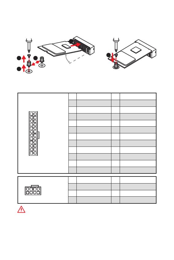
13
Overview of Components Overview of Components
ATX_PWR1, CPU_PWR1: Power Connectors
These connectors allow you to connect an ATX power supply.
Important
Make sure that all the power cables are securely connected to a proper ATX power
supply to ensure stable operation of the motherboard.
M2_1: M.2 Slot (Key M)
Please install the M.2 solid-state drive (SSD) into the M.2 slot as shown below.
1
2
3
4
5
30
24
131
12
ATX_PWR1
1 +3.3V 13 +3.3V
2 +3.3V 14 -12V
3 Ground 15 Ground
4 +5V 16 PS-ON#
5 Ground 17 Ground
6 +5V 18 Ground
7 Ground 19 Ground
8 PWR OK 20 Res
9 5VSB 21 +5V
10 +12V 22 +5V
11 +12V 23 +5V
12 +3.3V 24 Ground
5
4
1
8
CPU_PWR1
1 Ground 5 +12V
2 Ground 6 +12V
3 Ground 7 +12V
4 Ground 8 +12V
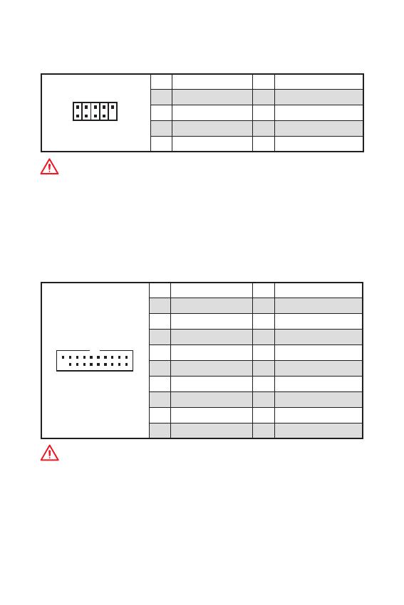
14
Overview of Components
JUSB3: USB 3.2 Gen1 Connector
This connector allows you to connect USB 3.2 Gen1 ports on the front panel.
1 10
1120
1 Power 11 USB2.0+
2 USB3_RX_DN 12 USB2.0-
3 USB3_RX_DP 13 Ground
4 Ground 14 USB3_TX_C_DP
5 USB3_TX_C_DN 15 USB3_TX_C_DN
6 USB3_TX_C_DP 16 Ground
7 Ground 17 USB3_RX_DP
8 USB2.0- 18 USB3_RX_DN
9 USB2.0+ 19 Power
10 NC 20 No Pin
Important
Note that the Power and Ground pins must be connected correctly to avoid possible
damage.
JUSB1~2: USB 2.0 Connectors
These connectors allow you to connect USB 2.0 ports on the front panel.
Important
y
Note that the VCC and Ground pins must be connected correctly to avoid possible
damage.
y
In order to recharge your iPad,iPhone and iPod through USB ports, please install
MSI
®
SUPER CHARGER utility.
1
2 10
9
1 VCC 2 VCC
3 USB0- 4 USB1-
5 USB0+ 6 USB1+
7 Ground 8 Ground
9 No Pin 10 NC
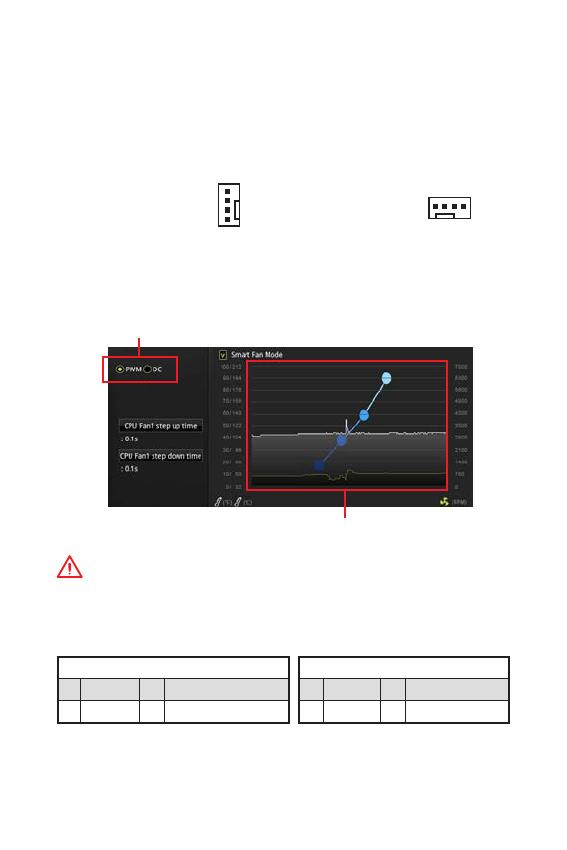
15
Overview of Components Overview of Components
CPU_FAN1, SYS_FAN1~2: Fan Connectors
Fan connectors can be classified as PWM (Pulse Width Modulation) Mode or DC
Mode. PWM Mode fan connectors provide constant 12V output and adjust fan speed
with speed control signal. DC Mode fan connectors control fan speed by changing
voltage. When you plug a 3-pin (Non-PWM) fan to a fan connector in PWM mode, the
fan speed will always maintain at 100%, which might create a lot of noise. You can
follow the instruction below to adjust the fan connector to PWM or DC Mode.
Switching fan mode and adjusting fan speed
You can switch between PWM mode and DC mode and adjust fan speed in BIOS >
HARDWARE MONITOR.
Select PWM mode or DC mode
Important
Make sure fans are working properly after switching the PWM/ DC mode.
There are gradient points of the fan speed that allow you to
adjust fan speed in relation to CPU temperature.
Default PWM Mode
fan connector
Default DC Mode fan
connector
1
CPU_FAN1
1
SYS_FAN1/ 2
PWM Mode pin definition
1 Ground 2 +12V
3 Sense 4 Speed Control Signal
DC Mode pin definition
1 Ground 2 Voltage Control
3 Sense 4 NC
Pin definition of fan connectors

16
Overview of Components
JTPM1: TPM Module Connector
This connector is for TPM (Trusted Platform Module). Please refer to the TPM
security platform manual for more details and usages.
1
2 14
13
1 LPC Clock 2 3V Standby power
3 LPC Reset 4 3.3V Power
5 LPC address & data pin0 6 Serial IRQ
7 LPC address & data pin1 8 5V Power
9 LPC address & data pin2 10 No Pin
11 LPC address & data pin3 12 Ground
13 LPC Frame 14 Ground
JCI1: Chassis Intrusion Connector
This connector allows you to connect the chassis intrusion switch cable.
Normal
(default)
Trigger the chassis
intrusion event
Using chassis intrusion detector
1. Connect the JCI1 connector to the chassis intrusion switch/ sensor on the chassis.
2. Close the chassis cover.
3. Go to BIOS > SETTINGS > Security > Chassis Intrusion Configuration.
4. Set Chassis Intrusion to Enabled.
5. Press F10 to save and exit and then press the Enter key to select Yes.
6. Once the chassis cover is opened again, a warning message will be displayed on
screen when the computer is turned on.
Resetting the chassis intrusion warning
1. Go to BIOS > SETTINGS > Security > Chassis Intrusion Configuration.
2. Set Chassis Intrusion to Reset.
3. Press F10 to save and exit and then press the Enter key to select Yes.
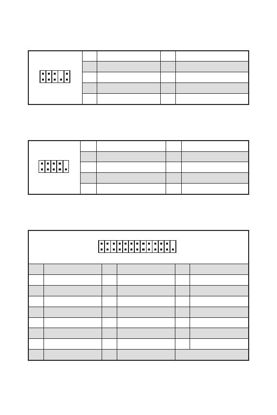
17
Overview of Components Overview of Components
JAUD1: Front Audio Connector
This connector allow you to connect audio jacks on the front panel.
1
2 10
9
1 MIC L 2 Ground
3 MIC R 4 NC
5 Head Phone R 6 MIC Detection
7 SENSE_SEND 8 No Pin
9 Head Phone L 10 Head Phone Detection
JCOM1: Serial Port Connector
This connector allows you to connect the optional serial port with bracket.
1
2 10
9
1 DCD 2 SIN
3 SOUT 4 DTR
5 Ground 6 DSR
7 RTS 8 CTS
9 RI 10 No Pin
1
2 26
25
1 RSTB# 2 AFD# 3 PRND0
4 ERR# 5 PRND1 6 PINIT#
7 PRND2 8 LPT_SLIN# 9 PRND3
10 Ground 11 PRND4 12 Ground
13 PRND5 14 Ground 15 PRND6
16 Ground 17 PRND7 18 Ground
19 ACK# 20 Ground 21 BUSY
22 Ground 23 PE 24 Ground
25 SLCT 26 No Pin
JLPT1: Parallel Port Connector
This connector allows you to connect the optional parallel port with bracket.

12
SATA1~4: SATA 6Gb/s
SATA 6Gb/s . SATA
.
SATA3
SATA4
SATA2
SATA1
y
SATA 90 . , .
y
SATA
.
JFP1, JFP2:
LED .
1
2 10
9
+
+
+—
——
—
+
LED
HDD LED
Reserved
JFP1
1 HDD LED + 2 Power LED +
3 HDD LED — 4 Power LED —
5 Reset Switch 6 Power Switch
7 Reset Switch 8 Power Switch
9 Reserved 10 No Pin
JFP2
1
+
+
—
—
Speaker
Buzzer
1 Speaker — 2 Buzzer +
3 Buzzer — 4 Speaker +
HDD LED
RESET SW
HDD LED
HDD LED —
HDD LED +
POWER LED —
POWER LED +
POWER LED
JFP1

13
ATX_PWR1, CPU_PWR1:
ATX .
ATX
.
M2_1: M.2 (Key M)
M.2 (SSD) M.2 .
1
2
3
4
5
30
24
131
12
ATX_PWR1
1 +3.3V 13 +3.3V
2 +3.3V 14 -12V
3 Ground 15 Ground
4 +5V 16 PS-ON#
5 Ground 17 Ground
6 +5V 18 Ground
7 Ground 19 Ground
8 PWR OK 20 Res
9 5VSB 21 +5V
10 +12V 22 +5V
11 +12V 23 +5V
12 +3.3V 24 Ground
5
4
1
8
CPU_PWR1
1 Ground 5 +12V
2 Ground 6 +12V
3 Ground 7 +12V
4 Ground 8 +12V

14
JUSB3: USB 3.2 Gen1
USB 3.2 Gen1 .
1 10
1120
1 Power 11 USB2.0+
2 USB3_RX_DN 12 USB2.0-
3 USB3_RX_DP 13 Ground
4 Ground 14 USB3_TX_C_DP
5 USB3_TX_C_DN 15 USB3_TX_C_DN
6 USB3_TX_C_DP 16 Ground
7 Ground 17 USB3_RX_DP
8 USB2.0- 18 USB3_RX_DN
9 USB2.0+ 19 Power
10 NC 20 No Pin
.
JUSB1~2: USB 2.0
USB 2.0 .
y
VCC .
y
USB iPad,iPhone iPod MSI
®
SUPER CHARGER
.
1
2 10
9
1 VCC 2 VCC
3 USB0- 4 USB1-
5 USB0+ 6 USB1+
7 Ground 8 Ground
9 No Pin 10 NC
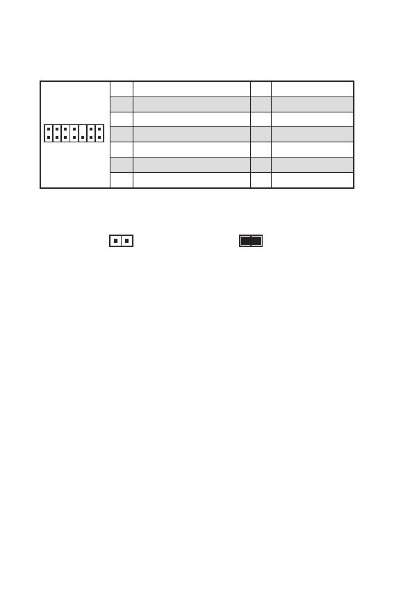
16
JTPM1: TPM
TPM (Trusted Platform Module) .
TPM .
1
2 14
13
1 LPC Clock 2 3V Standby power
3 LPC Reset 4 3.3V Power
5 LPC address & data pin0 6 Serial IRQ
7 LPC address & data pin1 8 5V Power
9 LPC address & data pin2 10 No Pin
11 LPC address & data pin3 12 Ground
13 LPC Frame 14 Ground
JCI1:
.
( )
1. JCI1 / .
2. .
3. BIOS > SETTINGS () > Security() > Chassis Intrusion Configuration(
) .
4. Chassis Intrusion( ) Enabled() .
5. F10 . Enter Yes .
6. .
1. BIOS > SETTINGS () > Security() > Chassis Intrusion Configuration(
) .
2. Chassis Intrusion( ) Reset() .
3. F10 . Enter Yes .

17
JAUD1:
.
1
2 10
9
1 MIC L 2 Ground
3 MIC R 4 NC
5 Head Phone R 6 MIC Detection
7 SENSE_SEND 8 No Pin
9 Head Phone L 10 Head Phone Detection
JCOM1:
.
1
2 10
9
1 DCD 2 SIN
3 SOUT 4 DTR
5 Ground 6 DSR
7 RTS 8 CTS
9 RI 10 No Pin
1
2 26
25
1 RSTB# 2 AFD# 3 PRND0
4 ERR# 5 PRND1 6 PINIT#
7 PRND2 8 LPT_SLIN# 9 PRND3
10 Ground 11 PRND4 12 Ground
13 PRND5 14 Ground 15 PRND6
16 Ground 17 PRND7 18 Ground
19 ACK# 20 Ground 21 BUSY
22 Ground 23 PE 24 Ground
25 SLCT 26 No Pin
JLPT1:
.

4
Spécifications
Suite du tableau de la page précédente
Stockage
Chipset AMD
®
B450
y 4 x ports SATA 6Gb/s
Support des architectures RAID 0, RAID1 et RAID 10
y 1 x slot M.2 (Touche M)
Support PCIe 3.0 x 4 (AMD Ryzen™ de 1ère, 2ème
et 3ème génération/ Ryzen™ avec cœurs graphiques
Radeon™ Vega/ AMD Ryzen™ avec cœurs graphiques
Radeon™ de 2ème génération) ou PCIe 3.0 x2 (Athlon™
avec cœurs graphiques Radeon™ Vega ) et SATA 6Gb/s
Support des périphériques de stockage 2242/ 2260/
2280 Support PCIe 3.0 x4 et des périphériques de
stockage SATA 6 Gb/s 2242/ 2260/ 2280
USB
Chipset AMD
®
B450
y 2 x ports USB 3.2 Gen1 (SuperSpeed USB) par
lintermédiaire du connecteur USB 3.2 Gen1 interne
y 8 x ports USB 2.0 (High-speed USB) (4 ports sur le
panneau arrière, 4 ports disponibles par lintermédiaire des
connecteurs USB internes)
y Processeur AMD
®
y 4 x ports USB 3.2 Gen1 (SuperSpeed USB) Type-A sur le
panneau arrière
Contrôleur E/S Contrôleur NUVOTON 6795D
Moniteur
système
y Détection de la température du CPU et du système
y Détection de la vitesse du ventilateur du CPU et du système
y Contrôle de la vitesse du ventilateur du CPU et du système
Dimensions
y Format m-ATX
y 24,4 cm x 24,4 cm (9,6 x 9,6)
Fonctions BIOS
y 1 x flash 256 Mb
y UEFI AMI BIOS
y ACPI 6.1, SM BIOS 2.8
y Multilingue
Connecteurs
sur le panneau
arrière
y 1 x port clavier/ souris PS/2
y 4 x ports USB 2.0 Type-A
y 1 x port VGA
y 1 x port DVI-D
y 1 x port HDMI™
y 4 x ports USB 3.2 Gen1 Type-A
y 1 x port LAN (RJ45)
y 3 x jacks audio
Suite du tableau sur la page suivante
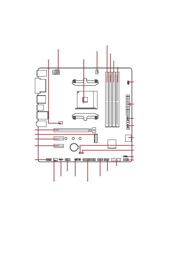
7
Panneau arrière Entrée/ Sortie Vue densemble des composants
CPU_FAN1
Socket
processeur
SYS_FAN1
PCI_E3
JAUD1
PCI_E2
M2_1
PCI_E1
DIMMA1
DIMMA2
DIMMB1
DIMMB2
JBAT1
JCI1
JFP2
JFP1
JUSB3
ATX_PWR1
CPU_PWR1
EZ Debug LED
SATA2
SATA1
JTPM1
JUSB1
JLPT1
JRGB1
JUSB2
JCOM1
SYS_FAN2
SATA34
Vue densemble des composants
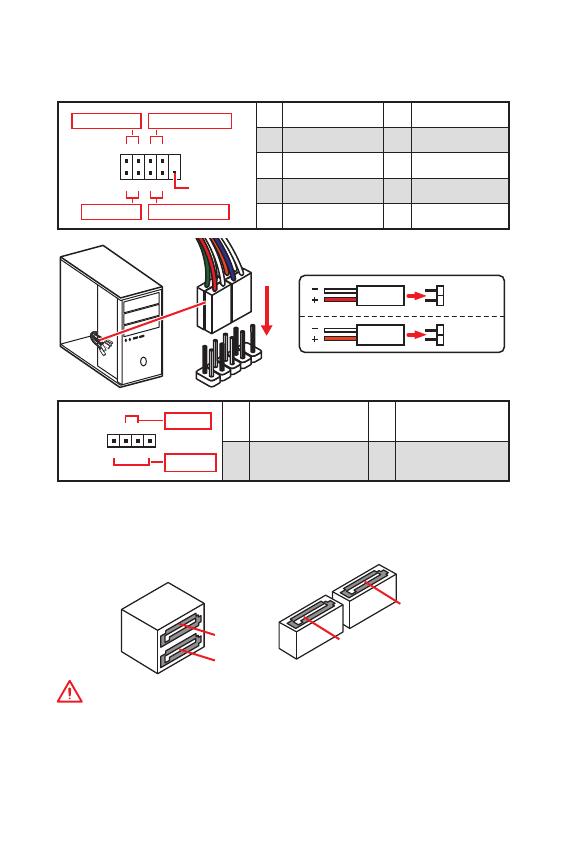
11
Vue densemble des composants Vue densemble des composants
SATA1~4 : Connecteurs SATA 6 Gb/s
Ces connecteurs utilisent une interface SATA 6 Gb/s. Chaque connecteur peut être
relié à un appareil SATA.
SATA3
SATA4
SATA2
SATA1
Important
y
Veuillez ne pas plier le câble SATA à 90 car cela pourrait entraîner une perte de
données pendant la transmission.
y
Le câble SATA dispose de prises identiques sur chaque côté. Néanmoins, il est
recommandé de connecter la prise plate sur la carte mère pour un gain despace.
JFP1, JFP2 : Connecteurs de panneau avant
Ces connecteurs se lient aux interrupteurs et indicateurs LED du panneau avant.
1
2 10
9
+
+
+—
——
—
+
Power LED
HDD LED Reset Switch
Reserved
Power Switch
JFP1
1 HDD LED + 2 Power LED +
3 HDD LED — 4 Power LED —
5 Reset Switch 6 Power Switch
7 Reset Switch 8 Power Switch
9 Reserved 10 No Pin
JFP2
1
+
+
—
—
Speaker
Buzzer
1 Speaker — 2 Buzzer +
3 Buzzer — 4 Speaker +
HDD LED
RESET SW
HDD LED
HDD LED —
HDD LED +
POWER LED —
POWER LED +
POWER LED
JFP1

12
Vue densemble des composants
ATX_PWR1, CPU_PWR1 : Connecteurs dalimentation
Ces connecteurs vous permettent de relier une alimentation ATX.
Important
Veuillez vous assurer que tous les câbles dalimentation sont branchés aux
connecteurs adéquats afin garantir une opération stable de la carte mère.
M2_1 : Slot M.2 (Touche M)
Installer le disque dur M.2 dans le slot M.2 comme indiqué ci-dessous.
1
2
3
4
5
30
24
131
12
ATX_PWR1
1 +3.3V 13 +3.3V
2 +3.3V 14 -12V
3 Ground 15 Ground
4 +5V 16 PS-ON#
5 Ground 17 Ground
6 +5V 18 Ground
7 Ground 19 Ground
8 PWR OK 20 Res
9 5VSB 21 +5V
10 +12V 22 +5V
11 +12V 23 +5V
12 +3.3V 24 Ground
5
4
1
8
CPU_PWR1
1 Ground 5 +12V
2 Ground 6 +12V
3 Ground 7 +12V
4 Ground 8 +12V
Loading…
![]()
Thank you for purchasing the MSI® B450M PRO-VDH MAX motherboard. This User Guide gives information about board layout, component overview, BIOS setup and software installation.
|
Contents |
|
|
Safety Information………………………………………………………………………………. |
2 |
|
Specifications……………………………………………………………………………………… |
3 |
|
Package contents ……………………………………………………………………………….. |
6 |
|
Rear I/O Panel ……………………………………………………………………………………. |
7 |
|
LAN Port LED Status Table……………………………………………………………………… |
7 |
|
Overview of Components …………………………………………………………………….. |
8 |
|
CPU Socket …………………………………………………………………………………………… |
9 |
|
DIMM Slots………………………………………………………………………………………….. |
10 |
|
PCI_E1~3: PCIe Expansion Slots ……………………………………………………………. |
11 |
|
JFP1, JFP2: Front Panel Connectors ……………………………………………………… |
12 |
|
SATA1~4: SATA 6Gb/s Connectors………………………………………………………….. |
12 |
|
M2_1: M.2 Slot (Key M) …………………………………………………………………………. |
13 |
|
ATX_PWR1, CPU_PWR1: Power Connectors……………………………………………. |
13 |
|
JUSB1~2: USB 2.0 Connectors………………………………………………………………. |
14 |
|
JUSB3: USB 3.2 Gen1 Connector …………………………………………………………… |
14 |
|
CPU_FAN1, SYS_FAN1~2: Fan Connectors……………………………………………… |
15 |
|
JTPM1: TPM Module Connector …………………………………………………………….. |
16 |
|
JCI1: Chassis Intrusion Connector…………………………………………………………. |
16 |
|
JAUD1: Front Audio Connector………………………………………………………………. |
17 |
|
JCOM1: Serial Port Connector ………………………………………………………………. |
17 |
|
JLPT1: Parallel Port Connector……………………………………………………………… |
17 |
|
JBAT1: Clear CMOS (Reset BIOS) Jumper ………………………………………………. |
18 |
|
EZ Debug LED: Debug LED indicators…………………………………………………….. |
18 |
|
JRGB1: RGB LED strip connector…………………………………………………………… |
18 |
|
BIOS Setup……………………………………………………………………………………….. |
19 |
|
Entering BIOS Setup …………………………………………………………………………….. |
19 |
|
Resetting BIOS…………………………………………………………………………………….. |
20 |
|
Updating BIOS……………………………………………………………………………………… |
20 |
|
Software Description…………………………………………………………………………. |
21 |
|
Installing Windows® 10 …………………………………………………………………………. |
21 |
|
Installing Drivers …………………………………………………………………………………. |
21 |
|
Installing Utilities…………………………………………………………………………………. |
22 |
Contents 1
Safety Information
yThe components included in this package are prone to damage from electrostatic discharge (ESD). Please adhere to the following instructions to ensure successful computer assembly.
yEnsure that all components are securely connected. Loose connections may cause the computer to not recognize a component or fail to start.
yHold the motherboard by the edges to avoid touching sensitive components.
yIt is recommended to wear an electrostatic discharge (ESD) wrist strap when handling the motherboard to prevent electrostatic damage. If an ESD wrist strap is not available, discharge yourself of static electricity by touching another metal object before handling the motherboard.
yStore the motherboard in an electrostatic shielding container or on an anti-static pad whenever the motherboard is not installed.
yBefore turning on the computer, ensure that there are no loose screws or metal components on the motherboard or anywhere within the computer case.
yDo not boot the computer before installation is completed. This could cause permanent damage to the components as well as injury to the user.
yIf you need help during any installation step, please consult a certified computer technician.
yAlways turn off the power supply and unplug the power cord from the power outlet before installing or removing any computer component.
yKeep this user guide for future reference.
yKeep this motherboard away from humidity.
yMake sure that your electrical outlet provides the same voltage as is indicated on the PSU, before connecting the PSU to the electrical outlet.
yPlace the power cord such a way that people can not step on it. Do not place anything over the power cord.
yAll cautions and warnings on the motherboard should be noted.
yIf any of the following situations arises, get the motherboard checked by service personnel:
Liquid has penetrated into the computer.
The motherboard has been exposed to moisture.
The motherboard does not work well or you can not get it work according to user guide.
The motherboard has been dropped and damaged.
The motherboard has obvious sign of breakage.
yDo not leave this motherboard in an environment above 60°C (140°F), it may damage the motherboard.
2 Safety Information
Specifications
|
Supports 1st, 2nd and 3rd Gen AMD Ryzen™/ Ryzen™ with |
||
|
CPU |
Radeon™ Vega Graphics and 2nd Gen AMD Ryzen™ with |
|
|
Radeon™ Graphics/ Athlon™ with Radeon™ Vega Graphics |
||
|
Desktop Processors for Socket AM4 |
||
|
Chipset |
AMD® B450 chipset |
|
|
y 4x DDR4 memory slots, support up to 64GB* |
||
|
Supports 1866/ 2133/ 2400/ 2667Mhz (by JEDEC) |
||
|
Supports 2667/ 2800/ 2933/ 3000/ 3066/ 3200/ 3466 MHz |
||
|
(by A-XMP OC MODE) |
||
|
Memory |
y Dual channel memory architecture |
|
|
y Supports ECC UDIMM memory (non-ECC mode) |
||
|
y Support non-ECC UDIMM memory |
||
|
* Please refer www.msi.com for more information on |
||
|
compatible memory. |
y1x PCIe 3.0 x16 slot
1st, 2nd and 3rd Gen AMD Ryzen™ support x16 mode
|
Expansion Slots |
Ryzen™ with Radeon™ Vega Graphics and 2nd Gen AMD |
|
|
Ryzen™ with Radeon™ Graphics support x8 mode |
||
|
Athlon™ with Radeon™ Vega Graphics support x4 mode |
y2x PCIe 2.0 x1 slots
y1x VGA port, supports a maximum resolution of 2048×1280@60Hz, 1920×1200@60Hz*
y1x DVI-D port, supports a maximum resolution of 1920×1200@60Hz*
|
Onboard |
y 1x HDMI™ 1.4 port, supports a maximum resolution of |
|
Graphics |
4096×2160 @30Hz, 2560×1600 @60Hz* |
|
* Only support when using Ryzen™ with Radeon™ Vega |
|
|
Graphics, 2nd Gen AMD Ryzen™ with Radeon™ Graphics and |
|
|
Athlon™ with Radeon™ Vega Graphics processors |
|
|
* Maximum shared memory of 2048 MB |
|
|
AMD® B450 Chipset |
|
|
y 4x SATA 6Gb/s ports |
|
|
Supports RAID 0, RAID1 and RAID 10 |
|
|
Storage |
y 1x M.2 slot (Key M) |
|
Supports PCIe 3.0 x4 (1st, 2nd and 3rd Gen AMD |
|
|
Ryzen™/ Ryzen™ with Radeon™ Vega Graphics and 2nd |
|
|
Gen AMD Ryzen™ with Radeon™ Graphics) or PCIe 3.0 x2 |
|
|
(Athlon™ with Radeon™ Vega Graphics) and SATA 6Gb/s |
|
|
Supports 2242/ 2260 /2280 storage devices |
|
|
Continued on next page |
Specifications 3
|
Continued from previous page |
||
|
Audio |
Realtek® ALC892 Codec |
|
|
y 7.1-Channel High Definition Audio |
||
|
LAN |
1x Realtek® 8111H Gigabit LAN controller |
|
|
AMD® B450 Chipset |
||
|
y 2x USB 3.2 Gen1 (SuperSpeed USB) ports through the |
||
|
internal USB 3.2 Gen1 connector |
||
|
USB |
y 8x USB 2.0 (High-speed USB) ports (4 ports on the back |
|
|
panel, 4 ports available through the internal USB connectors) |
||
|
y AMD® processor |
||
|
y 4x USB 3.2 Gen1 (SuperSpeed USB) Type-A ports on the |
||
|
back panel |
||
|
I/O Controller |
NUVOTON 6795D Controller Chip |
|
|
Hardware |
y CPU/System temperature detection |
|
|
y CPU/System fan speed detection |
||
|
Monitor |
||
|
y CPU/System fan speed control |
||
|
Form Factor |
y m-ATX Form Factor |
|
|
y 9.6 in. x 9.6 in. (24.4 cm x 24.4 cm) |
||
|
y 1x 256 Mb flash |
||
|
BIOS Features |
y UEFI AMI BIOS |
|
|
y ACPI 6.1, SM BIOS 2.8 |
||
|
y Multi-language |
||
|
y 1x PS/2 keyboard/ mouse combo port |
||
|
y 4x USB 2.0 Type-A ports |
||
|
y 1x VGA port |
||
|
Back Panel |
y 1x DVI-D port |
|
|
Connectors |
y 1x HDMI™ port |
|
|
y 4x USB 3.2 Gen1 Type-A ports |
||
|
y 1x LAN (RJ45) port |
||
|
y 3x audio jacks |
||
|
y 1x 24-pin ATX main power connector |
||
|
Internal |
y 1x 8-pin ATX 12V power connector |
|
|
y 4x SATA 6Gb/s connectors |
||
|
Connectors |
y 2x USB 2.0 connectors (supports additional 4 USB 2.0 ports) |
|
|
y 1x USB 3.2 Gen1 connector (supports additional 2 USB 3.2 |
||
|
Gen1 ports) |
||
|
Continued on next page |
4 Specifications
|
Continued from previous page |
||
|
y 1x 4-pin CPU fan connector |
||
|
y 2x 4-pin system fan connectors |
||
|
y 1x Front panel audio connector |
||
|
y 2x Front panel connectors |
||
|
Internal |
y 1x TPM module connector |
|
|
Connectors |
y 1x Chassis Intrusion connector |
|
|
y 1x Serial port connector |
||
|
y 1x Parallel port connector |
||
|
y 1x RGB LED strip connector |
||
|
y 1x Clear CMOS jumper |
||
|
y Drivers |
||
|
y APP MANAGER |
||
|
y SUPER CHARGER |
||
|
y COMMAND CENTER |
||
|
y LIVE UPDATE 6 |
||
|
Software |
y MYSTIC LIGHT |
|
|
y SMART TOOL |
||
|
y X-BOOST |
||
|
y RAMDISK |
||
|
y Norton™ Security |
||
|
y Google Chrome™,Google Toolbar, Google Drive |
||
|
y CPU-Z MSI GAMING |
||
Specifications 5
Package contents
Please check the contents of your motherboard package. It should contain:
yMotherboard
yDriver DVD
yQuick Installation Guide
yI/O Shielding
ySATA 6G Cable x2
yCase Badge
yProduct registration card
yM.2 Screw x1
Important
If any of the above items are damaged or missing, please contact your retailer.
6 Package contents
Rear I/O Panel
|
Line-out |
Line-in |
||||||||||||||||||||||||||||||||
|
PS/2 |
VGA |
USB 2.0 |
|||||||||||||||||||||||||||||||
|
LAN |
|||||||||||||||||||||||||||||||||
|
USB 2.0 |
DVI-D |
USB 3.2 Gen1 |
Mic in |
LAN Port LED Status Table
Link/ Activity LED
|
Status |
Description |
|
Off |
No link |
|
Yellow |
Linked |
|
Blinking |
Data activity |
Speed LED
|
Status |
Description |
|
Off |
10 Mbps connection |
|
Green |
100 Mbps connection |
|
Orange |
1 Gbps connection |
Audio 7.1-channel Configuration
To configure 7.1-channel audio, you have to connect front audio I/O module to JAUD1 connector and follow the below steps.
1.Click on the Realtek HD Audio Manager > Advanced Settings to open the dialog below.
2.Select Mute the rear output device, when a front headphone plugged in.
3.Plug your speakers to audio jacks on rear and front I/O panel. When you plug into a device at an audio jack, a dialogue window will pop up asking you which device is current connected.
Rear I/O Panel 7
Overview of Components
PCI_E1
M2_1
PCI_E2
PCI_E3
JAUD1
|
CPU_PWR1 |
DIMMA1 |
|||||||||||||||
|
CPU_FAN1 |
||||||||||||||||
|
DIMMA2 |
||||||||||||||||
|
SYS_FAN1 |
CPU Socket |
DIMMB1 |
||||||||||||||
|
DIMMB2 |
||||||||||||||||
EZ Debug LED
ATX_PWR1
SATA1
SATA2
SATA▼3▲4
JBAT1
JCI1
JFP2
JFP1
JUSB3
|
JCOM1 |
JUSB2 |
|
|
JRGB1 |
JTPM1 |
JUSB1 |
|
SYS_FAN2 |
JLPT1 |
8 Overview of Components
CPU Socket
Please install the CPU into the CPU socket as shown below.
2
3
Important
yWhen changing the processor, the system configuration could be cleared and reset BIOS to default values due to the AM4 processor’s architecture.
yAlways unplug the power cord from the power outlet before installing or removing the CPU.
yWhen installing a CPU, always remember to install a CPU heatsink. A CPU heatsink is necessary to prevent overheating and maintain system stability.
yConfirm that the CPU heatsink has formed a tight seal with the CPU before booting your system.
yOverheating can seriously damage the CPU and motherboard. Always make sure the cooling fans work properly to protect the CPU from overheating. Be sure to apply an even layer of thermal paste (or thermal tape) between the CPU and the heatsink to enhance heat dissipation.
yIf you purchased a separate CPU and heatsink/ cooler, Please refer to the documentation in the heatsink/ cooler package for more details about installation.
Overview of Components 9
DIMM Slots
Please install the memory module into the DIMM slot as shown below.
2
Memory module installation recommendation
DIMMB2
|
DIMMA2 |
DIMMA2 |
|||
DIMMB2
DIMMB1
DIMMA2
DIMMA1
10 Overview of Components
![]()
Important
yAlways insert memory modules in the DIMMA2 slot first.
yDue to chipset resource usage, the available capacity of memory will be a little less than the amount of installed.
yBased on processor specification, the Memory DIMM voltage below 1.35V is suggested to protect the processor.
yDue to AM4 CPU/memory controller official specification limitation, the frequency of memory modules may operate lower than the marked value under the default state. Please refer www.msi.com for more information on compatible memory.
PCI_E1~3: PCIe Expansion Slots
|
Processors |
Ryzen™ with Radeon™ |
Athlon™ with |
||
|
1st, 2nd and |
||||
|
Vega Graphics and 2nd |
Radeon™ Vega |
|||
|
3rd Gen AMD |
||||
|
Gen AMD Ryzen™ with |
||||
|
Ryzen™ |
Graphics |
|||
|
Radeon™ Graphics |
||||
|
Slots |
||||
|
PCI_E1 |
PCIe 3.0 x16 |
PCIe 3.0 x8 |
PCIe 3.0 x4 |
|
|
PCI_E2 |
PCIe 2.0 x1 |
PCIe 2.0 x1 |
PCIe 2.0 x1 |
|
|
PCI_E3 |
PCIe 2.0 x1 |
PCIe 2.0 x1 |
PCIe 2.0 x1 |
Important
yWhen adding or removing expansion cards, always turn off the power supply and unplug the power supply power cable from the power outlet. Read the expansion card’s documentation to check for any necessary additional hardware or software changes.
yIf you install a large and heavy graphics card, you need to use a tool such as MSI Gaming Series Graphics Card Bolster to support its weight to prevent deformation of the slot.
Overview of Components 11
JFP1, JFP2: Front Panel Connectors
These connectors connect to the switches and LEDs on the front panel.
|
Power LED |
Power Switch |
1 |
HDD LED + |
2 |
Power LED + |
|
|
+ — + — |
3 |
HDD LED — |
4 |
Power LED — |
||
|
2 |
10 |
5 |
Reset Switch |
6 |
Power Switch |
|
|
1 |
9 |
|||||
|
7 |
Reset Switch |
8 |
Power Switch |
|||
|
+ — — + |
Reserved |
|||||
|
HDD LED |
Reset Switch |
9 |
Reserved |
10 |
No Pin |
|
|
HDDLED |
RESETSW |
||
|
JFP1 |
|||
|
+ — |
Buzzer |
1 |
|
|
JFP2 1 |
+ |
||
|
— |
Speaker |
3 |
|
|
HDD LED |
HDD LED — |
||||||
|
HDD LED + |
|||||||
|
POWER LED — |
|||||||
|
POWER LED |
POWER LED + |
||||||
|
Speaker — |
2 |
Buzzer + |
|
Buzzer — |
4 |
Speaker + |
SATA1~4: SATA 6Gb/s Connectors
These connectors are SATA 6Gb/s interface ports. Each connector can connect to one SATA device.
SATA1
SATA4
SATA2
SATA3
Important
yPlease do not fold the SATA cable at a 90-degree angle. Data loss may result during transmission otherwise.
ySATA cables have identical plugs on either sides of the cable. However, it is recommended that the flat connector be connected to the motherboard for space saving purposes.
12 Overview of Components
M2_1: M.2 Slot (Key M)
Please install the M.2 solid-state drive (SSD) into the M.2 slot as shown below.
|
4 |
|||
|
1 |
3 |
5 |
|
|
30° |
|||
|
2 |
ATX_PWR1, CPU_PWR1: Power Connectors
These connectors allow you to connect an ATX power supply.
|
1 |
+3.3V |
13 |
+3.3V |
|||||
|
2 |
+3.3V |
14 |
-12V |
|||||
|
12 |
24 |
3 |
Ground |
15 |
Ground |
|||
|
4 |
+5V |
16 |
PS-ON# |
|||||
|
5 |
Ground |
17 |
Ground |
|||||
|
ATX_PWR1 |
6 |
+5V |
18 |
Ground |
||||
|
7 |
Ground |
19 |
Ground |
|||||
|
8 |
PWR OK |
20 |
Res |
|||||
|
1 |
13 |
9 |
5VSB |
21 |
+5V |
|||
|
10 |
+12V |
22 |
+5V |
|||||
|
11 |
+12V |
23 |
+5V |
|||||
|
12 |
+3.3V |
24 |
Ground |
|
8 |
5 |
1 |
Ground |
5 |
+12V |
|
|
CPU_PWR1 |
2 |
Ground |
6 |
+12V |
||
|
3 |
Ground |
7 |
+12V |
|||
|
4 |
1 |
|||||
|
4 |
Ground |
8 |
+12V |
|||
Important
Make sure that all the power cables are securely connected to a proper ATX power supply to ensure stable operation of the motherboard.
Overview of Components 13
JUSB1~2: USB 2.0 Connectors
These connectors allow you to connect USB 2.0 ports on the front panel.
|
1 |
VCC |
2 |
VCC |
|||||||
|
2 |
10 |
3 |
USB0- |
4 |
USB1- |
|||||
|
5 |
USB0+ |
6 |
USB1+ |
|||||||
|
1 |
9 |
7 |
Ground |
8 |
Ground |
|||||
|
9 |
No Pin |
10 |
NC |
Important
yNote that the VCC and Ground pins must be connected correctly to avoid possible damage.
yIn order to recharge your iPad,iPhone and iPod through USB ports, please install MSI® SUPER CHARGER utility.
JUSB3: USB 3.2 Gen1 Connector
This connector allows you to connect USB 3.2 Gen1 ports on the front panel.
|
1 |
Power |
11 |
USB2.0+ |
|||
|
2 |
USB3_RX_DN |
12 |
USB2.0- |
|||
|
3 |
USB3_RX_DP |
13 |
Ground |
|||
|
10 |
4 |
Ground |
14 |
USB3_TX_C_DP |
||
|
5 |
USB3_TX_C_DN |
15 |
USB3_TX_C_DN |
|||
|
11 |
6 |
USB3_TX_C_DP |
16 |
Ground |
||
|
7 |
Ground |
17 |
USB3_RX_DP |
|||
|
8 |
USB2.0- |
18 |
USB3_RX_DN |
|||
|
9 |
USB2.0+ |
19 |
Power |
|||
|
10 |
NC |
20 |
No Pin |
|||
Important
Note that the Power and Ground pins must be connected correctly to avoid possible damage.
14 Overview of Components
CPU_FAN1, SYS_FAN1~2: Fan Connectors
Fan connectors can be classified as PWM (Pulse Width Modulation) Mode or DC Mode. PWM Mode fan connectors provide constant 12V output and adjust fan speed with speed control signal. DC Mode fan connectors control fan speed by changing voltage. When you plug a 3-pin (Non-PWM) fan to a fan connector in PWM mode, the fan speed will always maintain at 100%, which might create a lot of noise. You can follow the instruction below to adjust the fan connector to PWM or DC Mode.
|
Default PWM Mode |
Default DC Mode fan |
1 |
||||||||
|
fan connector |
1 |
connector |
||||||||
|
SYS_FAN1/ 2 |
||||||||||
|
CPU_FAN1 |
||||||||||
Switching fan mode and adjusting fan speed
You can switch between PWM mode and DC mode and adjust fan speed in BIOS > HARDWARE MONITOR.
Select PWM mode or DC mode
There are gradient points of the fan speed that allow you to adjust fan speed in relation to CPU temperature.
Important
Make sure fans are working properly after switching the PWM/ DC mode.
Pin definition of fan connectors
PWM Mode pin definition
|
1 |
Ground |
2 |
+12V |
|
3 |
Sense |
4 |
Speed Control Signal |
DC Mode pin definition
|
1 |
Ground |
2 |
Voltage Control |
|
3 |
Sense |
4 |
NC |
Overview of Components 15
JTPM1: TPM Module Connector
This connector is for TPM (Trusted Platform Module). Please refer to the TPM security platform manual for more details and usages.
|
1 |
LPC Clock |
2 |
3V Standby power |
|||||||||
|
3 |
LPC Reset |
4 |
3.3V Power |
|||||||||
|
2 |
14 |
5 |
LPC address & data pin0 |
6 |
Serial IRQ |
|||||||
|
7 |
LPC address & data pin1 |
8 |
5V Power |
|||||||||
|
1 |
13 |
9 |
LPC address & data pin2 |
10 |
No Pin |
|||||||
|
11 |
LPC address & data pin3 |
12 |
Ground |
|||||||||
|
13 |
LPC Frame |
14 |
Ground |
JCI1: Chassis Intrusion Connector
This connector allows you to connect the chassis intrusion switch cable.
|
Normal |
Trigger the chassis |
|||||
|
(default) |
intrusion event |
Using chassis intrusion detector
1.Connect the JCI1 connector to the chassis intrusion switch/ sensor on the chassis.
2.Close the chassis cover.
3.Go to BIOS > SETTINGS > Security > Chassis Intrusion Configuration.
4.Set Chassis Intrusion to Enabled.
5.Press F10 to save and exit and then press the Enter key to select Yes.
6.Once the chassis cover is opened again, a warning message will be displayed on screen when the computer is turned on.
Resetting the chassis intrusion warning
1.Go to BIOS > SETTINGS > Security > Chassis Intrusion Configuration.
2.Set Chassis Intrusion to Reset.
3.Press F10 to save and exit and then press the Enter key to select Yes.
16 Overview of Components
JAUD1: Front Audio Connector
This connector allow you to connect audio jacks on the front panel.
|
1 |
MIC L |
2 |
Ground |
|||||||
|
2 |
10 |
3 |
MIC R |
4 |
NC |
|||||
|
5 |
Head Phone R |
6 |
MIC Detection |
|||||||
|
1 |
9 |
7 |
SENSE_SEND |
8 |
No Pin |
|||||
|
9 |
Head Phone L |
10 |
Head Phone Detection |
JCOM1: Serial Port Connector
This connector allows you to connect the optional serial port with bracket.
|
1 |
DCD |
2 |
SIN |
|||||||
|
2 |
10 |
3 |
SOUT |
4 |
DTR |
|||||
|
5 |
Ground |
6 |
DSR |
|||||||
|
1 |
9 |
7 |
RTS |
8 |
CTS |
|||||
|
9 |
RI |
10 |
No Pin |
JLPT1: Parallel Port Connector
This connector allows you to connect the optional parallel port with bracket.
|
2 |
26 |
|||||||||||||||||
|
1 |
25 |
|||||||||||||||||
|
1 |
RSTB# |
2 |
AFD# |
3 |
PRND0 |
|||||||||||||
|
4 |
ERR# |
5 |
PRND1 |
6 |
PINIT# |
|||||||||||||
|
7 |
PRND2 |
8 |
LPT_SLIN# |
9 |
PRND3 |
|||||||||||||
|
10 |
Ground |
11 |
PRND4 |
12 |
Ground |
|||||||||||||
|
13 |
PRND5 |
14 |
Ground |
15 |
PRND6 |
|||||||||||||
|
16 |
Ground |
17 |
PRND7 |
18 |
Ground |
|||||||||||||
|
19 |
ACK# |
20 |
Ground |
21 |
BUSY |
|||||||||||||
|
22 |
Ground |
23 |
PE |
24 |
Ground |
|||||||||||||
|
25 |
SLCT |
26 |
No Pin |
Overview of Components 17
JBAT1: Clear CMOS (Reset BIOS) Jumper
There is CMOS memory onboard that is external powered from a battery located on the motherboard to save system configuration data. If you want to clear the system configuration, set the jumpers to clear the CMOS memory.
|
Keep Data |
Clear CMOS/ Reset |
|||||
|
(default) |
BIOS |
Resetting BIOS to default values
1.Power off the computer and unplug the power cord.
2.Use a jumper cap to short JBAT1 for about 5-10 seconds.
3.Remove the jumper cap from JBAT1.
4.Plug the power cord and power on the computer.
EZ Debug LED: Debug LED indicators
These LEDs indicate the status of the motherboard.
CPU — indicates CPU is not detected or fail.
DRAM — indicates DRAM is not detected or fail.
VGA — indicates GPU is not detected or fail.
BOOT — indicates booting device is not detected or fail.
JRGB1: RGB LED strip connector
This connector allows you to connect the 5050 RGB LED strip.
|
1 |
5050 LED strip |
|||
|
1 |
+12V |
2 |
G |
|
|
3 |
R |
4 |
B |
|
|
1 JRGB1 |
Extension cable (optional) |
Important
yThis connector supports 5050 RGB multi-color LED strips (12V/G/R/B) with the maximum power rating of 3A (12V). Please keeping the LED strip shorter than 2 meters to prevent dimming.
yAlways turn off the power supply and unplug the power cord from the power outlet before installing or removing the RGB LED strip.
yPlease use MSI’s software to control the extended LED strip.
18 Overview of Components
BIOS Setup
The default settings offer the optimal performance for system stability in normal conditions. You should always keep the default settings to avoid possible system damage or failure booting unless you are familiar with BIOS.
Important
yBIOS items are continuous update for better system performance. Therefore, the description may be slightly different from the latest BIOS and should be held for reference only. You could also refer to the HELP information panel for BIOS item description.
yThe pictures in this chapter are for reference only and may vary from the product you purchased.
yThe BIOS items will vary with the processor.
Entering BIOS Setup
Press Delete key, when the Press DEL key to enter Setup Menu, F11 to enter Boot Menu message appears on the screen during the boot process.
Function key
F1: General Help
F2: Add/ Remove a favorite item
F3: Enter Favorites menu
F4: Enter CPU Specifications menu
F5: Enter Memory-Z menu
F6: Load optimized defaults
F7: Switch between Advanced mode and EZ mode
F8: Load Overclocking Profile
F9: Save Overclocking Profile
F10: Save Change and Reset*
F12: Take a screenshot and save it to USB flash drive (FAT/ FAT32 format only).
* When you press F10, a confirmation window appears and it provides the modification information. Select between Yes or No to confirm your choice.
BIOS Setup 19
Resetting BIOS
You might need to restore the default BIOS setting to solve certain problems. There are several ways to reset BIOS:
yGo to BIOS and press F6 to load optimized defaults.
yShort the Clear CMOS jumper on the motherboard.
Important
Please refer to the Clear CMOS jumper section for resetting BIOS.
Updating BIOS
Updating BIOS with M-FLASH
Before updating:
Please download the latest BIOS file that matches your motherboard model from MSI website. And then save the BIOS file into the USB flash drive.
Updating BIOS:
1.Press Del key to enter the BIOS Setup during POST.
2.Insert the USB flash drive that contains the update file into the computer.
3.Select the M-FLASH tab and click on Yes to reboot the system and enter the flash mode.
4.Select a BIOS file to perform the BIOS update process.
5.After the flashing process is 100% completed, the system will reboot automatically.
Updating the BIOS with Live Update 6
Before updating:
Make sure the LAN driver is already installed and the Internet connection is set properly.
Updating BIOS:
1.Install and launch MSI LIVE UPDATE 6.
2.Select BIOS Update.
3.Click on Scan button.
4.Click on Download icon to download and install the latest BIOS file.
5.Click Next and choose In Windows mode. And then click Next and Start to start updating BIOS.
6.After the flashing process is 100% completed, the system will restart automatically.
20 BIOS Setup
Software Description
Please download and update the latest utilities and drivers at www.msi.com
Installing Windows® 10
1.Power on the computer.
2.Insert the Windows® 10 disc into your optical drive.
3.Press the Restart button on the computer case.
4.Press F11 key during the computer POST (Power-On Self Test) to get into Boot Menu.
5.Select your optical drive from the Boot Menu.
6.Press any key when screen shows Press any key to boot from CD or DVD…
message.
7.Follow the instructions on the screen to install Windows® 10.
Installing Drivers
1.Start up your computer in Windows® 10.
2.Insert MSI® Driver Disc into your optical drive.
3.The installer will automatically appear and it will find and list all necessary drivers.
4.Click Install button.
5.The software installation will then be in progress, after it has finished it will prompt you to restart.
6.Click OK button to finish.
7.Restart your computer.
Software Description 21
Installing Utilities
Before you install utilities, you must complete drivers installation.
1.Insert MSI® Driver Disc into your optical drive.
2.The installer will automatically appear.
3.Click Utilities tab.
4.Select the utilities you want to install.
5.Click Install button.
6.The utilities installation will then be in progress, after it has finished it will prompt you to restart.
7.Click OK button to finish.
8.Restart your computer.
22 Software Description
MSI® B450M PRO-VDH MAX. , , BIOS.
|
…………………………………………………………………………………………….. |
2 |
|||
|
……………………………………………………………………………………………………. |
3 |
|||
|
………………………………………………………………………………………….. |
6 |
|||
|
I/O ……………………………………………………………………………………….. |
7 |
|||
|
LAN |
LED ……………………………………………………………………….. |
7 |
||
|
………………………………………………………………………………………….. |
8 |
|||
|
CPU |
……………………………………………………………………………………………….. |
9 |
||
|
DIMM …………………………………………………………………………………………… |
10 |
|||
|
PCI_E1~3: PCIe ………………………………………………………………………. |
11 |
|||
|
JFP1, JFP2: …………………………………………………………………. |
12 |
|||
|
SATA1~4: SATA 6Gb/s …………………………………………………………………. |
12 |
|||
|
M2_1: M.2 (Key M)…………………………………………………………………………. |
13 |
|||
|
ATX_PWR1, CPU_PWR1: ………………………………………………………. |
13 |
|||
|
JUSB1~2: USB 2.0 ………………………………………………………………………. |
14 |
|||
|
JUSB3: USB 3.2 Gen1 …………………………………………………………………. |
14 |
|||
|
CPU_FAN1, SYS_FAN1~2: ……………………………………………………….. |
15 |
|||
|
JTPM1: TPM ……………………………………………………………………….. |
16 |
|||
|
JCI1: |
……………………………………………………………………………. |
16 |
||
|
JAUD1: |
…………………………………………………………………….. |
17 |
||
|
JCOM1: |
…………………………………………………………………….. |
17 |
||
|
JLPT1: ……………………………………………………………………… |
17 |
|||
|
JBAT1: CMOS (Reset BIOS) …………………………………………………… |
18 |
|||
|
EZ LED: LED ………………………………………………………….. |
18 |
|||
|
JRGB1: RGB LED ……………………………………………………………… |
18 |
|||
|
BIOS ………………………………………………………………………………………….. |
19 |
|||
|
BIOS |
…………………………………………………………………………………………….. |
19 |
||
|
BIOS |
…………………………………………………………………………………………….. |
20 |
||
|
BIOS |
………………………………………………………………………………………. |
20 |
||
|
………………………………………………………………………………….. |
21 |
|||
|
Windows® 10 …………………………………………………………………………… |
21 |
|||
|
…………………………………………………………………………………. |
21 |
|||
|
…………………………………………………………………………………. |
22 |
1
y (ESD).
y . ,.
y .
y ESD. ESD ,.
y .
y .
y . ,.
y .
y .
y . y .
y PSU PSU.
y . . y .
y , ..
.
..
.
y 60°C (140°F) . .
2
|
AM4 1,2 3 AMD Ryzen™/ Radeon™ |
|||
|
CPU |
Ryzen™/ Radeon™ 2 |
||
|
AMD Ryzen™ / Radeon™ Athlon™ |
|||
|
AMD® B450 |
|||
|
y |
DDR4 4 , 64GB* |
||
|
1866/ 2133/ 2400/ 2667Mhz (by JEDEC) |
|||
|
2667/ 2800/ 2933/ 3000/ 3066/ 3200/ 3466 MHz (by |
|||
|
A-XMP OC ) |
|||
|
y |
|||
|
y |
ECC UDIMM |
(non-ECC ) |
|
|
y non-ECC UDIMM |
|||
|
* www.msi. |
|||
|
com . |
|||
|
y PCIe 3.0 x16 1 |
|||
|
1,2 3 AMD Ryzen™ x16 |
|||
|
Radeon™ Ryzen™ Radeon™ |
|||
|
2 AMD Ryzen™ x8 |
|||
|
Radeon™ Athlon™ x4 |
|||
|
y PCIe 2.0 x1 2 |
|||
|
y VGA 1 , 2048×1280@60Hz, 1920×1200@60Hz* |
|||
|
y DVI-D 1 , 1920×1200@60Hz* |
|||
|
y HDMI™ 1.4 1 , 4096×2160 @30Hz, 2560×1600 |
|||
|
@60Hz* |
|||
|
* Radeon ™ Ryzen ™ Radeon ™ |
|||
|
2 AMD Ryzen ™ / Radeon ™ |
|||
|
Athlon ™ . |
|||
|
* |
2048 MB |
||
3
|
AMD® B450 |
||
|
y SATA 6Gb/s 4 |
||
|
RAID 0, RAID1 RAID 10 |
||
|
PCIe 3.0 x4 (1,2 3 AMD Ryzen™/ Radeon™ |
||
|
y M.2 1 (Key M) |
||
|
Ryzen™ Radeon™ |
||
|
2 AMD Ryzen™ ) PCIe 3.0 |
x2(Radeon™ |
|
|
Athlon™) SATA 6Gb/s |
||
|
2242/ 2260 /2280 |
||
|
Realtek® ALC892 |
||
|
y 7.1- HD |
||
|
LAN |
Realtek® 8111H Gigabit LAN 1 |
|
|
AMD® B450 |
||
|
y USB 3.2 Gen1 ( USB) USB 3.2 Gen1 |
||
|
2 |
||
|
USB |
y USB 2.0 ( USB) 8 ( 4 , USB |
|
|
4 ) |
||
|
AMD® |
||
|
y USB 3.2 Gen1 ( USB) A 4 |
||
|
I/O |
NUVOTON 6795D |
yCPU/y CPU/
yCPU/
|
y m-ATX |
|
|
y 9.6 in. x 9.6 in. (24.4 cm x 24.4 cm) |
|
|
y 256 Mb 1 |
|
|
BIOS |
y UEFI AMI BIOS |
|
y ACPI 6.1, SM BIOS 2.8 |
|
|
y |
|
4
|
y PS/2 / 1 |
|||
|
y USB 2.0 A 4 |
|||
|
y VGA |
1 |
||
|
y DVI-D 1 |
|||
|
y HDMI™ 1 |
|||
|
y USB 3.2 Gen1 A 4 |
|||
|
y LAN (RJ45) 1 |
|||
|
y |
3 |
||
|
y 24 ATX 1 |
|||
|
y 8 ATX 12V 1 |
|||
|
y SATA 6Gb/s 4 |
|||
|
y USB 2.0 2 ( USB 2.0 4 ) |
|||
|
y USB 3.2 Gen1 1 ( USB 3.2 Gen1 2 ) |
|||
|
y 4 CPU 1 |
|||
|
y 4 2 |
|||
|
y 1 |
|||
|
y 2 |
|||
|
y TPM 1 |
|||
|
y 1 |
|||
|
y |
1 |
||
|
y |
1 |
||
|
y RGB LED |
1 |
||
|
y CMOS |
1 |
||
|
y |
|||
|
y |
|||
|
y |
|||
|
y |
|||
|
y 6 |
|||
|
y |
|||
|
y |
|||
|
y X- |
|||
|
y |
|||
|
y ™ |
|||
|
y : , , |
|||
|
y CPU-Z MSI |
5
. .: y
y DVD y y I/O
y SATA 6G 2 y
y y M.2 1
.
6
I/O
|
PS/2 |
VGA |
USB 2.0 |
Line |
Line |
||||||||||||||||||||||||||||||||
|
LAN |
||||||||||||||||||||||||||||||||||||
|
DVI-D |
Mic |
|||
|
USB 2.0 |
USB 3.2 Gen1 |
LAN LED
|
LED |
||
|
10 Mbps |
||
|
. |
||
|
100 Mbps |
||
|
. |
||
|
1 Gbps |
||
|
. |
7.1-
7.1 I/O JAUD1 ..
1.Realtek HD Audio Manager(Realtek HD ) > Advanced Settings() .
2.Mute the rear output device, when a front headphone plugged in () .
3.I/O ..
I/O 7
PCI_E1
M2_1
PCI_E2
PCI_E3
JAUD1
|
CPU_PWR1 |
DIMMA1 |
|||||||||||||||
|
CPU_FAN1 |
||||||||||||||||
|
DIMMA2 |
||||||||||||||||
|
SYS_FAN1 |
CPU |
DIMMB1 |
||||||||||||||
|
DIMMB2 |
||||||||||||||||
EZ LED
ATX_PWR1
SATA1
SATA2
SATA▼3▲4
JBAT1
JCI1
JFP2
JFP1
JUSB3
|
JCOM1 |
JUSB2 |
|
|
JRGB1 |
JTPM1 |
JUSB1 |
|
SYS_FAN2 |
JLPT1 |
8
![]()
CPU
CPU CPU .
4
|
3 |
7 |
|
|
5 |
8 |
|
|
6 |
y, AM4 BIOS.
yCPU .
yCPU , CPU . CPU.
yCPU .
yCPU CPU. CPU( ) .
yCPU / , /.
9
DIMM
DIMM .
2
( )
DIMMB2
|
DIMMA2 |
DIMMA2 |
|||
DIMMB2
DIMMB1
DIMMA2
DIMMA1
10
yDIMMA2 .
y.
yCPU CPU DIMM 1.35V .
yAM4 CPU/ . www.msi.com .
PCI_E1~3: PCIe
|
Radeon™ |
Radeon™ |
||||||||
|
1,2 |
3 |
Ryzen™ |
|||||||
|
AMD |
® |
Ryzen |
Radeon™ |
||||||
|
2 AMD |
Athlon™ |
||||||||
|
Ryzen™ |
|||||||||
|
PCI_E1 |
PCIe 3.0 x16 |
PCIe 3.0 x8 |
PCIe 3.0 x4 |
||||||
|
PCI_E2 |
PCIe 2.0 x1 |
PCIe 2.0 x1 |
PCIe 2.0 x1 |
||||||
|
PCI_E3 |
PCIe 2.0 x1 |
PCIe 2.0 x1 |
PCIe 2.0 x1 |
y..
y,MSI Gaming Series Graphics Card Bolster.
11
JFP1, JFP2:
LED .
|
LED |
1 |
HDD LED + |
2 |
|||
|
+ — + — |
3 |
HDD LED — |
4 |
|||
|
JFP1 |
2 |
10 |
5 |
Reset Switch |
6 |
|
|
1 |
9 |
|||||
|
7 |
Reset Switch |
8 |
||||
|
+ — — + |
Reserved |
|||||
|
HDD LED |
9 |
Reserved |
10 |
Power LED +
Power LED —
Power Switch
Power Switch
No Pin
HDD LEDSWRESET
JFP1
|
HDD LED |
HDD LED — |
||||||
|
HDD LED + |
|||||||
|
POWER LED — |
|||||||
|
POWER LED |
POWER LED + |
||||||
|
Buzzer |
1 |
Speaker — |
2 |
Buzzer + |
||
|
3 |
Buzzer — |
4 |
Speaker + |
|||
|
Speaker |
||||||
SATA1~4: SATA 6Gb/s
SATA 6Gb/s . SATA.
SATA1
SATA4
SATA2
SATA3
ySATA 90 . , .
ySATA .
12
M2_1: M.2 (Key M)
M.2 (SSD) M.2 .
|
4 |
|||
|
1 |
3 |
5 |
|
|
30° |
|||
|
2 |
ATX_PWR1, CPU_PWR1:
ATX .
|
1 |
+3.3V |
13 |
+3.3V |
|||||
|
2 |
+3.3V |
14 |
-12V |
|||||
|
12 |
24 |
3 |
Ground |
15 |
Ground |
|||
|
4 |
+5V |
16 |
PS-ON# |
|||||
|
5 |
Ground |
17 |
Ground |
|||||
|
ATX_PWR1 |
6 |
+5V |
18 |
Ground |
||||
|
7 |
Ground |
19 |
Ground |
|||||
|
8 |
PWR OK |
20 |
Res |
|||||
|
1 |
13 |
9 |
5VSB |
21 |
+5V |
|||
|
10 |
+12V |
22 |
+5V |
|||||
|
11 |
+12V |
23 |
+5V |
|||||
|
12 |
+3.3V |
24 |
Ground |
|
8 |
5 |
1 |
Ground |
5 |
+12V |
|
|
CPU_PWR1 |
2 |
Ground |
6 |
+12V |
||
|
3 |
Ground |
7 |
+12V |
|||
|
4 |
1 |
|||||
|
4 |
Ground |
8 |
+12V |
|||
|
ATX |
||||||
|
. |
13
JUSB1~2: USB 2.0
USB 2.0 .
|
1 |
VCC |
2 |
VCC |
||||||
|
2 |
10 |
3 |
USB0- |
4 |
USB1- |
||||
|
5 |
USB0+ |
6 |
USB1+ |
||||||
|
1 |
9 |
7 |
Ground |
8 |
Ground |
||||
|
9 |
No Pin |
10 |
NC |
yVCC .
yUSB iPad,iPhone iPod MSI® SUPER CHARGER
.
JUSB3: USB 3.2 Gen1
USB 3.2 Gen1 .
|
1 |
Power |
11 |
USB2.0+ |
|||||
|
2 |
USB3_RX_DN |
12 |
USB2.0- |
|||||
|
3 |
USB3_RX_DP |
13 |
Ground |
|||||
|
1 |
10 |
4 |
Ground |
14 |
USB3_TX_C_DP |
|||
|
5 |
USB3_TX_C_DN |
15 |
USB3_TX_C_DN |
|||||
|
6 |
USB3_TX_C_DP |
16 |
Ground |
|||||
|
20 |
11 |
|||||||
|
7 |
Ground |
17 |
USB3_RX_DP |
|||||
|
8 |
USB2.0- |
18 |
USB3_RX_DN |
|||||
|
9 |
USB2.0+ |
19 |
Power |
|||||
|
10 |
NC |
20 |
No Pin |
.
14
|
CPU_FAN1, SYS_FAN1~2: |
|||||||||
|
PWM (Pulse Width Modulation) DC . |
|||||||||
|
PWM 12V |
|||||||||
|
. DC . |
|||||||||
|
PWM 3- (Non-PWM) , 100% |
|||||||||
|
. PWM DC |
|||||||||
|
. |
|||||||||
|
PWM |
DC |
1 |
|||||||
|
1 |
|||||||||
|
CPU_FAN1 |
SYS_FAN1/ 2 |
||||||||
PWM DC BIOS > HARDWARE MONITOR() .
PWM DC
CPU .
PWM/ DC , .
PWM
|
1 |
Ground |
2 |
+12V |
|
3 |
Sense |
4 |
Speed Control Signal |
DC
|
1 |
Ground |
2 |
Voltage Control |
|
3 |
Sense |
4 |
NC |
15
JTPM1: TPM
TPM (Trusted Platform Module) .TPM .
|
1 |
LPC Clock |
2 |
3V Standby power |
|||||||||
|
3 |
LPC Reset |
4 |
3.3V Power |
|||||||||
|
2 |
14 |
5 |
LPC address & data pin0 |
6 |
Serial IRQ |
|||||||
|
7 |
LPC address & data pin1 |
8 |
5V Power |
|||||||||
|
1 |
13 |
9 |
LPC address & data pin2 |
10 |
No Pin |
|||||||
|
11 |
LPC address & data pin3 |
12 |
Ground |
|||||||||
|
13 |
LPC Frame |
14 |
Ground |
JCI1:
.
1. JCI1 / . 2. .
3. BIOS > SETTINGS ( ) > Security( ) > Chassis Intrusion Configuration(
) .
4. Chassis Intrusion( ) Enabled( ) .
5. F10 . Enter Yes . 6. .
1.BIOS > SETTINGS ( ) > Security( ) > Chassis Intrusion Configuration() .
2.Chassis Intrusion( ) Reset( ) .
3.F10 . Enter Yes .
16
JAUD1:
.
|
1 |
MIC L |
2 |
Ground |
|||||||
|
2 |
10 |
3 |
MIC R |
4 |
NC |
|||||
|
5 |
Head Phone R |
6 |
MIC Detection |
|||||||
|
1 |
9 |
7 |
SENSE_SEND |
8 |
No Pin |
|||||
|
9 |
Head Phone L |
10 |
Head Phone Detection |
JCOM1:
.
|
1 |
DCD |
2 |
SIN |
|||||||
|
2 |
10 |
3 |
SOUT |
4 |
DTR |
|||||
|
5 |
Ground |
6 |
DSR |
|||||||
|
1 |
9 |
7 |
RTS |
8 |
CTS |
|||||
|
9 |
RI |
10 |
No Pin |
JLPT1:
.
|
2 |
26 |
|||||||||||||||||
|
1 |
25 |
|||||||||||||||||
|
1 |
RSTB# |
2 |
AFD# |
3 |
PRND0 |
|||||||||||||
|
4 |
ERR# |
5 |
PRND1 |
6 |
PINIT# |
|||||||||||||
|
7 |
PRND2 |
8 |
LPT_SLIN# |
9 |
PRND3 |
|||||||||||||
|
10 |
Ground |
11 |
PRND4 |
12 |
Ground |
|||||||||||||
|
13 |
PRND5 |
14 |
Ground |
15 |
PRND6 |
|||||||||||||
|
16 |
Ground |
17 |
PRND7 |
18 |
Ground |
|||||||||||||
|
19 |
ACK# |
20 |
Ground |
21 |
BUSY |
|||||||||||||
|
22 |
Ground |
23 |
PE |
24 |
Ground |
|||||||||||||
|
25 |
SLCT |
26 |
No Pin |
17
JBAT1: CMOS (Reset BIOS)
CMOS. CMOS.
|
CMOS / |
||||||
|
( ) |
BIOS |
BIOS
1. . 2. JBAT1 5-10 .
3. JBAT1 .
4. .
EZ LED: LED
LED .
CPU— CPU .
DRAM — DRAM .
VGA — GPU .
BOOT — .
JRGB1: RGB LED
5050 RGB LED .
|
1 |
5050 LED |
||||
|
1 |
+12V |
2 |
G |
||
|
3 |
R |
4 |
B |
( ) |
|
|
1 |
JRGB1 |
||||
y3A (12V) 5050 RGB — LED (12V/G/R/B)
. LED 2m .
yRGB LED .
yMSI LED .
18
![]()
BIOS
. BIOS,
.
yBIOS .BIOS . BIOSHELP( ) .
y.
yBIOS .
BIOS
Press DEL key to enter Setup Menu, F11 to enter Boot Menu(DEL , F11 )Delete .
F1:
F2: /
F3:
F4: CPU
F5: Memory-Z
F6:
F7: EZ
F8:
F9:
F10: *
F12: USB (FAT/ FAT32 )
* F10 . Yes No .
BIOS 19
BIOS
BIOS . BIOS.
y BIOS F6 . y CMOS .
BIOS CMOS .
BIOS
M-FLASH BIOS
BIOS MSI® BIOS USB.
BIOS :
1. POST Del BIOS .
2. USB .
3. M-FLASH Yes.
4. BIOS BIOS .
5. 100% .
Live Update 6 BIOS
LAN . BIOS :
1. MSI LIVE UPDATE 6 .
2. BIOS Update .
3. Scan .
4. Download BIOS .
5. Next In Windows mode Next Start BIOS
.
6. 100% .
20 BIOS
www.msi.com.
Windows® 10
1. .
2. Windows® 10 .
3. Restart .
4. POST (Power-On Self Test) F11 .
5. .
6. Press any key to boot from CD or DVD….
7. Windows® 10 .
1. Windows® 10 .
2. MSI® .
3. .
4. Install .
5. . . 6. OK .
7. .
21
. 1. MSI® .
2. .
3. Utilities( ) .
4. .
5. Install( ) .
6. . . 7. OK( ) .
8. .
22
Merci d’avoir acheté une carte mère MSI® B450M PRO-VDH MAX. Ce manuel d’utilisateur fournit des informations sur le schéma, la vue d’ensemble des composants, la configuration du BIOS et l’installation des logiciels.
|
Table des matières |
|
|
Informations de sécurité……………………………………………………………………… |
2 |
|
Spécifications……………………………………………………………………………………… |
3 |
|
Contenu……………………………………………………………………………………………… |
5 |
|
Panneau arrière Entrée/ Sortie ……………………………………………………………. |
6 |
|
Tableau explicatif de l’état de la LED du port LAN…………………………………….. |
6 |
|
Vue d’ensemble des composants…………………………………………………………. |
7 |
|
Socket processeur …………………………………………………………………………………. |
8 |
|
Slots DIMM……………………………………………………………………………………………. |
9 |
|
PCI_E1~3 : Slots d’extension PCIe ………………………………………………………… |
10 |
|
JFP1, JFP2 : Connecteurs de panneau avant…………………………………………… |
11 |
|
SATA1~4 : Connecteurs SATA 6 Gb/s………………………………………………………. |
11 |
|
M2_1 : Slot M.2 (Touche M)……………………………………………………………………. |
12 |
|
ATX_PWR1, CPU_PWR1 : Connecteurs d’alimentation ……………………………. |
12 |
|
JUSB1~2 : Connecteurs USB 2.0……………………………………………………………. |
13 |
|
JUSB3 : Connecteur USB 3.2 Gen1 ………………………………………………………… |
13 |
|
CPU_FAN1, SYS_FAN1~2 : Connecteurs pour ventilateurs……………………….. |
14 |
|
JTPM1 : Connecteur de module TPM……………………………………………………… |
15 |
|
JCI1 : Connecteur intrusion châssis……………………………………………………….. |
15 |
|
JAUD1 : Connecteur audio avant……………………………………………………………. |
16 |
|
JCOM1 : Connecteur de port série …………………………………………………………. |
16 |
|
JLPT1 : Connecteur de port parallèle …………………………………………………….. |
16 |
|
JBAT1 : Cavalier Clear CMOS (Réinitialisation BIOS)………………………………… |
17 |
|
EZ Debug LED : Indicateurs LED Debug …………………………………………………. |
17 |
|
JRGB1 : Connecteur de ruban LED RGB…………………………………………………. |
17 |
|
Configuration du BIOS ……………………………………………………………………….. |
18 |
|
Entrer dans l’interface Setup du BIOS …………………………………………………… |
18 |
|
Réinitialiser le BIOS……………………………………………………………………………… |
19 |
|
Mettre le BIOS à jour…………………………………………………………………………….. |
19 |
|
Informations sur les logiciels……………………………………………………………… |
20 |
|
Installer Windows® 10…………………………………………………………………………… |
20 |
|
Installer les pilotes ………………………………………………………………………………. |
20 |
|
Installer les utilitaires…………………………………………………………………………… |
20 |
Table des matières 1
Informations de sécurité
y Les composants dans l’emballage peuvent être endommagés par des décharges électrostatiques (ESD). Pour vous assurer de correctement monter votre ordinateur, veuillez vous référer aux instructions ci-dessous.
y Assurez-vous de bien connecter tous les composants. En cas de mauvaise connexion, il se peut que l’ordinateur ne reconnaisse pas le composant et que le démarrage échoue.
y Veuillez tenir la carte mère par les bords pour éviter de toucher les composants sensibles.
y Il est recommandé de porter un bracelet antistatique lors de la manipulation de la carte mère pour prévenir tout dommage. Si vous n’avez pas de bracelet antistatique, touchez un objet métallique relié à la terre avant de manipuler la carte mère afin de vous décharger de votre charge statique. Touchez régulièrement l’objet métallique pendant toute la manipulation.
y Tant que la carte mère n’est pas installée, conservez-la dans un récipient protégé contre les ondes électrostatiques ou sur une couche antistatique.
y Avant de démarrer l’ordinateur, vérifiez si toutes les vis et les composants métalliques sont bien fixés sur la carte mère ou ailleurs dans le boîtier de l’ordinateur.
y Ne démarrez pas l’ordinateur avant d’avoir terminé l’installation. Ceci peut endommager les composants ou vous blesser.
y Si vous avez besoin d’aide pendant l’installation, veuillez consulter un technicien informatique certifié.
y Avant d’installer les composants d’ordinateur, veuillez toujours mettre hors tension et débrancher le cordon d’alimentation.
y Gardez ce manuel pour références futures. y Protégez ce manuel contre l’humidité.
y Avant de brancher le bloc d’alimentation sur la sortie électrique, veuillez vous assurer que la tension de la sortie électrique est bien égale à celle du bloc d’alimentation.
yPlacez le cordon d
yVeuillez prêter attention à toutes les alertes et remarques indiquées sur la carte mère.
yDans un cas comme ci-dessous, faites appel au service autorisé pour vérifier votre carte mère :
Un liquide a pénétré dans l’ordinateur.
La carte mère a été exposée à de l’humidité.
La carte mère ne fonctionne pas comme indiqué dans les instructions.
La carte mère est tombée par terre et a été endommagée.
La carte mère est cassée.
yNe pas mettre la carte mère dans un environnement dont la température est supérieure à 60°C (140°F) sous peine de l’endommager. ’’
2 Informations de sécurité
Spécifications
|
Socket AM4 pour processeurs AMD Ryzen™ de 1ère, 2ème et |
||
|
CPU |
3ème génération/ Ryzen™ avec cœurs graphiques Radeon™ |
|
|
Vega/ AMD Ryzen™ avec cœurs graphiques Radeon™ de 2ème |
||
|
génération/ Athlon™ avec cœurs graphiques Radeon™ Vega |
||
|
Chipset |
Chipset AMD® B450 |
|
|
y 4 x slots pour mémoire DDR4, support jusqu’à 64 Go* |
||
|
Support 1866/ 2133/ 2400/ 2667Mhz (par JEDEC) |
||
|
Support 2667/ 2800/ 2933/ 3000/ 3066/ 3200/ 3466 MHz |
||
|
(par A-XMP OC MODE) |
||
|
Mémoire |
y Architecture mémoire double canal |
|
|
y Support mémoire ECC UDIMM (mode non-ECC) |
||
|
y Support mémoire non-ECC UDIMM |
||
|
* Veuillez vous référer au site www.msi.com pour plus |
||
|
d’informations sur la mémoire compatible. |
||
|
y 1 x slot PCIe 3.0 x16 |
||
|
Le mode x 16 est supportée par les processeurs AMD® |
||
|
Ryzen™ de 1ère, 2ème et 3ème génération |
||
|
Le mode x 8 est supporté par les processeurs |
||
|
Slots |
Ryzen™ avec cœurs graphiques Radeon™ Vega et par |
|
|
d’extension |
les processeurs AMD Ryzen™ avec cœurs graphiques |
|
|
Radeon™ de 2ème génération |
||
|
Le mode x 4 est supporté par les processeurs Athlon™ |
||
|
avec cœurs graphiques Radeon™ Vega |
||
|
y 2 x slots PCIe 2.0 x1 |
||
|
y 1 x port VGA, supportant une résolution maximum de |
||
|
2048×1280@60Hz, 1920×1200@60Hz* |
||
|
y 1 x port DVI-D, supportant une résolution maximum de |
||
|
1920×1200@60Hz* |
||
|
Sorties vidéo |
y 1 x port HDMI™ 1.4, supportant une résolution maximum de |
|
|
4096×2160 @30Hz, 2560×1600 @60Hz* |
||
|
intégrées |
* Cette résolution est seulement supportée lors de |
|
|
l’utilisation des processeurs Ryzen™ avec cœurs graphiques |
||
|
Radeon™ Vega et AMD Ryzen™ avec cœurs graphiques |
||
|
Radeon™ de 2ème génération/ Athlon™ avec cœurs |
||
|
graphiques Radeon™ Vega |
||
|
* La mémoire partagée maximale est de 2048 Mo. |
||
|
Audio |
Realtek® ALC892 Codec |
|
|
y Audio haute définition 7,1 |
||
|
LAN |
1 x contrôleur Realtek® 8111H Gigabit LAN |
|
|
Suite du tableau sur la page suivante |
Spécifications 3
Suite du tableau de la page précédente
|
Chipset AMD® B450 |
||
|
y 4 x ports SATA 6Gb/s |
||
|
Support des architectures RAID 0, RAID1 et RAID 10 |
||
|
y 1 x slot M.2 (Touche M) |
||
|
Stockage |
Support PCIe 3.0 x 4 (AMD Ryzen™ de 1ère, 2ème |
|
|
et 3ème génération/ Ryzen™ avec cœurs graphiques |
||
|
Radeon™ Vega/ AMD Ryzen™ avec cœurs graphiques |
||
|
Radeon™ de 2ème génération) ou PCIe 3.0 x2 (Athlon™ |
||
|
avec cœurs graphiques Radeon™ Vega ) et SATA 6Gb/s |
||
|
Support des périphériques de stockage 2242/ 2260/ |
||
|
2280 Support PCIe 3.0 x4 et des périphériques de |
||
|
stockage SATA 6 Gb/s 2242/ 2260/ 2280 |
||
|
Chipset AMD® B450 |
||
|
y 2 x ports USB 3.2 Gen1 (SuperSpeed USB) par |
||
|
l’intermédiaire du connecteur USB 3.2 Gen1 interne |
||
|
y 8 x ports USB 2.0 (High-speed USB) (4 ports sur le |
||
|
USB |
panneau arrière, 4 ports disponibles par l’intermédiaire des |
|
|
connecteurs USB internes) |
||
|
y Processeur AMD® |
||
|
y 4 x ports USB 3.2 Gen1 (SuperSpeed USB) Type-A sur le |
||
|
panneau arrière |
||
|
Contrôleur E/S |
Contrôleur NUVOTON 6795D |
|
|
Moniteur |
y Détection de la température du CPU et du système |
|
|
y Détection de la vitesse du ventilateur du CPU et du système |
||
|
système |
||
|
y Contrôle de la vitesse du ventilateur du CPU et du système |
||
|
Dimensions |
y Format m-ATX |
|
|
y 24,4 cm x 24,4 cm (9,6”x 9,6”) |
||
|
y 1 x flash 256 Mb |
||
|
Fonctions BIOS |
y UEFI AMI BIOS |
|
|
y ACPI 6.1, SM BIOS 2.8 |
||
|
y Multilingue |
||
|
y 1 x port clavier/ souris PS/2 |
||
|
y 4 x ports USB 2.0 Type-A |
||
|
Connecteurs |
y 1 x port VGA |
|
|
y 1 x port DVI-D |
||
|
sur le panneau |
y 1 x port HDMI™ |
|
|
arrière |
||
|
y 4 x ports USB 3.2 Gen1 Type-A |
||
|
y 1 x port LAN (RJ45) |
||
|
y 3 x jacks audio |
||
|
Suite du tableau sur la page suivante |
4 Spécifications
|
Suite du tableau de la page précédente |
||
|
y 1 x connecteur d’alimentation principal ATX 24 broches |
||
|
Connecteurs |
y 1 x connecteur d’alimentation ATX 12V 8 broches |
|
|
y 4 x connecteurs SATA 6 Gb/s |
||
|
internes |
y 2 x connecteurs USB 2.0 (support de 4 autres ports USB 2.0) |
|
|
y 1 x connecteur USB 3.2 Gen1 (support de 2 autres ports |
||
|
USB 3.2 Gen1) |
||
|
y 1 x connecteur de ventilateurs CPU 4 broches |
||
|
y 2 x connecteurs de ventilateurs système 4 broches |
||
|
y 1 x connecteur audio avant |
||
|
y 2 x connecteurs de panneau avant |
||
|
Connecteurs |
y 1 x connecteur de module TPM |
|
|
internes |
y 1 x connecteur intrusion châssis |
|
|
y 1 x connecteur de port série |
||
|
y 1 x connecteur de port parallèle |
||
|
y 1 x connecteur de ruban LED RGB |
||
|
y 1 x cavalier Clear CMOS |
||
|
y Pilotes |
||
|
y APP MANAGER |
||
|
y SUPER CHARGER |
||
|
y COMMAND CENTER |
||
|
y LIVE UPDATE 6 |
||
|
Logiciel |
y MYSTIC LIGHT |
|
|
y SMART TOOL |
||
|
y X-BOOST |
||
|
y RAMDISK |
||
|
y Norton™ Security |
||
|
y Google Chrome™, Google Toolbar et Google Drive |
||
|
y CPU-Z MSI GAMING |
||
Contenu
Vérifiez tous les articles dans le carton d’emballage de votre carte mère. L’emballage doit contenir :
yCarte mère
yDVD de pilotes
yGuide d’installation rapide
yProtection I/O Shielding
yCâble SATA 6G x 2
yInsigne pour châssis
yCarte d’enregistrement de produit
yVis M.2 x 1
Important
Veuillez contacter votre revendeur si un des éléments ci-dessus est endommagé ou manquant.
Contenu 5
Panneau arrière Entrée/ Sortie
|
Sortie Ligne |
Entrée Ligne |
|||||||||||||||||||||||||||||||||
|
PS/2 |
VGA |
USB 2.0 |
||||||||||||||||||||||||||||||||
|
LAN |
||||||||||||||||||||||||||||||||||
|
USB 2.0 |
DVI-D |
USB 3.2 Gen1 |
Entrée |
|
Microphone |
Tableau explicatif de l’état de la LED du port LAN
LED indiquant la connexion et l’activité
|
Etat |
Description |
|
Eteint |
Pas de connexion |
|
Jaune |
Connexion correcte |
|
Clignote |
Activité en cours |
LED indiquant la vitesse
|
Etat |
Description |
|
Eteint |
Débit de 10 Mbps |
|
Vert |
Débit de 100 Mbps |
|
Orange |
Débit de 1 Gbps |
Configuration audio 7,1-canal
Pour régler le système audio 7,1, connectez le module audio entrée/ sortie du panneau avant au connecteur JAUD1 et suivez les étapes ci-dessous.
1.Cliquez sur Realtek HD Audio Manager > Advanced Settings (Paramètres avancés) pour ouvrir le dialogue suivant.
2.Choisissez Mute the rear output device, when a front headphone plugged in
(Passer le périphérique arrière en silencieux quand un casque est branché à l’avant).
3.Branchez vos haut-parleurs aux prises audio sur les panneaux entrée/sortie arrière et avant. Lorsqu’un périphérique est branché sur une prise audio, une fenêtre de dialogue apparaîtet vous demande de choisir le périphérique connecté que vous souhaitez utiliser.
6 Panneau arrière Entrée/ Sortie
1
< 1> Contents
Contents
Safety Information ………………………………………………………………………………. 2
Specifications ………………………………………………………………………………………3
Package contents ………………………………………………………………………………..6
Rear I/O Panel …………………………………………………………………………………….7
LAN Port LED Status Table ………………………………………………………………………7
Overview of Components ……………………………………………………………………..8
CPU Socket ……………………………………………………………………………………………9
DIMM Slots …………………………………………………………………………………………..10
PCI_E1~3: PCIe Expansion Slots …………………………………………………………….11
JFP1, JFP2: Front Panel Connectors ………………………………………………………12
SATA1~4: SATA 6Gb/s Connectors…………………………………………………………..12
M2_1: M.2 Slot (Key M) ………………………………………………………………………….13
ATX_PWR1, CPU_PWR1: Power Connectors…………………………………………….13
JUSB1~2: USB 2.0 Connectors ……………………………………………………………….14
JUSB3: USB 3.2 Gen1 Connector ……………………………………………………………14
CPU_FAN1, SYS_FAN1~2: Fan Connectors ………………………………………………15
JTPM1: TPM Module Connector ……………………………………………………………..16
JCI1: Chassis Intrusion Connector ………………………………………………………….16
JAUD1: Front Audio Connector ………………………………………………………………. 17
JCOM1: Serial Port Connector ……………………………………………………………….17
JLPT1: Parallel Port Connector………………………………………………………………17
JBAT1: Clear CMOS (Reset BIOS) Jumper ……………………………………………….18
EZ Debug LED: Debug LED indicators ……………………………………………………..18
JRGB1: RGB LED strip connector ……………………………………………………………18
BIOS Setup ……………………………………………………………………………………….. 19
Entering BIOS Setup ……………………………………………………………………………..19
Resetting BIOS ……………………………………………………………………………………..20
Updating BIOS ………………………………………………………………………………………20
Software Description ………………………………………………………………………….21
Installing Windows
®
10 ………………………………………………………………………….21
Installing Drivers ………………………………………………………………………………….21
Installing Utilities ………………………………………………………………………………….22
Thank you for purchasing the MSI
®
B450M PRO-VDH MAX
motherboard. This User Guide gives information about
board layout, component overview, BIOS setup and software
installation.
4
Specifications
Continued from previous page
Audio
Realtek
®
ALC892 Codec
y 7.1-Channel High Definition Audio
LAN 1x Realtek
®
8111H Gigabit LAN controller
USB
AMD
®
B450 Chipset
y 2x USB 3.2 Gen1 (SuperSpeed USB) ports through the
internal USB 3.2 Gen1 connector
y 8x USB 2.0 (High-speed USB) ports (4 ports on the back
panel, 4 ports available through the internal USB connectors)
y AMD
®
processor
y 4x USB 3.2 Gen1 (SuperSpeed USB) Type-A ports on the
back panel
I/O Controller NUVOTON 6795D Controller Chip
Hardware
Monitor
y CPU/System temperature detection
y CPU/System fan speed detection
y CPU/System fan speed control
Form Factor
y m-ATX Form Factor
y 9.6 in. x 9.6 in. (24.4 cm x 24.4 cm)
BIOS Features
y 1x 256 Mb flash
y UEFI AMI BIOS
y ACPI 6.1, SM BIOS 2.8
y Multi-language
Back Panel
Connectors
y 1x PS/2 keyboard/ mouse combo port
y 4x USB 2.0 Type-A ports
y 1x VGA port
y 1x DVI-D port
y 1x HDMI™ port
y 4x USB 3.2 Gen1 Type-A ports
y 1x LAN (RJ45) port
y 3x audio jacks
Internal
Connectors
y 1x 24-pin ATX main power connector
y 1x 8-pin ATX 12V power connector
y 4x SATA 6Gb/s connectors
y 2x USB 2.0 connectors (supports additional 4 USB 2.0 ports)
y 1x USB 3.2 Gen1 connector (supports additional 2 USB 3.2
Gen1 ports)
Continued on next page
6
Package contents
Package contents
Please check the contents of your motherboard package. It should contain:
y Motherboard
y Driver DVD
y Quick Installation Guide
y I/O Shielding
y SATA 6G Cable x2
y Case Badge
y Product registration card
y M.2 Screw x1
Important
If any of the above items are damaged or missing, please contact your retailer.
12
Overview of Components
SATA1~4: SATA 6Gb/s Connectors
These connectors are SATA 6Gb/s interface ports. Each connector can connect to one
SATA device.
SATA3
SATA4
SATA2
SATA1
Important
y
Please do not fold the SATA cable at a 90-degree angle. Data loss may result during
transmission otherwise.
y
SATA cables have identical plugs on either sides of the cable. However, it is
recommended that the flat connector be connected to the motherboard for space
saving purposes.
JFP1, JFP2: Front Panel Connectors
These connectors connect to the switches and LEDs on the front panel.
1
2 10
9
+
+
+—
——
—
+
Power LED
HDD LED Reset Switch
Reserved
Power Switch
1 HDD LED + 2 Power LED +
3 HDD LED — 4 Power LED —
5 Reset Switch 6 Power Switch
7 Reset Switch 8 Power Switch
9 Reserved 10 No Pin
JFP2
1
+
+
—
—
Speaker
Buzzer
1 Speaker — 2 Buzzer +
3 Buzzer — 4 Speaker +
HDD LED
RESET SW
HDD LED
HDD LED —
HDD LED +
POWER LED —
POWER LED +
POWER LED
JFP1
13
Overview of Components Overview of Components
ATX_PWR1, CPU_PWR1: Power Connectors
These connectors allow you to connect an ATX power supply.
Important
Make sure that all the power cables are securely connected to a proper ATX power
supply to ensure stable operation of the motherboard.
M2_1: M.2 Slot (Key M)
Please install the M.2 solid-state drive (SSD) into the M.2 slot as shown below.
1
2
3
4
5
30
24
131
12
ATX_PWR1
1 +3.3V 13 +3.3V
2 +3.3V 14 -12V
3 Ground 15 Ground
4 +5V 16 PS-ON#
5 Ground 17 Ground
6 +5V 18 Ground
7 Ground 19 Ground
8 PWR OK 20 Res
9 5VSB 21 +5V
10 +12V 22 +5V
11 +12V 23 +5V
12 +3.3V 24 Ground
5
4
1
8
CPU_PWR1
1 Ground 5 +12V
2 Ground 6 +12V
3 Ground 7 +12V
4 Ground 8 +12V
14
Overview of Components
JUSB3: USB 3.2 Gen1 Connector
This connector allows you to connect USB 3.2 Gen1 ports on the front panel.
1 10
1120
1 Power 11 USB2.0+
2 USB3_RX_DN 12 USB2.0-
3 USB3_RX_DP 13 Ground
4 Ground 14 USB3_TX_C_DP
5 USB3_TX_C_DN 15 USB3_TX_C_DN
6 USB3_TX_C_DP 16 Ground
7 Ground 17 USB3_RX_DP
8 USB2.0- 18 USB3_RX_DN
9 USB2.0+ 19 Power
10 NC 20 No Pin
Important
Note that the Power and Ground pins must be connected correctly to avoid possible
damage.
JUSB1~2: USB 2.0 Connectors
These connectors allow you to connect USB 2.0 ports on the front panel.
Important
y
Note that the VCC and Ground pins must be connected correctly to avoid possible
damage.
y
In order to recharge your iPad,iPhone and iPod through USB ports, please install
MSI
®
SUPER CHARGER utility.
1
2 10
9
1 VCC 2 VCC
3 USB0- 4 USB1-
5 USB0+ 6 USB1+
7 Ground 8 Ground
9 No Pin 10 NC
15
Overview of Components Overview of Components
CPU_FAN1, SYS_FAN1~2: Fan Connectors
Fan connectors can be classified as PWM (Pulse Width Modulation) Mode or DC
Mode. PWM Mode fan connectors provide constant 12V output and adjust fan speed
with speed control signal. DC Mode fan connectors control fan speed by changing
voltage. When you plug a 3-pin (Non-PWM) fan to a fan connector in PWM mode, the
fan speed will always maintain at 100%, which might create a lot of noise. You can
follow the instruction below to adjust the fan connector to PWM or DC Mode.
Switching fan mode and adjusting fan speed
You can switch between PWM mode and DC mode and adjust fan speed in BIOS >
HARDWARE MONITOR.
Select PWM mode or DC mode
Important
Make sure fans are working properly after switching the PWM/ DC mode.
There are gradient points of the fan speed that allow you to
adjust fan speed in relation to CPU temperature.
Default PWM Mode
fan connector
Default DC Mode fan
connector
1
CPU_FAN1
1
SYS_FAN1/ 2
PWM Mode pin definition
1 Ground 2 +12V
3 Sense 4 Speed Control Signal
DC Mode pin definition
1 Ground 2 Voltage Control
3 Sense 4 NC
Pin definition of fan connectors
16
Overview of Components
JTPM1: TPM Module Connector
This connector is for TPM (Trusted Platform Module). Please refer to the TPM
security platform manual for more details and usages.
1
2 14
13
1 LPC Clock 2 3V Standby power
3 LPC Reset 4 3.3V Power
5 LPC address & data pin0 6 Serial IRQ
7 LPC address & data pin1 8 5V Power
9 LPC address & data pin2 10 No Pin
11 LPC address & data pin3 12 Ground
13 LPC Frame 14 Ground
JCI1: Chassis Intrusion Connector
This connector allows you to connect the chassis intrusion switch cable.
Normal
(default)
Trigger the chassis
intrusion event
Using chassis intrusion detector
1. Connect the JCI1 connector to the chassis intrusion switch/ sensor on the chassis.
2. Close the chassis cover.
3. Go to BIOS > SETTINGS > Security > Chassis Intrusion Configuration.
4. Set Chassis Intrusion to Enabled.
5. Press F10 to save and exit and then press the Enter key to select Yes.
6. Once the chassis cover is opened again, a warning message will be displayed on
screen when the computer is turned on.
Resetting the chassis intrusion warning
1. Go to BIOS > SETTINGS > Security > Chassis Intrusion Configuration.
2. Set Chassis Intrusion to Reset.
3. Press F10 to save and exit and then press the Enter key to select Yes.
17
Overview of Components Overview of Components
JAUD1: Front Audio Connector
This connector allow you to connect audio jacks on the front panel.
1
2 10
9
1 MIC L 2 Ground
3 MIC R 4 NC
5 Head Phone R 6 MIC Detection
7 SENSE_SEND 8 No Pin
9 Head Phone L 10 Head Phone Detection
JCOM1: Serial Port Connector
This connector allows you to connect the optional serial port with bracket.
1
2 10
9
1 DCD 2 SIN
3 SOUT 4 DTR
5 Ground 6 DSR
7 RTS 8 CTS
9 RI 10 No Pin
1
2 26
25
1 RSTB# 2 AFD# 3 PRND0
4 ERR# 5 PRND1 6 PINIT#
7 PRND2 8 LPT_SLIN# 9 PRND3
10 Ground 11 PRND4 12 Ground
13 PRND5 14 Ground 15 PRND6
16 Ground 17 PRND7 18 Ground
19 ACK# 20 Ground 21 BUSY
22 Ground 23 PE 24 Ground
25 SLCT 26 No Pin
JLPT1: Parallel Port Connector
This connector allows you to connect the optional parallel port with bracket.
12
SATA1~4: SATA 6Gb/s
SATA 6Gb/s . SATA
.
SATA3
SATA4
SATA2
SATA1
y
SATA 90 . , .
y
SATA
.
JFP1, JFP2:
LED .
1
2 10
9
+
+
+—
——
—
+
LED
HDD LED
Reserved
JFP1
1 HDD LED + 2 Power LED +
3 HDD LED — 4 Power LED —
5 Reset Switch 6 Power Switch
7 Reset Switch 8 Power Switch
9 Reserved 10 No Pin
JFP2
1
+
+
—
—
Speaker
Buzzer
1 Speaker — 2 Buzzer +
3 Buzzer — 4 Speaker +
HDD LED
RESET SW
HDD LED
HDD LED —
HDD LED +
POWER LED —
POWER LED +
POWER LED
JFP1
13
ATX_PWR1, CPU_PWR1:
ATX .
ATX
.
M2_1: M.2 (Key M)
M.2 (SSD) M.2 .
1
2
3
4
5
30
24
131
12
ATX_PWR1
1 +3.3V 13 +3.3V
2 +3.3V 14 -12V
3 Ground 15 Ground
4 +5V 16 PS-ON#
5 Ground 17 Ground
6 +5V 18 Ground
7 Ground 19 Ground
8 PWR OK 20 Res
9 5VSB 21 +5V
10 +12V 22 +5V
11 +12V 23 +5V
12 +3.3V 24 Ground
5
4
1
8
CPU_PWR1
1 Ground 5 +12V
2 Ground 6 +12V
3 Ground 7 +12V
4 Ground 8 +12V
14
JUSB3: USB 3.2 Gen1
USB 3.2 Gen1 .
1 10
1120
1 Power 11 USB2.0+
2 USB3_RX_DN 12 USB2.0-
3 USB3_RX_DP 13 Ground
4 Ground 14 USB3_TX_C_DP
5 USB3_TX_C_DN 15 USB3_TX_C_DN
6 USB3_TX_C_DP 16 Ground
7 Ground 17 USB3_RX_DP
8 USB2.0- 18 USB3_RX_DN
9 USB2.0+ 19 Power
10 NC 20 No Pin
.
JUSB1~2: USB 2.0
USB 2.0 .
y
VCC .
y
USB iPad,iPhone iPod MSI
®
SUPER CHARGER
.
1
2 10
9
1 VCC 2 VCC
3 USB0- 4 USB1-
5 USB0+ 6 USB1+
7 Ground 8 Ground
9 No Pin 10 NC
16
JTPM1: TPM
TPM (Trusted Platform Module) .
TPM .
1
2 14
13
1 LPC Clock 2 3V Standby power
3 LPC Reset 4 3.3V Power
5 LPC address & data pin0 6 Serial IRQ
7 LPC address & data pin1 8 5V Power
9 LPC address & data pin2 10 No Pin
11 LPC address & data pin3 12 Ground
13 LPC Frame 14 Ground
JCI1:
.
( )
1. JCI1 / .
2. .
3. BIOS > SETTINGS () > Security() > Chassis Intrusion Configuration(
) .
4. Chassis Intrusion( ) Enabled() .
5. F10 . Enter Yes .
6. .
1. BIOS > SETTINGS () > Security() > Chassis Intrusion Configuration(
) .
2. Chassis Intrusion( ) Reset() .
3. F10 . Enter Yes .
17
JAUD1:
.
1
2 10
9
1 MIC L 2 Ground
3 MIC R 4 NC
5 Head Phone R 6 MIC Detection
7 SENSE_SEND 8 No Pin
9 Head Phone L 10 Head Phone Detection
JCOM1:
.
1
2 10
9
1 DCD 2 SIN
3 SOUT 4 DTR
5 Ground 6 DSR
7 RTS 8 CTS
9 RI 10 No Pin
1
2 26
25
1 RSTB# 2 AFD# 3 PRND0
4 ERR# 5 PRND1 6 PINIT#
7 PRND2 8 LPT_SLIN# 9 PRND3
10 Ground 11 PRND4 12 Ground
13 PRND5 14 Ground 15 PRND6
16 Ground 17 PRND7 18 Ground
19 ACK# 20 Ground 21 BUSY
22 Ground 23 PE 24 Ground
25 SLCT 26 No Pin
JLPT1:
.
4
Spécifications
Suite du tableau de la page précédente
Stockage
Chipset AMD
®
B450
y 4 x ports SATA 6Gb/s
Support des architectures RAID 0, RAID1 et RAID 10
y 1 x slot M.2 (Touche M)
Support PCIe 3.0 x 4 (AMD Ryzen™ de 1ère, 2ème
et 3ème génération/ Ryzen™ avec cœurs graphiques
Radeon™ Vega/ AMD Ryzen™ avec cœurs graphiques
Radeon™ de 2ème génération) ou PCIe 3.0 x2 (Athlon™
avec cœurs graphiques Radeon™ Vega ) et SATA 6Gb/s
Support des périphériques de stockage 2242/ 2260/
2280 Support PCIe 3.0 x4 et des périphériques de
stockage SATA 6 Gb/s 2242/ 2260/ 2280
USB
Chipset AMD
®
B450
y 2 x ports USB 3.2 Gen1 (SuperSpeed USB) par
lintermédiaire du connecteur USB 3.2 Gen1 interne
y 8 x ports USB 2.0 (High-speed USB) (4 ports sur le
panneau arrière, 4 ports disponibles par lintermédiaire des
connecteurs USB internes)
y Processeur AMD
®
y 4 x ports USB 3.2 Gen1 (SuperSpeed USB) Type-A sur le
panneau arrière
Contrôleur E/S Contrôleur NUVOTON 6795D
Moniteur
système
y Détection de la température du CPU et du système
y Détection de la vitesse du ventilateur du CPU et du système
y Contrôle de la vitesse du ventilateur du CPU et du système
Dimensions
y Format m-ATX
y 24,4 cm x 24,4 cm (9,6 x 9,6)
Fonctions BIOS
y 1 x flash 256 Mb
y UEFI AMI BIOS
y ACPI 6.1, SM BIOS 2.8
y Multilingue
Connecteurs
sur le panneau
arrière
y 1 x port clavier/ souris PS/2
y 4 x ports USB 2.0 Type-A
y 1 x port VGA
y 1 x port DVI-D
y 1 x port HDMI™
y 4 x ports USB 3.2 Gen1 Type-A
y 1 x port LAN (RJ45)
y 3 x jacks audio
Suite du tableau sur la page suivante
7
Panneau arrière Entrée/ Sortie Vue densemble des composants
CPU_FAN1
Socket
processeur
SYS_FAN1
PCI_E3
JAUD1
PCI_E2
M2_1
PCI_E1
DIMMA1
DIMMA2
DIMMB1
DIMMB2
JBAT1
JCI1
JFP2
JFP1
JUSB3
ATX_PWR1
CPU_PWR1
EZ Debug LED
SATA2
SATA1
JTPM1
JUSB1
JLPT1
JRGB1
JUSB2
JCOM1
SYS_FAN2
SATA34
Vue densemble des composants
11
Vue densemble des composants Vue densemble des composants
SATA1~4 : Connecteurs SATA 6 Gb/s
Ces connecteurs utilisent une interface SATA 6 Gb/s. Chaque connecteur peut être
relié à un appareil SATA.
SATA3
SATA4
SATA2
SATA1
Important
y
Veuillez ne pas plier le câble SATA à 90 car cela pourrait entraîner une perte de
données pendant la transmission.
y
Le câble SATA dispose de prises identiques sur chaque côté. Néanmoins, il est
recommandé de connecter la prise plate sur la carte mère pour un gain despace.
JFP1, JFP2 : Connecteurs de panneau avant
Ces connecteurs se lient aux interrupteurs et indicateurs LED du panneau avant.
1
2 10
9
+
+
+—
——
—
+
Power LED
HDD LED Reset Switch
Reserved
Power Switch
JFP1
1 HDD LED + 2 Power LED +
3 HDD LED — 4 Power LED —
5 Reset Switch 6 Power Switch
7 Reset Switch 8 Power Switch
9 Reserved 10 No Pin
JFP2
1
+
+
—
—
Speaker
Buzzer
1 Speaker — 2 Buzzer +
3 Buzzer — 4 Speaker +
HDD LED
RESET SW
HDD LED
HDD LED —
HDD LED +
POWER LED —
POWER LED +
POWER LED
JFP1
12
Vue densemble des composants
ATX_PWR1, CPU_PWR1 : Connecteurs dalimentation
Ces connecteurs vous permettent de relier une alimentation ATX.
Important
Veuillez vous assurer que tous les câbles dalimentation sont branchés aux
connecteurs adéquats afin garantir une opération stable de la carte mère.
M2_1 : Slot M.2 (Touche M)
Installer le disque dur M.2 dans le slot M.2 comme indiqué ci-dessous.
1
2
3
4
5
30
24
131
12
ATX_PWR1
1 +3.3V 13 +3.3V
2 +3.3V 14 -12V
3 Ground 15 Ground
4 +5V 16 PS-ON#
5 Ground 17 Ground
6 +5V 18 Ground
7 Ground 19 Ground
8 PWR OK 20 Res
9 5VSB 21 +5V
10 +12V 22 +5V
11 +12V 23 +5V
12 +3.3V 24 Ground
5
4
1
8
CPU_PWR1
1 Ground 5 +12V
2 Ground 6 +12V
3 Ground 7 +12V
4 Ground 8 +12V
Содержание
-
Safety Information
2
-
Specifications
3
-
Package contents
6
-
Rear I/O Panel
7
-
LAN Port LED Status Table
7
-
Overview of Components
8
-
CPU Socket
9
-
DIMM Slots
10
-
PCI_E1~3: PCIe Expansion Slots
11
-
JFP1, JFP2: Front Panel Connectors
12
-
SATA1~4: SATA 6Gb/s Connectors
12
-
M2_1: M.2 Slot (Key M)
13
-
ATX_PWR1, CPU_PWR1: Power Connectors
13
-
JUSB1~2: USB 2.0 Connectors
14
-
JUSB3: USB 3.2 Gen1 Connector
14
-
CPU_FAN1, SYS_FAN1~2: Fan Connectors
15
-
JTPM1: TPM Module Connector
16
-
JCI1: Chassis Intrusion Connector
16
-
JAUD1: Front Audio Connector
17
-
JCOM1: Serial Port Connector
17
-
JLPT1: Parallel Port Connector
17
-
JBAT1: Clear CMOS (Reset BIOS) Jumper
18
-
EZ Debug LED: Debug LED indicators
18
-
JRGB1: RGB LED strip connector
18
-
BIOS Setup
19
-
Entering BIOS Setup
19
-
Resetting BIOS
20
-
Updating BIOS
20
-
Software Description
21
-
Installing Windows® 10
21
-
Installing Drivers
21
-
Installing Utilities
22
-
안전 지침
2
-
사양
3
-
제품 내용물
6
-
후면 I/O 패널
7
-
LAN 포트 LED 상태 표시도
7
-
구성품 개요
8
-
CPU 소켓
9
-
DIMM 슬롯
10
-
PCI_E1~3: PCIe 확장 슬롯
11
-
JFP1, JFP2: 전면 패널 커넥터
12
-
SATA1~4: SATA 6Gb/s 커넥터
12
-
M2_1: M.2 슬롯 (Key M)
13
-
ATX_PWR1, CPU_PWR1: 전원 커넥터
13
-
JUSB1~2: USB 2.0 커넥터
14
-
JUSB3: USB 3.2 Gen1 커넥터
14
-
CPU_FAN1, SYS_FAN1~2: 팬 커넥터
15
-
JTPM1: TPM 모듈 커넥터
16
-
JCI1: 섀시 침입 커넥터
16
-
JAUD1: 전면 오디오 커넥터
17
-
JCOM1: 시리얼 포트 커넥터
17
-
JLPT1: 패러렐 포트 커넥터
17
-
JBAT1: CMOS (Reset BIOS) 클리어 점퍼
18
-
EZ 디버그 LED: 디버그 LED 표시등
18
-
JRGB1: RGB LED 스트립 커넥터
18
-
BIOS 설정
19
-
BIOS 설정
19
-
BIOS 리셋
20
-
BIOS 업데이트
20
-
소프트웨어 설명
21
-
Windows® 10 설치하기
21
-
드라이버 설치하기
21
-
유틸리티 설치하기
22
-
Informations de sécurité
2
-
Spécifications
3
-
Contenu
5
-
Panneau arrière Entrée/ Sortie
6
-
Tableau explicatif de l’état de la LED du port LAN
6
-
ensemble des composants
7
-
Socket processeur
8
-
Slots DIMM
9
-
PCI_E1~3 : Slots d’extension PCIe
10
-
JFP1, JFP2 : Connecteurs de panneau avant
11
-
SATA1~4 : Connecteurs SATA 6 Gb/s
11
-
M2_1 : Slot M.2 (Touche M)
12
-
ATX_PWR1, CPU_PWR1 : Connecteurs d’alimentation
12
-
JUSB1~2 : Connecteurs USB 2.0
13
-
JUSB3 : Connecteur USB 3.2 Gen1
13
-
CPU_FAN1, SYS_FAN1~2 : Connecteurs pour ventilateurs
14
-
JTPM1 : Connecteur de module TPM
15
-
JCI1 : Connecteur intrusion châssis
15
-
JAUD1 : Connecteur audio avant
16
-
JCOM1 : Connecteur de port série
16
-
JLPT1 : Connecteur de port parallèle
16
-
JBAT1 : Cavalier Clear CMOS (Réinitialisation BIOS)
17
-
EZ Debug LED : Indicateurs LED Debug
17
-
JRGB1 : Connecteur de ruban LED RGB
17
-
Configuration du BIOS
18
-
Entrer dans l’interface Setup du BIOS
18
-
Réinitialiser le BIOS
19
-
Mettre le BIOS à jour
19
-
Informations sur les logiciels
20
-
Installer Windows® 10
20
-
Installer les pilotes
20
-
Installer les utilitaires
20
-
Sicherheitshinweis
2
-
Spezifikationen
3
-
Packungsinhalt
6
-
Rückseite E/A
7
-
LAN Port LED Zustandstabelle
7
-
Übersicht der Komponenten
8
-
CPU Sockel
9
-
DIMM Steckplätze
10
-
PCI_E1~3: PCIe Erweiterungssteckplätze
11
-
JFP1, JFP2: Frontpanel-Anschlüsse
12
-
SATA1~4: SATA 6Gb/s Anschlüsse
12
-
M2_1: M.2 Steckplatz (Key M)
13
-
ATX_PWR1, CPU_PWR1: Stromanschlüsse
13
-
JUSB1~2: USB 2.0 Anschlüsse
14
-
JUSB3: USB 3.2 Gen1 Anschluss
14
-
CPU_FAN1, SYS_FAN1~2: Stromanschlüsse für Lüfter
15
-
JTPM1: TPM Anschluss
16
-
JCI1: Gehäusekontaktanschluss
16
-
JAUD1: Audioanschluss des Frontpanels
17
-
JCOM1: Serieller Anschluss
17
-
JLPT1: Parallele Schnittstelle
17
-
JBAT1: Clear CMOS Steckbrücke (Reset des BIOS)
18
-
EZ Debug LED: Debug LED-Anzeigen
18
-
JRGB1: RGB LED-Streifen Anschluss
18
-
BIOS-Setup
19
-
Öffnen des BIOS Setups
19
-
Reset des BIOS
20
-
Aktualisierung des BIOS
20
-
Softwarebeschreibung
21
-
Installation von Windows® 10
21
-
Installation von Treibern
21
-
Installation von Utilities
22
-
Безопасное использование продукции
2
-
Технические характеристики
3
-
Комплект поставки
6
-
Задняя панель портов ввода/ вывода
7
-
Таблица состояний индикатора порта LAN
7
-
Компоненты материнской платы
8
-
Процессорный сокет
9
-
Слоты DIMM
10
-
PCI_E1~3: Слоты расширения PCIe
11
-
JFP1, JFP2: Разъемы передней панели
12
-
SATA1~4: Разъемы SATA 6 Гб/с
12
-
M2_1: Разъем M.2 (Ключ M)
13
-
ATX_PWR1, CPU_PWR1: Разъемы электропитания
13
-
JUSB1~2: Разъемы USB 2.0
14
-
JUSB3: Разъем USB 3.2 Gen1
14
-
CPU_FAN1, SYS_FAN1~2: Разъемы вентиляторов
15
-
JTPM1: Разъем модуля ТРМ
16
-
JCI1: Разъем датчика открытия корпуса
16
-
JAUD1: Разъем аудио передней панели
17
-
JCOM1: Разъем последовательного порта
17
-
JLPT1: Разъем параллельного порта
17
-
JBAT1: Джампер очистки данных CMOS (Сброс BIOS)
18
-
EZ Debug LED: Индикатор отладки
18
-
JRGB1: Разъем ленты RGB LED
18
-
Настройка BIOS
19
-
Вход в настройки BIOS
19
-
Сборс BIOS
20
-
Обновление BIOS
20
-
Описание программного обеспечения
21
-
Установка Windows® 10
21
-
Установка драйверов
21
-
Установка утилит
21
-
安全信息
2
-
规格
3
-
包装内容
6
-
后置 I/O 面板
7
-
LAN 端口 LED 状态表
7
-
组件概述
8
-
CPU 底座
9
-
DIMM 插槽
10
-
PCI_E1~3: PCIe 扩展插槽
11
-
JFP1, JFP2: 前置面板接口
12
-
SATA1~4: SATA 6Gb/s 接口
12
-
M2_1: �口 (M 键)
13
-
ATX_PWR1, CPU_PWR1: 电源接口
13
-
JUSB1~2: USB 2.0 接口
14
-
JUSB3: USB 3.2 Gen1 接口
14
-
CPU_FAN1, SYS_FAN1~2: 风扇接口
15
-
JTPM1: TPM 模组接口
16
-
JCI1: 机箱入侵检测接口
16
-
JAUD1: 前置音频接口
17
-
JCOM1: 串行端头接口
17
-
JLPT1: 并行端头接口
17
-
JBAT1: 清除 CMOS (重启 BIOS) 跳线
18
-
EZ Debug LED: 侦错 LED ��灯
18
-
JRGB1: RGB LED 灯条�口
18
-
BIOS 设置
19
-
进� BIOS 设置
19
-
重启 BIOS
20
-
更新 BIOS
20
-
软件��
21
-
�装 Windows® 10
21
-
�装驱动
21
-
�装工具
22
-
安全說明
2
-
主機板規格
3
-
包裝內容物
5
-
背板 I/O
6
-
網路連接埠 LED 燈狀態表
6
-
元件總覽
7
-
CPU 腳座
8
-
記憶體插槽
9
-
PCI_E1~3: PCIe 擴充插槽
10
-
JFP1, JFP2: 系統面板接頭
11
-
SATA1~4: SATA 6Gb/s 插孔
11
-
M2_1: M.2 插槽 (M Key)
12
-
ATX_PWR1, CPU_PWR1: 電源接頭
12
-
JUSB1~2: USB 2.0 接頭
13
-
JUSB3: USB 3.2 Gen1 接頭
13
-
CPU_FAN1, SYS_FAN1~2: 風扇電源接頭
14
-
JTPM1: TPM 模組接頭
15
-
JCI1: 機殼開啟接頭
15
-
JAUD1: 前置音效插孔
16
-
JCOM1: 序列埠接頭
16
-
JLPT1: 平行埠接頭
16
-
JBAT1: 清除 CMOS (重置 BIOS) 功能跳線
17
-
EZ Debug LED: 偵錯 LED 指示燈
17
-
JRGB1: RGB LED 燈條接頭
17
-
BIOS 設定
18
-
進入 BIOS 設定
18
-
重設 BIOS
19
-
更新 BIOS
19
-
軟體說明
20
-
安裝 Windows® 10
20
-
安裝驅動程式
20
-
安裝公用程式
20
-
��に�する��事項
2
-
仕�
3
-
同�のパッケージ
6
-
リアI/Oパネル
7
-
LANポートLED状��
7
-
コンポーネントの��
8
-
CPUソケット
9
-
DIMMスロット
10
-
PCI_E1~3: PCIe��スロット
11
-
JFP1�JFP2: フロントパネルコネクター
12
-
SATA1~4: SATA 6Gb/sコネクター
12
-
M2_1: M.2スロット (Key M)
13
-
ATX_PWR1�CPU_PWR1: ��コネクター
13
-
JUSB1~2: USB 2.0コネクター
14
-
JUSB3: USB 3.2 Gen1コネクター
14
-
CPU_FAN1�SYS_FAN1~2: ファンコネクター
15
-
JTPM1: TPMモジュールコネクター
16
-
JCI1: ケース開放スイッチコネクター
16
-
JAUD1: フロントオーディオコネクター
17
-
JCOM1: シリアルポートコネクター
17
-
JLPT1: パラレルポートコネクター
17
-
JBAT1: クリアCMOS (BIOSリセット) ジャンパ
18
-
EZ Debug LED: デバッグLEDインジケーター
18
-
JRGB1: RGB LEDストリップコネクター
18
-
BIOSの��
19
-
BIOSセットアップ�面の�動
19
-
BIOSのリセット
20
-
BIOSのアップデート��
20
-
ソフトウェアの解�
21
-
Windows® 10のインストール
21
-
ドライバーのインストール
21
-
ユーティリティのインストール
22
3.0
Rated 3.0 out of 5
3.0 out of 5 stars (based on 1 review)
Your overall rating
MSI B450M PRO-VDH MAX (01) PDF MANUAL
Click here to download MSI B450M PRO-VDH MAX (01) PDF MANUAL
MSI B450M PRO-VDH MAX (01) PDF MANUAL
FREE ENGLISH PDF
OPERATING INSTRUCTIONS
USER GUIDE – USER MANUAL
OWNER GUIDE – OWNER MANUAL
REFERENCE GUIDE – REFERENCE MANUAL
INSTRUCTION GUIDE – INSTRUCTION MANUAL
Your overall rating
- YouTube
MSI B450M PRO-VDH MAX (01) PDF MANUAL
MSI B450M PRO-VDH MAX (01) PDF MANUAL

Summary of Content for MSI B450M Pro-VDH Max User’s Guide PDF
1< 1> Contents
Contents Safety Information ……………………………………………………………………………….2
Specifications ………………………………………………………………………………………3
Package contents ………………………………………………………………………………..6
Rear I/O Panel …………………………………………………………………………………….7 LAN Port LED Status Table ………………………………………………………………………7
Overview of Components ……………………………………………………………………..8 CPU Socket ……………………………………………………………………………………………9 DIMM Slots …………………………………………………………………………………………..10 PCI_E1~3: PCIe Expansion Slots …………………………………………………………….11 JFP1, JFP2: Front Panel Connectors ………………………………………………………12 SATA1~4: SATA 6Gb/s Connectors…………………………………………………………..12 M2_1: M.2 Slot (Key M) ………………………………………………………………………….13 ATX_PWR1, CPU_PWR1: Power Connectors…………………………………………….13 JUSB1~2: USB 2.0 Connectors ……………………………………………………………….14 JUSB3: USB 3.2 Gen1 Connector ……………………………………………………………14 CPU_FAN1, SYS_FAN1~2: Fan Connectors ………………………………………………15 JTPM1: TPM Module Connector ……………………………………………………………..16 JCI1: Chassis Intrusion Connector ………………………………………………………….16 JAUD1: Front Audio Connector ……………………………………………………………….17 JCOM1: Serial Port Connector ……………………………………………………………….17 JLPT1: Parallel Port Connector………………………………………………………………17 JBAT1: Clear CMOS (Reset BIOS) Jumper ……………………………………………….18 EZ Debug LED: Debug LED indicators ……………………………………………………..18 JRGB1: RGB LED strip connector ……………………………………………………………18
BIOS Setup ………………………………………………………………………………………..19 Entering BIOS Setup ……………………………………………………………………………..19 Resetting BIOS ……………………………………………………………………………………..20 Updating BIOS ………………………………………………………………………………………20
Software Description ………………………………………………………………………….21 Installing Windows 10 ………………………………………………………………………….21 Installing Drivers ………………………………………………………………………………….21 Installing Utilities ………………………………………………………………………………….22
Thank you for purchasing the MSI B450M PRO-VDH MAX motherboard. This User Guide gives information about board layout, component overview, BIOS setup and software installation.
2 Safety Information
Safety Information y The components included in this package are prone to damage from electrostatic
discharge (ESD). Please adhere to the following instructions to ensure successful computer assembly.
y Ensure that all components are securely connected. Loose connections may cause the computer to not recognize a component or fail to start.
y Hold the motherboard by the edges to avoid touching sensitive components.
y It is recommended to wear an electrostatic discharge (ESD) wrist strap when handling the motherboard to prevent electrostatic damage. If an ESD wrist strap is not available, discharge yourself of static electricity by touching another metal object before handling the motherboard.
y Store the motherboard in an electrostatic shielding container or on an anti-static pad whenever the motherboard is not installed.
y Before turning on the computer, ensure that there are no loose screws or metal components on the motherboard or anywhere within the computer case.
y Do not boot the computer before installation is completed. This could cause permanent damage to the components as well as injury to the user.
y If you need help during any installation step, please consult a certified computer technician.
y Always turn off the power supply and unplug the power cord from the power outlet before installing or removing any computer component.
y Keep this user guide for future reference.
y Keep this motherboard away from humidity.
y Make sure that your electrical outlet provides the same voltage as is indicated on the PSU, before connecting the PSU to the electrical outlet.
y Place the power cord such a way that people can not step on it. Do not place anything over the power cord.
y All cautions and warnings on the motherboard should be noted.
y If any of the following situations arises, get the motherboard checked by service personnel:
Liquid has penetrated into the computer.
The motherboard has been exposed to moisture.
The motherboard does not work well or you can not get it work according to user guide.
The motherboard has been dropped and damaged.
The motherboard has obvious sign of breakage.
y Do not leave this motherboard in an environment above 60C (140F), it may damage the motherboard.
3Safety Information Specications
Specifications
CPU Supports 1st, 2nd and 3rd Gen AMD Ryzen/ Ryzen with Radeon Vega Graphics and 2nd Gen AMD Ryzen with Radeon Graphics/ Athlon with Radeon Vega Graphics Desktop Processors for Socket AM4
Chipset AMD B450 chipset
Memory
y 4x DDR4 memory slots, support up to 64GB*
Supports 1866/ 2133/ 2400/ 2667Mhz (by JEDEC) Supports 2667/ 2800/ 2933/ 3000/ 3066/ 3200/ 3466 MHz
(by A-XMP OC MODE) y Dual channel memory architecture
y Supports ECC UDIMM memory (non-ECC mode)
y Support non-ECC UDIMM memory
* Please refer www.msi.com for more information on compatible memory.
Expansion Slots
y 1x PCIe 3.0 x16 slot
1st, 2nd and 3rd Gen AMD Ryzen support x16 mode Ryzen with Radeon Vega Graphics and 2nd Gen AMD
Ryzen with Radeon Graphics support x8 mode Athlon with Radeon Vega Graphics support x4 mode
y 2x PCIe 2.0 x1 slots
Onboard Graphics
y 1x VGA port, supports a maximum resolution of 2048×1280@60Hz, 1920×1200@60Hz*
y 1x DVI-D port, supports a maximum resolution of 1920×1200@60Hz*
y 1x HDMI 1.4 port, supports a maximum resolution of 4096×2160 @30Hz, 2560×1600 @60Hz*
* Only support when using Ryzen with Radeon Vega Graphics, 2nd Gen AMD Ryzen with Radeon Graphics and Athlon with Radeon Vega Graphics processors * Maximum shared memory of 2048 MB
Storage
AMD B450 Chipset y 4x SATA 6Gb/s ports
Supports RAID 0, RAID1 and RAID 10 y 1x M.2 slot (Key M)
Supports PCIe 3.0 x4 (1st, 2nd and 3rd Gen AMD Ryzen/ Ryzen with Radeon Vega Graphics and 2nd Gen AMD Ryzen with Radeon Graphics) or PCIe 3.0 x2 (Athlon with Radeon Vega Graphics) and SATA 6Gb/s Supports 2242/ 2260 /2280 storage devices
Continued on next page
4 Specications
Continued from previous page
Audio Realtek ALC892/ ALC897 Codec
y 7.1-Channel High Definition Audio
LAN 1x Realtek 8111H Gigabit LAN controller
USB
AMD B450 Chipset
y 2x USB 3.2 Gen1 (SuperSpeed USB) ports through the internal USB 3.2 Gen1 connector
y 8x USB 2.0 (High-speed USB) ports (4 ports on the back panel, 4 ports available through the internal USB connectors)
y AMD processor y 4x USB 3.2 Gen1 (SuperSpeed USB) Type-A ports on the
back panel
I/O Controller NUVOTON 6795D Controller Chip
Hardware Monitor
y CPU/System temperature detection y CPU/System fan speed detection y CPU/System fan speed control
Form Factor y m-ATX Form Factor y 9.6 in. x 9.6 in. (24.4 cm x 24.4 cm)
BIOS Features
y 1x 256 Mb flash y UEFI AMI BIOS y ACPI 6.1, SM BIOS 2.8 y Multi-language
Back Panel Connectors
y 1x PS/2 keyboard/ mouse combo port y 4x USB 2.0 Type-A ports y 1x VGA port y 1x DVI-D port y 1x HDMI port y 4x USB 3.2 Gen1 Type-A ports y 1x LAN (RJ45) port y 3x audio jacks
Internal Connectors
y 1x 24-pin ATX main power connector y 1x 8-pin ATX 12V power connector y 4x SATA 6Gb/s connectors y 2x USB 2.0 connectors (supports additional 4 USB 2.0 ports) y 1x USB 3.2 Gen1 connector (supports additional 2 USB 3.2
Gen1 ports)
Continued on next page
5Specications Specications
Continued from previous page
Internal Connectors
y 1x 4-pin CPU fan connector
y 2x 4-pin system fan connectors
y 1x Front panel audio connector
y 2x Front panel connectors
y 1x TPM module connector
y 1x Chassis Intrusion connector
y 1x Serial port connector
y 1x Parallel port connector
y 1x RGB LED strip connector
y 1x Clear CMOS jumper
Software
y Drivers
y APP MANAGER
y SUPER CHARGER
y COMMAND CENTER
y LIVE UPDATE 6
y MYSTIC LIGHT
y SMART TOOL
y X-BOOST
y RAMDISK
y Norton Security
y Google Chrome,Google Toolbar, Google Drive
y CPU-Z MSI GAMING
6 Package contents
Package contents Please check the contents of your motherboard package. It should contain:
y Motherboard
y Driver DVD
y Quick Installation Guide
y I/O Shielding
y SATA 6G Cable x2
y Case Badge
y Product registration card
y M.2 Screw x1
Important
If any of the above items are damaged or missing, please contact your retailer.
7Package contents Rear I/O Panel
Rear I/O Panel
Link/ Activity LED
Status Description
Off No link
Yellow Linked
Blinking Data activity
Speed LED
Status Description
Off 10 Mbps connection
Green 100 Mbps connection
Orange 1 Gbps connection
LAN Port LED Status Table
Audio 7.1-channel Configuration To configure 7.1-channel audio, you have to connect front audio I/O module to JAUD1 connector and follow the below steps.
1. Click on the Realtek HD Audio Manager > Advanced Settings to open the dialog below.
2. Select Mute the rear output device, when a front headphone plugged in.
3. Plug your speakers to audio jacks on rear and front I/O panel. When you plug into a device at an audio jack, a dialogue window will pop up asking you which device is current connected.
PS/2 LAN
USB 3.2 Gen1USB 2.0
USB 2.0
DVI-D
VGA
Line-inLine-out
Mic in
8 Overview of Components
CPU_FAN1
CPU SocketSYS_FAN1
PCI_E3
JAUD1
PCI_E2 M2_1
PCI_E1
DIMMA1
DIMMA2
DIMMB1
DIMMB2
JBAT1 JCI1
JFP2 JFP1
JUSB3
ATX_PWR1
CPU_PWR1
EZ Debug LED
SATA2
SATA1
JTPM1 JUSB1
JLPT1
JRGB1 JUSB2JCOM1
SYS_FAN2
SATA34
Overview of Components
9Overview of Components Overview of Components
CPU Socket Please install the CPU into the CPU socket as shown below.
Important
y When changing the processor, the system configuration could be cleared and reset BIOS to default values due to the AM4 processors architecture.
y Always unplug the power cord from the power outlet before installing or removing the CPU.
y When installing a CPU, always remember to install a CPU heatsink. A CPU heatsink is necessary to prevent overheating and maintain system stability.
y Confirm that the CPU heatsink has formed a tight seal with the CPU before booting your system.
y Overheating can seriously damage the CPU and motherboard. Always make sure the cooling fans work properly to protect the CPU from overheating. Be sure to apply an even layer of thermal paste (or thermal tape) between the CPU and the heatsink to enhance heat dissipation.
y If you purchased a separate CPU and heatsink/ cooler, Please refer to the documentation in the heatsink/ cooler package for more details about installation.
3
5
6
8
2
10 Overview of Components
DIMM Slots Please install the memory module into the DIMM slot as shown below.
1 2 3
2
Memory module installation recommendation
DIMMB2
DIMMA2 DIMMA2
DIMMB2 DIMMB1 DIMMA2 DIMMA1
11Overview of Components Overview of Components
Important
y Always insert memory modules in the DIMMA2 slot first. y Due to chipset resource usage, the available capacity of memory will be a little less
than the amount of installed. y Based on processor specification, the Memory DIMM voltage below 1.35V is
suggested to protect the processor. y Due to AM4 CPU/memory controller official specification limitation, the frequency
of memory modules may operate lower than the marked value under the default state. Please refer www.msi.com for more information on compatible memory.
PCI_E1~3: PCIe Expansion Slots
Important
y When adding or removing expansion cards, always turn off the power supply and unplug the power supply power cable from the power outlet. Read the expansion cards documentation to check for any necessary additional hardware or software changes.
y If you install a large and heavy graphics card, you need to use a tool such as MSI Gaming Series Graphics Card Bolster to support its weight to prevent deformation of the slot.
Processors
Slots
1st, 2nd and 3rd Gen AMD Ryzen
Ryzen with Radeon Vega Graphics and 2nd Gen AMD Ryzen with Radeon Graphics
Athlon with Radeon Vega Graphics
PCI_E1 PCIe 3.0 x16 PCIe 3.0 x8 PCIe 3.0 x4
PCI_E2 PCIe 2.0 x1 PCIe 2.0 x1 PCIe 2.0 x1
PCI_E3 PCIe 2.0 x1 PCIe 2.0 x1 PCIe 2.0 x1
12 Overview of Components
SATA1~4: SATA 6Gb/s Connectors These connectors are SATA 6Gb/s interface ports. Each connector can connect to one SATA device.
SATA3
SATA4 SATA2
SATA1
Important
y Please do not fold the SATA cable at a 90-degree angle. Data loss may result during transmission otherwise.
y SATA cables have identical plugs on either sides of the cable. However, it is recommended that the flat connector be connected to the motherboard for space saving purposes.
JFP1, JFP2: Front Panel Connectors These connectors connect to the switches and LEDs on the front panel.
1 2 10
9
+ +
+ —
— —
— +
Power LED
HDD LED Reset Switch
Reserved
Power Switch 1 HDD LED + 2 Power LED +
3 HDD LED — 4 Power LED —
5 Reset Switch 6 Power Switch
7 Reset Switch 8 Power Switch
9 Reserved 10 No Pin
JFP2 1
+
+ —
—
Speaker
Buzzer 1 Speaker — 2 Buzzer +
3 Buzzer — 4 Speaker +
HD D L
ED RE
SET SW
HDD LED HDD LED — HDD LED +
POWER LED — POWER LED +
POWER LED
JFP1
13Overview of Components Overview of Components
ATX_PWR1, CPU_PWR1: Power Connectors These connectors allow you to connect an ATX power supply.
Important
Make sure that all the power cables are securely connected to a proper ATX power supply to ensure stable operation of the motherboard.
M2_1: M.2 Slot (Key M) Please install the M.2 solid-state drive (SSD) into the M.2 slot as shown below.
1
2
3
4
5 30
24
131
12
ATX_PWR1
1 +3.3V 13 +3.3V
2 +3.3V 14 -12V
3 Ground 15 Ground
4 +5V 16 PS-ON#
5 Ground 17 Ground
6 +5V 18 Ground
7 Ground 19 Ground
8 PWR OK 20 Res
9 5VSB 21 +5V
10 +12V 22 +5V
11 +12V 23 +5V
12 +3.3V 24 Ground
5
4 1
8
CPU_PWR1
1 Ground 5 +12V
2 Ground 6 +12V
3 Ground 7 +12V
4 Ground 8 +12V
14 Overview of Components
JUSB3: USB 3.2 Gen1 Connector This connector allows you to connect USB 3.2 Gen1 ports on the front panel.
1 10
1120
1 Power 11 USB2.0+
2 USB3_RX_DN 12 USB2.0-
3 USB3_RX_DP 13 Ground
4 Ground 14 USB3_TX_C_DP
5 USB3_TX_C_DN 15 USB3_TX_C_DN
6 USB3_TX_C_DP 16 Ground
7 Ground 17 USB3_RX_DP
8 USB2.0- 18 USB3_RX_DN
9 USB2.0+ 19 Power
10 NC 20 No Pin
Important
Note that the Power and Ground pins must be connected correctly to avoid possible damage.
JUSB1~2: USB 2.0 Connectors These connectors allow you to connect USB 2.0 ports on the front panel.
Important
y Note that the VCC and Ground pins must be connected correctly to avoid possible damage.
y In order to recharge your iPad,iPhone and iPod through USB ports, please install MSI SUPER CHARGER utility.
1
2 10
9
1 VCC 2 VCC
3 USB0- 4 USB1-
5 USB0+ 6 USB1+
7 Ground 8 Ground
9 No Pin 10 NC
15Overview of Components Overview of Components
CPU_FAN1, SYS_FAN1~2: Fan Connectors Fan connectors can be classified as PWM (Pulse Width Modulation) Mode or DC Mode. PWM Mode fan connectors provide constant 12V output and adjust fan speed with speed control signal. DC Mode fan connectors control fan speed by changing voltage. When you plug a 3-pin (Non-PWM) fan to a fan connector in PWM mode, the fan speed will always maintain at 100%, which might create a lot of noise. You can follow the instruction below to adjust the fan connector to PWM or DC Mode.
Switching fan mode and adjusting fan speed You can switch between PWM mode and DC mode and adjust fan speed in BIOS > HARDWARE MONITOR.
Select PWM mode or DC mode
Important
Make sure fans are working properly after switching the PWM/ DC mode.
There are gradient points of the fan speed that allow you to adjust fan speed in relation to CPU temperature.
Default PWM Mode fan connector
Default DC Mode fan connector
1
CPU_FAN1
1
SYS_FAN1/ 2
PWM Mode pin definition
1 Ground 2 +12V
3 Sense 4 Speed Control Signal
DC Mode pin definition
1 Ground 2 Voltage Control
3 Sense 4 NC
Pin definition of fan connectors
16 Overview of Components
JTPM1: TPM Module Connector This connector is for TPM (Trusted Platform Module). Please refer to the TPM security platform manual for more details and usages.
1
2 14
13
1 LPC Clock 2 3V Standby power
3 LPC Reset 4 3.3V Power
5 LPC address & data pin0 6 Serial IRQ
7 LPC address & data pin1 8 5V Power
9 LPC address & data pin2 10 No Pin
11 LPC address & data pin3 12 Ground
13 LPC Frame 14 Ground
JCI1: Chassis Intrusion Connector This connector allows you to connect the chassis intrusion switch cable.
Normal (default)
Trigger the chassis intrusion event
Using chassis intrusion detector 1. Connect the JCI1 connector to the chassis intrusion switch/ sensor on the chassis.
2. Close the chassis cover.
3. Go to BIOS > SETTINGS > Security > Chassis Intrusion Configuration.
4. Set Chassis Intrusion to Enabled.
5. Press F10 to save and exit and then press the Enter key to select Yes.
6. Once the chassis cover is opened again, a warning message will be displayed on screen when the computer is turned on.
Resetting the chassis intrusion warning 1. Go to BIOS > SETTINGS > Security > Chassis Intrusion Configuration.
2. Set Chassis Intrusion to Reset.
3. Press F10 to save and exit and then press the Enter key to select Yes.
17Overview of Components Overview of Components
JAUD1: Front Audio Connector This connector allow you to connect audio jacks on the front panel.
1
2 10
9
1 MIC L 2 Ground
3 MIC R 4 NC
5 Head Phone R 6 MIC Detection
7 SENSE_SEND 8 No Pin
9 Head Phone L 10 Head Phone Detection
JCOM1: Serial Port Connector This connector allows you to connect the optional serial port with bracket.
1
2 10
9
1 DCD 2 SIN
3 SOUT 4 DTR
5 Ground 6 DSR
7 RTS 8 CTS
9 RI 10 No Pin
1
2 26
25
1 RSTB# 2 AFD# 3 PRND0
4 ERR# 5 PRND1 6 PINIT#
7 PRND2 8 LPT_SLIN# 9 PRND3
10 Ground 11 PRND4 12 Ground
13 PRND5 14 Ground 15 PRND6
16 Ground 17 PRND7 18 Ground
19 ACK# 20 Ground 21 BUSY
22 Ground 23 PE 24 Ground
25 SLCT 26 No Pin
JLPT1: Parallel Port Connector This connector allows you to connect the optional parallel port with bracket.
18 Overview of Components
JBAT1: Clear CMOS (Reset BIOS) Jumper There is CMOS memory onboard that is external powered from a battery located on the motherboard to save system configuration data. If you want to clear the system configuration, set the jumpers to clear the CMOS memory.
Keep Data (default)
Clear CMOS/ Reset BIOS
Resetting BIOS to default values 1. Power off the computer and unplug the power cord.
2. Use a jumper cap to short JBAT1 for about 5-10 seconds.
3. Remove the jumper cap from JBAT1.
4. Plug the power cord and power on the computer.
EZ Debug LED: Debug LED indicators These LEDs indicate the status of the motherboard.
CPU — indicates CPU is not detected or fail.
DRAM — indicates DRAM is not detected or fail.
VGA — indicates GPU is not detected or fail.
BOOT — indicates booting device is not detected or fail.
JRGB1: RGB LED strip connector This connector allows you to connect the 5050 RGB LED strip.
Important
y This connector supports 5050 RGB multi-color LED strips (12V/G/R/B) with the maximum power rating of 3A (12V). Please keeping the LED strip shorter than 2 meters to prevent dimming.
y Always turn off the power supply and unplug the power cord from the power outlet before installing or removing the RGB LED strip.
y Please use MSIs software to control the extended LED strip.
1 JRGB1 Extension cable (optional)
5050 LED strip 1
1 +12V 2 G
3 R 4 B
19Overview of Components BIOS Setup
BIOS Setup The default settings offer the optimal performance for system stability in normal conditions. You should always keep the default settings to avoid possible system damage or failure booting unless you are familiar with BIOS.
Important
y BIOS items are continuous update for better system performance. Therefore, the description may be slightly different from the latest BIOS and should be held for reference only. You could also refer to the HELP information panel for BIOS item description.
y The pictures in this chapter are for reference only and may vary from the product you purchased.
y The BIOS items will vary with the processor.
Entering BIOS Setup Press Delete key, when the Press DEL key to enter Setup Menu, F11 to enter Boot Menu message appears on the screen during the boot process.
Function key F1: General Help
F2: Add/ Remove a favorite item
F3: Enter Favorites menu
F4: Enter CPU Specifications menu
F5: Enter Memory-Z menu
F6: Load optimized defaults
F7: Switch between Advanced mode and EZ mode
F8: Load Overclocking Profile
F9: Save Overclocking Profile
F10: Save Change and Reset*
F12: Take a screenshot and save it to USB flash drive (FAT/ FAT32 format only).
* When you press F10, a confirmation window appears and it provides the modification information. Select between Yes or No to confirm your choice.
20 BIOS Setup
Resetting BIOS You might need to restore the default BIOS setting to solve certain problems. There are several ways to reset BIOS:
y Go to BIOS and press F6 to load optimized defaults.
y Short the Clear CMOS jumper on the motherboard.
Important
Please refer to the Clear CMOS jumper section for resetting BIOS.
Updating BIOS
Updating BIOS with M-FLASH Before updating:
Please download the latest BIOS file that matches your motherboard model from MSI website. And then save the BIOS file into the USB flash drive.
Updating BIOS:
1. Press Del key to enter the BIOS Setup during POST.
2. Insert the USB flash drive that contains the update file into the computer.
3. Select the M-FLASH tab and click on Yes to reboot the system and enter the flash mode.
4. Select a BIOS file to perform the BIOS update process.
5. After the flashing process is 100% completed, the system will reboot automatically.
Updating the BIOS with Live Update 6 Before updating:
Make sure the LAN driver is already installed and the Internet connection is set properly.
Updating BIOS:
1. Install and launch MSI LIVE UPDATE 6.
2. Select BIOS Update.
3. Click on Scan button.
4. Click on Download icon to download and install the latest BIOS file.
5. Click Next and choose In Windows mode. And then click Next and Start to start updating BIOS.
6. After the flashing process is 100% completed, the system will restart automatically.
21BIOS Setup Software Description
Software Description Please download and update the latest utilities and drivers at www.msi.com
Installing Windows 10 1. Power on the computer.
2. Insert the Windows 10 disc into your optical drive.
3. Press the Restart button on the computer case.
4. Press F11 key during the computer POST (Power-On Self Test) to get into Boot Menu.
5. Select your optical drive from the Boot Menu.
6. Press any key when screen shows Press any key to boot from CD or DVD… message.
7. Follow the instructions on the screen to install Windows 10.
Installing Drivers 1. Start up your computer in Windows 10.
2. Insert MSI Driver Disc into your optical drive.
3. The installer will automatically appear and it will find and list all necessary drivers.
4. Click Install button.
5. The software installation will then be in progress, after it has finished it will prompt you to restart.
6. Click OK button to finish.
7. Restart your computer.
22 Software Description
Installing Utilities Before you install utilities, you must complete drivers installation. 1. Insert MSI Driver Disc into your optical drive.
2. The installer will automatically appear.
3. Click Utilities tab.
4. Select the utilities you want to install.
5. Click Install button.
6. The utilities installation will then be in progress, after it has finished it will prompt you to restart.
7. Click OK button to finish.
8. Restart your computer.
1< 1>
……………………………………………………………………………………………..2
…………………………………………………………………………………………………….3
…………………………………………………………………………………………..6
I/O ………………………………………………………………………………………..7 LAN LED ………………………………………………………………………..7
…………………………………………………………………………………………..8 CPU ………………………………………………………………………………………………..9 DIMM ……………………………………………………………………………………………10 PCI_E1~3: PCIe ……………………………………………………………………….11 JFP1, JFP2: ………………………………………………………………….12 SATA1~4: SATA 6Gb/s ………………………………………………………………….12 M2_1: M.2 (Key M) ………………………………………………………………………….13 ATX_PWR1, CPU_PWR1: ……………………………………………………….13 JUSB1~2: USB 2.0 ……………………………………………………………………….14 JUSB3: USB 3.2 Gen1 ………………………………………………………………….14 CPU_FAN1, SYS_FAN1~2: ………………………………………………………..15 JTPM1: TPM ………………………………………………………………………..16 JCI1: …………………………………………………………………………….16 JAUD1: ……………………………………………………………………..17 JCOM1: ……………………………………………………………………..17 JLPT1: ………………………………………………………………………17 JBAT1: CMOS (Reset BIOS) ……………………………………………………18 EZ LED: LED …………………………………………………………..18 JRGB1: RGB LED ………………………………………………………………18
BIOS …………………………………………………………………………………………..19 BIOS ……………………………………………………………………………………………..19 BIOS ……………………………………………………………………………………………..20 BIOS ……………………………………………………………………………………….20
…………………………………………………………………………………..21 Windows 10 ……………………………………………………………………………21 ………………………………………………………………………………….21 ………………………………………………………………………………….22
MSI B450M PRO-VDH MAX . , , BIOS .
2
y (ESD)
.
y . , .
y .
y ESD . ESD , .
y .
y .
y . , .
y .
y .
y .
y .
y PSU PSU .
y . .
y .
y , .
.
.
.
.
.
y 60C (140F) . .
3
CPU AM4 1,2 3 AMD Ryzen/ Radeon Ryzen/ Radeon 2 AMD Ryzen / Radeon Athlon
AMD B450
y DDR4 4 , 64GB* 1866/ 2133/ 2400/ 2667Mhz (by JEDEC) 2667/ 2800/ 2933/ 3000/ 3066/ 3200/ 3466 MHz (by
A-XMP OC ) y y ECC UDIMM (non-ECC ) y non-ECC UDIMM
* www.msi. com .
y PCIe 3.0 x16 1 1,2 3 AMD Ryzen x16 Radeon Ryzen Radeon
2 AMD Ryzen x8 Radeon Athlon x4
y PCIe 2.0 x1 2
y VGA 1, 2048×1280@60Hz, 1920×1200@60Hz*
y DVI-D 1, 1920×1200@60Hz* y HDMI 1.4 1, 4096×2160 @30Hz, 2560×1600
@60Hz* * Radeon Ryzen Radeon 2 AMD Ryzen / Radeon Athlon . * 2048 MB
4
AMD B450 y SATA 6Gb/s 4
RAID 0, RAID1 RAID 10 y M.2 1 (Key M)
PCIe 3.0 x4 (1,2 3 AMD Ryzen/ Radeon Ryzen Radeon 2 AMD Ryzen ) PCIe 3.0 x2(Radeon Athlon) SATA 6Gb/s 2242/ 2260 /2280
Realtek ALC892/ ALC897
y 7.1- HD
LAN Realtek 8111H Gigabit LAN 1
USB
AMD B450 y USB 3.2 Gen1 ( USB) USB 3.2 Gen1
2
y USB 2.0 ( USB) 8 ( 4, USB 4)
AMD y USB 3.2 Gen1 ( USB) A 4
I/O NUVOTON 6795D
y CPU/ y CPU/ y CPU/
y m-ATX y 9.6 in. x 9.6 in. (24.4 cm x 24.4 cm)
BIOS
y 256 Mb 1 y UEFI AMI BIOS
y ACPI 6.1, SM BIOS 2.8
y
5
y PS/2 / 1 y USB 2.0 A 4 y VGA 1 y DVI-D 1 y HDMI 1 y USB 3.2 Gen1 A 4 y LAN (RJ45) 1 y 3
y 24 ATX 1 y 8 ATX 12V 1 y SATA 6Gb/s 4 y USB 2.0 2 ( USB 2.0 4)
y USB 3.2 Gen1 1 ( USB 3.2 Gen1 2)
y 4 CPU 1 y 4 2 y 1 y 2 y TPM 1 y 1 y 1 y 1
y RGB LED 1 y CMOS 1
y y y y y 6
y y y X- y y
y : , , y CPU-Z MSI
6
. .:
y y DVD
y y I/O y SATA 6G 2 y y y M.2 1
.
7 I/O
I/O
LAN LED
7.1- 7.1 I/O JAUD1 . .
1. Realtek HD Audio Manager(Realtek HD ) > Advanced Settings( ) .
2. Mute the rear output device, when a front headphone plugged in ( ) .
3. I/O . .
PS/2 LAN
USB 3.2 Gen1USB 2.0
USB 2.0
DVI-D
VGA
Line Line
Mic
/ LED
LAN
.
LAN
.
LAN
.
LED
10 Mbps
.
100 Mbps
.
1 Gbps
.
8
CPU_FAN1
CPU SYS_FAN1
PCI_E3
JAUD1
PCI_E2 M2_1
PCI_E1
DIMMA1
DIMMA2
DIMMB1
DIMMB2
JBAT1 JCI1
JFP2 JFP1
JUSB3
ATX_PWR1
CPU_PWR1
EZ LED
SATA2
SATA1
JTPM1 JUSB1
JLPT1
JRGB1 JUSB2JCOM1
SYS_FAN2
SATA34
9
CPU CPU CPU .
y , AM4 BIOS
. y CPU . y CPU , CPU . CPU
. y CPU . y CPU CPU
. CPU ( ) .
y CPU / , / .
1
3
5
4
6
7
8
2
10
DIMM DIMM .
1 2 3
2
()
DIMMB2
DIMMA2 DIMMA2
DIMMB2 DIMMB1 DIMMA2 DIMMA1
11
y DIMMA2 . y . y CPU CPU DIMM 1.35V . y AM4 CPU/
. www.msi.com .
PCI_E1~3: PCIe
y .
.
y , MSI Gaming Series Graphics Card Bolster .
1,2 3 AMD Ryzen
Radeon Ryzen Radeon 2 AMD Ryzen
Radeon Athlon
PCI_E1 PCIe 3.0 x16 PCIe 3.0 x8 PCIe 3.0 x4
PCI_E2 PCIe 2.0 x1 PCIe 2.0 x1 PCIe 2.0 x1
PCI_E3 PCIe 2.0 x1 PCIe 2.0 x1 PCIe 2.0 x1
12
SATA1~4: SATA 6Gb/s SATA 6Gb/s . SATA .
SATA3
SATA4 SATA2
SATA1
y SATA 90 . , . y SATA
.
JFP1, JFP2: LED .
1 2 10
9
+ +
+ —
— —
— +
LED
HDD LED
Reserved
JFP1
1 HDD LED + 2 Power LED +
3 HDD LED — 4 Power LED —
5 Reset Switch 6 Power Switch
7 Reset Switch 8 Power Switch
9 Reserved 10 No Pin
JFP2 1
+
+ —
—
Speaker
Buzzer 1 Speaker — 2 Buzzer +
3 Buzzer — 4 Speaker +
HD D L
ED RE
SET SW
HDD LED HDD LED — HDD LED +
POWER LED — POWER LED +
POWER LED
JFP1
13
ATX_PWR1, CPU_PWR1: ATX .
ATX .
M2_1: M.2 (Key M) M.2 (SSD) M.2 .
1
2
3
4
5 30
24
131
12
ATX_PWR1
1 +3.3V 13 +3.3V
2 +3.3V 14 -12V
3 Ground 15 Ground
4 +5V 16 PS-ON#
5 Ground 17 Ground
6 +5V 18 Ground
7 Ground 19 Ground
8 PWR OK 20 Res
9 5VSB 21 +5V
10 +12V 22 +5V
11 +12V 23 +5V
12 +3.3V 24 Ground
5
4 1
8
CPU_PWR1
1 Ground 5 +12V
2 Ground 6 +12V
3 Ground 7 +12V
4 Ground 8 +12V
14
JUSB3: USB 3.2 Gen1 USB 3.2 Gen1 .
1 10
1120
1 Power 11 USB2.0+
2 USB3_RX_DN 12 USB2.0-
3 USB3_RX_DP 13 Ground
4 Ground 14 USB3_TX_C_DP
5 USB3_TX_C_DN 15 USB3_TX_C_DN
6 USB3_TX_C_DP 16 Ground
7 Ground 17 USB3_RX_DP
8 USB2.0- 18 USB3_RX_DN
9 USB2.0+ 19 Power
10 NC 20 No Pin
.
JUSB1~2: USB 2.0 USB 2.0 .
y VCC . y USB iPad,iPhone iPod MSI SUPER CHARGER
.
1
2 10
9
1 VCC 2 VCC
3 USB0- 4 USB1-
5 USB0+ 6 USB1+
7 Ground 8 Ground
9 No Pin 10 NC
15
CPU_FAN1, SYS_FAN1~2: PWM (Pulse Width Modulation) DC . PWM 12V . DC . PWM 3- (Non-PWM) , 100% . PWM DC .
PWM DC BIOS > HARDWARE MONITOR( ) .
PWM DC
PWM/ DC , .
CPU .
PWM
DC
1
CPU_FAN1
1
SYS_FAN1/ 2
PWM 1 Ground 2 +12V
3 Sense 4 Speed Control Signal
DC 1 Ground 2 Voltage Control
3 Sense 4 NC
16
JTPM1: TPM TPM (Trusted Platform Module) . TPM .
1
2 14
13
1 LPC Clock 2 3V Standby power
3 LPC Reset 4 3.3V Power
5 LPC address & data pin0 6 Serial IRQ
7 LPC address & data pin1 8 5V Power
9 LPC address & data pin2 10 No Pin
11 LPC address & data pin3 12 Ground
13 LPC Frame 14 Ground
JCI1: .
( )
1. JCI1 / .
2. .
3. BIOS > SETTINGS () > Security() > Chassis Intrusion Configuration( ) .
4. Chassis Intrusion( ) Enabled() .
5. F10 . Enter Yes .
6. .
1. BIOS > SETTINGS () > Security() > Chassis Intrusion Configuration( ) .
2. Chassis Intrusion( ) Reset() .
3. F10 . Enter Yes .
17
JAUD1: .
1
2 10
9
1 MIC L 2 Ground
3 MIC R 4 NC
5 Head Phone R 6 MIC Detection
7 SENSE_SEND 8 No Pin
9 Head Phone L 10 Head Phone Detection
JCOM1: .
1
2 10
9
1 DCD 2 SIN
3 SOUT 4 DTR
5 Ground 6 DSR
7 RTS 8 CTS
9 RI 10 No Pin
1
2 26
25
1 RSTB# 2 AFD# 3 PRND0
4 ERR# 5 PRND1 6 PINIT#
7 PRND2 8 LPT_SLIN# 9 PRND3
10 Ground 11 PRND4 12 Ground
13 PRND5 14 Ground 15 PRND6
16 Ground 17 PRND7 18 Ground
19 ACK# 20 Ground 21 BUSY
22 Ground 23 PE 24 Ground
25 SLCT 26 No Pin
JLPT1: .
18
JBAT1: CMOS (Reset BIOS) CMOS . CMOS .
( )
CMOS/
BIOS
BIOS 1. .
2. JBAT1 5-10 .
3. JBAT1 .
4. .
EZ LED: LED LED .
CPU— CPU .
DRAM — DRAM .
VGA — GPU .
BOOT — .
JRGB1: RGB LED 5050 RGB LED .
y 3A (12V) 5050 RGB — LED (12V/G/R/B)
. LED 2m . y RGB LED
. y MSI LED .
1 JRGB1 ()
5050 LED 1
1 +12V 2 G
3 R 4 B
19 BIOS
BIOS . BIOS , .
y BIOS .
BIOS . BIOS HELP() .
y . y BIOS .
BIOS Press DEL key to enter Setup Menu, F11 to enter Boot Menu(DEL , F11 ) Delete .
F1: F2: / F3:
F4: CPU F5: Memory-Z
F6: F7: EZ
F8: F9:
F10: *
F12: USB (FAT/ FAT32 )
* F10 . Yes No .
20 BIOS
BIOS BIOS . BIOS .
y BIOS F6 .
y CMOS .
BIOS CMOS .
BIOS M-FLASH BIOS BIOS MSI BIOS USB .
BIOS :
1. POST Del BIOS .
2. USB .
3. M-FLASH Yes .
4. BIOS BIOS .
5. 100% .
Live Update 6 BIOS LAN .
BIOS :
1. MSI LIVE UPDATE 6 .
2. BIOS Update .
3. Scan .
4. Download BIOS .
5. Next In Windows mode Next Start BIOS .
6. 100% .
21BIOS
www.msi.com .
Windows 10 1. .
2. Windows 10 .
3. Restart .
4. POST (Power-On Self Test) F11 .
5. .
6. Press any key to boot from CD or DVD… .
7. Windows 10 .
1. Windows 10 .
2. MSI .
3. .
4. Install .
5. . .
6. OK .
7. .
22
. 1. MSI .
2. .
3. Utilities() .
4. .
5. Install() .
6. . .
7. OK() .
8. .
1< 1> Table des matires
Table des matires Informations de scurit ………………………………………………………………………2
Spcifications ………………………………………………………………………………………3
Contenu ………………………………………………………………………………………………5
Panneau arrire Entre/ Sortie …………………………………………………………….6 Tableau explicatif de ltat de la LED du port LAN ……………………………………..6
Vue densemble des composants ………………………………………………………….7 Socket processeur ………………………………………………………………………………….8 Slots DIMM …………………………………………………………………………………………….9 PCI_E1~3 : Slots dextension PCIe …………………………………………………………10 JFP1, JFP2 : Connecteurs de panneau avant ……………………………………………11 SATA1~4 : Connecteurs SATA 6 Gb/s ……………………………………………………….11 M2_1 : Slot M.2 (Touche M) …………………………………………………………………….12 ATX_PWR1, CPU_PWR1 : Connecteurs dalimentation …………………………….12 JUSB1~2 : Connecteurs USB 2.0 …………………………………………………………….13 JUSB3 : Connecteur USB 3.2 Gen1 …………………………………………………………13 CPU_FAN1, SYS_FAN1~2 : Connecteurs pour ventilateurs ………………………..14 JTPM1 : Connecteur de module TPM ………………………………………………………15 JCI1 : Connecteur intrusion chssis ………………………………………………………..15 JAUD1 : Connecteur audio avant …………………………………………………………….16 JCOM1 : Connecteur de port srie ………………………………………………………….16 JLPT1 : Connecteur de port parallle ……………………………………………………..16 JBAT1 : Cavalier Clear CMOS (Rinitialisation BIOS) …………………………………17 EZ Debug LED : Indicateurs LED Debug ………………………………………………….17 JRGB1 : Connecteur de ruban LED RGB ………………………………………………….17
Configuration du BIOS ………………………………………………………………………..18 Entrer dans linterface Setup du BIOS ……………………………………………………18 Rinitialiser le BIOS ………………………………………………………………………………19 Mettre le BIOS jour……………………………………………………………………………..19
Informations sur les logiciels………………………………………………………………20 Installer Windows 10 ……………………………………………………………………………20 Installer les pilotes ……………………………………………………………………………….20 Installer les utilitaires ……………………………………………………………………………20
Merci davoir achet une carte mre MSI B450M PRO-VDH MAX. Ce manuel dutilisateur fournit des informations sur le schma, la vue densemble des composants, la congura- tion du BIOS et linstallation des logiciels.
2 Informations de scurit
Informations de scurit y Les composants dans lemballage peuvent tre endommags par des dcharges
lectrostatiques (ESD). Pour vous assurer de correctement monter votre ordinateur, veuillez vous rfrer aux instructions ci-dessous.
y Assurez-vous de bien connecter tous les composants. En cas de mauvaise connexion, il se peut que lordinateur ne reconnaisse pas le composant et que le dmarrage choue.
y Veuillez tenir la carte mre par les bords pour viter de toucher les composants sensibles.
y Il est recommand de porter un bracelet antistatique lors de la manipulation de la carte mre pour prvenir tout dommage. Si vous navez pas de bracelet antistatique, touchez un objet mtallique reli la terre avant de manipuler la carte mre afin de vous dcharger de votre charge statique. Touchez rgulirement lobjet mtallique pendant toute la manipulation.
y Tant que la carte mre nest pas installe, conservez-la dans un rcipient protg contre les ondes lectrostatiques ou sur une couche antistatique.
y Avant de dmarrer lordinateur, vrifiez si toutes les vis et les composants mtalliques sont bien fixs sur la carte mre ou ailleurs dans le botier de lordinateur.
y Ne dmarrez pas lordinateur avant davoir termin linstallation. Ceci peut endommager les composants ou vous blesser.
y Si vous avez besoin daide pendant linstallation, veuillez consulter un technicien informatique certifi.
y Avant dinstaller les composants dordinateur, veuillez toujours mettre hors tension et dbrancher le cordon dalimentation.
y Gardez ce manuel pour rfrences futures.
y Protgez ce manuel contre lhumidit.
y Avant de brancher le bloc dalimentation sur la sortie lectrique, veuillez vous assurer que la tension de la sortie lectrique est bien gale celle du bloc dalimentation.
y Placez le cordon dalimentation de faon viter que lon marche dessus. Ne posez rien sur le cordon dalimentation.
y Veuillez prter attention toutes les alertes et remarques indiques sur la carte mre.
y Dans un cas comme ci-dessous, faites appel au service autoris pour vrifier votre carte mre :
Un liquide a pntr dans lordinateur.
La carte mre a t expose de lhumidit.
La carte mre ne fonctionne pas comme indiqu dans les instructions.
La carte mre est tombe par terre et a t endommage.
La carte mre est casse.
y Ne pas mettre la carte mre dans un environnement dont la temprature est suprieure 60C (140F) sous peine de lendommager.
3Informations de scurit Spcications
Spcifications
CPU Socket AM4 pour processeurs AMD Ryzen de 1re, 2me et 3me gnration/ Ryzen avec curs graphiques Radeon Vega/ AMD Ryzen avec curs graphiques Radeon de 2me gnration/ Athlon avec curs graphiques Radeon Vega
Chipset Chipset AMD B450
Mmoire
y 4 x slots pour mmoire DDR4, support jusqu 64 Go*
Support 1866/ 2133/ 2400/ 2667Mhz (par JEDEC)
Support 2667/ 2800/ 2933/ 3000/ 3066/ 3200/ 3466 MHz (par A-XMP OC MODE)
y Architecture mmoire double canal
y Support mmoire ECC UDIMM (mode non-ECC)
y Support mmoire non-ECC UDIMM
* Veuillez vous rfrer au site www.msi.com pour plus dinformations sur la mmoire compatible.
Slots dextension
y 1 x slot PCIe 3.0 x16
Le mode x 16 est supporte par les processeurs AMD Ryzen de 1re, 2me et 3me gnration
Le mode x 8 est support par les processeurs Ryzen avec curs graphiques Radeon Vega et par les processeurs AMD Ryzen avec curs graphiques Radeon de 2me gnration
Le mode x 4 est support par les processeurs Athlon avec curs graphiques Radeon Vega
y 2 x slots PCIe 2.0 x1
Sorties vido intgres
y 1 x port VGA, supportant une rsolution maximum de 2048×1280@60Hz, 1920×1200@60Hz*
y 1 x port DVI-D, supportant une rsolution maximum de 1920×1200@60Hz*
y 1 x port HDMI 1.4, supportant une rsolution maximum de 4096×2160 @30Hz, 2560×1600 @60Hz*
* Cette rsolution est seulement supporte lors de lutilisation des processeurs Ryzen avec curs graphiques Radeon Vega et AMD Ryzen avec curs graphiques Radeon de 2me gnration/ Athlon avec curs graphiques Radeon Vega * La mmoire partage maximale est de 2048 Mo.
Audio Realtek ALC892/ ALC897 Codec
y Audio haute dfinition 7,1
LAN 1 x contrleur Realtek 8111H Gigabit LAN
Suite du tableau sur la page suivante
4 Spcications
Suite du tableau de la page prcdente
Stockage
Chipset AMD B450
y 4 x ports SATA 6Gb/s Support des architectures RAID 0, RAID1 et RAID 10
y 1 x slot M.2 (Touche M) Support PCIe 3.0 x 4 (AMD Ryzen de 1re, 2me
et 3me gnration/ Ryzen avec curs graphiques Radeon Vega/ AMD Ryzen avec curs graphiques Radeon de 2me gnration) ou PCIe 3.0 x2 (Athlon avec curs graphiques Radeon Vega ) et SATA 6Gb/s
Support des priphriques de stockage 2242/ 2260/ 2280 Support PCIe 3.0 x4 et des priphriques de stockage SATA 6 Gb/s 2242/ 2260/ 2280
USB
Chipset AMD B450
y 2 x ports USB 3.2 Gen1 (SuperSpeed USB) par lintermdiaire du connecteur USB 3.2 Gen1 interne
y 8 x ports USB 2.0 (High-speed USB) (4 ports sur le panneau arrire, 4 ports disponibles par lintermdiaire des connecteurs USB internes)
y Processeur AMD
y 4 x ports USB 3.2 Gen1 (SuperSpeed USB) Type-A sur le panneau arrire
Contrleur E/S Contrleur NUVOTON 6795D
Moniteur systme
y Dtection de la temprature du CPU et du systme y Dtection de la vitesse du ventilateur du CPU et du systme y Contrle de la vitesse du ventilateur du CPU et du systme
Dimensions y Format m-ATX y 24,4 cm x 24,4 cm (9,6 x 9,6)
Fonctions BIOS
y 1 x flash 256 Mb y UEFI AMI BIOS y ACPI 6.1, SM BIOS 2.8 y Multilingue
Connecteurs sur le panneau arrire
y 1 x port clavier/ souris PS/2 y 4 x ports USB 2.0 Type-A y 1 x port VGA y 1 x port DVI-D y 1 x port HDMI y 4 x ports USB 3.2 Gen1 Type-A y 1 x port LAN (RJ45) y 3 x jacks audio
Suite du tableau sur la page suivante
5Spcications Contenu
Suite du tableau de la page prcdente
Connecteurs internes
y 1 x connecteur dalimentation principal ATX 24 broches y 1 x connecteur dalimentation ATX 12V 8 broches y 4 x connecteurs SATA 6 Gb/s y 2 x connecteurs USB 2.0 (support de 4 autres ports USB 2.0) y 1 x connecteur USB 3.2 Gen1 (support de 2 autres ports
USB 3.2 Gen1)
Connecteurs internes
y 1 x connecteur de ventilateurs CPU 4 broches y 2 x connecteurs de ventilateurs systme 4 broches y 1 x connecteur audio avant y 2 x connecteurs de panneau avant y 1 x connecteur de module TPM y 1 x connecteur intrusion chssis y 1 x connecteur de port srie y 1 x connecteur de port parallle y 1 x connecteur de ruban LED RGB y 1 x cavalier Clear CMOS
Logiciel
y Pilotes y APP MANAGER y SUPER CHARGER y COMMAND CENTER y LIVE UPDATE 6 y MYSTIC LIGHT y SMART TOOL y X-BOOST y RAMDISK y Norton Security y Google Chrome, Google Toolbar et Google Drive y CPU-Z MSI GAMING
Contenu Vrifiez tous les articles dans le carton demballage de votre carte mre. Lemballage doit contenir :
y Carte mre y DVD de pilotes y Guide dinstallation rapide y Protection I/O Shielding y Cble SATA 6G x 2 y Insigne pour chssis y Carte denregistrement de produit y Vis M.2 x 1
Important
Veuillez contacter votre revendeur si un des lments ci-dessus est endommag ou manquant.
6 Panneau arrire Entre/ Sortie
Panneau arrire Entre/ Sortie
LED indiquant la connexion et lactivit
Etat Description
Eteint Pas de connexion
Jaune Connexion correcte
Clignote Activit en cours
LED indiquant la vitesse
Etat Description Eteint Dbit de 10 Mbps
Vert Dbit de 100 Mbps
Orange Dbit de 1 Gbps
Tableau explicatif de ltat de la LED du port LAN
Configuration audio 7,1-canal Pour rgler le systme audio 7,1, connectez le module audio entre/ sortie du panneau avant au connecteur JAUD1 et suivez les tapes ci-dessous.
1. Cliquez sur Realtek HD Audio Manager > Advanced Settings (Paramtres avancs) pour ouvrir le dialogue suivant.
2. Choisissez Mute the rear output device, when a front headphone plugged in (Passer le priphrique arrire en silencieux quand un casque est branch lavant).
3. Branchez vos haut-parleurs aux prises audio sur les panneaux entre/sortie arrire et avant. Lorsquun priphrique est branch sur une prise audio, une fentre de dialogue apparatet vous demande de choisir le priphrique connect que vous souhaitez utiliser.
PS/2 LAN
USB 3.2 Gen1USB 2.0
USB 2.0
DVI-D
VGA
Entre LigneSortie Ligne
Entre Microphone
7Panneau arrire Entre/ Sortie Vue densemble des composants
CPU_FAN1 Socket processeurSYS_FAN1
PCI_E3
JAUD1
PCI_E2 M2_1
PCI_E1
DIMMA1
DIMMA2
DIMMB1
DIMMB2
JBAT1 JCI1
JFP2 JFP1
JUSB3
ATX_PWR1
CPU_PWR1
EZ Debug LED
SATA2
SATA1
JTPM1 JUSB1
JLPT1
JRGB1 JUSB2JCOM1
SYS_FAN2
SATA34
Vue densemble des composants
8 Vue densemble des composants
Socket processeur Installer le CPU dans le socket du processeur comme indiqu ci-dessous.
Important
y Lorsque vous changez le processeur, il se peut que la configuration du systme soit efface et que le BIOS soit rinitialis ses valeurs par dfaut en raison de larchitecture du processeur AM4.
y Avant dinstaller ou de retirer le processeur du socket, veillez toujours dbrancher le cble dalimentation de la prise lectrique.
y Lors de linstallation dun processeur, noubliez pas dinstaller un ventilateur pour processeur. Un ventilateur de processeur est ncessaire pour protger le processeur contre la surchauffe et maintenir la stabilit du systme.
y Assurez-vous de ltanchit entre le ventilateur et le processeur avant de dmarrer votre systme.
y La surchauffe peut facilement endommager le processeur et la carte mre. Assurez-vous toujours que le systme de refroidissement fonctionne correctement pour protger le processeur de la surchauffe. Assurez-vous dappliquer une couche de pte thermique (ou adhsif thermique) entre le processeur et le systme de refroidissement afin damliorer la dissipation de la chaleur.
y Si vous avez achetez un processeur indpendamment du ventilateur, veuillez vous rfrer la documentation dans le paquet du ventilateur pour plus dinformations concernant linstallation.
1
3
5
4
6
7
8
2
9Vue densemble des composants Vue densemble des composants
Slots DIMM Insrer le module de mmoire dans lemplacement DIMM comme indiqu ci- dessous.
1 2 3
2
Installation recommande de module mmoire
DIMMB2
DIMMA2 DIMMA2
DIMMB2 DIMMB1 DIMMA2 DIMMA1
10 Vue densemble des composants
Important
y Veillez toujours insrer un module de mmoire dans lemplacement DIMMA2 en premier.
y Du fait des ressources utilises par le chipset, la capacit de mmoire disponible est un peu moins leve que celle installe.
y Bas sur les spcifications du processeur, une tension dune barrette mmoire en dessous de 1.35V est conseille pour protger le processeur.
y Du fait des limites officiels des spcifications du contrleur CPU/ mmoire AM4, les modules de mmoire peuvent fonctionner une frquence rduite par rapport la valeur indique en mode dfaut. Veuillez vous rfrer au site www.msi.com pour plus dinformations sur la mmoire compatible.
PCI_E1~3 : Slots dextension PCIe
Important
y Veillez toujours mettre lordinateur hors tension et dbrancher le cordon dalimentation avant dinstaller les cartes dextension. Rfrez-vous la documentation des cartes pour vrifier si un composant ou un logiciel doit tre modifi.
y Si vous installez une carte graphique lourde, il vous faut utiliser un outil comme la barre de support MSI Gaming Series pour supporter son poids et pour viter la dformation du slot.
Processeurs
Slots
AMD Ryzen de 1re, 2me et 3me gnration
Ryzen avec curs graphiques Radeon Vega et AMD Ryzen avec curs graphiques Radeon de 2me gnration
Athlon avec curs graphiques Radeon Vega
PCI_E1 PCIe 3.0 x16 PCIe 3.0 x8 PCIe 3.0 x4
PCI_E2 PCIe 2.0 x1 PCIe 2.0 x1 PCIe 2.0 x1
PCI_E3 PCIe 2.0 x1 PCIe 2.0 x1 PCIe 2.0 x1
11Vue densemble des composants Vue densemble des composants
SATA1~4 : Connecteurs SATA 6 Gb/s Ces connecteurs utilisent une interface SATA 6 Gb/s. Chaque connecteur peut tre reli un appareil SATA.
SATA3
SATA4 SATA2
SATA1
Important
y Veuillez ne pas plier le cble SATA 90 car cela pourrait entraner une perte de donnes pendant la transmission.
y Le cble SATA dispose de prises identiques sur chaque ct. Nanmoins, il est recommand de connecter la prise plate sur la carte mre pour un gain despace.
JFP1, JFP2 : Connecteurs de panneau avant Ces connecteurs se lient aux interrupteurs et indicateurs LED du panneau avant.
1 2 10
9
+ +
+ —
— —
— +
Power LED
HDD LED Reset Switch
Reserved
Power Switch
JFP1
1 HDD LED + 2 Power LED +
3 HDD LED — 4 Power LED —
5 Reset Switch 6 Power Switch
7 Reset Switch 8 Power Switch
9 Reserved 10 No Pin
JFP2 1
+
+ —
—
Speaker
Buzzer 1 Speaker — 2 Buzzer +
3 Buzzer — 4 Speaker +
HD D L
ED RE
SET SW
HDD LED HDD LED — HDD LED +
POWER LED — POWER LED +
POWER LED
JFP1
12 Vue densemble des composants
ATX_PWR1, CPU_PWR1 : Connecteurs dalimentation Ces connecteurs vous permettent de relier une alimentation ATX.
Important
Veuillez vous assurer que tous les cbles dalimentation sont branchs aux connecteurs adquats afin garantir une opration stable de la carte mre.
M2_1 : Slot M.2 (Touche M) Installer le disque dur M.2 dans le slot M.2 comme indiqu ci-dessous.
1
2
3
4
5 30
24
131
12
ATX_PWR1
1 +3.3V 13 +3.3V
2 +3.3V 14 -12V
3 Ground 15 Ground
4 +5V 16 PS-ON#
5 Ground 17 Ground
6 +5V 18 Ground
7 Ground 19 Ground
8 PWR OK 20 Res
9 5VSB 21 +5V
10 +12V 22 +5V
11 +12V 23 +5V
12 +3.3V 24 Ground
5
4 1
8
CPU_PWR1
1 Ground 5 +12V
2 Ground 6 +12V
3 Ground 7 +12V
4 Ground 8 +12V
13Vue densemble des composants Vue densemble des composants
JUSB3 : Connecteur USB 3.2 Gen1 Ce connecteur vous permet de relier un port USB 3.2 Gen1 sur le panneau avant.
1 10
1120
1 Power 11 USB2.0+
2 USB3_RX_DN 12 USB2.0-
3 USB3_RX_DP 13 Ground
4 Ground 14 USB3_TX_C_DP
5 USB3_TX_C_DN 15 USB3_TX_C_DN
6 USB3_TX_C_DP 16 Ground
7 Ground 17 USB3_RX_DP
8 USB2.0- 18 USB3_RX_DN
9 USB2.0+ 19 Power
10 NC 20 No Pin
Important
Notez que les cbles dalimentation et de terre doivent tre branchs correctement afin dviter dendommager la carte.
JUSB1~2 : Connecteurs USB 2.0 Ces connecteurs vous permettent de relier des ports USB 2.0 sur le panneau avant.
Important
y Notez que les broches VCC et Terre doivent tre branches correctement afin dviter tout dommage sur la carte mre.
y Pour recharger votre iPad, iPhone ou iPod par lintermdiaire dun port USB, veuillez installer lutilitaire MSI SUPER CHARGER.
1
2 10
9
1 VCC 2 VCC
3 USB0- 4 USB1-
5 USB0+ 6 USB1+
7 Ground 8 Ground
9 No Pin 10 NC
14 Vue densemble des composants
CPU_FAN1, SYS_FAN1~2 : Connecteurs pour ventilateurs Les connecteurs pour ventilateurs peuvent tre utiliss en mode PWM (Pulse Width Modulation) et en mode DC. En mode PWM, les connecteurs fournissent une sortie de 12V constante et ajustent la vitesse des ventilateurs avec un signal de contrle de vitesse. En mode DC, les connecteurs contrlent la vitesse des ventilateurs en modifiant la tension. Quand vous branchez un ventilateur 3 broches (Non-PWM) un connecteur de ventilateur de mode PWM, la vitesse sera toujours maintenue 100% et cela occasionnera du bruit. Vous pouvez suivre les instructions ci-dessous pour rgler manuellement le connecteur de ventilateur en mode PWM ou mode DC.
Basculer entre les modes des ventilateurs et ajuster la vitesse Vous pouvez alterner entre le mode PWM et le mode DC et ajuster la vitesse des ventilateurs dans le BIOS > HARDWARE MONITOR.
Choisissez le mode PWM ou le mode DC
Important
Veuillez vous assurer que les ventilateurs fonctionnent correctement aprs avoir bascul entre les modes PWM et DC.
Il y a des points de gradient de la vitesse du ventilateur qui vous permet dajuster la vitesse de ventilateur par rapport la temprature du processeur.
Connecteur pour ventilateurs en mode PWM par dfaut
Connecteur pour ventilateurs en mode DC par dfaut1
CPU_FAN1
1
SYS_FAN1/ 2
Dfinition des broches en mode PWM
1 Ground 2 +12V
3 Sense 4 Speed Control Signal
Dfinition des broches en mode DC
1 Ground 2 Voltage Control
3 Sense 4 NC
Dfinition des broches des connecteurs de ventilateur
15Vue densemble des composants Vue densemble des composants
JTPM1 : Connecteur de module TPM Ce connecteur est reli un module TPM (Trusted Platform Module). Veuillez vous rfrer au manuel du module TPM pour plus dinformations.
1
2 14
13
1 LPC Clock 2 3V Standby power
3 LPC Reset 4 3.3V Power
5 LPC address & data pin0 6 Serial IRQ
7 LPC address & data pin1 8 5V Power
9 LPC address & data pin2 10 No Pin
11 LPC address & data pin3 12 Ground
13 LPC Frame 14 Ground
JCI1 : Connecteur intrusion chssis Ce connecteur est reli un cble dinterrupteur intrusion chssis.
Normal
(dfaut)
Commencer lactivit intrusion chssis
Utilisation du dtecteur dintrusion chssis 1. Reliez le connecteur JCI1 linterrupteur ou au capteur dintrusion chssis situ
sur le botier du PC.
2. Fermez le couvercle du botier.
3. Allez dans le BIOS > SETTINGS (Rglages) > Security (Scurit) > Chassis Intrusion Configuration (Configuration intrusion chssis).
4. Rglez Chassis Intrusion (Intrusion chssis) sur Enabled (Activ).
5. Appuyez sur F10 pour sauvegarder et quitter. Ensuite appuyez sur la touche Enter (Entre) pour choisir Yes (Oui).
6. Dsormais, si le botier du PC est ouvert quand lordinateur est allum, vous recevrez un message dalerte lcran.
Rinitialisation de lalerte intrusion chssis 1. Allez dans le BIOS > SETTINGS (Rglages) > Security (Scurit) > Chassis
Intrusion Configuration (Configuration intrusion chssis).
2. Mettez Chassis Intrusion (Intrusion chssis) en Reset (Remettre).
3. Appuyez sur F10 pour sauvegarder et quitter. Ensuite appuyez sur la touche Enter (Entre) pour choisir Yes (Oui).
16 Vue densemble des composants
JAUD1 : Connecteur audio avant Ce connecteur se lie aux jacks audio du panneau avant.
1
2 10
9
1 MIC L 2 Ground
3 MIC R 4 NC
5 Head Phone R 6 MIC Detection
7 SENSE_SEND 8 No Pin
9 Head Phone L 10 Head Phone Detection
JCOM1 : Connecteur de port srie Ce connecteur vous permet de relier un port srie en option.
1
2 10
9
1 DCD 2 SIN
3 SOUT 4 DTR
5 Ground 6 DSR
7 RTS 8 CTS
9 RI 10 No Pin
1
2 26
25
1 RSTB# 2 AFD# 3 PRND0
4 ERR# 5 PRND1 6 PINIT#
7 PRND2 8 LPT_SLIN# 9 PRND3
10 Ground 11 PRND4 12 Ground
13 PRND5 14 Ground 15 PRND6
16 Ground 17 PRND7 18 Ground
19 ACK# 20 Ground 21 BUSY
22 Ground 23 PE 24 Ground
25 SLCT 26 No Pin
JLPT1 : Connecteur de port parallle Ce connecteur sert connecter un support de port parallle optionnel.
17Vue densemble des composants Vue densemble des composants
JBAT1 : Cavalier Clear CMOS (Rinitialisation BIOS) Une mmoire CMOS est intgre et est alimente en externe par une batterie situe sur la carte mre afin de conserver les donnes de configuration systme. Si vous souhaitez nettoyer la configuration systme, placez le cavalier sur Effacer CMOS de manire nettoyer la mmoire CMOS.
Conserver les donnes
(dfaut)
Effacer CMOS/ Rinitialiser BIOS
Rinitialiser le BIOS aux valeurs par dfaut 1. Eteignez lordinateur et dbranchez le cble dalimentation de la prise lectrique.
2. Utilisez un couvercle de cavalier pour fermer JBAT1 pour environ 5-10 secondes.
3. Enlevez le couvercle de cavalier du JBAT1.
4. Branchez de nouveau le cble dalimentation votre ordinateur et allumez-le.
EZ Debug LED : Indicateurs LED Debug Ces LEDs indiquent ltat de la carte mre.
CPU — indique que le CPU nest pas dtect ou que son initialisation a chou.
DRAM — indique que la mmoire DRAM nest pas dtecte ou que son initialisation a chou.
VGA — indique que le GPU nest pas dtect ou que son initialisation a chou.
BOOT — indique que le priphrique de dmarrage nest pas dtect ou que son initialisation a chou.
JRGB1 : Connecteur de ruban LED RGB Ce connecteur vous permet de connecter un ruban LED RGB de type 5050.
Important
y Ce connecteur supporte des rubans LED RGB (rouge/vert/bleu) de type 5050 avec une puissance nominale maximale de 3A (12V). Veuillez garder la longueur du ruban LED infrieure 2 mtres pour viter la gradation des couleurs.
y Avant dinstaller ou de retirer le ruban LED, veillez toujours teindre lalimentation et dbrancher le cble dalimentation de la prise lectrique.
y Veuillez utiliser un logiciel MSI ddi pour contrler le ruban dextension LED.
1 JRGB1 Cble dextension (en option)
ruban LED de type 5050 1
1 +12V 2 G
3 R 4 B
18 Conguration du BIOS
Configuration du BIOS Les rglages par dfaut fournissent une performance optimale pour la stabilit du systme en conditions normales. Veillez toujours garder les rglages par dfaut pour viter dendommager le systme ou tout problme au dmarrage, sauf si vous tes familier avec le BIOS.
Important
y Le BIOS est constamment mis jour afin doffrir de meilleures performances systme. Par consquent, la description peut diffrer selon la version de BIOS utilise et nest donc donne qu titre de rfrence. Vous pouvez aussi vous rfrer longlet Help (Aide) pour obtenir la description des fonctions du BIOS.
y Les photos ne sont donnes qu titre de rfrence et peuvent varier selon le produit que vous achetez.
y Les lments du BIOS peuvent varier selon le processeur.
Entrer dans linterface Setup du BIOS Pendant le dmarrage, lorsquapparat le message Press DEL key to enter Setup Menu, F11 to enter Boot Menu sur lcran, veuillez appuyer sur la touche Suppr.
Touches de fonction F1: Aide gnrale
F2: Ajouter ou supprimer un lment favori
F3: Entrer dans le menu Favoris
F4: Entrer dans le menu de rglages du processeur
F5: Entrer dans le menu Memory-Z
F6: Charger les rglages par dfaut
F7: Alterner entre le mode avanc et le mode simplifi
F8: Charger le profil doverclocking
F9: Sauvegarder le profil doverclocking
F10: Sauvegarder les modifications et rglages*
F12: Prendre une capture dcran et la conserver dans le lecteur flash USB (au format FAT/ FAT32 uniquement).
* Lorsque vous appuyez sur F10, une fentre de confirmation apparat et fournit linformation de modification. Choisissez entre Oui et Non pour confirmer.
19Conguration du BIOS Conguration du BIOS
Rinitialiser le BIOS Il se peut que vous ayez besoin de rcuprer les rglages BIOS par dfaut pour rsoudre des problmes. Pour rinitialiser les rglages du BIOS, veuillez suivre lune des mthodes suivantes :
y Allez dans le Setup du BIOS et appuyez sur F6 pour charger les rglages par dfaut.
y Court-circuitez le cavalier Clear CMOS sur la carte mere.
Important
Veuillez vous rfrer la section cavalier Clear CMOS pour en savoir plus sur la rinitialisation du BIOS.
Mettre le BIOS jour
Mettre le BIOS jour avec M-FLASH Avant la mise jour :
Veuillez tlcharger la dernire version de BIOS compatible votre carte mre sur le site MSI. Ensuite, veuillez sauvegarder le nouveau BIOS sur le lecteur flash USB.
Mettre le BIOS jour:
1. Appuyez sur la touche Suppr pour entrer dans linterface Setup du BIOS pendant le processus de POST.
2. Connectez le lecteur Flash USB contenant le profil lordinateur.
3. Choisissez longlet M-FLASH et cliquez sur Yes (Oui) pour redmarrer le systme et entrer dans le mode Flash.
4. Choisissez un profil BIOS pour commencer la mise jour du BIOS.
5. Une fois la mise jour termine, le systme redmarrera automatiquement. automatically.
Mettre le BIOS jour avec Live Update 6 Avant la mise jour :
Assurez-vous que le lecteur LAN est bien install et que lordinateur est correctement connect internet.
Mettre le BIOS jour :
1. Installez et lancez MSI LIVE UPDATE 6.
2. Choisissez BIOS Update (Mettre le BIOS jour).
3. Cliquez sur le bouton Scan.
4. Cliquez sur licne Download pour tlcharger et installer la dernire version du BIOS.
5. Cliquez sur Next (Suivant) et choisissez le mode In Windows. Ensuite, cliquez sur Next (Suivant) et Start (Commencer) pour lancer la mise jour du BIOS.
6. Une fois la mise jour termine, le systme redmarrera automatiquement.
20 Informations sur les logiciels
Informations sur les logiciels Veuillez vous rfrer au site www.msi.com pour tlcharger et mettre jour les derniers utilitaires et pilotes.
Installer Windows 10 1. Allumez lordinateur.
2. Insrez le disque de Windows 10 dans le lecteur optique.
3. Appuyez sur le bouton Restart du botier de lordinateur.
4. Appuyez sur la touche F11 pendant le POST (Power-On Self Test) du systme pour entrer dans le menu Boot Menu.
5. Choisissez le lecteur optique du Boot Menu.
6. Appuyez sur nimporte quelle touche lorsquapparat le message (Press any key to boot from CD or DVD).
7. Suivez les instructions lcran pour installer Windows 10.
Installer les pilotes 1. Allumez lordinateur sous Windows 10.
2. Insrez le disque MSI Driver Disc dans le lecteur optique.
3. Loutil dinstallation apparat automatiquement. Il trouvera et listera tous les pilotes dont vous avez besoin.
4. Cliquez sur le bouton Install.
5. Linstallation des pilotes commence. Une fois termine, il vous sera demand de redmarrer.
6. Cliquez sur le bouton OK pour terminer.
7. Redmarrez votre ordinateur.
Installer les utilitaires Avant dinstaller les utilitaires, il faut complter linstallation des pilotes.
1. Insrez le disque MSI Driver Disc dans le lecteur optique.
2. Loutil dinstallation apparat automatiquement.
3. Cliquez sur longlet Utilities.
4. Choisissez les utilitaires que vous voulez installer.
5. Cliquez sur le bouton Install.
6. Linstallation des utilitaires commence. Une fois termine, il vous sera demand de redmarrer.
7. Cliquez sur le bouton OK pour terminer.
8. Redmarrez votre ordinateur.
1< 1> Inhalt
Inhalt Sicherheitshinweis ………………………………………………………………………………2
Spezifikationen ……………………………………………………………………………………3
Packungsinhalt ……………………………………………………………………………………6
Rckseite E/A ……………………………………………………………………………………..7 LAN Port LED Zustandstabelle …………………………………………………………………7
bersicht der Komponenten …………………………………………………………………8 CPU Sockel…………………………………………………………………………………………….9 DIMM Steckpltze …………………………………………………………………………………10 PCI_E1~3: PCIe Erweiterungssteckpltze ……………………………………………….11 JFP1, JFP2: Frontpanel-Anschlsse ……………………………………………………….12 SATA1~4: SATA 6Gb/s Anschlsse ………………………………………………………….12 M2_1: M.2 Steckplatz (Key M) …………………………………………………………………13 ATX_PWR1, CPU_PWR1: Stromanschlsse ……………………………………………..13 JUSB1~2: USB 2.0 Anschlsse ……………………………………………………………….14 JUSB3: USB 3.2 Gen1 Anschluss…………………………………………………………….14 CPU_FAN1, SYS_FAN1~2: Stromanschlsse fr Lfter …………………………….15 JTPM1: TPM Anschluss …………………………………………………………………………16 JCI1: Gehusekontaktanschluss …………………………………………………………….16 JAUD1: Audioanschluss des Frontpanels ………………………………………………..17 JCOM1: Serieller Anschluss …………………………………………………………………..17 JLPT1: Parallele Schnittstelle ………………………………………………………………..17 JBAT1: Clear CMOS Steckbrcke (Reset des BIOS) …………………………………..18 EZ Debug LED: Debug LED-Anzeigen ……………………………………………………..18 JRGB1: RGB LED-Streifen Anschluss ……………………………………………………..18
BIOS-Setup ……………………………………………………………………………………….19 ffnen des BIOS Setups …………………………………………………………………………19 Reset des BIOS …………………………………………………………………………………….20 Aktualisierung des BIOS ………………………………………………………………………..20
Softwarebeschreibung ……………………………………………………………………….21 Installation von Windows 10 …………………………………………………………………21 Installation von Treibern ………………………………………………………………………..21 Installation von Utilities …………………………………………………………………………22
Danke, dass Sie sich fr das MSI B450M PRO-VDH MAX Motherboard entschieden haben. Dieses Handbuch gibt in- formationen ber Motherboard-Layout, Komponentenber- sicht, BIOS-Setup und Softwareinstallation.
2 Sicherheitshinweis
Sicherheitshinweis y Die im Paket enthaltene Komponenten sind der Beschdigung durch
elektrostatischen Entladung (ESD). Beachten Sie bitte die folgenden Hinweise, um die erfolgreichen Computermontage sicherzustellen.
y Stellen Sie sicher, dass alle Komponenten fest angeschlossen sind. Lockere Steckverbindungen knnen Probleme verursachen, zum Beispiel: Der Computer erkennt eine Komponente nicht oder startet nicht.
y Halten Sie das Motherboard nur an den Rndern fest, und verhindern Sie die Berhrung der sensiblen Komponenten.
y Um eine Beschdigung der Komponenten durch elektrostatische Entladung (ESD) zu vermeiden, sollten Sie eines elektrostatischen Armbands whrend der Handhabung des Motherboards tragen. Wenn kein elektrostatischen Handgelenkband vorhanden ist, sollten Sie Ihre statische Elektrizitt ableiten, indem Sie ein anderes Metallobjekt berhren, bevor Sie das Motherboard anfassen.
y Bewahren Sie das Motherboard in einer elektrostatische Abschirmung oder einem Antistatiktuch auf, wenn das Motherboard nicht installiert ist.
y berprfen Sie vor dem Einschalten des Computers, dass sich keine losen Schrauben und andere Bauteile auf dem Motherboard oder im Computergehuse befinden.
y Bitte starten Sie den Computer nicht, bevor die Installation abgeschlossen ist. Dies knnte permanente Schden an den Komponenten sowie zu das Verletzung des Benutzers verursachen.
y Sollten Sie Hilfe bei der Installation bentigen, wenden Sie sich bitte an einen zertifizierten Computer-Techniker.
y Schalten Sie die Stromversorgung aus und ziehen Sie das das Stromkabel ab, bevor Sie jegliche Computer-Komponente ein- und ausbauen.
y Bewahren Sie die Bedienungsanleitung als knftige Referenz auf.
y Halten Sie das Motherboard von Feuchtigkeit fern.
y Bitte stellen Sie sicher, dass Ihre Netzspannung den Hinweisen auf dem Netzteil vor Anschluss des Netzteils an die Steckdose entspricht.
y Verlegen Sie das Netzkabel so, dass niemand versehentlich darauf treten kann. Stellen Sie nichts auf dem Netzkabel ab.
y Alle Achtungs- und Warnhinweise auf dem Motherboard mssen befolgt werden.
y Falls einer der folgenden Umstnde eintritt, lassen Sie bitte das Motherboard von Kundendienstpersonal prfen:
Flssigkeit ist in dem Computer eingedrungen.
Das Motherboard wurde Feuchtigkeit ausgesetzt.
Das Motherboard funktioniert nicht richtig oder Sie knnen es nicht wie in der Bedienungsanleitung beschrieben bedienen.
Das Motherboard ist heruntergefallen und beschdigt.
Das Motherboard weist offensichtlich Zeichen eines Schadens auf.
y Nutzen und lagern Sie das Gert nicht an Stellen, an denen Temperaturen von mehr als 60C herrschen — das Motherboard kann in diesem Fall Schaden nehmen.
3Sicherheitshinweis Spezikationen
Spezifikationen
CPU
Untersttzt die AMD Ryzen der 1., 2. und 3. Generation Prozessoren/ Ryzen Prozessoren mit Radeon Vega Grafikprozessor und AMD Ryzen der 2. Generation Prozessoren mit Radeon Grafikprozessor/ Athlon Prozessoren mit Radeon Vega Vega-Grafik-Desktop- Prozessoren fr Sockel AM4
Chipsatz AMD B450 Chipsatz
Speicher
y 4x DDR4 Speicherpltze, aufrstbar bis 64 GB*
Untersttzt 1866/ 2133/ 2400/ 2667Mhz (durch JEDEC) Untersttzt 2667/ 2800/ 2933/ 3000/ 3066/ 3200/ 3466
MHz (durch A-XMP OC MODE) y Dual-Kanal-Speicherarchitektur y Untersttzen ECC UDIMM-Speicher (non-ECC Modus)
y Untersttzen non-ECC UDIMM-Speicher
* Weitere Informationen zu kompatiblen Speicher finden Sie unter: www.msi.com.
Erweiterung- anschlsse
y 1x PCIe 3.0 x16 Steckplatz
Untersttzt x16 Geschwindigkeit mit AMD Ryzen der 1., 2. und 3. Generation Prozessoren Untersttzt x8 Geschwindigkeit mit Ryzen Prozessoren
mit Radeon Vega Grafikprozessor und AMD Ryzen der 2. Generation Prozessoren mit Radeon Grafikprozessor Untersttzt x4 Geschwindigkeit mit Athlon mit
Radeon Vega Grafikprozessor y 2x PCIe 2.0 x1 Steckpltze
Onboard-Grafik
y 1x VGA Anschluss, Untersttzung einer maximalen Auflsung von 2048×1280@60Hz, 1920×1200@60Hz*
y 1x DVI-D Anschluss, Untersttzung einer maximalen Auflsung von 1920×1200@60Hz*
y 1x HDMI 1.4 Anschluss, Untersttzung einer maximalen Auflsung von 4096×2160 @30Hz, 2560×1600 @60Hz*
* Diese Funktion wird nur bei der Verwendung von Ryzen Prozessoren mit Radeon Vega Grafikprozessor und AMD Ryzen der 2. Generation Prozessoren mit Radeon Grafikprozessor/ Athlon Prozessoren mit Radeon Vega Grafikprozessor * Der maximale gemeinsame Speicher des Prozessors betrgt 2048 MB.
Fortsetzung auf der nchsten Seite
4 Spezikationen
Fortsetzung der vorherigen Seite
Aufbewahrung
AMD B450 Chipsatz y 4x SATA 6Gb/s Anschlsse
Untersttzt RAID 0, RAID1 und RAID 10 y 1x M.2 Steckplatz (Key M)
Untersttzt PCIe 3.0 x4 (AMD Ryzen der 1., 2. und 3. Generation Prozessoren/ Ryzen Prozessoren mit Radeon Vega Grafikprozessor und AMD Ryzen der 2. mit Radeon Grafikprozessor) oder PCIe 3.0 x2 (Athlon Prozessoren mit Radeon Vega Grafikprozessor) und SATA 6Gb/s Untersttzt 2242/ 2260 /2280 Speichergerte
Audio Realtek ALC892/ ALC897 Codec
y 7.1-Kanal-HD-Audio
LAN 1x Realtek 8111H Gigabit LAN Controller
USB
AMD B450 Chipsatz
y 2x USB 3.2 Gen1 (SuperSpeed USB) Anschlsse stehen durch die internen USB 3.2 Gen1 Anschlsse zur Verfgung
y 8x USB 2.0 (High-speed USB) Anschlsse (4 Anschlsse an der rckseitigen Anschlussleiste, 4 Anschlsse stehen durch die internen USB Anschlsse zur Verfgung)
y AMD Prozessor y 4x USB 3.2 Gen1 (SuperSpeed USB) Typ-A Anschlsse an
der rckseitigen Anschlussleiste
E/A Anschluss NUVOTON 6795D Controller Chip
Hardware Monitor
y CPU/System Temperaturerfassung
y CPU/System Geschwindigkeitserfassung
y CPU/System Lfterdrehzahlregelung
Formfaktor y m-ATX Formfaktor y 9,6 Zoll x 9,6 Zoll (24,4 cm x 24,4 cm)
BIOS Funktionen
y 1x 256 Mb Flash y UEFI AMI BIOS y ACPI 6.1, SM BIOS 2.8 y Multi-language
Fortsetzung auf der nchsten Seite
5Spezikationen Spezikationen
Fortsetzung der vorherigen Seite
Hintere Ein-/ und Ausgnge
y 1x PS/2 Tastatur/ Maus-Combo-Anschluss y 4x USB 2.0 Typ-A Anschlsse y 1x VGA Anschluss y 1x DVI-D Anschluss y 1x HDMI Anschluss y 4x USB 3.2 Gen1 Typ-A Anschlsse y 1x LAN (RJ45) Anschluss y 3x Audiobuchsen
Interne Anschlsse
y 1x 24-poliger ATX Stromanschluss y 1x 8-poliger ATX12V Stromanschluss y 4x SATA 6Gb/s Anschlsse y 2x USB 2.0 Anschlsse (untersttzt zustzliche 4 USB 2.0
Anschlsse) y 1x USB 3.2 Gen1 Anschluss (untersttzt zustzliche 2 USB
3.2 Gen1 Anschlsse)
Interne Anschlsse
y 1x 4-poliger CPU-Lfter-Anschluss
y 2x 4-polige System-Lfter-Anschlsse
y 1x Audioanschluss des Frontpanels
y 2x Frontpanel-Anschlsse
y 1x TPM Anschluss
y 1x Gehusekontaktschalter
y 1x Serieller Anschluss
y 1x Parallele Schnittstelle
y 1x RGB LED-Streifen Anschluss
y 1x Clear CMOS Steckbrcke
Software
y Treiber
y APP MANAGER
y SUPER CHARGER
y COMMAND CENTER
y LIVE UPDATE 6
y MYSTIC LIGHT
y SMART TOOL
y X-BOOST
y RAMDISK
y Norton Security
y Google Chrome, Google Toolbar, Google Drive
y CPU-Z MSI GAMING
6 Packungsinhalt
Packungsinhalt berprfen Sie den Packungsinhalt des Mainboards. Die Packung sollte enthalten:
y Motherboard
y Treiber-DVD
y Schnellinstallationsanleitung
y Anschlussblende
y SATA 6G Kabel x2
y Gehuse-Aufkleber
y Produktregistrierungskarte
y M.2 Schraube x1
Wichtig
Falls einer der oben aufgefhrten Artikel beschdigt ist oder fehlt, wenden Sie sich bitte an Ihren Hndler.
7Packungsinhalt Rckseite E/A
Rckseite E/A
Verbindung/ Aktivitt LED
Zustand Bezeichnung
Aus Keine Verbindung
Gelb Verbindung
Blinkt Datenaktivitt
Geschwindigkeit LED
Zustand Bezeichnung
Aus 10 Mbps-Verbindung
Grn 100 Mbps-Verbindung
Orange 1 Gbps-Verbindung
LAN Port LED Zustandstabelle
Audio 7.1-Kanal Konfiguration Um 7.1-Kanal-Audio zu konfigurieren, mssen Sie den Front-Audio-Anschluss mit dem JAUD1 Anschluss verbinden und folgen Sie die untenstehenden Schritten.
1. Klicken Sie auf Realtek HD Audio Manager > Advanced Settings, um das Dialogfeld zu ffnen.
2. Whlen Sie Mute the rear output device (die rckseitigen Ausgnge stumm schalten) aus, wenn ein Front-Kopfhrer eingesteckt wird.
3. Schlieen Sie Ihre Lautsprecher an die Ausgangsbuchsen auf der Rckseite und am Frontpanel an. Nach dem Anschluss eines Audio-Klinkensteckers erscheint ein Dialogfenster und fragt nach einer Besttigung fr das angeschlossene Gert.
PS/2 LAN
USB 3.2 Gen1USB 2.0
USB 2.0
DVI-D
VGA
Line-InLine-Out
Mic In
8 bersicht der Komponenten
CPU_FAN1
CPU SockelSYS_FAN1
PCI_E3
JAUD1
PCI_E2 M2_1
PCI_E1
DIMMA1
DIMMA2
DIMMB1
DIMMB2
JBAT1 JCI1
JFP2 JFP1
JUSB3
ATX_PWR1
CPU_PWR1
EZ Debug LED
SATA2
SATA1
JTPM1 JUSB1
JLPT1
JRGB1 JUSB2JCOM1
SYS_FAN2
SATA34
bersicht der Komponenten
9bersicht der Komponenten bersicht der Komponenten
CPU Sockel Installieren Sie bitte die CPU in den CPU Sockel, wie unten aufgezeigt.
Wichtig
y Bei einem Wechsel des Prozessors sollte aufgrund der AM4-Prozessorarchitektur die Systemkonfiguration gelscht und das BIOS auf die Standardwerte zurckgesetzt werden.
y Ziehen Sie das Netzkabel ab, bevor Sie die CPU ein- und ausbauen. y Wenn Sie die CPU einbauen, denken sie bitte daran einen CPU-Khler zu
installieren. Ein CPU-Khlkrper ist notwendig, um eine berhitzung zu vermeiden und die Systemstabilitt beizubehalten.
y Stellen Sie sicher, dass Ihr Khlkrper eine feste Verbindung mit der CPU hergestellt hat, bevor Sie Ihr System starten.
y berhitzung beschdigt die CPU und das System nachhaltig. Stellen Sie stets eine korrekte Funktionsweise des CPU Khlers sicher, um die CPU vor berhitzung zu schtzen. Stellen Sie sicher, dass eine gleichmige Schicht thermischer Paste oder thermischen Tapes zwischen der CPU und dem Khlkrper vorhanden ist, um die Wrmeableitung zu erhhen.
y Verwenden Sie bitte die Installationsanweisung des Khlkrpers/Khlers, falls Sie eine seperate CPU oder einen Khlkrper/ Khler erworben haben.
3
5
6
8
2
10 bersicht der Komponenten
DIMM Steckpltze Setzen Sie bitte ein Speichermodul wie untern gezeigt in den DIMM-Steckplatz ein.
1 2 3
2
Speichermodul-Installationsempfehlung
DIMMB2
DIMMA2 DIMMA2
DIMMB2 DIMMB1 DIMMA2 DIMMA1
11bersicht der Komponenten bersicht der Komponenten
Wichtig
y Um einen sicheren Systemstart zu gewhrleisten, bestcken Sie immer DIMMA2 zuerst.
y Aufgrund der Chipsatzressourcennutzung wird die verfgbare Kapazitt des Speichers kleiner sein als die Gre der installierten Speicherkapazitt.
y Basierend auf der Prozessorspezifikation wird eine Speicherspannung unter 1,35 Volt vorgeschlagen, um der Prozessor zu schtzen.
y Speichermodule knnen auf Basis der offizielle Spezifikation der AM4 CPU/ des Speicher-Controllers mit einer niedrigeren Frequenz unter dem Standardzustand arbeiten. Weitere Informationen zu kompatiblen Speichermodulen finden Sie unter: http://www.msi.com.
PCI_E1~3: PCIe Erweiterungssteckpltze
Wichtig
y Achten Sie darauf, dass Sie den Strom abschalten und das Netzkabel aus der Steckdose herausziehen, bevor Sie eine Erweiterungskarte installieren oder entfernen. Lesen Sie bitte auch die Dokumentation der Erweiterungskarte, um notwendige zustzliche Hardware oder Software-nderungen zu berprfen.
y Wenn Sie eine groe und schwere Grafikkarte einbauen, bentigen Sie einen Grafikkarten-Stabilisator (Graphics Card Bolster) der das Gewicht trgt und eine Verformung des Steckplatzes vermeidet.
Prozessoren
Steckpltze
AMD Ryzen der 1., 2. und 3. Generation Prozessoren
Ryzen Prozessoren mit Radeon Vega Grafikprozessor und AMD Ryzen der 2. Generation Prozessoren mit Radeon Grafikprozessor
Athlon Proz- essoren mit Radeon Vega Grafikprozessor
PCI_E1 PCIe 3.0 x16 PCIe 3.0 x8 PCIe 3.0 x4
PCI_E2 PCIe 2.0 x1 PCIe 2.0 x1 PCIe 2.0 x1
PCI_E3 PCIe 2.0 x1 PCIe 2.0 x1 PCIe 2.0 x1
12 bersicht der Komponenten
SATA1~4: SATA 6Gb/s Anschlsse Dieser Anschluss basiert auf der Hochgeschwindigkeitsschnittstelle SATA 6Gb/s. Pro Anschluss kann ein SATA Gert angeschlossen werden.
SATA3
SATA4 SATA2
SATA1
Wichtig
y Knicken Sie das SATA-Kabel nicht in einem 90 Winkel. Datenverlust knnte die Folge sein.
y SATA-Kabel haben identische Stecker an beiden Enden. Es wird empfohlen den flachen Stecker auf dem Motherboard einstecken.
JFP1, JFP2: Frontpanel-Anschlsse Diese Anschlsse verbinden die Schalter und LEDs des Frontpanels.
1 2 10
9
+ +
+ —
— —
— +
Power LED
HDD LED Reset Switch
Reserved
Power Switch 1 HDD LED + 2 Power LED +
3 HDD LED — 4 Power LED —
5 Reset Switch 6 Power Switch
7 Reset Switch 8 Power Switch
9 Reserved 10 No Pin
JFP2 1
+
+ —
—
Speaker
Buzzer 1 Speaker — 2 Buzzer +
3 Buzzer — 4 Speaker +
HD D L
ED RE
SET SW
HDD LED HDD LED — HDD LED +
POWER LED — POWER LED +
POWER LED
JFP1
13bersicht der Komponenten bersicht der Komponenten
ATX_PWR1, CPU_PWR1: Stromanschlsse Mit diesen Anschlssen verbinden Sie die ATX Stromstecker.
Wichtig
Stellen Sie sicher, dass alle Anschlsse mit den richtigen Anschlssen des Netzteils verbunden sind, um einen stabilen Betrieb der Hauptplatine sicherzustellen.
M2_1: M.2 Steckplatz (Key M) Bitte installieren Sie das M.2 Solid-State-Laufwerke (SSD) in den M.2 Steckplatz (siehe unten).
1
2
3
4
5 30
24
131
12
ATX_PWR1
1 +3.3V 13 +3.3V
2 +3.3V 14 -12V
3 Ground 15 Ground
4 +5V 16 PS-ON#
5 Ground 17 Ground
6 +5V 18 Ground
7 Ground 19 Ground
8 PWR OK 20 Res
9 5VSB 21 +5V
10 +12V 22 +5V
11 +12V 23 +5V
12 +3.3V 24 Ground
5
4 1
8
CPU_PWR1
1 Ground 5 +12V
2 Ground 6 +12V
3 Ground 7 +12V
4 Ground 8 +12V
14 bersicht der Komponenten
JUSB3: USB 3.2 Gen1 Anschluss Mit diesem Anschluss knnen Sie den USB 3.2 Gen1 Anschluss auf dem Frontpanel verbinden.
1 10
1120
1 Power 11 USB2.0+
2 USB3_RX_DN 12 USB2.0-
3 USB3_RX_DP 13 Ground
4 Ground 14 USB3_TX_C_DP
5 USB3_TX_C_DN 15 USB3_TX_C_DN
6 USB3_TX_C_DP 16 Ground
7 Ground 17 USB3_RX_DP
8 USB2.0- 18 USB3_RX_DN
9 USB2.0+ 19 Power
10 NC 20 No Pin
Wichtig
Bitte beachten Sie, dass Sie die mit Stromfhrende Leitung und Erdleitung bezeichneten Pins korrekt verbinden mssen, ansonsten kann es zu Schden kommen.
JUSB1~2: USB 2.0 Anschlsse Mit diesen Anschlssen knnen Sie die USB 2.0 Anschlsse auf dem Frontpanel verbinden.
Wichtig
y Bitte beachten Sie, dass Sie die mit VCC (Stromfhrende Leitung) und Ground (Erdleitung) bezeichneten Pins korrekt verbinden mssen, ansonsten kann es zu Schden kommen.
y Um das iPad, iPhone und iPod ber USB-Anschlsse aufzuladen, installieren Sie bitte die MSI SUPER CHARGER Software.
1
2 10
9
1 VCC 2 VCC
3 USB0- 4 USB1-
5 USB0+ 6 USB1+
7 Ground 8 Ground
9 No Pin 10 NC
15bersicht der Komponenten bersicht der Komponenten
CPU_FAN1, SYS_FAN1~2: Stromanschlsse fr Lfter Diese Anschlsse knnen im PWM (Pulse Width Modulation) Modus oder DC-Modus betrieben werden. Im PWM-Modus bieten die Lfteranschlsse konstante 12V Ausgang und regeln die Lftergeschwindigkeit per Drehzahlsteuersignal. Im DC- Modus bestimmen die Lfteranschlsse die Lftergeschwindigkeit durch ndern der Spannung. Wenn Sie einen 3-Pin (Non-PWM) Lfter an einen PWM-Modus Lfteranschluss anschlieen, luft der Lfter mit hchster Drehzahl und kann unangenehm laut werden. Folgen Sie den folgenden Anweisungen, um den PWM- oder DC-Modus auszuwhlen.
Umschalten des Lfter-Modus und Anpassung der Lfterdrehzahl Sie knnen unter BIOS > HARDWARE MONITOR zwischen dem PWM- und DC-Modus umschalten und die Lfterdrehzahl ndern.
Whlen Sie den PWM- oder DC-Modus aus
Wichtig
berprfen Sie die ordnungsgeme Funktion der Lfter nach dem Umschalten des PWM-/ DC-Modus.
Die Gradientenpunkte des Lfterverlaufs erlauben die Anpasssung der Lfterdrehzahl in Abhngigkeit von der CPU-Temperatur.
Lfteranschlsse des Standard- PWM-Modus
Lfteranschlsse des Standard-DC-Modus
1
CPU_FAN1
1
SYS_FAN1/ 2
Pin-Belegung des PWM-Modus
1 Ground 2 +12V
3 Sense 4 Speed Control Signal
Pin-Belegung des DC-Modus
1 Ground 2 Voltage Control
3 Sense 4 NC
Pin-Belegung der Lfteranschlsse
16 bersicht der Komponenten
JTPM1: TPM Anschluss Dieser Anschluss wird fr das TPM Modul (Trusted Platform Module) verwendet. Weitere Informationen ber den Einsatz des optionalen TPM Modules entnehmen Sie bitte dem TPM Plattform Handbuch.
1
2 14
13
1 LPC Clock 2 3V Standby power
3 LPC Reset 4 3.3V Power
5 LPC address & data pin0 6 Serial IRQ
7 LPC address & data pin1 8 5V Power
9 LPC address & data pin2 10 No Pin
11 LPC address & data pin3 12 Ground
13 LPC Frame 14 Ground
JCI1: Gehusekontaktanschluss Dieser Anschluss wird mit einem Kontaktschalter verbunden.
Normal (Standardwert)
Lse den Gehuseeingriff aus
Gehusekontakt-Detektor verwenden 1. Schlieen Sie den JCI1-Anschluss am Gehusekontakt-Schalter/ Sensor am
Gehuse an.
2. Schlieen Sie die Gehuseabdeckung.
3. Gehen Sie zu BIOS > SETTINGS > Security > Chassis Intrusion Configuration.
4. Stellen Sie Chassis Intrusion auf Enabled.
5. Drcken Sie F10 zum Speichern und Beenden und drcken Sie dann die Enter— Taste, um Ja auszuwhlen.
6. Bei eingeschaltetem Computer wird eine Warnmeldung auf dem Bildschirm angezeigt, wenn die Gehuseabdeckung wieder geffnet wird.
Gehusekontakt-Warnung zurcksetzen 1. Gehen Sie zu BIOS > SETTINGS > Security > Chassis Intrusion Configuration.
2. Stellen Sie Chassis Intrusion auf Reset.
3. Drcken Sie F10 zum Speichern und Beenden und drcken Sie dann die Enter- Taste, um Ja auszuwhlen.
17bersicht der Komponenten bersicht der Komponenten
JAUD1: Audioanschluss des Frontpanels Dieser Anschluss ermglicht den Anschluss von Audiobuchsen eines Frontpanels.
1
2 10
9
1 MIC L 2 Ground
3 MIC R 4 NC
5 Head Phone R 6 MIC Detection
7 SENSE_SEND 8 No Pin
9 Head Phone L 10 Head Phone Detection
JCOM1: Serieller Anschluss Mit diesem Anschluss knnen Sie das optionale serielle Schnittstelle mit dem Einbausatze verbinden.
1
2 10
9
1 DCD 2 SIN
3 SOUT 4 DTR
5 Ground 6 DSR
7 RTS 8 CTS
9 RI 10 No Pin
1
2 26
25
1 RSTB# 2 AFD# 3 PRND0
4 ERR# 5 PRND1 6 PINIT#
7 PRND2 8 LPT_SLIN# 9 PRND3
10 Ground 11 PRND4 12 Ground
13 PRND5 14 Ground 15 PRND6
16 Ground 17 PRND7 18 Ground
19 ACK# 20 Ground 21 BUSY
22 Ground 23 PE 24 Ground
25 SLCT 26 No Pin
JLPT1: Parallele Schnittstelle Mit dieser Schnittstelleknnen Sie das optionale parallele Schnittstelle mit dem Einbausatze verbinden.
18 bersicht der Komponenten
JBAT1: Clear CMOS Steckbrcke (Reset des BIOS) Der Onboard CMOS Speicher (RAM) wird durch eine externe Spannungsversorgung durch eine Batterie auf dem Motherboard versorgt, um die Daten der Systemkonfiguration zu speichern. Wenn Sie die Systemkonfiguration lschen wollen, mssen Sie die Steckbrcke fr kurze Zeit umsetzen.
Daten beibehalten
(Standardwert
Clear CMOS/ Reset BIOS
Rcksetzen des BIOS auf Standardwerte 1. Schalten Sie den Computer ab und ziehen Sie das Netzkabel ab.
2. Verwenden Sie eine Steckbrcke, um JBAT1 fr 5-10 Sekunden kurzzuschlieen.
3. Entfernen Sie die Steckbrcke von JBAT1.
4. Stecken Sie das Kabel Ihres Computers in die Steckdose hinein und schalten Sie den Computer ein.
EZ Debug LED: Debug LED-Anzeigen Diese LEDs zeigen den Status des Motherboards an.
CPU — CPU wird nicht erkannt oder ist fehlerhaft.
DRAM — DRAM wird nicht erkannt oder ist fehlerhaft.
VGA — GPU wird nicht erkannt oder ist fehlerhaft.
BOOT — Boot-Gert wird nicht erkannt oder ist fehlerhaft.
JRGB1: RGB LED-Streifen Anschluss Mit diesem Anschluss knnen Sie den 5050 RGB LED-Streifen anschlieen.
Wichtig
y Dieser Anschluss untersttzt die 5050 RGB Mehr-Farb-LED-Streifen (12V/G/R/B) mit der maximalen Leistung von 3 A (12 V). Beachten Sie bitte, dass die Lnge des LED-Streifens maximal 2 Meter betragen darf um eine Verdunkelung der LED zu verhindern.
y Schalten Sie die Stromversorgung aus und ziehen Sie das Netzkabel ab, bevor Sie die RGB-LED-Streifen ein- und ausbauen.
y Bitte verwenden Sie die MSI-Software zur Steuerung des LED-Leuchtstreifens.
1 JRGB1 Verlngerungskabel (optional)
5050 LED Streifen 1
1 +12V 2 G
3 R 4 B
19bersicht der Komponenten BIOS-Setup
BIOS-Setup Die Standardeinstellungen bieten die optimale Leistung fr die Systemstabilitt unter Normalbedingungen. Sie sollten immer die Standardeinstellungen behalten, um mgliche Schden des Systems oder Boot-Fehler zu vermeiden, auer Sie besitzen ausreichende BIOS Kenntnisse.
Wichtig
y BIOS Funktionen werden fr eine bessere Systemleistung kontinuierlich aktualisiert. Deswegen knnen die Beschreibungen leicht von der letzten Fassung des BIOS abweichen und sollten demnach nur als Anhaltspunkte dienen. Fr eine Beschreibung der BIOS Funktionen rufen Sie die HELP Informationstafel aus.
y Die Bilder .in diesem Kapitel stellen lediglich Referenzen dar und knnen von dem von Ihnen erworbenen Produkt abweichen.
y Die BIOS-Funktion variiert je nach dem Prozessor.
ffnen des BIOS Setups Whrend des BOOT-Vorgangs drcken Sie die Taste Delete, wenn die Meldung Press DEL key to enter Setup Menu, F11 to enter Boot Menu erscheint.
Funktionstasten F1: Allgemeine Hilfe
F2: Hinzufgen/ entfernen einen Favoritenpunkt
F3: ffnen das Favoriten-Men
F4: ffnen das CPU-Spezifikationen-Men
F5: ffnen das Memory-Z-Men
F6: Laden der ursprnglichen Setup-Standardwerte
F7: Wechseln zwischen dem Erweiterten-Modus und EZ-Modus
F8: OC-Profil wird vom USB-Stick geladen
F9: OC-Profil wird auf einem USB-Stick gespeichert
F10: Speichern oder Zurcksetzen der nderungen*
F12: Machen einen Screenshot und speichern auf einen FAT/FAT32-USB- Laufwerk.
* Beim Drcken der F10 Taste wird das Fenster zum Speichern der Einstellungen angezeigt. Whlen Sie Yes, um die Wahl zu besttigen, oder No, um die derzeitige Einstellung beizubehalten.
20 BIOS-Setup
Reset des BIOS Sie knnen die Werkseinstellung wieder herstellen, um bestimmte Probleme zu lsen. Es gibt verschiedene Mglichkeiten, um das BIOS zurckzusetzen:
y ffnen Sie das BIOS und drcken Sie F6, um optimierten Einstellungen zu laden.
y Schlieen Sie die Clear CMOS Steckbrcke an das Motherboard an.
Wichtig
Bitte lesen Sie fr Informationen zum BIOS-Reset im Bereich Clear CMOS Steckbrcke nach.
Aktualisierung des BIOS
Aktualisierung des BIOS mit dem M-FLASH-Programm Vorbereitung:
Laden Sie bitte die neueste BIOS Version, die dem Motherboard-Modell entspricht, von der ofziellen MSI Website herunter und speichern Sie die BIOS-Datei auf USB- Flash-Laufwerk.
BIOS-Aktualisierungsschritte:
1. Drcken Sie whrend des POST-Vorgangs die Taste (Entf), um das BIOS zu ffnen.
2. Schlieen das USB-Flashlaufwerk mit der BIOS-Datei an den Computer.
3. Whlen Sie die Registerkarte M-FLASH und klicken Sie auf Yes (Ja), um das System neu zu starten. Rufen Sie den Flash-Modus auf.
4. Whlen Sie die BIOS-Datei zur Durchfhrung des BIOS-Aktualisierungsprozesses aus.
5. Nachdem das Flashen des BIOS vollstndig ist, startet das System automatisch neu.
Aktualisierung des BIOS mit Live Update 6 Vorbereitung:
Stellen Sie sicher, dass zuvor die LAN-Treiber installiert wurden und eine Internetverbindung eingerichtet ist.
BIOS-Aktualisierungsschritte:
1. Installieren und starten Sie MSI LIVE UPDATE 6.
2. Whlen Sie BIOS Update aus.
3. Klicken Sie auf die Scan Taste.
4. Klicken Sie auf dieses Download-Icon, um die neueste BIOS-Datei zu laden und zu installieren.
5. Klicken Sie auf Next (Weiter) und whlen Sie In Windows Mode aus. Und klicken dann auf Next (Weiter) und Start (Starten), um das BIOS-Update zu starten.
6. Nachdem das Flashen des BIOS vollstndig ist, startet das System automatisch neu.
21BIOS-Setup Softwarebeschreibung
Softwarebeschreibung Laden Sie die neuesten Treiber und Dienstprogramme von www.msi.com herunter und aktualisieren Sie sie.
Installation von Windows 10 1. Schalten Sie den Computer ein.
2. Legen Sie die Windows 10 Disk in das optisches Laufwerk.
3. Drcken Sie die Taste Restart auf dem Computergehuse. 4. Drcken Sie die F11-Taste whrend des POST-Vorgangs (Power-On Self Test), um
das Bootmenu zu ffnen. 5. Whlen Sie das optische Laufwerk aus dem Bootmenu.
6. Wenn eine entsprechende Meldung Press any key to boot from CD or DVD… angezeigt wird, drcken Sie eine beliebige Taste.
7. Folgen Sie den Anweisungen auf dem Bildschirm, um das Dienstprogramm Windows 10 zu installieren.
Installation von Treibern 1. Starten Sie Ihren Computer mit Windows 10.
2. Legen Sie die MSI Treiber Disk in das optisches Laufwerk. 3. Der Installer wird automatisch erscheint und findet und finden Sie die bentigten
Treiber in die Liste.
4. Klicken Sie auf Install. 5. Die Software-Installation ist im Gange. Wenn die Installation abgeschlossen ist,
werden Sie dazu aufgefordet, den Computer neu zu starten. 6. Klicken Sie auf OK zum Beenden. 7. Starten Sie Ihren Computer neu.
22 Softwarebeschreibung
Installation von Utilities Bevor Sie Anwendungen installieren, mssen Sie die Treiber-Installation vollstndig beendet haben. 1. Legen Sie die MSI Treiber Disk in das optisches Laufwerk.
2. Der Installer wird automatisch erscheint.
3. Klicken Sie auf Utilities.
4. Whlen Sie die Dienstprogramme, die installiert werden soll.
5. Klicken Sie die Taste Install.
6. Die Utilities-Installation ist im Gange. Wenn die Installation abgeschlossen ist, werden Sie dazu aufgefordet, den Computer neu zu starten.
7. Klicken Sie auf OK zum Beenden.
8. Starten Sie Ihren Computer neu.
1< 1>
…………………………………………2
…………………………………………………………3
………………………………………………………………………….6
/ …………………………………………..7 LAN ………………………………………..7
…………………………………………………..8 ……………………………………………………………………………9 DIMM ………………………………………………………………………………………..10 PCI_E1~3: PCIe …………………………………………………….11 JFP1, JFP2: ……………………………………………..12 SATA1~4: SATA 6 / …………………………………………………………….12 M2_1: M.2 ( M) …………………………………………………………………13 ATX_PWR1, CPU_PWR1: ……………………………..13 JUSB1~2: USB 2.0 ………………………………………………………………….14 JUSB3: USB 3.2 Gen1 ……………………………………………………………….14 CPU_FAN1, SYS_FAN1~2: ……………………………….15 JTPM1: ………………………………………………………………..16 JCI1: …………………………………………..16 JAUD1: …………………………………………….17 JCOM1: …………………………………………17 JLPT1: …………………………………………………17 JBAT1: CMOS ( BIOS) ………………………..18 EZ Debug LED: …………………………………………………….18 JRGB1: RGB LED …………………………………………………………..18
BIOS ………………………………………………………………………………19 BIOS ……………………………………………………………………….19 BIOS ………………………………………………………………………………………….20 BIOS ……………………………………………………………………………….20
………………………………………..21 Windows 10 ……………………………………………………………………….21 ………………………………………………………………………..21 ……………………………………………………………………………….21
MSI B450M PRO-VDH MAX. , BIOS .
2
y ,
. , , .
y , . , .
y .
y . , , , .
y , , .
y , .
y , . , .
y , , .
y .
y .
y .
y , , .
y , . .
y , .
y :
.
.
.
.
.
y 60 C (140 F), .
3
AMD Ryzen 1-, 2- 3- / Ryzen Radeon Vega AMD Ryzen 2- Radeon/ Athlon Radeon Vega AM4
AMD B450
y 4x DDR4, 64*
1866/ 2133/ 2400/ 2667 ( JEDEC)
2667/ 2800/ 2933/ 3000/ 3066/ 3200/ 3466 ( A-XMP OC)
y y ECC UDIMM ( non-ECC)
y non-ECC UDIMM
* , www.msi.com .
y 1x PCIe 3.0 x16
AMD Ryzen 1-, 2- 3- x16
Ryzen Radeon Vega AMD Ryzen 2- Radeon x8
Athlon Radeon Vega x4
y 2x PCIe 2.0 x1
y 1x VGA, 2048×1280@60, 1920×1200@60*
y 1x DVI-D, 1920×1200@60*
y 1x HDMI 1.4, 4096×2160 @30, 2560×1600 @60*
* Ryzen Radeon Vega AMD Ryzen 2- Radeon/ Athlon Radeon Vega. * — 2048
4
AMD B450
y 4x SATA 6 / RAID 0, RAID1 RAID 10
y 1x M.2 ( M)
PCIe 3.0 x4 ( AMD Ryzen 1-, 2- 3- / Ryzen Radeon Vega
AMD Ryzen 2- Radeon) PCIe 3.0 x2 ( Athlon Radeon Vega) SATA 6 /
2242/ 2260 /2280
Realtek ALC892/ ALC897 Codec
y 7.1- High Definition Audio
LAN 1x Realtek 8111H
USB
AMD B450
y 2x USB 3.2 Gen1 (SuperSpeed USB) USB 3.2 Gen1
y 8x USB 2.0 (High-speed USB) (4 , 4 USB)
AMD
y 4x USB 3.2 Gen1 (SuperSpeed USB) Type-A
— NUVOTON 6795D
y CPU/ y CPU/ y CPU/
— y m-ATX — y 9.6 x 9.6 (24.4 x 24.4 )
BIOS
y 1x 256 y UEFI AMI BIOS
y ACPI 6.1, SM BIOS 2.8
y
5
y 1x PS/2 / y 4x USB 2.0 Type-A
y 1x VGA
y 1x DVI-D
y 1x HDMI
y 4x USB 3.2 Gen1 Type-A
y 1x LAN (RJ45)
y 3x
y 1x 24- ATX
y 1x 8- ATX 12 y 4x SATA 6/ y 2x USB 2.0 ( 4-
USB 2.0)
y 1x USB 3.2 Gen1 ( 2- USB 3.2 Gen1)
y 1x 4- y 2x 4- y 1x y 2x y 1x TPM
y 1x y 1x y 1x y 1x LED
y 1x CMOS
y
y APP MANAGER
y SUPER CHARGER
y COMMAND CENTER
y LIVE UPDATE 6
y MYSTIC LIGHT
y SMART TOOL
y X-BOOST
y RAMDISK
y Norton Security
y Google Chrome, Google Toolbar, Google Drive
y CPU-Z MSI GAMING
6
. :
y y y y y SATA 6/ x2
y
y y M.2 x1
— , , .
7 /
/
LAN
Audio 7.1- 7.1 JAUD1. .
1. Realtek HD Audio Manager > Advanced Settings, , .
2. Mute the rear output device, when a front headphone plugged in.
3. . .
PS/2 LAN
USB 3.2 Gen1USB 2.0
USB 2.0
DVI-D
VGA
/ .
. 10 /
100 /
1 /
8
CPU_FAN1
SYS_FAN1
PCI_E3
JAUD1
PCI_E2 M2_1
PCI_E1
DIMMA1
DIMMA2
DIMMB1
DIMMB2
JBAT1 JCI1
JFP2 JFP1
JUSB3
ATX_PWR1
CPU_PWR1
EZ Debug LED
SATA2
SATA1
JTPM1 JUSB1
JLPT1
JRGB1 JUSB2JCOM1
SYS_FAN2
SATA34
9
, , .
!
y — 4, BIOS .
y , .
y . , , .
y .
y . . ( ) .
y , . .
1
3
5
4
6
7
8
2
10
DIMM , DIMM, .
1 2 3
2
DIMMB2
DIMMA2 DIMMA2
DIMMB2 DIMMB1 DIMMA2 DIMMA1
11
!
y DIMMA2. y ,
, . y ,
DIMM 1.35 . .
y — 4/ , . — www.msi.com.
PCI_E1~3: PCIe
!
y , . .
y , , MSI Gaming Series Graphics Card Bolster .
AMD Ryzen 1-, 2- 3-
Ryzen Radeon Vega AMD Ryzen 2- Radeon
Athlon Radeon Vega
PCI_E1 PCIe 3.0 x16 PCIe 3.0 x8 PCIe 3.0 x4
PCI_E2 PCIe 2.0 x1 PCIe 2.0 x1 PCIe 2.0 x1
PCI_E3 PCIe 2.0 x1 PCIe 2.0 x1 PCIe 2.0 x1
12
SATA1~4: SATA 6 / SATA 6 /. SATA.
SATA3
SATA4 SATA2
SATA1
y SATA . ,
. y SATA .
, .
JFP1, JFP2: , .
1 2 10
9
+ +
+ —
— —
— +
Power LED
HDD LED Reset Switch
Reserved
Power Switch
JFP1
1 HDD LED + 2 Power LED +
3 HDD LED — 4 Power LED —
5 Reset Switch 6 Power Switch
7 Reset Switch 8 Power Switch
9 Reserved 10 No Pin
JFP2 1
+
+ —
—
Speaker
Buzzer 1 Speaker — 2 Buzzer +
3 Buzzer — 4 Speaker +
HD D L
ED RE
SET SW
HDD LED HDD LED — HDD LED +
POWER LED — POWER LED +
POWER LED
JFP1
13
ATX_PWR1, CPU_PWR1: ATX.
!
.
M2_1: M.2 ( M) M.2 (SSD) M.2, .
1
2
3
4
5 30
24
131
12
ATX_PWR1
1 +3.3V 13 +3.3V
2 +3.3V 14 -12V
3 Ground 15 Ground
4 +5V 16 PS-ON#
5 Ground 17 Ground
6 +5V 18 Ground
7 Ground 19 Ground
8 PWR OK 20 Res
9 5VSB 21 +5V
10 +12V 22 +5V
11 +12V 23 +5V
12 +3.3V 24 Ground
5
4 1
8
CPU_PWR1
1 Ground 5 +12V
2 Ground 6 +12V
3 Ground 7 +12V
4 Ground 8 +12V
14
JUSB3: USB 3.2 Gen1 USB 3.2 Gen1 .
1 10
1120
1 Power 11 USB2.0+
2 USB3_RX_DN 12 USB2.0-
3 USB3_RX_DP 13 Ground
4 Ground 14 USB3_TX_C_DP
5 USB3_TX_C_DN 15 USB3_TX_C_DN
6 USB3_TX_C_DP 16 Ground
7 Ground 17 USB3_RX_DP
8 USB2.0- 18 USB3_RX_DN
9 USB2.0+ 19 Power
10 NC 20 No Pin
!
, , .
JUSB1~2: USB 2.0 USB 2.0 .
!
y , , VCC .
y , iPad, iPhone iPod USB, , MSI SUPER CHARGER.
1
2 10
9
1 VCC 2 VCC
3 USB0- 4 USB1-
5 USB0+ 6 USB1+
7 Ground 8 Ground
9 No Pin 10 NC
15
CPU_FAN1, SYS_FAN1~2: : PWM (PulseWidth Modulation) . PWM 12, . , . , 3- (Non-PWM) PWM, . . , PWM DC, .
BIOS > HARDWARE MONITOR : PWM DC, .
PWM DC
!
, PWM/ DC.
.
PWM
1
CPU_FAN1
1
SYS_FAN1/ 2
PWM
1 Ground 2 +12V
3 Sense 4 Speed Control Signal
DC
1 Ground 2 Voltage Control
3 Sense 4 NC
16
JTPM1: (Trusted Platform Module). . .
1
2 14
13
1 LPC Clock 2 3V Standby power
3 LPC Reset 4 3.3V Power
5 LPC address & data pin0 6 Serial IRQ
7 LPC address & data pin1 8 5V Power
9 LPC address & data pin2 10 No Pin
11 LPC address & data pin3 12 Ground
13 LPC Frame 14 Ground
JCI1: .
( )
1. JCI1.
2. .
3. BIOS > SETTINGS > Security > Chassis Intrusion Configuration.
4. Chassis Intrusion Enabled.
5. F10, , Enter, Yes.
6. .
1. BIOS > SETTINGS > Security > Chassis Intrusion Configuration.
2. Chassis Intrusion, Reset.
3. F10, , Enter, Yes.
17
JAUD1: .
1
2 10
9
1 MIC L 2 Ground
3 MIC R 4 NC
5 Head Phone R 6 MIC Detection
7 SENSE_SEND 8 No Pin
9 Head Phone L 10 Head Phone Detection
JCOM1: , .
1
2 10
9
1 DCD 2 SIN
3 SOUT 4 DTR
5 Ground 6 DSR
7 RTS 8 CTS
9 RI 10 No Pin
1
2 26
25
1 RSTB# 2 AFD# 3 PRND0
4 ERR# 5 PRND1 6 PINIT#
7 PRND2 8 LPT_SLIN# 9 PRND3
10 Ground 11 PRND4 12 Ground
13 PRND5 14 Ground 15 PRND6
16 Ground 17 PRND7 18 Ground
19 ACK# 20 Ground 21 BUSY
22 Ground 23 PE 24 Ground
25 SLCT 26 No Pin
JLPT1: , .
18
JBAT1: CMOS ( BIOS) CMOS . ( CMOS ), .
( )
/ BIOS
BIOS 1. .
2. , JBAT1 5-10 .
3. JBAT1.
4. .
EZ Debug LED: .
CPU — .
DRAM — DRAM .
VGA — .
BOOT — .
JRGB1: RGB LED 5050 RGB .
!
y 5050 RGB (12/G/R/B) 3 (12). , 2 , .
y RGB, .
y MSI .
1 JRGB1
()
5050 LED 1
1 +12V 2 G
3 R 4 B
19 BIOS
BIOS . BIOS, . , .
!
y , BIOS . BIOS . BIOS, HELP.
y .
y BIOS .
BIOS Delete, Press DEL key to enter Setup Menu, F11 to enter Boot Menu .
F1: F2: / F3:
F4: F5: Memory-Z
F6: F7: EZ
F8: F9:
F10: *
F12: USB — ( FAT / FAT32 ).
* F10 . Yes No, .
20 BIOS
BIOS BIOS . :
y BIOS F6 .
y CMOS .
!
BIOS, CMOS.
BIOS
BIOS M-FLASH :
, BIOS MSI, . BIOS — USB.
BIOS:
1. Del BIOS POST.
2. — USB, .
3. M-FLASH Yes .
4. BIOS BIOS.
5. , .
BIOS Live Update 6 :
, .
BIOS:
1. MSI LIVE UPDATE 6.
2. BIOS Update.
3. Scan.
4. Download, BIOS.
5. Next In Windows mode. Next Start BIOS.
6. , .
21 BIOS
C : www.msi.com.
Windows 10 1. .
2. Windows 10 .
3. Restart .
4. F11 POST (Power-On Self Test) , .
5. .
6. , Press any key to boot from CD or DVD…
7. , Windows 10.
1. Windows 10.
2. MSI Driver Disc .
3. , .
4. Install.
5. . .
6. OK .
7. .
.
1. MSI Driver Disc .
2. .
3. Utilities.
4. .
5. Install.
6. . .
7. OK .
8. .
1< 1>
……………………………………………………………………………………………..2
……………………………………………………………………………………………………3
……………………………………………………………………………………………..6
I/O ……………………………………………………………………………………….7 LAN LED ……………………………………………………………………………..7
……………………………………………………………………………………………..8 CPU ……………………………………………………………………………………………….9 DIMM ……………………………………………………………………………………………10 PCI_E1~3: PCIe ………………………………………………………………………11 JFP1, JFP2: ……………………………………………………………………..12 SATA1~4: SATA 6Gb/s …………………………………………………………………….12 M2_1: (M )………………………………………………………………………………….13 ATX_PWR1, CPU_PWR1: ………………………………………………………….13 JUSB1~2: USB 2.0 …………………………………………………………………………14 JUSB3: USB 3.2 Gen1 …………………………………………………………………….14 CPU_FAN1, SYS_FAN1~2: ………………………………………………………..15 JTPM1: TPM …………………………………………………………………………..16 JCI1: …………………………………………………………………………16 JAUD1: ……………………………………………………………………………17 JCOM1: ……………………………………………………………………………17 JLPT1: …………………………………………………………………………….17 JBAT1: CMOS ( BIOS) ……………………………………………………….18 EZ Debug LED: LED …………………………………………………………….18 JRGB1: RGB LED ……………………………………………………………………18
BIOS ………………………………………………………………………………………….19 BIOS ……………………………………………………………………………………..19 BIOS …………………………………………………………………………………………….20 BIOS …………………………………………………………………………………………….20
……………………………………………………………………………………………21 Windows 10 …………………………………………………………………………………21 ………………………………………………………………………………………………21 ………………………………………………………………………………………………22
MSI B450M PRO-VDH MAX ,,BIOS
2
y (ESD),
y y , y , (ESD) , ESD
, y , y ,
y
y ,, y ,, y y y ,
y , y y ,
,
y 60 ( 140 ),
3
CPU AM4 , AMD Radeon Vega Graphics Radeon Graphics AMD / Radeon Vega Graphics Athlon
AMD B450
y 4 DDR4 , 64GB*
1866/ 2133/ 2400/ 2667Mhz ( JEDEC) 2667/ 2800/ 2933/ 3000/ 3066/ 3200/ 3466 MHz (
A-XMP OC ) y y ECC UDIMM ( -ECC )
y -ECC UDIMM * www.msi.com ,
y 1 PCIe 3.0 x16 , AMD x16
Radeon Vega Graphics Radeon
Graphics AMD x8 Radeon Vega Graphics Athlon
x4 y 2 PCIe 2.0 x1
y 1 VGA, 2048×1280@60Hz, 1920×1200@60Hz*
y 1 DVI-D , 1920×1200@60Hz*
y 1 HDMI 1.4 , 4096×2160 @30Hz, 2560×1600 @60Hz*
* Radeon Vega Graphics Radeon Graphics AMD Radeon Vega Graphics Athlon * 2048 MB
AMD B450 y 4 SATA 6Gb/s
RAID 0, RAID1 RAID 10 y 1 M.2 (M )
PCIe 3.0 x4 (, AMD Radeon Vega Graphics Radeon Graphics AMD ) PCIe 3.0 x2 ( Radeon Vega Graphics Athlon) SATA 6Gb/s 2242/ 2260 /2280
4
Realtek ALC892/ ALC897
y 7.1-
LAN 1 Realtek 8111H
USB
AMD B450
y 2 USB 3.2 Gen1 (SuperSpeed USB) USB 3.2 Gen1
y 8 USB 2.0 (High-speed USB) (4 , USB 4 )
y AMD y 4 USB 3.2 Gen1 (SuperSpeed USB) Type-A
I/O NUVOTON 6795D
y CPU/ y CPU/ y CPU/
y m-ATX y 9.6 x 9.6 (24.4 x 24.4 )
BIOS
y 1 256 Mb flash y UEFI AMI BIOS y ACPI 6.1, SM BIOS 2.8 y
y 1 PS/2 / y 4 USB 2.0 Type-A y 1 VGA y 1 DVI-D y 1 HDMI y 4 USB 3.2 Gen1 Type-A y 1 LAN (RJ45) y 3
y 1 24-pin ATX y 1 8-pin ATX 12V y 4 SATA 6Gb/s y 2 USB 2.0 ( 4 USB 2.0 ) y 1 USB 3.2 Gen1 ( 2 USB 3.2 Gen1 )
5
y 1 4-pin CPU y 2 4-pin y 1 y 2 y 1 TPM y 1 y 1 y 1 y 1 RGB LED y 1 CMOS
y y APP
y y COMMAND CENTER
y LIVE UPDATE 6 y RGB LED y y y y
y Google ,Google ,Google y MSI GAMING CPU-Z
6
y y DVD y y I/O y SATA 6G x2
y y y M.2 x1
,
7 I/O
I/O
/
10 Mbps
100 Mbps
1 Gbps
LAN LED
7.1- 7.1 , I/O JAUD1 , 1. Realtek HD Audio Manager > Advanced Settings
2. Mute the rear output device, when a front headphone plugged in ,
3. I/O ,
PS/2 LAN
USB 3.2 Gen1USB 2.0
USB 2.0
DVI-D
VGA
8
CPU_FAN1
CPU SYS_FAN1
PCI_E3
JAUD1
PCI_E2 M2_1
PCI_E1
DIMMA1
DIMMA2
DIMMB1
DIMMB2
JBAT1 JCI1
JFP2 JFP1
JUSB3
ATX_PWR1
CPU_PWR1
EZ Debug LED
SATA2
SATA1
JTPM1 JUSB1
JLPT1
JRGB1 JUSB2JCOM1
SYS_FAN2
SATA34
9
CPU CPU CPU ,
y , AM4 , BIOS
y CPU ,, y CPU , CPU CPU
y CPU CPU y CPU ,,
CPU , CPU ( )
y CPU / ,/
3
5
6
8
21
4
7
10
DIMM DIMM ,
1 2 3
2
DIMMB2
DIMMA2 DIMMA2
DIMMB2 DIMMB1 DIMMA2 DIMMA1
11
y DIMMA2 y , y , 1.35V y AM4 CPU /,
www.msi.com ,
PCI_E1~3: PCIe
y ,,
y , MSI
,
, AMD
Radeon Vega Graphics Radeon Graphics AMD
Radeon Vega Graphics Athlon
PCI_E1 PCIe 3.0 x16 PCIe 3.0 x8 PCIe 3.0 x4
PCI_E2 PCIe 2.0 x1 PCIe 2.0 x1 PCIe 2.0 x1
PCI_E3 PCIe 2.0 x1 PCIe 2.0 x1 PCIe 2.0 x1
12
SATA1~4: SATA 6Gb/s SATA 6Gb/s SATA
SATA3
SATA4 SATA2
SATA1
y SATA 90 , y SATA ,,
JFP1, JFP2: LED
1 2 10
9
+ +
+ —
— —
— +
Power LED
HDD LED Reset Switch
Reserved
Power Switch 1 HDD LED + 2 Power LED +
3 HDD LED — 4 Power LED —
5 Reset Switch 6 Power Switch
7 Reset Switch 8 Power Switch
9 Reserved 10 No Pin
JFP2 1
+
+ —
—
Speaker
Buzzer 1 Speaker — 2 Buzzer +
3 Buzzer — 4 Speaker +
HD D L
ED RE
SET SW
HDD LED HDD LED — HDD LED +
POWER LED — POWER LED +
POWER LED
JFP1
13
ATX_PWR1, CPU_PWR1: ATX
ATX ,
M2_1: (M ) M.2 (SSD) M.2 ,
1
2
3
4
5 30
24
131
12
ATX_PWR1
1 +3.3V 13 +3.3V
2 +3.3V 14 -12V
3 Ground 15 Ground
4 +5V 16 PS-ON#
5 Ground 17 Ground
6 +5V 18 Ground
7 Ground 19 Ground
8 PWR OK 20 Res
9 5VSB 21 +5V
10 +12V 22 +5V
11 +12V 23 +5V
12 +3.3V 24 Ground
5
4 1
8
CPU_PWR1
1 Ground 5 +12V
2 Ground 6 +12V
3 Ground 7 +12V
4 Ground 8 +12V
14
JUSB3: USB 3.2 Gen1 USB 3.2 Gen1
1 10
1120
1 Power 11 USB2.0+
2 USB3_RX_DN 12 USB2.0-
3 USB3_RX_DP 13 Ground
4 Ground 14 USB3_TX_C_DP
5 USB3_TX_C_DN 15 USB3_TX_C_DN
6 USB3_TX_C_DP 16 Ground
7 Ground 17 USB3_RX_DP
8 USB2.0- 18 USB3_RX_DN
9 USB2.0+ 19 Power
10 NC 20 No Pin
,
JUSB1~2: USB 2.0 USB 2.0
y ,VCC y iPad,iPhone iPod USB , MSI SUPER
CHARGER
1
2 10
9
1 VCC 2 VCC
3 USB0- 4 USB1-
5 USB0+ 6 USB1+
7 Ground 8 Ground
9 No Pin 10 NC
15
CPU_FAN1, SYS_FAN1~2: PWM () DC PWM 12V DC 3 (-PWM) PWM , 100%, PWM DC
PWM DC , BIOS > HARDWARE MONITOR
PWM DC
PWM/ DC ,
, CPU
PWM
DC 1
CPU_FAN1
1
SYS_FAN1/ 2
PWM 1 Ground 2 +12V
3 Sense 4 Speed Control Signal
DC 1 Ground 2 Voltage Control
3 Sense 4 NC
16
JTPM1: TPM TPM () TPM
1
2 14
13
1 LPC Clock 2 3V Standby power
3 LPC Reset 4 3.3V Power
5 LPC address & data pin0 6 Serial IRQ
7 LPC address & data pin1 8 5V Power
9 LPC address & data pin2 10 No Pin
11 LPC address & data pin3 12 Ground
13 LPC Frame 14 Ground
JCI1:
()
1. JCI1 / 2. 3. BIOS > SETTINGS > Security > Chassis Intrusion Configuration 4. Chassis Intrusion Enabled 5. F10 , Enter Yes 6. ,,
1. BIOS > SETTINGS > Security > Chassis Intrusion Configuration 2. Chassis Intrusion Reset 3. F10 , Enter Yes
17
JAUD1:
1
2 10
9
1 MIC L 2 Ground
3 MIC R 4 NC
5 Head Phone R 6 MIC Detection
7 SENSE_SEND 8 No Pin
9 Head Phone L 10 Head Phone Detection
JCOM1:
1
2 10
9
1 DCD 2 SIN
3 SOUT 4 DTR
5 Ground 6 DSR
7 RTS 8 CTS
9 RI 10 No Pin
1
2 26
25
1 RSTB# 2 AFD# 3 PRND0
4 ERR# 5 PRND1 6 PINIT#
7 PRND2 8 LPT_SLIN# 9 PRND3
10 Ground 11 PRND4 12 Ground
13 PRND5 14 Ground 15 PRND6
16 Ground 17 PRND7 18 Ground
19 ACK# 20 Ground 21 BUSY
22 Ground 23 PE 24 Ground
25 SLCT 26 No Pin
JLPT1:
18
JBAT1: CMOS ( BIOS) CMOS , , CMOS
()
CMOS/ BIOS
BIOS 1. , 2. JBAT1 5-10 3. JBAT1 4.
EZ Debug LED: LED LED
CPU — CPU DRAM — DRAM VGA — GPU BOOT —
JRGB1: RGB LED 5050 RGB LED
y 5050 RGB LED (12V/G/R/B) 3A (12V)
LED 2 , y RGB LED ,, y MSI LED
1 JRGB1 ()
5050 LED 1
1 +12V 2 G
3 R 4 B
19 BIOS
BIOS ,, , BIOS
y ,BIOS ,
, BIOS y , y BIOS
BIOS , Press DEL key to enter Setup Menu, F11 to enter Boot Menu , Delete
F1: F2: / F3: Favorites
F4: CPU F5: Memory-Z
F6: F7: EZ F8: F9:
F10: *
F12: U (FAT/ FAT32 )
* F10 ,, Yes No
20 BIOS
BIOS BIOS BIOS
y BIOS, F6 y CMOS
CMOS , BIOS
BIOS
M-FLASH BIOS MSI BIOS BIOS U BIOS 1. POST Del BIOS 2. U 3. M-FLASH Yes, flash 4. BIOS BIOS 5. 100% ,
Live Update 6 BIOS LAN BIOS 1. MSI LIVE UPDATE 6 2. BIOS Update 3. Scan 4. Download BIOS 5. Next, In Windows mode Next Start BIOS 6. 100% ,
21BIOS
www.msi.com
Windows 10 1. 2. Windows 10 3. Restart 4. POST () F11 5. 6. Press any key to boot from CD or DVD… 7. Windows 10
1. Windows 10 2. MSI 3. , 4. Install 5. 6. OK 7.
22
, 1. MSI 2. 3. Utilities 4. 5. Install 6. 7. OK 8.
1< 1>
……………………………………………………………………………………………..2
………………………………………………………………………………………….3
………………………………………………………………………………………….5
I/O ………………………………………………………………………………………………6 LED ………………………………………………………………………..6
……………………………………………………………………………………………..7 CPU ……………………………………………………………………………………………….8 …………………………………………………………………………………………….9 PCI_E1~3: PCIe ………………………………………………………………………10 JFP1, JFP2: ……………………………………………………………………..11 SATA1~4: SATA 6Gb/s …………………………………………………………………….11 M2_1: M.2 (M Key) …………………………………………………………………………12 ATX_PWR1, CPU_PWR1: ………………………………………………………….12 JUSB1~2: USB 2.0 …………………………………………………………………………13 JUSB3: USB 3.2 Gen1 …………………………………………………………………….13 CPU_FAN1, SYS_FAN1~2: …………………………………………………14 JTPM1: TPM …………………………………………………………………………..15 JCI1: ……………………………………………………………………………….15 JAUD1: ……………………………………………………………………………16 JCOM1: ………………………………………………………………………………16 JLPT1: ………………………………………………………………………………..16 JBAT1: CMOS ( BIOS) …………………………………………………17 EZ Debug LED: LED …………………………………………………………….17 JRGB1: RGB LED …………………………………………………………………….17
BIOS ………………………………………………………………………………………….18 BIOS ……………………………………………………………………………………..18 BIOS …………………………………………………………………………………………….19 BIOS …………………………………………………………………………………………….19
……………………………………………………………………………………………20 Windows 10 …………………………………………………………………………………20 ……………………………………………………………………………………….20 ……………………………………………………………………………………….20
MSI B450M PRO-VDH MAX BIOS
2
y (ESD)
y
y y
y y y y y y y y
y
y y
y 60C (140F)
3
AM4 AMD Ryzen/ Radeon Vega Ryzen/ Radeon AMD Ryzen / Radeon Vega Athlon
AMD B450
y 4 DDR4 64GB*
1866/ 2133/ 2400/ 2667Mhz ( JEDEC)
2667/ 2800/ 2933/ 3000/ 3066/ 3200/ 3466 MHz ( A-XMP OC MODE)
y y ECC UDIMM (-ECC )
y non-ECC UDIMM * www.msi.com
y 1 PCIe 3.0 x16 AMD Ryzen x16 Radeon Vega Ryzen /
Radeon AMD Ryzen x8 Radeon Vega AMD Athlon
x4 y 2 PCIe 2.0 x1
y 1 VGA 2048×1280@60Hz, 1920×1200@60Hz*
y 1 DVI-D 1920×1200@60Hz*
y 1 HDMI 1.4 4096×2160 @30Hz, 2560×1600 @60Hz* * Radeon Vega Ryzen / Radeon AMD Ryzen / Radeon Vega Athlon * 2048 MB
AMD B450 y 4 SATA 6Gb/s
RAID 0RAID1 RAID 10
y 1 M.2 (M Key)
PCIe 3.0 x4 ( AMD Ryzen / Radeon Vega Ryzen / Radeon AMD Ryzen ) PCIe 3.0 x2 (Radeon Vega Athlon ) SATA 6Gb/s
2242/ 2260 /2280
4
Realtek ALC892/ ALC897
y 7.1
1 Realtek 8111H Gigabit
USB
AMD B450
y 2 USB 3.2 Gen1 (SuperSpeed USB) USB 3.2 Gen1
y 8 USB 2.0 (High-speed USB) (4 4 USB )
AMD y 4 USB 3.2 Gen1 (SuperSpeed USB) Type-A
I/O NUVOTON 6795D
y CPU/ y CPU/ y CPU/
y m-ATX
y 9.6 in. x 9.6 (24.4 x 24.4 )
BIOS
y 1 256 Mb flash
y UEFI AMI BIOS
y ACPI 6.1, SM BIOS 2.8
y
y 1 PS/2 / y 4 USB 2.0 Type-A y 1 VGA y 1 DVI-D y 1 HDMI y 4 USB 3.2 Gen1 Type-A y 1 LAN (RJ45) y 3
y 1 24-pin ATX y 1 8-pin ATX 12V y 4 SATA 6Gb/s y 2 USB 2.0 ( 4 USB 2.0 )
y 1 USB 3.2 Gen1 ( 2 USB 3.2 Gen1 )
5
y 1 4-pin CPU y 2 4-pin y 1 y 2 y 1 TPM y 1 y 1 y 1 y 1 RGB LED y 1 CMOS
y
y y SUPER CHARGER
y COMMAND CENTER
y LIVE UPDATE 6
y MYSTIC LIGHT
y SMART TOOL
y X-BOOST
y RAMDISK y Norton Security
y Google ChromeGoogle Google y CPU-Z MSI GAMING
y y DVD
y y I/O y SATA 6G x2
y y y M.2 x1
6 I/O
I/O
/
10 Mbps
100 Mbps
1 Gbps
LED
7.1 7.1 I/O JAUD1 1. Realtek HD Audio Manager > Advanced Settings
2. 3. I/O
PS/2
USB 3.2 Gen1USB 2.0
USB 2.0
DVI-D
VGA
7 I/O
CPU_FAN1
CPU SYS_FAN1
PCI_E3
JAUD1
PCI_E2 M2_1
PCI_E1
DIMMA1
DIMMA2
DIMMB1
DIMMB2
JBAT1 JCI1
JFP2 JFP1
JUSB3
ATX_PWR1
CPU_PWR1
EZ Debug LED
SATA2
SATA1
JTPM1
JLPT1
JRGB1 JUSB2JCOM1
SYS_FAN2
SATA34
8
CPU CPU CPU
y AM4 BIOS y y CPU CPU
y CPU y CPU CPU CPU
y CPU / /
1
3
5
4
6
7
8
2
9
DIMM
1 2 3
2
DIMMB2
DIMMA2 DIMMA2
DIMMB2 DIMMB1 DIMMA2 DIMMA1
10
y DIMMA2 y y 1.35V y AM4 CPU/
www.msi.com
PCI_E1~3: PCIe
y
y MSI Gaming Series
AMD Ryzen
Radeon Vega Ryzen/ Radeon AMD Ryzen
Radeon Vega Athlon
PCI_E1 PCIe 3.0 x16 PCIe 3.0 x8 PCIe 3.0 x4
PCI_E2 PCIe 2.0 x1 PCIe 2.0 x1 PCIe 2.0 x1
PCI_E3 PCIe 2.0 x1 PCIe 2.0 x1 PCIe 2.0 x1
11
SATA1~4: SATA 6Gb/s SATA 6Gb/s SATA
SATA3
SATA4 SATA2
SATA1
y SATA 90 y SATA
JFP1, JFP2: LED
1 2 10
9
+ +
+ —
— —
— +
Power LED
HDD LED Reset Switch
Reserved
Power Switch
JFP1
1 HDD LED + 2 Power LED +
3 HDD LED — 4 Power LED —
5 Reset Switch 6 Power Switch
7 Reset Switch 8 Power Switch
9 Reserved 10 No Pin
JFP2 1
+
+ —
—
Speaker
Buzzer 1 Speaker — 2 Buzzer +
3 Buzzer — 4 Speaker +
HD D L
ED RE
SET SW
HDD LED HDD LED — HDD LED +
POWER LED — POWER LED +
POWER LED
JFP1
12
ATX_PWR1, CPU_PWR1: ATX
ATX
M2_1: M.2 (M Key) M.2 SSD M.2
1
2
3
4
5 30
24
131
12
ATX_PWR1
1 +3.3V 13 +3.3V
2 +3.3V 14 -12V
3 Ground 15 Ground
4 +5V 16 PS-ON#
5 Ground 17 Ground
6 +5V 18 Ground
7 Ground 19 Ground
8 PWR OK 20 Res
9 5VSB 21 +5V
10 +12V 22 +5V
11 +12V 23 +5V
12 +3.3V 24 Ground
5
4 1
8
CPU_PWR1
1 Ground 5 +12V
2 Ground 6 +12V
3 Ground 7 +12V
4 Ground 8 +12V
13
JUSB3: USB 3.2 Gen1 USB 3.2 Gen1
1 10
1120
1 Power 11 USB2.0+
2 USB3_RX_DN 12 USB2.0-
3 USB3_RX_DP 13 Ground
4 Ground 14 USB3_TX_C_DP
5 USB3_TX_C_DN 15 USB3_TX_C_DN
6 USB3_TX_C_DP 16 Ground
7 Ground 17 USB3_RX_DP
8 USB2.0- 18 USB3_RX_DN
9 USB2.0+ 19 Power
10 NC 20 No Pin
JUSB1~2: USB 2.0 USB 2.0
y y USB iPadiPhone iPod MSI SUPER CHARGER
1
2 10
9
1 VCC 2 VCC
3 USB0- 4 USB1-
5 USB0+ 6 USB1+
7 Ground 8 Ground
9 No Pin 10 NC
14
CPU_FAN1, SYS_FAN1~2: (PWM) DC PWM 12V DC 3 ( PWM) PWM 100% PWM DC
PWM DC BIOS > HARDWARE MONITOR
PWM DC
PWM/ DC
CPU
PWM
DC
1
CPU_FAN1
1
SYS_FAN1/ 2
PWM 1 Ground 2 +12V
3 Sense 4 Speed Control Signal
DC 1 Ground 2 Voltage Control
3 Sense 4 NC
15
JTPM1: TPM (TPM) TPM
1
2 14
13
1 LPC Clock 2 3V Standby power
3 LPC Reset 4 3.3V Power
5 LPC address & data pin0 6 Serial IRQ
7 LPC address & data pin1 8 5V Power
9 LPC address & data pin2 10 No Pin
11 LPC address & data pin3 12 Ground
13 LPC Frame 14 Ground
JCI1:
()
1. JCI1 2. 3. BIOS > SETTINGS > Security > Chassis Intrusion Configuration 4. Chassis Intrusion Enabled 5. F10 Enter Yes 6.
1. BIOS > SETTINGS > Security > Chassis Intrusion Configuration 2. Chassis Intrusion Reset 3. F10 Enter Yes
16
JAUD1:
1
2 10
9
1 MIC L 2 Ground
3 MIC R 4 NC
5 Head Phone R 6 MIC Detection
7 SENSE_SEND 8 No Pin
9 Head Phone L 10 Head Phone Detection
JCOM1:
1
2 10
9
1 DCD 2 SIN
3 SOUT 4 DTR
5 Ground 6 DSR
7 RTS 8 CTS
9 RI 10 No Pin
1
2 26
25
1 RSTB# 2 AFD# 3 PRND0
4 ERR# 5 PRND1 6 PINIT#
7 PRND2 8 LPT_SLIN# 9 PRND3
10 Ground 11 PRND4 12 Ground
13 PRND5 14 Ground 15 PRND6
16 Ground 17 PRND7 18 Ground
19 ACK# 20 Ground 21 BUSY
22 Ground 23 PE 24 Ground
25 SLCT 26 No Pin
JLPT1:
17
JBAT1: CMOS ( BIOS) CMOS CMOS
()
CMOS/
BIOS
BIOS 1. 2. JBAT1 5-10 3. JBAT1 4.
EZ Debug LED: LED LED
CPU — CPU DRAM — VGA — BOOT —
JRGB1: RGB LED 5050 RGB LED
y 5050 RGB LED (12V/G/R/B) 3A12V
LED 2 , LED y RGB LED y MSIs LED
1 JRGB1 ()
5050 LED 1
1 +12V 2 G
3 R 4 B
18 BIOS
BIOS BIOS
y BIOS BIOS
HELP BIOS y y BIOS
BIOS DEL F11 Boot Menu Delete
F1: F2: / F3:
F4: CPU F5: Memory-Z
F6: F7: EZ
F8: F9:
F10: *
F12: USB FAT/ FAT32
* F10
19BIOS BIOS
BIOS BIOS BIOS
y BIOS F6 y CMOS
CMOS BIOS
BIOS
M-FLASH BIOS MSI BIOS BIOS USB BIOS 1. POST Del BIOS 2. USB 3. M-FLASH
4. BIOS BIOS 5. 100%
Live Update 6 BIOS BIOS 1. MSI LIVE UPDATE 6 2. BIOS Update (BIOS ) 3. Scan () 4. Download () BIOS 5. Next () In Windows mode Next () Start ( ) BIOS
6. 100%
20
www.msi.com
Windows 10 1. 2. Windows 10 3. 4. (POST) F11 5. 6. Press any key to boot from CD or DVD… 7. Windows 10
1. Windows 10 2. MSI 3. 4. 5. 6. 7.
1. MSI 2. 3. 4. 5. 6. 7. 8.
1< 1>
………………………………………………………………………….2
……………………………………………………………………………………………………3
…………………………………………………………………………………6
I/O ………………………………………………………………………………………7 LANLED ……………………………………………………………………………..7
…………………………………………………………………………..8 CPU ……………………………………………………………………………………………9 DIMM ……………………………………………………………………………………….10 PCI_E1~3: PCIe …………………………………………………………………..11 JFP1JFP2: ……………………………………………………..12 SATA1~4: SATA 6Gb/s ……………………………………………………………12 M2_1: M.2 (Key M) ……………………………………………………………………..13 ATX_PWR1CPU_PWR1: …………………………………………………13 JUSB1~2: USB 2.0 ………………………………………………………………….14 JUSB3: USB 3.2 Gen1 …………………………………………………………….14 CPU_FAN1SYS_FAN1~2: ……………………………………………..15 JTPM1: TPM …………………………………………………………..16 JCI1: …………………………………………………………16 JAUD1: ………………………………………………………17 JCOM1: …………………………………………………………..17 JLPT1: …………………………………………………………….17 JBAT1: CMOS (BIOS) ……………………………………………..18 EZ Debug LED: LED ……………………………………………..18 JRGB1: RGB LED ……………………………………………………..18
BIOS ……………………………………………………………………………………….19 BIOS …………………………………………………………………..19 BIOS ………………………………………………………………………………………20 BIOS …………………………………………………………………………20
…………………………………………………………………………….21 Windows 10 ……………………………………………………………………21 ………………………………………………………………………..21 …………………………………………………………………..22
MSI B450M PRO-VDH MAX BIOS
2
y (ESD)PC
y
y
y (ESD) ESD
y
y PC
y PC
y PC
y PCPC
y y y
y
y y
PC
y 60OC (140OF)
3
CPU AM4 1/2/3AMD Ryzen/ Radeon Vega RyzenRadeon2 AMD Ryzen/ Radeon VegaAthlon
AMD B450
y DDR4464GB*
1866/ 2133/ 2400/ 2667Mhz (JEDEC) 2667/ 2800/ 2933/ 3000/ 3066/ 3200/ 3466 MHz (A-XMP
OC MODE) y y ECC UDIMM (non-ECC )
y Non-ECC UDIMM * www.msi.com
y PCIe 3.0 x16 x1 AMD Ryzen1/2/3 x16 Radeon VegaRyzenRadeon
2AMD Ryzen x8 Radeon VegaAMD
Athlon x4 y PCIe 2.0 x1 x2
y VGA x12048x1280@60Hz, 1920×1200@60Hz*
y DVI-D x11920x1200@60Hz* y HDMI 1.4 x14096x2160 @30Hz,
2560×1600 @60Hz* * Radeon Vega Ryzen / Radeon 2 AMD Ryzen /Radeon Vega Athlon * 2048 MB
4
AMD B450
y SATA 6Gb/s x4 RAID 0RAID 1RAID 10
y M.2 x1 (Key M) PCIe 3.0 x 4 (AMD Ryzen1/2/3/Radeon Vega
RyzenRadeon 2AMD Ryzen)PCIe 3.0 x2 (Radeon Vega AMD Athlon)SATA 6Gb/s 2242/ 2260/ 2280
Realtek ALC892/ ALC897
y 7.1HD
LAN Realtek 8111H Gigabit LAN x1
USB
AMD B450
y USB 3.2 Gen1 (SuperSpeed USB) x2USB 3.2 Gen1
y USB 2.0 (High-speed USB) x8 (4 USB4) AMD
y USB 3.2 Gen1 (SuperSpeed USB) Type-A x4
I/O NUVOTON 6795D
y CPU/ y CPU/ y CPU/
y m-ATX y 9.6 in. x 9.6 in. (24.4 cm x 24.4 cm)
BIOS
y 256 Mb x1 y UEFI AMI BIOS y ACPI 6.1, SM BIOS 2.8 y
5
y PS/2/ x1 y USB 2.0 Type-A x4 y VGA x1 y DVI-D x1 y HDMI x1 y USB 3.2 Gen1 Type-A x4 y LAN (RJ45) x1 y x3
y 24ATX x1 y 8ATX 12V x1 y SATA 6Gb/s x4 y USB 2.0 x2 (4USB 2.0) y USB 3.2 Gen1 x1 (2USB 3.2 Gen1
)
y 4CPU x1
y 4 x2
y x1
y x2
y TPM x1
y x1
y x1
y x1
y RGB LED x1
y CMOS x1
y y APP MANAGER
y SUPER CHARGER
y COMMAND CENTER
y LIVE UPDATE 6
y MYSTIC LIGHT
y SMART TOOL
y X-BOOST
y RAMDISK
y Norton Security
y Google Chrome,Google Toolbar, Google Drive
y CPU-Z MSI GAMING
6
y y DVD
y y I/O y SATA 6G x2
y y y M.2 x1
7 I/O
I/O
/ LED
Off
LED
Off 10 Mbps
100 Mbps
1 Gbps
LANLED
7.1 7.1I/O JAUD1 1. Realtek HD Audio Manager > Advanced Settings
2. Mute the rear output device, when a front headphone plugged in ( )
3. I/O
PS/2 LAN
USB 3.2 Gen1USB 2.0
USB 2.0
DVI-D
VGA
8
CPU_FAN1
CPUSYS_FAN1
PCI_E3
JAUD1
PCI_E2 M2_1
PCI_E1
DIMMA1
DIMMA2
DIMMB1
DIMMB2
JBAT1 JCI1
JFP2 JFP1
JUSB3
ATX_PWR1
CPU_PWR1
EZ Debug LED
SATA2
SATA1
JTPM1 JUSB1
JLPT1
JRGB1 JUSB2JCOM1
SYS_FAN2
SATA34
9
CPU CPUCPU
y AM4
BIOS y CPU
y CPUCPUCPU
y CPUCPU
y CPUCPU
CPU CPUCPU
y CPUCPUCPU
1
3
5
4
6
7
8
2
10
DIMM DIMM
1 2 3
2
DIMMB2
DIMMA2 DIMMA2
DIMMB2 DIMMB1 DIMMA2 DIMMA1
11
y DIMMA2 y
y CPU1.35VDIMM
y AM4 CPU/
www.msi.com
PCI_E1~3: PCIe
y
y MSI Gaming Series Graphics Card Bolster
1/2/3AMD Ryzen
Radeon Vega Ryzen Radeon 2 AMD Ryzen
Radeon Vega Athlon
PCI_E1 PCIe 3.0 x16 PCIe 3.0 x8 PCIe 3.0 x4
PCI_E2 PCIe 2.0 x1 PCIe 2.0 x1 PCIe 2.0 x1
PCI_E3 PCIe 2.0 x1 PCIe 2.0 x1 PCIe 2.0 x1
12
SATA1~4: SATA 6Gb/s SATA 6Gb/s SATA
SATA3
SATA4 SATA2
SATA1
y SATA90
y SATA
JFP1JFP2: LED
1 2 10
9
+ +
+ —
— —
— +
Power LED
HDD LED Reset Switch
Reserved
Power Switch
JFP1
1 HDD LED + 2 Power LED +
3 HDD LED — 4 Power LED —
5 Reset Switch 6 Power Switch
7 Reset Switch 8 Power Switch
9 Reserved 10 No Pin
JFP2 1
+
+ —
—
Speaker
Buzzer 1 Speaker — 2 Buzzer +
3 Buzzer — 4 Speaker +
HD D L
ED RE
SET SW
HDD LED HDD LED — HDD LED +
POWER LED — POWER LED +
POWER LED
JFP1
13
ATX_PWR1CPU_PWR1: ATX
ATX
M2_1: M.2 (Key M) M.2 (SSD)M.2
1
2
3
4
5 30
24
131
12
ATX_PWR1
1 +3.3V 13 +3.3V
2 +3.3V 14 -12V
3 Ground 15 Ground
4 +5V 16 PS-ON#
5 Ground 17 Ground
6 +5V 18 Ground
7 Ground 19 Ground
8 PWR OK 20 Res
9 5VSB 21 +5V
10 +12V 22 +5V
11 +12V 23 +5V
12 +3.3V 24 Ground
5
4 1
8
CPU_PWR1
1 Ground 5 +12V
2 Ground 6 +12V
3 Ground 7 +12V
4 Ground 8 +12V
14
JUSB3: USB 3.2 Gen1 USB 3.2 Gen1
1 10
1120
1 Power 11 USB2.0+
2 USB3_RX_DN 12 USB2.0-
3 USB3_RX_DP 13 Ground
4 Ground 14 USB3_TX_C_DP
5 USB3_TX_C_DN 15 USB3_TX_C_DN
6 USB3_TX_C_DP 16 Ground
7 Ground 17 USB3_RX_DP
8 USB2.0- 18 USB3_RX_DN
9 USB2.0+ 19 Power
10 NC 20 No Pin
JUSB1~2: USB 2.0 USB 2.0
y VCC
y USBiPadiPhoneiPod MSI SUPER CHARGER
1
2
9
1 VCC 2 VCC
3 USB0- 4 USB1-
5 USB0+ 6 USB1+
7 Ground 8 Ground
9 No Pin 10 NC
15
CPU_FAN1SYS_FAN1~2: PWM ()DCPWM 12V DC 3 (Non-PWM)PWM 100% PWM/DC
BIOS > HARDWARE MONITORPWMDC
PWM/DC
PWM/ DC
CPU
PWM
DC
1
CPU_FAN1
1
SYS_FAN1/ 2
PWM 1 Ground 2 +12V
3 Sense 4 Speed Control Signal
DC 1 Ground 2 Voltage Control
3 Sense 4 NC
16
JTPM1: TPM TPM (Trusted Platform Module)TPM
1
2 14
13
1 LPC Clock 2 3V Standby power
3 LPC Reset 4 3.3V Power
5 LPC address & data pin0 6 Serial IRQ
7 LPC address & data pin1 8 5V Power
9 LPC address & data pin2 10 No Pin
11 LPC address & data pin3 12 Ground
13 LPC Frame 14 Ground
JCI1:
()
1. JCI1/
2. 3. BIOS > SETTINGS > Security > Chassis Intrusion Configuration 4. Chassis IntrusionEnabled 5. F10Enter
Yes 6.
1. BIOS > SETTINGS > Security > Chassis Intrusion Configuration 2. Chassis IntrusionReset 3. F10Enter
Yes
17
JAUD1:
1
2 10
9
1 MIC L 2 Ground
3 MIC R 4 NC
5 Head Phone R 6 MIC Detection
7 SENSE_SEND 8 No Pin
9 Head Phone L 10 Head Phone Detection
JCOM1:
1
2 10
9
1 DCD 2 SIN
3 SOUT 4 DTR
5 Ground 6 DSR
7 RTS 8 CTS
9 RI 10 No Pin
1
2 26
25
1 RSTB# 2 AFD# 3 PRND0
4 ERR# 5 PRND1 6 PINIT#
7 PRND2 8 LPT_SLIN# 9 PRND3
10 Ground 11 PRND4 12 Ground
13 PRND5 14 Ground 15 PRND6
16 Ground 17 PRND7 18 Ground
19 ACK# 20 Ground 21 BUSY
22 Ground 23 PE 24 Ground
25 SLCT 26 No Pin
JLPT1:
18
JBAT1: CMOS (BIOS) CMOS CMOS
()
CMOS/ BIOS
BIOS 1. PC 2. JBAT15-10 3. JBAT1 4.
EZ Debug LED: LED LED
CPU — CPU DRAM — DRAM VGA — GPU BOOT —
JRGB1: RGB LED 5050 RGB LED
y 3A (12V)5050 RGBLED
(12V/G/R/B)LED 2m2m LED
y RGB LED
y MSI LED
1 JRGB1 ()
5050 LED 1
1 +12V 2 G
3 R 4 B
19 BIOS
BIOS BIOS BIOS
y BIOSBIOS
BIOS HELP
y
y BIOS
BIOS Press DEL key to enter Setup Menu, F11 to enter Boot Menu Delete
F1: F2: Favorites/ F3: Favorites
F4: CPU F5: Memory-Z
F6: optimized defaults F7: EZ
F8: OC F9: OC
F10: *
F12: USB (FAT/ FAT32 )
* F10Yes No
20 BIOS
BIOS BIOSBIOS
y BIOSoptimized defaults y CMOS
BIOSCOMS
BIOS M-FLASHBIOS :
MSIWEBBIOSUSB BIOS:
1. POST BIOS 2. BIOSUSBUSB
3. M-FLASHYes
4. BIOSBIOS 5.
Live Update 6BIOS :
LAN BIOS: 1. MSI LIVE UPDATE 6 2. BIOS 3. 4. BIOS
5. Next In Windows mode Next Start
BIOS 6.
21BIOS
www.msi.com
Windows 10 1. PC 2. Windows 10 3. PCRestart 4. POST (Power-On Self Test)F11 5. 6. Press any key to boot from CD or DVD…
(Enter)
7. Windows 7/ 10
1. Windows 10 2. MSI 3.
4. Install 5.
6. OK 7. PC
22
1. MSI 2. 3. Utilities 4. 5. Install 6.
7. OK 8. PC
i< 1> Regulatory Notices
FCC Compliance Statement Note: This equipment has been tested and found to comply with the limits for a Class B digital device, pursuant to part 15 of the FCC Rules. These limits are designed to provide reasonable protection against harmful interference in a residential installation. This equipment generates, uses and can radiate radio frequency energy and, if not installed and used in accordance with the instructions, may cause harmful interference to radio communications. However, there is no guarantee that interference will not occur in a particular installation. If this equipment does cause harmful interference to radio or television reception, which can be determined by turning the equipment off and on, the user is encouraged to try to correct the interference by one or more of the following measures:
y Reorient or relocate the receiving antenna. y Increase the separation between the equipment and receiver.
y Connect the equipment into an outlet on a circuit different from that to which the receiver is connected.
y Consult the dealer or an experienced radio/TV technician for help.
Caution: Changes or modifications not expressly approved by the party responsible for compliance could void the users authority to operate the equipment.
Tested to comply with FCC standards FOR HOME OR OFFICE USE
This device complies with part 15 of the FCC Rules. Operation is subject to the following two conditions: (1) This device may not cause harmful interference, and (2) this device must accept any interference received, including interference that may cause undesired operation.
CE Conformity Products bearing the CE marking comply with one or more of the following EU Directives as may be applicable:
RED 2014/53/EU; Low Voltage Directive 2014/35/ EU; EMC Directive 2014/30/EU; RoHS Directive 2011/65/EU. Compliance with these directives is assessed using applicable European Harmonized Standards. The point of contact for regulatory matters is MSI, MSI-NL Eindhoven 5706 5692 ER Son.
C-Tick Compliance
B ( ) (B) , .
B
VCCI-B
Battery Information European Union:
Batteries, battery packs, and accumulators should not be disposed of as unsorted household waste. Please use the public collection system to return, recycle, or treat them in compliance with the local regulations.
Taiwan: For better environmental protection, waste batteries should be collected separately for recycling or special disposal.
California, USA: The button cell battery may contain perchlorate material and requires special handling when recycled or disposed of in California. For further information please visit:
http://www.dtsc.ca.gov/hazardouswaste/ perchlorate/
CAUTION: There is a risk of explosion, if battery is incorrectly replaced. Replace only with the same or equivalent type recommended by the manufacturer.
Chemical Substances Information In compliance with chemical substances regulations, such as the EU REACH Regulation (Regulation EC No. 1907/2006 of the European Parliament and the Council), MSI provides the information of chemical substances in products at: http://www.msi.com/html/popup/csr/evmtprtt_ pcm.html
Regulatory Notices
ii Regulatory Notices
WEEE (Waste Electrical and Electronic Equipment) Statement ENGLISH To protect the global environment and as an environmentalist, MSI must remind you that… Under the European Union (EU) Directive on Waste Electrical and Electronic Equipment, Directive 2002/96/EC, which takes effect on August 13, 2005, products of electrical and electronic equipment cannot be discarded as municipal wastes anymore, and manufacturers of covered electronic equipment will be obligated to take back such products at the end of their useful life. MSI will comply with the product take back requirements at the end of life of MSI-branded products that are sold into the EU. You can return these products to local collection points.
DEUTSCH Hinweis von MSI zur Erhaltung und Schutz unserer Umwelt Gem der Richtlinie 2002/96/EG ber Elektro- und Elektronik-Altgerte drfen Elektro- und Elektronik-Altgerte nicht mehr als kommunale Abflle entsorgt werden. MSI hat europaweit verschiedene Sammel- und Recyclingunternehmen beauftragt, die in die Europische Union in Verkehr gebrachten Produkte, am Ende seines Lebenszyklus zurckzunehmen. Bitte entsorgen Sie dieses Produkt zum gegebenen Zeitpunkt ausschliesslich an einer lokalen Altgertesammelstelle in Ihrer Nhe.
FRANAIS En tant qucologiste et afin de protger lenvironnement, MSI tient rappeler ceci… Au sujet de la directive europenne (EU) relative aux dchets des quipement lectriques et lectroniques, directive 2002/96/EC, prenant effet le 13 aot 2005, que les produits lectriques et lectroniques ne peuvent tre dposs dans les dcharges ou tout simplement mis la poubelle. Les fabricants de ces quipements seront obligs de rcuprer certains produits en fin de vie. MSI prendra en compte cette exigence relative au retour des produits en fin de vie au sein de la communaut europenne. Par consquent vous pouvez retourner localement ces matriels dans les points de collecte.
MSI , , …. () ( WEEE 2002/96/EC), 13 2005 , , , , . MSI , MSI EC, . .
ESPAOL MSI como empresa comprometida con la proteccin del medio ambiente, recomienda: Bajo la directiva 2002/96/EC de la Unin Europea en materia de desechos y/o equipos electrnicos, con fecha de rigor desde el 13 de agosto de 2005, los productos clasificados como elctricos y equipos electrnicos no pueden ser depositados en los contenedores habituales de su municipio, los fabricantes de equipos electrnicos, estn obligados a hacerse cargo de dichos productos al termino de su perodo de vida. MSI estar comprometido con los trminos de recogida de sus productos vendidos en la Unin Europea al final de su periodo de vida. Usted debe depositar estos productos en el punto limpio establecido por el ayuntamiento de su localidad o entregar a una empresa autorizada para la recogida de estos residuos.
NEDERLANDS Om het milieu te beschermen, wil MSI u eraan herinneren dat. De richtlijn van de Europese Unie (EU) met betrekking tot Vervuiling van Electrische en Electronische producten (2002/96/EC), die op 13 Augustus 2005 in zal gaan kunnen niet meer beschouwd worden als vervuiling. Fabrikanten van dit soort producten worden verplicht om producten retour te nemen aan het eind van hun levenscyclus. MSI zal overeenkomstig de richtlijn handelen voor de producten die de merknaam MSI dragen en verkocht zijn in de EU. Deze goederen kunnen geretourneerd worden op lokale inzamelingspunten.
iiiRegulatory Notices Regulatory Notices
SRPSKI Da bi zatitili prirodnu sredinu, i kao preduzee koje vodi rauna o okolini i prirodnoj sredini, MSI mora da vas podesti da Po Direktivi Evropske unije (EU) o odbaenoj ekektronskoj i elektrinoj opremi, Direktiva 2002/96/EC, koja stupa na snagu od 13. Avgusta 2005, proizvodi koji spadaju pod elektronsku i elektrinu opremu ne mogu vie biti odbaeni kao obian otpad i proizvoai ove opreme bie prinueni da uzmu natrag ove proizvode na kraju njihovog uobiajenog veka trajanja. MSI e potovati zahtev o preuzimanju ovakvih proizvoda kojima je istekao vek trajanja, koji imaju MSI oznaku i koji su prodati u EU. Ove proizvode moete vratiti na lokalnim mestima za prikupljanje.
POLSKI Aby chroni nasze rodowisko naturalne oraz jako firma dbajca o ekologi, MSI przypomina, e… Zgodnie z Dyrektyw Unii Europejskiej (UE) dotyczc odpadw produktw elektrycznych i elektronicznych (Dyrektywa 2002/96/EC), ktra wchodzi w ycie 13 sierpnia 2005, tzw. produkty oraz wyposaenie elektryczne i elektroniczne nie mog by traktowane jako mieci komunalne, tak wic producenci tych produktw bd zobowizani do odbierania ich w momencie gdy produkt jest wycofywany z uycia. MSI wypeni wymagania UE, przyjmujc produkty (sprzedawane na terenie Unii Europejskiej) wycofywane z uycia. Produkty MSI bdzie mona zwraca w wyznaczonych punktach zbiorczych.
TRKE evreci zelliiyle bilinen MSI dnyada evreyi korumak iin hatrlatr: Avrupa Birlii (AB) Kararnamesi Elektrik ve Elektronik Malzeme At, 2002/96/EC Kararnamesi altnda 13 Austos 2005 tarihinden itibaren geerli olmak zere, elektrikli ve elektronik malzemeler dier atklar gibi pe atlamayacak ve bu elektonik cihazlarn reticileri, cihazlarn kullanm sreleri bittikten sonra rnleri geri toplamakla ykml olacaktr. Avrupa Birliine satlan MSI markal rnlerin kullanm sreleri bittiinde MSI rnlerin geri alnmas istei ile ibirlii ierisinde olacaktr. rnlerinizi yerel toplama noktalarna brakabilirsiniz.
ESKY Zle nm na ochran ivotnho prosted — spolenost MSI upozoruje… Podle smrnice Evropsk unie (EU) o likvidaci elektrickch a elektronickch vrobk 2002/96/ EC platn od 13. srpna 2005 je zakzno likvidovat elektrick a elektronick vrobky v bnm komunlnm odpadu a vrobci elektronickch vrobk, na kter se tato smrnice vztahuje, budou povinni odebrat takov vrobky zpt po skonen jejich ivotnosti. Spolenost MSI spln poadavky na odebrn vrobk znaky MSI, prodvanch v zemch EU, po skonen jejich ivotnosti. Tyto vrobky mete odevzdat v mstnch sbrnch.
MAGYAR Annak rdekben, hogy krnyezetnket megvdjk, illetve krnyezetvdknt fellpve az MSI emlkezteti nt, hogy … Az Eurpai Uni (EU) 2005. augusztus 13-n hatlyba lp, az elektromos s elektronikus berendezsek hulladkairl szl 2002/96/EK irnyelve szerint az elektromos s elektronikus berendezsek tbb nem kezelhetek lakossgi hulladkknt, s az ilyen elektronikus berendezsek gyrti kteless vlnak az ilyen termkek visszavtelre azok hasznos lettartama vgn. Az MSI betartja a termkvisszavtellel kapcsolatos kvetelmnyeket az MSI mrkanv alatt az EU-n bell rtkestett termkek esetben, azok lettartamnak vgn. Az ilyen termkeket a legkzelebbi gyjthelyre viheti.
ITALIANO Per proteggere lambiente, MSI, da sempre amica della natura, ti ricorda che. In base alla Direttiva dellUnione Europea (EU) sullo Smaltimento dei Materiali Elettrici ed Elettronici, Direttiva 2002/96/EC in vigore dal 13 Agosto 2005, prodotti appartenenti alla categoria dei Materiali Elettrici ed Elettronici non possono pi essere eliminati come rifiuti municipali: i produttori di detti materiali saranno obbligati a ritirare ogni prodotto alla fine del suo ciclo di vita. MSI si adeguer a tale Direttiva ritirando tutti i prodotti marchiati MSI che sono stati venduti allinterno dellUnione Europea alla fine del loro ciclo di vita. possibile portare i prodotti nel pi vicino punto di raccolta
iv Regulatory Notices
JIS C 0950 JIS C 0950200671 http://www.msi.com/html/popup/csr/ cemm_jp.html http://tw.msi.com/html/popup/csr_tw/ cemm_jp.html
India RoHS This product complies with the India E-waste (Management and Handling) Rule 2011 and prohibits use of lead, mercury, hexavalent chromium, polybrominated biphenyls or polybrominated diphenyl ethers in concentrations exceeding 0.1 weight % and 0.01 weight % for cadmium, except for the exemptions set in Schedule 2 of the Rule.
Trkiye EEE ynetmelii Trkiye Cumhuriyeti: EEE Ynetmeliine Uygundur
, 3 2008 1057.
Vit Nam RoHS K t ngy 01/12/2012, tt c cc sn phm do cng ty MSI sn xut tun th Thng t s 30/2011/TT-BCT quy nh tm thi v gii hn hm lng cho php ca mt s ha cht c hi c trong cc sn phm in, in t
Environmental Policy y The product has been designed to enable proper reuse of parts and recycling and should not be thrown away at its end of life.
y Users should contact the local authorized point of collection for recycling and disposing of their end-of-life products.
y Visit the MSI website and locate a nearby distributor for further recycling information.
Users may also reach us at gpcontdev@msi. com for information regarding proper Disposal, Take-back, Recycling, and Disassembly of MSI products.
vRegulatory Notices Regulatory Notices
Copyright Micro-Star Intl Co.,Ltd.
Copyright 2020 All rights reserved.
The MSI logo used is a registered trademark of Micro-Star Intl Co., Ltd. All other marks and names mentioned may be trademarks of their respective owners. No warranty as to accuracy or completeness is expressed or implied. MSI reserves the right to make changes to this document without prior notice.
Technical Support If a problem arises with your system and no solution can be obtained from the user guide, please contact your place of purchase or local distributor. Alternatively, please try the following help resources for further guidance.
y Visit the MSI website for technical guide, BIOS updates, driver updates, and other information: http://www.msi.com
y Register your product at: http://register. msi.com
Revision History Version 8.0, 2019/06, first release. Version 8.1, 2020/09, updated release.
(Pb)
(Hg)
(Cd)
(Cr(VI))
(PBB)
(PBDE)
*
**
SJ/T 11364 : GB/T 26572 : GB/T 26572 RHS * : **
(Pb)
(Hg)
(Cd)
(Cr+6)
(PBB)
(PBDE)
Manualsnet FAQs
If you want to find out how the B450M Pro-VDH Max MSI works, you can view and download the MSI B450M Pro-VDH Max User’s Guide on the Manualsnet website.
Yes, we have the User’s Guide for MSI B450M Pro-VDH Max as well as other MSI manuals. All you need to do is to use our search bar and find the user manual that you are looking for.
The User’s Guide should include all the details that are needed to use a MSI B450M Pro-VDH Max. Full manuals and user guide PDFs can be downloaded from Manualsnet.com.
The best way to navigate the MSI B450M Pro-VDH Max User’s Guide is by checking the Table of Contents at the top of the page where available. This allows you to navigate a manual by jumping to the section you are looking for.
This MSI B450M Pro-VDH Max User’s Guide consists of sections like Table of Contents, to name a few. For easier navigation, use the Table of Contents in the upper left corner.
You can download MSI B450M Pro-VDH Max User’s Guide free of charge simply by clicking the “download” button in the upper right corner of any manuals page. This feature allows you to download any manual in a couple of seconds and is generally in PDF format. You can also save a manual for later by adding it to your saved documents in the user profile.
To be able to print MSI B450M Pro-VDH Max User’s Guide, simply download the document to your computer. Once downloaded, open the PDF file and print the MSI B450M Pro-VDH Max User’s Guide as you would any other document. This can usually be achieved by clicking on “File” and then “Print” from the menu bar.