![]()
Quick Start
Thank you for purchasing the MSI® MPG Z490 GAMING CARBON WIFI motherboard. This Quick Start section provides demonstration diagrams about how to install your computer. Some of the installations also provide video demonstrations. Please link to the URL to watch it with the web browser on your phone or tablet. You may have even link to the URL by scanning the QR code.
Preparing Tools and Components
Intel® LGA 1200 CPU
CPU Fan
Chassis
DDR4 Memory
|
Power Supply Unit |
Graphics Card |
Thermal Paste
|
SATA Hard Disk Drive |
SATA DVD Drive |
|
Phillips Screwdriver |
A Package of Screws |
Quick Start 1
Safety Information
∙∙The components included in this package are prone to damage from electrostatic discharge (ESD). Please adhere to the following instructions to ensure successful computer assembly.
∙∙Ensure that all components are securely connected. Loose connections may cause the computer to not recognize a component or fail to start.
∙∙Hold the motherboard by the edges to avoid touching sensitive components. ∙∙It is recommended to wear an electrostatic discharge (ESD) wrist strap when
handling the motherboard to prevent electrostatic damage. If an ESD wrist strap is not available, discharge yourself of static electricity by touching another metal object before handling the motherboard.
∙∙Store the motherboard in an electrostatic shielding container or on an anti-static pad whenever the motherboard is not installed.
∙∙Before turning on the computer, ensure that there are no loose screws or metal components on the motherboard or anywhere within the computer case.
∙∙Do not boot the computer before installation is completed. This could cause permanent damage to the components as well as injury to the user.
∙∙If you need help during any installation step, please consult a certified computer technician.
∙∙Always turn off the power supply and unplug the power cord from the power outlet before installing or removing any computer component.
∙∙Keep this user guide for future reference. ∙∙Keep this motherboard away from humidity.
∙∙Make sure that your electrical outlet provides the same voltage as is indicated on the PSU, before connecting the PSU to the electrical outlet.
∙∙Place the power cord such a way that people can not step on it. Do not place anything over the power cord.
∙∙All cautions and warnings on the motherboard should be noted.
∙∙If any of the following situations arises, get the motherboard checked by service personnel:
▪▪Liquid has penetrated into the computer.
▪▪The motherboard has been exposed to moisture.
▪▪The motherboard does not work well or you can not get it work according to user guide.
▪▪The motherboard has been dropped and damaged. ▪▪The motherboard has obvious sign of breakage.
∙∙Do not leave this motherboard in an environment above 60°C (140°F), it may damage the motherboard.
2 Quick Start

Installing a Processor |
2 |
|
1 |
 3
3
6


 8
8
Quick Start 3
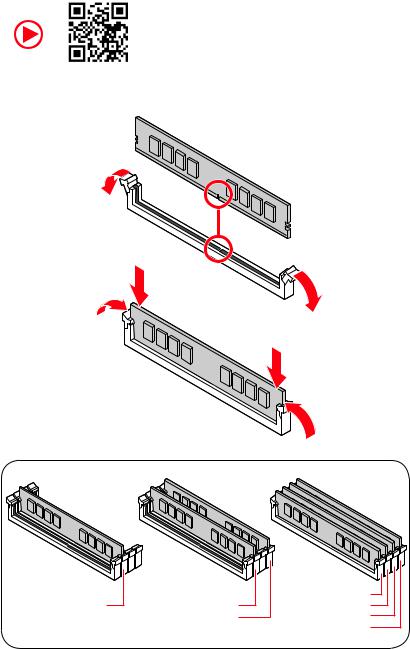
Installing DDR4 memory
|
DIMMA2 |
DIMMA2 |
DIMMA1 |
|
DIMMA2 |
||
|
DIMMB2 |
DIMMB1 |
|
|
DIMMB2 |
4 Quick Start
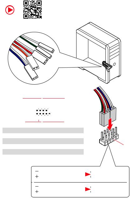
Connecting the Front Panel Header
|
— |
|||
|
LED |
|||
|
LED+ |
POWER |
||
|
POWER |
|||
|
LED |
|||
|
SW |
HDD |
||
|
POWER |
|||
|
SW |
|||
|
RESET |
|
Power LED |
Power Switch |
||||||||||||||||||||
|
+ — -+ |
|||||||||||||||||||||
|
JFP1 |
2 |
10 |
|||||||||||||||||||
|
1 |
9 |
Reserved |
|||||||||||||||||||
|
+ — +- |
|||||||||||||||||||||
|
HDD LED |
Reset Switch |
||||||||||||||||||||
|
1 |
HDD LED + |
2 |
Power LED + |
||||||||||||||||||
|
3 |
HDD LED — |
4 |
Power LED — |
||||||||||||||||||
|
5 |
Reset Switch |
6 |
Power Switch |
||||||||||||||||||
|
7 |
Reset Switch |
8 |
Power Switch |
||||||||||||||||||
|
9 |
Reserved |
10 |
No Pin |
HDDLED RESETSW
|
HDD LED — |
|||||||
|
HDD LED |
|||||||
|
HDD LED + |
|||||||
|
POWER LED — |
|||||||
|
POWER LED |
POWER LED + |
||||||
Quick Start 5
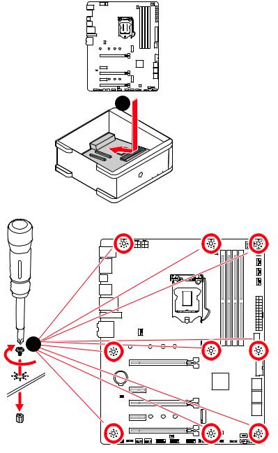
Installing the Motherboard
1
BAT1
*3 kgf·cm = 0.3 N·m = 2.6 lbf·in
6 Quick Start
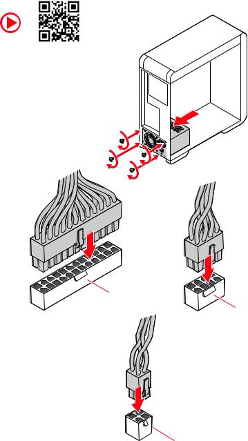
Connecting the Power Connectors
ATX_PWR1
CPU_PWR1
CPU_PWR2
Quick Start 7
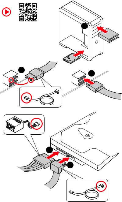
Installing SATA Drives
|
1 |
5
4
8 Quick Start

Installing a Graphics Card
1
5
 4
4
6
Quick Start 9

Connecting Peripheral Devices
10 Quick Start
![]()
Power On
 1
1
 2
2
3
4
Quick Start 11
|
Contents |
|
|
Quick Start ………………………………………………………………………………………………. |
1 |
|
Preparing Tools and Components……………………………………………………………….. |
1 |
|
Safety Information …………………………………………………………………………………….. |
2 |
|
Installing a Processor………………………………………………………………………………… |
3 |
|
Installing DDR4 memory ……………………………………………………………………………. |
4 |
|
Connecting the Front Panel Header…………………………………………………………….. |
5 |
|
Installing the Motherboard…………………………………………………………………………. |
6 |
|
Connecting the Power Connectors………………………………………………………………. |
7 |
|
Installing SATA Drives………………………………………………………………………………… |
8 |
|
Installing a Graphics Card ………………………………………………………………………….. |
9 |
|
Connecting Peripheral Devices …………………………………………………………………. |
10 |
|
Power On………………………………………………………………………………………………… |
11 |
|
Specifications…………………………………………………………………………………………. |
14 |
|
JCORSAIR1 Connector Specification………………………………………………………….. |
19 |
|
Package contents …………………………………………………………………………………… |
20 |
|
Block Diagram ………………………………………………………………………………………. |
21 |
|
Rear I/O Panel ……………………………………………………………………………………….. |
22 |
|
LAN Port LED Status Table……………………………………………………………………….. |
22 |
|
Audio Ports Configuration ………………………………………………………………………… |
22 |
|
Realtek Audio Console …………………………………………………………………………….. |
23 |
|
Installing Antennas………………………………………………………………………………….. |
25 |
|
Overview of Components ………………………………………………………………………… |
26 |
|
CPU Socket …………………………………………………………………………………………….. |
28 |
|
DIMM Slots……………………………………………………………………………………………… |
29 |
|
PCI_E1~5: PCIe Expansion Slots……………………………………………………………….. |
30 |
|
M2_1~2: M.2 Slots (Key M) ……………………………………………………………………….. |
31 |
|
SATA1~6: SATA 6Gb/s Connectors …………………………………………………………….. |
33 |
|
JFP1, JFP2: Front Panel Connectors …………………………………………………………. |
34 |
|
JAUD1: Front Audio Connector …………………………………………………………………. |
34 |
|
CPU_PWR1~2, ATX_PWR1: Power Connectors …………………………………………… |
35 |
|
JUSBC1: USB 3.2 Gen 2 10Gbps Type-C Connector……………………………………… |
36 |
|
JUSB3: USB 3.2 Gen 1 5Gbps Connector ……………………………………………………. |
36 |
|
JUSB1~2: USB 2.0 Connectors………………………………………………………………….. |
37 |
|
JTPM1: TPM Module Connector………………………………………………………………… |
37 |
|
CPU_FAN1, PUMP_FAN1, SYS_FAN1~6: Fan Connectors…………………………….. |
38 |
|
JCI1: Chassis Intrusion Connector…………………………………………………………….. |
39 |
12 Contents
|
JCOM1: Serial Port Connector ………………………………………………………………….. |
39 |
|
JBAT1: Clear CMOS (Reset BIOS) Jumper ………………………………………………….. |
40 |
|
JTBT1: Thunderbolt Add-on Card Connector ……………………………………………… |
40 |
|
JRTD3: Intel RTD3 Connector …………………………………………………………………… |
40 |
|
JRGB1: RGB LED connector……………………………………………………………………… |
41 |
|
JRAINBOW1~2: Addressable RGB LED connectors……………………………………… |
42 |
|
JCORSAIR1: CORSAIR Connector ……………………………………………………………… |
43 |
|
EZ Debug LED…………………………………………………………………………………………. |
44 |
|
LED_SW1: EZ LED Control ……………………………………………………………………….. |
44 |
|
Installing OS, Drivers & Utilities ………………………………………………………………. |
45 |
|
Installing Windows® 10…………………………………………………………………………….. |
45 |
|
Installing Drivers …………………………………………………………………………………….. |
45 |
|
Installing Utilities ……………………………………………………………………………………. |
45 |
|
UEFI BIOS………………………………………………………………………………………………. |
46 |
|
BIOS Setup……………………………………………………………………………………………… |
47 |
|
Entering BIOS Setup………………………………………………………………………………… |
47 |
|
Resetting BIOS………………………………………………………………………………………… |
48 |
|
Updating BIOS…………………………………………………………………………………………. |
48 |
|
EZ Mode …………………………………………………………………………………………………. |
50 |
|
Advanced Mode ………………………………………………………………………………………. |
53 |
|
SETTINGS Menu ……………………………………………………………………………………… |
54 |
|
OC Menu…………………………………………………………………………………………………. |
56 |
|
M-FLASH Menu ………………………………………………………………………………………. |
60 |
|
OC PROFILE Menu…………………………………………………………………………………… |
61 |
|
HARDWARE MONITOR Menu…………………………………………………………………….. |
62 |
|
RAID Configuration…………………………………………………………………………………. |
64 |
|
Enabling Intel® Rapid Storage Technology………………………………………………….. |
64 |
|
Creating RAID Volume …………………………………………………………………………….. |
65 |
|
Removing a RAID Volume ………………………………………………………………………… |
66 |
|
Resetting Disks to Non-RAID ……………………………………………………………………. |
67 |
|
Rebuilding RAID Array……………………………………………………………………………… |
68 |
|
Installing RAID Driver………………………………………………………………………………. |
69 |
|
Installing Intel® Rapid Storage Technology Software …………………………………… |
69 |
|
Intel® Optane™ Memory Configuration …………………………………………………….. |
70 |
|
System Requirements …………………………………………………………………………….. |
70 |
|
Installing the Intel® Optane™ memory ………………………………………………………. |
70 |
|
Removing the Intel® Optane™ memory ……………………………………………………… |
72 |
|
Troubleshooting …………………………………………………………………………………….. |
73 |
Contents 13

Specifications
|
Supports 10th Gen Intel® Core™ and Pentium® Gold / |
||
|
CPU |
Celeron® processors for LGA 1200 socket* |
|
|
* Please go to www.intel.com for more compatibility information. |
||
|
* Onboard graphics output are disabled when using F SKU processors. |
||
|
Chipset |
Intel® Z490 Chipset |
|
|
∙∙4x DDR4 memory slots, support up to 128GB* |
||
|
∙∙Supports 1R 2133/2666/2933 MHz* |
||
|
▪▪1DPC 1R Max speed up to 4800+ MHz |
||
|
▪▪1DPC 2R Max speed up to 4266+ MHz |
||
|
Memory |
▪▪2DPC 1R Max speed up to 4400+ MHz |
|
|
▪▪2DPC 2R Max speed up to 4000+ MHz |
||
|
∙∙Supports Dual-Channel mode |
||
|
∙∙Supports non-ECC, un-buffered memory |
||
|
∙∙Supports Intel® Extreme Memory Profile (XMP) |
||
|
* Please refer www.msi.com for more information on compatible memory. |
||
|
∙∙3x PCIe 3.0 x16 slots*, support x16/ x0/ x4 or x8/ x8/ x4 |
||
|
Expansion Slot |
mode |
|
|
∙∙2x PCIe 3.0 x1 slots |
||
|
* Please refer to page 30 for details. |
||
|
Multi-GPU |
∙∙Supports 2-Way NVIDIA® SLI™ Technology |
|
|
∙∙Supports 3-Way AMD® CrossFire™ Technology |
||
|
∙∙1x HDMI port, supports a maximum resolution of |
||
|
Onboard Graphics |
4096×2160 @30Hz |
|
|
∙∙1x DisplayPort, supports a maximum resolution of |
||
|
4096×2304 @60Hz |
||
|
∙∙Maximum shared memory is 1GB |
||
|
Continued on next page |
14 Specifications

Continued from previous page
|
Intel® Z490 Chipset |
|
|
∙∙6x SATA 6Gb/s ports*/** |
|
|
∙∙2x M.2 slots (Key M) |
|
|
▪▪M2_1 supports up to PCIe 3.0 x4 and SATA 6Gb/s, |
|
|
2242/ 2260/ 2280/ 22110 storage devices* |
|
|
Storage |
▪▪M2_2 supports up to PCIe 3.0 x4 and SATA 6Gb/s, |
|
2242/ 2260/ 2280 storage devices** |
|
|
▪▪Intel® Optane™ Memory Ready*** |
|
|
▪▪Supports Intel® Smart Response Technology for Intel |
|
|
Core™ processors |
|
|
* SATA2 will be unavailable when installing M.2 SATA SSD in the M2_1 slot. |
|
|
** SATA5 & SATA6 will be unavailable when installing M.2 SSD in the M2_2 slot. |
|
|
*** Before using Intel® Optane™ memory modules, please ensure that you have |
|
|
updated the drivers and BIOS to the latest version from MSI website. |
|
|
Intel® Z490 Chipset |
|
|
RAID |
∙∙Supports RAID 0, RAID 1, RAID 5 and RAID 10 for SATA |
|
storage devices |
|
|
∙∙Supports RAID 0 and RAID 1 for M.2 PCIe storage devices |
|
|
∙∙Intel® Z490 Chipset |
|
|
▪▪5x USB 3.2 Gen 2 10Gbps ports (4 Type-A ports on the |
|
|
back panel, 1 Type-C internal connector) |
|
|
USB |
▪▪2x USB 3.2 Gen 1 5Gbps ports are available through |
|
the internal USB 3.2 Gen 1 5Gbps connector |
|
|
▪▪6x USB 2.0 ports (2 Type-A ports on the back panel, 4 |
|
|
ports through the internal USB 2.0 connectors) |
|
|
∙∙ASMedia® ASM3241 Chipset |
|
|
▪▪1x USB 3.2 Gen 2×2 20Gbps port on the back panel |
|
|
Audio |
∙∙Realtek® ALC1220 Codec |
|
▪▪7.1-Channel High Definition Audio |
|
|
▪▪Supports S/PDIF output |
|
|
LAN |
∙∙1x Realtek® RTL8125B 2.5G LAN controller |
|
Continued on next page |
Specifications 15

|
Continued from previous page |
|
|
Intel® AX201 |
|
|
∙∙The Wireless module is pre-installed in the M.2 (Key-E) |
|
|
Wireless LAN & |
slot |
|
∙∙Supports MU-MIMO TX/RX, 2.4GHz/ 5GHz (160MHz) up to |
|
|
Bluetooth® |
2.4Gbps |
|
∙∙Supports 802.11 a/b/g/n/ac/ax |
|
|
∙∙WiFi 6 pre-certified |
|
|
∙∙Supports Bluetooth® 5.1, FIPS, FISMA |
|
|
∙∙1x 24-pin ATX main power connector |
|
|
∙∙1x 8-pin ATX 12V power connector |
|
|
∙∙1x 4-pin ATX 12V power connector |
|
|
∙∙6x SATA 6Gb/s connectors |
|
|
∙∙2x M.2 slots (M-Key) |
|
|
∙∙1x USB 3.2 Gen 2 10Gbps Type-C port |
|
|
∙∙1x USB 3.2 Gen 1 5Gbps connector (supports additional 2 |
|
|
USB 3.2 Gen 1 5Gbps ports) |
|
|
∙∙2x USB 2.0 connectors (supports additional 4 USB 2.0 |
|
|
ports) |
|
|
∙∙1x 4-pin CPU fan connector |
|
|
∙∙1x 4-pin water-pump fan connector |
|
|
Internal Connectors |
∙∙6x 4-pin system fan connectors |
|
∙∙1x Front panel audio connector |
|
|
∙∙2x System panel connectors |
|
|
∙∙1x Chassis Intrusion connector |
|
|
∙∙1x 4-pin RGB LED connector |
|
|
∙∙2x 3-pin RAINBOW LED connectors |
|
|
∙∙1x 3-pin CORSAIR LED connector |
|
|
∙∙1x Serial port connector |
|
|
∙∙1xTPM module connector |
|
|
∙∙1x TBT connector* |
|
|
∙∙1x RTD3 connector |
|
|
∙∙1x Clear CMOS jumper |
|
|
* Thunderbolt card needs to support RTD3. |
|
|
Continued on next page |
16 Specifications

Continued from previous page
|
LED Features |
∙∙1x EZ LED Control switch |
|
|
∙∙4x EZ Debug LED |
||
|
∙∙1 x PS/2 keyboard/ mouse combo port |
||
|
∙∙2 x USB 2.0 Type-A ports |
||
|
∙∙1x Display port |
||
|
Back Panel |
∙∙1x HDMI port |
|
|
∙∙1 x USB 3.2 Gen 2×2 20Gbps Type-C port |
||
|
Connectors |
∙∙4 x USB 3.2 Gen 2 10Gbps Type-A ports |
|
|
∙∙1 x LAN (RJ45) port |
||
|
∙∙2 x Wi-Fi Antenna connectors |
||
|
∙∙5 x Audio jacks |
||
|
∙∙1 x Optical S/PDIF Out connector |
||
|
I/O Controller |
NUVOTON NCT6687 Controller Chip |
|
|
Hardware Monitor |
∙∙CPU/System temperature detection |
|
|
∙∙CPU/System fan speed detection |
||
|
∙∙CPU/System fan speed control |
||
|
Form Factor |
∙∙ATX Form Factor |
|
|
∙∙12 in. x 9.6 in. (30.5 cm x 24.4 cm) |
||
|
∙∙1x 256 Mb flash |
||
|
BIOS Features |
∙∙UEFI AMI BIOS |
|
|
∙∙ACPI 6.2, SMBIOS 3.2 |
||
|
∙∙Multi-language |
||
|
∙∙Drivers |
||
|
∙∙DRAGON CENTER |
||
|
∙∙MSI APP Player (BlueStacks) |
||
|
Software |
∙∙Open Broadcaster Software (OBS) |
|
|
∙∙CPU-Z MSI GAMING |
||
|
∙∙Intel® Extreme Tuning Utility |
||
|
∙∙Google Chrome™, Google Toolbar, Google Drive |
||
|
∙∙Norton™ Internet Security Solution |
||
|
Continued on next page |
Specifications 17

Continued from previous page
|
∙∙Gaming Mode |
||
|
∙∙Gaming Hotkey |
||
|
∙∙LAN Manager |
||
|
∙∙Mystic Light |
||
|
∙∙Ambient Link |
||
|
Dragon Center |
∙∙User Scenario |
|
|
∙∙Hardware Monitor |
||
|
Features |
||
|
∙∙True Color |
Please refer to http://download.msi. |
|
|
∙∙Live Update |
com/manual/mb/DRAGONCENTER2. |
|
|
∙∙DPC Latency Tuner |
pdf for more details. |
|
|
∙∙Speed Up |
||
|
∙∙Smart Tool |
||
|
∙∙Super Charger |
||
|
∙∙Audio |
||
|
▪▪Audio Boost 4 |
||
|
∙∙Network |
||
|
▪▪2.5G LAN |
||
|
▪▪LAN Manager with Realtek 8125B |
||
|
▪▪Intel WiFi |
||
|
∙∙Cooling |
||
|
Special Features |
▪▪M.2 Shield Frozr X2 |
|
|
▪▪Pump Fan |
||
|
▪▪Smart Fan Control |
||
|
∙∙LED |
||
|
▪▪Mystic Light |
||
|
▪▪Mystic Light Extension (RAINBOW/CORSAIR/RGB) |
||
|
▪▪Mystic Light SYNC |
||
|
▪▪Ambient Link |
||
|
▪▪EZ LED Control |
||
|
▪▪EZ DEBUG LED |
||
|
Continued on next page |
18 Specifications

Continued from previous page
∙∙Performance
▪▪Multi GPU – SLI Technology
▪▪Multi GPU – CrossFire Technology
▪▪DDR4 Boost
▪▪Core Boost
▪▪Game Boost
▪▪Lightning USB 20G
▪▪USB 3.2 Gen 2 10G
Special Features ▪▪USB with Type A+C
▪▪Front USB Type-C ▪▪Dual CPU Power (8+4 pin)
∙∙Protection
▪▪PCI-E Steel Armor X2
▪▪Pre-installed I/O Shielding
∙∙Experience ▪▪Dragon Center ▪▪Click BIOS 5
JCORSAIR1 Connector Specification
|
Supporting CORSAIR RGB Products |
Maximum connection |
|
Lighting Node PRO LED Strip |
20* |
|
* 20% brightness is recommended when the number of |
|
|
LED strips exceeds 8. |
|
|
HD120 RGB Fan |
6 |
|
SP120 RGB Fan |
6 |
|
LL120 RGB Fan |
6 |
Specifications 19

Package contents
Please check the contents of your motherboard package. It should contain:
|
Motherboard |
MPG Z490 GAMING CARBON WIFI |
||
|
SATA 6G cables (2 cables/pack) |
1 |
||
|
Cable |
LED JRGB Y cable |
1 |
|
|
LED JCORSAIR cable |
1 |
||
|
LED JRAINBOW cable |
1 |
||
|
Wi-Fi Antenna |
1 |
||
|
Accessories |
M.2 screws (3 pcs./pack) |
1 |
|
|
Case Badge |
1 |
||
|
SATA cable stickers |
1 |
||
|
Product registration card |
1 |
||
|
Application |
Driver DVD |
1 |
|
|
Documentation |
User manual |
1 |
|
|
Quick installation guide |
1 |
||
Important
If any of the above items are damaged or missing, please contact your retailer.
20 Package contents
![]()
Block Diagram
|
2 Channel DDR4 Memory |
||
|
Processor |
||
|
Switch |
||
|
PCI Express Bus |
||
|
DMI 3.0 |
||
|
2x PCIe x1 slot |
||
|
1x SATA 6Gb/s |
Switch |
|
|
1x M.2 |
1x Intel AX201 Wireless LAN |
|
|
1x M.2 |
|||
|
1x Realtek 2.5G LAN |
|||
|
2x SATA 6Gb/s |
Switch |
PCH |
|
|
JHL7540 |
|||
|
3x SATA 6Gb/s |
ASMEDIA |
||
|
3241 |
1x USB 3.2 Gen2 x 2 |
||
5x USB 3.2 Gen2
2x USB 3.2 Gen1
6x USB 2.0
|
NUVOTON |
Realtek |
|
6687 |
ALC1220P |
Rear Audio Jacks
Block Diagram 21

Rear I/O Panel
|
PS/2 Combo port |
2.5 Gbps LAN |
Audio Ports |
|
DisplayPort |
USB 3.2 Gen 2 |
|
(10Gbps) Type-A |
|
USB 2.0 Type-A |
USB 3.2 Gen 2×2 |
Wi-Fi Antenna |
|
(20Gbps) Type-C |
connectors |
Optical
S/PDIF-Out
LAN Port LED Status Table
Link/ Activity LED
|
Status |
Description |
|
Off |
No link |
|
Yellow (2.5Gb LAN) |
Linked |
|
Blinking |
Data activity |
Speed LED
|
Status |
2.5 Gbps LAN |
|
Off |
10 Mbps |
|
Green |
100 Mbps/ 1 Gbps |
|
Orange |
2.5 Gbps |
Audio Ports Configuration
|
Audio Ports |
Channel |
||||
|
2 |
4 |
6 |
8 |
||
|
Center/ Subwoofer Out |
● |
● |
|||
|
Rear Speaker Out |
● |
● |
● |
||
|
Line-In/ Side Speaker Out |
● |
||||
|
Line-Out/ Front Speaker Out ● |
● |
● |
● |
||
|
Mic In |
|||||
|
(●: connected, Blank: empty) |
22 Rear I/O Panel

Realtek Audio Console
After Realtek Audio Console is installed. You can use it to change sound settings to get better sound experience.
Application Enhancement
Device
Selection
 Main Volume
|
Connector Settings |
Jack |
Status |
|
∙∙Device Selection — allows you to select a audio output source to change the related options. The check sign indicates the devices as default.
∙∙Application Enhancement — the array of options will provide you a complete guidance of anticipated sound effect for both output and input device.
∙∙Main Volume — controls the volume or balance the right/left side of the speakers that you plugged in front or rear panel by adjust the bar.
∙∙Jack Status — depicts all render and capture devices currently connected with your computer.
∙∙Connector Settings — configures the connection settings.
Auto popup dialog
When you plug into a device at an audio jack, a dialogue window will pop up asking you which device is current connected.
Each jack corresponds to its default setting as shown on the next page.
Important
The pictures above for reference only and may vary from the product you purchased.
Rear I/O Panel 23

Audio jacks to headphone and microphone diagram
Audio jacks to stereo speakers diagram
AUDIO INPUT
Audio jacks to 7.1-channel speakers diagram
AUDIO INPUT
|
Rear |
Front |
|
Side |
Center/ |
|
Subwoofer |
24 Rear I/O Panel
 Loading…
I
Quick Start
Quick Start
Thank you for purchasing the MSI®
MPG Z490 GAMING CARBON
WIFI
motherboard. This Quick Start section provides demonstration
diagrams about how to install your computer. Some of the
installations also provide video demonstrations. Please link to the
URL to watch it with the web browser on your phone or tablet. You
may have even link to the URL by scanning the QR code.
Kurzanleitung
Danke, dass Sie das MSI®
MPG Z490 GAMING CARBON WIFI
Motherboard gewählt haben. Dieser Abschnitt der Kurzanleitung
bietet eine Demo zur Installation Ihres Computers. Manche
Installationen bieten auch die Videodemonstrationen. Klicken Sie
auf die URL, um diese Videoanleitung mit Ihrem Browser auf Ihrem
Handy oder Table anzusehen. Oder scannen Sie auch den QR Code
mit Ihrem Handy, um die URL zu öffnen.
Présentation rapide
Merci d’avoir choisi la carte mère MSI®
MPG Z490 GAMING
CARBON WIFI
. Ce manuel fournit une rapide présentation avec
des illustrations explicatives qui vous aideront à assembler votre
ordinateur. Des tutoriels vidéo sont disponibles pour certaines
étapes. Cliquez sur le lien fourni pour regarder la vidéo sur votre
téléphone ou votre tablette. Vous pouvez également accéder au lien
en scannant le QR code qui lui est associé.
Быстрый старт
Благодарим вас за покупку материнской платы MSI®
MPG Z490
GAMING CARBON WIFI
. В этом разделе представлена информация,
которая поможет вам при сборке комьютера. Для некоторых
этапов сборки имеются видеоинструкции. Для просмотра видео,
необходимо открыть соответствующую ссылку в веб-браузере
на вашем телефоне или планшете. Вы также можете выполнить
переход по ссылке, путем сканирования QR-кода.
3.0
Rated 3.0 out of 5
3.0 out of 5 stars (based on 1 review)
Your overall rating
MSI MPG Z490 GAMING CARBON WIFI (01) PDF MANUAL
Click here to download MSI MPG Z490 GAMING CARBON WIFI (01) PDF MANUAL
MSI MPG Z490 GAMING CARBON WIFI (01) PDF MANUAL
FREE ENGLISH PDF
OPERATING INSTRUCTIONS
USER GUIDE – USER MANUAL
OWNER GUIDE – OWNER MANUAL
REFERENCE GUIDE – REFERENCE MANUAL
INSTRUCTION GUIDE – INSTRUCTION MANUAL
Your overall rating
- YouTube
MSI MPG Z490 GAMING CARBON WIFI (01) PDF MANUAL
MSI MPG Z490 GAMING CARBON WIFI (01) PDF MANUAL
|
Код: 124414 Извините, товара сейчас нет в наличии
Бесплатная доставка
Извините, товара сейчас нет в наличии Сравнить Новости интернет-магазина «Лаукар»:28.03.2023 22.02.2023 13.02.2023 Дополнительная информация в категории Материнская плата:Таблица Авторизованных сервисных центров по брендам. Описание Инструкция Отзывы (0) В интернет-магазине бытовой техники «Лаукар» Вы можете скачать инструкцию к товару Материнская плата MSI MPG Z490 GAMING CARBON WIFI совершенно бесплатно. Все инструкции, представленные на сайте интернет-магазина бытовой техники «Лаукар», предоставляются производителем товара. Для того чтобы скачать инструкцию, Вам необходимо нажать на ссылку «скачать инструкцию», расположенную ниже, а в случае, если ссылки нет, Скачать инструкцию Смотреть инструкцию
Фирма-производитель оставляет за собой право на внесение изменений в конструкцию, дизайн и комплектацию товара: Материнская плата MSI MPG Z490 GAMING CARBON WIFI. Пожалуйста, сверяйте информацию о товаре с информацией на |