
Перейти к контенту
- Manuals
- Brands
- Omron Manuals
- Relays
- ZEN-20C1DR-D-V2
Manuals and User Guides for Omron ZEN-20C1DR-D-V2. We have 1 Omron ZEN-20C1DR-D-V2 manual available for free PDF download: Datasheet
Программируемое реле ZEN, питание 12-24В=, аналог.вх., 12 входов 24В=, 8 релейн.вых, ЖК- дисплей,часы,календарь, возм. расширение
ZEN-20C1DR-D-V2: Технические характеристики
Скачать datasheet по ZEN-20C1DR-D-V2 в формате PDF
| Категория согл. EN 954-1 | B |
| Тип питающего напряжения | DC (постоян.) |
| Степень защиты (IP) | IP20 |
| Категория взрывобезопасности по пыли | Нет (без) |
| Уровень исполнения согл. EN ISO 13849-1 | Уровень А |
| Категория взрывобезопасности по газу | Нет (без) |
| Поддержка протокола INTERBUS-Safety | нет |
| Выдвижной (-ая) | да |
| Задатчик связей вводы/вывода | нет |
| Поддержка протокола KNX | нет |
| Основное устройство | да |
| Радиостандарт GSM | нет |
| Поддержка протокола PROFINET CBA | нет |
| Поддержка протокола SafetyBUS p | нет |
| Монтаж на стену/непосредственная установка | да |
| Поддержка протокола SUCONET | нет |
| Поддержка протокола INTERBUS | нет |
| Радиостандарт UMTS | нет |
| Радиостандарт Bluetooth | нет |
| С таймером | да |
| Поддержка протокола Data-Highway | нет |
| Поддержка протокола DeviceNet | нет |
| Поддержка протокола других шинных систем | нет |
| С релейным выходом | да |
| С дисплеем | да |
| Поддержка протокола CAN | нет |
| С оптическим интерфейсом |
нет
|
| Поддержка протокола PROFIsafe | нет |
| Радиостандарт GPRS | нет |
| Поддержка протокола Foundation Fieldbus | нет |
| Устройство наращивания | да |
| Возможна установка спереди | нет |
| Поддержка протокола PROFINET IO | нет |
| Подходит для функций безопасности | нет |
| Поддержка протокола AS-Interface Safety at Work | нет |
| Поддержка протокола TCP/IP | нет |
| Поддержка протокола MODBUS | нет |
| Дополнит. исполнение (EX ib) | нет |
| Поддержка протокола SERCOS | нет |
| Поддержка протокола LON | нет |
| Дополнит. исполннение (EX ia) | нет |
| Дублирование | нет |
| Поддержка протокола DeviceNet Safety | нет |
| Поддержка протокола EtherNet/IP | нет |
| Возможность монтажа на рейку | да |
| Радиостандарт WLAN 802.11 | нет |
| Поддержка протокола PROFIBUS | нет |
| Поддержка протокола ASI | нет |
| Возможна сборка на полках/стойках | нет |
| Количество беспроводных HW-интерфейсов | 0 |
| Количество HW-интерфейсов Industrial Ethernet | 0 |
| Количество параллельных HW-интерфейсов | 0 |
| Количество аналог. выходов | 0 |
| Количество HW-интерфейсов USB | 0 |
| Количество аналог. входов | 2 |
| Количество HW-интерфейсов TTY | 0 |
| Количество HW-интерфейсов PROFINET | 0 |
| Количество HW-интерфейсов RS-232 | 0 |
| Количество цифров. входов | 12 |
| Количество HW-интерфейсов RS-485 | 1 |
| SIL согл. IEC 61508 | 0 |
| Количество HW-интерфейсов RS-422 | 1 |
| Количество цифров. выходов | 8 |
| Количество других HW-интерфейсов | 1 |
| Глубина |
56 мм |
| Высота |
90 мм |
| Коммутируем. ток |
5.000 А |
| Ширина |
122.5 мм |
| Напряжение питания постоян. тока (DC) |
10.8…28.8 В |

ZEN Support
Программное обеспечение
en
ZIP
16,6 МБ
o
Пожалуйста, войдите или зарегистрируйтесь, чтобы получить информацию

ZEN v2
Руководство по сетевым интерфейсам
enPDF
1,6 МБ
ZEN v2
Руководство по эксплуатации
enPDF
3,4 МБ
ZEN-series
Уведомление о снятии с производства
en
PDF
738,0 КБ
o
Пожалуйста, войдите или зарегистрируйтесь, чтобы получить информацию
ZEN-series
Уведомление о снятии с производства
en
PDF
738,0 КБ
o
Пожалуйста, войдите или зарегистрируйтесь, чтобы получить информацию
ZEN v2
Руководство по сетевым интерфейсам
enPDF
1,6 МБ
ZEN v2
Руководство по эксплуатации
enPDF
3,4 МБ
ZEN Support
Программное обеспечение
en
ZIP
16,6 МБ
o
Пожалуйста, войдите или зарегистрируйтесь, чтобы получить информацию
* Изображения служат только для ознакомления,
см. техническую документацию
Добавить в корзину 1 шт.
на сумму 83 530 руб.
Посмотреть альтернативные предложения2
Номенклатурный номер: 8008901262
Артикул: ZEN-20C1DR-D-V2
Страна происхождения: КИТАЙ
Бренд / Производитель: Omron

Описание
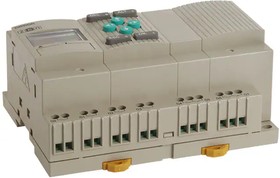
Программируемый логический контроллер (ПЛК) Монтаж на шасси, DIN-рейка 12 ~ 24 В постоянного тока
Технические параметры
| Approval Agency | CE, cULus |
| Display Type | LCD — Black Characters |
| ECCN | EAR99 |
| Expandable | 3 Modules Max |
| HTSUS | 8537.10.9170 |
| Ingress Protection | IP20 |
| Moisture Sensitivity Level (MSL) | 1 (Unlimited) |
| Mounting Type | Chassis Mount, DIN Rail |
| Number of Characters Per Row | 12, 12, 12, 12 |
| Number of Inputs and Type | 12 — Digital (10), Analog/Digital (2) |
| Number of Outputs and Type | 8 — Relay |
| Operating Temperature | 0В°C ~ 55В°C |
| Package | Box |
| RoHS Status | RoHS Compliant |
| Series | ZEN V2 -> |
| Software | ZEN Support Software |
| Voltage — Supply | 12 ~ 24VDC |
| Weight | 0.772 lb (350.17 g) |
| Communication Port Type | RS485 |
| Display Included | Yes |
| Input Type | Analogue |
| Manufacturer Series | ZEN |
| Maximum Operating Temperature | +55°C |
| Minimum Operating Temperature | 0°C |
| Number of Communication Ports | 1 |
| Number of Inputs | 12 |
| Number of Outputs | 8 |
| Output Type | Relay |
| Programming Interface | Computer |
| Programming Language Used | Ladder Diagram |
| Supply Voltage | 12 → 24 V dc |
| Width | 70mm |
| Вес, г | 1 |
Техническая документация
Сроки доставки
Доставка в регион Курск
| Магазин «ЧИП и ДИП» | 4 июля1 | бесплатно |
| ПВЗ Boxberry | 30 июня1 | бесплатно |
| ПВЗ СДЭК | 3 июля1 | бесплатно |
| ПВЗ Л-Пост | 3 июля1 | бесплатно |
| ПВЗ 5Post | 4 июля1 | бесплатно |
| Почта России | 11 июля1 | бесплатно |
| Курьер | 3 июля1 | 416 руб.2 |
| ТК DPD | 30 июня1 | 546 руб.2 |
| ТК «Деловые линии» | 3 июля1 | 824 руб.2 |
Цена и наличие в магазинах
| ул. Карла Маркса, 68, ТЦ «Мега Гринн», 1 этаж | нет в наличии |
- Manuals
- Brands
- OMRON Manuals
- Relays
- ZEN
Manuals and User Guides for OMRON ZEN. We have 4 OMRON ZEN manuals available for free PDF download: Operation Manual, Communications Manual, Quick Manual

ZEN-20C1DR-D-V2 Программируемое реле с ЖК дисплеем: 12 аналоговых входов / 8 релейных выходов, Uпит. 12…24V DC, часы, календарь, возможность расширения
Цена розничная
29641.00 ₽
Внимание! Актуальные цены будут указаны в выставленном счете или КП.
Условия доставки
Доставка заказа от 250 рублей*
*Весом до 1 кг, до пункта выдачи курьерской службы в г. Москва
- Доставка по всей России до двери или в пункт выдачи
- Ежедневная отправка заказов курьерскими службами
- Бесплатная доставка до терминалов ТК два раза в неделю
- Самовывоза нет
ZEN.fm
| Наименование | Краткое описание | Карточка товара |
||
|---|---|---|---|---|
| — | — | |||
| — | — | |||
| — | — | |||
| — | — | |||
| — | — | |||
| — | — | |||
| — | — | |||
| — | — | |||
| — | — | |||
| — | — | |||
| — | — | |||
| — | — | |||
| — | — | |||
| — | — | |||
| — | — | |||
| — | — | |||
| — | — | |||
| — | — | |||
| ZEN10C1ARAV2.1 (OMRON-IA) |
|
— | модуль цпу | |
| ZEN10C1DRDV2.1 (OMRON-IA) |
|
— | модуль цпу | |
| ZEN10C1DTDV2.1 (OMRON-IA) |
|
— | модуль цпу | |
| ZEN10C2ARAV2.1 (OMRON-IA) |
|
— | модуль цпу | |
| ZEN10C2DRDV2.1 (OMRON-IA) |
|
— | модуль цпу | |
| ZEN10C2DTDV2.1 (OMRON-IA) |
|
— | модуль цпу | |
| ZEN10C3ARAV2.1 (OMRON-IA) |
|
— | модуль цпу | |
| ZEN10C3DRDV2.1 (OMRON-IA) |
|
— | модуль цпу | |
| ZEN10C4ARAV2.1 (OMRON-IA) |
|
— | модуль цпу | |
| ZEN10C4DRDV2.1 (OMRON-IA) |
|
— | модуль цпу | |
| ZEN20C1ARAV2.1 (OMRON-IA) |
|
— | модуль цпу | |
| ZEN20C1DRDV2.1 (OMRON-IA) |
|
— | модуль цпу |
Скачать документацию: Документация на серию ZEN10 (1.3 Мб)
Программируемое реле ZEN, питание 12-24В=, аналог.вх., 12 входов 24В=, 8 релейн.вых, ЖК- дисплей,часы,календарь, возм. расширение
ZEN-20C1DR-D-V2: Технические характеристики
Скачать datasheet по ZEN-20C1DR-D-V2 в формате PDF
| Категория согл. EN 954-1 |
B
|
| Тип питающего напряжения | DC (постоян.) |
| Степень защиты (IP) | IP20 |
| Категория взрывобезопасности по пыли | Нет (без) |
| Уровень исполнения согл. EN ISO 13849-1 | Уровень А |
| Категория взрывобезопасности по газу | Нет (без) |
| Поддержка протокола INTERBUS-Safety | нет |
| Выдвижной (-ая) | да |
| Задатчик связей вводы/вывода | нет |
| Поддержка протокола KNX | нет |
| Основное устройство |
да
|
| Радиостандарт GSM | нет |
| Поддержка протокола PROFINET CBA | нет |
| Поддержка протокола SafetyBUS p | нет |
| Монтаж на стену/непосредственная установка | да |
| Поддержка протокола SUCONET | нет |
| Поддержка протокола INTERBUS | нет |
| Радиостандарт UMTS | нет |
| Радиостандарт Bluetooth | нет |
| С таймером | да |
| Поддержка протокола Data-Highway |
нет
|
| Поддержка протокола DeviceNet | нет |
| Поддержка протокола других шинных систем | нет |
| С релейным выходом | да |
| С дисплеем | да |
| Поддержка протокола CAN | нет |
| С оптическим интерфейсом | нет |
| Поддержка протокола PROFIsafe | нет |
| Радиостандарт GPRS | нет |
| Поддержка протокола Foundation Fieldbus | нет |
| Устройство наращивания |
да
|
| Возможна установка спереди | нет |
| Поддержка протокола PROFINET IO | нет |
| Подходит для функций безопасности | нет |
| Поддержка протокола AS-Interface Safety at Work | нет |
| Поддержка протокола TCP/IP | нет |
| Поддержка протокола MODBUS | нет |
| Дополнит. исполнение (EX ib) | нет |
| Поддержка протокола SERCOS | нет |
| Поддержка протокола LON | нет |
| Дополнит. исполннение (EX ia) |
нет
|
| Дублирование | нет |
| Поддержка протокола DeviceNet Safety | нет |
| Поддержка протокола EtherNet/IP | нет |
| Возможность монтажа на рейку | да |
| Радиостандарт WLAN 802.11 | нет |
| Поддержка протокола PROFIBUS | нет |
| Поддержка протокола ASI | нет |
| Возможна сборка на полках/стойках | нет |
| Количество беспроводных HW-интерфейсов | 0 |
| Количество HW-интерфейсов Industrial Ethernet |
0
|
| Количество параллельных HW-интерфейсов | 0 |
| Количество аналог. выходов | 0 |
| Количество HW-интерфейсов USB | 0 |
| Количество аналог. входов | 2 |
| Количество HW-интерфейсов TTY | 0 |
| Количество HW-интерфейсов PROFINET | 0 |
| Количество HW-интерфейсов RS-232 | 0 |
| Количество цифров. входов | 12 |
| Количество HW-интерфейсов RS-485 | 1 |
| SIL согл. IEC 61508 |
0
|
| Количество HW-интерфейсов RS-422 | 1 |
| Количество цифров. выходов | 8 |
| Количество других HW-интерфейсов | 1 |
| Глубина |
56 мм |
| Высота |
90 мм |
| Коммутируем. ток |
5.000 А |
| Ширина |
122.5 мм |
| Напряжение питания постоян. тока (DC) |
10.8…28.8 В |
Programmable Relay
ZEN V2 Units
Please read and understand this catalog before purchasing the products. Please consult your OMRON representative if you have any
questions or comments. Refer to “Warranty and Application
Considerations” on page 36, and “Precautions for Safe Use” on page 34.
Even Broader Applications with Increased
Functionality and Higher Precision
• Increased functionality in a compact body (70 mm wide
×
90 mm high).
• Easy programming is available using the LCD and operation buttons. (See note 1.)
• This single Unit easily provides relay, timer, counter, and time switch functions.
• Expansion is easy with Expansion I/O Units, allowing up to 44
I/O points. (See note 2.)
• Economy-type and Communications-type CPU Units have been added to series.
• Improved Weekly Timers (See note 1.)
Increased timing accuracy with a monthly deviation of ±15 s max. Multiple-day operation and pulse output operation have been added.
• Select from two power supply options:
100 to 240 VAC or 12 to 24 VDC.
Note: 1. Not supported for [email protected] C2 @@ @ -V2 models.
2. When using CPU Units with 20 I/O points.
The information in this document applies to V2 Units.
Refer to page 29 for details on differences with previous
products.
Features
■
Easy and Simple Programming for Automatic Small-scale Control
Saves Space, Wiring, and Installation Steps
• Versatile functionality in a compact body (70 mm wide
×
90 mm high).
• This single Unit easily provides relay, timer, counter, and time switch functions. Wiring work is greatly reduced because separate wiring is not required for devices such as timers and counters.
Easy Programming
The LCD screen comes with 8 operation buttons on the front panel to enable programming in ladder view format. The LCD screen also has a backlight, making it easier to see when the ZEN is used in dark locations.
Note: Not supported for [email protected] C2 @@ @ -V2 models.
70 mm
90 mm
Programmable Relay
ZEN V2 Units
1
Flexible Expansion Enables Up to 44 I/O
Points
Up to three Expansion I/O Units can be connected if there are not enough I/O points. Expansion I/O Units are only 35 mm wide.
Note: CPU Units with 10 I/O points can be expanded to 34 I/O points.
Expansion I/O Units cannot be connected to Economy-type
CPU Units.
Support Software with Simulation Function
• Programs can be easily written, saved, and monitored by personal computer.
• Programs can be simulated on the personal computer without connecting to the ZEN.
Note: For notebook computers that do not have an RS-232C serial port, connect the computer to the ZEN by connecting an
OMRON CS1W-CIF31 USB-Serial Conversion Cable to the
ZEN-CIF01 Connecting Cable.
Other Versatile Functions
• Use of a Memory Cassette makes it easy to copy and save programs.
• Equipped with two analog input channels (CPU Units with DC power supply only).
• Password function ensures security. (See note.)
• Multi-language display in six languages (English, Japanese,
German, French, Spanish, Italian). (See note.)
• Display user-set messages or analog-converted values. (See note.)
Note: Not supported for [email protected] C2 @@ @ -V2 models.
■
Enhanced Features of V2 CPU Units
Improved Weekly Timer and Calendar Timer
Functions
Note: Not supported for [email protected] C2 @@ @ -V2 models.
• The time precision has been increased.
Conventional model: 2-min difference/month
↓
-V2 models:
±
15-s difference/month (at 25
°
C)
• Multiple-day operation and pulse-output operation are now possible.
• These improved functions are convenient for time-controlled applications such as lighting and air conditioning control.
RS-485 Communications Model Added to
Series
Production line conditions can be remotely monitored by monitoring the ZEN control status.
Lighting control Air conditioning control
Economy-type Added to the Series
• Economy-type CPU Units with a more affordable price have been added to the series, although Expansion I/O Units cannot be added.
12 to 24 VDC Line Voltage Operation
Operation is now possible with 12 VDC.
Expansion I/O Units have been reduced to half-size (35 mm wide).
Production line
Office
More Precise Analog Input
Conventional model:
±
10% FS
→
-V2 models:
±
1.5% FS
DC power supply models are equipped with two analog inputs (0 to
10 V). There are four analog comparators. The increased precision makes it even easier to use the Unit in simple control applications with voltage, current, temperature, and other analog values.
8-digit Counter, 150-Hz Counter
• An 8-digit counter and 8-digit comparator have been added.
• The maximum count for DC power supply models is 150 Hz.
Twin-timer Operation Added
Twin-timer operation allows you to set ON and OFF times separately, greatly simplifying intermittent operation.
2
Programmable Relay
ZEN V2 Units
■
Series Configuration
CPU Unit
Power supply voltage: 100 to 240 VAC, 12 to 24 VDC, Output: Relay, transistor output
With LCD display, operation buttons, and calendar/clock function
10 I/O points 20 I/O points
LED type
10 I/O points
ZEN-10C2 @
20 I/O points
ZEN-20C2 @
This CPU Unit has no LCD, operation buttons, or calendar/clock function
Standard LCD type Economy type
ZEN-10C1 @ ZEN-10C3 @
Expansion I/O Units cannot be connected.
Expansion I/O Unit
Only 35-mm wide.
4 input, 4 output points
Communications type
Standard LCD type Economy type
ZEN-10C4 @ ZEN-20C1 @ ZEN-20C3 @
(10 I/O points)
RS-485 communications type.
Expansion I/O Units cannot be connected.
Power Supply Unit
Same shape and design as ZEN.
24 VDC, 30 W
Support Software
Allows easy programming and operation simulation.
Programmable Relay
ZEN V2 Units
3
Model Number Structure
■
Model Number Legend
Note: This model number legend includes combinations that are not available.
Please check “List of Models” for availability.
CPU Units
ZEN-
@
C
@@@
—
@
-V2
1
2 3 4 5
1. Number of I/O points
10: 6 inputs and 4 outputs (See note.)
20: 12 inputs and 8 outputs
2. Type classifier
1: Standard LCD type with display
2: LED type without display
3: Economy type with display
(Expansion I/O Units cannot be connected.)
4: Communications type with display
Note: The Communications-type CPU Unit has 6 inputs and 3 outputs.
Expansion I/O Units
ZEN-8E1
@@
1 2 3 4
1. Number of I/O points
8: 4 inputs and 4 outputs
2. Unit version classifier
E1: Can connect to V2 CPU Units (See note.)
3. Input type
A: AC input
D: DC input
4. Output type
R: Relay
T: Transistor
5. Supply voltage
A: AC power supply
D: DC power supply
3. Input type
A: AC input
D: DC input
4. Output type
R: Relay
T: Transistor
Note: Use a ZEN-8E @@ /-4E @ to connect to pre-V1 and V1 CPU Units.
4
This data sheet is provided as a guideline for selecting products. Be sure to refer to the following user manuals for application precautions and other information required for operation before attempting to use the product.
ZEN Operation Manual (Cat. No. Z211)
ZEN Communications User’s Manual (Cat. No. Z212)
ZEN Support Software Operation Manual (Cat. No. Z184-E1-03)
The PDF versions of these manuals can be downloaded from the following website.
ZEN Website http://www.zen.omron.co.jp/eng/index.html
Programmable Relay
ZEN V2 Units
Ordering Information
■
List of Models
CPU Units and Expansion I/O Units
Unit
CPU
Units
Name
Standard
LCD type
No. of
I/O points
10
LCD display
Yes
Power supply voltage
100 to 240 VAC
12 to 24 VDC
6
Inputs
100 to 240 VAC
12 to 24 VDC
4
Outputs
Relays
Buttons, calendar, and clock
Yes
Analog input
No
Yes
20 100 to 240 VAC
12 to 24 VDC
12 100 to 240 VAC
12 to 24 VDC
8
Transistors
Relays No
Yes
LED type without display
(See note 1.)
10
20
No 100 to 240 VAC
12 to 24 VDC
100 to 240 VAC
12 to 24 VDC
6 100 to 240 VAC
12 to 24 VDC
4
12 100 to 240V AC 8
12 to 24 VDC
Transistors
Relays
Transistors
Relays
No No
Yes
No
Yes
ZEN Kit
Economy type
(Expansion
I/O Units cannot be connected)
Communications type
10
20
Expansion I/O Units
Yes 100 to 240 VAC
12 to 24 VDC
100 to 240 VAC
12 to 24 VDC
6 100 to 240 VAC
12 to 24 VDC
12 100 to 240 VAC
12 to 24 VDC
4
8
Transistors
Relays
Relays
Yes
10 100 to 240 VAC
12 to 24 VDC
6 100 to 240 VAC
12 to 24 VDC
3 Relays
Set containing CPU Unit (ZEN-10C1AR-A-V2), Connecting Cable, ZEN Support Software, and manual.
Set containing CPU Unit (ZEN-10C1DR-D-V2), Connecting Cable, ZEN Support Software, and manual.
8 —100 to 240 VAC 4 100 to 240 VAC 4 Relays —
No
Yes
No
Yes
No
Yes
12 to 24 VDC
—
12 to 24 VDC
Transistors
Model
ZEN-10C1AR-A-V2
ZEN-10C1DR-D-V2
ZEN-10C1DT-D-V2
ZEN-20C1AR-A-V2
ZEN-20C1DR-D-V2
ZEN-20C1DT-D-V2
ZEN-10C2AR-A-V2
ZEN-10C2DR-D-V2
ZEN-10C2DT-D-V2
ZEN-20C2AR-A-V2
ZEN-20C2DR-D-V2
ZEN-20C2DT-D-V2
ZEN-10C3AR-A-V2
ZEN-10C3DR-D-V2
ZEN-20C3AR-A-V2
ZEN-20C3DR-D-V2
ZEN-10C4AR-A-V2
ZEN-10C4DR-D-V2
ZEN-KIT01-EV4
ZEN-KIT02-EV4
ZEN-8E1AR
(See notes 2, 3.)
ZEN-8E1DR
(See note 2.)
ZEN-8E1DT
(See note 2.)
Note: 1. Programming is not possible using only the CPU in the LED-type CPU Unit. ZEN Support Software or a Memory Cassette is required.
2. Cannot be connected to pre-V1 and V1 CPU Units.
3. The ZEN-8E1AR cannot be connected to a CPU Unit with DC power supply.
Power Supply Unit
30 W
Power ratings Input voltage
100 to 240 VAC
Output voltage
24 VDC
Note: Refer to the ZEN-PA03024 Datasheet (Cat. No. L103) for detailed specifications.
1.3 A
Output current Model
ZEN-PA03024
Programmable Relay
ZEN V2 Units
5
Accessories (Order Separately)
Name Specifications
Memory Cassette EEPROM (for data security and copying)
Remarks
Enables programs and parameter settings to be saved or copied to another
ZEN. (See note 1.)
Model
ZEN-ME01
LCD-type CPU Unit with display (See note 2.)
Supported
LED-type CPU Unit without display (See note 3.)
Not supported Transfer from ZEN to
Memory
Transfer from Memory
Cassette to ZEN
Supported Automatic transfer when power turned ON
Not supported Memory Cassette initialization
—
Supported
Connecting Cable 2 m RS-232C (9-pin Dsub connector)
Battery Unit
ZEN-CIF01
10 years min. Battery life
(at 25
°
C)
Ladder programs and parameter settings are saved to the CPU Unit EEP-ROM but calendar, clock, and holding timer bits and holding timer/counter present values are held by the capacitor. Therefore, if the power supply is interrupted for 2 days or more (at 25°C), this data will be reset. Use a Battery Unit for systems where the power supply may be interrupted for long periods.
ZEN-BAT01
ZEN Support
Software
Runs on Windows 95, 98,
2000, ME, XP, or NT 4.0.
Specifically designed for the ZEN (CD-ROM).
ZEN-SOFT01-V4
Note: 1. Memory Cassettes created using a CPU Unit can be read to other CPU Units, regardless of which model is used. Restrictions, apply, however, to
the functions that can be used, depending on the CPU Unit version combination. For details, refer to “Memory Cassette and CPU Unit
Combinations” on page 33.
2. Standard LCD-type, Economy-type, and Communications-type CPU Units (i.e., excluding [email protected] C2 @@ @ -V2 models).
3. LED-type CPU Unit without display (i.e., [email protected] C2 @@ @ -V2 models).
Mounting Accessories (Order Separately)
Name
Mounting Track
End Plate
Spacer
Specifications Model
50 cm (l)
×
7.3 mm (t) PFP-50N
1 m (l)
×
7.3 mm (t)
1 m (l)
×
16 mm (t)
PFP-100N
PFP-100N2
PFP-M
PFP-S
System Configuration
Power Supply Unit
Battery Unit
CPU Unit
Expansion I/O Unit
Connecting Cable
Memory Cassette
Support Software
Note: 1. Up to 3 Expansion I/O Units can be connected to any type of CPU Unit except for Economy-type CPU Units. Expansion I/O Units with AC Inputs, however, cannot be connected to CPU Units with DC Power Supplies.
2. The Connecting Cable and Memory Cassette cannot be connected to the ZEN at the same time.
3. Programs cannot be written to LED-type CPU Units (i.e., [email protected] C2 @@ @ -V2 models) without the ZEN Support Software or a Memory Cassette.
6
Programmable Relay
ZEN V2 Units
Specifications
■
Ratings
Item
Rated supply voltage
Operating voltage range
Power consumption
ZEN-
@
C
@
AR-A-V2/ZEN-8E1AR
100 to 240 VAC, 50/60 Hz
85 to 264 VAC
CPU Units without Expansion I/O Units
• ZEN-10C1AR-A-V2/ZEN-10C2AR-A-V2
100 V AC: 5 VA max.
240 V AC: 7 VA max.
• ZEN-10C3AR-A-V2
100 V AC: 5 VA max.
240 V AC: 6 VA max.
• ZEN-10C4AR-A-V2
100 V AC: 6 VA max.
240 V AC: 8 VA max.
• ZEN-20C @ AR-A-V2
100 V AC: 7 VA max.
240 V AC: 10 VA max.
CPU Units with three Expansion I/O Units
• ZEN-10C1AR-A-V2/ZEN-10C2AR-A-V2
100 V AC: 6 VA max.
240 V AC: 8 VA max.
• ZEN-10C4AR-A-V2
100 V AC: 7 VA max.
240 V AC: 9 VA max.
• ZEN-20C @ AR-A-V2
100 V AC: 8 VA max.
240 V AC: 11 VA max.
Specification
[email protected]
10.8 to 28.8 VDC
C
@
D
@
12 to 24 VDC (DC ripple rate: 5% max.)
CPU Units without Expansion I/O Units
• ZEN-10C @ DR-D-V2
12/24 V DC: 3 W max.
(ZEN-10C3DR-D-V2: 2.8 W max.)
• ZEN-10C @ DT-D-V2
12/24 V DC: 2 W max.
• ZEN-20C @ DR-D-V2
12/24 V DC: 4 W max.
• ZEN-20C
@
DT-D-V2
12/24 V DC: 2 W max.
CPU Units with three Expansion I/O Units
• ZEN-10C @ DR-D-V2
12/24 V DC: 4 W max.
• ZEN-10C @ DT-D-V2
12/24 V DC: 3 W max.
• ZEN-20C @ DR-D-V2
12/24 V DC: 5 W max.
• ZEN-20C @ DT-D-V2
12/24 V DC: 3 W max.
Expansion I/O Units
• ZEN-8E1DR
12/24 V DC: 2 W max.
-D-V2/ZEN-8E1D @
Expansion I/O Units
• ZEN-8E1AR
100 V AC: 3 VA max.
240 V AC: 4 VA max.
Inrush current
ZEN-10C
ZEN-20C
@
@
AR-A-V2: 3 A max.
AR-A-V2: 4 A max.
ZEN-10C @ D @ -D-V2: 30 A max.
ZEN-20C @ D @ -D-V2: 30 A max.
15 A max.
ZEN-8E1AR: 1.5 A max.
0 to 55
°
C (
−
25 to 55
°
C for [email protected] C2 @@ @ -V2 models)
ZEN-8E1DR:
Ambient temperature
Ambient storage temperature
−
20 to 75
°
C (
−
40 to 75
°
C for [email protected] C2 @@ @ -V2 models)
Ambient humidity
Ambient conditions
Mounting method
10% to 90% (with no condensation)
No corrosive gases
Surface mounting, DIN track mounting (standard (vertical) installation and horizontal installation) (See notes 1 and 2.)
Terminal block
Terminal screw tightening torque
Degree of protection
Solid-line terminal block (use solid lines or fine wiring terminals.)
0.5 to 0.6 N·m
IP20 (Mounted inside a control panel)
Note: 1. Can be mounted to 35-mm DIN Track.
2.
Standard (Vertical) installation
Horizontal installation
Programmable Relay
ZEN V2 Units
7
■
Characteristics
Item
Control method
I/O control method
Programming language
Program capacity
Stored program control
Cyclic scan
Ladder diagram
Specification
96 lines (3 input conditions and 1 output per line)
Max. No. of control I/O points
44 points (See note 1.)
CPU Units with 20 I/O points: 12 inputs and 8 outputs
Expansion I/O Units: 4 inputs and 4 outputs each, up to 3 Units.
LCD display (See note 2.)
12 characters
×
4 lines, with backlight
Operation buttons (See note 2.) 8 (4 cursor buttons and 4 operation buttons)
User program backup
Power interruption hold
Internal EEPROM, Memory Cassette (optional)
Internal holding bit status, holding timer/counter present values, calendar and clock (year, month, day of month, day of week, time)
• Super capacitor backup time: 2 days min. (25
°
C)
• Life of optional battery: 10 years min. (25
°
C)
Accuracy:
±
15 s/month (at 25
°
C)
Calendar and clock function
(See note 2.)
Timer accuracy
Maximum counting speed
Insulation resistance
Insulation
0.01 s unit:
−
0.05%
−
10 ms max. (rate for set value) min/s unit:
−
0.05%
−
1 s max. (rate for set value) h/min unit:
−
0.05%
−
1 min max. (rate for set value)
150 Hz: 8-Digit counter (F) set to high-speed operations (CPU Units with DC power supplies only)
(The counting speed may be less than 150 Hz depending on the cycle time of the program. See page 22.)
20 M
Ω
(at 500 VDC) min.:
Between power supply terminals and all output terminals.
Between terminals of different output circuits.
Between all terminals of CPU Unit and all terminals of Expansion I/O Unit.
• Reinforced insulation
Between power supply or input terminals and output terminals.
Between terminals of different output circuits.
Between all terminals of CPU Unit and all terminals of Expansion I/O Unit.
• No separation
Between power supply and input terminals of the same unit.
Between power supply terminals of CPU Unit and computer connector,
Battery Unit connector, or all Expansion Unit connectors (all interfaces are live parts).
Dielectric strength
Vibration resistance
2,300 VAC, 50/60 Hz for 1 min (leakage current 1 mA max.):
Between power supply terminals and all output terminals.
Between terminals of different output circuit.
Between all terminals of CPU Unit and all terminals of Expansion I/O Unit.
Conforms to IEC60068-2-6, 5 to 9 Hz with 3.5-mm single amplitude, 9 to 150 Hz acceleration 9.8 m/s
2
,
10 sweeps each in X, Y, and Z directions (1 octave/min)
Shock resistance
Weight
Conforms to IEC60068-2-27, 147 m/s
2
, 3 times each in X, Y, and Z directions.
CPU Unit with 10 I/O points: Approx. 300 g max.
CPU Unit with 20 I/O points: Approx. 350 g max.
Expansion I/O Unit: Approx. 120 g max.
Note: 1. Up to 34 points for CPU Units with 10 I/O points. With Communications-type CPU Units, however, the CPU Unit has 6 inputs and 3 outputs, for a maximum of 33 I/O points.
2. Not provided for LED-type CPU Unit without display (i.e., ZEN-
@
C2
@@
—
@
-V2 models).
■
Communications Specifications (Communications-type CPU Units)
Item
Communications
Synchronization method
Baud rate
Transmission code
Data bit length
Stop bit length
Error detection
Flow control
Interface
Retry function
Node number
ZEN-10C4
@
R-
@
-V2
RS-485 (two-wire, half duplex)
Start-stop synchronization
4800, 9600, or 19200 bps
ASCII
7 or 8 bits
1 or 2 bits
Vertical parity (none, even, odd), Block check character (BCC)
None
RS-485
None
0 to 99 (default: 1), XX (broadcasting)
8
Programmable Relay
ZEN V2 Units
■
Approved Standards
Item
Safety standards
EMC
(See note.)
Specification
cULus: UL508/CSA C22.2 No.142 Class I Div2 (pending approval)
Conforms to EN/IEC 61131-2 clause 11, excluding 11.7.2.2 (Overvoltage category 2 and Pollution degree II conforms to IEC 60664-1)
Radiation Field Emission
Noise Terminal Voltage Emission
CISPR11
CISPR11
Class A, Group 1
Class A, Group 1
Electrostatic Discharge Immunity
Electromagnetic Field Immunity
Electrical Fast Transient/Burst Immunity
Surge Immunity
IEC61000-4-2
IEC61000-4-3
IEC61000-4-4
IEC61000-4-5
In air: 8 kV, In contact: 6 kV
10 V/m
Power line
AC I/O: 2 kV
DC I/O: 1 kV
Normal Noise
AC power supply, AC I/O: 1 kV
DC power supply, DC I/O: 0.5 kV
Common Noise
AC power supply, AC I/O: 2 kV
DC power supply: 1 kV
DC I/O: 0.5 kV
Immunity to Conducted Disturbances Induced by Radio-frequency Fields
IEC61000-4-6 3 V
Momentary Power Interruption Immunity IEC61131-2 CPU Units with AC Power Supplies:
10 ms max.
CPU Units with DC Power Supplies:
2 ms max. (level: PS1)
Note: EMC conforms to EN 61131-2 clause 8 except in the following cases.
• When Expansion I/O Units with DC inputs are connected to a CPU Unit with an AC power supply, the burst immunity between power supplies will be 1 kv.
• When the signal wire for transistor outputs exceeds 10 m, the surge immunity of DC output signal lines will not conform.
■
Input Specifications
CPU Unit
AC Inputs (Not Isolated)
Item
Input voltage
Input impedance
Input current
ON voltage
OFF voltage
ON response time
OFF response time
Note: Can be selected using the filter settings.
Specifications
100 to 240 VAC +10%,
−
15%, 50/60 Hz
680 k
Ω
0.15 mA/100 VAC, 0.35 mA/240 VAC
80 VAC min.
25 VAC max.
50 ms or 70 ms at 100 VAC (See note.)
100 ms or 120 ms at 240 VAC (See note.)
100 to 240 VAC
Circuit drawing
IN
330 k
Ω
300 k
Ω
IN
51 k
Ω
Internal circuit
N
L
DC Inputs: I0 to I3 for Units with 10 I/O points, I0 to I9 for Units with 20 I/O Points (Not Isolated)
Item
Input voltage
Input impedance
Input current
ON voltage
OFF voltage
ON response time
OFF response time
12 to 24 VDC +20%,
−
10%
5.3 k
Ω
4.5 mA (typ.)/24 VDC
8 VDC min.
5 VDC max.
Specifications
15 ms or 50 ms (See note.)
12 to 24 VDC
Circuit drawing
IN
5.1 k
Ω
1.8 k
Ω
IN
COM
Note: Can be selected using the input filter settings, except when I0 is being used for an 8-digit counter with a high-speed input.
Internal circuit
Programmable Relay
ZEN V2 Units
9
DC Inputs: I4 and I5 for Units with 10 I/O points, Ia and Ib for Units with 20 I/O Points
(Not Isolated)
Circuit drawing
Analog
Inputs
Item
DC Inputs Input voltage
Input impedance
Input current
Specifications
12 to 24 VDC +20%,
−
10%
PNP:
NPN:
5.5 k
Ω
/14 VDC min.
100 k
Ω
/14 VDC max.
5.2 k
Ω
PNP:
NPN:
4.3 mA (typ.)/24 VDC
4.6 mA (typ.)/24 VDC
ON voltage
OFF voltage
Input range
External input impedance
8 VDC min.
3 VDC max.
ON response time
15 ms or 50 ms (See note.)
OFF response time
0 to 10 V
100 k
Ω
min.
Resolution
Accuracy
0.1 V (1/100 FS)
±
1.5% FS (at ambient operating temperature within rated range)
AD conversion data 0 to 10.5 V (in increments of 0.1 V)
Note: Can be selected using the input filter settings.
+
IN
−
COM
12 to 24 VDC
47 k
Ω
220 k
Ω
150 k
Ω
27 k
Ω
6.2 k
Ω
5.6 k
Ω
47 k
Ω
Expansion I/O Unit
AC Inputs (Not Isolated)
Item
Input voltage
Input impedance
Input current
ON voltage
OFF voltage
ON response time
Off response time
680 k
Ω
80 VAC min.
25 VAC max.
Specifications
100 to 240 VAC +10%,
−
15%, 50/60 Hz
0.15 mA/100 VAC, 0.35 mA/240 VAC
50 ms or 70 ms at 100 VAC (See note.)
100 ms or 120 ms at 240 VAC (See note.)
Note: Can be selected using the input filter settings.
100 to
240 VAC
N
L
Circuit drawing
IN
330 k
Ω
300 k
Ω
IN
51 k
Ω
DC Inputs (ZEN-8E1DR: Not Isolated, ZEN-8E1DT: Photocoupler Isolated)
Circuit drawing Item
Input voltage
Input impedance
Input current
ON voltage
OFF voltage
ON response time
OFF response time
Specifications
12 to 24 VDC +20%,
−
10%
6.5 k
Ω
3.7 mA (typ.)/24 VDC
8 VDC min.
5 VDC max.
15 ms or 50 ms (See note 1.)
12 to
24 VDC
IN
IN
±
6.2 k
Ω
(See note 2.)
COM
1.8 k
Ω
Note: 1. Can be selected using the input filter settings.
2. The ZEN-8E1DT has no +/- terminals. There is no need to supply power.
Internal circuit
10
Programmable Relay
ZEN V2 Units
■
Output Specifications (CPU Units and Expansion I/O Units)
Units with Relay Outputs
Item Specifications
Maximum switching capacity 250 VAC/8 A (resistive load: cos
φ
= 1)
24 VDC/5 A (resistive load)
Use the following values for the total of all outputs.
CPU Units with 10 I/O points: 20 A max.
(15 A max. for Communications-type CPU Units)
CPU Units with 20 I/O points: 40 A max.
Expansion I/O Units: 20 A max.
Minimum switching capacity 5 VDC/10 mA (resistive load)
Relay life Electrical
Resistive load: 50,000 times (cos
φ
= 1)
Inductive load: 50,000 times (cos
φ
= 0.4)
Mechanical
10 million times
ON response time
OFF response time
15 ms max.
5 ms max.
Circuit drawing
Q0 to Q3/OUT0 to OUT3
L
Q4/Q6
L
COM
L
Q5/Q7
Models with
20 I/O points only
The life under the worst conditions, of the output contacts used in
ZEN relay outputs is given in the above table. Guidelines for the normal life of the relays are shown in the diagram on the right.
Note: The switching capacity, switching durability, and applicable load area when actually using the relay depend on the type of load, environmental conditions, and switching conditions.
Therefore, be sure to confirm these conditions for the actual machine before use.
Life-test Curve (Reference Value)
Usage: 360 times/hour
1,000
500
300
250-VAC resistive load
24-VDC resistive load/
250-VAC inductive load
24-VDC inductive load
(t = 7 ms)
100
50
30
10
0 2 4 6 8 10
Contact current (A)
Units with Transistor Outputs
Item Specifications
Maximum switching capacity 24 VDC +20%, 500 mA
Leakage current
Residual voltage
ON response time
OFF response time
0.1 mA max.
1.5 V max.
1 ms max.
1 ms max.
Circuit drawing
Each circuit is configured with an independent common circuit
Q0 to Q3/OUT0 to OUT3
390
Ω
L
L
1 k
Ω
Internal circuit
COM
+
L
Q4/Q6
Models with
20 I/O points only
L
Q5/Q7
Programmable Relay
ZEN V2 Units
11
Connections
■
Input Connections
Units with AC Power Supply
Note: 1. Supply power to both the CPU Unit and Expansion I/O Units from the same power supply and turn them ON and OFF at the same time.
2. The input circuit commons for CPU Units with AC power supply are internally connected to the N terminal of the power supply circuit.
Wire the L terminal to the power supply of the input device.
3. The input circuit commons for Expansion I/O Units with AC power supply are internally connected to the N terminal of the power supply circuit. Wire the L terminal to the power supply of the input device.
CPU Units with 10 I/O Points and Expansion I/O Units
100 to 240 VAC, 50/60 Hz
L N
Circuit protector
Input device
L N NC I0 I1 I2 I3 I4 I5 L N IN0 IN1 IN2 IN3
CPU Unit with 10 I/O points ZEN-8E1AR Expansion
I/O Unit (AC input type)
CPU Units with 20 I/O Points and Expansion I/O Units
100 to 240 VAC, 50/60 Hz
L N
Circuit protector
Input device
L N NC I0 I1 I2 I3 I4 I5 NC I6 I7 I8 I9 Ia Ib L N IN0 IN1 IN2 IN3
CPU Unit with 20 I/O points Expansion I/O Unit
ZEN-8E1AR
(AC input type)
Connecting Expansion I/O Units with DC Inputs
Circuit protector
L
100 to 240 VAC, 50/60 Hz
N
DC power supply
Input device
COM IN0 IN1 IN2 IN3
Input device
L N NC I0 I1 I2 I3 I4 I5
COM IN0 IN1 IN2 IN3
CPU Unit with 10 I/O points
Expansion I/O
UnitZEN-8E1DR
(DC inputs and relay outputs)
Expansion I/O
UnitZEN-8E1DT
(DC inputs and transistor outputs)
Note: When connecting Expansion I/O Units with DC inputs to a CPU Unit with an AC power supply, the burst noise immunity will be 1 kV (IEC
61000-4-4).
12
Programmable Relay
ZEN V2 Units
Units with DC Power Supply
Note: 1. Be sure to connect the COM terminal before turning ON the power supply. If the COM terminal is disconnected, or if the wiring is changed after turning ON the power supply, a malfunction may occur.
2. Apply the power supply voltage through a relay or switch in such a way that the voltage reaches the rated value within 4 s. If the voltage is applied gradually, the power may not be reset or unstable output operations may result.
CPU Units with 10 I/O Points
For Connections to Negative (
−
) Common (PNP Connection)
12 to 24 VDC
Input device
COM
CPU Unit with 10 I/O points
For Connecting Analog Input Devices to Input Terminals I4 and I5
12 to 24 VDC
DC power supply
COM
CPU Unit with 10 I/O points
Note: When connecting an analog input device, always connect the negative side to the COM terminal.
For Connections to Positive (+) Common (NPN Connection)
12 to 24 VDC
+
−
COM
I0 I1 I2 I3 I4 I5
Input device
CPU Units with 10 I/O points
Note: When connected to the positive (+) common, I4 and I5 cannot be used as analog inputs.
Programmable Relay
ZEN V2 Units
13
CPU Units with 20 I/O Points
For Connections to a Negative Common (PNP Connection)
12 to 24 VDC
COM I0 I1 I2 I3 I4 I5 NC I6 I7 I8 I9 Ia Ib
Input device
CPU Unit with 20 I/O points
For Connecting Analog Input Devices to Input Terminals Ia and Ib
12 to 24 VDC
DC power supply
COM I0 I1 I2 I3 I4 I5 NC I6 I7 I8 I9 Ia Ib
CPU Unit with 20 I/O points
Note: When connecting an analog input device, always connect the negative side to the COM terminal.
For Connections to Positive (+) Common (NPN Connection)
12 to 24 VDC
+
−
COM I0 I1 I2 I3 I4 I5 NC I6 I7 I8 I9 Ia Ib
Input device
CPU Units with 20 I/O points
Note: When connected to the positive (+) common, Ia and Ib cannot be used as analog inputs.
Expansion I/O Units
Note: 1. Supply power to both the CPU Unit and Expansion I/O Units from the same power supply and turn them ON and OFF at the same time.
2. ZEN-8E1AR Expansion I/O Units with AC inputs cannot be connected to CPU Units with DC power supply.
3. The input circuit commons for ZEN-8E1DR Expansion I/O Units with relay outputs are each internally connected to one side of the power supply circuit (COM terminal).
4. ZEN-8E1DT Expansion I/O Units with transistor outputs do not need to be connected to a power supply.
For Connections to Negative (
−
) Common
12 to 24 VDC
+
−
COM I0 I1 I2 I3 I4 I5
±
COM IN0 IN1 IN2 IN3
Input device
NC COM IN0 IN1 IN2 IN3
Input device
CPU Units with 10 I/O points ZEN-8E1DR
Expansion I/O Units
(DC input, relay output)
For Connections to Positive (+) Common
12 to 24 VDC
ZEN-8E1DT
Expansion I/O Units
(DC input, transistor output)
+
−
COM I0 I1 I2 I3 I4 I5
CPU Units with 10 I/O points
±
COM IN0 IN1 IN2 IN3
Input device
NC COM IN0 IN1 IN2 IN3
Input device
ZEN-8E1DR
Expansion I/O Units
(DC input, relay output)
ZEN-8E1DT
Expansion I/O Units
(DC input, transistor output)
14
Programmable Relay
ZEN V2 Units
■
Output Connections
Units with Relay Outputs
All four relay output circuits in both CPU Units with 10 I/O points and Expansion I/O Units have independent contacts. CPU Units with 20 I/O points have 4 independent contacts (Q0 to Q3) and the remaining four (Q4 to Q7) have 2 points/common. There are no restrictions for polarity.
Standard LCD-type CPU Units, LED-type CPU Units, and Economy-type CPU Units
CPU Units with 10 I/O Points CPU Units with 20 I/O Points
Q4 Q5 Q6 Q7 Q0 Q1 Q2 Q3 Q0 Q1 Q2 Q3
Communications-type CPU Units
Communications-type CPU Units
Q0 Q1 Q2 B (+) A (
−
)
RS-485
Expansion I/O Units
Expansion I/O Unit
OUT
2
OUT
0
OUT
1
OUT
3
Units with Transistor Outputs
All four transistor output circuits in both CPU Units with 10 I/O points and Expansion I/O Units have independent contacts. CPU Units with 20 I/O points have 4 independent contacts (Q0 to Q3) and the remaining four (Q4 to Q7) have 2 points/common. For CPU Units with 10 I/O points and
CPU Units with 20 I/O points, the terminals of output Q0 to Q3 have polarity given on the terminal block, but no problem will result from reversing the connection positions of the power supply and load.
Note: Do not exceed a cable lentgh of 10 m when connecting transistor outputs.
Standard LCD-type CPU Units and LED-type CPU Units without Display
CPU Units with 10 I/O Points CPU Units with 20 I/O Points
+
Q0
−
+
Q1
−
+
Q2
−
+
Q3
−
+
−
Q0
+
−
Q1
+
−
Q2
+
−
Q3
−
+
−
Q4 Q5
−
+
−
Q6 Q7
Q0 to Q3 Q0 to Q3
Expansion I/O Units
Expansion I/O Units
+
OUT2
−
+
OUT3
−
+
OUT0
−
+
OUT1
−
Programmable Relay
ZEN V2 Units
15
Nomenclature
■
Standard LCD-type, Economy-type, and Communications-type CPU
Units (Except for ZEN-
@
C2
@@
—
@
-V2 Models)
CPU Units with 10 I/O Points
Left side Right side Front
Power supply terminals
Input terminals
Display screen
Operation buttons
Display Screen
Battery Unit connector
(Remove the seal to connect the Battery Unit.)
Output terminals
(See note 1.)
ZEN Support Software connector
(also used for Memory Cassette.)
CPU Units with 20 I/O Points
Left side
Power supply terminals
Front
Input terminals
I 6 I 7 I 8 I 9 I a I b
Expansion Unit connector cover (See note 2.)
Do not remove this cover until connecting an Expansion Unit.
Right side
Display screen
20C1AR-A-V2
Operation buttons
RUN ERR
Icon Meanings
Icon
RUN
ERR
▲
▼
Meaning
Display while in RUN mode.
Indicates an error.
Displayed when there is a higher-level menu or ladder program line than the one currently displayed.
Displayed when there is a lower-level menu or ladder program line than the one currently displayed.
Displayed when a password had been set.
Q4 Q5 Q6 Q7
Battery Unit connector
(Remove the seal to connect the Battery Unit.)
Output terminals
ZEN Support Software connector
(also used for Memory Cassette.)
Expansion Unit connector cover (See note 2.)
Do not remove this cover until connecting an Expansion Unit.
Note: 1. With Communications-type CPU Units, the Q3 terminal is used as the RS-485 terminal. For details, refer to “Output Connections” on page
15.
2. Economy-type CPU Units are not provided with an Expansion Unit connector. Do not remove the cover.
16
Programmable Relay
ZEN V2 Units
Operation Buttons
DEL Button ALT Button
ESC Button OK Button
Cursor
Buttons
Operation Button Names and Operations
Button
DEL —
Menus
Function
Writing ladder program
Deletes inputs, outputs, connection lines, and blank lines.
Setting parameters Button input bit
(See page 25.)
—B6 ON
ALT
Up
Down
—• Switches between normally open and normally closed conditions.
• Changes to connection line write mode.
• Inserts a line.
—
Moves the cursor up and down.
• Moves the cursor up and down.
• Selects bit types and functions.
B7 ON
• Moves the cursor up and down.
• Changes numerals and parameters.
B5 ON
B2 ON
Left
Right
ESC
OK
—Moves the cursor right and left.
Moves the cursor right and left.
B3 ON
B4 ON
Returns to the previous screen.
Cancels the setting and returns to the previous operation.
Selects the menu item at the cursor position.
Confirms the setting.
Cancels the setting and returns to the previous operation.
B0 ON
Confirms the setting.
B1 ON
Programmable Relay
ZEN V2 Units
17
■
LED-type CPU Units without Display (ZEN-
@
C2
@@
—
@
-V2 Models)
CPU Units with 10 I/O Points
Left side Front Right side
Power supply terminals
Input terminals
LED indicators
Battery Unit connector
(Remove the seal to connect the Battery Unit.)
LED Indicators
Name
POWER
Output terminals
ZEN Support Software connector
(also used for Memory Cassette.)
Expansion Unit connector cover
Do not remove this cover until connecting an Expansion Unit.
RUN
LED
Green Lit
Not lit
Green Lit
Not lit
CPU Units with 20 I/O Points
ERROR Red Lit
Left side
Power supply terminals
Front
Input terminals
Right side
Not lit
I 6 I 7 I 8 I 9 I a I b
Status
Power is ON.
Power is OFF.
Operating
(RUN)
Stopped
(STOP)
Error occurred.
Normal
20C2AR-A-V2
Battery Unit connector
(Remove the seal to connect the Battery Unit.)
Q4
Output terminals
Q5 Q6 Q7
ZEN Support Software connector
(also used for Memory Cassette.)
LED indicators
Expansion Unit connector cover
Do not remove this cover until connecting an Expansion Unit.
■
Expansion I/O Units (ZEN-8E1
@@
models)
Left side Front
Power supply terminals
Input terminals
Right side
Expansion Unit connector
Output terminals
Expansion Unit connector cover
Do not remove this cover until connecting an Expansion Unit.
18
Programmable Relay
ZEN V2 Units
Operation
■
Bits
Timers
Name
Input bits
Expansion input bits
Output bits
Work bits
Holding bits
Holding timers
Counters
8-digit counter
I
Symbol
X
Q
Expansion output bits Y
M
H
T
#
C
F
Bit addresses
I0 to Ib
(See note 2.)
X0 to Xb
Q0 to Q7
(See note 2.)
Y0 to Yb
M0 to Mf
H0 to Hf
T0 to Tf
No. of points
12
12
8
12
16
16
Operation
Reflect the ON/OFF status of the input devices connected to the input terminals on the CPU Unit.
Reflect the ON/OFF status of the input devices connected to the input terminals on the Expansion I/O Units.
The ON/OFF status of these output bits is used to control the output devices connected to the output terminals on the CPU Unit.
The ON/OFF status of these output bits is used to control the output devices connected to the output terminals on the Expansion I/O Units.
Details
(See note 1.)
—
1
Work bits can be used only within the ZEN program. I/Os for external devices cannot be made (i.e., all I/O is internal).
Used the same as the work bits. However, if the power to the ZEN is turned
OFF, these bits also maintain the previous ON/OFF status.
16
#0 to #7
C0 to Cf
8
16
X: ON-delay timer
■
: OFF-delay timer
O: One-shot pulse timer
F: Flashing pulse timer
W: Twin timer
Functions are selected from the screen when parameter settings are made.
Time units can be selected from the following:
0.01-s unit: 0.01 to 99.99 s min/s unit: 00 min 01 s to h/s unit:
99 min 59 s
00 h 01 min to
99 h 59 min
Hold the present value being counted even if the trigger input or power supply is turned OFF and continue timing when the trigger input or power is restored.
Reversible 4-digit counters that can be incremented and decremented.
2
3
4
F0
@0 to @f
1
16
Reversible 8-digit counters that can be incremented and decremented.
CPU Units with DC power supply support a high-speed counter up to 150 Hz.
For details, refer to “8-digit Counter Operation” on page 22.
Turn ON and OFF during specified times on specified days.
5
6
Weekly timers
(See note 3.)
Calendar timers
(See note 3.)
@
*
Display bits
(See note 3.)
D
Analog comparator bits A
Timer/counter comparator bits
8-digit counter comparator bits
Button input bits
(See note 3.)
P
G
B
*
0 to
* f
D0 to Df
A0 to A3
P0 to Pf
G0 to G3
B0 to B7
16
16
4
16
4
8
Turn ON and OFF between specified dates.
Display user-specified messages, times, timer/counter present values, or analog-converted values.
Used as program input conditions to output analog comparator comparison results. These bits can be used only for CPU Units with DC power supply.
Compare the present values of timers (T), holding timers (#), and counters
(C). Comparison can be made between the same two counters or timers, or with constants.
Used to compare the present values of 8-digit counters (F) and output the comparison results.
Used as program input conditions and turn ON when operation buttons are pressed in RUN Mode.
7
8
9
10
11
12
Note: 1. For details, refer to the indicated item numbers on the following pages.
2. CPU Units with 10 I/O points have 6 input bits (I0 to I5) and 4 output bits (Q0 to Q3). Output bit Q3 of Communications-type CPU Units, however, cannot be output externally. It can be used as a work bit.
3. These input bits are not supported by LED-type CPU Units without display.
1.
Additional Bit Output Functions
[: Normal
S: Set
I0 I1
[Q0
Set/Reset operation
SQ1
I2
R: Reset
RQ1
I3
A: Alternate
AQ2
I0 I1 I2
I3
Q0
Q0 will turn ON or OFF depending on the ON/OFF status of the execution condition I0.
Q1 Q1
Q1 will stay ON once the execution condition I1 has turned ON once. A reset is used to turn Q1 OFF.
Q1 is forced OFF when the execution condition I2 is turned
ON.
Q2
Q2 alternates between turning ON and OFF when the execution condition I3 turns ON.
Programmable Relay
ZEN V2 Units
19
2.
Using Timers and Holding Timers
X: ON-delay timer
Trigger input
Reset input
Setting
Present value
0
Timer bit
■
: OFF-delay timer
Trigger input
Reset input
Setting
Present value
0
Timer bit
O: One-shot pulse timer
Trigger input
Reset input
Setting
Present value
0
Timer bit
F: Flashing pulse timer
Trigger input
Reset input
Setting
Present value
0
Timer bit
W: Twin timer
Trigger input
Reset input
ON-time
OFF-time
Present value
0
Timer bit
3.
Using Holding Timers
X: ON-delay timer
Trigger input
Reset input
Setting
Present value
0
Timer bit
Turns ON after set delay after the trigger input turns ON.
Basic Operation
Trigger input
Timing
Output
Main Applications
When delayed operation or a time lag is required.
Stays ON while the trigger input is ON and turns OFF after a set delay after the trigger input has turned OFF.
Basic Operation
Trigger input
Timing
Output
Main Applications
Useful for OFF delay circuits for lights or fans
Turns ON for a set period after the trigger input turns ON and regardless of how long the trigger input remains ON.
Basic Operation
Trigger input
Timing
Output
Main Applications
Useful for set operations where operation is always required during a regular period only.
Repeatedly turns ON and OFF in a set cycle while the trigger input is ON.
Basic Operation
Trigger input
Timing Timing Timing Timing
Output
Main Applications
Useful for flashing emergency lights or sounding buzzers as the output for an alarm circuit.
Repeatedly turns ON and OFF in a set cycle while the trigger input is ON.
Independent ON- and OFF-time settings are possible.
Basic Operation
Trigger input
Timing
(OFF-time)
Timing
(ON-time)
Timing
(OFF-time)
Timing
(ON-time)
Output
Main Applications
Useful for intermittent (ON/OFF) operation, such as that used for fans.
Turns ON after set delay after the trigger input turns ON. The present value is held while the trigger input is OFF.
Main Applications
To continue operation after momentary power loss or power interruptions.
Also can be used when delayed operation or a time lag is required.
20
Programmable Relay
ZEN V2 Units
4.
Counter Operation
Counter direction specification input
Counter input
Reset input
Set value
Present value
0000
Counter bit
The counter bit turns ON when the counter value (present value) reaches the set value (present value
≥
set value). The counter returns to
0 and the counter bit turns OFF when the reset input turns ON. Count inputs are not accepted while the reset input is turned ON. The counter present value and counter bit (ON/OFF) are held even if the operating mode is changed or the power supply is interrupted.
Programmable Relay
ZEN V2 Units
21
5.
8-digit Counter Operation
Count speed
H High speed
Counter direction specification input
Counter input
Reset input
L Low speed
Set value
Present value
00000000
Counter bit
Operation
The counter bit turns ON when the counter value (present value) reaches the set value (present value
≥
set value). The counter returns to 0 and the counter bit turns OFF when the reset input turns ON. Count inputs are not accepted while the reset input is turned ON. The counter present value and counter bit (ON/OFF) are held even if the operating mode is changed or the power supply is interrupted.
High-speed Operation
For CPU Units with DC power supply, high-speed operation is possible for input I0 only. (Maximum counting speed: 150 Hz)
Counting Speed of the 8-digit Counter
The maximum counting speed of the 8-digit counter is 150 Hz. When the ladder program volume is large, however, this speed will be less than 150
Hz. Calculate the cycle time and confirm the maximum counting speed using the following formula. The calculation serves as a guide only, so allow a suitable margin in the actual machine.
Maximum counting speed = 1,000,000 Hz/
Cycle time (
µ s)
×
2.2
Hz
Note: Even if the calculated maximum counting speed exceeds 150 Hz using this formula, the maximum counting speed will be 150 Hz.
Cycle Time Calculation Method
Cycle time
(
µ s)
= Common processing time
+ Processing time taken when Expansion I/O
Units are connected
+ Ladder program execution time
+ Communications processing time (only for CPU Units with communications)
Refer to the following table for ZEN execution times. The execution times are provided as a guide. External factors, button operations, execution of
ZEN Support Software operations, and timing of the processing affects the actual processing times.
Common Processing Time Ladder Program Execution Time
Unit type
Standard LCD-type CPU Units,
Economy-type CPU Units, and
Communications-type CPU Units
LED-type CPU Units
Unit type
Expansion I/O Units
Communications Processing Time (only for CPU Units with
Communications)
Reading information
Writing set values
Common processing time
850
µ s
200
µ s
Expansion I/O Unit Processing Time
Writing time information
Expansion I/O Unit processing time
160
µ s per Unit
170
µ s
Twin timer: 11,000
µ s
Others: 6,000
µ s
820
µ s
Per line 30
µ s: Line containing program
7
µ s: Empty lines
Per output CPU Unit output bits (Q) 4
µ s
Expansion I/O Unit output bits (Y)
Work bits (M)
Holding bits (H)
Timers (T)/Holding timers (#)
Counters (C)/8-Digit
Counters (F)
Display bits (D)
15
13
µ
µ s s
Weekly timers (@)
Calendar timers (*)
Analog comparators (A)
Comparators (P)
8-Digit Comparators (G)
*1
*2
*3
Hour and minute (CLK)/Year and month (DAT)/Month and day
(DAT1): 21
µ s
Timers (T)/Holding timers
(#)/Counters (C)/Analog comparators: 28
µ s
Characters (CHR)/8-Digit
Counters (F): 38
µ s
4
µ s
1
µ s
3
µ s
7
µ s
4
µ s
*4
*5
Example Calculation of Ladder Program Execution Time
00
01
I0
Q0
02
03
I3
I4
04
@0
I1
P0
I2
T0
[Q0
[Q1
TT0
[Q2
Ladder program execution time =
(30
×
5) + (4
×
3) + 15 + 4 + 7 = 188 (
µ s)
*5: P0
*4: @0
*3: T0 (output)
*2: Q (outputs) for 3 points
*1: For 5 lines
22
Programmable Relay
ZEN V2 Units
6.
Weekly Timer Operation (Only for Standard LCD-type, Economy-type, and Communicationstype CPU Units)
Operation Weekly timer mode
N Normal operation
Typical Timer Operation
Date setting
Mon Tues Wed
24:00
17:30 Stop time
Start time
8:15
0:00
Weekly timer bit
Timer Operation Extending Past Midnight
Thurs
Date setting
Mon Tues Wed Thurs
Start time
24:00
23:00
Fri
Fri
Sat
Sat
Sun
Sun
Between Tuesday and Friday every week, the weekly timer bit turns ON from 08:15 until
17:30.
Between Tuesday and Friday every week, the weekly timer bit turns ON from 23:00 until 05:00 the following day.
D Multipleday operation
P Pulseoutput operation
Stop time 5:00
0:00
Weekly timer bit
24:00
17:30 Stop time
Start time 8:15
0:00
Weekly timer bit
Mon Tues
Date setting
Wed Thurs
Tues
Date setting
Wed Thurs
24:00
Mon
Fri
Fri
Sat
Sat
Sun
Sun
The weekly timer bit turns ON from Tuesday
08:15 until Friday 17:30 every week.
Every week, from Tuesday through Friday, the weekly timer bit turns ON for 15 minutes and thirty seconds from 08:15.
Start time
8:15
0:00
Weekly timer bit
Operation time setting:
15 minutes, 30 seconds
7.
Calendar Timer Operation (Only for Standard LCD-type, Economy-type, and
Communications-type CPU Units)
End date
Start date
Dec 31
Sep 1
Apr 1
Jan 1
Calendar timer bit
The calendar timer bit is ON between 1 April and 31 August.
Programmable Relay
ZEN V2 Units
23
8.
Display Settings (Only for Standard LCD-type, Economy-type, and Communications-type
CPU Units)
Backlight/display function screen switching
L0: No backlight; No switching to display function screen (See note 1.)
L1: Backlight; No switching to display function screen (See note 1.)
L2: No backlight; Switching to display function screen (See note 2.)
L3: Backlight; Switching to display function screen (See note 2.)
Display start position
X (digit): 00 to 11
Y (line): 0 to 3
Y0 to Y3
X00 X11
Display object
Monitoring
CHR
DAT
CLK
Characters (Up to 12 characters — English, numerals, symbols)
Month/day (5 digits
@@
/
@@
) hour/minute (5 digits
@@
:
@@
)
Analog-converted value (4 digits
@@
:
@
) I4 to I5
T0 to Tf
#0 to #7
Timer present value (5 digits
@@
.
@@
)
Holding timer present value (5 digits
@@
C0 to Cf Counter present value (4 digits
@@@@
)
.
@@
)
F0 8-digit counter present value(8 digits
@@@@@@@@
)
A: Can read settings during operation.
D: Cannot read settings during operation.
Note: 1. When L0 or L1 are selected to disable the display function screen, the display function screen will not be displayed automatically. Use operation buttons to move to the display function screen.
2. When L2 or L3 are selected, the ZEN switches to the display function screen if the display function is enabled and the specified data is displayed. The Main Screen will no longer be displayed. To display the Main Screen, change the CPU Unit to STOP mode.
9.
Analog Comparator Operation
•
Example 1
(When comparison shows analog input
1
≥
5.2 V)
Setting
10.5
10.0
•
Example 2
(When comparison shows analog input 1 is
≤ analog input 2)
Converted value
10.0
Analog input 1
5.2
Analog input 2
00.0
0.0
Analog comparator bit
10.5 V
10.0 V Input voltage
00.0
Analog comparator bit
10.
Timer/Counter Comparator Operation
•
Example 1
(When comparison setting is holding timer #0
≥
12 min 34 s)
#0 present value
•
Example 2
(When comparison setting is counter 1 (C1)
≤ counter 2 (C2))
C1 present value
Setting
12 min 34 s
C2 present value
0
Comparator bit
Comparator bit
11.
8-digit Counter Comparator Operation
•
When comparison setting is
8-digit counter F0
≥
12000000
F0 present value
12000000
8-digit counter comparator bit
0
24
Programmable Relay
ZEN V2 Units
12.
Specifications for Button Input Bits (Only for Standard LCD-type, Economy-type, and
Communications-type CPU Units)
The operation buttons are used to perform operations for input bits. They are useful when checking program operations or forcefully resetting holding timers or counters.
ALT
Button input 7 (B7)
DEL
Button input 6 (B6)
Button input 5 (B5)
Button input 4 (B4)
Button input 3 (B3)
Button input 2 (B2)
OK
Button input 1 (B1)
ESC
Button input 0 (B0)
■
Password Function (Only for Standard LCD-type, Economy-type, and
Communications-type CPU Units)
The ZEN has a password function to prevent incorrect manipulation of ladder programs or settings data by other operators. When the password
(0000 to 9999) is set, the following operations will not be possible unless the password is input correctly.
• Editing ladder program
• Program all clear
• Monitoring ladder programs
• Changing/clearing password
• Changing backlight OFF time
• Setting input filter
• Setting RS-485 communications
Programmable Relay
ZEN V2 Units
25
■
ZEN Support Software Functions
Note: Always use ZEN-SOFT01-V4 as the Support Software for the V2 CPU Unit.
Creating Ladder Programs
ZEN ladder programs can be created with ease.
Simulating Ladder Programs
The simulation function makes it possible to check whether correct operation is performed without connecting to the ZEN.
Note: The Edit Input Dialog Box is displayed when an input bit is inserted. Timer, counter, and other parameter settings are also set in the Edit Input Dialog Box. They cannot be set in the Edit
Output Dialog Box.
Monitoring Ladder Programs
The operating status can be monitored from the Support Software by connecting to the ZEN using a Connecting Cable (ZEN-CIF01).
Printing Ladder Programs
Ladder programs and I/O comments, as well as timer, counter and other parameter settings can be printed.
Note: Both RS-485 communications and the ZEN monitoring function cannot be used at the same time with Communications-type CPU Units.
The Support Software can also be used to save files and edit comments.
Refer to the ZEN Support Software Operation Manual (Cat. No.Z184-E1-03) for details.
26
Programmable Relay
ZEN V2 Units
Dimensions
Note: All units are in millimeters unless otherwise indicated.
■
CPU Units
CPU Units with 10 I/O Points
ZEN-10C
@@@
—
@
-V2
70
60
90 80 45
56
44
Unit Mounting Holes
4.5
5.5
Note: Use M4 screws for mounting.
Mounting Hole Dimensions
Two, M4
4.7
(Sliding: 13 max.)
CPU Units with 20 I/O Points
ZEN-20C
@@@—@—
V2
80
122.5
112.5
I 6 I 7 I 8 I 9 I a I b
56
44
90 80
20C1AR-A-V2
60 (112.5) *
* The dimensions in parentheses refer to models with 20 I/O points.
45
Q4 Q5 Q6 Q7
4.7
(Sliding: 13 max.)
Dimensions with Battery Unit
44
CPU Units with 10 I/O Points CPU Units with 20 I/O Points
17.5
87.5
70 17.5
140
122.5
I 6 I 7 I 8 I 9 I a I b
20C1AR-A-V2
45 45
Q4 Q5 Q6 Q7
Programmable Relay
ZEN V2 Units
27
■
Expansion I/O Units
ZEN-8E1
@@
2
35
90 97
DIN Track Hook
(Using Slide)
7.6
Two, 3.5 dia.
45
54
44
Mounting Hole Dimensions
17.5
Two, M3
90 97
2
■
Power Supply Units
ZEN-PA03024
70
60
7.6
90 80
56
44
45
Mounting Hole Dimensions
Two, M4
80
60
4.7
(Sliding: 13 max.)
■
Accessories (Order Separately)
Battery Unit Memory Cassette
ZEN-BAT01 ZEN-ME01
Connecting Cable
ZEN-CIF01
Cable length: 2m
28
Programmable Relay
ZEN V2 Units
■
Track Mounting Accessories (Order Separately)
Mounting Track
PFP-100N
PFP-50N
PFP-100N2
4.5
7.3
±
0.15
35 ±
0.3
27 ±
0.15
4.5
15 25
10
25 25 25 15 (5) * 1
10
1,000 (500) *
* The numbers in parentheses () are dimensions for the PFP-50N.
End Plate
PFP-M
M4
×
8 pan-head
50 screw
11.5
10
M4 spring washer
10
6.2
1.8
1
1.8
35.5 35.3
1.3
4.8
15 25
10
25
1,000
Spacer
PFP-S
25
10
25 15
5
35
±
0.3
27 24
1
44.3
16
12
16.5
16
34.8
29.2
1.5
Precautions when Selecting ZEN Programmable Relays
■
Changes in Comparison with Previous Models
• The power supply and transistor output voltage ranges for CPU Units and Expansion I/O Units with DC power supply has been expanded to
10.8 to 28.8 VDC.
• The width of Expansion I/O Units has been reduced by half and only 8-point models are available.
• The connection method between the CPU Unit and Expansion I/O Units has changed.
• Twin timer operation has been added to timers.
• Multiple-day operation and pulse-output operation has been added to weekly timers.
• An 8-digit counter and 8-digit comparators have been added.
• The accuracy of analog inputs has been increased to
±
1.5% FS.
• The timing accuracy of weekly timers and calendar timers has been increased to
±
15 s or less per month (at 25
°
C).
• Australia and New Zealand Daylight Saving Time (DST) settings have been added.
• CPU Units with RS-485 communications and economic CPU Units have been added.
• The heat slits in the cases of CPU Units and Expansion I/O Units have been removed to prevent foreign matter from entering.
Model numbers have been changed to reflect the improved functionality.
Previous Model Numbers
[email protected] C @@@ @
[email protected] C @@@ @ -V1
[email protected] E @@
(Pre-V1 CPU Units)
(V1 CPU Units)
(4E/8E-type Expansion I/O Units)
New Model Numbers
[email protected] C @@@ @ -V2
ZEN-8E1 @@
(V2 CPU Units)
(8E1-type Expansion I/O Unit)
Memory Cassettes, Connecting Cables, and Battery Units have not been changed and can be used as they are with the new models.
Programmable Relay
ZEN V2 Units
29
Precautions when Switching from Previous Units
• Previous models of Expansion I/O Units cannot be connected to V2 CPU Units.
• ZEN-8E1 @ R Expansion I/O Units with relay outputs need to be connected to a power supply.
• A ZEN-
@
C
@
D
@
-D-V2 CPU Unit with DC power supply cannot be connected to an Expansion I/O Unit with AC inputs.
• When connecting Expansion I/O Units with DC inputs to a CPU Unit with an AC power supply, the burst noise immunity will be 1 kV (IEC 61000-
4-4).
• There is no change to the 8 A per contact for relay output, but the total output for all contacts must be as follows:
Units with 10 I/O Points: 20 A max. (15 A max. for Communications-type CPU Units)
Units with 20 I/O Points: 40 A max.
Expansion I/O Units: 20 A max.
• Always use the ZEN-SOFT01-V4 Support Software for V2 CPU Units.
• Input wiring for CPU Units with DC power supplies differs from that for Pre-V1 CPU Units. Refer to the following diagrams.
V2 and V1 CPU Units
COM wiring depends on whether a negative common or positive common is being used.
Negative (
−
) COM Wiring
Positive (+) COM Wiring
24 VDC
24 VDC
COM wiring required.
COM wiring required.
Analog inputs possible.
Input devices
Input devices
+
−
COM
+
−
COM
Pre-V1 CPU Units
The input circuit common terminal is connected internally to the negative (
−
) side of the power supply circuit.
24 VDC
Analog inputs possible.
Input devices
+
−
NC
CPU Unit with 10 I/O Points
CPU Unit with 10 I/O Points
Note: I4 and I5 (Ia and Ib for CPU Units with 20 I/O points) cannot be used as analog input terminals.
CPU Unit with 10 I/O Points
■
Changes
Ratings and Specifications
CPU Units
Rated power supply voltage
Item
Models with DC power supply
Power consumption
Models with AC power supply
Models with DC power supply
10.8 to 28.8 VDC
See Ratings on page 7.
V2 Units
Inrush current Models with AC power supply
DC inputs
I0 to I3
(See note 1.)
Models with DC power supply
Models with 10 I/O points: 30 A max.
Models with 20 I/O points: 30 A max.
Input impedance
5.3 k
Ω
ON voltage
Input common
Models with 10 I/O points: 3 A max.
Models with 20 I/O points: 4 A max.
8 VDC min.
Independent common terminal
20.4 to 26.4 VDC
30 VA max.
(with 3 Expantion I/O Units connected)
6.5 W max.
(with 3 Expantion I/O Units connected)
40 A max.
20 A max.
5 k
Ω
V1 Units
16 VDC min.
4.8 k
Pre-V1 Units
Ω
5 k
Ω
16 VDC min.
5 VDC max.
150 k
Ω
min.
±
10% FS (at ambient operating temperature within rated range)
8 A per output
Internally connected to power supply terminal
DC inputs
I4 to I5
(See note 2.)
Analog inputs
I4 to I5
(See note 2.)
Control outputs
Input impedance
5.2 to 5.5 k
Ω
ON voltage
8 VDC min.
OFF voltage
3 VDC max.
Input impedance
100 k
Ω
min.
Accuracy
±
1.5% FS (at ambient operating temperature within rated range)
Relay outputs
8 A per output
Total for all outputs must be as follows:
Units with 10 I/O Points: 20 A max.
(15 A max. for Communications-type CPU Units)
Units with 20 I/O Points: 40 A max.
Timing accuracy of weekly and calendar timers
Transistor outputs 28.8 V max.
±
15 s or less per month (at 25
°
C)
26.4 V max.
±
2 min per month
Mounting direction
Standard (vertical) installation and horizontal installation Standard (vertical) installation
Connectable Expansion I/O Units
ZEN-8E1 @ (See note 3.) ZEN-4E @ and ZEN-8E @
Case structure
No heat slits Heat slits
30
Programmable Relay
ZEN V2 Units
Note: 1. Units with 20 I/O Points: I0 to I9
2. Units with 20 I/O Points: Ia to Ib
3. Refer to page 32 for details on compatible combinations of CPU Units and Expansion I/O Units.
Expansion I/O Units
Model
Rated power supply voltage
AC inputs
DC inputs
Item
Input impedance
Isolation
Input common
Input impedance
Isolation
ON voltage
Input common
Control output Relay outputs
Unit with 8 I/O Points
DC-type Expansion
I/O Units
10.8 to 28.8 VDC
680 k
No isolation
Internally connected to power supply terminal
6.5 k
Ω
Ω
8E1 type 4E/8E type
Units with 4 input, 4 output, or 8 I/O points
20.4 to 26.4 VDC
83 k
Ω
Photocoupler
Independent common terminal
4.7 k
Ω
Photocoupler ZEN-8E1DR: No isolation
ZEN-8E1DT: Photocoupler
8 VDC min.
8 A per output
Total for all outputs must be as follows:
Units with 10 I/O Points: 20 A max.
Units with 20 I/O Points: 40 A max.
16 VDC min.
ZEN-8E1DR: Internally connected to power supply terminal
ZEN-8E1DT: Independent common terminal
Independent common terminal
8 A per output
Transistor outputs
28.8 V max.
Mounting screws
M3 (mounting holes on DIN Track hooks)
Connectable CPU Unit
Dimensions (H
×
W
×
D)
Case structure
V2 CPU Units (See note.)
90
×
35
×
56 mm
No heat slits
26.4 V max.
M4 (mounting holes on Unit)
V1 or Pre-V1 CPU Units
90
×
70
×
56 mm
Heat slits
Note: Refer to page 32 for details on compatible combinations of CPU Units and Expansion I/O Units.
Other Functions
Bits
Item
Timer operation
Weekly timer operation
Addition of bits
V2 Units
ON-delay, OFF-delay, one-shot pulse, flushing pulse, twin timer operation
Timer operation, multiple-day operation, pulse-
output operation
8-digit counter (1 counter, up to 150 Hz)
8-digit comparators (4 comparators)
V1 Units Pre-V1 Units
ON-delay, OFF-delay, one-shot pulse, flushing pulse
Timer operation
—
Daylight Saving Time (DST) Setting
Manual, EU, US.
Australia, New Zealand
Items set for password
Ladder program editing
Program all clear
Ladder monitoring
Password change/clear
Backlight shut-off time
Input filter settings
Node number setting (See note.)
LCD contrast adjustment
Menus Node number setting window
Modem initialization window
RS-485 communications
Not possible
Node number setting window deleted (except for
Units with communications).
Modem initialization window deleted (except for
Units with communications).
Economy-type CPU Units
Manual, EU, US
Possible
Ladder program editing
Ladder monitoring
Password change/clear
Backlight shut-off time
Input filter settings
Node number setting
Node number setting window displayed.
Modem initialization window displayed.
Models added with communications.
ZEN-10C4 @ [email protected] -V2
—
Economy-type models added.
[email protected] C3 @ [email protected] -V2
Expansion I/O Units cannot be connected.
Other functions are the same as the standard LCD models.
—
Note: Not displayed for V2 CPU Units except for Units with Communications.
Programmable Relay
ZEN V2 Units
31
Bits
Name
Input bits
Output bits
Timers
Holding timers
Counters
Weekly timers
Calendar timers
Display bits
I
V2 Units
10 I/O points 20 I/O points
6 points 12 points
Q 4 points (See note.) 8 points
T 16 points
# 8 points
C 16 points
@ 16 points
*
16 points
D 16 points
Work bits
Holding bits
Expansion input bits
Expansion output bits
M 16 points
H 16 points
X 12 points
Y 12 points
Analog comparator bits
A 4 points
Timer/counter comparator bits
P 16 points
8-digit counter
F 1 point
8-digit counter comparator bits G 4 points
CPU Unit
V1 Units
10 I/O points 20 I/O points
6 points
4 points
12 points
8 points
—
—
Pre-V1 Units
10 I/O points
6 points
4 points
8 points
4 points
8 points
8 points
8 points
8 points
Note: Output bit Q3 of Communications-type CPU Units cannot be output externally. It can be used as a work bit.
■
Compatible Combinations of CPU Units and Expansion I/O Units
The Expansion I/O Units that can be connected to V2 CPU Units are different from those that can be connected to V1 CPU Units and previous
CPU Units. Expansion I/O Units with AC Inputs cannot be connected to V2 CPU Units with DC Power Supplies. Expansion I/O Units cannot be connected to Economy-type CPU Units.
V2
Version
V1 and Pre-V1
CPU Units
CPU Unit type Power supply
Standard LCD type
LED type
Communications type
AC
Standard LCD type
LED type
Economy type
DC
Standard LCD type
LED type
AC
DC
AC
DC
Model
[email protected] C1AR-A-V2
[email protected] C2AR-A-V2
ZEN-10C4AR-A-V2
ZEN-
ZEN-
@
@
C1D
C2D
@
@
-D-V2
-D-V2
ZEN-
@
C3AR-A-V2
ZEN-
@
C3DR-D-V2
ZEN-
@
C1AR-A-V1
[email protected] C1AR-A
ZEN-
@
C2AR-A-V1
ZEN-
@
C2AR-A
ZEN-
@
C1D
@
-D-V1
[email protected] C1D @ -D
ZEN-
@
C2D
@
-D-V1
ZEN-
@
C2D
@
-D
Supported
Expansion I/O Units
ZEN-8E1AR
ZEN-8E1DR
ZEN-8E1DT
ZEN-8E1DR
ZEN-8E1DT
Not supported.
ZEN-4EA
ZEN-4ED
ZEN-4ER
ZEN-8EAR
ZEN-8EDR
ZEN-8EDT
32
Programmable Relay
ZEN V2 Units
■
Memory Cassette and CPU Unit Combinations
Be aware of the following restrictions when using a Memory Cassette containing a program that was stored from a CPU Unit with a different version of system software.
System software version of CPU Unit used to write the Memory Cassette
Ver. 1.0
Ver. 1.1
Ver. 2.0
(V1 CPU
Units)
Ver. 3.0
(V2 CPU
Units)
Ver. 1.0
OK
Restrictions (See note
1.)
10 I/O points Restrictions
(See notes 1 and 2.)
20 I/O points Restrictions
(See notes 1, 2, and 3.)
10 I/O points Restrictions
(See notes 1, 2, and 4.)
20 I/O points Restrictions
(See notes 1 to 4.)
System software version of CPU Unit used to read the Memory Cassette
Ver. 1.1
Ver. 2.0 (V1 CPU Units) Ver. 3.0 (V2 CPU Units)
OK
OK
10 I/O points
OK
OK
20 I/O points
OK
OK
10 I/O points
OK
OK
20 I/O points
OK
OK
Restrictions
(See note 2.)
Restrictions
(See notes 2 and 3.)
Restrictions
(See notes 2 and 4.)
Restrictions
(See notes 2, 3, and 4.)
OK
Restrictions
(See note 3.)
Restrictions
(See note 4.)
Restrictions
(See note 4.)
OK
OK
Restrictions
(See note 4.)
Restrictions
(See note 4.)
OK
Restrictions
(See note 3.)
OK
Restrictions
(See note 3.)
OK
OK
OK
OK
Note: 1. The display functions (display clear: -CD @ and day/month display: DAT1) cannot be used and will be ignored.
2. Only the memory area ranges supported by the pre-V1 CPU Units can be used for Timers, Holding Timers, Counters, Weekly Timers, Calendar Timers, and
Displays (i.e., only half of each).
3. Only 6 inputs and 4 outputs can be used in the CPU Unit I/O bits. Any others will be ignored.
4. Twin timer operation for timers, multiple-day operation and pulse operation for weekly timers, the 8-digit counter, and 8-digit comparators cannot be used.
New Zealand and Australia cannot be set for Daylight Saving Time (DST).
■
Support Software and CPU Unit Combinations
CPU Unit system software
Ver. 1.0 (Pre-V1 Units) OK
Ver. 1.0
ZEN-SOFT01
Ver. 1.1 (Pre-V1 Units) Restrictions
(See note 1.)
Ver. 2.0 (V1 CPU Units) 10 I/O points Restrictions
(See notes 1 and 2.)
Ver. 3.0 (V2 CPU Units)
20 I/O points Not applicable.
Not applicable.
OK
OK
Support Software
Ver. 2.0
ZEN-SOFT01-V2
Ver. 3.0
ZEN-SOFT01-V3
Restrictions
(See notes 1 and 2.)
Restrictions
(See note 2.)
OK Restrictions
(See note 2.)
Not applicable.
Not applicable.
OK
Not applicable.
Ver. 4.1
ZEN-SOFT01-V4
Restrictions
(See notes 1, 2, and 3.)
Restrictions
(See notes 2 and 3.)
Restrictions
(See note 3.)
Restrictions (See note 3.)
OK
Note: 1. The display functions (display clear: -CD @ and day/month display: DAT1) cannot be used and will be ignored.
2. Only the memory area ranges supported by the pre-V1 CPU Units can be used for Timers, Holding Timers, Counters, Weekly Timers, Calendar Timers, and
Displays (i.e., only half of each).
3. Twin timer operation for timers, multiple-day operation and pulse operation for weekly timers, the 8-digit counter, and 8-digit comparators cannot be used.
New Zealand and Australia cannot be set for Daylight Saving Time (DST).
■
Difference between ZEN Programmable Relays and PLC Ladder
Program Execution
ZEN Programmable Relays OMRON SYSMAC PLCs
I0
0
Q0
1
I3
2
I4
3
4
Bus bar
T0
I1 I2
[ Q0
[ Q1
TT0
Executed sequentially from the bus bar.
[ Q2
ZEN executes the entire ladder program (up to 96 lines) from the first to last line at one time. Each row is executed in order from left to right starting from the left bus bar.
2
3
0
1
4
I0
Q0
I3
I4
T0
I1 I2
[ Q0
[ Q1
TT0
[ Q2
END
PLCs execute ladder programs one rung (circuit) at a time, starting with the top rung and executing it in order from the left. When the END instruction is reached, the program is executed again from the first rung.
The ON/OFF status produced by an output contact will not be used as the input contact status in the same cycle, but it can be used in the next cycle.
0
1
I0
M0
[ M0
[ Q0
I0
M0
Q0
1 cycle 1 cycle
When the following instructions are executed, Q0 turns ON/OFF at the same time as the other bits.
0
1
I0
M0
[ M0
[ Q0
I0
M0
Q0
Programmable Relay
ZEN V2 Units
33
Precautions
!
WARNING
Serious human hazard may occasionally occur due to ignition or rupture of the lithium battery used in the Battery Unit. Do not short the battery terminals or charge, disassemble, deform under pressure, or incinerate the battery.
Never use any battery that has been dropped on the floor or otherwise subjected to excessive shock.
!
CAUTION
Electric shock, fire, or malfunction may occur. Do not disassemble, modify, or repair the ZEN or touch any of the internal parts.
Electric shock may occur. Never touch the I/O terminals, computer connector, or Battery Unit connector while power is being supplied.
Electric shock may occur. Do not remove the Expansion Unit connector cover unless an Expansion I/O Unit will be permanently installed.
Fire may occasionally occur. Tighten the terminal block screws to the specified torque (0.5 to 0.6 N·m) so that they do not become loose.
■
Precautions for Safe Use
Please observe the following precautions for safe use of this product.
Circuit Design
• All interface connectors and battery connectors are live parts. They may not be directly connected to a Safety Extra Low Voltage
(SELV) circuit or to accessible conductive parts.
For programming units and personal computers use only the connecting cable ZEN-CIF01 (optional accessory) manufactured by
OMRON.
ZEN-CIF01 provides safe (reinforced) insulation between personal computers and ZEN.
• Provide emergency stop circuits, external interlock circuits, limit circuits, and other safety circuits in addition to any provided within the ZEN control circuits to ensure safety of the overall system in the event of ZEN failure or external factors.
• If the ZEN discovers an error during self-diagnosis, operation will be stopped and all outputs will be turned OFF. As a countermeasure for such problems, external safety measures must be provided to ensure safety in the overall system.
• Outputs from the ZEN may remain ON or OFF due to faults in internal circuits such as output relay fusing or burning, or output transistor destruction. As a countermeasure for such problems, external safety measures must be provided to ensure safety in the overall system.
• Fail-safe measures must be taken by the user to ensure overall system safety in the event of broken signal lines or momentary power interruptions.
• The durability of the output relays is largely affected by the switching conditions. Confirm the operation of the system under actual operating conditions and set the switching frequency to ensure that adequate performance will be provided. Insulation faults and burning in the ZEN may result if relays are used after their performance has deteriorated.
Connecting Expansion I/O Units
• Supply power to both the CPU Unit and Expansion I/O Units from the same power supply and turn them ON and OFF at the same time.
• When connecting Expansion I/O Units with DC inputs to a CPU
Unit with an AC power supply, the burst noise immunity will be 1 kV
(IEC 61000-4-4).
• Expansion I/O Units with AC inputs (ZEN-8E1AR) cannot be connected to a CPU Unit with a DC power supply.
System Startup and Program Changes
• Check the user program for proper execution before actually running it on the Unit.
• Disconnect the output lines from the system before testing operation in any system in which incorrect operation can result in injury or equipment damage.
• Confirm safety before attempting any of the following operations.
• Changing the operating mode (RUN/STOP).
• Using the button switches.
• Changing bit status or parameter settings.
• Double-check all wiring before turning ON the power supply.
• Refer to “Cycle Time Calculation Method” on page 22 and confirm
that the increase in the cycle time will not affect operation. If the cycle time is too long, it may become impossible to read input signals accurately. The increase in the cycle time will be particularly noticeable when set values are written in RUN mode for a CPU Unit with communications (ZEN-10C4 @ [email protected] -V2).
Installation and Wiring
• Do not allow the ZEN to fall during installation.
• Be sure that the DIN Track mounting levers, Memory Cassettes,
Battery Units, cable connectors, and other items with locking devices are properly locked into place. Improper locking may result in malfunction.
• For surface mounting, tighten mounting screws to the following torque.
CPU Units: 1.03 N·m max.
Expansion I/O Units: 0.46 N·m max.
• Use wires with cross-sectional areas of 0.2 to 2.5 mm
2
(equivalent to AWG24 to AWG14) for wiring and strip them for 6.5 mm. If using stranded wires, always connect straight crimp terminals (0.25 to
2.5 mm
2
).
Handling
• The environment of use for the ZEN is «Pollution degree 2» and
«Overvoltage category II» specified in IEC60664-1.
• Always use the ZEN within the rated ambient operating temperature and humidity. The rated ambient operating temperature is 0 to 55
°
C (-25 to 55
°
C for LED-type CPU Units).
If the ZEN is used near sources of heat, such as a power supply, the internal temperature of the ZEN may increase, lowering the durability of the ZEN.
• Discharge static electricity from your body, e.g., by touching a grounded metal plate, before touching any Unit.
• The exterior of the Units will be damaged if it comes into contact with organic solvents (e.g., benzene or paint thinner), strong alkalies, or strong acids. Never allow such substances to come into contact with the Units.
• Do not apply voltages exceeding the rated voltages. Internal elements may be destroyed.
• Short failures or open failures may result from the destruction of output elements. Do not use loads that exceed the rated output current.
Maintenance
When replacing a CPU Unit, transfer to the new Unit and confirm all settings for clock data, internal holding bits, holding timers, and counters before starting operation again.
34
Programmable Relay
ZEN V2 Units
Transportation and Storage
• Use special packing boxes when transporting the ZEN and do not subject it to excessive shock or vibration or drop it during shipment.
• Store the ZEN within the rated ranges. If the ZEN has been stored at
−
10
°
C or lower, allow it to stand at room temperature for three hours or longer before turning ON the power supply.
■
Precautions for Correct Use
Installation Environment
• Do not install the ZEN in the following locations.
• Locations subject to radical changes in temperature
• Locations with high humidity subject to condensation
• Locations subject to excessive dust or dirt
• Locations subject to corrosive gas
• Locations subject to direct sunlight
• Do not install the ZEN in locations subject to shock or vibration.
Extended use in such locations may cause damage from stress.
• In environments subject to static electricity (e.g., close to pipes conveying forming materials, powders, or fluid materials), separate the ZEN as far as possible from the source of static electricity.
• The ZEN is neither waterproof nor oil-proof. Do not use it in locations subject to water or oil.
• Use the ZEN within the allowable power supply voltage range. Be particularly careful in locations with bad power supply conditions, e.g., large fluctuations in the power supply voltage.
• Do not install the ZEN in locations subject to excessive noise, which may cause the ZEN to fail.
• Take appropriate and sufficient countermeasures when installing systems in the following locations:
• Locations subject to strong electromagnetic fields
• Locations subject to possible exposure to radioactivity
Power Supply
• Always turn OFF the power supply to the ZEN before attempting any of the following.
• Assembling the ZEN
• Connecting or disconnecting any cables or wiring
• Attaching or removing the Memory Cassette
• Attaching or removing the Battery Unit
• If the power supply is interrupted for two days or more (at 25
°
C), the internal capacitor will discharge and internal bit status and the contents of PV areas will be lost or corrupted and dates and times will be reset. When restarting operation after the power supply has been interrupted for an extended period of time, check the system in advance to confirm that no errors will occur.
Handling
• Connect connectors only after confirming that the direction or polarity is correct.
• Failures could result if dust or dirt enters the ZEN. Always connect the connector cover to the computer connector whenever it is not being used.
• Do not remove the label from the left side of the CPU Unit if a
Battery Unit is not mounted.
Other
• The execution of the ladder program in the ZEN is different from
that for other PLCs. Refer to “Difference between ZEN
Programmable Relays and PLC Ladder Program Execution” on page 33.
• Abide by all local ordinances and regulations when disposing of the
ZEN.
• The Battery Unit (ZEN-BAT01, sold separately) contains a lithium battery. Observe all applicable legal requirements for your area when disposing of the lithium battery.
Programmable Relay
ZEN V2 Units
35
Warranty and Application Considerations
Warranty and Limitations of Liability
WARRANTY
OMRON’s exclusive warranty is that the products are free from defects in materials and workmanship for a period of one year
(or other period if specified) from date of sale by OMRON.
OMRON MAKES NO WARRANTY OR REPRESENTATION, EXPRESS OR IMPLIED, REGARDING NON-INFRINGEMENT,
MERCHANTABILITY, OR FITNESS FOR PARTICULAR PURPOSE OF THE PRODUCTS. ANY BUYER OR USER
ACKNOWLEDGES THAT THE BUYER OR USER ALONE HAS DETERMINED THAT THE PRODUCTS WILL SUITABLY MEET
THE REQUIREMENTS OF THEIR INTENDED USE. OMRON DISCLAIMS ALL OTHER WARRANTIES, EXPRESS OR
IMPLIED.
LIMITATIONS OF LIABILITY
OMRON SHALL NOT BE RESPONSIBLE FOR SPECIAL, INDIRECT, OR CONSEQUENTIAL DAMAGES, LOSS OF PROFITS,
OR COMMERCIAL LOSS IN ANY WAY CONNECTED WITH THE PRODUCTS, WHETHER SUCH CLAIM IS BASED ON
CONTRACT, WARRANTY, NEGLIGENCE, OR STRICT LIABILITY.
In no event shall the responsibility of OMRON for any act exceed the individual price of the product on which liability is asserted.
IN NO EVENT SHALL OMRON BE RESPONSIBLE FOR WARRANTY, REPAIR, OR OTHER CLAIMS REGARDING THE
PRODUCTS UNLESS OMRON’S ANALYSIS CONFIRMS THAT THE PRODUCTS WERE PROPERLY HANDLED, STORED,
INSTALLED, AND MAINTAINED AND NOT SUBJECT TO CONTAMINATION, ABUSE, MISUSE, OR INAPPROPRIATE
MODIFICATION OR REPAIR.
Application Considerations
SUITABILITY FOR USE
OMRON shall not be responsible for conformity with any standards, codes, or regulations that apply to the combination of products in the customer’s application or use of the products.
Take all necessary steps to determine the suitability of the product for the systems, machines, and equipment with which it will be used.
Know and observe all prohibitions of use applicable to this product.
NEVER USE THE PRODUCTS FOR AN APPLICATION INVOLVING SERIOUS RISK TO LIFE OR PROPERTY WITHOUT
ENSURING THAT THE SYSTEM AS A WHOLE HAS BEEN DESIGNED TO ADDRESS THE RISKS, AND THAT THE OMRON
PRODUCTS ARE PROPERLY RATED AND INSTALLED FOR THE INTENDED USE WITHIN THE OVERALL EQUIPMENT OR
SYSTEM.
PROGRAMMABLE PRODUCTS
OMRON shall not be responsible for the user’s programming of a programmable product, or any consequence thereof.
Disclaimers
CHANGE IN SPECIFICATIONS
Product specifications and accessories may be changed at any time based on improvements and other reasons. Consult with your OMRON representative at any time to confirm actual specifications of purchased product.
DIMENSIONS AND WEIGHTS
Dimensions and weights are nominal and are not to be used for manufacturing purposes, even when tolerances are shown.
PERFORMANCE DATA
Performance data given in this catalog is provided as a guide for the user in determining suitability and does not constitute a warranty. It may represent the result of OMRON’s test conditions, and the users must correlate it to actual application requirements. Actual performance is subject to the OMRON Warranty and Limitations of Liability.
Note: This datasheet is provided as a guideline for selecting products. Do not use this document to operate the Unit.
ALL DIMENSIONS SHOWN ARE IN MILLIMETERS.
To convert millimeters into inches, multiply by 0.03937. To convert grams into ounces, multiply by 0.03527.
Cat. No. L106-E1-01
In the interest of product improvement, specifications are subject to change without notice.
OMRON Corporation
Industrial Automation Company
Control Devices Division H.Q.
Analog Controller Division
Shiokoji Horikawa, Shimogyo-ku,
Kyoto, 600-8530 Japan
Tel: (81)75-344-7080/Fax: (81)75-344-7189
Printed in Japan
????-?M (????) (?)