
У С Т Р О Й С Т В О Р А Д И О П Р И Е М Н О Е O N K Y O Т X — N R 5 0 0 0 E (РУКОВОДСТВО ПО ЭКСПЛУАТАЦИИ) ME 67 Вы приобрели устройство радиоприемное производства компании «Тоттори Онкио Корпорейшн», Япония («Tottori Onkyo Corporation», Japan). Модель TX-NR5000E является cетевым аудио/видео
A/V РЕСИВЕР ONKYO TX-NR5000E РУКОВОДСТВО ПО ЭКСПЛУАТАЦИИ Благодарим Вас за покупку A/V ресивера производства компании Onkyo. Пожалуйста, перед выполнением соединений и включением питания внимательно прочтите это руководство. Следуя инструкциям, приведенным в данном руководстве, Вы обеспечите
Прочие полезные сведения Соотношение между входным сигналом и возможными режимами прослушивания Диагностика и устранение неполадок Технические характеристики 143 146 150 Стр. 2 оригинала ПРЕДОСТЕРЕЖЕНИЕ: ДЛЯ СНИЖЕНИЯ ОПАСНОСТИ ВОЗГОРАНИЯ ИЛИ ПОРАЖЕНИЯ ЭЛЕКТРИЧЕСКИМ ТОКОМ НЕ ПОДВЕРГАЙТЕ ДАННЫЙ
c) Аппарат попал под дождь; d) Аппарат не работает должным образом при выполнении инструкций по эксплуатации. Пользуйтесь только указанными в инструкциях по эксплуатации органами управления, так как неправильное выполнение прочих регулировок может привести к повреждениям, устранение которых
Для европейских моделей Декларация соответствия европейским техническим стандартам (СЕ). Стр. 8 оригинала Поставляемые принадлежности В комплект поставки аппарата входят следующие принадлежности: Пульт ДУ и три элемента питания (типа АА/R6) 1 комплект Рамочная АМ антенна 1 шт. Комнатная FM антенна
• Падающий на сенсор TX-NR5000E яркий свет (прямые солнечные лучи или люминесцентное освещение) может мешать нормальной работе дистанционного управления. Имейте это в виду при размещении TX-NR5000E. • Пользование другим пультом ДУ аналогичного типа или работа использующего инфракрасное излучение
CD, NET AUDIO) (50, 60, 63, 76) Этими кнопками выбирается источник сигнала для главной зоны. Индикатор источника, выбранного для главной зоны, подсвечивается синим цветом; источника, выбранного для Зоны 2 – зеленым цветом; а выбранного для Зоны 3 или записи – красным цветом.  MASTER VOLUME (Общий
17) ZONE 3 LEVEL (Громкость в Зоне 3) (68) Нажатие этой кнопки настраивает регулятор SELECT/PRESET на регулировку громкости в Зоне 3. Поворачивая регулятор, установите желаемую громкость. 18) Регулятор CONTROL/TUNING (Управление/Настройка радио) (52, 60, 68, 70, 86) В режиме прослушивания радио –
Разъем для подсоединения к локальной сети. 3 DIGITAL OPTICAL IN/OUT (Цифровые оптические аудио входы и выходы) Входы и выходы цифрового аудиосигнала. С точки зрения качества звука равнозначны коаксиальным входам/выходам. 3 DIGITAL COAXIAL IN/OUT (Цифровые коаксиальные аудио входы и выходы) Входы и
источников на двух комплектах АС не поддерживается). Возможны различные конфигурации АС, например, вместо тыловых АС можно подсоединить АС для воспроизведения в другой комнате. 15 Выходные розетки переменного тока Отключаемые розетки переменного тока, в которые можно вставить вилки шнуров питания
Cтр. 16 оригинала КНОПКИ ПУЛЬТА ДУ – РЕЖИМ AMP Ниже описаны кнопки, используемые для управления TX-NR5000E. Работа пульта при использовании Net-Tune описана на стр. 74. Управление другими компонентами описано на стр. 124-136. Управление TX-NR5000E осуществляется в режиме пульта AMP. Для перехода в
Выбор приоритетного аудио входа для текущего источника: цифровой, многоканальный, аналоговый, i.LINK. 19) LIGHT Включение/выключение подсветки кнопок пульта. 20) DIRECT TUNING (Прямая настройка) Включение режима прямой настройки тюнера. Нажмите эту кнопку, затем с помощью цифровых кнопок введите
Digital, Pro Logic IIx, ТНХ Surround EX и т.д., очень важны конфигурация и размещение АС. Фронтальные левая и правая АС Через эти АС проходит большая часть звукового сопровождения. Они играют самую важную роль в системе домашнего кинотеатра – создают звуковые образы и поля. Центральная АС Помогает
движение звука было более плавным. Тыловые АС • Располагаются на 1 м (или более) выше уровня ушей. • Единственная тыловая АС располагается прямо за спиной слушателя. • Две тыловые АС располагаются под углом 30о от центральной оси (см. рисунок в оригинале), образуя равносторонний треугольник с
стандарт THX Ultra2, разместите тыловые АС как можно ближе друг к другу и выполните установки в суб-меню «THX Audio Setup» (см. стр. 91). РАЗМЕЩЕНИЕ АС ДЛЯ ПРОСЛУШИВАНИЯ МНОГОКАНАЛЬНОЙ МУЗЫКИ, НАПРИМЕР, DVD-AUDIO Данное размещение (см. рисунок в оригинале) основано на рекомендациях ITU-R (Сектора
центрального канала распределяется между фронтальными левой и правой АС. Cтр. 22 оригинала ПРИМЕРЫ ПОДСОЕДИНЕНИЯ АС TX-NR5000E имеет две группы клемм для подсоединения комплектов АС А и В. Это позволяет построить две 7.1-канальные системы или другие конфигурации АС. Например, можно некоторые каналы
• Звук будет включаться кнопкой MAIN A на пульте. Main A: 7.1-канальная система и две дополнительные фронтальные АС, подсоединенные способом BTL (мостовым) или bi-amp (c двумя усилителями) (Если Вы хотите использовать либо 7.1-канальный комплект, либо дополнительные фронтальные АС, в зависимости от
Примечания: • Даже если Вы используете только одну АС, подсоедините ее к клеммам правого или левого каналов, но не к обоим каналам одновременно. • Во избежание повреждения внутренних цепей TX-NR5000E никогда не закорачивайте колоночные кабели положительной (+) и отрицательной (-) полярности друг на
громкости, чем позволяет TX-NR5000E. При использовании усилителя мощности подсоедините каждую АС к соответствующему каналу усилителя мощности. Стр. 27 оригинала ПОДСОЕДИНЕНИЕ СПОСОБОМ BTL (мостовое) Для получения большей выходной мощности можно использовать BTL (Bridge TransformerLess), т.е.
2. С помощью кнопок или аналогичных приспособлений зафиксируйте антенну в этом положении. Осторожно: постарайтесь не пораниться кнопками. Если комнатная FM антенна не обеспечивает достаточно чистый прием, рекомендуется использовать наружную FM антенну. ПОДСОЕДИНЕНИЕ РАМОЧНОЙ АM АНТЕННЫ Входящая в
вместе с наружной АМ антенной. Надписи на рисунке: Наружная антенна Изолированный антенный кабель Рамочная АМ антенна Наружная АМ антенна наиболее эффективна, когда она растянута горизонтально вне помещения, но иногда можно добиться приемлемого результата, растянув ее горизонтально над окном.
• • записывать только PCM сигнал, как сигнал аналогового источника, через аналоговые выходы AUDIO OUT. Сигнал со входа ETHERNET выводится только на аналоговые выходы AUDIO OUT, как сигнал аналогового источника. При воспроизведении аудиосигнала со входов PH или AUDIO IN в Зоне 3, cигнал источника
• Прежде, чем выполнять соединения, проверьте, какими разъемами оборудован ТВ/проектор, и приобретите подходящие кабели. Руководствуйтесь сведениями, изложенными на стр. 31. • TX-NR5000E снабжен преобразователем видеосигнала, который позволяет соединять источник сигнала с ресивером и ресивер с
• Выполните видео и аудио соединения, используя цифровые и аналоговые разъемы. Руководствуйтесь сведениями, изложенными на стр. 30. • На рисунке показано соединение в предположении, что подсоединяемое устройство рассматривается как источник VIDEO 1. В этом случае нет необходимости менять заводские
Cтр. 36 оригинала Пример подсоединения источника VIDEO 3 В случае подсоединения к другим аудио разъемам тех же групп, cделайте соответствующие установки в суб-меню Audio Assign (стр. 94). Для цифрового видеомагнитофона В случае подсоединения к другим аудио разъемам тех же групп, cделайте
• • • • • Выполните аудио соединения, используя цифровые и аналоговые разъемы. Руководствуйтесь сведениями, изложенными на стр. 30. На рисунке показано, как выполнить соединения, чтобы не менять заводских установок TX-NR5000E. Если вы хотите использовать не оптический, а коаксиальный цифровой
Пример подсоединения источника TAPE 1 В случае подсоединения к другим цифровым или аналоговым аудио выходным разъемам, cделайте соответствующие установки в суб-меню Audio Assign (стр. 91). В случае подсоединения к другим цифровым или аналоговым аудио выходным разъемам, cделайте соответствующие
Если TX-NR5000E соединяется кабелем i.LINK с другим аппаратом марки ONKYO, системные операции управления выполняются через i.LINK. В этом случае отсоедините RI кабель во избежание ошибок. Надпись на рисунке: Кроме аудио соединения i.LINK, выполните видео соединение (например, подсоедините VIDEO или
5. Кнопками ▲/▼ выберите «g. i.LINK» и нажмите ENTER. 6. Кнопками ◄/► выберите устройство. Если вы не хотите прослушивать звук, поступающий через i.LINK, несмотря на то, что это соединение выполнено, выберите «No». На передней панели 1. Выберите желаемый источник и нажмите кнопку SETUP. 2.
ПОДСОЕДИНЕНИЕ К РАЗЪЕМАМ HDMI Что такое HDMI? HDMI (High Definition Multimedia Interface – мультимедийный интерфейс высокого разрешения) – это стандарт цифрового интерфейса, разработанный для телевизоров нового поколения, в ответ на появление цифрового телевещания. Помимо функций, обеспечиваемых
Чтобы звук поступал через выход HDMI на колонки телевизора, сделайте установку «Audio Output Assign» -> «HDMI Out» -> «Enable» (стр. 92). Пример соединения с более высоким качеством изображения Перед выполнением соединения внимательно ознакомьтесь с Руководством по эксплуатации DVD проигрывателя.
Использование 12-В триггерных сигналов Можно автоматически включать подсоединенные AV компоненты по сигналу, выводимому TX-NR5000E на 12-Вольтовые триггерные выходы. Подсоединение TX-NR5000E имеет пять 12-В триггерных выходов с нагрузочной способностью: А: 200 мА B, C, D, E: 100 мА. Каждый из 12-В
TX-NR5000E Например: Проигрыватель компакт-дисков Onkyo Например: Кассетная дека Onkyo Стр. 48 оригинала Основные функции пульта ДУ ПЕРЕХОД В РЕЖИМ УПРАВЛЕНИЯ TX-NR5000E (АМР) 1. Нажмите на колесо прокрутки. В нижней строке дисплея пульта появляется индикация «AMP». 2. Кнопки, используемые в режиме
строке дисплея пульта), и нажмите на колесо прокрутки. НАСТРОЙКА ПУЛЬТА Нажатие кнопки CUSTOM переводит пульт в режим настройки. В этом режиме можно ввести в пульт код управляемого компонента, обучить пульт командам управления другим компонентом, а также запрограммировать макрофункцию (серию
ВКЛЮЧЕНИЕ ПИТАНИЯ C ПУЛЬТА Сначала выполните шаг 1 процедуры «Включение питания», описанной на предыдущей странице, чтобы перевести ресивер в режим готовности. 1. Нажмите на колесо прокрутки. Дисплей пульта показывает «AMP». Пульт вошел в режим управления ресивером. 2. Нажмите кнопку ON. Чтобы
Регулировка тембра Для каждого комплекта АС можно отрегулировать уровень низких (Bass), средних (Mid) и высоких (High) частот. Как выполнить эту процедуру в меню настройки, см. на стр. 118. 1. Нажмите кнопку TONE. 2. Поворачивая рукоятку SELECT/PRESET, выберите канал и диапазон частот. 3.
монофонический. Если число каналов окружающего звука 1, значит, канал окружающего звука монофонический, если 0 – каналов окружающего звука нет. Если число на месте канала низкочастотных эффектов отсутствует, значит этого канала в источнике нет. Если входной сигнал не кодирован в цифровом формате,
Корректирует высокочастотную составляющую звуковой дорожки фильма, делая ее более пригодной для домашнего прослушивания. Такая коррекция полезна, если звук из фронтальных АС кажется слишком резким. Подсказка: Эту функцию можно включить также через меню Listening Mode Setup. В меню настройки режимов
Surround», а также кодированных в Dolby Surround ТВ программ. PLII Music: Используйте для стерео источников, таких как обычные музыкальные CD, или DVD с записью живых концертов. PLII Game: Используйте для игровых дисков. Dolby Pro Logic IIх Извлекает 7.1 каналов из 2-канального или 5.1-канального
Режим используется для воспроизведения CD, DVD и LD с маркировкой «dts» или «dts-ES». DTS Neo:6 Извлекает 6.1 каналов из 2-канального материала. 6 каналов имеют полный частотный диапазон и превосходно разделены между собой. Режим Cinema предназначен для просмотра фильмов, режим Music – для
Фирменные режимы DSP Onkyo All Ch Stereo: Полезный режим для воспроизведения фоновой музыки. АС всех каналов создают стереообраз, равномерно наполняющий пространство. Full Mono: В этом режиме все АС издают монофонический звук, поэтому музыка звучит одинаково в любой точке помещения. Mono Movie: Для
режим. Стр. 59 оригинала ВЫБОР РЕЖИМА ПРОСЛУШИВАНИЯ Примечание: Возможность выбора того или иного режима прослушивания зависит от звукового формата входного сигнала. Выбор режима прослушивания с передней панели 1. Нажмите желаемую кнопку селектора источников. 2. Запустите воспроизведение на
• основной и вспомогательный каналы переключаются следующим образом: Основной («Main») -> Вспомогательный («Sub») -> Основной + вспомогательный («Main + Sub») -> Основной и т.д. Если подсоединены наушники, этими кнопками включается и выключается режим Dolby Headphone. Подсказка: В таблице на стр.
Ввод частот вещания радиостанций в память (предустановка) В память этого аппарата можно ввести частоты вещания максимум 40 радиостанций. 1. Настройтесь на радиостанцию, частоту вещания которой хотите сохранить в памяти. 2. Нажмите кнопку MEMORY на передней панели. На дисплее начинает мигать номер
PTY: Тип программы Когда принимается RDS станция, передающая информацию о типе программы, на дисплей выводится тип программы согласно классификации. Производится автоматический поиск RDS станций, передающих программу заданного типа. TP: Программа дорожной информации Производится автоматический
ALARM музыка категориям, например: джаз, ритм-н-блюз, фолк, кантри, регги. Экстренная информация Когда RDS станция передает экстренное сообщение, на дисплее будет мигать индикация “ALARM”. Стр. 63 оригинала ВЫВОД НА ДИСПЛЕЙ РАДИОТЕКСТА (RT) Если принимаемая в данный момент RDS станция передает
или другие источники 5.1-7.1-канального аудиосигнала. Для использования многоканального входа нужно сделать определенные установки в меню настройки. Прослушивание сигнала с многоканального входа возможно только в главной зоне. ПОДСОЕДИНЕНИЕ С помощью трех или четырех стерео аудиокабелей или
Подсказка: Установленные во время этой процедуры уровни громкости не влияют на уровни, заданные с помощью тестового сигнала (стр. 90). Данная регулировка действует только для многоканального источника. Стр. 66 оригинала Прослушивание музыки и просмотр видео в Зонах 2 и 3 ПОДСОЕДИНЕНИЕ И НАСТРОЙКА
AUDIO OUT 1-5 DIGITAL OUT OPTICAL 1-2 DIGITAL OUT COAXIAL 1-2 2. Подсоедините АС Зоны 2/3 к усилителю мощности. 3. Подсоедините ТВ/проектор Зоны 2/3 к любому из композитных выходов VIDEO OUT 1-4. 4. Сделайте следующие установки в меню настройки: Speaker/Output Setup -> Audio Output Assign, далее
1. Включите питание TX-NR5000E и выберите источник для Зоны 2/3. Для Зоны 2, нажмите кнопку ZONE 2 и выберите источник регулятором SELECT/PRESET. Для Зоны 3, нажмите кнопку REC/ZONE 3 и выберите источник регулятором CONTROL/TUNING. При нажатии кнопок ZONE 2 или REC/ZONE 3 индикатор STANDBY мигает в
• Запись с DVD и других источников, защищенных от копирования, невозможна. • Запись сигнала с многоканального входа невозможна. • На выполнение цифровой записи существуют некоторые ограничения. Обратитесь к Руководствам по эксплуатации цифрового записывающего оборудования. • DTS сигнал в аналоговом
3. Нажмите кнопку REC/ZONE 3 и в течение 3 секунд рукояткой CONTROL/TUNING выберите «Rec Sel:SOURCE». (возможно, в этом случае надо выбрать не SOURCE, а желаемый источник – перев.) При нажатии кнопки REC/ZONE 3 индикатор STANDBY мигает в течение 3 секунд. Вы должны успеть выполнить операцию, пока
Функции Интернет-радио TX-NR5000E позволяет: • Прослушивать потоковое Интернет-радио форматов WMA и МР3. • Сортировать станции по жанру, стране или языку. • Вводить в память до 30-ти предустановок станций. Функции Net-Tune Для передачи аудио данных через локальную сеть Onkyo разработала фирменный
• Роутер Ethernet Роутер управляет сетью, распределяет потоки данных и присваивает IP адреса. Ваш роутер должен поддерживать: — NAT (Network Address Translation, трансляция сетевых адресов). NAT позволяет нескольким объединенным в сеть компьютерам одновременно выходить в Интернет через единственный
Примечание: Когда не подсвечена ни одна из кнопок INPUT и MODE, колесо прокрутки меняет источник сигнала и режим пульта одновременно (выбирая режим Net-Tune, убедитесь, что верхняя строчка дисплея показывает «MSRV», т.е. музыкальный сервер, или «IRD», то есть Интернет-радио, а нижняя – «NET-T»).
Стр. 76 оригинала ПРОСЛУШИВАНИЕ ИНТЕРНЕТ-РАДИО Для прослушивания Интернет-радио должны быть выполнены системные требования и подсоединения, изложенные на стр. 72-73. 1. При погашенных кнопках INPUT и MODE колесом прокрутки выберите IRD (Internet Radio). Нижняя строчка дисплея пульта покажет
Если включен ТВ/проектор, вся информация сразу отображается на экране. Ввод Интернет-станций в память предустановок В память предустановок можно ввести до 30-ти Интернет-станций. 1. Настройтесь на желаемую станцию. 2. Нажмите кнопку ►. TX-NR5000E входит в режим предустановок; текущий номер
Запустите сервер Net-Tune или выберите другой сервер в суб-меню Music Server -> Select Server (стр. 95). 4. Воспроизведение музыкального файла запускается кнопкой > (PLAY). В процессе воспроизведения TX-NR5000E может показывать на дисплее 5 типов данных; переключение между ними производится
Выбрав нужный тип символа, нажмите цифробуквенную кнопку. Рассмотрим, например, как работает кнопка 2ABC. Когда выбраны заглавные буквы: Однократное нажатие кнопки запустит поиск по букве «А». Двукратное нажатие кнопки запустит поиск по букве «В», тройное нажатие – по букве «С». Когда выбраны
«Not Found» означает, что не найден ни один сервер. При появлении такого сообщения проверьте подсоединение и работоспособность сервера. 6. Нажмите кнопку SETUP. Процедура конфигурации завершена. Меню пропадает с экрана. Стр. 82-83 оригинала Структура меню настройки При настройке TX-NR5000E можно
CONTROL/TUNING,,для подтверждения выбора нажимайте на рукоятку. Вместо кнопки RETURN пользуйтесь кнопкой EXIT. Примечание: Рекомендуется производить настройку с передней панели, а не с пульта. Если настройка производилась с пульта, то после изменения идентификационного номера пульта (стр. 142)
Auto: Это установка по умолчанию. Если вы не меняли эту установку, ТВ стандарт определяется и автоматически устанавливается самим TX-NR1000/TX-NR5000E. PAL: Используйте эту установку, когда вы знаете, что ТВ стандарт — PAL. NTSC: Используйте эту установку, когда вы знаете, что ТВ стандарт — NTSC.
Main A 2ch (по умолчанию): Если Surr L/R установлена в положение “Main A,” вы можете выбрать этот пункт. Выбирайте это вариант, когда вы подсоединили и используете пару задних тыловых колонок в главной комнате A. Main A 1ch (SBL): Если Surr L/R установлена в положение “Main A,” вы можете выбрать
Powered Zone 2: Выбирайте этот вариант, когда усиленный сигнал направляется в Зону 2 (Zone 2). • Если (Speaker A) Surr Back установлен в положение “BTL for Front” (мостовое включение) или “Bi-Amp for Front,” (би-ампинг) тогда этот пункт не выводится на дисплей. (Это происходит потому, что если уже
6 Ом: Выбирайте этот вариант, когда импеданс подсоединенной колонки не менее, чем 6 Ом и не более, чем 8 Ом. 4 Ом: Выбирайте этот вариант, когда импеданс подсоединенной колонки не менее, чем 4 Ом и не более, чем 6 Ом. • Когда выбрано мостовое включение “BTL for Front” для задних тыловых каналов
Измерьте расстояние между зоной прослушивания и каждой из АС. Определение расстояний позволит синхронизировать звучание колонок во времени, и их звуки будут одновременно достигать зоны прослушивания. Это очень важное свойство для достижения реалистичности звучания в домашнем театре. Установки в
Ширина — Width Доступные значения вычисляются на базе заданий частоты “Frequency” и глубины “Depth”. Вы можете выбрать любое из этих значений в соответствии со вкусом. Подменю калибровки уровней громкости — Level Calibration Sub-menu Используйте это подменю для установки громкости каждой из
Yes: Установите “Yes” если ваш сабвуфер совместим со стандартом THX Ultra2 или же если его возможности по воспроизведению басов простираются вниз до 20 Гц. В противном случае, выставьте “No.” No (по умолчанию): Установите “No”, если вы используете сабвуфер, не отвечающий приведенным выше
Analog 3 (AUDIO OUT 3) Analog 4 (AUDIO OUT 4) Analog 5 (AUDIO OUT 5) Opt 1 Out (DIGITAL OUT OPTICAL 1) Opt 2 Out (DIGITAL OUT OPTICAL 2) Coax 1 Out (DIGITAL OUT COAXIAL 1) Coax 2 Out (DIGITAL OUT COAXIAL 2) Video 3 Rec Out Zone 2 Out Zone 3 Out Tape 1 Rec Out Tape 2 Rec Out Video 1 Rec Out Zone 2
Когда вход (REC) устройства для записи звука (например, MD-рекордера) с наименованием TAPE 2 подсоединен к источнику DIGITAL OUT OPTICAL 1, установите “Opt 1 Out” в положение “Tape 2 Rec Out.” Пример 2: Когда вход (IN) устройства для записи изображения (например, DVD -рекордера) с наименованием
Когда видео вход устройства для записи изображений (например, видеомагнитофона VCR) с наименованием VIDEO 1 подсоединен к источнику VIDEO OUT 2, вы должны установить “Composite Video 2” в положение “Video 1 Rec Out.” Пример 2: Когда вы хотите подсоединить телевизор к выходу VIDEO OUT 3 чтобы
д о в VIDEO 2 VIDEO 3 6 7 No No Coax 3 Opt 4 No No 3 4 3 4 VIDEO 4 VIDEO 5 VIDEO 6 VIDEO 7 8 9 No Front (fixed) No No No No Opt 5 Coax 4 Coax 5 Front Opt (fixed) No No No No 5 6 No Front (fixed) No No 5 Front (fixed) RCA 3 RCA 4/BNC No No No No Video Video Video Video Video Video Примечание:
выберите ваше значение, вращая ручку [CONTROL/TUNING], и нажмите на нее для подтверждения. Если вы хотите вернуться к предыдущей операции, нажмите кнопку [EXIT]. Пример 1 Когда аналоговый аудио вход подсоединен к “VIDEO 1,” цифровой аудио вход – к “COAXIAL 2,” а видео – к “S VIDEO 2” и “COMPONENT
SBL/SBR (7.1 ch) (по умолчанию): Выбирайте этот вариант, когда используете задние тыловые каналы. Настройка завершена и меню исчезает с экрана. Стр. 95 оригинала Настройка входов — Input Setup – продолжение Чувствительность сабвуфера Следующие настройки предназначены также для “Multichannel 1” или
Подменю назначения видео — Video Assign Sub-menu Далее следуют настройки для видео. Composite Video 1-6: Выберите устройство, подключенное к разъемам “VIDEO IN 1- 6”. Last: Выбирайте этот вариант, когда вы хотите выдать на выход видеосигнал от последнего выбранного устройства. No: Выбирайте этот
• если оба пункта: “Center” и “Surr L/R” установлены в положение “Not Used” в подменю Speaker Configuration, вы не можете выбрать THX, Mono Movie, Enhance, Orchestra, Unplugged, Studio-Mix, TV Logic, All Ch Stereo, или Full Mono. Analog/PCM Здесь вы можете задать режим прослушивания для
Здесь вы можете задать режим прослушивания для воспроизведения Super Audio CD на устройстве, подсоединенном к терминалу i.LINK (AUDIO). Вы можете выбрать один из режимов прослушивания, перечисленных ниже: (Main A/B) Pure Audio, Direct, Stereo, Mono, SACD (по умолчанию), THX, Mono Movie, Enhance,
Вы можете выбрать один из режимов прослушивания, перечисленных ниже: (Main A/B) Pure Audio, Direct, Stereo, и Last. (Zone 2) Direct, Stereo, и Last. Подменю ввода и редактирования символов — Character Edit Sub-menu Символьный дисплей — Character Display Определите, будет ли выводиться на экран имя
A/V Sync Когда изображение не синхронизовано со звуком, вы можете устранить рассогласование. Это можно проделать как в зоне Main B и Zone 2, так и в Main A. Задержки можно выставить в диапазоне от 0.0 мс до 300.0 мс с интервалом в 0.1 мс. Относительные задержки — Relative Delay — Center, Surr L/R,
A delay-E delay Когда устройство, запускаемое 12V триггером, включается, может для его питания мгновенно потребоваться большой ток. Для того, чтобы сгладить этот эффект, вы можете ввести временной интервал на подачу выходного сигнала 12V Trigger. Это поможет предотвратить появление к динамиках
Center B: Выдает звук только на колонку, подсоединенную к клеммам CENTER SPEAKERS B. Center A+B: Выдает звук на колонки, подсоединенные к клеммам CENTER SPEAKERS A и CENTER SPEAKERS B. Front L/R A: Выдает звук на колонки, подсоединенные к клеммам FRONT L/R SPEAKERS A. Front L/R B: Выдает звук на
Off (по умолчанию): Эффекты не используются. Стр. 100 оригинала Настройка режима прослушивания — Listening Mode Setup Re-EQ On: обрабатывает звуковую дорожку с переподчеркнутыми высокими частотами так, чтобы оптимизировать ее для домашнего театра. Academy On: Понижает уровень высоких и фильтрует
• Когда “(Speaker A) Center” установлен в положение “Not Used”, и “(Speaker B) Front L/R” установлен в положение, иное, чем “Main A” в подменю Speaker Configuration, эта установка не будет выведена в меню d. Сабвуфер Здесь вы задаете режим использования сабвуфера при проигрывании источников в
A (по умолчанию): Выдает звук на колонку, подсоединенную к клеммам FRONT L/R SPEAKERS A. B: Выдает звук на колонку, подсоединенную к клеммам FRONT L/R SPEAKERS B. A+B: Выдает звук на колонки, подсоединенные к клеммам FRONT L/R SPEAKERS A и FRONT L/R SPEAKERS B. Заметьте, что этот вариант
A (по умолчанию): Выдает звук на колонку, подсоединенную к клеммам CENTER SPEAKERS A. B: Выдает звук на колонку, подсоединенную к клеммам CENTER SPEAKERS B. A+B: Выдает звук на колонки, подсоединенные к клеммам CENTER SPEAKERS A и CENTER SPEAKERS B. c. Тыловые колонки Surr L/R Sp Здесь вы задаете
A (по умолчанию): Выдает звук только на сабвуфер, подсоединенный к клеммам SUBWOOFER PRE OUT A. B: Выдает звук только на сабвуфер, подсоединенный к клеммам SUBWOOFER PRE OUT B. A+B: Выдает звук на сабвуферы, подсоединенные к клеммам SUBWOOFER PRE OUT A и SUBWOOFER PRE OUT B. Not Used: Никакие
• Когда значения импеданса, установленные для “Front L/R A” или “Front L/R B” в подменю Speaker Impedance равны “6 Ом ” или “4 Ом ,” доступны варианты “A” и “B.” A (по умолчанию): Выдает звук на колонку, подсоединенную к клеммам FRONT L/R SPEAKERS A. B: Выдает звук на колонку, подсоединенную к
Это можно сделать, когда “(Speaker B) Surr Back ” установлен в положение “Main A” в подменю Speaker Configuration. Однако, если “(SPEAKERS A) Surr Back” в положении “BTL for Front,” “Bi-Amp for Front,” или “Not Used,” эти установки не выводятся на дисплей. • Когда значения импеданса, установленные
NR5000E. Установки для задних тыловых каналов, которые вы выбрали, будут применены ко всем сигналам i.LINK(IEEE1394):DVD-Audio входа “*/2.” • Однако, если “(Speaker A) Surr Back” в положении “BTL for Front,” “Bi-Amp for Front,” или “Not Used,” эти установки не выводятся на дисплей. Dolby EX:
Выберите выводные колоночные клеммы, к которым должна быть подсоединена желаемая колонка. Это можно сделать, когда “(Speaker B) Center ” установлен в положение “Main A” в подменю Speaker Configuration. • Когда значения импеданса, установленные для “ Center A ” или “ Center B ” в подменю Speaker
A (по умолчанию): Выдает звук только на сабвуфер, подсоединенный к клеммам SUBWOOFER PRE OUT A. B: Выдает звук только на сабвуфер, подсоединенный к клеммам SUBWOOFER PRE OUT B. Стр. 105 оригинала Настройка режима прослушивания — Listening Mode Setup A+B: Выдает звук на сабвуферы, подсоединенные к
On: Обрабатывает звуковую дорожку с переподчеркнутыми высокими частотами так, чтобы оптимизировать ее для домашнего театра. d. Фронтальные колонки Здесь вы можете определить, какие колонки использовать при проигрывании источника в режиме, когда TX-NR1000/TX-NR5000E воспроизводит Super Audio CD.
к которым должна быть подсоединена желаемая колонка. Это можно сделать, когда “(Speaker B) Surr L/R ” установлены в положение “Main A” в подменю Speaker Configuration. Однако, если “(Speaker A) Surr Back” в положении “BTL for Front,” “Bi-Amp for Front,” или “Not Used,” эти установки не выводятся на
Manual (Ручной): Установка “SB Mode (5ch)” применяется вне зависимости от наличия сигнала идентификации Dolby Digital EX. d. Режим с тыловыми задними каналами — SB Mode (5ch) В этом варианте выбирается улучшенный режим воспроизведения – когда вы проигрываете 5.1канальный аналоговый источник в
g. Центральная колонка Здесь вы можете определить, какую центральную колонку использовать, когда TX-NR1000/TXNR5000E воспроизводит Dolby Digital. Выберите выводные колоночные клеммы, к которым должна быть подсоединена желаемая колонка. Это можно сделать, когда “(Speaker B) Center ” установлен в
ином чем “Main A” в подменю Speaker Configuration, доступные варианты будут только “A” или “Not Used.” A (по умолчанию): Выдает звук только на сабвуфер, подсоединенный к клеммам SUBWOOFER PRE OUT A. B: Выдает звук только на сабвуфер, подсоединенный к клеммам SUBWOOFER PRE OUT B. A+B: Выдает звук на
Здесь вы можете определить, какие колонки использовать при проигрывании источника в режиме, когда TX-NR1000/TX-NR5000E воспроизводит DTS. Выберите выходные клеммы, к которым вы хотите подсоединить их. Это можно сделать, когда “(Speaker B) Front L/R” установлен в положение “Main A” в подменю Speaker
должна быть подсоединена желаемая колонка. Это можно сделать, когда “(Speaker B) Surr L/R ” установлены в положение “Main A” в подменю Speaker Configuration. Однако, если “(Speaker A) Surr Back” в положении “BTL for Front,” “Bi-Amp for Front,” или “Not Used,” эти установки не выводятся на дисплей •
PLIIx Movie (по умолчанию): Воспроизводит 5.1-канальный источник, как 6.1-канальный или выше с использованием режима Dolby Pro Logic IIx Movie. • Когда вы установили (Speaker A) Surr Back в положение “Main A 1ch (SBL)” в подменю Speaker Configuration, вы не можете выбрать “PLIIx Movie.” PLIIx
f. Тыловые колонки — Surr L/R Sp Здесь вы можете определить, какие тыловые колонки использовать, когда TX-NR1000/TXNR5000E воспроизводит AAC. Выберите выводные колоночные клеммы, к которым должна быть подсоединена желаемая колонка. Это можно сделать, когда “(Speaker B) Surr L/R ” установлены в
Это можно сделать, когда “(Speaker A) Center” или “(Speaker A) Surr Back ” установлены в положение иное, чем “Not Used” в подменю Speaker Configuration. • Однако, если “(Speaker A) Surr Back” в положении “BTL for Front,” “Bi-Amp for Front,” или “Not Used,” будет использован режим PLII вместо PLIIx.
Эта настройка может быть проведена, когда “(Speaker A) Surr Back” установлена в положение “Main A” в подменю Speaker Configuration. DTS NEO:6 Music — это режим прослушивания в котором оригинальный 2-канальный источник воспроизводится как 6-канальный. При этом сигнал центрального канала создается на
Здесь вы можете определить, какие тыловые колонки использовать, когда TX-NR1000/TXNR5000E воспроизводит Dolby Pro Logic IIx или DTS NEO:6. Выберите выводные колоночные клеммы, к которым должна быть подсоединена желаемая колонка. Это можно сделать, когда “(Speaker B) Surr L/R ” установлены в
Это можно сделать, когда “(Speaker A) Surr Back ” установлен в положение иное, чем “Not Used” в подменю Speaker Configuration. a. Surround EX Эта опция настраивает эффект Surround EX. Auto: Автоматически проигрывает источник с использованием режима Surround EX,когда источник выдает сигнал
• Когда значения импеданса, установленные для “Front L/R A” или “Front L/R B” в подменю Speaker Impedance равны “6 Ом ” или “4 Ом ,” доступны варианты “A” и “B.” A (по умолчанию): Выдает звук на колонку, подсоединенную к клеммам FRONT L/R SPEAKERS A. B: Выдает звук на колонку, подсоединенную к
A (по умолчанию): Выдает звук на колонки, подсоединенные к клеммам SURR BACK L/R SPEAKERS A. B: Выдает звук на колонки, подсоединенные к клеммам SURR BACK L/R SPEAKERS. A+B: Выдает звук на колонки, подсоединенные к клеммам SURR BACK L/R SPEAKERS A и SURR BACK L/R SPEAKERS B h. Сабвуфер Здесь вы
Здесь вы можете определить, какие колонки использовать при проигрывании источника. Выберите выходные клеммы, к которым вы хотите подсоединить их. Это можно сделать, когда “(Speaker B) Front L/R” установлен в положение “Main A” в подменю Speaker Configuration • Когда значения импеданса,
Стр. 115 оригинала Настройка режима прослушивания — Listening Mode Setup • Когда установки для “(Speaker A) Surr Back” и “(Speaker B) Surr Back” в подменю Speaker Configuration различны, доступны варианты “A” или “B.” A (по умолчанию): Выдает звук на колонки, подсоединенные к клеммам SURR BACK L/R
• Когда значения импеданса, установленные для “Front L/R A” или “Front L/R B” в подменю Speaker Impedance равны “6 Ом ” или “4 Ом ,” доступны варианты “A” и “B.” A (по умолчанию): Выдает звук на колонку, подсоединенную к клеммам FRONT L/R SPEAKERS A. B: Выдает звук на колонку, подсоединенную к
• Когда установки для “(Speaker A) Surr Back” и “(Speaker B) Surr Back” в подменю Speaker Configuration различны, доступны варианты “A” или “B.” A (по умолчанию): Выдает звук на колонки, подсоединенные к клеммам SURR BACK L/R SPEAKERS A. B: Выдает звук на колонки, подсоединенные к клеммам SURR BACK
• Когда значения импеданса, установленные для “ Center A ” или “ Center B ” в подменю Speaker Impedance равны “6 Ом ” или “4 Ом ,” доступны варианты “A” и “B.” A (по умолчанию): Выдает звук на колонку, подсоединенную к клеммам CENTER SPEAKERS A. B: Выдает звук на колонку, подсоединенную к клеммам
DTS NEO:6: Эффекты Dolby Virtual Speaker реализуются после того, как сигнал декодирован DTS NEO:6. Подменю режимов прослушивания в наушниках — Dolby Headphone Setup Sub-menu Это подменю позволяет вам включать и отключать функцию Dolby Headphone, когда вы используете наушники. a. Mode On (Default):
Опция для настройки басов в задних тыловых колонках L/R. Задается с интервалом в 1 дБ в диапазоне от –12 дБ до +12 дБ. По умолчанию она равна “0.” • Если “Surr Back” установлена в положение “BTL for Front” или “Bi-Amp for Front” в подменю Speaker Configuration,эта строка меню не выводится. Surr Bk
a. Headphone Level — уровень в наушниках Когда уровень громкости разный в наушниках и колонках, вы можете заранее точно подстроить его в наушниках. Задается с интервалом в 0.5 дБ в диапазоне от –12 дБ до +12 дБ. Подменю настройки экранного меню — OSD Setup Sub-menu a. Component Video – компонентное
Disable (по умолчанию): Отключаются, если TX-NR1000/TX-NR5000E находится в режиме standby, чтобы сберечь электроэнергию. Экранное меню OSD для DVD — OSD for DVD a. Экранное меню OSD для DVD Даже когда DVD-плеер прямо подсоединен к телевизору, OSD меню TX-NR1000/TX-NR5000E можно вывести на его
DHCP (Dynamic Host Configuration Protocol – Динамический Протокол Конфигурации Хост-устройства) и Auto IP – это алгоритмы, которые автоматически проводят настройку параметров сети, таких как IP-адреса сетевых устройств — TX-NR1000/TX-NR5000E, компьютера – PC и широкополосного роутера. DNS (Domain
Disable (по умолчанию): Выключает функции прокси-сервера. b. Ввод URL прокси-сервера — Proxy URL Input Введите доменное имя прокси-сервера. Когда в строке “a. Proxy Server” установлено “Disable“ при нажатии на кнопку [ENTER] ресивер TX-NR1000/TX-NR5000E переходит в режим ввода символов. Нажмите на
Порт Ethernet: 10BASE-T Типы файлов: MP3, WMA, WAV (поддерживает несжатые форматы и частоты дискретизации 32,44.1, 48 кГц ) (WMA файлы с защитой контента не могут воспроизводиться) Стр. 123 оригинала Настройка замка и версий — Lock/Version Setup Следующие подменю позволяют вам закрыть доступ к
подобными устройствами. Стр. 129 оригинала Управление компонентами других марок Чтобы направить команду с пульта RC-577М/558M на один из компонентов вашего домашнего театра, нажмите кнопку MODE и с помощью колеса прокрутки выберите компонент, которым хотите управлять. Затем нажимайте кнопки
Стр. 134 оригинала Управление спутниковым тюнером (SAT) 1. Поворачивая колесо прокрутки, выберите «SAT» одновременно в качестве источника сигнала и для управления. Выполняйте эту операцию, когда кнопки пульта MODE и INPUT погашены. Если вы хотите управлять тюнером, не меняя источник сигнала,
ON, STANДБ Y TV [i/o] TV CH +/Цифровые кнопки CH/DISC +/TV INPUT TV VOL ▲/▼ Включение телевизора и перевод его в режим готовности Включение и выключение телевизора Переключение телевизионного канала Ввод чисел Переключение кабельного канала Выбор входа телевизора Регулировка громкости телевизора *
Примечания: • Невозможно обучить новым командам кнопки: LIGHT, CUSTOM, MACRO, MODE, INPUT, ZONE 2, ZONE 3, а также колесо прокрутки. • Пульт TX-NR5000E может выучить приблизительно 150 команд. Однако, команды некоторых пультов требуют большего количества памяти, что приводит к уменьшению
Дисплей показывает «OK» и возвращается к обычному режиму. Стр. 138 оригинала Запуск макрофункции 1. Нажмите кнопку MACRO. 2. Колесом прокрутки выберите номер макрофункции и нажмите на колесо. Операции выполняются в запрограммированном порядке. Наименование макрофункции Можно присвоить макрофункциям
Удаление режимов управления Можно сделать так, что ненужные вам режимы не будут появляться при вращении колеса прокрутки. Режим AMP удалить невозможно. 1. Нажмите кнопку CUSTOM и удерживайте более 3-х секунд. Пульт входит в режим настройки. 2. Колесом прокрутки выберите «MODE» и нажмите на колесо.
Можно выбрать ID от 0 до 9 и от A до F. 6. Колесом прокрутки выберите такой же канал (CH), как у РЧ сенсора, и нажмите на колесо. Можно выбрать канал от 0 до 3. Если присвоение прошло успешно, дисплей показывает «OK». Стр. 142 оригинала ИЗМЕНЕНИЕ ИДЕНТИФИКАЦИОННОГО НОМЕРА ПУЛЬТА Здесь описано, как
АУДИО Нет звука или очень слабый звук? • Убедитесь, что штекеры всех соединительных аудио кабелей вставлены до упора. • Убедитесь, что подсоединены входы и выходы всех компонентов. • Убедитесь в правильной полярности подсоединения АС и в том, что проводники кабелей находятся в контакте с
• Убедитесь в правильности конфигурации АС (стр. 88). Нет звука из сабвуфера? • При воспроизведении материала, не содержащего данных LFE (канал низкочастотных эффектов), звука из сабвуфера не будет. • Убедитесь в правильности конфигурации АС (стр. 88). Нет звука при воспроизведении сигнала
• • воспроизведение источника примерно на три секунды, затем запустить воспроизведение снова. DTS сигнал с некоторых CD и LD проигрывателей может не воспроизводиться, даже если они подсоединены через цифровые входы. Это связано с тем, что параметры цифрового сигнала (такие, как выходной уровень,
идентификационный номер пульта, как у РЧ сенсора. Не удается управлять другими компонентами? • Если речь идет о компоненте Onkyo, убедитесь, что подсоединены RI и аналоговый аудио кабель. Подсоединения только RI кабеля недостаточно (стр. 47). • Для управления компонентами Onkyo направляйте пульт на
• • Когда Вы загружаете или копируете большой файл на ПК, воспроизведение звука может прерываться. В этом случае закройте ненужные приложения, используйте более мощный ПК или заведите отдельный серверный ПК специально для Net-Tune Central. Когда сервер поставляет WAV-файлы одновременно нескольким
СООБЩЕНИЯ ОБ ОШИБКАХ Если на дисплее появляется одно из приведенных ниже сообщений, это значит, что выполнение заданной Вами операции невозможно по указанной причине. «Not available with headphones use» Невозможно, потому что подсоединены наушники. «Not available in this Sp Config» Невозможно при
каналах (на 6 Ом, 1 кГц, DIN) Динамическая мощность: Общие гармонические искажения: Декремент затухания: Интермодуляционные искажения: Входная чувствительность и полное сопротивление: Выходной уровень и полное сопротивление: Перегрузка фоно Частотная характеристика: Девиация RIAA Регулировка
Частотная характеристика: Разделение стерео каналов: Cтерео: 0,3 % 30 Гц — 15 кГц, +1,0 дБ 45 дБ на частоте 1000 Гц 30 дБ от 100 до 10000 Гц AM Диапазон настройки (европейские модели): Рабочая чувствительность: Коэффициент ослабления зеркального канала: Коэффициент ослабления ПЧ: Отношение
![]()
AV Receiver
TX-NR1000
TX-NR5000E
Instruction Manual
Thank you for purchasing an Onkyo AV Receiver. Please read this manual thoroughly before making connections and plugging in the unit.
Following the instructions in this manual will enable you to obtain optimum performance and listening enjoyment from your new AV Receiver.
Please retain this manual for future reference.
Contents
Installation and
Connections 18
|
Using the Remote |
|
|
Controller |
124 |
Miscellaneous 143
En

PORTABLE CART WARNING
S3125A
WARNING:
TO REDUCE THE RISK OF FIRE OR ELECTRIC SHOCK, DO NOT EXPOSE THIS APPARATUS TO RAIN OR MOISTURE.
CAUTION:
TO REDUCE THE RISK OF ELECTRIC SHOCK, DO NOT REMOVE COVER (OR BACK). NO USER-SERVICEABLE PARTS INSIDE. REFER SERVICING TO QUALIFIED SERVICE PERSONNEL.
|
WARNING |
AVIS |
|
|
RISK OF ELECTRIC SHOCK |
RISQUE DE CHOC ELECTRIQUE |
|
|
DO NOT OPEN |
NE PAS OUVRIR |
The lightning flash with arrowhead symbol, within an equilateral triangle, is intended to alert the user to the presence of uninsulated “dangerous voltage” within the product’s enclosure that may be of sufficient
magnitude to constitute a risk of electric shock to persons.
The exclamation point within an equilateral triangle is intended to alert the user to the presence of important operating and maintenance (servicing) instructions in the literature accompanying the appliance.
Important Safety Instructions
1.Read these instructions.
2.Keep these instructions.
3.Heed all warnings.
4.Follow all instructions.
5.Do not use this apparatus near water.
6.Clean only with dry cloth.
7.Do not block any ventilation openings. Install in accordance with the manufacturer’s instructions.
8.Do not install near any heat sources such as radiators, heat registers, stoves, or other apparatus (including amplifiers) that produce heat.
9.Do not defeat the safety purpose of the polarized or grounding-type plug. A polarized plug has two blades with one wider than the other. A grounding type plug has two blades and a third grounding prong. The wide blade or the third prong are provided for your safety. If the provided plug does not fit into your outlet, consult an electrician for replacement of the obsolete outlet.
10.Protect the power cord from being walked on or pinched particularly at plugs, convenience receptacles, and the point where they exit from the apparatus.
11.Only use attachments/accessories specified by the manufacturer.
12. Use only with the cart, stand, tripod, bracket, or table specified by the manufacturer, or sold with the apparatus. When a cart is used, use caution when moving the cart/ apparatus combination to avoid injury from tip-over.
13.Unplug this apparatus during lightning storms or when unused for long periods of time.
14.Refer all servicing to qualified service personnel. Servicing is required when the apparatus has been damaged in any way, such as power-supply cord or plug is damaged, liquid has been spilled or objects have fallen into the apparatus, the apparatus has been exposed to rain or moisture, does not operate normally, or has been dropped.
15.Damage Requiring Service
Unplug the apparatus from the wall outlet and refer servicing to qualified service personnel under the following conditions:
A.When the power-supply cord or plug is damaged,
B.If liquid has been spilled, or objects have fallen into the apparatus,
C.If the apparatus has been exposed to rain or water,
D.If the apparatus does not operate normally by following the operating instructions. Adjust only those controls that are covered by the operating instructions as an improper adjustment of other controls may result in damage and will often require extensive work by a qualified technician to restore the apparatus to its normal operation,
E.If the apparatus has been dropped or damaged in any way, and
F.When the apparatus exhibits a distinct change in performance this indicates a need for service.
16.Object and Liquid Entry
Never push objects of any kind into the apparatus through openings as they may touch dangerous voltage points or short-out parts that could result in a fire or electric shock.
The apparatus shall not be exposed to dripping or splashing and no objects filled with liquids, such as vases shall be placed on the apparatus.
Don’t put candles or other burning objects on top of this unit.
17.Batteries
Always consider the environmental issues and follow local regulations when disposing of batteries.
18.If you install the apparatus in a built-in installation, such as a bookcase or rack, ensure that there is adequate ventilation.
Leave 20 cm (8″) of free space at the top and sides and 10 cm (4″) at the rear. The rear edge of the shelf or board above the apparatus shall be set 10 cm (4″) away from the rear panel or wall, creating a flue-like gap for warm air to escape.
2

Precautions
1.Recording Copyright
Unless it’s for personal use only, recording copyrighted material is illegal without permission of the copyright holder.
2.AC Fuse
The AC fuse inside the TX-NR1000/TX-NR5000E is not user-serviceable. If you cannot turn on the TX-NR1000/ TX-NR5000E, contact your Onkyo dealer.
3.Care
Occasionally you should dust the TX-NR1000/ TX-NR5000E all over with a soft cloth. For stubborn stains, use a soft cloth dampened with a weak solution of mild detergent and water. Dry the TX-NR1000/ TX-NR5000E immediately afterwards with a clean cloth. Don’t use abrasive cloths, thinners, alcohol, or other chemical solvents, because they may damage the finish or remove the panel lettering.
4.Power
WARNING
BEFORE PLUGGING IN THE UNIT FOR THE FIRST TIME, READ THE FOLLOWING SECTION CAREFULLY. AC outlet voltages vary from country to country. Make sure that the voltage in your area meets the voltage requirements printed on the TX-NR1000/TX-NR5000E’s rear panel (e.g., AC 230 V, 50 Hz or AC 120 V, 60 Hz).
The Worldwide model has a voltage selector for compatibility with power systems around the world. Before you plug in this model, make sure that the voltage selector is set to the correct voltage for your area.
For USA, Canadian, and Australian models
Setting the [STANDBY/ON] switch to STANDBY does not fully shutdown the TX-NR1000/TX-NR5000E. If you do not intend to use the TX-NR1000/TX-NR5000E for an extended period, remove the power cord from the AC outlet.
For British Models
Replacement and mounting of an AC plug on the power supply cord of this unit should be performed only by qualified service personnel.
IMPORTANT
The wires in the mains lead are coloured in accordance with the following code:
Blue: Neutral
Brown: Live
As the colours of the wires in the mains lead of this apparatus may not correspond with the coloured markings identifying the terminals in your plug, proceed as follows:
The wire that is coloured blue must be connected to the terminal that is marked with the letter N or coloured black.
The wire that is coloured brown must be connected to the terminal that is marked with the letter L or coloured red.
IMPORTANT
The plug is fitted with an appropriate fuse. If the fuse needs to be replaced, the replacement fuse must be approved by ASTA or BSI to BS1362 and have the same ampere rating as that indicated on the plug. Check for the ASTA mark or the BSI mark on the body of the fuse.
IF THE FITTED MOULDED PLUG IS UNSUITABLE FOR THE SOCKET OUTLET IN YOUR HOME THEN THE FUSE SHOULD BE REMOVED AND THE PLUG CUT OFF AND DISPOSED OF SAFELY. THERE IS A DANGER OF SEVERE ELECTRICAL SHOCK IF THE CUT OFF PLUG IS INSERTED INTO ANY 13 AMPERE SOCKET.
If in any doubt, consult a qualified electrician.
For U.S. Models
Note to CATV system installer:
This reminder is provided to call the CATV system installer’s attention to Section 820-40 of the NEC which provides guidelines for proper grounding and, in particular, specifies that the cable ground shall be connected to the grounding system of the building, as close to the point of cable entry as practical.
FCC Information for User
CAUTION:
User changes or modifications not expressly approved by the party responsible for compliance could void the user’s authority to operate the equipment.
NOTE:
This equipment has been tested and found to comply with the limits for a Class B digital device, pursuant to Part 15 of the FCC Rules. These limits are designed to provide reasonable protection against harmful interference in a residential installation.
This equipment generates, uses, and can radiate radio frequency energy and, if not installed and used in accordance with the instructions, may cause harmful interference to radio communications. However, there is no guarantee that interference will not occur in a particular installation. If this equipment does cause harmful interference to radio or television reception, which can be determined by turning the equipment off and on, the user is encouraged to try to correct the interference by one or more of the following measures:
•Reorient or relocate the receiving antenna.
•Increase the separation between the equipment and the receiver.
•Connect the equipment into an outlet on a circuit different from that to which the receiver is connected.
•Consult the dealer or an experienced radio/TV technician for help.
For Canadian Models
NOTE:
THIS CLASS B DIGITAL APPARATUS COMPLIES WITH CANADIAN ICES-003.
RSS 210, Low Power Licence-Exempt Radiocommunications Devices (All FrequencyBands).
For models having a power cord with a polarized plug:
CAUTION:
TO PREVENT ELECTRIC SHOCK, MATCH WIDE BLADE OF PLUG TO WIDE SLOT, FULLY INSERT.
Modèle Canadien
REMARQUE:
CET APPAREIL NUMÉRIQUE DE LA CLASSE B EST CONFORME À LA NORME NMB-003 DU CANADA. CNR-210, Dispositifs de radiocommunications de faible puissance, exempts de licence (pour toutes les bandes de fréquences).
Sur les modèles dont la fiche est polarisée:
ATTENTION:
POUR ÉVITER LES CHOCS ÉLECTRIQUES, INTRODUIRE LA LAME LA PLUS LARGE DE LA FICHE DANS LA BORNE CORRESPONDANTE DE LA PRISE ET POUSSER JUSQU’AU FOND.
3

Table of Contents
|
Getting Started |
|
|
Important Safety Instructions …………………….. |
2 |
|
Precautions……………………………………………….. |
3 |
|
Features ……………………………………………………. |
6 |
|
Supplied Accessories ………………………………… |
8 |
|
Connecting the Supplied Power Cord ………… |
8 |
|
Before Using the TX-NR1000/TX-NR5000E ….. |
9 |
|
Installing the Batteries ……………………………… |
9 |
|
Using the Remote Controller …………………….. |
9 |
|
Index Parts and Facilities …………………………. |
10 |
|
Front Panels …………………………………………. |
10 |
|
Inner Panels …………………………………………. |
12 |
|
Rear Panel……………………………………………. |
14 |
|
Front Panel Display ……………………………….. |
15 |
|
Remote Controller (Amp Mode)……………….. |
16 |
|
Installation and Connections |
|
|
Speaker Placement ………………………………….. |
18 |
|
Basic Speaker Placements for Home Theater |
|
|
and the Function of Respective Speakers….. |
18 |
|
Placing the Speakers……………………………… |
19 |
|
Speaker Placement Suitable for |
|
|
THX Audio………………………………………….. |
20 |
|
Speaker Placement Suitable for |
|
|
a Music Source such as DVD-Audio ………. |
20 |
|
Available Speaker Placements According to |
|
|
the Number of Speakers ………………………. |
21 |
|
Connection Examples…………………………….. |
22 |
|
Connecting Speakers……………………………….. |
25 |
|
Connecting to the Speaker Terminals ………. |
25 |
|
Connecting a Subwoofer ………………………… |
26 |
|
Connecting Auxiliary Power Amplifier |
|
|
(For Speaker System [A] only) ………………. |
26 |
|
Using the BTL Connection………………………. |
27 |
|
Using Bi-amp Connection……………………….. |
27 |
|
Connecting Antennas ………………………………. |
28 |
|
Connecting the Indoor FM Antenna………….. |
28 |
|
Connecting the AM Loop Antenna……………. |
28 |
|
Connecting an Outdoor FM Antenna………… |
29 |
|
Connecting an Outdoor AM Antenna………… |
29 |
|
Connecting AV Components…………………….. |
30 |
|
Types of Connection Cables and |
|
|
Terminals …………………………………………… |
30 |
|
Connecting Monitors such as TV or |
|
|
Projector…………………………………………….. |
32 |
|
Connecting a DVD Player……………………….. |
33 |
|
Connecting a DVD Recorder or Digital VCR |
|
|
(VIDEO 1)…………………………………………… |
34 |
|
Connecting a VCR (VIDEO 2, VIDEO 3) …… |
35 |
|
Connecting a DBS Tuner, DBS TV, or |
|
|
BS/CS Tuner ………………………………………. |
37 |
|
Connecting a Portable DVD Player or |
|
|
Video Camcorder ………………………………… |
38 |
|
Connecting a CD Player, Turntable or |
|
|
Tuner…………………………………………………. |
38 |
|
Connecting a Recording Device such as |
|
|
MD Recorder, DAT Deck, CD Recorder or |
|
|
Cassette Deck…………………………………….. |
39 |
|
Connection Using the i.LINK (AUDIO) |
|
|
Terminal ( )……………………………………… |
40 |
|
Connection Using HDMI Terminals…………… |
43 |
|
|
Connecting Components not Reached by the |
||
|
Remote Controller Signals (IR IN/OUT)….. |
45 |
|
|
If Remote Controller Signal Does not Reach the |
||
|
TX-NR1000/TX-NR5000E Remote Sensor….. |
45 |
|
|
If Remote Controller Signal Does not Reach |
||
|
Other Components ………………………………. |
46 |
|
|
Using an External Device with 12V Trigger |
||
|
Terminal ………………………………………………. |
46 |
|
|
Connecting |
-compatible AV |
|
|
Components ………………………………………… |
47 |
|
|
Connections for Remote Control ( )………. |
47 |
|
|
Operations |
||
|
Basic Operation of Remote Controller |
||
|
Buttons ……………………………………………….. |
48 |
|
|
To Operate the TX-NR1000/TX-NR5000E |
||
|
(AMP Mode) |
……………………………………….. |
48 |
|
To Select an Input Source……………………….. |
48 |
|
|
To Operate a Connected Component |
||
|
(Mode Switching)…………………………………. |
49 |
|
|
To Select a Source in Zone 2 or Zone 3 ……. |
49 |
|
|
To Perform a Macro Operation ………………… |
49 |
|
|
Customizing Your Remote Controller………… |
49 |
|
|
Connecting the Power/Basic Operations ….. |
50 |
|
|
Turning on the Power……………………………… |
50 |
|
|
Operating on the TX-NR1000/TX-NR5000E….. |
50 |
|
|
Turning on the Power from the Remote |
||
|
Controller ……………………………………………. |
51 |
|
|
Operating with Remote Controller…………….. |
51 |
|
|
Using the Listening Modes ………………………. |
56 |
|
|
Selecting the Listening Mode …………………… |
59 |
|
|
Listening to Radio Broadcasts…………………. |
60 |
|
|
Using the Tuner……………………………………… |
60 |
|
|
Tuning into a Radio Station……………………… |
60 |
|
|
Listening to RDS Broadcasts |
||
|
(European models only) ……………………….. |
62 |
|
|
Listening to RDS Broadcasts …………………… |
62 |
|
|
PTY Program Types in Europe ………………… |
62 |
|
|
Displaying Radio Text (RT) ……………………… |
63 |
|
|
Performing a PTY Scan ………………………….. |
63 |
|
|
Performing a TP Scan…………………………….. |
63 |
|
|
Enjoying Multichannel Playback ………………. |
64 |
|
|
How to Connect……………………………………… |
64 |
|
|
How to Set Up ……………………………………….. |
64 |
|
|
Playing Back in Multichannel Sound …………. |
65 |
|
|
Adjusting the Volume Level of Speakers for |
||
|
Multichannel Playback………………………….. |
65 |
|
|
Enjoying Movies and Music in the Remote |
||
|
Zone (Zone 2/3) ……………………………………. |
66 |
|
|
Connecting and Setup…………………………….. |
66 |
|
|
Enjoying Movies and Music in a Remote |
||
|
Zone ………………………………………………….. |
67 |
|
|
Recording a Source…………………………………. |
69 |
|
|
Recording Audio/Video While Playing……….. |
70 |
|
|
Recording Audio/Video on a Component While |
||
|
Playing Another …………………………………… |
70 |
|
|
Recording the Video from One Source and the |
||
|
Audio from Another Source …………………… |
71 |
|
|
Enjoying Net Audio………………………………….. |
72 |
|
|
About Net-Tune……………………………………… |
72 |
|
|
Networking Your TX-NR1000/TX-NR5000E….. |
73 |
4

Table of Contents—Continued
|
About Network Configuration …………………… |
73 |
|
Using the Remote Controller……………………. |
74 |
|
Enjoying Internet Radio…………………………… |
76 |
|
Playing a Music File Saved on the Net-Tune |
|
|
Server ………………………………………………… |
78 |
|
Configuring the Music Server…………………… |
80 |
|
Setup Menu |
|
|
Setup Menu……………………………………………… |
82 |
|
OSD Map (MAIN A)………………………………… |
82 |
|
OSD Map (MAIN B)………………………………… |
84 |
|
OSD Map (ZONE 2) ……………………………….. |
85 |
|
Navigating the Setup Menu……………………… |
86 |
|
Hardware Setup……………………………………….. |
87 |
|
Remote Control Setup Sub-menu …………….. |
87 |
|
TV Format Sub-menu……………………………… |
87 |
|
AM Frequency Setup Sub-menu |
|
|
(Asian and Australian Models Only) ……….. |
87 |
|
Speaker/Output Setup ……………………………… |
88 |
|
Speaker Configuration Sub-menu…………….. |
88 |
|
Speaker Impedance Sub-menu ……………….. |
89 |
|
Speaker Crossover Sub-menu…………………. |
89 |
|
Speaker Distance Sub-menu …………………… |
89 |
|
Notch Filter Sub-menu ……………………………. |
90 |
|
Level Calibration Sub-menu…………………….. |
90 |
|
THX Audio Setup Sub-menu……………………. |
91 |
|
Audio Output Assign Sub-menu……………….. |
91 |
|
Video Output Assign Sub-menu……………….. |
92 |
|
Input Setup ……………………………………………… |
93 |
|
Audio Assign Sub-menu (when input is other |
|
|
than NET AUDIO)………………………………… |
94 |
|
Music Server Sub-menu (when input is NET |
|
|
AUDIO) ………………………………………………. |
95 |
|
Video Assign Sub-menu………………………….. |
95 |
|
Listening Mode Preset Sub-menu…………….. |
96 |
|
Character Edit Sub-menu………………………… |
97 |
|
IntelliVolume Sub-menu ………………………….. |
98 |
|
Delay Sub-menu ……………………………………. |
98 |
|
12V Trigger Assign Sub-menu …………………. |
98 |
|
Listening Mode Setup………………………………. |
99 |
|
Mono Setup Sub-menu …………………………… |
99 |
|
Multiplex Setup Sub-menu ………………………. |
99 |
|
Stereo Setup Sub-menu………………………… |
100 |
|
Direct, Pure Audio Setup Sub-menu ……….. |
101 |
|
Multichannel Input Setup Sub-menu ……….. |
102 |
|
i.LINK(IEEE1394):DVD-Audio Input Setup |
|
|
Sub-menu …………………………………………. |
103 |
|
i.LINK(IEEE1394):SACD Input Setup |
|
|
Sub-menu …………………………………………. |
105 |
|
Dolby Digital Setup Sub-menu ……………….. |
106 |
|
DTS Setup Sub-menu …………………………… |
108 |
|
AAC Setup Sub-menu…………………………… |
109 |
|
Dolby Pro Logic IIx/DTS NEO:6 (2ch Input only) |
|
|
Setup Sub-menu………………………………… |
110 |
|
THX Setup Sub-menu …………………………… |
112 |
|
Mono Movie Setup/Enhance Setup/Orchestra |
|
|
Setup/Unplugged Setup/Studio-Mix Setup/TV |
|
|
Logic Setup Sub-menu ……………………….. |
114 |
|
All Ch Stereo Setup/Full Mono Setup |
|
|
Sub-menu …………………………………………. |
115 |
|
Dolby Virtual Speaker Setup Sub-menu ….. |
116 |
|
Dolby Headphone Setup Sub-menu ……….. |
117 |
|
Audio Adjust ………………………………………….. |
118 |
|
Tone Control Sub-menu ……………………….. |
118 |
|
Preference……………………………………………… |
119 |
|
Volume Setup Sub-menu ……………………… |
119 |
|
Headphone Level Setup Sub-menu ……….. |
119 |
|
OSD Setup Sub-menu………………………….. |
119 |
|
OSD Position Sub-menu ……………………… |
119 |
|
i.LINK Setup …………………………………………… |
120 |
|
Wakeup Setup …………………………………….. |
120 |
|
OSD for DVD ………………………………………. |
120 |
|
OSD for DVD (Zone 2) …………………………. |
120 |
|
System Control Setup…………………………… |
120 |
|
Network Setup ……………………………………….. |
121 |
|
IP Address Sub-menu …………………………. |
121 |
|
Proxy Sub-menu…………………………………. |
121 |
|
MAC Address Sub-menu ………………………. |
121 |
|
Client Sub-menu………………………………….. |
122 |
|
Lock/Version Setup………………………………… |
123 |
|
Lock Setup Sub-menu ………………………….. |
123 |
|
Firmware Version Sub-menu…………………. |
123 |
|
Using the Remote Controller |
|
|
Operating Onkyo Products Using the Remote |
|
|
Controller …………………………………………… |
124 |
|
Operating Onkyo Products Using the |
|
|
Connection ……………………………………….. |
124 |
|
DVD Mode ………………………………………….. |
124 |
|
CD Mode ……………………………………………. |
126 |
|
MiniDisc Mode …………………………………….. |
127 |
|
Tape Mode …………………………………………. |
128 |
|
Using the Remote Controller with Other |
|
|
Components……………………………………….. |
129 |
|
Entering a Remote Control Code …………… |
129 |
|
Learning Commands from Another Remote |
|
|
Controller………………………………………….. |
136 |
|
Using Macros………………………………………. |
137 |
|
Other Settings for the Remote Controller … |
139 |
|
Editing Remote Controller Modes…………… |
139 |
|
Resetting the Remote Controller ……………. |
141 |
|
Using the Remote Controller with Radio |
|
|
Frequency (RC-558M only)…………………. |
141 |
|
Changing the Remote Controller’s |
|
|
Control ID …………………………………………. |
142 |
|
Miscellaneous |
|
|
Relationship Between Input Source and |
|
|
Listening Mode …………………………………… |
143 |
|
Troubleshooting …………………………………….. |
146 |
|
Power ………………………………………………… |
146 |
|
Audio …………………………………………………. |
146 |
|
Video …………………………………………………. |
147 |
|
Tuner …………………………………………………. |
147 |
|
Remote Controller ……………………………….. |
147 |
|
Recording …………………………………………… |
148 |
|
Zone 2/Zone 3 …………………………………….. |
148 |
|
Net-Tune…………………………………………….. |
148 |
|
Others………………………………………………… |
148 |
|
Error Messages …………………………………… |
149 |
|
Specifications ………………………………………… |
150 |
5

Features
Amplifier Features
•192 kHz/24-Bit DAC for All Channels
•Color-Coded Heavy Duty Dual Banana Plug Compatible Transparent Speaker Posts
•Color-Coded 7.1 Multi-Channel Inputs and Pre Outs
•Powered Zone 2 and Zone 3
•5 12V DC Trigger Outputs and 3 IR Inputs/ Outputs
•Massive, Shielded Toroidal Transformer, the kind you find only in the best high end audio equipment, to provide copious amounts of pure current
•Huge Custom Designed Audio Tuned Reference Capacitors to deliver greater power at low frequencies, and provide tremendous continuous power reserves during the most dynamic sound effects and music demands
•Powerful Transistors. These high power, high quality transistors are ready to amplify your electrical signals for the highest performance possible
•High Grade Dual Aluminum Extruded Heatsinks and auto-switched cooling fan to keep things cool when the action gets hot
•WRAT (Wide Range Amplifier Technology)
•Optimum Gain Volume Circuitry
Audio/Video Features
•THX Ultra2 Certified
•THX Surround EX, DTS-ES Discrete/Matrix 6.1, DTS NEO:6, DTS 96/24, Dolby Digital EX, Dolby Pro Logic II/IIx, Dolby Headphone, Dolby Virtual Surround
•4 Wideband Component Video Inputs and 2 Outputs
•Dual Monitor Outputs (S Video/Composite) to route the onscreen signal to a small monitor and make adjustments without distracting the audience
•13 Digital Inputs (1 Optical on Front) (7 Optical/6 Coaxial/12 Assignable) to connect any variety of digital sources to the TX-NR1000/TX-NR5000E’s powerful digital processor
•4 Digital Outputs (2 Optical/2 Coaxial/4 Assignable) to make direct digital dubs to other digital devices
•Wolfson 192 kHz/24-Bit D/A Converters for all channels
•Dual 32-Bit DSP Chips for high grade main and multizone decoding
•Non-Scaling Configuration
Next Generation User Interface
•HDMI (High Definition Multimedia Interface)
•i.Link (IEEE1394) Digital Input for DVD-Audio and SACD
•Net-Tune Function with MP3/WAV/WMA Decoding
•Ethernet Plug-In Capability and 1 Output
•Bi-Directional RS-232 Port to download new programs and provide easy interface with touchscreen controllers from other manufacturers
•Composite and S Video to Component Video Upconversion (NTSC and PAL Compatible)
•Speaker A and B Mode for 7.1 Channels
•BTL and Bi-Wiring Connectable for FL/FR with SBR/SBL
•Dual 32-Bit DSP Chips for high grade main and multizone decoding
•5 12V DC Trigger Outputs and 3 IR Inputs/ Outputs for multizone operation of multiple components
•Individual Crossover Adjustment
FM/AM Tuner Features
•40 FM/AM Presets
•FM/AM Auto Tuning
Other Performance Features
•VLSC (Vector Linear Shaping Circuitry)
•Solid Aluminum Volume Knob for quality you can feel—ergonomically pleasing and convenient for those quick in-the-dark level changes
•Separate PC Boards to keep audio and video signals completely separate
•Rec Out Selector (On Front) to tape one program while watching or listening to another
•Gold-Plated RCA Jacks to resist corrosion and provide distortion-free signal transmission
•2 Sets of Color-Coded Heavy Duty, Transparent, Dual-Banana-Plug Speaker Terminals for all channels to provide distortion-free signal transfer and accommodate heavy gauge speaker cable
•Impeccable Quality Materials —a heavy gauge, reinforced steel chassis, rigid aluminum panels and brazen stabilizers to enhance overall chassis stability
•Large Multi-Emitter Output Transistors to provide faster switching speed, which translates into a wider dynamic range
•Zone 2 Multiroom/Multisource (audio and video) to set up additional rooms
•Detachable Heavy Duty IEC Power Cord to minimize interference from external sources and increase power stability—detachable for ease of installation
6

Features—Continued
•Audiophile Grade Parts
•IntelliVolume
•Pure Audio Mode
•Digital Upsampling
•Absolute Ground Plate
•Large, Fluorescent, 35 Dot Matrix Display With 4 Mode Dimmer
•For Ultimate Control—The Last Remote You’ll Ever Need
•A-Form Listening Mode Memory
In catalogs and on packaging, the letter added to the end of the product name indicates the color of the TX-NR1000/TX-NR5000E. Specifications and operation are the same regardless of color.
•THX is a trademark or registered trademark of THX Ltd.
•HDMI, the HDMI logo and High Definition Multimedia Interface are trademarks or registered trademarks of HDMI Licensing, LLC.
•Manufactured under license from Dolby Laboratories. “Dolby,” “Pro Logic,” “Surround EX,” and the double-D symbol are trademarks of Dolby Laboratories.
•“DTS,” “DTS 96/24,” “DTS-ES,” and “NEO:6” are trademarks of Digital Theater Systems, Inc.
•The i.LINK logo is a trademark of Sony Corporation, registered
in the U.S. and other countries.
•Re-Equalization and the “Re-EQ” logo are trademarks of THX Ltd.
•“Net-Tune” is a trademark of Onkyo Corporation.
•Windows Media and the Windows logo are trandemarks, or
registered trademarks of Microsoft Corporation in the United States and/or other countries.
•Intel and Pentium are registered trademarks of Intel Corporation.
•MPEG Layer-3 audio coding technology licensed from Fraunhofer IIS and THOMSON multimedia.
•Xantech is a registered trademark of Xantech Corporation.
•Niles is a registered trademark of Niles Audio Corporation.
“This product incorporates copyright protection technology that is protected by U.S. patents and other intellectual property rights. Use of this copyright protection technology must be authorized by Macrovision Corporation, and is intended for home and other limited consumer uses only unless otherwise authorized by Macrovision. Reverse engineering or disassembly is prohibited.”
THX Ultra2
Before any home theater component can be THX Ultra2 certified, it must pass a rigorous series of quality and performance tests. Only then can a product feature the THX Ultra2 logo, which is your guarantee that the Home Theater products you purchase will give you superb performance for many years to come. THX Ultra2 requirements define hundreds of parameters, including power amplifier performance, and pre-amplifier performance and operation for both digital and analog domains. THX Ultra2 receivers also feature proprietary THX technologies (e.g., THX Mode) which accurately translate film soundtracks for home theater playback.
For European Models
Declaration of Conformity
We, ONKYO EUROPE ELECTRONICS GmbH LIEGNITZERSTRASSE 6, 82194 GROEBENZELL, GERMANY
declare in own responsibility, that the ONKYO product described in this instruction manual is in compliance with the corresponding technical standards such as EN60065, EN55013, EN55020 and EN61000-3-2, -3-3.
GROEBENZELL, GERMANY
I. MORI
ONKYO EUROPE ELECTRONICS GmbH
7

Supplied Accessories
Make sure you have the following accessories:
Remote Controller & Three Batteries (AA/R6)
AM Loop Antenna
Indoor FM antenna
(connector type varies from country to country)
|
Front Left |
Front Left |
SP-B / Zone 2 |
Left |
SP-B / Zone 2 |
Left |
Front Right |
Front Right |
SP-B / Zone 2 |
Right |
SP-B / Zone 2 |
Right |
Surround Left |
Surround Left |
Surround Right |
Surround Right |
Center |
Center |
Surround Back |
Left |
Surround Back |
Left |
Zone 2 |
Left |
Zone 2 |
Left |
Surround Back Right |
Surround Back Right |
Zone 2 |
Right |
Zone 2 |
Right |
|
1 |
2 |
||||||||||||||||||||||||||||||
|
3 |
|||||||||||||||||||||||||||||||
|
Speaker Cable |
Speaker Labels
Terminal Wrench
A wrench to screw/unscrew the speaker terminal cap.
Power Plug adapter
Only supplied in certain countries. Use this adapter if your AC outlet does not match the plug on the TX-NR1000/TX-NR5000E’s power cord (adapter varies from country to country).
Power Cord
Connecting the Supplied Power Cord
Plug the supplied power cord into this AC INLET.
•Do not use a power cord other than the one supplied with the TX-NR1000/TX-NR5000E. The power cord supplied is designed for use with the TX-NR1000/ TX-NR5000E and should not be used with any other device.
•Never have the power cord disconnected from the TX-NR1000/TX-NR5000E while the other end is plugged into the wall outlet. Doing so may cause an electric shock. Always connect by plugging into the wall outlet last and disconnect by unplugging from the wall outlet first.
Power Cord (supplied)
AC INLET
DO NOT connect the power cord at this time.
8

Before Using the TX-NR1000/TX-NR5000E
Installing the Batteries
1 To open the battery compartment, press the small hollow and slide off the cover.
2 Insert the three supplied batteries (AA/R6) in accordance with the polarity diagram inside the battery compartment.
3 Put the cover onto the remote controller and slide it shut.
Notes:
•The supplied batteries should last for about six months, although this will vary with usage.
•If the remote controller doesn’t work reliably, try replacing the batteries.
•Don’t mix new and old batteries, or different types of batteries.
•If you intend not to use the remote controller for a long time, remove the batteries to prevent possible leakage and corrosion.
•Expired batteries should be removed as soon as possible to prevent damage from leakage or corrosion.
Using the Remote Controller
To use the remote controller, point it at the TX-NR1000/TX-NR5000E’s remote control sensor, as shown below. The TX-NR1000/TX-NR5000E’s [STANDBY] indicator flashes while a signal is being received from the remote controller.
|
Remote control sensor |
TX-NR1000/ |
|
TX-NR5000E |
STANDBY indicator
|
30˚ |
(5 |
m) |
|||
|
. |
|||||
|
30˚ |
.16 |
ft |
|||
|
Appr |
ox |
||||
Notes:
•The remote controller may not work reliably if the TX-NR1000/TX-NR5000E is subjected to bright light, such as direct sunlight or inverter-type fluorescent lights. Keep this in mind when installing the TX-NR1000/TX-NR5000E.
•If another remote controller of the same type is used in the same room, or the TX-NR1000/TX-NR5000E is installed close to equipment that uses infrared rays, the remote controller may not work reliably.
•Don’t put anything, such as a book, on the remote controller, because the buttons may be pressed inadvertently, thereby draining the batteries.
•The remote controller may not work reliably if the TX-NR1000/TX-NR5000E is installed in a rack behind colored glass doors. Keep this in mind when installing the TX-NR1000/TX-NR5000E.
•The remote controller will not work if there’s an obstacle between it and the TX-NR1000/ TX-NR5000E’s remote control sensor.
•(RC-558M only) You can set the transmission signal format to infrared (IR), or radio frequency (RF) for use with the optional RF Receiver. This is useful when, for example, the TX-NR1000/TX-NR5000E is installed in a rack or is not in line of sight of the remote controller.
•To select AMP mode, press the scroll wheel. “AMP” appears on the display.
9

Index Parts and Facilities
Here is an explanation of the controls and displays on the front panel of the TX-NR1000/TX-NR5000E. The specifications for your model may differ due to regional requirements.
Front Panels
USA, Canadian, and Australian models
MASTER VOLUME
 STANDBY/ON
STANDBY
|
DISPLAY |
TAPE 1 |
TAPE 2 |
TUNER |
PHONO |
CD |
NET AUDIO |
||
|
REC / ZONE 3 ( RED ) |
||||||||
|
MAIN ( BLUE ) |
||||||||
|
ZONE 2 ( GREEN ) |
||||||||
|
DVD |
VIDEO 1 |
VIDEO 2 |
VIDEO 3 |
VIDEO 4 |
VIDEO 5 |
VIDEO 6 |
VIDEO 7 |
OPEN |
|
PURE AUDIO |
European models
|
MASTER VOLUME |
||||||||||
|
STANDBY/ON |
||||||||||
|
STANDBY |
||||||||||
|
POWER |
DISPLAY |
TAPE 1 |
TAPE 2 |
TUNER |
PHONO |
CD |
NET AUDIO |
|||
|
REC / ZONE 3 ( RED ) |
||||||||||
|
MAIN ( BLUE ) |
||||||||||
|
ZONE 2 ( GREEN ) |
||||||||||
|
ON |
OFF |
DVD |
VIDEO 1 |
VIDEO 2 |
VIDEO 3 |
VIDEO 4 |
VIDEO 5 |
VIDEO 6 |
VIDEO 7 |
OPEN |
|
PURE AUDIO |
10
![]()
Index Parts and Facilities—Continued
For further operational instructions, see the pages indicated in brackets [ ].
1POWER switch (for all models other than USA, Canadian, and Australian models) [50]
Press to turn on and off the main power supply for the TX-NR1000/TX-NR5000E. When the TX-NR1000/TX-NR5000E is turned on with the [POWER] switch, the [STANDBY] indicator lights.
•Before turning on the power, check to make sure that all cords are properly connected.
•When the power is turned on, a sudden surge of current will occur that may adversely affect the operation of other devices. To prevent this, do not plug the TX-NR1000/TX-NR5000E into the same circuit used by sensitive equipment, e.g., computers.
2STANDBY indicator [9, 50]
Lights when the TX-NR1000/TX-NR5000E is in the standby state and when a signal is received from the remote controller.
3STANDBY/ON button [50]
If pressed with the [POWER] switch turned on (with the receiver plugged in for USA, Canadian, and Australian models), the TX-NR1000/TX-NR5000E turns on and the display lights up. If pressed again, the TX-NR1000/TX-NR5000E returns to the standby state. In the standby state, the display is turned off and the TX-NR1000/TX-NR5000E cannot be operated.
4 Remote control sensor [9]
5DISPLAY button [54]
Press to display information about the current input source signal. Each time you press the [DISPLAY] button, the screen changes to show you different information concerning the input signal.
6 Front display
7Input source buttons and indicators (DVD, VIDEO 1–7, TAPE 1-2, TUNER, PHONO, CD, and NET AUDIO) [50, 60, 63, 76]
Press these buttons to select the input source for the main zone.
After selecting the input source, the corresponding indicator turns blue. If you select Zone 2, the indicator turns green. If you select Zone 3 or Rec, the indicator turns red.
8MASTER VOLUME dial [50]
Use to control the volume in the main zone. The volume for the remote zone (Zone 2 and Zone 3) is independent.
9OPEN button
Press this button to open the front panel door.
0PURE AUDIO indicator [59]
Lights during pure audio playback.
11

Index Parts and Facilities—Continued
Inner Panels
USA, Canadian, and Australian models
|
LISTENING |
AUDIO |
TONE |
ZONE 2 |
SETUP |
REC/ZONE 3 |
VIDEO 7 INPUT |
||||||
|
MODE |
SELECTOR |
SELECT/PRESET |
CONTROL/TUNING |
|||||||||
|
DIGITAL |
S VIDEO |
VIDEO |
L |
AUDIO |
R |
|||||||
|
PHONES |
||||||||||||
|
TUNING |
||||||||||||
|
MODE |
MEMORY |
DIMMER |
LEVEL |
EXIT |
LEVEL |
|||||||
|
CLEAR |
PUSH TO ENTER |
PUSH TO ENTER |
European models
|
LISTENING |
AUDIO |
TONE |
ZONE 2 |
SELECT/PRESET |
SETUP |
CONTROL/TUNING |
REC/ZONE 3 |
VIDEO 7 INPUT |
||||
|
MODE |
SELECTOR |
|||||||||||
|
DIGITAL |
S VIDEO |
VIDEO |
L |
AUDIO |
R |
|||||||
|
PHONES |
||||||||||||
|
TUNING |
||||||||||||
|
MODE |
MEMORY |
RT/PTY/TP |
LEVEL |
EXIT |
LEVEL |
|||||||
|
CLEAR |
PUSH TO ENTER |
PUSH TO ENTER |
12

Index Parts and Facilities—Continued
ALISTENING MODE button [59]
Press this button to enter the setup mode for the listening mode. Turning the [SELECT/PRESET] allows you to select the listening mode. To confirm your selection and exit the setup mode, press the [SELECT/PRESET].
BAUDIO SELECTOR button [55]
Press this button to enter the audio selector mode. Turning the [SELECT/PRESET] allows you to select the audio mode.
CTONE button [52]
Press this button to enter the tone adjustment mode. Turning the [SELECT/PRESET] allows you to select the channel to adjust the tone. To adjust the tone level, turn the [CONTROL/TUNING].
DZONE 2 button [68]
Press this button to enter the Zone 2 configuration mode. Turning the [SELECT/PRESET] allows you to select the input source for Zone 2. Also, if you want to configure other Zone 2 settings such as standby/on setting, listening mode, volume adjustment, audio selector mode, and display settings, press this button first.
EREC/ZONE 3 button [68, 70]
Press this button to enter the Rec/Zone 3 mode. Turning the [CONTROL/TUNING] allows you to select the input source for the Rec mode or Zone 3. Also, if you want to configure the setting for Zone 3, including standby/on setting or volume adjustment, press this button first.
Note:
Recording and Zone 3 operations uses the same circuit and therefore cannot be used at the same time.
FVIDEO 7 INPUT terminals
For connecting a video camera or game device.
GZONE 3 LEVEL button [68]
Press this button to enter the volume adjustment mode for Zone 3. Turning the [SELECT/PRESET] allows you to adjust the volume.
HCONTROL/TUNING dial [52, 60, 68, 70, 86]
When the input source is FM or AM, turning this jog dial allows you to select the frequency to receive. When used with other buttons, this [CONTROL/ TUNING] dial is used to select the mode settings or values. Also the dial is pressed to confirm the settings or values you select.
ISETUP button [86]
Press this button to enter the setup mode. First, select the parameter to change by turning the [SELECT/PRESET] and press the [SELECT/ PRESET] to confirm the parameter. Then, change the parameter value by turning the [CONTROL/ TUNING] and press the [CONTROL/TUNING] to confirm the value.
JEXIT button [86]
Press this button to return to the last menu. To exit from the setup mode, press the [SETUP] button again.
KSELECT/PRESET dial [59, 61, 63, 68, 71, 86]
When the input source is FM or AM, turning this jog dial allows you to switch between your preset stations. When used with other buttons, the [SELECT/PRESET] dial is used to select the mode settings or parameters. Also the dial is pressed to confirm the settings or parameters you select.
LZONE 2 LEVEL button [68]
Pressing this button enters the volume adjustment mode for Zone 2. To adjust volume, turn the [SELECT/PRESET].
MDIMMER button (Other than European models) [52]
Press to set the brightness of the front display. There are four settings available: normal, dark, very dark, and volume only.
For European models, this function can be operated only with the remote controller.
MRT/PTY/TP button (European models only) [63]
This button is only available on European models. Press this button to tune into the Radio Data System (RDS) for FM broadcasting. RDS was developed within the European Broadcasting Union (EBU) and is available in most European countries. Each time the button is pressed, the display changes from RT (radio text) to PTY (program type) to TP (traffic program) and then back to RT again.
NMEMORY button [61]
Press to assign the radio station, to which you are currently tuned, as a preset channel or press to delete a previously preset station.
OTUNING MODE button [60, 61]
This button is used to select the Auto or Manual Tuning Mode.
PPHONES jack [52]
This is a standard stereo jack for connecting stereo headphones.
13
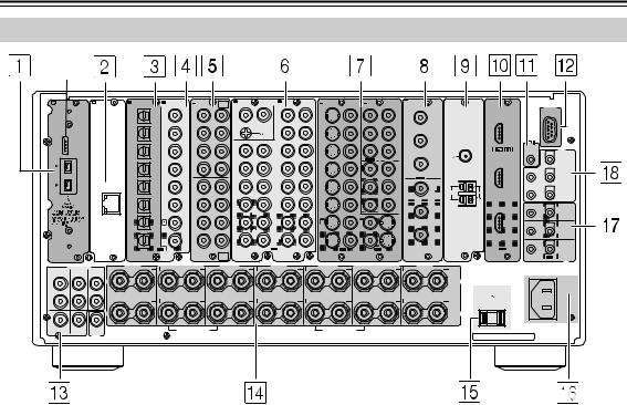
Index Parts and Facilities—Continued
Rear Panel
|
* |
|||||||||||||||||||
|
A |
B |
C DIGITAL IN |
D DIGITAL IN |
E |
MULTI |
F |
AUDIO IN |
G |
H S VIDEO |
VIDEO |
I |
COMPONENT |
J |
K |
L |
||||
|
— CH |
L |
VIDEO |
|||||||||||||||||
|
OPTICAL |
COAXIAL |
FR |
FL IN 1 |
R |
L |
R |
IN |
IN |
IN 1 |
IN 2 |
COMPONENT VIDEO |
ANTENNA |
HDMI |
RS232 |
|||||
|
1 |
1 |
PH |
4 |
1 |
Y |
IN 4 |
|||||||||||||
|
Y |
|||||||||||||||||||
|
SUB |
C |
IN 1 |
|||||||||||||||||
|
2 |
2 |
5 |
2 |
PB |
|||||||||||||||
|
GND |
PB |
||||||||||||||||||
|
SR |
SL |
R |
L |
||||||||||||||||
|
“Net-Tune” |
REMOTE |
12V |
|||||||||||||||||
|
3 |
3 |
1 |
6 |
3 |
PR |
CONTROL |
|||||||||||||
|
is a trademark of |
FM |
TRIGGER |
|||||||||||||||||
|
Onkyo Corporation. |
OUT |
||||||||||||||||||
|
SBR |
SBL |
OUT 1 |
IN 3 |
75 |
|||||||||||||||
|
PR |
A |
||||||||||||||||||
|
200mA MAX. |
|||||||||||||||||||
|
4 |
4 |
2 |
7 |
4 |
Y |
IN 2 |
B 100mA MAX. |
||||||||||||
|
C |
|||||||||||||||||||
|
FR |
FL |
OUT 2 |
100mA MAX. |
||||||||||||||||
|
ETHERNET |
5 |
5 |
3 |
8 |
5 |
PB |
Y |
D 100mA MAX. |
|||||||||||
|
(Net-Tune) |
|||||||||||||||||||
|
AM |
E |
||||||||||||||||||
|
SUB |
C |
100mA MAX. |
|||||||||||||||||
|
6 |
6 |
1 |
9 |
6 |
PR |
||||||||||||||
|
SR |
SL |
PB |
MAIN |
||||||||||||||||
|
1 |
1 |
2 |
4 |
1 |
3 |
||||||||||||||
|
SBR |
SBL |
ZONE 2 |
|||||||||||||||||
|
PR |
|||||||||||||||||||
|
2 |
2 |
3 |
5 |
2 |
4 |
|
OUT |
R |
L |
OUT |
R |
L |
OUT |
OUT |
OUT |
ZONE 3 |
|
MULTI |
S VIDEO |
VIDEO |
VIDEO |
S VIDEO |
|||||
|
— CH |
IN |
OUT |
|||||||
|
IN 2 |
|||||||||
|
IR |
|
PRE OUT A |
SURR R |
SURR BACK R (ASSIGNABLE) |
FRONT R |
CENTER |
FRONT L |
SURR BACK L (ASSIGNABLE) |
SURR L |
|
|
(SINGLE) |
||||||||
|
FRONT |
SURR |
SURR |
||||||
|
BACK |
||||||||
|
L |
A |
SPEAKERS A |
||||||
|
AC INLET |
|
AC OUTLET |
||||||
|
AC 120V |
60Hz |
|||||
|
R |
SWITCHED |
|||||
|
120W 1A MAX. |
||||||
|
B |
SPEAKERS B |
|||||
|
CENTER |
SUB |
SUB |
FRONT R (BTL) |
FRONT L (BTL) |
||
|
WOOFER |
WOOFER |
MODEL NO. TX-NR1000 |
||||
|
PRE |
UDC/UDT |
|||||
|
OUT B |
*This terminal is provided for future service enhancement and is not used currently. Never plug the cable connector for other terminals into this terminal.
1( ) i.LINK S400 (AUDIO) terminals
Some of the Asian models are not equipped with the i.LINK(AUDIO) terminals.
These connectors are for connecting to the i.LINK (AUDIO)-ready device using a 4-pin (S400) i.LINK (AUDIO) cable. The TX-NR1000/TX-NR5000E complies with the standards on audio only transmissions.
2ETHERNET (Net-Tune)
This connector is for connecting to an Ethernet network.
3DIGITAL OPTICAL IN/OUT
The input/output terminals for digital sound signal. The sound quality equals the signal passed through the COAXIAL terminals.
4DIGITAL COAXIAL IN/OUT
The input/output terminals for digital sound signal. The sound quality equals the signal passed through the OPTICAL terminals.
5MULTI-CH IN 1/2
This connector is for connecting components with a multichannel output.
Two sets of multichannel input terminals are available on the TX-NR1000/TX-NR5000E.
6AUDIO IN/OUT
These connectors are for connecting to the audio input and output jacks on audio/video components. To connect a turntable, connect to the PH jacks.
In addition to the PH jacks, the TX-NR1000/ TX-NR5000E offers nine input and five output jacks.
7VIDEO/S VIDEO IN/OUT
These connectors are for connecting to the video input and output jacks on video components.
Six input and 4 output jacks are available for each of VIDEO and S VIDEO connection.
8COMPONENT VIDEO IN/OUT
These connectors are for connecting to the component video outputs/inputs of video components that have them.
European and Asian models are equipped with three inputs and one output for the RCA-type COMPONENT connection and one input and output for the BNC-type COMPONENT connection.
For other than European and Asian models, there are four inputs and two outputs for the RCA-type COMPONENT connection.
Check the type of terminals or jacks on the device to connect before making connections.
9ANTENNA (FM/AM)
These jacks are for connecting the FM indoor antenna and the AM loop antenna that are supplied with the TX-NR1000/TX-NR5000E.
0HDMI IN/OUT
This interface can transfer digital audio and video signals simultaneously. The terminal can be connected to the HDMI terminal on the components such as DVD player, set top box (B tuner), projector, and digital TV.
A REMOTE CONTROL
This jack is for connecting other Onkyo components equipped with the same  terminal. The audio connection cables must also be connected.
14
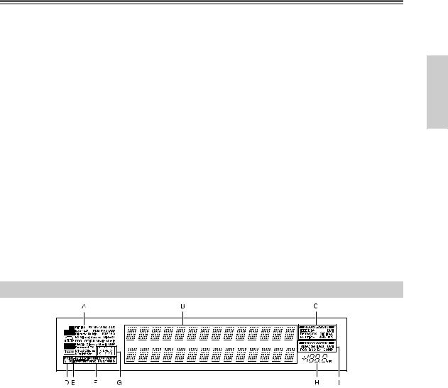
Index Parts and Facilities—Continued
BRS 232
This port is for connecting the TX-NR1000/ TX-NR5000E to home automation and external controllers.
CPRE OUT A/B
To use the TX-NR1000/TX-NR5000E as a preamplifier, connect a power amplifier to this jack.
DSPEAKERS A/B
These terminals are for connecting the speakers. Two sets of home theater connections are available (simultaneous playback of different sources in each of two home theaters is not supported).
Depending on your system, various speaker connections will be available. For example, you can use the surround back speakers for playback in a different room.
EAC OUTLET
The TX-NR1000/TX-NR5000E is equipped with AC mains outlets for connecting the power cords from other devices so that their power is supplied through the TX-NR1000/TX-NR5000E. By doing this, you can leave the connected device turned on and have the [STANDBY/ON] button on the TX-NR1000/TX-NR5000E turn on and off the
device together with the TX-NR1000/ TX-NR5000E.
The shape, number, and total capacity of the AC outlets may differ depending on the area of purchase.
Caution:
Make sure that the total capacity of the components connected to the TX-NR1000/TX-NR5000E does not exceed the capacity that is printed on the rear panel (e.g., AC 120V — 60Hz SWITCHED 120W 1A MAX.).
FAC INLET
This connector is for connecting the supplied power cord.
GIR IN/OUT
These connectors are for connecting the remote sensor of a multiroom kit (sold separately).
The connectors are provided for main room, Zone 2, and Zone 3.
H12V TRIGGER OUT
These connectors are used to connect to the 12V TRIGGER IN terminal of a component. Available connectors are one with maximum current capacity of 200 mA and four with 100 mA.
Front Panel Display
AListening mode or input format indicators
One of these indicators lights to show the format of the current input source. In addition, one of the listening mode indicators lights to indicate the current listening mode.
BMultifunction display
During normal operation, shows the current input source. When the FM or AM input is selected, shows the frequency and preset number. When the [DISPLAY] button is pressed, shows the listening mode and input source format.
CAudio input signal path indicators
Shows from which terminal the audio input signal is coming.
DMAIN A/B indicators
Indicates which room is currently in use.
ESLEEP indicator
Lights when the sleep timer is turned on.
FTuning indicators
AUTO indicator
Lights when receiving FM broadcasts in the stereo mode. Turns off when placed into the monaural mode.
RDS indicator (European models only)
Lights when an RDS station is being received.
 TUNED
TUNED indicator
Lights when a radio station is being received.
MEMORY indicator
Lights when the [MEMORY] button is pressed to preset a radio station.
FM STEREO indicator
Lights when an FM broadcast station is being received in stereo. Turns off when placed into the monaural mode.
GProgram format display
When the input source is DVD video, Super Audio CD, or compressed digital audio signal such as Dolby Digital and DTS, the channels corresponding to the input source light.
HVolume display
Shows the volume level.
IVideo input signal path indicators
Shows from which terminal the video input signal is coming.
15

Index Parts and Facilities—Continued
Remote Controller (Amp Mode)
The TX-NR1000/TX-NR5000E’s remote controller is a multipurpose device that can be used to control not just the TX-NR1000/TX-NR5000E but your other AV components as well. This section explains how its various operating modes can be used to control the TX-NR1000/TX-NR5000E. When you use the NetTune mode, see page 74 for details. See page 124-136 for information on using the remote controller to control Onkyo components connected via  and TVs, VCRs, and AV components made by other manufacturers.
Scroll wheel
|
1 |
2 |
3 |
+ |
|||||||||
|
@. — ‘ / |
ABC |
DEF |
TV CH |
|||||||||
|
4 |
5 |
6 |
— |
|||||||||
|
GHI |
JKL |
MNO |
||||||||||
|
7 |
8 |
9 |
||||||||||
|
PQRS |
TUV |
WXYZ |
TV VOL |
|||||||||
|
+10 |
0 |
CLEAR |
||||||||||
|
—/— |
# |
|||||||||||
|
DIRECT TUNING |
||||||||||||
|
CUSTOM |
||||||||||||
|
ZONE 3 |
||||||||||||
|
MACRO |
ZONE 2 |
|||||||||||
|
MODE |
INPUT |
|||||||||||
|
DIMMER |
SLEEP |
|||||||||||
|
U |
M |
|||||||||||
|
TV |
EN |
E |
N |
|||||||||
|
M |
U |
|||||||||||
|
INPUT |
P |
|||||||||||
|
O |
||||||||||||
|
T |
ER |
AU |
DI |
|||||||||
|
V |
||||||||||||
|
R |
O |
A |
||||||||||
|
+ |
E |
|||||||||||
|
S |
D |
|||||||||||
|
J |
||||||||||||
|
CH |
ENTER |
VOL |
||||||||||
|
DISC |
||||||||||||
|
— |
E |
E |
||||||||||
|
X |
||||||||||||
|
D |
||||||||||||
|
PREV |
R |
IT |
GU |
|||||||||
|
P |
||||||||||||
|
E |
T |
URN |
||||||||||
|
CH |
SET |
|||||||||||
|
DISPLAY |
MUTING |
|||||||||||
|
REC |
MAIN A |
MAIN B |
RANDOM |
|||||||||
|
AUDIO |
SUBTITLE |
ANGLE |
LAST M |
|||||||||
|
SURR |
THX |
ALL ST |
STEREO |
|||||||||
|
REPEAT |
A-B |
SEARCH |
MEMORY |
|||||||||
|
PURE A |
DIRECT |
DSP |
DSP |
|||||||||
|
REPEAT |
VIDEO |
MUSIC |
PHOTO |
|||||||||
|
TEST TONE |
CH SEL |
LEVEL- |
LEVEL+ |
|||||||||
|
PLAYLIST |
ALBUM |
ARTIST |
GENRE |
|||||||||
|
AUDIO SEL |
L NIGHT |
Re-EQ |
||||||||||
|
CAPS |
DELETE |
LANGUAGE |
LOCATION |
RC-557M
RC-558M
Amp mode is used to control the TX-NR1000/ TX-NR5000E. To select Amp mode, press the scroll wheel. “AMP” appears on the display.
Note:
While neither the [INPUT] button nor the [MODE] button is illuminated, rolling the scroll wheel changes the input source and remote controller mode simultaneously.
1ON button
This button is used to turn on the TX-NR1000/ TX-NR5000E.
2STANDBY button
This button is used to set the TX-NR1000/ TX-NR5000E to Standby.
3Number/letter buttons
These buttons are used to enter numbers and letters.
4CUSTOM button
This button is used to access various settings that you can use to customize the operation of the remote controller.
5MACRO button
This button is used with the Macro function.
6MODE button
This button is used with the scroll wheel to select the remote controller modes.
7DIMMER button
This button is used to adjust the display brightness.
8Up/Down/Left/Right [ ]/[
]/[ ]/[
]/[ ]/[
]/[ ] & ENTER buttons
These buttons are used to select items on the onscreen setup menus (OSD). The [ENTER] button is also used to enter names and to confirm settings.
9CH +/– button
This button is used to select radio presets.
0RETURN button
This button is used to return to the previously displayed onscreen setup menu (OSD).
ADISPLAY button
This button is used to display various information about the currently selected input source.
BMAIN A button
For the speakers used in main room A, every press of this button toggles the status between enabled and disabled.
CTHX button
This button is used to select the THX listening modes.
DSURR button
This button is used to select the Dolby and DTS listening modes.
16

Index Parts and Facilities—Continued
EDIRECT button
This button is used to select the Direct listening mode.
FPURE A button
This button is used to select the Pure Audio listening mode.
GTEST TONE, CH SEL, LEVEL– & LEVEL+ buttons
These buttons are used to adjust the level of each speaker individually. These functions can be set only with the remote controller. The [LEVEL–] and [LEVEL+] buttons are also used to adjust the volume in Zone 2 or Zone 3.
HAUDIO SEL button
This button is used to select the audio input signal format: analog, digital, multichannel, or i.LINK.
ILIGHT button
This button is used to turn on or off the remote controller’s illuminated buttons.
JDIRECT TUNING button
This button is used with the number buttons to select a radio station by entering its frequency. Press this button first, and then use the number buttons to enter the frequency.
KDisplay
The top line of this LCD display shows the name of the currently selected input source. The bottom line shows the currently selected remote controller mode.
LZONE 3 button
This button is used when you want to set the volume and input source for Zone 3.
MZONE 2 button
This button is used when you want to set the volume and input source for Zone 2.
NINPUT button
This button is used to select the input source. Press this button first, and then roll the scroll wheel until the name of the input source appears on the display.
OSLEEP button
This button is used to set the Sleep function. This function can be set only with the remote controller.
PVOL 
 button
This button is used to set the volume of the TX-NR1000/TX-NR5000E.
QSETUP button
This button is used to access the onscreen setup menus (OSD) that appear on the TV.
RMUTING button
This button is used to mute the TX-NR1000/ TX-NR5000E. This function can be set only with the remote controller.
SMAIN B button
For the speakers used in main room B, every press of this button toggles the status between enabled and disabled.
TAll ST button
This button is used to select the All Ch Stereo listening mode.
USTEREO button
This button is used to select the Stereo listening mode.
V DSP/DSP
  buttons
These buttons are used to select the listening modes.
WRe-EQ button
This button is used to turn on and off the Re-EQ function.
XL NIGHT button
This button is used to set the Late Night function.
17

Speaker Placement
Basic Speaker Placements for Home Theater and the Function of Respective Speakers
The TX-NR1000/TX-NR5000E has many excellent features to recreate a clear three-dimensional sound image and lively sound movement. This enables you to enjoy, at home, the rich sound effects of a live theater or concert hall performance. When playing a DVD, you can enjoy sound effects provided by DTS or Dolby Digital, depending on the recording format. In addition, you can enjoy THX sound and Onkyo’s proprietary DSP surround playback for TV or digital satellite broadcasts.
Front left and right speakers
Outputs overall sound. They play the most important role in a home theater system, by creating basic sound images and fields.
Center speaker
Complements the sound effects from front left and right speakers to enrich and clear the sound image and movement. In movies, an actor’s speech comes mainly from the center speaker.
Subwoofer
Outputs only bass sounds to enhance and complement bass sound effects.
Surround back speakers
Enhances the sound space representation with surround channel signals. Recreating sound movement effects and sound fields behind the listener gives a more realistic experience.
Surround left and right speakers
Enhances the sensation of being at a live performance by giving three-dimensional sound movement to the sound effects.
•For optimum surround playback, set the distance between the listener and the speakers so that the time it takes the sound to reach the listener is same. Also, you need to set each speaker volume level individually in order to balance the volume level between speakers (See pages 88 to 90).
18

Speaker Placement—Continued
Placing the Speakers
To fully enjoy surround sound, the configuration and placement of the speakers used are important. Be sure to read through the descriptions in the previous page and shown below.
This section provides examples and descriptions that assume a typical situation.
Front Left and Right Speakers, and Center Speaker
|
• |
Place the front left and right speakers symmetrically and so |
||||
|
that the distance from the listening position is the same. |
|||||
|
• |
When placing speakers, direct the speakers toward the |
||||
|
TV or screen |
|||||
|
position of the listener’s ears where the listener sits to enjoy Front |
Front |
||||
|
Center |
|||||
|
Left |
Right |
music or movies.
•Place the three speakers so that the heights of the three speakers are aligned. The ideal height for the speakers is the height of the listener’s ears. When placing the center speaker above or below the TV, tilt it toward the listener’s ears.
•Place the center speaker as close to the screen or monitor as possible and in the center between the left and right front
speakers. When placing the center speaker near the TV, use a shielded speaker.
•If no center speaker is used, place the left and right front speakers closer to each other.
Left and Right Surround Speakers
•Place these speakers on each side of, or angled behind, the listener.
•Place the surround speakers symmetrically from the listener position and so that the distance from the listener is equal between left and right surround speakers.
•When enjoying mainly movies, placing the surround speakers about 3 feet (1 m) higher than the height of the listener’s ears, results in more of a surround effect.
•When enjoying mainly music, placing the surround speakers at the height of the front speakers may provide a better surround effect.
Surround Back
•When using surround back speakers in addition to the
surround speakers, placing the surround speakers slightly forward from their current position will make the sound movement smoother.
Surround Back Speakers
•Place the speakers about 3 feet (1 m) or higher than the height of the listener’s ears.
•When using one surround back speaker, place it behind the listener.
•When using two surround back speakers, place them behind the listener so that the angles between the lines from each surround back speaker to the listener and a line straight back from the listener are about 30 degrees, forming an equilateral triangle of the listener and the two surround back speakers.
*When using a THX-certified speaker system, also refer to “Speaker Placement Suitable for THX Audio” on the next page.
19
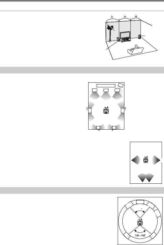
Speaker Placement—Continued
Subwoofer
Using a subwoofer greatly improves the volume level and sound quality of bass sounds. The subwoofer effect depends not only on the listening position but also on the shape of the listening room.
•In general, place the subwoofer in a corner of the room or at a point 1/3 the width of the room.
•Play a movie or music that contains high quality bass sounds to determine the subwoofer placement. Change the subwoofer’s position and check the effect, then select the position where the bass sounds are best heard.
•You can place two subwoofers for more powerful and richer heavy bass sounds.
Speaker Placement Suitable for THX Audio
To enjoy sources using THX Cinema or THX Surround EX technology, we recommend using a THX speaker system from THX Ltd. A speaker system supporting the THX Ultra2 standard is best suited for THX Ultra2 Cinema or THX Music Mode.
The layout example on the right represents a case using the dipole speakers. A dipole speaker is a two-way directivity speaker that outputs the same sound in two directions such as forward and backward.
Most dipole speakers are marked with an arrow indicating how they should be oriented in the room in order to match their phases*. Dipole surround speakers should be placed so that their arrows point forward toward the screen, and dipole surround back speakers should be placed so that their arrows point toward each other.
|
Layout with dipole speakers |
||||
|
1 |
2 |
1 |
TV or screen |
|
|
2 |
Subwoofer |
|||
|
3 |
4 |
5 |
3 |
Front left speaker |
|
4 |
Center speaker |
|||
|
5 |
Front right speaker |
|||
|
6 |
Surround left speaker |
|||
|
7 |
Surround right |
|||
|
6 |
7 |
speaker |
||
|
Surround back left |
||||
|
10 |
8 |
|||
|
speaker |
||||
|
9 |
Surround back right |
|||
|
8 |
9 |
speaker |
||
|
10 |
Listening position |
|||
*Phase: The word represents the waveform position in one cycle (0 to 360 degrees) of a sine wave. If the phase does not match between multiple waveforms due to the distance between multiple speakers, the speaker orientation, or the miswiring of positive and negative poles, the sound image or space may be obscured or the sound may be less easy to listen to.
|
When playing the source in the THX Ultra2 Cinema or THX Music Mode format using two |
||||||||
|
6 |
7 |
|||||||
|
surround back speakers supporting the THX Ultra2 standard, place them as close together as |
||||||||
|
10 |
||||||||
|
possible. After placing the surround back speakers, perform the settings described in the |
||||||||
|
As close as |
||||||||
|
“THX Audio Setup” (page 91). |
||||||||
|
possible |
||||||||
|
8 |
9 |
Speaker Placement Suitable for a Music Source such as DVD-Audio
This placement is based on the ITU-R* recommendation. In this placement, five speakers with the same performance capabilities are used for front left and right, center, and left and right surround speakers, and they are placed so that the distances between every speaker and the listening position are equal to each other and the heights of the speaker and the listener’s ears are the same. A mixing studio used for making multichannel DVD-Audio source material adopts this placement.
*ITU-R: International Telecommunication Union Radiocommunication Sector
|
Center |
|
|
Front |
Front |
|
Left |
Right |
|
60 |
|
|
Sub- |
|
|
woofer |
|
|
SL |
SR |
20
![]()
Speaker Placement—Continued
Available Speaker Placements According to the Number of Speakers
The following speaker placements will be available according to the number of speakers connected to the TX-NR1000/TX-NR5000E. For the number of speaker channel, _.1 ch represents a subwoofer.
Key to abbreviations:
FL: Front left speaker, FR: Front right speaker, C: Center speaker, SL: Surround left speaker, SR: Surround right speaker, SBL: Surround back left speaker, SBR: Surround back right speaker, SW: Subwoofer
2 ch/2.1 ch
This placement is used with two speakers (front left and right speakers). It is optimum for 2 ch sources including analog 2 ch, 2 ch linear PCM, Dolby Digital, DTS, DTS96/24, and AAC format sources. When the number of channels in the source is 3.1 or greater, the signals will be distributed through the left and right channels accordingly.
3 ch/3.1 ch
This placement is used with three speakers (front left, front right, and center speakers). When the number of channels in the source is 4.1 or greater, the signal for surround and surround back channels will be output through the front left and right speakers.
4 ch/4.1 ch
In this placement, when the number of channels in the source is 5.1 or greater, the center channel signal will be output through the front left and right speakers, and the surround back channels will be output through the surround speakers.
5 ch/5.1 ch
This placement is suitable for
|
SW |
playing 5.1 ch sources |
|||||||
|
FL |
C |
FR |
||||||
|
including analog multichannel, |
||||||||
|
Dolby Digital, DTS, and AAC |
||||||||
|
format sources. When the |
||||||||
|
source is 2 ch or mono, the |
||||||||
|
signal will be decoded with |
||||||||
|
SL |
SR |
|||||||
|
Dolby Pro Logic II or DTS |
||||||||
|
NEO:6 format and played as |
||||||||
|
5.1 ch sources. |
||||||||
|
When the number of channels in the source is 6.1 or |
greater, the surround back signal will be distributed through the surround left and right speakers accordingly.
6 ch/6.1 ch/7 ch/7.1 ch (with center speaker)
This placement is suitable for playing 6.1 ch sources including DTS-ES Matrix/ Discrete and Dolby Surround EX format signals.
When you use two surround back speakers, the same signal will be output from them because the surround back channel is mono. When the source is 2 ch or mono, it will be decoded with the Dolby Pro Logic IIx/DTS NEO:6 format and played as 6.1/7.1 ch sources.
SBL SBR
6 ch/6.1 ch/5 ch/5.1 ch (without center speaker)
This placement is suitable for playing 5.1 or 6.1 ch sources when the surround back sound is much more preferred than the center sound with less speaker units than the normal configuration. The center channel signal will be output through the front left and right speakers.
21

Speaker Placement—Continued
Connection Examples
The TX-NR1000/TX-NR5000E has two speaker terminal blocks for speaker systems [A] and [B]. This allows you to build two 7.1 ch home theater systems, and various speaker placements and connections are also available. For example, some channels of either speaker system can be used for another room (Zone 2), or you can select one of two speaker systems for playback according to the source.
When you use two speaker systems, you have to associate the speakers with the zone (e.g., Main A, Main B, etc.). After making the association, for example, pressing the “MAIN A” button on the remote controller will output the source from the speakers configured as “Main A.”
Here are some examples of speaker placement and zone association. These examples can be your reference when you build your own home theater system. The illustration on the right represents the actual settings displayed corresponding to each example. For details on configuring speaker placement and zone association, see page 88.
*In the following illustrations, white speakers denote speaker system [A] and gray ones denote speaker system [B]. *Key to abbreviations:
FL: Front left speaker; FR: Front right speaker; C: Center speaker; SL: Surround left speaker; SR: Surround right speaker; SBL: Surround back left speaker; SBR: Surround back right speaker; SW: Subwoofer
When you wish to configure 7.1 ch speaker system in the main room A only, the initial setting can be used without any modification.
Main room A: 7.1 ch speaker system; Main room B: 7.1ch speaker system
|
SW |
SW |
1-1.Speaker Config |
|||||
|
FR |
FR |
||||||
|
FL |
C |
FL |
C |
===================== |
|||
|
Speaker A |
|||||||
|
a.Front L/R |
:Main A |
||||||
|
Main room A |
Main room B |
b.Center |
:Main A |
||||
|
c.Surr L/R |
:Main A |
||||||
|
d.Surr Back |
|||||||
|
SL |
SR |
SL |
SR |
:Main A |
2ch |
||
|
e.Subwoofer |
:Main A |
||||||
|
Speaker B |
|||||||
|
f.Front L/R |
:Main B |
||||||
|
g.Center |
:Main B |
||||||
|
h.Surr L/R |
:Main B |
||||||
|
i.Surr Back |
|||||||
|
SBL |
SBR |
SBL |
SBR |
:Main B |
2ch |
||
|
j.Subwoofer |
:Main B |
•Set all the zone parameters for speaker system [A] to “Main A.”
•Set all the zone parameters for speaker system [B] to “Main B.”
•Pressing the [MAIN A] or [MAIN B] button causes the sound to be output from the speaker system associated with the zone button. Both speaker
systems cannot be selected simultaneously.
*If you set all the zone parameters for speaker system [B] to “Main A” and play a single source, the same audio signal will be output from both speaker systems [A] and [B].
Main room A: 7.1 ch speaker system; Main room B: 5.1 ch speaker system; Sub room (Zone 2): 2 ch
|
speakers |
|||
|
SW |
|||
|
FL |
C |
FR |
|
|
Main room A |
|||
|
SL |
SR |
SL |
|
|
SBL |
SBR |
FL C FR
Zone 2
Main room B
SR
|
1-1.Speaker Config |
|
|
===================== |
|
|
Speaker A |
|
|
a.Front L/R |
:Main A |
|
b.Center |
:Main A |
|
c.Surr L/R |
:Main A |
|
d.Surr Back |
|
|
:Main |
A 2ch |
|
e.Subwoofer |
:Main A |
|
Speaker B |
|
|
f.Front L/R |
:Main B |
|
g.Center |
:Main B |
|
h.Surr L/R |
:Main B |
|
i.Surr Back |
Main B |

 :Powered Zone 2
j.Subwoofer :Main B 
•Set all the zone parameters for speaker system [A] to “Main A.” Set the zone parameters for speaker system [B] to “Main B” and “Zone 2” accordingly.
•Both main room A and B cannot be used simultaneously. However, while either of the main rooms is used, you can enjoy a different source in Zone 2.
•Note that when you use Zone 2, the surround back speakers for main room A cannot be used since Zone 2 uses the surround back speaker circuit for main room A.
22

Speaker Placement—Continued
Main room A: 7.1 ch speaker systems and the two additional front speakers
(When you want to use speaker system [A] for movies and enjoy 7.1 surround sound and the two additional front
speakers for classic music.)
FL 
 FL
FL 
 C
C 
 FR
FR 
 FR
FR
SW
Main room A
|
SL |
SR |
|||||
|
SBL |
SBR |
1-1.Speaker Config
=====================
Speaker A
|
a.Front L/R |
:Main A |
|
b.Center |
:Main A |
|
c.Surr L/R |
:Main A |
|
d.Surr Back |
|
|
:Main A |
2ch |
|
e.Subwoofer |
:Main A |
|
Speaker B |
|
|
f.Front L/R |
:Main A |
|
g.Center |
:Not Used |
|
h.Surr L/R |
:Not Used |
i.Surr Back :Not Used
j.Subwoofer :Not Used

3-3.Stereo
=====================
a. Re-EQ/Academy :Off
b.Front Speaker: B
c.Subwoofer: A
Here is an example of the stereo sources.
•Set all the zone parameters for speaker system [A] to “Main A.”
•Set the front speaker parameters for speaker system [B] to “Main A.”
•If you want to use the front speakers of speaker system [B] for specific sources, select the source and set the front speaker setting parameters to “B” in the listening mode setup menu.
When you want to output to both speaker systems simultaneously, you can choose the “A+B” setting unless any of the speakers has an impedance of 8 ohm or lower.
•To output the sound, press the [MAIN A] button on the remote controller.
Main room A: 7.1 ch speaker system and the two additional front speakers connected through the BTL or bi-amp connection (when you want to use either the 7.1 ch speakers or the additional front speakers according to the source)
|
FL |
FL |
C |
FR |
FR |
||||||
|
SW |
Main room A
|
SL |
SR |
|||||
|
SBL |
SBR |
1-1.Speaker Config
=====================
Speaker A
|
a.Front L/R |
:Main A |
|
b.Center |
:Main A |
|
c.Surr L/R |
:Main A |
|
d.Surr Back |
|
|
:Main A |
2ch |
|
e.Subwoofer |
:Main A |
|
Speaker B |
|
|
f.Front L/R |
:Main A |
|
g.Center |
:Not Used |
|
h.Surr L/R |
:Not Used |
|
i.Surr Back |
|
|
:BTL for Front |
|
|
j.Subwoofer |
:Not Used |
3-3.Stereo
=====================
a. Re-EQ/Academy :Off
b.Front Speaker: B
c.Subwoofer: A
Here is an example of the stereo sources.
•Set all the zone parameters for speaker system [A] to “Main A.”
•For speaker system [B], set the front speaker parameters to “Main A” and the surround back speaker parameters to “BTL for Front” or “Bi-Amp for Front” (For details on connections, see page 27).
•When you want to use the front speakers of speaker system [B] for specific sources, select the source and set the
front speaker parameters to “B” in the listening mode setup menu.
*When using the BTL or bi-amp connections, the two speaker systems cannot be used to output simultaneously due to the speaker impedance limitation.
23
Speaker Placement—Continued
Main room A: 5.1 ch speaker system including the front speakers connected through the BTL or biamp connections
SR
1-1.Speaker Config
=====================
Speaker A
|
a.Front L/R |
:Main A |
|
|
b.Center |
:Main A |
|
|
c.Surr L/R |
:Main A |
|
|
d.Surr Back |
||
|
:BTL for Front |
||
|
e.Subwoofer |
:Main A |
|
|
Speaker |
B |
|
|
f.Front L/R |
:Not Used |
|
|
g.Center |
:Not Used |
|
|
h.Surr L/R |
:Not Used |
|
|
i.Surr Back |
||
|
:Not Used |
||
|
j.Subwoofer |
:Not Used |
•For speaker system [A], set the surround back speaker parameters to “BTL for Front” or “Bi-Amp for Front” and all the other speaker parameters to “Main A” (For details on speaker connections, see page 27).
•For speaker system [B], set the speaker parameters to “Not Used.”
*When using the BTL or bi-amp connections, you cannot use Zone 2 since the surround back channel is used for the front speakers of main room A.
Main room A: 7.1 ch from speaker system [A] and additional subwoofer and surround speakers from speaker system [B] (suitable for enjoying more powerful and lively surround sound in main room A); Main room B: two front speakers from speaker system [B] using the BTL or bi-amp connections
|
FL |
FR |
||||||||||||||||||||
|
FL |
C |
FR |
|||||||||||||||||||
|
SW |
SW |
Main room B |
|||||||||||||||||||
|
Main room A |
|||||||||||||||||||||
|
SL |
SR |
||||||||||||||||||||
|
SL |
SR |
||||||||||||||||||||
|
SBL |
SBR |
1-1.Speaker Config
=====================
Speaker A
|
a.Front L/R |
:Main A |
|
b.Center |
:Main A |
|
c.Surr L/R |
:Main A |
|
d.Surr Back |
|
|
:Main A |
2ch |
|
e.Subwoofer |
:Main A |
|
Speaker B |
|
|
f.Front L/R |
:Main B |
|
g.Center |
:Not Used |
|
h.Surr L/R |
:Main A |
i.Surr Back
:BTL for Front j.Subwoofer :Main A
3-5.Multichannel Input
=====================
b.Re-EQ :Off

g.Subwoofer :A+B

Here is an example of the multichannel sources.
•For speaker system [A], set all the speaker parameters to “Main A.”
•For speaker system [B], set the surround speaker and subwoofer parameters to “Main A,” the front speaker parameters to “Main B,” and the surround back speaker parameters to “BTL for Front” or “Bi-Amp for Front” (For details on speaker connections, see page 27).
•When you want to use the surround speakers and subwoofer of speaker system [B] for specific sources, select the source and set the parameters for these speakers to “B” or “A+B” in the listening mode setup menu.
When you set the parameter to “B,” the audio signal comes out from the surround speakers and subwoofer of speaker system [B]. When you set the parameter to “A+B,” the signal comes out from the surround speakers and subwoofer of both speaker systems [A] and [B].
24

Connecting Speakers
Connecting to the Speaker Terminals
After determining the layout of your speaker system, it is now necessary to connect the speakers correctly to your TX-NR1000/TX-NR5000E.
For the USA and Canadian models, you can also use banana plugs/connectors.
Caution:
You can connect speakers with an impedance of between 4 and 16 ohms. If the impedance of any of the connected speakers is 4 ohms or more, but less than 6 ohms, be sure to set the Speaker Impedance to “4 ohms” (see page 89).
If you use speakers with a lower impedance, and use the amplifier at high volume levels for a long period of time, the built-in protection circuit may be activated. Notes:
•Even if you are using only one speaker or listening to monaural (mono) sound, never connect a single speaker in parallel to both the right and left channel terminals.
R L
•To prevent circuitry damage, never short-circuit the positive (+) and negative (–) speaker wire.
|
• Be sure to connect the positive and |
|
|
negative cables for the speakers |
NO! |
|
properly. If they are mixed up, the |
|
|
left and right signals will be |
|
|
reversed and the audio will sound unnatural. |
•Do not connect more than one speaker cable to one speaker terminal. Doing so may damage the TX-NR1000/TX-NR5000E.
Connecting the Speaker Cable
1.Strip away approx. 5/8 inch (15 mm) of the wire insulation.
2.Twist the wire ends tightly together.
3.Unscrew the speaker terminal cap.
4.Insert the exposed wire end.
5.Tighten speaker terminal cap.
|
1 |
2 |
|
|
5/8″ |
||
|
(15 mm) |
||
|
3 |
4 |
5 |
Tip:
The terminal wrench that comes with this unit is a useful tool for tightening/loosening the speaker terminal cap.
Attaching the Speaker Labels
The positive speaker terminals on the TX-NR1000/ TX-NR5000E are color coded for easy identification. Attach the supplied speaker labels to the speaker cables, and then match the colors on the speaker cables to the corresponding terminals.
|
Speaker label |
Speaker label |
The speaker channels are colored as follows:
Front left speaker (+): White Front right speaker (+): Red Center speaker (+): Green Surround left speaker (+): Blue Surround right speaker (+): Grey
Surround back left speaker (+): Brown Surround back right speaker (+): Tan
|
Front right |
Center |
Front left |
|||||||||||||||||||||||||||||
|
speaker |
speaker |
speaker |
|||||||||||||||||||||||||||||
FRONT R CENTER FRONT L
SPEAKERS A
|
TX-NR1000/ |
|
|
TX-NR5000E |
|
|
SURR R SURR BACK R (ASSIGNABLE) |
SURR BACK L (ASSIGNABLE) SURR L |
|
(SINGLE) |
|
|
SPEAKERS A |
SPEAKERS A |
|
Surround |
Surround |
|
right |
left |
|
speaker |
speaker |
|
Surround |
Surround |
|
back right |
back left |
|
speaker |
speaker |
25
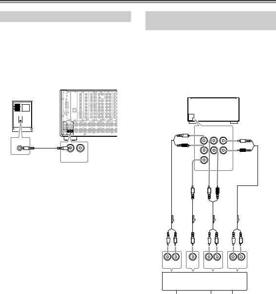
Connecting Speakers—Continued
Connecting a Subwoofer
Use the SUBWOOFER PRE OUT A/B jack to connect a subwoofer with a built-in power amplifier. If your subwoofer does not have a built-in amplifier, connect an amplifier to the SUBWOOFER PRE OUT A/B jack and the subwoofer to the amplifier.
You can connect two subwoofers for different speaker systems. You have to assign a subwoofer to the room in which it will be used (See pages 88, 89).
|
OPTICAL |
COAXIAL |
R |
L |
R |
L |
IN |
||
|
PH |
||||||||
|
R |
L |
|||||||
|
ETHERNET |
||||||||
|
R |
L |
R |
L |
|||||
|
PRE OUT A |
SURR R |
SURR BACK R ASSIGNABLE |
FRONT R |
CENTER |
FRONT L |
|||
|
L |
A |
|||||||
|
R |
||||||||
|
B |
||||||||
|
FRONT R (BTL) |
FRONT L |
|||||||
|
PRE |
||||||||
|
OUT B |
||||||||
|
LINE INPUT |
||||||||
|
SUB |
SUB |
|||||||
|
WOOFER |
WOOFER |
|||||||
|
PRE |
PRE |
|||||||
|
OUT A |
OUT B |
Connecting Auxiliary Power Amplifier (For Speaker System [A] only)
These jacks are for connecting an auxiliary power amplifier. The PRE OUT terminals on the TX-NR1000/ TX-NR5000E use the mode settings for speaker system [A].
You can use an auxiliary power amplifier to listen at louder volumes than you can with the TX-NR1000/ TX-NR5000E alone. When using a power amplifier, connect each speaker to the power amplifier.
TX-NR1000/
TX-NR5000E
to White
|
L |
PRE OUT A |
to Brown |
||
|
FRONT |
SURR SURR |
|||
|
BACK |
L |
|||
|
L |
||||
|
R |
R |
|||
|
to Red |
R |
|||
|
to Tan |
||||
|
CENTER |
||||
|
to Blue |
to Gray |
|||
|
to Green |
L |
R |
||
|
Front |
Center |
Surround |
Surround back |
R  L R
L R  L R
L R  L
L
|
INPUT |
INPUT |
INPUT |
INPUT |
|
R L |
R L |
R L |
Power amplifier
|
1 |
2 |
3 |
4 |
5 |
6 |
7 |
||||||||||||||||||
|
1. |
Front left speaker |
6. |
Surround back left |
|||||||||||||||||||||
|
2. |
Front right speaker |
speaker |
||||||||||||||||||||||
|
3. |
Center speaker |
7. |
Surround back right |
|||||||||||||||||||||
|
4. |
Surround left |
speaker |
||||||||||||||||||||||
|
speaker |
5.Surround right speaker
26
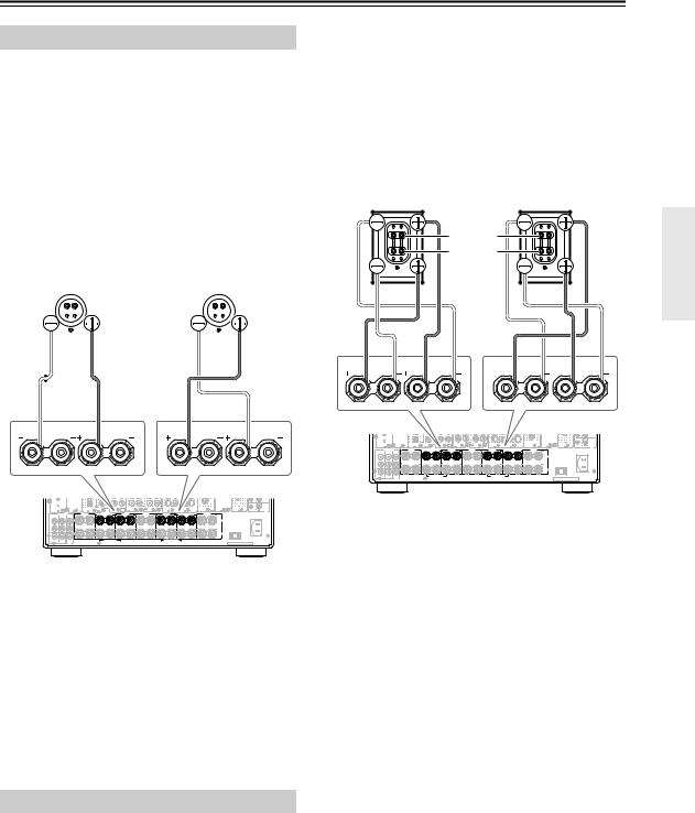
Connecting Speakers—Continued
Using the BTL Connection
To get more powerful sound output, you can make the BTL (Bridged Transless) connection using the front and surround back speaker terminals on the TX-NR1000/ TX-NR5000E. In this connection, two speaker outputs of the stereo amplifier will be used as mono output by combining the individual stereo channel outputs, allowing you to get about twice the output.
Note:
When using the BTL connection, make sure that the speaker impedance is 8 ohm or higher.
For the settings on the BTL connection, see pages 88, 89.
|
Right speaker |
Left speaker |
||||||||||
Caution:
•When making the bi-amp connection, make sure to remove the shorting bars connecting the high range (Tweeter) and low range (Woofer) terminals.
•When using the bi-amp connection, make sure that
the speaker impedance is 8 ohm or higher.
For the settings on the bi-amp connection, see pages 88, 89.
Bi-wiring-enabled speakers
|
Right speaker |
Left speaker |
High range (Tweeter)
Low range (Woofer)
|
SURR BACK R (ASSIGNABLE) |
FRONT R |
FRONT L |
SURR BACK L (ASSIGNABLE) |
|
(SINGLE) |
|
SURR BACK R (ASSIGNABLE) |
FRONT R |
FRONT L |
SURR BACK L (ASSIGNABLE) |
|
(SINGLE) |
|
R |
L |
R |
|||||||
|
PRE OUT A |
SURR R |
SURR BACK R ASSIGNABLE |
FRONT R |
CENTER |
FRONT L |
SURR BACK L ASSIGNABLE |
SURR L |
||
|
L |
A |
SPEAKERS A |
AC INLET |
||||||
|
AC OUTLET |
|||||||||
|
R |
|||||||||
|
B |
SPEAKERS B |
||||||||
|
FRONT R (BTL) |
FRONT L (BTL) |
||||||||
|
PRE |
UDC/UDT |
MODEL NO. TX-NR1000 |
|||||||
|
OUT B |
In the BTL connection, the (–) L/R speaker terminals on the TX-NR1000/TX-NR5000E will not be used.
1.Connect the (+) terminal on the right speaker to the FRONT R SPEAKERS (+) terminal on the TX-NR1000/TX-NR5000E and the (–) terminal on the right speaker to the SURR BACK R SPEAKERS (+) terminal on the TX-NR1000/ TX-NR5000E.
2.Connect the (+) terminal on the left speaker to the FRONT L SPEAKERS (+) terminal on the TX-NR1000/TX-NR5000E and the (–) terminal on the left speaker to the SURR BACK L SPEAKERS
(+) terminal on the TX-NR1000/TX-NR5000E.
Using Bi-amp Connection
When you use bi-wiring-enabled speakers for the front speakers, you can make the bi-amp connection. In this connection, the front and surround back speaker terminals will be used for tweeter and woofer, respectively. This connection allows you to obtain high quality sound as well as maximum treble and bass performance from the tweeter and woofer, enriching your sound experience.
|
R |
L |
R |
|||||||
|
PRE OUT A |
SURR R |
SURR BACK R ASSIGNABLE |
FRONT R |
CENTER |
FRONT L |
SURR BACK L ASSIGNABLE |
SURR L |
||
|
L |
A |
SPEAKERS A |
AC INLET |
||||||
|
AC OUTLET |
|||||||||
|
R |
|||||||||
|
B |
SPEAKERS B |
||||||||
|
FRONT R (BTL) |
FRONT L (BTL) |
||||||||
|
PRE |
UDC/UDT |
MODEL NO. TX-NR1000 |
|||||||
|
OUT B |
1.Connect the (+) tweeter terminal of the right speaker to the FRONT R SPEAKERS (+) terminal on the TX-NR1000/TX-NR5000E and the (+) woofer terminal of the right speaker to the SURR BACK R SPEAKERS (+) terminal on the TX-NR1000/TX-NR5000E.
2.Connect the (–) tweeter terminal of the right speaker to the FRONT R SPEAKERS (–) terminal on the TX-NR1000/TX-NR5000E and the (–) woofer terminal of the right speaker to the SURR BACK R SPEAKERS (–) terminal on the TX-NR1000/TX-NR5000E.
3.Connect the (+) tweeter terminal of the left speaker to the FRONT L SPEAKERS (+) terminal on the TX-NR1000/TX-NR5000E and the (+) woofer terminal of the left speaker to the SURR BACK L SPEAKERS (+) terminal on the TX-NR1000/ TX-NR5000E.
4.Connect the (–) tweeter terminal of the left speaker to the FRONT L SPEAKERS (–) terminal on the TX-NR1000/TX-NR5000E and the (–) woofer terminal of the left speaker to the SURR BACK L SPEAKERS (–) terminal on the TX-NR1000/ TX-NR5000E.
27

Connecting Antennas
This chapter explains how to connect the supplied indoor FM antenna and AM loop antenna, and how to connect commercially available outdoor FM and AM antennas.
FM antenna connector
AM antenna push terminals
|
DIGITAL IN |
DIGITAL IN |
AUDIO IN |
S VIDEO |
VIDEO |
|||||||||||
|
OPTICAL |
COAXIAL |
FR |
FL |
R |
L |
R |
L |
IN |
IN |
IN 1 |
IN 2 |
COMPONENT VIDEO |
ANTENNA |
HDMI |
RS232 |
|
1 |
1 |
PH |
4 |
1 |
Y |
IN 4 |
|||||||||
|
Y |
|
SUB |
C |
IN 1 |
|||||||||||||
|
2 |
2 |
5 |
2 |
P |
|||||||||||
|
SR |
SL |
R |
L |
P |
|||||||||||
|
the HDMI logo |
REMOTE |
12V |
|||||||||||||
|
“Net-Tune” |
3 |
3 |
1 |
6 |
3 |
P |
HDMI,trademark |
CONTROL |
|||||||
|
is a trademark of |
FM |
is aregistered |
TRIGGER |
||||||||||||
|
Onkyo Corporation. |
SBR |
SBL |
1 |
IN 3 |
75 |
trademarksor |
of HDMI |
OUT |
|||||||
|
P |
Licensing LLC. |
A |
|||||||||||||
|
4 |
4 |
2 |
7 |
4 |
Y |
IN 2 |
B |
||||||||
|
C |
|||||||||||||||
|
FR |
FL |
2 |
|||||||||||||
|
ETHERNET |
5 |
5 |
3 |
8 |
5 |
P |
Y |
D |
|||||||
|
Net-Tune |
E |
||||||||||||||
|
SUB |
C |
AM |
|||||||||||||
|
6 |
6 |
1 |
9 |
6 |
P |
||||||||||
|
SR |
SL |
P |
MAIN |
||||||||||||
|
1 |
1 |
2 |
4 |
1 |
3 |
||||||||||
|
SBR |
SBL |
ZONE 2 |
|||||||||||||
|
P |
|||||||||||||||
|
2 |
2 |
3 |
5 |
2 |
4 |
||||||||||
|
R |
L |
R |
L |
ZONE 3 |
|||||||||||
|
S VIDEO |
VIDEO |
VIDEO |
S VIDEO |
||||||||||||
|
IN |
|
SURR R |
SURR BACK R (ASSIGNABLE) |
FRONT R |
CENTER |
FRONT L |
SURR BACK L (ASSIGNABLE) |
SURR L |
IR |
||||
|
PRE OUT A |
|||||||||||
|
FRONT |
SURR |
SURR |
SINGLE |
||||||||
|
BACK |
|||||||||||
|
L |
A |
SPEAKERS A |
AC INLET |
||||||||
|
AC OUTLET |
|||||||||||
|
AC 120V |
60Hz |
||||||||||
|
R |
SWITCHED |
||||||||||
|
120W 1A MAX. |
|||||||||||
|
B |
SPEAKERS B |
||||||||||
|
CENTER |
SUB |
SUB |
FRONT R (BTL) |
FRONT L (BTL) |
|||||||
|
WOOFER |
WOOFER |
MODEL NO. TX-NR1000 |
|||||||||
|
PRE |
UDC/UDT |
||||||||||
|
OUT B |
Connecting the Indoor FM Antenna
The supplied indoor FM antenna is for indoor use only.
1 Attach the FM antenna, as shown.
■ USA and Canadian Model
FM
75 Insert the plug fully into the socket.
■ Other Models
FM
75 Insert the plug fully into the socket
Once your TX-NR1000/TX-NR5000E is ready for use, you’ll need to tune into an FM radio station and adjust the position of the FM antenna to achieve the best possible reception.
2 Use thumbtacks or something similar to fix the FM antenna into position.
Thumbtacks, etc.
Caution: Be careful that you don’t injure yourself when using thumbtacks.
If you cannot achieve good reception with the supplied indoor FM antenna, try using a commercially available outdoor FM antenna instead.
Connecting the AM Loop Antenna
The supplied indoor AM loop antenna is for indoor use only.
1 Assemble the AM loop antenna, inserting the tabs into the base, as shown.
2 Connect both wires of the AM loop antenna to the AM push terminals, as shown.
(The antenna’s wires are not polarity sensitive, so they can be connected in either terminal)
Make sure that the wires are attached securely and that the push terminals are gripping the bare wires, not the insulation.
|
Push |
Insert wire |
Release |
|
AM |
Once your TX-NR1000/TX-NR5000E is ready for use, you’ll need to tune into an AM radio station and adjust the position of the AM antenna to achieve the best possible reception. Keep the antenna as far away as possible from your TX-NR1000/TX-NR5000E, TV, speaker cables, and power cords.
If you cannot achieve good reception with the supplied indoor AM loop antenna, try using a commercially available outdoor AM antenna.
28
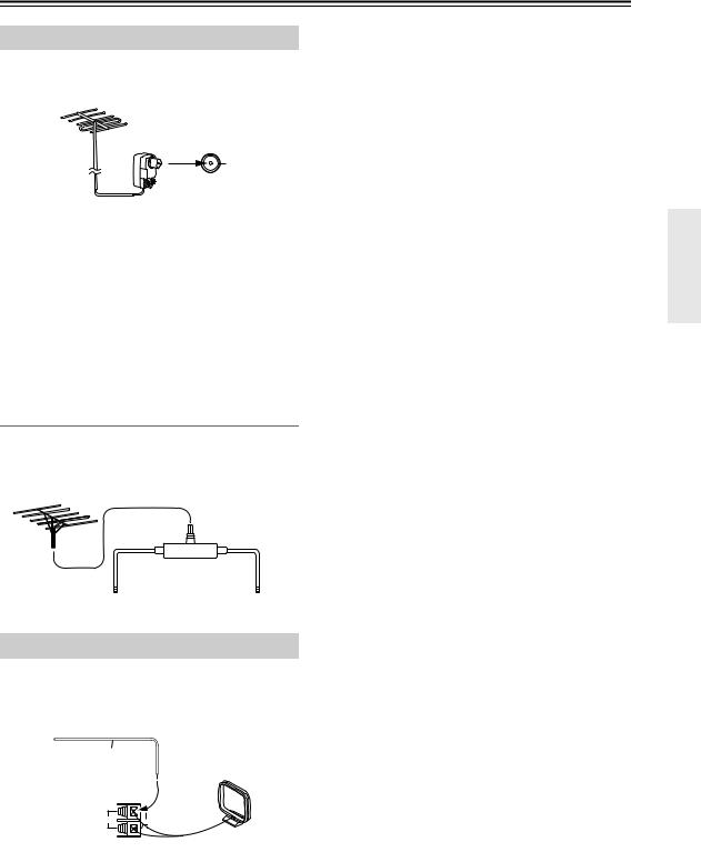
Connecting Antennas—Continued
Connecting an Outdoor FM Antenna
If you cannot achieve good reception with the supplied indoor FM antenna, try using a commercially available outdoor FM antenna instead.
FM 75
Notes:
•Outdoor FM antennas work best outside, but acceptable results can sometimes be obtained when installed in an attic or loft.
•For best results, install the outdoor FM antenna well away from tall buildings, preferably with a clear line of sight to your local FM transmitter.
•Outdoor antennas should be located away from possible noise sources, such as neon signs, busy roads, etc.
•For safety reasons, outdoor antennas should be situated well away from power lines and other high voltage equipment.
•Outdoor antennas must be grounded in accordance with local regulations to prevent electric shock hazards.
Using a TV/FM Antenna Splitter
It’s best not to use the same antenna for both FM and TV reception, as this can cause interference problems. If circumstances demand it, use a TV/FM antenna splitter, as shown.
TV/FM antenna splitter
|
To AV receiver |
To TV (or VCR) |
Connecting an Outdoor AM Antenna
If good reception cannot be achieved using the supplied AM loop antenna, an outdoor AM antenna can be used in addition to the loop antenna, as shown.
Outdoor antenna (aerial)
Insulated antenna cable
AM loop antenna
AM
Outdoor AM antennas work best when installed outside horizontally, but good results can sometimes be obtained indoors by mounting it horizontally above a window.
Note that the AM loop antenna should be left connected. Outdoor antennas must be grounded in accordance with local regulations to prevent electric shock hazards.
29

Connecting AV Components
Types of Connection Cables and Terminals
In addition to the conventional terminals, the TX-NR1000/TX-NR5000E has various terminals that are capable of nextgeneration digital transmission.
Before connecting AV components to the TX-NR1000/TX-NR5000E, make sure that your cable type matches the terminal shape and the signal type and that the cable length is appropriate for the placement of your connected components.
Audio cables
|
Cable names |
Cable forms |
Terminals shapes |
Description |
|
|
Optical cable |
||||
|
The connection using these cable types trans- |
||||
|
mits digital audio signals. There is no sound |
||||
|
quality difference among these cable types. |
||||
|
Note: |
||||
|
Some optical cables have their own covers. |
||||
|
Before making a connection, remove the cov- |
||||
|
ers. When plugging in a cable, be sure to match |
||||
|
the connector shape with the terminal shape. |
||||
|
Coaxial cable |
Each optical terminal on the TX-NR1000/ |
|||
|
TX-NR5000E has its own shutter-type cover. |
||||
|
For the TX-NR1000/TX-NR5000E, plug in the |
||||
|
optical cables so that the optical cable connec- |
||||
|
tor pushes the terminal cover down. |
||||
|
Audio connection |
This connection transmits an analog audio sig- |
|||
|
cable |
nal. Plug the red connector (R) into the right |
|||
|
channel terminal and the white connector (L) |
||||
|
into the left channel connector. |
||||
|
Multichannel con- |
MULTI |
|||
|
nection cable |
— CH |
|||
|
FR |
FL IN 1 |
|||
|
SUB |
C |
The terminals for this cable type are for DVD |
||
|
players that are compatible with the DVD-Audio |
||||
|
SR |
SL |
format. This connection transmits multichannel |
||
|
analog audio signals. |
||||
|
SBR |
SBL |
|||
|
i.LINK connection |
This connection can be used for connecting |
|||
|
cable |
||||
|
i.LINK (AUDIO)-enabled devices and to transmit |
||||
|
(4-pin (S400) type) |
||||
|
digital audio signals. Also, multichannel analog |
||||
|
audio signals from DVD-Audio or Super Audio |
||||
|
CD format sources will be transmitted digitally. |
||||
|
The TX-NR1000/TX-NR5000E handles only |
||||
|
audio signals through i.LINK connection. |
||||
|
Ethernet cable |
The Ethernet cable is used for connecting multi- |
|||
|
(CAT-5 Straight |
||||
|
ETHERNET |
ple PCs or network-ready audio components |
|||
|
type) |
||||
|
that constitute a local area network (LAN). A |
||||
|
(Net-Tune) |
||||
|
LAN is a smaller network composed within a |
||||
|
house or building. The connecting terminals for |
||||
|
the Ethernet cables are often called “LAN port” |
||||
|
or “broadband port.” |
*The audio input signal from the ETHERNET (Net-Tune) or MULTI-CH IN terminal will not be output to the HDMI OUT terminal. Also, the DVD audio or SACD audio input signal from the i.LINK (AUDIO) terminal will not be output to the HDMI OUT terminal.
When you play a source in the remote zone (Zone 2 or Zone 3), the following restrictions are applied.
•When you play the audio signal supplied through the i.LINK (AUDIO) interface, the audio signal will not be output to Zone 2 or Zone 3. With this connection, you cannot record the audio signal from the source.
•The audio input signal from the LAN port will be output only to the AUDIO OUT terminals as an analog source.
•When you play the audio signal from the PH or AUDIO IN terminals in Zone 3, the input source will be output only to the AUDIO OUT terminals as an analog source. Similarly, in this connection, you can record only the audio signal as an analog source through the AUDIO OUT terminals.
30
![]()
Connecting AV Components—Continued
•When you play the audio signal from the DIGITAL IN terminals in Zone 2, the source will be downmixed into 2- channel analog audio signal and output to the AUDIO OUT terminals.
•When you play the audio signal from the DIGITAL IN terminals in Zone 3, only the PCM signal will be output as an analog source to the AUDIO OUT terminals. Similarly, with this connection, you can record only the PCM signal as an analog source through the AUDIO OUT terminals.
•The audio input signal from the HDMI IN terminal can be output to the HDMI OUT terminal.
•The audio input signal from the MULTI-CH IN terminals in Zone 2 will be downmixed into a 2-channel source for output. You cannot play the source from the MULTI-CH IN terminals in Zone 3 and record it.
Video cables
|
Cable names |
Cable forms |
Terminals shapes |
Description |
|
|
Component video |
||||
|
connection cable |
||||
|
(RCA type) |
Y |
Y |
||
|
PB |
PB |
In this connection, the video signal is decom- |
||
|
PR |
PR |
posed into three color difference signals (Y, Pb/ |
||
|
Cb, and Pr/Cr) and carried through three |
||||
|
cables, which provides better video quality than |
||||
|
the S Video connection. |
||||
|
Component video |
The terminal shape for the component video |
|||
|
connection cable can be BNC-type or RCA- |
||||
|
connection cable |
type. For the TX-NR1000/TX-NR5000E, the US |
|||
|
(BNC type) |
model is equipped only with RCA-type termi- |
|||
|
Y |
Y |
nals, and the other models are equipped with |
||
|
PB |
PB |
both RCA-type and BNC-type terminals. |
||
|
This connection cannot transmit information for |
||||
|
PR |
PR |
controlling video devices (e.g., aspect ratio). |
||
|
S Video connection |
The video quality is better than with the com- |
|||
|
cable |
posite signal. In this connection, the |
|||
|
TX-NR1000/TX-NR5000E cannot transmit the |
||||
|
information for controlling video devices (e.g., |
||||
|
aspect ratio). |
||||
|
Video connection |
This connection transmits the standard video |
|||
|
cable |
||||
|
signal and is widely used for various video |
||||
|
devices such as TV and video recorder. |
||||
|
HDMI connection |
This connection carries the video signals digi- |
|||
|
cable |
||||
|
tally. |
||||
|
(Note that no audio signal is carried with this |
||||
|
unit.) |
Note:
When you play the source in the remote zone (Zone 2 or Zone 3), connect the TV or monitor to the VIDEO 1, VIDEO 2, or VIDEO 3 terminal.
•Always refer to the instructions that came with the component that you are connecting.
•Do not plug in the power cord until all connections have been properly made.
•Insert all plugs and connectors securely. Improper connections can result in noise, poor performance, or damage to the equipment.
Example: Audio connection cable
Wrong!
 Right!
•Do not bind audio/video connection cables with power cords and speaker cables. Doing so may adversely affect the picture and sound quality.
31

Connecting AV Components—Continued
Connecting Monitors such as TV or Projector
•This section describes the connections for displaying the video source or the operating information of the TX-NR1000/TX-NR5000E on a monitor device such as a TV or projector. Before making a connection, check the terminal types on the monitor device and acquire the necessary cables by referring to page 31.
•The TX-NR1000/TX-NR5000E incorporates a video converter, which allows you to enjoy the video source even when the connections between the playback device and the TX-NR1000/TX-NR5000E and between the TX-NR1000/TX-NR5000E and the monitors are different. When your TV or monitor has various types of input terminals, use the connection with which you can get the best video quality (For a model with no HDMI terminal, note that the input signal from the COMPONENT terminal will be output only to the COMPONENT terminal).
•The VIDEO OUT 4 and S VIDEO OUT 4 terminals can be used only for Main room A.
•When you enjoy the video source in the remote zone (Zone 2 or Zone 3), the TV or monitor should be connected to
the VIDEO 1, VIDEO 2, or VIDEO 3 terminal.
*For more information on the HDMI interface, see page 43.
Monitor device such as TV or projector for Main room A
Make a connection using any of the terminals below.
*1 When connecting to the other S VIDEO OUT terminal, configure the video output settings accordingly using the Video Output Assign sub-menu (See page 92).
*2 When connecting to the other VIDEO OUT terminal, configure the video output settings accordingly using the Video Output Assign sub-menu (See page 92).
*3 European and Asian models only.
|
VIDEO |
S VIDEO |
COMPONENT |
COMPONENT |
HDMI |
||
|
IN |
IN |
VIDEO (RCA) |
VIDEO (BNC) *3 |
IN |
||
|
IN |
IN |
|||||
|
Y |
PB |
PR |
Y |
PB |
PR |
|
*2 |
*1 |
|||||||||
|
H S VIDEO |
VIDEO |
I |
COMPONENT |
J |
K |
L |
||||
|
L |
VIDEO |
|||||||||
|
IN |
IN |
IN 1 |
IN 2 |
COMPONENT VIDEO |
ANTENNA |
HDMI |
RS232 |
|||
|
1 |
Y |
IN 4 |
||||||||
|
Y |
||||||||||
|
IN 1 |
||||||||||
|
2 |
PB |
|||||||||
|
PB |
||||||||||
|
REMOTE |
12V |
|||||||||
|
3 |
PR |
CONTROL |
||||||||
|
FM |
TRIGGER |
|||||||||
|
OUT 1 |
IN 3 |
75 |
OUT |
|||||||
|
PR |
A |
|||||||||
|
200mA MAX. |
||||||||||
|
4 |
Y |
IN 2 |
B 100mA MAX. |
|||||||
|
C |
||||||||||
|
OUT 2 |
100mA MAX. |
|||||||||
|
5 |
PB |
Y |
D 100mA MAX. |
|||||||
|
E |
||||||||||
|
AM |
||||||||||
|
100mA MAX. |
||||||||||
|
6 |
PR |
|||||||||
|
PB |
MAIN |
|||||||||
|
1 |
3 |
|||||||||
|
ZONE 2 |
||||||||||
|
PR |
||||||||||
|
2 |
4 |
|||||||||
|
L |
OUT |
OUT |
OUT |
ZONE 3 |
||||||
|
S VIDEO |
VIDEO |
VIDEO |
S VIDEO |
|||||||
|
H |
I |
J |
K |
L |
IN |
OUT |
||||
|
IR |
*2
|
*2 |
|
|
VIDEO |
VIDEO |
|
IN |
IN |
|
Monitor device such as TV |
Monitor device such as TV |
|
for Main room B |
for Zone 2 |
*2
VIDEO
IN
Monitor device such as TV for Zone 3
32

Connecting AV Components—Continued
Connecting a DVD Player
•When connecting a DVD player to the TX-NR1000/TX-NR5000E, make connections for video and audio signals using digital and analog terminals. Before making connections, refer to page 30 for correct connections.
•When you want to perform analog recording of the audio signal from a DVD player or operate your  -compatible Onkyo products via
  connections between the TX-NR1000/TX-NR5000E, you have to make analog audio signal connections. Connect the audio output terminals on the DVD player to the AUDIO IN terminals on the TX-NR1000/ TX-NR5000E using analog audio cables (RCA/phono).
•This section shows the connection example when you use the default settings of the TX-NR1000/TX-NR5000E. However, you can connect a DVD player to other terminals within the same terminal section on the TX-NR1000/ TX-NR5000E. In such case, remember to configure the audio input assignment in the Audio Assign sub-menu (See page 94) and the video input assignment in the Video Assign sub-menu (See page 95).
•For a model without a HDMI terminal, when you connect a DVD player to the COMPONENT terminals, be sure to
use the COMPONENT terminal to connect a TV or projector.
*For more information on the HDMI interface, see page 43.
*For more information on the i.LINK (AUDIO) interface, see page 40.
DVD player
AUDIO OUT
DIGITAL
OPTICAL
When connecting to other audio terminals within the same terminal section, configure the audio input settings accordingly using the Audio Assign sub-menu. (See page 94.)
|
AUDIO OUT |
|||
|
MULTICH OUT |
AUDIO OUT |
||
|
FRONT |
SURR |
CENTER SURR BACK |
ANALOG |
|
L |
L |
||
|
R |
R |
||
|
SUB |
|||
|
WOOFER |
When connecting to other video terminals within the same terminal section, configure the video input settings accordingly using the Video Assign sub-menu. (See page 95.)
|
VIDEO OUT |
|||||
|
S VIDEO |
VIDEO |
COMPONENT |
HDMI |
||
|
OUT |
OUT |
OUT (RCA) |
OUT |
||
|
Y |
PB |
PR |
|
C |
DIGITAL IN |
D |
DIGITAL IN |
E |
MULTI |
F |
AUDIO IN |
G |
H S VIDEO |
VIDEO |
I |
COMPONENT |
J |
K |
L |
|||
|
— CH |
VIDEO |
|||||||||||||||||
|
OPTICAL |
COAXIAL |
FR |
FL |
IN 1 |
R |
L |
R |
L |
IN 1 |
IN 2 |
COMPONENT VIDEO |
ANTENNA |
HDMI |
RS232 |
||||
|
1 |
1 |
PH |
4 |
1 |
Y |
IN 4 |
||||||||||||
|
Y |
||||||||||||||||||
|
SUB |
C |
IN 1 |
||||||||||||||||
|
2 |
2 |
5 |
2 |
PB |
||||||||||||||
|
GND |
PB |
|||||||||||||||||
|
SR |
SL |
R |
L |
|||||||||||||||
|
“Net-Tune” |
REMOTE |
12V |
||||||||||||||||
|
3 |
3 |
1 |
6 |
3 |
PR |
CONTROL |
||||||||||||
|
is a trademark of |
FM |
TRIGGER |
||||||||||||||||
|
Onkyo Corporation. |
OUT |
|||||||||||||||||
|
SBR |
SBL |
OUT 1 |
IN 3 |
75 |
||||||||||||||
|
PR |
A |
|||||||||||||||||
|
200mA MAX. |
||||||||||||||||||
|
4 |
4 |
2 |
7 |
4 |
Y |
IN 2 |
B 100mA MAX. |
|||||||||||
|
C |
||||||||||||||||||
|
FR |
FL |
OUT 2 |
100mA MAX. |
|||||||||||||||
|
ETHERNET |
5 |
5 |
3 |
8 |
5 |
PB |
Y |
D 100mA MAX. |
||||||||||
|
(Net-Tune) |
||||||||||||||||||
|
AM |
E |
|||||||||||||||||
|
SUB |
C |
100mA MAX. |
||||||||||||||||
|
6 |
6 |
1 |
9 |
6 |
PR |
|||||||||||||
|
SR |
SL |
PB |
MAIN |
|||||||||||||||
|
1 |
1 |
2 |
4 |
1 |
3 |
|||||||||||||
|
SBR |
SBL |
ZONE 2 |
||||||||||||||||
|
PR |
||||||||||||||||||
|
2 |
2 |
3 |
5 |
2 |
4 |
||||||||||
|
OUT |
R |
L |
OUT R |
L |
OUT |
OUT |
OUT |
ZONE 3 |
|||||||
|
MULTI |
G |
S VIDEO |
VIDEO |
VIDEO S VIDEO |
|||||||||||
|
— CH |
IN |
OUT |
|||||||||||||
|
A |
B |
C |
D |
IN 2 |
F |
H |
I |
J |
K |
L |
IR |
||||
|
SURR R |
SURR BACK R (ASSIGNABLE) |
FRONT R |
CENTER |
FRONT L |
SURR BACK L (ASSIGNABLE) |
SURR L |
|||||||||
|
PRE OUT A |
|||||||||||||||
|
(SINGLE) |
33

Connecting AV Components—Continued
Connecting a DVD Recorder or Digital VCR (VIDEO 1)
•When connecting a DVD recorder or digital VCR to the TX-NR1000/TX-NR5000E, make connections for video and audio signals using digital and analog terminals. Before making connections, refer to page 30 for correct connections.
•This section shows the connection example when you use the VIDEO 1 as an input. In this case, you do not need additional configurations. When connecting to other terminals within the same terminal section on the TX-NR1000/ TX-NR5000E, configure the audio input assignment in the Audio Assign sub-menu (See page 94), the video input assignment in the Video Assign sub-menu (See page 95), the audio output assignment in the Audio Output Assign sub-menu (See page 91), and the video output assignment in the Video Output Assign sub-menu (See page 92).
•You can change the display name for the input source to represent the actual connected device (See page 97).
•When you want to perform analog recording of the audio signal from the digital device, you have to make analog audio signal connections. Connect the audio output terminals on the digital device to the AUDIO IN terminals on the TX-NR1000/TX-NR5000E using analog audio cables (RCA/phono).
•For a model without a HDMI terminal, when you connect a DVD recorder or digital VCR to the COMPONENT ter-
minals, be sure to use the COMPONENT terminals to connect a TV or projector.
*For more information on the HDMI interface, see page 43.
*For more information on the i.LINK (AUDIO) interface, see page 40.
Example for connecting with the VIDEO 1 as input
Digital video recorder (DVD recorder, digital VCR)
When connecting to other audio terminals within same terminal section, configure the audio input settings accordingly using the Audio Assign sub-menu (See page 94).
|
AUDIO OUT |
VIDEO OUT |
||||||
|
AUDIO OUT |
AUDIO OUT |
S VIDEO |
VIDEO |
COMPONENT |
|||
|
DIGITAL |
ANALOG |
||||||
|
OUT |
OUT |
OUT (RCA) |
|||||
|
COAXIAL |
R L |
Y |
PB |
PR |
|||
When connecting to other video terminals within the same terminal section, configure the video input settings accordingly using the Video Assign submenu (See page 95).
|
C DIGITAL IN |
D DIGITAL IN |
E |
MULTI |
F |
AUDIO IN |
G |
H S VIDEO |
VIDEO |
I |
COMPONENT |
J |
K |
L |
||||
|
— CH |
L |
VIDEO |
|||||||||||||||
|
OPTICAL |
COAXIAL |
FR |
FL IN 1 |
R |
L |
R |
IN |
IN |
IN 1 |
IN 2 |
COMPONENT VIDEO |
ANTENNA |
HDMI |
RS232 |
|||
|
1 |
1 |
PH |
4 |
1 |
Y |
IN 4 |
|||||||||||
|
Y |
|||||||||||||||||
|
SUB |
C |
IN 1 |
|||||||||||||||
|
2 |
2 |
GND |
5 |
2 |
PB |
||||||||||||
|
SR |
SL |
R |
L |
PB |
|||||||||||||
|
“Net-Tune” |
HDMI, the HDMI logo |
REMOTE |
12V |
||||||||||||||
|
3 |
3 |
1 |
6 |
3 |
PR |
CONTROL |
|||||||||||
|
is a trademark of |
FM |
is a trademark |
TRIGGER |
||||||||||||||
|
Onkyo Corporation. |
or registered |
OUT |
|||||||||||||||
|
SBR |
SBL |
OUT 1 |
IN 3 |
75 |
trademarks of HDMI |
||||||||||||
|
PR |
Licensing LLC. |
A |
|||||||||||||||
|
200mA MAX. |
|
4 |
4 |
2 |
7 |
4 |
Y |
IN 2 |
B 100mA MAX. |
||
|
C |
|||||||||
|
FR |
FL |
OUT 2 |
100mA MAX. |
||||||
|
ETHERNET |
5 |
5 |
3 |
8 |
5 |
PB |
Y |
D 100mA MAX. |
|
|
(Net-Tune) |
|||||||||
|
AM |
E |
||||||||
|
SUB |
C |
100mA MAX. |
|||||||
|
6 |
6 |
1 |
9 |
6 |
PR |
||||
|
SR |
SL |
PB |
MAIN |
||||||
|
1 |
1 |
2 |
4 |
1 |
3 |
||||
|
SBR |
SBL |
ZONE 2 |
|||||||
|
PR |
|||||||||
|
2 |
2 |
3 |
5 |
2 |
4 |
||||||||||
|
OUT |
R |
L |
OUT R |
L |
OUT |
OUT |
OUT |
ZONE 3 |
|||||||
|
MULTI |
G |
S VIDEO |
VIDEO |
VIDEO |
S VIDEO |
||||||||||
|
— CH |
IN |
OUT |
|||||||||||||
|
A |
B |
C |
D |
IN 2 |
F |
H |
I |
J |
K |
||||||
|
L |
IR |
||||||||||||||
|
( |
) |
( |
) |
||||||||||||
When connecting to other audio terminals within the same terminal section, configure the audio output settings accordingly using the Audio Output Assign submenu (See page 91).
|
AUDIO IN |
R |
L |
S VIDEO |
|
|
DIGITAL |
AUDIO IN |
|||
|
IN |
||||
|
COAXIAL |
ANALOG |
|||
|
AUDIO IN |
VIDEO IN |
When connecting to other video terminals within the same terminal section, configure the video output settings accordingly using the Video Output Assign submenu (See page 92).
34

Connecting AV Components—Continued
Connecting a VCR (VIDEO 2, VIDEO 3)
•When connecting a VCR to the TX-NR1000/TX-NR5000E, make connections for video and audio signals. Before making connections, refer to page 30 for correct connections.
•This section shows the connection example when you use VIDEO 2 or VIDEO 3 as an input. In this case, you do not need additional configurations. When connecting to other terminals within the same terminal section on the TX-NR1000/TX-NR5000E, configure the audio input assignment in the Audio Assign sub-menu (See page 94), the video input assignment in the Video Assign sub-menu (See page 95), the audio output assignment in the Audio Output Assign menu (See page 91), and the video output assignment in the Video Output Assign menu (See page 92).
•You can change the display name for the input source to represent the actual connected device (See page 97).
•For a model without a HDMI terminal, when you connect a VCR to the COMPONENT terminals, be sure to use the
COMPONENT terminals to connect a TV or projector.
*For more information on the HDMI interface, see page 43.
*For more information on the i.LINK (AUDIO) interface, see page 40.
Example for connecting with the VIDEO 2 as input
|
VCR |
||||||||||||||
|
When connecting to other |
AUDIO OUT |
VIDEO OUT |
||||||||||||
|
audio terminals within the |
AUDIO OUT |
AUDIO OUT |
S VIDEO |
VIDEO |
COMPONENT |
|||||||||
|
DIGITAL |
ANALOG |
|||||||||||||
|
same terminal section, config- |
OUT |
OUT |
VIDEO (RCA) |
|||||||||||
|
COAXIAL |
R |
L |
Y |
PB PR |
||||||||||
|
ure the audio input settings |
||||||||||||||
|
accordingly using the Audio |
||||||||||||||
|
Assign sub-menu (See page |
||||||||||||||
|
94). |
||||||||||||||
|
For digital |
||||||||||||||
|
VCR |
||||||||||||||
|
C DIGITAL IN |
D DIGITAL IN |
E |
MULTI |
F |
AUDIO IN |
G |
H S VIDEO |
VIDEO |
I |
COMPONENT |
J |
K |
||
|
— CH |
L |
VIDEO |
||||||||||||
|
OPTICAL |
COAXIAL |
FR FL |
IN 1 |
R |
L |
R |
IN |
IN |
IN 1 |
IN 2 |
COMPONENT VIDEO |
|||
|
1 |
1 |
PH |
4 |
1 |
Y |
IN 4 |
||||||||
|
Y |
||||||||||||||
|
SUB |
C |
|
2 |
2 |
5 |
2 |
PB |
|||||
|
GND |
PB |
||||||||
|
SR |
SL |
R |
L |
||||||
|
“Net-Tune” |
3 |
3 |
1 |
6 |
3 |
PR |
|||
|
is a trademark of |
FM |
||||||||
|
Onkyo Corporation. |
|||||||||
|
SBR |
SBL |
OUT 1 |
IN 3 |
75 |
|||||
|
PR |
|||||||||
|
4 |
4 |
2 |
7 |
4 |
Y |
||||
|
FR |
FL |
OUT 2 |
|||||||
|
ETHERNET |
5 |
5 |
3 |
8 |
5 |
PB |
Y |
||
|
(Net-Tune) |
|||||||||
|
SUB |
C |
AM |
|||||||
|
6 |
6 |
1 |
9 |
6 |
PR |
||||
|
SR |
SL |
PB |
|||||||
|
1 |
1 |
2 |
4 |
1 |
3 |
SBR SBL

 PR
PR 
|
2 |
2 |
3 |
5 |
2 |
4 |
|
OUT |
R |
L |
OUT |
R |
L |
OUT |
OUT |
|
MULTI |
G |
S VIDEO |
VIDEO |
VIDEO |
S VIDEO |
||||
|
— CH |
|||||||||
|
A |
B |
C |
D |
IN 2 |
F |
H |
I |
J |
|
|
( |
) |
( |
) |
When connecting to other video terminals within the same terminal section, configure the video input settings accordingly using the Video Assign sub-menu (See page 95).
|
L |
|||
|
ANTENNA |
HDMI |
RS232 |
|
|
IN 1 |
|||
|
HDMI, the HDMI logo |
REMOTE |
12V |
|
|
CONTROL |
|||
|
is a trademark |
TRIGGER |
||
|
or registered |
|||
|
trademarks of HDMI |
OUT |
||
|
Licensing LLC. |
A |
||
|
200mA MAX. |
|||
|
IN 2 |
B 100mA MAX. |
||
|
C |
|||
|
100mA MAX. |
|||
|
D 100mA MAX. |
|||
|
E |
|||
|
100mA MAX. |
|||
|
MAIN |
|||
|
ZONE 2 |
|||
|
OUT |
ZONE 3 |
||
|
K |
L |
IN |
OUT |
|
IR |
When connecting to other audio terminals within the same terminal section, configure the audio output settings accordingly using the Audio Output Assign sub-menu (See page 91).
|
R |
L |
||
|
AUDIO IN |
S VIDEO |
||
|
IN |
|||
|
ANALOG |
|||
|
AUDIO IN |
VIDEO IN |
When connecting to other video terminals within the same terminal section, configure the video output settings accordingly using the Video Output Assign sub-menu (See page 92).
35

Connecting AV Components—Continued
Example for connecting with the VIDEO 3 as input
VCR
When connecting to other audio terminals within the same terminal section, configure the audio input settings accordingly using the Audio Assign sub-menu (See page 94).
AUDIO OUT
AUDIO OUT AUDIO OUT
DIGITAL ANALOG OPTICAL
R L
For digital VCR
|
VIDEO OUT |
||||
|
S VIDEO |
VIDEO |
COMPONENT |
||
|
OUT |
OUT |
OUT (RCA) |
||
|
Y |
PB |
PR |
When connecting to other video terminals within the same terminal section, configure the video input settings accordingly using the Video Assign sub-menu (See page 95).
*
|
C DIGITAL IN |
D DIGITAL IN |
E |
MULTI |
F |
AUDIO IN |
G |
H S VIDEO |
VIDEO |
I |
COMPONENT |
J |
K |
L |
||
|
— CH |
L |
VIDEO |
|||||||||||||
|
OPTICAL |
COAXIAL |
FR |
FL IN 1 |
R |
L |
R |
IN |
IN |
IN 1 |
IN 2 |
COMPONENT VIDEO |
ANTENNA |
HDMI |
RS232 |
|
|
1 |
1 |
PH |
4 |
1 |
Y |
IN 4 |
|||||||||
|
Y |
|||||||||||||||
|
SUB |
C |
IN 1 |
|
2 |
2 |
5 |
2 |
PB |
||||||||
|
GND |
PB |
|||||||||||
|
SR |
SL |
R |
L |
|||||||||
|
“Net-Tune” |
HDMI, the HDMI logo |
REMOTE |
12V |
|||||||||
|
3 |
3 |
1 |
6 |
3 |
PR |
CONTROL |
||||||
|
is a trademark of |
FM |
is a trademark |
TRIGGER |
|||||||||
|
Onkyo Corporation. |
or registered |
OUT |
||||||||||
|
SBR |
SBL |
OUT 1 |
IN 3 |
75 |
trademarks of HDMI |
|||||||
|
PR |
Licensing LLC. |
A |
||||||||||
|
200mA MAX. |
||||||||||||
|
4 |
4 |
2 |
7 |
4 |
Y |
IN 2 |
B 100mA MAX. |
|||||
|
C |
||||||||||||
|
FR |
FL |
OUT 2 |
100mA MAX. |
|||||||||
|
ETHERNET |
5 |
5 |
3 |
8 |
5 |
PB |
Y |
D 100mA MAX. |
||||
|
(Net-Tune) |
E |
|||||||||||
|
AM |
||||||||||||
|
SUB |
C |
100mA MAX. |
||||||||||
|
6 |
6 |
1 |
9 |
6 |
PR |
|||||||
|
SR |
SL |
PB |
MAIN |
|||||||||
|
1 |
1 |
2 |
4 |
1 |
3 |
|||||||
|
SBR |
SBL |
ZONE 2 |
||||||||||
|
PR |
||||||||||||
|
2 |
2 |
3 |
5 |
2 |
4 |
|
OUT |
R |
L |
OUT |
R |
L |
OUT |
OUT |
OUT |
ZONE 3 |
|
MULTI |
G |
S VIDEO |
VIDEO |
VIDEO |
S VIDEO |
|||||||
|
— CH |
IN |
OUT |
||||||||||
|
A |
B |
C |
D |
IN 2 |
F |
H |
I |
J |
K |
L |
IR |
|
|
( |
) |
( |
) |
|||||||||
When connecting to other audio terminals within the same terminal section, configure the audio output settings accordingly using the Audio Output Assign sub-menu (See page 91).
R L
AUDIO IN ANALOG
AUDIO IN
When connecting to other video terminals within the same terminal section, configure the video output settings accordingly using the Video Output Assign sub-menu (See page 92).
*European and Asian models use the BNC type component terminals, and other models use the RCA type.
36

Connecting AV Components—Continued
Connecting a DBS Tuner, DBS TV, or BS/CS Tuner
•When connecting a DBS tuner, DBS TV, or BS/CS tuner to the TX-NR1000/TX-NR5000E, make connections for video and audio signals using digital and analog terminals. Before making connections, refer to page 30 for correct connections.
•This section shows the connection example when you use the VIDEO 4 or VIDEO 5 as an input. In this case, you do not need additional configurations. When connecting to other terminals within the same terminal section on the TX-NR1000/TX-NR5000E, remember to configure the audio input assignment in the Audio Assign sub-menu (See page 94) and the video input assignment in the Video Assign sub-menu (See page 95). When you use the S VIDEO terminal for connection, you should configure the Video Assign sub-menu.
•You can change the display name for the input source to represent the actual connected device (See page 97).
•For a model without a slot for the HDMI terminal, when you connect a BS/CS tuner or LD player to the COMPO-
NENT terminals, be sure to use the COMPONENT terminals to connect a TV or projector.
*For more information on the HDMI interface, see page 43.
*For more information on the i.LINK (AUDIO) interface, see page 40.
Example for connecting with the VIDEO 4 as input
When connecting to other audio terminals within the same terminal section, configure the audio input settings accordingly using the Audio Assign sub-menu (See page 94).
|
AUDIO OUT |
AUDIO OUT |
||||
|
DIGITAL |
ANALOG |
VIDEO |
|||
|
OPTICAL |
R |
L |
OUT |
||
When connecting to other video terminals within the same terminal section, configure the video input settings accordingly using the Video Assign sub-menu (See page 95).
|
C |
DIGITAL IN |
D |
DIGITAL IN |
E |
MULTI |
F |
AUDIO IN |
G |
H S VIDEO |
VIDEO |
I |
COMPONENT |
J |
K |
L |
||||
|
— CH |
L |
VIDEO |
|||||||||||||||||
|
OPTICAL |
COAXIAL |
FR |
FL |
IN 1 |
R |
L |
R |
IN |
IN |
IN 1 |
IN 2 |
COMPONENT VIDEO |
ANTENNA |
HDMI |
RS232 |
||||
|
1 |
1 |
PH |
4 |
1 |
Y |
IN 4 |
|||||||||||||
|
Y |
|||||||||||||||||||
|
SUB |
C |
IN 1 |
|||||||||||||||||
|
2 |
2 |
5 |
2 |
PB |
|||||||||||||||
|
GND |
PB |
||||||||||||||||||
|
SR |
SL |
R |
L |
||||||||||||||||
|
“Net-Tune” |
HDMI, the HDMI logo |
REMOTE |
12V |
||||||||||||||||
|
is a trademark of |
3 |
3 |
1 |
6 |
3 |
PR |
FM |
is a trademark |
CONTROL |
TRIGGER |
|||||||||
|
Onkyo Corporation. |
or registered |
OUT |
|||||||||||||||||
|
SBR |
SBL |
OUT 1 |
IN 3 |
75 |
trademarks of HDMI |
||||||||||||||
|
PR |
Licensing LLC. |
A |
|||||||||||||||||
|
200mA MAX. |
|||||||||||||||||||
|
4 |
4 |
2 |
7 |
4 |
Y |
IN 2 |
B 100mA MAX. |
||||||||||||
|
C |
|||||||||||||||||||
|
FR |
FL |
OUT 2 |
100mA MAX. |
||||||||||||||||
|
ETHERNET |
5 |
5 |
3 |
8 |
5 |
PB |
Y |
D 100mA MAX. |
|
(Net-Tune) |
||||||||
|
AM |
E |
|||||||
|
SUB |
C |
100mA MAX. |
|
6 |
6 |
1 |
9 |
6 |
PR |
|
PB |
|||||
|
SR |
SL |
MAIN |
|||
|
1 |
1 |
2 |
4 |
1 |
3 |
|
SBR |
SBL |
ZONE 2 |
|||
|
PR |
|||||
|
2 |
2 |
3 |
5 |
2 |
4 |
||||||||||
|
OUT |
R |
L |
OUT R |
L |
OUT |
OUT |
OUT |
ZONE 3 |
|||||||
|
MULTI |
G |
S VIDEO |
VIDEO |
VIDEO |
S VIDEO |
||||||||||
|
— CH |
IN |
OUT |
|||||||||||||
|
A |
B |
C |
D |
IN 2 |
F |
H |
I |
J |
K |
||||||
|
L |
IR |
||||||||||||||
|
( |
) |
( |
) |
||||||||||||
|
R |
L |
|
|
AUDIO OUT |
AUDIO OUT |
|
|
DIGITAL |
VIDEO |
|
|
COAXIAL |
OUT |
When connecting to other audio terminals within the same terminal section, configure the audio input settings accordingly using the Audio Assign sub-menu (See page 94).
When connecting to other video terminals within the same terminal section, configure the video input settings accordingly using the Video Assign sub-menu (See page 95).
Example for connecting with the VIDEO 5 as input
37

Connecting AV Components—Continued
Connecting a Portable DVD Player or Video Camcorder
•When connecting a portable DVD player or video camcorder to the TX-NR1000/TX-NR5000E, use the VIDEO 7 INPUT terminals on the front panel.
•You can change the display name for the input source to represent the actual connected device (See page 97).
|
VIDEO 7 INPUT |
|||
|
OPTICAL |
S VIDEO |
VIDEO |
L—-AUDIO—-R |
Game, Portable DVD,
Video Camcorder
|
AUDIO OUT |
AUDIO OUT |
|||||||||
|
DIGITAL |
ANALOG |
VIDEO |
S VIDEO |
|||||||
|
OPTICAL |
R |
L |
OUT |
OUT |
||||||
Connecting a CD Player, Turntable or Tuner
•When connecting a CD player to the TX-NR1000/TX-NR5000E, make connections using digital or analog terminals. Before making connections, refer to page 30 for correct connections. This section shows the connection example when you use the default audio input assignment settings. However, when you use coaxial cables for digital audio signals, connect the CD player to any terminal between the AUDIO IN DIGITAL COAXIAL 1 and 6, and remember to configure the audio input assignment settings in the Audio Assign sub-menu (See page 94).
•When connecting a turntable, use the PH terminal. The PH terminal on the TX-NR1000/TX-NR5000E is designed for turntables that use a moving magnet (MM) cartridge. When you want to use a turntable with a moving coil (MC) cartridge, connect the turntable through a step-up transformer or head amplifier.
•If you assign other terminals to the PHONO input source, you need to configure the audio input assignment settings in the Audio Assign sub-menu (See page 94).
•When a turntable is equipped with a ground wire, connect the wire to the GND terminal on the TX-NR1000/ TX-NR5000E. However, some turntables may produce noise when the ground wire is connected to the TX-NR1000/ TX-NR5000E. In such a case, you do not have to connect the ground wire.
•When you want to perform analog recording of the audio signal or operate your  -compatible Onkyo products via
 connections between the TX-NR1000/TX-NR5000E, you have to make analog audio signal connections. Connect the audio output terminals on the source device to the AUDIO IN terminals on the TX-NR1000/TX-NR5000E using analog audio cables (RCA/phono).
CD Player
When connecting to other audio terminals within the same terminal section, configure the audio input settings accordingly using the Audio Assign sub-menu (See page 94).
Turntable
AUDIO OUT AUDIO OUT
DIGITAL ANALOG
OPTICAL R L
|
GND |
||||||||||||||
|
C |
DIGITAL IN |
D DIGITAL IN |
E |
MULTI |
F |
AUDIO IN |
G |
H S VIDEO |
VIDEO |
I |
COMPONENT |
J |
K |
L |
|
— CH |
VIDEO |
|||||||||||||
|
OPTICAL |
COAXIAL |
FR |
FL IN 1 |
R |
L |
R |
L |
IN 1 |
IN 2 |
COMPONENT VIDEO |
ANTENNA |
|||
|
1 |
1 |
PH |
4 |
1 |
Y |
IN 4 |
||||||||
|
Y |
||||||||||||||
|
SUB |
C |
|||||||||||||
|
2 |
2 |
5 |
2 |
PB |
||||||||||
|
GND |
PB |
|||||||||||||
|
SR |
SL |
R |
L |
|||||||||||
|
“Net-Tune” |
3 |
3 |
1 |
6 |
3 |
PR |
HD |
|||||||
|
is a trademark of |
FM |
is |
||||||||||||
|
Onkyo Corporation. |
or |
|||||||||||||
|
SBR |
SBL |
OUT 1 |
IN 3 |
75 |
tra |
|||||||||
|
PR |
Lic |
|||||||||||||
|
4 |
4 |
2 |
7 |
4 |
Y |
|||||||||
|
FR |
FL |
OUT 2 |
38

Connecting AV Components—Continued
Connecting a Recording Device such as MD Recorder, DAT Deck, CD Recorder or Cassette Deck
•When connecting a MD recorder, DAT deck or CD recorder to the TX-NR1000/TX-NR5000E, make connections using digital or analog terminals. Before making connections, refer to page 30 for correct connections.
•Connect a cassette or DAT tape deck to TAPE1, and an MD or CD recorder to TAPE 2.
•When you connect a cassette deck to the TX-NR1000/TX-NR5000E, be sure to use only analog audio terminals. In the initial settings, no terminal of this unit is assigned to a REC terminal of the cassette deck. To achieve the assignment, connect the REC terminal of the cassette deck to any of the AUDIO OUT 1 to 5 terminals and set the terminal to “Tape 1 Rec Out” in the Audio Output Assign sub-menu (See page 91). In addition, you can switch the input source “TAPE2” to MD or CDR. Press the [TAPE 2] button on the front panel to display “TAPE 2,” then press the [TAPE 2] button again and hold it for 3 seconds. This changes the display to “MD.” If you wish to change it to “CDR,” release the button once, and press and hold it again for 3 seconds. This operation enables you to operate Onkyo’s MD or CD recorders with the remote controller of this unit (Please note that the  connection is required).
•When connecting to other terminals, remember to configure the audio input assignment in the Audio Assign submenu (See page 94) and the audio output assignment in the Audio Output Assign sub-menu (See page 91).
•You can change the display name for the input source to represent the actual connected device (See page 97).
•When you want to perform analog recording of an audio signal or operate your  -compatible Onkyo products via
  connections between the TX-NR1000/TX-NR5000E, you have to make analog audio signal connections. Connect the audio output terminals on the source device to the AUDIO IN terminals on the TX-NR1000/TX-NR5000E using analog audio cables (RCA/phono).
Example for connecting with the TAPE 1 as input
Cassette deck or DAT deck
When connecting to other digital audio terminals or to other analog audio output terminals, configure the audio output settings accordingly using the Audio Output Assign sub-menu (See page 91).
|
AUDIO IN |
AUDIO OUT |
AUDIO OUT |
|||||
|
DIGITAL |
DIGITAL |
ANALOG |
|||||
|
OPTICAL |
OPTICAL |
R |
L |
||||
When connecting to other audio terminals within the same terminal section, configure the audio input settings accordingly using the Audio Assign sub-menu (See page 94).
“Net-Tune”
is a trademark of Onkyo Corporation.
ETHERNET
(Net-Tune)
|
C DIGITAL IN |
D DIGITAL IN |
|
OPTICAL |
COAXIAL |
|
1 |
1 |
|
2 |
2 |
|
3 |
3 |
|
4 |
4 |
|
5 |
5 |
|
6 |
6 |
A  B
B  C D
C D
|
E |
MULTI |
F |
AUDIO IN |
G |
H S VIDEO |
VIDEO |
I |
COMPONENT |
J |
K |
L |
||||
|
— CH |
VIDEO |
||||||||||||||
|
FR |
FL |
IN 1 |
R |
L |
R |
L |
IN 1 |
IN 2 |
COMPONENT VIDEO |
ANTENNA |
HDMI |
RS232 |
|||
|
PH |
4 |
1 |
Y |
IN 4 |
|||||||||||
|
Y |
|||||||||||||||
|
SUB |
C |
IN 1 |
|||||||||||||
|
5 |
2 |
PB |
|||||||||||||
|
GND |
PB |
||||||||||||||
|
SR |
SL |
R |
L |
||||||||||||
|
HDMI, the HDMI logo |
REMOTE |
12V |
|||||||||||||
|
1 |
6 |
3 |
PR |
CONTROL |
|||||||||||
|
FM |
is a trademark |
TRIGGER |
|||||||||||||
|
or registered |
|||||||||||||||
|
SBR |
SBL |
OUT 1 |
IN 3 |
75 |
trademarks of HDMI |
OUT |
|||||||||
|
PR |
Licensing LLC. |
A |
|||||||||||||
|
200mA MAX. |
|||||||||||||||
|
2 |
7 |
4 |
Y |
IN 2 |
B 100mA MAX. |
||||||||||
|
C |
|||||||||||||||
|
FR |
FL |
OUT 2 |
100mA MAX. |
||||||||||||
|
3 |
8 |
5 |
PB |
Y |
D 100mA MAX. |
||||||||||
|
E |
|||||||||||||||
|
AM |
|||||||||||||||
|
SUB |
C |
100mA MAX. |
|||||||||||||
|
1 |
9 |
6 |
PR |
||||||||||||
|
SR |
SL |
PB |
MAIN |
||||||||||||
|
2 |
4 |
1 |
3 |
||||||||||||
|
SBR |
SBL |
ZONE 2 |
|||||||||||||
|
PR |
|||||||||||||||
|
3 |
5 |
2 |
4 |
||||||||||||
|
R |
L |
OUT |
R |
L |
OUT |
OUT |
OUT |
ZONE 3 |
|||||||
|
MULTI |
G |
S VIDEO |
VIDEO |
VIDEO |
S VIDEO |
||||||||||
|
— CH |
IN |
OUT |
|||||||||||||
|
IN 2 |
F |
H |
I |
J |
K |
L |
|||||||||
|
IR |
|
PRE OUT A |
SURR R |
SURR BACK R (ASSIGNABLE) |
FRONT R |
CENTER |
FRONT L |
SURR BACK L (ASSIGNABLE) |
SURR L |
|
(SINGLE) |
When connecting to other digital audio terminals or to other analog audio output terminals, configure the audio output settings accordingly using the Audio Output Assign sub-menu (See page 91).
|
AUDIO IN |
AUDIO OUT |
R |
L |
|
|
AUDIO OUT |
||||
|
DIGITAL |
DIGITAL |
|||
|
ANALOG |
||||
|
OPTICAL |
COAXIAL |
When connecting to other audio terminals within the same terminal section, configure the audio input settings accordingly using the Audio Assign sub-menu (See page 94).
MD recorder or CD recorder
Example for connecting to the TAPE 2 as input
39

Connecting AV Components—Continued
Connection Using the i.LINK (AUDIO) Terminal (  ) (Other than Chinese model)
What is i.LINK
i.LINK is an appellation of IEEE1394, which is the digital interface standard defined by the Institute of Electrical and Electronics Engineers (IEEE).
Connecting i.LINK (AUDIO)-supported devices allows high speed data transfer such as digital sound between the linked devices, and their control.
What is i.LINK (AUDIO)
The TX-NR1000/TX-NR5000E supports “i.LINK (AUDIO)” of the i.LINK transfer format. Accordingly, “i.LINK (AUDIO)” must also be supported for other devices that you want to connect to the TX-NR1000/TX-NR5000E. The TX-NR1000/TX-NR5000E does not support other i.LINK transfer formats such as “MPEG-2 TS” used for BS digital broadcasts or “DV” used for DVD recorders, digital video, etc. The TX-NR1000/TX-NR5000E connected to other i.LINK(AUDIO)-supported devices via i.LINK cable enables you to transfer multichannel digital sound such as DVDAudio and SACD (video signal is not supported).
Even when multiple devices are connected to each other, you can perform data transfer and control of target devices via another device.
The IEEE interfaces on the TX-NR1000/TX-NR5000E are designed conforming to the standards below.
1.IEEE Std 1394a-2000, Standard for a High Performance Serial Bus
2.IEC60958 bitstream, DVD-Audio, and SACD in the AM824 Sequence adaptation layers of Audio and Music Data Transmission Protocol 2.0
Copyright Protection System
The TX-NR1000/TX-NR5000E supports the DTCP (Digital Transmission Contents Protection) system. The DTCP system uses technologies for data encryption and authentication during the data transfer between the i.LINK-con- nected digital devices in order to protect the copyright of the content against illegal duplication. To enjoy replaying DVD-Audio, etc., the DTCP must also be supported by other devices connected to the TX-NR1000/TX-NR5000E.
How to Make a Connection through the i.LINK (AUDIO) Interface
Use the S400 4-pin i.LINK cable to connect the i.LINK (AUDIO) terminal on the TX-NR1000/TX-NR5000E to the i.LINK (AUDIO) terminal on the i.LINK (AUDIO)-enabled device.
•When using the i.LINK connection, you need to configure the audio input assignment settings in the “i.LINK” section of the Audio Assign sub-menu (Some i.LINK-connected devices may require audio output settings).
•The TX-NR1000/TX-NR5000E supports only audio signal transmission through the i.LINK (AUDIO) interface. When connecting video devices, you need to make a connection using other terminals for video signal.
VIDEO OUT
Note:
If any other Onkyo product is connected to the TX-NR1000/ TX-NR5000E via i.LINK, system operation can be achieved via i.LINK cable. In that case, disconnect the  connection as it may introduce errors.
In addition to the i.LINK audio connection, make sure to connect the terminals for images such as VIDEO and/or S VIDEO terminals.
|
C |
DIGITAL IN |
D DIGITAL IN |
E |
MULTI |
F |
AUDIO IN |
G |
H S VIDEO |
VIDEO |
I |
COMPONENT |
J |
K |
L |
|
— CH |
VIDEO |
|||||||||||||
|
OPTICAL |
COAXIAL |
FR |
FL IN 1 |
R |
L |
R |
L |
IN 1 |
IN 2 |
COMPONENT VIDEO |
ANTENNA |
|||
|
1 |
1 |
PH |
4 |
1 |
Y |
IN 4 |
||||||||
|
Y |
||||||||||||||
|
SUB |
C |
|||||||||||||
|
2 |
2 |
5 |
2 |
PB |
||||||||||
|
GND |
PB |
|||||||||||||
|
SR |
SL |
R |
L |
|||||||||||
|
“Net-Tune” |
3 |
3 |
1 |
6 |
3 |
PR |
HDMI, t |
|||||||
|
is a trademark of |
FM |
is a tra |
||||||||||||
|
Onkyo Corporation. |
or regi |
|||||||||||||
|
SBR |
SBL |
OUT 1 |
IN 3 |
75 |
tradem |
|||||||||
|
PR |
Licens |
|||||||||||||
|
4 |
4 |
2 |
7 |
4 |
Y |
|||||||||
|
FR |
FL |
OUT 2 |
||||||||||||
|
ETHERNET |
5 |
5 |
3 |
8 |
5 |
PB |
Y |
|||||||
|
(Net-Tune) |
||||||||||||||
|
SUB |
C |
AM |
||||||||||||
|
6 |
6 |
1 |
9 |
6 |
PR |
|||||||||
|
SR |
SL |
PB |
||||||||||||
|
1 |
1 |
2 |
4 |
1 |
3 |
40
![]()
Connecting AV Components—Continued
Interconnection of i.LINK (AUDIO)-supported Devices
The i.LINK connection allows for data transfer, even if the TX-NR1000/TX-NR5000E is connected to other devices via another i.LINK (AUDIO)-supported device. You can connect up to 17 devices in a daisy chain (in-line) connection arrangement using the i.LINK connection.
Example: TX-NR1000/TX-NR5000E
i.LINK ready DVD player i.LINK-ready BS tuner
… up to 17 devices
For devices in a branched connection arrangement, you can connect up to 63, as long as they have three or more i.LINK (AUDIO) terminals.
Example: TX-NR1000/TX-NR5000E
i.LINK-ready DVD player i.LINK-ready BS tuner
… up to 63 devices
i.LINK-ready MD recorder
Be sure to avoid the looped connection arrangement of devices as shown below. The output signals should not be returned to the original signal output device, which may cause device failure.
|
i.LINK (AUDIO)-ready |
i.LINK (AUDIO)-ready |
|
|
device |
device |
|
|
i.LINK (AUDIO)-ready |
i.LINK (AUDIO)-ready |
|
|
i.LINK (AUDIO)- device |
device |
|
|
ready device |
Notes:
•Do not connect any devices that do not support i.LINK (AUDIO), such as “MPEG-2 TS” ready devices used for BS digital broadcasts and “DV” ready devices used for digital video, etc.
•Do not connect/disconnect i.LINK cable to or from other devices, connect additional devices, or turn them on/off while any i.LINK (AUDIO)-ready device is playing. Otherwise, the audio sound may be interrupted.
•Some i.LINK (AUDIO)-ready devices cannot transfer data when the power mode is set to standby or off. Refer to the individual User Manual of the i.LINK (AUDIO)-ready device you want to connect.
•i.LINK (AUDIO)-ready devices have their own maximum data transfer rate: either S100 (100 Mbps*), S200 (200 Mbps*) or S400 (400 Mbps*). The rate label is located near the i.LINK (AUDIO) terminals. The TX-NR1000/ TX-NR5000E has a maximum data transfer rate of 400 Mbps. However, this may decrease depending on the specifications or the maximum data transfer rate of devices connected to the TX-NR1000/TX-NR5000E. It is recom-
mended to connect devices with the same maximum data transfer rate.
*“Mbps” stands for “mega bits per second” which indicates the maximum data size transferred per second. For example, 400 Mbps indicates that 400 mega bits of data can be transferred every second.
•The i.LINK feature does not assure successful connectivity between all i.LINK (AUDIO)-ready devices. Successful data transfer and control signal communications depend on the individual features of each device.
41

Connecting AV Components—Continued
How to Configure i.LINK Connections
Selecting a Device
When the i.LINK connection is ready, you can use the setup menu to select any device which is connected via i.LINK. Once you have configured the i.LINK setting, the next time you select the input source, it will be selected as the playing source.
Using Remote Control
1.Press the [INPUT] button, and then turn the scroll wheel to select any source for setting.
2.Press the scroll wheel, and then press the [SETUP] button.
3.Use the [ ]/[
]/[ ] buttons to select “Input Setup,” and then press the [ENTER] button.
4.Use the [ ]/[
]/[ ] buttons to select “Audio Assign,” and then press the [ENTER] button.
5.Use the [ ]/[
]/[ ] buttons to select “g. i.LINK.”
6.Use the [ ]/[
]/[ ] buttons to select any device.
If you do not want to hear audio sound regardless if the i.LINK connection is ready, select “No.”
Using Control Buttons on TX-NR1000/TX-NR5000E
1.Select any input source, and then press the [SETUP] button.
2.Turn the [SELECT/PRESET] dial to select “Input Setup,” and then press the dial.
3.Turn the [SELECT/PRESET] dial to select “Audio Assign,” and then press the dial.
4.Turn the [SELECT/PRESET] dial to select “g. i.LINK,” and then press the dial.
5.Turn the [CONTROL/TUNING] dial to select any device.
If you do not want to hear audio sound regardless if the i.LINK connection is ready, select “No.”
Using Useful Functions While the i.LINK Connection is Ready
If any other Onkyo product is connected to the TX-NR1000/TX-NR5000E via i.LINK and assigned as a input source (Audio Assign), you can use the following functions. The  connection must be disconnected to use them.
i.LINK Selector Change
When the i.LINK-connected device starts playing, the input source will automatically be changed to the one assigned to the device even if another input source has been selected. See page 120 for detailed operations.
Note:
You cannot hear audio sound of i.LINK-connected devices in Zone 2.
Control of DVD Player
You can control a DVD player by emitting signals from the remote controller to the TX-NR1000/TX-NR5000E.
Auto Start (Wakeup Setup)
While the TX-NR1000/TX-NR5000E is in standby mode, you can configure the setting of any i.LINK-connected device. See page 120 for detailed operations.
OSD for DVD
If DVD player is connected to the TX-NR1000/TX-NR5000E via i.LINK, you can output the OSD of the TX-NR1000/TX-NR5000E on a TV, even if a DVD player is directly connected to the TV. You can configure the setting to specify the display area on the TV, for example, right or left side of the screen. When multiple devices are connected, you can select any specific device through which the output is sent. This function is also available in Zone 2. See page 120 for detailed operations.
Note:
While the OSD for DVD is used, do not change mode to standby, nor turn on/off the player.
System Control Setup
You can select on/off of the i.LINK (AUDIO) output of a DVD player from the TX-NR1000/TX-NR5000E. See page 120 for detailed operations.
Notes on “DTCP ERROR XXXX” Message
“DTCP ERROR XXXX” message (where “XXXX” is a device name) indicates that the connected device does not support DTCP (Digital Transmission Contents Protection). In this case follow the procedure described below.
1.From the Setup Menu, select “6. i.LINK Setup” → “6-1. Wakeup Setup” to set “a. Wakeup on i.LINK (IEEE1394)” to “Disable.”
2.Disconnect the device from the main unit by removing the i.LINK cable from the rear panel.
3.Press the [STANDBY/ON] button so that the main unit enters the Standby mode.
42

Connecting AV Components—Continued
Connection Using HDMI Terminals
About the HDMI (High Definition Multimedia Interface)
The High Definition Multimedia Interface (HDMI) is an interface standard for next-generation TV, designed to connect between STB (Set Top Box) and display digitally in the home, responding to technological changes such as digitalization of TV broadcasting.
In addition to the existing features provided by the Digital Visual Interface (DVI)*1 standard, HDMI allows transmission of both audio and control signals. Moreover, multiple cables are required for video, audio, and control signals in conventional connections, but the HDMI interface allows you to make a connection through a single HDMI cable, thus enabling transfer of digital video and sound data between HDMI-supported devices.
In principle, the HDMI video stream (video signals) is compatible with the DVI. You can use the HDMI-DVI conversion cables to connect with TVs or monitors that are outfitted with DVI terminals, though video images may not be visible depending on the combination of devices. The TX-NR1000/TX-NR5000E uses HDCP; you can enjoy pictures on HDCP ready monitors.
The HDMI interfaces on the TX-NR1000/TX-NR5000E are designed to conform to the standards below. High-Definition Multimedia Interface Specification Informational Version 1.0
Copyright Protection System
The TX-NR1000/TX-NR5000E supports High-bandwidth Digital Contents Protection (HDCP)*2, technology to protect copyright of digital video signals against illegal duplication. HDCP must also be supported on the devices connected to the TX-NR1000/TX-NR5000E. Use the HDMI cable supplied with the product or those from the marketplace to connect the HDMI OUT terminal on the TX-NR1000/TX-NR5000E with the HDMI input terminals on TVs or monitors.
*1 DVI (Digital Visual Interface): The digital display interface standard set by DDWG*3 in 1999.
*2 HDCP (High-bandwidth Digital Contents Protection): The video data encryption technology for DVI developed by Intel. This technology is designed to protect the video content and a HDCP-compliant DVI receiver is required to play the encrypted video content.
*3 DDWG (Digital Display Working Group): The standardization group for digital interface for display, operated mainly by Intel, Silicon Image, FUJITSU, and Hewlett-Packard (Compaq Computer).
How to Make a Connection through the HDMI Interface
Use the HDMI cable to connect the HDMI terminals on the TX-NR1000/TX-NR5000E and on an HDMI-enabled device such as a DVD player, TV, or projector.
Set HDMI to 1 or 2 in the Video Assign sub-menu according to the connected device you wish to use. In the initial settings, 1 is assigned to DVD, and 2 to Video 1.
Basically, the HDMI can transmit audio signals. However in order to playback the audio signal with the TX-NR1000/ TX-NR5000E, make a separate digital connection with a DVD player or other devices, since the TX-NR1000/ TX-NR5000E cannot playback any audio signals supplied from its HDMI IN 1/2 terminals.
•When other input source than 1 or 2 is selected, analog/digital audio signals and analog video signals will be converted into the HDMI format and output through the HDMI OUT terminal (In the initial settings, no audio signal is output. Appropriate setting should be made in the Audio Output Assign sub-menu).
•Analog audio signals will be output in the PCM format. Digital audio signals will be output through the HDMI OUT terminal only if the connected TV or projector can playback the digital audio signals.
A TV or projector that supports PCM audio signals only, for example, cannot playback audio signals in the Dolby Digital format supplied as an input source to the TX-NR1000/TX-NR5000E. In order to properly playback the audio signals in this case, the player should be configured to output the PCM signals.
When an analog audio connection is made on the TX-NR1000/TX-NR5000E, analog audio signal is output in the PCM format.
43

Connecting AV Components—Continued
Connection example when the source selection is performed on the TX-NR1000/TX-NR5000E
DVD Player with HDMI OUTPUT
|
ENT J |
K |
L |
|
|
COMPONENT VIDEO |
ANTENNA |
HDMI |
RS232 |
IN 4
Y
Y
IN 1
PB
PB
TV or Projector
|
HDMI |
REMOTE |
12V |
|||
|
PR |
CONTROL |
||||
|
FM |
TRIGGER |
||||
|
OUT |
75 |
OUT |
|||
|
PR |
A |
||||
|
200mA MAX. |
|||||
|
Y |
IN 2 |
B 100mA MAX. |
|||
|
C |
|||||
|
OUT 2 |
100mA MAX. |
||||
|
PB |
Y |
D 100mA MAX. |
|||
|
E |
|||||
|
AM |
|||||
|
100mA MAX. |
|||||
|
PR |
|||||
|
PB |
MAIN |
||||
|
Set Top Box with HDMI OUTPUT |
ZONE 2 |
||
|
PR |
|||
|
OUT |
ZONE 3 |
||
|
J |
IN |
OUT |
|
|
K |
IR |
||
|
E) |
SURR L |
||
|
SPEAKERS A |
AC INLET |
||
|
AC OUTLET |
|||
|
AC 120V 60Hz |
|||
|
SWITCHED |
|||
|
120W 1A MAX. |
|||
|
SPEAKERS B |
|||
|
HDMI |
UDC/UDT |
MODEL NO. TX-NR1000 |
|
|
OUT |
TX-NR1000/TX-NR5000E
HDMI
IN
Tips:
To enable HDMI audio output of the TX-NR1000/TX-NR5000E from the TV speakers, enable HDMI Out according to “HDMI Out” on page 92.
Connection example for higher video quality
When connecting an AV component equipped with the HDMI input terminal, you can use the connecting layout shown below. Before making a connection, read the instruction manual of the connected device thoroughly.
|
K |
L |
|||||
|
ONENT VIDEO |
ANTENNA |
HDMI |
RS232 |
TV or Projector |
||
|
Y |
||||||
|
IN 4 |
DVD Player with HDMI |
|||||
|
IN 1 |
||||||
|
PB |
INPUT and OUTPUT |
|||||
|
REMOTE |
12V |
|||||
|
CONTROL |
||||||
|
FM |
TRIGGER |
|||||
|
75 |
OUT |
|||||
|
PR |
A |
|||||
|
200mA MAX. |
||||||
|
IN 2 |
B 100mA MAX. |
|||||
|
C |
||||||
|
OUT 2 |
100mA MAX. |
|||||
|
Y |
D 100mA MAX. |
E |
||||
|
AM |
||||||
|
100mA MAX. |
||||||
|
PB |
MAIN |
|||||
|
ZONE 2 |
||||||
|
PR |
||||||
|
HDMI |
HDMI |
|||||
|
OUT |
ZONE 3 |
IN |
IN |
|||
|
J |
K |
L |
IN |
OUT |
||
|
SURR L |
IR |
|||||
|
SPEAKERS A |
AC INLET |
|||||
|
AC OUTLET |
||||||
|
AC 120V 60Hz |
||||||
|
SWITCHED |
||||||
|
120W 1A MAX. |
||||||
|
SPEAKERS B |
||||||
|
UDT |
MODEL NO. TX-NR1000 |
HDMI |
||||
|
OUT |
|
TX-NR1000/TX-NR5000E |
Before making a connection, read the |
|
|
DVD instruction manual thoroughly. |
||
Notes:
•Any input video signal that is not supplied through the HDMI IN terminal (analog video input) will be present on the HDMI OUT terminal with its original resolution. Therefore, it will not be displayed on the monitor that is not compatible with the resolution. In this case, adjust the resolution of the input video signal on the source video device.
•The TX-NR1000/TX-NR5000E is designed to suppress the audio signal whose audio format is not supported with the monitor. However, when a supported digital audio signal is supplied, the monitor may produce unwanted noisy sound at the time the sampling frequency or signal format is switched. In this case, disable the audio output and enable the sound from the speakers built in the monitor.
44

Connecting Components not Reached by the Remote Controller Signals (IR IN/OUT)
In order to use the remote controller to control the TX-NR1000/TX-NR5000E from a remote location, you will need to prepare a multiroom kit (sold separately) such as one listed below:
• Multiroom Kits such as those made by Niles® and Xantech®
These kits can also be used when the AV receiver is not in line of sight of the remote controller, for example, when it’s installed inside a cabinet.
RF Receivers can also be used with the remote controller to control the TX-NR1000/TX-NR5000E from a remote location. To use RF Receivers, set the Transmission Signal Format setting to “RF” (See page 141 for details).
If Remote Controller Signal Does not Reach the TX-NR1000/TX-NR5000E Remote Sensor
Effective Sensor Layout
Example for the main room
If the TX-NR1000/TX-NR5000E is located inside a cabinet or other enclosure where the infrared rays from the remote controller cannot enter, then operation with the remote controller will not be possible. In such a case, it will be necessary to install a remote sensor at a location outside of the cabinet so that the infrared rays from the controller can be sensed.
IR Receiver
Connecting
block
IR IN
|
TX-NR |
|
|
1000/ |
Remote controller |
|
TX-NR |
|
|
5000E |
|
In the |
Main room |
|
|
cabinet |
||
|
: Signal flow |
Example for the remote zone (Zone 2/Zone 3)
The IR IN input allows you to control the TX-NR1000/ TX-NR5000E from the remote zone (Zone 2/Zone 3) with the remote controller even though the remote zone may be on the other side of the building from the main zone. The diagram below shows how to make the proper connections for the remote zone.
To IR IN
IR Receiver
TX-NR1000/
TX-NR5000E Connecting block
Remote controller
|
Main room |
Zone 2/Zone 3 room |
 : Signal flow
Making Sensor Connections
When you place the IR receiver in the main room, connect the cable from the connecting block to the IR IN MAIN terminal. When you place the IR receiver in the remote zone, connect the cable from the connecting block to the ZONE 2 or ZONE 3 terminal accordingly. Make the connection as shown below. Do not plug any equipment into the power outlet until all the connections are complete.
from connecting block
|
Mini plug cable |
TX-NR1000/TX-NR5000E |
|


 ZONE 2

 ZONE 3
IR
45

Connecting Components not Reached by the Remote Controller Signals (IR IN/OUT)—Continued
If Remote Controller Signal Does not Reach Other Components
Effective Sensor Layout
In this situation, you will need to use a commercially available IR emitter. Connect the mini plug of the IR emitter to the IR OUT terminal on the TX-NR1000/ TX-NR5000E and then place the IR emitter on the remote sensor of the component or facing it. When the IR emitter is connected, only the signal input to the IR IN terminal is output to the IR OUT terminal. The signal input from the remote sensor on the front of the TX-NR1000/TX-NR5000E will not be output to the IR OUT terminal.
|
Connecting |
IR Receiver |
|
block |
IR IN
TX-NR1000/
IR OUT 
 TX-NR5000E
IR Emitter
Remote controller
Other component
 : Signal flow
Making Sensor Connections
When you place the IR receiver in the main room, connect the cable from the connecting block to the IR OUT MAIN terminal. When you place the IR receiver in the remote zone, connect the cable from the connecting block to the ZONE 2 or ZONE 3 terminal accordingly.
Other component
: Signal flow
Remote control sensor
Mini plug
Emitter
IR Emitter


 ZONE 2

 ZONE 3
IR
TX-NR1000/TX-NR5000E
Using an External Device with 12V Trigger Terminal
You can automatically turn on the connected AV components with the output signal from the TX-NR1000/ TX-NR5000E’s 12V TRIGGER OUT terminal.
Making a Connection
Connect the 12V TRIGGER OUT terminal on the TX-NR1000/TX-NR5000E to the 12V TRIGGER IN terminal on other components. Every 12V TRIGGER OUT terminal can be connected to the components whether they are placed in the main room, Zone 2, or Zone 3.
The TX-NR1000/TX-NR5000E has five 12V TRIGGER OUT terminals and the maximum currents to be connected are as follows:
A: 200 mA
B, C, D and E: 100 mA
After making connections, configure the association between the room (zone) and the component to be turned on (Refer to “12V Trigger Assign” under “Input Setup” on page 98).
Device A
12V TRIGGER
IN
200mA MAX.
|
12V |
|
|
TRIGGER |
|
|
OUT |
|
|
Device B |
A |
|
200mA MAX. |
|
|
12V TRIGGER |
B 100mA MAX. |
|
IN |
C |
|
100mA MAX. |
|
|
100mA MAX. |
|
|
D 100mA MAX. |
|
|
E |
|
|
100mA MAX. |
|
|
Device C |
12V TRIGGER |
|
IN |
|
|
100mA MAX. |
Device D
12V TRIGGER
IN
100mA MAX.
Device E
12V TRIGGER
IN
100mA MAX.
46
 Loading…
Перейти к контенту
Ресиверы и усилители Onkyo

- Размер инструкции: 1.26 Мб
- Формат файла: pdf
Если вы потеряли инструкцию от ресивера и усилителя Onkyo TX-NR5000E, можете скачать файл для просмотра на компьютере или печати.
Инструкция для ресивера и усилителя Onkyo TX-NR5000E на русском языке. В руководстве описаны возможности и полезные функции, а также правила эксплуатации. Перед использованием внимательно ознакомьтесь с инструкцией.
Чтобы не читать всю инструкцию вы можете выполнить поиск по содержимому внутри инструкции и быстро найти необходимую информацию. Рекомендации по использованию помогут увеличить срок службы ресивера и усилителя Onkyo TX-NR5000E. Если у вас появилась проблема, то найдите раздел с описанием неисправностей и способами их решения. В нем указаны типичные поломки и способы их решения.
- Инструкции и руководства
- Бренды
- ONKYO
- TX-NR5000E
- Справочник Пользователя
![]()
HOME THEATER
TX-NR5000E & DV-SP1000E
BEYOND IMAGINATION