
P5KPL-AM IN/ROEM/SI

Регистрация устройства поможет вам управлять его гарантией, получать техническую поддержку и отслеживать статус ремонта.
Регистрация продукта
Руководства пользователя
Версия IE4555
33.72 KB
P5KPL-AM IN/ROEM/SI Insert Page
Версия U4555
1.53 MB
P5KPL-AM IN/ROEM/SI European Quick Start Guide for Multiple Languages
Версия E4555
1.45 MB
P5KPL-AM IN/ROEM/SI user’s manual(English)
![]()

E4422
First Edition V1
February 2009
Copyright © 2009 ASUSTeK Computer Inc. All Rights Reserved.
No part of this manual, including the products and software described in it, may be reproduced, transmitted, transcribed, stored in a retrieval system, or translated into any language in any form or by any means, except documentation kept by the purchaser for backup purposes, without the express written permission of ASUSTeK Computer Inc. (“ASUS”).
Product warranty or service will not be extended if: (1) the product is repaired, modified or altered, unless such repair, modification of alteration is authorized in writing byASUS; or (2) the serial number of the product is defaced or missing.
ASUS PROVIDES THIS MANUAL “AS IS” WITHOUT WARRANTY OF ANY KIND, EITHER EXPRESS OR IMPLIED, INCLUDING BUT NOT LIMITED TO THE IMPLIED WARRANTIES OR CONDITIONS OF MERCHANTABILITY OR FITNESS FOR A PARTICULAR PURPOSE. IN NO EVENT SHALL ASUS, ITS DIRECTORS, OFFICERS, EMPLOYEES OR AGENTS BE LIABLE FOR ANY INDIRECT, SPECIAL, INCIDENTAL, OR CONSEQUENTIAL DAMAGES (INCLUDING DAMAGES FOR LOSS OF PROFITS, LOSS OF BUSINESS, LOSS OF USE OR DATA, INTERRUPTION OF BUSINESS AND THE LIKE), EVEN IF ASUS HAS BEEN ADVISED OF THE POSSIBILITY OF SUCH DAMAGES ARISING FROM ANY DEFECT OR ERROR IN THIS MANUAL OR PRODUCT.
SPECIFICATIONS AND INFORMATION CONTAINED IN THIS MANUAL ARE FURNISHED FOR INFORMATIONAL USE ONLY, AND ARE SUBJECT TO CHANGE AT ANY TIME WITHOUT NOTICE, AND SHOULD NOT BE CONSTRUED AS A COMMITMENT BY ASUS. ASUS ASSUMES NO RESPONSIBILITY OR LIABILITY FOR ANY ERRORS OR INACCURACIES THAT MAY APPEAR IN THIS MANUAL, INCLUDING THE PRODUCTS AND SOFTWARE DESCRIBED IN IT.
Products and corporate names appearing in this manual may or may not be registered trademarks or copyrights of their respective companies, and are used only for identification or explanation and to the owners’ benefit, without intent to infringe.
ii

Contents
|
Notices……………………………………………………………………………………………. |
v |
|
Safety information…………………………………………………………………………… |
vi |
|
About this guide……………………………………………………………………………… |
vi |
|
P5KPL-AM IN specifications summary…………………………………………… |
viii |
|
Chapter 1 |
Product intruction |
||
|
1.1 |
Before you proceed……………………………………………………………. |
1-1 |
|
|
1.2 |
Motherboard overview……………………………………………………….. |
1-2 |
|
|
1.2.1 |
Motherboard layout …………………………………………………. |
1-2 |
|
|
1.2.2 |
Layout contents . …………………………………………………….. |
1-2 |
|
|
1.3 |
Central Processing Unit (CPU)……………………………………………. |
1-3 |
|
|
1.4 |
System memory…………………………………………………………………. |
1-3 |
|
|
1.4.1 |
Overview ……………………………………………………………….. |
1-3 |
|
|
1.4.2 |
Memory configurations . …………………………………………… |
1-3 |
|
|
1.5 |
Expansion slots…………………………………………………………………. |
1-7 |
|
|
1.5.1 |
PCI slot …………………………………………………………………. |
1-7 |
|
|
1.5.2 |
PCI Express x1 slot . ……………………………………………….. |
1-7 |
|
|
1.6 |
Jumpers |
…………………………………………………………………………….. |
1-7 |
|
1.7 |
Connectors………………………………………………………………………… |
1-9 |
|
|
1.7.1 …………………………………………………….. |
Rear panel ports |
1-9 |
|
|
1.7.2 ……………………………………………….. |
Internal connectors |
1-10 |
|
|
1.8 |
Software ………………………………………………………………support |
1-15 |
|
|
1.8.1 ………………………………… |
Installing an operating system |
1-15 |
|
|
1.8.2 …………………………………………. |
Support CD information |
1-15 |
|
Chapter 2 |
BIOS information |
||
|
2.1 |
Managing and updating your BIOS……………………………………… |
2-1 |
|
|
2.1.1 |
ASUS Update utility………………………………………………… |
2-1 |
|
|
2.1.2 |
ASUS EZ Flash 2 utility.………………………………………….. |
2-2 |
|
|
2.1.3 |
ASUS CrashFree BIOS 3 utility………………………………… |
2-3 |
|
|
2.2 |
BIOS setup program…………………………………………………………… |
2-4 |
|
|
2.3 |
Main menu…………………………………………………………………………. |
2-4 |
|
|
2.3.1 |
System Time………………………………………………………….. |
2-4 |
|
|
2.3.2 |
System Date………………………………………………………….. |
2-4 |
|
|
2.3.3 |
Primary IDE/SATA1-2.…………………………………………….. |
2-5 |
iii

Contents
|
2.3.4 |
Storage Configuration……………………………………………… |
2-5 |
|
|
2.3.5 |
System Information…………………………………………………. |
2-6 |
|
|
2.4 |
Advanced menu…………………………………………………………………. |
2-6 |
|
|
2.4.1 |
JumperFree Configuration……………………………………….. |
2-6 |
|
|
2.4.2 |
USB Configuration………………………………………………….. |
2-8 |
|
|
2.4.3 |
CPU Configuration………………………………………………….. |
2-8 |
|
|
2.4.4 |
Chipset…………………………………………………………………. |
2-9 |
|
|
2.4.5 |
Onboard Devices Configuration……………………………… |
2-10 |
|
|
2.4.6 |
PCI PnP………………………………………………………………. |
2-10 |
|
|
2.5 |
Power menu…………………………………………………………………….. |
2-11 |
|
|
2.5.1 |
Suspend Mode……………………………………………………… |
2-11 |
|
|
2.5.2 |
ACPI 2.0 Support…………………………………………………… |
2-11 |
|
|
2.5.3 |
ACPIAPIC Support……………………………………………….. |
2-11 |
|
|
2.5.4 |
APM Configuration………………………………………………… |
2-11 |
|
|
2.5.5 |
Hardware Monitor…………………………………………………. |
2-12 |
|
|
2.6 |
Boot menu……………………………………………………………………….. |
2-13 |
|
|
2.6.1 |
Boot Device Priority………………………………………………. |
2-13 |
|
|
2.6.2 |
Boot Settings Configuration……………………………………. |
2-13 |
|
|
2.6.3 |
Security……………………………………………………………….. |
2-14 |
|
|
2.7 |
Tools menu………………………………………………………………………. |
2-15 |
|
|
2.7.1 |
ASUS EZ Flash 2…………………………………………………. |
2-15 |
|
|
2.7.2 |
AI NET 2……………………………………………………………… |
2-15 |
|
|
2.8 |
Exit menu…………………………………………………………………………. |
2-16 |
iv
Notices
Federal Communications Commission Statement
This device complies with Part 15 of the FCC Rules. Operation is subject to the following two conditions:
•This device may not cause harmful interference, and
•This device must accept any interference received including interference that may cause undesired operation.
This equipment has been tested and found to comply with the limits for a Class B digital device, pursuant to Part 15 of the FCC Rules. These limits are designed to provide reasonable protection against harmful interference in a residential installation. This equipment generates, uses and can radiate radio frequency energy and, if not installed and used in accordance with manufacturer’s instructions, may cause harmful interference to radio communications. However, there is no guarantee that interference will not occur in a particular installation. If this equipment does cause harmful interference to radio or
television reception, which can be determined by turning the equipment off and on, the user is encouraged to try to correct the interference by one or more of the following measures:
•Reorient or relocate the receiving antenna.
•Increase the separation between the equipment and receiver.
•Connect the equipment to an outlet on a circuit different from that to which the receiver is connected.
•Consult the dealer or an experienced radio/TV technician for help.
The use of shielded cables for connection of the monitor to the graphics card is required to assure compliance with FCC regulations. Changes or modifications to this unit not expressly approved by the party responsible for compliance could void the user’s authority to operate this equipment.
Canadian Department of Communications Statement
This digital apparatus does not exceed the Class B limits for radio noise emissions from digital apparatus set out in the Radio Interference Regulations of the Canadian Department of Communications.
This class B digital apparatus complies with Canadian ICES-003.
DO NOT throw the motherboard in municipal waste. This product has been designed to enable proper reuse of parts and recycling. This symbol of the crossed out wheeled bin indicates that the product (electrical and electronic equipment) should not be placed in municipal waste. Check local regulations for disposal of electronic products.
DO NOT throw the mercury-containing button cell battery in municipal waste. This symbol of the crossed out wheeled bin indicates that the battery should not be placed in municipal waste.

Safety information
Electrical safety
•To prevent electric shock hazard, disconnect the power cable from the electric outlet before relocating the system.
•When adding or removing devices to or from the system, ensure that the power cables for the devices are unplugged before the signal cables are connected. If possible, disconnect all power cables from the existing system before you add a device.
•Before connecting or removing signal cables from the motherboard, ensure that all power cables are unplugged.
•Seek professional assistance before using an adapter or extension cord. These devices could interrupt the grounding circuit.
•Ensure that your power supply is set to the correct voltage in your area. If you are not sure about the voltage of the electrical outlet you are using, contact your local power company.
•If the power supply is broken, do not try to fix it by yourself. Contact a qualified service technician or your retailer.
Operation safety
•Before installing the motherboard and adding devices on it, carefully read all the manuals that came with the package.
•Before using the product, ensure that all cables are correctly connected and the power cables are not damaged. If you detect any damage, contact your dealer immediately.
•To avoid short circuits, keep paper clips, screws, and staples away from connectors, slots, sockets, and circuitry.
•Avoid dust, humidity, and temperature extremes. Do not place the product in any area where it may become wet.
•Place the product on a flat and stable surface.
•If you encounter technical problems with the product, contact a qualified service technician or your retailer.
About this guide
This user guide contains the information you need when installing and configuring the motherboard.
How this guide is organized
This guide contains the following parts:
•Chapter 1: Product introduction
This chapter describes the features of the motherboard and the new technology it supports.
•Chapter 2: BIOS setup
This chapter tells how to change system settings through the BIOS setup menus. Detailed descriptions of the BIOS parameters are also provided.
vi
Conventions used in this guide
To ensure that you perform certain tasks properly, take note of the following symbols used throughout this manual.
DANGER/WARNING: Information to prevent injury to yourself when trying to complete a task.
CAUTION: Information to prevent damage to the components when trying to complete a task.
IMPORTANT: Instructions that you MUST follow to complete a task.
NOTE: Tips and additional information to help you complete a task.
Where to find more information
Refer to the following sources for additional information and for product and software updates.
1.ASUS websites
The ASUS website provides updated information on ASUS hardware and software products.
2.Optional documentation
Your product package may include optional documentation, such as warranty flyers, that may have been added by your dealer. These documents are not part of the standard package.
Typography
|
Bold text |
Indicates a menu or an item to select. |
|
Italics |
Used to emphasize a word or a phrase. |
|
<Key> |
Keys enclosed in the less-than and greater-than sign means |
|
that you must press the enclosed key. |
|
|
Example: <Enter> means that you must press the Enter or |
|
|
Return key. |
|
|
<Key1>+<Key2>+<Key3> |
If you must press two or more keys simultaneously, the key |
|
names are linked with a plus sign (+). |
|
|
Example: <Ctrl>+<Alt>+<D> |
|
|
Command |
Means that you must type the command exactly as shown, |
|
then supply the required item or value enclosed in brackets. |
|
|
Example: At the DOS prompt, type the command line: |
|
|
afudos /i[filename] |
|
|
afudos /iP5KPLAMI.ROM |
vii

P5KPL-AM IN specifications summary
|
CPU |
LGA775 socket for Intel® Core™2 Quad/ Core™2 |
|
Extreme / Core™2 Duo / Pentium® D / Pentium® 4 / |
|
|
Celeron® E1000 Series and Celeron 400 Series |
|
|
Processors |
|
|
Support Intel® 45nm CPU |
|
|
Intel® Hyper-Threading Technology ready |
|
|
Supports Enhanced Intel SpeedStep® Technology (EIST) |
|
|
(Refer to www.asus.com for Intel CPU support list) |
|
|
Chipset |
Northbridge: Intel® G31 |
|
Southbridge: Intel® ICH7 |
|
|
Front Side Bus |
1600(O.C.) / 1333 / 1066 / 800 / 533MHz |
|
Memory |
Dual channel memory architecture |
|
2×240-pinDIMMsocketssupportsunbufferednon-ECC |
|
|
4GB1066(O.C.)/800/667MHzDDR2 memory modules |
|
|
* Refer to www.asus.com for memory QVL (Qualify Vendor |
|
|
List) |
|
|
Expansion Slots |
1 x PCI Express x1 slot |
|
2 x PCI slots |
|
|
VGA |
Integrated Gfx (Intel GMA3100) in North bridge supports |
|
— Maximum resolution: 2048 x 1536 @ 75Hz |
|
|
Storage |
Southbridge Intel® ICH7 supports: |
|
— 1 x UltraDMA100 / 66 / 33 hard disk drives |
|
|
— 2 x SATA150/300 ports |
|
|
LAN |
Realtek® RTL8131, 10/100 LAN |
|
Audio |
VT1705 6-CH high-DefinitionAudio CODEC |
|
USB |
Max. 8 x USB2.0 ports (4 ports at mid-board, 4 ports at |
|
back panel |
|
|
ASUS Features |
ASUS CrashFree BIOS 3 |
|
ASUS Q-Fan |
|
|
ASUS EZ Flash 2 |
|
|
Rear panel |
1 x PS/2 keyboard port |
|
1 x PS/2 mouse port |
|
|
1 x VGA port |
|
|
1 x LAN (RJ-45) port |
|
|
4 x USB 2.0 ports |
|
|
6-channel audio I/O port |
|
|
(continued on the next page) |
viii

P5KPL-AM IN specifications summary
|
Internal connectors |
1 xHigh Definition frontpanelaudioconnector |
|
2 xUSB2.0connectors supportsadditional 4 USBports |
|
|
2 x SerialATAconnectors |
|
|
1 x CPU fan connector |
|
|
1 x IDE connector |
|
|
1 x 24-pin EATXPWR 12 V power connector |
|
|
1 x 4-pinATX 12 V power connector |
|
|
1 x System Panel connector |
|
|
BIOS features |
8 Mb Flash ROM,AMI BIOS, PnP, DMI2.0, WfM2.0, |
|
SM BIOS 2.5 |
|
|
Manageability |
WOL, PXE,RPL, WOR, PME Wake Up |
|
Support CD contents |
Drivers |
|
ASUS PC Probe II |
|
|
ASUS Update utility |
|
|
Accessories |
1 x Serial ATA cable |
|
1 x Ultra ATA66 cable |
|
|
I/Oshield |
|
|
User manual |
|
|
Form factor |
uATX form factor: 9.6 in x 7.0 in (24.4 cm x 17.8cm) |
*Specifications are subject to change without notice.
ix
Chapter 1
Product introduction
Thank you for buying an ASUS® P5KPL-AM IN motherboard!
Before you start installing the motherboard, and hardware devices on it, check the items in your motherboard package. Refer to page ix for the list of accessories.
If any of the items is damaged or missing, contact your retailer.
1.1Before you proceed
Take note of the following precautions before you install motherboard components or change any motherboard settings.
• Unplug the power cord from the wall socket before touching any component.
•Use a grounded wrist strap or touch a safely grounded object or a metal object, such as the power supply case, before handling components to avoid damaging them due to static electricity
•Hold components by the edges to avoid touching the ICs on them.
•Whenever you uninstall any component, place it on a grounded antistatic pad or in the bag that came with the component.
•Before you install or remove any component, ensure that the ATX power supply is switched off or the power cord is detached from the power supply. Failure to do so may cause severe damage to the motherboard, peripherals, or components.
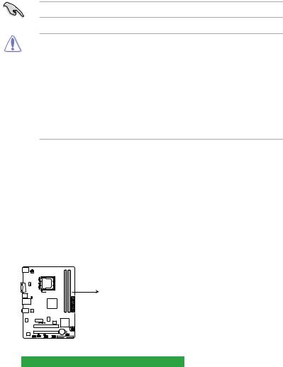
Onboard LED
This motherboard comes with a standby power LED that lights up to indicate that the system is ON, in sleep mode, or in soft-off mode. This is a reminder that you must shut down
the system and unplug the power cable before removing or plugging in any motherboard component. The illustration below shows the location of the onboard LED.
P5KPL-AM IN
SB_PWR
ON OFF
Standy Power Powered Off
P5KPL-AM IN Onboard LED

1.2Motherboard overview
1.2.1Motherboard layout
Ensure that you install the motherboard into the chassis in the correct orientation. The edge with external ports goes to the rear part of the chassis.
Place this side towards the rear of the chassis.
|
1 |
2 |
3 |
4 |
5 |
||||
|
17.8cm(7.0in) |
||||||||
|
KBMS |
||||||||
|
ATX12V |
||||||||
|
VGA |
module) |
module) |
||||||
|
CPU_FAN |
LGA775 |
pin-240 |
pin-240 |
|||||
|
USB34 |
PS2 USBPW1-4 |
DIMMA1 (64bit, |
DIMMB1 (64bit, |
|||||
|
LAN1_USB12 |
Intel® |
DDR2 |
DDR2 |
|||||
|
G31 B0 |
||||||||
|
AUDIO |
ITE |
EATXPWR |
||||||
|
IT8755E |
||||||||
|
8131 |
PCIEX1_1 |
ICS 9LRS954A4GLF |
||||||
|
RTL |
||||||||
|
8Mb |
Intel® |
|||||||
|
BIOS |
ICH7 |
SATA2 |
SATA1 |
|||||
|
PCI1 |
P5KPL-AM IN
|
Lithium Cell |
|||||
|
PCI2 |
CMOS Power |
CLRTC |
|||
|
VIA |
SPEAKER |
||||
|
VT1705 |
SB_PWR |
USBPW5-8 |
USB56 |
PRI_IDE |
|
|
AAFP |
F_PANEL |
USB78 |
|||
Place six screws into the holes indicated by circles to secure the motherboard to the chassis. DO NOT overtighten the screws! Doing so can damage the motherboard.
1.2.2Layout contents
|
Connectors/Jumpers/Slots |
Page |
Connectors/Jumpers/Slots |
Page |
||
|
1. |
ATX power connectors (24-pin EATXPWR, 4-pin |
1-13 |
8. |
Speaker connector (4-1 pin SPEAKER) |
1-14 |
|
ATX12V) |
|||||
|
2. |
CPU fan connector (4-pin CPU_FAN) |
1-12 |
9. |
IDE connector (40-1 pin PRI_EIDE) |
1-11 |
|
3. |
Keyboard/mouse power (3-pin PS2_USBPW1-4) |
1-9 |
10. |
USB connectors (10-1 pin USB56 USB78) |
1-11 |
|
4. |
LGA775 CPU socket |
1-3 |
11. |
USB device wake-up (3-pin USBPW5-8) |
1-7 |
|
5. |
DDR2 DIMM slots |
1-3 |
12. |
System panel connector (10-1 pin PANEL) |
1-14 |
|
6. |
Serial ATA connectors (7-pin SATA1-4) |
1-10 |
13. |
Onboard LED |
1-1 |
|
7. |
Clear RTC RAM (3-pin CLRTC) |
1-8 |
14. |
Front panel audio connector (10-1 pin |
1-12 |
|
AAFP) |
|
Chapter 1: Product introduction |
1-2 |
1.3Central Processing Unit (CPU)
The motherboard comes with a surface mount LGA775 socket designed for the Intel® Core
™2 Quad / Core™2 Extreme / Core™2 Duo / Pentium® D / Pentium® 4 and Celeron® E1000 Series and Celeron 400 Series processors.
• Ensure that all power cables are unplugged before installing the CPU.
• Upon purchase of the motherboard, make sure that the PnP cap is on the socket and the socket contacts are not bent. Contact your retailer immediately if the PnP cap
is missing, or if you see any damage to the PnP cap/socket contacts/motherboard components.ASUS will shoulder the cost of repair only if the damage is shipment/ transit-related.
•Keep the cap after installing the motherboard. ASUS will process Return Merchandise
Authorization (RMA) requests only if the motherboard comes with the cap on the
LGA775 socket.
•The product warranty does not cover damage to the socket contacts resulting from incorrect CPU installation/removal, or misplacement/loss/incorrect removal of the PnP cap.
1.4System memory
1.4.1Overview
The motherboard comes with two Double Data Rate 2 (DDR2) Dual Inline Memory Modules
(DIMM) sockets.
The figure illustrates the location of the DDR2 DIMM sockets:
DIMM_B1
DIMM_A1
P5KPL-AM IN
P5KPL-AM IN 240-pin DDR2 DIMM sockets
|
Channel |
Sockets |
|
Channel A |
DIMM_A1 |
|
Channel B |
DIMM_B1 |
1.4.2Memory configurations
You may install 512MB, 1GB, and 2GB unbuffered ECC/non-ECC DDR2 DIMMs into the
DIMM sockets.
 Loading…
-
Драйверы
29
-
Инструкции по эксплуатации
2

ASUS P5KPL-AM IN/ROEM/SI инструкция по эксплуатации
(40 страниц)
- Языки:Английский
-
Тип:
PDF -
Размер:
1.5 MB -
Описание:
P5KPL-AM IN/ROEM/SI user’s manual(English)
Просмотр

ASUS P5KPL-AM IN/ROEM/SI инструкция по эксплуатации
(38 страниц)
-
Тип:
PDF -
Размер:
1.7 MB -
Описание:
P5KPL-AM IN/ROEM/SI European Quick Start Guide for Multiple Languages
Просмотр
На NoDevice можно скачать инструкцию по эксплуатации для ASUS P5KPL-AM IN/ROEM/SI. Руководство пользователя необходимо для ознакомления с правилами установки и эксплуатации ASUS P5KPL-AM IN/ROEM/SI. Инструкции по использованию помогут правильно настроить ASUS P5KPL-AM IN/ROEM/SI, исправить ошибки и выявить неполадки.
- Производитель
- Asus
- Модель
- P5KPL-AM IN/ROEM/SI
- Операционная система
-
- Windows 8.1
- Windows 8
- Windows 7
- Windows Vista
- Windows Server 2003
- Windows XP
- Windows 2000
- MS-DOS
- Тип файла
-
- Инструкция
- Версия
-
E4555
32-bit
64-bit
Просмотреть содержимое архива
Вы нашли то, что искали?
Дополнительная информация
P5KPL-AM IN/ROEM/SI user’s manual(English)
Полезно
0 %
0
Commentary
Ваше имя
Your Donation Will Be Matched 1-to-1! Can You Chip In?
Dear Patron: Please don’t scroll past this. The Internet Archive is a nonprofit fighting for universal access to quality information. We build and maintain all our own systems, but we don’t charge for access, sell user information, or run ads. Instead, we’re powered by online donations averaging about $14. We’d be deeply grateful if you’d join the one in a thousand users that support us financially.
Right now, we have a matching gift campaign that will double the impact of every donation. We understand that not everyone can donate right now, but if you can afford to contribute this Tuesday, we promise it will be put to good use. Our resources are crucial for knowledge lovers everywhere—so if you find all these bits and bytes useful, please pitch in.
Your Donation Will Be Matched! Can You Chip In?
Dear Patron: Please don’t scroll past this. Right now we have a matching gift campaign that will double the impact of every donation. We understand that not everyone can give right now, but if you can afford to contribute this Tuesday, we promise it will be put to good use. If you find all these bits and bytes useful, please pitch in.