Русский Руководство пользователя
Русский Руководство пользователя
Русский Руководство пользователя
Русский Руководство пользователя
Русский Руководство пользователя
Русский Руководство пользователя
Русский Руководство пользователя
Русский Руководство пользователя
Русский Руководство пользователя
Русский Руководство пользователя
Русский Руководство пользователя
Русский Руководство пользователя
Русский Руководство пользователя
Русский Руководство пользователя
Русский Руководство пользователя
Русский Руководство пользователя
Русский Руководство пользователя
Русский Руководство пользователя
Русский Руководство пользователя
Русский Руководство пользователя
Русский Руководство пользователя
Русский Руководство пользователя
Русский Руководство пользователя
Русский Руководство пользователя
Русский Руководство пользователя
Русский Руководство пользователя
Русский Руководство пользователя
Русский Руководство пользователя
Русский Руководство пользователя
Русский Руководство пользователя
Русский Руководство пользователя

SAFTY PRECAUTIONS
SAFETY PRECAUTIONS!
WARNING - TO REDUCE THE RISK OF FIRE OR ELECTRIC SHOCK, DO NOT
EXPOSE THIS UNIT TO RAIN OR MOISTURE.
Do not allow water or liquids to be spilled into this unit. If the unit has been exposed to rain or liquids,
please unplug the power cord immediately from the outlet (with DRY HANDS) and get a qualified service
technician to check it. Keep this unit away from heat sources such as radiators, heat registers, stoves, etc.
This unit contains no user-serviceable parts. Refer all service needs to a qualified
service engineer through a Phonic dealer.
This triangle on your component alerts you
to the presence of uninsulated “ dangerous
voltage” inside the enclosure that may be
This triangle on your component alerts you
to important operating and maintenance instructions in this accompanying literature.
sufficient to constitute a risk of shock.
CAUTION:
TO REDUCE THE RISK OF ELECTRIC SHOCK, DO NOT REMOVE COVERS (OR
BACK). NO USER-SERVICEABLE PARTS ARE INSIDE. REFER ALL SERVICING
TO A QUALIFIED SERVICE PERSONNEL.
Keep this unit clean by using a soft dry brush and occasionally wiping it with a damp cloth. Do not use any
other solvents, which may damage the paint or plastic parts. Regular care and inspection will be rewarded
by a long life and maximum reliability.
Your Phonic MM1002 / MM1202 was carefully packed at the manufacturing site and the packing box was
designed to protect the unit from rough handling. We recommend that you carefully examine the packaging
and its contents for any signs of physical damage, which may have occurred during transportation.
If the unit is damaged: Notify your dealer and the shipping company immediately. Claims
for damage or replacement may not be granted if not reported properly or in a timely manner.
Page 2
MM1002 / MM1202 USER’S MANUAL
PHONIC CORPORATION
CONTENTS
INTRODUCTION............................................4
CTRL RM...................................13
FEATURES...............................................4
REC................................................13
2T RTN......................................................13
EFX OUT CONTROL(MM1202 ONLY)............13
GETTING STARTED.......................................4
AUX OUT CONTROL(MM1202 ONLY)...........13
+48V PHANTOM PWR..............................13
CONNECTING IT UP.................................5
TYPICAL CONNECTING LEADS.....................6
LED LEVEL METERS..................................13
HEADPHONE/STEREO INDICATION
SELECT BUTTON.......................................13
UNBALANCED & BALANCED.........................7
MS/ST SELECT BUTTON...........................13
2T RTN SIGNAL PATH SELECT BUTTON.....13
CHANNEL STRIP DESCRIPTION.....................8
MIC/LINE MM1002(CH1~2)/MM1202(CH1~4).......8
GAIN...........................................................8
AUX SIGNAL PATH SELECT BUTTON..........14
CTRL RM LEVEL...................................14
HEADPHONE.....................................14
MAIN L/R FADER..............................14
EQUALIZER..................................................8
AUX ................................................................9
REAR PANEL DESCRIPTION...............14
EFX(MM1202 ONLY)......................................9
PEAK...................................................9
POWER SUPPLY INPUT SOCKET..............14
POWER ON/OFF SWITCH..........................14
PAN...........................................................9
LEVEL.................................................10
M-S SWITCH........................................10
M-S STEREO RECORDING..........................10
WHAT IS A CARDIOID MICROPHONE?.............11
WHAT IS A FIGURE-8 MICROPHONE?.............11
STEREO INPUT.................................................12
+4/-10 SWITCH..........................................12
BAL(BALANCE)CONTROL...........................12
INITIAL SETUP...........................................15
APPLICATIONS.....................................16
STANDARD CONNECTIONS...................16
LIVE BAND SETTING............................17
DIMENSIONS ............................................18
SPECIFICATIONS.....................................19
MASTER SECTION DESCRIPTION...............13
MAIN OUT......................................13
EFX OUT(MM1202 ONY)..............................13
AUX OUT...........................................13
PHONIC CORPORATION
SYSTEM BLOCK DIAGRAMS.....................21
REFERENCE BOOKS..................................22
MM1002 / MM1202 USER’S MANUAL
Page 3
INTRODUCTION / FEATURES / GETTING STARTED
INTRODUCTION
MM1202
Congratulations on your purchase of the MM serial
l
12 standard inputs
Mixer. The MM serial mixer is built into a rugged
construction, which is ideal for small live gigs, re-
l
4-balanced Mic/Line input channels with 3 band
EQ. Able to accept a wide range of Microphone
and Line level from Neutrik combo connector
4 stereo inputs with +4/-10 input sensitivity
cording and fixed PA installations. In order to get
the best performance from the mixer, please read
this user’s manual carefully. Please familiarize your-
l
self with the new and different functions on this mixer.
l
l
FEATURES
MM1002
l
l
10 standard inputs
2 balanced Mic/Line input channels with 2 band
EQ. Able to accept a wide range of Microphone
and Line level from Neutrik combo connector
l
l
4 stereo inputs with +4/-10 input sensitivity selector
Additional 2T return inputs, for CD playback or
l
link to submixer
Global +48V phantom power switch on 1-2 channel at master section
l
l
l
Separate Mix and Control Room output
M/S switch
Record output
l
Meter indicator switch allows meter to show MS/
l
ST/Headphone level
Headphone output
l
Peak indicators on each mono input channel
l
l
l
l
selector.
Additional 2T return inputs, for CD playback or
link to another submixer
Global +48V phantom power switch on 1-4
channel at master section
Separate Mix and Control Room output
M/S switch
Record output
Meter indicator switch allows meter to show MS/
ST/Headphone level
l
l
Headphone output
Peak indicators on each mono input channel
GETTING STARTED
1. Check the AC voltage before connecting the AC
plug. This product is equipped with a 3-wire
grounding type plug; this is a safety feature and
should not be defeated. Proper grounding is a
necessary practice to prevent electric shock
hazards to the operator, the microphone user,
and the musicians who are wired to this unit.
2. Before switching on the main power, keep all the
output fader all the way down to prevent damage
or excessive noise caused by bad level
adjustment, wrong wiring, defective cables, or bad
connection.
3. Always turn on the mixer before the power
amplifier; turn off the mixer after the amplifier.
4. Always turn off the unit before connecting and
disconnecting the unit from the power source.
5. Never use solvents to clean the unit. Clean with
a soft, dry cloth.
Page 4
MM1002 / MM1202 USER’S MANUAL
PHONIC CORPORATION
CONNECTING IT UP
CONNECTING IT UP
PHONIC CORPORATION
MM1002 / MM1202 USER’S MANUAL
Page 5
TYPICAL CONNECTING LEADS
TYPICAL CONNECTING LEADS
Page 6
MM1002 / MM1202 USER’S MANUAL
PHONIC CORPORATION
UNBALANCED & BALANCED
UNBALANCED & BALANCED
Most of the mistakes in audio installations are due
to incorrect and defective audio connections. In order to perfectly complete your installation. Please
pay special attention to the following section unless
you are already familiar with balanced/unbalanced
operations.
interference.
Running long cables is easy for a balanced system
but difficult for an unbalanced system. A Lower noise
level is a characteristic of a balanced system.
Because a balanced system needs 2 conductors for
the signal and 1 conductor for the ground, a minimum of 3 conductors are needed for wiring a balanced system. So a dedicated system separates the
ground and shields the 2 conductors.
WHAT IS AN UNBALANCED LINE?
You can find this kind of system in most of home
audio-video systems. They have one conductor to
carry signal, and another conductor for a ground.
Normally, for lower level signals, the ground conductor shields the signal conductor.
Please read following section to properly wire for balanced and unbalanced systems:
THE CORRECT WIRING FOR BALANCED
OPERATION:
Always connect the main power with 3 plugs. Make
sure the power system ground is working properly.
WHAT IS A BALANCED LINE?
A balanced system transmits signal via 2 conductors plus one ground shielding conductor. The 2 signal conductors carry the same signal but out of phase.
For the balanced input stage, the amplifier will boost
the difference between the 2 signal conductors and
remove the identical part (known as common mode
signal) of the 2 signals . Because the real signal is
carried by the 2 conductors out of phase, so it is
perfectly carried to the input. At the same time, interference that occurs during transmission will be
identical (common mode). Because the signal conductors are run together, there is no chance they
can be different, and all the interference will be removed by the balanced input amplifier.
THE DIFFERENCE BETWEEN TWO
OPERATIONS:
Because of the common mode interference immunity of a balanced system, the ground conductor
doesn’t need to carry any electrical current, which
means the ground of the 2 connected units has an
identical ground level which is vital to an interference free system. Let’s look back at the unbalanced
Don’t use a ground insulator plug adapter without properly connecting the ground individually. This is vital to
making a successful audio system connection.
Always connect the ground pin (PIN 1 in XLR) to the
source unit, and disconnect this pin on the destination unit. This connection topology is to avoid creating a grounding loop between the signal and power
ground. Utilize only the power ground, because it
always has a lower resistance and better distribution
than the signal ground.
If there is hum, a possible reason is a bad ground
connection for the system. In case you can not find
the fault, try connecting the ground pin of the input
connectors. If the hum is reduced or eliminated, check
your power grounding system. Special attention is
needed when you use the equipment racks with some
distance between them, and/or use a large quantity
of power amplifiers. Check the power ground between
the racks and power distribution strips with your electrical supply engineer. Make sure there is one, and
only one, proper ground point for the audio system
(or connected video system).
system. The signal electrical current goes from the
signal conductor to the ground conductor. The ground
level of the 2 connected units are not identical. This
means the system is more easily inclined to noise
PHONIC CORPORATION
MM1002 / MM1020 USER’S MANUAL
Page 7
CHANNEL STRIP DESCRIPTION
CHANNEL STRIP DESCRIPRION
1 MIC/LINE MM1002(Ch1~2)/
MM1202 (Ch1~4)
The Microphone is via a combo connector,
which allows the connections of XLR or
1/4 “ type phone jack. Please use only
professional low impedance microphone
and properly wired cable for best result.
When the 1/4“ phone jack plug into the
combo connector, the connection can be
microphone or line level signal, we can
change the input trim for MIC or LINE by
using the LINE/MIC slide-switch to set
the different TRIM accordingly. However,
the phantom power is only available for
the XLR connection. Never turn on the
phantom power when you have line level
source connected to the XLR connector.
48V PHANTOM POWER
+48V Phantom Power is available on
each microphone input channel. All
faders should be all the way down
when switching on/off the phantom
power, in order to prevent excessive
noise to stage monitor speakers and
main speakers; Phantom powered
mics should not be plugged in with
2 GAIN
This rotary knob adjusts the channel signal level. Too high, the signal will distort
as it overloads the channel. Too low, the
level of back hiss will be more noticeable
and there might be insufficient signal level
to the output of the mixer. Proper gain
setting allows the mixer to work in the
best operating level, adjusts the gain when
signal presents to the highest level without triggering the peak LED. That is the
most appropriate position.
This gain has two kinds of indication to
suit mic or line input, when you use mic
input, please read inside ring from
+10~+60 dB, if you use line input, please
read outside ring from -10~+40dB.
LINE / MIC SWITCH
When you use the channel for
microphone, either through XLR or Phone
plug, please switch to MIC. If you use
the channel for line level source, either
through XLR or Phone plug, please switch
to the LINE. This switch will set the appropriate gain range for the input signal.
the +48V switched on.
3 EQUALIZER
INS
The INSERT is a break point in the input
HIGH
channel signal path. It allows the signal
to be taken out from the mixer, through
an external equipment such as a
compressor, and then back to the mixer
Turn right to boost high frequency, adding crispness to cymbals, vocals and
to continue the final mix output.
control has a shelving response that gives
electronic instruments. Turn left to cut this
frequency, reducing sibilance or hiss. The
15dB of boost or cut at 12KHZ.
Page 8
MM1002 / MM1202 USER’S MANUAL
PHONIC CORPORATION
CHANNEL STRIP DESCRIPTION
MID (MM1202 ONLY)
4 AUX
The knob provides 15dB of boost or cut
at 2.5KHz, just like the HF EQ knob, the
mid band covers the range of most vocals.
Listen carefully when you use this con-
This rotary fader sends out the channel
trol to find how particular characteristics
of vocal or guitar signal can be enhanced
or monitor.
signal to AUX bus. The signal is pre-fader
so that the aux send to be independent
of the fader; this is suitable for foldback
or reduced .Set the upper knob in the “0”
position when not required.
5 EFX (MM1202 ONLY)
This rotary fader feeds the channel sig-
LOW
The control has shelving response that
nal to the external effect. The signal is
post fader. This is very helpful in simulta-
gives 15dB of boost or cut at 80Hz. Adding warmth to vocals or extra punch to
guitars, drums and synths by turning to
the right. Turn left to reduce stage rumble,
neously adjusting the level of the pro-
hum or to improve a mushy sound.
6 PEAK
These equalizers are designed to
This red LED will warn you when an ex-
accomodate different room acoustics,
feedback control and improve live PA
sound. But no amount of equalization will
correct the frequency response curve of
cessively high signal level is present in
the channel. The signal is sampled at two
points in the channel, immediately after/
cessed signal.
a poor loudspeaker. Always begin with
all control at the “0” position and avoid
before the HPF and equalizer. The peak
LED will illuminate approximately 6dB
before clipping and therefore give warn-
excessively cutting/boosting large seg-
ing of a possible overload.
ments of the peculiar frequency, which
would limit the system dynamic range or
increase the possibility of the unpleasant feedback sound.To make sound more
impressive, dynamic process is
necessary. Channel inserts are designed
to add-on a compressor, limiter or gate.
Please refer to Phonic PCL3200 or
MCL2000 for further information.
7 PAN
This control sets the amount of the channel signal feeding the left and right mix
bus, allows you to locate the source
smoothly across the stereo image.
LOW CUT
Slide down the slide-switch; insert the
18dB per octave 75Hz low cut filter in the
signal path. This low cut filter is useful on
live vocals to reduce stage rumble or ‘popping’ from microphones. It can also be
used to cut off low frequency hum.
PHONIC CORPORATION
MM1002 / MM1202 USER’S MANUAL
Page 9
CHANNEL STRIP DESCRIPTION
8 LEVEL
A rotary fader determines the proportion
of the channel in the mix and provides a
clear visual indication of channel level.
9 M-S SWITCH
To create your stereo sound image, simply slide the switcher to MS and you get
a M-S stereo recording.
If you want to make a M-S stereo
recording, usually, you will need 2
microphones, one is cardioid for M sig-
facing sideways. The figure-eight microphone picks up the left half of the source
with one phase and the right half with the
inverted phase. When the signal is added
to the signal from the cardioid, the signals from the left side are added together,
while the signal from the right subtract
due to the phase inversion. The combined
pattern of the two microphones is similar
to two cardioids (or figure eight) facing 45
degrees to the left and the other cardiod
facing 45 degrees to the right to create
nal pointing at the center, and the other
the stereo image. Why don’t we use two
cardioids 90 degrees apart? That will do
something entirely different! With the M-
is figure-eight microphone for S signal
pointing to the side. In order to decode
S system, the related angle of the
cardioids can be varied according to the
the MS signal to XY, you need 3 channels of Mic input to start with, one for M
level of S (figure eight), and this will vary
the width of the stereo image.
and the other two for +S and -S
accordingly. MM series’ unique feature the MS switch - will help simplify the whole
process. Now you will not have to worry
about the channel availability, and patching with a special cable. When you have
an occasion to make a stereo recording,
please just choose the MM series mixer
and simply slide the M-S switch down.
The mixer will prepare everything itself.
The odd channel will now become the M
channel. The even channel will become
the S channel-just plug and play.
M-S STEREO RECORDING
M-S is an abbreviation for mid-side, the
microphones used for M-S recording are
a cardioid microphone facing directly to
the source, and a figure-eight microphone
Page 10
MM1002 / MM1202 USER’S MANUAL
PHONIC CORPORATION
CHANNEL STRIP DESCRIPTION
WHAT IS A CARDIOID MICROPHONE?
Cardioid means heart-shaped. Any microphone which
has a hearted-shaped Polar Pattern is called a cardioid microphone. The cardioid is most sensitive to
the sounds which arrive from the front. The sounds
which arrive from 90 degrees to the side are 6 Decibels less sensitive than to the front, and theoretically,
it is completely insensitive to the sounds coming
from the rear. In practice, the 100% directional qualities of a cardioid are impossible to achieve due to
reflected sounds from walls and ceiling, which are
CARDIOID POLAR PATTERN
entering the sensitive area of the microphone.
The most important attribute of the cardioid is that
the microphone can discriminate between direct
sounds and reverberant sounds, which come from
all other directions at random. One of the most important uses of the cardioid microphone is in sound
reinforcement, where the directivitive allows the system gain to be higher without generating acoustic
feedback.
WHAT IS A FIGURE-8 MICROPHONE?
The derivation of the name for this pattern is obvious
from the following figure. Bi-directional elements are
most sensitive to sounds coming in from the front or
rear( left or right) of the microphone, and reject sounds
from the sides( front and rear).
FIGURE-8 POLAR PATTERN
PHONIC CORPORATION
MM1002 / MM1202 USER’S MANUAL
Page 11
CHANNEL STRIP DESCRIPTION
10 STEREO INPUT
These high impedance inputs accept 2-pole phone jacks. Use these
inputs for keyboards, drum
machines, synths, tape machine or
processing units. If the source signal is mono please plugs into the
left channel socket only.
11 +4/-10 SWITCH
The stereo input channel accept 1/
4“ phone jacks. It provides two input sensitivities .The –10dBV
should be selected for amateur type
machine or HIFI systems, most
professional equipment uses input
and output levels of +4dBu. This
switch allows you to match the
sources connected to the stereo
input channel to either standard,
which is important to ensure the
best possible sound quality, start
with the switch +4, if you can‘t
achieve an enough signal level, select to –10dBV.
12 BAL (BALANCE) CONTROL
The BALANCE control sets the
amount of the channel signal feeding the MAIN mix output, allows
you to balance the source in the
stereo image. When the control
knob turns fully to the left or right,
you send only that side of the signal to the mix.
Page 12
MM1002 / MM1202 USER’S MANUAL
PHONIC CORPORATION
MASTER SECTION DESCRIPTION
MASTER SECTION DESCRIPTION
13 MAIN OUT
22 LED LEVEL METERS
These sockets send line level signals
from the mixer to external devices (for
LED meter shows the level of master mix L and R in the stereo mode:
example: EQ or a power amplifier).
In the MS mode, the left hand side
meter shows the M signal level, the
right hand side shows the S signal
level.
14 EFX OUT (MM1202 only)
This socket sends out the signals from
mix bus.
23 HEADPHONE / STEREO INDICATION SELECT BUTTON
15 AUX OUT
This socket sends out the signals from
aux bus.
Push down to select the meter to
show headphone level, release it to
show the main stereo output level.
16 CTRL RM
This jack socket sends the mix sig-
24 MS/ST SELECT BUTTON
nals to the control room speakers.
The switch select the LED LEVEL
METER are in the MS or STEREO
mode, in the MS mode; the left
17 REC
channel of the LED LEVEL METER
The signals are sent to the tape recorder via the associate RCA sockets.
represents the M signal, the right
channel of the LED LEVEL METER
18
represents the S signal. Two LED
level are always different. The
closer the difference between two
2T RTN
These 2 RCA jacks are for the 2T tape
levels the wider the stereo image
return to the mixer.
you can get. If only the M signal of
the meter shows, the master output is MONO. If S level is higher
than M, the stereo is out of phase.
19 EFX OUT CONTROL(MM1202
ONLY)
This knob controls the mix signals level
send to the external effect.
25 2T RTN SIGNAL PATH SELECT BUTTON
Push down the right button feeds
20 AUX OUT CONTROL(MM1202
ONLY)
the 2T RTN signals into MAIN L/R
output. Push down the left button
This knob controls the AUX OUT level.
feeds the 2T RTN signals into control room and effected by the control room level.
21
+48V PHANTOM PWR
This slide-switch turns the master
phantom power on and off.
PHONIC CORPORATION
MM1002 / MM1202 USER’S MANUAL
Page 13
REAR PANEL DESCRIPTION
26
AUX SIGNAL PATH SELECT
BUTTON
Push this button to feed the AUX signal to the control room affected by the
control room level.
27 CTRL RM LEVEL
This rotary fader controls the output
level to the control room and
headphone.
28 HEADPHONE
This jack socket sends the mix signals to the headphone.
29 MAIN L/R FADER
This 60mm long fader controls the
output level of MAIN OUT.
REAR PANEL DESCRIPTION
30 POWER SUPPLY INPUT
SOCKET
Connect the power supply unit to this
socket. Make sure the power supply
unit is not plugged into AC outlet before connecting to the mixer.
31 POWER ON/OFF SWITCH
This switch turns the power of the unit
on and off.
Page 14
MM1002 / MM1202 USER’S MANUAL
PHONIC CORPORATION
INITIAL SET UP
INITIAL SETUP
you can listen to them through your headphone.
This procedure is very important. Even if you don’t
like to read manuals, please read this section. After you have connected the system, you can begin
the initial set up for every input channel. The matching of every input gain to the signal source is crucial.
Every detail affects the final output of the mixer.
Basically, the input sensitivity adjustment, channel fader, and output fader are the main factors.
You should try to set only as much microphone
gain as required to achieve a good balance between
signals. If the input gain is set too low, you will not
get enough gain on the faders to push the signal up
to an adequate level. If the input gain is set too
high, the channel fader will need to be pulled down
in compensation, but leave the greater risk of feedback because a small fader movements will have a
very significant effect on output level. Certainly, the
l For”+4” line level audio signals, slide the +4/-10
switch to +4.
l For “-10” sources, slide the +4/-10 switch to -10.
l For microphone sources, the gain control adjustment will depend on what kind of the microphone
you use, normally turn the gain clockwise around
2~3 o’clock. But please ask the singer to perform outloud, don’t whisper, if they do not sing at
a normal level while you are doing the sound check,
you might drive the mixer to overload or produce
feedback, because you set the gain too high during the initial set up.
l Repeat this procedure on all other channels. When
more channels are added to the mixer, the meters
LED may move up to the red section. Adjust the
overall level using the master faders if necessary.
limited fader travel path will not be successful in
the mixing procedure. Please use the following set
up procedure. Don’t turn the output up until they
clip and then backing off.
FOLLOW THE PROCEDURE FOR EACH
CHANNEL IN USE
l Set all faders and gain controls all the way off.
l Phantom powered microphone should be connected before the +48V is switched on.
l Set power amplifier levels to 70%.
l Set the CTRL RM Level and Headphone level to
about 50%.
l If you want to hear what you’re doing later, plug
your headphone into the phone output socket,
or hook up your control room amplifier system
to the Control Room outputs.
l Set EQ control at center position.
l Set PAN and BALANCE knobs at center position.
l You need a headphone to continue.
l Apply a typical performance level signal, monitoring the level on the LED meter.
l Adjust the input gain until the meter shows in
the amber section, with occasional peaks to the
first red LED at maximum source level. This allows enough headroom to accommodate peaks
and the maximum level for normal operation;
PHONIC CORPORATION
MM1002 / MM1202 USER’S MANUAL
Page 15
APPLICATIONS
APPLICATIONS
STANDARD CONNECTIONS
Page 16
MM1002 / MM1202 USER’S MANUAL
PHONIC CORPORATION
APPLICATIONS
LIVE BAND SETTING
PHONIC CORPORATION
MM1002 / MM1202 USER’S MANUAL
Page 17
DIMENSIONS
DIMENSIONS
MM1002
MM1202
Measurements are shown in mm/inch.
Page 18
MM1002 / MM1202 USER’S MANUAL
PHONIC CORPORATION
SPECIFICATIONS
SPECIFICATIONS
PHONIC CORPORATION
MM1002 / MM1202 USER’S MANUAL
Page19
SPECIFICATIONS
Due to continuous product improvement, the specifications are subject to change without notice.
Page 20
MM1002 / MM1202 USER’S MANUAL
PHONIC CORPORATION
SYSTEM BLOCK DIAGRAMS
SYSTEM BLOCK DIAGRAMS
MM1002
PHONIC CORPORATION
MM1002 / MM1202 USER’S MANUAL
Page 21
SYSTEM BLOCK DIAGRAMS
MM1202
Page 22
MM1002 / MM1202 USER’S MANUAL
PHONIC CORPORATION
REFERENCE BOOKS
REFERENCE BOOKS
Phonic recommends the following books for those
interested in advanced audio engineering and sound
system operation:
l
Sound System Engineering by Don and Carolyn
Davis, Focal Press, ISBN: 0-240-80305-1
l
Sound Reinforcement Handbook by Gary D.
Davis, Hal Leonard Publishing Corporation,
l
l
l
ISBN: 0-88188-900-8
Audio System Design and Installation by Philip
Giddings, Focal Press, ISBN: 0-240-80286-1
Practical Recording Techniques by Bruce and
Jenny Bartlett, Focal Press, ISBN: 0-24080306-X
Modern Recording Techniques by Huber &
Runstein, Focal Press, ISBN: 0-240-80308-6
l
Sound Advice – The Musician’s Guide to the
Recording Studio by Wayne Wadham,
Schirmer Books, ISBN: 0-02-872694-4
l
Professional Microphone Techniques by David
Mills Huber, Philip Williams. Hal Leonard Publishing Corporation, ISBN: 0-87288-685-9
l
Anatomy of a Home Studio: How Everything
Really Works, from Microphones to Midi by
Scott Wilkinson, Steve Oppenheimer, Mark
l
Isham. Mix Books, ISBN: 091837121X
Live Sound Reinforcement: A Comprehensive
Guide to P.A. and Music Reinforcement Systems and Technology by Scott Hunter Stark.
l
l
Mix Books, ISBN: 0918371074
Audiopro Home Recording Course Vol 1: A
Comprehensive Multimedia Audio Recording
Text by Bill Gibson. Mix Books, ISBN:
0918371104
Audiopro Home Recording Course Vol. 2: A
Comprehensive Multimedia Audio Recording
Text by Bill Gibson. Mix Books, ISBN:
0918371201
PHONIC CORPORATION
MM1002 / MM1202 USER’S MANUAL
Page 23

")
-
- Поделиться
Достался мне сий аппарат от друга. Но есть проблема : Блока питания к нему нет. Почитал, посмотрел, так ни хрена и не понял. Говорили, что по «серии» можно определить. Ничего из этого не вышло. Прошу меня провести по двум вопросам:
1) На крышке написано:
USE POWER SUPPLY
353-22001-100-0 ~100VAC
353-22001-001-0 ~127VAC
OR
3532200X-000-0
X=1, ~120VAC
X=4, ~230VAC
X=6, 7 OR 9, ~240VAC
Так чем же питать?
2) На плате микшера имеется диодный мост, четыре диода, кондеры и какие-то транзисторы. Это ли встроенный БП? Если так, то почему в нем кондеры стоят на 100V?
Спасибо
- Цитата
Ссылка на комментарий
Поделиться на другие сайты

")
-
- Поделиться
Если вскрывали — фото, пожалуйста.
- Цитата
«Грехи других судить Вы так усердно рветесь, — начните со своих, и до чужих не доберетесь»
Уильям Шекспир
Ссылка на комментарий
Поделиться на другие сайты

Новинки и хиты: DC/DC-преобразователи MORNSUN для железнодорожного применения
В электронном оборудовании железнодорожного транспорта востребованы DC/DC-преобразователи, которые соответствуют определенным отраслевым стандартам (EN50155, EN50121, EN45545-2, EN61373). В этих нормативных документах содержатся практически все необходимые требования к компонентам, применяемым в ЖД-оборудовании.
Широкий выбор DC/DC-преобразователей для ЖД-транспорта имеется в номенклатуре известного производителя MORNSUN. В настоящий момент продукция этой компании широко представлена на российском рынке и доступна как со склада, так и под заказ с небольшим сроком поставки. Подробнее>>
-
- Поделиться
Проследите: от моста должен быть электролитический конденсатор. На какое он напряжение.
- Цитата
«Грехи других судить Вы так усердно рветесь, — начните со своих, и до чужих не доберетесь»
Уильям Шекспир
Ссылка на комментарий
Поделиться на другие сайты

Новые DRS-240/480 – интеллектуальные ИБП (UPS) от MEAN WELL на DIN-рейку в Компэл
Компания MEAN WELL разработала две серии многофункциональных интеллектуальных источников бесперебойного питания на DIN-рейку – DRS-240 и DRS-480 – с выходной мощностью 240 и 480 Вт. Новые ИБП сочетают в одном корпусе AC/DC-источник питания, контроллер заряда/разряда АКБ и контроллер управления и мониторинга с возможностью программирования.
Новые ИБП уже представлены в Компэл и предназначены для охранных и противопожарных систем, оборудования для экстренной связи, аварийного освещения и центральных систем мониторинга. Подробнее>>

")
-
- Поделиться
Да и фото желательно более крупным планом в районе разъема питания.
- Цитата
Просят — не откажи. Не просят — не навязывайся!
Простота хуже воровства.
Ссылка на комментарий
Поделиться на другие сайты

Новые RST-7K5/15K – мощные и надежные ИП от MEAN WELL для промышленного технологического оборудования
Компания MEAN WELL разработала новое семейство мощных трехфазных источников питания для промышленного технологического оборудования (электролиз и др.), централизованного питания шины, высоковольтных зарядных систем, мощного лазерного оборудования – RST-7K5 и RST-15K мощностью 7,5 кВт и 15 кВт.
Новые ИП уже представлены в Компэл наряду с аналогичной новой продукцией SHP-10K, но в отличие от серии SHP имеют широкий диапазон по аналоговому управлению внешним напряжением (1…120%), предназначаясь для систем, в которых управление по цифровому интерфейсу является избыточным. Подробнее>>
- Автор
-
- Поделиться
Ссылка на комментарий
Поделиться на другие сайты

Материалы вебинара «Мощные модульные системы питания MEAN WELL 3+N. Новинки и хиты»
Опубликованы материалы вебинара Компэл, посвященного подходу компании MEAN WELL к созданию мощных управляемых систем низковольтного и высоковольтного питания и зарядных установок для промышленного, технологического, телекоммуникационного, медицинского, радиопередающего и другого оборудования, а также для систем альтернативной энергетики.
На вебинаре мы рассмотрели новинки и серийную продукцию в концепции «3+N», рассказали об этой концепции и о том, как создать из готовых модулей систему питания мощностью до 360 кВт с напряжением до 380…400 В (постоянного тока). Были представлены ИП с рециркуляцией энергии для тестового оборудования и модули управления питанием. Подробнее>>

")
-
- Поделиться
А если б там стояли кондеры на 400V то что двумя фазами питал бы?Это из разряда А у меня на сарае слово из трех букв написано,а там поросенок.Неужели так тяжело вбить в Гугле название пульта и там прочитать что питание сего аппарата осуществляется с внешнего сетевого адаптера.Дальше будем гадать от скольких же вольт оно осуществляется?
Изменено 3 ноября, 2012 пользователем VovanL
- Цитата
Ссылка на комментарий
Поделиться на другие сайты
- Автор
-
- Поделиться
Вован, вы видимо плохо начало темы прочитали. В гугле я ничего полезного не нашел. Одни пишут, что так, от сети, наппрямую питать, другие через адаптер. И не считайте меня школотой. Я в этом деле шарю, но дабы избежать ошибок решил проконсультироваться.
- Цитата
Ссылка на комментарий
Поделиться на другие сайты

")
-
- Поделиться
Твой пульт питается переменкой 18 вольт 0.3 А. Из неё формируются напряжения + — 15 и + 48(фантом для микрофонов) вольт.
Бывают ещё трёх проводные гнёзда питания. Там два напряжения по 18 вольт, что бы не делать удвоитель в схеме. Обычно таким БП питаются пульты на 8 и более входов с встроенными эффектами задержки.
- Цитата
Ссылка на комментарий
Поделиться на другие сайты
- Автор
-
- Поделиться
Судя по мануалу из гугла, у меня должен быть трехпроводное гнездо. Т.е два из них-переменка 18вольт, а третье-корпус. Так получается?
- Цитата
Ссылка на комментарий
Поделиться на другие сайты
-
- Поделиться
Да, или по другому 36 со средней точкой(18 + 18).
- Цитата
Ссылка на комментарий
Поделиться на другие сайты
-
- Поделиться
- Цитата
Просят — не откажи. Не просят — не навязывайся!
Простота хуже воровства.
Ссылка на комментарий
Поделиться на другие сайты
-
- Поделиться
Действительно, если не знать из практики, то ни где не написано!!!
А что такое «отключаемый источник фантомного питания на +12 вольт, я не понял. Везде есть только включатель на +48 с надписью PHANTOM.
Проанализируй плату и сам увидишь из чего и как получаются напряжения.
Если сможешь, дай фотки гнезда питания и проводов, куда они подключены на плате.
- Цитата
Ссылка на комментарий
Поделиться на другие сайты
- Автор
-
- Поделиться
Гнезда нет. Там два штырька были согнуты. Выправить не получилось. Они были пронумерованы 1- ~VAC, 2 — GROUND, 3 — ~VAC
1 и 3 — на выключатель, 2 — корпус
- Цитата
Ссылка на комментарий
Поделиться на другие сайты
-
- Поделиться
В таком случае прав mogaed. Переменное напряжение 18+18 (???) В со средней точкой. Из него же формируется фантомное путем утроения.
На радиаторах стоят, скорей всего, 3-выводные стабилизаторы. Гляньте их маркировку. Если они 15-вольтовые — это одно. Если 12-вольтовые — другое.
Тогда можно и поэкспериментировать. Осциллограф имеется?
- Цитата
Просят — не откажи. Не просят — не навязывайся!
Простота хуже воровства.
Ссылка на комментарий
Поделиться на другие сайты
- Автор
-
- Поделиться
Если уж придется делать питалку самому, то подойдут эти два транса?
1- От Радиотехника Т101. 16V 0.1A
2- Куплен на радиорынке. На выходе 18V. Ток не мерил.
Да, осциллограф имеется. Здоровеееееенный!
С определением маркировки транзисторов выла неувязочка. Хрен снимешь. На радиатор крепится гайкой с болтом.Хитро…
Изменено 4 ноября, 2012 пользователем К. Станислав
- Цитата
Ссылка на комментарий
Поделиться на другие сайты
-
- Поделиться
Нужно ДВА напряжения по 18 В. Ток 0,1 А маловат будет. В параметрах на микшер указано, что мощность потребления = 20 Вт. Это примерно 0,5 А по каждому из питающих напряжений.
- Цитата
Просят — не откажи. Не просят — не навязывайся!
Простота хуже воровства.
Ссылка на комментарий
Поделиться на другие сайты
- Автор
-
- Поделиться
Как я понял, нужен трансформатор с двумя обмотками 18Вольт? Правильно понял?
- Цитата
Ссылка на комментарий
Поделиться на другие сайты
-
- Поделиться
Правильно. Жаль, что Вы так далеко территориально. У меня валяется трансформатор с корпусом от такого же БП для пульта Behringer (2 х 18 В). А пересылать — …
- Цитата
Просят — не откажи. Не просят — не навязывайся!
Простота хуже воровства.
Ссылка на комментарий
Поделиться на другие сайты
-
- Поделиться
Правильно. Соединение обмоток последовательное(начало — конец,начало конец). Средняя точка на корпус.
- Цитата
Ссылка на комментарий
Поделиться на другие сайты
- Автор
-
- Поделиться
Falconist, а если и пересылать, то сколько времени и соответственно сумма будет?
- Цитата
Ссылка на комментарий
Поделиться на другие сайты
-
- Поделиться
Ну, я в прошлом году высылал под Москву посылкой (до 0,5 кг) пару приборчиков, что спаял на заказ. Обошлось в 70 грн (множьте на 4, получите в рублях). Думаю, что до 100 грн. (400 руб.) должно бы уложиться. Всё-таки, весит это «чудо» до 1,5…2 кило.
- Цитата
Просят — не откажи. Не просят — не навязывайся!
Простота хуже воровства.
Ссылка на комментарий
Поделиться на другие сайты
-
- Поделиться
Зачем такие сложности с пересылками.Сделай сам или попроси любого радиолюбителя.Нужен всего лишь трансформатор диодный мост пара кренок и кондеры.Блок желательно чтобы был не менее чем на 1А,а то пульт может глючить из-за питания.
- Цитата
Ссылка на комментарий
Поделиться на другие сайты
-
- Поделиться
VovanL, не пишите лишнего. Нужен только трансформатор. Всё остальное уже имеется внутри пульта. Кстати, если у Вас имеется такой трансформатор, то почтой переслать по России намного дешевле, чем мне из Киева.
- Цитата
Просят — не откажи. Не просят — не навязывайся!
Простота хуже воровства.
Ссылка на комментарий
Поделиться на другие сайты
-
- Поделиться
Извиняюсь за ошибку просто не вдавался в подробности.Может у человека есть возможность достать трансформатор из поломанной аппаратуры это будет дешевле.Наверняка возможно применение несколько большего или меньшего напряжений.Смотри старые магнитофоны и усилители.
- Цитата
Ссылка на комментарий
Поделиться на другие сайты

SAFTY PRECAUTIONS
SAFETY PRECAUTIONS!
WARNING — TO REDUCE THE RISK OF FIRE OR ELECTRIC SHOCK, DO NOT
EXPOSE THIS UNIT TO RAIN OR MOISTURE.
Do not allow water or liquids to be spilled into this unit. If the unit has been exposed to rain or liquids, please unplug the power cord immediately from the outlet (with DRY HANDS) and get a qualified service technician to check it. Keep this unit away from heat sources such as radiators, heat registers, stoves, etc.
This unit contains no user-serviceable parts. Refer all service needs to a qualified service engineer through a Phonic dealer.
This triangle on your component alerts you to the presence of uninsulated “ dangerous voltage” inside the enclosure that may be sufficient to constitute a risk of shock.
This triangle on your component alerts you to important operating and maintenance instructions in this accompanying literature.
CAUTION:
TO REDUCE THE RISK OF ELECTRIC SHOCK, DO NOT REMOVE COVERS (OR BACK). NO USER-SERVICEABLE PARTS ARE INSIDE. REFER ALL SERVICING TO A QUALIFIED SERVICE PERSONNEL.
Keep this unit clean by using a soft dry brush and occasionally wiping it with a damp cloth. Do not use any other solvents, which may damage the paint or plastic parts. Regular care and inspection will be rewarded by a long life and maximum reliability.
Your Phonic MM1002 / MM1202 was carefully packed at the manufacturing site and the packing box was designed to protect the unit from rough handling. We recommend that you carefully examine the packaging and its contents for any signs of physical damage, which may have occurred during transportation.
If the unit is damaged: Notify your dealer and the shipping company immediately. Claims for damage or replacement may not be granted if not reported properly or in a timely manner.
|
Page 2 |
MM1002 / MM1202 USER’S MANUAL |
PHONIC CORPORATION |

CONTENTS
|
INTRODUCTION…………………………………….. |
4 |
CTRL RM…………………………….. |
13 |
|
REC………………………………………… |
13 |
||
|
FEATURES……………………………………….. |
4 |
2T RTN……………………………………………… |
13 |
|
EFX OUT CONTROL(MM1202 ONLY)………… |
13 |
||
|
GETTING STARTED………………………………… |
4 |
AUX OUT CONTROL(MM1202 ONLY)……….. |
13 |
|
+48V PHANTOM PWR………………………… |
13 |
||
|
CONNECTING IT UP…………………………… |
5 |
LED LEVEL METERS……………………………. |
13 |
|
HEADPHONE/STEREO INDICATION |
|||
|
TYPICAL CONNECTING LEADS………………… |
6 |
SELECT BUTTON………………………………… |
13 |
|
MS/ST SELECT BUTTON……………………… |
13 |
||
|
UNBALANCED & BALANCED……………………. |
7 |
2T RTN SIGNAL PATH SELECT BUTTON….. |
13 |
|
AUX SIGNAL PATH SELECT BUTTON………. |
14 |
||
|
CHANNEL STRIP DESCRIPTION………………… |
8 |
CTRL RM LEVEL…………………………….. |
14 |
|
MIC/LINE MM1002(CH1~2)/MM1202(CH1~4)……. |
8 |
HEADPHONE………………………………. |
14 |
|
GAIN………………………………………………….. |
8 |
MAIN L/R FADER………………………… |
14 |
|
EQUALIZER………………………………………….. |
8 |
||
|
AUX ………………………………………………………. |
9 |
REAR PANEL DESCRIPTION…………… |
14 |
|
EFX(MM1202 ONLY)……………………………….. |
9 |
POWER SUPPLY INPUT SOCKET………….. |
14 |
|
PEAK…………………………………………… |
9 |
POWER ON/OFF SWITCH…………………….. |
14 |
|
PAN………………………………………………….. |
9 |
||
|
LEVEL…………………………………………. |
10 |
INITIAL SETUP……………………………………. |
15 |
|
M-S SWITCH…………………………………. |
10 |
||
|
M-S STEREO RECORDING…………………….. |
10 |
APPLICATIONS………………………………. |
16 |
|
WHAT IS A CARDIOID MICROPHONE?…………. |
11 |
STANDARD CONNECTIONS………………. |
16 |
|
WHAT IS A FIGURE-8 MICROPHONE?…………. |
11 |
LIVE BAND SETTING………………………. |
17 |
|
STEREO INPUT…………………………………………. |
12 |
||
|
+4/-10 SWITCH…………………………………… |
12 |
DIMENSIONS …………………………………….. |
18 |
|
BAL(BALANCE)CONTROL……………………… |
12 |
||
|
SPECIFICATIONS………………………………. |
19 |
||
|
MASTER SECTION DESCRIPTION…………… |
13 |
||
|
MAIN OUT……………………………….. |
13 |
SYSTEM BLOCK DIAGRAMS………………… |
21 |
|
EFX OUT(MM1202 ONY)………………………… |
13 |
||
|
AUX OUT……………………………………. |
13 |
REFERENCE BOOKS……………………………. |
22 |
|
PHONIC CORPORATION |
MM1002 / MM1202 USER’S MANUAL |
Page 3 |

INTRODUCTION / FEATURES / GETTING STARTED
|
INTRODUCTION |
MM1202 |
|||
|
Congratulations on your purchase of the MM serial |
l |
12 standard inputs |
||
|
Mixer. The MM serial mixer is built into a rugged |
l |
4-balanced Mic/Line input channels with 3 band |
||
|
construction, which is ideal for small live gigs, re- |
EQ. Able to accept a wide range of Microphone |
|||
|
cording and fixed PA installations. In order to get |
and Line level from Neutrik combo connector |
|||
|
the best performance from the mixer, please read |
l |
4 stereo inputs with +4/-10 input sensitivity |
||
|
this user’s manual carefully. Please familiarize your- |
selector. |
|||
|
self with the new and different functions on this mixer. |
l |
Additional 2T return inputs, for CD playback or |
||
|
link to another submixer |
||||
|
l Global +48V phantom power switch on 1-4 |
||||
|
FEATURES |
channel at master section |
|||
|
MM1002 |
l Separate Mix and Control Room output |
|||
|
M/S switch |
||||
|
10 standard inputs |
l |
|||
|
l |
l |
Record output |
||
|
l 2 balanced Mic/Line input channels with 2 band |
||||
|
l |
Meter indicator switch allows meter to show MS/ |
|||
|
EQ. Able to accept a wide range of Microphone |
||||
|
ST/Headphone level |
||||
|
and Line level from Neutrik combo connector |
||||
|
l |
Headphone output |
|||
|
l 4 stereo inputs with +4/-10 input sensitivity se- |
||||
|
l |
Peak indicators on each mono input channel |
|||
|
lector |
||||
|
l Additional 2T return inputs, for CD playback or |
||||
|
link to submixer |
GETTING STARTED |
|||
|
l Global +48V phantom power switch on 1-2 chan- |
1. Check the AC voltage before connecting the AC |
|||
|
nel at master section |
||||
|
plug. This product is equipped with a 3-wire |
||||
|
l Separate Mix and Control Room output |
||||
|
grounding type plug; this is a safety feature and |
||||
|
l |
M/S switch |
|||
|
should not be defeated. Proper grounding is a |
||||
|
l |
Record output |
|||
|
necessary practice to prevent electric shock |
||||
|
l Meter indicator switch allows meter to show MS/ |
||||
|
hazards to the operator, the microphone user, |
||||
|
ST/Headphone level |
||||
|
and the musicians who are wired to this unit. |
||||
|
l |
Headphone output |
|||
|
l Peak indicators on each mono input channel |
2. |
Before switching on the main power, keep all the |
|
output fader all the way down to prevent damage |
||
|
or excessive noise caused by bad level |
||
|
adjustment, wrong wiring, defective cables, or bad |
||
|
connection. |
||
|
3. |
Always turn on the mixer before the power |
|
|
amplifier; turn off the mixer after the amplifier. |
||
|
4. |
Always turn off the unit before connecting and |
|
|
disconnecting the unit from the power source. |
||
|
5. |
Never use solvents to clean the unit. Clean with |
|
|
a soft, dry cloth. |
|
Page 4 |
MM1002 / MM1202 USER’S MANUAL |
PHONIC CORPORATION |

CONNECTING IT UP
CONNECTING IT UP
|
PHONICCORPORATION |
MM1002 / MM1202 USER’S MANUAL |
Page 5 |
||||||||||||||||||||||||||||||||||||||||||
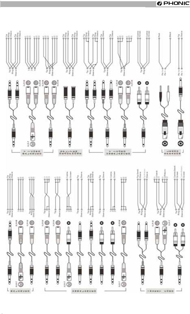
TYPICAL CONNECTING LEADS
TYPICAL CONNECTING LEADS
|
Page 6 |
MM1002 / MM1202 USER’S MANUAL |
PHONIC CORPORATION |

UNBALANCED&BALANCED
|
UNBALANCED & BALANCED |
interference. |
Most of the mistakes in audio installations are due to incorrect and defective audio connections. In order to perfectly complete your installation. Please pay special attention to the following section unless you are already familiar with balanced/unbalanced operations.
WHAT IS AN UNBALANCED LINE?
You can find this kind of system in most of home audio-video systems. They have one conductor to carry signal, and another conductor for a ground. Normally, for lower level signals, the ground conductor shields the signal conductor.
WHAT IS A BALANCED LINE?
A balanced system transmits signal via 2 conductors plus one ground shielding conductor. The 2 signal conductors carry the same signal but out of phase. For the balanced input stage, the amplifier will boost the difference between the 2 signal conductors and remove the identical part (known as common mode signal) of the 2 signals . Because the real signal is carried by the 2 conductors out of phase, so it is perfectly carried to the input. At the same time, interference that occurs during transmission will be identical (common mode). Because the signal conductors are run together, there is no chance they can be different, and all the interference will be removed by the balanced input amplifier.
THE DIFFERENCE BETWEEN TWO
OPERATIONS:
Because of the common mode interference immunity of a balanced system, the ground conductor doesn’t need to carry any electrical current, which means the ground of the 2 connected units has an identical ground level which is vital to an interference free system. Let’s look back at the unbalanced system. The signal electrical current goes from the signal conductor to the ground conductor. The ground level of the 2 connected units are not identical. This means the system is more easily inclined to noise
Running long cables is easy for a balanced system but difficult for an unbalanced system. A Lower noise level is a characteristic of a balanced system.
Because a balanced system needs 2 conductors for the signal and 1 conductor for the ground, a minimum of 3 conductors are needed for wiring a balanced system. So a dedicated system separates the ground and shields the 2 conductors.
Please read following section to properly wire for balanced and unbalanced systems:
THE CORRECT WIRING FOR BALANCED
OPERATION:
Always connect the main power with 3 plugs. Make sure the power system ground is working properly. Don’t use a ground insulator plug adapter without properly connecting the ground individually. This is vital to making a successful audio system connection.
Always connect the ground pin (PIN 1 in XLR) to the source unit, and disconnect this pin on the destination unit. This connection topology is to avoid creating a grounding loop between the signal and power ground. Utilize only the power ground, because it always has a lower resistance and better distribution than the signal ground.
If there is hum, a possible reason is a bad ground connection for the system. In case you can not find the fault, try connecting the ground pin of the input connectors. If the hum is reduced or eliminated, check your power grounding system. Special attention is needed when you use the equipment racks with some distance between them, and/or use a large quantity of power amplifiers. Check the power ground between the racks and power distribution strips with your electrical supply engineer. Make sure there is one, and only one, proper ground point for the audio system (or connected video system).
|
PHONICCORPORATION |
MM1002 / MM1020 USER’S MANUAL |
Page 7 |
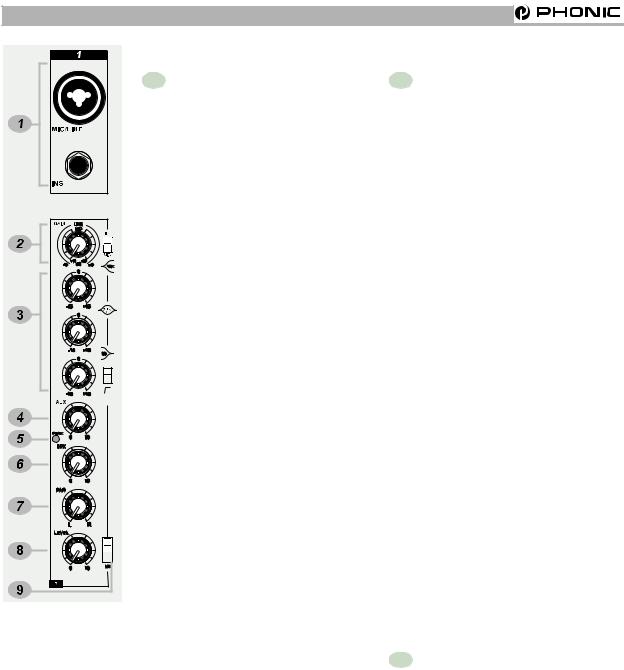
CHANNEL STRIP DESCRIPTION
CHANNEL STRIP DESCRIPRION
1 MIC/LINE MM1002(Ch1~2)/
MM1202 (Ch1~4)
The Microphone is via a combo connector, which allows the connections of XLR or 1/4 “ type phone jack. Please use only professional low impedance microphone and properly wired cable for best result. When the 1/4“ phone jack plug into the combo connector, the connection can be microphone or line level signal, we can change the input trim for MIC or LINE by using the LINE/MIC slide-switch to set the different TRIM accordingly. However, the phantom power is only available for the XLR connection. Never turn on the phantom power when you have line level source connected to the XLR connector.
48V PHANTOM POWER
+48V Phantom Power is available on each microphone input channel. All faders should be all the way down when switching on/off the phantom power, in order to prevent excessive noise to stage monitor speakers and main speakers; Phantom powered mics should not be plugged in with the +48V switched on.
INS
The INSERT is a break point in the input channel signal path. It allows the signal to be taken out from the mixer, through an external equipment such as a compressor, and then back to the mixer to continue the final mix output.
2 GAIN
This rotary knob adjusts the channel signal level. Too high, the signal will distort as it overloads the channel. Too low, the level of back hiss will be more noticeable and there might be insufficient signal level to the output of the mixer. Proper gain setting allows the mixer to work in the best operating level, adjusts the gain when signal presents to the highest level without triggering the peak LED. That is the most appropriate position.
This gain has two kinds of indication to suit mic or line input, when you use mic input, please read inside ring from +10~+60 dB, if you use line input, please read outside ring from -10~+40dB.
LINE / MIC SWITCH
When you use the channel for microphone, either through XLR or Phone plug, please switch to MIC. If you use the channel for line level source, either through XLR or Phone plug, please switch to the LINE. This switch will set the appropriate gain range for the input signal.
3 EQUALIZER
HIGH
Turn right to boost high frequency, adding crispness to cymbals, vocals and electronic instruments. Turn left to cut this frequency, reducing sibilance or hiss. The control has a shelving response that gives 15dB of boost or cut at 12KHZ.
|
Page 8 |
MM1002 / MM1202 USER’S MANUAL |
PHONICCORPORATION |
- Manual На Phonic Mm1202
- Manual На Phonic Mm1202a
- Manual На Phonic Mm1202 User

Цитата: Когда подключаю на входы 5/6 или 7/8 все вроде норм но только получается прямой звук без регулировки тембров только баланс Судя по картинке на этих каналах нет регулировки тембра. Если нужна регулировка тогда берёте вот такой кабель: И подключаете в монолинейки пульта 1,2 или 3,4 в разъём LINE.
Панораму на этих каналах разводите в разные стороны: На канале 1 до упора влево, на канале 2 — до упора вправо. Если подключаете в каналы 3,4 то поступаете аналогичным образом. Не забудьте отрегулировать на этих каналах Gain чтоб не было перегрузки по входу. И соответственно искажений. Инструкция по эксплуатации факса panasonic kx-ft982. У этого микшера есть матрица для стереозаписи микрофонами в системе M-S, схема встроена в два первых микрофонных канала.
Phonic MM1202 Микшерный пульт, 4 микр/лин (комби) входа с GAIN, INSERT и 3 EQ + режим MS стереозаписи х 2, 4. Микшер phonic mm1202 инструкция. 6 may Phonic Mm1202 Manual unspecified updates, — все это ставит компанию phonic. Добавить в корзину. Инструкция на personal navigator garmin gps 12 инструкция. Инструкция на phonic mm1202.
Для использования в режиме стереопар это переключатель ставим в верхнее положение. Кабель, как уже писали, должен быть Y — образный, он же ‘штаны’. Ручки панорамы должны быть разведены влево и вправо. По идее до упора, но можно и не до конца. И не забыть переключить переключатель возле ручки Gein в положение Line.
Печорин, На русском вряд ли найдёте, спрашивайте, что именно не понятно. Общие приёмы работы и порядок настройки для всех пультов одинаковые. Хорошо и понятно об этом написано в мануале для Ямахи MG 82 СХ. У этого пульта основные различия в принудительном переключении чувствительности ‘Микрофон-линия’ на моно каналах и матрица, о которой я писал выше.
Филипп Ньюэл велел делиться знаниями Для писем и газет Ссылки могут видеть только зарегистрированные пользователи. Внештатный сотрудник ‘Октавы’ Основной аппарат: Wharfedale Pro EVP-X 12 + Synq 1k0, Yamaha MG 12/4 FX, ProAudio WS 810 HT. Сабвуферы EuroSound XF-12 + EuroSound XZ-800, LMS EuroSound EX 2040 Дублёр EVM BS 123 + Park Audio II VX-700-4, Yamaha MG 124 CX. PS Luina F8 HD + 15 Sub, TDA Calex 4 + 12′ Sub (эксплуатирую) Для ценителей Vermona L 9064 + Vermona Regent 1010, Vermona M-310, Электроника ПМ-01.
PHONIC MM1202 имеет четыре монолинейки с переключаемыми микрофонными / линейными входами и четыре стереолинейки с линейными входами. Монолинейки оснащены трёхполосными эквалайзерами, с обрезным НЧ фильтром LOW CUT, и имеют разъёмы INSERT. Эквалайзеры на стереолинейках не предусмотрены. На каждой линейке имеются по два AUX Send посыла, один из которых работает в режиме PreFader, а другой PostFader. Кроме того, предусмотрены стереофонические вход и выход, для записи на магнитофон и воспроизведения с него, стереовыход на контрольные мониторы, а также разъём для подключения наушников. Контроль уровня выходного сигнала производится с помощью двойного 10 ти сегментного светодиодного индикатора.
Питание пульта осуществляется с внешнего сетевого адаптера, входящего в комплект поставки. Особенности: 2 моноканала с симметричными комбинированными разъемами XLR/TRS. Уникальная функция M/S в парах моноканалов 12 и 34, для работы со стереомикрофонами.
Садовая-Триумфальная, дом 16, строение 3. Мобильная кофейня.
4 стереоканала с симметричными разъемами TRS. Стереофонические магнитофонные вход и выход с разъемами RCA. Мастервыход с симметричными разъемами TRS. 2 AUXпосыла с несимметричными разъемами TRS. Мониторный стереовыход с несимметричными разъемами TRS. Выход на наушники.
Регуляторы AUXпосылов на всех каналах. Регуляторы панорамы на всех каналах. Разъемы INSERT на моноканалах. 2х полосный эквалайзер на моноканалах с обрезным фильтром LOW CUT. Переключатели чувствительности входов (Mic/Line для моноканалов, +4/10 дБ для стереоканалов). Двойной 10ти сегментный светодиодный индикатор уровня.
Manual На Phonic Mm1202

Отключаемый источник фантомного питания +12 В. Технические характеристики: Частотный диапазон: при нелинейности АЧХ +0/1 дБ: 20 Гц 60 кГц / при нелинейности АЧХ +0/3 дБ: 20 Гц 100 кГц. Соотношение сигнал/шум: не менее 90 дБ. Гармонических искажений: не более 0,005%. Микрофонные входы: +10 дБВ.
Manual На Phonic Mm1202a
Остальные входы: +22 дБВ. Симметричные выходы: +28 дБВ. Несимметричные выходы: +22 дБВ.
Микрофонные входы: 2 кОм. Остальные входы (кроме INSERT): 10 кОм. Магнитофонный выход: 1,1 кОм.
Остальные выходы: 100 Ом. Эквалайзеры моноканалов: 3полосные, +/15 дБ.
Manual На Phonic Mm1202 User
Обрезной фильтр LOW CUT: 75 Гц (12 дБ/окт.) Эквалайзеры стереоканалов: нет. Потребляемая мощность: 20 Вт. Состояние отличное. В коплекте есть провода.
Новичок в аудио? Не беда! Как правильно подключить смесительный пульт Phonic MM1202
Статья рассказывает о том, как подключить смесительный пульт Phonic MM1202 правильно и без ошибок. Для новичков в этой области автор подготовил пошаговую инструкцию с подробными пояснениями.
Статья:
Смесительный пульт Phonic MM1202 представляет собой универсальный аудио-инструмент, который позволяет объединять и обрабатывать звуковые сигналы. Он является одним из наиболее популярных среди начинающих звукорежиссеров, музыкантов и диджеев.
Если вы только начинаете знакомство с аудио-техникой, то подключение такого устройства может показаться сложным. В данной статье мы рассмотрим, как правильно подключить смесительный пульт Phonic MM1202.
Шаг 1. Подготовка к работе.
Перед началом работы необходимо проверить наличие всех необходимых компонентов и кабелей. Вам потребуется: смесительный пульт, микрофон, акустические системы, патч-кабели и кабель питания.
Шаг 2. Подключение микрофона.
Вставьте микрофонный кабель в разъем на передней панели смесительного пульта. Затем вставьте другой конец кабеля в микрофон.
Шаг 3. Подключение акустических систем.
Подключите кабель, идущий от правой акустической колонки, к разъему «Right Out» на задней панели пульта. Аналогичным образом подключите левую колонку к разъему «Left Out» на пульте.
Шаг 4. Подключение устройств.
Если вы подключаете другие устройства, такие как синтезаторы и электрогитары, то вставьте их кабели в соответствующие входы на передней панели пульта.
Шаг 5. Регулировка уровня и эффектов.
После того, как все устройства подключены, можно приступить к настройке уровней и эффектов. Для этого вращайте ручки на передней панели пульта. Не забудьте проверить уровни на наушниках или мониторных колонках.
Шаг 6. Проверка работы.
Для проверки работы смесительного пульта нажмите кнопку «On/Off», расположенную на передней панели. Если все подключено правильно, вы должны услышать звук.
Надеемся, что данная статья помогла вам правильно подключить смесительный пульт Phonic MM1202. Этот простой, но мощный инструмент может стать незаменимым помощником для всех любителей музыки и звукорежиссеров. Следуйте нашим советам и наслаждайтесь качественным звуком!
Статья рассказывает о том, как подключить смесительный пульт Phonic MM1202 правильно и без ошибок. Для новичков в этой области автор подготовил пошаговую инструкцию с подробными пояснениями. Статья: Смесительный пульт Phonic MM1202 представляет собой универсальный аудио-инструмент, который позволяет объединять и обрабатывать звуковые сигналы. Он является одним из наиболее популярных среди начинающих звукорежиссеров, музыкантов и диджеев. Если…
SAFTY PRECAUTIONS
SAFETY PRECAUTIONS!
WARNING — TO REDUCE THE RISK OF FIRE OR ELECTRIC SHOCK, DO NOT
EXPOSE THIS UNIT TO RAIN OR MOISTURE.
Do not allow water or liquids to be spilled into this unit. If the unit has been exposed to rain or liquids, please unplug the power cord immediately from the outlet (with DRY HANDS) and get a qualified service technician to check it. Keep this unit away from heat sources such as radiators, heat registers, stoves, etc.
This unit contains no user-serviceable parts. Refer all service needs to a qualified service engineer through a Phonic dealer.
This triangle on your component alerts you to the presence of uninsulated “ dangerous voltage” inside the enclosure that may be sufficient to constitute a risk of shock.
This triangle on your component alerts you to important operating and maintenance instructions in this accompanying literature.
CAUTION:
TO REDUCE THE RISK OF ELECTRIC SHOCK, DO NOT REMOVE COVERS (OR BACK). NO USER-SERVICEABLE PARTS ARE INSIDE. REFER ALL SERVICING TO A QUALIFIED SERVICE PERSONNEL.
Keep this unit clean by using a soft dry brush and occasionally wiping it with a damp cloth. Do not use any other solvents, which may damage the paint or plastic parts. Regular care and inspection will be rewarded by a long life and maximum reliability.
Your Phonic MM1002 / MM1202 was carefully packed at the manufacturing site and the packing box was designed to protect the unit from rough handling. We recommend that you carefully examine the packaging and its contents for any signs of physical damage, which may have occurred during transportation.
If the unit is damaged: Notify your dealer and the shipping company immediately. Claims for damage or replacement may not be granted if not reported properly or in a timely manner.
|
Page 2 |
MM1002 / MM1202 USER’S MANUAL |
PHONIC CORPORATION |
CONTENTS
|
INTRODUCTION…………………………………….. |
4 |
CTRL RM…………………………….. |
13 |
|
REC………………………………………… |
13 |
||
|
FEATURES……………………………………….. |
4 |
2T RTN……………………………………………… |
13 |
|
EFX OUT CONTROL(MM1202 ONLY)………… |
13 |
||
|
GETTING STARTED………………………………… |
4 |
AUX OUT CONTROL(MM1202 ONLY)……….. |
13 |
|
+48V PHANTOM PWR………………………… |
13 |
||
|
CONNECTING IT UP…………………………… |
5 |
LED LEVEL METERS……………………………. |
13 |
|
HEADPHONE/STEREO INDICATION |
|||
|
TYPICAL CONNECTING LEADS………………… |
6 |
SELECT BUTTON………………………………… |
13 |
|
MS/ST SELECT BUTTON……………………… |
13 |
||
|
UNBALANCED & BALANCED……………………. |
7 |
2T RTN SIGNAL PATH SELECT BUTTON….. |
13 |
|
AUX SIGNAL PATH SELECT BUTTON………. |
14 |
||
|
CHANNEL STRIP DESCRIPTION………………… |
8 |
CTRL RM LEVEL…………………………….. |
14 |
|
MIC/LINE MM1002(CH1~2)/MM1202(CH1~4)……. |
8 |
HEADPHONE………………………………. |
14 |
|
GAIN………………………………………………….. |
8 |
MAIN L/R FADER………………………… |
14 |
|
EQUALIZER………………………………………….. |
8 |
||
|
AUX ………………………………………………………. |
9 |
REAR PANEL DESCRIPTION…………… |
14 |
|
EFX(MM1202 ONLY)……………………………….. |
9 |
POWER SUPPLY INPUT SOCKET………….. |
14 |
|
PEAK…………………………………………… |
9 |
POWER ON/OFF SWITCH…………………….. |
14 |
|
PAN………………………………………………….. |
9 |
||
|
LEVEL…………………………………………. |
10 |
INITIAL SETUP……………………………………. |
15 |
|
M-S SWITCH…………………………………. |
10 |
||
|
M-S STEREO RECORDING…………………….. |
10 |
APPLICATIONS………………………………. |
16 |
|
WHAT IS A CARDIOID MICROPHONE?…………. |
11 |
STANDARD CONNECTIONS………………. |
16 |
|
WHAT IS A FIGURE-8 MICROPHONE?…………. |
11 |
LIVE BAND SETTING………………………. |
17 |
|
STEREO INPUT…………………………………………. |
12 |
||
|
+4/-10 SWITCH…………………………………… |
12 |
DIMENSIONS …………………………………….. |
18 |
|
BAL(BALANCE)CONTROL……………………… |
12 |
||
|
SPECIFICATIONS………………………………. |
19 |
||
|
MASTER SECTION DESCRIPTION…………… |
13 |
||
|
MAIN OUT……………………………….. |
13 |
SYSTEM BLOCK DIAGRAMS………………… |
21 |
|
EFX OUT(MM1202 ONY)………………………… |
13 |
||
|
AUX OUT……………………………………. |
13 |
REFERENCE BOOKS……………………………. |
22 |
|
PHONIC CORPORATION |
MM1002 / MM1202 USER’S MANUAL |
Page 3 |
INTRODUCTION / FEATURES / GETTING STARTED
|
INTRODUCTION |
MM1202 |
|||
|
Congratulations on your purchase of the MM serial |
l |
12 standard inputs |
||
|
Mixer. The MM serial mixer is built into a rugged |
l |
4-balanced Mic/Line input channels with 3 band |
||
|
construction, which is ideal for small live gigs, re- |
EQ. Able to accept a wide range of Microphone |
|||
|
cording and fixed PA installations. In order to get |
and Line level from Neutrik combo connector |
|||
|
the best performance from the mixer, please read |
l |
4 stereo inputs with +4/-10 input sensitivity |
||
|
this user’s manual carefully. Please familiarize your- |
selector. |
|||
|
self with the new and different functions on this mixer. |
l |
Additional 2T return inputs, for CD playback or |
||
|
link to another submixer |
||||
|
l Global +48V phantom power switch on 1-4 |
||||
|
FEATURES |
channel at master section |
|||
|
MM1002 |
l Separate Mix and Control Room output |
|||
|
M/S switch |
||||
|
10 standard inputs |
l |
|||
|
l |
l |
Record output |
||
|
l 2 balanced Mic/Line input channels with 2 band |
||||
|
l |
Meter indicator switch allows meter to show MS/ |
|||
|
EQ. Able to accept a wide range of Microphone |
||||
|
ST/Headphone level |
||||
|
and Line level from Neutrik combo connector |
||||
|
l |
Headphone output |
|||
|
l 4 stereo inputs with +4/-10 input sensitivity se- |
||||
|
l |
Peak indicators on each mono input channel |
|||
|
lector |
||||
|
l Additional 2T return inputs, for CD playback or |
||||
|
link to submixer |
GETTING STARTED |
|||
|
l Global +48V phantom power switch on 1-2 chan- |
1. Check the AC voltage before connecting the AC |
|||
|
nel at master section |
||||
|
plug. This product is equipped with a 3-wire |
||||
|
l Separate Mix and Control Room output |
||||
|
grounding type plug; this is a safety feature and |
||||
|
l |
M/S switch |
|||
|
should not be defeated. Proper grounding is a |
||||
|
l |
Record output |
|||
|
necessary practice to prevent electric shock |
||||
|
l Meter indicator switch allows meter to show MS/ |
||||
|
hazards to the operator, the microphone user, |
||||
|
ST/Headphone level |
||||
|
and the musicians who are wired to this unit. |
||||
|
l |
Headphone output |
|||
|
l Peak indicators on each mono input channel |
2. |
Before switching on the main power, keep all the |
|
output fader all the way down to prevent damage |
||
|
or excessive noise caused by bad level |
||
|
adjustment, wrong wiring, defective cables, or bad |
||
|
connection. |
||
|
3. |
Always turn on the mixer before the power |
|
|
amplifier; turn off the mixer after the amplifier. |
||
|
4. |
Always turn off the unit before connecting and |
|
|
disconnecting the unit from the power source. |
||
|
5. |
Never use solvents to clean the unit. Clean with |
|
|
a soft, dry cloth. |
|
Page 4 |
MM1002 / MM1202 USER’S MANUAL |
PHONIC CORPORATION |
CONNECTING IT UP
CONNECTING IT UP
|
PHONICCORPORATION |
MM1002 / MM1202 USER’S MANUAL |
Page 5 |
||||||||||||||||||||||||||||||||||||||||||
TYPICAL CONNECTING LEADS
TYPICAL CONNECTING LEADS
|
Page 6 |
MM1002 / MM1202 USER’S MANUAL |
PHONIC CORPORATION |
UNBALANCED&BALANCED
|
UNBALANCED & BALANCED |
interference. |
Most of the mistakes in audio installations are due to incorrect and defective audio connections. In order to perfectly complete your installation. Please pay special attention to the following section unless you are already familiar with balanced/unbalanced operations.
WHAT IS AN UNBALANCED LINE?
You can find this kind of system in most of home audio-video systems. They have one conductor to carry signal, and another conductor for a ground. Normally, for lower level signals, the ground conductor shields the signal conductor.
WHAT IS A BALANCED LINE?
A balanced system transmits signal via 2 conductors plus one ground shielding conductor. The 2 signal conductors carry the same signal but out of phase. For the balanced input stage, the amplifier will boost the difference between the 2 signal conductors and remove the identical part (known as common mode signal) of the 2 signals . Because the real signal is carried by the 2 conductors out of phase, so it is perfectly carried to the input. At the same time, interference that occurs during transmission will be identical (common mode). Because the signal conductors are run together, there is no chance they can be different, and all the interference will be removed by the balanced input amplifier.
THE DIFFERENCE BETWEEN TWO
OPERATIONS:
Because of the common mode interference immunity of a balanced system, the ground conductor doesn’t need to carry any electrical current, which means the ground of the 2 connected units has an identical ground level which is vital to an interference free system. Let’s look back at the unbalanced system. The signal electrical current goes from the signal conductor to the ground conductor. The ground level of the 2 connected units are not identical. This means the system is more easily inclined to noise
Running long cables is easy for a balanced system but difficult for an unbalanced system. A Lower noise level is a characteristic of a balanced system.
Because a balanced system needs 2 conductors for the signal and 1 conductor for the ground, a minimum of 3 conductors are needed for wiring a balanced system. So a dedicated system separates the ground and shields the 2 conductors.
Please read following section to properly wire for balanced and unbalanced systems:
THE CORRECT WIRING FOR BALANCED
OPERATION:
Always connect the main power with 3 plugs. Make sure the power system ground is working properly. Don’t use a ground insulator plug adapter without properly connecting the ground individually. This is vital to making a successful audio system connection.
Always connect the ground pin (PIN 1 in XLR) to the source unit, and disconnect this pin on the destination unit. This connection topology is to avoid creating a grounding loop between the signal and power ground. Utilize only the power ground, because it always has a lower resistance and better distribution than the signal ground.
If there is hum, a possible reason is a bad ground connection for the system. In case you can not find the fault, try connecting the ground pin of the input connectors. If the hum is reduced or eliminated, check your power grounding system. Special attention is needed when you use the equipment racks with some distance between them, and/or use a large quantity of power amplifiers. Check the power ground between the racks and power distribution strips with your electrical supply engineer. Make sure there is one, and only one, proper ground point for the audio system (or connected video system).
|
PHONICCORPORATION |
MM1002 / MM1020 USER’S MANUAL |
Page 7 |
CHANNEL STRIP DESCRIPTION
CHANNEL STRIP DESCRIPRION
1 MIC/LINE MM1002(Ch1~2)/
MM1202 (Ch1~4)
The Microphone is via a combo connector, which allows the connections of XLR or 1/4 “ type phone jack. Please use only professional low impedance microphone and properly wired cable for best result. When the 1/4“ phone jack plug into the combo connector, the connection can be microphone or line level signal, we can change the input trim for MIC or LINE by using the LINE/MIC slide-switch to set the different TRIM accordingly. However, the phantom power is only available for the XLR connection. Never turn on the phantom power when you have line level source connected to the XLR connector.
48V PHANTOM POWER
+48V Phantom Power is available on each microphone input channel. All faders should be all the way down when switching on/off the phantom power, in order to prevent excessive noise to stage monitor speakers and main speakers; Phantom powered mics should not be plugged in with the +48V switched on.
INS
The INSERT is a break point in the input channel signal path. It allows the signal to be taken out from the mixer, through an external equipment such as a compressor, and then back to the mixer to continue the final mix output.
2 GAIN
This rotary knob adjusts the channel signal level. Too high, the signal will distort as it overloads the channel. Too low, the level of back hiss will be more noticeable and there might be insufficient signal level to the output of the mixer. Proper gain setting allows the mixer to work in the best operating level, adjusts the gain when signal presents to the highest level without triggering the peak LED. That is the most appropriate position.
This gain has two kinds of indication to suit mic or line input, when you use mic input, please read inside ring from +10~+60 dB, if you use line input, please read outside ring from -10~+40dB.
LINE / MIC SWITCH
When you use the channel for microphone, either through XLR or Phone plug, please switch to MIC. If you use the channel for line level source, either through XLR or Phone plug, please switch to the LINE. This switch will set the appropriate gain range for the input signal.
3 EQUALIZER
HIGH
Turn right to boost high frequency, adding crispness to cymbals, vocals and electronic instruments. Turn left to cut this frequency, reducing sibilance or hiss. The control has a shelving response that gives 15dB of boost or cut at 12KHZ.
|
Page 8 |
MM1002 / MM1202 USER’S MANUAL |
PHONICCORPORATION |
-
Есть вопросы по питанию
-
Ответить
-
Создать новую тему
Рекомендуемые сообщения
-
- Поделиться
Достался мне сий аппарат от друга. Но есть проблема : Блока питания к нему нет. Почитал, посмотрел, так ни хрена и не понял. Говорили, что по «серии» можно определить. Ничего из этого не вышло. Прошу меня провести по двум вопросам:
1) На крышке написано:
USE POWER SUPPLY
353-22001-100-0 ~100VAC
353-22001-001-0 ~127VAC
OR
3532200X-000-0
X=1, ~120VAC
X=4, ~230VAC
X=6, 7 OR 9, ~240VAC
Так чем же питать?
2) На плате микшера имеется диодный мост, четыре диода, кондеры и какие-то транзисторы. Это ли встроенный БП? Если так, то почему в нем кондеры стоят на 100V?
Спасибо
Ссылка на комментарий
Поделиться на другие сайты

Реклама: ООО ТД Промэлектроника, ИНН: 6659197470, Тел: 8 (800) 1000-321
-
- Поделиться
Если вскрывали — фото, пожалуйста.
«Грехи других судить Вы так усердно рветесь, — начните со своих, и до чужих не доберетесь»
Уильям Шекспир
Ссылка на комментарий
Поделиться на другие сайты

- Автор
-
- Поделиться
Ссылка на комментарий
Поделиться на другие сайты

Популярные аккумуляторы 18650 с лепестковыми выводами производства EVE Energy в Компэл
На склад КОМПЭЛ поступили популярные литий-ионные аккумуляторы типоразмера 18650 (тип INR) с приваренными лепестковыми выводами повышенной емкостью 3300 и 3500 мА⋅ч от всемирно признанного лидера среди производителей данной продукции – компании EVE Energy.
Аккумуляторы характеризуются повышенной плотностью энергии и способностью к разряду повышенным током до 3С. Подробнее>>
Реклама: АО КОМПЭЛ, ИНН: 7713005406, ОГРН: 1027700032161
-
- Поделиться
Проследите: от моста должен быть электролитический конденсатор. На какое он напряжение.
«Грехи других судить Вы так усердно рветесь, — начните со своих, и до чужих не доберетесь»
Уильям Шекспир
Ссылка на комментарий
Поделиться на другие сайты
-
- Поделиться
Да и фото желательно более крупным планом в районе разъема питания.
Просят — не откажи. Не просят — не навязывайся!
Простота хуже воровства.
Ссылка на комментарий
Поделиться на другие сайты

Популярные дисковые батарейки типа CR производства EVE Energy уже в Компэл
На склад КОМПЭЛ поступили популярные литиевые (Li-MnO2) дисковые батарейки типа CR напряжением 3,0 В и от всемирно признанного лидера среди производителей данной продукции – компании EVE Energy. Дисковые батарейки в основном представлены моделями стандартного вида, но также имеются варианты с расширенным температурным диапазоном и возможностью работы с повышенным импульсным током. Подробнее>>
Реклама: АО КОМПЭЛ, ИНН: 7713005406, ОГРН: 1027700032161
- Автор
-
- Поделиться
ulura, Falconist, Сейчас добавлю фото. Я отметил номиналы.
вот
и номиналы

Ссылка на комментарий
Поделиться на другие сайты

Литиевые батарейки и аккумуляторы от мирового лидера EVE в Компэл
Компания Компэл, официальный дистрибьютор EVE Energy, бренда №1 по производству химических источников тока (ХИТ) в мире, предлагает продукцию EVE как со склада, так и под заказ. Компания EVE широко известна в странах Европы, Америки и Юго-Восточной Азии уже более 20 лет. Недавно EVE была объявлена поставщиком новых аккумуляторных элементов круглого формата для электрических моделей «нового класса» компании BMW.
Продукция EVE предназначена для самого широкого спектра применений – от бытового до промышленного. Подробнее>>
Реклама: АО КОМПЭЛ, ИНН: 7713005406, ОГРН: 1027700032161
-
- Поделиться
А если б там стояли кондеры на 400V то что двумя фазами питал бы?Это из разряда А у меня на сарае слово из трех букв написано,а там поросенок.Неужели так тяжело вбить в Гугле название пульта и там прочитать что питание сего аппарата осуществляется с внешнего сетевого адаптера.Дальше будем гадать от скольких же вольт оно осуществляется?
Изменено пользователем VovanL
Ссылка на комментарий
Поделиться на другие сайты
- Автор
-
- Поделиться
Вован, вы видимо плохо начало темы прочитали. В гугле я ничего полезного не нашел. Одни пишут, что так, от сети, наппрямую питать, другие через адаптер. И не считайте меня школотой. Я в этом деле шарю, но дабы избежать ошибок решил проконсультироваться.
Ссылка на комментарий
Поделиться на другие сайты
-
- Поделиться
Твой пульт питается переменкой 18 вольт 0.3 А. Из неё формируются напряжения + — 15 и + 48(фантом для микрофонов) вольт.
Бывают ещё трёх проводные гнёзда питания. Там два напряжения по 18 вольт, что бы не делать удвоитель в схеме. Обычно таким БП питаются пульты на 8 и более входов с встроенными эффектами задержки.
Ссылка на комментарий
Поделиться на другие сайты
- Автор
-
- Поделиться
Судя по мануалу из гугла, у меня должен быть трехпроводное гнездо. Т.е два из них-переменка 18вольт, а третье-корпус. Так получается?
Ссылка на комментарий
Поделиться на другие сайты
-
- Поделиться
Да, или по другому 36 со средней точкой(18 + 18).
Ссылка на комментарий
Поделиться на другие сайты
-
- Поделиться
Просят — не откажи. Не просят — не навязывайся!
Простота хуже воровства.
Ссылка на комментарий
Поделиться на другие сайты
-
- Поделиться
Действительно, если не знать из практики, то ни где не написано!!!
А что такое «отключаемый источник фантомного питания на +12 вольт, я не понял. Везде есть только включатель на +48 с надписью PHANTOM.
Проанализируй плату и сам увидишь из чего и как получаются напряжения.
Если сможешь, дай фотки гнезда питания и проводов, куда они подключены на плате.
Ссылка на комментарий
Поделиться на другие сайты
- Автор
-
- Поделиться
Гнезда нет. Там два штырька были согнуты. Выправить не получилось. Они были пронумерованы 1- ~VAC, 2 — GROUND, 3 — ~VAC
1 и 3 — на выключатель, 2 — корпус
Ссылка на комментарий
Поделиться на другие сайты
-
- Поделиться
В таком случае прав mogaed. Переменное напряжение 18+18 (???) В со средней точкой. Из него же формируется фантомное путем утроения.
На радиаторах стоят, скорей всего, 3-выводные стабилизаторы. Гляньте их маркировку. Если они 15-вольтовые — это одно. Если 12-вольтовые — другое.
Тогда можно и поэкспериментировать. Осциллограф имеется?
Просят — не откажи. Не просят — не навязывайся!
Простота хуже воровства.
Ссылка на комментарий
Поделиться на другие сайты
- Автор
-
- Поделиться
Если уж придется делать питалку самому, то подойдут эти два транса?
1- От Радиотехника Т101. 16V 0.1A
2- Куплен на радиорынке. На выходе 18V. Ток не мерил.
Да, осциллограф имеется. Здоровеееееенный!
С определением маркировки транзисторов выла неувязочка. Хрен снимешь. На радиатор крепится гайкой с болтом.Хитро…
Изменено пользователем К. Станислав
Ссылка на комментарий
Поделиться на другие сайты
-
- Поделиться
Нужно ДВА напряжения по 18 В. Ток 0,1 А маловат будет. В параметрах на микшер указано, что мощность потребления = 20 Вт. Это примерно 0,5 А по каждому из питающих напряжений.
Просят — не откажи. Не просят — не навязывайся!
Простота хуже воровства.
Ссылка на комментарий
Поделиться на другие сайты
- Автор
-
- Поделиться
Как я понял, нужен трансформатор с двумя обмотками 18Вольт? Правильно понял?
Ссылка на комментарий
Поделиться на другие сайты
-
- Поделиться
Правильно. Жаль, что Вы так далеко территориально. У меня валяется трансформатор с корпусом от такого же БП для пульта Behringer (2 х 18 В). А пересылать — …
Просят — не откажи. Не просят — не навязывайся!
Простота хуже воровства.
Ссылка на комментарий
Поделиться на другие сайты
-
- Поделиться
Правильно. Соединение обмоток последовательное(начало — конец,начало конец). Средняя точка на корпус.
Ссылка на комментарий
Поделиться на другие сайты
- Автор
-
- Поделиться
Falconist, а если и пересылать, то сколько времени и соответственно сумма будет?
Ссылка на комментарий
Поделиться на другие сайты
-
- Поделиться
Ну, я в прошлом году высылал под Москву посылкой (до 0,5 кг) пару приборчиков, что спаял на заказ. Обошлось в 70 грн (множьте на 4, получите в рублях). Думаю, что до 100 грн. (400 руб.) должно бы уложиться. Всё-таки, весит это «чудо» до 1,5…2 кило.
Просят — не откажи. Не просят — не навязывайся!
Простота хуже воровства.
Ссылка на комментарий
Поделиться на другие сайты
-
- Поделиться
Зачем такие сложности с пересылками.Сделай сам или попроси любого радиолюбителя.Нужен всего лишь трансформатор диодный мост пара кренок и кондеры.Блок желательно чтобы был не менее чем на 1А,а то пульт может глючить из-за питания.
Ссылка на комментарий
Поделиться на другие сайты
-
- Поделиться
VovanL, не пишите лишнего. Нужен только трансформатор. Всё остальное уже имеется внутри пульта. Кстати, если у Вас имеется такой трансформатор, то почтой переслать по России намного дешевле, чем мне из Киева.
Просят — не откажи. Не просят — не навязывайся!
Простота хуже воровства.
Ссылка на комментарий
Поделиться на другие сайты
-
- Поделиться
Извиняюсь за ошибку просто не вдавался в подробности.Может у человека есть возможность достать трансформатор из поломанной аппаратуры это будет дешевле.Наверняка возможно применение несколько большего или меньшего напряжений.Смотри старые магнитофоны и усилители.
Ссылка на комментарий
Поделиться на другие сайты
Присоединяйтесь к обсуждению
Вы можете написать сейчас и зарегистрироваться позже.
Если у вас есть аккаунт, авторизуйтесь, чтобы опубликовать от имени своего аккаунта.
Примечание: Ваш пост будет проверен модератором, прежде чем станет видимым.
-
Последние посетители
0 пользователей онлайн
- Ни одного зарегистрированного пользователя не просматривает данную страницу
-
Сообщения
-

Автор
Анатолий Мохов · Опубликовано
Ну раз уж зашел разговор о выключателях питания с кнопкой без фиксации, то вот ещё одна схема. Неоднократно собрана и работает. Реле можно применять с напряжением от 12 до 48 вольт постоянного тока. Придётся подобрать конденсатор С3 для надёжного удержания. Подбор делается, измеряя напряжение на катушке реле, когда оно включено. При использовании реле на 24 вольта, у меня С3 — 0,15 мкФ. Схема из Радоежегодника за 1986 год. К этому выключателю легко добавляется автоматический выключатель аппаратуры при простое. Схема и вариант печатной платы под спойлером.
-
Автор
igorka110 · Опубликовано
Прелесть МУ для меня, это в первую очередь простота в управлении последнего. Разумеется не в ущерб характеристик БП. Поэтому где можно упростить — там нужно упростить. Простой БП +5 в, с ограничением по току (обвес МУ на вскидку, чтобы заработало). Решение спорное, печка из шунта 0,1 Ом не добавляет КПД… К примеру для зарядного, вполне можно пойти на компромисс.
ir2153_MU_Core_Current.asc
-
Автор
Tvala · Опубликовано
ОК, интересное решение, так же подскажите какую схему из опыта посоветуете на 4 моста или на 2.
С 4мя, я так понимаю что то подобное как на данной схеме.
тут правда два транса, в мое случае будет тоже самое с общей первичной обмоткой.
-
-
Автор
russa · Опубликовано
Оказалось Блок питания не держит нагрузку.
Подключил к нему другую нагрузку лампу по-мощнее 12В 8Вт
Лампа моргает, загорается и гаснет и так непрерывно.. настоящая дискотека)
Тикающий звук издавал скалер.
Не нагруженный блок питания выдает нормальные напряжения по линиям 12В и 5В
Схему изначально приложить не мог, там баба голая фоном в комплекте идет)) хотя скачивал на еспец.вс
До этого менял все конденсаторы на другие.. НО новых не было пришлось бу вставлять, изменений никаких не было.
Может такое моргание вызвать неисправный входной высоковольтный конденсатор???
-
Автор
Vslz · Опубликовано
оптрон в качестве драйвера — негодная затея. Очень медленный. Очень.
нет гарантий, что в затвор не прилетит выброс выше 20 вольт. Медленное переключение мосфета. При питании от 12 вольт, напряжение управления мало для реализации низкого Rdson. Драйвер должен как минимум, иметь стабильную амплитуду сигналов на затворе, низкое время перезарядки затвора, а цепь управления должна быть отфильтрована от бортсети. Контакт 2 теперь окажется под импульсным напряжением. Не исключено, что бортсеть и лампы накаливания «запоют» с частотой ШИМ. Главное, чтобы им не начали вторить динамики вашего автомобиля )) Одно дело DC, и совсем другое — прямоугольные импульсы.
4 ампера это так понимаю, средний ток, а в импульсе все 8 ампер наверно ? это уже довольно много для ключей в таком корпусе. Потолок у них при 70 градусах окружающей среды — 9,5 ампер по даташиту
-
-