
-
Contents
-
Table of Contents
-
Bookmarks
Quick Links
Related Manuals for Phonic MM1002
Summary of Contents for Phonic MM1002
-
Page 2: Safety Precautions
Your Phonic MM1002 / MM1202 was carefully packed at the manufacturing site and the packing box was designed to protect the unit from rough handling. We recommend that you carefully examine the packaging and its contents for any signs of physical damage, which may have occurred during transportation.
-
Page 3: Table Of Contents
M A I N O U T ……..1 3 SYSTEM BLOCK DIAGRAMS…..21 EFX OUT(MM1202 ONY)……13 AUX OUT………..13 REFERENCE BOOKS……..22 PHONIC CORPORATION MM1002 / MM1202 USER’S MANUAL Page 3…
-
Page 4: Introduction
4. Always turn off the unit before connecting and disconnecting the unit from the power source. 5. Never use solvents to clean the unit. Clean with a soft, dry cloth. Page 4 MM1002 / MM1202 USER’S MANUAL PHONIC CORPORATION…
-
Page 5: Connecting It Up
CONNECTING IT UP CONNECTING IT UP PHONIC CORPORATION MM1002 / MM1202 USER’S MANUAL Page 5…
-
Page 6: Typical Connecting Leads
TYPICAL CONNECTING LEADS TYPICAL CONNECTING LEADS Page 6 MM1002 / MM1202 USER’S MANUAL PHONIC CORPORATION…
-
Page 7: Unbalanced & Balanced
The signal electrical current goes from the signal conductor to the ground conductor. The ground level of the 2 connected units are not identical. This means the system is more easily inclined to noise PHONIC CORPORATION MM1002 / MM1020 USER’S MANUAL Page 7…
-
Page 8: Channel Strip Description
The compressor, and then back to the mixer control has a shelving response that gives to continue the final mix output. 15dB of boost or cut at 12KHZ. Page 8 MM1002 / MM1202 USER’S MANUAL PHONIC CORPORATION…
-
Page 9: Aux
Channel inserts are designed bus, allows you to locate the source to add-on a compressor, limiter or gate. smoothly across the stereo image. Please refer to Phonic PCL3200 or MCL2000 for further information. LOW CUT Slide down the slide-switch; insert the 18dB per octave 75Hz low cut filter in the signal path.
-
Page 10: Level
S channel-just plug and play. M-S STEREO RECORDING M-S is an abbreviation for mid-side, the microphones used for M-S recording are a cardioid microphone facing directly to the source, and a figure-eight microphone Page 10 MM1002 / MM1202 USER’S MANUAL PHONIC CORPORATION…
-
Page 11: What Is A Cardioid Microphone
Bi-directional elements are most sensitive to sounds coming in from the front or rear( left or right) of the microphone, and reject sounds from the sides( front and rear). FIGURE-8 POLAR PATTERN PHONIC CORPORATION MM1002 / MM1202 USER’S MANUAL Page 11…
-
Page 12: Stereo Input
When the control knob turns fully to the left or right, you send only that side of the sig- nal to the mix. Page 12 MM1002 / MM1202 USER’S MANUAL PHONIC CORPORATION…
-
Page 13: Master Section Description
2T RTN signals into con- This knob controls the AUX OUT level. trol room and effected by the con- trol room level. +48V PHANTOM PWR This slide-switch turns the master phantom power on and off. PHONIC CORPORATION MM1002 / MM1202 USER’S MANUAL Page 13…
-
Page 14: Aux Signal Path Select Button
Make sure the power supply unit is not plugged into AC outlet be- fore connecting to the mixer. 31 POWER ON/OFF SWITCH This switch turns the power of the unit on and off. MM1002 / MM1202 USER’S MANUAL PHONIC CORPORATION Page 14…
-
Page 15: Initial Setup
Adjust the input gain until the meter shows in the amber section, with occasional peaks to the first red LED at maximum source level. This al- lows enough headroom to accommodate peaks and the maximum level for normal operation; PHONIC CORPORATION MM1002 / MM1202 USER’S MANUAL Page 15…
-
Page 16: Applications
APPLICATIONS APPLICATIONS STANDARD CONNECTIONS Page 16 MM1002 / MM1202 USER’S MANUAL PHONIC CORPORATION…
-
Page 17: Live Band Setting
APPLICATIONS LIVE BAND SETTING PHONIC CORPORATION MM1002 / MM1202 USER’S MANUAL Page 17…
-
Page 18: Dimensions
DIMENSIONS DIMENSIONS MM1002 MM1202 Measurements are shown in mm/inch. Page 18 MM1002 / MM1202 USER’S MANUAL PHONIC CORPORATION…
-
Page 19: Specifications
SPECIFICATIONS SPECIFICATIONS PHONIC CORPORATION MM1002 / MM1202 USER’S MANUAL Page19…
-
Page 20
SPECIFICATIONS Due to continuous product improvement, the specifications are subject to change without notice. Page 20 MM1002 / MM1202 USER’S MANUAL PHONIC CORPORATION… -
Page 21: System Block Diagrams
SYSTEM BLOCK DIAGRAMS SYSTEM BLOCK DIAGRAMS MM1002 PHONIC CORPORATION Page 21 MM1002 / MM1202 USER’S MANUAL…
-
Page 22
SYSTEM BLOCK DIAGRAMS MM1202 Page 22 MM1002 / MM1202 USER’S MANUAL PHONIC CORPORATION… -
Page 23: Reference Books
REFERENCE BOOKS REFERENCE BOOKS Phonic recommends the following books for those interested in advanced audio engineering and sound system operation: Sound System Engineering by Don and Carolyn Davis, Focal Press, ISBN: 0-240-80305-1 Sound Reinforcement Handbook by Gary D. Davis, Hal Leonard Publishing Corporation,…
This manual is also suitable for:
Mm1202
SAFTY PRECAUTIONS
WARNING — TO REDUCE THE RISK OF FIRE OR ELECTRIC SHOCK, DO NOT
Do not allow water or liquids to be spilled into this unit. If the unit has been exposed to rain or liquids,
please unplug the power cord immediately from the outlet (with DRY HANDS) and get a qualified service
technician to check it. Keep this unit away from heat sources such as radiators, heat registers, stoves, etc.
This unit contains no user-serviceable parts. Refer all service needs to a qualified
This triangle on your component alerts you
to the presence of uninsulated » dangerous
voltage» inside the enclosure that may be
sufficient to constitute a risk of shock.
CAUTION:
TO REDUCE THE RISK OF ELECTRIC SHOCK, DO NOT REMOVE COVERS (OR
BACK). NO USER-SERVICEABLE PARTS ARE INSIDE. REFER ALL SERVICING
TO A QUALIFIED SERVICE PERSONNEL.
Keep this unit clean by using a soft dry brush and occasionally wiping it with a damp cloth. Do not use any
other solvents, which may damage the paint or plastic parts. Regular care and inspection will be rewarded
by a long life and maximum reliability.
Your Phonic MM1002 / MM1202 was carefully packed at the manufacturing site and the packing box was
designed to protect the unit from rough handling. We recommend that you carefully examine the packaging
and its contents for any signs of physical damage, which may have occurred during transportation.
Notify your dealer and the shipping company immediately
If the unit is damaged:
for damage or replacement may not be granted if not reported properly or in a timely manner.
Page 2
EXPOSE THIS UNIT TO RAIN OR MOISTURE.
service engineer through a Phonic dealer.
MM1002 / MM1202 USER’S MANUAL
This triangle on your component alerts you
to important operating and maintenance in-
structions in this accompanying literature.
. Claims
PHONIC CORPORATION
![]()
PHONIC MM1002 VER.2.1 MIXER

Type:  (PDF)
(PDF)
Size
2.9 MB
Page
23
Category
AUDIO
SERVICE MANUAL
If you get stuck in repairing a defective appliance
download
this repair information for help. See below.
Good luck to the repair!
Please do not offer the downloaded file for sell only
use it for personal usage!
Looking for similar phonic manual?
Document preview [1st page]

Click on the link for free download!
Document preview [2nd page]

Click on the link for free download!
Please tick the box below to get download link:
- Also known:
PHONIC MM-1002 MM1002 MIXER MM 1002
- If you have any question about repairing write your question to the Message board. For this no need registration.
- If the site has helped you and you also want to help others, please Upload a manual, circuit diagram or eeprom that is not yet available on the site.
Have a nice Day! - Please take a look at the below related repair forum topics. May be help you to repair.
Warning!
If you are not familiar with electronics, do not attempt to repair!
You could suffer a fatal electrical shock! Instead, contact your nearest service center!
Note! To open downloaded files you need acrobat reader or similar pdf reader program. In addition,
some files are archived,
so you need WinZip or WinRar to open that files. Also some files are djvu so you need djvu viewer to open them.
These free programs can be found on this page: needed progs
If you use opera you have to disable opera turbo function to download file!
If you cannot download this file, try it with CHROME or FIREFOX browser.
Relevant AUDIO forum topics:
Hello, good afternoon, good people from the Forum, someone have a Phonic Powerpod 410R schematic with (Class D amplifier) I will really appreciate it
Hola muy buenas tardes gente buena de la Foro alguien tendrá esquemático de Phonic Powerpod 410R con (amplificador Clase D) la verdad apreciare mucho
Üdv!
A címben említett erősítőm egyik csatornája nagyon alacson jelszintnél elkezd torzítani. Ilyenkor a végfokot meghajtó műveleti erősítő kimenete az egekbe szökik. A végtranzisztorok mégsem követik ezt. A tápfeszültségeket megvizsgáltam. Egyik alkatrészen sem látható fizikai hiba vagy égésnyom. Kis jelszintnél tökéletes jelet ad az erősítő.
Ha valaki nálam jobban ismerik az ilyen és hozzá hasonló «H» osztályú erősítőket, illetve bármi ötlete van azt megköszönöm!
Az erősítő rajza megtalálható ezen az oldalon.
Adott egy Phonic Powerpod 1062 keverőerősítő. Úgy került hozzám, hogy bekapcsol, de nem szól. Szétszedtem és akkor szembesültem azzal, hogy az egyik oldalban szét van égve több ellenállás, valamint az egyik végtranyó. Pár mérés után kiderült, hogy zárlatos mindkét végtranyó, a meghajtók, valamint 2 fet, ami a végtranyók tápellátását szolgálja, ha jól látom a rajzon. Jelzem nem vagyok profi, csak hobbi szinten javítgatok. A rajz szerint 2 féle tápról üzemel, ha jól tudom ezt hívják emeletes tápnak. A rajz fent van itt a tanyán. Most odáig eljutottam, hogy kicseréltem a szétégett ellenállásokat és az összes zárlatos tranyót, fetet. Most indul a végfok, behúz a védelem reléje is, de még nem mertem indítani, csak a hálózati bizti helyére kötött 100W-os izzóval. Működik, szól is, de ahogy írtam nem vagyok profi, így nem tudom esetleg kell-e még valamit cserélni/megnézni, mielőtt beteszem a biztit és élesben próbálom. Nem szeretném ha ellőné az új alkatrészeket és azt sem tudom, hogy mi a fene okozhatott ekkora pusztítást. Aki esetleg javított már ilyet, vagy tudna adni néhány jó tanácsot, azt megköszönném.
Similar manuals:
If you want to join us and get
repairing help
please sign in or sign up by completing a simple electrical test
or write your question to the Message board without registration.
You can write in English language into the forum (not only in Hungarian)!
E-Waste Reduce

SAFTY PRECAUTIONS
SAFETY PRECAUTIONS!
WARNING — TO REDUCE THE RISK OF FIRE OR ELECTRIC SHOCK, DO NOT
EXPOSE THIS UNIT TO RAIN OR MOISTURE.
Do not allow water or liquids to be spilled into this unit. If the unit has been exposed to rain or liquids, please unplug the power cord immediately from the outlet (with DRY HANDS) and get a qualified service technician to check it. Keep this unit away from heat sources such as radiators, heat registers, stoves, etc.
This unit contains no user-serviceable parts. Refer all service needs to a qualified service engineer through a Phonic dealer.
This triangle on your component alerts you to the presence of uninsulated “ dangerous voltage” inside the enclosure that may be sufficient to constitute a risk of shock.
This triangle on your component alerts you to important operating and maintenance instructions in this accompanying literature.
CAUTION:
TO REDUCE THE RISK OF ELECTRIC SHOCK, DO NOT REMOVE COVERS (OR BACK). NO USER-SERVICEABLE PARTS ARE INSIDE. REFER ALL SERVICING TO A QUALIFIED SERVICE PERSONNEL.
Keep this unit clean by using a soft dry brush and occasionally wiping it with a damp cloth. Do not use any other solvents, which may damage the paint or plastic parts. Regular care and inspection will be rewarded by a long life and maximum reliability.
Your Phonic MM1002 / MM1202 was carefully packed at the manufacturing site and the packing box was designed to protect the unit from rough handling. We recommend that you carefully examine the packaging and its contents for any signs of physical damage, which may have occurred during transportation.
If the unit is damaged: Notify your dealer and the shipping company immediately. Claims for damage or replacement may not be granted if not reported properly or in a timely manner.
|
Page 2 |
MM1002 / MM1202 USER’S MANUAL |
PHONIC CORPORATION |

CONTENTS
|
INTRODUCTION…………………………………….. |
4 |
CTRL RM…………………………….. |
13 |
|
REC………………………………………… |
13 |
||
|
FEATURES……………………………………….. |
4 |
2T RTN……………………………………………… |
13 |
|
EFX OUT CONTROL(MM1202 ONLY)………… |
13 |
||
|
GETTING STARTED………………………………… |
4 |
AUX OUT CONTROL(MM1202 ONLY)……….. |
13 |
|
+48V PHANTOM PWR………………………… |
13 |
||
|
CONNECTING IT UP…………………………… |
5 |
LED LEVEL METERS……………………………. |
13 |
|
HEADPHONE/STEREO INDICATION |
|||
|
TYPICAL CONNECTING LEADS………………… |
6 |
SELECT BUTTON………………………………… |
13 |
|
MS/ST SELECT BUTTON……………………… |
13 |
||
|
UNBALANCED & BALANCED……………………. |
7 |
2T RTN SIGNAL PATH SELECT BUTTON….. |
13 |
|
AUX SIGNAL PATH SELECT BUTTON………. |
14 |
||
|
CHANNEL STRIP DESCRIPTION………………… |
8 |
CTRL RM LEVEL…………………………….. |
14 |
|
MIC/LINE MM1002(CH1~2)/MM1202(CH1~4)……. |
8 |
HEADPHONE………………………………. |
14 |
|
GAIN………………………………………………….. |
8 |
MAIN L/R FADER………………………… |
14 |
|
EQUALIZER………………………………………….. |
8 |
||
|
AUX ………………………………………………………. |
9 |
REAR PANEL DESCRIPTION…………… |
14 |
|
EFX(MM1202 ONLY)……………………………….. |
9 |
POWER SUPPLY INPUT SOCKET………….. |
14 |
|
PEAK…………………………………………… |
9 |
POWER ON/OFF SWITCH…………………….. |
14 |
|
PAN………………………………………………….. |
9 |
||
|
LEVEL…………………………………………. |
10 |
INITIAL SETUP……………………………………. |
15 |
|
M-S SWITCH…………………………………. |
10 |
||
|
M-S STEREO RECORDING…………………….. |
10 |
APPLICATIONS………………………………. |
16 |
|
WHAT IS A CARDIOID MICROPHONE?…………. |
11 |
STANDARD CONNECTIONS………………. |
16 |
|
WHAT IS A FIGURE-8 MICROPHONE?…………. |
11 |
LIVE BAND SETTING………………………. |
17 |
|
STEREO INPUT…………………………………………. |
12 |
||
|
+4/-10 SWITCH…………………………………… |
12 |
DIMENSIONS …………………………………….. |
18 |
|
BAL(BALANCE)CONTROL……………………… |
12 |
||
|
SPECIFICATIONS………………………………. |
19 |
||
|
MASTER SECTION DESCRIPTION…………… |
13 |
||
|
MAIN OUT……………………………….. |
13 |
SYSTEM BLOCK DIAGRAMS………………… |
21 |
|
EFX OUT(MM1202 ONY)………………………… |
13 |
||
|
AUX OUT……………………………………. |
13 |
REFERENCE BOOKS……………………………. |
22 |
|
PHONIC CORPORATION |
MM1002 / MM1202 USER’S MANUAL |
Page 3 |

INTRODUCTION / FEATURES / GETTING STARTED
|
INTRODUCTION |
MM1202 |
|||
|
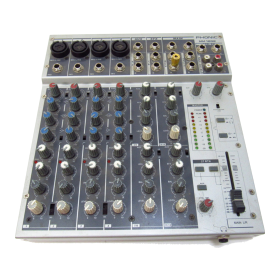
Congratulations on your purchase of the MM serial |
l |
12 standard inputs |
||
|
Mixer. The MM serial mixer is built into a rugged |
l |
4-balanced Mic/Line input channels with 3 band |
||
|
construction, which is ideal for small live gigs, re- |
EQ. Able to accept a wide range of Microphone |
|||
|
cording and fixed PA installations. In order to get |
and Line level from Neutrik combo connector |
|||
|
the best performance from the mixer, please read |
l |
4 stereo inputs with +4/-10 input sensitivity |
||
|
this user’s manual carefully. Please familiarize your- |
selector. |
|||
|
self with the new and different functions on this mixer. |
l |
Additional 2T return inputs, for CD playback or |
||
|
link to another submixer |
||||
|
l Global +48V phantom power switch on 1-4 |
||||
|
FEATURES |
channel at master section |
|||
|
MM1002 |
l Separate Mix and Control Room output |
|||
|
M/S switch |
||||
|
10 standard inputs |
l |
|||
|
l |
l |
Record output |
||
|
l 2 balanced Mic/Line input channels with 2 band |
||||
|
l |
Meter indicator switch allows meter to show MS/ |
|||
|
EQ. Able to accept a wide range of Microphone |
||||
|
ST/Headphone level |
||||
|
and Line level from Neutrik combo connector |
||||
|
l |
Headphone output |
|||
|
l 4 stereo inputs with +4/-10 input sensitivity se- |
||||
|
l |
Peak indicators on each mono input channel |
|||
|
lector |
||||
|
l Additional 2T return inputs, for CD playback or |
||||
|
link to submixer |
GETTING STARTED |
|||
|
l Global +48V phantom power switch on 1-2 chan- |
1. Check the AC voltage before connecting the AC |
|||
|
nel at master section |
||||
|
plug. This product is equipped with a 3-wire |
||||
|
l Separate Mix and Control Room output |
||||
|
grounding type plug; this is a safety feature and |
||||
|
l |
M/S switch |
|||
|
should not be defeated. Proper grounding is a |
||||
|
l |
Record output |
|||
|
necessary practice to prevent electric shock |
||||
|
l Meter indicator switch allows meter to show MS/ |
||||
|
hazards to the operator, the microphone user, |
||||
|
ST/Headphone level |
||||
|
and the musicians who are wired to this unit. |
||||
|
l |
Headphone output |
|||
|
l Peak indicators on each mono input channel |
2. |
Before switching on the main power, keep all the |
|
output fader all the way down to prevent damage |
||
|
or excessive noise caused by bad level |
||
|
adjustment, wrong wiring, defective cables, or bad |
||
|
connection. |
||
|
3. |
Always turn on the mixer before the power |
|
|
amplifier; turn off the mixer after the amplifier. |
||
|
4. |
Always turn off the unit before connecting and |
|
|
disconnecting the unit from the power source. |
||
|
5. |
Never use solvents to clean the unit. Clean with |
|
|
a soft, dry cloth. |
|
Page 4 |
MM1002 / MM1202 USER’S MANUAL |
PHONIC CORPORATION |

CONNECTING IT UP
CONNECTING IT UP
|
PHONICCORPORATION |
MM1002 / MM1202 USER’S MANUAL |
Page 5 |
||||||||||||||||||||||||||||||||||||||||||
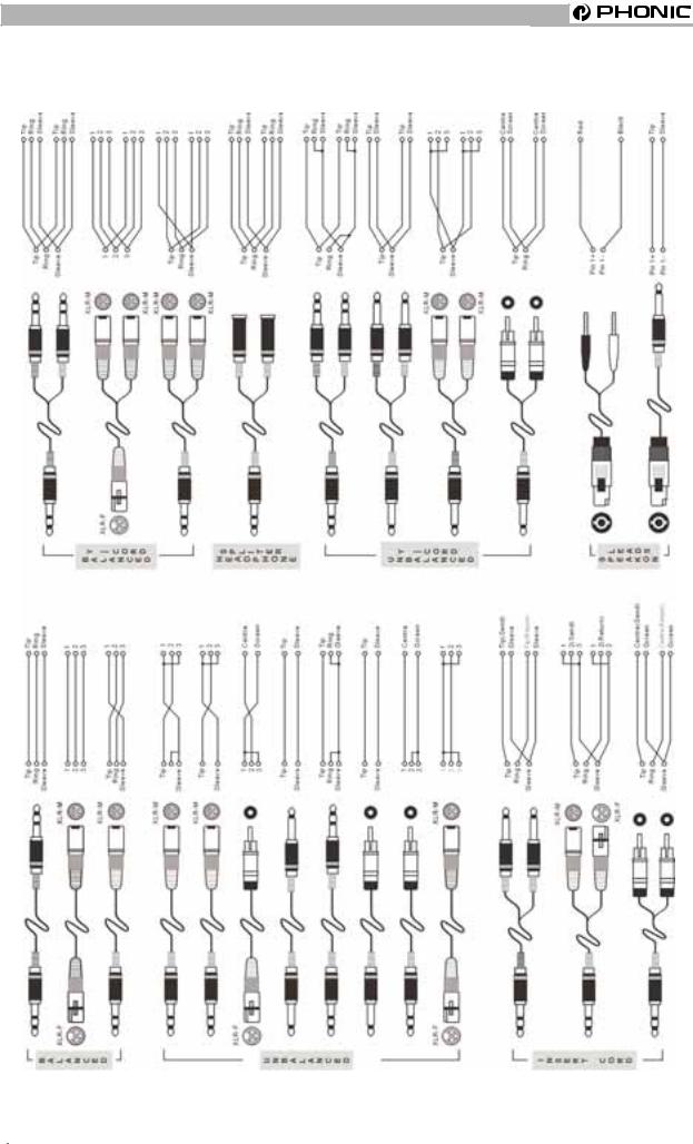
TYPICAL CONNECTING LEADS
TYPICAL CONNECTING LEADS
|
Page 6 |
MM1002 / MM1202 USER’S MANUAL |
PHONIC CORPORATION |

UNBALANCED&BALANCED
|
UNBALANCED & BALANCED |
interference. |
Most of the mistakes in audio installations are due to incorrect and defective audio connections. In order to perfectly complete your installation. Please pay special attention to the following section unless you are already familiar with balanced/unbalanced operations.
WHAT IS AN UNBALANCED LINE?
You can find this kind of system in most of home audio-video systems. They have one conductor to carry signal, and another conductor for a ground. Normally, for lower level signals, the ground conductor shields the signal conductor.
WHAT IS A BALANCED LINE?
A balanced system transmits signal via 2 conductors plus one ground shielding conductor. The 2 signal conductors carry the same signal but out of phase. For the balanced input stage, the amplifier will boost the difference between the 2 signal conductors and remove the identical part (known as common mode signal) of the 2 signals . Because the real signal is carried by the 2 conductors out of phase, so it is perfectly carried to the input. At the same time, interference that occurs during transmission will be identical (common mode). Because the signal conductors are run together, there is no chance they can be different, and all the interference will be removed by the balanced input amplifier.
THE DIFFERENCE BETWEEN TWO
OPERATIONS:
Because of the common mode interference immunity of a balanced system, the ground conductor doesn’t need to carry any electrical current, which means the ground of the 2 connected units has an identical ground level which is vital to an interference free system. Let’s look back at the unbalanced system. The signal electrical current goes from the signal conductor to the ground conductor. The ground level of the 2 connected units are not identical. This means the system is more easily inclined to noise
Running long cables is easy for a balanced system but difficult for an unbalanced system. A Lower noise level is a characteristic of a balanced system.
Because a balanced system needs 2 conductors for the signal and 1 conductor for the ground, a minimum of 3 conductors are needed for wiring a balanced system. So a dedicated system separates the ground and shields the 2 conductors.
Please read following section to properly wire for balanced and unbalanced systems:
THE CORRECT WIRING FOR BALANCED
OPERATION:
Always connect the main power with 3 plugs. Make sure the power system ground is working properly. Don’t use a ground insulator plug adapter without properly connecting the ground individually. This is vital to making a successful audio system connection.
Always connect the ground pin (PIN 1 in XLR) to the source unit, and disconnect this pin on the destination unit. This connection topology is to avoid creating a grounding loop between the signal and power ground. Utilize only the power ground, because it always has a lower resistance and better distribution than the signal ground.
If there is hum, a possible reason is a bad ground connection for the system. In case you can not find the fault, try connecting the ground pin of the input connectors. If the hum is reduced or eliminated, check your power grounding system. Special attention is needed when you use the equipment racks with some distance between them, and/or use a large quantity of power amplifiers. Check the power ground between the racks and power distribution strips with your electrical supply engineer. Make sure there is one, and only one, proper ground point for the audio system (or connected video system).
|
PHONICCORPORATION |
MM1002 / MM1020 USER’S MANUAL |
Page 7 |
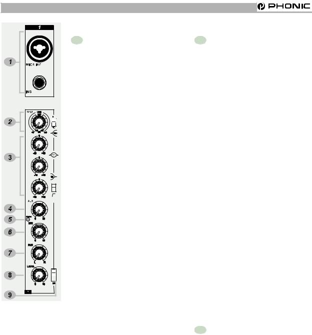
CHANNEL STRIP DESCRIPTION
CHANNEL STRIP DESCRIPRION
1 MIC/LINE MM1002(Ch1~2)/
MM1202 (Ch1~4)
The Microphone is via a combo connector, which allows the connections of XLR or 1/4 “ type phone jack. Please use only professional low impedance microphone and properly wired cable for best result. When the 1/4“ phone jack plug into the combo connector, the connection can be microphone or line level signal, we can change the input trim for MIC or LINE by using the LINE/MIC slide-switch to set the different TRIM accordingly. However, the phantom power is only available for the XLR connection. Never turn on the phantom power when you have line level source connected to the XLR connector.
48V PHANTOM POWER
+48V Phantom Power is available on each microphone input channel. All faders should be all the way down when switching on/off the phantom power, in order to prevent excessive noise to stage monitor speakers and main speakers; Phantom powered mics should not be plugged in with the +48V switched on.
INS
The INSERT is a break point in the input channel signal path. It allows the signal to be taken out from the mixer, through an external equipment such as a compressor, and then back to the mixer to continue the final mix output.
2 GAIN
This rotary knob adjusts the channel signal level. Too high, the signal will distort as it overloads the channel. Too low, the level of back hiss will be more noticeable and there might be insufficient signal level to the output of the mixer. Proper gain setting allows the mixer to work in the best operating level, adjusts the gain when signal presents to the highest level without triggering the peak LED. That is the most appropriate position.
This gain has two kinds of indication to suit mic or line input, when you use mic input, please read inside ring from +10~+60 dB, if you use line input, please read outside ring from -10~+40dB.
LINE / MIC SWITCH
When you use the channel for microphone, either through XLR or Phone plug, please switch to MIC. If you use the channel for line level source, either through XLR or Phone plug, please switch to the LINE. This switch will set the appropriate gain range for the input signal.
3 EQUALIZER
HIGH
Turn right to boost high frequency, adding crispness to cymbals, vocals and electronic instruments. Turn left to cut this frequency, reducing sibilance or hiss. The control has a shelving response that gives 15dB of boost or cut at 12KHZ.
|
Page 8 |
MM1002 / MM1202 USER’S MANUAL |
PHONICCORPORATION |
-
Inhalt
-
Inhaltsverzeichnis
-
Lesezeichen
Quicklinks
MU1002X
Kompaktmixer mit Effektprozessor
BEDIENUNGSANLEITUNG
PHONIC CORPORATION – Bedienungsanleitung MU1002X
1
Verwandte Anleitungen für Phonic MU 1002X
Inhaltszusammenfassung für Phonic MU 1002X
-
Seite 1
MU1002X Kompaktmixer mit Effektprozessor BEDIENUNGSANLEITUNG PHONIC CORPORATION – Bedienungsanleitung MU1002X… -
Seite 2
Netzstecker bei Gewitter oder wenn es längere Zeit nicht gebraucht wird. 14. Das Gerät sollte unbedingt von nur geschultem Personal repariert werden, wenn: Das Netzkabel oder der Netzstecker beschädigt wurde, Gegenstände oder Flüssigkeiten in das PHONIC CORPORATION – Bedienungsanleitung MU1002X… -
Seite 3: Inhaltsverzeichnis
REGLER UND SCHALTER STIRNSEITE BEDIENFLÄCHE EINGANGSKANÄLE DIGITALE EFFEKTSEKTION SUMMEN SEKTION DIGITALE EFFEKTPROGRAMME ANWENDUNGS- UND VERKABELUNGSBEISPIELE LIVE BAND SUBMIXER FÜR EIN FOH PULT TECHNISCHE DATEN ABMESSUNGEN BLOCKSCHALTBILD TYPISCHE KABELVERBINDUNGEN SYMMETRISCH UND UNSYMMETRISCH GLOSSAR NACHSCHLAGEWERKE GARANTIE UND SERVICE PHONIC CORPORATION – Bedienungsanleitung MU1002X…
-
Seite 4: Einführung
Sicherheitsanweisungen. Bewahren Sie die hochwertigen Phonic Mixer aus der MU Serie Anleitung gut auf, wenn Sie später noch mal entschieden haben. etwas nachschlagen wollen. Machen Sie sich Die MU Serie ist eine Weiterentwicklung der in Ruhe mit den verschiedenen Funktionen beliebten MM und MR Serie.
-
Seite 5: Vor Der Inbetriebnahme
Kopfhörer in die dafür vorgesehene einzelnen Kanäle beginnen. Buchse (#6) oder verkabeln Sie Ihre allerwichtigste ist die richtige Einstellung der Monitoranlage mit den Control Room Pegel in den einzelnen Kanälen. Jedes Ausgängen (#7). einzelne Detail Einfluss PHONIC CORPORATION – Bedienungsanleitung MU1002X…
-
Seite 6
Spitzenpegel und arbeiten immer im kann mithilfe eines Equalizers oder eines optimalen Bereich für durchschnittliche automatischen Feedback Unterdrückers Pegel. (z.B. PHONIC I7100) erreicht werden. Bei Mikrofonen hängt die Vorverstärkung Es gilt die Regel: Was man sieht, hört Mikrofons auch. Daher… -
Seite 7: Ein- Und Ausgänge Oberseite
Phantomspeisung einschalten..(siehe auch #13). Anmerkung: Wenn Sie unsymmetrische Mikrofone oder Line Signale an den XLR Eingang angeschlossen haben, dürfen Sie die Phantomspeisung nicht verwenden! 2. LINE diese dreipolige Klinkenbuchse werden Geräte mit Linienpegel angeschlossen, also Ausnahme PHONIC CORPORATION – Bedienungsanleitung MU1002X…
-
Seite 8
Es handelt sich also um das gleiche Signal, werden. das auch an den Ausgängen CTRL RM (#7) anliegt, jedoch mit einem Pegel, der für Kopfhörer ausgelegt ist. 7. CTRL RM Es gibt zwei unsymmetrische Klinkenbuchsen (linker und rechter Kanal) für den Anschluss PHONIC CORPORATION – Bedienungsanleitung MU1002X… -
Seite 9: Stirnseite
Ersatzteilnummer das Netzteil hat: Lautsprechern zu vermeiden. 353-22004-000-0 Noch mal als Checkliste: • Regeln Sie Gain, Kanal und Master Bitte verwenden Sie nur das Original Phonic Regler ganz runter. • Netzteil. Schließen Sie das Kondensatormikrofon • Externe Netzteile haben den Vorteil, dass Schalten Sie die Phantomspeisung ein.
-
Seite 10: Bedienfläche
Peak Anzeige aufleuchtet, obwohl der Gain allen Reglern in 12-Uhr-Stellung, d.h. auf der Regler relativ niedrig eingestellt ist. “0” Position. Vermeiden extreme Anhebungen oder Absenkungen einzelner Der Regelumfang der Eingangsempfindlichkeit Frequenzbereiche, dadurch erstreckt sich über zwei verschiedene Dynamikumfang einer Lautsprecheranlage PHONIC CORPORATION – Bedienungsanleitung MU1002X…
-
Seite 11
Trittschall von Mikrofonstativen auf der Bühne SEND (#5) bzw. in das interne Effektgerät (#24 oder Poppgeräusche bei Nahbesprechung ~ #29) gelangt, vorhören (näheres dazu lesen wirkungsvoll reduziert. Ebenso kann 50 Hz Sie bitte unter #31). Brummen wirkungsvoll unterdrückt werden. PHONIC CORPORATION – Bedienungsanleitung MU1002X… -
Seite 12
Bedenken Sie, dass eine Veränderung in der Klangregelung auch den internen Pegel ändert – wenn Sie z.B. sehr viele Bässe anheben, kann es passieren, dass die Peak Anzeige aufleuchtet, obwohl der Gain Regler relativ niedrig eingestellt ist. PHONIC CORPORATION – Bedienungsanleitung MU1002X… -
Seite 13: Digitale Effektsektion
Eingang des DSP übersteuert. Er ist also von der Stellung der einzelnen EFX SEND Regler (#19) in den Eingangskanälen abhängig. Um den optimalen Dynamikumfang und damit besten Signal/Rauschabstand Effektprozessors zu gewährleisten, sollten Sie die einzelnen EFX SEND Regler der Kanäle PHONIC CORPORATION – Bedienungsanleitung MU1002X…
-
Seite 14
Musikgeschäft erhältlich. Wichtig ist, dass es Taster mehrmals hintereinander betätigen, dabei um einen Impulsschalter („momentary berechnet Prozessor Abstand switch“) handeln muss. zwischen den letzten beiden Betätigungen und interpretiert ihn als die Verzögerungszeit des 29. EFX TO MAIN PHONIC CORPORATION – Bedienungsanleitung MU1002X… -
Seite 15: Summen Sektion
Sie den Schalter EFX CUE, drehen in den einzelnen Kanälen die EFX SEND Regler TO MAIN L-R (#19) auf, die Sie in der Beschallungszone Wird dieser Schalter gedrückt, gelangt das hörbar machen wollen, und kontrollieren Sie Zweispursignal in die Summenschiene (#36). PHONIC CORPORATION – Bedienungsanleitung MU1002X…
-
Seite 16
–20 dB bis +17 dB. Die LED Ketten sitzen schaltungstechnisch in der CONTROL ROOM Sektion, und zwar vor dem Lautstärkeregler CTRL RM / PHONES (#32), sind also nicht abhängig von dessen Stellung. PHONIC CORPORATION – Bedienungsanleitung MU1002X… -
Seite 17
Gerät diesen zusätzlichen Pegel verträgt. 35. MONO Wenn Sie diesen Schalter drücken, werden die Signale linken rechten Summenschiene vor dem Summen Fader (#36) einer Monosumme zusammengemischt. Das bedeutet, dass an beiden Summenausgängen Links / Rechts (#4) PHONIC CORPORATION – Bedienungsanleitung MU1002X… -
Seite 18: Digitale Effektprogramme
Verzögerungszeit durch zweimaliges Antippen der TAP DELAY Taste TAP DELAY bzw. eines Fußschalters 100 ms (600 bpm) – Verzögerungszeit definiert wird. Die Anzahl der Wiederholungen 2690 ms (22,3 bpm) wird mit dem Regler PARAMETER eingestellt. PHONIC CORPORATION – Bedienungsanleitung MU1002X…
-
Seite 19: Anwendungs- Und Verkabelungsbeispiele
Lassen Sie Ihrer Phantasie freien Lauf. So kommen Sie womöglich auch auf ungewöhnliche Lösungen bei Aufgaben in der Beschallungs- und Aufnahmetechnik. Erlaubt ist, was gefällt! Der MU1002X Mixer ist mit zahlreichen Möglichkeiten ausgestattet, die Ihnen die Arbeit im Studio oder Live erheblich vereinfachen. LIVE BAND PHONIC CORPORATION – Bedienungsanleitung MU1002X…
-
Seite 20: Submixer Für Ein Foh Pult
SUBMIXER FÜR EIN FOH PULT PHONIC CORPORATION – Bedienungsanleitung MU1002X…
-
Seite 21: Technische Daten
Maximalpegel Mikrofonvorverstärker +10 dBu Alle anderen Eingänge +22 dBu Unsymmetrische Ausgänge +22 dBu Symmetrische Ausgänge +28 dBu Impedanzen Mikrofoneingang 2k Ohm alle anderen Eingänge 10k Ohm 2-Spur Ausgänge 1,1k Ohm alle anderen Ausgänge 150 Ohm PHONIC CORPORATION – Bedienungsanleitung MU1002X…
-
Seite 22
20 Watt Netzspanung 220 ~ 240 V, 50/60 Hz Gewicht 1,7 kg Abmessungen (B x H x T) 218 x 70 x 233 mm Phonic behält sich das Recht vor, technische Änderungen ohne vorherige Ankündigung vorzunehmen. PHONIC CORPORATION – Bedienungsanleitung MU1002X… -
Seite 23: Abmessungen
ABMESSUNGEN Die Maße sind in mm/inch angegeben. PHONIC CORPORATION – Bedienungsanleitung MU1002X…
-
Seite 24: Blockschaltbild
BLOCKSCHALTBILD PHONIC CORPORATION – Bedienungsanleitung MU1002X…
-
Seite 25: Typische Kabelverbindungen
Ausgangsseite (entweder XLR oder 6,3 mm TRS Klinke) und einen 2-polige Mono Klinke für die Last = Eingangsseite, wobei ausgangsseitig die Verbindung am Ring des Klinkensteckers getrennt werden sollte. Diese Vorgehensweise garantiert die besten Audioergebnisse bei elektronisch symmetrierten Ausgängen. PHONIC CORPORATION – Bedienungsanleitung MU1002X…
-
Seite 26: Symmetrisch Und Unsymmetrisch
(siehe Stiften. Stellen Sie sicher, dass das System Abbildung 5). ordnungsgemäß geerdet ist. Verwenden Sie niemals einen Masse isolierenden Stecker, ohne das System zusätzlich separat zu erden. Dies eine Grundbedingung für eine einwandfrei Audioverbindung. PHONIC CORPORATION – Bedienungsanleitung MU1002X…
-
Seite 27
Racks einer gewissen Entfernung zueinander aufgestellt sind, und/oder wenn Sie eine größere Anzahl von Leistungsendstufen verwenden. aaaaaaaaaaaaaa aaaaaaaaaaaaaa aaaaaaaaaaaaaa aaaaaaaaaaaaaa aaaaaaaaaaaaaa aaaaaaaaaaaaaa aaaaaaaaaaaaaa aaaaaaaaaaaaaa aaaaaaaaaaaaaa aaaaaaaaaaaaaa aaaaaaaaaaaaaa aaaaaaaaaaaaaa aaaaaaaaaaaaaa aaaaaaaaaaaaaa aaaaaaaa aaaaaaaa aaaaaaaa aaaaaaaa aaaaaaaa PHONIC CORPORATION – Bedienungsanleitung MU1002X… -
Seite 28: Glossar
Kompressor, Gate, etc. Panoramaregler. Verteilt ein Signal auf die linke und rechte Summe. Peaking Bandpass. Glockencharakteristik. Ein Klangregler bearbeitet nur einen bestimmten Frequenzbereich, der nach oben und unten begrenzt ist. PFL – pre fader listening PHONIC CORPORATION – Bedienungsanleitung MU1002X…
-
Seite 29
Abschirmung als Rückführung dient. Meist sehr störanfällig gegenüber Brummeinstreuungen und Verlusten im Höhenbereich auf langen Strecken. +48V 48V Gleichspannung, auch Phantomspeisung genannt, an Mikrofoneingängen. Dient zur Speisung von Kondensatormikrofonen und aktiven DI Boxen. PHONIC CORPORATION – Bedienungsanleitung MU1002X… -
Seite 30: Nachschlagewerke
Gibson. Mix Books, ISBN: 0918371104 _ Audiopro Home Recording Course Vol. 2: A Comprehensive Multimedia Audio Recording Text by Bill Gibson. Mix Books, ISBN: 0918371201 Phonic behält sich das Recht vor, technische Änderungen ohne vorherige Ankündigung durchzuführen. PHONIC CORPORATION – Bedienungsanleitung MU1002X…
-
Seite 31: Erwerb Von Weiteren Phonic Artikeln Und Ersatzteilen
„Händlersuche“. SERVICE UND REPARATUR Im Fall eines Problems oder einer Reparatur wenden Sie sich bitte an Ihren Phonic Fachhändler, bei dem Sie das Gerät erworben haben. Phonic gibt keine Service Unterlagen an Endkunden heraus, und warnt den Anwender nachdrücklich davor, selbst Reparaturen vorzunehmen, weil dadurch jegliche Garantieansprüche erlischen.
-
Contents
-
Table of Contents
-
Bookmarks
Quick Links
Related Manuals for Phonic MM1002
Summary of Contents for Phonic MM1002
-
Page 2: Safety Precautions
Your Phonic MM1002 / MM1202 was carefully packed at the manufacturing site and the packing box was designed to protect the unit from rough handling. We recommend that you carefully examine the packaging and its contents for any signs of physical damage, which may have occurred during transportation.
-
Page 3: Table Of Contents
M A I N O U T ……..1 3 SYSTEM BLOCK DIAGRAMS…..21 EFX OUT(MM1202 ONY)……13 AUX OUT………..13 REFERENCE BOOKS……..22 PHONIC CORPORATION MM1002 / MM1202 USER’S MANUAL Page 3…
-
Page 4: Introduction
4. Always turn off the unit before connecting and disconnecting the unit from the power source. 5. Never use solvents to clean the unit. Clean with a soft, dry cloth. Page 4 MM1002 / MM1202 USER’S MANUAL PHONIC CORPORATION…
-
Page 5: Connecting It Up
CONNECTING IT UP CONNECTING IT UP PHONIC CORPORATION MM1002 / MM1202 USER’S MANUAL Page 5…
-
Page 6: Typical Connecting Leads
TYPICAL CONNECTING LEADS TYPICAL CONNECTING LEADS Page 6 MM1002 / MM1202 USER’S MANUAL PHONIC CORPORATION…
-
Page 7: Unbalanced & Balanced
The signal electrical current goes from the signal conductor to the ground conductor. The ground level of the 2 connected units are not identical. This means the system is more easily inclined to noise PHONIC CORPORATION MM1002 / MM1020 USER’S MANUAL Page 7…
-
Page 8: Channel Strip Description
The compressor, and then back to the mixer control has a shelving response that gives to continue the final mix output. 15dB of boost or cut at 12KHZ. Page 8 MM1002 / MM1202 USER’S MANUAL PHONIC CORPORATION…
-
Page 9: Aux
Channel inserts are designed bus, allows you to locate the source to add-on a compressor, limiter or gate. smoothly across the stereo image. Please refer to Phonic PCL3200 or MCL2000 for further information. LOW CUT Slide down the slide-switch; insert the 18dB per octave 75Hz low cut filter in the signal path.
-
Page 10: Level
S channel-just plug and play. M-S STEREO RECORDING M-S is an abbreviation for mid-side, the microphones used for M-S recording are a cardioid microphone facing directly to the source, and a figure-eight microphone Page 10 MM1002 / MM1202 USER’S MANUAL PHONIC CORPORATION…
-
Page 11: What Is A Cardioid Microphone
Bi-directional elements are most sensitive to sounds coming in from the front or rear( left or right) of the microphone, and reject sounds from the sides( front and rear). FIGURE-8 POLAR PATTERN PHONIC CORPORATION MM1002 / MM1202 USER’S MANUAL Page 11…
-
Page 12: Stereo Input
When the control knob turns fully to the left or right, you send only that side of the sig- nal to the mix. Page 12 MM1002 / MM1202 USER’S MANUAL PHONIC CORPORATION…
-
Page 13: Master Section Description
2T RTN signals into con- This knob controls the AUX OUT level. trol room and effected by the con- trol room level. +48V PHANTOM PWR This slide-switch turns the master phantom power on and off. PHONIC CORPORATION MM1002 / MM1202 USER’S MANUAL Page 13…
-
Page 14: Aux Signal Path Select Button
Make sure the power supply unit is not plugged into AC outlet be- fore connecting to the mixer. 31 POWER ON/OFF SWITCH This switch turns the power of the unit on and off. MM1002 / MM1202 USER’S MANUAL PHONIC CORPORATION Page 14…
-
Page 15: Initial Setup
Adjust the input gain until the meter shows in the amber section, with occasional peaks to the first red LED at maximum source level. This al- lows enough headroom to accommodate peaks and the maximum level for normal operation; PHONIC CORPORATION MM1002 / MM1202 USER’S MANUAL Page 15…
-
Page 16: Applications
APPLICATIONS APPLICATIONS STANDARD CONNECTIONS Page 16 MM1002 / MM1202 USER’S MANUAL PHONIC CORPORATION…
-
Page 17: Live Band Setting
APPLICATIONS LIVE BAND SETTING PHONIC CORPORATION MM1002 / MM1202 USER’S MANUAL Page 17…
-
Page 18: Dimensions
DIMENSIONS DIMENSIONS MM1002 MM1202 Measurements are shown in mm/inch. Page 18 MM1002 / MM1202 USER’S MANUAL PHONIC CORPORATION…
-
Page 19: Specifications
SPECIFICATIONS SPECIFICATIONS PHONIC CORPORATION MM1002 / MM1202 USER’S MANUAL Page19…
-
Page 20
SPECIFICATIONS Due to continuous product improvement, the specifications are subject to change without notice. Page 20 MM1002 / MM1202 USER’S MANUAL PHONIC CORPORATION… -
Page 21: System Block Diagrams
SYSTEM BLOCK DIAGRAMS SYSTEM BLOCK DIAGRAMS MM1002 PHONIC CORPORATION Page 21 MM1002 / MM1202 USER’S MANUAL…
-
Page 22
SYSTEM BLOCK DIAGRAMS MM1202 Page 22 MM1002 / MM1202 USER’S MANUAL PHONIC CORPORATION… -
Page 23: Reference Books
REFERENCE BOOKS REFERENCE BOOKS Phonic recommends the following books for those interested in advanced audio engineering and sound system operation: Sound System Engineering by Don and Carolyn Davis, Focal Press, ISBN: 0-240-80305-1 Sound Reinforcement Handbook by Gary D. Davis, Hal Leonard Publishing Corporation,…
This manual is also suitable for:
Mm1202
SAFTY PRECAUTIONS
WARNING — TO REDUCE THE RISK OF FIRE OR ELECTRIC SHOCK, DO NOT
Do not allow water or liquids to be spilled into this unit. If the unit has been exposed to rain or liquids,
please unplug the power cord immediately from the outlet (with DRY HANDS) and get a qualified service
technician to check it. Keep this unit away from heat sources such as radiators, heat registers, stoves, etc.
This unit contains no user-serviceable parts. Refer all service needs to a qualified
This triangle on your component alerts you
to the presence of uninsulated » dangerous
voltage» inside the enclosure that may be
sufficient to constitute a risk of shock.
CAUTION:
TO REDUCE THE RISK OF ELECTRIC SHOCK, DO NOT REMOVE COVERS (OR
BACK). NO USER-SERVICEABLE PARTS ARE INSIDE. REFER ALL SERVICING
TO A QUALIFIED SERVICE PERSONNEL.
Keep this unit clean by using a soft dry brush and occasionally wiping it with a damp cloth. Do not use any
other solvents, which may damage the paint or plastic parts. Regular care and inspection will be rewarded
by a long life and maximum reliability.
Your Phonic MM1002 / MM1202 was carefully packed at the manufacturing site and the packing box was
designed to protect the unit from rough handling. We recommend that you carefully examine the packaging
and its contents for any signs of physical damage, which may have occurred during transportation.
Notify your dealer and the shipping company immediately
If the unit is damaged:
for damage or replacement may not be granted if not reported properly or in a timely manner.
Page 2
EXPOSE THIS UNIT TO RAIN OR MOISTURE.
service engineer through a Phonic dealer.
MM1002 / MM1202 USER’S MANUAL
This triangle on your component alerts you
to important operating and maintenance in-
structions in this accompanying literature.
. Claims
PHONIC CORPORATION
![]()
PHONIC MM1002 VER.2.1 MIXER
Type: (PDF)
Size
2.9 MB
Page
23
Category
AUDIO
SERVICE MANUAL
If you get stuck in repairing a defective appliance
download
this repair information for help. See below.
Good luck to the repair!
Please do not offer the downloaded file for sell only
use it for personal usage!
Looking for similar phonic manual?
Document preview [1st page]
Click on the link for free download!
Document preview [2nd page]
Click on the link for free download!
Please tick the box below to get download link:
- Also known:
PHONIC MM-1002 MM1002 MIXER MM 1002
- If you have any question about repairing write your question to the Message board. For this no need registration.
- If the site has helped you and you also want to help others, please Upload a manual, circuit diagram or eeprom that is not yet available on the site.
Have a nice Day! - Please take a look at the below related repair forum topics. May be help you to repair.
Warning!
If you are not familiar with electronics, do not attempt to repair!
You could suffer a fatal electrical shock! Instead, contact your nearest service center!
Note! To open downloaded files you need acrobat reader or similar pdf reader program. In addition,
some files are archived,
so you need WinZip or WinRar to open that files. Also some files are djvu so you need djvu viewer to open them.
These free programs can be found on this page: needed progs
If you use opera you have to disable opera turbo function to download file!
If you cannot download this file, try it with CHROME or FIREFOX browser.
Relevant AUDIO forum topics:
Hello, good afternoon, good people from the Forum, someone have a Phonic Powerpod 410R schematic with (Class D amplifier) I will really appreciate it
Hola muy buenas tardes gente buena de la Foro alguien tendrá esquemático de Phonic Powerpod 410R con (amplificador Clase D) la verdad apreciare mucho
Üdv!
A címben említett erősítőm egyik csatornája nagyon alacson jelszintnél elkezd torzítani. Ilyenkor a végfokot meghajtó műveleti erősítő kimenete az egekbe szökik. A végtranzisztorok mégsem követik ezt. A tápfeszültségeket megvizsgáltam. Egyik alkatrészen sem látható fizikai hiba vagy égésnyom. Kis jelszintnél tökéletes jelet ad az erősítő.
Ha valaki nálam jobban ismerik az ilyen és hozzá hasonló «H» osztályú erősítőket, illetve bármi ötlete van azt megköszönöm!
Az erősítő rajza megtalálható ezen az oldalon.
Adott egy Phonic Powerpod 1062 keverőerősítő. Úgy került hozzám, hogy bekapcsol, de nem szól. Szétszedtem és akkor szembesültem azzal, hogy az egyik oldalban szét van égve több ellenállás, valamint az egyik végtranyó. Pár mérés után kiderült, hogy zárlatos mindkét végtranyó, a meghajtók, valamint 2 fet, ami a végtranyók tápellátását szolgálja, ha jól látom a rajzon. Jelzem nem vagyok profi, csak hobbi szinten javítgatok. A rajz szerint 2 féle tápról üzemel, ha jól tudom ezt hívják emeletes tápnak. A rajz fent van itt a tanyán. Most odáig eljutottam, hogy kicseréltem a szétégett ellenállásokat és az összes zárlatos tranyót, fetet. Most indul a végfok, behúz a védelem reléje is, de még nem mertem indítani, csak a hálózati bizti helyére kötött 100W-os izzóval. Működik, szól is, de ahogy írtam nem vagyok profi, így nem tudom esetleg kell-e még valamit cserélni/megnézni, mielőtt beteszem a biztit és élesben próbálom. Nem szeretném ha ellőné az új alkatrészeket és azt sem tudom, hogy mi a fene okozhatott ekkora pusztítást. Aki esetleg javított már ilyet, vagy tudna adni néhány jó tanácsot, azt megköszönném.
Similar manuals:
If you want to join us and get
repairing help
please sign in or sign up by completing a simple electrical test
or write your question to the Message board without registration.
You can write in English language into the forum (not only in Hungarian)!
E-Waste Reduce
SAFTY PRECAUTIONS
SAFETY PRECAUTIONS!
WARNING — TO REDUCE THE RISK OF FIRE OR ELECTRIC SHOCK, DO NOT
EXPOSE THIS UNIT TO RAIN OR MOISTURE.
Do not allow water or liquids to be spilled into this unit. If the unit has been exposed to rain or liquids, please unplug the power cord immediately from the outlet (with DRY HANDS) and get a qualified service technician to check it. Keep this unit away from heat sources such as radiators, heat registers, stoves, etc.
This unit contains no user-serviceable parts. Refer all service needs to a qualified service engineer through a Phonic dealer.
This triangle on your component alerts you to the presence of uninsulated “ dangerous voltage” inside the enclosure that may be sufficient to constitute a risk of shock.
This triangle on your component alerts you to important operating and maintenance instructions in this accompanying literature.
CAUTION:
TO REDUCE THE RISK OF ELECTRIC SHOCK, DO NOT REMOVE COVERS (OR BACK). NO USER-SERVICEABLE PARTS ARE INSIDE. REFER ALL SERVICING TO A QUALIFIED SERVICE PERSONNEL.
Keep this unit clean by using a soft dry brush and occasionally wiping it with a damp cloth. Do not use any other solvents, which may damage the paint or plastic parts. Regular care and inspection will be rewarded by a long life and maximum reliability.
Your Phonic MM1002 / MM1202 was carefully packed at the manufacturing site and the packing box was designed to protect the unit from rough handling. We recommend that you carefully examine the packaging and its contents for any signs of physical damage, which may have occurred during transportation.
If the unit is damaged: Notify your dealer and the shipping company immediately. Claims for damage or replacement may not be granted if not reported properly or in a timely manner.
|
Page 2 |
MM1002 / MM1202 USER’S MANUAL |
PHONIC CORPORATION |
CONTENTS
|
INTRODUCTION…………………………………….. |
4 |
CTRL RM…………………………….. |
13 |
|
REC………………………………………… |
13 |
||
|
FEATURES……………………………………….. |
4 |
2T RTN……………………………………………… |
13 |
|
EFX OUT CONTROL(MM1202 ONLY)………… |
13 |
||
|
GETTING STARTED………………………………… |
4 |
AUX OUT CONTROL(MM1202 ONLY)……….. |
13 |
|
+48V PHANTOM PWR………………………… |
13 |
||
|
CONNECTING IT UP…………………………… |
5 |
LED LEVEL METERS……………………………. |
13 |
|
HEADPHONE/STEREO INDICATION |
|||
|
TYPICAL CONNECTING LEADS………………… |
6 |
SELECT BUTTON………………………………… |
13 |
|
MS/ST SELECT BUTTON……………………… |
13 |
||
|
UNBALANCED & BALANCED……………………. |
7 |
2T RTN SIGNAL PATH SELECT BUTTON….. |
13 |
|
AUX SIGNAL PATH SELECT BUTTON………. |
14 |
||
|
CHANNEL STRIP DESCRIPTION………………… |
8 |
CTRL RM LEVEL…………………………….. |
14 |
|
MIC/LINE MM1002(CH1~2)/MM1202(CH1~4)……. |
8 |
HEADPHONE………………………………. |
14 |
|
GAIN………………………………………………….. |
8 |
MAIN L/R FADER………………………… |
14 |
|
EQUALIZER………………………………………….. |
8 |
||
|
AUX ………………………………………………………. |
9 |
REAR PANEL DESCRIPTION…………… |
14 |
|
EFX(MM1202 ONLY)……………………………….. |
9 |
POWER SUPPLY INPUT SOCKET………….. |
14 |
|
PEAK…………………………………………… |
9 |
POWER ON/OFF SWITCH…………………….. |
14 |
|
PAN………………………………………………….. |
9 |
||
|
LEVEL…………………………………………. |
10 |
INITIAL SETUP……………………………………. |
15 |
|
M-S SWITCH…………………………………. |
10 |
||
|
M-S STEREO RECORDING…………………….. |
10 |
APPLICATIONS………………………………. |
16 |
|
WHAT IS A CARDIOID MICROPHONE?…………. |
11 |
STANDARD CONNECTIONS………………. |
16 |
|
WHAT IS A FIGURE-8 MICROPHONE?…………. |
11 |
LIVE BAND SETTING………………………. |
17 |
|
STEREO INPUT…………………………………………. |
12 |
||
|
+4/-10 SWITCH…………………………………… |
12 |
DIMENSIONS …………………………………….. |
18 |
|
BAL(BALANCE)CONTROL……………………… |
12 |
||
|
SPECIFICATIONS………………………………. |
19 |
||
|
MASTER SECTION DESCRIPTION…………… |
13 |
||
|
MAIN OUT……………………………….. |
13 |
SYSTEM BLOCK DIAGRAMS………………… |
21 |
|
EFX OUT(MM1202 ONY)………………………… |
13 |
||
|
AUX OUT……………………………………. |
13 |
REFERENCE BOOKS……………………………. |
22 |
|
PHONIC CORPORATION |
MM1002 / MM1202 USER’S MANUAL |
Page 3 |
INTRODUCTION / FEATURES / GETTING STARTED
|
INTRODUCTION |
MM1202 |
|||
|
Congratulations on your purchase of the MM serial |
l |
12 standard inputs |
||
|
Mixer. The MM serial mixer is built into a rugged |
l |
4-balanced Mic/Line input channels with 3 band |
||
|
construction, which is ideal for small live gigs, re- |
EQ. Able to accept a wide range of Microphone |
|||
|
cording and fixed PA installations. In order to get |
and Line level from Neutrik combo connector |
|||
|
the best performance from the mixer, please read |
l |
4 stereo inputs with +4/-10 input sensitivity |
||
|
this user’s manual carefully. Please familiarize your- |
selector. |
|||
|
self with the new and different functions on this mixer. |
l |
Additional 2T return inputs, for CD playback or |
||
|
link to another submixer |
||||
|
l Global +48V phantom power switch on 1-4 |
||||
|
FEATURES |
channel at master section |
|||
|
MM1002 |
l Separate Mix and Control Room output |
|||
|
M/S switch |
||||
|
10 standard inputs |
l |
|||
|
l |
l |
Record output |
||
|
l 2 balanced Mic/Line input channels with 2 band |
||||
|
l |
Meter indicator switch allows meter to show MS/ |
|||
|
EQ. Able to accept a wide range of Microphone |
||||
|
ST/Headphone level |
||||
|
and Line level from Neutrik combo connector |
||||
|
l |
Headphone output |
|||
|
l 4 stereo inputs with +4/-10 input sensitivity se- |
||||
|
l |
Peak indicators on each mono input channel |
|||
|
lector |
||||
|
l Additional 2T return inputs, for CD playback or |
||||
|
link to submixer |
GETTING STARTED |
|||
|
l Global +48V phantom power switch on 1-2 chan- |
1. Check the AC voltage before connecting the AC |
|||
|
nel at master section |
||||
|
plug. This product is equipped with a 3-wire |
||||
|
l Separate Mix and Control Room output |
||||
|
grounding type plug; this is a safety feature and |
||||
|
l |
M/S switch |
|||
|
should not be defeated. Proper grounding is a |
||||
|
l |
Record output |
|||
|
necessary practice to prevent electric shock |
||||
|
l Meter indicator switch allows meter to show MS/ |
||||
|
hazards to the operator, the microphone user, |
||||
|
ST/Headphone level |
||||
|
and the musicians who are wired to this unit. |
||||
|
l |
Headphone output |
|||
|
l Peak indicators on each mono input channel |
2. |
Before switching on the main power, keep all the |
|
output fader all the way down to prevent damage |
||
|
or excessive noise caused by bad level |
||
|
adjustment, wrong wiring, defective cables, or bad |
||
|
connection. |
||
|
3. |
Always turn on the mixer before the power |
|
|
amplifier; turn off the mixer after the amplifier. |
||
|
4. |
Always turn off the unit before connecting and |
|
|
disconnecting the unit from the power source. |
||
|
5. |
Never use solvents to clean the unit. Clean with |
|
|
a soft, dry cloth. |
|
Page 4 |
MM1002 / MM1202 USER’S MANUAL |
PHONIC CORPORATION |
CONNECTING IT UP
CONNECTING IT UP
|
PHONICCORPORATION |
MM1002 / MM1202 USER’S MANUAL |
Page 5 |
||||||||||||||||||||||||||||||||||||||||||
TYPICAL CONNECTING LEADS
TYPICAL CONNECTING LEADS
|
Page 6 |
MM1002 / MM1202 USER’S MANUAL |
PHONIC CORPORATION |
UNBALANCED&BALANCED
|
UNBALANCED & BALANCED |
interference. |
Most of the mistakes in audio installations are due to incorrect and defective audio connections. In order to perfectly complete your installation. Please pay special attention to the following section unless you are already familiar with balanced/unbalanced operations.
WHAT IS AN UNBALANCED LINE?
You can find this kind of system in most of home audio-video systems. They have one conductor to carry signal, and another conductor for a ground. Normally, for lower level signals, the ground conductor shields the signal conductor.
WHAT IS A BALANCED LINE?
A balanced system transmits signal via 2 conductors plus one ground shielding conductor. The 2 signal conductors carry the same signal but out of phase. For the balanced input stage, the amplifier will boost the difference between the 2 signal conductors and remove the identical part (known as common mode signal) of the 2 signals . Because the real signal is carried by the 2 conductors out of phase, so it is perfectly carried to the input. At the same time, interference that occurs during transmission will be identical (common mode). Because the signal conductors are run together, there is no chance they can be different, and all the interference will be removed by the balanced input amplifier.
THE DIFFERENCE BETWEEN TWO
OPERATIONS:
Because of the common mode interference immunity of a balanced system, the ground conductor doesn’t need to carry any electrical current, which means the ground of the 2 connected units has an identical ground level which is vital to an interference free system. Let’s look back at the unbalanced system. The signal electrical current goes from the signal conductor to the ground conductor. The ground level of the 2 connected units are not identical. This means the system is more easily inclined to noise
Running long cables is easy for a balanced system but difficult for an unbalanced system. A Lower noise level is a characteristic of a balanced system.
Because a balanced system needs 2 conductors for the signal and 1 conductor for the ground, a minimum of 3 conductors are needed for wiring a balanced system. So a dedicated system separates the ground and shields the 2 conductors.
Please read following section to properly wire for balanced and unbalanced systems:
THE CORRECT WIRING FOR BALANCED
OPERATION:
Always connect the main power with 3 plugs. Make sure the power system ground is working properly. Don’t use a ground insulator plug adapter without properly connecting the ground individually. This is vital to making a successful audio system connection.
Always connect the ground pin (PIN 1 in XLR) to the source unit, and disconnect this pin on the destination unit. This connection topology is to avoid creating a grounding loop between the signal and power ground. Utilize only the power ground, because it always has a lower resistance and better distribution than the signal ground.
If there is hum, a possible reason is a bad ground connection for the system. In case you can not find the fault, try connecting the ground pin of the input connectors. If the hum is reduced or eliminated, check your power grounding system. Special attention is needed when you use the equipment racks with some distance between them, and/or use a large quantity of power amplifiers. Check the power ground between the racks and power distribution strips with your electrical supply engineer. Make sure there is one, and only one, proper ground point for the audio system (or connected video system).
|
PHONICCORPORATION |
MM1002 / MM1020 USER’S MANUAL |
Page 7 |
CHANNEL STRIP DESCRIPTION
CHANNEL STRIP DESCRIPRION
1 MIC/LINE MM1002(Ch1~2)/
MM1202 (Ch1~4)
The Microphone is via a combo connector, which allows the connections of XLR or 1/4 “ type phone jack. Please use only professional low impedance microphone and properly wired cable for best result. When the 1/4“ phone jack plug into the combo connector, the connection can be microphone or line level signal, we can change the input trim for MIC or LINE by using the LINE/MIC slide-switch to set the different TRIM accordingly. However, the phantom power is only available for the XLR connection. Never turn on the phantom power when you have line level source connected to the XLR connector.
48V PHANTOM POWER
+48V Phantom Power is available on each microphone input channel. All faders should be all the way down when switching on/off the phantom power, in order to prevent excessive noise to stage monitor speakers and main speakers; Phantom powered mics should not be plugged in with the +48V switched on.
INS
The INSERT is a break point in the input channel signal path. It allows the signal to be taken out from the mixer, through an external equipment such as a compressor, and then back to the mixer to continue the final mix output.
2 GAIN
This rotary knob adjusts the channel signal level. Too high, the signal will distort as it overloads the channel. Too low, the level of back hiss will be more noticeable and there might be insufficient signal level to the output of the mixer. Proper gain setting allows the mixer to work in the best operating level, adjusts the gain when signal presents to the highest level without triggering the peak LED. That is the most appropriate position.
This gain has two kinds of indication to suit mic or line input, when you use mic input, please read inside ring from +10~+60 dB, if you use line input, please read outside ring from -10~+40dB.
LINE / MIC SWITCH
When you use the channel for microphone, either through XLR or Phone plug, please switch to MIC. If you use the channel for line level source, either through XLR or Phone plug, please switch to the LINE. This switch will set the appropriate gain range for the input signal.
3 EQUALIZER
HIGH
Turn right to boost high frequency, adding crispness to cymbals, vocals and electronic instruments. Turn left to cut this frequency, reducing sibilance or hiss. The control has a shelving response that gives 15dB of boost or cut at 12KHZ.
|
Page 8 |
MM1002 / MM1202 USER’S MANUAL |
PHONICCORPORATION |
2 docs – User Manuals, Help Guides and Specs – for the Phonic MU 1002X product are present in our data base.
Tips for Finding Manuals:
This web-page provides a list of 2 accessible operating manuals and information books describing Phonic MU 1002X.
All manuals and instructions for Phonic MU 1002X are introduced in an easy-to-use PDF format and may be gratuitously downloaded or looked through directly from the site.
The page offers the following types of manuals: Music Mixer.
Helpful hints: While selecting a necessary guide for Phonic MU 1002X one should pay special attention to the type of the document.
We try to supply you with the fullest possible set of papers we or our users are able to find. These may be overviews and specifications of the device, mounting and installing instructions, the unit operating rules and maintenance regulations and much more.
Haven’t found a required manual for your Phonic MU 1002X?
Check in a while. We update our guides collection and add new documents on a daily basis for you to be always able to find the very paper you need on our web-site. In case you own a directory or an instruction for Phonic MU 1002X, which is absent on our site, and you’d like to share it with the public, please send it to us as a scanned copy or a PDF file, and we’ll definitely place it on our page while providing your name as a supplier of the doc. Lots of our users will be grateful for your assistance!
|
10 898 торговых марок |
Скачайте инструкцию БЕСПЛАТНО! Diplodocs позволяет скачать несколько типов инструкций для наилучшего использования PHONIC MU1002X |

|
Вам требуется помощь по использованию изделия? Все инструкции по категориям |
инструкция по эксплуатации PHONIC MU1002XDiplodocs поможет скачать инструкцию PHONIC MU1002X .
Введите модель изделия PHONIC…
|

Copyright © 2005 — 2012 — Diplodocs —
Все права защищены.
Торговые марки принадлежат их соответствующим владельцам.
![]()
PHONIC MM1002 VER.2.1 MIXER
Type: (PDF)
Size
2.9 MB
Page
23
Category
AUDIO
SERVICE MANUAL
If you get stuck in repairing a defective appliance
download
this repair information for help. See below.
Good luck to the repair!
Please do not offer the downloaded file for sell only
use it for personal usage!
Looking for similar phonic manual?
Document preview [1st page]
Click on the link for free download!
Document preview [2nd page]
Click on the link for free download!
Please tick the box below to get download link:
- Also known:
PHONIC MM-1002 MM1002 MIXER MM 1002
- If you have any question about repairing write your question to the Message board. For this no need registration.
- If the site has helped you and you also want to help others, please Upload a manual, circuit diagram or eeprom that is not yet available on the site.
Have a nice Day! - See related repair forum topics below. May be help you to repair.
Warning!
If you are not familiar with electronics, do not attempt to repair!
You could suffer a fatal electrical shock! Instead, contact your nearest service center!
Note! To open downloaded files you need acrobat reader or similar pdf reader program. In addition,
some files are archived,
so you need WinZip or WinRar to open that files. Also some files are djvu so you need djvu viewer to open them.
These free programs can be found on this page: needed progs
If you use opera you have to disable opera turbo function to download file!
If you cannot download this file, try it with CHROME or FIREFOX browser.
Relevant AUDIO forum topics:
Hola muy buenas tardes gente buena de la Foro alguien tendrá esquemático de Phonic Powerpod 410R con (amplificador Clase D) la verdad apreciare mucho
Adott egy Phonic Powerpod 1062 keverőerősítő. Úgy került hozzám, hogy bekapcsol, de nem szól. Szétszedtem és akkor szembesültem azzal, hogy az egyik oldalban szét van égve több ellenállás, valamint az egyik végtranyó. Pár mérés után kiderült, hogy zárlatos mindkét végtranyó, a meghajtók, valamint 2 fet, ami a végtranyók tápellátását szolgálja, ha jól látom a rajzon. Jelzem nem vagyok profi, csak hobbi szinten javítgatok. A rajz szerint 2 féle tápról üzemel, ha jól tudom ezt hívják emeletes tápnak. A rajz fent van itt a tanyán. Most odáig eljutottam, hogy kicseréltem a szétégett ellenállásokat és az összes zárlatos tranyót, fetet. Most indul a végfok, behúz a védelem reléje is, de még nem mertem indítani, csak a hálózati bizti helyére kötött 100W-os izzóval. Működik, szól is, de ahogy írtam nem vagyok profi, így nem tudom esetleg kell-e még valamit cserélni/megnézni, mielőtt beteszem a biztit és élesben próbálom. Nem szeretném ha ellőné az új alkatrészeket és azt sem tudom, hogy mi a fene okozhatott ekkora pusztítást. Aki esetleg javított már ilyet, vagy tudna adni néhány jó tanácsot, azt megköszönném.
Sziasztok!
Egyik barátomé ez a Phonic AM442D keverőpult, azzal keresett meg hogy az effekt nem működik. Nem volt kijelzés sem.
Szétszerelés után a kijelző szegmensek egy része visszajött, de hiányosan. A kis fekete csatlakozó volt kontakthibás, tisztítása után minden rendbejött.
A kezelőgomb encodere stabilan működik, de sajnos a gomb lenyomása (select) után is villognak a tizedespontok és nincs jel az effekt kimenetén. Ha jól emlékszem a program kiválasztása után ha lenyomom a gombot normális esetben a pontok villogása megáll és ezután működik.
Csináltam képet a panelről. Az encoder és a select gomb a 63FIV3T feliratú ic-re van bekötve, a select a 14 -es lábára csatlakozik. 3.3V feszültség van a lábon, a gomb lenyomásakor rendesen testre (0,0V)kerül.
Lehet hogy a hibás csatlakozó miatt a tápellátása ingadozott, szakadozott. Talán ettől hibásodott meg. Ram van rajta, de flash ic-t nem láttam. A fekete szövet alatt csak néhány ellenállás van, nincs oxid alatta. A tápja 5V, stabil, zavarmentes. A két stabilizátor 3.3V és 1.25V feszültséget állít elő, ez is rendben van.
A keverőn az egyik master poti ropog kicsit, de minden más jónak tűnik. A kis gombokat próbáltam mindenféle variációban, de nem ettől van letiltva a select.
Ha valaki találkozott ilyennel vagy ötlete van, kérem segítsen kicsit mert nincs több ötletem.
Köszönöm!
Sziasztok!
Kezdem feladni a dolgot, a bal oldalon fix 12V-ra felakadt a kimenet. Átmértem mindent, végtranzisztorok jók, tápfetek jók, elégve nincs semmi, melegedni nem melegszik semmi, kh hiba nincs, LDR ledje aktív így az IC5 kimenetén 13V van, tápegység rendben van, és mégsem jó… Van valakinek tippje, mit csinálhatnék még vele?![]()
Similar manuals:
If you want to join us and get
repairing help
please sign in or sign up by completing a simple electrical test
or write your question to the Message board without registration.
You can write in English language into the forum (not only in Hungarian)!
E-Waste Reduce