
Основные характеристики
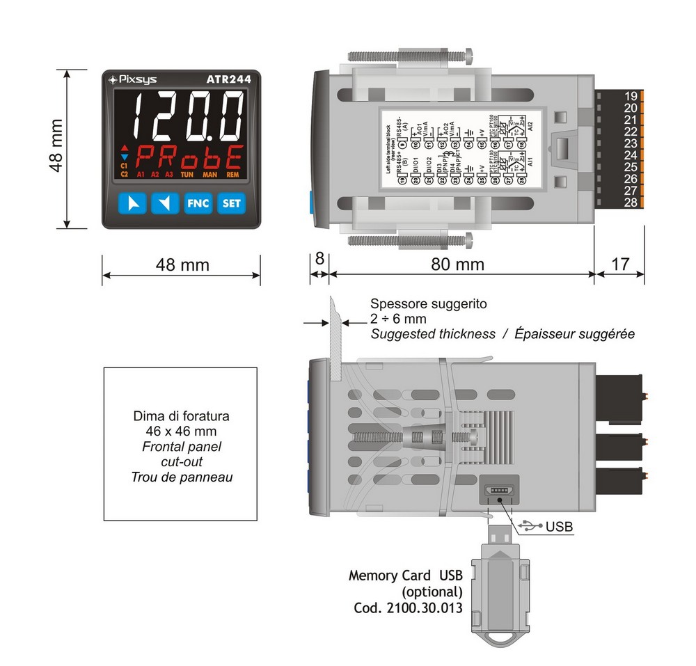
Размеры:
48(В) x 48(Ш) x 105(Г) мм
Напряжение питания:
от 24 до 230 В перем./пост. тока ± 15 %, 50/60 Гц, гальваническая развязка 2,5 кВ
Потребляемая мощность:
8 Вт
Дисплей:
2 светодиодных дисплея: 4-значный белый и 4-значный красный
Условия эксплуатации:
0-45°C, относительная влажность 35-95%
Входы:
1 или 2 настраиваемых аналоговых входа, выбираемых как:
Тип термопары K, S, R, J, T, N, B (с автоматической компенсацией холодного спая от -25 до 85°C, ± 0,2% полной шкалы ± 1 цифра, разрешение 16 бит)
Pt100, Pt500, Pt1000, Ni100, PTC1K, NTC10K (β 3435K)
Линейные аналоговые сигналы от 0 до 10 В (50000 точек), от 0/4 до 20 мА (40000 точек), от 0 до 60 мВ (25000 точек)
Потенциометр от 1 до 150 кОм (50000 точек)
Время выборки (аналоговые входы): Программируется от 2,1 мс (частота до 470 Гц)
2 или 4 цифровых входа: настраиваются для изменения заданных значений, удержания, работы, запуска настройки, пуска/остановки, блокировки конфигурации
1 вход трансформатора тока (ТТ): 50 мА, 800 мкс — 4096 точек
Выходы:
2 или 3 реле: 250 В перем. тока, 5 А, резистивное изменение
2 выхода SSR: 12/24 В пост. тока, макс. 30 мА
1 или 2 аналоговых выхода: по выбору от 4 до 20 мА (40 000 точек ± 0,2 % полной шкалы) или от 0 до 10 В пост. тока (40 000 точек ± 0,2 % полной шкалы>) для команды или повторной передачи PV/SPV
Последовательная связь (модели -T): RS485 Modbus RTU Slave (от 4800 до 115200 бод)
Режимы управления:
ВКЛ/ВЫКЛ с гистерезисом, P, PI, PID, PD, пропорциональный времени, ручная или автоматическая настройка
Режимы тревоги:
Абсолютное/пороговое значение, полоса, высокое/низкое отклонение. Аварийный сигнал с дополнительным ручным сбросом. Сигнализация обрыва петли.
Герметизация:
Передняя панель IP54 (IP65 с прокладкой), IP20 (корпус и клеммные колодки)
Конфигурация:
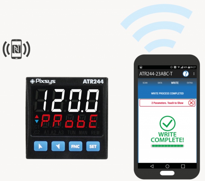
Параметры, защищенные паролем, дополнительная карта памяти для повторных конфигураций, программное обеспечение для ПК, настройка NFC через приложение MyPixsys для смартфонов Android
Основные варианты применения:
- Нагревательные элементы и управление горелками
- Металлообрабатывающие печи
- Холодильное оборудование
- Кожевенное и обувное оборудование
- Экструзия пластика
- Молочная промышленность
- Текущий контроль
- Сушильные машины
- Контроль тензодатчика
- Клапаны с электроприводом
- Литье под давлением
- Дистанционное управление через RS485 Modbus
- Холодильные камеры
- Фармацевтическая индустрия
- Преобразователь сигналов
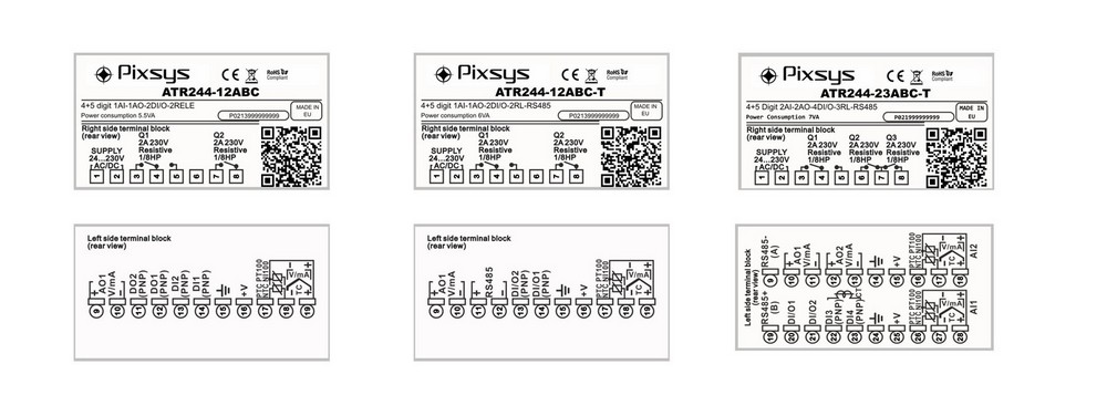
Электрическое подключение
Размеры (мм)
Для ATR244 доступны следующие аксессуары:
- Карта памяти для быстрой настройки многих контроллеров
- Программное обеспечение LABSOFTVIEW для настройки
Варианты заказа
ATR244-12ABC — Контроллер/индикатор с конфигурацией через NFC, монтируемый на панель, 1 аналоговый вход, 2 реле 5 А, 2 выхода SSR, 2 цифровых входа, 1 аналоговый выход В/мА, напряжение питания от 24 до 230 В перем./пост. тока.
ATR244-12ABC-T — Контроллер/индикатор с конфигурацией через NFC, монтируемый на панель, 1 аналоговый вход, 2 реле 5 A, 2 выхода SSR, 2 цифровых входа, 1 аналоговый выход В/мА, RS485, напряжение питания от 24 до 230 В перем./пост. тока.
ATR244-23BC-T — Контроллер/индикатор с конфигурацией через NFC, монтируемый на панель, 2 аналоговых входа, 3 реле 5 A, 2 выхода SSR, 2/4 цифровых входа, 2 аналоговых выхода В/мА, RS485, напряжение питания от 115 до 230 В перем./пост. тока.
ATR244-23A-T — Контроллер/индикатор с конфигурацией через NFC, монтируемый на панель, 2 аналоговых входа, 3 реле 5 A, 2 выхода SSR, 2/4 цифровых входа, 2 аналоговых выхода В/мА, RS485, напряжение питания 24 В пост. тока.
9 мая, 2018
Видео Продукты Фото Контакты
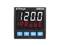
Контроллер PID-процесса 48×48 мм ATR244
-размер 48×48 мм,
-Программируемая NFC / RFID
-раздельные / двойные аналоговые входы,
-аналитические результаты,
многовольтный источник питания,
-RS485 / Modbus.
Контроллер процесса ATR244 устанавливает новые стандарты для контроллеров Pixsys ATR. Он выделяется ярким дисплеем, который обеспечивает оптимальную видимость и повышенный уровень информации для оператора рядом с новой функцией справки прокрутки.
ATR244 полагается на флагманский режим программирования Pixsys по технологии NFC / RFID с выделенными приложениями MyPixsys для Android (которые уже используются для преобразователей сигналов Pixsys и индикаторов STR), не требующих электрических соединений и источников питания, что позволяет быстро настраивать / обновлять данные на сайте.
Доступность включает модель с двойным аналоговым входом и двойным аналоговым выходом для максимальной гибкости приложений. В одном устройстве можно достичь двух отдельных контуров ПИД-регулирования нагрева / охлаждения в одном устройстве или для обработки математических операций между двумя значениями процесса.
Выходы могут быть выбраны как команда / несколько режимов тревоги / повторная передача аналогового сигнала. Стандарт последовательной связи — RS485 с протоколом Modbus RTU / Slave.
Удобная, мультимедийная поддержка и прослеживаемость
Для всего спектра продуктов Pixsys мы предоставляем техническую поддержку для установки, программирования и работы через наш онлайн-форум и через Skype.
Интерфейс контроллера ATR244 гарантирует, что продукт прост в использовании; оператор также поддерживается средствами программирования, такими как App MyPixsys (для устройств Android) и программным обеспечением LABSOFTVIEW.
На нашем канале YouTube доступны обучающие видеоролики. Что касается всего ассортимента продуктов PIXSYS, благодаря QR-коду прослеживаемость продукта гарантируется на весь его жизненный цикл; информацию и документацию онлайн можно также получить, прочитав QR-код, который направляет ваше мобильное устройство в технические характеристики продукта и проверяет его условия гарантии.
Коды для заказа — Блок питания 24..230 Vac / Vdc
Аналоговый вход ATR244-12ABC1 + 2 реле 5 A + 2 SSR + 2 D.I. + 1 аналоговый выход V / мА
Аналоговый вход ATR244-12ABC-T1 + 2 реле 5 A + 2 SSR / D.I. + 1 аналоговый выход V / mA + RS485
Коды для заказа — Блок питания 24 или 115..230 Vac / Vdc
Аналоговые входы ATR244-23A-T2 + 3 реле 5 A + 2 SSR + 2/4 D.I. + 2 аналогового выхода V / mA + RS485 + CT
Аналоговые входы ATR244-23BC-T2 + 3 реле 5 A + 2 SSR + 2/4 D.I. + 2 аналогового выхода V / mA + RS485 + CT
Основные функции
Box48 x 48 (передняя панель) x 105 мм
Источник питания24..230 В AC / DC ± 15% 50/60 Гц — гальваническая развязка 2,5KV
Потребление8 Вт
Дисплей 4 цифры 0,5 «белый + 4 цифры 0,3» красный
Условия эксплуатации Температура 0-45 ° C, влажность 35..95 RH%
MaterialBox: ПК UL94V2 самозатухающий, передняя панель: ПК UL94V2
WeightApprox. 185 г
SealingIP65 (передняя панель) IP20 (коробка и клеммные колодки)
Быстрые параметры настройки Карты памяти, программное обеспечение LABSOFTVIEW или EASY-UP
APP / NFCProgramming через APP MyPixsys для смартфонов Android
входные
1 или 2 — ConfigurableRes. 16 бит, выбирается для типа TC K, S, R, J, T, N, B (автоматическая компенсация холодного спая) -25..85 ° C, ± 0,2% F.S. ± 1 цифра FS), терморезисторы PT100, PT500, PT1000, Ni100, PTC1K, NTC10K (β 3435K), сигналы процесса 0,10 В (50000 точек), 0 / 4,20 мА (40000 точек), 0..60 мВ (25000 точек), потенциометр 1..150 кОм (50000 точек)
Время выборки Программируемая до 2,1 мс (частота до 470 Гц)
2/4 цифровых входа Изменение заданной точки, удержание, запуск, запуск настройки, запуск / останов, настройка блокировки
1 Трансформатор тока (C.T.) inputSelection C.T. 50 мА, 800 мкс — 4096 точек
Выходы
2/3 релеРеле 5 A — 250 В переменного тока резистивное изменение
2 SSR12 / 24 V DC — максимум 30 мА
1/2 analogueSelection 4..20 mA (40000 точек ± 0,2% F.S.) или 0..10 V DC (40000 точек ± 0,2% F.S.) для команды или повторной передачи PV / SPV
Последовательная связьRS485 Modbus RTU — ведомый (4800..115200 бод-код-T)
Возможности программного обеспечения
Алгоритмы управления — ВЫКЛ с гистерезисом, P., P.I., P.I.D., P.D. пропорциональное время
TuningManual или автоматический
Защита данных Блокировка заданного значения управления / тревоги / Доступ к параметрам по паролю
Режимы тревоги: Абсолютный / Порог, Полоса, Высокое / Низкое отклонение. Тревога с дополнительным ручным сбросом. Тревога прерывания петли
Авто / Ручная функцияВыходная процентная команда также с автоматическим изменением в случае отказа датчика
Двойной P.I.D. Отопление / охлаждение P.I.D.
Программируемая функцияПрограммированный цикл / 3 шага
Градиент Soft-StartRising, выраженный как градусы / час или фиксированный выходной процент
Логика открытия / закрытия логикиOpen / Close для моторных клапанов
https://www.lasma.eu/ru/dobavit-k-korzine
Продукты
Код: ATR24412ABC
Доступно на месте: 5+ шт.

Код: ATR24423AT
Доступно на месте: 5+ шт.

Код: ATR24423BCT
Доступно на месте: 4 шт.
Код: ATR24412ABCT
Доступно на месте: 2 шт.
|
ORDERING CODES |
ATR244-12ABC |
ATR244-12ABC-T |
ATR244-13ABC |
ATR244-23A-T |
ATR244-23BC-T |
|---|---|---|---|---|---|
|
Power supply |
24..230 V AC / DC ±15% 50/60 Hz — galvanic isolation 2,5KV |
24 V AC / DC ±15% 50/60 Hz — galvanic isolation 2,5KV |
115..230 V AC ±15% 50/60 Hz — galvanic isolation 2,5KV |
||
|
Power consumption |
6 Watt/VA |
6 Watt/VA |
6 Watt/VA |
6 Watt/VA |
6 Watt/VA |
|
Display |
4 digits 0,52’’, 5 digits 0,30’’ |
||||
|
Analogue inputs |
1 x Ris. 16bit, programmable for thermocouples K, S, R, J, T, N, B (automatic compensation of cold junction-25..85°C, ±0,2% F.S. ±1 digit F.S.), Thermoresistances PT100, PT500, PT1000, Ni100, PTC1K, NTC10K (β 3435K), process signals 0..10 V (50000 points), 0/4..20mA (40000 points), 0..60 mV (25000 points), potentiometer 1..150 KΩ (50000 points) |
2 x Ris. 16bit, programmable for thermocouples K, S, R, J, T, N, B (automatic compensation of cold junction-25..85°C, ±0,2% F.S. ±1 digit F.S.), Thermoresistances PT100, PT500, PT1000, Ni100, PTC1K, NTC10K (β 3435K), process signals 0..10 V (50000 points), 0/4..20mA (40000 points), 0..60 mV (25000 points), potentiometer 1..150 KΩ (50000 points) |
|||
|
Sampling time |
Programmable up to 2,1 ms (frequency up to 470 Hz) |
||||
|
TA input |
— |
— |
— |
1x T.A. 50 mA, 800 μs — 4096 points |
1x T.A. 50 mA, 800 μs — 4096 points |
|
Digital inputs |
2x PNP |
2x PNP (overlapped to outputs SSR) |
2x PNP |
4x PNP(overlapped to outputs SSR) |
4x PNP(overlapped to outputs SSR) |
|
Digital outputs |
2x SSR 12 / 24 V DC — 25 mA max |
2x SSR 12 / 24 V DC — 25 mA max (overlapped to inputs) |
2x SSR 12 / 24 V DC — 25 mA max |
2x SSR 12 / 24 V DC — 25 mA max overlapped to inputs) |
2x SSR 12 / 24 V DC — 25 mA max (overlapped to inputs) |
| Auxiliary Outputs |
12/24 VDC — 30mA max for sensor supply |
||||
|
Relay Output |
2x 2 A — 250 V AC resistive load |
2x 2 A — 250 V AC resistive load |
3x 2 A — 250 V AC resistive load |
3x 2 A — 250 V AC resistive load |
3x 2 A — 250 V AC resistive load |
|
Analogue outputs |
1x Selection 4..20 mA (40000 points ± 0,2% F.S.) o 0..10 V DC (40000 points ± 0,2% F.S.) for command or retransmission PV / SPV |
1x Selection 4..20 mA (40000 points ± 0,2% F.S.) o 0..10 V DC (40000 points ± 0,2% F.S.) for command or retransmission PV / SPV |
1x Selection 4..20 mA (40000 points ± 0,2% F.S.) o 0..10 V DC (40000 points ± 0,2% F.S.) for command or retransmission PV / SPV |
2x Selection 4..20 mA (40000 points ± 0,2% F.S.) o 0..10 V DC (40000 points ± 0,2% F.S.) for command or retransmission PV / SPV |
2x Selection 4..20 mA (40000 points ± 0,2% F.S.) o 0..10 V DC (40000 points ± 0,2% F.S.) for command or retransmission PV / SPV |
|
Serial communication |
— |
RS485 (1200..115200 Baud) galvanically isolated |
— |
RS485 (1200..115200 Baud) galvanically isolated |
RS485 (1200..115200 Baud) galvanically isolated |
|
USB |
1x micro USB for programming via PC with LabSoftView |
- Control algorithms
ON — OFF with hysteresis, P., P.I., P.I.D., P.D. time proportional
- Tuning
Manual or automatic
- Alarm mode
Absolute / Threshold, Band, High / Low deviation. Alarm with optional Manual reset. Loop Break Alarm
- Dual P.I.D.
Heating / Cooling with dual P.I.D.
- Soft-Start
Rising gradient expressed as Degrees / Hour or fixed output percentage
- Open / Close logics
Open / Close logics for motorized valves
- Software parameter configuration
Memory Card, software LABSOFTVIEW, codes EASY-UP — Programming via APP (NFC) «MyPixsys» for Android and iOS devices
- Data protection
Lock of Command/Alarm Setpoints — Access to parameters by Password
- Communication protocols
Modbus RTU
- Programmer function
Cycle with up to 12 steps and end-of-step recovery/waiting functions
Download or browse on-line these Quick Start Manual for Pixsys ATR244 Controller.
Summary of Contents:
 |
[Page 1] Pixsys ATR244 ATR244 Controller / Regolatore Quick start guide — Guida breve all’installazione |
 |
[Page 2] Pixsys ATR244 … |
 |
[Page 3] Pixsys ATR244 Table of contents 1 Safety guide lines ……………………………………………………………………………………………………………………………………… 5 2 Model Identification ………………………….. |
 |
[Page 4] Pixsys ATR244 Indice degli argomenti 1 Norme di sicurezza ………………………………………………………………………………………………………………………………….72 2 Identificazione di modello ……………………. |
 |
[Page 5] Pixsys ATR244 User manual — ATR244 — 5 Introduction The process controller ATR244 stands out for the bright display which ensures optimal visibility and increased level of information for the operator beside a scrolling Help function. ATR244 relies on Pixsys fla… |
 |
[Page 6] Pixsys ATR244 6 — ATR244 — User manual 3.2 Hardware Features Analogue inputs AI1 – AI2: Configurable via software. Input: Thermocouple type K, S, R, J,T,E,N,B. Automatic compensation of cold junction from -25…85 °C. Thermoresistances: PT100, PT500, PT1000… |
 |
[Page 7] Pixsys ATR244 User manual — ATR244 — 7 4 Dimensions and Installation 19 20 21 22 23 24 25 26 27 28 FNC SET ATR244 C1 C2 MAN TUN REM A2A1 A3 48 mm 80 mm 8 48 mm Memory Card USB (optional) Cod. 2100.30.013 Spessore suggerito 2 ÷ 6 mm Suggested thickness / É … |
 |
[Page 8] Pixsys ATR244 8 — ATR244 — User manual 5.1 Wiring diagram ATR244-12ABC ATR244-12ABC-T 10 9 11 12 13 14 15 16 17 18 19 TC V/mA PTC NTC PT100 NI100 + – AO1 V/mA +V DO2 (PNP) DO1 (PNP) DI2 (PNP) DI1 (PNP) (Rear view) Q1 2A 230V Resistive 1/8HP SUPPLY 24…230V AC/… |
 |
[Page 9] Pixsys ATR244 User manual — ATR244 — 9 5.1.b Analogue Input AI1 ATR244-12x For thermocouples K, S, R, J, T, E, N, B. • Comply with polarity • For possible extensions, use compensated cable and terminals suitable for the thermocouples used (compensated). �… |
 |
[Page 10] Pixsys ATR244 10 — ATR244 — User manual 5.1.c Analogue Input AI2 (only ATR244-23x) AI2 TC Shield/Schermo 18 17 For thermocouples K, S, R, J, T, E, N, B. • Comply with polarity • For possible extensions, use compensated cable and terminals suitable for the… |
 |
[Page 11] Pixsys ATR244 User manual — ATR244 — 11 5.1.g Digital outputs 12ABC 12ABC-T 23x SSR output for command or alarm. Range 12 VDC/25 mA or 24 VDC/15mA selectable by parameter 282 v.out. 11 DO2 (PNP) 12 DO1 (PNP) 15 13 DI/O2 (PNP) 14 DI/O1 (PNP) 15 20 DI/O1 (PNP)… |
 |
[Page 12] Pixsys ATR244 12 — ATR244 — User manual 6 Display and Key Functions FNC SET ATR244 C1 C2 MAN TUN REM A2A1 A3 3 15 4 2 1 5 6 11 12 13 14 7 8 9 10 6.1 Numeric Indicators (Display) 1 123.4 Normally displays the process. During the configuration phase, it displays… |
 |
[Page 13] Pixsys ATR244 User manual — ATR244 — 13 7 Dual input mode Each ATR401 model is provided with two analogue inputs: it is possible to do mathematic operations between 2 measured process values, correlating obtained result to the command or alarm outputs, or to gi… |
 |
[Page 14] Pixsys ATR244 14 — ATR244 — User manual 7. 3 Remote setpoint by serial input It is possible to enable remote setpoint function selecting en.ser. or en .se. t. on par. 56 rem .s . The remote setpoint must be written on the word modbus 1249 for the command 1 an… |
 |
[Page 15] Pixsys ATR244 User manual — ATR244 — 15 8.4 Tuning once Set once on parameter 73 t u n .1 , or on parameter 98 tun.2. Autotuning procedure is executed only once at next ATR244 restart. If the procedure doesn’t work, will be executed at next restart. 8.5 Synch… |
 |
[Page 16] Pixsys ATR244 16 — ATR244 — User manual switched to RUN, otherwise is kept in STOP; • t .1 . s . e . : If timer 1 is enabled (par. 328 t m r.1 different from di s a b .), acting on the digital input, the status of the timer switches from STOP to RUN e vice v… |
 |
[Page 17] Pixsys ATR244 User manual — ATR244 — 17 8.9 Dual Action (Heating-Cooling) ATR244 is suitable also for systems requiring a combined heating-cooling action. The command output has to be configured as PID for Heating (Par. 38 a c . t .1 or Par. 57 a c. t.2 = Heat… |
 |
[Page 18] Pixsys ATR244 18 — ATR244 — User manual 3 ACTIVE ACTIVE SPV PV x = COOL x = COOL x = COOL < 0 = 0 > 0 … |
 |
[Page 19] Pixsys ATR244 User manual — ATR244 — 19 8.11 Soft-Start Function ATR244 is provided with two types of softstart selectable on parameter 264 SS. tY. ( “Softstart Type” ). 1 First selection ( GrAd .) enables gradient softstart. AAt starting the controller reac… |
 |
[Page 20] Pixsys ATR244 20 — ATR244 — User manual Modbus RTU protocol features Supported functions WORD READING (max 50 word) (0x03, 0x04) SINGLE WORD WRITING (0x06) MULTIPLE WORDS WRITING (max 50 word) (0x10) Here below a list of all available addresses and supported func… |
 |
[Page 21] Pixsys ATR244 User manual — ATR244 — 21 Modbus address Description Read Write Reset value 1010 Error flags 2 Bit0 = Missing calibrations error Bit1 = Eeprom CPU bench parameters corrupted Bit2 = Eeprom CPU setpoint bench corrupted Bit3 = RFid memory not format… |
 |
[Page 22] Pixsys ATR244 22 — ATR244 — User manual Modbus address Description Read Write Reset value 1214 Start/Stop 0=controller in STOP 1=controller in START R/W 0 1215 Hold conversion ON/OFF 0=Hold conversion OFF 1=Hold conversion ON R/W 0 1216 Tune management for regu… |
 |
[Page 23] Pixsys ATR244 User manual — ATR244 — 23 Modbus address Description Read Write Reset value 1230 Cooling output percentage with regulation 2 in double loop (0-1000) RO 0 1231 Cooling output percentage with regulation 2 in double loop (0-100) RO 0 1232 Command out… |
 |
[Page 24] Pixsys ATR244 24 — ATR244 — User manual 10 Reading and confi guration through NFC Scan the Qr-Code to download the App on Google Play Store® The controller ATR244 is supported by the App MyPixsys: using an ANDROID smartphone with NFC connection it is possibl… |
 |
[Page 25] Pixsys ATR244 User manual — ATR244 — 25 The ATR244 will show a restart request, necessary to update the configuration with the new written modifications; if it does not restart, the ATR 244 will continue to work with the previous configuration. In addition to … |
 |
[Page 26] Pixsys ATR244 26 — ATR244 — User manual 12 Table of Configuration Parameters GROUP A — A . i n .1 — Analogue input 1 1 S EN .1 Sensor AI1 Analogue input configuration / sensor AI1 selection tc. k Tc-K -260 °C..1360 °C. (Default) tc. s Tc-S -40 °C…. |
 |
[Page 27] Pixsys ATR244 User manual — ATR244 — 27 7 i.o.L.1 Linear Input over Limits AI1 If AI1 is a linear input, allows to the process to overpass the limits (Par. 3 and 4). diS a b. Disabled (Default) Enab. Enabled 8 o . c A .1 Offset Calibration AI1 AI1 Offse… |
 |
[Page 28] Pixsys ATR244 28 — ATR244 — User manual GROUP B — A.i n .2 — Analogue input 2 18 SEN.2 Sensor AI2 Analogue input configuration / sensor AI2 selection diS a b. Disabled Disabled. (Default) tc. k Tc-K -260 °C..1360 °C. tc. s Tc-S -40 °C..1760 °C t… |
 |
[Page 29] Pixsys ATR244 User manual — ATR244 — 29 25 o . cA.2 Offset Calibration AI2 AI2 Offset calibration. Value added/subtracted to the process value (ex: usually correcting the ambient temperature value). -9999..+9999 [digit 1 p. 65 ] (degrees.tenths for temperatu… |
 |
[Page 30] Pixsys ATR244 30 — ATR244 — User manual GROUP C — c m d .1 — Outputs and regulation Process 1 35 c.ou.1 Command Output 1 Selects the command output related to the process1 and the outputs related to the alarms. c. o 2 Command on relay output Q2. c. o1 Com… |
 |
[Page 31] Pixsys ATR244 User manual — ATR244 — 31 40 L.L.S.1 Lower Limit Setpoint 1 Lower limit setpoint selectable for command setpoint 1. -9999..+30000 [digit 1 p. 65 ] (degrees.tenths for temperature sensors). Default 0. 41 U . L . S .1 Upper Limit Setpoint 1 Uower… |
 |
[Page 32] Pixsys ATR244 32 — ATR244 — User manual 48 a.ma.1 Automatic / Manual 1 Enables the automatic/manual selection for command 1 diS a b. Disabled (Default) Enab. Enabled En.Sto. Enabled with memory 49÷53 Reserved Parameters — Group C Reserved parameters — Gr… |
 |
[Page 33] Pixsys ATR244 User manual — ATR244 — 33 60 U.L.S.2 Upper Limit Setpoint 2 Uower limit setpoint selectable for command setpoint 2. -9999..+30000 [digit 1 p. 65 ] (degrees for temperature sensors). Default 1750. 61 c. re.2 Command Reset 2 Type of reset for com… |
 |
[Page 34] Pixsys ATR244 34 — ATR244 — User manual 67 a.ma.2 Automatic / Manual 2 Enables the automatic/manual selection for command 2 diS a b. Disabled (Default) Enab. Enabled En.Sto. Enabled with memory 68÷72 Reserved Parameters — Group D Reserved parameters — Gr… |
 |
[Page 35] Pixsys ATR244 User manual — ATR244 — 35 81 o.d.t.1 Off Deviation Threshold 1 Selects deviation from command setpoint 1, to calculate the intervention threshold of “Off Over Setpoint 1“ function. -9999…+9999 [digit 1 p. 65 ] (degrees.tenths for temp. se… |
 |
[Page 36] Pixsys ATR244 36 — ATR244 — User manual 92 mn.i.1 Minimum Integral Time 1 Selects the min. integral time 1 value selectable by the automatic tune for the P.I.D. regulation of process 1. 0.0…1000.0 seconds. Default: 30.0 s. 93 o . c . L.1 Overshoot Control… |
 |
[Page 37] Pixsys ATR244 User manual — ATR244 — 37 104 p.b.c.2 Proportional Band Centered 2 Defines if the proportional band 2 must be centered or not on the setpoint. In double loop functioning (heating/cooling), always disabled. diS a b. Disabled. Band under (heatin… |
 |
[Page 38] Pixsys ATR244 38 — ATR244 — User manual 114 m.G.t.2 Max Gap Tune 2 Selects the max. process-setpoint gap beyond which the automatic tune recalculates PID parameters of process 2. 0-10000 [digit 1 p. 65 ] (degrees.tenths for temp. sensors). Default: 2.0 115 m … |
 |
[Page 39] Pixsys ATR244 User manual — ATR244 — 39 GROUP G — AL. 1 — ALARM 1 123 A L .1 . f . Alarm 1 Function Alarm 1 selection. diS a b. Disabled (Default) A b . u p. A . Absolute Upper Activation. Absolute referred to the process, active over Ab.Lo.a. Absolute … |
 |
[Page 40] Pixsys ATR244 40 — ATR244 — User manual 129 A.1.L.L. Alarm 1 Lower Limit Lower limit selectable for the alarm 1 setpoint. -9999..+30000 [digit 1 p. 65 ] (degrees for temp. sensors). Default 0. 130 A .1 . u . L . Alarm 1 Upper Limit Upper limit selectable for… |
 |
[Page 41] Pixsys ATR244 User manual — ATR244 — 41 GRUPPO H — AL. 2 — Alarm 2 141 AL.2. f. Alarm 2 Function Alarm 2 selection. diS a b. Disabled (Default) A b . u p. A . Absolute Upper Activation. Absolute referred to the process, active over Ab.Lo.a. Absolute Low… |
 |
[Page 42] Pixsys ATR244 42 — ATR244 — User manual 147 A.2.L. L. Alarm 2 Lower Limit Lower limit selectable for the alarm 2 setpoint. -9999..+30000 [digit 1 p. 65 ] (degrees for temp. sensors). Default 0. 148 A.2. u .L. Alarm 2 Upper Limit Upper limit selectable for th… |
 |
[Page 43] Pixsys ATR244 User manual — ATR244 — 43 GROUP I — AL. 3 — Alarm 3 159 AL.3. f. Alarm 3 Function Alarm 3 selection. diS a b. Disabled (Default) A b . u p. A . Absolute Upper Activation. Absolute referred to the process, active over Ab.Lo.a. Absolute Lowe… |
 |
[Page 44] Pixsys ATR244 44 — ATR244 — User manual 164 a .3.Hy . Alarm 3 Hysteresis Alarm 3 hysteresis. -9999..+9999 [digit 1 p. 65 ] (degrees for temp. sensors). Default 0.5. 165 A.3.L.L Alarm 3 Lower Limit Lower limit selectable for the alarm 3 setpoint. -9999..+300… |
 |
[Page 45] Pixsys ATR244 User manual — ATR244 — 45 GROUP J — AL. 4 — Alarm 4 177 A L.4. f. Alarm 4 Function Alarm 4 selection. diS a b. Disabled (Default) A b . u p. A . Absolute Upper Activation. Absolute referred to the process, active over Ab.Lo.a. Absolute Low… |
 |
[Page 46] Pixsys ATR244 46 — ATR244 — User manual 181 A.4.o.t. Alarm 4 Output Type Defines the output type if the alarm 4 is analogue. 0.1 0 v Output 0…10 V. Default 4.20 ma Output 4…20 mA. 182 a .4. H y . Alarm 4 Hysteresis Alarm 4 hysteresis. -9999..+9999 … |
 |
[Page 47] Pixsys ATR244 User manual — ATR244 — 47 GROUP K — AL. 5 — Alarm 5 (only on -ABC-T) 195 AL.5. f. Alarm 5 Function Alarm 5 selection 5. diS a b. Disabled (Default) A b . u p. A . Absolute Upper Activation. Absolute referred to the process, active over… |
 |
[Page 48] Pixsys ATR244 48 — ATR244 — User manual 200 a .5.Hy . Alarm 5 Hysteresis Alarm 5 hysteresis. -9999..+9999 [digit 1 p. 65 ] (degrees for temp. sensors). Default 0.5. 201 A.5.L.L. Alarm 5 Lower Limit Lower limit selectable for the alarm 5 setpoint. -9999..+300… |
 |
[Page 49] Pixsys ATR244 User manual — ATR244 — 49 GROUP L — AL. 6 — Alarm 6 (only on -ABC-T) 213 AL.6. f. Alarm 6 Function Alarm 6 selection. diS a b. Disabled (Default) A b . u p. A . Absolute Upper Activation. Absolute referred to the process, active over A… |
 |
[Page 50] Pixsys ATR244 50 — ATR244 — User manual 217 A.6. o . t. Alarm 6 Output Type Defines the output type if the alarm 6 is analogue. 0.1 0 v Output 0…10 V. Default 4.20 ma Output 4…20 mA. 218 a.6.Hy. Alarm 6 Hysteresis Alarm 6 hysteresis -9999..+9999 [d… |
 |
[Page 51] Pixsys ATR244 User manual — ATR244 — 51 GROUP M — d.i . 1 — Digital input 1 231 d.i.1.f. Digital Input 1 Function Digital input 1 functioning. diS a b. Disabled (Default) 2 t. s w. 2 Setpoints Switch 2 t.s w .i. 2 Setpoints Switch Impulsive 3 t.s w.i. … |
 |
[Page 52] Pixsys ATR244 52 — ATR244 — User manual GROUP N — d.i . 2 — Digital input 2 239 d.i.2.f. Digital Input 2 Function Digital input 2 functioning. diS a b. Disabled (Default) 2 t. s w. 2 Setpoints Switch 2 t.s w .i. 2 Setpoints Switch Impulsive 3 t.s w.i. … |
 |
[Page 53] Pixsys ATR244 User manual — ATR244 — 53 GROUP O — d.i . 3 — Digital input 3 247 d .i.3. f. Digital Input 3 Function Digital input 3 functioning. diS a b. Disabled (Default) 2 t. s w. 2 Setpoints Switch 2 t.s w .i. 2 Setpoints Switch Impulsive 3 t.s w.i…. |
 |
[Page 54] Pixsys ATR244 54 — ATR244 — User manual GROUP P — d.i . 4 — Digital input 4 255 d.i.4.f. Digital Input 4 Function Digital input 4 functioning. diS a b. Disabled (Default) 2 t. s w. 2 Setpoints Switch 2 t.s w .i. 2 Setpoints Switch Impulsive 3 t.s w.i. … |
 |
[Page 55] Pixsys ATR244 User manual — ATR244 — 55 GROUP Q — sft.s — Soft-start and mini cycle 263 Pr. cY. Pre-programmed Cycle Enables special functionings. diS a b. Disabled (Default) Enab. Enabled (all remote sepoint functions are inhibited) 264 SS.TY. Soft-St… |
 |
[Page 56] Pixsys ATR244 56 — ATR244 — User manual GROUP R — di s p. — Display 277 v .FLt Visualization Filter dis a b. Disabled ptcHf Pitchfork filter (Default) fi. o r d. First Order fi. o r. p. First Order with Pitchfork 2 sa.m. 2 Samples Mean …. …n Sa… |
 |
[Page 57] Pixsys ATR244 User manual — ATR244 — 57 282 v.out Voltage Output Selects the voltage on the sensors power terminals and of the digital outputs (SSR). 12 v 12 volt (Default) 24 v 24 volt 283 S cL. t. Scrolling Time Select the duration for the visualizatio… |
 |
[Page 58] Pixsys ATR244 58 — ATR244 — User manual GROUP S — ct — Current transformer 287 ct F. Current Transformer Function Enables the C.T. input and selects the net frequency DiS a b. Disabilitato (Default) 50 Hz 50 Hz 60 Hz 60 Hz 288 ct v . Current Transfor… |
 |
[Page 59] Pixsys ATR244 User manual — ATR244 — 59 GROUP T — a. o. 1 — Retransmission 1 298 r t M .1 Retransmission 1 Retransmission for output. Parameters 300 and 301 define lower and upper limit of the operating scale. diS a b. Disabled (Default) c.1.S Pv Comman… |
 |
[Page 60] Pixsys ATR244 60 — ATR244 — User manual GROUP U — a. o. 2 — Retransmission 2 308 rtM.2 Retransmission 2 Retransmission for output AO2. Parameters 310 and 311 define lower and upper limit of the operating scale. diS a b. Disabled (Default) c.1.S Pv Comma… |
 |
[Page 61] Pixsys ATR244 User manual — ATR244 — 61 GROUP V — s e r. — Seriale 318 sL. a d . Slave Address Selects slave address for serial communication. 1…254. Default: 247. 319 bd . rt. Baud Rate Selects baudrate for serial communication 1. 2 k 1200 bit/s 2.4 … |
 |
[Page 62] Pixsys ATR244 62 — ATR244 — User manual GROUP W — ti m r — Timer 328 t m r.1 Timer 1 Enabling Timer 1 diS a b. Disabled (Default) Enab. Enabled En.St A. Enabled and active at start 329 t.b. t.1 Time Base Timer 1 Selects time base for timer 1 m m.SS … |
 |
[Page 63] Pixsys ATR244 User manual — ATR244 — 63 13 Alarm Intervention Modes 13.a Absolute or threshold alarm active over (par. 123 A L .1 . F. = A b . u P. A. ) Alarm Spv Pv O On On O Hysteresis parameter > 0 Time Alarm output Absolute … |
 |
[Page 64] Pixsys ATR244 64 — ATR244 — User manual 13.d Upper deviation alarm (par. 123 A L .1 . F. = up.dev. ) Pv Comand Spv Alarm Spv O O On On Hysteresis parameter > 0 Time Alarm output Alarm Spv Comand Spv Upper deviation alarm value … |
 |
[Page 65] Pixsys ATR244 User manual — ATR244 — 65 14 Table of Anomaly Signals If installation malfunctions, the controller switches off the regulation output and reports the anomaly noticed. For example, controller will report failure of a connected thermocouple visualiz… |
 |
[Page 66] Pixsys ATR244 66 — ATR244 — User manual Table of configuration parameters GROUP A — A . i n .1 — Analogue input 1 1 S EN .1 Sensor AI1 26 2 d .P. 1 Decimal Point 1 26 3 d eG r. Degree 26 4 L.L.i .1 Lower Linear Input AI1 26 5 u.L.i.1 Upper Lin… |
 |
[Page 67] Pixsys ATR244 User manual — ATR244 — 67 56 rEM.S. Remote Setpoint (only on ATR244-23ABC-T) 32 57 Ac. t.2 Action type 2 32 58 c.HY.2 Command Hysteresis 2 32 59 L.L.S.2 Lower Limit Setpoint 2 32 60 U.L.S.2 Upper Limit Setpoint 2 33 61 c. re.2 … |
 |
[Page 68] Pixsys ATR244 68 — ATR244 — User manual 110 o.d.b.2 Overlap / Dead Band 2 37 111 c. c. t.2 Cooling Cycle Time 2 37 112 L.L.P.2 Lower Limit Output Percentage 2 37 113 U.L. p.2 Upper Limit Output Percentage 2 37 114 m.G.t.2 Max Gap Tune 2 38 115 … |
 |
[Page 69] Pixsys ATR244 User manual — ATR244 — 69 164 a .3.Hy . Alarm 3 Hysteresis 44 165 A.3.L.L Alarm 3 Lower Limit 44 166 A.3. u .L. Alarm 3 Upper Limit 44 167 a .3. re. Alarm 3 Reset 44 168 A.3.S. e. Alarm 3 State Error 44 169 A.3.Ld . Alarm 3 Led… |
 |
[Page 70] Pixsys ATR244 70 — ATR244 — User manual 218 a.6.Hy. Alarm 6 Hysteresis 50 219 A.6.L.L. Alarm 6 Lower Limit 50 220 A.6. u .L. Alarm 6 Upper Limit 50 221 a .6. re. Alarm 6 Reset 50 222 A.6.S. e. Alarm 6 State Error 50 223 rES. Reserved 50 224 … |
 |
[Page 71] Pixsys ATR244 User manual — ATR244 — 71 278 vi.d.2 Visualization Display 2 56 279 tMo.d. Timeout Display 56 280 tMo .S. Timeout Selection 56 281 u.M.P. c. User Menu Pre-Programmed Cycle 56 282 v.out Voltage Output 57 283 S cL. t. Scrolling … |
 |
[Page 72] Pixsys ATR244 72 — ATR244 — Manuale d’uso Introduzione Il regolatore ATR244 si distingue per il display performante che garantisce ottima leggibilità e aumenta le informazioni fruibili per l’operatore, in aggiunta ad un’utile funzione di Help a scorrimento… |
 |
[Page 73] Pixsys ATR244 Manuale d’uso — ATR244 — 73 3.2 Caratteristiche Hardware Ingressi analogici AI1 – AI2: Configurabile via software. Ingresso: Termocoppie tipo K, S, R, J,T,E,N,B. Compensazione automatica del giunto freddo da -25..85 °C. Termoresistenze: PT100… |
 |
[Page 74] Pixsys ATR244 74 — ATR244 — Manuale d’uso 4 Dimensioni e installazione 19 20 21 22 23 24 25 26 27 28 FNC SET ATR244 C1 C2 MAN TUN REM A2A1 A3 48 mm 80 mm 8 48 mm Memory Card USB (optional) Cod. 2100.30.013 Spessore suggerito 2 ÷ 6 mm Suggested thickness / … |
 |
[Page 75] Pixsys ATR244 Manuale d’uso — ATR244 — 75 5.1 Schema di collegamento ATR244-12ABC ATR244-12ABC-T 10 9 11 12 13 14 15 16 17 18 19 TC V/mA PTC NTC PT100 NI100 + – AO1 V/mA +V DO2 (PNP) DO1 (PNP) DI2 (PNP) DI1 (PNP) (Rear view) Q1 2A 230V Resistive 1/8HP SUPPLY … |
 |
[Page 76] Pixsys ATR244 76 — ATR244 — Manuale d’uso 5.1.b Ingresso analogico AI1 ATR244-12x Per termocoppie K, S, R, J, T, E, N, B. • Rispettare la polarità. • Per eventuali prolunghe utilizzare cavo compensato e morsetti adatti alla termocoppia utilizzata (compe… |
 |
[Page 77] Pixsys ATR244 Manuale d’uso — ATR244 — 77 5.1.c Ingresso analogico AI2 (solo ATR244-23x) AI2 TC Shield/Schermo 18 17 Per termocoppie K, S, R, J, T, E, N, B. • Rispettare la polarità. • Per eventuali prolunghe utilizzare cavo compensato e morsetti adatti… |
 |
[Page 78] Pixsys ATR244 78 — ATR244 — Manuale d’uso 5.1.g Uscite digitali 12ABC 12ABC-T 23x 11 DO2 (PNP) 12 DO1 (PNP) 15 13 DI/O2 (PNP) 14 DI/O1 (PNP) 15 20 DI/O1 (PNP) DI/O2 (PNP) 21 24 Uscita SSR per comando o allarme. Portata 12 VDC/25 mA o 24 VDC/15mA selezionabi… |
 |
[Page 79] Pixsys ATR244 Manuale d’uso — ATR244 — 79 6 Funzione dei visualizzatori e tasti FNC SET ATR244 C1 C2 MAN TUN REM A2A1 A3 3 15 4 2 1 5 6 11 12 13 14 7 8 9 10 6.1 Indicatori numerici (display) 1 123.4 Normalmente visualizza il processo. In fase di configurazio… |
 |
[Page 80] Pixsys ATR244 80 — ATR244 — Manuale d’uso 7 Modalità doppio ingresso L’ATR244-23xx-T prevede due ingressi analogici: è possibile eseguire operazioni matematiche tra le grandezze misurate, correlando il risultato alle uscite di comando o di allarme, oppure … |
 |
[Page 81] Pixsys ATR244 Manuale d’uso — ATR244 — 81 7. 3 Setpoint remoto da ingresso seriale È possibile abilitare la funzione di setpoint remoto impostando en.ser. o en .s e. t. su par. 56 rem.s. Il setpoint remoto deve essere scritto sulla word modbus 1249 per il coma… |
 |
[Page 82] Pixsys ATR244 82 — ATR244 — Manuale d’uso 8.4 Tuning once Impostare once sul parametro 73 t u n .1 , o sul parametro 98 tu n .2. La procedura di autotuning viene eseguita solo una volta alla successiva riaccensione dell’ATR244. Se per qualsiasi motivo la pro… |
 |
[Page 83] Pixsys ATR244 Manuale d’uso — ATR244 — 83 • M. reS.: Permette il reset delle uscite nel caso fosse impostato il riarmo manuale per le gli allarmi ed anche per le uscite di comando selezionate nel par. 234 d . i .1 . r. o 242 d .i . 2. r. o 250 d .i .3. r. … |
 |
[Page 84] Pixsys ATR244 84 — ATR244 — Manuale d’uso 8.8 Heater Break Alarm su CT (Trasformatore Amperometrico — solo ATR244-23xx-T) Permette di misurare la corrente sul carico per gestire un allarme in caso di parziale rottura del carico, attuatore in corto o sempre ap… |
 |
[Page 85] Pixsys ATR244 Manuale d’uso — ATR244 — 85 2 ACTIVE ACTIVE SPV PV x = COOL x = COOL x = COOL < 0 = 0 > 0 … |
 |
[Page 86] Pixsys ATR244 86 — ATR244 — Manuale d’uso 8.11 Funzione Soft-Start L’ ATR244 implementa due tipologie di softstart selezionabili sul parametro 264 SS. tY. ( “Softstart Type” ). 1 La prima selezione ( GrAd .) abilita il softstart a gradiente. All’accens… |
 |
[Page 87] Pixsys ATR244 Manuale d’uso — ATR244 — 87 Modbus RTU protocol features Baud-rate Selezionabile da parametro 319 bd . rt. 1200bit/s 28800bit/s 2400bit/s 38400bit/s 4800bit/s 57600bit/s 9600bit/s 115200bit/s 19200bit/s Formato Selezionabile da parametro 320 s. p… |
 |
[Page 88] Pixsys ATR244 88 — ATR244 — Manuale d’uso Modbus address Descrizione Read Write Reset value 1009 Flags errori 1 Bit0 = Errore processo AI1 (sonda 1) Bit1 = Errore processo AI2 (sonda 2) Bit2 = Errore giunto freddo Bit3 = Errore sicurezza Bit4 = Errore generic… |
 |
[Page 89] Pixsys ATR244 Manuale d’uso — ATR244 — 89 Modbus address Descrizione Read Write Reset value 1106 Setpoint reale (gradiente) del loop di regolazione 1 con selezione del punto decimale RO 0 1107 Setpoint reale (gradiente) del loop di regolazione 2 con selezion… |
 |
[Page 90] Pixsys ATR244 90 — ATR244 — Manuale d’uso Modbus address Descrizione Read Write Reset value 1219 Selezione automatico/manuale per loop di regolazione 2 0=automatico; 1=manuale R/W 0 1220 Percentuale uscita comando per loop di regolazione 1 (0-10000) Percentua… |
 |
[Page 91] Pixsys ATR244 Manuale d’uso — ATR244 — 91 Modbus address Descrizione Read Write Reset value 1303 Setpoint 4 del loop di regolazione 1, con selezione del punto decimale R/W EEPROM 1304 Setpoint 1 del loop di regolazione 2, con selezione del punto decimale R/W … |
 |
[Page 92] Pixsys ATR244 92 — ATR244 — Manuale d’uso Posizionarsi sulla prima scheda SCAN per effettuare la lettura dei dati già presenti sullo strumento; il telefono va posto a contatto con il frontale del regolatore, avendo cura di far coincidere il più possibile la… |
 |
[Page 93] Pixsys ATR244 Manuale d’uso — ATR244 — 93 11.1 Caricamento valori di default Procedura che permette di ripristinare le impostazioni di fabbrica dello strumento. Premere Effetto Eseguire 1 FNC per 3 secondi Sul display 1 compare PASS,, mentre sul display 2 co… |
 |
[Page 94] Pixsys ATR244 94 — ATR244 — Manuale d’uso 2 d .P. 1 Decimal Point 1 Seleziona il tipo di decimale visualizzato per AI1 0 Default 0.0 1 decimale 0.0 0 2 decimali 0.000 3 decimali 3 d eG r. Degree °C Gradi Centigradi (Default) °F Gradi Fahrenhe… |
 |
[Page 95] Pixsys ATR244 Manuale d’uso — ATR244 — 95 12 c . F r.1 Conversion Frequency AI1 Frequenza di campionamento del convertitore analogico/digitale per AI1. Aumentando la velocità di conversione diminuisce la stabilità di lettura (es: per transitori veloci come… |
 |
[Page 96] Pixsys ATR244 96 — ATR244 — Manuale d’uso 20 rEs . Reserved Parametro riservato. 21 L.L.i .2 Lower Linear Input AI2 Limite inferiore dell’ingresso analogico AI2 solo per normalizzati. Es: con ingresso 4..20 mA questo parametro assume il valore associato … |
 |
[Page 97] Pixsys ATR244 Manuale d’uso — ATR244 — 97 29 c.Fr.2 Conversion Frequency AI2 Frequenza di campionamento del convertitore analogico/digitale per AI2. Aumentando la velocità di conversione diminuisce la stabilità di lettura (es: per transitori veloci come la… |
 |
[Page 98] Pixsys ATR244 98 — ATR244 — Manuale d’uso 36 c . P r.1 Command Process 1 (solo su ATR-ABC-T) Seleziona la grandezza correlata al processo 1 e quindi all’uscita di comando 1. A.i n .1 Valore letto sull’ingresso AI1. (Default) A.i n . 2 V… |
 |
[Page 99] Pixsys ATR244 Manuale d’uso — ATR244 — 99 44 c . L d .1 Command Led 1 Definisce lo stato del led C1 in corrispondenza della relativa uscita. Se è impostato il comando per la valvola, questo parametro non viene gestito. o.c. Acceso a contatto aperto o SSR… |
 |
[Page 100] Pixsys ATR244 100 — ATR244 — Manuale d’uso 56 rEM.S. Remote Setpoint (solo su ATR-ABC-T) Setpoint remoto attivo. Il setpoint di comando trasmesso da un’altro dispositivo viene acquisito tramite un secondo ingresso analogico (è necessario im… |
![]()
Техническая документация
-

Техническая документация Unical
Перейти
-
Техническая документация ELCO
Перейти
-
Техническая документация FBR
Перейти
-
Газовые комплектующие
Перейти

Техническая документация Unical
Техническая документация ELCO VECTRON
Техническая документация ELCO EK EVO NEXTRON
Техническая документация FBR
Газовые комплектующие
![]()
© 2018 prof-kotel.ru
Складская программа
БИБЛИОТЕКА
ПОДБОР
ИНФОЦЕНТР
Каталог
- Котлы Unical
- Горелки ELCO
- Горелки FBR
Контакты
+7 (495) 744-78-35
prof-kotel@prof-kotel.ru
г. Москва, ул. Кирпичная, д. 48
Закажите обратный звонок.
Или позвоните нам самостоятельно.
+7 (495) 744-78-35
Close
Напишите нам и мы обязательно вам поможем!
Ваш E-mail
Ваше имя
Ваш вопрос:
Этот регулятор я выбрал только потому что он на практике показал свою надёжность. Цена у него тоже приемлема, и в технических параметрах указано что он может храниться при температурае до -30 градусов. Это важно поскольку оборудование зимой стоит на улице.
Pixsys
ATR121 настройка
регулятора.
Кнопки:
SET
изменение
текущего задания OUT1
или
OUT2
FNC
Функциональная
кнопка доступа к параметрам и выхода
из режима параметров.
Δ
Кнопка
“На
верх”
изменение
задания или параметра в режиме параметров
∇ Кнопка
“Вниз”
изменение
задания или параметра в режиме параметров
Изменение
задания.
«1 уровень
»:
-
Если
нажать кнопки Δ
или ∇
то
регулятор сразу изменяет задание для
OUT
1. При
этом индикатор OUT
1
мигает.
-
Можно
нажать на кнопку SET.
Тогда
регулятор переходит к изменению OUT
1. Так
же мигает индикатор OUT
1. Если
нажать ещё раз SET
то
регулятор перейдёт на изменение задания
OUT
2. Будет
мигать индикатор OUT
2. -
После
окончания изменения задания регулятор
сам автоматически перейдёт в режим
индикации текущей температуры.
Изменение
параметров регулятора.
Нажать
кнопку
FNC на
5 сек.
На
дисплее появятся
000 и
первый с лева ноль будет мигать.
Кнопкой▲
изменить
значение на
1. Перейти
к следующей цифре можно нажав кнопку
SET. Весь
пароль:
123
Выход
из режима параметрирования — нажать
кнопку FNC.
|
Параметр |
Описание |
Значение |
|
c.ou |
Типы |
Не |
|
SEn. |
Выбор |
Pt1 |
|
dP. |
Десятичная |
|
|
Lo.S. |
Нижний |
0 |
|
Hi.S. |
Верхний |
120 |
|
cA.o |
Коррекция |
+ |
|
rEG. |
Тип работы. Нагрев или |
В |
|
HY.c |
Гистерезис. Возврат |
2.0 |
Остальные
параметры не меняются. Александр
Клапин