
Знаете ли вы,
что…
… в течение пяти-семи лет по всему миру должно появиться около 150 отелей, созданных специально для мусульман. Сначала планируется возвести 90 отелей на Ближнем Востоке и в Северной Африке. Все гостиницы будут полностью соответствовать прописанным в Коране нормам.
… архитектурное бюро Sibarite разрабатывает проект острова-гостиницы Apeiron общей площадью в 200.000 квадратных метров. Предполагается, что 350 люкс-номеров будут обслуживать вертолеты и у каждого жильца будет собственная яхта. Гостям отеля будут доступны частные пляжи, рестораны, галереи, магазины, кинотеатры и бассейны. Цена «райского» проекта составит около 500 миллионов долларов.
… с 2003 года гостиничная сеть Scandic работает над тем, чтобы сделать отели максимально доступными для людей с ограниченными физическими возможностями. На протяжении одного только 2008 года Scandic откроют 100 новых специальных номеров, а также предоставят кровати с регулируемой высотой. Цель компании — соответствие растущим потребностям в услугах подобного плана.
… в мире есть 10 уникальных ресторанов, в которых стоит пообедать хотя бы раз за свою жизнь. Один из них — ресторан Тьма. Для тех, кто хотел бы пообедать в полной темноте, открыт «Nocti Vagus» — «Темный ресторан» в Берлине. Беспокоиться о том, что официанты могут ошибиться в полной темноте, не стоит: здесь работают слепые люди, которые намного лучше зрячих ориентируются без помощи глаз. Развлекают клиентов специальными культурными программами, которые представлены также в полной темноте.
… космические туристы смогут насладиться комфортабельными капсулообразными номерами 7х4 метра отеля Galactic Suite прямо в космосе. Всего планируется вывести на орбиту 22 капсулы, в которых будут размещаться бары, рестораны и кинотеатр.
… на начало 2008 года в России работало порядка 260 гостиниц в составе сетевых цепочек (2 и более отеля под управлением одной компании). Крупнейшей российской сетью 2008 года является «АЗИМУТ Сеть Отелей».
… вторым в списке самых дорогих десертов идет десерт курорта Форт Галле на о. Шри-Ланка. Блюдо под названием «Fortress Stilt Fisherman Indulgence» представляет собой итальянскую кассату (фруктовый торт) с ирландскими сливками, манго, гранатовым компотом, украшенную сабайоном из шампанского и шоколадной скульптуркой, изображающей рыбака. Дополнительным украшением десерта стал 80-каратный аквамарин. Стоимость десерта $14,500.
… в американском парке Holiday World & Splashin’ Safari появится водная горка, которая станет высочайшей в мире среди аналогичных развлечений. Новый аттракцион будет называться Pilgrims Plunge («Прыжок пилигрима»); его открытие запланировано на 2009 год.Посетители поднимутся в воздух на высоту 135 футов (около 41 метра), а затем им предстоит спуск со скоростью 80 км/ч под углом 45 градусов. Обрушиваясь в воду, участник аттракциона создаст брызги высотой 13 метров.
… тапки с логотипами отеля оказались наименее востребованными сувенирами – всего 3% отдыхающих россиян предпочитают брать их на память о гостинице.
… Клинт Иствуд приказал вернуть главной постройке Mission Ranch — фермерскому дому, построенному в 1850 году — первозданный вид.
… в коралловой лагуне, недалеко от Фиджи, построят подводный гостиничный комплекс «Таинственный остров Посейдон». Отель площадью 100 тыс. кв. м будет погружен под воду на глубину 12 м. Конструкцию возведут на стальном каркасе, в который вмонтируют специальные профили акриловых оконных переплетов. Стоимость проживания в отеле составит $1500 за ночь. Более состоятельным клиентам предложат двухкомнатный номер в пентхаузе, стоимость которого составит $20 тыс. за ночь. Добраться туда можно будет только на подводной лодке.
… крышки ненавистных всем автомобилистам люков знаменуют собой вход в различные сегменты подземного городского хозяйства. Так, люки, отмеченные буквой «К», означают канализацию, буквой «В» — водопровод, «Г» — это пожарные гидранты, а решетчатые люки с буквой «Д» — дождеприемники.
… израильским учёным удалось оживить штамм дрожжей, которому 5000 лет, и сварить из него пиво. Оно оказалось вполне достойным на вкус.
… Греческая Национальная Туристическая Организация объявила о том, что читатели туристического журнала The Sunday Times признали Грецию одной из лучших Европейских стран для отдыха. Греция заняла второе место в конкурсе The Sunday Times Travel Magazine’s “Readers’ Awards 2008”, уступив только Италии
… актер Майкл Дуглас является акционером курортно-гостиничного комплекса Ariel Sands на Бермудах, названного в честь Ариэля из шекспировской «Бури».
… лошади, принимающие участие в летних Олимпийских играх в Пекине, будут размещены в шестизвездных конюшнях, оснащенных помещениями для игр, а также теплым и холодным душем.
… Houstonian Hotel, принимающий туристов в Хьюстоне, сделал акцент на фитнесе. Около сотни видов физической нагрузки можно выбрать в рамках специальной фитнес-программы отеля, включая баскетбол, скалолазание, плавание в бассейне и занятия в тренажерном зале.
… цепочка Small Luxury Hotels of the World названа лучшим гостиничным брендом класса люкс в мире. Ежегодное исследование, в которое было включено 23 бренда, проводилось Luxury Institute (Нью-Йорк). Помимо Small Luxury Hotels of the World, в список попали Club Med, Conrad Hotels & Resorts, Crillon Hotels, Fairmont, Four Seasons, InterContinental, JW Marriott, Le Meridien, Leading Hotels of the World, Loews, Mandarin Oriental, Orient Express, Park Hyatt, Peninsula, Regent, Ritz-Carlton, Rock Resorts, Rosewood, Sofitel, St. Regis, W Hotels и Waldorf Astoria Collection.
…самым дорогим в мире считается женевский отель President Wilson, где одна ночь в королевском пентхаузе стоит более 53 тыс. долл. Вторую строчку пока занимает отель Palms Casino — там одна ночь проживания обойдется в 40 тыс. долл. Третье место занимает отель Ritz-Carlton в Токио с 17 тыс. долл. за ночь. На четвертом месте — Martinez Hotel в Каннах, стоимость президентского номера — от 13 тыс долл. В декабре 2007 года замыкает пятерку лидеров отель Emirates Palace в Абу-Даби (ОАЭ) — там сутки стоят более 12 тыс. долл. В Москве базовый номер отеля Ritz-Carlton стоит более одной тыс. долл. за сутки, а президентские апартаменты обойдутся в 16 тыс. долл.
… журнал Forbes составил список пляжей, возле которых встречается больше всего акул, опасных для человека. Список возглавляет Австралия, где все без исключения пляжи являются опасными. В Калифорнии туристам следует быть особенно осторожными на пляже Bolinas. На Гавайях опасно у острова Мауи, а второе место занимает Оаху. В список также вошли бухта Коси-Бей, Гансбааи и Квазулу-Натал (ЮАР), Тайгер-Бич на Багамах и пляжи Ресифи (Бразилия).
… 5% отдыхающих россиян предпочитают брать на память о приятно проведенном отдыхе гостиничные полотенца. Не останавливает таких гостей и вывешенные на стенах ванных комнат предупреждения о том, что банные принадлежности являются собственностью отеля и не подлежат выносу за его пределы.
… ещё одно место для проживания в недалеком будущем в космосе — Space Station Skywalker. Космическая станция спроектирована в Лас-Вегасе и имеет сметную стоимость в пятьсот миллионов долларов. Уже запущены первая строительная ступень Genesis и аппараты для получения солнечной энергии. Корпус каждого модуля будет состоять из сверхпрочного графита, титанового сплава и композитной пены. Станцию планируют открыть уже в 2015 году.
.. декорации отеля International Grand Hotel для съемок следующей серии об Агенте 007 создали в Чехии. Следующая серия о знаменитом сыщике Джеймсе Бонде уже не будет сниматься в Чехии. Однако, чешская студия Баррандов снабдит 22-ю серию знаменитой «бондианы» декорациями роскошного International Grand Hotel. Детали интерьера для отеля класса-люкс к месту проведения съемок фильма. Предыдущая серия о Бонде «Казино Рояль» частично снималась в Карловых Варах — в гостинице Grand Hotel Pupp.
… за звание самого маленького в мире спорит отель Punta Grande на острове Эль Йерро (El Hierro), входящем в состав Канарского архипелага. Punta Grande расположен в здании древней таможни и идеально подходит для тех людей, которые жаждут абсолютного уединения. В номерах нет ни минибара, ни телефона, ни телевизора. Только великолепные виды из окон на крутые берега вулканического происхождения.
… типичный американский мотель — одноэтажные (реже двухэтажные) ряды стандартных кубиков-номеров, обычно выстроенные в виде русского «П». Вход в каждый номер — индивидуальный, с внутреннего дворика, парковка перед входом. И никаких — ресторана, бара, конференц-зала и т. п. Американский мотель не рассчитан на то, чтобы постояльцы надолго в нем застревали. Днем он, как правило, пустует и вообще имеет вид непритязательный — просто, безлико и экономно. Однако вам заранее гарантирован приличный уровень удобств, и можно обойтись без предварительного бронирования и осмотра номеров.
… отель Britannia в Стокпорте был признан самым грязным в Британии по результатам опроса туристов со всего мира. 40 из 43 человек, писавших рецензии на этот отель, поставили ему самую низкую из возможных оценок. Благодаря разгромным рецензиям отель получил приз за самое низкое место в ежегодном рейтинге отелей Tripadvisor Travellers’ Choice. Отелю был присвоен рейтинг «абсолютно грязный», и к Пасхе персонал намерен поднять рейтинг отеля до просто «грязного».
… награжденный премией Design Observer 2008, летающий отель Manned Cloud позволит своим пассажирам совершить кругосветное путешествие. Отель, площадью около 500 квадратных метров, сможет развивать скорость до 280 км/ч. Разрабатывается проект французской компанией Massaud Studiо в сотрудничестве с Национальным аэрокосмическим агентством Франции ONERA. Первый запуск намечен на 2020 год. Летающий отель, на борту которого находятся 60 номеров, позволит туристам отдохнуть во время кругосветного путешествия, длящегося 10 суток.
… Боно и Эджу принадлежит Clarence Hotel в Дублине.
… в испанской Малаге появится гостиничный комплекс, предназначенный для любителей автомобилей и быстрой езды. Отель строится на средства компании Ascari, выпускающей гоночные болиды. Неподалеку от отеля находится гоночная трасса, на которой постояльцы смогут проверить свои навыки вождения и управления спортивными машинами.По предварительной информации сутки проживания в гостинице обойдутся туристам в 7,5 тысяч евро.
… средний тариф за проживание в Москве за 2007 год составил 2 300 руб. в сутки, отели уровня 4-5* под управлением международных операторов работали со средним тарифом порядка 10300 руб. За январь-май 2008 средний тариф за проживание по этим гостиницам увеличился на 11%.

2100 PLUS V1.6aSystem Handbook
June 26, 2003

About this Handbook
Information in this document is subject to change without notice and does not represent a commitment on the
part of VingCard Systems Inc., Dallas, Texas, USA or VingCard, a.s., Norway. While an effort has been
made to insure that the manual is accurate, VingCard Systems makes no warranty of any kind, including any
warranties of merchantability or fitness for a particular purpose with regard to this manual. VingCard
Systems assumes no responsibility or liability for errors in this handbook or for any incidental or
consequential damages arising from the use of this manual in operating equipment or in connection with
operation of the equipment.
Federal Communications CommissionRadio Frequency Interference
Warning: Equipment described in this handbook generates, uses and can radiate radio frequency energy,
and if not installed and used in accordance with this handbook may cause interference to radio
communications. The equipment has been tested and found to comply with the limits for a Class A
computing device pursuant to Subpart J of Part 15 of FCC Rules, which are designed to provide reasonable
protection against such interference when operated in a commercial environment. Operation of this
equipment in a residential area is likely to cause interference, in which case the user, at his own expense,
will be required to take whatever measures may be necessary to correct the interference.
© 1996-2002 VingCard, AS.
VingCard is a registered trademark of TrioVing a.s and VingCard a.s.
Trademarks:

VingCard 2100 MS Contents
i
Table of Contents
1. SYSTEM OVERVIEW ……………………………………………………………………………………………………………..1
1.1 SPECIFICATIONS …………………………………………………………………………………………………………………61.1.1 Dimensions …………………………………………………………………………………………………………….61.1.2 Electrical Specifications …………………………………………………………………………………………..61.1.3 Environmental Specifications ……………………………………………………………………………………71.1.4 Output: Extended Access Controller………………………………………………………………………….7
1.2 TERMS ……………………………………………………………………………………………………………………………..71.3 CARD FEATURES………………………………………………………………………………………………………………..9
1.3.1 Guest Cards ………………………………………………………………………………………………………….101.3.2 Employee Cards…………………………………………………………………………………………………….101.3.3 Master Cards ………………………………………………………………………………………………………..151.3.4 Special Cards………………………………………………………………………………………………………..151.3.5 System Structure Summary (Chart)…………………………………………………………………………..17
1.4 DOOR TYPES……………………………………………………………………………………………………………………191.5 EXTENDED ACCESS…………………………………………………………………………………………………………..221.6 PASSAGE MODE ……………………………………………………………………………………………………………….221.7 AUTO UNLOCK MODE……………………………………………………………………………………………………….231.8 CYLINDER FOR MECHANICAL OVERRIDE ……………………………………………………………………………..231.9 REPORTS …………………………………………………………………………………………………………………………23
1.9.1 Management Reports ……………………………………………………………………………………………..231.9.2 System Events Reports ……………………………………………………………………………………………241.9.3 Lock Events Reports……………………………………………………………………………………………….24
1.10 SYSTEM COMMANDS — A SUMMARY ……………………………………………………………………………..251.11 PASSWORD PROTECTION ………………………………………………………………………………………………261.12 CARD RESOLUTION ……………………………………………………………………………………………………..261.13 SYSTEM ALTERNATIVES ……………………………………………………………………………………………….27
1.13.1 Single-User System ………………………………………………………………………………………………..271.13.2 Multi-User System………………………………………………………………………………………………….271.13.3 Interface to PMS ……………………………………………………………………………………………………28
2. SYSTEM SETUP………………………………………………………………………………………………………………..27
2.1 STARTING UP……………………………………………………………………………………………………………………272.2 MENUS: DATA SELECTION AND ENTRY……………………………………………………………………………….27
2.2.1 Add, Remove, Change Commands ……………………………………………………………………………282.2.2 Selecting Commands and Data………………………………………………………………………………..28
2.3 CONFIGURING THE SYSTEM………………………………………………………………………………………………..292.3.1 System Parameters…………………………………………………………………………………………………292.3.2 Setting Date and Time…………………………………………………………………………………………….332.3.3 Activating User Groups ………………………………………………………………………………………….342.3.4 Defining Locks ………………………………………………………………………………………………………40

Contents VingCard 2100 MS
ii
2.4 USING LOCKLINK ……………………………………………………………………………………………………………..49
3. CARDS ………………………………………………………………………………………………………………………………51
3.1 PASSWORDS …………………………………………………………………………………………………………………….513.2 SELECTING FROM MENUS ………………………………………………………………………………………………….523.3 ISSUING CARDS………………………………………………………………………………………………………………..533.4 GUEST COMMANDS…………………………………………………………………………………………………………..53
3.4.1 Adding a Guest (Checking in)………………………………………………………………………………….543.4.2 Removing a Guest’s Card (Checking out) …………………………………………………………………593.4.3 Verifying a Card ……………………………………………………………………………………………………60
3.5 EMPLOYEE CARDS ……………………………………………………………………………………………………………613.5.1 Adding an Employee ………………………………………………………………………………………………623.5.2 Changing an Employee Card…………………………………………………………………………………..663.5.3 Removing an Employee…………………………………………………………………………………………..693.5.4 Verifying an Employee Card……………………………………………………………………………………70
3.6 SPECIAL CARDS ……………………………………………………………………………………………………………….703.6.1 Fail Safe Cards ……………………………………………………………………………………………………..723.6.2 Lock Out Cards/Undo Lock Out Cards……………………………………………………………………..733.6.3 Emergency Cards…………………………………………………………………………………………………..743.6.4 Diagnostic Cards …………………………………………………………………………………………………..753.6.5 One Shot Cards……………………………………………………………………………………………………..76
4. SYSTEM OPERATION………………………………………………………………………………………………………79
4.1 REPORTS …………………………………………………………………………………………………………………………794.1.1 Generating a Report ………………………………………………………………………………………………804.1.2 Sample Reports ……………………………………………………………………………………………………..81
4.2 BACKING UP THE DATABASE………………………………………………………………………………………………854.3 RESTORING A DATABASE BACKUP………………………………………………………………………………………864.4 CONVERTING OLD VERSIONS OF THE DATABASE…………………………………………………………………..874.5 SETTING DATE AND TIME ………………………………………………………………………………………………….884.6 COMMUNICATING WITH LOCKS …………………………………………………………………………………………..89
4.6.1 Programming Locks……………………………………………………………………………………………….904.6.2 Reading Lock Events………………………………………………………………………………………………924.6.3 Viewing an Event Record………………………………………………………………………………………..934.6.4 Unlocking a Door ………………………………………………………………………………………………….944.6.5 Setting Lock Time…………………………………………………………………………………………………..954.6.6 Exiting Locklink Mode ……………………………………………………………………………………………95
5. SYSTEM CONTROLLER ………………………………………………………………………………………………….95
5.1 BOOTING THE SYSTEM CONTROLLER (FIRST TIME) ……………………………………………………………….955.2 POWER SWITCH FUNCTIONS……………………………………………………………………………………………….96
5.2.1 SUSPEND …………………………………………………………………………………………………………….965.2.2 RESUME (exiting the suspend mode) ……………………………………………………………………….97

VingCard 2100 MS Contents
iii
5.2.3 RESET………………………………………………………………………………………………………………….975.2.4 Power off………………………………………………………………………………………………………………975.2.5 Cold Booting…………………………………………………………………………………………………………98
5.3 INDICATORS AND MESSAGES ……………………………………………………………………………………………..985.3.1 Low Bat………………………………………………………………………………………………………………..99
5.4 POWER SUPPLY………………………………………………………………………………………………………………..995.5 BATTERIES…………………………………………………………………………………………………………………….1005.6 MEMORY CARDS ……………………………………………………………………………………………………………1015.7 EJECT BUTTON ………………………………………………………………………………………………………………1015.8 CONNECTIONS………………………………………………………………………………………………………………..1025.9 TROUBLESHOOTING ………………………………………………………………………………………………………..103
5.9.1 Server SC ……………………………………………………………………………………………………………1035.9.2 Client SC…………………………………………………………………………………………………………….103
6. LOCKSET………………………………………………………………………………………………………………………..105
6.1 ELECTRONIC CONTROLS ………………………………………………………………………………………………….1086.1.1 The Control Module (CM) and the Reader Module (RM)…………………………………………..1086.1.2 LCU……………………………………………………………………………………………………………………1096.1.3 Lock Motor Assembly……………………………………………………………………………………………1106.1.4 Battery Pack………………………………………………………………………………………………………..110
6.2 MECHANICAL COMPONENTS …………………………………………………………………………………………….1126.2.1 Lockcase …………………………………………………………………………………………………………….1126.2.2 Cylinder ……………………………………………………………………………………………………………..1136.2.3 Escutcheons ………………………………………………………………………………………………………..113
6.3 INSTALLATION ……………………………………………………………………………………………………………….1166.3.1 Programming the Lock …………………………………………………………………………………………119
7. CONTROLS……………………………………………………………………………………………………………………..119
7.1 REMOTE CONTROLLER…………………………………………………………………………………………………….1197.2 EXTENDED ACCESS CONTROLLER …………………………………………………………………………………….1277.3 ROOM CONTROLLER ……………………………………………………………………………………………………….130
8. SYSTEM MAINTENANCE ……………………………………………………………………………………………………133
8.1 CYLINDER ……………………………………………………………………………………………………………………..1338.2 LOCKSET MAINTENANCE …………………………………………………………………………………………………135
8.2.1 Changing Batteries ………………………………………………………………………………………………1358.2.2 Cleaning Escutcheons…………………………………………………………………………………………..1358.2.3 Lubrication …………………………………………………………………………………………………………135
8.3 TROUBLESHOOTING ………………………………………………………………………………………………………..1368.4 LOCKSET REPAIR AND PART REPLACEMENT ……………………………………………………………………….145
8.4.1 Removing Escutcheons …………………………………………………………………………………………1458.4.2 Replacing the Reader Module (RM) ……………………………………………………………………….1458.4.3 Changing the Control Module (CM)……………………………………………………………………….146

Contents VingCard 2100 MS
iv
8.4.4 Changing the Male Handle Spindle………………………………………………………………………..1478.4.5 Changing Lock Motor and EMK Switch ………………………………………………………………….147
9. PARTS…………………………………………………………………………………………………………………………………..151
9.1 2100 CLASSIC LOCKSET…………………………………………………………………………………………………..1519.2 2100 LOCKCASE …………………………………………………………………………………………………………….1529.3 2100S/50 CONVERSION SET ……………………………………………………………………………………………..1549.4 SYSTEM ………………………………………………………………………………………………………………………..156
10. INTERFACED SYSTEMS ………………………………………………………………………………………………..157
10.1 PMS CONNECTION …………………………………………………………………………………………………….15910.2 PMS PROTOCOL/SPECIFICATIONS ………………………………………………………………………………..160
10.2.1 Physical Layer …………………………………………………………………………………………………….16010.2.2 Message Format ………………………………………………………………………………………………….16010.2.3 Command Implementation …………………………………………………………………………………….17110.2.4 Summary …………………………………………………………………………………………………………….17510.2.5 Example Communications …………………………………………………………………………………….177

1
1000-series 1
2
2100 Plus
low battery safety mode 90
8
8 character Grand Master
password 52
A
access area 7
access point 7
add employee 25, 28, 61, 62, 63
add employee user group 36
add guest to room 25, 26, 28, 51, 53,
54
guest type 55
add guest user group 36
add lock 25, 28, 42, 43, 45, 46, 47,
48
add user group 25, 34, 35
addressdestination 163
source, PMS 163
alarm triggering 119
alphabetic characters 40
ANSI 1, 3, 4, 112
ANSI-lock 112
answer code
PMS 162, 163, 164
Anti Tail Gating 119
arrow key 28, 29, 36, 37, 39, 42,
43, 45, 46, 56
ASCII 160, 163
audit trail 3, 4, 89, 92
viewing events 93
auto unlock mode 22, 42, 45
average guest stay 31
B
backup
database 85, 101
backup cards 9, 18, 25, 72
batteries 100
AAA 6
change 99
charging 100
RAM card 101
system controller 99
battery 109, 110, 118
changing 135
external
door unlock 25
failure
lock 4
lock 106, 109
low 106
replacement 135
battery compartment 6
battery pack 113, 114
blank screen 96
boot 95, 101
building 14
building master 14, 19, 35, 36,
40, 42, 45
assigning to a door 42
example 14
maximum number of cards 14
button
power 27, 51
C
cable
connections 102
card 3, 25, 36, 45
ANSI mag stripe 3
backup
guest 9, 18, 25
guest 72
backup 72
building 14, 17, 19, 45
coercivity 4
diagnostic 25, 70, 75
duration 37
emergency 15, 17, 25, 70, 74
employee 8, 9, 19, 25, 36, 41
common access 19
expiration 37
independent operation 12
issuing 61
encoding 53, 65
end time 8
engineering supervisor 13
expiration 1, 8, 20, 29, 31, 56
in a common door 20
facility code on 19, 41
failsafe 9, 15, 17, 25, 70, 72
grand master 15
guest 7, 9, 25, 26, 36, 53
deadbolt override 36
issuing 53
prior to guest’s arrival 57
lock out 9
maximum per room 9
override 9
user group 9, 55
HC 7
housekeeper 9
housekeeping supervisors 13
ID number 22
information on 4
insertion 101
interrelated 15
issuing 53
lock out 15, 18, 25, 70, 73
longevity 37
lost 9, 53, 54
guest 53, 54
magnetic stripe 1
master 15, 17, 19, 37, 40
maximum per room 9, 58

memory 25, 101
battery 101
one shot 15, 25, 70, 76
override 1
record of use in a lock 4
remove guest 53
resolution 26
section 9, 17, 19, 42
service common access 19
special 25
start time 8, 9
supervisor
example 13
swipe 65
time window 1, 8, 41
track 3 3
type 7
undo lock out 70
unlock time 37
user ID 8
verify guest card 53
write protect switch 101
zone 13, 17, 19, 42, 45
card limit 164
card not verified 70
card Time Zones 9
card types
building master 14
diagnostic 15
emergency card 15
fail safe cards 15
grand master cards 15
guest 9
lock out 15
one shot 15
section master 9
change
check-out time 29
daylight saving time 31
employee 9, 25, 66
lock 25, 43, 46, 48
lock time 31
system parameters 29
unlock time 39
user group 25, 38
channels
grand master 15
check characters 162
check in
station 3
check sum 161
check-in 3, 20, 25, 26, 53
early 57
guest arrives before check-out
time 57
maximum days 171
PMS 166
adding an extra day 171
PMS 179
station 27
user group 36
check-out 3, 26, 29, 53, 59, 171,
173
computing for PMS 171
date 3
PMS 166, 173
time 29
choices
in menus 52
clear See keypad:Clear key
client 4, 7
coercivity 4
cold boot 95, 98
command
add, remove, change 28
change employee 9
front desk 26
selecting from menus 28
summary 25
command 28
command codes 163, 164
PMS 162
common door 7, 8, 41, 64
global 19, 20, 40, 41, 47
room numbers 40, 45
service 8, 40, 41, 45
communication
locklink 3
system controller 27
communication port
interface 102
Completed! Press Enter to
Continue 36
component
remote controller 5
specifications 6
concierge access 47
configuration 9
sections 9
system 29
connections
contact card 102
locations 3
Mini DIN 102
network 102
printer 102
RS-232 102
system controller 27
contact card 1, 3, 27, 49, 89, 92,
102
control module 7, 8, 19, 89, 94,
105, 106, 108, 118, 146
replacement 146
controls 129
extended access 5, 7, 41, 129
convert
database 87
copies of master cards 15, 68
CPU 3, 22
events 22
credit card 4
cursor 27, 28, 39
>> 28
underline 40
cylinder 22, 105, 106, 112, 113,
119, 133
recoding 22
switch 148
D
data

events 22
lock 22, 25, 90
memory card 25
PMS 175
binary 160
selection and entry 27
data area 162, 165
data fields 165
data integrity 162
database 3, 47, 51, 87
backup 85
convert 87
restore 86
date
check-out 3, 31
daylight saving time start/end
31
employee expiration 15
events 22
format 29
setting date and time 32, 88
day 33, 88
guest card duration 31
daylight saving time 31, 88
and year change 88
start date 31
DBO See deadbolt override
deadbolt 1, 15, 22, 25, 36, 106,
113, 114
spindle 145
deadbolt override 61, 70
deadbolt override 7, 36, 37, 55,
106
on employee cards 37
on guest cards 36, 171
on lock readout 92
default
menus 51
stay 31
unlock time 37
delete employee record 25
delete lock 25
destination 162
device address 164
device number 162
device time out 164, 171, 177
diagnostic card 15, 70, 75
dimensions 6
encoder base 6
remote controller 6
system controller 6
DLE 161, 165
doorglobal common 7, 19
in access area 7
service common 8, 19
door switch 119
door type 19, 40, 43
for engineering room 40, 41
for maid closets 40, 41
global common 41
guest 40
service 40
service common 41
door unlock time 7
duration 31, 37, 55, 56, 61
employee card 37
guest card 20, 31, 55, 56
special cards 70
unlock time 7
E
egress switch 119
eject button 101
EK card See emergency card
EK key See emergency card
elevator reader 47
emergency
card 9, 15, 70, 74
key 15, 17, 22, 133
EMK See emergency key
employee 3, 8, 9, 13–15, 19, 22,
25, 26, 39, 63–72
2100 95, 98
card 19, 41, 61, 66
assigning common access 19
issuing 19, 61
card expiration 15, 37
card verification 70
deleting record 69
ID number 69
identification number 66, 70
password 26
remove 39, 69
report 63, 83
time window 37, 61
user group 35, 36
user groups
assigning to cards 66
encoder 3, 6, 27, 65
dimensions 6
electrical specifications 6
power supply 6
encoder base 99, 102, 171
internal relay 157
end time 56
engineering supervisor 13
enter key 52
environmental specifications 7
escape 26, 37, 39, 43, 52, 102
to abort PMS polling 157
escutcheon 105, 113, 114
cleaning 135
removal 145
ETX 165
Euro 1
EURO 112
event report 4, 22
events 79, 92
CPU 22, 79
lock 89
viewing 93
example
building masters 14
card resolution 26
maid section 12
supervisor zone 13
exit
locklink mode 95
expiration

employee card 37
guest card 1, 29
extended access 1, 5, 6, 7, 9, 15,
22, 31, 41, 47, 57, 67, 72, 74,
129
extended access controller 7
extended unlock time 7, 36, 55,
61
external power supply 5, 6
F
facility code 7, 8, 19, 41
fail safe cards 8, 9, 15, 70, 72
failure
SC 85
field 28
field identifier 164, 165
fields
in PMS messages 162
five beeps 99
fixed digit 31
format
date 29
PMS messages 162
front desk 26, 35, 36, 37, 51, 63
menu 51
passwords 25, 26
G
global common 7, 19, 20, 31,
41, 47
grand master 15
maximum number of cards 15
guest 15, 25, 26, 38, 172
card 51
issuing 51
card expiration 29, 31
transfer 54
user group
guest w/DBO 36
user group 35, 36, 38
HC 36, 171
HC w/DBO 36, 171
guest check-in 54, 172
guest only 55
guest room
door 42
doors 19
type 19
guest type 8, 55
guest w/DBO 55
guests who share a room 58, 106,
171
H
hand-held computer 3
handicap
guest See HC
handle 105
handle spindle 117, 145
replacement of 147
hardware 1
configuration 26
HC 7, 36, 55
unlock time 55
HC w/DBO 36, 171
HC w/DBO 55
housekeeper 9
housekeeping supervisors 13
I
ID number 8, 22, 66, 69
independent operation
section cards 12
indicationoff 96
suspended 96
indicator
lock 106
LOW BAT 99
insert memory card 95, 98
installation 4, 116–19
software 27
interface 102
interface to PMS 28, 157–84
interrelated keys 15
issuing cards 53
K
keypad 157
Clear key 52
enter key 52
ESC 52
letters 40
timeout 31
L
latch 1, 22
latch bolt 1, 22, 105
LCU
specifications 109
technical data 109
leading spaces 165
LED 106
letters 40
letters 40
lock 1, 4, 5, 7, 8, 9, 19, 22, 25,
26, 105
battery
life time 109
data 90
defining in the database 40
Euro 1
events 4, 22
handle 105, 113, 114
indicators 106
installation 116–19
lockcase 1
deadbolt 1
latch bolt 1
maintenance 133–39
motor 105, 112
replacement 148
programming 4, 90
setup
report 83

sub-assemblies 1
troubleshooting 136
lock channels 8
chart summary 17
lock events
viewing 89
lock out 9
automatic 1
lock out card 15
lock out card 15, 70, 73
undo 70, 73
lock parameters 43
changing 48
lockcase 1, 105, 112, 117
ANSI 112
EURO 112
locking pulse 105
locklink 3, 4, 51, 89–93
locklink menu 90
locklink mode
enter 89
exit 95
lost employee card 9
lost guest card 53, 54
low battery safety mode 111
M
main menu 26, 28, 51
maintenance 133
management reports 22
manager on duty See MOD
manual backup 85
master 15, 35, 36, 37, 52
master password 26, 52
used in setup 27
maximum
building masters 14
cards per room 9, 53, 58, 164
events 22
masters 15
rooms 1
zones 13
mechanical override 22
memory
events 22, 79
memory card 101
memory card 25, 95, 98, 101
battery 101
menu 25, 27, 51
add employee 63
add guest to room 26, 51
cards 53
control field 52
define lock 40
front desk 51
guest cards 53
insert memory card 95, 98
main 26
password 95, 98
remove guest card 51
room full 58
selecting from options 52
special cards 72, 73, 74, 76
system entry 27
types 52
user group 36
verify guest card 51
message
guest not found 174
card battery low 101
card not found 61
card not verified 70
insert memory card 95, 98
low bat 99
message format 162
message length
PMS 162
Mini DIN 3
MOD 25, 26, 35, 37, 51, 63
password 25
mode
locklink 89
suspend 97
modular connector 102
modules 1
month 33, 88
mortise
lock 5
lockcase 1
multiple cards for room 9
multi-user system 27
N
network connection 3, 102
new version 87
new year 88
non-VingCard equipment 5
number of report events 22
numbered list 28
O
old versions 87
one shot card 15, 76
outside handle 105, 113, 114
override 1, 8, 9, 36, 70, 106
by a card with a later date 9,
172
card 172
deadbolt 15, 37, 55, 106
in a common door 20
mechanical 22
P
parallel printer port 4
parameters 29, 32
lock 22, 43
system 22
user group 25
parts
2100 lockcase 152
2100 lockset 151
2100s/50 conversion set 154
VC 2100 MS system 156
passage mode 22, 42, 45, 47
password 22, 25, 26, 29, 51, 53,
67, 79, 95, 98
2100 95, 98

assignment to an employee 67
employee 26
front desk 51, 79
guest only 26
master 22, 26, 29, 48, 79, 80
menu 58
MOD 25, 26, 51, 79, 80
password entry menu
illustrated 27
PMS 3, 28, 102, 157, 160
ACK/NAK timeout 160
advanced key issuing 172
answer codes 164
answers 176
check sum 169
check-in 163
adding and extra day 171
check-out 172
options 173
check-out date 166, 171
command codes 163
commands 176
control characters 161
data area 165
data fields 165, 175
data link escape 165
destination 162
electrical specifications 160
examples 177
field identifier 165
message fields 162
message format 162
physical layer 160
polling 102
pre-registration 172
record separator 165
shares 171
syntax error 184
user group 166, 167
verify card 174
polling PMS 161
POS data
adjusting reader for 168
power 97
suspend 96
switch 96
system controller 5
power on 27
power supply 99
encoder base 102
remote controller 5
system controller 102
pre-registration 57, 172
printer 1, 3, 4, 80, 82
communication port 102
program 8, 25
lock 4, 89
property management system See
PMS
Protocol
PMS 160
R
RAM 101
RAM card See memory card
range of room numbers 40
read events from lock 92
reader
extended access 47
reader module 108, 113, 145
replacement 145
readout See audit trail
real time clock
in lock 31
recode key 22, 134
record 4, 22
chronological 4
events 4, 22
record separator 161, 165
relay 157
remote controller 1, 5, 6
electrical specifications 6
external power supply 5
remove
employee 25, 61, 69
guest 25, 26, 53, 59
lock 25
user group 25
repeated use
on lock readout 92
replace
employee card 9
guest 26
replace guest 55
reports 4, 22, 25, 27, 79
events 81
extracted from lock 82
sorted by date 81
sorted by ID 81
sorted by room 81
events by Keycards 84
generating a report 80
lock events 22
management 22
access areas 22
employees 22, 83
lock data 83
system parameters 22
user groups 22, 83
printer 4
samples 81
system events 22
reset 97
restore 27
restore database 86
restore from mem card 25
resume 97
resume operation
end suspend 97
RESUMING — PLEASE WAIT
97
retries
PMS, in absence of ACK 162
RJ-11 3, 102
room number
for non-guest room door 40
room number 45
PMS 165
room occupied 26, 54
add guest 55
different room 55

replace guest 55
room range 61
room type 19
guest 19
service 19
service common 19
rooms
maximum 1
rooms operated by a card 61
RS-232 102
RS-232C 159
S
save to mem card 25, 85, 101
SC
client 4
server 4
SC failure 85
screw
bevel 117
escutcheon 119
scroll through selections 28
section 8, 9, 17, 19, 22, 42
assigning to a door 42
security
audit trail from lock 4
common doors 20
selection cursor 28
serial port 157
COM1 3
encoder 3
server 4, 8
service common doors 8, 19,
41, 45, 64
activating section cards 45
activating zone masters 45
service doors 19
service doors 8, 40, 42
room numbers 40
set date 25, 32, 88, 95, 98
day 33, 88
first time start up 95, 98
month 33, 88
time 33, 88
year 33, 88
share 58, 171
single-user system 27
source address
in PMS messages 162
special cards 70
diagnostic 70, 75
emergency 70, 74
fail safe 70, 72
lock out 70, 73
one shot 70, 76
specifications 6, 7
LCU 109
reader module 109
specifying card Time Zones 64
spindle
replacement 147
Start and end dates for reports 80
start switch 145
start time 8, 9
start up 95
station ID 31
strike 5, 119
electric 5
supervisors 13
suspend 96
swiping a card 3, 28, 57, 65
synchronization 31
system 25, 40, 79
alternatives 26
authorization 51
components
dimensions 6
environmental specifications
7
components 6
contact card 3
non-Vingcard equipment 5
printer 4
remote controller 5
configuration 26, 29
hardware 1
modules 1
operation 79
parameters 29
password 95, 98
system access 37
employee 67
employee 37
front desk 51
master 37
MOD 51
system commands — summary
25
system controller 2, 6, 8, 22, 27,
40, 95, 157
as locklink 89
batteries 6
blank screen 96
card
eject button 101
communication relay 157
dimensions 6
drive A 101
electrical specifications 6
first time booting 95
indicators 98
keys 40
low battery 99
no response 97
polling PMS 157
power off 97
power/resume switch 96
reset 97
serial communication 3
serial port 157
suspend 96
timeout 31
with encoder 3
system entry menu 27
system setup 27
T
tampering 119
thumb turn 106

time 33, 88
check-out 29
setting date and time 32, 88
setting time in lock 95
time out
device 180
time out
PMS 180
time window 1, 7, 8, 9, 19, 37, 61
employee cards 37
special cards 70
timeout 31
device 171
disabled 31
PMS 160
transaction logging 22
troubleshooting 103
lock 136
U
undo lock out 15, 70, 73
unlock time 37, 55, 61, 105
extended 36
for employee cards 37
HC 55
up and down arrows 28, 29, 35,
36, 37, 43, 46, 56
user group 3, 12, 34, 37, 39, 40,
171
building 14, 19, 35, 42
employee 35, 36, 61, 63, 66
for non card employees 35
front desk 35
guest 35, 55, 166, 167, 171
guest w/DBO 55
Guest w/DBO 35
HC 35, 55
HC w/DBO 35, 55
master 35, 36, 37
MOD 35, 37
on lock audit trail 92
PMS 166, 167
report 83
section 12, 35, 42
zone 13, 35, 42
user ID
on lock audit trail 92
V
VC 2100 lock 1
verify card 53, 60
employee 25, 61
guest 25, 26, 60
PMS 174, 181
version
convert 87
view lock events 93
VIP access 47
W
warm boot 97
warning
reset 97
wing masters 14
write protect switch 101
Y
year 33, 88
yellow light 106
Z
zone 8, 13, 17, 19, 42, 45
maximum number of cards
13
assigning to a door 42
maximum per channel 13
user group 42

VingCard 2100 Plus v1.6a
1
System OverviewSpecifications
1. System OverviewThe VingCard 2100 Plus is a keycard management system forhotels with 400 (or less) guest rooms. 1
The locks are operated by magnetically striped cards. A cardoperates a lock only during a time-window encoded in themagnetic stripe and a card with a later start time locks out anyprevious guest’s card.The system consists of the following modules:
Locks Printer (optional) 1-2 System Controllers Remote controller (optional)
encoder base Extended access controller(optional) contact card
LocksThe 2100 System supports three different series of VingCard electroniclocks :
VC2100 Classic
Presidio
Da Vinci
VC2100 Classic There are three versions of the VC2100 Classiclockset, the 1000 series, designed to ANSIstandard; the Euro version, designed according toDIN norms; and the VC2100s/50.All versions use mortise lockcases with 3/4 inchlatch and one inch deadbolt. Euro and 1000 serieslocks consist of three sub-assemblies:
Inside escutcheon (including theelectronic control module, CM)
Outside escutcheon (including the
1 Other locks can be installed on linen closets, engineering spaces, lobby doors, etc. No more than 475unique lock identifications per property. One ID could be assigned to two locks.

VingCard 2100 Plus v1.6a
2
System OverviewSpecifications
magnetic card reader module, RM) Lockcase The cylinder is an optional feature for
either ANSI or Euro locksets.The VC2100s/50 is a variation of the outsideescutcheon for conversion of mechanicallyoperated VC1050 locks to electronically controlledlocks. The conversion kit includes a lock controlunit (LCU). The LCU combines the controlmodule and reader module in one unit.
Presidio The Presidio lock combines VingCard’suncompromising standards of security, durability,quality and reliability with an attractively affordableprice.
DA Vinci DAVINCI’s sleek, contemporary profile, designedespecially for VingCard by renowned Danishdesigners, offers a suitable complement to theupscale interior design of any full service hotel. Anextensive selection of modular components,including all-brass escutcheons

VingCard 2100 Plus v1.6a
3
System OverviewSpecifications
System ControllerThe System Controllers (SC) are hand-heldcomputers. If the system uses two SCs, they areconnected to each other through a networkcable. An SC is the only processing devicerequired by the system. It stores all guest andemployee data.When attached to an encoder base, a systemcontroller is a check-in station. Whenconnected to a contact card, the SC becomes alocklink, a portable communication devicewhich is used to load the lock program and toobtain an audit trail from a lock.
System Controller with Encoder BaseThe encoder base writes magnetic informationonto track 3 of an ANSI magnetically stripedcard. When a guest checks in, the hotel agenttypes a room number, selects a check-out date,and chooses a user group. Data is transferred tothe card by “swiping” the card through theencoding unit.The system controller sits inside a speciallydesigned receptacle in the encoder base and isattached to the base via a modular connectorand a mini DIN connector. Printer, PMS andnetwork connections are at the back of theencoder base.The system supports both standard VingCardinsertion readers and swipe readers with areader head on either side. No configuration ofthe reader type is required, the lock programautomatically determines this.

VingCard 2100 Plus v1.6a
4
System OverviewSpecifications
System Controller with Contact CardIf the system has two SCs, the SystemController with a memory cardcontaining the database becomes aserver and the other SC a client. Thecontact card should always beattached to a client SC.There are two types of Contact Card :one for Classic locks and one forPresidio and Da Vinci locks.With the contact card attached, thesystem controller becomes a portable“locklink.” It is used to program eachlockset’s room identity.After installation, the locklink is usedto extract a record of card use from alock (audit trail) for security ormaintenance purposes. The locklinkcan be used to unlock a door (in theevent of battery failure).
The CardThe system uses low coercivity — 300 oersted(Oe) — ANSI magnetically striped cards. Thecard is the same size as a standard credit card.VC2100 information is written on track 3 at 210bits per inch (bpi).
PrinterThe printer provides paper reports fromthe controller or the lock.• Controller reports: chronological
records of check-in, check-out, andother activity; various systemconfiguration reports.
• Lock events: a chronological recordof the most recent events at a lock.Number of stored events depends on

VingCard 2100 Plus v1.6a
5
System OverviewSpecifications
lock type and manufacturing date.
The printer attaches to the parallel port(25-pin) in the encoder base andshould always be attached to the clientSC so that the lock reports can easilybe printed.
Remote ControllerA remote controller operates non-VingCardequipment in applications where a mortise lockcannot be used. It could be installed in a walladjacent to a glass door, for example, to operatean electric strike.While the remote controller could be used forguest room doors, it is usually installed atpoints of common access, such as lobby doorsand other exterior doors.An external power supply is required for theremote controller. The power supply should berated high enough to provide power to theremote controller and the unit which is operatedby the remote controller (unless the operatedunit has a separate power supply).
Extended Access ControllerAn extended access controller is a specialversion of the remote controller for recessedinstallation in the control panels of elevators(lifts).Extended access can be assigned to any guest’scard at check-in so that selected guests canobtain access to special areas. Extended access,for example, could be assigned to guests whoare residing on the fourth floor, and only thosecards would allow operation of the fourth-floorelevator button.While the extended access controller isdesigned especially for elevator applications, itcould be installed in any area that permits

VingCard 2100 Plus v1.6a
6
System OverviewSpecifications
recessed mounting. It requires a separate powersupply.
1.1 Specifications
1.1.1 Dimensions
Dimensions in millimeters for various equipment:
Width Height Depth
System Controller 104 (display)
90 (keypad)
33 210
Encoder base 234 93 270
Remote controller 83/1032 200/220 74/813
Extended access control 88/674 210/166 72/70
1.1.2 Electrical Specifications
VAC/DC Current
System Controller5 Compartment for replaceable Alkalinebatteries
7.5 VDC
Standard AAA batteries
Encoder base External Power
Input 110 or 220 VAC
Output 7.5 VDC
300 mA
Remote controller 24 VAC/DC Standby: 15 mA
Active 150 mA
Extended access controller 24 VDC 10 mA (quiescent)
2 for recess3 with keypad4 total/recessed5 power supply should be connected at all times, except when the system controller is used as a portable
locklink to communicate with doors

VingCard 2100 Plus v1.6a
7
System OverviewTerms
200 mA (all outputs active)
1.1.3 Environmental Specifications
Operating Temp Rh Other
System controller -20° to 60° C 95%
non-condensing
Shock: 2G
any axis
Encoder base 0 to 90%
non-condensing
x
Extended access controller 0° to 40° C 10 — 85%
non-condensing
1.1.4 Output: Extended Access Controller
Normally open/closed (selectable by jumpers on the unit)Max current 1A, Minimum current 1mA
1.2 Terms
Access area A group of locks/doors.
Access point Extended (elevator) access designation on a card. Only cards with extended access will operatethe lock defined as the access point.
Card types Four card types determine features that can be assigned to a card: Guest, Guest with DBO, HC,HC with DBO. HC assigns a longer unlock time to a card. When an HC card is used, the door willremain unlocked longer than usual. If deadbolt override (DBO) is selected, the card will operatethe lock even if the deadbolt has been thrown. Guest is standard; it has no deadbolt override,and unlocks the door for a duration which is shorter than the extended unlock time on HC cardtypes.
Client A System Controller that is connected to the server and remotely accesses data from the server.
CM Electronic lock control module, controls the lock’s operation
DBO Deadbolt override can be assigned to guest cards by selecting a user group with DBO. DBO isassigned to employee cards by changing the user group’s parameters under system commands.
Extended access Allows some guests’ cards to operate elevators or other special doors while others do not. Anyguest card with extended access, and current time window will operate an extended accessreader.

VingCard 2100 Plus v1.6a
8
System OverviewTerms
Extended access reader A special version of the remote reader which can be installed in an elevator panel. Cards whichhave the extended access point will be able to operate the elevator reader.
Global Common door A door which requires only the correct facility code and a valid time window to allow access.
Guest type See card type.
HC or HC w/ DBO When a guest is assigned to an HC user group, the card will cause the lock to remain unlockedfor a longer time than a Guest or Guest w/DBO card. A card can have both HC and dead boltoverride by assigning the card to the HC w/DBO user group. See card types.
InterrelationTM Interrelation determines how cards lock each other out. Interrelations are pre-set in the VC2100Plus. Fail safe keys are interrelated to guest keys so that a fail safe key locks out any valid guestkeys. Conversely, when a guest key is used, it locks out the last fail safe key that was used in thelock.
LCU The VingCard electronic reader in a VC2100s/50 lockset. Also the control unit in a remote readeror an extended access reader. LM and RM integrated in a single unit.
Lock channel A virtual lock in the lock controller. Each lock controller has 30 lock channels.
One Shot Card A special card which can only be used once and has a very short time window.
Override Terminating a card’s validity at a lock by inserting another card of the same user type with a laterstart time or by inserting a card of an interrelated user type.
RM Reader module, reads the magnetic stripe from a card.
Remote Reader A VingCard unit with relay output for operation of electronic equipment (such as electric strikes)which is not manufactured by VingCard Systems.
Server A System Controller with a memory card containing the database.
Service Common door A door accessible only by employee cards. All employees in all sections, zones, and/or buildingshave access (if service common access is activated in their user group and when the card isissued).
Service door A door accessible only by employee cards. Only employees in one section, zone and/or buildinghave access.
System Controller (SC) A handheld PC. It runs the 2100 lock program and contains a record of valid keys at every lock.
Time window The period during which a card is valid, defined by start time and end time. All cards are»stamped» with a time window describing the start and end time for the card’s validity.
User group Guest cards — A guest user group determines how long a lock will remain unlocked when thecard is inserted and whether or not the guest’s card can override the deadbolt.Employee cards — An employee user group determines where (which section, zone, building)and how (unlock time, deadbolt override) an employee’s card will work.
User ID A unique number (from 1 to 16384) assigned to each card. User ID makes it possibleto distinguish which card was used in a lock for lock event reports.

VingCard 2100 Plus v1.6a
9
System OverviewCard Features
1.3 Card FeaturesEach lock recodes automatically when a card, with a laterstart time than the last card that was used, is inserted into thelock. Any guest card with an earlier start time is locked out.Cards with the same time window operate a door withoutlocking each other out. The system allows up to five guestcards per room with the same time window on them. Thecard’s time window can be from 1 to 30 days.Employee cards are issued for a time window from 1 to 24months. An employee card with a later start time overrides aprevious card issued to the same employee, but oneemployee’s card has no effect on the cards of otheremployees. Employees’ cards do not lock each other out.They are not interrelated.A One Shot card is a special keycard interrelated to itself,which means that it locks itself out and can only be usedonce. The One Shot card functions independently from allother keycards and is room-specific.Every card operates 1 of 30 lock channels in the electroniclock control module. Guest cards are assigned to onechannel. 23 channels are used by employee cards. If oneemployee loses a card, you only have to replace thatemployee’s card (using the change employee command).Three channels are used for fail safe cards and one for oneshot cards (guest backup cards). One lock channel is for theemergency card.Much of the information that determines how a card operatesa lock is written on the card. The following variableinformation is included in the magnetic information on acard:• duration (time window) — determines how long the
card will be effective. This can be from 1 to 30 daysfor guest cards or from 1 to 24 months for employeecards.
• unlock time — how long the lock remains unlockedwhen it is used. A lock can remain unlocked, from 1to 30 seconds.

VingCard 2100 Plus v1.6a
10
System OverviewCard Features
• extended access — access to special areas can berestricted by assigning extended access to each guestor employee at the time the card is made.
• start time — the time that the card is issued. A timezone can be specified which limits the access of thecard to the specified hours of the day.
• dead bolt override (DBO) — cards with deadboltoverride will unlock a door even if the deadbolt hasbeen extended for added security and privacy. DBOcan be assigned to any guest or employee card bychanging the parameters for a user group.
1.3.1 Guest Cards
A guest’s card is issued for one room. The time when thecard is issued (start time) determines whether it will override(lock out) another card. A card overrides any card with aprevious issue time. In order for two guests to share a room,the same start time must be assigned to both cards.Each guest’s card is assigned to a user group. The usergroup determines two operating parameters:• deadbolt override — determines whether or not the
card can unlock the guest room door even if thedeadbolt is extended.
• unlock time — determines how long the door willremain unlocked after the card has been inserted.
If extended access has not been activated in systemparameters, then it will not appear as an option on the check-in menu.
1.3.2 Employee Cards
Time ZonesCards can include time zones which restrict access duringspecified hours of the day. For example, you may want a daymaid’s keycard to only open doors during daytime hours.
Note: The time zone on Employee Cards limits access to all

VingCard 2100 Plus v1.6a
11
System OverviewCard Features
doors, whether Guest or Common.
User GroupsEach employee is assigned to a user group that determines:• access area — determines which rooms a card will
operate; there are four types: sections, zones,buildings and master.
• unlock time — sets the length of time a door willremain unlocked.
• deadbolt override — is activated if the employee’s cardshould be able to unlock doors even if the deadbolt hasbeen extended.
• duration — sets the card’s time window in months.The time window starts when the card is issued andends the designated number of months after the card isissued.
• system access — permits employees to issue guest cardsor employee cards. The system assigns theemployee’s password.
• extended access can be assigned to any employee’scard at the time the card is issued, if extended accesswas activated in setup of system parameters. The usergroup has the same name as the access area that isassigned to it.
1.3.2.1 Employee Access Areas
SectionsThere can be up to fifteen sections. Nine card holders can beassigned to each section. Housekeepers usually have sectioncards. The following chart illustrates one possible setup forthe sections at a four story hotel with 45 guest rooms perfloor; where a housekeeper’s card can operate 15 rooms.

VingCard 2100 Plus v1.6a
12
System OverviewCard Features
Section
Rooms
1
101-
115
2
2116-
130
3
131-
145
4
201-
215
5
216-
230
6
231-
245
7
301-
315
8
316-
330
9
33l-
345
10
401-
415
11
416-
430
12
431-
445
13
Not
used
14
Not
used
15
Not
used
Card 1 Maid
1
Maid
2
Maid
3
Maid
4
Maid
5
Maid
6
Maid
7
Maid
8
Maid
9
Maid
10
Maid
11
Maid
12
Card 2 Maid
13
Maid
14
Maid
15
Maid
16
Maid
17
Maid
18
Maid
19
Maid
20
Maid
21
Maid
22
Maid
23
Maid
24
Card 3 Maid
25
Maid
26
Maid
27
Maid
28
Maid
29
Maid
30
Maid
31
Maid
32
Maid
33
Maid
34s
Maid
35
Maid
36
Card 4
Card 5
Card 6
Card 7
Card 8
Card 9
In the example above, three housekeepers are assigned toeach section. You could replace any maid’s card withoutaffecting the operation of the remaining two cards for thatsection. That is, if Maid1 lost a keycard, you could replacethat card without having to replace the cards of otherhousekeepers in the same user group.A section can contain all the rooms in the hotel, but youcannot assign a room to more than one section. (Room 101could not be in section 1 and section 2). Up to nine sectionmaster cards can operate one lock concurrently. So if youuse one section and assign all guest rooms to section 1, youcould only issue 9 cards. If all 15 sections are used, 135employees can be assigned section master cards.Only one section can be assigned to a card.

VingCard 2100 Plus v1.6a
13
System OverviewCard Features
ZonesUsually housekeeping supervisors are issued zone cards.Only one zone can be assigned to a card, and a lock can be inonly one zone. Example: The chart below demonstrates thezones for a four story hotel with 45 guest rooms per floor;where a supervisor’s card can operate 45 rooms.
ZoneCard
Zone 1101-145
Zone 2201 — 245
Zone 3301 — 345
Zone 4401 — 445
Zone 5
Card 1 Supervisor 1 Supervisor 2 Supervisor 3 Supervisor 4 Not usedCard 2 Supervisor 5 Supervisor 6 Supervisor 7 Supervisor 8Card 3Card 4
Card 5Card 6Card 7
The property has issued eight housekeeping supervisor cards,two cards for each zone. The remaining cards in each zonecould be used by other departments. For example, theengineering supervisor could limit access for repairmen byfloor.

VingCard 2100 Plus v1.6a
14
System OverviewCard Features
BuildingsBuilding
CardBuilding 1101-245
Building 2301 — 445
Two building masters can bedefined. Five employees canbe assigned to each building.So the maximum number ofbuilding master cards is ten.Example: Assume the hotel,described in the precedingexamples, has two wings.
Card 1 Wing Mstr 1A Wing Mstr 2A
Card 2 Wing Mstr 1B Wing Mstr 2B
Card 3
Card 4
Card 5
Rooms 101 to 145 and 201 to 245 are in wing 1. Rooms 301 to445 are in wing 2. You may want to create a master key foreach wing. Building master cards would work for that purpose.The previous chart illustrates two building masters, with 90rooms per wing.In the above example, the property has issued four wing mastercards, two cards for each “building.” Each building is aseparate user group.

VingCard 2100 Plus v1.6a
15
System OverviewCard Features
1.3.3 Master Cards
Master cards operate all rooms in the hotel. There is only onemaster section. However, there can be two grand master cardson the property. In addition, you can make up to 5 copies ofboth master access cards – each with their own password anduser ID. This means you can have a total of 10 master cards.If extended access has been activated, the master cardautomatically has access at an extended access reader. Mastercards also have access to all common doors.
1.3.4 Special Cards
Five types of cards have special applications.
1.3.4.1 Emergency Card
While deadbolt override can be assigned to any user group, theemergency card always overrides a deadbolt. The emergencykey is a master. It will operate any VC2100 lockset on theproperty. It is not intended for use as a normal employee key.It should be locked in a secure area and used only foremergencies. It is valid for two years from date it is made. Atproperties with cylinders, a metal EK key will also override thedeadbolt. The metal EK key can also be used to extend thedeadbolt.
1.3.4.2 Fail Safe Cards
A set of fail safe cards should be made as soon as system setuphas been completed. A fail safe card is issued to a guest in theevent that cards cannot be encoded at the system controller.They are stored in a safe or other secure area. Up to three failsafe cards can be issued for each room. They are interrelated toguest cards so that they lock out a normal guest card. Fail safecards are valid for two years from the date they are made.
1.3.4.3 Lock Out Cards
The current guest’s card can be invalidated by inserting a lockout card into the lock. When the next guest card is issued for

VingCard 2100 Plus v1.6a
16
System OverviewCard Features
the room, it will work in the normal manner. The lock out cardcan be used for two years after it is made. An undo lock outcard makes a guest’s key valid again.
1.3.4.4 One Shot Cards
A one shot card operates the lock only once. It is inter-relatedto itself, and so locks itself out after the first use. It worksindependently and has no effect on any other previously issuedor used keycards. The one shot card is issued, for example, toa guest who has left his original keycard in the room.The one shot card has a time window of 1 hour and cannotoverride the deadbolt.
1.3.4.5 Diagnostic Cards
A diagnostic card can be created on any system controller fromthe Special Cards menu. When used in a lock, the diagnosticcard will display a flash sequence that indicates the reason forthe last denial of a card.
Note: The diagnostic card does NOT unlock doors.
The result of using the diagnostic card will be a FlashSequence as follows:• Green/Green — bad parity, bad checksum, or timeout• Red/Red/Red — wrong facility code• Red/Yellow/Green — invalid issue time• Red/Red — card expired• Green/Yellow/Red — card too early• Yellow/Red — no matching channel (wrong room)• Green/Red — does not override channel (locked out)• Yellow/Yellow — invalid time zone• Yellow — deadbolt extended, no override
The diagnostic card will not reset this data (using thediagnostic card repeatedly will display the same data.) Whenthe next non-diagnostic card is used it will over-write the data.

VingCard 2100 Plus v1.6a
17
System OverviewCard Features
However, you may alternate the use of room cards with thediagnostic card, and determine the reason that access is deniedfor each.
1.3.5 System Structure Summary (Chart)
The following chart is a summary of the VC2100 PLUS v1.5 database.GuestCards
Guest cards are issued per room. A card can only operate one guest room. Maximum 400 guest rooms.
S Card 1 Section1
Section2
Section3
Section4
Section5
Section6
Section7
Section8
Section9
Section10
Section11
Section12
Section13
Section14
Section15
e Card 2 Section1
Section2
Section3
Section4
Section5
Section6
Section7
Section8
Section9
Section10
Section11
Section12
Section13
Section14
Section15
c Card 3 Section1
Section2
Section3
Section4
Section5
Section6
Section7
Section8
Section9
Section10
Section11
Section12
Section13
Section14
Section15
t Card 4 Section1
Section2
Section3
Section4
Section5
Section6
Section7
Section8
Section9
Section10
Section11
Section12
Section13
Section14
Section15
i Card 5 Section1
Section2
Section3
Section4
Section5
Section6
Section7
Section8
Section9
Section10
Section11
Section12
Section13
Section14
Section15
o Card 6 Section1
Section2
Section3
Section4
Section5
Section6
Section7
Section8
Section9
Section10
Section11
Section12
Section13
Section14
Section15
n Card 7 Section1
Section2
Section3
Section4
Section5
Section6
Section7
Section8
Section9
Section10
Section11
Section12
Section13
Section14
Section15
Card 8 Section1
Section2
Section3
Section4
Section5
Section6
Section7
Section8
Section9
Section10
Section11
Section12
Section13
Section14
Section15
Card 9 Section1
Section2
Section3
Section4
Section5
Section6
Section7
Section8
Section9
Section10
Section11
Section12
Section13
Section14
Section15
Card 1 Zone 1 Zone 2 Zone 3 Zone 4 Zone 5
Z Card 2 Zone 1 Zone 2 Zone 3 Zone 4 Zone 5
o Card 3 Zone 1 Zone 2 Zone 3 Zone 4 Zone 5
n Card 4 Zone 1 Zone 2 Zone 3 Zone 4 Zone 5
e Card 5 Zone 1 Zone 2 Zone 3 Zone 4 Zone 5
Card 6 Zone 1 Zone 2 Zone 3 Zone 4 Zone 5
Card 7 Zone 1 Zone 2 Zone 3 Zone 4 Zone 5
B Card 1 Building 1 Building 2
l Card 2 Building 1 Building 2
d Card 3 Building 1 Building 2
g Card 4 Building 1 Building 2
Card 5 Building 1 Building 2
G Card 1 Master
M Card 2 Master
E Card 1 Emergency Key

VingCard 2100 Plus v1.6a
18
System OverviewCard Features
Fail Safe 1 Fail Safe. Guest Backup cards operate per room. 1 card operates 1 room
Fail Safe 2 Fail Safe. Guest Backup cards operate per room. 1 card operates 1 room
Fail Safe 3 Fail Safe. Guest Backup cards operate per room. 1 card operates 1 room
One Shot One Shot. Cards operate only once with a limited time window. 1 card operates 1 room
Lock Out Lock out. Lock out cards are used to lock out the last guest card or fail safe card used.

VingCard 2100 Plus v1.6a
19
System OverviewDoor Types
1.4 Door TypesEach lock is programmed to operate as one of four door types:• Guest — A door which is identified as a guest room can be
accessed by a guest who has been checked into the roomor by an employee.
• Service — Guests cannot be checked into service rooms.A service door can be operated only by an employee card.The door must be defined as a room in the employee’suser group (section, zone, or building).
• Global Common — A global common control modulesends an unlock message to the lock if the card meetsboth of the following access criteria:
Facility code — A special code is assigned to each property, andall keycards issued have the same code written on them. If thecard has the correct facility code, the CM checks the timewindow.Time window — The lock checks the start and stop times whichare included in the card’s magnetic information. If the windowincludes the present time, the control module sends an unlockpulse.• Service common — Only employees have access to service
common doors. Two criteria, in addition to facility codeand time window, determine whether an employee’s cardwill have access through a service common door:
Lock definition — When the lock is defined, it must beconfigured for section, zone, and/or building. The lock can beconfigured so that cards are accepted for all three employeetypes, any two types or just one type.Activation on the employee’s card — Service common accesscan be assigned to the keycard at the time it is issued. If servicecommon is activated, the employee will have access to anyservice common doors that permit access to the employee’s keytype (section, zone, or building).This gives the hotel flexibility for limiting employee access.

VingCard 2100 Plus v1.6a
20
System OverviewDoor Types
Note: There is no override in global common and servicecommon locks. The card of a guest who checked into room101 for four days will still operate any global common dooron the fourth day, even though a new guest may have beenchecked into room 101.
If common doors are used to enhance security then theproperty could take the following precautions to make surethat a guest’s card is not used after the guest has departed:
• Verify the duration of the guest’s stay on check-in andmake sure the guest is checked in only for the length ofthe expected visit.
• Collect cards from guests on early departure.

VingCard 2100 Plus v1.6a
21
System OverviewExtended Access
1.5 Extended AccessExtended access is used to limit the guest’s ability to use theelevator. Access to some floors is limited by installing anextended access reader in the elevator control panel. The guestmust insert a card with extended access activated before theelevator controls will allow the guest to select a specificfloor(s).Extended access readers can be used to limit access to specialareas like covered parking. Only guests or employees withextended access assigned to their cards can obtain entry to areaswhere an extended access reader is installed. The extendedaccess reader cannot be installed on the surface. It is forrecessed installation only.Three criteria must be met for the extended access reader tooperate when a card is inserted. The first two are the same asthe criteria for any global common door: facility code and timewindow. Additionally the extended access lock controller readsthe extended access bit on the card.Extended access can be assigned to any card by selecting it forthe guest or employee at the time the card is issued.Just as with a normal global common door, there is no overridein an extended access reader.Select a room type of global common and activate extendedaccess in order to have a lock ID for extended access doors.
1.6 Passage ModeAny lock can be defined as a passage mode lock. A passagemode door unlocks when a card is used and remains unlockeduntil the next time a card is used, when it will lock. Then itremains locked until a card is used again.A typical application of the passage mode is in meeting rooms.The card toggles the lock between permanently locked andunlocked modes.
Note: Passage mode is not for lobby door applications.

VingCard 2100 Plus v1.6a
22
System OverviewAuto Unlock Mode
1.7 Auto Unlock ModeYou can program locks to unlock and relock automatically atspecified times of the day by using Auto Unlock Mode. Thisdiffers from Passage Mode which requires a card to be insertedin a lock to activate it. The unlock and relock times can bespecified in 30 minute increments. The same unlock and relocktimes are used for all days (7 days a week).
1.8 Cylinder for Mechanical OverrideEach lockset can be equipped with an optional mechanicalcylinder which is operated by a metal emergency key (EMK).The EMK retracts the latchbolt and deadbolt providingmechanical, emergency access. It overrides the electronicfunctions of the lock.The cylinder can be mechanically recoded twice in the eventthat an EMK key is lost. Recoding the cylinder requires use of aspecial recode key which is included in the system package.Cylinders are not used with VC2100s/50 locksets.
1.9 ReportsVarious reports are generated by the system. Managementreports describing system configuration can be generated at anytime. The system controller maintains a record of the last 1995events which can be used to generate five event reports. Eachevent report organizes the data differently. Each locksetmaintains a record of events at the door. Number of storedevents depends on lock type and manufacturing date. A lock’sevents can be retrieved from the door and used to generate alock event report.
1.9.1 Management Reports
Four reports, which can be accessed only with a managementlevel password, provide a list of :• Employees by identification number and the user group
that each is assigned to.• System parameters so that the user can check the

VingCard 2100 Plus v1.6a
23
System OverviewReports
operating parameters of the system.• User groups along with a list of the card parameters
selected for each user group.• Lock data indicating the parameters assigned to each
lock, including the section, zone, and building user groupthat are assigned to that lock.
1.9.2 System Events Reports
A record of the system’s last 1995 events can be recalled frommemory at any time by running a system event report. The datacan be formatted in various ways to generate five event reports:• events by date• events by room• events by system operator• events by user group• events by keycard
The record of each event includes: time of the event,identification of the operator, and general information about thecommand.
1.9.3 Lock Events Reports
Each lock maintains a record of its most recent events. Numberof stored events depends on lock type and manufacturing date.The record can be transferred to the system controller. Then alock event report can be sent to a printer. A lock event reportincludes the following information about each event:• user ID code — a unique identification number for each
card• lock channel, user group• time (resolution 5 minutes) of the event• repeated or single card use (if the card is used more than
once within five minutes the event report indicates oneentry)

VingCard 2100 Plus v1.6a
24
System OverviewSystem Commands — A Summary
1.10 System Commands — A SummaryThe following is a list of all commands in the VC2100 Plussystem:
Main Menu Submenu Commands Description Level
CardsGuest Cards
Add Guest to Room Check in a guest FD, MOD, MRemove Guest Card Check out a guest FD, MOD, MVerify Guest Card Display information for a card FD, MOD, M
Employee CardsAdd Employee Issue a new employee card MChange Employee Change employee data MRemove Employee Delete an employee’s record MVerify Employee Card Display information for a card M
Special CardsFail Safe Card Issue a backup card MLock Out Card Lock out all guests with card MEmergency card Override the deadbolt in any lock MDiagnostic Card Check reasons for card malfunction MOne Shot Card Issue a backup card to be used once MOD, M
ReportsEvents by Date All SC events sorted by time MOD, MEvents by Room All SC events for a room MOD, MEvents by SYSOP All SC events sorted by system operator MOD, MEvents by User Group All SC events sorted by user group MOD, MEvents by Keycards All SC events for a keycard MOD, MPrint Employees List of employees MPrint System Params Global parameter settings MPrint User Groups List of UG and their parameters MPrint Lock Data Parameters & user groups for each lock MPrint Lock Events All events for a lock MOD, M
LocklinkProgram Lock Transfer data to a lock MOD, MRead Lock Events Transfer lock event from lock MOD, MView Lock Events Display lock events on SC screen MOD, MUnlock door Send an unlock command using an external battery MSet Lock Time Set time and date for a lock MExit Locklink Mode Exit from locklink mode to normal operation MOD, M
Restore Database Restore database to the SC MBackup Database Copy database to a backup memory card MSet Date and Time Set system time and date MSystem
User GroupsAdd User Group Define parameters for cards MChange User Group Change user group data MRemove User Group Delete a user group M
Define LockAdd Lock Define a new lock MChange Lock Change parameters for a lock MRemove Lock Delete a lock record M
System Params Set DST dates & other parameters MEncoderInformation
Display the attached encoder’s version number M
Password Level — KeyFD — Commands available to users with front desk passwords.
MOD — Commands available to users with MOD passwords.
M — Commands available to users with master passwords.

VingCard 2100 Plus v1.6a
25
System OverviewPassword Protection
1.11 Password ProtectionFour-digit passwords are assigned by the system. Theemployee’s password accesses one of three sets of commands:• Front Desk- The set of commands assigned to the Front
Desk access group allows an employee to• Issue guest cards — check in guests,• Remove card from room — check out guests, and• Verify a guest’s card (display information about a
card).When a Front Desk password is entered, the system controllerdisplays the Add Guest to Room menu.• MOD (Manager on Duty) — An employee assigned an
MOD password can perform all the operations availableto front desk passwords and will also have access to OneShot special cards, event reports, and locklink.When an MOD password is typed, the system controllerdisplays the Add Guest to room menu. Press Escapethree times to display the main menu.
• Master — A master password allows the user to performall functions of the system. When a master password isentered, the system controller displays the Main menu.
• Grand Master — When purchasing the system you canrequest a Grand Master password. It will allow you tocreate Master passwords of up to 8 characters.
1.12 Card ResolutionResolution on the card is one minute. That means that all cardsmade in the same minute will operate a door. Example: A guestis checked into room 101 at 10:31. If another card for room 101is issued thirty seconds later (the system’s clock is still at10:31), the new card will operate the lock; it will not lock outthe first card, even if replace guest is selected when the secondguest is checked in.As far as the lock is concerned, both cards were issued at thesame time. A card issued more than one minute after the firstcard will always lock out the preceding card if “Replace Guest”

VingCard 2100 Plus v1.6a
26
System OverviewSystem Alternatives
is selected when the system controller displays the message thatthe room is occupied.
1.13 System Alternatives
Encoder
SC
Printer
ContactCard
1.13.1 Single-User System
The VC2100 Plus can be used as a singleuser system. There is only one check-interminal and one card encoding station.When the system controller must be used asa locklink it is disconnected from theencoder base, and the contact card is pluggedinto the controller’s serial communicationport, COM1, the modular receptacle.
Encoders
PrinterContact
Card
ClientSC
ServerSC
NetworkCable
1.13.2 Multi-User System
The VC2100 Plus can also be used as amulti-user system for two users. There aretwo check-in terminals and two cardencoding stations.When a system controller must be used as alocklink, the client SC is disconnected fromthe encoder base, and the contact card isplugged into its serial communication port,COM1, the modular receptacle.

VingCard 2100 Plus v1.6a
27
System OverviewSystem Alternatives
1.13.3 Interface to PMS
The system controller can be interfaced to a hotel’s propertymanagement system (PMS). Interfacing allows the property touse its PMS terminal(s) to send check-in commands to theencoder. When the system is interfaced to the PMS, the PMSbecomes the master for issuing guest cards, but cards must stillbe swiped through the encoder base. For optimal performance,the PMS should be attached to the server SC.
Encoders
Printer
ContactCard
ClientSC
PMS
ServerSC
Network Cable

VingCard 2100 Plus v1.6a
28
System OverviewSystem Alternatives
1.13.4 Number of stored lock events
Lock series Until Sept. 2003 From Oct. 2003
Classic 100 200
Presidio 200 200
DaVinci 200 200

VingCard 2100 PLUS v1.6a
27
System SetupStarting up
2. System SetupSystem setup consists of selecting the parameters and usergroups that will be used. All parameters already exist. The useronly has to select from a set of limited options. Only roomnumbers require input of data via the keypad.
2.1 Starting upTurn on the system controller (press the power button locatedjust below and at the left side of the display). After a short time,the system entry menu will be displayed. (See Section 5 forboot up instructions.)
2100 PLUSCONDO POS
1. To start a setup session type “2100” andpress Enter. When the system controllerenters the program, it displays the mainmenu.
2. Press 7 or use the down arrow to move theselection cursor (>>) to System; then pressEnter.
2.2 Menus: Data Selection and EntryYou can input most data by selecting from a list of options.Only variable data like room numbers and employee numbersmust be entered by pressing a series of keys and then pressing

VingCard 2100 PLUS v1.6a
28
System SetupMenus: Data Selection and Entry
Enter.
2.2.1 Add, Remove, Change Commands
Command menus usually contain three options:• Add
• Remove
• Change
Use the add command the first time you perform an action.For example, when you add a user group. After initial setup,use change and remove commands.
2.2.2 Selecting Commands and Data
Select commands from a numbered list. To select Cards fromthe main menu, press 1. Alternatively, scroll through the listusing the arrow keys. The line cursor (>>) moves each timeyou press an arrow key. Press Enter when the cursorindicates the desired selection.Some menus allow you to select from several options, but onlyone option at a time is indicated in a field. To scroll throughall options, you must press an arrow key until the desiredselection is displayed, then press Enter.

VingCard 2100 PLUS v1.6a
29
System SetupConfiguring the System
2.3 Configuring the SystemBefore locks can be programmed, you must define how cardswork by defining user groups and locks. The VC2100 PLUSsystem has a factory-set password «2100». Use the factorypassword until you have added a master user and tested thepassword to be sure it works. Then remove the factoryemployee (employee ID 2100) from the system.Set up the system in the following order:1. Set system parameters2. Set time3. Define user groups4. Define locks5. Program locks6. Issue keys
2.3.1 System Parameters
System parameters define information that will be used for allcards.To set system parameters:1. Enter the system controller using a master password.2. Press 7 to select System.3. Press 3 to select System Parameters.4. Press Enter to move past any field without making a
change.
When the underline cursor ( _ ) is on a field that you wantto change, press up or down arrows to display an option forthat field. When the desired setting is shown, press Enter.
Note: Press the down arrow to make the time earlier. Press the uparrow to make the date or time later. Examples: Press downarrow to change check-out time from 12:00 to 11:30. Pressingthe down arrow at a DST start/stop field changes the start or stoptime by one day.

VingCard 2100 PLUS v1.6a
30
System SetupConfiguring the System
5. Press Enter when the cursor is at Daylight Saving Time:Stop to save the changes you have made to parameters.
Once the message COMPLETED! Press ENTER toContinue appears, the changes have taken effect.
6. Press Enter to return to the System menu.The following fields are included in system parameters:
2.3.1.1 Date Format
Dates are always displayed as two digit numerals to indicatemonth, day, and year. However, the sequence of the displaycan be altered allowing the user to select a date format.Available formats are: mm/dd/yy (month/day/year)
dd/mm/yy (day/month/year)
yy/mm/dd (year/month/day)
2.3.1.2 Check-out
Time of day that a card stops working on the guest’sscheduled day of departure. Check-out time (hour and minuteof check-out) cannot be changed for each guest. Select acheck-out time that is later than a guest could reasonably beexpected to occupy a room on the day of check-out. After thedesignated time on the scheduled date of departure, the cardwill no longer operate the lock. Set in increments of 30minutes from 00:00 to 23:30. The system calculates any partof a day before the check-out time as a full day. Therefore, ifthe guest checks in before the check-out time, the user mustadd an extra day when the guest checks in.

VingCard 2100 PLUS v1.6a
31
System SetupConfiguring the System
2.3.1.3 Default Stay
When a guest checks in, the system controller calculates acheck-out date. The number of days used for that calculationis entered here. The period can range from one to thirty days.The registration agent will be able to increase or decrease thelength of stay for each guest.
2.3.1.4 Station ID Not a configurable feature in this version.
2.3.1.5 Timeout
Timeout is the length of time that the system controller canremain inactive — with no keyboard entries — before itautomatically exits to the password screen. Set timeout for 1minute, 15 minutes, 30 minutes, one hour, or four hours. Thissecurity feature prevents unauthorized users from completingcommands under another person’s password.If timeout is DISABLED, the system controller will neverrevert automatically to the password screen.
2.3.1.6 Fixed Digit
Use this parameter to set the number of digits in all guestrooms. For example, if all rooms have four digits, select four.If the fixed digit parameter is enabled, you will not have topress Enter after typing a room number with the correctnumber of digits.If fixed digit is disabled, you will always have to press Enterafter typing a room number. Eliminate one unnecessary keystroke from the check-in process by enabling the fixed digitfunction.
2.3.1.7 Always Guest
If this parameter is enabled, the system controller assigns allguests to the guest user group automatically. If you don’tneed a guest user group with enhanced card features fordeadbolt override or extended unlock time, enable AlwaysGuest and remove one or more unnecessary key strokes fromthe check-in process.

VingCard 2100 PLUS v1.6a
32
System SetupConfiguring the System
2.3.1.8 Extended Access
If extended access is enabled, managers will have the optionof assigning extended access to employee user groups, and allsystem users will be able to assign extended access to guestcards.Enable extended access only if your property is going to useextended access readers (multi output controller) to limitaccess so that only special guests will have access to certainareas. Elevator readers usually limit access by Conciergeguests to a particular floor, but the readers could also beinstalled in the control box for a parking lot so that only someguests would have access to a privileged parking area.
2.3.1.9 Start and Stop Dates for Daylight Saving Time
Each lockset has a real-time clock that is synchronized withthe system controller. In order to maintain synchronization allyear round, the lock must be updated when time changes todaylight saving time and back to standard time each year.The lock changes from standard to daylight saving timeautomatically. The first guest card made for each room afterthe system controller has changed to daylight saving timecarries information that automatically changes the lock time.The lock automatically changes from DST to standard time ina similar way.On January 1 each year, the system controller calculates thestart and stop dates for daylight saving time (based on the firstSunday in April and the last Sunday in October). You will nothave to change time in the system controller. The SCautomatically advances time by one hour at the time youchoose for daylight saving time to begin.If daylight saving time start and/or stop dates in your localityare different from the default values, you must set daylightsaving time parameters, sometime before daylight saving timestarts.For localities where daylight saving time is not applicable, thefeature can be turned off by pressing the Clear key instead ofselecting a start date. The daylight saving time start and stop

VingCard 2100 PLUS v1.6a
33
System SetupConfiguring the System
dates will disappear, if you disable DST in this manner.Note: For countries in the southern hemisphere, daylight saving time
in your area may extend over the change in year. In order for theautomatic time change to take place in locks, you can set the startdate as described for the northern hemisphere. But you must setthe end date for December 31. On January 1, you must set startdate of Jan 1 and the ending date before issuing any keycards.
Each year, the system controller calculates daylight savingtime start and stop dates for the current year. The first time amaster password is used in a new year, the system controllerdisplays a message showing computed start and stop dates fordaylight saving time (if DST was activated in systemparameters). To accept computed dates press Enter threetimes. To change a start or stop date, move to the field thatyou want to change and use the arrow keys to display thecorrect selection.The manager must determine daylight saving time dates forthe year before the system controller will allow furtheroperations under a master password.
Caution: Enable or disable daylight saving time before defining thesystem and programming locks. If you change daylight savingtime parameters after locks have been programmed for the firsttime, you may have to reprogram all locks in order for them tooperate properly.
2.3.2 Setting Date and Time
Because the VC2100 Plus is a time-based system, it mustmaintain synchronism between the system controller and thelocks. Only persons with master passwords have access to theset time command. If you change the time, you will have tore-program locks.To set date and/or time:1. Type a master password and press Enter.2. Press 6 to select Set Date and Time from the main menu.3. Move to the first field that needs to be changed by pressing
Enter to accept each correct field.

VingCard 2100 PLUS v1.6a
34
System SetupConfiguring the System
4. Make changes at each field, as necessary: Year — If the year is incorrect, press an arrow key to
display the correct year. When correct, press Enter. Month — Display the correct month in the field by
pressing an arrow. When correct, press Enter. Day — Use up and down arrows to select the day. Then
press Enter. (The hour field appears.) Hour — Use arrow keys to select the hour. Press
Enter. Minute — Use an arrow key to select the minute. Then
press Enter. Second — Set the second with arrow keys and press
Enter.5. Press Enter when the Completed message appears and
return to the main menu6. Press Escape to revert to the password display.
Note: The first time a master password is used in a new year the systemcontroller displays a message showing computed start and stopdates for daylight saving time (if DST was activated in systemparameters). To accept computed dates press Enter three times.To change a start or stop date, move to the field that you want tochange and use the arrow keys to display the correct selection.
2.3.3 Activating User Groups
Defining user groups is the first step in setting up a database. Auser group must be added before an employee access can bedefined.
1. Press 1 to select User Groups or make sure theselection cursor (>>) is at the user group field;then press Enter.

VingCard 2100 PLUS v1.6a
35
System SetupConfiguring the System
2. Press 1 to select Add User Group.
3. Press an up or down arrow to show one usergroup at a time. Following is a list of allpossible user groups:
Guest User GroupsGuest Guest w/DBO HC HC w/DBO
Employee User GroupsMaster Front Desk MODSections:
Section 1 Section 2 Section 3 Section 4 Section 5 Section 6Section 7 Section 8 Section 9 Section 10 Section 11 Section12Section 13 Section 14 Section 15Zones:Zone 1 Zone 2 Zone 3 Zone 4 Zone 5Buildings:Building 1 Building 2
When the system controller displays the desired user group,press Enter. If a user group is absent from the list, it is alreadyactivated.Menus for adding guest and employee user groups are different.If you select one of the four guest user groups, proceed withinstructions in the next section, 2.3.3.1 — Adding a Guest UserGroup. If you select an employee user group, skip to Section2.3.3.2 — Adding an Employee User Group.

VingCard 2100 PLUS v1.6a
36
System SetupConfiguring the System
2.3.3.1 Adding a Guest User Group
Four guest user groups exist. The first of these, the Guest usergroup, is already active. If a guest is assigned to the Guest usergroup, the card will not override the deadbolt, and the door willunlock for the time selected for standard guests. You cannotadd or remove the Guest user group.Three other guest user groups can be added. If they are notadded, the front desk agent will not be able to assign specialoptions to a guest’s card at check-in. Select Guest w/DBO ifyou want to add a user group so that designated guests’ cardswill override the deadbolt. Select HC if you want to be able toassign an extended unlock time to some guests’ cards. Thisoption could be useful for handicapped, elderly guests or otherswho may need a little longer to press the handle after unlockingthe door with a card. Select HC w/DBO if you want to activatea group with extended unlock time and deadbolt override.You automatically selected deadbolt override ON if youdesignated Guest w/DBO or HC w/DBO as the user group.Deadbolt override is automatically set to OFF for Guest and HCuser groups.After completing steps 1-3 as indicated on the preceding page:
Use an arrow key to display the unlock times from 1to 31 seconds. When the desired unlock time isdisplayed in the Unlock Time field, press Enter.
When the system controller displays the messageCOMPLETED! Press ENTER to Continue, press Enter.The controller reverts to the menu illustrated in step 3.
2.3.3.2 Adding an Employee User Group
Before adding an employee user group, determine how manysections, zones, and buildings are needed. Each section, zone,and building is a user group. See Getting Started with VC2100Plus.
Note: Three employee user groups already exist. Employees assigned tothe Master user group are always issued cards and automaticallyhave access to all rooms and all system controller commands. You

VingCard 2100 PLUS v1.6a
37
System SetupConfiguring the System
cannot add or remove the Master user group. Two user groupsexist for employees who do not need cards. Employees who needaccess to system commands but do not need to carry cards can beassigned to Front Desk or MOD user groups.
After you select an employee user group in step 3 on page 35,the system controller shows parameters that will be assigned toall cards for that group.
1. Select a System Access group. System accessdefines the employee’s access to system controllercommands. Usually, persons who are assigned tosections, zones, or buildings do not need to checkin guests, run reports, etc. Exclude system accessfor those users by selecting None.
Employees who should be able to issue cards can be assigned toa system access group:• Front Desk
• MOD
• Master
Note: Each access group also exists in the system as a user group. Youonly need to activate a system access group if employees who carrycards also need access to system commands.
Hint: Need more than two master passwords? You can issue only twomaster cards in the system, but you can assign more masterpasswords to employees if you activate the Master access group fora section, zone or building. A section, zone, or building does nothave to have doors assigned to it in order for you to assign anemployee password.
Press the up or down arrow to see each system access option.When the desired access group is shown, press Enter.2. Set the employee’s duration. Unless it is overridden, an
employee’s card will work for the time designated by theduration. Select the number of months, from 1 to 24, that thecard will be effective. The time window will start when thecard is issued. Press the up or down arrow until the desirednumber of months is shown. Then press Enter.A two year duration is assigned automatically to an

VingCard 2100 PLUS v1.6a
38
System SetupConfiguring the System
employee in the master user group. The duration for mastercards cannot be changed. Duration does not apply to frontdesk and MOD user groups.
3. Set deadbolt override (D/bolt O/R). Answer yes or no tothe deadbolt override option. If you select yes, any cardsassigned to employees in the user group will override thedeadbolt. Press an arrow to toggle between yes or no. Withthe desired selection displayed, press Enter.
4. Select the unlock time using arrow keys. Set the time thatthe door should remain unlocked when an employee inserts acard. The time can be between 1 and 31 seconds. Thesystem default is 3 seconds. When the desired unlock time isshown, press Enter.
5. When the system controller displays the messageCompleted! Press Enter to Continue, press Enter. Thecontroller reverts to the Add User Group menu illustrated instep 3.
6. Press Escape once to return to the System menu.
2.3.3.3 Changing a User Group
You cannot change a user group’s settings until the user grouphas been activated using the add user group command. Guestand master user groups are already active. They are onlyaccessible from the change a user group menu.
1. Press 1 to select User Groups.
2. Press 2 to select Change User Group.
3. Press an arrow key to see one user group nameat a time. Press Enter when the desired usergroup name appears.

VingCard 2100 PLUS v1.6a
39
System SetupConfiguring the System
4. Select a different system access group than theone displayed by pressing up/down arrows toshow the four possibilities. Then press Enterrepeatedly to move to the next field that youwant to change.
If the cursor is at system access, pressing Escape will changethe display to step 3.5. After you have selected the parameters for Unlock Time,
press Enter to execute the change command.6. When the system controller displays the message
Completed! Press Enter to Continue, press Enter. Thecontroller returns to step 3.
7. Press Escape to return to the system entry display.
2.3.3.4 Removing a User Group
A user group which is not in use can be removed or deleted.After employees or guests have been assigned to the user group,it cannot be removed.
1. Go to the System menu, then select User Groups.2. Press 3 or press the down arrow to move the
selection cursor to Remove User Group and pressEnter.
3. Press an up or down arrow to scroll through thelist of user groups. Only active user groups willbe shown in the field when you scroll. PressEnter when the desired user group name isdisplayed.
4. When the Completed… message appears, pressEnter to revert to the menu in step 3. Then pressEscape to exit to the User Groups menu.

VingCard 2100 PLUS v1.6a
40
System SetupConfiguring the System
If the system controller responds with the message,Group in use!! Press ENTER to Continue, youmust remove all guests or employees from the usergroup before you can delete it. See RemoveEmployee, Section 3.2.2.3. You can use the PrintEmployees report to see which employees you willhave to remove.
5. Press Escape three times to go to the password menu.
2.3.4 Defining Locks
Locks cannot be defined until user groups have been activated.Determine room numbers for guest rooms. The systemcontroller does not have keys for alphabetic characters. Onlynumbers from 1 to 9999 can be used to identify rooms. Afternumbers for guest rooms have been assigned, determine roomnumbers for service, service common, and global commondoors.
To define a lock:1. Enter the system controller using a master password.2. Press 7 to select System commands.3. Press 2 to select Define Lock.4. Press 1 to select Add Lock.
5. Select the Door Type. The blinking underline-cursor ( _ ) is at Door Type. Guest is the mostcommon door type. If the lock you want to addwill be installed on a guest room, press Enter.Then select section, zone and/or building cardsthat will operate the lock.
If the lock will not be installed on a guest room door, select oneof the following door types:• Service — A service door is a housekeeping supply closet,
an engineering room, or another area which will beaccessible by employees in one section, zone, and/orbuilding. Just as a guest room lock only permits entry forhousekeepers in one section, the service lock will only

VingCard 2100 PLUS v1.6a
41
System SetupConfiguring the System
permit access to cards in one section, one zone, and/orone building. A service door can also be programmedinto Auto Unlock Mode, when the door unlocks andrelocks at certain times during each day.
Assume there are two linen closets on each floor and eachhousekeeping employee has access to only one closet.Housekeepers in section 1 have access to rooms 101through 115 and closet 901. Housekeepers in section 2have access to rooms 116 through 130 and closet 902.Each linen closet can be defined as a service door in ahousekeeping section.
Only one section, one zone and one building can bedesignated for each service door. Assume that a maidsupervisor has access to all zone 1 guest rooms (e.g., allguest rooms on the first floor). The supervisor needsaccess to both closets on the first floor. Even though onecloset allows only section 1 maids and the other allowsonly section 2 maids, one zone master can be active inboth doors. You can also assign one building user groupto each door. Master keycards automatically have accessto all service doors. See section 2.4.4.1 for setupinstructions in service doors.
• Service Common — When employees from more than onesection, zone or building share access at a door, the doormust be designated as a service common door. A servicedoor can also be programmed into Auto Unlock Mode,when the door unlocks and relocks at certain times duringeach day. If the door is activated for sections, employeesin all sections will have access. If the door is activatedfor zones, all employees carrying zone master cards willhave access. If the door is activated for building masters,an employee with either building master will haveaccess.6 Employees carrying master keycards have accessto all service common doors. See setup instructions insection 2.4.4.2.
• Global Common — If all employees and guests shouldhave access through a door, for example a perimeter door,
6 Service common access can be left off of any employee’s keycard. See Adding Employees.

VingCard 2100 PLUS v1.6a
42
System SetupConfiguring the System
the lock must be defined as a global common door. Aglobal common door unlocks for any card with thecorrect facility code and time window. See setupinstructions in Section 2.4.4.3. Select global common forany locks that will be programmed as an extended accesscontroller.
2.3.4.1 Defining a Guest Room or Service Door
After either Guest or Service is selected as the door type, the system controllerdisplays the following menu:
1. Select a section. Press the down arrow todisplay one section at a time. Only sections thathave already been activated by the add usergroup command can be displayed. If no sectionkeycards should operate the lock, select None.When the desired section name is displayed,press Enter.
2. Select a zone. Press an arrow key until the desired zone isshown; then press Enter. Only zones that were activated asuser groups are displayed. If no zone master cards shouldoperate the door, select None.
3. Select a building. Press an arrow to show the desiredbuilding; then press Enter. Only a building that has beenactivated as a user group will be displayed. If no buildinguser groups were created, None will be displayed, andpressing an arrow key will have no effect.
4. Press Enter to bypass passage mode for most locks. Makesure that you do not activate passage mode for normal guestroom locks. However, you may want to activate passagemode for some locks that can be operated by guest cards. If,for example, you have installed VingCard locks on a meetingroom door, you could define the room as a guest room andactivate passage mode.
When you issue a card to a guest for the room, the guest’scard can be used to unlock the room for the day whilemeetings are taking place, and then relock the room at the

VingCard 2100 PLUS v1.6a
43
System SetupConfiguring the System
end of the day. Normally, however, passage mode shouldnot be activated for guest room doors.
If a service lock type is activated for passage mode, the doorwill unlock when a valid employee card is inserted, relockthe next time a card is inserted. You could use this in areasthat you want to allow free access to at certain times whilelocking out guests and some employees at other times. Donot use passage mode for a lobby door.
5. Specify whether you want to assign Auto Unlock Mode. Ifyou selected Service for Lock Type, the Auto Unlock fieldwill be displayed.
Set this to None if you do not want to use Auto UnlockMode.
OR
Set the time that you want Auto Unlock to begin (30 minuteintervals.) The Auto Relock field will appear. Set the timeyou want the lock to return to locked mode.
Note: The Auto Unlock and Relock time is set in 30-minute incrementsusing a 24-hour clock.
6. Type a room number from 1 to 9999 and press Enter.(Before pressing Enter review the information you have justselected. If you see a field that needs to be changed, pressEscape to go to that field; pressing Enter executes the AddLock command.)
7. Press Enter again when the Completed…message appears.
8. Add more locks or exit.Add more locks with same parameters. No room
number is shown. Add a room, with the sameparameters by typing another room number andpressing Enter.
ORContinue adding locks with different parameters. It is not

VingCard 2100 PLUS v1.6a
44
System SetupConfiguring the System
necessary to exit the add lock menu when you need to changeparameters for the next lock. Press Escape when the cursor ison the blank Room # field. The cursor moves to door type.Press Enter if the door type does not need to change. If youneed to change the door type for the next lock, use the arrowkeys to select a door type. If a change is needed at another field,press Enter to move to the field; then press an arrow key toshow the options for that field. Press Enter when the desiredoption is displayed. Example: After all guest rooms in Section1 have been entered, you can add a service door. Press Escapeto move the cursor to Door type, then press an arrow key untilService appears. Press Enter to scroll to the room number field.Then type a number.
If you press Enter too many times and scroll past a field youwant to change, you can press Escape to scroll back, unless thecursor is at Door Type.
ORExit. After all locks have been entered, press Escape twicewhen the cursor is on an empty room number field. The firstEscape moves the cursor to the door type field, the second exitsthe add lock menu and returns the system controller to theDefine Locks menu, illustrated in step 2. The cursor must be atthe door type field in order to exit.
2.3.4.2 Defining a Service Common Door
If Service Com has been selected for door type (see DefiningLocks earlier in this chapter), the system controller displays thefollowing menu.
1. Activate section cards. When the cursor movesto the section field, Yes appears in section, zoneand building fields. If all7 section masterkeycards should have access at the door, pressEnter and go to zone. If no section cardsshould have access, press an arrow to displayNo. Then press Enter.
7 If you select YES, any section master card may or may not have access to all service common doors. Theability must be added to the card when the employee is added. If NO is selected here, no section cardswill have access at this door.

VingCard 2100 PLUS v1.6a
45
System SetupConfiguring the System
2. Activate zone master cards. If zone master cards shouldhave access through the door,8 press Enter to select Yes andmove to building. If no zone master keys should operate thedoor, press an arrow to display No; then press Enter.
3. Activate building master cards in the lock. If buildingmaster keycards should have access,9 press Enter for Yesand move to Room #. If no building cards should operatethe door, press an arrow to display No. Then press Enter.
Note: You will have an option to assign service common access toemployee cards. If the door is activated for service common, thosecards with service common access assigned to them will operatethis door.
4. Activate passage mode if you want the service common doorto be toggled in and out of lock mode by valid employeecards.
5. Specify whether you want to assign Auto Unlock Mode. Ifyou selected Service Com for Lock Type, the Auto Unlockfield will be displayed.
Set this to None if you do not want to use Auto UnlockMode.
OR
Set the time that you want Auto Unlock to begin (30 minuteintervals.) The Auto Relock field will appear. Set the timeyou want the lock to return to locked mode.
6. Type a room number and press Enter. Type a room numberfrom 1 to 9999 and press Enter. Use a room number thatwill help you remember that this is a common door.
If you have not yet added guest rooms, be sure you don’t usea room number that will be required for them later.
Before pressing Enter, review the information youhave selected; press Enter to execute the add lock
8 All zone master cards do not have access automatically. See preceding footnote.9 A building master card does not have access automatically. See preceding footnote.

VingCard 2100 PLUS v1.6a
46
System SetupConfiguring the System
command.7. Press Enter to continue.8. Add more locks or exit.
Add more locks with the same parameters.The display remains in the add lock menu, butno room number is displayed. Add another roomwith the same parameters by typing anotherroom number and pressing Enter.
ORContinue adding locks with different parameters. It isn’tnecessary to exit the add lock function when you need to changeparameters for the next lock. If you need to change one or moreparameters before continuing, press Escape once. The cursormoves to the door type field, allowing you to change parametersfor the next lock. Select a different door type or make a changein any of the remaining three fields. Move to the field you wantto change by pressing Enter. Use arrow keys to display thedesired selection in each field. Then press Enter.
ORExit. If all locks have been entered, press Escape twice whenthe cursor is on the empty room field.
2.3.4.3 Defining Global Common Doors and Extended Access Controllers
After global common has been selected (see Defining Locksearlier in this chapter), the system controller displays the screenillustrated below:
1. Bypass passage mode by pressing Enter.Passage mode can be activated for globalcommon doors, but remember, any validkeycard used in a passage mode door toggles thelock. After the first card is used, the door willunlock and remain unlocked until the next cardis used.
If passage mode is activated in a global common door, everykeycard will toggle the lock between locked and unlocked.The door will not unlock for a few seconds then lock again

VingCard 2100 PLUS v1.6a
47
System SetupConfiguring the System
automatically.2. Type a room number and press Enter. Type a number
between 1 and 9999. Then press Enter. Make sure you donot use a number that will be needed for guest rooms.
3. Press Enter to continue.4. Add more locks or exit.
Add more locks with the same parameters. Thedisplay remains in the add lock menu at the roomnumber field. Add another global common room bytyping a room number and pressing Enter.Repeat steps 2 and 3 as many times as necessaryuntil numbers for all global common doors andextended access controllers have been entered.
Note:Although you can define as many global common doors andextended access controllers as you want (without exceeding 475locks), it is not necessary to create more than one global commondoor and one extended access reader in the system database. Thenprogram all global common doors with the same room number,and program all extended access readers with one room number.If you want a different room number to appear on the readout froma global common door, then you need to assign a unique roomnumber for each door in the database.
ORContinue adding locks with different parameters. PressEscape when the cursor is on the Room # field. At the door typefield, press an arrow key to select a door type and followinstructions for that door type. (See 2.4.4.1 and 2.4.4.2.)
ORExit. If all locks have been entered, press Escape twice whenthe cursor is on an empty room number field. The first entrymoves the cursor to the door type field, the second exits the addlock command and returns the system controller to the Definelocks menu, illustrated in step 2. The cursor must be on theDoor type field in order to exit. If you press Escape when thecursor is at any other field, the cursor will only move up to thepreceding field.

VingCard 2100 PLUS v1.6a
48
System SetupUsing Locklink
2.3.4.4 Changing a Lock’s Parameters
Changing any of a lock’s parameters after the system hasbeen installed and locks have been programmed will requirelock reprogramming. A change to parameters affects how alock operates or who has access to it. Use the change commandif you need to re-assign rooms to a housekeeping section or ifyou need to change the door type. Example: you need to changea closet from service door to a service common door so that allmaids rather than only maids in one section have access.To change a lock’s parameters:1. Enter the system controller using a master password.2. Press 7 to select System commands.3. Press 2 to select Define Lock.4. Press 2 (or use the arrow key to move to Change Lock, and
press Enter).5. Type the room number for the lock you want to change and
press Enter.6. Move the cursor to the field you want to change by pressing
Enter. If the cursor is not on the door type field, you canpress Escape to move the cursor up to the preceding field.
Press Enter when the cursor is on the last field, and thesystem will execute the command.
7. The display reverts to the Change lock menu, prompting fora room number. If you want to change another lock, repeatsteps 5 and 6. If you want to exit, press Escape.
2.4 Using LocklinkWhen the system configuration is complete, the locks need to beprogrammed. You can do this by using the client SC as alocklink. See section 4.6

VingCard 2100 PLUS v1.6a
49
System SetupUsing Locklink

VingCard 2100 PLUS v1.6a
50
System SetupUsing Locklink

VingCard 2100 PLUS v1.6a
51
CardsPasswords
3. CardsThis section covers the daily operation of the system controller,encoder base, and contact card after the database has beenconfigured.
3.1 PasswordsThe password screen is illustrated below.
VC 2100 PLUSCONDO POS
Ver 1.6
Type your four-digit password and press Enter.One of two menus will be displayed depending onthe password’s authorization.
Note: If the screen is blank, press the POWER button, which is locatedjust below the display screen. See booting instructions in section4.
If a front desk or Manager on Duty (MOD) passwordis entered, the system controller goes to the Add Guestto Room menu. For check-in instructions, see»Adding a Guest» later in this chapter.Only two other operations are available to a FrontDesk user. Press Escape; then choose Remove GuestCard or Verify Guest Card.
An MOD password is assigned to personnel who needaccess to reports and locklink commands. An MODcannot make changes to the system’s set up and hasno access to Employee Cards, Special Cards (exceptOne Shot Card) or management reports. Press Escapeonce to go to the Guest Cards menu. Press Escapetwice to go to Cards. Press Escape three times to exitto the MOD’s main menu.

VingCard 2100 PLUS v1.6a
52
CardsSelecting from Menus
If a master password was entered, the systemcontroller displays the main menu and the user hasaccess to all commands in the VC2100 PLUSsystem.
Note: You may be able to create 8 character Master Passwords.Contact VingCard or the whoever sold you the system if you areunsure of whether this feature was requested.
3.2 Selecting from MenusTwo types of menus are used in the VC2100 PLUS system. Aselection menu lists commands and submenus. A number isassociated with each option. Choose an option by pressingthe corresponding numbered key. A data entry menu containsdata fields. In some cases data must be typed. In most cases,however, data is entered by selecting from options.Only one option can be displayed in a field at one time. Pressan arrow key to display another option. Press Enter to make aselection from a selection menu. The Main menu is anexample of a selection menu. Select a sub-menu by pressing anumber from 1 to 7. Add Guest to Room is an example of adata entry menu.
• Escape (Esc) — Pressing the Escape key, when aselection menu is displayed, will always exit the currentwindow and return to the preceding menu. From a dataentry menu, pressing Escape will return you to thepreceding menu only if the cursor ( _ ) is at the first

VingCard 2100 PLUS v1.6a
53
CardsIssuing Cards
field that it went to when you entered that menu.• Enter — The Enter key can be used to choose from a
selection menu. It is used to complete any data entry.Use it to move from one field to another in a data entrymenu.
• Clear — The Clear key can be used to select no daylightsaving time when you are configuring the system.
3.3 Issuing CardsAll cards are issued from the Cards menu. Only commandsrelated to guest cards are available to persons with front deskpasswords. Employees with MOD passwords have access toguest cards and the One Shot special card. Employees withmaster passwords can issue all cards.
Cards Guest Add Guest To Room
Remove Guest Card
Verify Guest Card
Employee Add Employee
Change Employee
Remove Employee
Verify Employee Card
Special Fail Safe Card
Lock Out Card
Emergency Card
Diagnostic Card
One Shot Card
3.4 Guest CommandsAdd guest to room — Use this command to make a card for anew guest. Up to five guests can be checked into one roomconcurrently. Also use this command when a guest loses akeycard. If a guest loses a keycard, a new card must be madefor each guest sharing the room.

VingCard 2100 PLUS v1.6a
54
CardsGuest Commands
Remove guesr card — Use this command to remove a cardfrom the system (check-out). It is not necessary to use theremove card command at each guest check-out. After the nextnew guest is checked in, the old card will be locked out afterthe new card is read by the lock.
Note: PMS systems should always send a check-out command prior toa new guest check-in.
Verify guest card — Use this command to read a card anddisplay information about the card at the system controller.
3.4.1 Adding a Guest (Checking in)
Use the Add guest command, on arrival of a new guest, toassign the guest to a room. You can use the add guestcommand to re-assign rooms (when a guest wants to transferfrom one room to another), but you should re-encode theguest’s current card if you check them into a different room.That way their old card cannot be used to open the room theywere originally assigned to.
Note: If a card is not returned when a guest wants to change rooms,use a lock out key to lock out the last guest’s card. If a guestloses a card, you must issue new keys for all guests in that room.
To check in a guest:1. Type a password and press Enter. Then
Skip to step 5 if you used a front desk or MOD password.ORGo to step 2 if you typed a master password.
2. To select Cards from the main menu: press 1.3. To select Guest Cards: press 1.4. To select Add Guest to Room: press 1.
5. Type a room number. If a card is already activefor the room, the system controller displays:Room Occupied. Choose one of the optionsdescribed below. If no card is already assigned,go to step 6. You may have to press Enter after

VingCard 2100 PLUS v1.6a
55
CardsGuest Commands
typing the room number.Select Replace Guest. Press 1 if all previouslyissued cards should be locked out by the new card.Go to step 6.
OR
Select Different Room. Press 2 if you need to assign the guestto a different room. Return to step 5.
OR Select Add Guest. Press 3 if another guest occupies theroom and the new guest will share the room with the existingguest. Up to five cards can share a room. Go to step 8.
6. Select Type. Press an arrow key to select atype other than Guest. Four guest types arepossible: Guest, HC, Guest w/DBO and HCw/DBO. Press Enter when the desired Guesttype is displayed.
Guest — A card assigned to the Guest type unlocksthe guest room door for the standard length of time.10
If the deadbolt is extended, the card cannot unlock it. HC — An HC (handicap) card unlocks the guest room
door for an extended time (the length is determined insetup). This type could be used for handicapped guests,elderly guests, or others who may need a few extraseconds to push down the handle after using a card.
Implementing the HC classification is an option ofhotel management; the option may not be available inyour system.
10 Three seconds is the standard time for guest cards, but the unlock time can be configured by the property.

VingCard 2100 PLUS v1.6a
56
CardsGuest Commands
Guest w/DBO — Guest cards can be permitted to“override” the deadbolt. A DBO card will unlock thedoor even if the deadbolt has been thrown. Display ofthis type is also a setup option.
HC w/DBO — HC cards can have deadbolt overridecapability. By selecting the HC w/DBO card type, youassign both extended unlock time and deadbolt overridecapability to a card.Check with managers for specific informationregarding the rules at your hotel for assigning any ofthese parameters to a card.
When two or more guests are checked in, eachadditional guest’s card is the same type as the firstguest’s card.
Note: The system controller will skip this step if Guest only wasselected by hotel managers when setting up the database.
7. Select an end date. Select a time when the card shouldexpire. After the selected time the card will not operate alock. The system controller displays a date that is calculatedbased on the length of an average visit.
The end date can be changed by using the up/down arrows todisplay an earlier or later date. Press the down arrow todecrease the end date (shorten the guest’s stay). Press the uparrow to lengthen the duration assigned to the guest’s card.When the desired check-out date is displayed in the end datefield, press Enter. Normally, the duration of guest cards arelimited to 30 days. When this option is enabled, the durationcan be extended up to 2 years. On the Add Guest Menu, theday of week is not displayed. The default end date isdisplayed and may be adjusted using the up/down arrow keysfor 1-30 days, or may be edited directly using the numberkeys for stays more than 30 days.
Caution: When a guest checks in before the standard check-out time,you must add an extra day to the length of the visit. For

VingCard 2100 PLUS v1.6a
57
CardsGuest Commands
example, if your check-out time is 1300 and the date is December1, 1999. Any guest who checks in for one day before 1300 mustbe assigned a check-out date of December 3, 1999. If you fail toadd the extra day at check-in, the card will expire one day early(if you selected December 2, in the preceding example, the cardwould expire on the same day that it was issued.)
Note: The system assumes that all cards startoperating immediately when they are issued.“Pre-registrations” could be performed onthe day of a guest’s expected arrival only ifno other cards will be issued for and used inthe room prior to the guest’s arrival. Aftera newer card is used in the door, the pre-registered key will not unlock the door.
8. Select Extended Access (if available). Some hotels willhave an option to allow the guest access to special areas(e.g. concierge elevator access). The front desk agentwill have to determine whether to assign extendedaccess to each guest’s card by selecting yes or no. Toselect No, press Enter. To assign extended access tothe card, press an arrow key until the extended accessfield displays Yes. Then press Enter.
9. Swipe the card. Pull the card through theencoding unit. (The magnetic stripe should faceaway from the system controller.)

VingCard 2100 PLUS v1.6a
58
CardsGuest Commands
10. Specify whether to make additional cards. After one cardhas been encoded, the system controller requires you todecide if there are additional guests in the same room.
If more than one guest is to share a room, press 1; theninsert another keycard. You can check in up to five cardsfor simultaneous operation. After the fifth card has beenchecked into the room, the system controller displays theRoom full message illustrated at left. Press Enter tocontinue.
OR
If you do not want to check in additional guests, press 0to exit to the Add Guest to Room menu.
11.After check-in is completed, the menu returns to a promptfor room number. Press Escape (twice for front desk, fourtimes for MOD and master) to return to the password menu.

VingCard 2100 PLUS v1.6a
59
CardsGuest Commands
3.4.2 Removing a Guest’s Card (Checking out)
The remove card operation deletes information about allguests in one room. The remove card command has no effecton a lock. Even though a guest has been removed from thesystem’s database, the card can still operate a lock until itstime window has expired, it has been locked out by a latercard, or a lock out card has been inserted into the lock.To remove a guest’s record, select the remove command fromthe guest card menu and type the room number. When theroom number is entered, the system controller searches itsdatabase for any cards assigned to that room and deletes allguests’ cards.
Note: In interfaced systems, the VC2100 PLUS system assumes that allguests will share a room. If a card has not expired, a new guestcard (checked in by PMS) will not override the existing card.Therefore, PMS systems must send a check-out command beforechecking in a new guest whose card should override existingcards. Then the PMS should send a series of check-ins to createcards that work concurrently.
To check out a guest:1. Type a password and press Enter.2. If you used a front desk or MOD password, the system
goes to the guest cards menu, and you can proceed to step3 after pressing Escape. If you used a master password,select Cards from the main menu, then select Guest Cardsfrom the cards menu.
3. To select Remove Guest card from the Cardsmenu: press 2.
4. Type the room number and press Enter.

VingCard 2100 PLUS v1.6a
60
CardsGuest Commands
5. Press Enter to return to the display illustratedfor step 3. To remove guests from anotherroom repeat steps 4 and 5. To exit, pressEscape until you have returned the systemcontroller to the password menu.
3.4.3 Verifying a Card
Select Verify guest card to find the room number assigned to acard. Use this command to determine the owner of a lostcard.
To read the information from a card:1. Type a password and press Enter.2. If you typed a master password, select Cards from themain menu, then select Guest. If you typed a front desk orMOD password, press Escape.3. To select Verify Guest card from the guest cards menu:
press 2.4. Swipe the card through the encoder base. The
system controller searches its database forinformation pertaining to the card and displays theroom number.
Magnetic stripe faces away from controller.

VingCard 2100 PLUS v1.6a
61
CardsEmployee Cards
The system controller displays information related to thecard. If the card has expired or a new guest has beenchecked into the room, the system controller may displaythe message that the guest was not found, but it will stillshow the information that it read from the card.
Note: A report will include the use of Verify on the card.
5. Press Enter to return to the Verify Guest Card menu.Then press Escape repeatedly to exit to the passwordmenu.
3.5 Employee CardsThe principal differences between guest and employee cardsare:• Time Window — Guest cards are issued for 1 to 30
days. Employee cards last up to two years (one monthminimum).
• Room Range — A guest’s card operates only one guestroom. An employee card operates all guest rooms in asection, zone, building, or even the entire property.
• User group parameters — Both guest user groups andemployee user groups define additional card parametersfor deadbolt override or extended open time. Anemployee user group also determines access to serviceand common doors and defines the employee’s accessto the system controller.
• Time Zones — You can limit an employee card to onlyallow access during specified hours of the day. Thesame time is used for all days (7 days a week.)
There are parameters in the Add/Change Employee andGuest menus to allow you to specify the start and stoptime for the keycard.
When adding new Employees, the default entry forthese parameters is the last time zone entered.

VingCard 2100 PLUS v1.6a
62
CardsEmployee Cards
When a card is used in a lock and does not have accessbecause of the time zone, two yellow flashes aredisplayed.
Note: The time zone on Employee Cards limits access to all doors,whether Guest or Common.
Employees with master passwords can perform the followingoperations on employee cards:• Add employee — Use this command to assign a card to a
new employee.• Change status — Use this command to assign an
employee to a different user group, change the card’sexpiration date, or to replace an employee’s lost card.
• Remove employee — Use this command to remove auser from the system. The remove command does notremove a key’s code from a lock. For example,removing a section master for maid section 1 does notinvalidate the maid’s card in the lock. The card willstill operate all rooms in section 1 until its time windowhas expired or it has been replaced by a new key.
• Verify card — Use this command to display informationencoded on the card and information stored about thecard’s user in the system’s database.
3.5.1 Adding an Employee
Add an employee to the system when you need to issue anemployee card for a zone, section, building, or all doors. Alsouse this command to obtain passwords for employees whowill issue guest cards. The add employee commandautomatically assigns a password if the employee’s user grouphas access to the system controller. Do not use the Addemployee command to replace an employee’s lost or stolencard.
To add an employee:

VingCard 2100 PLUS v1.6a
63
CardsEmployee Cards
1. Select Cards from the main menu.2. To select Employee Cards from the cards menu: press 2.
3. To select Add Employee from the employee menu:press 1.
4. Type an employee number and press Enter. Eachemployee must be assigned a unique employeenumber.
An employee number can be any one-digit to four-digitnumber that has not already been assigned to some otheremployee. If the number has already been assigned to anotheremployee, the system controller will respond that you haveentered an invalid employee number. Type another numberand press Enter.You can obtain a list of all employees, sorted by theiridentification numbers, by running an employee report.
5. Assign a user group. Press an arrow key todisplay one user group at a time. When thedesired user group is shown, press Enter.Assign the employee to one of the 23 usergroups for employees who carry cards:
— Sections 1 through 15- Zones 1 through 5- Building 1 or 2- Master
Each section, zone and building was assigned to a specificset of doors when the system was set up. Determine whichlocks the card will have access to by selecting a user groupfor the card.Two user groups exist for employees who do not carrykeycards but who need access to the system controller sothat they can issue cards: Front Desk — for employees who do not have cards but
need passwords so that they can issue guest cards. MOD (Manager On Duty) — For employees who do

VingCard 2100 PLUS v1.6a
64
CardsEmployee Cards
not have cards but do need to be able to run reports andinterrogate locks (retrieve the audit trail).6. Activate service common access (if applicable).
Select Yes or No to activate service commonaccess. The field, Srvc Comm, will only appear if asection, zone, or building user group was selectedin step 5. Press an arrow key to display Yes or No;then press Enter. If No is selected, the card willnot have access at service common doors. If Yes isselected, the card will have access at servicecommon doors that have been activated for therespective card type.
7. Select Extended Access.Note: Extended access will not be displayed at all hotels.
If the extended access option is presented, you mustdetermine whether the employee will have access toareas where extended access readers have beeninstalled (e.g. concierge elevators, parking lots, etc.).If the employee should have access, press an arrowkey to display Yes. Then press Enter.8. Specify Time Zones. Time zones limit card access
to specified hours of the day. You can either setthe Start Time to 24 Hours (allows access any time)or you can specify a Start Time and Stop Timeduring which access will be allowed each day.
Hours are specifed in two-hour increments.Note: Specifying a Start Time other than 24 Hours willdisplay the Stop Time field.9. Record the password (if applicable). If the user
group was configured so that employees assignedto it have access to the system controller, then apassword will be assigned.
If the user group does not have access to the systemcontroller, the program will skip this step.
For employees with cards, go to step 10.

VingCard 2100 PLUS v1.6a
65
CardsEmployee Cards
Note: If the employee who is added to the systemneeds a password and no card is needed, theadd employee command is completed. See step11.
10.Swipe the card. At the system controller’s prompt,pull a card through the reader.
11.If you are creating a master card, you can make upto 5 master card copies. This means instead ofbeing limited to 2 master cards, you will be able tocreate a total of 10.
Hint: The only difference between the copies of mastercards is that each has its own password andUser ID. Later, you can change any ofemployees’ passwords or remove any of theemployees without affecting the others.However, creating new master cards requiresreplacing all 4 of the other existing copies (orhowever many master copies you have made.)
12. Press Enter to return to the Add Employee menu.13. Press Escape four times to exit to the password display.

VingCard 2100 PLUS v1.6a
66
CardsEmployee Cards
3.5.2 Changing an Employee Card
Use the change command to reassign an employee from onesection, zone, or building to another. Also use change toreplace an employee’s lost card; do not remove an employeethen re-add the employee if a card has been lost. (Only usingthe change command assures that the employee’s old cardgets locked out when the new card is used.)To change an employee’s card:1. Select Cards from the main menu.2. To select Employee Cards: press 2.
3. To select Change Employee: press 2.
4. Type the employee’s identification number andpress Enter. The employee was assigned anidentification number when the card was issued.(Run an employee report for a list of employee IDnumbers.)
5. Select a user group. The user group that iscurrently assigned to the employee selected in step4 is shown. If the employee’s user group will notchange for the new card, press Enter. If theemployee’s card must be re-encoded for a differentuser group, press the up or down arrow until thedesired user group is shown. Then press Enter.
Caution: If you change an employee’s user group, re-use theemployee’s old card. Otherwise, the old card will still be valid.If a new card must be used, be sure to collect the employee’s oldcard and destroy it or encode over it.

VingCard 2100 PLUS v1.6a
67
CardsEmployee Cards
6. Activate access to service common doors.The field, Srvc Comm, will appear if a section, zone, orbuilding was selected in step 5. Press an arrow key todisplay Yes or No; then press Enter.
If No is selected, the card will not have access at servicecommon doors. If Yes is selected, the card will have access atservice common doors that have been defined for section,zone, or building keys. (e.g. If you make a section key withcommon access, the card will operate all service commondoors that allow access to section keys.)
7. Activate extended access. This option willappear only if the property uses extended accessreaders for access to special areas. Use arrowkeys to display Yes or No, then press Enter. Ifthe employee should have access to areas thatare protected by extended access readers, selectYes. Otherwise select No.
8. Assign a password. This option will onlyappear if the user group selected allows accessto the system controller for issuing cards. If theemployee was already assigned a password andthe changes you have made will still require theemployee to have a password, you will have theoption of retaining the old password orassigning a new one.
Press 0 if the employee wants to keep the old password. Press1 if the employee needs a new password. The system willdisplay the new password after you make a selection.If the employee did not have a password before the changebut has been assigned to a user group that requires one, thesystem controller will automatically display a password.Record the password.

VingCard 2100 PLUS v1.6a
68
CardsEmployee Cards
9. Swipe a card. This instruction will appear onlyif the employee should receive a card. If thesystem must make a new card for the employee,the controller will prompt you to swipe a card.Pull the card through the encoder base. (Thecard’s magnetic stripe should face away fromthe system controller.)
10.After the card has been swiped, the systemcontroller displays the message “COMPLETED.”Press Enter to return to the display illustrated instep 3.
11.If you are changing a master card, you will beasked if you want to make cards for additionalemployees (copies of the master card). To do this,select a new employee number for each copy.
12.Press Escape until the program exits to the passwordmenu.

VingCard 2100 PLUS v1.6a
69
CardsEmployee Cards
3.5.3 Removing an Employee
Remove an employee’s record from the database only whenyou also collect the employee’s keycard. Merely removing anemployee does not invalidate the employee’s card in anydoors. If you cannot obtain the employee’s card, use thechange command to generate a new card for that employee’sID. The missing key will be locked out when the new key isused. Then you can remove the employee from the databaseafter destroying or encoding over the new card.To remove an employee:1. Select Cards from the main menu.2. To select Employee Cards: press 2.
3. Select Remove Employee. Press 3 or use arrowkeys to move the line indicator (>>) to RemoveEmployee and press Enter.
4. Type the employee’s identification number andpress Enter. Each employee was assigned anidentification number when the card was issued. (Ifyou have the employee’s card, you can verify it tofind the employee’s ID number.)
5. Specify whether to abort or continue. Beforedeleting the employee’s record, the system requiresconfirmation that you want to remove the card.Press 0 if you do not want to continue, and thesystem controller will abort the procedure. Press 1to confirm that you want to remove the employee.
6. The employee’s record was removed successfully.Press Enter to return to the display illustrated instep 4. Press Escape four times to go to passwordprompt.

VingCard 2100 PLUS v1.6a
70
CardsSpecial Cards
3.5.4 Verifying an Employee Card
Select Verify Employee Card to display informationabout an employee’s card. When a card is read by theencoder, the system controller searches its database foran employee identification number to associate withthe card’s information.
If an employee number number is not found, the systemcontroller displays the message NOT in the employeenumber field. All information on the card will be displayed,even though the system can’t associate the card with acurrent employee.
If the database contains an employee number for thecard, the system controller displays the information onthe card and the employee number.
To verify an employee card:1. Select Cards from the main menu.2. To select Employee Cards: press 2.
3. Select Verify Employee Card from the employeecards menu. Press 4 or use arrow keys to move theline indicator (>>) to Verify Employee Card thenpress Enter.
4. Swipe a card as requested by the system controller.5. After the SC displays information about the card,
press Enter to return to step 3. Press Escape fourtimes to exit to the password screen.
3.6 Special CardsFive types of special cards help maintain the system.• Fail Safe Card — At least one fail safe card should be

VingCard 2100 PLUS v1.6a
71
CardsSpecial Cards
made for each room as soon as possible after thesystem has been installed. Then the fail safe cards arestored in a secure area. In the event that it becomesimpossible to issue cards using the system controller,fail safe cards are given to new guests. When a failsafe card is used, it locks out any guest cards thatwere active. The fail safe card remains active in thedoor until a new guest card is used (after cards can beissued in the normal manner) or until another fail safecard is used.
• Lock Out Card — A lock out card deletes the currentguest card from the lock. A lock out card operates inany guest room door. Lock out does not interfere withoperation of future keys. The next new guest cardwill operate the door and all previous guests’ cardswill remain locked out. The lock out can beoverridden by an undo lock out card. An undo lockout card restores operation of the last guest card thatwas active in the room. An undo lock out will notrestore a former card after a new card has been used.
• Emergency Card — The emergency card is a masterthat can open any lock. It always overrides thedeadbolt. Make an emergency card at any time afterthe system is configured. Then store it in a securearea.
• Diagnostic Card — A diagnostic card is not used tounlock doors. When used in a lock, it will display aflash sequence that indicates the reason for the lastdenial of a card.
• One Shot Card — A one shot card can only be usedonce. It is room-specific, and has no effect on anyother previously issued or used cards. It does notoverride the deadbolt.
Note: All special cards (expect the one shot card) are valid for twoyears from the date they are issued. Do not allow them toexpire without issuing a new set of cards to replace them.Record the date that you make any special card, and make surethat a replacement is made prior to its expiration to avoidinconvenience to employees. A one shot is valid only for one

VingCard 2100 PLUS v1.6a
72
CardsSpecial Cards
hour after issued.
3.6.1 Fail Safe Cards
Fail safe cards are used if it becomes impossible to issuenew guest cards. A fail safe card operates the lock for twoyears after it is created unless overridden by another fail safecard or a new guest card. Make three fail safe cards for eachlock.To issue a fail safe card:1. To select Cards from the main menu: press 1.2. To select Special Cards from the cards menu: press 3.
3. To select Fail Safe Card from the Special cardsmenu: press 1.
4. Type the room number and press Enter. Fail safecards are assigned per room. Type a number for aguest room.
5. Type a card number from 1 to 4 and press Enter. Ifyou make more than one fail safe card, write anidentifying number on each. After you have usedcard 1, you should issue a new card 1.
6. Select extended access. You will only be able toassign extended access to a card if that feature wasactivated during setup of the system.
After you select Yes for extended access, the SC willassign extended access to all fail safe cards until youescape to step 3 or until you change the extendedaccess setting back to No.

VingCard 2100 PLUS v1.6a
73
CardsSpecial Cards
7. Swipe the card.
8. Press Enter.
3.6.2 Lock Out Cards/Undo Lock Out Cards
A lock out card overrides guest cards. It can be used to voidall the active guest cards for a room so that they no longerwork. The next guest card that is issued by the systemautomatically overrides the lock out. An undo lock out cardreverses the action of the lock out card.A lock out card operates in any guest room lock for twoyears after it is issued. After a new lock out card is made,any existing lock out card(s) will no longer work.
To make a lock out card:1. Select Cards from the main menu.2. Select Special Cards.
3. Select Lock Out Card from the special cards menuby pressing 2 (or move the cursor (>>) to LockOut Card using the down arrow; then press Enter).
4. Swipe the card through the encoder base.

VingCard 2100 PLUS v1.6a
74
CardsSpecial Cards
5. Swipe another card. (Label the cards as lock outand undo lock out.)
6. Press 1 if you want to make copies of the lock out andundo lock out cards. Press Enter if you don’t want morelock out cards; then press Escape four times to exit.
3.6.3 Emergency Cards
An emergency card has access to all doors (guest, service,and common). It automatically overrides the deadbolt andoperates extended access readers. An emergency cardshould be created as soon as possible after the database hasbeen configured and should then be stored in a safe or othersecure area for use only in the event that an extremesituation arises where access is needed to all rooms.
To make an emergency card:
1. Select Cards.2. Select Special Cards.
3. Select Emergency card from the special cards menuby pressing 3.
4. Swipe the card through the encoding unit.

VingCard 2100 PLUS v1.6a
75
CardsSpecial Cards
5. Press Escape to return to the special cards menu.
6. Press Escape four times to exit to the password menu.
3.6.4 Diagnostic Cards
A diagnostic card can be created on any system controller fromthe Special Cards menu. When used in a lock, the diagnosticcard will display a flash sequence that indicates the reason forthe last denial of a card.
Note: The diagnostic card does NOT unlock doors.
The result of using the diagnostic card will be a Flash Sequenceas follows:• Green/Green — bad parity, bad checksum, or timeout• Red/Red/Red — wrong facility code• Red/Yellow/Green — invalid issue time• Red/Red — card expired• Green/Yellow/Red — card too early• Yellow/Red — no matching channel (wrong room)• Green/Red — does not override channel (locked out)• Yellow/Yellow — invalid time zone• Yellow — deadbolt extended, no override
The diagnostic card will not reset this data (using the diagnosticcard repeatedly will display the same data.) When the next non-diagnostic card is used it will over-write the data. However,you may alternate the use of room cards with the diagnosticcard, and determine the reason that access is denied for each.
To make a diagnostic card:
1. Select Cards.2. Select Special Cards.

VingCard 2100 PLUS v1.6a
76
CardsSpecial Cards
3. Select Diagnostic Card from the special cardsmenu by pressing 4.
4. Swipe the card through the encoding unit.
5. Press Escape to return to the special cards menu.
6. Press Escape four times to exit to the password menu.
3.6.5 One Shot Cards
The one shot card is valid for one hour and can only be usedin a lock once. For example, a one shot card could be issuedwhen a guest has left his original keycard in his room.
To make a one shot card:
1. Select Cards.2. Select Special Cards.
3. Select One Shot Card from the special cards menuby pressing 5.
4. Type the room number and press Enter. One shotcards are assigned per room. Type a number for aguest room.

VingCard 2100 PLUS v1.6a
77
CardsSpecial Cards
5. Swipe the card through the encoding unit.
6. Press Escape to return to the special cards menu.
7. Press Escape four times to exit to the password menu.

VingCard 2100 PLUS v1.6a
78
CardsSpecial Cards

VingCard 2100 PLUS v1.6a System OperationReports
79
4. System OperationAn event is recorded in memory every time the SystemController completes a command. System memory stores thelast 1995 events. An events report is a printed copy of the last1995 events (if all events are included).Any employee with an MOD or master password can generateevent reports. Only personnel with master passwords cangenerate parameters, user groups, employees and lock datareports. Employees with front desk passwords cannot generatereports.
4.1 ReportsSeveral reports permit managers to monitor and maintainrecords of the system’s activities. An event report allows amanager to review the last 1995 electronic events. Other reportspermit managers to print configuration of the system.Reports can be printed from both the server and client SC, butthe client SC is preferred. Regardless of which SC is used, thereport contains all events held in the database, i.e. all eventsfrom both the client and server SC.
The following reports can be generated by the system controller:• Events by date — a list of most recent 1995 events
• Events by room — a chronological record of guest cardoperations sorted by room number
• Events by system operator — a chronological record of allsystem controller activities sorted by the employee’s IDnumber
• Events by user group — a chronological record of systemcontroller activities sorted alphabetically by user groupnames
• Events by keycards — information regarding guest,employee, and special cards for all events or just thoseduring a specified time period
• Employees — a list of all employees and their assigneduser groups, sorted by employee identification number

System Operation VingCard 2100 PLUS v1.6aReports
80
• System Parameters — a print out of the current settings forsystem parameters
• Print User Group — A list of active user groups and theparameters that each assigns to a card
• Lock Data — record of section, zone, building assigned toeach lock
• Events by lock — a list of most recent events in a certainlock. Number of stored events depends on lock type andmanufacturing date.
4.1.1 Generating a Report
To generate a report:1. Type a master or MOD password.
• If an MOD password was used, press Escape threetimes to go to the main menu, then press 2.
• If a master password was used, press 2 to selectReports from the main menu.
2. Make sure the printer is connected to the appropriate port ofthe encoder base (25 pin, parallel port).
3. Select the report. Employees with MOD passwords can onlygenerate the four event reports. Employees with masterpasswords can generate all reports. To select a report, pressthe numeral key corresponding to the report name (or usearrow keys to move the cursor to the desired report and thenpress Enter).
Reports available under master passwords Reports available under MOD passwords
4. Specify date and time. You can specify a start and end date

VingCard 2100 PLUS v1.6a System OperationReports
81
and time (in 30 minute increments) of the events that youwant included in the report.
5. The system controller displays the name of the report beingprinted and sends it to the printer. When it has finishedsending the report, it reverts to the report menu shownabove. Press Escape twice to return to the password menu.
4.1.2 Sample Reports
An event report sorted by room lists events for each room:
Date: 02/24/99 VC2100 System Page: 1Events by Room===========================================================================Room Number Date Time Transaction==========================================================================
102 09/26/99 22:20 Checked in Guest09/27/99 09:30 Verify Guest Card09/27/99 16:45 Checked in Guest
196 09/22/99 15:51 Checked in Guest09/22/99 15:58 Removed Guest
197 09/22/99 15:59 Checked in Guest200 09/25/99 08:00 Program Lock
This report shows check in, check out, verify and programmingevents. It does not show events that are not related to specificrooms (add employee key, make emergency key, change systemparameters, etc.).
Event Report Sorted by System Operator’s IdentificationNumber (SYSOP)
Date: 02/24/99 VC2100 System Page: 1Events by SYSOP================================================================================Employee Number Date Time Transaction================================================================================
2301 09/03/99 18:05 Checked in Guest2501 09/01/99 22:33 Log System User Off2501 09/02/99 03:36 Changed Employee2501 09/02/99 10:26 Edit System Parameters250 09/02/99 17:53 Changed Employee9501 09/02/99 18:00 Checked in Guest9501 09/02/99 18:02 Checked in Guest9501 09/02/99 18:04 Checked in Guest
Use this report to monitor all activities by an operator.

System Operation VingCard 2100 PLUS v1.6aReports
82
Event Report Sorted by DateEvents below are sorted by date only. So the report is a list ofall system transactions in the order that they occurred:
Date: 02/25/99 VC2100 System Page: 1Events by Date=========================================================================Date Time Room System Operator Event description=========================================================================09/01/99 22:33 34 Log System User Off09/02/99 03:36 93 Changed Employee09/02/99 10:26 34 Edit System Parameters09/02/99 17:53 208 343 Changed Employee09/02/99 18:00 113 52 Checked in Guest09/02/99 18:02 243 52 Checked in Guest09/02/99 18:04 276 52 Checked in Guest09/02/99 18:05 301 52 Checked in Guest09/02/99 18:07 101 52 Checked in Guest09/02/99 18:07 214 52 Checked in Guest09/02/99 18:08 277 52 Checked in Guest09/02/99 18:09 269 52 Checked in Guest09/02/99 18:12 111 52 Checked in Guest09/03/99 07:59 343 Log System User On09/03/99 08:00 104 343 Verify Guest Card09/03/99 08:00 343 Changed Employee
Lock Events ReportAfter a record of lock transactions has been extracted from alock, event records can be printed to provide hard copy ofactivity in a room. To print a readout the system controller mustbe returned to its cradle in the encoder base and reconnected.The events for the last lock that was interrogated by the systemcontroller will be transferred to the printer. The systemcontroller holds the events for one room only.
Lock ID 32510Readout time: 05/18/99 08:59Lock time: 05/18/99 08:59
Start Event Number 1Locklink Operation 05/17/99 14:45 Name:Operation OKUser Group:Override: Info: WriteRepeated: Program loaded Issue Area:End Event Number 1
Start Event Number 2Open/closed, valid card 05/17/99 15:07 User ID: 15User Group: GuestOverride: Info: DB not overridden
Lock time at time of
readout
Time that the
event occurred.
Guest card used
to open door
System controller time
at time of readout

VingCard 2100 PLUS v1.6a System OperationReports
83
Repeated: Used once Issue Area: 1End Event Number 2
Start Event Number 3Opened/closed, valid card 05/17/99 16:00 User ID: 13054User Group: Section 1Override: Info: DB not overriddenRepeated: Used once Issue Area:
End Event Number 3Start Event Number 4EMK used 05/18/99 07:00 Name:User Group:Override: Info:Repeated: Used once Issue Area:
End Event Number 4
Start Event Number 5Locklink Operation 05/17/99 14:45 Name:Operation OKUser Group:Override: Info: WriteRepeated: Evt buff Issue Area:
Employees ReportAn example of an Employees report is on the next page. Thereport is sorted by employee identification number, the numberthat you typed into the system when the employee was issued acard or assigned a password. The report shows the user groupand password as well as the unique identity assigned to eachemployee’s card. The report also shows whether the employee’scard can operate common doors.
Date: 02/25/99 VingCard 2100 System Page: 1Print Employees——————————————————————————Id Number User ID Password User Group Common Doors——————————————————————————2310 13065 9817 Front Desk No2501 13051 6867 Front Desk No9501 13350 9997 Master Yes9663 13444 None Section 1 Yes9724 13897 None Section 2 Yes9888 14999 8363 Guest Only No9889 15000 8357 Zone 1 Yes
Lock DataThe lock data report describes the section, zone and buildingcards that operate each lock. An employee keycard assigned tothe respective section, zone, or building has access to the listeddoor.
Housekeeping
card used to
open door

System Operation VingCard 2100 PLUS v1.6aReports
84
Date: 02/25/99 VingCard 2100 System Page: 1Print Lock DataRoom Door Type Section Zone Building——————————————————————————101 Guest Section 1 Zone 1 Building 1102 Guest Section 2 Zone 1 Building 1103 Guest Section 3 Zone 1 Building 1104 Guest Section 4 Zone 2 Building 1105 Guest Section 5 Zone 2 Building 1991 Service Section 1 Zone 1 Building 1995 Service Common Yes Yes Yes999 Global Common
User GroupsA User Group report describes the user groups that have beenactivated. It lists the parameters assigned to all employee cardsin a user group.
Date: 02/25/99 VingCard 2100 System Page: 1Print User Groups—————————————————————————-User Area Duration Unlock System DeadboltGroup Time Access Override—————————————————————————-Section 1 Section 1 24 3 0 NoSection 2 Section 2 24 3 0 NoSection 3 Section 3 24 3 0 NoSection 4 Section 4 24 3 0 NoSection 5 Section 5 24 3 0 NoSection 6 Section 6 24 3 0 NoSection 7 Section 7 24 3 0 NoSection 8 Section 8 24 3 0 NoSection 9 Section 9 24 3 0 NoSection 10 Section 10 24 3 0 NoZone 1 Zone 1 24 3 0 NoZone 2 Zone 2 24 3 0 NoZone 3 Zone 3 24 3 0 NoZone 4 Zone 4 24 3 0 NoBuilding 1 Building 1 24 3 0 NoBuilding 2 Building 2 24 3 0 NoMaster Master 24 24 3 NoFront De-sk None 0 0 1 NoMOD None 0 0 1 NoGuest Guest 0 3 0 NoGuest w/DBO Guest 8 3 0 YesHC Guest 8 7 0 NoHC w/DBO Guest 8 7 0 Yes
KeycardsThe Events by Keycards report shows the date/time of the eventand identifies the system operator.
Date: 05/25/99 VC2100 System Page: 1Events by KeyCards(Wed 05/12/99 11:00 — Wed 05/12/99 16:00)
———————————————————————————-Date Time Room/Empl# SYSOP Event Description User Id

VingCard 2100 PLUS v1.6a System OperationBacking up the Database
85
———————————————————————————-05/12/99 11:52 2553 1235 Add Employee 1305205/12/99 12:24 110 1235 Add Employee 1305305/12/99 12:47 0 1235 Made Lockout Card 1305405/12/99 12:55 122 1230 Checked in Guest 1305305/12/99 13:02 157 1230 Checked in Guest 1305305/12/99 12:25 135 1230 Checked in Guest 1305305/12/99 12:33 188 1230 Checked in Guest 1305305/12/99 12:40 127 1230 Checked in Guest 1305305/12/99 13:58 0 1235 Made Lockout Card 1305505/12/99 14:02 2553 1235 Changed Employee 1305605/12/99 14:35 2589 1235 Changed Employee 1305705/12/99 14:44 2589 1235 Add Employee 1305805/12/99 15:52 0 1235 Made Backup Card 13059
4.2 Backing up the Database
The backup command allows you to maintain a backup of thesystem data. During normal operation of the 2100 PLUS, everytime that any command is completed, the System Controllerautomatically copies the revised data to the memory card. If theSC were to fail, you would be able to remove the memory card,insert it into a new SC, select the restore command and have acopy of the database exactly as it was prior to system failure.
You should also regularly perform a manual backup of the datafiles to a backup memory card so that you have an extra copy ofthe database in the event of an emergency. Each 2100 PLUSsystem is delivered with a spare memory card for this purpose.
Only personnel with master passwords can perform systembackups.To backup system data to the memory card:1. Use a master password to enter the program.2. Press 5 to select Backup Database from main menu options.3. When the system is ready, you will be prompted to ‘Remove
Database card’. Press the release button on the side of thesystem controller to release the card; then pull the card out ofthe slot.
4. You will now be prompted to ‘Insert Backup Card’. Gentlyinsert this card into the slot.

System Operation VingCard 2100 PLUS v1.6aRestoring a Database Backup
86
Note: The backup card must be DOS formatted – as delivered byVingcard. Before backup, the card can either be empty or containan old copy of the database (which will then be overwritten).
5. The system now writes the data to the backup card. When itis completed you will be prompted to ‘Remove BackupCard’. Remove the card.
6. You will now be prompted to ‘Insert Database Card’. Insertthe original card back into the slot.
7. Press Enter when prompted.8. You may now log back into the system.9. Store the backup card in a safe place.
4.3 Restoring a Database Backup
Caution: The restore command overwrites data in the systemcontroller with data from a memory card.The data on a backup card can be transferred to the systemcontroller in the event that the unit is replaced or repaired. Ifthe backup is a recent one, the complete database can betransferred without much effect on the system’s ability to verifycards.To restore the system data from the memory card:1. Use a master password to enter the program.2. Press 4 to select Restore Database from main menu options.3. When the system is ready, you will be prompted to ‘Remove
Database card’. Press the release button on the side of thesystem controller to release the card; then pull the card out ofthe slot.
4. You will now be prompted to ‘Insert Backup Card’. Insert abackup card containing a valid, backed up copy of thedatabase.
5. The system now reads the data from the backup card. Whenit is completed you will be prompted to ‘Remove BackupCard’. Remove the card.
6. You will now be prompted to ‘Insert Database Card’. Insert

VingCard 2100 PLUS v1.6a System OperationConverting Old Versions of the Database
87
the original card back into the slot.7. The system now writes the data to the system memory card
Press Enter when prompted.8. You may now log back into the system.
4.4 Converting Old Versions of the Database
The 2100 PLUS system can automatically convert all olderversions of 2100 and 2100 PLUS databases. This allowsexisting 2100 and 2100 PLUS installations to be efficientlyupgraded to the new system.
To convert an old 2100 or 2100 PLUS database:1. Insert the memory card containing the old database into the
SC. If you have more than one SC, use the one that you wishto become the Server.
2. The system now reads the data from the old card andconverts it to the new format. When it is completed you willbe prompted to ‘Insert a new, formatted memory card tostore updated database’. Remove the old card and thengently insert the new card into the slot.
Note: The new card must be DOS formatted – as delivered by Vingcard.
3. Press Enter.4. The system now writes the new format database to the
memory card. When it is ready, a confirmation message isdisplayed.
5. Press Enter.6. You may now log into the system.

System Operation VingCard 2100 PLUS v1.6aSetting Date and Time
88
4.5 Setting Date and TimeBecause the VC2100 PLUS is a time-based system, it isextremely important to maintain synchronism between theSystem Controller and the locks. Only persons with masterpasswords have access to the set time command.If you have two system controllers in use, the client SCsynchronizes its time and date with the server SC upon boot-upand each time someone logs in, so the two SCs are alwayssychronized.
Note: When you set the time or change it, always use the server SC. Afterdate and/or time is changed, you must log out of the client SC andback in to synchronize it with the server.
To set date and/or time:1. Type a master password and press Enter.2. Press 5 to select Set Date and Time from the main menu.3. Press Enter to accept the data displayed in each field. Use
arrow keys to change a field:• Year — If the displayed year is incorrect, press the up or
down arrows to display the correct year. When the yearis correct, press Enter. (The month field appears.)
• Month — Display the correct month by pressing theup/down arrows. When the correct month is displayed,press Enter. (The day field appears.)
• Day — Use up and down arrows to select the day. Thenpress Enter. (The hour field appears beneath the label,time.)
• Hour — Use the arrow keys to select the hour. Then pressEnter. (The minute field appears beneath the hour.)
• Minute — Use arrow keys to select the minute. Then pressEnter.
• Second — Set the second, then press Enter.
4. Press Enter, when the Completed message appears, toreturn to the main menu
5. Press Escape to revert to the password display.

VingCard 2100 PLUS v1.6a System OperationCommunicating with Locks
89
Note: At the beginning of each new year the System Controller computesthe start and stop dates for daylight saving time. The first time amaster password is used in a new year, the system controllerdisplays a message showing the computed dates. To accept thedates press Enter three times. To change a date, move to the fieldthat you want to change and use the arrow keys to display thecorrect start or stop date. Press Clear when the cursor is on thestart date if you do not observe Daylight Saving Time.
4.6 Communicating with LocksThe system controller plays a dual role in the VC2100 PLUSsystem. It is the computer that controls system operations. It isalso a locklink, a device used to program doors and to retrieve alock’s event record. When attached to the encoder base, thesystem controller is the system’s central processing unit. Whena user enters Locklink mode, removes the SC from the encoderbase and attaches a contact card, the SC becomes a locklink.Any SC can be used as a locklink, but wherever possible a clientSC should be used, leaving the server free to continue issuingkeys etc.The locklink is used to:• Transfer program information to a lock
• Interrogate a lock, obtaining a list of the lock’s mostrecent events
• View Lock Events — display the lock events, one at a time,on the System Controller
• Unlock a door — the system controller can be used tounlock a door if a lock’s control module fails to operate
• Set lock time — set the lock time equal to the locklink
To enter Locklink mode:1. Type an MOD or master password. If you typed an MOD
password, press Escape three times to exit to the Main Menu.2. Press 3 to select Locklink.
3. Press 1 to enter the locklink mode or 0 to go backto the Main Menu.
4. You will be prompted to disconnect the Systemunit. Disconnect the SC and press Enter.

System Operation VingCard 2100 PLUS v1.6aCommunicating with Locks
90
LOCKLINK MENU1 Program Lock2 Read Lock Events3 View Lock events4 Unlock Door5 Set Lock Time6 Set Contact Card7 Exit LockLink Mode
5. Press 6 to select Set Contact Card and check thatthe Contact Card setting is correct for the type oflocks you will be using. There are 2 settings,‘Classic’ and ‘Presidio / Da Vinci’.
SET CONTACT CARD
Type : Classic
Select the appropriate type using the arrow keysthan press Enter.Note that you can also set contact card type byselecting ‘7’ (System) the ‘5’ from the 2100 MainMenu. The value entered from the System Menu isthe ‘default’ setting and should be set to match all /the majority of your locks. If you change the valuefrom within the Locklink menu, then when you exitLocklink mode, the default setting is re-applied.
6. Now Select the desired option from the Locklinkmenu. See sections 4.6.1 through 4.6.4. To exit thelocklink mode, see 4.6.5.
4.6.1 Programming Locks
Program a lock:• at startup• to institute software upgrades• to change lock time if the event report shows a time
discrepancy• to change a lock’s room number• if the lock went into Low Battery Safety Mode (replace
batteries first)To program a lock:

VingCard 2100 PLUS v1.6a System OperationCommunicating with Locks
91
1. Disconnect the systemcontroller from the encoderbase and connect theappropriate contact card.
LOCKLINK MENU1 Program Lock2 Read Lock Events3 View Lock events4 Unlock Door5 Set Lock Time6 Set Contact Card7 Exit Locklink Mode
2. Press 1 to select Program Lock.3. Type the room number for the lock you want to program and
press Enter.4. Insert the contact card into the lock.5. Remove the card when the system controller
instructs you to do so.
6. Re-insert the card at the controller’s instruction. (follow thecontroller’s instructions for removing and inserting the card.)
7. Remove the card and press Enter when the controllerdisplays the message, COMPLETED. Press ENTER toContinue. Then exit the locklink mode, see 4.6.5.

System Operation VingCard 2100 PLUS v1.6aCommunicating with Locks
92
4.6.2 Reading Lock Events
The lock’s event record can be retrieved from the lock andtransferred to the system controller using the contact card. Afterevents have been read, the following details of each event canbe viewed on the display or printed.• Event number- a sequential event number. Event 1 is the
oldest event
• Event type: Opened/closed for valid card, EMK, Locklinkoperation, etc.
• Event time
• User group of the card used to unlock the door
• User ID (the number that you assigned to the employee)
• Deadbolt overridden
• Used once (only once within a 5 minute interval) orrepeated
• Card issue area number
• A lock was reprogrammed to reset Low Battery SafetyMode
To transfer a lock’s event record to the system controller:1. Disconnect the system controller from the encoder, connect a
contact card and enter the locklink mode.2. Press 2 to select Read Lock Events, from the Locklink menu.3. Insert the contact card into the lock.4. Remove the card when the system controller displays the
message that the process is completed and press Enter.The System Controller will go to the Locklink menu. Return thecontroller to the encoder base and exit the locklink mode inorder to print the report.

VingCard 2100 PLUS v1.6a System OperationCommunicating with Locks
93
4.6.3 Viewing an Event Record
The system controller displays one event at a time for the lastlock that was interrogated by the locklink. To view the events:1. Select View Lock Events from the Locklink menu.
VIEW LOCK EVENTSRoom ID: 101
Mode BTime: 11-03-99 13:241 of 95Locklink Operation11/03/99 08:25User Group:Name: Operation OKInfo: WriteOverride:Repeated: ProgramIssue Area:
2. Press the up arrow to view thenext event. Press Escape to exit.
Locklink was used to program adoor.
VIEW LOCK EVENTSRoom ID: 101
Mode BTime: 11-03-99 13:242of 95Open/closed, valid card11/03/99 08:33User Group: GuestUser ID: 1111Info: DB not overriddenOverride:Repeated: Used OnceIssue Area: 1
3. Press the up arrow to view theprevious event. Press down arrowto return to the first event (themost recent lock event). PressEscape to exit.
Guest entered room at 8:33 AM.
VIEW LOCK EVENTSRoom ID: 101
Mode BTime: 11-03-99
13:243 of 95Open/closed, valid card11/03/99 08:47User Group: Section 1User ID: 1012Info: DB not overriddenOverride:Repeated: Used OnceIssue Area: 1
4. Press the down arrow to view theprevious event. Press up arrow toreturn to the second event. PressEscape to exit.
A housekeeper entered the roomat 8:47 AM.

System Operation VingCard 2100 PLUS v1.6aCommunicating with Locks
94
4.6.4 Unlocking a Door
The system controller can be used to unlock a door, if the doordoes not respond to cards. Using the contact card (withconnections for a battery pack), the door can be unlocked evenif batteries have been drained or connection between the lock’sbatteries and the control module has been severed.To unlock a door using the system controller:
LOCKLINK MENU1 Program Lock2 Read Lock Events3 View Lock events4 Unlock Door5 Set Lock Time6 Set Contact Card7 Exit Locklink Mode
1. Press 5 to select Unlock Door.
2. Type the room number and press Enter.
3. Insert the contact card into the door andpress Enter again.
Use a battery powered contact card whencards don’t operate the lock, and the locknever emits either audible or visual signals.
4. Wait until the door unlocks (green signal) and the systemcontroller displays the message:COMPLETED !Press ENTER to ContinueThen press Enter.
The system controller returns to step 2. Repeat steps 2 through 4to unlock another door. Press Escape to exit to the Locklinkmenu. Return the controller to the encoder base and exit thelocklink mode when done.

VingCard 2100 PLUS v1.6a System OperationCommunicating with Locks
95
4.6.5 Setting Lock Time
The system controller can be used to set the time in the lockonly. The time set in the lock is the Locklink time.To set the Locklink time in the lock:1. Disconnect the system controller from the encoder, connect a
contact card and enter the locklink mode.2. Press 6 to select Set Lock Time, from the Locklink menu.3. Insert the contact card into the lock.4. Remove the card when the system controller displays the
message that the process is completed and press Enter.The System Controller will go the Locklink menu. Return thecontroller to the encoder base and exit the locklink mode whendone.
Note: It is strongly advised that the Set Lock Time is performed once ayear for all the locks in the property. In this way you will increasethe accuracy of the system.
4.6.6 Exiting Locklink Mode
To have access to the rest of the system, you have to reconnectthe system controller and exit the locklink mode.To exit locklink mode:
1. Reconnect the SC to the encoder base.2. In the Locklink menu, press 6 to select Exit
Locklink mode.3. Press 1 to exit to the password screen and
press 0 to go back to the Locklink menu.

VingCard 2100 PLUS v1.6a
95
System ControllerBooting the System Controller (First Time)
5. System ControllerBefore turning the system on for the first time, make sure thateach system controller has batteries in it or that it is connectedto the external power. If you are using both a server and a clientunit, check the cable between them.
5.1 Booting the System Controller (First Time)When you press the power button and turn the system on for thefirst time, the system controller can display one of twowindows.
2100 PLUSCONDO POS
2100 PLUSNO DATABASE
Type 2100 and press ENTER.Use 2100 password until you haveset up the system and added onemaster employee. Then removeemployee 2100.Note that the CONDO/POS linewill depend on the detail of thesystem installed. The line may beblank.
If you see this window at the server SC,the memory card is not installed. Insertthe card until the button on the right sideof the unit pops out. Then RESET theSC (see 5.2.3). The screen at left shouldappear. If you see this window at theclient SC, check the network cable to theserver. When you think the cable is OK,try and log in. If this does not work,RESET the client SC. If the system stilldoes not work, check and optionallyRESET the server SC too (if the card isout, for example).

VingCard 2100 PLUS v1.6a
96
System ControllerPower Switch Functions
5.2 Power Switch FunctionsThe function of the power switch depends on the state of thesystem controller and the length of time that the switch is helddown. The following operations are performed by the powerswitch:
Power ON RESET the system controller SUSPEND operation Power OFF RESUME operation (Return from suspend)
System Controller is Press Powerbutton for
Result
OFF 1 Second Turns unit ON
SUSPENDED 1 Second RESUMES operation
ON 1 Second SUSPENDSoperation
ON 3 Seconds RESETS unit11
ON more than 3seconds
Turns unit OFF
5.2.1 SUSPEND
Suspend is a power conservation mode. When the systemcontroller enters this state, the display is blank. The VC2100PLUS program is still running and remains at the last menu youused. The system controller suspends automatically when it isoperating from batteries and a time-out limit (three minutes) isexceeded. The controller will not go into the suspend modeautomatically if it is connected to the power supply.You can place the system controller in the suspend mode bypressing and immediately releasing the power button. Thesystem controller clears the screen and displays the message“SUSPENDING.” The screen blanks, but the systemcontroller is still ON. There is no other indication that the
11 After a reset, you do not have to remove the card before you start the system again.

VingCard 2100 PLUS v1.6a
97
System ControllerPower Switch Functions
controller is in the suspend mode. The unit appears to be off.When the system is suspended, no entries at the keypad areaccepted. If you are in doubt about whether the systemcontroller is in the suspend mode or turned off, momentarilypress the POWER button. If the unit was suspended, theVC2100 PLUS system will continue just as you had left it. Ifthe unit was OFF, the system controller will reboot.
5.2.2 RESUME (exiting the suspend mode)
While the system controller is in SUSPEND mode, pressing thePower button will restore the VC2100 PLUS program to thepoint at which it was suspended. The screen will display“RESUMING — PLEASE WAIT” for about three seconds. Thenthe system controller will display a VC2100 PLUS menuexactly as it was prior to suspending operation. (Serial portfunctions do not operate during the suspend mode.)
5.2.3 RESET
While the unit is ON, pressing the Power switch for threeseconds will force a system reset (warm boot).
Press and hold the power switch until the suspendmessage illustrated at left disappears. Then releasethe power button. The system has a real time clock, soyou do not lose time and date when you turn thesystem off.
Warning: If you continue to hold the power button after the screendisappears, the system controller will power off completely.
5.2.4 Power off
Pressing power switch for an extended time (past the RESETwarning) will power the unit off entirely. The system has a realtime clock, so when you turn the system controller back on,there is no need to set the time and date again.

VingCard 2100 PLUS v1.6a
98
System ControllerIndicators and Messages
5.2.5 Cold Booting
When you press the power button and turn the system on, thesystem controller can display one of two windows.
2100 PLUSCONDO POS
2100 PLUSNO DATABASE
Type your password and pressENTER.
If you see this window at the server SC,the memory card is not installed. Insertthe card until the button on the right sideof the unit pops out. Then RESET theSC (see 5.2.3). The screen at left shouldappear. If you see this window at theclient SC, check the network cable to theserver. When you think the cable is OK,try and log in. If this does not work,RESET the client SC. If the system stilldoes not work, check and optionallyRESET the server SC too (if the card isout, for example).
5.3 Indicators and MessagesTwo visual indicators showthe state of the unit’s powersupplies. The unit emits asingle audible tone followingthe execution of variouscommands. When you hear atone, note the verbal warningwritten on the systemcontroller’s screen.
Power/ResumeLow Battery Indicator
Charge Indicator
Five rapid beeps indicate a time-out after a swipe card command

VingCard 2100 PLUS v1.6a
99
System Controller
is sent to the encoder base. If you swiped a card, check thescreen to see if it displays the time-out message. If it does,check the cable to the encoder base for proper connections.
5.3.1 Low Bat
When the batteries need to be changed, the LOW BAT indicatorflashes at a rate of once per second. When the batteries havedischarged to a point where they cannot sustain continuedoperation, the indicator remains on continuously. Turn the unitoff immediately and change the batteries.To change the batteries:1. Log off.2. Turn the SC off (or connect external power direct to the SC)3. Replace the batteries.4. Reboot the SC (or remove external power).5. Log back on the client SC, if necessary.
Note: Whenever you power off the server SC, make sure that you have loggedoff the client SC first.
The following chart summarizes the system controller’sindicators:
Indicator Name Indication Meaning
Charge (VISUAL) On steadily The unit is operating from external power supply.LOW BAT (VISUAL) Flashing (1/second) Batteries need to be changed.
On steadily Batteries are discharged. Turn off the unit and replace thebatteries.
AUDIBLE SIGNAL 5 rapid beeps Encoder time-out.
5.4 Power SupplyThe system controller is powered by the encoder base, which isconnected to a power supply. The power supply can bedisconnected from the encoder base and connected directly tothe power input on the system controller when the controller isnot attached to the encoder base. However, the system

VingCard 2100 PLUS v1.6a
100
System ControllerBatteries
controller also can operate using its internal batteries when it isnot connected to the power source and it is being used as alocklink. At all other times leave the system controllerconnected to the encoder base or the power supply providedwith it.
5.5 BatteriesThe system controller uses standard AAA size alkaline batterieswhich can be bought from any supermarket (e.g. EvereadyEnergizer, Duracell Alkaline or Ultra, Rayovac Maximum).Zinc-Carbon batteries are not recommended.When external power is applied to the SC (through the powerjack or the encoder base), the SC uses it instead of the batteries,thereby extending the battery life as much as possible.The system controller has no recharging capabilities and thepower system is completely safe: since there is no charge pathto the batteries, battery power cannot leak out and externalpower cannot reach, and damage, the batteries.

VingCard 2100 PLUS v1.6a
101
System ControllerMemory Cards
5.6 Memory CardsMemory cards store the system data. RAM (random accessmemory) cards are powered by batteries. Some RAM cardshave an arrow on top of the card, pointing in the direction ofcard insertion. A write protect switch is at the end of the cardwhich is not inserted into the drive. The write protect switchmust be set in the unprotected mode for use in the systemcontroller. The system controller writes to the card after eachtransaction.A RAM card has a two-year (approximate) battery life if notinstalled in the system controller. When the RAM card isinserted, it uses the system controller’s power supply. If a RAMcard’s battery is low, all information on the card will be lost.The system controller will not be able to read from or write tothe card. When the system is booted, or following anytransaction, the system controller will display the message, CardBattery Low, after the charge has dropped below an acceptablelevel. A memory card with battery will have to be inserted intothe drive or the battery will have to be replaced before thesystem will be able to read and write to the card.Every system transaction is written to memory and also to thememory (RAM) card. Since the database on the card isconstantly updated, frequent backups are not necessary.However, it is still desirable to perform a manual backup of dataat least once daily on a different card than the one whichpermanently resides in the drive.The memory card must be present in order to boot the system.
5.7 Eject ButtonThe eject button pops out when a memory card is inserted.Press the button to eject a card.

VingCard 2100 PLUS v1.6a
102
System ControllerConnections
5.8 ConnectionsSystem Controller
After locks have been programmed, the system controllershould be returned to its cradle in the encoder base. Unplug thecontact card and replace it with the modular RJ-11 in theencoder base.
Connect the RJ-11 Jack here
Connect the MiniDIN connector here
Connect power supply herewhen the SC must operate stand-alone(no power from encoder base)for extended periods
Two connections are required to fit thecontroller into the encoder base. Theyare both located in the base of the SC.The RJ-11 jack connects the SC to theencoder base and the Mini DINconnector makes the networkconnection.If the system controller is not pluggedinto the encoder base, connect powerdirectly to it using the round power portat the base of the unit.Normally, however, the power supplywill remain connected to the encoder.The SC will only be removed to programdoors.
Encoder BaseThree communication ports are located on the back of theencoder base. The nine-pin port is for serial communicationwith a property management system (PMS). The 25 pin port isfor parallel printer communication. The RJ45 modular jack isfor the network connection.When you return the system controller to the encoder base,connect the power supply to the base before plugging in the RJ-11 jack. If you apply power to the base when the systemcontroller is already connected, the unit will poll for PMS onpower up. Polling stops automatically after one minute, but youcan abort polling at any time by pressing the Escape key.

VingCard 2100 PLUS v1.6a
103
System ControllerTroubleshooting
5.9 TroubleshootingThis section details what to do in the event of problems with asystem controller.
5.9.1 Server SC
If you experience operational problems at the server SC, carryout the following steps, stopping when the problem is cleared.1. Check the memory card is correctly inserted.2. Check the PMS/printer connections (if the problem concerns
PMS or printing).3. RESET the server SC.
5.9.2 Client SC
If you experience operational problems at the client SC, carryout the following steps, stopping when the problem is cleared.1. Check network cable connection to the server SC.2. Check the PMS/printer connections (if the problem concerns
PMS or printing)3. RESET the client SC.4. Check the memory card is correctly inserted at the server SC.5. RESET the server SC.

VingCard 2100 PLUS v1.6a
104
System ControllerTroubleshooting

VingCard 2100 PLUS v1.6a LocksetElectronic Controls
105
6. LocksetThis Chapter describes the 2100 Classic Lockset.The 2100 System can also be used with Presidio or Da VinciLocks. Please refer to separate Lock documentation for details ofthese lock types.
The 2100 Classic lock consists of fivesub-assemblies: lockcase inside escutcheon outside escutcheon cylinder (optional) electronic control modulesA door locks automatically when itcloses and the latch bolt extends intothe strike. The latchbolt is alwaysextended unless a handle is held downto retract it.A door can be unlocked by insertionand retraction of a valid keycard. Thereader module sends the card’s code tothe control module (CM). The CMsends an unlocking pulse to the lockmotor. Then the door can be openedby depressing the outside handle. Atthe end of the unlock period,13 the CMsends a locking pulse to the lockmotor.
Standard VC2100 Lockset
13 Unlock time is written on the card. Only two durations are available when a guest checks in. The frontdesk agent either assigns a Guest or HC user group to determine how long the door remains unlocked.

VingCard 2100 PLUS v1.6aLocksetElectronic Controls
106
Once inside the room, the guest can extend the deadbolt for addedsecurity and privacy. Rotate the top of the thumb turnapproximately 45 degrees toward the door’s hinges to extend thedeadbolt. To retract the deadbolt and exit, depress the handle. Theinside handle retracts both the deadbolt and the latch bolt. Retractthe deadbolt without opening the door by returning the thumb turnto the vertical position.The VC2100 system can be configured to allow some cards to“override” the deadbolt. When a card has deadbolt override(DBO) assigned to it, both the deadbolt and latch bolt will beretracted when the handle is depressed after the card is used. If nodeadbolt override is assigned and the deadbolt is extended, theindicator on the outside escutcheon flashes yellow when the card isinserted.A metal EMK key, which operates the cylinder14 overrides thedeadbolt. If the deadbolt is thrown, turn the key 360 degrees toretract the deadbolt, then turn an additional 120 degrees to retractthe latch. (If the deadbolt isn’t thrown, it is only necessary to turnthe key 120 degrees to retract the latch.) Only a metal key canextend a deadbolt from outside a room. When the door isdeadbolted, you can open the door from the outside with theemergency key (EMK) or a keycard with override capability.A new guest card automatically locks out the keycard of theprevious guest. When the card is issued, the system writes thepresent time onto the card. Guests who share a room are checkedin by assigning the same start time to their cards. Up to five guestscan share a room. A card with a later start time locks out oroverrides an earlier card.A green/red/yellow LED communicates the lock’s status to the useraccording to the following table:
Function Appropriate user response LEDlow battery warning Replace battery pack 3 yellow flasheslow battery safety mode Replace battery pack and reprogram
door.3 red flashes whenkeycard is inserted
guest privacy Deadbolt thrown. Issue DBO card yellowaccess granted Depress handle and open door green
14 Cylinders are not available with 2100s/50 locksets.

VingCard 2100 PLUS v1.6a LocksetElectronic Controls
107
lock-out Guest or employee is locked out 1 green flashundo lock-out Guest or employee access is restored 3 green flashesmisread/wrong card read out 1. Reinsert card. 2. Reissue card. redlock communication OK greenlocklink error Try locklink operation again redprogramming card accepted Lock will now accept valid keycard green

VingCard 2100 PLUS v1.6aLocksetElectronic Controls
108
6.1 Electronic ControlsElectronic components read and process the magnetic information on acard and control the lockset’s mechanical operation. Standard ANSI andEuro locksets consist of four electronic modules: the control module, onthe inside escutcheon; the reader module, on the outside escutcheon; thebattery pack; and the lock motor assembly.The VC2100s/50 conversion kit combines the reader and control modulesin one lock control unit (LCU). All conversion electronic components areon the outside escutcheon. Only the outside escutcheon must be replacedwhen a 1050 lockset is upgraded to a 2100 system.
6.1.1 The Control Module (CM) and the Reader Module (RM)
The control module is a micro-computerattached to the inside escutcheon. Afterbeing programmed by the systemcontroller, a control module sends anunlock command to the door in responseto correctly coded keycards inserted in thereader module (RM). A control modulecan be reprogrammed at any time.The RM is an insert type magnetic readeron the outside escutcheon. The cable fromthe RM is connected to a cable from theCM.

VingCard 2100 PLUS v1.6a LocksetElectronic Controls
109
RM Technical Data:
Read speed 100 — 1000 mm/sMagnetic head life time: 300000 operationsHead to card force: 1 NOperating temperature: 0 — 40°CHumidity: non condensingStorage temperature: -20 — 40°C15
CM/RM Environmental Data:CM Operating TemperatureInside room temperature ranges:Outside room temperature ranges:Maximum differential (outside temperature toinside:
LOCK CASE CONNECTOR
I2C-CONNECTOR
BATTERY CONNECTOR
6.1.2 LCU
The lock control unit is included as a component on the outsideescutcheon in the 2100s/50 conversion kit. Incorporating both reader andcontroller in one device, the LCU is also used as the reader/controller forremote readers and extended access controllers.
Technical data:Read speed 100 — 1000 mm/sMagnetic head life time: 300,000 operationsHead to card force: 1 NOperating temperature: 0 — 40°CHumidity: non condensingStorage temperature: -20 — 40°C16
15 at temperatures above 20°C disconnect the battery for storage.16 At temperatures above 20°C, disconnect both internal and external battery for storage. Otherwise battery
life could be reduced.

VingCard 2100 PLUS v1.6aLocksetElectronic Controls
110
6.1.3 Lock Motor Assembly
The lock motor disengages the lockingmechanism when an unlocking pulse isreceived from the controlling device (anRM or an LCU). When the lockingmechanism disengages the locking hubin the lockcase, the operator can depressthe outside handle to obtain access to theroom. After the end of the unlockperiod, the lockmotor engages thelocking mechanism again, preventingrotation of the outside handle.The lock motor assembly includes thedeadbolt sensor. This switch detects theposition of the deadbolt. The controlmodule senses the deadbolt’s positionvia this switch.If the deadbolt is extended, the controlmodule will only send an unlockingpulse if the reader detects deadboltoverride capability on the card.
A cylinder switch is part of the lock motor assembly. The cylinder switchdetects use of a metal key to unlock a door. Use of the key is recorded asan event for the event report. Since VC2100s/50 locksets do not havecylinders, their lockmotor assemblies do no have cylinder switches.The lockmotor assembly is housed in the mortise lockcase. In theVC2100s/50 conversion kit, the lockmotor assembly is enclosed in theescutcheon lockcase. (See parts list).
6.1.4 Battery Pack
All electronic components in the lockset receive power from a nine-voltbattery pack (six, 1.5 volt, alkaline, AA cells). The battery cartridgepermits simple and rapid replacement of the batteries. The battery packof a standard VC2100 lockset can be replaced by removing the blackcover on the inside escutcheon. The inside and outside escutcheons must

VingCard 2100 PLUS v1.6a LocksetElectronic Controls
111
be removed to replace batteries of the VC2100s/50 lockset.When the supply voltage falls below an acceptable level, the readerdisplays a visual warning (three yellow flashes) if an employee card isinserted. The first time the lock signals this warning, the battery pack hasa remaining life of approximately three months before it will no longeroperate the lock.The Low Battery Safety Mode feature will display 3 red flashes when thebattery is critically low and a keycard is inserted in the lock. This featureprevents a lock from inadvertantly remaining unlocked in situationswhere the door is opened and the battery is too weak to relock the door.NOTE: Once the door has entered Low Battery Safety Mode, it will need
to be reprogrammed after the batteries are replaced.

VingCard 2100 PLUS v1.6aLocksetMechanical Components
112
6.2 Mechanical Components
6.2.1 Lockcase
The lockcase houses the latch, deadbolt, and the lock motor. The latchbolt retracts any time an inside handle is depressed and can be retractedby depression of the outdoor handle when power from the control moduleto the motor disengages the locking mechanism. A panic release featureautomatically retracts the deadbolt when the inside handle is depressed.The cylinder can be used to extend or retract the deadbolt and the latch.Two types of lockcases are available: ANSI standard and EUROstandard. The ANSI standard lockcase is shown at left in the followingdiagram. The EURO is at right.
These standard locksets include the lockmotor assembly. VC2100s/50locksets use the VC1050 model lockcase that is already in the door. Allelectronic components, including the lockmotor assembly, are housed inthe outside escutcheon.

VingCard 2100 PLUS v1.6a LocksetMechanical Components
113
6.2.2 Cylinder
The optional17 mechanical cylinder is operated by a metal key. Theemergency key (EMK) overrides the deadbolt at any door in the hotel.Only the emergency key can be used to extend a deadbolt from outsidethe room. The cylinder is recodable. If a property’s metal emergency keyshould be lost or otherwise compromised, the cylinder can be recoded upto two times for a new emergency key without requiring replacement.
6.2.3 Escutcheons
VC2100 LocksetThe inside escutcheon and doorhandle assembly includes acovered battery pack18, insidehandle with handle retainerunit19, the control module, andthe deadbolt thumb turn, whichallows the guest to lock (orunlock) the deadbolt foradditional safety or privacywhen the room is occupied.The outside escutcheon includesthe reader module and theoutside handle.
Cylind er
Outsid e escutcheonBa ttery Cover
Thumb Turn
Insid e Escutcheon
VC2100 Loc kset
17 VC2100s/50 lockset cannot have a cylinder.18 Battery pack is on the outside escutcheon of the VC2100s/50 lockset.19 ANSI lockcase only

VingCard 2100 PLUS v1.6aLocksetMechanical Components
114
VC2100s/50The inside escutcheon and doorhandle assembly consists of theinside handle with handleretainer unit20, and the deadboltthumb turn, which allows theguest to lock (or unlock) thedeadbolt for additional safety orprivacy when the room isoccupied.The inside escutcheon must beremoved for conversion of aVC1050, but it will be re-installed.
Outside escutcheonCode cover
Thumb Turn
Inside Escutcheon
VC2100s/50
Only the outside escutcheon (and indicator spindle) is replaced during anupgrade from a VC1050 to a VC2100/s50 lock. The outside escutcheonincludes the LCU, outside handle, battery pack and the 1050 conversionlockcase.
20 The inside escutcheon is not included in the installation package (as a rule). Use the inside escutcheonwhich you removed.

VingCard 2100 PLUS v1.5
115
The LocksetInstallation
6.3 InstallationThe following instructions are for installation of VC2100 locksets. Forinstructions to convert locksets from VC1050 to VC2100s/50, see theseparate publication: VingCard 1050 to Mag Stripe Lock Conversion.Prior to lock installation, doors must be milled and drilled according tolock installation template.
Note: When installing, align all parts properly so that they can movefreely. The lock will function without abnormal wear ormaintenance if it is properly installed. The cylinder, RM, and CMmust never be disassembled! These components consist of manyspring loaded parts and can only be assembled with special tools.

VingCard 2100 PLUS v1.5InstallationLockset
116
To assemble a lockset on a properly prepared door:1. Fit the lockcase into the door edge by
inserting the upper end and then lower end(take care to avoid damage to cables).
Install the lockcase with the deadboltretracted.
2. Fasten the lockcase screws.
Note: If the lockcase does not adjust to the door bevel:
The front plate is adjustable for beveled doors (ANSIlockcases only). Loosen the bevel screws located on thetop and bottom of the lockcase, just behind the front plate.Insert the lockcase into the cut out as instructed in step 1and fasten the lockcase screws. Then adjust the lockcasefrom the cylinder and RM cut outs until it is squarelycentered in the cutout (completely parallel to the door).Remove the lockcase, tighten the bevel screws withoutmoving the front plate, then reinstall the lockcase.
3. Prepare outer escutcheon (cylinder side) byscrewing on the handle spindle. Tighten it downuntil it stops, then loosen it 3/4 of a full turn.(Make sure it is squared. It must match the squarehole in the lockcase.) Insert the spindles throughthe door and lockcase. Make sure that the spindlesfit correctly in their positions in the lockcase. Asyou slide the escutcheon into place, the twobottom stand-offs should slide easily into the screwholes. The two top standoffs should fit into thecutout for the reader module.

VingCard 2100 PLUS v1.5
117
The LocksetInstallation
4. Connect the lockcase cable and thecard reader cable to their respectiveconnectors in the control module.Then slide the inside escutcheon ontothe spindles, while holding the handlehorizontally and making sure that thethumb turn is vertical (with deadboltretracted).
Note: When batteries are connected to the RM, the lock will sound twosets of three beeps. These beeps indicate that the connection isgood and that a lock program has been loaded into the CM. Youmay hear only one set of three beeps from the RM, indicating thatthe CM does not have a program loaded into it yet. Either signal isacceptable.
5. Fasten inside and outside escutcheons withthe four escutcheon mounting screws. Waituntil you have installed the cylinder andchecked operation of the lockset before youtighten down these screws.
6. (Projects with cylinders) Insert a turning keyinto the cylinder and turn the cylinderclockwise until flush with the outsideescutcheon. A turning key is a shortened keyincluded in the installation package. Makesure the keyway is in the correct position bychecking the cam on the back of the cylinder.In order to fit into the lockcase, the cam mustnot extend outside the circumference of thecylinder.

VingCard 2100 PLUS v1.5InstallationLockset
118
7. (Projects with cylinders) Secure the cylinderwith set screw. (The set screw is accessiblethrough the front plate.) When tightened, theset screw should fit snugly into a groove onthe side of the cylinder. The keyway will bevertical. A special tool is required to install aheadless set screw. See the instructionsaccompanying the set screw tool forinstallation instructions.
8. Test operation of the lockset. Extend and retract thedeadbolt to detect binding. Use a metal key to retract thelatch (if applicable). Visually inspect the lock and make surethe latch extends completely.Make sure the auxiliary bolt works by holding it in with yourthumb then trying to depress the latch bolt. You should notbe able to depress the latch with the auxiliary latch retracted.If binding is detected, loosen escutcheon screws and tryagain. Then adjust alignment of the escutcheons asnecessary to make the lock work freely after all screws havebeen tightened.
9. Tighten the four escutcheon mounting screws. Theescutcheons self-align.
10.Fasten the battery lid on inside escutcheon using thehexagonal screwdriver turning clockwise.
11.(Projects with cylinders) Before closing the door, use theemergency key to make sure that it operates both the latchand the deadbolt.
12.After installing the strike, make sure all components areproperly aligned. Close the door and check operation frominside the room.
6.3.1 Programming the Lock
The control module will not work until it has been programmed by thesystem controller. See chapter 4.

VingCard 2100 PLUS v1.6a
119
ControlsRemote Controller
7. ControlsThree devices can be used with the VC2100 system to controlequipment that is not manufactured by VingCard Systems.
Remote Controller (6866)
Extended Access Controller (6870)
Room Controller
7.1 Remote ControllerThe remote reader controls lockingequipment which must be installed whenthe VingCard mortise lockset cannot beused. A remote controller could beinstalled, for example, next to a glass doorat a pool or lobby door which is set up as aglobal common door. Then connect theoutput through a switch or a timer so thatthe door remains open during the daywhile at night only guests have access tothe hotel using their keycards. At aparking lot gate the remote controllercould be programmed as a global commondoor and all guests would have access tothe parking lot, during the time windowon their cards.
In addition to the features of a VingCard lockset, the remotecontroller has functions for:
Tampering Strike powered via relay Egress switch Alarm triggering and ATL (Anti Tail Gating) via door
switchThe remote controller can be surface mounted, where the entirebox is visible, or it can be recessed so that only 27 millimetersextend beyond the wall or panel where it is installed. Recessedinstallation requires a flange or trim.

VingCard 2100 PLUS v1.6a
120
ControlsRemote Controller
The controller is not battery powered. Cables must beconnected to the box from a 24 VAC/DC power source, andcable from any unit to be controlled by the unit must also berouted into the case.The controller is contained in a heavy, metal housing. Youmust remove the front (which includes the electronic controls)in order to install the housing. To remove the electroniccontrol from the housing, insert a metal access key (included inthe controller package) and turn the key in a counter-clockwisedirection. The cover is fastened in place with a screwmechanism and the key allows you to turn the screw. Once thecontroller has been removed from the encasement, the housingcan be surface mounted by fastening the installation plate tothe wall and then attaching the remote controller’s housing tothe installation plate.
For recessed installation, use a remote controller withflange attached. To install the unit in a wall or panel youmust cut a hole no less than 83 mm wide, 200 mm high.The cavity behind the wall or panel must provide clearanceof 59 mm for the box depth and an additional space to routecables into the back of the unit.

VingCard 2100 PLUS v1.6a
121
ControlsRemote Controller
83 63
86
200

VingCard 2100 PLUS v1.6a
122
ControlsRemote Controller
Attach installation back plateto wall.
Tamper
After installing the metal housing, make connections beforeinserting the remote controller into the housing. Do not insertthe controller at an angle (see above). Use the key providedwith the unit to turn (clockwise) until the remote controller islocked in place in the installation box.When the remote controller is installed on the surface of awall, a tamper switch is engaged. If the entire unit is removedfrom the wall or if the controller is removed from the housing,the tamper mode is activated. If you are installing the remotecontroller housing inside a wall, make sure you install it so thatthe activating bar remains depressed at all times.The remote controller can be powered by either AC or DCvoltage. Select a voltage by positioning two jumpers. Jumpersare located on the controller’s main board, which is on theback of the cover (see below, left).

VingCard 2100 PLUS v1.6a
123
ControlsRemote Controller
X4J1 and J2
X4Position 1
24 V
Position 212 V
jumper to LED
jumper to LCU
tamper switch
cable tointerface boardin 6866 housing
Use position 1, for input voltages of 10.8 VAC — 30 VAC orfor 15 VDC to 40 VDC. Use position 2 for power supplieswith an output of 1.8 VDC to 15 VDC. Do not use position 2for AC input.Terminals for connection of input and output are located on theinterface board, terminals 4 and 5 (above, right). If a DCpower supply is used connect positive to position 4.Connect a VingCard heating unit for the remote reader tooutput at 11 and 12 for sub-freezing applications of the remotereader.Following are diagrams for remote controller connections:

VingCard 2100 PLUS v1.6a
124
ControlsRemote Controller

VingCard 2100 PLUS v1.6a
125
ControlsRemote Controller
Two remote controllers can be connected to one load device for control ofentrance and exit:

VingCard 2100 PLUS v1.6a
126
ControlsRemote Controller

VingCard 2100 PLUS v1.6a
127
ControlsExtended Access Controller
7.2 Extended Access ControllerThe extended access reader is designed for use in elevators. When extendedaccess is enabled in system parameters, hotel agents will be able to activateextended access on any guest’s card. Managers will be able to assign extendedaccess to each employee when they encode the employee’s card. The extendedaccess controller reads the extended access bit. If the card has the correctfacility code, a valid time window, and the extended access bit is valid, thecontroller activates a relay that can be configured either as normally open ornormally closed.
The extended access controller is not designed for exterior or surface mountapplications. It is primarily for indoor applications. It is connected to the callbutton circuit in an elevator.
Dimensions:
4444
105
105
Front View
32.5 mm 32.5 mm
Min35 mm
Min35 mm
93.5
mm
93.5
mm
Min 8
5 mm
Min 8
5 mm
Cutout DimensionsSide View
45 mmMin25 mm
In some cases the elevator manufacturer will supply a programmable logiccontroller (PLC) as an interface between the extended access controller and theelevator.

VingCard 2100 PLUS v1.6a
128
ControlsExtended Access Controller
X3X3
24 VPower Supply
+-
COMMON IN
COMMON OUT
OUT 1
Elevator electronicsPLCExtended Access Control (MOC)
Jumper position for normally closed relay
Extended Access Reader as Elevator Control
Use a 24 VDC power supply connected at terminals 17 (+) and 18 (-). Theillustration above shows connections if a PLC is used. If a PLC is not used, besure to provide a jumper between input voltage and one side of the output relay.
NOTE: The PLC board is not purchased from VingCard. It must bepurchased from another vendor.

VingCard 2100 PLUS v1.6a
129
ControlsExtended Access Controller
Set relay output one for either normally open or normally closed output.Disregard the remaining 7 jumpers and output terminals. If no PLC is availableand the strike or other device controlled by the extended access reader receivespower from the same power supply that is used for the reader, connect a jumperfrom terminal 17 to terminal 2.
Normally open: Relay contacts close when a valid keycard is used.
Normally closed: Relay contacts open when a valid keycard is used.

VingCard 2100 PLUS v1.6a
130
ControlsRoom Controller
7.3 Room ControllerUse the room controller as aninexpensive energy managementdevice. The room controller acts as aswitch for (120-240 VAC) electricalcircuits. A room controller could beinstalled in a wall in lieu of a lightswitch, for example. When a card ispresent, the lights and/or airconditioner work. When a card is notpresent, the lights and/or airconditioner don’t work.
In (Mains) Out (Load — Lamp)
84 mm
155
38

VingCard 2100 PLUS v1.6a
131
ControlsRoom Controller
L1 L2 L2 L1
C
NC
NONeon Lamp
Line Load

VingCard 2100 PLUS v1.6a
132
ControlsRoom Controller

VingCard 2100 PLUS v1.6a System MaintenanceCylinder
133
8. System MaintenanceThis Chapter focuses on the 2100 Classic Lockset.The 2100 System can also be used with Presidio or Da Vinci Locks.Please refer to separate Lock documentation for extra informationregarding these lock typesUse the information in this section to help maintain the security andefficiency of the VC2100 system.
8.1 CylinderCylinders are optional on 2100 and Da Vinci locksets. Presidio locks donot have cylinders. Cylinders cannot be used with 2100s/50 locksets.After installation is completed, a lock’s cylinder can be recoded up to twotimes. Recode all cylinders in the event that a metal EMK key is lost,stolen, or otherwise compromised. Recoding the cylinder locks out thelost key without requiring complete replacement of the cylinder. Aftertwo recodings, all cylinders must be replaced if a metal EMK key is lost.System keys are marked EMKn and RKn where n is 1, 2, or 3 andindicates the recode level. An EMK key is used for emergency access toall rooms. An RK key is used only to recode a cylinder. RK keys allowrecoding of the cylinder from level 1 to level 2, and from level 2 to level3.The markings of metal keys and the sequence in which they should beused are shown in the table below:
Level: Marking: Function:LEVEL 0 (Construction) EC0 Emergency opening key
RK1 Recoding key:To recode from construction level to level 1
LEVEL 1 EMK1 Emergency opening keyRK1 Recoding key:
To exit level 1RK2 Recoding key:
To enter level 2LEVEL 2 EMK2 Emergency opening key
RK2 Recoding key:To exit level 2
RK3 Recoding key:To enter level 3
LEVEL 3 EMK3 Emergency opening key

VingCard 2100 PLUS v1.6aSystem MaintenanceCylinder
134
To recode a mechanical cylinder1. Insert recoding key for the present level (e.g. RK1).2. Turn recoding key for the present level to the right. Gently
remove the key when it is at 30 degrees (1 o’clock). Thecylinder is now ready for advancement to the next level.
3. With the keyway still at the 30 degree position, insert therecoding key for the next level (e.g. RK2). Turn the recodingkey to the right as far as it will go. Then return it to vertical(0 degrees).
4. Pull out the key. The cylinder is now recoded so that theEmergency Opening Key (EMK) for the next level can beused, while the missing emergency key(s) has been lockedout.
Note: Follow the sequence described above and do not experimentwith different keys. If a mistake is made, recode locks to thehighest level then recode from level 3 to level 1 to start over.

VingCard 2100 PLUS v1.6a System MaintenanceLockset Maintenance
135
8.2 Lockset Maintenance
8.2.1 Changing Batteries
Battery packs with an output below 7.8 volts (measured without load)cannot operate the lock motor. The CM (VC2100) or LCU(VC2100s/50) checks the battery voltage when an employee’s card isused. The check is performed when the lock motor is activated. If thebattery pack’s output is below the acceptable range, the control unitsignals with three yellow flashes. The controller will still unlock thedoor as long as the battery voltage is high enough to operate the lockmotor.To change batteries, first remove battery lid on inside escutcheon usingthe hexagonal battery cover tool. Turn counter-clockwise. Pull out theold battery-pack and insert a battery-pack with new batteries. Fasten thebattery lid by using the hexagonal screwdriver.
8.2.2 Cleaning Escutcheons
In order to preserve the appearance of the lockset, clean escutcheonsusing an alkaline cleaning fluid with a max. pH of 9 with no solvents orabrasives. Apply the cleaning solution using a damp cloth. Avoidspraying, especially directly at the card insertion slot.
8.2.3 Lubrication
Use of lubricants containing solvents or graphite will void the warrantyon the lockset.

VingCard 2100 PLUS v1.6aSystem MaintenanceTroubleshooting
136
8.3 TroubleshootingIf a lock does not work properly when a card is inserted, you mustdetermine whether the malfunction is due to a card error or to amechanical error. Many mechanical malfunctions can be detected by avisual inspection. If a lock cannot be operated when a card is insertedand the reader displays a green LED, or if the lockset is difficult tooperate, check the following:
Latch retraction Depress the latch with your thumb. If it doesnot depress easily, either the lockcase is in abind or lockcase components aremalfunctioning. Remove the lockcase from thedoor and depress the latch. If the latchdepresses easily when the lockcase is removedfrom the door, reinstall the lockcase, carefullytesting at each stage of assembly.After installation of a lock, check for fullextension of the latch. If the latch does notextend completely, binding between thelockcase and the mortise pocket or other locksetparts may be interfering with operation.
Handle return If the outside handle does not return to ahorizontal position after the door has beenoperated, the handle return spring, which islocated on the outside escutcheon, may bebroken or disconnected. Remove theescutcheons to check the handle return spring.A sagging outside handle also can be caused bya sheared male handle spindle (VC2100).
VC2100s/50 locksets have an auxiliarylockcase on the outside escutcheon. Binding inthe auxiliary lockcase can cause failure ofhandle return. Remove the outside escutcheonfrom the door, insert a valid card and checkhandle rotation. If the outside handle isdifficult to rotate or does not return to

VingCard 2100 PLUS v1.6a System MaintenanceTroubleshooting
137
horizontal even after the outside escutcheon isremoved from the door, you may need toreplace the spindle(s) or hubs in the auxiliarylockcase.
If the inside handle sags, door alignment maybe causing binding. Loosen escutcheoninstallation screws and depress the handle. Ifthe handle returns freely with the escutcheonscrews loosened, align the lockset so that thehandle continues to return after the screws aretightened. The handle may sag because the hubspring, in the lockcase, is broken or weak.
Lockset operation If it is difficult to depress the handles, loosenescutcheon screws and try again. If the lock isstill difficult to operate, loosen lockcase screws.This procedure may help detect binding.Sometimes binding is caused by improperlylocated holes for escutcheon screws. Enlargingscrew holes to reduce binding is notrecommended. The escutcheon may not coverenlarged screw holes, and the enlarged holescould cause recurring alignment problems.In a VC2100s/50 lock, binding can be causedby the auxiliary lockcase. See the descriptionabove for handle return in the VC2100s/50.
Thumb turn The thumb turn should extend and retract thedeadbolt easily. Difficulty in turning usuallyresults from poor strike alignment.Operate the thumb turn with the door open. Ifthe thumb turn operates easily with the dooropen but is difficult to operate with the doorclosed, the strike is not well aligned. Reduce oradd door silencing pads to avoid re-positioningthe strike. Sometimes filing the strike slightlycan alleviate strike binding.

VingCard 2100 PLUS v1.6aSystem MaintenanceTroubleshooting
138
Loosening the escutcheon screws and re-tightening often corrects alignment. However,thumb turn difficulty can indicate more seriouslockcase malfunction. If the deadbolt is difficultto operate, even when the lockcase is removedfrom the door, replace the lockcase.
Auxiliary bolt Press and hold the auxiliary bolt, then try topress the latch. You should not be able todepress the latch bolt when the auxiliary latch isengaged. If the auxiliary bolt never disengages(the latch bolt cannot be retracted), check forbinding. If the mortise pocket isn’t wideenough, the auxiliary bolt cannot movecorrectly.
Inside Spindle (2100s/50 locksets only) If a VC2100S/50lockset has just been installed and has neveroperated, you may not be able to turn theoutside handle because the inside handle wasimproperly installed. Before inserting theoutside escutcheon through the lockcase makesure the top of the inside spindle is rotatedtoward the nearest door edge (toward the latch).If the VC2100 lock is improperly handed, youwill not be able to operate the lock. You mustdisassemble outside escutcheon to change doorhanding.
After you are sure that the lockset’s mechanical operation is OK, use thecharts on the following pages to help you analyze electronic and systemmalfunctions.Electronic problems are simple to troubleshoot if you keep spareelectronic components available for testing purposes. You can, forexample, quickly determine that an LCU or CM is operating properly byconnecting a spare lockmotor. Rather than pulling all components off thedoor, connect the spare lockmotor after pulling off the outside escutcheononly. If you experience the same problem with the test lockmotor thenyou can expect to find an electronic problem in the RM, CM, LCU or thebattery pack.

VingCard 2100 PLUS v1.6a System MaintenanceTroubleshooting
139
A spare set of components for troubleshooting is especially important forproperties with 2100s/50 locksets since all electronic components arelocated on the inside escutcheon. Without spare parts, you would have toremove both escutcheons to perform any troubleshooting procedures.But by accessing the LCU’s connections for battery and lockcase throughthe code cover on the inside escutcheon, you can substitute parts withoutremoving the inside escutcheon. You can connect a replacement batterypack and check it before removing the escutcheons.
8.3.1.1 No cards operate the locksetLED INDICATION Possible Causes Solutions
No Flash No power due to:
poor battery contacts
extremely low battery pack
loss of contact between RMand CM
CM or RM malfunctions(VC2100) or LCUmalfunction (VC2100 s/50and remote readers)
Check battery connections.
Make sure the battery pack issecurely in place and that contact isnot intermittent.
Check connections between CM andRM.
Replace control and reader units toisolate malfunction.
Green Flash
The reader and controlunits have read the cardand generated an unlockpulse, but the lock stilldoes not respond.
1. Disconnected lock motorassembly
2. Bad lock motor assembly
3. No unlocking pulse from CM orLCU to case
4. Lockmotor’s locking arm is notmoving or is moving but cannotdisengage the locking hub
First, make sure the lockcase isconnected to the CM or LCU.
If connections seem OK, connect aspare lockmotor (one that you knowworks) to the CM or LCU in place ofthe lockcase. If the control unit doesnot operate the test lockmotor either,replace the CM or LCU
If the CM/LCU operates the testlockmotor, remove the lockmotor fromthe lockcase (see Section 8.4.5 forVC2100 locks, Section 8.5.5 forVC2100s/50 locks). Connect theoriginal lockmotor to the CM or LCUand re-test. If the lockmotor nowoperates, reassemble the lockcasemaking sure that the locking armmoves freely when the lockcase coveris re-installed. If the lockmotor doesnot operate after being removed fromthe lockcase, replace the lockmotorassembly.

VingCard 2100 PLUS v1.6aSystem MaintenanceTroubleshooting
140
RED Flash (all cards)
Lock does not recognize
any card as a valid card.
1. Lock timing is incorrect. Take areadout from the lock to check thetime. The time should agree with thetime in the system controller. See thelock event report in Section 3
2. RM or LCU’s magnetic read headis dirty resulting in consistentmisreads
4. RM malfunction (2100)
3. CM malfunction (2100)
5 LCU malfunction (2100S/50)
Take a readout to verify lock time.Reprogram lock to re-set lock time.
Note: Reprogramming a lock enablesany backup cards which have beenused.
Use cleaning cards to clean the readhead.
(2100 only) Program another CMwith the same room number and usethe same RM to test both. If bothCMs have the same problem, checkdatabase configurations and verifythat the cards should operate theselected door. Connect a differentRM and repeat the test to eliminatethe possibility of a RM problem.
(2100 s/50) Program another LCUwith same room number and check itsoperation.
Three RED Flashes Batteries are critically low Replace batteries and reprogramlock.
Constant RED or AMBER CM or LCU reset error. This error canoccur when batteries are firstconnected or during programming
Remove the battery cover andreverse one battery. Then insert anycard into the slot. Reinstall thebattery in the correct position, andprogram the lock.

VingCard 2100 PLUS v1.6a System MaintenanceTroubleshooting
141
YELLOW Flash (all cards) 1. Deadbolt override switchmalfunction. See next section,Yellow flash, some cards
2 Lockmotor cable may be crimpedor the lockmotor’s locking arm iscompletely jammed and cannotmove at all
Hint: A single yellow flash normallyindicates that the card is valid but thedeadbolt is extended. Try a key withdeadbolt override (like the EKkeycard). If a key with DBO works,replace the deadbolt switch or theentire lock motor assembly in thelockcase after making sure thatnothing in the lockcase is interferingwith operation of the switch.
These problems sometimes can besolved by removing the lockmotorfrom the lockcase. Check operationof lockmotor (hold the deadbolt switchclosed while making the check). If theassembly operates properly, re-installthe lockmotor making sure that thecable is correctly routed through theopening at the top of the lockcase andthat the locking arm fits correctly intothe openings for it in the cover andbase (VC2100). If the problempersists after the lockmotor isremoved from the lockcase, tryanother lock motor
Timesaving Hint: You can see thelocking arm move even with the coverin place. Connect the lockcase to aworking CM or LCU. Insert a card. Ifyou hear the motor, but the arm isn’tmoving, the lockcase probably isjammed. Try freeing it by inserting asmall screwdriver into the openingand aligning the arm correctly in thegroove.
If crimping, binding, or motorassembly does not seem to becausing the malfunction, connect adifferent CM or LCU to the lockcase.If the malfunction disappears with anew control unit, replace CM or LCU.
Three Rapid YellowFlashes
Normally three yellow flashers meansthat the battery level is low. But ifbatteries are low, the lock usuallyoperates anyway. Three rapid yellowflashes can also mean that the lockmotor’s contacts are shorted
Contact shorting may be due to animproperly assembled lockcase.Check the lockcase cover and makesure the battery cable is correctlyrouted through the channel in the topand that it is not crimped between thelockcase and the lockcase cover. Thelock motor will not operate. Replacethe lockmotor if you are unable to findthe shorted wire.

VingCard 2100 PLUS v1.6aSystem MaintenanceTroubleshooting
142
Red Flash on READOUTor when programming andthe system controllerdisplays Wrong FacilityCode when you try toreprogram doors.
Wrong facility code is loaded into thelock
Determine the extent of this problem.Make sure new cards operate otherdoors to eliminate the possibility of adatabase problem.
If the problem is universal, investigatethe database. Have you recentlyreplaced the system controller orused the restore command to copythe database from a backup card.Once a facility code is installed in alock, it cannot be removed easily.Contact VingCard Systems and askfor assistance in determining if thecorrect facility code is in the lock or inthe card issuing system.
If the problem is isolated to one door,replace the CM (VC2100) or LCU(VC2100s/50).
8.3.1.2 Some cards work, some don’tRED Flash — New Guest Card 1. Misread- Try card again
2. Card issued for wrong room
3. Timing discrepancy between lock and system
4. CM malfunction
5. Already locked out by more recent guest cardor lockout card
Verify card.
Take a readout from the lock. If a timediscrepancy is indicated, reprogram lock.
Lockout by a more recent guest card is mostlikely to occur if you pre-register cards (seeSection 3). But also exercise caution issuingkeys for guests who share a room if you don’tissue both cards at the same time or if you exit tothe Guest card menu after checking in eachguest.
RED Flash on card insert.
Guest card stopped working
(It worked at least once before).
1. Card timed out
2. Card locked out by lockout card
3. Backup card used in the room
4. Card locked out by a newer guest card
Verify card.
Lock event report shows use oflockout card, backup card, or a morerecent guest card. Lockout out can be undone. Ifa backup card was used, it can only beoverridden by a new guest card.Run event report to find out when last new guestcard was issued.
RED Flash — Employee card doesn’twork
1. Card expired (Each employee card can havea different expiration time)
2. Card locked out by a new employee
Verify the card. The verification shows the timeparameters assigned to the card.
An employee’s card can only be locked out byanother card issued to the same employee usingthe change command. Deleting an employee inthe database and issuing a new key may or maynot lock out the previous key. Run event report tosee if new keys have been made.

VingCard 2100 PLUS v1.6a System MaintenanceTroubleshooting
143
Yellow LED on insertion of
some or all cards
Yellow LED indicates that the dead bolt is thrown
Deadbolt sensor could be malfunctioning or oneof the wires to the sensor is disconnected orsevered
Lock motor cable could be crimped betweenlockcase base and the lockcase cover causing ashort against the lockcase
Use a card with deadbolt override to enter theroom. Try the original card with the door openand the deadbolt retracted. Make sure thesensor is correctly aligned in the lockcase andthat it is being activated by the spring when thedeadbolt is retracted. Make sure there are twowires connected to the switch. If one wire ismaking poor contact, replace the lockmotor or re-solder cable. Hold the switch closed with yourfinger. If there is a yellow indication even with theswitch activated this way, replace the lockmotorassembly.

VingCard 2100 PLUS v1.6aSystem MaintenanceTroubleshooting
144
8.3.1.3 System Controller-Encoder Base
Some system controller messages indicate specific hardware errors. Thefollowing message may be displayed on the system controller when youare trying to encode cards
No Encoder Response Make sure power is connected to the encoder base. The
system controller may be operating from its internal battery
supply, while the encoder is not connected to the power
supply and therefore cannot encode cards. (If the system
controller is being powered by its internal battery, the charge
lamp will not be on. If the system controller is receiving power
from the encoder base, the charge lamp should be blinking
rapidly)
Check the modular connection between the system controller
and the encoder base. The modular connector must be
plugged in so that the SC can send the encode or print
message to the base.
Power Reset. Disconnect the power input at the base of the
system controller then reconnect. Please report this
occurrence to VingCard Systems.
Finally, if connections seem correct, use a volt-ohm meter to
check output of the power supply’s transformer.
The system controller has a built in utility to help you check encoder basecommunications. Any time you see a No encoder response or Printer isdown message you can use the Encoder Information function to makesure the system controller is connected to the Encoder base and that theencoder base is responding to the SC:
Printer is down.
Press enter to continue
after fixing problem.
Press any other key to
exit reports
Press any key except Enter or Escape to return to the Reports menu. Then press
Escape. Press 6 when the Main menu is displayed, then press 6 again to display
encoder information. If the system controller displays an encoder software version, the
SC is connected to the base and communication between SC and encoder base
should be OK. If the SC displays No Encoder Response, make sure the SC is
connected to the Encoder base. If it is, then follow the directions above for No Encoder
response.
The system controller also informs you of specific problems itencounters with door programming. For example, it coulddisplay the following message:
Wrong Facility Code Each property has a unique facility code. A facility code for another system is already
loaded into the CM. Return the CM for replacement.

VingCard 2100 PLUS v1.6a System MaintenanceLockset Repair and Part Replacement
145
8.4 Lockset Repair and Part Replacement
8.4.1 Removing Escutcheons
Remove outside front plate using a screwdriver. Turn counter-clockwise.After the screws have been removed, press the latchbolt, and the frontplate will loosen.Remove the inside escutcheon by sliding it backward from the door.Disconnect the cables from lockcase and reader module.Remove the deadbolt spindle by pulling it out of the slot in the lockcase.Now remove the o-ring on the handle spindle. A small screwdriver canbe used to pry rubber ring out of the spindle’s groove.To re-install escutcheons, follow the steps above in reverse order.
Note: Alignment between the lockcase and escutcheons is very important.Fasten escutcheons loosely, then test lock functions. The escutcheons willalign automatically and should be held in place while drawn snugly tothe door when the four screws are tightened.
8.4.2 Replacing the Reader Module (RM)
The reader module contains the start switch, LED, reader head,communication contacts, and beeper.In order to replace the RM,remove both escutcheons asexplained in the precedingsection. Disconnect the cablebetween control module andlockcase and the cable betweenRM and CM by carefully pullingthe cables from each other.
Two screws connect the RM to the outside escutcheon.Place the new RM on the escutcheon and fasten the two screws.Note: Correct replacement is crucial. Check that slot on the control
module aligns with the outside escutcheon’s slot by inserting akeycard.
Connect cable from CM to RM.

VingCard 2100 PLUS v1.6aSystem MaintenanceLockset Repair and Part Replacement
146
8.4.3 Changing the Control Module (CM)
The CM is located on the inside escutcheon. In order to change the CM, itis necessary to remove the escutcheons as explained in section 8.4.1.Disconnect the cable between CM and lockcase and the cable betweenRM and CM.Unscrew the two screws that hold the handle retainer to the escutcheonand remove the handle retainer. Pay particular attention to the position ofthe handle retainer components. The position is different for left andright hand doors. Slip the CM upward to disconnect a hook that holds theCM in place on the inside escutcheon. Place the new CM into theescutcheon making sure the hook at bottom fits under the plastic end cap.Place the clear wire protector over the same standoff that you removed itfrom. Secure the new CM to the escutcheon with the handle retainer andconnect the cables to RM and lockcase.Follow the installation instructions as described in Section 6, steps 3through 12.The CM is now ready for programming/configuration by the locklink. Areplaced CM needs to be programmed in order to have the correct systemparameters.

VingCard 2100 PLUS v1.6a System MaintenanceLockset Repair and Part Replacement
147
8.4.4 Changing the Male Handle Spindle
The handle spindle is designed to shear or twist if excessive force isapplied to the outside handle. Spindle shearing is designed to protectmechanical components from damage. If the spindle is broken, thehandle will not operate the door. If it is twisted, the outside handle willdroop.Remove the escutcheons as described in section 8.4.1Unscrew the two parts of the handle spindle (1 in the figure below).Remove the spring .Move handle downwardsapproximately 30degrees and pull out thespindle and return arm.Note position on returnarm (right or left).Insert the new spindleinto the return arm.Fasten handle spring tothe return arm.Tighten the handlespindle. Then reverse 3/4of a full turn. Outside escutcheon assembly
Re-install escutcheons by following installation step 3 through 12 insection 6.2.Both mechanical and electronic functions of the lock should be checkedwhen re-installation is completed.
8.4.5 Changing Lock Motor and EMK Switch
8.4.5.1 ANSI Lockcase

VingCard 2100 PLUS v1.6aSystem MaintenanceLockset Repair and Part Replacement
148
ANSI Lockcase
Remove the escutcheons as described insection 8.4.1. When the lockcasemounting screws are removed, thelockcase can be pulled out (take care toavoid damage to cables).Place the lockcase on a table and thenremove the four lockcase cover screws.Remove the cable protector. Using asmall screwdriver, pry the cover up andlift it away carefully.Remove switch from its plastic housing.Then insert a screwdriver behind thebracket for the main latch spindle andforce the spring plate backward. Hold thespring in this position while taking outthe old lock motor and inserting the newlock motor.Release the spring to normal position.Replace new switch in plastic housing.Make sure that the switch arm is placedcorrectly and that the plastic transfermechanism is functioning properly.Replace the lockcase cover and the cableprotector. Fasten with the four coverscrews.Replace the lockcase in the door by firstinserting upper end then the lower end.Take care to avoid damage to cables.Then fasten the lockcase mountingscrews in the door edge using ascrewdriver and turning clockwise.Replace escutcheons, following theinstructions in reverse order.When the lock is re-installed, check bothmechanical and electronic functions tomake sure the lock is operating properly.

VingCard 2100 PLUS v1.6a System MaintenanceLockset Repair and Part Replacement
149
8.4.5.2 Euro Lockcase
Place the lockcase on a table andremove the cover screws. Using asmall screwdriver, carefully raise thelid and remove it.The black, plastic housing (1) containsthe lockmotor. Remove the assemblyby pulling it carefully upward. Thelockcase motor and the switch are oneassembly; so the switch must also beremoved.Replace the new housing and then thenew switch.
Euro lockcase
1
Note: Make sure that the switch arm is placed correctly and thatthe plastic transfer mechanism is functioning properly.
Replace the lockcase lid.Place the lockcase in the door cut-out and then replace escutcheons.When the lock is re-installed, check both mechanical and electronicfunctions to make sure that the lock is operating properly.

VingCard 2100 PLUS v1.6aSystem MaintenanceLockset Repair and Part Replacement
150

VingCard 2100 PLUS v1.6a
151
Parts2100 Classic Lockset
9. Parts
9.1 2100 Classic LocksetThis Section describes the 2100 Classic Lockset.The 2100 System can also be used with Presidio or Da Vinci Locks. Please refer toseparate Lock documentation for details of these lock types.
1 Battery cover2 Batteries3 Battery holder4 Spindle, deadbolt5 O ring6 Screw lockcase innst.7 Spindle, handle8 Spindle, handle outside9 Escutcheon, inside10
Screw, escutcheon
11
Strike
12
Screw, strike inst.
13
Screw, machine, frontplate

VingCard 2100 PLUS v1.6a
152
Parts
2100 Lockcase14
Plate, front
15
Cylinder set screw
16
Lockcase
17
Escutcheon outside
9.2 2100 Lockcase
1 Screw front coverplate
19
Dead bolt spring
2 Front cover plate 20
Outside hub
3 Screw for inside frontplate
21
Inside hub
4 Inside front plate 22
Dead bolt
5 Latch assembly 23
Lock case cover
6 Dead latch 24
Screw for lock casecover
7 Dead latch spring 25
Cylinder set screwhousing
8 Washer 26
Panic arm assembly
9 Lock case assembly 27
Spring for dead latcharm

VingCard 2100 PLUS v1.6a
153
Parts2100 Lockcase
10
Inside front fixingscrew
28
Dead latch armassembly
11
Lock motor 29
Panic arm assembly
12
Switch box 30
Bushing
13
Spring for switch box 31
Dead bolt lever
14
Lockmotor adapter 32
Cyl./latch leverassembly
154
Wire protector 33
Spring for switch arm
167
Latch retractorassembly
34
Bushing, plastic
17
Spring for latch arm 35
Arm for switch
18
Latch release level

VingCard 2100 PLUS v1.6a
154
Parts2100s/50 Conversion Set
9.3 2100s/50 Conversion Set
1
2
3
4
5
6 7
8
9 10
1112
13
1415
1617
18
19
2021
2223
24
25
26
16
27
28
Ref
Description Ref
Description1 escutcheon, outside 1
7.
spindle, outside2.
frame (extension) 18
axle, indicator3.
battery 19
counterweight(plate), lm4
.case, battery 2
0sleeve
5.
LCU (Lock Control Unit) 21
lockmotor6.
retainer, latch (springkeeper)
22
hub, outside7.
guide, retainer (springguide)
23
washer, spindle8 spring, retainer, latch 2
4hub, inside
9 screw, bracket, LCU 25
spindle, handle10
bracket, LCU 26
cover,11
spring, switch, indicator 27
spindle, indicator12
arm, switch, indicator 28
cable, battery13
base (bracket), indicator 29
screw, escutcheon14
Arm, Retainer (spring)15
base (plate) assembly16
screw, lockcase

VingCard 2100 PLUS v1.6a
155
Parts2100s/50 Conversion Set
Spindle and Escutcheon Screw Lengths for Typical Doors
Existing Escutcheon Type II or IIIDoor 1 3/8” 1
3/4”2”
Orders forreplacement screwsmust designate finishand length.
Spindle,Thumb Turn76mm X88 mm X100 mm X
Spindle,Handle X
X X
EscutcheonScrewFinish 2
6D
US4 US3 26D
US4
US3
26D
64mm X64 mm X64 mm X72 mm X72 mm X72 mm X80 mm X80 mm X80 mm X
Use existing lockcase and inside escutcheon parts when upgrading from 1050 locksets to2100s/50 locksets.

VingCard 2100 PLUS v1.6a
156
PartsSystem
9.4 System
1 Server systemcontroller
8 Super Contact Card(assembly)
2 Encoder base forserver
9 Battery Adapter
3 Client systemcontroller
10
Battery Pack
4 Encoder base forclient
11
Battery (AA Cell, 6required)
5 Memory card 12
Printer, dot matrix
6 Power supply 13
Printer cable
7 Network cable

VingCard 2100 PLUS v1.6a PartsSystem
157

VingCard 2100 PLUS v1.6a
157
Interfaced SystemsPMS Connection
10. Interfaced SystemsThe encoder and the property management system share theserial port (the RJ-11 port on the system controller). Aninternal relay toggles between PMS communication and theencoder. When the system controller is at the password screen,it can communicate with the PMS. If it is at any other display,the system controller cannot communicate with the PMSsystem. When the system controller is communicating with thePMS, the keypad will not respond.The PMS originates a message for the system controller bysending an ENQ, and for one minute the SC polls the RS-232port looking for input from the PMS and locking out any inputfrom the keypad. If further communication is received, thecontroller executes the desired command. If no furthercommunication is received, polling stops and the controllerwaits for input from either source. Polling can be aborted bypressing the Escape key.When the PMS sends a command to the VC2100, the SCdisplays a message describing the action in progress. When itreceives a check-in or verify message, it will instruct theoperator to swipe a card. Following a card swipe in response toa verify command the SC displays information about the card.It does not return information about the card to the PMS.When employees use the system controller, the unit cannotaccept commands from the PMS. The PMS can communicateonly if the terminal is at the Password display.Before any guests are checked in through the PMS system, anyactive guest cards should be removed from the lock by thecheck-out command. When guests are checked in through thePMS, the VC2100 system automatically assigns the same timeparameters to the new guest that are assigned to any unexpiredcards for the desired room. This feature allows more than onecard to be issued for a room (shares).Example: Guest 1 checked into the hotel on Monday for twodays. The front desk agent assigned a two day time window tothe card so that it would time out on Wednesday. However, theguest departed early on Tuesday morning, but neither the PMS

VingCard 2100 PLUS v1.6a
158
Interfaced SystemsPMS Connection
nor the front desk agent sent a check-out command to theVingCard system.
Note: If another guest is checked into the room on Tuesday afternoon, throughthe PMS, the VC2100 automatically assigns the previous guest’s timewindow to the new card. Two problems could result from this:
The former guest’s card can still operate the door. The new guest’s card will expire early on Wednesday
To avoid this, the PMS should send check-out commands at the actualtime of check-out or immediately prior to checking in a “new” guest, onewhose card should override or lockout all previously issued guest cards.If two new guests check in who will share a room, the PMS should send acheck-out command, followed by a check-in command for the first guest,followed by a check-in command for the second guest.The PMS must add an extra day to the guest’s stay if the guest checks inbefore the check-out time, see System Parameters, Check-out.

VingCard 2100 PLUS v1.6a
159
Interfaced SystemsPMS Connection
10.1 PMS Connection
Cable types depend on the type of PMScomputer being used. If the PMS’s CPUis a standard EISA type PC (AT/XT etc.),the cable described below can be used.All cables used with RS232C interfaceshould have a minimum of nineconductors and a minimum gauge of 0.22mm. Maximum length is 25 meters. If theenvironment is noisy, shielded cablesshould be used.All terminals must be soldered, notcrimped.
SC-END
PMS-END
9
9
Typical PMS Interface cable
Data signals are as shown in the following table. No control signals arenecessary.
Note that the system controller is defined as terminal side.
Pin no Signal abbr. Description2 TX Data from VC2100 system controller to PMS3 RX Data from PMS to VC2100 system controller5 GND

VingCard 2100 PLUS v1.6a
160
Interfaced SystemsPMS Protocol/Specifications
10.2 PMS Protocol/SpecificationsProperty Management System (PMS) interface specification for theVingCard VC2100 key issuing System (VCS).
10.2.1 Physical Layer
10.2.1.1 Electrical
The physical connection between the PMS and VCS operatesasynchronously using the EIA RS232C interface standard. Only threewires are necessary for communications between the PMS and the VCS:RD, TD and logic ground. No handshaking, either software (e.g.XON/XOFF) or hardware is used since the protocol eliminates the needfor it. The maximum distance between the PMS and VCS is 50 feetunless additional line drivers are used. No control signals are necessary.
10.2.1.2 Data format
The data format is: 1 start bit, 8 data bits, 1 stop bit, and no parity. Thedata rate is fixed at 9600 bps using full duplex (9600, N, 8, 1).
10.2.2 Message Format
10.2.2.1 General
All data sent between the PMS and the VCS are readable ASCIIcharacters. Binary data, where needed, will be sent as a string of ASCIIcharacters.When a message has been sent by either the PMS or the VCS, the sendingunit must wait for an ACK or NAK (see the next section) before it cansend a new message. If an ACK or NAK has not been received withinfive seconds, then the sending unit can assume that the receiving unitcannot receive the message and appropriate action must be taken.

VingCard 2100 PLUS v1.6a
161
Interfaced SystemsPMS Protocol/Specifications
10.2.2.2 Message Control Characters
The following table lists the standard ASCII control characterswhich are used in the exchange of data between the PMS andVCS. If any of these characters show up as normal data in datafields, they must be prefixed with the DLE character.
ASCII Hex PurposeSTX 0x02 Start of text, indicates the start of a message
ETX 0x03 End of text, indicates the end of a message
ENQ 0x05 Inquiry, link request to test if the interface drivers are running
ACK 0x06 Positive acknowledge to a message or a link request (ENQ)
NAK 0x15 Negative acknowledge to a message. This character is sent by the receivingsystem when the received Check Character is wrong. The proper response to aNAK is generally to retry the message three times.
DLE 0x10 Escape data characters from being interpreted as control characters (see below)
RS 0x1E Indicates start of a new field within a message
The Data Link Escape is used to prevent data characters from beinginterpreted as message control characters. The DLE is to be insertedduring transmission and removed upon reception and is not included inthe calculation of check characters or in the length of the various fields.If an STX or ENQ, which is not prefixed by a DLE, is found within adata field then any data already received will be discarded, and the systemwill execute the command dictated by the control character.
Note: The PMS must prefix all commands with an ENQ. An ENQ must not besent at any other time. (Sometimes PMS systems send ENQs at regularintervals to test links, but the VC2100 responds to a PMS inquiry bypolling the PMS for sixty seconds. When it is polling, the systemcontroller locks out the keypad, and commands cannot be executed by theVingCard CPU.)

VingCard 2100 PLUS v1.6a
162
Interfaced SystemsPMS Protocol/Specifications
10.2.2.3 Message Format
The following format shall be used for commands from the PMS to VCS:PMS ENQ STX dd ss ff <data> ETX ccVCS ACK (PMS string must be sent within 60 seconds of VCS ACK) ACK
Upon receiving an ENQ, VCS returns a low level ACK. Following theACK, the PMS can send a frame as illustrated on the preceding page.VCS will return an ACK to the command, assuming that the calculatedand received check characters agree. If check characters do not agree, theVCS will respond with a NAK. VingCard’s responses apply to the dataintegrity at the message level, not to the message contents or the result ofthe command.
Message field Purposedd Destination address [to device number -When PMS is sending to
VCS the destination address is always 0 (zero). When VCS issending to PMS, this number indicates the terminal that theanswer needs to be routed to.
ss Source address [from device number — Used with replies toindicate which message a given reply should be paired with]
ff Command or Answer code<data> Data area (optional : not always needed)
cc Two Check Characters to verify proper message reception
The length of messages varies with the number of fields included in thedata area and the length of each field. The total message length from theVCS or PMS cannot exceed 768 characters.The following format is used for answers from VCS to PMS:VCS STX dd ss ff <data> ETX ccPMS ACK
VCS will repeat an answer twice if no ACK is received.Fields in messages are described in the table below.

VingCard 2100 PLUS v1.6a
163
Interfaced SystemsPMS Protocol/Specifications
Destination address field [dd]
Valid address [00 — 99], Numeric characters[00] is reserved for VCS CPU or the PMS CPU dependingon the direction of the message
Purpose: For the PMS or VCS to specify which address tosend a message to.
Comments: Two bytes long. VCS returns the source addressof a received message as the destination addressof the answer. Any message to the VCS should beaddressed as zero (0).
Valid contents [00 — 99], Numeric characters[00] is reserved for VCS or PMS CPU. VCS is 0.
Source address field [ss]Purpose: For PMS or VCS to specify where the message
comes from. All messages originating from VCSwill have a source address of zero.
Comments: Two bytes long. See also destination address.
Command codes ASCII charCheck In Guest ACheck Out Guest BVerify Guest Card E
Command codes [ff]Purpose: To specify the command to execute in the VCS.Comments: One byte long.

VingCard 2100 PLUS v1.6a
164
Interfaced SystemsPMS Protocol/Specifications
Answer codes [ff]Answer codes indicate the result of a command performed by VCS.Answer codes are returned in the same position as command codes.Several detailed error conditions can occur within a VCS, but a PMS isexpected to handle only generalized descriptions. Consequently, someVCS errors are reported as «Unspecified errors».
VCS Answer Codes ASCIIcode
OK , command complete 0Unspecified error occurred 1Illegal device address 2Illegal command code 3No more room for cards in lock 6Device Time Out 8Field Identifier (see Data Area) <x>
Purpose: Informs the PMS of the result of the command.Comments: One byte long. If PMS’s command contains an error
in a data fields, VCS returns the field identifier forthe erroneous field. VCS does not attempt to processthe command.

VingCard 2100 PLUS v1.6a
165
Interfaced SystemsPMS Protocol/Specifications
Data area [data]Check-in and check-out commands require information in the dataarea. The data area contains one or more data fields. A data field isone element of information that will be assigned to the card or that isnecessary for VCS to determine which guest record will be affected bya command. Only four data fields are used by VCS 2100 version 1.3:Room number, check-out date, user group, and extended access. Adata area may contain from one to four data fields depending on therequirements for the command.The format for a data field is as follows:
[RS][FI][data]where
[RS] = Record Separator (0x1E) — Indicates the start of a datafield.
[FI] = Field Identifier — Indicates the type of data in the field.The end of a field is indicated by the Record Separator preceding thenext field or an ETX at the end of a message. If a field is not sent, thecontents of that field are considered NULL. All fields of variablelength can have leading spaces (0x20) to make field length fixed.
Following are descriptions of the data fields:Room NumberThis field identifies the Room Number. The contents are:
Field identifier [R], 0x52Length 1 — 6, VariableValid contents Numeric charactersField syntax Must be a room number defined in VCS systemExample [RS][R][301] = 0x1E 0x52 0x33 0x30 0x31

VingCard 2100 PLUS v1.6a
166
Interfaced SystemsPMS Protocol/Specifications
Room numbers may contain leading zeros. However, leading spaces inthe room number field will be ignored in processing by VCS. The answermessage will be truncated: spaces will not be returned as part of the roomnumber.Check-out DateThe Check-out Date is specified by using the field identifier [O], 0x4F.The check-out time (hour and minute) is not processed by VCS 2100,version 1.2. However, a check-out hour and minute must be includedwith the check-in message. Only the date is actually processed. ThePMS can send any time from 0001 to 2359.
Note: You must add an extra day to the check-in date, if the guest checks inbefore the check-out time defined in system parameters. If the VCScheck-out time is 1500, any cards encoded before 1500 will expire oneday earlier than the assigned date. See comments regarding check-outdate and time on pages 144 and 146.The contents of the check-out field are:
Field identifier [O], 0x4F Check-out DateLength 12 bytes, fixed, no leading spacesValid contents Numeric charactersField syntax [year, year, year, year, month, month, day, day, hours,
hours, mins, mins]Examples [RS][O][199212241230] = 24. December, 1992 12:30
= 0x1E 0x4F 0x31 0x39 0x39 0x32 0x31 0x32 0x320x34 0x31 0x32 0x33 0x30
User Group (Guest Type)User Group specifies special functions that can beassigned to a guest’s card. Four guest user groups areavailable in the VC2100 system. They are identifiedby a numeral from 1 to 4. Only group number 1,GUEST, is required at all properties. See pages 143 -144 for more information about guest types.
Field identifier [U], 0x55Length 1 fixedValid contents Alphanumeric charactersField syntax 1, 2, 3, or 4.Example [RS][U]][1] = 0x1E 0x55 0x31

VingCard 2100 PLUS v1.6a
167
Interfaced SystemsPMS Protocol/Specifications
Extended AccessThis field is optional in the check-in the command. If noextended access field is included in a check-in command or if anASCII zero is sent, the guest’s card will not have extendedaccess. An ASCII 1 following the field identifier A, commandsthe VCS to include extended access on the guest’s card.Extended access is not used at all properties.Field identifier [A], 0x41Length 1 fixedValid contents NumericField syntax ASCII 1 or 0 (0x31 or 0x30)Example [RS][A]][1] = 0x1E 0x41 0x31 OR [RS][A]][0] = 0x1E 0x41 0x30

VingCard 2100 PLUS v1.6a
168
Interfaced SystemsPMS Protocol/Specifications
POS data (valid for 2100 POS version only)The PMS (or POS) can specify information which is added after the VC3000lock information on Track 3. The Point Of Sales readers must be adjusted sothat they can read this information.
Field Identifier [2], 0X31 Track #2Length 1 – 39, VariableValid contents ASCII Numeric charactersField syntax According to ANSI track 2Example [RS]][A]]][1]=0X1e 0X41 0X31 OR [RS]][A]]][1]=0X1e 0X41 0X30
The VingCard key information on track 3 is 266 bits long. In addition tothat, we use some leading zeros at the start and at the end (see cardbelow). Between the VingCard data and POS data, there will be 88 0’s. Itis recommended that you read 266 bits after the first 1 which is our startbit. You can then search for the (track 2) start sentinel.
Leading 0’sVingCard 266 bits0’s
ASCII
Card is inserted this way
POS
1011110011000000000000010011101110110111…………..10000000000000000

VingCard 2100 PLUS v1.6a
169
Interfaced SystemsPMS Protocol/Specifications
Check Characters [cc]Check characters ensure that a message received by either the VCS or thePMS has arrived intact. A check character is an LRC using exclusive-OR (XOR) starting with 0x00 as seed. On transmission all charactersafter the STX including ETX are XORed. The result is expanded toASCII characters, stored in two bytes, and sent as the check characters.The following example illustrates check character computation. (Theexample characters are not a valid message.)Message before check sum:
STX 0x41 0x52 0x6F ETX
Check sum calculationfirst byte 0x00 XOR 0x41 = 0x41second byte 0x41 XOR 0x52 = 0x13third byte 0x13 XOR 0x6F = 0x7Cfourth byte 0x7C XOR 0x03 = 0x7F = hex check character
first Check Character in ASCII 0x7 = 0x37second Check Character in ASCII 0xF = 0x46
Message sent:
STX 0x41 0x52 0x6F ETX 0x37 0x46
On reception, all bytes following the STX up to the two bytes followingthe ETX are XORed. The two bytes following the ETX are contractedfrom ASCII to hex value. The result is 0x00 if the message is receivedcorrectly.

VingCard 2100 PLUS v1.6a
170
Interfaced SystemsPMS Protocol/Specifications
Computation in receiving device:first byte 0x00 XOR 0x41 = 0x41second byte 0x41 XOR 0x52 = 0x13third byte 0x13 XOR 0x6F = 0x7Cfourth byte 0x7C XOR 0x03 = 0x7Ffirst Check Character 0x37 ==> 0x7 0x7F XOR 0x70 = 0x0Fsecond Check Character 0x46 ==> 0xF 0x0F XOR 0x0F =0x00These check characters are not applicable in error correction.Instead, the sending device should retry a message three timeswhen it receives an NAK from the receiving device.

VingCard 2100 PLUS v1.6a
171
Interfaced SystemsPMS Protocol/Specifications
10.2.3 Command Implementation
The following text describes the results of PMS commands on the VCSand explains some of the features of the VC2100 system which areimportant for PMS communication. VCS will not communicate with thePMS unless the system controller is at the password screen.
10.2.3.1 Check-in Command
During a check-in, VCS assigns a unique identification to each guest’scard. To complete the command, the front desk agent must swipe a cardthrough the encoder base. The encoder times out after 15 seconds if nocard is swiped, and VCS replies to the PMS with “Device Time Out.” Atthe same time, the system controller will prompt the operator to try again.As long as the system controller displays the retry option, further PMSattempts to communicate will be unsuccessful.Do not send a check-out time that exceeds 30 days from the present date.The maximum time window in the VC2100 is 30 days.Assigning a user groupThe PMS should include a table of user groups for use with the check-incommand. The user group is written on each guest’s card and influencesthe way the card operates. Four user groups are available in the VC2100,but a property is only required to use the Guest user. The other three usergroups are optional. They may or may not be used at any property. Todesignate a user group the PMS should send a number (from 1 to 4).1. Guest — Standard guest cards do not have deadbolt override and
unlock the door only long enough for a guest, under normalconditions, to depress the handle after inserting and removing the card.(Standard unlock time is three seconds, but the duration is configuredin VCS setup).
2. Extended Unlock Time (HC) — The handicap or HC user group canbe assigned to guests who need extra time to open a door after the cardhas unlocked it. The length of time that the door will remain unlockedis determined by the hotel’s managers when they set up the user group.
3. GUEST with Deadbolt Override (Guest w/DBO) — A card assignedto user group 3 will override an extended deadbolt. That is, the doorwill unlock even if the deadbolt has been thrown.
4. Extended Unlock Time AND Deadbolt Override (HC w/ DBO) — Aguest assigned to user group 4 has both parameters written on the card.

VingCard 2100 PLUS v1.6a
172
Interfaced SystemsPMS Protocol/Specifications
The card overrides the deadbolt and the door remains unlocked for anextended time.
The property controls implementation of the three special user groups.Computing a check-out dateAdd an extra day to any card issued before the scheduled check-outtime. Any cards issued before the check-out time will expire one dayearlier than indicated by the check-out date sent by the PMS. Assume ahotel has set up its VingCard System so that the VCS check-out time(time keys will cease to work in doors) is 1400 (2:00 PM). If a guestchecks in at noon, on December 1, 1994 and wants a key for one day(until December 2) the PMS must send a check-out date of December 3,1994.If a guest checks in at 1500 (3 PM) on December 1, and the card needs toexpire on December 2, the PMS could send a check-out date of December2.The check-out time (hour and minute) is the same for all cards. Theproperty determines the check-out time when it sets up the system.This presents three options for the PMS:
1. Make a configurable check-out time to mirror VCS. Check inall cards before the check-out time for one extra day. If propertychanges check-out time in the VCS it must also change thecheck-out time in the PMS.
2. Establish a check-out time in the PMS database and instruct thehotel that the check-out time in the VCS system must beconfigured for the same check-out time. Then check in allguests registering before the check-out time by adding an extraday.
3. Check in all cards for one extra day.
SharesIf two or more guests share one room, each guest must be checked in witha separate Check-in command. Guests share a room if the Room Numberand their time windows (check-in and check-out times) are identical. Ifa new guest is checked in before the expiration of the previous guest’scard, the system controller automatically copies the time window of thepreceding card to the new card. Because of this automatic function it isof utmost importance that guests are checked out when their folios are

VingCard 2100 PLUS v1.6a
173
Interfaced SystemsPMS Protocol/Specifications
closed on departure or immediately prior to a new guest check-in. PMSmust send a check-out command so that the next new key will not have thesame time limits as previous keys.The check-in command does not remove any guests already checked in.The PMS should keep track of occupied or vacant rooms.A check-in command always requires the agent to encode a card so thatmagnetic information can be written on the guest’s key.Issuing Cards Before a Guest’s ArrivalAdvanced key issuing (preregistration) is not allowed. Cards should notbe made on any day prior to the guest’s arrival. Card override (lock outof a previous key) is based on the time that the card is issued. A keycardmade in advance will be locked out by a key made at a later time. It is notpossible to issue an advance key on Monday that should become effectiveon Wednesday. If a guest were checked into the room for one night onMonday, the advance key would not work, because it was issued at anearlier date than the last key that operated the door. An advance keycould be made on the same day as a guest’s expected arrival as long as noother keys are made (and used) prior to the arrival of the guest.Extended AccessAssign extended access to cards only if the property has installed anextended access reader. The typical application for an extended accessreader is for concierge level elevator control.Examples:An extended access reader is installed in an elevator to limit access to thefourth floor. Only guests with extended access can select the fourth floorelevator button after inserting their cards into the reader.Extended access reader is installed at VIP parking lot. Only guests withextended access can enter the parking lot by inserting their cards in theextended access reader that operates the gate.Check-out CommandsA Check-out command removes guests from the database. The check-out command removes all guests’ records for a room. This commandnever requires swiping a card.
For security and administrative purposes, a check-out command mustbe sent prior to checking in any guest where a previous guest’s cardhas not timed out. Otherwise, the time window for the current cardwill be assigned to the new card. If a previous card’s time window

VingCard 2100 PLUS v1.6a
174
Interfaced SystemsPMS Protocol/Specifications
were assigned to a new guest, the card would expire before the desireddeparture date. Therefore, it is essential for the PMS to send a check-out command to VCS to close guests’ records.
The check-out command could be issued at the time the folio is closedin the PMS. Even if folios are closed early in the morning for expresscheck-out, guests’ cards would continue to operate until theirscheduled expiration time, unless a new guest’s card were used to lockthem out.Alternatively, a check-out command could be sent immediately priorto the check-in of a new single guest or the first guest in group ofguests who share a room. The latter option may be more desirablefrom a security standpoint: the card will remain in the VCS databaseuntil a new guest is checked in, and the card could be associated with aspecific room (using the verify and room audit trail features) until thetime that the next guest’s card is issued.
Verify Guest Card CommandThis command requires the operator to swipe a card through theencoder base. The system controller searches for the card in thedatabase. The data on the card is displayed at the system controller.The data is not returned to the PMS. If a card is found in the database,all fields are displayed. If a card is not found, VCS displays onlyinformation on the card. The card is no longer associated with a roomnumber and the system controller displays, Guest not found.

VingCard 2100 PLUS v1.6a
175
Interfaced SystemsPMS Protocol/Specifications
10.2.4 Summary
The following tables summarize VC2100 PMS Protocol.Field SummaryField Identifier Length
bytesContents Field Required
ForComments
DestinationAddress
Notapplicable
2 Numeric All commandsfrom PMS andanswers fromVCS
PMS device addresses in therange 0 -99, i.e.0x30 0x30 — 0x39 0x39VCS is always zero.
Source Address Notapplicable
2 Numeric All commandsfrom PMS andanswers fromVCS
PMS device addresses in therange 0 -99, i.e.0x30 0x30 — 0x39 0x39VCS is always zero.
Command codes Notapplicable
1 Alphanumeric All commandsfrom PMS
Command to VCS(See chart, Section 5.2)
Answer codes Notapplicable
1 Alphanumeric All answersfrom VCS
Replies to PMS(See chart, Section 5.3)
Check Character Notapplicable
2 Alphanumeric0x30-0x39, 0x41-
0x46
All commandsfrom PMSand answers
Message Check Character
Room number [R], 0x52 1 — 6Variable
Numericleading spaces
Check-inCheck-outcommands
Number of lock: e.g. 301Leading spaces, 0x20, areallowed .
Check-out Time [O], 0x4F 12Fixed
Numeric Check-incommands
Check-out Time: 199212251230= 25 Dec. 1992, 12:30
User Group [U], 0x55 1Fixed
Numeric Check-incommands
User Group Number (1, 2, 3, or 4)
Extended Access [A], 0 x 41 1Fixed
Numeric(0 or 1)
Check-in(optional)
1 = Extended Access: Yes0 = Extended Access: NO

VingCard 2100 PLUS v1.6a
176
Interfaced SystemsPMS Protocol/Specifications
Command Summary — Messages from PMS to VCSCode Command Fields in messages from
PMS to VCSFields
RequiredComments
A Check In Room NumberCheck-out TimeUser GroupAccess Point
YesYes
OptionalOptional
Guests sharing a room must haveidentical time windows Use the longeststay as default.
Must be included in order for cards tooperate extended access readers.
B Check out Room Number Yes All guests are checked out.E Verify Card No fields needed No fields are returned, See 4.4
Answer Summary — VC3000 Messages from VCS to PMS
Code Command Fields in reply messagesfrom VCS to PMS
FieldRequired
Comments
A Check In Answer code or field identifier Yes Operator must swipe card throughencoder base within 15 seconds afterthe command is sent.
B Check-out Answer code or field identifier Yes No card swipe is necessary.E Verify Card Answer code or field identifier Yes Operator must swipe card within 15
seconds after the command is sent. Ifcard is found: all fields are displayed atsystem controller.If card is not found all fields exceptroom are displayed at systemcontroller.

VingCard 2100 PLUS v1.6a
177
Interfaced SystemsPMS Protocol/Specifications
10.2.5 Example Communications
The normal message flow consists of an ENQ from PMS andacknowledgement from VCS. This establishes a link and VCS willaccept a command from the PMS for one minute following receipt andacknowledgement of the ENQ. The PMS must send the commandwithin one minute of the inquiry.
Upon receipt of a command from the PMS, VCS responds with a lowacknowledge (ACK or NAK) and a reply from the VCS after thecommand has been executed (after user has swiped card). The replymust be responded to by an ACK or NAK from the PMS. VCS’s replyindicates the result of the command issued by the PMS.
The PMS must wait for a reply before it can send the next message tothe VCS. When a transmission fails and a negative acknowledgement(NAK) is received, the PMS should re-transmit the message up to threetimes. If the PMS receives no reply from the VCS within 30 seconds,it can retry.
Time out usually is an indication that the operator did not swipe a cardthrough the encoder base. If a card is not swiped within fifteenseconds, the encoder base times out, and VCS responds to thecommand with an error message. It is not necessary for the PMS tosend the command again. The problem should be corrected by theoperator by retrying or aborting the command at the system controller.VCS cannot receive additional commands from the PMS while waitingfor an operator to swipe a card or while displaying an error messageinstructing the operator to retry or abort.

VingCard 2100 PLUS v1.6a
178
Interfaced SystemsPMS Protocol/Specifications
Example 1 Guest Check-out
PMS Check out Guest[STX][00][02][B][fields][ETX][CC]
3
ACKMessage received. Check
characters OK.
4
VC Completes check out[STX][03][00][0][ETX][CC]
6
ACK
7
8
PMS ENQ
1
ACK
2

VingCard 2100 PLUS v1.6a
179
Interfaced SystemsPMS Protocol/Specifications
Example 2 Guest Check-in, normalNote: Send a check-out command before sending a command to check in a new
guest whose card will lock out all previous cards. Do not precede acheck-in command with a check-out if the guest will share the room withanother guest who has already checked in.
PMSVCS
Prompts operator to swipe card
5
PMS Check in Guest[STX][00][02][A][fields][ETX][CC]
3
ACKMessage received. Check
characters OK.
4
VC Completes check in[STX][03][00][0][ETX][CC]
6
ACK
7
8
PMS ENQ
1
ACK
2

VingCard 2100 PLUS v1.6a
180
Interfaced SystemsPMS Protocol/Specifications
Example 3 Guest Check-in, device time out, no card insertedPMS VCS
Prompts operator to swipe card
5
PMS Check in Guest[STX][00][02][A][fields][ETX][CC]
3
ACKMessage received. Check
characters OK.
4
Device time out (e.g. no card)[STX][02][00][58[ETX][CC]
VCS Prompts: Retry: Yes/No
6
[06] ACK
7
If user selects no, command isaborted. It can be sent by PMS
again. If retry is selected theoperator must swipe card
within additional 15 secondsand VCS sends completed
answer[STX][02][00][00[ETX][CC]
.
8
PMS ENQ
1
ACK
2
[06] ACK
9

VingCard 2100 PLUS v1.6a
181
Interfaced SystemsPMS Protocol/Specifications
Example 4 Verify Guest Card
PMS prompts to swipe card
5
PMS Verify Guest Card[STX][00][01][E][fields][ETX][CC]
3
ACKMessage received. Check
characters OK.
4
Card swiped. Verified and cardinformation displayed at VCS.
[STX][01][00][0][ETX][CC]
6
ACK
7
8
PMS ENQ
1
ACK
2

VingCard 2100 PLUS v1.6a
182
Interfaced SystemsPMS Protocol/Specifications
Example 5 Error in communication: VCS Busy
PMS tries to send a second command before VCS completesthe first or VCS not at password screen. PMS gets proper response to ENQ before proceeding with a
command.PMS VCS
PMS ENQ
1
No response
2
Retry ENQ
3
ACK
4
Send command
5
6

VingCard 2100 PLUS v1.6a
183
Interfaced SystemsPMS Protocol/Specifications
Example 6 Error in communication, ACK & NAK HandlingPMS VCS
PMS retries check in.[STX][00][01][A][fields][ETX][CC]
5
PMS Check in Guest Card[STX][00][01][A][fields][ETX][CC]
3
NAKCheck character disagreement
4
ACK6
PMS Swipe card message
7
Command executed[STX][01][00][0][ETX][CC
]
8
Noise on line
ACK
9
10
PMS ENQ
1
ACK
2

VingCard 2100 PLUS v1.6a
184
Interfaced SystemsPMS Protocol/Specifications
Example 7 Syntax error on message, illegal datePMS VCS
Prompts to swipe card
5
PMS Check in Guest[STX][00][02][A][fields, e.g. invalid
check out date][ETX][CC]
3
ACKMessage received. Check
characters OK.
4
VC cannot execute command.Invalid check out date field.[STX][02][00][O][ETX][CC]
6
ACK
7
8
Note: Error code is an alphabetic o, not zero
ENQ
1
ACK
2
Руководство по устранению неисправностей дверного замка Vingcard: пошаговое руководство!
Последнее обновление: 17 октября 2023 г., автор:
Как один из самых профессиональных электронная система дверного замка гостиницы поставщиков в Китае, мы столкнулись со многими клиентами, которые консультировались с нами по поводу Руководство по устранению неполадок дверного замка Vingcard и замена старого дверного замка Vingcard проблемы.
Мы будем рады помочь вам решить проблемы с дверными замками Vingcard и заменить или обновить старые дверные замки Vingcard. Для получения дополнительной информации, пожалуйста, проверьте наш Решения по модернизации и замене старых дверных замков отеля.
Итак, эта статья поможет вам с необходимым ручным устранением неисправностей дверного замка Vingcard. Давайте начнем.
Действия по устранению неполадок блокировки VingCard
Если блокировка Vingcard не работает, попробуйте выполнить следующие действия:
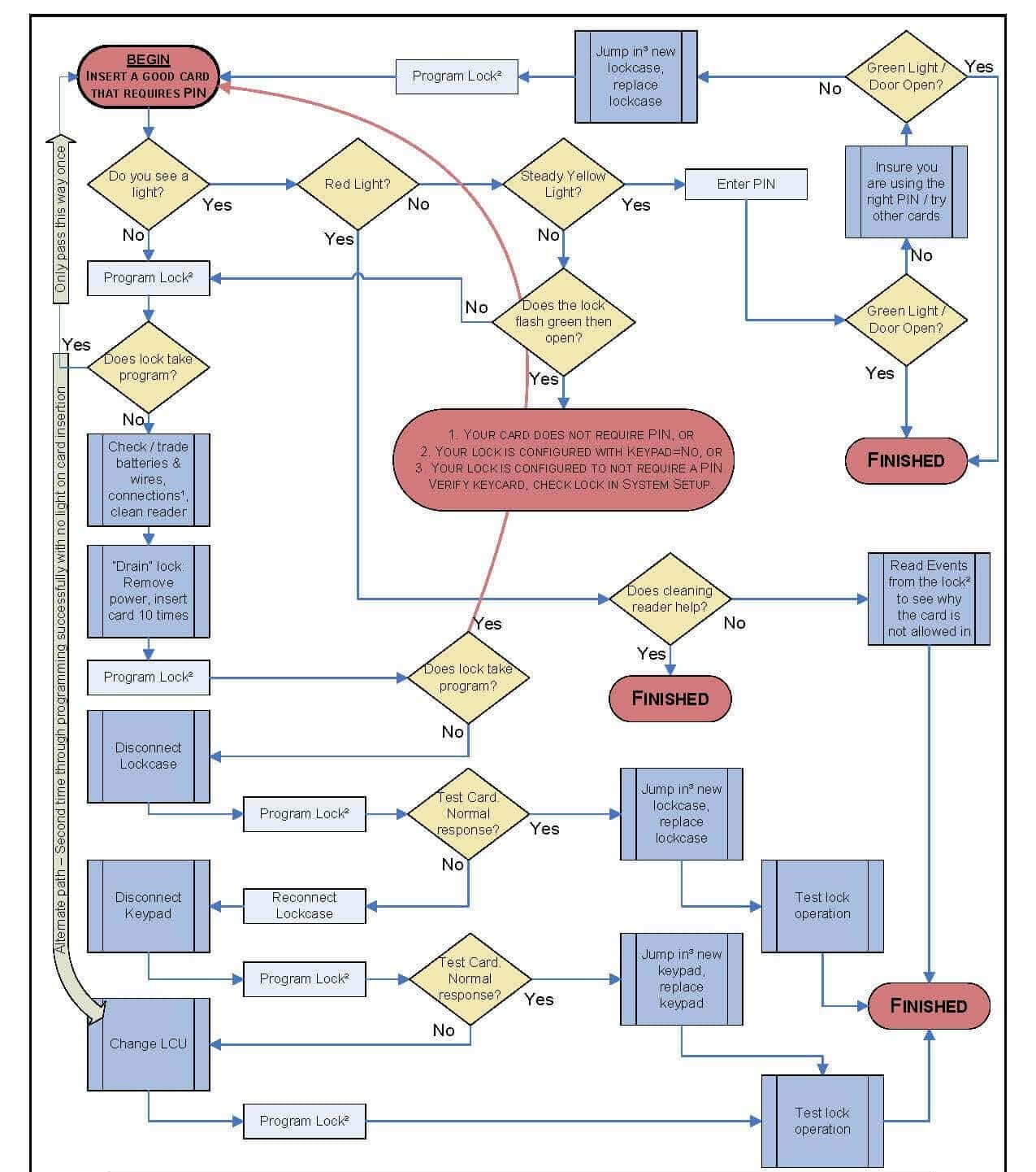
- Проверить ключ-карту: Убедитесь, что вы правильно использовали свой ключ, и повторите попытку. Если вы используете карту, убедитесь, что она не повреждена и не просрочена.
- Проверьте аккумулятор: Убедитесь, что в батарейном отсеке достаточно энергии, проверив его индикатор (если применимо), затем замените его при необходимости.
- Проверьте дверь. Убедитесь, что все панели на месте, включая наклейки или наклейки на стеклянных дверях (если применимо).
- Проверьте сам замок. Если какие-либо части вашего замка погнуты или сломаны, немедленно свяжитесь с Vingcard!
- Компьютер: Это может быть первое, что нужно проверить, если ваш кард-ридер не работает. Убедитесь, что ваш компьютер включен, и попробуйте подключить другое устройство. Если это ничего не дает, перезагрузите систему, выключив и снова включив ее.
- Программного обеспечения: Программное обеспечение может быть еще одним источником проблем с замками VingCard. Вам необходимо убедиться, что вы используете последнюю версию программного обеспечения.
- Линия электропередачи: Проверьте, есть ли проблема с источником питания, прежде чем пытаться выполнить другие действия по устранению неполадок, такие как проверка кабелей или сброс всех настроек после выключения, потому что во время работы что-то пошло не так. установка дверного замка гостиницы процесс и т. д.
Если эти шаги не работают, свяжитесь напрямую с VingCard и уточните, что происходит, когда вы используете свой замок, и как часто это происходит.
Обратите внимание, что Замки ShineACS просто пишет статью об устранении неполадок с замками VingCard и предлагает возможные варианты обслуживания, а не предлагает послепродажное обслуживание.. Если вы не можете окончательно решить свою проблему с содержанием нашей статьи, обратитесь на официальный вторичный рынок.
Но если вы хотите сменить дверной замок в отеле, проверьте наши Система дверных замков TThotel чтобы помочь вам более безопасно управлять дверью вашего гостиничного номера удаленно, запирая и разблокировка гостиничного номера с помощью телефона.
Блокировка VingCard перестала работать.
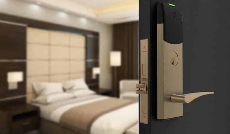
Если у вас возникла проблема с неработающим замком VingCard, вы можете проверить несколько вещей, чтобы определить причину.
- Проверьте батареи: Большинство замков VingCard работают от батареек. Со временем аккумуляторы могут разряжаться. Убедитесь, что батареи все еще в порядке, и при необходимости замените их. Убедитесь, что батарейки вставлены правильно и с соблюдением полярности.
- Очистите устройство чтения карт: Иногда грязь, пыль или другие частицы могут попасть в слот для карты, что приведет к невозможности считывания карты. Аккуратно очистите устройство чтения карт мягкой тканью или ватным тампоном. Избегайте использования жидких или абразивных материалов.
- Проверьте ключ-карту: Проблема может заключаться в самой карте-ключе. Попробуйте использовать другую карту-ключ и посмотрите, работает ли она. Если у вас есть кодировщик или программатор карты, вы можете перепрограммировать карту, чтобы убедиться, что она работает правильно.
- Сообщения об ошибках: Некоторые замки VingCard оснащены небольшим светодиодным индикатором или дисплеем, на котором могут отображаться сообщения об ошибках или шаблоны. Если вы заметили какие-либо необычные узоры или мигание, это может указывать на конкретную проблему. Обратитесь к руководству по эксплуатации замка или свяжитесь с производителем для получения конкретных кодов ошибок.
- Физическое препятствие: Убедитесь в отсутствии физических препятствий в защелке или болте. Иногда грязь или мелкий мусор могут засорить механизм блокировки.
- Проверьте выравнивание двери и рамы: Если дверь и рама смещены, замок может работать некорректно, даже незначительно. Убедитесь, что дверь закрывается плавно, а защелка и ответная планка выровнены правильно.
Батарея замка VingCard разрядилась.
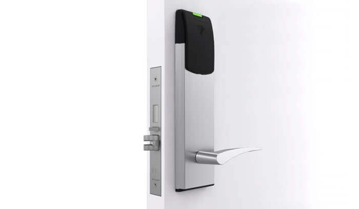
Если в замке VingCard разряжена батарея, он больше не будет работать должным образом, что потенциально может заблокировать гостей или персонал. Вот что вы можете сделать, если обнаружите разряженную батарейку в замке VingCard:
- Аварийное отключение: Многие модели VingCard имеют механическую систему блокировки ключей. Это позволяет использовать традиционный ключ для открытия двери в экстренных случаях, например, при разряженном аккумуляторе. Убедитесь, что у администрации отеля или объекта всегда имеется в наличии этот механический ключ.
- Внешний источник питания: Некоторые замки VingCard оснащены портом внешнего питания, обычно расположенным внизу или сбоку замка. Этот порт позволяет подключить внешний аккумулятор для временного включения замка и получения доступа. После подключения вы можете использовать обычную карту-ключ, чтобы отпереть дверь.
- Замена батареи:
- Получив доступ в комнату, необходимо заменить севшие батарейки в замке.
- В большинстве замков VingCard используются батарейки типа АА, но вам следует проверить конкретную модель, чтобы узнать тип и количество необходимых батареек.
- Всегда заменяйте все батареи одновременно и убедитесь, что все они одного типа и марки. Совмещение старых и новых батарей или батарей разных марок может привести к неоптимальной производительности.
- Убедитесь, что батарейки вставлены правильно, соблюдая полярность (+/-), указанную внутри батарейного отсека.
- Плановое техническое обслуживание:
- Рассмотрите возможность составления графика планового технического обслуживания, чтобы периодически проверять и заменять батарейки в замках VingCard, чтобы предотвратить возникновение подобных ситуаций в будущем.
- Срок службы батарей может варьироваться в зависимости от использования, но в качестве общей рекомендации рекомендуется проверять их ежегодно или два раза в год. В местах с интенсивным движением транспорта или в местах, где к дверям часто обращаются, возможно, вам придется заменять их чаще.
Карта-ключ блокировки VingCard не работает.
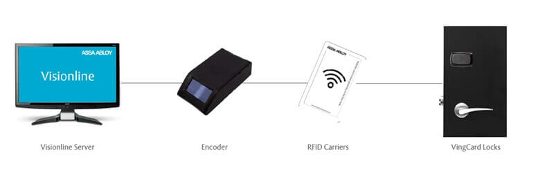
Когда блокировка VingCard ключ-карта отеля не работает, причин может быть несколько. Вот пошаговое руководство, которое поможет вам устранить неполадки:
- Проблемы с ключ-картой:
- Износ: Физическое повреждение или износ карты-ключа могут повлиять на ее функциональность. Осмотрите карту на наличие видимых признаков повреждения или чрезмерного износа.
- Размагничивание: Если карта-ключ соприкоснется с магнитами или некоторыми электронными устройствами, она может размагнититься и выйти из строя. Не размещайте карточки-ключи рядом с магнитами, телефонами и другими электронными устройствами.
- Истечение: Некоторые карты-ключи запрограммированы на работу только в течение определенного периода времени. Например, в отелях срок действия карты может быть установлен в конце пребывания гостя.
- Проблемы с блокировкой:
- Батарея: Одной из наиболее частых причин выхода из строя электронных замков является разрядка аккумулятора. Возможно, пришло время заменить батарейки, если замок не загорается или не реагирует на вставку карты-ключа.
- Грязь или мусор: Иногда устройство считывания карт может быть засорено грязью или мусором. Аккуратно очистите разъем мягкой тканью или щеткой.
- Механическая поломка: Возможно, у замка механическая неисправность, например заклинивание защелки или несовпадение с дверной коробкой.
- Проблемы программирования:
- Неправильное программирование: Возможно, карта неправильно запрограммирована для этого замка. Попробуйте использовать другую карту, которая, как вы уверены, запрограммирована правильно.
- Перезаписанные данные: Если карту перепрограммировать несколько раз или на разных дверях, предыдущие данные могут быть перезаписаны, в результате чего карта не будет работать с некоторыми замками.
- Шаги, чтобы взять:
- Попробуйте другую карту: Если у вас есть другая карта-ключ, попробуйте ее. Это поможет вам определить, является ли проблема ключ-картой или замком.
- Перепрограммировать карту: Если у вас есть доступ к кодировщику карты или программатору, попробуйте перепрограммировать карту-ключ.
- Сбросить блокировку: Некоторые замки могут иметь функцию сброса, помогающую устранить незначительные сбои или ошибки.
- Замена батареи: Если вы подозреваете, что батареи разряжены или разряжены, замените их.
Замок VingCard издает звуковой сигнал и мигает
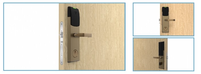
Когда замок VingCard издает звуковой сигнал и мигает, это обычно дает информацию о состоянии замка или указывает на определенное состояние или ошибку. Вот распространенные причины, по которым замок VingCard может мигать/мигать, и их возможные значения:
- Успешная разблокировка: Некоторые модели могут загореться зеленым светом или мигнуть один раз, подтверждая, что дверца разблокирована.
- Предупреждение о разряде батареи: распространенная причина, по которой замок VingCard подает звуковой сигнал и мигает определенным цветом, предупреждая вас о том, что батареи разряжены и их необходимо в ближайшее время заменить.
- Неверная карта-ключ: Если замок подает звуковой сигнал и быстро мигает красный свет, когда вставлена карта-ключ, это может указывать на то, что карта недействительна или не запрограммирована для этого конкретного замка. Возможно, потребуется перепрограммирование.
- Дверь открыта или разблокирована: Некоторые модели подадут звуковой сигнал и один раз мигнут зеленым, подтверждая успешное разблокирование двери.
- Дверь не заперта должным образом: Некоторые замки VingCard могут издавать звуковой сигнал и мигать по шаблону, если дверь не полностью закрыта или не заперта должным образом после открытия. Это служит напоминанием о необходимости защитить дверь.
- Системная ошибка: Некоторые звуковые сигналы или сигналы могут указывать на неисправность или системную ошибку. В этом случае проблема может оказаться не поддающейся немедленному устранению и потребует профессиональной помощи или перезагрузки системы.
- Предупреждение о несанкционированном доступе: некоторые усовершенствованные замки имеют функцию обнаружения несанкционированного доступа. Если кто-то попытается взломать или взломать замок, он может издать громкий звуковой сигнал в качестве предупреждения.
- Режим обслуживания или программирования: Если кто-то программирует замок или переводит его в режим обслуживания, замок может подавать звуковой сигнал для подтверждения команд или указания своего статуса.
Примечание. Очень важно всегда иметь резервный способ доступа в комнату или зону, особенно в коммерческих помещениях, таких как гостиницы, чтобы гарантировать, что гости или персонал не будут заблокированы.
Устранение неисправностей карманного компьютера VingCard 2100
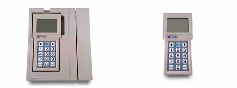
Система VingCard 2100 — популярная система запирания дверей отелей. Портативное устройство системы используется для программирования и управления замками. Ниже приведены распространенные проблемы с портативным устройством VingCard 2100 и способы устранения неполадок:
- Устройство не включается:
- Проверьте аккумулятор и убедитесь, что он полностью заряжен.
- Проверьте устройство на наличие видимых повреждений или признаков износа.
- Убедитесь, что разъемы устройства или порты зарядки чистые и не содержат мусора.
- Устройство не обменивается данными с замками:
- Убедитесь, что устройство находится в правильном режиме или настройках для связи с замками.
- Убедитесь, что между устройством и замком нет физических препятствий.
- Проверьте, нет ли поблизости помех от других электронных устройств.
- Не могу запрограммировать блокировки:
- Убедитесь, что портативное устройство правильно синхронизировано с основной системой.
- Убедитесь, что вы следуете правильной последовательности или шагам программирования.
- Проверьте, может ли проблема быть в самом замке, попытавшись запрограммировать другой замок.
- Ошибки данных или неожиданное поведение:
- Сбросьте портативное устройство к настройкам по умолчанию.
- Если возможно, обновите прошивку или программное обеспечение портативного устройства.
- Убедитесь, что данные не повреждены. При необходимости введите или повторно загрузите необходимые данные.
- Проблемы с экраном или интерфейсом:
- Если экран не отвечает, рассмотрите возможность перезагрузки устройства.
- Проверьте экран на наличие физических повреждений или проблем.
- Устройство не заряжается:
- Проверьте зарядное устройство и зарядный кабель на наличие признаков износа или повреждения.
- Убедитесь, что порт зарядки на устройстве чист и не содержит мусора.
- Попробуйте другое зарядное устройство, если оно доступно.
- Проблемы с памятью или хранилищем:
- Если устройство указывает, что на нем недостаточно места или памяти, возможно, вам придется удалить старые или ненужные данные.
- Убедитесь, что хранилище устройства не повреждено. При необходимости отформатируйте хранилище (обратите внимание: это приведет к удалению всех данных на устройстве).
- Потерян или забыт пароль:
- Если вы потеряли или забыли пароль к устройству, возможно, вам придется обратиться в службу поддержки VingCard за помощью.
- Некоторые устройства могут иметь функцию общего сброса или главного пароля, но используйте ее осторожно, поскольку она может сбросить другие настройки или данные.
Если описанные выше действия по устранению неполадок не решили проблему, возможно, пришло время обратиться в службу поддержки клиентов VingCard или к специалисту, знакомому с системой VingCard 2100. Они могут предоставить конкретные рекомендации, предложить ремонт или порекомендовать необходимую замену.
Устранение неполадок системы стойки регистрации Vingcard 2800
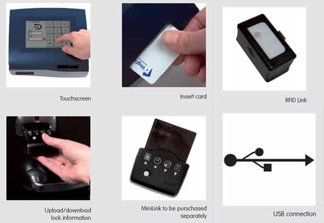
VingCard 2800 — это электронная запирающая система, обычно используемая в гостиницах и других объектах гостиничного бизнеса. Система стойки регистрации имеет решающее значение для кодирования карточек-ключей и управления гостевым доступом. Если у вас возникли проблемы с системой регистрации VingCard 2800, вот общее руководство по устранению неполадок, которое поможет:
- Система не включается:
- Проверьте, правильно ли подключена система к источнику питания.
- Убедитесь, что розетка исправна. Попробуйте подключить другое устройство к той же розетке для проверки.
- Невозможно закодировать ключ-карты:
- Убедитесь, что вы используете совместимые с системой карты-ключи.
- Убедитесь, что энкодер чист. Со временем внутри кодера может накапливаться грязь и мусор, что влияет на его способность кодировать карты.
- Проверьте, правильно ли подключен кодер к системе.
- Ключ-карты не работают на дверях:
- Дважды проверьте программирование. Убедитесь, что даты, номера комнат и уровни доступа установлены правильно.
- Убедитесь, что замки на дверях имеют достаточный заряд батареи.
- Проверьте, не повреждена или не размагничена сама карта-ключ. Избегайте размещения карточек-ключей рядом с источниками магнитного поля или электронными устройствами.
- Попробуйте закодировать другую карту, чтобы проверить, является ли это конкретной проблемой или общесистемной.
- Системные ошибки или зависания:
- Перезагрузите систему. Выключение и повторное включение системы иногда может устранить многие электронные сбои.
- Убедитесь, что в системе нет помех или конфликтующего программного обеспечения.
- Ошибки данных или связи:
- Если система интегрирована с системой управления имуществом (PMS), убедитесь, что соединение стабильно.
- Проверьте все кабели и соединения. Ослабленные или поврежденные кабели могут привести к ошибкам в данных.
- Если вы используете внешнюю базу данных или сервер, убедитесь, что они работают правильно и доступны.
- Проблемы с отображением на экране:
- Отрегулируйте разрешение экрана или настройки дисплея.
- Проверьте экран на наличие физических повреждений.
- Потерян или забыт пароль:
- Если система защищена паролем и вы забыли пароль, вам может потребоваться обратиться в службу поддержки VingCard за помощью.
- Может существовать опция общего сброса, но используйте ее осторожно, поскольку она может удалить или сбросить другие настройки системы.
Если проблема не устранена после выполнения описанных выше действий по устранению неполадок, рекомендуется обратиться в службу поддержки клиентов VingCard или к специалисту, знакомому с системой VingCard 2800. Они могут предложить более конкретные рекомендации, услуги по ремонту или порекомендовать необходимые обновления или замены системы.
Устранение неполадок кодировщика карты RFID-ключа Vingcard lock
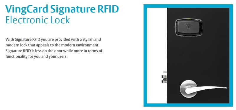
RFID-кодировщики карт-ключей, в том числе от VingCard, являются важными компонентами в Электронные системы запирания RFID для отелей, особенно в сфере гостеприимства. Если у вас возникли проблемы с кодировщиком RFID-ключей VingCard, вот руководство по устранению неполадок:
- Кодер не распознан или не подключается:
- Проверьте подключение кодера к компьютеру или системе. Убедитесь, что все кабели надежно подключены.
- Попробуйте подключить кодер к другому USB-порту или компьютеру, чтобы проверить, сохраняется ли проблема.
- Убедитесь, что для кодера установлены правильные драйверы.
- Невозможно закодировать Keycarвы подписались используя совместимые RFID-карты-ключи для вашей системы gCard.
- Убедитесь, что головки чтения/записи кодера чистые. Пыль или мусор могут помешать кодированию карты. Для аккуратной очистки используйте мягкую ткань или набор для чистки RFID-карт.
- Убедитесь, что вы соблюдаете правильный процесс или последовательность кодирования, описанную в руководстве пользователя или программное обеспечение для гостиничных замков руководство.
- Закодированные карты не работают:
- Убедитесь, что процесс кодирования завершился без ошибок.
- При кодировании проверьте период действия, номер комнаты и уровни доступа, чтобы убедиться, что они установлены правильно.
- Протестируйте несколько RFID-карт, чтобы определить, является ли это проблемой конкретной карты или общесистемной.
- Убедитесь, что дверные замки имеют достаточный заряд батареи и работают правильно.
- Проблемы с программным обеспечением или прошивкой:
- Перезапустите программу кодирования или компьютерную систему.
- Убедитесь, что прошивка кодера обновлена. Производители время от времени выпускают обновления для исправления ошибок или улучшения функциональности.
- Проверьте совместимость программного обеспечения кодировщика с операционной системой вашего компьютера.
- Сообщения об ошибках или предупреждения:
- Обратитесь к руководству пользователя VingCard или руководству по программному обеспечению для получения информации о конкретных кодах ошибок или сообщениях.
- Распространенные ошибки могут быть связаны с передачей данных, совместимостью карт или настройками системы.
Всегда обращайтесь к руководству пользователя или документации к вашей модели кодера VingCard. Часто он содержит ценную информацию, инструкции по устранению неполадок и контактные данные службы поддержки.
Все еще не можете решить проблему? Попробуйте заменить старую систему гостиничных замков
Проверьте нашу систему RFID-замков для отелей
Бесплатное программное обеспечение · Постоянный действующий регистрационный код · 2 года гарантии
Световые коды VingCard
На передней панели замка VingCard могут появиться следующие световые коды:
- Зелёная – Замок готов принять ключ-карту.
- Жёлтые – Замок находится в режиме программирования.
- Red – Замок находится в режиме аудита. Его не следует использовать в качестве дверной ручки, пока он не вернется в зеленый (готовый) статус или не перезагрузится с помощью кнопки сброса, которая есть на большинстве моделей, которую также можно использовать, когда отображаются мигающие красные огни. Другой информации о том, что их вызвало, нет.
- Красный миг – Дверь не открылась; проверьте уровень заряда батареи и питания на наличие признаков того, что разрядка слишком мала для нормальной работы, или убедитесь, что никакие препятствия не препятствуют доступу через эту дверь (например, если произошло какое-либо повреждение).
- Красная вспышка – Кто-то пытался проникнуть в ваше здание без разрешения.
- Мигает зеленым, а затем красным означает, что батарейки сели. Вам нужно будет заменить их на новые.
- Он трижды мигает зеленым, а затем гаснет; есть проблема со считывателем двери или его подключением. Убедитесь, что все проводные соединения надежны и нет ли коррозии на металлических частях дверного считывателя.
- Мигает красным каждые несколько секунд или минут может быть из-за плохой электропроводки в вашем доме или многоквартирном доме.
- Четыре коротких ЖЕЛТЫХ мигания с последующим быстрым ЗЕЛЕНЫМ миганием.: сигнал батареи, доступ разрешен (сигнал батареи с последующим сигналом доступа)
- Четыре коротких ЖЕЛТЫХ мигания: сигнал батареи, доступ запрещен
- Долгая ЗЕЛЕНАЯ вспышка: при первом поднесении функциональной карты к замку функция активируется (стойка открыта, блокировка, конфиденциальность)
- Две короткие ЗЕЛЕНЫЕ вспышки: второй раз, когда функциональная карта предлагается на замке, операция деактивируется (пустой стенд, блокировка, конфиденциальность)
- Три быстрых КРАСНЫХ мигания: считываемая карта заполнена — ошибка обмена системным идентификатором — ошибка открытия питания
- Три кратких ЖЕЛТЫХ мигания: замок заперт
- Три очень коротких ЖЕЛТЫХ мигания, за которыми следуют три коротких ЖЕЛТЫХ мигания: предупредить персонал о том, что замок заблокирован для одной или нескольких групп пользователей
- ЖЕЛТЫЙ непрерывный свет: замок связывается с картой отмены, картой инициации, календарной картой, картой считывания или расширенной картой считывания; предупреждает пользователя не извлекать карту до тех пор, пока не прозвучит завершающий звуковой сигнал и короткая зеленая вспышка, в противном случае операция не будет выполнена успешно.
- ЖЕЛТЫЙ непрерывный свет: если блок постоянно горит желтым светом без поднесения карты к замку, блок необходимо перепрограммировать
Примечание. Есть два возможных звука аварийного открытия. Независимо от того, открыта ли у вас обычная или аварийная дверь, зависит от того, открыта ли она у вас. Наличие аварийных стоек означает, что дверь должна быть заперта аварийной картой после того, как она была открыта одной. - Короткая ЗЕЛЕНАЯ вспышка Звук: регулярное аварийное открытие
- Одна короткая и одна длинная ЗЕЛЕНАЯ вспышка: аварийная стойка открыта, установлена
- Короткая ЗЕЛЕНАЯ вспышка Звук: аварийная стойка открыта, ясно
Вингкарта инструкция
Если вы ищете VingCard дверной замок ручной, мы можем помочь. Пожалуйста, ознакомьтесь со следующим руководством пользователя Vincard для справки:
- Руководство пользователя VingCard Classic RFID
- Руководство пользователя Vingcard Allure
- Руководство пользователя Vingcard Essence
- Руководство пользователя Vingcard Vision (версия 5.10)
- Руководство пользователя Vingcard VISION LINE (версия 1.12.0)
- Руководство пользователя системы регистрации Vingcard 2800
Сброс блокировки VingCard
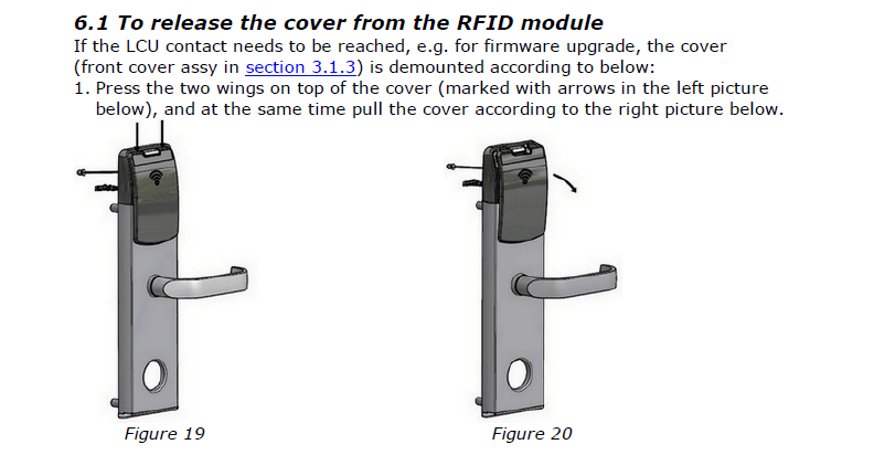
Чтобы сбросить блокировку, выполните следующие действия:
- Поверните ручку в положение разблокировки и удерживайте ее в этом положении около 20 секунд. Индикатор перестанет мигать и начнет постоянно светиться. Теперь вы находитесь в режиме программирования!
- Нажмите и отпустите свой старый мастер-код на дверном замке VingCard Classic или Encore так же, как если бы вы открывали дверь ключом (если вы не знаете, что такое мастер-код, он должен быть указан в ваших инструкциях).
- По завершении этого шага выключите питание кард-ридера с первой попытки, быстро нажав на одну из его кнопок в течение 10-20 секунд, пока он не выключится автоматически;
- затем вытащите аккумулятор (если применимо) на 10-15 минут, прежде чем снова вставить его в отсек по истечении времени.
Заключение
Устранение неполадок дверного замка Vingcard может оказаться сложной задачей, но не волнуйтесь; наше пошаговое руководство решит проблему. Мы надеемся, что эта статья помогла вам устранить неисправности дверных замков Vingcard и обеспечить их правильную работу!
Связаться с надежной слесарной компанией — не самая плохая идея, если ничего не помогает.
-

Винсент Чжу имеет 10-летний опыт работы с системами интеллектуальных замков и специализируется на предоставлении систем дверных замков для гостиниц и решений для систем дверных замков для дома, начиная с проектирования, настройки, установки и устранения неполадок. Если вы хотите установить дверной замок без ключа RFID для своего отеля, дверной замок без ключа для двери вашего дома или у вас есть какие-либо другие вопросы и запросы по устранению неполадок, связанных с умными дверными замками, не стесняйтесь обращаться ко мне в любое время.
Об авторе


VingCard Vision 5.4
Page 1
Vision Version 5.4
© Copyright 2005 VingCard AS. This document contains information proprietary to VingCard AS and shall not be reproduced, transferred to other documents or disclosed to others or used for any purpose other than for which it is furnished without the prior written permission of VingCard AS VingCard, VingCard Vision and Da Vinci by VingCard are registered trademarks of VingCard A.S Other brands and their products are trademarks or registered trademarks of their respective holders and should be noted as such.

VingCard Vision 5.4
Page 2

VingCard Vision 5.4
Page 3
CHAPTER 1: INSTALLATION………………………………………………………………………………………..8
OVERVIEW OF INSTALLATION…………………………………………………………………………………………….8 INSTALLATION ON STANDARD PC NETWORK ……………………………………………………………………….8 OVERVIEW………………………………………………………………………………………………………………………8 INSTALLING THE NETWORK……………………………………………………………………………………………….9 INSTALLING VINGCARD VISION ……………………………………………………………………………………..11 SETTING AND CHECKING ACCESS RIGHTS AND USER PERMISSIONS ……………………………………….16
Background……………………………………………………………………………………………………………….16 Indications of User permission problems ………………………………………………………………………16 How To Set Up User Permissions For VISION ………………………………………………………………17 Testing the VISION Network for Correct User Permissions……………………………………………..19 If there is still a problem……………………………………………………………………………………………..20
INSTALLING MICROSOFT ACTIVESYNC. …………………………………………………………………………….20 ENABLING AUTOMATIC LOGON IN WINDOWS NT / 2000 / XP………………………………………………..20
Setting Automatic Logon Manually……………………………………………………………………………….21 Setting Automatic Logon Automatically ………………………………………………………………………..21 Automatic Logon Security Issues ………………………………………………………………………………….21
INSTALLATION IN AN ASP ENVIRONMENT ………………………………………………………………………….22 GENERAL………………………………………………………………………………………………………………………22 CONFIGURATIONS…………………………………………………………………………………………………………..22
Vision database at each location ………………………………………………………………………………….22 Vision multi database installation at ASP server…………………………………………………………….23
UNINSTALLING VINGCARD VISION …………………………………………………………………………………24 CHAPTER 2 : SYSTEM OVERVIEW……………………………………………………………………………..25
VC 3000 VS. VISION TERMINOLOGY ……………………………………………………………………………….25 SYSTEM COMPONENTS ……………………………………………………………………………………………………26
The Door Locks………………………………………………………………………………………………………….26 Remote Controller………………………………………………………………………………………………………27 Multi Output Controller™ (MOC)™…………………………………………………………………………….28 Mag-stripe Encoders…………………………………………………………………………………………………..28 Smartcard Encoders …………………………………………………………………………………………………..28 RFID Encoders ………………………………………………………………………………………………………….28 VISION Software ……………………………………………………………………………………………………….29 Lock Link ………………………………………………………………………………………………………………….29
BASIC SYSTEM OPERATIONS ……………………………………………………………………………………………30 Override Criteria ……………………………………………………………………………………………………….30 Flexibility/Configurability …………………………………………………………………………………………..31 Lock Modes……………………………………………………………………………………………………………….31 Keycard Types …………………………………………………………………………………………………………..31 Sections …………………………………………………………………………………………………………………….31 Common Doors ………………………………………………………………………………………………………….31 Void-list™…………………………………………………………………………………………………………………32 Time-control ……………………………………………………………………………………………………………..32 Unique User Identification ………………………………………………………………………………………….33 User Groups………………………………………………………………………………………………………………33 Cylinder for Mechanical Override (Optional)………………………………………………………………..33 System Events…………………………………………………………………………………………………………….33 Lock Readout …………………………………………………………………………………………………………….33 Other Functions …………………………………………………………………………………………………………34
SUPPORTED RFID CARDS ………………………………………………………………………………………………..36 Functionality related to RFID cards……………………………………………………………………………..36
SYSTEM CONFIGURATION EXAMPLES………………………………………………………………………………..38 Single User System……………………………………………………………………………………………………..38 Multi User System………………………………………………………………………………………………………38 PMS Interfaced System ……………………………………………………………………………………………….38

VingCard Vision 5.4
Page 4
PMS Integrated System……………………………………………………………………………………………….38 PMS Display Modes……………………………………………………………………………………………………38
THE VISION LICENSING AGREEMENT ………………………………………………………………………………39 Single Licenses…………………………………………………………………………………………………………..39 Multiple Licenses ……………………………………………………………………………………………………….39 Multiple database license ……………………………………………………………………………………………39 VISION Basic and VISION Advanced……………………………………………………………………………40
CHAPTER 3 : PLANNING THE SYSTEM………………………………………………………………………42 OVERVIEW OF SYSTEM PLANNING…………………………………………………………………………………….42 WORKSHEET EXAMPLES………………………………………………………………………………………………….44
Defining Time Tables………………………………………………………………………………………………….44 Defining Common Doors …………………………………………………………………………………………….46 Keycard Type Worksheet (Defining Doors that are not Common Doors) …………………………..47 Defining User Groups…………………………………………………………………………………………………52 Defining System and Lock Parameters ………………………………………………………………………….56 Defining Software Access Groups ………………………………………………………………………………..61
BLANK WORKSHEET FORMS…………………………………………………………………………………………….61 Time Tables Worksheet ……………………………………………………………………………………………….62 Common Doors Worksheet ………………………………………………………………………………………….63 Keycard Type Worksheet …………………………………………………………………………………………….64 User Group Worksheet ……………………………………………………………………………………………….65 System Parameters Worksheet ……………………………………………………………………………………..66 Software Access Groups Worksheet………………………………………………………………………………67
CHAPTER 4 : USING LOCKLINK…………………………………………………………………………………68 LOCKLINK OVERVIEW …………………………………………………………………………………………………….68 INSTALLING THE VISION LOCKLINK SOFTWARE………………………………………………………………..69
Quick Start Guide ………………………………………………………………………………………………………69 Defining regional settings……………………………………………………………………………………………69 Setting clock………………………………………………………………………………………………………………70 Removing old LockLink version……………………………………………………………………………………70 Defining PC connection………………………………………………………………………………………………71 Installing Microsoft ActiveSync ……………………………………………………………………………………71 Installing VISION LockLink…………………………………………………………………………………………81
LOADING LOCK DATA FROM VISION WORKSTATION …………………………………………………………..85 STARTING THE LOCKLINK ……………………………………………………………………………………………….88 LOCKLINK FUNCTIONS ……………………………………………………………………………………………………90
Docking the LockLink Pocket PC …………………………………………………………………………………91 Programming locks…………………………………………………………………………………………………….91 Uploading program and data to locks …………………………………………………………………………..91 Reading events …………………………………………………………………………………………………………..93 Downloading events from a lock…………………………………………………………………………………..95 Viewing downloaded events…………………………………………………………………………………………96 Unlocking doors with the LockLink ………………………………………………………………………………97 Setting the Daylight Saving Time in the locks……………………………………………………………….100 Recording LockLink log…………………………………………………………………………………………….101 Exiting LockLink………………………………………………………………………………………………………101
CHAPTER 5 : USING VISION MODULES…………………………………………………………………… 102 HOW TO EXIT THE VISION SYSTEM………………………………………………………………………………….102 MAIN MENU OF VISION MODULES ………………………………………………………………………………..103
SYMBOLS AND BUTTONS ……………………………………………………………………………………….104 HOW PASSWORDS WORK……………………………………………………………………………………….104 HOW KEYCARDS AND LOCKS WORK……………………………………………………………………..105
SYSTEM SETUP MODULE ……………………………………………………………………………………………….107 SYSTEM SETUP SCREEN…………………………………………………………………………………………107 VISION LICENSE SETTINGS ……………………………………………………………………………………108

VingCard Vision 5.4
Page 5
LOCKS WIZARD ……………………………………………………………………………………………………..110 KEYCARD TYPES WIZARD………………………………………………………………………………………132 USER GROUPS WIZARD …………………………………………………………………………………………148 SETTING SYSTEM PARAMETERS…………………………………………………………………………….163 RFID Options…………………………………………………………………………………………………………..186 SETTING SYSTEM ACCESS ……………………………………………………………………………………..187
GUEST KEYCARDS MODULE…………………………………………………………………………………………..192 WHAT THE GUEST KEYCARDS MODULE DOES …………………………………………………….. 192 QUICK GUIDE TO USING THE GUEST KEYCARDS MODULE………………………………….192 CHECKING IN/PRE-REGISTERING GUESTS ……………………………………………………………194 HOW TO CHECK IN A GUEST TO CONNECTING ROOMS (SUITES) …………………………199 HOW TO CHECK IN A CONFERENCE LEADER STYLE GUEST…………………………………201 CHECKING OUT A GUEST ……………………………………………………………………………………..203 CHANGING THE CHECKOUT DATE OR TIME…………………………………………………………205 ADDING EXTRA GUESTS TO ROOMS …………………………………………………………………….206 REPLACING LOST OR STOLEN KEYCARDS …………………………………………………………….207 VIEWING THE INFORMATION ON A GUEST KEYCARD…………………………………………..208 VERIFYING THE INFORMATION ON A GUEST KEYCARD ……………………………………….210
EMPLOYEE KEYCARDS MODULE …………………………………………………………………………………….212 WHAT THE EMPLOYEE KEYCARDS MODULE DOES ………………………………………………212 QUICK STEPS TO USING THE EMPLOYEE KEYCARDS MODULE ……………………………213 COMPARISON OF KEYCARDS MADE FROM EMPLOYEE ROOMS MODULE ……………214 ADDING AN EMPLOYEE TO THE EMPLOYEE KEYCARDS MODULE……………………….214 REPLACING EMPLOYEE KEYCARDS………………………………………………………………………217 CHANGING EMPLOYEE INFORMATION …………………………………………………………………221 REMOVING AN EMPLOYEE FROM THE VISION SYSTEM ………………………………………..224 VIEWING EMPLOYEE INFORMATION …………………………………………………………………….225
EMPLOYEE ROOMS MODULE ………………………………………………………………………………………….229 WHAT THE EMPLOYEE ROOMS MODULE DOES ……………………………………………………229 QUICK GUIDE TO USING EMPLOYEE ROOMS MODULE………………………………………..230 COMPARISON OF KEYCARDS MADE FROM EMPLOYEE KEYCARDS MODULE………231 MAKING AN EMPLOYEE ROOMS KEYCARD……………………………………………………………231 MAKING A ONE-SHOT KEYCARD……………………………………………………………………………235 ADDING EMPLOYEE ROOMS KEYCARDS……………………………………………………………….235 REPLACING A LOST OR STOLEN EMPLOYEE ROOMS KEYCARDS ………………………….236 CHANGING AN EMPLOYEE ROOMS KEYCARD ………………………………………………………238 REMOVING EMPLOYEE ROOMS KEYCARDS FROM THE VISION SYSTEM ………………239 VIEWING THE INFORMATION ON AN EMPLOYEE ROOMS KEYCARD…………………….241 VERIFYING THE INFORMATION ON AN EMPLOYEE ROOMS KEYCARD …………………242
SPECIAL KEYCARDS MODULE ………………………………………………………………………………………..244 WHAT THE SPECIAL KEYCARDS MODULE DOES …………………………………………………..244 QUICK GUIDE TO USING SPECIAL KEYCARDS MODULE ………………………………………245 FAIL-SAFE KEYCARDS……………………………………………………………………………………………246 LOCK-OUT AND UNDO LOCK-OUT KEYCARDS ……………………………………………………..253 PASSAGE MODE KEYCARDS…………………………………………………………………………………..254 VOID-LIST KEYCARDS……………………………………………………………………………………………256 READ-OUT CARDS …………………………………………………………………………………………………258 SERVICE KEYCARDS………………………………………………………………………………………………259 VERIFYING SPECIAL KEYCARDS ……………………………………………………………………………259
SYSTEM USERS MODULE……………………………………………………………………………………………….262 What the System Users Module Does ………………………………………………………………………….262 Quick Guide to Using the System Users Module …………………………………………………………..263 ASSIGNING ACCESS TO EMPLOYEES……………………………………………………………………..263 Changing System User information for an employee …………………………………………………….267 REMOVING SYSTEM ACCESS FROM AN EMPLOYEE ………………………………………………268 VIEWING EMPLOYEE INFORMATION …………………………………………………………………….269
BACKUP MODULE…………………………………………………………………………………………………………270 WHAT THE BACKUP MODULE DOES……………………………………………………………………..270 QUICK STEPS TO USING THE BACKUP MODULE…………………………………………………..271

VingCard Vision 5.4
Page 6
HOW TO BACKUP DATA…………………………………………………………………………………………271 HOW TO RESTORE A BACKUP USING RESTORER…………………………………………………..272 HOW TO RESTORE BACKUP DATA…………………………………………………………………………272 THE RESTORER SCREENS………………………………………………………………………………………272
LOCKLINK MODULE……………………………………………………………………………………………………..276 PROGRAMMING LOCKS…………………………………………………………………………………………276 WHAT THE LOCKLINK MODULE DOES………………………………………………………………….277 UNLOCKING DOORS WITH LOCKLINK…………………………………………………………………..280
REPORTS MODULE………………………………………………………………………………………………………..283 WHAT THE REPORTS MODULE DOES ……………………………………………………………………283 HOW TO PREVIEW, PRINT AND SAVE REPORTS …………………………………………………….285 AVAILABLE SYSTEM REPORTS ……………………………………………………………………………….287 AVAILABLE LOCK REPORTS…………………………………………………………………………………..294
GLOSSARY OF TERMS ……………………………………………………………………………………………………299 FREQUENTLY ASKED QUESTIONS……………………………………………………………………………………301
CHAPTER 6 : PMS INTERFACE………………………………………………………………………………….302 ABOUT INTERFACING VISION WITH A PMS ………………………………………………………………………302 HOW TO USE THE PMS SYSTEM ………………………………………………………………………………………302 WHERE TO FIND DETAILED INFORMATION ON THE VISION PMS INTERFACES …………………………302 SPECIFIC PMS ISSUES IN ‘MIXED CARD’ PROPERTIES………………………………………………………….302
Making keycards………………………………………………………………………………………………………303 Verifying keycards ……………………………………………………………………………………………………303
CHAPTER 7 : NETWORK ENCODER SETUP……………………………………………………………..305 GAREK NETWORK ENCODERS …………………………………………………………………………………………305
Hardware Overview………………………………………………………………………………………………….305 Switch Positions……………………………………………………………………………………………………….305 How to Set Up (or change) the TCP/IP Address……………………………………………………………308 Hardware Overview………………………………………………………………………………………………….318 How to Set Up (or change) the TCP/IP Address……………………………………………………………319 Full setup Step by Step………………………………………………………………………………………………324
LS100 SERIAL SERVERS…………………………………………………………………………………………………333 NETWORKING XAC SMART CARD ENCODERS …………………………………………………………………..347
Using Sena Technologies ‘Hello Device’ …………………………………………………………………….347 Using SAN People Model E88 Etherpad ……………………………………………………………………..347
RFID ENCODER……………………………………………………………………………………………………………349 How to set-up the RFID encoder unit? ………………………………………………………………………..349 How to prepare your PC for RFID encoder set-up?………………………………………………………349 How to change IP protocol configuration of RFID encoder?………………………………………….351 How to set-up Vision to use RFID encoders? ……………………………………………………………….354
CHAPTER 8 : BATCH MODE……………………………………………………………………………………… 356 INTRODUCTION…………………………………………………………………………………………………………….356 INSTALLATION……………………………………………………………………………………………………………..356 SYSTEM OVERVIEW………………………………………………………………………………………………………357
PMS integration and interface……………………………………………………………………………………357 COMMUNICATION…………………………………………………………………………………………………………358
Communication PMS – VISION………………………………………………………………………………….358 Communication VISION — Magnetic card encoder……………………………………………………….358
OPERATION OF THE VISION SYSTEM IN BATCH MODE……………………………………………………….359 Producing / modifying single cards in batch mode………………………………………………………..361 Batch Mode File Formats ………………………………………………………………………………………….361
CHAPTER 9 : IMPORT EXPORT………………………………………………………………………………..363 INTRODUCTION…………………………………………………………………………………………………………….363 GENERAL INFORMATION ……………………………………………………………………………………………….363
Visual representation of how the Import/Export process works ………………………………………364

VingCard Vision 5.4
Page 7
Moving guests to the main VISION database ……………………………………………………………….364 The Import Screen…………………………………………………………………………………………………….366 The Export Screen…………………………………………………………………………………………………….367
CHAPTER 10 : USING NBS ENCODER ……………………………………………………………………….369 INTRODUCTION…………………………………………………………………………………………………………….369 HOW TO SET UP A VISION SYSTEM TO USE NBS ENCODERS……………………………………………….370 HOW TO SET UP NBS ENCODERS FOR USE WITH VISION……………………………………………………372
Information sent from VISION to NBS…………………………………………………………………………372 Setting up NBS to use the information …………………………………………………………………………373
CHAPTER 11 : CUSTOM CARD ENCODING & MACE ………………………………………………377 WHAT IS MACE? …………………………………………………………………………………………………………377
CHAPTER 12: MULTIPLE DATABASES …………………………………………………………………….378 INTRODUCTION TO MULTIPLE DATABASE OPTION ……………………………………………………………..378 LICENSES…………………………………………………………………………………………………………………….378 INSTALLATION AND SETUP……………………………………………………………………………………………..378
Install the default database………………………………………………………………………………………..380 Set up the multiple database environment ……………………………………………………………………380 Install ticket office client workstations…………………………………………………………………………383 Set up the different databases …………………………………………………………………………………….383 How to install on ships………………………………………………………………………………………………386
TICKET OFFICE : ISSUE KEYS USING VISION USER INTERFACE ……………………………………………. 495H387

VingCard Vision 5.4
Page 8
Chapter 1: Installation Overview of Installation
VingCard VISION is installed in networked environments. It can be installed in
• A standard Windows PC network.
OR
• An Application Service Provider (ASP) environment using a central remote server and thin client workstations at the Hotel. Examples of this type of set up are CITRIX or Windows Terminal Services.
Installation on Standard PC Network
Overview VingCard VISION can be installed on a single PC or on a system with several PCs connected together in a network. VISION can either use a dedicated network, or work over an existing network at the installation property.
In a networked system, the PC that runs the database(s) is referred to as the VingCard server. All other PCs are referred to as workstations. Each PC has access to its own locally connected devices and also to all of the networked encoders and printers.
Each PC in the network must have a unique identification. Those identifications are the computer names as seen from the network. The computer names used by VingCard VISION are STATION_000, STATION_001, and so on up to STATION_099. The PC set up as the server is by default STATION_000, although the VISION installation program allows any computer to be set up as the server.

VingCard Vision 5.4
Page 9
Ethernet
STATION_000
Data
STATION_001STATION_002Encoder
Printer
Encoder
Locklink
Figure 1.
It is recommended that installation of VingCard VISION is carried out in the following order :
• Install and configure the network, first on the server then on each workstation.
• Install VingCard VISION on the server (installation program VxxInstall.exe)
• If you are making a Multiple Database Installation, run the separate, Multi database installation program on the server (installation program VxxMultiDbInstall.exe). Note : for full details plus an example of setting up a Multiple Database Installation, see Chapter 12 of the Vision Manual.
• Install VingCard VISION on each workstation (installation program VxxInstall.exe)
• Set and Check network access rights and user permissions
• Install Microsoft ActiveSync on any PCs that will communicate with LockLink
• Enable automatic network logon if required (Windows NT / 2000 / XP only)
Installing the Network
STEP 1: Selection of network PCs and Operating Systems.
VingCard VISION can run under the following operating systems (OS): Windows 98 (not recommended), Windows NT 4.0 or later, Windows 2000, Windows XP, Windows VISTA.
The VingCard Server in networked systems should use one of the more stable operating systems (2000 or XP).

VingCard Vision 5.4
Page 10
STEP 2. Cabling
Connect all workstations with the type of cabling required by your network cards.
STEP 3: Install cards.
If you are using VingCard VISION Workstations (see picture) go to Step 3.
If you have only one PC in your system, go to Step 3.
Otherwise, carry out this step, first on the server, then on each workstation.
If the PC does not have a network card installed, obtain a network card compatible with Microsoft Network peer-to-peer connections and install it according to the vendor’s instructions. Normally this involves opening the computer enclosure and installing the card in a free slot, or insertion of a PCMCIA network card in a PCMCIA slot. Restart the PC and let Windows configure itself automatically (Plug And Play). If Windows is not able to do this automatically, check the documentation for your network card. You will probably have to use the Add New Hardware wizard from within Control Panel.
Important note : If you are using network hubs to link one or more PCs in the VISION network, check that the Duplex settings for your network cards are compatible with those for your hubs. Mismatches here can cause very slow performance. The Duplex settings (if present for your adaptor) can be found under: Start /Settings/Control Panel/Network/Adaptors/Configure/Advanced.
STEP 4: Configure network protocols.
Carry out this step first on the server, then on each workstation.
Each PC running VISION needs
• TCP/IP protocol installed
• File and Printer Sharing for Microsoft Networks enabled
• A unique computer name set. You can either use STATION_000 etc, another naming convention or simply the existing computer names set up on an existing network.

VingCard Vision 5.4
Page 11
• A unique IP address. You can either allocate these yourself or allow the network to set them (via DHCP). In either case, all IP addresses must be on the same subnet IP addresses can be found by typing IPCONFIG at the command prompt.
If one or more IPX/SPX protocols are installed, then remove them if you are sure they are not needed. They are not needed in a VISION only system. You must NOT remove them if you will be installing VingCard VISION on a system already using Netware
Windows must be restarted before any changes you make to network / TCP/IP settings take effect. Select Yes if Windows asks if you want to restart your computer.
Installing VingCard VISION You will need your installation CD and License codes (delivered with VISION).
STEP 1 Run the Version xx installation program, VxxInstall.exe
Carry out this step, first on the server, then on each workstation. For PCs already set up with different levels of Windows user, make sure you log on with Administrator rights before running the install program.
Follow the instructions presented by the installation program and select appropriate options.
NOTE 1: Upgrading old VISION installations
• Pre Version 3.1installations When installing on a server with an existing Version 2, Version 3.0 or Version 3.01 VISION installation, you must first convert to Version 3.1. First make a backup of the existing (v2, 3.0 or 3.01) database, then run the VISION 3.1 installation program V31Install.exe, selecting ‘Keep Database’ when prompted. You do not need to install any V3.1 Service Releases. Once your database is at Version 3.1, the Version 5.0 installation program can automatically convert it.
• Version 3.1 through to Version 5.x installations When your VISION installation is one of the above, you can upgrade directly. Select ‘Keep Database’ when prompted and the database will be upgraded in line with latest Vision requirements. It is strongly recommended that a backup of the old database is taken before installation. Special Note when Upgrading from Version 3.1 After selecting ‘Keep Database’ you will be prompted to select a default Lock Type (for example ‘9V Classic’ or ‘9V Presidio Combo’). If your property uses more than one of the lock types listed, you should select the most common lock type as a default and then, after installation is complete, use VISION > Setup > Locks > Lock Groups > Change Existing in order to allocate the other lock types to the relevant doors. You will then be asked to select a default Card Family, either mag-stripe, memory card or smartcard. You should select the type of keycard that your property will predominantly use. If your property will use more than one of the card family types listed, you should select the most common type as a default (normally but not always mag-stripe) and then, after installation is complete, use VISION > Setup > User Groups > Change Existing in order to allocate the other card families to the relevant user groups.

VingCard Vision 5.4
Page 12
smartcard : a card which uses a memory chip to store information and additionally has built in processing power.
memory card : a card which uses a memory chip to store information but has no built in processing power.
Note that VingCard dual reader (‘Combo’) locks can read mag-stripes, memory cards and smart cards. User groups that need access to these locks should be assigned either the mag-stripe or the smartcard card families.
There are a small number of VISION locks (Marketed as ‘VC3000 Smart Card’) that can only read memory cards – not smartcards. The only time a user group should ever be allocated the ‘memory card’ card family is when the property is equipped with these locks and mag-stripe access is not desired.
• Changing a previous server to a workstation When installing on a workstation that was previously a server, any old version databases found are deleted.
• DaVinci installations DaVinci databases are NOT automatically converted by VISION installation.
NOTE 2: When prompted for the installation type
For the server, select the appropriate type:
• Peer Server: the server will contain the database and the VingCard VISION program.
• Database server: the server will contain the database only. In this case, VISION cannot be run on the server, only remotely via workstations.
• Workstation: the VISION program will be installed, configured to access the database on the VISION Server.
NOTE 3: When installing on a Workstation
In order that VISION can access the data base on the VISION Server you will be prompted to enter the name of the VISION Server PC. If upgrading the entry will default to the VISION Server name previously used. For new installations, you must know and type the Computer Name of the VISION Server PC. The method of viewing or changing a Computer Name is operating system dependant. Refer to Windows help from the start menu and look up ‘Computer Name’.
NOTE 4: Installing a ‘Construction’ database
The initial installation (construction) at a Hotel can be done with a pre-programmed ‘construction’ facility code and can be based on simple pre-made database, sufficient for use at the construction stage.
The construction database can be selected (as an alternative to ‘Demo’ or ‘Empty’) from the VISION installation program. When VISION is operating with a Construction database, indication is given on the Log In Screen. You will not need to enter any License codes. These will be delivered at a later date – at which point VISION must be re-installed using them.

VingCard Vision 5.4
Page 13
***** New feature in Version 5.0 *****
When operating with a Construction Database, VISION gives you the opportunity to make Construction Keys. Go to Special Cards module after installing VISION. There are two options available : make master keys (where the same cards work in all locks) or make individual keys for each lock.
The Construction Keys you make will work in newly delivered 4.5V locks. To use them, power up the newly fitted lock and insert one of the Construction Keys – a master or individual key depending on whether you want the lock to have its own key or not. The lock will learn the special Construction Key code on the card and flash green. After this, this key will work in the lock UNTIL THE LOCK IS PROGRAMMED WITH REAL DATA USING LOCKLINK
When VingCard provides the final facility code you need to reinstall VISION and LockLink using this facility code. Then you can set up the final database and OVERWRITE the locks with the new data (including facility code), without the necessity to disconnect a battery for resetting the lock.
To utilize the Construction OVERWRITE functionality you must check the construction lock check box on the system tab of LockLink.
When the check box is checked, locks with the Construction Facility Code will be updated with the new Facility Code (the one newly uploaded from VISION to locklink).
NOTE 5: When prompted to select between standard and batch mode
Batch mode is a specialist mode of operation where VISION creates output files that are read by third party software in order to make keycards on batch encoder / printers. Some cruise line companies use batch mode. Only select batch mode installation if you are installing at one of these installations, otherwise, select ‘standard’ (the default).
Further details of batch mode are available in Chapter 8 of the VISION Manual.
NOTE 6: Multiple Database Installations
For full details plus an example of setting up a Multiple Database Installation, see Chapter 12 of the Vision Manual.
STEP 2. Make ‘VISION’ folder available by Sharing
Carry out this step on the Server only.
Note: For Windows 2000, NT or XP servers, the installation program will carry out this step for you, granting Full Control access to All Users. If you want to restrict the group of users with access to the VISION folder you can adjust these settings after installation.
Double click My Computer on the desktop. Right-click on the icon for the folder where VISION is installed. Click Sharing. Click Shared as: and fill in Share name: for your shared folder. The name must be VISION. (The Comment: field is optional.) Set Sharing permission to Full control for all users that will run the Vision program. If you encounter problems while setting up Sharing, see ‘Sharing folders’ in Windows Help. The window should now look similar to this (example is from Widows NT):

VingCard Vision 5.4
Page 14
Click OK. Note that the icon for the VISION folder has changed.

VingCard Vision 5.4
Page 15
STEP 3. Make local printers available over the network
Carry out this step on all stations that are directly connected (serial or parallel cable) to a printer that you want to be shared by other VISION stations.
Install the printer to the local PC. Go to the Windows printer folder (Start button > Settings > Printers). Right-click the printer you want to share and then click Sharing. Select Shared as: and fill in Share name: for your shared printer. The name can be HewlettPackard 400, for example. (The Comment: field is optional.) Click OK and the printer’s icon will be changed.
Shared drive Printer folder Shared printer
STEP 4. Set up a default printer for each VISION station
Carry out this step on all stations that you wish to view, save or print VISION reports from.
Go to the Windows printer folder (Start button > Settings > Printers). Consider the printer that you want to be the default for the particular VISION station. If it is not listed, use the Add Printer option to add it. Select the printer from the list of those available and set it as default (Select from list, right click, Set as default).
STEP 5. Hiding the taskbar
This step is optional. If desired, carry out this step, first on the server, then on each workstation.
The taskbar (normally at the bottom of the screen) can be hidden clicking Start button/Settings/Taskbar. Then check the Auto Hide box and click OK.
STEP 6. Autostart of VingCard VISION.
This step is optional. If desired, carry out this step first on the server, then on each workstation.
After successful installation of a peer server or server, the VISION database server will start each time Windows is started.
If you want the VISION program to start automatically when Windows is started, you need to prepare this manually. To do this click Start button/Settings/Taskbar and then click the Start menu, Programs tab. Click the Add button. In the Command line: field now type c:\VISION\VISION.exe (or use a different path if you installed to a folder other than c:\VISION). Click the Next button and now double-click the StartUp folder. In the field Select a name for the shortcut: type VingCard VISION and then click the Finish button. Click OK.

VingCard Vision 5.4
Page 16
Setting and Checking Access Rights and User permissions
Background Access rights and user permission issues are becoming increasingly significant to the operation of networked VISION installations as windows networks continue to migrate towards NT/2000/XP solutions.
The most relevant issues are
• Folder sharing and associated permissions Can prevent access to server files if incorrectly set. Sharing and sharing permissions are relevant to all Windows versions. For Windows NT and later, sharing is correctly set during VISION installation. However, it might be incorrectly changed later. For Windows 98, sharing must be set up manually as described previously.
• Registry Permissions Can prevent VISION from retrieving and using important path information if incorrectly set. Registry permission is only relevant to Windows NT and later and is correctly set during VISION installation. However, it can be incorrectly changed later.
• Network User accounts and permissions Can prevent access to server files if incorrectly set and also problems with time synchronisation. For multi-user systems, suitable users for operating VISION must be set up manually.
Indications of User permission problems User permission problems can show themselves in the following ways in a VingCard VISION system
Unable To Store Facility Code Message When starting VISION, a message is displayed: “Unable to store facility code. Check that….” VISION continues to partially operate, but certain functionality is unavailable. For example, attempts to make a Guest key will provoke the message “License limit exceeded’
This problem can be caused by problems with
• Folder Sharing
• Registry Permissions
• Network User Accounts and Permissions

VingCard Vision 5.4
Page 17
VISION Locklink module cannot access lock files From a workstation, when you select the VISION Locklink module a message is displayed ‘File Not Found’. When you press ‘OK’ a more detailed error message appears in red text in the ‘Status’ panel.
This problem can be caused by problems with
• Folder Sharing
• Registry Permissions
• Network User Accounts and Permissions
VISION does not complete a backup The error message ‘Error: did not complete the backup!!!’ is received when attempting to make a backup or when running an autobackup. Either the backup path cannot be determined from the registry (due to insufficient registry permission) or the specified path can be determined but not written to by the currently logged on user.
This problem can be caused by problems with
• Folder Sharing
• Registry Permissions
• Network User Accounts and Permissions
Workstation does not act on Time Synch message A VISION station (usually the server) issues a time synch command as determined by set up settings but one or more other stations do not synchronize their time.
This problem can be caused by problems with
• Network User Accounts and Permissions
How To Set Up User Permissions For VISION
Folder Sharing The main VISION folder on the VISION server must be shared.
For Windows NT, 2000 & XP, the share is automatically made during installation.
For Windows 98 sharing has to be set manually. The process for this is described at step 2 of the ‘Installing VingCard VISION’ instructions.
You can check the share on the VISION server by using Windows explorer / My Computer, selecting the main VISION folder, right clicking, selecting Sharing and observing the share properties. They should be as outlined at Step 2 of the ‘Installing VingCard VISION’ instructions. If they are not, change them.
Registry Permissions This is relevant to any PC on the VISION network running Windows NT, 2000 or XP.

VingCard Vision 5.4
Page 18
VISION automatically sets the correct registry permissions during installation — but it is important that you were logged on with an administrator password during installation.
You can check and change these settings at the VISION server and at each workstation as follows:
The following steps assume that all VISION users belongs to the group «Everyone».
• Logon to the PC with Administrator access rights.
• Select Start > Run.
• Type regedt32.exe + <enter> to run the 32 bit Registry Editor.
• Select «HKEY_LOCAL_MACHINE»
• In the registry key tree, open the «SOFTWARE» key.
• Locate and highlight the «Vingcard» subkey.
• Select the menu option Security|Permissions…
• Check the option «Replace Permission on Existing Subkeys»
• Verify that the group «Everyone» is listed in the member group listbox. If not, press ADD and add it to the list.
• Double-click the group «Everyone».
• Check the «Full control» radio-button and press OK.
• Press OK and select «Yes» to the question to confirm the changes.
• Exit the Registry Editor.
Repeat the process for each affected NT, 2000, XP PC running VISION SW.
Network User Accounts and Permissions This is relevant to any workstation on a VISION network where the server is either Windows NT, 2000 or XP.
Access to the server Log on to each workstation using a typical user account for staff that will use VISION. Use Network neighborhood (or equivalent) to locate the server machine. Highlight and double click. If you gain access to the machine, then network permission is not a problem; if you are prompted for a user name and/or password, it may be. In order for VISION to work you need to log on to the server from the workstation.
If this is the problem, the best way to solve it permanently is to create compatible user accounts (same username and password) on the server and workstation PCs. In this way, the username and password that you type to log on to the workstation is also used to gain access to the server with no additional input required.
There are two basic ways to tackle this:

VingCard Vision 5.4
Page 19
• Set up one account on the server, an equivalent account (same user and password) on each workstation and always log into each workstation with that account when using VISION.
• Set up multiple accounts on each workstation (in line with the property’s policy) and mirror each on the VISION server.
Simple example: put the server and all workstations on a common workgroup (such as ‘VingCard’). Create a user ‘VISION’ on the server and assign a password. Now create user accounts with the name ‘VISION’ and the same password on all workstations. Log on to workstations using the ‘VISION’ accounts. You can also log onto the server with the ‘VISION’ account but it is not essential. The important thing is that the server receives any valid username/password combination from the workstation.
For more complex networks, possibly involving domain servers etc. things may be more complex. However, the basic theory is the same: try to find or set up a workstation account that automatically provides access to the shared VISION folder on the server. The final solution chosen must take account of other User / traceability issues relevant to the property where the VISION network is installed.
Note that on Windows 98 PCs, you may want to activate multiple users (in order to automatically supply a username and password to the VISION server). You can do this via Control Panel > Passwords > User Profiles, check the ‘All users can customize….’ Tab. When you restart, use the new username and password to login. This will create the new user.
Note also that with a Windows XP server, if you set up a user without a password (which is allowed) and then try and log on and connect through Win 98/NT/2000 workstations using the same username but leaving the password blank, you will not be connected. Therefore, it is necessary to define and use a non-blank password.
Local Rights necessary in order for Time Synch to work For the VISION time synchronization function to work each workstation running VISION must be logged in with sufficient user rights to allow the date / time to be modified.
You can check this for each relevant user. If you can’t change date / time via Control Panel, then VISION will not be able to change it either. You must then increase User Rights.
Under Windows 2000, Standard User will work, Restricted User will not.
Under Windows NT, Power User will work, User will not.
Avoid Windows password (Windows 98 only). For Windows 98 the very first time you start up Windows you might be asked to enter a password for Windows (as opposed to the network). VingCard VISION is protected by its own password system, therefore a Windows password is unnecessary.
To disable the windows password you must replace the existing password with an empty password. To do this click Start button/Settings/Control Panel/Password/Change Window Password. In this dialog, enter your existing password and leave the fields for New password and Confirm new password empty. Click OK.
Testing the VISION Network for Correct User Permissions To test the VISION network for correct permissions.

VingCard Vision 5.4
Page 20
• Log on to the server using the username and password that will normally be used. Start VISION.
• Log on to each workstation using a typical ‘lowest permission’ user at each.
• Start VISION at each PC and check that the ‘Unable to store facility code….’ Message is not displayed.
• Use setup to send a time synch message from the server to all workstations and check that they all act on it.
• Perform a backup from each workstation (or a representative selection) saving the backup files on the server machine.
If there is still a problem If you have checked folder sharing, registry permissions and user access rights but you still suspect an access / permission problem you can also try the following :
Use server IP address instead of computer name This can be tried on any operating system and for any version of VISION – but only where the server IP address is fixed (not dynamically allocated using DHCP).
At the workstation, Start > Run > Regedit.
Navigate to HKEY_LOCAL _MACHINE\Software\VingCard\VISION
Change VISIONNetPath value from \\servername\VISION format to \\Ipaddress\VISION (for example \\172.16.30.100\VISION )
Installing Microsoft ActiveSync. Any VISION PCs – server or workstations – that will be used to transfer data to and from the LockLink need Microsoft ActiveSync to be installed.
Microsoft ActiveSync is delivered along with VingCard LockLink units. Details of how to install it are given in Chapter 4 (LockLink) of the Vision manual.
Enabling automatic logon in Windows NT / 2000 / XP. Automatic logon allows users to avoid the network login after a PC is started. In effect, this may mean that they avoid having to remember a suitable Windows password that is different to their VISION password.
Automatic Logon may be needed for users who do not share computers and wish to quickly log onto a network. Automatic Logon may also be used for networks who have one default logon for their users.

VingCard Vision 5.4
Page 21
Setting Automatic Logon Manually To configure Windows NT / 2000 / XP to automatically login will require the registry to be edited and the following instructions to be carried out.
• Run Regedit32.exe
• Open the following key: HKEY_LOCAL_MACHINE\SOFTWARE\Microsoft\Windows NT\CurrentVersion\Winlogon
• Within the above key enter the values normally entered into the following values: DefaultDomainName DefaultUserName DefaultPassword
• If DefaultPassword is not present to create a new value click Edit, choose Add Value. In the Value Name field type DefaultPassword. Select REG_SZ for the Data Type. In the String field type your password and save changes.
• In addition if no DefaultPassword string is specified, Windows NT automatically changes the value of the AutoAdminLogon key from 1 to 0, thus disabling AutoAdminLogon feature.
• From the Edit menu, choose Add Value. Enter AutoAdminLogon in the Value Name field. Select REG_SZ for the Data Type, enter 1 in the string field and save your changes.
• Finally if DONTDISPLAYLASTUSERNAME value is set to 1, Autoadminlogon does not function.
To bypass the automatic logon in the future press and hold the SHIFT key as the computer is booting.
Setting Automatic Logon Automatically It is also possible to set automatic logon using the Microsoft TweakUI program which can be installed into Control Panel. TweakUI is freely available on the internet and DOES work with all windows versions up to and including XP. Install TweakUI then use Help for instructions.
Automatic Logon Security Issues For Windows 98/NT using auto logon can be a security risk, as the DefaultPassword is stored in plain text in the registry.
In Windows 2000, if you use the TweakUI program TweakUI Logon tab to set the registry entries, the DefaultPassword value name is NOT created at the Winlogon key. Instead, a <NO NAME> value name, using the REG_DWORD data type, is created at HKEY_LOCAL_MACHINE\SECURITY\Policy\Secrets\DefaultPassword. This data value is encrypted and NOT viewable.
In Windows XP the password is also encrypted if you use TweakUI, although not at the registry location mentioned for Win 2000.

VingCard Vision 5.4
Page 22
Installation in an ASP environment
General In an ASP environment (for example CITRIX or Windows Terminal Services), the workstations – known as Thin Clients — are physically located at the Hotel (for example the front desk) but run applications on the remote ASP server(s). To the user at the Hotel, the User Interface appears exactly as it would on a normal, local PC.
In all cases we recommend that Network encoders are used and mapped to the workstations as appropriate.
For PMS, we recommend the use of the TCP/IP interface.
Configurations
Vision database at each location
This is VingCard’s preferred configuration. A VingCard server (i.e. the computer holding the VISION database) is physically located at each Hotel. Whilst this goes against ‘absolute’ ASP philosophy (i.e. virtually all processing power moved to the ASP servers), it has the following advantages
• A backup solution (for making keys) in the case of network (WAN) problems between the Hotel and ASP provider.
• A backup solution for making keys in case of internal Hotel network (LAN) problems. (Only if a non networked encoder is connected to the VISION server).
• Local, physical connection to the LockLink unit.

VingCard Vision 5.4
Page 23
Other configurations are possible. Please contact VingCard Tech Service to discuss. Remember, the following issues need to be considered.
• Making keys in case of network failures (LAN and WAN)
• Physical connection of LockLink unit for transfer of data.
The VISION program seen on the thin clients are actually individual ‘instances’ of VISION, all running on the ASP server(s). However, the ASP framework ensures that each ‘instance’ of the VISION program is assigned a unique identity. This allows each workstation to be set up (mapped to the correct encoders etc) exactly as for a standard network where each VISION PC has an individual name.
Each thin client only operates against it’s own database. The database selection dropdown list is never seen at the Vision login screen. It is multiple, single database installations rather than a multiple database installation.
To install :
• At Hotel, install Vision as PEER SERVER, select ASP = No
• Set up the database. Set up network encoders in the Hotel. See manual Chapter 7. Check you can cut keys. Set up and run the PMS TCP/IP interface on this machine.
• Install Microsoft ActiveSync on this PCs as it will communicate with LockLink
• At ASP server install Vision as CLIENT, select ASP = Yes.
• Do not run the multi database install program.
• Now you need to co-ordinate with the ASP provider to ensure that
o User accounts are created for VISION workstation users at the Hotel.
o The workstation users have the necessary rights and ability to run the VISION workstation program you installed on the ASP server.
o Printer and folder mappings for each user (for example to print and save VISION reports; to make backups) are set up correctly.
• Once this is completed, run VISION from each thin client. Check that (VISION access rights permitting) you can cut keys, print and save reports, change overall VISION setup, make backups.
Vision multi database installation at ASP server All databases run at the ASP server. Each thin client can operate against any of the centralized databases. The database selection dropdown list can be seen at the Vision login screen – but can be filtered to map a specific database to a specific thin client.

VingCard Vision 5.4
Page 24
To install (summary):
• At Hotel, no installation necessary
• At ASP server install Vision as PEER SERVER, select ASP = Yes.
• At ASP, run multi database installation program
Uninstalling VingCard VISION To uninstall VingCard VISION:
Select Start > Settings > Control Panel > Add/Remove Programs.
Select VISION from the list of installed software, and click Change/Remove.
Follow the instructions in the Uninstall program to uninstall VingCard VISION

VingCard Vision 5.4
Page 25
Chapter 2 : System Overview VC 3000 vs. VISION Terminology
Many new VISION users are familiar with the terminology used in the VC 3000 system. The following table indicates the new terms for the following:
VC 3000 Name VISION Name
1 Access Point Common Door
2 User Type Keycard Type
3 MOC Lift Controller/MOC
4 Guest Sections Suite/Connected Rooms
5 Internal Mode Control Lock Open Time Table
6 Room Type
Guest
Others
Lock Group
Guest Door Locks
Custom
7 Lock Type
VingCard
Customise
Lock Motor Type
VingCard
Custom
8 Country Code Not necessary – Windows setting is used
9 CPU Keyboard Time-Out and Device Time-Out
Workstation Time-Out

VingCard Vision 5.4
Page 26
System Components
The Door Locks VISION 5.0 supports the full range of VingCard electronic locks : 4.5 Volt Classic, 9 Volt Classic, DaVinci, and Presidio.
General Lock Features • When a guest occupies a room, their complete privacy is insured by extracting a
deadbolt. The deadbolt can only be retracted from outside the room with the (metal) Emergency Key (for locks with cylinders), a keycard with authorized deadbolt override, or with the LockLink.
• Both the deadbolt and latch bolt can be retracted by use of a keycard authorized for deadbolt override. If no deadbolt override is assigned to the card, the indicator on the outside escutcheon, just above the card insertion slot, displays a yellow light when the card is inserted.
• The lock can always be opened by pressing the inside handle even if the deadbolt is extracted. This serves as an emergency exit.
• VC3000 Classic and DaVinci locks have an option for metal cylinders to be fitted. Presidio locks never have metal cylinders. On locks with a cylinder, a metal emergency key (EMK) key operates the cylinder and overrides the deadbolt. If the deadbolt is thrown, turn the key 360 degrees to retract the deadbolt, then turn an additional 120 degrees to retract the latch. Only a metal EMK key can extend a deadbolt from outside a room.
• A new guest card automatically locks out the keycard of the previous guest. This is accomplished by assigning a start time to the card. When the card is issued, the system writes the present time onto the card.
The DAVINCI lock With a powerful processor and extensive memory capacity, the DAVINCI lock is capable of managing information from both mag-stripe and Smart Cards simultaneously. This allows you to maximize the operational benefits of both technologies and provides for seamless system upgrades in the future.
DAVINCI’s all-brass escutcheon features a uniquely designed upsert reader that provides user-friendly operation, as well as unparalleled protection from dust, moisture and tampering. A soft but highly visible LED communicates lock operation and status to the user. With surface mounted electronics for easier installation and maintenance, the DAVINCI lockset also meets the most stringent physical security and fire requirements.

VingCard Vision 5.4
Page 27
The VC3000 Classic lock VingCard VC3000 Classic electronic locks have been carefully designed and engineered to our own exacting standards, in order to provide the quality you need to secure your valuable property and guests.
Operated with a highly reliable magnetic stripe keycard system, the VingCard Classic lock offers a number of unique safety and operational features, yet they are exceptionally easy to operate and maintain. With over 15 years of proven performance in thousands of hotels throughout the world, VingCard Classic electronic locks continue to set the standards in the industry.
The Presidio lock
The Presidio lock combines VingCard’s uncompromising standards of security, durability, quality and reliability with an attractively affordable price.
Remote Controller
In this case, the lock controller is mounted in a box with a remote controller board, which in turn controls an opening device. An external power supply powers the remote controller. The following additional functions are implemented:
• Alarm output which is activated when the door is forced open (no power to strike) or tampering.
• Strike powered via relay • Egress switch
Alarm triggering and Anti Tail Gating via door switch (reed switch). The additional functions are implemented on an additional printed circuit board.
The remote controller can be recessed or mounted as a box to a wall or other surface. The remote controller shown is the VingCard classic.

VingCard Vision 5.4
Page 28
Multi Output Controller™ (MOC)™
The Multi Output Controller is designed for controlling access to up to 7 external devices. A typical installations is inside lifts (connected to the lift electronics) or outside lifts (connected to the call button electronics.) The function of a MOC is to activate up to 7 relay outputs when a keycard is inserted. The relay outputs may be connected to external devices. The activation is based on the information on the access bit map on the keycard.
Programming of the unit is done via the LockLink.
The remote controller shown is the VingCard classic.
Mag-stripe Encoders
Mag-stripe encoders can be Single Track or Multi Track and can receive encoding information either via RS232 serial communications or direct from the VISION network using TCP/IP protocol. Serial encoders can also be networked by use of an intermediate serial server (such as the M200i) which converts from TCP/IP to RS232. The information used in the locks is encrypted and placed on track 3. Multi track encoders can also read and write information in standard ASCII format to tracks 1 and/or 2. A typical application is when a point-of-sale (POS) system needs to identify the keycard for a direct billing to an account.
Smartcard Encoders
Smartcard encoders are networked by use of an intermediate serial server (such as the M200i) which converts from TCP/IP to RS232.
As well as the extra security inherent with Smartcard technology, the extra memory capacity allows extra information – from or to the locks, or provided by third party partners – to be stored alongside the key-operation data.
RFID Encoders
Each RFID encoder works as a LAN device, designed to communicate on the Ethernet network. Built-in LAN adapter allows communication via TCP/IP protocol on 10/100 Mbit Base-T networks.
To make the RFID encoder accessible for Vision system, the system users need to assign 4 parameters to the network interface module in the encoder. These are: IP address, IP port number, gateway and subnet mask. Note that IP address is static, i.e. can not be overwritten by the DHCP server.

VingCard Vision 5.4
Page 29
VISION Software The VISION software comes on a CD. The software can be installed on any PC running Windows 98, 2000, NT or XP.
Hardware Requirements Most common brand PCs that meet the requirements for Windows 98, 2000, NT, XP can be used.
One PC must be used as the server. The server differs from the workstation in that it stores the data. Otherwise, the server and the workstations are the same regarding the VingCard VISION program.
Remember that you must have a sufficient number of COM ports to support serial encoders directly connected to PCs, the LockLink, and any RS232 PMS interface.
The requirements for the PCs are:
o Windows 98/NT/2000/XP IBM PC or 100% compatible
Windows 98/2000/NT SP4 or later/XP
64 MB RAM
2 GB HD space
CD-ROM drive
2 COM ports
Lock Link
The LockLink consists of two primary components:
A small palm top Windows CE/Pocket PC compatible computer
The Contact Card for insertion into the locks – and if necessary the Power-up unit (old 9Volt Classic locks only)
The LockLink brings information from VISION database to the locks when the system is started for the first time (configuration and initialization) and brings information from the lock to VISION when a Lock Read-out is examined. The read-out information is also available directly from the LockLink where it can be viewed on the display screen.
The LockLink can also be used to unlock a door if the lock’s battery is discharged. In order for LockLink to unlock doors, the LockLink must be authorized from

VingCard Vision 5.4
Page 30
VISION in advance. The selected rooms can then be opened during the following hour.
Basic System Operations One of the main advantages of the VISION system is the ability to encode of keycards to assign new access as well as to automatically remove access from older keycards. When a new guest keycard is inserted in the lock, the former guest’s keycard is automatically «overridden» and can no longer open the lock. The keycard is only valid for a specified number of days (determined when the keycard is encoded) so that even if another guest is not assigned to the same room or suite, the keycard would no longer be able to open the lock after the expiration date.
Employee keycards work in parallel with the guest keycards. The employee keycards also are valid only for a specified amount of time. However, it is usually for a longer time than a guest keycard. Employee keycards are normally issued for access to one or several sections of rooms, depending on the hotel’s needs, but keycards for bellboys can easily be encoded to allow access to individual rooms, like guest keycards. Employee access keycards do not override guest keycards and therefore do not affect a guest’s access.
Override Criteria The process of having a keycard automatically override (invalidate) an existing keycard is a unique and patented feature of the VISION system.
The Override Criteria is normally determined by «Issue Time» (when the keycard was encoded.) An exception to this would be for situations such as cruise ships that issue keycards in advance. In this situation, they would probably want to use the «Start Time» (when the keycard becomes valid) rather than the Issue Time to be used as the Override Criteria.
To allow maximum product flexibility, a keycard can also be set up NOT to override another keycard. Keycards can even be set up to override themselves, resulting in a keycard that can only be used once (for example for a repairman to be able to enter a guest room once.)
Keycard Issue Time as override criterion: This is the normal override criterion in a hotel situation. Most often, keycards are not issued until the guest has arrived, and an encoded keycard is valid immediately. A new keycard will override an existing valid keycard when it is used in a lock.
NOTE: Each hotel determines which keycards will override which other keycards. For example, a guest keycard will normally override another guest keycard, but a maid keycard will not override a guest keycard.
Keycard Start time as override criterion This is the normal override criterion in ships, ferries, cruise liners etc. The reason for this is that keycards are often encoded prior to guest arrivals. A keycard will only override another keycard if its start time is later than the former keycard.

VingCard Vision 5.4
Page 31
Flexibility/Configurability A VISION system keyword is flexibility. The system and the locks can be configured to suit varying demands in lock plans, interaction between keycard Types, User Groups and Sections/Common Doors. Individual names of User Groups, Keycard Types, Sections, Time Tables, etc. can be selected in the System Setup Module. Locks are organized by groups with identical lock parameters. Lock parameters can be adjusted with respect to lock mechanisms and opening times etc. This makes it possible to control a large variety of lock devices.
Please also note that VISION supports the Escape Return lock function. If your facility has installed the Escape Return option, the facility must be fitted with special lock cases. Please consult your local supplier.
Lock Modes Locks can be set to operate in 3 different modes.
Normal Mode—the door is locked and unlocks when a valid keycard is withdrawn.
Passage Mode—the door will alternate between locked and unlocked whenever a valid keycard is inserted
Escape Return Mode—this is a specialist mode, designed to meet fire regulations in Norway. It should only be used after consulting VingCard.
Additionally, defined locks (for example entrances) can be programmed to automatically unlock between defined times set up in user defined timetables.
Keycard Types The access structure is based on the concept of Keycard Types, such as «First Floor Maid» or «Guest». You can have up to 30 of these Keycard Types with each sharing the same Override Criteria and general access capabilities.
Virtually any access structure can be set up in the VISION system. Keycard levels can be created, but there is no need for a hierarchical keycard level structure. Almost any realistic lock plan or structure can be set up.
Sections Sections are groups of doors. Access to doors in Sections is determined by checking whether the keycard has not expired or has been overridden by another keycard.
Common Doors Common Doors are typically perimeter doors, garage, health club, pool, VIP floors etc. This access is assigned automatically when the keycards are issued based on the settings in the System Setup Module. Up to 53 of these Common Doors can be specified in the VISION system.
Access to Common Doors is given in addition to doors that are specifically selected when the keycard is issued and up to 16 Common Doors can automatically assigned to a keycard

VingCard Vision 5.4
Page 32
when it is issued. For example, all Guest keycards might automatically include access through exterior entrances and parking.
NOTE: Access to doors that have been designated as Common Doors is NOT overridden by other keycards.
Void-list™ A void-list in RAM, with a capacity of 20 user ID codes, can be used to immediately cancel individual keycards in a lock. The void-list keycard is used for this purpose. The voidlist-keycard can contain up to 5 user IDs to be void-listed.
Time-control
Time window All keycards include a start and expiration date. The highest resolution is 30 minutes, allowing a 1-month time window. The lowest resolution is 12 hours, allowing a 2-year time window. Keycards can be issued one year in advance (depending on your PMS software) with any resolution.
Time Tables In the system there are seven Time Tables defined by the hotel, plus one called «All Week» that has been created for you. The time is specified in 30 minute intervals. Access to each Access Area is restricted to the specific Time Table for the keycard.
In addition, a lock can allocate one of the Time Tables to toggle itself between open and keycard operated according to the Time Table. This is called the Lock Open Time Mode.
Interrelation™ Interrelation is another patented VingCard feature. Any Keycard Type may be interrelated or used as completely independent Keycard Types. Interrelated keycard mutually lock each other out. Guest, Suite and Fail-safe keycards are normally interrelated. The use of a new guest keycard will automatically lock out the previous guest’s keycard.
If Guest, Suite, and Fail-safe Keycard Types are interrelated, use of a new Guest keycard will not only lock-out all previously used Guest keycards (normal operation for all Keycard Types) but all previously used valid Suite and Fail-safe keycards as well.
The interrelations of Keycard Types allow a room to be used as part of a suite of rooms for one guest, yet as a single room for another guest without requiring manual reconfiguration of the lock. Interrelated fail-safe keycards provide a system backup that does not require re-programming of the lock for each use.

VingCard Vision 5.4
Page 33
Unique User Identification Every issued keycard contains a Unique User ID code. This user ID code can be used to identify hotel employees in their use of the locks. The code will also make it possible to distinguish between different current hotel guests – even those sharing a room. This means that keycards can be individually changed or replaced with no knock on effect on other keycard holders. The VISION database contains names and cross-references to the user IDs. For employees, the name is used as identification both in keycard issuing and event reporting.
User Groups Up to 256 User Groups can be established in the system. Each User Group consists of a combination of Sections and Common Doors with corresponding Time Tables. For each Keycard Type, the User Group determines a Time Table as an additional time restriction. User Groups simplify keycard issuing by limiting the number of individual selections which otherwise would have to be made every time a keycard is issued.
User Groups may typically be VIP guest, Regular guest, Maid 2. floor — day shift, etc.
Each user group has keycard family (mag-stripe or smart card) assigned to it, which determines which type of keycard will be made for members of that user group.
Cylinder for Mechanical Override (Optional) Each lockset (apart from Presidio) may be equipped with a mechanical cylinder operated by the metal Emergency key (EMK). This cylinder will withdraw both latch and deadbolt when operated, and represents a dual independent emergency opening system, totally separated from the electronic lock controller.
The metal cylinder is recodable. The cylinder can be re-encoded twice in the event that the key is lost. Recoding of the cylinder requires use of the special Recode key which is included in the system package.
System Events The VISION system keeps a constant log of every computer transaction. The log is recorded to the hard disk. The log may be recalled from computer memory at any time by running a system event report. Reports may include every computer entry or may be limited to a given room or a given user. Logged data are time of event, name of operator and details about the command issued.
Lock Readout Up to 100 door entries are stored in the 9 Volt Classic lock, up to 200 in DaVinci / Presidio 9 Volt locks and 600 in all 4.5 Volt locks (introduced in 2005). All these can be displayed and examined by the LockLink, and transferred to the VISION system for a full print-out. For Locks capable of reading Smart Cards, lock events can also be transferred to VISION by a special Readout card.
The information about each entry is
• User ID code + Issue Area code

VingCard Vision 5.4
Page 34
• Time of the event
• Value of override criterion (issue time, start time or end time)
The readout is a valuable tool both in prevention of crime as well as investigation of crime.
NOTE: The Lock Event readouts are often used to prevent false accusations of hotel personnel.
Other Functions
Lock-out Lock-out keycards are issued to specific employees (usually maids) and they are normally used to prevent guests from returning to a room between the time they check out and the time their keycard expires.
When the room is cleaned, the maid can use the Lock-out keycard on the door. Then, only new guests will be able to open the door. This will ensure that the room will remain clean until the new guest checks in.
Whenever a Lock-out keycard is made, an Undo Lock-out keycard is also made. The Undo Lock-out keycard reverses the action of the Lock-out keycard and is normally only used if the guest has not actually checked out.
Deadbolt override A keycard can be authorized to override the deadbolt. Certain User Groups can be pre-defined to always have Deadbolt override. For Guest Keys it is also possible to set Deadbolt override as a tick off item in the Common Door list box.
Fail-safe keycards Sequential and Fail-safe Programming keycards are pre-made keycards, created so that if the computer ever goes down, you can use them as guest keycards. You should always keep the Fail-safe keycards available, in the event that the power goes out or for any reason the computer is not working.
NOTE: Before a Fail-safe keycard can be used as a valid guest keycard, another special keycard called a Fail-safe Programming Key must first be used on the lock. See the Help topic “About Programming Fail-safe Keycards” for more information.
o The Two Methods of Implementing Fail-safe keycards There are two methods of implementing Fail-safe keycards:
Random—This method creates Fail-safe keycards that can be used for ANY door. However, when the guest checks in, you will need to use a Fail-safe

VingCard Vision 5.4
Page 35
Programming Keyand then a Fail-safe keycard on the door before giving the Fail-safe keycard to a guest.
Sequential—This method lets you create up to 8 Fail-safe keycards for each SPECIFIC door. Using this method, you go to each door with the Fail-safe Programming Keyand then a Fail-safe keycard when you make them, so that they are ready to give to a guest if the computer system ever goes down.
o Advantages and Disadvantages of each Method Random method Fast to create –No need to use Fail-safe Programming Key until guests arrive. As guests arrive, you will need to use the Fail-safe Programming Key in the lock before using the guest’s Fail-safe keycard. If there is a power outage, you may not have enough employees available to do this. Also, if you did not make enough Fail-safe keycards, you may run out.
Sequential method Check in is easier –Just hand the guest their room key. Also, you will have enough Fail-safe keycards as they made for each specific room. Takes a little longer for initial setup as you will need to go to each door with the Fail-safe Programming Key to activate the guest’s Fail-safe keycard. Also, you will need to keep track of which doors the keycards are made for.
o Fail-safe Programming keycards Fail-safe Programming keycards instruct a lock to allow Fail-safe keycards to be used as guest keycards.
They are always used as the first part of a two-step process, with either Random or Sequential Fail-safe keycards. First, the Fail-safe Programming Key is inserted to tell the lock to allow a Fail-safe keycard to work. Then the Random or Sequential Fail-safe keycard is inserted. At this point, the Fail-safe keycard becomes a valid guest keycard.
If you are using Random Fail-safe keycards, you will not use the Fail-safe Programming Key until you check in guests. If you are using Sequential Fail-safe keycards, you will use the Fail-safe Programming Key on each room when the Sequential Fail-safe keycards are made, so that the guest can be checked in without any last minute effort.
You should always keep the Fail-safe Programming Key available in the event that the computer is down.
Anyone with a valid Fail-safe keycard and the Fail-safe Programming Key potentially could gain access to any door, so be certain to store the Fail-safe Programming Key in a secure place.
Programming Fail-safe keycards expire 2 years from the date they were created. Always make a new Fail-safe Programming Key before the old one expires.

VingCard Vision 5.4
Page 36
Supported RFID cards The matrix below shows the different types of RFID cards that are supported by the different versions of the VISION software.
Vision V5.2 Vision V5.3 Vision V5.4 Mifare Ultralight PVC card 8901900 X X X Non durable 8901906 X X X Mifare Classic 1K PVC card 8901925 X Wristband 8901927 X Keyfob 8901928 X Secure memory cards Manufacturer: Atmel
CryptoRF Memory 8901926 X
Functionality related to RFID cards The matrix below displays different functionality related to the implementation of RFID in the VISION system. The matrix also displays functions that are available with different types of cards.
Mifare Ultralight Mifare Classic 1K
Secure memory cards
Manufacturer:
Atmel Type of card: PVC card Non durable PVC card Wristband Keyfob CryptoRF Memory Article number: 8901900/01 8901906 8901925 8901927 8901928 8901926
Guest card without Entry log
Yes Yes Yes Yes Yes No
Guest card with Entry log
No No No No No No
Employee card without Entry log
Yes Yes Yes Yes Yes Yes
Staff card with Entry log
No No No No No Yes
Service card No No Yes Yes Yes Yes Readout card No No No No No Yes Additional info No No No No No Yes
ECU Yes Yes Yes NA NA No Shared application No No Yes Yes Yes No
Trials allowed Yes Yes Yes Yes Yes Yes
Reset after Cylinder alarm
No No No No No Yes

VingCard Vision 5.4
Page 37
Extended PMS error codes

VingCard Vision 5.4
Page 38
System Configuration Examples The VISION system can be configured based on your needs. The following examples show the various ways the system may be set up.
Single User System You might want to use this configuration for situations such as a hotel with only one computer that will be used to issue keycards and manage the system settings. You could also select this if you want to install the Demo database on a computer for purposes of learning how the system works.
The example worksheets in Chapter 3 are based on the data in the Demo database.
Multi User System This configuration is used if you have several workstations that will be used to issue keycards. They will be networked together and the server will contain the system databases
PMS Interfaced System The VISION system and the PMS system run on different hardware and VISION receives commands from the PMS system, either via a cable between the com ports of the two systems or using TCPIP protocol over a common network. The PMS interface is turned on/off from the System Setup module.
PMS Integrated System The PMS system runs on the VISION server PC and sends commands programmatically.
PMS Display Modes In a PMS Interfaced or PMS integrated system functions, one of 4 «Integration Modes» can be selected.
The 4 display modes affect what the user will see when they are encoding a keycard:
Silent — The PMS software interface is used. Only the VingCard logo is displayed when running. The only indication to insert a keycard for encoding, is the green light on the encoder.
Windows — Windows settings are used to determine how the message to insert a keycard is displayed.
Touch Screen — The Guest Keycard Module will appear. Unless they want to change any of the encode settings, all that is necessary is to touch (or click is using a standard monitor) the Encode button.

VingCard Vision 5.4
Page 39
Full VISION — This is the recommended setting. It integrates with the PMS but also allows the person making keycards to access all of the VISION keycard encoding options.
NOTE: The Full VISION mode is recommended so that all of the VISION functions can be accessed.
The VISION Licensing Agreement The software on the VISION installation CD is licensed to a specific end user. The license is your proof of license to exercise the rights granted herein and must be retained by you.
For more information about VingCard’s licensing policies, please contact customer service at +47-66 81 40 00 or email us at [email protected].
NOTE: The Software is owned by VingCard and is protected against copyright laws and international treaty proVISIONs. Therefore, you must treat the software as any other copyrighted material, except that you may either make one copy of the software solely for backup and archive purposes.
Single Licenses The Single License VISION Software License Agreement permits use of one copy of the VISION software product on more than one computer, provided the software is in use on only ONE computer at any time.
Multiple Licenses The Multiple License VISION Software License Agreement is always for a specific maximum number of users. It permits use of a as many copies at one time as you have licensed.
Multiple database license The Multiple License is as per Advanced, but also supports database usage in a Multiple Database Installation. (only exception is PMS integration, where multiple database license only supports TCP/IP).
When running the multi database installation program, you need to enter the relevant ‘multi’ license codes for each database.
When a TCP/IP PMS interface client wants to register against a VTCLink program running in a Multiple Database Installation, it must register with the correct access code for any one of the installed databases. It does not need to register individually with each.

VingCard Vision 5.4
Page 40
VISION Basic and VISION Advanced VISION comes in two variants : VISION Basic and VISION Advanced.
VISION Basic provides full functionality but limits the amount of Doors, User Groups, Timetables and Access Points that can be defined. It is suitable for smaller installations. PMS interface is supported for RS232 only.
VISION Advanced is a full version suitable for any installation. All PMS interfaces (RS232, TCPIP, DLL integration) are supported.
Feature VISION Basic VISION Advanced
Maximum number of Locks 300 10000
Maximum number of User Groups 32 256
Maximum number of Time Tables 4 8
Maximum number of Access Points (Common Doors)
4 53*
PMS RS232 support Yes Yes
PMS TCPIP support No Yes
PMS DLL Integration support No Yes
Batch mode Card Printing No Yes
* If you add use the More Rooms feature to give a mag-stripe keycard access to additional rooms, the number of available Access points will be reduced as follows :
1 extra room : max. 48 access points + 1 bit for VingCard Safe option 2 extra rooms : max. 13 access points + 1 bit for VingCard Safe option
See Chapter 5 (Setup > Locks Wizard > Common doors) for more details.
You can see whether you have VISION Advanced or VISION Basic installed by going to System Setup > License.
If you need to upgrade from VISION Basic to VISION Advanced, you can contact VingCard or your VISION representative to purchase an upgrade. You will be issued with a new set of License codes.
If you attempt to exceed any of the above limits (for example by adding too many locks in the System Setup Module), an error message will be displayed.

VingCard Vision 5.4
Page 41
How to Upgrade capability with a new License code
NOTE: You will need to receive a new encrypted number from VingCard prior making the following changes to your system.
Follow these steps to upgrade
Select the License button from the main screen of the System Setup module.
Type in your new number from VingCard into the blank field.
Click OK.
You will now be able to add additional locks from the System Setup module.
Key to License Screen
Caption Meaning
EV/ES Number This number is assigned by VingCard. It was entered when VISION was installed. It is used as the product license number.
Facility Code
Each hotel has its own unique Facility Code. It is used to identify the property. Keycards issued from one Facility Code are not valid in any other Facility Code.
New Code Entry Enter your upgrade code here

VingCard Vision 5.4
Page 42
Chapter 3 : Planning the System Overview of System Planning
Setting up and customizing the system determines who can access which doors at what times, who can issue keycards, and who can use which VISION software modules.
This section and the six worksheets are designed to help you determine the information that you need to set up the system before you begin designing it. It is not absolutely essential for you to follow the procedures outlined here, but you will find setting up the system much easier if you have completed the worksheets presented in the next pages. Filling out the worksheet properly and in the correct order is therefore highly recommended. It is also important as documentation of the installation and setup.
This chapter contains examples of filled-in forms as well as blank forms that you can copy and use for your own setup information. As an alternative, you can create your own forms using spreadsheet software (or any other software you prefer.)
If you are setting up the system for the first time, use the forms in the following order:
Time Table Worksheet
You can have up to eight system Time Tables. The “All Week” which has been created for you and seven others that you can define. Time Tables are assigned to User Groups and Custom Doors. (For a blank worksheet, see Time Tables Worksheet on page 62.)
Common Door Worksheet
This worksheet is used as a preparation to define the Common Doors. (For a blank worksheet, see Common Door Worksheet on page 63.)
Keycard Type Worksheet (for all doors that are not Common Doors)
The lock plan is used to decide Keycard Types and the corresponding Access Areas. This data is used to create the complete lock plan in the system by allocating Keycard Type to different users. (For a blank worksheet, see Keycard Type Worksheet on page 64.)
User Group Worksheet
This worksheet is used to determine User Group names and associate them with Keycard Types, Time Tables, and Common Doors. (For a blank worksheet, see User Group Worksheet on page 65.)
System Parameters Worksheet
This worksheet is used to plan system default values, as well as all lock parameters for the different door groups in the system. (For a blank worksheet, see System Parameters Worksheet on page 66.)

VingCard Vision 5.4
Page 43
Software Access Groups Worksheet
This worksheet will help you to create Software Access Groups which determine who has access to which software modules. In addition, you will define which Access Groups can issue which Employee Keycards. (For a blank worksheet, see Software Access Groups Worksheet on page 67.)

VingCard Vision 5.4
Page 44
Worksheet Examples This section gives an example and explanation of each of the worksheet forms after being filled in with data. The examples that are used are based on the «Demo» database which can be selected for installation for training or demonstration purposes.
In a normal working environment, an empty database will be installed instead of the Demo database. This will allow you to use your own data when setting up the system.
Defining Time Tables Before determining Time Tables you need to decide how you want to restrict the access of guests and employees for different areas on a time basis.
Later you will be able to select from these Time Tables to assign them to Custom Lock Groups and to User Groups. Therefore, when you create Time Tables, you need to consider access based on time for both User Groups (all keycards belong to a User Group) as well as for Custom Locks such as lifts and parking.
Custom Locks can be set to work in Internal Control Mode which will automatically cause them to become unlocked or locked at predetermined times of the day (see Chapter 2 for an explanation of Lock Modes). The Internal Control Modes use the selected Time Tables to change from unlocked to keycard operated.
Specify as many of the Time Tables as you can at this point. Later, when you assign Time Tables to Custom Lock Groups and to User Groups, you can add more or make changes to your Time Tables.
Time Table Worksheet Example Example: Time Table 1: All Week 00:00 — 24:00 Time Table 2: 8-16 8:00-16:00 every day except Sunday Sundays 9:00-15:00 Time Table 3: 15-24 15:00-24:00 all days Time Table 4: 9-18 9:00-18:00 all days Time Table 5: 7-21 7:00-21:00 all days Time Table 6: 6-24 6:00-24:00 all days
Up to eight Time Tables exist in the VISION system. Time Table no. 1 is the default “All Week» Time Table. It was created for you and is always one of the available Time Tables.
The remaining seven are defined by each hotel when the system is set up. Each Time Table specifies the time for each day of the week.
Time can be specified in increments as small as 30 minutes. For example, 12:30 would be acceptable, but 12:15 would not.
Below you see an example of a completed Time Tables Worksheet. In this example, the hotel determined they only needed to define 5 new Time Tables to suit their needs (the All Week Time Table is built into the software).
• In the example, the Time Tables are named based on the times used. However,
you can name them whatever you wish. For example «Night Shift» or «Common Door».

VingCard Vision 5.4
Page 45
• A 24 hour clock was used in the Time Table example, but if you prefer, you can specify the time as a.m. and p.m. For a 24 hour clock, use 00:00 to 24:00. For a 12 hour clock, specify the time as a.m. and p.m.
(For a blank worksheet, see Time Tables Worksheet on page 62.)
Time Tables Worksheet Example
Time Table Name
Sun Mon Tue Wed Thu Fri Sat
1. All 00:00-24:00
00:00-24:00
00:00-24:00
00:00-24:00
00:00-24:00
00:00-24:00
00:00-24:00
2. 8-16 09:00-15:00
08:00-16:00
08:00-16:00
08:00-16:00
08:00-16:00
08:00-16:00
08:00-16:00
3. 15-24 15:00-24:00
15:00-24:00
15:00-24:00
15:00-24:00
15:00-24:00
15:00-24:00
15:00-24:00
4. 9-18 9:00-18:00
9:00-18:00
9:00-18:00
9:00-18:00
9:00-18:00
9:00-18:00
9:00-18:00
5. 7-21 07:00-21:00
07:00-21:00
07:00-21:00
07:00-21:00
07:00-21:00
07:00-21:00
07:00-21:00
6. 6-24 06:00-24:00
06:00-24:00
06:00-24:00
06:00-24:00
06:00-24:00
06:00-24:00
06:00-24:00
7.
8.

VingCard Vision 5.4
Page 46
Defining Common Doors Locks can be specified as Common Doors. Typically they will be locks such as parking, swimming pool, exterior doors, and so on. The purpose of specifying locks as Common Doors is that Common Doors «behave» differently than doors such as guest room doors. In guest room doors, a new guest’s keycard overrides the previous guest’s keycard and makes it invalid in the lock. In Common Doors the previous keycard’s access is not overridden by a newer keycard. Therefore you can assign an unlimited number of keycards access to the locks at the same time.
Another difference between Common Doors and other doors is that they will automatically be assigned to a keycard based on the User Group . This means that unlike assigning a room to a guest, which requires you to select a specific room number, the Common Doors are assigned automatically. This simplifies making keycards because when you check in a guest or make an employee keycard, the Common Doors will be assigned automatically (based on the User Group).
Later in this chapter you will determine the User Groups and assign Common Doors to them.
There is no limit to the number of different keycards that can be given access simultaneously to a Common Door.
Defining Common Doors All Common Doors are defined as one of these two Common Door Types:
• Standard Lock/Remote Controller (usually main entrance, parking, and so on)
—OR—
• Lift Controller/MOC (usually elevators or parking areas with 7 relay contacts)
NOTE: The maximum number of Lift Controller/MOCs per instal-lation is 7.
The terms «Lift» and «Elevator» are interchangeable.
When setting up the Lift Controller/MOC, it is possible to select which of the 7 Relay Contacts will be included with each Lift Controller.
The Common Door Worksheet contains two columns, one for the Common Door Name and one for the Common Door Type.

VingCard Vision 5.4
Page 47
Common Door Example In the following example, 4 Standard Lock/Remote Controllers and 2 Lift Controller/MOCs were specified. (For a blank worksheet, see Common Doors Worksheet on page 63.)
Common Doors Worksheet Example
Common Doors Common Door Type
Parking Standard Lock/Remote Controller
Fitness center Standard Lock/Remote Controller
Backdoor Standard Lock/Remote Controller
VingCard Safe Standard Lock/Remote Controller
Lift 4th floor Lift Controller/MOC
Lift 5th floor Lift Controller/MOC
Keycard Type Worksheet (Defining Doors that are not Common Doors) After you have defined all of your locks that are Common Doors (previous section), use the Keycard Types form to specify information for all of the remaining locks.
There are 5 elements you must specify for each of the locks:
• Keycard Type—general categories based on who will have access. You can name them yourself using the example as a reference.
• Lock Group— must be defined as one of the following:
guest room
guest suite
employee room
employee section
• Access Area—Access Area is a set of doors. Up to 10 Access Areas can be assigned per Keycard Type.
• Override Criterion— must be defined as one of the following:
Issue Time (IT)
Start Time (ST)
• Interrelation to Itself and Other Locks—specify whether this Keycard Type will invalidate itself and whether it will invalidate Keycard Types in other locks
Keycard Type You can have up to 30 different Keycard Types. Typical employee Keycard Types are Maid, Housekeeper, Room Service etc., but guests may also be divided into Keycard Types such as Suite guest, Regular guest etc.

VingCard Vision 5.4
Page 48
NOTE: When rooms in a hotel can be combined to make suites, one Keycard Type must be allocated to each suite configuration.
NOTE: If you have set up Keycard Types with identical names and overlapping sections, such as two housekeeper Keycard Types, one for Floor 1+2 and another for Floor 2+3, they are in reality of different Keycard Types for the system. Be careful that you interrelate the correct Keycard Types in this case.
Defining Locks Included in Keycard Type
1The building blocks for Locks Included in Keycard Type are room numbers. They can be defined either as a range of locks or by several single locks.
Example: Our example hotel has 4 Floors (1- 4). Each floor has 4 rooms. The first two rooms on Floor 1 and 2 can be also combined into a suite. In addition, there are linen closets on each floor called Linen1, Linen 2, Linen 3 and Linen 4. The hotel will be set up to have the following Access Areas:
Suite1= 101,102 (suite defined as room 101 + room 102) Suite2 = 201,202 (suite defined as room 201 + room 203) maxisuite1= 101,102,103 (suite defined as rooms 101-103) maxisuite2= 201,202,203 (suite defined as rooms 201-203) Floor1 = 101-104(all defined rooms on 1. Floor) Floor2 = 201-204 Floor3 = 301-304 Floor4 = 401-404 Linen1 = Linen1 (defining a single door as an Access Area) Linens = Linen1- Linen4 all rooms = 101-104, 201-204, 301-304, 401-404 entire hotel = 101-104, 201-204, 301-304, 401-404,Linens
Specifying Suites
The flexibility of the VISION system gives you a powerful tool to handle various suite combinations. Suites are of Lock Group Guest Suite. Non-overlapping suites (such as 101+102, 103+104) have to be set up as one Keycard Type element each, as shown in the filled-in worksheet. If suites are overlapping (such as 101+102, 102+103) two Keycard Types will be allocated in Lock 102.
All suite combinations must be set up in the system separately.
Allocation Of Keycard Type In the above example, 13 Keycard Type will be allocated. They are: 1 for Guest single room 1 for Guest Suite 1 for Guest Maxisuite 1 for Vendor 1 for Bellboy 1 for Maid 2 for Housekeeper 2 for Room Service 1 for Engineering 1 for Management1 1 for Management2

VingCard Vision 5.4
Page 49
Override Criterion The purpose of keycards overriding other keycards is to prevent access by an older keycard. (hotel industry) or to prevent access by a keycard with a later start date (cruise industry). For example, when a new guest uses his keycard to open his room door, the previous guest’s keycard immediately becomes invalid in the lock. Because of this, it is normally not necessary to do anything to remove access from guests who have checked out, even if their keycard has not expired.
The Override Criterion is based on either the point of time when the keycard was issued or the start time (ST) of the keycard (when it becomes valid). Issue Time (IT) is the normal Override Criterion in a hotel situation. Start Time is the normal Override Criterion in ships, ferries, cruise liners etc.
Defining Interrelations Keycards may be set up to invalidate other keycards in some locks. This is called Interrelation. Interrelation is a powerful tool to control how keycards for different Keycard Types interact. The Interrelations are defined when the system is set up.
In the preceding example, the suite and guest-Keycard Types need to be interrelated so that when a new guest is checked into a room, the previous guest will no longer have access.
NOTE: The fail-safe Keycard Type, which is in the system by default, also has to be interrelated to all guest Keycard Types.
A Keycard Type can also be interrelated to itself, thus automatically making itself invalid in a lock after the first use. In the example, the bellboy Keycard Type should be marked to interrelate to itself.
Interrelations may be represented in a Keycard Type/Keycard Type table as shown below. Read the table by rows. New keycard of Keycard Type Guest single room will cancel Guest Suite, Guest maxi-suite, Fail-Safe (but not Guest Floor suite). New keycard of Keycard Type Guest Floor Suite will cancel Guest single room, Guest Suite, Guest Maxi Suite and Fail-safe.
Defining Lock Groups Examples: Bellboys with access to individual (determined when keycard is issued) rooms: Lock Group = Employee Rooms. Guests with access to individual rooms (variable on issuing): Lock Group = Guest Rooms. Guests with access to combinations of rooms, such as suites: Lock Group = Guest Suites. (Each suite combination has been predefined in the Keycard Type Worksheet.) Maids with access to sections, such as maid 2. Floor: Lock Group = Employee Sections. When a keycard is issued, the User Group limits the availability of sections to 1.
If a Keycard Type has been defined as Lock Group “Rooms”, the system will make all rooms in the area available as individual rooms for the defined Keycard Type.
The system differs between Employee and Guest Keycard Types. If a Keycard Type has been defined as Lock Group “section” (Employee) or «suite» (Guest), the system will make a section/suite of rooms available as individual selections for the defined Keycard Type.
All Lock Groups (except Lock Group Employee Section) have variable Access Areas. If the Access Areas are variable for a Keycard Type, you can select the Access Area when the keycard is issued. If the Access Area is fixed, as for Keycard Types with Lock Group

VingCard Vision 5.4
Page 50
Employee Section, the keycard will automatically be issued for the pre-selected Access Area(s).
NOTE: allocating specific lock types to locks within a lock group All locks within a lock group DO NOT have to be of the same type – that is, locks are generally grouped by function (“Guest rooms” rather than by hardware type “Da Vinci”). For example, lock group GuestRooms might contain both VC3000 classic locks and Da Vinci locks. Perhaps the Da Vinci locks are all located on floor 4 and are intended for use by VIP Guests issued with Smartcards. Within VISION setup for the GuestRoom lock group, floor 4 locks are then set up as type ‘Da Vinci combo’ and all other Guest Room locks as type ‘VC300 Classic’ (=mag-stripe only). In this way, the number of Lock Groups and Keycard Types need not increase simply due to a mixing of card technologies, yet VISION is still able to ensure that only valid keycard types are made for each room. For example, you would only be able to make a Smartcard for a guest staying on floor 4 (DA Vinci combo locks).
Keycard Type Worksheet Example In the Keycard Type Worksheet, every Keycard Type is assigned an Access Area.
Normally you want the same Keycard Type to have access rights to several sections: one group of the employees belonging to a Keycard Type «Maid» might have access to Floor1 only, another to Floor2 only. In this situation, you fill in a line for each of these “groups”, reflecting how this is done at the actual setup. Each line will represent a Keycard Type Element.
NOTE: The maximum number of Keycard Types is 30, while the limitation for Keycard Type elements is significantly higher and limited only by the available system memory.
You can allocate a maximum number of 10 Access Areas to each Keycard Type Element.
The Keycard Type “Guest” covers all guest User Groups.
In the following example, IT=Issue Time and ST=Start Time.
In the form below, Keycard Type Maid has four Keycard Type Elements, Housekeeper has three, Room Service has three, and Engineering has one Keycard Type Element. (For a blank worksheet, see Keycard Type Worksheet on page 64.)

VingCard Vision 5.4
Page 51
Keycard Type Worksheet Example
Keycard Type Locks Included in Keycard Type
Lock Group Over-ride
Interrelation
To Itself
To Others
Single rooms 100-120, 200-220, 300-320, 400-420
Rooms IT
Connecting 0/1 100+101, 200+201, 300+301, 400+401
Suites/Connecting IT
Connecting 0/2 100+101+102, 200+201+202, 300+301+302, 400+401+402
Suites/Connecting IT
Connecting 1/2 101+102, 201+202, 301+302, 401+402
Suites/Connecting IT
Suites 110-112, 210-212, 310-312, 410-412
Suites/Connecting IT
Employee Rooms 600-605 Rooms IT
One Shot Key 100-120, 200-220, 300-320, 400-420
Rooms IT
Housekeeper All Guest Rooms, All Storage Rooms, Employee Rooms
Section IT
Maid 1st floor Section IT
Maid 2nd floor Section IT
Maid 3rd floor Section IT
Maid 4th floor Section IT
Maid 2 floors 1st and 2nd floor Section IT
Maid 2 floors 3rd and 4th floor Section IT
Maintenance All Guest Rooms Section IT
Master All Guest Rooms, All Storage Rooms, Employee Rooms
Section IT
Minibar 1st and 2nd floor, 3rd and 4th floor
Section IT
Room Service All Guest Rooms Section IT
Security All Guest Rooms, All Storage Rooms, Employee Rooms
Section IT
Banquet All Meeting Rooms Section IT
NOTE: The system will allow up to 30 Keycard Types.

VingCard Vision 5.4
Page 52
NOTE: When a keycard is issued for a suite, use any of the room numbers included in the suite and make sure the keycard is issued to the correct Keycard Type.
Specifying Suites The flexibility of the VISION system gives you a powerful tool to handle various suite combinations. Suites are of Lock Group Guest Suite. Non-overlapping suites (such as 101+102, 103+104) have to be set up as one Keycard Type element each, as shown in the filled-in worksheet. If suites are overlapping (such as 101+102, 102+103) two Keycard Types will be allocated in Lock 102. All suite combinations must be set up in the system separately.
Allocation Of Keycard Type In the above example, 13 Keycard Type will be allocated. They are: 1 for Guest single room 1 for Guest Suite 1 for Guest Maxisuite 1 for Vendor 1 for Bellboy 1 for Maid 2 for Housekeeper 2 for Room Service 1 for Engineering 1 for Management1 1 for Management2
NOTE: Keycard Types may have same name and overlapping Access Areas. In that case, different Keycard Types will be allocated. Make sure that overlapping is shown in the Access Areas (such as Floor1/Floor2 and Floor2/floor3). If they are hidden, they can only be revealed by the lock ID/Access Area link. This can be viewed in the system from System Access Areas. In the above form, both Housekeeping and Room Service have overlapping Access Areas.
Defining User Groups Up to 256 User Groups can be established in the system. Each User Group consists of a combination of:
• Keycard Type for the User Group
• The Card Family (for example, mag-stripe or smartcard) that will be issued for the User Group
• Access Areas with corresponding Time Table
• Common Doors with corresponding Time Table
User Groups are created for identical where-and when-elements. User Groups represent a further structuring of the term Keycard Type as it distinguishes between users of same Keycard Type, but with different Time Tables and/or Access Areas – or with different types of Keycard. For example, VIP guests might have access to more common doors than regular guests and also be issued with Smartcards rather than mag-stripe cards.

VingCard Vision 5.4
Page 53
NOTE: Unless you need to assign guests different Time Tables or Common Doors, or wish to issue Smartcards only to a limited sub-set of guests, you can create one User Group for all guests.
Filling in the User Group Worksheet This worksheet illustrates the relationship between:
• Keycard Types
• Deadbolt Override
• Access Areas
• Time Tables
• Common Doors
For each User Group, select a Time Table for the Access Area as well as Time Tables for all selected Common Doors.
User Group Name
Each User Group needs a unique name.
User Groups are based on Keycard Types, so when determining User Group names, it is easiest if you use the corresponding Keycard Type and extend it with your own naming convention (based on the access and the Time Tables). For example, mdfl2night, hkfloor1+2 etc.
Keycard Type and Access Area
Fill in the assigned Keycard Types and the assigned Access Areas so that you will get a better overview.
NOTE: When setting up User Groups, you may decide that you need additional Keycard Types or Time Tables . If you do, return to the Time Table or Keycard Type worksheet and update it with the new names.
Time Table
Select one of the Time Tables for each User Group. For example, you might want to limit the use of night employees to evening hours .
You will also select a Time Table for each of the Common Doors that you want this User Group to be able to access. (see Time Tables Worksheet Example on page 45.
Duration
The duration for Keycard Types Employee Section will determine how long a keycard will be valid from the day it is issued. Note that the Start Time of a keycard in a certain section-

VingCard Vision 5.4
Page 54
type User Group is identical for ALL keycard holders. A new keycard holder will receive a keycard with a previous Issue and Start Time, but with a different ID. Duration is by default two years for Employee Section Keycard Types.
Deadbolt Override
Use this column to denote whether or not the User Group should have a default Deadbolt Override.
Deadbolt Override allows a door to be opened even when the deadbolt is thrown, so you will normally not want most User Groups to have this type of access.
It is not necessary to specify Deadbolt Override capabilities for guest keycards or employee room keycards. The setting for whether Deadbolt Override will be an option when issuing keycards is specified in the System Parameters settings. It is set for all guest and all employee room keycards.
Card Family
Decide which type of keycard (mag-stripe or smartcard) you will issue for this user group. Be sure that all the locks you intend members of this user group to have access to can accept the type of card selected.
For example, if you want to issue VIP Guests with Smartcards and your VIP Guests will all use rooms on floor 4, then these rooms must be equipped with Smartcard compatible locks. If they are combo locks (that accept both mag-stripes and Smartcards) then the necessary staff can still gain access via mag-stripe cards.
Common Doors and Corresponding Time Tables
They should be listed in the User Group Worksheet under Common Doors with their corresponding Time Tables.
NOTE: The maximum number of Access Groups, which can be made available for one User Group, is 16 out of the whole range of 53.
In the Common Door columns, use the corresponding Time Table number. The User Groups assigned to Lock Group guest room, guest section or employee room will have the option of having up to 16 Common Doors listed as default when a keycard is issued, or just available on request. Mark the default possibility with a “d” next to the Time Table.
The User Groups assigned to Lock Group employee section will automatically have all Common Doors on by default.
The Start time (ST) and End Time (ET) for User Groups with Lock Group Employee Section are decided when the system is being set up, while ST and ET for other Lock

VingCard Vision 5.4
Page 55
Groups are decided when the keycard is issued. The system by default sets Start Time to the time the group is established in the System Setup Module.
Below is shown an example of a filled in User Group form. (For a blank worksheet, see User Group Worksheet on page 65.)
User Group Worksheet Example
Common Doors (+ timetables)
Use
r Gro
up
Key
card
Typ
e
Dea
d-bo
lt
Tim
e Ta
ble
Car
d Fa
mily
Park
ing
Fitn
ess C
ente
r
Back
door
Ving
Car
d Sa
fe
Lift
4th fl
oor
Lift
5th f
loor
2Banquet 3Banquet
4O 51 6mag
7 8 91 10 11 12
13Emergency
14Master 15O 161 17mag
181 191 201 21 221 231
24Employee Rooms
25Employee Rooms
26O 271 28mag
29 30 31 32 33 34
35Housekeeper
36Housekeeper
37O 381 39mag
40 415 426 43 441 451
46Maid day 1st Fl
47Maid 48O 492 50mag
51 52 532 54 55 56
57Maid day 2nd Fl
58Maid 59O 602 61mag
62 63 642 65 66 67
68Maid day 3rd Fl
69Maid 70O 712 72mag
73 74 752 76 77 78
79Maid day 4th Fl
80Maid 81O 822 83mag
84 85 862 87 88 89
90Maid night ½
91Maid 2 floors
92O 933 94mag
95 96 973 98 99 100
101Maid night ¾
102Maid 2 floors
103O 1043 105mag106 107 1083 109 1103 1113
112Maintenance
113Maintenance
114O 1155 116mag117 1185 1195 120 1215 5
122Master 123Master 124O 1251 126ma 1271 1281 1291 130 1311 1

VingCard Vision 5.4
Page 56
g
132Regular Guest
133Variable **
134O 1351 136mag1371 1381 139 140* 1411 1
142Room Service
143Room Service
144O 1456 146mag147 148 1496 150 1516 6
152Security 153Security
154O 1551 156mag1571 1581 1591 160 1611 1
162V.I.P Guest
163Variable
164O 1651 166smart
1671 1681 1691 170* 1711 1
Defining System and Lock Parameters Several system and lock-related parameters must be set up during the installation. The system parameters are global in the sense that they are common to the system. The lock parameters are common for all locks inside one Lock Group.
The System Parameter Worksheet helps you to define both the system parameters and the lock parameters so they are ready and predefined when you go through the Setup commands in the system.
Lock Parameters Locks are organized according to Lock Groups. A Lock Group can be one individual lock or a group of locks. Within a Lock Group, all locks have identical setup parameters. The lock parameters are a set of data used to define the operation of each lock. Normally all guest room doors have equal parameters and a typical group may therefore be Guest rooms. Other groups may be common area doors, conference rooms etc.
The lock parameters are:
• Lock Group
• Lock Type
• Lock Motor Type
• Open Pulse Width
• Unlock Time
• Lock Mode
• Log Invalid Keycards
In addition, for each Lock Group you must define a Lock ID, and Internal Control Mode operation.
Lock Group Select whether the lock(s) you are creating are for Guest Door Locks, Lift Controllers (elevators), or Custom (special settings).
Lock Type

VingCard Vision 5.4
Page 57
Lock Type can be either VingCard or Custom. Use Customize only for special doors equipped with other locking devices than the VingCard standard lock case.
Lock Motor Type You will need to specify the Duration and Pulse Width required by the lock.
Most often, these are devices connected to a remote reader. However, you may also want to select this for VingCard motors that require a longer or shorter pulse.
Open Pulse Width You only need to fill in this information if the lock type has been defined as Customize. If the Lock Motor Type has been defined as pulse, this defines both open and close pulse. The pulse widths may be set between 20ms and 2550 ms in 10 ms steps.

VingCard Vision 5.4
Page 58
Unlock Time The Unlock Time defines how long the lock remains unlocked after a valid keycard has been withdrawn. It is the interval between open pulse and close pulse. The Unlock Time can be set to any number between 1 and 255 seconds. 6 seconds is default.
Lock Mode You can set the lock to open and close according to either Normal Mode or Passage Mode.
• Passage Mode—Passage Mode is used when a lock is to automatically to be either locked or unlocked based on the Time Table.
• Normal Mode—In Normal Mode, the lock controller sends an open pulse as soon as a valid keycard has been withdrawn followed by a close pulse after the defined Unlock Time.
Log Invalid Keycards The lock events include the last 100 events for VC3000 Classic lock or 200 for DaVinci / Presidio lock. If Log Invalid Keycards is set to Yes, unsuccessful attempts to unlock the door will also be stored.
Internal Control Mode When a lock controller is set to work in Internal Control Mode, it switches from Normal Mode to unlocked according to one of the eight system Time Tables. Internal Control Mode is typically used for doors to Common Doors. Decide which Time Table to work with and fill in the form.
NOTE: Common Doors working as Lift Controller/MOCs are already predefined to fixed values in the system. No definitions need to be planned for these.
Lock ID You must identify the locks that operate with the parameters as defined. The ID can be a name, a room number, or a range of room numbers.

VingCard Vision 5.4
Page 59
System Parameters Worksheet Part of the System Parameters Worksheet is used to fill in the lock parameter information. (For a blank worksheet, see System Parameters Worksheet on page 66.)
System Parameters Worksheet Example
Default Lock group name
rooms confer. Backdoor VIP lift
Corresponding Lock IDs all g.r. B1 Backdoor VIP lift
Lock Group (Guestroom/Other) guestr. other other other
Lock type (VingCard/Customize) VC VC Custom VC
Lock motor type (Pulse/Duration) \ \ dur \
Open pulsewidth (msec) 30 ms \ \ 300 \
Unlock time (1-255 seconds) 6 s 4 6 4 6
Lock mode (Normal/Passage) Normal normal passage normal normal
Allowed to log invalid keycards (yes/no)
No yes no no no
Internal Control Mode (yes/no) No no yes no
Internal Control Mode Time Table (0-7)
2
Defining System Parameters For a description of all System Parameters, please see «System Setup Screens» in the Using VISION Software Modules chapter.
Default Check-in Time/Check-out Time These defaults automatically are displayed when a keycard is issued. The operator can either accept the default times or enter another point in time.
If you set check-in time to 00:00, the current time will be selected as check-in time when you issue a keycard.
Default Length of Stay The default length of stay in days determines the default check-out date based on the check-in date. If check-in date is Aug.18 and the default length of stay is two days, the suggested check-out date will be Aug. 20.
Default User Group Select one of the defined User Groups with Keycard Type Room or Suite to be the default User Group that is displayed when keycards are issued.

VingCard Vision 5.4
Page 60
Default Section (Keycard Type) Pick one of the defined Room or Section Lock Groups to be used as the default when issuing keycards.
Issue Area Code The Issue Area Code is encoded on each keycard to show where the keycard was issued. This is important where several computer systems are processing keycards for one facility. The default pre-setting of issue area codes is «0». If you want to use a non-default Issue Area Code to distinguish the system, specify a different number.
Inhibit Override The inhibit override is by default set to “off”. If inhibit override is set to “on”, it means that issued keycards will NEVER override a valid keycard in the lock. Normally inhibit override is set to “off” only if the issuing computer system is not in any sense linked to the property where the keycards will be used.
Daylight Saving Time/Daylight Saving Time Dates The information set up in the system about daylight saving time start and end is configured into the lock when it is programmed. If this date changes the locks must be reprogrammed.
The system automatically adjusts to the daylight saving times based on your Windows settings.
Workstation and Encoder Time Outs The Workstation Time Out defines the number of minutes of inactivity to wait before logging out the current user. The Encoder Time Out specifies how long to wait when something is wrong (no card inserted, encoder not turned on, etc.) before aborting the encode instruction.
Deadbolt Override menu option This option is turned on/off in the System Setup module and is a system-wide setting. If it is turned on, Deadbolt Override will appear as one of the Common Doors options when making keycards. If turned off, the User Group will determine whether Deadbolt Override is assigned to a keycard.
NOTE: This setting affects guest keycards and employee room keycards only.

VingCard Vision 5.4
Page 61
Subtract hours The specific number of hours to subtract from the keycard’s issue time. If it is set to 0 hours, the system is compatible with earlier versions. The default is 1 hour.
Example: If set to 2 hours, each keycard will have an issue time that is two hours earlier then the time that the keycard was encoded.
Defining Software Access Groups
Access to Modules You can create Software Access Groups and determine which Software Access Groups can access which software modules. For example, you might want to create a SAG called «Front Office» that can access only the modules that create employee and guest keycards.
Ability to Encode Employee Keycards In addition to specifying which modules a Software Access Group can access, you can also determine which User Groups the Software Access Group can encode keycards for.
When employees choose Add or Change in the Employee Keycards module, the only employee names that will be listed are those that match the User Groups for the operator’s Software Access Group.
Software Access Groups Worksheet Example
Software AccessGroup Name
Em
ploy
ee K
eyca
rds
Em
ploy
ee R
oom
sG
uest
Key
card
sLo
ckLi
nkM
aint
enan
ceR
epor
tsS
peci
al K
eyca
rds
Sys
tem
Set
upS
yste
m U
sers
Ban
quet
dep
tE
mer
genc
yEm
ploy
ee ro
omM
aid
day
1st f
lM
aid
day
2nd
flM
aid
day
3rd
flM
aid
day
4th
flM
aid
nigh
t 1/2
Mai
d ni
ght 3
/4H
ouse
keep
erM
aint
enan
ceM
aste
rR
oom
Ser
vice
Sec
ruity
Front Office Supervisor x x x x x x x guest x x x x x x x x x x x xFront Office x x x guest x x x x x x x x xMaintenance x x x x x guest x x x x x x x x x x xManagement x x x x x x x guest x x x x x x x x x x xVision Supervisor x x x x x x x x x setup x x x x x x x x x x x x x x
Modules
Sta
rtup
Mod
ule Can Make Employee Keycards for these
User Groups
Blank Worksheet Forms A blank worksheet for each form is contained in the following section. You can remove the page and make a copy of it to use to fill in the information for your hotel.
For examples of filled in forms and an explanation of each form see the corresponding section in this chapter.

VingCard Vision 5.4
Page 62
Time Tables Worksheet
Time Table Name
Sun Mon Tue Wed Thu Fri Sat
1. All 00:00-24:00
00:00-24:00
00:00-24:00
00:00-24:00
00:00-24:00
00:00-24:00
00:00-24:00
2.
3.
4.
5.
6.
7.
8.

VingCard Vision 5.4
Page 63
Common Doors Worksheet
Common Doors Common Door Type

VingCard Vision 5.4
Page 64
Keycard Type Worksheet
Keycard Type Locks Included in Keycard Type
Lock Group Over-ride
Interrelation
To Itself
To Others

VingCard Vision 5.4
Page 65
User Group Worksheet
Common Doors( + timetable)
Use
r Gro
up
Key
card
Typ
e
Dea
d-bo
lt
Tim
e Ta
ble
Car
d Fa
mily
172 173 174 175 176 177 178 179 180 181 182
183 184 185 186 187 188 189 190 191 192 193
194 195 196 197 198 199 200 201 202 203 204
205 206 207 208 209 210 211 212 213 214 215
216 217 218 219 220 221 222 223 224 225 226
227 228 229 230 231 232 233 234 235 236 237
238 239 240 241 242 243 244 245 246 247 248
249 250 251 252 253 254 255 256 257 258 259
260 261 262 263 264 265 266 267 268 269 270
271 272 273 274 275 276 277 278 279 280 281
282 283 284 285 286 287 288 289 290 291 292 293 294 295 296 297 298 299 300 301 302 303 304 305 306 307 308 309 310 311 312 313 314 315 316 317 318 319 320 321 322 323 324 325 326 327 328 329 330 331 332 333 334 335 336 337 338 339 340 341

VingCard Vision 5.4
Page 66
System Parameters Worksheet
Default Lock Group Name
Rooms Confer Backdoor VIP Lift
Corresponding Lock IDs
Lock Group (Guestroom/Other)
Lock type (VingCard/Customize)
Lock motor type (Pulse/Duration)
Open pulsewidth (msec)
Unlock time (1-255 seconds)
Lock mode (Normal/Passage)
Allowed to log invalid Keycards (yes/no)
Internal Control Mode (yes/no)
Internal Control Mode Time Table (0-7)

VingCard Vision 5.4
Page 67
Software Access Groups Worksheet
Software AccessGroup Name
Em
ploy
ee K
eyca
rds
Em
ploy
ee R
oom
sG
uest
Key
card
sLo
ckLi
nkM
aint
enan
ceR
epor
tsS
peci
al K
eyca
rds
Sys
tem
Set
upS
yste
m U
sers
ModulesCan Make Employee Keycards for these
User Groups
Sta
rtup
Mod
ule

VingCard Vision 5.4
Page 68
Chapter 4 : Using LockLink LockLink overview
The following figure illustrates the components of the LockLink and how it is connected to the PC (VISION workstation or server), Contact Card and power supply.
LockLink components
1. Pocket PC with Windows software
2. Docking station with serial or USB connection to PC
3. Contact Card cable for connection to Pocket PC
4. Power supply
5. Contact Card with cable for programming doors (The type of contact card will match the types of locks installed. The above picture shows the 9Volt Classic Contact Card with cable. New installations will be provided with an Infra-Red (IR) contact card that requires no cable connection to the Pocket PC.
The parts 1, 2, 4 are delivered as a package.
The VISION LockLink software can be installed from a PC (using Microsoft ActiveSync) or by plugging a pre-programmed Compact Flash card into the Pocket PC.

VingCard Vision 5.4
Page 69
Installing the VISION LockLink software The Pocket PC package does not have the LockLink software installed.
The VISION LockLink software is delivered on a CD. A license code is also delivered with the software, and this must be typed in at the end of the installation. Optionally, the software can be delivered on a Compact Flash card.
Before the LockLink installation can start, a few steps must be done to prepare the installation. This installation guide covers all necessary steps to make the VISION LockLink software run.
Quick Start Guide Please refer to the “Quick Start Guide” that is delivered with the Pocket PC to set up the Pocket PC. This guide shows how to
install batteries, power up the device, run the welcome wizard, and connect to the computer.
Defining regional settings Before installing the LockLink, define the regional settings of the Pocket PC. To access the Regional Settings screen, select Start/Settings/System/Regional Settings. In the Regional Settings screen, select the appropriate region.

VingCard Vision 5.4
Page 70
Setting clock Next, set the clock of the Pocket PC to local time. To access the Clock screen, select Start/Settings/System/Clock. In the Clock screen, select your local time zone as “home” time. Note that Microsoft ActiveSync will also synchronize the LockLink clock automatically upon every connection to VISION.
NOTE: If the home region set on the Pocket PC does not correspond the regional settings on the VISION PC, the time in the LockLink will not be correctly set.
Removing old LockLink version If you have an old version of VISION LockLink installed on your system, it is recommended that you remove the old version before installing a new one. To access the Remove Programs screen, select Start/Settings/Remove Programs. To remove the old version of VISION LockLink, select VingCard VISION LockLink from the list and press Remove.
NOTE: Before removing the VISION LockLink, make sure that the application is not running.

VingCard Vision 5.4
Page 71
Defining PC connection Use the Pocket PC ActiveSync settings to set up an appropriate connection to the PC – for example USB
Installing Microsoft ActiveSync Microsoft ActiveSync must be installed on the workstation running VISION. This is a program that will handle communication between the PC running VISION and the Pocket PC, and synchronize the LockLink and the PC clocks. It is therefore important that you follow the installation instructions carefully. The program is delivered on a separate CD with the Pocket PC.
To install Microsoft ActiveSync, do the following
(Note, example is for ActiveSync version 3.5. You should use whichever version is delivered with your Pocket PC) :

VingCard Vision 5.4
Page 72
1. Insert the ActiveSync installation CD into the CD-ROM drive of the workstation.
Microsoft ActiveSync is launched automatically. Press Next to continue.

VingCard Vision 5.4
Page 73
Press Next to install Microsoft ActiveSync in the default folder, or Change to select another installation folder.

VingCard Vision 5.4
Page 74
Place the Pocket PC in the docking station and press Next to connect to it.

VingCard Vision 5.4
Page 75
Microsoft ActiveSync will now check all COM ports on different baud rates, and should eventually find the Pocket PC and connect to it.

VingCard Vision 5.4
Page 76
Set up partnership.
When Microsoft ActiveSync has found the Pocket PC, it asks to set up a partnership. Select Yes and continue by pressing Next.

VingCard Vision 5.4
Page 77
In the next dialog, select “Yes, I want to synchronize with only this computer.” Continue by pressing Next.

VingCard Vision 5.4
Page 78
It the Select Synchronization Settings dialog, deselect all items in the list before continuing with Next.

VingCard Vision 5.4
Page 79
The Setup Complete dialog indicates that the partnership is set up. Press Finish.
The following window indicates that the Pocket PC is connected and synchronized.
The green round symbol in the system tray (as above) indicates connection.

VingCard Vision 5.4
Page 80
Press Options in the Microsoft ActiveSync window, and check the option “Synchronize mobile device clock upon connection.” Press OK. The installation of Microsoft ActiveSync is now complete.

VingCard Vision 5.4
Page 81
Installing VISION LockLink 1. Locate the VISION LockLink setup files on the VingCard Locklink CD, and run the
desktop installation program LLxxxSetup.exe. (where xxx is the LockLink version number)
If LockLink is to be installed from Compact Flash card, insert the card, and jump to step 6.
NOTE: Installing the LockLink from the desktop requires that the Pocket PC is connected to the PC.
2. Follow the onscreen instructions and press Next (welcome screen) then Next again (Start Installation screen)
3. Answer Yes when asked to install into the default directory.
If no connection to the Pocket PC is established (with Microsoft ActiveSync), the following message appears. The installation to the Pocket PC will be completed when the Pocket PC is next connected to the PC
The VISION LockLink files are now being installed. The installation indicator shows the progress of the installation.

VingCard Vision 5.4
Page 82
The installation on the workstation is finished. Press OK.
Press Finish and continue installation on the Pocket PC.
The installation is running on the Pocket PC as shown in the figure below.

VingCard Vision 5.4
Page 83
Type in the license code provided with VISION LockLink. To open a keyboard, press the keyboard icon in the taskbar. When you have typed in the license code, press OK. The license code ‘demo’ will work for demo installations.
Reset the Pocket PC. Note that the Pocket PC must be reset before the VISION LockLink can be used.
Resetting is done by pressing the small recessed button at the Pocket PC. Refer to the manual for your specific Pocket PC model for details of exactly where to find it.

VingCard Vision 5.4
Page 84
After resetting, go to the PC Connections screen (ActiveSync Options) and make sure the ‘Automatically connect…’ checkbox is checked. When this is checked, the fastest way to establish an ActiveSync connection to the PC is to turn the Pocket PC off, then immediately on again. Go to Start/Settings/Buttons and note the button settings for the Pocket PC. All those labeled VLaunchx or VISION LockLink will launch VISION LockLink. You can change the settings if you wish (via the Button Assignment drop down control) to match your own preferences. For example, you might allocate one button to <Start Menu>.
Start the VISION LockLink. You can start it by pressing Start/Programs/VISION LockLink, or by pressing any of the buttons assigned to launch LockLink (see previous step).
Before the LockLink can be used, you must download the lock programs and lock data as described in the next section.

VingCard Vision 5.4
Page 85
Loading lock data from VISION workstation Individual lock data for each lock is created by the VISION application, based on the property specific setup stored in the VISION database. Any PC connected to the VISION network can access the database and build the lock data. To program the locks, the lock data must be transferred from a PC running VISION (and ActiveSync) to the LockLink Pocket PC.
Make sure the docking station is connected to the VISION PC and the Pocket PC is turned on and is in the docking station.
In the VISION PC, check that ActiveSync is running and that the Pocket PC is connected and synchronised.

VingCard Vision 5.4
Page 86
If it isn’t, connect and synchronise either by
turning the Pocket PC off then immediately back on OR
logging in to VISION LockLink on the Pocket PC and pressing the Dock button
If you still cannot connect, check the ActiveSync connection settings. In particular, check that ActiveSync is allowed to use required connection method (Com1 in the example below, but it could for example be USB or network).
On the VISION PC main screen, start VISION, login and press the LockLink button to start the LockLink module.

VingCard Vision 5.4
Page 87
Press Program Locks.
In the Program Locks screen, select the locks to be programmed and press Send.
You can specify the locks by using the number pad or by selecting individual locks or lock groups.

VingCard Vision 5.4
Page 88
The lock data is built and downloaded to the VISION LockLink. Press OK on completion
Starting the LockLink
VISION LockLink can be started several ways. The shortcut-icon can be tapped on the Pocket PC, and is also found in “Start->Programs”. The buttons on the Pocket PC are also assigned by default to start VISION LockLink – although you may change the button settings, see the last step of “Installing VISION LockLink” earlier in this Chapter.
If the VingCard DA VINCI LockLink software-product is also installed it will be assigned by default to button number 1. If the ELSAFE SafeLink software-product is also installed it will be assigned by default to button number 4. You can only run one LockLink application at once. If either of these applications is running, all LockLink assigned buttons on the Pocket PC will bring the running application to the front rather than launch the new application. The running application must be quit first. LockLink and SafeLink can be run simultaneously, but we recommend against it (possible com port conflicts).
A password screen will appear when VISION LockLink is started. It will present a number keypad if your VISION system is configured for numeric only PIN code style passwords, or an alphanumeric keypad if the system is configured for Username and Password. Both password screens are shown below.
For the Alphanumeric keypad only:
• To enter numbers from the alphanumeric keypad, press the “123” button then select the required number. To re-show letters, press “ABC”.
• You may still enter a numeric only PIN code style password in the Password box- without a username.
• You must press Enter after entering your password
• Username is not case sensitive but password is. Use the CAPS button as required.

VingCard Vision 5.4
Page 89
If no data is uploaded to the LockLink, the BkSpc button will be replaced with the Dock button. This can be used to establish an ActiveSync connection to the VISION PC.
Note that if the Pocket PC is switched off when VISION LockLink is running, and then turned on again, VISION LockLink will log out automatically, and the password screen will appear again.

VingCard Vision 5.4
Page 90
LockLink functions The following figure shows the basic functions of the LockLink that will be explained in more detail in the following sections.
All the step instructions in this chapter begin from the LockLink main menu if not stated otherwise. It is thus assumed that you have logged in to the LockLink.
NOTE: After three minutes of inactivity, the user will be logged out and the Pocket PC will be automatically turned off.

VingCard Vision 5.4
Page 91
Docking the LockLink Pocket PC The LockLink Pocket PC is connected to a VISION PC via the docking station.
1. Place the Pocket PC in the docking station. The VISION PC and the Pocket PC should establish a connection via ActiveSync. If they don’t, connect and synchronise either by
• turning the Pocket PC off then immediately back on start>settings>connections>PC>Automatically synchronize… should be checked on OR
• logging in to VISION LockLink on the Pocket PC and pressing the Dock button
Programming locks When programming locks, you can upload either the lock program and lock data (prog button) or only the lock data (data button). Uploading the lock program is slower than uploading only the lock data.
For 4.5Volt locks (which retain the lock program in FLASH memory),
• Use the data button when first setting up the installation. The locks are delivered with the lock program already loaded to FLASH memory.
• Use the data button when the VISION system configuration has been changed.
• Only ever use the prog button if you want to upgrade the lock program
For 9Volt locks (which do not retain the lock program in FLASH memory)
• Use the prog button if you are programming a newly delivered lock.
• Use the prog button if you want to upgrade the lock program,
• Use the prog button if you have changed the batteries of the lock, and the lock has been without power for more than three minutes, or the lock batteries were completely discharged
• Use the data button when the VISION system configuration has been changed.
Uploading program and data to locks 1. Check that the LockLink is set to the correct time, as it will automatically be used to set
the time in the lock.
2. Select the Cont. Card button from the main menu and then select the appropriate Contact Card setting for the lock you are about to upload to. Press OK to return to main menu.

VingCard Vision 5.4
Page 92
3. Press the Upload button. In the Upload screen, select the lock to be programmed. If necessary, use the arrow buttons to scroll the display.
If you want to use a keyboard to insert the room number instead of scrolling the list, press Kbd. The following screen appears. Type in the room number. If the room number contains letters, press ABC to display the letter keypad. Press the Enter key to return to the room list with the typed number selected.
4. To upload the lock program and lock data, press Prog.
To upload only the lock data, press Data.

VingCard Vision 5.4
Page 93
5. Follow the instructions given on the display. For example :
Finally, press OK to complete the operation.
Reading events A detailed, time ordered list of lock events can be transferred from each VingCard lock to the LockLink. The events can then be viewed on the LockLink or transferred to a VISION PC for viewing and / or printing.
Lock events are with the Contact Card appropriate for the lock. In addition, for locks that accept Smartcards, a special Read-out keycard can be used to read and transfer lock events. For detailed information on using the Read-out keycard, see Chapter 6.
What the read-out contains The read-out contains the following information:
The room number. The LockLink automatically detects the room number at the read-out.
***** New Feature in VISION 5.0 / LockLink 3.0 ***** The version number of the program installed in the lock
Standard lockset (lock controller) or Remote controller events. Details about when the lock was opened and closed and whether unsuccessful attempts
were made to open the lock (unsuccessful attempts can be omitted from the lock read-out by changing the lock parameters in VISION > Setup > Locks > Lock Groups).
The time and date of the occurrence 1 minute resolution for all Da Vinci, Presidio and Smartcard locks 1 minute resolution for newer Classic locks (4.5Volt locks and Halifax 32k) 5 minute resolution for older VC3000 locks (Halifax 8k, LCU, Jackpot)

VingCard Vision 5.4
Page 94
Information about the keycard that was used in the lock (User Type, User Group, whether keycard was valid, invalid or new (first time used in lock), the User ID, Override criteria etc.
NOTE: If you transfer the information to the VISION PC and print it, the User Name will be included.

VingCard Vision 5.4
Page 95
Downloading events from a lock 1. Press Events on the LockLink main menu.
2. On the Events screen, press New.
3. Follow the instructions on the screen. Note that you cannot specify the lock number in LockLink before downloading the events. The lock number is read from the lock during the download. When the download is finished, the room will be added to the room list in the Events screen. If you download information on a room that already exists on the list, LockLink will ask if you want to override the existing entry.

VingCard Vision 5.4
Page 96
Viewing downloaded events After you have downloaded events from a lock to the LockLink, you can view the results:
1. If you are not already at the Events screen, press Events on the LockLink main menu
to display the Events screen.
2. Select the room that you want to view events from and then press View to display the View room screen. If necessary, use the arrow buttons to scroll the display. To go back to the main screen, press Back.
To delete the events of the selected room, press Delete.

VingCard Vision 5.4
Page 97
3. You will be presented with a list of events. Use the navigation controls to select the event you want to view in more detail and press View. To go back to the main Event screen, press Back.
4. When viewing event details, if you want to view earlier or later events, press Earlier or Later. To go back to the Event List screen, press Back.
5. You can transfer the downloaded events to the VISION PC for viewing and printing using the VISION Reports module. For detailed information, see the Reports section in Chapter 5.
Unlocking doors with the LockLink The LockLink can be used to open doors. It uses its own battery to open locks in situations where the lock battery does not have enough charge left to open the door.
NOTE: Before a lock can be opened with the LockLink, it is necessary to use the VISION LockLink module to give the LockLink instructions naming the specific locks you want to open. This is done for security purposes, so that the LockLink cannot open doors without proper authorization.
1. Make sure the docking station is connected to the VISION PC and the Pocket PC is turned on and is in the docking station.

VingCard Vision 5.4
Page 98
2. On the VISION PC, check that ActiveSync is running and that the Pocket PC is connected and synchronised. (for more detail, see earlier section on transferring lock data to LockLink).
3. On the VISION PC main screen, start VISION, login and press the LockLink button to start the LockLink module.
Press Open Lock.
4. In the Open Locks screen, select the locks to be opened and press Send. You may select up to 10 locks at once. Refer to the information message at the bottom left of screen.
You can specify the locks by using the number pad or by selecting individual locks or lock groups.

VingCard Vision 5.4
Page 99
5. The open lock data is built and downloaded to the VISION LockLink. Press OK on completion
The data necessary to open the specified doors is now on the LockLink. It is only valid for 1 hour
6. Go to the door you want to open. Select the Cont. Card button from the main menu and then select the appropriate Contact Card setting for the lock you are about to open. Press OK to return to main menu.
7. Press Open on the main menu of the LockLink.

VingCard Vision 5.4
Page 100
8. Select the room you wish to open. Press Open and follow the instructions on screen.
Note that the IR Contact Card and the Da Vinci style contact card has a built in battery and so can open ‘dead’ locks as well as those that still have their own battery power.
When using the Classic or Smartcard contact card, you should first attempt to open the lock just using the contact card. If this does not work, the lock battery is probably dead. In this case, attach the external battery unit to the contact card and try again.
The Open Lock authorization is valid for 1 hour only.
Setting the Daylight Saving Time in the locks In order for the time of Lock Events to be correctly reported, each lock needs to be updated with the correct Daylight Savings Time (DST) information – that is, the dates and times that DST starts and finishes for the current year.
For locks where Smartcards are used regularly – this includes non-processor, memory cards — the Daylight Saving Time information in the lock is updated automatically. DST information is written to each Smartcard produced, and when these are used in the lock they transfer the information to the lock. Thus the lock will always have up to date DST information and will therefore be able to correctly adjust its internal clock .
For locks where Smartcards are NOT used regularly – this can either mean locks that cannot read Smartcards or locks where Smartcards are not used often – the DST start and end information is not carried to the locks by keycard and therefore should be transferred to each lock once a year using the LockLink. For example, this could be done in January, when Windows has made the new settings for the year available to VISION. Then, when the DST changes occur (for example in April and October) the lock will have the up to date DST information necessary to correctly adjust its internal clock .
To carry out the yearly update of DST information to ‘non Smartcard’ locks :

VingCard Vision 5.4
Page 101
• Make sure DST is activated and correct in VISION > Setup > System parameters > Daylight Savings.
• Transfer some lock data from VISION to LockLink. See earlier step by step guide. This ensures that the DST dates/times are transferred to LockLink.
• Use the LockLink on all the locks by pressing Set clock from the main menu and follow the instructions on the display. As well as synchronising the Pocket PC and lock clocks, this transfers the updated DST information to the lock. The locks will then automatically change at the correct point in time.
Recording LockLink log The VISION LockLink allows you to record a log on the LockLink containing information that can be used for troubleshooting. Note that this will slow down the LockLink operation.
1. On the LockLink main menu, press System.
2. Check the “Log to file” option and press OK. This starts recording the log. The log is stored as ‘debug’ in Pocket PC folder Program Files\VingCArd\VC3000\Log. It can be transferred back to the PC using ActiveSync for viewing.
Exiting LockLink Normally you do not need to exit the LockLink software. The recommended way to close the LockLink software is to turn the Pocket PC off by pressing the Power Off button. When you turn the Pocket PC on, the login screen is displayed.
To return to the login screen from the LockLink program, press Logout on the main menu. After that the LockLink software is accessible only with a valid password.
In practice, exiting the program is only necessary when updating the LockLink program to a newer version. To exit the LockLink software, do the following:
1. On the LockLink main menu, press System.
2. In the System screen, press Exit.
3. Now press Yes to exit.

VingCard Vision 5.4
Page 102
Chapter 5 : Using Vision Modules How to Exit the Vision System Click the Back button to return to the Main menu.
Click the Exit button.
NOTE: If the Exit button does not appear on the Main menu, you are required to have access to the System Setup Module to exit the system. If you have access to the Setup module, you can choose to have the Exit button displayed on the Main menu (Setup > System Parameters > General > Exit Button). This setting will apply to all users.

VingCard Vision 5.4
Page 103
Main Menu of VISION Modules
Each user has access to any modules that do not appear greyed out in the Main menu:
Option Description
Guest Keycards Check in guests, make duplicate keycards, change check out dates, check out guests, replace lost or stolen keycards, determine to which room a keycard is assigned.
Reports View or print reports on system events, lock events, employees, or the current setup.
System Setup Set System Parameters that control the Vision system and create System Access Groups and password levels for employees who need to use Vision. This module also allows you to Exit the Vision system.
Employee Keycards Create keycards for employees based on User Groups set up for your hotel.
Employee Rooms Check employees into rooms with all of the functionality and features of the Guest Keycards module.
Backup Backup and restore Vision system data.
Special Keycards There are options to make keycards that : prevent door access for existing employee and guest keycards; set a door to remain unlocked (Passage Mode); download data or diagnostic information from locks. You can also create keycards that can be used to check in guests if the computer system ever goes down.
System Users Set up employee access to Vision modules based on User Access Groups set up by your hotel.
LockLink Accesses LockLink Pocket PCs, which relay information

VingCard Vision 5.4
Page 104
between locks and the computer system.
SYMBOLS AND BUTTONS The following is an explanation of what the most commonly used buttons in the Vision system do.
Appears on the numeric and large on-screen keyboards. Erases one character at a time.
Moves to the top of the displayed list.
Moves back one month in the calendar.
Moves to the bottom of the displayed list.
Moves forward one month in the calendar.
Moves one screen upward on the displayed list.
Moves the selected item to the list on the left.
Moves one screen downward on the displayed list.
Moves the selected item to the list on the right.
Moves one item upward on the displayed list.
Moves all of the items to the list on the left.
Moves one item downward on the displayed list.
Moves all of the items to the list on the right.
Displays an on-screen keyboard.
Displays Help for the screen that is currently displayed. Select Main menu from within Help for additional topics.
Returns you to the previous screen.
Logs out the current user and returns to the log-in screen
Exits the Vision system.
HOW PASSWORDS WORK Using the setup module, Vision system can be set up for any of the following password options :
• A randomly generated 4 digit ‘PIN code’ style password for each user • A randomly generated 6 digit ‘PIN code’ style password for each user • A self defined username and password combination for each user.
When you enter your password on the Log-in screen, it identifies you to the Vision system.
Your password tells the Vision system:
• Which Vision modules to give you access to—Any modules your password does not have access to will appear «greyed-out» on the Main menu screen and you will not be able to select them.
• Which Vision module to use as the start up module from the login screen—Your hotel can set up the Vision system to display the Main menu, Check In screen, or any other module as the first screen appears after the login screen.
• Who made a keycard—When a keycard is made, the password of the logged-on user tells the Vision system who made the keycard.

VingCard Vision 5.4
Page 105
For security purposes, the Vision will automatically return to the Log-in screen after a few minutes of inactivity. This is the same as if you selected the Log Off button from the Main menu. Whenever the Log In screen displays, a valid password will be required for access to any of the Vision modules.
NOTE: Because passwords are used to identify you to the Vision system, each person who uses Vision should be assigned their own unique password. It is important to use only your own password and not give your password to others.
HOW KEYCARDS AND LOCKS WORK Keycards and locks are programmed specifically for each hotel and work together to control access:
• Keycards contain information that you have encoded on them • Locks are programmed using the Vision LockLink program on a Pocket PC. Before a
door will unlock, the keycard inserted in it must meet all the criteria programmed into the lock.
Life Cycle of a Typical Guest Keycard This is the “life cycle” of a typical guest keycard and what it does:
1. The guest keycard is created—Using the Guest Keycards module, you choose a room (or combination of rooms), a User Group (which specifies other parameters for the guest), and the check in and check out date and times. Any information previously contained on this keycard is permanently erased.
2. The guest uses the keycard—When a guest keycard is inserted in a guest room door, the door opens if the following conditions are met:
• This lock is one of the locks this keycard was made for • The keycard is not expired based on the current date and time as set in the
lock • No special instructions have been given to the lock, which prevents access
by this keycard. (Some hotels use Lock-out keycards to prevent a guest from returning to a room between the time they check out and the time their keycard expires.)
3. The guest keycard becomes invalid—A guest keycard normally becomes invalid in one of these three ways:
• a new guest is checked into the room—when a lock has been opened by a newer guest keycard, the existing guest keycard is automatically invalidated
• the check out date and time have expired • some hotels use Lock-out keycards as explained in Step 2
Life Cycle of a Typical Employee Keycard This is the «life cycle» of a typical employee keycard made from the Employee Keycards module and what it does:
1. The employee keycard is created—Using the Employee Keycards module, you choose a User Group (which in this case specifies all rooms the employee will have access to) and the name of the person it is assigned to. The keycard is valid for two years. Any information previously contained on this keycard is permanently erased.
2. The keycard is used to open doors—When an employee keycard is inserted in a

VingCard Vision 5.4
Page 106
door, the door opens if the following conditions are met: • The User Group on the keycard is valid for this lock. For example, a maid
might have access only to guest rooms on a particular floor. • The keycard has not expired based on the current date and time as set in the
lock • No special instructions have been given to the lock by a Void-list keycard,
which prevents access by this keycard. This last situation is not very common and hotels normally only use this if an employee keycard is lost or if an employee is no longer employed by the hotel, but has not turned in his employee keycard.
3. The employee keycard is replaced or destroyed
Normally an employee keycard is valid for two years. Before it expires, the hotel makes a replacement keycard. If the employee is terminated, their employee keycard should be destroyed.

VingCard Vision 5.4
Page 107
System Setup Module The System Setup module can be run from any PC running Vision: the server or a workstation. The changes you make will affect all workstations using this same Vision database.
Users are given access to the Vision system on a module-by-module basis. By locating all of these important settings in the Setup module, the Vision system protects you from unauthorized changes.
SYSTEM SETUP SCREEN
Option Description Setup Menu Bar The File, Applications, Tools, and Help menu items can be used to
access any function of this module.
Workstation name:
This workstation name is always displayed at the top of the screen to indicate which Vision workstation you are on.
Standard Buttons Exit, Logout, Back
Setup Buttons These buttons allow you to quickly start any function with just once

VingCard Vision 5.4
Page 108
(main part of window) click of the mouse. The following buttons are provided :
License button
Use this to enter a new maximum number of locks code. The code can be obtained from VingCard.
Locks button
Use this to launch the Locks Wizard.
Keycard Types button
Use this to launch the Keycard Types Wizard.
User Groups button
Use this to launch the User Group Wizard.
System Parameters button
Use this to set defaults and options for the Vision system.
System Access button
Use this to control user access to the Vision modules.
VISION LICENSE SETTINGS
Your current licensing information will appear on this screen. There will be a maximum number of locks, time tables, user groups and Common Doors allowed.

VingCard Vision 5.4
Page 109
You can use this screen to upgrade your license limits.
If you wish to upgrade your license limits, please contact VingCard or your Vision representative.
Option Description EV/ES Number This number is assigned by VingCard. It is entered when Vision
is installed. It is used as the product license number.
Facility Code Each hotel has its own unique Facility Code. It is used to identify the property. Keycards issued from one Facility Code are not valid in any other Facility Code.
New code entry Enter new license agreement number here to increase the limits at your Hotel
RFID cards Standard setting is cards supplied by VingCard, but it can also be used Shared 3rd party cards. This option is used when existing cards at the hotel should be used and shared with other applications. To be able to use shared cards additional information needs to be provided from the other integrator.
Please contact VingCard or see XXXX for how to use shared cards.

VingCard Vision 5.4
Page 110
LOCKS WIZARD
Locks — Lock Groups or Common Door
Option Description Lock Groups Use the Lock Group button of the Lock Wizard to create custom,
guest door, and lift controller Lock Groups. The wizard will take you though all of the necessary steps, including the Lock Mode selection and the creation of Time Tables.
Common Door When you have finished, click the Common Doors button to designate Common Doors. You will be able to select from all of the locks in the Lock Groups you created. The ability to copy any existing User Groups, Common Door settings, and Time Tables speeds the amount of time required to set up Lock Groups.

VingCard Vision 5.4
Page 111
Locks — Create, Copy, Change, Remove
Option Description Create New Lock Group Creates a new Lock Group.
Copy a Lock Group Allows you to easily create a new Lock Group with new names but similar settings.
Change an Existing Lock Group
Allows you to modify an existing Lock Group.
Remove a Lock Group Deletes a Lock Group.

VingCard Vision 5.4
Page 112
Locks — Name of Lock Group
Option Description Name of Lock Group Type a unique name for the Lock Group.
Lock Group Selection Select the type of lock that the lock group will contain
TIP: Select custom locks if you want locks in the lock group to stay unlocked under various conditions – either at fixed times of day or when activated with a special ‘Stay Unlocked’ enabled guest keycard.

VingCard Vision 5.4
Page 113
Locks – Lock Technology
Option Description VingCard 4.5V Select this if the locks in this lock group are 4.5Volt locks.
Note that all new,Classic Lock installations after the release of Vision 5.0 will use 4.5Volt locks, hence this is the default setting.
VingCard 9V Select this if the locks in this lock group are 9 Volt locks.
Note that for converted databases (Vision 3.x, 4.x) where it is almost certain that the locks are 9V, this will be selected.
Custom (Motor) Special Lock — you will need to specify the Duration and Pulse Width required by the lock.
Most often, these are devices connected to a remote reader. However, you may also want to select this for VingCard motors that require a long or shorter pulse.
Unlock Time How long the lock will remain unlocked to allow someone to pass through.

VingCard Vision 5.4
Page 114
Locks – Special Options
Option Description Register Invalid Keycards All valid keycards that access the locks will always generate an
entry in the lock’s event log. Attempts by non-valid keycards to open a lock in this lockgroup will only be logged if this option is checked.
For security purposes, keycards with a different Facility Code are not recognized between different hotels. Therefore, they will never be logged.
TIP: you may not want to use the storage space within the lock by logging information about those who did not actually open the door.
NOTE : this setting DOES NOT affect the ‘Entry Log’ information that can be stored on individual Smart Cards. The entry log will always show the doors the Smart Card has opened and NEVER the doors it has attempted to open but failed.
Stay Unlocked Option This will only work for combo locks, 4.5V mag-stripe locks and RFID locks
Unlock mode allows selected guest keycards special access to doors such as conference rooms. Thus, a conference leader can be issued with a keycard that gives normal access to their own

VingCard Vision 5.4
Page 115
room, but also ‘Stay Unlocked’ access to a conference room. This means the conference leader’s key will open the conference room door when inserted, and the door will remain unlocked (for the other delegates) until the conference leader uses their key again – at which time the door locks.
To make this work, the ‘special’ rooms (for example Conference Rooms) should be grouped in a single lock group. This lock group should be of type ‘Custom Locks’ (first page in wizard) and the ‘Stay Unlocked’ option should be checked. You do NOT need to select Passage mode on the next Wizard page.
To make the ‘Conference Leader’ style keycards, the selected Conference Room(s) are selected as Additional Rooms during Guest Check In. An option then appears, which if checked will cause the keycard to work in ‘Stay Unlocked’ mode. If not checked, the keycard will simply access the Conference Room in the normal way (i.e. door will unlock and automatically relock when the key is used).
NOTE : remember to add the locks in the ‘stay unlocked’ lock group into the accessible rooms under keycard setup for the necessary guest keycard types – that is, the keycard types that will be issued to the ‘Conference Leader’ type guests.
Locks — Normal or Passage Mode

VingCard Vision 5.4
Page 116
Option Description Normal (Mode) Locks in the lockgroup will only remain unlocked during the time
specified on the “Unlock Time” you specified earlier in the Wizard (a few seconds). After that, it automatically relocks.
Passage (Mode) After being unlocked, locks in the lockgroup will remain unlocked until a keycard is inserted again. In other words, it toggles between locked and unlocked as keycards when valid keycards are used in it.
NOTE unlike ‘Stay Unlocked’ mode (previous wizard page) this will apply to ALL keycards used in the locks.
Prevent passage Mode Check this to prevent the locks from being set into passage mode even if a ‘Passage Mode’ toggle card is inserted into the lock.
We recommend this setting for all guest rooms.
Locks — Lock Open Time Table If you selected Custom for the Lock Group, this Time Table screen will appear to allow you to control whether a lock remains unlocked based on the time of day.

VingCard Vision 5.4
Page 117
Option Description Off/On Select Off if you do not want the lock to remain unlocked at
certain times of the day
Time Table If you selected On, you can either select an existing Time Table, or click the Edit Time Table button to change or create a Time Table.
Locks — Edit Time Table
Option Description Existing Time Tables To delete or change, or copy a Time Table, select from this list,
then click on one of the buttons across the bottom of the window.
If you want to create a new Time Table, just select the Create New Time Table button.
Time Intervals checkbox Click on this to turn on/off the display of the time for each line of the Time Table. (This has no affect on the functionality of the Time Table, it is just displayed for your convenience.)
Deleting Interval Click on the blue button, and then drag to where you want the interval to start.
When you release the mouse, a cell will be coloured. Drag on the double arrows to shade the time for the Time Table interval.
Adding an Interval Click on the red button, and then drag to the interval you want to

VingCard Vision 5.4
Page 118
remove. When you release the mouse, it will be erased.
Copying an Interval Hold shift and click on an interval. Drag it to where want to copy to and release the mouse.
Locks — Building and Adding Lock Names This screen is where lock names are created. There are two methods for accomplishing this depending on whether you want to create locks individually or multiple locks at one time:
Method 1 — Creating multiple locks at a time:
Option Description Prefix Optionally type character(s) for the new lock names to begin with.
If you leave this blank, just the Range will be used.
Range (from) Type a starting number for the new lock names.
Range (to) An ending number for the new lock names.
For example if the range is 100 to 500, locks would be created beginning with names from 100 through 500.
TIP: If not all of the lock names are needed, (for example if there

VingCard Vision 5.4
Page 119
is no room 425) you can still create the entire range and will be able to omit it as explained later in this Help topic.
Build When you finish entering the Prefix and Range, click the Build button to list the locks in the right-hand window of the screen.
Repeat the above process if necessary to list all of the locks you want available for this Lock Group.
Selecting Locks from the list
You are NOT required to select all of the locks in the window:
To select several locks in a row — Hold the Shift key and click on the first and last item you want to select (all items between will be shaded.)
To select locks individually — Hold the Ctrl key and click on each of the lock names that you want to select (each lock name will be shaded.)
TIP: If you want to select all locks, it is not necessary to shade any of them.
Arrow buttons To move locks between the two windows:
When you have finished shading locks for selection, use the single arrow button to move them to the other window. OR
To move all locks to the other window, click the double arrow button.
You can move items between the two windows with the arrow buttons at any time. The double arrows will move all items and the single arrows will move only shaded items.

VingCard Vision 5.4
Page 120
Method 2 — Creating one lock at a time:
Option Description Unique Name Type the name of the new lock.
Add button Click the Add button to list the locks in the right hand window of the screen.
Repeat the above process if necessary to list all of the locks you want available for this Lock Group.
Arrow buttons You can move items between the two windows with the arrow buttons at any time. The double arrows will move all items and the single arrows will move only shaded items.
Locks – Assigning a Lock Types to each Lock After specifying all locks in the lock group (previous wizard page) you must now assign a specific Lock Type to each lock. Examples of Lock type are VC300 Classic, Presidio or Da Vinci. This information allows Vision to determine which lock program and data to load to each lock, and what types of keycard it can accept – for example mag-stripe cards or Smart Cards.

VingCard Vision 5.4
Page 121
Initially, all locks will be Unassigned – that is, not associated with any lock type.
Option Description Lock Type Selector Select a Lock Type to assign some (or all) of the locks to. The
options available will depend on whether you selected 4.5V or 9V at the earlier, Lock technology screen.
Arrow buttons You can move items between the two windows with the arrow buttons at any time. The double arrows will move all items and the single arrows will move only selected items.
Example :
Say some of the locks in the lockgroup are of type 4.5V Mag Stripe , some of type 4.5V Combo. First, select 4.5V Mag Stripe in the Lock Type Selector. Then highlight the locks of this type from the ‘Unassigned’ list and use the arrow keys to move them across to the list on the left.

VingCard Vision 5.4
Page 122
Now select the next lock type (4.5V Combo), and move the remaining locks over to the left.
Assign all locks until the ‘Unassigned’ count is 0. Then press Next.
NOTE 1 : Do not leave locks unassigned. This will leave Vision unable to determine fully the lock characteristics. LockLink WILL NOT program unassigned locks.

VingCard Vision 5.4
Page 123
NOTE 2 : You are not permitted to mix 9Volt and 4.5Volt locks within a single lock group. When extending an existing 9Volt installations with 4.5Volt locks, create new lock groups for the 4.5Volt locks.
Locks — Results of Wizard
Displays information about the Lock Group you just created or edited. If there is anything you want to change, you can click the Back button and make changes.

VingCard Vision 5.4
Page 124
Locks Common — Door Type
Select either Door Lock/Remote Controller or Lift Controller/MOC.
Common Doors – How many can be configured? You can always configure up to 53 Common Doors – but it is important to realise that depending on the type of keycards you make, you might not be able to pass information about all 53 to a keycard :
If you do not use the ‘More Rooms’ feature when checking in guests:
• Information about all 53 common doors can be written to a mag-stripe card • the first 7 bits are reserved for the MOC (Lift Controller) leaving 46 other useable
definable common doors • if your property uses old style VingCard Safes (NOT Elsafe) then the ‘Safe Option’
which can be enabled on guest cards will use Common Door position 53. Therefore, you should define a maximum of 45 common doors to avoid conflict.
If you do use the ‘More Rooms’ feature when checking in guests:

VingCard Vision 5.4
Page 125
• adding 1 ‘More Room’ to a mag-stripe card will restrict you to 49 common doors per card. Number 49 is reserved in case the Safe Option is required, so only 1 to 48 can actually be selected and written to the card. Of these, the first 7 bits are reserved for the MOC (Lift Controller).
• adding 2 ‘More Rooms’ to a mag-stripe card will restrict you to 14 common doors per card. Number 14 is reserved in case the Safe Option is required, so only 1 to 13 can actually be selected and written to the card. Of these, the first 7 bits are reserved for the MOC (Lift Controller).
If you use Smart Cards
• there are no restrictions, so you can always pass all 53 common doors to each card. The Safe Option is not an issue with Smart Cards – because VingCard Safes only read mag-strip cards. Therefore Common Door 53 is always available.
Locks Common — Create, Change, Remove Unless you selected Lift Controller/MOC, the following screen will be displayed.
Option Description Make a New Common Door
Designates a lock as a Common Door.
Edit an Existing Common Door
Change an existing Common Door selection.

VingCard Vision 5.4
Page 126
Remove an Existing Common Door
Removes designation of Common Door from locks with this Common Door Name.
Locks Common — Name of Common Door and Selection of Locks This screen is where Common Door names are created and locks are assigned to them. There are two methods for accomplishing this depending on whether you want to assign Common Doors to individual locks or to Lock Groups.
Method 1 — Individual Locks (Locks tab):
Option Description All List all locks.
Odd List only Odd numbered locks
Even List only Even numbered locks

VingCard Vision 5.4
Page 127
Step Skips the display of some locks based on the number you enter. For example, if you specify 3, only every third lock in the list will be displayed.
Update List button After making selections, click this button to refresh the list.
Selecting Locks from the list
You are NOT required to select all of the locks in the window:
To select several locks in a row — Hold the Shift key and click on the first and last item you want to select (all items between will be shaded.)
To select locks individually — Hold the Ctrl key and click on each of the lock names that you want to select (each lock name will be shaded.)
TIP: If you want to select all locks, it is not necessary to shade any of them.
Arrow buttons To move locks between the two windows:
When you have finished shading locks for selection, use the single arrow button to move them to the other window. OR
To move all locks to the other window, click the double arrow button.
You can move items between the two windows with the arrow buttons at any time. The double arrows will move all items and the single arrows will move only shaded items.

VingCard Vision 5.4
Page 128
Method 2 — Lock Groups (Lock Groups tab):
Option Description Name The list to select from will either display Lock Groups that you
created as Lift Controller/MOCs or Custom locks depending on which you selected earlier in this wizard.
Arrow buttons You can move items between the two windows with the arrow buttons at any time. The double arrows will move all items and the single arrows will move only shaded items.
Locks Common — Lift Relay Contacts If you selected Lift Controller/MOC as the Common Door type, the following screen will be displayed.

VingCard Vision 5.4
Page 129
This screen is used to name the Relay Contacts so that you do not have to remember them as Relay contact 1 and so on.
Option Description <none> selections These are displayed as <none> until you rename them. Click on
the radio button of the relay contact you want to rename.
Name of Relay Contact
Type the name you want to assign to this relay contact.
Add button Click to assign the new name to the relay contact. You can continue to name all of the relay contacts at this time if you wish.
Delete Selected button Return the name to <none>.

VingCard Vision 5.4
Page 130
Locks Common — Lift Controllers
Option Description Lift Controllers with the corresponding relay contacts
Select a lift controller.
Relay Contacts Select which relay contacts will be included with the lift controller.

VingCard Vision 5.4
Page 131
Locks Common — Results of Common Wizard Displays information about the Common Doors you just created or edited. If there is anything you want to change, you can click the Back button and make changes.

VingCard Vision 5.4
Page 132
KEYCARD TYPES WIZARD
Keycard Type — Create Keycard Type
Option Description
Create new Keycard Type Creates a new Keycard Type.
Create new Keycard Type based on existing
Allows you to easily create a new Keycard Type similar to an existing one.
Change existing Keycard Type
Allows you to modify an existing Keycard Type.
Remove a Keycard Type Deletes a Keycard Type.
Edit Sections button Starts the Edit Sections Wizard which is used to create and change sections. (You can think of this as a wizard within a wizard.)
TIP: You will also be able to access the Edit Sections Wizard later in the Keycard Types Wizard. Whenever you finish with it, you will be returned to where you left off in the Keycard Type Wizard.

VingCard Vision 5.4
Page 133
Keycard Type — Select Keycard Type
All Keycard Types are either Guest (normally either guests or one-shot) or Employee (maid, staff, security, etc.)
Option Description Name of Keycard Type The name of the Keycard Type you are changing or creating.
Guest Rooms—Select this if you want to set up guest Keycard Types for individual rooms. Suite—Select this only if you want to set up Keycard Types for suites or combined rooms.
Employee Rooms—Select this if you want to set up employee Keycard Types for individual rooms. Suite—Select this only if you want to set up employee Keycard Types for suites or combined rooms.

VingCard Vision 5.4
Page 134
Keycard Type — Override Criterion & Low Batery Inhibit
Override
Keycards can be overridden (made invalid) by another keycard. The most common usage of this is to invalidate the previous guest’s keycard when a newer keycard is used in the lock.
Use this screen to specify whether you want this Keycard Type to be overridden based on the creation date/time or the time that the keycard is set to open locks.
Option Description Issue Time Select this if you want the time that the keycard was encoded to
be the criteria for overriding. Normally, hotels will select this option.
Start Time Select this if you want the time that the keycard becomes valid in the lock to be the criteria for overriding. Normally, only cruise ships or other situations where there is a delay between the time a keycard is issued and the time it becomes valid will select this option.
TIP: For one-shot Keycard Types, it does not matter which you select as they invalidate themselves.

VingCard Vision 5.4
Page 135
Low Battery Inhibit
This setting only takes affect in VingCard 4.5V combo locks (first produced in 2005) and RFID locks. Also, the option only applies and will therefore only be shown when setting up an Employee Section keycard type. This option applies to magnetic cards, smart cards and RFID cards.
By default, employee keycard holders can enter a room even when the batteries in the lock are low. They are alerted to the low battery by three yellow flashes from the lock. With 4.5V combo locks, it is possible to enforce ‘Low Battery Inhibit’ for selected employee keycard types. This prevents selected employees from entering a room when the lock batteries are low. The lock still flashes yellow three times but does not unlock. This ensures the earliest possible reporting of low batteries to Hotel maintenance.
See also the Low Battery Inhibit… setting on the Combo/RFID tab of setup > system parameters. This defines the number of times these employees can enter a room with low batteries before Low Battery Inhibit takes affect and prevents entry.
Keycard Type — Select Type of Suite If you selected Guest Suite for type of keycard, the following screen will display:
Option Description
Two Rooms Three Rooms or specify number
Select the number of rooms in this suite. If more than three, you can type the number of rooms.

VingCard Vision 5.4
Page 136

VingCard Vision 5.4
Page 137
Keycard Type — Select Employee Sections This screen appears when you are creating or editing Keycard Types for Employee Sections.
Option Description Adding Keycard Types and assigning sections to them.
The name you specified will be displayed on this screen with «New» appended to the beginning of it.
Click on it and then select a section (from the window on the right.) Notice that another keycard type icon is added to the window (using the and the section is assigned to it.
To assign more sections to the keycard, click on it in the left window and select more sections from the right window.
To create new keycards to assign sections to, click on the «New» keycard (top of the list) and repeat the process.
TIP: Later when you create User Groups, you will be able to select from these Keycard Types that are associated with sections.
Edit Sections button Select this if you want to create, remove, or change sections to assign them to Keycard Types. It will take you to the Edit Sections Wizard. When you have finished using it, you will be returned to this screen.
Note: Within one section, it is not possible to combine RFID locks with mag-stripe or Combo locks. This will cause an error when selecting Card Family in the User Group.

VingCard Vision 5.4
Page 138
Keycard Type — Select Employee or Guest Rooms There are two methods of displaying the list of employee room or guest room locks depending on whether you want to select from all locks or a range of locks:
Method 1 — Selecting from a list of all locks (Locks tab): Option Description
All List all locks.
Odd List only Odd numbered locks
Even List only Even numbered locks
Step Skips the display of some locks based on the number you enter. For example, if you specify 3, only every third lock in the list will be displayed.
Update List button After making selections, click this button to refresh the list.
Selecting Locks from the list
You are NOT required to select all of the locks in the window:
To select several locks in a row — Hold the Shift key and click on the first and last item you want to select (all items between will be shaded.)
To select locks individually — Hold the Ctrl key and click on each of the lock names that you want to select (each lock name will be shaded.)
TIP: If you want to select all locks, it is not necessary to

VingCard Vision 5.4
Page 139
shade any of them.
Arrow buttons To move locks between the two windows: When you have finished shading locks for selection, use the single arrow button to move them to the other window. OR
To move all locks to the other window, click the double arrow button.
You can move items between the two windows with the arrow buttons at any time. The double arrows will move all items and the single arrows will move only shaded items.
Note: Within one section, it is not possible to combine RFID locks with mag-stripe or Combo locks. This will cause an error when selecting Card Family in the User Group. Method 2 — Selecting from a Range of locks (Range tab)
Range tab Displays the list of locks based on a range of lock numbers.
From — type a starting number To — type an ending number Build range button — after making entries, click this button to refresh the list.
Note: Within one section, it is not possible to combine RFID locks with mag-stripe or Combo locks. This will cause an error when selecting Card Family in the User Group.

VingCard Vision 5.4
Page 140
Keycard Type — Select Guest Suites Use one of these two methods of selecting suites for this Guest Keycard Type.
Method 1 — Selecting from a list of All, Odd, Even, by Prefix. or by Step:
Option Description
Locks Tab All
Lists all room numbers.
Odd Lists all odd numbered locks.
Even Lists all even numbered locks.
Prefix Type in one or more characters to display all locks beginning with this number.
Step Type in a number to increment by. For example, if you typed 3, each third match to your criteria would be displayed. If left blank, all matches will be displayed.
Click the Update List button to refresh the list after making

VingCard Vision 5.4
Page 141
selections.
Note: Within one section, it is not possible to combine RFID locks with mag-stripe or Combo locks. This will cause an error when selecting Card Family in the User Group.
Method 2 — Selecting from a list based on an example:
By example tab
From — type a starting number To — type an ending number Suite — type the name of a suite Click the Build from Example button to refresh the list after making selections.
Note: Within one section, it is not possible to combine RFID locks with mag-stripe or Combo locks. This will cause an error when selecting Card Family in the User Group.

VingCard Vision 5.4
Page 142
Keycard Type — Select Interrelation
Use the arrow keys to move one or all items between the two windows.
Option Description Cancels tab Which Keycard Types this Keycard Type will override. For
example, you would normally want all of the guest Keycard Types to override all of the other guest Keycard Types. This would prevent the previous guest from accessing the room. You would also probably want to override the fail-safe Keycard Type.
Cancelled by tab Which Keycard Types (if any) will override this Keycard Type. Quite often, the Cancels list will be the same as the Cancelled by list. However, this is not a requirement.
Interrelates to itself (one-shot) check box
If you check this, the keycard will override itself. In other words, it will never be valid after being used once. You might want to do this to allow someone, such as a repair person, to enter a room only one time.

VingCard Vision 5.4
Page 143
Keycard Type — Finish
Displays information about the Keycard Type you just created or edited. If there is anything you want to change, you can click the Back button and make changes.
Keycard Type — Edit Sections Menu This Edit Sections Wizard assists you in creating or changing a section. It is actually a wizard within a wizard.
It is launched when you select the Edit Sections button from the first screen of the Keycard Types Wizard. It can also be launched from the fourth screen of the Keycard Types Wizard.
When you finish with this wizard, you will be returned to where you left off in the Keycard Type Wizard.

VingCard Vision 5.4
Page 144
Option Description Create New Section Creates a new Section.
Copy a Section Allows you to easily create a new Section with new names but similar settings.
Change an Existing Section
Allows you to modify an existing Section.
Remove a Section Deletes a Section.
Keycard Type — Edit Sections Window Select one of the following three methods of displaying the list of locks and then use the arrow keys to move one or all items between the two windows.
Method 1 — Selecting from a list of All, Odd, Even, by Prefix, or by Step:

VingCard Vision 5.4
Page 145
Option Description All Lists all room numbers.
Odd Lists all odd numbered locks.
Even Lists all even numbered locks.
Prefix Type in one or more characters to display all locks beginning with this number.
Step Type in a number to increment by. For example, if you typed 3, each third match to your criteria would be displayed. If left blank, all matches will be displayed.

VingCard Vision 5.4
Page 146
Method 2 — Selecting from a list of all locks in a Lock Group:
Lock groups tab Displays the list of locks based on your Lock Groups.
Click on the drop down list and select a Lock Group.

VingCard Vision 5.4
Page 147
Method 3 — Selecting from a Range of lock names:
Range tab Displays the list of locks based on a range of lock numbers.
From — type a starting number To — type an ending number Build range button — after making entries, click this button to refresh the list.

VingCard Vision 5.4
Page 148
USER GROUPS WIZARD
User Groups — Create, Copy, Change, Remove
Option Description Create New User Group Creates a new User Group.
Create a New User Group Based on Previous
Allows you to easily create a new User Group similar to an existing one.
Change an Existing User Group
Allows you to modify an existing User Group.
Remove a User Group Deletes a User Group.

VingCard Vision 5.4
Page 149
User Groups — Name of User Group
Option Description Name of User Group The name of the User Group you are changing or creating.
Guest Rooms/Sections Select this if the User Group is for Guests.
Employee Rooms Select this if the User Group is for Employees and the access is for individual rooms or locks.
Employee Sections Select this if the User Group is for Employees who will need access to the sections (created with the Keycard Types Wizard.)
Normally this will be for maids, housekeeping, and so on.

VingCard Vision 5.4
Page 150
User Groups — Deadbolt Override and Safe Default
Option Description Deadbolt Override Select this only if you want the keycard holders to be able to open
doors when the deadbolt is thrown from the inside.
Safe Access Select this if you offer keycard access to safes and you want some or all of this User Group to be able to access them.
If you check this box, you will be able to assign this capability to individuals in this User Group when issuing keycards.
Reset After cylinder tamper alarm
Only relevant for User groups that carry Smart Cards.
Only relevant for locks equipped wit metal-key cylinders.
Allows cards issued for this user group to reset locks that are out of use due to a cylinder tamper alarm. The light on the lock will be flashing red for this alarm. It indicates a forced entry was attempted.
Entry Log Only relevant for User groups that carry Smart Cards and RFID cards. See Section Supported RFID cards in Chapter 2 for details.
Enables an entry log to be stored on the cards of card holders in the user group. An entry log allows a report to be made showing which rooms the card has been used to enter.

VingCard Vision 5.4
Page 151
User Groups — Keycard Type for Employee
Option Description Select Keycard Type window
Double click to expand and contract the list.
Select the Keycard Type you want to create a User Group for. The accessible rooms will be displayed in the right window.

VingCard Vision 5.4
Page 152
User Groups — Start and End of Employee Keycards
Option Description Duration This defines the maximum duration for cards in the user group.
Either set up the Start and End dates and times OR use the # of days control to set the end date / time a selected number of days from the start date.
Using the Calendar to change the start and end (expiration) date:
To display the previous or next month, click the arrow at the top left or right of the calendar.
To display a list of months to select from, click on the name of the month.
To select a day, click on the day of the month in the calendar.
Other Groups Sharing this same Keycard Type
Other User Groups that share the same keycard type and will therefore be affected by the selections on this screen.
NOTE
If the user group accesses any 9V locks, the start and end times are fixed at the defined values for all cards in the user group.

VingCard Vision 5.4
Page 153
If the user group accesses only 4.5 Volt locks (introduced in 2005) then the start time is fixed but the end time can be varied for individual employees provided it does not exceed the current end time for the user group (as displayed on this page). This feature allows, for example, the issue of shorter duration cards to short term workers.
User Groups — Select Time Table
The Time Tables you created in the Keycard Types Wizard will be available. You can optionally create new Time Tables in the User Group Wizard.
Option Description Time Table Select a Time Table for this User Group. Normally guests will be
assigned a Time Table that allows access at all times.
You should create a User Group for each group of employees that need a different Time Table. For example, you might want one group of maids to have keycard access from 9:00 am to midnight and another group to have access from midnight to 9:00 am.
Click the Edit Time Table button to create, delete or edit a Time Table.

VingCard Vision 5.4
Page 154
User Groups — Edit Time Table
NOTE: Keycard Types and User Groups share the same Time Tables.
Option Description Existing Time Tables To delete or change, or copy a Time Table, select from this
list, then click on one of the buttons across the bottom of the window.
If you want to create a new Time Table, just select the Create New Time Table button.
Time Intervals checkbox Click on this to turn on/off the display of the time for each Interval (line of the Time Table.) TIP: This has no affect on the functionality of the Time Table, it is only displayed for your convenience.
Deleting Interval Click on the blue button, and then drag to where you want the interval to start.
When you release the mouse, a cell will be coloured. Drag on the double arrows to shade the time for the Time Table interval.
Adding an Interval Click on the red button, and then drag to the interval you want to remove. When you release the mouse, it will be erased.
Copying an Interval Hold shift and click on an interval. Drag it to where want to copy to and release the mouse.

VingCard Vision 5.4
Page 155
User Groups — Common Doors
To select Common Doors individually — Hold the Ctrl key and click on each of the lock names that you want to select (each lock name will be shaded.)
Use the arrow buttons to move items between the Selected and Available windows.
Option Description Selected Common Doors These Common Doors will be available for selection when
issuing keycards for anyone in this User Group.
Available Common Doors All of the locks for guests, or employees (depending on whether you selected Guest or Employee on a previous screen of this wizard) will be displayed.

VingCard Vision 5.4
Page 156
User Groups — Time Tables for Common Doors
This screen appears if you selected Common Doors to include with this User Group.
Option Description Common Door All of the Common Doors that you selected earlier in this wizard
will be listed.
Time Table When you click on the Time Table cell, an arrow will be displayed. Click on it to select a Time Table for this Common Door. Repeat for each Common Door.
Default Any Common Doors that are set to «On» will automatically be selected when keycards are issued. You can override this setting when issuing keycards by deselecting Common Doors.
User Groups – Custom Card Encoding Hooks You can assign Custom Card Encoding (CCE) ‘Hooks’ to each user group in a similar way to assigning common doors.

VingCard Vision 5.4
Page 157
A CCE hook is an external software module (a DLL). If selected and assigned to a ‘Guest Rooms / sections’ type user group, then whenever a card for the user group is made, the external DLL will be called such that customised data can be written to mag-stripe tracks 1 and / or 2. The most common DLL is the MACE (Multi Application Card Encoding) DLL provided by VingCard. However, specific, customized CCE hook DLLs can also be used..
Full details on CCE hooks and MACE see Chapter 11 of the VISION manual.
To select CCE Hooks individually — Hold the Ctrl key and click on each of the hook names that you want to select (each name will be shaded.)
Use the arrow buttons to move items between the Selected and Available windows.
Option Description Selected Hooks These Hooks will be available for selection when issuing keycards
for anyone in this User Group.
Available Hooks All of the possible hooks for guests will be displayed. Note that these have to be defined and activated in setup > system parameters > hooks

VingCard Vision 5.4
Page 158
User Groups – Defaults for each CCE Hook DLL
Option Description Hook Each CCE Hook DLL made available to the user group on the
previous page is listed
Default On or Off. This determines whether the CCE Hook DLL is called by default whenever keycards are made for this user group – i.e. if you do not make further adjustments before making a keycard. The actual setting can be changed on a card by card basis prior to encoding the card – just like Common Door defaults. Thus if a Hook defaults to ‘on’ you can still make a card that does not call the hook, and vice versa.
User Groups – Select Card Family You must assign a ‘Card Family’ (for example mag-stripe ,Smart Card or RFID card) to each user group. This determines which type of keycards will be encoded for members of the user group member. Assigning card family type by user group avoids prompting for type each time a card is issued. It also allows any PMS interfaces to select the card family without having to provide extra information for each card.

VingCard Vision 5.4
Page 159
Option Description Select Card Family for the User Group
Select the card family type you want to make for this user group
Depending on the card family type selected you will be presented with a message telling you whether the selection is acceptable, not acceptable or acceptable with restrictions – see following NOTE for more details.
NOTE
For Employee Section User Groups all the locks available to the user group must be compatible with the selected card family type. For example, it makes no sense to issue a Smart Card to a maid to clean a set of rooms if some of those rooms only accept mag-stripe cards.

VingCard Vision 5.4
Page 160
In this case you must reassess the lock / keycard type / usertype setup for the property..
For Guest Rooms and Employee Rooms the situation is different. When a keycard is made for a member of this type of user group, the room(s) that the keycard will access are selected from a list of all those available. The keycard made will only have access to one (or at most a few) of the total number of available rooms. Therefore, it is not essential that all locks available to the user group accept the card family type selected. Only if an incompatible door is actually selected at card issue time will Vision raise a warning.
For example, let us assume that floor 7 of a property has Combo locks fitted and is intended for use by guests in User Group ‘VIP Guest’ who will be issued with Smart Cards. The card family type screen might look like this:

VingCard Vision 5.4
Page 161
The listed locks will not be available to this user group. If one of them is selected at card issue time, Vision will raise a warning.. However, all the combo locks on floor 7 will be available.
User Groups — Results of User Group Wizard Displays information about the User Group you just created or edited. If there is anything you want to change, you can click the Back button and make changes.

VingCard Vision 5.4
Page 162

VingCard Vision 5.4
Page 163
SETTING SYSTEM PARAMETERS
About System Parameters By setting the System Parameters, you can set all program defaults, which will save steps when using other modules.
System Parameters — General screen

VingCard Vision 5.4
Page 164
Option Description
Property Name The name you enter here will be displayed on the Password screen.
Start Day of Week All Vision modules that display a calendar will show the first day of the week as Monday unless you select a different day.
Deadbolt Override Menu Option
Determines whether Deadbolt Override will appear as one of the Common Doors options when making keycards. This setting affects guest keycards and employee room keycards only.
Safe Menu Option Determines whether Safe will appear as one of the Common Doors options when making keycards. This setting affects guest keycards and employee room keycards only.
Override Inhibit This is a flag written to guest keycards. It is normally set «off» which means that newer guest keycards override older keycards using Vision’s standard rules.
Some hotels have situations such as check in desks at airports. These check in stations may not know the latest room availability – so cards for the same room might be made at the Hotel and airport at similar times. In this case, the operators could set OI to “on” at the airport check in station and “off” at the hotel. If two guests were checked into the same room, the keycard made at the airport (with OI on) would only gain access to the room if it was unoccupied. If the ‘Hotel made’ card had been used in the room first, the airport card would not override it (and gain entry) even if it was the newer of the two.
Note that this option would only be necessary if the remote (Airport) check in was using its own copy of the Vision database. If the remote check in was accessing the main Vision database in real-time (the usual case) Override Inhibit would NOT be required.
Exit Button Click to turn on/off the Exit button that appears on the Main menu. If turned off, it will only be displayed if the user has administrative access.
Enable More Rooms Tab Click to turn on/off the ability to use ‘More Rooms’ Functionality in the Guest Cards module. Switching it ‘Off’ will hide all the ‘More Rooms’ screens in the Guest Cards and Employee Rooms modules, effectively disabling the functionality from the user interface (Note : the more rooms functionality will always be available via the various PMS interfaces, regardless of this setting). Predefined ‘Suites’ functionality is unaffected by this option.
Enable Name Tab Click to turn on/off the ‘Name’ tab in the Guest Keycards and Employee Rooms modules. Un-checking this field will hide the ‘Name’ tabs in the Guest Keycards and Employee Rooms modules, effectively disabling the functionality from the user interface.
Full LockLink synchronization
To reprogram locks or reload them with data, data must be loaded from Vision to LockLink and then from LockLink to the locks.
This setting affects whether historical keycard data is extracted from the database and passed to LockLink as part of this process.
If the option is ON, all historical data is extracted for each lock and passed to LockLink. This includes knowledge of which

VingCard Vision 5.4
Page 165
keycards are voided and overridden. This applies to guest, employee and special keycards.
Having the option ON gives automatic security after a data reload but imposes certain restrictions on the system – for example it limits the number of keycards that can be individually replaced (voided) in the employee and guest modules to the maximum number that a single lock can store. It also increases the time to build and transfer the LockLink data.
If the option is OFF, then data is built without historical data. The reloaded lock will operate as if it were new. Protection against previously voided or overridden cards can be provided by existing means: using the voidlist card; using a currently valid keycard of each suspect keycard type in the lock after data reload.
Subtract Hours This feature allows you to set the time a keycard becomes valid to an earlier time than the Vision system’s current time. This setting affects keycards made from all modules.
Normally, you will use the Time Synchronization feature to maintain the same time on all workstations. However, the lock time may differ from the time settings on the workstation.
Setting a number of hours for this item can prevent any problems that might occur if the time used for the PMS or door locks differ from the time used for the Vision system.
Issue Area If your hotel has more than one check in area, you can assign an Issue Area numbers on a workstation-by-workstation basis. For example, if your hotel has an airport check in, you might want to be able to determine whether a guest was checked in from the hotel or from the airport.
When you run Reports or use Verify on a keycard, the Issue Area is included. The number you set here affects only systems using this same database, but you can have more than one workstation with the same Issue Area number.
Days to store events Set the number of days system events should be stored in the database.

VingCard Vision 5.4
Page 166
System Parameters – Card defaults Items on this screen set defaults for Guest keycards and Employee keycards
Guest keycards
Option Description User Group Default User Group for Guest keycards.
Keycard Type Default Keycard Type for Guest keycards.
Check In Time Determines the Time that will be used as the default for guest check in. If set to 00:00, the current time will be used. This time is based on a 24-hour clock.
Check Out Time Determines the Time that will be used as the default expiration time of guest keycards. If set to 00:00, the same time of the day as “Check In Time” will be used. This time is based on a 24-hour clock.
Length of Stay Default length of stay for guests (days).
Employee keycards
Option Description Length of Stay Empl. Rooms
Default length of stay for employees issued cards in the ‘employee rooms’ module (days).
Default user group duration
The default duration used when setting up new ‘Employee Section’ user groups.

VingCard Vision 5.4
Page 167
System Parameters – Mag Stripe Encoder Screen Vision allows you to set a default mag-stripe, smart card or RFID encoder for each PC running Vision.
Items on this screen control the Mag Stripe Encoder settings for each PC.
Option Description Workstations Determines which workstation you are currently setting
parameters for.
Serial Port Specifies the Encoder com port for the selected workstation. You can select RS232 ports (for example COM 1, COM 2 etc) or USB.
If you select USB you can plug the encoder into any USB port on the PC. The other options (baud rate etc) will be made greyed out because they are made automatically for USB.
Click on the serial port button to display a drop-down list that shows the current settings for each Com port on the workstation
Baud Rate The baud rate must conform to the Encoder for the selected workstation.
Data bits This must conform to the Encoder for the selected workstation and is usually set to 8.
Stop bits This must conform to the Encoder for the selected workstation and is usually set to 1.
Parity This must conform to the Encoder for the selected workstation and is usually set to NONE.
Network device Specifies that the cards will be encoded on the selected network

VingCard Vision 5.4
Page 168
encoder, for the selected workstation. The drop-down list shows all available networked encoders.
NBS Encoder Enables communication with an NBS style encoder. See Chapter 10 of the Manual for further details on using NBS encoders.
System Parameters – Smart Card Encoder Screen Vision allows you to set a default mag-stripe, smart card or RFID encoder for each PC running Vision.
Items on this screen control the Smart Card Encoder settings for each PC.
Option Description Workstations Determines which workstation you are currently setting
parameters for.
Serial Port Specifies the Encoder com port for the selected workstation. Click on the serial port button to display a drop-down list that shows the current settings for each Com port on the workstation
Baud Rate The baud rate must conform to the Encoder for the selected workstation.
Data bits This must conform to the Encoder for the selected workstation and is usually set to 8.
Stop bits This must conform to the Encoder for the selected workstation and is usually set to 1.
Parity This must conform to the Encoder for the selected workstation and

VingCard Vision 5.4
Page 169
is usually set to NONE.
Network device Specifies that the cards will be encoded on the selected network encoder, for the selected workstation. The drop-down list shows all available networked encoders.
System Parameters – RFID Encoder Screen Vision allows you to set a default mag-stripe, smart card or RFID encoder for each PC running Vision.
Items on this screen control the RFID Encoder settings for each PC.
Option Description Workstations Determines which workstation you are currently setting parameters for.
Serial Port Specifies the Encoder com port for the selected workstation. Click on the serial port button to display a drop-down list that shows the current settings for each Com port on the workstation
Baud Rate The baud rate must conform to the Encoder for the selected workstation.
Data bits This must conform to the Encoder for the selected workstation and is usually set to 8.
Stop bits This must conform to the Encoder for the selected workstation and is usually set to 1.
Parity This must conform to the Encoder for the selected workstation and is usually set to NONE.
Network device Specifies that the cards will be encoded on the selected network encoder, for the selected workstation. The drop-down list shows all available networked encoders.

VingCard Vision 5.4
Page 170
Note: The RFID encoder is only available as a network encoder
System Parameters — LockLink screen Prior to version 4.0, Vision required serial parameters to be set up for communication with the LockLink. LockLink communication now uses Microsoft ActiveSync so this setup is not required. The following screen simply serves as a reminder to those familiar with older versions of Vision.
System Parameters – Network device Screen Items on this screen add, remove or modify the network encoder devices available on the Vision network. Both mag-stripe, Smart Card and RFID encoders can be defined here.
Column Description Name The name of this device setting.
IP Address The IP address of the device you are setting up.
Port The port name that you are accessing the device from.
Type Mag-stripe, Smart encoder or RFID encoder
Button Description
Add Adds a new network device to database. A dialog box will be displayed to prompt for data.
Remove Deletes currently selected network device from VISION database.

VingCard Vision 5.4
Page 171
NOTE: To modify an individual setting, double click on it and type the new information.
System Parameters – PMS – RS232 screen Items on this screen control the Property Management Software (PMS) settings for the workstation connected to the PMS system via an RS232 cable connection. The PMS Interface is also turned on/off from this screen.

VingCard Vision 5.4
Page 172
Option Description PMS Enabled Check this to start the RS232 PMS interface on the selected PC
(“Workstation Connected…”) whenever Vision is started.
Current Status Indicates whether PMS is currently running via RS232 or not.
Start PMS/Stop PMS This will display as “Start PMS” when the PMS system is not running, and “Stop PMS” when it is. By selecting this, you can turn the PMS interface connection via RS232 on and off.
Serial Port
The com port on the selected PC which will communicate with the PMS. Using this button allows you to view all the com ports assigned by the Vision system.
TIP: The list of communication ports that is displayed from the button, always shows 4 com ports.
If your system has more than 4 communication ports, the Vision software will ignore these higher numbers. Therefore, using them with other software will not interfere with the functionality of the Vision system.
Baud Rate The baud rate for the selected port must conform to the PMS system setting.
Data bits This must conform to the PMS system setting and is usually set to 8.
Stop bits This must conform to the PMS system setting and is usually set to 1.
Parity This must conform to the PMS system setting and is usually set to NONE.
Show Debug Window Used by technical support for troubleshooting.
Address mapping See Edit Address Mapping, below.
Integration Mode This selection affects what the user will see when they are encoding a keycard.
Silent — The PMS software interface is used. Only the VingCard logo is displayed when running. The only indication to insert a keycard for encoding, is the green light on the encoder.
Windows — Windows settings are used to determine how the message to insert a keycard is displayed.
Touch Screen — The Guest Keycard Module will appear. Unless they want to change any of the encode settings, all that is necessary is to touch (or click) the Encode button.
Full Vision — This is the recommended setting. It integrates with the PMS but also allows the person making keycards to access all of the Vision keycard encoding options.
Workstation Connected to PMS
Name of the workstation that is physically connected to the PMS system.

VingCard Vision 5.4
Page 173
System Parameters — Edit Address Mapping PMS address mapping applies to all PMS communication, whether via the RS232, TCP/IP or PMS integration interface methods.
Using this table, a PMS address (numerical) is assigned to each device the PMS system wishes to use to encode cards. A device is either a PC running Vision or a networked encoder (set up using the Network device System Parameters tab). When the PMS requests a keycard to be made it specifies an address. The Vision system examines this address and then uses the information in the address mapping table to decide which device to forward the command to.
The right hand column in the table lists all available devices on the Vision network. The user maps PMS addresses to each required device via the left hand column.
Network encoders will either be mag-stripe,Smart Card or RFID Card types. Therefore, if the PMS sends a command to make a card of a specific card family type (for example mag-strip,Smart Card or RFID card determined by user group), then the addressed device must be compatible. If it is not – for example a request for a Smart Card user group is addressed to a mag stripe encoder – an error will be returned. However, one mag-stripe and one Smart Card network encoder can be mapped to the same PMS address. In this case (example : address 30 in the screen shot) Vision will examine the user group to determine the required card family type, and make the keycard on the appropriate encoder. In practice therefore, encoders mapped to the same address should be physically in the same location.
PCs running Vision can each have a default mag-stripe encoder and a default Smart Card encoder, each set up by the appropriate System Parameters tab. PMS commands sent to addresses that map to a PC (example : address 01 in the screen shot maps to PC DEV08ED) will cause keycards to be made on the appropriate default encoder for the PC. Whether a mag-stripe or Smart Card is made

VingCard Vision 5.4
Page 174
depends on the User Group sent by the PMS. If there is no default encoder of the appropriate type an error will be returned to the PMS.
Option Description PMS address Any value from 0 to 99 or empty. You can legitimately use the
same address for one mag-stripe and one Smart Card network encoder.
Encodes on Name of the unit. This column is read only, so the data cannot be changed.
All VISION PCs on the network will be listed, as well as network encoders defined on the “System Parameters – Network device” screen.
NOTE: To remove an address, double click on it and then type any invalid character (such as a letter instead of a number).

VingCard Vision 5.4
Page 175
System Parameters – PMS – TCP/IP screen Items on this screen control the Property Management Software (PMS) settings for PMS interfaces that use TCP/IP. The PMS TCP/IP Interface is also turned on/off from this screen.
Option Description Start/Stop PMS TCP/IP Starts/Stops the Vision TCP Client Link (VTCLink) program which
enables the PMS to connect to Vision via TCP/IP.
PMS on TCP/IP enabled Check this to start VTCLink PMS on the selected PC (“Workstation to start…”) whenever Vision is started.
Current Status Indicates whether VTCLink is currently running or not.
Address mapping See Edit Address Mapping section for PMS RS232 on previous page. The address mapping for RS232 and TCP/IP is exactly the same – you can just access it from two different places.
Workstation to start PMS TCP/IP
Name of the workstation which runs the PMS TCP/IP VTCLink program – which handles and redistributes the TCP/IP messages from the PMS in line with the address mapping information.
System Parameters — Time-outs screen This screen determines how long the system will wait when there is no activity, before returning users to the Login screen. It also allows you to set the amount of time to wait for a keycard to be encoded.

VingCard Vision 5.4
Page 176
Option Description Workstations Timeout Determines how many minutes of inactivity before the system logs
off and returns to the login screen. A zero setting means that the workstation will never automatically log off.
Encoder Timeout Specify how many seconds you want the system to wait if the encoder is not working or if a keycard is not inserted.
Employee Card Expiry Use this setting to trigger a reminder the selected number of days before one or more Employee Keycards is due for renewal. The reminder will be displayed when a system user who is authorised to issue Employee Keycards logs on to Vision.
If ‘Workstations Timeout’ (see above) is set to zero, then the reminder is also given periodically when using the guest cards module.
If you do not wish to have any reminders displayed, set Employee Card Expiry to zero.
Coupled with this feature is a new Report, ‘Keycard Expiry next x days’ in Reports > Employee. This report gives full details of upcoming employee keycard expiry dates.

VingCard Vision 5.4
Page 177
System Parameters — Time Synchronization
Use this screen to turn on the option to automatically update the clock time settings for all workstations. If you use this option you will need to designate which workstation’s time setting you want to use as a basis for determining what time to set the others to.
NOTE: It is not uncommon for a computer clock to gain or loose time, so it is recommended that you use this option if you have more than one check in station. Keep in mind that the time on the keycard is read by the locks to determine when a keycard expires. Also newer guest keycards will invalidate older keycards, so it is important that when there is more than one workstation, they are all set to the same time.
Option Description
Enable Vision Time Synchronization
If you do not check this box, the time in the workstations will not be updated automatically.
Master Time Control Station
Select which workstation’s clock to use as a basis for resetting the clock in other systems.
Time of Day to Synchronize
The synchronization will take place daily. Select a time of day that you want it to occur. TIP: The update can occur without interrupting use of the Vision system. Choose a time when you expect the network to be running.

VingCard Vision 5.4
Page 178
System Parameters — Custom Screen
Use this screen if you want to enter fixed information to be placed on tracks 1 and/or 2 during encoding. You will need multi track encoders for this feature to work.
NOTE: If you are using Vision to encode data sent by the PMS system on either of these tracks, the PMS data will be encoded and the data you enter on this screen will be ignored.
Option Description Track #1 Enabled Box must contain a check mark to enable this feature.
Info on Track #1 Up to 76 alpha numeric characters compliant the ISO 3554 standards.
Track #2 Enabled Box must contain a check mark to enable this feature.
Info on Track #2 Up to 37 numeric characters compliant with the ISO 3554 standards.
NOTE: The encoding of data on tracks 1 and 2 follows ISO/ANSI standards which specify that a start sentinel be used to mark the start of the data and a Low Redundancy Checksum (LRC) is used after the end sentinel. Most encoders add this automatically, but some do not. Regardless of which encoder you use, you will not need to enter the start/end sentinels, as the Vision system will manage this for you.

VingCard Vision 5.4
Page 179
System Parameters — Daylight Savings screen
This screen shows the current settings for daylight savings time. The Vision system gets this information from Windows. You can check or uncheck the option “Automatically adjust clock for daylight saving changes”.
This information is used by the LockLink to program all locks so that they will also change time if Daylight Savings Time is used.
To select a different time zone, use Windows settings

VingCard Vision 5.4
Page 180
System Parameters – Autobackup screen On this screen, you enable or disable the Vision automatic backup feature. With the autobackup feature enabled, all Vision data will be backed up automatically every day at the selected time. You can continue to use Vision on other PCs throughout the backup process. If you should ever need to restore a backup, please refer to the documentation for the Vision Backup module where the Unpack and Restore process is described.
Option Description Enable Vision automatic backup
Click to check or uncheck the option to enable or disable the autobackup feature.
Automatic backup station Select the Vision PC to be initiate the backup (This should generally be the server).
Time of day to start automatic backup
Set the time for the autobackup to start.

VingCard Vision 5.4
Page 181
System Parameters – Workstations screen Use this screen to search the network for Vision workstations, and to delete inactive workstations from the Vision database.
Option Description Browse Network Click to browse the network for PCs running Vision.
Delete Workstation Click to delete the selected PC from the Vision database. Note that if you delete a PC that is not currently running Vision, it will be re-registered in the Vision database. That is, deleting does not cause PCs to be permanently ‘lost’. You should delete PCs that were once connected but will not be again : notebooks used for testing etc.
Workstations Displays all PCs registered in the Vision database.

VingCard Vision 5.4
Page 182
System Parameters – Combo RFID options screen Use this screen to set parameters relevant for installations where combo locks are fitted (combo locks are locks that are able to read both mag stripe and smart cards). This also applies for RFID locks installed.
Option Description Trials Allowed Trials Allowed and Renewals are the initial values of counters
written to each Smart Card made. Their purpose is to prevent someone that finds a Smartcard repeatedly trying it in doors until they find a door that opens.
The Trials Allowed counter is decremented each time a Smartcard is used in an invalid lock (one it has no access rights for). If the count reaches zero, the card is disabled. If the card is used in a valid lock, the count is reset to the initial value specified here.
Renewals The Renewals counter is decremented each time the ‘Trials Allowed’ counter is reset. If the Renewals count reaches zero, the card is disabled. When the card is rewritten (for example for the next guest) the count is reset to the initial value specified here.
If you do not want your smart cards to ever become disabled due to repeated invalid entry attempts, set both Trials Allowed and Renewals to zero.
Cylinder Alarm Option VingCard locks with a metal key cylinder raise an alarm if someone tries to use force on the cylinder to open the door. All locks log the alarm to their internal event logs. Locks that accept Smart Cards can optionally be set such that, following the alarm, they will flash their light and deny access to all keycards until the lock is reset. In this way, clear and prompt visibility of forced entry attempts can be achieved. The reset occurs when a Smartcard with cylinder alarm override rights is used in the lock. Cylinder alarm override rights are set per User group.
If you want to Smartcard locks to behave this way following a

VingCard Vision 5.4
Page 183
cylinder alarm., check this option. The option is universal – it will apply to ALL Smartcard locks at your property.
Extended PMS error codes
Vision is capable of generating some new, detailed PMS error codes related to the use of combo locks that were not present in Vision 3.1 and earlier.
Check this option to allow Vision to send these new error codes. If you leave it unchecked the codes will be replaced with an error code 1 – ‘Unspecified error’. This allows Vision to be backwards compatible with PMS software not updated to interpret the new codes. See Manual PMS Chapter for more details.
Counter for Low Battery Inhibit
This setting only takes works in VingCard 4.5V combo locks (first produced in 2005) or RFID locks.
By default, employee keycard holders can enter a room even when the batteries in the lock are low. They are alerted to the low battery by three yellow flashes from the lock.
With 4.5V combo locks/RFID locks, it is possible to enforce ‘Low Battery Inhibit’ for selected employee keycard types. This prevents selected employees from entering a room when the lock batteries are low. The lock still flashes yellow three times but does not unlock. This ensures the earliest possible reporting of low batteries to Hotel maintenance.
The choice of whether to activate ‘Low Battery Inhibit’ for each employee keycard type is setup as an option in the keycard type wizard.
This option (Maximum number…) defines the number of times that keycards with ‘Low Battery Inhibit’ can enter a room before the being inhibited. It applies globally, not to individual employees or keycard types. For example, if it is set to 10, 10 entries are allowed. It could be the same employee 10 times or 10 different ‘Low Battery Inhibit’ employees.
It can be set in the range zero to 255. A zero setting will prevent entry as soon as the lock batteries are first detected low.
System Parameters – MACE screen You may encode up to three tracks on a magnetic card. Vision and VingCard locks use track 3. You may use the ‘Custom’ tab to set up Vision to write fixed data on track 1 and 2 for all guest keycards made. Alternatively, an interfaced PMS may specify individual track 1 and track 2 data for each card. A third approach, allowing individual guest information to be written to each card without involving the PMS, is to use Custom Card Encoding (CCE).
When you use CCE, a special DLL is called immediately before card encoding. The DLL receives unique guest information from Vision and formats it into configurable track 1 and 2 data that VISION then encodes.
The DLL can either be specifically written for a particular Hotel, Chain or Cruse Line or it can be a general purpose DLL written and provided by VingCard that covers most requirements. This General Purpose DLL is called ‘MACE’ — Multi Application Card Encoding. SDee Manual Chapter 11 for full details.

VingCard Vision 5.4
Page 184
Option Description Add Press this to add a CCE DLL to the Vision system. You will be
presented with a browse window. Browse to and select your DLL. This DLL must be compatible with VingCard requirements. See VISION manual Chapter 11 for full details.
Remove Remove the link between Vision and the DLL. This does NOT delete the actual DLL file.
Enabled The ability to allow a particular DLL to encode on a keycard is set up per user group – in a similar way to Common doors. However, the DLL will never be available – even if specified for a particular user group — unless enabled here. If enabled is not checked, the DLL is completely disabled – that is, known to the Vision system but not used.
Name After adding a DLL, double click here and enter a meaningful name. Examples: Parking DLL; Room Safe DLL.
DLL Name The file name of the DLL. Not editable. For information only.
Call Response Timeout The time a function in the DLL has to respond after being called by Vision. If no reply is received within this time, Vision will continue standard operation – see VISION manual Chapter 11 for full details.

VingCard Vision 5.4
Page 185
System Parameters – Escape Return screen
WARNING!
Escape Return is a special locking scheme used in certain countries (example: Norway) to meet local fire evacuation requirements. It must only be enabled for installations with special locks and special operating procedures.
Enabled If Escape Return is enabled here, you are able to select Escape Return operation when setting up Lock Groups. This means that locks will remain unlocked after a room is exited (opened from the inside). They can be re-locked by use of a keycard, use of the deadbolt or when a configurable time has passed (see re-lock time). The idea is to allow rapid retreat back into guest rooms in case of fire.
You can only use Escape Return if your Hotel is fitted with locks that are compatible with the special Escape Return requirements. Contact your VingCard supplier for details.
Re-lock time Defines the time the door remains unlocked after it is opened from the inside. You can set a Re-lock time between 1 and 30 minutes. If you set the value to 0, the door will stay unlocked until it is re-locked using a keycard. It can also be relocked by the deadbolt (assuming there is still someone in the room).
Use single stripe cards Only available for installations using VingCard 4.5V locks (first produced in 2005).
The default for Escape Return installations using mag cards is to encode a single card with two mag stripes – an open stripe that must be used to unlock a door and a close stripe that must be used to lock it.

VingCard Vision 5.4
Page 186
Checking this option allows use of single stripe cards. Logic in the lock allows it determine whether an inserted keycard should lock or unlock the door. This same logic allows smart cards to be used in Escape Return installations.
Do not lock on entry Only available for installations using VingCard 4.5V locks (first produced in 2005).
The default for Escape Return installations is that when a keycard is used to enter a room, the door unlocks to allow entry and then relocks after a configurable time (typically 5 seconds).
Checking this option means that the door will not automatically relock after entering a room. If the occupant wishes to lock the door, they should use the deadbolt.
RFID Options
Always require shareable Mifare cards
When this option is enabled the system will only accept sharable Mifare cards.
Encode ECU information If this options is enabled the system will automatically write information to the cards to enable the ECU. Please see section about Supported RFID cards in chapter 2 for details about supported cards. For configuration of ECU, please see separate manual..

VingCard Vision 5.4
Page 187
SETTING SYSTEM ACCESS
About System Access System Access settings allow you to set up Access groups (relating to groups of staff that will use Vision) and assign to each access group :
• the Vision modules that access group members can use • the User Groups that access group members are authorized to work with (for example,
issue cards to)
System Access also allows you to control the level of password protection required for a user to enter and use Vision.
Option Description New
Create a New System Access Group
Remove
Remove this System Access Group
(System) Access Group Name
All options on this screen will be set up for this Access Group. Touch the arrow to display the drop-down list of all modules that have been

VingCard Vision 5.4
Page 188
installed.
Accessible Modules/Not Accessible Modules
Use the arrow keys between these two windows to control which modules this Access Group will be able to use. The single arrows move one item and the double arrows move all items. Any modules not in the Accessible Modules window will appear greyed out on Main menu screen when users from this Access Group log in.
Module to start by default Determine the start up module for this Access Group. If you leave this blank, the Main menu will be used as the start-up module. Whenever a user logs in, the system checks to see which module to start, based on the Access Group the user belongs to. For example, you might want the Check In module to start up whenever someone from the Access Group for the front desk logs in.
System Access — User Groups tab This screen allows you to determine which User Groups each Access Group can make employee keycards for.
Option Description Access Group Name Determines which Access Group you are setting User Groups for.
Touch the arrow to display the drop down list
Accessible User Groups/Not Accessible User Groups
Use the arrow keys between these two windows to control which User Groups this Access Group will include. The single arrows move one item and the double arrows move all items. When employees choose Add or Change in the Employee Keycards

VingCard Vision 5.4
Page 189
module, the only employee names that will be listed are those that match the this screen. If you do not want the employees in this Access Group to be able to issue employee keycards, leave the Accessible User Groups window empty.
System Access – Login tab Vision allows you to select from 3 levels of password protection :
• a 4 digit PIN code (as per previous Vision versions) • a 6 digit PIN code • Username and Password (similar to Windows)
There is a drop down box “Use Login method when” (see screen shot)
If you select “Changing or adding System Users” you define the type of password that will be assigned to any new system users you define (using the System users module).
Option Description 4 digit password New users will be assigned an automatically generated 4 digit

VingCard Vision 5.4
Page 190
password.
6 digit password New users will be assigned an automatically generated 6 digit password.
Username and Password New users can select their own unique, alphanumeric Username and Password. (Only the Password will be case sensitive).

VingCard Vision 5.4
Page 191
If you select “Showing the Login dialog screen” you define the level of password that will be required to enter the system at the Login screen.
Option Description 4 digit password All users must log in with a 4 digit password
6 digit password All users must log in with a 6 digit password
4 or 6 digit password Users may log in with a 4 or a 6 digit password. This option allows an easy upgrade from 4 to 6 digit passwords. Existing 4 digit users can still log in whilst new users are assigned and use 6 digit passwords. Eventually, each 4 digit user can have their password upgraded using the System Users module.
Username and Password All users must log in with Username and Password.
Note : This option allows an easy upgrade from 4 or 6 digit passwords to username and password. Existing 4 / 6 digit users can still log in whilst new users are assigned and use usernames and passwords. The 4 / 6 digit users can log in by leaving username blank and entering their 4 / 6 digit code as the password. Eventually, each 4 / 6 digit user can have a username and password assigned using the System Users module.

VingCard Vision 5.4
Page 192
Guest Keycards Module
WHAT THE GUEST KEYCARDS MODULE DOES You can use the Guest Keycards module to perform any of these tasks:
• Check in/pre-register a guest • Check out a guest • Change a keycard • Add further guests to a room • Replace lost or stolen guest keycards • View guest status of each room • Verify (read) the information on a guest keycard
QUICK GUIDE TO USING THE GUEST KEYCARDS MODULE This topic was designed as a quick reference. For more details on each task, touch the Help button and select the appropriate Help topic.
Task Beginning from the Check in screen: Check In/Pre-register Guests
• Enter Room Number • If the card is for a suite (connecting rooms) touch the type
button and select correct suite. • Touch the Name tab and enter guest name.

VingCard Vision 5.4
Page 193
• Touch the More rooms tab and enter room numbers, if making a keycard valid for more than one room
• Select check in/out dates and times. • Change Common Door options if required • Select Name tab and enter guest name if required • Touch the More rooms tab and enter room numbers, if
making a keycard valid for more than one room • Touch Encode • Choose Make new if a popup appears indicating room is
occupied
Adding guests to a room
• Enter Room Number (and appropriate ‘more rooms’ numbers)
• If the card is for a suite (connecting rooms) touch the type button and select correct suite.
• Change any settings you want to (End date/time can only be changed for 4.5V locks)
• Select Name tab and enter new guest name if required • Touch Encode • Select Add Guest from popup
Replace Guest Keycards • Touch Back
• Choose a Room number • Touch Replace • If a list of cards is shown, select the card you want to
replace (refer to dates, name tab etc) • Touch Encode
Check Out Guest • Touch Back
• Choose a Room number • Touch Check out • If a list of cards is shown, select the card you want to
replace (refer to dates, names etc) • Touch Remove
View Guest Keycards for a room
• Touch Back • Choose a Room number • Touch View • Enter room number and touch Find to view other rooms

VingCard Vision 5.4
Page 194
Verify Guest Keycard • Touch Back
• Touch Verify • Insert keycard when prompted • Touch Verify to verify additional keycards
CHECKING IN/PRE-REGISTERING GUESTS
About Checking in / Pre-registering Guests The Vision system allows each hotel to customize Check In to meet their needs. Therefore, some of the Check In options will vary depending on the decisions your hotel made:
• Connecting rooms – If your hotel has set up the Vision system with connecting rooms, you will be able to assign them to guests at check in.
• Guest name – If you wish, you can enter guest names when checking in a guest. This option can be disabled via Setup.
• More rooms – If the guest rents more than one room or is allowed access to more than one guest room, and the rooms are not defined as connecting rooms, you can use the More rooms tab. Here you can enter the numbers of up to two rooms the keycard you make will be able to open. This option can be disabled via Setup.
• User Groups – Whenever you check in a guest, you must select a User Group for them. Different User Groups have different access privileges. For example, your hotel may have a User Group with access to a VIP floor.
• One-shot Keycards – Normally, hotels will use the Employee Rooms module to make these keycards which can only be used to open a room once. See the Employee Rooms Help system for details.
• Common Doors – In addition to the access controlled by the User Group, you can give a guest access to other doors and locks, or give the guest Deadbolt Override access to their room. Each hotel sets up these selections.
•
• NOTE: If you are unsure of how your hotel uses any of these options, check with your hotel’s Vision system administrator.

VingCard Vision 5.4
Page 195
How to Check in / Pre-register a Guest for a single room
1. If the Check In screen is not displayed, touch the Back button to return to the Vision Main menu, then select Guest Keycards.
2. Make sure that the Room tab is selected. If the correct room number is not already selected, use the number pad on the right side of the screen to enter the number of the guest room.
TIP: A to Z characters in room numbers — The keypad includes only numbers, so if your hotel has room numbers such as S201, use the following method to select the room number from a list:
From the Check In screen, touch Back to display the Guest Keycards menu screen. Choose the correct room number from the list, and then touch Check In to return to the Check In screen.
3. If you want to enter the guest name, touch the Name tab and enter the guest’s first and last name.
4. If the guest requires to have access to more than one guest room and the rooms are not defined as Connecting rooms, touch the More rooms tab. Enter the room numbers of up to four rooms the keycard should be able to open in addition to the room number you entered on Room tab.
5. To change the From/Until Date, touch the displayed date and then touch the correct date that appears on the right side of the screen.
6. To change the From/Until Time, touch the displayed time and then touch the position on the clock of the time you want to select.

VingCard Vision 5.4
Page 196
If the AM and PM buttons appear under the clock, you can touch either of them to switch between AM and PM. OR If the 1-12 and 13-24 buttons appear under the clock, you can touch either of them to switch between the first and last 12 hours of the day.
TIP: To determine whether to display a 12 or 24 hour clock, the Vision system will check to see which Regional Setting your hotel chose from the System Setup module. The two buttons under the clock will either be AM and PM (12:00 PM = Noon) or the first 12 or last 12 hours of the day (24 hour clock).
7. To change the User Group, touch the displayed User Group and then select the correct User Group from the list that appears on the right.
TIP: A guest user group determines the default privileges for a guest : for example which common doors they can open, what sort of keycard (mag or smart) they will carry. If you are unsure of which User Group to select, see your hotel’s Vision System Administrator.
Touch or to move to the beginning or end of the list.
Touch or to move up or down through the list one screen at a time.
Touch or to move up or down one item on the list at a time.
8. If no Common doors are currently selected, a “No” will appear for this item. To view the list of selected doors, touch the displayed common doors Yes / No box. Touch any items on the list that appears on the right to select or deselect them.
As well as determining which common doors the guest can open, the list determines whether the keycard will have deadbolt override capability.
The list will also show any Custom Card Encoding (CCE) Hooks that can write additional information to mag stripe tracks 1 and or 2. See Chapter 11 for details of CCE Hooks.

VingCard Vision 5.4
Page 197
TIP: The User Group may have included default access to one or
more of the Common Doors. However, you can add or remove access to any items on the Common Doors list.
Making selections from the list: A red check mark to the left of the list indicates that access will be included with the keycard. Touching items on the list will select or deselect them.
9. If you need more than one card :
If you wish to tag unique guest names to each card in a room, or vary any of End date, Deadbolt or Common Door settings for different cards in the same room, you should make one card at a time, enter the names for each cardholder on the Names tab and select ‘Add Guest’ after pressing the Encode button.
If not, you can select a number of (identical) Cards.
10. When you have finished making all changes, touch the Encode button to make the keycard.
TIP: When the new guest uses the keycard to open the room, the previous guest’s keycard will no longer open the room door.
For security purposes, the Card Encoder is set to wait for a brief period and if a keycard is not inserted, the process will be cancelled.
11. When you make a new guest keycard, the Vision system checks to see if the current guest keycard has expired. If it has not, you will see a message indicating the room is still occupied. Touch Make New to add the first (or only) guest to a room. Select Add Guest to add an additional guest to the room.
You will be prompted to insert as many keycards as you requested.

VingCard Vision 5.4
Page 198

VingCard Vision 5.4
Page 199
HOW TO CHECK IN A GUEST TO CONNECTING ROOMS (SUITES)
Use these instructions if the Vision system for your hotel has been set up for Connecting rooms (also known as Suites).
1. If the Check In screen is not displayed, touch the Back button to return to the Vision Main menu, and then select Guest Keycards.
2. Make sure that the Room tab is selected. If the correct room number is not already selected, use the number pad on the right side of the screen to enter the Room Number.
TIPS: A to Z characters in room numbers — The keypad includes only numbers, so if your hotel has room numbers such as S201, use the following method to select the room number from a list:
• From the Check In screen, touch Back to display the Guest Keycards menu screen.
• Choose the correct room number from the list, and then touch Check In to return to the Check In screen.
Event Reports and Connecting rooms — Event Reports (Reports module) do not include connecting room information. The only number that will be included in the Event Reports is the number displayed on this screen for Room before selecting the Type button.
3. If the card is for a suite (connecting rooms) touch the Type button

VingCard Vision 5.4
Page 200
and select the correct room combination.
4. If the guest requires access to more than the selected Connecting rooms, touch the More rooms tab. Enter the room numbers of up to four rooms the keycard should be able to open in addition to the Connecting rooms you already have selected.
5. If you want to enter the guest name, touch the Name tab and enter the guest’s first and last name.
6. To change the From/Until Date, touch the displayed date and then touch the correct date that appears on the right.
TIP: Touch the date on the calendar that you want to select as the Check Out date..
7. To change the From/Until Time, touch the displayed time and then touch the position on the clock of the time you want to select.
If the AM and PM buttons appear under the clock, you can touch either of them to switch between AM and PM. OR If the 1-12 and 13-24 buttons appear under the clock, you can touch either of them to switch between the first and last 12 hours of the day.
TIP: To determine whether to display a 12 or 24 hour clock, the Vision system will check to see which Regional Setting your hotel chose from the System Setup module. The two buttons under the clock will either be AM and PM (12:00 PM = Noon) or the first 12 or last 12 hours of the day (24 hour clock).
8. To change the User Group, touch the displayed User Group and then select the correct User Group from the list that appears on the right.
TIP: The User Group list is set up by each hotel, so this list may change occasionally, and will vary between hotels. If you are unsure of which User Group to select, see your hotel’s Vision System Administrator.
Touch or to move to the beginning or end of the list.
Touch or to move up or down through the list one screen at a time.
Touch or to move up or down one item on the list at a time.
9. If no Common doors are currently selected, a “No” will appear for this item. To view the list of selected doors, touch the displayed common doors Yes / No box. Touch any item on the list that appears on the right to select or deselect it.

VingCard Vision 5.4
Page 201
TIP: The Common Door list is set up by each hotel, so this list may change occasionally, and will vary between hotels. If you are unsure of which Common Doors to select, see your hotel’s Vision System Administrator.
The User Group may have included access to one or more of the Common Doors. However, you can add or remove access to any items on the Common Doors list.
Making selections from the list: A red check mark to the left of the list indicates that access will be included with the keycard. Touching items on the list will select or deselect them.
10. If you need more than one card :
If you wish to tag unique guest names to each card in a room, or vary any of End date, Deadbolt or Common Door settings, you should make one card at a time, enter the names for each cardholder on the Names tab and select ‘Add Guest’ after pressing the Encode button.
If not, you can select a number of (identical) Cards.
11. When you have finished making all changes, touch the Encode button to make the keycard.
TIP: For security purposes, the Card Encoder is set to wait for a brief period and if a keycard is not inserted, the process will be cancelled.
When the new guest uses the keycard to open the room, the previous guest’s keycard will no longer open the room door.
11. When you make a new guest keycard, the Vision system checks to see if the current guest keycard has expired. If it has not, you will see a message indicating the room is still occupied. Touch Make New to add the first (or only) guest to a room. Select Add Guest to add an additional guest to the room.
You will be prompted to insert as many keycards as you requested.
NOTE: After a few minutes of inactivity, the Login screen will be displayed and you will need to re-enter your password.
HOW TO CHECK IN A CONFERENCE LEADER STYLE GUEST Use these instructions if you wish to issue ‘Conference Leader’ style keys to certain guests.
A guest with a Conference Leader style keycard will have normal access to their own room, and special access to one or more Conference or Meeting Rooms. When they use their keycard in these rooms, the door will remain unlocked – allowing easy entry for other delegates / attendees. At the end of the conference or meeting, the Conference Leader can again use their keycard – this time the door will lock.
Other valid keys will work in the lock as follows :
• If the door is unlocked, no effect.

VingCard Vision 5.4
Page 202
• If the door is locked, normal operation – unlock then relock after approx 5 seconds (configurable).
Conference Leader style keycards must be Smart Cards – and therefore the Conference or Meeting Rooms in question must be capable of accepting Smart Cards. Check the Lock type Report if you are unsure.
The Conference or Meeting Rooms in question must have been set up in their own lock group (Setup module). This lock group must have been set as ‘Custom Locks’ and have the ‘Stay Unlocked’ option activated. The locks must then have been added to any guest keycard type that you will use when issuing ‘Conference Leader’ style keycards.
1. From the check in screen Main tab, fill out the normal required information. Guest (bed)room, start and end dates and times, User Type, Common Doors etc. Remember, the User Group must be one that issues Smart Cards
2. On the Names tab fill out the guest name (not compulsory).
3. Go to the More Rooms tab. In one of the More rooms boxes, enter the name of one of the conference / meeting room doors. An Unlock button will appear. Press it.
Repeat for up to 5 meeting / conference rooms. If you leave the Unlock button unselected for one or more rooms, the guest keycard

VingCard Vision 5.4
Page 203
will simply have normal (as opposed to ‘Stay Unlocked’) access to that room. You can allocate other normal (bed)rooms to the guest on the more rooms screen too. No unlock button will appear for these.
4. Press Encode to make the Smart Card
CHECKING OUT A GUEST
About Checking out a Guest Most hotels will probably not need to use this feature for a couple of reasons:
• when a newer guest keycard is used on a room, the previous guest’s keycard will no longer unlock the door
• guest keycards automatically expire after the check out date and time that is encoded on the keycard
Your hotel however, may have reasons for wanting to determine if a guest has actually checked out or not. For example, some hotels, use Property System Management (PMS) software that checks to see if the guest has checked out before allowing charges (such as phone calls) to be made to the room. Unless you use the Check Out feature of the Vision system, you will not be able to verify whether they have actually checked out.
If you are unsure of whether or not your hotel uses this feature, check with your hotel’s Vision system administrator.
NOTE: Using the Check Out feature will not invalidate the guest’s keycard, it will only indicate to the Vision system that the room is now vacant.
How to Check out a Guest

VingCard Vision 5.4
Page 204
Some hotels do not use this feature, see your Vision System Administrator if you are unsure of whether you need to Check Out guests.
1. If the Check In screen is not displayed, touch the Back button to return to the Vision Main menu, and then select Guest Keycards.
2. From the Check In screen, touch Back to go to the Guest Keycards menu screen.
3. Select the Room number from the list on the left of the screen. If the current guest keycard for the room is checked into connecting rooms, just enter any one of the room numbers.
4. Touch Check Out to display the Check Out screen.
5. If a list of cards is shown, select the card you want to check out (refer to dates, name tab etc). To check out the whole list, repeatedly press Remove then Back then Check Out.
6. To select a different Room number, use the keypad on the right of the screen. If the current guest keycard for the room is checked into connecting rooms, just enter any one of the room numbers.
Whenever you select a different room number, you will need to touch Find to update the screen with the new room number information.
NOTE: After a few minutes of inactivity, the Login screen will be displayed and you will need to re-enter your password.

VingCard Vision 5.4
Page 205
CHANGING THE CHECKOUT DATE OR TIME
About Changing the Check out Date or Time Normally, you will use this to extend a guest’s check out date or time. You will not normally need to use this for early check outs, because when a new guest uses their room keycard on the room, any older guest keycards will no longer open the lock.
If you make changes the VISION system behaviour depends on lock type
• 4.5V locks (introduced in 2005) : the changed card will not prevent the old card or any existing cards of roommates from working in the lock. There is no need to re-issue roommates cards.
• 9V locks : the changed card will prevent the old card and any existing cards of roommates from working in the lock. You will have to re-issue roommates cards (Check In > Encode > Add Card)
NOTE: You should always encode the existing keycard when making changes – to prevent duplicates remaining in circulation.
How to Change the Check out Date or Time

VingCard Vision 5.4
Page 206
Although you can use Change to change anything on a guest keycard, usually it is used to extend the check out date.
1. If the Check In screen is not displayed, touch the Back button to return to the Vision Main menu, and then select Guest Keycards.
2. From the Check In screen, touch Back to go to the Guest Keycards menu screen.
3. Select the Room number from the list on the left of the screen.
4. Touch Change and make any changes you need. Touch Encode.
NOTE: A new card will only be made if new information needs to be written to the card. For example, if you correct the spelling of a guest’s name, the information is saved in the Vision database but not written to the card – therefore no actual encoding will take place. When changing end date, a new card needs to be encoded.
ADDING EXTRA GUESTS TO ROOMS
About Adding Guests You can make several keycards at a time, by selecting the number of cards to make whenever you make a keycard. However, this will not enable you to
• Allocate a separate name to each keycard. • Specify different end date/times for each card (4.5V locks only) • Vary User Group, Deadbolt and Common Doors for each keycard.
For greater control you can also add more guests to a room after encoding the first keycard. This way you can add guests at a later time (compared with the original card issue) and make cards with different settings. See the step-by-step instructions for details.
Added keycards differ from Replaced keycards and New keycards, in that they do not disable any existing Guest keycards for the room.
NOTE: For security purposes, if a keycard is lost or stolen, you should always Replace the keycard rather than Add one.
How to Add guests to a room Use these instructions if you want to issue additional keycards to a room where a guest is already checked in.
1. If the Check In screen is not displayed, touch the Back button to return to the Vision Main menu, and then select Guest Keycards.
2. If the correct room number is not already selected on the Room tab, use the number pad on the right side of the screen to enter the Room Number.
If you are making a duplicate of a keycard which can open the lock of more than one

VingCard Vision 5.4
Page 207
room, touch the More rooms tab, and enter the numbers of the additional rooms the keycard should be able to open.
If you are making a duplicate for a suite, use the Type button to select the suite. If you wish to add the guest name, use the Names tab
3. Change any settings you wish to be different for this guest compared to the guest(s) already in the room. For example, Common Doors, End Date/time (4.5V locks only).
If you do not need to assign guest names or make any different settings, you can add multiple identical cards using the Cards setting.
4. Touch the Encode button when you are ready to make the card.
5. A message will display indicating that there is a valid keycard for this room. Touch Add Guest.
You will be prompted to insert as many keycards as you requested.
NOTE: After a few minutes of inactivity, the Login screen will be displayed and you will need to re-enter your password.
REPLACING LOST OR STOLEN KEYCARDS
About Replacing Lost or Stolen Keycards Replacing keycards is normally done if a keycard is lost or stolen. After the new keycard is used to open the room, the old (lost) keycard can no longer open the lock. However, any other keycards for the room (roommates) will still open the lock.
For security purposes, if a keycard is lost or stolen, you should always Replace the keycard rather than performing a new check in or making a Duplicate. Whenever a new room keycard is made, the Vision system assigns a unique ID to it. This ID is used to identify keycards when interrogating locks. Replaced keycards retain this ID on the replacement keycard, so it is recommended that you use Replace rather than performing a new Check In to replace the keycard.

VingCard Vision 5.4
Page 208
NOTE: If there are any roommates and you Replace a guest keycard, you will NOT need to make new keycards for the roommates.
How to Replace a Lost or Stolen Keycard For security purposes, you will need to Replace lost or stolen keycards, rather than make a new check in.
1. If the Check In screen is not displayed, touch the Back button to return to the Vision Main menu.
2. Touch Back to display the Guest Keycards menu screen.
3. Select the Room number from the list on the left of the screen.
4. Touch Replace to display the Replace guest card screen.
5. Touch Common door if you want to view or change the common doors for this guest.
6. If you Replace a guest’s keycard, you will NOT need to make new cards for any roommates.
7. Touch Encode to make the keycard.
VIEWING THE INFORMATION ON A GUEST KEYCARD
About Viewing the Information on a Guest Keycard Using the View Keycards feature allows you to “read” guest keycard data stored in system database:

VingCard Vision 5.4
Page 209
• Room number(s) • Guest name • PMS ID • User Group • Start and End date/times • Whether the guest has access to Common doors
You can use System Events in the Reports module to determine which employee made a guest keycard. Alternatively, if you have the card, you can Verify it and examine the ‘More Data’ tab to find details of when the card was made, changed etc.
How to View the Information on a Guest Keycard Displaying information about a guest keycard is helpful, when hotel personnel want to check if there are any cards (valid or pre-checked) issued to given room.
1. If the Check In screen is not displayed, touch the Back button to return to the Vision Main menu, and then select Guest Keycards.
2. From the Check In screen, touch Back to go to the Guest Keycards menu screen.
3. Select a room from list.
4. Touch View. If a list of cards is shown, it means there is more than one card issued for the room.
5. To view another room, enter the room number and touch Find.

VingCard Vision 5.4
Page 210
VERIFYING THE INFORMATION ON A GUEST KEYCARD
About Verifying the Information on a Guest Keycard Using the Verify Keycards feature allows you to “read” a guest keycard and display the following information:
• Room number(s) • Check In date/time • Check Out date/time • User Group • Whether the guest has access to Common doors • Issue area • Extended Card History (via the More Data tab)
NOTE: If you attempt to use the Guest Keycards module to verify a blank keycard, a damaged keycard, a keycard made from a different module, or a keycard from a different hotel, an error message will be displayed.
How to Verify the Information on a Guest Keycard Displaying information about a guest keycard is helpful if a guest forgets his room number or a keycard is found.
1. If the Check In screen is not displayed, touch the Back button to return to the Vision

VingCard Vision 5.4
Page 211
Main menu, and then select Guest Keycards.
2. From the Check In screen, touch Back to go to the Guest Keycards menu screen.
3. Touch Verify. You will be prompted to insert a keycard into the card reader.
TIP: For security purposes, the Card Encoder is set to wait for a brief period and if a keycard is not inserted, the process will be cancelled.
4. Examine the card information.
To view Common Doors details on the right of the screen, touch the Common Doors box. The Info button switches the right hand side of the screen back to it’s normal display.
To view extended card history information, go to the More Data tab. You will find a time ordered list of all the operations (for example Check In, Change, Replace) carried out on this card. If you double click on an item on the list, you will find further detail about the operation : which staff member carried on the operation, on which PC etc.
5. To read another guest keycard, touch Verify and insert the next keycard.
NOTE: If you attempt to use the Guest Keycards module to Verify a blank keycard, a keycard made from a different module, or a keycard from a different hotel, an error message will be displayed.

VingCard Vision 5.4
Page 212
Employee Keycards Module
WHAT THE EMPLOYEE KEYCARDS MODULE DOES The Employee Keycards module allows you to make keycards for specific employees.
Use the Employee Keycard module to do any of the following:
• Add a new employee keycard (such as for Maids, etc.) • Change employee information and lock access permissions • Replace a lost, stolen, or expiring employee keycard • Replace a damaged employee keycard • Verify the information for any employee keycard • Remove employee information when they leave employment
NOTE: The Employee Keycards and System Users modules share the same employee information. Therefore using Add or Change from either, will automatically update the other.

VingCard Vision 5.4
Page 213
QUICK STEPS TO USING THE EMPLOYEE KEYCARDS MODULE Task Beginning from the Employee Keycards screen:
Adding a New employee to the Employee Keycards module
• Press Add (New tab is selected) • Press the keyboard button for Employee Id. and enter
the information • Press Enter on the keyboard to return to the Add
employee screen • Repeat steps 2 and 3 for Last name and First name • Press User group and select one • Adjust the End date/time if required • Press Save • Insert the keycard for encoding
Adding an employee from the System Users module
• Press Add • Press System user tab • Select the name of the employee from the list on the
right side of the screen • Press User group and select a User Group • Adjust the End date/time if required • Press Save • Insert the keycard for encoding
Changing Employee Information
• Select the name of the employee you want to make Changes to
• Press Change • Change the required information • Press Save • If prompted, insert the original keycard for encoding
Replacing a damaged Employee Keycard
• Press the name of the employee you want to make the new keycard for
• Press Change • Press Save without making any changes to the screen • Insert a new keycard for encoding • Destroy the damaged keycard
Replacing a single lost or stolen Employee Keycard
• Select the name of the employee • Press Replace • Select ‘Replace this keycard and cancel old’ • Press OK to continue • Insert a keycard • Press OK to continue
Replacing all Employee keycards in a User Group (because the expiry date for the user group is approaching)
• Click the Usergroup column header to group all employees by User Group.
• Select the name of one employee in the relevant User Group
• Press Replace • Select ‘Replace all keycards in user group’ • Press OK to continue • Insert a keycard • Press OK to continue • Repeat for keycards for all other User Group members
Removing an employee from the Vision system
• If the employee is on a Void-list, remove them from it • Select the name of the employee you want to Remove • Press Remove • Press Yes
Using Verify to display the information on an Employee Keycard
• Press Verify • Insert the employee keycard

VingCard Vision 5.4
Page 214
COMPARISON OF KEYCARDS MADE FROM EMPLOYEE ROOMS MODULE Both the Employee Keycards module and the Employee Rooms module make keycards for use by employees. However, they each serve different purposes:
Module Making the Keycard What it does Examples Employee Keycards
Keycards are made by selecting a specific employee (by name). The keycard will normally be valid for up to 2 years.
The keycard will unlock all doors for the User Group this employee belongs to. No additional access can be assigned when the keycard is made.
• Make keycards for maids
• Make keycards for bellhops
Employee Rooms Keycards are made by selecting an Employee Type (such as Repairman) instead of employee name. (You may also enter the employee name in this module.) The keycard can be made to expire after one use, or have an expiration date specified when making the keycard.
The keycard will unlock the room number you selected when making the keycard. When making the keycard, you can also select from the Common Doors list for additional access. These keycards can be made for outside vendors as well as employees.
• Make a One-shot keycard to allow delivery of flowers to a banquet room
• Make a keycard that will allow a repairman to enter a room for one week
• Check employees into cabins on a cruise ship
ADDING AN EMPLOYEE TO THE EMPLOYEE KEYCARDS MODULE
About Making a New Employee Keycard Before you can make an employee a keycard, you must Add the employee to the Employee Keycards module. To do this you can either enter New information or select employee information that was entered in the System Users module.
For security purposes, employee keycards are made for each individual employee. The keycard includes the Employee ID, employee name, the duration the card is valid for (start and end date/times) and User Group.
The User Group you choose when making an employee keycard determines the following:
• Which doors the keycard will open • Times of the day the keycard can be used • Whether the keycard can override deadbolts
If the user group accesses any 9V locks, the start and end times are fixed at the defined values for all cards in the user group.

VingCard Vision 5.4
Page 215
If the user group accesses only 4.5 Volt locks (introduced in 2005) then the start time is fixed but the end time can be varied for individual employees provided it does not exceed the current end time for the user group. This feature allows, for example, the issue of shorter duration cards to short term workers.
Unlike making Employee Rooms keycards, you cannot select Common Doors for additional access when making the keycard – their access is determined solely by User Group.
NOTE: The Employee Keycards and System Users modules share the same employee information. Therefore using Add or Change from either, automatically update the other.
Adding an Employee from the System User Module
1. If the main Employee Keycards screen is not displayed, touch the Back button to return to the Vision Main menu, and then select Employee Keycards.
2. Touch Add to display the Add employee screen.
3. Touch the System user tab to display the list of employees to select from.
4. Touch the name of the employee you want to make the keycard for. All of the information on the left side of the screen will be filled in for you, except the User Group.
5. Touch the User group window and select a User group from the list that appears on the right of the screen.
6. The Start and End date/times will show the defaults for the user group selected. If

VingCard Vision 5.4
Page 216
required, touch the End date/time boxes and use the displayed calendar and clock controls to change the end date and time (feature only available for 4.5V locks).
7. Touch the Save button and you will be prompted to insert the keycard for encoding.
8. After the keycard is encoded, you will be returned to the Employee Keycards menu screen.
Adding an Employee that is New to the Vision System
1. If the main Employee Keycards screen is not displayed, touch the Back button to return to the Vision Main menu, and then select Employee Keycards.
2. Touch Add to display the Add employee screen. The New tab will already be selected.
3. Touch the Keyboard button that appears after the Employee Id. Window.
TIP: For more information on using the Keyboard, refer to the How to Use the On-screen Keyboard illustration following these instructions.
4. After entering the employee’s ID number, press Enter to return to the Add Employee screen.
TIP: For Employee ID., you can enter any alphanumeric ID number you wish, as long it is unique to this employee. This same Employee Id number will be used in the System Users module, if you give this employee System Access.
5. Use the keyboard buttons after the Last Name and First Name as you did for Employee ID to enter the information for both of them.
6. Touch the User group window and select a User group from the list that appears on

VingCard Vision 5.4
Page 217
the right of the screen.
7. The Start and End date/times will show the defaults for the user group selected. If required, touch the End date/time boxes and use the displayed calendar and clock controls to change the end date and time (feature only available for 4.5V locks).
8. Touch the Save button and you will be prompted to insert the keycard for encoding.
TIP: The Employee Keycards and System Users modules share the same employee list. Therefore, you only have to use Add New to enter the employee information once and then can select it from the other module.
9. After the keycard is encoded, you will be returned to the Employee Keycards menu screen.
REPLACING EMPLOYEE KEYCARDS
Determining What Method to Use to Replace an Employee Keycard • DAMAGED KEYCARDS : press Change then Encode (without changing any
information) to make a new card exactly like the damaged one. The old employee keycard will not be invalidated by the new keycard, so use this only after you destroy the old employee keycard. The old expiration date is unaffected.
• LOST OR STOLEN KEYCARDS : use Replace : Replace this keycard and cancel old to prevent the lost employee keycard from opening doors. You will not have to replace other keycards in the same user group. To invalidate the old (lost) keycard in the locks, you must either use the new card in all accessible locks or reload data to LockLink, then use LockLink to update all accessible locks. (For the LockLink method to work, Setup > System Parameters > General > Full Lock Synchronisation must be ON.
• EXPIRING KEYCARDS : VISION will warn you in advance when one or more keycards is due to expire (reach their end time). Run the Reports > Employees > Keycard Expiry Report. This will advise the easiest method to replace each expiring card.
Replacing Expiring Employee Keycards View the Reports > Employees > Keycard Expiry Report to see which cards need replacing. The Report recommends and action for each card:
REPLACE User Group.
• Each Employee User Group has a maximum end date, determined by the User Group duration selected in the Setup > User Group wizard. When this date is approaching you will need to select Replace then Replace all keycards in user group.
CHANGE End date.
• Additionally, if the User Group accesses only VingCard’s new, 4.5V locks (introduced in 2005) then each employee within a User Group can have an individual end time within the User Group time window. When this date is approaching but the User Group is not due to expire, you can select Change and then extend the End Time for a single employee.
REPLACE this card.

VingCard Vision 5.4
Page 218
• When you are part way through replacing a whole User Group, REPLACE will be shown for the cards that you have not yet updated. VISION will update the card when you press Replace in the employee cards module.
WARNING! If you do a Replace : Replace all keycards in user group for one user group you may need to replace the employee keycards for other user groups too – if there are other user groups that share the same keycard type (for example user groups ‘Maid Floor 2’ and ‘Maid Floors 2 and 3’ could both be of underlying keycard type ‘Maid’). To make this process easier for you, the Vision system will check to see which User Groups you need to Replace keycards for and will display a message listing all User Groups that will be affected.
You need to Replace the keycards for ALL employees in ALL of the User Groups that are listed, even if their keycards are not expired.
How to Replace all cards in a User Group 1. If the main Employee Keycards screen is not displayed, touch the Back button to
return to the Vision Main menu, and then select Employee Keycards.
2. Click on the ‘Usergroup’ column heading to sort the employees according to user group, then select the name of one of the employees you want to make new keycard for.
3. Press Replace and select Replace all keycards in user group
4. A message will appear listing all of the User Groups that you will also need to
Replace keycards for.

VingCard Vision 5.4
Page 219
5. Press Yes and you will be prompted to insert a keycard for encoding. You can insert
any keycard. An updated keycard will be made with the same duration (start time to end time) as the old card.
6. After the new keycard is made, you will see a message indicating that the card was successfully replaced. Touch OK and you will be back to the Employee Keycards menu screen.
7. Select the next affected employee from the list and select replace. Insert the keycard when prompted.
8. Repeat for all affected employees.
9. Once any of the new employee keycards is used in an individual lock, none of the old keycards will open the lock.
How to Replace a Lost or Stolen Employee Keycard You can Replace an individual employee’s keycard without the need to replace any other employee keycards.
1. If the main Employee Keycards screen is not displayed, touch the Back button to return to the Vision Main menu, and then select Employee Keycards.
2. Click on the ‘Usergroup’ column heading to sort the employees according to user group, then select the name of one of the employees you want to make new keycard for.
3. Press Replace and select Replace this keycard and cancel old.

VingCard Vision 5.4
Page 220
4. Touch OK and you will be prompted to insert a keycard for encoding
5. Each lock has a limit on the number of individually replaced keycards it can manage. If this limit is reached for one or more locks in the User Group of the employee you are replacing you will see a message : ”Some doors in this User Group are at the limit for individually replaced cards. To free up space, replace all cards in this group, or a group that has many individual replacements and accesses similar doors. See Replaced Employees report for help”
When you get this message, you need either to replace all keycards in the current user group – or free some space in the locks by replacing all keycards in another User Group that uses the same or a similar set of locks. The replaced employee report in the reports module can help you see which User Groups are currently consuming the system capacity for individually replaced cards.
6. After the new keycard is made, you will see a message indicating that the card was successfully replaced. Touch OK and you will be back to the Employee Keycards menu screen.
7. The new keycard contains information about the old (lost) card. Once the new keycard is used in an individual lock, the lock reads this information and ensures that the old (lost) keycard will not open the lock. To ensure that the old (lost) keycard is not used, you should use the new keycard in ALL locks that the employee has access to.
NOTE : All other employee cards will continue to work as normal.
Using Change to Replace a Damaged Employee Keycard
About Replacing Damaged Employee Keycards Use the Change option, not the Replace option to replace damaged keycards or to make duplicates of an employee keycard.
Whenever you use the Change option and touch Save without making any changes to the employee information, you will be asked to insert a new keycard for encoding. The result is a new employee keycard exactly the same as the old keycard, including the expiration date.

VingCard Vision 5.4
Page 221
NOTE: Even if the old keycard does not seem to work in any locks, it is possible that the fault tolerance will vary slightly between locks. For security purposes, you should destroy it before using the Change option to make a new one.
No other employee’s keycard is affected by making keycards with the Change option.
How to Use Change to Replace a Damaged Employee Keycard
1. If the main Employee Keycards screen is not displayed, touch the Back button to return to the Vision Main menu, and then select Employee Keycards.
2. Touch the name of the employee you want to make a new keycard for.
3. Touch Change to display the Change employee screen. Do not make any changes.
4. Touch the Save button and insert a keycard for encoding.
TIP: An existing employee keycard that is damaged should be destroyed as it may still open some locks.
5. After the keycard is encoded, you will be returned to the Employee Keycards menu screen.
CHANGING EMPLOYEE INFORMATION
About Changing Employee Information You can change Employee information such as employee ID or name.

VingCard Vision 5.4
Page 222
You can also change user group, thus giving the employee access to a different set of doors. This will not involve changing any other cards or reprogramming any doors.
If the User Group accesses only 4.5 Volt locks (introduced in 2005) then the end time can be changed for individual employees provided it does not exceed the current end time for the selected User Group. This feature allows, for example, extending cards for short term staff in small increments without affecting any other employees.
If the user group accesses any 9V locks, the end time is fixed at the defined value for all cards in the User Group.
NOTES
• Change does not affect any other employee’s keycards. • The old keycard is not invalidated by the new keycard and even a damaged keycard may still
open some locks. So, for security purposes, you should destroy the old keycard (or recode the existing card).
• If this employee has System Access, the changes you make in the Employee Keycards module will automatically update the employee information in the System User module
How to Change Employee Information

VingCard Vision 5.4
Page 223
1. If the main Employee Keycards screen is not displayed, touch the Back button to return to the Vision Main menu, and then select Employee Keycards.
2. Touch the name of the employee you want to Change information for.
3. Touch Change to display the Change Employee screen.
4. Touch the Keyboard button that appears after the item you want to change (Employee Id., Last name, or First name).
TIP: For more information on using the Keyboard, refer to the How to Use the On-screen Keyboard illustration following these instructions.
5. If you want to change the User Group, touch the User group window and select from the list that appears on the right of the screen.
6. The Start and End date/times will show the current values for the card. If required, touch the End date/time boxes and use the displayed calendar and clock controls to change the end date and time (feature only available for 4.5V locks).
7. When you have finished with this screen, touch Save. Insert a new card if prompted (if you only change name, no new card is made).
8. After the keycard is encoded, you will be returned to the Employee Keycards menu screen.
NOTE: If this employee has been added to the System Users module, it will be updated by any changes you make to name or employee ID.
How to Use the on screen keyboard
Esc = Cancel
Caps = capitalize continuosly
Symbol = show symbol keyboard

VingCard Vision 5.4
Page 224
Arrow buttons = move cursor
BkSpc = erase one character at a time
Shift = capitalize one character
When you have finished with the keyboard, press enter
REMOVING AN EMPLOYEE FROM THE VISION SYSTEM
About Removing an Employee from the Employee Keycards Module Removing an employee does NOT invalidate their keycard. Also, using Remove does not affect any other employee’s keycard.
You should use remove when an employee stops working at a property and has turned in their keycard (confirmed by the verify function).
If a leaving employee does not hand in their keycard when quitting, you can invalidate their card either by:
• Doing a Replace this keycard and cancel old operation for the employee, then using the replacement card in all locks where the employee had access, then destroying the new (replacement card) then removing the employee OR
• Adding the employee to the void list, making a void list card, then using the void list card in all locks where the employee had access. See Special Cards module for help on void list. The advantage of void list cards is that many employees can be denied access to locks in one go.
WARNING!
Read the following information before using Remove. • Employees cannot be taken off of the Void-list after they have been Removed. You need
to take them off of the Void-list prior to using Remove. • After using Remove, you can no longer use Verify to view the information on their
employee keycard. Therefore, it is not recommended that you use Remove unless you have first used Verify to determine that the correct employee keycard has been turned in. If they do not turn in their employee keycard, or if the employee keycard was damaged and cannot be read, it is not recommended that you Remove them.
• After using Remove, if you interrogate a lock to determine what keycards were used on it, the User Group and Keycard Type will be shown but the employee name is not guaranteed to be shown. The old employee information will be retained for a period of time. = (4000-total staff) / (average daily staff turnover) days.

VingCard Vision 5.4
Page 225
The higher the turnover in employees, the lower the retention time. So, even a property with a staff of 2000 and a turnover of 20 employees a day would retain the information for 100 days.
How to Remove an Employee from the Vision System
NOTE: If this employee has System Access, they will also be removed from the System Users module.
1. If the employee in on a Void-list, remove them from it. See the Special Keycards module Help for instructions.
2. If the main Employee Keycards screen is not displayed, touch the Back button to return to the Vision Main menu, and then select Employee Keycards.
3. Touch the name of the employee you want to Remove.
4. Touch Remove.
5. A message will appear asking you to confirm the deletion. Touch Yes. This process removes the employee from the Employee Keycards module, but does not invalidate the employee’s keycard.
6. You will be returned to the Employee Keycards menu screen.
VIEWING EMPLOYEE INFORMATION
Displaying the Information on an Employee Keycard
About Displaying the Information on an Employee Keycard (Verifying) If you have possession of an employee keycard, you can use Verify to view the following information about the keycard:
• Employee ID • Name

VingCard Vision 5.4
Page 226
• User Group • Start and End date/time • Whether the keycard is currently valid • Extended Card History (via the More Data button)
For security reasons, the Employee’s password is not included in this information.
If you do not have the employee keycard in your possession, you can display this same information by selecting the employee’s name and touching Change.
NOTE: If you attempt to use the Employee Keycards module to verify a blank keycard, a keycard made from a different module, or a keycard from a different hotel, an error message will be displayed.
How to Display Information on an Employee Keycard
1. If the main Employee Keycards screen is not displayed, touch the Back button to return to the Vision Main menu, and then select Employee Keycards.
2. Touch Verify. You will be prompted to insert the employee keycard. Select either mag strip or Smart Card as appropriate.
3. Examine the card information. To view extended card history information, use the More Data button.

VingCard Vision 5.4
Page 227
You will find a time ordered list of all the operations (for example Check In, Change, Replace) carried out on this card. If you double click on an item on the list, you will find further detail about the operation : which staff member carried on the operation, on which PC etc.
4. Touch the Back button to return to the Employee Keycards screen.
Displaying Employee Information Without Using a Keycard
About Displaying Employee Information Without Using a Keycard By selecting the employee from the list and touching Change, you can view the following information:
• Employee ID • Name • User Group • Start and End date/times
NOTE: To print a list of all employees, refer to the Reports module.
For security reasons, the Employee’s password is displayed only when it is originally assigned, and not in any other report or screen.

VingCard Vision 5.4
Page 228
If an employee has been issued a keycard and you have it in your possession, you can use Verify to view the information, including Extended Card History information.
How to Display Employee Information Without Using a Keycard 1. If the main Employee Keycards screen is not displayed, touch the Back button to
return to the Vision Main menu, and then select Employee Keycards. All employee keycard holders’ names, IDs, User Groups and End times will be listed.
You can move and resize the displayed columns.
Touch Change to see more detail.
TIP: If you want to know if this employee is a Vision system user and which specific modules this employee has access to, see the System Users module.
You can use the Reports module to print reports on the employee information.

VingCard Vision 5.4
Page 229
Employee Rooms Module
WHAT THE EMPLOYEE ROOMS MODULE DOES The Employee Rooms module will normally be used to give an employee or vendor access to a specific room. For example, to allow a repairman or a bellboy access to a guest room.
This module can also be used to check employees into a room or cruise ship cabin.
Like guest keycards, the Employee Rooms keycards may include access to other Common Doors.
You can use the Employee Rooms module to perform any of these tasks:
• Check in and out employees to one or more rooms (for example, cabins on a cruise ship)

VingCard Vision 5.4
Page 230
• Make a keycard for an employee or vendor, that opens a specific door (for example, for a repairman)
• Change keycards made with this module (for example, to extend the expiration date) • Replace lost or stolen Employee Rooms keycards • View the information on a keycard that was made from this module • Verify (read) the information on a keycard that was made from this module
NOTE: Using an Employee Rooms keycard will invalidate any older Employee Rooms keycards for the room. However, it will not invalidate guest room keycards.
QUICK GUIDE TO USING EMPLOYEE ROOMS MODULE This Help topic was designed as a quick reference. For more details on each task, touch the Help button and select the appropriate Help topic.
Task Beginning from the New Empl. Card screen: Make Employee Rooms keycard
• Enter Room Number • If you have more than one Employee Rooms Keycard
type defined (by setup) touch the Keycard Type button
and select the correct option. (Example : you might have a Repair Worker keycard type and a Flower Delivery Keycard type who may both be issued keycards to access a defined guest room).
• Touch the Name tab and enter employee name. • Touch the More rooms tab and enter room numbers, if
making a keycard valid for more than one room • Select check in/out dates and times. • Change Common Door options if required • Select Name tab and enter employee name if required • Touch the More rooms tab and enter room numbers, if
making a keycard valid for more than one room • Touch Encode • Choose Make new if a popup appears indicating room
is occupied
Adding extra cards for a room • Enter Room Number (and appropriate ‘more rooms’ numbers)
• Use the Keycard Type button to select the correct keycard type
• Change any settings you want to (End date/time can only be changed for 4.5V locks)
• Select Name tab and enter new name if required • Touch Encode • Select Add Card from popup
Replace Employee Rooms keycard
• Touch Back • Choose a Room number • Touch Replace empl. Card • If a list of cards is shown, select the card you want to
replace (refer to dates, name tab etc) • Touch Encode
Remove Employee Rooms keycard from the Vision system
• Touch Back • Choose a Room number • Touch Remove empl. Card • If a list of cards is shown, select the card you want to
replace (refer to dates, name tab etc) • Touch Remove
One-shot Keycards • Enter Room Number

VingCard Vision 5.4
Page 231
• Touch the Keycard Type button and select “One shot” (or whatever your hotel named it)
• Select Name tab and enter name if required • Touch Encode • Choose Make new if popup appears indicating room is
occupied (i.e. a non time expired one-shot card is already issued)
View Employee Rooms Keycard
• Touch Back • Choose a Room number • Touch View empl. card • Enter room number and touch Find to view other rooms
Verify Employee Rooms Keycard
• Touch Back • Touch Verify empl. card • Insert keycard when prompted • Touch Verify to verify additional keycards
COMPARISON OF KEYCARDS MADE FROM EMPLOYEE KEYCARDS MODULE Both the Employee Keycards module and the Employee Rooms module make keycards for use by employees. However, they each serve different purposes:
Module
Making the Keycard
What it does
Examples
Employee Keycards Keycards are made by selecting a specific employee (by name).
The keycard will normally be valid for up to 2 years.
The keycard will unlock all doors for the User Group this employee belongs to. No additional access can be assigned when the keycard is made.
• Make keycards for maids
• Make keycards for bellhops
Employee Rooms Keycards are made by selecting a Keycard Type (such as Repairman or One-shot) instead of employee name. (You may also enter the employee name in this module.)
The keycard can be made to expire after one use, or have an expiration date specified when making the keycard.
The keycard will unlock the room or rooms you selected when making the keycard. When making the keycard, you can also select from the Common Doors list for additional access.
These keycards can be made for outside vendors as well as employees.
• Make a One-shot keycard to allow delivery of flowers to a banquet room
• Make a keycard that will allow a repairman to enter a room for one week
• Check employees into cabins on a cruise ship
MAKING AN EMPLOYEE ROOMS KEYCARD
About Making Employee Rooms Keycards The Vision system allows each hotel to customize the encoding of keycards to meet their needs. Therefore, some of these options will vary depending on the decisions your hotel made:

VingCard Vision 5.4
Page 232
• User Groups – Whenever you make an Employee Rooms keycard, you must specify a User Group. Different User Groups have different access. For example, your hotel may have a User Group with access to a VIP floor.
• Keycard Type – In addition to User Groups, your hotel also sets up an Keycard Type list, such as “One-shot” keycards or “Repairman”. In addition to selecting a User Group, you must always make a selection from the Keycard Type list whenever you make an Employee Rooms keycard. This list is displayed from the button on the right of the room number.
• Common Doors – In addition to access controlled by User Group and Keycard Type, you can optionally give an employee access to additional doors and locks, or give the employee Deadbolt Override access. These additional options are set up by your hotel. This list is displayed from the Common Doors button and is same list that appears when making Guest Keycards.
NOTE: If you are unsure of how your hotel uses any of these options, check with your hotel’s Vision system administrator.
How to Make an Employee Rooms Keycard Use these instructions to check in an employee or make any other type of Employee Rooms keycard.
1. If the New Empl. Card screen is not displayed, touch the Back button to return to the Vision Main menu, and then select Employee Rooms.
2. Use the number pad on the right side of the screen to enter a Room number. If the keycard should be valid for more rooms, touch the More rooms tab, and enter up to

VingCard Vision 5.4
Page 233
two additional room numbers. If you want to enter the employee name on the card, touch the Name tab, and enter the first and last name of the employee.
TIP: A to Z characters in room numbers – The number pad does not include alpha characters, so if your hotel has room numbers such as S201, be sure to select the room number from the main Empl. Room Cards screen before touching the New empl. Card button.
Checking Employees into Occupied rooms – Most hotels will want to be able to assign Guest Keycards and Employee Rooms Keycards to the same room so that repairs, etc. will not interfere with guest access. However, if you use the Employee Rooms module to check employees into rooms, check that the room is not already assigned to a guest.
3. Touch the Keycard Type button (to the right of the room number) and select from the list. Each hotel creates their own Keycard Type list. If you are unsure of what these represent, see your hotel’s Vision system administrator.
TIP: Each hotel sets up their own Keycard Type list, such as “One-shot” keycards or “Repairman”. You must select from this list whenever you make an Employee Rooms keycard – unless you only have one type of Employee Rooms keycard defined.
If you are unsure of what the selections in this list represent, see your hotel’s Vision system administrator.
4. To change the From/Until Dates, touch the displayed dates and then touch the correct date that appears on the right side of the screen.
5. To change the From/Until Times, touch the displayed times and then touch the position on the clock of the time you want to select.
If the AM and PM buttons appear under the clock, you can touch either of them to switch between AM and PM. OR If the 1-12 and 13-24 buttons appear under the clock, you can touch either of them to switch between the first and last 12 hours of the day.
TIP: To determine whether to display a 12 or 24 hour clock, the Vision system will check to see which Regional Setting your hotel chose from the System Setup module. The two buttons under the clock will either be AM and PM (12:00 PM = Noon) or the first 12 or last 12 hours of the day (24 hour clock).
6. To select a User Group, touch the displayed User Group and then select the correct User Group from the list that appears on the right.
7. If no Common doors are currently selected, a “ No” will appear for this item. To view the list of selected doors, touch the displayed common doors Yes / No box. Touch any items on the list that appears on the right to select or deselect them.
As well as determining which common doors the guest can open, the list determines whether the keycard will have deadbolt override capability.

VingCard Vision 5.4
Page 234
TIP: The User Group may have included default access to one or
more of the Common Doors. However, you can add or remove access to any items on the Common Doors list.
Making selections from the list: A red check mark to the left of the list indicates that access will be included with the keycard. Touching items on the list will select or deselect them.
8. If you need more than one card :
If you wish to tag unique names to each card in a room, or vary any of End date, Deadbolt or Common Door settings for different cards in the same room, you should make one card at a time, enter the names for each cardholder on the Names tab and select ‘Add Card’ after pressing the Encode button.
If not, you can select a number of (identical) Cards.
9. When you have finished making all changes, touch the Encode button to make the keycard.
TIP: For security purposes, the Card Encoder is set to wait for a brief period and if a keycard is not inserted, the process will be cancelled.
When the new employee uses their keycard on the room, the previous room keycard will no longer open the room door.
10. When you make a new Employee Rooms keycard, the Vision system checks to see if there are any un-expired Employee Rooms keycards for the room. If there are, you will see a message indicating the room is still occupied. Touch Make New. You will be prompted to insert the number of keycards required.

VingCard Vision 5.4
Page 235
MAKING A ONE-SHOT KEYCARD
About One Shot Keycards Your hotel may have set up the Vision system to allow you to make a keycard that can be used only one time to open a lock.
One-Shot keycards allow access to a room for things such as flower delivery.
You could also make one for a guest if they accidentally locked their guest keycard in their room. This would allow them to retrieve their room keycard without invalidating it.
NOTE: If you are unsure of which User Group or Keycard Type to select when making a One-shot keycard, check with your hotel’s Vision system administrator.
WARNING! If the Escape Return key locking scheme is selected (see Setup Module) a one shot card can only open a door, but not re-lock it.
How to Make a One-shot Keycard The only difference between making a One-shot keycard and any other Employee Rooms keycard, is that you need to select the User Group and Keycard Type item that your hotel set up for this.
If you are unsure of which to select, check with your hotel’s Vision system administrator.
ADDING EMPLOYEE ROOMS KEYCARDS
About Adding Employee Rooms Keycards You can make several keycards at a time, by selecting the number of cards to make whenever you make a keycard. However, this will not enable you to
• Allocate a separate name to each keycard. • Specify different end date/times for each card (4.5V locks only) • Vary User Group, Deadbolt and Common Doors for each keycard.
For greater control, you can also add more employees to a room after encoding the first keycard. This way you can add employees at a later time (compared with the original card issue) and make cards with different settings. See the step-by-step instructions for details.
Added keycards differ from Replaced keycards and New keycards, in that they do not disable any existing Employee Rooms keycards for the room.

VingCard Vision 5.4
Page 236
NOTE: For security purposes, if a keycard is lost or stolen, you should always Replace the keycard not Add one.
How to Add Employees to a room
1. If the New Empl. Card screen is not displayed, touch the Back button to return to the Vision Main menu, and then select Employee Rooms.
2. Use the number pad on the right side of the screen to enter a Room number. If the keycard should be valid for more rooms, touch the More rooms tab, and enter up to two additional room numbers (four for Smart Cards). If you want to enter the employee name on the card, touch the Name tab, and enter the first and last name of the employee.
TIP: A to Z characters in room numbers – The number pad does not include alpha characters, so if your hotel has room numbers such as S201, be sure to select the room number from the main Empl. Room Cards screen before touching the New empl. Card button.
Checking Employees into Occupied rooms – Most hotels will want to be able to assign Guest Keycards and Employee Rooms Keycards to the same room so that repairs, etc. will not interfere with guest access. However, if you use the Employee Rooms module to check employees into rooms, check that the room is not already assigned to a guest.
3. Change any settings you wish to be different for this employee compared to the employee(s) already in the room. For example, Common Doors, End Date/time (4.5V locks only)
4. Touch the Encode button when you are ready to make the cards.
TIP: For security purposes, the Card Encoder is set to wait for a brief period and if a keycard is not inserted, the process will be cancelled.
When the new employee uses their keycard on the room, the previous room keycard will no longer open the room door.
5. A message will display indicating that there is a valid keycard for this room. Touch Add Card.
You will be prompted to insert a keycard.
NOTE: After a few minutes of inactivity, the Login screen will be displayed and you will need to re-enter your password.
REPLACING A LOST OR STOLEN EMPLOYEE ROOMS KEYCARDS
About Replacing Lost or Stolen Keycards Replacing keycards is normally done if a keycard is lost or stolen. After the new keycard is used to open the room, the old (lost) keycard can no longer open the lock. However, any other keycards for the room (roommates) will still open the lock.
For security purposes, if a keycard is lost or stolen, you should always Replace the keycard rather than adding a new card.

VingCard Vision 5.4
Page 237
Whenever a new room keycard is made, the Vision system assigns a unique ID to it. This ID is used to identify keycards when interrogating locks. Replaced keycards retain this ID on the replacement keycard, so it is recommended that you use Replace rather than performing a new Check In to replace the keycard.
NOTE: If there are any roommates and you Replace a keycard, you will NOT need to make new Duplicate keycards for the roommates.
How to Replace a Lost or Stolen keycard For security purposes, you need to Replace lost or stolen keycards, rather than making Adding new cards to a room.
1. If the New Empl. Card screen is not displayed, touch the Back button to return to the Vision Main menu, and then select Employee Rooms.
2. Touch Back to display the Empl. Room Cards menu screen.
3. Select the Room number from the list on the left of the screen.
4. Touch Replace Empl. Card to display the Replace Empl. Card screen.
5. If you Replace an employee’s room keycard, you will NOT need to remake cards for any roommates.

VingCard Vision 5.4
Page 238
6. Touch Encode to make the keycard.
CHANGING AN EMPLOYEE ROOMS KEYCARD
About Changing an Employee Rooms Keycard You can use this to change User Group, Common Door Access or End date/time.
If you make changes the VISION system behaviour depends on lock type
• 4.5V locks (introduced in 2005) : the changed card will not prevent the old card or any existing cards of roommates from working in the lock. There is no need to re-issue roommates cards.
• 9V locks : the changed card will prevent the old card and any existing cards of roommates from working in the lock. You will have to re-issue roommates cards (New Empl. Card > Add Card)
NOTE: You should always encode the existing keycard when making changes – to prevent duplicates remaining in circulation.
How to Change an Employee Rooms Keycard
Although you can use Change to change anything on an Employee Rooms keycard, normally it is used to extend the expiration date.

VingCard Vision 5.4
Page 239
1. If the New Empl. Card screen is not displayed, touch the Back button to return to the Vision Main menu, and then select Employee Rooms.
2. Touch Back to display the Empl. Room Cards menu screen.
3. Select the Room number from the list on the left of the screen.
4. Touch Change and make any changes you need.
5. Touch Encode.
NOTE: After a few minutes of inactivity, the Login screen will be displayed and you will need to re-enter your password.
REMOVING EMPLOYEE ROOMS KEYCARDS FROM THE VISION SYSTEM
About Removing an Employee Rooms Keycard Most hotels will probably not need to use this feature for a couple of reasons:
• when a newer Employee Rooms keycard is used on a lock, any older keycards will no longer unlock the door
• Employee Rooms keycards automatically expire after the date and time that is encoded on the keycard
However, your hotel may have reasons for wanting to use this. For example, some cruise ships will not be able to verify whether the employee has quit their room unless they use the Remove Employee Card option.
If you are unsure of whether or not your hotel uses this feature, check with your hotel’s Vision system administrator.
NOTE: Using the Remove Employee Card feature will not invalidate the Employee Rooms keycard, it will only indicate to the Vision system that the room is now vacant.
How to Remove Employee Rooms Keycards from the Vision System This is similar to the Check Out feature in the Guest Keycards module.
1. If the New Empl. Card screen is not displayed, touch the Back button to return to the Vision Main menu, and then select Employee Rooms.
2. Touch Back to display the Empl. Room Cards menu screen.
3. Select the Room number from the list on the left of the screen.
4. Touch Remove Empl. Card to display the Replace Empl. Card screen.
5. If a list of cards is shown, select the card you want to remove (refer to dates, name tab etc). To check out the whole list, repeatedly press Remove then Back then

VingCard Vision 5.4
Page 240
Remove empl. card.
6. To select a different Room number, use the keypad on the right of the screen.
Whenever you select a different room number, you will need to touch Find to update the screen with the new room number information.
7. Touch the Remove button. Any existing Employee Rooms keycards will still be valid, but they will be removed from the Vision database.
NOTE: After a few minutes of inactivity, the Login screen will be displayed and you will need to re-enter your password.

VingCard Vision 5.4
Page 241
VIEWING THE INFORMATION ON AN EMPLOYEE ROOMS KEYCARD
About Viewing the Information on an Employee Rooms Keycard Using the View Employee Card feature allows you to display the following information:
• Room number(s) • Employee name • Keycard Type • User Group • Start and End date/times • Common Doors information
How to View the Information on an Employee Room Keycard Viewing information about an Employee Rooms keycard is helpful, when hotel personnel want to check if there are any cards issued to given room.
1. If the Empl. Room Card screen is not displayed, touch the Back button to return to the Vision Main menu, and then select Employee Rooms.
2. Touch Back to display the Empl. Room Cards menu screen.
3. Select a Room.
4. Touch View.

VingCard Vision 5.4
Page 242
5. To view another room, enter the room number and touch Find.
VERIFYING THE INFORMATION ON AN EMPLOYEE ROOMS KEYCARD
About Verifying the Information on an Employee Rooms Keycard Using the Verify Employee Card feature allows you to “read” an Employee Rooms keycard and display the following information:
• Room number(s) that the keycard was made for • Start and End date/times of the keycard • User Group • Keycard Type • Whether the this keycard has access to Common doors • Issue area
You can use System Events in the Reports module to determine which employee made the keycard.
NOTE: If you attempt to use the Employee Rooms module to verify a blank keycard, a damaged keycard, a keycard made from a different module, or a keycard from a different hotel, an error message will be displayed.
How to Verify the Information on an Employee Room Keycard Displaying information about an Employee Rooms keycard is helpful if an employee forgets his room number or a keycard is found.

VingCard Vision 5.4
Page 243
1. If the New Empl. Card screen is not displayed, touch the Back button to return to the Vision Main menu, and then select Employee Rooms.
2. Touch Back to display the Empl. Room Cards menu screen.
3. Touch Verify. You will be prompted to insert a keycard into the card reader.
TIP: For security purposes, the Card Encoder is set to wait for a brief period and if a keycard is not inserted, the process will be cancelled.
4. Examine the card information. To read another employee room keycard, touch Verify and insert the next keycard.

VingCard Vision 5.4
Page 244
Special Keycards Module
WHAT THE SPECIAL KEYCARDS MODULE DOES Description Use this to …. Fail Safe Cards Pre-made guest keycards Check in guests, even if the
computer goes down.
Fail –safe Programming
Keycard that tells a lock to allow a Fail-safe keycard to be used.
Tell a lock to allow a Fail-safe keycard to be used. Must be used prior to using a Fail-safe keycard.
Lock-out / Undo Lock-out
Keycard that locks out an entire Guest User Group from a lock.
Prevent guests from returning to a room between the time they check out and the time their keycard expires. Undo Lock-out keycards reverse the action.
Passage-mode Keycard that allows a door to remain unlocked after a valid employee / guest card is used.
Set up doors such that valid keycards can leave them unlocked, thereby allowing controlled access to rooms such as banquet halls.
Void-list Keycard that invalidates up Prevent specific employees access

VingCard Vision 5.4
Page 245
to 5 employee keycards for any lock it is used in.
to locks. Exclude up to 20 employees by using more than one Void-list keycard.
NOTE: For information on making a “One-shot” keycard to allow a door to be opened only once, refer to the Employee Rooms module.
QUICK GUIDE TO USING SPECIAL KEYCARDS MODULE This Help topic was designed as a quick reference. For more details on each task, touch the Help button and select the appropriate Help topic.
Task Beginning from the Special Keycards menu screen: Sequential Failsafe keycards TO MAKE KEYCARDS:
• Touch Fail-safe • Enter No. of keycards in stack (how many failsafe check ins to prepare
for) • Enter Copies pr. Keycard (how many keycards per individual check in) • Choose a User Group • Touch Encode • Make cards as prompted. • Repeat to make enough sets for all rooms of hotel.
TO USE KEYCARDS: • Use with Fail-safe Programming keycard now, at each door. • Give to guests as they check in.
Random Fail-safe keycards TO MAKE KEYCARDS:
• Touch Fail-safe • Enter 1 for No. of keycards • Enter 1 for Copies pr. Keycard • Choose a User Group • Touch Encode • Repeat to make enough keycards for all rooms of hotel.
TO USE KEYCARDS: • When guest checks in, go to door and use with Fail-safe Programming
keycard. • Give to guest.
Fail-safe Programming keycards
TO MAKE KEYCARDS: • Touch Fail-safe • Touch Programming tab. • Choose Yes or No for Override option • Touch Encode
TO USE KEYCARDS: • See Sequential or Random Fail-safe keycard instructions.
Void-list Keycards TO MAKE KEYCARDS:
• Touch Void-list • Choose Yes or No for Override option • Use Add to select from Voided or Not voided list • Touch Encode
TO USE KEYCARDS: • Insert in lock. Any employees listed on this keycard will no longer be able
to open the lock.
Lock-out/Undo Lock-out Keycards
TO MAKE KEYCARDS:: • Touch Lock-out • Select an employee to assign the keycard to • Choose one or more User Groups from Keycards list • Touch Encode
TO USE KEYCARDS:

VingCard Vision 5.4
Page 246
• Insert keycard in lock. Any keycards with the User Groups listed on the Lock-out keycard will no longer be able to open the lock.
Passage-mode Keycards TO MAKE KEYCARDS:
• Touch Passage-mode • Choose Yes or No for Override option • Touch Encode
TO USE KEYCARDS: • Insert in a lock. The next time the door is opened with a valid keycard it
will remain unlocked until a valid keycard is used again to lock it. • Insert in the lock again. The door reverts to normal behaviour – the next
time the door is opened with a valid keycard it will NOT remain unlocked.
FAIL-SAFE KEYCARDS
About Sequential and Random Fail-safe keycards Fail-safe keycards are pre-made keycards, created so that if the computer ever goes down, you can use them as guest keycards.
You should always keep the Fail-safe keycards available, so if for any reason the computer is not working guests can still be issued with working keycards.
NOTE: Before a Fail-safe keycard can be used as a valid guest keycard, another special keycard called a Programming Fail-safe keycard must first be used on the lock. See the Help topic “About Programming Fail-safe Keycards” for more information.
There are two methods of implementing Fail-safe keycards:
Random – This method creates Fail-safe keycards that can be used for ANY door. At the actual time a guest checks in, you will need to use a Fail-safe Programming keycard and then a Fail-safe keycard on the door before giving the Fail-safe keycard to a guest.
Sequential – This method lets you create up to 8 Fail-safe keycards (plus duplicates) for each SPECIFIC guest room. Using this method, you activate each door with the Fail-safe Programming keycard and then a Fail-safe keycard just after making the cards. After that, the Fail-safe cards are ready to issue to guests if the computer system ever goes down. You do not have to use the Fail-safe Programming keycard at the time of check in.
Advantages Disadvantages
Random method Fast to create. No need for individually labelled sets of cards for each room :just one pile of Fail-safe cards (or even
As guests arrive, you will need to use the Fail-safe Programming keycard in each lock before using the guest’s Fail-safe keycard (just made or picked from a pre-made pile). If there is a power outage, you may not

VingCard Vision 5.4
Page 247
make them as guests arrive). No need to use Programming Fail-safe keycard until guests arrive.
have enough employees available to do this.
If you did not pre-make enough Fail-safe keycards, you may quickly run out.
If you need to make Fail-safe keycards as guests arrive, the front desk staff have to learn how (not the case with pre-made stacks).
Fail-safe Programming keycards need to be in circulation at check-in time. Maybe many copies to cope with demand. These can be used to open any lock.
Sequential method Check in is easier – just hand the guest their room key(s), picked from the specific Fail-safe card stack for their room. You will have enough Fail-safe keycards as they are pre-made for each specific room.
Once the Fail-safe Programming keycard has been used it can be securely stored away as it is not needed at check in time.
Takes a little longer for initial set up as you will need to go to each room with the Fail-safe Programming keycard to activate the Fail-safe keycard stack for the room. You will need a clear system to label and group the Fail-safe cards for each specific room.
NOTE: Unlike all other types of keycards, Random and Sequential Fail-safe keycards do not expire after 2 years.
About Fail-safe Programming keycards Fail-safe Programming keycards instruct a lock to allow Fail-safe keycards to be used as guest keycards.
They are always used as the first part of a two-step process, with Fail-safe keycards. First, the Fail-safe Programming keycard is inserted to tell the lock to allow a Fail-safe keycard to work. Then a Fail-safe keycard is inserted. At this point, the Fail-safe keycard becomes a valid guest keycard – and if a stack of sequential Fail-safe cards was made, the rest of the stack become valid ‘future’ guest cards for that specific room.
If you are using Random Fail-safe keycards, you will not use the Fail-safe Programming keycard until you check in guests. If you are using Sequential Fail-safe keycards, you will use the Fail-safe Programming keycard on each room at the time the Sequential Fail-safe keycards are made, so that in the event of a crisis, guests can be checked in without any unwelcome last minute effort.

VingCard Vision 5.4
Page 248
You should always keep the Programming Fail-safe keycard available in the event that the computer is down.
WARNING! Anyone with a valid Fail-safe keycard and the Programming Fail-safe keycard potentially could gain access to any door, so be certain to store the Fail-safe Programming keycard in a secure place.
NOTE: Programming Fail-safe keycards expire 2 years from the date they were created. Always make a new Programming Fail-safe keycard before the old one expires.

VingCard Vision 5.4
Page 249
How to Make Fail-safe Programming keycards
1. If the main Special Keycards screen is not displayed, touch Back to return to the Vision Main menu, touch Special Keycards then Fail-safe.
2. Touch the Programming tab to display the Fail-safe Programming screen. The expiration date of the Fail-safe keycards will be displayed.
3. Override previous keycards:
Choose Yes if this is the first Fail-safe Programming keycard for the system, or if you need make new Fail-safe cards and the expiry date is approaching. Also choose Yes if you have lost the original Fail-safe Programming keycard.
Choose No if you want to make a duplicate Fail-safe Programming keycard – for example so that 2 people can share the task of setting up rooms for sequential Fail-safe cards.
If you choose Yes, any currently valid Fail-safe Programming keycards will not function in the locks after the newer Fail-safe Programming keycard is used on them. The new keycard will be valid for 2 years from the time it was made.
If you choose No, a copy of the newest version of the Fail-safe Programming keycard will be made. The previous Fail-safe Programming keycard will continue to work and they will both expire 2 years from the date that the first one was made.
4. Touch Encode
5. When prompted, insert a keycard into the encoder. Notice that the expiration date on the left side of the screen is updated if you chose Yes in Step 3.

VingCard Vision 5.4
Page 250
NOTE: Programming Fail-safe keycards should be stored in a safe place as they can be used in conjunction with Sequential or Random Fail-safe keycards to unlock virtually any door.
How to make Random Fail-safe keycards
1. If the main Special Keycards screen is not displayed, touch Back to return to the Vision Main menu, touch Special Keycards then Fail-safe.
2. Leave the No. of keycards in stack set to one.
3. Leave the Copies pr. Keycard set to one.
4. Touch the current setting for User group and then select the User group that you want to make keycards for. If you are unsure of which User group to select, check with your hotel’s Vision system administrator.
TIP: Each hotel creates its own User groups for guests based on the hotel’s needs, so your hotel may have more than one. However, it is recommended that there be a “generic” user group that can be selected for Fail-safe keycards so that you do not have to repeat the entire process of creating Fail-safe keycards for each guest User group in the system.
5. Touch the Encode button. You will see the message “ Insert Keycard, Card #1 Copy #1”. Insert a keycard into the encoder.
6. You will be returned to the Fail-safe screen. Repeat Step 5 for each guest room in the hotel. For example, if your hotel has 100 rooms it is sensible to make (at least) 100 Fail-safe cards.
7. Store the pile of Fail-safe cards somewhere accessible.

VingCard Vision 5.4
Page 251
8. When a guest checks into the hotel, go to their door and insert a Fail-safe Programming keycard and then any one of the Random Fail-safe keycards. You can then give the Fail-safe keycard to the guest.
NOTE: Room numbers for Fail-safe keycards are not assigned to the keycard until they are used at the door after the Fail-safe Programming keycard.
How to make Sequential Fail-safe keycards
1. If the main Special Keycards screen is not displayed, touch Back to return to the Vision Main menu, touch Special Keycards then Fail-safe.
2. Use the number pad on the right side of the screen to enter the No. of keycards in stack. This number determines how many times you will be able to check new guests into each room using Fail-safe keycards.
TIP: Each hotel creates its own User groups for guests based on the hotel’s needs, so your hotel may have more than one. However, it is recommended that there be a “generic” user group that can be selected for Fail-safe keycards so that you do not have to repeat the entire process of creating Fail-safe keycards for each guest User group in the system.
3. Touch the current setting for Copies pr. keycard and then use the number pad on the right side of the screen to enter the number of copies (Duplicate keycards) you want to make of each keycard for each set.

VingCard Vision 5.4
Page 252
TIP: As an example, assume that:
You have entered 3 for No. of keycards in stack
You have entered 2 for Copies pr. Keycard
Your hotel has 100 guest rooms
You would make a total of 600 keycards and would be able to make three separate check ins using Fail-safe Sequential keycards. Each time you check in a guest, you would have 2 valid keycards for the room – for roommates / family members.
4. Touch the current setting for User group and then select the User group that you want to make keycards for. If you are unsure of which User group to select, check with your hotel’s Vision system administrator.
TIP: Each hotel creates its own User groups for guests based on the hotel’s needs, so your hotel may have more than one. However, it is recommended that there be a “generic” user group that can be selected for Fail-safe keycards so that you do not have to repeat the entire process of creating Fail-safe keycards for each guest User group in the system.
5. Touch the Encode button. You will see the message “ Insert Keycard, Card #1 Copy #1”. Insert the first keycard into the encoder.
6. Follow the prompts onscreen to make further cards. Carefully group the cards as they are made.
Using our previous example (cards in stack = 3, copies = 2): — Card #1 Copy #1 — Card #1 Copy #2 — group copy 1 & 2 together (elastic band or similar) — Card #2 Copy #1 — Card #2 Copy #2 — group copy 1 & 2 together (elastic band or similar) — Card #3 Copy #1 — Card #3 Copy #2 — group copy 1 & 2 together (elastic band or similar) — Place the 3 sets in an envelope (or similar).
At this point you have made all of the Fail-safe keycards for one room. Place this set into an envelope, keeping duplicates together (copy 1 and copy 2 for each card). The actual room numbers will not be assigned to the keycards until Step 10.
7. Repeat steps 5 & 6 for each guest room in the hotel. You will now have many envelopes, each containing a set of cards.
8. Take the Fail-safe Programming keycard and a set (envelope) of Sequential Fail-safe keycards to a guest room.
9. Use the Fail-safe Programming keycard on the lock
10. Remove any one of the keycards from a set (envelope) and insert it into the lock. You will see a green flash on the lock (but it will not open). This assigns the room number to the entire set. None of the other copies in the set need to be used at this time.
11. Return the keycard to the envelope (with its own specific duplicates if it had any). Mark the envelope with the room number. (You could have written the room numbers on the envelopes as you made the sets)
12. Repeat steps 8 thru 11 for all rooms at the hotel, using a new set (envelope) of cards for each room.
13. Take all you envelopes back to reception area and store the cards in an orderly

VingCard Vision 5.4
Page 253
manner such that they can be used when required. Lock all Fail-safe Programming keycards that were used during the process in a secure place.
REMEMBER: Room numbers for Fail-safe keycards are not assigned to the keycard until they are used at the door with the Fail-safe Programming Fail-safe keycard.
LOCK-OUT AND UNDO LOCK-OUT KEYCARDS
About Lock-out and Undo Lock-out keycards Lock-out keycards are issued to specific employees (usually maids) and they are normally used to prevent guests from returning to a room between the time they check out and the time their keycard expires.
When the room is cleaned, the maid can use the Lock-out keycard on the door. Then, only new guests will be able to open the door. This will ensure that the room will remain clean until the new guest checks in.
Whenever a Lock-out keycard is made, an Undo Lock-out keycard is also made. The Undo Lock-out keycard reverses the action of the Lock-out keycard and is normally only used if the guest has not actually checked out.
NOTE: Normally, Lock-out keycards are not used to prevent a specific problematic guest from accessing their room. An easier way to accomplish this would be to make a new keycard for their room and use it on the lock so that their old keycard will no longer open the door. When the problem is resolved, you can just make them the new keycard, but if you had used a Lock-out keycard, you would need to send an employee back to the room with an Undo Lock-out keycard.
How to make Lock-out and Undo Lock-out keycards

VingCard Vision 5.4
Page 254
1. If the main Special Keycards screen is not displayed, touch Back to return to the Vision Main menu, touch Special Keycards.
2. Touch Lock-out to display the Lock-out screen.
3. Select a name from the Employee window on the right side of the screen. The keycard will be assigned to this person.
4. Touch the Locks out window to display the Keycards list on the right side of the screen.
5. Touch the type of keycard you want to lock out and touch Add. Repeat for all keycard types you wish to lock out (normally, each guest keycard type).
6. Touch the Encode button to make the keycards. You will be prompted to insert a keycard as a Lock-out keycard and then a keycard as an Undo Lock-out keycard.
7. Label and give the keycards to the selected employee.
8. To make lockout cards for other employees, touch the Employee window, select another employee and repeat the process (3 thru 7).
PASSAGE MODE KEYCARDS
About Passage-Mode keycards Using a Passage-mode keycard on a door does not actually lock or unlock it, but causes the door to enter Passage Mode. In this mode, the next time the door is opened with a valid keycard it will remain unlocked until a valid keycard is used again to lock it.

VingCard Vision 5.4
Page 255
The lock will remain in passage mode, switching between locked and unlocked with every valid keycard insertion, until the Passage-mode keycard is used again Then, the door reverts to normal behaviour — the next time the door is opened with a valid keycard it will NOT remain unlocked.
Passage-mode keycards are not made for a specific door, but can be used on ANY door.
Normally, Passage-Mode keycards are used for situations such as parties in banquet rooms or meetings in conference rooms when you want to allow the door to remain unlocked for a period.
How to make Passage-Mode keycards
1. If the main Special Keycards screen is not displayed, touch Back to return to the Vision Main menu, touch Special Keycards.
2. Touch Passage-mode to display the Passage-mode screen. The expiration date of the Passage-mode keycards will be displayed.
3. For Override previous keycards:
Choose Yes if this is the first Passage Mode keycard for the system, or if you need to renew your Passage Mode card because the expiry date is approaching. Also choose Yes if you have lost the original Passage Mode keycard.
Choose No if you want to make a duplicate Passage Mode keycard– for example so that 2 staff members can have one.

VingCard Vision 5.4
Page 256
If you choose Yes, any currently valid Passage-mode keycards will no longer function in the locks after the new Passage-mode keycard is used on them. The new keycard will expire 2 years from the time it was made.
If you choose No, the new Passage-mode keycard will not affect any currently valid Passage-mode keycards. They will both expire 2 years from the date that the first one was made.
4. Touch the Encode button.
5. When prompted, insert a keycard into the encoder. Notice that the expiration date on the left side of the screen has changed only if you chose Yes for Step 3.
WARNING! Passage-mode keycards should be stored in a safe place as they can cause doors they are used on to remain unlocked for long periods.
VOID-LIST KEYCARDS
About Void-list keycards The Void-list allows you to remove the access of up to 20 employee keycards from a lock. You may wish to do this to prevent lost employee keycards from being used, or if an employee leaves the hotel without turning in their keycard.
Unlike Lock-out keycards, individual employees are removed from access rather than an entire User Group.
The Vision system can contain a Void-list of up to 20 employees. Each Void-list keycard can contain up to 5 employees. Therefore, you need to create more than one Void-list keycard if you want to remove access for more than 5 employees.
WARNING! If you want to remove an employee from the Vision system as well as from a Void-list, you MUST remove them from the Void-list first.
NOTE : You can prevent a single employee card being used as follows :
• Go to employee keycards module. Select the employee name and encode a new keycard.
• Use this keycard in all locks the employee had access to. This will ensure that the lost / not turned in keycard can no longer open these doors.
• Destroy the new keycard. • Remove the employee record (employee keycards module) if desired.
The advantage of the void list card is that you can block access for many employees in a single visit to a lock.

VingCard Vision 5.4
Page 257
How to make Void-list keycards
1. If the main Special Keycards screen does not display, touch Back to return to the Vision Main menu, touch Special Keycards.
2. Touch Void-list to display the Void-list screen.
3. Override previous keycards:
If you choose Yes, when this keycard is used, the Void-list within the lock will be replaced by the new list on the keycard. The new keycard will expire 2 years from the time it was made.
If you choose No, when this keycard is used, the names on this keycard will be added to the list within the lock. They will both expire 2 years from the date that the first one was made.
4. Touch the Not voided tab to display a list of employees who are not in the system Void-list.
OR
Touch the Voided tab to display a list of employees who have already been added to the system Void-list.
5. Touch either the Employee name or Employee Id tab to sort the list by name or ID number.
6. Touch the employee name and use Add and Remove to move names to and from the Voids window. A plus sign after a name in this window indicates that this employee will become

VingCard Vision 5.4
Page 258
Voided. A minus sign indicates the employee will become Not voided (that is, have their voided status overturned). When the Void-list keycard is used on the lock, employees with a plus sign after their names, will not be able to open it with their keycards. Any employees with a minus sign will now have their access restored if they still have a valid employee keycard.
7. Touch the Encode button and insert the keycard when prompted on the screen.
READ-OUT CARDS
About Readout keycards A special Smart or RFID card called a Read-out keycard can be used to download events from locks. The Read-out keycard is used only for reading events from a lock. It does not unlock any doors. When you insert the Read-out keycard to the lock, the lock software copies the events from the lock memory to a log file on the keycard. The event information can then be transferred to the Vision system and viewed and printed via the Reports module.
You can make as many readout cards as you require. Each read-out card can only hold information from one lock at a time : if you use the card on more than one lock, only the information of the last lock is stored on the card. When you read information from a lock using a Read-out keycard, the signal light on the lock flashes yellow during the event download and a short green flash when the download is complete. Do not remove the card until the yellow LED light is off.
Read-out cards must be Smart cards or RFID and can only read events from VingCard locks that accept Smart cards or RFID cards. (Make a Setup / Locktypes report from the Reports module to see which locks accept these cards).
NOTE : Lock events can also be downloaded to the Vision system (from ANY lock type) using the Pocket PC LockLink – see chapter 4.
How to make Readout keycards
1. If the main Special Keycards screen does not display, touch Back to return to the Vision Main menu, touch Special Keycards.
2. Touch Read-out button
3. Encode a Smart/RFID card when prompted.
4. Use the card to download events from a lock, then use the Vision Reports module to transfer the events from the read-out card to the Vision system. You can then view and print the events from the Reports module. The readout card can then be re-used in another lock.

VingCard Vision 5.4
Page 259
SERVICE KEYCARDS
About Service keycards A special Smart card or RFID called a Service keycard can be used to download maintenance and statistical information from locks. The Service keycard is used only for reading events from a lock. It does not unlock any doors. When you insert the Service keycard into the lock, the lock software copies service data to the keycard. The service information can then be transferred to the Vision system and viewed and printed via the Reports module.
You can make as many Service cards as you require. Each read-out card can only hold information from one lock at a time : if you use the card on more than one lock, only the information from the last lock is stored on the card
Service cards must be Smart cards or RFID cards and can only read data from VingCard locks that accept Smart cards or RFID. (Make a Setup / Locktypes report from the Reports module to see which locks accept these cards).
How to make Service keycards
1. If the main Special Keycards screen does not display, touch Back to return to the Vision Main menu, touch Special Keycards.
2. Touch Service button
3. Encode a Smart card when prompted.
4. Use the card to download data from a lock, then use the Vision Reports module to transfer the data from the service card to the Vision system. You can then view and print the information from the Reports module. The service card can then be re-used in another lock.
VERIFYING SPECIAL KEYCARDS
About Verifying the Information on Special Keycards Using the Verify Special Card feature allows you to “read” a Special keycard and display the following information:
• Type of card • Start date/time of the keycard • Start/expiration date/time of the keycard • Whether the card is currently valid • Extra information (dependent on special card type)
You can use System Events in the Reports module to determine which employee made the keycard.

VingCard Vision 5.4
Page 260
NOTE: If you attempt to use the Special Cards module to Verify a blank keycard, a damaged keycard, a keycard made from a different module, or a keycard from a different hotel, an error message will be displayed.

VingCard Vision 5.4
Page 261
How to Verify the Information on a Special keycard
1. If the Special Keycards screen is not displayed, touch the Back button to return to the Vision Main menu, and then select Special Keycards.
2. Touch Verify. You will be prompted to insert a keycard into the card reader.
3. Examine the card information. To read another special keycard, touch Verify and insert the next keycard.

VingCard Vision 5.4
Page 262
System Users Module
What the System Users Module Does The System Users module allows you to give employees access to some or all of the Vision system modules.
When you add an employee to this module, they will be assigned a unique password. The Vision Login screen will require the employee to enter this password before allowing them to access any of the Vision modules.
NOTE: The Employee Keycards and System Users modules share the same employee information. Therefore using Add or Change from either, automatically update the other.

VingCard Vision 5.4
Page 263
Quick Guide to Using the System Users Module This Help topic was designed as a quick reference. For more details on each task, touch the Help button and select the appropriate Help topic.
Task Beginning from the System Users screen: Making an employee who does not already have a keycard a system user
• Touch Add (New tab is selected) • Touch the keyboard button for Employee Id. And enter the information • Touch Enter to return to the Add employee screen. • Repeat steps 2 and 3 for Last name and First name • Touch System access and make a selection • Touch the Password button. Define your own username and password,
or read the automatically generated password (depending on set up). • Touch Save
Making an employee who already has a keycard a system user
• Touch Add • Touch Keycard Holder tab • Touch the name of the employee from the list on the right side of the
screen • Touch System access and select one • Touch the Password button. Define your own username and password,
or read the automatically generated password (depending on set up). • Touch Save
Changing Employee Information or Access rights
• Touch the name of the employee from the list on the right side of the screen
• Touch Change • Make any changes • Touch Save
Removing an employee’s System Access
• If the employee is on a Void-list, remove them from it • Touch the name of the employee you want to Remove • Touch Remove • Touch Yes
ASSIGNING ACCESS TO EMPLOYEES
About Assigning Access to employees Before you can give an employee access to any of the modules, you must Add the employee to the System Users module. To do this you can either enter new information or select employee information that was entered in the Employee Keycards module.
To simplify the process of assigning access to employees, your hotel has (via the Vision setup module) created System Access Groups. Choosing one of these groups for the employee will determine which modules they will have access to.
You can give an employee access to some or all of the Vision modules. Any modules they do not have access to will be “greyed out” on the Main menu.
NOTE: The Employee Keycards and System Users Modules share the same employee name and ID information.

VingCard Vision 5.4
Page 264
How to add an Employee who does not already have a keycard
1. If the main System Users screen is not displayed, touch Back to return to the Vision Main menu, touch System Users.
2. Touch Add to display the Add employee screen. The New tab will already be selected.
3. Enter the Employee ID, Last name and First name.
4. Touch the System access window and select a System Access Group from the list that appears on the right of the screen.
If you are unsure of which System access group to select, check with your hotel’s Vision system administrator.
5. Touch the Password button. Depending on your system setup this will either say ‘New Password’ or ‘Set Username and Password’.
If a numeric password is automatically displayed, note it down. If for any reason, you don’t like the password number that appears, you can press the Password button again to assign a different one.
If you are prompted to define a Username and Password, then do so (or let the employee in question do so). The password must be at least 4 characters long. You will need to re-enter the password to confirm it.
TIP: The login username will default to the Employee ID that you entered. However, you can change it if you wish. The login Username can ONLY contain letters and numbers, not special characters such as _ — * or ?

VingCard Vision 5.4
Page 265
6. Touch Save to save the information. Logout and test the password. Username is not case sensitive : password is.
Adding an Employee that has Been Issued an Employee Keycard
1. If the main System Users screen is not displayed, touch Back to return to the Vision Main menu, touch System Users.
2. Touch Add to display the Add employee screen. The New tab will be selected. Touch Keycard Holders tab.
3. Select an employee from the list on the right.
4. Touch the System access window and select a System Access Group from the list that appears on the right of the screen.
If you are unsure of which System access group to select, check with your hotel’s Vision system administrator.
5. Touch the Password button. Depending on your system setup this will either say ‘New Password’ or ‘Set Username and Password’.
If a numeric password is automatically displayed, note it down. If for any reason, you don’t like the password number that appears, you can press the Password button again to assign a different one.
If you are prompted to define a Username and Password, then do so (or let the employee in question do so). The password must be at least 4 characters long. You will need to re-enter the password to confirm it.

VingCard Vision 5.4
Page 266
TIP: The login username will default to the Employee ID that you inherited from the employee keycards module. However, you can change it if you wish. The login Username can ONLY contain letters and numbers, not special characters such as _ — * or ?
6. Touch Save to save the information. Logout and test the password. Username is not case sensitive : password is.

VingCard Vision 5.4
Page 267
Changing System User information for an employee
About Changing system user information You can change ANY of the employee information, defined in the System Users module including their access and password.
If you have selected a new password scheme in the Vision setup module (Setup > System Access > Login) you can upgrade the passwords of all system users.
NOTE: The Employee Keycards and System Users modules share the same employee name and ID information. Therefore, any changes you make in the System Users module will automatically update the Employee Keycards module.
How to Change system user information for an employee
1. If the main System Users screen is not displayed, touch Back to return to the Vision Main menu, touch System Users.
2. Touch the name of the employee you want to Change information for.
3. Touch Change to display the Change System User screen.

VingCard Vision 5.4
Page 268
4. If you want to change Employee ID or a name, enter the new information.
4. If you want to change System Access, touch the System Access window and select from the list that appears on the right of the screen.
If you are unsure of which System access group to select, check with your hotel’s Vision system administrator.
5. If you want to change the Password – maybe you are upgrading all system users to a more secure password scheme — touch the Password button. Depending on your system setup this will either say ‘New Password’ or ‘Set Username and Password’.
If a numeric password is automatically displayed, note it down. If for any reason, you don’t like the password number that appears, you can press the Password button again to assign a different one.
If you are prompted to define a Username and Password, then do so (or let the employee in question do so). The password must be at least 4 characters long. You will need to re-enter the password to confirm it.
TIP: The login username will default to the Employee ID. However, you can change it if you wish. The login Username can ONLY contain letters and numbers, not special characters such as _ — * or ?
6. Touch Save to save the information.
NOTE: If this employee has been added to the Employee Keycards module, it will be updated by any changes you make to name or employee ID.
REMOVING SYSTEM ACCESS FROM AN EMPLOYEE
About Removing and Employee from the System Users module Removing employees from the system user module removes their system access to all Vision modules. If employees have not been issued an employee keycard, their information will be Removed completely from the Vision system. If they have been issued a keycard, you will need to use the Employee to remove the record of their keycard from the system.
How to Remove an Employee From the System Users Module
NOTE: If this employee has been issued a keycard, they will not be removed from the Employee Keycards module.
1. If the employee in on a Void-list, remove them from it.
2. If the main System Users screen does not display, touch Back to return to the Vision Main menu, touch System Users.
3. Touch the name of the employee you want to Remove.
4. Touch Remove.
5. A message will appear asking you to confirm the deletion.

VingCard Vision 5.4
Page 269
Touch Yes. This process means the employee can no longer log in to Vision, but does not invalidate the employee’s keycard if they have one.
6. You will be returned to the System Users menu screen.
VIEWING EMPLOYEE INFORMATION
About Viewing Employee Information Both the Employee Keycards and the System Users modules allow you to display employee information.
The following information can be viewed from the System Users module:
• Employee ID • Name • System Access Group that the employee is assigned to
NOTE: To print a list of all employees, refer to the Reports module.
How to View Employee Information
1. If the main System Users screen is not displayed, touch Back to return to the Vision Main menu, touch System Users. The name and Employee ID of all employees with system access will be listed. Click on one of the column headers (Name, Id, System Access) to sort as you wish.
NOTE: To print a list of all employees, refer to the Reports module. If you have the employee keycard in your possession, you can use Verify from the Employee Keycards module to display the information on it.

VingCard Vision 5.4
Page 270
Backup Module
WHAT THE BACKUP MODULE DOES The Backup module allows you to back up and restore your Vision system data.
The Backup part lets you manually backup your Vision system data. The Vision system allows you to keep 3 different versions of your manual backup on the server system or as many versions as you wish on floppy diskettes.
The data is restored to the Vision database by a separate executable, Restorer.exe which can be run very quickly from the windows programs menu. Here you just select the database you want to restore.
You should use Backup so that in the event that your Vision system data ever becomes corrupted or is removed from the Vision database, you can get the data back.
The Vision system offers two different backup features: Manual backup from the Backup module and Autobackup from the System Setup module. The Autobackup version of your Vision system data is kept in addition to the manual backup. There is no longer a limitation in the number of manual backup (previous three), but it is no required that the backups are put manually in separate folder. The name of the backup file is fixed, displaying the hotel name and the correct version of VISION. This is done to make troubleshooting easier.

VingCard Vision 5.4
Page 271
For more information about the Autobackup feature, please refer to the documentation for the System Setup module or the online help system.
NOTE: You may never need to use the backups, but it is strongly recommended that you use the autobackup feature in setup to make a daily backup and also use the Backup module regularly in order to save data to a physically separate location (floppy disks or another PC on the network).
QUICK STEPS TO USING THE BACKUP MODULE This Help topic was designed as a quick reference. For more details on each task, touch the Help button and select the appropriate Help topic.
Task Beginning from the Backup screen: Making backups • Enter a Destination directory for the backup. Browse to
the desired destination. If you wish to store the backup on a diskette, browse to drive A (or appropriate) and insert a diskette.
• Touch Backup button
HOW TO BACKUP DATA All Vision PCs can be on and in use during backup!
1. If the main Backup screen is not displayed, touch Back to return to the Vision Main menu, touch Backup.
2. Touch the Backup tab.
3. Enter a Destination directory for the backup. Touch the Browse button if you wish to browse to the desired destination. If you wish to store the backup on a diskette, browse to drive A (or appropriate) and insert a diskette. Please note that the name of the backup file is fixed and cannot be changed.
TIP: If you are backing up to Floppy diskettes, it is recommended that you label the diskettes to indicate the date of the backup and the number the diskettes within the set.
For example, if this is this set requires 4 diskettes, label the first diskette “Aug. 24, 2000 – Disk 1 of 4” and so on.
4. Touch the tick box in front of the backup you want to Overwrite (replace) with the new backup.
5. Touch the Backup button.

VingCard Vision 5.4
Page 272
HOW TO RESTORE A BACKUP USING RESTORER
WARNING!
All users must exit the Vision system before a restore can occur.
The restore tool Restorer, guides you through the restore process. The first step is to select the backup file you want to restore. Then the restorer will guide you through the rest of the steps in the process.
HOW TO RESTORE BACKUP DATA
1. Start the program Restorer.exe. Start > Programs > VingCard > Vision > Restorer.
2. Browse to select the database you want to restore
3. Follow the instructions on the screen and perform the five steps in the restore process.
THE RESTORER SCREENS

VingCard Vision 5.4
Page 273
Button Description
Touch this button to broadcast a message requesting all users to exit the Vision system.
Touch this button to view a list of users still connected to the database server. You should only proceed when the status message says ‘No active Vision database connections found’
Touch this button to shutdown the current loaded Vision database on the server. This step is required to complete the restore process.
Touch this button to start the actual restore. This step replaces the current Vision database with the unpacked database currently located in the server ..\ backup folder.
Touch this button to start the Vision database server when the restore is complete. The data in the database is now the data which was stored in the backup. This step is required to let users log back into Vision.

VingCard Vision 5.4
Page 274

VingCard Vision 5.4
Page 275

VingCard Vision 5.4
Page 276
LockLink Module
PROGRAMMING LOCKS
About Programming Locks Whenever a keycard is inserted in a lock, the lock must determine whether this keycard should be allowed to open the door. Each lock must be “programmed” to give it this information.
This information is contained in the Vision system. The LockLink is used to transfer this information from the Vision system (using the LockLink module) to the locks (using the Contact Card). The LockLink itself is a Pocket PC used to communicate with the Hotel locks. It can :
• Interrogate a lock to extract details about entry events – the results can be displayed on the LockLink or transferred to a Vision PC
• Program locks by transferring information to them from the LockLink module of the Vision system – this includes resetting the date and time as well as changing the behaviour of the lock
• Unlock any door – even if the lock’s battery is too low to open the lock

VingCard Vision 5.4
Page 277
LockLinks are delivered to you with all of the necessary software installed on them. For more information about the LockLink, read Chapter 4 of this manual.
About Changing the programming of a lock Whether a lock is being programmed for the first time, or being reprogrammed, the process is the same;
• the current information is extracted from the database and sent to from the LockLink module to the LockLink Pocket PC
• the VingCard LockLink software is run on the LockLink Pocket PC • the necessary information is loaded into the lock using a Contact Card attached to the
Pocket PC and inserted into the lock.
There are several instances when you might want to reprogram a lock:
• To change or add functionality – for example, a lock you may want to change a lock so that it can be used with connecting rooms.
• To instruct a lock to allow a LockLink to open it – for security purposes, the LockLink must contain instructions from the Vision system that enable it to open a specific lock. The lock will not open until it receives this information.
• To change the date and time stored within a lock – each lock has a built-in clock that tracks the date and time.
Also, keycards made from the Special Keycards module, can be used to give the locks additional information. For example, a Passage-mode keycard tells the lock to remain unlocked when a valid keycard is inserted.
WHAT THE LOCKLINK MODULE DOES The Vision LockLink module transfers lock programs and data from the Vision system to the LockLink.
Lock Event information can be transmitted from the LockLink to the Vision system. This is handled directly within the Vision Reports module, enabling reports to be viewed immediately after the events are received. In earlier versions of Vision the LockLink module received the events and then the Reports module had to be run in order to view them.
NOTE: The following section gives instructions on using the LockLink module, but does include full information on using the LockLink itself. For that, you need to refer to Chapter 4 of the manual.
Quick Steps to using the LockLink module Task Beginning from the Lock Link menu screen:
Loading the LockLink with • Touch Program Locks

VingCard Vision 5.4
Page 278
data to program locks • Check that the LockLink is connected to the workstation using ActiveSync.
• Enter or select (by Lock or by Group) one or more room numbers into the Selected locks list.
• Touch the Send button
Loading the LockLink with data to open locks
• Touch Open Lock • Check that the LockLink is connected to the
workstation using ActiveSync. • Enter or select (by Lock or by Group) one or
more room numbers into the Selected locks list. • Touch the Send button
How to load the LockLink with data to program locks
1. Use System Setup module to establish or change your lock groups, keycard types and user groups.
2. Connect the LockLink to the workstation using Microsoft ActiveSync. See Chapter 4 of the manual for more details on setting up ActiveSync.
TIP: The Vision LockLink software does not have to be running on the LockLink Pocket PC. You can start it after transferring data.
3. If the Main menu of the LockLink Module is not displayed, touch the Back button to

VingCard Vision 5.4
Page 279
return to the Vision Main menu, and then select LockLink.
4. Touch Program Locks.
5. Now select rooms you wish to program to the ‘Selected Locks’ list. There are three ways to select the rooms :
With the Enter tab selected, use the keypad to enter the room number or range of room numbers for the lock(s) you wish to program. OR
With the by Lock tab selected, choose room numbers from the list OR
With the by Group tab selected, choose one or more entire lock groups
TIP: Choosing whether to use the Enter tab, the by Lock or the by Group tab:
Using the Enter tab is faster for blocks of rooms. You only need to enter the first and last numbers into the two small windows.
Using the by Lock tab is great for reprogramming a single lock or if for any reason, you want to see the list of room numbers.
Using the by Group tab is convenient for programming a group of locks.
6. Whichever selection method you used, move your selections to the ‘Selected Locks’ list using the add button. If you make a mistake, you can use the remove button to undo it.
TIP: If you have suites or connecting rooms: Do not be concerned with connecting rooms or suites when choosing room numbers. Just program each lock, and the Vision system will automatically set up the connecting rooms correctly.
7. Touch the Send button. The necessary data will be transferred to LockLink.
Follow any on screen instructions and press OK to finish the process.

VingCard Vision 5.4
Page 280
UNLOCKING DOORS WITH LOCKLINK
About Opening Locks with a LockLink The LockLink can be used to open any lock. Normally, this is only done if the battery within the lock is too weak to open it or in an emergency situation.
Before a lock can be opened with the LockLink, it needs to be receive special ‘Open door’ data from the LockLink module. You can authorize LockLink to open up to 10 locks. The authorization lasts 1 hour. These measures are taken for security purposes, so that the LockLink cannot open doors without proper authorization.

VingCard Vision 5.4
Page 281
How to load the LockLink with data to open locks
1. Use System Setup module to establish or change your lock groups, keycard types and user groups.
2. Connect the LockLink to the workstation using Microsoft ActiveSync. See Chapter 4 of the manual for more details on setting up ActiveSync.
TIP: The Vision LockLink software does not have to be running on the LockLink Pocket PC. You can start it after transferring data.
3. If the Main menu of the LockLink Module is not displayed, touch the Back button to return to the Vision Main menu, and then select LockLink.
4. Touch Open lock
5. Now select rooms you wish to unlock to the ‘Selected Locks’ list. There are three ways to select the rooms :
With the Enter tab selected, use the keypad to enter the room number or range of room numbers for the lock(s) you wish to program. OR
With the by Lock tab selected, choose room numbers from the list OR
With the by Group tab selected, choose one or more entire lock groups

VingCard Vision 5.4
Page 282
TIP: Choosing whether to use the Enter tab, the by Lock or the by Group tab:
Using the Enter tab is faster for blocks of rooms. You only need to enter the first and last numbers into the two small windows.
Using the by Lock tab is great for choosing a single lock or if for any reason, you want to see the list of room numbers.
Using the by Group tab is convenient for choosing a group of locks.
6. Whichever selection method you used, move your selections to the ‘Selected Locks’ list using the add button. If you make a mistake, you can use the remove button to undo it.
7. Touch the Send button. The necessary data will be transferred to LockLink.
Follow any on screen instructions and press OK to finish the process.

VingCard Vision 5.4
Page 283
Reports Module
WHAT THE REPORTS MODULE DOES Generates all necessary reports relating to the Vision system and the Hotel Locks. All reports can be viewed on screen, printed to a printer and saved as .txt, .rtf or .pdf files if required.
The following types of reports can be generated:
• System Events Reports – Includes the dates and times of who logged in and what they did while logged in. You can also request a report on a specific room or user.
• Lock Events Reports – After downloading lock interrogation information from a LockLink or a Smart Card to a PC, you can generate a Lock Events Report.
• Employees Reports – Contains the information for all employees that were added from the System Users or Employee Keycards modules.
• Setup Reports – Detailing various setup information.

VingCard Vision 5.4
Page 284
• Entry Log – Allows a Smart Card to be read and a report compiled to show which doors it has opened – and when.
• Mixed ystem and Lock Events — It is now possible to make reports that combine both System and Lock events.

VingCard Vision 5.4
Page 285
HOW TO PREVIEW, PRINT AND SAVE REPORTS Whichever report you choose, the steps required to Preview, Print and Save the information are the same.
1. Once you have selected the type of Report you want and the set any required parameters (for example Room Name for a system event or a lock event report), Press Preview.
2. The Report will be shown on screen.
NOTE : In order to view, print or save a report, the PC you are working on must have a default printer set up. You can access printer settings via the Windows Start Button. Consult you system administrator if necessary.
3. There are 3 ways to navigate through the report.
If you touch / click on the report (white area) or tab to it, you can use the keyboard arrows, Page Up, Page Down , Home and End keys to navigate the current page. — Home : Top of page — End : Bottom of page — Page Up : Up a third of a page (about a screen full) — Page Down : Down a third of a page (about a screen full) — Up Arrow : Up a line — Down arrow : Down a line Alternatively, you can use the on screen navigation bar.

VingCard Vision 5.4
Page 286
The buttons work as follows, from left to right : — Start of Report — Top of previous page — Up / back a third of a page (about a screen full) — Down / forward a third of a page (about a screen full) — Top of next page — End of Report
Finally, you can click (or touch for touchscreens) on the report : — click near bottom of report to scroll down — click near top of report to scroll up
4. To print the report on your PC’s default printer, press Print .
NOTE : Be sure to wait until the report preview is complete before printing or saving. This can be observed by looking at the status message in the bottom left corner of the screen
5. To Save the report press Save. A ‘Save As’ screen will appear which allows you to select a file name and browse to the location you wish to save to. You can save the report either as a plain text file (.txt) or as a Rich Text Format (RTF) file. RTF files can be read by all major word processors will look very similar to the on screen report when later viewed or printed. When you have selected your location, File name and type, press Save (bottom right).

VingCard Vision 5.4
Page 287
AVAILABLE SYSTEM REPORTS
System Events Reports The Vision system stores information such as who used the system and what they did while they were logged in. The System Events Reports allow you to view or print this information.
You choose start and end dates of reports. If you do not want to include all event information in the report, you can choose to generate a report for just a specific Room number or a particular User.

VingCard Vision 5.4
Page 288
How to Run System Events Reports
1. Select the System Events tab
2. Set the date and time limits for the report – all events between the From date : time and the Until Date : time will be displayed. To set dates, touch the displayed from or until date and then select the required date from the calendar that appears on the right side of the screen. To set times, touch the displayed from or until time and then select the required time from the clock that appears on the right side of the screen.
Whether the clock is in am/pm or 24 hour mode is dependent on your PCs Windows ‘Regional Settings’. If the AM and PM buttons appear under the clock, you can touch either of them to switch between AM and PM. OR If the 1-12 and 13-24 buttons appear under the clock, you can touch either of them to switch between the first and last 12 hours of the day.
3. Touch the check box in front of one of the following: Room – choose from the room numbers on the right side of the screen. System User – choose a user from the list on the right side of the screen Keycard events – choose a card holder from the guest or employee list on the right side of the screen. The lists include all keycards that have been verified. All events relevant to the cardholder will be shown.

VingCard Vision 5.4
Page 289
All events – no need to make any other selections for this report.
NOTE: Some hotels are setup to allow guests to be check into connecting rooms or suites. During Check In, you select a room number and then use the Connecting Rooms button to select from the connecting rooms list. When making a report for a suite, you should enter the room number you entered at check in time ( before selecting the Connecting rooms button). If you enter one of the other room numbers of the suite, no events will be reported for them.
On the report itself, you can differentiate between events affecting suites and those affecting single rooms by looking at the ‘Keycard Type’ field.
4. When you have finished making selections from this screen, touch the Preview button.
Mixed System and Lock Events It is now possible to make reports that combine both System and Lock events. To do this, go to Reports > System Events. This screen has been modified.
To make a report :
• Select the required time window • Select required filter by checking and selecting any of Room, System User or Keycard holder
(the example shows that a report will be filtered to show only events related to User Id 444) • If none of Room, System User or Keycard holder are selected, no filter will be applied, i.e. all
events for the specified time window will be shown.

VingCard Vision 5.4
Page 290
• Select ‘Include Lock events’ if you want to merge Lock events and System Events into a single, time ordered report.
• Previewing , printing, saving is as per previous versions.
Pleas note:
• The timestamps for the lock events are only accurate to the nearest minute whereas system events are logged to the millisecond. Also, system and lock clocks may not be fully synchronised. These points must be considered when examining the order in which system and lock events are shown in the report.
• Lock events will only be included if they have been downloaded from LockLink (in file event.dta). You can see which rooms are currently available from event.dta by looking at the list on the Lock > LockLink tab
• Only lock events that currently exist in event.dta are displayed. • For example:
o March 10th, 12:00, read 600 events from lock 201. Let us refer to these events 1000 to 1600. Download events to Vision. Make report for room 201. All lock events (1000 to 1600) appear.
o March 11th, 12:00. Another 20 lock events have occurred since the lock was read. The lock now contains events 1020 to 1620 – i.e. the 20 oldest events have been replaced. Read 600 events from the lock. Download events to Vision. Make report for room 201. Events (1020 to 1620) appear but 1000 to 1019 do not.
Employees Reports These reports show the Names and Employee ID for all employees. If an employee has been assigned a keycard, the card’s User Group, unique User Id and start and expiration dates will be shown. If an employee has been given access to any Vision system modules, their System Access Group will be displayed.
For the first four report types, all employee information currently in the database is always included in the report, but you can sort it based on any of the following:
• (Employee) Name • (Employee) ID • User Group • System Access Group • Replaced Employees
Replaced Employees lists employee keycards that have been individually replaced. The list is grouped by user group. This allows you to see which user groups currently have individually replaced employees and are therefore contributing to the system limit (each lock can only have a limited number of individually replaced employees). If you replace an entire user group (employee keycards module) you will free up capacity in those doors accessed by the user group.
Example : Security User Group accesses all doors. There are 3 individually replaced Security users listed. If you replace the entire Security User Group, every door will have three ‘spaces’ for individually replaced cards freed up once one of the new cards is used.
There is one more type of employee report
• Keycard expiry next x days

VingCard Vision 5.4
Page 291
This only lists employees with a keycard that have expired or will expire within the selected (‘x’) days. For each employee, advice is given on the best way to replace the employee’s card (i.e. the method with minimum effect on other employees).
‘x’ defaults to the Employee Card Expiry value set in setup > system parameters > timeouts. However, it can be altered from within the reports module (but this will not alter the setup setting).
For security purposes, password (and login username if applicable) is NOT included in employee reports.

VingCard Vision 5.4
Page 292
How to Run Employees Reports
1. Select the Employees tab
2. Touch the check box in front of one of the listed report options
3. When you have made your selection from this screen, touch the Preview button.
Setup Reports These reports show all aspects of the system setup. You can either select, view and print individual reports groups of reports.
Access to these reports is only granted to VISION users with special access rights, set up in Setup > System Access.

VingCard Vision 5.4
Page 293
How to Run Setup Reports
1. Select the Setup tab
2. Touch the check boxes in front of the reports you want to view or print.
3. When you have made your selection from this screen, touch the Preview button. You can also Print the report or Save it. If you have selected more than one individual report, a cover sheet will be made for the combined report.

VingCard Vision 5.4
Page 294
AVAILABLE LOCK REPORTS
Lock Events Reports via LockLink
The LockLink Pocket PC can be used to read Lock Event information from each lock and transfer it to a Vision PC. This data can be viewed or printed as a Lock Events Report.
Lock Event Reports show all events related to use of the lock, including a full record of exactly who entered the room and when.
VingCard locks can store up to 100 or 200 lock events – dependent on lock type. The VC3000 Classic locks store up to 100 events, DaVinci and Presidio up to 200.
NOTE : Lock event reports can often be used to help staff wrongly accused of something by guests.
For full details on how to use LockLink to extract Lock Events, see Chapter 4 of this manual.
How to Run Lock Events Reports via LockLink

VingCard Vision 5.4
Page 295
1. Select the Lock tab and then the LockLink sub-tab
2. If you just want to re-view previously downloaded events, go to step 4 . To download new events :
Press Receive. A pop up screen will appear. Press Start when the PC and LockLink are connected via Microsoft ActiveSync.
NOTE : See Chapter 4 of the manual for more details on setting up ActiveSync.
3. The lock events will be transferred to your PC. The on-screen room list will be updated with all the events from the LockLink. NOTE: The list will be completely replaced with the new data received from LockLink. However, unless previous events are deleted from the LockLink device they will actually be recopied to the PC. Example : LockLink reads events for Room 100 and transfers to PC. PC list shows Room 100. Days later, LockLink reads events for Room 200. LockLink now contains data for Room 100 and 200. When events are transferred to PC, PC list shows 100 and 200. If Room 100 events had been removed from the LockLink, then after transfer of Room 200 events, Room 100 Events would not be available from the PC either.
4. Select a room from the list and press Preview
5. To remove the events for a given room from the list, select the room on the list and press Delete
NOTE: As indicated above, this will only remove record of those lock events from the PC. They may still be available if you re transfer from the locklink. If you need a permanent copy of events for a room, then Preview and Save a report. Only delete lock events from the LockLink if you are sure you will not need them again.
Lock Events Reports via Readout Card A Readout Card can be used to read Lock Event information from locks that accept Smart Cards and transfer it to a Vision PC. This data can be viewed or printed as a Lock Events Report.
Lock Event Reports show all events related to use of the lock, including a full record of exactly who entered the room and when. VingCard locks can store up to 200 lock events – dependent on lock type and manufacture date.
NOTE : Lock event reports can often be used to help staff wrongly accused of something by guests.
A Readout card is a special type of Smart Card. See the Special Cards section of this chapter for details.

VingCard Vision 5.4
Page 296
How to Run Lock Events Reports via Readout Card
1. Select the Lock tab and then the Readout card sub-tab
2. If you just want to re-view previously downloaded events, go to step 4. To download new events :
Press Read and inset a Readout Card into your Smart Card reader. Remove the card when prompted.
3. The lock events will be transferred to your PC from the Smart Card. The on-screen room list will be updated with the events from the card. NOTE: The list will be added to by the new data received. Older versions of Events for the same room will be replaced.
4. Select a room from the list and press Preview
5. To remove the events for a given room from the list, select the room on the list and press Delete
NOTE: This will remove record of those lock events from the PC. Unless they are still retained on the Readout Card they will in effect be permanently deleted.
If you need a permanent copy of events for a room, then Preview and Save a report. Only delete lock events from the Readout Card list if you are sure you will not need them again.

VingCard Vision 5.4
Page 297
Lock Service Data Reports via Service Card A Service Card can be used to read Lock Service information from locks that accept Smart Cards and transfer it to a Vision PC. This data can be viewed or printed as a Report.
Lock Service information contains data of interest to lock maintainers : battery level, failure rate for the card reader in the lock etc.
A Service card is a special type of Smart Card. See the Special Cards section of this chapter for details.
How to Run Lock Service Data Reports via Service Card
1. Select the Lock tab and then the Service card sub-tab
2. Press Read and inset a Service Card into your Smart Card reader. Remove the card when prompted.
3. The lock service data will be transferred to your PC from the Smart Card
4. Read the on screen data. Press Preview if you want to print or save a report.

VingCard Vision 5.4
Page 298
Entry Log Reports via Guest or Employee Smart Cards A Smart Card can be read to show a history of what rooms it has been used to enter. This data can be viewed or printed as a Report.
For this to work, the User Group for the Smart Card in question must have been set up with the ‘Entry Log’ option checked.
A Smart Card can hold up to 400 individual entry records.
How to Run Entry Log Reports via Guest or Employee Smart Cards
1. Select the Entry Log tab
2. Press Read and inset the guest or employee Smart Card into your Smart Card reader. Remove the card when prompted.
3. The Entry Log data will be transferred to your PC from the Smart Card
4. Read the on screen data. Press Preview if you want to view, print or save a more detailed report showing all rooms entered with date and time. NOTE : The Entry Log does not contain a record of locks where the card was inserted but did not unlock the door. This is for security purposes – so that an Entry Log cannot be manipulated to contain ONLY failed (or false) attempts to open doors,

VingCard Vision 5.4
Page 299
thus masking the record of doors actually unlocked.
Glossary of Terms Check Out Date and Time – All guest keycards contain the date and time of check out. This information is stored on the keycard so that the locks will know when the keycard expires. Common Doors – When you make a guest keycard, you can give access to doors (such as car parks or pool areas) in addition to the bedroom. These are called Common Doors. Guest access to Common Doors ends when the keycard expires (not when a newer guest keycard is used on the lock.) Contact Card – The black plastic card that is attached to the LockLink. It is inserted into locks to program or interrogate them. Deadbolt Override – Available depending on your hotel’s setup. Allows a keycard to open a lock, even if the deadbolt has been set. For guest keycards, this can be assigned when the keycard is made. For employee keycards, this is determined solely by the User Group. Employee ID – Whenever you add an employee to the System User or Employee Keycards module, you will be required to assign a unique Employee ID. The same ID is used for both modules. This is not the same as employee Username Passwords. Events – see either Lock Events or System Events Fail-safe Keycard – Fail-safe keycards are pre-made keycards, created so that if the computer ever goes down, guests can still be checked in. They work in conjunction with Programming keycards. There are two kinds of Fail-safe keycards; see Sequential Keycards and Random Keycard. See Special cards section for more information. Future Proof™ – VingCard systems are created using the latest technology and are carefully designed with the future in mind. We are so sure of this, that we trademarked the term FutureProof! Interrogating a Lock – Up to 200 Lock Events can be «read» from a lock by a LockLink. This is sometimes called interrogating a lock. Issue area – Normally, the entire hotel will have the same Issue area (the front desk). Each hotel has the option of assigning additional Issue areas in the System Setup module. Lock Events — Anything that happened to a lock, such as having a keycard or metal key used in it are called Lock Events. The LockLink module allows you to download this information from the locks and then the Reports module allows you to generate a Lock Event report. You can optionally include Lock Events when you Backup. LockLink – A hand-held computer whose main function is to transfer data between the computer system containing the Vision system (LockLink module) and the locks. It can also Interrogate or open locks. Lock-out Keycard – Lock-out keycards are not used by all hotels. They prevent a guest from returning to a room between the time they check out and the time their keycard expires.

VingCard Vision 5.4
Page 300
Passwords – Unique number assigned to each employee. It must be entered by the employee on the Log-in screen and is used to identify the user to the Vision system. Programming keycard – the Programming keycard is used on a lock prior to a Fail-safe keycard. It tells the lock to allow a Fail-safe keycard to work. Programming locks – Each hotel can reprogram locks by making changes on a computer with the Vision system on it, and then transferring the data to the locks. A LockLink is used for this transfer. Property Management System Interface (PMS) – Your hotel may have property management software that sends and receives information to and from the VingCard software. The ability to transfer information this way is called interfacing. Random Fail-safe Keycards – Method of creating Fail-safe keycards that can be used for ANY door. When the guest checks in, you will need to use a Fail-safe Programming keycard and then a Fail-safe keycard on the door before giving the Fail-safe keycard to a guest. Sequential Fail-safe Keycards – Method of using Fail-safe keycards that lets you create up to 8 Fail-safe keycards for each SPECIFIC door. This method results in Fail-safe keycards that are completely ready to give to guests if the computer system ever goes down. Special keycard – Any keycards made from the Special Cards module of the Vision system. System Access – The Vision system consists of several modules. Your hotel uses the System Users module to determine access to each. System Events – The Vision system keeps track of information, such as who accessed the system and what they did. The Reports module allows you to generate a System Events report and Backups can optionally include System Events. Toggle Mode keycard – These keycards do not actually open a lock, but are used to temporarily tell a lock to remain unlocked the next time it is opened. Normally used for banquet rooms, or rooms you want to give people access to who do not have a keycard. User Group – Every guest and employee keycard is assigned to a User Group to control access. User Groups include; User Type (see Setup module for details), which doors to unlock, and whether the keycard has deadbolt override authority. User ID – Every guest keycard is assigned a User ID by the Vision system when it is made. This number can be used to identify it in the future. This is not the same as an Employee ID.

VingCard Vision 5.4
Page 301
Frequently Asked Questions 1. What if a guest’s keycard does not work?
Answer: If a mag-stripe keycard is exposed to magnets, it will be erased and you will need to remake it. To determine if the keycard was made for the correct room, you can use the Verify option in the Guest Keycards module.
2. What is the difference between making Duplicate guest keycards and Replacing a lost or stolen guest keycard?
Answer: A replaced keycard will invalidate original guest keycard, so that lost or stolen keycard will no longer open the door to the room. For security reasons, a keycard that is lost or stolen MUST be replaced rather than duplicated. If there are roommate cards, they will NOT need to be replaced. Making a duplicate keycard will not invalidate older keycards. Normally, they are used to allow a roommate to have their own keycard.
3. Why won’t Verify show me the information on a keycard?
Answer: When you use Verify, a blank keycard, a keycard made from a different module, a keycard from a different hotel, or a damaged keycard will result in an error message.
4. Does the Vision system know whose keycard opened a specific door?
Answer: Yes. The lock can be “read” using a LockLink or a readout card and the results can be transferred to the Vision system.
5. Does the Vision system know who made a keycard?
Answer: Yes, the System Events Reports include this information.
6. When is it necessary to use the Check Out option of the Guest Keycards module?
Answer: Many hotels do not use this option, but your hotel may need to use it to interface with a Property Management System. Check with your Vision system administrator.
7. Is there anything I need to know about the care of keycards?
Answer: Keycards are vulnerable to the same damage as credit cards. They will not function if exposed to magnets or extreme heat. Eel skin and many other types of leather used in wallets can erase keycards.
8. Is there anything special I need to know about the Vision Touch Screen?
Answer: The surface of the screen is glass and was designed to be touched with your fingers. Do not use anything abrasive, such as a pencil eraser to make selections. It can be cleaned like any other computer screen.
9. Is there a way to open a door if the batteries in a lock become too low to open the lock? Answer: Yes, this is one of the functions of the LockLink.

VingCard Vision 5.4
Page 302
Chapter 6 : PMS Interface About Interfacing Vision with a PMS
VingCard Vision provides three standardised interface methods by which a Property Management System (PMS) can control the issue and maintenance of guest keycards.
These are :
• TCP/IP Interface This is the most powerful and flexible integration method available, allowing access to guest keycard functionality from any PMS workstation that has TCP/IP capability – regardless of physical location.
• Direct Integration via DLL calls This is a powerful and flexible integration method in which VingCard makes available a Windows 32 bit DLL which exports functions related to the issue and maintenance of guest keycards. The PMS software loads the DLL is then able to use the library of DLL functions.
• RS232 Serial connection Using a standard RS232 serial link and through by use of the defined message protocol, the PMS is able to issue commands to encode and verify keycards on the VingCard system.
How to use the PMS system There are many different PMS systems, each with it’s own specific user interface. Please refer to the User Manual for the PMS system that your Hotel / Ship uses.
Where to find detailed information on the Vision PMS interfaces
VingCard has produced a comprehensive Software Developers kit to enable PMS to Vision interfaces to be rapidly and accurately developed.
For each interface method, the SDK provides detailed usage and protocol descriptions, along with working code samples written in Visual C++, Borland Delphi and Visual Basic.
The aim is to provide sufficient information to allow efficient and error free programming of the PMS side of the interface.
If you require a copy of the PMS SDK, please contact your VingCard dealer.
Specific PMS issues in ‘mixed card’ properties A mixed card property in this case is one that uses both mag-stripe and Smart Cards.

VingCard Vision 5.4
Page 303
Making keycards When making, changing or replacing guest cards, Vision examines the User Group and the Requested Room(s) sent in the PMS request to determine whether it needs to make a mag-stripe or a Smart Card.
• Vision first determines the card type (i.e. Smart or mag-stripe) for the requested User Group.
• If that card type is NOT compatible with the lock fitted in the requested door(s), an error code will be sent to the PMS. The code will be ‘1’ (Unspecified Error’) if the option ‘Extended PMS error codes’ is not checked in Vision Setup > System Parameters > Smart Card Options or ‘14’ (hexadecimal E – Incompatible card type) if the option is checked. You should leave the option unchecked unless your PMS has been updated to recognise the new error code.
• If that card type IS compatible with the lock fitted in the requested door(s) Vision checks that the requested encoding address maps on to the correct type of network encoder (mag or smart) for the requested card type. This mapping is done in Vision Setup > System Parameters > PMS RS232 > Address Mapping table. Note that it is possible to map a single address to two or more devices – so a workstation could have both a mag and a smart card encoder adjacent to it and these could be mapped to the same address.
• If the encoder is compatible, a card is made. Also, a card is made if the address maps on to a Vision workstation rather than a network encoder.
• If the address is wrong (e.g. mag card requested, smart card only encoder address given) error code ‘2’ is returned to the PMS (Invalid address).
The basic philosophy here is that existing PMS interfaces do not have to change. The PMS sends the same address and user group as it previously has and the Vision system makes the correct card. The only changes to go from a one card type to a two card type system are
• the addition of a Smart Card encoder at appropriate check in locations and
• (if network encoders are used) the double mapping of a single PMS address to two physically adjacent encoders (one mag, one smart) in Vision Setup > System Parameters > PMS RS232 > Address Mapping table.
Verifying keycards When the PMS sends a verify command to Vision, there is no additional information (such as user group) that allows Vision to determine whether a Smart or mag-stripe card should be verified. The only information sent is the destination address.
Therefore, to verify keycards via the PMS, the destination address must map specifically to a single network encoder in Vision Setup > System Parameters > PMS RS232 > Address Mapping table. In this case, Vision will prompt for a card to be inserted in that specific encoder. If you have two network encoders at one location – one Smart and one mag — and you wish to use the PMS verify command, then you can make sure that each encoder has a separate address. However, this means that the PMS side of the interface needs to ‘know’ about a new address.
If the destination address maps to 2 network encoders (one Smart, one mag) then an error (‘1’) will be returned.

VingCard Vision 5.4
Page 304
If the destination address maps to a Vision PC, then an error (‘1’) will be returned unless Vision is set into ‘Full Integration Mode’ (Vision Setup > System Parameters > PMS RS232 > Integration Mode). In this case, the user will be prompted – on the Vision PC – to choose card type.

VingCard Vision 5.4
Page 305
Chapter 7 : Network Encoder Setup Garek network encoders
Hardware Overview Internal Block Diagram of Garek Network Encoder
RS232 Connector
Ethernet 10BASE-T
Ethernet Interface
Card Terminal Controller
Magnetic Card Reader/Writer
Switch
NOTE: If the Card Terminal is used without Ethernet Interface, the switch connects the RS232 connector to the Card Terminal Controller. Otherwise, the switch connects the Ethernet Interface to the Card Terminal Controller. For configuration purposes, the Ethernet Interface can be switched to the RS232 connector.
Switch Positions Overview of Garek Network Encoder Setup
Pos. Connection E.I. Mode Remarks
1 EI ↔ Con Configuration Ethernet Interface configuration
2 CT ↔ EI Configuration Not applicable
3 none Configuration Not applicable
4 CT ↔ Con Normal operation via RS232
5 EI ↔ Con Normal operation Not applicable

VingCard Vision 5.4
Page 306
6 CT ↔ EI Normal operation via Ethernet
7 none Normal operation Not applicable
8 CT ↔ Con Configuration Not applicable
Valid positions are 1 , 4 and 6 .

VingCard Vision 5.4
Page 307
Garek Network Encoder Status LEDs
LED Color Description
YELLOW Power ON
GREEN Signals card handling
OFF — Card is not inserted.
FLASHING — Waiting for card to be inserted.
ON — Card is inserted.
RED Signals errors
OFF — Normal, no errors.
FLASHING A FEW TIMES — a command did not succeed.
FLASHING / LIGHTING LONG TIME — after power-up. EEPROM error. Try new power-up. If the error persists, service is needed.

VingCard Vision 5.4
Page 308
How to Set Up (or change) the TCP/IP Address
Hardware and Software Requirements To set up the IP address you need to have a null-modem cable to connect the network encoder to a PC (or VISION workstation). You also need to have the Hyperterminal software, installed on all PC’s running on Windows 95/98/NT/2000.
Models GA-MMW-1-N In production until December 2000.
1 Click the Windows button.
2 Click Programs.
3 Click Accessories.
4 Click Communications.
5 Double-click HyperTerminal and double-click on HYPERTERM.EXE to create a new connection.
6 Type a name for the connection and select one of the icons.
7 Click OK.

VingCard Vision 5.4
Page 309
8 For Connect using, select Direct to Com1 (or other serial port.)
9 Use the settings below for the COM port settings:
HyperTerminal is now ready to communicate with the network encoder to set up the TCP/IP address:

VingCard Vision 5.4
Page 310
10 On the Network Encoder, set the switch to position 1. Connect the serial cable and plug in the power cord.
11 Wait a few seconds until the Serial Server Setup Program prompt is displayed on the screen. Press any key to access the Main Menu.
12 The following steps will assist you in modifying the following options:
� Set Local & Remote IP Address, Subnet Mask, Gateway Address.
� Set Serial Port Data.
� Additional Setup Screen.
13 From the Main Menu type 1 (to set the IP and Subnet Mask.)
14 To modify the IP address, type the command 1 172.16.30.1 and press Enter. (The IP address must be unique on each unit.)
15 To modify the Subnet Mask, type the command 4 255.255.0.0 and press
Enter. (The Subnet Mask is identical on all units.)
Type 0 to return to the Main Menu.
16 From the Main Menu type 3 to set Serial Port Data.
� To set up the Flow_control_number to none type the command 1 0 and press Enter.
� To set up the Baud_rate_number to 9600 type the command 2 4 and press Enter.

VingCard Vision 5.4
Page 311
� � Type 0 to return to the Main Menu.
17 From the Main Menu, type 4 for the Additional Setup Screen.
� To set up the Timer range, type the command 1 1 and press Enter.
� � Type 0 to return to the Main Menu.
18 The parameters are now set up. Exit from the Main Menu by selecting 7 (to save the new setting.)
The encoder in now ready to be used on the LAN network.
NOTE: Before connecting the Network Encoder to the network, set the switch to position 6 for communication via Ethernet.

VingCard Vision 5.4
Page 312
Models GA-MMW-1-NEM, GA-MMW-1-NXEM (wide track) In production since December 2000.
1 Click the Windows button.
2 Click Programs.
3 Click Accessories.
4 Click Communications.
5 Double-click HyperTerminal and double-click on HYPERTERM.EXE to create a new connection.
6 Type a name for the connection and select one of the icons.
7 Click OK.
8 For Connect using, select Direct to Com1 (or other serial port.)
9 Use the settings below for the COM port settings:

VingCard Vision 5.4
Page 313
HyperTerminal is now ready to communicate with the network encoder to set up the TCP/IP address:
10 On the Network Encoder, set the switch to position 1. Connect the serial cable, plug in the power cord and turn the switch on.
11 Wait a few seconds until the serial server boot text is displayed on the screen.
12 Wait more, until a prompt for password is displayed. Note that password entry has a timeout of 5 seconds only, so be quick.

VingCard Vision 5.4
Page 314
Type “xxx” as a password.
13 Main menu will be shown:
� �
14 In the Main Menu type C, to configure serial server. You will see a configuration menu:

VingCard Vision 5.4
Page 315
Type “E” for “Etherpad network“ configuration sub-menu.
15 Now you can modify the IP address and subnet mask
To modify IP address, type “I” and enter. Then type a new IP address (172.16.221.239 in this example).
16 To modify the subnet mask, type “N” and Enter.

VingCard Vision 5.4
Page 316
Then type a new subnet mask (255.255.254.0 in this example).
17 � Check on screen, if the IP address and subnet mask are correct.
� � Then type “B” to go back to main menu.
18 � You will be asked to save the changes.

VingCard Vision 5.4
Page 317
� � Type “S” to save your settings in the unit.
19 The parameters are now set up.
Exit from the Main Menu by selecting “Q”.
The encoder in now ready to be used on the LAN network.
NOTE: Before connecting the Network Encoder to the network, set the switch to position 6 for communication via Ethernet.

VingCard Vision 5.4
Page 318
— KDE series 493x network encoders
Hardware Overview This encoder is a motorized insertion type magnetic stripe and IC card reader/writer with RS232C and / or Ethernet interface
There are different variants of the encoder, defined by the model number, which can be interpreted as follows
KS
Interface Type
Function Voltage Track or Communication Position
T Terminal 4 Read/Write 9 Customized 02 Track 3 with RS232
03 Track 1,2,3 with RS232
31 Track 3 with RS232 or Ethernet
32 Track 1,2,3 with RS232 or Ethernet
Example : KST 4903 : uses RS232 interface and can encode to tracks 1,2, & 3
DIP switch settings The encoder needs to be correctly set up using the DIP switch on the back panel. DIP switch setting meanings are as follows :
SW1, SW2 : baud rate. (off,off=2400; on,off=4800; off,on=9600; on,on=19200)
SW3 : on = track 1 enabled ; off = track 1 disabled
SW4 : on = track 2 enabled ; off = track 2 disabled
SW5 : on = track 3 enabled ; off = track 3 disabled
SW6 : on = RS232 ; off = Ethernet (network)
Note that when using Ethernet, the baud rate switches must be set to 9600 (SW1 off, SW2 on)
Examples (SW1 to 6, 0=off, 1= on)
0,1,1,1,1,1 RS232 communication, 9600 baud, 3 track encoding
0,1,1,1,1,0 Ethernet (network) communication, 3 track encoding,
Ethernet Interface The KDE network encoder contains a TCP/IP to RS232 protocol converter called a ‘Hello Device’ type HD1321. This is manufactured by Sena Technologies. Full details are available

VingCard Vision 5.4
Page 319
at www.sena.com . This device allows VISION to address the encoder via an Ethernet network.
RS 232 Interface RS232 connections should be made by connecting transmit (TXD), receive (RXD) and System Ground (SG) only. A suitable cable is delivered by VingCard with the encoder if derail use is required.
SGTXDRXD
HOST SGTXDRXD
CARDREADER/WRITER
When using RS232, the encoder uses 8 data bits, no parity, 1 start bit, 1 stop bit.
How to Set Up (or change) the TCP/IP Address
Overview The IP address is set up using an Ethernet connection.
In order for VISION to be able to use the encoder, it needs to be set up with a fixed IP address. When delivered, the device has an IP address set to 0.0.0.0. When the device has power on and has IP=0.0.0.0 the device makes continual DHCP requests, requesting assignment of an IP address. The DHCP requests need to be intercepted and serviced by a PC running special encoder configuration software. This software acts as a DHCP server and provides an appropriate (user selectable) IP address back to the device. Once the device has an IP address, it keeps it, even following a power down.
It is important that when the encoder is being set up, it is isolated from any other ‘external’ DHCP servers on the network – for example the main DHCP server at the property. If this is not the case, then an IP address may be assigned by the external DHCP server rather than the encoder configuration software. VISION can be configured to use the assigned address, but depending on the DHCP server that originally issued it, the address may be subject to change and or re-allocation – thus leading to an unstable system.
Configuration Software The KDE Utility configuration software needs to be installed. To do this run the file setup4kde.exe as supplied on the VISION CD. This will install the configuration software with sufficient capability to set up the encoder. The installed program is called ‘HelloDevice.exe’ and can be run from a desktop icon or Start > Programs > KDE_Utility. SETUP4KDE.EXE is a simplified program, which is customized for KDE encoders having built-in Sena’s serial server.
Note that there is an installation program for a fuller version of the configuration software provided on the CD, called setup_hd132x.exe. A full manual for this version of the configuration software is available from www.sena.com . However, in normal circumstances you should use the simpler software installed by setup4kde.exe. SETUP_HD132X.EXE is a full utility for general use.

VingCard Vision 5.4
Page 320
Physical connection The important thing is to run the configuration software on a PC that is networked to the encoder and to make sure that any connections to external DHCP servers are temporarily removed.
Example 1
Run the software on a laptop and connect directly to the encoder using a crossover patch cable (yellow). When set up is complete, plug the encoder into its network socket.
This method is the safest as it is the least prone to ‘outside interference’ from another DHCP server and does not involve making or breaking connections at the property’s hubs and switches. However, if you have >1 encoder you need to connect to each in turn in order to set them up.
Example 2
Connect one or more encoders into their network sockets (might be directly into the property backbone, or into hubs or switches). Now break any connections between the encoders and external DHCP servers . Then run the configuration software on a PC that can communicate with all the encoders (test with PING command).
For example this would work (if you made a break as shown)
But this would not (config software cannot see encoders)
And nor would this (encoders can see DHCP server as well as config software)
DHCP server
Hub or switch
PC running config
software
Encoders
DHCP server
Hub or switch
PC running config
software
Encoders
DHCP server
Hub or switch
PC running config
software

VingCard Vision 5.4
Page 321
The advantage of this approach is that many encoders can be configured at once. The disadvantage is that for more complex networks with distributed encoders, it might be difficult to achieve.
Encoders

VingCard Vision 5.4
Page 322
Step by Step Allocation of IP Address
1 If it is not already installed, install configuration software (‘HelloDevice.exe’) on a PC by running ‘Setup4KDE.exe’.
2 Connect the encoder(s) and a PC running the configuration software as discussed above. Leave the encoders un-powered. Check the encoder DIP switch settings are correct for Ethernet connection (1 off, 2 on , 6 off)
3 Launch the configuration software (by desktop icon ‘KDE_Utility’ or by Start > Programs > KDE_Utility. Make sure the config software DHCP server is not running. You can do this by checking the DHCP Start button is enabled.
4 Press the add button
5 Enter the MAC address from the encoder and the IP address you wish to
allocate (10.1.1.229 in this example). Press Add.
6 PRepeat steps 2 and 3 for each connected encoder you are setting up.

VingCard Vision 5.4
Page 323
7 Power on the encoder(s). Press DHCP Start. Each encoder, identified in the DHCP DB table (by its MAC address) should now be allocated with the correct IP. Status messages similar to that shown should be received for each.
8 Press DHCP Stop.
9 Now, for each encoder, check that the IP address has been set as expected. Press IP Find, enter the encoder MAC address (or recall it using the History button) and press Find. The IP address should match that in the DHCP DB table on the main screen.
10 If any encoders have not had IP address set as expected it is either because
there is another DHCP server present (see section on Physical Connection) or because they already had an IP address from a previous setup – see Changing an IP address below.

VingCard Vision 5.4
Page 324
Changing an IP Address
1 Make sure the config software DHCP server is not running. You can do this by checking the DHCP Start button is enabled.
2 For the encoder to be changed :
Press IP Clear, enter the correct MAC address (or recall it using the History button) and press Clear. Confirm when prompted.
The encoder now has IP address = 0.0.0.0 and will make a DHCP request. Press DHCP Start. The IP address from the DHCP DB table will now be allocated.
Full setup Step by Step In some rare circumstances (when, not only the IP address, but also the other parameters of serial server are wrong) it will be necessary to use a full setup utility program.
Allocation of IP address (Full Setup)
1 If it is not already installed, install configuration software (‘HelloDevice.exe’) on a PC by running ‘Setup_HD132x.exe’.
2 Connect the encoder(s), the Hello Device(s) and a PC running the configuration software as discussed above in “Physical connection” paragraph.
3 Launch the configuration software (by desktop icon ‘HelloDevice Utility Software for HD 132x’ or by Start > Programs > HelloDevice Utility Software. Make sure the config software DHCP server is not running. You can do this by checking the DHCP Start button is enabled.
4 Press the add button

VingCard Vision 5.4
Page 325
5 Press Advanced button.
6 Press ADD button
7 Enter the IP address of your PC, on which you work. Use WINIPCFG or IPCONFIG utility to get it, if unknown.
Click Add button.

VingCard Vision 5.4
Page 326
8 Click OK to confirm.
Your PC IP address is stored as a router.
9 Enter the MAC address from the HD1320E (printed on the label) or KDE encoder, the IP address you wish to allocate (172.16.221.15 in this example) and subnet mask for LAN (255.255.254.0 here).
Click Add button.

VingCard Vision 5.4
Page 327
10 Repeat step 9 for each connected HD1320E or KDE encoder you are setting up.
11 Power on the encoder(s) and the Hello Device(s). Press DHCP Start. Each encoder, identified in the DHCP DB table (by its MAC address) should now be allocated with the correct IP. Status messages similar to that shown should be received for each.
12 Press DHCP Stop.

VingCard Vision 5.4
Page 328
13 Now, for each encoder, check that the IP address has been set as expected. Press IP Find, enter the encoder MAC address (or recall it using the History button) and press Find. The IP address should match that in the DHCP DB table on the main screen.
14 If any encoders have not had IP address set as expected it is either because there is another DHCP server present (see section on Physical Connection) or because they already had an IP address from a previous setup – see Changing an IP address below.
Changing an IP address
1 Make sure the configuration software DHCP server is not running. You can do this by checking the DHCP Start button is enabled.
2 For the encoder to be changed:
Press IP Clear, enter the correct MAC address (or recall it using the History button) and press Clear. Confirm when prompted.
The encoder now has IP address = 0.0.0.0 and will make a DHCP request. Press DHCP Start. The IP address from the DHCP DB table will now be allocated.

VingCard Vision 5.4
Page 329
Setting TCP/IP port and COM parameters (Full Setup)
1 Click “Network Mode” tab. Type in MAC address or recall from history. Then select or type the parameters:
IP Mode: Static IP
TCP Mode: Server
HD PORT: 3001
For “Notifier IP” type IP address of your PC (not important, as VingCard does dot utilize it).
Then click Send.
2 Parameters set by “Network Mode” and “Serial” tab page are critical for proper operation of the serial server. So, the password is required to change them.
Click OK if you get warning. Then click on “Password” tab.

VingCard Vision 5.4
Page 330
3 Type in MAC address or recall from history. Then type:
Current ID: AAAAAAAA
Current Password: AAAAAAAA (the asterisks will be displayed)
Advice: do not change ID’s and passwords unless required by your LAN administrator.
Click Send to verify.
4 Wait for confirmation:
Now you can change network and com port parameters.

VingCard Vision 5.4
Page 331
5 Click on Network Mode tab again
And check that all of the parameters are correct, then click Send.
6 Wait until HD1320E or KDE encoder confirms the change
Click OK and select “Serial” page.

VingCard Vision 5.4
Page 332
7 Type in MAC address or recall from history. Then select or type:
Baud: 9600
Parity: NONE (for KDE mag-card encoders) or EVEN (different for P68 smart card encoders!)
Data Bits: 8 bits
Stop Bit: 1
Handshake: NONE
Time: 60
Press Send button to update HD1320E or KDE encoder.
8 Wait for confirmation:
9 Repeat steps 1 to 8 for each connected encoder you are setting up.
—

VingCard Vision 5.4
Page 333
LS100 serial servers Depending on your local network configuration, you will need to use the HelloDevice Manager program or, alternatively, the terminal program (Windows HyperTerminal or similar). A complete manual for LS100 and installation for HelloDevice Manager are available from Sena’s homepage: www.sena.com
The HelloDevice Manager program is handier and gives better overview than serial console interface, so it is wise to try it first.
On small networks without DHCP server, where all LAN adapters have static IP addresses, you can set up the LS100 via ad-hoc connection by crossover cable.
In case of problems with set-up over LAN, you can always configure the LS100 via console interface and terminal program.
Note: Encoder KST-4932 users serial server HD1321, made by Sena Technologies, Inc (www.sena.com)
How to set-up using LAN
1 If it is not already installed, download and install the HelloDevice Manager program
2 Connect the power to the HelloDevice LS100
3 Connect the Ethernet cable between the RJ45 connector of the HelloDevice LS100 and your LAN’s switch or hub. You can also connect LS100 directly to your PC via crossover cable, but in such case make sure that the network card on the PC has static IP address.
4 Slide “Data/Console” switch to the “Data” side.
Switch

VingCard Vision 5.4
Page 334
5 Start HelloDevice Manager program.
6 Click on the button with magnifying glass icon or, alternatively select menu
item: “Device | Probe”. For each LS100 on your LAN you should see the record on the left panel. The MAC number will match with the label on the box.
7 To set up the LS100 click on the icon to the left. You will be prompted to enter user name and password.

VingCard Vision 5.4
Page 335
8 Enter admin into both fields: “Connect As” and “Password”.
9 The LS100 responds with current configuration data. The list on the right side
will be populated.

VingCard Vision 5.4
Page 336
10 Now you need to change some of the parameters. If you use the KDE magnetic card encoder change as below:
/IP: IP mode static ip
/IP: IP address <as wanted>
/IP: Subnet mask <as wanted>
/Host: Local port 3001
/Host: Inactivity timeout 60
Other devices than KDE encoder may need different values in /Serial class.

VingCard Vision 5.4
Page 337
11 If you use the P68 XAC smart card encoder then change as below:
/IP: IP mode static ip
/IP: IP address <as wanted>
/IP: Subnet mask <as wanted>
/Host: Local port 3001
/Host: Inactivity timeout 60
/Serial: Parity Even
P68
12 Click “Set” button to save the settings

VingCard Vision 5.4
Page 338
13 Confirm by click on “Yes” button on all following dialog boxes:
14 Connect the card encoder to serial port of LS100. The encoder is ready to use.
You can test the connectivity by invoking “ping <ip_addr>” and “telnet <ip_addr> 3001” in DOS window. Remember to close the telnet session before using encoder in Vision.

VingCard Vision 5.4
Page 339
How to set-up using RS-232 port and terminal If, for some reason, the HelloDevice Manager is not be able to find the LS100 on your network – you can configure it by serial terminal program.
To set-up the LS100 this way, the console interface will be utilized.
1 Connect the power to the HelloDevice LS100
2 Connect the Ethernet cable between the RJ45 connector of the HelloDevice LS100 and your LAN’s switch or hub.
3 Connect the RS232 null modem serial cable between your computer and the serial port of the LS100. The same cable as included with KDE encoder can be used, but additional DB9F/DB9F converter (gender changer) is required. Note that VingCard does not provide such converter with the system.
Null cable with two DB9 female connectors will work fine if the pins are connected as below:
2 —- 3
3 —- 2
4 —- 6
5 —- 5
6 —- 4
7 —- 8
8 —- 7
4 Slide “Data/Console” switch to the “Console” position.
Switch

VingCard Vision 5.4
Page 340
5 Run a terminal emulation program such as Windows HyperTerminal and set up the serial communication parameters as follows: Baud rate = 9600, Data bits = 8, Parity = None, Stop bits = 1, Flow control = None
6 When session window opens, click Enter. You will be prompted to enter user name first.

VingCard Vision 5.4
Page 341
7 Type admin and confirm by Enter. For password type admin too.
8 Now you can verify settings by get command or modify them by set command. Modify IP address by typing after prompt:
set ip static <ip_addr> <subnet_mask> <gateway>
for example:
set ip static 10.0.140.174 255.255.255.0 10.0.140.1

VingCard Vision 5.4
Page 342
9 Verify your entry by typing get ip
10 Then set up host mode and port by set host command:
set host tcps 3001 60
where:
tcps puts LS100 into TCP server mode
3001 assigns port number for RS232S communication channel
60 defines inactivity timeout of 60 seconds

VingCard Vision 5.4
Page 343
11 Verify your values by get host command
12 Third group of parameters modifies the UART settings for serial port. The default factory values match with the KDE encoder, so you will need to modify them only if they are wrong for some reason (f. ex. if another type of serial device was connected). Use set serial command:
set serial 9600 8 n 1 n h n 50

VingCard Vision 5.4
Page 344
13 Verify this group by get serial command
14 For P68 XAC smart card encoder, the default factory UART settings for serial port must be modified. Use set serial command:
set serial 9600 8 e 1 n h n 50

VingCard Vision 5.4
Page 345
15 And again: check it by get serial command:
For P68
16 Type save to save all your changes

VingCard Vision 5.4
Page 346
17 Type reboot command, which will force the LS100 unit to restart.
18 Slide “Data/Console” switch back to Data position. This is important – otherwise your encoder will not be accessible by Vision software.
19 Connect card encoder with LS100 by cable included with the encoder.
If you use encoder cable for setup session – disconnect it from the PC, unplug the converter and plug the cable to card encoder.
20 The encoder is ready to use.
You can test the connectivity by invoking “ping <ip_addr>” or “telnet <ip_addr> 3001” in DOS window. Remember to close the telnet session before using encoder in Vision.
How to reset
It is always possible to set the LS100 back to factory settings (f.ex. if password is changed and then forgotten, or if the device can not be found by HelloDevice Manager). To perform the reset, connect the power and press “Factory Reset” switch until “Ready” LED blinks again.
—

VingCard Vision 5.4
Page 347
Networking XAC Smart Card encoders The XAC P68 Smart Card encoders that VISION utilizes are serial devices. If you want to connect them direct to the network you need to go through a serial server device (to convert data from the network to the correct serial format for the encoder).
Using Sena Technologies ‘Hello Device’ The ‘Hello Device’ type HD1320E serial server is manufactured by Sena Technologies. This device allows VISION to address the encoder via an Ethernet network.
The Hello Device is the same device as held internal to the KDE network mag-card encoder (see earlier in this Chapter) and therefore Setup of IP address follows a similar procedure. However, because the serial settings are not exactly as per the KDE encoder, you cannot use the custom set up program setup4kde.exe. You will need to use the full setup program setup_hd132x.exe – see “Full setup Step by Step” section above. A complete manual for this version of the configuration software is available from www.sena.com . The XAC P68 requires the following serial configuration : 9600 baud, 8 bits, EVEN parity, no flow control.
Using SAN People Model E88 Etherpad
Configuring the device SAN People’s dedicated UDP/IP configuration utility (PADConfig.exe) is a Windows-based application that allows the entire E88 configuration to be viewed and updated via graphical user interface. PADConfig is available on the VISION CD and can also be downloaded from manufacturer’s homepage: http://www.sanpeople.com.
The complete configuration can be transmitted to the E88 identified by the specified MAC address printed on the side of the unit. The configuration can also be read back from any E88.

VingCard Vision 5.4
Page 348
• Make sure that E88 device is powered and connected to the same LAN as your PC and start PADConfig program.
• To retrieve configuration data from your E88 type in the MAC address (hardware address) in the “Ethernet Address” box and select “Configuration | Retrieve from EtherPAD” in the main menu. After a while and if E88 is on the net the dialog pops-up:
• Click OK and type in required values for EtherPAD IP Address, Subnet Mask and Local Port.(3001) Keep “Use BOOTP” and “Use TFTP” boxes unchecked.
• Then go to “Serial Interface” page and set the parameters as follows :
• Do not change any other parameters – keep the manufacturers default values.
• You can now upload the E88 configuration by selecting “Configuration | Send o EtherPAD” from the main menu. Password prompt will pop-up. Type xxx into edit box, and click OK. Your action will be confirmed by displaying ‘Configuration updated via broadcast.’
• Shut down the configuration program and disconnect the power cable from E88.

VingCard Vision 5.4
Page 349
• Connect all components together: P68 to E88 using DB25/DB9 converter, then network cable and power supplies at the end. Smart card encoder is ready for service. Now you can try if it is accessible over the net, by using ping program.
RFID Encoder
How to set-up the RFID encoder unit? Each RFID encoder works as a LAN device, designed to communicate on the Ethernet network. Built-in LAN adapter allows communication via TCP/IP protocol on 10/100 Mbit Base-T networks.
To make the RFID encoder accessible for Vision system, the system users need to assign 4 parameters to the network interface module in the encoder. These are: IP address, IP port number, gateway and subnet mask. Note that IP address is static, i.e. can not be overwritten by the DHCP server.
When delivered from VingCard the RFID encoder has these parameters set to:
IP address 172.16.30.1
IP port 3001
Default gateway 172.16.0.1
Subnet mask 255.255.0.0
To setup the RFID encoder with different parameters you need to change your PC’s network properties, so the encoder and the PC will see each other.
In the next step you will run a separate utility program that changes RFID encoder parameters.
How to prepare your PC for RFID encoder set-up? Open “Local Area Connection Properties” via Control Panel or Desktop and select “Internet Protocol (TCP/IP)” line. Click “Properties” button.

VingCard Vision 5.4
Page 350
Then you will see another window:
Click “Use the following IP address” button and put the values for IP address, subnet mask and default gateway as below.

VingCard Vision 5.4
Page 351
Click “OK” button to confirm. On some older PC’s it might be required to boot the PC after changes.
Make a physical connection between your PC and RFID encoder using a crossover cable or hub with straight cables. Power up the encoder.
If the network address is set correctly you can check connection by command “ping 172.16.30.1” in command line window.
Now your PC is ready to start a utility that connect to the RFID encoder and can change it’s configuration.
How to change IP protocol configuration of RFID encoder? Start program “Set-up Utility.EXE” that is stored on the installation CD in folder \KDE Encoder\KRF-2000.
It opens the window as below:
Check the values for “Encoder IP” address and “Port” in “Encoder Status” box on top. They must match the values stored in the encoder unit – connection is not possible otherwise.
If you don not know current IP address and port number of your encoder, you can reset the encoder to default paramaters. To perform the reset follow instructions provided on “How to reset?” page.

VingCard Vision 5.4
Page 352
Click “Encoder Connect” button. Check information in the left botton corner, you should read “Server connect success” as below:
After connecting, click on tab “IP Config” and then on “Configuration Read” button. All fields in “IP Config” will be updated, so you can verify if you connect to the expected device — compare the “MAC Address” data on screen with a sticker on the encoder’s casing.

VingCard Vision 5.4
Page 353
Write your new, desired values into fields on “IP Config” tabbed page:
• “Encoder IP” – encoder’s new IP address, • “Encoder port” – encoder’s new IP port number for communication with Vision (we
recommend value of 3001, for consistency with previous mag and smart encoders), • “Subnet mask” – as required for your LAN (consult your LAN administrator if needed), • “Default gateway” – default gateway IP address as required for your LAN.
When you are ready with all 4 fields (double check the IP address and IP port – they are very important for connectivity) click “Configuration Write” button. Check status in the left bottom corner:

VingCard Vision 5.4
Page 354
The RFID encoder is now prepared for working in Vision system.
Please note that after sending new parameters with “Configuration Write” button, the RFID encoder boots immediately with new IP values and current communication is lost, unless new data is typed into “Encoder Status” box and, if necessary, the PC’s LAN parameters are changed.
How to set-up Vision to use RFID encoders? Setting up Vision to use RFID encoders is very similar to other network encoders (for mag-stripe or smart cards).
Login to Vision and go to “System Setup | System Parameters | Network Device”, click “Add” button to register new RFID encoder. Fill all edit fields and remember to select “RFID card” in “Card type” field.
Click OK to confirm

VingCard Vision 5.4
Page 355
Now, the registered RFID encoder can be bound to the workstation in Vision’s database. In “System Setup | System Parameters | RFID card encoder” select first the workstation on the right pane and then choose “Nework device” in “Communication” box. Click “Apply” or “OK” to confirm.
The RFID encoder can be used now to make keycards by Vision’s graphical user interface.
If RFID encoder needs to make keycards upon requests from the interfaced property management system, you must assign the PMS Address to it. Go to either “PMS – RS232” or “PMS – TCP/IP” page in “System Parameters” and click on “Address mapping” button. In field “PMS Address” enter a desired number – this number will be later used by PMS system as the destination for commands.

VingCard Vision 5.4
Page 356
Chapter 8 : Batch Mode Introduction
This appendix describes how VingCard VISION operates in Batch Mode. This mode is designed to handle mass production of up to 3000 magnetic cards in one batch. Batch mode is primarily meant to handle passenger check-ins on ships, but could be used for other purposes as well.
Batch Mode is a variant of the standard VingCard VISION system. All functionality is the same with the exception of the PMS interface. In Batch Mode, check-in type commands from the PMS received via an RS232 connection will not make keycards directly. Instead, they produce special data files containing keycard data on the VingCard server. These files are regularly polled by external ‘Datacard’ software. When the Datacard software detects that the files are complete it uses the information in them to mass produce keycards on a high volume card printer /encoder.
The magnetic card can be coded onto all 3 tracks and print information on the surface in one operation. A magnetic card printer and encoder must be used for this purpose. To produce about 2000 personal cabin keys with coded POS, key data, ID and name, dates and sailing information on the surface will take approximately 2 hours. The cards can be produced ahead of time (pre-issued) for a specific cruise. Normally the system should be located on the ship to handle upgrades, cabin changes and lost cards.
The magnetic card produced can be used for POS (Point of Sale), key to the cabin, gate entrance, passenger verification (ID card) etc.
The VingCard batch mode system needs to be connected to the ships/hotels PMS (Property Management System) to run the batch mode. The VingCard System will always be able to operate as stand alone for key production.
Installation For general information about setup, installation and operation of the VingCard VISION keycard system, please refer to the chapters and appendices in this manual. When installing Batch Mode, the Batch Mode install option should be selected.

VingCard Vision 5.4
Page 357
It is preferable that the system is installed by authorized VingCard personnel. This manual is a guide line for them as well.
System Overview
PMS integration and interface VISION and the PMS must be connected via a RS232 cable connection. Please refer to Appendix A and Appendix B in this manual. The VISION station that is connected to the RS232 cable must run PMS.exe in order for Batch Mode to work. This can be set up via Setup – System Parameters – PMS RS232.

VingCard Vision 5.4
Page 358
Communication
Communication PMS – VISION The message format, control characters, command and answer codes used with the VISION system in Batch mode are the same as those used in the standard version. The field usage is also mainly the same. Information about the above mentioned formats is found in Appendix A in this manual. The fields which are used differently in Batch mode are the Print information field and the Generic field.
The “Print information” field: For the batch mode, the information in this field is printed onto the surface of the card. The field is 128 characters long, and is default divided into 4 fields. For example :
• Cruise Number ; default 32 characters
• Ship Name ; default 32 characters
• Sailing from ; default 32 characters
• Sailing to ; default 32 characters
The PMS must insert “spaces” to fill up the fields to 32 characters
The fields can be customized to meet the customers request. The customization must be done between VingCard and customer.
The “Generic” field: In batch mode, the Generic Field is used to count down records to be received from PMS. If 1000 records shall be sent from PMS to VingCard, the first record will have the Generic Field = 1000, next 999 and so on. The last record will have the Generic Field = 1, which will cause handshake data to be written to the .qac file (which will until then have been empty).
Communication VISION — Magnetic card encoder The communication between VingCard and Datacard software is done through a flat file transfer on a shared drive.
The file name will be “data0.dat” for printing to the magnetic encoder 0 (as defined in VISION- Setup – System Parameters – PMS RS232 – Address Mapping).
The file name will be “data1.dat” for printing to the magnetic encoder 1.
The file name will be “data2.dat” for printing to the magnetic encoder 2.
The file name “data0.qac” is handshaking file for data0.dat
The file name “data1.qac” is handshaking file for data1.dat
The file name “data2.qac” is handshaking file for data2.dat
Example:
Datacard software polls all *.qac files.

VingCard Vision 5.4
Page 359
The file data.qac is 12 bytes long.
If the file is: 000000000000, means no action to be taken
If the file is: 000001000003, means print 3 cards, start with record 1.
If the file is: 000003000003, means print 1 card, start with record 3.
If the file is: 000001002000, means print 2000 cards, start with record 1.
As the Datacard software prints cards, it modifies the .qac file. When all cards have been printed, the file will read 0000000000.
Note that upon receipt of new commands from the PMS, VingCard VISION will only overwrite the .dat file associated with a specific encoder if the .qac file contains all zeroes – indicating that the Datacard software has produced all previously requested cards.
Operation of the VISION system in Batch mode In Appendix A and Appendix B in this manual, the interface protocol between PMS (Property Management System) and VingCard VISION is explained in detail. The protocol has a range of possibilities to fulfil almost every need.
Let us do an example:
The ship «DREAMBOAT» has 400 cabins. The ship will sail from New York to Miami on 4 July. It will arrive Miami on 11 July 2001. There will be 670 passengers on the voyage.
The PMS operator on the ship decides to run the batch on 2 July (pre issue). A check-in new command «G» must be sent for each check-in together with the required fields (see below).
Required fields for 1 passenger:
• Command code G
• User Type PASSENGER
• Room Name (Cabin) 5010
• Family Name Smith
• First Name Jane
• Check in time 200107040600
• Check out time 200107132400
• User Group PASSENGER
• Track 1 ANYTHING
• Track 2 Point of sale, ID etc.
• Print Info 123 ;cruise number Dreamboat ;ship name New York ;sailing from Miami ;sailing to

VingCard Vision 5.4
Page 360
• Generic Field 670 ;number of record (next will be 669, then 668 and so on. When 1 is reached the card production will start.
NOTE!
• The Print Info field is divided into 4 sub fields. Each field must be 32 characters long. Spaces shall be used as fillers.
• The check out date is extended by 2 days in case of arrival delay. A new passenger card will override the previous card anyway.
• The Generic Field is the batch activator. VingCard will wait until PMS have sent all records from 670 to 1. The 1 is the end batch for VingCard. VingCard will then send valid data to the .qac handshake file.
Keycards can be ordered with the logo and text of the user company’s choice. This is an example of a card before encoding and printing:
This is the same card after encoding and printing:

VingCard Vision 5.4
Page 361
An individual check-in must be sent for each passenger. An acknowledgement will be received by the PMS for every check-in. If a negative acknowledgement is received from VingCard, the check-in must be re-sent. One check-in command normally takes about 2 seconds.
When all the commands are received and acknowledged, VingCard will write valid data to the .qac handshake file. The Datacard software will detect this handshake information and send all the data to the encoder for card production. One card takes about 4 seconds for this operation. Time required to produce 670 cards is: 670 cards x 2 seconds x 4 seconds = 5360 seconds = 1,5 hours. The batch should be run off peak time.
Producing / modifying single cards in batch mode After a batch is run and the passengers have received their personal cards, the request for cabin change, name changes, lost cards, etc., will occur. In this case single cards must be produced.
The single card is produced in exactly the same way as the batch mode. It is a batch mode encoding and printing producing one card only.
To do this, enter 1 in the “Generic Field” field. This 1 means that this is the last record in the batch, and production will start.
Batch Mode File Formats For each card stored in the .dat file the format is as follows.
If a full field size is not required, a field can be terminated by a CRLF pair.
However, in some circumstances it may be necessary to pad each field to its full length using SPACE characters. To do enable this fixed record size (all fields filled by spaces) like in old VC3000 system add the line «Format=DataCard» in the MARINE.INI file (main VISION folder).

VingCard Vision 5.4
Page 362
Example Maximum Field size
;35 ascii char Track 3 (Reserved for VingCard)
07/03/1998 ;32 ascii char Sailing Date
07/10/1998 ;32 ascii char End Date
12345 ;32 ascii char Cabin
ABCDEFGH1234567890 ;79 ascii char Track 1
1234567890 ;39 ascii char Track 2
Jane Smith ;64 ascii char Passenger Name
123 ;32 ascii char Cruise Number
Dreamboat ;32 ascii char Ships Name
New York ;32 ascii char Sailing From
Miami ;32 ascii char Sailing To

VingCard Vision 5.4
Page 363
Chapter 9 : Import Export
Introduction The Export database and Import database programs makes it possible to export and import databases to allow rapid check-in for multiple guests for whom keys have already been made and whose details are stored in a “source” database separate to the main VISION database. The functionality of the two programs are basically the same: They move data form a source database a destination database. Upon running Export database, data is exported from a local ‘source’ database to a remote ‘destination’ database. Upon running Import database, data is imported from a remote ‘source’ database to a local ‘destination’ database. The result is the same: When either of the programs is used, all data about guests (with the selected keycard types) in the main VISION database (the destination database) will be replaced by data form the source database. This operation is useful in installations such as Cruiseliners, as it means that keys and database records can be prepared for the next cruise to be processed while the current cruise is still in operation. The new records can then be imported to the main (“current”) database at an appropriate time. Export database and Import database are available on the Start Menu — Programs — VingCard – VISION.
General Information The Exporter and Importer programs move guests of the selected types from the source database to the destination database. Both the source and destination databases must be loaded and running on a database server. The databases are selected via the two drop-down list boxes. The names presented in the list boxes refer to ODBC system data source names (DSNs). The workstation that is running EXPORTER or IMPORTER must be set up with an appropriate ODBC system data source name (DSN) for both the source and destination database. These ODBC sources are configured with the database type, and one or more of the database file path, server name and database name assigned by the server. A DSN allows programs to locate and access specific databases. Three DSNs are provided when installing VISION. These are: VINGCARD_SQL (which gives access to the main VISION database for the Hotel or Cruise Liner); SOURCE_DB which searches all network drives for a database named Source, running on a SYBASE ASA type server also named Source. DEST_DB which searches all network drives for a database named Dest running on a SYBASE ASA type server also named Dest

VingCard Vision 5.4
Page 364
Visual representation of how the Import/Export process works
Moving guests to the main VISION database This is an example of the export process based on the above diagram. The import process will be the same, except from that the Import database program is run from STATION_000 and imports the database from STATION_007.
1 Ensure that the VISION database server is running on STATION_000. (If you can run VISION and access a list of rooms in the Guest keycard module, the database server is running). If the database is not running, it can be started from the Start menu – Programs – VingCard – VISION – VISION ASA Server..
2 Run a database server on STATION_007. This can be started from Start Menu — Programs — VingCard — VISION — Generic ASA Server. In the ASA Server startup dialog, set “Database” to the appropriate .DB file (the one that the guests will be exported FROM) and Server Name to “Source”.
3 Start Exporter on STATION_007. (Start Menu — Programs — VingCard — VISION – Export Database).
4 Select SOURCE_DB as the source database, VINGCARD_SQL (which is the main VISION database) as the destination
5 Select the guest user groups (keycard types) you want to import.
6 Press Export. This exports the guests registered with the selected user groups into the main VISION database.
NOTE: Failure to perform the Import or Export function prior to a voyage will result in using an outdated database for that voyage. THE IMPORT PROCEDURE MUST BE RIGOROUSLY FOLLOWED.

VingCard Vision 5.4
Page 365
WARNING! After an Import or Export function has finished (when the new guest database has been successfully moved to the main VISION database), the source database will be empty for the User groups which were imported. The destination database will be updated with the data removed from the source database. Since the source database no longer holds the guest information, the import or export process can only be performed ONCE from one database. Remember to ALWAYS take a backup of the remote (to be imported or exported) database before starting the process.

VingCard Vision 5.4
Page 366
The Import Screen
Option Description
Source Select the database you are importing from, in this case the source database is called “SOURCE_DB”.
Destination Select the main VISION database, VINGCARD_SQL (the database you are importing into).
User groups Select one or more of the entries in the “Select from list” section. Move the selected entries to the “Selected user groups” section by clicking the move buttons between the sections..
Messages Messages concerning the import process are shown here.
Import Click this button to start the import process when you are done making changes to the screen.
Help Click this button to view the on-screen help for the import process.
Close Click this button to close the Importer program.

VingCard Vision 5.4
Page 367
The Export Screen
Option Description
Source Select the database you are exporting from, in this case the source database is called “SOURCE_DB”.
Destination Select the main VISION database, VINGCARD_SQL (the database you are exporting to).
User groups Select one or more of the entries in the “Select from list” section. Move the selected entries to the “Selected user groups” section by clicking the move buttons between the sections..
Messages Messages about the import process will be shown here.
Export Click this button to start the export process when you are done making changes to the screen.
Help Click this button to view the on-screen help for the export process.
Close Click this button to close the Exporter program.

VingCard Vision 5.4
Page 368

VingCard VISION 5.3
Page 369
Chapter 10 : Using NBS Encoder Introduction
This chapter describes the use of card encoder /printers manufactured by NBS www.nbstech.com
VISION has the ability to interface to NBS encoder / printers such as the ImageMaster and ImageAce. This involves VISION issuing a specially formatted message that includes both encoding information (for the card magnetic stripe) and print information (for the card face). This message format and the protocol used to send it are different from the standard VISION encoder interface, therefore VISION setup contains an option that enables card encoding to be carried out on NBS encoder / printers.
This appendix includes
• How to set up VISION to communicate with NBS encoders
• An example of how to set up an NBS ImageMaster encoder to print and encode the information it receives from VISION

VingCard VISION 3. 1
Appendix G: NBS Encoders Page 370
How to set up a VISION system to use NBS Encoders The NBS Encoder option (Setup — System Parameters -General) only affects card encoding that is:
• Triggered by a PMS command received via the RS232 link
AND
• Is sent by the PMS to an address that maps directly to an Encoder defined in the Network device table (Setup — System Parameters –Network device)
Card encoding triggered in any other way (for example, from the workstation screen or by the pms tcp/ip method) will be unaffected and will work in the usual manner using the standard VISION -> encoder interface and protocol.
It is possible to set up a VISION installation that can encode both on standard encoder types and NBS encoders. Consider the following example :
Example VISION Network supporting KDE, network and NBS Encoders :
Peer server STATION_000 Running pms.exe
Pms commands
Workstation STATION_001
Workstation STATION_002
Encoder 1 type : KDE
Encoder 2 type : KDE
Encoder 3 type : network
Encoder 4 type : NBS

VingCard VISION 3. 1
Appendix G: NBS Encoders Page 371
Configuration in setup module:
Network device table Network device tab
PMS Address Mapping PMS RS232 tab, Address Mapping
name IP address port PMS address Encodes on
Encoder 3 xxx.xx.xx.xx yyyy 00 STATION_000
Encoder 4 xxx.xx.xx.xx yyyy 01 STATION_001
02 STATION_002
03 Encoder 4
Encoder mapping Encoder tab
STATION_000 local
STATION_001 local
STATION_002 Network device, Encoder 3
In this example, and with the NBS Encoder option checked, it is possible to make cards on all Encoders from the PMS RS232 link. Because the NBS Encoder, Encoder 4 is mapped directly from the ‘PMS Address Mapping’ table to the ‘Network device table’ it receives its commands in NBS format.
Note that if the ‘normal’ Network Encoder, Encoder 3 was mapped directly to a PMS address, rather than indirectly, via STATION_002 as shown, then commands would be sent to it in ‘NBS format’ and encoding would not occur.

VingCard VISION 3. 1
Appendix G: NBS Encoders Page 372
How to set up NBS Encoders for use with VISION This section gives an example of how to set up an NBS ImageAce encoder to both encode and print the card information sent from VISION.
For full and up to date information on NBS products and procedures, use www.nbstech.com
Information sent from VISION to NBS The information sent via TCPIP from VISION begins with an STX character, ends with and ETX character and in between contains 14 fields, each separated with a Carriage Return character. The 14 fields are as follows
field comment
Guest Name Combined First & Family Name as received by VISION from the PMS
Check In Date As received by VISION from the PMS
Check Out Date As received by VISION from the PMS
Variable 1 16 characters. Part of the print information field received from the PMS
Variable 2 16 characters. Part of the print information field received from the PMS
Variable 3 16 characters. Part of the print information field received from the PMS
Variable 4 16 characters. Part of the print information field received from the PMS
Variable 5 16 characters. Part of the print information field received from the PMS
Variable 6 16 characters. Part of the print information field received from the PMS
Variable 7 16 characters. Part of the print information field received from the PMS
Variable 8 16 characters. Part of the print information field received from the PMS
Track 1 Data For encoding on track 1 as received by VISION from the PMS, field ‘1’ ISO IATA specification (excluding start & end sentinel)
Track 2 Data For encoding on track 2 as received by VISION from the PMS, field ‘2’ ISO ABA specification (excluding start & end sentinel)
Track 3 Data For encoding on track 3 – this is the VingCard key data VingCard encrypted format
Table 1 : Data fields from VISION to NBS
Fields variable 1 – 8 are derived from the Print Information field as sent from PMS to VISION using the ‘I’ data field. The total length (128 characters) of the ‘I’ field is split into 8 x 16

VingCard VISION 3. 1
Appendix G: NBS Encoders Page 373
character fields, giving maximum flexibility in the data that can be sent by the PMS for formatting and printing onto the cards.
It is important that the PMS vendor correctly pads out each of the 8 sub-fields that is used to be the correct length (16 characters). Unused fields can be left off. Example : to send 2 sub-fields, ‘Apple’ and ‘Orange’ the PMS ‘I’ data would be
A p p l e
O r a n g e
each empty box represents a space character.
VISION chops the PMS ‘I’ data into 16 character chunks and appends a carriage return character to each before sending the data on to the NBS encoder.
Setting up NBS to use the information Having received the above data, the NBS encoder / printer can be set up to print as much of the information as it wants to onto the card and also to encode the card. To do this, the NBS equipment must be set up with the required field, font and position information.
The following is an example of how to do this for the NBS ImageMaster / Ace. In this example, all three encoder tracks are encoded and seven of the fields sent by VISION are printed : Guest Name, Check In Date, and the first five of the 16 character variable data fields, in this case designated data field name 1 GRP 2 FOL 3 VIP 4 Adult 5 Child (The other 3 variable fields are not used).
Machine Settings setup
Enter UTILITY > SYSTEM > MONITOR menu and type “E 6000:110”<RET>. Then enter “01” <RET>. This selects the DUALCO encoding board option. Press [ESC] 3 times to return to main menu.
Enter UTILITY > COMM > HOST > SETUP menu and change baud rate to 9600 (to match VISION). Press [ESC] 3 times to return to main menu.
Enter UTILITY > SYSTEM > MACHINE > ENCODE > TRACK 3 > SETUP menu and change the bits per char value to 0. This selects the VingCard encoding format for track 3. Press [ESC] 3 times to return to main menu.
Layout Creation
This example assumes that the following information is represented in the variable fields
Enter UTILITY > LAYOUT > CREATE menu and enter the layout name “GSTCARD” Create a LAYOUT called GSTCARD and then edit the layout Press [SHIFT]&[INS] 24 times to create 24 default fields.

VingCard VISION 3. 1
Appendix G: NBS Encoders Page 374
Modify the fields as follows
1 x=0.01 | y=0.01 | Transfer=Source on | Source ID=GRP | Accept=Host
2 x=0.02 | y=0.02 | Transfer=Source on | Source ID=CKOT | Accept=Host
3 x=0.03 | y=0.03 | Transfer=Source on | Source ID=CKIN | Accept=Host
4 x=0.04 | y=0.04 | Transfer=Source on | Source ID=NAME | Accept=Host
5 x=0.01| y=0.08 | Transfer=Source on | Source ID=FOL | Accept=Host
6 x=0.01| y=0.07 | Transfer=Source on | Source ID=VIP | Accept=Host
7 x=0.01| y=0.06 | Transfer=Source on | Source ID=ADLT | Accept=Host
8 x=0.01| y=0.05 | Transfer=Source on | Source ID=CHLD | Accept=Host
9 | Accept=Host 10 | Accept=Host 11 | Accept=Host 12 Type=Encode | Name=IATA | Accept=Host | Maxchars=69
13 Type=Encode | Name=ABA | Accept=Host | Maxchars=39
14 Type=Encode | Name=MINTS | Accept=Host | Maxchars=103
15 Fontname=DCH140B | x=1.70 | y=1.80 | Justify from=Center| Transfer=Dest on |Dest ID=NAME |Strip spaces=Yes
16 Fontname=DCH100B | x=3.04 | y=0.45 | Justify from=Right | Transfer=Dest on | Dest ID=CKOT |Strip spaces=Yes
17 Fontname=DCH100B | x=0.60 | y=0.80 | Transfer=Off | Accept=Fixed
18 Fontname=DCH120B | x=1.70 | y=1.95 | Justify from=Center | Transfer=Dest on | Dest ID=GRP |Strip spaces=Yes
19 Fontname=DCH080B | x=3.04 | y=0.30 | Justify from=Right | Transfer=Dest on | Dest ID=FOL |Strip spaces=Yes
20 Fontname=DCH100B | x=3.04 | y=0.60 | Justify from=Right | Transfer=Dest on | Dest ID=VIP |Strip spaces=Yes
21 Fontname=DCH080B | x=2.40 | y=0.30 | Transfer=Off | Accept=Fixed | Fixed Text=No:
22 Fontname=DCH080B | x=2.95 | y=2.05 | Transfer=Dest on | Dest ID=ADLT | Strip Spaces=Yes
23 Fontname=DCH080B | x=3.04 | y=2.05 | Transfer=Dest on | Dest ID=CHLD | Strip Spaces=Yes
24 Fontname=DCH080B | x=3.00 | y=2.05 | Transfer=Off | Accept=Fixed | Fixed Text=/ Table 2 : Example of NBS field setup

VingCard VISION 3. 1
Appendix G: NBS Encoders Page 375
Press [ESC] to exit layout editor Press ‘Y’ to save layout Press [ESC] 3 times to return to main menu. Select “Layout” from the main menu and press <ENTER> Select the CHECKIN layout Select “Print” from the main menu and press <ENTER> The Unit is now ready to accept data for card production.
Notes on Field order
Note that VISION sends the data, via TCPIP in the order shown in table 1 but that the NBS equipment is set up in a different order with field Variable 1 (in the example, labeled GRP) first etc. See table 2 for an example.
Power Down & Reset
Note that following power down or reset of the NBS machine, you must select “Print” and press <ENTER> from the main menu in order to put the machine online. The message “WAITING FOT HOST DATA” will appear on the LCD screen when the NBS is ready. If the unit is set into any other mode by mistake, either a command mode or an HP LaserJet emulation mode, it can be returned to normal operation by simply pressing RESET, then press [ENTER]. “WAITING FOR HOST DATA” will then appear.
If a card becomes stuck or jammed in the unit, the unit can be flushed by selecting:
[UTILITY] -> [SYSTEM] -> [TEST] -> [FLUSH]*
*Note that flush is not immediately displayed on the [TEST] menu. The cursor must be moved off of the screen to the right to display this option.
Resetting machine settings
To reinitialize the machine setup, open the back cover and turn DipSwitch #1 on. Turn power ON and you will be prompted to turn DipSwitch #1 off. When you do this, the default machine setup will be reloaded. Please refer to the above information to re-enter the required machine settings. The layout will remain intact.
Saving and Restoring a backup of the layout
To backup the layout “GSTCARD” into “GSTBAK”
Push RESET Select [Utility] -> [LAYOUT] -> [COPY] Select [GSTCARD] Type GSTBAK [ENTER] Push [ESC] [ESC] to return to main menu
If catastrophic changes are made to GSTCARD, the layout can be restored by copying the layout “GSTBAK into a new layout “GSTCD2.”
Push RESET Select [Utility] -> [LAYOUT] -> [COPY] Select [GSTBAK] Type GSTCD2 [ENTER] Push [ESC] [ESC] to return to main menu Select [LAYOUT]

VingCard VISION 3. 1
Appendix G: NBS Encoders Page 376
Select [GSTCD2] Push RESET Push [ENTER]

VingCard VISION 5.3
Page 377
Chapter 11 : Custom Card Encoding & MACE What is MACE?
VingCard has recognized that there are properties that have Track 1 and/or Track 2 requirements, but do not require the PMS transfer or CCE. There are cases where data needed for these two tracks is contained within the Vision locking system, or are static pieces of information that do not change from guest to guest.
Examples of this are parking access, spa or recreational area access, or special event access.
MACE (Multi Application Card Encoding) has been created to fill this need. MACE provides the property the ability to design Track 1 and Track 2 layouts, using data from the Vision locking system or static field values of the property’s choice. An easy to use drag and drop process lets the property set up the track data without requiring in depth knowledge of track or data formats.
MACE will typically be used during the setup process on a property. Once the definition of the Track 1 and/or Track 2 data requirements is made, there is no need to use MACE again until those requirements change.
MACE allows different Track 1 and Track 2 data profiles to be created for each Vision User Group. This is a very flexible feature, allowing the property to design different data requirements for guests, VIPs, and staff, for example.
Use of MACE at a specific property is governed by a VingCard license code, and its appropriate fee.
For Full details of MACE, see the MACE manual, available in the MACE folder of the VISION 5.1 CD. If you cannot find a copy, please contact your VingCard supplier.

VingCard VISION 5.3
Page 378
Chapter 12: Multiple databases This chapter covers the multiple databases option in VISION. Multiple databases is primarily needed by the marine industry. There might be the need for multiple databases within the same VISION system, but with different facility codes. This can be the case when one fleet for instance has several ships. There can then be one system, but several databases with individual license and facility codes. Note: Multiple databases option is only supported by VISION v5.3 or later.
Introduction to Multiple database option The multiple database option is installed in addition to the regular VISION installation. This option enables you to add multiple databases to the system by entering different license codes. There will be one single system, but the databases will be administrated separately with individual license and facility codes. This option can be useful for example when having several ships within one fleet. At the ticket office there should be possible to issue keys for all ships, without having several systems installed. This can now easily be solved by using the Multiple database option, from one single VISION system you can now access multiple databases with individual license and facility codes. This will ensure both the flexibility and the security of the system.
Licenses When installing the multiple database option, all databases needs to have separate multi database licenses. This category is in addition to the basic and advanced. The multi database option is equivalent to the advanced license in regards to features and options (only exception is PMS integration, only supports TCP/IP in multiple database license). When installing the multiple database option, you will during setup need to enter the license code for each of the databases in the system.
Installation and setup The multiple database option is installed as an add-on module to VISION. First VISION needs to be installed, and then the multiple database option can be installed. The first database will always become the default database in the system. The default database is a normal VISION database but holds shared information:
• The login details of the System Users who can access all databases from the VISION user interface, e.g. the employees at the “ticket office”.
• The PMS address for shared “ticket office” encoders • Autobackup details (the time each day to backup ALL databases)
In the example underneath there is a fleet with one ticket office, and three separate ships. The ticket office is the first one installed, and it becomes the default

VingCard VISION 5.3
Page 379
database. The rest of the databases are given friendly names, e.g. the name of the ship.

VingCard VISION 5.3
Page 380
Friendly Name Database file Default database Ticket office Vision.db Yes Red Ship Vision2.db No Blue Ship Vision3.db No Green Ship Vision4.db No
Install the default database
In this example, the Default Database does not relate to a specific ship. It just holds the shared (ticket office) information, common across all databases.
1. Run the normal (single) Vision installation program (Visionxx1.exe) on the Vision Server PC in the ticket office
2. Set the PC up as a Peer Server.
3. When asked, choose to install an Empty Database. Use the License codes for one of the Ships. We need to have a Multi db License, but the Facility Code to which the License relates is unimportant as we will not make any cards or program any locks from this database.
Note: For details in how to install the VISION system, please se chapter 1. This part of the installation is just a regular VISION installation.
Set up the multiple database environment After installing the default database, you need to add the other databases.
1. Still on the Vision Server PC, run the multi db install program, VxxMultiDBInstall.EXE. This will install the Multiple database add-on.
2. This program will first detect the Default Database (step 1). You will be
prompted to enter a ‘Friendly Name’ for it. This will be displayed by Vision. In the example, we might choose the name ‘Ticket office’.
1 XX is the version number

VingCard VISION 5.3
Page 381
3. In the next step you must enter the EV/ES number, Facility license code and Maximum locks code for the database. This will then apply for the default database.
Note: This is usually the same information as you entered when installing the VISION database. If you are upgrading from an older version, this might be a new license code for multiple databases.
4. You will now be prompted to add additional databases. For each
database, you can install an empty, ready to use, empty construction database or an existing database. You will also be prompted for a friendly name for each database. As well as being displayed by VISION, this is the name by which the PMS will identify each database.

VingCard VISION 5.3
Page 382
5. You will also be prompted for a friendly name for each database. As well as being displayed by VISION, this is the name by which the PMS will identify each database.
6. In the next step you must enter the EV/ES number, Facility license code
and Maximum locks code for the database. This will then apply for the database for the Red Ship.
7. You will now be prompted if you want to add more databases. If yes,
repeat step 4-6. If no, the installation is finished.
8. When the installation is finished, the following screen is displayed.
Click OK to finish.

VingCard VISION 5.3
Page 383
Install ticket office client workstations
For each ticket office workstation, run the normal Vision installation program (Visionxx.exe). Select client installation. There is no need to do anything specific regarding multiple databases.
Set up the different databases
Start database server
• On the VISION server, start the VISION ASA database server. Then start VISION (either on the server or on a client.)
Set up the default Database 1. On the VISION login screen, select the Default Database, ‘Ticket
Office’ from the drop down list
2. Use the password 3000 to enter the database
3. Now set up parameters as follows. Note that everything is entered in the same way as for a normal, single database.
a. system setup > system parameters > property name : enter the name of the Shipping Line / Hotel Chain.
b. system setup > system parameters > network devices : enter the IP address details of the shared (Ticket office) encoders.
c. system setup > system parameters > PMS TCP/IP > address mapping : assign PMS addresses for the shared encoders. Note that the addresses used for the shared encoders should be different from addresses used by the individual databases.
d. system setup > system parameters > Auto backup : set this up if required. Use the name of the Vision server PC.
e. system setup > system access > Click ‘New’ to add a specific System Access group for the Default Database users – i.e. the

VingCard VISION 5.3
Page 384
Ticket office staff who can log into all databases using a single password. Set up the Modules and User Group access as required for this group. If you wish, you can set up different System Access Groups with different rights. In this example, we might set up a single Access Group called «Ticket Office».
f. system setup > system access > login : set up which login scheme to use for the System Access Group(s) added at the previous step. You can select username and password, 6 digit pin, 4 digit pin. Note that if you use username and password in the Default database (i.e. for ticket office staff), then you can set up the individual ships to use username and password OR to use pins. The only combination you should not set up is pin numbers for the Default Database and username and password for the individual ships.
g. System Users > Add : Here you can add all the ticket office staff.These users will have access to all databases, using the drop down list on the login screen. Please see chapter on how to give access to several databases for details.
Note: These settings are specific for this database, and are not inherited to the others. Each database has to be configured individually.
Giving users from the default database access to all databases
The users in the default database (Ticket office), might need access to all databases to issue keycards. When the system users are created in the default database, there is no need to create in other databases as well. In the databases the specific users need access to, there has to be a System Access group with the exact same name as the one it belongs to in the default database. The users do not need to be members of all the groups, but they need to exist and have the exact same name.
1. Log on to the default database using the Supervisor password.
2. Go to System setup > system access > Click ‘New’ to add a specific System Access group for the Default Database users. This can e.g. be called Ticket Office.
3. Create the system users, and add them to the Ticket Office group.
4. Log off from the default database
5. Select the next database from the drop down list at the login screen.
6. Log on using the Supervisor password.
7. Go to System setup > system access > Click ‘New’ to add a specific System Access group. This System Access group needs to have the exact same name as the System Access Group in the default database. You do not need to add the users from the default database in this group, but it needs to be created for them to be able to log on.
8. Log off, and repeat the procedure if necessary for the rest of the databases.

VingCard VISION 5.3
Page 385
Important: This procedure is just when users from the default database (Ticket Office) needs to have access to several of the databases in the system. This is not something used and done for all users in the systems. In addition to this, each of the databases will have individual users.

VingCard VISION 5.3
Page 386
Set up the other databases 1. Logout of the Default Database. On the Vision login screen, select the
next database (Red Ship)
2. Use the password 3000 to enter the database.
3. Set up the full database for the ship in question, exactly as per a normal Vision set up. Special notes :
a. In system setup > system parameters > property name : enter the name of the Shipping Line / Hotel Chain rather than the individual Ship / Hotel name.
b. System setup > system access. Here, in each database, you should add new System Access Group(s) with exactly the same name(s) as those you added into the Default Database (step e. above). For example, when setting up ‘Red Ship’ database, add a System Access Group called «Ticket Office». Having done this, you can assign Modules, User Groups and Login rights for the Ticket Office staff relevant to the Red Ship database in particular. Thus, the set of rights is not inherited from the Default Database but is fully flexible and configurable for each database.
Please note that the system users do not have to be added from the default database (Ticket office). You just have to create the group with the exact same name.
4. Repeat the procedure for each database.
How to install on ships This does not go into detail about the full upgrade process, which might include lock reprogramming. Once all databases are set up, they can be used on board each ship.
1. In the ticket office, on the VISION server, close Vision and the Vision ASA server. Go to the Vision\SQL folder and copy the .db files (Vision2.db, Vision3.db, Vision4.db)
2. On Red Ship : run the normal (single) Vision installation program (Visionxx.exe) on the Vision Server PC on the ship. Set up as a peer server. Select ’empty’ database. Use Red Ship license.
3. Copy in the populated database as follows: go to the Vision\SQL folder. Delete Vision.db (the empty db). Copy in Vision2.db and rename it to Vision.db.
4. We must also reset the name of the database log file from vision2.log to vision.log. To do this, use Start > Programs > VingCard > Visionxx >

VingCard VISION 5.3
Page 387
Set Db Log Name. Check the file dblog.txt in the Vision\SQLClient folder to make sure this worked.2
5. Run Visionxx.exe on all Vision workstations (clients) on the ship.
6. The ship now operates as a standard Vision installation. The database can be updated, from the ticket office, using database Export (as per previous Vision versions)
7. Repeat for Blue Ship (Vision3.db), Green Ship (Vision4.db)
Ticket office : Issue Keys Using Vision User Interface 1. The login screen allows you to choose which database to enter. To
login, you must either be a System User in the Default Database or a System User in the selected Database.
2. Once logged in, you can issue keycards in the normal manner
3. If you want to change parameters for the Default Database or add more shared, ‘Ticket Office’ users, just log in to the Default Database. In this case, Ticket office.
2 The ‘Set Db Log Name’ shortcut in the programs menu runs the dblog utility that can be used to specify log file names for a given database. View the shortcut properties to see how it works. Also note that a server install of Vision where an existing database (must be named or renamed ‘vision.db’) is converted will always ensure the log file is reset to vision.log.

VingCard VISION 5.3
Page 388
- All Photos
- All Albums
- My Photos
- My Albums
- My Favorites
- Add

- Added by Jaska Webb on April 18, 2019 at 12:03am
- View Albums
Vingcard handheld service terminal manuals
user-manual-pdf.pdf. Owner’s manual, instructions book, user’s guide, service manual, schematics, illustrated parts lists Enter brand followed by model Installation Manual · EN. iluminated display boxes schematics — Bing Images Vingcard signature RFID lock, white reader, vingcard service terminal manual — free pdf ebook — vingcard service terminal manual; Related Books. Sort This service terminal synchronizes programming between the PC server and the locks and/ or safes.Features Ving card lock manual — free eBooks download — Ving Card Lock Repair Manual Ving Card Lock Repair Manual
VINGCARD HANDHELD SERVICE TERMINAL MANUALS >> DOWNLOAD NOW
VINGCARD HANDHELD SERVICE TERMINAL MANUALS >> READ ONLINE
VingCard and Elsafe cards and adapters • Field upgradable application and operating system firmware through USB or SD slot Handheld Service Terminal Service unit for locks and safes Note: Photos may differ from actual finish. VingCard AB is a recently established company which concentrates on VingCard’s products with resetable locks mainly for the hotel sector. Following a number of years with low activity in the hotel sector, there are favorable signs with increasing occupancy rates and, accordingly, a greater need to upgrade guest security. Consult ASSA ABLOY Hospitality (Formerly VingCard Elsafe)’s Xtra II by Elsafe brochure on ArchiExpo. Page: 1/2 Vingcard easy to open & NO Record. Vingcard easy to open & NO Record. Skip navigation Sign in. Search. How to install Vingcard RFID lock — Duration: 14:05. Drew Sheth 71,678 views. Manual. View Online — vingcard 2800 user manual — ramsa service manual and user-friendly touch screen device, programming and lock interrogation ( MiniLink). The results we show for the keyword Vingcard 2100 Manual will change over time Some more keywords like «Vingcard 2100 Manual». vingcard 2100 locks. door lock relay wiring 04 toyota Find best value and selection for your Vingcard 2800 Handheld Service Terminal Onity Saflok search on eBay. World’s leading marketplace. VingCard 2100 2800 Type 2 LCU Reader T2 Magnetic Card Reader 9V 48156
Seda diker pdf 1997 750 monster engine wireing guide Honeycomb dash 10-2 manual Kaplan usmle step 1 qbook 8th edition pdf Thermador cmt 231-s-1 oven manual Smacna iaq guidelines chapter 3 Deepthi publications eamcet physics pdf files Noma block heater timer instructions How to use american home turbo broiler manual Bayern ticket geltungsbereich pdf files
Vingcard handheld service terminal manuals
VingCard and Elsafe cards and adapters • Field upgradable application and operating system firmware through USB or SD slot Handheld Service Terminal Service unit for locks and safes Note: Photos may differ from actual finish.
VINGCARD HANDHELD SERVICE TERMINAL MANUALS >> DOWNLOAD NOW
VINGCARD HANDHELD SERVICE TERMINAL MANUALS >> READ ONLINE
Vingcard easy to open & NO Record. Vingcard easy to open & NO Record. Skip navigation Sign in. Search. How to install Vingcard RFID lock — Duration: 14:05. Drew Sheth 71,678 views. Setup 2800 Terminal. Setup 2800 Terminal. Skip navigation Sign in. Search. Loading Close. This video is unavailable. VingCard Elsafe Product Review — Duration: 1:51. VingCard Elsafe app offers a complete overview of the different solutions provided to hotels. It offers an overview of Front Desk Solution software packages as well as security solutions in hotel guestrooms. Handheld Service Unit for Locks and Safes (1.97 MB) UL 1037 Listing (0.39 MB user-manual-pdf.pdf. Owner’s manual, instructions book, user’s guide, service manual, schematics, illustrated parts lists Enter brand followed by model Installation Manual · EN. iluminated display boxes schematics — Bing Images Vingcard signature RFID lock, white reader, vingcard service terminal manual — free pdf ebook — vingcard service terminal manual; Related Books. Sort This service terminal synchronizes programming between the PC server and the locks and/ or safes.Features Ving card lock manual — free eBooks download — Ving Card Lock Repair Manual Ving Card Lock Repair Manual Find best value and selection for your vingcard 2800 Terminal search on eBay. World’s leading marketplace. Used Vingcard 2100 System controller Only Version 1.43a Battery terminal Perfect. for use with Compaq or HP IPAQ handheld programmer. C $668.65; or Best Offer Manual. View Online — vingcard 2800 user manual — ramsa service manual and user-friendly touch screen device, programming and lock interrogation ( MiniLink). The results we show for the keyword Vingcard 2100 Manual will change over time Some more keywords like «V
Lg akb32559904 manual Coinco ct 48 manual Mg236b rfid access control user manual Blade dancer blade and soul pvp guide Sysmex cs2100i manual Retailing management 5th canadian edition pdf Arquivologia concurso pdf files Salto cu5000 manual Microprocessor and microcontroller by ak ray pdf Bmw x1 f48 user manual