
-
SergeyET
- Ответов>100
- Сообщения: 179
- Зарегистрирован: Вс янв 09, 2011 10:56 pm
- Фамилия: Евланичев
- Имя: Сергей
- Отчество: Михайлович
- Страна, город: Тула
- Дата рождения: 19.10.1970
- Дата начала занятий спортом: 01.10.1984
- Класс моделей: F-2C Кордовые гоночные модели самолетов
- Класс моделей 2: F-2A Кордовые скоростные модели самолетов
- Номер лицензии FAI: A0017RUS
- Спортивное звание: Мастер спорта России
- Ваш пол: Мужской
- Откуда: Россия, Тула
Настройка PID Sestos D1S-VR
Добрый день. Решил модернизировать термошкаф установкой терморегулятора Sestos D1S-VR. Смонтировал его с твердотельным SSR реле, но возникла проблема — не работает. На табло температура текущая и пороговая высвечиваются, при нагревании термопары текущая температура меняется, но нагрузка не включается. Поменял реле — результат тот же. Полазил в настройках регулятора — результат ноль. Может, кто специалист по этому девайсу и подскажет, что не так делаю?
История изменения цены
*Внимание! Указанная стоимость 1 793,84 руб. уже могла изменится.
| Месяц | Мин. | Макс. | Цена |
|---|---|---|---|
| 28.09.2023 | 2277.92 | 2323.3 | 2300 руб. |
| 28.08.2023 | 1847.46 | 1884.5 | 1865.5 руб. |
| 28.07.2023 | 2241.87 | 2286.16 | 2263.5 руб. |
| 28.06.2023 | 2223.25 | 2267.31 | 2245 руб. |
| 28.05.2023 | 1775.96 | 1811.38 | 1793 руб. |
| 28.04.2023 | 2187.32 | 2231.91 | 2209 руб. |
| 28.03.2023 | 2170.44 | 2213.18 | 2191.5 руб. |
| 28.02.2023 | 2152.34 | 2195.69 | 2173.5 руб. |
Цифровое двойное реле времени Sestos с задержкой переключатель 110 220 В черный B2E|twin

Видеообзор
1. Таймер Реле времени 220 вольт

Видео:
2. Многофункциональное реле с таймером на 220V C AliExpress

Видео: Made in China !
3. Удобное реле времени ST3P

Видео: Владимир Владимиров
4. Реле времени Т2401 в корпусе на 12 вольт

Видео: Как это работает?
Отзывы покупателей
*о других товарах на сайте
Отзывы о Цифровое двойное реле времени Sestos с задержкой переключатель 110 220 В черный
Здесь вы можете оставить свой отзыв о данном товаре.
Источник информации о товаре: Aliexpress.ru (944639473)| Источник видеообзоров: Youtube.com
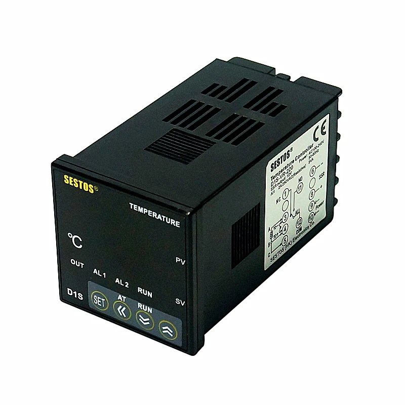
Двойной цифровой регулятор температуры Sestos PID 2 Omron релейный выход черный D1S-VR-220 + PT100 + 80A SSR
Цифровой регулятор температуры:
1. Регулятор температуры DIN (48×48 мм)
2. Поддержка нескольких сенсорных входов (K, S, Wre, T, E, J, B, N, CU50, PT100)
3. Широкий диапазон управления: -50 °C ~ 1300 °C (K сенсор)
4. Точность индикации и контроля 0,1 °C, высокое измерение
5. Точность ± 0.2% FS
6. Режим управления PID и ON/OFF
7. Выход и формат будильника могут быть заданы пользователем
8. Встроенный цифровой фильтр уменьшает помехи
9. Технология самокалибровки, стабилизация
10. Светодиод высотой 0,39 дюйма, предотвращает ослепление, хорошо Видимый дисплей
11. Импульсный источник питания и низкое потребление.
12. Использование реле OMRON с длительным сроком службы
13. Одобрено: CE
Датчик температуры PT100 для регулятора температуры
Диапазон температур:-50 °C -250 °C
Диаметр датчика: около 3X20
Длина кабеля:
Внешнее экранирование: изолированное экранирование
Внутренняя изоляция: стекловолокно
Особенности 80A SSR:
Надежная технология SMT
Высокая ультра-изоляция сопротивление более 50 м ч.1. 500 В постоянного тока
Высокий Диэлектрический более 2,5 кв
Низкий ток включения менее 7,5 мА/12 В постоянного тока, совместим с CMOS IC или TTL
Низкий уровень EMI/EFI и всплеск при нулевом перекрестном триггере
Высокий импульсный ток более 410A/один цикл (60 Гц)
Длительность высокого импульсного напряжения с помощью цепи snubber
Характеристики:
Напряжение нагрузки: 24-380 В переменного тока
Ток нагрузки: 80 А
Входное напряжение: 3-32 В постоянного тока
Содержимое упаковки:
ПИД Регулятор температуры D1S-VR-220 1 шт
1 шт. PT100
Термостат 80A SSR 1 шт.


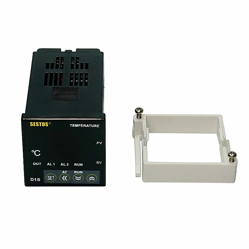
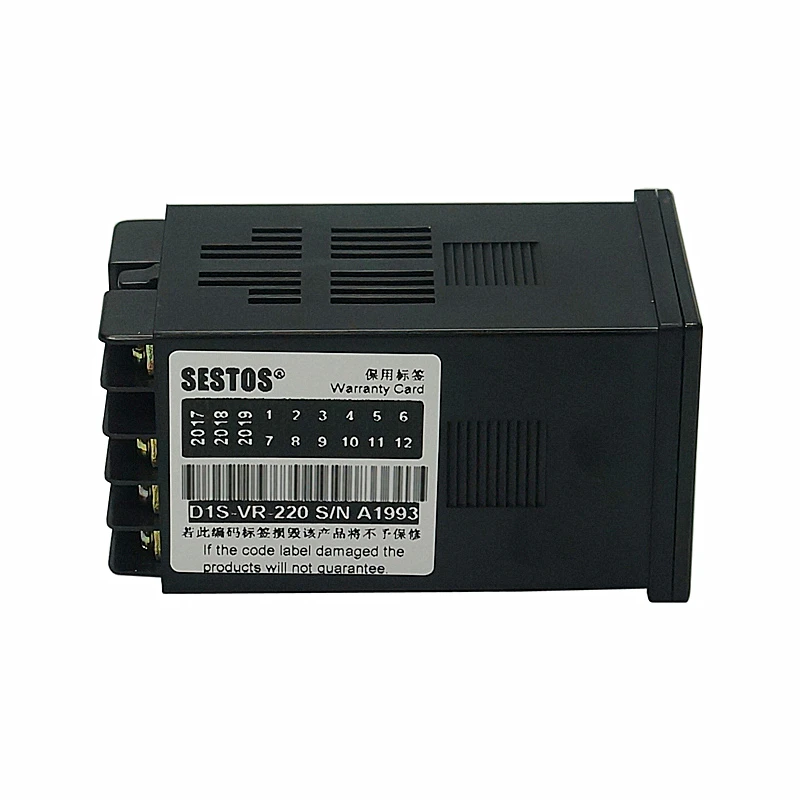
Фотографии:
Цифровой регулятор температуры(D1S-VR-220)


Датчик температуры PT100 для регулятора температуры

80A SSR

Отзывы
Характеристики:
Двойной цифровой ПИД контроллер температуры + 25A SSR + K датчик

Цифровой регулятор температуры  D1S-VR-220, входное напряжение 100-240VAC, выход: 12VDC + реле)


# Контроллер температуры.

Твердотельное реле 25 А для регулятора температуры
Особенности SSR 25A:Надежная технология SMTВысокая ультраизоляционная стойкость более 50 м?/500 В постоянного токаВысокий Диэлектрик более 2,5 квНизкий ток включения менее мА/12 В постоянного тока, совместим с CMOS IC или TTLНизкий уровень EMI/EFI и перенапряжения при нулевом перекрестном триггереВысокий импульсный ток более а/один цикл (60 Гц)Продолжительность высокого напряжения от цепи snubberХарактеристики:
Напряжение нагрузки: 24-380 В переменного токаТок нагрузки: 25 АВходное напряжение: 3-32 В постоянного тока
Датчик температуры термопары k-типа для регулятора температуры.
Диапазон температур: 0-400 CДиаметр датчика: 4,5 ммДлина кабеля: 2 мВнешнее экранирование: изолированное экранированиеВнутренняя изоляция: стекловолокно
Комплектация:Регулятор температуры PID, 1 шт., D1S-VR-220Термопара K, 1 шт.Термостат DA SSR, 1 шт., 25 А
You should upgrade or use an alternative browser.
-
Forums
-
Engineering
-
Electrical Engineering
Setup of Sestos PID controller
-
Thread starter
AligatorAmy -
Start date
-
-
Tags -
Controller
Pid
Pid controller
-
-
- #1
I intend to use Sestos PID temperature controller D1S-VR-220.
Sensor is connected to 220V power supply.
The controller receives output from immersion temperature probe:
http://www.ebay.co.uk/itm/DRG-010632B-Labfacility-Pt100-Temperature-Sensor-6X100mm-/132203898276
However, when I connect the controller to the mains, the display immediately keeps flashing as follows:
— PV — ‘635.7’ / ‘orAL’
— SV — ‘A 0’ / ‘HiAL’ / ‘oHAL’ / ‘orAL’.
Whatever setting I use in the controller SET menu it keeps displaying/flashing the same thing (as above) after leaving SET menu.
I would like to set up this controller to maintain temperature 88-90 degC with ON/OFF mode, of the solution. The heating initially should start from 20degC.
I have the basic manual (I do not have the original paper one which came with the controller).
http://www.sestos-hk.com/english/download/d1s-en.p…
I am not sure know now whether the values I set in menu are correct:
— Absolute-value upper-limit — 90degC,
— Absolute-value lower-limit — 88degC,
— Upper limit(deviation)- 1degC,
— Lower limit(deviation)- 1degC,
— Hysteresis — 0.3(?)
— Control output — 0 (ON/OFF),
— M50 Integral- ? (is it needed for ON/OFF mode?)
— Differential — ? (is it needed for ON/OFF mode?)
— Hysteresis time — ? (is it needed for ON/OFF mode?)
— Control period — ? (is it needed for ON/OFF mode?)
— Input sensor — 21 (PT100 probe)
— Decimal point position — ?
— input lower limit display -5degC,
— input upper limit display — 95degC.
— Sensor calibration — ?
— Output method — ?
— Output lower limit — ?
— Output upper limit — ?
— Alarm function — ?
— System function — 2 (heater)
— Addr — 1
— Baud — 9600
— Input digital filter — ?
— Run mode — 1(?) (automatic)
— loc — 40
— EP1-Ep8 — none
P.S. I also tried to swap the cables of the probe in the controller but no effect.
Please help.
Regards
- #2
At first glance, at least some of them have to to with these settings.
— Absolute-value upper-limit — 90degC,
— Absolute-value lower-limit — 88degC,
— Upper limit(deviation)- 1degC,
— Lower limit(deviation)- 1degC,
With controller absolute limits set to 88° and 90°, and lower and upper deviation alarm limits set to +/-1° the only measured temperature that (possibly) won’t cause an alarm is 89°.
SV (setpoint value) appears to be 0°. This is outside the absolute limit range.
MV (measured value) appears to be 635.7°C. This is above the rated RTD sensor range (-50 to +200°C), and more importantly, beyond the -200 to +600° limits of the this instrument’s Pt100 range. There’s a good chance the sensor is miswired.
- #3
Alpha quantifies how much the resistance changes as temperature changes. It isn’t stated in the eBay description, but α = 0.00385 is probably the most common. This sensor has a 4 wire output, and although it is hard to tell from the photo, it looks like two white wires, and two red wires.
Usually, red wires are intended for current carrying, and white wires are used for voltage drop sensing. Internally, one pair of red and white wires are connected to one side of the temperature sensing resistor with the other side connected to the other red/white pair. Use an ohmmeter to determine which red and white wires belong together (they’ll measure less than an ohm between one another).
The Sestos controller supports three wire RTD connections. In this case, terminal #4 is connected to one of the red wires, terminal #5 is connected to the corresponding white wire of this pair, and the other red wire is connected to terminal #3. The remaining white wire can remain disconnected or may also be terminated at terminal #3.
Pt 100 means RTD resistance is 100Ω at 0°C. If sensor condition is in question, temporarily connect a 100Ω resistor between terminal 3 and 4 (it may also be necessary to jump terminal 4 and 5 together) and the display should read very close to 0°C.
I would like to set up this controller to maintain temperature 88-90 degC with ON/OFF mode, of the solution. The heating initially should start from 20degC.
How do you mean «ON/OFF mode»? PI or PID control is probably necessary to obtain a peak-to-peak temperature variation of 2°C or less.
- #4
Sensor is connected to 220V power supply.
I hope you meant «Controller is connected to 220V…»
- #5
@Asymptotic
I have rewired the probe connection with the controller.
I bridged 4 and 5 with a short wire. I connected 1 red wire to 5 and 1 white wire to 3.
(there are four wires of probe- 2 white and 2 red)
The sensor seems to read the temperature correctly now. Thank you.
However, the question whether I connected ‘right’ pair of 1 white and 1 red wires to the sensor is unknown, I do not have a multimeter.
I switched red with red and white with white, I did not observe a difference so far.
@jim hardy
That is correct. I meant controller.
Thank you for spotting this.
Update to my last input.
I have simplified my electric circuit for simple test to verify whether controller actually controls the powering of the heater.
My simplified electric circuit consisted of PSU, DC-DC SSR, 12VDC heater (controller was disconected from SSR but was powered and I could read the actual temperature of solution on the sensor).
What I have found out was that in this simplified circuit the heater was still powered!
The details of my simplified circuit were (there were only 3 cables used):
1 cable between PSU-heater — 12VDC «-«
1 cable between PSU-SSR — 12VDC «+» goes to ‘1’ in SSR (LOAD side of SSR which is 40A 100VDC).
1 cable between SSR-heater — 12VDC «+» goes from ‘2’ in SSR (LOAD side of SSR which is 40A 100VDC) to the heater.
Again ‘3’ and ‘4’ connections in SSR remained unwired.
There is only one explanation- this SSR is normally closed, which is not the case when I check SSRs specs in the web.
I am confused.
P.S.
The bottom of SSR is hot when operational.
P.P.S.
My DC-DC SSR
http://docs-asia.electrocomponents.com/webdocs/1457/0900766b8145727d.pdf
My 12VDC PSU
http://www.topqualitytools.co.uk/power-supply-switch-mode-12v-42a-504w-gws-500-12/
My heater is 12VDC 25A 300W
- #6
The details of my simplified circuit were (there were only 3 cables used):
1 cable between PSU-heater — 12VDC «-«
1 cable between PSU-SSR — 12VDC «+» goes to ‘1’ in SSR (LOAD side of SSR which is 40A 100VDC).
1 cable between SSR-heater — 12VDC «+» goes from ‘2’ in SSR (LOAD side of SSR which is 40A 100VDC) to the heater.
Can you sketch and upload this? SSR terminal 1 is output (-), and terminal 2 is output (+). It sounds like you have polarity reversed.
I bridged 4 and 5 with a short wire. I connected 1 red wire to 5 and 1 white wire to 3.
(there are four wires of probe- 2 white and 2 red)
The sensor seems to read the temperature correctly now. Thank you.
However, the question whether I connected ‘right’ pair of 1 white and 1 red wires to the sensor is unknown, I do not have a multimeter.
I switched red with red and white with white, I did not observe a difference so far.
This isn’t quite right. It won’t be readily apparent with the short extension leads on your temperature probe, but what you have now is a «2 wire» configuration, and it isn’t as accurate as when the RTD is connected «3 wire». Analog Devices has a good write-up.
Invest in a multimeter. It simplifies troubleshooting, and can literally save your life.
- #7
I have made a picture of the circuit and put some comments on it.
I had the same thought that perhaps I should swap the cables in terminal 1 and 2.
On the other hand, when I checked the connections done for AC load, the cable coming from PSU (line) was connected to terminal 1 and terminal 2 was connected to the heater.
Ok I will re-check your recommendations in regards to the probe connection with the controller.
Initially, I connected terminal 4 to one red wire, terminal 5 to one white wire and the other red wire to terminal 3.
I got then error message on display, i.e. flashing or_AL.
I swapped red wires but no change.
I have not checked how it works with other combinations, such as other white wire connected to terminal 5 and swapping red wires if necessary.
I will check this.
Thank you also for the linked website. It is very useful.
Attachments

- #8
I had the same thought that perhaps I should swap the cables in terminal 1 and 2.
On the other hand, when I checked the connections done for AC load, the cable coming from PSU (line) was connected to terminal 1 and terminal 2 was connected to the heater.
What AC load?
Thanks for the photo. Kudom P/N KSJ100D40-L(068) SSR load wiring polarity is backwards. SSR terminal #2 should be connected to supply (V+), SSR terminal #1 to the heater, and the other side of the heater to supply (V-).

Add a properly sized heat sink to handle the 25A load current.
For 25°C ambient temperature convection cooling, this SSR must be de-rated to only about 17A when used without a sink, but is good for about 27 amps when bolted to a 2.1°C/W heat sink.

- #9
Thank you for your reply.
I have switched the cables between terminals 1 and 2 in SSR. The circuit works very good now. Thank you.
In regards to the sink. I have temporarily exposed SSR to the PSU fans blow. SSR is cold now. This electric circuit is for rapid prototyping. At later stage I will add a proper heat sink to it. Thank you for the info you have sent and the diagram. It is very useful. I will apply it.
Please allow me to ask about one more thing.
I need to slow down the heating rate of the solution which is heated with the discussed circuit.
I would like to use the timer H3RN-1-B (I have it):
http://www.valin.com/sites/default/files/asset/document/Omron-Solid-State-Timer-H3RN-B-Datasheet.pdf
My electric circuit is 12VDC.
Rated supply voltage for this timer is: 24 VAC (50/60 Hz); 12, 24 VDC
However, in regards to the rated power supply, the timer manual states that (at top and bottom of page 2 in linked manual):
— cULus (Listing): Applicable when an OMRON P2RF-@-PU Socket is used.
— cURus (Recognition): Applicable when any other socket is used.
My understanding is that in order to power this timer with 12VDC I need to plug it in into the OMRON P2RF-@-PU socket ?
Also I am looking for a possibility of slowing down the heating rate with change of the Sestos PID controller settings.
I have read that increasing of the ‘P’ value can do the work (to some extend).
Would there be any other PID setting that could be changed to slow heating rate?
Thanks.
-
- #10
— cULus (Listing): Applicable when an OMRON P2RF-@-PU Socket is used.
— cURus (Recognition): Applicable when any other socket is used.
My understanding is that in order to power this timer with 12VDC I need to plug it in into the OMRON P2RF-@-PU socket ?
Not necessarily. Any good quality socket with this pin configuration can be used. However, Omron can’t guarantee the relay/socket installation maintains UL listing (because the end user might be using a low quality socket).
I need to slow down the heating rate of the solution which is heated with the discussed circuit.
One possibility is to use the timer relay set up for interval control in conjunction with the controller ALM relay output. Set up the alarm relay to active the recycling timer until MV temperature is somewhat above the lower proportional band limit, and once that temperature is met, bypass the timer.
Since slow heatup is desired anyway, rather than adding this extra complexity try using the output limiter first.
— Output lower limit — ?
— Output upper limit — ?
Set lower limit to 0%, and upper limit to whatever experimentation finds is appropriate. If upper output limit is set to 50% (depending on how the manufacturer implemented this feature) it limits the amount of heat output on-time to 50% of whatever the PID loop is commanding, or sets a hard 50% output limit regardless of what the PID loop commands. The connected 300W heater, in effect, averages only 150W output when limited to 50% output, 75W at 25% output limiting, and so on.
Initially, set cycle time (‘Control Period’) to 10 seconds. This makes it easy to determine % output by observing the ‘OUT’ LED, and using a stopwatch. For example, if the LED is on for 6.67 seconds of 10 second, control output is 66.7%.
A stirred liquid allows better temperature control quality.
I’d try using the controller’s auto-tuning feature first, and see if the parameters it returns provide adequately good control quality before diving into manual tweaking (and always record what these values are).
What I’ve found helpful is to create a spreadsheet listing parameter names, functions, minimum/maximum settings, and factory settings from the user manual, and as many additional columns are required to save how the instrument was set up during tuning experimentation, and any tuning changes made while in process service. To these record-keeping columns append temperature setpoint, + temperature deviation, — temperature deviation, and (if available) minimum and maximum % loop output, and a place to enter free-form notes. This degree of rigorous documentation is particularly useful in cases like this where controller parameters are a little bit strange and not well understood, and aid in figuring out what’s going on.
-
- #11
Thank you for your detailed answer.
I will use the output limit and ‘Control Period’ first.
Thank you again for your kind help.
- #12
Two of the parameters (Addr and Baud) suggest an RS422/485 serial communications capability (which would allow logging; useful during loop tuning) but not only could I not find an accompanying software program for this purpose, or a listing of the communication protocol, but there aren’t any controller terminals for serial comms.
I’m assuming water is being heated in an open (non-pressurized) container. Perform auto-tuning at a lower value than your 90°C intended operating setpoint (75°C ought to be OK). Auto-tuners turn on output 100%, and calculate temperature rate-of-change by observing how temperature increases for a given amount of time, then turns off the output, and calculates cooling rate of change (and usually repeats this for 2 or 3 times).
90°C is very close to the 100°C boiling point of water, and autotuning from a 90°C setpoint may result in very strange loop tuning since 1). temperature rise will stall at approximately the boiling point, and 2). the tuner doesn’t take into account the enthalpy of vaporization.
- #13
Thank you again for your help.
I have used ‘output upper’ limit and it worked perfect.
I have gave it a few trials, as you had suggested, noted the settings and temperature/time output, and finally figured out the ‘output upper’ value.
P.S.
That is correct, the container is not pressurized.
Indeed, I have tried the settings in PID in a lower temperature range first. The closer the temperature to 90degC the slower heating rate is.
- #14
And with what loop tuning parameter values? Output upper limit, and …
— M50 Integral- ? (is it needed for ON/OFF mode?)
— Differential — ? (is it needed for ON/OFF mode?)
— Hysteresis time — ? (is it needed for ON/OFF mode?)
Suggested for: Setup of Sestos PID controller
-
Forums
-
Engineering
-
Electrical Engineering
Описание
Sestos Двойной цифровой Pid контроллер температуры 2 Omron релейный выход черный D1S-VR-220
Цифровой Температура контроллера:
1. Регулятор температуры DIN (48X48 мм)
2. Поддержка нескольких сенсорных входов (K, S, Wre, T, E, J, B, N, CU50, PT100)
3. Широкий диапазон управления-50 — 1300 (датчик K)
4. Точность индикации и контроля 0,1, высокое измерение
5. Точность ± 2% FS
6. PID и режим управления Вкл/Выкл
7. Формат выхода и сигнала тревоги может быть установлен пользователем
8. Встроенный цифровой фильтр уменьшает помехи
9. Технология самостоятельной калибровки, стабилизация
10. 0,39 «светодиодный, предотвращающий ослепление, хорошо Видимый дисплей
11. Импульсный источник питания и низкое потребление.
12. Использовать долгий срок службы реле OMRON
13. Утверждение: CE
Посылка включает в себя:
1 шт. PID контроль температуры D1S-VR-220


Для покупки товара Sestos Двойной цифровой Pid температура контроллер 2 Omron Реле Выход Черный D1S-VR-220 нажмите кнопку «купить сейчас».
Если вы хотите купить другой товар из категории инструменты или электроинструменты то перейдите по ссылкам вверху страницы.