
ТЕХНИЧЕСКИЕ ХАРАКТЕРИСТИКИ XY-LPWM3
| Характеристики генератора сигналов | |
| Количество каналов | 3 |
| Диапазон частот | 1 Гц — 150 кГц |
| Форма сигналов | прямоугольная |
| Рабочее напряжение | 3,3 — 30 В |
| Диапазон рабочего цикла | 0 — 100% |
| Точность рабочего цикла | ± 1% |
| Точность частоты | ± 2% |
| Выходной ток | 5 — 30 мА |
| Применение | тестирование усилителей, динамиков, других низкочастотных и аудио устройств, с дополнительным выходным ключем может использоваться для тестирования мощных устройств |
| Общие характеристики | |
| Дисплей | LCD |
| Рабочая температура | -40℃ ~ 85℃ |
| Рабочая влажность | 0 — 95% |
| Габариты | 55 х 38 мм |
| Вес | 15 г |
| Комплектация | генератор сигналов XY-LPWM3 — 1 шт |
XY LPWM3
Модель генератора xy lpwm3 – это устройство для генерации прямоугольных импульсов. Главным отличием от других моделей является наличие трех каналов генерации. Основными настраиваемыми параметрами формируемой сигнальной последовательности являются скважность и частота.
С помощью приборов можно тестировать различную аудиоаппаратуру, в том числе усилители и динамики, а также управлять небольшими сервоприводами в конструкции автомобиля.
Исполнение
Устройство представляет собой плату, на одной стороне которой расположены контакты для подключения, LCD-дисплей и четыре группы микровыключателей для управления настройками. С другой стороны – распаяна электронная схема с микроконтроллерами и прочими элементами. Корпус отсутствует. Для установки платы в коробку или на панель предусмотрено четыре монтажных отверстия по углам.
Подключение входных и выходных сигналов выполняется с помощью пайки. Все контакты и кнопки подписаны и удобно объединены в группы прямоугольной маркировкой. Электронные компоненты впаяны в плату аккуратно и надежно. При должной эксплуатации устройство прослужит вам много дольше 12-месячного гарантийного срока.
Особенности
Главным преимуществом модели xy lpwm является наличие трех выходных каналов. Это очень удобно и позволяет тестировать сразу несколько аудиоустройств. Прибор работает в частотном диапазоне от 1 до 150 000 Гц.
Из других эксплуатационных преимуществ следует выделить высокую точность генерации:
- для рабочего цикла – не более 1 %;
- для частоты – не более 2 %.
Включение происходит при подаче напряжения от 3,3 до 30 В. От конкретного значения входного питания зависит максимальная амплитуда на выходе. Выходной ток на генераторе не очень высокий и составляет максимум 30 мА. Поэтому для проверки мощных потребителей необходимо использовать более мощные выходные транзисторы.
Инструкция для xy lpwm
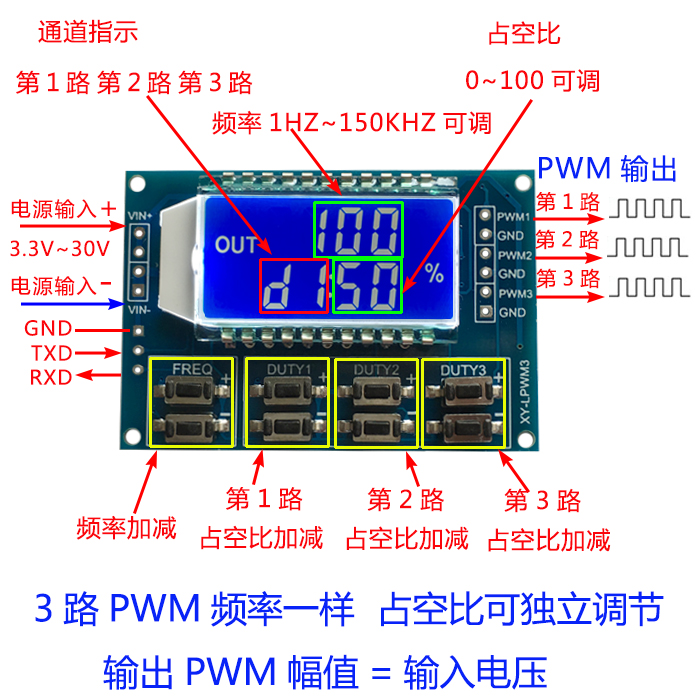
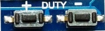
На небольшом цифровом экране LCD-типа располагается информация о параметрах формируемого сигнала. Интерфейс двухстрочный. На верхней строке находится значение частоты, чтобы изменить его, необходимо использовать группу переключателей FREQ. На нижней выводится уставка по скважности с маркировкой соответствующего канала d1, d2 или d3. Для изменения этих параметров предусмотрены микропереключатели DUTY 1, 2 и 3.

Технические характеристики, внешний вид и комплектация
товара
могут быть изменены
производителем без предварительного уведомления.
| Характеристики генератора сигналов | |
| Количество каналов | 3 |
| Диапазон частот | 1 Гц — 150 кГц |
| Форма сигналов | прямоугольная |
| Рабочее напряжение | 3,3 — 30 В |
| Диапазон рабочего цикла | 0 — 100% |
| Точность рабочего цикла | ± 1% |
| Точность частоты | ± 2% |
| Выходной ток | 5 — 30 мА |
| Применение | тестирование усилителей, динамиков, других низкочастотных и аудио устройств, с дополнительным выходным ключем может использоваться для тестирования мощных устройств |
| Общие характеристики | |
| Дисплей | LCD |
| Рабочая температура | -40℃ ~ 85℃ |
| Рабочая влажность | 0 — 95% |
| Габариты | 55 х 38 мм |
| Вес | 15 г |
| Комплектация | генератор сигналов XY-LPWM3 — 1 шт |
XY LPWM3
Модель генератора xy lpwm3 – это устройство для генерации прямоугольных импульсов. Главным отличием от других моделей является наличие трех каналов генерации. Основными настраиваемыми параметрами формируемой сигнальной последовательности являются скважность и частота.
С помощью приборов можно тестировать различную аудиоаппаратуру, в том числе усилители и динамики, а также управлять небольшими сервоприводами в конструкции автомобиля.
Исполнение
Устройство представляет собой плату, на одной стороне которой расположены контакты для подключения, LCD-дисплей и четыре группы микровыключателей для управления настройками. С другой стороны – распаяна электронная схема с микроконтроллерами и прочими элементами. Корпус отсутствует. Для установки платы в коробку или на панель предусмотрено четыре монтажных отверстия по углам.
Подключение входных и выходных сигналов выполняется с помощью пайки. Все контакты и кнопки подписаны и удобно объединены в группы прямоугольной маркировкой. Электронные компоненты впаяны в плату аккуратно и надежно. При должной эксплуатации устройство прослужит вам много дольше 12-месячного гарантийного срока.
Особенности
Главным преимуществом модели xy lpwm является наличие трех выходных каналов. Это очень удобно и позволяет тестировать сразу несколько аудиоустройств. Прибор работает в частотном диапазоне от 1 до 150 000 Гц.
Из других эксплуатационных преимуществ следует выделить высокую точность генерации:
- для рабочего цикла – не более 1 %;
- для частоты – не более 2 %.
Включение происходит при подаче напряжения от 3,3 до 30 В. От конкретного значения входного питания зависит максимальная амплитуда на выходе. Выходной ток на генераторе не очень высокий и составляет максимум 30 мА. Поэтому для проверки мощных потребителей необходимо использовать более мощные выходные транзисторы.
Инструкция для xy lpwm
На небольшом цифровом экране LCD-типа располагается информация о параметрах формируемого сигнала. Интерфейс двухстрочный. На верхней строке находится значение частоты, чтобы изменить его, необходимо использовать группу переключателей FREQ. На нижней выводится уставка по скважности с маркировкой соответствующего канала d1, d2 или d3. Для изменения этих параметров предусмотрены микропереключатели DUTY 1, 2 и 3.
Технические характеристики, внешний вид и комплектация товара
могут быть изменены
производителем без предварительного уведомления.
3 канала с цифровым дисплеем ШИМ-частота импульсов, прямоугольная волна, модуль генератора сигналов прямоугольной формы с регулируемым рабочим циклом
3- КАНАЛЬНЫЙ ШИМ-ИМПУЛЬСНЫЙ МОДУЛЬ С РЕГУЛИРУЕМЫМ РАБОЧИМ ЦИКЛОМ, ГЕНЕРАТОР ПРЯМОУГОЛЬНЫХ СИГНАЛОВ ПРЯМОУГОЛЬНОЙ ВОЛНЫ
Основные моменты модуля:
1. 3 канала выхода PWM , регулируемая частота, 3 канала частотного выхода, рабочий цикл можно регулировать независимо, подходит для большинства случаев;
2. Частота ЖК- дисплея и рабочий цикл очень четкие и легко настраиваются.
3. Широкий частотный диапазон и высокая точность;
4. Возможна последовательная связь.
1. Описание модуля
3- полосный выход PWM , широкий частотный диапазон, рабочий цикл можно независимо регулировать в реальном времени;
Частота разделена на четыре диапазона, которые переключаются автоматически:
1. XXX ( без десятичной точки ) : наименьшая единица — 1 Гц , диапазон значений — 1 Гц ~ 999 Гц ;
2. Наименьшая единица измерения X.XX (десятичная точка — сотни) составляет 0,01 кГц , а диапазон значений составляет 1,00 кГц ~ 9,99 кГц ;
3. XX.X ( десятичная точка находится в разряде десятков ) : наименьшая единица измерения — 0,1 кГц ; диапазон значений — 10,0 кГц ~ 99,9 кГц.
4. XXX ( десятичная точка в десятках и сотнях ) : наименьшая единица измерения — 1 кГц ; диапазон значений — от 1 кГц до 150 кГц.
например, отображение частоты: 100 означает выход ШИМ, импульс 100 Гц ;
1.01 означает, что PWM выводит 1.01K импульсов;
54.1 означает, что ШИМ выдает импульс 54,1 кГц ;
1.2.4 представляет выходной импульс ШИМ 124 кГц ;
Диапазон значений рабочего цикла: 0 ~ 100% , где 100% представлено A0% .
Все параметры настройки сохраняются после отключения питания.
2. Настройка параметров
Модуль имеет 8 независимых кнопок для установки частоты и рабочего цикла. Он поддерживает короткое нажатие (увеличение или уменьшение на одну единицу) и долгое нажатие (быстрое увеличение или уменьшение). Это очень просто. Параметры автоматически сохраняются после настройки. .
3- канальные кнопки рабочего цикла могут быть нажаты одновременно для настройки в реальном времени. На ЖК-дисплее отображается рабочий цикл последней нажатой кнопки. Производительность в реальном времени очень высока, и его можно использовать как простой режим. циклическое сканирование нескольких каналов.
3. Параметры модуля:
1. Рабочее напряжение: 3,3 ~ 30 В ;
2. Частотный диапазон: 1 Гц ~ 150 кГц ;
3. Точность частоты: точность в каждом диапазоне около 2% ;
4. Нагрузочная способность сигнала: выходной ток может составлять около 5 ~ 30 мА ;
5. Амплитуда выходного сигнала: амплитуда ШИМ равна напряжению источника питания;
6. Температура окружающей среды: -20 ~ + 70 ℃.
4. Сфера применения:
1. Используется в качестве генератора прямоугольных сигналов для генерации прямоугольных сигналов для экспериментальной разработки и использования;
2. Используется для генерации прямоугольного сигнала для управления приводом двигателя;
3. Генерировать регулируемые импульсы для использования MCU ;
4. Создавайте регулируемые импульсы и схемы, связанные с управлением ( например, ШИМ- регулировка яркости и регулировка скорости).
5. Управление последовательным портом (однокристальная связь уровня TTL )
Стандарт связи : 9600 бит / с Бит данных : 8
стоповых бит : 1
контрольный бит : нет
Управление потоком : нет
1. Установите частоту ШИМ.
«F101»: установите частоту 101 Гц (001 ~ 999)
«F1.05»: установите частоту 1,05 кГц (1,00 ~ 9,99).
« F10.5 »: установите частоту 10,5 кГц (10,0 ~ 99,9)
«F1.0.5»: установите частоту 105 кГц (1.0.0 ~ 1.5.0)
2. Установите рабочий цикл ШИМ.
«Dx: yyy»: установить рабочий цикл ШИМ x: ( 1 ~ 3 ) Серийный номер ШИМ , yyy: ( 000 ~ 100 ) Рабочий цикл % ;
Например , Dl: 050 , установить первый один -ходовой PWM рабочий цикл 50%
3. Прочтите параметры настройки.
Отправьте строку « read », чтобы прочитать установленные параметры.
Формат считываемых данных следующий: F156 , D1 : 052 , D2 : 059 , D3 : 058 ,
Установить успешный возврат: ВНИЗ ;
Если настройка не удалась, верните: ПАДЕНИЕ .
Для покупки товара в нашем интернет-магазине выберите понравившийся товар и добавьте его в корзину. Далее перейдите в Корзину и нажмите на «Оформить заказ» или «Быстрый заказ».
Когда оформляете быстрый заказ, напишите ФИО, телефон и e-mail Вам перезвонит менеджер и уточнит условия заказа. По результатам разговора вам придет подтверждение оформления товара на почту. Теперь останется только ждать доставки и радоваться новой покупке.
Оформление заказа в стандартном режиме выглядит следующим образом. Заполняете полностью форму по последовательным этапам: адрес, способ доставки, оплаты, данные о себе. Советуем в комментарии к заказу написать информацию, которая поможет курьеру вас найти. Нажмите кнопку «Оформить заказ».
Оплачивайте покупки удобным способом. В интернет-магазине доступно 2 варианта оплаты:
- Наличные при самовывозе или доставке курьером. Специалист свяжется с вами в день доставки, чтобы уточнить время и заранее подготовить сдачу с любой купюры. Вы подписываете товаросопроводительные документы, вносите денежные средства, получаете товар и чек.
- Безналичный расчет при самовывозе или оформлении в интернет-магазине: карты Visa и MasterCard. Чтобы оплатить покупку, система перенаправит вас на сервер системы ASSIST. Здесь нужно ввести номер карты, срок действия и имя держателя.
Экономьте время на получении заказа. В интернет-магазине доступно 4 варианта доставки:
- Курьерская доставка работает с 10.00 до 19.00. Когда товар поступит на склад, курьерская служба свяжется для уточнения деталей. Специалист предложит выбрать удобное время доставки и уточнит адрес. Осмотрите упаковку на целостность и соответствие указанной комплектации.
- Самовывоз из магазина. Когда заказ поступит на склад, вам придет уведомление. Для получения заказа обратитесь к сотруднику и назовите номер.
- СДЭК. Вы получите уведомление о готовности Вашего заказа от транспортной компании. Срок хранения — 14 дней.
- Почтовая доставка через почту России. Когда заказ придет в отделение, на ваш адрес придет извещение о посылке.
Description
The PWM Signal Generator Module combines an accurate 0-150kHz PWM generator with pushbutton controls and LCD display that shows frequency and duty cycle.
PACKAGE INCLUDES:
- XY-LPWM or HW-753 PWM Signal Generator Module
KEY FEATURES OF PWM SIGNAL GENERATOR MODULE:
- 0-150kHz output frequency range
- 0-100% duty cycle
- 3-30V operation and output pulse amplitude
- Simple pushbutton interface
- LCD display of frequency and duty cycle
- 5-30mA maximum current output
- Serial TTL interface, 3.3V logic compatible.
This is a nice little module that can be used as a flexible square wave generator for conducting experiments, testing and controlling devices that require a PWM input. Having the display and simple pushbutton interface makes it easy to set. Adding an output driver allows it to drive motors, solenoids, servos, dim LEDs and other pulse applications.
Theory of Operation
The reverse engineered schematics show the basic layout of the module.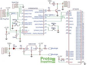
These modules are built with either a Holtek N76E003AT20 or ST Micro STM8S003F3P6 microcontroller and functionality is the same in either case.
The VIN+ input voltage powers a 3.3V linear regulator that supplies 3.3V to the logic circuits on the module.
The microcontroller accepts inputs form the pushbuttons or the TTL serial interface and generates the PWM output signal by using the built-in oscillator and timing circuits of the microcontroller.
The PWM output pin on the microcontroller drives an NPN MMBT3904 type transistor which in turn drives the PWM output pin of the module. The transistor has a series 1K resistor tied to VIN+, so the PWM signal will swing between ground and the module supply voltage on the VIN+ pin.
The 1K resistor limits the maximum available drive current which will vary depending on the VIN+ input voltage and range from about 5mA up to 30mA. This output is suitable fro driving a logic input or to drive a MOSFET transistor if you need to increase the module drive capability. There is also an easy hack to boost the current capability up to about 100mA which is explained down below in Our Evaluation Results section.
Besides the VIN power input connector and PWM output connectors described below, there is a connector on the back of the board labeled J3 which provides access to the programming port of the microcontroller. This is only of interest to anyone thinking about hacking the software on the module.
Note that we may ship boards with fabs marked XY-LWPM or HW-753. The minor functionality differences are noted down below under ‘Our Evaluation Results”
Powering the Module
The module can operate from 3 to 30V power input on the VIN+ connections. The two connections are internally connected and only one needs to be used. Same for VIN- which is the ground connection.
The VIN+ input has a Schottky reverse polarity protection diode. The module logic circuits are powered from a 3.3V regulator, so the VIN+ voltage is usually selected to set the amplitude that is needed for the PWM output. If the PWM output will be used with 5V logic, the module should be powered from 5V.
Below 4V, the LCD backlight will start to dim, but the module will continue to work down to 3V.
The module draws about 20mA from the power source under typical 5V operation.
Setting PWM Frequency
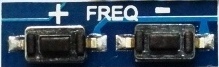 The frequency of the PWM output can be set over the range from 0Hz to 150kHz by pressing the FREQ+ and FREQ- buttons. Holding the buttons down accelerates the frequency change.
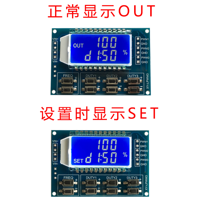
When the output is being adjusted, the display shows SET. When no adjustments are being made, it displays OUT.
The current frequency is shown in the upper half of the display with the decimal point indicating the range that is being displayed.
If the display shows XXX, the value is in Hz. A display of 500 indicated 500Hz. The value can be adjusted in increments of 1Hz over the range of 0-999Hz.
If the display shows X.XX, the value is in kHz. A display of 1.00 indicates 1kHz. The value can be adjusted in increments of 10Hz over the range of 1.00kHz – 9.99kHz.
If the display shows XX.X, the value is in tens of kHz. A display of 10.0 indicates 10kHz. The value can be adjusted in increments of 100Hz over the range of 10.0kHz – 99.9kHz.
If the display shows X.X.X, the value is in hundreds of kHz. A display of 1.0.0 indicates 100kHz. The value can be adjusted in increments of 1kHz over the range of 100kHz – 150kHz. This use of multiple decimal points isn’t the most intuitive way to display the value, but it’s not too bad once you get used to it.
Setting PWM Duty Cycle
 The duty cycle can be set over the range of 0-100% by pushing the DUTY+ and DUTY- buttons. Holding the buttons down accelerates the duty cycle change.
The current duty cycle is shown on the bottom half of the display with a % sign after it.
SERIAL CONTROL INTERFACE
The module has a serial port which provides control over the basic functionality of the module including setting the frequency and duty cycle as well as reading back the current settings.
The serial port is 3.3V compatible, so if using with a 5V MCU, you will need to use a logic level shifter on the module RX line to avoid possible damage.
Communications use 9600 baud rate. As with any serial port, the TX/RX lines are cross-connected, so the MCU TX line connects to the module RX and the MCU RX line connects to the module TX. GND connects to the MCU ground and is not needed if the module power and ground are coming from the MCU.
The communications protocol is very basic as described below.
Setting Frequency
Fxxx = Set Frequency
To set the frequency you send the data in the same format that it is displayed on the LCD proceeded by an upper case ‘F’.
‘F100‘ = Frequency set to 100Hz
‘F1.00‘ = Frequency set to 1kHz
‘F10.0‘ = Frequency set to 10kHz
‘F1.0.0‘ = Frequency set to 100kHz
The module responds with ‘DOWN‘ if the command was understood and ‘FAIL‘ if it wasn’t, such as if the command was formatted incorrectly.
Setting Duty Cycle
Dxxx = Set Duty Cycle
To set the duty cycle, you send the desired duty cycle preceeded by an upper case ‘D’.
‘D050‘ = Duty cycle set to 50%
Reading Current Settings
To read the current settings, you send a lower case ‘read‘.
The module will respond with the frequency and duty cycle like this:
F1.00
D050
or it may report
F=1.00KHz D= 50%
Module Connections
The connections to the module are straightforward with power on the upper left side, serial connections on lower left side and PWM output on the right side.
Note that the VIN+, VIN-, PWM and PWM GND connections have two connection points each. These are all connected internally, so only 1 pin of each needs to be connected. The grounds are also all in common.
- VIN+= Power 3 to 30V (x2)
- VIN- = Ground (x2)
- PWM = PWM Output (x2)
- GND = PWM Ground (x2)
Serial Port (labeled on backside)
- GND = Serial Ground
- TXD = Transmit Data out of the module. Connects to MCU RXD
- RXD = Receive Data into the module. Connects to MCU TXD
Module Assembly
The module has 4 M2 size holes in the four corners for mounting if desired.
This module does not come with any headers, but they can be ordered separately if needed.
OUR EVALUATION RESULTS:
These modules have a nice price/performance ratio and have good potential for embedding into a number of different applications.
The LCD screen has a downward viewing angle. This works especially well when mounted in a typical horizontal orientation where you are viewing the screen at a bit on an angel from the button side of the module but is less optimal if viewing the module straight on. The screen is not viewable at a downward angle.
Note that there are at least 3 flavors of this module on the market. The behavior is mostly the same, but there are some differences which are noted here. We may ship modules labeled either XY-LPWM or HW-753. We do not ship the LPWM as the serial port is non-functional on the ones that we have tested.
Modules with the marking XY-LPWM
- Pressing and holding the FREQ or DUTY buttons cause the output of the module to change as the display changes
- Serial read will return with the data formatted like this:
F1.00
D050 - Bad serial commands report ‘FAIL’
Modules with the marking HW-753
- Pressing and holding the FREQ or DUTY buttons cause the output of the module to change as the display changes
- Serial read will return with the data formatted like this:
F=1.00KHz D= 50% - Bad serial commands report ‘FALL’, but not in all cases.
Modules with the marking LPWM
- Pressing and holding the FREQ or DUTY buttons do not cause a change on the output until the button is released. The output then changes after about 1 second delay.
- Serial port does not appear to be operational.
Output Drive Limitations
The most likely issue to run into with these modules is trying to drive too large a load and have the output amplitude decrease too much due to the voltage drop through the 1K resistor R2. This resistor is selected to provide safe operation over the wide input voltage range. At 30V, it can pass 30mA and dissipate up to 0.9W which is why it is a physically large resistor.
For driving a logic input, this is not an issue since the current requirements are small, but if you are trying to get a little more drive from it without having to resort to hanging a MOSFET on the output there are some things you can do.
For a dedicated application where you know what voltage you will be using it with, such as 5V, R2 can be replaced or paralleled with a lower value resistor to increase the current handling capability and decrease the voltage drop through it.
The maximum current limitation depends on the current capability of the small transistor which is typically a MMBT3904 that can handle up to 200mA max continuous but is best kept down around 100mA to be on the safe side. A 50 ohm 1/2W resistor would work in this case to provide up to 100mA of drive at 5V.
To really boost the output, you can hang something like the High-Power Dual MOSFET module on the output.
Output Accuracy
The accuracy is pretty good. On a sample basis we measured the following.
- 100Hz / 50% duty cycle measured 100.86Hz with 50.01% / 49.99% duty cycle
- 1kHz / 50% duty cycle measured 1.01kHz with 49.98% / 50.02% duty cycle
- 10kHz / 50% duty cycle measured 10.09kHz with 49.82% / 50.18% duty cycle
- 150kHz / 50% duty cycle measured 152.233kHz with 47.24% / 52.76% duty cycle
Below are some O’scope waveform captures showing typical performance at these same frequencies.
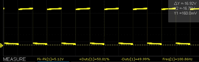
XY-LPWM 100Hz Scope Capture
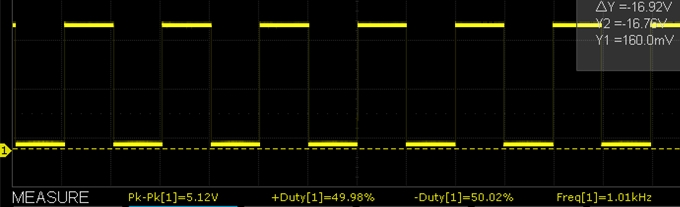
XY-LPWM 1kHz Scope Capture
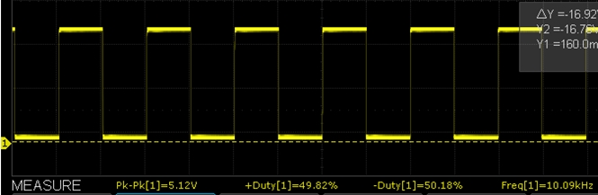
XY-LPWM 10kHz Scope Capture
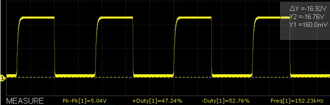
XY-LPWM 150kHz Scope Capture
Example Using the PWM Signal Generator Serial Control Interface
The program below is very simple and just passes characters between your computer and a MCU such as a Mega 2560 or Uno board which then passes the characters to and from the PWM Signal Generator module.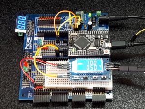
It uses SoftSerial to provide the serial port for the PWM Signal Generator module so that it will work with any MCU even if it only has one serial port. In our setup, we are actually using the Mega 2560 Pro which does have 4 hardware serial ports, one of which could have been used instead. We are using pins 10 & 11 for the SoftSerial port so that it will work with the Mega 2560 and also work with the Uno and most Arduino boards.
Connect the module RXD to the MCU pin 11 and the module TXD to MCU pin 10
Connect VIN+ to the MCU 5V and VIN- to the MCU ground.
Note that the module RXD pin needs to have the incoming signal level shifted from 5V down to 3.3V to avoid possible damage. This can be done with a logic level shifter or a simple resistor voltage divider network.
Once the program is downloaded, open the Serial Monitor Window and ensure it is set for 9600 baud and also select ‘No Line Ending‘ or else the module will not recognize the command that you are sending it.
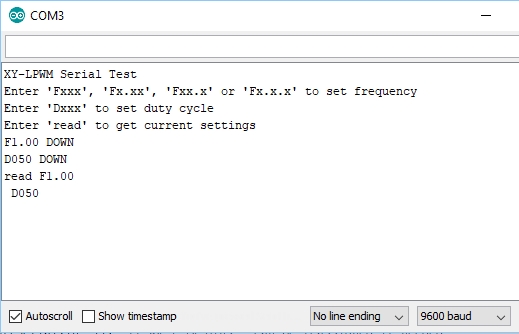 You can type the command that you want to send to the module in the upper window and see what the module module responds with in the main window. The MCU echos the command it receives followed by the response of the PWM module.
Valid Commands:
- Fxxx, Fx.xx, Fxx.x or Fx.x.x = Set the frequency
- Dxxx = Set the duty cycle
- read = Read current settings
Note that commands to set the frequency like F100 or duty cycle like D050 must be uppercase. To read the current settings the read command must be lowercase for no apparent reason whatsoever. Press enter to send the command.
An example output is shown here to the right and you should see the LCD display update with the new values. In this case the commands typed in and sent were F1.00, D050, read
To see what the actual PWM output is doing, you will need an O’scope or frequency counter. Alternatively you can wire an LED with a 1K series resistor across the PWM output and keep the frequency down in the 1-10Hz range so you can see the LED flash rate change. Be sure to keep the series resistor value fairly high to avoid accidentally overloading the PWM output.
PWM Signal Generator Control Test Program
/*  Simple program to exercise the PWM Module serial port

Uses hardware serial to talk to the host computer and software serial for
communication with the PWM module for compatibility with any MCU

Connections
  MCU 5V to module VIN+
  MCU GND to module VIN-
  MCU D11 to module RXD using a logic level shifter or voltage divider
  MCU D10 to module TXD

  When a command is entered in the Serial Monitor on the computer, the MCU will
  relay it to the PWM module and echo it to the Serial Monitor window.

  Note that frequency and duty cycle are upper case i.e. 'F100' or 'D050'
  The 'read' query on the other hand is lower case.

  Ensure that Serial Monitor Window is set for 9600 and 'No line ending'

  Any characters returned from the module will be displayed in the Serial Monitor Window.

  Uses Softserial.h library.  Can use hardware serial port if MCU supports it
*/
#include <SoftwareSerial.h>
SoftwareSerial SoftSerial(10, 11); // RX | TX pins.  Can be reassigned if needed

const long BAUDRATE = 9600;    // Baud rate of the XY-LPWM module
char c = ' ';                  // Character being transmitted
//===============================================================================
//  Initialization
//===============================================================================
void setup()
{
    SoftSerial.begin(BAUDRATE);  // Init soft serial object
    Serial.begin(9600);          // Init hardware serial
    Serial.println("PWM Module Serial Test");
    Serial.println("Enter 'Fxxx', 'Fx.xx', 'Fxx.x' or 'Fx.x.x' to set frequency");
    Serial.println("Enter 'Dxxx' to set duty cycle");
    Serial.println("Enter 'read' to get current settings");
}
//===============================================================================
//  Main
//===============================================================================
void loop()
{
     // Watch for any characters returned from module
    if (SoftSerial.available())
    {
        c = SoftSerial.read();
        if (c=='F' || c=='D') Serial.write(' ');  // Add space between commands
        Serial.write(c);
    }
     // Read char from the Serial Monitor and send to the XY-LPWM module
    if (Serial.available())
    {
        c = Serial.read();
        SoftSerial.write(c);
        Serial.write(c);  // Echo character typed to serial monitor window
    }
}
BEFORE THEY ARE SHIPPED, THESE MODULES ARE:
- Sample inspected and tested per incoming shipment
Notes:
- The module may have solder flux on the pins of the LCD module. It is not recommended to clean as the cleaning fluid can easily get under the LCD module where it will be optically visible as a blotchiness in the backlighting and it can be difficult or impossible to remove.
Technical Specifications
| Operational Ratings | ||
| Vcc | Range | 3 – 30V (3.3 or 5V typical) |
| Frequency | Specified Range | 0 – 150kHz |
| Duty Cycle | 0 – 100% | |
| PWM Pulse Amplitude | Same as VIN+ | |
| Dimensions | L x W x H | 52 x 32 x 10mm (2.05 x 1.26 x 0.39″) |
| Datasheets | Nuvoton microcontroller | N76E003 |
| ST Micro microcontroller | STM8S003F3 | |
| Holtek LCD controller | HT1621 |
-
Robotics
-

Written by
Ali Akbar Hosseini

Table of Contents
Introduction
You must have come across the terms “square pulse generation” and “pulse width modulation” (or PWM), and you probably have worked with them—for example, which pins of Arduino (or any other microcontroller) can generate PWM pulses. Pulse width modulation is a technique for generating square pulse signals with desired features, which are widely used in different areas of Electronics. Some of these applications include controlling the color and brightness of LEDs, controlling engines and timers, and synchronizing digital systems. This technique is also used in almost all switching power supplies and other methods for controlling the voltage or power.
Due to the importance of this concept, first, we will briefly explain it.
What is PWM?
PWM (or Pulse Width Modulation) is a process through which we control and adjust the parameters of a square waveform. The most important parameters include frequency, duty cycle, and voltage amplitude.
Consider the figure below:
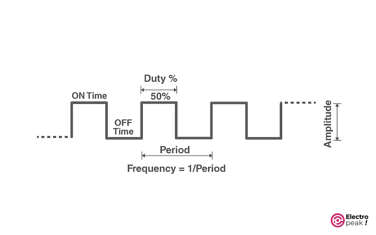
Here are the main parameters of a square waveform:
Period: The time taken for one cycle of the waveform. Its symbol is T, with a unit of “second.”
Frequency: The inverse of period. In other words, frequency is the number of periods per second. Its symbol is “f,” with a unit of Hz (1Hz=1/1s).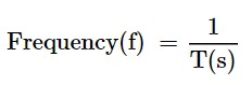
Duty Cycle: The ratio of on-time to the period. And it is usually represented in a percentage. 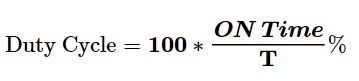
Amplitude: voltage amplitude.
Example: We have a voltage waveform that is on for 1.2 seconds and off for 0.8 seconds. And this process is repeated every 2 seconds. Find the frequency and duty cycle of the waveform.
Simple, isn’t it? Since the process is repeated every 2 seconds, the period would be 2 seconds.
Frequency = 1/2 = 0.5 Hz.
Duty Cycle: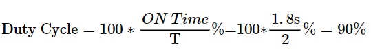
In this tutorial, we will not provide a complete explanation of the PWM concept and the related methods and applications. Therefore, the introduction above is necessary and perhaps enough for our purposes. You can refer to the numerous articles about this topic if you need more information.
Various modules and components have been designed and manufactured to generate PWM signals with different methods. In this tutorial, we will learn how to use the XY-LPWM module, which is almost a complete and well-equipped component for our purpose.
XY-LPWM PWM Signal Generator Module Features
XY-LPWM is a square pulse generator module that has more features compared to many other modules in this family. The output frequency of the module ranges from 0 Hz to 150 KHz, and you can adjust the duty cycle from 0 to 100%. In addition, the accuracy of the output frequency is 2% which is considered a great accuracy for many applications.
It is very easy to work with the XY-LPWM module due to the one LCD and four push buttons to adjust the frequency and duty cycle independently. In addition, the TTL serial user interface is designed on the module, by which we can communicate with the module through the serial port of a computer.
The input voltage is between 3.3 to 30 DC volts. The voltage amplitude of the output pulse is also generated without any drop compared to the input voltage amplitude.
XY-LPWM Specifications
• Input voltage: 3.3 to 30 volts
• Current consumption of module: 20mA (at 5V power supply)
• Output voltage amplitude: equals to the input voltage amplitude
• Frequency: 0 Hz to 150 KHz
• Frequency Accuracy: around 2%
• Duty cycle: 0 to 100%
• Maximum output current: 30 mA
• Operating temperature: -20 to 70 °C
• An LCD screen to display the frequency and duty cycle of the generated wave
• TTL Serial Interface with a 3.3V logic level
• Dimensions: 52*32*10 mm
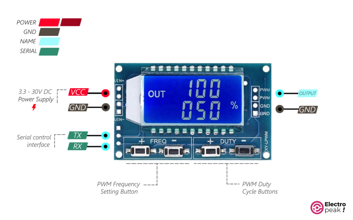
XY-LPWM Pinout
• VIN+: power supply of module (input voltage)
• GND: ground
• VIN-: ground
• PWM: output pin of pulse
Serial communication pins:
• TXD: transmit data pin
• RXD: receive data pin
Required Materials

Hardware Components
| PWM Signal Generator Module with a Digital Display | × | 1 | |
| PWM Switch Module* | × | 1 | |
| 12V Fan** | × | 1 | |
| Jumper Wire | × | 1 | |
| 5 to 12V Power Supply | × | 1 |
*: We use PWM Switch Module to increase the module’s output power. And there are many similar items for it in the market. Of course, you don’t need to buy this module if you are looking for a low-power output.
**: The 12V fan also tests and simulates the engine speed control. You don’t need this component for other purposes.
How to Use XY-LPWM Digital Pulse Generator Module
Module’s Power Supply
You should use this module within a voltage range of 3 to 30 volts which are supplied by the VIN+ pins. The two VIN+ pins are internally connected, so all you have to do is connect one to the power supply’s positive pin. The same applies to the VIN- pins connected to the circuit GND.
The power input of the module is protected by a Schottky diode against high voltages. In addition, the logic circuit of the module works with a voltage level of 3.3 which is provided by a 3.3V regulator on the board.
Note
Unlike many pulse generator modules, the module’s output voltage has no drop compared to the input voltage. Therefore, the output voltage amplitude equals the input voltage amplitude.
When the output voltage goes below 4V, the screen backlight decreases. The module, however, functions properly even at voltages as low as 3V.
The module draws 20mA from the power supply at operating voltages lower than or equal to 5V. In other words, the power consumption at an operating voltage of 5V is about 0.1 w.
Warning
The power mentioned above is the module’s operating power which is not the same as the module’s output power. In addition, the power supply must be able to support both of them.
For example, at an operating voltage of 5V, the maximum total power consumption is equal to the sum of the following powers:
Module’s power consumption= operating voltage * module’s current consumption= 20mA * 5V = 0.1 w,
Output power = output voltage * output current = 30mA * 5V = 0.15 w.
The power supply, therefore, must provide at least 0.25 w of power, i.e. it must provide at least 50mA at an operating voltage of 5V.
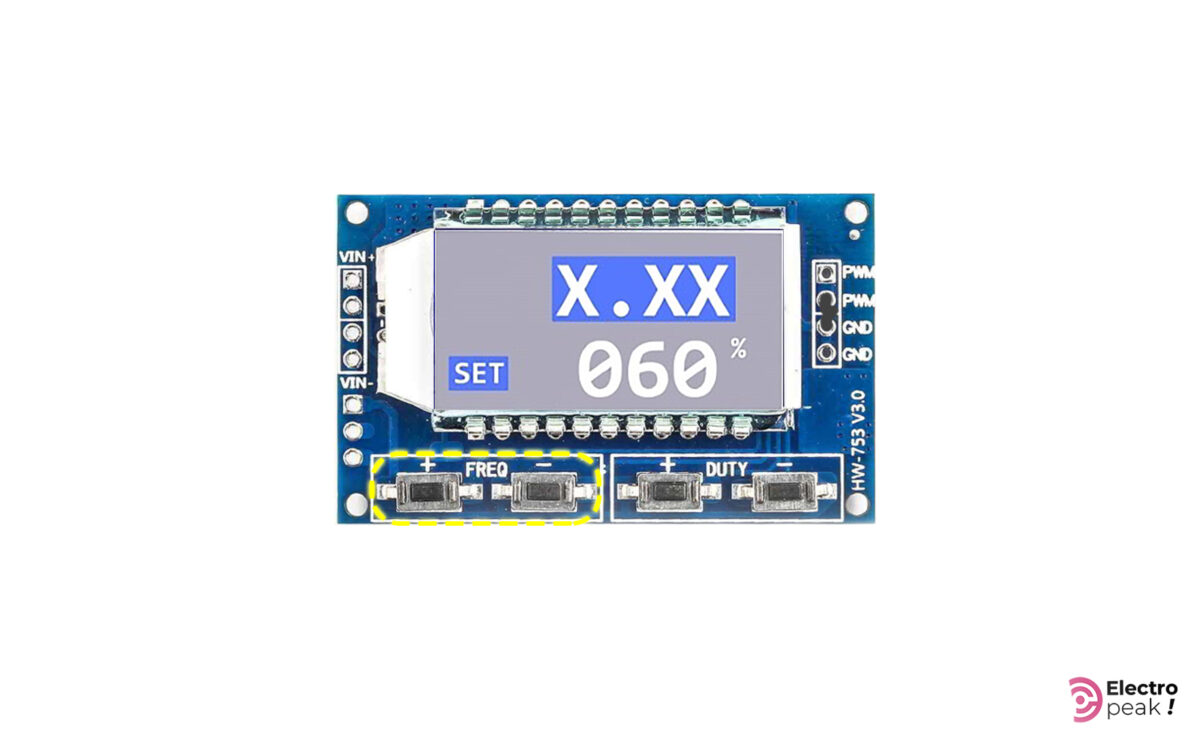
Initial Test of XY-LPWM PWM Signal Generator Module
For a simple test on XY-LPWM module, connect the wires as shown below. The power supply voltage must be between 3.3 to 30 volts.

You can see the general screen format in the image above. The first line is the output pulse frequency, and the second line shows the duty cycle percentage of the output pulse signal.
Warning
In some models of XY-LPWM modules, the output duty cycle percentage is complementary to the duty cycle displayed on the screen. For example, if it shows 60%, the output duty cycle is in fact 40%. In practice, though, this won’t be a problem because you can adjust its complementary to have the desired duty cycle.
You can observe the module output with an oscilloscope to make sure that you’ve got the desired output frequency and duty cycle.
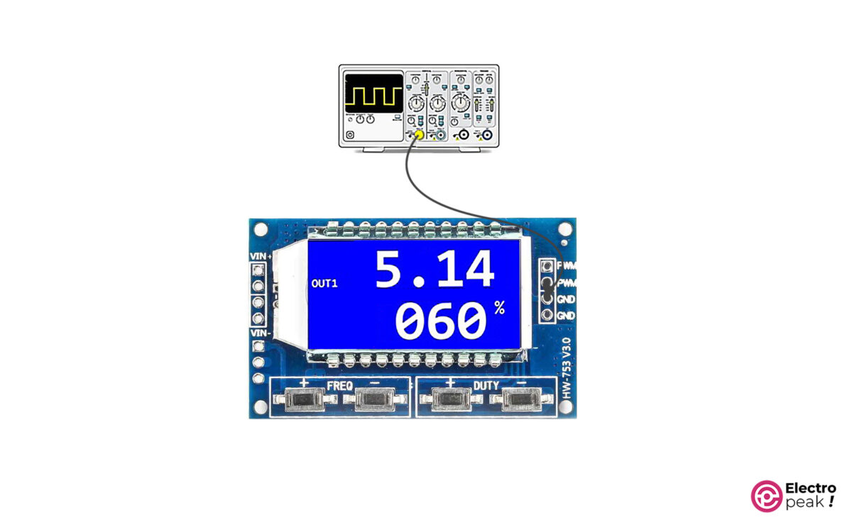
The waveform frequency on the oscilloscope must be equal to the frequency shown on the module screen.
Solution for Output Current Limitation in XY-LPWM Pulse Generator Module
As mentioned, the maximum output current of the XY-LPWM module is 30mA. This current will work perfectly well when using logic circuits because they don’t need a lot of current. But 30mA won’t be nearly enough when running a device such as a DC motor. For such cases, we have to amplify the output current.
One way to increase the output current and power is to use switching circuits. In this method, we use the output signal of the XY-LPWM module as the excitation signal for the switching circuits. Therefore, we can use the switching circuit output to run high-power devices.
There are colorful switching circuits, and most of them are designed based on transistors. Using these circuits, we can run and control an actuator such as a motor (which has a high amount of voltage and current) by a weak excitation signal (which has a low amount of voltage and current). We can get the excitation signal from a microcontroller or any other circuit, such as the XY-LPWM module.
First, let’s briefly explain one type of switching circuit that has a MOSFET transistor.
MOSFET as Switch
The circuit below shows the general form of using a MOSFET in a switching circuit.
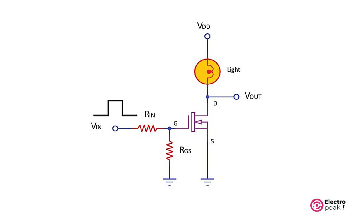
In the above circuit, as the input voltage (VIN) goes up, so does the voltage of the transistor’s gate pin (G). This will activate the transistor, which means, now, there is a connection between the drain pin (D) and the source pin (S), and the current can flow from VDD to GND. As a result, we can turn on a light (or any consumer) in the circuit.
To provide the required excitation signal for the transistor, we should connect the VIN pin to a microcontroller or a circuit. By doing so, the current consumed by the consumer will no longer pass through the VIN pin. In addition, the VDD value, which works as the power supply for the consumer, can be much higher than the excitation voltage. (The voltage and current of “Drain-Source” and “excitation signal” are different in various transistors. So if you need the exact specs of each specific model, you should see their datasheet.)
For example, let’s control a 12V motor with Arduino. Since the voltage of Arduino pins is 5V and their current can be 30mA at most, we can’t connect the Arduino pins, as an output, directly to the motor pin. Solution: The above switching circuit. All you have to do is connect the Arduino’s output pin to VIN, and VDD to the 12V power supply and then replace the light with a motor. In this case, we can activate the power supply circuit of the 12V motor with the Arduino’s 5V signal. Now, we control the speed of a DC motor with a power-switching module.
In this example, we use the HW-517 MOSFET Switching Module as the switching circuit. This module has two AOD4184A Power MOSFETs in parallel, which can provide 15A. In addition, the excitation voltage of the HW-517 module is between 3.3 to 20V, and the output voltage can range from 5 to 36V.
Motor Speed Control by XY-LWPM Pulse Generator Module and MOSFET Switch
Wiring
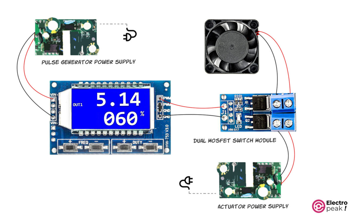
In the above circuit, the output of the XY-LPWM module is given to the switching module as the excitation signal. The MOSFETs are switched on and off with the same frequency and duty cycle as the excitation signal. As a result, the connection between the fan and the power supply on the right side is switched on and off. This way, we can control the average voltage given to the fan by controlling the frequency and duty cycle. In addition, the DC motor speed is proportional to the average voltage.
Tip
Since the excitation voltage of the MOSFET module is between 3.3 to 20 volts, the output voltage of the pulse generator must also be within the same range. Therefore, the voltage of the pulse generator’s power supply must range from 3.3 to 20 volts.
The power supply on the right side should have a voltage value between 5 to 36 volts; its exact value is determined by the consumer’s operating voltage (here, the fan). Also, we should choose the power supply current according to the actuator current.
If the actuator voltage is between 5 to 20 volts, we can use a typical power supply as long as it can provide the required total current.
We can also use the above circuit to control the color and brightness of RGB LEDs.
XY-LPWM Pulse Generator Module Configuration
Frequency Settings
You can adjust the module frequency from 0 Hz to 150 KHz. To do that, simply press the buttons related to frequency adjustment—the “+” button for increasing the frequency and the “-“ button for decreasing it. Remember that the frequency changes more quickly if you press and hold the buttons.
When you are changing the frequency, the word “OUT” disappears, and then the word “SET” appears on the screen. The value related to the frequency also changes on the screen (in the first line).
Here are the formats to display the frequency value:
XXX: In this format, the value is the output frequency represented in Hz. And it ranges from 0 to 999Hz. For example, when you see “300” on the screen, it means 300Hz.

X.XX: The value is represented in “KHz,” and it ranges from 1KHz to 9.99KHz. For example, when you see “1.00” on the screen, it means 1KHz. In addition, whenever you press the related buttons, the frequency changes by 10Hz.

XX.X: The value is represented in tens of KHz, and it ranges from 10.0KHz to 99.9KHz. For example, when you see “10.0” on the screen, it means 10KHz. In addition, whenever you press the related buttons, the frequency changes by 100Hz.
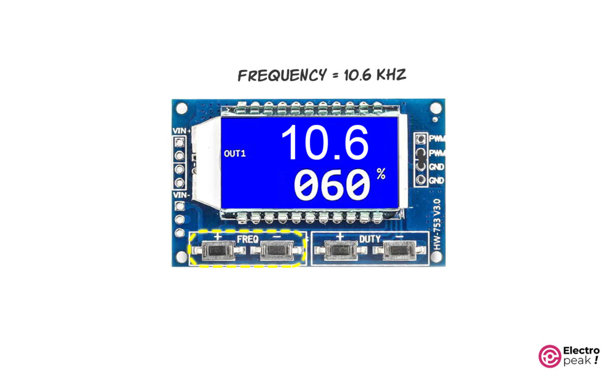
X.X.X: The value is represented in hundreds of KHz, and it ranges from 100KHz to 150KHz. For example, when you see “1.0.0” on the screen, it means 100KHz. In addition, whenever you press the related buttons, the frequency changes by 1KHz.

Duty Cycle Settings
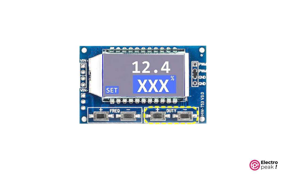
The module’s duty cycle ranges from 0 to 100%. To adjust this parameter, you can press the buttons “+” and “-“ shown in the image above. In addition, the three-digit number on the second line of the screen represents this parameter.
Controlling XY-LPWM Pulse Generator Module with Serial Interface
As mentioned, the module has a serial interface port with a 3.3V logic level. We can adjust the frequency features of the generated wave or restore the adjusted features by some specific commands using the serial port.
If you are using a 5V logic-level microcontroller to communicate with the module, make sure to use a voltage-level converter so as not to damage the pulse generator module.
The serial communication baud rate is 9600.
Frequency Settings
To adjust the frequency, send the data—in a similar format as in the display with an “F” prefix—to the module via the serial interface. Look at the examples below:
• F100: Adjusting the frequency to 100Hz
• F1.00: Adjusting the frequency to 1kHz
• F10.0: Adjusting the frequency to 10kHz
• F1.0.0: Adjusting the frequency to 100kHz
If the module understands the message, it will respond with the word “DOWN”. Otherwise, it will show the word “FAIL.”
Duty Cycle Settings
To adjust the duty cycle, send it to the module with a “D” prefix. Here’s an example:
D050: Adjusting the duty cycle to 50%.
Value Reading
You should send the word “read” to the module to read the module settings.
What’s Next?
With three XY-LPWM modules and three switch modules, as in the second example, build an RGB color controller and adjust the color and brightness of an RGB LED String.
Build a digital-to-analog converter using a pulse generator module and an RC circuit.
Using Arduino, write a code that can both receive the values from the serial port of a computer and then apply it to the module.
Get Updates And Learn From The Best
More To Explore
Comments (2)
-

Ajay Shee
Reply
Nicely Explained
August 29, 2023 at 6:55 am
-
Mohammad Damirchi
Reply
you’re welcome
August 30, 2023 at 5:31 am
-


Leave a Reply
Китайские цифровые модули ШИМ контроллеров (PWM) стали заметно доступнее по цене, но правильный выбор модуля, который будет делать именно то что нужно, остаётся актуальным. Вот несколько тестов и советов, которые помогут в процессе подбора подобного устройства избежать ошибок.
Для примера возьмём самый популярный, недорогой и компактный 2-канальный модуль PWM, описанный на Али как «XY-PWM 2-канальный регулируемый генератор импульсов ШИМ с цифровым светодиодным дисплеем».
Это крохотный 2-канальный модуль генератора ШИМ с переменной частотой от 1 Гц до 150 кГц и рабочим циклом от 0% до 100%. Частотой ШИМ и рабочим циклом каждого канала можно управлять независимо с помощью кнопочных переключателей, имеющихся на плате. Модуль может питаться от внешнего источника постоянного тока 5-30 В, но также оснащён и micro-USB 5 В. Он дополнительно предоставляет возможность настраивать определенные параметры импульса извне, через стандартный последовательный COM интерфейс.
Давайте ознакомимся с его основными характеристиками:
- Два независимых ШИМ с переменной частотой и рабочим циклом.
- Параметры настраиваются через последовательный протокол
- Рабочее напряжение: 5 – 30 В постоянного тока.
- Поддерживает micro-USB 5V
- Диапазон частот: 1 Гц ~ 150 кГц
- Точность частоты: около 2%.
- Нагрузочная способность сигнала: выходной ток 8-30 мА
- Выходная амплитуда: 5 В pp по умолчанию
- Рабочий цикл: 0% ~ 100%
Управление модуля имеет три кнопки – SET, UP, DOWN. Быстрое нажатие кнопки SET переключает все четыре параметра (FA1: частота PWM1, DU1: рабочий цикл PWM1, FA2: частота PWM2, DU2: рабочий цикл PWM2), а долгое нажатие позволяет изменять частотный диапазон. Кнопки UP и DOWN можно использовать для изменения текущих параметров.
Обратите внимание, что выбор частоты ШИМ делится на три диапазона:
- XXX (без десятичной точки): наименьшая единица измерения – 1 Гц. Диапазон от 1 Гц до 999 Гц.
- X (одна десятичная точка): Минимальная единица измерения – 0,1 кГц. Диапазон от 0,1 кГц до 99,9 кГц.
- XX (три десятичных знака): наименьшая единица – 1 кГц. Диапазон от 1 кГц до 150 кГц.
Последовательные параметры (скорость 9600 бод):
- Биты данных: 8
- Стоповый бит: 1
- Бит четности: Нет
- Управление потоком: Нет
Формат команды для установки частоты PWM – «S1FXXXT», что означает «Установите частоту PWM1 на XXX Гц (от 001 Гц до 999 Гц). И «S1DXXXT» применимо для установки рабочего цикла (Установите рабочий цикл PWM1 на XXX (001 ~ 100).
- S1: PWM1
- S2: PWM2
- F: частота
- D: Рабочий цикл
- T: знак конца
Конечно можно построить простой генератор ШИМ с помощью таймера 555, но все же для этого потребуется частотомер или осциллограф, чтобы настроить их правильно, а здесь уже всё готово.
Компоненты, расположенные рядом со входом модуля, – это один диод Шоттки SS34 (защита от обратного входного питания) и один стабилизатор напряжения HT7150-1 LDO (5 В / 30 мА). Это позволяет безопасно подавать источник постоянного тока в диапазоне 5-30 В через точки DC IN (VIN + и VIN-). Также можно включить модуль через разъем micro-USB, предпочтительно от источника питания USB или внешнего аккумулятора мобильного телефона. В любом случае, вход питания USB должен быть стандартным, с чистыми 5 В, поскольку на плате нет ничего что могло бы стабилизировать это напряжение. Трехзначный индикатор представляет собой красный светодиодный дисплей с общим катодом (3631AS).
Далее следует пара транзисторов MMBT3904L, вставленных на выводах импульсного выхода микроконтроллера. Тут есть два независимых выходных канала ШИМ, но они используют одну и ту же общую / заземляющую (0 В) линию.
Теперь становится ясно, что каждый транзистор работает как «буфер», который инвертирует фактический сигнал импульсного выхода микроконтроллера. С резистором нагрузки коллектора 620 Ом можно ожидать выходного сигнала с широтно-импульсной модуляцией уровня 5 В, который может управлять внешней нагрузкой с 8 мА максимального тока на канал.
Для теста использовался USB-блок питания. Сначала установили оба канала ШИМ на 25 кГц (50%) и наблюдали за выходным сигналом на осциллографе.
Канал осциллографа 1 (желтый) на PWM1, а канал осциллографа 2 (синий) – на базу Q1 (то есть первый вывод импульсного выхода микроконтроллера).
Возвращаясь к двухканальным сигналам ШИМ заметим, что такое дело будет полезно во многих случаях, таких как управление шаговыми двигателями, управление бесколлекторными двигателями постоянного тока, преобразование постоянного напряжения. Поскольку модуль XY-PWM можно использовать для генерации двух сигналов ШИМ с одинаковой (но переменной) частотой и рабочим циклом, результирующие прямоугольные волны с двухфазным смещением могут сыграть важную роль в чередующихся / фазосдвинутых сигналов.
Согласно описанию, двухканальный ШИМ-модуль даже совместим с серией промышленных двухфазных гибридных шаговых сервоприводов RMCS-111x.
Кстати, разъем встроенного 4-контактного интерфейса напоминает знакомый интерфейс программатора SWIM для микроконтроллеров STM. Чаще всего STM8S003K составляет основу такого двухканального модуля ШИМ.
Другое испытание проводилось с небольшим вентилятором BLDC на 12 В / 100 мА, просто подключили его к каналу PWM1 (25 кГц) двойного модуля PWM (с питанием от БП) через один модуль МОП IRF530 (не логика), как показано на схеме подключения. Использовали обычный метод «фиксированной частоты и переменного рабочего цикла» для управления скоростью вентилятора, и установка показала отличную производительность.
Вот выходной сигнал ШИМ 20 кГц (50%) (x2), обработанный двухканальным модулем ШИМ и снятый USB-осциллографом.
Выходное напряжение ШИМ модуля находится на уровне 5 В, потому что транзисторы драйвера питаются от встроенного стабилизатора напряжения 5 В / 30 мА LDO. И простое вырезание одной дорожки сделает ее готовой к выходам ШИМ более высокого уровня.
После этого можно подать более высокое напряжение между контактными площадками V + и GND. Если это вход 12 В, то получим выходы ШИМ с уровнем 12 В, но убедитесь что есть 100% изоляция между V + и дорожкой 5 В, иначе схема может сгореть. В общем подобный блок прекрасная основа более сложных приборов и электрических исполнительных механизмов.

Одноканальный импульсный генератор XY-LPWM с LCD дисплеем.

- Комментарии
- Информация
-
-
sova
Модуль XY-LPWM регулируемого импульсного генератора, построен на базе трех микросхем.
1. Микросхема N76E003AT20 — 8-bit микроконтроллер или аналог STM8S003F3Pb;
2. Микросхема HT1621B — Контроллер для LCD дисплея;
3. Микросхема HM5333B – Линейный стабилизатор на 3.3В.— Питание модуля (Vin) осуществляется от источника питания в пределах 3.3В до 30В
— Диапазон регулирования частоты от 1Гц до 150кГц, который разбит на четыре поддиапазона:
Первый — 1Гц-999Гц с шагом 1Гц;
Второй — 1кГц-9.99кГц с шагом 0.01кГц
Третий — 10кГц-99.9 кГц с шагом 0.1кГц
Четвертый — 100кГц-150кГц с шагом 1кГц
— Точность в каждом диапазоне составляет около 2%
— Коэффициент заполнения сигнала изменяется от 0 до 100%
— Выходной ток ГИ может составлять около 5-30 мА
— Амплитуда выходного сигнала равна питанию модуля. Например, на ГИ мы подали питание 12В, соответственно амплитуда выходного сигнала будет также 12В.
— Модуль XY-LPWM управляется как вручную, с помощью кнопок FREG и DUTY, так и через компьютер, подсоединив его к TTL последовательному порту (TXD, RXD, GND).
Команда «read» — это считывание настроек (F и D);
команда «DXXX» — изменение коэффициент заполнения сигнала (XXX от 001 до 100);
команда «F101» установка частоты 101Гц(от 001 до 999), «F1.05» установка частоты 1.05кГц(1.00-9.99), «F10.5» установка частоты 10,5КГц(10.0-99.9), «F1.0.5» установка частоты 105кГц(1.0.0-1.5.0)
Пока нет ни одного комментария. -
-
- Из альбомов:
- Управление шаговым двигателем.
- Добавил(а):
- sova
- Дата:
- 4 апр 2018
- Просмотры:
- 10.013
- Количество комментариев:
- 1
Данные EXIF
- File Size:
-
64,6 КБ
- Mime Type:
-
image/jpeg
- Width:
-
432px
- Height:
-
900px
Примечание: данные EXIF будут сохранены на корректных типах файлов при загрузке фото. Фото может потом пройти ряд манипуляций (поворот, отражение, обрезка и т.д. и т.п.)
