

RU
Руководство пользователя
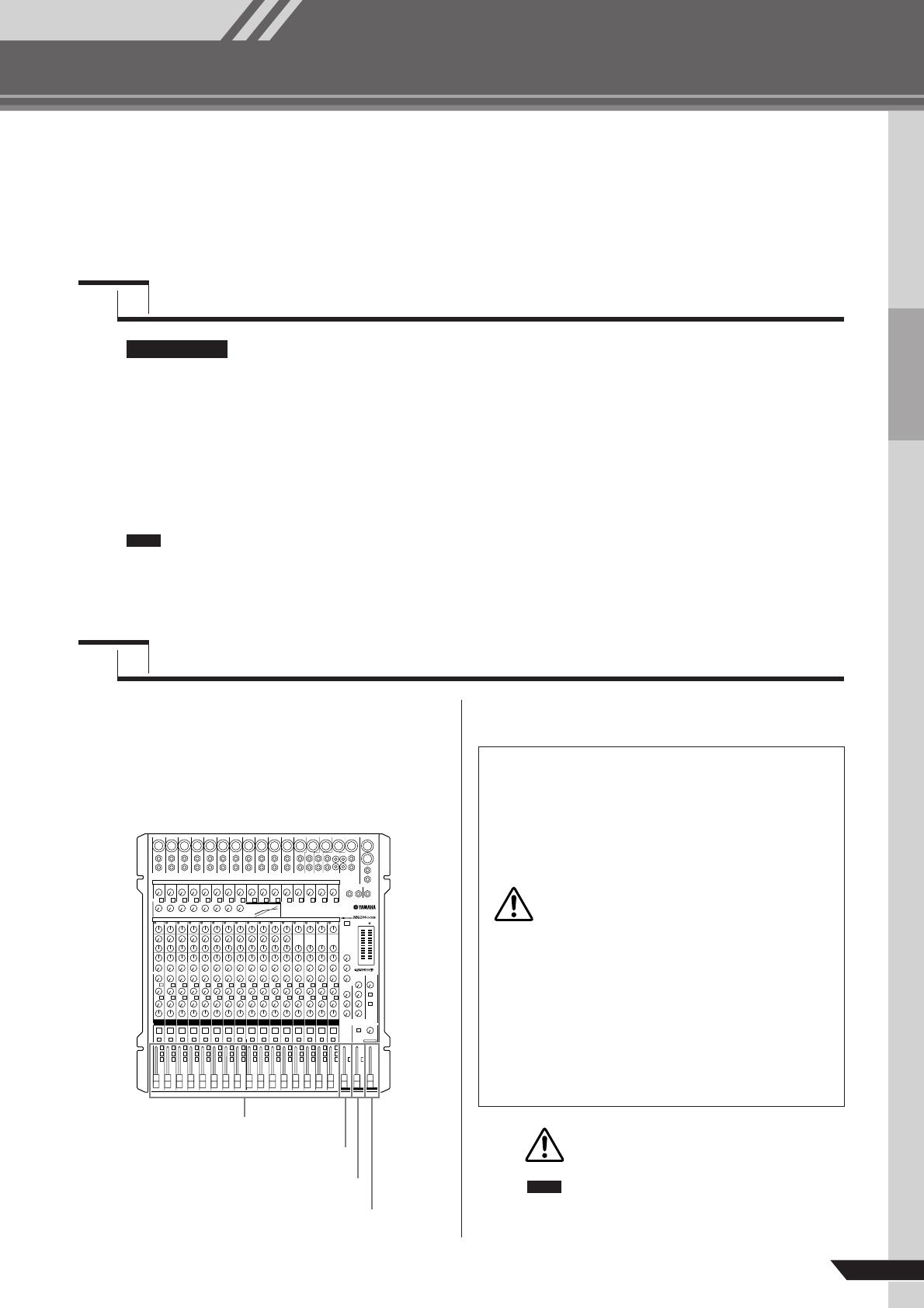
МИКШЕРНЫЙ ПУЛЬТ
Отличительные особенности
Входные каналы ………………………стр. 12
Благодаря микрофонным / линейным входам (до
16-ти) (MG166CX/MG166C: 10) или стереофониче-
ским входам (до четырех), к микшеру MG можно
одновременно подключать самые разнообразные
устройства: микрофоны, устройства линейного
уровня, стереофонические синтезаторы и прочее.
Компрессия……………………………….стр. 10
Компрессия повышает общий уровень без привне-
сения искажений при сжатии очень сильных пиков
сигнала от микрофонов и гитар.
Передачи AUX и возврат
стерофонического сигнала AUX .стр. 16
Можно воспользоваться разъемом AUX SEND для
подачи передаваемого сигнала на внешнее устрой-
ство обработки сигналов, а затем возвращать обра-
ботанный стереофонический сигнал через разъем
RETURN.
Высококачественные цифровые
эффекты (MG166CX) ……………стр. 15, 19
С помощью встроенных цифровых эффектов
MG166CX способен выдавать широкий диапазон
вариаций звука, которые все он формирует само-
стоятельно.

MG206C/MG166CX/MG166C Руководство пользователя
2
MG206C/MG166CX/MG166C Руководство пользователя
3
МЕРЫ ПРЕДОСТОРОЖНОСТИ
ПОЖАЛУЙСТА, ВНИМАТЕЛЬНО ПРОЧИТАЙТЕ
ПЕРЕД НАЧАЛОМ ЭКСПЛУАТАЦИИ УСТРОЙСТВА.
* пожалуйста, храните это руководство в надежном месте, чтобы при необходимости вы могли к нему обратиться.
ВНИМАНИЕ
ОСТОРОЖНО
Электропитание/Сетевой кабель
Не открывайте
Внимание вода
Устройство работает неправильно
Электропитание/Сетевой кабель
Местоположение
Чтобы избежать серьезной травмы или летального исхода от электрического тока, короткого замыкания,
пожара и др., всегда соблюдайте ниже перечисленные меры предосторожности.
Эти меры включают, но не ограничены, следующим
:
Перед использованием убедитесь, что сетевое напряжение •
соответствует напряжению питания усилителя. Требуемое
напряжение указано на корпусе устройства.
Используйте только адаптер питания AC (PA-30) или анало- •
гичный, рекомендуемый Yamaha.
Не размещайте шнур питания вблизи источников высокой •
температуры типа обогревателей и радиаторов. Во избежа-
ние повреждения шнура питания чрезмерно не перегибайте
его и не ставьте на него тяжелые предметы.
Не открывайте устройство и не пытайтесь разбирать вну- •
тренние детали или что-либо переделывать во внутренней
схеме инструмента. Прибор не содержит никаких пригодных
к эксплуатации пользователем деталей. Если Вам кажется,
что устройство работает неправильно, немедленно прекра-
тите использование и пригласите квалифицированного спе-
циалиста фирмы Yamaha.
Не оставляйте устройство под дождем, не используйте его вблизи •
источников влаги и не размещайте возле всевозможных емкостей
содержащих жидкости, которые могли бы пролиться на прибор.
Никогда не вставляйте и не вынимайте электрическую вилку •
влажными руками.
Если сетевой шнур или вилка оказываются потертыми или •
поврежденными, если нет звука во время использования
устройства, если появляются специфические запахи или
дым, которые, как Вам кажется, вызваны неисправностью
устройства, немедленно отключите питание, отсоедините
электрическую вилку от розетки, и доставьте устройство для
осмотра квалифицированному обслуживающему персоналу
фирмы Yamaha.
Если устройство упало или повреждено, немедленно отклю- •
чите питание, отсоедините кабель питания от розетки и пре-
доставьте устройство для осмотра квалифицированному об-
служивающему персоналу фирмы Yamaha.
Всегда следуйте основным мерам предосторожности, перечисленным ниже, чтобы избежать потенциаль-
ной опасности или повреждения самого устройства. Эти меры включают, но не ограничены, следующим:
Не оставляйте устройство включенным в сеть во время гро- •
зы. Также выключайте его, если в течение длительного вре-
мени не будете им пользоваться
Не тяните за шнур при отключении кабеля питания, всегда •
держите непосредственно вилку.
Во избежание нежелательного шума, удостоверьтесь, что •
расстояние между адаптером питания и микшером не ме-
нее 50 см
Не накрывайте сетевой кабель тканью или одеялом. •
Перед перемещ • ением устройства, отсоедините все подклю-
ченные к нему кабели.
Устанавливая устройство, оставьте достаточно места для •
свободного доступа к розетке электропитания, чтобы при не-
обходимости легко отключить вилку от розетки. Даже когда
выключатель питания отключен, внутри устройства остается
электричество. Если вы не используете продукт длительное
время, выключайте его сетевой кабель из розетки.
Если это устр • ойство монтируется в стойку стандарта EIA,
оставьте заднюю часть стойки открытой и убедитесь, что за
ней есть свободное пространство не менее 10 см. Также если
данное устройство монтируется вместе с другими устройства-
ми, выделяющими тепло, например, усилителями мощно-
сти, сохраняйте достаточно свободного пространства между
устройством и источником тепла или установите вентиляци-
онные панели, чтобы предотвратить чрезмерное повышение
температуры устройств. Недостаточная вентиляция может при-
вести к перегреву устройств и их выходу из строя или даже
к пожару.
Не устанавливайте все контроллеры эквалайзера и контролле- •
ры уровня – LEVEL на максимум. В зависимости от состояния
подключенных устройств, это может вызвать обратную связь
и повредить динамики.
Не устанавливайте инструмент в помещениях с повышенной •
влажностью или запыленностью, под прямыми солнечными
лучами или в зоне вибрации, вне помещения или рядом с на-
гревательными приборами. Установка в таких местах может
повлечь за собой деформацию панели и повреждение внутрен-
них компонентов.
Не ставьте устройство на неустойчивую поверхность, оно мо- •
жет случайно упасть.
Не закрывайте вентиляционные отверстия. Данное устройство •
имеет вентиляционные отверстия на нижней и задней стенке
для предотвращения внутреннего перегрева. В частности не
ставьте устройство на бок и не переворачивайте его. Недо-
статочная вентиляция может привести к перегреву устройства
и его выходу из строя или даже к пожару.
Не используйте устройство возле телевизоров, радиоприем- •
ников, стереофонического оборудования, мобильного телефо-
на, или других электрических устройств. Это может привести
к возникновению помех непосредственно в устройстве и в при-
борах находящихся вблизи.
MG206C/MG166CX/MG166C Руководство пользователя
4
Подключение Предосторожности при работе
Перед соединением системы с другими устройствами, вы- •
ключите питание на всех устройствах. Перед включением
или выключением питания каких-либо устройств, установи-
те все уровни громкости на минимум.
При включении питания Вашей звуковой системы, данное •
устройство всегда включайте ПОСЛЕДНИМ, чтобы избе-
жать повреждения громкоговорителей. При выключении пи-
тания, устройство должно быть выключено ПЕРВЫМ по той
же причине.
Не вставляйте пальцы или руки в отверстия устройства. •
Избегайте попадания инородных предметов в корпус устрой- •
ства (бумаги, пластмассовых или металлических объектов,
и т.д.) Если это произошло, немедленно отключите питание
и отсоедините сетевой шнур. Затем дайте осмотреть устрой-
ство квалифицированным специалистам от Yamaha.
Не используйте устройство в течение длительного периода •
времени на высоком уровне громкости, так как это может
привести к потере слуха. Если Вы испытываете какие-либо
проблемы со слухом, проконсультируйтесь с врачом.
Не давите своим весом на устройство, и не размещайте •
на нем тяжелых предметов, а также чрезмерно не давите
на кнопки, выключатели или гнезда.
Разъемы XLR-типа распаяны следующим образом: контакт 1 — земля, контакт 2 — «горячий» (+), контакт 3 — «холодный» (—).
Вставляемые штекеры TRS-типа распаяны следующим образом: рукав — земля, наконечник — посыл, кольцо — возврат.
Yamaha не несет ответственности за ущерб, вызванный неправильной эксплуатацией или моди
фикациями устройства.
Всегда выключайте питание, когда не пользуетесь устройством.
Даже когда выключатель питания находится в положении STANDBY, небольшое напряжение все же поступает на модуль. Отключайте
кабель от розетки, если в течение длительного времени не будете пользоваться микшером.
Работа компонентов с перемещающимися контактами, типа выключателей, контроллеров громкости и гнезд, постепенно ухудшается. Про-
консультируйтесь с квалифицированным обслуживающим персоналом о возможности замены дефектных компонентов.
При работе, микшер может нагреваться от 15 до 200С. Это нормально. Обратите внимание, что температура панели может превы-
шать 500С при температуре окружающей среды более 300С. Примите все необходимые меры для предотвращения возгорания.
* Данное руководство по эксплуатации относится к моделям MG206C/MG166CX/MG166C. Основное различие между этими тре-
мя моделями заключается в количестве входных каналов и наличии внутренних эффектов. MG206C имеет 20 входных каналов,
а MG166CX/MG166C имеют по 16 каналов. И только MG166CX имеет внутренние эффекты.
* В данном руководстве термин «микшеры MG» относится к моделям MG206C, MG166CX и MG166C.
* Иллюстрации в руководстве служат только в информативных целях и могут не соответствовать реальному устройству во время работы.
* Названия компаний и названия изделий–торговые марки или зарегистрированные торговые марки их соответствующих владельцев.
Копирование коммерческой музыки или аудио данных для других целей кроме личного использования строго запрещено в соответствии
с законом об авторском праве. Пожалуйста, уважайте авторские права, и проконсультируйтесь со специалистом по авторским правам,
если у Вас возникли сомнения в допустимости использования музыкального продукта.
Технические характеристики в руководстве служат только в информативных целях и могут не соответствовать реальному устройству
во время работы. Компания Yamaha оставляет за собой право изменять данные и технические характеристики устройств без пред-
варительного уведомления
MG206C/MG166CX/MG166C Руководство пользователя
5
Введение ……………………………………..5
Содержание…………………………………………….5
Перед включением микшера……………………5
Включение питания…………………………………5
Основы работы микшера……..6
Краткое руководство……………………6
Оптимальное использование микшера…..8
Разница между понятиями
«балансный» и «небалансный»……………..8
Уровни сигнала и децибел……………………….8
Использовать или не использовать эквалайзер…..9
Обстановка……………………………………………10
Эффекты модуляции:
Фазер, хорус и фленджер……………………10
Компрессия…………………………………………..10
Справочная информация…….11
Установка……………………………………11
Передняя и задняя панель………….12
Блок управления каналами……………………12
Цифровые эффекты………………………………15
Блок центрального управления………………16
Список программ цифровых эффектов
(только в модели MG166CX)……………….19
Список разъемов…………………………………..19
Устранение неисправностей………20
Характеристики…………………………..21
Комплектация
t Руководство пользователя
t Адаптор переменного тока (PA-30)*
* Может не поставляться в комплекте, в зависимости от региона.
Пожалуйста, проконсультируйтесь с представителем
компании Yamaha.
Введение
1
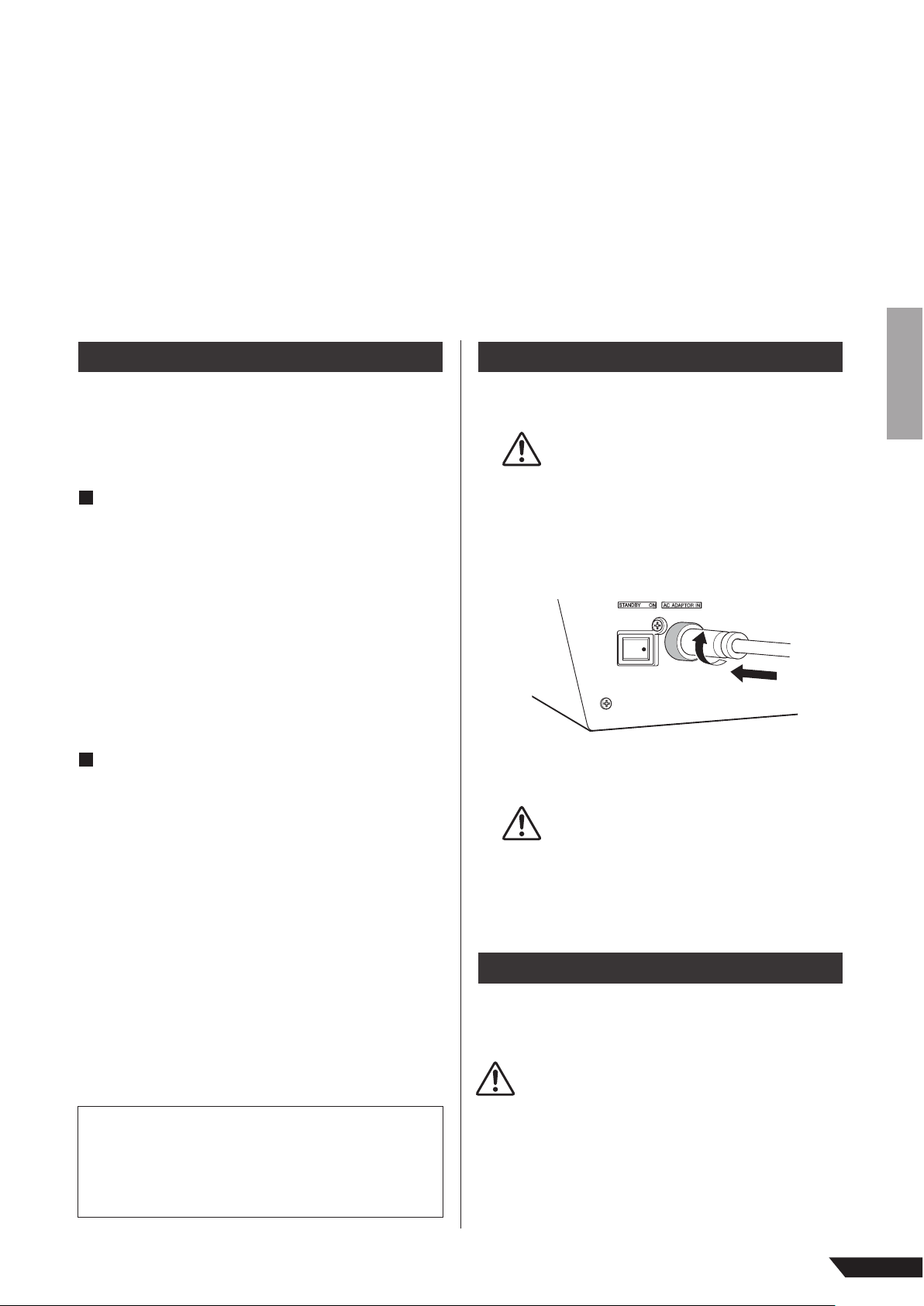
Убедитесь, что кнопка включения питания
микшера находится в положении STANDBY
Используйте только прилагающийся сетевой
адаптер (PA-30) или эквивалентный, рекомен-
дованный компанией Yamaha. Использование
другого адаптера может повлечь за собой
повреждение оборудования, перегрев или
возгорание
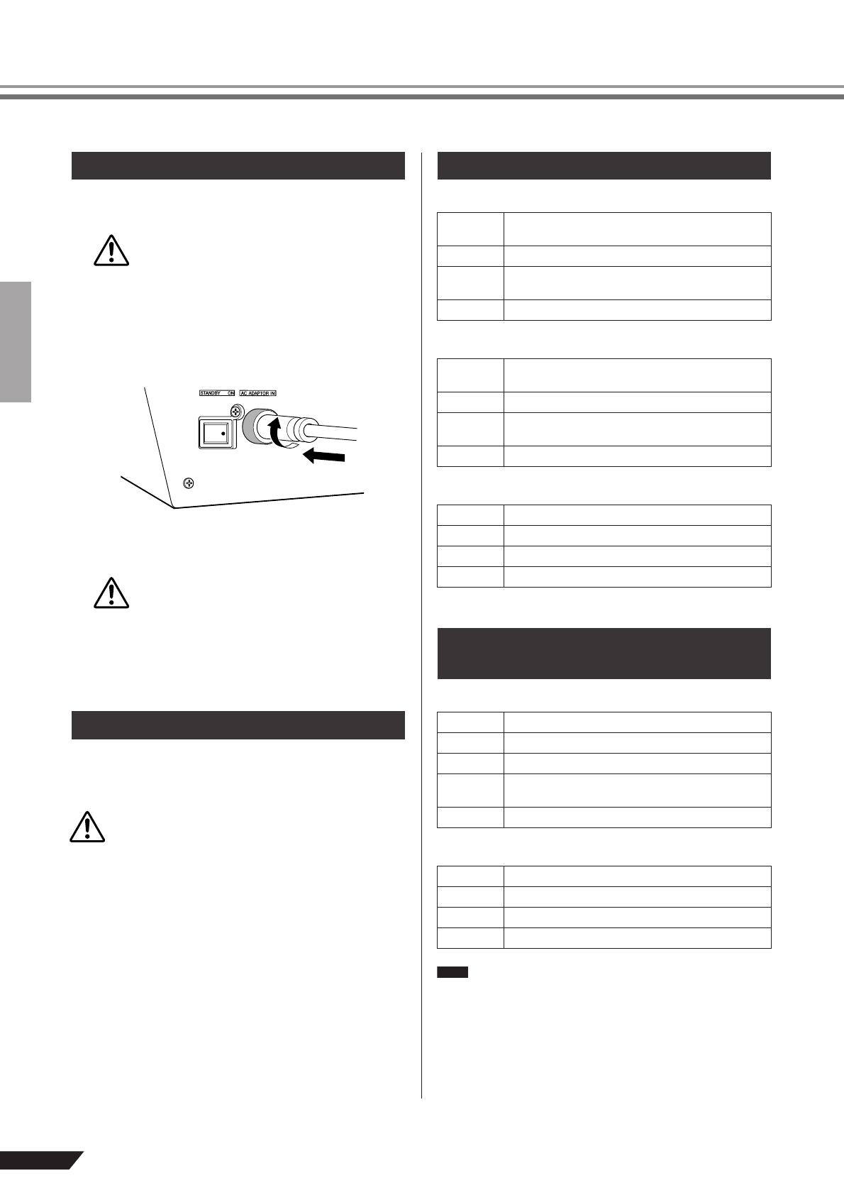
2
Подключите сетевой адаптер к разъему AC
ADAPTOR IN (q) на задней панели микшера,
а затем поверните закрепляющее кольцо
по часовой стрелке (w), чтобы гарантировать
соединение
3
Включите сетевой адаптер в стандартную
бытовую розетку.
t Обязательно отключайте микшер от сети,
если не планируете его некоторое время
использовать, а также во время грозы.
t Чтобы избежать появления нежелательного
шума, следите за тем, чтобы между сетевым
адаптером и микшером было расстояние
не менее 50 см.
Переведите кнопку питания микшера в положение ON.
Для выключения питания переведите кнопку питания
в положение STANDBY.
Обратите внимание, что когда переключатель нахо-
дится в положении STANDBY, в систему продолжает
поступать остаточный ток. Если микшер не плани-
руется использовать в ближайшее время,
отключите его от сети.
Перед включением микшера
Включение питания
CAUTION
q
w
CAUTION
CAUTION
Содержание
Благодарим за приобретение микшерной консоли YAMAHA MG206C/MG166CX/MG166C.
MG206C/MG166CX/MG166C оснащены входными каналами, дающими возможность широкого спектра
применений. Модель MG166CX обладает высококачественными встроенными эффектами для создания
отличного звучания. Микшер предлагает обширные возможности применения при легкости в управле-
нии. Для максимального использования превосходных возможностей микшера и безотказной работы
в течение многих лет внимательно прочтите это руководство пользователя до начала эксплуатации.
Пожалуйста, сохраните данное руководство для дальнейшего применения.
MG206C/MG166CX/MG166C Руководство пользователя
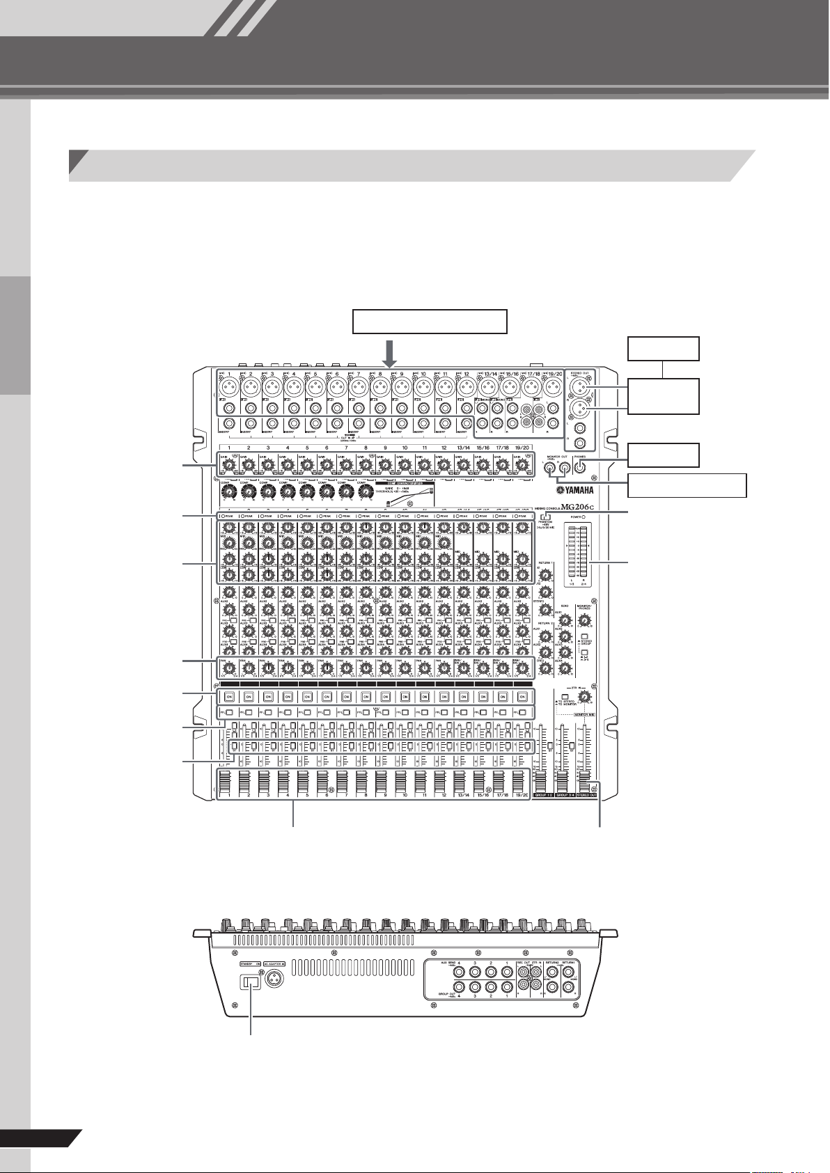
Основы работы микшера
6
Краткое руководство
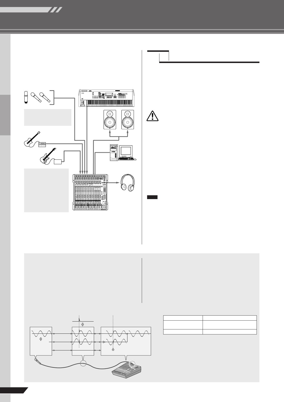
Сначала подсоедините колонки и подайте на них стереосигнал. В некоторых случаях
(в зависимости от типа источника сигнала) необходимые действия могут отличаться
от нижеприведенных.
Подача звука на динамики
Переключатели
панорама/баланс
1 , 4
Регуляторы
усиления
4
Индикаторы пиков
Эквалайзер
5
Переключатели
включения
каналов
4
Переключатели
предмикшерного
контроля
5
Переключатели
тонального
сигнала
1 , 7 Фейдеры каналов
4 , 7
Счетчик уровня
3
Переключатель
фантомного питания
Микрофоны, инструменты
2
Колонки
Усилитель
мощности
2
Наушники
2 , 4
Мониторные колонки
1 , 6 , 7 Основной фейдер стерео-выхода
MG206C
1 , 3 Выключатель питания
Mixer Basics
Основы работы микшера
Краткое руководство
MG206C/MG166CX/MG166C Руководство пользователя
7
1
2
3
4
5
6
7
ПРИМ.
ПРИМ.
CAUTION
ПРИМ.
ПРИМ.
Убедитесь, что микшер выключен,
а все регуляторы уровней* находятся
в крайнем нижнем положении.
*Основной фейдер STEREO OUT, фейдеры каналов, ре-
гуляторы GAIN, и т.д.
Установите регуляторы эквалайзера и PAN/
BAL в положение .
Отключите все остальные внешние
устройства, после чего подсоедините
микрофоны, инструменты и динами-
ки.
Для получения информации о подключении •
внешних устройств см. «Пример подключе-
ния» на странице 11.
Подключайте электрогитары и бас-гитары •
через промежуточное устройство, например,
директ-бокс, предусилитель или симулятор
усилителя. Прямое подключение этих ин-
струментов к микшеру MG может привести к
ухудшению звучания и к образованию шума.
Во избежание повреждения динами-
ков включайте устройства в следую-
щем порядке: периферийные устрой-
ства → микшер MG → усилители мощ-
ности (или активные динамики). При
выключении питания порядок обрат-
ный.
При использовании конденсаторных микро-
фонов, которым требуется фантомное пита-
ние, включайте переключатель фантомного
питания на микшере MG перед включением
питания усилителя мощности или активных
динамиков. Более детальная информация
приведена на стр. 17.
Установите регуляторы GAIN каналов
в такое положение, чтобы соответ-
ствующие индикаторы PEAK загора-
лись на короткое время на максималь-
ных уровнях.
Чтобы использовать указатель уровня и по-
лучать точную информацию об уровне входя-
щего сигнала, поместите кнопку PFL (пред-
микшерный контроль) канала во включенное
положение. Установите регуляторы GAIN в та-
кое положение, чтобы индикатор уровня ино-
гда поднимался выше уровня “ ” (0). Обратите
внимание, что выход PHONES посылает пред-
микшерный сигнал со всех каналов, на кото-
рых включена кнопка PFL, чтобы эти сигналы
можно было контролировать через наушники.
Нажмите кнопки ON и ST всех исполь-
зуемых каналов.
Установите основной фейдер STEREO
OUT в положение “0”.
Установите фейдеры каналов таким
образом, чтобы создать желаемый
начальный баланс, а затем отрегули-
руйте общую громкость, используя
основной фейдер STEREO OUT.
Чтобы использовать указатель уровня для •
определения уровня шин STEREO L/R (сте-
рео левый/правый), установите переключа-
тель PFL в положение “выкл.”, а переклю-
чатель MONITOR (монитор) – в положение
STEREO (стерео).
Если индикатор PEAK загорается часто, не- •
много уменьшите установку фейдеров ка-
налов, чтобы избежать искажения звука.
MG206C/MG166CX/MG166C Руководство пользователя
Основы работы микшера
8
Оптимальное использование микшера
Горячий(+)
Холодный (–)
Земля
Источник
Кабель
Шум удален
Бесшумный
сигнал
Инверсия
фазы
Приемное
устройство
Инверсия
фазы
Подведем итог
Микрофоны
Короткие
провода
Длинные
провода
Шум
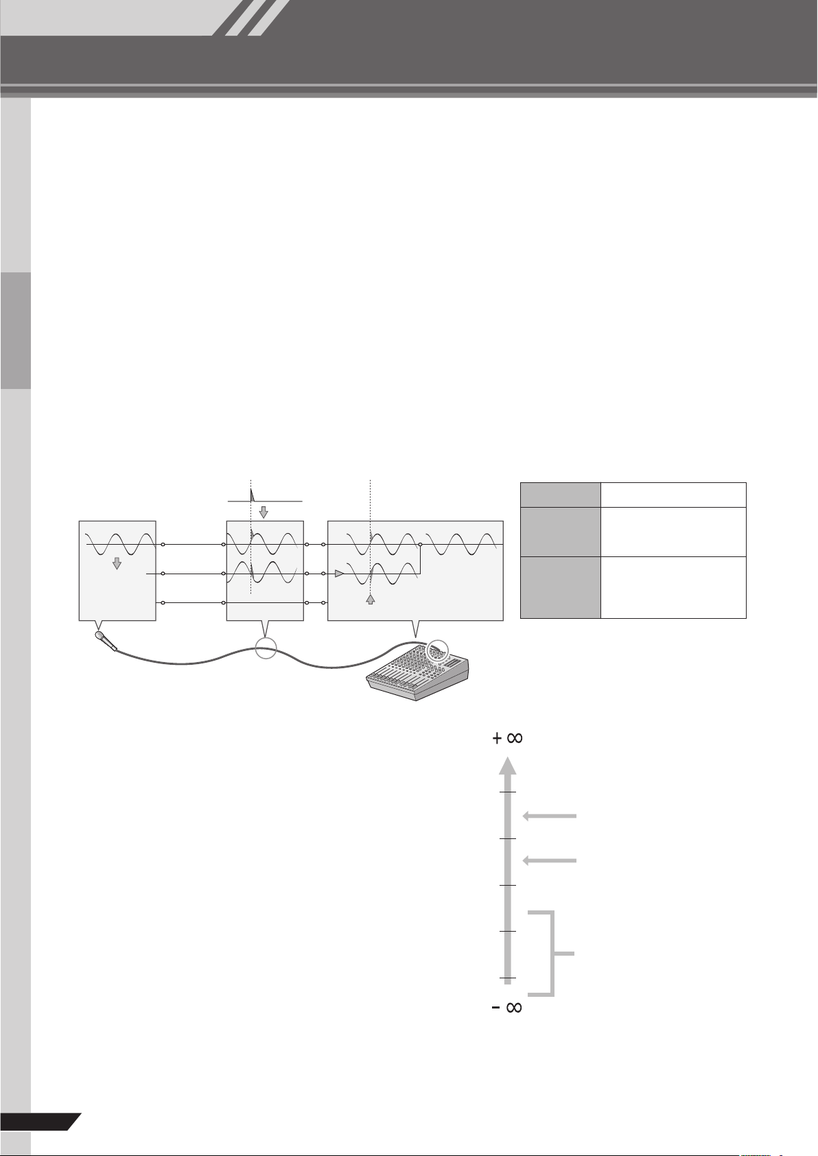
Балансное подавление шума
+ 20 дБе
0 дБе
0.775 В
—
20 дБе
—
40 дБе
—
60 дБе
Входы и выходы на домашней
аудиоаппаратуре обычно имею
номинальный уровень
–7.8 дБе (–10 дБВ).
Большинство профессиональны
микшеров, усилителей мощност
и других устройств имеют
номинальный уровень входа и
выхода +4 дБе.
Уровни сигнала микрофонов
бывают различными в
зависимости от типа
микрофона и источника.
Средний уровень речи
около –30 дБе, щебетание птиц
может быть ниже –50 дБе,
в то время как басовый барабан
может производить уровень до
0 дБе.
Используйте симметричные
линии.
Несимметричные линии
допустимы в относительно
свободной от шума
обстановке.
Уровень внешнего электро-
магнитного шума – решаю-
щий фактор, но симметрич-
ные линии являются
предпочтительными.
Вы приобрели микшер и готовы использовать его.
Достаточно ли все подключить, произвести настройки и начинать работу?
Если у Вас уже имеется подобный опыт, то проблем возникнуть не должно.
Если же Вы впервые работаете с микшером, рекомендуем внимательно изучить данное вводное руковод-
ство и выучить несколько основных правил, которые помогут эффективно использовать микшер и доби-
ваться оптимального сведения.
Разница между понятиями «балансный» и «небалансный»
Одним словом: «шум». Основная суть симметричных (балансных) линий заключается в подавлении шума. При любой
длине провод работает как антенна и собирает случайное электромагнитное излучение, которое постоянно окружает нас:
радио- и телесигналы, равно как случайный электромагнитный шум, вырабатываемый линиями электропередач, мотора-
ми, бытовыми электроприборами, компьютерными мониторами и другими разнообразными источниками. Чем длиннее
провод, тем больше шума он, вероятнее всего, соберет. Поэтому симметричные линии – лучший выбор при использовании
длинного кабеля. Если Ваша «студия», в целом, ограничивается рабочим столом, а все соединения не превышают метра
или двух, то может быть использована несимметричная (небалансная) линия (но только при условии, что в помещении нет
высокого уровня электромагнитного шума). Кроме того, симметричные линии чаще всего используются в проводах микро-
фонов. Причина состоит в том, что уровень выходного сигнала с большинства микрофонов очень низок, поэтому даже не-
заметное количество шума считается для данной системы большим и, кроме того, в мощном предусилителе микшера оно
будет увеличиваться до значительной степени.
Уровни сигнала и децибел
Рассмотрим одну из наиболее широко используемых еди-
ниц измерения звука: децибел (дБ). Если малейшему раз-
личаемому человеком звуку присвоить условное значение
1, то самый громкий звук, который может услышать чело-
век, будет приблизительно в 1 000 000 (один миллион) раз
громче. Слишком много цифр для практических расчетов,
поэтому для измерений, связанных со звуком, была соз-
дана более подходящая единица — «децибел» (дБ). В этой
системе разница между самым мягким и самым громким
звуками, которые могут быть различимы человеком, со-
ставляет 120 дБ. Это нелинейная шкала, и разница в 3 дБ
ведет к увеличению или уменьшению громкости в два раза.
Встречается несколько различных дБ: дБе, дБВ, дБМ и
другие, но основной единицей децибелов является дБе. «0
дБе» соответствует уровню сигнала в 0,775 вольта. Напри-
мер, если выходной уровень микрофона -40дБе (0,00775 В),
чтобы поднять этот уровень до 0 дБе (0,775 В) на стадии
предусиления микшером, необходимо усиление сигнала в
100 раз. Может возникнуть необходимость работы микшера
с широким диапазоном разноуровневых сигналов, поэтому
нужно выравнивать входной и выходной уровни настолько
точно, насколько это возможно. Чаще всего «номинальный»
уровень для входа и выхода микшера указан на панели или
в руководстве пользователя.
Основы работы микшера
Краткое руководство
MG206C/MG166CX/MG166C Руководство пользователя
Оптимальное использование микшера
9
20 50 100 200 500 1 k 2 k 5 k 10 k 20 k
(
Hz
)
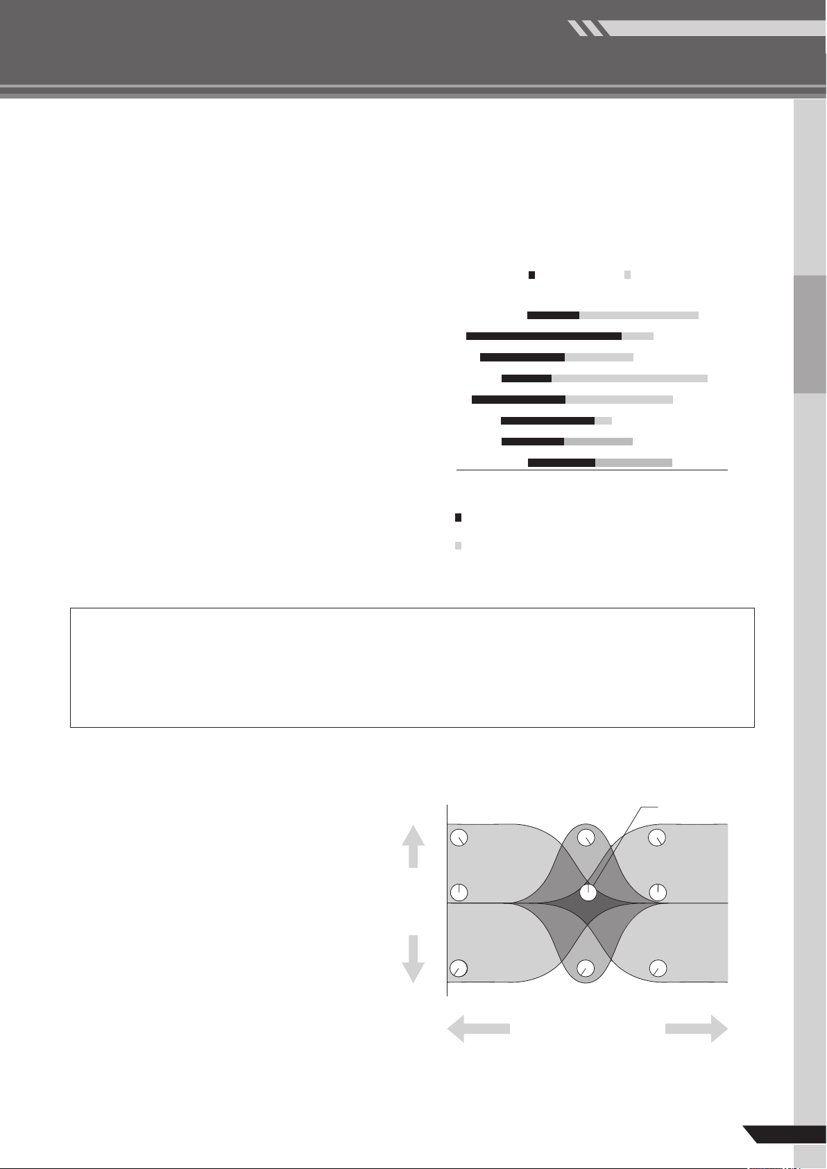
Фундаментальные и гармонические частотные диапазоны
некоторых музыкальных инструментов
Фортепиано
Басовый барабан
Рабочий (малый) барабан
Бас-гитара (контрабас)
Гитара
Тромбон
Труба
Тарелки
Фундаментальные: частоты, определяющие высоту
основного тона.
Гармонические: многократные волны фундаментальной
частоты, которые играют важную роль
в определении тембра инструмента.
Частота (Гц)
Увеличение
низких частот
Средний
уровень
низких
частот
Увеличение
средних частот
Средний уровень
средних частот
Увеличение
высоких частот
Средний уровень
высоких частот
Срез высоких
частот
Срез средних частот
Срез низких
частот
Сигнал
Уровень (дБ)
Использовать или не использовать эквалайзер
В целом, чем меньше используется эквалайзер, тем лучше. Существует много ситуаций, в которых приходится срезать
определенные частотные диапазоны, при этом поднимать уровень частот следует с расчетом и осторожностью. Правиль-
ное использование эквалайзера может устранить взаимное влияние инструментов в сведении и придать общему звучанию
большую четкость. В случае плохой эквализации (а чаще всего, плохого поднятия уровня частот) качество звучания будет
крайне низким.
Срез частот для более чистого сведения
Пример: тарелки обладают в среднем и низком диапазоне ча-
стот большой энергией, которая в реальности не воспринимает-
ся как звук музыки, но которая может влиять на чистоту других
инструментов в этих диапазонах. Теоретически можно полно-
стью убрать низкие частоты на каналах тарелок, не изменив
при этом их звучание в сведении. Однако заметная разница за-
ключается в том, что сведение будет звучать более «объемно»,
а инструменты в более низких диапазонах будут звучать более
четко. Как не странно, фортепиано также обладает необычай-
но мощными низкими частотами, уменьшив уровень которых
можно более эффективно использовать другие инструменты – в
частности, барабаны и бас-гитару. Естественно, это не следу-
ет делать, если фортепиано играет соло-партию. Для басового
барабана и бас-гитар действует противоположное правило: за-
частую имеет смысл уменьшить уровень высоких частот, что-
бы создать больший объем сведения без нарушения звучания
инструментов. Однако в каждом случае нужно ориентироваться
по ситуации, поскольку иногда требуется слышимое звучание
«щелчков» бас-гитары.
Некоторые данные о частоте
Считается, что самая низкая и самая высокая частоты, которые могут быть различимы человеческим
ухом, находятся примерно на уровне 20 Гц и 20000 Гц соответственно. Среднестатистический разговор
происходит в диапазоне ориентировочно 300-3000 Гц. Частота стандартного камертона, который используется
для настройки гитар и других инструментов – 440 Гц (что соответствует клавише «ля» третьей октавы на
фортепиано концертного строя). Увеличьте эту частоту до уровня 880 Гц, и Вы получите тон на октаву выше
(т.е. «ля» третьей октавы на клавиатуре фортепиано). Точно так же можно уменьшить частоту до 220 Гц,
чтобы получить «ля» второй октавы, т.е. на октаву ниже.
Увеличивайте уровень
с осторожностью
При создании особых или необычных эффектов мож-
но увеличивать уровень без ограничений. Но если
просто необходимо хорошее звучание в сведении,
следует поднимать уровень только очень маленькими
шагами. Минимальное увеличение уровня в среднем
диапазоне может придать вокалу больший эффект
присутствия, а небольшое увеличение высоких частот
может придать определенным инструментам больше
«объема». Прислушайтесь, и если инструменты зву-
чат нечетко, попытайтесь использовать уменьшение
уровня для удаления частот, которые создают бес-
порядок в сведении. Не пытайтесь поднять уровень
для достижения чистоты сведения! Одна из самых
больших проблем, связанных с излишним увеличе-
нием уровня частот, – это усиление сигнала, которое
увеличивает уровень шума и потенциально перегру-
жает всю схему.
 Loading…
Suggest us how to improve StudyLib
(For complaints, use
another form
)
Your e-mail
Input it if you want to receive answer
Rate us
1
2
3
4
5
Yamaha
MG166CX-USB Технические данные
Популярность:
2289 просмотры
Подсчет страниц:
2 страницы
Тип файла:
Размер файла:
2.54 Mb
RU
Руководство пользователя
МИКШЕРНЫЙ ПУЛЬТ
Отличительные особенности
Входные каналы ………………………стр. 12
Благодаря микрофонным / линейным входам (до
16-ти) (MG166CX/MG166C: 10) или стереофониче-
ским входам (до четырех), к микшеру MG можно
одновременно подключать самые разнообразные
устройства: микрофоны, устройства линейного
уровня, стереофонические синтезаторы и прочее.
Компрессия……………………………….стр. 10
Компрессия повышает общий уровень без привне-
сения искажений при сжатии очень сильных пиков
сигнала от микрофонов и гитар.
Передачи AUX и возврат
стерофонического сигнала AUX .стр. 16
Можно воспользоваться разъемом AUX SEND для
подачи передаваемого сигнала на внешнее устрой-
ство обработки сигналов, а затем возвращать обра-
ботанный стереофонический сигнал через разъем
RETURN.
Высококачественные цифровые
эффекты (MG166CX) ……………стр. 15, 19
С помощью встроенных цифровых эффектов
MG166CX способен выдавать широкий диапазон
вариаций звука, которые все он формирует само-
стоятельно.
МИКШЕРНЫЙ ПУЛЬТ Руководство пользователя Отличительные особенности Входные каналы ………………………стр. 12 Благодаря микрофонным / линейным входам (до 16-ти) (MG166CX/MG166C: 10) или стереофоническим входам (до четырех), к микшеру MG можно одновременно подключать самые разнообразные
2 MG206C/MG166CX/MG166C Руководство пользователя
МЕРЫ ПРЕДОСТОРОЖНОСТИ ПОЖАЛУЙСТА, ВНИМАТЕЛЬНО ПРОЧИТАЙТЕ ПЕРЕД НАЧАЛОМ ЭКСПЛУАТАЦИИ УСТРОЙСТВА. * пожалуйста, храните это руководство в надежном месте, чтобы при необходимости вы могли к нему обратиться. ВНИМАНИЕ Чтобы избежать серьезной травмы или летального исхода от электрического тока,
Подключение • Перед соединением системы с другими устройствами, выключите питание на всех устройствах. Перед включением или выключением питания каких-либо устройств, установите все уровни громкости на минимум. Предосторожности при работе • При включении питания Вашей звуковой системы, данное
Введение Благодарим за приобретение микшерной консоли YAMAHA MG206C/MG166CX/MG166C. MG206C/MG166CX/MG166C оснащены входными каналами, дающими возможность широкого спектра применений. Модель MG166CX обладает высококачественными встроенными эффектами для создания отличного звучания. Микшер предлагает
Основы работы микшера Краткое руководство Mixer Basics Подача звука на динамики Сначала подсоедините колонки и подайте на них стереосигнал. В некоторых случаях (в зависимости от типа источника сигнала) необходимые действия могут отличаться от нижеприведенных. 2 Микрофоны, инструменты Колонки 2
Основы работы микшера Краткое руководство 1 Убедитесь, что микшер выключен, а все регуляторы уровней* находятся в крайнем нижнем положении. *Основной фейдер STEREO OUT, фейдеры каналов, регуляторы GAIN, и т.д. ПРИМ. Установите регуляторы эквалайзера и PAN/ BAL в положение . 5 Нажмите кнопки ON и ST
Основы работы микшера Оптимальное использование микшера Вы приобрели микшер и готовы использовать его. Достаточно ли все подключить, произвести настройки и начинать работу? Если у Вас уже имеется подобный опыт, то проблем возникнуть не должно. Если же Вы впервые работаете с микшером, рекомендуем
Основы работы микшера Оптимальное использование Краткое руководство микшера Использовать или не использовать эквалайзер В целом, чем меньше используется эквалайзер, тем лучше. Существует много ситуаций, в которых приходится срезать определенные частотные диапазоны, при этом поднимать уровень частот
Основы работы микшера Краткое руководство Оптимальное использование микшера Обстановка Сведение может стать еще лучше после добавления эффектов обстановки, таких как реверберация (искусственное эхо) или задержка. Встроенные эффекты MG166CX’s могут использоваться для добавления реверберации или
Справочная информация Справочная информация Установка Характеристики Reference Гитара Задняя панель Записывающее устройство Процессор эффектов Активные мониторные колонки Бас-гитара CD-плеер Активные колонки Синтезатор Микрофон ДИ-бокс Процессор эффектов (эксайтер) Наушники Активные колонки MG206C
Справочная информация Передняя Передняя и задняя панелии задняя панель Блок управления каналами MG206C MG166CX/MG166C * Каналы 1 to 8 (Моно) 12 Каналы 9 to 12 (Моно) Каналы 13/14 and 15/16 (Стерео) Каналы 17/18 and 19/20 (Стерео) MG206C/MG166CX/MG166C Руководство пользователя MG166C : EFFECT m AUX3
Справочная информация Передняя и задняя панели MIC (микрофонные) входы “джек” Переключатель 80 (фильтр верхних частот) Симметричные входы XLR-типа (1: земля; 2: горячий; 3: холодный). Эта кнопка включает или выключает ФВЧ. Чтобы включить ФВЧ, нажмите на кнопку. ФВЧ убирает частоты ниже 80 Гц (ФВЧ
Справочная информация Передняя и задняя панели Регуляторы AUX (дополнительные), EFFECT (эффектов) Настраивают уровень сигнала, посылаемого с канала на шины AUX и EFFECT. Данные регуляторы обычно выставляются близко к положению “ ”. Эти элементы управления посылают либо сигнал с фейдера,
Справочная информация Передняя и задняя панели Цифровые эффекты * Цифровые эффекты поддерживаются только в модели MG166CX. Джековый вход для FOOT SWITCH (педали) К этому входу можно подключить педаль Yamaha FC5 (продается отдельно), которая используется для включения/выключения цифровых эффектов.
Справочная информация Передняя и задняя панели Блок центрального управления MG206C MG166CX/MG166C * Rear panel 16 MG206C/MG166CX/MG166C Руководство пользователя , MG166C : EFFECT m AUX3
Справочная информация Передняя и задняя панели Джековый выход PHONES (наушники) Джековые выходы SEND (посылы) (AUX, EFFECT) Эти сбалансированные по сопротивлению* стереоджековые TRSвыходы подают сигнал с шин AUX/EFFECT. При подключении системы мониторов, должна быть выбрана опция пре-фейдера, а
Справочная информация Передняя и задняя панели Течение сигнала для СВЕДЕНИЯ В МОНИТОРЕ Основные регуляторы SEND (AUX, EFFECT) (посылы) Настраивают уровень сигнала, посылаемого на джековые выходы SEND (AUX, EFFECT). ПРИМ. В модели MG166CX основной регулятор SEND (EFFECT) не влияет на уровень
Справочная информация Передняя и задняя панели Список программ цифровых эффектов (только в модели MG166CX) № Программа Параметр Описание 1 REVERB HALL 1 ВРЕМЯ РЕВЕРБЕРАЦИИ 2 REVERB HALL 2 ВРЕМЯ РЕВЕРБЕРАЦИИ Реверберация, имитирующая большое пространство, такое как концертный зал. 3 REVERB ROOM 1
Справочная информация Устранение неисправностей Микшер не включается Проверьте, правильно ли включен прилагаемый сетевой адаптер в подходящую стенную электророзетку. Правильно ли прилагаемый сетевой адаптер подключен к микшеру? Нет звука Правильно ли подключены микрофоны, внешние устройства и
Справочная информация Характеристики Характеристики MG206C Электрические характеристики Частотная характеристика STEREO OUT GROUP OUT AUX SEND MONITOR OUT, REC OUT Общее гармоническое исSTEREO OUT кажение (ОГИ + N) Фон и шум CH INPUT 1–12 MIC STEREO OUT GROUP OUT Фон и шум измеряются
Справочная информация Передняя и задняя панели Характеристики Характеристики аналогового входа Входы CH INPUT MIC (Каналы 1–12) Усиление Входное сопротивление Достаточное сопротивление -60 дБ 3kΩ 50–600Ω Микрофоны 10kΩ 600Ω Линии 3kΩ 50–600Ω Микрофоны 10kΩ 600Ω Линии 10kΩ 600Ω Линии
Справочная Справочная информация информация Передняя иХарактеристики задняя панели MG166CX/MG166C Электрические характеристики Частотная характеристика STEREO OUT МИН СРЕД МАКС -3.0 0.0 1.0 дБ +14 дБе на 20 Гц-20 кГц, регуляторы GAIN на входе — на минимуме 0.1 % GAIN: минимум (CHs 1-11/12) 20 Гц–20
Справочная информация Характеристики Характеристики аналогового входа Входы CH INPUT MIC (Каналы 1–8) CH INPUT LINE (Каналы 1–8) Усиление Входное сопротивление Достаточное сопротивление 3kΩ 50–600Ω Микрофоны 10kΩ 600Ω Линии 3kΩ 50–600Ω Микрофоны 10kΩ 600Ω Линии -60 дБ -16 дБ -34 дБ +10 дБ ST CH MIC
Справочная информация Характеристики Пространственные схемы (MG206C/MG166CX/MG166C) 444 102 5 488.5 496 98 478 43 41 Единица измерения: мм Установка на стойку Для установки микшера MG необходимо 12 единиц рэкового пространства. CAUTION Если микшер MG необходимо установить с устройствами, имеющими
(CH1 to 12) [-60 to -16dBu] MG206C/MG166CX/MG166C Руководство пользователя -60dBu -50dBu -40dBu -30dBu -20dBu -10dBu 0dBu +10dBu +20dBu +30dBu (CH17/18, 19/20) ST CH INPUT [6 to 50dB] [-10dBV] [-7.8dBu] 2TR IN R CH IN MIC Gain:Max [-60dBu] CH IN LINE Gain:Max [-34dBu] CH IN MIC Gain:Min [-16dBu] ST
[-60 to -16dBu] MG206C/MG166CX/MG166C Руководство пользователя -60dBu -50dBu -40dBu -30dBu -20dBu -10dBu 0dBu +10dBu +20dBu +30dBu (CH9/10, 11/12) L R L R CH IN MIC Gain:Max [-60dBu] CH IN LINE Gain:Max [-34dBu] CH IN MIC Gain:Min [-16dBu] CH IN LINE Gain:Min [+10dBu] FOOT SW EFFECT ON/OFF only
Yamaha Pro Audio global web site: http://www.yamahaproaudio.com/ Yamaha Manual Library http://www.yamaha.co.jp/manual/ U.R.G., Pro Audio & Digital Musical Instrument Division, Yamaha Corporation © 2007 Yamaha Corporation WJ74360 703POAP7.3-01A0 Printed in China
Owner’s Manual
Bedienungsanleitung
Mode d’emploi
Manual de instrucciones
EN
DE
FR
ES
EnglishDeutschFrançaisEspañol
Features
Input Channels………………………………………………………….page 16
With up to 16 (MG166CX-USB/MG166C-USB: 10) mic/line inputs
or up to four stereo inputs, the MG mixer can simultaneously
connect to a wide range of devices: microphones, line-level
devices, stereo synthesizers, and more.
Compression………………………………………………………………page 9
Compression increases the overall level without introducing
distortion by compressing excessive peaks in the signals from
microphones and guitars.
Cubase AI 4 DAW Software Supplied………………………….page 10
By connecting the MG mixer to the computer via a USB cable an
audio data mixed by the MG mixer can be recorded on Cubase AI
4.
High-quality digital effects (MG166CX-USB)………..pages 19, 23
With digital effects built in, the MG166CX-USB can deliver a wide
range of sound variations all by itself.
Caractéristiques
Canaux d’entrée………………………………………………………..page 64
Avec 16 entrées micro/ligne (MG166CX-USB/MG166C-USB: 10)
ou quatre entrées stéréo maximum, la console de mixage MG peut
connecter simultanément une grande variété d’appareils : micros,
appareils de ligne, synthétiseurs stéréo, etc.
Compression…………………………………………………………….page 57
La compression augmente le niveau général sans engendrer de
distorsion en comprimant les pics excessifs des signaux des
micros et des guitares.
Le logiciel DAW Cubase AI 4 fournit…………………………..page 58
En connectant la console de mixage MG à un ordinateur via un
câble USB, des donnés audio créées par la console de mixage MG
peuvent être enregistrées sur Cubase AI 4.
Effets numériques de qualité supérieure
(MG166CX-USB)…………………………………………………pages 67, 71
Grâce aux effets numériques intégrés, la console MG166CX-USB
peut proposer de nombreuses variations de sons.
Funktionen
Eingangskanäle…………………………………………………………Seite 40
Mit bis zu 16 Mikrofon-/Line-Eingängen (MG166CX-USB/MG166C-
USB: 10) oder bis zu vier Stereoeingängen können viele Geräte
gleichzeitig am MG-Mischpult angeschlossen werden: Mikrofone,
Geräte mit Leitungspegel, Stereo-Synthesizer uvm.
Kompression…………………………………………………………….Seite 33
Kompression erhöht den Durchschnittspegel, ohne Verzerrung
hinzuzufügen, indem übermäßige Pegelspitzen der Signale von
Mikrofonen oder Gitarren komprimiert werden.
DAW-Software Cubase AI 4 mitgeliefert………,…………….Seite 34
Wenn Sie Ihr MG-Mischpult über ein USB-Kabel am Computer
anschließen, können durch das MG-Mischpult gemischte
Audiodaten in Cubase AI 4 aufgenommen werden.
Hochwertige Digitaleffekte (MG166CX-USB)………..Seiten 43, 47
Mit den eingebauten digitalen Effekten kann das MG166CX-USB
aus sich heraus eine Reihe von Klangvariationen liefern.
Características
Canales de entrada…………………………………………………página 88
Con un máximo de 16 entradas de micrófono/línea (MG166CX-
USB/MG166C-USB: 10) o cuatro entradas estereofónicas, la
mezcladora MG puede conectarse simultáneamente con una gran
variedad de dispositivos: micrófonos, dispositivos de nivel de línea,
sintetizadores estereofónicos, etc.
Compresión……………………………………………………………página 81
La compresión aumenta el nivel general sin causar distorsión,
mediante la compresión del exceso de picos en las señales de los
micrófonos y guitarras.
El software DAW Cubase AI 4 suministrado…………….página 82
Al conectar la mezcladora MG con un ordenador por medio de un
cable USB, se puede grabar en Cubase AI 4 datos de audio
creados por la mezcladora MG.
Efectos digitales de alta calidad (MG166CX-USB)
…páginas 91, 95
Gracias a sus efectos digitales incorporados, la mezcladora
MG166CX-USB puede producir por sí misma una amplia gama de
variaciones de sonido.

MG206C-USB/MG166CX-USB/MG166C-USB Owner’s Manual
2
* This applies only to products distributed by Yamaha-Kemble Music (U.K.) Ltd. (2 wires)
* This applies only to products distributed by YAMAHA CORPORATION OF AMERICA. (FCC DoC)
IMPORTANT NOTICE FOR THE UNITED KINGDOM
Connecting the Plug and Cord
IMPORTANT. The wires in this mains lead are coloured in accordance with the following code:
BLUE : NEUTRAL
BROWN : LIVE
As the colours of the wires in the mains lead of this apparatus may not correspond with the coloured makings identifying the terminals
in your plug proceed as follows:
The wire which is coloured BLUE must be connected to the terminal which is marked with the letter N or coloured BLACK.
The wire which is coloured BROWN must be connected to the terminal which is marked with the letter L or coloured RED.
Making sure that neither core is connected to the earth terminal of the three pin plug.
COMPLIANCE INFORMATION STATEMENT
(DECLARATION OF CONFORMITY PROCEDURE)
Responsible Party : Yamaha Corporation of America
Address : 6600 Orangethorpe Ave., Buena Park, Calif. 90620
Telephone : 714-522-9011
Type of Equipment : Mixing Console
Model Name : MG206C-USB/MG166CX-USB/MG166C-USB
This device complies with Part 15 of the FCC Rules.
Operation is subject to the following two conditions:
1) this device may not cause harmful interference, and
2) this device must accept any interference received including interference that may cause undesired operation.
See user manual instructions if interference to radio reception is suspected.
1. IMPORTANT NOTICE: DO NOT MODIFY THIS UNIT!
This product, when installed as indicated in the instructions
contained in this manual, meets FCC requirements. Modifi-
cations not expressly approved by Yamaha may void your
authority, granted by the FCC, to use the product.
2. IMPORTANT: When connecting this product to accessories
and/or another product use only high quality shielded cables.
Cable/s supplied with this product MUST be used. Follow all
installation instructions. Failure to follow instructions could
void your FCC authorization to use this product in the USA.
3. NOTE: This product has been tested and found to comply
with the requirements listed in FCC Regulations, Part 15 for
Class “B” digital devices. Compliance with these require-
ments provides a reasonable level of assurance that your use
of this product in a residential environment will not result in
harmful interference with other electronic devices. This
equipment generates/uses radio frequencies and, if not
installed and used according to the instructions found in the
users manual, may cause interference harmful to the opera-
tion of other electronic devices. Compliance with FCC regula-
* This applies only to products distributed by YAMAHA CORPORATION OF AMERICA. (class B)
tions does not guarantee that interference will not occur in all
installations. If this product is found to be the source of inter-
ference, which can be determined by turning the unit “OFF”
and “ON”, please try to eliminate the problem by using one of
the following measures:
Relocate either this product or the device that is being
affected by the interference.
Utilize power outlets that are on different branch (circuit
breaker or fuse) circuits or install AC line filter/s.
In the case of radio or TV interference, relocate/reorient the
antenna. If the antenna lead-in is 300 ohm ribbon lead,
change the lead-in to co-axial type cable.
If these corrective measures do not produce satisfactory
results, please contact the local retailer authorized to distrib-
ute this type of product. If you can not locate the appropriate
retailer, please contact Yamaha Corporation of America,
Electronic Service Division, 6600 Orangethorpe Ave, Buena
Park, CA90620
The above statements apply ONLY to those products distrib-
uted by Yamaha Corporation of America or its subsidiaries.
FCC INFORMATION (U.S.A.)
MG206C-USB/MG166CX-USB/MG166C-USB Owner’s Manual
3
PRECAUTIONS
PLEASE READ CAREFULLY BEFORE PROCEEDING
* Please keep this manual in a safe place for future reference.
WARNING
Always follow the basic precautions listed below to avoid the possibility of serious injury or even death from electrical
shock, short-circuiting, damages, fire or other hazards. These precautions include, but are not limited to, the following:
• Only use the voltage specified as correct for the device. The required voltage is
printed on the name plate of the device.
• Use only the included power adaptor (PA-30 or an equivalent recommended by
Yamaha).
• Do not place the power cord near heat sources such as heaters or radiators, and
do not excessively bend or otherwise damage the cord, place heavy objects on
it, or place it in a position where anyone could walk on, trip over, or roll anything
over it.
• Do not open the device or attempt to disassemble the internal parts or modify
them in any way. The device contains no user-serviceable parts. If it should
appear to be malfunctioning, discontinue use immediately and have it inspected
by qualified Yamaha service personnel.
• Do not expose the device to rain, use it near water or in damp or wet conditions,
or place containers on it containing liquids which might spill into any openings.
• Never insert or remove an electric plug with wet hands.
• If the power cord or plug becomes frayed or damaged, or if there is a sudden
loss of sound during use of the device, or if any unusual smells or smoke
should appear to be caused by it, immediately turn off the power switch,
disconnect the electric plug from the outlet, and have the device inspected by
qualified Yamaha service personnel.
• If this device or the AC power adaptor should be dropped or damaged,
immediately turn off the power switch, disconnect the electric plug from the
outlet, and have the device inspected by qualified Yamaha service personnel.
CAUTION
Always follow the basic precautions listed below to avoid the possibility of physical injury to you or others, or damage
to the device or other property. These precautions include, but are not limited to, the following:
• Remove the electric plug from the outlet when the device is not to be used for
extended periods of time, or during electrical storms.
• When removing the electric plug from the device or an outlet, always hold the
plug itself and not the cord. Pulling by the cord can damage it.
•To avoid generating unwanted noise, make sure there is adequate distance (50
cm or more) between the AC power adaptor and the device.
• Do not cover or wrap the AC power adaptor with a cloth or blanket.
• Before moving the device, remove all connected cables.
• When setting up the device, make sure that the AC outlet you are using is easily
accessible. If some trouble or malfunction occurs, immediately turn off the
power switch and disconnect the plug from the outlet. Even when the power
switch is turned off, electricity is still flowing to the product all the minimum
level. When you are not using the product for a long time, make sure to unplug
the power cord from the wall AC outlet.
• If this device is to be mounted in an EIA-standard rack, leave the back of the rack
open and make sure that it is at least 10 cm away from walls or surfaces. Also, if
this device is to be mounted with devices that tend to generate heat, such as
power amplifiers, be sure to keep an adequate gap between this device and the
heat-generating devices or install ventilation panels to prevent high
temperatures from developing inside this device.
Inadequate ventilation can result in overheating, possibly causing damage to the
device(s), or even fire.
•Avoid setting all equalizer controls and faders to their maximum. Depending on
the condition of the connected devices, doing so may cause feedback and may
damage the speakers.
• Do not expose the device to excessive dust or vibrations, or extreme cold or heat
(such as in direct sunlight, near a heater, or in a car during the day) to prevent
the possibility of panel disfiguration or damage to the internal components.
• Do not place the device in an unstable position where it might accidentally fall
over.
• Do not block the vents. This device has ventilation holes at the bottom/rear to
prevent the internal temperature from becoming too high. In particular, do not
place the device on its side or upside down. Inadequate ventilation can result in
overheating, possibly causing damage to the device(s), or even fire.
• Do not use the device in the vicinity of a TV, radio, stereo equipment, mobile
phone, or other electric devices. Doing so may result in noise, both in the device
itself and in the TV or radio next to it.
• Before connecting the device to other devices, turn off the power for all devices.
Before turning the power on or off for all devices, set all volume levels to
minimum.
• When turning on the AC power in your audio system, always turn on the power
amplifier LAST, to avoid speaker damage. When turning the power off, the power
amplifier should be turned off FIRST for the same reason.
• Do not insert your fingers or hands in any gaps or openings on the device
(vents, etc.).
•Avoid inserting or dropping foreign objects (paper, plastic, metal, etc.) into any
gaps or openings on the device (vents, etc.) If this happens, turn off the power
immediately and unplug the power cord from the AC outlet. Then have the
device inspected by qualified Yamaha service personnel.
• Do not use the device or headphones for a long period of time at a high or
uncomfortable volume level, since this can cause permanent hearing loss. If you
experience any hearing loss or ringing in the ears, consult a physician.
• Do not rest your weight on the device or place heavy objects on it, and avoid use
excessive force on the buttons, switches or connectors.
Power supply/Power cord
Do not open
Water warning
If you notice any abnormality
Power supply/Power cord
Location
Connections
Handling caution
(5)-4 1/2

MG206C-USB/MG166CX-USB/MG166C-USB Owner’s Manual
4
Always turn the power off when the device is not in use.
Even when the power switch is in the “STANDBY” position, electricity is still flowing to the device at the minimum level. When you are not using the device for a long time,
make sure you unplug the power cord from the wall AC outlet.
The performance of components with moving contacts, such as switches, volume controls, and connectors, deteriorates over time. Consult qualified Yamaha service
personnel about replacing defective components.
The MG mixer may heat up by as much as 15 to 20°C while the power is on. This is normal. Please note that the panel temperature may exceed 50°C in ambient temperatures
higher than 30°C, and use caution to prevent burns.
* This Owner’s Manual applies to the MG206C-USB/MG166CX-USB/MG166C-USB. The main differences between the three models are the number of input channels and
whether the internal effects are included. The MG206C-USB has 20 input channels while the MG166CX-USB/MG166C-USB have 16 channels. And only the MG166CX-
USB has internal effects.
* In this manual the term “MG mixsers” refers to the MG206C-USB/MG166CX-USB/MG166C-USB.
Specifications and descriptions in this owner’s manual are for information purposes only. Yamaha Corp. reserves the right to change or modify products or specifications at
any time without prior notice. Since specifications, equipment or options may not be the same in every locale, please check with your Yamaha dealer.
SPECIAL NOTICES
• The owner’s manual is the exclusive copyright of Yamaha Corporation.
• The included software is the exclusive copyright of Steinberg Media Technologies GmbH.
• Use of the software and this manual is governed by the license agreement which the purchaser fully agrees to upon breaking the seal of the software packaging. (Please
read carefully the Software Licensing Agreement at the end of this manual before installing the application.)
• Copying of the software or reproduction of this manual in whole or in part by any means is expressly forbidden without the written consent of the manufacturer.
•Yamaha makes no representations or warranties with regard to the use of the software and documentation and cannot be held responsible for the results of the use of this
manual and the software.
• This disk is a DVD-ROM. Do not attempt to play the disk on a DVD player. Doing so may result in irreparable damage to your DVD player.
• Visit the web address below for the latest information on supplied software and operating system requirements.
<http://www.yamahasynth.com/>
The illustrations and LCD screens as shown in this owner’s manual are for instructional purposes only, and may appear somewhat different from those on your instrument.
This product incorporates and bundles computer programs and contents in which Yamaha owns copyrights or with respect to which it has license to use others’ copyrights.
Such copyrighted materials include, without limitation, all computer software, style files, MIDI files, WAVE data, musical scores and sound recordings. Any unauthorized use
of such programs and contents outside of personal use is not permitted under relevant laws. Any violation of copyright has legal consequences. DON’T MAKE, DISTRIBUTE
OR USE ILLEGAL COPIES.
Copying of the commercially available musical data including but not limited to MIDI data and/or audio data is strictly prohibited except for your personal use.
• Windows is the registered trademarks of Microsoft® Corporation.
• Apple and Macintosh are trademarks of Apple Computer, Inc., registered in the U.S. and other countries.
• Steinberg and Cubase are the registered trademarks of Steinberg Media Technologies GmbH.
• The company names and product names in this Owner’s Manual are the trademarks or registered trademarks of their respective companies.
Specifications and descriptions in this owner’s manual are for information purposes only. Yamaha Corp. reserves the right to change or modify products or specifications at
any time without prior notice. Since specifications, equipment or options may not be the same in every locale, please check with your Yamaha dealer.
XLR-type connectors are wired as follows (IEC60268 standard): pin 1: ground, pin 2: hot (+), and pin 3: cold (-).
Insert TRS phone jacks are wired as follows: sleeve: ground, tip: send, and ring: return.
Yamaha cannot be held responsible for damage caused by improper use or modifications to the device, or data that is lost or destroyed.
Copying of commercially available music or other audio data for purposes other than personal use is strictly prohibited by copyright law. Please respect all
copyrights, and consult with a copyright specialist if you are in doubt about permissible use.
MG206C-USB/MG166CX-USB/MG166C-USB Owner’s Manual
5
Introduction…………………………………… 5
Contents…………………………………………………..5
Before Turning on the Mixer ……………………….6
Turning the Power On/OFF…………………………6
Computer System Requirements…………………6
Cubase AI 4 System Requirements……………..6
■ Mixer Basics………………………….. 7
Quick Guide…………………………………… 7
1. Installing Cubase AI 4…………………………….7
2. Connecting to the MG mixer ……………………7
3. Powering Up the System ………………………..8
4. Adjusting Level and Tone ……………………….9
5. Recording with Cubase AI 4 ………………….10
6. Mixing with Cubase AI 4 ……………………….13
Introduction
Thank you for your purchase of the Yamaha MG206C-USB/MG166CX-USB/MG166C-USB mixing
console. The MG206C-USB/MG166CX-USB/MG166C-USB feature input channels suitable for a
wide range of usage environments. Furthermore, the mixer has the USB connector that enables you to
record an audio data mixed with the mixer on the included Cubase AI 4 DAW software.
Please read through this manual carefully before beginning use, so that you will be able to take full
advantage of this mixer’s superlative features and enjoy trouble-free operation for years to come.
Contents
■ Reference ……………………………. 15
Setup…………………………………………….15
Front & Rear Panels ………………………16
Channel Control Section…………………………..16
Digital Effects………………………………………….19
Master Control Section …………………………….20
Digital Effect Program List
(Only MG166CX-USB)…………………………..23
Jack List…………………………………………………23
Troubleshooting ……………………………24
Specifications ……………………………….99
About the accessory disk…………….106
SOFTWARE LICENSE AGREEMENT
…106
Accessories
• Cubase AI 4 DVD-ROM
• USB cable
• Owner’s Manual
•AC power adaptor (PA-30)*
*May not be included depending on your particular area. Please
check with your Yamaha dealer.
Introduction
MG206C-USB/MG166CX-USB/MG166C-USB Owner’s Manual
6
1
Be sure that the mixer’s power switch is in the
STANDBY position.
Use only the included power adaptor (PA-30) or
an equivalent recommended by Yamaha. Use of a
different adaptor may result in equipment dam-
age, overheating, or fire.
2
Connect the power adaptor to the AC ADAPTOR IN
connector (
q) on the rear of the mixer, and then
turn the fastening ring clockwise (
w) to secure the
connection.
3
Plug the power adaptor into a standard household
power outlet.
• Be sure to unplug the adaptor from the outlet
when not using the mixer, or when there are
lightning storms in the area.
•To avoid generating unwanted noise, make
sure there is 50 cm or more between the power
adaptor and the mixer.
Press the mixer’s power switch to the ON position.
When you are ready to turn the power off, press the
power switch to the STANDBY position.
Note that trace current continues to flow while the
switch is in the STANDBY position. If you do not plan
to use the mixer again for a long while, please be sure
to unplug the adaptor from the wall outlet.
Windows Vista
Windows XP
Macintosh
Windows
Macintosh
•A DVD driver is required for installation.
•To activate your software license, install the application
while the computer is connected to the internet.
Before Turning on the Mixer
Turning the Power On/OFF
CAUTION
q
w
CAUTION
CAUTION
Computer System Requirements
Computer
Windows-based computer with built-in USB inter-
face
OS Windows Vista
CPU
1 GHz or higher Intel Core/Pentium/Celeron proces-
sor
Memory 1 GB or more
Computer
Windows-based computer with built-in USB inter-
face
OS Windows XP Professional/XP Home Edition
CPU
750 MHz or higher Intel Core/Pentium/Celeron pro-
cessor
Memory 96 MB or more (128 MB or more recommended)
Computer Macintosh computer with built-in USB interface
OS MacOS X 10.3.3 or higher
CPU Macintosh G3 300 MHz or higher/Intel processor
Memory 128 MB or more
Cubase AI 4 System Require-
ments
OS Windows XP Professional/XP Home Edition
CPU 1.4 GHz or higher Intel Pentium processor
Memory 512 MB or more
Audio
Interface
Windows DirectX compatible
Hard Disk 400 MB or more
OS MacOS X 10.4 or higher
CPU Power Mac G4 1 GHz/Core Solo 1.5 GHz or higher
Memory 512 MB or more
Hard Disk 400 MB or more
Mixer Basics
MG206C-USB/MG166CX-USB/MG166C-USB Owner’s Manual
7
Quick Guide
This quick setup and operation guide covers everything from installing the Cubase AI 4 software to
using Cubase AI 4 for recording and mixdown. While going through this section you might find it
useful to also refer to the “Front and Rear Panels” section on page 16, as well as the pdf manual
supplied with the Cubase AI 4 software.
Since the End-User Software License Agreement (EUSLA) shown on your PC-display in your
installing the “DAW” software is replaced by the agreement at the end of this manual, you
should disregard the EUSLA. Read the Software License Agreement at the end of this man-
ual carefully, and install the software if you agree to it.
1
Start the computer and log on to the Administrator account.
2
Insert the included DVD-ROM into the computer’s DVD-ROM drive.
3
Open the “Cubase AI 4 for Windows” folder and double-click on the “CubaseAI4.msi”.
Follow the on-screen instructions to install the Cubase AI 4 software.
• When installing Cubase AI 4, you will need a working internet connection to register your Cubase AI 4. Make
sure to fill in all required fields for user registration. If you do not register the product, you will be unable to use
the application after a limited period of time expires.
•For a Macintosh computer, double-click the “CubaseAI4.mkpg” icon for installation.
1
Turn the power to the MG mixer and all
gear that is to be connected to the MG
mixer off/standby (except the computer),
and set the channel faders, STEREO OUT
Master fader, GROUP 1-2 fader and GROUP
3-4 fader to their minimum settings.
2
Connect the MG mixer to your computer
using the supplied USB cable.
When connecting or disconnecting the USB
cable be sure to turn the 2TR IN/USB control
all the way down.
Disconnect the USB cable when using the MG
mixer without the computer.
Step
1
Installing Cubase AI 4
IMPORTANT !
NOTE
Step
2
Connecting to the MG mixer
Channel fader
STEREO OUT Master fader
GROUP 3-4 fader
GROUP 1-2 fader
USB Connection Precautions
Be sure to observe the following points when connecting to
the computer’s USB interface.
Failure to observe these rules can result in computer freezes/
hang-ups and possibly data loss or corruption. If the MG
mixer or computer does hang up, turn the power to both
devices off and then on again, and restart the computer.
• Be sure to wake the computer from sleep/sus-
pended/standby mode before making a con-
nection to the computer’s USB connector.
• Connect the MG mixer to the computer before
turning the MG mixer power on.
•Always quit all applications running on the
computer before turning the MG mixer’s power
on or off, or connecting or disconnecting the
USB cable.
•Wait at least 6 seconds between turning the
MG mixer on or off, and between connecting
or disconnecting the USB cable.
CAUTION
CAUTION
NOTE
Mixer Basics
Quick Guide
MG206C-USB/MG166CX-USB/MG166C-USB Owner’s Manual
Mixer Basics
8
3
Connecting Microphones and/or Instru-
ments.
For details on making connections refer to the “Setup”
section on page 15 and the “Front & Rear Panels” sec-
tion on page 16.
To prevent loud pops and noises, turn on the
power to your sound gear starting with the
sources (instruments, CD players, etc.) and end-
ing with the power amplifier or powered speakers.
Example : Instruments, microphones, and CD players first, then
the mixer, and finally the power amplifier or powered
speakers.
Observe the following precautions when
turning on phantom power.
• Make sure that the PHANTOM switch is off when
phantom power is not needed.
• When turning the switch on, be sure that only con-
denser microphones are connected to the XLR input
jacks. Other devices may be damaged if connected
to phantom power. This precaution does not apply to
balanced dynamic microphones, however, as these
will not be affected by phantom power.
•To minimize the possibility of speaker damage, turn
phantom power on ONLY while your power amplifier
or powered speakers are switched off. It’s also a
good idea to turn the mixer’s output controls—STE-
REO OUT Master fader , GROUP 1-2 fader and
GROUP 3-4 fader—all the way down.
•We recommend that you set the computer output to the
maximum level and mute the computer’s internal
speaker. For details on how to make the setting refer to
the “The recorded sound is too low in level.” in the “Trou-
bleshooting” on page 24.
• The first time you connect to the computer’s USB con-
nector, or change the connection to a different USB port,
a driver installation display may appear after turning the
power to the MG mixer on. If this occurs, wait until the
installation is complete before proceeding.
DI
USB cable
Be sure to turn the MG mixer
PHANTOM switch on when
using phantom-powered con-
denser microphones.
Although electric guitars
and basses can be con-
nected directly to the
mixer’s inputs, the sound is
likely to be thin and possi-
bly noisy. For best results
with these types of instru-
ments use a DI box (direct
box) or amp simulator
between the instrument
and the mixer.
Step
3
Powering Up the System
CAUTION
Balanced, Unbalanced—What’s the Difference?
In a word: “noise.” The whole point of balanced lines is noise
rejection, and it’s something they’re very good at. Any length of
wire will act as an antenna to pick up the random electromag-
netic radiation we’re constantly surrounded by: radio and TV sig-
nals as well as spurious electromagnetic noise generated by
power lines, motors, electric appliances, computer monitors, and
a variety of other sources. The longer the wire, the more noise it
is likely to pick up.
That’s why balanced lines are the best choice for long cable runs.
If your “studio” is basically confined to your desktop and all con-
nections are no more than a meter or two in length, then unbal-
anced lines are fine—unless you’re surrounded by extremely
high levels of electromagnetic noise. Another place balanced
lines are almost always used is in microphone cables. The rea-
son for this is that the output signal from most microphones is
very small, so even a tiny amount of noise will be relatively large,
and will be amplified to an alarming degree in the mixer’s high-
gain head amplifier.
Noise
Hot (+)
Cold (–)
Ground
Source
Cable
Noise cancelled
Noise-free
signal
Phase
inversion
Receiving device
Phase
inversion
Balanced noise cancellation
Cable Guidelines
Microphone cable Balanced is best.
Short line-level cables
Unbalanced cable is fine in a rela-
tively noise-free environment.
Long line-level cables Balanced is best.
Mixer Basics
Quick Guide
MG206C-USB/MG166CX-USB/MG166C-USB Owner’s Manual
9
Level Adjustment
1
The first step is to set the level controls on
all instruments and other sources appro-
priately.
2
Adjust the channel GAIN controls so that
the corresponding PEAK indicators flash
briefly on the highest peak levels.
3
Engage the ON and ST switches of the input
channels that you would like to record.
4
Make sure that the PFL switch is off ( ),
and that the MONITOR switch is set to STE-
REO ( ).
5
Raise the STEREO OUT Master fader to the
0 dB position.
6
Set the channel faders to create the
desired initial balance while monitoring via
headphones or monitor speakers. The
overall headphone level is adjusted by the
MONITOR/PHONES control.
Tone Adjustment
The MG mixer’s compressors, 3-band equalizers and digital
effects make it easy to shape the tone of independent
channels to achieve the best possible mix.
The MG166CX-USB has built-in digital effects. Refer to
“Use the Built-in Digital Effects to Refine Your Mixes” on
page 14 and “Digital Effect Program List” on page 23 for
details.
Step
4
Adjusting Level and Tone
PEAK
indicator
GAIN control
ON switch
ST switch
PFL switch
Channel fader
STEREO OUT Master fader
MONITOR switch
MONITOR/PHONES control
NOTE
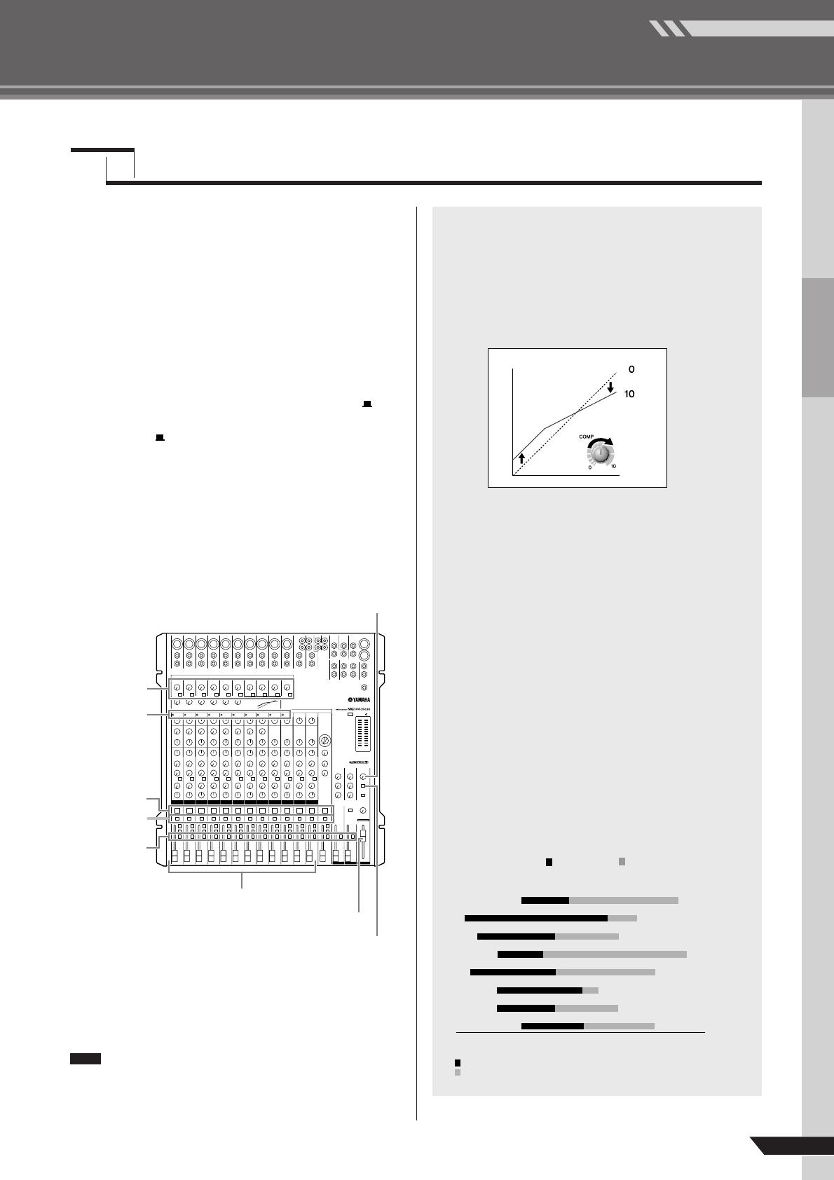
Compression
One form of compression known as “limiting” can, when
properly used, produce a smooth, unified sound with no
excessive peaks or distortion. A common example of the use
of compression is to “tame” a vocal that has a wide dynamic
range in order to tighten up the mix. Compression can also
be applied to guitar tracks to add extra sustain. Too much
compression can be a cause of feedback, however, so use it
sparingly.
Equalizer Tips
The best advice that can be given regarding equalization
while recording is simply to use as little equalization as possi-
ble. If you want a little more presence you can turn the HIGH
end up a bit. Or you can boost the bass a little if you feel the
low end is lacking. During recording it’s better to use EQ
sparingly for compensation only.
●
Cut for a Cleaner Mix
For example: pianos have a lot of energy in the mid and
low frequency ranges that you don’t really perceive as
musical sound, but which can interfere with the clarity of
other instruments in these ranges. You can basically turn
the low EQ on piano channels all the way down without
changing the way they sound in the mix. You’ll hear the dif-
ference, however, in the way the mix sounds more “spa-
cious,” and instruments in the lower ranges will have better
definition. Naturally you won’t want to do this if the piano is
playing solo.
The reverse applies to kick drums and bass guitars: you
can often roll off the high end to create more space in the
mix without compromising the character of the instru-
ments. You’ll have to use your ears, though, because each
instrument is different and sometimes you’ll want the
“snap” of a bass guitar, for example, to come through.
20 50 100 200 500 1 k 2 k 5 k 10 k 20 k
(
Hz
)
Piano
Bass Drum
Snare Drum
Bass
Guitar
Trombone
Tr umpet
Cymba
l
Fundamental: The frequency that determines the basic musical pitch.
Harmonics: Multiples of the fundamental frequency that play a role in
determining the timbre of the instrument.
The fundamental and harmonic frequency ranges of
some musical instruments.
Quick Guide
MG206C-USB/MG166CX-USB/MG166C-USB Owner’s Manual
Mixer Basics
10
This section describes the procedure for recording to the Cubase AI 4 software we installed earlier via the MG mixer.
For details on operation of the Cubase AI 4 software refer to the pdf-format manual provided with the software.
Cubase AI 4 Setup
1
To prevent the playback sound from
Cubase AI 4 from being directly rere-
corded, set the MG mixer’s 2TR IN/USB
switch to TO MONITOR ( ).
2
Launch Cubase AI 4.
Windows:
Click [Start] → [All Program] → [Steinberg Cubase AI
4] → [Cubase AI 4] to launch the program. If the ASIO
Multimedia dialog window appears, click [Yes].
Macintosh:
Double-click the [Application] → [Cubase AI 4].
• If you specified a file destination when installing
the Cubase AI 4 software, launch the applica-
tion from that location.
• Create a Cubase AI 4 shortcut or alias on your
desktop so you can easily launch the program
when required.
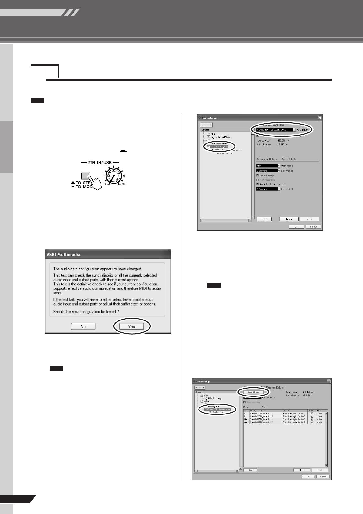
3
Select [Device Setup] from the [Device]
menu to open the Device Setup window.
Windows:
Select [VST Audio System] in the [Device] field on the
left side of the window. Select [ASIO DirectX Full
Duplex Driver] in the [ASIO Driver] field on the right
side of the window. A dialog window will appear asking
“Do you want to switch the ASIO driver?”. Click
[Switch].
Macintosh:
Select [VST Audio System] in the [Device] field on the
left side of the window. Select [USB Audio CODEC (2)]
in the [ASIO Driver] field on the right side of the win-
dow, and click [OK]. Skip ahead to step 6, below.
Under Mac OS X you can select either [USB
Audio CODEC (1)] or [USB Audio CODEC (2)]
in the [ASIO Driver] field. Normally you should
select [USB Audio CODEC (2)], but if you will
only be playing back and mixing previously
recorded data you can select [USB Audio
CODEC (1)] to lighten the load on the com-
puter’s CPU.
4
On a Windows computer select [ASIO
DirectX Full Duplex Driver] in the [Devices]
field on the left side of the Device Setup
window, and click [Control Panel] on the
right side of the window.
Step
5
Recording with Cubase AI 4
NOTE
NOTE
NOTE
Mixer Basics
Quick Guide
MG206C-USB/MG166CX-USB/MG166C-USB Owner’s Manual
11
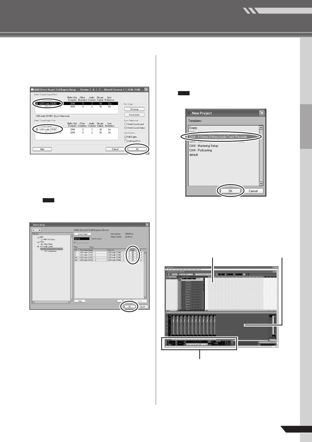
5
The ASIO Direct Sound Full Duplex Setup
dialog window will be displayed. Check
only the input port and output port [USB
Audio CODEC] checkbox.
6
Make sure that “USB Audio CODEC 1/2”
are shown in the [Port System Name] field,
and check the [Visible] column in the
Device Setup window. Click [OK] to close
the window.
If the [Port System Name] field does not
change, close and restart the Cubase AI 4,
then open the Device Setup window.
7
Select [New Project] from the [File] menu
to create a new project file.
The new project dialog window will open. For this
example select [CAI4 — 4 Stereo 8 Mono Audio Track
Recorder] and click [OK].
Recorded Cubase AI 4 data is stored as a
“project file”.
8
When the directory selection dialog win-
dow appears, select the folder to which the
project and audio files for the project are to
be stored, and click [OK].
An empty project window with 4 stereo and 8 monaural
tracks will appear.
NOTE
NOTE
Project window
Transport panel
Mixer window
Quick Guide
MG206C-USB/MG166CX-USB/MG166C-USB Owner’s Manual
Mixer Basics
12
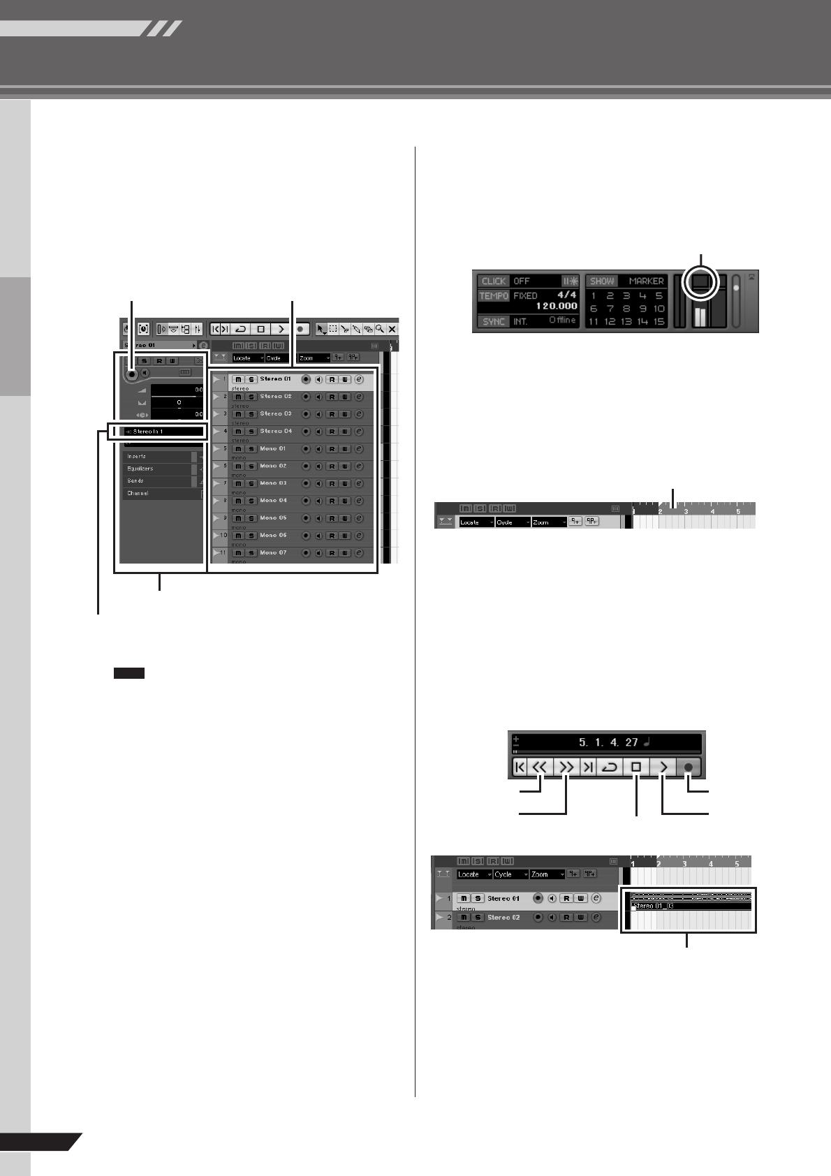
Preparing to Record
1
Click in the track list (the area in which the
track names are displayed) to select a
track to record on.
The various settings for the selected track are available
in the Inspector on the left side of the display.
You will normally use a stereo track when
recording synthesizers, and a monaural track
when recording vocals or guitar.
2
Click the Input Routing field in the Inspec-
tor to select the audio input source. Select
“Stereo In 1” for a stereo track and “Left
(Right)-Stereo In 1” for a monaural track.
3
Make sure the [Record Enable] button for
the track to be recorded is turned on.
If the [Record Enable] button is off, click it to turn it on.
4
Play the instrument to be recorded, and
adjust the MG mixer’s GAIN controls, chan-
nel faders and STEREO OUT Master fader
so that the Clipping indicator never light.
5
Specify the point at which you want to start
recording via the ruler at the top of the
project window.
Click the black area of the ruler to move the project cur-
sor (the vertical black line) to that position.
Recording and Playback
1
Click the Transport panel [Record] button
to begin recording.
When recording is started the project cursor will begin
moving to the right and a box that displays the recording
results will be created.
2
Play the part.
3
When you finish recording the track, click
the Transport panel [Stop] button.
Inspector
Input routing
[Record Enable] button Track list
NOTE
<Transport panel>
Clipping indicator
Stop
Record
Start
Rewind
Forward
<Transport panel>
Recording results
Mixer Basics
Quick Guide
MG206C-USB/MG166CX-USB/MG166C-USB Owner’s Manual
13
4
To hear playback of the track you have just
recorded, use either the Transport panel
[Rewind] button or the ruler to rewind to
the beginning of the recorded section, then
click the Transport panel [Start] button.
The overall playback level will be displayed via the mas-
ter section bus level meter on the right side of the mixer
window, and the channel level will be displayed via the
channel strip level meter.
• Click the [Narrow/Wide] button in the upper left
corner of the mixer window to increase the
width of the mixer’s channel strips.
• The output signal from Cubase AI 4 is routed to
the MG mixer’s 2TR IN inputs. To hear the play-
back sound via a pair of headphones plugged
into the MG mixer, set the bus select switch to
TO MONITOR ( ) and adjust the volume with
the 2TR IN/USB control and the MONITOR/
PHONES control.
5
To save the project file select [Save]
from the [File] menu and enter a file
name before actually saving the file.
Save your project file frequently to insure against losing
large amounts of data if a problem occurs.
6
Repeat steps 1 through 5 to record further
material on the same track.
7
To record additional material on a different
track, select a new track and repeat the
record procedure.
You can monitor the sound being recorded and
a previously recorded sound simultaneously
while recording (MONITOR MIX). Refer to “F
2TR IN/USB” on page 22 for details.
In this section we’ll try mixing down multiple recorded audio tracks to stereo, and creating a wav file. Mixes can be stored as
WAV or AIFF files, which can then be recorded to audio CDs.
1
Launch Cubase AI 4 and open a project
file.
2
Click the [Start] button on the Transport
Panel.
3
While listening to playback, drag the chan-
nel strip level faders up and down to create
the desired initial balance, then adjust the
overall volume using the bus volume fader.
4
Drag the pan controls on the top of the
channel strips left and right to set the
stereo position of each track.
NOTE
Level meter Bus level meter
[Narrow/Wide] button[Narrow/Wide] button
NOTE
Step
6
Mixing with Cubase AI 4
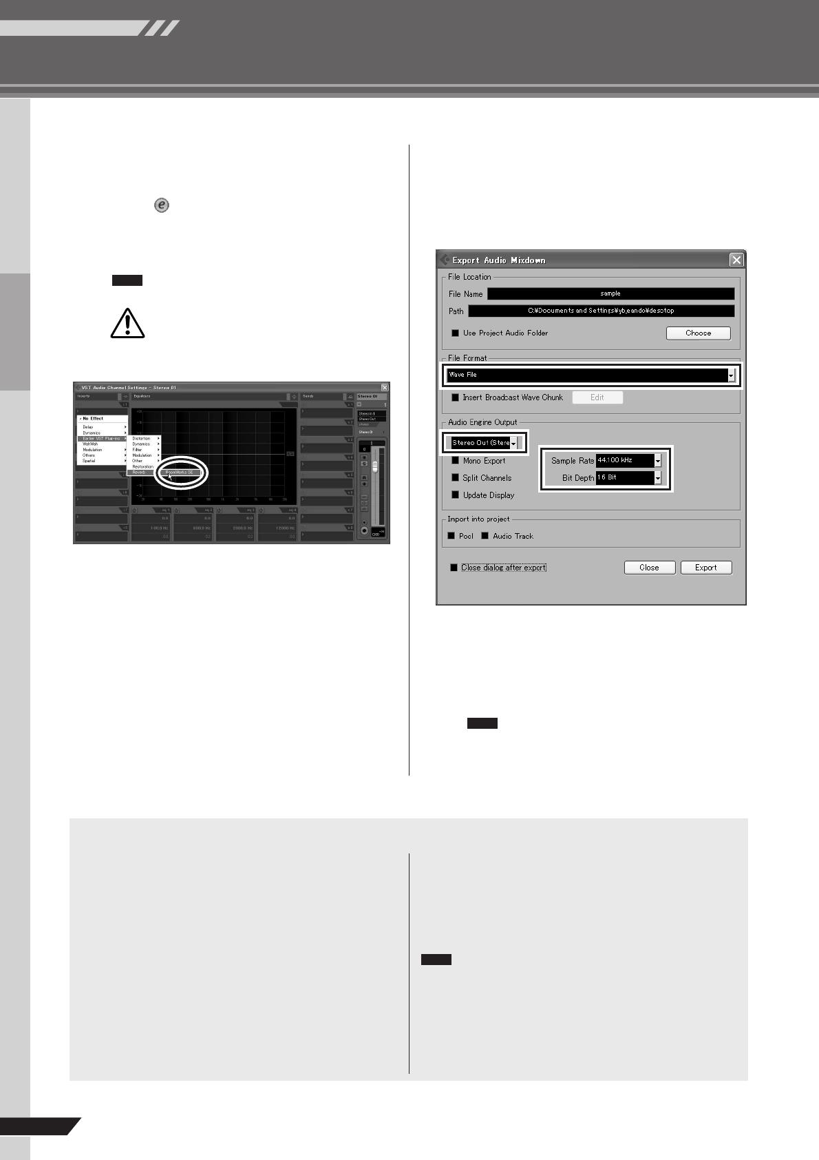
Quick Guide
MG206C-USB/MG166CX-USB/MG166C-USB Owner’s Manual
Mixer Basics
14
5
At this point you can begin to use EQ to
refine your mix, and add effects.
As an example let’s try adding reverb. Click the [Edit]
button ( ) on the left side of the channel strip to
open the VST audio channel settings window. Click
Insert 1 and select Earlier VST Plug-ins → Reverb →
RoomWorks SE.
For further details refer to the pdf manual pro-
vided with the Cubase AI 4 software.
It’s a good idea to lower the channel fader a
bit before adding an effect, since the effect
can cause an increase in the overall channel
level.
6
When the final mix adjustments have
been made, go to the [File] menu and
select [Export] → [Audio Mixdown].
7
Enter a file name and select a destina-
tion for the file as well as a file type.
If you intend to use the file to create an audio CD, select
the WAV file type (AIFF on Macintosh OS X), Stereo
Out (stereo), 16 bit, and 44.1 kHz.
8
Click [Export].
Progress of the mixdown operation will be shown in a
progress window. When the progress window closes the
mixdown is complete.
Wave files created by mixdown can be directly
played back using the Windows Media Player,
or iTunes on a Macintosh computer.
NOTE
CAUTION
NOTE
Use the Built-in Digital Effects to Refine Your Mixes (Only MG166CX-USB)
●
Reverb and Delay Time
The optimum reverb time for a piece of music will depend on the
music’s tempo and density, but as a general rule longer reverb
times are good for ballads, while shorter reverb times are more
suited to uptempo tunes. Delay times can be adjusted to create a
wide variety of “grooves”. When adding delay to a vocal, for
example, try setting the delay time to dotted eighth notes corre-
sponding to the tune’s tempo.
●
Reverb Tone
Different reverb programs will have different “reverb tone” due to
differences in the reverb time of the high or low frequencies. Too
much reverb, particularly in the high frequencies, can result in
unnatural sound and interfere with the high frequencies in other
parts of the mix. It’s always a good idea to choose a reverb pro-
gram that gives you the depth you want without detracting from
the clarity of the mix.
●
Reverb Level
It’s amazing how quickly your ears can lose perspective and fool
you into believing that a totally washed-out mix sounds perfectly
fine. To avoid falling into this trap start with reverb level all the way
down, then gradually bring the reverb into the mix until you can
just hear the difference. Any more than this normally becomes a
“special effect.”
For details on the modulation effects, refer to “Digital
Effect Program List (Only MG166CX-USB)” on page 23.
NOTE
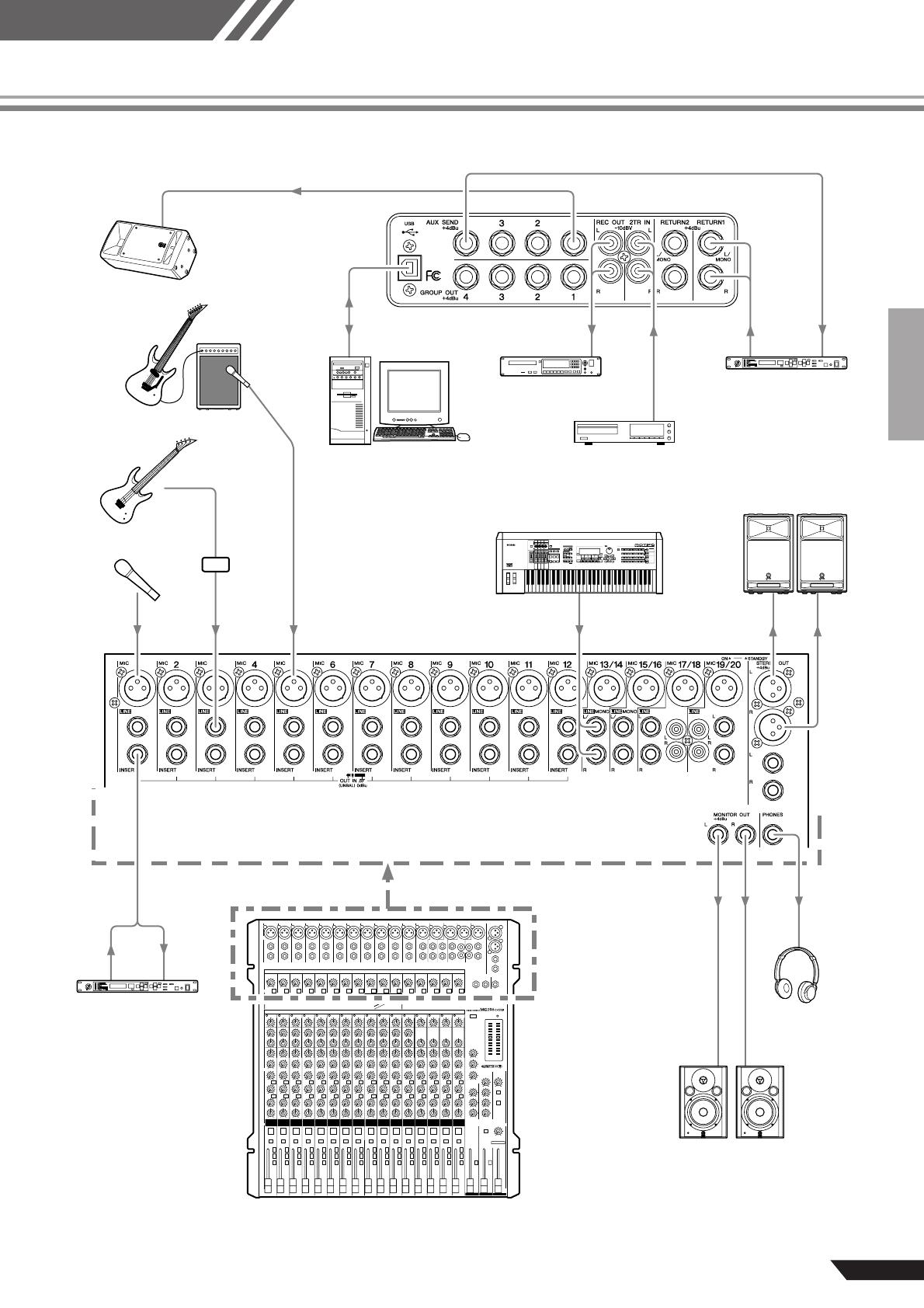
Reference
MG206C-USB/MG166CX-USB/MG166C-USB Owner’s Manual
15
Setup
DI
Recorder
Synthesizer
CD Player
Microphone
Powered speakers
Powered monitor
speakers
Bass
Headphones
Guitar
Effect processor
Effect processor
(exciter)
Powered monitor
speakers
MG206C-USB
Rear panel
Personal Computer
Reference
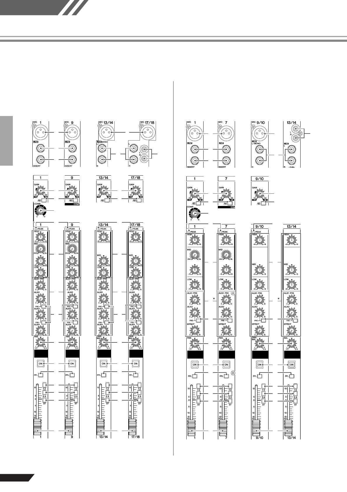
MG206C-USB/MG166CX-USB/MG166C-USB Owner’s Manual
Reference
16
Front & Rear Panels
Channel Control Section
Channels
13/14 and 15/16
(Stereo)
Channels
1 to 8
(Monaural)
Channels
9 to 12
(Monaural)
● MG206C-USB
Channels
17/18 and 19/20
(Stereo)
1
2
1
5
6 6
C C
D D
F
G
H
F
G
H
I I
E E
0
A
9 9
7 7
8
0
A
BB
4
3
Channels
9/10 and 11/12
(Stereo)
Channels
1 to 6
(Monaural)
Channels
7 and 8
(Monaural)
Channels
13/14 and 15/16
(Stereo)
● MG166CX-USB/MG166C-USB
* A MG166C-USB : EFFECT → AUX3
1
2
1
5
6
6
C
D
F
G
H
I
E
0
A
9 9
7
7
8
3
4
B
C
D
F
G
H
I
E
0
B
A
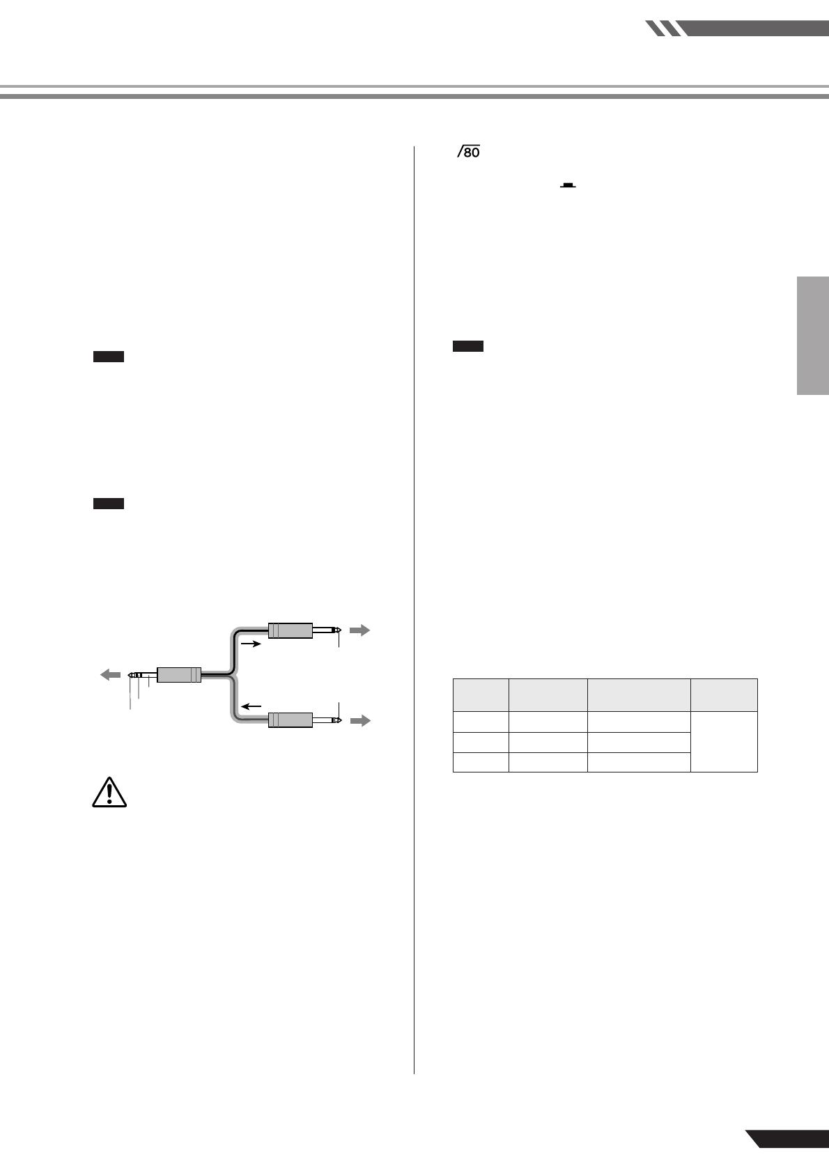
Reference
Front & Rear Panels
MG206C-USB/MG166CX-USB/MG166C-USB Owner’s Manual
17
1 MIC Input jacks
These are balanced XLR-type microphone input jacks. (1:
Ground; 2: Hot; 3: Cold)
2 LINE Input Jacks (monaural channels)
These are balanced TRS phone-jack line inputs. (T: Hot; R:
Cold; S: Ground). You can connect either balanced or unbal-
anced phone plugs to these jacks.
3 LINE Input Jacks (stereo channels)
These are unbalanced phone-jack stereo line inputs.
4 LINE Input Jacks (stereo channels)
These are unbalanced stereo RCA pin jacks.
On channels that provide multiple input jack options
only one type of jack can be used at a time.
5 INSERT Jacks
These jacks can be used to insert an external signal-process-
ing device between the equalizer and fader of the corre-
sponding monaural input channel. The INSERT jacks are
ideal for connecting devices such as graphic equalizers,
compressors, or noise filters into the corresponding chan-
nels.
These are TRS (tip, ring, sleeve) phone jacks that
carry both the send and return signal (tip = send/out;
ring = return/in; sleeve = ground). Patching external
devices via an INSERT jack requires a special cable
such as illustrated below (insert cable sold sepa-
rately).
The signal output from the INSERT jacks is
reverse-phased. This should not be a problem
when connecting to an effect unit, but please be
aware of the possibility of phase conflict when
connecting to other types of device. A reversed-
phased signal may result in degraded sound
quality or even complete sound cancellation.
6 GAIN Control
Adjusts the input signal level. To get the best balance
between the S/N ratio and the dynamic range, adjust the gain
so that the PEAK indicator
9 lights only occasionally and
briefly on the highest input transients. The -60 to -16 scale is
the MIC input adjustment range. The -34 to +10 scale is the
LINE input adjustment range.
7 Switch (High-Pass Filter)
This switch toggles the HPF on or off. To turn the HPF on,
press the switch in ( ). The HPF cuts frequencies below
80 Hz (the HPF does not apply to the line inputs of stereo
input channels
3, 4).
8 COMP Control
Adjusts the amount of compression applied to the channel.
As the knob is turned to the right the compression ratio
increases while the output gain is automatically adjusted
accordingly. The result is smoother, more even dynamics
because louder signals are attenuated while the overall level
is boosted.
Avoid setting the compression too high, as the higher
average output level that results may lead to feed-
back.
9 PEAK indicator
The peak level of the post-EQ signal is detected, and the
PEAK indicator lights red when the level reaches 3 dB
below clipping.
For XLR-equipped stereo input channels, both the post-EQ
and post-mic-amp peak levels are detected, and the indicator
lights red if either of these levels reaches 3 dB below clip-
ping.
0 Equalizer (HIGH, MID and LOW)
This three-band equalizer adjusts the channel’s high, mid,
and low frequency bands. Setting the knob to the “▼” posi-
tion produces a flat response in the corresponding band.
Turning the knob to the right boosts the corresponding fre-
quency band, while turning to the left attenuates the band.
The monaural channels have MID frequency controls to
adjust the midrange frequency band.
The following table shows the EQ type, frequency, and max-
imum cut/boost for each of the three bands.
* The monaural channel MID frequency can be adjusted from
250 Hz to 5 kHz. The MID frequency is 2.5 kHz when the
MID frequency control is set at the center position.
NOTE
NOTE
To the INSERT I/O jack
To the input jack of the
external processor
Tip: OUT
Tip: IN
To the output jack of
the external processor
Sleeve (Ground)
Ring: IN
Tip: OUT
CAUTION
Band Type Frequency
Maximum
Cut/Boost
HIGH
Shelving 10 kHz
±15 dBMID Peaking 2.5 kHz*
LOW
Shelving 100 Hz
NOTE
Front & Rear Panels
MG206C-USB/MG166CX-USB/MG166C-USB Owner’s Manual
Reference
18
A AUX, EFFECT Control
Adjusts the level of the signal sent from the channel to the
AUX and EFFECT buses. These knobs should generally be
set close to the “▼” position. These controls send either the
signal from immediately prior to the channel fader (pre-fader
signal) or the signal after the channel fader (post-fader sig-
nal) to the corresponding buses. The types of signals sent by
the AUX and EFFECT controls on each mixer model are as
follows:
• MG206C-USB
AUX1: Pre-fader
AUX2, 3: Pre-fader/post-fader (determined by the AUX
PRE switch
B)
AUX4: Post-fader
• MG166CX-USB
AUX1: Pre-fader
AUX2: Pre-fader/post-fader (determined by the AUX
PRE switch
B)
EFFECT: Post-fader
• MG166C-USB
AUX1: Pre-fader
AUX2: Pre-fader/post-fader (determines by the AUX
PRE switch
B)
AUX3: Post-fader
•To send the signal to the STEREO bus engage the
ON switch ( ).
• On stereo channels, the L (odd) and R (even) input
signals are mixed and sent to the AUX and
EFFECT buses.
B AUX PRE Switch
Selects whether the pre-fader or the post-fader signal is fed
to the AUX buses. If the switch is on ( ), the mixer sends
the pre-fader signal to the AUX buses, so that AUX outputs
are not affected by the channel fader
I. If the switch is off
() the mixer sends the post-fader signal to the AUX
buses.
C PAN Control
PAN/BAL Control
BAL Control
The PAN control determines the stereo positioning of the
channel signal on the GROUP 1/2 and GROUP 3/4 buses or
on the STEREO L/R bus. The BAL control knob sets the
balance between left and right channels. Signals input to the
L input (odd channel) go to the GROUP 1 or 3 buses or to
the STEREO L bus; signals input to the R input (even chan-
nel) go to the GROUP 2 or 4 buses or the STEREO R bus.
On channels where this knob provides both PAN and
BAL control, the knob operates as a PAN control
when input is received via the MIC jack or L (MONO)
input only, and as a BAL control when input is
received via both L and R inputs.
D ON Switch
Turn this switch on to send the signal to the buses. The
switch lights orange when on.
E PFL (Pre-Fader Listen) Switch
This switch lets you monitor the channel’s pre-fader signal.
Press the switch in ( ) so that it lights to turn it on. When
the switch is on the channel pre-fader signal is output to the
PHONES and MONITOR OUT jacks for monitoring.
F 1-2 Switch
This switch assigns the channel’s signal to the GROUP 1/2
bus.
To send the signal to the GROUP 1/2 bus turn the
ON switch on ( ).
G 3-4 Switch
This switch assigns the channel’s signal to the GROUP 3/4
bus.
To send the signal to the GROUP 3/4 bus turn the
ON switch on ( ).
H ST Switch
This switch assigns the channel’s signal to the STEREO L/R
bus.
To send the signal to the STEREO bus turn the ON
switch on ( ).
I Channel Fader
Adjusts the level of the channel signal. Use these faders to
adjust the balance between the various channels.
Set the fader sliders for unused channels all the way
down to minimize noise.
NOTE
NOTE
NOTE
NOTE
NOTE
NOTE
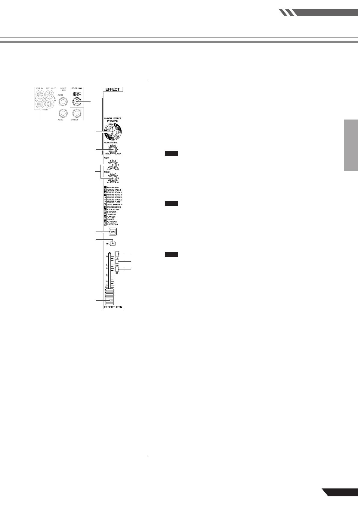
Reference
Front & Rear Panels
MG206C-USB/MG166CX-USB/MG166C-USB Owner’s Manual
19
Digital Effects * Only the MG166CX-USB has digital effects.
4
3
5
0
2
6
1
7
8
9
1 FOOT SWITCH Jack
A Yamaha FC5 foot switch (sold separately) can be connected to this jack
and used to toggle the digital effects ON and OFF.
2 PROGRAM Dial
Selects one of the 16 internal effects. See page 23 for details about the
internal effects.
3 PARAMETER Control
Adjusts the parameter (depth, speed, etc.) for the selected effect. The last
value used with each effect type is saved.
When you change to a different effect type, the mixer automatically
restores the value that was previously used with that type (regard-
less of the current position of the PARAMETER knob).
These parameter values are reset when the power is turned off.
4 AUX Control
Adjusts the level of the signal sent from the internal digital effect unit to
the AUX buses.
The signal level sent to the AUX buses is not affected by the
EFFECT RTN fader.
5 ON Switch
Switches the internal effect on or off. The internal effect is applied only if
this switch is turned on. The switch lights orange when on.
An optional Yamaha FC5 foot switch (sold separately) can be used to tog-
gle the digital effects ON and OFF.
The ON switch lights and the internal effect unit is active when the
power is initially turned on.
6 PFL Switch
Turn this switch on to send the effect signal to the PFL bus.
7 1-2 Switch
This switch assigns the effect signal to the GROUP 1/2 bus.
8 3-4 Switch
This switch assigns the effect signal to the GROUP 3/4 bus.
9 ST Switch
This switch assigns the effect signal to the STEREO L/R bus.
0 EFFECT RTN Fader
Adjusts the signal level sent from the internal digital effect unit to the STE-
REO bus.
NOTE
NOTE
NOTE
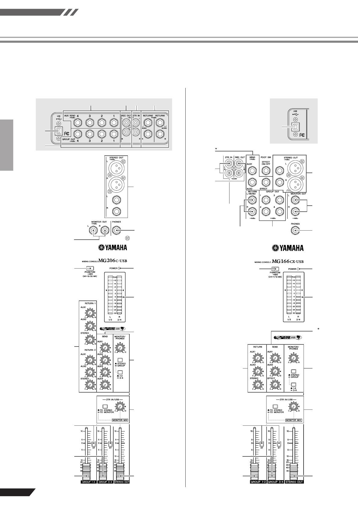
Front & Rear Panels
MG206C-USB/MG166CX-USB/MG166C-USB Owner’s Manual
Reference
20
Master Control Section
A
B
J
F
0
C
I
G
7
9
5
2
4
8
36
E
D
H
1
A
B
J
E
F
D
0
C
7
9
8
I
G
H
1
3
6542
Rear panel
● MG206C-USB
● MG166CX-USB/MG166C-USB
Rear panel
*
2, D MG166C-USB :
EFFECT → AUX3