
E
MIXING CONSOLE
Owner’s Manual
PHONES
L
(MONO)
R
C-R OUT
ST OUTPUT
RTN SEND
GROUP
OUTPUTINPUT INPUT
L
(MONO)
R
L
(MONO)
R
EFFECT MONI
2
1
2
3
4
MONI
1
PHANTOM +48V
ON
MIC
INPUT INPUT INPUT INPUT INPUT INPUT INPUT INPUT
LINE LINELINE LINE LINE LINE LINE LINE
INS
I ⁄ O
INS
I ⁄ O
INS
I ⁄ O
INS
I ⁄ O
INSERT I/O
OUT IN
9
10
11
12
12345678
ST
GROUP
4
GROUP
3
GROUP
2
GROUP
1
11
12
9
10
010
3
4
ST
GROUP
EFFECT
MONI2
METER
C-R•PHONES
TAPE IN
ST
EFFECT
⁄ MONI
C-R•PHONES
010
010
010
010
010
010
ST
MONI
SEND
RTN
MONI 1MONI
EFFECT ⁄ MONI 2
ST
TAPE IN
ST
010
LR
L
R
TAPE IN
REC OUT
PHANTOM POWER
ON
VOCAL
L HALL S HALL
DIGITAL
EFFECT
MONI 1
EFFECT
/ MONI 2
L
R
PEAK
+5
+3
+1
0
-1
-3
-5
-7
-10
-15
-20
ST GRAPHIC EQUALIZER
10
5
0
5
10
15
20
30
40
00
10
5
0
5
10
15
20
30
40
00
10
5
0
5
10
15
20
30
40
00
10
5
0
5
10
15
20
30
40
00
10
5
0
5
10
15
20
30
40
00
+12
-12
6
0
6
+12
-12
6
0
6
8k4k
2k
1k
500
250
125
2413
10
5
0
5
10
15
20
30
40
00
1
2
3
4
+10
-34
GAIN
HIGH
MID
LOW
MONI 1
EFFECT
BAL
PEAK
-15
+15
-15
+15
-15
+15
0
10
0
10
2413
10
5
0
5
10
15
20
30
40
00
1
2
3
4
+10
-34
GAIN
HIGH
MID
LOW
MONI 1
EFFECT
BAL
PEAK
-15
+15
-15
+15
-15
+15
0
10
0
10
8
2413
1
2
3
4
10
5
0
5
10
15
20
30
40
00
-16
-60
+10
-34
PAN
GAIN
HIGH
MID
LOW
MONI 1
EFFECT
PEAK
-15
+15
-15
+15
-15
+15
0
10
0
10
7
2413
1
2
3
4
10
5
0
5
10
15
20
30
40
00
-16
-60
+10
-34
PAN
GAIN
HIGH
MID
LOW
MONI 1
EFFECT
PEAK
-15
+15
-15
+15
-15
+15
0
10
0
10
6
2413
1
2
3
4
10
5
0
5
10
15
20
30
40
00
-16
-60
+10
-34
PAN
GAIN
HIGH
MID
LOW
MONI 1
EFFECT
PEAK
-15
+15
-15
+15
-15
+15
0
10
0
10
5
2413
1
2
3
4
10
5
0
5
10
15
20
30
40
00
-16
-60
+10
-34
PAN
GAIN
HIGH
MID
LOW
MONI 1
EFFECT
PEAK
-15
+15
-15
+15
-15
+15
0
10
0
10
4
2413
1
2
3
4
10
5
0
5
10
15
20
30
40
00
-16
-60
+10
-34
PAN
GAIN
HIGH
MID
LOW
MONI 1
EFFECT
PEAK
-15
+15
-15
+15
-15
+15
0
10
0
10
3
2413
1
2
3
4
10
5
0
5
10
15
20
30
40
00
-16
-60
+10
-34
PAN
GAIN
HIGH
MID
LOW
MONI 1
EFFECT
PEAK
-15
+15
-15
+15
-15
+15
0
10
0
10
2
2413
1
2
3
4
10
5
0
5
10
15
20
30
40
00
-16
-60
+10
-34
PAN
GAIN
HIGH
MID
LOW
MONI 1
EFFECT
PEAK
-15
+15
-15
+15
-15
+15
0
10
0
10
1
2413
1
2
3
4
10
5
0
5
10
15
20
30
40
00
-16
-60
+10
-34
PAN
GAIN
HIGH
MID
LOW
MONI 1
EFFECT
PEAK
-15
+15
-15
+15
-15
+15
0
10
0
10
MIC
MIC
MIC
MIC
MIC
MIC MIC
L
R
OFF
MIXING CONSOLE
Precautions
MX12/4—Owner’s Manual
1. Avoid Excessive Heat, Humidity, Dust and Vibration
Keep the unit away from locations where it is likely to be
exposed to high temperatures or humidity — such as
near radiators, stoves, etc. Also avoid locations which
are subject to excessive dust accumulation or vibration
which could cause mechanical damage.
2. Ventilation
The unit has ventilation slots on the rear and bottom
panels. Do not block these vents.
3. Avoid Physical Shocks
Strong physical shocks to the unit can cause damage.
Handle it with care.
4. Do Not Open the Case or Attempt Repairs or Modi-
fications Yourself
This product contains no user-serviceable parts. Refer
all maintenance to qualified Yamaha service personnel.
Opening the case and/or tampering with the internal
circuitry voids the warranty.
5. Always power off before making connections
Always turn the power OFF before connecting or dis-
connecting cables. This is important to prevent damage
to the unit itself as well as other connected equipment.
6. Handle Cables Carefully
Always plug and unplug cables — including the AC
power cord — by gripping the connector, not the cord.
7. Clean With a Soft Dry Cloth
Never use solvents such as benzine or thinner to clean
the unit. Wipe clean with a soft, dry cloth.
8. Always Use the Correct Power Supply
Make sure that the power supply voltage specified on the
rear panel matches your local AC mains supply. Also
make sure that the AC mains supply can deliver more
than enough current to handle all equipment used in
your system.
FCC INFORMATION (U.S.A.)
1. IMPORTANT NOTICE: DO NOT MODIFY THIS UNIT! This
product, when installed as indicated in the instructions contained in this
manual, meets FCC requirements. Modifications not expressly
approved by Yamaha may void your authority, granted by the FCC, to
use the product.
2. IMPORTANT: When connecting this product to accessories and/or
another product use only high quality shielded cables. Cable/s supplied
with this product MUST be used. Follow all installation instructions.
Failure to follow instructions could void your FCC authorization to use
this product in the USA.
3. NOTE: This product has been tested and found to comply with the
requirements listed in FCC Regulations, Part 15 for Class “B” digital
devices. Compliance with these requirements provides a reasonable
level of assurance that your use of this product in a residential
environment will not result in harmful interference with other
electronic devices. This equipment generates/uses radio frequencies
and, if not installed and used according to the instructions found in the
users manual, may cause interference harmful to the operation of other
electronic devices. Compliance with FCC regulations does not
guarantee that interference will not occur in all installations. If this
product is found to be the source of interference, which can be
determined by turning the unit “OFF” and “ON”, please try to eliminate
the problem by using one of the following measures: Relocate either
this product or the device that is being affected by the interference.
Utilize power outlets that are on different branch (circuit breaker or
fuse) circuits or install AC line filter/s. In the case of radio or TV
interference, relocate/reorient the antenna. If the antenna lead-in is 300
ohm ribbon lead, change the lead-in to coaxial type cable. If these
corrective measures do not produce satisfactory results, please contact
the local retailer authorized to distribute this type of product. If you can
not locate the appropriate retailer, please contact Yamaha Corporation
of America, Electronic Service Division, 6600 Orangethorpe Ave,
Buena Park, CA 90620
* This applies only to products distributed by YAMAHA
CORPORATION OF AMERICA.
IMPORTANT NOTICE FOR
THE UNITED KINGDOM
Connecting the Plug and Cord
WARNING: THIS APPARATUS MUST BE EARTHED
IMPORTANT: The wires in this mains lead are coloured in accordance with
the following code:
GREEN-AND-YELLOW : EARTH
BLUE : NEUTRAL
BROWN : LIVE
As the colours of the wires in the mains lead of this apparatus may not
correspond with the coloured markings identifying the terminals in your
plug, proceed as follows:
The wire which is coloured GREEN and YELLOW must be connected to
the terminal in the plug which is marked by the letter E or by the safety earth
symbol or coloured GREEN and YELLOW.
The wire which is coloured BLUE must be connected to the terminal which
is marked with the letter N or coloured BLACK.
The wire which is coloured BROWN must be connected to the terminal
which is marked with the letter L or coloured RED.
* This applies only to products distributed by YAMAHA KEMBLE
MUSIC (U.K.) LTD.

MX12/4
1
MX12/4—Owner’s Manual
Thank you for purchasing the Yamaha MX12/4 mixing console. The
MX12/4 is a 12 in/4 group out mixer that provides an ideal balance of
operability, functionality, and simplicity.
In order to take full advantage of the MX12/4’s functionality and to enjoy
long and trouble-free use, please read this owner’s manual before use, and
keep it for future reference.
Features
• The MX12/4 provides 12 input channels, and
mixes them to stereo or to four group outputs.
• A C-R OUT jack is provided for convenient con-
nection to a sub amp for monitoring. You can
monitor the main stereo output, the TAPE IN
input, and the effect/monitor signals.
• A digital effect unit is built-in, allowing you to cre-
ate a polished mix without the need for additional
equipment.
• Two SEND jacks are provided: the MONO 1 jack
(pre fader) and the EFFECT/MONO 2 jack (post/
pre fader). These can be used as sends for external
effects or a monitor system.
• Phantom power is provided, so that condenser
microphones requiring an external power supply
can be easily connected.
• INS I/O jacks are provided for input channels 1-4,
allowing individual effects to be inserted into each
channel.
• Input channels 1-8 provide both XLR type mic
inputs and TRS phone line inputs. Channels 9-12
provide stereo line inputs. The MX12/4 accommo-
dates a wide range of sources, from microphones to
line level devices and stereo output synthesizers.
• TAPE IN jacks and REC OUT jacks make it easy to
connect tape decks for playback and recording.
Contents
Front panel………………………………………….2
Channel control section …………………………2
Master control section……………………………4
Connector section…………………………………6
Rear panel…………………………………………..8
Application Example……………………………..9
Specifications…………………………………….10
General specifications…………………………. 10
Input specifications ……………………………..11
Output specifications…………………………… 11
Dimensions ……………………………………….. 12
Block and Level diagram……………………… 13
2
Front panel
MX12/4—Owner’s Manual
Front panel
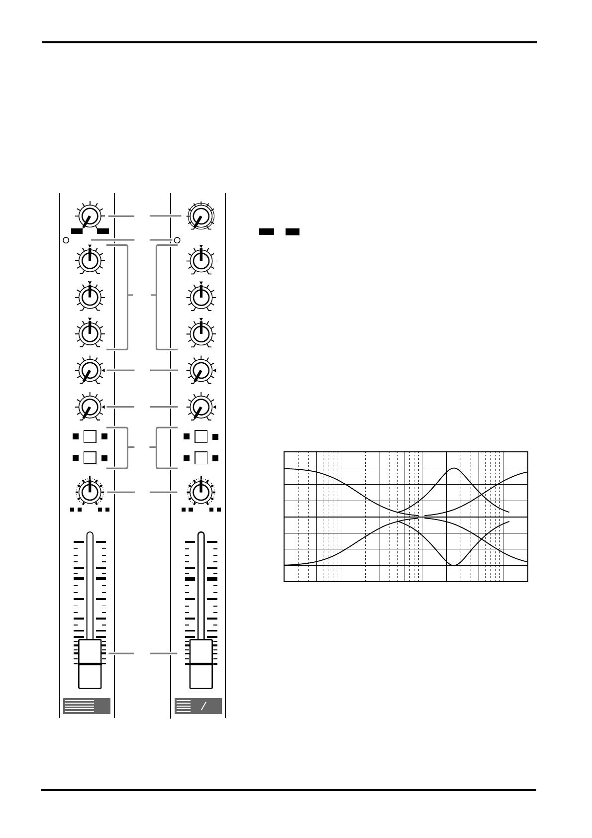
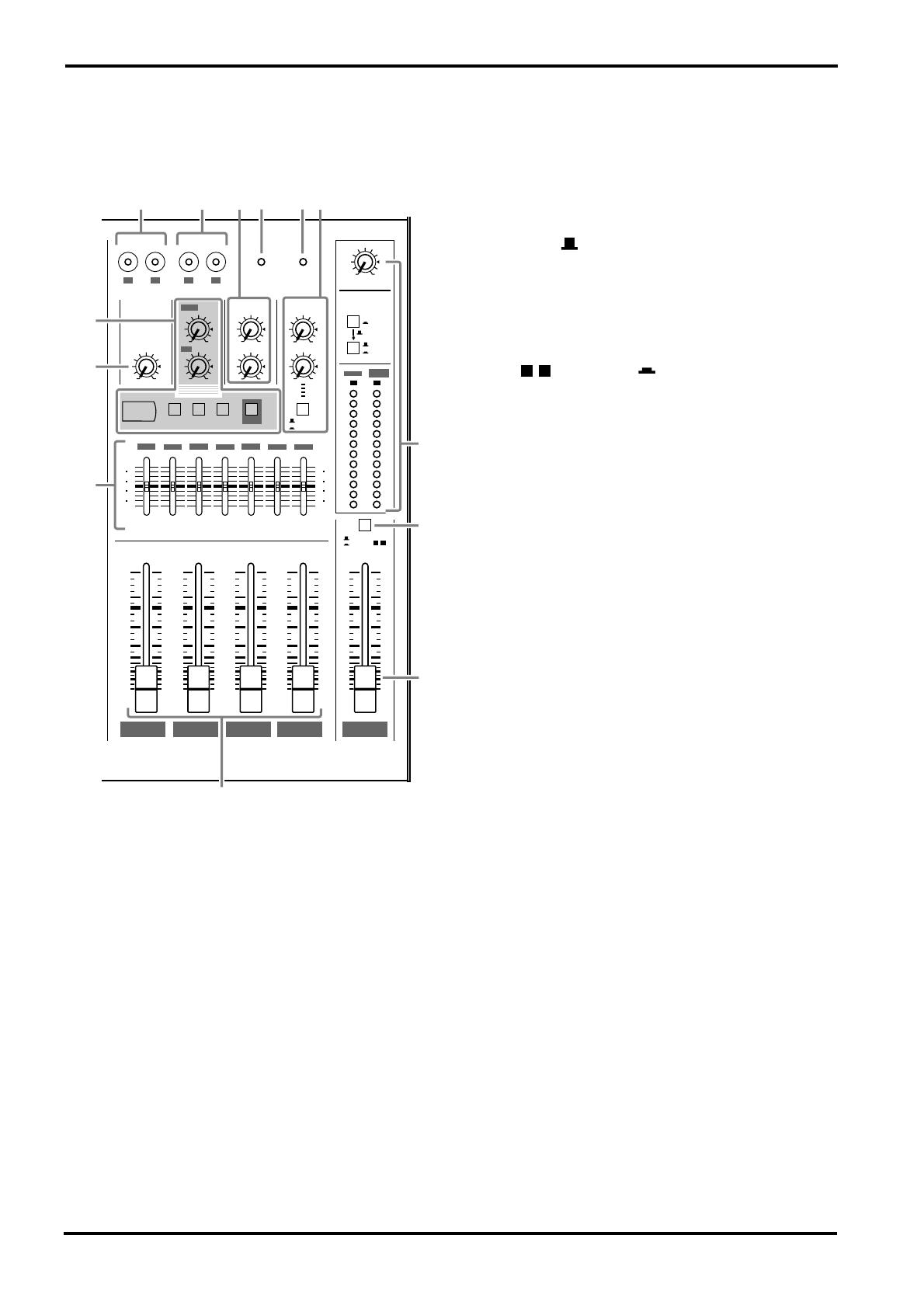
Channel control section
1
GAIN control
Use this knob to adjust the sensitivity according to the input sig-
nal level, so that the input level is appropriate.
For the best balance of S/N ratio and dynamic range, adjust this
knob so that the peak indicator
2
lights occasionally.
~ indicates the MIC input adjustment level, and –34~
+10 indicates the LINE input adjustment level.
2
PEAK indicator
This detects the peak level post EQ.
The indicator will light red 3dB before clipping, warning that
clipping level is near.
3
Equalizer
This provides
±
15dB of control over the high, mid and low
ranges at the following center frequencies.
HIGH : 12kHz (shelving)
MID : 2.5kHz (peaking)
LOW : 80Hz (shelving)
The frequency response will be flat when the knob is in the “
▼
”
position.
4
MONI (monitor) control
This knob controls the level of the signal that is sent from each
channel to the MONI bus.
Since this control is placed before the channel fader, it controls
the level independently from the channel fader setting.
5
EFFECT control
This knob controls the level of the signal that is sent from each
channel to the EFFECT bus.
Since this control is placed after the channel fader, the signal
level will be affected by the channel fader setting.
9
10
2413
10
5
0
5
10
15
20
30
40
00
1
2
3
4
+10
-34
GAIN
HIGH
MID
LOW
MONI
EFFECT
BAL
PEAK
0
10
0
10
1
2413
1
2
3
4
10
5
0
5
10
15
20
30
40
00
-16
-60
+10
-34
PAN
GAIN
HIGH
MID
LOW
MONI
EFFECT
PEAK
0
10
0
10
Channels 1~8
(monaural)
Channels 9~12
(stereo)
1
2
3
4
5
6
7
8
-15
+15
-15
+15
-15
+15
-15
+15
-15
+15
-15
+15
–60
–16
Response [dB]
+5
+10
+15
–15
–10
–5
0
Frequency [Hz]
10k1k100 20k20
+20
–20
Channel control section
3
MX12/4—Owner’s Manual
6
Group select switches
These switches send the signal of each channel to GROUP buses 1~4.
When the / switches are on (pressed in), the signal will be sent to the GROUP buses 1/2.
When the / switches are on (pressed in), the signal will be sent to the GROUP buses 3/4.
When both switches are on, the signal will be sent to GROUP buses 1/2 and 3/4.
7
PAN (panpot) control
BAL (balance) control
The PAN knobs (channels 1~8) set the stereo position of the signal that is sent to the GROUP
buses 1/2 or 3/4.
The BAL knobs (channels 9~12) set the balance between the left/right channels, and assign
the signals received at inputs 9 L (MONO) and 11 L (MONO) to the GROUP buses 1/3, and
the signals received at inputs 10 R and 12 R to the GROUP buses 2/4.
If signals are input monaurally to input 9 L (MONO) or 11 L (MONO), the same signal will
be sent to groups 1~4.
8
Channel fader
This controls the output level of the input channel signal, adjusting the volume balance
between channels. The faders of unused channels should be lowered.
1 2
3 4
EFFECT
MONI
EFFECT
MONI
PEAK
PEAK
PHANTOM
GAIN
LOW
MID
HIGH
BAL
R
L(MONO)
EQHA
INPUT
9/10
11/12
HA EQ
LOW
MID
EQ
GAIN
HA
HIGH
PAN
PAD
MIC
LINE
INPUT
5-8
EFFECT
MONI
MONI
EFFECT
INPUT
1-4
LINE
MIC
INS
I/O
PAD
PHANTOM
MASTER
GROUP
4321
PAN
HIGH
HA
GAIN
EQ
MID
LOW
PEAK
4
Front panel
MX12/4—Owner’s Manual
Master control section
1
ST OUT output select switch
This switch selects the signal which is output via the
ST
fader from the ST OUTPUT jacks.
ST position ( )
The ST OUTPUT jacks will output the ST bus signal
(the post-fader signals of groups 1~4, the input signals
from the RTN jacks, the return signal from the internal
digital effect, and the input signal from the TAPE IN
jacks).
GROUP position ( )
The ST OUTPUT jacks will output the pre-fader sig-
nals of groups 3/4.
When this position is selected, the input channel sig-
nals will be sent directly to the ST bus without passing
through the group buses 1~4. This setting lets you use
the MX12/4 as a simple 12 in-2 out mixer.
2
ST master fader
This fader adjusts the final combined level of all chan-
nels, and sends the signal to the ST OUTPUT jacks.
The meters allow you to view the L and R output levels.
3
GROUP 1~4 faders
These faders adjust the signal levels of groups 1~4, and
send their signals to GROUP OUTPUT 1~4 jacks
respectively and to the ST bus.
Groups 1 and 3 are sent to ST L, and groups 2 and 4 are
sent to ST R.
4
Stereo graphic EQ
This is a stereo 7-band graphic equalizer that adjust the
tonal quality of the signal output to the ST OUTPUT
jacks.
A
±
12dB boost or cut is provided at each of the fre-
quency bands 125, 250, 500, 1k, 2k, 4k, and 8kHz.
5
TAPE IN jacks
These are line level input jacks to which an external DAT recorder or CD player etc. can be
connected for monitoring. The signals which are input here are sent to the ST bus. The input
levels are adjusted by the TAPE IN ST control (
9
). Depending on the setting of the C-R•
PHONES select switch (
D
), the signal can also be monitored directly from the C-R OUT jack.
6
REC OUT jacks
These jacks allow an external DAT recorder or cassette recorder to be connected, to record the
same signal as the ST OUTPUT jacks.
The signals that are output from these jacks are not affected by the settings of the ST master
fader or the graphic EQ. Make recording level adjustments on the recording device.
7
PHANTOM indicator
This indicator will light when the PHANTOM switch (rear panel
2
) is on.
8
POWER indicator
This indicator will light when the MX12/4’s power is on.
ST
GROUP 4
GROUP 3
GROUP 2
GROUP 1
010
3
4
ST
GROUP
EFFECT
MONI2
METER
C-R•PHONES
TAPE IN
ST
EFFECT
⁄ MONI
C-R•PHONES
010
010
010
010
010
010
ST
MONI
SEND
RTN
MONI 1MONI
EFFECT ⁄ MONI 2
ST
TAPE IN
ST
010
LR
L
R
TAPE IN
REC OUT
PHANTOM POWER
ON
VOCAL
L HALL S HALL
DIGITAL
EFFECT
MONI 1
EFFECT
/ MONI 2
L
R
PEAK
+5
+3
+1
0
-1
-3
-5
-7
-10
-15
-20
ST GRAPHIC EQUALIZER
10
5
0
5
10
15
20
30
40
00
10
5
0
5
10
15
20
30
40
00
10
5
0
5
10
15
20
30
40
00
10
5
0
5
10
15
20
30
40
00
10
5
0
5
10
15
20
30
40
00
+12
-12
6
0
6
+12
-12
6
0
6
8k4k
2k
1k
500
250
125
3
AB
1
2
4
5
6
78
9
0
C
3 4

Master control section
5
MX12/4—Owner’s Manual
9
ST control
This knob adjusts the monitor level of the external device (tape deck etc.) connected to the
TAPE IN jacks (
5
).
0
DIGITAL EFFECT
MONI control
—This knob adjusts the level of the return signal which is sent from the inter—
nal digital effect to the MONI bus.
ST control
—This knob adjusts the level of the return signal which is sent from the internal
digital effect to the ST bus.
Effect select switches
—These switches select the effect type for the internal digital effect:
VOCAL, L HALL (large hall), or S HALL (small hall).
Do not attempt to turn off all switches or to simultaneously press two or more switches, since
this will cause malfunctions.
ON switch
—This switch turns the internal digital effect on/off. When this is off, no signal will
be sent from the internal digital effect.
A
RTN
MONI control
—This knob adjusts the level of the signal that is sent from the RTN jacks to the
MONI bus.
ST control
—This knob adjusts the level of the signal that is sent from the RTN jacks to the ST
bus. If a signal is input only to the RTN L (MONO) jack, the same signal will be sent to the ST
bus L and R.
B
SEND
MONI 1 control
—This knob adjusts the level of the MONI bus signal that is output to the
SEND MONI 1 jack.
EFFECT/MONI 2 control
—This knob adjusts the level of the EFFECT bus or MONI bus sig-
nal that is output to the SEND EFFECT/MONI 2 jack.
The level of the signal that is sent from the EFFECT bus to the internal digital effect is fixed,
and cannot be adjusted (nor by this control).
Output select switch
—This switch selects the signal that will be output to the SEND EFFECT/
MONI 2 jack.
EFFECT position
()
—The EFFECT bus signal will be output.
MONI 2 position
()
—The MONI bus signal will be output.
C
C-R•PHONES
Here you can select and adjust the signal that is output to the C-R OUT jack and the PHONES
jack.
C-R•PHONES control
— This knob adjusts the output level to the C-R OUT jack and
PHONES jack.
Output select switch
—These switches select the output signal for the C-R OUT jack and
PHONES jack.
•
When the upper switch is on (TAPE IN ), the signal from the TAPE IN
jacks will be output.
•
When the upper switch is off ( )
• When the lower switch is off (ST ), the same signal as the ST OUT—
PUT jacks will be output.
• When the lower switch is on (EFFECT/MONI ), the signal of the
SEND MONI 1 jack will be sent to the L channel, and the SEND
EFFECT/MONI 2 signal will be sent to the R channel.
Meter
—The LEDs indicate the output level before the C-R•PHONES control. A position of 0
indicates nominal level, and when clipping level is approached, PEAK will light red as a warn-
ing.
6
Front panel
MX12/4—Owner’s Manual
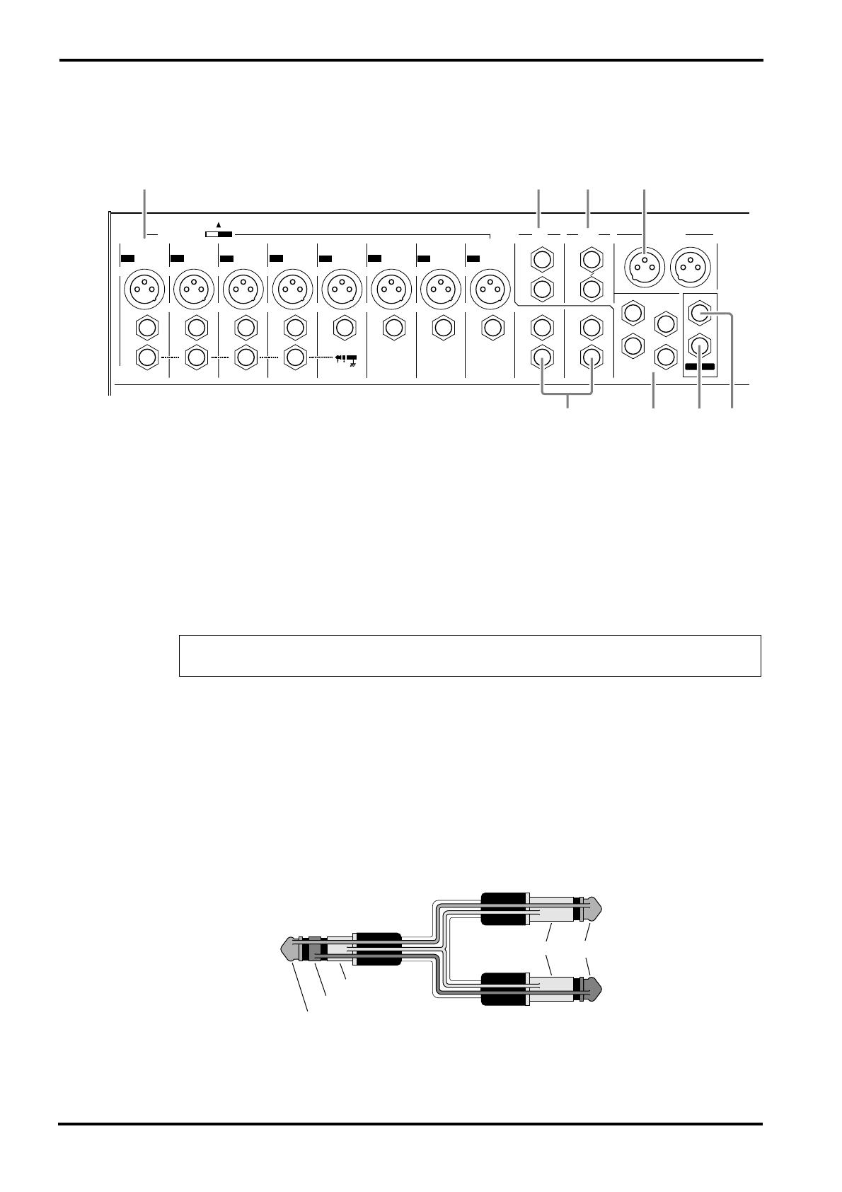
Connector section
1
INPUT
MIC (1~8)
—These are balanced XLR type mic input jacks (1: ground, 2: hot, 3: cold).
These inputs are compatible with 50~600
Ω
microphones.
LINE (1~8)
—These are balanced TRS phone type line input jacks (T: hot, R: cold, S:
ground).
These inputs are compatible with 600 ohm line level devices.
It is also possible to connect unbalanced phone plugs, but noise may enter the signal if the
cables are long or if the location is susceptible to electromagnetic interference.
INS I/O 1~4
—These are input/output jacks placed between the equalizer and fader of input
channels 1~4.
The nominal input level/impedance is 0dB/600
Ω
, and the nominal output level/impedance is
0dB/10k
Ω
.
Devices such as graphic equalizers, compressors or noise filters can be connected here.
The INS I/O jacks provide bi-directional connections using TRS (tip, ring, sleeve) phone
jacks. These connections require a special insertion cable such as shown in the following dia-
gram.
Note:
It is not possible to connect both the MIC INPUT jack and the LINE INPUT jack for
an individual input channel. Only one or the other jack may be used.
PHONES
L(MONO)
R
C-R OUT
ST OUTPUT
RTN SEND
GROUP
OUTPUTINPUT INPUT
L
(MONO)
R
L
(MONO)
R
EFFECT MONI
2
1
2
3
4
MONI
1
PHANTOM +48V
ON
MIC
INPUT INPUT INPUT INPUT INPUT INPUT INPUT INPUT
LINE LINELINE LINE LINE LINE LINE LINE
INS
I ⁄ O
INS
I ⁄ O
INS
I ⁄ O
INS
I ⁄ O
INSERT I/O
OUT IN
9
10
11
12
12345678
MIC
MIC
MIC
MIC
MIC
MIC MIC
L
R
OFF
2135
4687
to the input jack of
the external processor
to the output jack of
the external processor
to the INS I/O jack
Tip
Tip
Ring
Sleeve
Sleeve

Connector section 7
MX12/4—Owner’s Manual
2 RTN L (MONO), R
These are unbalanced phone type line input jacks, with a nominal input level and impedance
of +4dB/600Ω.
The signals which are input from these jacks are sent to the ST bus and the MONI bus.
Normally, these jacks are used to receive the return signal from an external effect device such
as reverb or delay, but they can also be used as auxiliary stereo inputs. If only the L (MONO)
jack is connected, the same signal will be sent both to the R jack and L jack, for monaural
input.
3 SEND MONI 1, EFFECT/MONI 2
These are unbalanced phone type output jacks. The nominal input level and impedance are
+4dB/600Ω.
The MONI 1 jack outputs the MONI bus signal, and the EFFECT/MONI 2 jack outputs the
signal of the EFFECT bus or MONI bus. These are used to send signals to an external effect
unit or to a monitor system such as a cue box.
4 INPUT 9~12
These are unbalanced phone type stereo line input jacks, compatible with 600Ω line level
devices.
If only the L (MONO) jack is connected, the same signal will be sent both to the L and R jacks,
for monaural input. In this case, the group select switch (channel control section 6) will send
the same signal to the group buses 1/2 or 3/4.
5 ST OUTPUT (L, R)
These are balanced XLR type output jacks with a nominal output/impedance of +4dB/600Ω.
They provide stereo output of the mixed signal, and are normally connected to a power amp
etc. which drives the main speakers.
These outputs can also be used in order to record the signal at a level adjusted by the ST fader.
6 GROUP OUTPUT 1~4
These are unbalanced phone type output jacks which output the signals of group buses 1~4,
with a nominal output/impedance of +4dB/600Ω. Normally these are connected to the input
jacks of an MTR or an external mixer.
7 C-R OUT
This is a stereo phone type output jack for connection to a monitor system etc., with a nomi-
nal output/impedance of +4dB/10kΩ.
The source monitored by this jack is selected by the C-R•PHONES output select switch (mas-
ter control section C).
8 PHONES
This is a stereo phone type output jack for connecting a set of headphones.
The source monitored by the headphones is selected by the C-R•PHONES output select
switch (master control section C).
Note: An insertion cable can also be used when connecting this jack to a stereo monitor sys-
tem.
8 Rear panel
MX12/4—Owner’s Manual
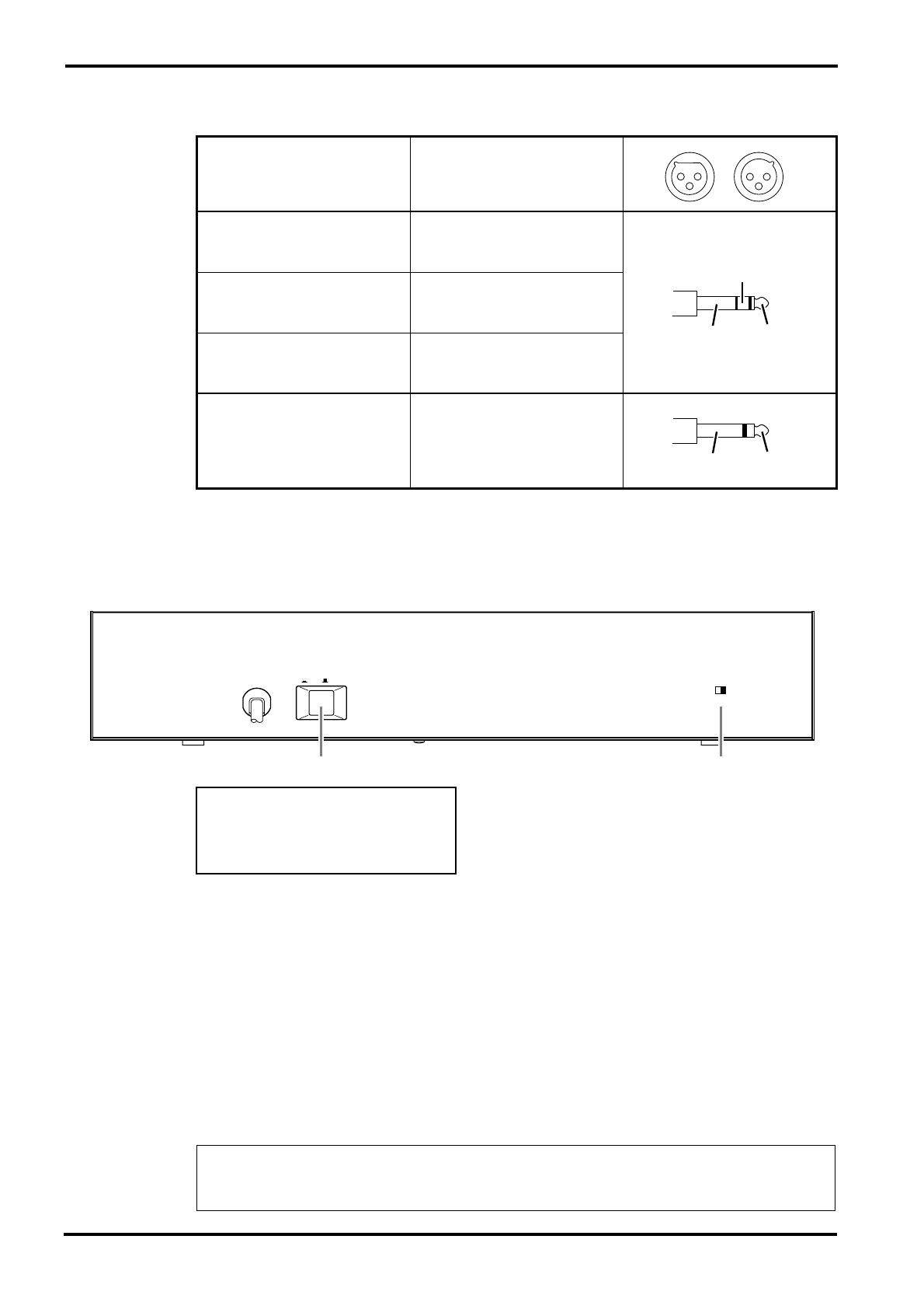
Connector polarity
Rear panel
1 POWER switch
When this is on, power is applied to the unit.
When turning off the power, the rule for audio equipment is to turn off devices in the order of
their closeness to the speakers (normally beginning with the power amp).
2 PHANTOM switch
This switch turns the phantom power on/off for all channels 1~8.
Use this when you are using condenser microphones.
When this switch is on, +48V DC will be supplied to pins 2 and 3 of all XLR type MIC INPUT
connectors.
If you do not require phantom power, be sure to set this in the OFF position.
MIC INPUT
ST OUTPUT
Pin 1: ground
Pin 2: hot (+)
Pin 3: cold (–)
LINE Input
Tip: hot (+)
Ring: cold (–)
Sleeve: ground
INS I/O
Tip: Output
Ring: Input
Sleeve: ground
C-R OUT
Tip: L
Ring: R
Sleeve: ground
Stereo Input
RTN
GROUP OUTPUT
SEND MONI1
SEND EFFECT/MONI2
Tip: hot
Sleeve: ground
Note: Although it will not cause problems to connect balanced dynamic microphones or line
level devices with this switch turned on, connecting unbalanced devices or devices for which
the center of the transformer is ungrounded may cause hum or malfunction.
PHANTOM MASTER
CH1 ~ 8
ON OFF
(+48V)
POWER
ON ⁄ OFF
21
Phantom Power Warning
To prevent hazard or damage, connect
only microphones and cables that
conform to the IEC268-15A standard.
10 Specifications
MX12/4—Owner’s Manual
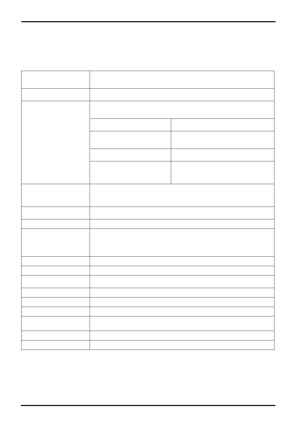
Specifications
■ General specifications
Frequency response
20Hz~20kHz+1dB, –2dB @+4dB
Input Gain control at minimum level
Total harmonic distortion
<0.1%@+14dB 20Hz~20kHz
Hum and noise
(Rs=150Ω, 20Hz~20kHz)
–128dB equivalent input noise
–95dB residual output noise
–87dB (ST OUT/GROUP OUT)
ST master/GROUP fader at nominal level and all
channel fader at minimum.
–64dB (68dB S/N)
(ST OUT/GROUP OUT)
ST master/GROUP fader at nominal level
One channel fader, Gain control: maximum.
Fader: nominal
–80dB (MONITOR1 OUT, EFFECT/
MONITOR2 OUT)
Master level control at nominal level and all channel
level controls at minimum.
–64dB (68dB S/N)
(MONITOR1 OUT, EFFECT/MONITOR2
OUT)
Master fader at nominal level
One channel fader, Gain control: maximum.
Fader: nominal
Control level: nominal
Maximum voltage gain
84dB MIC IN to GROUP OUT
58dB LINE IN to GROUP OUT
90dB MIC IN to EFFECT/MONITOR2 OUT
80dB MIC IN to MONITOR1 OUT
Crosstalk at 1kHz
70dB adjacent input
70dB input to output
Gain control 44dB variable
Input channel equalization
±15dB Maximum
HIGH 12kHz shelving
MID LOW 2.5kHz peaking
LOW 80Hz shelving
* Turn over/Roll off frequency of shelving: 3dB below maximum variable level
Meters 12 points LED
Channel peak indicators An indicator for each channel turns on when the pre-channel fader signal is 3dB below clipping.
Graphic equalizer
7 bands (125, 250, 500, 1k, 2k, 4k, 8kHz)
±12 Maximum
Internal digital effect 3 types
Phantom power +48V (balanced)
Option Rack Mount Kit RK124
Power supply/
Power consumption
USA and Canadian 120V AC 60Hz, 30W
General 230V AC 50Hz, 40W
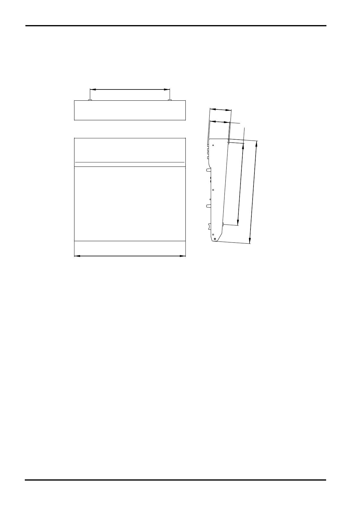
Dimensions (WxHxD) 436.2×83.1×401.2mm
Weight 7.0kg
Input specifications 11
MX12/4—Owner’s Manual
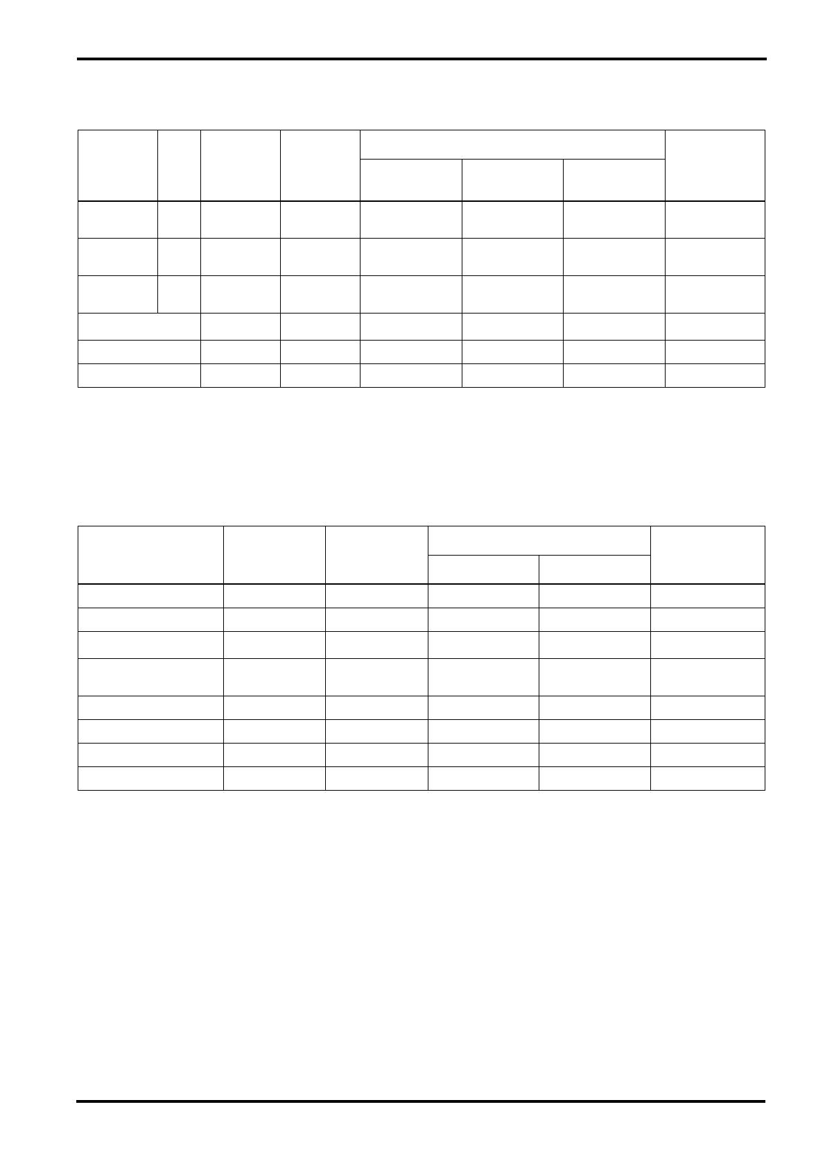
■ Input specifications
■ Output specifications
1. Sensitivity is the lowest level that will produce an output of +4 dB (1.23V) or the nominal output level when the unit is set to maximum gain.
2. XLR type connectors and phone jacks (TRS) (T=Hot, R=Cold, S=Gnd) are balanced.
3. Phone jacks are unbalanced.
4. Phone jacks (I/O) (T=OUT, R=IN, S=GND) are unbalanced.
• 0dB=0.775Vrms, 0dBV=1Vrms
1. XLR type connectors are balanced.
2. Phone jacks are unbalanced.
3. ST phone jacks (T=L, R=R, S=GND) are unbalanced.
4. Phone jacks (I/O) (T=OUT, R=IN, S-GND) are unbalansed.
• 0dB=0.775Vrms, 0dBV=1Vrms
Input
connectors
Gain
trim
Input
impedance
Nominal
impedance
Input level
Connector type
Sensitivity
1
Nominal level
Max. before
clipping
MIC INPUT
(1-8)
MAX
MIN
5kΩ 50~600Ω mic
–90dB (24.5µV)
–36dB (12.3mV)
–60dB (775µV)
–16dB (123mV)
–40dB (7.75mV)
+4dB (1.23V)
XLR3-31 type
2
LINE INPUT
(1-8)
MAX
MIN
50kΩ 600Ω line
–64dB (490µV)
–10dB (245mV)
–34dB (15.5mV)
+10dB (2.45V)
–14dB (155mV)
+30dB (24.5V)
Phone jack (TRS)
2
ST INPUT
(9-12)
MAX
MIN
10kΩ 600Ω line
–54dB (1.55mV)
–10dB (245mV)
–34dB (15.5mV)
+10dB (2.45V)
–14dB (155mV)
+30dB (24.5V)
Phone jack
3
RTN (L•R) 10kΩ 600Ω line –12dB (195mV) +4dB (1.23V) +20dB (7.75V)
Phone jack
3
TAPE IN (L•R) 10kΩ 600Ω line –26dBV (50.1mV) –10dBV (316mV) +18dBV (7.75V) RCA pin jack
INS I/O (1-4) 10kΩ 600Ω line –20dB (77.5mV) 0dB (775mV) +20dB (7.75V) Phone jack (I/O)
4
Output connector
Output
impedance
Nominal
impedance
Output level
Connector type
Nominal
Max. before clipping
ST OUTPUT (L•R) 150Ω 600Ω Lines +4dB (1.23V) +24dB (12.3V) XLR-3-32 type
1
GROUP OUTPUT (1-4) 75Ω 600Ω Lines +4dB (1.23V) +20dB (7.75V) Phone jack
2
MONITOR1 OUT 75Ω 600Ω Lines +4dB (1.23V) +20dB (7.75V)
Phone jack
2
SEND MONI1,
EFFECT/MONI2
75Ω 600Ω Lines +4dB (1.23V) +20dB (7.75V)
Phone jack
2
C-R OUT 470Ω 10kΩ Lines +4dB (1.23V) +20dB (7.75V) ST phone jack
3
REC OUT (L•R) 600Ω 10kΩ Lines –10dBV (316mV) +10dBV (3.16V) RCA pin jack
PHONES 100Ω 40Ω Phones 3mW 100mW ST phone jack
INS I/O (1-4) 600Ω 10kΩ Lines 0dB (775mV) +20dB (7.75V) Phone jack
4
12 Specifications
MX12/4—Owner’s Manual
■ Dimensions
Specifications are subject to change without prior notice.
W:436.2
310
H:83.1
3.2
76.6
D:401.2
13.5
320
Units mm
Block and Level diagram 13
MX12/4—Owner’s Manual
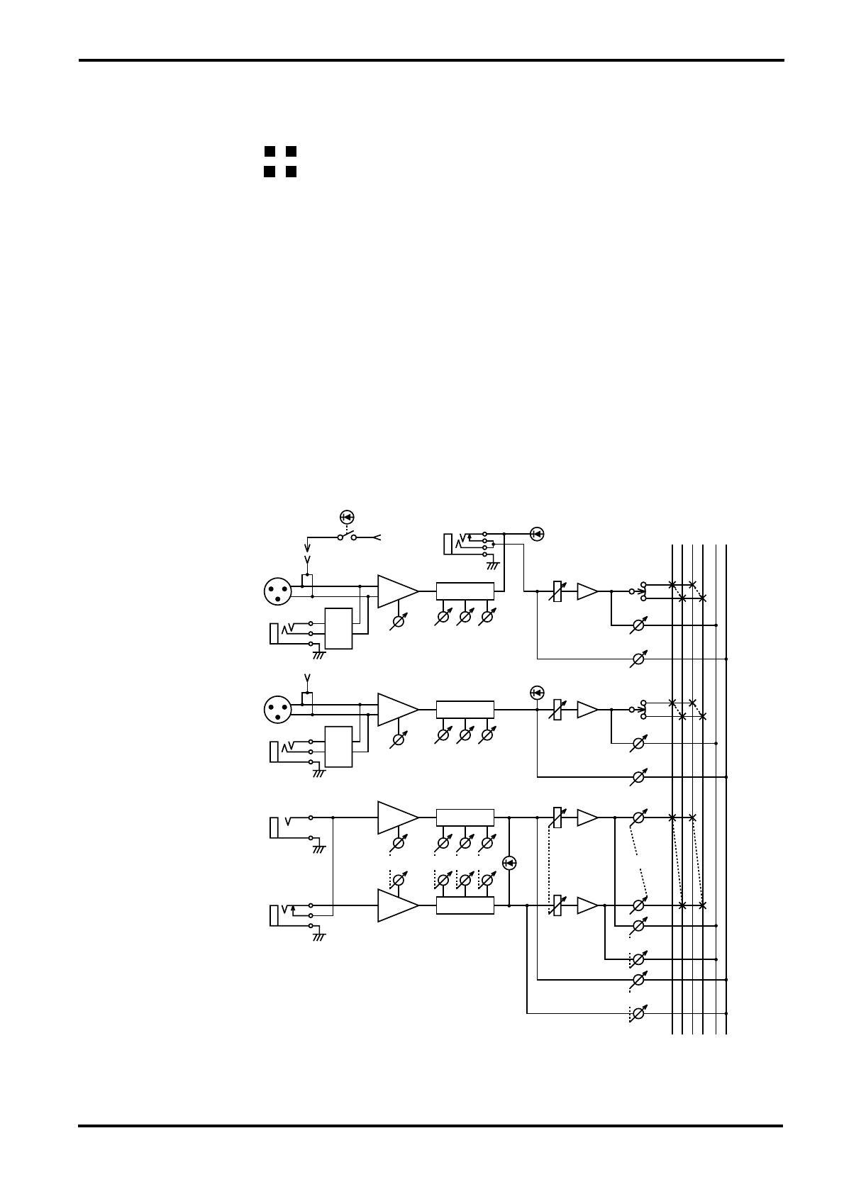
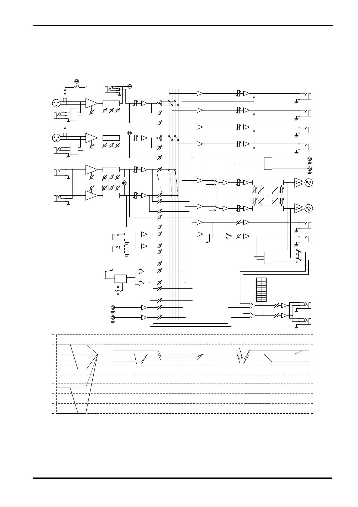
■ Block and Level diagram
EFFECT
EFFECT
GROUP,EFFECT,MONITOR
EFFECT,MONITOR
GROUP,ST
EFFECT,MONITOR,TAPE
(from EFFECT)
7 BAND ST GEQ
7 BAND ST GEQ
ST
ST
INS
MONI
ST
REC
ST
TAPE
RTN
MIC
MIC
LINE
LINE
GROUP 3 4
ST
ST
OUTPUT
EFFECT
MONI
MONI
ST
–50
–40
–30
–20
–10
0
10
20 20
10
0
–10
–20
–30
–40
–50
–60–60
EFFECT
/MONI
PEAK
PEAK
PHANTOM
TAPE IN
(to DSP)
ON
S HALL
L HALL
VOCAL
DSP
ST
MONI
RTN
L(MONO)
R
PAD
EFFECT
MONI 2
EFFECT/
MONI 2
MONI 1
SEND
EFFECT/
MONI 2
MONI 1
PAD
REC OU
L
R
R
L
8k4k
250125
ST
C-R.PHONES
C-R OUT
GROUP 4
GROUP 3
4
3
GROUP
OUTPUT
2
1
GROUP 2
ST
GAIN
LOW
MID HIGH
BAL
R
L(MONO)
EQHA
INPUT
9/10
11/12
HA EQ
LOW
MID
EQ
GAIN
HA
HIGH
PAN
PAD
MIC
LINE
INPUT
5-8
EFFECT
MONI
MONI
EFFECT
INPUT
1-4
LINE
MIC
INS
I/O
PAD
PHANTOM
MASTER
GROUP ST
TAPE IN
PHONES
R
L
GROUP 1
RL4321
PAN
HIGH
HA
GAIN
EQ
MID
LOW
PEAK

VV68420 R0 1 IP YAMAHA CORPORATION
P.O.Box 1, Hamamatsu, Japan
96 09 700 NP Printed in Taiwan
- Главная
-
Yamaha
-
Микшеры
-
MX12/4
На этой странице вы найдёте полный список документов на Микшеры Yamaha MX12/4.
Выберите необходимый PDF файл.
-

Микшеры
Yamaha MX12/4 Руководство по эксплуатацииТип файла
PDFРазмер
276 KbКол-во страниц
16Просмотров
13011Download / Read online

- 1
Другие Yamaha Микшеры
-
Yamaha ProMix 01 Руководство по эксплуатации
PDF файлов
1Просмотров
27139 -
Yamaha DSP5D Руководство пользователя
PDF файлов
5Просмотров
20877 -
Yamaha MG166CX-USB Руководство пользователя
PDF файлов
3Просмотров
20385 -
Yamaha MX12/4 Руководство по эксплуатации
PDF файлов
1Просмотров
19578 -
Yamaha MG82cx Руководство пользователя
PDF файлов
3Просмотров
14251 -
Yamaha PM5D-RH V2 Руководство пользователя
PDF файлов
2Просмотров
7339
Другие устройства Yamaha
-
Стереоресиверы
Yamaha HTR-6130 Руководство пользователяPDF файлов
2Просмотров
38146 -
Стереоресиверы
Yamaha HTR-5930 Руководство пользователяPDF файлов
2Просмотров
36807 -
Мотоциклы
Yamaha FJR1300 Руководство пользователяPDF файлов
2Просмотров
36302 -
Стереоресиверы
Yamaha RX-V357 Руководство по эксплуатацииPDF файлов
1Просмотров
35634 -
Стереоресиверы
Yamaha RX-V440RDS Руководство по эксплуатацииPDF файлов
1Просмотров
33781 -
Стереоресиверы
Yamaha HTR-6030 Руководство по эксплуатацииPDF файлов
1Просмотров
31508
Вопросы
-
слабая батарея
Ноутбуки
Acer
1310
Alex 12.02.2016 17:26
Ранее вы смотрели
Производители
ButtKicker
Crowson Technology
K2 Mounts
Kestrel Meters
Kole Audio
Officemate International Corporation
Plasmon
Stealth Cam
Technicolor
ViewSonic
Типы устройств
IP Софтфоны (программные телефоны)
Телефон-трубки
Модемы и роутеры
Бутербродницы (Сэндвичницы)
Настольные пилы
Уличная газовая горелка
Защита от перенапряжения
Музыкальное оборудование
Медленноварки SeariousTM
Автомобильное освещение
Устройства
AeroComm CL4424
Avaya BayRS Version 15.1.0.0
Bosch SHY99A
Craftsman Utility Sharpener (21174)
Hans Grohe II
KitchenAid KSRV22FVBT02
Lincoln Electric LINCOLN WELDING ARMS IM886
Magikitch’n CG-60
Philips SWV3800
Sony HVL-S3D
freeuserguide.ru
About Us
Contacts
Disclamers
Privacy Policy
Эта страница полезна для вас? Поделитесь ссылкой:
![]()
Русский
- Bedienungsanleitung Yamaha MX12/4
- Yamaha MX12/4 User Manual
- Manual Usuario Yamaha MX12/4
- Mode d’emploi Yamaha MX12/4
- Istruzioni Yamaha MX12/4
- инструкция Yamaha MX12/4
- Yamaha MX12/4の取扱説明書
- Handleiding Yamaha MX12/4
- Manual de uso Yamaha MX12/4
Вам нужна инструкция? Мы поможем Вам ее найти и сэкономить Ваше время.
- 16 stron
- 0.27 mb
Изделие Yamaha MX12/4, а также другие, которыми Вы пользуетесь ежедневно, наверняка вы получили в комплекте с инструкцией обслуживания. Из опыта наших пользователей мы знаем, что большинство из Вас не уделили этому особого внимания. Большая часть инструкций, сразу же после покупки попадает в корзину для мусора вместе с коробкой — это ошибка. Ознакомьтесь с информацией, касающейся инструкции Yamaha MX12/4, которая поможет Вам в будущем сэкономить нервы и избежать головной боли.
Важная подсказка — не забывайте хотя бы раз прочитать инструкцию Yamaha MX12/4
Если вы не хотите каждый раз читать информационные брошюры, касающиеся, тех или Yamaha MX12/4 иных изделий, достаточно, прочитать их раз — сразу же после покупки устройства. Вы получите основное знания, касающиеся поддержания изделия Yamaha MX12/4 в хорошем эксплуатационном состоянии, так, чтобы без проблем достигнуть его планируемого цикла работы. Затем инструкцию можно отложить на полку и вернуться к ней только в случае, если вы не уверены, правильно ли проводится техобслуживание изделия. Правильный уход является необходимым элементом Вашего удовольствия Yamaha MX12/4.
Раз в году пересмотрите шкафчик, в котором держите инструкции для всех устройств, — выбросите те, которыми вы уже не пользуетесься. Это поможет Вам сохранять порядок в своей домашней базе инструкций обслуживания.
Summary of Contents for Yamaha MX12/4
Что находится в инструкции Yamaha MX12/4? Почему стоит ее прочитать?
- Гарантия и подробности, касающиеся техобслуживания изделия
Хорошей идеей будет прикрепить чек к странице инструкции. Если что-то плохое случится во время использования Yamaha MX12/4, у вас будет комплект документов, необходимый для гарантийного ремонта. В этой части инструкции вы найдете информацию об авторизованных сервисных центрахYamaha MX12/4 а также, как самостоятельно правильно ухаживать за оборудованием — так, чтобы не потерять гарантийных прав. - Указания по монтажу и Setup
Не терять нервов и времени на самостоятельную попытку установки и первого запуска изделия. Воспользуйтесь рекомендациями производителя Yamaha MX12/4 чтобы правильно запустить изделие, без лишнего риска повреждения оборудования. - Информация, касающаяся дополнительных запчастей (входящих в комплект а также являющихся опцией)
Пересматривая эту часть документа вы сможете проверить, доставлен ли ваш Yamaha MX12/4 с полним комплектом аксессуаров. Вы также сможете узнать, какие дополнительные запчасти или аксессуары для Yamaha MX12/4 Вы сможете найти и докупить к своему устройству. - Troubleshooting
Самые частые проблемы, касающиеся Yamaha MX12/4 и методы их решения. Это очень полезная часть руководства по обслуживанию — она позволит Вам сэкономить много времени на поиск решений. 90% проблем с Yamaha MX12/4 повторяется у многих пользователей. - Требования, касающиеся питания и энергетический класс
Информация, касающаяся количества потребляемой энергии, а также рекомендации, касающиеся установки и питания Yamaha MX12/4. Прочитайте, чтобы оптимально пользоваться Yamaha MX12/4 и не использовать большего количества ресурсов, нежели это необходимо для правильной работы изделия. - Специальные функции Yamaha MX12/4
Здесь вы можешь узнать, как персонализировать изделие Yamaha MX12/4. Вы узнаете, какие дополнительные функции могут помочь Вам удобно использовать продукт Yamaha MX12/4 а также, какие функции Вашего устройства оптимальны для выполнения конкретной деятельности.
Как видите в инструкции вы найдете информацию, которая реально поможет Вам в использовании Вашего изделия. Стоит с ней ознакомиться, чтобы избежать разочарований, возникающих из более короткого, нежели предусматривалось, периода исправности изделия Yamaha MX12/4. Если все же вы не хотите копить инструкции в своем доме, наш сайт поможет Вам в этом — вы должны найти у нас руководство по обслуживанию большинства из своих устройств, а также Yamaha MX12/4.
Комментарии (0)
Хорошее руководство по эксплуатации
Законодательство обязывает продавца передать покупателю, вместе с товаром, руководство по эксплуатации Yamaha MX12/4. Отсутствие инструкции либо неправильная информация, переданная потребителю, составляют основание для рекламации в связи с несоответствием устройства с договором. В законодательстве допускается предоставлении руководства в другой, чем бумажная форме, что, в последнее время, часто используется, предоставляя графическую или электронную форму инструкции Yamaha MX12/4 или обучающее видео для пользователей. Условием остается четкая и понятная форма.
Что такое руководство?
Слово происходит от латинского «instructio», тоесть привести в порядок. Следовательно в инструкции Yamaha MX12/4 можно найти описание этапов поведения. Цель инструкции заключается в облегчении запуска, использования оборудования либо выполнения определенной деятельности. Инструкция является набором информации о предмете/услуге, подсказкой.
К сожалению немного пользователей находит время для чтения инструкций Yamaha MX12/4, и хорошая инструкция позволяет не только узнать ряд дополнительных функций приобретенного устройства, но и позволяет избежать возникновения большинства поломок.
Из чего должно состоять идеальное руководство по эксплуатации?
Прежде всего в инструкции Yamaha MX12/4 должна находится:
— информация относительно технических данных устройства Yamaha MX12/4
— название производителя и год производства оборудования Yamaha MX12/4
— правила обслуживания, настройки и ухода за оборудованием Yamaha MX12/4
— знаки безопасности и сертификаты, подтверждающие соответствие стандартам
Почему мы не читаем инструкций?
Как правило из-за нехватки времени и уверенности в отдельных функциональностях приобретенных устройств. К сожалению само подсоединение и запуск Yamaha MX12/4 это слишком мало. Инструкция заключает ряд отдельных указаний, касающихся функциональности, принципов безопасности, способов ухода (даже то, какие средства стоит использовать), возможных поломок Yamaha MX12/4 и способов решения проблем, возникающих во время использования. И наконец то, в инструкции можно найти адресные данные сайта Yamaha, в случае отсутствия эффективности предлагаемых решений. Сейчас очень большой популярностью пользуются инструкции в форме интересных анимаций или видео материалов, которое лучше, чем брошюра воспринимаются пользователем. Такой вид инструкции позволяет пользователю просмотреть весь фильм, не пропуская спецификацию и сложные технические описания Yamaha MX12/4, как это часто бывает в случае бумажной версии.
Почему стоит читать инструкции?
Прежде всего здесь мы найдем ответы касательно конструкции, возможностей устройства Yamaha MX12/4, использования отдельных аксессуаров и ряд информации, позволяющей вполне использовать все функции и упрощения.
После удачной покупки оборудования/устройства стоит посвятить несколько минут для ознакомления с каждой частью инструкции Yamaha MX12/4. Сейчас их старательно готовят или переводят, чтобы они были не только понятными для пользователя, но и чтобы выполняли свою основную информационно-поддерживающую функцию.
-
Инструкции по эксплуатации
1

Yamaha MX12/4 инструкция по эксплуатации
(16 страниц)
- Языки:Английский
-
Тип:
PDF -
Размер:
432.33 KB
Просмотр
На NoDevice можно скачать инструкцию по эксплуатации для Yamaha MX12/4. Руководство пользователя необходимо для ознакомления с правилами установки и эксплуатации Yamaha MX12/4. Инструкции по использованию помогут правильно настроить Yamaha MX12/4, исправить ошибки и выявить неполадки.
Руководства Yamaha MX12 4 Размер файлов: 1304 KB, Язык: English, Формат: pdf, Платформа: Windows/Linux, Дата: 2016-11-17
На данной странице вы можете скачать руководства Yamaha MX12 4. Мы предлагаем вам ознакомиться с руководством пользователя, инструкцией по сервисному обслуживанию и ремонту.
Также здесь вы найдете список заказных номеров на комплектующие Yamaha MX12 4.
Все файлы предоставляются исключительно в ознакомительных целях. И не являютя руководством по ремонту, а направлены лишь на то чтобы помочь вам более детально ознакомиться с принципом построения устройства.
Содержимое представленных здесь руководств требуют от вас знания технического английского языка.
Если вы собираетесь скачать руководство по сервисному обслуживанию Yamaha MX12 4, иными словами сервис мануал, вы дожны обладать хотя бы минимальными познаниями в области электроники и пониманием базовых принципов работы электромеханических устройств.
Для просмотра руководств вам понадобится Adobe Acrobat Reader версии 9 и выше либо другая программа для просмотра pdf файлов.
В связи с популярностью информации представленной на сайте и ее бесплатного предоставления конечному пользователю, убедительная просьба использовать специальные программные продукты для многопотокового скачивания файлов.
Руководства для Yamaha MX12 4
- Руководство пользователя (User manual)
- Руководство по сервисному обслуживанию (Service manual)
- Руководство по ремонту (Repair manual)
- Перечень комплектующих (PartList)