
![]()
WRE6505 v2
Wireless AC750 Range Extender
Version 1.00
Edition 1, 10/2016
Quick Start Guide
User’s Guide
Default Login Details
|
Web Address |
http://zyxelsetup |
|
http://DHCP-assigned IP |
|
|
http://192.168.1.2 |
|
|
www.zyxel.com |
|
|
Password |
1234 |
Copyright © 2016 ZyXEL Communications Corporation

IMPORTANT!
READ CAREFULLY BEFORE USE.
KEEP THIS GUIDE FOR FUTURE REFERENCE.
Related Documentation
•Quick Start Guide
The Quick Start Guide shows how to connect the WRE6505 v2 and access the Web Configurator wizards.
•More Information
Go to support.zyxel.com to find other information on the WRE6505 v2.
WRE6505 v2 User’s Guide
2

|
Contents Overview |
|
|
Contents Overview |
|
|
User’s Guide ……………………………………………………………………………………………………………………….. |
8 |
|
Introduction …………………………………………………………………………………………………………………………….. |
9 |
|
The Web Configurator …………………………………………………………………………………………………………….. |
13 |
|
WRE6505 v2 Modes ………………………………………………………………………………………………………………. |
19 |
|
Repeater Mode ……………………………………………………………………………………………………………………… |
21 |
|
Access Point Mode ………………………………………………………………………………………………………………… |
27 |
|
eaZy123 Wizard Setup ……………………………………………………………………………………………………………. |
33 |
|
Tutorials ……………………………………………………………………………………………………………………………….. |
38 |
|
Technical Reference ………………………………………………………………………………………………………….. |
46 |
|
Monitor …………………………………………………………………………………………………………………………………. |
47 |
|
Wireless LAN ………………………………………………………………………………………………………………………… |
49 |
|
LAN ……………………………………………………………………………………………………………………………………… |
66 |
|
One Connect …………………………………………………………………………………………………………………………. |
68 |
|
Maintenance ………………………………………………………………………………………………………………………….. |
70 |
|
Troubleshooting …………………………………………………………………………………………………………………….. |
83 |
WRE6505 v2 User’s Guide
3

|
Table of Contents |
||
|
Table of Contents |
||
|
Contents Overview ……………………………………………………………………………………………………………… |
3 |
|
|
Table of Contents ………………………………………………………………………………………………………………… |
4 |
|
|
Part I: User’s Guide ………………………………………………………………………………. |
8 |
|
|
Chapter |
1 |
|
|
Introduction…………………………………………………………………………………………………………………………. |
9 |
|
|
1.1 |
Overview …………………………………………………………………………………………………………………………… |
9 |
|
1.2 |
Securing the WRE6505 v2 …………………………………………………………………………………………………. |
10 |
|
1.3 |
Front Panel ………………………………………………………………………………………………………………………. |
10 |
|
1.4 |
WPS Button ……………………………………………………………………………………………………………………… |
11 |
|
1.4.1 Wi-Fi Protected Setup ………………………………………………………………………………………………. |
12 |
|
|
Chapter |
2 |
|
|
The Web Configurator ………………………………………………………………………………………………………… |
13 |
|
|
2.1 |
Overview …………………………………………………………………………………………………………………………. |
13 |
|
2.2 |
Accessing the Web Configurator …………………………………………………………………………………………. |
13 |
|
2.2.1 Login Screen …………………………………………………………………………………………………………… |
13 |
|
|
2.2.2 Password Screen …………………………………………………………………………………………………….. |
14 |
|
|
2.2.3 Home Screen …………………………………………………………………………………………………………… |
15 |
|
|
2.3 |
Navigating the Web Configurator ………………………………………………………………………………………… |
16 |
|
2.3.1 Title Bar ………………………………………………………………………………………………………………….. |
17 |
|
|
2.3.2 Navigation Panel ……………………………………………………………………………………………………… |
18 |
|
|
2.4 |
Resetting the WRE6505 v2 ………………………………………………………………………………………………… |
18 |
|
Chapter |
3 |
|
|
WRE6505 v2 Modes ……………………………………………………………………………………………………………. |
19 |
|
|
3.1 |
Overview …………………………………………………………………………………………………………………………. |
19 |
|
3.1.1 Device Modes ………………………………………………………………………………………………………….. |
19 |
|
|
Chapter |
4 |
|
|
Repeater Mode …………………………………………………………………………………………………………………… |
21 |
|
|
4.1 |
Overview …………………………………………………………………………………………………………………………. |
21 |
|
4.2 What You Can Do …………………………………………………………………………………………………………….. |
21 |
|
|
4.3 |
What You Need to Know ……………………………………………………………………………………………………. |
21 |
|
4.3.1 Setting your WRE6505 v2 to Repeater Mode ………………………………………………………………. |
22 |
|
|
4.3.2 Configuring your WLAN, LAN and Maintenance Settings ………………………………………………. |
22 |
WRE6505 v2 User’s Guide
4

|
Table of Contents |
||
|
4.4 |
Repeater Mode Status Screen ……………………………………………………………………………………………. |
22 |
|
4.5 |
Configuration Menus …………………………………………………………………………………………………………. |
25 |
|
Chapter |
5 |
|
|
Access Point Mode…………………………………………………………………………………………………………….. |
27 |
|
|
5.1 |
Overview …………………………………………………………………………………………………………………………. |
27 |
|
5.2 What You Can Do …………………………………………………………………………………………………………….. |
27 |
|
|
5.3 |
What You Need to Know ……………………………………………………………………………………………………. |
28 |
|
5.3.1 Setting your WRE6505 v2 to AP Mode ……………………………………………………………………….. |
28 |
|
|
5.3.2 Configuring your WLAN, LAN and Maintenance Settings ………………………………………………. |
28 |
|
|
5.4 |
AP Mode Status Screen …………………………………………………………………………………………………….. |
28 |
|
5.5 |
Configuration Menus …………………………………………………………………………………………………………. |
31 |
|
Chapter |
6 |
|
|
eaZy123 Wizard Setup………………………………………………………………………………………………………… |
33 |
|
|
6.1 |
Overview …………………………………………………………………………………………………………………………. |
33 |
|
6.2 |
Accessing the Wizard ………………………………………………………………………………………………………… |
33 |
|
6.3 |
Using the Wizard ………………………………………………………………………………………………………………. |
33 |
|
6.3.1 Repeater Mode ………………………………………………………………………………………………………… |
33 |
|
|
6.3.2 AP Mode …………………………………………………………………………………………………………………. |
36 |
|
|
Chapter |
7 |
|
|
Tutorials…………………………………………………………………………………………………………………………….. |
38 |
|
|
7.1 |
Overview …………………………………………………………………………………………………………………………. |
38 |
|
7.2 |
Connecting to the Internet from an Access Point …………………………………………………………………… |
38 |
|
7.3 |
Connecting to a Wireless Network Using WPS ……………………………………………………………………… |
38 |
|
7.3.1 Push Button Configuration (PBC) ……………………………………………………………………………….. |
39 |
|
|
7.3.2 PIN Configuration …………………………………………………………………………………………………….. |
40 |
|
|
7.4 |
Connecting the WRE6505 v2 (in Repeater mode) to an AP ……………………………………………………. |
41 |
|
7.4.1 Selecting an AP from an Automatically Detected List ……………………………………………………. |
42 |
|
|
7.4.2 Selecting an AP by Manually Entering Security Information …………………………………………… |
43 |
|
Part II: Technical Reference…………………………………………………………………. |
46 |
|
Chapter 8 |
|
|
Monitor………………………………………………………………………………………………………………………………. |
47 |
|
8.1 Overview …………………………………………………………………………………………………………………………. |
47 |
|
8.2 What You Can Do …………………………………………………………………………………………………………….. |
47 |
|
8.3 Packet Statistics Screen ………………………………………………………………………………………………….. |
47 |
|
Chapter 9 |
|
|
Wireless LAN……………………………………………………………………………………………………………………… |
49 |
WRE6505 v2 User’s Guide
5

|
Table of Contents |
|||
|
9.1 Overview …………………………………………………………………………………………………………………………. |
49 |
||
|
9.2 What You Can Do …………………………………………………………………………………………………………….. |
49 |
||
|
9.3 What You Should Know …………………………………………………………………………………………………….. |
49 |
||
|
9.3.1 Wireless Security Overview ……………………………………………………………………………………….. |
50 |
||
|
9.4 General Wireless LAN Screen ……………………………………………………………………………………………. |
51 |
||
|
9.5 Wireless Security ……………………………………………………………………………………………………………… |
54 |
||
|
9.5.1 No Security ……………………………………………………………………………………………………………… |
54 |
||
|
9.5.2 WEP Encryption ………………………………………………………………………………………………………. |
54 |
||
|
9.5.3 WPA-PSK/WPA2-PSK ………………………………………………………………………………………………. |
56 |
||
|
9.6 AP Select Screen ……………………………………………………………………………………………………………… |
57 |
||
|
9.7 MAC Filter ……………………………………………………………………………………………………………………….. |
60 |
||
|
9.8 Wireless LAN Advanced Screen …………………………………………………………………………………………. |
61 |
||
|
9.9 Quality of Service (QoS) Screen …………………………………………………………………………………………. |
62 |
||
|
9.10 WPS Screen …………………………………………………………………………………………………………………… |
62 |
||
|
9.11 WPS Device Screen ………………………………………………………………………………………………………… |
63 |
||
|
9.12 |
Scheduling Screen ………………………………………………………………………………………………………….. |
64 |
|
|
Chapter |
10 |
||
|
LAN …………………………………………………………………………………………………………………………………… |
66 |
||
|
10.1 |
Overview ……………………………………………………………………………………………………………………….. |
66 |
|
|
10.2 |
LAN IP Screen ……………………………………………………………………………………………………………….. |
66 |
|
|
Chapter |
11 |
||
|
One Connect ……………………………………………………………………………………………………………………… |
68 |
||
|
11.1 Overview ……………………………………………………………………………………………………………………….. |
68 |
||
|
11.1.1 What You Can Do …………………………………………………………………………………………………… |
68 |
||
|
11.2 One Connect Screen ……………………………………………………………………………………………………….. |
68 |
||
|
Chapter |
12 |
||
|
Maintenance ………………………………………………………………………………………………………………………. |
70 |
||
|
12.1 |
Overview ……………………………………………………………………………………………………………………….. |
70 |
|
|
12.2 What You Can Do …………………………………………………………………………………………………………… |
70 |
||
|
12.3 |
General …………………………………………………………………………………………………………………………. |
70 |
|
|
12.4 |
System Password Screen ……………………………………………………………………………………………….. |
71 |
|
|
12.5 |
Time Screen …………………………………………………………………………………………………………………… |
71 |
|
|
12.6 |
Firmware Upgrade Screen ……………………………………………………………………………………………….. |
73 |
|
|
12.7 |
Backup / Restore Screen …………………………………………………………………………………………………. |
75 |
|
|
12.7.1 Backup Configuration ……………………………………………………………………………………………… |
76 |
||
|
12.7.2 Restore Configuration ……………………………………………………………………………………………… |
76 |
||
|
12.7.3 Back to Factory Defaults …………………………………………………………………………………………. |
77 |
||
|
12.8 |
Restart Screen ……………………………………………………………………………………………………………….. |
77 |
|
|
12.9 System Mode …………………………………………………………………………………………………………………. |
78 |
||
|
12.9.1 System WPS Behavior ……………………………………………………………………………………………. |
79 |
WRE6505 v2 User’s Guide
6

Table of Contents
|
Chapter 13 |
||
|
Troubleshooting…………………………………………………………………………………………………………………. |
83 |
|
|
13.1 |
Power, Hardware Connections, and LEDs ………………………………………………………………………….. |
83 |
|
13.2 |
WRE6505 v2 Access and Login ………………………………………………………………………………………… |
84 |
|
13.3 |
Internet Access ………………………………………………………………………………………………………………. |
85 |
|
13.4 |
Resetting the WRE6505 v2 to Its Factory Defaults ………………………………………………………………. |
86 |
|
13.5 |
Wireless Problems ………………………………………………………………………………………………………….. |
86 |
|
Appendix |
A |
Customer Support ……………………………………………………………………………………………. |
88 |
|
Appendix |
B |
Setting Up Your Computer’s IP Address ……………………………………………………………… |
94 |
|
Appendix |
C Legal Information …………………………………………………………………………………………… |
122 |
|
|
Index ……………………………………………………………………………………………………………………………….. |
130 |
WRE6505 v2 User’s Guide
7

8
1
Introduction
1.1 Overview
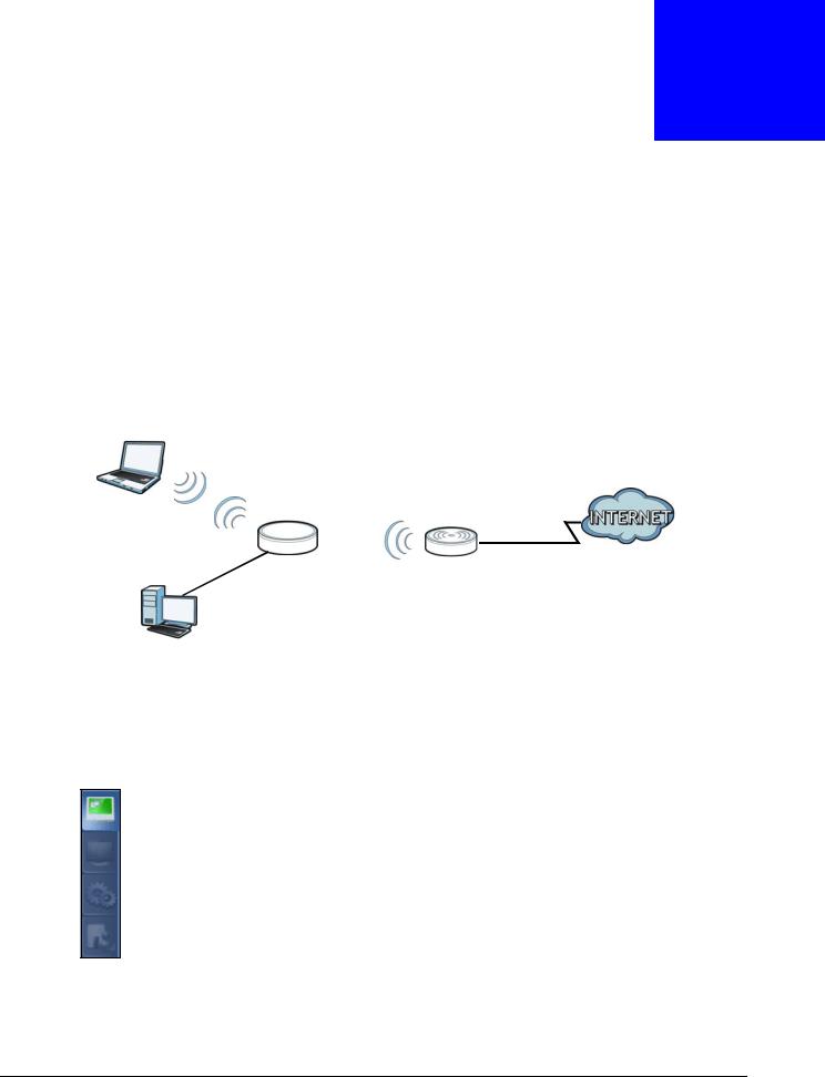
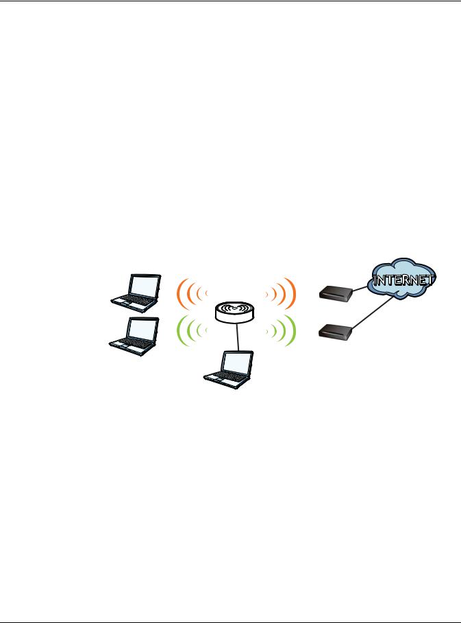
The WRE6505 v2 allows you to easily extend existing IEEE 802.11 b/g/n/ac wireless networks fast and easy. Simply plug the WRE6505 v2 directly into a power outlet and the LED signal strength indicator allows you to determine the ideal installation location. The one-click Wi-Fi Protected Setup (WPS Button on page 11) provides frustration-free wireless client setup and completes the instant network access setup.
Figure 1 Universal Repeater
WLAN
AP
N
Your can create the following connections using the WRE6505 v2:
•LAN. You can connect network devices via the Ethernet port of the WRE6505 v2 so that they can communicate with each other and access the Internet.
•WLAN. Wireless clients can connect to the WRE6505 v2 to access network resources.
Use a (supported) web browser to manage the WRE6505 v2.
See Chapter 7 on page 38 for more information.
WRE6505 v2 User’s Guide
9
Chapter 1 Introduction
1.2 Securing the WRE6505 v2
Do the following things regularly to make the WRE6505 v2 more secure and to manage the WRE6505 v2 more effectively.
•Change the password. Use a password that’s not easy to guess and that consists of different types of characters, such as numbers and letters.
•Write down the password and put it in a safe place.
•Back up the configuration (and make sure you know how to restore it). Restoring an earlier working configuration may be useful if the device becomes unstable or even crashes. If you forget your password, you will have to reset the WRE6505 v2 to its factory default settings. If you backed up an earlier configuration file, you would not have to totally re-configure the WRE6505 v2. You could simply restore your last configuration.
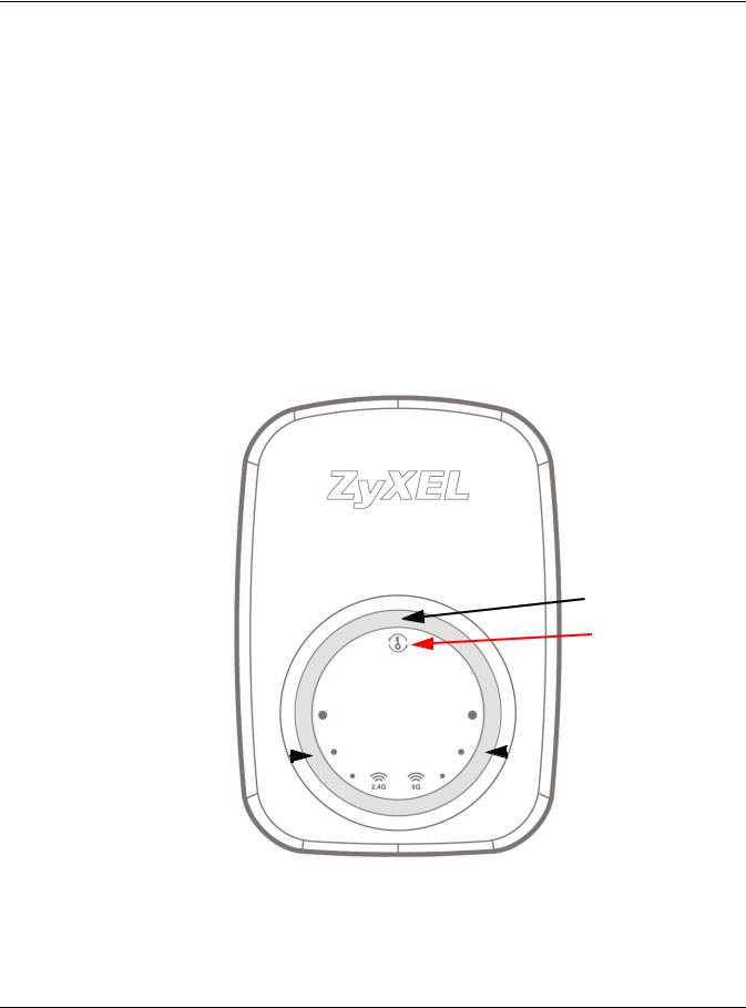
1.3Front Panel
Figure 2 Front Panel
 Power/WPS LED
 WPS Button
2.4 GHz Signal
Strength LEDs 
 5 GHz Signal
Strength LEDs
WRE6505 v2 User’s Guide
10
![]()
Chapter 1 Introduction
The following table describes the LEDs.
Table 1 Front Panel LEDs
|
LED |
COLOR |
STATUS |
DESCRIPTION |
|
Power/WPS |
Blue |
On |
The WRE6505 v2 is receiving power and functioning properly. |
|
Blinking |
The WRE6505 v2 is booting, resetting to factory defaults, the |
||
|
WRE6505 v2 is waiting for another WPS device to connect, or |
|||
|
firmware upgrade is in progress. |
|||
|
Off |
The WRE6505 v2 is not receiving power, or there is no WPS |
||
|
connection established. |
|||
|
2.4 GHz Signal |
White |
On |
The more the LEDs are on the better the Wi-Fi signal strength. |
|
Strength |
• Three LEDs: signifies a signal strength of 51% ~ 100% |
||
|
• Two LEDs: signifies a signal strength of 20% ~ 50% |
|||
|
• One LED: signifies a signal strength under 20% |
|||
|
Blinking |
Firmware upgrade is in progress. |
||
|
Off |
The 2.4 GHz wireless LAN is not enabled, there is no signal |
||
|
detected or the WRE6505 v2 (repeater mode) is not connected |
|||
|
to a wireless router/AP, or the LEDs are turned off using the |
|||
|
WPS button. |
|||
|
5 GHz Signal |
White |
On |
The more the LEDs are on the better the Wi-Fi signal strength. |
|
Strength |
• Three LEDs: signifies a signal strength of 51% ~ 100% |
||
|
• Two LEDs: signifies a signal strength of 20% ~ 50% |
|||
|
• One LED: signifies a signal strength under 20% |
|||
|
Blinking |
Firmware upgrade is in progress. |
||
|
Off |
The 5 GHz wireless LAN is not enabled, there is no signal |
||
|
detected or the WRE6505 v2 (repeater mode) is not connected |
|||
|
to a wireless router/AP, or the LEDs are turned off using the |
|||
|
WPS button. |
|||
1.4 WPS Button
The WPS button can be used to begin Wi-Fi Protected Setup (WPS), reboot the WRE6505 v2 while keeping it’s configuration or reboot the WRE6505 v2 to factory default configuration.
Table 2 WPS Button Functions
|
ACTION |
RESULT |
|
|
Press thress times within |
Turn off or turn on all LEDs. |
|
|
5 seconds |
||
|
AP Mode |
||
|
Push twice within 5 |
The WRE6505 v2 begins connecting to a wireless client via WPS. See Section 1.4.1 |
|
|
seconds |
on page 12. |
|
|
Hold for 5 to 10 seconds |
The WRE6505 v2 keeps its configuration and reboots. |
|
|
Hold for more than 10 |
The WRE6505 v2 resets its configuration to factory defaults and reboots. See |
|
|
seconds |
Section 2.4 on page 18. |
|
|
Repeater Mode |
||
|
Push twice within 5 |
The WRE6505 v2 begins connecting to a wireless client via WPS. See Section 1.4.1 |
|
|
seconds |
on page 12. |
|
|
WRE6505 v2 User’s Guide |
11

|
Chapter 1 Introduction |
||
|
Table 2 WPS Button Functions |
||
|
ACTION |
RESULT |
|
|
Hold for 5 to 10 seconds |
he WRE6505 v2 keeps its configuration and reboots. |
|
|
Hold for more than 10 |
TThe WRE6505 v2 resets its configuration to factory defaults and reboots. See |
|
|
seconds |
Section 2.4 on page 18. |
|
1.4.1 Wi-Fi Protected Setup
Your WRE6505 v2 supports Wi-Fi Protected Setup (WPS), which is an easy way to set up a secure wireless network. WPS is an industry standard specification, defined by the Wi-Fi Alliance.
WPS allows you to quickly set up a wireless network with strong security, without having to configure security settings manually. Each WPS connection works between two devices. Both devices must support WPS (check each device’s documentation to make sure).
Depending on the devices you have, you can either press a button (recommended) on the device itself, or in its configuration utility or enter a PIN (a unique Personal Identification Number that allows one device to authenticate the other) in each of the two devices. When WPS is activated on a device, it has two minutes to find another device that also has WPS activated. Then, the two devices connect and set up a secure network by themselves.
For more information on using WPS, see Section 7.3 on page 38.
WRE6505 v2 User’s Guide
12

2
The Web Configurator
2.1 Overview
This chapter describes how to access the WRE6505 v2 Web Configurator and provides an overview of its screens.
The Web Configurator is an HTML-based management interface that allows easy setup and management of the WRE6505 v2 via Internet browser. Use Internet Explorer 6.0 and later versions, Mozilla Firefox 3 and later versions, or Safari 2.0 and later versions. The recommended screen resolution is 1024 by 768 pixels.
In order to use the Web Configurator you need to allow:
•Web browser pop-up windows from your device.
•JavaScript (enabled by default).
•Java permissions (enabled by default).
Refer to Chapter 13 Troubleshooting to see how to make sure these functions are allowed in Internet Explorer.
2.2Accessing the Web Configurator
1Make sure your WRE6505 v2 hardware is properly connected and prepare your computer or computer network to connect to the WRE6505 v2 (refer to the Quick Start Guide).
2Launch your web browser.
3Open a web browser such as Internet Explorer and type “http://zyxelsetup” or “http://192.168.1.2” as the web address in your web browser.
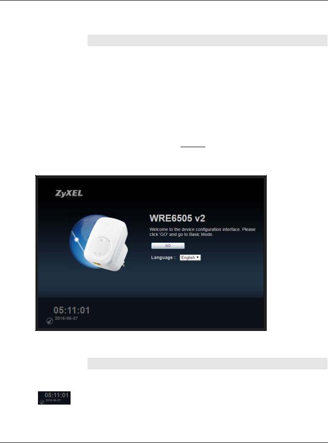
2.2.1 Login Screen
The Web Configurator initially displays the following login screen.
WRE6505 v2 User’s Guide
13

Chapter 2 The Web Configurator
Figure 3 Login Screen
The following table describes the labels in this screen.
Table 3 Login screen
|
LABEL |
DESCRIPTION |
|
Password |
Type «1234» (default) as the password. |
|
Language |
Select the language you want to use to configure the Web Configurator. Click Login. |
|
This shows the time (hh:mm) and date (yyyy:mm:dd) of the timezone you select in the |
|
|
Maintenance > Time screen (see Section 12.5 on page 71). The time is in 24-hour |
|
|
format, for example 15:00 is 3:00 PM. |
|
2.2.2 Password Screen
You should see a screen asking you to change your password (highly recommended) as shown next.
Figure 4 Change Password Screen
WRE6505 v2 User’s Guide
14
Chapter 2 The Web Configurator
The following table describes the labels in this screen.
Table 4 Change Password Screen
|
LABEL |
DESCRIPTION |
|
New Password |
Type a new password. |
|
Retype to Confirm |
Retype the password for confirmation. |
|
Apply |
Click Apply to save your changes back to the WRE6505 v2. |
|
Ignore |
Click Ignore if you do not want to change the password this time. |
2.2.3 Home Screen
If you have previously logged into the Web Configurator but did not click Logout, you may be redirected to the Home screen.
You can also open this screen by clicking Home (
 ) in the Web Configurator screens. The Home screen displays as follows.
Figure 5 Home Screen
The following table describes the labels in this screen.
Table 5 Home Screen
|
LABEL |
DESCRIPTION |
|
GO |
Click this to return to the previous screen. |
|
Language |
Select a language to go to the Web Configurator in that language and click GO. |
|
(This is just an example). This shows the time (hh:mm:ss) and date (yyyy:mm:dd) of the |
|
|
timezone you select in Section 2.2.3.1 on page 16 or Section 12.5 on page 71. |
|
WRE6505 v2 User’s Guide
15

Chapter 2 The Web Configurator
2.2.3.1 Time/Date Edit
One timezone can cover more than one country. You can choose a particular country in which the WRE6505 v2 is located and have the WRE6505 v2 display and use the current time and date for its logs.
Click the  icon to change the time and date display.
Figure 6 Change Time Zone
The following table describes the labels in this screen.
Table 6 Change Time Zone
|
LABEL |
DESCRIPTION |
|
Change time zone |
Select the specific country whose current time and date you want the WRE6505 v2 to |
|
display. |
|
|
Finish |
Click this to apply the settings and refresh the weather display. |
2.3 Navigating the Web Configurator
The following summarizes how to navigate the web configurator from the Status screen.
WRE6505 v2 User’s Guide
16

Chapter 2 The Web Configurator
Figure 7 The Web Configurator’s Main Screen
A
C
B
The Web Configurator’s main screen is divided into these parts:
•A — Title Bar
•B — Navigation Panel
•C — Main Window
2.3.1Title Bar
The title bar provides some useful links that always appear over the screens below, regardless of how deep into the Web Configurator you navigate.
Figure 8 Title Bar
The icons provide the following functions.
Table 7 Title Bar: Web Configurator Icons
|
LABEL |
DESCRIPTION |
|
Logout |
Click this at any time to exit the Web Configurator. |
|
Home |
Click this to open the home screen. See Section 2.2.3 on page 15. |
WRE6505 v2 User’s Guide
17
|
Chapter 2 The Web Configurator |
||
|
Table 7 Title Bar: Web Configurator Icons (continued) |
||
|
LABEL |
DESCRIPTION |
|
|
About |
Click this icon to view copyright and a link for related product information. |
|
|
eaZy123 |
Click this icon to open the wizard. See Chapter 6 on page 33. |
|
2.3.2 Navigation Panel
Use the menu items on the navigation panel to open screens to configure WRE6505 v2 features.
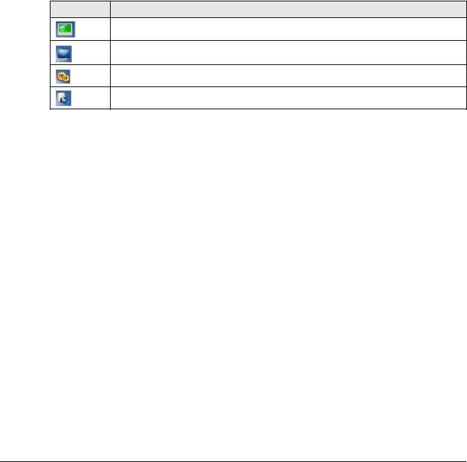
The following table describes the icons shown in the navigation panel.
Table 8 Navigation Panel Menu Icons
ICON DESCRIPTION
Click this icon to see the Status page. The information in this screen depends on the device mode you select.
Click this icon to see the Monitor navigation menu.
Click this icon to see the Configuration navigation menu.
Click this icon to see the Maintenance navigation menu.
2.4 Resetting the WRE6505 v2
If you forget your password or IP address, or you cannot access the Web Configurator, press the WPS button for more than 10 seconds to reload the factory-default configuration file. This means that you will lose all configurations that you had previously saved, the password will be reset to
1234.
1Make sure the power LED is on.
2Press and hold the WPS button. After 10 seconds, the power LED begins flashing.
3Release the WPS button. The WRE6505 v2 reloads factory defaults and begins to reboot.
WRE6505 v2 User’s Guide
18

3
WRE6505 v2 Modes
3.1 Overview
This chapter introduces the different modes available on your WRE6505 v2.
•System mode. This is the operating mode of your WRE6505 v2, or simply how the WRE6505 v2 is being used in the network.
3.1.1Device Modes
This refers to the operating mode of the WRE6505 v2, which can act as a:
•Repeater: In this mode, the WRE6505 v2 can be an access point and a wireless client at the same time. Go to Section 4.4 on page 22 to view the Status screen in this mode. Use this mode if there is an existing wireless router or access point in your network and you also want to allow clients to connect to the WRE6505 v2 wirelessly.
•Access Point: Use this mode if you want to extend your network by allowing network devices to connect to the WRE6505 v2 wirelessly. Go to Section 5.4 on page 28 to view the Status screen in this mode.
In this mode, you can also set the WRE6505 v2 to work as an AP only, a wireless bridge to establish wireless links with other APs (WDS bridge), or an AP and bridge simultaneously (WDS repeater). See Section 5.2 on page 27 for more information.
The following figure is an illustration of the device configuration modes of the WRE6505 v2.
Figure 9 Device Mode Example
Note: Choose your device mode carefully to avoid having to change it later.
WRE6505 v2 User’s Guide
19

Chapter 3 WRE6505 v2 Modes
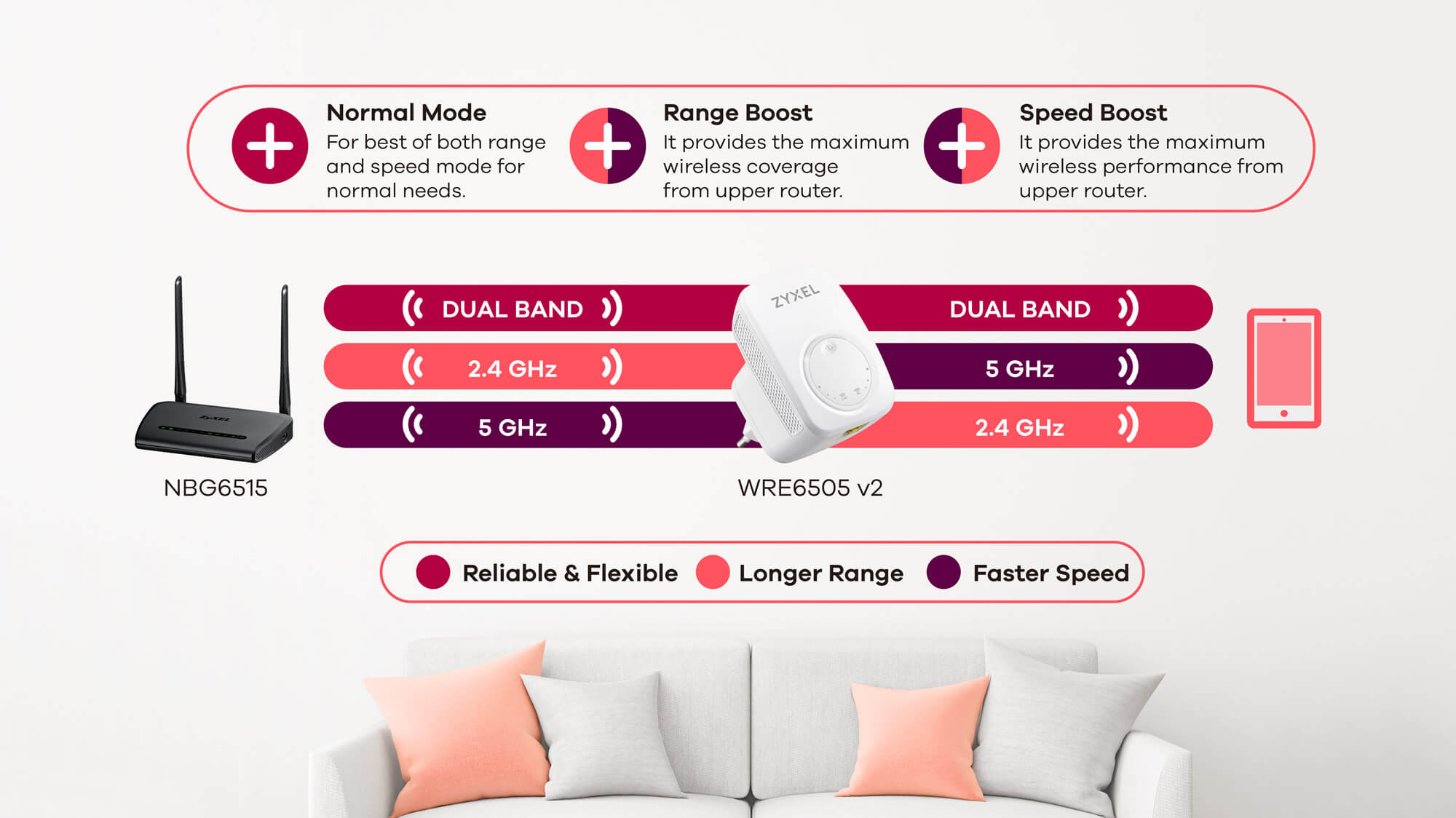
Under Repeater mode, the WRE6505 v2 supports three WPS behaviors: Normal mode, Range boost mode, and Speed boost mode. These behaviors are only available in Repeater mode through the
Maintenance screen.
3.1.1.1 Changing Operating Mode
The WRE6505 v2 is in repeater mode by default. To change its operating mode, access the web configurator and go to the Maintenance > System Mode screen. See Section 12.9 on page 78 for detailed information.
The WRE6505 v2 restarts automatically after you change operating modes.
WRE6505 v2 User’s Guide
20
![]()
4
Repeater Mode
4.1 Overview
In repeater mode, your WRE6505 v2 can act as an access point and wireless client at the same time. The WRE6505 v2 can connect to an existing network through another access point and also lets wireless clients connect to the network through it. This helps you expand wireless coverage when you have an access point or wireless router already in your network.
In the example below, the WRE6505 v2 (A) is configured as a repeater. It has three clients that want to connect to the Internet. The WRE6505 v2 wirelessly connects to the available access point (B).
Figure 10 Repeater Mode
A B
After the WRE6505 v2 and the access point connect, the WRE6505 v2 acquires its IP address from the access point. The clients of the WRE6505 v2 can now surf the Internet.
4.2What You Can Do
•Use the Status screen (Section 7.1 on page 38) to view read-only information about your WRE6505 v2.
•Use the LAN screen (Chapter 10 on page 66) to set the IP address for your WRE6505 v2.
•Use the Wireless LAN > AP Select screen (Section 9.6 on page 57) to scan for available access points within transmission range and connect to an AP.
•Use other Wireless LAN screens (Section 9.4 on page 51) to configure the wireless settings and wireless security between the wireless clients and the WRE6505 v2.
4.3What You Need to Know
With the exception of the AP Select screen other configuration screens in Repeater mode are similar to the ones in Access Point Mode. See Chapter 3 on page 19 of this User’s Guide.
WRE6505 v2 User’s Guide
21
Chapter 4 Repeater Mode
4.3.1 Setting your WRE6505 v2 to Repeater Mode
1To use your WRE6505 v2 as a repeater, see Section 3.1.1.1 on page 20.
2Connect your computer to the LAN port of the WRE6505 v2.
3Open a web browser such as Internet Explorer and type “http://zyxelsetup” or “http://192.168.1.2” as the web address in your web browser.
4Enter “1234” (default) as the password and click Login.
5Type a new password and retype it to confirm, then click Apply. Otherwise, click Ignore.
Note: You have to log in to the Web Configurator again when you change modes. As soon as you do, your WRE6505 v2 is already in Repeater mode.
Note: If a client is connected to the WRE6505 v2 through the wired Ethernet connection, the client can only access the 2.4 GHz Wi-Fi. In the following figure, the LAN Client is only able to communicate with devices in the 2.4 GHz wireless network.
Figure 11 Repeater Mode Overview
|
5 GHz |
WRE |
|
2.4 GHz |
|
|
2.4 GHz |
2.4 GHz AP |
|
2.4 GHz |
|
|
LAN Client |
4.3.2Configuring your WLAN, LAN and Maintenance Settings
•See Chapter 9 on page 49 and Chapter 10 on page 66 for information on configuring your wireless network and LAN settings.
•See Chapter 12 on page 70 for information on configuring your Maintenance settings.
4.4 Repeater Mode Status Screen
Click  to open the Status screen.
WRE6505 v2 User’s Guide
22
Chapter 4 Repeater Mode
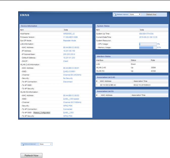
Figure 12 Status: Repeater Mode
The following table describes the labels shown in the Status screen.
Table 9 Status Screen: Repeater Mode
|
LABEL |
DESCRIPTION |
|||
|
Select a number of seconds or None from the drop-down list box to refresh all |
||||
|
screen statistics automatically at the end of every time interval or to not |
||||
|
refresh the screen statistics. |
||||
|
Click this button to refresh the status screen statistics. |
||||
|
Device Information |
||||
|
Host Name |
This is the WRE6505 v2’s system name you configure in the Maintenance > |
|||
|
General screen. |
||||
|
Firmware Version |
This is the firmware version and the date created. |
|||
|
Sys OP Mode |
This is the device mode (Section 3.1.1 on page 19) to which the WRE6505 v2 |
|||
|
is set — Repeater Mode. |
||||
|
LAN Information |
||||
|
MAC Address |
This shows the LAN Ethernet adapter MAC Address of your device. |
|||
|
IP Address |
This shows the LAN port’s IP address. |
|||
|
IP Subnet Mask |
This shows the LAN port’s subnet mask. |
|||
|
Default Gateway |
This shows the LAN port’s gateway IP address. |
|||
|
DHCP |
This shows the LAN port’s DHCP role — Client or None. |
|||
|
WLAN 2.4G Information |
||||
|
MAC Address |
This shows the wireless adapter MAC Address of your WRE6505 v2. |
|||
|
WRE6505 v2 User’s Guide |
23
|
Chapter 4 Repeater Mode |
||
|
Table 9 Status Screen: Repeater Mode |
||
|
LABEL |
DESCRIPTION |
|
|
SSID |
This shows a descriptive name used to identify the WRE6505 v2 in the wireless |
|
|
LAN. |
||
|
Channel |
This shows the channel number which you select manually or the WRE6505 v2 |
|
|
automatically scans and selects. |
||
|
Security |
This shows the level of wireless security the WRE6505 v2 is using. |
|
|
To AP Connection |
This displays whether the WRE6505 v2 is connected to an AP or not. |
|
|
To AP SSID |
This displays the SSID of the connected AP. |
|
|
Click the Release_Configuration button to remove all configured wireless |
||
|
and wireless security settings for WPS connections on the WRE6505 v2. |
||
|
To AP Security |
This displays the type of established security protocol with the AP. |
|
|
WLAN 5G Information |
||
|
MAC Address |
This shows the wireless adapter MAC Address of your WRE6505 v2. |
|
|
SSID |
This shows a descriptive name used to identify the WRE6505 v2 in the wireless |
|
|
LAN. |
||
|
Channel |
This shows the channel number which you select manually or the WRE6505 v2 |
|
|
automatically scans and selects. |
||
|
Security |
This shows the level of wireless security the WRE6505 v2 is using. |
|
|
To AP Connection |
This displays whether the WRE6505 v2 is connected to an AP or not. |
|
|
To AP SSID |
This displays the SSID of the connected AP. |
|
|
Click the Release_Configuration button to remove all configured wireless |
||
|
and wireless security settings for WPS connections on the WRE6505 v2. |
||
|
To AP Security |
This displays the type of established security protocol with the WRE6505 v2. |
|
|
System Status |
||
|
Item |
This column shows the type of data the WRE6505 v2 is recording. |
|
|
Data |
This column shows the actual data recorded by the WRE6505 v2. |
|
|
System Up Time |
This is the total time the WRE6505 v2 has been on. |
|
|
Current Date/Time |
This field displays your WRE6505 v2’s present date and time. |
|
|
System Resource |
||
|
CPU Usage |
This displays what percentage of the WRE6505 v2’s processing ability is |
|
|
currently used. When this percentage is close to 100%, the WRE6505 v2 is |
||
|
running at full load, and the throughput is not going to improve anymore. If |
||
|
you want some applications to have more throughput, you should turn off |
||
|
other applications (for example, using bandwidth management. |
||
|
Memory Usage |
This shows what percentage of the heap memory the WRE6505 v2 is using. |
|
|
Interface Status |
||
|
Interface |
This displays the WRE6505 v2 port types. The port types are: LAN and WLAN. |
|
|
Status |
For the LAN port, this field displays Down (line is down) or Up (line is up or |
|
|
connected). |
||
|
For the WLAN, it displays Up when the WLAN is enabled or Down when the |
||
|
WLAN is disabled. |
||
|
Rate |
For the LAN ports, this displays the port speed and duplex setting or is left |
|
|
blank when the line is disconnected. |
||
|
For the WLAN, it displays the maximum transmission rate when the WLAN is |
||
|
enabled and is left blank when the WLAN is disabled. |
||
|
Association List 2.4G |
||
|
WRE6505 v2 User’s Guide |
24
|
Chapter 4 Repeater Mode |
||
|
Table 9 Status Screen: Repeater Mode |
||
|
LABEL |
DESCRIPTION |
|
|
# |
This is the index number of an associated wireless station. |
|
|
MAC Address |
This field displays the MAC address of an associated wireless station. |
|
|
Association Time |
This field displays the time a wireless station first associated with the WRE6505 |
|
|
v2’s WLAN network. |
||
|
Association List 5G |
||
|
# |
This is the index number of an associated wireless station. |
|
|
MAC Address |
This field displays the MAC address of an associated wireless station. |
|
|
Association Time |
This field displays the time a wireless station first associated with the WRE6505 |
|
|
v2’s WLAN network. |
||
4.5 Configuration Menus
Use the menu in the navigation panel to configure WRE6505 v2 features in Repeater mode. The following screen and table show the features you can configure in Repeater mode.
Figure 13 Menus: Repeater Mode
The following table describes the sub-menus.
Table 10 Menus: Repeater Mode
|
LINK |
TAB |
FUNCTION |
|
Status |
Status |
This screen shows the WRE6505 v2’s general device, system and interface |
|
status information. |
||
|
MONITOR |
||
|
Monitor |
||
|
Packet |
Packet |
Use this screen to view port status, packet specific statistics, the «system |
|
Statistics |
Statistics |
up time» and so on. |
CONFIGURATION
Network
WRE6505 v2 User’s Guide
25

|
Chapter 4 Repeater Mode |
|||
|
Table 10 Menus: Repeater Mode |
|||
|
LINK |
TAB |
FUNCTION |
|
|
Wireless LAN |
General |
Use this screen to configure general wireless LAN and wireless security |
|
|
2.4G |
settings. |
||
|
AP Select |
Use this screen to choose an access point that you want the WRE6505 v2 |
||
|
to connect to. |
|||
|
MAC Filter |
Use this screen to configure the WRE6505 v2 to block access to devices or |
||
|
block the devices from accessing the WRE6505 v2. |
|||
|
Advanced |
Use this screen to configure advanced wireless settings. |
||
|
QoS |
Use this screen to enable Wi-Fi MultiMedia Quality of Service (WMMQoS). |
||
|
WPS |
Use this screen to enable WPS. |
||
|
WPS Device |
Use this screen to add a wireless station using WPS. |
||
|
Wireless LAN |
General |
Use this screen to configure general wireless LAN settings. |
|
|
5G |
|||
|
AP Select |
Use this screen to choose an access point that you want the WRE6505 v2 |
||
|
to connect to. |
|||
|
MAC Filter |
Use this screen to configure the WRE6505 v2 to block access to devices or |
||
|
block the devices from accessing the WRE6505 v2. |
|||
|
Advanced |
Use this screen to configure advanced wireless settings. |
||
|
QoS |
Use this screen to enable Wi-Fi MultiMedia Quality of Service (WMMQoS). |
||
|
WPS |
Use this screen to enable WPS. |
||
|
WPS Device |
Use this screen to add a wireless station using WPS. |
||
|
LAN |
IP |
Use this screen to configure LAN IP address and subnet mask. |
|
|
OneConnect |
OneConnect |
Use this screen to enable or disable Wi-Fi auto-configuration. |
|
|
MAINTENANCE |
|||
|
General |
General |
Use this screen to view and change administrative settings such as system |
|
|
and domain names. |
|||
|
Password |
Password |
Use this screen to change the password of your WRE6505 v2. |
|
|
Setup |
|||
|
Time |
Time Setting |
Use this screen to change your WRE6505 v2’s time and date. |
|
|
Firmware |
Firmware |
Use this screen to upload firmware to your WRE6505 v2. |
|
|
Upgrade |
Upgrade |
||
|
Backup |
Backup |
Use this screen to backup and restore the configuration or reset your |
|
|
Restore |
Restore |
WRE6505 v2 to the factory defaults. |
|
|
Restart |
Restart |
Use this screen to reboot the WRE6505 v2 without turning the power off. |
|
|
System Mode |
System Mode |
Use this screen to select how you want to use your WRE6505 v2. |
|
WRE6505 v2 User’s Guide
26
5
Access Point Mode
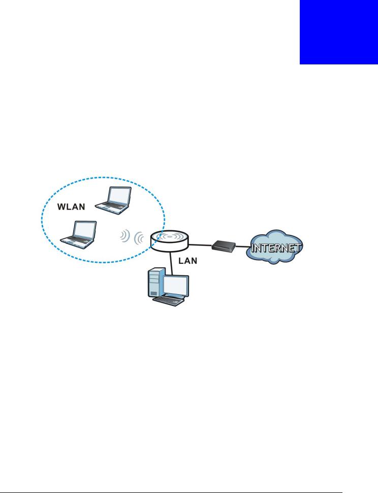
5.1 Overview
In Access Point (AP) mode your WRE6505 v2 bridges a wired network (LAN) and wireless LAN (WLAN) in the same subnet. See the figure below for an example.
Figure 14 Wireless Internet Access in Access Point Mode
Note: See Chapter 7 on page 38 for an example of setting up a wireless network in Access Point mode.
5.2What You Can Do
•Use the Status screen (Section 5.4 on page 28) to view read-only information about your WRE6505 v2.
•Use the LAN screen (Chapter 10 on page 66) to set the IP address for your WRE6505 v2 acting as an access point.
•Use the Wireless LAN screens (Section 9.10 on page 62) to configure the wireless settings and wireless security between the wireless clients and the WRE6505 v2.
WRE6505 v2 User’s Guide
27

Chapter 5 Access Point Mode
5.3 What You Need to Know
With the exception of the Scheduling screen other configuration screens in Access Point mode are similar to the ones in repeater mode. See Chapter 3 on page 19 of this User’s Guide.
5.3.1 Setting your WRE6505 v2 to AP Mode
By default, AP mode in the WRE6505 v2 is not configured with a static IP address. To set up your WRE6505 v2 in AP mode for the first time, the directly-connected router must have the DHCP server function enabled.
1To use your WRE6505 v2 as an access point, see Section 3.1.1.1 on page 20.
2Connect one end of an Ethernet cable to the Ethernet port on the WRE6505 v2 and the other end to your router.
3Connect your computer to your network, make sure both the WRE6505 v2 and computer are under the same subnet.
4Open a web browser window and type “http://zyxelsetup” in the web address. The login screen displays.
5Enter “1234” (default) as the password and click Login.
6Type a new password and retype it to confirm, then click Apply. Otherwise, click Ignore. The WRE6505 v2 Web Configurator displays, which allows you to configure the AP mode.
5.3.2Configuring your WLAN, LAN and Maintenance Settings
•See Chapter 9 on page 49 and Chapter 10 on page 66 for information on configuring your wireless network and LAN settings.
•See Chapter 12 on page 70 for information on configuring your Maintenance settings.
5.4 AP Mode Status Screen
Click  to open the Status screen.
WRE6505 v2 User’s Guide
28

Chapter 5 Access Point Mode
Figure 15 Status Screen: Access Point Mode
The following table describes the labels shown in the Status screen.
Table 11 Status Screen: Access Point Mode
|
LABEL |
DESCRIPTION |
|||
|
Select a number of seconds or None from the drop-down list box to refresh all |
||||
|
screen statistics automatically at the end of every time interval or to not refresh |
||||
|
the screen statistics. |
||||
|
Click this button to refresh the status screen statistics. |
||||
|
Device Information |
||||
|
Host Name |
This is the WRE6505 v2’s system name you configure in the Maintenance > |
|||
|
General screen. |
||||
|
Firmware Version |
This is the firmware version and the date created. |
|||
|
Sys OP Mode |
This is the device mode (Section 3.1.1 on page 19) to which the WRE6505 v2 is set |
|||
|
— AP Mode. |
||||
|
LAN Information |
||||
|
MAC Address |
This shows the LAN Ethernet adapter MAC Address of your device. |
|||
|
IP Address |
This shows the LAN port’s IP address. |
|||
|
IP Subnet Mask |
This shows the LAN port’s subnet mask. |
|||
|
Default Gateway |
This shows the LAN port’s gateway IP address. |
|||
|
DHCP |
This shows the LAN port’s DHCP role — Client or None. |
|||
|
WLAN 2.4G Information |
||||
|
MAC Address |
This shows the wireless adapter MAC Address of your device. |
|||
|
SSID |
This shows a descriptive name used to identify the WRE6505 v2 in the wireless |
|||
|
LAN. |
||||
|
Channel |
This shows the channel number which you select manually or the WRE6505 v2 |
|||
|
automatically scans and selects. |
||||
|
WRE6505 v2 User’s Guide |
29

|
Chapter 5 Access Point Mode |
||
|
Table 11 Status Screen: Access Point Mode (continued) |
||
|
LABEL |
DESCRIPTION |
|
|
Security |
This shows the level of wireless security the WRE6505 v2 is using. |
|
|
WLAN 5G Information |
||
|
MAC Address |
This shows the wireless adapter MAC Address of your device. |
|
|
SSID |
This shows a descriptive name used to identify the WRE6505 v2 in the wireless |
|
|
LAN. |
||
|
Channel |
This shows the channel number which you select manually or the WRE6505 v2 |
|
|
automatically scans and selects. |
||
|
Security |
This shows the level of wireless security the WRE6505 v2 is using. |
|
|
System Status |
||
|
Item |
This column shows the type of data the WRE6505 v2 is recording. |
|
|
Data |
This column shows the actual data recorded by the WRE6505 v2. |
|
|
System Up Time |
This is the total time the WRE6505 v2 has been on. |
|
|
Current Date/Time |
This field displays your WRE6505 v2’s present date and time. |
|
|
System Resource |
||
|
CPU Usage |
This displays what percentage of the WRE6505 v2’s processing ability is currently |
|
|
used. When this percentage is close to 100%, the WRE6505 v2 is running at full |
||
|
load, and the throughput is not going to improve anymore. If you want some |
||
|
applications to have more throughput, you should turn off other applications (for |
||
|
example, using bandwidth management. |
||
|
Memory Usage |
This shows what percentage of the heap memory the WRE6505 v2 is using. |
|
|
Interface Status |
||
|
Interface |
This displays the WRE6505 v2 port types. The port types are: LAN and WLAN. |
|
|
Status |
For the LAN port, this field displays Down (line is down) or Up (line is up or |
|
|
connected). |
||
|
For the WLAN, it displays Up when the WLAN is enabled or Down when the WLAN |
||
|
is disabled. |
||
|
Rate |
For the LAN ports, this displays the port speed and duplex setting or is left blank |
|
|
when the line is disconnected. |
||
|
For the WLAN, it displays the maximum transmission rate when the WLAN is |
||
|
enabled and is left blank when the WLAN is disabled . |
||
|
Association List 2.4G |
||
|
# |
This is the index number of an associated wireless client. |
|
|
MAC Address |
This field displays the MAC address of an associated wireless client. |
|
|
Association Time |
This field displays the time a wireless station first associated with the WRE6505 |
|
|
v2’s WLAN network. |
||
|
Association List 5G |
||
|
# |
This is the index number of an associated wireless client. |
|
|
MAC Address |
This field displays the MAC address of an associated wireless client. |
|
|
Association Time |
This field displays the time a wireless station first associated with the WRE6505 |
|
|
v2’s WLAN network. |
||
WRE6505 v2 User’s Guide
30
![]()
Chapter 5 Access Point Mode
5.5 Configuration Menus
Use the menu in the navigation panel to configure WRE6505 v2 features in Access Point mode. The following screen and table show the features you can configure in Access Point mode.
Figure 16 Menu: Access Point Mode
The following table describes the sub-menus.
Table 12 Navigation Panel: Access Point Mode
|
LINK |
TAB |
FUNCTION |
|
|
Status |
Status |
This screen shows the WRE6505 v2’s general device, system and interface |
|
|
status information. |
|||
|
MONITOR |
|||
|
Monitor |
|||
|
Packet |
Packet |
Use this screen to view port status, packet specific statistics, the «system |
|
|
Statistics |
Statistics |
up time» and so on. |
|
|
CONFIGURATION |
|||
|
Network |
|||
|
Wireless LAN |
General |
Use this screen to configure general wireless LAN and wireless security |
|
|
2.4G |
settings. |
||
|
MAC Filter |
Use this screen to configure the WRE6505 v2 to block access to devices or |
||
|
block the devices from accessing the WRE6505 v2. |
|||
|
Advanced |
Use this screen to configure advanced wireless settings. |
||
|
QoS |
Use this screen to enable Wi-Fi MultiMedia Quality of Service (WMMQoS). |
||
|
WPS |
Use this screen to enable and configure WPS. |
||
|
WPS Device |
Use this screen to add a wireless station using WPS. |
||
|
Scheduling |
Use this screen to schedule the times the Wireless LAN is enabled or |
||
|
disabled. |
|||
|
Wireless LAN |
General |
Use this screen to configure general wireless LAN settings. |
|
|
5G |
|||
|
MAC Filter |
Use this screen to configure the WRE6505 v2 to block access to devices or |
||
|
block the devices from accessing the WRE6505 v2. |
|||
|
Advanced |
Use this screen to configure advanced wireless settings. |
||
|
QoS |
Use this screen to enable Wi-Fi MultiMedia Quality of Service (WMMQoS). |
||
|
WPS |
Use this screen to enable and configure WPS. |
||
|
WPS Device |
Use this screen to add a wireless station using WPS. |
||
|
Scheduling |
Use this screen to schedule the times the Wireless LAN is enabled or |
||
|
disabled. |
|||
|
LAN |
IP |
Use this screen to configure LAN IP address and subnet mask. |
|
WRE6505 v2 User’s Guide
31

|
Chapter 5 Access Point Mode |
|||
|
Table 12 Navigation Panel: Access Point Mode |
|||
|
LINK |
TAB |
FUNCTION |
|
|
OneConnect |
OneConnect |
Use this screen to enable or disable Wi-Fi auto-configuration. |
|
|
MAINTENANCE |
|||
|
General |
General |
Use this screen to view and change administrative settings such as system |
|
|
and domain names. |
|||
|
Password |
Password |
Use this screen to change the password of your WRE6505 v2. |
|
|
Setup |
|||
|
Time |
Time Setting |
Use this screen to change your WRE6505 v2’s time and date. |
|
|
Firmware |
Firmware |
Use this screen to upload firmware to your WRE6505 v2. |
|
|
Upgrade |
Upgrade |
||
|
Backup |
Backup |
Use this screen to backup and restore the configuration or reset your |
|
|
Restore |
Restore |
WRE6505 v2 to the factory defaults. |
|
|
Restart |
Restart |
Use this screen to reboot the WRE6505 v2 without turning the power off. |
|
|
System Mode |
System Mode |
Use this screen to select how you want to use your WRE6505 v2. |
|
WRE6505 v2 User’s Guide
32

6
eaZy123 Wizard Setup
6.1 Overview
This chapter provides information on the wizard setup screens in the Web Configurator.
The Web Configurator’s wizard setup helps you configure your device.
6.2 Accessing the Wizard
Launch your web browser and type «http://zyxelsetup» or “http://192.168.1.2” as the website address. See Section 2.2 on page 13 for detailed information.
Note: The wizard appears when the WRE6505 v2 is accessed for the first time or when you reset the WRE6505 v2 to its default factory settings.
The wizard screen opens.
Note: If you have already configured the wizard screens and want to open it again, click the eaZy123 icon ( ) on the upper right corner of any Web Configurator screen.
6.3 Using the Wizard
The eaZy123 wizard for the WRE6505 v2 is available in both Repeater and AP mode.
6.3.1Repeater Mode
1The wizard scans for available Wi-Fi networks and displays the network list. Select a 2.4 GHz Wi-Fi network to which you want the WRE6505 v2 to connect to extend the network. Click Continue.
If the wireless router or AP you want to connect to is not listed, click Choose Network Manually and go to step 3 to configure the SSID and security settings manually.
If you don’t want to associate with a 2.4 GHz network, click Skip 2.4 GHz.
WRE6505 v2 User’s Guide
33

Chapter 6 eaZy123 Wizard Setup
2 Type the selected network’s Wi-Fi password (key) if wireless security is enabled. Click Continue.
3If you click Choose Network Manually, the following screen displays. Enter the SSID and security settings of your wireless router or AP. Click Continue.
WRE6505 v2 User’s Guide
34

Chapter 6 eaZy123 Wizard Setup
4The 5 GHz setup screen displays. Repeat previous steps to select and connect to a 5 GHz Wi-Fi network.
5Configure the wireless settings between the WRE6505 v2 and its wireless clients. The WRE6505 v2 automatically copies the SSID of the associated AP and appends “.speed” to the 5GHz SSID. Click
Apply.
WRE6505 v2 User’s Guide
35

Chapter 6 eaZy123 Wizard Setup
6The eaZy 123 setup wizard is complete. Verify the WRE6505 v2’s wireless network settings and click GO to log into the web configurator again.
6.3.2AP Mode
1Configure the wireless settings between the WRE6505 v2 and its wireless clients. The WRE6505 v2 automatically copies the SSID of the associated AP and appends “.speed” to the 5GHz SSID. Click
Apply.
WRE6505 v2 User’s Guide
36

Chapter 6 eaZy123 Wizard Setup
2The eaZy 123 setup wizard is complete. Verify the WRE6505 v2’s wireless network settings and click GO to log into the web configurator again.
WRE6505 v2 User’s Guide
37

7
Tutorials
7.1 Overview
This chapter provides tutorials for your WRE6505 v2 (in access point or repeater mode) as follows:
•Connecting to the Internet from an Access Point
•Connecting to a Wireless Network Using WPS
•Connecting the WRE6505 v2 (in Repeater mode) to an AP
7.2Connecting to the Internet from an Access Point
This section gives you an example of how to set up an access point (AP) and wireless client (a notebook (B), in this example) for wireless communication. B can access the Internet through the access point (A) wirelessly.
Figure 17 Wireless Access Point Connection to the Internet
7.3 Connecting to a Wireless Network Using WPS
This section gives you an example of how to set up wireless network using WPS. The following example uses the WRE6505 v2 as the AP and NWD-211AN as the wireless client which connects to a notebook.
Note: The wireless client must be a WPS-aware device (for example, a WPS USB adapter or PCI card).
The following WPS methods for creating a secure connection are described in the tutorial.
•Push Button Configuration (PBC) — create a secure wireless network simply by pressing a button. See Section 7.3.1 on page 39.This is the easier method.
•PIN Configuration — create a secure wireless network simply by entering a wireless client’s PIN (Personal Identification Number) in the WRE6505 v2’s interface. See Section 7.3.2 on page 40. This is the more secure method, since one device can authenticate the other.
WRE6505 v2 User’s Guide
38

Chapter 7 Tutorials
7.3.1 Push Button Configuration (PBC)
The push button configuration function found in the interface is only available in AP mode. The WPS button, see Section 1.3 on page 10, can also be used for PBC configurations in either AP or Repeater mode.
1Make sure that your WRE6505 v2 is turned on and that it is connected to your network.
2Launch your wireless client’s configuration utility.
3In the wireless client utility, find the WPS settings. Enable WPS and press the WPS button (Start or WPS button).
4Log into WRE6505 v2’s Web Configurator. Make sure WPS is enabled in the Network > Wireless LAN > WPS screen.
5Navigate to Network > Wireless LAN 2.4G or Wireless LAN 5G > WPS Device and press the
WPS button.
Note: Your WRE6505 v2 has a WPS button located on its panel, as well as a WPS button in its configuration utility. Both buttons have exactly the same function; you can use one or the other.
Note: It doesn’t matter which button is pressed first. You must press the second button within two minutes of pressing the first one.
The WRE6505 v2 sends the proper configuration settings to the wireless client. This may take up to two minutes. Then the wireless client is able to communicate with the WRE6505 v2 securely.
The following figure shows you how to set up wireless network and security by pressing a button on both WRE6505 v2 and wireless client (the NWD-211AN in this example).
WRE6505 v2 User’s Guide
39

Chapter 7 Tutorials
Figure 18 Example WPS Process: PBC Method
AP
Wireless Client
WITHIN 2 MINUTES
SECURITY INFO
COMMUNICATION
7.3.2 PIN Configuration
When you use the PIN configuration method, you need to use both WRE6505 v2’s configuration interface and the client’s utilities.
The push button configuration function is only available in AP mode.
1Launch your wireless client’s configuration utility. Go to the WPS Station settings and select the PIN method to get a PIN number.
2On the WRE6505 v2, navigate to the Network > Wireless LAN 2.4G or Wireless LAN 5G >
WPS screen.
3Obtain the PIN number for the WRE6505 v2 or press the Generate button to create a new PIN number. See Section 9.10 on page 62
4Enter the WRE6505 v2 PIN number in the wireless station’s utility screen.
The WRE6505 v2 authenticates the wireless client and sends the proper configuration settings to the wireless client. This may take up to two minutes. Then the wireless client is able to communicate with the WRE6505 v2 securely.
WRE6505 v2 User’s Guide
40
 Loading…

Ликвидация мертвых зон Wi-Fi с репитером Zyxel WRE6505v2
Видео
Компактный стильный дизайн, который хорошо впишется в интерьер вашего дома
Репитер беспроводной сети Zyxel WRE6505v2 прекрасно впишется в интерьер вашего дома. По размерам это устройство не больше чайной чашки, и его можно вставить в любую электрическую розетку. Если вас отвлекает мигание его светодиодов в темноте, то их можно отключить, три раза нажав кнопку WPS.

Высокоскоростная сеть Wi-Fi без мертвых зон
С помощью Zyxel WRE6505v2 вы сможете легко ликвидировать все мертвые зоны в вашем доме. Для этого нужно только вставить повторитель в электрическую розетку, нажать на нем кнопку WPS, потом нажать такую же кнопку на маршрутизаторе, после чего репитер скопирует все настройки вашей сети Wi-Fi и начнет передавать сигнал беспроводной сети на мобильные устройства, которые находятся вне зоны покрытия маршрутизатора.
Три режима расширения беспроводной сети
Используя WRE6505v2, вы сможете расширить свою сеть Wi-Fi так, как вам это удобно. Можно выбрать режим Normal для расширения покрытия как для 2.4 ГГц, так и для 5 ГГц, режим Range для расширения покрытия только в диапазоне 2.4 ГГц, либо режим Speed для расширения только в диапазоне 5 ГГц.
Индикация мощности сигнала помогает выбрать оптимальное место для репитера
Светодиодные индикаторы WRE6505v2 помогут выбрать место для установки репитера, где он обеспечивает наилучшее покрытие вашего дома. Они отображают мощность сигнала для каждого из двух частотных диапазонов по отдельности.

Возможность отключения светодиодов
Вам мешает мигание светодиодов? Тогда отключите их, трижды нажав кнопку WPS на репитере WRE6505v2.

Есть вопросы?
Мы всегда готовы помочь!
Контакты
На чтение 2 мин Опубликовано Обновлено
Zyxel wre6505 v2 — это мощный и универсальный беспроводной репитер, который позволяет расширить зону покрытия Wi-Fi сигнала в вашем доме или офисе. Но чтобы использовать его на полную мощность, необходимо правильно подключить и настроить устройство.
В данной статье мы рассмотрим подробную инструкцию по настройке Zyxel wre6505 v2. Вы узнаете, как подключить репитер к вашей сети, как изменить пароль и имя Wi-Fi сети, а также как настроить дополнительные функции устройства.
Для начала настройки вам потребуется доступ к роутеру и сети Wi-Fi с которой вы хотите усилить сигнал. Первым шагом будет подключение репитера к роутеру.
1. Подключите Zyxel wre6505 v2 к источнику питания и дождитесь, пока индикаторы на устройстве перестанут мигать и загорятся постоянным светом. Это может занять несколько минут.
Основные характеристики модели Zyxel wre6505 v2
1. Режимы работы:
Маршрутизатор WRE6505 v2 поддерживает режимы моста (Bridge), точки доступа (Access Point) и универсального повторителя (Universal Repeater). Это позволяет настраивать устройство в соответствии с требованиями конкретной сетевой ситуации.
2. Поддержка передачи данных на скорости до 750 Мбит/с:
Данная модель поддерживает стандарты беспроводной связи 802.11b/g/n/ac, что позволяет достигать скорости передачи данных до 750 Мбит/с. Высокая скорость обеспечивает стабильное и быстрое подключение к сети.
3. Автоматический канал источника сигнала:
С помощью технологии Auto Channel Selection модель Zyxel wre6505 v2 может автоматически выбирать наилучший канал для передачи сигнала. Это позволяет минимизировать вмешательство сигнала и обеспечить стабильное соединение.
4. Поддержка технологии Beamforming:
Технология Beamforming позволяет устройству концентрировать сигнал в направлении клиента, что делает связь более надежной и увеличивает скорость передачи данных.
5. Легкое подключение с помощью кнопки WPS:
Zyxel wre6505 v2 оснащен кнопкой WPS (Wi-Fi Protected Setup), которая позволяет легко и безопасно подключить новые устройства к сети. Для этого достаточно нажать кнопку на маршрутизаторе и на устройстве, которое вы хотите подключить.
6. Удобное управление через веб-интерфейс:
Устройство имеет веб-интерфейс, через который можно настроить все необходимые параметры. Веб-интерфейс предоставляет пользователю доступ к настройкам сети, безопасности и другим функциям.
7. Совместимость с различными операционными системами:
Модель Zyxel wre6505 v2 совместима с различными операционными системами, включая Windows, Mac OS и Linux. Это позволяет использовать устройство с любым компьютером или ноутбуком.

www.zyxel.com
WRE6505 v2
Wireless AC750 Range Extender
Version 1.00
Edition 1, 10/2016
Copyright © 2016 ZyXEL Communications Corporation
User’s Guide
Default Login Details
Web Address http://zyxelsetup
http://DHCP-assigned IP
http://192.168.1.2
Password 1234

WRE6505 v2 User’s Guide
2
IMPORTANT!
READ CAREFULLY BEFORE USE.
KEEP THIS GUIDE FOR FUTURE REFERENCE.
Related Documentation
•Quick Start Guide
The Quick Start Guide shows how to connect the WRE6505 v2 and access the Web Configurator
wizards.
•More Information
Go to support.zyxel.com to find other information on the WRE6505 v2.

Contents Overview
WRE6505 v2 User’s Guide
3
Contents Overview
User’ s Guide ……………………………………………………………………………..…………………….…………………..8
Introduction ………..………….…………….………….…………….………….…………….………….…………………..………9
The Web Configurator ………………………………….………….……………..…………….…………….….……………….13
WRE6505 v2 Modes ……………..…………….………….…………….…………….………….…………….………………..19
Repeater Mode ………………………….………….…………….…………….………….…………….……..………………….21
Access Point Mode ……………….…………….…………….………….…………….………….…………….………………..27
eaZy123 Wizard Setup ….…………….…………….…………….………….…………….……………..……..…………..….33
Tutorials …………….………….…………….………….…………….………….…………….…………..……………….……….38
Technical Reference …………………………….……………………………………………..……………………………..46
Monitor ……………………….…………….………….…………….………….…………….………….….………………….…….47
Wireless LAN ……………………….…………….………….…………….………….…………….……………….……………..49
LAN …….…………….………….…………….………….………….…………….………….…………….………………..……….66
One Connect …………….………….…………….…………….………….…………….………….………………….…………..68
Maintenance ………….………….……………..…………….………….…………….………….…………..………..…………..70
Troubleshooting ………..………….…………….………….…………….…………….………….………….…………………..83

Table of Contents
WRE6505 v2 User’s Guide
4
Table of Contents
Contents Overview …………………….……………………………………………..………………………….……………..3
Table of Contents ………………………………………….……………………………………………..………..…………….4
Part I: User’s Guide …………..…………………………………………………………………..8
Chapter 1
Introduction…………………………………………………..……………………………………………..………..…………….9
1.1 Overview ……………….………….…………….………….…………….………….…………….……..………………………9
1.2 Securing the WRE6505 v2 ……..………….…………….…………….…………….………….……………..………….10
1.3 Front Panel ………….………….…………….………….…………….………….…………….………....…………….…….10
1.4 WPS Button ……..………….……………..………………………..………….…………….………….……………….……. 11
1.4.1 Wi-Fi Protected Setup …………………………….………….…………….………….…………….…….……….12
Chapter 2
The Web Configurator…………………………………………………………………………………………….…………..13
2.1 Overview ……………….………….…………….………….…………….………….…………….……..…………………….13
2.2 Accessing the Web Configurator ..…………….………….……………..…………….………….……………….…….13
2.2.1 Login Screen ………………….………….…………….………….…………….………….…………….…………..13
2.2.2 Password Screen ……………….………………………..………….…………….………….……………………..14
2.2.3 Home Screen ……………….………….…………….………….…………….………….…………….………….….15
2.3 Navigating the Web Configurator …………..…………….………….…………….……………..……………….…….16
2.3.1 Title Bar .………….…………….………….…………….………….………….…………….……….…………….….17
2.3.2 Navigation Panel ………………………..…….………………….………….…………….………….……………..18
2.4 Resetting the WRE6505 v2 .……………….………….…………….………….…………….………….………………..18
Chapter 3
WRE6505 v2 Modes……………………………………….……………………………………………..…………………….19
3.1 Overview …………….…………….………….…………….………….…………….………….………..…………………….19
3.1.1 Device Modes …………………….…………….…………….………….…………….………….…………………..19
Chapter 4
Repeater Mode……………………………………..……………………………………………..……………..………………21
4.1 Overview …………….…………….………….…………….………….…………….………….………..…………………….21
4.2 What You Can Do ..………….…………….…………….………….…………….…………….…………...………………21
4.3 What You Need to Know …………………………….………….…………….………….…………….……………….….21
4.3.1 Setting your WRE6505 v2 to Repeater Mode ……..……….………………………..……………………..22
4.3.2 Configuring your WLAN, LAN and Maintenance Settings ……………….………….…………….…….22

Table of Contents
WRE6505 v2 User’s Guide
5
4.4 Repeater Mode Status Screen ………………………………..………….…………….………….………………….….22
4.5 Configuration Menus …………..………….…………….…………….………….…………….…………...……………...25
Chapter 5
Access Point Mode………………………………………………….…………………………………………….………..….27
5.1 Overview …………….…………….………….…………….………….…………….………….………..…………………….27
5.2 What You Can Do ..………….…………….…………….………….…………….…………….…………...………………27
5.3 What You Need to Know …………………………….………….…………….………….…………….……………….….28
5.3.1 Setting your WRE6505 v2 to AP Mode ……..…………….…………….……………..……………………..28
5.3.2 Configuring your WLAN, LAN and Maintenance Settings ……………….………….…………….…….28
5.4 AP Mode Status Screen ………………………….………….……………..…………….………….………..………..….28
5.5 Configuration Menus …………..………….…………….…………….………….…………….…………...……………...31
Chapter 6
eaZy123 Wizard Setup……………………………………………………………….. ………..………………….………….33
6.1 Overview …………….…………….………….…………….………….…………….………….………..…………………….33
6.2 Accessing the Wizard ………….…………….…………….………….…………….…………….………………..……….33
6.3 Using the Wizard ……….…………….……….…………….…………….………….…………….………………..……….33
6.3.1 Repeater Mode ……….………….…………….…………….………….…………….………….……….………….33
6.3.2 AP Mode ………….………….…………….………….…………….………….…………….………….……………..36
Chapter 7
Tutorials……………………………………………….……………………………………………..……….…………………….38
7.1 Overview …………….…………….………….…………….………….…………….………….………..…………………….38
7.2 Connecting to the Internet from an Access Point …………….……………….………….………….……………..38
7.3 Connecting to a Wireless Network Using WPS ………………….…………….……………..……………………..38
7.3.1 Push Button Configuration (PBC) ….…………….……………..…………….………….…………….…….…39
7.3.2 PIN Configuration ………………….…………….………….…………….………….…………….…….………….40
7.4 Connecting the WRE6505 v2 (in Repeater mode) to an AP ……………………….………….…………….….41
7.4.1 Selecting an AP from an Automatically Detected List …………………….…………….…………….….42
7.4.2 Selecting an AP by Manually Entering Security Information ……………………….………….……….43
Part II: Technical Reference.…………………………………………………………………46
Chapter 8
Monitor………………………………………………………….……………………………………………..………..…………..47
8.1 Overview …………….…………….………….…………….………….…………….………….………..…………………….47
8.2 What You Can Do ..………….…………….…………….………….…………….…………….…………...………………47
8.3 Packet Statistics Screen ………………….………….…………….…………….………….…………………..……….47
Chapter 9
Wireless LAN…………………………………………………………………………………………………….………………..49

Table of Contents
WRE6505 v2 User’s Guide
6
9.1 Overview …………….…………….………….…………….………….…………….………….………..…………………….49
9.2 What You Can Do ..………….…………….…………….………….…………….…………….…………...………………49
9.3 What You Should Know ………………….…………….………….…………….………….…………….………………..49
9.3.1 Wireless Security Overview …………….………….……………..………………………..…………….……….50
9.4 General Wireless LAN Screen ..………….…………….…………….………….…………….…………….…………..51
9.5 Wireless Security ………………….…………….…………….………….…………….………….……………………..….54
9.5.1 No Security …………….………….…………….………….…………….………….…………….………….……….54
9.5.2 WEP Encryption …………………………………………..…………….………….…………….………..………...54
9.5.3 WPA-PSK/WPA2-PSK ..……………………………………………………….……………………..……………..56
9.6 AP Select Screen ……………….………….…………….…………….………….…………….………….……….……….57
9.7 MAC Filter .…………….………….…………….…………….………….…………….………….……..………..…………..60
9.8 Wireless LAN Advanced Screen ………………….…………….………….…………….…………….………..…..….61
9.9 Quality of Service (QoS) Screen ..…………….……………..…………….…………….…………….……..…………62
9.10 WPS Screen ..…………….……………..………………………..………….…………….………….…..……………..….62
9.11 WPS Device Screen ………….…………….………….…………….………….…………….………….………………..63
9.12 Scheduling Screen …..………….…………….………….…………….…………….………….………………..……….64
Chapter 10
LAN …………………………………………………………………………………………..………………..……………………..66
10.1 Overview ……….……………..………….…………….………….…………….………….…………………….…………..66
10.2 LAN IP Screen ……..…………….………….…………….………….………….…………….…………………..……….66
Chapter 11
One Connect ………………………………………..………………………………………………………………..…………..68
11.1 Overview .…………….…………….………….…………….………….…………….………….…………………..……….68
11.1.1 What You Can Do …………………..…………….………….…………….…………….………….…….……….68
11.2 One Connect Screen …………………………….……………..…………….………….…………….…….…………….68
Chapter 12
Maintenance………………………………………………………………………………………..……………………………..70
12.1 Overview ……….……………..………….…………….………….…………….………….…………………….…………..70
12.2 What You Can Do ……………….………….…………….………….…………….………….…………….…….……….70
12.3 General ………………….…………….…………….………….……………..………………………...…………………….70
12.4 System Password Screen ……………….………….…………….………….………….…………….………………..71
12.5 Time Screen ..…………….………….…………….……………..………….…………….………….….………………….71
12.6 Firmware Upgrade Screen …………….…………….…………….………….…………….…………….…..…………73
12.7 Backup / Restore Screen ..…………….………….…………….………….…………….………….…………………..75
12.7.1 Backup Configuration .………….…………….………….…………….………….…………….………..………76
12.7.2 Restore Configuration .…………….………….…………….………….…………….………….……….……….76
12.7.3 Back to Factory Defaults ……………………………..………….…………….………….……………...……..77
12.8 Restart Screen ………..………………..………………………..………….…………….………….……………………..77
12.9 System Mode …………….……………..…………….………….…………….…………….………….…………………..78
12.9.1 System WPS Behavior …..……….…………….………….…………….………….…………….……………..79

Table of Contents
WRE6505 v2 User’s Guide
7
Chapter 13
Troubleshooting…………………………………………….……………………………………………..…………………….83
13.1 Power, Hardware Connections, and LEDs .………….………….…………….………….…………….…………..83
13.2 WRE6505 v2 Access and Login …..………………………..………….…………….………….……………...……..84
13.3 Internet Access ….………….…………….…………….………….…………….………….………………….…………..85
13.4 Resetting the WRE6505 v2 to Its Factory Defaults …………………………….…………….………….……….86
13.5 Wireless Problems ..………….…………….………….………….…………….………….……………...………………86
Appendix A Customer Support …………………………………………………………………………………………….88
Appendix B Setting Up Your Computer’s IP Address …………………………………………………………..….94
Appendix C Legal Information ……………….……………………………………………..…………………………...122
Index ……………………………………………………………………………….………………………….……………………130

8
PART I
User’s Guide

WRE6505 v2 User’s Guide
9
CHAPTER 1
Introduction
1.1 Overview
The WRE6505 v2 allows you to easily extend existing IEEE 802.11 b/g/n/ac wireless networks fast
and easy. Simply plug the WRE6505 v2 directly into a power outlet and the LED signal strength
indicator allows you to determine the ideal installation location. The one-click Wi-Fi Protected Setup
(WPS Button on page 11) provides frustration-free wireless client setup and completes the instant
network access setup.
Figure 1 Universal Repeater
Your can create the following connections using the WRE6505 v2:
•LAN. You can connect network devices via the Ethernet port of the WRE6505 v2 so that they can
communicate with each other and access the Internet.
•WLAN. Wireless clients can connect to the WRE6505 v2 to access network resources.
Use a (supported) web browser to manage the WRE6505 v2.
See Chapter 7 on page 38 for more information.
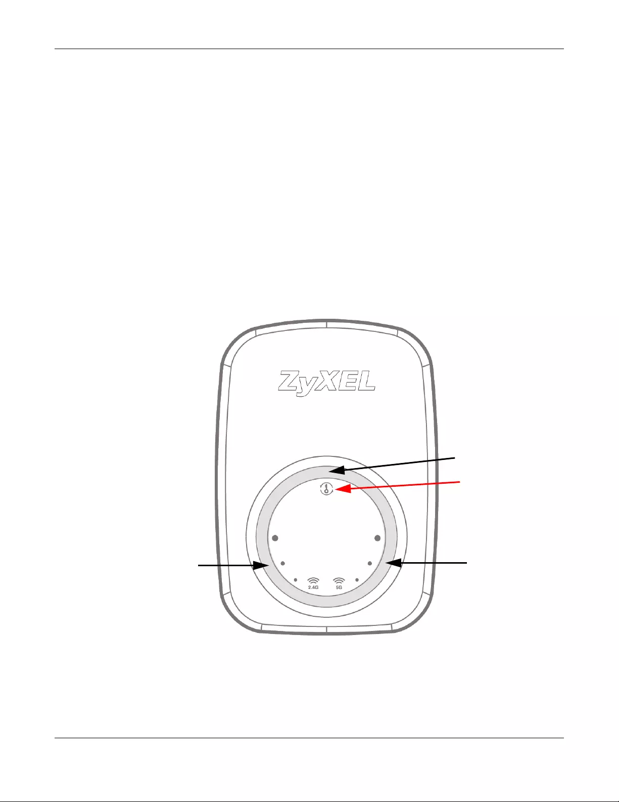
Chapter 1 Introduction
WRE6505 v2 User’s Guide
10
1.2 Securing the WRE6505 v2
Do the following things regularly to make the WRE6505 v2 more secure and to manage the
WRE6505 v2 more effectively.
• Change the password. Use a password that’s not easy to guess and that consists of different
types of characters, such as numbers and letters.
• Write down the password and put it in a safe place.
• Back up the configuration (and make sure you know how to restore it). Restoring an earlier
working configuration may be useful if the device becomes unstable or even crashes. If you
forget your password, you will have to reset the WRE6505 v2 to its factory default settings. If
you backed up an earlier configuration file, you would not have to totally re-configure the
WRE6505 v2. You could simply restore your last configuration.
1.3 Front Panel
Figure 2 Front Panel
WPS Button
Power/WPS LED
5 GHz Signal
Strength LEDs
2.4 GHz Signal
Strength LEDs
Chapter 1 Introduction
WRE6505 v2 User’s Guide
11
The following table describes the LEDs.
1.4 WPS Button
The WPS button can be used to begin Wi-Fi Protected Setup (WPS), reboot the WRE6505 v2 while
keeping it’s configuration or reboot the WRE6505 v2 to factory default configuration.
Table 1 Front Panel LEDs
LED COLOR STATUS DESCRIPTION
Power/WPS Blue On The WRE6505 v2 is receiving power and functioning properly.
Blinking The WRE6505 v2 is booting, resetting to factory defaults, the
WRE6505 v2 is waiting for another WPS device to connect, or
firmware upgrade is in progress.
Off The WRE6505 v2 is not receiving power, or there is no WPS
connection established.
2.4 GHz Signal
Strength
White On The more the LEDs are on the better the Wi-Fi signal strength.
• Three LEDs: signifies a signal strength of 51% ~ 100%
• Two LEDs: signifies a signal strength of 20% ~ 50%
• One LED: signifies a signal strength under 20%
Blinking Firmware upgrade is in progress.
Off The 2.4 GHz wireless LAN is not enabled, there is no signal
detected or the WRE6505 v2 (repeater mode) is not connected
to a wireless router/AP, or the LEDs are turned off using the
WPS button.
5 GHz Signal
Strength
White On The more the LEDs are on the better the Wi-Fi signal strength.
• Three LEDs: signifies a signal strength of 51% ~ 100%
• Two LEDs: signifies a signal strength of 20% ~ 50%
• One LED: signifies a signal strength under 20%
Blinking Firmware upgrade is in progress.
Off The 5 GHz wireless LAN is not enabled, there is no signal
detected or the WRE6505 v2 (repeater mode) is not connected
to a wireless router/AP, or the LEDs are turned off using the
WPS button.
Table 2 WPS Button Functions
ACTION RESULT
Press thress times within
5 seconds
Turn off or turn on all LEDs.
AP Mode
Push twice within 5
seconds
The WRE6505 v2 begins connecting to a wireless client via WPS. See Section 1.4.1
on page 12.
Hold for 5 to 10 seconds The WRE6505 v2 keeps its configuration and reboots.
Hold for more than 10
seconds
The WRE6505 v2 resets its configuration to factory defaults and reboots. See
Section 2.4 on page 18.
Repeater Mode
Push twice within 5
seconds
The WRE6505 v2 begins connecting to a wireless client via WPS. See Section 1.4.1
on page 12.

Chapter 1 Introduction
WRE6505 v2 User’s Guide
12
1.4.1 Wi-Fi Protected Setup
Your WRE6505 v2 supports Wi-Fi Protected Setup (WPS), which is an easy way to set up a secure
wireless network. WPS is an industry standard specification, defined by the Wi-Fi Alliance.
WPS allows you to quickly set up a wireless network with strong security, without having to
configure security settings manually. Each WPS connection works between two devices. Both
devices must support WPS (check each device’s documentation to make sure).
Depending on the devices you have, you can either press a button (recommended) on the device
itself, or in its configuration utility or enter a PIN (a unique Personal Identification Number that
allows one device to authenticate the other) in each of the two devices. When WPS is activated on
a device, it has two minutes to find another device that also has WPS activated. Then, the two
devices connect and set up a secure network by themselves.
For more information on using WPS, see Section 7.3 on page 38.
Hold for 5 to 10 seconds he WRE6505 v2 keeps its configuration and reboots.
Hold for more than 10
seconds
TThe WRE6505 v2 resets its configuration to factory defaults and reboots. See
Section 2.4 on page 18.
Table 2 WPS Button Functions
ACTION RESULT

WRE6505 v2 User’s Guide
13
CHAPTER 2
The Web Configurator
2.1 Overview
This chapter describes how to access the WRE6505 v2 Web Configurator and provides an overview
of its screens.
The Web Configurator is an HTML-based management interface that allows easy setup and
management of the WRE6505 v2 via Internet browser. Use Internet Explorer 6.0 and later versions,
Mozilla Firefox 3 and later versions, or Safari 2.0 and later versions. The recommended screen
resolution is 1024 by 768 pixels.
In order to use the Web Configurator you need to allow:
• Web browser pop-up windows from your device.
• JavaScript (enabled by default).
• Java permissions (enabled by default).
Refer to Chapter 13 Troubleshooting to see how to make sure these functions are allowed in
Internet Explorer.
2.2 Accessing the We b Configurator
1Make sure your WRE6505 v2 hardware is properly connected and prepare your computer or
computer network to connect to the WRE6505 v2 (refer to the Quick Start Guide).
2Launch your web browser.
3Open a web browser such as Internet Explorer and type “http://zyxelsetup” or “http://192.168.1.2”
as the web address in your web browser.
2.2.1 Login Screen
The Web Configurator initially displays the following login screen.
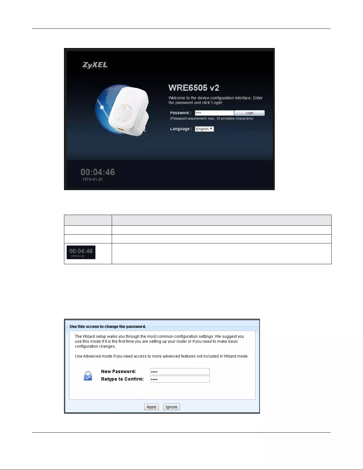
Chapter 2 The Web Configurator
WRE6505 v2 User’s Guide
14
Figure 3 Login Screen
The following table describes the labels in this screen.
2.2.2 Password Screen
You should see a screen asking you to change your password (highly recommended) as shown
next.
Figure 4 Change Password Screen
Table 3 Login screen
LABEL DESCRIPTION
Password Type «1234» (default) as the password.
Language Select the language you want to use to configure the Web Configurator. Click Login.
This shows the time (hh:mm) and date (yyyy:mm:dd) of the timezone you select in the
Maintenance > Time screen (see Section 12.5 on page 71). The time is in 24-hour
format, for example 15:00 is 3:00 PM.
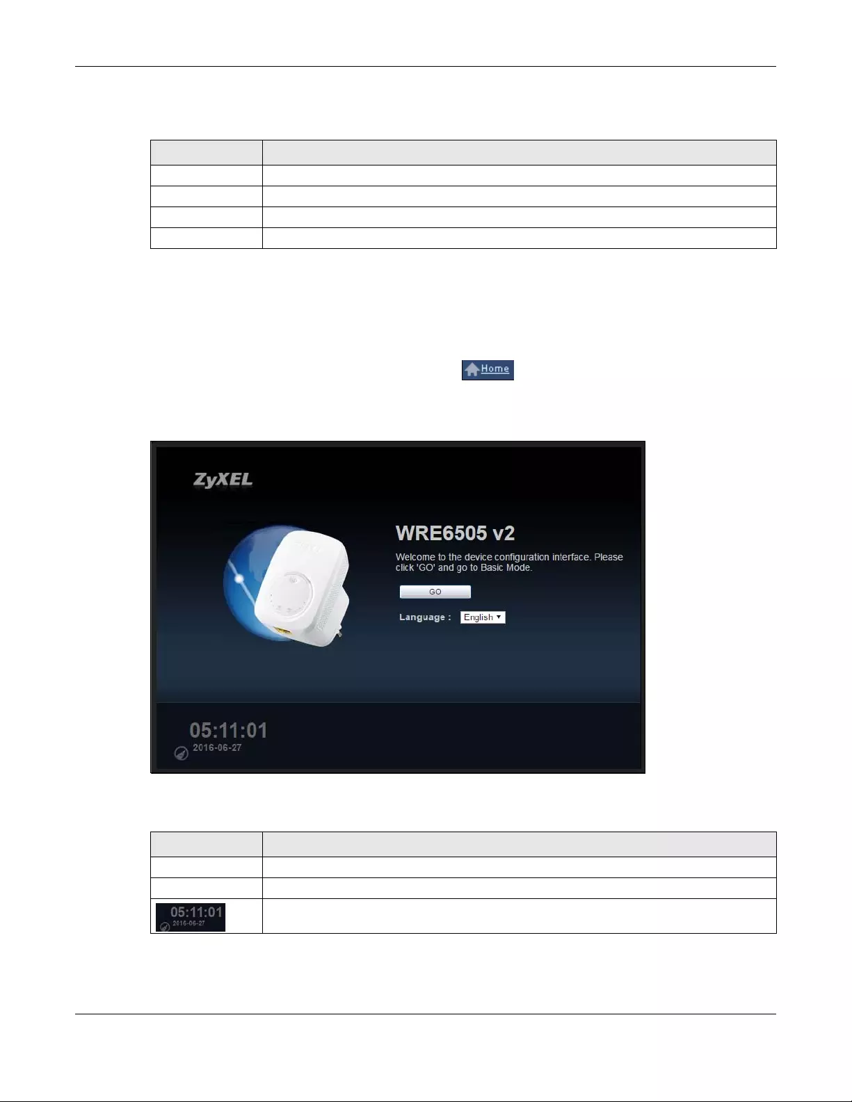
Chapter 2 The Web Configurator
WRE6505 v2 User’s Guide
15
The following table describes the labels in this screen.
2.2.3 Home Screen
If you have previously logged into the Web Configurator but did not click Logout, you may be
redirected to the Home screen.
You can also open this screen by clicking Home ( ) in the Web Configurator screens.
The Home screen displays as follows.
Figure 5 Home Screen
The following table describes the labels in this screen.
Table 4 Change Password Screen
LABEL DESCRIPTION
New Password Type a new password.
Retype to Confirm Retype the password for confirmation.
Apply Click Apply to save your changes back to the WRE6505 v2.
Ignore Click Ignore if you do not want to change the password this time.
Table 5 Home Screen
LABEL DESCRIPTION
GO Click this to return to the previous screen.
Language Select a language to go to the Web Configurator in that language and click GO.
(This is just an example). This shows the time (hh:mm:ss) and date (yyyy:mm:dd) of the
timezone you select in Section 2.2.3.1 on page 16 or Section 12.5 on page 71.
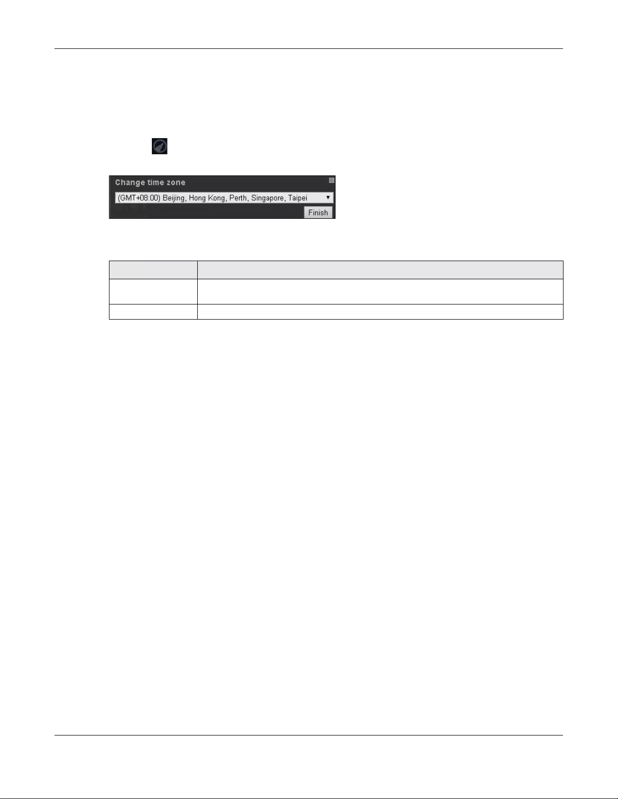
Chapter 2 The Web Configurator
WRE6505 v2 User’s Guide
16
2.2.3.1 Time/Date Edit
One timezone can cover more than one country. You can choose a particular country in which the
WRE6505 v2 is located and have the WRE6505 v2 display and use the current time and date for its
logs.
Click the icon to change the time and date display.
Figure 6 Change Time Zone
The following table describes the labels in this screen.
2.3 Navigating the We b Configurator
The following summarizes how to navigate the web configurator from the Status screen.
Table 6 Change Time Zone
LABEL DESCRIPTION
Change time zone Select the specific country whose current time and date you want the WRE6505 v2 to
display.
Finish Click this to apply the settings and refresh the weather display.
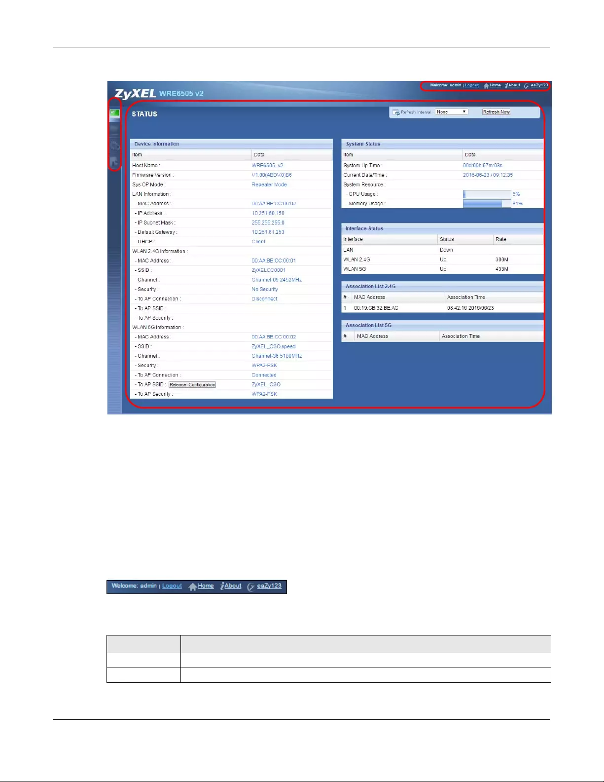
Chapter 2 The Web Configurator
WRE6505 v2 User’s Guide
17
Figure 7 The Web Configurator’s Main Screen
The Web Configurator’s main screen is divided into these parts:
•A — Title Bar
•B — Navigation Panel
•C — Main Window
2.3.1 Title Bar
The title bar provides some useful links that always appear over the screens below, regardless of
how deep into the Web Configurator you navigate.
Figure 8 Title Bar
The icons provide the following functions.
Table 7 Title Bar: Web Configurator Icons
LABEL DESCRIPTION
Logout Click this at any time to exit the Web Configurator.
Home Click this to open the home screen. See Section 2.2.3 on page 15.
Chapter 2 The Web Configurator
WRE6505 v2 User’s Guide
18
2.3.2 Navigation Panel
Use the menu items on the navigation panel to open screens to configure WRE6505 v2 features.
The following table describes the icons shown in the navigation panel.
2.4 Resetting the WRE6505 v2
If you forget your password or IP address, or you cannot access the Web Configurator, press the
WPS button for more than 10 seconds to reload the factory-default configuration file. This means
that you will lose all configurations that you had previously saved, the password will be reset to
1234.
1Make sure the power LED is on.
2Press and hold the WPS button. After 10 seconds, the power LED begins flashing.
3Release the WPS button. The WRE6505 v2 reloads factory defaults and begins to reboot.
About Click this icon to view copyright and a link for related product information.
eaZy123 Click this icon to open the wizard. See Chapter 6 on page 33.
Table 7 Title Bar: Web Configurator Icons (continued)
LABEL DESCRIPTION
Table 8 Navigation Panel Menu Icons
ICON DESCRIPTION
Click this icon to see the Status page. The information in this screen depends on the device
mode you select.
Click this icon to see the Monitor navigation menu.
Click this icon to see the Configuration navigation menu.
Click this icon to see the Maintenance navigation menu.

WRE6505 v2 User’s Guide
19
CHAPTER 3
WRE6505 v2 Modes
3.1 Overview
This chapter introduces the different modes available on your WRE6505 v2.
•System mode. This is the operating mode of your WRE6505 v2, or simply how the WRE6505 v2
is being used in the network.
3.1.1 Device Modes
This refers to the operating mode of the WRE6505 v2, which can act as a:
•Repeater: In this mode, the WRE6505 v2 can be an access point and a wireless client at the
same time. Go to Section 4.4 on page 22 to view the Status screen in this mode. Use this mode
if there is an existing wireless router or access point in your network and you also want to allow
clients to connect to the WRE6505 v2 wirelessly.
•Access Point: Use this mode if you want to extend your network by allowing network devices to
connect to the WRE6505 v2 wirelessly. Go to Section 5.4 on page 28 to view the Status screen in
this mode.
In this mode, you can also set the WRE6505 v2 to work as an AP only, a wireless bridge to
establish wireless links with other APs (WDS bridge), or an AP and bridge simultaneously (WDS
repeater). See Section 5.2 on page 27 for more information.
The following figure is an illustration of the device configuration modes of the WRE6505 v2.
Figure 9 Device Mode Example
Note: Choose your device mode carefully to avoid having to change it later.

Chapter 3 WRE6505 v2 Modes
WRE6505 v2 User’s Guide
20
Under Repeater mode, the WRE6505 v2 supports three WPS behaviors: Normal mode, Range boost
mode, and Speed boost mode. These behaviors are only available in Repeater mode through the
Maintenance screen.
3.1.1.1 Changing Operating Mode
The WRE6505 v2 is in repeater mode by default. To change its operating mode, access the web
configurator and go to the Maintenance > System Mo de screen. See Section 12.9 on page 78 for
detailed information.
The WRE6505 v2 restarts automatically after you change operating modes.
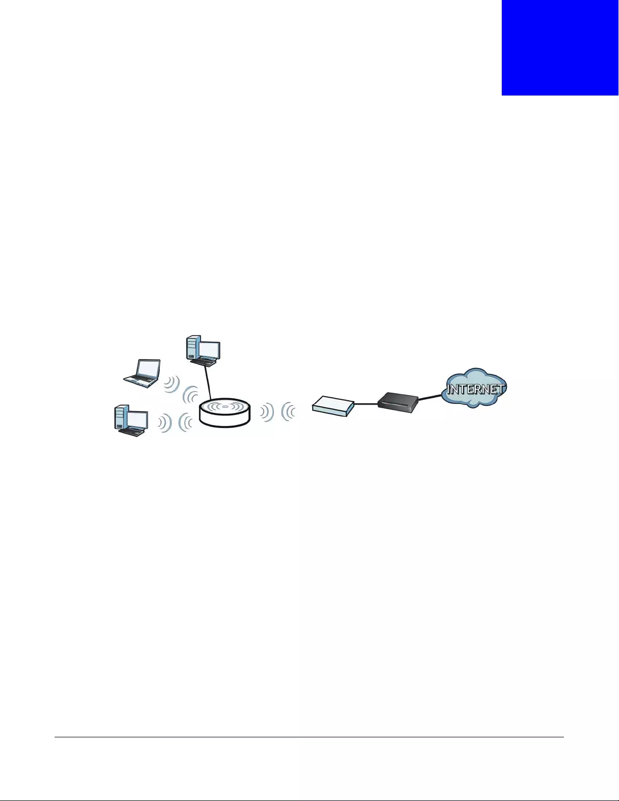
WRE6505 v2 User’s Guide
21
CHAPTER 4
Repeater Mode
4.1 Overview
In repeater mode, your WRE6505 v2 can act as an access point and wireless client at the same
time. The WRE6505 v2 can connect to an existing network through another access point and also
lets wireless clients connect to the network through it. This helps you expand wireless coverage
when you have an access point or wireless router already in your network.
In the example below, the WRE6505 v2 (A) is configured as a repeater. It has three clients that
want to connect to the Internet. The WRE6505 v2 wirelessly connects to the available access point
(B).
Figure 10 Repeater Mode
After the WRE6505 v2 and the access point connect, the WRE6505 v2 acquires its IP address from
the access point. The clients of the WRE6505 v2 can now surf the Internet.
4.2 What You Can Do
•Use the Status screen (Section 7.1 on page 38) to view read-only information about your
WRE6505 v2.
•Use the LAN screen (Chapter 10 on page 66) to set the IP address for your WRE6505 v2.
•Use the Wireless LAN > AP Select screen (Section 9.6 on page 57) to scan for available access
points within transmission range and connect to an AP.
•Use other Wireless LAN screens (Section 9.4 on page 51) to configure the wireless settings and
wireless security between the wireless clients and the WRE6505 v2.
4.3 What You Need to Know
With the exception of the AP Select screen other configuration screens in Repeater mode are
similar to the ones in Access Point Mode. See Chapter 3 on page 19 of this User’s Guide.

Chapter 4 Repeater Mode
WRE6505 v2 User’s Guide
22
4.3.1 Setting your WRE6505 v2 to Repeater Mode
1To use your WRE6505 v2 as a repeater, see Section 3.1.1.1 on page 20.
2Connect your computer to the LAN port of the WRE6505 v2.
3Open a web browser such as Internet Explorer and type “http://zyxelsetup” or “http://192.168.1.2”
as the web address in your web browser.
4Enter “1234” (default) as the password and click Login.
5Type a new password and retype it to confirm, then click Apply. Otherwise, click Ignore.
Note: You have to log in to the Web Configurator again when you change modes. As soon
as you do, your WRE6505 v2 is already in Repeater mode.
Note: If a client is connected to the WRE6505 v2 through the wired Ethernet connection,
the client can only access the 2.4 GHz Wi-Fi. In the following figure, the LAN Client
is only able to communicate with devices in the 2.4 GHz wireless network.
Figure 11 Repeater Mode Overview
4.3.2 Configuring your WLAN, LAN and Maintenance Settings
•See Chapter 9 on page 49 and Chapter 10 on page 66 for information on configuring your
wireless network and LAN settings.
•See Chapter 12 on page 70 for information on configuring your Maintenance settings.
4.4 Repeater Mode Status Screen
Click to open the Status screen.
WRE
LAN Client
5 GHz
5 GHz AP
5 GHz
5 GHz
2.4 GHz AP
2.4 GHz2.4 GHz
2.4 GHz
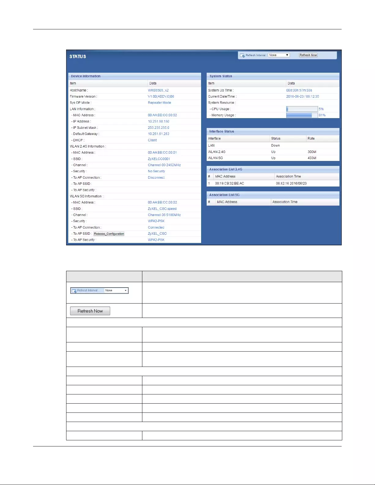
Chapter 4 Repeater Mode
WRE6505 v2 User’s Guide
23
Figure 12 Status: Repeater Mode
The following table describes the labels shown in the Status screen.
Table 9 Status Screen: Repeater Mode
LABEL DESCRIPTION
Select a number of seconds or None from the drop-down list box to refresh all
screen statistics automatically at the end of every time interval or to not
refresh the screen statistics.
Click this button to refresh the status screen statistics.
Device Information
Host Name This is the WRE6505 v2’s system name you configure in the Maintenance >
General screen.
Firmware Version This is the firmware version and the date created.
Sys OP Mode This is the device mode (Section 3.1.1 on page 19) to which the WRE6505 v2
is set — Repeater Mo de.
LAN Information
MAC Address This shows the LAN Ethernet adapter MAC Address of your device.
IP Address This shows the LAN port’s IP address.
IP Subnet Mask This shows the LAN port’s subnet mask.
Default Gateway This shows the LAN port’s gateway IP address.
DHCP This shows the LAN port’s DHCP role — Client or None.
WLAN 2.4G Information
MAC Address This shows the wireless adapter MAC Address of your WRE6505 v2.

Chapter 4 Repeater Mode
WRE6505 v2 User’s Guide
24
SSID This shows a descriptive name used to identify the WRE6505 v2 in the wireless
LAN.
Channel This shows the channel number which you select manually or the WRE6505 v2
automatically scans and selects.
Security This shows the level of wireless security the WRE6505 v2 is using.
To AP Connection This displays whether the WRE6505 v2 is connected to an AP or not.
To AP SSID This displays the SSID of the connected AP.
Click the Release_Configuration button to remove all configured wireless
and wireless security settings for WPS connections on the WRE6505 v2.
To AP Security This displays the type of established security protocol with the AP.
WLAN 5G Information
MAC Address This shows the wireless adapter MAC Address of your WRE6505 v2.
SSID This shows a descriptive name used to identify the WRE6505 v2 in the wireless
LAN.
Channel This shows the channel number which you select manually or the WRE6505 v2
automatically scans and selects.
Security This shows the level of wireless security the WRE6505 v2 is using.
To AP Connection This displays whether the WRE6505 v2 is connected to an AP or not.
To AP SSID This displays the SSID of the connected AP.
Click the Release_Configuration button to remove all configured wireless
and wireless security settings for WPS connections on the WRE6505 v2.
To AP Security This displays the type of established security protocol with the WRE6505 v2.
System Status
Item This column shows the type of data the WRE6505 v2 is recording.
Data This column shows the actual data recorded by the WRE6505 v2.
System Up Time This is the total time the WRE6505 v2 has been on.
Current Date/Time This field displays your WRE6505 v2’s present date and time.
System Resource
CPU Usage This displays what percentage of the WRE6505 v2’s processing ability is
currently used. When this percentage is close to 100%, the WRE6505 v2 is
running at full load, and the throughput is not going to improve anymore. If
you want some applications to have more throughput, you should turn off
other applications (for example, using bandwidth management.
Memory Usage This shows what percentage of the heap memory the WRE6505 v2 is using.
Interface Status
Interface This displays the WRE6505 v2 port types. The port types are: LAN and WLAN.
Status For the LAN port, this field displays Down (line is down) or Up (line is up or
connected).
For the WLAN, it displays Up when the WLAN is enabled or Down when the
WLAN is disabled.
Rate For the LAN ports, this displays the port speed and duplex setting or is left
blank when the line is disconnected.
For the WLAN, it displays the maximum transmission rate when the WLAN is
enabled and is left blank when the WLAN is disabled.
Association List 2.4G
Table 9 Status Screen: Repeater Mode
LABEL DESCRIPTION
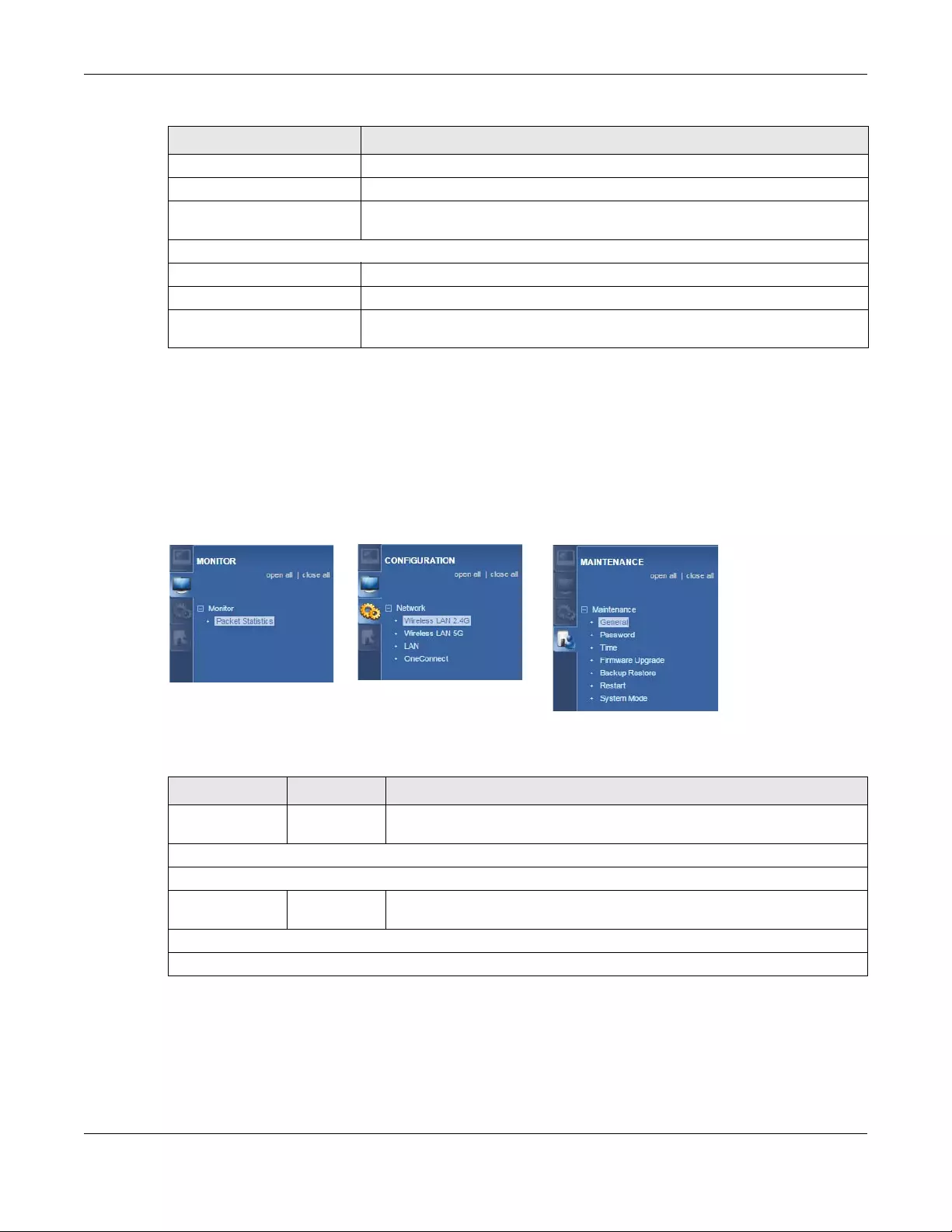
Chapter 4 Repeater Mode
WRE6505 v2 User’s Guide
25
4.5 Configuration Menus
Use the menu in the navigation panel to configure WRE6505 v2 features in Repeater mode.
The following screen and table show the features you can configure in Repeater mode.
Figure 13 Menus: Repeater Mode
The following table describes the sub-menus.
# This is the index number of an associated wireless station.
MAC Address This field displays the MAC address of an associated wireless station.
Association Time This field displays the time a wireless station first associated with the WRE6505
v2’s WLAN network.
Association List 5G
# This is the index number of an associated wireless station.
MAC Address This field displays the MAC address of an associated wireless station.
Association Time This field displays the time a wireless station first associated with the WRE6505
v2’s WLAN network.
Table 9 Status Screen: Repeater Mode
LABEL DESCRIPTION
Ta ble 10 Menus: Repeater Mode
LINK TAB FUNCTION
Status Status This screen shows the WRE6505 v2’s general device, system and interface
status information.
MONITOR
Monitor
Packet
Statistics Packet
Statistics
Use this screen to view port status, packet specific statistics, the «system
up time» and so on.
CONFIGURATION
Network
Chapter 4 Repeater Mode
WRE6505 v2 User’s Guide
26
Wireless LAN
2.4G General Use this screen to configure general wireless LAN and wireless security
settings.
AP Select Use this screen to choose an access point that you want the WRE6505 v2
to connect to.
MAC Filter Use this screen to configure the WRE6505 v2 to block access to devices or
block the devices from accessing the WRE6505 v2.
Advanced Use this screen to configure advanced wireless settings.
QoS Use this screen to enable Wi-Fi MultiMedia Quality of Service (WMMQoS).
WPS Use this screen to enable WPS.
WPS Device Use this screen to add a wireless station using WPS.
Wireless LAN
5G General Use this screen to configure general wireless LAN settings.
AP Select Use this screen to choose an access point that you want the WRE6505 v2
to connect to.
MAC Filter Use this screen to configure the WRE6505 v2 to block access to devices or
block the devices from accessing the WRE6505 v2.
Advanced Use this screen to configure advanced wireless settings.
QoS Use this screen to enable Wi-Fi MultiMedia Quality of Service (WMMQoS).
WPS Use this screen to enable WPS.
WPS Device Use this screen to add a wireless station using WPS.
LAN IP Use this screen to configure LAN IP address and subnet mask.
OneConnect OneConnect Use this screen to enable or disable Wi-Fi auto-configuration.
MAINTENANCE
General General Use this screen to view and change administrative settings such as system
and domain names.
Password Password
Setup
Use this screen to change the password of your WRE6505 v2.
Time Time Setting Use this screen to change your WRE6505 v2’s time and date.
Firmware
Upgrade Firmware
Upgrade
Use this screen to upload firmware to your WRE6505 v2.
Backup
Restore Backup
Restore
Use this screen to backup and restore the configuration or reset your
WRE6505 v2 to the factory defaults.
Restart Restart Use this screen to reboot the WRE6505 v2 without turning the power off.
System Mode System Mode Use this screen to select how you want to use your WRE6505 v2.
Ta ble 10 Menus: Repeater Mode
LINK TAB FUNCTION
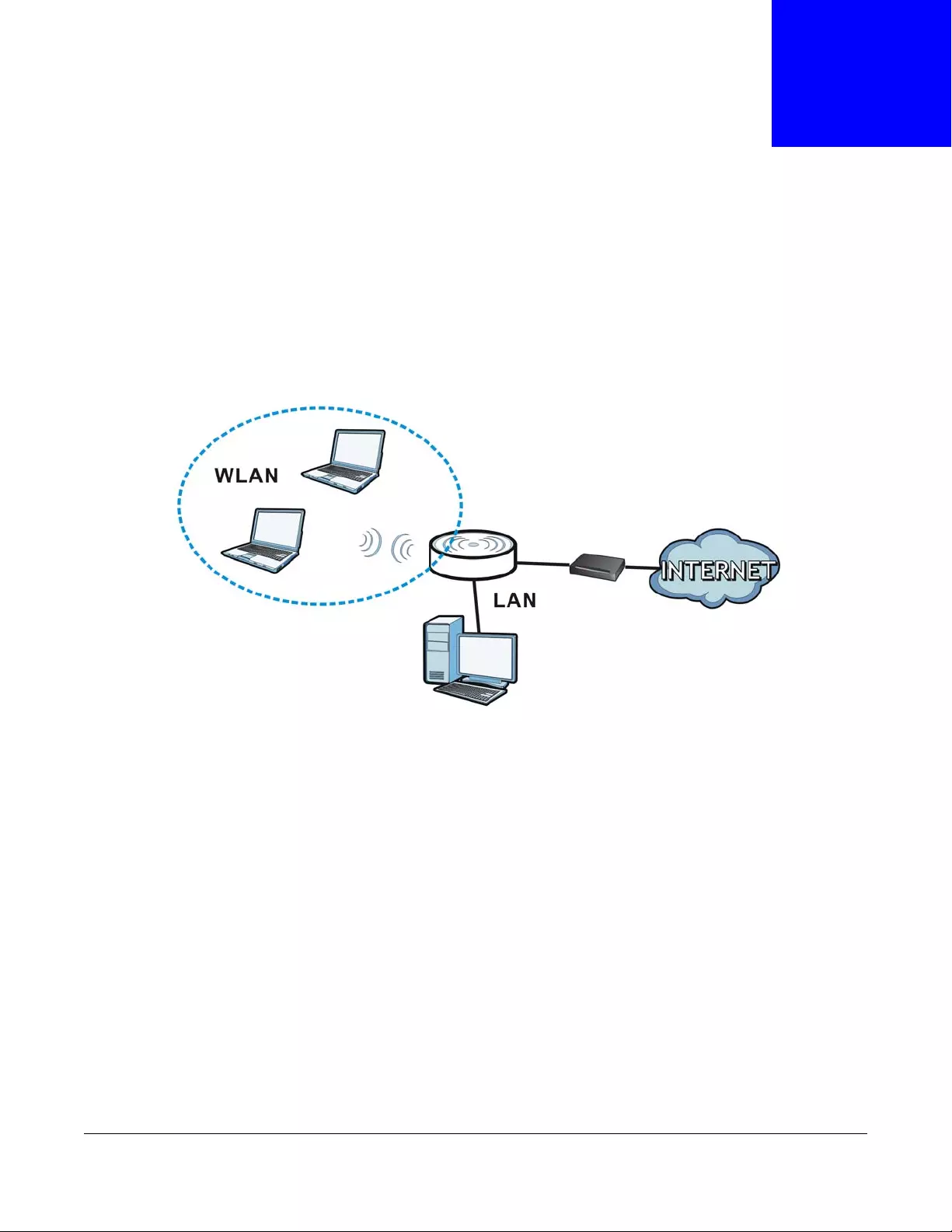
WRE6505 v2 User’s Guide
27
CHAPTER 5
Access Point Mode
5.1 Overview
In Access Point (AP) mode your WRE6505 v2 bridges a wired network (LAN) and wireless LAN
(WLAN) in the same subnet. See the figure below for an example.
Figure 14 Wireless Internet Access in Access Point Mode
Note: See Chapter 7 on page 38 for an example of setting up a wireless network in
Access Point mode.
5.2 What You Can Do
•Use the Status screen (Section 5.4 on page 28) to view read-only information about your
WRE6505 v2.
•Use the LAN screen (Chapter 10 on page 66) to set the IP address for your WRE6505 v2 acting
as an access point.
•Use the Wireless LAN screens (Section 9.10 on page 62) to configure the wireless settings and
wireless security between the wireless clients and the WRE6505 v2.

Chapter 5 Access Point Mode
WRE6505 v2 User’s Guide
28
5.3 What You Need to Know
With the exception of the Scheduling screen other configuration screens in Access Point mode are
similar to the ones in repeater mode. See Chapter 3 on page 19 of this User’s Guide.
5.3.1 Setting your WRE6505 v2 to AP Mode
By default, AP mode in the WRE6505 v2 is not configured with a static IP address. To set up your
WRE6505 v2 in AP mode for the first time, the directly-connected router must have the DHCP
server function enabled.
1To use your WRE6505 v2 as an access point, see Section 3.1.1.1 on page 20.
2Connect one end of an Ethernet cable to the Ethernet port on the WRE6505 v2 and the other end to
your router.
3Connect your computer to your network, make sure both the WRE6505 v2 and computer are under
the same subnet.
4Open a web browser window and type “http://zyxelsetup” in the web address.
The login screen displays.
5Enter “1234” (default) as the password and click Login.
6Type a new password and retype it to confirm, then click Apply. Otherwise, click Ignore.
The WRE6505 v2 Web Configurator displays, which allows you to configure the AP mode.
5.3.2 Configuring your WLAN, LAN and Maintenance Settings
•See Chapter 9 on page 49 and Chapter 10 on page 66 for information on configuring your
wireless network and LAN settings.
•See Chapter 12 on page 70 for information on configuring your Maintenance settings.
5.4 AP Mode Status Screen
Click to open the Status screen.
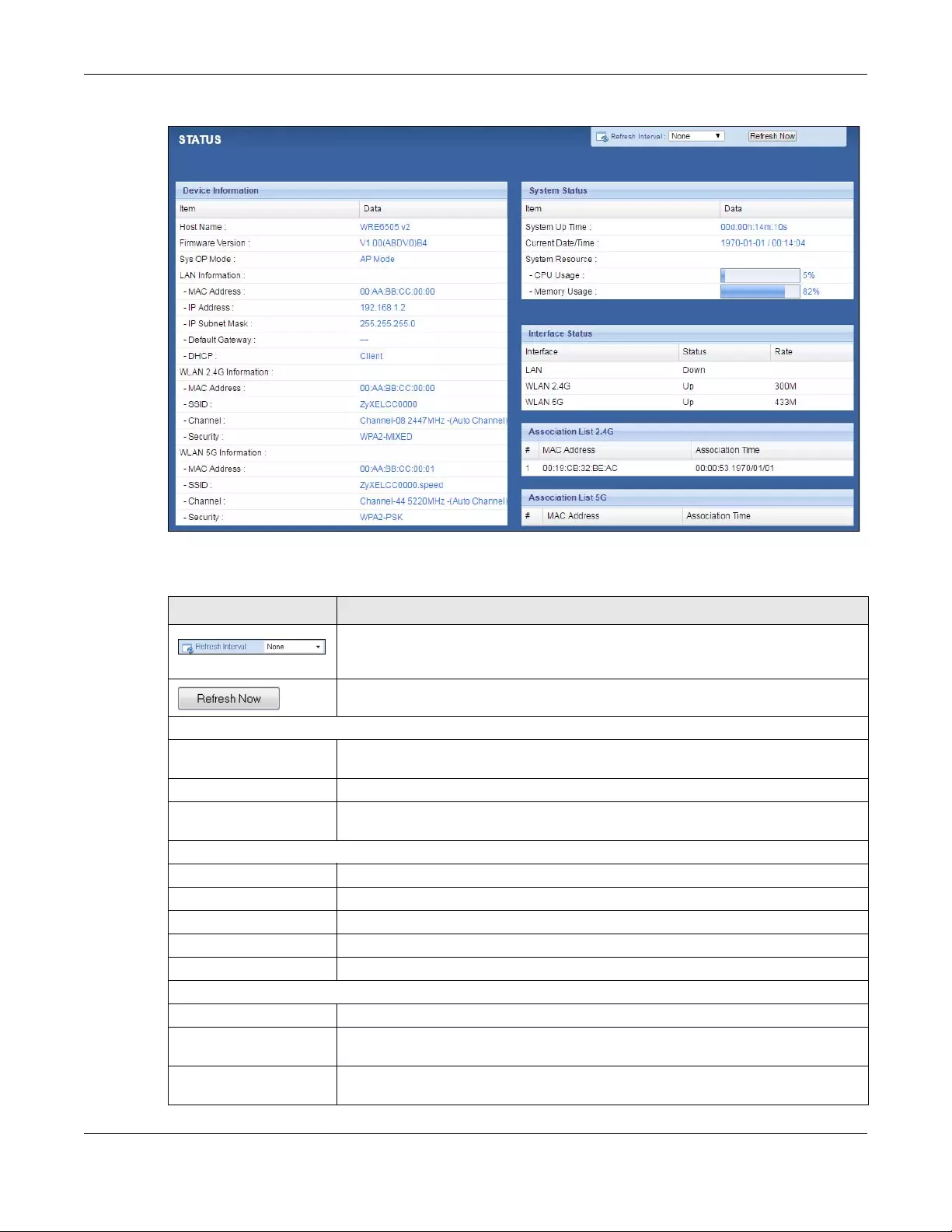
Chapter 5 Access Point Mode
WRE6505 v2 User’s Guide
29
Figure 15 Status Screen: Access Point Mode
The following table describes the labels shown in the Status screen.
Table 11 Status Screen: Access Point Mode
LABEL DESCRIPTION
Select a number of seconds or None from the drop-down list box to refresh all
screen statistics automatically at the end of every time interval or to not refresh
the screen statistics.
Click this button to refresh the status screen statistics.
Device Information
Host Name This is the WRE6505 v2’s system name you configure in the Maint enance >
General screen.
Firmware Version This is the firmware version and the date created.
Sys OP Mode This is the device mode (Section 3.1.1 on page 19) to which the WRE6505 v2 is set
— AP Mode.
LAN Information
MAC Address This shows the LAN Ethernet adapter MAC Address of your device.
IP Address This shows the LAN port’s IP address.
IP Subnet Mask This shows the LAN port’s subnet mask.
Default Gateway This shows the LAN port’s gateway IP address.
DHCP This shows the LAN port’s DHCP role — Client or None.
WLAN 2.4G Information
MAC Address This shows the wireless adapter MAC Address of your device.
SSID This shows a descriptive name used to identify the WRE6505 v2 in the wireless
LAN.
Channel This shows the channel number which you select manually or the WRE6505 v2
automatically scans and selects.

Chapter 5 Access Point Mode
WRE6505 v2 User’s Guide
30
Security This shows the level of wireless security the WRE6505 v2 is using.
WLAN 5G Information
MAC Address This shows the wireless adapter MAC Address of your device.
SSID This shows a descriptive name used to identify the WRE6505 v2 in the wireless
LAN.
Channel This shows the channel number which you select manually or the WRE6505 v2
automatically scans and selects.
Security This shows the level of wireless security the WRE6505 v2 is using.
System Status
Item This column shows the type of data the WRE6505 v2 is recording.
Data This column shows the actual data recorded by the WRE6505 v2.
System Up Time This is the total time the WRE6505 v2 has been on.
Current Date/Time This field displays your WRE6505 v2’s present date and time.
System Resource
CPU Usage This displays what percentage of the WRE6505 v2’s processing ability is currently
used. When this percentage is close to 100%, the WRE6505 v2 is running at full
load, and the throughput is not going to improve anymore. If you want some
applications to have more throughput, you should turn off other applications (for
example, using bandwidth management.
Memory Usage This shows what percentage of the heap memory the WRE6505 v2 is using.
Interface Status
Interface This displays the WRE6505 v2 port types. The port types are: LAN and WLAN.
Status For the LAN port, this field displays Down (line is down) or Up (line is up or
connected).
For the WLAN, it displays Up when the WLAN is enabled or Down when the WLAN
is disabled.
Rate For the LAN ports, this displays the port speed and duplex setting or is left blank
when the line is disconnected.
For the WLAN, it displays the maximum transmission rate when the WLAN is
enabled and is left blank when the WLAN is disabled .
Association List 2.4G
# This is the index number of an associated wireless client.
MAC Address This field displays the MAC address of an associated wireless client.
Association Time This field displays the time a wireless station first associated with the WRE6505
v2’s WLAN network.
Association List 5G
# This is the index number of an associated wireless client.
MAC Address This field displays the MAC address of an associated wireless client.
Association Time This field displays the time a wireless station first associated with the WRE6505
v2’s WLAN network.
Table 11 Status Screen: Access Point Mode (continued)
LABEL DESCRIPTION
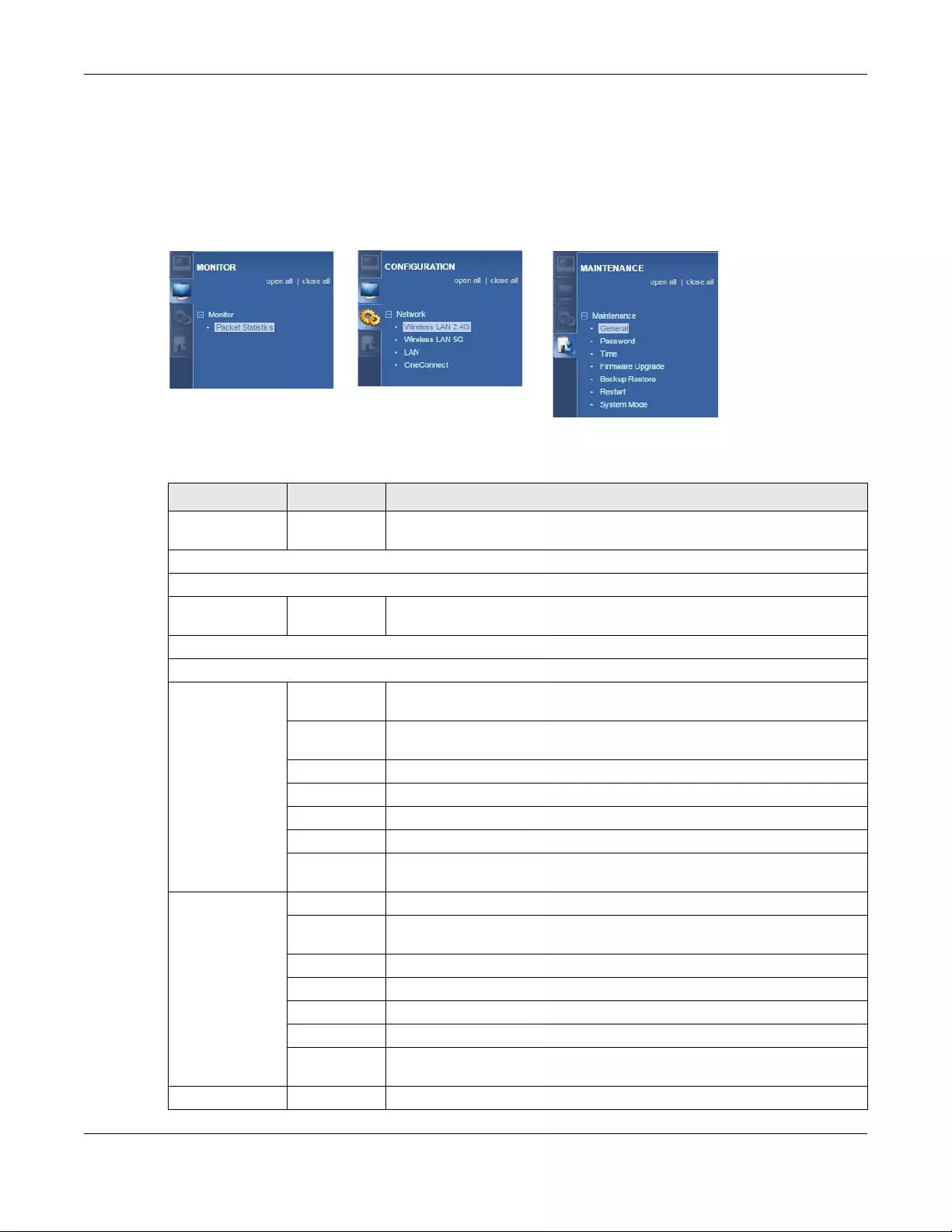
Chapter 5 Access Point Mode
WRE6505 v2 User’s Guide
31
5.5 Configuration Menus
Use the menu in the navigation panel to configure WRE6505 v2 features in Access Point mode.
The following screen and table show the features you can configure in Access Point mode.
Figure 16 Menu: Access Point Mode
The following table describes the sub-menus.
Ta ble 12 Navigation Panel: Access Point Mode
LINK TAB FUNCTION
Status Status This screen shows the WRE6505 v2’s general device, system and interface
status information.
MONITOR
Monitor
Packet
Statistics Packet
Statistics
Use this screen to view port status, packet specific statistics, the «system
up time» and so on.
CONFIGURATION
Network
Wireless LAN
2.4G General Use this screen to configure general wireless LAN and wireless security
settings.
MAC Filter Use this screen to configure the WRE6505 v2 to block access to devices or
block the devices from accessing the WRE6505 v2.
Advanced Use this screen to configure advanced wireless settings.
QoS Use this screen to enable Wi-Fi MultiMedia Quality of Service (WMMQoS).
WPS Use this screen to enable and configure WPS.
WPS Device Use this screen to add a wireless station using WPS.
Scheduling Use this screen to schedule the times the Wireless LAN is enabled or
disabled.
Wireless LAN
5G General Use this screen to configure general wireless LAN settings.
MAC Filter Use this screen to configure the WRE6505 v2 to block access to devices or
block the devices from accessing the WRE6505 v2.
Advanced Use this screen to configure advanced wireless settings.
QoS Use this screen to enable Wi-Fi MultiMedia Quality of Service (WMMQoS).
WPS Use this screen to enable and configure WPS.
WPS Device Use this screen to add a wireless station using WPS.
Scheduling Use this screen to schedule the times the Wireless LAN is enabled or
disabled.
LAN IP Use this screen to configure LAN IP address and subnet mask.
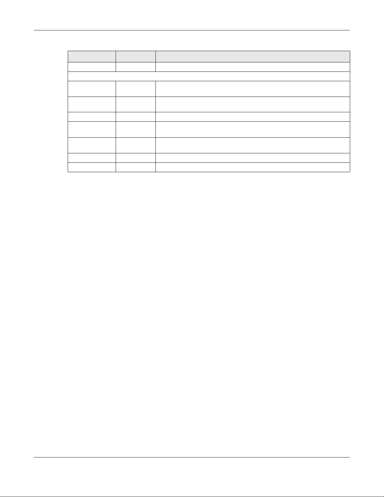
Chapter 5 Access Point Mode
WRE6505 v2 User’s Guide
32
OneConnect OneConnect Use this screen to enable or disable Wi-Fi auto-configuration.
MAINTENANCE
General General Use this screen to view and change administrative settings such as system
and domain names.
Password Password
Setup
Use this screen to change the password of your WRE6505 v2.
Time Time Setting Use this screen to change your WRE6505 v2’s time and date.
Firmware
Upgrade Firmware
Upgrade
Use this screen to upload firmware to your WRE6505 v2.
Backup
Restore Backup
Restore
Use this screen to backup and restore the configuration or reset your
WRE6505 v2 to the factory defaults.
Restart Restart Use this screen to reboot the WRE6505 v2 without turning the power off.
System Mode System Mode Use this screen to select how you want to use your WRE6505 v2.
Ta ble 12 Navigation Panel: Access Point Mode
LINK TAB FUNCTION

WRE6505 v2 User’s Guide
33
CHAPTER 6
eaZy123 Wizard Setup
6.1 Overview
This chapter provides information on the wizard setup screens in the Web Configurator.
The Web Configurator’s wizard setup helps you configure your device.
6.2 Accessing the Wizard
Launch your web browser and type «http://zyxelsetup» or “http://192.168.1.2” as the website
address. See Section 2.2 on page 13 for detailed information.
Note: The wizard appears when the WRE6505 v2 is accessed for the first time or when
you reset the WRE6505 v2 to its default factory settings.
The wizard screen opens.
Note: If you have already configured the wizard screens and want to open it again, click
the eaZy123 icon ( ) on the upper right corner of any Web Configurator
screen.
6.3 Using the Wizard
The eaZy123 wizard for the WRE6505 v2 is available in both Repeater and AP mode.
6.3.1 Repeater Mode
1The wizard scans for available Wi-Fi networks and displays the network list. Select a 2.4 GHz Wi-Fi
network to which you want the WRE6505 v2 to connect to extend the network. Click Continue.
If the wireless router or AP you want to connect to is not listed, click Choose Network Manually
and go to step 3 to configure the SSID and security settings manually.
If you don’t want to associate with a 2.4 GHz network, click Skip 2.4 GHz.
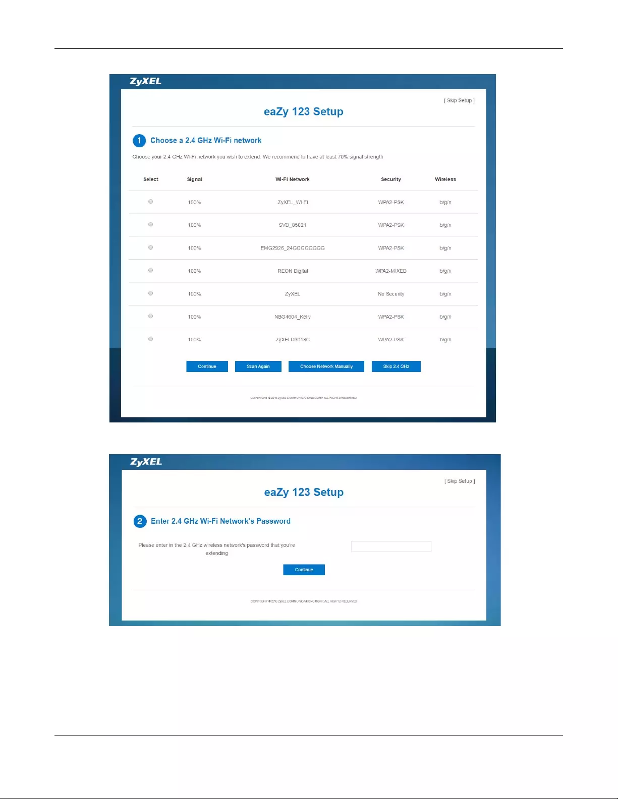
Chapter 6 eaZy123 Wizard Setup
WRE6505 v2 User’s Guide
34
2Type the selected network’s Wi-Fi password (key) if wireless security is enabled. Click Continue.
3If you click Choose Network Manually, the following screen displays. Enter the SSID and security
settings of your wireless router or AP. Click Continue.
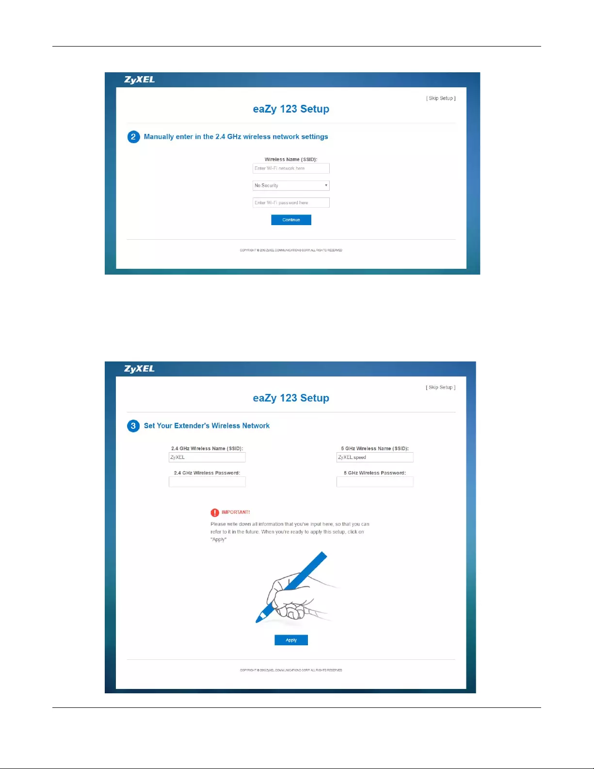
Chapter 6 eaZy123 Wizard Setup
WRE6505 v2 User’s Guide
35
4The 5 GHz setup screen displays. Repeat previous steps to select and connect to a 5 GHz Wi-Fi
network.
5Configure the wireless settings between the WRE6505 v2 and its wireless clients. The WRE6505 v2
automatically copies the SSID of the associated AP and appends “.speed” to the 5GHz SSID. Click
Apply.
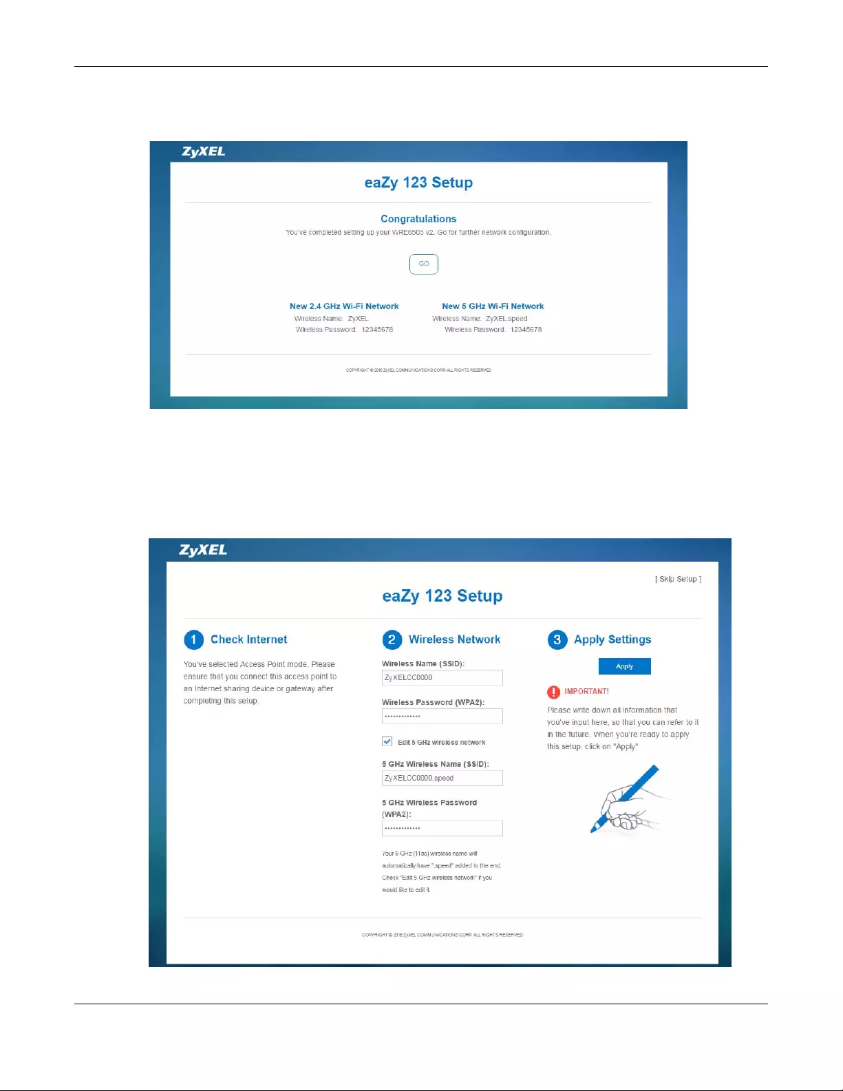
Chapter 6 eaZy123 Wizard Setup
WRE6505 v2 User’s Guide
36
6The eaZy 123 setup wizard is complete. Verify the WRE6505 v2’s wireless network settings and
click GO to log into the web configurator again.
6.3.2 AP Mode
1Configure the wireless settings between the WRE6505 v2 and its wireless clients. The WRE6505 v2
automatically copies the SSID of the associated AP and appends “.speed” to the 5GHz SSID. Click
Apply.
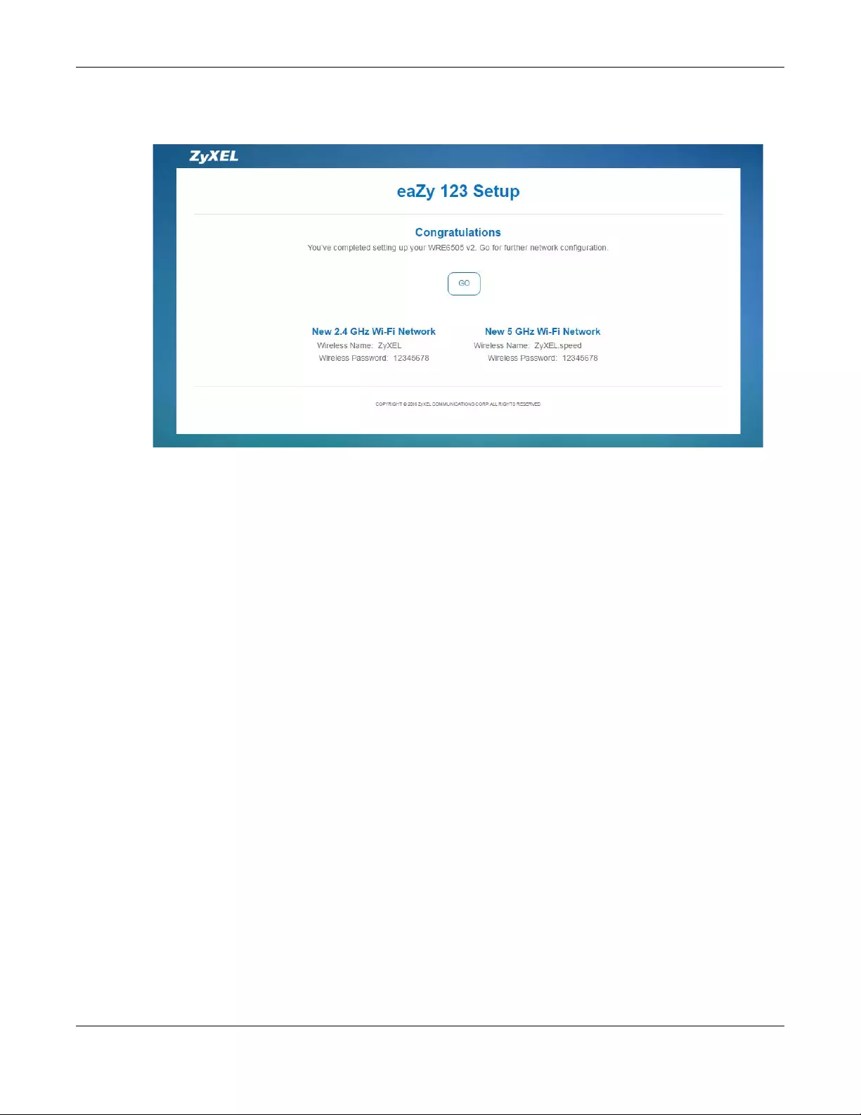
Chapter 6 eaZy123 Wizard Setup
WRE6505 v2 User’s Guide
37
2The eaZy 123 setup wizard is complete. Verify the WRE6505 v2’s wireless network settings and
click GO to log into the web configurator again.

WRE6505 v2 User’s Guide
38
CHAPTER 7
Tutorials
7.1 Overview
This chapter provides tutorials for your WRE6505 v2 (in access point or repeater mode) as follows:
•Connecting to the Internet from an Access Point
•Connecting to a Wireless Network Using WPS
•Connecting the WRE6505 v2 (in Repeater mode) to an AP
7.2 Connecting to the Internet from an Access Point
This section gives you an example of how to set up an access point (AP) and wireless client (a
notebook (B), in this example) for wireless communication. B can access the Internet through the
access point (A) wirelessly.
Figure 17 Wireless Access Point Connection to the Internet
7.3 Connecting to a Wireless Network Using WPS
This section gives you an example of how to set up wireless network using WPS. The following
example uses the WRE6505 v2 as the AP and NWD-211AN as the wireless client which connects to
a notebook.
Note: The wireless client must be a WPS-aware device (for example, a WPS USB adapter
or PCI card).
The following WPS methods for creating a secure connection are described in the tutorial.
•Push Button Configuration (PBC) — create a secure wireless network simply by pressing a
button. See Section 7.3.1 on page 39.This is the easier method.
•PIN Configuration — create a secure wireless network simply by entering a wireless client’s PIN
(Personal Identification Number) in the WRE6505 v2’s interface. See Section 7.3.2 on page 40.
This is the more secure method, since one device can authenticate the other.

Chapter 7 Tutorials
WRE6505 v2 User’s Guide
39
7.3.1 Push Button Configuration (PBC)
The push button configuration function found in the interface is only available in AP mode. The WPS
button, see Section 1.3 on page 10, can also be used for PBC configurations in either AP or
Repeater mode.
1Make sure that your WRE6505 v2 is turned on and that it is connected to your network.
2Launch your wireless client’s configuration utility.
3In the wireless client utility, find the WPS settings. Enable WPS and press the WPS button (Start or
WPS button).
4Log into WRE6505 v2’s Web Configurator. Make sure WPS is enabled in the Network > Wireless
LAN > WPS screen.
5Navigate to Network > Wireless LAN 2.4G or Wireless LAN 5G > WPS Device and press the
WPS button.
Note: Your WRE6505 v2 has a WPS button located on its panel, as well as a WPS button
in its configuration utility. Both buttons have exactly the same function; you can
use one or the other.
Note: It doesn’t matter which button is pressed first. You must press the second button
within two minutes of pressing the first one.
The WRE6505 v2 sends the proper configuration settings to the wireless client. This may take up to
two minutes. Then the wireless client is able to communicate with the WRE6505 v2 securely.
The following figure shows you how to set up wireless network and security by pressing a button on
both WRE6505 v2 and wireless client (the NWD-211AN in this example).
Chapter 7 Tutorials
WRE6505 v2 User’s Guide
40
Figure 18 Example WPS Process: PBC Method
7.3.2 PIN Configuration
When you use the PIN configuration method, you need to use both WRE6505 v2’s configuration
interface and the client’s utilities.
The push button configuration function is only available in AP mode.
1Launch your wireless client’s configuration utility. Go to the WPS Station settings and select the PIN
method to get a PIN number.
2On the WRE6505 v2, navigate to the Network > Wireless LAN 2.4G or Wireless LAN 5G >
WPS screen.
3Obtain the PIN number for the WRE6505 v2 or press the Generate button to create a new PIN
number. See Section 9.10 on page 62
4Enter the WRE6505 v2 PIN number in the wireless station’s utility screen.
The WRE6505 v2 authenticates the wireless client and sends the proper configuration settings to
the wireless client. This may take up to two minutes. Then the wireless client is able to
communicate with the WRE6505 v2 securely.
Wireless Client
SECURITY INFO
COMMUNICATION
WITHIN 2 MINUTES
AP
Chapter 7 Tutorials
WRE6505 v2 User’s Guide
41
The following figure shows an example of how to set up wireless network and security on WRE6505
v2 and wireless client (ex. NWD210N in this example) by using PIN method.
Figure 19 Example WPS Process: PIN Method
7.4 Connecting the WRE6505 v2 (in Repeater mode) to an
AP
Repeater mode allows you to extend the original AP coverage.
Authentication by PIN
SECURITY INFO
WITHIN 2 MINUTES
Wireless Client
COMMUNICATION
Chapter 7 Tutorials
WRE6505 v2 User’s Guide
42
•Selecting an AP from an Automatically Detected List — create a secure wireless network
simply by selecting an AP from a list of detected APs. See Section 7.4.1 on page 42.This is the
easier method.
•Selecting an AP by Manually Entering Security Information — create a secure wireless
network by manually entering the AP’s wireless security settings in the WRE6505 v2’s interface.
See Section 7.4.2 on page 43. This is useful when the AP is hidden.
7.4.1 Selecting an AP from an Automatically Detected List
Follow the steps below to create a secure wireless network by selecting an AP from a list of detected
APs.
The AP select function is only available in repeater mode. See Section 3.1.1 on page 19.
The instructions require that your hardware is connected (see the Quick Start Guide) and you are
logged into the Web Configurator through your LAN connection (see Section 2.2 on page 13).
1Open the Network > Wir eless LAN 2.4G or Wireless LAN 5G > AP Select screen. Select an AP
form the Select column and click Continue.
Figure 20 Tutorial: Selecting an automatically detected AP
2Type the Wi-Fi key if wireless security is enabled on the selected AP and click Continue.
Figure 21 Tutorial: The KEY field
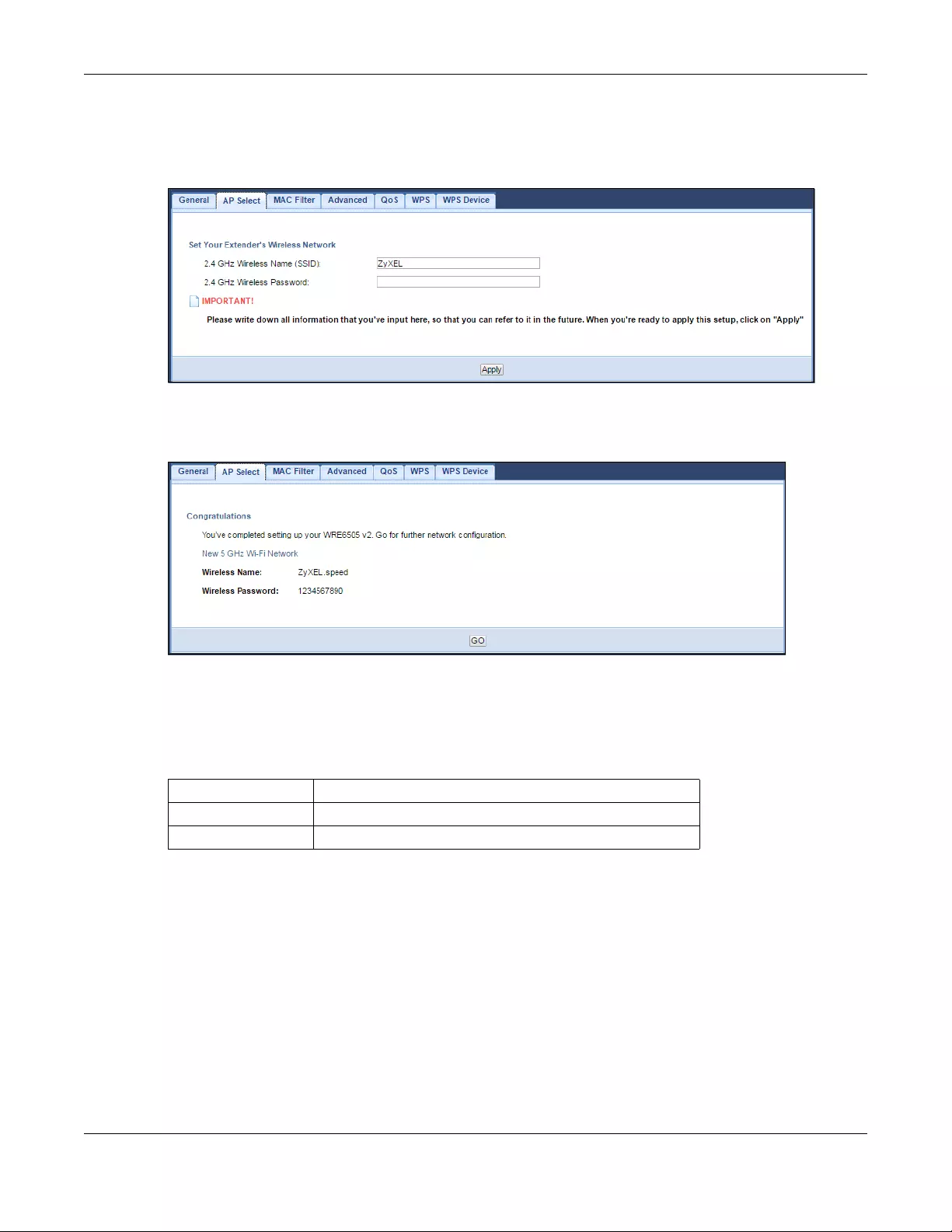
Chapter 7 Tutorials
WRE6505 v2 User’s Guide
43
3Configure the wireless settings between the WRE6505 v2 and its wireless clients. The WRE6505 v2
automatically copies the SSID of the associated AP and appends “.speed” to the 5GHz SSID. Click
Apply to save settings and restart the WRE6505 v2.
Figure 22 Tutorial: Configure WRE6505 v2’s WLAN
4You have successfully set up your WRE6505 v2 to connect to an AP. Click GO to go to the Status
screen.
Figure 23 Tutorial: Saving settings
7.4.2 Selecting an AP by Manually Entering Security Information
This example shows you how to configure wireless security settings with the following parameters
on your WRE6505 v2.
Follow the steps below to create a secure wireless network by manually entering the AP’s wireless
security settings in the WRE6505 v2’s interface.
The instructions require that your hardware is connected (see the Quick Start Guide) and you are
logged into the Web Configurator through your LAN connection (see Section 2.2 on page 13).
1Open the Network > Wireless LAN 2.4G or Wireless LAN 5G > AP Select screen. Select
Choose Network Manually.
SSID ZyXEL
Security WPA(2)-PSK
Wi-Fi Key 1234567890
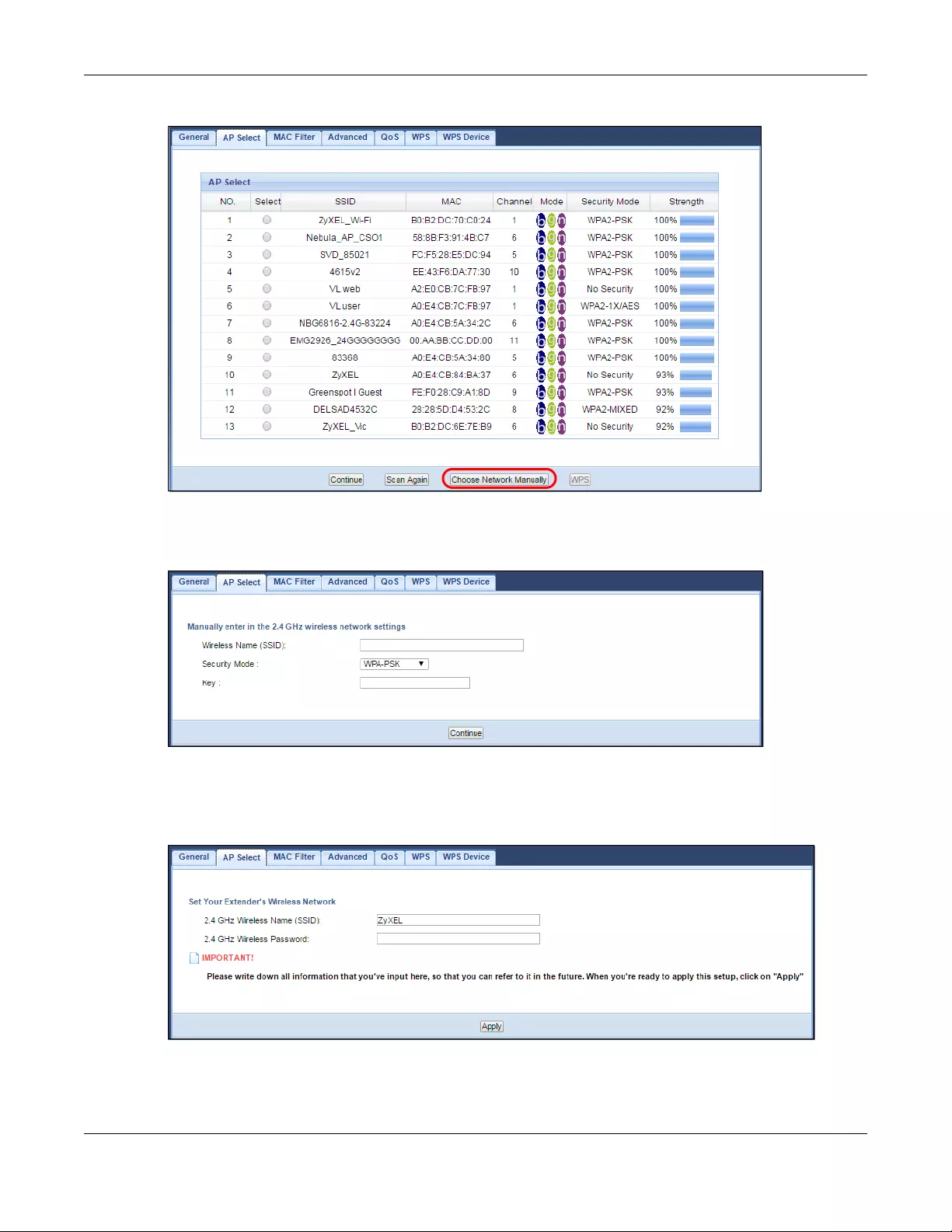
Chapter 7 Tutorials
WRE6505 v2 User’s Guide
44
Figure 24 Tutorial: Manually Entering Wireless Security Information
2Type the SSID of the AP into the Wireless Name (SSID) field, set the security settings and click
Continue.
Figure 25 Tutorial: Typing an SSID
3Configure the wireless settings between the WRE6505 v2 and its wireless clients. The WRE6505 v2
automatically copies the SSID of the associated AP and appends “.speed” to the 5GHz SSID. Click
Apply to save settings and restart the WRE6505 v2.
Figure 26 Tutorial: Configure WRE6505 v2’s WLAN
4You have successfully set up your WRE6505 v2 to connect to an AP. Click GO to go to the Status
screen.
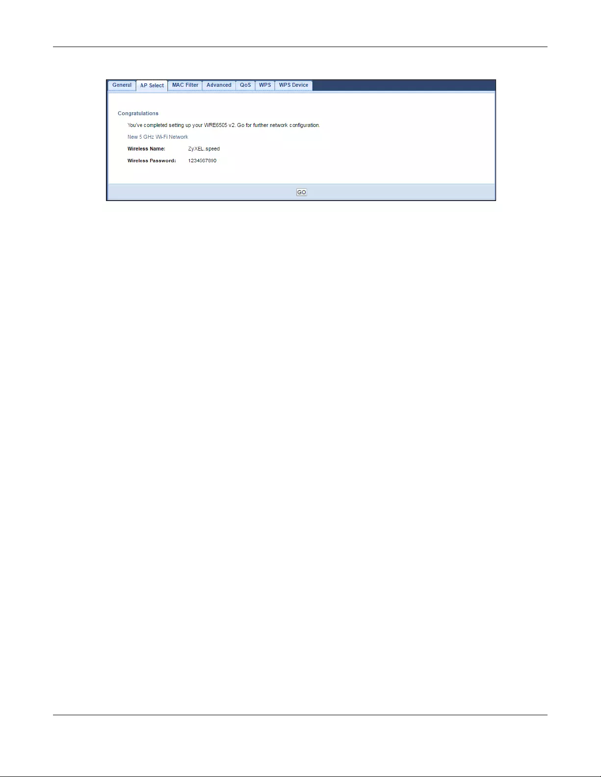
Chapter 7 Tutorials
WRE6505 v2 User’s Guide
45
Figure 27 Tutorial: Saving settings

46
PART II
Technical Reference

WRE6505 v2 User’s Guide
47
CHAPTER 8
Monitor
8.1 Overview
This chapter discusses read-only information related to the device state of the WRE6505 v2.
8.2 What You Can Do
•use the Packet Statistics screen (Section 8.3 on page 47) to view port status, packet specific
statistics, the «system up time» and so on.
8.3 Packet Statistics Screen
Click Monitor > Packet Statistics. Read-only information here includes port status, packet
specific statistics and the «system up time». The Poll Interval(s) field is configurable and is used
for refreshing the screen.
Figure 28 Monitor > Packet Statistics

Chapter 8 Monitor
WRE6505 v2 User’s Guide
48
The following table describes the labels in this screen.
Ta ble 13 Monitor > Packet Statistics
LABEL DESCRIPTION
Port This is the WRE6505 v2’s port type.
Status For the LAN ports, this displays the port speed or Down when the line is disconnected.
For the WLAN, it displays the maximum transmission rate when the WLAN is enabled
and Down when the WLAN is disabled.
TxPkts This is the number of transmitted packets on this port.
RxPkts This is the number of received packets on this port.
Collisions This is the number of collisions on this port.
Tx kb/s This displays the transmission speed in kilobits per second on this port.
Rx kb/s This displays the reception speed in kilobits per second on this port.
System Up Time This is the total time the WRE6505 v2 has been on.
Poll Interval(s) Select the time interval in seconds for refreshing statistics in this field.
Refresh Now Click this button to update the screen statistics immediately.

WRE6505 v2 User’s Guide
49
CHAPTER 9
Wireless LAN
9.1 Overview
This chapter discusses how to configure the wireless network settings in your WRE6505 v2. See
Section 1.1 on page 9 for an overview of wireless networks.
9.2 What You Can Do
•Use the General screen to enable the Wireless LAN (2.4G/5G), enter the SSID and select the
wireless security mode (Section 9.4 on page 51).
•Use the AP selec t screen to choose an access point that you want the WRE6505 v2 (in repeater
mode) to connect to. You should know the security settings of the target AP (Section 9.6 on page
57). This screen is available only when the WRE6505 v2 is in repeater mode.
•Use the MAC Filter screen to allow or deny wireless stations based on their MAC addresses from
connecting to the WRE6505 v2 (Section 9.7 on page 60).
•Use the Advanced screen to allow intra-BSS networking and set the RTS/CTS Threshold (Section
9.8 on page 61).
•Use the QoS screen to enable Wi-Fi MultiMedia Quality of Service (WMMQoS). This allows the
WRE6505 v2 to automatically set priority levels to services, such as e-mail, VoIP, chat, and so on
(Section 9.8 on page 61).
•Use the WPS screen to enable WPS to quickly set up a wireless network with strong security,
without having to configure security settings manually (Section 9.10 on page 62).
•Use the WPS Device screen to add a wireless station using WPS (Section 9.11 on page 63).
•Use the Scheduling screen to set the times your wireless LAN is turned on and off (Section 9.12
on page 64). This screen is available only when the WRE6505 v2 is in AP mode.
9.3 What You Should Know
Every wireless network must follow these basic guidelines.
• Every wireless client in the same wireless network must use the same SSID.
The SSID is the name of the wireless network. It stands for Service Set IDentity.
• If two wireless networks overlap, they should use different channels.
Like radio stations or television channels, each wireless network uses a specific channel, or
frequency, to send and receive information.

Chapter 9 Wireless LAN
WRE6505 v2 User’s Guide
50
• Every wireless client in the same wireless network must use security compatible with the AP.
Security stops unauthorized devices from using the wireless network. It can also protect the
information that is sent in the wireless network.
9.3.1 Wireless Security Overview
The following sections introduce different types of wireless security you can set up in the wireless
network.
9.3.1.1 MAC Address List
Every wireless client has a unique identification number, called a MAC address.1 A MAC address is
usually written using twelve hexadecimal characters2; for example, 00A0C5000002 or
00:A0:C5:00:00:02. To get the MAC address for each wireless client, see the appropriate User’s
Guide or other documentation.
You can use the MAC Address List to tell the AP which wireless clients are allowed to use the
wireless network. If a wireless client is allowed to use the wireless network, it still has to have the
correct settings (SSID, channel, and security). If a wireless client is not allowed to use the wireless
network, it does not matter if it has the correct settings.
This type of security does not protect the information that is sent in the wireless network.
Furthermore, there are ways for unauthorized devices to get the MAC address of an authorized
wireless client. Then, they can use that MAC address to use the wireless network.
9.3.1.2 Encryption
Wireless networks can use encryption to protect the information that is sent in the wireless
network. Encryption is like a secret code. If you do not know the secret code, you cannot
understand the message.
For example, if users do not log in to the wireless network, you can choose no authentication, if
users do log on to the wireless network, you can choose No Security, Static WEP, WPA-PSK, or
WPA2-PSK.
Usually, you should set up the strongest encryption that every wireless client in the wireless
network supports. Suppose the wireless network has two wireless clients. Device A only supports
WEP, and device B supports WEP and WPA-PSK. Therefore, you should set up Static WEP in the
wireless network.
1. Some wireless devices, such as scanners, can detect wireless networks but cannot use wireless networks. These kinds
of wireless devices might not have MAC addresses.
2. Hexadecimal characters are 0, 1, 2, 3, 4, 5, 6, 7, 8, 9, A, B, C, D, E, and F.
Ta ble 14 Types of Encryption for Each Type of Authentication
NO AUTHENTICATION
Weakest No Security
Static WEP
WPA-PSK
Strongest WPA2-PSK
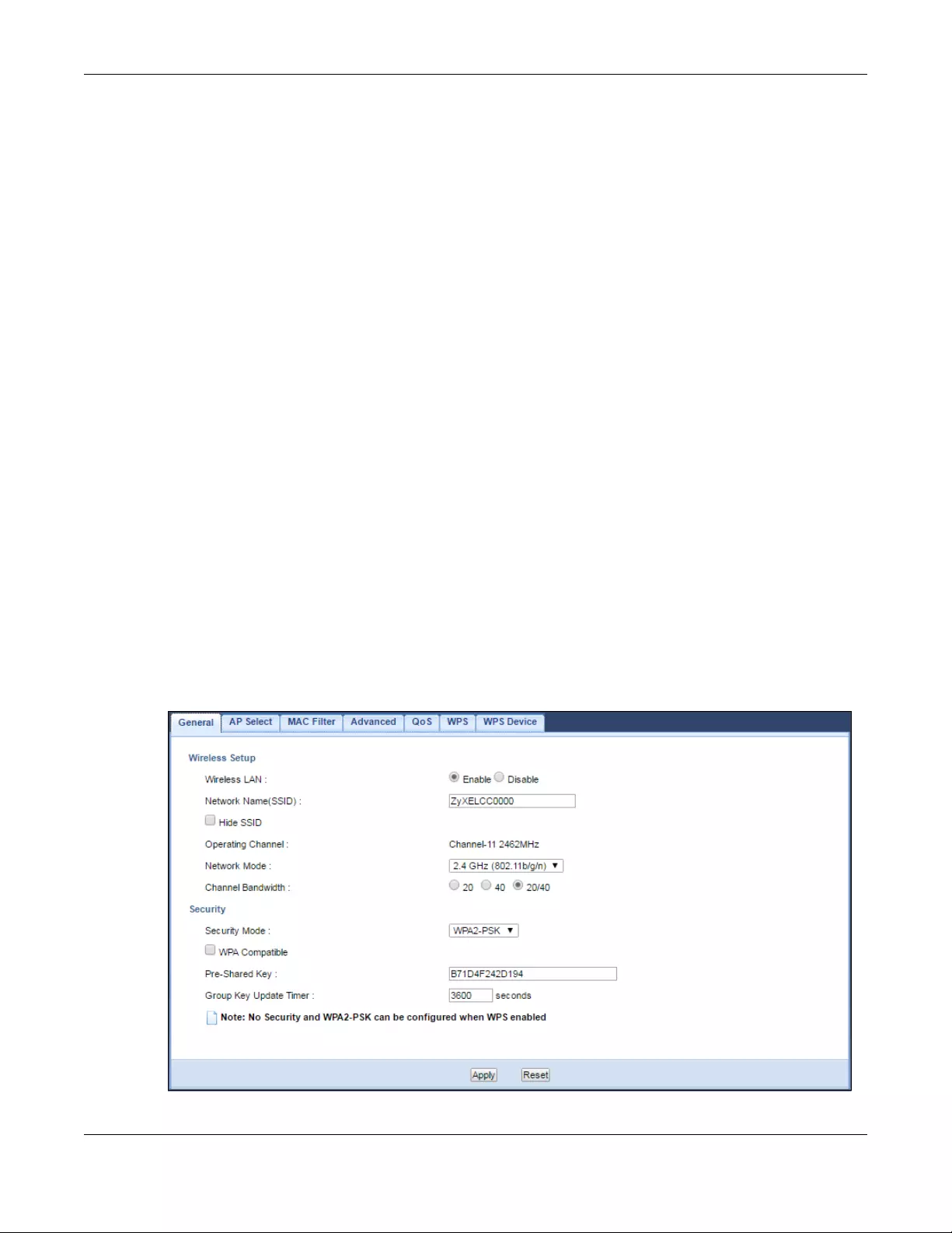
Chapter 9 Wireless LAN
WRE6505 v2 User’s Guide
51
Note: It is recommended that wireless networks use WPA-PSK, or stronger encryption.
IEEE 802.1x and WEP encryption are better than none at all, but it is still possible
for unauthorized devices to figure out the original information pretty quickly.
Many types of encryption use a key to protect the information in the wireless network. The longer
the key, the stronger the encryption. Every wireless client in the wireless network must have the
same key.
9.3.1.3 WPS
Wi-Fi Protected Setup (WPS) is an industry standard specification, defined by the Wi-Fi Alliance.
WPS allows you to quickly set up a wireless network with strong security, without having to
configure security settings manually. Depending on the devices in your network, you can either
press a button (on the device itself, or in its configuration utility) or enter a PIN (Personal
Identification Number) in the devices. Then, they connect and set up a secure network by
themselves. See how to set up a secure wireless network using WPS in the Section 7.3 on page 38.
9.4 General Wireless LAN Screen
Use this screen to enable the Wireless LAN, enter the SSID and select the wireless security mode.
Note: If you are configuring the WRE6505 v2 from a computer connected to the wireless
LAN and you change the WRE6505 v2’s SSID, channel or security settings, you will
lose your wireless connection when you press Apply to confirm. You must then
change the wireless settings of your computer to match the WRE6505 v2’s new
settings.
Click Network > Wireless LAN 2.4G or Wireless LAN 5G to open the General screen.
Figure 29 Network > Wireless LAN 2.4G/5G > General (Repeater Mode)
Chapter 9 Wireless LAN
WRE6505 v2 User’s Guide
52
Figure 30 Network > Wireless LAN 2.4G/5G > General (AP Mode)
The following table describes the general wireless LAN labels in this screen.
Ta ble 15 Network > Wireless LAN 2.4G/5G > General
LABEL DESCRIPTION
Wireless Setup
Wireless LAN This is turned on by default. Click Disable to turn off the wireless LAN function.
Network Name
(SSID)
The SSID (Service Set IDentity) identifies the Service Set with which a wireless client is
associated. Enter a descriptive name (up to 32 printable characters found on a typical
English language keyboard) for the wireless LAN.
Hide SSID Select this check box to hide the SSID in the outgoing beacon frame so a wireless client
cannot obtain the SSID through scanning using a site survey tool.
Channel
Selection
Set the operating frequency/channel depending on your particular region.
Select a channel from the drop-down list box. The options vary depending on the frequency
band and the country you are in.
This option is only available when the WRE6505 v2 is in AP mode and Auto Channel
Selection is disabled.
Auto Channel
Selection
This option is available only when the WRE6505 v2 is in AP mode.
Select this option to have the WRE6505 v2 automatically scan for and select a channel which
is not used by another device.
Operating
Channel
This displays the channel the WRE6505 v2 is currently using.

Chapter 9 Wireless LAN
WRE6505 v2 User’s Guide
53
Network Mode 2.4 GHz is the frequency used by IEEE 802.11b/g/n wireless clients.
5 GHz is the frequency used by IEEE 802.11ac/a/n wireless clients.
Select 2 .4 GHz (802.11b) to allow only IEEE 802.11b compliant WLAN devices to associate
with the WRE6505 v2.
Select 2 .4 GHz (802.11g) to allow only IEEE 802.11g compliant WLAN devices to associate
with the WRE6505 v2.
Select 2.4 GHz (802.11n) to allow only IEEE 802.11n compliant WLAN devices to associate
with the WRE6505 v2.
Select 2.4 GHz (802.11b/g) to allow both IEEE802.11b and IEEE802.11g compliant WLAN
devices to associate with the WRE6505 v2. The transmission rate of your WRE6505 v2 might
be reduced.
Select 2.4 GHz (802.11b/g/n) to allow both IEEE802.11b, IEEE802.11g and IEEE802.11n
compliant WLAN devices to associate with the WRE6505 v2. The transmission rate of your
WRE6505 v2 might be reduced.
Select 5 GHz (802.11a) to allow only IEEE 802.11a compliant WLAN devices to associate
with the WRE6505 v2.
Select 5 GHz (802.11a/n) to allow both IEEE802.11a and IEEE802.11n compliant WLAN
devices to associate with the WRE6505 v2. The transmission rate of your WRE6505 v2 might
be reduced.
Select 5 GHz ( 802.11a/n/a c) to allow both IEEE802.11a, IEEE802.11n and IEEE802.11ac
compliant WLAN devices to associate with the WRE6505 v2. The transmission rate of your
WRE6505 v2 might be reduced..
Channel
Bandwidth
Select the channel bandwidth you want to use for your wireless network.
Select 20 MHz if you want to lessen radio interference with other wireless devices in your
neighborhood.
Select 40 MHz if you want to lessen radio interference with other wireless devices in your
neighborhood.
Select 20/40 MHz to allow the WRE6505 v2 to choose the channel bandwidth (20 or 40
MHz) that has least interference.
Select 20/40/80 MHz to allow the WRE6505 v2 to choose the channel bandwidth (20 or 40
or 80 MHz) that has least interference. This option is available only when you select 5 GHz
(802.11a/n/ac) in the Network Mode field.
Security
Security Mode If the WRE6505 v2 is in repeater mode, select No Security or the available modes to match
as provided by the source AP or wireless router.
If the WRE6505 v2 is in AP mode, select WPA2-PSK, WPA-PSK or Static WEP to add
security on this wireless network. The wireless clients which want to associate to this
network must have same wireless security settings as this device. After you select to use a
security, additional options appears in this screen. See Section 9.5 on page 54 for detailed
information on different security modes. Or you can select No Security to allow any client to
associate this network without authentication.
Note: If the WPS function is enabled (default), only No Security and WPA2-PSK are available
in this field.
Apply Click Apply to save your changes back to the WRE6505 v2.
Reset Click Reset to return to the previous menu without saving.
Ta ble 15 Network > Wireless LAN 2.4G/5G > General (continued)
LABEL DESCRIPTION
Chapter 9 Wireless LAN
WRE6505 v2 User’s Guide
54
9.5 Wireless Security
The screen varies depending on what you select in the Security Mode field.
9.5.1 No Security
Select No Security to allow wireless clients to communicate with the access point without any data
encryption.
Note: If you do not enable any wireless security on your WRE6505 v2, your network is
accessible to any wireless networking device that is within range.
Figure 31 Network > Wireless LAN 2.4G/5G > General: No Security
The following table describes the labels in this screen.
9.5.2 WEP Encryption
WEP encryption scrambles the data transmitted between the wireless stations and the access points
to keep network communications private. It encrypts unicast and multicast communications in a
network. Both the wireless stations and the access points must use the same WEP key.
Your WRE6505 v2 allows you to configure up to four 64-bit or 128-bit WEP keys but only one key
can be enabled at any one time.
Select Static WEP from the Security Mode list.
Ta ble 16 Network > Wireless LAN 2.4G/5G > General: No Security
LABEL DESCRIPTION
Security Mode Choose No Security from the drop-down list box.
Apply Click Apply to save your changes back to the WRE6505 v2.
Reset Click Reset to reload the previous configuration for this screen.

Chapter 9 Wireless LAN
WRE6505 v2 User’s Guide
55
Figure 32 Network > Wireless LAN 2.4G/5G > General: Static WEP
The following table describes the wireless LAN security labels in this screen.
Ta ble 17 Network > Wireless LAN 2.4G/5G > General: Static WEP
LABEL DESCRIPTION
Security Mode Select Static WEP to enable data encryption.
PassPhrase Enter a Passphrase (up to 26 printable characters) and click Generate.
A passphrase functions like a password. In WEP security mode, it is further converted by
the WRE6505 v2 into a complicated string that is referred to as the “key”. This key is
requested from all devices wishing to connect to a wireless network.
WEP Encryption Select 64-bits or 128-bits.
This dictates the length of the security key that the network is going to use.
Authentication
Method
Select Auto or Shared Key from the drop-down list box.
This field specifies whether the wireless clients have to provide the WEP key to login to
the wireless client. Keep this setting at Auto unless you want to force a key verification
before communication between the wireless client and the WRE6505 v2 occurs.
Select Shared Key to force the clients to provide the WEP key prior to communication.
ASCII Select this option in order to enter ASCII characters as WEP key.
Chapter 9 Wireless LAN
WRE6505 v2 User’s Guide
56
9.5.3 WPA-PSK/WPA2-PSK
Select WPA-PSK or WPA2-PSK from the Security Mode list.
Figure 33 Network > Wireless LAN 2.4G/5G > General: WPA-PSK/WPA2-PSK
Hex Select this option in order to enter hexadecimal characters as a WEP key.
The preceding «0x», that identifies a hexadecimal key, is entered automatically.
Key 1 to Key 4 The WEP keys are used to encrypt data. Both the WRE6505 v2 and the wireless stations
must use the same WEP key for data transmission.
If you chose 64-bits, then enter any 5 ASCII characters or 10 hexadecimal characters
(«0-9», «A-F»).
If you chose 128-bits, then enter 13 ASCII characters or 26 hexadecimal characters («0-
9″, «A-F»).
You must configure at least one key, only one key can be activated at any one time. The
default key is key 1.
Apply Click Apply to save your changes back to the WRE6505 v2.
Reset Click Reset to reload the previous configuration for this screen.
Ta ble 17 Network > Wireless LAN 2.4G/5G > General: Static WEP (continued)
LABEL DESCRIPTION
Chapter 9 Wireless LAN
WRE6505 v2 User’s Guide
57
The following table describes the labels in this screen.
9.6 AP Select Screen
Use this screen (available in repeater mode only) to choose an access point that you want the
WRE6505 v2 to connect to. You should know the security settings of the target AP.
To open this screen, click Network > Wireless LAN 2.4G or Wireless LAN 5G > AP Select.
Figure 34 Network > Wireless LAN 2.4G/5G > AP Select (Repeater Mode)
Ta ble 18 Network > Wireless LAN 2.4G/5G > General: WPA-PSK/WPA2-PSK
LABEL DESCRIPTION
Security Mode Select WPA-PSK or WPA2-PSK to enable data encryption.
WPA-PSK
Compatible
This field appears when you choose WPA2-PSK as the Security Mode.
Check this field to allow wireless devices using WPA-PSK security mode to connect to
your WRE6505 v2.
Pre-Shared Key WPA-PSK/WPA2-PSK uses a simple common password for authentication.
Type a pre-shared key from 8 to 63 case-sensitive keyboard characters.
Group Key Update
Timer
The Group Key Update Timer is the rate at which the AP sends a new group key out to
all clients.
The default is 3600 seconds (60 minutes).
Apply Click Apply to save your changes back to the WRE6505 v2.
Reset Click Reset to reload the previous configuration for this screen.
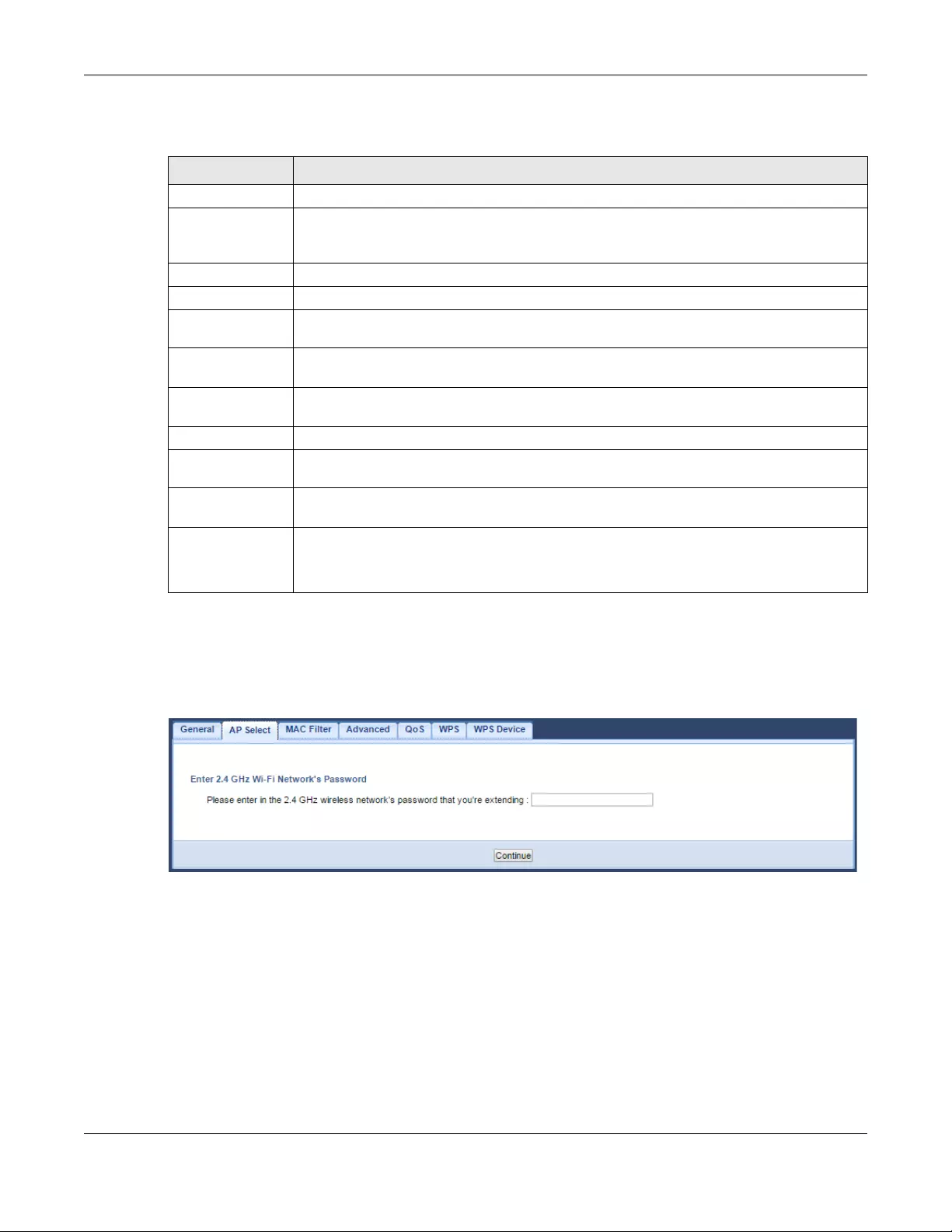
Chapter 9 Wireless LAN
WRE6505 v2 User’s Guide
58
The following table describes the labels in this screen.
Enter a Wi-Fi key
If wireless securoty is enabled on the selected AP, the following screen displays after you click
Continue in the AP Select screen. Enter the AP’s Wi-Fi key and click Continue.
Set up the WRE6505 v2’s WLAN for clients
Use this screen to configure the wireless settings between the WRE6505 v2 and its wireless clients.
The WRE6505 v2 automatically copies the SSID of the associated AP. You can set the SSID and Wi-
Fi key of the WRE6505 v2’s WLAN to be the same as those on the AP to which the WRE6505 v2
wants to connect. Click Apply to save your settings.
Ta ble 19 Network > Wireless LAN 2.4G/5G > AP Select (Repeater Mode)
LABEL DESCRIPTION
Select Use the radio button to select the wireless device to which you want to connect.
SSID This displays the Service Set IDentity of the wireless device. The SSID is a unique name
that identifies a wireless network. All devices in a wireless network must use the same
SSID.
MAC This displays the MAC address of the wireless device.
Channel This displays the channel number used by this wireless device.
Mode This displays which IEEE 802.11b/g/n wireless networking standards the wireless device
supports.
Security Mode This displays the type of security configured on the wireless device. When No Security is
shown, no security is configured and you can connect to it without a password.
Strength This displays the strength of the wireless signal. The signal strength mainly depends on
the antenna output power and the distance between your WRE6505 v2 and this device.
Continue Click Continue to start the next step in the AP setup process.
Scan Again Click Scan Again to search for available wireless devices within transmission range and
update this table.
Choose Network
Manually
Select this to set up the AP manually.
WPS This button is configurable only when you enable WPS in the Wi rel ess L AN 2.4G/5G >
WPS screen.
Click this button to connect to the selected AP via WPS.
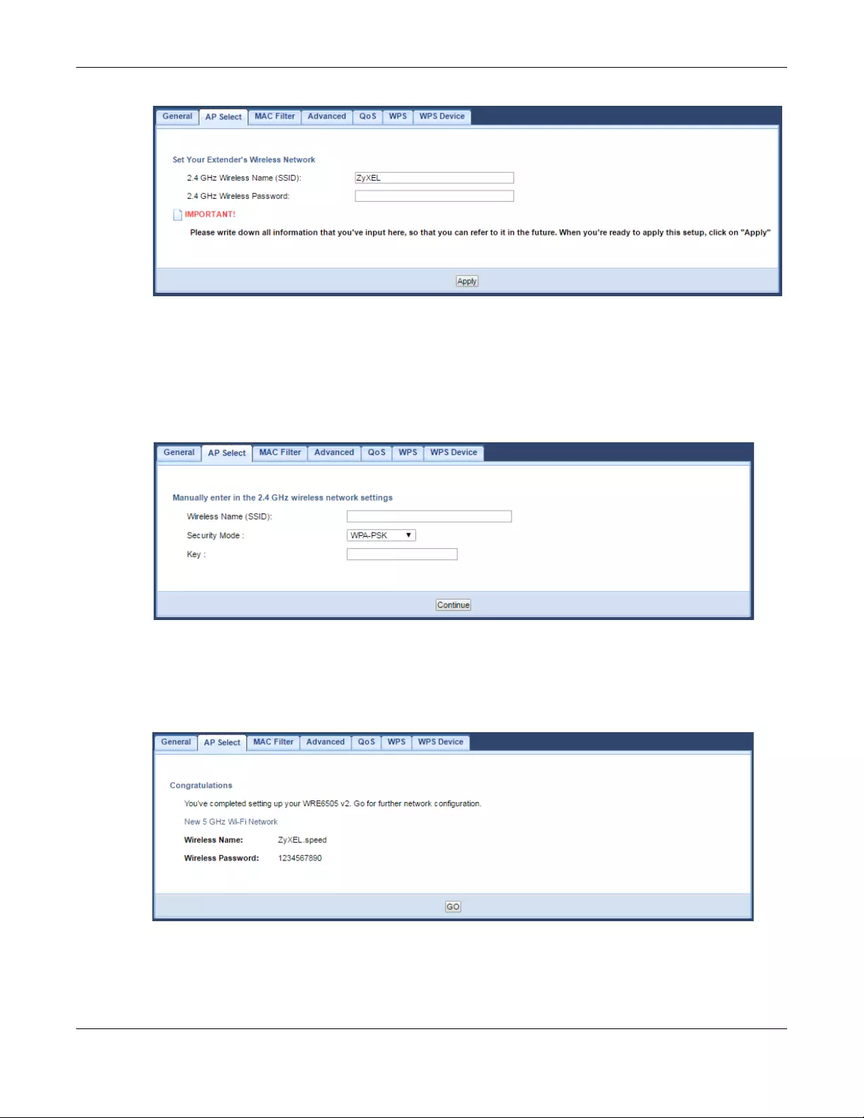
Chapter 9 Wireless LAN
WRE6505 v2 User’s Guide
59
Choose AP network manually
Use this screen to manually enter the SSID, security mode and Wi-Fi key of the AP to which you
want the WRE6505 v2 to connect. This is useful when the AP’s SSID is hidden. Click Continue to
configure the wireless settings between the WRE6505 v2 and its wireless clients (see Set up the
WRE6505 v2’s WLAN for clients on page 58).
Complete the AP and WLAN setup
This screen displays when you have successfully set up your WRE6505 v2 to connect to an AP.
Verify the WRE6505 v2’s wireless network settings and click GO to open the Status screen.
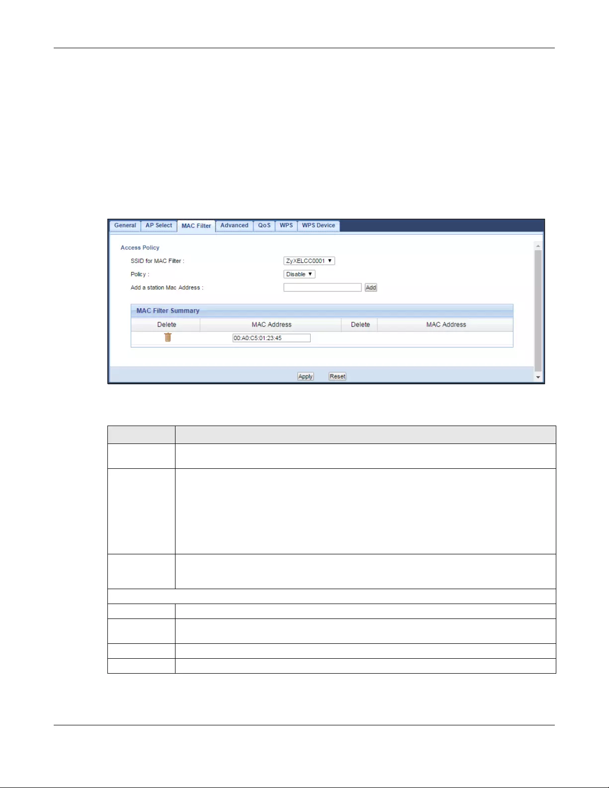
Chapter 9 Wireless LAN
WRE6505 v2 User’s Guide
60
9.7 MAC Filter
The MAC Filter screen allows you to specify which devices are allowed to access the WRE6505 v2,
while denying access to all unspecified devices. Every Ethernet device has a unique MAC (Media
Access Control) address. The MAC address is assigned at the factory and consists of six pairs of
hexadecimal characters, for example, 00:A0:C5:00:00:02. You need to know the MAC address of
the devices to configure this screen.
To change your WRE6505 v2’s MAC Address List settings, click Network > Wireless LAN 2.4G or
Wireless LAN 5G > MAC Filter. The screen appears as shown.
Figure 35 Network > Wireless LAN 2.4G/5G > MAC Filter
The following table describes the labels in this menu.
Ta ble 20 Network > Wireless LAN 2.4G/5G> MAC Filter
LABEL DESCRIPTION
SSID for MAC
Filter
Select the SSID for which you want to configure MAC filtering.
Policy Define the filter action for the list of MAC addresses in the MAC Addr ess table.
Select Disable to deactivate the MAC filtering rule you configure below.
Select Allow to permit access to the WRE6505 v2, MAC addresses not listed will be denied
access to the WRE6505 v2.
Select Reject to block access to the WRE6505 v2, MAC addresses not listed will be allowed to
access the WRE6505 v2
Add a station
Mac Address
Enter the MAC addresses of the wireless station that are allowed or denied access to the
WRE6505 v2 and click Add. Enter the MAC addresses in a valid MAC address format, that is,
six hexadecimal character pairs, for example, 12:34:56:78:9a:bc.
MAC Filter Summary
Delete Click the delete icon to remove the MAC address from the list.
MAC Address This is the MAC address of the wireless station that are allowed or denied access to the
WRE6505 v2.
Apply Click Apply to save your changes back to the WRE6505 v2.
Reset Click Reset to reload the previous configuration for this screen.

Chapter 9 Wireless LAN
WRE6505 v2 User’s Guide
61
9.8 Wireless LAN Advanced Screen
Use this screen to configure advanced wireless LAN parameters.
Click Network > Wireless LAN 2.4G or Wireless LAN 5G > Advanced. The screen appears as
shown.
Figure 36 Network > Wireless LAN 2.4G/5G > Advanced
The following table describes the labels in this screen.
Ta ble 21 Network > Wireless LAN 2.4G/5G > Advanced
LABEL DESCRIPTION
RTS/CTS
Threshold
Data with its frame size larger than this value will perform the RTS (Request To Send)/
CTS (Clear To Send) handshake.
Enter a value between 1 and 2347.
Fragmentation
Threshold
The threshold (number of bytes) for the fragmentation boundary for directed messages.
It is the maximum data fragment size that can be sent. Enter an even number between
256 and 2346.
Enable Intra-BSS
Traffic Blocking
A Basic Service Set (BSS) exists when all communications between wireless clients or
between a wireless client and a wired network client go through one access point (AP).
Intra-BSS traffic is traffic between wireless clients in the BSS. When Intra-BSS traffic
blocking is not enabled, wireless clients can access the wired network and communicate
with each other. When Intra-BSS traffic blocking is enabled, wireless clients can still
access the wired network but cannot communicate with each other.
Output Power Set the output power of the WRE6505 v2 in this field. If there is a high density of APs in
an area, decrease the output power of the WRE6505 v2 to reduce interference with other
APs. Select one of the following 100%, 50% or 25%. See the product specifications for
more information on your WRE6505 v2’s output power.
HT (High Throughput) Physical Mode
Guard Interval Select Auto to increase data throughput. However, this may make data transfer more
prone to errors.
Select Long to prioritize data integrity. This may be because your wireless network is
busy and congested or the WRE6505 v2 is located in an environment prone to radio
interference.
Apply Click Apply to save your changes to the WRE6505 v2.
Reset Click Reset to reload the previous configuration for this screen.
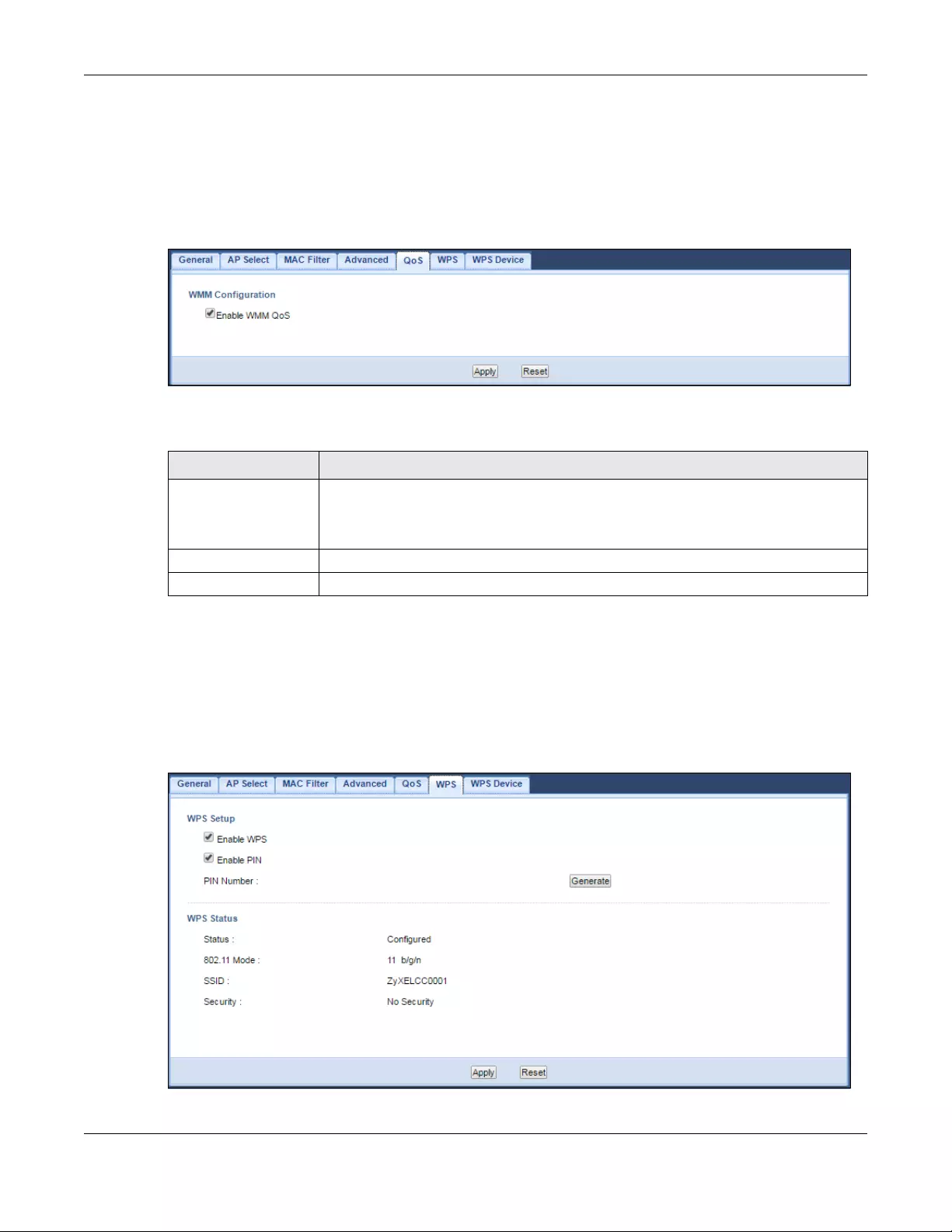
Chapter 9 Wireless LAN
WRE6505 v2 User’s Guide
62
9.9 Quality of Service (QoS) Screen
The QoS screen allows you to automatically give a service (such as VoIP and video) a priority level.
Click Network > Wireless LAN 2.4G or Wireless LAN 5G > QoS. The following screen appears.
Figure 37 Network > Wireless LAN 2.4G/5G > QoS
The following table describes the labels in this screen.
9.10 WPS Screen
Use this screen to enable/disable WPS, view or generate a new PIN and check current WPS status.
To open this screen, click Network > Wireless LAN 2.4G or Wireless LAN 5G > WPS tab.
Figure 38 Network > Wireless LAN 2.4G/5G > WPS
Ta ble 22 Network > Wireless LAN 2.4G/5G > QoS
LABEL DESCRIPTION
Enable WMM QoS Check this to have the WRE6505 v2 automatically give a service a priority level
according to the ToS value in the IP header of packets it sends. WMM QoS (Wifi
MultiMedia Quality of Service) gives high priority to voice and video, which makes
them run more smoothly.
Apply Click Apply to save your changes to the WRE6505 v2.
Reset Click Reset to reload the previous configuration for this screen.

Chapter 9 Wireless LAN
WRE6505 v2 User’s Guide
63
The following table describes the labels in this screen.
9.11 WPS Device Screen
Use this screen when you want to add a wireless station using WPS. To open this screen, click
Network > Wireless LAN 2.4G or Wireless LAN 5G > WPS Device.
Note: After you click WPS on this screen, you have to press a similar button in the
wireless station utility within 2 minutes. To add the second wireless station, you
have to press these buttons on both device and the wireless station again after the
first 2 minutes.
Ta ble 23 Network > Wireless LAN 2.4G/5G > WPS
LABEL DESCRIPTION
WPS Setup
Enable WPS Select this to enable the WPS feature.
Enable PIN Select this to enable the PIN number.
PIN Number This displays a PIN number last time system generated. Click Generate to generate a
new PIN number.
WPS Status
Status This displays Configured when the WRE6505 v2 has connected to a wireless network
using WPS or when Enable WPS is selected and wireless or wireless security settings
have been changed. The current wireless and wireless security settings also appear in the
screen.
This displays Unconfigured if WPS is disabled and there are no wireless or wireless
security changes on the WRE6505 v2 or click Release Configuration (AP mode only) to
remove the configured wireless and wireless security settings.
Release
Configuration
(AP mode only)
This button is only available when the WPS status displays Configured.
Click this button to remove all configured wireless and wireless security settings for WPS
connections on the WRE6505 v2.
802.11 Mode This is the 802.11 mode used. Only compliant WLAN devices can associate with the
WRE6505 v2.
SSID This is the name of the wireless network (the WAP3205 v2’s first SSID).
Security This is the type of wireless security employed by the network.
Apply Click Apply to save your changes back to the WRE6505 v2.
Reset Click Reset to reload the previous configuration for this screen.
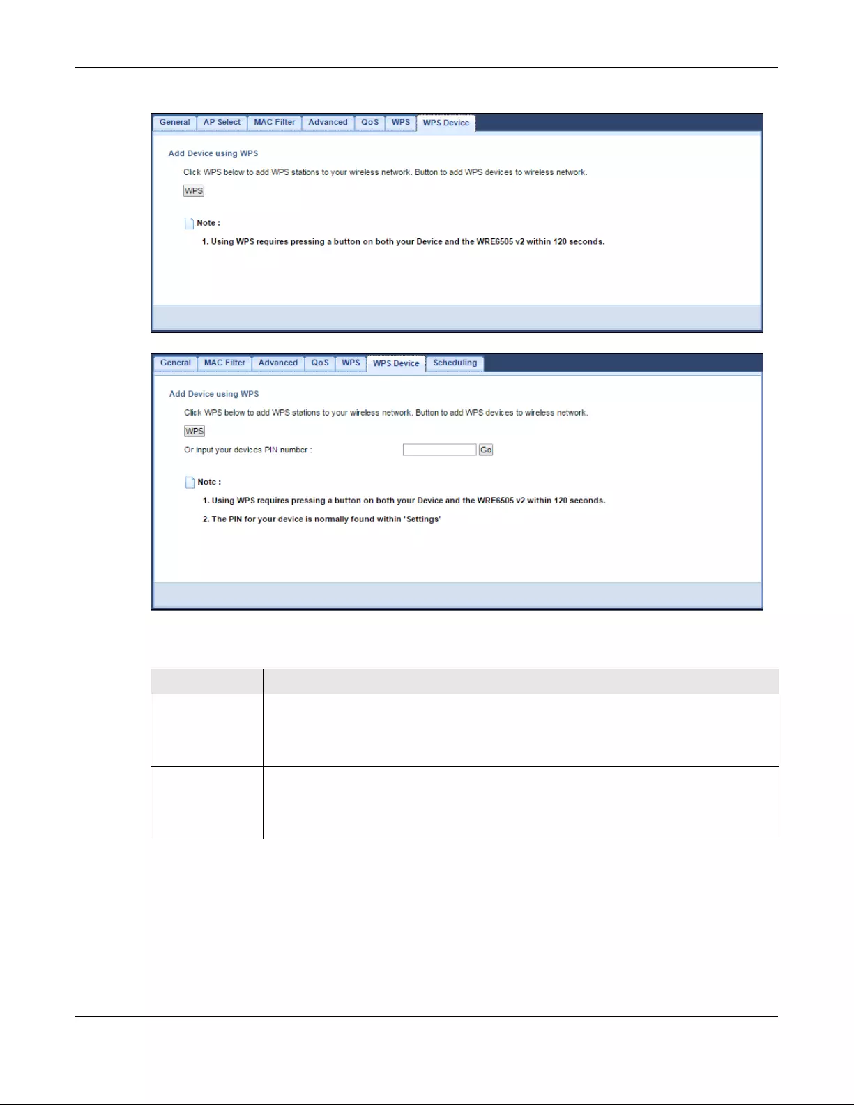
Chapter 9 Wireless LAN
WRE6505 v2 User’s Guide
64
Figure 39 Network > Wireless LAN 2.4G/5G > WPS Device (Repeater Mode)
Figure 40 Network > Wireless LAN 2.4G/5G > WPS Device (AP Mode)
The following table describes the labels in this screen.
9.12 Scheduling Screen
Use this screen (available in AP mode only) to set the times your wireless LAN is turned on and off.
Wireless LAN scheduling is disabled by default. The wireless LAN can be scheduled to turn on or off
on certain days and at certain times. To open this screen, click Network > Wireless LAN 2.4G or
Wireless LAN 5G > Scheduling tab.
Ta ble 24 Network > Wireless LAN 2.4G/5G > WPS Device
LABEL DESCRIPTION
WPS Use this button when you use the PBC (Push Button Configuration) method to configure
wireless stations’s wireless settings. See Section 7.3.1 on page 39.
Click this to start WPS-aware wireless station scanning and the wireless security
information synchronization.
Or input your
devices PIN
number (AP mode
only)
Use this button when you use the PIN Configuration method to configure wireless station’s
wireless settings. See Section 7.3.2 on page 40.
Type the same PIN number generated in the wireless station’s utility. Then click Go to
associate to each other and perform the wireless security information synchronization.
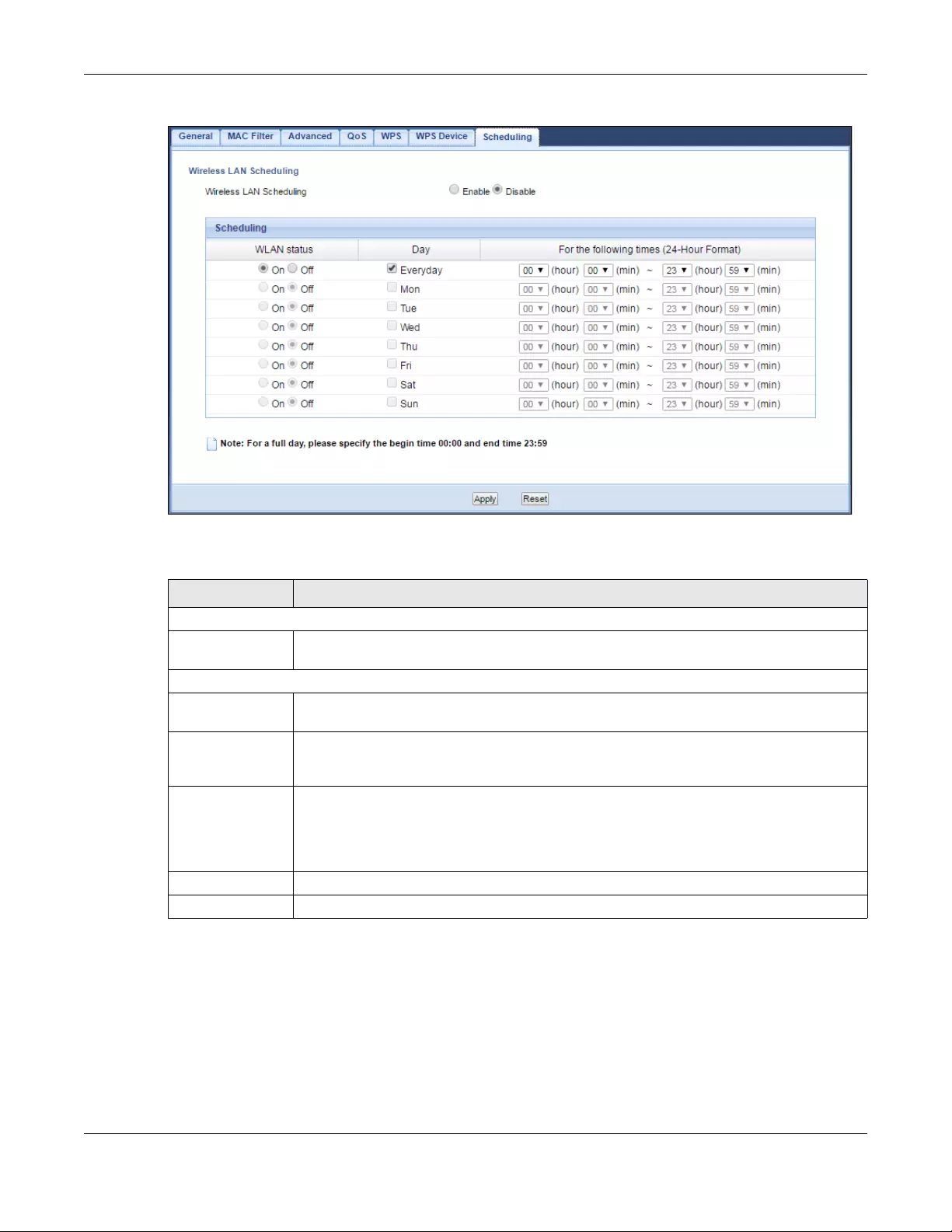
Chapter 9 Wireless LAN
WRE6505 v2 User’s Guide
65
Figure 41 Network > Wireless LAN 2.4G/5G > Scheduling
The following table describes the labels in this screen.
Ta ble 25 Network > Wireless LAN 2.4G/5G > Scheduling
LABEL DESCRIPTION
Wireless LAN Scheduling
Wireless LAN
Scheduling
Select to enable or disable wireless LAN scheduling.
Scheduling
WLAN Status Select On or Off to specify whether the Wireless LAN is turned on or off. This field works
in conjunction with the Day and For the following times fields.
Day Select Everyday or the specific days to turn the Wireless LAN on or off. If you select
Everyday you can not select any specific days. This field works in conjunction with the
For the following times field.
For the following
times (24-Hour
Format)
Select a begin time using the first set of hour and minute (min) drop down boxes and
select an end time using the second set of hour and minute (min) drop down boxes. If
you have chosen On earlier for the WLAN Status the Wireless LAN will turn on between
the two times you enter in these fields. If you have chosen Off earlier for the WLAN
Status the Wireless LAN will turn off between the two times you enter in these fields.
Apply Click Apply to save your changes back to the WRE6505 v2.
Reset Click Reset to reload the previous configuration for this screen.
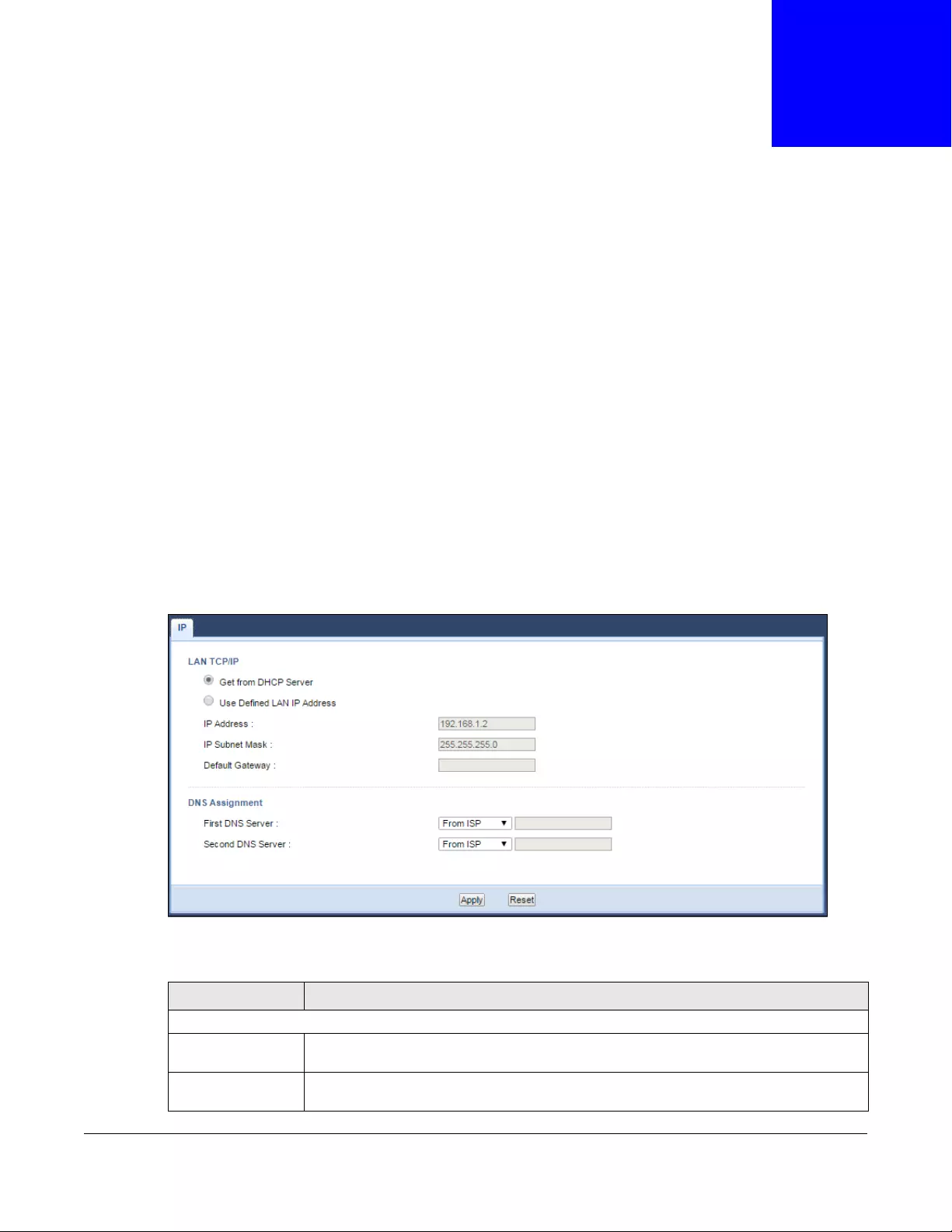
WRE6505 v2 User’s Guide
66
CHAPTER 10
LAN
10.1 Overview
This screen allows you to assign the WRE6505 v2 a fixed or dynamic management IP address. The
default IP address of the WRE6505 v2 is 192.168.1.2. Alternatively, you can connect to the
WRE6505 v2 using the default domain name, http://zyxelsetup.
10.2 LAN IP Screen
Use this screen to change the WRE6505 v2’s management IP address and configure the DNS server
information that the WRE6505 v2 sends to the DHCP clients. Click Network > LAN.
Note: If you change the IP address of the WRE6505 v2 in the screen below, you will need
to log into the WRE6505 v2 again using the new IP address.
Figure 42 Network > LAN > IP
The following table describes the labels in this screen.
Ta ble 26 Network > LAN > IP
LABEL DESCRIPTION
LAN TCP/IP
Get from DHCP
Server
Select this to have the WRE6505 v2 get a dynamic IP address from a DHCP server.
User Defined LAN
IP Address
Click this to enable the manual IP configuration.

Chapter 10 LAN
WRE6505 v2 User’s Guide
67
IP Address Enter the IP address of your WRE6505 v2 in dotted decimal notation.
IP Subnet Mask Enter the subnet mask of your WRE6505 v2 in dotted decimal notation.
Default Gateway Enter the gateway of your WRE6505 v2 in dotted decimal notation.
DNS Assignment
First DNS Server
Second DNS Server
Select From ISP if your ISP or router to which the WRE6505 v2 connects dynamically
assigns DNS server information (and the WRE6505 v2’s IP address). The field to the
right displays the (read-only) DNS server IP address that the ISP assigns.
Select User-Defined if you have the IP address of a DNS server. Enter the DNS server’s
IP address in the field to the right.
Select None if you do not want to configure DNS servers. If you do not configure a DNS
server, you must know the IP address of a computer in order to access it.
Apply Click Apply to save your changes back to the WRE6505 v2.
Reset Click Reset to reload the previous configuration for this screen.
Ta ble 26 Network > LAN > IP (continued)
LABEL DESCRIPTION

WRE6505 v2 User’s Guide
68
CHAPTER 11
One Connect
11.1 Overview
One Connect is a ZyXEL-proprietary feature. It complies with the IEEE 1905.1 standard and allows
auto-detection and auto-configuration.
If your wireless router supports ZyXEL One Connect, WRE6505 v2 for example, you can download
and install the ZyXEL One Connect App in your mobile device to check the connection status, do
speed test, turn on or turn off the devices in your network, block or allow a device’s access and set
up a guest Wi-Fi network from the mobile device. You can even use the App to access the WRE6505
v2’s web configurator. The mobile device with the App installed must be connected to the WRE6505
v2 wirelessly.
Figure 43 ZyXEL One Connect App
11.1.1 What You Can Do
Use the One Connect screen to enable or disable Wi-Fi auto-configuration (Section 11.2 on page
68).
11.2 One Connect Screen
Use this screen to enable or disable Wi-Fi auto-configuration on the WRE6505 v2.
Click Configuration > Network > OneConnect to open the following screen.
Figure 44 Configuration > Network > OneConnect
Chapter 11 One Connect
WRE6505 v2 User’s Guide
69
The following table describes the labels in this screen.
Ta ble 27 Configuration > Network > OneConnect
LABEL DESCRIPTION
One Connect
Auto-configuration Select Enable to allow the WRE6505 v2 to automatically update the wireless settings on
the APs or wireless repeaters (which also support ZyXEL One Connect) in its network.
Select Disable to turn this feature off if you want to have the APs or repeaters in the
network use different wireless settings.
Apply Click Apply to save your changes back to the WRE6505 v2.
Reset Click Reset to reload the previous configuration for this screen.
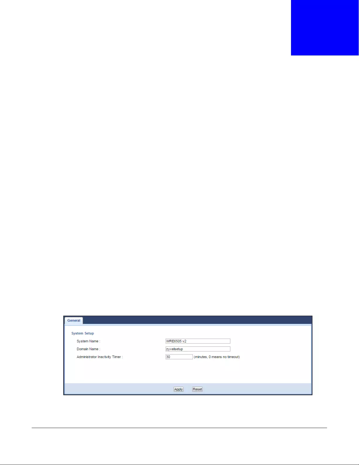
WRE6505 v2 User’s Guide
70
CHAPTER 12
Maintenance
12.1 Overview
This chapter provides information on the Maintenance screen.
12.2 What You Can Do
•Use the General screen to set the system and domain names (Section 12.3 on page 70).
•Use the Password screen to set the password (Section 12.4 on page 71).
•Use the Time screen to change your WRE6505 v2’s time and date (Section 12.5 on page 71).
•Use the Firmware Upgrade screen to update firmware (Section 12.6 on page 73).
•Use the Backup Restore screen to backup and restore device configurations (Section 12.7 on
page 75).
•Use the Restart screen to reboot the WRE6505 v2 without turning the power off (Section 12.8
on page 77).
•Use the System Mode screen to select how you want to use your WRE6505 v2 (Section 12.9 on
page 78).
12.3 General
Use this screen to set the system and domain names and the timeout period of the management
session. Click Maintenance > General. The following screen displays.
Figure 45 Maintenance > General
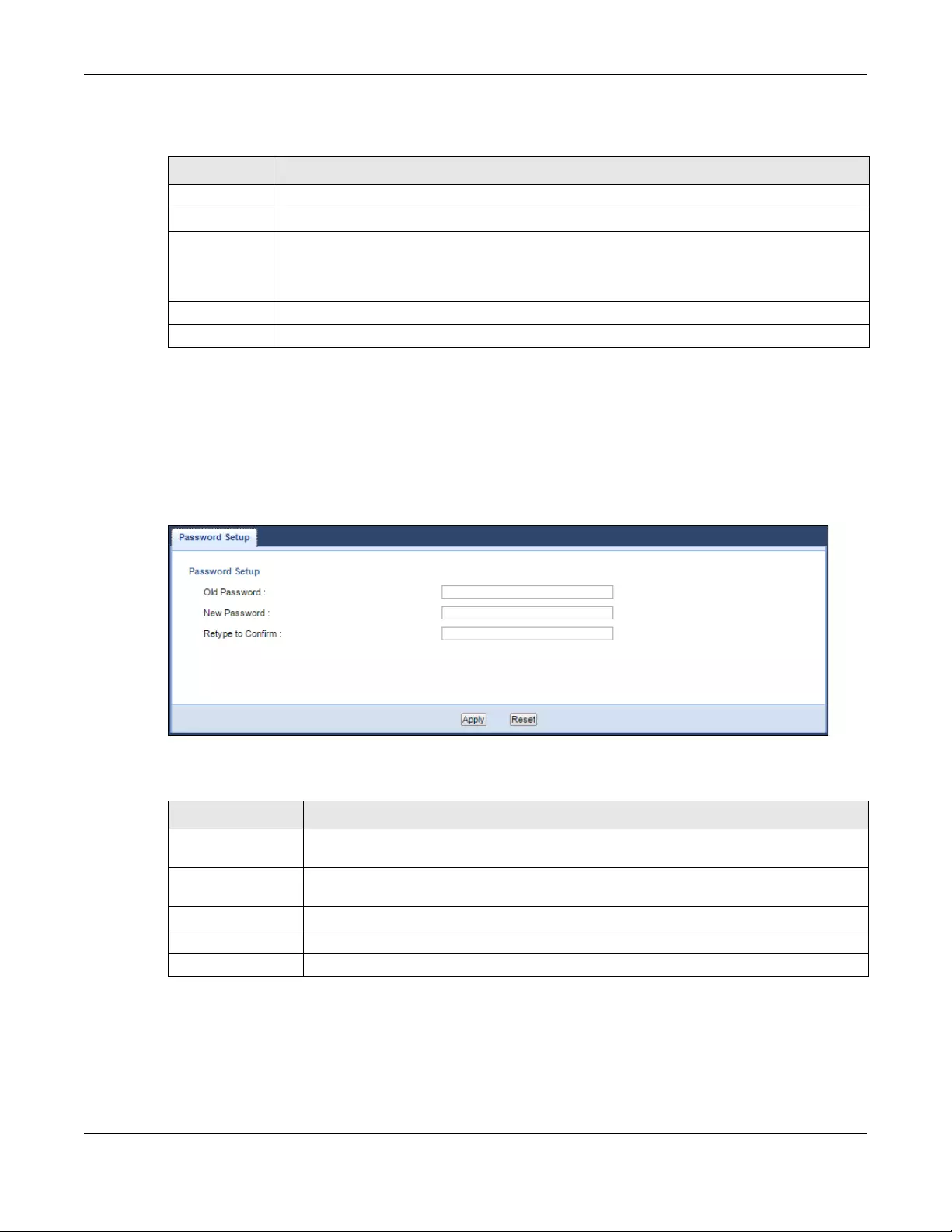
Chapter 12 Maintenance
WRE6505 v2 User’s Guide
71
The following table describes the labels in this menu.
12.4 System Password Screen
Use this screen to set the web configurator password. Click Maintenance > System. The following
screen displays.
Figure 46 Maintenance > Password
The following table describes the labels in this screen.
12.5 Time Screen
Use this screen to configure the WRE6505 v2’s time based on your local time zone. To change your
WRE6505 v2’s time and date, click Maintenance > Time. The screen appears as shown.
Ta ble 28 Maintenance > General
LABEL DESCRIPTION
System Name Enter a descriptive name to identify the WRE6505 v2 in an Ethernet network.
Domain Name This is the domain name of the WRE6505 v2.
Administrator
Inactivity
Timer
Type how many minutes a management session can be left idle before the session times out.
After it times out you have to log in with your password again. Very long idle timeouts may
have security risks. A value of «0» means a management session never times out, no matter
how long it has been left idle (not recommended).
Apply Click Apply to save your changes back to the WRE6505 v2.
Reset Click Reset to reload the previous configuration for this screen.
Ta ble 29 Maintenance > System > Password
LABEL DESCRIPTION
Old Password Type the default password or the existing password you use to access the system in this
field.
New Password Type your new system password (up to 30 characters). Note that as you type a
password, the screen displays an asterisk (*) for each character you type.
Retype to Confirm Type the new password again in this field.
Apply Click Apply to save your changes back to the WRE6505 v2.
Reset Click Reset to reload the previous configuration for this screen.
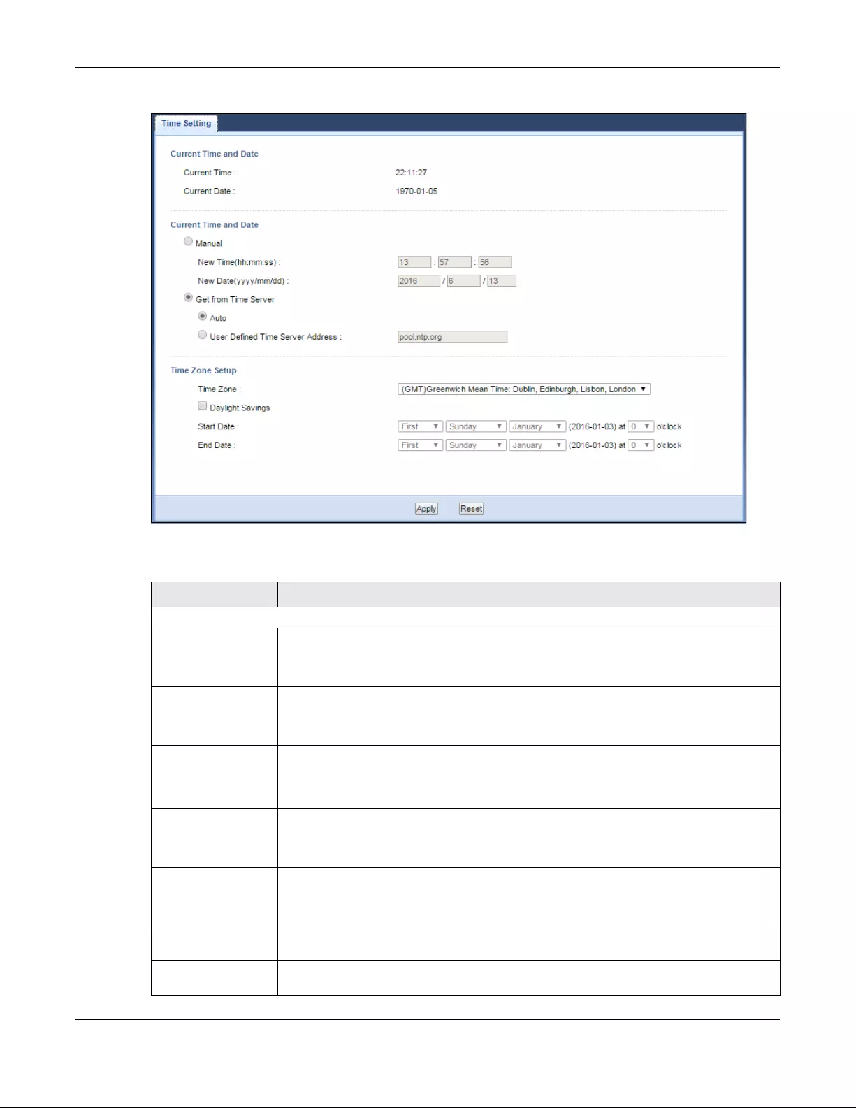
Chapter 12 Maintenance
WRE6505 v2 User’s Guide
72
Figure 47 Maintenance > Time
The following table describes the labels in this screen.
Ta ble 30 Maintenance > Time
LABEL DESCRIPTION
Current Time and Date
Current Time This field displays the time of your WRE6505 v2.
Each time you reload this page, the WRE6505 v2 synchronizes the time with the time
server.
Current Date This field displays the date of your WRE6505 v2.
Each time you reload this page, the WRE6505 v2 synchronizes the date with the time
server.
Manual Select this radio button to enter the time and date manually. If you configure a new
time and date, Time Zone and Daylight Saving at the same time, the new time and date
you entered has priority and the Time Zone and Daylight Saving settings do not affect
it.
New Time
(hh:mm:ss)
This field displays the last updated time from the time server or the last time
configured manually.
When you select Manual, enter the new time in this field and then click Apply.
New Date
(yyyy/mm/dd)
This field displays the last updated date from the time server or the last date configured
manually.
When you select Manual, enter the new date in this field and then click Apply.
Get from Time
Server
Select this radio button to have the WRE6505 v2 get the time and date from the time
server you specified below.
Auto Select Auto to have the WRE6505 v2 automatically get the time and date from a pre-
defined time server (pool.ntp.org).

Chapter 12 Maintenance
WRE6505 v2 User’s Guide
73
12.6 Firmware Upgrade Screen
Find firmware at www.zyxel.com in a file that (usually) uses the system model name with a “*.bin”
extension, e.g., “WRE6505 v2.bin”. The upload process uses HTTP (Hypertext Transfer Protocol)
and may take up to two minutes. After a successful upload, the system will reboot.
Click Maintenance > Firmware Upgrade. Follow the instructions in this screen to upload
firmware to your WRE6505 v2.
User Defined Time
Server Address
Select User Defined Time Server Address and enter the IP address or URL (up to 20
extended ASCII characters in length) of your time server. Check with your ISP/network
administrator if you are unsure of this information.
Time Zone Setup
Time Zone Choose the time zone of your location. This will set the time difference between your
time zone and Greenwich Mean Time (GMT).
Daylight Savings Daylight saving is a period from late spring to early fall when many countries set their
clocks ahead of normal local time by one hour to give more daytime light in the
evening.
Select this option if you use Daylight Saving Time.
Start Date Configure the day and time when Daylight Saving Time starts if you selected Daylight
Savings. The at field uses the 24 hour format. Here are a couple of examples:
Daylight Saving Time starts in most parts of the United States on the second Sunday of
March. Each time zone in the United States starts using Daylight Saving Time at 2 A.M.
local time. So in the United States you would select Second, Sunday, March and
select 2 in the at field.
Daylight Saving Time starts in the European Union on the last Sunday of March. All of
the time zones in the European Union start using Daylight Saving Time at the same
moment (1 A.M. GMT or UTC). So in the European Union you would select Last,
Sunday, March. The time you select in the at field depends on your time zone. In
Germany for instance, you would select 2 because Germany’s time zone is one hour
ahead of GMT or UTC (GMT+1).
End Date Configure the day and time when Daylight Saving Time ends if you selected Daylight
Savings. The at field uses the 24 hour format. Here are a couple of examples:
Daylight Saving Time ends in the United States on the first Sunday of November. Each
time zone in the United States stops using Daylight Saving Time at 2 A.M. local time.
So in the United States you would select First, Sunday, November and select 2 in the
at field.
Daylight Saving Time ends in the European Union on the last Sunday of October. All of
the time zones in the European Union stop using Daylight Saving Time at the same
moment (1 A.M. GMT or UTC). So in the European Union you would select Last,
Sunday, October. The time you select in the at field depends on your time zone. In
Germany for instance, you would select 2 because Germany’s time zone is one hour
ahead of GMT or UTC (GMT+1).
Apply Click Apply to save your changes back to the WRE6505 v2.
Reset Click Reset to begin configuring this screen afresh.
Ta ble 30 Maintenance > Time (continued)
LABEL DESCRIPTION
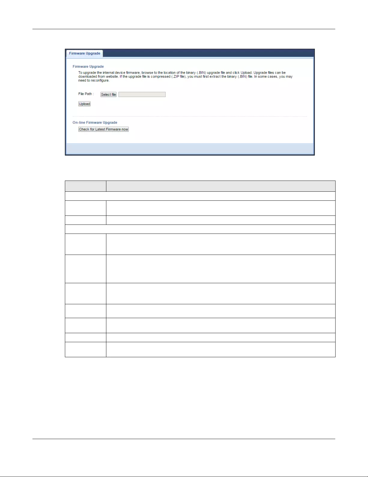
Chapter 12 Maintenance
WRE6505 v2 User’s Guide
74
Figure 48 Maintenance > Firmware Upgrade
The following table describes the labels in this screen.
Note: Do not turn off the WRE6505 v2 while firmware upload is in progress!
After you see the Firmware Upgrading screen, wait until the upgrade process is complete.
Ta ble 31 Maintenance > Firmware Upgrade
LABEL DESCRIPTION
Firmware Upgrade
File Path Click Select file to find the .bin file you want to upload. Remember that you must
decompress compressed (.zip) files before you can upload them.
Upload Click Upload to begin the upload process. This process may take up to two minutes.
On-line Firmware Upgrade
Check for
Latest
Firmware Now
The following fields display when you click this button.
You are
currently
using
firmware
version:
The firmware version consists of the trunk version number, model code, and release number.
For example, V1.00(AAAG.5) means V1.00 is the trunk number, AAAG represents WRE6505
v2, and 5 means the fifth release.
The Latest
Firmware
Version
Compare the release number in the previous field with the release number in this one to see
if you have the latest firmware. In this example, V1.00(AAAG.5), the numbers are the same
(5), so the WRE6505 v2 already has the latest firmware.
Release
Date The date the firmware was issued is shown in year-month-date format.
Release
Note The release note shows what has changed (new features, bug fixes, known issues) in this
firmware version. Check the Release Note before deciding to use new firmware.
Size This is the size of the firmware in bytes. 15073234 is about 15 MB.
Do_Firmware_
Upgrade
Click this button to download and upgrade the new firmware to the WRE6505 v2.
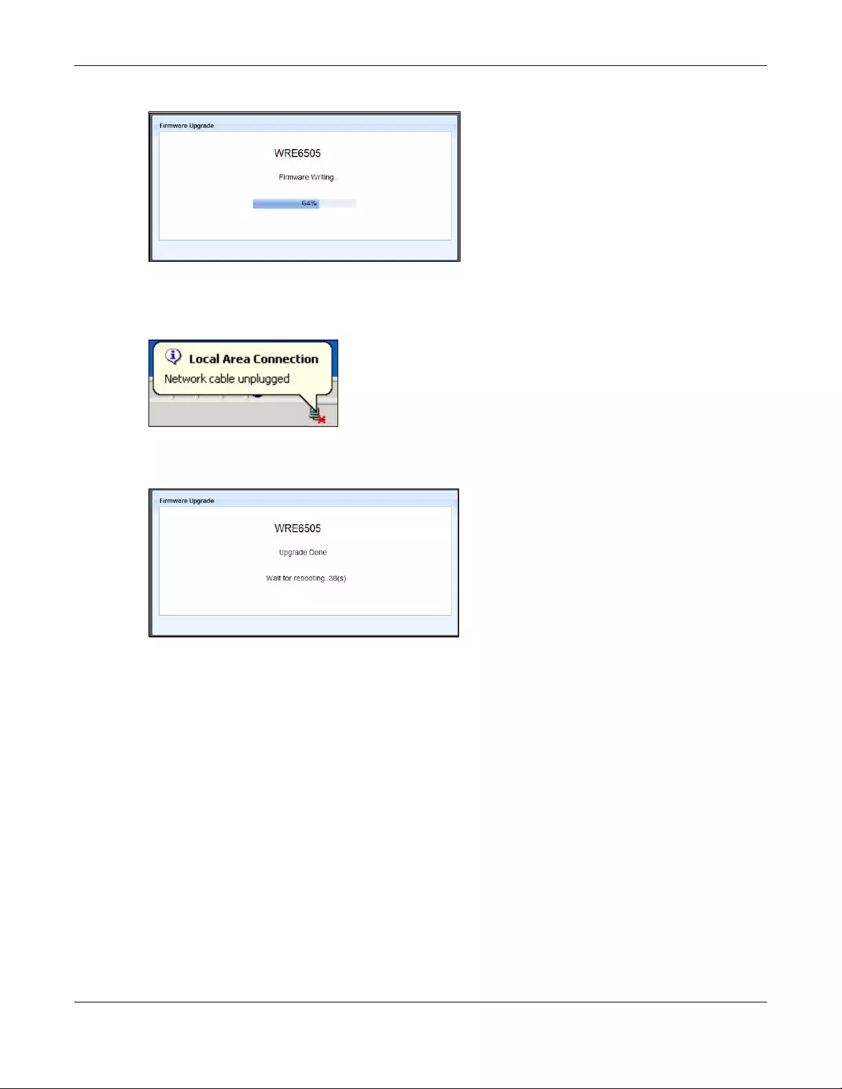
Chapter 12 Maintenance
WRE6505 v2 User’s Guide
75
Figure 49 Firmware Upgrading
The WRE6505 v2 automatically restarts in this time causing a temporary network disconnect. In
some operating systems, you may see the following icon on your desktop.
Figure 50 Network Temporarily Disconnected
After the WRE6505 v2 restarts, the Upgrade Accomplished screen appears.
Figure 51 Upgrade Accomplished
Refresh the web page and log in again and check your new firmware version in the Status screen.
12.7 Backup / Restore Screen
Click Maintenance > Backup/Restore. Information related to factory defaults, backup
configuration, and restoring configuration appears as shown next.

Chapter 12 Maintenance
WRE6505 v2 User’s Guide
76
Figure 52 Maintenance > Backup/Restore
12.7.1 Backup Configuration
Backup configuration allows you to back up (save) the WRE6505 v2’s current configuration to a file
on your computer. Once your WRE6505 v2 is configured and functioning properly, it is highly
recommended that you back up your configuration file before making configuration changes. The
backup configuration file will be useful in case you need to return to your previous settings.
Click Backup to save the WRE6505 v2’s current configuration to your computer.
12.7.2 Restore Configuration
Restore configuration allows you to upload a new or previously saved configuration file from your
computer to your WRE6505 v2.
Note: Do not turn off the WRE6505 v2 while configuration file upload is in progress.
After you see a “configuration upload successful” screen, you must then wait one minute before
logging into the WRE6505 v2 again.
The WRE6505 v2 automatically restarts in this time causing a temporary network disconnect. In
some operating systems, you may see the following icon on your desktop.
Ta ble 32 Maintenance Restore Configuration
LABEL DESCRIPTION
File Path Click Select file to find the file you want to upload. Remember that you must decompress
compressed (.ZIP) files before you can upload them.
Upload Click Upload to begin the upload process.
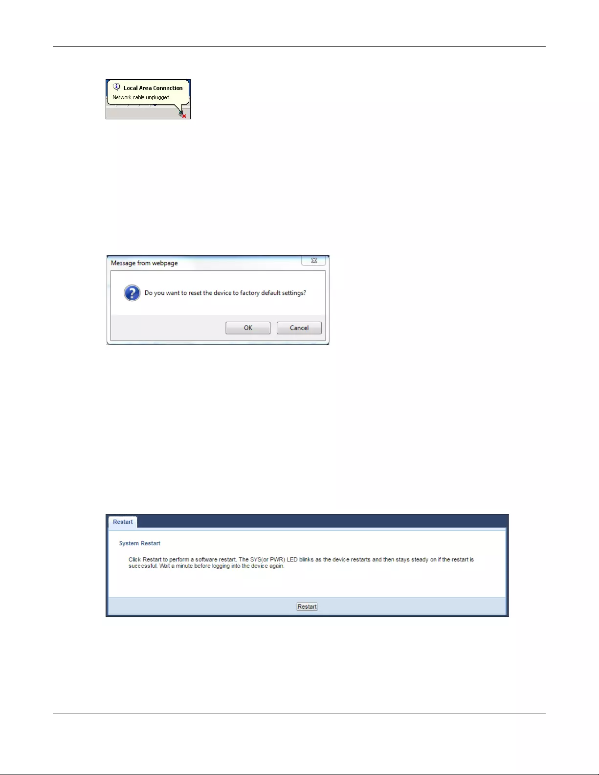
Chapter 12 Maintenance
WRE6505 v2 User’s Guide
77
Figure 53 Temporarily Disconnected
If you uploaded the default configuration file you may need to change the IP address of your
computer to be in the same subnet as that of the default WRE6505 v2 IP address (192.168.1.2).
Refer to your operating system’s help files for details on how to set up your computer’s IP address.
12.7.3 Back to Factory Defaults
Click the Reset button to clear all user-entered configuration information and return the WRE6505
v2 to its factory defaults. The following warning screen appears.
Figure 54 Reset Warning Message
You can also press the WPS button (see Section 1.4 on page 11) on the front panel for more than
10 seconds to reset the factory defaults of your WRE6505 v2. Refer to Section 1.4 on page 11 for
more information on the resetting the WRE6505 v2.
12.8 Restart Screen
System restart allows you to reboot the WRE6505 v2 without turning the power off. Click
Maintenance > Restart. The following screen displays. Click Restart to have the WRE6505 v2
reboot. This does not affect the WRE6505 v2’s configuration.
Figure 55 Maintenance > Restart

Chapter 12 Maintenance
WRE6505 v2 User’s Guide
78
12.9 System Mode
Use this screen to change the operating mode of the WRE6505 v2. For further information on
system operating mode, see Section 3.1.1 on page 19.
Figure 56 Maintenance > System Mode
The following table describes the labels in this menu.
Ta ble 33 Maintenance > System Mode
LABEL DESCRIPTION
AP Mode Select this option to set the WRE6505 v2 to act as an access point.
Normal mode The default WPS behavior, both 2.4 GHz and 5 GHz bands are supported in up and down
broadcasting.
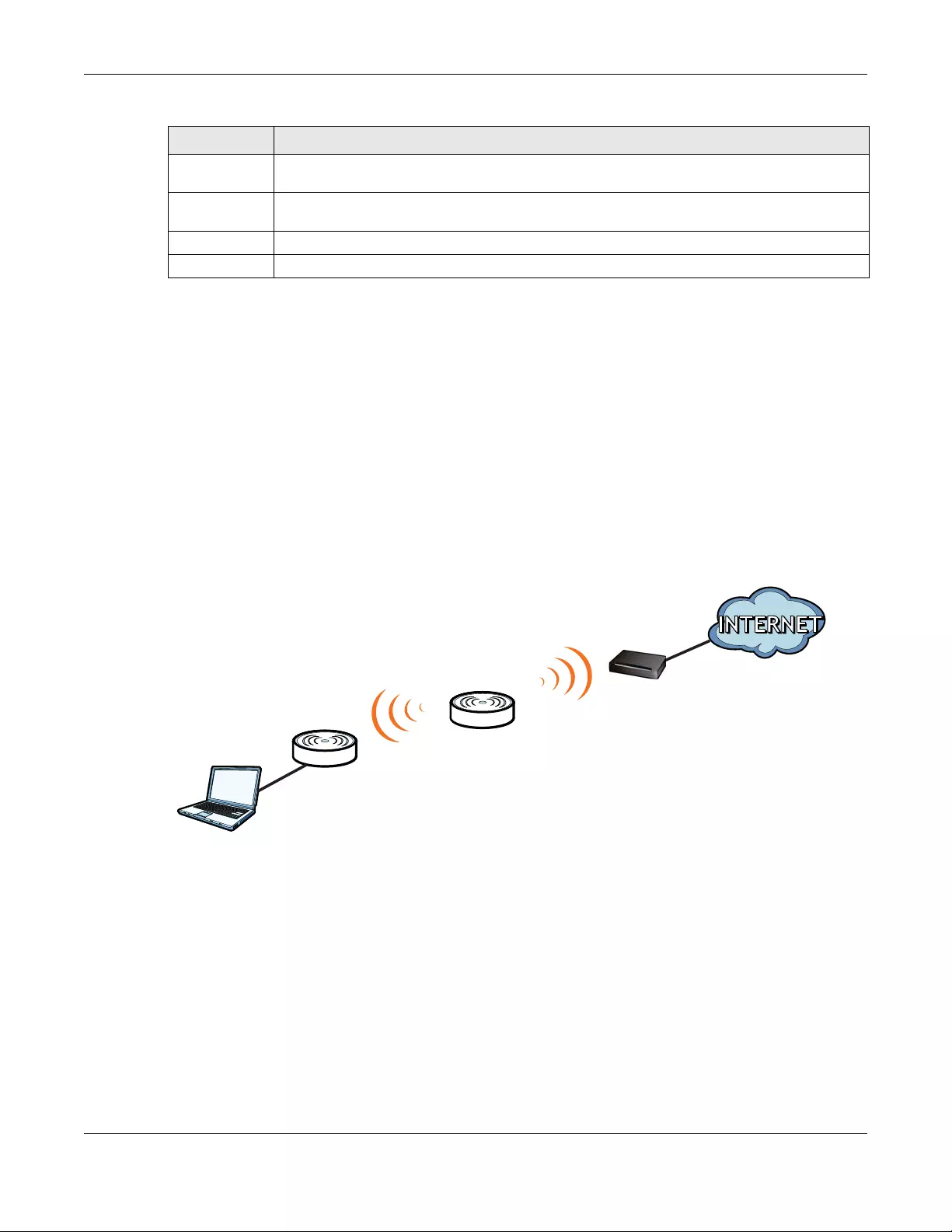
Chapter 12 Maintenance
WRE6505 v2 User’s Guide
79
12.9.1 System WPS Behavior
In Repeater mode (see Chapter 3 on page 20), you can select the type of WPS behavior: Normal
Mode, Range Boost, or Speed Boost mode.
The device enables you to extend the range of your dual-band router to eliminate «dead spots» in
your wireless network. You can choose from normal mode, range boost, or speed boost modes for
both your 2.4GHz and 5GHz networks.
The following terms are used to describe the WPS behavior:
• Up: The connection from the WRE6505 v2 to the Router
• Down: The connection from the WRE6505 v2 to a client
Figure 57 Normal Mode with Up and Down Broadcasting
• Home wireless network: 2.4G SSID = Home2.4G_2.4GEXT; 5G SSID = Home5G_5GEXT.
• Work wireless network: 2.4G SSID = Work2.4G_2.4GEXT; 5G SSID = Work5G_5GEXT.
• No profile: There is no currently defined profile.
The following section describes the Normal, Range Boost, and Speed Boost mode (WPS) behaviors
in a home and work network connection.
As connection profiles are established, the WRE6505 v2 maintains a record of the varying profiles
and automatically joins the network when in range.
Note: The home wireless network is the initial setup environment. The WRE6505 v2 does
not have any established network profiles at the time of initial setup.
Range boost
mode
Select this option to set the WRE6505 v2 to Range boost mode—the 2.4 GHz band is
supported on the Up behavior, while the 5 GHz band is supported on the Down behavior.
Speed boost
mode
Select this option to set the WRE6505 v2 to Speed boost mode—the 5 GHz band is
supported on the Up behavior, while the 2.4 GHz band is supported on the Down behavior.
Apply Click Apply to save your changes back to the WRE6505 v2.
Reset Click Reset to reload the previous configuration for this screen.
Ta ble 33 Maintenance > System Mode (continued)
LABEL DESCRIPTION
Universal
Repeater
Client
Up
Router
Down
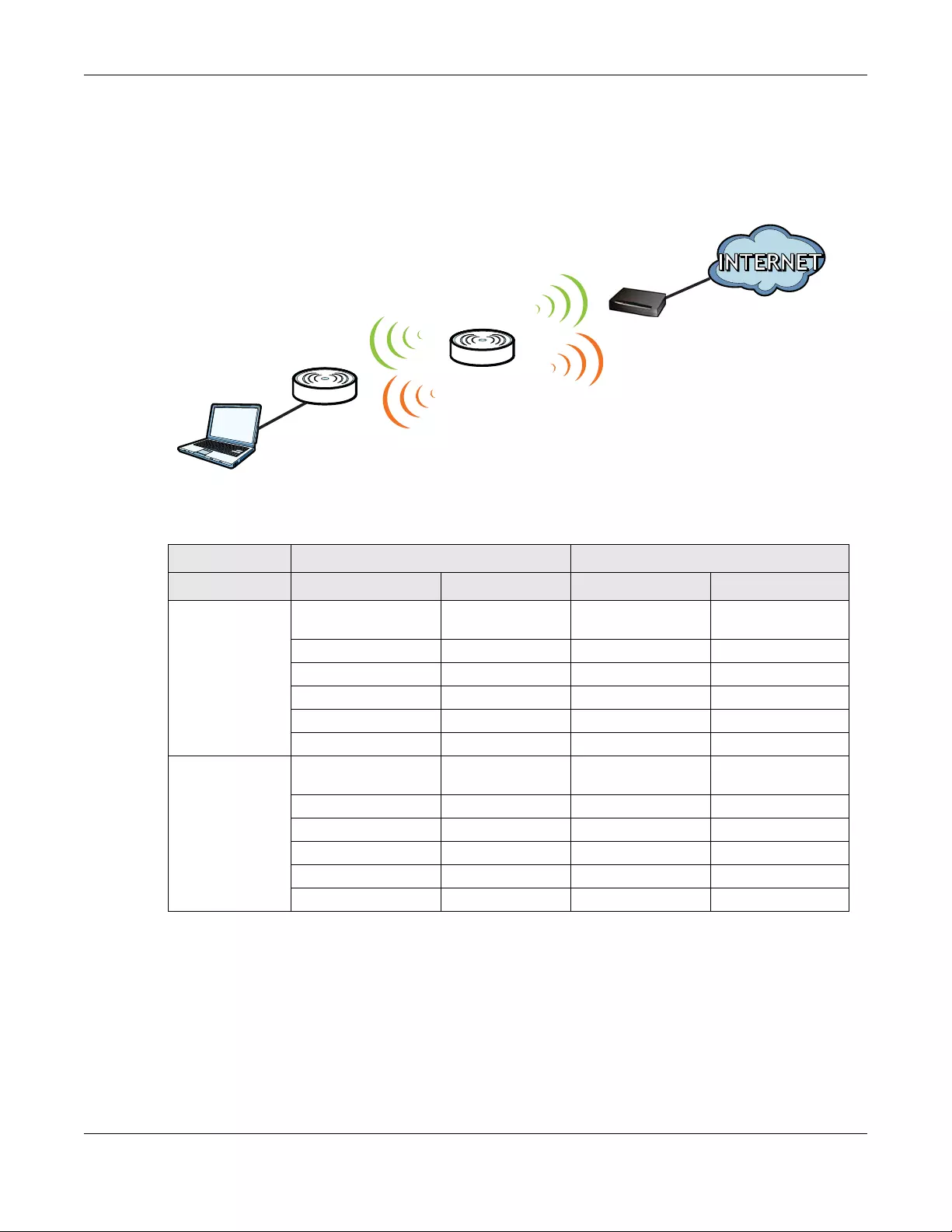
Chapter 12 Maintenance
WRE6505 v2 User’s Guide
80
12.9.1.1 Normal Mode
In normal mode, both Down and Up WPS behaviors are supported for both 2.4 GHz and 5 GHz
bands.
Figure 58 Maintenance > System Mode> Normal mode
The following table describes the labels in the previous screen.
12.9.1.2 Range Boost Mode
In range boost mode, the 2.4 GHz band is supported on the Down behavior, while the 5 GHz band is
supported on the Up behavior.
Ta ble 34 WPS Behavior: Normal Mode
HOME WIRELESS NETWORK WORK WIRELESS NETWORK
WPS BAND UP DOWN UP DOWN
2.4 GHz No profile
(Initial Setup)
No profile
(Initial Setup)
Work1 Work1_2.4GEXT
No profile No profile No profile Work2_2.4GEXT
Home1 Home1_2.4GEXT Work3 Work3_2.4GEXT
no profile no profile No profile Work4_2.4GEXT
Home1 Home1_2.4GEXT Work3 Work3_2.4GEXT
Home1 Home1_2.4GEXT Work1 Work1_2.4GEXT
5 GHz No profile
(Initial Setup)
No profile
(Initial Setup)
No profile Work1_5GEXT
No profile No profile Work2_5GEXT Work2_5GEXT
No profile No profile No profile Work3_5GEXT
Home2 Home2_5GEXT Work4 Work4_5GEXT
Home2 Home2_5GEXT Work2_5GEXT Work2_5GEXT
Home2 Home2_5GEXT Work4 Work4_5GEXT
Universal
Repeater
Client
2.4 GHz / 5 GHz
Up
2.4 GHz / 5 GHz
Down
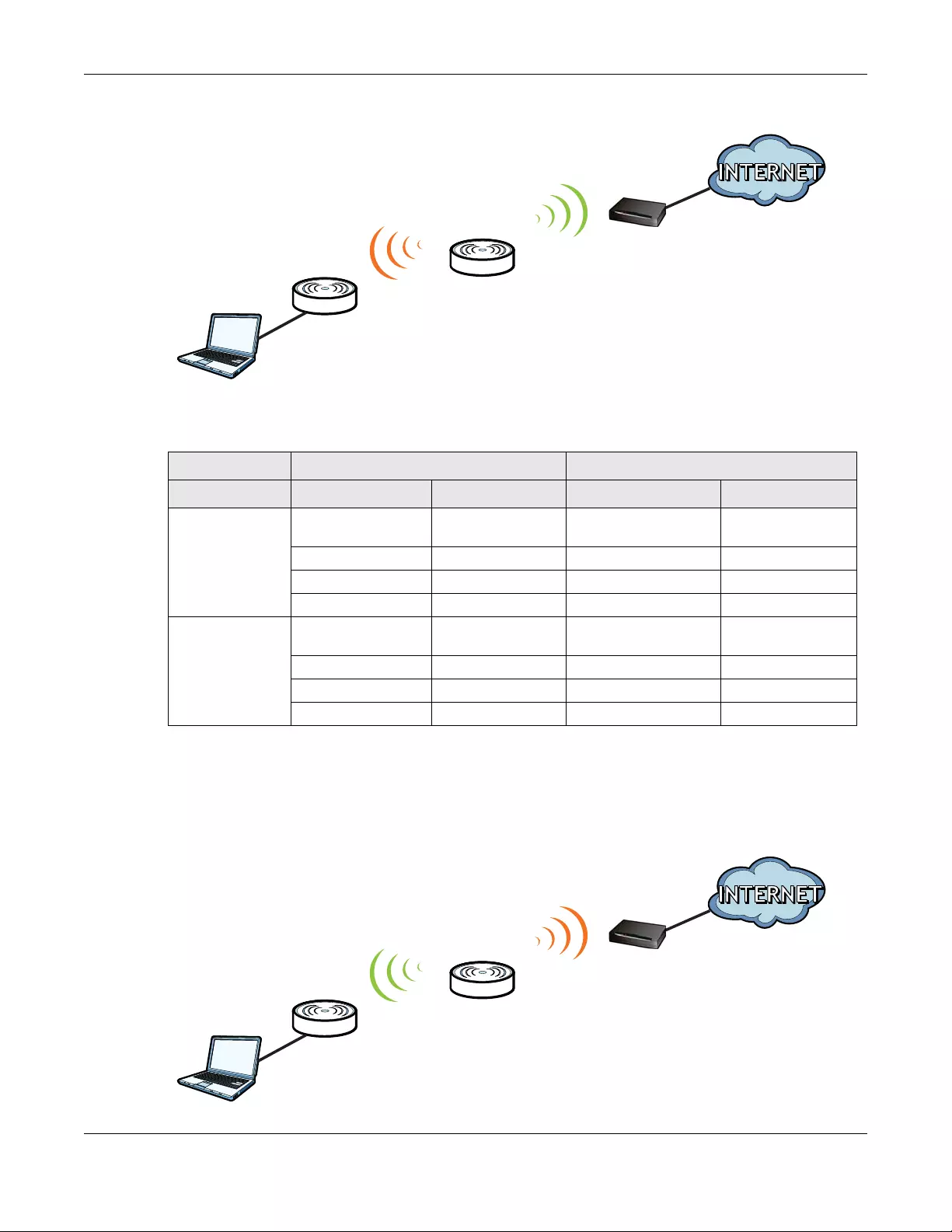
Chapter 12 Maintenance
WRE6505 v2 User’s Guide
81
Figure 59 WPS Behavior: Range Boost Mode
The following table describes the labels in the previous screen.
12.9.1.3 Speed Boost Mode
In speed boost mode, the 5 GHz band is supported on the Down behavior, while the 2.4 GHz band
is supported on the Up behavior.
Figure 60 WPS Mode: Speed Boost Mode
Ta ble 35 WPS Behavior: Range Boost Mode
HOME WIRELESS NETWORK WORK WIRELESS NETWORK
WPS BAND UP DOWN UP DOWN
2.4 GHz No profile
(Initial Setup)
No profile
(Initial Setup)
Work1 Off
Home1 Home1_2.4GEXT Work3 Off
No profile Home2_2.4GEXT Work3 Off
Home1 Home1_2.4GEXT Work3 Off
5 GHz No profile
(Initial Setup)
No profile
(Initial Setup)
No profile Work1_5GEXT
Home2 Home2_5GEXT Work2 Work3_5GEXT
Home2 Home2_5GEXT Work2 Work3_5GEXT
No profile No profile No profile Work3_5GEXT
Universal
Repeater
Client
2.4 GHz
Up
5 GHz
Down
Universal
Repeater
Client
5 GHz
Up
2.4 GHz
Down

Chapter 12 Maintenance
WRE6505 v2 User’s Guide
82
The following table describes the labels in the previous screen.
Ta ble 36 WPS Mode: Speed Boost Mode
HOT SPOT 1 (HOME) HOT SPOT 2 (WORK)
WPS BAND UP DOWN UP DOWN
2.4 GHz No profile
(Initial Setup)
No profile
(Initial Setup)
No profile Work2_2.4GEXT
Home1 Home1_2.4GEXT Work1 Work4_2.4GEXT
No profile Home2_2.4GEXT No profile Work4_2.4GEXT
Home1 Home1_2.4GEXT Work1 Work3_2.4GEXT
5 GHz No profile
(Initial Setup)
No profile
(Initial Setup)
Work2 Off
Home2 Home2_5GEXT Work4 Off
Home2 Home2_5GEXT Work4 Off
No profile No profile Work3 Off

WRE6505 v2 User’s Guide
83
CHAPTER 13
Troubleshooting
This chapter offers some suggestions to solve problems you might encounter. The potential
problems are divided into the following categories.
•Power, Hardware Connections, and LEDs
•WRE6505 v2 Access and Login
•Internet Access
•Resetting the WRE6505 v2 to Its Factory Defaults
•Wireless Problems
13.1 Power, Hardware Connections, and LEDs
The WRE6505 v2 does not turn on. None of the LEDs turn on.
1Make sure the WRE6505 v2 is plugged in to an appropriate power source. Make sure the power
source is turned on.
2Disconnect and re-connect the WRE6505 v2.
3Remove the WRE6505 v2 from the outlet. Then connect an electrical device that you know works
into the same power outlet. This checks the status of the power outlet.
4If the problem continues, contact the vendor.
One of the LEDs does not behave as expected.
1Make sure you understand the normal behavior of the LED. See Section 1.3 on page 10.
2Make sure you understand how the LEDs are enabled or disabled. See Section 1.3 on page 10.
3Check the hardware connections. See the Quick Start Guide.
4Inspect your cables for damage. Contact the vendor to replace any damaged cables.
5Disconnect and re-connect the WRE6505 v2.
6If the problem continues, contact the vendor.

Chapter 13 Troubleshooting
WRE6505 v2 User’s Guide
84
13.2 WRE6505 v2 Access and Login
I forgot the password.
1The default password is 1234.
2If this does not work, you have to reset the device to its factory defaults. See Section 13.4 on page
86.
I cannot see or access the Login screen in the Web Configurator.
1Make sure you are using the correct address.
• The default web address (URL) of the WRE6505 v2 is http://zyxelsetup.
2Check the hardware connections, and make sure the LEDs are behaving as expected. See the Quick
Start Guide.
3Make sure your Internet browser does not block pop-up windows and has JavaScript and Java
enabled.
4Reset the device to its factory defaults, and try to access the WRE6505 v2 with the default address.
5If the problem continues, contact the network administrator or vendor, or try one of the advanced
suggestions.
Advanced Suggestions
• If your computer is connected wirelessly, use a computer that is connected to a LAN/ETHERNET
port.
I can see the Login screen, but I cannot log in to the WRE6505 v2.
1Make sure you have entered the password correctly. The default password is 1234.
2This can happen when you fail to log out properly from your last session. Try logging in again after
5 minutes.
3Disconnect and re-connect the WRE6505 v2.
4If this does not work, you have to reset the device to its factory defaults. See Section 13.4 on page
86.

Chapter 13 Troubleshooting
WRE6505 v2 User’s Guide
85
13.3 Internet Access
I cannot access the Internet.
1Check the hardware connections, and make sure the LEDs are behaving as expected. See the Quick
Start Guide.
2Try to connect directly to the AP. If you can access the Internet, check that the WRE6505 v2
(repeater mode) has associated with the AP by checking the Status screen. See Section 4.4 on
page 22.
3If you are trying to access the Internet wirelessly, make sure the wireless settings in the wireless
client are the same as the settings in the AP.
4Disconnect all the cables from your device, and follow the directions in the Quick Start Guide again.
5If the problem continues, contact the network administrator or vendor.
I cannot access the Internet anymore. I had access to the Internet (with the WRE6505 v2 in
repeater mode), but my Internet connection is not available anymore.
1Check the hardware connections, and make sure the LEDs are behaving as expected. See the Quick
Start Guide and Section 1.3 on page 10.
2Reboot the WRE6505 v2.
3Try to connect directly to the AP. If you can access the Internet, check that the WRE6505 v2
(repeater mode) has associated with the AP by checking the Status screen. See Section 4.4 on
page 22.
4If the problem continues, contact the network administrator or vendor.
The Internet connection is slow or intermittent.
1There might be a lot of traffic on the network. Look at the LEDs, and check Section 1.3 on page 10.
If the WRE6505 v2 is sending or receiving a lot of information, try closing some programs that use
the Internet, especially peer-to-peer applications.
2Check the signal strength. If the signal strength is low, try moving the WRE6505 v2 closer to the AP
if possible, and look around to see if there are any devices that might be interfering with the
wireless network (for example, microwaves, other wireless networks, and so on).
3Reboot the WRE6505 v2.

Chapter 13 Troubleshooting
WRE6505 v2 User’s Guide
86
4If the problem continues, contact the network administrator or vendor, or try one of the advanced
suggestions.
Advanced Suggestion
• Check the settings for QoS. If it is disabled, you might consider activating it.
13.4 Resetting the WRE6505 v2 to Its Factory Defaults
If you reset the WRE6505 v2, you lose all of the changes you have made. The WRE6505 v2 re-loads
its default settings, and the password resets to 1234. You have to make all of your changes again.
You will lose all of your changes when you reset the WRE6505 v2 to its factory defaults.
To reset the WRE6505 v2,
1Make sure the power LED is on.
2Press the WPS button for longer than 10 seconds, the Power LED begins to blink, to set the
WRE6505 v2 back to its factory-default configuration.
OR
3Click Maintenance > Backup Restore > Restore and then click Reset.
If the WRE6505 v2 restarts automatically, wait for the WRE6505 v2 to finish restarting, and log in
to the Web Configurator. The password is 1234.
If the WRE6505 v2 does not restart automatically, disconnect and reconnect the WRE6505 v2.
Then, follow the directions above again.
13.5 Wireless Problems
I cannot access the WRE6505 v2 or ping any computer from the WLAN.
1Make sure the wireless LAN is enabled on the WRE6505 v2.
2Make sure the wireless adapter on the wireless station is working properly.
3Make sure the wireless adapter installed on your computer is IEEE 802.11 compatible and supports
the same wireless standard as the WRE6505 v2.
4Make sure your computer (with a wireless adapter installed) is within the transmission range of the
WRE6505 v2.

Chapter 13 Troubleshooting
WRE6505 v2 User’s Guide
87
5Check that both the WRE6505 v2 and your wireless station are using the same wireless and
wireless security settings, and that both the WRE6505 v2 and the AP are using the same wireless
and wireless security settings.
6Make sure traffic between the WLAN and the LAN is not blocked by the MAC Address List of the
WRE6505 v2. See Section 9.7 on page 60.

WRE6505 v2 User’s Guide
88
APPENDIX A
Customer Support
In the event of problems that cannot be solved by using this manual, you should contact your
vendor. If you cannot contact your vendor, then contact a ZyXEL office for the region in which you
bought the device.
See http://www.zyxel.com/homepage.shtml and also
http://www.zyxel.com/about_zyxel/zyxel_worldwide.shtml for the latest information.
Please have the following information ready when you contact an office.
Required Information
• Product model and serial number.
• Warranty Information.
• Date that you received your device.
• Brief description of the problem and the steps you took to solve it.
Corporate Headquarters (Worldwide)
Taiwan
• ZyXEL Communications Corporation
• http://www.zyxel.com
Asia
China
• ZyXEL Communications (Shanghai) Corp.
ZyXEL Communications (Beijing) Corp.
ZyXEL Communications (Tianjin) Corp.
• http://www.zyxel.cn
India
• ZyXEL Technology India Pvt Ltd
• http://www.zyxel.in
Kazakhstan
•ZyXEL Kazakhstan
• http://www.zyxel.kz

Appendix A Customer Support
WRE6505 v2 User’s Guide
89
Korea
• ZyXEL Korea Corp.
• http://www.zyxel.kr
Malaysia
• ZyXEL Malaysia Sdn Bhd.
• http://www.zyxel.com.my
Pakistan
• ZyXEL Pakistan (Pvt.) Ltd.
• http://www.zyxel.com.pk
Philippines
• ZyXEL Philippines
• http://www.zyxel.com.ph
Singapore
• ZyXEL Singapore Pte Ltd.
• http://www.zyxel.com.sg
Taiwan
• ZyXEL Communications Corporation
• http://www.zyxel.com/tw/zh/
Thailand
• ZyXEL Thailand Co., Ltd
• http://www.zyxel.co.th
Vietnam
• ZyXEL Communications Corporation-Vietnam Office
• http://www.zyxel.com/vn/vi
Europe
Austria
• ZyXEL Deutschland GmbH
• http://www.zyxel.de
Belarus
•ZyXEL BY
• http://www.zyxel.by

Appendix A Customer Support
WRE6505 v2 User’s Guide
90
Belgium
• ZyXEL Communications B.V.
• http://www.zyxel.com/be/nl/
• http://www.zyxel.com/be/fr/
Bulgaria
•ZyXEL България
• http://www.zyxel.com/bg/bg/
Czech Republic
• ZyXEL Communications Czech s.r.o
• http://www.zyxel.cz
Denmark
• ZyXEL Communications A/S
• http://www.zyxel.dk
Estonia
•ZyXEL Estonia
• http://www.zyxel.com/ee/et/
Finland
• ZyXEL Communications
• http://www.zyxel.fi
France
•ZyXEL France
• http://www.zyxel.fr
Germany
• ZyXEL Deutschland GmbH
• http://www.zyxel.de
Hungary
• ZyXEL Hungary & SEE
• http://www.zyxel.hu
Italy
• ZyXEL Communications Italy
• http://www.zyxel.it/

Appendix A Customer Support
WRE6505 v2 User’s Guide
91
Latvia
•ZyXEL Latvia
• http://www.zyxel.com/lv/lv/homepage.shtml
Lithuania
• ZyXEL Lithuania
• http://www.zyxel.com/lt/lt/homepage.shtml
Netherlands
•ZyXEL Benelux
• http://www.zyxel.nl
Norway
• ZyXEL Communications
• http://www.zyxel.no
Poland
• ZyXEL Communications Poland
• http://www.zyxel.pl
Romania
•ZyXEL Romania
• http://www.zyxel.com/ro/ro
Russia
• ZyXEL Russia
• http://www.zyxel.ru
Slovakia
• ZyXEL Communications Czech s.r.o. organizacna zlozka
• http://www.zyxel.sk
Spain
• ZyXEL Communications ES Ltd
• http://www.zyxel.es
Sweden
• ZyXEL Communications
• http://www.zyxel.se
Switzerland
•Studerus AG

Appendix A Customer Support
WRE6505 v2 User’s Guide
92
• http://www.zyxel.ch/
Turkey
•ZyXEL Turkey A.S.
• http://www.zyxel.com.tr
UK
• ZyXEL Communications UK Ltd.
• http://www.zyxel.co.uk
Ukraine
•ZyXEL Ukraine
• http://www.ua.zyxel.com
Latin America
Argentina
• ZyXEL Communication Corporation
• http://www.zyxel.com/ec/es/
Brazil
• ZyXEL Communications Brasil Ltda.
• https://www.zyxel.com/br/pt/
Ecuador
• ZyXEL Communication Corporation
• http://www.zyxel.com/ec/es/
Middle East
Israel
• ZyXEL Communication Corporation
• http://il.zyxel.com/homepage.shtml
Middle East
• ZyXEL Communication Corporation
• http://www.zyxel.com/me/en/

Appendix A Customer Support
WRE6505 v2 User’s Guide
93
North America
USA
• ZyXEL Communications, Inc. — North America Headquarters
• http://www.zyxel.com/us/en/
Oceania
Australia
• ZyXEL Communications Corporation
• http://www.zyxel.com/au/en/
Africa
South Africa
• Nology (Pty) Ltd.
• http://www.zyxel.co.za

WRE6505 v2 User’s Guide
94
APPENDIX B
Setting Up Your Computer’s IP Address
Note: Your specific WRE6505 v2 may not support all of the operating systems described
in this appendix. See the product specifications for more information about which
operating systems are supported.
This appendix shows you how to configure the IP settings on your computer in order for it to be
able to communicate with the other devices on your network. Windows Vista/XP/2000, Mac OS 9/
OS X, and all versions of UNIX/LINUX include the software components you need to use TCP/IP on
your computer.
If you manually assign IP information instead of using a dynamic IP, make sure that your network’s
computers have IP addresses that place them in the same subnet.
In this appendix, you can set up an IP address for:
•Windows XP/NT/2000 on page 94
•Windows Vista on page 98
•Windows 7 on page 102
•Mac OS X: 10.3 and 10.4 on page 106
•Mac OS X: 10.5 and 10.6 on page 109
•Linux: Ubuntu 8 (GNOME) on page 112
•Linux: openSUSE 10.3 (KDE) on page 116
Windows XP/NT/2000
The following example uses the default Windows XP display theme but can also apply to Windows
2000 and Windows NT.
1Click Start > Control Panel.
Appendix B Setting Up Your Computer’s IP Address
WRE6505 v2 User’s Guide
95
2In the Control Panel, click the Network Connections icon.
3Right-click Local Area Connection and then select Properties.
4On the General tab, select Internet Protocol (TCP/IP) and then click Properties.

Appendix B Setting Up Your Computer’s IP Address
WRE6505 v2 User’s Guide
96
5The Internet Protocol TCP/IP Properties window opens.

Appendix B Setting Up Your Computer’s IP Address
WRE6505 v2 User’s Guide
97
6Select Obtain an IP address automatically if your network administrator or ISP assigns your IP
address dynamically.
Select Use the following IP Address and fill in the IP address, Subnet mask, and Default
gateway fields if you have a static IP address that was assigned to you by your network
administrator or ISP. You may also have to enter a Preferred DNS server and an Alternate DNS
server, if that information was provided.
7Click OK to close the Internet Protocol (TCP/IP) Properties window.
8Click OK to close the Local Area Connection Properties window.
Verifying Settings
1Click Start > All Programs > Accessories > Command Prompt.
2In the Command Prompt window, type «ipconfig» and then press [ENTER].
You can also go to Start > Control Panel > Network Connections , right-click a network
connection, click Status and then click the Support tab to view your IP address and connection
information.
Appendix B Setting Up Your Computer’s IP Address
WRE6505 v2 User’s Guide
98
Windows Vista
This section shows screens from Windows Vista Professional.
1Click Start > Control Panel.
2In the Control Panel, click the Network and Internet icon.
3Click the Network and Sharing Center icon.
4Click Manage network connections.
Appendix B Setting Up Your Computer’s IP Address
WRE6505 v2 User’s Guide
99
5Right-click Local Area Connection and then select Properties.
Note: During this procedure, click Continue whenever Windows displays a screen saying
that it needs your permission to continue.
6Select Internet Protocol Version 4 (TCP/IPv4) and then select Properties.
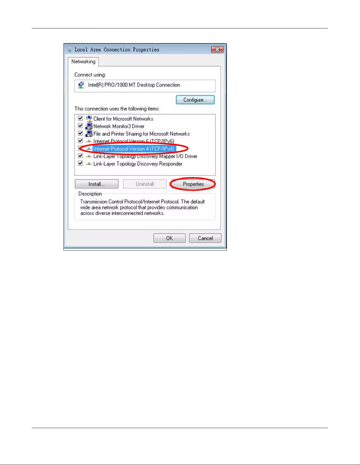
Appendix B Setting Up Your Computer’s IP Address
WRE6505 v2 User’s Guide
100
7The Internet Protocol Version 4 (TCP/IPv4) Properties window opens.
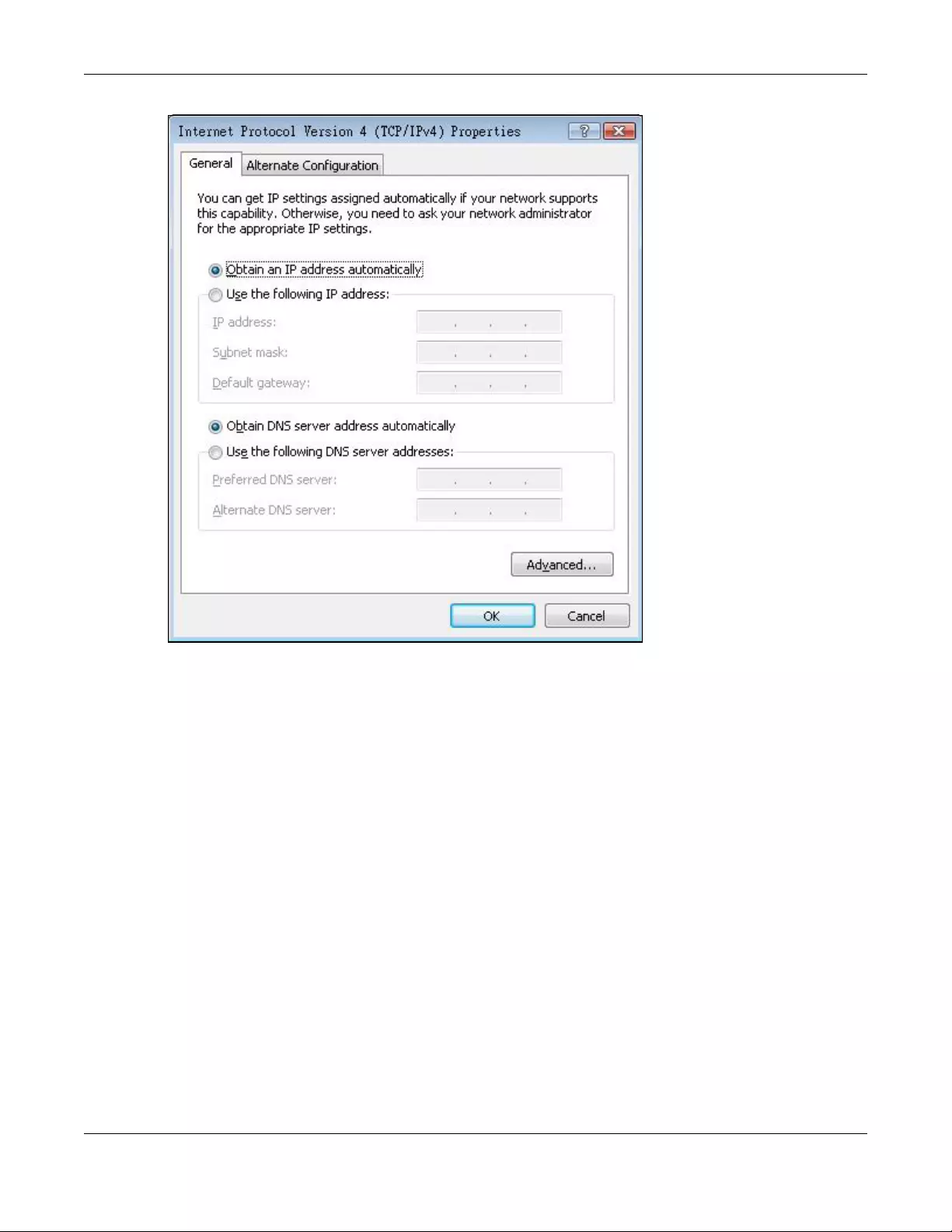
Appendix B Setting Up Your Computer’s IP Address
WRE6505 v2 User’s Guide
101
8Select Obtain an IP address automatically if your network administrator or ISP assigns your IP
address dynamically.
Select Use the following IP Address and fill in the IP address, Subnet mask, and Default
gateway fields if you have a static IP address that was assigned to you by your network
administrator or ISP. You may also have to enter a Preferred DNS server and an Alternate DNS
server, if that information was provided.Click Advanced.
9Click OK to close the Internet Protocol (TCP/IP) Properties window.
10 Click OK to close the Local Area Connection Properties window.
Verifying Settings
1Click Start > All Programs > Accessories > Command Prompt.
2In the Command Prompt window, type «ipconfig» and then press [ENTER].
You can also go to Start > Control Panel > Network Connections , right-click a network
connection, click Status and then click the Support tab to view your IP address and connection
information.
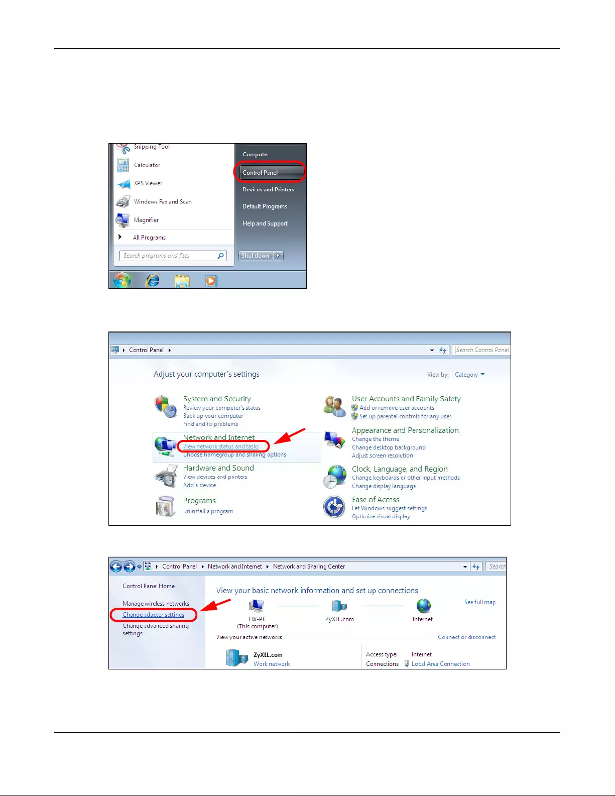
Appendix B Setting Up Your Computer’s IP Address
WRE6505 v2 User’s Guide
102
Windows 7
This section shows screens from Windows 7 Enterprise.
1Click Start > Control Panel.
2In the Control Panel, click View network status and tasks under the Network and Internet
category.
3Click Change adapter settings.
4Double click Local Area Connection and then select Properties.
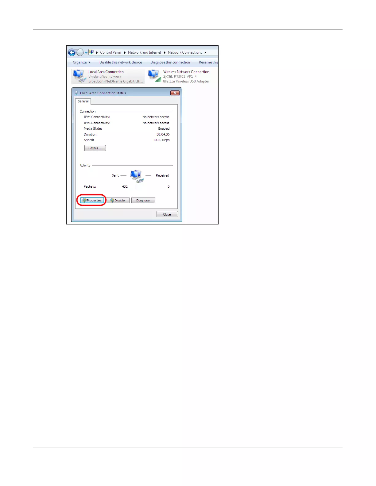
Appendix B Setting Up Your Computer’s IP Address
WRE6505 v2 User’s Guide
103
Note: During this procedure, click Continue whenever Windows displays a screen saying
that it needs your permission to continue.
5Select Internet Protocol Version 4 (TCP/IPv4) and then select Properties.
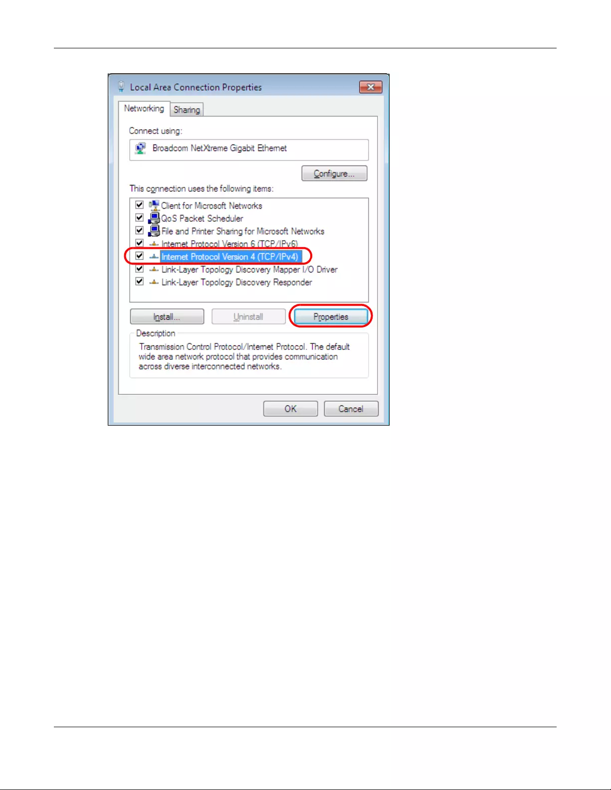
Appendix B Setting Up Your Computer’s IP Address
WRE6505 v2 User’s Guide
104
6The Internet Protocol Version 4 (TCP/IPv4) Properties window opens.
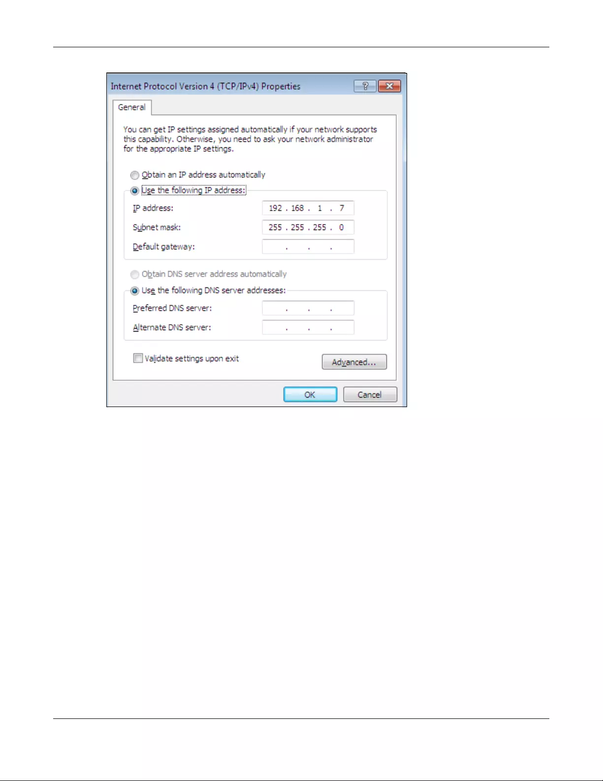
Appendix B Setting Up Your Computer’s IP Address
WRE6505 v2 User’s Guide
105
7Select Obtain an IP address automatically if your network administrator or ISP assigns your IP
address dynamically.
Select Use the following IP Address and fill in the IP address, Subnet mask, and Default
gateway fields if you have a static IP address that was assigned to you by your network
administrator or ISP. You may also have to enter a Preferred DNS server and an Alternate DNS
server, if that information was provided. Click Advanced if you want to configure advanced
settings for IP, DNS and WINS.
8Click OK to close the Internet Protocol (TCP/IP) Properties window.
9Click OK to close the Local Area Connection Properties window.
Verifying Settings
1Click Start > All Programs > Accessories > Command Prompt.
2In the Command Prompt window, type «ipconfig» and then press [ENTER].
3The IP settings are displayed as follows.
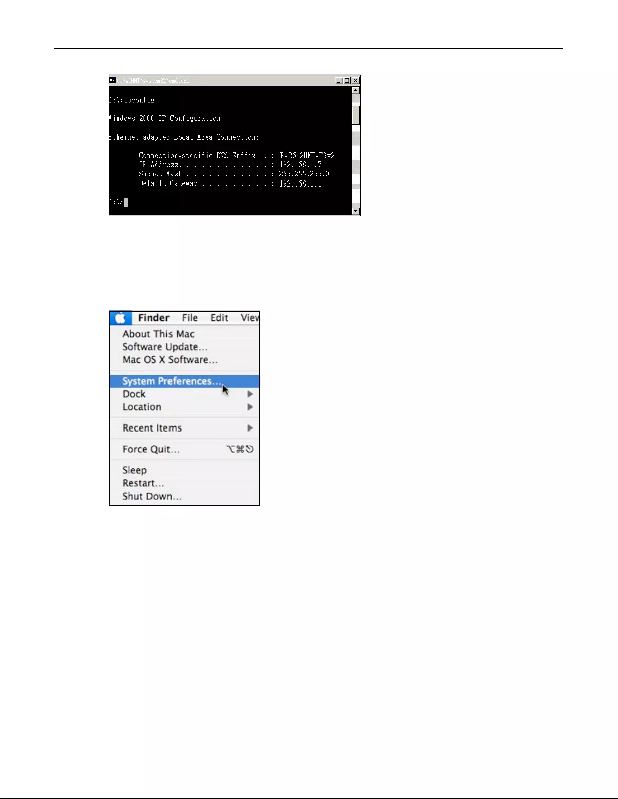
Appendix B Setting Up Your Computer’s IP Address
WRE6505 v2 User’s Guide
106
Mac OS X: 10.3 and 10.4
The screens in this section are from Mac OS X 10.4 but can also apply to 10.3.
1Click Apple > System Preferen ces .
2In the System Preferences window, click the Network icon.
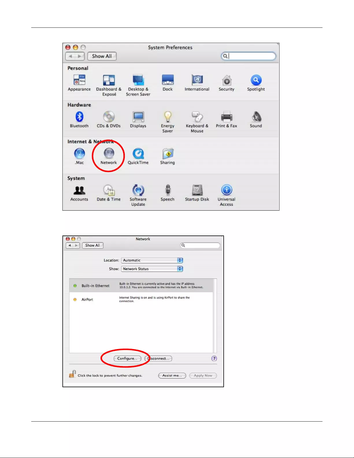
Appendix B Setting Up Your Computer’s IP Address
WRE6505 v2 User’s Guide
107
3When the Network preferences pane opens, select Built-in Ethernet from the network
connection type list, and then click Configure.
4For dynamically assigned settings, select Using DHCP from the Configur e IPv4 list in the TCP/IP
tab.
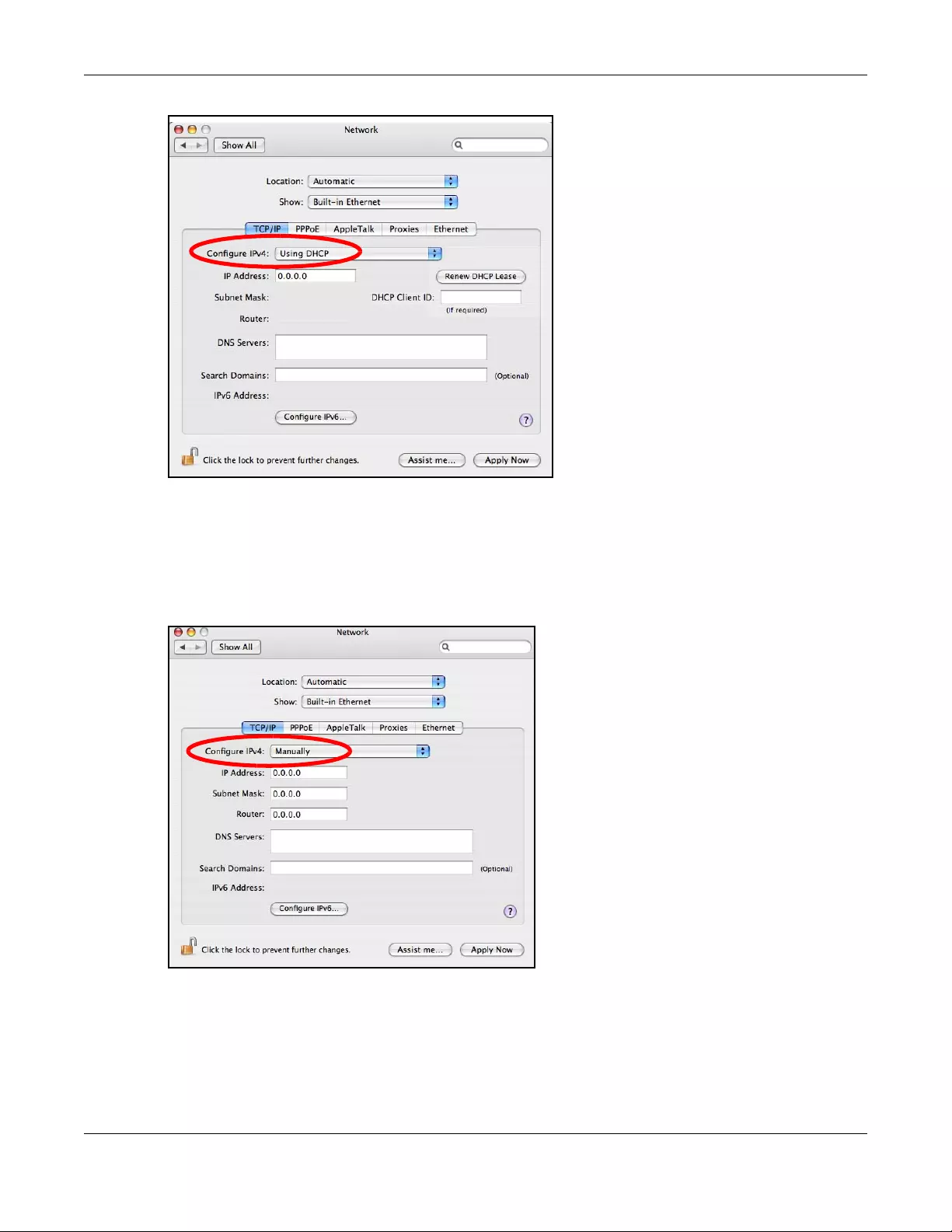
Appendix B Setting Up Your Computer’s IP Address
WRE6505 v2 User’s Guide
108
5For statically assigned settings, do the following:
•From the Configure IPv4 list, select Manually.
•In the IP Address field, type your IP address.
•In the Subnet Mask field, type your subnet mask.
•In the Router field, type the IP address of your device.
6Click Apply Now and close the window.
Verifying Settings
Check your TCP/IP properties by clicking Applications > Utilities > Network Utilities, and then
selecting the appropriate Network Interface from the Info tab.

Appendix B Setting Up Your Computer’s IP Address
WRE6505 v2 User’s Guide
109
Figure 61 Mac OS X 10.4: Network Utility
Mac OS X: 10.5 and 10.6
The screens in this section are from Mac OS X 10.5 but can also apply to 10.6.
1Click Apple > System Preferen ces .
2In System Preferen ces, click the Network icon.
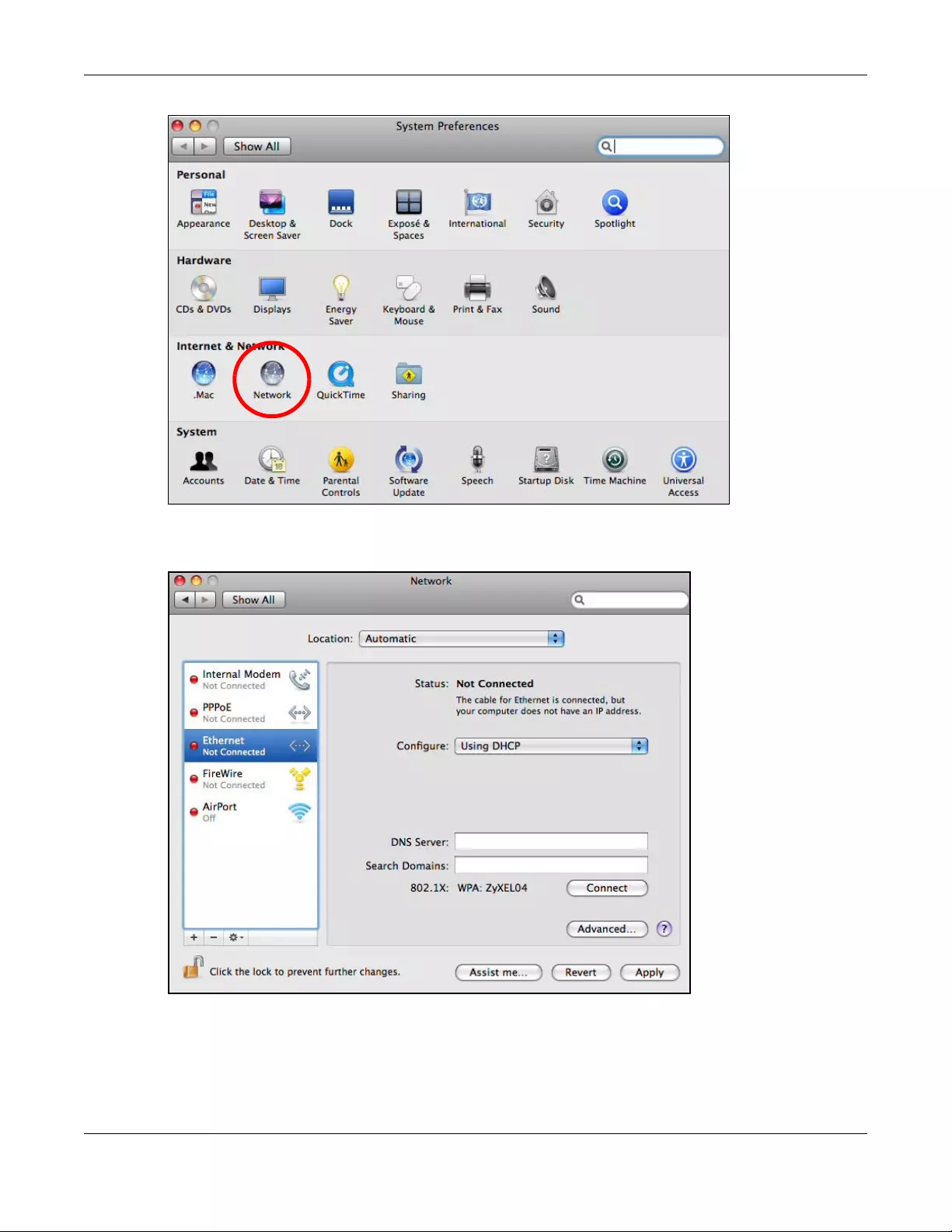
Appendix B Setting Up Your Computer’s IP Address
WRE6505 v2 User’s Guide
110
3When the Network preferences pane opens, select Ethernet from the list of available connection
types.
4From the Configure list, select Using DHCP for dynamically assigned settings.
5For statically assigned settings, do the following:
•From the Configure list, select Manually.
•In the IP Address field, enter your IP address.
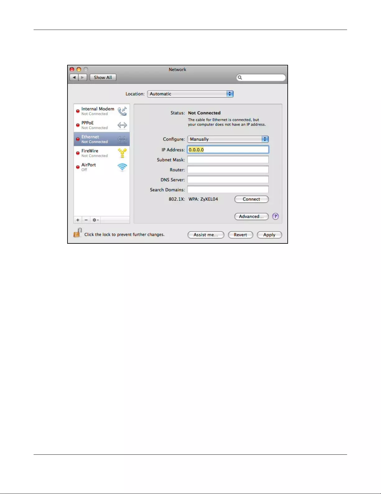
Appendix B Setting Up Your Computer’s IP Address
WRE6505 v2 User’s Guide
111
•In the Subnet Mask field, enter your subnet mask.
•In the Router field, enter the IP address of your WRE6505 v2.
6Click Apply and close the window.
Verifying Settings
Check your TCP/IP properties by clicking Applications > Utilities > Network Utilities, and then
selecting the appropriate Network interface from the Info tab.

Appendix B Setting Up Your Computer’s IP Address
WRE6505 v2 User’s Guide
112
Figure 62 Mac OS X 10.5: Network Utility
Linux: Ubuntu 8 (GNOME)
This section shows you how to configure your computer’s TCP/IP settings in the GNU Object Model
Environment (GNOME) using the Ubuntu 8 Linux distribution. The procedure, screens and file
locations may vary depending on your specific distribution, release version, and individual
configuration. The following screens use the default Ubuntu 8 installation.
Note: Make sure you are logged in as the root administrator.
Follow the steps below to configure your computer IP address in GNOME:
1Click System > Administration > Network.
2When the Network Settings window opens, click Unlock to open the Authenticate window. (By
default, the Unlock button is greyed out until clicked.) You cannot make changes to your
configuration unless you first enter your admin password.
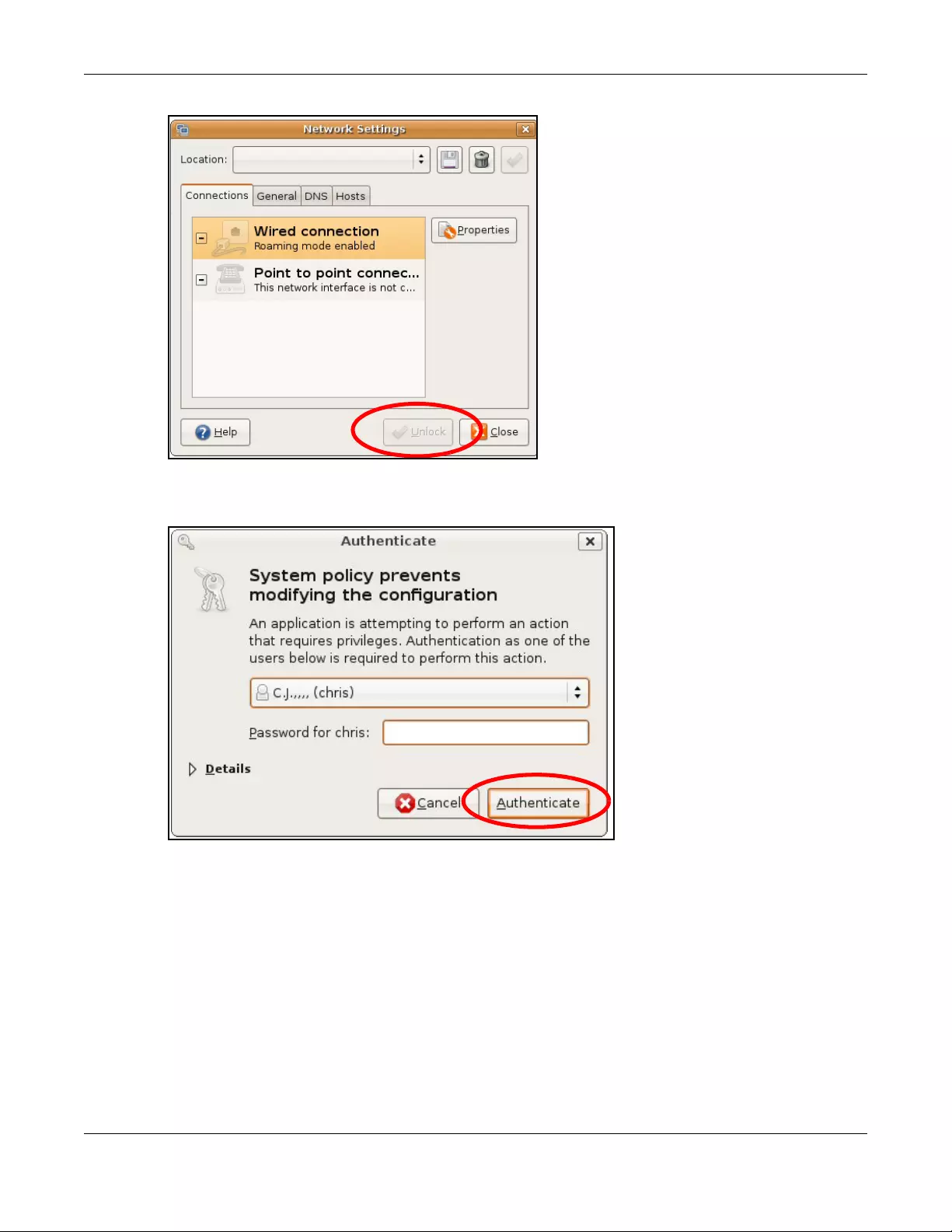
Appendix B Setting Up Your Computer’s IP Address
WRE6505 v2 User’s Guide
113
3In the Authenticate window, enter your admin account name and password then click the
Authenticate button.
4In the Network Settings window, select the connection that you want to configure, then click
Properties.
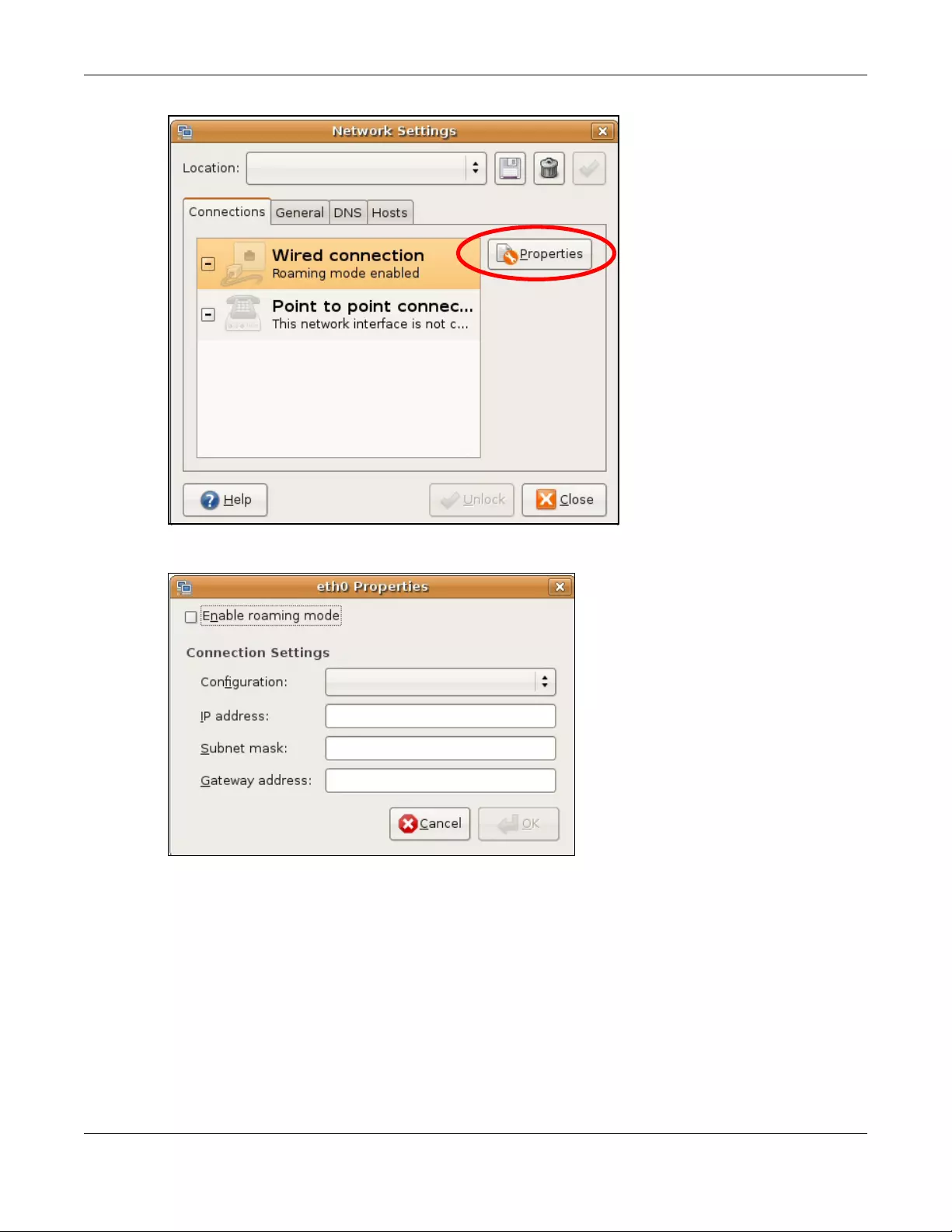
Appendix B Setting Up Your Computer’s IP Address
WRE6505 v2 User’s Guide
114
5The Properties dialog box opens.
•In the Configuration list, select Automatic Configuration (DHCP ) if you have a dynamic IP
address.
•In the Configuration list, select Static IP address if you have a static IP address. Fill in the
IP address, Subnet mask, and Gateway address fields.
6Click OK to save the changes and close the Properties dialog box and return to the Network
Settings screen.
7If you know your DNS server IP address(es), click the DNS tab in the Network Settings window
and then enter the DNS server information in the fields provided.
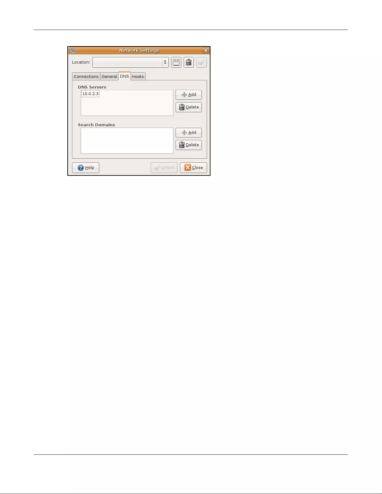
Appendix B Setting Up Your Computer’s IP Address
WRE6505 v2 User’s Guide
115
8Click the Close button to apply the changes.
Verifying Settings
Check your TCP/IP properties by clicking System > Administration > Network Tools, and then
selecting the appropriate Network device from the Devices tab. The Interface Statistics
column shows data if your connection is working properly.

Appendix B Setting Up Your Computer’s IP Address
WRE6505 v2 User’s Guide
116
Figure 63 Ubuntu 8: Network Tools
Linux: openSUSE 10.3 (KDE)
This section shows you how to configure your computer’s TCP/IP settings in the K Desktop
Environment (KDE) using the openSUSE 10.3 Linux distribution. The procedure, screens and file
locations may vary depending on your specific distribution, release version, and individual
configuration. The following screens use the default openSUSE 10.3 installation.
Note: Make sure you are logged in as the root administrator.
Follow the steps below to configure your computer IP address in the KDE:
1Click K Menu > Computer > Administrator Settings (YaST).
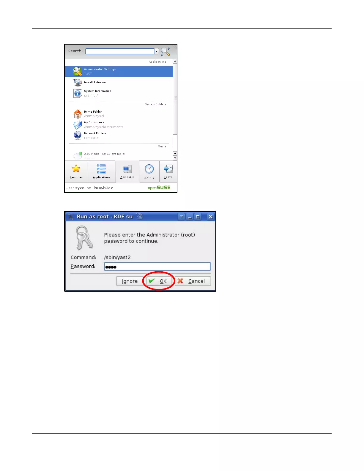
Appendix B Setting Up Your Computer’s IP Address
WRE6505 v2 User’s Guide
117
2When the Run as Root — KDE su dialog opens, enter the admin password and click OK.
3When the YaST Control Center window opens, select Network Devices and then click the
Network Card icon.
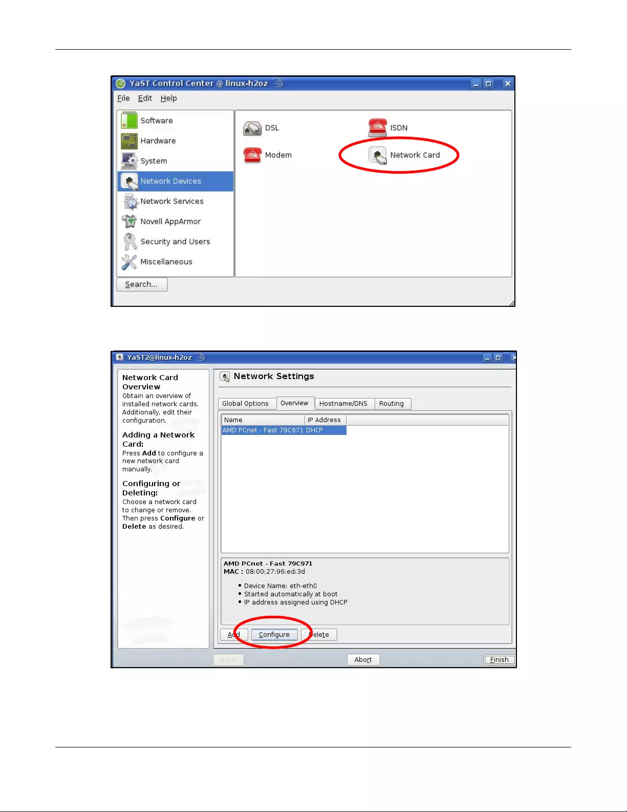
Appendix B Setting Up Your Computer’s IP Address
WRE6505 v2 User’s Guide
118
4When the Network Settings window opens, click the Overview tab, select the appropriate
connection Name from the list, and then click the Configure button.
5When the Network Card Setup window opens, click the Address tab

Appendix B Setting Up Your Computer’s IP Address
WRE6505 v2 User’s Guide
119
Figure 64 openSUSE 10.3: Network Card Setup
6Select Dynamic Address (DHCP) if you have a dynamic IP address.
Select Statically assigned IP Address if you have a static IP address. Fill in the IP address,
Subnet mask, and Hostname fields.
7Click Next to save the changes and close the Network Card Setup window.
8If you know your DNS server IP address(es), click the Hostname/DNS tab in Network Settings
and then enter the DNS server information in the fields provided.
Appendix B Setting Up Your Computer’s IP Address
WRE6505 v2 User’s Guide
120
9Click Finish to save your settings and close the window.
Verifying Settings
Click the KNetwork Manager icon on the Task bar to check your TCP/IP properties. From the
Options sub-menu, select Show Conne ction Information.
Figure 65 openSUSE 10.3: KNetwork Manager
When the Connection Status — KNetwork Manager window opens, click the Statistics tab to
see if your connection is working properly.
Appendix B Setting Up Your Computer’s IP Address
WRE6505 v2 User’s Guide
121
Figure 66 openSUSE: Connection Status — KNetwork Manager

WRE6505 v2 User’s Guide
122
APPENDIX C
Legal Information
Copyright
Copyright © 2016 by ZyXEL Communications Corporation.
The contents of this publication may not be reproduced in any part or as a whole, transcribed, stored in a retrieval system, translated into
any language, or transmitted in any form or by any means, electronic, mechanical, magnetic, optical, chemical, photocopying, manual, or
otherwise, without the prior written permission of ZyXEL Communications Corporation.
Published by ZyXEL Communications Corporation. All rights reserved.
Disclaimer
ZyXEL does not assume any liability arising out of the application or use of any products, or software described herein. Neither does it
convey any license under its patent rights nor the patent rights of others. ZyXEL further reserves the right to make changes in any
products described herein without notice. This publication is subject to change without notice.
Regulatory Notice and Statement
UNITED STATES of AMERICA
The following information applies if you use the product within USA area.
FCC EMC St atement
• The device complies with Part 15 of FCC rules. Operation is subject to the following two conditions:
(1) This device may not cause harmful interference, and
(2) This device must accept any interference received, including interference that may cause undesired operation.
• Changes or modifications not expressly approved by the party responsible for compliance could void the user’s authority to operate the
device.
• This product has been tested and complies with the specifications for a Class B digital device, pursuant to Part 15 of the FCC Rules.
These limits are designed to provide reasonable protection against harmful interference in a residential installation. This device
generates, uses, and can radiate radio frequency energy and, if not installed and used according to the instructions, may cause
harmful interference to radio communications. However, there is no guarantee that interference will not occur in a particular
installation.
• If this device does cause harmful interference to radio or television reception, which is found by turning the device off and on, the user
is encouraged to try to correct the interference by one or more of the following measures:
• Reorient or relocate the receiving antenna
• Increase the separation between the devices
• Connect the equipment to an outlet other than the receiver’s
• Consult a dealer or an experienced radio/TV technician for assistance
The following information applies if you use the product with RF function within USA area.
FCC Radiation Exposure Statement
• This device complies with FCC RF radiation exposure limits set forth for an uncontrolled environment.
• This transmitter must be at least 20 cm from the user and must not be co-located or operating in conjunction with any other antenna
or transmitter.
CANADA
The following information applies if you use the product within Canada area.
Industry Canada ICES statement
CAN ICES-3 (B)/NMB-3(B)

Appendix C Legal Information
WRE6505 v2 User’s Guide
123
Industry Canada RSS-GEN & RSS-247 st atement
• This device complies with Industry Canada license-exempt RSS standard(s). Operation is subject to the following two conditions: (1)
this device may not cause interference, and (2) this device must accept any interference, including interference that may cause
undesired operation of the device.
• This radio transmitter has been approved by Industry Canada to operate with the antenna types listed below with the maximum
permissible gain and required antenna impedance for each antenna type indicated. Antenna types not included in this list, having a
gain greater than the maximum gain indicated for that type, are strictly prohibited for use with this device.
If the product with 5G wireless function operating in 5150-5250 MHz and 5725-5850 MHz , the following attention must be paid,
• The device for operation in the band 5150-5250 MHz is only for indoor use to reduce the potential for harmful interference to co-
channel mobile satellite systems.
• For devices with detachable antenna(s), the maximum antenna gain permitted for devices in the band 5725-5850 MHz shall be such
that the equipment still complies with the e.i.r.p. limits specified for point-to-point and non-point-to-point operation as appropriate;
and
• The worst-case tilt angle(s) necessary to remain compliant with the e.i.r.p. elevation mask requirement set forth in Section 6.2.2(3) of
RSS 247 shall be clearly indicated.
If the product with 5G wireless function operating in 5250-5350 MHz and 5470-5725 MHz , the following attention must be paid.
• For devices with detachable antenna(s), the maximum antenna gain permitted for devices in the bands 5250-5350 MHz and 5470-
5725 MHz shall be such that the equipment still complies with the e.i.r.p. limit.
• Le présent appareil est conforme aux CNR d’Industrie Canada applicables aux appareils radio exempts de licence. L’exploitation est
autorisée aux deux conditions suivantes : (1) l’appareil ne doit pas produire de brouillage, et (2) l’utilisateur de l’appareil doit accepter
tout brouillage radioélectrique subi, même si le brouillage est susceptible d’en compromettre le fonctionnement.
• Le présent émetteur radio de modèle s’il fait partie du matériel de catégorieI) a été approuvé par Industrie Canada pour fonctionner
avec les types d’antenne énumérés ci-dessous et ayant un gain admissible maximal et l’impédance requise pour chaque type
d’antenne. Les types d’antenne non inclus dans cette liste, ou dont le gain est supérieur au gain maximal indiqué, sont strictement
interdits pour l’exploitation de l’émetteur.
Lorsque la fonction sans fil 5G fonctionnant en 5150-5250 MHz and 5725-5850 MHz est activée pour ce produit , il est nécessaire de
porter une attention particulière aux choses suivantes
• Les dispositifs fonctionnant dans la bande 5150-5250 MHz sont réservés uniquement pour une utilisation à l’intérieur afin de réduire
les risques de brouillage préjudiciable aux systèmes de satellites mobiles utilisant les mêmes canaux;
• Pour les dispositifs munis d’antennes amovibles, le gain maximal d’antenne permis (pour les dispositifs utilisant la bande de 5 725 à 5
850 MHz) doit être conforme à la limite de la p.i.r.e. spécifiée pour l’exploitation point à point et l’exploitation non point à point, selon
le cas;
• Les pires angles d’inclinaison nécessaires pour rester conforme à l’exigence de la p.i.r.e. applicable au masque d’élévation, et énoncée
à la section 6.2.2 3) du CNR-247, doivent être clairement indiqués.
Lorsque la fonction sans fil 5G fonctionnant en 5250-5350 MHz et 5470-5725 MHz est activée pour ce produit , il est nécessaire de porter
une attention particulière aux choses suivantes.
• Pour les dispositifs munis d’antennes amovibles, le gain maximal d’antenne permis pour les dispositifs utilisant les bandes de 5 250 à
5 350 MHz et de 5 470 à 5 725 MHz doit être conforme à la limite de la p.i.r.e.
Industry Canada radiation exposure statement
This device complies with IC radiation exposure limits set forth for an uncontrolled environment. This device should be installed and
operated with a minimum distance of 20 cm between the radiator and your body.
Déclaration d’exposition aux radiations:
Cet équipement est conforme aux limites d’exposition aux rayonnements IC établies pour un environnement non contrôlé. Cet
équipement doit être installé et utilisé avec un minimum de 20 cm de distance entre la source de rayonnement et votre corps.
EUROPEAN UNION
The following information applies if you use the product within the European Union.
Declaration of Conformity with Regard to EU Directive 1999/5/EC (R&TTE Directive)
• Compliance information for 2.4GHz and/or 5GHz wireless products relevant to the EU and other Countries following the EU Directive
1999/5/EC (R&TTE).
• This device is restricted to indoor use only when operating in the 5150 to 5350 MHz frequency range.
Български
(Bulgarian) С настоящото ZyXEL декларира, че това оборудване е в съответствие със съществените изисквания и другите
приложими разпоредбите на Директива 1999/5/ЕC.
Español
(Spanish) Por medio de la presente ZyXEL declara que el equipo cumple con los requisitos esenciales y cualesquiera otras
disposiciones aplicables o exigibles de la Directiva 1999/5/CE.
Čeština
(Czech) ZyXEL tímto prohlašuje, že tento zařízení je ve shodě se základními požadavky a dalšími příslušnými ustanoveními
směrnice 1999/5/EC.
Dansk (Danish) Undertegnede ZyXEL erklærer herved, at følgende udstyr udstyr overholder de væsentlige krav og øvrige relevante
krav i direktiv 1999/5/EF.

Appendix C Legal Information
WRE6505 v2 User’s Guide
124
National Restrictions
• This product may be used in all EU countries (and other countries following the EU Directive 1999/5/EC) without any limitation except
for the countries mentioned below:
• Ce produit peut être utilisé dans tous les pays de l’UE (et dans tous les pays ayant transposés la directive 1999/5/CE) sans aucune
limitation, excepté pour les pays mentionnés ci-dessous:
• Questo prodotto è utilizzabile in tutte i paesi EU (ed in tutti gli altri paesi che seguono le direttiva 1999/5/EC) senza nessuna
limitazione, eccetto per i paesii menzionati di seguito:
• Das Produkt kann in allen EU Staaten ohne Einschränkungen eingesetzt werden (sowie in anderen Staaten die der Richtlinie 1999/5/CE
folgen) mit Außnahme der folgenden aufgeführten Staaten:
In the majority of the EU and other European countries, the 2.4GHz and 5GHz bands have been made available for the use of wireless
local area networks (LANs). Later in this document you will find an overview of countries in which additional restrictions or requirements
or both are applicable. The requirements for any country may evolve. ZyXEL recommends that you check with the local authorities for the
latest status of their national regulations for both the 2.4GHz and 5GHz wireless LANs. The following countries have restrictions and/or
requirements in addition to those given in the table labeled “Overview of Regulatory Requirements for Wireless LANs”:.
Belgium
• The Belgian Institute for Postal Services and Telecommunications (BIPT) must be notified of any outdoor wireless link having a range
exceeding 300 meters. Please check http://www.bipt.be for more details.
• Draadloze verbindingen voor buitengebruik en met een reikwijdte van meer dan 300 meter dienen aangemeld te worden bij het
Belgisch Instituut voor postdiensten en telecommunicatie (BIPT). Zie http://www.bipt.be voor meer gegevens.
• Les liaisons sans fil pour une utilisation en extérieur d’une distance supérieure à 300 mètres doivent être notifiées à l’Institut Belge des
services Postaux et des Télécommunications (IBPT). Visitez http://www.ibpt.be pour de plus amples détails.
Denmark
Deutsch
(German) Hiermit erklärt ZyXEL, dass sich das Gerät Ausstattung in Übereinstimmung mit den grundlegenden Anforderungen
und den übrigen einschlägigen Bestimmungen der Richtlinie 1999/5/EU befindet.
Eesti keel
(Estonian) Käesolevaga kinnitab ZyXEL seadme seadmed vastavust direktiivi 1999/5/EÜ põhinõuetele ja nimetatud direktiivist
tulenevatele teistele asjakohastele sätetele.
Ελληνικά
(Greek) ΜΕ ΤΗΝ ΠΑΡΟΥΣΑ ZyXEL ∆ΗΛΩΝΕΙ ΟΤΙ εξοπλισμός ΣΥΜΜΟΡΦΩΝΕΤΑΙ ΠΡΟΣ ΤΙΣ ΟΥΣΙΩ∆ΕΙΣ ΑΠΑΙΤΗΣΕΙΣ ΚΑΙ ΤΙΣ
ΛΟΙΠΕΣ ΣΧΕΤΙΚΕΣ ∆ΙΑΤΑΞΕΙΣ ΤΗΣ Ο∆ΗΓΙΑΣ 1999/5/ΕC.
English Hereby, ZyXEL declares that this device is in compliance with the essential requirements and other relevant provisions
of Directive 1999/5/EC.
Français
(French) Par la présente ZyXEL déclare que l’appareil équipements est conforme aux exigences essentielles et aux autres
dispositions pertinentes de la directive 1999/5/EC.
Hrvatski
(Croatian) ZyXEL ovime izjavljuje da je radijska oprema tipa u skladu s Direktivom 1999/5/EC.
Íslenska
(Icelandic) Hér með lýsir, ZyXEL því yfir að þessi búnaður er í samræmi við grunnkröfur og önnur viðeigandi ákvæði tilskipunar
1999/5/EC.
Italiano
(Italian) Con la presente ZyXEL dichiara che questo attrezzatura è conforme ai requisiti essenziali ed alle altre disposizioni
pertinenti stabilite dalla direttiva 1999/5/CE.
Latviešu valoda
(Latvian) Ar šo ZyXEL deklarē, ka iekārtas atbilst Direktīvas 1999/5/EK būtiskajām prasībām un citiem ar to saistītajiem
noteikumiem.
Lietuvių kalba
(Lithuanian) Šiuo ZyXEL deklaruoja, kad šis įranga atitinka esminius reikalavimus ir kitas 1999/5/EB Direktyvos nuostatas.
Magyar
(Hungarian) Alulírott, ZyXEL nyilatkozom, hogy a berendezés megfelel a vonatkozó alapvetõ követelményeknek és az 1999/5/EK
irányelv egyéb elõírásainak.
Malti (Maltese) Hawnhekk, ZyXEL, jiddikjara li dan tagħmir jikkonforma mal-ħtiġijiet essenzjali u ma provvedimenti oħrajn relevanti li
hemm fid-Dirrettiva 1999/5/EC.
Nederlands
(Dutch) Hierbij verklaart ZyXEL dat het toestel uitrusting in overeenstemming is met de essentiële eisen en de andere
relevante bepalingen van richtlijn 1999/5/EC.
Polski (Polish) Niniejszym ZyXEL oświadcza, że sprzęt jest zgodny z zasadniczymi wymogami oraz pozostałymi stosownymi
postanowieniami Dyrektywy 1999/5/EC.
Português
(Portuguese) ZyXEL declara que este equipamento está conforme com os requisitos essenciais e outras disposições da Directiva
1999/5/EC.
Română
(Romanian) Prin prezenta, ZyXEL declară că acest echipament este în conformitate cu cerinţele esenţiale şi alte prevederi
relevante ale Directivei 1999/5/EC.
Slovenčina
(Slovak) ZyXEL týmto vyhlasuje, že zariadenia spĺňa základné požiadavky a všetky príslušné ustanovenia Smernice 1999/5/EC.
Slovenščina
(Slovene) ZyXEL izjavlja, da je ta oprema v skladu z bistvenimi zahtevami in ostalimi relevantnimi določili direktive 1999/5/EC.
Suomi
(Finnish) ZyXEL vakuuttaa täten että laitteet tyyppinen laite on direktiivin 1999/5/EY oleellisten vaatimusten ja sitä koskevien
direktiivin muiden ehtojen mukainen.
Svenska
(Swedish) Härmed intygar ZyXEL att denna utrustning står I överensstämmelse med de väsentliga egenskapskrav och övriga
relevanta bestämmelser som framgår av direktiv 1999/5/EC.
Norsk
(Norwegian) Erklærer herved ZyXEL at dette utstyret er I samsvar med de grunnleggende kravene og andre relevante
bestemmelser I direktiv 1999/5/EF.

Appendix C Legal Information
WRE6505 v2 User’s Guide
125
• In Denmark, the band 5150 — 5350 MHz is also allowed for outdoor usage.
• I Danmark må frekvensbåndet 5150 — 5350 også anvendes udendørs.
Italy
• This product meets the National Radio Interface and the requirements specified in the National Frequency Allocation Table for Italy.
Unless this wireless LAN product is operating within the boundaries of the owner’s property, its use requires a “general authorization.”
Please check http://www.sviluppoeconomico.gov.it/ for more details.
• Questo prodotto è conforme alla specifiche di Interfaccia Radio Nazionali e rispetta il Piano Nazionale di ripartizione delle frequenze in
Italia. Se non viene installato all ‘interno del proprio fondo, l’utilizzo di prodotti Wireless LAN richiede una “Autorizzazione Generale”.
Consultare http://www.sviluppoeconomico.gov.it/ per maggiori dettagli.
Latvia
• The outdoor usage of the 2.4 GHz band requires an authorization from the Electronic Communications Office. Please check http://
www.esd.lv for more details.
• 2.4 GHz frekvenèu joslas izmantoðanai ârpus telpâm nepiecieðama atïauja no Elektronisko sakaru direkcijas. Vairâk informâcijas:
http://www.esd.lv.
Notes:
1. Although Norway, Switzerland and Liechtenstein are not EU member states, the EU Directive 1999/5/EC has also been implemented
in those countries.
2. The regulatory limits for maximum output power are specified in EIRP. The EIRP level (in dBm) of a device can be calculated by
adding the gain of the antenna used(specified in dBi) to the output power available at the connector (specified in dBm).
List of national codes
Safety Warnings
• Do not use this product near water, for example, in a wet basement or near a swimming pool.
• Do not expose your device to dampness, dust or corrosive liquids.
• Do not store things on the device.
• Do not obstruct the device ventilation slots as insufficient airflow may harm your device. For example, do not place the device in an
enclosed space such as a box or on a very soft surface such as a bed or sofa.
• Do not install, use, or service this device during a thunderstorm. There is a remote risk of electric shock from lightning.
• Connect ONLY suitable accessories to the device.
• Do not open the device or unit. Opening or removing covers can expose you to dangerous high voltage points or other risks. ONLY
qualified service personnel should service or disassemble this device. Please contact your vendor for further information.
• Make sure to connect the cables to the correct ports.
• Place connecting cables carefully so that no one will step on them or stumble over them.
• Always disconnect all cables from this device before servicing or disassembling.
• Do not remove the plug and connect it to a power outlet by itself; always attach the plug to the power adaptor first before connecting
it to a power outlet.
• Do not allow anything to rest on the power adaptor or cord and do NOT place the product where anyone can walk on the power adaptor
or cord.
• Please use the provided or designated connection cables/power cables/ adaptors. Connect it to the right supply voltage (for example,
110V AC in North America or 230V AC in Europe). If the power adaptor or cord is damaged, it might cause electrocution. Remove it
from the device and the power source, repairing the power adapter or cord is prohibited. Contact your local vendor to order a new one.
• Do not use the device outside, and make sure all the connections are indoors. There is a remote risk of electric shock from lightning.
• CAUTION: Risk of explosion if battery is replaced by an incorrect type, dispose of used batteries according to the instruction. Dispose
them at the applicable collection point for the recycling of electrical and electronic devices. For detailed information about recycling of
this product, please contact your local city office, your household waste disposal service or the store where you purchased the product.
COUNTRY ISO 3166 2 LETTER CODE COUNTRY ISO 3166 2 LETTER CODE
Austria AT Liechtenstein LI
Belgium BE Lithuania LT
Bulgaria BG Luxembourg LU
Croatia HR Malta MT
Cyprus CY Netherlands NL
Czech Republic CZ Norway NO
Denmark DK Poland PL
Estonia EE Portugal PT
Finland FI Romania RO
France FR Serbia RS
Germany DE Slovakia SK
Greece GR Slovenia SI
Hungary HU Spain ES
Iceland IS Switzerland CH
Ireland IE Sweden SE
Italy IT Turkey TR
Latvia LV United Kingdom GB

Appendix C Legal Information
WRE6505 v2 User’s Guide
126
• The following warning statements apply, where the disconnect device is not incorporated in the device or where the plug on the power
supply cord is intended to serve as the disconnect device,
— For permanently connected devices, a readily accessible disconnect device shall be incorporated external to the device;
— For pluggable devices, the socket-outlet shall be installed near the device and shall be easily accessible.
Environment Statement
ErP (Energy-related Products)
ZyXEL products put on the EU market in compliance with the requirement of the European Parliament and the Council published Directive
2009/125/EC establishing a framework for the setting of ecodesign requirements for energy-related products (recast), so called as «ErP
Directive (Energy-related Products directive) as well as ecodesign requirement laid down in applicable implementing measures, power
consumption has satisfied regulation requirements which are:
• Network standby power consumption < 8W, and/or
• Off mode power consumption < 0.5W, and/or
• Standby mode power consumption < 0.5W.
(Wireless setting, please refer to «Wireless» chapter for more detail.)
European Union — Disposal and Recycling Information
The symbol below means that according to local regulations your product and/or its battery shall be disposed of separately from domestic
waste. If this product is end of life, take it to a recycling station designated by local authorities. At the time of disposal, the separate
collection of your product and/or its battery will help save natural resources and ensure that the environment is sustainable development.
Die folgende Symbol bedeutet, dass Ihr Produkt und/oder seine Batterie gemäß den örtlichen Bestimmungen getrennt vom Hausmüll
entsorgt werden muss. Wenden Sie sich an eine Recyclingstation, wenn dieses Produkt das Ende seiner Lebensdauer erreicht hat. Zum
Zeitpunkt der Entsorgung wird die getrennte Sammlung von Produkt und/oder seiner Batterie dazu beitragen, natürliche Ressourcen zu
sparen und die Umwelt und die menschliche Gesundheit zu schützen.
El símbolo de abajo indica que según las regulaciones locales, su producto y/o su batería deberán depositarse como basura separada de la
doméstica. Cuando este producto alcance el final de su vida útil, llévelo a un punto limpio. Cuando llegue el momento de desechar el
producto, la recogida por separado éste y/o su batería ayudará a salvar los recursos naturales y a proteger la salud humana y
medioambiental.
Le symbole ci-dessous signifie que selon les réglementations locales votre produit et/ou sa batterie doivent être éliminés séparément des
ordures ménagères. Lorsque ce produit atteint sa fin de vie, amenez-le à un centre de recyclage. Au moment de la mise au rebut, la
collecte séparée de votre produit et/ou de sa batterie aidera à économiser les ressources naturelles et protéger l’environnement et la
santé humaine.
Il simbolo sotto significa che secondo i regolamenti locali il vostro prodotto e/o batteria deve essere smaltito separatamente dai rifiuti
domestici. Quando questo prodotto raggiunge la fine della vita di servizio portarlo a una stazione di riciclaggio. Al momento dello
smaltimento, la raccolta separata del vostro prodotto e/o della sua batteria aiuta a risparmiare risorse naturali e a proteggere l’ambiente
e la salute umana.
Symbolen innebär att enligt lokal lagstiftning ska produkten och/eller dess batteri kastas separat från hushållsavfallet. När den här
produkten når slutet av sin livslängd ska du ta den till en återvinningsstation. Vid tiden för kasseringen bidrar du till en bättre miljö och
mänsklig hälsa genom att göra dig av med den på ett återvinningsställe.
Appendix C Legal Information
WRE6505 v2 User’s Guide
127
Environmental Product Declaration

Appendix C Legal Information
WRE6505 v2 User’s Guide
128
台灣
以下訊息僅適用於產品具有無線功能且銷售至台灣地區
• 第十二條 經型式認證合格之低功率射頻電機,非經許可,公司,商號或使用者均不得擅自變更頻率、加大功率或變更原設計之特性及功能。
• 第十四條 低功率射頻電機之使用不得影響飛航安全及干擾合法通信;經發現有干擾現象時,應立即停用,並改善至無干擾時方得繼續使用。
前項合法通信,指依電信法規定作業之無線電通信。 低功率射頻電機須忍受合法通信或工業、科學及醫療用電波輻射性電機設備之干擾。
• 電磁波曝露量 MPE 標準值 1 mW/cm2,送測產品實測值為: 0.183 mW/cm2。本產品使用時建議應距離人體 20 cm。
• 無線資訊傳輸設備忍受合法通信之干擾且不得干擾合法通信;如造成干擾,應立即停用, 俟無干擾之虞,始得繼續使用。
• 無線資訊傳設備的製造廠商應確保頻率穩定性,如依製造廠商使用手冊上所述正常操作, 發射的信號應維持於操作頻帶中
以下訊息僅適用於產品操作於 5.25-5.35 秭赫頻帶內並銷售至台灣地區
• 在 5.25-5.35 秭赫頻帶內操作之無線資訊傳輸設備,限於室內使用。
以下訊息僅適用於產品屬於專業安裝並銷售至台灣地區
• 本器材須經專業工程人員安裝及設定,始得設置使用,且不得直接販售給一般消費者。
安全警告 — 為了您的安全,請先閱讀以下警告及指示 :
• 請勿將此產品接近水、火焰或放置在高溫的環境。
• 避免設備接觸 :
— 任何液體 — 切勿讓設備接觸水、雨水、高濕度、污水腐蝕性的液體或其他水份。
— 灰塵及污物 — 切勿接觸灰塵、污物、沙土、食物或其他不合適的材料。
• 雷雨天氣時,不要安裝,使用或維修此設備。有遭受電擊的風險。
• 切勿重摔或撞擊設備,並勿使用不正確的電源變壓器。
• 若接上不正確的電源變壓器會有爆炸的風險。
• 請勿隨意更換產品內的電池。
• 如果更換不正確之電池型式,會有爆炸的風險,請依製造商說明書處理使用過之電池。
• 請將廢電池丟棄在適當的電器或電子設備回收處。
• 請勿將設備解體。
• 請勿阻礙設備的散熱孔,空氣對流不足將會造成設備損害。
• 請插在正確的電壓供給插座 ( 如 : 北美 / 台灣電壓 110V AC,歐洲是 230V AC)。
• 假若電源變壓器或電源變壓器的纜線損壞,請從插座拔除,若您還繼續插電使用,會有觸電死亡的風險。
• 請勿試圖修理電源變壓器或電源變壓器的纜線,若有毀損,請直接聯絡您購買的店家,購買一個新的電源變壓器。
• 請勿將此設備安裝於室外,此設備僅適合放置於室內。
• 請勿隨一般垃圾丟棄。
• 請參閱產品背貼上的設備額定功率。
• 請參考產品型錄或是彩盒上的作業溫度。
• 產品沒有斷電裝置或者採用電源線的插頭視為斷電裝置的一部分,以下警語將適用 :
— 對永久連接之設備, 在設備外部須安裝可觸及之斷電裝置;
— 對插接式之設備, 插座必須接近安裝之地點而且是易於觸及的。
About the Symbols
Various symbols are used in this product to ensure correct usage, to prevent danger to the user and others, and to prevent property
damage. The meaning of these symbols are described below. It is important that you read these descriptions thoroughly and fully
understand the contents.
Appendix C Legal Information
WRE6505 v2 User’s Guide
129
Explanation of the Symbols
Viewing Certifications
Go to http://www.zyxel.com to view this product’s documentation and certifications.
ZyXEL Limited Warranty
ZyXEL warrants to the original end user (purchaser) that this product is free from any defects in material or workmanship for a specific
period (the Warranty Period) from the date of purchase. The Warranty Period varies by region. Check with your vendor and/or the
authorized ZyXEL local distributor for details about the Warranty Period of this product. During the warranty period, and upon proof of
purchase, should the product have indications of failure due to faulty workmanship and/or materials, ZyXEL will, at its discretion, repair or
replace the defective products or components without charge for either parts or labor, and to whatever extent it shall deem necessary to
restore the product or components to proper operating condition. Any replacement will consist of a new or re-manufactured functionally
equivalent product of equal or higher value, and will be solely at the discretion of ZyXEL. This warranty shall not apply if the product has
been modified, misused, tampered with, damaged by an act of God, or subjected to abnormal working conditions.
Note
Repair or replacement, as provided under this warranty, is the exclusive remedy of the purchaser. This warranty is in lieu of all other
warranties, express or implied, including any implied warranty of merchantability or fitness for a particular use or purpose. ZyXEL shall in
no event be held liable for indirect or consequential damages of any kind to the purchaser.
To obtain the services of this warranty, contact your vendor. You may also refer to the warranty policy for the region in which you bought
the device at http://www.zyxel.com/web/support_warranty_info.php.
Registration
Register your product online to receive e-mail notices of firmware upgrades and information at www.zyxel.com for global products, or at
www.us.zyxel.com for North American products.
Open Source Licenses
This product contains in part some free software distributed under GPL license terms and/or GPL like licenses. Open source licenses are
provided with the firmware package. You can download the latest firmware at www.zyxel.com. To obtain the source code covered under
those Licenses, please contact support@zyxel.com.tw to get it.
SYMBOL EXPLANATION
Alternating current (AC):
AC is an electric current in which the flow of electric charge periodically reverses direction.
Direct current (DC):
DC if the unidirectional flow or movement of electric charge carriers.
Earth; ground:
A wiring terminal intended for connection of a Protective Earthing Conductor.
Class II equipment:
The method of protection against electric shock in the case of class II equipment is either double insulation
or reinforced insulation.

Index
WRE6505 v2 User’s Guide
130
Index
A
AP
automatic selection 42
configuring 42, 43
connection 41
manual selection 43
AP Mode
menu 31
status screen 22, 28
AP mode
scheduling 64
setting up 28
B
backup configuration 76
C
certifications 125
viewing 129
channel 24, 29, 30
configuration
backup 76
reset factory defaults 77
restore 76
connection
AP 41
contact information 88
copyright 122
CPU usage 24, 30
customer support 88
D
Daylight saving 73
disclaimer 122
documentation
related 2
duplex setting 24, 30
E
encryption 50
key 51
F
factory defaults
restore 77
file sharing
FTP 68
firmware upgrade
screen 73
firmware upload 73
file extension
using HTTP
firmware version 23, 29
G
general 70
guide
quick start 2
I
Internet
connection 41
IP Address 67

Index
WRE6505 v2 User’s Guide
131
L
LAN 66
LAN IP
screen 66
LAN setup 66
language 77
link type 24, 30
logout
Web Configurator 17
M
MAC 60
MAC address 50
MAC address filtering 60
MAC address list 50, 60
managing the device
good habits 10
media access control 60
memory usage 24, 30
mode
access point 19
normal 80
range boost 80
speed boost 81
universal repeater 19
N
navigation
panel 25, 31
navigation panel 25, 31
normal mode 80
O
operating
mode 20
operating mode
changing 20
normal 80
range boost 80
speed boost 81
other documentation 2
P
PIN
configuration 38, 40
port speed 24, 30
push button
configuration 38, 39
Q
quick start guide 2
R
range boost mode 80
related documentation 2
reset the device 18
resetting
factory default 18
restore configuration 76
RTS/CTS threshold 61
S
scheduling 64
wireless LAN 64
security
PBC 38, 39
PIN 38, 40
WPS 38
service set identification 58
service set identity. see SSID.
speed boost mode 81
SSID 24, 29, 30, 49, 58
subnet mask 67

Index
WRE6505 v2 User’s Guide
132
Summary
Packet statistics 47
system 70
WPS behavior 79
system mode 78
normal 80
range boost 80
speed boost 81
system password
screen 71
T
Time setting 71
W
warranty 129
note 129
web configurator
accessing 13
overview 13
WEP Encryption 53, 55, 57
WEP encryption 54
WEP key 54
wireless channel 86
wireless LAN 86
wireless network 50
basic guidelines 49
encryption 50
security 50
SSID 49
wireless security 50
overview 50
troubleshooting 86
type 50
wireless tutorial 38
wizard setup 33
WPS 62
behavior 79
screen 62
WPS button 11, 18
-
Page 1
WRE6505 v2 Wireless AC750 Range Extender Version 1.00 Edition 1, 10/2016 Quick Start Guide User’s Guide Default Login Details Web Address http://zyxelsetup http://DHCP-assigned IP http://192.168.1.2 www.zyxel.com Password 1234 Copyright © 2016 ZyXEL Communications Corporation… -
Page 2
KEEP THIS GUIDE FOR FUTURE REFERENCE. Related Documentation • Quick Start Guide The Quick Start Guide shows how to connect the WRE6505 v2 and access the Web Configurator wizards. • More Information Go to support.zyxel.com to find other information on the WRE6505 v2. -
Page 3: Table Of Contents
Contents Overview Contents Overview User’s Guide ……………………….8 Introduction ………………………….9 The Web Configurator ……………………..13 WRE6505 v2 Modes ……………………..19 Repeater Mode ……………………….21 Access Point Mode ……………………..27 eaZy123 Wizard Setup ……………………..33 Tutorials …………………………38 Technical Reference ……………………..46 Monitor …………………………47 Wireless LAN ……………………….49 LAN ……………………………66 One Connect ……………………….68…
-
Page 4: Table Of Contents
Repeater Mode ……………………….21 4.1 Overview ……………………….21 4.2 What You Can Do ……………………..21 4.3 What You Need to Know ……………………21 4.3.1 Setting your WRE6505 v2 to Repeater Mode ……………..22 4.3.2 Configuring your WLAN, LAN and Maintenance Settings …………22 WRE6505 v2 User’s Guide…
-
Page 5
7.3.1 Push Button Configuration (PBC) ………………..39 7.3.2 PIN Configuration ……………………40 7.4 Connecting the WRE6505 v2 (in Repeater mode) to an AP ………….41 7.4.1 Selecting an AP from an Automatically Detected List ………….42 7.4.2 Selecting an AP by Manually Entering Security Information ………..43 Part II: Technical Reference……………. -
Page 6
12.6 Firmware Upgrade Screen ………………….73 12.7 Backup / Restore Screen ……………………75 12.7.1 Backup Configuration ………………….76 12.7.2 Restore Configuration ………………….76 12.7.3 Back to Factory Defaults …………………..77 12.8 Restart Screen ……………………..77 12.9 System Mode ……………………..78 12.9.1 System WPS Behavior ………………….79 WRE6505 v2 User’s Guide… -
Page 7
13.1 Power, Hardware Connections, and LEDs ………………83 13.2 WRE6505 v2 Access and Login ………………….84 13.3 Internet Access ……………………..85 13.4 Resetting the WRE6505 v2 to Its Factory Defaults ……………..86 13.5 Wireless Problems ……………………..86 Appendix A Customer Support ………………….88 Appendix B Setting Up Your Computer’s IP Address …………….94 Appendix C Legal Information ………………….122… -
Page 8: User’s Guide
User’s Guide…
-
Page 9: Introduction
WLAN Your can create the following connections using the WRE6505 v2: • LAN. You can connect network devices via the Ethernet port of the WRE6505 v2 so that they can communicate with each other and access the Internet. • WLAN. Wireless clients can connect to the WRE6505 v2 to access network resources.
-
Page 10: Securing The Wre6505 V2
If you forget your password, you will have to reset the WRE6505 v2 to its factory default settings. If you backed up an earlier configuration file, you would not have to totally re-configure the WRE6505 v2.
-
Page 11: Wps Button
LEDs are turned off using the WPS button. 1.4 WPS Button The WPS button can be used to begin Wi-Fi Protected Setup (WPS), reboot the WRE6505 v2 while keeping it’s configuration or reboot the WRE6505 v2 to factory default configuration. Table 2 WPS Button Functions…
-
Page 12: Wi-Fi Protected Setup
Section 2.4 on page 1.4.1 Wi-Fi Protected Setup Your WRE6505 v2 supports Wi-Fi Protected Setup (WPS), which is an easy way to set up a secure wireless network. WPS is an industry standard specification, defined by the Wi-Fi Alliance. WPS allows you to quickly set up a wireless network with strong security, without having to configure security settings manually.
-
Page 13: The Web Configurator
H A PT ER The Web Configurator 2.1 Overview This chapter describes how to access the WRE6505 v2 Web Configurator and provides an overview of its screens. The Web Configurator is an HTML-based management interface that allows easy setup and management of the WRE6505 v2 via Internet browser.
-
Page 14: Password Screen
71). The time is in 24-hour format, for example 15:00 is 3:00 PM. 2.2.2 Password Screen You should see a screen asking you to change your password (highly recommended) as shown next. Figure 4 Change Password Screen WRE6505 v2 User’s Guide…
-
Page 15: Home Screen
Type a new password. Retype to Confirm Retype the password for confirmation. Apply Click Apply to save your changes back to the WRE6505 v2. Ignore Click Ignore if you do not want to change the password this time. 2.2.3 Home Screen If you have previously logged into the Web Configurator but did not click Logout, you may be redirected to the Home screen.
-
Page 16: Navigating The Web Configurator
2.2.3.1 Time/Date Edit One timezone can cover more than one country. You can choose a particular country in which the WRE6505 v2 is located and have the WRE6505 v2 display and use the current time and date for its logs.
-
Page 17: Title Bar
The icons provide the following functions. Table 7 Title Bar: Web Configurator Icons LABEL DESCRIPTION Logout Click this at any time to exit the Web Configurator. Home Click this to open the home screen. See Section 2.2.3 on page WRE6505 v2 User’s Guide…
-
Page 18: Navigation Panel
Chapter 6 on page 2.3.2 Navigation Panel Use the menu items on the navigation panel to open screens to configure WRE6505 v2 features. The following table describes the icons shown in the navigation panel. Table 8 Navigation Panel Menu Icons…
-
Page 19: Wre6505 V2 Modes
Status screen in this mode. In this mode, you can also set the WRE6505 v2 to work as an AP only, a wireless bridge to establish wireless links with other APs (WDS bridge), or an AP and bridge simultaneously (WDS repeater).
-
Page 20
Speed boost mode. These behaviors are only available in Repeater mode through the Maintenance screen. 3.1.1.1 Changing Operating Mode The WRE6505 v2 is in repeater mode by default. To change its operating mode, access the web configurator and go to the Maintenance > System Mode screen. See Section 12.9 on page 78 detailed information. -
Page 21: Repeater Mode
Repeater Mode 4.1 Overview In repeater mode, your WRE6505 v2 can act as an access point and wireless client at the same time. The WRE6505 v2 can connect to an existing network through another access point and also lets wireless clients connect to the network through it. This helps you expand wireless coverage when you have an access point or wireless router already in your network.
-
Page 22: Setting Your Wre6505 V2 To Repeater Mode
WRE6505 v2 is already in Repeater mode. Note: If a client is connected to the WRE6505 v2 through the wired Ethernet connection, the client can only access the 2.4 GHz Wi-Fi. In the following figure, the LAN Client is only able to communicate with devices in the 2.4 GHz wireless network.
-
Page 23
Click this button to refresh the status screen statistics. Device Information Host Name This is the WRE6505 v2’s system name you configure in the Maintenance > General screen. Firmware Version This is the firmware version and the date created. -
Page 24
Table 9 Status Screen: Repeater Mode LABEL DESCRIPTION SSID This shows a descriptive name used to identify the WRE6505 v2 in the wireless LAN. Channel This shows the channel number which you select manually or the WRE6505 v2 automatically scans and selects. -
Page 25: Configuration Menus
WLAN network. 4.5 Configuration Menus Use the menu in the navigation panel to configure WRE6505 v2 features in Repeater mode. The following screen and table show the features you can configure in Repeater mode. Figure 13 Menus: Repeater Mode The following table describes the sub-menus.
-
Page 26
Use this screen to configure general wireless LAN and wireless security 2.4G settings. AP Select Use this screen to choose an access point that you want the WRE6505 v2 to connect to. MAC Filter Use this screen to configure the WRE6505 v2 to block access to devices or block the devices from accessing the WRE6505 v2. -
Page 27: Access Point Mode
Access Point Mode 5.1 Overview In Access Point (AP) mode your WRE6505 v2 bridges a wired network (LAN) and wireless LAN (WLAN) in the same subnet. See the figure below for an example. Figure 14 Wireless Internet Access in Access Point Mode…
-
Page 28: What You Need To Know
5.3.1 Setting your WRE6505 v2 to AP Mode By default, AP mode in the WRE6505 v2 is not configured with a static IP address. To set up your WRE6505 v2 in AP mode for the first time, the directly-connected router must have the DHCP server function enabled.
-
Page 29
MAC Address This shows the wireless adapter MAC Address of your device. SSID This shows a descriptive name used to identify the WRE6505 v2 in the wireless LAN. Channel This shows the channel number which you select manually or the WRE6505 v2 automatically scans and selects. -
Page 30
This displays what percentage of the WRE6505 v2’s processing ability is currently used. When this percentage is close to 100%, the WRE6505 v2 is running at full load, and the throughput is not going to improve anymore. If you want some applications to have more throughput, you should turn off other applications (for example, using bandwidth management. -
Page 31: Configuration Menus
Chapter 5 Access Point Mode 5.5 Configuration Menus Use the menu in the navigation panel to configure WRE6505 v2 features in Access Point mode. The following screen and table show the features you can configure in Access Point mode. Figure 16 Menu: Access Point Mode The following table describes the sub-menus.
-
Page 32
WRE6505 v2 to the factory defaults. Restart Restart Use this screen to reboot the WRE6505 v2 without turning the power off. System Mode System Mode Use this screen to select how you want to use your WRE6505 v2. WRE6505 v2 User’s Guide… -
Page 33: Eazy123 Wizard Setup
See Section 2.2 on page 13 for detailed information. Note: The wizard appears when the WRE6505 v2 is accessed for the first time or when you reset the WRE6505 v2 to its default factory settings. The wizard screen opens.
-
Page 34
Type the selected network’s Wi-Fi password (key) if wireless security is enabled. Click Continue. If you click Choose Network Manually, the following screen displays. Enter the SSID and security settings of your wireless router or AP. Click Continue. WRE6505 v2 User’s Guide… -
Page 35
The 5 GHz setup screen displays. Repeat previous steps to select and connect to a 5 GHz Wi-Fi network. Configure the wireless settings between the WRE6505 v2 and its wireless clients. The WRE6505 v2 automatically copies the SSID of the associated AP and appends “.speed” to the 5GHz SSID. Click Apply. -
Page 36: Ap Mode
Chapter 6 eaZy123 Wizard Setup The eaZy 123 setup wizard is complete. Verify the WRE6505 v2’s wireless network settings and click GO to log into the web configurator again. 6.3.2 AP Mode Configure the wireless settings between the WRE6505 v2 and its wireless clients. The WRE6505 v2 automatically copies the SSID of the associated AP and appends “.speed”…
-
Page 37
Chapter 6 eaZy123 Wizard Setup The eaZy 123 setup wizard is complete. Verify the WRE6505 v2’s wireless network settings and click GO to log into the web configurator again. WRE6505 v2 User’s Guide… -
Page 38: Tutorials
7.3 Connecting to a Wireless Network Using WPS This section gives you an example of how to set up wireless network using WPS. The following example uses the WRE6505 v2 as the AP and NWD-211AN as the wireless client which connects to a notebook.
-
Page 39: Push Button Configuration (Pbc)
Navigate to Network > Wireless LAN 2.4G or Wireless LAN 5G > WPS Device and press the WPS button. Note: Your WRE6505 v2 has a WPS button located on its panel, as well as a WPS button in its configuration utility. Both buttons have exactly the same function; you can use one or the other.
-
Page 40: Pin Configuration
On the WRE6505 v2, navigate to the Network > Wireless LAN 2.4G or Wireless LAN 5G > WPS screen. Obtain the PIN number for the WRE6505 v2 or press the Generate button to create a new PIN number. See Section 9.10 on page 62 Enter the WRE6505 v2 PIN number in the wireless station’s utility screen.
-
Page 41: Connecting The Wre6505 V2 (In Repeater Mode) To An Ap
Figure 19 Example WPS Process: PIN Method Wireless Client WITHIN 2 MINUTES Authentication by PIN SECURITY INFO COMMUNICATION 7.4 Connecting the WRE6505 v2 (in Repeater mode) to an Repeater mode allows you to extend the original AP coverage. WRE6505 v2 User’s Guide…
-
Page 42: Selecting An Ap From An Automatically Detected List
• Selecting an AP by Manually Entering Security Information — create a secure wireless network by manually entering the AP’s wireless security settings in the WRE6505 v2’s interface. Section 7.4.2 on page 43. This is useful when the AP is hidden.
-
Page 43: Selecting An Ap By Manually Entering Security Information
Apply to save settings and restart the WRE6505 v2. Figure 22 Tutorial: Configure WRE6505 v2’s WLAN You have successfully set up your WRE6505 v2 to connect to an AP. Click GO to go to the Status screen. Figure 23 Tutorial: Saving settings 7.4.2 Selecting an AP by Manually Entering Security Information…
-
Page 44
Apply to save settings and restart the WRE6505 v2. Figure 26 Tutorial: Configure WRE6505 v2’s WLAN You have successfully set up your WRE6505 v2 to connect to an AP. Click GO to go to the Status screen. WRE6505 v2 User’s Guide… -
Page 45
Chapter 7 Tutorials Figure 27 Tutorial: Saving settings WRE6505 v2 User’s Guide… -
Page 46: Technical Reference
Technical Reference…
-
Page 47: Monitor
H A PT ER Monitor 8.1 Overview This chapter discusses read-only information related to the device state of the WRE6505 v2. 8.2 What You Can Do • use the Packet Statistics screen (Section 8.3 on page 47) to view port status, packet specific statistics, the «system up time»…
-
Page 48
This displays the reception speed in kilobits per second on this port. System Up Time This is the total time the WRE6505 v2 has been on. Poll Interval(s) Select the time interval in seconds for refreshing statistics in this field. -
Page 49: Wireless Lan
(Section 9.4 on page 51). • Use the AP select screen to choose an access point that you want the WRE6505 v2 (in repeater mode) to connect to. You should know the security settings of the target AP (Section 9.6 on page 57).
-
Page 50: Wireless Security Overview
Some wireless devices, such as scanners, can detect wireless networks but cannot use wireless networks. These kinds of wireless devices might not have MAC addresses. Hexadecimal characters are 0, 1, 2, 3, 4, 5, 6, 7, 8, 9, A, B, C, D, E, and F. WRE6505 v2 User’s Guide…
-
Page 51: General Wireless Lan Screen
Use this screen to enable the Wireless LAN, enter the SSID and select the wireless security mode. Note: If you are configuring the WRE6505 v2 from a computer connected to the wireless LAN and you change the WRE6505 v2’s SSID, channel or security settings, you will lose your wireless connection when you press Apply to confirm.
-
Page 52
Select a channel from the drop-down list box. The options vary depending on the frequency band and the country you are in. This option is only available when the WRE6505 v2 is in AP mode and Auto Channel Selection is disabled. -
Page 53
Security Security Mode If the WRE6505 v2 is in repeater mode, select No Security or the available modes to match as provided by the source AP or wireless router. If the WRE6505 v2 is in AP mode, select WPA2-PSK, WPA-PSK or Static WEP to add security on this wireless network. -
Page 54: Wireless Security
Both the wireless stations and the access points must use the same WEP key. Your WRE6505 v2 allows you to configure up to four 64-bit or 128-bit WEP keys but only one key can be enabled at any one time.
-
Page 55
A passphrase functions like a password. In WEP security mode, it is further converted by the WRE6505 v2 into a complicated string that is referred to as the “key”. This key is requested from all devices wishing to connect to a wireless network. -
Page 56: Wpa-Psk/Wpa2-Psk
The preceding «0x», that identifies a hexadecimal key, is entered automatically. Key 1 to Key 4 The WEP keys are used to encrypt data. Both the WRE6505 v2 and the wireless stations must use the same WEP key for data transmission.
-
Page 57: Ap Select Screen
Use this screen (available in repeater mode only) to choose an access point that you want the WRE6505 v2 to connect to. You should know the security settings of the target AP. To open this screen, click Network > Wireless LAN 2.4G or Wireless LAN 5G > AP Select.
-
Page 58
The WRE6505 v2 automatically copies the SSID of the associated AP. You can set the SSID and Wi- Fi key of the WRE6505 v2’s WLAN to be the same as those on the AP to which the WRE6505 v2 wants to connect. Click Apply to save your settings. -
Page 59
Use this screen to manually enter the SSID, security mode and Wi-Fi key of the AP to which you want the WRE6505 v2 to connect. This is useful when the AP’s SSID is hidden. Click Continue to configure the wireless settings between the WRE6505 v2 and its wireless clients (see Set up the WRE6505 v2’s WLAN for clients on page… -
Page 60: Mac Filter
Chapter 9 Wireless LAN 9.7 MAC Filter The MAC Filter screen allows you to specify which devices are allowed to access the WRE6505 v2, while denying access to all unspecified devices. Every Ethernet device has a unique MAC (Media Access Control) address. The MAC address is assigned at the factory and consists of six pairs of hexadecimal characters, for example, 00:A0:C5:00:00:02.
-
Page 61: Wireless Lan Advanced Screen
Output Power Set the output power of the WRE6505 v2 in this field. If there is a high density of APs in an area, decrease the output power of the WRE6505 v2 to reduce interference with other APs.
-
Page 62: Quality Of Service (Qos) Screen
DESCRIPTION Enable WMM QoS Check this to have the WRE6505 v2 automatically give a service a priority level according to the ToS value in the IP header of packets it sends. WMM QoS (Wifi MultiMedia Quality of Service) gives high priority to voice and video, which makes them run more smoothly.
-
Page 63: Wps Device Screen
The current wireless and wireless security settings also appear in the screen. This displays Unconfigured if WPS is disabled and there are no wireless or wireless security changes on the WRE6505 v2 or click Release Configuration (AP mode only) to remove the configured wireless and wireless security settings. Release This button is only available when the WPS status displays Configured.
-
Page 64: Scheduling Screen
Wireless LAN scheduling is disabled by default. The wireless LAN can be scheduled to turn on or off on certain days and at certain times. To open this screen, click Network > Wireless LAN 2.4G or Wireless LAN 5G > Scheduling tab. WRE6505 v2 User’s Guide…
-
Page 65
If you have chosen Off earlier for the WLAN Status the Wireless LAN will turn off between the two times you enter in these fields. Apply Click Apply to save your changes back to the WRE6505 v2. Reset Click Reset to reload the previous configuration for this screen. -
Page 66: Lan
WRE6505 v2 sends to the DHCP clients. Click Network > LAN. Note: If you change the IP address of the WRE6505 v2 in the screen below, you will need to log into the WRE6505 v2 again using the new IP address.
-
Page 67
Enter the gateway of your WRE6505 v2 in dotted decimal notation. DNS Assignment First DNS Server Select From ISP if your ISP or router to which the WRE6505 v2 connects dynamically assigns DNS server information (and the WRE6505 v2’s IP address). The field to the Second DNS Server right displays the (read-only) DNS server IP address that the ISP assigns. -
Page 68: One Connect
One Connect is a ZyXEL-proprietary feature. It complies with the IEEE 1905.1 standard and allows auto-detection and auto-configuration. If your wireless router supports ZyXEL One Connect, WRE6505 v2 for example, you can download and install the ZyXEL One Connect App in your mobile device to check the connection status, do speed test, turn on or turn off the devices in your network, block or allow a device’s access and set…
-
Page 69
One Connect Auto-configuration Select Enable to allow the WRE6505 v2 to automatically update the wireless settings on the APs or wireless repeaters (which also support ZyXEL One Connect) in its network. Select Disable to turn this feature off if you want to have the APs or repeaters in the network use different wireless settings. -
Page 70: Maintenance
• Use the Restart screen to reboot the WRE6505 v2 without turning the power off (Section 12.8 on page 77). • Use the System Mode screen to select how you want to use your WRE6505 v2 (Section 12.9 on page 78).
-
Page 71: System Password Screen
Click Reset to reload the previous configuration for this screen. 12.5 Time Screen Use this screen to configure the WRE6505 v2’s time based on your local time zone. To change your WRE6505 v2’s time and date, click Maintenance > Time. The screen appears as shown.
-
Page 72
When you select Manual, enter the new date in this field and then click Apply. Get from Time Select this radio button to have the WRE6505 v2 get the time and date from the time Server server you specified below. -
Page 73: Firmware Upgrade Screen
(usually) uses the system model name with a “*.bin” extension, e.g., “WRE6505 v2.bin”. The upload process uses HTTP (Hypertext Transfer Protocol) and may take up to two minutes. After a successful upload, the system will reboot.
-
Page 74
This is the size of the firmware in bytes. 15073234 is about 15 MB. Do_Firmware_ Click this button to download and upgrade the new firmware to the WRE6505 v2. Upgrade Note: Do not turn off the WRE6505 v2 while firmware upload is in progress! After you see the Firmware Upgrading screen, wait until the upgrade process is complete. -
Page 75: Backup / Restore Screen
Chapter 12 Maintenance Figure 49 Firmware Upgrading The WRE6505 v2 automatically restarts in this time causing a temporary network disconnect. In some operating systems, you may see the following icon on your desktop. Figure 50 Network Temporarily Disconnected After the WRE6505 v2 restarts, the Upgrade Accomplished screen appears.
-
Page 76: Backup Configuration
Figure 52 Maintenance > Backup/Restore 12.7.1 Backup Configuration Backup configuration allows you to back up (save) the WRE6505 v2’s current configuration to a file on your computer. Once your WRE6505 v2 is configured and functioning properly, it is highly recommended that you back up your configuration file before making configuration changes. The backup configuration file will be useful in case you need to return to your previous settings.
-
Page 77: Back To Factory Defaults
If you uploaded the default configuration file you may need to change the IP address of your computer to be in the same subnet as that of the default WRE6505 v2 IP address (192.168.1.2). Refer to your operating system’s help files for details on how to set up your computer’s IP address.
-
Page 78: System Mode
Chapter 12 Maintenance 12.9 System Mode Use this screen to change the operating mode of the WRE6505 v2. For further information on system operating mode, see Section 3.1.1 on page Figure 56 Maintenance > System Mode The following table describes the labels in this menu.
-
Page 79: System Wps Behavior
Table 33 Maintenance > System Mode (continued) LABEL DESCRIPTION Range boost Select this option to set the WRE6505 v2 to Range boost mode—the 2.4 GHz band is mode supported on the Up behavior, while the 5 GHz band is supported on the Down behavior. Speed boost…
-
Page 80
Home2_5GEXT Work2_5GEXT Work2_5GEXT Home2 Home2_5GEXT Work4 Work4_5GEXT 12.9.1.2 Range Boost Mode In range boost mode, the 2.4 GHz band is supported on the Down behavior, while the 5 GHz band is supported on the Up behavior. WRE6505 v2 User’s Guide… -
Page 81
In speed boost mode, the 5 GHz band is supported on the Down behavior, while the 2.4 GHz band is supported on the Up behavior. Figure 60 WPS Mode: Speed Boost Mode 5 GHz 2.4 GHz Universal Down Repeater Client WRE6505 v2 User’s Guide… -
Page 82
Home1 Home1_2.4GEXT Work1 Work4_2.4GEXT No profile Home2_2.4GEXT No profile Work4_2.4GEXT Home1 Home1_2.4GEXT Work1 Work3_2.4GEXT 5 GHz No profile No profile Work2 (Initial Setup) (Initial Setup) Home2 Home2_5GEXT Work4 Home2 Home2_5GEXT Work4 No profile No profile Work3 WRE6505 v2 User’s Guide… -
Page 83: Troubleshooting
13.1 Power, Hardware Connections, and LEDs The WRE6505 v2 does not turn on. None of the LEDs turn on. Make sure the WRE6505 v2 is plugged in to an appropriate power source. Make sure the power source is turned on.
-
Page 84: Wre6505 V2 Access And Login
Make sure your Internet browser does not block pop-up windows and has JavaScript and Java enabled. Reset the device to its factory defaults, and try to access the WRE6505 v2 with the default address. If the problem continues, contact the network administrator or vendor, or try one of the advanced suggestions.
-
Page 85: Internet Access
Internet, especially peer-to-peer applications. Check the signal strength. If the signal strength is low, try moving the WRE6505 v2 closer to the AP if possible, and look around to see if there are any devices that might be interfering with the wireless network (for example, microwaves, other wireless networks, and so on).
-
Page 86: Resetting The Wre6505 V2 To Its Factory Defaults
13.4 Resetting the WRE6505 v2 to Its Factory Defaults If you reset the WRE6505 v2, you lose all of the changes you have made. The WRE6505 v2 re-loads its default settings, and the password resets to 1234. You have to make all of your changes again.
-
Page 87
Chapter 13 Troubleshooting Check that both the WRE6505 v2 and your wireless station are using the same wireless and wireless security settings, and that both the WRE6505 v2 and the AP are using the same wireless and wireless security settings. -
Page 88: Appendix A Customer Support
• Brief description of the problem and the steps you took to solve it. Corporate Headquarters (Worldwide) Taiwan • ZyXEL Communications Corporation • http://www.zyxel.com Asia China • ZyXEL Communications (Shanghai) Corp. ZyXEL Communications (Beijing) Corp. ZyXEL Communications (Tianjin) Corp. • http://www.zyxel.cn India • ZyXEL Technology India Pvt Ltd • http://www.zyxel.in Kazakhstan •…
-
Page 89
• ZyXEL Singapore Pte Ltd. • http://www.zyxel.com.sg Taiwan • ZyXEL Communications Corporation • http://www.zyxel.com/tw/zh/ Thailand • ZyXEL Thailand Co., Ltd • http://www.zyxel.co.th Vietnam • ZyXEL Communications Corporation-Vietnam Office • http://www.zyxel.com/vn/vi Europe Austria • ZyXEL Deutschland GmbH • http://www.zyxel.de Belarus • ZyXEL BY • http://www.zyxel.by… -
Page 90
Appendix A Customer Support Belgium • ZyXEL Communications B.V. • http://www.zyxel.com/be/nl/ • http://www.zyxel.com/be/fr/ Bulgaria • ZyXEL България • http://www.zyxel.com/bg/bg/ Czech Republic • ZyXEL Communications Czech s.r.o • http://www.zyxel.cz Denmark • ZyXEL Communications A/S • http://www.zyxel.dk Estonia • ZyXEL Estonia • http://www.zyxel.com/ee/et/ Finland •… -
Page 91
• ZyXEL Communications Poland • http://www.zyxel.pl Romania • ZyXEL Romania • http://www.zyxel.com/ro/ro Russia • ZyXEL Russia • http://www.zyxel.ru Slovakia • ZyXEL Communications Czech s.r.o. organizacna zlozka • http://www.zyxel.sk Spain • ZyXEL Communications ES Ltd • http://www.zyxel.es Sweden • ZyXEL Communications • http://www.zyxel.se Switzerland •… -
Page 92
Appendix A Customer Support • http://www.zyxel.ch/ Turkey • ZyXEL Turkey A.S. • http://www.zyxel.com.tr • ZyXEL Communications UK Ltd. • http://www.zyxel.co.uk Ukraine • ZyXEL Ukraine • http://www.ua.zyxel.com Latin America Argentina • ZyXEL Communication Corporation • http://www.zyxel.com/ec/es/ Brazil • ZyXEL Communications Brasil Ltda. -
Page 93
Appendix A Customer Support North America • ZyXEL Communications, Inc. — North America Headquarters • http://www.zyxel.com/us/en/ Oceania Australia • ZyXEL Communications Corporation • http://www.zyxel.com/au/en/ Africa South Africa • Nology (Pty) Ltd. • http://www.zyxel.co.za WRE6505 v2 User’s Guide… -
Page 94: Appendix B Setting Up Your Computer’s Ip Address
PP EN D I X Setting Up Your Computer’s IP Address Note: Your specific WRE6505 v2 may not support all of the operating systems described in this appendix. See the product specifications for more information about which operating systems are supported.
-
Page 95
Appendix B Setting Up Your Computer’s IP Address In the Control Panel, click the Network Connections icon. Right-click Local Area Connection and then select Properties. On the General tab, select Internet Protocol (TCP/IP) and then click Properties. WRE6505 v2 User’s Guide… -
Page 96
Appendix B Setting Up Your Computer’s IP Address The Internet Protocol TCP/IP Properties window opens. WRE6505 v2 User’s Guide… -
Page 97
In the Command Prompt window, type «ipconfig» and then press [ENTER]. You can also go to Start > Control Panel > Network Connections, right-click a network connection, click Status and then click the Support tab to view your IP address and connection information. WRE6505 v2 User’s Guide… -
Page 98
Windows Vista This section shows screens from Windows Vista Professional. Click Start > Control Panel. In the Control Panel, click the Network and Internet icon. Click the Network and Sharing Center icon. Click Manage network connections. WRE6505 v2 User’s Guide… -
Page 99
Right-click Local Area Connection and then select Properties. Note: During this procedure, click Continue whenever Windows displays a screen saying that it needs your permission to continue. Select Internet Protocol Version 4 (TCP/IPv4) and then select Properties. WRE6505 v2 User’s Guide… -
Page 100
Appendix B Setting Up Your Computer’s IP Address The Internet Protocol Version 4 (TCP/IPv4) Properties window opens. WRE6505 v2 User’s Guide… -
Page 101
In the Command Prompt window, type «ipconfig» and then press [ENTER]. You can also go to Start > Control Panel > Network Connections, right-click a network connection, click Status and then click the Support tab to view your IP address and connection information. WRE6505 v2 User’s Guide… -
Page 102
This section shows screens from Windows 7 Enterprise. Click Start > Control Panel. In the Control Panel, click View network status and tasks under the Network and Internet category. Click Change adapter settings. Double click Local Area Connection and then select Properties. WRE6505 v2 User’s Guide… -
Page 103
Appendix B Setting Up Your Computer’s IP Address Note: During this procedure, click Continue whenever Windows displays a screen saying that it needs your permission to continue. Select Internet Protocol Version 4 (TCP/IPv4) and then select Properties. WRE6505 v2 User’s Guide… -
Page 104
Appendix B Setting Up Your Computer’s IP Address The Internet Protocol Version 4 (TCP/IPv4) Properties window opens. WRE6505 v2 User’s Guide… -
Page 105
Click OK to close the Local Area Connection Properties window. Verifying Settings Click Start > All Programs > Accessories > Command Prompt. In the Command Prompt window, type «ipconfig» and then press [ENTER]. The IP settings are displayed as follows. WRE6505 v2 User’s Guide… -
Page 106
Mac OS X: 10.3 and 10.4 The screens in this section are from Mac OS X 10.4 but can also apply to 10.3. Click Apple > System Preferences. In the System Preferences window, click the Network icon. WRE6505 v2 User’s Guide… -
Page 107
Appendix B Setting Up Your Computer’s IP Address When the Network preferences pane opens, select Built-in Ethernet from the network connection type list, and then click Configure. For dynamically assigned settings, select Using DHCP from the Configure IPv4 list in the TCP/IP tab. WRE6505 v2 User’s Guide… -
Page 108
• In the Router field, type the IP address of your device. Click Apply Now and close the window. Verifying Settings Check your TCP/IP properties by clicking Applications > Utilities > Network Utilities, and then selecting the appropriate Network Interface from the Info tab. WRE6505 v2 User’s Guide… -
Page 109
Figure 61 Mac OS X 10.4: Network Utility Mac OS X: 10.5 and 10.6 The screens in this section are from Mac OS X 10.5 but can also apply to 10.6. Click Apple > System Preferences. In System Preferences, click the Network icon. WRE6505 v2 User’s Guide… -
Page 110
From the Configure list, select Using DHCP for dynamically assigned settings. For statically assigned settings, do the following: • From the Configure list, select Manually. • In the IP Address field, enter your IP address. WRE6505 v2 User’s Guide… -
Page 111
Appendix B Setting Up Your Computer’s IP Address • In the Subnet Mask field, enter your subnet mask. • In the Router field, enter the IP address of your WRE6505 v2. Click Apply and close the window. Verifying Settings Check your TCP/IP properties by clicking Applications > Utilities > Network Utilities, and then selecting the appropriate Network interface from the Info tab. -
Page 112
When the Network Settings window opens, click Unlock to open the Authenticate window. (By default, the Unlock button is greyed out until clicked.) You cannot make changes to your configuration unless you first enter your admin password. WRE6505 v2 User’s Guide… -
Page 113
Appendix B Setting Up Your Computer’s IP Address In the Authenticate window, enter your admin account name and password then click the Authenticate button. In the Network Settings window, select the connection that you want to configure, then click Properties. WRE6505 v2 User’s Guide… -
Page 114
Click OK to save the changes and close the Properties dialog box and return to the Network Settings screen. If you know your DNS server IP address(es), click the DNS tab in the Network Settings window and then enter the DNS server information in the fields provided. WRE6505 v2 User’s Guide… -
Page 115
Verifying Settings Check your TCP/IP properties by clicking System > Administration > Network Tools, and then selecting the appropriate Network device from the Devices tab. The Interface Statistics column shows data if your connection is working properly. WRE6505 v2 User’s Guide… -
Page 116
The following screens use the default openSUSE 10.3 installation. Note: Make sure you are logged in as the root administrator. Follow the steps below to configure your computer IP address in the KDE: Click K Menu > Computer > Administrator Settings (YaST). WRE6505 v2 User’s Guide… -
Page 117
Appendix B Setting Up Your Computer’s IP Address When the Run as Root — KDE su dialog opens, enter the admin password and click OK. When the YaST Control Center window opens, select Network Devices and then click the Network Card icon. WRE6505 v2 User’s Guide… -
Page 118
Appendix B Setting Up Your Computer’s IP Address When the Network Settings window opens, click the Overview tab, select the appropriate connection Name from the list, and then click the Configure button. When the Network Card Setup window opens, click the Address tab WRE6505 v2 User’s Guide… -
Page 119
Click Next to save the changes and close the Network Card Setup window. If you know your DNS server IP address(es), click the Hostname/DNS tab in Network Settings and then enter the DNS server information in the fields provided. WRE6505 v2 User’s Guide… -
Page 120
Click the KNetwork Manager icon on the Task bar to check your TCP/IP properties. From the Options sub-menu, select Show Connection Information. Figure 65 openSUSE 10.3: KNetwork Manager When the Connection Status — KNetwork Manager window opens, click the Statistics tab to see if your connection is working properly. WRE6505 v2 User’s Guide… -
Page 121
Appendix B Setting Up Your Computer’s IP Address Figure 66 openSUSE: Connection Status — KNetwork Manager WRE6505 v2 User’s Guide… -
Page 122: Appendix C Legal Information
The contents of this publication may not be reproduced in any part or as a whole, transcribed, stored in a retrieval system, translated into any language, or transmitted in any form or by any means, electronic, mechanical, magnetic, optical, chemical, photocopying, manual, or otherwise, without the prior written permission of ZyXEL Communications Corporation. Published by ZyXEL Communications Corporation. All rights reserved.
-
Page 123: European Union
ZyXEL tímto prohlašuje, že tento zařízení je ve shodě se základními požadavky a dalšími příslušnými ustanoveními (Czech) směrnice 1999/5/EC. Dansk (Danish) Undertegnede ZyXEL erklærer herved, at følgende udstyr udstyr overholder de væsentlige krav og øvrige relevante krav i direktiv 1999/5/EF. WRE6505 v2 User’s Guide…
-
Page 124
Les liaisons sans fil pour une utilisation en extérieur d’une distance supérieure à 300 mètres doivent être notifiées à l’Institut Belge des services Postaux et des Télécommunications (IBPT). Visitez http://www.ibpt.be pour de plus amples détails. Denmark WRE6505 v2 User’s Guide… -
Page 125: Safety Warnings
For detailed information about recycling of this product, please contact your local city office, your household waste disposal service or the store where you purchased the product. WRE6505 v2 User’s Guide…
-
Page 126
återvinningsstation. Vid tiden för kasseringen bidrar du till en bättre miljö och mänsklig hälsa genom att göra dig av med den på ett återvinningsställe. WRE6505 v2 User’s Guide… -
Page 127
Appendix C Legal Information Environmental Product Declaration WRE6505 v2 User’s Guide… -
Page 128
Various symbols are used in this product to ensure correct usage, to prevent danger to the user and others, and to prevent property damage. The meaning of these symbols are described below. It is important that you read these descriptions thoroughly and fully understand the contents. WRE6505 v2 User’s Guide… -
Page 129
This product contains in part some free software distributed under GPL license terms and/or GPL like licenses. Open source licenses are provided with the firmware package. You can download the latest firmware at www.zyxel.com. To obtain the source code covered under those Licenses, please contact support@zyxel.com.tw to get it. WRE6505 v2 User’s Guide… -
Page 130: Index
HTTP viewing firmware version 23, 29 channel 24, 29, 30 configuration backup reset factory defaults restore general connection guide quick start contact information copyright CPU usage 24, 30 customer support Internet connection IP Address Daylight saving WRE6505 v2 User’s Guide…
-
Page 131
25, 31 wireless LAN normal mode security 38, 39 38, 40 service set identification operating service set identity. see SSID. mode speed boost mode operating mode SSID 24, 29, 30, 49, 58 changing subnet mask WRE6505 v2 User’s Guide… -
Page 132
WEP Encryption 53, 55, 57 WEP encryption WEP key wireless channel wireless LAN wireless network basic guidelines encryption security SSID wireless security overview troubleshooting type wireless tutorial wizard setup behavior screen WPS button 11, 18 WRE6505 v2 User’s Guide…